Embed Size (px)
Citation preview

Fusion Engineering and Design 72 (2004) 181–221
A fusion reactor design with a liquid first wall and divertor
R.E. Nygrena,∗, T.D. Rognlienb, M.E. Rensinkb, S.S. Smolentsevc, M.Z. Youssefc,M.E. Sawand, B.J. Merrille, C. Eberlef, P.J. Fogartyf, B.E. Nelsonf,
D.K. Szeg, R. Majeskih
a Sandia National Laboratories, P.O. Box 5800, MS 1129, Albuquerque, NM 87185-1129, USAb Lawrence Livermore National Laboratory, USAc University of California, Los Angeles, CA, USA
d University of Wisconsin, USAe Idaho National Energy and Environmental Laboratory, USA
f Oak Ridge National Laboratory, USAg University of California, San Diego, CA, USAh Princeton Plasma Physics Laboratory, USA
Available online 25 September 2004
Abstract
Within the magnetic fusion energy program in the US, a program called APEX is investigating the use of free flowing liquidsurfaces to form the inner surface of the chamber around the plasma. As part of this work, the APEX Team has investigatedseveral possible design implementations and developed a specific engineering concept for a fusion reactor with liquid walls.
chamberor a firstn salt (arial ofrticlesW isthe first
that aree, but thenew worker is the
Our approach has been to utilize an already established design for a future fusion reactor, the ARIES-RS, for the basicgeometry and magnetic configuration, and to replace the chamber technology in this design with liquid wall technology fwall and divertor and a blanket with adequate tritium breeding. This paper gives an overview of one design with a moltemixture of lithium, beryllium and sodium fluorides) forming the liquid surfaces and a ferritic steel for the structural matethe blanket. The design point is a reactor with 3840 MW of fusion power of which 767 MW is in the form of energetic pa(alpha power) and 3073 MW is in the form of neutrons. The alpha plus auxiliary power total 909 MW of which 430 Mradiated from the core mostly onto the first wall and the balance flows into the edge plasma and is distributed betweenwall and the divertor. In pursuing the application of liquid surfaces in APEX, the team has developed analytical toolssignificant achievements themselves and also pursued experiments on flowing liquids. This work is covered elsewherpaper will also note several such areas to indicate the supporting science behind the design presented. Significantin modeling the plasma edge to understand the interaction of the plasma with the liquid walls is one example. Anothincorporation of magneto-hydrodynamic (MHD) effects in fluid modeling and heat transfer.© 2004 Elsevier B.V. All rights reserved.
Keywords: APEX; Magneto-hydrodynamic effects; Alpha power
∗ Corresponding author. Tel.: +1 505 845 3135;fax: +1 505 845 3130.
E-mail address:[email protected] (R.E. Nygren).
0920-3796/$ – see front matter © 2004 Elsevier B.V. All rights reserved.doi:10.1016/j.fusengdes.2004.07.007

182 R.E. Nygren et al. / Fusion Engineering and Design 72 (2004) 181–221
1. Introduction
This paper presents a design with flowing liquidwalls facing the plasma that is one possible embod-iment of the chamber for a magnetic fusion reactor.The effort is a product of the advanced power extrac-tion (APEX) study, a part of the Enabling TechnologyProgram in the US Magnetic Fusion Energy ScienceProgram. APEX is exploring innovative concepts forfusion chamber technology that could dramatically en-hance fusion as an attractive and competitive sourceof energy[1]. Work on liquid surface plasma facingcomponents and related plasma–surface interactions,some of which is described later, is being performedin the advanced limiter-divertor plasma facing systems(ALPS) program[2].
The main focus of APEX has been on how we mightuse flowing liquids as the inner surface of the vacuumchamber that directly faces the plasma. The attractionof this idea is that, while removing the surface heatload, this liquid surface is continuously renewed andis immune to both the radiation damage and thermalstresses that would affect and limit the performance ofa solid chamber wall. Both liquid metals and moltensalts have been investigated. APEX has also includedstudies of systems with solid walls and a paper on thiswork is also presented in this journal.1
In this section, we present background informationabout APEX and the approach being taken in develop-ing designs for chamber technology. The next sectiong ands in-c opedf ecificc ) ast cedf tionsi iump witht ar thee
notd lant,r ysics
olidfi thisj
and plasma technologies, e.g., fueling, that would ap-pear in a complete reactor design are not coveredhere.
1.1. Chamber technology
Chamber technology refers to the components in afusion reactor that interact directly with the plasma, re-move the heat, breed tritium fuel and protect the plasmaboundary as well as other components like the magnets.The main parts are the first wall, divertor, blanket andshield, and our design development includes the pri-mary heat transfer loop and the tritium recovery sys-tem.
A central theme in APEX is to identify radically dif-ferent solutions in chamber technology that can lead tofusion reactors with smaller volume for a given power(higher power density) and with simple and robust com-ponents that are likely to produce high availability in afusion reactor. When one looks toward the future andwhat is likely to govern decisions about the economicsof fusion energy, the conclusion that power density andavailability are dominating factors is inescapable. Andchamber technology is the critical link.
The general mission of APEX and an explanationof the considerations of chamber technology and highpower density may be found in a paper by the APEXTeam Leader, Prof. Mohamed Abdou, and the APEXTeam, and in presentations on the APEX website[1].While ideas for fusion reactors utilizing liquid metalsa smai ed int or oped.S e un-d ancet y ex-c co-n eld[
1
signf maa .
thet and
ives a general description of chamber technologyome of the history of our design development andludes some examples of innovative ideas develor the designs. Subsequent sections present a sphamber design that utilizes a molten salt (Flinabehe working liquid in the chamber and an advanerritic steel as the structural material. These secnclude descriptions on materials, neutronics, tritrocessing and safety. The R&D issues associated
his design are described in a separate section nend of the paper.
Since our focus is on chamber technology, we doevelop descriptions of the magnets, balance of peactor hall, etc. These elements, along with the ph
1 See article by C.P.C. Wong et al., “Molten salt self-cooled srst wall and blanket design based on advanced ferritic steel,” inournal.
nd even liquids with free surfaces facing the plan local areas of high heat flux have been presenthe past[3–21], the work in APEX is novel for tweasons. First, new ideas have indeed been develecond, the work to investigate and understand therlying science and engineering needed to adv
hese concepts goes into a depth that significantleeds previous work. More information about the eomics of fusion may be found in articles by Sheffi
22,23].
.2. Our approach
Our intent in this paper is to show the reader a deor a fusion reactor with a liquid wall next to the plasnd to present that design from several viewpoints
First, the design is a visual embodiment ofechnological solutions being developed in APEX

R.E. Nygren et al. / Fusion Engineering and Design 72 (2004) 181–221 183
represents one possible vision of a future fusion powerplant. A design study forces the integration of manycompeting requirements into a self-consistent whole.For example, heat removal is very challenging. Increas-ing the fusion power density means higher heat loadson the components, but increasing the rate of coolantflow also increases the (parasitic) power needed forpumping. Second, we have undertaken several designsand have investigated lithium, tin, tin–lithium and twomolten salts (Flibe and Flinabe) as coolants. The paperwill be also present highlights from this other designwork in addition to the Flinabe design that is presentedin some detail.
Third, the design studies draw upon other parts ofAPEX in which tools are being developed to under-stand and predict such features as fluid flow and theinteraction of the plasma edge with flowing liquids.In these areas, our understanding is sometimes in-complete, but the APEX Team is making significantadvances in science and engineering sciences. Theseadvances are also important in their own right andsome are noted in this and other papers in this journalissue.
A final viewpoint regarding the design work inAPEX is a perspective on chamber technology. Thepath toward realizing fusion as an energy source de-pends critically on the development of chamber tech-nology as the means for the eventual deployment offusion. Progress in chamber technology comes fromvarious disciplines such as fluid mechanics, neutron-i hollyo oalst fu-s romc wallc ere,b romw theg , then forR ield-i anyb rma-t asl bert theq intedt
2. Goals for high power density and powerhandling
Chamber technology serves two of the three funda-mental functions of fusion energy systems. The first isconfining the plasma itself. The second is (1) breed-ing of sufficient tritium to assure that the plasma isself-sustained and that fusion is a “renewable” en-ergy source. The third is extracting power in a prac-tical, reliable, safe, and economical fusion energy sys-tem. The economics pushes fusion toward high powerdensity (fusion power divided by the volume of theplasma) and high-temperature coolants, and these setthe overall requirements for tritium breeding and heatremoval [1]. In quick summary, our design task ad-dresses these two system functions in the followingway. Neutronic analyses show adequate tritium breed-ing. Modeling of the plasma edge defines the heatloads, and thermal–hydraulic analyses show that theheat removal is adequate. Evaluation of thermal trans-port shows an operating point with reasonable thermalefficiency. Evaluation of safety indicates manageableapproaches to the issues. A separate paper on safety ispresented in this journal.2
In our chamber design, we utilize the configurationfrom an existing design study for a 2170MW D/T fu-sion power plant called ARIES-RS[24,25], and adaptthis for a liquid surface first wall and divertor and a liq-uid blanket. It has 16 toroidal field coils that surroundthe plasma chamber. The plasma has a major radius of5 en-s heb owerd tod
2
fu-s ati ronst (he-l thep rans-f line
cs, heat transfer and materials science that are wutside of plasma physics. Moreover, important g
hat directly affect the physics missions of majorion confinement experiments have both drawn fhamber technology (such as heat removal andonditioning systems) and, of more importance heen driven by developments and conclusions fork in chamber technology. (Examples includeoal of steady state rather than pulsed operationeed for mitigation of plasma disruptions, the needF injection systems because of the problematic sh
ng requirements for neutral beam ports, and masic aspects of damage to materials and confi
ion that extraction of tritium from solids as welliquids was possible.) The point here is that chamechnology is and has been integrally involved inuest of managing plasmas, and has sometimes po
he way.
.5 m, an aspect ratio of 4, a current of 11 MA and a dity of 2 × 10²⁰ m−3. For our design, we retained tasic magnetic configuration and increased the pensity by using a higher fusion power of 3840 MWefine the heat loads for the first wall and divertor.
.1. Power flow
Where does this power go? About 20% of theion power is in the form of 3.7 MeV helium ions thnteract in the plasma, and 80% is 14.1 MeV neuthat penetrate the chamber wall. The alpha powerium ions) plus the auxiliary power added to heatlasma are distributed in the plasma and must be t
erred to the chamber wall either as radiation (
2 See article by B.J. Merrill et al. in this journal.

184 R.E. Nygren et al. / Fusion Engineering and Design 72 (2004) 181–221
or bremmstrahlung) or by direct collisions of parti-cles with the wall. Some fraction of these collidingparticles are energetic neutrals produced by charge-exchange processes, but most are ions and electronsat the edge of the plasma. These follow magnetic fieldlines that intersect two thin toroidal stripes on a compo-nent called the divertor. This transfer of energy has tobe achieved without overheating and excessively erod-ing the plasma facing materials and without releasingimpurities from the walls that would degrade the ther-monuclear burn process. The helium produced in thefusion process has to be removed from the plasma toprevent dilution of the D/T ions.
A prerequisite for designing the heat removal sys-tems of the first wall and divertor in high power densitydevices is a plasma regime in which a large fraction ofthe alpha power can be converted into radiation in thecore and edge plasmas so that the resulting heat loadfrom the charged particles striking the divertor is man-ageable. While this goal of a high radiative fractionmitigates the peak heat loads, large radiative coolingalso tends to decrease the thermal isolation and stabilityof the core plasma. Developing solutions for plasmasthat are stable with this large cooling is a concern, andsome recent and important progress in this area will benoted.
In the jargon of fusion we refer to the radiation com-ing from the core plasma as core radiation. We also referto the edge plasma and edge radiation. As noted above,at the plasma edge there are magnetic field lines thati ary)t linesf callt be-c eingd ntot
2
is3 ofa cur-r itsd MWw walla thed
Table 1Power balance parameters for the APEX chamber systems
First wall area (m2) 434Average neutron wall loading (MW/m2) 7.08Average surface heat flux (MW/m2) 1.76Fusion power (MW) 3840Alpha power (MW) 767Auxiliary power to plasma (MW) 142Power to the first wall (MW) 765Power to the divertor (MW) 144Neutron power (MW) 3073Blanket energy multiplication 1.06Blanket thermal power (MW) 3257Total thermal power 4024Total power (thermal + aux.) (MW) 4166
A basic design criterion for the parts of our heatremoval systems that face the plasma is that the com-ponent should not contaminate the plasma by excessvaporization of material or by ejecting material intothe plasma. Solid heat sinks, for example carbon ar-mor on a copper substrate or tungsten, require activecooling to keep the temperature within a range that canpreserve the structural integrity. Also, the large tem-perature gradient between the heated surface and thecoolant typically produces significant stresses. For liq-uid surfaces, the main concerns are excessive evapora-tion and splashing.
Another basic factor in handling the high surfaceheat loads is that the high coolant flow rates (10 m/s)needed result in a large throughput but small rise in thebulk temperature. This is the least convenient form toremove heat for a power conversion cycle but is accom-modated in the design to be described by recirculatingpart of the first wall flow.
2.3. Chamber configuration
The three principal features of the fusion chamberare (1) the first wall and divertor, (2) the blanket and (3)the shield (seeFig. 1). The first wall and divertor aredirectly exposed to the plasma and receive heat con-verted from the alpha power and auxiliary heating, asnoted above. Tritium (H3 or T) fuel for the reactor isbred from lithium (Li) contained in the blanket.3 Theshield protects components such as the magnets from
.Tn
ntersect the wall. We refer to the surface (boundhat separates the core with closed magnetic fieldrom this outer region as the separatrix, and wehe outer region of plasma the “scrape-off layer”ause it is scraped off from the main plasma by biverted onto the chamber wall, more specifically, o
he divertor.
.2. Power loads on the first wall and divertor
In our chamber design, the fusion power840 MW, the alpha power is 767 MW, and 142 MWuxiliary power are supplied to the plasma to driveents in the plasma for controlling the distribution ofensity and temperature. So a total power of 909ill be transmitted as surface heat loads to the firstnd divertor.Table 1gives average heat loads foresign and information on the power balance.
3 The dominant reaction is Li6 + neutron→ T + He, +4.78 MeVhere is also an endothermic reaction, Li7 + neutron→ T + He +eutron,−2.47 MeV.

R.E. Nygren et al. / Fusion Engineering and Design 72 (2004) 181–221 185
Fig. 1. Chamber components: first wall and divertor, blanket andshield.
neutron damage. The temperatures and mix of the fluidstreams from the first wall, divertor and blanket mustbe designed for efficient energy conversion. Since highexit temperatures in these coolant streams are gener-ally desirable for power conversion, there is typically atrade-off between the coolant temperatures that can beachieved, the heat loads that can be handled, and thetemperature limits of the materials. Designing a solidfirst wall is challenging primarily because of (1) thethermal stresses that arise in the coolant channels andthe radiation damage to this structure, and (2) the re-quirements for remote maintenance associated with thepotential threat of leaks from these coolant channels.With a liquid chamber wall, these concerns are elimi-nated. The issue of radiation damage to structure in theblanket remains, but without the complication of thehigh surface heat load.
In our preliminary evaluations of a first wall (FW)and blanket in the APEX design activity, a concept withseparated streams of flowing liquid for the FW andblanket initially proposed by Neil Morley of UCLAwas deemed the most promising. The first wall is a2 cm thick “skin” of flowing liquid that surrounds the
plasma. Behind the first wall is a blanket of a slowerflowing liquid, such as the molten salt Flibe (a combi-nation of lithium and beryllium fluorides, LiF–BeF2)or the liquid metal mixture, Pb–Li. In the simplest im-plementation of this concept, the first wall stream alsobecomes the divertor stream at the bottom of the cham-ber.
2.4. Working fluids
Our mechanical design has proceeded through sev-eral design concepts. Each concept evaluated has in-cluded detailed CAD renderings and several innovativefeatures. Before describing our current design, a briefhistory of the evolution of this design activity is givenhere along with a few of the innovative ideas that havecome from this work.
Fig. 2shows the development path of our liquid sur-face chamber designs and some of our preliminary con-clusions. In 1999 and early 2000, we studied a designwith the molten salt Flibe as the working liquid, and in2000 and 2001 with Li and with Sn–Li. In each case,the same fluid serves as the first wall and as the tritium-breeding medium in the blanket. The Flibe and Li de-signs had problems with limited windows for operatingtemperature. Excessive surface temperature (vaporiza-tion of F) limited the Flibe design and poor thermal effi-ciency limited the Li design. The limit in each case was
F mberd
ig. 2. Summary of APEX research paths on liquid surface chaesigns.
186 R.E. Nygren et al. / Fusion Engineering and Design 72 (2004) 181–221
the allowable impurity generation from the wall andthis in turn set the restriction in the surface temperatureof the fluid[26]. The Li design also had the interestingfeature that the bremmstrahlung radiation, greater inthis design because of a plasma regime with very lowrecycling and high edge temperature, penetrated intothe Li, and this penetration slightly reduced the surfacetemperature compared to an equivalent purely surfaceheat load.Section 7.4describes this further.
Each of the designs included a thick liquid blan-ket with the same working fluid as the first wall. Theblanket must contain sufficient Li so that the tritiumbred from the Li can fuel the reactor. Also the thickblanket reduces the activation and radiation damage inthe structure behind the blanket. The tritium breedingand the neutronic response of the materials behind theblanket are part of the design evaluations and thesedepend on the blanket material. For example, Li mod-erates both high-energy and low-energy neutrons welldue to inelastic scattering in Li7 and absorption in Li6.Flinabe is effective in attenuating high-energy neutronsdue to inelastic scattering in F and (n, 2n) reactions inBe.Sections 7.1–7.3contain references to work on theearlier designs.
In 2000 and 2001 we began evaluating designs withSn as the first wall stream to be separated from a Pb–Liblanket. The analysis of plasma–surface interactionsgave a fairly good operating temperature range withthe surface temperature limit of Sn being 810–840◦Cfor the FW and 1630◦C (1480◦C for Ga) for the di-v idm y ofm ctst sferf tor.T eticfi ate-o Li( esa thatf eda aves
auseo orp lat-t eticfi on-
tribution of turbulence to heat transfer in low Prandtlnumber fluids is less important than in coolants suchas water, oil or molten salts, the enhancement wouldnevertheless be helpful in reducing the surface tem-perature in a liquid metal first wall. An interestingidea with a good scientific basis is the possibility of“2D” turbulent structures (with the axis of the vortic-ity parallel to the magnetic field) that might enhanceheat transfer in MHD-controlled liquid metal flows.Some work was done in this area as part of collab-orations at UCLA. MHD-controlled free surface liq-uid metal flows has been an active area of investiga-tion through both modeling and experimental workin APEX and the subject of another article in thisjournal.4 The safety aspects of a chamber with liq-uid metal walls have also been assessed in APEX[27].
In FY2002 we began evaluating a design with themolten salt Flinabe as the working fluid. Flinabe is amixture of lithium, beryllium and sodium fluorides andhas similarities to Flibe. It also appears that a signifi-cantly lower melting point, perhaps as low as 290◦C,may be possible with the ternary mixture. This lowermelting point extends the window of operating tem-perature enough that a workable design appears possi-ble. We began this design with some skepticism sincemolten salts generally have poor thermal conductiv-ity and good thermal conductivity would seem to bean a priori requirement for any first wall and diver-tor material. In this regard, our APEX/ARIES designw singr
2
era p-o era-t sig-n i[ y ar d as
ceM r-l uidm 002)3
ertor. However, predictions of the flows for the liquetal systems were not available due to the difficultodeling the magneto-hydrodynamic (MHD) effe
hat dominate the fluid flow and thus the heat tranor liquid metal systems in a magnetic fusion reache jet flow from nozzles and flow across magneld lines in the divertor are beyond the current stf-the-art in this regard. Fluid flow calculations forand Sn), with simple correlations for the MHD forcnd the assumption of an insulating wall, did show
ast thin layers (∼20 mm-thick flow streams launcht 10 m/s) would flow down and adhere to a concubstrate.
Liquid metals are good heat transfer agents becf their high thermal conductivities and low vapressures, although Li is somewhat higher in this
er regard. However, one effect of a strong magneld is the suppression of turbulence. While the c
ith Flinabe, presented later, is a startling and pleaesult.
.5. Some innovative ideas
In utilizing a Sn–Li mixture, we hoped that the lowctivity of the Li in the Sn–Li mixture and lower evaration rate would raise the allowable surface temp
ure of the first wall for operation. The increase wasificant, from 380◦C for Li to 590◦C for 0.8Sn–0.2L
28], but segregation of Li to the surface (driven beduction in the surface tension) was also identifie
4 See N. Morley et al. “Modeling for liquid metal free surfaHD flow for fusion liquid walls” in this journal; see also, N.B. Mo
ey, S. Smolentsev, D. Gao, Modeling infinite/axisymmetric liqetal magnetohydrodynamic free surface flows, FED 63/64 (243–351.

R.E. Nygren et al. / Fusion Engineering and Design 72 (2004) 181–221 187
an issue[29]. This segregation presents the intriguingpossibility that Sn with Li as a minority constituentcould have a surface comprised mostly of Li, whichwould then be preferentially sputtered into the plasmamore than Sn and is a fairly benign impurity. We re-main intrigued with this idea; however, we put its im-plementation into a design on hold because (a) the pre-diction of liquid metal flows is a challenging problemnoted subsequently and (b) the surface chemistry is abit complicated for predictive modeling of interactionswith the edge plasma. A Li-rich surface would alsotrap hydrogen until it became saturated, but the reten-tion of both the hydrogen and the Li on the surfaceis a balance between their depletion and supply. Thedepletion from sputtering and evaporation depend re-spectively on the flux and energy of the deuterium (D)and tritium (T) neutrals coming to the surface and on thetemperature of the Sn–Li. The supply of Li from seg-regation depends on the temperature of the Sn–Li andhow much of the evaporated and sputtered material isredeposited. Readers are referred to Ref.[29] for moreinformation.
One of our goals in the APEX design activity hasbeen to minimize the amount of solid structure thatis directly exposed to the plasma. Some examples ofneeded solid structures are flow deflectors that createpenetrations for diagnostics and for plasma heating andthe nozzles that inject the liquid. Some early work5 onthe flow of non-conducting fluids around penetrationsindicated the potential problems of splashing and flowt ec-t fy-i Thec e-d am-i wp
ndF les.I aw mat f a
Ku-r EXw n-t andN
Fig. 3. Flow around a penetration: modified wall topology (top);flow cross-section (left-handed view) at A showing velocity vectorsperpendicular to downstream direction.
section of nested nozzles was produced using rapid-prototyping techniques.
Another of their innovations was a flexible “bag”of woven SiC (Fig. 5), rather than a solid partition, toguide Sn–Li in the blanket and separate this from theflowing Li or Sn–Li in the first wall. Semi-permeable,woven “bags” would extend the full height of the ma-chine, and would be relatively narrow in the poloidaldirection and deep in the toroidal direction. The bagscould easily be deep enough to provide sufficient pro-tection to the back structure to make it a lifetime com-ponent. The first wall stream would flow on the faces ofthe bags toward the plasma, while the bulk flow wouldenter pipes at the bottom of the bags and exit out thetop of the bags. The primary structural load on the bagswould be limited to the head pressure of the liquid thatis chosen and some small piping losses, but would be onthe order of 0.3 MPa. Another interesting benefit of thebag concept is that, if we assume that the back plateis separately cooled and we are allowed to “freeze”some liquid as a thermal insulating barrier at the inter-face to the back plate, then the back plate can be madefrom ferritic steel (or austenitic, like 304L) and oper-ate within its temperature limits, while the main flow ofliquid can operate at a much higher temperature. Freez-ing some material at the boundary of a molten pool isoften used as a means of protecting crucibles. The bagswould be constructed of a very fine weave of wire or
hickening of the stream adjacent to the flow deflor (penetration wall) could be mitigated by moding the back wall (underneath the free surface).hallenging calculations were done with a 3D timependent Navier–Stokes computational fluid dyn
cs simulation.Fig. 3 shows an example of the floattern.
To initiate the first wall flow, authors Nelson aogarty invented a system of “self-shielding” nozz
n their clever scheme (Fig. 4), the flows overlap inay that prevents any line of sight from the plas
o the solid surface of a nozzle. A plastic model o
5 This unpublished work and the figure shown were done byani Gulec, then on staff at UCLA, and is archived on the APebsite (e.g., May Meeting, see Ref.[1]). Some related work is co
inuing as part of graduate research being directed by Alice Yingeil Morley.

188 R.E. Nygren et al. / Fusion Engineering and Design 72 (2004) 181–221
Fig. 4. Self-shielding nozzles: module (left), front view of fast flow cassette nozzles (center), side cutaway view of flow cassette (right).
Fig. 5. SiC bag to form blanket with flexible wall.
fiber. The material could be anything that is compati-ble with the fluid (SiC, graphite, W, Ta, V, etc.). A hightemperature material is preferred, however, to provideprotection against transient, localized loss of flow onthe surface and better resistance to creep. Embrittle-ment of the bag fibers may not be a concern, since verysmall diameter fibers can remain in the elastic rangeand still provide a very flexible structure.
Some other innovations are embedded in the de-velopment of tools that are being used in the APEXProgram. The applications are for APEX but the de-velopment is really a part of fundamental engineer-ing sciences. One example is the development of edgemodeling to describe the interaction of the liquid sur-faces with the edge plasma. This work is cited in Refs.[26,28,30]and was used to specify the heat loads for the

R.E. Nygren et al. / Fusion Engineering and Design 72 (2004) 181–221 189
Fig. 6. Diagram of Flinabe streams and temperatures.
heat transfer calculations summarized inSections 4.2and 4.3. Further descriptions of this work are includedin articles elsewhere in this journal.6 Another exampleis the development of modeling and experiments onMHD effects in free surface flows.7 A third exampleis the development of a treatment for heat transfer influids, such as Flibe and Flinabe, that experience someMHD effects because they are weak electrical conduc-tors and also can have enhanced heat transfer near thefree surface due to the presence of waviness. Some re-sults of this work are given in Sections 3.1.1 and 3.1.2and in publications[31–33].
3. The liquid wall chamber
The mechanical and magnetic configurations for theliquid wall chamber are taken from an existing de-
6 See the article “Design integration of liquid surface divertors,”by R. Nygren et al. in this journal.
7 See the article “Modeling for liquid metal free surface MHDflow for fusion liquid walls” by N. Morley et al. in this journal.
sign study for a fusion power plant called ARIES-RS[24,25] with 16 toroidal field coils, a major radius of5.5 m, aspect ratio of 4 and fusion power of 2170 MWD/T. However, for the liquid wall chamber design, afusion power of 3840 MW was specified to set moreaggressive goals for power density, neutron wall loadand heat removal. (Parameters were given previously inTable 1.) About 430 MW is radiated from the core; thebalance flows into the edge plasma and is distributedbetween the first wall and the divertor, and there arealso large radiation regions near the X-point. The totalpower to the divertor is only 144 MW and the peak heatload is 12 MW/m2.
This section presents the flow configuration. Subse-quent sections present the heat transfer, energy conver-sion, materials and the mechanical design.Fig. 1showsa section of the chamber with the first wall, divertor andblanket.Fig. 6 is a diagram of the temperatures of theFlinabe streams. The fluid (Flinabe) flows in two maincircuits. One supplies the first wall and divertor and theother supplies the blanket.

190 R.E. Nygren et al. / Fusion Engineering and Design 72 (2004) 181–221
Fig. 7. Fast flow configuration for first wall and divertor.
3.1. Flow paths – first wall
The thin flowing first wall removes surface heat andprotects the flow substrate, which is the front wall ofthe blanket structure, from this surface heat load.Fig. 7shows the flow path for the flowing liquid first wall. Theinertia of the flow injected against the flow substratekeeps the stream against the convex substrate. There isa strong flow shear in the layer adjacent to the substrateand a fundamental question for this flow path is whethera stable flow can be established and maintained.
The working fluid for the first wall and blanket isFlinabe, a mixture of lithium, beryllium and sodiumfluorides. Flinabe is a molten salt similar to Flibe, buthas a lower melting point8 that extends the window ofoperating temperature and a workable design appearspossible.
The inboard and outboard first wall streams flowdownwards from the top of the chamber. The first wallstream enters at 402◦C and the bulk temperature risesto 422◦C at the exit from the divertor. The estimatedmaximum surface temperature of the first wall is 509◦Cand occurs at the bottom. At the bottom, these streamsbecome the inboard and outboard divertor flow. Since
8 The melting point is not well known and is the subject of experi-ments at Idaho National Engineering and Environmental Laboratory.
a rapid flow for the blanket does not lead to a work-able design for several reasons, this approach, with asingle fast stream for the first wall and divertor, is thesimplest implementation for the chamber flow, and wehave tried to make this work in the APEX designs. In-troducing a separate divertor stream offers the potentialadvantages of separate control for fluid parameters suchas inlet velocity and temperature but also introduces thecomplexity of a separate flow loop.
A set of nozzles at the top of the chamber injectsFlinabe streams onto the front surfaces of the blanketmodules that guide the flow of the first wall. Each noz-zle (Fig. 4) injects several fluid streams and is fed by amanifold. One set of nozzles feeds the inner first walland another set feeds the outer first wall. The nozzlesare “self-shielding” in that the overlapping streams pre-vent any line-of-sight from the plasma directly to a noz-zle. The nozzle arrays distribute the flows uniformly inthe toroidal direction. The streams must have sufficientvelocity (∼10 m/s) in the poloidal direction (down thefirst wall) to keep the surface temperature below somecritical value based on the evaporation and must be rel-atively stable with respect to thickening or thinning asit travels from the top to the bottom of the reactor. Thethickness of the first wall flow at midplane is 23 mm.
The inboard wall flows vertically downward at10 m/s with no toroidal component that would tendto separate the flow from the inboard blanket sur-face. The outboard wall flows have both poloidal andtoroidal components of velocity and both force the liq-u achnt in-b theo d int teda ano oz-z , theo imeda ncei ps.
3
cles.T omet ver,
id against the guiding surface of the blanket. Eozzle is canted at 20◦ from the horizontal and 45◦ to
he radial plane. On an individual nozzle head, theoard flow is injected below the outboard flow, andutboard flow is split into a main stream, and injecte
he poloidal direction. Also, auxiliary stream inject an angle under the neighboring nozzle, to formverlapping pattern. With this overlap, none of the nles are exposed (line-of-sight) to the plasma. Alsoutboard nozzle arrays have two tiers of nozzles at slightly differing angles so that, as the radial dista
ncreases, the streams ‘fan’ out to alleviate any ga
.2. Flow paths – divertor
The divertor collects and exhausts heat and partihe streams from the inner and outer first wall bec
he streams of the inner and outer divertor. Howe

R.E. Nygren et al. / Fusion Engineering and Design 72 (2004) 181–221 191
the features of the divertor flow differ from that of thefirst wall in three ways.
First, in the divertor, the toroidally continuous firstwall flow must be separated at the sector boundaries andguided into the exhaust duct. In the outboard divertor,a deflector on the plasma-facing side of the stream (seeFig. 7) redirects the outer first wall flow downwardto become the outer divertor stream. On the inboardside, the slight redirection needed is guided by the flowsubstrate (blanket surface).
Second, the flow in the divertor cuts across themagnetic flux surfaces to intercept charged particles,whereas the first wall is generally along one magnetic
flux surface. Since the charged particles (carrying ahigh heat load) come into the divertor surface at agrazing angle, any protrusion (like a surface wave)collects a large heat flux and “shadows” the regionwhere these particles would otherwise deposit. An-other effect is the MHD forces that arise from the ra-dial and poloidal components of and gradients in thefield.
Third, the peak heat load in the divertor is muchhigher than the first wall. The Flinabe thermally mixesas it passes through the deflector and then the surfacetemperature reaches a maximum of∼610◦C during thebrief exposure to the peak heat flux of∼12 MW/m2
Fig. 8. Blanket sector and cross-section of inboard blanket module.
Inset (right) shows dimensions and distribution of Flinabe temperatures.
192 R.E. Nygren et al. / Fusion Engineering and Design 72 (2004) 181–221
in the divertor. The issues related to heat transfer arediscussed further inSection 4.
Below the divertor, the inner and outer fluid streamsjoin in the upper part of the exhaust ducts and flow outof the bottom of the chamber through this duct. Thepumping duct is protected with a removable sleeve thatalso provides radiation shielding for the duct wall andmagnets. The duct (1 m diameter) is large enough tocarry the flowing fluid and provide sufficient conduc-tance for pumping exhaust gases. For example, even ifthe flow velocity dropped from 10 m/s in the divertorto 5 m/s in the duct, the duct would only be one-thirdfull.
3.3. Flow paths – blanket
About 80% of the heat produced by the reactor iscollected in the blanket. The flow must move throughthe blanket and provide cooling so that the tempera-tures in the beryllium multiplier and in the structure arewell managed without local hot spots that would leadto degradation of the materials. The second fluid flowcircuit is for the inner and outer blankets.Fig. 8showsa blanket sector and a cutaway of the blanket. The wallsare made of an advanced ferritic steel. Behind the fer-ritic steel wall that forms the flow substrate for the firstwall is a section of the blanket with beryllium balls.The beryllium is a neutron multiplier that increases therate of tritium breeding in the Flinabe. Most of the in-terior space is an open volume for the flowing Flinabe.Tt
an-na eepp e)a fterp bett t6 theb
theF er( omts orts w
at 422◦C, and becomes the inlet stream for the firstwall with a temperature of 402◦C.
The radial build of the inboard blanket is 544 mm;that of the outboard blanket is 644 mm. Both have a5 mm front wall, 40 mm Flinabe plenum and 60 mmberyllium bed (57% packing density). The main breed-ing region at the back of the blanket is 400 mm deepin the inner blanket and 500 mm deep in the outerblanket.
3.4. Operating temperature
For a fusion reactor design with a liquid wall, thetemperature window spans the lowest temperature, atthe inlet to the chamber (same as the exit from theheat exchanger), to the highest temperature, found onthe surface of the liquid facing the plasma as it flowsdown the first wall and down the divertor. This rangeof operating temperature that we call the “temperaturewindow” must be consistent with some system that canconvert heat into electrical energy (or some other enduse) with reasonable efficiency. This is a basic issuefor economic feasibility and depends primarily on twogeneral features.
The first is the span of the temperature window.This depends on the heat loads, flow rates and ther-mal properties of the liquid. This span must be suf-ficient for the (additive) temperature differences for(a) the local heat transfer (Tw − TB), i.e., the differ-ence between the maximum temperature at the surfaceb ad-j (b)t t too fi-c win-d err va-p em-p apo-r si ncei ion,
umt ritiesf turei therea
he inner blanket modules extend 7.5◦ toroidally andhe outer modules 4.5◦.
The Flinabe enters at the back of the side chels of the blanket (from vertical pipes) at 402◦Cnd flows (radially) along the sides to a 40 mm dlenum between the front wall (first wall flow guidnd a bed of beryllium balls 100 mm deep. Aassing through the beryllium multiplier the Flina
emperature in the inboard blanket is 557◦C and inhe outboard blanket is 550◦C. The Flinabe exits a46◦C through a vertical pipe at the back oflanket.
Within the blanket itself, the temperature oflinabe rises from 422 to 646◦C. In the heat exchangHX), the temperature of the Flinabe that exits frhe blanket decreases from 646 to 312◦C. This 312◦Ctream mixes with the flow stream from the supptructure at 437◦C and the recirculating first wall flo
eing heated and the coolest temperature in theacent bulk fluid that is absorbing the heat, andhe overall rise in coolant temperature from inleutlet (Tout − Tin). For good power conversion efiency, we need a large operating temperatureow. For our liquid wall chamber, there is a furthequirement that the fluid have a sufficiently lowor pressure over this range and/or low melting terature so that the source term for impurities evated from the walls9 still allows the desired conditionn the plasma. Impurity generation and its importan this design work is discussed in the next sect
9 Since the first wall is closer to the main plasma, the maximemperature of the wall, which sets the evaporation rate of impurom the first wall, is one important limit. The maximum temperan the divertor can be higher because the evaporated impuritiesre more easily kept from the main plasma.

R.E. Nygren et al. / Fusion Engineering and Design 72 (2004) 181–221 193
specifically inSection 4.2on heat loads and plasmaedge modeling.
The second feature is minimum operating tempera-ture, and this usually depends solely on the choice offluid. The inlet coolant temperature (Tin) has to be sig-nificantly higher than the melting temperature of thereactor coolant. The obvious reason is so that the fluiddoes not freeze. There are also issues with the precipi-tation of solids in cold spots in some systems and withthe (desirable) decrease in viscosity with increasingtemperature above the melting point.
For our chamber design we selected Flinabe, amolten salt mixture of LiF, NaF and BeF2, as the liq-uid for the walls and blanket after previously findingthat the temperature window for Flibe was too restric-tive, as noted earlier. The material properties are verysimilar to Flibe, with the same BeF2 concentration atthe same temperature. The key advantage is the meltingtemperature. A few compositions have melting temper-ature of around 300◦C, which is significantly belowthat of 460◦C for Flibe. Since the maximum allowablecoolant surface temperature is only 515◦C (as will bediscussed later), a melting temperature of 300◦C willsignificantly increase the available coolant temperaturewindow. The properties of Flinabe and Flibe are de-scribed further inSection 5on materials.
The determination of the power balance based onmodeling of the plasma edge as well as the basic al-pha and auxiliary power that we have specified for thisdesign (seeTable 1), together with the considerationso r theflu doesn ablec s ofs sa ur-f n anda herea s int bal-a ands ure,a
ingfiT mev the
temperature window would be too small for a rea-sonable power conversion system. Our solution wasto have only a small fraction of the first wall coolant(5100 of 27,000 kg/s) pass through the blanket and goto the power conversion system, while the remainderis recirculated. With this solution, there is some para-sitic “cost” in the power required for recirculation ofFlinabe through the first wall (and a minor amount tothe support structure), but overall we believe this is aneffective solution. The Flinabe stream from the blanketheats to 646◦C, which is an attractive outlet temper-ature for power conversion. The blanket coolant flowwas described in the previous section and shown inFigs. 7 and 8. More detail on the coolant temperaturesis given in the next section.
In obtaining the results summarized above and in thenext section, we have concluded that a Flinabe-basedliquid wall can (1) remove the large surface heat loadsin a fusion reactor with high power density and (2)achieve an operating temperature window that is con-sistent both with reasonable chamber wall conditionsfor stable plasma operation and a balance of plant thathas efficient power conversion.
4. Heat transfer
A fifth of the power in a fusion reactor is depositedas a surface heat load to the chamber and a fundamentalissue for high power density designs such as those beingpursued in APEX is their power handling capability. Inp heatl nt”i thato ar-r oft le ina thed argef thefi e toh uids lant( chi thec era-t ture,a wr
f energy conversion noted above, are the basis foow rates and temperatures shown inFig. 7. This fig-re shows only the bulk average temperatures andot give the peak surface temperature. The allowoolant surface temperature, including the effectputtering and evaporation, is 515◦C. The heat loadlong the first wall and divertor and the resulting s
ace temperatures are discussed in the next sectiore consistent with these results. The results shownnd in the next section are the product of iteration
he design parameters to achieve as satisfactorynce and include considerations of the evaporationputtering, maximum allowable coolant temperatnd surface and nuclear heating.
An obvious concern as we considered a fast flowrst wall was that the coolant temperature rise (Tout −in) in this stream would be very small. If the saolumetric flow rate were used in the blanket then
articular, the challenge is to balance the surfaceoads to the first wall and divertor. The “strike poin the divertor is a very small area compared tof the first wall, and it is essential that the power cied into the divertor be a relatively small fractionhe total power for this heat load to be manageab
compact fusion reactor. Relatively low power toivertor then means that the first wall receives a l
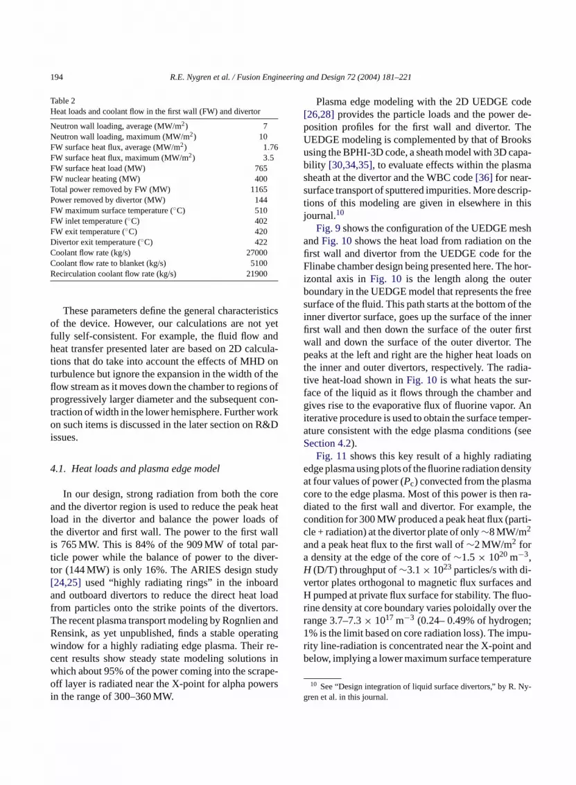
raction of the particle power. A large heat load torst wall can also be a challenge, for example, duigh thermal stresses in a solid first wall. In our liqurface chamber design, the flow path of the coofirst wall) is the full length of the chamber wall, whis much longer than designs for solid walls, andhallenge is to keep the evaporation (impurity genion), and therefore the maximum surface temperat an acceptable level.Table 2gives heat loads and floates for our Flinabe design.
194 R.E. Nygren et al. / Fusion Engineering and Design 72 (2004) 181–221
Table 2Heat loads and coolant flow in the first wall (FW) and divertor
Neutron wall loading, average (MW/m2) 7Neutron wall loading, maximum (MW/m2) 10FW surface heat flux, average (MW/m2) 1.76FW surface heat flux, maximum (MW/m2) 3.5FW surface heat load (MW) 765FW nuclear heating (MW) 400Total power removed by FW (MW) 1165Power removed by divertor (MW) 144FW maximum surface temperature (◦C) 510FW inlet temperature (◦C) 402FW exit temperature (◦C) 420Divertor exit temperature (◦C) 422Coolant flow rate (kg/s) 27000Coolant flow rate to blanket (kg/s) 5100Recirculation coolant flow rate (kg/s) 21900
These parameters define the general characteristicsof the device. However, our calculations are not yetfully self-consistent. For example, the fluid flow andheat transfer presented later are based on 2D calcula-tions that do take into account the effects of MHD onturbulence but ignore the expansion in the width of theflow stream as it moves down the chamber to regions ofprogressively larger diameter and the subsequent con-traction of width in the lower hemisphere. Further workon such items is discussed in the later section on R&Dissues.
4.1. Heat loads and plasma edge model
In our design, strong radiation from both the coreand the divertor region is used to reduce the peak heatload in the divertor and balance the power loads ofthe divertor and first wall. The power to the first wallis 765 MW. This is 84% of the 909 MW of total par-ticle power while the balance of power to the diver-tor (144 MW) is only 16%. The ARIES design study[24,25] used “highly radiating rings” in the inboardand outboard divertors to reduce the direct heat loadfrom particles onto the strike points of the divertors.The recent plasma transport modeling by Rognlien andRensink, as yet unpublished, finds a stable operatingwindow for a highly radiating edge plasma. Their re-cent results show steady state modeling solutions inwhich about 95% of the power coming into the scrape-o ersi
Plasma edge modeling with the 2D UEDGE code[26,28] provides the particle loads and the power de-position profiles for the first wall and divertor. TheUEDGE modeling is complemented by that of Brooksusing the BPHI-3D code, a sheath model with 3D capa-bility [30,34,35], to evaluate effects within the plasmasheath at the divertor and the WBC code[36] for near-surface transport of sputtered impurities. More descrip-tions of this modeling are given in elsewhere in thisjournal.10
Fig. 9shows the configuration of the UEDGE meshandFig. 10shows the heat load from radiation on thefirst wall and divertor from the UEDGE code for theFlinabe chamber design being presented here. The hor-izontal axis inFig. 10 is the length along the outerboundary in the UEDGE model that represents the freesurface of the fluid. This path starts at the bottom of theinner divertor surface, goes up the surface of the innerfirst wall and then down the surface of the outer firstwall and down the surface of the outer divertor. Thepeaks at the left and right are the higher heat loads onthe inner and outer divertors, respectively. The radia-tive heat-load shown inFig. 10is what heats the sur-face of the liquid as it flows through the chamber andgives rise to the evaporative flux of fluorine vapor. Aniterative procedure is used to obtain the surface temper-ature consistent with the edge plasma conditions (seeSection 4.2).
Fig. 11shows this key result of a highly radiatingedge plasma using plots of the fluorine radiation densitya ac n ra-d thec rti-caaH -v andH uo-r ther n;1 pu-r andb ture
y-g
ff layer is radiated near the X-point for alpha pown the range of 300–360 MW.
t four values of power (Pc) convected from the plasmore to the edge plasma. Most of this power is theiated to the first wall and divertor. For example,ondition for 300 MW produced a peak heat flux (pale + radiation) at the divertor plate of only∼8 MW/m2
nd a peak heat flux to the first wall of∼2 MW/m2 fordensity at the edge of the core of∼1.5× 10²⁰ m−3,(D/T) throughput of∼3.1× 10²³ particles/s with di
ertor plates orthogonal to magnetic flux surfacespumped at private flux surface for stability. The fl
ine density at core boundary varies poloidally overange 3.7–7.3× 10¹⁷ m−3 (0.24– 0.49% of hydroge% is the limit based on core radiation loss). The imity line-radiation is concentrated near the X-pointelow, implying a lower maximum surface tempera
10 See “Design integration of liquid surface divertors,” by R. Nren et al. in this journal.

R.E. Nygren et al. / Fusion Engineering and Design 72 (2004) 181–221 195
Fig. 9. Mesh for UEDGE 2D model of APEX/ARIES plasma edge.
for the first wall than for (assumed) uniform radiation.The power balance for this case is as follows:
• Fluorine radiated power = 223 MW.• Hydrogen radiated power = 63 MW (reduced for re-
absorption).• Particle power to divertor = 12 MW.• Particle power to walls = 2 MW.
The set of four cases (left side inFig. 11) shows aprogression from a case that is not stable (MARFE),through two cases (300 and 400 MW) with stable oper-ation, to the 440 MW case that is unstable and “burnsthrough” onto the target. At the right ofFig. 11 is a
Fig. 10. Radiated heat flux vs. distance around the chamber fromUEDGE model.
later case (Pc = 480 MW) with revised surface temper-atures for the Flinabe and different plasma conditions,for which stable solutions were found with even higherconvected power.
We must emphasize here an important caveat regard-ing the plasma edge modeling and the stability of suchhighly radiating edge-plasmas. An operating windowexists, but outside this window, the edge impurities caneither lead to a radiation collapse of the core, or be-come ineffective in the edge, thereby allowing a largeparticle heat-flux to reach the divertor. We considercases where the highly radiating plasma is effective,and this has several implications for our design work.First, the liquid surface does present the potential ad-vantage that this surface is regenerated in the event ofa transient that results in excessive local heating thatextinguishes the plasma. Second, it is reasonable to in-vestigate designs based upon relatively modest peakheat fluxes (8–10 MW/m2) in the divertor as well asdesigns in which we maximize the peak heat flux thatcan be handled.

196 R.E. Nygren et al. / Fusion Engineering and Design 72 (2004) 181–221
4.2. First wall heat transfer
The surface temperature of the first wall increasesfrom top to bottom as heat is added to the flowingFlinabe first wall over its long flow path of about6.5 m. Author Smolentsev has calculated the surfacetemperature along the flow path using a fluid flowand heat transfer model that includes MHD (magneto-hydrodynamic) effects. Typical output includes theflow thickness, quantities that characterize the turbu-lence and the velocity and temperature fields. Themodel has been described elsewhere[33]. Some resultsfor our chamber design are summarized here.
The approach is based on the standard “K–ε” modelused widely in engineering applications to characterizeturbulent flow. In the work for APEX, author Smolent-sev and other collaborators have expanded the basicmodel to include the effects of MHD on the turbulence,particularly in the region of fluid near the free surface.The effect of MHD forces on the thickness (or speed)of the flow was also evaluated but there was little effectin the case of Flinabe. The effect on the heat transferin the near surface was significant. In general in the
orine ra
presence of a strong magnetic field, the turbulent ed-dies in the bulk of the fluid tend toward a 2D state withcirculation around the direction of the magnetic fieldand elongation in the direction of the field. Thus theturbulent structure is anisotropic, and near the free sur-face, there is also a damping of the turbulent transport.The other reason for anisotropy is turbulence redistri-bution near the free surface. This phenomenon occursin the thin near-surface layer (known as a blockagelayer) and is caused by a blockage effect on turbulencedue to the capillary forces and the gravity force com-ponent normal to the free surface. The blockage effectresults in suppression of the velocity pulsations nor-mal to the free surface and some enhancement of theother two velocity components due to continuity. Suchturbulence redistribution near the free surface reducesheat transfer rate unless the surface waves enhance fluidmixing within the blockage layer. Thus, in these flows,one must characterize separately the turbulence in thebulk fluid and the turbulence near the free surface.
The turbulence anisotropy at the surface can be char-acterized by the turbulent Prandtl number, which isthe ratio of eddy diffusivity for momentum to eddy
Fig. 11. UEDGE “maps” of flu
diation. See text for explanation.
R.E. Nygren et al. / Fusion Engineering and Design 72 (2004) 181–221 197
diffusivity for heat. Based on the experimental data forsubcritical flows (Froude11 number <1)[37], the distri-bution for the turbulent Prandtl number was evaluated.This distribution exhibits increases within the blockagelayer when approaching the free surface. This differsradically from the assumed treatment for fluids likeFlinabe in closed channel flows where the ReynoldsAnalogy is often assumed so that the turbulent Prandtlnumber is approximately unity and does not vary acrossthe layer. In developing a solution for this problem,Smolentsev and collaborators incorporated Joule dis-sipation from both velocity and electric field pulsationsin the treatment of the dissipation term in the equationfor turbulent kinetic energy and in the destruction termin the equation for the dissipation rate. They utilizedthe “K–ε” model to characterize the eddy diffusivityfor momentum as well as effective thermal conductiv-ity across the liquid layer.
Freeze et al.[32] have also investigated the effect ofwaviness on the heat transfer of inclined thick flowingfilms appearing in supercritical flows (Froude number>1). Here the basic findings were a dependence of wavi-ness (amplitude and wave length) on the component ofthe Froude number normal to the free surface and, withthe free surface heated, an enhancement of the pen-etration of heat, i.e., lower surface temperature, dueto waviness. Comparisons with predictions of a “K–ε”model were made and improvements were developedthrough an expression for the near-surface turbulentPrandtl number evaluated from flow experiments donei
ret es,e an-a rsusl facet e inF vest ture.B ont em-p . Thes cal-
c-t tion.F pingt
culated with the waviness effect, and the correspondingdistribution of the turbulent Prandtl number was evalu-ated from the experimental data for supercritical flowsunder conditions relevant to the reference case. Twocurves are plotted because the impact of the magneticfield on the wave motion is still not clear. Although theexperimental regimes were chosen to be close enoughto the first wall flow in our design, the present experi-mental setup did not provide any measurements with amagnetic field. Therefore, the two curves in the figuregive a possible range for the surface temperature. Theupper curve corresponds to a flow regime in which allwaves are suppressed by a magnetic field. The lowercurve gives a temperature assuming the MHD has noimpact on the surface waves. The true location of thetemperature curve can be calculated if experimentaldata on wave suppression by a magnetic field becomeavailable in the future.
As the Flinabe first wall flows (against a structuralflow substrate) down the upper half of the chamber, theradius of the chamber and the width covered by the flowincrease until the mid-plane, and then both decrease inthe bottom half of the chamber. This change in width,and the corresponding thinning or slowing of the firstwall flow, are not treated by the current 2D version ofthe models developed.
Fig. 12 shows the rise in temperature of the out-board Flinabe first wall as it flow downward. It has
F flowp
n a hydrodynamic test facility (FliHy) at UCLA.Variations in heat flux along the flow length a
reated by dividing the flow length into various zonach with a specified heat flux, or by providing anlytical function that describes the heat load ve
ength along the flow path. The estimates of suremperature for our Flinabe first wall, such as thosig. 12, have typically been presented with two cur
hat bound the likely range of the surface temperaoth calculations include the effect of the MHD
urbulence. The first curve, with a higher surface terature, is calculated assuming no surface wavesecond curve, with a lower surface temperature, is
11 The Froude number (Fr =V2/gD) is a dimensionless scaling faor that arises from the gravitational term of the equation of moorFr less than unity, gravitational effects are important in dam
urbulence.
ig. 12. Temperature rise of Flinabe first wall vs. distance alongath.
198 R.E. Nygren et al. / Fusion Engineering and Design 72 (2004) 181–221
a starting thickness and flow rate of 23 mm thick and10 m/s, an average surface flux of 1.76 MW/m2 andpeak of 3.5 MW/m2 and an average nuclear wall loadof 7 MW/m2 and peak of 10 MW/m2. The neutronsproduce volumetric (bulk) heating and the heating ratemight typically be expressed in W/g and would varywith the distance of the penetrating neutron flux. How-ever, the convention here is to represent the power ofthe source term as a “neutron wall load” or power flux.The penetration of the surface heat and nuclear heatingcontribute about equally to the rise in bulk temperatureof ∼18◦C. The surface temperature profiles rise as thetemperature gradient in the fluid develops over roughly2 m of the flow length. The rise in surface temperaturewithout the effect of waviness is 130 and 90◦C withthe waviness. With an inlet temperature of 402◦C, themaximum estimated surface temperature of the Flinabefirst wall is 532◦C when the potential advantage of thewavy flow is not taken into account, and is 492◦C withwaviness. Since we anticipate that some waviness willoccur, we conclude that the maximum surface temper-ature will not exceed the allowable maximum surfacetemperature of 510◦C, and the first wall power han-dling is adequate.
4.3. Divertor heat transfer
The divertor heat load comprises a peaked heat loadfrom charged particles hitting the surface at the “strikepoint” and a more uniform radiative heat load. Thes r onw them mesp then tralsa utel
eatl ithad eakh mrtt thorS gthi in-s hort
Fig. 13. Heat load profiles for the divertor from UEDGE and averagevalues for peak and background.
distance due to the high heat flux and generally poorthermal conductivity of the Flinabe. The rise in tem-perature is about 135◦C. This, added to the bulk tem-perature of 420◦C leaving the first wall gives a peakof about 555◦C. This is higher than the allowable tem-perature of 510◦C for the first wall, but is acceptable inthe divertor where there is more shielding of impuritiesfrom the main plasma.
There are some differences between the heat transferin the divertor and that for the first wall beyond theobvious one of a higher heat load in the divertor. In thetop of the outboard divertor, the flow from the first wallimpinges onto the deflector (seeFig. 15) and is directed
F longfl
trike point is a toroidal band around the chambehich the charged particles deposit as they followagnetic flux surfaces. The radiative heat load corimarily from the strongly radiating zones nearull point in the separatrix. Charge exchange neund radiation from the main plasma also contrib
esser amounts to the heat load.Fig. 13shows a detailed view of the divertor h
oad from the UEDGE model described previously wpeak heat load of only 10–12 MW/m2 in the outboardivertor. The figure also shows a flat profile with a peat flux of 10.6 MW/m2 that is the sum of the uniforadiated heat flux into the divertor of∼3 MW/m2 plushe average of 7.6 MW/m2 over the peak.Fig. 14showshe temperature rise in the divertor calculated by aumolentsev for these conditions. Here the flow len
s short and the contribution from nuclear heating isignificant. The temperature rises rapidly within a s
ig. 14. Temperature rise of Flinabe in divertor vs. distance aow.

R.E. Nygren et al. / Fusion Engineering and Design 72 (2004) 181–221 199
Fig. 15. CAD drawing of divertor cassette (top) and backside view(PATRAN Model) of deflector (bottom).
downward, as shown inFig. 7. Before receiving thepeak heat load of the divertor, the fluid has passed thedeflector, where thermal mixing of the fluid occurs.This mixing destroys the thermal gradient in the firstwall flow, and the flow stream leaving the deflector tobecome the divertor flow has an approximately uniformtemperature equal to the bulk temperature from the firstwall stream.Fig. 15shows some of the details of thedeflector, such as vanes which direct flow.
The flow initially exiting from the deflector also hasa somewhat higher turbulence in the layer near the freesurface than in the layer upstream of the deflector. Thisenhances the heat transfer. An issue in designing thedivertor was how to minimize the peak surface tem-perature, and, in this regard, having the peak heat loadclose to the deflector was investigated.
Fig. 16shows profiles of the turbulent viscosity ver-sus the normalized distance from the back (flow sub-
Fig. 16. Profiles of turbulent viscosity vs. normalized distance fromback surface of flow at several distances downstream from exit ofdeflector.
strate) to the free surface at several locations down-stream from the deflector. A substrate must be presentin this model, so there is a continuing source of drag topromote turbulence at the back surface. However, theright side of the plots gives some sense of how the tur-bulence decays from an initially higher value towardthat of a developed free surface.
Fig. 17shows temperature profiles for several po-sitions of the peak heat on the divertor stream. As thelocation of the peak heat load gets further from the exit
Fig. 17. Surface temperature vs. distance from exit of deflector alongdivertor flow for four cases with the peak divertor heat flux locatedat 5, 10, 15 or 20 cm downstream from the deflector.

200 R.E. Nygren et al. / Fusion Engineering and Design 72 (2004) 181–221
of the deflector, the peak temperature is higher. Theincrease in peak temperature with distance from thedeflector exit is roughly linear with a slope of∼32◦Cincrease in surface temperature for each 0.1 m increasein distance from the peak heat load to the deflectorexit. Thus the proximity is important and the generalapproach to keep the peak heat load within∼0.2 m ofthe deflector exit is a good guideline. This increase isdue both to the heating of the stream from the 3 MW/m2
heat load before the peak heat flux is encountered andto the lessening of turbulence near the free surface. Theroughly linear dependence of the increase on distanceis actually the sum of a less than linear increase in thepre-heating and a more than linear increase due to thelessening turbulence.
A peak heat load of 11.7 MW/m2, slightly higherthan inFig. 13, was used in the heat transfer calcula-tions for the divertor. The increase takes into accountlocal shaping in the divertor and (toroidal) openings forparticle pumping. The model described in the previoussection was also used to calculate the temperature risein the divertor.
Another aspect of heat transfer in the divertor is thecooling of the deflector itself, which receives a heatload of 3 MW/m2 from the plasma. While most of thearea on the back of the deflector is in contact with theflowing Flinabe, there must be a lip at the upstreamentrance to catch any waves. This lip receives the sameheat load but must conduct this heat along the lip ofthe deflector to the area that is cooled by the Flinabe.A tedt rmalc asei 2Dt endom ofa olu-t ec-t idet
r ist thee andw tru-s wei otht ) are
spread evenly over this surface. But when a toroidalopening exists, some particles diffuse radially outwardin this gap and impinge “head on” onto the edge ofthe opening. This circumstance can produce very highlocal heat loads. The techniques for mitigating this isto make the plasma-facing surface near these leadingedges gradually recede so that the diffusing heat loadspreads over this larger receding area. For the liquidstream in the divertor, this simply means that the de-flector is shaped so that the region at the sides of thestream for a particular sector are slightly further out inradius at the location of the peak heat flux. The divertorshape and cooling of the lip are discussed further in ourcompanion article.12
4.4. Blanket heat transfer
Heat is generated in the blanket as the result of nu-clear heating. Neutrons (14.1 MeV) produced in thecore plasma from the fusion reaction penetrate the firstwall and blanket and dissipate energy through scatter-ing, deposit energy when stopped and undergo nuclearreactions with Be and Li7 that produce other neutrons.The heat in the blanket is removed by flowing Flinabe,as indicated inFigs. 6 and 8. A subsequent section ofthis paper covers the tritium breeding in the blanketand also gives more details on the radial build of theblanket and nuclear heating. Here we summarize thecoolant temperatures and pressure drops (seeTable 3).
5
ol-o ndF usly.F terialf dera ruc-t resi allso er.T edw r.
y-g
n initial thermal analysis of the deflector indicahat (a) the deflector should be made of a good theonductor and (b) the lip should be thick to increts thermal conductance. For a 100 mm-long lip ahermal analysis indicates a problem with the veryf the lip where the temperature reaches∼900◦C. Theaterial is copper clad with a thin layer (0.5 mm)dvanced ferritic steel. The more likely design s
ion, not yet done, is to cool the lip by forced convion in an internal channel for Flinabe that runs inshe lip.
A further concern for the heating of the divertohe “leading edge” problem. Charged particles atdge of a plasma follow the magnetic field linesill deposit a tremendous heat load on any proion that has intercepted this particle flux. Whenmagine that the divertor is a continuous and smooroidal surface, these particles (and their energy
. Materials
In the design effort in APEX on chamber techngy with liquid walls, we have investigated Flibe alinabe and several liquid metals, as noted previoor the design presented here, Flinabe is the ma
or the flowing first wall and divertor and the breend coolant for the blanket design. The primary st
ural material for the blanket and auxiliary structus an advanced ferritic steel. The front and side wf the blanket are 5 mm thick. The back wall is thickhe blanket also utilizes beryllium in the form of a bith 5 mm beryllium pebbles as a neutron multiplie
12 See “Design integration of liquid surface divertors,” by R. Nren et al. in this journal.

R.E. Nygren et al. / Fusion Engineering and Design 72 (2004) 181–221 201
Table 3Heat loads and coolant flow in the blanket
Blanket power (MW) 2857Blanket coolant inlet temperature (◦C) 422Coolant temperature entering the Be bed (◦C) 483Coolant temperature exiting the Be bed (◦C) 544Maximum Be temperature (◦C) 600Blanket exit temperature (◦C) 646Coolant temperature entering the HX (◦C) 646Return coolant temperature from the HX (◦C) 312Blanket flow rate (kg/s) 5100Estimated power conversion efficiency (%) 49Width of the blanket unit (mm) 300Width of the side wall channel (mm) 10Diameter of the Be pebble (mm) 5Radial depth of the Be bed (mm) 60Coolant velocity along the side channel (m/s) 0.18Coolant velocity in blanket module (m/s) 0.013Pressure drop through Be bed (MPa) 0.02Other pressure drops Small
5.1. Flinabe
The motivation in selecting Flinabe as a workingfluid was that it had a melting temperature lower thanFlibe. We had evaluated Flibe earlier as a possibleworking fluid and found a problem with the operat-ing temperature window. The molten salt Flinabe isa mixture of three fluorides; the nominal 1:1:1 mix-ture is LiF–NaF–BeF2. The neutronics characteristicsof Flinabe and tritium extraction are described in latersections.
We have little data on the physical properties ofFlinabe, but we believe these are similar to anothermolten salt, Flibe, but with a lower melting tempera-ture. Flibe is a mixture of LiF and BeF that was stud-ied for use in molten salt fission reactors (and actinideburners) but much of the data are in laboratory technicalreports or foreign journals[38–43]. Good data compila-tions also were done in the past for the HYLIFE-II study[44], a heavy-ion driver inertial fusion power plant, andfor the blanket comparison and selection study[45].A more recent assessment of Flibe also discusses itschemistry and the issues associated with tritium pro-cessing[46].
We are still gathering and reviewing the data on themelting temperatures of Flinabe mixtures.13
13 Moore et al.[42] indicate aTm of 315◦C for a compositionsomewhat more rich in BeF2 than the 1:1:1 mixture. (TheTm of
Our conclusions based on a review of these data areas follows.
1. There may be mixtures of Flinabe that have meltingtemperatures below 300◦C; this should be investi-gated in new experimental work.
2. Based on a binary phase diagram of the mixtureNa2BeF4 and Li2BeF4 by Toropov, there appears tobe a salt mixture of 30% Na2BeF4 and 70% Li2BeF4(a ternary mixture of 20% NaF, 47% LiF and 33%BeF2) with a melting temperature of∼290◦C. Thisis a reasonable basis for an assumption of a usefulFlinabe mixture with a melting temperature as lowas 290◦C.
3. The minimum temperature must be sufficientlyabove the melting temperature to provide a marginof safety against freezing.
We are using the thermo-physical properties of Flibefor our heat transfer calculations. Basically Flibe is apoor electrical and thermal conductor with a thermalconductivity of about 1 W/m K. A high flow rate andturbulent heat transfer are necessary to accomplish theheat transfer in our design. Its viscosity is rather high(kinematic viscosity of 11× 10−6 m2/s), about an orderof magnitude greater than water, so the pressure dropsthrough piping are a concern and large passages aredesirable.
The evaluations of the compatibility of Flibe with anadvanced ferritic steel indicate an allowable interfacet ◦ ef n-k cess
2 cans a-t opovb .Ts idusr ofN .W ment.Ms ) areN -t ot e.T idusp
emperature of up to 700C. Chemistry control of thormation of HF will be needed either within the blaet or in the balance of plant. This requires an ex
40◦C noted for the 1:1:1 mixture appears to be an error. Onepeculate that this should have been 420◦C based on the temperure contours sketched in the diagram.) The quite detailed Torinary phase diagram gives aTm of 350◦C for the 1:1:1 mixtureoropov also shows a eutectic at 290◦C for the Na2BeF4–Li2BeF4
ystem with only a narrow range of composition for the liquegion from 350 down to 290◦C bounded by the precipitationa3Li(BeF4)2 on the Na-rich side and NaLiBeF4 on the Li-rich sideith minor differences, these diagrams are in pretty good agreeoore identifies a phase 5NaF–LiF–3BeF2 andTm of 320◦C. The
olids formed from the peritectic reactions (Toropov diagrama2BeF4 in either the�′ or � phase and Na3Li(BeF4)2. The cen
er of this region, 1:1 Na2BeF4:Na3Li(BeF4)2, would correspond the composition 5NaF–LiF–3BeF2 for which Moore notes a phasoropov’s temperature for the peritectic reaction from the liquhase is∼340◦C.

202 R.E. Nygren et al. / Fusion Engineering and Design 72 (2004) 181–221
of beryllium in contact with the Flibe (or Flinabe) tostabilize the fluoride in the salt.
Flinabe has a low solubility for tritium. This makesthe recovery of tritium from Flinabe easier but meansthere is a relatively high partial pressure of tritium in theprimary Flinabe loop that can drive tritium permeation(seeSection 9).
5.2. Structural material
Various structural materials have been and are be-ing investigated and considered for fusion applications[47,48]. An advanced ferritic steel was selected as thestructural material. This class of materials has beenidentified as attractive in the fusion program for thefollowing reasons.
1. We believe such materials can be produced withcompositions that result in low activation.
2. Radiation experiments have shown that such alloyshave low swelling.
3. Recent developments with oxide-dispersion-strengthened (ODS) ferritic alloys have producedalloys with comparatively high strength and creepresistance to temperatures approaching 800◦C;whereas the mechanical properties of previousferritics declined above 550◦C.
Features (1) and (2) above have been known forsome time and ferritic steels have been considered int lan-k DSf e-c turet lica-t Sf nalL Yt-t am -s itht om-p
yett kingl hism laters sion
of the use of advanced ferritic steels elsewhere in thisjournal.14
5.3. Other materials
A complete reactor design would specify the mate-rials needed for the shielding, magnets and auxiliarycomponents. However, the focus of our effort in APEXis on the chamber technology. One class of materi-als that we do note here is ceramic coatings. We haveidentified the need for two such applications, describedbriefly below, in our design work. The potential needsfor coatings in various fusion applications is recognizedand has been recently reviewed[51].
Some designs with flowing liquid metals useceramic coatings between the flowing metal and thechannel or substrate. The coating provides electricalinsulation that forces MHD-induced currents to closewithin the liquid metal rather than through the wallsof the channel or substrate. Typical objectives in suchapplications are the reduction of the pressure drop ina channel or the reduction of flow asymmetries, suchas jets or stagnation in side layers. Another applica-tion, specific to (poloidally) flowing liquid metal wallsis the possible need for insulating fins at a few toroidallocations to interrupt the path for full toroidal electricalcurrents in the liquid wall. These applications are notedhere simply for completeness because designs with liq-uid metal walls have been considered in APEX. Then e fu-s inc eend
ucet ousb rel-a ryF sideo ucet hem (See
signb wallr ility,s skye
he past as potential structural materials for fusion bets. It is really the recent developments in the Oerritic alloys [49,50] and the extension of good mhanical properties to significantly higher temperahat are now bringing renewed interest to the appion of ferritics in fusion. One formulation of an ODerritic steel being developed at Oak Ridge Natioaboratory and designated 12YWT has 0.25% of
ria and superior properties[49]. It appears to haveaximum working temperature of 800◦C and corre
ponding yield strength of 320 MPa. When used whe molten salt coolant Flibe, the two materials are catible up to 700◦C.
The material is new and still being developed. Ashere remain issues in regard to methods for maarge production lots and fabricating and joining t
aterial. These issues are discussed further in theection on R&D issues. Also, there is further discus
eed for such insulators has been recognized in thion program in work on designs with liquid metalslosed channels, but effort within APEX has not birected to this area.
Another application is for coatings that can redhe permeation of tritium. This is a concern for varilanket designs. In our design with Flinabe and atively high partial pressure of tritium in the primalinabe loop, we specify a ceramic coating on the inf the piping in the primary heat exchanger to red
he tritium permeation from the primary loop into tolten salt loop for the secondary heat exchanger.
14 See “Molten salt self-cooled solid first wall and blanket deased on advanced ferritic steel” by Wong et al. and “Solidecirculating blanket: geometry, materials, materials compatibtructural evaluation, fabrication and fluid circuits” by Sviatoslavt al.

R.E. Nygren et al. / Fusion Engineering and Design 72 (2004) 181–221 203
Table 4Chamber Modules
Module type Volume (m3) #/Sector Total
Inboard blanket 3.11 3 48
Outboard blanketFull length modules 3.77 3 48Penetration modules 2.46 2 32
Nozzle cassette 9.50 1 16Divertor cassette 2.95 1 16
ShieldMain shield module 26.22 1 16Removable rear plug, top 7.54 1 16Removable rear plug, middle 2.95 1 16Removable rear plug, bottom 8.19 1 16
RF system cassette 1.23 1 16Diagnostic cassette 1.23 1 16
a later section, Energy conversion, for further informa-tion.).
6. Mechanical design
The mechanical design has been developed by au-thors, Nelson, Fogarty and Eberle to the point that wecan see that the design integration of the sectors andpiping systems, manifolding, etc. is self-consistent, thatthe sizes and locations of the piping and ducts are rea-
board
sonable in terms of the pressure drops, and that the com-ponents are amenable to handling for remote mainte-nance. Experienced designers have done this work andwe anticipate that the designs can be made robust interms of the mechanical and EM (electromotive) forcesthat such a structure must withstand. The objective ofthis work is to develop a nominally workable designfor the chamber technology. We have not had the timenor resources to develop the full engineering detailsthat would show the mechanical response of the struc-ture to various types of off normal events and transientloading that are associated with a detailed engineeringdesign and safety analysis.
6.1. Overall structure
The solid mechanical structure of the chamber con-sists of the modules listed inTable 4and their associatedpiping and support. There are 16 toroidal field coils andtherefore 16 openings between the Dewar for the su-perconducting coils. The number of blanket modulesis determined by various design constraints, such asthe routing of piping, arrangements for manifolds andthe size and weight that can be handled during remotemaintenance.
The CAD views by author Fogarty inFigs. 18 and 19show the various blanket modules and how they arenested together during assembly of the chamber. The
Fig. 18. Modules and assembly for in
blanket (left) and outboard blanket (right).
204 R.E. Nygren et al. / Fusion Engineering and Design 72 (2004) 181–221
Fig. 19. CAD drawings of nested modules and cassettes in place (left) and withdrawn (center) from the shield module (light gray) with blanketmodules are still in place. Drawing on right shows removable shield liner (dark gray) above its location after installation.
piping systems from the modules extend past the shieldmodules. The vacuum boundary for the chamber, ex-cluding the piping penetrations and those for the largeexhaust ducts, is the outer envelope of the shield mod-ules and the (radially) outboard portions of the out-board blanket, divertor and nozzle modules. Weldedjoints between these modules and the shield modulesand between adjacent shield modules provide the vac-uum seal.
Each blanket module consists of a back plate, anouter shell fed by two Flinabe inlet pipes, and an innervolume. The dimensions are given in previousFig. 8.The Flinabe enters the inner volume by first flowingthrough a 60 mm-thick bed of 5 mm diameter berylliumpebbles and passing back into the large inner reservoirand eventually to the outlet pipe.
A big challenge in the design of solid fusion cham-bers (solid first wall and blanket) is dealing with typ-ically high stresses in the first wall that result fromthe surface heat load, necessary cooling and the asso-ciated thermal gradient. In our design, this challengeis substantially mitigated because the liquid first wallintercepts and carries away this surface heat load.
There are also thermal stresses in the blanket butthese are less severe than in a solid first wall. The blan-ket modules design provides for flexure of the innerand outer side walls to relieve stress. The front and side
walls are 5 mm-thick advanced ferritic steel. However,there is always a concern with the constraint wherethe side walls join to the top or bottom, and there is athermal gradient across the inner wall that divides thehotter Flinabe from the inlet flow. Based on experiencefrom other designs, we do not anticipate a problem, butwe have not yet performed the 3D thermal and stressanalysis of the structure to confirm this opinion.
6.2. RF system – an example of wall penetrations
Our chamber design provides cassettes for RF heat-ing and current drive systems as shown inFig. 19. Thesepenetrations of the first wall present the challenge ofdiverting the first wall flow, and we have tried to iden-tify a representative RF system to include in the de-sign integration of the chamber. RF power launchingstructures and diagnostics will both probably requirewall penetrations. The diagnostics are unspecified atthis point but we are assuming that the approach de-scribed here will be adequate. Fusion reactor designsoften include many types of RF heating (ECH, ICRFand LH) because this provides the most versatility, andat this point in time, we are unsure of what exactly willbe needed.
ECH (electron cyclotron heating) requires a waveguide and “free space” launch, i.e., the antenna does

R.E. Nygren et al. / Fusion Engineering and Design 72 (2004) 181–221 205
not have to conform to the shape at the edge of theplasma and can be fairly compact. For current drivewith ECH, the launchers are typically placed at thetop of the device near the null point and the launchedpower density is∼100 MW/m2. ICRF (ion-cyclotron)antennas are placed at the plasma edge. The penetra-tion is a small coaxial lead. For current drive, ICRFantennae can be placed in any poloidal location. Thetypical launched power density is∼10 MW/m2. Themost stringent requirement appears to be that the grillsfor lower hybrid heating (LHH) must be in fairly closeproximity to the plasma. The typical launched powerdensity is 50–60 and 88 MW/m2 (used in ARIES) isnot a large extrapolation.
Although including all types of RF heating providesthe most versatile option, we have elected a more re-stricted set consisting of LHH, for the edge to com-pensate for excess current in the core, and ECH forcore current drive. Our assumption is that a viableignition scenario could be developed with ECH andLHH, e.g., heating of a low-density plasma followedby an increase in density. Our approach here has beento identify the types of systems that are likely to beneeded and include these in the design configuration;however, there is no self-consistent physics basis withwhich to estimate the required RF power. We havetaken nominal values of 80 MW for the ECH core cur-rent drive and 12 MW for the LHH system to counterexcessive currents at the edge (edge overdrive) thatmay result from the ECH. The parameters are given inT
thefl thep thep pen-e owni thes by ac ovet oft thew ed
TR
T ity (MW
E ctorL
fluid. The nozzle system could be incorporated as theoutlet for any necessary cooling passages within thestructure itself. Some initial work was done on the wallshaping and is discussed in the later section on R&DIssues.
6.3. Piping
The inlet and outlet pipes and manifolds for onesector are evident inFig. 18. The pressure drops for theflow paths were calculated and found to be acceptable.The piping arrangement consists of several separatesets of pipes.
The first set supplies the liquid first wall itself andconsists of separate pipes for each inboard and outboardnozzle array. The first wall (and divertor) flow exits viathe pump ducts; these ducts carry the total first wallflow into a reservoir from which it is pumped througha heat exchanger and then back to nozzle array for thefirst wall.
There are separate piping systems for the internalcooling of each divertor cassette and of each heating ordiagnostic cassette.
Each blanket can is fed from two supply pipes at thebottom of the sector. The pipes are routed and shapedto maintain bulk shielding while providing space forthe liquid wall drain system. This is particularly chal-lenging for the inner blanket modules. For these, theindividual inlet and outlet manifolds have multiple in-let or outlet pipes, and the nested array of the individ-u ans( sin-g othti tes,t
6
d ash e”b y of
able 5.The basic requirement for penetrations is that
uid path in the first wall has to be redirected aroundenetration without causing splashing of fluid intolasma edge. Our example in this regard is a largetration near the mid-plane for the RF cassettes sh
n Fig. 19. We anticipate that the technology formooth flow around penetrations can be managedombination of flow separation and wall shaping abhe penetration and auxiliary nozzles at the bottomhe structures, so that the downstream “hole” inake of the FW fluid flow can be filled with the add
able 5F Heating for ARIES-RS/CLIFF
ype Function Frequency (Hz) Power dens
CH Core current drive 100H Edge overdrive 4.6G 88
) Power (MW) Width (m) Height (m) Location
80 0.15 0.17 Two per se12 0.35 0.39 One only
al pipes to and from the upper middle and lower cseparated fluid containers) to the manifolds of ale inner blanket module is designed to minimize b
he radial space and the void volume needed.Table 6s a piping chart showing sizes, quantities, flow raemperatures, etc.
.4. Maintenance
The chamber components may be classifieigh maintenance, low maintenance and “lifetimased on the expected reliability and/or frequenc

206 R.E. Nygren et al. / Fusion Engineering and Design 72 (2004) 181–221
Table 6Piping specifications
Circuit type Sector power (MW) Tin (◦C) Tout Flow rate No. ofcircuits
Pipe i.d.(cm)
Velocity(m/s)◦C kg/s m3/s l/s
First wall fast flowInboard 28.6 403 420 663 0.331 331 10 15 1.9Outboard 41.2 403 420 955 0.478 478 20 15 1.4Flow under OB penetration 3.0 403 420 70 0.035 35 21 3.5 1.7Total, all sectors 1165 27000 13.5 13500
Blanket modulesInboard 52.8 422 646 96 0.048 48 9 7.5 1.2Outboard 122.7 422 646 222 0.111 111 15 7.5 1.7Total, all sectors 2808 5079 2.54 2540
DivertorsInboard 3.2 420 422Outboard 5.8 420 422 Cooled by first wall fast flowTotal, all sectors 144
Structure (shielding, vacuum vessel, etc.)Inboard 2.0 422 437 54 0.027 27 4 7.5 1.5Outboard 1.1 422 437 29 0.014 14 4 5 1.8Total, all sectors 49 1316 0.66 658
replacement. The maintenance scheme for each generalclassification is described below.
6.4.1. High maintenance componentsThose components considered most likely to fail
during operation (liquid supply systems, film formers,heating elements, diagnostics devices, and divertors)are designated as high-maintenance items and were de-signed as removable cassettes. The RF modules andnozzle and divertor cassettes shown inFig. 19are ex-amples.
To increase the availability factor of the machine, itis imperative that these high maintenance componentscan be rapidly replaced without having to disassem-ble the entire device. For example, each nozzle arrayis contained in a cassette that can be removed and re-placed independently from the rest of the reactor inter-nals. The cassettes and nozzles will be exposed to highneutron fluences, and the nozzles and internal pipingare subject to erosion and degradation from the highvelocity flow. Frequent replacement of the film form-ing cassettes, perhaps as often as once every 2 years, isassumed.
6.4.2. Low maintenance componentsThe low-maintenance items, e.g., the blanket/shield
modules, are extremely heavy and not designed to be
remotely maintained or remotely transported. For theirinfrequent maintenance, a total sector is removed. Pre-viousFig. 8shows a sector,Fig. 18shows blanket mod-ules andFig. 19shows the blanket modules nested inthe shield module.
There is insufficient clearance, and not really evenan open pathway, through either the back of the blan-ket or the top of the liquid supply system, to extractlarge components. Consequently, access to the blan-ket modules requires removal of a whole sector. Sincethe outboard blanket and shield would have to be re-moved first anyway to gain access to the inboard com-ponents, removing a sector module intact is easier andfaster and provides the needed access (in a hot cell)to all components for necessary repairs and scheduledmaintenance.
Another concern that justifies the approach of re-moving entire sectors for access to low maintenancecomponents is the possibility, and perhaps the likeli-hood, that at some time, leaks or damage might re-sult in these large components, such as blanket mod-ules, sticking to each other or to the shield module.An alternative of removing individual modules re-motely rather than a whole sector, presents the riskof one or more of the following undesirable circum-stances. First, the component itself could be damagedor destroyed during the attempted extraction. Second,

R.E. Nygren et al. / Fusion Engineering and Design 72 (2004) 181–221 207
Table 7Radial build at the midplane of the initial APEX LW configuration
Inboard side Outboard side
Zone Inner radius (cm) Zone Inner radius (cm)
Central solenoid 13.6 Plasma 437Inner casinga 91.7 SOL 687Winding packb 101.8 Liquid FWc 690Outer casinga 199.88 FW substrated 692Gap 209 Blankete 692.5Vacuum vessel inner wallf 289 HT-shieldg 752.5Vacuum vesselh 291 Gap 782.5Vacuum vessel outer wallf 307 LT-shieldi 784.5Gap 309 Gap 814.5LT-shieldi 314 Vacuum vessel inner wallf 825Gap 342 Vacuum vesselh 827HT-shieldg 344 Vacuum vessel outer wallf 853Blankete 371.5 Gap 855FW substrated 411.5 Inner casinga 875Liquid FWc 412 Winding packb 893SOL 414 Outer casinga 992.5Outer radius 1012.5
a 100% SS316 LN.b 18% epoxy, 19% Cu, 3% Nb–Sn, 17% liquid He-4, 43% SS316 LW.c Liquid breeder.d 100% structure.e 90% breeder/coolant, 10% structure. When a multiplier is used, the first 10 cm consists of 60% Be, 30% breeder, and 10% structure.f 100% ferritic steel.g High-temperature shield: 95% structure, 5% coolant/breeder.h 81% SS316, 19% water.i Low-temperature shield: 95% structure, 5% coolant/breeder.
adjacent components might be damaged. Third, theprocess of dealing with these damaged componentsand completing their extraction and any necessary re-pairs and cleanup to the remaining structure wouldlikely take the device out of service for an extendedperiod.
Thus, we believe it is prudent to do all major repairsof non-cassette components outside of the machine in ahot cell room. While such repairs occur, a replacementsector would be installed.
6.4.3. Lifetime componentsThe vacuum vessel and coil sets are considered
to be lifetime components and therefore need to beprotected with adequate shielding. If repairs are re-quired, the shielding minimizes the neutron dam-age to the vessel material and makes it possibleto cut, remove, replace, and reweld sections of thevessel. This procedure follows the sector removalprocess.
7. Neutronics
In the molten salt LiF–NaF–BeF2 (Flinabe) the Liatom is in one of three fluoride molecules and its tri-tium breeding capability is less than that of LiF–BeF2(Flibe), in which Li is in one of two molecules. Thelower Li concentration requires a comparatively greateramount of neutron multiplier (beryllium) to improvethe tritium breeding ratio (TBR). Author Youseff hereshows these characteristics for two types of structuralmaterials, namely SiC and ferritic steel (FS-HT-9) inthe initial CLiFF configuration, which was used ear-lier for assessment of TBR with other liquid breeders[52–56]. The TBR in the final blanket configurationwith advance ferritic steel (AFS – nanocomposite fer-ritic NCF) structure, as well as other characteristics ofthe final design, such as nuclear heating and require-ments for shielding are given in this section. The initialand final tritium breeding assessments reported in thenext two subsections were based on the 1:1:1 mixture
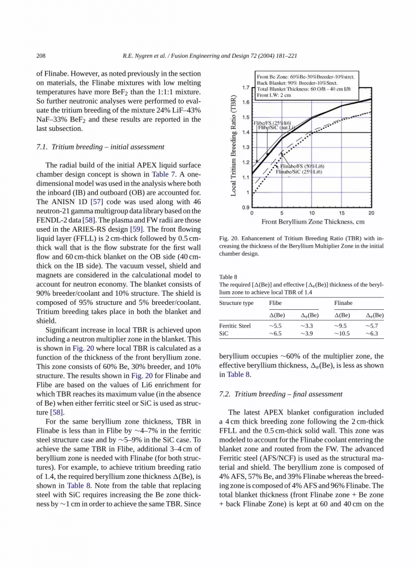
208 R.E. Nygren et al. / Fusion Engineering and Design 72 (2004) 181–221
of Flinabe. However, as noted previously in the sectionon materials, the Flinabe mixtures with low meltingtemperatures have more BeF2 than the 1:1:1 mixture.So further neutronic analyses were performed to eval-uate the tritium breeding of the mixture 24% LiF–43%NaF–33% BeF2 and these results are reported in thelast subsection.
7.1. Tritium breeding – initial assessment
The radial build of the initial APEX liquid surfacechamber design concept is shown inTable 7. A one-dimensional model was used in the analysis where boththe inboard (IB) and outboard (OB) are accounted for.The ANISN 1D [57] code was used along with 46neutron-21 gamma multigroup data library based on theFENDL-2 data[58]. The plasma and FW radii are thoseused in the ARIES-RS design[59]. The front flowingliquid layer (FFLL) is 2 cm-thick followed by 0.5 cm-thick wall that is the flow substrate for the first wallflow and 60 cm-thick blanket on the OB side (40 cm-thick on the IB side). The vacuum vessel, shield andmagnets are considered in the calculational model toaccount for neutron economy. The blanket consists of90% breeder/coolant and 10% structure. The shield iscomposed of 95% structure and 5% breeder/coolant.Tritium breeding takes place in both the blanket andshield.
Significant increase in local TBR is achieved uponincluding a neutron multiplier zone in the blanket. Thisi af ne.T 10%sF forw nceo ruc-t
inFs oa ofb uc-t atioos ngs ick-n nce
Fig. 20. Enhancement of Tritium Breeding Ratio (TBR) with in-creasing the thickness of the Beryllium Multiplier Zone in the initialchamber design.
Table 8The required [�(Be)] and effective [�e(Be)] thickness of the beryl-lium zone to achieve local TBR of 1.4
Structure type Flibe Flinabe
�(Be) �e(Be) �(Be) �e(Be)
Ferritic Steel ∼5.5 ∼3.3 ∼9.5 ∼5.7SiC ∼6.5 ∼3.9 ∼10.5 ∼6.3
beryllium occupies∼60% of the multiplier zone, theeffective beryllium thickness,�e(Be), is less as shownin Table 8.
7.2. Tritium breeding – final assessment
The latest APEX blanket configuration includeda 4 cm thick breeding zone following the 2 cm-thickFFLL and the 0.5 cm-thick solid wall. This zone wasmodeled to account for the Flinabe coolant entering theblanket zone and routed from the FW. The advancedFerritic steel (AFS/NCF) is used as the structural ma-terial and shield. The beryllium zone is composed of4% AFS, 57% Be, and 39% Flinabe whereas the breed-ing zone is composed of 4% AFS and 96% Flinabe. Thetotal blanket thickness (front Flinabe zone + Be zone+ back Flinabe Zone) is kept at 60 and 40 cm on the
s shown inFig. 20where local TBR is calculated asunction of the thickness of the front beryllium zohis zone consists of 60% Be, 30% breeder, andtructure. The results shown inFig. 20for Flinabe andlibe are based on the values of Li6 enrichmenthich TBR reaches its maximum value (in the absef Be) when either ferritic steel or SiC is used as st
ure[58].For the same beryllium zone thickness, TBR
linabe is less than in Flibe by∼4–7% in the ferriticteel structure case and by∼5–9% in the SiC case. Tchieve the same TBR in Flibe, additional 3–4 cmeryllium zone is needed with Flinabe (for both str
ures). For example, to achieve tritium breeding rf 1.4, the required beryllium zone thickness�(Be), ishown inTable 8. Note from the table that replaciteel with SiC requires increasing the Be zone thess by∼1 cm in order to achieve the same TBR. Si

R.E. Nygren et al. / Fusion Engineering and Design 72 (2004) 181–221 209
Fig. 21. Comparison of the Local Tritium Breeding Ratio (TBR)between the initial and later configuration versus.
O/B and I/B side, respectively, as shown inTable 6. Inthis more realistic configuration, the TBR as a functionof the breeding zone exhibits lower values which areshown inFig. 21. For a 12 cm-thick Be zone, the lo-cal TBR is∼1.3 and is 1.4 at∼28 cm-thick Be zone.The local value adopted in the present design is TBR∼1.22 at a thickness of the beryllium zone�(Be) =6 cm (57% dense), which is equivalent to an effectiveberyllium thickness�e(Be) = 3.4 cm. The correspond-ing TBR (∼1.22) is used as the reference value and be-lieved to be adequate in meeting tritium self-sufficiencygoal.
7.3. Nuclear heating and shielding
Nuclear heating (from both neutrons and gammarays) have been estimated throughout the APEX liquidwall (LW) configurations with Flinabe as the coolantand breeder. The power multiplication (ratio of powerin all components to incident neutron power) is shownin Table 9for the initial and latest liquid surface cham-ber designs. About 31% of the total nuclear heat isdeposited in the I/B whereas the balance (∼69%) isdeposited in the O/B at the mid plane. The contribu-tion to the total heating from each component is shownin Table 10. The power deposited in the front flowingliquid layer is∼12–14%, whereas most of the power(∼80–83%) is deposited in the blanket (excluding thesolid FW flow substrate).
Table 9Total power and power multiplication in APEX LW concept (averageneutron wall load = 7 MW/m2)
Latest LW Initial LW
Total nuclear power deposited per cmheight (MW/cm)
5.15 5.62
Total incident power per cm height(MW/cm)
4.86 4.86
Power multiplication (PM) ∼1.06 ∼1.16
The required minimum shield thickness, both in theinboard and outboard side, was estimated such that theupper limits to radiation damage to the magnet will notbe exceeded. This optimization is needed to eliminateoversized shield and thus reduce cost. This also willallow for more space, particularly on the inboard side,for manifolds and piping to route coolant. The upperlimits to radiation damage to the magnet consideredin the analysis are: (1) end-of-life fast neutron fluence(En > 0.1 MeV) of 1.0× 10¹⁹ n/cm2; (2) end-of-lifeinsulator (glass-fiber-filled, GFF, polyimide) dose of1.0×109 Grays (1.0×10¹¹ rad); (3) end-of-life copperstabilizer of 6× 10⁻³ dpa; and (4) peak winding packpower density of 2 mW/cm3.
Table 11gives the minimum shield thickness re-quired on both the inboard and outboard side. The goodradiation attenuation characteristics of Flinabe resultedin thinner shield. The minimum shield requirement isdriven by the limit on the end-of-life neutron fluence.As shown in the table, this minimum shield is∼56 cmin the inboard side and∼26 cm in the outboard side.With this shield thickness, the vacuum vessel can lastthe plant lifetime (30 years). Note that the total shield
Table 10Percentage (%) power deposited in various componentsa
Component I/B O/B
Front Flinabe liquid layer (%) 13.74 12.27
BlanketSolid first wall (%) 3.69 3.56
S
SVT
d∼
Front breeding zone (%) 21.37 20.14Beryllium zone (%) 22.82 23.43Back breeding zone (%) 35.25 39.85
ubtotal (%) 83.13 86.98
hield (%) 3.09 0.74acuum vessel (%) 0.04 0.01otal (%) 100 100
a % of total nuclear heating rate: inboard∼31.13%, outboar68.87%.

210 R.E. Nygren et al. / Fusion Engineering and Design 72 (2004) 181–221
Table 11Minimum shield thickness requirement in APEX LW concept for radiation damage not to exceed design limits
Inboard (cm) Outboard (cm)
Fast neutron fluence (En > 0.1 MeV) – design limit: 1× 10¹⁹ n/cm2 56 26Dose to insulator – design limit: 1.0× 10¹¹ rad 48 12Cu stabilizer – design limit: 6× 10⁻³ dpa 54 23Vacuum vessel – design limit: 200 dpa No restriction No restrictionVacuum vessel helium – design limit: 1 appm 37 25
thickness in the I/B shown inTable 7is ∼55 cm (342-314 LT-shield + 371.5-344 HT shield) which is justenough to meet the requirement there. The total shieldthickness in O/B shown inTable 7is ∼60 cm. It canthus be reduced to∼26 cm with substantial savings inthe cost of magnet protection on the outboard side.
7.4. Attenuation of X-rays from bremmstrahlungradiation
Because the radiation from the plasma is incident ona liquid layer, as opposed to solid material in solid FWconcepts, X-rays from bremmstrahlung radiation candeposit the power over a measurable length in the liquidlayer. This depends on the penetration length whichis a function of both incident X-rays energy and theliquid material under consideration.Fig. 22gives thepenetration length (mean free path) of X-rays in severalmaterials as a function of the incident photon energy.As shown, lithium is the best candidate for depositingthe surface heat over a longer depth. The penetration for
F eralm
Fig. 23. Total activity generated in the Flinabe blanket.
Flinabe is similar to Flibe which shows that power fromsurface heating can be spread over a measurable depthin the front Flinabe layer. This was accounted for whenthe inlet and exit temperature of the front flowing layerwere calculated. More on the attenuation of X-rays canbe found in Ref.[60].
8. Radioactivity, decay heat, and radwaste
Author Sawan performed activation calculations forthe Flinabe blanket in the APEX liquid wall concept todetermine the generated radioactive inventory and de-cay heat. The detailed results used for the safety assess-ment are included in another article15 in this journal.
Fig. 23shows the total activity generated in the blan-ket constituents as a function of time following shut-down. The Flinabe activity is dominated by16N (T1/2 =
15 See “Safety assessment of two ferritic steel molten salt blanketdesign concepts” by B. Merrill et al. in this journal.
ig. 22. Attenuation Length (mean free path) of X-rays in sevaterials.

R.E. Nygren et al. / Fusion Engineering and Design 72 (2004) 181–221 211
Fig. 24. Total decay heat generated in the Flinabe blanket.
7.13 s) for up to a minute after shutdown, and by22Na(T1/2 = 2.605 years),24Na (T1/2 = 14.96 h), and18F(T1/2 = 1.83 h) at later time. The total Flinabe activityis less than the total structure activity except for thefirst minute after shutdown. The total24Na activity ismuch lower than the total structure activity and is ex-pected not to be a major concern when Flinabe is usedin fusion systems.
Fig. 24gives the decay heat results. Decay heat gen-erated in the Flinabe is much larger than that generatedin the NCF structure and should be a concern during aloss of flow accident (LOFA). The waste disposal rating(WDR) of the structure in the CLiFF blanket is <0.8and is contributed primarily by94Nb produced fromtransmutation of Mo. In addition, the Flinabe and BeWDR values are well below unity (<0.004). Hence, allblanket components will qualify as Class C low levelwaste.
9. Tritium processing
The fundamental requirement for tritium processingis to recover tritium bred in the breeding material effi-ciently to provide the fuel for the reactor. Tritium hasa very low solubility in both Flibe and Flinabe. TheHenry’s law constant is only 7× 10⁻⁵ mol H2/l atm[61]. Using this solubility, along with the rates of tri-tium production and flow and temperature of Flinabe
given previously, author Sze calculates that the tritiumpartial pressure over the Flinabe to be about 40 Pa atthe exit of the reactor. This is an exceeding high tri-tium partial pressure, so the tritium recovery from theFlinabe will not be a technical issue. However, the highpartial pressure makes tritium control a challenge.
Gas purging is the easiest method for recoveringtritium from Flinabe, and a vacuum disengager processis proposed for this purpose. A key step in the process isusing a vacuum system to pump tritium from the moltensalt coolant. Although this process was proposed forFlibe, it can certainly be used to recover tritium fromFlinabe.
The tritium permeation rate in the primary heattransfer system was calculated by TMAP code as notedin the next section. Without mitigation, the high tritiumpartial pressure over the Flinabe loop in this systemwill drive tritium permeation into the power conver-sion system. We address this in our design with thefollowing features. We use a ceramic coating on theinside of the piping of the primary loop in the primaryheat exchanger. Such a system has been evaluated forthe molten salt reactor program. We also specify a sec-ondary molten salt heat exchanger to provide furtherisolation and reduction of tritium available for perme-ation into the steam generator. Again, such a system,with a floural boral nitride salt, was designed for use inthe molten salt reactor program.
The tritium permeated into the secondary moltensalt coolant can be removed by a secondary recoverys canb op.W ngec ager rs ina thes e al-l antsw daryt i-t
s fort sedo ti-g ) aref engi-n tingt quid
ystem. In the purging systems, molecular sievese used to recover tritium from helium in a helium loater distillation with vapor phase catalyst excha
an be used to recover tritium from water. The leakates from secondary coolants are important factossessing the feasibility of tritium recovery fromecondary loops. If the leakage rates are high, thowable tritium concentration in the secondary coolill be low, and the coolant process rates for secon
ritium recovery will be high. Tritium removal from eher He or water is quite feasible.
A separate issue is whether secondary systemritium recovery are affordable. Thus far, we have uur limited resources in APEX primarily to invesate the issues that tell us whether our design(s
easible based on fundamentals of science andeering and the requirements imposed by integra
ogether the various technologies needed for our li

212 R.E. Nygren et al. / Fusion Engineering and Design 72 (2004) 181–221
wall chamber. The sizing and cost for a compatible tri-tium recovery system deployed as part of the balanceof plant equipment needed to complement our liquidwall chamber design has not yet been done.
10. Safety
In this section, we summarize the safety assessmentperformed for the Advance Ferritic Steel (AFS) Flinabecooled blanket design in the APEX liquid wall chamberconcept. A more detailed discussion can be found in aseparate paper16 in this journal. For this blanket designconcept, we examine the site boundary dose during aworst-case (frequency < 10−6 per year) confinement-boundary-bypass accident. A confinement-bypass ac-cident was chosen because, based on a previous safetystudy [62], this accident can produce significant en-vironmental releases. The worst-case confinement-bypass accident examined here is one that is postu-lated to occur as a result of a total loss-of-site-power,which leads to a loss of plasma control and an inducedplasma disruption. The electromagnetic currents gen-erated in the internal components of the vacuum vessel(VV) by this disruption produces forces that in theoryfail the windows of a diagnostic port or plasma-heatingduct. In addition, the postulated rapid plasma currentdecay of this disruption produces runaway electronsthat, when lost from the plasma confinement field, faila blanket wall by melting. As a consequence, air froma am-b itht VVt thism ralc set hatr inte-n tiona t oft mo cci-d ndert
nketd
allowed dose at the site should not exceed 10 mSv dur-ing worst-case weather conditions[64]. This dose limitensures that a site evacuation plan will not be requiredfor a facility that adopts this blanket design concept.
The major radiological inventories in this blanketdesign are the activation products in the AFS struc-tures, the activation products in the Flinabe coolant, andthe tritium in blanket and cooling system components.These inventories can be mobilized during this acci-dent scenario by AFS oxidation or coolant evaporationin the case of activation products, and by permeationin the case of tritium. Activation calculations were per-formed for the APEX liquid wall blanket design. Theneutron flux used for the activation calculations wasgenerated by the discrete ordinates neutron transportcode DANTSYS 3.0[65]. The activation analysis wasperformed using the activation code DKR-PULSAR2.0[66]. The code combined the neutron flux with theFENDL/A-2.0 [67] cross-section library to calculatethe activity and decay heat as a function of time fol-lowing shutdown. The radioactive isotopes Na-22, Na-24, and F-18 dominate the radioactivity levels of theFlinabe of the APEX liquid wall blanket design. Thedominant isotope in the AFS is Fe-55. This blanket canbe disposed of as Class C, or low-level waste.
We have used the tritium migration analysis pro-gram (TMAP)[68] to predict tritium permeation andinventories for this blanket concept. Three sources oftritium were considered: (1) tritium ions that escape theplasma magnetic field and impinge on the liquid firstw ec ul-t etc eac-t tem( l in-v opi or-t lows oft
ps orq th oft -of-c ilet eri-e r isl e
room adjoining the reactor enters the plasma cher by way of the failed VV port. This air reacts w
he hot metal and spilt molten salt inside of theo mobilize radioactive material, and to transportobilized material to the adjoining room by natu
onvection airflow through the failed VV port. Becauhis room is a ‘non-nuclear’ room, that is a room tequires frequent human access for equipment maance and would not be leak tight, natural convecirflow to the environment can develop in a duc
he heat-ventilation-air conditioning (HVAC) systef this room. Of ultimate concern regarding this aent is the risk this accident poses to the public. U
he DOE Fusion Safety Standard[63], the maximum
16 See “Safety assessment of two ferritic steel molten salt blaesign concepts” by B. Merrill et al. in this journal.
all (FW), (2) tritium that is bred within the Flinaboolant, and (3) tritium produced in the beryllium miplier. The TMAP model developed for this blankoncept includes representations of the major ror components of the primary heat transport sysPHTS). Based on our TMAP calculations, the totaentory of tritium in the NCF steel of the primary los about 115 g. Of this inventory, the AFS in-vessel pion is 77.6 g (68% of total). Because of the veryolubility of tritium in Flinabe, there is less than 2 gritium in the coolant.
Because the PHTS exists as four separate loouadrants, during this bypass accident, one-four
he in-vessel components will experience a lossooling accident (LOCA) through the failed FW, whhe remaining 3/4th of the components will expnce a loss-of-flow accident (LOFA) as pump powe
ost. We use the MELCOR code[69,70]to analyze th

R.E. Nygren et al. / Fusion Engineering and Design 72 (2004) 181–221 213
consequences of this accident. The input models for thisblanket design include a complete one dimensional ra-dial conduction/thermal-radiation heat transfer modelof the in-vessel components and an entire PHTS. Basedon MELCOR results, the APEX liquid wall blanketdesign does not produce high temperatures during aLOCA, but high temperatures (∼1100◦C) are reachedfor a sustained period of time during a LOFA due to thedecay heat of Flinabe. Therefore, we are proposing thatpassive measures be taken to remedy this problem. Twopossible measures are either an in-vessel natural con-vection decay heat removal system similar to those pro-posed by Refs.[71,72], or a passively activated valvethat drains the Flinabe from the blanket into a tank thatis passively cooled.
During a worst-case VV bypass accident, we deter-mined that the release of AFS oxide aerosol, activatedFlinabe aerosol, and tritium to the environment doesnot exceed the no-evacuation dose limit of 10 mSv dur-ing the first week of this accident, provided that thesereleases are stacked. Based on radiological dose cal-culations performed by Ref.[73], the dose for stackedreleases of tritium as HTO is 77 mSv/kg, assuming a1 km site boundary and worst-case weather conditions.The specific dose for the Flinabe is 1.1 mSv/kg, with91% of the dose from F-18, 7% of the dose from Na-22,and 2% of the dose from Na-24. Unlike the specific dosefor tritium and the molten salts, the specific dose for theAFS will change with time because the oxide compo-sition will vary with temperature. The specific dose forA at8 ropst thes osea assr ecificd ox-i ringt ter 1w n ther de-s nal2 re-l havet ses,t ad-e tiona
Safety analyses have been also performed as partof the development of liquid metal designs in APEX.These will not be summarized here but have been pub-lished elsewhere[74].
11. Power conversion
The APEX design activity has focused on the appli-cation of innovative technology for the fusion chamber.Our goal is to develop designs that would be appropri-ate for high power density fusion reactors. Our effortsdo not cover other technology such as the magnets,power systems, reactor hall, etc., but there must clearlybe some coupling to the energy conversion system. Ourchosen “interface” is the primary heat exchanger.
For the Flinabe design, we have an operating tem-perature window with Flinabe from the blanket cominginto the primary heat exchanger at 646 and exiting at312◦C, as shown in previousFig. 6. This is adequatefor coupling to a steam cycle with reasonable efficiencyin power conversion.
We also specify a secondary molten salt heat ex-changer between the primary Flinabe loop and thesteam generator. The need for the secondary heat ex-changer arises primarily from concerns with tritiumpermeation from the primary Flinabe loop and the needfor additional recovery of tritium to minimize the trans-port of tritium into the steam cycle.
1
ex-t withF X.T torsa falli
••••••
entlye &D
FS oxides from the APEX liquid wall blanket starts.3 mSv/kg, peaks at 15.3 mSv/kg after 1 h, and d
o 1.7 mSv/kg by 7 days. The major contributors topecific dose are Mn-54, Ca-45, and Ti-45. The dt the site boundary is the integrated product of melease times the specific dose. Based on these spose values and our predictions of radioactive AFS
de, Flinabe aerosol, and tritium mass releases duhis accident, the total dose at the site boundary afeek, if the releases are stacked, is 1.5 mSv. Give
ate of releases from the APEX liquid wall blanketign, the facility must be isolated within an additioweeks to remain below the 10 mSv limit. If these
eases cannot be stacked, then the facility wouldo be isolated within 5 days. Even for ground releahe time allowed for isolation and facility cleanup isquate even for manual operation of plant remediand isolation systems.
2. R&D issues
The discussion of R&D issues here is brief butends beyond the specific APEX chamber designlinabe and includes the evolution of work in APEhe major issues in developing designs for divers part of an integrated liquid chamber technology
nto the following categories:
Plasma edge conditions and particle pumping.Flow stability.Piping, nozzles and auxiliary structures.Startup, shutdown, transients and safety.Materials and fabrication.Remote maintenance of the structure.
There are also some inconsistencies that currxist in our design calculations. These are note R

214 R.E. Nygren et al. / Fusion Engineering and Design 72 (2004) 181–221
issues but simply work that has yet to be done. Forexample, the design choices to date have been basedon average neutron wall loading and surface heat flux,shown previously inTable 2, being representative ofthe entire first wall area. In fact, the average neutronwall loading is significantly higher and the averagesurface heat flux slightly higher for the outboard firstwall and blanket modules than for inboard wall andmodules. This will not affect the design in a drasticway, but further analyses would yield a more accurateand detailed accounting of the power in inboard andoutboard first wall and blanket modules, and the flowrates in our figures and tables would have to be slightlymodified.
12.1. Plasma edge conditions and particlepumping
For the ARIES/CLIFF design with free surfaces offlowing liquid Flinabe facing the plasma, a stable oper-ating window for a plasma with high density and highrecycling (very low throughput) was developed throughdetailed plasma edge modeling, as noted inSection 4.1.These results are very encouraging because they pointtoward a solution with relatively modest peak poweronto the divertor.
The effort on plasma edge modeling identified sev-eral interesting issues on which further work should bedone were resources available. One such area is pump-ing of helium ash and impurities. An often-used ap-p di-v willb ex-h ionp smae atest ex-h ere,t eryl p-i uma
t oft edi ikep omem ltedt ion
was developed), and these results show some redistri-bution of the profiles of hydrogen and helium densitiesand temperatures along the divertor surface.
Adequate pumping of helium is a basic requirementfor a fusion plant and is a critical issue if the condi-tions for pumping, e.g., high throughput exhaust, arenot present. In the design here with a strongly radiationplasma edge, this solution has been developed withoutthe need for strong gas puffing at the edge, which alsowould increase the throughput.
Productive directions for further edge modelingwould be to investigate the effects of the tilting of thetarget and of increasing the throughput with gas puff-ing at the edge. However, this work implies a level ofeffort above that currently supported in the program.Each target angle requires a new mesh for the model.Also, the UEDGE cases for strongly radiating edgeplasmas interacting with Flinabe walls have rather longrun times, and developing each solution, after manynon-converging trial runs, is a slow process.
The APEX effort included extensive edge modelingto address the issues of interaction between the plasmaedge and the liquid surfaces. However the scope ofwork did not include a commensurate effort on model-ing of a plasma core and coupling with the edge mod-eling. Two areas that might affect the edge solutionsidentified but could not be assessed during the work todate in the APEX and ALPS Programs are: (1) the fu-eling scenario and the addition of cold hydrogen at theedge of the plasma and (2) access to the stable operatingw
nves-t f theA ctlya ougho s ofi fort a-t rtedb dA ts inc up-p theP rsityo n re-p sr ndL ri-
roach to pumping in Tokamaks with high-densityertors and strong pumping is that sufficient heliume carried with the hydrogen to provide reasonableaust of the (helium) ash and impurities. In many fuslant designs, gas puffing of deuterium at the pladge is introduced for various reasons and domin
he exhaust stream, i.e., only a few percent of theaust stream is tritium. In the design presented h
here is no gas puffing, very high recycling, and vow throughput. The relatively low conventional pumng rate implied may not be sufficient to remove helit its rate of production.
Another and perhaps related area is the effecilting of the target. In the UEDGE model discussn Section 4.1, the target (divertor surface at the stroint) is orthogonal to the magnetic flux surfaces. Sodeling was also done in configurations with a ti
arget (mostly before the strongly radiating solut
indow from startup.We also note here other researchers who are i
igating the response of liquid surfaces as part oLPS and APEX Programs. This research has direffected the design development reported here thrur discussions in ALPS and APEX on the issue
mplementing liquid chamber designs. Preparationhe installation of a Li test module in the NSTX (Nional Spherical Torus Experiment) has been repoy Ying et al. [75] who co-chairs an activity calleLIST on this research area. Ongoing experimenurrent drive experiment-upgrade (CDX-U) that sort the NSTX Li-module are a collaboration byrinceton Plasma Physics Laboratory, the Univef California, San Diego and others, and have beeorted by Kaita et al.[76,77]. Some of this work waeported in the Mini-Conference on Lithium Walls aow Recycling Regimes in Tokamaks I at the Ame
R.E. Nygren et al. / Fusion Engineering and Design 72 (2004) 181–221 215
can Physical Society Meeting in Quebec City in 2000[78].
12.2. Fluid flow and stability
The issues regarding flow stability differ somewhatfor the low Prandtl17 number fluids (e.g., liquid metals)and high Prandtl number fluids (e.g., molten salts). Thediscussion below is divided into two parts.
For liquid metals (low Prandtl number), their ther-mal conductivity is so high that much of the heat trans-fer occurs through thermal conduction so that the ef-fects of turbulence in heat transfer is diminished com-pared with other fluids. The primary general issue in thethermal–hydraulic control of liquid metal flows and inthe design of free surface liquid metal flows for cham-ber technology is our current inability to predict theMHD effects. We must account for these in the de-velopment of chamber designs, and to do so, we willneed 3D models that can handle fast flow in high mag-netic fields with field gradient effects and redirectionsof flow through bends and constrictions (nozzles) cou-pled with free surface flows. There is some develop-ment work in this area. However, the capability neededis beyond the current state-of the-art and represents amajor challenge in engineering science. Another paperin this journal provides further discussion.18 An attrac-tive aspect of liquid metal is the potential for the MHDeffects to stabilize flow perturbations and suppress theformation of waves or splashing. This is particularlyi e isn ins can-n endo
et-a then thefi re ism n off Ifw ows ssue
hu-
s
for materials development in this area. Another issuein this regard is the lack of data on basic physical prop-erties of some liquid metals at temperature above theregion near their melting point.
All of these are important issues and at the pointwhere the implementation of liquid metal applicationsfor fusion is considered, there must be serious consid-eration given to the coordinated effort in developingmodels, experiments and experimental facilities to ad-dress the needs for developing this technology.
For molten salts, turbulent heat transfer is extremelyimportant. Controlling the quality of the surfaces of theflow streams is a fundamental issue for liquid chambertechnology, and the requirements differ for the first walland divertor streams.
Near the first wall, in the outer scrape off region,we anticipate comparatively little heat convected bycharged particles, i.e., relatively small convected heatflux parallel to the magnetic field. This means thatthe first wall is not particularly sensitive to protru-sions (bumps) that would intercept this parallel heatflux. Therefore waviness in the first wall flow streamis acceptable as long as the waviness does not leadto the generation of droplets that could move into theplasma.
In contrast, the divertor receives a high heat loadfrom charged particles and its surface must be free ofbumps or waviness that would cause a concentration ofthe heat load onto a small area unless the enhancementin thermal conduction from the wavy surface is enought far,w mso x.
a oni rtheri
1
oz-z ent ange-m ilablew de-s verd OakR eree ess.
mportant for the divertor where a smooth surfaceeded at the strike point. The stabilization of flowtreams of liquid metals has been observed, but weot exploit such behavior in our designs until we extur current understanding.
There are also other issues for the use of liquid mls for flowing first walls and divertors, such aseed for insulating layers and toroidal breaks inrst wall. These will become better defined as theore progress on the understanding and predictio
ast MHD-controlled flows in high magnetic fields.e do need to introduce insulating coatings on flubstrates, then there is also an important R&D i
17 The Prandtl number,Pr = Cpµ/k, whereCp , µ andk are theeat capacity, viscosity and thermal conductivity.18 See “Modeling for liquid metal free surface MHD flow for f
ion liquid walls” by N. Morley et al. in this journal.
o offset the very high heat local deposition. Thuse have looked briefly at this problem simply in terf the increase in the intensity of the local heat flu
For Flinabe, there is also a lack of consistent datts physical properties. This issue is discussed fun Section 12.5.
2.3. Piping, nozzles and structure
Our approach in specifying the piping and the nles that inject the flow for the first wall has beo develop what appears to be a reasonable arrent based upon the considerations of space avaithin the envelopes consistent with the ARIES-RSign from which our configuration was taken. A cleesign for the nozzle arrays was developed atidge National Laboratory and plastic prototypes wven made using a rapid prototype fabrication proc

216 R.E. Nygren et al. / Fusion Engineering and Design 72 (2004) 181–221
However, the detailed fluid flow design for such nozzleshas not been done.
The basic requirement is that the flow be free ofdrips, droplets and side spray and deliver a flow pat-tern so that multiple streams will coalesce on the firstwall without splashing and continue their momentumdown the first wall so that a flow that is fairly uniformtoroidally in its thickness and velocity is established.
Confirming that a first wall flow system will performas expected implies a detailed fluid flow analysis plussome type of testing program and associated facility.A related issue is the requirement for quality control infabricating the nozzle arrays so that appropriate spec-ifications for procuring arrays can be included in thedetailed design.
Regarding fluid flow around penetrations, some ini-tial design and analysis was done by Karani Gulecwhile at UCLA and a result was shown previouslyin Fig. 3. A sharp-edged solid chevron parts the fluidupstream of the penetration. Gulec studied fins andmodifications to the shape of the back wall as meth-ods to guide the flow. He found satisfactory initialresults with gently sloped modifications to the shapeof the back wall, such as recessing the back wall toincrease the volume available for fluid adjacent tothe penetration. Gulec provided for rejoining of theparted stream by beveling the lower part of the re-cess adjacent to the penetration to push fluid intothe region downstream of the penetration. This tech-nique worked but requires that the flow opening have at
thata the( amw nde ette.S eighto orefl thep ool-i as-s omet non signo ored n thef oothp ing
flow below it indicate that the “penetration problem”can be managed.
We anticipate that some structure facing the plasma,such as some hardware for RF systems or possibly theflow deflector in the divertor, may require internal cool-ing. For example, the preliminary thermal analysis ofthe flow deflector indicated that a design without inter-nal cooling would only work if the lip of the deflector (anominally unwetted leading edge to catch waves in theflow) was not too long. If a longer lip were needed (asmight be shown by future analyses and experiments onthe waviness of the first wall flow) then a more compli-cated design solution would be needed with auxiliarycooling by forced convection with a Flinabe stream incooling channels inside the lip. This design is quitepossible and would be accomplished by placing cool-ing channels in the deflector lip and connecting coolingpassages in the body of the deflector and its supportstructure. But such design work as well as the exper-iments and analysis on flows around penetrations re-mains as future work.
With the exception of the challenging problem ofmodeling liquid metal MHD effects in complicated ge-ometries with high magnetic fields and flow rates, mostof the issues noted above result from lack of informa-tion that can be addressed by future work, as opposedto the need to find new solutions because of seeminglyinsurmountable problems. The scope of the work im-plies experimental and analytical efforts and new ex-perimental facilities.
1
avioro llst t oft
thel eena aturesn iousr t in-c de-s owns aini ingc onalc
apered tail.We also propose, but have not yet analyzed,
dditional flow be introduced from nozzles atpoloidal) bottom of the cassette. This auxiliary streould fill in the flow in the wake of the penetration aliminate a tapered tail on the lower part of the cassuch an arrangement could reduce the overall hf the cassette and, in doing so, may also provide mexibility in the arrangement of the hardware withinenetration. Since we would anticipate that some c
ng would be needed for the structure within the cette, the redirection of this cooling stream to beche fill flow in the wake of the penetration presentsew requirement in the technology beyond the def the nozzles and flow streams. It is clear that metailed design and fluid flow analysis are needed i
uture, but we believe the analysis to date on the smarting flow around a large penetration and the join
2.4. Startup, shutdown, transients and safety
There are several types of transients in the behf the plasma or the flowing layers of the liquid wa
hat can affect the performance of the facility. Moshese are poorly characterized at this time.
There are various issues associated with howiquid flow is introduced and these have not yet bddressed. Preheating of the system to the tempereeded to maintain the fluids as molten is an obvequirement, but the provisions for this are not yeluded in the design. For example, in our Flinabeign, we do not presently have startup and shutdcenarios that assure that the molten salt will remn the liquid state to prevent plugging, or that pluggan be adequately mitigated to restore full operatiapability.

R.E. Nygren et al. / Fusion Engineering and Design 72 (2004) 181–221 217
We presume that the fluid must be present when theplasma startup occurs. For designs with liquid metalwalls, magnetic transients during startup may presentsome concerns that need to be addressed.
A beneficial aspect of transients in the plasma be-havior that produce hot spots in the flowing liquidis that the surface is continually regenerated and istherefore self-repairing in this sense. This is true forplasma disruptions also. However, there is clearly thepotential for consequences to the structure, such asthe deflector in the divertor, that have not yet beenanalyzed.
For electrically conducting fluids, the coupling be-tween motion of this fluid and motion and electricalcurrents in the plasma is receiving some study in theAPEX and ALPS Programs, but this work is just start-ing. For liquid metals, the conducting shell near theplasma may have the potential for beneficial effects instabilizing the plasma. However, the plasma coupled toa conducting shell with a free and movable surface isnot a simple problem for analysis.
Transient events in the plasma that can lead to eddycurrents in the auxiliary structure (e.g. plasma disrup-tions or rapid plasma displacements) may be mitigatedin part by fluid walls in that a liquid metal wall wouldprovide a huge conductance while a molten salt wouldinsulate around auxiliary structures. However, neitherthe characteristics of such plasma events nor the re-sponse of the structures has been evaluated.
With regard to safety, a preliminary evaluation oft out,m ldm cci-d t willp t gene nketc er-t idedi hiev-a ves-t
fetyi tri-t thes andw ngea costo ow-
ing Flinabe chamber walls is an important task that stillremains to be done.
12.5. Materials and fabrication
We included here issues regarding to fluids as wellas structural materials.
As we investigate the potential for liquid metals indetail, we will also need further data on the physicalproperties of such metals as tin, for which there is lit-tle data at temperatures much higher than their melt-ing points[79]. We have used extrapolations of data insome cases, where little or no data existed.
For Flinabe in particular, our lack of data on its phys-ical properties is a significant issue. Concerns aboutdefining a mixture with a low melting point and ob-taining data, such as viscosity, were noted inSection 5.Our premise at this point is that there is a combina-tion of lithium, beryllium and sodium fluorides withan acceptably low melting temperature to fit our de-sired window of operating temperature, and that it willremain a homogeneous fluid through the temperaturecycles of our reactor and its energy conversion system.We are still in the process of gathering and evaluatingold and obscure reports on the preparation of Flinabeand the physical properties of the mixtures that werestudied. Some new experiments on Flinabe were initi-ated in 2004 at Sandia National Laboratories and thepreliminary data confirm that there are compositionsthat melt at∼305◦C. A more complete reporting oft don t thist thep un-d ture,a adia-t d tom andi
ec-i iono per-t s thep cur-r icalt ide.C ndv ood
he liquid metal chamber designs has been carriedainly from the point of view of accidents that couobilize radiation and hazardous material. The aent analysis suggests that a loss-of-flow accidenroduce excessive temperatures due to decay hearated in Flinabe, and proposes either passive blaooling or passively activated blanket draining in cain accident scenarios. Passive cooling is not provn the present design. Passive draining may be acble with the present design, but further detailed in
igation is needed.Another issue related to tritium recovery and sa
s the sizing and cost of a secondary system forium recovery in the balance of plant. As noted inection on tritium processing, the molecular sievesater distillation with vapor phase catalyst exchare technically feasible methods. The sizing andf deploying such systems in a fusion reactor with fl
-
hese data will be made in the future. Clearly, weot have adequately supported design properties a
ime and more work will be needed to characterizehysical properties of this molten salt mixture, toerstand the variations of properties with temperand to observe and understand its behavior in a r
ion environment in regard to the chemistry needeitigate the effects of radiation-induced breakup
onization.The primary structural material for the blanket sp
fied in the design is ferritic steel with a nano-dispersf oxide and is as yet unproven. Our material pro
ies database is very limited. Among the concerns irocessing for production in large quantities. Theent method of production involves thermo-mechanreatments to obtain the super-fine dispersion of oxurrently, small lots of material are ball milled aacuum-pressed under conditions of extremely g

218 R.E. Nygren et al. / Fusion Engineering and Design 72 (2004) 181–221
vacuum. Whether this, or other techniques for obtain-ing the beneficial microstructure, can be implementedfor large production runs has not yet been determined.In addition, ferritic steel is not weldable. Diffusionbonding is the preferred joining technique and this be-comes more difficult in complex geometries.
At this point we assume that the ultimate devel-opment of fusion as an energy source will require apurposeful parallel development of suitable materials.The high temperature performance of the material isdriven by the desire for an operating window associ-ated with high efficiency for electrical production. Thepotential for advanced ferritic alloys continues to berecognized in the fusion program worldwide and thereis ongoing research and development. However, muchmore is needed to confirm a material of this type fordeployment in future fusion devices. A “first level” inthis regard is that there are sufficient data to indicatethat the basic performance requirements in terms ofstrength, creep resistance, corrosion, etc. are satisfied.While there are still issues, as noted above, theadvanced ferritic steels do seem to have the capabilityto provide the performance needed. A much moredemanding level in the proving of materials must occurfor the confirmation of performance needed to satisfythe projection of high, e.g., 97.8%,19 availability thatwill be required for the blanket system in a futurefusion reactor. At that point, one needs detailed dataon a proven material, which in turn implies significantmaterials development including the database itselfp icatet forp
1
rkedo ithr sign-m mpo-n ivenb de-t ance
portc n theA
scenarios have received little attention to date, leav-ing many important questions unanswered at thistime.
13. Closing remarks
In this paper, we have presented a design for thecomponents of a fusion reactor chamber in which jetsof flowing molten Flinabe (a combination of lithium,beryllium and sodium fluorides) form the first wall anddivertor, and in which Flinabe is also the breeding ma-terial in the blanket. We have also presented some workon other concepts to show the overall scope of the ef-fort.
That a design could be developed with a moltensalt, with its low thermal conductivity, as the primaryheat transfer agent, is a surprising and, we believe,significant result. An important aspect of this resultwas the determination of an acceptable power balance,confirmed through extensive plasma edge modeling,in which the power load to the divertor was limitedthrough radiation from the plasma core and plasmaedge.
In our approach to design for an advance chambertechnology with liquid walls, we are assuming that var-ious technologies can be made available in the future.We believe our technological solutions are “reasonableextrapolations” with a basis for their feasibility in cur-rent science and technology. Our intent is to show newp thatc onsf
A
XT R)w De-p theU alL asa d inA en-t o-h tiona site
lus a demonstrated capability to produce and fabrhe material in conformance with the desired goalserformance and quality assurance.
2.6. Remote maintenance of the structure
Remote maintenance scenarios have been wout at a superficial level. The modular design weplaceable cassettes, component lifetime asents, component installation sequences, and coent/sector removal scenarios are all partially dry remote maintenance requirements. However,
ailed remote maintenance designs and mainten
19 Goals for availability were presented in the APEX Interim reompleted in January 2000. This document may be found oPEX websitehttp://www.fusion.ucla.edu/APEX/.
otential directions for fusion chamber technologyan help guide the vision for fusion and the directior research in both technology and physics.
cknowledgements
This work is the result of effort by the APEeam. The work of two authors (TDR and MEas performed under the auspices of the U.S.artment of Energy by contractW-7405-Eng-48 atniversity of California Lawrence Livermore Nationaboratory. The primary contributors are listeduthors but the design effort has been presentePEX Meetings with helpful discussions by the
ire APEX Team and the Director of APEX, Prof. Mamed Abdou. The APEX Team and more informabout the APEX Study is given on the APEX web

R.E. Nygren et al. / Fusion Engineering and Design 72 (2004) 181–221 219
http://www.fusion.ucla.edu/APEX/. The authors alsowish to express their appreciation to the Office of Fu-sion Energy Science of the Department of Energy andto the DOE Manager of the APEX Study, Sam Berk forsupporting this work.
References
[1] M.A. Abdou, APEX Team, Exploring novel high power con-cepts for attractive fusion systems, Fus. Eng. Des. 45 (1999)145–167, http://www.fusion.ucla.edu/APEX/.
[2] R. Mattas, ALPS Team, ALPS – advanced limiter-divertorplasma facing systems, Fus. Eng. Des. 49–50 (2000) 127,http://fusion.anl.gov/ALPSInfo Center/calls.html.
[3] B. Badger, UWMAK-I, A Wisconsin Toroidal Fusion ReactorDesign, University of Wisconsin, UWFDM-68, 1973.
[4] L. Golubchikov, Development of a liquid-metal fusion-reactordivertor with a capillary-pore system, JNM 237 (1976)667–672.
[5] J.H. Pitts, A consistent HYLIFE wall design that withstandstransient loading conditions, in: Proceedings of the Fourth ANSTopical Meeting on the Technology of Controlled Nuclear Fu-sion, King of Prussia, PA, 14–17 October, 1980.
[6] E. Muraviev, Contact devices for divertor and limiter systemsof Tokamak reactors. I. Devices with LM working surface, Vo-prosy Atomnoi Nauki I Tekhniki Ser. Termoyaderniy Sintez 2(1980) 57–64.
[7] W. Wells, A system for handling divertor ion and energy fluxbased on a lithium droplet cloud, Nucl. Technol./Fus. 1 (1981)120.
[8] V. Baranov, Liquid metal film flow for fusion application, in:Proceedings of the Seventh Beer Sheva International Seminaron Liquid Metal Magnetohydrodynamics, 1983.
tor,logy,
[ tor,En-, pp.
[ fi-
[ ing
[ us.
[ 92)
[ ent
[ s.
[ ntag-
[18] V. Pistunovich, Research of the capillary structure heat removalefficiency under divertor conditions, JNM 237 (1996) 650–654.
[19] V. Lazarev, et al., Compatibility of the lithium capillary limiterwith plasma in T-11M, ECA 23J (1999) 845–848.
[20] V.A. Evtikhin, et al., Energy removal and MHD performance oflithium capillary-pore systems for divertor target application,FED 49 (2000) 195–199.
[21] M.A. Mahdavi, M. Schaffer, Heat removal with a liquid pel-let curtain (paper), in: Proceedings of the Innovative Confine-ment Concepts Workshop, Princeton Plasma Physics Labora-tory, April, 1998.
[22] J. Sheffield, World population and energy demand growth: thepotential role of nuclear energy in an efficient world, Fus. Tech-nol. 34 (3 Pt. 2) (1998) 281–287;J. Sheffield, World population and energy demand growth: thepotential role of fusion energy in an efficient world, Phil. Trans.R. Soc. London Ser. A: Math. Phys. Eng. Sci. 357 (1752) (1999)377–391.
[23] J. Sheffield, K.A. Williams, R.L. Reid, S. Hadley, An assess-ment of the economics of future electric power generation op-tions and the implications for fusion, Fus. Technol. 39 (2) (2001)228–248.
[24] M.A. Tillack, et al., Engineering Design of the ARIES-RSPower Plant, Fus. Eng. Des. 41 (1998) 491.
[25] C.P.C. Wong, et al., ARIES divertor system – selection andanalysis, FED 38 (1997) 115.
[26] T.D. Rognlien, M.E. Rensink, Edge-plasma properties in liquid-wall environments, in: Proceedings of the Eighth InternationalWorkshop on Edge Plasma Theory in Fusion Devices, Helsinki,Finland, 10–12 September, 2001.
[27] B.J. Merrill, D.K. Sze, H.Y. Khater, E.A. Mogahed, Safety im-plications of CliFF liquid metal first walls, FED 63–64 (2002)285–293.
[28] T.D. Rognlien, M.E. Rensink, Interactions between liquid-wall
[ Liq-
[ ro-ors,
[ en-as
[ riza-h Fr,ass
[ p-n a
[ dueas 7
[ lysis001)
[9] A. Bond, A liquid metal protected divertor for a demo reacin: Proceedings of the 13th Symposium on Fusion TechnoVarese, Italy, 1984, p. 1225.
10] B. Karasev, LM contact divertor for INTOR Tokamak reacin: Proceedings of the Fourth All-Union Conference ongineering Problems of Fusion Reactors, Leningrad, 1988225–256.
11] V. Vodyanyuk, Liquid metal Tokamak limiter – problem denition and first results, Plasma Phys. 14 (1988) 628.
12] I. Kirillov, Alternate concepts of the divertor targets workmaterials to the ITER, October 1990, ITER-IL-PC-8-0-18.
13] C. Liao, A feasibility assessment of liquid-metal divertors, FTechnol. 21 (1992) 1845–1851.
14] S. Mirnov, Liquid-metal Tokamak divertors, JNM 196 (1945–49.
15] V. Chuyanov, Advanced divertor plates system developmproposal, ITER EDA Memo (1994).
16] E. Muraviev, Liquid-metal-cooled divertor for ARIES, FuEng. Des. 29 (1995) 98–104.
17] E. Muraviev, Open surface MHD flow of liquid metal coolain a rotating divertor target of a Tokamak fusion reactor, Mnetohydrodynamics 31 (1995) 306.
vapor and edge plasmas, JNM 290–293 (2001) 312–316.29] R. Bastasz, W. Eckstein, Plasma–Surface Interactions on
uids, JNM 290–293 (2001) 19–24.30] J.N. Brooks, T.D. Rognlien, D.N. Ruzic, J.P. Allain, E
sion/redeposition of lithium-based liquid surface divertJNM 290-293 (2001) 185.
31] S. Smolentsev, B. Freeze, N. Morley, M. Abdou, Experimtal study of turbulent supercritical open channel water flowapplied to the CLiFF concept, Fus. Eng. Des., in press.
32] B. Freeze, S. Smolentsev, N. Morley, M. Abdou, Charactetion of surface waves and their effect on heat transfer in highigh We open channel turbulent water flow, Int. J. Heat MTransfer, in press.
33] S. Smolentsev, M. Abdou, N. Morley, A. Ying, T. Kunugi, Aplication of theK–epsilon model to open channel flows imagnetic field, Int. J. Eng. Sci. 40 (2002) 693–711.
34] J.N. Brooks, D. Naujoks, Sheath superheat transmissionto redeposition of thermally emitted material, Phys. Plasm(2000) 2565.
35] J.N. Naujoks, Brooks, Combined sheath and thermal anaof overheated surfaces in fusion devices, JNM 290–293 (21123.

220 R.E. Nygren et al. / Fusion Engineering and Design 72 (2004) 181–221
[36] J.N. Brooks, Modeling of sputtering erosion/redeposition – sta-tus and implications for fusion design, FED 60 (4) (2002)515–526.
[37] H. Ueda, R. Moller, S. Komori, T. Mizushina, Eddy diffusivitynear the free surface of open channel flow, Int. J. Heat MassTransfer 20 (1977) 1127.
[38] J.H. Schaffer, Preparation and handling of salt mixtures for themolten salt reactor experiments, Oak Ridge National Labora-tory, Oak Ridge, TN, 1971, ORNL-4616.
[39] S. Cantor, Density and viscosity of several molten flouride mix-tures, Oak Ridge National Laboratory, Oak Ridge, TN, 1973.ORNL/TM-4308;S. Cantor, et al., Viscosity and density in LiF–BeF2 solutions,J. Chem. Phys. 50 (1969) 2874.
[40] S. Cantor, S.D.S. Hsu, W.T. Ward, Vapor pressures of flouridemelts, Reactor Chem. Div. Annual Progress Report, Oak RidgeNational Laboratory, Oak Ridge, TN, 1965, ORNL-391324-26.
[41] W.R. Grimes, et al., Fused-salt Systems, Sec. 6 in Reactor Hand-book, vol. 2, Engineering, USAEC Report AECD-3646, 1955.
[42] R.E. Moore, C.J. Barton, W.R. Grimes, R.E. Meadows, L.M.Bratcher, G.D. White, T.N. McVay, L.A. Harris, in: R.B. Thoma(Ed.), Phase Diagrams of Nuclear Reactor Materials, Oak RidgeNational Laboratory, ORNL-2548, 1959, p. 43;E.M. Levin, C.R. Robbins, H.F. McMurdie, in: M.K. Reser(Ed.), Phase Diagrams for Ceramists, American Ceramic So-ciety, 1979, p. 436.
[43] N.A. Toropov, I.L. Shchetnikova, Modelnye Sistemy –Na2BeF4–Li2BeF4 I Ca2SiO4–Mg2SiO4, Zhurnal Neorganis-che Khimi 2 8 (1957) 1855–1863;E.M. Levin, C.R. Robbins, H.F. McMurdie, in: M.K. Reser(Ed.), Phase Diagrams for Ceramists, American Ceramic So-ciety, 1979, p. 436.
[44] R.W. Moir, M.G. Adamson, R.O. Bangerter, R.L. Bieri, R.H.Condit, et al., HYLIFE Progress Report, Lawrence Livermore
n-994)
[ finalIL,
l.,Fus.
[ S.–752.
[ ials
[ for000)
[ s ofJune
er,eep
properties of an oxide dispersion-strengthened ferritic steel, J.Nucl. Mater. 307–311 (2002) 773–777.
[50] S. Ukai, M. Fujiwara, Perspective of ODS alloys application innuclear environments, J. Nucl. Mater. 307–311 (2002) 749–757.
[51] D.L. Smith, J.H. Park, I. Lyubinski, V. Evitkhin, A. Perujo, H.Glassbrenner, T. Terai, S. Zinkle, Progress in coating develop-ment for fusion systems, FED 61–62 (2002) 629–641.
[52] M.Z. Youssef, N.B. Morley, D.-K. Sze, Nuclear performance ofthe thin-liquid FW concept of the CLiFF design, Fus. Technol.39 (2) (2001) 839–845.
[53] M.Z. Youssef, M.E. Sawan, D.-K. Sze, The breeding potentialof Flinabe and comparison to Flibe in CLiFF high power densityconcept, Fus. Eng. Des. 61–62 (2002) 497–503.
[54] M.Z. Youssef, M.S. Sawan, Component lifetime comparisonand waste volume in CLiFF Sn/Flibe and Sn/LiPb blankets,this issue, Fus. Eng. Des. 63–64 (2002) 277–283.
[55] M.Z. Youssef, M.A. Abdou, Heat deposition, damage, and tri-tium breeding characteristics in thick liquid wall blanket con-cepts, Fus. Eng. Des. 49–50 (2000) 719.
[56] M.Z. Youssef, M.S. Sawan, Radwaste volume in lithium andFlibe LW and comparison to conventional SW concepts, Fus.Eng. Des. 63–64 (2002) 263–269.
[57] W.W. Engle, ANISN: a one dimensional discrete ordinatestransport code with anisotropic scattering, Report K-1693,Union Carbide Corporation, 1967.
[58] A.B. Pashchenko, Completion of FENDL-1 and start ofFENDL-2, INDC(NDS)-352, IAEA Nuclear Data Section, In-ternational Atomic Energy Agency, March 1996.
[59] F. Najmabadi, et al., Overview of the ARIES-RS reversed-shearTokamak power plant study, Fus. Eng. Des. 38 (1997) 3–35.
[60] M.Z. Youssef, N. Morley, A. El-Azab, X-ray surface and vol-umetric heat deposition and tritium breeding issues in liquid-protected FW in high power density devices, Fus. Technol. 34(1998) 697–705.
[61] A.P. Malinauskas, D.M. Richardson, MSR Program Semian-Oak
[ Re-oc-ncy,
[ ies:
[ ningeting–21
[ ee-sys-
uted
[ R-des
[ tionport.
National Laboratory, Livermore, CA, 1991. UCID-21816;R.W. Moir, et al., HYLIFE-II: a molten-salt inertial fusion eergy power plant design – final report, Fus. Technol. 25 (15–25.
45] D.L. Smith, et al., Blanket comparison and selection study (report), vols. 1–3, Argonne National Laboratory, Argonne,September 1984. ANL-Report, ANL:FPP-84-1;D.L. Smith, C.C. Baker, D.K. Morgan, M.A. Abdou, et aOverview of the blanket comparison and selection study,Technol. 8 (1) (1985) 10–44.
46] D.K. Sze, K. McCarthy, M. Sawan, M. Tillack, A. Ying,Zinkle, Flibe assessments, Fus. Technol. 2 (2) (2001) 746
47] T. Muroga, M. Gasparotto, S.J. Zinkle, Overview of materresearch for fusion reactors, FED 61–62 (2002) 13–25.
48] S. Zinkle, N. Ghoniem, Operating temperature windowsfusion reactor structural materials, Fus. Eng. Des. 51–52 (255–71.
49] R.L. Klueh, et al. Microstructure and mechanical propertieoxide dispersion-strengthened steels, DOE/ER-0313/28,2000;R.L. Klueh, P.J. Maziasz, I.S. Kim, L. Heatherly, D.T. HoelzN. Hashimoto, E.A. Kenik, K. Miyahara, Tensile and cr
nual Progress Report, Oak Ridge National Laboratory,Ridge, TN, February 1972, ORNL-4782.
62] R. Aymar, et al., Technical Basis for the ITER Final Designport, Cost Review and Safety Analysis (FDR), ITER EDA Dumentation Series No. 16, International Atomic Energy AgeVienna, 1998, Chapter IV, pp. 36–50.
63] DOE STD 6002-96, The Safety of Magnetic Fusion FacilitRequirements, May 1996.
64] L. Cadwallader, D. Petti, Safety in the design of three burplasma experiments, in: Presented at the 15th Topical Meon the Technology of Fusion Energy, Washington, DC, 17November 2002, Fus. Sci. Technol., in press.
65] R.E. Alcouffe, et al., DANTSYS 3.0, One-, two-, and thrdimensional multigroup discrete ordinates transport codetem, RSICC Computer Code Collection CCC-547, Contribby Los Alamos National Lab, August 1995.
66] M.J. Sisolak, Q. Wang, H. Khater, D. Henderson, DKPULSAR2.0: a radioactivity calculation code that inclupulsed/intermittent operation, in press.
67] A. Pashchenko, et al., FENDL/A-2.0: neutron activacross-section data library for fusion applications, ReINDC(NDS)-173, IAEA Nuclear Data Section, March 1997

R.E. Nygren et al. / Fusion Engineering and Design 72 (2004) 181–221 221
[68] B.J. Merrill, J.L. Jones, D.F. Holland, TMAP/MOD1: Tritiummigration analysis program code description and user’s manual,Idaho National Engineering Laboratory Report, EGG-EP-7407,April 1988.
[69] R.O. Gauntt, et al., MELCOR Computer Code Reference Man-uals: Version 1.8.4, NUREG/CR-6619, vol. 2, Rev. 1, July 1997,HS-RM 37-41.
[70] B.J. Merrill, R.L. Moore, S.T. Polkinghorne, D.A. Petti,Modifications to the MELCOR code for application in fu-sion accident analysis, Fus. Eng. Des. 51–52 (2000) 555–563.
[71] C.P.C. Wong, et al., Evaluation of the tungsten alloy vaporizinglithium first wall and blanket concept, Fus. Technol. 39 (2001)815–822.
[72] D. Steiner, et al., ARIES-RS safety design and analysis, Fus.Eng. Des. 38 (1997) 189–218.
[73] M. Abbott, Revised results – MACCS2 doses for fusion isotopesreleased to the atmosphere using P-G dispersion parameters, AnINEEL letter to D.A. Petti, MLA-11-99, 14 April 1999.
[74] B.J. Merrill, D.K. Sze, H.Y. Khater, E.A. Mogahed, Safety im-plications of CLiFF liquid metal first walls, FED 63–64 (2002)285–293.
[75] A. Ying, et al., MHD and heat transfer issues and characteristicsfor Li free surface flows under NSTX conditions, in: Proceed-ings of the 14th ANS Topical Meeting on the Technology ofFusion Energy, Park City, Utah, 15–19 October, 2000.
[76] R. Kaita, R. Majeski, M. Boaz, P. Efthimion, B. Jones, etal., Spherical torus plasma interactions with large-area liq-uid lithium surfaces in CDX-U, Fus. Eng. Des. 61–62 (2002)217–222.
[77] R. Majeski, M. Boaz, D. Hoffman, B. Jones, R. Kaita, et al.,CDX-U operation with a large area liquid lithium limiter, J.Nucl. Mater. 313 (2003) 625–629.
[78] See conference website:http://www.aps.org/meet/DPP00/baps/abs/S1350.html.
[79] R.E. Nygren, Part 4, Section 7, Notes on the thermal Proper-ties of Sn, ALPS Report, August 2001, p. 162.http://fusion.anl.gov/ALPSInfo Center/alps.pdf.


