Embed Size (px)
Citation preview

Ae
Aa
b
a
ARRAA
KUNBM
1
oowecp[(TdlH
adbam
0d
Journal of Hazardous Materials 199– 200 (2012) 401– 409
Contents lists available at SciVerse ScienceDirect
Journal of Hazardous Materials
jou rn al h om epage: www.elsev ier .com/ loc ate / jhazmat
membrane-free, continuously feeding, single chamber up-flow biocatalyzedlectrolysis reactor for nitrobenzene reduction
i-Jie Wanga,∗, Dan Cuia, Hao-Yi Chenga, Yu-Qi Guoa, Fan-Ying Konga, Nan-Qi Rena, Wei-Min Wub
State Key Laboratory of Urban Water Resource and Environment, Harbin Institute of Technology, No. 73 Huanghe Road, Harbin 150090, PR ChinaDepartment of Civil & Environmental Engineering, Stanford University, Stanford, CA 94305-4020, USA
r t i c l e i n f o
rticle history:eceived 28 June 2011eceived in revised form 4 November 2011ccepted 8 November 2011vailable online 17 November 2011
eywords:p-flow biocatalyzed electrolysis reactor
a b s t r a c t
A new bioelectrochemical system (BES), a membrane-free, continuous feeding up-flow biocatalyzed elec-trolysis reactor (UBER) was developed to reduce oxidative toxic chemicals to less- or non-toxic reducedform in cathode zone with oxidation of electron donor in anode zone. Influent was fed from the bottom ofUBER and passed through cathode zone and then anode zone. External power source (0.5 V) was providedbetween anode and cathode to enhance electrochemical reactions. Granular graphite and carbon brushwere used as cathode and anode, respectively. This system was tested for the reduction of nitroben-zene (NB) using acetate as electron donor and carbon source. The influent contained NB (50–200 mg L−1)
−1
itrobenzene reductionioelectrochemical systemicrobial fuel cellsand acetate (1000 mg L ). NB was removed by up to 98% mainly in cathode zone. The anode poten-tial maintained under −480 mV. The maximum NB removal rate was up to 3.5 mol m−3 TV d−1 (TV = totalempty volume) and the maximum aniline (AN) formation rate was 3.06 mol m−3 TV d−1. Additional energyrequired was less than 0.075 kWh mol−1 NB. The molar ratio of NB removed vs acetate consumed var-ied from 4.3 ± 0.4 to 2.3 ± 0.1 mol mol−1. Higher influent phosphate or acetate concentration helped NBremoval rate. NB could be efficiently reduced to AN as the power supplied of 0.3 V.
© 2011 Elsevier B.V. All rights reserved.
. Introduction
In recent years, bioelectrocatalysis using biological materialsr microorganisms as catalysts for electrochemical processes [1]r bioelectrochemical system (BES) [2,3] become attractive forastewater treatment and removal of various contaminants via
lectrical biochemical reactions. In a BES, oxidization of organicompounds such as glucose, acetate, etc. [2,3] and inorganic com-ounds such as sulfide [4] occurs at anode. At the cathode, oxygen5] or other electron acceptors such as nitrate [6], nitrobenzeneNB) [7], perchlorate [8], and reduced metal ions can be reduced.o date, BES has been tested for reductive dehalogenation [9–12],ecolorization of azo dyes [7,13] and copper (II) reduction to metal-
ic copper [14,15] as well as for the generation of H2 [16], CH4 [17],2O2 [18], ethanol [19], and desalination [20].
NB is one of toxic contaminants in industrial wastewaters suchs dying and printing wastewater [21]. NB is difficult to be oxi-ized due to the strong electron affinity of the nitro group [22]
ut it can be reduced to aniline (AN) via reductive pathway [23]nd AN is then degraded in natural ecosystem or wastewater treat-ent system under aerobic or denitrifying condition [24]. Recently,∗ Corresponding author. Tel.: +86 451 86282195; fax: +86 451 86282195.E-mail addresses: [email protected], [email protected] (A.-J. Wang).
304-3894/$ – see front matter © 2011 Elsevier B.V. All rights reserved.oi:10.1016/j.jhazmat.2011.11.034
attempts to use BES for NB reduction were reported [7,25]. Toensure the reduction thermodynamically favorable, external powersource was used to enhance the reduction of NB to AN in cathodechamber [7].
Except for sediment biofuel cells [3,26], most BES reactors aredesigned with ion exchange membrane (IEM) to separate anodeand cathode chambers [2,27,28], including those tested for NBreduction [7,25,45]. In general, IEM is one of costly componentsof BESs for either operational maintenance or replacement duringlong-term operation for wastewater treatment [29]. In addition, theinstallation of membrane could cause pH gradient [29] and increaseinternal resistance. Development of membrane-free BES could bea cost-effective approach for potential application and furtherenhancement of power density [30] or decrease of potential loss byreducing the resistance [31]. Attempts to develop membrane-free,single chamber reactor have been reported on MFCs for power gen-eration and MEC for hydrogen production [27,30–32]. All reportedconfigurations were set up by installing anode and cathode verti-cally in one chamber. The electrogenic microorganisms on anodecould be inhibited if influent contained inhibitory or toxic com-pounds [33,34]. Penetration of cathode content to anode chamber
is a design and operational issue for cathodic reduction-type BEStreating toxic metals and other compounds for reductive detoxi-fication [14]. The inhibition of NB to bioanode was confirmed byintroducing NB to anode chamber in a MFC, which caused decline
402 A.-J. Wang et al. / Journal of Hazardous Materials 199– 200 (2012) 401– 409
ft: sch
oiasiaidrn
orbtr3
2
2
rIdTzzt
A
C
4
Fig. 1. Conceptual design of up-flow biocatalyzed electrolysis reactor (UBER). Le
f power density as NB concentration increased [25]. After NBs reduced to AN, the toxicity is significantly reduced. Aromaticmines are 500 times averagely less inhibitory than their corre-ponding nitroaromatics [35]. Our previous data indicated that thenfluence on polarization curve by adding AN was much less thandding NB (unpublished data). Considering the difference of tox-city between NB and its reduced daughter products, the reactoresign should set cathode zone prior to anode zone in order toeduce influent NB to less inhibitory AN and reduce or preventegative impact on anode microorganisms.
In this study, we have developed a membrane-free, continu-usly feeding, single chamber up-flow biocatalyzed electrolysiseactor (UBER) by setting cathode below anode. This system haseen tested for the reduction of NB to AN with acetate as an elec-ron donor source. The results demonstrated the feasibility of NBeduction in the novel system at volumetric loading rate (LR) at.5 mol m−3 d−1 with >98% NB removal efficiency.
. Materials and methods
.1. Concept of UBER
The conceptual diagram of the UBER is presented in Fig. 1A. Thiseactor is composed of a cathode zone followed by an anode zone.nfluent containing target compound (NB in this study) and electrononor source (acetate) is continuously fed from the reactor bottom.he target compound is reduced as it passes through the cathodeone and the electron donor was mainly oxidized as it passes anodeone. Acetate oxidization occurs in anode zone and NB is reducedo AN in cathode zone:
node : CH3COO− + 4H2O → 2HCO3− + 9H+ + 8e− (1)
+ −
athode : C6H5NO2 + 6H + 6e → C6H5NH2 + 2H2O (2)The overall reaction is
C6H5NO2 + 3CH3COO− + 4H2O → 4C6H5NH2 + 6HCO3− + 3H+
ematic diagram of the system. Right: laboratory scale reactor for NB reduction.
(3)
Based on the stoichiometry, the reduction of one mole of NBto AN requires 0.75 mol of acetate (or 0.365 g acetic acid g−1 NB).The actual ratio in BES could be more than 0.75 because of micro-bial cell synthesis using acetate as carbon source and oxidationof acetate near anode due to non-electrogenic reactions such asmethanogenesis.
A laboratory scale UBER in this study was constructed with apile of parallel plexiglas plates with a thickness of 3.0 cm (Fig. 1B).The outside shape of the reactor appeared to be rectangular(H 13 cm × 6 cm × 6 cm) and the internal reaction zone was in cylin-der shaped (ID 5.0 cm × H 13.0 cm) with total empty volume (TV) of250 mL and an effective liquid volume of 180 mL after installationof cathode and anode. Carbon brush (ID 4.5 cm × L 4.0 cm, TOHOTE-NAX Co. Ltd., USA) was used as anode, which was fixed on the upperportion of the reactor (1.0 cm below the outlet). Graphite granuleswith diameter from 3.0 to 5.0 mm (Harbin Northern Electrical Car-bon Co. Ltd., China) were filled in the down portion as cathode withan inserted graphite rod (Harbin Northern Electrical Carbon Co. Ltd.,China) for electricity conductance. Two plates with even distribu-tion holes were installed at 2.0 cm above the bottom of the reactorand the top of cathode zone (8.0 cm above the bottom) to ensureeven distribution of up-flow fluid. The distance between the anodezone and cathode zone was 2.0 cm. Three samples ports (SP) werestalled at 1.0, 6.0 and 12.0 cm above the bottom (named as SP1#,SP2# and SP3#) to monitor aqueous chemical composition insidethe reactor.
The pH of the influent solution was maintained at 7.0 withconductivity of 2.77–7.53 mS cm−1 depends on influent phos-phate concentration (Supplementary data, Table S1). An Ag/AgClreference electrode (+0.197 V vs Standard hydrogen electrode)(Shanghai Precision Scientific Instruments Co., Ltd., China) was
placed between anode and cathode for the measurement of halfpotentials. A DC power device was connected to the UBER to sup-ply constant external power between the anode and cathode. Torecord the current by a data acquisition recorder (Keithley 2700,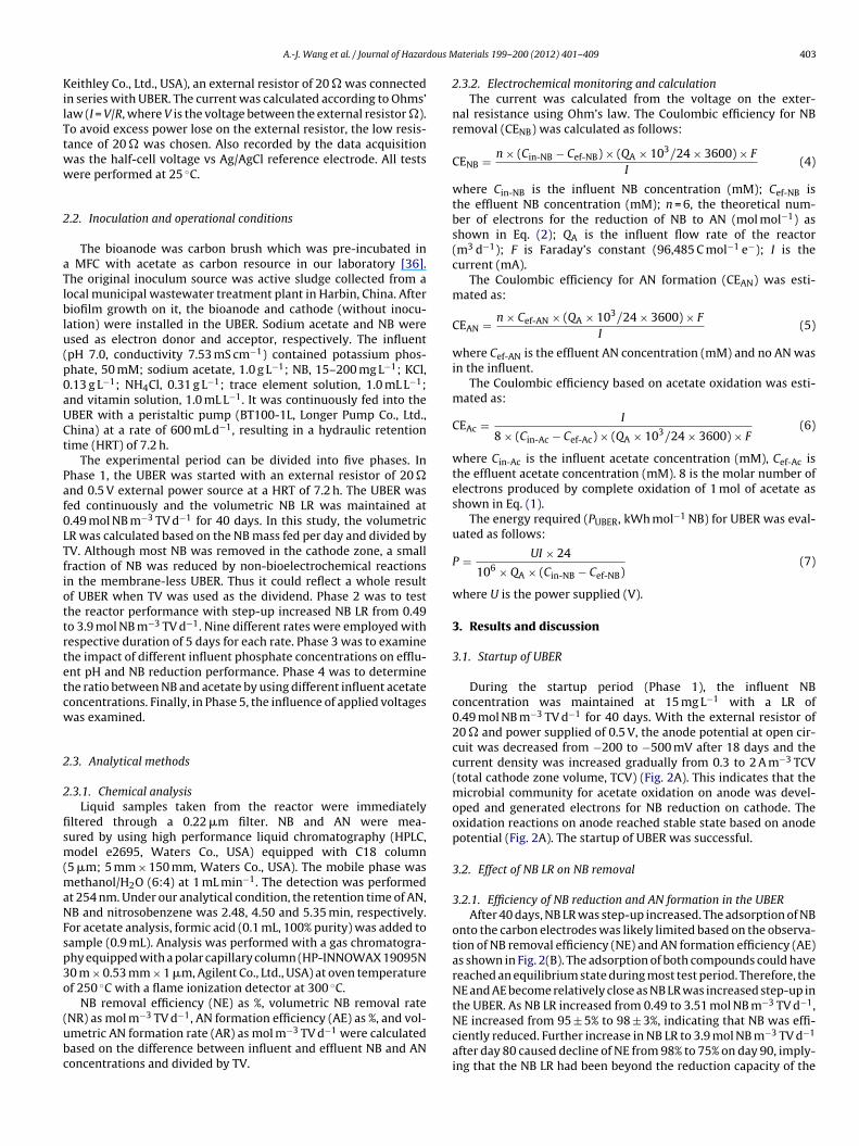
dous M
KilTtww
2
aTlblu(p0aUCt
Paf0LTfiottrtetcw
2
2
fism(maNFsp3o
(ubc
A.-J. Wang et al. / Journal of Hazar
eithley Co., Ltd., USA), an external resistor of 20 � was connectedn series with UBER. The current was calculated according to Ohms’aw (I = V/R, where V is the voltage between the external resistor �).o avoid excess power lose on the external resistor, the low resis-ance of 20 � was chosen. Also recorded by the data acquisitionas the half-cell voltage vs Ag/AgCl reference electrode. All testsere performed at 25 ◦C.
.2. Inoculation and operational conditions
The bioanode was carbon brush which was pre-incubated in MFC with acetate as carbon resource in our laboratory [36].he original inoculum source was active sludge collected from aocal municipal wastewater treatment plant in Harbin, China. Afteriofilm growth on it, the bioanode and cathode (without inocu-
ation) were installed in the UBER. Sodium acetate and NB weresed as electron donor and acceptor, respectively. The influentpH 7.0, conductivity 7.53 mS cm−1) contained potassium phos-hate, 50 mM; sodium acetate, 1.0 g L−1; NB, 15–200 mg L−1; KCl,.13 g L−1; NH4Cl, 0.31 g L−1; trace element solution, 1.0 mL L−1;nd vitamin solution, 1.0 mL L−1. It was continuously fed into theBER with a peristaltic pump (BT100-1L, Longer Pump Co., Ltd.,hina) at a rate of 600 mL d−1, resulting in a hydraulic retentionime (HRT) of 7.2 h.
The experimental period can be divided into five phases. Inhase 1, the UBER was started with an external resistor of 20 �nd 0.5 V external power source at a HRT of 7.2 h. The UBER wased continuously and the volumetric NB LR was maintained at.49 mol NB m−3 TV d−1 for 40 days. In this study, the volumetricR was calculated based on the NB mass fed per day and divided byV. Although most NB was removed in the cathode zone, a smallraction of NB was reduced by non-bioelectrochemical reactionsn the membrane-less UBER. Thus it could reflect a whole resultf UBER when TV was used as the dividend. Phase 2 was to testhe reactor performance with step-up increased NB LR from 0.49o 3.9 mol NB m−3 TV d−1. Nine different rates were employed withespective duration of 5 days for each rate. Phase 3 was to examinehe impact of different influent phosphate concentrations on efflu-nt pH and NB reduction performance. Phase 4 was to determinehe ratio between NB and acetate by using different influent acetateoncentrations. Finally, in Phase 5, the influence of applied voltagesas examined.
.3. Analytical methods
.3.1. Chemical analysisLiquid samples taken from the reactor were immediately
ltered through a 0.22 �m filter. NB and AN were mea-ured by using high performance liquid chromatography (HPLC,odel e2695, Waters Co., USA) equipped with C18 column
5 �m; 5 mm × 150 mm, Waters Co., USA). The mobile phase wasethanol/H2O (6:4) at 1 mL min−1. The detection was performed
t 254 nm. Under our analytical condition, the retention time of AN,B and nitrosobenzene was 2.48, 4.50 and 5.35 min, respectively.or acetate analysis, formic acid (0.1 mL, 100% purity) was added toample (0.9 mL). Analysis was performed with a gas chromatogra-hy equipped with a polar capillary column (HP-INNOWAX 19095N0 m × 0.53 mm × 1 �m, Agilent Co., Ltd., USA) at oven temperaturef 250 ◦C with a flame ionization detector at 300 ◦C.
NB removal efficiency (NE) as %, volumetric NB removal rate
NR) as mol m−3 TV d−1, AN formation efficiency (AE) as %, and vol-metric AN formation rate (AR) as mol m−3 TV d−1 were calculatedased on the difference between influent and effluent NB and ANoncentrations and divided by TV.aterials 199– 200 (2012) 401– 409 403
2.3.2. Electrochemical monitoring and calculationThe current was calculated from the voltage on the exter-
nal resistance using Ohm’s law. The Coulombic efficiency for NBremoval (CENB) was calculated as follows:
CENB = n × (Cin-NB − Cef-NB) × (QA × 103/24 × 3600) × F
I(4)
where Cin-NB is the influent NB concentration (mM); Cef-NB isthe effluent NB concentration (mM); n = 6, the theoretical num-ber of electrons for the reduction of NB to AN (mol mol−1) asshown in Eq. (2); QA is the influent flow rate of the reactor(m3 d−1); F is Faraday’s constant (96,485 C mol−1 e−); I is thecurrent (mA).
The Coulombic efficiency for AN formation (CEAN) was esti-mated as:
CEAN = n × Cef-AN × (QA × 103/24 × 3600) × F
I(5)
where Cef-AN is the effluent AN concentration (mM) and no AN wasin the influent.
The Coulombic efficiency based on acetate oxidation was esti-mated as:
CEAc = I
8 × (Cin-Ac − Cef-Ac) × (QA × 103/24 × 3600) × F(6)
where Cin-Ac is the influent acetate concentration (mM), Cef-Ac isthe effluent acetate concentration (mM). 8 is the molar number ofelectrons produced by complete oxidation of 1 mol of acetate asshown in Eq. (1).
The energy required (PUBER, kWh mol−1 NB) for UBER was eval-uated as follows:
P = UI × 24
106 × QA × (Cin-NB − Cef-NB)(7)
where U is the power supplied (V).
3. Results and discussion
3.1. Startup of UBER
During the startup period (Phase 1), the influent NBconcentration was maintained at 15 mg L−1 with a LR of0.49 mol NB m−3 TV d−1 for 40 days. With the external resistor of20 � and power supplied of 0.5 V, the anode potential at open cir-cuit was decreased from −200 to −500 mV after 18 days and thecurrent density was increased gradually from 0.3 to 2 A m−3 TCV(total cathode zone volume, TCV) (Fig. 2A). This indicates that themicrobial community for acetate oxidation on anode was devel-oped and generated electrons for NB reduction on cathode. Theoxidation reactions on anode reached stable state based on anodepotential (Fig. 2A). The startup of UBER was successful.
3.2. Effect of NB LR on NB removal
3.2.1. Efficiency of NB reduction and AN formation in the UBERAfter 40 days, NB LR was step-up increased. The adsorption of NB
onto the carbon electrodes was likely limited based on the observa-tion of NB removal efficiency (NE) and AN formation efficiency (AE)as shown in Fig. 2(B). The adsorption of both compounds could havereached an equilibrium state during most test period. Therefore, theNE and AE become relatively close as NB LR was increased step-up inthe UBER. As NB LR increased from 0.49 to 3.51 mol NB m−3 TV d−1,
NE increased from 95 ± 5% to 98 ± 3%, indicating that NB was effi-ciently reduced. Further increase in NB LR to 3.9 mol NB m−3 TV d−1after day 80 caused decline of NE from 98% to 75% on day 90, imply-ing that the NB LR had been beyond the reduction capacity of the

404 A.-J. Wang et al. / Journal of Hazardous M
Fig. 2. Reactor operation in Phase 1 and 2. (A) Change in anode potential and cur-rf
rwt
Ntcdnc
C
i3atvtTir
aerwnifcda
observed in cathode zone although it was limited (Fig. S2 in Supple-
ent density during Phase 1 startup period. (B) NB removal efficiency (NE) and ANormation efficiency (AE) at different NB loading rates in Phase 2.
eactor. At that time, the influent NB concentration was 200 mg L−1,hich was much higher than NB levels reported in most NB con-
aining wastewaters [37].In the effluent, AN was a dominant product as more than 98%
B was removed. AN formation efficiency varied from 92.0 ± 0.3%o 81.0 ± 0.2%. At higher NB LR (>3.51 mol NB m−3 TV d−1), lowoncentration of nitrosobenzene was observed, indicating pro-uction of less reduced intermediate. The formation efficiency ofitrosobenzene was 2.2–3.6%. This reaction likely occurred in theathode zone as
6H5NO2 + 2H+ + 2e− → C6H5NO + H2O (8)
The volumetric NB removal rate and AN formation ratencreased linearly with the increase of NB LR when NB LR was below.51 mol NB m−3 TV d−1 (Fig. 3A). The maximum NB removal ratend AN formation rate were 3.50 and 3.06 mol m−3 TV d−1, respec-ively. Based on the linear regression of the data of these two ratess NB LR (Fig. 3A), the slope for NB removal rate is slightly higherhan AN formation rate, i.e. 0.992 vs 0.892 (Supplementary data).he difference was likely due to the formation of another reducedntermediate, such as nitrosobenzene, especially at high NB loadingates.
The samples taken from SP2# (sample pot above cathode zonend below anode zone in Fig. 1B) were analyzed to determine thefficiency of NB reduction in cathode zone. The efficiencies of NBemoval and AN formation determined in SP2# were comparedith the data from the effluent (Fig. 3B). The both efficiencies wereearly the same, indicating that NB was mainly converted to AN
n the cathode zone. Although AN could be used as electron donoror electrochemical oxidation, but it was not oxidized further when
athode effluent flowed through anode zone. This was presumablyue to the anaerobic condition in the reactor and the presence ofcetate.aterials 199– 200 (2012) 401– 409
3.2.2. Cell potential and current densityThe relationship between anode and cathode potentials and NB
LR is illustrated in Fig. 3C. As NB LR was step-up increased from0.49 to 3.51 mol NB m−3 TV d−1, anode potential dropped slightlybut still maintained at about −500 mV. Correspondingly, cathodepotentials were stable at about −950 mV. Current density increasedlinearly from 3.8 to 39.2 A m−3 TCV (As current was generated byeletrogenic reactions on the electrodes. The electrons given on theanode should be equal to those accepted on the cathode. Currentdensity could be expressed based on the volume of anode or cath-ode zone. In this study, NB was mainly reduced by electrochemicalreactions on the cathode. So the current density was evaluatedbased on the TCV). After NB LR reached 3.9 mol NB m−3 TV d−1,which was likely beyond the reduction capability of cathode zone,the NB concentration at SP2# increased from 0.37 to 50 mg L−1
accompanied with the anode and cathode potentials increasedrapidly to nearly −250 and −700 mV, respectively. At the sametime, the current density dropped from 39.2 to 30 A m−3 TCV.This observation indicated that the high NB LR caused the fail-ure of NB reduction in the cathode zone. When cathode effluentwith NB concentration >50 mg L−1 entered anode zone, anodicbacteria were inhibited gradually and lost electrogenic activity,resulting in the increase of anode potential. It is because AN isless inhibitory to microorganisms, a high AN concentration incathode zone effluent would not cause negative effect on anodicmicroorganisms [30] if the conversion of NB to AN was efficientin cathode zone. On the other hand, high NB concentration fromcathode effluent could be inhibitory to anode microorganisms ifthe efficiency of reduction of NB to AN became poor as observed.To confirm this, the variation of anode potential and current atdifferent nitrobenzene concentrations was tested (Fig. S1 in Sup-plementary data). When NB concentration reached higher than50 mg L−1, anode gradually lost its function. Based on the aboveobservation, application of a proper NB LR to ensure high extentof NB reduction in cathode zone is essential for the maintenanceof active anode microbial community and stable operation ofthe UBER.
3.2.3. Coulombic efficiency (CE)The Coulombic efficiency of NB removal at the cathode was eval-
uated as the ratio of the current calculated based on complete NBremoval or formation of AN vs the current measured across cir-cuit of the UBER. As shown in Fig. 3D, Coulombic efficiency of NBremoval and AN formation rose with the step-up increase in NB LRfrom 0.15 to 1.17 mol NB m−3 TV d−1. Coulombic efficiency of NBremoval reached to 99% with 82% of Coulombic efficiency of ANformation at NB LR of 2.5 mol NB m−3 TV d−1, indicating that major-ity of electrons from cathode electrode was used for NB reduction.At the beginning, the increase in Coulombic efficiency was accom-panied with the increase in NB LR (<1.17 mol NB m−3 TV d−1).This suggested that a part of electrons was consumed for otherreactions in cathode zone. Hydrogen generation could be a compet-itive reaction for electrons because at cathode potentials rangingbetween −980 and −890 mV (Fig. 3C), generation of hydrogen gaswas energetically favorable. Besides, when NB LR reached above2.5 mol NB m−3 TV d−1, the calculated Coulombic efficiencies forNB reduction appeared slightly higher than 100%. This deviationwas likely due to that a part of NB was removed or reduced bynon-electrochemical processes in cathode zone. Even though thecathode was not inoculated previously, there was no membraneto separate anode and cathode zones and the cathode zone couldnot be operated under sterile condition, microbial growth was
mentary data). Therefore, oxidation of acetate could also occur andreleased electrons for NB reduction in cathode zone. This hypoth-esis was further confirmed by an experiment with open circuit,

A.-J. Wang et al. / Journal of Hazardous Materials 199– 200 (2012) 401– 409 405
Fig. 3. Reactor performance at different NB loading rates in Phase 2. (A) NB removal rate and AN formation rate vs NB loading rate. (B) Comparison of the NB removal (NE) andA de). (Cb
itr
3
taassaca7up3t(ctprtt(ca(dc
at cathode without affecting the function of anode in lower phos-phate concentration, although an optimal hydraulic residence timeshould be adjusted because of the lower conductivity.
N formation (AE) in the effluent vs samples from SP2# (NE-Cathode and AE-Cathoase on NB reduction (CE-NB) and AN formation (CE-AN).
.e. a small fraction of NB (<15%) was reduced to AN. Consideringhis effect, the calculated Coulombic efficiency based on total NBeduction could be overestimated by at least 15%.
.3. Effect of phosphate buffer concentration
The pH is an important parameter that can greatly influencehe BES performance. When acetate is oxidized on anode (Eq. (1)),cidity is generated. In order to maintain a neutral pH and a lownodic over-potential and thereby a high microbial activity, theupplementation of enough buffer capacity in BES should be con-idered [38–40]. High buffer capacity can maintain proper pH innode chamber [40]. In Phase 3, the effect of the influent phosphateoncentration on UBER was examined. The influent NB LR was keptt 2.0 mol NB m−3 TV d−1 with influent NB of 100 mg L−1 and HRT of.2 h. During the test, influent phosphate concentration was grad-ally decreased from 50 to 25, 10 and 5 mM at the end. InfluentH was kept at 7.0 but respective conductivity was 7.53, 5.01,.34 and 2.73 mS cm−1. The change in phosphate buffer concen-ration resulted in only slight decline in effluent pH from 7.0 to 6.7Table S1 in Supplementary data). When influent phosphate con-entration was higher than 5 mM, NB removal efficiency was higherhan 90% but rapidly dropped to below 70% with influent phos-hate of 5 mM. But AN formation efficiency was less influenced andemained above 80% throughout the test (Fig. 4A). Correspondingly,he anode potential was kept about −500 mV and sharply increasedo −250 mV as phosphate concentration decreased from 10 to 5 mMFig. 4B). The current density was correlated to influent phosphateoncentration and declined from 28.7 ± 0.8 to 13.7 ± 1.3 A m−3 TCV
s the phosphate concentration decreased from 50 to 5.0 mMFig. 4B). In general, microbial activity in anode cannot changeramatically as pH drops from 7.0 to 6.7. The gradual decline inurrent density and then NE could be caused by the decline of ionic) Anode potential, cathode potential and current density. (D) Coulombic efficiency
strength of the electrolyte and electrolyte conductivity, resultingin decreased reaction rate. Our data showed that the UBER wasfavorable to overcome protons transfer limitation for NB reduction
Fig. 4. Effect of different influent phosphate concentrations on reactor performance.(A) NE and AE at different influent phosphate concentrations. (B) Anode potentialand current density at different phosphate concentrations.

406 A.-J. Wang et al. / Journal of Hazardous M
FNd
3
bttagr3raictffiter
Ft
tively even when 0.3 V was supplied. When power supplied wasfurther reduced to 0.2 V, effluent NB concentration quickly reachedto 70 ± 4.7 mg L−1 with a low NE of 30.0 ± 4.7%, indicating thereaction rate of NB reduction was greatly decreased. As shown in
ig. 5. Effect of influent acetate concentration on NB reduction performance (A)E and AE with different acetate concentrations. (B) Anode potential and currentensity at different acetate concentrations.
.4. Influence of acetate concentration
In this study, acetate was used as the electron donor and car-on source for anodic bacteria growth. Phase 4 test was designedo investigate the influence of acetate concentration on NB reduc-ion. The influent contained phosphate concentration of 50 mMnd NB of 100 mg L−1. The influent acetate concentration wasradually decreased from 1000 to 500, 300 and 200 mg L−1 withespective influent ratio of acetate vs NB of 15.0, 7.5, 4.5 and.0 mol mol−1. The experiment lasted 35 days. NB was efficientlyemoved (>95%) when acetate concentration was between 300nd 1000 mg L−1 (Fig. 5A). The NE dropped rapidly to 55% whennfluent acetate concentration was 200 mg L−1. AN formation effi-iency was higher than 80%, indicating that NB was mostly reducedo AN. Correspondingly, the anode potential gradually increasedrom −450 to −350 mV when acetate concentration was decreasedrom 1000 to 300 mg L−1 (Fig. 5B). The anode potential quicklyncreased above −100 mV as the acetate concentration was fur-
her decreased to 200 mg L−1, indicating the anodic microbiallectrogenic activity become poor. Coulombic efficiency on NBemoval decreased from 105 ± 1% to 78 ± 1% when influent acetateig. 6. Coulombic efficiency and reductant dosage ratio at various acetate concen-rations.
aterials 199– 200 (2012) 401– 409
concentration decreased from 1000 to 200 mg L−1 (Fig. 6). Corre-spondingly, Coulombic efficiency on acetate oxidation increasedfrom 21.8 ± 0.8% to 53.6 ± 3%, which was lower than that on NBremoval. Theoretically, 0.75 mol acetate is required per mol of NBconverted to AN. The reductant dosage ratio in the UBER var-ied from 4.3 ± 0.4 to 2.3 ± 0.1 mol acetate mol−1 NB and the lowestvalue was at influent acetate concentration of 300 mg L−1. Thelower Coulombic efficiency on acetate oxidation and higher reduc-tant dosage may be due to that the acetate was converted tomethane by acetoclastic methanogenesis and used for cell synthesis[42]. These results indicated that influent acetate of 300 mg L−1 wasminimum level for the reduction of NB at 100 mg L−1 with removal>95% in the UBER.
3.5. Effect of power supplied
NB was efficiently reduced to AN when the applied voltage was0.5 V in the UBER. As the reductive potentials of many nitroaro-matic compounds are often more negative than −700 mV [43],the cathode potential in the UBER varied from −800 to −900 mVas the external power 0.5 V was supplied, which could ensurecomplete NB reduction to AN. However, the less power was sup-plied, the less energy was required. Thus, Phase 5 work was totest the effect of the different power levels supplied. The volu-metric NB LR was kept at 2.0 mol NB m−3 TV d−1 (influent NB of100 mg L−1) with HRT of 7.2 h. The external power supplied wasgradually decreased from 0.5 to 0.2 V. As shown in Fig. 7A, whenthe power was reduced from 0.5 to 0.3 V, effluent NB concen-tration increased from 5.5 ± 0.2 to 13.3 ± 4.3 mg L−1, companiedwith the NE decreased from 94.0 ± 0.2% to 86.6 ± 4.3%. Corre-spondingly, effluent AN concentration decreased from 66.5 ± 1.3 to60.2 ± 1.0 mg L−1. This demonstrated that NB was removed effec-
Fig. 7. (A) Concentrations of effluent NB and AN and NB removal efficiency (NE) andAN formation efficiency (AE) at different power supplied. (B) Anode and cathodepotential at different power supplied.

A.-J. Wang et al. / Journal of Hazardous M
Fig. 8. Comparison of bioanode with abiotic anode electron output (A) LinearvC
FparopibN9t0
3
eofcoNwtetOat0o(nm
these substrates work in other BESs [32,41].
olt-ampere (VA) of bioanode and abiotic anode with external power supply. (B)omparison of power required by bioanode vs abiotic anode.
ig. 7B, both anode and cathode potentials increased as power sup-lied decreased. When power supplied varied from 0.5 to 0.3 V,node and cathode potentials were still below −400 and −700 mV,espectively. These levels were suitable for anodic microbial growthn acetate and NB reduction on the cathode. When power sup-lied reduced to 0.2 V, the anode and cathode potential respectively
ncreased to −279 and −469 mV, indicating the redox potentialsecome less favorable for anodic microorganisms and reduction ofB at cathode. During Phase 5 test, NE was maintained at above0% (Fig. 7A), suggesting that the removal NB was mainly reducedo AN. Thus, high NB removal efficiency can achieve with at least.3 V power supplied in the UBER.
.6. Bioanode vs abiotic anode
In this study, the NB removal rate greatly increased in the pres-nce of small power was supplied, implying that the combinationf biological and electrochemical reactions in UBER was success-ul. The external power needed (0.3–0.5 V) was small with limitedost and much lower than electrochemical reduction. Based onur estimation (Table S3 in Supplementary data), when influentB concentration increases from 0.41 to 1.46 mM, power requiredould be less than 0.075 kWh mol−1 NB, which was just 10% of
hat required for electrochemical methods [36]. The low externalnergy requirement by UBER was mainly contributed by the elec-rogenic function of bioanode with added electron donor (acetate).ne experiment was designed for the comparison of linear volt-mpere (VA) for bioanode with abiotic anode. The results showedhat the current quickly increased as power supplied reached to.17 V for bioanode, while 1.2 V for abiotic anode (Fig. 8A). Bioan-de needed less power than abiotic anode at the same current
Fig. 8B). This demonstrated that NB could be reduced at an exter-al power source of 0.17 V when bioanode was employed, which isuch lower than that required for electrochemical reduction withaterials 199– 200 (2012) 401– 409 407
abiotic anode. This was mainly due to the lower overpotential ofbioanode in UBER [28,44].
3.7. Significance of UBER concept and potential implementation
The results in this study demonstrated the feasibility ofthe concept of membrane-free, continuously feeding UBER. Thissystem is especially favorable to treat wastewater containinginhibitory chemicals which can be electrochemically reduced toless inhibitory products (such as NB to AN). In this study, we usedsynthetic wastewater containing acetate as electron donor and NBas target organic pollutant. Other substrates or municipal wastew-ater will be tested as electron donor in further, as well as other toxicorganic chemicals as electron acceptor, to enlarge the applicationof UBER.
Although no inoculum was introduced to the UBER except forinstallation of pre-enriched bioanode, the microbial growth in cath-ode zone could still occur by slow bacterial migration from anodezone since no membrane was used to separate both zones. Thenumber of bacteria on cathode was limited based on SEM observa-tion (Supplementary data, Fig. S2). The bacteria attached on cathodecould partially contribute to NB reduction with organic carbon aselectron donor as observed in other study with biocathode whichenhanced NB reduction significantly in a fed-batch BES [45]. How-ever, in this study, the transformation rate of NB to AN was likelylimited due to almost no or limited attached bacteria on cathodeand, the transformation of NB to AN, therefore, was mainly due toabiotic cathodic reduction. Further research will be conducted toexamine whether biocathode could enhance NB reduction in theUBER.
Higher NB removal performance was achieved by UBER thanother published laboratory-scale reactor configurations includingtrickling filter [46], fixed bed reactor [47] and anaerobic migratingblanket reactor [37] in term of the maximum NB removal rate (3.5in this study vs 0.044, 1.93 and 0.44 mol m−3 TV d−1, respectively)and NB removal efficiency (Supplementary data, Table S2). Li et al.[25] showed that NB could be reduced on the cathode for powergeneration in a batch feeding two-chamber MFC. The NE was 98%in 24 h, which was much slower than UBER and Pt was used as cat-alyst resulting in a high cost. Compared with the published resultsusing continuously feeding mode BES with IEM [7], NB removalrate in UBER based on the cathode volume was slightly higher atsimilar current density (i.e. 7.0 mol m−3 TCV d−1 in UBER at cur-rent density of 39.2 A m−3 TCV and 6.5 mol m−3 TCV d−1 in ref. [7] atcurrent density of 44.6 A m−3 TCV) (Supporting data, Table S2), butlower then their maximum of 8.57 mol m−3 TCV d−1 at current den-sity of 59.5 A m−3 TCV, indicating optimal condition, such as higherapplied voltage to enhance current, would further improve the per-formance of UBER. However, the energy requirement by our UBERwas slightly higher than the two-chamber BES by Mu et al. at similarcurrent density and NB removal rate [7]. This suggests that furtherresearch is needed for optimization of energy consumption by UBERfor scaling-up.
Acetate was used as electron donor source in this study. The ratioof NB reduced vs acetate consumed (mol mol−1) was 2.3, which wasabout 3 times of the theoretical value (0.75 mol mol−1) for reduc-tion of NB to AN. This suggests that a part of acetate was not directlyused for the reduction and the performance of the UBER couldbe improved further considering low microbial cell synthesis foracetate consumption (<0.1) under anaerobic condition. Other elec-tron donor source such as ethanol, glucose or complicated organicsin municipal wastewater could also work for NB reduction since
The ion strength or conductivity of wastewater influences elec-tron transfer and internal resistance of BES. In this study, we foundthe higher influent phosphate concentration resulted in higher

4 dous M
Noccfo
et
4
etascrtvHtUc
A
5RSJa
A
t
R
[
[
[
[
[
[
[
[
[
[
[
[
[
[
[
[
[
[
[
[
[
[
[
[
[
[
[
[
[
08 A.-J. Wang et al. / Journal of Hazar
B removal performance and 10 mM was minimum level with-ut greatly affecting the NE. Except for enhancement of bufferapacity favorable for kinetics, proper ion strength or conductivityould benefit to the electron transfer and thus the reduction per-ormance. Further research is needed to examine the mechanismf the enhancement and optimization of UBER operation.
In addition, the lower power needed (0.3 V) resulted in a lowernergy required and the absence of membrane made a great con-ribution to reduce the cost of UBER.
. Conclusion
A membrane-free, continuously feeding up-flow biocatalyzedlectrolysis reactor (UBER) was developed for the wastewa-er treatment with electrochemical reduction. NB was selecteds a target chemical and acetate was used as electron donorource. The results indicate that NB can be continuously and effi-iently removed (>99%) with AN as a major product (>80%). Theatio of acetate consumed vs NB removed varied from 4.3 ± 0.4o 2.3 ± 0.1 mol acetate mol−1 NB, being 6–3 times of theoreticalalue. The reduction reaction occurred mainly in cathode zone.igh Coulombic efficiencies for NB reduction (99%) and A forma-
ion (>80%) were observed. This demonstrated the feasibility of theBER as single reactor with anodic biological and cathodic electro-hemical functions.
cknowledgements
National Natural Science Foundation of China (Grant No.0876024 No. 51078100 and No. 51178140), by National Creativeesearch Groups Project (Grant No. 50821002), by Heilongjiangcience Foundation for Distinguished Young Scholars (Grant No.C201003), and by State Key Laboratory of Urban Water Resourcend Environment (Grant No. 2010DX11 and No. 2008NQ03).
ppendix A. Supplementary data
Supplementary data associated with this article can be found, inhe online version, at doi:10.1016/j.jhazmat.2011.11.034.
eferences
[1] H.A.O. Hill, I.J. Higgins, Bioelectrocatalysis, Philos. Tans. R. Soc. Lond. A 302(1981) 267–273.
[2] B.E. Logan, B. Hamelers, R. Rozendal, U. Schrorder, J. Keller, S. Freguia, P.Aelterman, W. Verstraete, K. Rabaey, Microbial fuel cells: methodology andtechnology, Environ. Sci. Technol. 40 (2006) 5181–5192.
[3] D.R. Lovley, Microbial fuel cells: novel microbial physiologies and engineeringapproaches, Curr. Opin. Biotechnol. 17 (2006) 327–332.
[4] K. Rabaey, K. Van De Sompel, L. Maignien, N. Boon, P. Aelterman, P. Clauwaert,L. De Schamphelaire, T.H. Pham, J. Vermeulen, M. Verhaege, P. Lens, W. Ver-straete, Microbial fuel cells for sulfide removal, Environ. Sci. Technol. 40 (2006)5218–5224.
[5] A. Bergel, D. Feron, A. Mollica, Catalysis of oxygen reduction in PEM fuel cell byseawater biofilm, Electrochem. Commun. 7 (2005) 900–904.
[6] P. Clauwaert, K. Rabaey, P. Aelterman, L.D. Schamphelaire, H.T. Pham, P. Boeckx,N. Boo, W. Verstraete, Biological denitrification in microbial fuel cells, Environ.Sci. Technol. 41 (2007) 3354–3360.
[7] Y. Mu, A.R. René, R. Korneel, K. Jürg, Nitrobenzene removal in bioelectrochem-ical systems, Environ. Sci. Technol. 43 (2009) 8690–8695.
[8] C. Butler, P. Clauwaert, S. Green, W. Verstraete, R. Nerenber, Bioelectrochemicalperchlorate reduction in a microbial fuel cell, Environ. Sci. Technol. 44 (2010)4685–4691.
[9] F. Aulenta, A. Catervi, M. Majone, S. Panero, P. Reale, S. Rossetti, Electron trans-fer from a solid-state electrode assisted by methyl viologen sustains efficientmicrobial reductive dechlorination of TCE, Environ. Sci. Technol. 41 (2007)2554–2559.
10] S.M. Strycharz, T.L. Woodard, J.P. Johnson, K.P. Nevin, P.A. Sanford, F.E. Loffler,
D.R. Lovley, Graphite electrode as a sole electron donor for reductive dechlo-rination of tetrachlorethene by geobacter lovely, Appl. Environ. Microbiol. 74(2008) 5943–5947.11] F. Aulenta, A. Canosa, P. Reale, S. Rossetti, S. Panero, M. Majone, Microbial Reduc-tive Dechlorination of trichloroethene to ethene with electrodes serving as
[
aterials 199– 200 (2012) 401– 409
electron donors without the external addition of redox mediators, Biotechnol.Bioeng. 101 (2010) 85–91.
12] S.M. Strycharz, S.M. Gannon, A.R. Boles, A.E. Franks, K.P. Nevin, D.R. Lovley,Reductive dechlorination of 2-chlorophenol by Anaeromyxobacter dehaloge-nans with an electrode serving as the electron donor, Environ. Microbiol. Rep.2 (2010) 289–294.
13] J. Sun, Z. Bi, B. Hou, Y.Q. CaO, Y.Y. Hua, Further treatment of decolorization liquidof azo dye coupled with increased power production using microbial fuel cellequipped with an aerobic biocathode, Water Res. 45 (2010) 1–9.
14] H.C. Tao, W. Li, M. Liang, N. Xu, J.R. Ni, W.M. Wu, A membrane-free baffledmicrobial fuel cell for cathodic reduction of Cu(II) with electricity generation,Bioresour. Technol. 102 (2011) 4774–4778.
15] H.C. Tao, M. Liang, W. Li, L.J. Zhang, J.R. Ni, W.M. Wu, Removal of copper fromaqueous solution by electrodeposition in cathode chamber of microbial fuelcell, J. Hazard. Mater. 189 (2011) 186–192.
16] R.A. Rozendal, H.V.M. Hamelers, G.J.W. Euverink, S.J. Metz, C.J.N. Buisman,Principle and perspectives of hydrogen production through biocatalyzed elec-trolysis, Int. J. Hydrogen Energy 31 (2006) 1632–1640.
17] S. Cheng, D. Xing, D.F. Call, B.E. Logan, Direct biological conversion of electri-cal current into methane by electromethanogenesis, Environ. Sci. Technol. 43(2009) 3953–3958.
18] R.A. Rozendal, E. Leone, J. Keller, K. Rabaey, Efficient hydrogen peroxide gen-eration from organic matter in a bioelectrochemical system, Electrochem.Commun. 11 (2009) 1752–1755.
19] K.J.J. Steinbusch, H.V.M. Hamelers, J.D. Schaap, C. Kampman, C.J.N. Buisman,Bio-electrochemical ethanol production through mediated acetate reductionby mixed cultures, Environ. Sci. Technol. 24 (2009) 513–517.
20] X.X. Cao, X. Huang, P. Liang, K. Xiao, Y.G. Zhou, X.Y. Zhang, B.E. Logan, A newmethod for water desalination using microbial desalination cells, Environ. Sci.Technol. 43 (2009) 7148–7152.
21] M. Rodriguez, V. Timokhin, F. Michl, S. Contreras, J. Gimenez, S. Esplugas, Theinfluence of different irradiation sources on the treatment of nitrobenzene,Catal. Today 76 (2002) 291–300.
22] P. Gurevich, A. Oren, S. Sarig, Y. Henis, Reduction of aromatic nitrocompoundsin anaerobic ecosystems, Water Sci. Technol. 27 (1993) 89–96.
23] Ö.S. Kuscu, D.T. Sponza, Effects of nitrobenzene concentration and hydraulicretention time on the treatment of nitrobenzene in sequential anaerobic baf-fled reactor (ABR)/continuously stirred tank reactor (CSTR) system, Bioresour.Technol. 100 (2009) 2162–2170.
24] M.A. De, O.A. O’Connor, D.S. Kosson, Metabolism of aniline under differ-ent anaerobic electron-accepting and nutritional conditions, Environ. Toxicol.Chem. 13 (1994) 233–239.
25] J. Li, G. Liu, R. Zhang, Y. Luo, C. Zhang, M. Li, Electricity generation by two typesof microbial fuel cells using nitrobenzene as the anodic or cathodic reactants,Bioresour. Technol. 101 (2010) 4013–4020.
26] A.J. Wang, H.Y. Cheng, N.Q. Ren, D. Cui, N. Lin, W.M. Wu, Sediment microbial fuelcell with floating biocathode for organic removal and energy recovery, Front.Environ. Sci. Eng. China (2011), Published online, July 11.
27] J. Heilmann, B.E. Logan, Production of electricity from proteins using a singlechamber microbial fuel cell, Water Environ. Res. 78 (2006) 531–537.
28] V.M.H. Hubertus, T.H. Annemiek, H.J.A.S. Tom, W.J. Adriaan, P.B.T.B.S. David,J.N.B. Cees, New applications and performance of bioelectrochemical systems,Appl. Microbiol. Biotechnol. 85 (2010) 1673–1685.
29] R.A. Rozendal, H.V.M. Hamelers, C.J.N. Buisman, Effects of membrane cationtransport on pH and microbial fuel cell performance, Environ. Sci. Technol. 40(2006) 5206–5211.
30] H. Liu, B.E. Logan, Electricity generation using an air-cathode single chambermicrobial fuel cell in the presence and absence of a proton exchange membrane,Environ. Sci. Technol. 38 (2004) 4040–4046.
31] H. Liu, H.Q. Hu, Y.Z. Fan, Hydrogen production using single-chambermembrane-free microbial electrolysis cells, Water Res. 42 (2008) 4172–4178.
32] J.R. Kim, S.H. Jung, J.M. Regan, B.E. Logan, Electricity generation and micro-bial community analysis of ethanol powered microbial fuel cells, Bioresour.Technol. 98 (2007) 2568–2577.
33] D. Davila, J.P. Esquivel, N. Sabate, J. Mas, Silicon-based microfabricated micro-bial fuel cell toxicity sensor, Biosens. Bioelectron. 26 (2011) 2426–2430.
34] H.J. Kim, M. Kim, M.S. Hyun, G.M. Gadd, A novel biomonitoring system usingmicrobial fuel cells, J. Environ. Monit. 9 (2007) 1323–1328.
35] B.A. Donlon, E. RazoFlores, G. Lettinga, J.A. Field, Continuous detoxification,transformation, and degradation of nitrophenols in upflow anaerobic sludgeblanket (UASB) reactors, Biotechnol. Bioeng. 51 (1996) 439–449.
36] A.J. Wang, D. Sun, G.L. Cao, H.Y. Wang, N.Q. Ren, W.M. Wu, B.E. Logan, Integratedhydrogen production process from cellulose by combining dark fermentation,microbial fuel cells, and a microbial electrolysis cell, Bioresour. Technol. 102(2011) 4137–4143.
37] Ö.S. Kus c u, D.T. Sponza, Effect of increasing nitrobenzene loading rates on theperformance of anaerobic migrating blanket reactor and sequential anaerobicmigrating blanket reactor completely stirred tank reactor system, J. Hazard.Mater. 168 (2009) 390–399.
38] C.I. Torres, A.K. Marcus, B.E. Rittmann, Proton transport inside the biofilm limits
electrical current generation by anode-respiring bacteria, Biotechnol. Bioeng.100 (2008) 872–881.39] T.H.J.A. Sleutels, R. Lodder, H.V.M. Hamelers, C.J.N. Buisman, Improved perfor-mance of porous bio-anodes in microbial electrolysis cells by enhancing massand charge transport, Int. J. Hydrogen Energy 34 (2009) 9655–9661.

dous M
[
[
[
[
[
[
[
A.-J. Wang et al. / Journal of Hazar
40] T.H.J.A. Sleutels, H.V.M. Hamelers, C.J.N. Buisman, Reduction of pH bufferrequirement in bioelectrochemical systems, Environ. Sci. Technol. 44 (2010)8259–8263.
41] S. Freguia, Sequential anode–cathode configuration improves cathodic oxygenreduction and effluent quality of microbial fuel cells, Water Res. 42 (2008)1387–1396.
42] B. Virdis, K. Rabaey, Z. Yuan, R. Rozendal, J. Keller, Electron fluxes in a microbialfuel cell performing carbon and nitrogen removal, Environ. Sci. Technol. 43(2009) 5144–5149.
43] M.C.F. Oliveira, Study of the hypophosphite effect on the electrochemical reduc-tion of nitrobenzene on Ni, Electrochim. Acta 48 (2003) 1829–1835.
[
aterials 199– 200 (2012) 401– 409 409
44] A.K. Marcus, Conduction-based modeling of the biofilm anode of a microbialfuel cell, Biotechnol. Bioeng. 98 (2007) 1171–1182.
45] A.J. Wang, H.Y. Cheng, B. Liang, N.Q. Ren, D. Cui, N. Lin, B.H. Kim, K. Rabaey, Effi-cient reduction of nitrobenzene to aniline with a biocatalyzed cathode, Environ.Sci. Technol. (2011), Published online, October 28.
46] O. Dickel, W. Haug, H.J. Knackmuss, Biodegradation of nitrobenzene by
a sequential anaerobic-aerobic process, Biodegradation 4 (1993) 187–194.47] R. Gerlach, M. Steiof, C.L. Zhang, J.B. Hughes, Low aqueous solubility electrondonors for the reduction of nitroaromatics in anaerobic sediments, J. Contam.Hydrol. 36 (1999) 91–104.