Embed Size (px)
Citation preview

A Miniature Gamma Camera' J. N. AARSVOLD,~ R. A. MINTZER,~ N. J. YASILLO,~ S. J. HEIMSATH; T. A. BLOCK: K. L. MATTHEWS,b
X. PAN: C. WU,b R. N. BECK! C-T. CHEN,b
bFrank Center for Image Analysis Franklin McLean Memorial Research Institute
Department of Radiology CDepartment of Surgery
University of Chicago Chicago, Illinois 60637
AND M. COOPER^
INTRODUCTION
Radiotracer imaging procedures, such as planar nuclear medicine scans and single-photon emission computed tomography (SPECT) studies, are useful compo- nents of diagnostic and treatment-assessment protocols applied to patients who have sustained high-voltage electrical injuries.'-'* However, such imaging procedures are often difficult to perform because they usually require transport of patients to nuclear medicine clinics. We have designed and constructed a prototype mobile miniature-gamma-camera system that can be used in electrical trauma units. In this paper, we discuss the design of the prototype and report the present imaging characteristics of this system.
GAMMA-CAMERA IMAGING
Most gamma cameras have four major components: a scintillation crystal [NaI(Tl)], an array of photomultiplier tubes (PMTs), a parallel-hole collimator (lead), and radiation shielding (lead). They produce images as follows: The radiation shielding and collimator septa stop gamma rays directed at the camera, except those that pass through the collimator holes. The gamma rays that pass through the holes are photons traveling essentially parallel to the sides of the holes and perpendicular to the front face of the scintillation crystal. Although some of the gamma rays that reach the scintillation crystal pass through the crystal undetected, most interact with the crystal and are converted to light. The light is detected by the PMTs and converted to electrical signals. All of the PMTs in the array detect some light. However, the amount of light detected by each tube, and thus the magnitude of the signal that each produces, differs. In other words, each PMT response depends on
"Support for this work was provided by the Department of Energy through Grant No. DE-FG02-86ER60418 and by the Electrical Power Research Institute.
192

AARSVOLD el al.: MINIATURE GAMMA CAMERA 193
the position of the PMT relative to the location of the gamma-ray/scintillation- crystal interaction. The signals from all of the PMTs in the array are systematically weighted and summed in hardware in order to produce a set of signals that are used for calculation of an estimate of the location of an interaction. An image is generated by histogramming the location estimates of numerous interactions.
Conventional gamma cameras (see FIGURE 1) are designed for general-purpose imaging. Some are moderate in size, having fields of view measuring 25 cm x 25 cm,
FIGURE 1. Conventional gamma camera.
and have been incorporated into mobile systems. Most are relatively large and have fields of view that are approximately 30 cm x 40 cm in size. Because of the bulk of these cameras, systems comprising them weigh more than 1000 kg and are necessarily stationary; they are most often housed in nuclear medicine clinics. Conventional gamma cameras have approximately 70 conventional PMTs. The best conventional cameras have approximately 4.0-mm full-width-at-half-maximum (FWHM) and 8.0-mm full-width-at-tenth-maximum (FWTM) intrinsic resolution.

194 ANNALS NEW YORK ACADEMY OF SCIENCES
FIGURE 2. Mechanical diagram of the UC miniature gamma camera.
FIGURE 3. Components of the UC miniature gamma camera. The camera is 92 mm X 92 mrn x 190 mm in size and weighs approximately 5 kg.

AARSVOLD et al.: MINIATURE GAMMA CAMERA 195
THE UNIVERSITY OF CHICAGO MINIATURE GAMMA CAMERA
The University of Chicago (UC) miniature gamma camera (see FIGURES 2 and 3) has been designed to be the principal component of task-specific imaging systems (see FIGURE 4).I3J4 The camera’s principal component is the 77 mm x 77 mm x 70 mm Hamamatsu R2487 position-sensitive photomultiplier tube (PSPMT).lS-ls (The
FIGURE 4. The UC miniature gamma camera, mobile transport cart, and positioning arm.
R2487 and its updated version, the R3941, are being used in the development of a variety of task-specific medical imaging devices. References 19-26 report results of several of the present efforts.) The UC camera, including tungsten radiation shield- ing and a lead collimator, measures 92 mm x 92 mm x 190 mm and weighs approximately 5 kg. Because of the camera’s relatively small size, mobile systems that can be used conveniently in locations such as electrical trauma units can be

196 ANNALS NEW YORK ACADEMY OF SCIENCES
constructed. The four major components of the U C camera are a NaI(T1) scintilla- tion crystal, a single PSPMT, a lead parallel-hole collimator, and tungsten radiation shielding. In the U C camera, estimates of the locations of gamma-ray interactions are determined from the outputs of the single PSPMT rather than from the signals of an array of conventional PMTs as in a conventional gamma camera. The PSPMT has 18 anode wires in one direction (the x direction) and 16 anode wires in the perpendicular direction (the y direction). The currents from these anodes are divided by two resistive chains connected to the PSPMT, and it is the outputs of these resistive chains that are used to compute the estimates of scintillation-event loca- tions. FIGURE 2 illustrates the components of the U C miniature gamma camera, FIGURE 3 is a photograph of the U C camera, and FIGURE 4 shows the first-version portable system.
The PSPMT in the prototype camera is optically coupled to the 2-mm-thick glass exit window of a 73 mm x 73 mm x 8 mm scintillation crystal assembly. The surface of the crystal coupled to the exit window is polished, the front face of the crystal is diffuse, and the four edges have been treated with black epoxy and are thus absorptive. The performance of the camera with this crystal is satisfactory, but the crystal design was developed ad hoc and probably can be improved.
We designed the U C camera so that collimators with different sensitivity and resolution characteristics can be easily interchanged. The collimator we have used most extensively is one designed to have maximum sensitivity, given the constraint that imaging is to be performed with 3-mm resolution at a distance of 5 cm from the collimator face. The collimator design was optimized by means of a ray-tracing program developed by Gunter and ~ o l l e a g u e s . ~ ~ ~ ~ ~ The collimator is a square-hole collimator of 21.5 mm thickness with a hole separation of 1.2 mm and face-to-face openings of 1.02 mm. All of our collimators have been mounted within brass collars for interchangeability and external support.
In order to keep the outer dimensions of the camera to a minimum, the camera housing was chosen to be a tungsten alloy rather than lead so that it could simultaneously provide structural strength and the required radiation shielding.
In addition to the radiation shielding, collimator, crystal, and PSPMT, the camera comprises magnetic shielding, a printed circuit board with preamp and line-driver electronics, and a high-voltage power supply (Hamamatsu C1309-06).
The system includes the camera, six Nuclear Instrumentation Modules (NIM) (four pulse-shaping amplifiers, one summing amplifier, and one constant-fraction timing discriminator), a four-channel 1Zbit bipolar analog-to-digital converter board (National Instruments NB-A2000), a direct-memory-access board (National Instru- ments NB-DMA2800), and a Macintosh Quadra 700.
STATISTICAL POSITION ESTIMATION
A PSPMT assembly (henceforth referred to as simply the PSPMT) has four outputs,x+,x-,y+, andy-, from its two resistive chains. The four PSPMT outputs are statistical quantities. One estimate of the location of a gamma-ray interaction that does not consider the statistical nature of the data is the pair,
x = (x+ - x - ) / ( x + + x - )
AARSVOLD et al.: MINIATURE GAMMA CAMERA 197
and
Y = (Y+ - Y - ) / ( Y + + Y - ) .
This estimate is conveniently calculated and is sometimes sufficient. In conventional gamma cameras, the weighted outputs of their arrays of PMTs are reasonably linear with respect to position and position estimates based on the calculations shown above are relatively reliable. However, the outputs of a PSPMT are not linear with respect to position. Thus, images generated using only this computation on PSPMT outputs are distorted.
We have implemented a maximum-likelihood (ML) position-estimation scheme that generates images from PSPMT outputs with significantly less distortion than those produced when only the computations shown in the previous paragraph are used. The scheme we have implemented is similar to others used in a variety of multiple-tube system^^^-^^ and will be outlined below. However, before outlining our ML scheme, we present a comparison of images of a 10 x 10 point array produced by the conventional position-estimation calculation described above and our ML scheme.
We obtained the data used for the comparison images by stepping a l-mm- diameter beam of 141-keV gamma rays from a y y m T ~ source to each of 100 uniformly spaced locations and by collecting 20,000 counts at each location. The 10 x 10 array filled a 48 mm X 48 mm area. The experimental setup for the data collection, which includes the camera, anx-y positioning stage, and a tungsten source holder, is shown in FIGURE 5.
FIGURE 6 is an image of the array of points generated with the deterministic estimation calculation indicated above. The image is compressed and warped, and the spacing of the points is not uniform.
FIGURE 7 is an image of the array of points generated with our ML position- estimation scheme. This image is a more accurate representation of the array of points. The image is not compressed, the points are uniformly spaced, and the center-to-center spacing of the points is correct.
An ML position estimate is the location in a scintillation crystal that is most likely to have generated a specified set of PSPMT outputs. Because the outputs of the miniature gamma camera are digitized, there are only a finite number of possible output combinations; because we generate digital images, there are only a finite number of possible locations in the scintillation crystal to be considered. Thus, the position-estimation task is reduced to determining an appropriate mapping from one discrete space, the space of output combinations, to another discrete space, the space of possible locations. In our implementation of ML position estimation, we characterize our camera by generating a lookup table (LUT) that is a mapping from each of the possible output combinations to the most likely scintillation-event location that would have produced the output. Most of the possible outputs of the PSPMTs cannot result from detection of unscattered gamma rays produced by the radionuclide being imaged. Thus, in practice, most of the LUT entries indicate that their corresponding output combinations are to be ignored during imaging. The LUT is generated a priori with calibration experiments. For imaging, the LUT is loaded into memory. During imaging, appropriate estimates are obtained by simply compar- ing the PSPMT outputs to the LUT.
The likelihood of a particular PSPMT output quadruple, given an event at

198 ANNALS NEW YORK ACADEMY OF SCIENCES
location (xl ,yj) , can be denoted
p @ + 7 x-9 Y +, Y - Ixn Y,).
This likelihood could be the basis of our ML scheme. However, because the four outputs are not independent, we choose to reduce computer memory requirements
FIGURE 5. The UC miniature gamma camera, calibration stage, and tungsten source holder.
for the prototype and we use the following form of the likelihood as the basis of OUI
estimation scheme:
P ( X Y,Zl4 ,Y,L
where
x = x+ - x-,
Y = Y + -Y->

AARSVOLD et ai.: MINIATURE GAMMA CAMERA 199
FIGURE 6. A 10 x 10 scan array produced using a I-mm-diameter beam from a %Tc source in a 48-mm square field of view. Conventional position arithmetic was used. The image represents 20,000 counts per point.
and
z = x + + x - + y + + y - .
When these expressions are used, the ML position estimate for the output (X, Y, z ) is the locationx, = x' andyj =y ' that maximizes the likelihoodP(X, Y, zI x;,y,).
FIGURE 7. A 10 x 10 scan array produced with a I-mm-diameter beam from a 99mTc source in a 48-mm square field of view. ML position estimation was used. The image represents 20,000 counts per point. The image has been flood-normalized by a 5,000,000-count flood.

200 ANNALS NEW YORK ACADEMY OF SCIENCES
In the present implementation, we compute X and Y to &bit accuracy and z to 6-bit accuracy. This implies that there are 28+R+6 = 222 possible (X , Y , z ) combina- tions. We assume that there are 64 x 64 = 212 possible scintillation locations. The LUT generation process is therefore a determination of the appropriate locations to be assigned to the 222 possible camera outputs. The LUT generation process begins with a calibration procedure using the setup shown in FIGURE 5. This calibration process determines the estimates of the probability distributions P(X, Y, z 1 xL,y,) for i = 0, . . . , 63 and j = 0, . . . , 63. This is done by the stepping of a 1-mm-diameter beam from a 9 9 m T ~ source to each of the 4096 possible scintillation locations and by collection of 20,000 counts at each location. The LUT generation process ends with a search through these measured distributions for the ML position estimates for each of the possible camera output triples (X, Y, 2) .
FIGURE 8. A 4 x 4 scan array produced with a 1-mm-diameter beam from a 99mT~ source in a 48-mm square field of view. ML position estimation was used. The image represents 20,000 counts per point. The image has been flood-normalized by a 5,000,000-count flood.
CAMERA CHARACTERISTICS AND INITIAL IMAGES
The 4 x 4 array of points in FIGURE 8 was generated in the same way as the array in FIGURE 7. This array was generated so that we could estimate the intrinsic resolution of our prototype camera. FIGURE 9 is a graph obtained by the summing of the rows of pixels that represent the 12-mm strip centered on the third row of points in the array shown in FIGURE 8. From the graph, we estimate that the intrinsic resolution of the prototype is 2.4-3.8 mm FWHM and 4.8-7.6 mm FWTM.
In addition to the point arrays in FIGURES 7 and 8, several other laboratory images and several clinical images have been obtained with the prototype camera. FIGURES 10, 11, and 12 are representative samples of images obtained thus far. FIGURE 10 is a composite of nine posterior-view images of a 500-g rat injected with

AARSVOLD et al.: MINIATURE GAMMA CAMERA 201
FIGURE 9. Vertical sum of the activity in the 12-mm strip containing the third row of points in the 4 x 4 array in FIGURE 8. This trace indicates that the U C miniature gamma camera has an intrinsic resolution of approximately 2.4-3.8 mm FWHM and 4.8-7.6 mm FWTM. The horizontal axis is the pixel number and the vertical axis is the relative magnitude.
1.5 mCi of 9 y m T ~ PYP (technetium-99m pyrophosphate). Imaging commenced approximately 3 h after the injection of the radiotracer; the rat was anesthetized during the imaging session. FIGURES 11 and 12 are images of the left knee and part of the right hand, respectively, of a two-year-old child. They were obtained approxi- mately 3 h after the injection of 4.5 mCi of yymTc HDP (technetium-99m hydroxymeth-
FIGURE 10. Composite of nine posterior-view images of a 500-g rat injected with 1.5 mCi of 99mTc PYP. Imaging was started 3 h after injection. Each image represents 100,000-150,000 counts accumulated in 10 min.
202 ANNALS NEW YORK ACADEMY OF SCIENCES
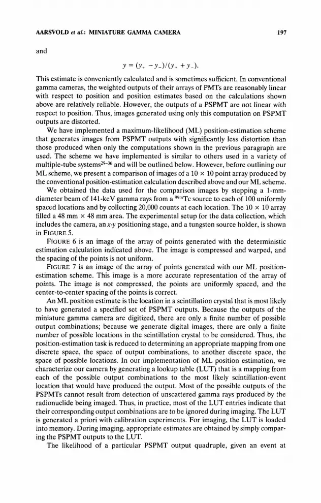
FIGURE 11. Anterior view of the left knee of a two-year-old child injected with 4.5 mCi of y Y m T ~ HDP. Imaging was started 3 h after injection. The image represents 100,000 counts accumulated in 10 min.
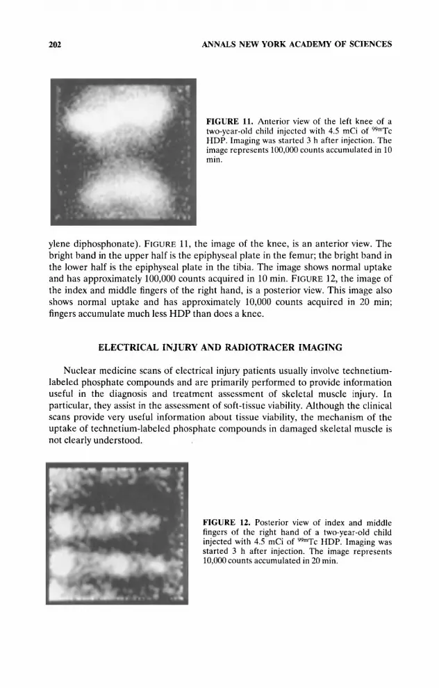
ylene diphosphonate). FIGURE 11, the image of the knee, is an anterior view. The bright band in the upper half is the epiphyseal plate in the femur; the bright band in the lower half is the epiphyseal plate in the tibia. The image shows normal uptake and has approximately 100,000 counts acquired in 10 min. FIGURE 12, the image of the index and middle fingers of the right hand, is a posterior view. This image also shows normal uptake and has approximately 10,000 counts acquired in 20 min; fingers accumulate much less HDP than does a knee.
ELECTRICAL INJURY AND RADIOTRACER IMAGING
Nuclear medicine scans of electrical injury patients usually involve technetium- labeled phosphate compounds and are primarily performed to provide information useful in the diagnosis and treatment assessment of skeletal muscle injury. In particular, they assist in the assessment of soft-tissue viability. Although the clinical scans provide very useful information about tissue viability, the mechanism of the uptake of technetium-labeled phosphate compounds in damaged skeletal muscle is not clearly understood.
FIGURE 12. Posterior view of index and middle fingers of the right hand of a two-year-old child injected with 4.5 mCi of yymTc HDP. Imaging was started 3 h after injection. The image represents 10.000 counts accumulated in 20 min.
AARSVOLD el al.: MINIATURE GAMMA CAMERA 203
The device described above will be useful not only as a clinical imager, but also as a laboratory tool. Its relatively fine resolution and relatively small size make it a convenient device for use in studies involving small-animal imaging, the type of studies necessary for clarifying the mechanism of uptake of technetium-labeled phosphate compounds and other radiotracers in damaged soft tissue. Additional remarks related to such studies can be found in an accompanying paper in these proceeding^^^ and in the references listed there.
SUMMARY
We have described a mobile miniature-gamma-camera system for use in electri- cal trauma units and have presented images and imaging characteristics of a prototype system. The system has as its principal component a miniature gamma camera based on a PSPMT. The camera is 92 mm x 92 mm x 190 mm in size, weighs 5 kg, has a 48 mm x 48 mm field of view, and has an intrinsic resolution of approximately 3 mm FWHM and 6 mm FWTM. It is expected that devices of this type will be useful as imaging tools in electrical trauma units and laboratories where imaging studies regarding uptake mechanisms of radiopharmaceuticals for assessing tissue viability are carried out.
1.
2.
3.
4.
5.
6.
7. 8.
9.
10.
11.
12.
13.
REFERENCES
HUNT, J. , S. LEWIS, R. PARKEY & C. BAXTER. 1979. The use of technetium99m stannous pyrophosphate scintigraphy to identify muscle damage in acute electric burns. J. Trauma 19(6): 409-413.
HUNT, J. L., R. M. SATO & C. R. BAXTER. 1980. Acute electric burns. Arch. Surg. 115(4): 434-438.
BRILL, D. R. 1981. Radionuclide imaging of nonneoplastic soft tissue disorders. Semin. Nucl. Med. l l(4): 277-288.
CAMERON, G. G., N. D. GREYSON, W. A. CUMMING, G. R. LLOYD & J . R. BIRCH. 1981. The case of the missing vault: a “cold” bone lesion following electrical burn. Clin. Nucl. Med. 6( 1): 30-33.
HOLLIMAN, C. J., J. R. SAFFLE, M. KRAVITZ & G. D. WARDEN. 1982. Early surgical decompression in the management of electrical injuries. Am. J. Surg. 144: 733-739.
SPENCER, R. R., A. G. WILLIAMS, JR., F. A. METTLER, JR., J. H. CHRISTIE, R. D. ROSENBERG & W. D. WEAVER. 1983. Tc-99m PYP scanning following low voltage electrical injury. Clin. Nucl. Med. 8(12): 591-593.
BINGHAM, H. 1986. Electrical burns. Clin. Plast. Surg. 13(1): 75-85. HAMMOND, J. S . & C. G. WARD. 1988. High-voltage electrical injuries: management and
outcome of 60 cases. South. Med. J. 81(11): 1351-1352. TIMMONS, J. H., M. F. HARTSHORNE, V. J. PETERS, M. A. CAWTHON & J. M. BAUMAN.
1988. Muscle necrosis in the extremities: evaluation with Tc-99m pyrophosphate scanning-a retrospective review. Radiology 167(1): 173-178.
CHANG, L. Y. & J. Y. YANG. 1991. The role of bone scans in electric burns. Burns 17(3): 250-253.
DELPASSAND, E. S., R. D. DHEKNE, B. J. BARRON & W. H. MOORE. 1991. Evaluation of soft tissue injury by Tc-99m bone agent scintigraphy. Clin. Nucl. Med. 16(5): 309-314.
SAYMAN, H. B., I. URGANCIOGLU, I. USLU & T. KAPICIOGLU. 1992. Prediction of muscle viability after electrical burn necrosis. Clin. Nucl. Med. 17(5): 395-396.
YASILLO, N. J., R. N. BECK & M. COOPER. 1990. Design considerations for a single tube gamma camera. IEEE Trans. Nucl. Sci. 37(2): 609-615.

204 ANNALS NEW YORK ACADEMY OF SCIENCES
14. YASILLO, N. J., J. N. AARSVOLD, R. N. BECK, T. A. BLOCK, C-T. CHEN, M. COOPER, S. J. HEIMSATH, K. L. MATTHEWS, R. A. MINTZER, X. PAN, T. C. VAZQUEZ & C. WU. 1993. A clinical miniature gamma camera [abstract]. J. Nucl. Med. 34(5): 112P.
15. KUME, H., S. SUZUKI, J. TAKEUCHI & K. OBA. 1985. Newly developed photomultiplier tubes with position sensitivity capability. IEEE Trans. Nucl. Sci. 32( 1): 448-452.
16. KUME, H., S. MURAMATSU & M. IIDA. 1986. Position-sensitive photomultiplier tubes for scintillation imaging. IEEE Trans. Nucl. Sci. 33( 1): 359-363.
17. UCHIDA, H., T. YAMASHITA, M. IIDA & S. MURAMATSU. 1986. Design of a mosaic BGO detector system for positron CT. IEEE Trans. Nucl. Sci. 33(1): 464-467.
18. HAYASHI, T. 1989. New photomultiplier tubes for medical imaging. IEEE Trans. Nucl. Sci.
19. ANTICH, P. P., P. V. KULKARNI, J. ANDERSON, A. CONSTANTINESCU, J. PRIOR, J. FERNANDO & R. W. PARKEY, 1992. High resolution 1-125 imaging of rat brain blood Aow with plastic scintillation detectors and position-sensitive photomultipliers [abstract]. J. Nucl. Med. 33(5): 1003.
GREEN, M. V., A. MARKOWITZ, T. E. TEDDER & M. I. CHAPARRO. 1991. A small animal scintillation camera using a single position-sensitive phototube for event location [preprint]. In IEEE Proceedings: IVth International Symposium on Biomedical Engi- neering.
21. GREEN, M. V., A. MARKOWITZ, T. E. TEDDER, M. P. ANDRICH, E. S. OWENS & R. D. NEUMANN. 1992. SPECT imaging in small animals [abstract]. J. Nucl. Med. 33(5): 852.
22. GREEN, M. V., M. P. ANDRICH, D. DOUDET, A. MARKOWITZ, T. E. TEDDER, E. S. OWENS, M. I. CHAPARRO & R. D. NEUMANN. 1992. Evaluation of cardiovascular function in small animals using a microcomputer-based scintigraphic imaging system. Preprint.
23. PANI, R., F. SCOPINARO, G. DEPAOLA, R. VACCARO & L. VALLETTA. 1992. Very high resolution gamma camera prototype [abstract]. Eur. J. Nucl. Med. 19(8): 584.
24. REDUS, R. H., J. GORDON, W. J. MCGANN, G. ENTINE, A. B. BRILL, H. LIU & A. KARELLAS. 1992. Intraoperative nuclear imaging probe. In Conference Record of the
HE, Z . , A. J. BIRD, D. RAMSDEN & Y. MENG. 1993. A 5-inch-diameter position-sensitive scintillation counter. In Conference Record of the 1992 IEEE NSSIMIC. Vol. 1:
36(1): 1078-1083.
20.
1991 IEEE NSSIMIC. VOI. 3: 1887-1891. 25.
129-131. 26. HE, Z., D. RAMSDEN, S. M. HOLDER & S. H. DUNCAN. 1993. Two fast data acqu
processing systems for a compact gamma camera. In Conference Record of the 1992 IEEE NSSIMIC. Vol. 2: 1101-1103.
27. BECK, R. N. & L. D. REDTUNG. 1985. Collimator design using ray-tracing techniques. IEEE Trans. Nucl. Sci. 32(1): 865-869.
28. GUNTER, D. L., A. BARTLETT, X. YU & R. N. BECK. 1990. Optimal design of parallel-hole collimators [abstract]. J. Nucl. Med. 31(5): 728.
29. GRAY, R. M. & A. MACOVSKI. 1976. Maximum a posten'on' estimation of position in scintillation cameras. IEEE Trans. Nucl. Sci. 23( 1): 849-852.
30. MILSTER, T. D., L. A. SELBERG, H. H. BARRETT, R. L. EASTON, G. R. Ross~, J. ARENDT & R. G. SIMPSON. 1984. A modular scintillation camera for use in nuclear medicine. IEEE Trans. Nucl. Sci. 31(1): 578-580.
31. MILSTER, T. D., L. A. SELBERG, H. H. BARRETI-, A. L. LANDESMAN & R. H. SEACAT 111. 1985. Digital position estimation for the modular scintillation camera. IEEE Trans. Nucl. Sci. 32(1): 748-752.
32. CLINTHORNE, N. H., W. L. ROGERS, L. SHAO & K. F. KORAL. 1987. A hybrid maximum- likelihood position computer for modular scintillation cameras. IEEE Trans. Nucl. Sci.
33. MILSTER, T. D. 1987. Design and construction of a modular gamma camera. Ph.D. dissertation. University of Arizona, Tucson, Arizona.
34. AARSVOLD, J. N., H. H. BARRETT, J. C. CHEN, A. L. LANDESMAN, T. D. MILSTER, D. D. PATTON, T. J. RONEY, R. K. ROWE, R. H. SEACAT I11 & L. M. STRIMBU. 1988. Modular scintillation cameras: a progress report. In SPIE-Medical Imaging 11: Image Formation, Detection, and Interpretation. Volume 914. R. H. Schneider & S. J. D y e r Il l , Eds.:
34(1): 97-101.
319-325.

AARSVOLD et al.: MINIATURE GAMMA CAMERA 205
35. MILSTER, T. D., J. N. AARSVOLD, H. H. SARRETT, A. L. LANDESMAN, L. S. MAR, D. D. PATTON, T. J. RONEY, R. K. ROWE & R. H. SEACAT 111. 1990. A full-field modular gamma camera. J. Nucl. Med. 31(5): 632-639.
36. PAWLOWSKI, J., B. KARI, Y. LIU & W. CHANG. 1993. Bar-detector with extended field of view for a modular SPECT system. In Conference Record of the 1992 IEEE NSS/MIC.
37. CHEN, C-T., J. N. AARSVOLD, T. A. BLOCK, K. L. MA-ITHEWS, R. A. MINTER, J. MUKHERJEE, N. J. YASILLO, L. P. RIVER, M. COOPER & R. C. LEE. 1994. Radionuclide probes for tissue damage. This volume.
V O ~ . 2: 850-852.