Embed Size (px)
Citation preview
A Model-Driven Approach to Performability Analysis of Dynamically Reconfigurable Component-Based Systems
Vincenzo Grassi° Raffaela Mirandola* Antonino Sabetta° ° Dipartimento di Informatica, Sistemi e Produzione, Università di Roma “Tor Vergata”, Italy
{vgrassi, sabetta}@info.uniroma2.it *Dipartimento di Elettronica e Informazione, Politecnico di Milano, Italy
ABSTRACT Dynamic reconfiguration techniques appear promising to build component-based (C-B) systems for application domains that have strong adaptability requirements, like the mobile and the service-oriented computing domains. However, introducing dynamic reconfiguration features into a C-B application makes even more challenging the design and verification of functional and non functional requirements. Our goal is to support the model-based analysis of the effectiveness of reconfigurable C-B applications, with a focus on the assessment of the non-functional performance and reliability attributes. As a first step towards this end, we address the issue of selecting suitable analysis models for reconfigurable systems, suggesting to this end the use of joint performance and reliability (performability) models. Furthermore, we propose a model-driven approach to automatically transform a design model into an analysis model. For this purpose, we build on the existence of intermediate languages that have been proposed to facilitate this transformation and we extend one of them, to capture the core features (from a performance/reliability viewpoint) of a dynamically reconfigurable C-B system. Finally, we illustrate by a simple application example the main steps of the proposed approach. Categories and Subject Descriptors D.2.2 [Software engineering]: Design tools and techniques; C.4 [Performance of systems]: Modeling techniques.
General Terms: Design, Performance, Reliability.
Keywords: Model-driven development, dynamic reconfiguration, performability. 1. INTRODUCTION Dynamic reconfiguration of applications is becoming a key challenge that software developers are facing today, due to the emergence of more and more classes of applications that are highly complex and distributed, and operate in heterogeneous and rapidly changing environments (like those from the mobile, pervasive or service-oriented computing domains). The IBM initiative on autonomic computing [22], whose goal is to devise adaptive behaviours for the fulfilment of self*-properties, is an example of the efforts in this direction.
The main goal of a dynamic reconfiguration is to make the
application able to meet its functional requirements in different execution environments, while achieving and maintaining at the same time some required Quality of Service (QoS) goal (non functional requirement) like timeliness and reliability [36]. In the case of component-based (C-B) applications [8], dynamic reconfiguration can be obtained in different ways, including dynamic component replacement, component assembly modification or component relocation on different devices.
Introducing dynamic reconfiguration features into a C-B application makes its design and development even more challenging. Hence, it is useful to have methodologies and tools that support the application designers in this activity. In this respect, our goal is to support the model-based analysis of the effectiveness of reconfigurable C-B applications, with a focus on the assessment of performance and reliability attributes.
Model-based analysis allows the early QoS assessment of a C-B system, prior to its actual implementation. Hence, it can be useful for the QoS-driven selection of the components and their interconnection architecture. It can also be useful to devise suitable reconfiguration strategies for the dynamic contexts where the application will be deployed. Once the application is implemented, model-based reasoning may be used to predict the impact of different reconfigurations in a changing context, driving in this way the reconfiguration process.
In this perspective, we tackle in this paper the following two problems: • which kind of model is suitable for the performance and reliability
analysis of dynamically reconfigurable systems; • how we can support the construction of such a model.
Concerning the first problem, we build on past work on the joint analysis of performance and reliability of reconfigurable systems. Research in this field was motivated by the consideration that reconfigurable systems may exhibit different performance or reliability levels during some observation period. Moreover, performance and reliability are sometimes competing QoS attributes, as one could be achieved at the expense of the other. This led to the definition of the performability concept as a unifying framework to deal with these multi-level and possibly competing attributes, and to the proposal of suitable models to support performability analysis [17]. We base on this work our suggestion for a model that supports performance and reliability analysis of a C-B dynamically reconfigurable system.
To address the second problem, we leverage MDD-based model transformation methodologies and tools [3, 29]. The focus of MDD methodologies is typically on a transformation path from high level to platform specific models (up to the executable code) of a software application [27]. The idea of exploiting MDD methodologies for QoS assessment has emerged in recent years [7,9,35]. Indeed, the construction of a QoS model can be seen as a special type of model transformation that takes as input some
Permission to make digital or hard copies of all or part of this work for personal or classroom use is granted without fee provided that copies are not made or distributed for profit or commercial advantage and that copies bear this notice and the full citation on the first page. To copy otherwise, or republish, to post on servers or to redistribute to lists, requires prior specific permission and/or a fee. WOSP’07, February 5–8, 2007, Buenos Aires, Argentina. Copyright 2007 ACM 1-59593-297-6/07/0002...$5.00.

design-oriented model of the software system (plus some additional information related to the QoS attribute of interest) and generates an analysis-oriented model, that lends itself to the application of some analysis methodology.
However, defining such a “single step” transformation could be quite cumbersome, for several reasons: the large semantic gap between the source and target model of the transformation, the heterogeneous design notations that could be used by different component providers, and the different target analysis notations one could be interested in, to support different kinds of analysis (e.g. queueing networks, Markov processes). To alleviate these problems, some intermediate modeling languages have been recently proposed, to capture and express the relevant information for the analysis of QoS attributes. Their goal is to help in distilling this information from complex design-oriented models, serving as a bridge between design-oriented and analysis-oriented notations [13, 16, 41].
A limitation of existing intermediate languages is that they only support the modeling of static systems. To overcome this limitation, we propose an intermediate language for the modeling of dynamically reconfigurable C-B systems that captures the core features (from a performance/reliability viewpoint) of such systems. This language can be used in a two-step transformation path from design-oriented to analysis-oriented models, and is defined as an extension of one of the existing intermediate languages. The extension we propose is purposely minimal, according to the nature of these intermediate languages.
The paper is organized as follows. In section 2 we discuss related work. In section 3 we outline the core concepts of a reconfigurable C-B application that should be captured in a model of that application. In section 4 we first outline the basic ideas of our MDD based transformation path; then, after a brief description of the key features of the intermediate language we use as starting point, we present its extension, showing how the introduction of a minimal set of new concepts is sufficient to support the modeling of reconfigurable C-B applications. In section 5 we discuss the kind of target analysis-oriented model we intend to generate, and we outline transformation rules from the intermediate to the target model. In section 6 we describe an example of reconfigurable application in a dynamic context, and we use it to illustrate the main steps of our transformation path from a design to an analysis model, up to the solution of the latter model. Section 7 concludes the paper and outlines future extensions. 2. RELATED WORK In this section we review related work in the three areas covered by our work, that is: design-oriented modeling notations for dynamically reconfigurable C-B systems; MDD methodologies for QoS assessment of C-B systems; analysis-oriented notations for the performance/reliability assessment of reconfigurable systems. 2.1 Design notations for reconfigurable systems Design-oriented notations that can be related to C-B systems are the Architecture Description Languages (ADLs) defined within the Software Architecture based approaches to software design, and built around the “component-connector” model [25]. Specifically, dynamic software architectures languages, such as CommUnity [40], Dynamic Wright [1], Dynamic Acme [11], Rapide [23], are described and compared in [5] by outlining the kind of architectural dynamism they are able to handle. !-adl is a new architectural language [32] that supports the description of dynamic software architecture from a runtime perspective.
These ADLs are often formal notations that do not present friendly interfaces to be used by software developers. In this
respect, UML is a more user-friendly notation, and it is the de facto standard for software design, from both the industrial and academic perspective [37]. However, it does not specifically address the modeling of dynamically reconfigurable systems.
To fill this gap, some UML profiles have been recently proposed to deal with dynamic software architectures. Specifically, a first step towards the definition of a UML profile for dynamic Software Architectures has been proposed in [19]. A UML profile that provides a higher-level interface for the use of !-adl has been presented in [31]. Other UML-based notations have been proposed for the modeling of a specific kind of dynamic architectures, where the dynamism is caused by the mobility of physical devices or of logical software components. A review of these notations can be found in [14]. In the example of section 6 we will use one of such notations [12].
The notations summarized above are mainly targeted to the modeling of functional aspects during the application design. To take into account also performance or reliability requirements during the design phase, related information must be embedded in the design notations. Regarding UML, standard extensions have been defined to deal with performance characteristics (the UML-SPT profile) [38], and, more generally, with Quality of Service characteristics (the UML-QoS profile) [39]. Other notations are emerging within specific C-B domains, like the notations to express QoS ontologies for the service-oriented computing domain [24]; these notations could be used to embed QoS information in languages for the specification of service-oriented applications like BPEL4WS [2] and OWL-S [33].
2.2 MDD-based transformations from design to analysis models In the last years, the focus in software development has been shifted from a code-centric approach to a model-centric approach. The model-driven development (MDD) paradigm [3] is centered around a transformation path that goes from high-level design models to platform specific models, up to the executable code. As a consequence, model transformation has been actively investigated in the last years particularly in the area of model-to-code transformation.
Regarding the generation of QoS analysis models from design models, most of the existing works concerns the definition of ad-hoc algorithms that act as a bridge between the design model and some analysis models (see [4]). To the best of our knowledge, only few works explicitly exploit MDD methodologies and tools to generate models for the analysis of extra-functional properties, such as performance or reliability. In particular, Petriu et al. derive a Layered Queuing Network from UML diagrams by using XSLT language and graph transformation [16]; Cortellessa et al. define the Software Performance MDA framework that extends the canonical view of the MDA approach [27] to embed additional types of models, to get a Model Driven approach keeping into account performance issues [7]. Finally, as already mentioned in the introduction, some intermediate languages [13, 16, 41] have been defined to capture the relevant information for the analysis of non-functional attributes. Furthermore, a step-wise refinement process based on one of such languages has been also proposed in [15], to support the derivation of detailed analysis-oriented models refining high-level architectural models of C-B systems.
All the model transformation methodologies for QoS assessment reviewed above consider only static systems. Model transformation methodologies for the performance evaluation of a specific class of dynamic systems (mobile systems) are reviewed in [14].

2.3 Analysis notations for reconfigurable systems The performability concept was introduced by Meyer in the early ’80s [26] to deal in a unified way with the performance and reliability characteristics of reconfigurable systems. It was motivated by work on gracefully degradable fault-tolerant systems, but it can be easily extended to other kinds of reconfigurable systems. The basic idea behind this concept is that a reconfigurable system may have several working configurations, each characterized by a possibly different performance level, where “performance” has a broad scope, whose meaning depends on the specific domain. It may be a throughput or a response time measure, or any other suitable measure, also including reliability measures. A performability measure quantifies (in probabilistic terms) the ability of the system to achieve and maintain a satisfactory performance level in a given time interval (that may be assumed finite or infinite), taking into account the variations that may occur in the system structure and environment.
Models traditionally used in performance analysis (e.g. queueing networks) or reliability analysis (e.g. Markov models with “up” and “down” states) are not well suited for the performability analysis of reconfigurable systems. Indeed, they often assume a static configuration of the computing platform (as in the case of queueing networks), or are based on too coarse a classification of the different system configurations (as in up/down Markov models). Several modeling methodologies for performability analysis have been proposed since the original proposal [17]. In many cases, to reduce the complexity of a performability model, a “two level” modeling approach has been suggested, based on the consideration that events concerning the normal system operation (basically, the system actions) occur at a much higher rate than events related with the system reconfiguration (e.g. the events that trigger a reconfiguration and the consequent reconfiguration actions). Hence, a performability model can be built as a composition of a reconfiguration model, that describes changes occurring in the system configuration, and a family of performance models, one for each possible system configuration. The latter can be solved separately, and the obtained results can be included in the former, which can then be solved to get a performability measure. Typical models resulting from this decomposition approach are reward models (for example Markov or semi-Markov reward models [17]), which are state-based models where a reward is associated with each state and/or transition: - states model the possible system configurations; - transitions model the system evolution; - rewards associated with states represent the system performance
in the corresponding configurations (calculated by the associated performance model);
- rewards associated with transitions may be used to model the “cost” of reconfigurations (for instance, it could be expressed as a negative reward); alternatively, the cost of reconfigurations may also be modeled by the (negative) reward associated with some “reconfiguration” states.
These models can be used to calculate probabilistic reward
measures like the reward at some time instant t, or the total reward accumulated over some time interval [0, t], with t possibly going to infinity if we want to consider steady-state measures. Depending on which kind of reward we associate to the model states and transitions, these reward measures correspond to some performance measure of interest. For example, if the reward associated with a state is the system throughput in that state, then the reward accumulated in [0, t] is the number of service requests processed in that interval, while this accumulated reward divided by t is the
average throughput in the same interval. Alternatively, if the reward associated with a state is the system availability in that state, then the reward accumulated in [0, t] divided by t is the average availability in that interval.
A vast literature exists about this modeling approach. We refer to [17 (in particular chapts. 3, 4, 9)] for further details and references.
3. CORE CONCEPTS FOR
RECONFIGURABLE SYSTEMS An important step toward the definition of a modeling notation for dynamically reconfigurable systems is the identification of the key features that must be represented. In this respect, a classification of the possible reconfigurations that may occur in a distributed system was presented in [18]. That classification distinguishes three possible kinds of reconfiguration: • implementation: the internal implementation of a software module
is changed. An example of this kind of reconfiguration occurs in service-oriented architectures [42], where a Web accessible service interface may be dynamically (re-)bound to a software module that implements it;
• structural: the logical interconnection among system modules (the system topology) is changed. An example of this kind of reconfiguration occurs when we add or remove modules from a given architecture, to cope with changes in the service request load;
• geometric: the mapping of a software module to the underlying platform is changed; this kind of reconfiguration occurs, for example, in systems that exploit logical mobility [10]. In addition to this classification, we think it is useful to introduce
another one, which is orthogonal to the former. It concerns the kind of events that cause the reconfiguration, considering them from the viewpoint of a running application: • Synchronous: the triggering event is synchronous with respect to
the application logic, i.e. it corresponds to a given step in the application execution. An example of triggering event is the request for a service offered by some remote component.
• Asynchronous: the triggering event is asynchronous with respect to the application logic, i.e. it occurs independently of the current application state and depends on the context where the application is executed. Examples of this type of events are: the portable device on top of which the application is running is brought to a different place; the battery level of the same device drops below a given threshold, and so forth. Finally, it is important to take into account that a reconfiguration
may have a cost associated with it. It is represented by the resources that must be consumed to realize it and by the delay that such reconfiguration can possibly introduce in the operation of the system. For example, moving some component of a distributed application to a different device while the application is running involves the use of computational and network resources. 4. A MOF METAMODEL FOR
RECONFIGURABLE C-B SYSTEMS In this section we first present the key points of our MDD-based approach to the generation of a performability model for a reconfigurable C-B system (sub-section 4.1). Then we present the metamodel of the intermediate language that we propose to support this generation process. As pointed out in the introduction, this metamodel is an extension of an existing metamodel whose focus is on the modeling of static C-B systems. To make the paper self-contained we summarize in sub-section 4.2 the relevant features of the metamodel we have adopted as starting point, and then we present its extension in sub-section 4.3.
4.1 The basic methodology The central element of our approach is the definition of a suitable intermediate modeling language. As already outlined in the introduction, the goal of an intermediate language is to support the splitting of the complex task of deriving an analysis model (e.g. a queueing network) from a high level design model (expressed using UML or other component-oriented notations) into two separate and presumably simpler tasks:
extracting from the design model only the information that may be relevant for the analysis of some QoS attribute and expressing it in the notation provided by the intermediate language; generating an analysis model based on the information expressed in the intermediate language. These two tasks may be solved independently of each other.
Moreover, as a positive side effect of this two steps approach built around a single intermediate language, we may mitigate the “n-by-m” problem of translating n heterogeneous design notations (that could be used by different component providers) into m analysis notations (that support different kinds of analysis), reducing it to a less complex task of defining n+m transformations: n from different design notations to the intermediate language, and m from it to different analysis notations.
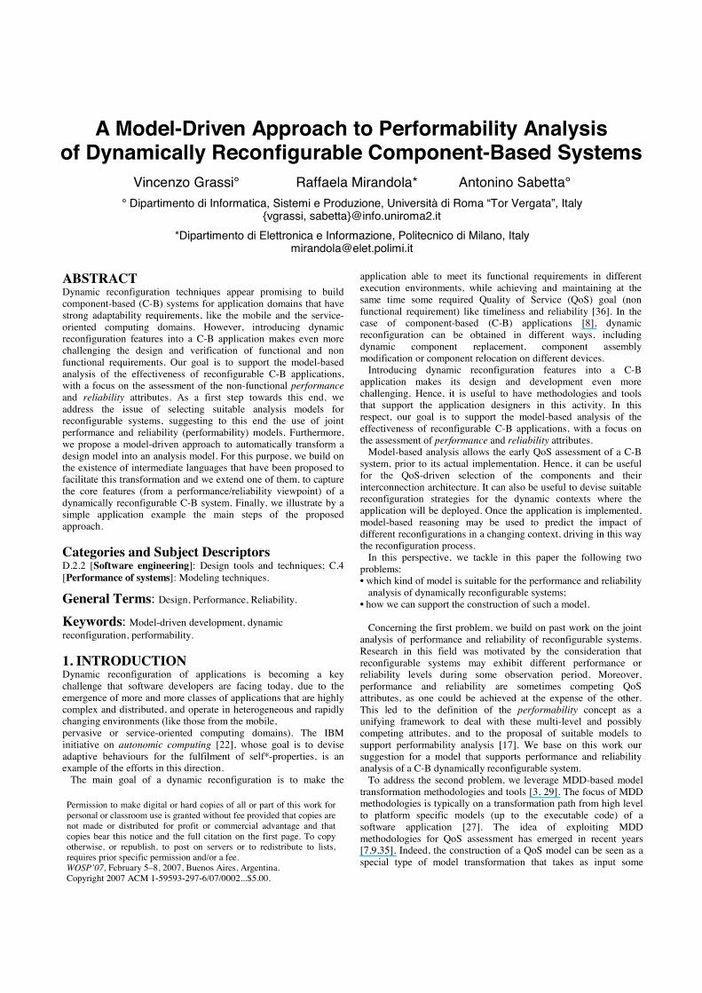
To define a suitable intermediate language for reconfigurable C-B systems, we build on an existing language: KLAPER (Kernel LAnguage for PErformance and Reliability analysis) [13]. The KLAPER goal was to capture in a lightweight and compact model only the relevant information for the performance and reliability analysis of static C-B systems, while abstracting away irrelevant details. In this section we present its extension for reconfigurable systems, which is called D-KLAPER. Fig. 1 provides a graphical representation of the scope of our work (grey parts) and of the role played by D-KLAPER. In particular, we point out that D-KLAPER is neither a language to be used for the system design (notations like UML are better suited for this purpose) nor an analysis language (specific notations exist for this purpose, e.g. stochastic process algebras). D-KLAPER has been designed as an intermediate “distilled” language to help define transformations between design-oriented and analysis-oriented notations, filling the large semantic gap that usually divides them.
Design models usingdiffe rent not atio ns
Target Ana lysismodels
DN1
DN2
DNn
AN1
AN2
ANm
mob-UML reward model
D-KLAPE Rmodel
Figure 1. Our contribution within a transformation path from design models of C-B applications (expressed using notations DN1, ..,DNn) to different types of performance/reliability models (expressed by notations AN1, .., ANm). The figure also shows the design and target notations used as examples in this paper.
To take advantage of the current state of the art in the field of
model transformation methodologies, D-KLAPER is defined as a MOF (Meta-Object Facility) compliant metamodel [28], where MOF is the metamodeling framework proposed by the Object
Management Group (OMG) for the management of models and their transformations within the MDD approach to software development [28,30].
4.2 The “static” metamodel Fig. 2 shows the structure of the “static” KLAPER MOF metamodel (excluding the shadowed parts), while Fig. 3 summarizes the list of attributes and associations for the relevant KLAPER metaclasses.1 We refer to [13] for the complete MOF specification and to [20] for an up-to-date view of its implementation status.
To support the distillation from the design models of a C-B system of the relevant information for performance/reliability analysis, KLAPER is built around an abstract representation of such a system, modeled (including the underlying platform) as an assembly of interacting Resources. Each Resource offers (and possibly requires) one or more Services. A KLAPER Resource is thus an abstract modeling concept that can be used to represent both software components and physical resources like processors and communication links.
To bring performance/reliability related information within such an abstract model, each activity in the system is modeled as the execution of a Step that may take time to be completed, and/or may fail before its completion: the internalExecTime, internalFailTime and internalFailProb attributes of each step may be used for this purpose.
Steps are grouped in Behaviors (directed graphs of nodes) that may be associated either with the Services offered by Resources (reactive behavior), or with a Workload modeling the demand injected into the system by external entities like the system users (proactive behavior).
ServiceCall steps model the relationship between required and offered services. Each ServiceCall specifies the name of the requested service and the type of resource that should provide it. In the original metamodel presented in [13], ServiceCalls were explicitly associated with the actual resource/service instances.
In this paper we present an extended metamodel where the information concerning the relationship between a ServiceCall and the actual recipient of the call is represented separately by means of instances of the Binding metaclass. This allows a clearer separation between the specification of the components and the description of how they are composed. In fact a set of bindings can be regarded as a self-contained specification of an assembly. Similarly, since the service call concept is also used to represent the access to platform level services by software components, a suitable set of bindings can describe as well the deployment of an application on the underlying platform.
Finally, we point out that the performance/reliability attributes associated with a service behavior step concern only the internal service characteristics; they do not take into account possible delays or failures caused by the use of other required services, that are needed to complete that step. In this respect, we remark that when we build a KLAPER model (first task outlined above) our goal is mainly “descriptive”. The Bindings included in the model help to identify which external services may cause additional delays or failure possibilities. How to properly mix this “external” information with the internal information to get an overall picture of the service performance or reliability is out of the KLAPER scope. This problem must be solved during the generation and solution of an analysis model derived from a KLAPER model.
1 This metamodel is a slight modification of the metamodel presented in [13] that fixes some minor problems.

Behavior
Step1..*in 0..*
out 0..*
Serv iceCall
Activity
Transi tion
Start End
Branch Fork Join
0..1
0..*
Acquire Release
nestedBehavior
Work load0..1
0..*
ActualParam
{ordered}0..*
actualParam
Serv ice
Resource
offeredService 0..*
behavior
resourc e
0..1
0..1 t o
0..1 from
Control
0..*
KlaperModel 0..*
0..*
0..1
Reconfig
CreateBinding
0..*
Binding
0..1
DeleteBinding
Figure 2. The (D-) KLAPER MOF metamodel. The grey parts show the introduced extensions to model reconfigurable systems.
Resource: attributes: name, type, capacity, schedulingPolicy,
description; associations: offeredService. Service: attributes:name, formalParams, speedAttr, failAttr,
description; associations: behavior, resource. Behavior : associations: usedService, step, workload. Step : attributes: name; associations: in, out. Activity : attributes: name, repetition, /internalExecTime,
/internalFailProb, /internalFailTime,completionModel; associations: nestedBehavior, serviceCall.
Branch : attributes: branchProbs. Acquire : attributes : resourceUnits; associations: resource Release : attributes: resourceUnits; associations: resource ServiceCal : associations: to, from. Workload :l: attributes: resourceType, serviceName, isSynch;
associations: step, actualParam; ActualParam : attributes: value. Transition attributes: workloadType, arrivalProcess, population,
initialResource; associations: behavior. Binding : associations : serviceCall, service. ------------------ dynamic extension ---------------------------------- Reconfiguration: attributes : sourceStep, targetService. CreateBinding DeleteBinding
Figure 3. Attributes and associations of the main KLAPER metaclasses 4.3 The “dynamic” metamodel extension KLAPER’s metamodel was originally designed to provide a minimal set of modeling concepts to be used as a bridge between high-level (user-friendly) modeling notations and analysis-oriented notations. Along the same lines, we define the extension that enables the modeling of reconfigurable systems, preserving the
minimalist style of the overall metamodel. The dynamic extension of KLAPER's metamodel consists of three metaclasses, shown in grey in figure 2: Reconfiguration (abstract), CreateBinding, and DestroyBinding, defined as a specialization of Activity steps.
In our metamodeling framework, all reconfigurations are modeled using (a combination of) these reconfiguration steps, which are used to create and/or delete Bindings between ServiceCall steps and Services. This approach is at the same time lightweight and powerful. On one hand, basic Reconfiguration steps can be arranged in behaviors, to model more complex reconfiguration mechanisms. On the other hand, Reconfiguration steps are activities, implying that they carry information related to failure rate, execution time and resource demand as any other ordinary activity. In addition to the usual semantics of activities, which do not have side effects on the model, reconfiguration steps can create or destroy bindings and thus they change the model.
Thanks to this extension, D-KLAPER is able to support the modeling of all the basic features of a reconfigurable system that we outlined in section 3, as we argue below.
• Implementation/Structural/Geometric reconfigura-tion. Given
the unifying concept of Resource, which spans physical and logical elements, a suitable combination of Binding creations/deletions can capture any of the three types of reconfiguration discussed in [18]. In fact the distinction among the classes of implementation, structural, or geometric configurations is lost when representing a system using D-KLAPER. A change in any of the three configurations can be described, in a D-KLAPER model, as a re-routing of a service call to a different service (and possibly to a different resource). We point out that we model in this way also the creation/deletion of components, as at the D-KLAPER model level we assume that there exists a finite “resource pool”. In this way the addition/removal of components can be modeled by the creation/destruction of bindings with resources in the pool. The size of the pool can be selected based on information about the maximum number of components that can be created in the scenario we want to analyze.
• Synchronous/Asynchronous reconfiguration. Re-garding
synchronous reconfigurations, a basic premise is that a C-B system is modeled by a set of D-KLAPER resources, each offering one or more services. Hence, the operation of a system corresponds to the execution of the behaviors associated with those services. The triggering of a reconfiguration caused by the reaching of a given step in a service behavior can be modeled by inserting before (or after) that step one or more Reconfiguration steps, or a call to a suitable "reconfiguration service". The behavior of such a service would be composed of reconfiguration steps, possibly together with other types of steps. Regarding asynchronous reconfigurations, we recall that the Workload concept was introduced in KLAPER to support the modeling of proactive behaviors injected into a system. Originally this concept was used to model the arrival of service demands from the clients of the system. In D-KLAPER we extend the scope of this concept to model the occurrence of triggering events for asynchronous reconfigurations, which are modeled by the execution of one or more reconfiguration workloads. The behavior associated with such workloads can be used to model the dynamics of asynchronous reconfigurations, specifying their type (which reconfiguration occurs) and timing (when it occurs).

• Reconfiguration cost. As already mentioned above, Reconfiguration steps inherit from the Activity metaclass all the properties that can be used to model the timing, failure or resource demand characteristics of a reconfiguration. Moreover, Reconfiguration steps can be included in more complex “reconfiguration behaviors”, that increase the flexibility in modeling the resource demand connected to a given reconfiguration.
Finally, D-KLAPER is also able to support, at its level of
intermediate language, the modular modeling of C-B reconfigurable systems. In fact, with a minor extension of the scope of the Resource metaclass, we may represent a reconfiguration as the execution of a service offered by a “reconfiguration resource”. Technically, this resource is indistinguishable from other “normal” KLAPER resources, as it is instantiated from the same metaclass; the only difference is that the behavior associated with its offered service includes Reconfiguration activities. The dispatching of a reconfiguration caused by the occurrence of some triggering event can thus be modeled by a ServiceCall to that offered service. In this way, for example, changing the kind of reconfiguration triggered by an event simply consists in calling a different service. Maintaining this modularity at the D-KLAPER level may facilitate the derivation of an analysis model. 5. FROM A D-KLAPER MODEL TO A PERFORMABILITY MODEL As we argued in section 4.3, D-KLAPER is able to capture and express the key features of a C-B reconfigurable system. Hence, thanks to the reduced “distance” between a true design-oriented notation and D-KLAPER, it should be relatively simple to devise a mapping to a corresponding D-KLAPER model starting from a design model of a C-B reconfigurable system expressed in one of such notations. However, none of the notations reviewed in section 2.1 seems to have gained a widespread acceptance yet. Hence, in this section we do not address in detail the first step of the transformation path presented in section 2.1. We will outline, in section 6, a possible transformation from a specific design-oriented notation. In this section we will focus instead on the second step (from D-KLAPER to a suitable performability model). For this purpose, we discuss first some issues concerning the structure of the D-KLAPER model that represents the starting point for this step. Then, we present a possible metamodel for the target analysis-oriented model and outline transformation rules from the D-KLAPER metamodel to this metamodel. 5.1 Structure of a D-KLAPER model We recall that, given the “intermediate language” nature of D-KLAPER, a D-KLAPER model is not assumed to be built from scratch, but rather obtained as the result of a transformation from a design-oriented notation. Even if we are not selecting any specific design-oriented notation, we may make considerations about some general characteristics that could be shared by different notations. Then, based on this, we make some assumptions about the structure of the resulting D-KLAPER model.
Firstly, we note that several design-oriented notations for dynamically reconfigurable systems adopt a “separation of concerns” perspective, where the modeling of the aspects related to the reconfiguration is kept separate from the modeling of the normal system operation. In particular, this is achieved by defining one or more entities (separate from the entities that model the normal operation) that model both the occurrence of events that trigger the reconfiguration and the corresponding reconfiguration
activities. For example, this is the case of Dynamic Wright [1] with its Configuror entity, of the UML Profile for Dynamic Architectures [19] with its Dynamic and Behavior Aspects, and of the UML Profile for Mobile Systems [12] with its Mobility Manager.
Secondly, we note that one of the main motivations for dynamically reconfigurable systems is the adaptation to changing environments. This implies that the reconfigurations that are taken into consideration for such systems are mainly of asynchronous type. As a consequence, without excessive loss of generality, we assume in the following that only asynchronous reconfigurations may occur.
Then, for any design model where these two considerations hold, we may argue that the mapping to D-KLAPER model generates two different models: • a base model that represents the system in a normal operation
state; • a reconfiguration model that represents the aspects of the system
related to reconfiguration.
The base model is obtained by a mapping from the “normal operation” part of the source design model. The definition of such a mapping for two different source notations (UML and OWL-S) is outlined in [13]. The resulting D-KLAPER base model includes resources modeling the components and physical devices of the source design model. The execution time and failure attributes of each step belonging to the Behaviors of the services offered by such resources provide the basic information for a performance/reliability analysis of the system during its normal operation. We remark that, because we assumed that all reconfigurations are asynchronous, the base model is not concerned with reconfigurations, i.e. the service behaviors do not contain Create/DestroyBinding steps or calls to reconfiguration resources. The bindings that model the relationships between the offered and required services of the resources in the base model can be, in general, only partially specified; we may expect that only “static” bindings are specified, while “dynamic” bindings are left unspecified or, if specified, they only indicate a possible initial value.
The reconfiguration model is obtained by a mapping from the separate entities that model the reconfiguration aspect in the original model. In this respect, some design notations suggest a further separation of concerns, keeping distinct the modeling of the occurrence of reconfiguration triggering events from the modeling of activities realizing a reconfiguration. For example, this is the case of the notations defined in [12, 19]. To enhance modularity, we assume that this separation is maintained at the D-KLAPER model level. Hence, guidelines for the definition of the mapping whose target is a D-KLAPER reconfiguration model could be as follows: - information about the dynamics of the occurrence of
reconfiguration triggering events is used to build a D-KLAPER reconfiguration workload; its associated behavior consists of Activity steps, whose InternalExecutionTime attribute represents the timing of such events, and ServiceCall steps which activate suitable reconfiguration services;
- information about the kind of reconfiguration that take place in the system is used to build D-KLAPER reconfiguration resources; their services are activated by ServiceCall steps in the reconfiguration workload; the associated behavior consists of Create/DestroyBinding steps (modeling the change in the binding relationships caused by a reconfiguration), and ServiceCall steps (modeling the consumption of computing/communication resources needed to carry out a reconfiguration).
5.2 Transformation to a target analysis model Based on the discussion in section 2.3, the target analysis-oriented model we intend to generate from a D-KLAPER model is a performability model. In this respect, the separation of concerns maintained at the D-KLAPER model level between the normal operation of the system and its reconfiguration aspects makes the reward models outlined in section 2.3 a suitable candidate as target notation to build a performability model of a C-B reconfigurable system.
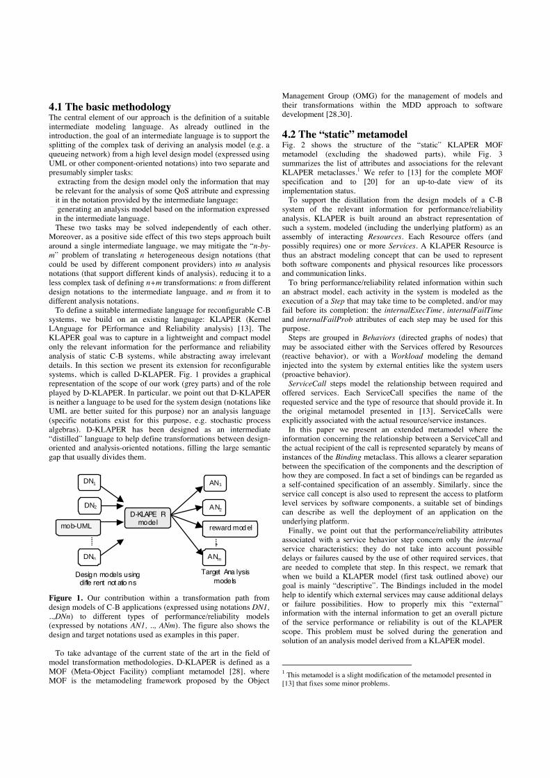
Fig. 4 shows a possible MOF metamodel for a Semi-Markov Reward (SMR) model [17], which is required to exploit MOF-based MDD methodologies and tools in the definition of a transformation from D-KLAPER models to reward models. According to this metamodel, a SMR model consists of a set of states and transitions. The residenceTime attribute of a state represents (through a probability distribution) the duration of the residence time in that state before the occurrence of a transition to another state. The next state is selected according to the transProb probabilities associated with transitions. If the residenceTime attribute is missing in all the process states, a discrete time Markov model is assumed. Both states and transitions may optionally have a reward attribute. A PerformanceModel may be optionally associated with states and transitions. If it is present, it indicates the performance model that must be solved to calculate the corresponding reward value.
Given this metamodel, a transformation from a D-KLAPER model, structured as described in section 5.1, to a SMR model can be outlined as follows.
First of all, some preliminary steps must be performed:
1. The D-KLAPER reconfiguration workload is “executed” to generate D-KLAPER models of all the possible system configurations. Each ServiceCall step (in this workload) that activates one or more reconfiguration resources generates a new configuration. These D-KLAPER models are obtained from the base model, through the specification of the missing bindings. Given our assumption of a fixed number of resource instances in the D-KLAPER model, there is a finite number of possible configurations;
2. The D-KLAPER models obtained at step 1 for all the system configurations are mapped to corresponding suitable performance models;
3. The behavior associated with each D-KLAPER reconfiguration resource is mapped to a corresponding suitable performance model.
State
name : String [0..1] isStart : Boolean reward : Expression[0..1] res idenceTime : Expression[0..1]
incoming 0..*
Transition
transProb : Expression reward : Express ion [0..1]
outgoing0..*
Parameter
name : String type : Type
{ordered}0..* forma lParam
fromto1 1
SMR
name : String
1..*
0..1c alculatedBy
0..1
PerformanceModel
PerformanceMode l
ca lculatedBy
Figure 4. MOF metamodel of a Semi-Markov Reward
model.
Steps 2 and 3 above require the use of transformation rules
defining a mapping from D-KLAPER models to performance models. Examples of these transformations for two different target analysis-oriented models (Extended Queueing Networks and Discrete Time Markov Processes) are given in [13].
Once these preliminary steps have been performed, we can generate a SMR model. For this purpose, we may define a (almost) direct mapping from the behavior associated with the D-KLAPER reconfiguration workload and the states and transitions of a SMR model. In this mapping, the internalExecutionTime attribute of each behavior step is used to define the residenceTime attribute of corresponding SMR states. Branch steps and their branchProb attributes are used to define SMR transitions and their transProb attributes. Regarding the SMR rewards, the performance models generated at step 2 above are associated to the SMR states modeling the corresponding system configuration, while the performance models generated at step 3 are associated to the SMR states (or transitions) that model the occurrence of a reconfiguration.
The SMR model obtained as result of this transformation process can then be solved to calculate a suitable reward measure that corresponds to some performability measure (as outlined in section 2.3). To obtain the solution, we must first solve the performance models to calculate the values of the reward attributes. Then, we can solve the SMR model, using existing tools (e.g. SHARPE [34]).
6. AN APPLICATION EXAMPLE 6.1 The design-oriented model In this example we consider a simple infrastructure aimed to support the development of context-aware applications [6]. In particular, this infrastructure provides information about the physical location of mobile devices within a given area (e.g. a university campus). The central element of this infrastructure is a software component called LocationAgent that provides two different services: • an on-demand service, which upon request returns the current
location of the device; • a notification service, which, after a suitable subscription, notifies
the subscriber when the device exits from its current “position interval” and enters a new interval (a position interval is a set of positions specified at subscription time).
Each mobile device has its own LocationAgent. To offer these
services, the LocationAgent relies on two other components: • InPS, which is the high-level interface of an indoor positioning
system, and provides upon request the current location of the device (expressed as: building, room/corridor, etc.) when it is within one of the campus buildings. This component is deployed on a fixed server in the campus.
• GPS, which is the high-level interface for a Global Positioning System card attached to the portable device, and is deployed on the portable device itself. This component provides, upon request, the position of the portable device expressed as geographical coordinates. It is used when the mobile device is outside of the campus buildings.
To offer the notification service, the LocationAgent periodically
(each P time units) asks the current device position to one of these two components: GPS when the device is outdoor, InPS when it is indoor.

<<MobileCode>>
LocationAgent
GPS
InP S
getLoccurrentLoc
loc
loc
subscribeLoc
notifyLo c
Figure 5. Components of the positioning infrastructure
The UML2 Component Diagram [37] in Fig. 5 represents these
three software components with their provided and required interfaces, while the activity diagram in fig. 6 describes the behavior of the notification service (notifyLoc) offered by the LocationAgent. This diagram is annotated with performance-related information using the UML-SPT Profile [38]. For example, the annotation attached to the "get currentLoc" step models the fact that this step requires a "loc" operation provided by an external component (InPS or GPS), as well as the use of a "transmit" service of some communication infrastructure to send the request and to get the answer (L bytes). Fig. 7 depicts the deployment of components on a (simplified) computing and communication infrastructure. The UML-SPT performance annotations (partially) shown in this figure are an example of how to model the transmission speed of the two wireless access points.
The model in fig. 7 uses the notation of the UML Profile for Mobile Systems (PMS) [12]. This profile defines an extension of the UML language that enables the representation of mobility in design models. UML-PMS enables the modeling of the relevant concepts related to mobility, such as: the modeling of logical and physical locations, the dynamic association between a mobile entity and its location, and a set of primitive operations that can be combined to model arbitrary mobility patterns and adaptation strategies. One of its main features is that the modeling of mobility aspects is kept separate from the modeling of other system aspects. The reader is referred to [12] for further details.
The possible physical locations of a mobile device (PDA) have been roughly modeled in fig. 7 by two different places (“indoor” and “outdoor”) where two different kinds of wireless Access Points (AP) are available to connect the PDA to the campus network. We assume that the PDA alternates between these two places according to a physical mobility pattern, which is modeled by the state machine (Mobility Manager in the vocabulary of UML-PMS) depicted in fig. 8. The move operation triggered by a state transition suitably changes the NodeLocation of PDA (shown in fig. 7) with one of the two possible places where it can stay.
wait T timeuni ts
getcurrentLoc
out ofinterval?
no
yes
sendnot ification
<<PAstep>> {PAdelay=('est', 'mean',$P,'ms')}
<<PAstep>> {PAextOp=('transmit',1)}
<<PAstep>> { PAextOp =('loc',1), PAextOp =('transmi t',$L)}
Figure 6 Behavior of the LocationAgent component
<<Mobi leElem>>
PDA
<<PAhost>>ap1 : WiFiAP
<<PAhost>>ap2: GPRSAP
Serv er
<<Place>>Outdoor
<<Mobi leCode>>LocationAgent
GPS
InPS
<<Place>>Indoor
<<deploy>>
<<N ode Location>>
<<NodeLocation>>
<<N ode Location>>
<<AllowedDepl.>>
<<AllowedDepl.>>
<<deploy>>wi_1:
WlessInterf.
<<deploy>>
PArat e = ...
PArate = ...
Figure 7. Example deployment of the positioning infrastructure
All communications between the components that are deployed
on the PDA and those that run on some fixed server go through the PDA wireless interface. Such communications consume precious energy of the portable devices [21]. The periodic monitoring of the PDA position performed by the LocationAgent causes a significant amount of interactions. For this reason, it is interesting to investigate whether an adaptation policy for the LocationAgent can be defined so that they can be reduced at a minimum.
Indo or Outdoo r
<<PhysicalMove >>move(P DA, Outdoor)
<<PhysicalMove >>move(PDA, Indoor)
<<PAstep >>PAdelay = ('assm', 'dist', exp("1))
<<PAstep >>PAdelay = ('ass m', 'd ist', exp("2))
<<MobilityManager >>PDA_In-Out
Figure 8. UML-PMS model of the PDA device physical
mobility.
A possible solution is based on code mobility mechanisms [10]. The LocationAgent can be defined as a mobile agent, which moves to a fixed server when the PDA is inside a building (Indoor place), and moves back to the PDA when the PDA is outdoor (Outdoor place). Consequently, when the PDA is within a building, the periodic communications between the LocationManager and InPS do not involve the PDA and its wireless interface, thus saving energy. A one-way communication only occurs in the case of a change of position interval. On the other hand, when the PDA is outdoor the interactions between the LocationAgent and GPS occur internally, and do not use the wireless interface. The state machine of fig. 9 models this adaptation policy, using the notation of UML-PMS profile. The “MA” activity dispatched by this state machine indicates the execution of the “Mobile Agent” pattern activity defined in UML-PMS.
However, the effectiveness of this strategy must be analyzed: moving the LocationAgent has a non-negligible communication cost, which may defeat the purpose, depending on the size of the agent, and on how frequently the position of the PDA changes.

Locati onAgentat PDA
move(PDA,Outdoor) /MA(LocationAgent, PDA)
<<MobilityManager>>MA
Lo cati o nAgentat Server
move(PDA,Indoor ) /MA(LocationAgent, Server)
Figure 9. UML-PMS model of a mobile-agent based adaptation policy.
According to the discussion presented in section 3, the
reconfigurations occurring in this example can be classified as follows: a) The binding of the PDA wireless interface to a new AP caused
by the PDA physical movement is a geometric reconfiguration. b) The binding of the LocationAgent to GPS/InPS when PDA
moves indoor/outdoor is a structural reconfiguration. c) The binding/unbinding of the LocationAgent to the PDA wireless
card when the agent migrates to the PDA/fixed server is a geometric reconfiguration.
All these reconfigurations are asynchronous, as they are all
triggered by physical location changes of the PDA, which occur independently of the application running on that device.
From the viewpoint of the cost of these reconfigurations, if the metric considered is the traffic passing through the wireless interface (and the energy consumption that it implies), then only the reconfiguration at point c above has a cost, which is proportional to the size of the LocationAgent [43].
6.2 Mapping to the D-KLAPER model
The design model described above is based on the separation of concerns between normal operation (figures 5 through 7) and reconfiguration aspects (figures 8 and 9). Hence, the D-KLAPER model we get from it has the structure outlined in section 5.1. This translation is summarized in the following.
The base model is basically obtained by defining a Resource with suitable Services and Behaviors for each physical computing node or device, as well as for each software component. This procedure is analogous to the one presented in [13] for non-dynamic systems. As an example, Fig. 10 partially depicts the KLAPER resource modeling the LocationManager component, showing only the behavior of the notification service. This behavior has been derived from the activity diagram in fig. 6. Step 1 of this behavior models the timing of the periodic check of the PDA position. Steps 2 and 3 model the request for the PDA position (“get currentLoc” step in fig. 6): the two PAextOp have been mapped to two service calls addressed to a “transmission” service and a “positioning” service, respectively. Finally, step 4 models the transmission of the notification of a position change, whose frequency is modeled by the probability prob1.
Other examples of KLAPER resources obtained from design level components are shown in Figures 11 and 12, for the PDA wireless network interface and the GPS component, respectively.
Resource type = "LocationAgent" name = "LA" capacity = 1 scheduling = "FIFO"
Serv ice
name = "notifyLoc"
Serv iceCall name = step2 resour ceType = "net" serviceName = "transmit" isSynch = true
offered Service
behavior
ActualParam value = locSize
actual Param
Start
Serv ice name = "getLoc" failAttr : Real
offered Servi ce
Serv iceCall name = step4 resourceType = "net" serviceName = "transmit" isSynch = fal se
Activity name = step1 internalExecTi me = P
behavior
B ranch prob1 : Real prob2 : Real
Serv iceCall name = step3 resour ceType = "positioning" serviceName = "loc" isSynch = true
ActualParam value = L
actual Param
Figure 10. D-KLAPER (partial) model of the LocationManager component (showing only the notification service behavior).
Resource type = "WlessInterface" name = "WI_1" capacity = * schedul ing = "PS"
Serv iceCallname = step1 resourceType = "A ccessPoint" servi ceName = "transmi t"
offered Serv ice
behavior
End
Sta rt
ActualParam value = nbytes
actual Param
Serv ice name = "transmit" formalParams = nbytes : integer
Figure 11. D-KLAPER model of a wireless interface.
Resource type = "GPS" name = "GPS_1" capacity = 1 schedul ing = "FIFO"
Serv ice
name = " loc"
Serv iceCallname = step1 resourceType = "net" servi ceName = "transmit"
offered Serv ice
behavior
End
Sta rt
ActualParam value = locS ize
actual Param
Figure 12. D-KLAPER model of the GPS component.

Resource
type = "reconfigResource" name = "InToOut"
Service
name = "move"
DestroyBinding name = step1 sourceStep = wi_1.transmit.step1 targetService = ap1.transmit
offered Serv ice
behavior
End
Start
Destro yBinding name = step2 sourceStep = LA.notifyLoc.step3 targetService = inps. loc
CreateBinding name = step3 sourceStep = wi_1.transmit.step1 targetService = ap2.transmit
CreateBinding name = step4 sourceStep = LA.notif yLoc.step3 targetService = gps.loc
Figure 13. D-KLAPER model of the “reconfiguration resource” that models the physical movement of PDA from the indoor to the outdoor position.
On the other hand, figures 13 through 15 show the
reconfiguration model, consisting of suitable reconfiguration resources and reconfiguration workload. The first two figures depict the reconfiguration resources InToOut and ServToPDA respectively. As described in section 5.1, these resources are modeling abstractions used as containers for reconfiguration services (called move in both cases) that correspond to the high-level reconfiguration operations attached to the transitions of the Mobility Manager (see figures 8 and 9). These reconfigurations are modeled in D-KLAPER in terms of operations, such as those that create/destroy bindings, as well as by using calls to services offered by other ‘conventional’ resources. In particular, the InToOut resource models one of the move operations dispatched by the state machine in fig. 8, while the ServToPDA resource models one of the MA (i.e. Mobile Agent) operations dispatched by the state machine in fig. 9.
It can be observed that the reconfiguration performed by resource InToOut does not involve any cost and is instantaneous. This is consistent with the fact that it models a physical phenomenon (the change of position of the PDA) that does not consume system resources and does not directly introduce delays in the system’s operation.
In contrast, the move service of resource ServToPDA does use system resources and it does have an impact on the performance. The behavior of this latter service has been derived from the “Mobile Agent” mobility pattern modeled within UML-PMS (we refer to [14] for details about the modeling of this pattern). In mapping that mobility pattern model to a D-KLAPER model, we have assumed, for simplicity’s sake, that the only external service that is required to transfer the LocationAgent is the transmission service offered by a resource of type net. A more detailed description could have modeled as well the processing that is needed to marshall/unmarshall the agent before/after it is transmitted over the network. Anyway, what is important to remark in this example is that both binding manipulation primitives and standard activities can be combined in the behavior of a reconfiguration service. As a result, the impact on resource usage and timing is easily captured, as is the change in the binding between service calls and services.
Resource
type = "reconfigResource" name = "ServToPDA"
Serv ice
name = "move"
CreateBinding name = step1 sourceStep = ServToPDA.mo ve.step2 targetService = ap2.transmit
offered Serv ice
behavior
End
Start
Serv iceCall name = step2 resourceType = net serviceName =transm it
DestroyBinding name = step3 sourceStep = LA.notifyLoc.step2 targetService = wi _1.transmit
ActualParam value = LAsize
actual Param
Figure 14. D-KLAPER model of the “reconfiguration resource” that models the migration of the LocationManager from the Server to the PDA.
The services of the two InToOut and ServToPDA reconfiguration
resources have a strictly reactive behavior, which means that they are not performed unless explicitly invoked by some other behavior. The pro-active injection into the system of requests for these reconfiguration services is modeled by the reconfiguration workload depicted in fig. 15. It has been derived from the (merging of the) two state machines depicted in figures 8 and 9. As we can see, the exponentially distributed delays for the reconfiguration triggering in fig. 8 have been mapped to KLAPER activities whose InternalExecutionTime attribute has the same distribution.
Work load
Serv iceCall resourceType = "reconfigResource" serviceName = InToOut.move
Start
Activity
inter nalExecTi me = exp ("1)
behavior
Serv iceCall resourceType = reconfigResource serviceName = ServToPDA.move
Serv iceCall resourceType = "reconfigResource" serviceName = OutToIn.move Activity
i nternalExecTi me = exp("2)
Serv iceCall resourceType = reconfigResource serviceName = PDAtoServ.mo ve
Activity
Activity
Figure 15. D-KLAPER model of the “reconfiguration workload” that models the timing of movements from indoor to outdoor and vice-versa (and the corresponding system reconfigurations, modeled by ServiceCall to suitable “reconfiguration resources”).

6.3 Mapping to the SMR model Following the guidelines outlined in section 5.2, the D-KLAPER model (partially) presented in figures 10 through 15 can be mapped to a SMR model.
First of all, we perform the three preliminary steps mentioned above. From the reconfiguration workload in fig. 15 we get all the possible system configurations; in this case we have two possible configurations: [a: PDA outdoor and LocationAgent at PDA] and [b: PDA indoor and LocationAgent at fixed server].
For example, from the reconfiguration services in figures 13 and 14 activated by this workload we see that in configuration a the following bindings exist: - step 3 in fig. 10 is bound to the GPS component; - step 2 in fig. 10 is not bound to any resource; - step 1 in fig. 11 is bound to the ap2 access point (the D-KLAPER
model of this latter device is not shown in any figure). Once all the bindings in the two configurations have been
established, we can map the KLAPER models obtained in this way to suitable performance models. We recall that the performance metric we are considering is the traffic passing through the wireless interface (and the implied energy consumption). Given the simplicity of the example, we can directly calculate that the average traffic through this interface is: - 0 bytes per unit time in configuration a (all the communications
take place within the PDA); - (prob1*locsize)/P bytes per unit time in configuration b (the only
communications that go through the wireless interface are those that notify a change of position interval, occurring with prob1 frequency at each cycle).
Analogously, from the behavior of the reconfiguration resources in figures 13 and 14 we can directly derive the traffic generated each time a reconfiguration occurs, in both the system configurations. It is equal to LAsize bytes, which is the size of the LocationAgent.
Then, we can build an SMR model, according to the guidelines given in section 5.2. The SMR we get for our example is depicted in fig. 16 (actually, it is a Markov reward model). Since we have already calculated the rewards to be associated with states and transitions, we have directly specified them within the model.
name = a reward = 0 residenceTime = exp("2)
name = b reward = (p rob1*locsize)/P residenceTime = exp("1)
reward = LAsize
reward = LAsize
to
to
from
from
Figure 16. SMR model.
This model can be solved by using standard solution tools (e.g.
SHARPE [34]). In this case we are interested in calculating the average reward accumulated in a time interval [0, T] which corresponds to the average number of bytes traversing the wireless interface in that interval. This solution step could require a further transformation to put the model in the format accepted by such tools. Figure 17 shows some numerical results we got from this model, for the following values of the system parameters: "1 = "2 = lambda movement/minute (see figure 17);
LAsize = 10 Kbytes; P = 6 request/minute; locsize = 100 bytes prob1 = 0.1.
Figure 17. Numerical results.
In figure 17 we compare the performance we got for the
dynamically reconfigurable system (“mobile” lines) with that obtained from a static system where the LocationAgent is always located at the PDA device (“static” lines). For this purpose we have used a corresponding “static” performance model not shown here. As it can be seen, for all the considered durations of the observation interval, the reconfigurable system provides better results only when the frequencies of the movement between the two locations drop below a given threshold. In the other cases, a non-reconfigurable system system actually performs better. 7. CONCLUSIONS Emerging applications within the mobile, ubiquitous and service oriented computing domains pose strong requirements of adaptability, which can be handled by introducing dynamic reconfiguration features. However, doing so in C-B software applications makes the design and the verification of their functional and non functional requirements even more challenging. In this context the definition of methodologies and tools supporting the software developer activity plays a crucial role. Towards this end we have presented a model-driven approach that builds on the existence of intermediate languages and extends one of them, to capture the core features (from a performance/reliability viewpoint) of a dynamically reconfigurable C-B system. To remain independent of the design and analysis oriented notations that could be used, we have defined our extension within the framework of a MOF-based language, proposed as an intermediate notation between design and analysis notations.
We are working on the automation of the proposed approach, since this represents a key point for its successful application and complete validation (the current status of the implementation can be found at [20]). Future works also include the development of other transformations to make available blueprints for various plausible dynamic reconfiguration policies. We also plan to validate our approach by applying it to industrial case studies. 8. ACKNOWLEDGMENTS Work partially supported by EU FP7 STREP Project “PLASTIC” (IST 026955), and by Italian MUR-FIRB projects “PERF” and “ART DECO”.
9. REFERENCES [1] Allen R., Douence R., Garlan D. "Specifying and Analyzing
Dynamic Software Architectures" In Fundamental Approaches to Software Engineering, LNCS 1382, Springer Verlag, 1998.
[2] T. Andrews et al. “Business Process Execution Language for Web Services Version 1.1” May 2003, on line at: http://www.ibm.com/developerworks/library/ws-bpel/.
[3] C. Atkinson, T. Kühne "Model-Driven Development: A Metamodeling Foundation", IEEE Software, vol. 20, no. 5, pp. 36- 41, 2003.
[4] S. Balsamo, A. di Marco, P. Inverardi, M. Simeoni “Model-based performance prediction in software development: a survey” IEEE Trans. on Software Engineering, Vol. 30/5, May 2004, pp. 295-310.
[5] Bradbury J.S., Cordy J.R., Dingel J., Wermelinger M., “A survey of self-management in dynamic software architecture specifications” In proceedings of WOSS ’04, Oct. 2004, Newport Beach, CA, USA.
[6] P.J. Brown, J.D. Bovey, X. Chen "Context-aware applications: from the laboratory to the marketplace" IEEE Personal Communications, vol. 4, no. 5, Oct. 1997, pp. 58-64.
[7] V. Cortellessa, A. Di Marco, P. Inverardi "Software Performance Model-Driven Architecture" in Proc. of the 21st Annual ACM SAC - Track on Model Transformation. Dijon, France April 23 -27, 2006.
[8] I. Crnkovic, M. Larsson (eds.), Building Reliable Component-Based Software Systems, Artech House, 2002.
[9] Di Marco A., Mirandola R. "Model Transformation in Software Performance Engineering" QoSA 2006, LNCS 2006.
[10] A. Fuggetta, G.P. Picco, G. Vigna “Understanding code mobility” IEEE Trans. on Software Engineering, vol. 24, no. 5, 1998, pp. 342-361.
[11] Garlan D., Monroe, R., Wile D. "ACME: Architectural Description of Component-Based Systems. Foundations of Component-Based Systems" (Leavens G.T., Sitaraman M. Eds.), Cambridge University Press, 2000.
[12] V. Grassi, R. Mirandola A. Sabetta "A UML Profile to Model Mobile Systems" in Proc. of UML 2004, LNCS 3273 Springer Verlag 2004, pp.128-142.
[13] V. Grassi, R. Mirandola, A. Sabetta "From design to analysis models: a kernel language for performance and reliability analysis of component-based systems" in Proc. WOSP 2005, ACM, pp 25-36.
[14] V. Grassi "Performance Analysis of Mobile Systems" SFM 2005, LNCS 3465 Springer Verlag 2005, pp.107-154
[15] V. Grassi, R. Mirandola, A. Sabetta "A Model Transformation Approach for the Early Performance and Reliability Analysis of Component-Based Systems" in Proc. of CBSE 2006, LNCS 4063 Springer Verlag 2006, pp. 270-284.
[16] G. Gu, D.C. Petriu "From UML to LQN by XML Algebra-Based Graph Transformations" in Proc. of WOSP 2005, ACM, pp. 99-110.
[17] B.R. Haverkort, R. Marie, G. Rubino, K Trivedi (eds.), Performability Modelling: Techniques and Tools, J. Wiley and Sons, 2001.
[18] C. Hofmeister, Dynamic reconfiguration of distributed applications, PhD dissertation, Dept. of Computer Science, University of Maryland, 1993.
[19] M.H. Kacem, M.N.Miladi, M. Jmaiel, A. H. Kacem, K. Drira, "Towards a UML profile for the description of dynamic software architectures" COEA 2005, pp 25-39.
[20] KLAPER: http://valerianus.ce.uniroma2.it/wiki/klaper/start [21] R. Kravets, P. Krishnan "Power management techniques for
mobile communications", in Proc. MOBICOM 1998, Dallas, TX, Oct. 1998.
[22] IBM: www.research.ibm.com/autonomic/. [23] Luckham D.C., Kenney J.J., Augustin L.M., Vera J., Bryan D.,
Mann W. "Specification and Analysis of System Architecture Using RAPIDE" IEEE Trans. on Software Engineering, Vol. 21, No. 4, April 1995.
[24] E. M. Maximilien, M.P. Singh "A framework and ontology for dynamic service selection" IEEE Internet Computing, Sept.-Oct. 2004, pp. 84-93.
[25] N. Medvidovic, R.N. Taylor “A classification and comparison framework for software architecture description languages” IEEE Trans. on Software Engineering, vol. 26, no. 1, Jan. 2000, pp. 70-93.
[26] J.F. Meyer "On evaluating the performability of degradable computer systems" IEEE Trans. on Computers, 29 (8), 1980, pp. 720-731.
[27] “MDA Guide Version 1.0.1” OMGDocument omg/03-06-01, on line at: www.omg.org/docs/omg/03-06-01.pdf.
[28] “Meta Object Facility (MOF) 2.0 Core Specification”, OMG Adopted Specification ptc/03-10-04, on line at: www.omg.org/docs/ptc/03-10-04.pdf.
[29] http://www.modelware-ist.org/ [30] “MOF 2.0 Query/Views/Transformations RFP”, OMG Document
ad/2002-04-10, on line at: www.omg.org/docs/ad/02-04-10.pdf. [31] Oquendo F. "Formally Modelling Software Architectures with the
UML 2.0 Profile for -ADL" ACM Software Engineering Notes, Vol. 31, No. 1, January 2006.
[32] Oquendo F. "A Model-Driven Formal Method for Architecture-Centric Software Engineering" ACM Software Engineering Notes, Vol. 31, No. 3, May 2006.
[33] “OWL-S: Semantic Markup for Web Services” White Paper, The OWL Services Coalition, Nov. 2003, on line at: www.daml.org/services/owl-s/1.0/owl-s.pdf.
[34] SHARPE: on line at http://www.ee.duke.edu/~kst/ [35] A. Solberg, K.E. Husa, J. Aagedal, E. Abrahamsen “QoS-Aware
MDA” in Proc. SIVOES-MDA ’03 (in conjunction with UML03) (2003).
[36] C.U. Smith, L. Williams. Performance solutions: A Practical Guide to Creating Responsive, Scalable Software. Addison Wesley, 2002.
[37] “UML 2.0 Superstructure Specification” OMG Adopted Specification ptc/03-08-02, on line at: www.omg.org/docs/ptc/03-08-02.pdf.
[38] “UML Profile for Schedulability, Performance, and Time Specification”, OMG Adopted Specification ptc/02-03-02, on line at: www.omg.org/docs/ptc/02-03-02.pdf.
[39] “UML Profile for Modeling Quality of Service and Fault Tolerance Characteristics and Mechanisms”, OMG Adopted Specification ptc/04-09-012, on line at: www.omg.org/docs/ptc/04-09-01.pdf.
[40] M. Wermelinger, A. Lopes, and J. L. Fiadeiro "A graph based architectural (re)configuration language" In Proc. ESEC/FSE 2001. Software Engineering Notes, 26(5):21-32, ACM, 2001.
[41] M. Woodside et al. “Performance by Unified Model Analysis (PUMA)” in Proc. WOSP 2005: 5th ACM Int. Workshop on Software and Performance, Palma de Mallorca, Spain, July 11-14, 2005, pp. 1-12.
[42] WorldWide Web Consortium (W3C). Web Services Glossary. http://www.w3.org/TR/ws-gloss/ (February 2004).
[43] L.M. Feeney “An energy-consumption model for performance analysis of routing protocols for mobile ad hoc networks” Mobile Networks and Applications, 6(3):239-250, June 2001.


