Embed Size (px)
Citation preview

A
MD
a
ARRA
KHRKR
1
aitstmrvcbavacmi
h1
International Journal of Greenhouse Gas Control 23 (2014) 12–21
Contents lists available at ScienceDirect
International Journal of Greenhouse Gas Control
j ourna l ho me page: www.elsev ier .com/ locate / i jggc
new reservoir simulator for studying hydrate dynamics in reservoir
.T. Vafaei, B. Kvamme ∗, A. Chejara, K. Jemaiepartment of Physics and Technology, University of Bergen, Allegaten 55, N-5007 Bergen, Norway
r t i c l e i n f o
rticle history:eceived 20 June 2013eceived in revised form 28 January 2014ccepted 1 February 2014
eywords:ydrateseservoir simulationineticsetrasoCodeBright
a b s t r a c t
Natural gas hydrates in sediments are generally, not in thermodynamic equilibrium, due to Gibbs phaserule. This is when the impacts of solid mineral surfaces and corresponding adsorbed phases are takeninto account. As a consequence, the distribution of water and hydrate formers over possible phases,including hydrate is governed by minimum free energy according to the combined first and second lawsof thermodynamics. In this work, we propose the use of a reactive transport reservoir simulator as anew platform for dynamic modelling of hydrates in porous media. Each hydrate phase transition (for-mation and dissociation) is modelled as a pseudo reaction, with corresponding changes in free energiesas the driving forces for the phase transition itself and dynamically coupled to transport of mass andheat. This simulator is different from any of the current platforms developed by industry and academia.The main purpose of this paper is therefore to describe the simulator, integration algorithms as well asapproaches for modelling non-equilibrium thermodynamics and kinetics. More specifically, a multi-scale
approach, with phase field theory as the core, is used for estimating kinetic rates of different possiblephase transitions. Kinetic results from these advanced theories for the different hydrate phase transitionsare simplified and implemented into the reservoir simulator (RetrasoCodeBright) in a similar fashion asfor reaction kinetic models for mineral/fluid reactions. Another advantage of this specific platform is thatit contains implicit geo mechanics. Representative examples are used to illustrate the simulator.© 2014 Elsevier Ltd. All rights reserved.
. Introduction
Natural gas hydrate in reservoir is continuously attracting thettention of more researchers around the world. The reason is itsmportance in different fields of interest, ranging from a poten-ial energy resource to environmental issues. Hydrate can occur inediments below the oceanic floor or in the permafrost whereverhe thermodynamic conditions are suitable and water and guest
olecules are available. Investigations show that there are hugeesources of natural gas hydrate in the earth which, due to the higholumetric concentration of methane gas per hydrate volume, isonsidered as a substantial energy resource. Besides, methane com-ustion releases less CO2 per unit energy compared to both coalnd oil which means a cleaner fuel from environmental point ofiew. On the contrary, methane can be over twenty times moreggressive than CO2 in trapping the heat in the atmosphere and in
ase of leakage from sediments it can affect marine life and the cli-ate substantially. As will be discussed in Section 2 below, hydratesn porous media can never reach true equilibrium simply because
∗ Corresponding author. Tel.: +47 55580000/55583310; fax: +47 55583380.E-mail address: [email protected] (B. Kvamme).
ttp://dx.doi.org/10.1016/j.ijggc.2014.02.001750-5836/© 2014 Elsevier Ltd. All rights reserved.
there are too many phases to distribute the masses over. But thereare also consequences of first and second laws of thermodynamicsleading to non-uniform hydrates which formally means differenthydrate phases. The objective of this study has therefore been topresent a new and alternative simulator for studies of hydratedynamics in porous media, which incorporates free energy analysisand kinetic models based on the state-of-the-art theory. Capa-bilities for analysis of geomechanics stability have been anotherobjective and one of the reasons for the development to be based onthe RetrasoCodeBright reactive transport platform (Saaltink et al.,2004). This section is organized with a brief overview of the mostimportant hydrate production methods in Section 1.1, followed bya brief summary of existing academic and industrial tools appliedfor studies of hydrate dynamics in porous media in Section 1.2.
1.1. Hydrate production
There are several scenarios for methane production from natu-ral gas hydrate reservoirs. One such method is depressurization
in which hydrate stability is disturbed by pressure reductionaccording to the water–gas–hydrate equilibrium curve, resulting inhydrate dissociation and release of methane. It is currently consid-ered as a feasible process with respect to expenses and production
l of Gre
rsbITsihfhmmhbmtvsc
1
chfotsmaectHafgaistem
tcddsfeaeN2L
ctaoBwtl
M.T. Vafaei et al. / International Journa
ate and has been investigated by many research groups throughimulation studies. Thermal stimulation is another method which isased on moving out from stability region by temperature increase.
t is considered to be costly due to the huge amount of energy waste.he third method is to use inhibitors such as methanol or brine tohift the equilibrium curve and dissociate hydrate. The final methods injection of CO2 into the methane hydrate reservoirs. CO2-ydrate is more stable than CH4-hydrate. Therefore CO2-hydrate
ormation will provide the necessary heat to dissociate methaneydrate. This can be considered both as a natural gas productionethod and a CO2 sequestration process (Graue et al., 2008). In thisethod, the two primary mechanisms for CO2 to convert in situ CH4
ydrate are: (1) solid state conversions and (2) new CO2 hydrateeing formed from free liquid water in the pores. Both of theseechanisms have been proven theoretically as well as experimen-
ally (Kvamme et al., 2007, 2013b). Mechanism 1 can hardly beiewed as one of the three “classical” mechanisms mentioned aboveince the enthalpy change is limited and it is dominated by entropyhanges. It is, therefore considered as an independent method.
.2. Hydrate simulation research
Modelling hydrate production from sediments is fairly newompared to simulations of oil and gas production. In addition, theydrate phase and its dynamic interactions with other phases are
ar more complex than conventional oil and gas systems. On topf this, there are practically no reference data of real production toest the simulator since data from the only producing field, Mes-ayokha (Sloan and Koh, 2007) is not detailed enough and its qualityay be questionable. The few hydrate reservoir simulators, which
re available, are typically not described well enough in open lit-rature to provide sufficient basis for review. There is an on-goingode comparison study run by NETL with a brief description onheir web pages. A few publications (Anderson et al., 2011a, 2011b;unter et al., 2011; Wilson et al., 2011) related to the study arelso published. But the different parameters applied by the dif-erent simulators for running the test examples in the study areenerally not given. There is, as a result, limited value in giving
detailed review of the simulators here. For many simulators its not even clear how the impact of hydrate formation and dis-ociation on flow properties are handled. Interested readers areherefore advised to study the NETL code comparison study andventually send requests towards the different code developers forore details.The main purpose of this manuscript is to describe an alterna-
ive strategy which allows for non-equilibrium modelling and aonvenient platform for that. Since this work is directed towardsevelopment of a 3D reservoir simulator, it is not our intention toiscuss published work on more limited studies, in fewer dimen-ions and/or very limited model systems. Some examples can beound in the reference lists (Holder and Angert, 1982; Burshearst al., 1986; Yousif et al., 1991; Xu and Ruppel, 1999; Swinkelsnd Drenth, 2000; Davie and Buffett, 2001; Goel et al., 2001; Hongt al., 2003; Hong and Pooladi-Darvish, 2005; Ahmadi et al., 2004;azridoust and Ahmadi, 2007; Liu et al., 2008; Sun and Mohanty,006; Uddin et al., 2008; Phirani and Mohanty, 2010; Gamwo andiu, 2010; Kvamme et al., 2011; Jemai et al., 2014).
From the NETL code comparison study and the few open publi-ations available on results from different simulators it is clear thathe hydrate dissociation process in the reservoir is mostly treated asn equilibrium reaction and in fewer cases as kinetics. The majorityf kinetic approaches are based on the kinetic model of Kim and
ishnoi (Kim et al., 1987). This is a fairly simple kinetic model inhich the molar kinetic rate of hydrate formation is proportionalo the difference fugacity of guest at actual condition and at equi-ibrium. The model has been parameterized by fitting experimental
enhouse Gas Control 23 (2014) 12–21 13
data from kinetic experiments using a laboratory scale PVT cell. Thesimplicity of the model, as well as the experimental set-up raisesquestions on transferability to hydrate kinetics in porous media.Pressure reduction as a production method will be highly affectedby heat transport limitations and in some simulators kinetic limi-tations due to heat transport are used to describe associated phasetransition kinetics. As will be discussed in more detail in Section2 below, hydrates in nature are unable to reach thermodynamicequilibrium. An important distinction in this work is that we applya reactive transport simulator that opens up for describing allcompeting phase transitions as pseudo solid/fluid reactions of dis-sociation and formation in its advanced form. Another distinctionis that we apply advanced theoretical concepts on multiple scales(quantum mechanics, molecular modelling and statistical mechan-ics) to develop kinetic models for the different phase transitions.
Based on this approach a new reservoir hydrate simulator whichis developed on a former reactive transport reservoir simula-tor namely RetrasoCodeBright (RCB) will be introduced (Saaltinket al., 2004). The module is designed so that it can easily workaccording to the non-equilibrium thermodynamic package whichis being developed in this group. The choice of this particular pack-age as platform among other reactive transport simulators is theimplicit geo mechanical analysis which avoids time step differencesinvolved in explicit couplings to geo mechanical software.
2. Theory
To the best of our knowledge, the hydrate reservoir simula-tor presented in this paper is the first non-equilibrium simulatorthat incorporates a free energy analysis and kinetic models of com-peting phase transitions based on the state-of-the-art theoreticalmodelling (Kvamme et al., 2012, 2013a and references therein). Forthis reason, and unlike all other hydrate reservoir simulator plat-forms, it is based on a reactive transport simulator. Note that thiswork is progressing and not all possible routes to hydrate forma-tion and dissociation as discussed in Section 1.2 are implementedyet. The most important routes should be implemented by middleof 2014. At this stage we are therefore not able to compare andevaluate the relative impact of the different possible contributions.There is not even a general answer to this since the relative impactwill vary with different stages of production – from the initialstimulation towards stationary production and to the final stagesof decay of production. Another important distinction from otherplatforms, as mentioned above, is the use of advanced theoreticalconcepts for studies of different mechanisms and correspondingrates for kinetics of hydrate formation and dissociation. Details ofthese theoretical concepts are not given here but some referencesto published papers on representative results are given in Section2.2.
2.1. Non-equilibrium thermodynamics
In addition to water and hydrate former phase(s) both min-eral surfaces and hydrate surfaces have structural impact onsurrounding phases and give rise to adsorbed phases that affectshydrate formation and dissociation. Partial charges on the mineralsurfaces are incompatible with partial charges on hydrate surface(Kvamme et al., 2009, 2012; Svandal et al., 2006a, 2006b; Kvammeand Kuznetsova, 2010; Van Cuong et al., 2012a, 2012b). Thisimplies that hydrate never can attach mineral surfaces. On thecontrary, mineral surfaces can also adsorb hydrate formers and
give rise to favourable heterogeneous hydrate nucleation close tomineral surfaces. Distribution of available mass under equilibriumconstraint gives the number of variables which must be specifiedfor a system to be able to reach equilibrium. This degree of freedom
1 l of Greenhouse Gas Control 23 (2014) 12–21
bprhtrigH
iiophFus
rs
-
-
-
-
--
-
�
Isa
itdeteutntpw
htieffIona
Table 1Equations and independent variables.
Equation Variable name
Equilibrium of stresses DisplacementsBalance of liquid mass Liquid pressure
4 M.T. Vafaei et al. / International Journa
oils down to the number of components that participate in thehase transitions minus number of phases plus two (Gibbs phaseule). With water and methane distributed over fluid, water andydrate phases, the degree of freedom is only one while generallywo variables (temperature and pressure) are known locally in theeservoir. Adding adsorbed phases on minerals and hydrate resultsn a degree of freedom equal to minus one. And if either water oras is consumed totally there are still zero degrees of freedom.ydrate in porous media can therefore never reach equilibrium.
The situation does not change if there are more hydrate formersn the system. According to first and second laws of thermodynam-cs the most stable hydrate will form first and result in a rangef different hydrates with gradually increasing free energies pro-ortional to depletion of the best hydrate formers. These hydratesave different compositions and are by definition different phases.urthermore, there is no direct mechanism to make these hydratesniform since the most stable hydrates cannot rearrange to lesstable hydrates without contradicting first and second law.
Main phase transition scenarios due to hydrate dissociation andeformation for a system of water and one hydrate former can beummarized as below:
Hydrate dissociation towards free ‘bulk’ gas + free ‘bulk’ liquidwater + original hydrate left (�G1).
Hydrate dissociation due to sublimation (little water in gas phase)(�G2).
Hydrate dissociation towards liquid water due to unsaturatedmethane in water (�G3).
Hydrate reformation from free ‘bulk’ gas + free ‘bulk’ liquid water(�G4).
Hydrate reformation on gas water interface (�G5). Hydrate reformation from dissolved methane in aqueous solution(�G6).
Hydrate reformation from water and methane adsorbed on min-eral surfaces (�G7).
Where
Gi = xH,iw (�H,i
w − �pw) + xH,i
CH4(�H,iCH4 − �p
CH4) (1)
n Eq. (1), ‘H’ represents hydrate phase, ‘i’ represents any of theeven phase transition scenarios, ‘p’ represents liquid, gas anddsorbed phases, ‘x’ composition and ‘�’ chemical potential.
It should be noted that hydrate is not uniform and that evenn the simple case of only one hydrate forming gas componenthere can be many hydrate phases with different compositions,epending on the origins of the hydrate formers and water. Forxample, if a hydrate phase is formed slightly outside of a mineralhe hydrate surface itself, is an adsorption site with specific prop-rties as such. To analyse this system all impossible (�G > 0) andnlikely (|�G| < ε) cases must be disregarded. Taking into accounthe mass transport limited cases, all realistic phase transition sce-arios will be determined. The relative impact of the different phaseransitions will vary with many factors like distance from wells,roduction phase and possible connecting fractures and faultshich connect the hydrate formation to fluid and water.
As this study is still in progress, it will enable us to develop aydrate reservoir simulator which has the possibility to considerhe free energy changes of all phase transition scenarios and takento account the effect of the realistic ones on the flow and prop-rties of the porous media through advanced kinetic models. Theree energy changes in Eq. (1) are evaluated using absolute valuesor water chemical potentials (ice, liquid water, empty structures
and II) according to Kvamme and Tanaka (1995) and an equationf state for fluids. At this stage we have mainly used the origi-al Soave–Redlich–Kwong equation of state (SRK) (Soave, 1972)lthough there are more recent modifications for CO2 like Twu et al.
Balance of gas mass Gas pressureBalance of internal energy Temperature
(1991) which was applied in a recent hydrate study (Kvamme et al.,2013a).
2.2. Kinetic model
The results from phase field theory simulations (Baig, 2009)have been modified for use in the kinetic model. Phase field simu-lations are based on the minimization of Gibbs’ free energy on theconstraint of heat and mass transport. Extensive research has beengoing on in the same group on application of phase field theory inprediction of hydrate formation and dissociation kinetics. (Svandal,2006; Svandal et al., 2006a, 2006b; Tegze et al., 2006; Qasim et al.,2011; Baig, 2009; Kivela et al., 2012; Kvamme et al., 2013a). In thisstudy, the simulation results of such studies have been extrapolatedand used as the constant rate of the kinetic model in the numericaltool.
3. Numerical tool
The RetrasoCodeBright (RCB) is the result of coupling of twocodes: CodeBright and Retraso. This code was designed to modelproblems consisting of coupled thermal, hydraulic, geochemicaland geo mechanical processes. Retraso involves an explicit algo-rithm for updating the geochemistry (Saaltink et al., 1997, 2004),while CodeBright contains an implicit algorithm of material flow,heat-flow and geo-mechanical model equations (Olivella et al.,1994, 1996).
RCB is extended with hydrate phase transitions as “pseudo reac-tions”. RCB is capable of realistic modelling of the reaction ratesfor mineral dissolution and precipitation, at least to the level ofavailable experimental kinetic data.
The mathematical equations for the system are highly non-linear and are solved numerically. The numerical approach can beviewed as divided into two parts: spatial and temporal discretiza-tion. Finite element method is used for the spatial discretizationwhile finite differences are used for the temporal discretization.The Newton–Raphson method is used to solve the non-linear alge-braic systems of governing partial differential equations (Saaltinket al., 2004).
In one step the CodeBright calculates mass flow, heat trans-port and geo-mechanical deformation. All these properties aretransferred to Retraso. Porosity is updated according to mineralerosion/precipitation or hydrate formation/dissociation, and per-meability is updated according to a commonly used correlation(Kozeny, 1927). All detailed results from the individual flux andphase properties are transferred back to CodeBright for the nexttime step. The schematic illustration of the coupling of the twomodules is given in Fig. 1.
3.1. Constitutive equations and equilibrium laws
The governing equations such as stress equilibrium equations,mass balance equations and internal energy balance equation of the
medium as a whole are included. The variables and correspondingequations are tabulated in Table 1.Table 2 includes the constitutive laws and the correspondingindependent variables that are computed using each of the laws.

M.T. Vafaei et al. / International Journal of Greenhouse Gas Control 23 (2014) 12–21 15
Fig. 1. RCB solves the integrated equations sequentially in one time step.
Table 2Constitutive equations.
Constitutive equation Variable name
Darcy’s law Liquid and gas advective fluxFick’s law Vapour and gas non-advective fluxFourier’s law Conductive heat fluxRetention curve Liquid phase degree of saturationMechanical constitutive model Stress tensor
gbe
3
hatp
TE
Table 4Aquifer, rock and hydrate properties.
Property Value
Thermal conductivity of saturated medium (W/(m K)) 3.1Solid phase density (kg/m3) 2163Rock specific heat (J/(Kg K)) 874CO2 hydrate molecular weight (g/mole) 147.5CO2 hydrate density (Kg/m3) 1100CO2 hydrate specific heat (J/(Kg K)) 1376CO2 hydrate reaction enthalpy (J/mole) 51 858CO2 hydrate kinetic formation rate constant
(mol/(Pa m2 s))1.441 × 10⁻¹²
Phase density Liquid densityGas law Gas density
Table 3 includes equilibrium restrictions incorporated in theeneral formulation. The details about the governing equations cane found elsewhere (Liu et al., 2011; Olivella et al., 1996; Saaltinkt al., 1997).
.2. Modifications in RCB
The current version of RCB has been extended from ideal gas intoandling of CO according to the SRK equation of state (Kvamme
2nd Liu, 2008b). This equation of state is used for density calcula-ions as well as the necessary calculations of fugacities of the CO2hase as needed in the calculation of dissolution of the CO2 intoable 3quilibrium restrictions.
Equilibrium restrictions Variable name
Henry’s law Air dissolved mass fractionPsychometric law Vapour mass fraction
the groundwater (Hellevang and Kvamme, 2007; Kvamme and Liu,2008a, 2008b). The Newton–Raphson method used in the origi-nal RCB has been also modified to improve the convergence of thenumerical solution while increasing the range of working pressurein the system (Kvamme and Liu, 2008b).
This study includes the following implementations. CO2 andCH4 hydrates are added into the simulator as pseudo-mineralcomponents with the constant kinetic rate for hydrate formationand dissociation. Hydrate formation and dissociation can directlybe observed through porosity changes in the specific areas ofthe porous media. Porosity reduction indicates hydrate formationand porosity increase indicates hydrate dissociation. Temperature,pressure and CO2/CH4 concentrations in all possible phases arethree factors, which influence hydrate formation or dissociation.The kinetic rate used in this study is calculated from extrapolatedresults of phase field theory simulations by Baig (2009). In thenext stage, it will be replaced by a thermodynamic code, whichis already in the final stages, to account for all different compet-ing reactions shown in Eqs. (2)–(4). The energy balance for the gasphase is modified from ideal gas to real gas according to Eq. (5) usingSRK equation of state to calculate fugacity coefficient and deriva-tives. The energy balance for solid phase is also modified accordingto hydrate reaction enthalpy of Table 4.
8CH4 + 46H2O ↔ Hydrate1 (2)
6CO2 + 46H2O ↔ Hydrate2 (3)
Hydrate1 + 6CO2 ↔ Hydrate3 (4)
Hydrate3 is a mixed hydrate in which CO2 will dominate thefilling of large cavities and CH4 will dominate filling of the small cav-ities. Some recent studies (Kvamme et al., 2013b) using advancedtheoretical concepts indicate that the dominating mechanism in (4)is actually creation of a new mixed hydrate from CO2 and releasedmethane. The heat released from the formation of the new hydratewill contribute in dissociating the in situ CH4 hydrate. The enthalpyfor the fluid molecules involved in Eqs. (2)–(4) are readily availablefrom the equation of state used. At current stage we use the SRK(Soave, 1972) but can easily change to more accurate equation ofstate for CO2 at a later stage. The partial molar enthalpy for themolecules entering the hydrate from fluid phase, H̄i, are readilyavailable from the fugacity coefficients and ideal gas enthalpy. �yis a vector containing the mole fractions of the fluid. Enthalpy forwater as liquid, ice and in hydrate phase is available from Kvammeand Tanaka (1995).
H̄i(T, P, �y) = H̄ideal gasi
(T) − RT2 ∂ ln �i
∂T(5)
The “reaction” heat will appear as a source or sink term in the heatflow equation and the enthalpy which follows the mass transportis incorporated into the heat flux equations. The heat which dis-tributes (or consumes) to surroundings by conduction (simplified

16 M.T. Vafaei et al. / International Journal of Greenhouse Gas Control 23 (2014) 12–21
of the simulated 2D reservoir.
ctpomdlswhtmK
lP
4
gftaF
seicTip
TM
Table 6Initial and boundary conditions.
Parameter Bottom boundary Top boundary
Pressure (MPa) 4 1Mean stress (MPa) 8.76 2.33CO2 initial injection
pressure (MPa)4.0 (at the injection point) –
Gas and liquid outgoingpressure (MPa)
15 10
Temperature 284.15 373.35
Table 7Chemical species in different formations.
Species Aquifer Cap rock Fracture
Aqueous H2O, HCO3− , OH− ,
H+, CO2(aq),CO3
2− ,O2, SiO2(aq),2− −
H2O, HCO3− , OH− ,
H+, CO2(aq),CO3
2− ,O2, SiO2(aq),2− −
H2O, HCO3− , OH− ,
H+, CO2(aq),CO3
2− ,O2, SiO2(aq),2− −
Fig. 2. Schematic diagram
onduction model is implemented so far) is so far simplifiedhrough an average heat conductivity based on all surroundinghases. At the moment this has not been a major focus but it isn the agenda for a follow-up project. As such, the heat transportay be interpreted with some caution, although the incorporated
escription seems to be on the same level as other hydrate simu-ators. Heat transport in a dynamically flowing system undergoingolid/fluid phase transitions are very complex. More specifically,e therefore plan on using phase field theory (PFT) with implicitydrodynamics to conduct pore scale modelling of hydrate phaseransitions under different flow regions and different impacts of
ineral surfaces. Strategies for this have already been discussed byvamme et al. (2013a, 2013b).
To study geo-mechanics of the system, effective stress calcu-ation has been implemented into RCB according to Terzaghi’srinciple (Terzaghi, 1943).
. Model description
The geometry of the 2D domain is 1000 m × 300 m rectan-le. There are 3 aquifers, 2 cap rocks and 3 fracture zones. Theractures have the dimensions of 20 m × 20 m each. Two CO2 injec-ors are situated 10 m above the reservoir bottom in the leftnd right corners at constant pressure of 4 MPa as shown inig. 2.
The reservoir temperature gradient is 3.6 ◦C/100 m and pres-ure gradient is 1 MPa/100 m. The model is discretized into 1500lements with dimensions of 10 m × 20 m. The upper cap rocks located at the depth of 270 m down to 290 m and the lowerap rock is located at the depth of 330 m down to 350 m.ables 5–7 present the information regarding available species
n different phases, initial and boundary conditions and materialroperties.able 5aterial properties.
Property Aquifers Cap rocks Fractures
Young’s modulus, E (GPa) 0.5 0.5 0.5Poisson’s ratio 0.25 0.25 0.25Porosity 0.3 0.03 0.5Zero stress porosity, ˚0 0.3 0.03 0. 5Zero stress permeability, k0 (m2) 1.0−13 1.0−17 1.0−10
Irreducible gas and liquid saturation, Srg 0 0 0Van Genuchten’s gas-entry pressure, P0
(MPa) (at zero stress)0.0196 0.196 0.196
Van Genuchten’s exponent (m) 0.457 0.457 0.457Longitude dispersion factor (m) 11 11 11Molecular diffusion (m) 10−10 10−10 10−10
H2SiO4 , HSiO3 H2SiO4 , HSiO3 H2SiO4 , HSiO3
Gas CO2 (g) CO2 (g) CO2 (g)Rock mineral Quartz Quartz Quartz
5. Results and discussion
The simulation results processed by RCB are visualized usingGiD visual window.1 Each figure shows the results at two timesteps: results when the hydrate starts to form at day 602 and afterhydrate formation at day 647. Figs. 3–9 show gas flux, liquid flux,gas pressure, liquid pressure, effective stresses in xx direction, effec-tive stress in yy direction and porosity changes after 602 days and647 days. Porosity changes due to hydrate formation process, startsafter 602 days and below the upper cap rock. This can be explainedby pressure profile presented in Figs. 5 and 6. According to pressureincrease in and above the injection zone thermodynamic conditionsfor hydrate formation is achieved outside the initial region.
Both liquid and gas phase flux figures show that because of thefractures, flow will reach the upper aquifer in a relatively short time.The effect of porosity change on the flow is clearer in Figs. 3 and 4,where some scattered pattern of flow is found after 647 days inthe region where hydrate formation has happened. As soon as CO2reaches the top aquifer, it will start forming hydrate due to suit-able temperature and pressure conditions as shown in Fig. 9. Theimpact of different phase transitions on the local permeability callsfor development of new permeability correlations as well as new
strategies for efficient CO2 injection.Figs. 7 and 8 show, respectively, the effective stress in xx direc-tion and yy in the reservoir. Positive direction for x is towards right
1 CIMNE, International Center for Numerical Methods in Engineering,[email protected], Barcelona, Spain. “GiD – The personal pre- and post-processor”,see also: http://gid.cimne.upc.es/.

M.T. Vafaei et al. / International Journal of Greenhouse Gas Control 23 (2014) 12–21 17
Fig. 3. Gas flux: (a) after 602 days and (b) after 647 days.
602 d
att
ifsdtbad
Fig. 4. Liquid flux: (a) after
nd positive direction for y is upwards. In the absence of any realis-ic tensile strength to compare with, these figures merely illustratehe capability and feasibility of the code.
The primary use of the simulator in its ultimate form is for stud-es of different hydrate production scenarios, as well as hydrateormation during CO2 storage in reservoirs with cold zones. Butince the simulator contains models for all ranges of flow regimesown to molecular diffusion it is also relevant to apply the simula-
or for studies of natural methane fluxes form hydrates dissociatingy contact with under saturated water. Geo hazard related studiesre also natural extensions of applications. The hydrate simulatorescribed in this work is not complete in the sense that work isFig. 5. Gas pressure: (a) after 602
ays and (b) after 647 days.
in progress on implementation of the thermodynamics related tovarious routes that can lead to hydrate formation, and the cor-responding kinetics. And it is similar for the different hydratedissociation mechanisms described in Section 2. The whole phi-losophy behind the simulator is, however, so different from otherexisting industrial and academic simulators that it is worthwhile tobring preliminary results out to the community, both for a discus-sion on further directions in hydrate modelling and as a potential
platform for extended collaboration. As discussed in Section 2, theconcept of non-equilibrium thermodynamic modelling requiresconsistent thermodynamics for all components in all phases (idealgas as reference) so as to facilitate free energy minimization as a tooldays and (b) after 647 days.

18 M.T. Vafaei et al. / International Journal of Greenhouse Gas Control 23 (2014) 12–21
Fig. 6. Liquid pressure: (a) after 602 days and (b) after 647 days.
(MPa)
fitaeaasipfcp
Fig. 7. Effective stress in xx direction Sxx
or evaluation of net progress of hydrate formation or dissociationn different grid-blocks at given time steps. As such any comparisono Kim–Bishnoi model is not relevant since this model is empiricalnd applies fugacity as driving force. And even if it was relevantnough to compare publications of results from simulators thatpply this kinetic model, it is very hard to find publications whichre detailed enough in description of all parameters applied. A sub-tantial advantage of this simulator is that it is constructed so as tomplement all dimensions of thermodynamic dependencies (tem-
erature, pressure and concentrations in all phases) of relevanceor phase transition but there are also consistent couplings to geo-hemistry since hydrate phases are implemented as pseudo com-onents. This implies, for instance, that hydrate phase transitionFig. 8. Effective stress in yy direction Syy (MPa)
: (a) after 602 days and (b) after 647 days.
thermodynamics and kinetics in regions close to CO2 injection in areservoir with cold zones will be subject to local pH variations dueto dissociation of CO2 and/or dissolution of minerals like calcite andmagnesia. To the best of our knowledge, these couplings are uniqueto the hydrate simulator presented in this work; the proposed sim-ulator is also the only simulator which has implicit geo mechanicalcouplings which solves for stresses in all directions locally at everytime step. This opens up for a very detailed analysis of possiblenegative consequences of different production designs at the plan-
ning stage. But also opens up for theoretical studies of possibleextensions of fracturing which would still ensure that the geologicalstructures above would not collapse during production. So far theseare all positive possibilities which will be worked on gradually as: (a) after 602 days and (b) after 647 days.

M.T. Vafaei et al. / International Journal of Greenhouse Gas Control 23 (2014) 12–21 19
(b) af
idmfhatcpratwutonaha“sppct
6
rigoHcirautodpspt
Fig. 9. Porosity: (a) after 602 days (start of hydrate formation) and
t is a team work that involves development of the simulator inifferent directions, including development of new permeabilityodels. Since hydrate cannot attach directly to the mineral sur-
aces it is also given that the movable water will be in betweenydrate (pore filling) and mineral. These geometries are complexnd widely different from for instance permeability changes relatedo volume changes caused by mineral reactions. And the surfaceharacteristics are uniquely different. One way forward is to applyore scale modelling using hydrodynamics and then couple theesults to Darcy’s law for interpretation of the apparent perme-bility as a function of hydrate saturation in the pores. Work alonghese lines is already in progress in different groups around theorld. It would of course be of interest to compare with other sim-lators and we have been searching scientific papers as well ashe NETL code comparison study for detailed enough informationf applied parameters to provide sufficient comparison. Unfortu-ately the description of applied parameters is very incompletend even description of the codes is limited. As such it seems veryard to find reasonable studies to compare with since there is novailable information on which parameters the other simulatorstune” in order to match certain standard cases and/or results fromhort time pilot studies. The RCB code is scientifically open and allarameters we applied is available. So if similar information will berovided for other hydrate simulators that would be ideal for directomparisons that all would benefit from in terms of common effortsowards the next generation of hydrate modelling platforms.
. Conclusion
A new hydrate simulator is developed based on the availableeactive transport code of RCB. It consists of a system of three phasesncluding solid phase (mineral), liquid phase (water and dissolvedas) and gas phase (CO2 and water vapour). Three componentsf water, CO2 and heat are considered in the balance equations.ydrate is defined as a pseudo-mineral meaning that although it isonsidered as part of solid phase yet, regarding the energy balance,t is considered independently in terms of both internal energy andeaction enthalpy. At this stage, heat transport properties of hydratere not considered different from solid phase. Kinetic approach issed in this study and the kinetic rates obtained from phase fieldheory simulations are employed. Due to non-equilibrium naturef hydrate in the reservoir, the ultimate purpose is to study theynamics of hydrate in the reservoir by considering all possible
hase transition scenarios. The reactive transport module in thisimulator along with the hydrate definition in the system as aseudo-mineral gives the opportunity to reach this goal by couplinghe code with a non-equilibrium thermodynamic module.ter 647 days. White area refers to the porosity of 0.03 in cap rock.
The main purpose of this paper has been to discuss the generalconcept, and not to demonstrate all features that will be opened upby it. One example which is next on implementation is “reaction” ofhydrate with pure water (or more correct groundwater with somesalinity) which results in dissociation of hydrates due to under sat-urated water. This will contribute substantially to dissociation ofhydrate in initial stages – maybe even more than pressure reductionat these stages in reservoirs without underlying gas phase. Otherexamples are refreezing of hydrate due to cooling which can bevery complex and consisting of significant hydrate formation fromseveral phases (heterogeneous hydrate nucleation from adsorbedhydrate former on mineral surfaces are favourable, hydrate for-mation from aqueous solution and water/hydrate former interfaceformation). These different phase transitions have fundamentallydifferent kinetic rates. Hydrate formation from solution is mainlymass transport controlled and Fick’s type of law. Interface forma-tion is complex due to competitions of different cores when theinterface closes in by the hydrate. Hydrate formation from adsorbedphase is very fast in nucleating and might produce many activenuclei for rapid growth. None of these features are possible in exist-ing hydrate codes and are presently not implemented in RCB – butwork is in progress.
Another important feature is the implicit evaluation of geomechanics which does not have the problems of time shift whenusing explicit couplings to geo mechanical software.
Acknowledgement
We acknowledge the grant and support from Research Councilof Norway through the following projects:
- SSC-Ramore, “Subsurface storage of CO2 – risk assessment, mon-itoring and remediation”, project number: 178008/I30.
- FME-SUCCESS, project number: 804831.- PETROMAKS, “CO2 injection for extra production”, Research
Council of Norway, project number: 801445.- CLIMIT “Safe long term sealing of CO2 in hydrate”, Research Coun-
cil of Norway, project number: 224857.- PETROMAKS “CO2 injection for stimulated production of natural
gas”, Research Council of Norway, project numbers: 175968 and230083.
- STATOIL, under contract 4502354080.
Appendix A.
Governing equations in RCB
2 l of Gre
-
-
-
-
-
-
log Ka = Sa log Ca + Sa log a(Ca) (A-14)
where Ka is the equilibrium constant vector, which depends on
0 M.T. Vafaei et al. / International Journa
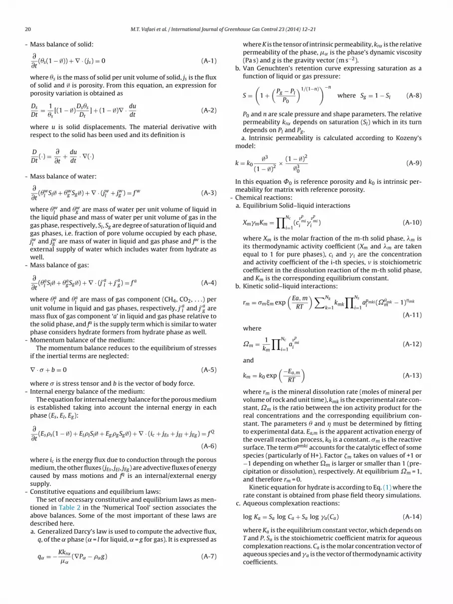
Mass balance of solid:
∂∂t
(�s(1 − ∅)) + ∇ · (js) = 0 (A-1)
where �s is the mass of solid per unit volume of solid, js is the fluxof solid and ∅ is porosity. From this equation, an expression forporosity variation is obtained as
Ds
Dt= 1
�s[(1 − ∅)
Ds�s
Dt] + (1 − ∅)∇ · du
dt(A-2)
where u is solid displacements. The material derivative withrespect to the solid has been used and its definition is
D
Dt(·) = ∂
∂t+ du
dt· ∇(·)
Mass balance of water:
∂∂t
(�wl Sl∅ + �w
g Sg∅) + ∇ · (jwl + jwg ) = f w (A-3)
where �wl
and �wg are mass of water per unit volume of liquid in
the liquid phase and mass of water per unit volume of gas in thegas phase, respectively, Sl, Sg are degree of saturation of liquid andgas phases, i.e. fraction of pore volume occupied by each phase,jwl
and jwg are mass of water in liquid and gas phase and fw is theexternal supply of water which includes water from hydrate aswell.
Mass balance of gas:
∂∂t
(�al Sl∅ + �a
gSg∅) + ∇ · (j′al + j′ag) = f a (A-4)
where �al
and �al
are mass of gas component (CH4, CO2, . . .) perunit volume in liquid and gas phases, respectively, j′al and j′ag aremass flux of gas component ‘a’ in liquid and gas phase relative tothe solid phase, and fa is the supply term which is similar to waterphase considers hydrate formers from hydrate phase as well.
Momentum balance of the medium:The momentum balance reduces to the equilibrium of stresses
if the inertial terms are neglected:
∇ · � + b = 0 (A-5)
where � is stress tensor and b is the vector of body force. Internal energy balance of the medium:
The equation for internal energy balance for the porous mediumis established taking into account the internal energy in eachphase (Es, El, Eg):
∂∂t
(Ess(1 − ∅) + EllSl∅ + EggSg∅) + ∇ · (ic + jEs + jEl + jEg) = f Q
(A-6)
where ic is the energy flux due to conduction through the porousmedium, the other fluxes (jEs, jEl, jEg) are advective fluxes of energycaused by mass motions and fq is an internal/external energysupply.
Constitutive equations and equilibrium laws:The set of necessary constitutive and equilibrium laws as men-
tioned in Table 2 in the ‘Numerical Tool’ section associates theabove balances. Some of the most important of these laws aredescribed here.a. Generalized Darcy’s law is used to compute the advective flux,
q, of the ̨ phase ( ̨ = l for liquid, ̨ = g for gas). It is expressed as
q˛ = −Kkr˛
�˛(∇P˛ − ˛g) (A-7)
enhouse Gas Control 23 (2014) 12–21
where K is the tensor of intrinsic permeability, kr˛ is the relativepermeability of the phase, �˛ is the phase’s dynamic viscosity(Pa s) and g is the gravity vector (m s−2).
b. Van Genuchten’s retention curve expressing saturation as afunction of liquid or gas pressure:
S =(
1 +(
Pg − Pl
P0
)1/(1−n))−n
where Sg = 1 − Sl (A-8)
P0 and n are scale pressure and shape parameters. The relativepermeability kr˛ depends on saturation (Sl) which in its turndepends on Pl and Pg.a. Intrinsic permeability is calculated according to Kozeny’s
model:
k = k0∅3
(1 − ∅)2× (1 − ∅)2
∅30
(A-9)
In this equation ˚0 is reference porosity and k0 is intrinsic per-meability for matrix with reference porosity.
- Chemical reactions:a. Equilibrium Solid–liquid interactions
XmmKm =∏Nc
i=1(c
vpmi
i
vpmi
i) (A-10)
where Xm is the molar fraction of the m-th solid phase, �m isits thermodynamic activity coefficient (Xm and �m are takenequal to 1 for pure phases), ci and i are the concentrationand activity coefficient of the i-th species, � is stoichiometriccoefficient in the dissolution reaction of the m-th solid phase,and Km is the corresponding equilibrium constant.
b. Kinetic solid–liquid interactions:
rm = �m m exp(
Ea, m
RT
)∑Nk
k=1kmk
∏Ns
i=1apmki
i (˝�mkm − 1)�mk
(A-11)
where
˝m = 1km
∏Nc
i=1a
vpmi
i(A-12)
and
km = k0 exp(−Ea,m
RT
)(A-13)
where rm is the mineral dissolution rate (moles of mineral pervolume of rock and unit time), kmk is the experimental rate con-stant, ˝m is the ratio between the ion activity product for thereal concentrations and the corresponding equilibrium con-stant. The parameters � and � must be determined by fittingto experimental data. Ea,m is the apparent activation energy ofthe overall reaction process, k0 is a constant. �m is the reactivesurface. The term apmki accounts for the catalytic effect of somespecies (particularly of H+). Factor �m takes on values of +1 or−1 depending on whether �m is larger or smaller than 1 (pre-cipitation or dissolution), respectively. At equilibrium ˝m = 1,and therefore rm = 0.
Kinetic equation for hydrate is according to Eq. (1) where therate constant is obtained from phase field theory simulations.
c. Aqueous complexation reactions:
T and P. Sa is the stoichiometric coefficient matrix for aqueouscomplexation reactions. Ca is the molar concentration vector ofaqueous species and a is the vector of thermodynamic activitycoefficients.

l of Gre
R
A
A
A
B
B
D
G
G
G
H
H
H
H
H
J
K
K
K
K
K
K
M.T. Vafaei et al. / International Journa
d. Gas–liquid interactions:
pf f Kf =∏Nc
i=1(cvfi
i vfii ) (A-15)
where pf is the partial pressure of the f-th species in the gasphase, f is its activity coefficient, ci and i are the concen-tration and activity coefficient of the i-th dissolved primaryspecies, respectively, �fi is the stoichiometric coefficient of thei-th species in the exsolution reaction of fluid f, and Kf is theequilibrium constant of the reaction.
eferences
hmadi, G., Ji, C., Smith, D.H., 2004. Numerical solution for natural gas productionfrom methane hydrate dissociation. Journal of Petroleum Science and Engineer-ing 41 (4), 269–285.
nderson, B.J., Hancock, S., Wilson, S., Enger, C., Collett, T., Boswell, R., Hunter, R.,2011a. Formation pressure testing at the Mount Elbert Gas Hydrate StratigraphicTest Well, Alaska North Slope: operational summary, history matching, andinterpretations. Marine and Petroleum Geology 28 (2), 478–492.
nderson, B.J., Kurihara, M., White, M.D., Moridis, G.J., Wilson, S.J., Pooladi-Darvish,M., Gaddipati, M., Masuda, Y., Collett, T.S., Hunter, R.B., Narita, H., Rose, K.,Boswell, R.M., 2011b. Regional long-term production modeling from a singlewell test, Mount Elbert Gas Hydrate Stratigraphic Test Well, Alaska North Slope.Marine and Petroleum Geology 28 (2), 493–501.
aig, K., 2009. Phase Field Theory Modeling of CH4 and CO2 Fluxes from Exposed Nat-ural Gas Hydrate Reserviors. Master Thesis submitted to University of Bergen,Bergen, Norway.
urshears, M., O’Brien, T.J., Malone, R.D., 1986. A multi-phase, multi-dimensional,variable composition simulation of gas production from a conventional gasreservoir in contact with hydrates. In: Paper 15246-MS Presented at the SPEUnconventional Gas Technology Symposium, Louisville, Kentucky, 18–21 May.
avie, M.K., Buffett, B.A., 2001. A numerical model for the formation of gas hydratebelow the seafloor. Journal of Geophysical Research 106 (B1), 497–514.
amwo, I.K., Liu, Y., 2010. Mathematical modeling and numerical simulation ofmethane production in a hydrate reservoir. Industrial & Engineering ChemistryResearch 49 (11), 5231–5245.
oel, N., Wiggins, M., Shah, S., 2001. Analytical modeling of gas recovery from in situhydrates dissociation. Journal of Petroleum Science and Engineering 29 (2),115–127.
raue, A., Kvamme, B., Baldwin, B., Stevens, J., Howard, J., Aspenes, E., Ersland, G.,Husebo, J., Zornes, D., 2008. MRI visualization of spontaneous methane produc-tion from hydrates in sandstone core plugs when exposed to CO2. SPE Journal13 (2), 146–152.
ellevang, H., Kvamme, B., 2007. An explicit and efficient algorithm to solve kinet-ically constrained CO2–water–rock interactions. In: Proceedings of the ThirdWSEAS International Conference on Mathematical Biology and Ecology, GoldCoast, Queensland, Australia, 17–19 January.
older, G., Angert, P., 1982. Simulation of gas production from a reservoir containingboth gas hydrates and free natural gas. In: Paper 11105-MS Presented at theSPE Annual Technical Conference and Exhibition, New Orleans, Louisiana, 26–29September.
ong, H., Pooladi-Darvish, M., 2005. Simulation of depressurization for gas produc-tion from gas hydrate reservoirs. Journal of Canadian Petroleum Technology 44(11).
ong, H., Pooladi-Darvish, M., Bishnoi, P.R., 2003. Analytical modeling of gas produc-tion from hydrates in porous media. Journal of Canadian Petroleum Technology42 (11), 45–56.
unter, R.B., Collett, T.S., Boswell, R., Anderson, B.J., Digert, S.A., Pospisil, G., Baker, R.,Weeks, M., 2011. Mount Elbert Gas Hydrate Stratigraphic Test Well, Alaska NorthSlope: overview of scientific and technical program. Marine and Petroleum Geol-ogy 28 (2), 295–310.
emai, K., Kvamme, B., Vafaei, M.T., 2014. Theoretical studies of CO2 hydrates forma-tion and dissociation in cold aquifers using RetrasoCodeBright simulator. WSEASTransactions on Heat and Mass Transfer (submitted for publication).
im, H.C., Bishnoi, P.R., Heidemann, R.A., Rizvi, S.S.H., 1987. Kinetics of methanehydrate decomposition. Chemical Engineering Science 42 (7), 1645–1653.
ivela, P.H., Baig, K., Qasim, M., Kvamme, B., 2012. Phase field theory modeling ofmethane fluxes from exposed natural gas hydrate reservoirs. AIP Conf. Proc.1504, 351–363, http://dx.doi.org/10.1063/1.4771728.
ozeny, J., 1927. Ueber kapillare Leitung des Wassers im Boden. Sitzungsber Akad.Wiss., Wien 136 (2a), 271–306.
vamme, B., Graue, A., Kuznetsova, T., Buanes, T., Ersland, G., 2007. Storage of CO2
in natural gas hydrate reservoirs and the effect of hydrate as an extra sealing incold aquifers. International Journal of Greenhouse Gas Control 1 (2), 236–246.
vamme, B., Jemai, K., Chejara, A., Vafaei, M.T., 2011. Proceedings of the Seventh
International Conference on Gas Hydrates (ICGH 2011) , Edinburgh, Scotland,United Kingdom, July 17–21.vamme, B., Kuznetsova, T., 2010. Investigation into stability and interfacial prop-erties of CO2 hydrate – aqueous fluid system. Mathematical and ComputerModelling 51, 156–159.
enhouse Gas Control 23 (2014) 12–21 21
Kvamme, B., Kuznetsova, T., Kivelæ, P-H., 2012. Adsorption of water and carbondioxide on hematite and consequences for possible hydrate formation. PhysicalChemistry Chemical Physics 14 (13), 4410–4424.
Kvamme, B., Kuznetsova, T., Kivelæ, P.-K., Bauman, J., 2013a. Can hydrate form incarbon dioxide from dissolved water? Physical Chemistry Chemical Physics,http://dx.doi.org/10.1039/C2CP43061D.
Kvamme, B., Kuznetsova, T., Uppstad, D., 2009. Modeling excess surface energyin dry and wetted calcite systems. Journal of Mathematical Chemistry 46 (3),756–762.
Kvamme, B., Liu, S., 2008a. Reactive transport of CO2 in saline aquifers with implicitgeomechanical analysis. In: Proceedings of the Greenhouse Gas Control Tech-nologies (GHGT) conference, Washington DC, USA.
Kvamme, B., Liu, S., 2008b. Simulating long term reactive transport of CO2 in salineaquifers with improved code RetrasoCodeBright. In: Presented at the 12th Inter-national Conference of International Association for Computer Methods andAdvances in Geomechanics (IACMAG), Goa, India, 1–6 October.
Kvamme, B., Qasim, M., Baig, K., Kivelä, P.-K., 2013b. Phase field theory modelingof methane fluxes from exposed natural gas hydrate reservoirs. InternationalJournal of Greenhouse Gas Control (submitted for publication).
Kvamme, B., Tanaka, H., 1995. Thermodynamic stability of hydrates for ethane,ethylene, and carbon dioxide. Journal of Physical Chemistry 99 (18), 7114–7119.
Liu, S., Lageide, L.A., Kvamme, B., 2011. Sensitivity study on storage of CO2 in salineaquifer formation with fracture using reactive transport reservoir simulator RCB.Journal of Porous Media 14 (11).
Liu, Y., Strumendo, M., Arastoopour, H., 2008. Simulation of methane productionfrom hydrates by depressurization and thermal stimulation. Industrial & Engi-neering Chemistry Research 48 (5), 2451–2464.
Nazridoust, K., Ahmadi, G., 2007. Computational modeling of methane hydrate dis-sociation in a sandstone core. Chemical Engineering Science 62 (22), 6155–6177.
Olivella, S., Carrera, J., Gens, A., Alonso, E.E., 1994. Non-isothermal multiphaseflow of brine and gas through saline media. Transport in Porous Media 15,271–293.
Olivella, S., Gens, A., Carrera, J., Alonso, E.E., 1996. Numerical formulation for a sim-ulator (CODE BRIGHT) for the coupled analysis of saline media. EngineeringComputations 13 (7), 87–112.
Phirani, J., Mohanty, K., 2010. Kinetic simulation of CO2 flooding of methanehydrates. In: Paper 134178-MS Presented at SPE Annual Technical Conferenceand Exhibition, Florence, 19–22 September.
Qasim, M., Kvamme, B., Baig, K., 2011. Phase field theory modeling of CH4/CO2 gashydrates in gravity fields. International Journal of Geology 5 (2), 48–52.
Sloan, E.D., Koh, C., 2007. Clathrate Hydrates of Natural Gases, 3rd ed. CRC Press,USA.
Soave, G., 1972. Equilibrium constants from a modified Redlich–Kwong equation ofstate. Chemical Engineering Science 27, 1197.
Saaltink, M., Batlle, M., Ayora, C., 2004. RETRASO: a code for modeling reactive trans-port in saturated and unsaturated porous media. Geologica Acta 2 (3), 235–251.
Saaltink, M., Benet, I., Ayora, C., 1997. RETRASO, A FORTRAN Code for solving 2DReactive Transport of Solutes, Users’ guide. E.T.S.I., Caminos, Canales y Puertos,Universitat Politecnica de Catalunya and Instituto de Ciencias de la Tierra, CSIC,Barcelona.
Sun, X., Mohanty, K.K., 2006. Kinetic simulation of methane hydrate formation anddissociation in porous media. Chemical Engineering Science 61 (11), 3476–3495.
Svandal, A., 2006. Modeling hydrate phase transitions using mean-field approaches.Ph.D. Thesis submitted to University of Bergen, Bergen, Norway.
Svandal, A., Kuznetsova, T., Kvamme, B., 2006a. Thermodynamic properties andphase transitions in the H2O/CO2/CH4 system. Fluid Phase Equilibria 246 (1–2),177–184.
Svandal, A., Kvamme, B., Granasy, L., Pusztai, T., Buanes, T., Hove, J., 2006b. The phase-field theory applied to CO2 and CH4 hydrate. Journal of Crystal Growth 287 (2),486–490.
Swinkels, W., Drenth, R.J.J., 2000. Reservoir-simulation model of production fromgas-hydrate accumulations. Journal of Petroleum Technology 52 (4), 76–77.
Tegze, G., Pusztai, T., Toth, G., Granasy, L., Svandal, A., Buanes, T., Kuznetsova, T.,Kvamme, B., 2006. Multiscale approach to CO2 hydrate formation in aqueoussolution: phase field theory and molecular dynamics. Nucleation and growth.Journal of Chemical Physics 124, 234710.
Terzaghi, K., 1943. Theoretical Soil Mechanics. John Wiley and Sons, New York.Twu, C.H., Bluc, D., Cunningham, J.R., Coon, J.E., 1991. Fluid Phase Equilibria 69, 33.Uddin, M., Coombe, D., Wright, F., 2008. Modeling of CO2-hydrate formation in geo-
logical reservoirs by injection of CO2 gas. Journal of Energy Resources Technology130 (3), 032502.
Van Cuong, P., Kvamme, B., Kuznetsova, T., Jensen, B., 2012a. Adsorption of waterand CO2 on calcite and clathrate hydrate: the effect of short-range forces andtemperature. International Journal of Energy and Environment 6 (3), 301–309.
Van Cuong, P., Kvamme, B., Kuznetsova, T., Jensen, B., 2012b. Molecular dynamicsstudy of calcite, hydrate and temperature effect on CO2 transport and adsorptionstability in geological formations. Molecular Physics 110 (11–12), 1097–1106.
Wilson, S.J., Hunter, R.B., Collett, T.S., Hancock, S., Boswell, R.M., Anderson, B.J., 2011.Alaska North Slope regional gas hydrate production modeling forecasts. Marineand Petroleum Geology 28 (2), 460–477.
Xu, W., Ruppel, C., 1999. Predicting the occurrence, distribution, and evolution
of methane gas hydrate in porous marine sediments. Journal of GeophysicalResearch 104 (B3), 5081–5095.Yousif, M.H., Abass, H.H., Selim, M.S., Sloan, E.D., 1991. Experimental and theoret-ical investigation of methane-gas-hydrate dissociation in porous media. SPEReservoir Engineering 6 (1), 69–76.