Embed Size (px)
Citation preview

Toward Elevated Agrobotics: Development of a Scaled Down Prototype for Visually Guided Date Palm Trees
Sprayer _____________________________________________________________________
Amir Shapiro Dept. of Mechanical
Engineering [email protected]
Eran Korkidi Dept. of Mechanical
Engineering [email protected]
Amnon Demri Dept. of Mechanical
Engineering [email protected]
Ohad Ben-Shahar
Dept. of Computer Science [email protected]
Raziel Riemer Dept. of Industrial Engineering
and Management [email protected]
Yael Edan Dept. of Industrial Engineering
and Management [email protected]
Abstract Agriculture operations at large heights are typically laborious, expensive, and
dangerous for human workers. Spraying and pollinating date palm trees, for instance,
is currently done manually by a team of several workers from a platform lifted 18
meters or more above the ground. This method is extremely unsafe and many
accidents have occurred due to instability when the platform is in a lifted position. In
this paper we present the concept of an autonomous field robot that will effectively
and accurately spray and pollinate date clusters. A scaled down prototype has been
designed and consists of a visually-controlled robotic arm that guides the jet of a
mounted sprayer directly to the date clusters completely autonomously and from a
short distance. Rather than an expensive dedicated platform, this robotic apparatus
can be towed by a standard tractor operated by a single driver, with no human worker
operating in the heights. This system can minimize risk of injury, significantly save
manpower, and deliver the spray with maximum accuracy thereby reducing chemical
disposure. The spraying guidance system is based on a proportional controller that
Ben-Gurion University of the Negev, PO Box 653, Beer-Sheva 84105, ISRAEL

uses a feedback from an image processing system combined with a small dead band.
The system was modeled mathematically and the effect of each component on overall
performance was evaluated by simulation. Results were used for tuning the
experimental system controller parameters. Experiments were performed to evaluate
the tracking performance of the visually guided tracking system on a single tree and a
10m long runway at a distance of 6m. These dimensions were inspired by the
conditions at a typical orchard. During the experiment the sprayer was towed along
the runway 19 times which the speed of the wagon was varied between 0.7 Km/h (0.2
m/sec) and 12 Km/h (3.3 m/sec). Experimental results indicate that up to a wagon
ve1ocity of 1.25 m/sec the tracking error was reasonably low and stayed below 10
degrees from the center of the target (typical date spraying speed is 1.1m/sec).
However at higher speeds the tracking quality reduced progressively and some drift
(i.e., accumulated error) was noticed in the pan axis due to image processing speed.
The simulations and experiments with a scaled down prototype show feasibility of the
presented method, and demonstrate how this new approach facilitates more efficient
high altitude agricultural robotics.
1 Introduction The use of robots in agriculture has been researched extensively for at least two
decades and technical feasibility has been demonstrated for a variety of agricultural
tasks such as automatic guidance of agricultural field and greenhouse operations (e.g.,
Wilson 2000; Torii 2000; Keicher and Seufert, 2000; Reid et al. 2000; Pilarski et al.,
1999, 2002), fruit selective harvesting (citrus: Hannan et al., 1990; Fujiura et al.,
1990;; Hannan and Burks, 2004; ; Rabatel et al., 1995; apples: Grand d'Esnon et al.,
1985; Kassay, 1992; grapes: Kondo, 1995; Monta et al., 1994; Sittichareonchai and
Sevila, 1989.; cucumbers: Arima et al., 1994; melons: Iida et al., 1996; radicchio:

Maio et al, 2006) seedling production (Simonton, 1990; Kondo and Monta, 1997;
Kondo et al., 1997; Kondo and Ting, 1998), Studies focused on object detection in
natural environments, gripper and manipulator design and autonomous guidance
(Edan, 1999). Nevertheless, despite the tremendous amount of research in the last
decade, commercial applications of robots in complex agriculture applications are still
rare. Dealing with natural objects requires a high-level of sophistication from robots.
Operating in unstructured and dynamic environments further complicates the
problem. Production inefficiencies and lack of economic justification are still the
main limiting factors (Sarig, 1993).
In this paper we further explore agricultural robotics (a.k.a. agrobotics) for the special
case of agricultural operations at large heights. This domain has received little
attention in the past. Specific needs and emerging applications provide strong
incentives for investigation of elevated agrobotics, and in this paper we initiate such a
line of research using a specific test case – that of an autonomous robot for elevated
spraying and pollinating of date palm trees. These agricultural operations are currently
conducted by a team of three workers – a driver and two assistants. These assistants
stand on a platform lifted up to 18m high and operate manual spraying guns targeted
towards the date clusters or flowers. This method is extremely unsafe and many
accidents including fatal ones have occurred due to lack of stability when the platform
is in a lifted position. Alternatively, date clusters are occasionally sprayed by a large
pressurized sprayer directly from the ground, a method that is highly unselective and
environmentally harmful. In this paper we show that all these problems can be solved
via a robot that implements autonomous targeted spraying and pollinating. More
generally, however, this robotic solution represents a prototypical approach for

executing elevated agriculture in a safe, environmentally friendly, and economical
manner, which is also manpower efficient.
Several robotic systems for spraying operations have been developed in the past. An
autonomous tractor for spraying in the field was developed at the Robotics Institute of
Carnegie Mellon University (Stentz, 2001). A precision sprayer was developed and
tested with a robust crop position detection system (Nishiwaki et al, 2004) for varying
field light conditions for rice crop fields. (Kevin et al. 2001) developed a fluid
handling system to allow on-demand chemical injection for a machine-vision
controlled sprayer. Application of reduced volumes calibrated accordingly to the
plants growth stage allowed to obtain a better coverage of the target and to reduce
ground losses in an apple orchard automatic sprayer (Balsari et al., 2002). By using
several turbulent air-jets nozzles an accurate vineyard sprayer was adjusted (Manor
and Gal, 2002). A spray boom that senses mesquite plants was designated to tractors
and all-terrain vehicles and controllers were designed to send fixed duration pulses of
voltage to solenoid valves for spray release through flat-fan nozzles when mesquite
canopies interrupted the light (Wiedemann et al., 2002). A machine vision sensing
system and selective herbicide control system was developed and installed on sprayer
by (Steward et al., 2002). A tree image processing, tree crown recognition, and smart
spray execution system (Zheng et al., 2004; Zheng 2005) was developed. Similarly,
autonomous operation of a speed-sprayer in an orchard was achieved using fuzzy
logic control of image processing and ultrasonic sensors and steered by two hydraulic
cylinders (Shin et al., 2002).
The proposed elevated agricultural robotic system is based on a mobile robotic arm
that is able to approach the date clusters, track them during movement, and guide a

mounted spraying gun toward them in an autonomous and continuous fashion. This
platform could be self powered, with autonomous navigation capabilities and path
planning. However, to simplify complexity and reduce cost, we opt for a platform that
is towed by a human driven vehicle (e.g., a tractor). Even so, the design imposes
several inherent challenges: (1) a stable platform that could reach heights of up to
18m, and could be folded down for transportation and storage, (2) a sensing
mechanism that could detect and track the spraying targets (date clusters in our case)
robustly and in real-time, and (3) a control system that would use the sensory
information to automatically target the spraying gun toward the targets. Obviously, for
a commercial system of that sort, an additional challenge is the design of a simple and
easy-to-use user interface that allows the farmer to easily operate the apparatus from
the seat of the driver.
In this paper we describe the design approach and a scaled-down prototype, including
evaluation of the vision-controlled spraying head. System performance was evaluated
in simulations and experiments. The paper concludes with future work and practical
extensions toward a field model.
2 The development of a scaled-down model The scaled-down prototype (Figure 1) constitutes a vision-controlled lifted spraying
mechanism with two degrees of freedom (DOF) pan-tilt head attached at its end. The
head accommodates both the spraying nozzles and a video camera which
continuously tracks the targets and compensates the spraying directions due to the
motion of the apparatus along the aisle and the errors due to the inherently non-flat
orchard bed.
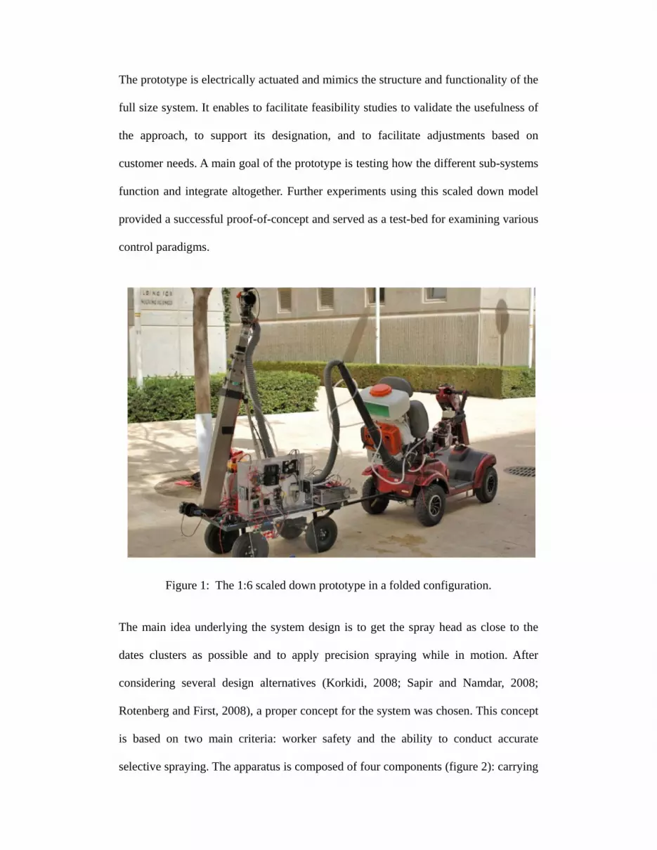
The prototype is electrically actuated and mimics the structure and functionality of the
full size system. It enables to facilitate feasibility studies to validate the usefulness of
the approach, to support its designation, and to facilitate adjustments based on
customer needs. A main goal of the prototype is testing how the different sub-systems
function and integrate altogether. Further experiments using this scaled down model
provided a successful proof-of-concept and served as a test-bed for examining various
control paradigms.
Figure 1: The 1:6 scaled down prototype in a folded configuration.
The main idea underlying the system design is to get the spray head as close to the
dates clusters as possible and to apply precision spraying while in motion. After
considering several design alternatives (Korkidi, 2008; Sapir and Namdar, 2008;
Rotenberg and First, 2008), a proper concept for the system was chosen. This concept
is based on two main criteria: worker safety and the ability to conduct accurate
selective spraying. The apparatus is composed of four components (figure 2): carrying
wagon, uplifted telescopic mast, spraying head and an automatic control unit for
target detection and tracking. The current model is scaled down by a 1:6 ratio, so that
it can be unfolded up to a height of 310 cm when fully open. The description of each
component follows.
2.1 The wagon
Existing solutions for spraying and pollinating date palm trees are typically based on
self-powered lifted platforms. These expensive vehicles are usually shared between
various agricultural tasks and hence become a critical resource. During the busy
season in the palm orchards, these platforms are not available for other required tasks.
The proposed field robot would replace these vehicles with a passive wagon on which
the robotic apparatus is mounted. This platform is a simple four wheels mechanism
that can be towed by any agricultural vehicle, in particular, a standard tractor
equipped with a towing hook. The only requirement of the towing hook is that it has
two rotational DOF: one to allow steering and the other to ensure that if the spraying
system overturns, the tractor and the driver will not tip over as well.
Since stability is an important issue for this elevated sprayer, the structure of the
wagon is designed to be heavy, so center of mass is kept as close to the ground as
possible. The large width and wheel span are necessary to reduce the roll angle while
wheels go over small obstacles such as small rocks, mounds or pits.

Figure 2: The conceptual design of the date sprayer (shown here with our future stereo
head rather than the present monocular head with which we experimented).
2.2 The mast
In order to get the spraying head to the desired height, lifting is performed using a
telescopic mast supported by an electric piston and a folding and unfolding system
based on cables and an electric winch. The elevation system is mounted on the
carrying wagon with one rotational DOF and supported by the electric piston. The
telescopic mast links are made of four box beams joined together by tensed stainless
steel cables and a pulleys system. One end of the cables is attached to the winch drum
at the bottom of the mast, while the other end goes over one link and under the
winch regular sprayer
telescopic mast
electric piston
spraying head
visual marker (Sec. 3.5)

following link and is finally attached to the top link (Figure 3b and c). Consequently,
when the winch spins it causes the cables to become shorter and thus reduces the
overlapping amount of the box beams in each other, causing an extension of the
telescopic mast. The opposite happens while the winch spins in reverse direction – the
cables get longer thus the mast will be folded down. To maintain stability of the links
a counter cable is stretched from the top link to the winch drum, wounded in direction
opposite to the winding of the main cables. Hence, it fits the lengthening direction and
amount of the mast. Between every pair of beam boxes there are six roll bearing to
provide smooth sliding and to allow enough room for the cables to pass through.
Opening all the links simultaneously makes it simpler to apply the control system and
to study the stability of the system.
Figure 3: (a) The folded sprayer mounted on a wagon, (b) the open telescopic mast
and the winch, and (c) pulleys and cables system of the folded telescopic mast.

Figure 4: (a) The design model of the spraying head, and (b) the actual head used in
our experiments.
2.3 The spraying head
The spraying head is a structure composed of a camera (and in the future, two
cameras for stereo vision) and a spraying hose connected to the top of the telescopic
mast through a two-axis gimbal – a computer-controlled pan-tilt system that can drive
the spraying hose. The two DOFs enable the head to home in on the date clusters and
continuously track and spray them while in motion. The spray is applied by an air
blast sprayer while a fluid chemical is injected into a blast of air going out of the hose
of the spraying gun. The air blast is produced by a big blower mounted on the towing
tractor and then is conveyed up to the gimbal through a flexible pipe that runs along
the mast. By attaching the blower and the pesticide tank to the tractor, unwanted
vibrations of the mast are prevented and the spraying system can be powered directly
by the tractor’s PTO (power take off). This extra weight at the base of the wagon also
contributes to its low center of mass and adds to its stability.

Figure 4 shows the basic design of the prototype's spraying head, and the physical
head used in our experiments. Note that in this preliminary version there is only one
camera mounted, although an identical camera can be mounted on the other side of
the sprayer to obtain more robust stereo vision (see future work).
2.4 System Control
During storage or transportation, the system is kept folded – both the winch and the
piston are in a low position and take up a small amount of space, making it easy for
maintenance and handling. There is no need for initial calibration every workday
since the system is already mounted and calibrated according to the specific system
design and geometry. However, an initialization and check up process is automatically
conducted on system start up.
The operation of the complete system contains four steps, all controlled by a heavy
duty laptop computer. The first step is to tilt the mast up to 70º using the electrical
piston. The second step is opening the telescopic links of the mast using the motor
which to drives the winch drum, this step ends when the spraying head is at the
desired height – about one meter bellow the dates clusters. Hence, the lower branches
do not interfere with the detection and spraying. This height of the spraying head will
stay fixed during the work in the orchard. The third step is to adjust the tracking gear
to track a certain marker which was initially posted on each tree. The last step is to
turn on the autonomous tracking mode (see below); from this moment on the system
is self functioning and operates autonomously.
The user interface of the system allows simple and intuitive operation. It is composed
of a wireless keyboard and three control buttons. The keyboard is used to enter the

desired height of the mast on a small LCD screen. The three buttons are for lifting,
opening the mast, and initiation of autonomous spraying mode. Both the winch and
the affixed axis of the mast are equipped with optical encoders to close the control
loop.
The main control loop is fed from a computer vision system (see Section 2.5 below),
which provides the control system a quantitative estimate of the tracking error – the
deviation of the current target from the current direction of the head. The control
algorithm uses a proportional control law and a feed-forward term to overcome
friction in the gears based on measuring the tracking error between the position of the
target and the center of the image. The control law is:
( ) pp CxxKV +−−= * (1)
where V is the motor velocity vector, Kp is the proportional coefficient, x and x* are
the current and desired locations of the target in the image, respectively, and Cp is the
feed-forward constant. Note that in our implementation, x* is defined as the center of
the image, which after calibration represents the direction of the head as a whole. This
control law was applied with a dead band region to prevent oscillations around the
target. The control hardware consists of two servo motors in a pan-tilt configuration.
The control architecture is sketched in Figure 5 and elaborated further in Section 3
below.
2.5 Computer vision and tracking subsystem
A key component in the described system is its ability to acquire and analyze visual
input. Toward that goal, a monocular vision module was developed in C++ and Visual
Studio 5. Image acquisition was conducted with a simple web cam (Microsoft's
LifeCam VX-6000) supported by the OpenCV open source library from Intel
(http://www.intel.com/technology/computing/opencv/index.htm).

To simplify development and to focus on feasibility tests and examination of proof-of-
concept, the vision module was implemented under the assumption that the spraying
targets are marked with a distinctively colored marker which is placed in their vicinity
in order to facilitate target identification via simple color-blob tracking. In the palm
tree application such marking was trivially obtained by stretching an elastic red band
just below the crown (Figure 2).
The initial, monocular vision module developed was based on the detection of color
blobs having a user-defined spec in the HSV (Hue, Saturation, and Value) color
space– a space which provides much greater robustness to variations in color
representation due to changes in illumination. Once the frame's RGB values were
converted to HSV, a predefined color window W around the desired hue value
provided a mean for target identification. For that, the hue channel was threshold to
create a binary image whose pixels are set to TRUE (or 1) if and only if the hue of the
same pixel in the original frame has hue value within the window W. This binary
image was then processed using the mathematical morphological operations of
Figure 5: The control architecture of the spraying system.
User interface
Controller
Image processing
Computer
Cameras and spraying

dilation and erosion (Serra, 1982) to eliminate noise (i.e., very small target
candidates) and to fill in small holes in big target candidates.
Using an OpenCV extension library for blob analysis and extraction
(http://opencvlibrary.sourceforge.net/cvBlobsLib), the processed binary image of
candidate targets was then processed further to identify connected components which
conform to predefined size (i.e., area) limits and aspect ratio. In the presence of a
distinctly colored target marker, this typically results in a single remaining target.
With a single target remaining in the image, the distance between its center of mass
(zero's order moments) to the center of the frame defines the spraying direction error.
This error was minimized by feeding it to a proportional controller that controlled the
spraying head and continuously redirected the target to the center of the frame.
2.6 Prototype summary
A 1:6 scaled-down prototype was built and tested. Figure 1 shows this model in its
folded position when connected to a towing vehicle. Figure 7 shows the same
prototype in its unfolded configuration. The system is mounted on a 52cm by 122cm
wagon and while in its folded configuration it reaches a maximal height of 128cm. Its
unfolded configuration allows the mast to reach a maximal height of 3.1m.

(a)
(b) (c)
(d) Figure 6: Vision guided spraying experiments: (a) side view, (b) the target to track
from the camera point of view, (c) spraying while in motion under a masking
effect caused by the spraying and (d) a snap shot of the vision module in action.

Figure 7: The prototype in a fully open configuration.
3 System modeling and parametric investigation To investigate the expected behavior of the different system components and
parameters and to explore its parameter space, the system architecture and control
scheme has been modeled. This study was also useful toward identifying possible
bottlenecks and expected limitations.

3.1 System model
In general, the controlled state of the system is a point in two dimensional space that
represents the pan and tilt angles of the head. However, since most of the head
position variability is in constrained to the pan axis (due to the wagon's forward
motion along the orchard's aisle) a simplified 1DOF model was used for analysis, as
sketched in Figure 8.
Figure 8: A simplified (1D) system model used in our analysis.
This simplified system model constitutes several components and parameters whose
values have implications on the overall behavior:
Controller – The control law is proportional with a feed-forward constant and a
dead band:
⎪⎩
⎪⎨
⎧
−≤−⋅≥+⋅≤
=banddeadErrCErrK
banddeadErrCErrKbanddeadErr
U
pp
pp
___0
(2)
Torque saturation (Usat) – The pan axis motor is limited to supply ±15 [Nm],
hence:
[ ][ ][ ]⎪
⎩
⎪⎨
⎧
−≤−≥≤
=NmU
NmUNmUU
U sat
1515151515
(3)
REALθU
Friction Controller
Err
Torque Saturation
+_
Zero-Order Hold=1/fps
REFθ
Transfer Function
2
1I S C S K⋅ + ⋅ +
Delay t t t→ −Δ
UtransUsat

Angle derivative (dθREAL/dt) - To consider the counter torque due to Coulomb
friction, the angular velocity was computed to find the direction of the friction
torque.
Friction component – The input to this component is the velocity and torque
applied by the motor. The output is the torque to be transmitted to the head after
reducing the friction torque (τF):
( )
( )⎪⎪⎪
⎩
⎪⎪⎪
⎨
⎧
≤+
≥−
≤
=
0
0
0
dtdU
dtd
U
U
U
REALFsat
REALFsat
Fsat
trans
θτ
θτ
τ
(4)
Transfer function – The transfer function of the spraying head is a typical
angle-torque transfer function of a rotational 1 DOF system, or after Laplace
transformation:
( )( ) KSCSISUS
+⋅+⋅= 2
1θ (5)
Delay module – Representing overhead in data acquisition, this module reflects
the delay incurred by this operation.
Zero Order Hold (ZOH) – Since image processing consumes time, the control
signal that it computes is refreshed only periodically at the frame processing
rate (ZOH=1/fps). To reflect this sampling effect a Zero Order Hold component,
with fps uniform sampling rate, is concatenated after the delay.
Reference angle (θREF) – The reference angle refers to the angle of the spraying
head in order to aim directly at the target. In the described model used in

simulations, the desired system state θREF was determined analytically as a
function of a constant wagon velocity v:
⎟⎟⎠
⎞⎜⎜⎝
⎛⋅
⋅−⋅⋅= −
rows
treesREF d
tvd5.0
5.0tan180 1
πθ (6)
where dtrees is the distance between trees in the row, and drows is the distance
between two tree rows in the orchard (in Figure 15, dtrees=10 and drows=12). We
chose this mathematical representation since the wagon is expected to move at
some slow constant velocity along the aisle.
3.2 Parameter estimation
Having defined this system model and parameters, the appropriate value of the
different parameters of each component was determined either empirically or by
numerical proximity.
The moment of inertia was estimated numerically as I=0.8[kg·m²] by using the solid
drawing model, the weight of the parts and their shape in conjunction with the
Parallel-Axis Theorem.
Bearing frication was measured using a force sensor by applying force at a known
moment arm. Averaging the results of several such measurements, this parameter was
estimated at τF=1.2[Nm].
Torque generated by the motor (BOSCH CHV 24V) was estimated at 15[Nm] from
its specification sheet and a measurement of the maximum current that it sustained
during acceleration of the spraying head to maximum speed (motor fully actuated).

As implied above, the two main parameters relating to image acquisition and
processing are the delay and the sampling rate. The delay reflects any gaps between
the end of the exposure interval and the end of storing the image in the frame buffer.
The sampling rate reflects the fact that the vision module refreshes tracking output at
discrete times. This rate depends on the algorithm efficiency and the computer
performance. Both parameters were estimated empirically by generating a synthetic
video sequence of a moving target at a known speed and measuring the throughput of
the tracking system. In particular, we generated a movie of a red square (100×100
pixels), moving horizontally on a computer screen at a known velocity and challenged
our vision system to track it while keeping time stamps at various stages of the
computation. Using this experiment it was found that the tracking system incorporates
a delay which is negligible compared to the sampling rate (hence in the simulations
we set it pessimistically to Δt=10ms), while the sampling rate itself varied in the
range of 3-10 fps, depending on the complexity of the scene analyzed.
In summary, the following values were used in the system model:
• I=0.8[kg·m²]
• C=0.4[Nm·sec/rad]
• K=0.002[Nm/rad]
• τF=1.2[Nm]
• dtrees=10[m]
• drows=12[m]
• Δt=0.01 [Sec]
• ZOH= 0.1[sec]=10 fps
3.3 Simulations
Simulations were performed in Simulink© (Simulink is a trademark of Matlab,
Mathworks, Natick, MA) using the above system model and parameters, to evaluate

the system dynamics and to examine its behavior under different parameter values
Based on these simulations optimal parameters were selected for the actual system.
Figure 9 illustrates one test run with system parameters set as above (Sec. 4.2),
controller parameters set to Kp=3[Nm/deg] and Cp=5.1 [Nm], with dead band = 1
[deg] and wagon velocity set to v=1.2 m/s. For this parameter set the system appears
to maintain maximum error of few degrees only and performs good tracking that
converges to the (time varying) reference angle up to a small angular bound (that is
determined by the dead band). This set of parameters reflects the exploration, tuning,
and optimization process of each parameter as described next.
Figure 9: Reference angle and system response for tracking a target when the sprayer
velocity is 1.2 [m/s].
The first constant investigated was the controller’s proportional gain Kp. With all
the rest of the parameters set as before, Kp was varied in the interval (0,12] Nm/deg.
For each Kp value the total Root Mean Square (RMS) tracking error over the entire
trajectory was calculated. As shown in Figure 10 (a), this error monotonically
decreases with a convergence value around Kp=3 [Nm/deg]. This behavior could be
explained as follows: an increased gain (Kp) can be viewed as a stiffer spring that
resists the error. At higher gains the controller turns into a high frequency on-off

switch (due to the motor torque limit). However, in a real system the motor behaves
similar to a low pass filter, and therefore the motor cannot generate high frequency
on-off torque (note: the motor dynamics is not modeled in the simulation). This
difference will cause real systems to oscillate if the gain is set too high. Moreover, in
Figure 10 (a), it is shown that the error monotonically decreases with a convergence
value around Kp=3 [Nm/deg]. Hence, this value was selected as the controller's
proportional gain.
Figure 10: RMS angular error of the spraying head (a) as a function of the controller’s
proportional gain (Kp) and (b) as a function of the controller’s offset parameter Cp.
Both graphs were computed for a wagon velocity of 1.2 [m/sec].
The next parameter investigated is the controller’s offset Cp. Again, all parameters
were set to their nominal values and Cp was varied between zero to approximately 20
[Nm]. As shown in Figure 10 (b), here too the dependency is monotonically
decreasing, with convergence value of 12 [Nm]. While it is tempting to use this value
for our system, such high offset values tend to turn the controller to switch to a high
frequency on-off controller (due to the motor torque limit). Therefore, this behavior is

impractical in real systems. Since it impossible due to the dynamic system of the
motor, therefore the offset was set to Cp =5.1 [Nm], which provides a near optimal
error without qualitative change in the controller behavior.
Figure 11: RMS angular error of the spraying head (a) as a function of the system
time delay, and (b) as a function of the sampling time. In both cases wagon velocity is
set to 1.2 [m/sec].
The following two parameters investigated are the delay and the sampling rate.
These parameters have strong influence on system behavior; however, since they are
determined by the image acquisition hardware and the vision algorithm we assume
they are constant (obviously, algorithms can be improved and speeded up. However,
these changes cannot be conducted on-line, hence we consider them as fixed). The
total RMS error was evaluated by fixing all other parameters and varying these two
constants within some range (Figure 11). The delay is mainly due to data transition
processes during the acquisition of the images by the camera. In our system this value
is very small and causes a negligible error. The sampling rate, on the other hand, is
determined by the image processing system that processes frames at a rate of 3-10 fps

(ZOH=1/fps). As expected, the effect of the delay is linear in nature. On the other
hand, the error tends to blow up for very small sampling rates. Due to the dead band
the error does not vanish even for very high sampling rates.
The effect of the dead band width on the tracking error was investigated (Figure 12),
and as expected the error increases as the dead band becomes wider. Since extremely
narrow dead bands can cause high frequency vibrations although they do not exhibit
much better performance over that obtained with a band of 1 [deg], in our system we
used 1 [deg] as the value of this parameter.
Figure 12: RMS error of the system as a function of the width of the dead band for
wagon velocity of 1.2 [m/sec].
The effect of the wagon speed on the system ability to follow the reference (desired)
trajectory was analyzed by fixing all parameters but the wagon speed, and varying the
latter from 0.1 to 4[m/s]. Both the total RMS error (Figure 13a), and the maximum
error were analyzed (Figure 13b). Note that since the field of view (FOV) of our
camera is approximately 71 degrees, the real system tracking would fail as soon as
the maximum error exceeds 35.5 degrees (half of the image plane), since these

conditions indicates that the target has left the image plane. As indicated in the results
presented, in our model this happens only at (approximately) 3.5 [m/s], a speed which
is well beyond existing practices in the field.
(a) (b) Figure 13: system performance as a function of wagon speed. (a) RMS tracking error.
(b) Maximum tracking error.
Figure 14: Tracking error of the spraying head as a function of the wagon velocity
exhibits a phase transition. (a) System responses in various velocities and (b) tracking
errors of the spraying head at different speeds.
Dead band Dead band

Further investagation of tracking performance as a function of wagon speed show that
the model exhibit a phase transition in its tracking behavior at a wagon velocity of
approximately [2 m/sec]. Below this speed the system exhibits a convergent
(oscilatory) behavior (Figure 14 a) and therefore, provides successful tracking. Above
this critical speed, however, the same system exhibits a divergent behavior with the
error growing throughout the run (Figure 14 b).
3.4 Simulations summary and conclusions
Desired values for the different parameters were derived using above simulation
analysis. In particular, the following values were employed:
• Kp=3[Nm/deg]
• Cp=5.1[Nm]
• dead band =1 [deg]
The simulations provide additional important insights. In particular, from Figure 14
and the corresponding simulations we conclude that drift in tracking and spraying
direction should be expected for higher speeds, hence the selection of wagon speed is
essentially constrained by this limit. Furthermore, Figure 11 b and its associated
simulations suggest that when building the system, a vision module (including
camera, hardware, and software) should perform no worse than 2.5 fps and for
optimal results should be faster than 10 fps. With these insights and results obtained,
the next section describes a field experiment with the real system and its results.
6m
tree trunk
target
10m runway
wagon
Robotic arm
10m
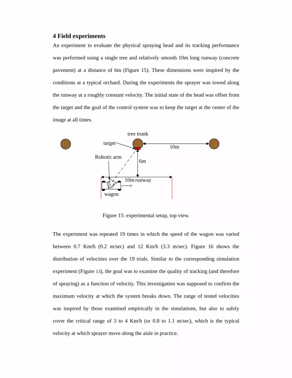
4 Field experiments An experiment to evaluate the physical spraying head and its tracking performance
was performed using a single tree and relatively smooth 10m long runway (concrete
pavement) at a distance of 6m (Figure 15). These dimensions were inspired by the
conditions at a typical orchard. During the experiments the sprayer was towed along
the runway at a roughly constant velocity. The initial state of the head was offset from
the target and the goal of the control system was to keep the target at the center of the
image at all times.
Figure 15: experimental setup, top view. The experiment was repeated 19 times in which the speed of the wagon was varied
between 0.7 Km/h (0.2 m/sec) and 12 Km/h (3.3 m/sec). Figure 16 shows the
distribution of velocities over the 19 trials. Similar to the corresponding simulation
experiment (Figure 13), the goal was to examine the quality of tracking (and therefore
of spraying) as a function of velocity. This investigation was supposed to confirm the
maximum velocity at which the system breaks down. The range of tested velocities
was inspired by those examined empirically in the simulations, but also to safely
cover the critical range of 3 to 4 Km/h (or 0.8 to 1.1 m/sec), which is the typical
velocity at which sprayer move along the aisle in practice.

0 5 10 15 200
0.5
1
1.5
2
2.5
3
3.5
Vel
ocity
m/s
Trial number Figure 16: the distribution of trial velocities.
In the prototype sprayer the camera is mounted parallel to the spraying gun. Hence,
the objective of the control system was set to bring the target (the red marker) to the
center of the image and keep it there hereafter. To quantify performance, the position
of the target in the image was recorded during each experimental run and errors were
computed as the offset vector relative to the center of the image (in pixels). Error in
the X and Y directions corresponded to the pan and tilt axes, respectively. The image
itself was 640x480 pixels in size, and as mentioned above, the sampling rate of the
vision system was up to 10 fps. The system controller parameters were set to the
highest value derived from the simulations without bringing the system to excessive
oscillations.
Experimental results indicate that up to a wagon ve1ocity of 1.25 m/sec the tracking
error was reasonably low and stayed within a 50 pixel distance from the center of the
image. Figure 17 shows the tracking error during a single experiment with a wagon
velocity of 1.18 m/sec. This entire experiment took less than 9 sec. Initial head error
converged with settling time of 3.5 sec while a correct direction-to-target was
maintained from that point on.

-300 -200 -100 0 100 200 300
-200
-150
-100
-50
0
50
100
150
200 Velocity=1.18 m/s
Y E
rror p
ixel
s
X Error pixels
XY error
Figure 17: Typical behavior of the tracking error in both the x and the y direction for
spraying velocities that are lower than 1.25 m/sec. (a) Tracking error as a function of
time. (b) Distribution of target positions in the image plane (note that the larger errors
are a results of the initial offset with which the trial was initiated.
For experimental runs using velocities higher than 1.25 m/sec, the tracking quality
reduced progressively and some drift (i.e., accumulated error) was noticed in the pan
axis. Figure 18 shows the tracking error and target position for a wagon velocity of
3.03 m/s. It is evident that the tilt error is not affected by the higher wagon velocity as
indeed it converges similarly to the previous case (Figure 17). In contrast, the pan
error appears to diverge and the head direction progressively drifts away from the
desired configuration. This drift started to appear at speeds slightly higher than typical
spraying speeds used in the filed.
0 10 20 30 40 50 60 70 80 90
-300
-200
-100
0
100
200
300Velocity=1.18 m/s
frame #
X errorY error
(a) (b)
Erro
r pix
els

0 5 10 15 20 25 30 35-300
-200
-100
0
100
200
300 Velocity=3.03 m/s
Erro
r pix
els
Time frame #
X errorY error
-300 -200 -100 0 100 200 300
-200
-150
-100
-50
0
50
100
150
200 Velocity=3.03 m/s
Y E
rror p
ixel
s
X Error pixels
XY error
Figure 18: typical behavior of the tracking error in both the x and the y direction for
speeds that are higher than 1.25 m/sec. (a) show the changes in the tracking error as a
function of time. (b) The tracking error in compression to the image frame.
To further probe system performance as a function of wagon velocity, the RMS of the
angular tracking error for each trial was analyzed. Figure 19 is a scatter plot of
velocities and corresponding RMS errors. The results can be described reasonably
well using a linear dependency (R=0.75, p<0.05). Following this approximation we
conclude that with wagon velocities of up to 1.25 m/s the angular error is less than 10
degrees, which is less than the typical solid angle of a spraying jet. Hence, as long as
the wagon moves no faster than this velocity, the target remains inside the spraying
cone. Since 1.25 m/sec is no slower than spraying velocities used in the field, our
prototype is able to replicate autonomously the spraying performance that is obtained
with human workers.
In summary, both the simulations and the field experiments showed qualitatively
similar behaviors, and exhibited quantitative similarities of head position errors as a
function of wagon velocity. Furthermore, both the theoretical model and the physical
prototype exhibit a phase transition at intermediate wagon velocity where tracking
(a) (b)

changes from oscillatory convergence to divergence (drift). From the simulated study
it can be seen that at 1.2m/s the system’s RMS error (Figure 11b) changes from a
relatively constant error for processing time cycle higher than 10 fps, to an increasing
error when the sampling rate is lower the 10fps. For the experimental system the
sampling rate is 8-3fps (based on the image complexity). Hence, for higher frame
rates this drift would occur at faster speeds.
0 0.5 1 1.5 2 2.5 3 3.52
4
6
8
10
12
14
16
Velocity m/s
RM
S o
f ang
ular
erro
r
R=0.75p<0.05
y = 2.8*x + 4.5 data 1
linear
Figure 19: The RMS of the angular error as a function of wagon velocity.
Certain qualitative differences between the model and the physical system were noted.
In particular, while the simulated system exhibited non linear dependency between
RMS error and wagon velocity (Figure 13a), the experimental physical system
behaved (roughly) linearly (Figure 19). This difference might be explained by the fact
that in the simulation model the motor was capable of generating torque and changing
its direction instantaneously. Obviously, real motors are not capable of behaving this
way, which entails slower response to error. Furthermore, the theoretical model
clearly ignores additional sources of error such as backslash in the transition,
vibration of the camera due to the motion of the musk, etc. Despite these

discrepancies, the simulation does provide important insights that the physical system
cannot. In particular, while we are not able to change the sampling rate easily in the
physical prototype, it is clear from the simulation that a faster vision module would
allow better performance in faster wagon velocities as well.
5 Conclusions and future work A prototypical operation of an elevated agricultural robot aimed for accurate spraying
and pollinating date palm trees is presented. Safety, economical reasons, saving
manpower, and environmental concerns all motivate the development of autonomous
robotic systems to handle such operations; in this paper the concept and design of a
small scaled prototype which has been built and tested are presented. The approach is
based on a visually guided robotic arm equipped with a spraying/pollinating gun
which tracks its targets continuously while in motion. Visual tracking pursues
distinctly colored markers which are attached to the tree crown in proximity to the
date clusters. Performance of both simulated and physical prototype suggests that
accurate spraying can be obtained even with the simple proportional control scheme
used. The control law parameters were selected based on simulations results to
achieve best possible tracking using the specific control scheme. Experiments show
that in regular spraying velocity of about 1.2 m/s tracking error was less than 10
degrees. This error magnitude still allows good spraying since the dispersion of the
spraying cone is about that magnitude as well. The scaled down model indicated the
feasibility of the proposed concept, and allows applying the concept to a full sized
prototype. The effect on tracking, caused by ground irregularity is intensified in the
scaled down model due to the narrow wheel span. It will be examined when a full
scaled model will be built so the large width will inhibit the roll angle caused by
wheels running over obstacles. Another important issue that is left for future work is

experimenting the spraying quality. Since scaled down sprayer could not deliver the
spray droplets in the same speed and rate to the target, this issue could not have been
tested yet. The full scale system would prevent workers from working at heights and
risking their lives. It will reduce human labor as only one worker (a driver) is needed
instead of three in the existing machines.
The main directions which are natural extensions of our results so far focus primarily
in the image processing aspects of the system. Undergoing research is aimed at
developing algorithms for stereo imaging. Stereo vision could offer important
advantages to our system and a solution to some critical problems. In particular, the
current monocular system does not address the fact that the orchard environment
where targeted spraying should be executed constitutes numerous targets of similar or
identical appearance (just imagine a red marker on each and every tree in the
orchard). As the robotic platform moves along an aisle, these targets become
occasionally occluded, sometimes by one another. This constraint poses severe
requirements on the tracking system which should be able discriminate between
identically looking targets whose image plane trajectory intersect each other in
unpredictable ways. One way to cope with this situation is to use stereo vision that
provides both 3D tracking (i.e., tracking not only in the image plane but in the three
dimensional physical space as well) and tracking through occlusions and/or target
merging.

Acknowledgments
This work was funded by the Jewish Colonization Association (ICA) foundation, the
Israeli Ministry of Science, and the Chief Scientist, Israeli Ministry of Agriculture. We
are also grateful for the support provided by the BGU Paul Ivanier Center for
Robotics Research and Production Management and by the BGU Rabbi W. Gunther
Plaut Chair in Manufacturing Engineering.
References
Arima, S., N. Kondo, Y. Shibano, J. Yamashita, T. Fujiura and H. Akiyoshi, (1994).
Study on cucumber harvesting robot (Part 1). Journal of the JSAM .56(1): 45-53.
Arima, S., N. Kondo, Y. Shibano, T. Fujiura, J. Yamashita and H. Nakamura, (1994).
Study on cucumber harvesting robot (Part 2). Journal of the JSAM .56(6): 69-76.
Balsari, P., Marucco, P., Oggero, G. (2002). Spray Applications in Italian Apple
Orchards: Target Coverage, Ground Losses and Drift, Paper number 021002,
ASAE, St. Joseph, Michigan, USA.
Edan Y. (1999). Food and Agricultural Robots. In: The Handbook of Industrial
Robotics: 1143-1155, 2nd Edition. Editor: S.Y. Nof, John Wiley and Sons.
Rotberg, A. First, G., (2007). Ben Gurion University of the Negev, ME, Israel. Senior
project report: 07-47 Date spraying, control.
Fujiura T., M. Ura, N. Kawamura and K. Namikawa. (1990). Fruit harvesting robot
for orchard, J. Japanese Society of Agricultural Machinery. 52(2): 35-42.
Gillis, K. P., Giles, D. K., Slaughter, D. C., Downey, D., (2001). Injection and fluid
handling system for machine-vision controlled spraying. ASAE Paper No.
011114, ASAE St. Joseph, MI 49085.

Grand d'Esnon, A. (1985). Robotic harvesting of apples. In Proc. Agri-Mation 1 Conf.
and Expo.: 210-214. Chicago. St. Joseph, Mich.: ASAE.
Hannan, M.W., Burks, T.F. (2004). Current developments in robotic harvesting of
citrus. ASAE Paper No. 043087, ASAE, St. Joseph, MI 49085.
Iida, M., K. Furube, K. Namikawa, M. Umeda. (1996). Development of watermelon
harvesting gripper. Journal of JSAM, 58(3):19-26.
Juste, F. and I. Fornes, (1990). Contributions to robotic harvesting of citrus in Spain.
In Proc. of the AG-ENG 90 Conference.: 146-147. Berlin, Germany.
Kassay, L. (1992). Hungarian robotic apple harvester, ASAE Paper No. 92-7042,
ASAE St. Joseph, MI, 49085.
Keicher, R and H. Seufert. (2000). Automatic guidance for agricultural vehicles in
Europe. Computers and Electronics in Agriculture 25(1): 169-194.
Kevin P., Gillis D., Ken Giles, David C., Slaughter D. (2001). Injection and fluid
handling system for machine-vision controlled spraying. ASAE Paper No.
011114, ASAE St. Joseph, MI 49085.
Kondo, N. and M. Monta, (1997). Basic study on chrysanthemum cutting sticking
robot, In Proc. of International Symposium on Agricultural Mechanization and
Automation, 1, 93-98. Taipei.
Kondo, N., M. Monta and Y. Ogawa. (1997). Cutting providing system and vision
algorithm for robotic chrysanthemum cutting sticking system, In Preprints of the
International Workshop on Robotics and Automated Machinery for Bio-
productions: 7-12.Valencia.
Kondo, N. and K. C. Ting. (1998). Robotics for Bioproduction Systems, St. Joseph,
Mich.: ASAE.

Kondo, N. (1995). Harvesting Robot Based on Physical Properties of Grapevine,
JARQ, 29(3): 171-177, Japan International Research Center for Agricultural
Science.
Korkidi, E. (2008). Autonomous palm trees sprayer, Senior project report: 08-85. Ben
Gurion University of the Negev, ME, Israel.
Manor, G., Gal., Y. (2002). Development of an Accurate Vineyard Sprayer, paper
number 021033, ASAE, St. Joseph, Michigan, USA.
Maio M. F. and Giulio Reina, (2006). Agricultural Robot for Radicchio Harvesting. .
Journal of field Robotics, 23(6/7), 363-377.
Molto E., F. Pla, and F. Juste, (1992). Vision systems for the location of citrus fruit in
a tree canopy. Journal of Agricultural Engineering Research, 52: 101-110.
Monta, M., Kondo, N., Y. Shibano and K. Mohri. (1994). Basic study on robot to
work in vineyard (Part 3) - Measurement of physical properties for robotization
and manufacture of berry thinning hand. Journal of the JSAM 56(2): 93-100.
Nishiwaki, K., Amaha, K., Otani, R. (2004). Development of nozzle positioning
system for precision sprayer, Automation technology for off-road equipment,
ASAE, St. Joseph, Michigan, USA.
Pilarski. T, M. Happold, H. Pangels, M. Ollis, K. Fitzpatrick, and A. Stentz. (1999).
The Demeter System for Automated Harvesting. Proceedings of the 8th
International Topical Meeting on Robotics and Remote Systems, April, 1999.
Pilarski, T., M. Happold, H. Pangels, M. Ollis, K. Fitzpatrick, and A. Stentz. (2002).
The Demeter system for automated harvesting. Autonomous Robots 13: 19-20.

Rabatel, G., A. Bourely, F. Sevila, and F. Juste. (1995). Robotic harvesting of citrus.
In Proc. International Conference on Harvest and Post-harvest Technologies for
Fresh Fruits and Vegetables: 232-239. Guanajuato, Mexico. St. Joseph, Mich.:
ASAE.
Reid, J. F. (2004). Mobile intelligent equipment for off-road environments. In Proc.
ATOE Conference, 1-9. St. Joseph, Mich.: ASAE.
Reid, J.F., Q. Zhang, N. Noguchi, and M. Dickson. (2000). Agricultural automatic
guidance research in North America. Computers and Electronics in Agriculture
25(1): 155-167.
Sapir, B. and Namdar, H. (2007). Ben Gurion University of the Negev, ME, Israel.
Senior project report: 07-46 Date spraying, control.
Sarig, Y. (1993). Robotics of fruit harvesting: a state-of-the-art review. Journal of
Agricultural Eng. Research 54(4): 265-280.
Serra, J. (1982). Image Analysis and Mathematical Morphology, Academic Press.
Shapiro, A., Korkidi, E., Rotenberg, A., Furst, G., Namdar, H., Sapir, b., Mishkin, M.,
Ben-Shahar, O,. Edan, Y. (2008). A robotic prototype for spraying and pollinating
date palm trees. The 9th Biennial ASME Conference on Engineering Systems
Design and Analysis ESDA 2008 July 7-9, 2008, Haifa, Israel
Shin, B.S., H. Kim, J.U. Park. (2002). Autonomous agricultural vehicle using
overhead guide. In Automation Technology for Off-Road Equipment, Proceedings
of the July 26-27, 2002 Conference (Chicago, Illinois, USA) 701P0502: 261-269.
Simonton, W., (1990). Automatic geranium stock processing in a robotic workcell.
Transactions of the ASAE 33(6): 2074-2080.

Sittichareonchai, A., F. Sevila. (1989). A robot to harvest grapes, ASAE Paper No.
89-7074, ASAE St. Joseph, MI, 49085.
Stentz, A. (2001). Robotic technologies for outdoor industrial vehicles, SPIE
Aerosense 2001 Conference.
Steward., B. L., Tian., L. F., Tang., L. (2002). Distance –based control system for
machine vision-based selective spraying; Transactions of ASAE, Vol. 45(5): 1255-
1262.
Torii, T. (2000). Research in autonomous agriculture vehicles in Japan. Computers
and Electronics in Agriculture 25(1): 133-153.
Wiedemann., H.T., Ueckert., D., McGinty., W.A. (2002). Spray boom for sensing and
selectively spraying small mesquite on highway rights-of-way, Applied
Engineering in Agriculture 18(6): 661 – 666.
Wilson, J.N. (2000). Guidance of agricultural vehicles – a historical perspective.
Computers and Electronics in Agriculture 25(1): 3-9.
Zheng, J. (2005). Intelligent pesticide spraying aims for tree target, Resource,
ASABE, St. Joseph, Michigan USA.
Zheng., J., Zhou. H., Xu. Y., Zhao. M., Zhang.H., Xiang. H., Chen. Y. (2004). Pilot
study on toward-target Precision Pesticide Application in Forestry, ASAE Annual
Meeting 2004; ASAE, St. Joseph, Michigan, USA.


