Embed Size (px)
Citation preview
C A R B O N 4 7 ( 2 0 0 8 ) 3 1 3 – 3 4 7
ava i lab le a t www.sc iencedi rec t . com
journal homepage: www.elsevier .com/ locate /carbon
Letters to the Editor
A simple thermal CVD method for carbon nanotubesynthesis on stainless steel 304 without the additionof an external catalyst
Carole E. Baddour, Faysal Fadlallah, Deniz Nasuhoglu, Reema Mitra,Leron Vandsburger, Jean-Luc Meunier*
Department of Chemical Engineering, McGill University, 3610 University St., Montreal, Quebec, Canada H3A 2B2
A R T I C L E I N F O
Article history:
Received 9 July 2008
Accepted 31 October 2008
Available online 7 November 2008
A B S T R A C T
A method is described to synthesize carbon nanotubes (CNTs) by thermal chemical vapour
deposition (th-CVD) directly on stainless steel substrates of various geometries. This
method allows the bulk metal surface to act as both the catalyst and support for the
CNT growth, thus enhancing the contact and adherence of the tubes to the substrate
and eliminating the requirement of adding an additional catalyst in the process. The pro-
cedure was optimized to obtain a uniform layer of CNTs on the substrate.
� 2008 Elsevier Ltd. All rights reserved.
Carbon nanotubes (CNTs) are widely studied and are start-
ing to be used for electrode and sensor applications [1,2]. In
such cases, a conducting substrate is most often required. Par-
ticularly, stainless steel (SS) seems an attractive candidate for
CNT growth due to its high iron content (�66%) and the possi-
bility to tailor active sites for the growth process. A direct
growth of the CNTon the bulk metal substrate should enhance
the adherence of the tubes to the electrodes and favour a bet-
ter electron/thermal transfer. Various procedures have been
used thus far to synthesize CNTs on this material. These in-
clude plasma-enhanced chemical vapour deposition (PE-
CVD) [3–5], thermal CVD [6–10], partial oxidation of methane
[11], pyrolysis of iron phthalocyanine (FePc) [12], a flame meth-
od [13] and a liquid phase method [14]. The majority of these
methods require the SS substrate to be treated prior to CNT
growth. Typical substrate preparation methods include treat-
ment in a hydrogen atmosphere [4,5], etching in HF or sulphu-
ric acids [4,6] and a combination of oxidation and reduction
[7]. It is important to note that in addition to the substrate
treatment, these techniques require an additional catalyst to
0008-6223/$ - see front matter � 2008 Elsevier Ltd. All rights reservedoi:10.1016/j.carbon.2008.10.038
* Corresponding author: Fax: +1 514 398 6678.E-mail address: [email protected] (J.-L. Meunier).
be added in order to grow CNTs on the SS surface [6,10,12].
For example, Masarapu and Wei [6] indicate in their direct
growth method that ferrocene was required as a catalyst,
and that no nanotubes were observed on the SS substrate
without a catalyst precursor. In such cases the SS substrate
essentially acts as a support for the catalyst nanoparticles,
and may not provide an optimal efficiency for electron trans-
port to the bulk of the electrode. We report here a simple pro-
cedure to synthesize multi-walled nanotubes (MWNTs)
directly on SS 304 by thermal CVD without any external addi-
tion of a catalyst precursor. In the present case, the SS itself
provides the active sites for CNT growth, enhancing in this
way the CNT-substrate surface interaction efficiency. The pro-
cess is optimized to achieve the growth of CNTs as a uniform
layer on various substrate geometries.
The CVD furnace used is a Lindberg/Blue HTF 55000 series.
A quartz tube is located inside the furnace such that approx-
imately half the tube is covered. The substrates are placed
directly in the quartz tube at the center of the furnace, paral-
lel to the gas flow. The carbon source and carrier gases are
d.
Substrate Cleaning30 min with acetone
in ultrasonic bath
Substrate Etchingin 35-38% HCl for
desired time
Heat Treatmentat 850 oC
for 30 min in N2
CNT Synthesisat 700 oC with C2H2
injection for desired time
Holdat 700 oC in N2 for desired time
followed by cool down
Fig. 1 – Simple procedure for CNT growth on SS 304.
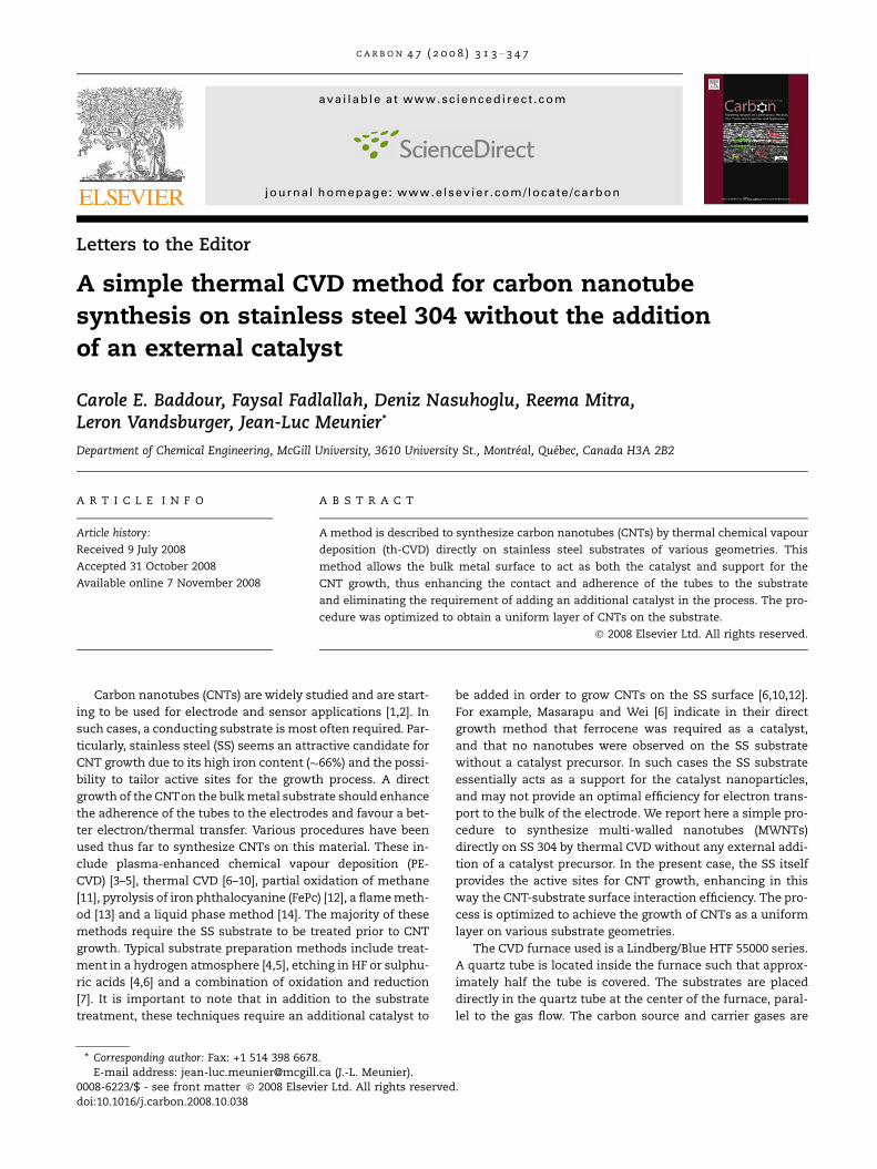
Fig. 2 – SEM images of CNTs synthesized at (a) 650 �C, (b) 700 �C, (c) 800 �C (close-up of CNT island), (d) 800 �C (distant view of
CNT islands) and (e) surface defect morphology observed on SS plate. All substrates were etched for 5 min in HCl and
preheated at 850 �C for 30 min.
314 C A R B O N 4 7 ( 2 0 0 8 ) 3 1 3 – 3 4 7
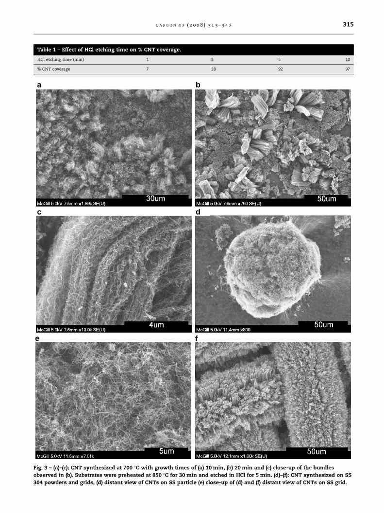
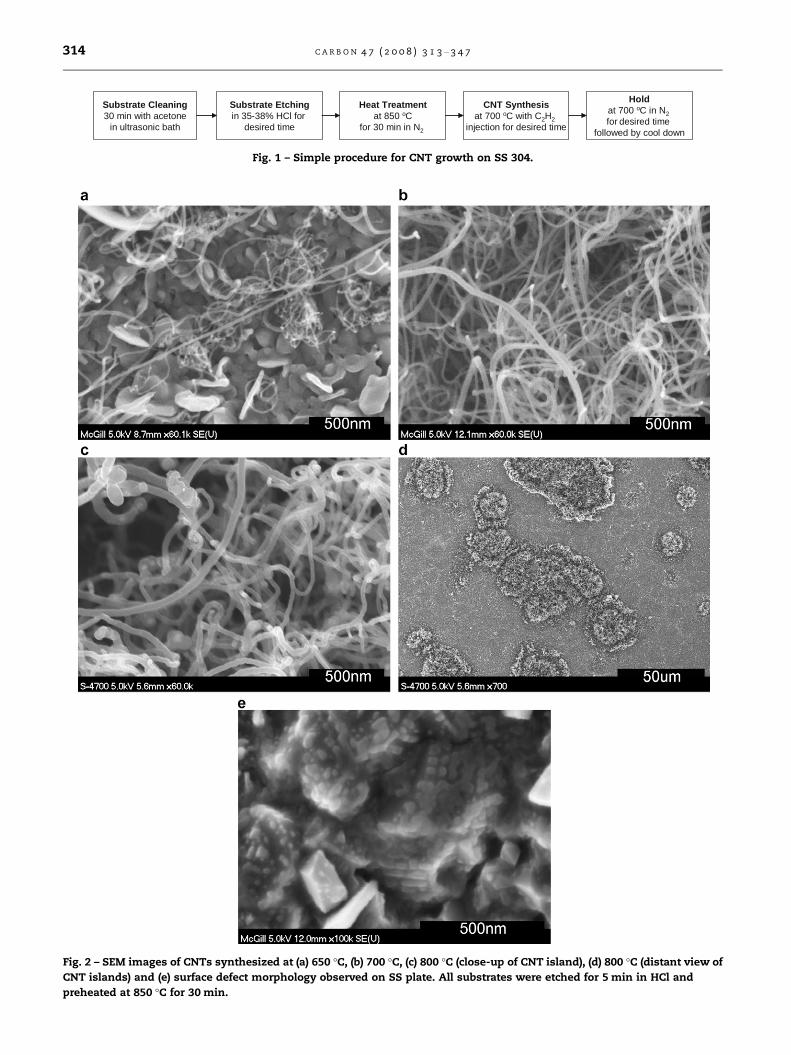
Table 1 – Effect of HCl etching time on % CNT coverage.
HCl etching time (min) 1 3 5 10
% CNT coverage 7 38 92 97
Fig. 3 – (a)–(c): CNT synthesized at 700 �C with growth times of (a) 10 min, (b) 20 min and (c) close-up of the bundles
observed in (b). Substrates were preheated at 850 �C for 30 min and etched in HCl for 5 min. (d)–(f): CNT synthesized on SS
304 powders and grids, (d) distant view of CNTs on SS particle (e) close-up of (d) and (f) distant view of CNTs on SS grid.
C A R B O N 4 7 ( 2 0 0 8 ) 3 1 3 – 3 4 7 315
acetylene (C2H2) and nitrogen (N2), respectively. The gas inlet
tube (U = 6.35 mm) is long enough to carry the gases to the
center of the furnace, while the gas outlet tube carries the ex-
haust to a ventilation system. Commercial grade multi-pur-
pose type 304 SS strips (0.762 mm thickness) with mirror-
like finish are used as both the catalyst and the support mate-
rial. Fig. 1 summarizes the procedure. The N2 and C2H2 flow
rates are set at 592 ± 5 sccm and 45 ± 5 sccm, respectively.
CNTs were synthesized at 650, 700 and 800 �C with sub-
strate preheating at 850 �C for 30 min, and at 650, 700, 800
and 850 �C without preheating. Fig. 2 illustrates the typical
results obtained with substrate preheating. In both cases
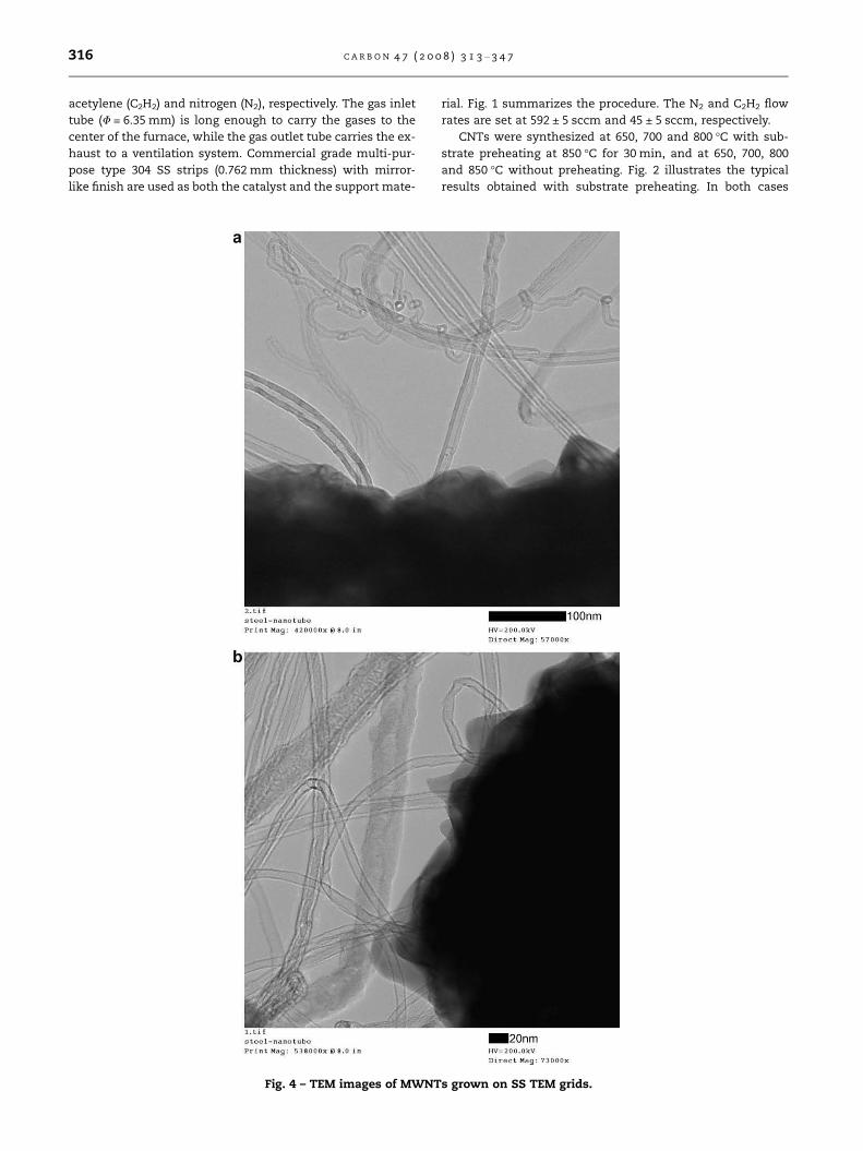
Fig. 4 – TEM images of MWNTs grown on SS TEM grids.
316 C A R B O N 4 7 ( 2 0 0 8 ) 3 1 3 – 3 4 7
with/without preheating, the least amount of amorphous car-
bon occurred at a synthesis temperature of 700 �C. At this
temperature, there was less amorphous carbon in the sample
which was preheated at 850 �C (Fig. 2b) compared to the sam-
ple which was not preheated. The percent CNT coverage by
area was 92% for the former and 87% for the latter. The nano-
tubes observed are multiwalled with diameters ranging from
20 to 70 nm and mainly grew with random orientation. It is
known that particle-like active catalytic sites are required
for the growth of CNTs [7]. The objective of the substrate
pre-treatment method is to generate these favourable growth
sites. We believe the heat treatment at 850 �C favourizes the
recrystallization process, and generates nanometer scale
grain structures providing particle-like active catalytic sites
such as surface defects (Fig. 2e).
The substrates were initially etched in HCl for, respec-
tively, 1, 3, 5 or 10 min in order to determine the effect of etch-
ing time on CNT growth. The amount of CNTs produced
increased with substrate etching time in HCl. Table 1 summa-
rizes the results. It should be noted the highest etching time
of 10 min produced a double layer of CNT growth. A base layer
of CNTs with small diameters (5–20 nm) was observed, while
the upper layer contained larger (40–70 nm) and much longer
CNTs, which grew in islands. The distance between the indi-
vidual islands was typically around 65 lm.
During the synthesis process, C2H2 at a flow rate of
45 ± 5 sccm was injected for respectively 1.5, 3 or 5 min. Small
amounts of CNTs were produced with C2H2 injections times
of 1.5 and 3 min, whereas the most enhanced CNT growth
was observed with a C2H2 injection time of 5 min. With re-
spect to CNT density, a C2H2 injection time of 10 min did
not further improve CNT growth [15].
CNT growth times of 0, 10, 20 and 30 min were tested. We
defined the growth time as the time the sample remained in
the furnace at the synthesis temperature in a N2 atmosphere
after the C2H2 flow was stopped. The residence time of C2H2
gas in the furnace is in the order of 3–5 min. Very few CNTs
were observed when no growth period was imposed. In con-
trast, an irregular CNT layer was observed with a growth time
of 10 min. A low magnification image (Fig. 3a) shows CNT
bundles reaching 5–10 lm in length. As seen in Fig. 3b, larger
and longer bundles with lengths up to 30–40 lm are observed
at a growth time of 20 min. These dense bundles contain
0.6 mm-diameter coils of intertwined CNTs with diameters
of 5–30 nm (Fig. 3c). As previously shown in Fig. 2b, a growth
time reaching 30 min resulted in a uniform layer of CNTs on
the substrate surface.
The procedure described here was also applied to SS 304
powders (70 lm mean diameter) and grids (400 mesh size). A
uniform layer of CNTs was obtained on both the powders
and grids, as shown in Fig. 3d–f. For the powders, the condi-
tions were: 7 min HCl etching, 30 min heat treatment at
850 �C, 675 �C synthesis temperature, 12 min C2H2 injection
and 30 min growth time. The grids were etched in HCl for
2.5 min and the synthesis temperature was 700 �C. No heat
treatment was necessary in this case. SS transmission elec-
tron microscopy (TEM) grids for high resolution imaging were
tested under the following growth conditions: 30 min heat
treatment at 850 �C, 700 �C synthesis temperature, 5 min
C2H2 injection and 30 min growth time. As shown in Fig. 4,
the MWNTs produced on SS TEM grids include nanotubes
with a small number of walls possibly reaching down to sin-
gle, double and triple-walled tubes.
To conclude, we present a simple method to grow a dense
layer of CNTs directly on SS 304 substrates such as plates,
grids and powders without the need of adding an additional
catalyst. The substrate preparation method is based on a sim-
ple acid etching technique followed by a heat treatment. TEM
imaging confirmed the presence of MWNTs including CNT
structures with a small number of walls. In contrast to other
treatment methods, the present method has no scale up lim-
itations and could easily be applied to large SS surfaces and
geometries. In addition, a catalyst precursor is not required
to grow the CNTs; the iron-based material surface of a com-
mercial-grade SS 304 itself acting as the catalyst. The tech-
nique is inexpensive and capable of producing a uniform
layer of CNTs on SS with minimal substrate treatment.
Acknowledgements
We acknowledge the financial support provided by the Na-
tional Sciences and Engineering Research Council (NSERC)
and McGill University.
R E F E R E N C E S
[1] Collins PG, Arnold MS, Avouris P. Engineering carbonnanotubes and nanotube circuits using electrical breakdown.Science 2001;292(5517):706–9.
[2] Kong J, Franklin NR, Zhou C, Chapline MG, Peng S, Cho K,et al. Nanotube molecular wires as chemical sensors.Science 2000;287(5453):622–5.
[3] Fan ZQ, Li R, Cai GW, Yang PX, Cheng RZ. Effects of substrateson deposition of carbon nanotube films. Rengong JingtiXuebao/J Synt Cryst 2007;36(4):894–7. +68.
[4] Park D, Kim YH, Lee JK. Pretreatment of stainless steelsubstrate surface for the growth of carbon nanotubes byPECVD. J Mater Sci 2003;38(24):4933–9.
[5] Wang N, Yao BD. Nucleation and growth of well-aligned,uniform-sized carbon nanotubes by microwave plasmachemical vapor deposition. Appl Phys Lett2001;78(25):4028–30.
[6] Masarapu C, Wei B. Direct growth of aligned multiwalledcarbon nanotubes on treated stainless steel substrates.Langmuir 2007;23(17):9046–9.
[7] Vander Wal RL, Hall LJ. Carbon nanotube synthesis uponstainless steel meshes. Carbon 2003;41(4):659–72.
[8] Wang Z, Wu Q, Zhang F-Y, Cui Y-Y. Synthesis of multi-walledcarbon nanotube bundles with uniform diameter. Matter Lett2007;61(8–9):1955–8.
[9] Yang H, Mercier P, Wang S, Akins D. High-pressure synthesisof carbon nanotubes with a variety of morphologies. ChemPhys Lett 2005;416(1–3):18–21.
[10] Yun Y, Gollapudi R, Shanov V, Schulz M, Dong Z, Jazieh A,et al. Carbon nanotubes grown on stainless steel to formplate and probe electrodes for chemical/biological sensing.J Nanosci Nanotechnol 2007;7(3):891–7.
[11] Mordkovich VZ, Kharitonov DN, Maslov IA, Kamenev AA.Ni–Fe competition in the catalysis of carbon nanotubegrowth. Fullerenes Nanotubes Carbon Nanostruct2006;14(2):201–6.
C A R B O N 4 7 ( 2 0 0 8 ) 3 1 3 – 3 4 7 317
[12] Song J, Sun M, Chen Q, Wang J, Zhang G, Xue Z. Field emissionfrom carbon nanotube arrays fabricated by pyrolysis of ironphthalocyanine. J Phys D: Appl Phys 2004;37(1):5–9.
[13] Lee G, Jurng J, Hwang J. Synthesis of carbon nanotubes on acatalytic metal substrate by using an ethylene inversediffusion flame. Carbon 2004;42(3):667–91.
[14] Yamagiwa K, Iwao Y, Mikami M, Takeuchi T, Saito M, KuwanoJ. Liquid-phase synthesis of carbon nanotubes from alcohols.Key Eng Mater 2007;350:19–22.
[15] Reddy NK, Meunier J-L, Coulombe S. Growth of carbonnanotubes directly on a nickel surface by thermal CVD. MaterLett 2006;60(29–30):3761–5.
Formation of nanocarbons during activation of mesocarbonmicrobeads with potassium hydroxide
Ruisheng Xue*, Hao Liu, Pingping Wang, Zengmin Shen
Beijing University of Chemical Technology, Beijing 100029, PR China
A R T I C L E I N F O
Article history:
Received 10 June 2008
Accepted 25 July 2008
Available online 3 August 2008
A B S T R A C T
Carbon nanotubes (CNTs) together with carbon nanofibers (CNFs) have been produced on
the surface of and inside mesocarbon microbeads containing Co nanoparticles during their
activation with potassium hydroxide (KOH). The resulting CNFs consist of a number of
platelet-shaped sub-units with width of about 500 nm and thickness of 50 nm. The CNTs,
with diameter of about 200 nm, grow from the inside to the surface of the activated carbon
beads. The results indicate that, in addition to the Co nanoparticles, the existence of KOH
also plays an important role in the nanocarbon growth.
� 2008 Published by Elsevier Ltd.
To improve the performance of carbon nanotubes (CNTs)
and carbon nanofibers (CNFs) in some potential applications,
activated carbon/CNT or CNF hybrids have been extensively
studied [1–8]. They combine the exciting characteristics of
CNTs or CNFs with the extensive porous structure and rapid
adsorption capability of activated carbon, and offer great po-
tential in applications such as energy storage [1,2], water
desalination [3], pollution control [4] and gas phase catalysis
[7]. Activated carbon/CNT hybrids have been prepared by mix-
ing the activated carbon and CNTs with adhesive [1–3] or by
ball milling [4]. Moreover, the immobilized CNFs or CNTs on
the surface of and inside activated carbon have been prepared
by chemical vapor decomposition of organic molecules in or
on the activated carbon embedded with catalyst [5–8]. This
paper reports that CNTs and CNFs can be produced on the
surface of and inside activated mesocarbon microbeads dur-
ing activation of mesocarbon microbeads containing Co
nanoparticles (MCMB/Co) with KOH. CNTs have been pre-
pared by the co-carbonization of an aromatic heavy oil and
ferrocene [9,10]. However, different from the growth mecha-
nism of nanocarbon in their report, the activation process
plays an important role in the nanocarbon growth in present
work.
MCMB/Co containing 4.45 wt% Co nanoparticles was pre-
pared by pyrolyzing the mixture of coal tar pitch and cobalt
acetate (12.5 wt%) at 410 �C for 0.5 h under nitrogen atmo-
sphere. The experimental process has been described else-
where [11]. MCMB/Co was mixed with KOH and the weight
ratio of KOH:MCMB/Co was 5. The mixture was heated at
2.3 �C/min up to 900 �C and held at this temperature for 1 h
in N2 flow. After cooling down, the sample was washed with
diluted HCl and distilled water and then dried in vacuum.
The activation product was named as AMCMB/Co. For com-
parison, MCMB/Co was carbonized at 1000 �C for 1 h under
nitrogen.
Activated carbon with a specific surface area of 2336 m2/g
was produced by activation of MCMB/Co and its adsorption
isotherm and pore size distribution was shown in Figs. 1
and 2, respectively. As seen from Fig. 1, the isotherm has a
steep initial portion and oblique line upward, which refer to
0008-6223/$ - see front matter � 2008 Published by Elsevier Ltd.doi:10.1016/j.carbon.2008.07.030
* Corresponding author: Fax: +86 10 64454912.E-mail address: [email protected] (R. Xue).
318 C A R B O N 4 7 ( 2 0 0 8 ) 3 1 3 – 3 4 7