Embed Size (px)
Citation preview

A Smart Home Control and Monitoring System For The Disabled, Rishab Shah, Harish N.S, Dr.G.N.
Rathna, Journal Impact Factor (2015): 8.9958 (Calculated by GISI) www.jifactor.com
www.iaeme.com/ijecet.asp 26 [email protected]
1,2
Department of Electrical and Electronics Engineering,
Bangalore Institute of Technology, Bangalore, India
3Department of Electrical Engineering, Indian Institute of Science, Bangalore, India
ABSTRACT
The recent advancements in the field of embedded systems enables us to develop a reliable
smart home system for easier access to home appliances. The aim is to provide a seamless
integration of various methods of controlling appliances in the smart home aiding the physically
challenged. This can be done by means of a non-invasive Brain-Computer Interface (BCI), text
messaging and a personalized web page. This paper proposes a novel method wherein the physically
challenged people can control the appliances by using Emotiv EPOC headset which reads the
Electroencephalographic (EEG) signals recorded from the brain activity and communicates with an
Arduino board. The proposed system has been built with the help of an Ethernet shield which runs a
webserver, and a GSM shield which communicates with the Arduino through text messaging (SMS).
Keywords: BCI, Arduino, Smart Home, SMS, Ethernet.
I. INTRODUCTION
A smart home, or smart house, is a home that incorporates advanced automation systems to
provide the inhabitants with sophisticated monitoring and control over the building's functions.
Another name popularly given to this concept is home automation.
This paper is focused on helping quadriplegics, pregnant women or the elderly maintain
independence and safety in the comfort of their homes. This form of home automation is called
assistive domotics. This is achieved by using a non-invasive BCI system [1], SMS and Ethernet. The
disabled can communicate with able-bodied people using the BCI system to send an emergency
SMS. The BCI technology is developing very rapidly, as it has innumerable uses [2]-[4], the most
important of which is improving the quality of life of the elderly and physically challenged. The
other two modes of control are used as contingencies to the BCI system so that an able-bodied
person can monitor and control the home appliances. This project enables the user to toggle lights,
other similar appliances and also control the speed of fans. To achieve this, the concept of EEG has
been used to record electrical activity of the brain along the scalp. EEG measures voltage
fluctuations resulting from ionic current flows within the neurons of the brain. The BCI system used
in this paper is the Emotiv EPOC [5] headset. An Arduino [6] board has been used as the
A SMART HOME CONTROL AND MONITORING SYSTEM
FOR THE DISABLED
Rishab Shah1, Harish N.S
2, Dr.G.N. Rathna
3
Volume 6, Issue 6, June (2015), pp. 26-35
Article ID: 40120150606004
International Journal of Electronics and Communication
Engineering & Technology (IJECET)
© IAEME: http://www.iaeme.com/IJECET.asp
ISSN 0976 – 6464(Print)
ISSN 0976 – 6472(Online)
IJECET
© I A E M E
A Smart Home Control and Monitoring System For The Disabled, Rishab Shah, Harish N.S, Dr.G.N.
Rathna, Journal Impact Factor (2015): 8.9958 (Calculated by GISI) www.jifactor.com
www.iaeme.com/ijecet.asp 27 [email protected]
microcontroller to control the electrical appliances. The Arduino Integrated Development
Environment (IDE) [6] has been used to program the microcontroller. The Arduino GSM Shield [7]
allows an Arduino board to send/receive SMS messages. The Arduino Ethernet Shield [8] allows an
Arduino board to connect to the internet.
II. IMPLEMENTATION
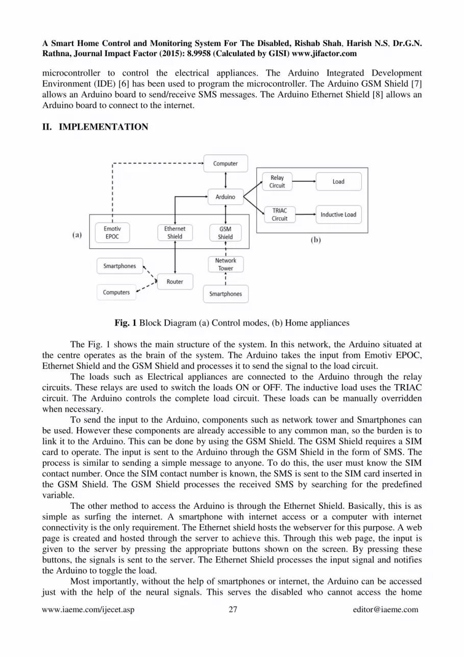
Fig. 1 Block Diagram (a) Control modes, (b) Home appliances
The Fig. 1 shows the main structure of the system. In this network, the Arduino situated at
the centre operates as the brain of the system. The Arduino takes the input from Emotiv EPOC,
Ethernet Shield and the GSM Shield and processes it to send the signal to the load circuit.
The loads such as Electrical appliances are connected to the Arduino through the relay
circuits. These relays are used to switch the loads ON or OFF. The inductive load uses the TRIAC
circuit. The Arduino controls the complete load circuit. These loads can be manually overridden
when necessary.
To send the input to the Arduino, components such as network tower and Smartphones can
be used. However these components are already accessible to any common man, so the burden is to
link it to the Arduino. This can be done by using the GSM Shield. The GSM Shield requires a SIM
card to operate. The input is sent to the Arduino through the GSM Shield in the form of SMS. The
process is similar to sending a simple message to anyone. To do this, the user must know the SIM
contact number. Once the SIM contact number is known, the SMS is sent to the SIM card inserted in
the GSM Shield. The GSM Shield processes the received SMS by searching for the predefined
variable.
The other method to access the Arduino is through the Ethernet Shield. Basically, this is as
simple as surfing the internet. A smartphone with internet access or a computer with internet
connectivity is the only requirement. The Ethernet shield hosts the webserver for this purpose. A web
page is created and hosted through the server to achieve this. Through this web page, the input is
given to the server by pressing the appropriate buttons shown on the screen. By pressing these
buttons, the signals is sent to the server. The Ethernet Shield processes the input signal and notifies
the Arduino to toggle the load.
Most importantly, without the help of smartphones or internet, the Arduino can be accessed
just with the help of the neural signals. This serves the disabled who cannot access the home
A Smart Home Control and Monitoring System For The Disabled, Rishab Shah, Harish N.S, Dr.G.N.
Rathna, Journal Impact Factor (2015): 8.9958 (Calculated by GISI) www.jifactor.com
www.iaeme.com/ijecet.asp 28 [email protected]
appliances by any other means. This method requires an Emotiv EPOC headset to access the
Arduino [9]. This head gear uses EEG signals. After suitable training, the system stores the signal
which can then be used repeatedly. Whenever the signal input is given, the system compares the
signal with previously stored signals and after the comparison, the system recognises the operation to
be carried out. This method is different in terms of operation compared to other two methods. The
Emotiv EPOC headset requires a computer to process and compare the signal before it is fed to the
Arduino.
III. CONTROL CIRCUITS
A. Relay Circuit
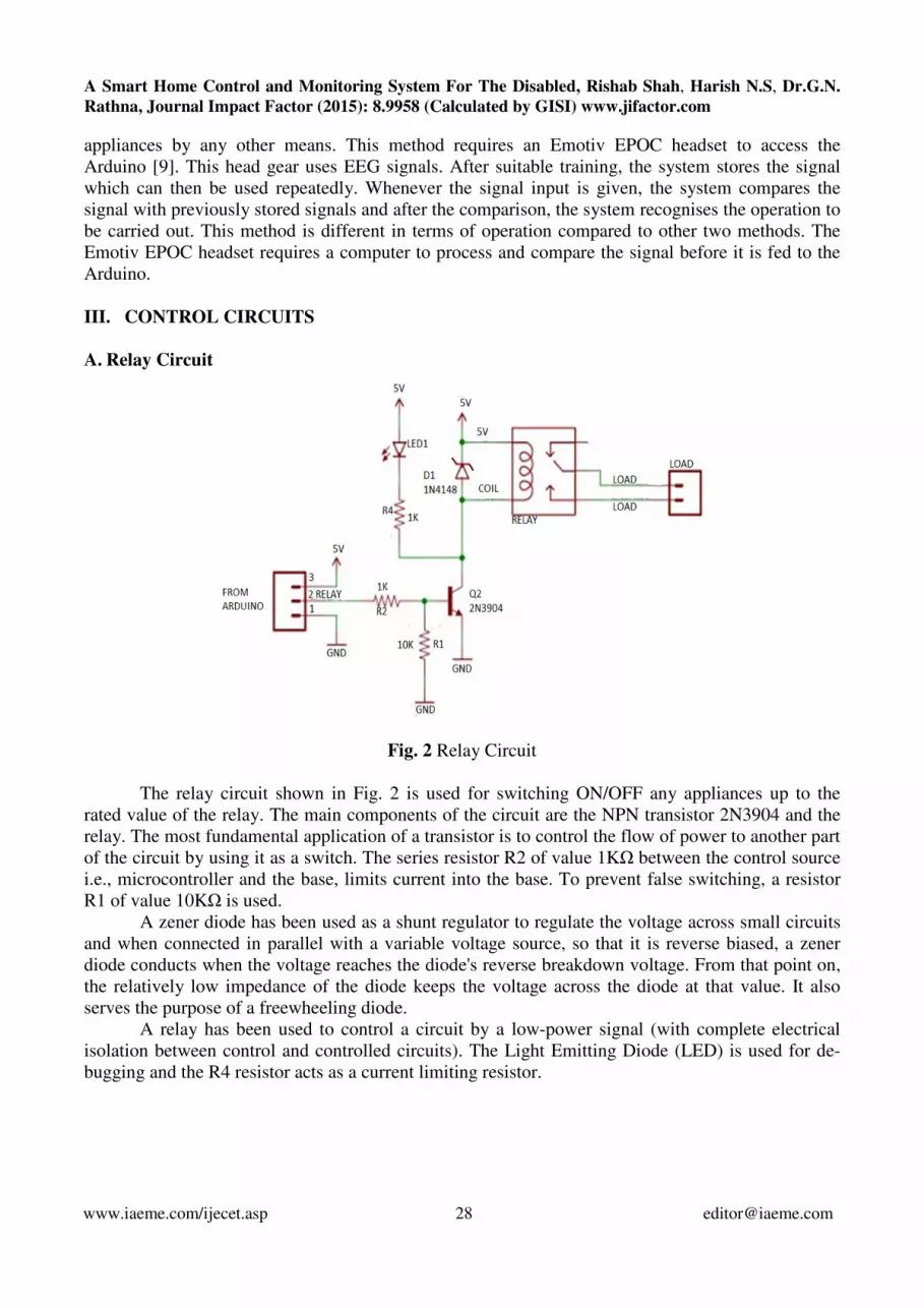
Fig. 2 Relay Circuit
The relay circuit shown in Fig. 2 is used for switching ON/OFF any appliances up to the
rated value of the relay. The main components of the circuit are the NPN transistor 2N3904 and the
relay. The most fundamental application of a transistor is to control the flow of power to another part
of the circuit by using it as a switch. The series resistor R2 of value 1KΩ between the control source
i.e., microcontroller and the base, limits current into the base. To prevent false switching, a resistor
R1 of value 10KΩ is used.
A zener diode has been used as a shunt regulator to regulate the voltage across small circuits
and when connected in parallel with a variable voltage source, so that it is reverse biased, a zener
diode conducts when the voltage reaches the diode's reverse breakdown voltage. From that point on,
the relatively low impedance of the diode keeps the voltage across the diode at that value. It also
serves the purpose of a freewheeling diode.
A relay has been used to control a circuit by a low-power signal (with complete electrical
isolation between control and controlled circuits). The Light Emitting Diode (LED) is used for de-
bugging and the R4 resistor acts as a current limiting resistor.

A Smart Home Control and Monitoring System For The Disabled, Rishab Shah, Harish N.S, Dr.G.N.
Rathna, Journal Impact Factor (2015): 8.9958 (Calculated by GISI) www.jifactor.com
www.iaeme.com/ijecet.asp 29 [email protected]
B. TRIAC Circuit
Fig. 3 Phase Controlled AC wave
Fig. 4 Zero Crossing Detector
A zero crossing detector (ZCD) is shown in Fig. 4 and it is H11AA11 is used for detecting or
monitoring AC signals. It provides AC Line/Digital Logic Isolation. It is a 6-PIN Dual In-Line

A Smart Home Control and Monitoring System For The Disabled, Rishab Shah, Harish N.S, Dr.G.N.
Rathna, Journal Impact Factor (2015): 8.9958 (Calculated by GISI) www.jifactor.com
www.iaeme.com/ijecet.asp 30 [email protected]
Package (DIP) opto-isolator AC Input/Transistor output. When the AC signal crosses zero point, the
zero crossing detector senses this and sends a signal to the Arduino, the Arduino interrupts the
program and navigates to Interrupt Service Routine (ISR) which determines the delay to be
introduced in the output waveform.
Fig. 5 TRIAC Circuit
The Arduino sends a signal as per the delay set according to the following equation:
The frequency here is 50Hz (that of the AC mains). The number of steps implies the
smoothness of the AC wave by sampling the input waveform. In this case, we have used 128 step
sampling. This means that one half cycle is divided into 128 steps. Substituting these values in the
above equation, we get a delay of 78 μs/step. This is the optimal value without introducing a phase
shift in the output waveform. In order to vary the speed of the single phase induction motors (fans),
this frequency step should be changed. A lower frequency step indicates a higher speed and vice
versa.
This varying output is fed to the opto-isolator. MOC3020M is a 6-Pin DIP Random-Phase
Optoisolators TRIAC Driver Output. The MOC3020M is optically isolated TRIAC driver devices.
Based on these waveforms the opto-isolator activates the gate terminal of the TRIAC.
Unwanted turn-ons are avoided by using a snubber circuit between MT1 and MT2. Snubber
circuit has been used to prevent premature triggering, caused by voltage spikes in the mains supply.
Because turn-ons are caused by internal capacitive currents flowing into the gate as a consequence of
a high voltage dv/dt, (i.e., rapid voltage change) a gate resistor has been connected between the gate
and MT1 to provide a low-impedance path to MT1 and further prevent false triggering. This,
however, increases the required trigger current or adds latency due to capacitor charging. On the
other hand, a resistor between the gate and MT1 helps draw leakage currents out of the device, thus
improving the performance of the TRIAC at high temperature, where the maximum allowed dv/dt is
lower. The LED and a current limiting resistor in series is used for de-bugging.

A Smart Home Control and Monitoring System For The Disabled, Rishab Shah, Harish N.S, Dr.G.N.
Rathna, Journal Impact Factor (2015): 8.9958 (Calculated by GISI) www.jifactor.com
www.iaeme.com/ijecet.asp 31 [email protected]
IV. EMOTIV EPOC HEADSET
Fig. 6 (a) Emotiv EPOC headset (b) Electrode points of Emotiv EPOC
The Emotiv System shown in Fig. 6(a) is an electronics company developing brain–computer
interfaces based on EEG technology. The Emotiv EPOC headset is a BCI and Scientific Contextual
EEG offering high resolution, 14 EEG electrodes and 2 reference electrodes, shown in Fig. 6(b). It is
connected to the computer using a proprietary 2.4GHz Bluetooth 4.0 connection.
The Emotiv control panel lets the user setup the electrodes for optimal signal reception. It
also contains 3 suites, viz the Expressiv suite, the Affectiv suite and the Cognitiv suite. The
Expressiv suite and the Cognitiv suite enables us to train the SDK for 8 seconds, so that it can
recognize our actions more accurately. The control panel can store profiles of multiple users, so that
there is no need to train the software every time. The Emotiv control panel enables us to set up the
headset so that optimum signal to noise ratio is obtained. This ensures that the background noises are
eliminated. The signals received by the electrodes are transmitted via Bluetooth to the computer
running the Emotiv control panel. These signals are then forwarded to the Emokey, where a number
of actions and their corresponding keystrokes and threshold values are defined.
Once the setup is done, the user selects a target software for the Emokey to send these
signals. In this case, it is the Arduino software serial monitor. The code written for this project
constantly checks the serial buffer for any received variable. If a variable is received and it matches
with the variables assigned in the Arduino code, the Arduino performs the particular action.
In emergency, the Emotiv EPOC headset is programmed to send a Short Messaging Service (SMS)
defined by a particular action to a predefined contact number.
Fig. 7 Emokey software

A Smart Home Control and Monitoring System For The Disabled, Rishab Shah, Harish N.S, Dr.G.N.
Rathna, Journal Impact Factor (2015): 8.9958 (Calculated by GISI) www.jifactor.com
www.iaeme.com/ijecet.asp 32 [email protected]
The Emokey software, shown in Fig. 7, acts as a bridging software to connect the Emotiv
control panel to the Arduino. It is used to assign variables to the user actions received from the
control panel. The Emokey software lets the user assign any character on the standard keyboard to a
particular action. Fig. 8 shows the flowchart of the working of the Emotiv EPOC headset.
Fig. 8 Flowchart for working of the Emotiv EPOC headset
V. GSM SHIELD
A Shield is a peripheral device which allows the Arduino microcontroller to perform specific
functions. The GSM shield uses a radio modem M10 by Quectel. Fig. 9 gives the Flowchart for the
working of the GSM shield.
Fig. 9 Flowchart for the working of the GSM shield

A Smart Home Control and Monitoring System For The Disabled, Rishab Shah, Harish N.S, Dr.G.N.
Rathna, Journal Impact Factor (2015): 8.9958 (Calculated by GISI) www.jifactor.com
www.iaeme.com/ijecet.asp 33 [email protected]
VI. ETHERNET SHIELD
In this project, the focus is on using the Arduino Ethernet Shield to create a webserver and
run a web page on it. This web page is configured to control the appliances in the smart home. The
flowchart for the working of the Ethernet shield is given in Fig. 10.
Fig. 10 Flowchart for the working of the Ethernet shield
Fig. 11 Webpage layout of the smart home

A Smart Home Control and Monitoring System For The Disabled, Rishab Shah, Harish N.S, Dr.G.N.
Rathna, Journal Impact Factor (2015): 8.9958 (Calculated by GISI) www.jifactor.com
www.iaeme.com/ijecet.asp 34 [email protected]
The buttons created in the web page, as shown in Fig. 11, are linked to the operation of home
appliances through the Arduino code, which then checks repeatedly for any button clicks. If a
particular button is clicked, the corresponding command is given from the Arduino to the port, which
in turn performs the action desired (say, turn on a particular light). These buttons are programmed
with toggling action to make the User Interface (UI) simpler and clearer.
To access the web page in the browser, the user has to be connected to the same network in
which the server is run. The IP address used earlier to run the server on acts as the Uniform Resource
Locator (URL) for the web page. The access to the web page can be made public by creating a HTTP
server and opening its port.
VII. REASON FOR USING TWO MICROCONTROLLERS
There are two devices which uses the interrupts during the process, they are GSM shield and
ZCD. The GSM shield continuously searches for the input. To conduct the search for an input,
specifically SMS in case of GSM shield, the GSM shield requires an interrupt. The GSM shield
interrupts the program at every 20ms as predefined in the library to check for any incoming SMSs.
The interrupt used in this case is a software interrupt. Whenever the SMS is received, the interrupt
stops the main Arduino program to save the received SMS.
Similarly, the ZCD needs an interrupt to send the signal whenever the zero-crossing is
observed. The ZCD uses a hardware interrupt. The time gap between each zero-crossing and GSM
search interval may be same. But when the input is received, it may alter the search interval. Due to
this the ZCD and the GSM Shield sometimes may need to use the interrupt simultaneously.
Microcontroller is incapable of interrupting a program to execute two different functions at the same
time. In such situations the microcontroller prioritizes the function which may induce some delay in
execution of other function. For this purpose, both the signals have to be dealt separately. This is
possible by using two separate microcontrollers to execute the interrupts.
VIII. CONCLUSION
This paper proposes a method to assist the physically challenged, people suffering from
quadriplegia, pregnant women, elderly citizens suffering from diseases like arthritis, etc. The
accuracy of the headset is around 80%. This means that there is still a 10-20% error rate [10]. Hence,
to reduce the effects of this error rate, we have integrated the BCI with SMS and HTTP based
commands.
IX. REFERNCES
1. R Corralejo, R. Horneroand D. Alvarez,. “A Domotic Control System using Brain-Computer
Interface (BCI)”, IWANN 2011, LNCS, 6691, part I, pp. 345-352, 2011.
2. Humaira Nisar, Vooi Voon Yap, Kim Ho Yeap, Aamir Saeed Malik, “Analysis of
Electroencephalogram signals generated from eye movements”, Australasian Physical and
Engineering Sciences in Medicine, Accepted, December, 2012.
3. H. Nisar, H.C. Balasubramaniam, W.T. Lee, Q.W. Yeoh, A. Malik, K. Yeap, “Analysis of
real-time brain activity while controlling an animated 3D cube,” Journal of Neurology, June
2013. (Accepted)
4. J. J. Szafir, “Non Invasive BCI through EEG: An Exploration of the Utilization of
Electroencephalography to Create Thought-Based Brain- Computer Interfaces,” Boston
College. 2010.
5.

A Smart Home Control and Monitoring System For The Disabled, Rishab Shah, Harish N.S, Dr.G.N.
Rathna, Journal Impact Factor (2015): 8.9958 (Calculated by GISI) www.jifactor.com
www.iaeme.com/ijecet.asp 35 [email protected]
6. Emotiv.com (2013). EPOC Features. [online] Retrieved from: http://www.emotiv.com/epoc/
7. Arduino (2005). [online] Retrieved from: http://www.arduino.cc/
8. Arduino GSM Shield (2014). [online] Retrieved from: http://www.arduino.c
c/en/Main/ArduinoGSMShield
9. Arduino Ethernet Shield (2014). [online] Retrieved from: http://www.arduino.cc
/en/Main/ArduinoEthernetShield
10. A. Vourvopoulos, and F. Liarokapis, “Brain-controlled NXT Robot: Tele-operating a robot
through brain electrical activity”, Third International Conference on Games and Virtual
Worlds for Serious Applications, Coventry University Coventry, UK. 2011.
11. Hyun-sang Cho et.al, “The Virtual Reality Brain Computer Interface System for Ubiquitous
Home Control,” LNAI 4304, pp. 992-996, 2006.
12. R. Kavitha,Dr. G. M. Nasira and Dr. N. Nachamai, “Smart Home Systems Using Wireless
Sensor Network – A Comparative Analysis” International journal of Computer Engineering
& Technology (IJCET), Volume 3, Issue 3, 2012, pp. 94 - 103, ISSN Print: 0976 – 6367,
ISSN Online: 0976 – 6375.
13. Deepthi Sucheendran, Asst Prof. Arun R, Dr. S.Sasidhar Babu, Prof. P.Jayakumar,
“Securedsms: A Protocol For SMS Security” International journal of Computer Engineering
& Technology (IJCET), Volume 5, Issue 12, 2014, pp. 37 - 41, ISSN Print: 0976 – 6367,
ISSN Online: 0976 – 6375.
14. Archita Agnihotri, “Vital Jacket A Wearable Monitoring System With SMS Facility”
International Journal Of Electronics and Communication Engineering &Technology
(IJECET), Volume 4, Issue 1, 2013, pp. 161 - 175, ISSN Print: 0976- 6464, ISSN Online:
0976 –6472.


