Embed Size (px)
Citation preview
This article appeared in a journal published by Elsevier. The attachedcopy is furnished to the author for internal non-commercial researchand education use, including for instruction at the authors institution
and sharing with colleagues.
Other uses, including reproduction and distribution, or selling orlicensing copies, or posting to personal, institutional or third party
websites are prohibited.
In most cases authors are permitted to post their version of thearticle (e.g. in Word or Tex form) to their personal website orinstitutional repository. Authors requiring further information
regarding Elsevier’s archiving and manuscript policies areencouraged to visit:
http://www.elsevier.com/copyright
Author's personal copy
A study on the rotary steam engine for distributed generationin small size power plants
Marco Antonelli ⇑, Luigi MartoranoUniversity of Pisa, Department of Energy and Systems Engineering, Italy
a r t i c l e i n f o
Article history:Received 12 October 2011Accepted 13 November 2011Available online 30 January 2012
Keywords:Renewable energyMicrogenerationCogenerationWankel engineBiomassesSolar energy
a b s t r a c t
The widespread use of the renewable energies requires compulsorily the development of new technolog-ical solutions for the efficient employment of these resources, such as small size, cogenerative powerplants.
A small volumetric steam engine may be considered an interesting device for an efficient and flexibleuse the heat generated by biomasses combustion or solar thermal collectors. In effects, this kind of enginemay be operated with different kind of fluids, is quite insensitive to high degrees of humidity at the end ofthe expansion and is able to manage small volumetric flow rates with no losses in conversion efficiency.
This paper shows the development of a rotary steam engine derived from a Wankel internal combus-tion engine. This engine was taken into account for this use due to its low bulk, vibration and noise run-ning. Moreover, its use as an external combustion engine overrides its typical disadvantages that mainlybelong to the combustion phase.
The numerical modeling and the experimental tests using compressed air in a first prototype are shownin this paper. The results of the experiments allowed the validation of the model developed and this wasemployed to carry out a first optimization of the engine by means of the increase of the discharge coef-ficient of the exhaust valves.
� 2011 Elsevier Ltd. All rights reserved.
1. Introduction
Although the use of renewable energies such as biomasses iswidely considered as one of the solutions for the arising troublesof pollutions, green house effect and energy resources diversifica-tion, due to their very widespread availability it is seldom conve-nient to concentrate the generation of electricity into a smallnumber of large power stations due to the practical unfeasibilityof the primary energy transportation, as underlined in the litera-ture [1,2].
The use of the water steam Rankine cycle is not well establishedfor very small size plants and the energy production from low-temperature heat still has some difficulties as well [3]. Organicworking fluids may be taken into account [3–5] to simplify theplant layout, as well as ammonia, benzene or carbon dioxide[4,7], where in this last case a transcritical Rankine cycle must beemployed. In this last case quite promising results were shownbut its real application is limited both by the larger heat exchang-ers area and by the very high fluid pressure needed [7]. Thermalefficiencies ranging between 8% and 20% were reported [5,8] forthe examined cases.
In this work the use of volumetric rotary engines was proposedupon the following considerations:
� Volumetric engines durability and reliability are almost insensi-tive even to quite high degrees of humidity [9] and they may beoperated with a small fluid mass flow regardless of the pressuredrop available [6,9].� Rotary engines are able to rotate at quite high speed in a very
silent way and with a very low degree of vibrations [10–12].� They may be used with different fluids and volumetric flow
rates by adjusting the rotating speed or the introduction degree.
Though significant technological improvements were reachedin the past, the Wankel internal combustion engine never reacheda wide volume of sales due to its well known combustion andlubrication inconvenients [10–15] that may be practically elimi-nated if it is used as an external combustion engine. Severalschemes were proposed to realize volumetric rotary engines[16,17], but the Wankel mechanism was reckoned as the mostpromising technological solution [17–19]. Nevertheless, for thismachine to be commercially successful, existing designs need tobe modified and optimized.
In this work the analysis of the use of volumetric engines in verysmall size plants (in the range of 5–50 kW) was carried out. Thoughmany working fluids may be suitable for this kind of applications,
0306-2619/$ - see front matter � 2011 Elsevier Ltd. All rights reserved.doi:10.1016/j.apenergy.2011.11.054
⇑ Corresponding author.E-mail address: [email protected] (M. Antonelli).
Applied Energy 97 (2012) 642–647
Contents lists available at SciVerse ScienceDirect
Applied Energy
journal homepage: www.elsevier .com/ locate/apenergy
Author's personal copy
in this first analysis only the use of steam was considered. Anumerical and experimental analysis was carried out by using aprototype built on the basis of a gasoline powered Ficht & SachsWankel engine.
2. The steam Wankel engine operation
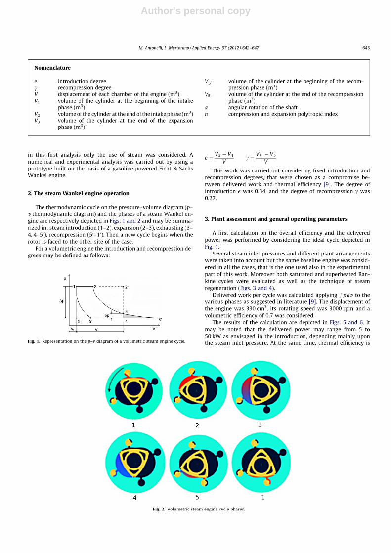
The thermodynamic cycle on the pressure–volume diagram (p–v thermodynamic diagram) and the phases of a steam Wankel en-gine are respectively depicted in Figs. 1 and 2 and may be summa-rized in: steam introduction (1–2), expansion (2–3), exhausting (3–4, 4–50), recompression (50–10). Then a new cycle begins when therotor is faced to the other site of the case.
For a volumetric engine the introduction and recompression de-grees may be defined as follows:
e ¼ V2 � V1
Vc ¼ V50 � V5
V
This work was carried out considering fixed introduction andrecompression degrees, that were chosen as a compromise be-tween delivered work and thermal efficiency [9]. The degree ofintroduction e was 0.34, and the degree of recompression c was0.27.
3. Plant assessment and general operating parameters
A first calculation on the overall efficiency and the deliveredpower was performed by considering the ideal cycle depicted inFig. 1.
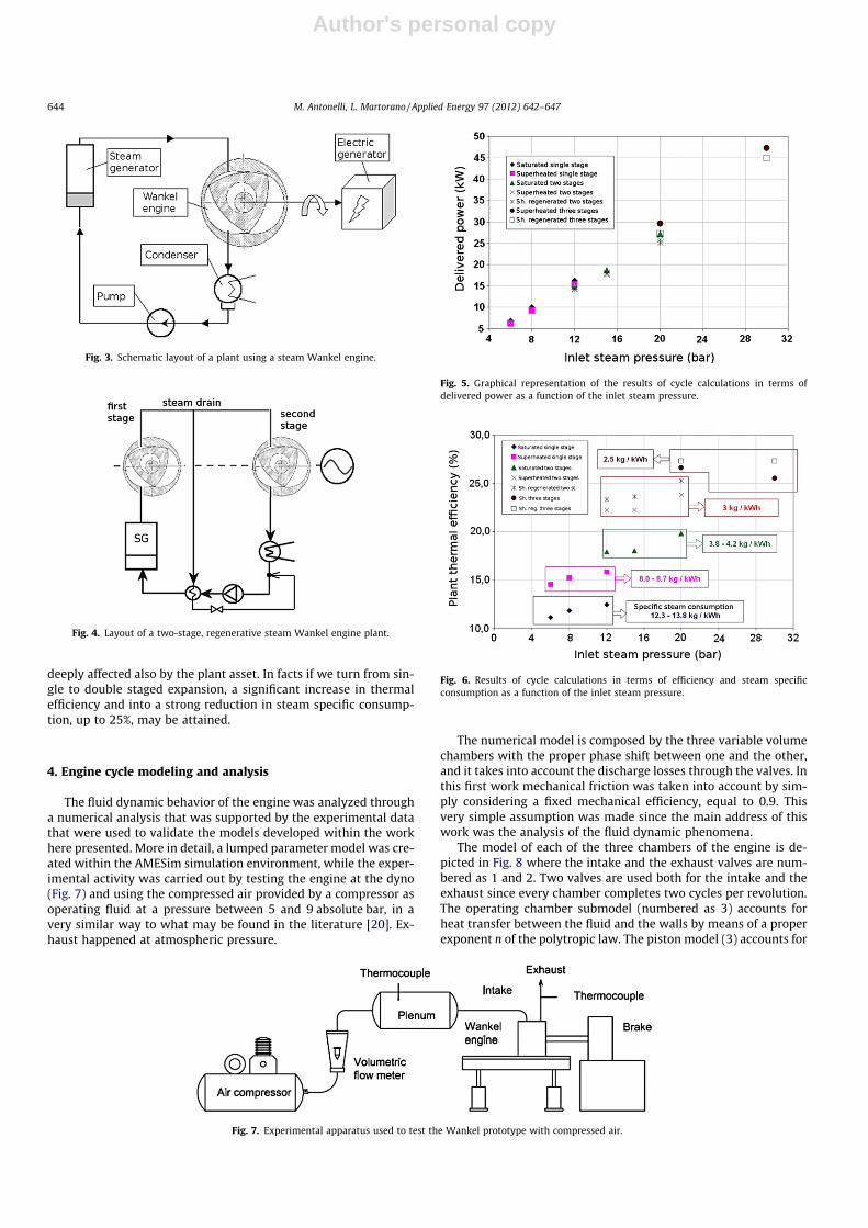
Several steam inlet pressures and different plant arrangementswere taken into account but the same baseline engine was consid-ered in all the cases, that is the one used also in the experimentalpart of this work. Moreover both saturated and superheated Ran-kine cycles were evaluated as well as the technique of steamregeneration (Figs. 3 and 4).
Delivered work per cycle was calculated applyingR
pdv to thevarious phases as suggested in literature [9]. The displacement ofthe engine was 330 cm3, its rotating speed was 3000 rpm and avolumetric efficiency of 0.7 was considered.
The results of the calculation are depicted in Figs. 5 and 6. Itmay be noted that the delivered power may range from 5 to50 kW as envisaged in the introduction, depending mainly uponthe steam inlet pressure. At the same time, thermal efficiency is
Nomenclature
e introduction degreec recompression degreeV displacement of each chamber of the engine (m3)V1 volume of the cylinder at the beginning of the intake
phase (m3)V2 volume of the cylinder at the end of the intake phase (m3)V3 volume of the cylinder at the end of the expansion
phase (m3)
V50 volume of the cylinder at the beginning of the recom-pression phase (m3)
V5 volume of the cylinder at the end of the recompressionphase (m3)
a angular rotation of the shaftn compression and expansion polytropic index
Fig. 1. Representation on the p–v diagram of a volumetric steam engine cycle.
Fig. 2. Volumetric steam engine cycle phases.
M. Antonelli, L. Martorano / Applied Energy 97 (2012) 642–647 643
Author's personal copy
deeply affected also by the plant asset. In facts if we turn from sin-gle to double staged expansion, a significant increase in thermalefficiency and into a strong reduction in steam specific consump-tion, up to 25%, may be attained.
4. Engine cycle modeling and analysis
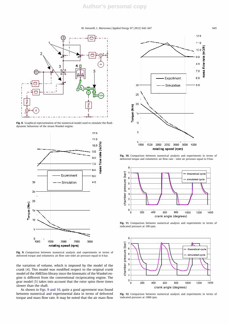
The fluid dynamic behavior of the engine was analyzed througha numerical analysis that was supported by the experimental datathat were used to validate the models developed within the workhere presented. More in detail, a lumped parameter model was cre-ated within the AMESim simulation environment, while the exper-imental activity was carried out by testing the engine at the dyno(Fig. 7) and using the compressed air provided by a compressor asoperating fluid at a pressure between 5 and 9 absolute bar, in avery similar way to what may be found in the literature [20]. Ex-haust happened at atmospheric pressure.
The numerical model is composed by the three variable volumechambers with the proper phase shift between one and the other,and it takes into account the discharge losses through the valves. Inthis first work mechanical friction was taken into account by sim-ply considering a fixed mechanical efficiency, equal to 0.9. Thisvery simple assumption was made since the main address of thiswork was the analysis of the fluid dynamic phenomena.
The model of each of the three chambers of the engine is de-picted in Fig. 8 where the intake and the exhaust valves are num-bered as 1 and 2. Two valves are used both for the intake and theexhaust since every chamber completes two cycles per revolution.The operating chamber submodel (numbered as 3) accounts forheat transfer between the fluid and the walls by means of a properexponent n of the polytropic law. The piston model (3) accounts for
Fig. 3. Schematic layout of a plant using a steam Wankel engine.
Fig. 4. Layout of a two-stage, regenerative steam Wankel engine plant.
Fig. 5. Graphical representation of the results of cycle calculations in terms ofdelivered power as a function of the inlet steam pressure.
Fig. 6. Results of cycle calculations in terms of efficiency and steam specificconsumption as a function of the inlet steam pressure.
Fig. 7. Experimental apparatus used to test the Wankel prototype with compressed air.
644 M. Antonelli, L. Martorano / Applied Energy 97 (2012) 642–647
Author's personal copy
the variation of volume, which is imposed by the model of thecrank (4). This model was modified respect to the original crankmodel of the AMESim library since the kinematic of the Wankel en-gine is different from the conventional reciprocating engine. Thegear model (5) takes into account that the rotor spins three timesslower than the shaft.
As shown in Figs. 9 and 10, quite a good agreement was foundbetween numerical and experimental data in terms of deliveredtorque and mass flow rate. It may be noted that the air mass flow
Fig. 8. Graphical representation of the numerical model used to simulate the fluid-dynamic behaviour of the steam Wankel engine.
Fig. 9. Comparison between numerical analysis and experiments in terms ofdelivered torque and volumetric air flow rate-inlet air pressure equal to 6 bar.
Fig. 10. Comparison between numerical analysis and experiments in terms ofdelivered torque and volumetric air flow rate - inlet air pressure equal to 9 bar.
Fig. 11. Comparison between numerical analysis and experiments in terms ofindicated pressure at 100 rpm.
Fig. 12. Comparison between numerical analysis and experiments in terms ofindicated pressure at 1000 rpm.
M. Antonelli, L. Martorano / Applied Energy 97 (2012) 642–647 645
Author's personal copy
rate behavior is far from being linear with the rotating speed, andin order to explain this behavior the in-chamber pressure wasanalyzed.
The simulated pressure cycles were compared with the sameideal cycle, plotted by means of the equations suggested by the lit-erature [9] at several rotating speeds, as reported in Figs. 11–13. At100 rpm (Fig. 11) the engine pressure behavior is very close to theideal one and only very slight differences can be noted, but if weincrease the rotating speed, for instance, up to 1000 (Fig. 12) andthen to 2500 rpm (Fig. 13), an increasing pressure drop acrossthe exhaust valve may be observed.
This fluid dynamic loss that prevents all the air to be completelydischarged and during the following recompression phase theremaining air pressure even exceeds the intake manifold pressureand steam backflow happens, thus reducing the volumetricefficiency.
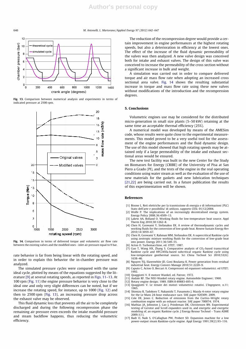
The reduction of the recompression degree would provide a cer-tain improvement in engine performances at the highest rotatingspeeds, but also a deterioration in efficiency at the lowest ones.The effect of the increase of the fluid dynamic permeability ofthe valves was then analyzed. A new valve design was conceivedboth for intake and exhaust valves. The design of this valve wasconceived to increase the permeability of the cross section withouta significant increase in bulk and weight.
A simulation was carried out in order to compare deliveredtorque and air mass flow rate when adopting an increased crosssectional area valve. Fig. 14 shows the resulting substantialincrease in torque and mass flow rate using these new valveswithout modifications of the introduction and the recompressiondegrees.
5. Conclusions
Volumetric engines use may be considered for the distributedmicro-generation in small size plants (5–50 kW) retaining at thesame time an acceptable thermal efficiency (25%).
A numerical model was developed by means of the AMESimcode, whose results were quite close to the experimental measure-ments. This model proved to be a very useful tool for the assess-ment of the engine performances and the fluid dynamic design.The use of this model showed that high rotating speeds may be at-tained only if a large permeability of the intake and exhaust sec-tional areas would be ensured.
The new test facility was built in the new Center for the Studyon Biomasses for Energy (CRIBE) of the University of Pisa at SanPiero a Grado (PI), and the tests of the engine in the real operatingconditions using water steam as well as the evaluation of the use ofnew materials for the gaskets and new lubrication techniques[21,22] are being carried out. In a future publication the resultsof this experimentation will be shown.
References
[1] Bisone L. Reti elettriche per la trasmissione di energia e di informazioni (PLC)Stato dell’arte e possibilita’ di utilizzo, rapporto CESI. 01/12/2004.
[2] Wolfe P. The implications of an increasingly decentralised energy system.Energy Policy 2008;36:4509–13.
[3] Lakew AA, Bolland O. Working fluids for low-temperature heat source. ApplTherm Eng 2010;30:1262–8.
[4] Chen H, Goswami Y, Stefanakos EK. A review of thermodynamic cycles andworking fluids for the conversion of low-grade heat. Renew Sustain Energy Rev2010;14:3059–67.
[5] Chen H, Goswami Y, Rahman MM, Stefanakos EK. A supercritical Rankine cycleusing zeotropic mixture working fluids for the conversion of low-grade heatinto power. Energy 2011;36:549–55.
[6] Acton O. Turbomacchine, ed. UTET; 1987.[7] Guo T, Wang HX, Zhang S. Comparative analysis of CO2-based transcritical
Rankine cycle and HFC245fa-based subcritical organic Rankine cycle usinglow-temperature geothermal source. Sci China Technol Sci 2010;53(6):1638–46.
[8] Nguyen TQ, Slawnwhite JD, Goni Boulama K. Power generation from residualindustrial heat. Energy Convers Manage 2010;51:2220–9.
[9] Caputo C, Acton O, Beccari A. Compressori ed espansori volumetrici. ed UTET;1992.
[10] Quaggiotti V. Il motore Wankel, ed. Patron; 1972.[11] Andale RF. The NSU-Wankel rotary engine. Automobile Engineer; 1960.[12] Rotary engine design; 1989. ISBN:0-89883-695-6.[13] Quaggiotti V. Le tenute dei motori volumetrici rotativi. L’Ingegnere, n.11;
1965.[14] Shimizu R, Tadokoro T, Nakanishi T, Funamoto J. Mazda 4-rotor rotary engine
for the Le Mans 24-hour endurance race. SAE paper 920309; 2009.[15] Cole DE, Jones C. Reduction of emissions from the Curtiss–Wright rotary
combustion engine with an exhaust reactor. SAE paper 700074; 1974.[16] Mathias JA, Johnston J, Cao J, Priedeman DK, Christensen RN. Experimental
testing of Gerotor and Scroll expanders used in, and energetic and exergeticmodeling of, an organic Rankine cycle. J Energy Resour Technol – Trans ASME2009;1(1).
[17] Badr O, Naik S, O’Callaghan PW, Probert SD. Expansion machine for a lowpower-output steam Rankine-cycle engine. Appl Energy 1991;39(2):93–116.
Fig. 13. Comparison between numerical analysis and experiments in terms ofindicated pressure at 2500 rpm.
Fig. 14. Comparison in terms of delivered torque and volumetric air flow ratebetween the existing valves and the modified ones - inlet air pressure equal to 9 bar.
646 M. Antonelli, L. Martorano / Applied Energy 97 (2012) 642–647

Author's personal copy
[18] Badr O, Naik S, O’Callaghan PW, Probert SD. Rotary Wankel engines asexpansion devices in steam Rankine-cycle engines. Appl Energy 1991;39(1):59–76.
[19] Badr O, Naik S, O’Callaghan PW, Probert SD. Wankel engines as steamexpanders: design considerations. Appl Energy 1991;40(2):157–70.
[20] Guangbin L, Yuanyang Z, Liansheng L, Pengchen S. Simulation and experimentresearch on wide ranging working process of scroll expander driven bycompressed air. Appl Therm Eng 2010;30:2073–9.
[21] Okularczyk W. Experimental investigations of guide rings made of UHMWPEand PTFE composite in water hydraulic systems. In: Archives of civil andmechanical engineering; 2004.
[22] Jia JH, Zhou HD, Gao SQ, Chen JM. A comparative investigation of the frictionand wear behavior of polyimide composites under dry sliding and water-lubricated condition. Wear 2006;261(11–12):1293–7.
M. Antonelli, L. Martorano / Applied Energy 97 (2012) 642–647 647