Embed Size (px)
Citation preview
IEEE TRANSACTIONS ON INDUSTRY APPLICATIONS, VOL. 38, NO. 6, NOVEMBER/DECEMBER 2002 1581
A Three-Phase Line-Interactive UPS SystemImplementation With Series-Parallel Active
Power-Line Conditioning CapabilitiesSérgio Augusto Oliveira da Silva, Pedro Francisco Donoso-Garcia, Porfirio Cabaleiro Cortizo, and
Paulo Fernando Seixas
Abstract—This paper presents a three-phase line-interactiveuninterruptible power supply (UPS) system with series-par-allel active power-line conditioning capabilities, using a syn-chronous-reference-frame (SRF)-based controller, which allowsan effective power-factor correction, load harmonic currentsuppression, and output voltage regulation. The three-phase UPSsystem is composed of two active power filter topologies. The firstone is a series active power filter, which works as a sinusoidalcurrent source in phase with the input voltage. The other is aparallel active power filter, which works as a sinusoidal voltagesource in phase with the input voltage, providing to the load a reg-ulated and sinusoidal voltage with low total harmonic distortion.Operation of a three-phase phase-locked loop structure, used inthe proposed line-interactive UPS implementation, is presentedand experimentally verified under distorted utility conditions. Thecontrol algorithm using the SRF method and the active power flowthrough the UPS system are described and analytically studied.Design procedures, digital simulations, and experimental resultsfor a prototype are presented to verify the good performance ofthe proposed three-phase line-interactive UPS system.
Index Terms—Active power-line conditioning, harmonic com-pensation, series-parallel active filter, synchronous referenceframe (SRF).
I. INTRODUCTION
T O IMPROVE the power source quality, uninterruptiblepower supply (UPS) systems have been employed, which
provide clean and uninterruptible power to critical loads such ascomputers, medical equipment, etc., against power supply dis-turbances [1]–[7]. In [6] and [7], three-phase parallel processingUPSs have been presented with harmonic and reactive powercompensation, but the output voltages and the input currentscannot be controlled simultaneously. Three-phase UPS systemswith series-parallel active power-line conditioning have beenproposed using different control strategies [1]–[3]. In [3], the
Paper IPCSD 02–045, presented at the 2001 Industry Applications SocietyAnnual Meeting, Chicago, IL, September 30–October 5, and approved for pub-lication in the IEEE TRANSACTIONS ONINDUSTRY APPLICATIONSby the Indus-trial Power Converter Committee of the IEEE Industry Applications Society.Manuscript submitted for review November 1, 2001 and released for publica-tion July 20, 2002.
S. A. O. da Silva is with the Department of Electrical Engineering, Fed-eral Center of Technological Education, 86300-000 Cornélio Procópio, Brazil(e-mail: [email protected]).
P. F. Donoso-Garcia, P. C. Cortizo, and P. F. Seixas are with the ElectricalEngineering R&D Center, Federal University of Minas Gerais, 31270-901 BeloHorizonte, Brazil (e-mail: [email protected]; [email protected];[email protected]).
Digital Object Identifier 10.1109/TIA.2002.804760
three-phase UPS system was employed for three-wire systems,and in [1] and [2] it was employed for three-wire and four-wiresystems. In these papers, two different approaches to controlthree-phase UPS systems using synchronous-reference-frame(SRF)-based controllers were proposed, but only simulationsresults were presented.
This paper presents experimental results for a three-phaseline-interactive UPS system with series-parallel activepower-line conditioning using an SRF-based controller, forthree-phase, three-wire, and four-wire systems. The seriesactive power filter acts as a sinusoidal current source andthe parallel active power filter acts as a sinusoidal voltagesource [2]. In this line-interactive UPS system, an effectivepower-factor correction is carried out. The output voltages arecontrolled to have constant rms values and low total harmonicdistortion (THD) and the source currents are controlled to bebalanced and sinusoidal quantities with low THD, also.
Operation of a three-phase phase-locked loop (PLL) struc-ture, used in the line-interactive UPS implementation, is pre-sented and experimentally tested under distorted utility condi-tions. A PLL model is shown and design procedures to achievethe proportional–integral (PI) controller gains are presented.
The control algorithm using the SRF method and the activepower flow through the UPS system are described and analyti-cally studied. Design procedures, digital simulations, and exper-imental results for a prototype are presented in order to verifythe good performance of the proposed three-phase line-interac-tive UPS system.
II. OPERATION OF THELINE-INTERACTIVE UPS TOPOLOGY
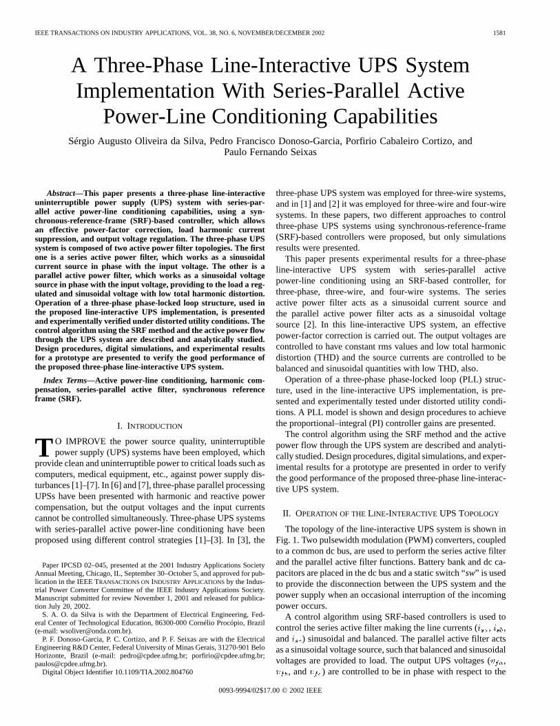
The topology of the line-interactive UPS system is shown inFig. 1. Two pulsewidth modulation (PWM) converters, coupledto a common dc bus, are used to perform the series active filterand the parallel active filter functions. Battery bank and dc ca-pacitors are placed in the dc bus and a static switch “sw” is usedto provide the disconnection between the UPS system and thepower supply when an occasional interruption of the incomingpower occurs.
A control algorithm using SRF-based controllers is used tocontrol the series active filter making the line currents (, ,and ) sinusoidal and balanced. The parallel active filter actsas a sinusoidal voltage source, such that balanced and sinusoidalvoltages are provided to load. The output UPS voltages (,
, and ) are controlled to be in phase with respect to the
0093-9994/02$17.00 © 2002 IEEE
1582 IEEE TRANSACTIONS ON INDUSTRY APPLICATIONS, VOL. 38, NO. 6, NOVEMBER/DECEMBER 2002
Fig. 1. Line-interactive UPS system topology.
Fig. 2. Block diagram of the current SRF-based controller.
input voltages ( , , and ), respectively. Both the paralleland the series filter use three independent controllers acting onhalf-bridge inverters.
III. SRF AND STATE FEEDBACK CONTROLLERS
A. Current SRF Controller (Standby Mode)
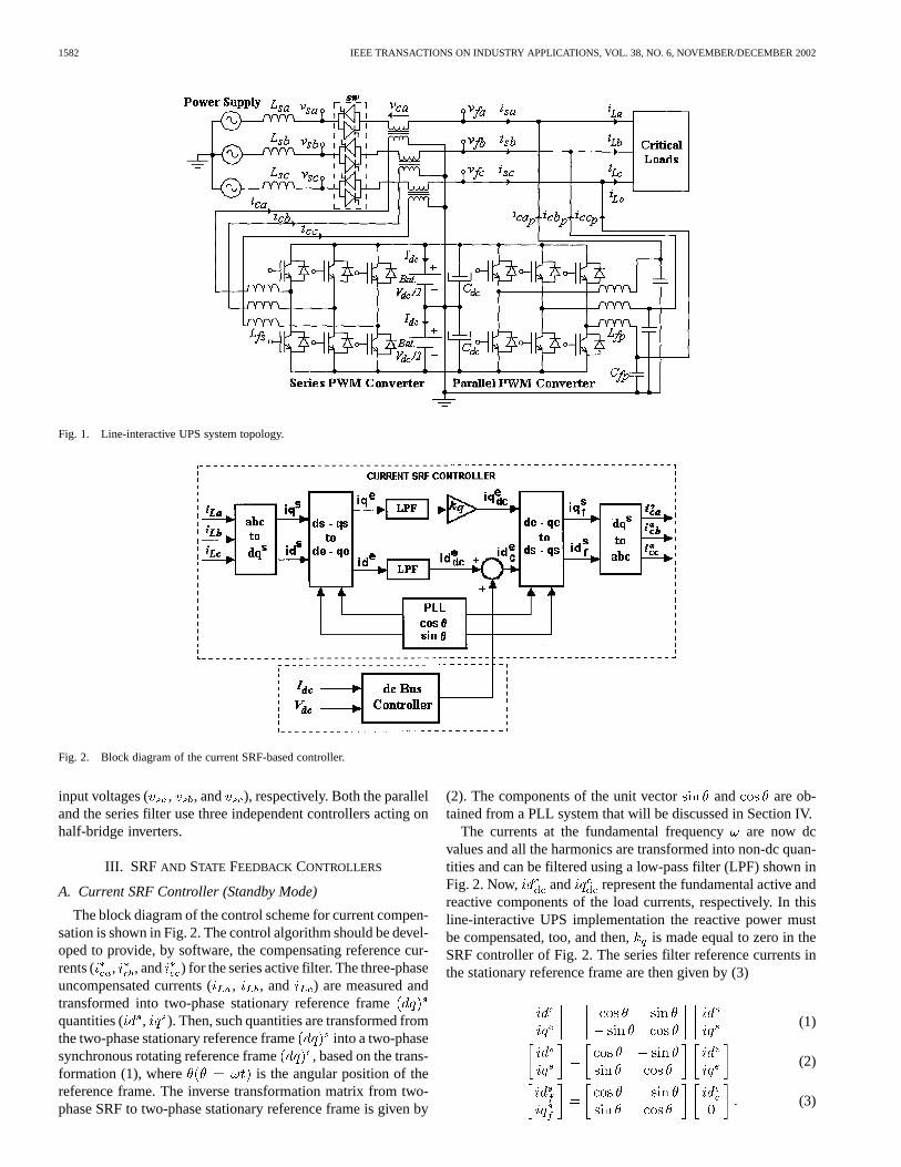
The block diagram of the control scheme for current compen-sation is shown in Fig. 2. The control algorithm should be devel-oped to provide, by software, the compensating reference cur-rents ( , , and ) for the series active filter. The three-phaseuncompensated currents ( , , and ) are measured andtransformed into two-phase stationary reference framequantities ( , ). Then, such quantities are transformed fromthe two-phase stationary reference frame into a two-phasesynchronous rotating reference frame , based on the trans-formation (1), where is the angular position of thereference frame. The inverse transformation matrix from two-phase SRF to two-phase stationary reference frame is given by
(2). The components of the unit vector and are ob-tained from a PLL system that will be discussed in Section IV.
The currents at the fundamental frequencyare now dcvalues and all the harmonics are transformed into non-dc quan-tities and can be filtered using a low-pass filter (LPF) shown inFig. 2. Now, and represent the fundamental active andreactive components of the load currents, respectively. In thisline-interactive UPS implementation the reactive power mustbe compensated, too, and then,is made equal to zero in theSRF controller of Fig. 2. The series filter reference currents inthe stationary reference frame are then given by (3)
(1)
(2)
(3)
DA SILVA et al.: THREE-PHASE LINE-INTERACTIVE UPS SYSTEM IMPLEMENTATION 1583
Fig. 3. Single-phase current controller of the series active filter.
Thereby, the dc components of the SRF are transformed intothe stationary reference frame and yield all fundamentalcomponents of the input uncompensated ac currents. The ma-trices that provide the linear transformation from three-phasesystem to two-phase stationary reference frame system andfrom two-phase system to three-phase stationary referenceframe system are given by (4) and (5), respectively. An addi-tional dc-bus controller is responsible for regulating the current
and the voltage . Apart from the conventional activepower filter applications, in which only the dc-bus voltage iscontrolled, the UPS dc-bus controller must be able to controlthe dc-bus current, too. The dc-bus controller is responsiblefor the control of the power flow through the UPS system. Itsoutput is added to the active current in theaxis and, thus,the amplitude of the input currents is controlled as shown inFig. 2
(4)
(5)
B. State Feedback Current Controller (Standby Mode)
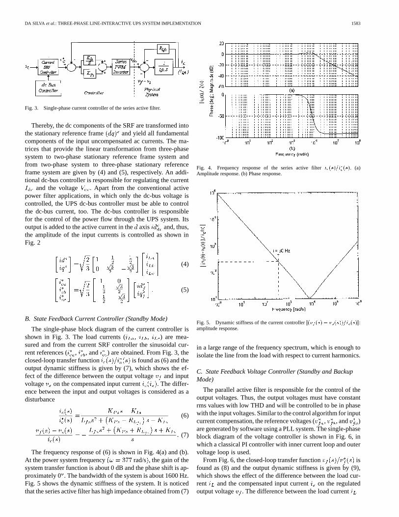
The single-phase block diagram of the current controller isshown in Fig. 3. The load currents ( , , ) are mea-sured and from the current SRF controller the sinusoidal cur-rent references ( , , and ) are obtained. From Fig. 3, theclosed-loop transfer function is found as (6) and theoutput dynamic stiffness is given by (7), which shows the ef-fect of the difference between the output voltageand inputvoltage on the compensated input current . The differ-ence between the input and output voltages is considered as adisturbance
(6)
(7)
The frequency response of (6) is shown in Fig. 4(a) and (b).At the power system frequency rad/s , the gain of thesystem transfer function is about 0 dB and the phase shift is ap-proximately 0 . The bandwidth of the system is about 1600 Hz.Fig. 5 shows the dynamic stiffness of the system. It is noticedthat the series active filter has high impedance obtained from (7)
Fig. 4. Frequency response of the series active filteri (s)=i (s). (a)Amplitude response. (b) Phase response.
Fig. 5. Dynamic stiffness of the current controllerj(v (s)� v (s))=i (s)j:amplitude response.
in a large range of the frequency spectrum, which is enough toisolate the line from the load with respect to current harmonics.
C. State Feedback Voltage Controller (Standby and BackupMode)
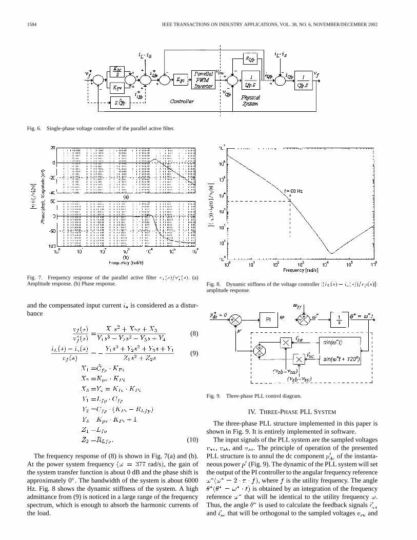
The parallel active filter is responsible for the control of theoutput voltages. Thus, the output voltages must have constantrms values with low THD and will be controlled to be in phasewith the input voltages. Similar to the control algorithm for inputcurrent compensation, the reference voltages (, , and )are generated by software using a PLL system. The single-phaseblock diagram of the voltage controller is shown in Fig. 6, inwhich a classical PI controller with inner current loop and outervoltage loop is used.
From Fig. 6, the closed-loop transfer function isfound as (8) and the output dynamic stiffness is given by (9),which shows the effect of the difference between the load cur-rent and the compensated input currenton the regulatedoutput voltage . The difference between the load current
1584 IEEE TRANSACTIONS ON INDUSTRY APPLICATIONS, VOL. 38, NO. 6, NOVEMBER/DECEMBER 2002
Fig. 6. Single-phase voltage controller of the parallel active filter.
Fig. 7. Frequency response of the parallel active filterv (s)=v (s). (a)Amplitude response. (b) Phase response.
and the compensated input currentis considered as a distur-bance
(8)
(9)
(10)
The frequency response of (8) is shown in Fig. 7(a) and (b).At the power system frequency rad/s , the gain ofthe system transfer function is about 0 dB and the phase shift isapproximately 0. The bandwidth of the system is about 6000Hz. Fig. 8 shows the dynamic stiffness of the system. A highadmittance from (9) is noticed in a large range of the frequencyspectrum, which is enough to absorb the harmonic currents ofthe load.
Fig. 8. Dynamic stiffness of the voltage controllerj(i (s)� i (s))=v (s)j:amplitude response.
Fig. 9. Three-phase PLL control diagram.
IV. THREE-PHASE PLL SYSTEM
The three-phase PLL structure implemented in this paper isshown in Fig. 9. It is entirely implemented in software.
The input signals of the PLL system are the sampled voltages, , and . The principle of operation of the presented
PLL structure is to annul the dc component of the instanta-neous power (Fig. 9). The dynamic of the PLL system will setthe output of the PI controller to the angular frequency reference
, where is the utility frequency. The angleis obtained by an integration of the frequency
reference that will be identical to the utility frequency .Thus, the angle is used to calculate the feedback signalsand that will be orthogonal to the sampled voltages and
DA SILVA et al.: THREE-PHASE LINE-INTERACTIVE UPS SYSTEM IMPLEMENTATION 1585
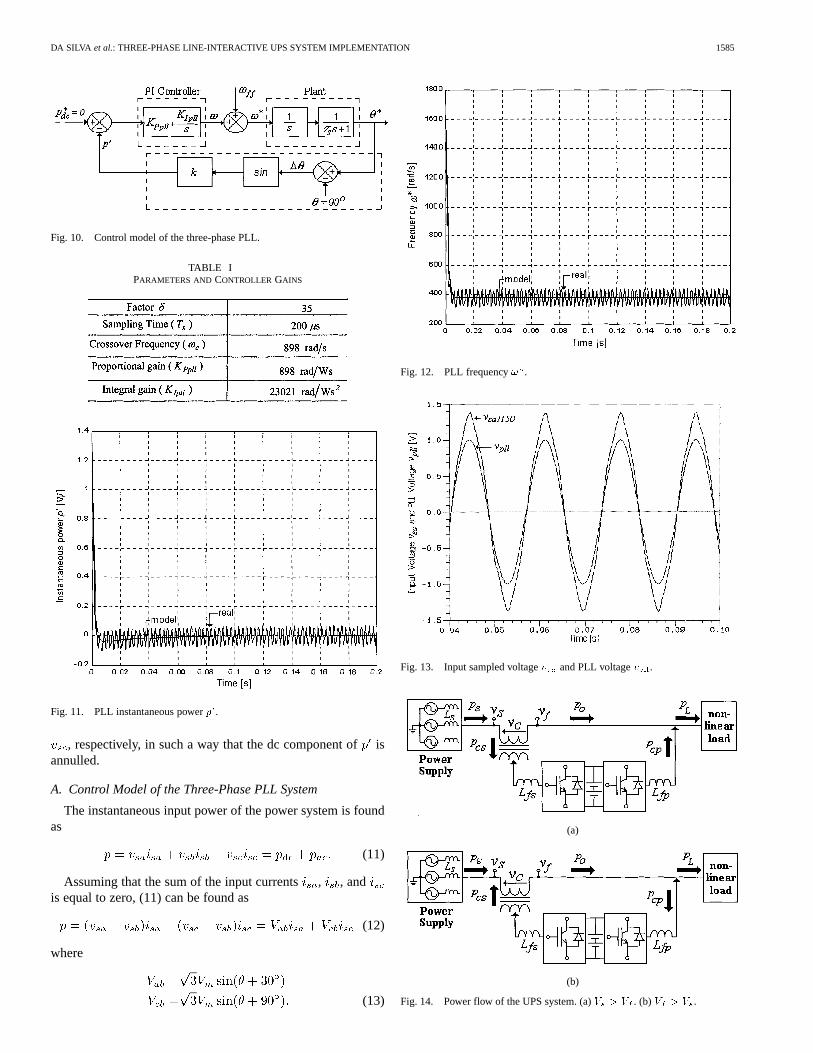
Fig. 10. Control model of the three-phase PLL.
TABLE IPARAMETERS AND CONTROLLER GAINS
Fig. 11. PLL instantaneous powerp .
, respectively, in such a way that the dc component ofisannulled.
A. Control Model of the Three-Phase PLL System
The instantaneous input power of the power system is foundas
(11)
Assuming that the sum of the input currents, , andis equal to zero, (11) can be found as
(12)
where
(13)
Fig. 12. PLL frequency! .
Fig. 13. Input sampled voltagev and PLL voltagev .
(a)
(b)
Fig. 14. Power flow of the UPS system. (a)V > V . (b)V > V .
1586 IEEE TRANSACTIONS ON INDUSTRY APPLICATIONS, VOL. 38, NO. 6, NOVEMBER/DECEMBER 2002
(a)
(b)
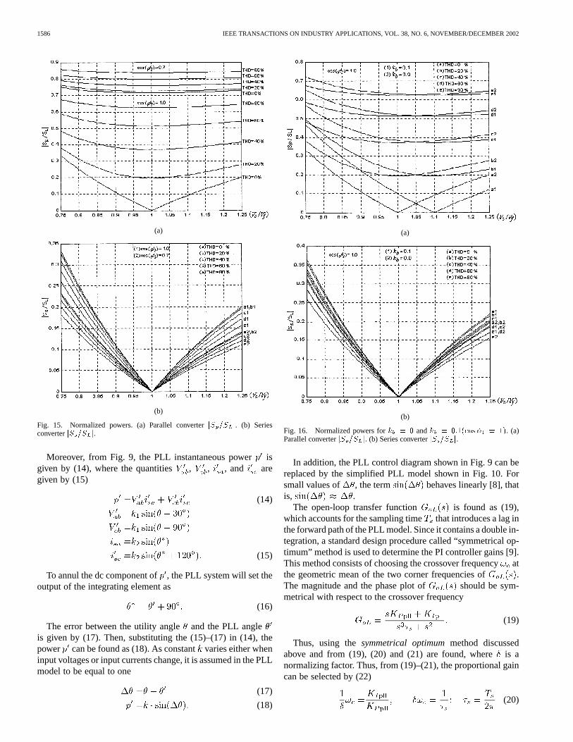
Fig. 15. Normalized powers. (a) Parallel converterjS =S j. (b) SeriesconverterjS =S j.
Moreover, from Fig. 9, the PLL instantaneous powerisgiven by (14), where the quantities , , , and aregiven by (15)
(14)
(15)
To annul the dc component of, the PLL system will set theoutput of the integrating element as
(16)
The error between the utility angleand the PLL angleis given by (17). Then, substituting the (15)–(17) in (14), thepower can be found as (18). As constantvaries either wheninput voltages or input currents change, it is assumed in the PLLmodel to be equal to one
(17)
(18)
(a)
(b)
Fig. 16. Normalized powers fork = 0 andk = 0:1(cos� = 1). (a)Parallel converterjS =S j. (b) Series converterjS =S j.
In addition, the PLL control diagram shown in Fig. 9 can bereplaced by the simplified PLL model shown in Fig. 10. Forsmall values of , the term behaves linearly [8], thatis, .
The open-loop transfer function is found as (19),which accounts for the sampling time that introduces a lag inthe forward path of the PLL model. Since it contains a double in-tegration, a standard design procedure called “symmetrical op-timum” method is used to determine the PI controller gains [9].This method consists of choosing the crossover frequencyatthe geometric mean of the two corner frequencies of .The magnitude and the phase plot of should be sym-metrical with respect to the crossover frequency
(19)
Thus, using thesymmetrical optimummethod discussedabove and from (19), (20) and (21) are found, whereis anormalizing factor. Thus, from (19)–(21), the proportional gaincan be selected by (22)
(20)
DA SILVA et al.: THREE-PHASE LINE-INTERACTIVE UPS SYSTEM IMPLEMENTATION 1587
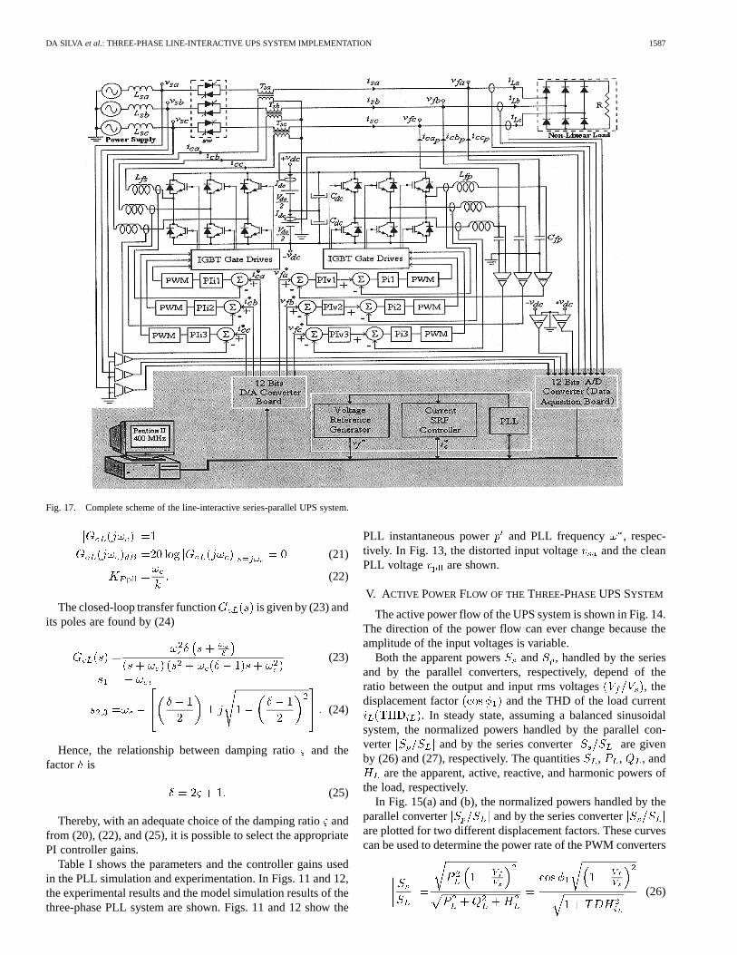
Fig. 17. Complete scheme of the line-interactive series-parallel UPS system.
(21)
(22)
The closed-loop transfer function is given by (23) andits poles are found by (24)
(23)
(24)
Hence, the relationship between damping ratioand thefactor is
(25)
Thereby, with an adequate choice of the damping ratioandfrom (20), (22), and (25), it is possible to select the appropriatePI controller gains.
Table I shows the parameters and the controller gains usedin the PLL simulation and experimentation. In Figs. 11 and 12,the experimental results and the model simulation results of thethree-phase PLL system are shown. Figs. 11 and 12 show the
PLL instantaneous power and PLL frequency , respec-tively. In Fig. 13, the distorted input voltage and the cleanPLL voltage are shown.
V. ACTIVE POWERFLOW OF THETHREE-PHASE UPS SYSTEM
The active power flow of the UPS system is shown in Fig. 14.The direction of the power flow can ever change because theamplitude of the input voltages is variable.
Both the apparent powers and , handled by the seriesand by the parallel converters, respectively, depend of theratio between the output and input rms voltages , thedisplacement factor and the THD of the load current
. In steady state, assuming a balanced sinusoidalsystem, the normalized powers handled by the parallel con-verter and by the series converter are givenby (26) and (27), respectively. The quantities, , , and
are the apparent, active, reactive, and harmonic powers ofthe load, respectively.
In Fig. 15(a) and (b), the normalized powers handled by theparallel converter and by the series converterare plotted for two different displacement factors. These curvescan be used to determine the power rate of the PWM converters
(26)
1588 IEEE TRANSACTIONS ON INDUSTRY APPLICATIONS, VOL. 38, NO. 6, NOVEMBER/DECEMBER 2002
(a) (b)
(c) (d)
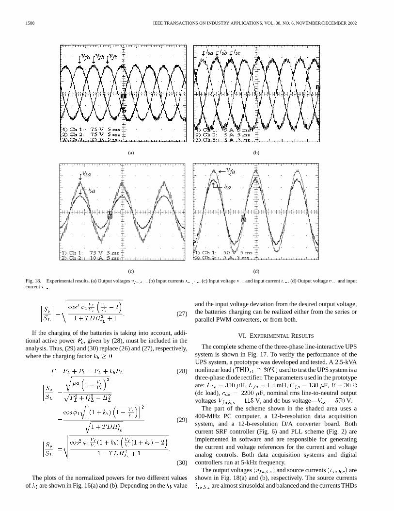
Fig. 18. Experimental results. (a) Output voltagesv . (b) Input currentsi . (c) Input voltagev and input currenti . (d) Output voltagev and inputcurrenti .
(27)
If the charging of the batteries is taking into account, addi-tional active power , given by (28), must be included in theanalysis. Thus, (29) and (30) replace (26) and (27), respectively,where the charging factor
(28)
(29)
(30)
The plots of the normalized powers for two different valuesof are shown in Fig. 16(a) and (b). Depending on thevalue
and the input voltage deviation from the desired output voltage,the batteries charging can be realized either from the series orparallel PWM converters, or from both.
VI. EXPERIMENTAL RESULTS
The complete scheme of the three-phase line-interactive UPSsystem is shown in Fig. 17. To verify the performance of theUPS system, a prototype was developed and tested. A 2.5-kVAnonlinear load used to test the UPS system is athree-phase diode rectifier. The parameters used in the prototypeare: H, mH, F,(dc load), F, nominal rms line-to-neutral outputvoltages V, and dc bus voltage— V.
The part of the scheme shown in the shaded area uses a400-MHz PC computer, a 12-b-resolution data acquisitionsystem, and a 12-b-resolution D/A converter board. Bothcurrent SRF controller (Fig. 6) and PLL scheme (Fig. 2) areimplemented in software and are responsible for generatingthe current and voltage references for the current and voltageanalog controls. Both data acquisition systems and digitalcontrollers run at 5-kHz frequency.
The output voltages and source currents areshown in Fig. 18(a) and (b), respectively. The source currents
are almost sinusoidal and balanced and the currents THDs
DA SILVA et al.: THREE-PHASE LINE-INTERACTIVE UPS SYSTEM IMPLEMENTATION 1589
(e) (f)
(g) (h)
(i)
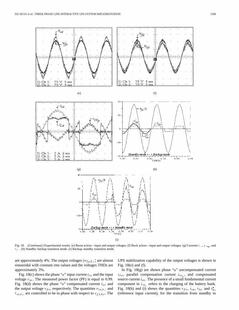
Fig. 18. (Continued.)Experimental results. (e) Boost action—input and output voltages. (f) Buck action—input and output voltages. (g) Currentsi , i , andi . (h) Standby–backup transition mode. (i) Backup–standby transition mode.
are approximately 4%. The output voltages are almostsinusoidal with constant rms values and the voltages THDs areapproximately 3%.
Fig. 18(c) shows the phase “” input current and the inputvoltage . The measured power factor (PF) is equal to 0.99.Fig. 18(d) shows the phase “” compensated current andthe output voltage , respectively. The quantities and
are controlled to be in phase with respect to . The
UPS stabilization capability of the output voltages is shown inFig. 18(e) and (f).
In Fig. 18(g) are shown phase “” uncompensated current, parallel compensation current , and compensated
source current . The presence of a small fundamental currentcomponent in refers to the charging of the battery bank.Fig. 18(h) and (i) shows the quantities , , and(reference input current), for the transition from standby to
1590 IEEE TRANSACTIONS ON INDUSTRY APPLICATIONS, VOL. 38, NO. 6, NOVEMBER/DECEMBER 2002
backup mode (0.02 s) and from backup to standby mode(0.31 s).
VII. CONCLUSIONS
A three-phase line-interactive UPS system topology withactive series-parallel power-line conditioning capabilities hasbeen implemented and tested. Sinusoidal and regulated outputvoltages, sinusoidal input currents, and high input power factorwere obtained. A model of a PLL system was presented andboth PLL system and the algorithm of the SRF-based controllerwere implemented in software without the use of any hardwarefilters.
The main advantage of the presented line-interactive UPStopology, as compared to the online topology, which uses twocascaded PWM power converters working at full power rating,is the smaller power rating handled by both series and parallelconverters during the standby mode, increasing the efficiency ofthe UPS. Depending on the VA load rating, the presented lineinteractive UPS system can be an attractive and practical solu-tion.
It has been demonstrated that the experimentally obtained re-sults have a good approximation with the theoretically predictedresults.
REFERENCES
[1] S. A. O. da Silva, P. F. Donoso-Garcia, and P. C. Cortizo, “A three-phaseseries-parallel compensated line-interactive UPS system with sinusoidalinput current and sinusoidal output voltage,” inConf. Rec. IEEE-IASAnnu. Meeting, vol. 2, 1999, pp. 826–832.
[2] S. A. O. da Silva, P. F. Donoso-Garcia, P. C. Cortizo, and P. F. Seixas,“A comparative analysis of control algorithms for three-phase line-inter-active UPS systems with series-parallel active power-line conditioningusing SRF method,” inProc. IEEE PESC, 2000, CD-ROM.
[3] F. Kamran and T. Habetler, “A novel on-line UPS with universal filteringcapabilities,” inProc. IEEE PESC’95, 1995, pp. 500–506.
[4] S. J. Jeon and G. H. Cho, “A series-parallel compensated uninterrupt-ible power supply with sinusoidal input current and sinusoidal outputvoltage,” inProc. IEEE PESC’97, 1997, pp. 297–303.
[5] R. Cheung, L. Cheng, P. Yu, and R. Sotudeh, “New line-interactive UPSsystem with DSP-based active power-line conditioning,” inProc. IEEEPESC’96, vol. 2, 1996, pp. 981–985.
[6] G. Joos, Y. Lin, P. D. Ziogas, and J. F. Lindsay, “An on-line UPS withimproved input-output characteristics,” inProc. IEEE APEC’92, 1992,pp. 598–605.
[7] Y. Lin, G. Joos, and J. F. Lindsay, “Performance analysis of par-allel—Processing UPS systems,” inProc. IEEE APEC’93, 1993, pp.533–539.
[8] V. Kaura and V. Blasko, “Operation of a phase locked loop system underdistorted utility conditions,”IEEE Trans. Ind. Applicat., vol. 33, pp.58–63, Jan./Feb. 1997.
[9] W. Leonard,Control of Electrical Drives. Berlin, Germany: Springer-Verlag, 1985, pp. 67–76.
Sérgio Augusto Oliveira da Silvareceived the B.S.and M.S. degrees in electrical engineering from theFederal University of Santa Catarina, Florianópolis,Brazil, in 1987 and 1989, respectively, and the Ph.D.degree from the Federal University of Minas Gerais,Belo Horizonte, Brazil, in 2001.
From 1990 to 1992, he was with Spectro—Engi-neering and Electronic Systems Inc., Brazil, workingon projects development, including switchingpower converters and UPS inverters. Since 1993,he has been a member of the Federal Center of
Technological Education (CEFET-PR), Cornélio Procópio, Brazil. where hecurrently is a Professor of Electrical Engineering. His present research involvespower electronic inverters, UPS systems, active filters, and control systems.
Pedro Francisco Donoso-Garcia (S’88-M’92)received the B.S. degree in electronic engineeringfrom the Federal University of Rio Grande do Sul,Porto Alegre, Brazil, in 1981, the M.S. degreein electrical and electronics engineering from theFederal University of Minas Gerais, Belo Horizonte,Brazil, in 1986, and the Ph.D. degree in electrical andelectronics engineering from the Federal Universityof Santa Catarina, Florianópolis, Brazil, in 1991.
He currently is an Associate Professor in the De-partment of Electronic Engineering, Federal Univer-
sity of Minas Gerais. His research interests include high-frequency and high-efficiency switching power converters UPS systems, power active filters, andaudio amplifiers.
Porfírio Cabaleiro Cortizo was born in Belo Hori-zonte, Brazil, in 1955. He received the B.S. degree inelectrical engineering from the Federal University ofMinas Gerais, Belo Horizonte, Brazil, in 1978, andthe Dr.Ing. degree from the Institut Polytechnique deToulouse, Toulouse, France, in 1984.
Since 1978, he has been a member of the Elec-tronic Engineering Department, Federal Universityof Minas Gerais, where he currently is a Professor ofElectrical Engineering. His research interests includehigh-frequency and high-efficiency switching power
converters UPS systems, active filters, and control systems.
Paulo Fernando Seixaswas born in Belo Horizonte,Brazil, in 1957. He received the B.S. and M.S.degrees in electrical engineering from the FederalUniversity of Minas Gerais, Belo Horizonte, Brazil,in 1980 and 1983, respectively, and the Ph.D.degree from the Institut Polytechnique de Toulouse,Toulouse, France, in 1988.
He has been a member of the Electrical Engi-neering Department, Federal University of MinasGerais, since 1980, where he currently is a Professorof Electrical Engineering. His research interests are
in the fields of electrical machines and drives, power electronics, and digitalsignal processing.


