Embed Size (px)
Citation preview
Received: 24 February 2018
DOI: 10.1002/mop.31387
A wideband antenna usingmetasurface for the 2G/3G/LTE/5G communications
Botao Feng1 | Lei Li1 |
Qingsheng Zeng2 | Kwok L. Chung3
1College of Electronic Science and Technology, Shenzhen University,Shenzhen, China2College of Aeronautics, Nanjing University of Aeronautics andAstronautics, Nanjing, China3School of Communications and Electronic Engineering, QingdaoUniversity of Technology, Qingdao, China
CorrespondenceBotao Feng, College of Electronic Science and Technology, ShenzhenUniversity, Shenzhen 518 060, China.Email: [email protected]
Funding informationFundamental Research Foundation of Shenzhen, Grant/Award Number: No.JCYJ20160308100236349; Key Project of Department of Education ofGuangdong Province, Grant/Award Number: No.2015KTSCX123; NaturalScience Foundation of Guangdong Province, China, Grant/Award Number:No.2016A030310056; Natural Science Foundation of SZU, Grant/AwardNumber: No.2016021
AbstractA wideband antenna using metasurface is proposed for thefuture 5G communications. By using the metasurface andthe multi-layer substrate with high relative permittivity, theheight of the proposed antenna can be reduced to 0.11 ?c inthe operating frequency band. The metasurface including40 unit cells are arranged on the second layer to improve thegain at the upper frequencies. Besides, by employing thedual arc-shaped defected ground structure, the impedancebandwidth can also be broaden and the gain can beimproved. The measured result shows that an impedancebandwidth of 77.2% (1.63-3.68 GHz) with a stable gain of5.1� 1.2 dBi can be obtained. Hence, the proposed antennais potentially suitable for the future 5G communications.
KEYWORDS
Metasurface antenna, wideband antenna, magneto-electric(ME) dipole,
stable beamwidth
1 | INTRODUCTION
WIDE bandwidth antennas with stable gain, which can satisfythe need of modern wireless communication system, have
attracted many researches attention because of its prominentmerits, such as much stabler data transmission rate and highercapacity.1 Since 2015, the frequency band ranging from 3.4 to3.6 GHz has been assigned to the future the fifth generation(5G) mobile communication by World Radio CommunicationConference 2015 (WRC-15).2 Therefore, the mobile commu-nication frequency bands for 2G/3G/LTE/5G communicationmay be expanded to 1.71-2.69 GHz and 3.4-3.6 GHz, respec-tively.3 Among the numerous antennas, the magneto-electric(ME) dipole antenna, which owns the outstanding advantagessuch as wide impedance bandwidth, stable gain, good front-to-back ratio (FBR) and low cross-polarization, and so on, isone of the most competitive candidates.4,5 However, one ofthe obvious drawbacks of the previous ME dipole antennas isthe bulky structure with high profile >0.25 λc6 (where λc isthe free-space wavelength at the center frequency). The tech-nology of antenna printed on the multi-layer substrate is oneof the most effective ways to obtain low profile feature.7
On the other hand, metasurface (MS) which owns theunique electromagnetic properties as the metamaterial hasbecome a hot research topic recently. Conventionally, the MSwhich consists of electrically small scatters is used to improvethe antenna performance. For example, by setting the MSnearby the radiated microstrip patches, the impedance band-width can be widen and the gain can also be increased. Inreference,8 by placing a MS above of the linear polarizationsource antenna, the signal can be converted between the linearand circular polarizations. However, due to the existence ofan air gap between the source antenna and the MS, the profileof the antenna is still high. On the other hand, frequencyreconfiguration can also be attained by mechanically rotatingthe MS around the center of the radiated antenna.9 In addition,the radar cross section can be reduced by using an asymmetriccross-shaped MS.10 Nevertheless, this kind of MS antennastill suffers from the narrow impedance bandwidth.
In this article, a low profile wideband antenna using MSis proposed for the future 5G mobile communication. Unlikethe traditional 3D ME dipole antenna, the ME antenna isprinted on the 5-layer integrated substrate to acquire thelow-profile property. By arranging the MS above the secondlayer, the antenna gain can be improved due to the MSinherent electromagnetic properties. Besides, the stair-shaped feeding structure cooperated with the arc-shapeddefected ground to achieve a good impedance matching. Asa result, an impedance bandwidth of 75% with a stable gainof 5.1 dBi and cross polarization <−30 dB can be obtainedover the entire operating frequency.
2 | ANTENNA GEOMETRY ANDWORKING MECHANISM
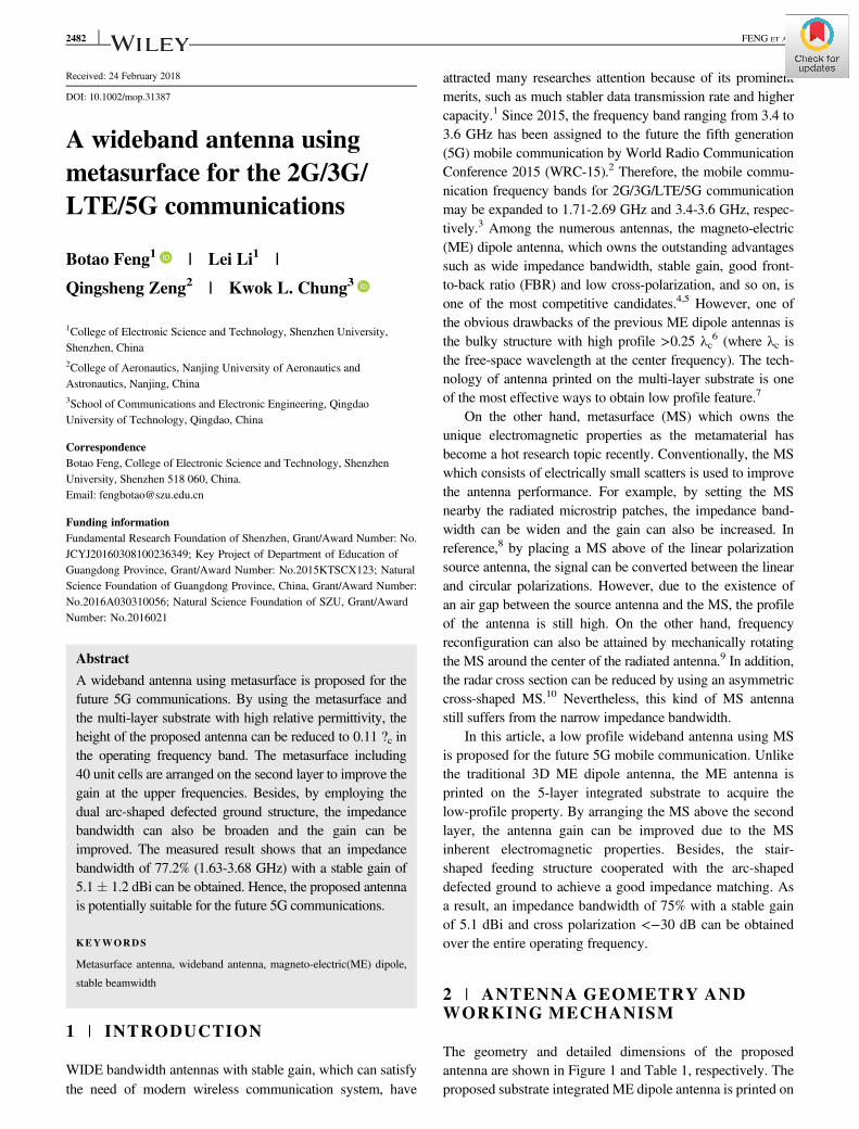
The geometry and detailed dimensions of the proposedantenna are shown in Figure 1 and Table 1, respectively. Theproposed substrate integrated ME dipole antenna is printed on
2482 FENG ET AL.
Taconic RF-35 substrate with a dielectric constant of 3.5 anda loss tangent of 0.0018. The antenna consists of the top-layerradiated electric dipole patch with bow-tie slot, the MS whichconsists of 40 unit cells set on the second layer, the arc-shapeddefeated ground above the fifth-layer substrate, and the stair-shaped feeding structure which is located at the center of the5-layer substrate. The bow-tie slot etched on the radiatedpatch is used to achieve a wide impedance bandwidth due tothe increased effective electric length. The electric dipolepatch is connected with the ground plane by a pair of viaholes. The via holes and the ground between them form themagnetic dipole. The stair-shaped feeding structure helps toreduce the height and provides flexible impedance matching.The electric dipole together with the magnetic dipole consti-tute a ME dipole antenna. It can be excited by the stair-shapedfeeding structure to obtain the complementary radiation pat-tern. Due to the MS and the arc-shaped defected ground, thegain can be increased and the profile of the antenna can alsobe reduced. Noting that the third- and fourth-layer substratesare used to improve the via hole impedance matching at thecost of slightly increasing the height of the antenna.
3 | PARAMETRIC STUDY ANDRESULT DISCUSSION
In order to study how the structures and the dimensionsaffected the antenna performances, such as wide
impedance bandwidth, H-plane beamwidth, and gain, etc.,some critical parameters are investigated by ANSYS elec-tromagnetic simulation software High Frequency Struc-ture Simulation.11
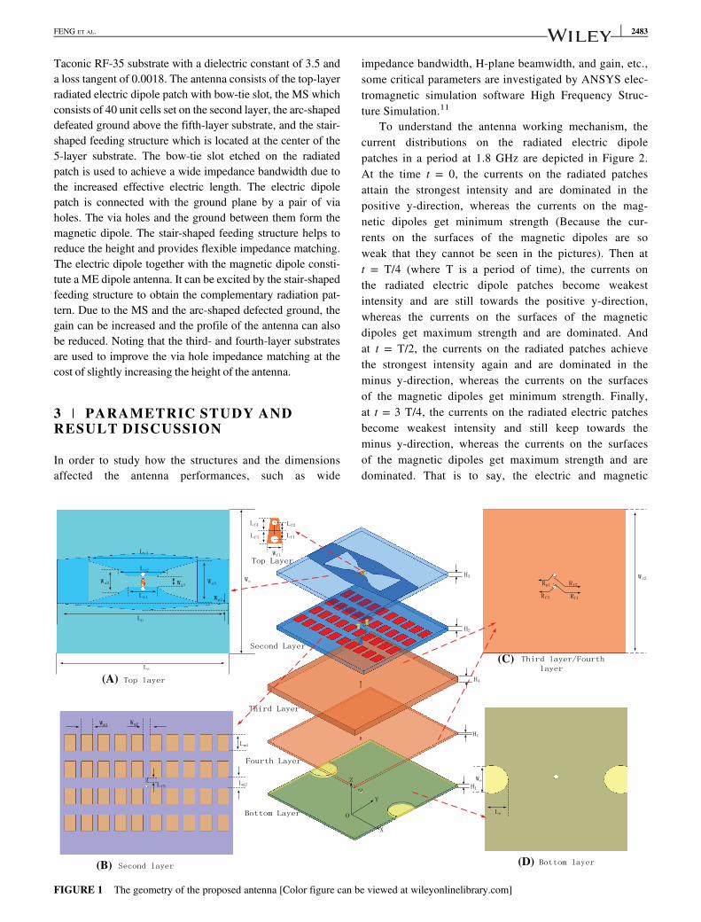
To understand the antenna working mechanism, thecurrent distributions on the radiated electric dipolepatches in a period at 1.8 GHz are depicted in Figure 2.At the time t = 0, the currents on the radiated patchesattain the strongest intensity and are dominated in thepositive y-direction, whereas the currents on the mag-netic dipoles get minimum strength (Because the cur-rents on the surfaces of the magnetic dipoles are soweak that they cannot be seen in the pictures). Then att = T/4 (where T is a period of time), the currents onthe radiated electric dipole patches become weakestintensity and are still towards the positive y-direction,whereas the currents on the surfaces of the magneticdipoles get maximum strength and are dominated. Andat t = T/2, the currents on the radiated patches achievethe strongest intensity again and are dominated in theminus y-direction, whereas the currents on the surfacesof the magnetic dipoles get minimum strength. Finally,at t = 3 T/4, the currents on the radiated electric patchesbecome weakest intensity and still keep towards theminus y-direction, whereas the currents on the surfacesof the magnetic dipoles get maximum strength and aredominated. That is to say, the electric and magnetic
(A)
(B) (D)
(C)
FIGURE 1 The geometry of the proposed antenna [Color figure can be viewed at wileyonlinelibrary.com]
FENG ET AL. 2483
dipoles are dominated to work in turn and hence thecomplementary unidirectional patterns can be obtainedin a period. As a result, the linearly polarized radiationpattern with a wide frequency bandwidth can beachieved.
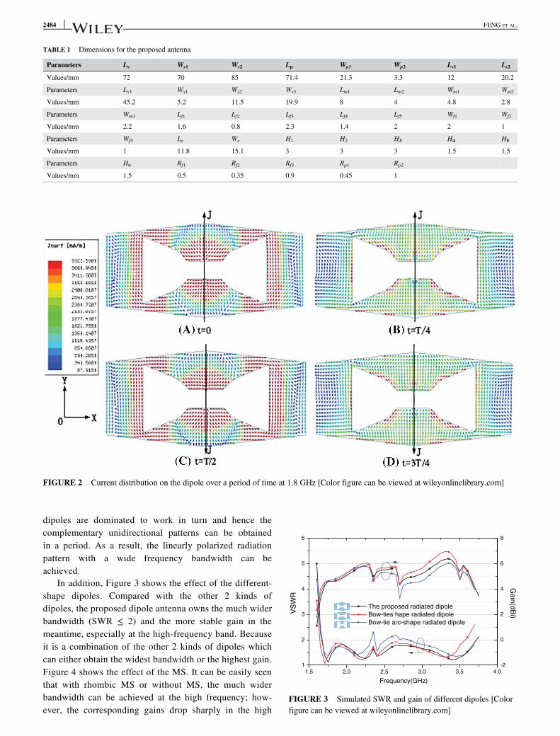
In addition, Figure 3 shows the effect of the different-shape dipoles. Compared with the other 2 kinds ofdipoles, the proposed dipole antenna owns the much widerbandwidth (SWR ≤ 2) and the more stable gain in themeantime, especially at the high-frequency band. Becauseit is a combination of the other 2 kinds of dipoles whichcan either obtain the widest bandwidth or the highest gain.Figure 4 shows the effect of the MS. It can be easily seenthat with rhombic MS or without MS, the much widerbandwidth can be achieved at the high frequency; how-ever, the corresponding gains drop sharply in the high
TABLE 1 Dimensions for the proposed antenna
Parameters Ls Ws1 Ws2 Lp Wp1 Wp2 Ls1 Ls2
Values/mm 72 70 85 71.4 21.3 3.3 12 20.2
Parameters Ls3 Ws1 Ws2 Ws3 Lm1 Lm2 Wm1 Wm2
Values/mm 45.2 5.2 11.5 19.9 8 4 4.8 2.8
Parameters Wm3 Lf1 Lf2 Lf3 Lf4 Lf5 Wf1 Wf2
Values/mm 2.2 1.6 0.8 2.3 1.4 2 2 1
Parameters Wf3 Le We H1 H2 H3 H4 H5
Values/mm 1 11.8 15.1 3 3 3 1.5 1.5
Parameters H6 Rf1 Rf2 Rf3 Rp1 Rp2
Values/mm 1.5 0.5 0.35 0.9 0.45 1
FIGURE 2 Current distribution on the dipole over a period of time at 1.8 GHz [Color figure can be viewed at wileyonlinelibrary.com]
1.5 2.0 2.5 3.0 3.5 4.01
2
3
4
5
6
VS
WR
Frequency(GHz)
The proposed radiated dipole
Bow-ties hape radiated dipole
Bow-tie arc-shape radiated dipole
-2
0
2
4
6
8
Ga
in(d
Bi)
FIGURE 3 Simulated SWR and gain of different dipoles [Colorfigure can be viewed at wileyonlinelibrary.com]
2484 FENG ET AL.
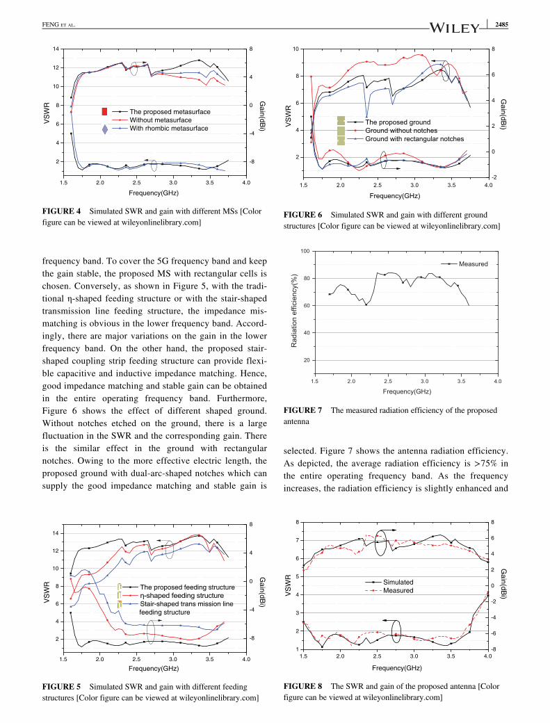
frequency band. To cover the 5G frequency band and keepthe gain stable, the proposed MS with rectangular cells ischosen. Conversely, as shown in Figure 5, with the tradi-tional η-shaped feeding structure or with the stair-shapedtransmission line feeding structure, the impedance mis-matching is obvious in the lower frequency band. Accord-ingly, there are major variations on the gain in the lowerfrequency band. On the other hand, the proposed stair-shaped coupling strip feeding structure can provide flexi-ble capacitive and inductive impedance matching. Hence,good impedance matching and stable gain can be obtainedin the entire operating frequency band. Furthermore,Figure 6 shows the effect of different shaped ground.Without notches etched on the ground, there is a largefluctuation in the SWR and the corresponding gain. Thereis the similar effect in the ground with rectangularnotches. Owing to the more effective electric length, theproposed ground with dual-arc-shaped notches which cansupply the good impedance matching and stable gain is
selected. Figure 7 shows the antenna radiation efficiency.As depicted, the average radiation efficiency is >75% inthe entire operating frequency band. As the frequencyincreases, the radiation efficiency is slightly enhanced and
1.5 2.0 2.5 3.0 3.5 4.0
2
4
6
8
10
12
14V
SW
R
Frequency(GHz)
The proposed metasurface
Without metasurface
With rhombic metasurface
-8
-4
0
4
8
Gain
(dB
i)
FIGURE 4 Simulated SWR and gain with different MSs [Colorfigure can be viewed at wileyonlinelibrary.com]
1.5 2.0 2.5 3.0 3.5 4.0
2
4
6
8
10
12
14
VS
WR
Frequency(GHz)
The proposed feeding structure
Stair-shaped trans mission line
feeding structure
-8
-4
0
4
8
Gain
(dB
i)
FIGURE 5 Simulated SWR and gain with different feedingstructures [Color figure can be viewed at wileyonlinelibrary.com]
1.5 2.0 2.5 3.0 3.5 4.0
2
4
6
8
10
VSW
R
Frequency(GHz)
The proposed groundGround without notchesGround with rectangular notches
-2
0
2
4
6
8G
ain(dBi)
FIGURE 6 Simulated SWR and gain with different groundstructures [Color figure can be viewed at wileyonlinelibrary.com]
1.5 2.0 2.5 3.0 3.5 4.0
20
40
60
80
100
Measured
Rad
iatio
n ef
ficie
ncy(
%)
Frequency(GHz)
FIGURE 7 The measured radiation efficiency of the proposedantenna
1.5 2.0 2.5 3.0 3.5 4.0
1
2
3
4
5
6
7
8
VS
WR
Frequency(GHz)
Simulated
Measured
-8
-6
-4
-2
0
2
4
6
8
Ga
in(d
Bi)
FIGURE 8 The SWR and gain of the proposed antenna [Colorfigure can be viewed at wileyonlinelibrary.com]
FENG ET AL. 2485
-40
-30
-20
-10
00
30
60
90
120
150
180
210
240
270
300
330
-40
-30
-20
-10
0
(A) 1.8GHz (simulated)
-40
-30
-20
-10
00
30
60
90
120
150
180
210
240
270
300
330
-40
-30
-20
-10
0
(B) 1.8GHz (measured)
-40
-30
-20
-10
00
30
60
90
120
150
180
210
240
270
300
330
-40
-30
-20
-10
0
(C) 2.7GHz (simulated)
-40
-30
-20
-10
00
30
60
90
120
150
180
210
240
270
300
330
-40
-30
-20
-10
0
(D) 2.7GHz (measured)
-40
-30
-20
-10
00
30
60
90
120
150
180
210
240
270
300
330
-40
-30
-20
-10
0
(E) 3.5GHz (simulated)
-40
-30
-20
-10
00
30
60
90
120
150
180
210
240
270
300
330
-40
-30
-20
-10
0
(F) 3.5GHz (measured)
Co-pol-Sim(H-plane:YOZ plane) Crsso-pol-Sim(H-plane:YOZ plane)
Co-pol-Sim(E-plane:XOZ plane) Cross-pol-Sim(E-plane:XOZ plane)
Co-pol-Mea(H-plane:YOZ plane) Crsso-pol-Mea(H-plane:YOZ plane
Co-pol-Mea(E-plane:XOZ plane) Cross-pol-Mea(E-plane:XOZ plane
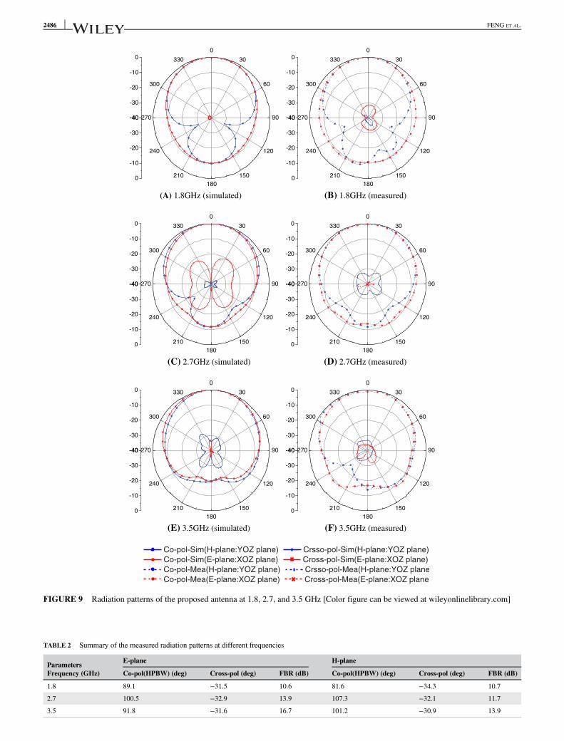
FIGURE 9 Radiation patterns of the proposed antenna at 1.8, 2.7, and 3.5 GHz [Color figure can be viewed at wileyonlinelibrary.com]
TABLE 2 Summary of the measured radiation patterns at different frequencies
ParametersE-plane H-plane
Frequency (GHz) Co-pol(HPBW) (deg) Cross-pol (deg) FBR (dB) Co-pol(HPBW) (deg) Cross-pol (deg) FBR (dB)
1.8 89.1 −31.5 10.6 81.6 −34.3 10.7
2.7 100.5 −32.9 13.9 107.3 −32.1 11.7
3.5 91.8 −31.6 16.7 101.2 −30.9 13.9
2486 FENG ET AL.
can be up to 85%. In other words, the power conversionefficiency is high. Figure 8 shows the SWR and the gainof the proposed antenna. The simulated bandwidth rangesfrom 1.62 to 3.69 GHz with a stable gain of 5.1 � 1.1 dBi,while measured bandwidth ranges from 1.63 to 3.68 GHzwith a stable gain of 5.1 � 1.2 dBi. They show the goodagreement. Figure 9 shows the radiation patterns at differ-ent frequencies. A short summary of them can bedescribed in Table 2. It can be seen that nearly the sym-metrical E- and H-plane radiation patterns can beobtained. In addition, the cross-polarizations of bothplanes are <−30 dB and the FBR is >10.6 dB over theentire bandwidth. Furthermore, the beamwidth in the H-plane is more than 89� over the entire operating frequencyband. In particular, it can be up to 107� in the 5G high fre-quency band. Table shows the comparison of the pro-posed antenna with the other referenced antennas. Exceptthe lower gain, the proposed antenna is better in theaspects of wide bandwidth, wide beamwidth in H-plane,low profile.
4 | CONCLUSION
A wideband antenna using MS is proposed for the future 5Gcommunications. By combining the inherent properties ofME dipole and MS, the antenna can achieve an impedancebandwidth of 77.2% (1.63-3.68 GHz) with a stable gain of5.1 � 1.2 dBi and a low-profile of 0.11 λc. In addition, byintroducing the arc-shaped defeated ground planes, theimpedance matching and the gain are improved. With theabove-mentioned features, the antenna can be suitable forthe future 5G applications.
ACKNOWLEDGMENTS
The research was supported by the Natural ScienceFoundation of Guangdong Province, China (No.2016A030310056), the Key Project of Department ofEducation of Guangdong Province (No.2015KTSCX123),the Fundamental Research Foundation of Shenzhen (No.JCYJ20160308100236349) and the Natural Science Foun-dation of SZU (No.2016021).
ORCID
Botao Feng http://orcid.org/0000-0003-3662-0183
Kwok L. Chung http://orcid.org/0000-0002-5381-7327
REFERENCES[1] An W, Lau K, Li S, Xue Q. Wideband e-shaped dipole antenna
with staircase-shaped feeding strip. IET Electronics Letters. 2010;46(24):1583-1584.
[2] “World radiocommunication conference allocates Spectrum forfuture innovation,” http://www.itu.int/net/pressofce/press_releases/2015/56.asp, accessed on Nov. 27, 2015. [Online].
[3] Ban YL, Li C, Sim CYD, Wu G, Wong KL. 4g/5g multiple anten-nas for future multi-mode smartphone applications. IEEE Access.2016;4:2981-2988.
[4] Luk KM, Wong H. A new wideband unidirectional antenna ele-ment.Microwave and Optical Technology Letters. 2006;1(1):35-44.
[5] Feng B, Yin S, Li S. A planar-printed e-shaped omnidirectionalmagneto-electric dipole antenna for wwan/lte applications. Micro-wave and Optical Technology Letters. 2014;56(8):1734-1739.
[6] Luk KM, Zhou SF, Li YJ, et al. A microfabricated low-profilewideband antenna array for terahertz communications. Sci Rep.2017;7(1):1268.
[7] Wu F, Luk KM. A compact and reconfigurable circularly polar-ized complementary antenna. IEEE Antennas and Wireless Propa-gation Letters. 2017;16:1188-1191.
[8] Zhu HL, Cheung SW, Chung KL, Yuk TI. Linear-to-circularpolarization conversion using metasurface. IEEE Transactions onAntennas and Propagation. 2013;61(9):4615-4623.
[9] Zhu HL, Liu XH, Cheung SW, Yuk TI. Frequency-reconfigurableantenna using metasurface. IEEE Transactions on Antennas andPropagation. 2014;62(1):80-85.
[10] Kandasamy K, Majumder B, Mukherjee J, Ray KP. Low-rcs andpolarization-reconfigurable antenna using cross-slot-based meta-surface. IEEE Antennas and Wireless Propagation Letters. 2015;14:1638-1641.
[11] A. Corp., “Hfss:high frequency structure simulator based on thefinite element method [online].” Available: https://www.ansys.com.
[12] Ge L, Luk KM. A three-element linear magneto-electric dipolearray with beamwidth reconfiguration. IEEE Antennas and Wire-less Propagation Letters. 2015;14:28-31.
[13] Lai HW, Wong H. Substrate integrated magneto-electric dipoleantenna for 5g wi-fi. IEEE Transactions on Antennas and Propa-gation. Feb 2015;63(2):870-874.
[14] Zhai H, Zhang K, Yang S, Feng D. A low-profile dual-banddual-polarized antenna with an amc surface for wlan applications.IEEE Antennas and Wireless Propagation Letters. 2017;16:2692-2695.
[15] Edalati A, Denidni TA. Reconfigurable beamwidth antenna basedon active partially reflective surfaces. IEEE Antennas and Wire-less Propagation Letters. 2009;8:1087-1090.
[16] Ghaemi K, Behdad N. A low-profile, wideband antenna with ver-tically polarized directional radiation. IEEE Antennas and Wire-less Propagation Letters. 2016;15:1093-1096.
[17] Ren YH, Ding J, Guo CJ, Qu Y, Song YC. A widebanddual-polarized printed antenna based on complementary split-ringresonators. IEEE Antennas and Wireless Propagation Letters.2015;14:410-413.
How to cite this article: Feng B, Li L, Zeng Q,Chung KL. A wideband antenna using metasurfacefor the 2G/3G/LTE/5G communications. Microw OptTechnol Lett. 2018;60:2482–2487. https://doi.org/10.1002/mop.31387
FENG ET AL. 2487


