Embed Size (px)
Citation preview
1
ACADEMIC REGULATIONS
COURSE STRUCTUREAND
DETAILED SYLLABUS
M.Tech (POWER ELECTRONICS AND ELECTRICAL DRIVES)
(ELECTRICAL & ELECTRONICS ENGINEERING)
M. Tech. Two Year Degree Course(Applicable for the batches admitted from 2014-15)
(MR-14 Regulations)
MALLA REDDY ENGINEERING COLLEGE(AUTONOMOUS)
(An Autonomous institution, Autonomy granted by UGC and affiliated to JNTUH, Accredited by NAAC with ‘A’ Grade, Accredited byNBA (2008-11) & Recipient of World Bank Assistance under TEQIP phase – II S.C.1.1for the period (2011-14))
Maisammaguda, Dhulapally (Post. Via. Kompally), Secunderabad – 500 100.Website: www.mrec.ac.in Email: [email protected]
2
MALLA REDDY ENGINEERING COLLEGE (AUTONOMOUS) Maisammaguda, Dhulapally (Post via. Kompally), Secunderabad – 500100
ACADEMIC REGULATIONS MR 14 FOR M. TECH. (REGULAR) DEGREE COURSE(Effective for the students admitted into first year from the academic year 2014-2015)
The M.Tech Degree of Malla Reddy Engineering College, Hyderabad shall be conferred on candidates by the Jawaharlal Nehru Technological University Hyderabad (JNTUH), Hyderabad who are admitted to the program and fulfill all the requirements for the award of the Degree.
1.0 ELIGIBILITY FOR ADMISSIONS
Admission to the above program shall be made subject to the eligibility, qualifications and Specialization as prescribed by the university/college from time to time.
Admissions shall be made on the basis of merit/rank obtained by the qualifying candidate at an Entrance Test conducted by the University/college or on the basis of any other order of merit approved by the University/college (sayPGECET/GATE) subject to reservations as laid down by the Government from time to time.
2.0 AWARD OF M. TECH. DEGREE2.1 A student shall be declared eligible for the award of the M. Tech. Degree, if he pursues a course of study in not
less than two and not more than four academic years. However, he is permitted to write the examinations for two more years after four academic years of course work.
2.2 A student, who fails to fulfill all the academic requirements for the award of the degree within four Academic years from the year of his admission, shall forfeit his seat inM. Tech. course.
2.3 The student shall register for all 88 credits and secure all the 88 credits.2.4 The minimum instruction days in each semester are 90.
3.0 COURSES OF STUDY The following specializations are offered at present for the M. Tech. course of study.
1. Advanced Manufacturing Systems(AMS) - Shift II2. Computer Science(CSe) - Shift I3. Computer Science and Engineering(CSE) - Shift I & II4. Control Systems(CS) - Shift I & II5. Digital Systems and Computer Electronics(DSCE) - Shift I6. Electrical Power Systems (EPS) - Shift I7. Embedded Systems(ES) - Shift I8. Geotechnical Engineering(GTE) - Shift I9. Machine Designs (MD) - Shift I10. Power Electronics and Electrical Drives(PEED) - Shift II11. Structural Engineering(SE) - Shift I12. Transportation Engineering(TE) - Shift II13. Thermal Engineering(THE) - Shift I14. VLSI System Design(VLSI SD) - Shift I
3.1 Departments offering M. Tech. Programmes with specializations are noted below:Branch Specialization Specialization
CodeCivil Engineering 1. Structural Engineering (SE)
2. Transportation Engineering (TE)3. Geotechnical Engineering (GE)
111213
Electrical and Electronics Engineering
1. Control Systems (CS)2. Power Electronics and Electrical Drives (PEED) 3. Electrical Power Systems (EPS)
222324
Mechanical Engineering
1. Thermal Engineering (TE)2. Advanced Manufacturing Systems (AMS) 3. Machine Designs (MD)
313233
Electronics and Communication Engineering
1.Digital Systems and Computer Electronics (DSCE)2. VLSI System Design (VLSI SD)3. Embedded Systems (ES)
414243
Computer Science and Engineering
1. Computer Science and Engineering (CSE)2. Computer Science (CSe)
5152
3
4.0 ATTENDANCE
The programs are offered on a unit basis with each subject being considered as a unit.
4.1 A student shall be eligible to write University examinations if he acquires a minimum of 75% of attendance in aggregate of all the subjects.
4.2 Condonation of shortage of attendance in aggregate up to 10% (65% and above and below 75%) in each semester shall be granted by the College Academic Committee.
4.3 Shortage of Attendance below 65% in aggregate shall not be condoned. 4.4 Students whose shortage of attendance is not condoned in any semester are not eligible to write their end
semester examination of that class and their registration shall stand cancelled. 4.5 A prescribed fee shall be payable towards condonation of shortage of attendance. 4.6 A student shall not be promoted to the next semester unless he satisfies the attendance requirement of the present
semester, as applicable. They may seek readmission into that semester when offered next. If any candidate fulfills the attendance requirement in the present semester, he shall not be eligible for readmission into the same class.
4.7 A student shall not be promoted to the next semester unless he satisfies the attendance requirements of the previous semester including the days of attendance in sports, games, NCC and NSS activities.
5.0 EVALUATION
The performance of the candidate in each semester shall be evaluated subject-wise, with a maximum of 100 marks for theory and 100 marks for practical’s, on the basis of Internal Evaluation and End Semester Examination.
5.1 For the theory subjects 60 marks shall be awarded based on the performance in the End Semester Examination and 40 marks shall be awarded based on the Internal Evaluation. The internal evaluation shall be made based on the average of the marks secured in the two Mid Term-Examinations conducted-one in the middle of the Semester and the other immediately after the completion of instruction. Each mid term examination shall be conducted for a total duration of 120 minutes with Part A as 2 questions to be answered out of 4 questions each question for 10 marks and Part B with 4 questions to be answered out of 6 questions each question for 5 marks. If any candidate is absent for any subject of a mid -term examination, an additional exam will be conducted in the deserving cases based on the recommendations of the College Academic Committee. End semester examination is conducted for 60 marks with 5 questions to be answered out of 8 questions, each question carries 12 marks.
5.2 For practical subjects, 60 marks shall be awarded based on the performance in the End Semester Examinations and 40 marks shall be awarded based on the day-to-day performance as Internal Marks.
5.3 There shall be two seminar presentations during I year I semester and II semester. For seminar, a student under the supervision of a faculty member, shall collect the literature on a topic and critically review the literature and submit it to the department in a report form and shall make an oral presentation before the Departmental Academic Committee consisting of Head of the Department, Supervisor and two other senior faculty members of the department. For each Seminar there will be only internal evaluation of 50 marks. A candidate has to secure a minimum of 50% of marks to be declared successful.
5.4 There shall be a Comprehensive Viva-Voce in II year I Semester. The Comprehensive Viva-Voce will be conducted by a Committee consisting of Head of the Department and two Senior Faculty members of the Department. The Comprehensive Viva-Voce is intended to assess the students’ understanding of various subjectshe has studied during the M. Tech. course of study. The Comprehensive Viva-Voce is evaluated for 100 marks by the Committee. There are no internal marks for the Comprehensive Viva-Voce.
5.5 A candidate shall be deemed to have secured the minimum academic requirement in a subject if he secures a minimum of 40% of marks in the End semester Examination and a minimum aggregate of 50% of the total marks in the End Semester Examination and Internal Evaluation taken together.
5.6 In case the candidate does not secure the minimum academic requirement in any subject (as specified in 5.5) he has to reappear for the End semester Examination in that subject. A candidate shall be given one chance to re-register for each subject provided the internal marks secured by a candidate are less than 50% and so has failed in the end examination. In such a case, the candidate must re-register for the subject(s) and secure the required minimum attendance. The candidate’s attendance in the re-registered subject(s) shall be calculated separately to decide upon his eligibility for writing the end examination in those subject(s). In the event of the student taking another chance, his internal marks and end examination marks obtained in the previous attempt stand cancelled.
5.7 Laboratory examination for M. Tech. courses must be conducted with two Examiners, one of them being the Laboratory Class Teacher and the second examiner shall be another Laboratory Teacher.
4
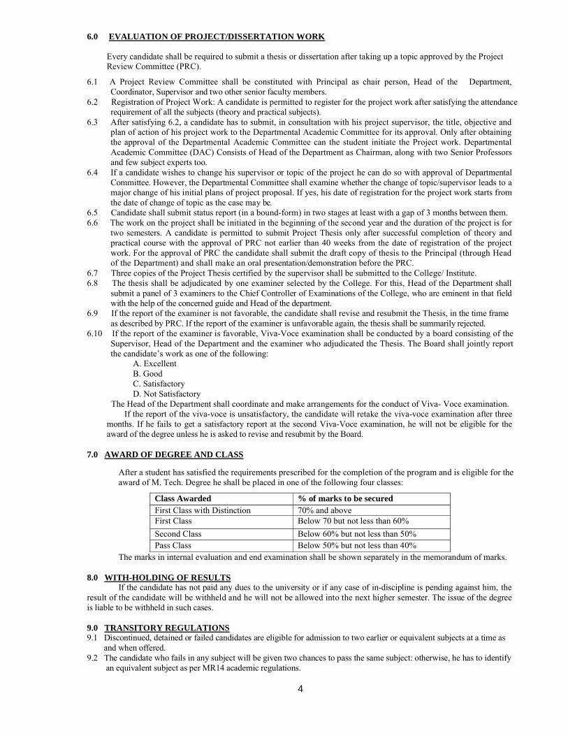
6.0 EVALUATION OF PROJECT/DISSERTATION WORK
Every candidate shall be required to submit a thesis or dissertation after taking up a topic approved by the Project Review Committee (PRC).
6.1 A Project Review Committee shall be constituted with Principal as chair person, Head of the Department, Coordinator, Supervisor and two other senior faculty members.
6.2 Registration of Project Work: A candidate is permitted to register for the project work after satisfying the attendance requirement of all the subjects (theory and practical subjects).
6.3 After satisfying 6.2, a candidate has to submit, in consultation with his project supervisor, the title, objective and plan of action of his project work to the Departmental Academic Committee for its approval. Only after obtaining the approval of the Departmental Academic Committee can the student initiate the Project work. Departmental Academic Committee (DAC) Consists of Head of the Department as Chairman, along with two Senior Professors and few subject experts too.
6.4 If a candidate wishes to change his supervisor or topic of the project he can do so with approval of Departmental Committee. However, the Departmental Committee shall examine whether the change of topic/supervisor leads to a major change of his initial plans of project proposal. If yes, his date of registration for the project work starts from the date of change of topic as the case may be.
6.5 Candidate shall submit status report (in a bound-form) in two stages at least with a gap of 3 months between them. 6.6 The work on the project shall be initiated in the beginning of the second year and the duration of the project is for
two semesters. A candidate is permitted to submit Project Thesis only after successful completion of theory and practical course with the approval of PRC not earlier than 40 weeks from the date of registration of the project work. For the approval of PRC the candidate shall submit the draft copy of thesis to the Principal (through Head of the Department) and shall make an oral presentation/demonstration before the PRC.
6.7 Three copies of the Project Thesis certified by the supervisor shall be submitted to the College/ Institute.6.8 The thesis shall be adjudicated by one examiner selected by the College. For this, Head of the Department shall
submit a panel of 3 examiners to the Chief Controller of Examinations of the College, who are eminent in that field with the help of the concerned guide and Head of the department.
6.9 If the report of the examiner is not favorable, the candidate shall revise and resubmit the Thesis, in the time frame as described by PRC. If the report of the examiner is unfavorable again, the thesis shall be summarily rejected.
6.10 If the report of the examiner is favorable, Viva-Voce examination shall be conducted by a board consisting of the Supervisor, Head of the Department and the examiner who adjudicated the Thesis. The Board shall jointly report the candidate’s work as one of the following:
A. Excellent B. Good C. Satisfactory D. Not Satisfactory The Head of the Department shall coordinate and make arrangements for the conduct of Viva- Voce examination.
If the report of the viva-voce is unsatisfactory, the candidate will retake the viva-voce examination after three months. If he fails to get a satisfactory report at the second Viva-Voce examination, he will not be eligible for the award of the degree unless he is asked to revise and resubmit by the Board.
7.0 AWARD OF DEGREE AND CLASS
After a student has satisfied the requirements prescribed for the completion of the program and is eligible for the award of M. Tech. Degree he shall be placed in one of the following four classes:
Class Awarded % of marks to be securedFirst Class with Distinction 70% and aboveFirst Class Below 70 but not less than 60%
Second Class Below 60% but not less than 50%Pass Class Below 50% but not less than 40%
The marks in internal evaluation and end examination shall be shown separately in the memorandum of marks.
8.0 WITH-HOLDING OF RESULTSIf the candidate has not paid any dues to the university or if any case of in-discipline is pending against him, the
result of the candidate will be withheld and he will not be allowed into the next higher semester. The issue of the degree is liable to be withheld in such cases.
9.0 TRANSITORY REGULATIONS9.1 Discontinued, detained or failed candidates are eligible for admission to two earlier or equivalent subjects at a time as and when offered.9.2 The candidate who fails in any subject will be given two chances to pass the same subject: otherwise, he has to identify an equivalent subject as per MR14 academic regulations.
5
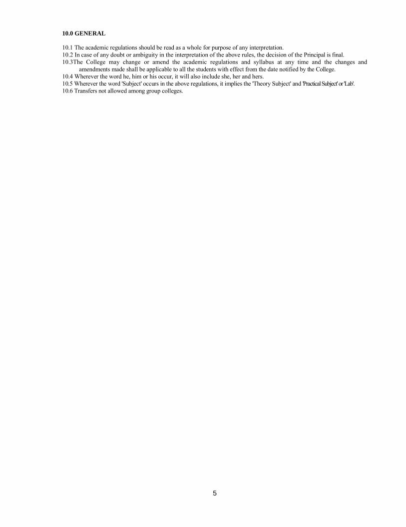
10.0 GENERAL
10.1 The academic regulations should be read as a whole for purpose of any interpretation. 10.2 In case of any doubt or ambiguity in the interpretation of the above rules, the decision of the Principal is final. 10.3The College may change or amend the academic regulations and syllabus at any time and the changes and
amendments made shall be applicable to all the students with effect from the date notified by the College. 10.4 Wherever the word he, him or his occur, it will also include she, her and hers. 10.5 Wherever the word 'Subject' occurs in the above regulations, it implies the 'Theory Subject' and 'Practical Subject' or 'Lab'. 10.6 Transfers not allowed among group colleges.
6
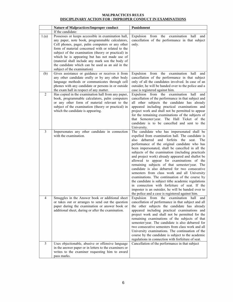
MALPRACTICES RULESDISCIPLINARY ACTION FOR / IMPROPER CONDUCT IN EXAMINATIONS
Nature of Malpractices/Improper conduct PunishmentIf the candidate:
1.(a) Possesses or keeps accessible in examination hall, any paper, note book, programmable calculators, Cell phones, pager, palm computers or any other form of material concerned with or related to the subject of the examination (theory or practical) in which he is appearing but has not made use of (material shall include any mark son the body of the candidate which can be used as an aid in the subject of the examination)
Expulsion from the examination hall and cancellation of the performance in that subject only.
(b) Gives assistance or guidance or receives it from any other candidate orally or by any other body language methods or communicates through cell phones with any candidate or persons in or outside the exam hall in respect of any matter.
Expulsion from the examination hall and cancellation of the performance in that subject only of all the candidates involved. In case of an outsider, he will be handed over to the police and a case is registered against him.
2 Has copied in the examination hall from any paper, book, programmable calculators, palm computers or any other form of material relevant to the subject of the examination (theory or practical) in which the candidate is appearing.
Expulsion from the examination hall and cancellation of the performance in that subject and all other subjects the candidate has already appeared including practical examinations and project work and shall not be permitted to appear for the remaining examinations of the subjects of that Semester/year. The Hall Ticket of the candidate is to be cancelled and sent to the University.
3 Impersonates any other candidate in connection with the examination.
The candidate who has impersonated shall be expelled from examination hall. The candidate is also debarred and forfeits the seat. The performance of the original candidate who has been impersonated, shall be cancelled in all the subjects of the examination (including practicals and project work) already appeared and shallot be allowed to appear for examinations of the remaining subjects of that semester/year. The candidate is also debarred for two consecutive semesters from class work and all University examinations. The continuation of the course by the candidate is subject tithe academic regulations in connection with forfeiture of seat. If the imposter is an outsider, he will be handed over to the police and a case is registered against him.
4 Smuggles in the Answer book or additional sheet or takes out or arranges to send out the question paper during the examination or answer book or additional sheet, during or after the examination.
Expulsion from the examination hall and cancellation of performance in that subject and all the other subjects the candidate has already appeared including practical examinations and project work and shall not be permitted for the remaining examinations of the subjects of that semester/year. The candidate is also debarred for two consecutive semesters from class work and all University examinations. The continuation of the course by the candidate is subject to the academic regulations in connection with forfeiture of seat.
5 Uses objectionable, abusive or offensive language in the answer paper or in letters to the examiners or writes to the examiner requesting him to award pass marks.
Cancellation of the performance in that subject
7
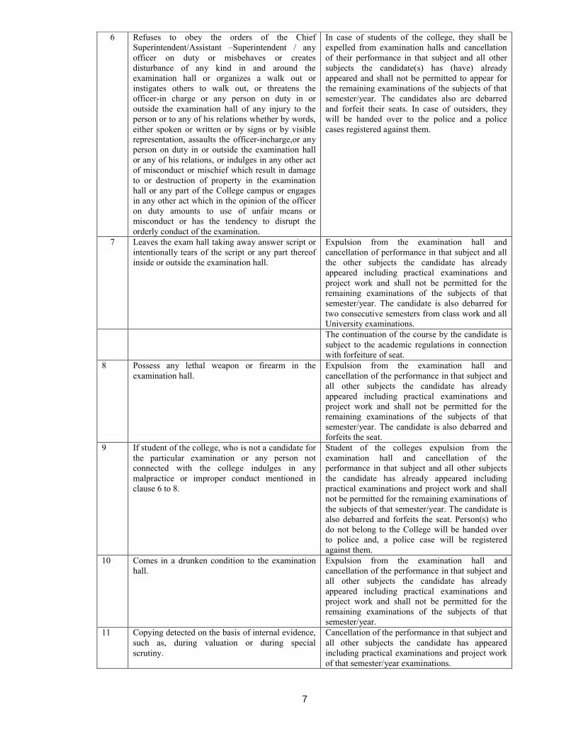
6 Refuses to obey the orders of the Chief Superintendent/Assistant –Superintendent / any officer on duty or misbehaves or creates disturbance of any kind in and around the examination hall or organizes a walk out or instigates others to walk out, or threatens the officer-in charge or any person on duty in or outside the examination hall of any injury to the person or to any of his relations whether by words, either spoken or written or by signs or by visible representation, assaults the officer-incharge,or any person on duty in or outside the examination hall or any of his relations, or indulges in any other act of misconduct or mischief which result in damage to or destruction of property in the examination hall or any part of the College campus or engages in any other act which in the opinion of the officer on duty amounts to use of unfair means or misconduct or has the tendency to disrupt the orderly conduct of the examination.
In case of students of the college, they shall be expelled from examination halls and cancellation of their performance in that subject and all other subjects the candidate(s) has (have) already appeared and shall not be permitted to appear for the remaining examinations of the subjects of that semester/year. The candidates also are debarred and forfeit their seats. In case of outsiders, they will be handed over to the police and a police cases registered against them.
7 Leaves the exam hall taking away answer script or intentionally tears of the script or any part thereof inside or outside the examination hall.
Expulsion from the examination hall and cancellation of performance in that subject and all the other subjects the candidate has already appeared including practical examinations and project work and shall not be permitted for the remaining examinations of the subjects of that semester/year. The candidate is also debarred for two consecutive semesters from class work and all University examinations.The continuation of the course by the candidate is subject to the academic regulations in connection with forfeiture of seat.
8 Possess any lethal weapon or firearm in the examination hall.
Expulsion from the examination hall and cancellation of the performance in that subject and all other subjects the candidate has already appeared including practical examinations and project work and shall not be permitted for the remaining examinations of the subjects of that semester/year. The candidate is also debarred and forfeits the seat.
9 If student of the college, who is not a candidate for the particular examination or any person not connected with the college indulges in any malpractice or improper conduct mentioned in clause 6 to 8.
Student of the colleges expulsion from the examination hall and cancellation of the performance in that subject and all other subjects the candidate has already appeared including practical examinations and project work and shall not be permitted for the remaining examinations of the subjects of that semester/year. The candidate is also debarred and forfeits the seat. Person(s) who do not belong to the College will be handed over to police and, a police case will be registered against them.
10 Comes in a drunken condition to the examination hall.
Expulsion from the examination hall and cancellation of the performance in that subject and all other subjects the candidate has already appeared including practical examinations and project work and shall not be permitted for the remaining examinations of the subjects of that semester/year.
11 Copying detected on the basis of internal evidence, such as, during valuation or during special scrutiny.
Cancellation of the performance in that subject and all other subjects the candidate has appeared including practical examinations and project work of that semester/year examinations.
8
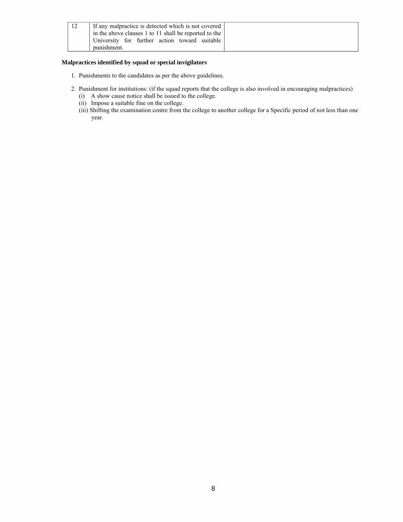
12 If any malpractice is detected which is not covered in the above clauses 1 to 11 shall be reported to the University for further action toward suitable punishment.
Malpractices identified by squad or special invigilators
1. Punishments to the candidates as per the above guidelines.
2. Punishment for institutions: (if the squad reports that the college is also involved in encouraging malpractices) (i) A show cause notice shall be issued to the college. (ii) Impose a suitable fine on the college. (iii) Shifting the examination centre from the college to another college for a Specific period of not less than one year.
9
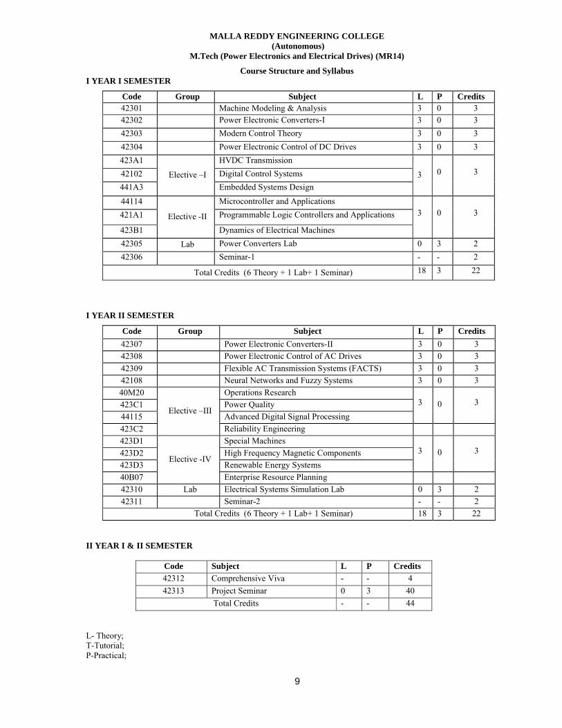
MALLA REDDY ENGINEERING COLLEGE(Autonomous)
M.Tech (Power Electronics and Electrical Drives) (MR14)
Course Structure and SyllabusI YEAR I SEMESTER
Code Group Subject L P Credits42301 Machine Modeling & Analysis 3 0 342302 Power Electronic Converters-I 3 0 3
42303 Modern Control Theory 3 0 3
42304 Power Electronic Control of DC Drives 3 0 3
423A1
Elective –I
HVDC Transmission
3 0 342102 Digital Control Systems
441A3 Embedded Systems Design
44114
Elective -II
Microcontroller and Applications3 0 3421A1 Programmable Logic Controllers and Applications
423B1 Dynamics of Electrical Machines
42305 Lab Power Converters Lab 0 3 2
42306 Seminar-1 - - 2
Total Credits (6 Theory + 1 Lab+ 1 Seminar) 18 3 22
I YEAR II SEMESTER
Code Group Subject L P Credits
42307 Power Electronic Converters-II 3 0 3
42308 Power Electronic Control of AC Drives 3 0 3
42309 Flexible AC Transmission Systems (FACTS) 3 0 3
42108 Neural Networks and Fuzzy Systems 3 0 3
40M20
Elective –III
Operations Research3 0 3423C1 Power Quality
44115 Advanced Digital Signal Processing
423C2 Reliability Engineering
423D1
Elective -IV
Special Machines3 0 3423D2 High Frequency Magnetic Components
423D3 Renewable Energy Systems
40B07 Enterprise Resource Planning
42310 Lab Electrical Systems Simulation Lab 0 3 2
42311 Seminar-2 - - 2
Total Credits (6 Theory + 1 Lab+ 1 Seminar) 18 3 22
II YEAR I & II SEMESTER
Code Subject L P Credits
42312 Comprehensive Viva - - 4
42313 Project Seminar 0 3 40
Total Credits - - 44
L- Theory;T-Tutorial;P-Practical;
10
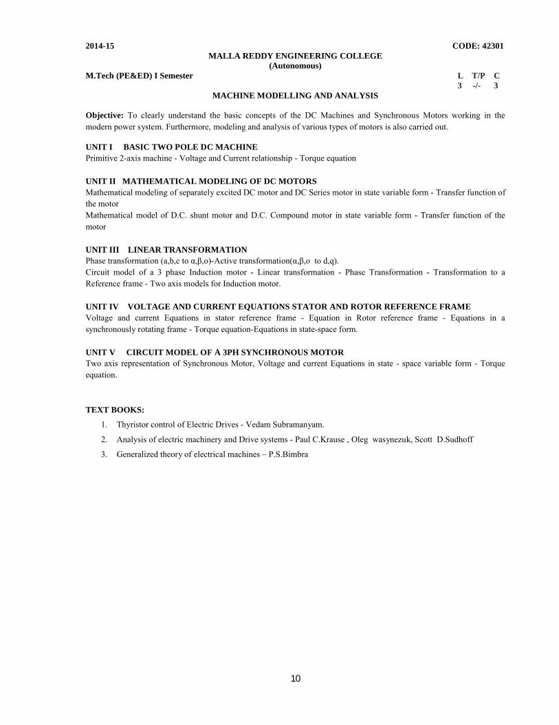
2014-15 CODE: 42301MALLA REDDY ENGINEERING COLLEGE
(Autonomous)M.Tech (PE&ED) I Semester L T/P C 3 -/- 3
MACHINE MODELLING AND ANALYSIS
Objective: To clearly understand the basic concepts of the DC Machines and Synchronous Motors working in the modern power system. Furthermore, modeling and analysis of various types of motors is also carried out.
UNIT I BASIC TWO POLE DC MACHINEPrimitive 2-axis machine - Voltage and Current relationship - Torque equation
UNIT II MATHEMATICAL MODELING OF DC MOTORSMathematical modeling of separately excited DC motor and DC Series motor in state variable form - Transfer function of the motor Mathematical model of D.C. shunt motor and D.C. Compound motor in state variable form - Transfer function of the motor
UNIT III LINEAR TRANSFORMATIONPhase transformation (a,b,c to α,β,o)-Active transformation(α,β,o to d,q).Circuit model of a 3 phase Induction motor - Linear transformation - Phase Transformation - Transformation to a Reference frame - Two axis models for Induction motor.
UNIT IV VOLTAGE AND CURRENT EQUATIONS STATOR AND ROTOR REFERENCE FRAMEVoltage and current Equations in stator reference frame - Equation in Rotor reference frame - Equations in a synchronously rotating frame - Torque equation-Equations in state-space form.
UNIT V CIRCUIT MODEL OF A 3PH SYNCHRONOUS MOTORTwo axis representation of Synchronous Motor, Voltage and current Equations in state - space variable form - Torque equation.
TEXT BOOKS:
1. Thyristor control of Electric Drives - Vedam Subramanyam.
2. Analysis of electric machinery and Drive systems - Paul C.Krause , Oleg wasynezuk, Scott D.Sudhoff
3. Generalized theory of electrical machines – P.S.Bimbra
11
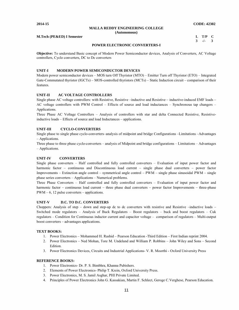
2014-15 CODE: 42302MALLA REDDY ENGINEERING COLLEGE
(Autonomous)M.Tech (PE&ED) I Semester L T/P C 3 -/- 3
POWER ELECTRONIC CONVERTERS-I
Objective: To understand Basic concept of Modern Power Semiconductor devices, Analysis of Converters, AC Voltage controllers, Cyclo converters, DC to Dc converters
UNIT-I MODERN POWER SEMICONDUCTOR DEVICESModern power semiconductor devices – MOS turn Off Thyristor (MTO) – Emitter Turn off Thyristor (ETO) – Integrated Gate-Commutated thyristor (IGCTs) – MOS-controlled thyristors (MCTs) – Static Induction circuit – comparison of their features.
UNIT-II AC VOLTAGE CONTROLLERS Single phase AC voltage controllers: with Resistive, Resistive –inductive and Resistive – inductive-induced EMF loads –AC voltage controllers with PWM Control – Effects of source and load inductances – Synchronous tap changers –Applications.Three Phase AC Voltage Controllers – Analysis of controllers with star and delta Connected Resistive, Resistive-inductive loads – Effects of source and load Inductances – applications.
UNIT-III CYCLO-CONVERTERSSingle phase to single phase cyclo-converters–analysis of midpoint and bridge Configurations –Limitations –Advantages – Applications.Three phase to three phase cyclo-converters – analysis of Midpoint and bridge configurations – Limitations – Advantages – Applications.
UNIT-IV CONVERTERS Single phase converters – Half controlled and fully controlled converters – Evaluation of input power factor and harmonic factor – continuous and Discontinuous load current – single phase dual converters – power factor Improvements – Extinction angle control – symmetrical angle control – PWM – single phase sinusoidal PWM – single phase series converters – Applications – Numerical problems.Three Phase Converters – Half controlled and fully controlled converters – Evaluation of input power factor and harmonic factor – continuous load current – three phase dual converters – power factor Improvements – three-phase PWM – 6, 12 pulse converters – applications.
UNIT-V D.C. TO D.C. CONVERTERSChoppers: Analysis of step – down and step-up dc to dc converters with resistive and Resistive –inductive loads –Switched mode regulators – Analysis of Buck Regulators – Boost regulators – buck and boost regulators – Cuk regulators – Condition for Continuous inductor current and capacitor voltage – comparison of regulators – Multi-output boost converters – advantages applications.
TEXT BOOKS:1. Power Electronics – Mohammed H. Rashid – Pearson Education -Third Edition – First Indian reprint 2004.2. Power Electronics – Ned Mohan, Tore M. Undeland and William P. Robbins – John Wiley and Sons – Second
Edition.3. Power Electronics Devices, Circuits and Industrial Applications- V. R. Moorthi - Oxford University Press
REFERENCE BOOKS:1. Power Electronics- Dr. P. S. Bimbhra, Khanna Pubishers.2. Elements of Power Electronics- Philip T. Krein, Oxford University Press.3. Power Electronics, M. S. Jamil Asghar, PHI Private Limited.4. Principles of Power Electronics John G. Kassakian, Martin F. Schlect, Geroge C.Verghese, Pearson Education.
12
2014-15 CODE: 42303MALLA REDDY ENGINEERING COLLEGE
(Autonomous)M.Tech (PE&ED) I Semester L T/P C 3 1/- 3
MODERN CONTROL THEORY
Objective: To understand the concepts of controllability and observability, analysis of state variables, Concept of State Feedback Controllers and Basic concept of Optimal control problems
UNIT- I MATHEMATICAL PRELIMINARIESFields, Vectors and Vector Spaces – Linear combinations and Bases – Linear Transformations and Matrices – Scalar Product and Norms – Eigen values, Eigen Vectors and a Canonical form representation of Linear operators – The concept of state – State Equations for Dynamic systems – Time invariance and Linearity – Non uniqueness of state model – State diagrams for Continuous-Time State models .
UNIT - II STATE VARIABLE ANALYSISLinear Continuous time models for Physical systems– Existence and Uniqueness of Solutions to Continuous-Time State Equations – Solutions of Linear Time Invariant Continuous-Time State Equations – State transition matrix and its properties.Controllability and Observability: General concept of controllability – General concept of Observability–Controllability tests for Continuous-Time Invariant Systems – Observability tests for Continuous-Time Invariant Systems –Controllability and Observability of State Model in Jordan Canonical form – Controllability and Observability Canonical forms of State model.
UNIT- III NON LINEAR SYSTEMS -IIntroduction – Non Linear Systems - Types of Non-Linearity – Saturation – Dead-Zone - Backlash – Jump Phenomenon etc;– Singular Points – Introduction to Linearization of nonlinear systems, Properties of Non-Linear systems –Describing function–describing function analysis of nonlinear systems – Stability analysis of Non-Linear systems through describing functions.Non Linear Systems –II: Introduction to phase-plane analysis, Method of Isoclines for Constructing Trajectories, singular points, phase-plane analysis of nonlinear control systems.
UNIT -IV STABILITY ANALYSISStability in the sense of Lyapunov, Lyapunov’s stability and Lypanov’s instability theorems - Stability Analysis of the
Linear continuous time invariant systems by Lyapunov second method – Generation of Lyapunov functions – Variable gradient method – Krasooviski’s method.State Feedback Controllers and Observers: State feedback controller design through Pole Assignment – State observers: Full order and Reduced order
UNIT- V INTRODUCTION TO OPTIMAL CONTROLFormulation of optimal control problems – calculus of variations – fundamental concepts, functionals, variation of functionals – fundamental theorem of Calculus of variations – boundary conditions – constrained minimization –formulation using Hamiltonian method – Linear Quadratic regulator
TEXT BOOKS:
1. Modern Control System Theory - M.Gopal – New Age International -1984 2. Modern Control Engineering - Ogata.K – Prentice Hall - 1997
REFERENCES:1. Optimal Control – Kircks-Dover Publicatoions
13
2014-15 CODE: 42304MALLA REDDY ENGINEERING COLLEGE
(Autonomous)M.Tech (PE&ED) I Semester L T/P C 3 -/- 3
POWER ELECTRONIC CONTROL OF DC DRIVES
Objective: To understand Controlled rectifiers fed DC Motor and chopper controlled fed DC motor and dynamic modeling of DC motor drives
UNIT–I SINGLE-PHASE CONTROLLED RECTIFIERS FED DC MOTORSeparately excited DC motors with rectified single –phase supply – single-phase semi converter and single phase full converter for continuous and discontinuous modes of operation – power and power factor.
UNIT–II THREE-PHASE CONTROLLED RECTIFIERS AND CONVERTERS FED DC MOTORThree-phase semi converter and Three phase full converter for continuous and discontinuous modes of operations –power and power factor - Addition of Free wheeling diode – Three phase double converter.
Three-phase controlled converter, control circuit, control modeling of three phase converter – Steady state analysis of three phase converter control DC motor drive – Two quadrant, Three phase converter controlled DC motor drive – DC motor and load converter
UNIT–III CURRENT & SPEED CONTROLLED DC DRIVECurrent and speed controllers - Current and speed feedback – Design of controllers – Current and speed controllers –Motor equations – filter in the sped feed back loop speed controller – current reference generator – current controller and flow chart for simulation – Harmonics and associated problems – sixth harmonics torque.
UNIT–IV CHOPPER CONTROLLED DC MOTOR DRIVESPrinciple of operation of the chopper – Four – quadrant chopper circuit – Chopper for inversion – Chopper with other power devices – model of the chopper – input to the chopper – steady state analysis of chopper controlled DC motor drives – rating of the devices – Pulsating torque.
Closed loop operation: Speed controlled drive system – current control loop – pulse width modulated current controller –hysteresis current controller – modeling of current controller – design of current controller.
UNIT–V DYNAMIC MODELING OF DC MOTOR DRIVESDynamic simulations of the speed controlled DC motor drives – Speed feedback speed controller – command current generator – current controller.
TEXT BOOKS:1. Power Electronics and Motor Control – Shepherd, Hulley, Liang – II Edition Cambridge University Press.2. Electronic Motor Drives Modeling Analysis and Control – R. Krishnan – I Edition Prentice Hall India.3. Power Electronics circuits, Devices and Applications – MH Rashid – PHI – 1 Edition 1995.4. Fundamentals of Electric Drives – GK Dubey Narosa Publishers 19955. Power Semiconductor drives – SB Dewan and A Straughen -1975.
14
2014-15 CODE: 423A1MALLA REDDY ENGINEERING COLLEGE
(Autonomous)M.Tech (PE&ED) I Semester L T/P C 3 -/- 3
HVDC TRANSMISSION(Elective-I)
Objective: To understand the basic concept of HVDC transmission , Control of HVDC converter systems and Basic Faults and Protection of HVDC system
UNIT-I INTRODUCTIONGeneral consideration, Power Handling Capabilities of HVDC Lines, Basic Conversion principles, static converter configuration.
UNIT-II STATIC POWER CONVERTERS3-pulse, 6-pulse, and 12-pulse converters, converter station and Terminal equipment, commutation process, Rectifier and inverter operation, equivalent circuit for converter – special features of converter transformers. Harmonics in HVDC Systems, Harmonic elimination, AC and DC filters.
UNIT-III CONTROL OF HVDC CONVERTERS AND SYSTEMSConstant current, constant extinction angle and constant ignition angle control, Individual phase control and equidistant firing angle control, DC power flow control. Interaction between HVAC and HVDC systems – Voltage interaction Harmonic instability problems and DC power modulation.
UNIT-IV MTDC SYSTEMS & OVER VOLTAGESSeries, Parallel and series parallel systems their operation and control. Over voltages due to disturbances on DC side, over voltages due to DC and AC side line faults.
UNIT-V CONVERTER FAULTS & PROTECTIONConverter faults, over current protection – valve group, and DC line protection over voltage protection of converters, surge arresters.
TEXT BOOKS:1. HVDC Transmission -J. Arillaga- Peter Peregrinus ltd- London UK- 1983
2. Direct Current Transmission - E.W. Kimbark- Wiely Inter Science – New York.
3. High Voltage Direct Current Transmission -KR Padiyar - Wiely Esatern Ltd -New Delhi – 1992.
4. Power Transmission by Direct Current -E. Uhlman - Springer Verlag- Berlin Helberg. 1985.
15
2014-15 CODE: 42102MALLA REDDY ENGINEERING COLLEGE
(Autonomous)M.Tech (PE&ED) I Semester L T/P C 3 -/- 3
DIGITAL CONTROL SYSTEMS(Elective-I)
Objective: To impart basic knowledge of A/D and D/A conversion, understand the basics of Z- Transform, the stability analysis of digital control system and digital process control design.
UNIT–I SAMPLE AND HOLD CIRCUIT, Z-TRANFORMSBlock Diagram of typical control system- advantages of sampling in control systems – examples of discrete data and digital systems – data conversion and quantization – sample and hold devices – D/A and A/D conversion – sampling theorem – reconstruction of sampled signals –ZOH.Z-transform: Definition and evaluation of Z-transforms – mapping between s-plane and z-plane – inverse z-plane transform – theorems of the Z-transforms –limitations of z-transforms –pulse transfer function –pulse transfer function of ZOH –relation between G(s) and G(z) – signal flow graph method applied to digital systems.
UNIT- II STATE SPACE ANALYSISState space modeling of digital systems with sample and hold – state transition equation of digital time in variant
systems – solution of time invariant discrete state equations by the Z-Transformation – transfer function from the state model – Eigen values – Eigen vector and diagonalisation of the A-matrix – Jordan canonical form. Computation of state transition matrix-Transformation to phase to variable canonical form-The state diagram – decomposition of digital system – Response of sample data system between sampling instants using state approach. Stability: Definition of stability – stability tests – The second method of Lyapunov.
UNIT- III TIME DOMAIN ANALYSISComparison of time response of continuous data and digital control systems-correlation between time response and root locus j the s-plane and z-plane – effect of pole-zero configuration in the z-plane upon the maximum overshoot and peak time of transient response – Root loci for digital control systems – steady state error analysis of digital control systems –Nyquist plot – Bode plot-G.M and P.M.
UNIT- IV DESIGN OF DIGITAL CONTROLLERThe digital control design with digital controller with bilinear transformation – Digital PID controller-Design with deadbeat response-Pole placement through state feedback-Design of full order state observer-Discrete Euler Lagrange Equation – Discrete maximum principle.
UNIT-V DIGITAL STATE OBSERVERDesign of - Full order and reduced order observers. Design by maximum principle: Discrete Euler langrange equation-discrete maximum principle.
TEXT BOOKS:1. Discrete-Time Control systems - K. Ogata, Pearson Education/PHI, 2nd Edition, 2003.2. Digital Control Systems-V. I. George, C. P. Kurian, Cengage Learning,1/e, 2012.3. Digital Control and State Variable Methods - M.Gopal, TMH, 3rd, 2008.4. Digital Control Engineering - M.Gopal, John Wiley & Sons, 3rd, 1984
REFERENCE BOOKS:1. Digital Control Systems, - Kuo, Oxford University Press, 2nd Edition, 2003.2. Digital Control Engineering Analysis and Design - M. Sami Fadali Antonio Visioli, AP Academic Press, 2nd
Edition, 2009.
16
2014-15 CODE: 441A3MALLA REDDY ENGINEERING COLLEGE
(Autonomous)M.Tech (PE&ED) I Semester L T/P C 3 -/- 3
EMBEDDED SYSTEMS DESIGN(Elective-I)
Objective: To impart basic knowledge of embedded systems, embedded firmware, RTO based embedded system design and task communication.
UNIT –I INTRODUCTION TO EMBEDDED SYSTEMSDefinition of Embedded System, Embedded Systems Vs General Computing Systems, History of Embedded Systems, Classification, Major Application Areas, Purpose of Embedded Systems, Characteristics and Quality Attributes of Embedded Systems.
UNIT –II TYPICAL EMBEDDED SYSTEMCore of the Embedded System: General Purpose and Domain Specific Processors, ASICs, PLDs, Commercial Off-The-Shelf Components (COTS), Memory: ROM, RAM, Memory according to the type of Interface, Memory Shadowing, Memory selection for Embedded Systems, Sensors and Actuators, Communication Interface: Onboard and External Communication Interfaces.
UNIT –III EMBEDDED FIRMWAREReset Circuit, Brown-out Protection Circuit, Oscillator Unit, Real Time Clock, Watchdog Timer, Embedded Firmware Design Approaches and Development Languages.
UNIT –IV RTOS BASED EMBEDDED SYSTEM DESIGNOperating System Basics, Types of Operating Systems, Tasks, Process and Threads, Multiprocessing and Multitasking, Task Scheduling.
UNIT –V TASK COMMUNICATIONShared Memory, Message Passing, Remote Procedure Call and Sockets, Task Synchronization: Task Communication/Synchronization Issues, Task Synchronization Techniques, Device Drivers, How to Choose an RTOS.
TEXT BOOKS:1. Embedded System Design - Frank Vahid, Tony Givargis, John Wiley.
REFERENCE BOOKS:1. Embedded Systems - Raj Kamal, TMH.2. Introduction to Embedded Systems - Shibu K.V, Mc Graw Hill3. Embedded Systems – Lyla, Pearson, 20134. An Embedded Software Primer - David E. Simon, Pearson Education.
17
2014-15 CODE: 44114MALLA REDDY ENGINEERING COLLEGE
(Autonomous)M.Tech(PE&ED) I Semester L T/P C 3 -/- 3
MICROCONTROLLERS AND APPLICATIONS(Elective-II)
Objective: To develop an in-depth understanding of the operation of microprocessors and microcontrollers, machine language programming & interfacing techniques.
UNIT-I OVERVIEW OF ARCHITECTURE & MICROCONTROLLER RESOURCESArchitecture of a microcontroller – Microcontroller resources – Resources in advanced and next generation microcontrollers – 8051 microcontroller – Internal and External memories – Counters and Timers – Synchronous serial-cum asynchronous serial communication - Interrupts.
UNIT-II 8051- MICROCONTROLLERS INSTRUCTION SETBasic assembly language programming – Data transfer instructions – Data and Bit-manipulation instructions –Arithmetic instructions – Instructions for Logical operations on the test among the Registers, Internal RAM, and SFRs –Program flow control instructions – Interrupt control flow.
UNIT-III REAL TIME CONTROLInterrupts: Interrupt handling structure of an MCU – Interrupt Latency and Interrupt deadline – Multiple sources of the interrupts – Non-maskable interrupt sources – Enabling or disabling of the sources – Polling to determine the interrupt source and assignment of the priorities among them – Interrupt structure in Intel 8051.Timers: Programmable Timers in the MCU’s – Free running counter and real time control – Interrupt interval and density constraints.
UNIT-IV SYSTEMS DESIGNDigital and Analog Interfacing Methods: Switch, Keypad and Keyboard interfacings – LED and Array of LEDs –Keyboard-cum-Display controller (8279) – Alphanumeric Devices – Display Systems and its interfaces – Printer interfaces – Programmable instruments interface using IEEE 488 Bus – Interfacing with the Flash Memory – Interfaces –Interfacing to High Power Devices – Analog input interfacing – Analog output interfacing – Optical motor shaft encoders – Industrial control – Industrial process control system – Prototype MCU based Measuring instruments – Robotics and Embedded control – Digital Signal Processing and digital filters.
UNIT-V REAL TIME OPERATING SYSTEM FOR MICROCONTROLLERS:Real Time operating system – RTOS of Keil (RTX51) – Use of RTOS in Design – Software development tools for Microcontrollers.16-Bit Microcontrollers: Hardware – Memory map in Intel 80196 family MCU system – IO ports – Programmable Timers and High-speed outputs and input captures – Interrupts – instructions.ARM 32 Bit MCUs: Introduction to 16/32 Bit processors – ARM architecture and organization – ARM / Thumb programming model – ARM / Thumb instruction set –Development-tools.
TEXT BOOKS:1. Raj Kamal, “Microcontrollers Architecture, Programming, Interfacing and System Design”–Pearson Education,
2005.2. Mazidi and Mazidi, “The 8051 Microcontroller and Embedded Systems” – PHI, 2000.
REFERENCE BOOKS:1. A.V. Deshmuk, “Microcontrollers (Theory & Applications)” – WTMH, 2005.2. John B. Peatman, “Design with PIC Microcontrollers” – Pearson Education, 2005.
18
2014-15 CODE: 421A1MALLA REDDY ENGINEERING COLLEGE
(Autonomous)M.Tech(PE&ED) I Semester L T/P C 3 -/- 3
PROGRAMMABLE LOGIC CONTROLLERS AND APPLICATIONS(Elective-II)
Objective: To impart knowledge on Mode of operation and programming of a Programmable Logic Controller (PLC), Characteristics of a PLC (synchronous, asynchronous), Analysis of the process schematic, analog PLC and PID controllers.
UNIT-I BASICSPLC Basics PLC system, I/O modules and interfacing CPU processor programming equipment programming formats, construction of PLC ladder diagrams, devices connected to I/O modules.
UNIT-II PROGRAMMING WITH EXAMPLESPLC programming input instructions, outputs, operational procedures, programming examples using contacts and coils. Drill press operation. Digital logical gates programming in the Boolean algebra SYSTEM, CONVERSION EXAMPLES-Ladder diagrams for process control – Ladder diagrams for sequence listings – ladder diagram construction and flow chart for spray process system.
UNIT-III REGISTERS AND COUNTERSPLC Registers: Characteristics of registers – module addressing – holding registers – output registers – PLC functions –Timer functions and industrial application counters – counter function industrial application – Architecture functions –number function comparison functions.- number conversion functions.
UNIT–IV DATA HANDLING FUCNTIONS AND SEQUENCE FUCNTIONSData handling functions: SKIP, Master control relay – Jump Move FIFO, FAL, ONS, CLR and sweep functions and their applications.Bit pattern and changing a bit shift register, sequence functions and applications – controlling of two axes and three axis Robots with PLC, Matrix functions.
UNIT-V ANALOG PLC Analog PLC operation: Analog modules and systems – Analog signal processing, multi-bit data processing, analog output application examples, PID principles, position indicator with PID control, PID modules, PID tuning, PID functions.
TEXT BOOKS:
1. Programmable Logic Controllers, W. Bolton, Elsevier, 5th edition, 2009.
2. Programmable Logic Controllers – Programming methods and Applications by J R Hackworth and F D
Hackworth Jr - Pearson Publications , 5th edition, 2004.
REFERENCE BOOK:
1. Programmable Logic Controllers – Principles and Applications by John W Webb and Ronald A Reiss – Fifth
edition – PHI, 1998.
19
2014-15 CODE: 423B1MALLA REDDY ENGINEERING COLLEGE
(Autonomous)M.Tech(PE&ED) II Semester L T/P C 3 -/- 3
DYNAMICS OF ELECTRICAL MACHINES(Elective-II)
Objective: To understand basic machine theory, dynamics of DC & AC machines.
UNIT-I BASIC MACHINE THEORYElectromechanical Analogy – Magnetic Saturation – Rotating field theory – Operation of Induction motor – equivalent circuit – Steady state equations of DC machines – operations of synchronous motor – Power angle characteristics
UNIT-II ELECTRODYNAMICAL EQUATION & THEIR SOLUTIONSSpring and Plunger system - Rotational motion – mutually coupled coils – Lagrange’s equation – Application of Lagrange’s equation, solution of Electro dynamical equations.
UNIT-III DYNAMICS OF DC MACHINESSeparately excited d. c. generator – stead state analysis – transient analysis – Separately excited d. c. motors – steadystate analysis – transient analysis – interconnection of machines – Ward Leonard system of speed control.
UNIT-IV INDUCTION MACHINE DYNAMICSInduction machine dynamics during starting and braking – accelerating time – induction machine dynamic during normal operation – Equation for dynamical response of the induction motor.
UNIT-V SYNCHRONOUS MACHINE DYNAMICSElectromechanical equation – motor operation – generator operation – small oscillations – general equations for small oscillations – representation of the oscillation equations in state variable form.
TEXT BOOKS:1. Electrical Machine Dynamics -Sen Gupta D.P. and J.W “Macmillan Press Ltd - 1980.2. Generalized Theory of Electrical Machines - P.S. Bimbhra- Khanna Publishers - 2002.
20
2014-15 CODE: 42305MALLA REDDY ENGINEERING COLLEGE
(Autonomous)M.Tech (PE&ED) I Semester L T/P C 0 -/3 2
POWER CONVERTERS LAB
1. Speed Measurement and closed loop control using PMDC motor.
2. Thyristorised drive for PMDC Motor with speed measurement and closed Loop control.
3. IGBT used single 4 quadrant chopper drive for PMDC motor with speed measurement and closed loop control.
4. Thyristorised drive for 1Hp DC motor with closed loop control.
5. 3-Phase input, Thyristorised drive, 3 Hp DC motor with closed loop
6. 3-Phase input IGBT, 4 quadrant chopper drive for DC motor with closed Loop control equipment.
7. Cyclo-converter based AC Induction motor control equipment.
8. Speed control of 3 phase wound rotor Induction motor.
9. Single-phase fully controlled converter with inductive load.
10. Single phase half wave controlled converter with inductive load
21
2014-15 CODE: 42307MALLA REDDY ENGINEERING COLLEGE
(Autonomous)M.Tech (PE&ED) II Semester L T/P C 3 -/- 3
POWER ELECTRONIC CONVERTERS-II
Objective: To understand the basic concepts and analysis of PWM, Resonant pulse, Multi level inverters, Modeling and control of AC/DC Power supplies.
UNIT-I PWM INVERTERS Principle of operation – performance parameters – single phase bridge inverter – evaluation of output voltage and current with resistive, inductive and Capacitive loads – Voltage control of single phase inverters – single PWM – Multiple PWM – sinusoidal PWM – modified PWM – phase displacement Control – Advanced modulation techniques for improved performance – Trapezoidal , staircase, stepped, harmonic injection and delta modulations – Advantage – application. Three phase inverters – analysis of 180 degree condition for output voltage And current with resistive, inductive loads –analysis of 120 degree Conduction – voltage control of three phase inverters – sinusoidal PWM – Third Harmonic PWM – 60 degree PWM – space vector modulation – Comparison of PWM techniques – harmonic reductions – Current Source Inverter – variable DC link inverter – buck and boost inverter – inverter circuit design – advantage applications
UNIT-II RESONANT PULSE INVERTERSResonant pulse inverters – series resonant inverters – series resonant inverters with unidirectional switches – series resonant inverters with bidirectional Switches – analysis of half bridge resonant inverter - evaluation of currents and Voltages of a simple resonant inverter – analysis of half bridge and full bridge resonant inverter with bidirectional switches – Frequency response of series resonant inverters – for series loaded inverter – for parallel loaded inverter – For series and parallel loaded inverters – parallel resonant inverters – Voltage control of resonant inverters – class E inverter and Class- E rectifier.Resonant converters: Resonant converters – Zero current switching resonant converters – L type ZCS resonant converter – M type ZCS resonant converter – zero voltage Switching resonant converters – comparison between ZCS and ZVS resonant Converters – Two quadrant ZVS resonant converters – resonant de-link Inverters – evaluation of L and C for a zero current switching inverter.
UNIT-III MULTILEVEL INVERTERSMultilevel concept – Classification of multilevel inverters – Diode clamped multilevel inverter – principle of operation –main features – improved diode Clamped inverter – principle of operation – Flying capacitors multilevel inverter –principle of operation – main features. Cascaded multilevel inverter – principle of operation – main features – Multilevel inverter applications – reactive power compensation – back to back intertie system – adjustable drives – Switching device currents – de link capacitor voltage balancing – features of Multilevel inverters – comparisons of multilevel converters.
UNIT-IV DC POWER SUPPLIESDC power supplies – classification – switched mode dc power supplies – fly back Converter – forward converter – push-pull converter – half bridge converter – Full bridge converter – Resonant dc power supplies – bidirectional power supplies – Applications.
UNIT-V AC POWER SUPPLIESAC power supplies – classification – switched mode ac power supplies – Resonant AC power supplies – bidirectional ac power supplies – multistage conversions – control circuits – applications. Introduction – power line disturbances – power conditioners – uninterruptible Power supplies – applications.
TEXT BOOKS:1. Power Electronics – Mohammed H. Rashid – Pearson Education – Third Edition.2. Power Electronics – Ned Mohan, Tore M. Undeland and William P. Robbins – John Wiley and Sons – Second
Edition
22
2014-15 CODE: 42308MALLA REDDY ENGINEERING COLLEGE
(Autonomous)M.Tech (PE&ED) II Semester L T/P C 3 -/- 3
POWER ELECTRONIC CONTROL OF AC DRIVES
Objectives: To understand Basic Concepts of AC drives, Analysis and Control of Induction Motor drives, Synchronous motor drives ,Variable reluctance drives, Brushless dc drives.
UNIT-I INTRODUCTIONIntroduction to motor drives – Torque production – Equivalent circuit analysis – Speed – Torque Characteristics with variable voltage operation Variable frequency operation constant v/f operation – Variable stator current operation –Induction motor characteristics in constant torque and field weakening regions.
UNIT-II STATOR SIDE CONTROL OF INDUCTION DRIVESScalar control – Voltage fed inverter control – Open loop volts/Hz control – speed control slip regulation – speed control with torque and flux control – current controlled voltage fed inverter drive – current – fed inverter control – Independent current and frequency control – Speed and flux control in Current –Fed inverter drive – Volts/Hz control of Current –fed inverter drive – Efficiency optimization control by flux program.
UNIT–III ROTOR SIDE CONTROL OF INDUCTION DRIVESSlip power recovery drives – Static Kramer Drive – Phasor diagram – Torque expression – speed control of Kramer Drive – Static Scheribus Drive – modes of operation.Vector control of Induction Motor Drives: Principles of Vector control – Vector control methods – Direct methods of vector control – Indirect methods of vector control – Adaptive control principles – Self tuning regulator Model referencing control.
UNIT–IV CONTROL OF SYNCHRONOUS MOTOR DRIVESSynchronous motor and its characteristics – Control strategies – Constant torque angle control – Unity power factor control – Constant mutual flux linkage control.Controllers: Flux weakening operation – Maximum speed – Direct flux weakening algorithm – Constant Torque mode controller – Flux Weakening controller – indirect flux weakening – Maximum permissible torque – speed control scheme – Implementation strategy speed controller design.
UNIT–V VARIABLE RELUCTANCE MOTOR DRIVEVariable Reluctance motor drive – Torque production in the variable reluctance motor Drive characteristics and control principles – Current control variable reluctance motor service drive.
BRUSHLESS DC MOTOR DRIVES: PMSM Brushless dc motor – Sinusoidal type of Brushless dc motor- current controlled Brushless dc motor Servo drive.
TEXT BOOKS:1. Electric Motor Drives Pearson Modeling, Analysis and control – R. Krishnan – Publications – 1st edition –
2002.2. Modern Power Electronics and AC Drives B K Bose – Pearson Publications 1st edition3. Power Electronics and Control of AC Motors – MD Murthy and FG Turn Bull Pergman Press 1st edition4. Power Electronics and AC Drives – BK Bose – Prentice Hall Eagle wood Diffs New Jersey,1st edition5. Power Electronic circuits Devices and Applications – M H Rashid – PHI – 1995.6. Fundamentals of Electrical Drives – G. K. Dubey – Narora publications – 1995 7. Power Electronics and Variable frequency drives – BK Bose – IEEE Press – Standard publications - 1st edition
– 2002.8. Power Electronics and Motor Drives Advances and Trends- Bimal Bose- Elesevier.
23
2014-15 CODE: 42309MALLA REDDY ENGINEERING COLLEGE
(Autonomous)M.Tech( PE&ED) II Semester L T/P C 3 -/- 3
FLEXIBLE AC TRANSMISSION SYSTEMS(FACTS)
Objectives: To understand basic concepts of FACTS, Voltage Source Converters, Analysis of Static shunt and series compensation and STATCOM including types.
UNIT-I FACTS CONCEPTSTransmission interconnections power flow in an AC system, loading capability limits, Dynamic stability considerations, importance of controllable parameters basic types of FACTS controllers, benefits from FACTS controllers.
UNIT-II VOLTAGE SOURCE CONVERTERSSingle phase three phase full wave bridge converters, transformer connections for 12 pulse, 24 and 48 pulse operation. Three level voltage source converter, pulse width modulation converter, basic concept of current source Converters, and comparison of current source converters with voltage source converters.
UNIT-III STATIC SHUNT COMPENSATIONObjectives of shunt compensation, mid-point voltage regulation voltage instability prevention, improvement of transient stability, Power oscillation damping, Methods of controllable VAR generation, variable impedance type static VAR generators, switching converter type VAR generators, hybrid VAR generators.
UNIT-IV SVC AND STATCOMThe regulation and slope transfer function and dynamic performance, transient stability enhancement and power oscillation, damping operating point control and summary of compensator control.
UNIT-V STATIC SERIES COMPENSATORSConcept of series capacitive compensation, improvement of transient stability, power oscillation damping, and functional requirements of GTO thyristor controlled series capacitor (GSC), thyristor switched series capacitor (TSSC), and thyristor controlled series capacitor (TCSC), Control schemes for GSC, TSSC and TCSC.
TEXT BOOKS:1. Understanding FACTS Devices- N.G. Hingorani and L. Guygi - IEEE Press Publications 2000.
24
2014-15 CODE: 42108MALLA REDDY ENGINEERING COLLEGE
(Autonomous)M.Tech (PE&ED) II Semester L T/P C 3 -/- 3
NEURAL NETWORKS AND FUZZY SYSTEMS
Objective: To impart knowledge on basics of neural networks and essentials of artificial neural networks with single layer and multi-layer feed forward networks. Also deals with associate memories and introduces fuzzy sets and fuzzy logic system components.
UNIT-I OVERVIEW Biological neuron Vs artificial neuron, structure and activation functions – Neural network architectures –learning methods, stability and convergence. Single layer networks –Mcculloh–pitts neuron model, Perceptron training and algorithm, delta learning, widrow-Hoff learning rules, limitations, adaline and modification.
UNIT-II MULTILAYER NETWORKS -IMultilayer networks, architectures and modeling, BP algorithm, radial basis functions. Unsupervised learning-Winner all learning, out star learning, Counter propagation networks, self organizing networks-Kohonen.
UNIT-III MULTILAYER NETWORKS –II AND BASICS OF FUZZY LOGIC SYSTEMSGrossberg, Hamming NET, MAXNET, Hopfield networks, recurrent and associative memory, BAM and ART architectures Fuzzy sets and systems – geometry of fuzzy sets – theorems – fuzzy and neural function estimators – FAM system architectures – Uncertainty and estimation – Types of uncertainty.
UNIT-IV MEASURES OF FUZZINESSMeasures of Fuzziness – Classical measures of uncertainty – measures of Dissonance – confession specificity –knowledge base defuzzification.
UNIT-V AI APPLICATIONSApplication to load forecasting, load flow, fault detection-unit commitments, LF control – economic dispatch, Neuro-Fuzzy controllers.
TEXTBOOKS:
1. Artificial neural networks – B.Yegna Narayana –PHI -1st edition 1999.
2. Neural networks – Simon Haykin – Prentice Hall International inc.1999.
REFERENCE BOOKS:
1. Neural networks and fuzzy system – Bart Kosko – 2nd edition, 2001.
2. Neural Network Fundamentals with Graphs, Algorithms & Applications – N.K.Bose and Liang –McGraw hill,
1996.
3. Fuzzy Logic with Fuzzy Applications – T.J.Rosee-Mcgraw Hill Inc .1997.
4. Fuzzy Logic and Neural Networks- M. Amirthavalli, Scitech Publications India Pvt. Ltd.
25
2014-15 CODE: 40M20MALLA REDDY ENGINEERING COLLEGE
(Autonomous)M.Tech(PE&ED) II Semester L T/P C 3 -/- 3
OPERATIONS RESEARCH(Elective – III)
Objective: To study and understand the concepts of about linear programming, game theory, non-linear optimization and geometric programming.
UNIT-I LINEAR PROGRAMMING-1Linear Programming Problem: Formulation – Graphical method - Simplex method – Artificial variable techniques – Big-M tune –phase methods.Duality theorem – Dual simplex method – Sensitivity analysis - effect of changes in cost coefficients, Constraint constants, Addition/Deletion of variables & constraints.
UNIT-II LINEAR PROGRAMMING-2Transportation problem – formulation – Initial basic feasible solution methods – Northwest, Least cost & Vogels methods, MODI optimization - Unbalanced & degeneracy treatment. Assignment problem – Formulation – Hungarian method – Variants of assignment problems, Sequencing problems – Flow shop sequencing – n jobsx2 machines sequencing - n jobsx3 machines sequencing – Job-shop sequencing – 2jobsxm machines sequencing – Graphical methods.
UNIT-III GAME THEORYGame Theory - Introduction - Terminology – Saddle point games - with out Saddle point games - 2x2 games, analytical method - 2�n and m�2 games – graphical method – dominance principle.Dynamic programming – Bellman’s principle of optimality – short route – capital investment – inventory allocation.
UNIT-IV NON-LINEAR OPTIMIZATIONNon linear optimization – Single variable optimization problem – Uni modal function – Elimination methods – Fibinocci & Golden reaction methods - Interpolation methods - Quadratic & cubic inter potation method. Multi variable optimization problem – Direct research methods – Uni-variant method – Pattern search methods – Powell’s , Hook-Jeaves & Rosen-brock’s search method.
UNIT-V GEOMETRIC PROGRAMMINGGeometric programming – Polynomial – Arithmetic – Sea metric inequality – Unconstrained G.P – Constraint G.P with type constraint.Simulation: Definition – Types- steps- Simulation of simple electrical systems – Advantages and Disadvantages.
TEXT BOOKS:1. Optimization Theory & Applications – S.S.Rao, New Age Internationals2. Operations Research - S.D.Sharma, Galgotia publishers3. Operations Research – Kausur & Kumar, Spinger Publishers
REFERENCES:1. Optimization Techniques: Theory & Practice – M.C.Joshi & K.M. More Ugalya, Narosa Publications2. Optimization : Theory & Practice – Beweridze, Mc Graw Hill3. Simulation Modelling & Analysis – Law & Kelton –TMH4. Optimization Concepts and Applications in Engineering- A.D. Belegundu , J.R.Chandrupata, Pearson
Education, Asia
26
2014-15 CODE: 423C1MALLA REDDY ENGINEERING COLLEGE
(Autonomous)M.Tech (PE&ED) II Semester L T/P C 3 -/- 3
POWER QUALITY(Elective – III)
Objective: To understand the basic concepts of Power Quality problems, Long & Short interruptions, Characteristics of Single phase and 3 phase Voltage Sag, Industrial Power Quality analysis.
UNIT-I INTRODUCTIONIntroduction of the Power Quality (PQ) problem, Terms used in PQ: Voltage, Sag, Swell, Surges, Harmonics, over voltages, spikes, Voltage fluctuations, Transients, Interruption, overview of power quality phenomenon, Remedies to improve power quality, power quality monitoring.
UNIT-II LONG & SHORT INTERRUPTIONSInterruptions – Definition – Difference between failures, outage, Interruptions – causes of Long Interruptions – Origin of Interruptions – Limits for the Interruption frequency – Limits for the interruption duration – costs of Interruption –Overview of Reliability evaluation to power quality, comparison of observations and reliability evaluation.Short interruptions: definition, origin of short interruptions, basic principle, fuse saving, voltage magnitude events due to re-closing, voltage during the interruption, monitoring of short interruptions, difference between medium and low voltage systems. Multiple events, single phase tripping – voltage and current during fault period, voltage and current at post fault period, stochastic prediction of short interruptions.
UNIT III 1 & 3-PHASE VOLTAGE SAG CHARACTERIZATIONVoltage sag – definition, causes of voltage sag, voltage sag magnitude, and monitoring, theoretical calculation of voltage sag magnitude, voltage sag calculation in non-radial systems, meshed systems, and voltage sag duration. Three phase faults, phase angle jumps, magnitude and phase angle jumps for three phase unbalanced sags, load influence on voltage sags.
UNIT-IV POWER QUALITY CONSIDERATIONS IN INDUSTRIAL POWER SYSTEMSVoltage sag – equipment behavior of Power electronic loads, induction motors, synchronous motors, computers, consumer electronics, adjustable speed AC drives and its operation.Mitigation of AC Drives, adjustable speed DC drives and its operation, mitigation methods of DC drives.
UNIT-V MITIGATION OF INTERRUPTIONS & VOLTAGE SAGSOverview of mitigation methods – from fault to trip, reducing the number of faults, reducing the fault clearing time changing the power system, installing mitigation equipment, improving equipment immunity, different events and mitigation methods. System equipment interface – voltage source converter, series voltage controller, shunt controller, combined shunt and series controller. Power Quality and EMC Standards: Introduction to standardization, IEC Electromagnetic compatibility standards, European voltage characteristics standards, PQ surveys.
TEXT BOOKS:1. Understanding Power Quality Problems - Math H J Bollen - IEEE Press.
REFERENCE BOOK:
1. Power Quality VAR Compensation in Power Systems, R. SastryVedam Mulukutla S. Sarma,CRC Press. 2. Power Quality, C. Sankaran, CRC Presss. 3. Electrical Power Systems Quality, Roger C. Dugan , Mark F. Mc Granaghan, Surya Santoso, H. Wayne
Beaty, Tata McGraw Hill Education Private Ltd.
27
2014-15 CODE: 44115MALLA REDDY ENGINEERING COLLEGE
(Autonomous)M.Tech(PE&ED) II Semester L T/P C 3 -/- 3
ADVANCED DIGITAL SIGNAL PROCESSING(Elective-III)
Objective: To impart knowledge on digital filter structures, filter design and DSP algorithm and finite word length effects and power spectrum applications.
UNIT–I DIGITAL FILTER STRUCTURESBlock diagram representation – Equivalent Structures – FIR and IIR digital filter Structures AII pass Filters-tunable IIR Digital Sine-cosine generator- Computational complexity of digital filter structures.
UNIT-II DIGITAL FILTER DESIGN Preliminary considerations- Bilinear transformation method of IIR filter design –design of Low pass high pass – Band pass, and Band stop- IIR digital filters – Spectral transformations of IIR filters – FIR filter design –based on Windowed Fourier series – design of FIR digital filters with least – mean square-error – constrained Least –square design of FIR digital filters.
UNIT-III DSP ALGORITHM IMPLEMENTATIONComputation of the discrete Fourier transform- Number representation – Arithmetic operations – handling of overflow –
Tunable digital filters – function approximation.
UNIT-IV ANALYSIS OF FINITE WORD LENGTH EFFECTSThe Quantization process and errors- Quantization of fixed –point and floating –point Numbers – Analysis of coefficient
Quantization effects – Analysis of Arithmetic Round-off errors- Dynamic range scaling – signal –to- noise in Low –order IIR filters- Low –Sensitivity Digital filter – Reduction of Product round-off errors feedback – Limit cycles in IIR digital filter – Round – off errors in FFT Algorithms.
UNIT-V POWER SPECTRUM ESTIMATIONEstimation of spectra from Finite Duration Observations signals- Non-parametric methods for power spectrum Estimation- parametric method for power spectrum Estimation- Estimation of spectral form-Finite duration observation of signals- Nonparametric methods for power spectrum estimation – Walsh methods – Blackman and torchy method.
TEXT BOOKS:1. Digital Signal Processing –Sanjit K. Mitra – TMH second edition2. Discrete Time Signal Processing – Alan V. Oppenheim, Ronald W, Shafer – PHI 1996 1ST Edition reprint
REFERENCE BOOKS:1. Digital Signal Processing principles – algorithms and Applications- john G. Proakis – PHI – 3RD edition 2002.2. Digital Signal Processing – S Salivahanan. A. Vallavaraj C. Gnanapriya – TMH – 2nd reprint 2001.3. Theory and Applications of Digital Signal Processing –Lourens R Rebinarand Bernold,1999.4. Digital Filter Analysis and Design - Auntoniam – TMH, 2002.
28
2014-15 CODE: 423C2MALLA REDDY ENGINEERING COLLEGE
(Autonomous)M.Tech (PE&ED) II Semester L T/P C 3 -/- 3
RELIABILITY ENGINEERING(Elective-III)
Objective: To impart knowledge on probability theory, significance of reliability, markov chains and continuous markov chains.
UNIT I ELEMENTS OF PROBABILITY THEORYProbability distributions: random variables, density and distribution functions. Mathematical expectation. Binominal distribution, Poisson distribution, normal distribution, exponential distribution, waybill distribution.
UNIT II DEFINITION OF RELIABILITYSignificance of the terms appearing in the definition. Component reliability, hazard rate, derivation of the reliability function in terms of hazard rate. Hazard models. Failures: causes of failures, types of failures(early failures, chance failures and wear-out failures). Modes of failure. Bath tub curve. Effect of preventive maintenance. Measures of reliability: mean time to failure and mean time between failures.
UNIT III RELIABILITY LOGIC DIAGRAM (RELIABILITY BLOCK DIAGRAMS)Classification of engineering systems: series, parallel, series-parallel, parallel-series and non-series-parallel configurations, expressions for the reliability of the basic configurations. Reliability evaluation of non-series-parallel configurations: minimal tie-set, minimal cut-set and decomposition methods. Deduction of the minimal cut sets from the minimal path sets.
UNIT IV DISCRETE MARKOV CHAINSGeneral modeling concepts, stochastic transitional probability matrix, time dependent probability evaluation and limiting state probability evaluation. Absorbing states.
UNIT V CONTINUOUS MARKOVA PROCESSESModeling concepts, state space diagram, stochastic transitional probability matrix, evaluating limiting state probabilities. Reliability evaluation of repairable systems.
TEXT BOOK:1. Reliability Evaluation of Engineering System - Roy billinton and Ronald N Allan, plenum press.
29
2014-15 CODE: 423D1MALLA REDDY ENGINEERING COLLEGE
(Autonomous)M.Tech (PE&ED) I Semester L T/P C 3 -/- 3
SPECIAL MACHINES(Elective–IV)
Objective: To understand basic concept and operation and control of Special Machines like Series Booster, shuntbooster Stepper motors, PM motors, linear induction motor.
UNIT-I D.C MACHINESSeries booster-Shunt booster-Non-reversible boost-Reversible booster-Armature excited machines—Rosenberg generator- The Amplifying and Metaldyne— Rotator and Regulex-third brush generator-three-wire generator-dynamometer.
UNIT–II STEPPER MOTORSIntroduction-synchronous inductor ( or hybrid stepper motor ), Hybrid stepping motor, construction, principles of operation, energization with two phase at a time- essential conditions for the satisfactory operation of a 2-phase hybrid stepper motor - very slow - speed synchronous motor for servo control-different configurations for switching the phase windings-control circuits for stepping motors-an open-loop controller for a 2-phase stepping motor.
UNIT-III: VARIABLE RELUCTANCE STEPPING MOTORSVariable reluctance ( VR ) Stepping motors, single-stack VR step motors, Multiple stack VR motors-Open-loop control of 3-phase VR step motor-closed-Loop control of step motor, discriminator (or rotor position sensor) transilator, major loop-characteristics of step motor in open-loop drive – comparison between open-loop position control with step motor and a position control servo using a conventional (dc or ac) servo motor- Suitability and areas of application of stepping motors-5- phase hybrid stepping motor - single phase - stepping motor, the construction, operating principle torque developed in the motor.Switched Reluctance Motor: Introduction – improvements in the design of conventional reluctance motors- Some distinctive differences between SR and conventional reluctance motors-principle of operation of SRM- Some design aspects of stator and rotor pole arcs, design of stator and rotor and pole arcs in SR motor-determination of L(θ)-θ profile - power converter for SR motor-A numerical example –Rotor sensing mechanism and logic control, drive and power circuits, position sensing of rotor with Hall problems-derivation of torque expression, general linear case.
UNIT–IV PERMANENT MAGNET MOTORSIntroduction, Hysteresis loops and recoil line- stator frames (pole and yoke - part) of conventional PM dc Motors, Equivalent circuit of a PM-Development of Electronically commutated dc motor from conventional dc motor.Brushless DC Motor: Types of construction – principle of operation of BLDM- sensing and switching logic scheme, sensing logic controller, lockout pulses –drive and power circuits, Base drive circuits, power converter circuit-Theoretical analysis and performance prediction, modeling and magnet circuit d-q analysis of BLDM -transient analysis formulation in terms of flux linkages as state variables-Approximate solution for current and torque under steady state –Theory of BLDM as variable speed synchronous motor ( assuming sinusoidal flux distribution )- Methods or reducing Torque Pulsations, 180 degrees pole arc and 120 degree current sheet.
UNIT-V LINEAR INDUCTION MOTORDevelopment of a double sided LIM from rotary type IM- A schematic of LIM drive for electric traction development of one sided LIM with back iron-field analysis of a DSLIM fundamental assumptions.
TEXT BOOKS:1. Special Electrical Machines - K.Venkataratnam - University press. 2. Electrical Machines - R.k. Rajput -5th edition.3. Stepper Motor : Fundamentals , Applications and Design-V.V. Athani, - New age International pub.
30
2014-15 CODE: 423D2MALLA REDDY ENGINEERING COLLEGE
(Autonomous)M.Tech (PE&ED) II Semester L T/P C 3 -/- 3 HIGH-FREQUENCY MAGNETIC COMPONENTS
(Elective-IV)
Objective: To study Fundamentals of Magnetic Devices, Skin effect and Proximity effect, Design of Transformers, Analysis of Integrated inductors and self capacitance
UNIT-I FUNDAMENTALS OF MAGNETIC DEVICESIntroduction, Magnetic Relationships, Magnetic Circuits, Magnetic Laws, Eddy Currents, Core Saturation, Volt-Second
Balance, Inductance, Inductance Factor, Magnetic Energy, Self-Resonant Frequency, Classification of Power Losses in Magnetic Components, Non-inductive Coils.Magnetic Cores: Introduction, Properties of Core Materials, Magnetic Dipoles, Magnetic Domains, Curie Temperature, Magnetization, Magnetic Materials, Hysteresis, Core Permeability, Core Geometries, Iron Alloy Cores, Amorphous Alloy Cores, Nickel–Iron and Cobalt–Iron Cores, Ferrite Cores, Powder Cores, Nano-crystalline Cores, Superconductors, Hysteresis Core Loss, Eddy-Current Core Loss, Total Core Loss, Complex Permeability.
UNIT-II SKIN EFFECT & PROXIMITY EFFECTIntroduction, Magnet Wire, Wire Insulation, Skin Depth, Ratio of AC-to-DC Winding Resistance, Skin Effect in Long
Single Round Conductor, Current Density in Single Round Conductor, Impedance of Round Conductor, Magnetic Field Intensity for Round Wire, Other Methods of Determining the Round Wire Inductance, Power Density in Round Conductor, Skin Effect on Single Rectangular Plate. Proximity and Skin Effects in Two Parallel Plates, Anti-proximity and Skin Effects in Two Parallel Plates, Proximity Effect in Multiple-Layer Inductor, Appendix: Derivation of Proximity Power Loss.Winding Resistance at High Frequencies: Introduction, Winding Resistance, Square and Round Conductors, Winding Resistance of Rectangular Conductor, Winding Resistance of Square Wire, Winding Resistance of Round Wire, Leakage Inductance, Solution for Round Conductor Winding in Cylindrical Coordinates, Litz Wire, Winding Power Loss for Inductor Current with Harmonics, Effective Winding Resistance for Non-sinusoidal Inductor Current, Thermal Model of Inductors.
UNIT-III TRANSFORMERSIntroduction, Neumann’s Formula for Mutual Inductance, Mutual Inductance, Energy Stored in Coupled Inductors, Magnetizing Inductance, Leakage Inductance, Measurement of Transformer Inductances, Stray Capacitance, High-Frequency Transformer Model, Non interleaved Windings, Interleaved Windings, AC Current Transformers, Winding Power Losses with Harmonics, Thermal Model of Transformers.Design of Transformers: Introduction, Area Product Method, Optimum Flux Density, Transformer Design for Fly-back Converter in CCM, Transformer Design for Fly-back Converter in DCM, Transformer Design for Fly-back Converter in CCM, Transformer Design for Fly-back Converter in DCM.
UNIT-IV INTEGRATED INDUCTORSIntroduction, Resistance of Rectangular Trace, Inductance of Straight Rectangular Trace, Construction of Integrated
Inductors, Meander Inductors, Inductance of Straight Round Conductor, Inductance of Circular Round Wire Loop, Inductance of Two-Parallel Wire Loop, Inductance of Rectangle of Round Wire, Inductance of Polygon Round Wire Loop, Bond-wire Inductors, Single-Turn Planar Inductor, Inductance of Planar Square Loop, Planar Spiral Inductors, Multi-metal Spiral Inductors, Planar Transformers, MEMS Inductors, Inductance of Coaxial Cable, Inductance of Two-Wire Transmission Line, Eddy Currents in Integrated Inductors, Model of RF Integrated Inductors, PCB Inductors.Design of Inductors: Introduction, Restrictions on Inductors, Window Utilization Factor, Temperature Rise of Inductors, Mean Turn Length of Inductors, Area Product Method, AC Inductor Design, Inductor Design for Buck Converter in CCM, Inductor Design for Buck Converter in DCM method.
31
UNIT-V SELF-CAPACITANCEIntroduction, High-Frequency Inductor Model, Self-Capacitance Components, Capacitance of Parallel-Plate Capacitor, Self-Capacitance of Foil Winding Inductors, Capacitance of Two Parallel Round Conductors, Capacitance of Round Conductor and Conducting Plane, Self-Capacitance of Single-Layer Inductors, Self-Capacitance of Multi-layer Inductors, Capacitance of Coaxial Cable.
TEXT BOOKS:1. Design of Magnetic Components for Switched Mode Power Converters, Umanand L., Bhat,S.R., ISBN:978-81-
224-0339-8, Wiley Eastern Publication, 1992.
REFERENCES:1. High-Frequency Magnetic Components, Marian K. Kazimierczuk, ISBN: 978-0-470- 71453-9 John Wiley &
Sons, Inc.2. G.C. Chryssis, High frequency switching power supplies, McGraw Hill, 1989 (2nd Edn.)3. Eric Lowdon, Practical Transformer Design Handbook, Howard W. Sams & Co., Inc., 19804. “Thompson --- Electrodynamic Magnetic Suspension.pdf”5. Witulski --- “Introduction to modeling of transformers and coupled inductors” Beattie --- “Inductance 101.pdf”6. P. L. Dowell, "Effects of eddy currents in transformer windings.pdf" 7. Dixon--- “Eddy current losses in transformer windings.pdf”8. J J Ding, J S Buckkeridge, “Design Considerations For A Sustainable Hybrid Energy System” IPENZ
Transactions, 2000, Vol. 27, No. 1/EMCh.9. Texas Instruments --- “Windings.pdf”10. Texas Instruments --- “Magnetic core characteristics.pdf”Ferroxcube --- “3f3 ferrite datasheet.pdf” Ferroxcube -
-- “Ferrite selection guide.pdf” Magnetics, Inc., Ferrite Cores (www.mag-inc.com)
32
2014-15 CODE: 423D3MALLA REDDY ENGINEERING COLLEGE
(Autonomous)M.Tech (PE&ED) II Semester L T/P C 3 -/- 3
RENEWABLE ENERGY SYSTEMS(Elective – IV)
Objective: To under stand the operation of Photo voltaic power Generation, Principles of MHD power generation, Tides and Tidal power and types of fuel cells.
UNIT-I PHOTOVOLTAIC POWER GENERATIONPhoto voltaic power generation ,spectral distribution of energy in solar radiation, solar cell configurations, voltage developed by solar cell, photo current and load current, practical solar cell performance, commercial photo voltaic systems, test specifications for PV systems, applications of super conducting materials in electrical equipment systems.
UNIT-II MHD & WIND POWER GENERATIONPrinciples of MHD power generation, ideal MHD generator performance, practical MHD generator, MHD technology.Wind Energy Conversion: Power from wind, properties of air and wind, types of wind Turbines, operating characteristics.
UNIT-III TIDAL POWER GENERATIONTides and tidal power stations, modes of operation, tidal project examples, turbines and generators for tidal power generation.Wave Energy Conversion: properties of waves and power content, vertex motion of Waves, device applications. Types of ocean thermal energy conversion systems. Application of OTEC systems examples.
UNIT-IV MISCELLANEOUS ENERGY CONVERSION SYSTEMSCoal gasification and liquefaction, biomass conversion, geothermal energy, thermo electric energy conversion, principles of EMF generation, description of fuel cells, Co-generation and energy storage, combined cycle co-generation, energy storage.Global Energy Position and Environmental Effects: energy units, global energy position.
UNIT-V FUEL CELLSTypes of fuel cells, H2-O2 Fuel cells, Application of fuel cells – Batteries, Description of batteries, Battery application for large power. Environmental effects of energy conversion systems, pollution from coal and preventive measures, steam stations and pollution, pollution free energy systems.
TEXT BOOKS:1. Energy Conversion Systems by Rakosh das Begamudre, New age International publishers.
2. Renewable Energy Resources by John Twidell and Tony Weir, Fspon & Co
33
2014-15 CODE: 40B07MALLA REDDY ENGINEERING COLLEGE
(Autonomous)M.Tech(PE&ED) II Semester L T/P C 3 -/- 3
ENTERPRISE RESOURCE PLANNING(Elective-IV)
Objective: To understand the operation of enterprise resource planning, problem statement, market planning and cost benefit analysis.
UNIT I GENERAL MODES FOR ERPGeneral modes for ERP, integrated management information; benefits of ERP. Business modeling for ERP. Representative lists of various core processes and of entities forming data model.
UNIT II ERP DOMAIN IN POWER PLANTSProblem statement; key issues; implementation methodology and guidelines. ERP domain in power plants: power plant management, project management, operation management, maintenance management. Fuel management, materials management, human resource management, finance management, safety management, and environment management.
UNIT III INTRODUCTION TO IRP AND DSMIntroduction to IRP and DSM; Framework of DSM. Customer load control; Interruptible electric service; Various evaluation criteria, Rate design in DSM: Objectives, Time –of –use (TOU) rate.
UNIT IV MARKET PLANNINGMarket planning, generic load-shape changes-Evaluating DSM programs, an over view of detailed evaluation approach.
UNIT V COST BENEFIT ANALYSISCost benefit analysis, consumer perspective, utility perspective, customer acceptance of DSM programs strategic marketing, marketing implementation strategies.
TEXT BOOKS:
1. “Enterprise resource planning-concepts and practice”. Vinod Kumar Garg and N.K. Venkita Krishnan: Prentice-hall of india pvt ltd., 1999.
2. Demand-side management: concepts and methods”C.W. gellings and J.G. chamberlin:, the Fairmount press.inc,1993.
34
2014-15 CODE: 42310MALLA REDDY ENGINEERING COLLEGE
(Autonomous)M.Tech (PE&ED) II Semester L T/P C 0 -/3 2
ELECTRICAL SYSTEMS SIMULATION LAB
Any ten experiments from the following can be conducted:
PART A (Any 5 experiments)
1. Write program and simulate dynamical system of following models:
a. I/O Model b) State variable model
b. Also identify time domain specifications of each.
2. Obtain frequency response of a given system by using various methods:
i. General method of finding the frequency domain specifications.
ii. (b) Polar plot (c) Bode plot
iii. Also obtain the Gain margin and Phase margin.
3. Determine stability of a given dynamical system using following methods.
(a) Root locus (b) Bode plot (c) Nyquist plot (d) Liapunov stability criteria
4. Transform a given dynamical system from I/O model to state variable model and vice versa.
5. Obtain model matrix of a given system, obtain it’s diagonalize form if exists or obtain Jordon Canonical form of
system.
6. Write a program and implement linear quadratic regulator 7. Design a compensator for a given systems for
required specifications.
7. Conduct a power flow study on a given power system.
8. Design a PID controller.
9. Conduct a power flow study on a given power system network using Guass-Seidel iterative method.
PART B (Any 5 experiments)
11. Develop a program to solve Swing Equation.
12. Develop a Simulink model for a single area load frequency problem and simulate the same.
13. Develop a Simulink model for a two-area load frequency problem and simulate the same.
14. Design a PID controller for two-area power system and simulate the same.
15. PSPICE Simulation of Single phase full converter using RL and E loads.
16. PSPICE Simulation of Three phase full converter using RL and E loads.
17. PSPICE Simulation of Single phase AC Voltage controller using RL load.
18. PSPICE Simulation of Three phase inverter with PWM controller.
19. PSPICE Simulation of resonant pulse commutation circuit.
20. PSPICE Simulation of impulse commutation circuit.