Embed Size (px)
Citation preview
BB227-BC05UEN-E1 REV. A COMBINATION CIRCUITSCopyright © 2014 Amatrol, Inc.
AC/DC ELECTRICAL SYSTEMSHANDS-ON SKILLS FOR LEARNING ACTIVITY PACKET 5:
COMBINATION CIRCUITS
ITEMS NEEDED FOR HANDS-ON SKILLSAmatrol Supplied 1 T7017 AC/DC Electrical Learning System
FIRST EDITION, LAP 5, REV. AAmatrol, AMNET, CIMSOFT, MCL, MINI-CIM, IST, ITC, VEST, and Technovate are trademarks or registered trademarks of Amatrol, Inc. All other brand and product names are trademarks or registered trademarks of their respective companies.Copyright © 2014 by AMATROL, INC.All rights Reserved. No part of this publication may be reproduced, translated, or transmitted in any form or by any means, electronic, optical, mechanical, or magnetic, including but not limited to photographing, photocopying, recording or any information storage and retrieval system, without written permission of the copyright owner.Amatrol, Inc., 2400 Centennial Blvd., Jeffersonville, IN 47130 USA, Ph 812-288-8285, FAX 812-283-1584 www.amatrol.com
BB227-BC05UEN-E1-S01, REV. A COMBINATION CIRCUITSCopyright © 2014 Amatrol, Inc.
S01-1
SKILL 1 TRACE THE CURRENT PATH IN A COMBINATION CIRCUIT
Procedure Overview
In this procedure, you will determine which components are in series and which are in parallel in a combination circuit by tracing the current path through the circuit.
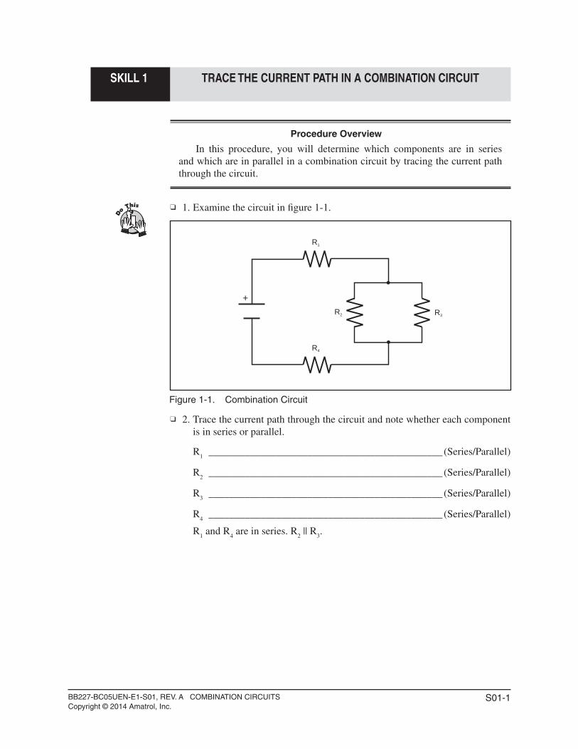
1. Examine the circuit in fi gure 1-1.
Figure 1-1. Combination Circuit
2. Trace the current path through the circuit and note whether each component is in series or parallel.
R1 _____________________________________________(Series/Parallel)
R2 _____________________________________________(Series/Parallel)
R3 _____________________________________________(Series/Parallel)
R4 _____________________________________________(Series/Parallel)
R1 and R
4 are in series. R
2 || R
3.
+
R1
R2 R3
R4
BB227-BC05UEN-E1-S01, REV. A COMBINATION CIRCUITSCopyright © 2014 Amatrol, Inc.
S01-2
SKILL 1 TRACE THE CURRENT PATH IN A COMBINATION CIRCUIT
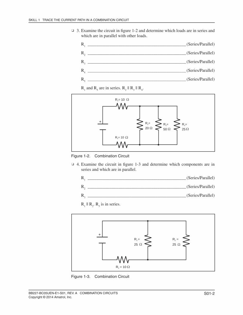
3. Examine the circuit in fi gure 1-2 and determine which loads are in series and which are in parallel with other loads.
R1 _____________________________________________(Series/Parallel)
R2 _____________________________________________(Series/Parallel)
R3 _____________________________________________(Series/Parallel)
R4 _____________________________________________(Series/Parallel)
R5 _____________________________________________(Series/Parallel)
R1 and R
5 are in series. R
2 || R
3 || R
4.
Figure 1-2. Combination Circuit
4. Examine the circuit in fi gure 1-3 and determine which components are in series and which are in parallel.
R1 _____________________________________________(Series/Parallel)
R2 _____________________________________________(Series/Parallel)
R3 _____________________________________________(Series/Parallel)
R1 || R
2. R
3 is in series.
Figure 1-3. Combination Circuit
+
R = 101
R =2 R =3
R = 105
20 50R =4
25
+
R = 103
R =1
25R =2
25
BB227-BC05UEN-E1-S02, REV. A COMBINATION CIRCUITSCopyright © 2014 Amatrol, Inc.
S02-1
SKILL 2 SOLVE A COMBINATION CIRCUIT
Procedure Overview
In this procedure, you will solve combination circuits using the seven-step process. You will calculate voltage and current values for each resistance in the circuit and redraw the circuit with all the values listed. In step 1, you will be led through the process. In steps 2 and 3, you will do it yourself.
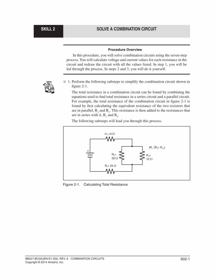
1. Perform the following substeps to simplify the combination circuit shown in fi gure 2-1.
The total resistance in a combination circuit can be found by combining the equations used to fi nd total resistance in a series circuit and a parallel circuit. For example, the total resistance of the combination circuit in fi gure 2-1 is found by fi rst calculating the equivalent resistance of the two resistors that are in parallel, R
2 and R
3. This resistance is then added to the resistances that
are in series with it, R1 and R
4.
The following substeps will lead you through this process.
Figure 2-1. Calculating Total Resistance
+
R = 251
R =2 R =3
R = 254
24V50 10
(R R = R )2 3 EQ
BB227-BC05UEN-E1-S02, REV. A COMBINATION CIRCUITSCopyright © 2014 Amatrol, Inc.
S02-2
SKILL 2 SOLVE A COMBINATION CIRCUIT
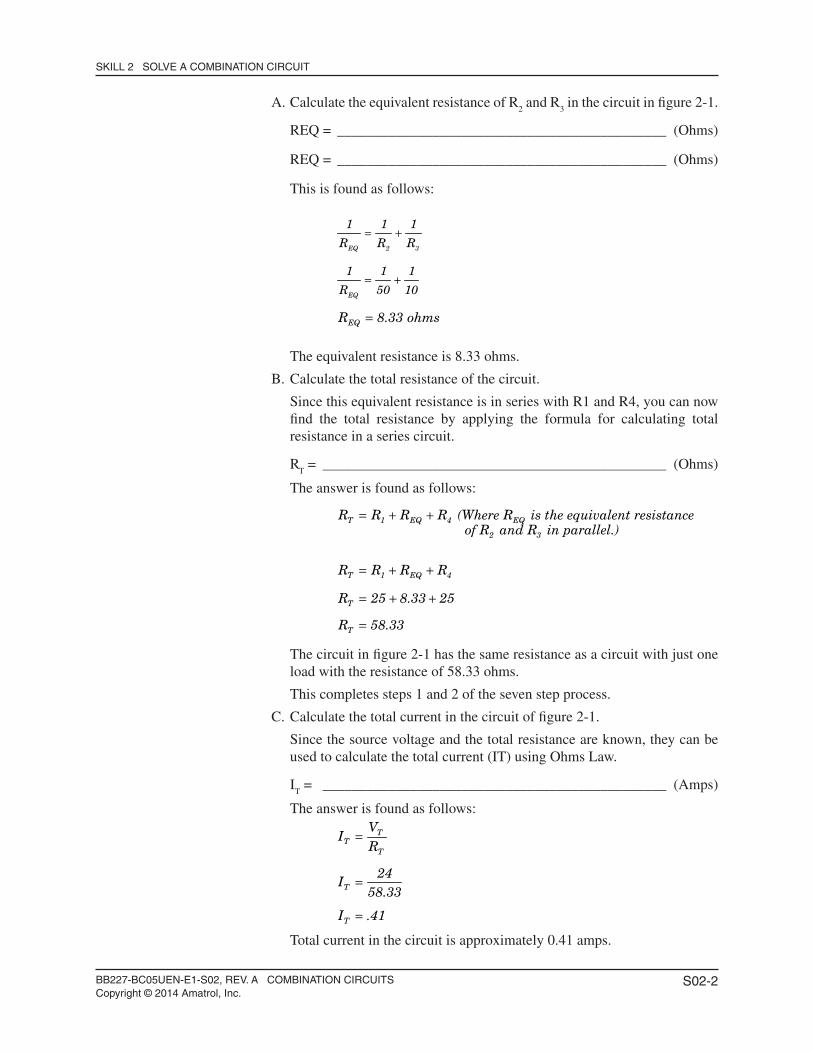
A. Calculate the equivalent resistance of R2 and R
3 in the circuit in fi gure 2-1.
REQ = _____________________________________________ (Ohms)
REQ = _____________________________________________ (Ohms)
This is found as follows:
EQ 2 3
EQ
EQ
1 1 1
R R R
1 1 1
R 50 10
R 8.33 ohms
= +
= +
=
The equivalent resistance is 8.33 ohms.
B. Calculate the total resistance of the circuit.
Since this equivalent resistance is in series with R1 and R4, you can now fi nd the total resistance by applying the formula for calculating total resistance in a series circuit.
RT = _______________________________________________ (Ohms)
The answer is found as follows:
T 1 EQ 4 EQ
2 3
T 1 EQ 4
T
T
R R R R (Where R is the equivalent resistance of R and R in parallel.)
R R R R
R 25 8.33 25
R 58.33
= + +
= + +
= + +
=
The circuit in fi gure 2-1 has the same resistance as a circuit with just one load with the resistance of 58.33 ohms.
This completes steps 1 and 2 of the seven step process.
C. Calculate the total current in the circuit of fi gure 2-1.
Since the source voltage and the total resistance are known, they can be used to calculate the total current (IT) using Ohms Law.
IT = _______________________________________________ (Amps)
The answer is found as follows:
TT
T
T
T
VI
R
24I
58.33
I .41
=
=
=
Total current in the circuit is approximately 0.41 amps.
BB227-BC05UEN-E1-S02, REV. A COMBINATION CIRCUITSCopyright © 2014 Amatrol, Inc.
S02-3
SKILL 2 SOLVE A COMBINATION CIRCUIT
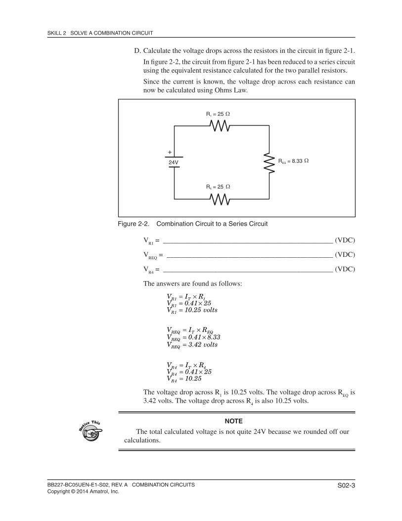
D. Calculate the voltage drops across the resistors in the circuit in fi gure 2-1.
In fi gure 2-2, the circuit from fi gure 2-1 has been reduced to a series circuit using the equivalent resistance calculated for the two parallel resistors.
Since the current is known, the voltage drop across each resistance can now be calculated using Ohms Law.
Figure 2-2. Combination Circuit to a Series Circuit
VR1
= _______________________________________________ (VDC)
VREQ
= ______________________________________________ (VDC)
VR4
= _______________________________________________ (VDC)
The answers are found as follows:
R1 T 1
R1
R1
REQ T EQ
REQ
REQ
R4 T 4
R4
R4
V I RV 0.41 25V 10.25 volts
V I RV 0.41 8.33V 3.42 volts
V I RV 0.41 25V 10.25
= ×= ×=
= ×= ×=
= ×= ×=
The voltage drop across R1 is 10.25 volts. The voltage drop across R
EQ is
3.42 volts. The voltage drop across R4 is also 10.25 volts.
NOTE
The total calculated voltage is not quite 24V because we rounded off our calculations.
+
R = 251
R = 8.33EQ
R = 254
24V
BB227-BC05UEN-E1-S02, REV. A COMBINATION CIRCUITSCopyright © 2014 Amatrol, Inc.
S02-4
SKILL 2 SOLVE A COMBINATION CIRCUIT
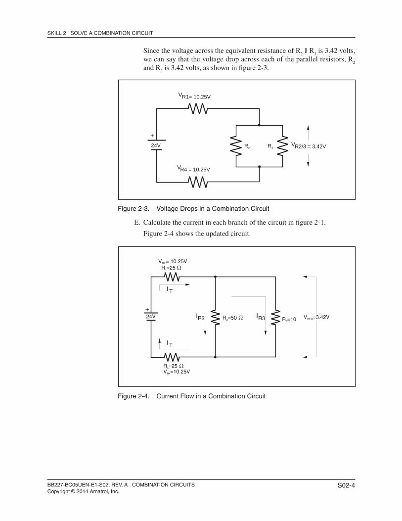
Since the voltage across the equivalent resistance of R2 || R
3 is 3.42 volts,
we can say that the voltage drop across each of the parallel resistors, R2
and R3 is 3.42 volts, as shown in fi gure 2-3.
Figure 2-3. Voltage Drops in a Combination Circuit
E. Calculate the current in each branch of the circuit in fi gure 2-1.
Figure 2-4 shows the updated circuit.
Figure 2-4. Current Flow in a Combination Circuit
+
R1= 10.25V
R2/3 = 3.42V
R4 = 10.25V
V
V
V
24V R2 R3
+
R =251
R =502 R =103
R =254
TI
TI
R2I R3I V =3.42VREQ24V
V = 10.25VR1
V =10.25VR4
BB227-BC05UEN-E1-S02, REV. A COMBINATION CIRCUITSCopyright © 2014 Amatrol, Inc.
S02-5
SKILL 2 SOLVE A COMBINATION CIRCUIT
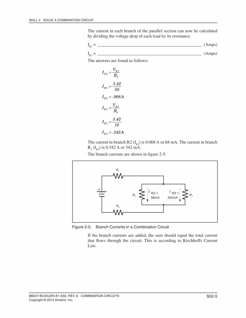
The current in each branch of the parallel section can now be calculated by dividing the voltage drop of each load by its resistance.
IR2
= _______________________________________________ (Amps)
IR3
= _______________________________________________ (Amps)
The answers are found as follows:
R2
R22
R2
R2
R3R3
3
R3
R3
VI
R
3.42I
50
I .068A
VI
R
3.42I
10
I .342A
=
=
=
=
=
=
The current in branch R2 (IR2
) is 0.068 A or 68 mA. The current in branch R
3 (I
R3) is 0.342 A or 342 mA.
The branch currents are shown in fi gure 2-5.
Figure 2-5. Branch Currents in a Combination Circuit
If the branch currents are added, the sum should equal the total current that fl ows through the circuit. This is according to Kirchhoffs Current Law.
+
R1
R2 R3
R4
R2 =I R3 =I68mA 342mA
24V
BB227-BC05UEN-E1-S02, REV. A COMBINATION CIRCUITSCopyright © 2014 Amatrol, Inc.
S02-6
SKILL 2 SOLVE A COMBINATION CIRCUIT
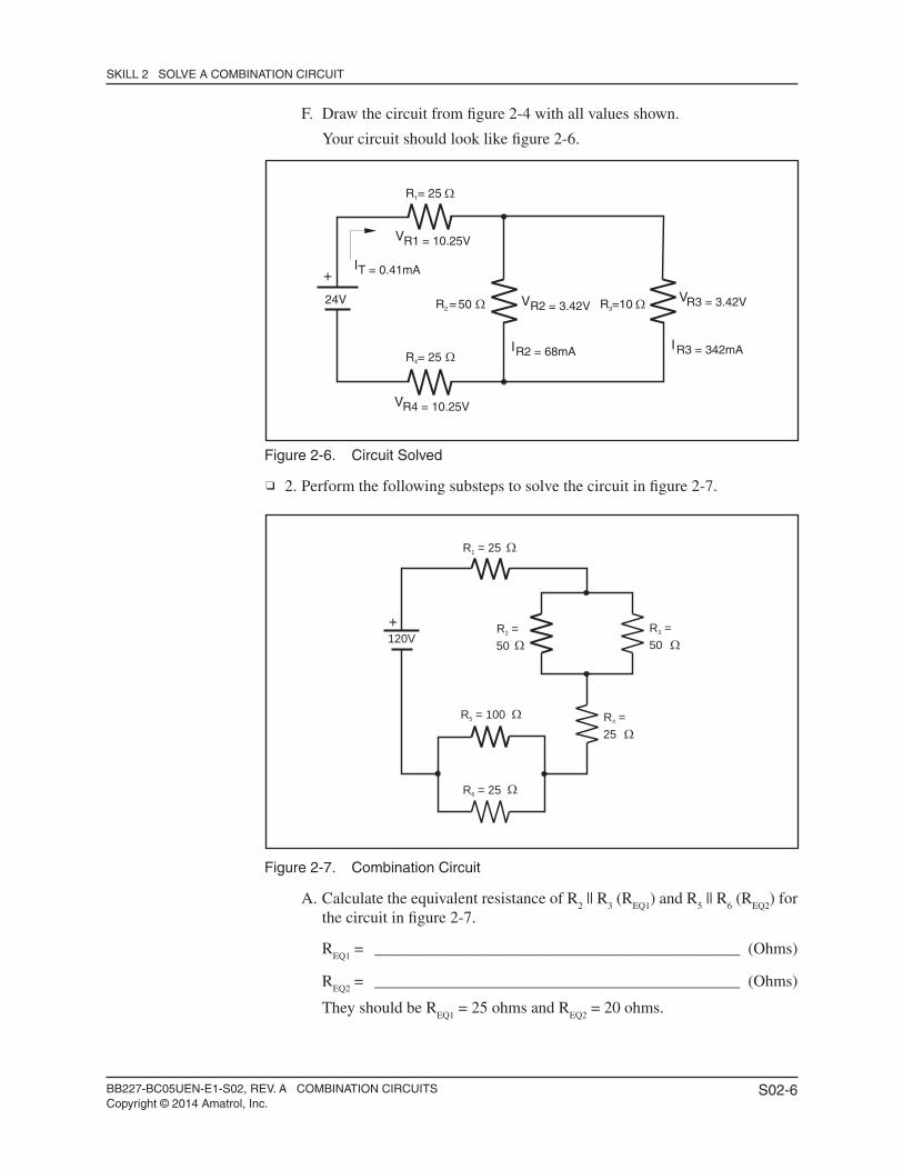
F. Draw the circuit from fi gure 2-4 with all values shown.
Your circuit should look like fi gure 2-6.
Figure 2-6. Circuit Solved
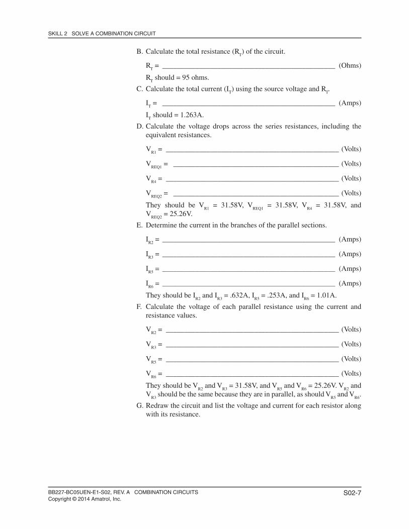
2. Perform the following substeps to solve the circuit in fi gure 2-7.
Figure 2-7. Combination Circuit
A. Calculate the equivalent resistance of R2 || R
3 (R
EQ1) and R
5 || R
6 (R
EQ2) for
the circuit in fi gure 2-7.
REQ1
= _____________________________________________ (Ohms)
REQ2
= _____________________________________________ (Ohms)
They should be REQ1
= 25 ohms and REQ2
= 20 ohms.
+
R = 251
R = 254
R3 = 3.42VR2 = 3.42V
R2 = 68mA
T = 0.41mA
R3 = 342mA
R1 = 10.25V
R4 = 10.25V
VV
I
I
I
V
V
24V R =502 R =103
+R = 251
R =2 R =3
R = 1005
50 50
R = 256
120V
R =4
25
BB227-BC05UEN-E1-S02, REV. A COMBINATION CIRCUITSCopyright © 2014 Amatrol, Inc.
S02-7
SKILL 2 SOLVE A COMBINATION CIRCUIT
B. Calculate the total resistance (RT) of the circuit.
RT = _______________________________________________ (Ohms)
RT should = 95 ohms.
C. Calculate the total current (IT) using the source voltage and R
T.
IT = _______________________________________________ (Amps)
IT should = 1.263A.
D. Calculate the voltage drops across the series resistances, including the equivalent resistances.
VR1
= _______________________________________________ (Volts)
VREQ1
= _____________________________________________ (Volts)
VR4
= _______________________________________________ (Volts)
VREQ2
= _____________________________________________ (Volts)
They should be VR1
= 31.58V, VREQ1
= 31.58V, VR4
= 31.58V, and V
REQ2 = 25.26V.
E. Determine the current in the branches of the parallel sections.
IR2
= _______________________________________________ (Amps)
IR3
= _______________________________________________ (Amps)
IR5
= _______________________________________________ (Amps)
IR6
= _______________________________________________ (Amps)
They should be IR2
and IR3
= .632A, IR5
= .253A, and IR6
= 1.01A.
F. Calculate the voltage of each parallel resistance using the current and resistance values.
VR2
= _______________________________________________ (Volts)
VR3
= _______________________________________________ (Volts)
VR5
= _______________________________________________ (Volts)
VR6
= _______________________________________________ (Volts)
They should be VR2
and VR3
= 31.58V, and VR5
and VR6
= 25.26V. VR2
and V
R3 should be the same because they are in parallel, as should V
R5 and V
R6.
G. Redraw the circuit and list the voltage and current for each resistor along with its resistance.
BB227-BC05UEN-E1-S02, REV. A COMBINATION CIRCUITSCopyright © 2014 Amatrol, Inc.
S02-8
SKILL 2 SOLVE A COMBINATION CIRCUIT
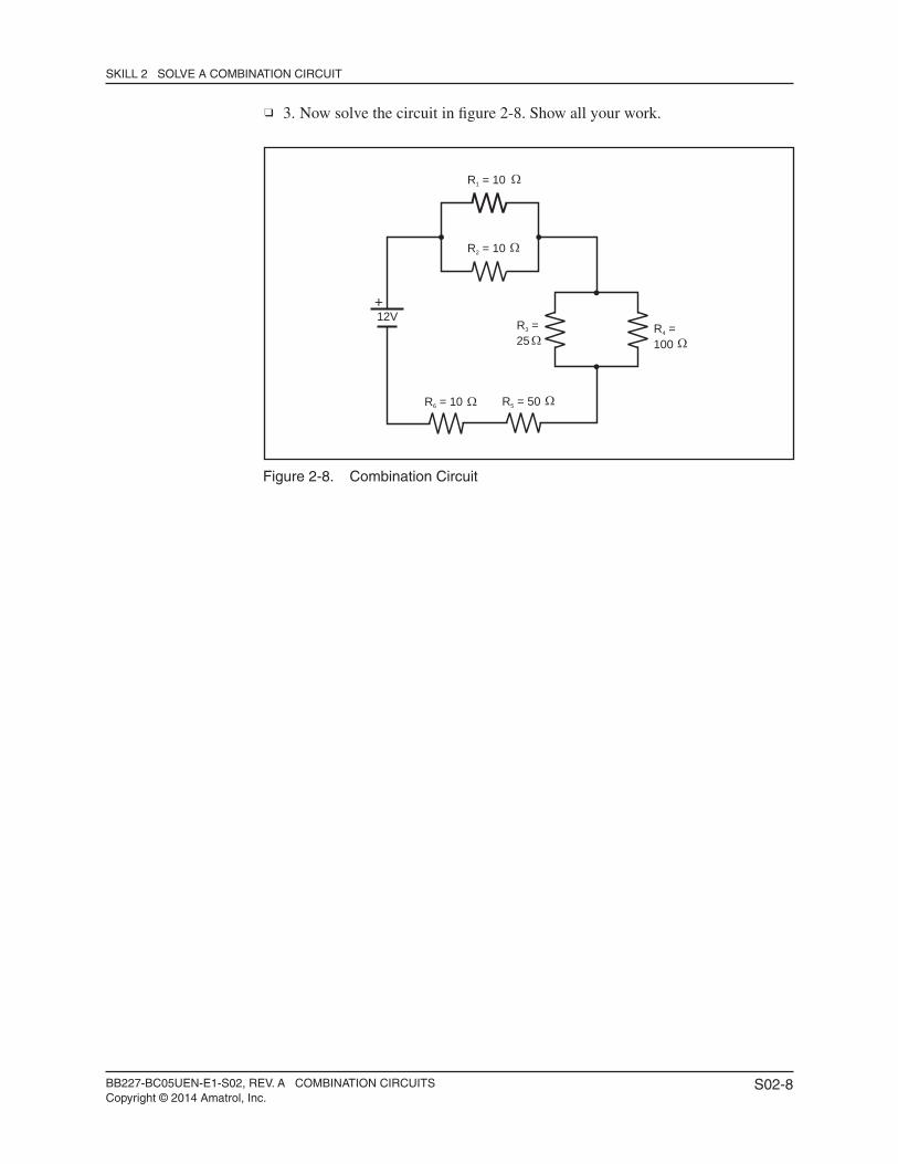
3. Now solve the circuit in fi gure 2-8. Show all your work.
Figure 2-8. Combination Circuit
+
R = 106
R =3 R =4
R = 101
25 100
R = 102
12V
R = 505
BB227-BC05UEN-E1-S03, REV. A COMBINATION CIRCUITSCopyright © 2014 Amatrol, Inc.
S03-1
SKILL 3 CONNECT AND OPERATE A BASIC LIGHTING CIRCUIT
Procedure Overview
In this procedure, you will connect a lighting circuit such as one you might fi nd in a commercial building. You will operate the circuit and observe the status of the lamps. You will also measure the voltage across the lamps with the switch on and off.
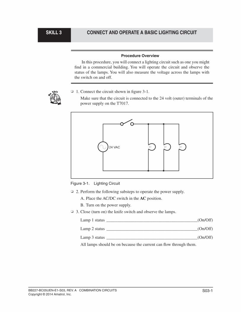
1. Connect the circuit shown in fi gure 3-1. Make sure that the circuit is connected to the 24 volt (outer) terminals of the
power supply on the T7017.
Figure 3-1. Lighting Circuit
2. Perform the following substeps to operate the power supply.
A. Place the AC/DC switch in the AC position.
B. Turn on the power supply. 3. Close (turn on) the knife switch and observe the lamps.
Lamp 1 status __________________________________________(On/Off)
Lamp 2 status __________________________________________(On/Off)
Lamp 3 status __________________________________________(On/Off)
All lamps should be on because the current can fl ow through them.
24 VAC
BB227-BC05UEN-E1-S03, REV. A COMBINATION CIRCUITSCopyright © 2014 Amatrol, Inc.
S03-2
SKILL 3 CONNECT AND OPERATE A BASIC LIGHTING CIRCUIT
4. Measure the voltage across each lamp with the DMM.
Voltage Lamp 1 = ________________________________________ (VAC)
Voltage Lamp 2 = ________________________________________ (VAC)
Voltage Lamp 3 = ________________________________________ (VAC)
Each lamp should have the source voltage across it, 24 VAC ± 2 VAC.
5. Now open (turn off) the knife switch and observe the lamps.
Lamp 1 status __________________________________________(On/Off)
Lamp 2 status __________________________________________(On/Off)
Lamp 3 status __________________________________________(On/Off)
All lamps should now be off because the current fl ow has been stopped. 6. Measure the voltage across each lamp with the DMM.
Voltage Lamp 1 = ________________________________________ (VAC)
Voltage Lamp 2 = ________________________________________ (VAC)
Voltage Lamp 3 = ________________________________________ (VAC)
All the lamps should have zero volts across them. 7. Turn off the power supply, disconnect the circuit, and store all components. You have now successfully connected and operated a typical lighting circuit.
BB227-BC05UEN-E1-S04, REV. A COMBINATION CIRCUITSCopyright © 2014 Amatrol, Inc.
S04-1
SKILL 4 CONNECT AND OPERATE A CEILING FAN CIRCUIT
Procedure Overview
In this procedure, you will connect a circuit that resembles a typical ceiling fan circuit. You will then control the operation of the fan motor and the lights with the three switches of the circuit.
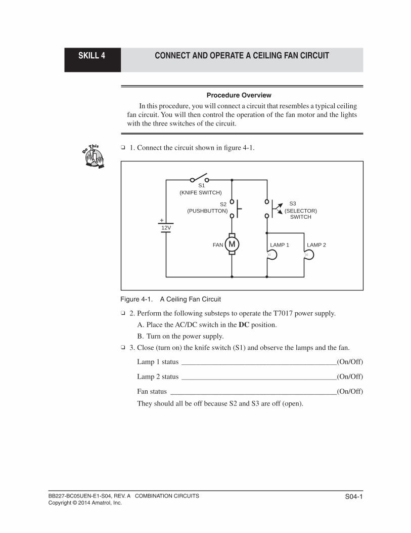
1. Connect the circuit shown in fi gure 4-1.
Figure 4-1. A Ceiling Fan Circuit
2. Perform the following substeps to operate the T7017 power supply.
A. Place the AC/DC switch in the DC position.
B. Turn on the power supply. 3. Close (turn on) the knife switch (S1) and observe the lamps and the fan.
Lamp 1 status __________________________________________(On/Off)
Lamp 2 status __________________________________________(On/Off)
Fan status _____________________________________________(On/Off)
They should all be off because S2 and S3 are off (open).
M
S1
S2 S3
FAN LAMP 1 LAMP 2
+
12V
(KNIFE SWITCH)
(PUSHBUTTON) (SELECTOR)SWITCH
BB227-BC05UEN-E1-S04, REV. A COMBINATION CIRCUITSCopyright © 2014 Amatrol, Inc.
S04-2
SKILL 4 CONNECT AND OPERATE A CEILING FAN CIRCUIT
4. Now press (turn on) the pushbutton switch (S2) and observe the lamps and the fan.
Lamp 1 status __________________________________________(On/Off)
Lamp 2 status __________________________________________(On/Off)
Fan status _____________________________________________(On/Off)
The fan should now be on because closing S2 allows current to fl ow through that branch. The lamps do not come on because S3 is not on (open).
5. Release the pushbutton and rotate (turn on) the selector switch (S3). Observe the lamps and the fan.
Lamp 1 status __________________________________________(On/Off)
Lamp 2 status __________________________________________(On/Off)
Fan status _____________________________________________(On/Off)
The fan should be off and the lights should be on because with S3 closed, current can fl ow in the branch that contains the lamps.
6. Now energize (turn on) both S2 and S3 together and observe the lamps and fan.
Lamp 1 status __________________________________________(On/Off)
Lamp 2 status __________________________________________(On/Off)
Fan status _____________________________________________(On/Off)
They should all be on because current can fl ow through both branches of the circuit.
7. Leave S2 and S3 on and open (turn off) the knife switch (S1) and observe the lamps and the fan.
Lamp 1 status __________________________________________(On/Off)
Lamp 2 status __________________________________________(On/Off)
Fan status _____________________________________________(On/Off)
They should all be off because there is no current fl ow to the branches because S1 is open (off).
8. Turn off the power supply, disconnect the circuit, and store all components. This procedure demonstrates how a typical ceiling fan with lights operates.
By using the three switches you can change the operation of the circuit.
BB227-BC05UEN-E1-A01, REV. A COMBINATION CIRCUITSCopyright © 2014 Amatrol, Inc.
A01-1
Activity 1. Rheostat Operation
Procedure Overview
In this procedure, you will measure the resistance of a rheostat as it is adjusted and note the effect the slider has on the resistance between it and either outside terminal.
You should also note that the sum of the two resistances created by the slider should always equal the resistance across the two outside terminals.
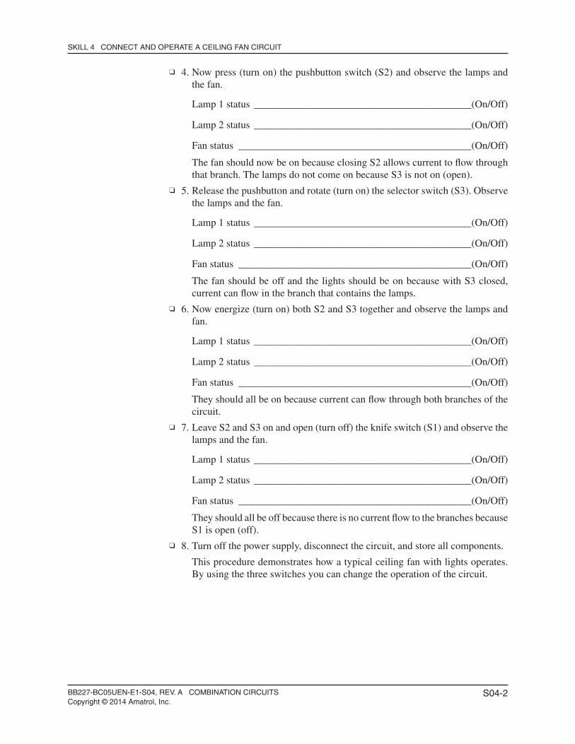
1. Prepare the DMM to measure resistance. 2. Locate the rheostat module and place it on the construction surface of the
T7017. 3. With the control knob on the rheostat facing you, turn the knob fully
counterclockwise. 4. Measure the resistance across the two outside terminals, as shown in fi gure
1-1.
Resistance = ___________________________________________ (Ohms)
It should be approximately 25 ohms.
Figure 1-1. Measurement of Rheostat Resistance
5. Turn the knob fully clockwise and measure the resistance across the two outside terminals.
Resistance = ___________________________________________ (Ohms)
It should be the same as in step 4, approximately 25 ohms. The resistance between the two outside terminals is always the maximum amount. The slider does not affect this value.
MAX600V600V
200mAMAX
FUSED
10A MAXFUSED
CAT 600VCAT 300V
HOLD
30XR
MIN MAXNON
CONTACTVOLTAGE
VBATT 9V
BATT 1.5V
COM
10A
mA
V 600600200200
200m200m
20M
2M
20k
200k
2k200 200m
20m
202022
V
A
10 A
2002m
BATT
OFF
2m
200m
200
20m
A
10 A
1.5V 9V
RHEOSTATMODULE
DMM
BB227-BC05UEN-E1-A01, REV. A COMBINATION CIRCUITSCopyright © 2014 Amatrol, Inc.
A01-2
ACTIVITY 1. RHEOSTAT OPERATION
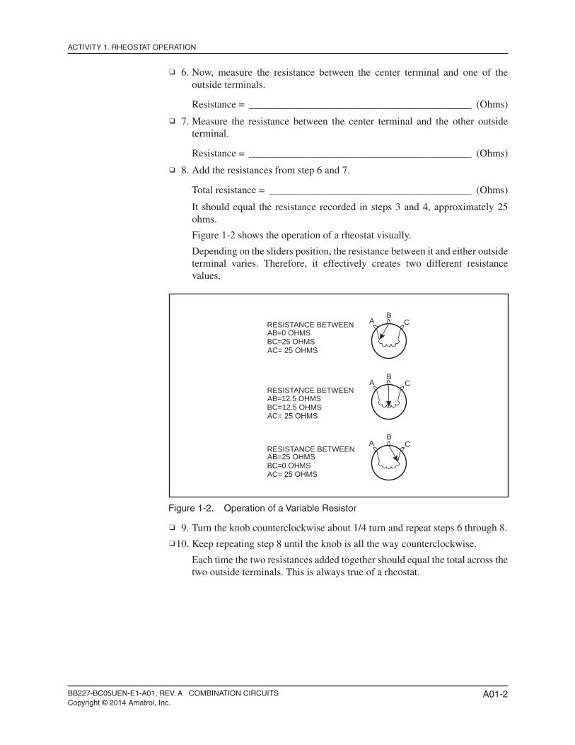
6. Now, measure the resistance between the center terminal and one of the outside terminals.
Resistance = ___________________________________________ (Ohms)
7. Measure the resistance between the center terminal and the other outside terminal.
Resistance = ___________________________________________ (Ohms)
8. Add the resistances from step 6 and 7.
Total resistance = _______________________________________ (Ohms)
It should equal the resistance recorded in steps 3 and 4, approximately 25 ohms.
Figure 1-2 shows the operation of a rheostat visually. Depending on the sliders position, the resistance between it and either outside
terminal varies. Therefore, it effectively creates two different resistance values.
Figure 1-2. Operation of a Variable Resistor
9. Turn the knob counterclockwise about 1/4 turn and repeat steps 6 through 8. 10. Keep repeating step 8 until the knob is all the way counterclockwise. Each time the two resistances added together should equal the total across the
two outside terminals. This is always true of a rheostat.
AB
C
AB
C
AB
C
AB=0 OHMSRESISTANCE BETWEEN
BC=25 OHMSAC= 25 OHMS
AB=12.5 OHMSRESISTANCE BETWEEN
BC=12.5 OHMSAC= 25 OHMS
AB=25 OHMSRESISTANCE BETWEEN
BC=0 OHMSAC= 25 OHMS
BB227-BC05UEN-E1-S05, REV. A COMBINATION CIRCUITSCopyright © 2014 Amatrol, Inc.
S05-1
SKILL 5 CONNECT AND OPERATE A RHEOSTAT AS A LIGHT DIMMER
Procedure Overview
In this procedure, you will connect and operate a rheostat in a circuit and use it to dim a lamp by controlling the voltage across the lamp.
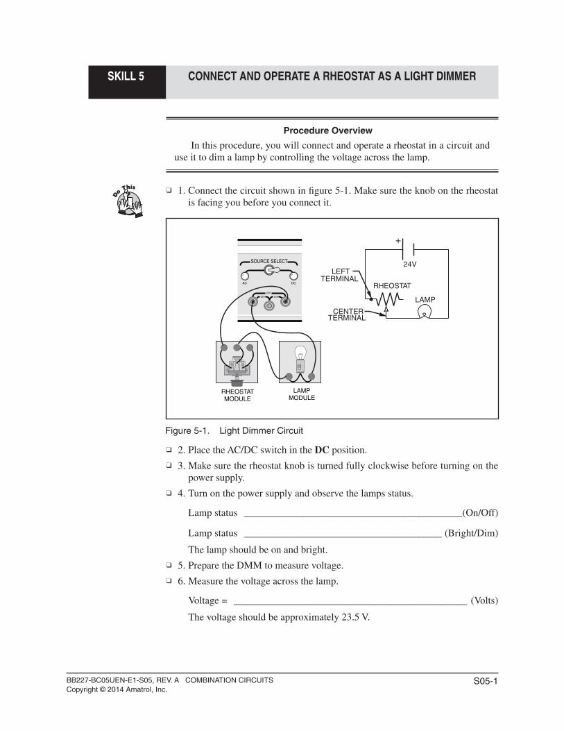
1. Connect the circuit shown in fi gure 5-1. Make sure the knob on the rheostat is facing you before you connect it.
Figure 5-1. Light Dimmer Circuit
2. Place the AC/DC switch in the DC position. 3. Make sure the rheostat knob is turned fully clockwise before turning on the
power supply. 4. Turn on the power supply and observe the lamps status.
Lamp status ___________________________________________(On/Off)
Lamp status _______________________________________ (Bright/Dim)
The lamp should be on and bright. 5. Prepare the DMM to measure voltage. 6. Measure the voltage across the lamp.
Voltage = ______________________________________________ (Volts)
The voltage should be approximately 23.5 V.
SOURCE SELECT
AC DC
12V 12V
24V
LAMPMODULE
RHEOSTATMODULE
+
LAMP
24V
CENTERTERMINAL
RHEOSTAT
LEFTTERMINAL
BB227-BC05UEN-E1-S05, REV. A COMBINATION CIRCUITSCopyright © 2014 Amatrol, Inc.
S05-2
SKILL 5 CONNECT AND OPERATE A RHEOSTAT AS A LIGHT DIMMER
7. Turn the knob about 1/4 turn counterclockwise and observe the lamp.
Lamp status __________________________________ (Brighter/Dimmer)
The lamp should start to dim somewhat. 8. Measure the voltage across the lamp.
Voltage = ______________________________________________ (Volts)
It should be lower than it was in step 6. 9. Turn the knob to about the half-way point and observe the lamp.
Lamp status __________________________________ (Brighter/Dimmer)
The lamp should be even dimmer. 10. Measure the voltage across the lamp.
Voltage = ______________________________________________ (Volts)
It should be lower than in step 8. 11. Turn the knob about 3/4 counterclockwise and observe the lamp.
Lamp status __________________________________ (Brighter/Dimmer)
The lamp should be even dimmer than before. 12. Measure the voltage across the lamp.
Voltage = ______________________________________________ (Volts)
It should be lower than in step 10. 13. Now turn the knob fully counterclockwise and observe the lamp.
Lamp status __________________________________ (Brighter/Dimmer)
The lamp should be very dim. 14. Measure the voltage across the lamp.
Voltage = ______________________________________________ (Volts)
It should be lower than in step 12. 15. Adjust the knob back and forth several more times and observe the lamp to
familiarize yourself with the operation. 16. Turn off the power supply, disconnect the circuit, and store all components.
BB227-BC05UEN-E1-S06, REV. A COMBINATION CIRCUITSCopyright © 2014 Amatrol, Inc.
S06-1
SKILL 6 DESIGN A VOLTAGE DIVIDER NETWORK
Procedure Overview
In this procedure, you will design circuits with all three types of voltage dividers. You will be led through the fi rst design of each type and will then work through the others yourself.
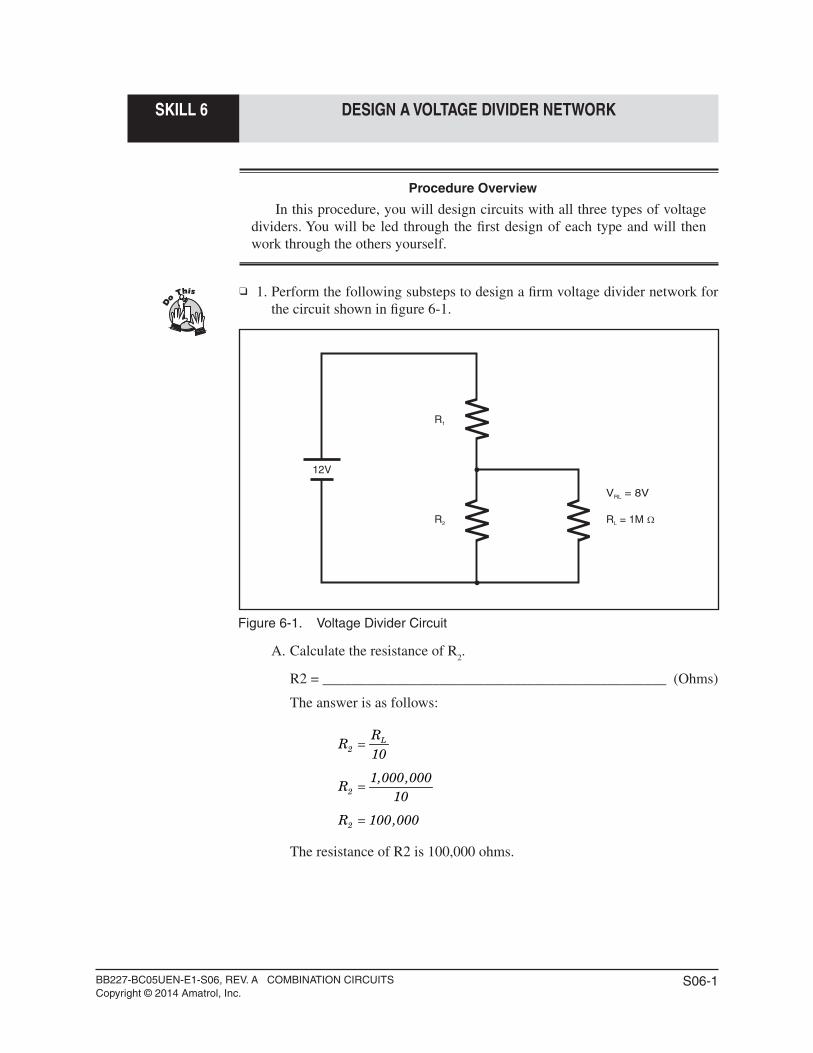
1. Perform the following substeps to design a fi rm voltage divider network for the circuit shown in fi gure 6-1.
Figure 6-1. Voltage Divider Circuit
A. Calculate the resistance of R2.
R2 = _______________________________________________ (Ohms)
The answer is as follows:
L
2
2
2
RR
10
1,000,000R
10
R 100,000
=
=
=
The resistance of R2 is 100,000 ohms.
R1
R2 R = 1ML
V = 8VRL
12V
BB227-BC05UEN-E1-S06, REV. A COMBINATION CIRCUITSCopyright © 2014 Amatrol, Inc.
S06-2
SKILL 6 DESIGN A VOLTAGE DIVIDER NETWORK
B. Calculate the resistance of R1.
R1 =(Ohms)
The basic formula is:
2
RL T1 2
RV V
R R⎛ ⎞
= ×⎜ ⎟+⎝ ⎠
The answer is found by rearranging the formula as follows:
T 2
1 2RL
RL
1
V RR R
V
12 100,000V 100,000
8
R 150,000 100,000
⎛ ⎞×= −⎜ ⎟⎝ ⎠
×⎛ ⎞= −⎜ ⎟⎝ ⎠
= −
The resistance of R1 is 50,000 ohms.
2. Design a fi rm voltage divider network for the circuit shown in fi gure 6-1 for an R
L of 75 K.
R2 = _________________________________________________ (Ohms)
R1 = _________________________________________________ (Ohms)
R2 is 7,500 ohms and R
1 is 3,750 ohms.
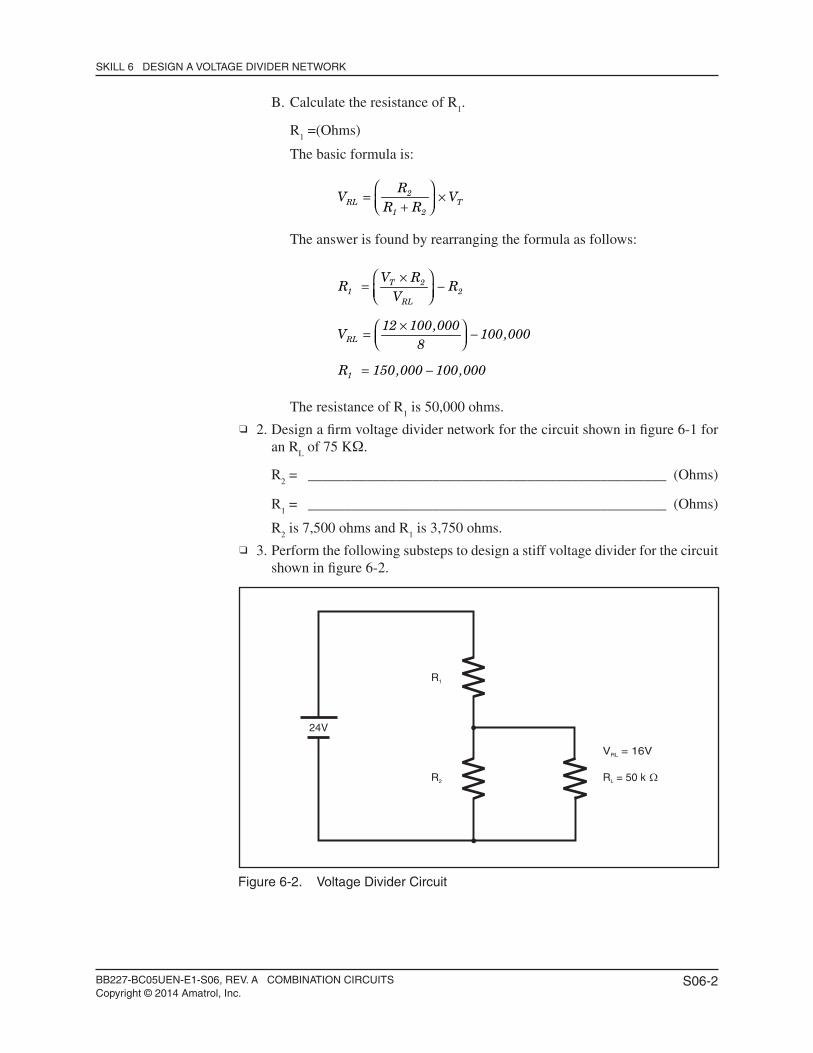
3. Perform the following substeps to design a stiff voltage divider for the circuit shown in fi gure 6-2.
Figure 6-2. Voltage Divider Circuit
R1
R2 R = 50 kL
V = 16VRL
24V
BB227-BC05UEN-E1-S06, REV. A COMBINATION CIRCUITSCopyright © 2014 Amatrol, Inc.
S06-3
SKILL 6 DESIGN A VOLTAGE DIVIDER NETWORK
A. Calculate the resistance of R2.
R2 = _______________________________________________ (Ohms)
L
2
2
RR
100
50,000R
100
=
=
The resistance of R2 is 500 ohms.
B. Calculate the resistance of R1.
R1 = _______________________________________________ (Ohms)
T 2
1 2RL
1
1
V RR R
V
24 500R 500
16
R 750 500
⎛ ⎞×= −⎜ ⎟⎝ ⎠
×⎛ ⎞= −⎜ ⎟⎝ ⎠
= −
The resistance of R1 is 250 ohms.
4. Design a stiff voltage divider network for the circuit shown in fi gure 30 for an R
L of 85K.
R2 = _________________________________________________ (Ohms)
R1 = _________________________________________________ (Ohms)
R2 is 850 ohms and R
1 is 425 ohms.
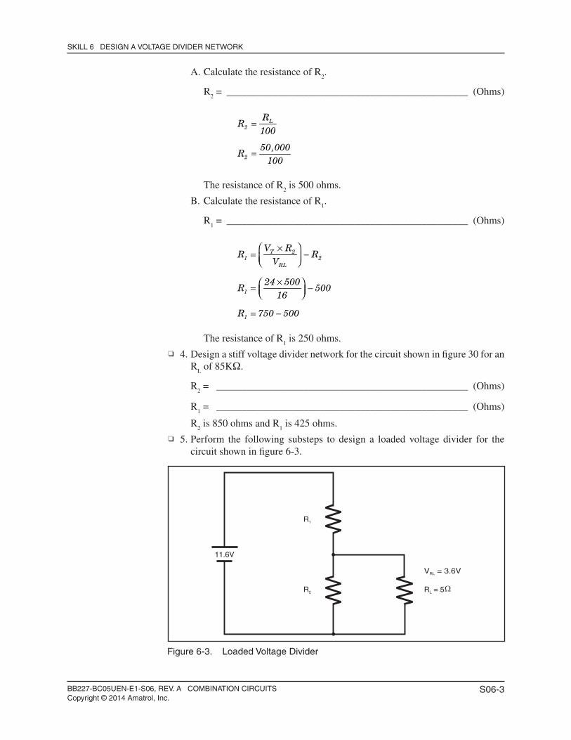
5. Perform the following substeps to design a loaded voltage divider for the circuit shown in fi gure 6-3.
Figure 6-3. Loaded Voltage Divider
R1
R2 R = 5L
V = 3.6VRL
11.6V
BB227-BC05UEN-E1-S06, REV. A COMBINATION CIRCUITSCopyright © 2014 Amatrol, Inc.
S06-4
SKILL 6 DESIGN A VOLTAGE DIVIDER NETWORK
A. Calculate the resistance of R2.
R2 = _______________________________________________ (Ohms)
Resistor R2 is chosen to be 10 times larger than R
L as follows:
2 L
2
R R 10
R 5 10
= ×
= ×
The resistance of R2 is 50 ohms.
B. Calculate REQ
(the resistance of R2 || R
L).
NOTE
The design of the loaded voltage dividers considers the effect of the load in parallel with the bleeder resistor.
REQ
= ______________________________________________ (Ohms)
EQ
2 L
EQ
EQ
1R
1 1R R
1R
.02 .2
1R
.22
=+
=+
=
The solution is as follows:
The resistance of REQ
is 4.55 ohms.
C. Calculate the value of R1.
R1 = _______________________________________________ (ohms)
This calculation uses the same voltage divider formula used to design stiff and fi rm dividers except the combined resistance of R
2 and R
L (R
EQ) is
used instead of just R2.
This can be rearranged as before:
EQ
RL T1 EQ
T EQ1 EQ
RL
1
1
RV V
R R
V RR R
V
11.6 4.55R 4.55
3.6
R 14.66 4.55
⎛ ⎞= ×⎜ ⎟+⎝ ⎠
×⎛ ⎞= −⎜ ⎟⎝ ⎠
×⎛ ⎞= −⎜ ⎟⎝ ⎠
= −
The resistance of R1 is 10.1 ohms.
BB227-BC05UEN-E1-S06, REV. A COMBINATION CIRCUITSCopyright © 2014 Amatrol, Inc.
S06-5
SKILL 6 DESIGN A VOLTAGE DIVIDER NETWORK
6. Design a loaded voltage divider for the circuit shown in fi gure 6-3. Use a VRL
of 10V and an R
L of 10 ohms.
R2 = _________________________________________________ (Ohms)
R1 = _________________________________________________ (Ohms)
R2 is 100 ohms and R
1 is 1.45 ohms.
7. Design a loaded voltage divider for the circuit shown in fi gure 6-3. Use a VRL
of 4V and an R
L of 2 ohms.
R2 = _________________________________________________ (Ohms)
R1 = _________________________________________________ (Ohms)
R2 is 20 ohms and R
1 is 3.46 ohms.
BB227-BC05UEN-E1-S07, REV. A COMBINATION CIRCUITSCopyright © 2014 Amatrol, Inc.
S07-1
SKILL 7 CONNECT AND OPERATE A VOLTAGE DIVIDER NETWORK
Procedure Overview
In this procedure, you will connect and operate a loaded voltage divider network. You will then take measurements to verify its operation.
1. Perform the following substeps to set the rheostat (RL) to the required load
resistance value.
NOTE
In the next step, the rheostat will be used in a voltage divider circuit to simulate the load (R
L). The two (2) 25-ohm resistors will be used in series to
simulate R2.
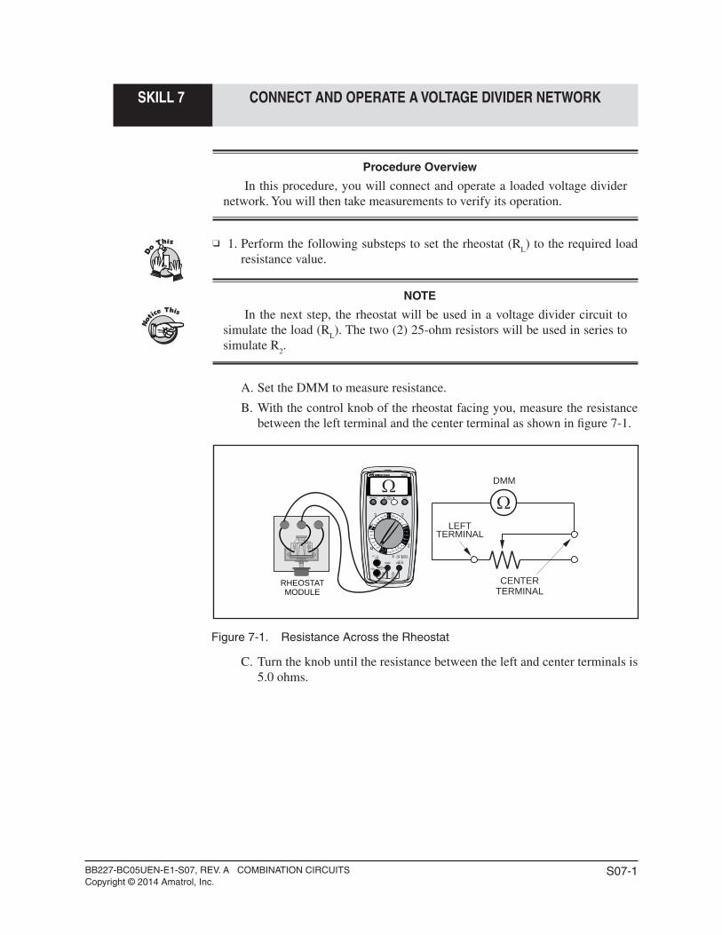
A. Set the DMM to measure resistance.
B. With the control knob of the rheostat facing you, measure the resistance between the left terminal and the center terminal as shown in fi gure 7-1.
Figure 7-1. Resistance Across the Rheostat
C. Turn the knob until the resistance between the left and center terminals is 5.0 ohms.
MAX600V600V
200mAMAX
FUSED
10A MAXFUSED
CAT 600VCAT 300V
HOLD
30XR
MIN MAXNON
CONTACTVOLTAGE
VBATT 9V
BATT 1.5V
COM
10A
mA
V 600600200200
200m200m
20M
2M
20k
200k
2k200 200m
20m
202022
V
A
10 A
2002m
BATT
OFF
2m
200m
200
20m
A
10 A
1.5V 9V
RHEOSTATMODULE
LEFTTERMINAL
CENTERTERMINAL
DMM
BB227-BC05UEN-E1-S07, REV. A COMBINATION CIRCUITSCopyright © 2014 Amatrol, Inc.
S07-2
SKILL 7 CONNECT AND OPERATE A VOLTAGE DIVIDER NETWORK
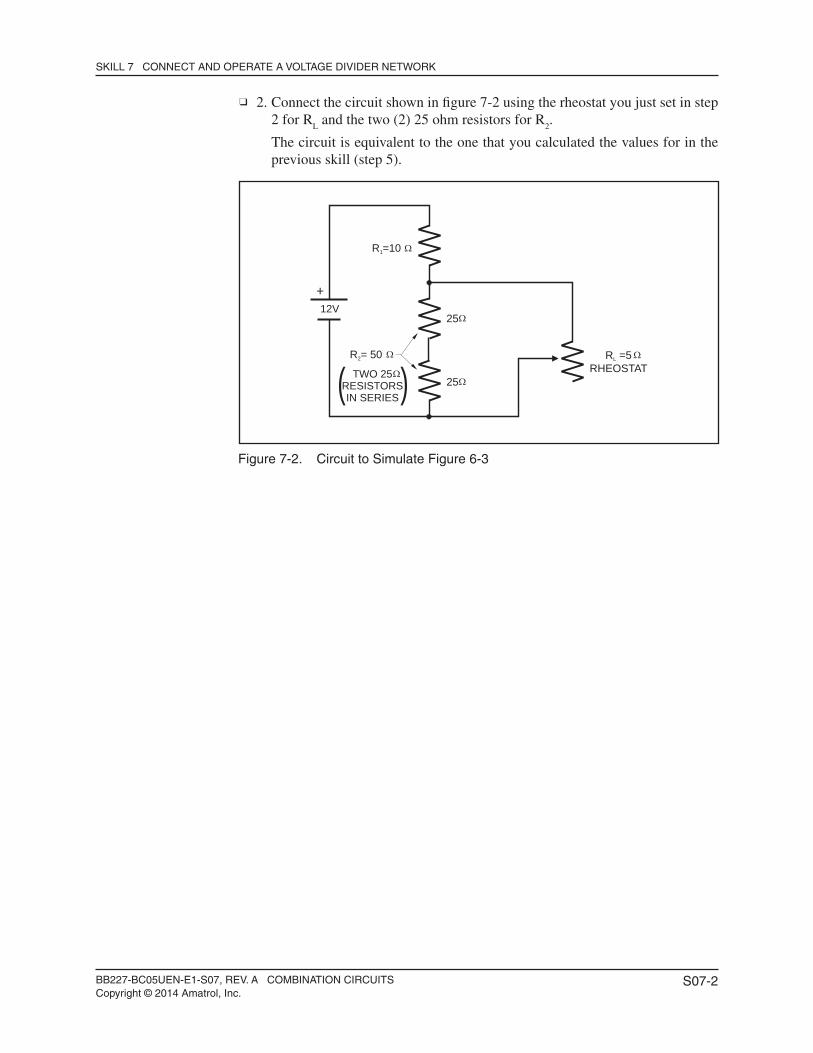
2. Connect the circuit shown in fi gure 7-2 using the rheostat you just set in step 2 for R
L and the two (2) 25 ohm resistors for R
2.
The circuit is equivalent to the one that you calculated the values for in the previous skill (step 5).
Figure 7-2. Circuit to Simulate Figure 6-3
+
R = 502
25
25
R =101
R =5RHEOSTAT
L
12V
TWO 25RESISTORSIN SERIES( )
BB227-BC05UEN-E1-S07, REV. A COMBINATION CIRCUITSCopyright © 2014 Amatrol, Inc.
S07-3
SKILL 7 CONNECT AND OPERATE A VOLTAGE DIVIDER NETWORK
3. Perform the following substeps to operate the circuit and make measurements.
A. Place the AC/DC switch in the DC position.
B. Turn on the power supply on the T7017.
C. Set the DMM to measure DC Volts.
D. Now measure the voltage across RL.
VRL
= _______________________________________________ (Volts)
It should be approximately 3.6V.
NOTE
Actual values will vary depending on the exact values of the resistors and the source voltage.
E. Turn off the power supply.
In the next two steps you will measure the unloaded voltage produced by the divider network.
4. Disconnect RL from the circuit and turn on the power supply.
5. Now measure the voltage across R2 (the series combination of the two 25
ohm resistors) to determine if unloaded voltage is close to the 3.6 V value produced when the load was attached?
Unloaded voltage close to loaded voltage? __________________ (Yes/No)
You should fi nd that the unloaded voltage is much greater than 3.6 V. This is because the loaded divider network requires that the load be constant for proper operation.
6. Turn off the power supply. 7. Disconnect the circuit and store all components.
BB227-BC05UEN-E1-S08, REV. A COMBINATION CIRCUITSCopyright © 2014 Amatrol, Inc.
S08-1
SKILL 8 LOCATE A SHORT CIRCUIT
Procedure Overview
In this procedure, you will troubleshoot a circuit to locate a short circuit using the four-step process. You will then repair the short and return the circuit to operation.
NOTE
Consult your instructor as to whether you should continue with this procedure or not. You will need an extra 3-amp fuse.
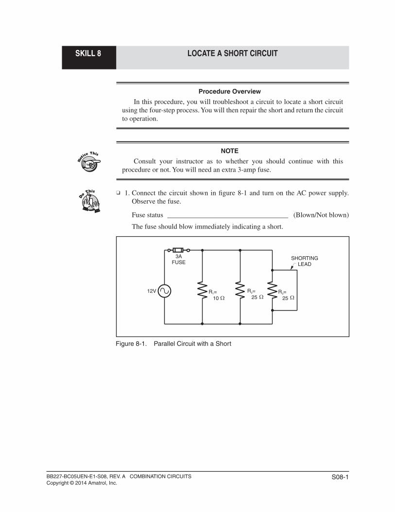
1. Connect the circuit shown in fi gure 8-1 and turn on the AC power supply. Observe the fuse.
Fuse status __________________________________ (Blown/Not blown)
The fuse should blow immediately indicating a short.
Figure 8-1. Parallel Circuit with a Short
SHORTINGLEAD
R =101
R =252 R =
253
12V
3AFUSE
BB227-BC05UEN-E1-S08, REV. A COMBINATION CIRCUITSCopyright © 2014 Amatrol, Inc.
S08-2
SKILL 8 LOCATE A SHORT CIRCUIT
2. Perform the following substeps to troubleshoot the circuit.
A. Look at the circuit to see if there are any visible signs of a short (smoke or soot).
B. Turn off and disconnect the power supply from the circuit.
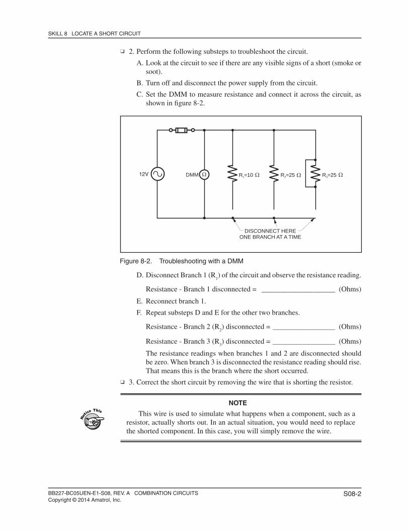
C. Set the DMM to measure resistance and connect it across the circuit, as shown in fi gure 8-2.
Figure 8-2. Troubleshooting with a DMM
D. Disconnect Branch 1 (R1) of the circuit and observe the resistance reading.
Resistance - Branch 1 disconnected = ____________________ (Ohms)
E. Reconnect branch 1.
F. Repeat substeps D and E for the other two branches.
Resistance - Branch 2 (R2) disconnected = _________________ (Ohms)
Resistance - Branch 3 (R3) disconnected = _________________ (Ohms)
The resistance readings when branches 1 and 2 are disconnected should be zero. When branch 3 is disconnected the resistance reading should rise. That means this is the branch where the short occurred.
3. Correct the short circuit by removing the wire that is shorting the resistor.
NOTE
This wire is used to simulate what happens when a component, such as a resistor, actually shorts out. In an actual situation, you would need to replace the shorted component. In this case, you will simply remove the wire.
R =101 R =252 R =253
DISCONNECT HEREONE BRANCH AT A TIME
DMM12V
BB227-BC05UEN-E1-S08, REV. A COMBINATION CIRCUITSCopyright © 2014 Amatrol, Inc.
S08-3
SKILL 8 LOCATE A SHORT CIRCUIT
4. Make sure all the branches are reconnected and observe the resistance reading.
Resistance reading = ____________________________________ (Ohms)
The reading should be 5.56 ohms, which is the effective resistance of the circuit. Therefore, the short circuit has been eliminated. If the reading is still zero, another short is present and must be found.
5. Replace the blown fuse with a 3-amp fuse. 6. Reconnect the power supply to the circuit. 7. Operate the circuit and observe the fuse.
Fuse status __________________________________ (Blown/Not blown)
The fuse should not blow since the short has been repaired. 8. Turn off the power supply. 9. Disconnect the circuit and store all components.
BB227-BC05UEN-E1-S09, REV. A COMBINATION CIRCUITSCopyright © 2014 Amatrol, Inc.
S09-1
SKILL 9 LOCATE AN OPEN CIRCUIT
Procedure Overview
In this procedure, you will troubleshoot a parallel circuit to determine where an open has occurred. You will then repair the open and return the circuit to operation.
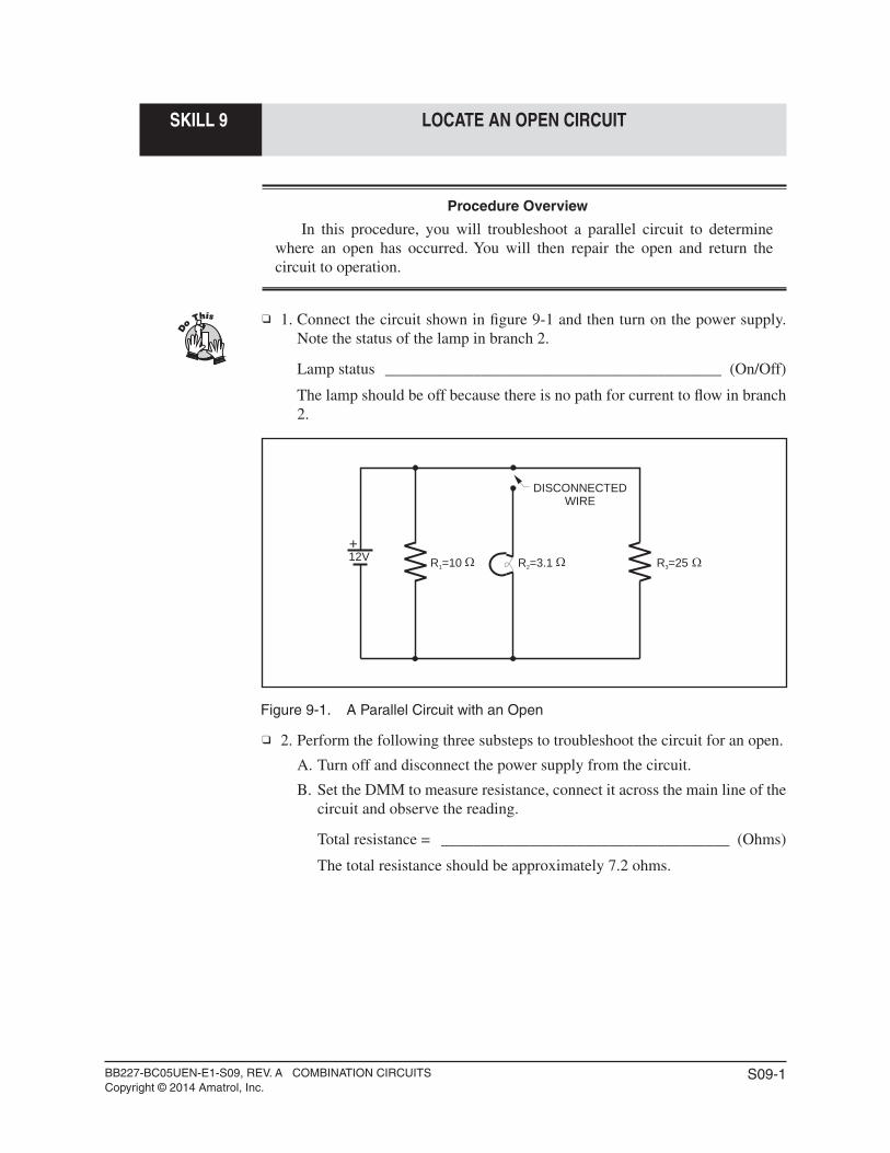
1. Connect the circuit shown in fi gure 9-1 and then turn on the power supply. Note the status of the lamp in branch 2.
Lamp status __________________________________________ (On/Off)
The lamp should be off because there is no path for current to fl ow in branch 2.
Figure 9-1. A Parallel Circuit with an Open
2. Perform the following three substeps to troubleshoot the circuit for an open.
A. Turn off and disconnect the power supply from the circuit.
B. Set the DMM to measure resistance, connect it across the main line of the circuit and observe the reading.
Total resistance = ____________________________________ (Ohms)
The total resistance should be approximately 7.2 ohms.
+12V R =101 R =3.12 R =253
DISCONNECTEDWIRE
BB227-BC05UEN-E1-S09, REV. A COMBINATION CIRCUITSCopyright © 2014 Amatrol, Inc.
S09-2
SKILL 9 LOCATE AN OPEN CIRCUIT
C. Disconnect branch 1 and record the resistance reading.
Resistance - Branch 1 disconnected = ____________________ (Ohms)
D. Reconnect branch 1.
E. Repeat substeps C and D for the other two branches.
Resistance - Branch 2 disconnected = ____________________ (Ohms)
Resistance - Branch 3 disconnected = ____________________ (Ohms)
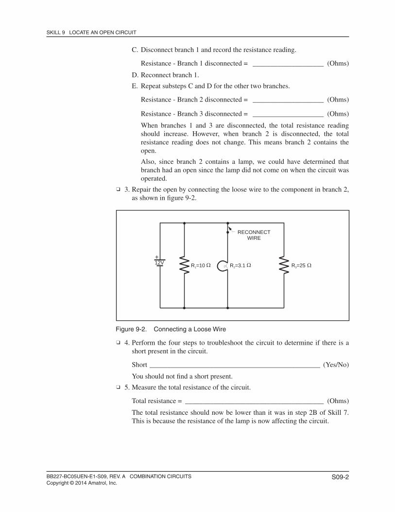
When branches 1 and 3 are disconnected, the total resistance reading should increase. However, when branch 2 is disconnected, the total resistance reading does not change. This means branch 2 contains the open.
Also, since branch 2 contains a lamp, we could have determined that branch had an open since the lamp did not come on when the circuit was operated.
3. Repair the open by connecting the loose wire to the component in branch 2, as shown in fi gure 9-2.
Figure 9-2. Connecting a Loose Wire
4. Perform the four steps to troubleshoot the circuit to determine if there is a short present in the circuit.
Short ________________________________________________ (Yes/No)
You should not fi nd a short present. 5. Measure the total resistance of the circuit.
Total resistance = _______________________________________ (Ohms)
The total resistance should now be lower than it was in step 2B of Skill 7. This is because the resistance of the lamp is now affecting the circuit.
+12V R =101 R =3.12 R =253
RECONNECTWIRE
BB227-BC05UEN-E1-S09, REV. A COMBINATION CIRCUITSCopyright © 2014 Amatrol, Inc.
S09-3
SKILL 9 LOCATE AN OPEN CIRCUIT
6. Reconnect the power supply to the circuit and turn on the circuit. Observe the lamp status.
Lamp status __________________________________________ (On/Off)
The lamp should now be on since the open has been repaired. 7. Turn off the power supply. 8. Disconnect the circuit and store all components.
NOTE
The same results you saw in this skill would have occurred if the lamp had been burned out, which happens frequently with lamps. When a lamp burns out, the fi laments inside the lamp open.


