Embed Size (px)
Citation preview
Activity OverviewIn these activities, you’ll explore using the Adafruit APDS9960 Gesture Sensor with the PRIZM® controller. The sensor connects to TETRIX® PRIZM using the gesture sensor adapter board and a standard sensor cable through the I2C port. The APDS9960 Gesture Sensor has several sensing capabilities that include:
• Proximity sensing that can detect distances up to about 40 centimeters.
• Color sensing that can measure the red, green, blue (RGB) color composition of an object as well as the ambient light level in the area.
• Gesture sensing capabilities that can detect simple gestures such as left, right, up, down, near, and far.
You’ll start by simply connecting the sensor to PRIZM to see what kind of data the sensor outputs. After that, you’ll attach the sensor to the TaskBot and use the sensor’s gesture detection capabilities to drive the TaskBot. Finally, you’ll modify the TaskBot sketch to include all three sensor functions in one sketch to navigate an obstacle course or maze. Although the APDS9960 Gesture Sensor has several other sensing capabilities, for the remainder of this guide, the APDS9960 Gesture Sensor will simply be referred to as the gesture sensor.
Parts NeededTo complete this activity, each team will need the following items:
• Fully assembled PRIZM TaskBot
• Adafruit APDS9960 Gesture Sensor
• This sensor is available from: Adafruit Industries Adafruit.com Sensor: Adafruit APDS9960 Proximity, Light, RGB, and Gesture Sensor Product ID: 3595
• TETRIX Gesture Sensor Adapter Board (46035)
• This adapter board is available at Pitsco.com/TETRIX-Adafruit-Proximity-Sensor-Adapter.
• USB cable
• Charged TETRIX 12-volt battery
• Computer with the following installed:
• Arduino Software (IDE) and Arduino libraries for TETRIX PRIZM and TETRIX APDS9960 Gesture Sensor
• Both libraries can be downloaded from the Pitsco website at Pitsco.com/TETRIX-PRIZM-Robotics-Controller.
ActivityGesture Sensor
DifficultyModerate
Class Time270 minutes
Grade Level• Middle school
• High school
Learning Focus• I2C sensors
• Programming/coding
1
TETRIX MAX Gesture Sensor Extension ActivityOverview

Before You BeginBefore you begin this activity, you’ll need to install the TETRIX APDS9960 Gesture Sensor Library. There are two methods of installing a library into the Arduino Software (IDE).
Importing a .zip LibraryIn the Arduino Software (IDE), navigate to Sketch > Include Library. From the drop-down menu, select Add .ZIP Library.
You will be prompted to select the library you would like to add. Navigate to the location where you saved the APDS9960 Gesture Sensor Library. Select and open the TETRIX_APDS9960_Gesture.zip file.
Return to the Sketch > Include Library menu. You should now see the TETRIX_APDS9960_Gesture library near the bottom of the drop-down menu. It is ready to be used. However, the example sketches used in this activity might not be available until the Arduino Software (IDE) has been restarted.
Manual InstallationTo install the Gesture Sensor library manually, follow the instructions provided in the PRIZM Programming Guide’s Software Setup section.
2
TETRIX MAX Gesture Sensor Extension ActivityLesson Guide

Activity SetupFor this activity, you’ll need to connect your PRIZM controller to a TETRIX 12-volt battery using the TETRIX on/off switch. Then, connect the gesture sensor to the I2C port on PRIZM. Flip the on/off switch to turn on PRIZM.
Proximity SensingOne of the features of the gesture sensor is its ability to detect proximity or distance to objects. The range of the sensor is much smaller (about 40 centimeters) than other types of sensors like the TETRIX Ultrasonic Sensor. However, it can be used to determine how close an object is. This makes it useful for tasks such as helping a robot avoid obstacles, locating objects that need to be picked up or moved, basic motion sensing, and filtering out invalid hand gestures for gesture detection.
The sensor reports proximity data as an 8-bit value between 0 and 255. However, the value it reports is not a standard unit of measurement (such as inches or centimeters) and can’t easily be converted to a unit of measurement. That’s because when an object is at the sensor’s maximum range (far away), the sensor reports a value of 0, and when an object is in close proximity to the sensor, it reports a maximum value of 255.
Building the Knowledge BaseWhen writing code, programmers often use variables to represent settings or parameters within the code. Variables also make it easy to store information and then use that information later in the program. There are several types of variables. For example, variables can be numbers, letters, words, sentences, or simply true or false.
Variables must be declared before they can be used. When a variable is declared, a storage place is created to hold information depending on the type of variable that is declared. Variables also have names. Variable names can be any letter and/or number combination as long as the name isn’t a key word, command, or function already used in the Arduino IDE. For example, you can’t use the word INPUT as a variable name because INPUT has another meaning.
Tip: In the Arduino IDE, variable names should always appear black. If the name is orange or blue, that word is a key word and can’t be used as the variable name.
3
TETRIX MAX Gesture Sensor Extension ActivityLesson Guide

The following table shows some of the most common types of variables and the type of information they can store.
When using variables to store information, it is a good practice to use a variable type that matches the type of data being stored in it. This reduces the amount of RAM needed by PRIZM for variables and speeds up PRIZM’s ability to run the program. For example, the proximity data returned by the gesture sensor ranges only from 0 to 255. So, to store this data in a variable, it wouldn’t make sense to use a long-type variable, which takes up 4 bytes of RAM. Instead, a byte variable is all that is needed, which takes up only 1 byte of RAM.
Note: After a program is compiled (verified) in the Arduino IDE, if there are no errors in the code, you will get a message that shows you the number of bytes used by the sketch from the program storage space. This number equates to the size of the sketch. PRIZM allows for a maximum program size of 32,256 bytes. The message also shows you the number of bytes used by variables from PRIZM’s dynamic memory. PRIZM’s dynamic memory can store up to 2,048 bytes of variable information.
Variable Type RAM Size Declaration
Code Values Example Code
boolean 1 byte bool true or false, 1 or 0
byte 1 byte byte 0 to 255
character 1 byte char A single letter, number, or standard keyboard symbol
integer 2 bytes int -32,768 to 32,767
long 4 bytes long -2,147,483,648 to 2,147,483,647
float 4 bytes float Decimal values
string Depends on length String Multiple characters combined
4
TETRIX MAX Gesture Sensor Extension ActivityLesson Guide

Opening the SketchLaunch the Arduino Software (IDE). The TETRIX APDS9960 Gesture Sensor Library includes a few example sketches to help you learn about the sensor. Open the Proximity Test sketch by selecting File > Examples > TETRIX_APDS9960_Gesture > PRIZM_APDS9960_Proximity_Test. The sketch will open in a new sketch window.
Executing the CodeConnect the PRIZM controller to the computer using the USB cable. With the PRIZM on, make sure to select the correct port in the Tools menu of the Arduino IDE. Upload the example sketch to the PRIZM. When the code is uploaded, the green LED on PRIZM will light up, indicating the code is ready to execute.
From the Tools menu, launch the serial monitor. This will let you observe the data from the sensor as you experiment. Press the green Start button on the PRIZM controller. Watch the serial monitor as you move your hand closer and then farther away from the sensor.
Note: In the bottom-right corner of the serial monitor, make sure the first drop-down menu is set to No line ending. The baud rate drop-down menu should be set to 9,600.
5
TETRIX MAX Gesture Sensor Extension ActivityLesson Guide

Moving ForwardThis sketch starts by including the PRIZM library and the Gesture Sensor library. It then creates and instantiates the PRIZM object and the APDS9960 Gesture Sensor object so that the code can use the library functions for each.
The next line of code creates a byte variable named proximity_data to store data from the sensor in. A byte variable is used because the proximity data from the sensor only has a range of 0 to 255. For now, a value of 0 is stored in this variable.
The void setup() function starts by initializing the PRIZM controller with the prizm.PrizmBegin() function. After that, the gesture sensor is initialized using the command apds.init(). This command prepares the sensor to be used by PRIZM.
The next command is apds.setProximityGain(PGAIN_2X), which sets the gain of the sensor. Gain is a ratio of the sensor input to the sensor output. In short, it is a way of setting the sensitivity of the sensor. For TETRIX-related activities, it is best to leave the parameter for this command as PGAIN_2X.
The command apds.enableProximitySensor(false) sets up the gesture sensor to measure proximity. There is one parameter for this function, which is whether interrupts should be enabled (true) or not (false). An interrupt is a way to stop a section of code from doing what it normally does to do something different. Think of it like your alarm clock that wakes you up from sleeping. An interrupt “wakes” PRIZM up from running the code you’ve written to do something different. This guide won’t go into the details of interrupts. For now, simply leave this parameter as false for all PRIZM sketches.
The remaining lines of the void setup() function initialize the serial port so we can monitor the data from the sensor and then create a short delay before heading into the main loop.
6
TETRIX MAX Gesture Sensor Extension ActivityLesson Guide

In the void loop() function, the apds.readProximity(proximity_data) command is the command that reads the information from the gesture sensor and stores that data in the proximity_data variable. The variable name inside the parentheses must be exactly the same as when the variable was declared at the beginning of the sketch. After the data is stored in the proximity_data variable, then a “Proximity: ” data label and the variable is displayed in the serial monitor. A short delay of 250 milliseconds slows down the loop so the serial monitor can more easily be read.
Real-World ConnectionProximity sensors have many applications. They are installed on many modern cars to detect nearby vehicles. In warehouses and manufacturing facilities, conveyor systems use proximity sensors to move products and goods between stations. Some mobile phones have proximity sensors to detect when they are held close to a person’s face. But there is one place where proximity sensors are used by millions of people every day – the public restroom. Proximity sensors are used in automatic toilets, faucets, soap dispensers, air dryers, and paper towel dispensers. Automatic toilets detect your proximity when you use them and then flush after you leave. When you wash your hands, faucets and dispensers detect the proximity of your hands so you don’t have to touch them. This cuts down on germ transmission and improves sanitation. It remains to be seen though why the one faucet that doesn’t work is always the first one you try.
7
TETRIX MAX Gesture Sensor Extension ActivityLesson Guide

Color SensingBesides detecting proximity, the gesture sensor can also detect color. The sensor is equipped with an infrared (IR) LED that emits an IR signal. This signal reflects off an object placed in front of the sensor, and four photodiodes on the sensor detect the reflection. Based on the reflected IR signal, the photodiodes can sense the amount of red, green, blue (RGB) and white (ambient) light. Each of these color values gets reported as a 16-bit value that can range from 0 to 65,535. The bigger the value, the more of that color is being reflected off the object and back into the sensor.
Building the Knowledge BaseIn the previous activity, you were introduced to variables and how they are used to store different types of data. One problem with using these standard data types is that they have different meanings on different systems. For example, an integer data type for PRIZM holds 16 bits of data, but an integer data type on other systems such as other Arduino microcontrollers or your computer might hold 32 or even 64 bits of data. When these systems need to pass integer-type data back and forth, they can get confused if they aren’t the same size.
To avoid confusion, programmers use the size_t data type where they can declare the exact size of a variable in bits. The following table shows some examples of the size_t data type and their standard equivalents.
This activity uses the uint16_t data type to declare variables that store the RGB and ambient light values from the gesture sensor.
Size_t Data Type
Description Range Standard Designation Example
uint8_t Unsigned integer of 8 bits (1 byte) 0 to 255 byte uint8_t variableName = 100;
int8_t Signed integer of 8 bits (1 byte) -127 to 128 (none) int8_t variableName = -50;
uint16_t Unsigned integer of 16 bits (2 bytes) 0 to 65,535 unsigned int uint16_t variableName = 60,000;
int16_t Signed integer of 16 bits (2 bytes) -32,768 to 32,767 int int16_t variableName = -30,000;
uint32_t Unsigned integer of 32 bits (4 bytes) 0 to 4,294,967,295 unsigned long
uint32_t variableName = 4,000,000,000;
int32_t Signed integer of 32 bits (4 bytes) -2,147,483,648 to 2,147,483,647 long int32_t variableName =
-2,000,000,000;
8
TETRIX MAX Gesture Sensor Extension ActivityLesson Guide

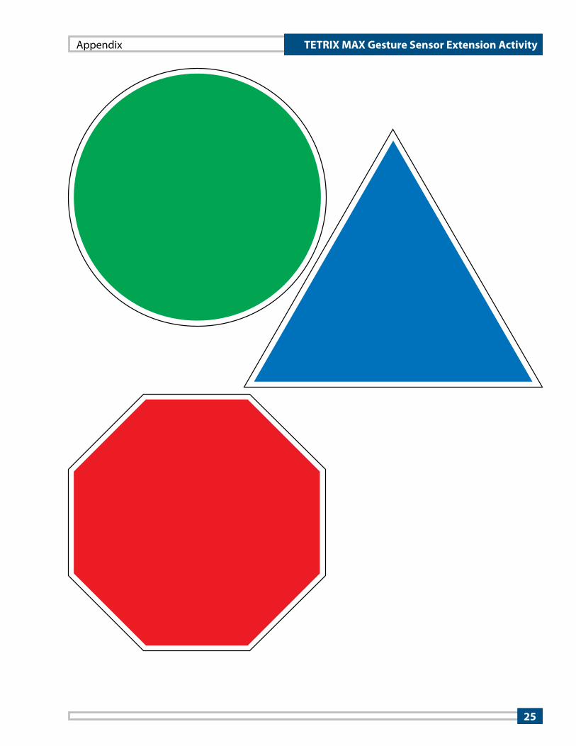
Executing the CodeLocate and print the colored signs in the Appendix of this guide. Then, cut out each sign with scissors. You will use these shapes to detect their color using the gesture sensor.
Connect the PRIZM controller to the computer using the USB cable. With the PRIZM on, make sure to select the correct port in the Tools menu of the Arduino IDE. Upload the example sketch to the PRIZM. When the code is uploaded, the green LED on PRIZM will light up indicating the code is ready to execute.
From the Tools menu, launch the serial monitor. This will let you observe the data from the sensor as you experiment. Press the green Start button on the PRIZM controller. Hold one of the colored signs about 5 centimeters from the color sensor. Look at the RGB color values in the serial monitor. You should notice that the color with the highest number matches the sign you are holding in front of the sensor. Experiment with the sensor by holding the signs closer and farther away from the sensor. How do the sensor readings compare to the distance the signs are away from the sensor?
The ambient light reading represents the amount of white light entering the sensor. Cup your hands and place them over the sensor. Observe the sensor’s ambient light reading in the serial monitor as you experiment.
Opening the SketchLaunch the Arduino Software (IDE). Open the Color Test sketch by selecting File > Examples > TETRIX_APDS9960_Gesture > PRIZM_APDS9960_Color_Test. The sketch will open in a new sketch window.
9
TETRIX MAX Gesture Sensor Extension ActivityLesson Guide

Moving ForwardThe beginning of this sketch starts the same as the Proximity Test sketch. The libraries for PRIZM and the gesture sensor are included and both objects are instantiated.
Next, four new variables are declared and set equal to zero – one variable for ambient light, and then a variable for each of the three colors of light. These variables are uint16_t variable type, which means that they are unsigned (u) integers (int) of 16 bits (16). That means that these variables can range from 0 to 65,535.
The only new line of code in the void setup() function is the apds.enableLightSensor() command, which must come after the apds.init() command that initializes the sensor. The apds.enableLightSensor(false) command sets the gesture sensor to light-sensing mode with no interrupts. Again, this guide won’t get into the details of using interrupts. For now, leave the parameter of this command set to false.
The void loop() function has four commands that read the ambient and RGB light entering the sensor. Each of these commands will store the sensor reading in whatever variable is placed in the parentheses. So the command apds.readAmbientLight(ambient_light) will read the ambient light from the gesture sensor and store the reading in the ambient_light variable. The commands for red, green, and blue light work the same way.
The final two commands in the void loop() function are function calls for printing or plotting the light levels. When you first open the sketch, the printLevels() function call should be uncommented and the plotLevels() function call is turned into a code comment (it should have two slash marks before the command).
10
TETRIX MAX Gesture Sensor Extension ActivityLesson Guide

The Arduino IDE does not let you print information in the serial monitor and plot data on the serial plotter at the same time. So, only one of these function calls can be executed at a time. The other must be turned off by using code comments. When the printLevels() function is called, the focus of the sketch jumps out of the void loop() function and jumps down to the void printLevels() function. This function prints data labels and the variables that have stored the light levels from the gesture sensor. When the function is done, the focus of the sketch jumps back up to the void loop() function, where it continues to loop.
plotLevels() function call
Green sign in front of sensor
printLevels() function call
Note: If time permits, try this short extension activity. Place comment slashes in front of the printLevels() function call and remove the comment slashes from the front of the plotLevels() function call.
Upload the sketch to PRIZM and then press the PRIZM’s Start button to execute the code. From the Tools menu in the Arduino IDE, select Serial Plotter. Hold the different colored signs up in front of the sensor again. Watch as blue (blue line), red (red line), green (green line), and ambient (orange line) light levels are plotted on the graph.
Because the ambient light levels are so high, it can be difficult to see the results when you first hold a colored sign up in front of the sensor. Hold the sign up for a while to give the scale of the y-axis of the graph time to automatically adjust.
11
TETRIX MAX Gesture Sensor Extension ActivityLesson Guide

Real-World ConnectionColor and light sensors are all around us. For quite some time, copy machines, printers, digital cameras, and mobile phones have all used some type of color or light sensor to operate. In recent years, fitness trackers and other wearable devices that monitor heart rate are using this technology as well. Photoplethysmography is the practice of using light to measure blood flow through the body from the skin’s surface. Most fitness trackers use this process by quickly flashing green LEDs against the skin. Blood is red in color, so it absorbs green light and reflects red light. Photodiodes embedded in the device detect the amount of red light being reflected and the lack of green light being reflected. These light levels correspond to the amount of blood flowing through a person’s veins. Over time, the peaks and valleys of the sensor data can be used to measure the heart rate of the person.
12
TETRIX MAX Gesture Sensor Extension ActivityLesson Guide

Building Interlude: Adding the Gesture Sensor to the TaskBot
Step 1 Parts Needed
Tip: Instructions for building the TaskBot can be found in the TETRIX PRIZM Robotics Controller Programming Guide that came with your TETRIX set.
Note: The ultrasonic and line finder sensors attached to the front of the TaskBot will not be used for this activity. It is your decisions whether you remove them or not.
Step 1.0The servo and flag mechanism at the back of the bot will not be used for this activity. Remove these components to make room for the gesture sensor.
Building Interlude
Assembled TaskBot
13
TETRIX MAX Gesture Sensor Extension Activity

Partial assembly should look like this.
Step 2 Parts Needed
Plates & BracketsPart No. Part Name Quantity39062 TETRIX MAX L Bracket . . . . . . . . . . . . . . . . . . . . . . . . . . . . . . . . . . . . 141790 TETRIX MAX Adjustable Angle Corner Bracket . . . . . . . . . . . 1
Electronics & ControlPart No. Part Name Quantity46035 TETRIX Gesture Sensor Adapter Board . . . . . . . . . . . . . . . . . . . 143076 Line Finder Sensor Mount . . . . . . . . . . . . . . . . . . . . . . . . . . . . . . . . 1NA Adafruit APDS9960 Gesture Sensor . . . . . . . . . . . . . . . . . . . . . . 1
Building Interlude
Nuts, Screws, & FastenersPart No. Part Name Quantity39094 Kep Nut . . . . . . . . . . . . . . . . . . . . . . . . . . . . . . . . . . . . . . . . . . . . . . . . . . 639097 Socket Head Cap Screw 6-32 x 1/2" . . . . . . . . . . . . . . . . . . . . . . 239098 Socket Head Cap Screw 6-32 x 5/16" . . . . . . . . . . . . . . . . . . . . . 4
SpacersPart No. Part Name Quantity39387 TETRIX MAX Flat Round Spacer . . . . . . . . . . . . . . . . . . . . . . . . . . 1
14
TETRIX MAX Gesture Sensor Extension Activity

Step 2.0
Detail
Step 2.1
Building Interlude
15
TETRIX MAX Gesture Sensor Extension Activity
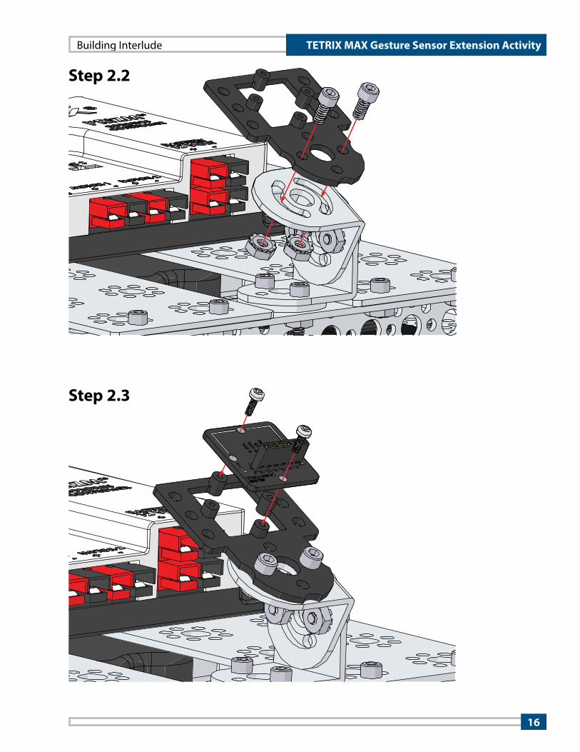
Step 2.2
Step 2.3
Building Interlude
16
TETRIX MAX Gesture Sensor Extension Activity

Step 2.4
Building Interlude
17
TETRIX MAX Gesture Sensor Extension Activity

Finished assembly should look like this.
Detail
18
TETRIX MAX Gesture Sensor Extension Activity

LED
Gesture SensingThe gesture sensor works by using four infrared (IR) sensors placed in a diamond pattern. These IR sensors work together to measure changes in light level over time at each location, enabling the sensor to recognize gestures. You can kind of think of it like a shadow from your hand passing over the IR sensors. As the shadow moves left, the IR sensor on the right reads a change in light levels first and then the two IR sensors in the middle followed by the IR sensor on the left. These changes in light levels between the four IR sensors translate the data into a gesture that moves right to left.
Building the Knowledge BaseIf you’ve been through the PRIZM Programming Guide, then you should be familiar with the if-else if conditional structure. An if-else if conditional structure lets you check for multiple conditions and run a set of commands based on which condition or conditions are true. However, the Arduino IDE has a simplified structure, called a switch-case structure, that can be used if the conditions are based on a single variable or value.
The command switch(variable){} starts a switch-case structure. The variable in the parentheses is used to choose which behavior gets run. The behaviors, or cases, for the switch-case are defined inside the braces. Each case lists the value of the variable for when that case is to be executed followed by a colon. The key word break is used to exit the switch-case structure. This key word is usually used at the end of each case.
Here is an example of an if-else if and a switch-case structure that do the exact same thing.
If-Else If Example Switch-Case Example
Note: In the switch-case example, notice the use of the colon after the case value. The colon indicates that the commands that follow the colon are what set the behavior for the case.
19
TETRIX MAX Gesture Sensor Extension ActivityLesson Guide

There are advantages and disadvantages of using an if-else if type structure versus a switch-case type structure. The following table lists some of these advantages and disadvantages of each.
Advantages Disadvantages
if-else if
• Can combine two or more conditions based on different variables
• Can build very complex logic structures
• Can nest if statements inside other if statements
• Can test for ranges of values
• Code is less clean.
• Code takes more memory.
switch-case
• Is a simple structure for choosing a behavior based on a single variable
• Code is clean and efficient.
• Can’t build complex logic structures based on multiple variables
• Can check for only a single value of a variable (no range of values)
Opening the SketchLaunch the Arduino Software (IDE). Open the Gesture_Motor_Drive sketch by selecting File > Examples > TETRIX_APDS9960_Gesture > PRIZM_APDS9960_Gesture_Motor_Drive. The sketch will open in a new sketch window.
20
TETRIX MAX Gesture Sensor Extension ActivityLesson Guide

Executing the CodeConnect the PRIZM controller to the computer using the USB cable. With the PRIZM on, make sure to select the correct port in the Tools menu of the Arduino IDE. Upload the Gesture_Motor_Drive sketch to the PRIZM. When the code is uploaded, the green LED with light up indicating the code is ready to execute.
Unplug the USB cable from PRIZM and place the TaskBot on the floor with the gesture sensor pointed toward you. Make sure there is lots of room for the robot to maneuver. Press PRIZM’s green Start button to execute the code. Use your hand to gesture left, right, up, and down about five to 10 centimeters from the gesture sensor. When you gesture left, you should see the TaskBot spin to the left. When you gesture right, the TaskBot should spin to the right. When you gesture up, the TaskBot should drive forward. And when you gesture down, the TaskBot should reverse. Experiment with the gesture sensor for a few minutes. What is the optimum distance from the sensor to make hand gestures? Can you think of ways to improve the sketch?
Moving ForwardLet’s look at the code for this sketch. At the beginning, the libraries for PRIZM and the gesture sensor are included and both objects are instantiated.
In the void setup() function, the only new line of code is the apds.enableGestureSensor(false) command. This command sets the gesture sensor to gesture mode with no interrupts. Again, this guide won’t get into the details of using interrupts. For now, leave the parameter of this command set to false.
There is only one command in the void loop() function, which is the handleGesture() function call. When the focus of the sketch gets to this point, it jumps down to the handleGesture() function below the main loop.
Note: The gesture sensor works best when you wave your entire hand in one direction two to three inches from the sensor.
21
TETRIX MAX Gesture Sensor Extension Activity
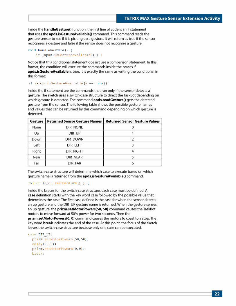
Inside the handleGesture() function, the first line of code is an if statement that uses the apds.isGestureAvailable() command. This command reads the gesture sensor to see if it is picking up a gesture. It will return as true if the sensor recognizes a gesture and false if the sensor does not recognize a gesture.
Notice that this conditional statement doesn’t use a comparison statement. In this format, the condition will execute the commands inside the braces if apds.isGestureAvailable is true. It is exactly the same as writing the conditional in this format:
Inside the if statement are the commands that run only if the sensor detects a gesture. The sketch uses a switch-case structure to direct the TaskBot depending on which gesture is detected. The command apds.readGesture() gets the detected gesture from the sensor. The following table shows the possible gesture names and values that can be returned by this command depending on which gesture is detected.
The switch-case structure will determine which case to execute based on which gesture name is returned from the apds.isGestureAvailable() command.
Inside the braces for the switch-case structure, each case must be defined. A case definition starts with the key word case followed by the possible value that determines the case. The first case defined is the case for when the sensor detects an up gesture and the DIR_UP gesture name is returned. When the gesture senses an up gesture, the prizm.setMotorPowers(50, 50) command causes the TaskBot motors to move forward at 50% power for two seconds. Then the prizm.setMotorPowers(0, 0) command causes the motors to coast to a stop. The key word break indicates the end of the case. At this point, the focus of the sketch leaves the switch-case structure because only one case can be executed.
Gesture Returned Sensor Gesture Names Returned Sensor Gesture Values
None DIR_NONE 0
Up DIR_UP 1
Down DIR_DOWN 2
Left DIR_LEFT 3
Right DIR_RIGHT 4
Near DIR_NEAR 5
Far DIR_FAR 6
22
TETRIX MAX Gesture Sensor Extension Activity
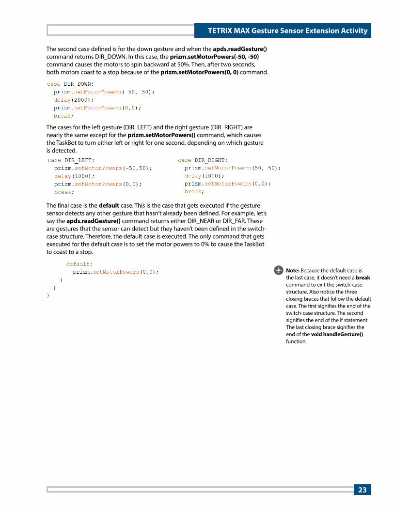
The second case defined is for the down gesture and when the apds.readGesture() command returns DIR_DOWN. In this case, the prizm.setMotorPowers(-50, -50) command causes the motors to spin backward at 50%. Then, after two seconds, both motors coast to a stop because of the prizm.setMotorPowers(0, 0) command.
The cases for the left gesture (DIR_LEFT) and the right gesture (DIR_RIGHT) are nearly the same except for the prizm.setMotorPowers() command, which causes the TaskBot to turn either left or right for one second, depending on which gesture is detected.
The final case is the default case. This is the case that gets executed if the gesture sensor detects any other gesture that hasn’t already been defined. For example, let’s say the apds.readGesture() command returns either DIR_NEAR or DIR_FAR. These are gestures that the sensor can detect but they haven’t been defined in the switch-case structure. Therefore, the default case is executed. The only command that gets executed for the default case is to set the motor powers to 0% to cause the TaskBot to coast to a stop.
Note: Because the default case is the last case, it doesn’t need a break command to exit the switch-case structure. Also notice the three closing braces that follow the default case. The first signifies the end of the switch-case structure. The second signifies the end of the if statement. The last closing brace signifies the end of the void handleGesture() function.
23
TETRIX MAX Gesture Sensor Extension Activity

Real-World ConnectionGesture sensing probably made its first big impact in the gaming industry where gestures are used to mimic the motion of bowling, playing tennis, or driving a car. As the technology has improved, it is finding more and more applications in the field of natural user interface (NUI). Technology companies are looking at how natural movements can be captured to create touch-free controls for computers and devices. One specific area where gesture control of computers is advancing is in the operating rooms of hospitals. Doctors and surgeons can switch views, zoom, and rotate X-rays, CT scans, MRIs, and other medical information displayed on touch-free monitors by simple gestures. This enables them to keep their operating tools in hand without having to touch standard control devices such as a keyboard or computer mouse.
Hacking the Code ActivityUsing the example as a reference, try creating a new sketch for the TaskBot to complete a maze or obstacle course using the gesture sensor. See if you can combine the three different sensing capabilities (proximity, color, and gesture) of the sensor to more precisely control the TaskBot. For example, you could use proximity sensing to detect when a colored sign is held up. You could use color sensing to detect which sign is being used and use those signs to control the speed of the TaskBot. You could use gesture sensing to help the TaskBot navigate the maze. Just remember that you need to set the mode of the sensor before reading proximity, color, or gesture using these commands:
• apds.enableProximitySensor(false)
• apds.enableLightSensor(false)
• apds.enableGestureSensor(false)
24
TETRIX MAX Gesture Sensor Extension Activity
Appendix
25
TETRIX MAX Gesture Sensor Extension Activity


