Embed Size (px)
Citation preview
Fli ht T t f L Ad ti C t llFlight Test of L1 Adaptive Controller on the NASA AirSTAR
Fli ht T t V hi lFlight Test Vehicle
I M G E i XIrene M. GregoryDynamic Systems and Control Branch
NASA Langley Research Center
Enric XargayDept. Aerospace Engineering
University of Illinois at Urbana-Champaign
Naira HovakimyanDept. Mechanical Engineering
University of Illinois at Urbana-Champaign
Chengyu CaoDept. Mechanical Science & Engineering
University of Connecticut y p gy
Aerospace Control and Guidance Systems Committee Meeting 106L J ll CALa Jolla, CA
October 13-15, 2010
Subscale Flight Testing
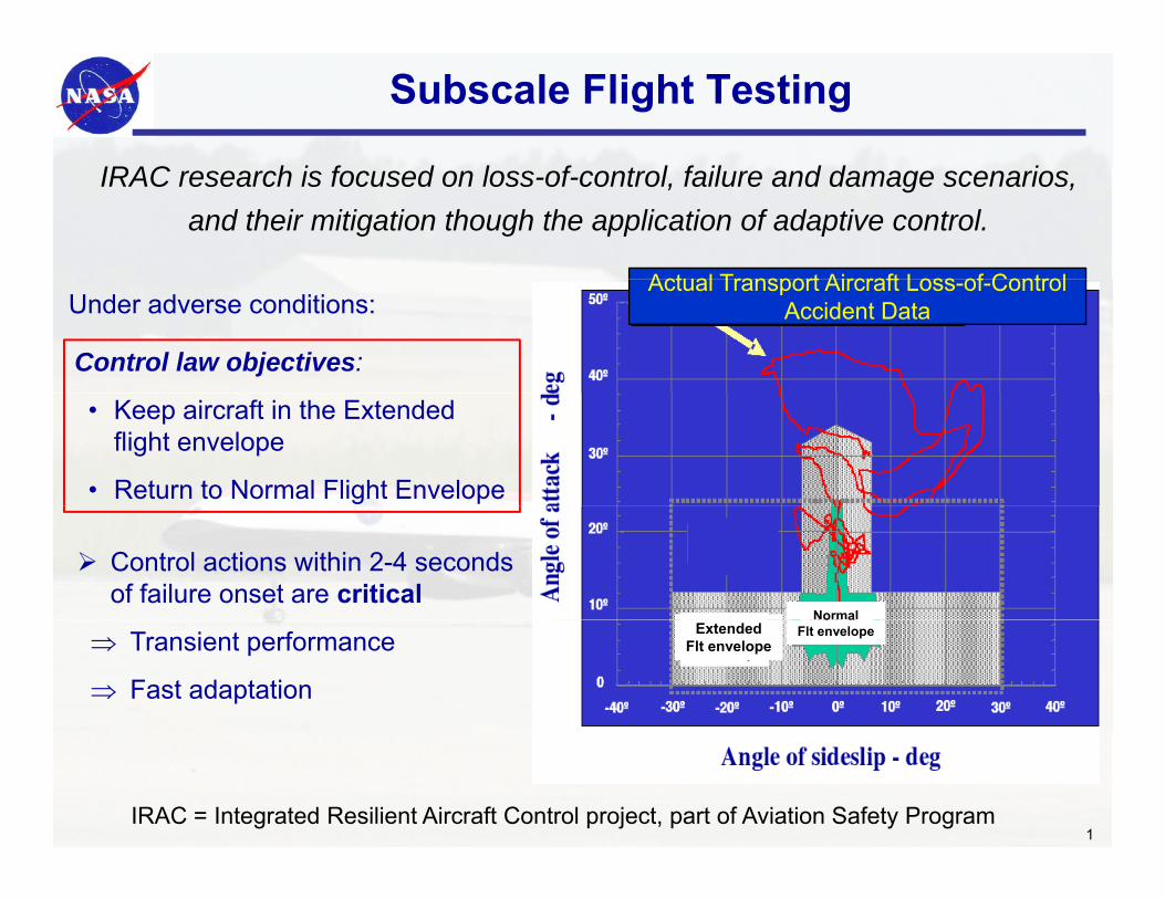
IRAC h i f d l f t l f il d d iIRAC research is focused on loss-of-control, failure and damage scenarios, and their mitigation though the application of adaptive control.
Actual Transport Aircraft Loss of Control
Control law objectives:
Under adverse conditions: Actual Transport Aircraft Loss-of-Control
Accident Data
• Keep aircraft in the Extended flight envelope
• Return to Normal Flight Envelope
Control actions within 2-4 seconds of failure onset are critical
Normal
⇒ Transient performance
⇒ Fast adaptation
ExtendedFlt envelope
o aFlt envelope
IRAC = Integrated Resilient Aircraft Control project, part of Aviation Safety Program1
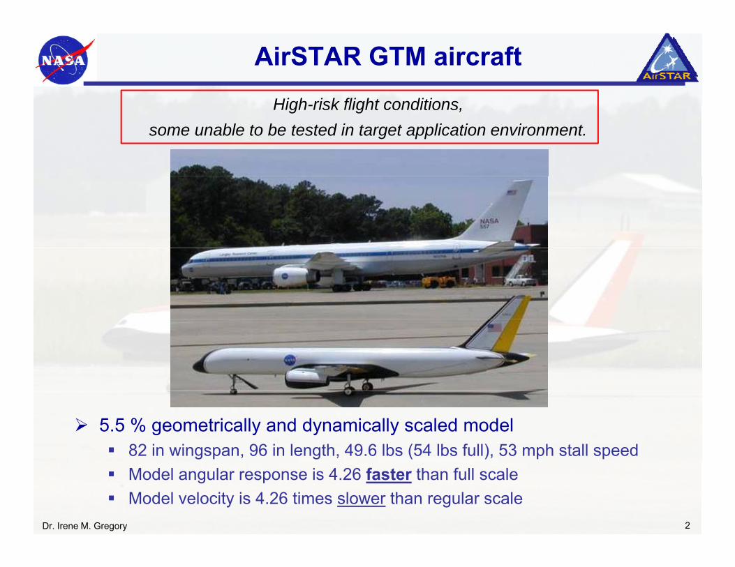
AirSTAR GTM aircraftHigh risk flight conditionsHigh-risk flight conditions,
some unable to be tested in target application environment.
5.5 % geometrically and dynamically scaled model82 in wingspan, 96 in length, 49.6 lbs (54 lbs full), 53 mph stall speedModel angular response is 4.26 faster than full scaleModel velocity is 4.26 times slower than regular scale
Dr. Irene M. Gregory 2
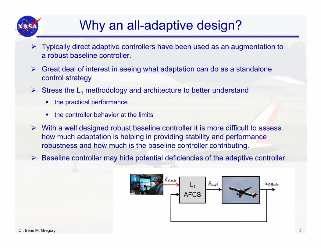
Why an all-adaptive design?Typically direct adaptive controllers have been used as an augmentation toTypically direct adaptive controllers have been used as an augmentation to a robust baseline controller.
Great deal of interest in seeing what adaptation can do as a standalone control strategycontrol strategy
Stress the L1 methodology and architecture to better understand the practical performance
the controller behavior at the limits
With a well designed robust baseline controller it is more difficult to assess how much adaptation is helping in providing stability and performance p p g p g y probustness and how much is the baseline controller contributing.
Baseline controller may hide potential deficiencies of the adaptive controller.
Robust Baseline
L1
AFCS
L1 AdaptiveControl Law
Dr. Irene M. Gregory 3
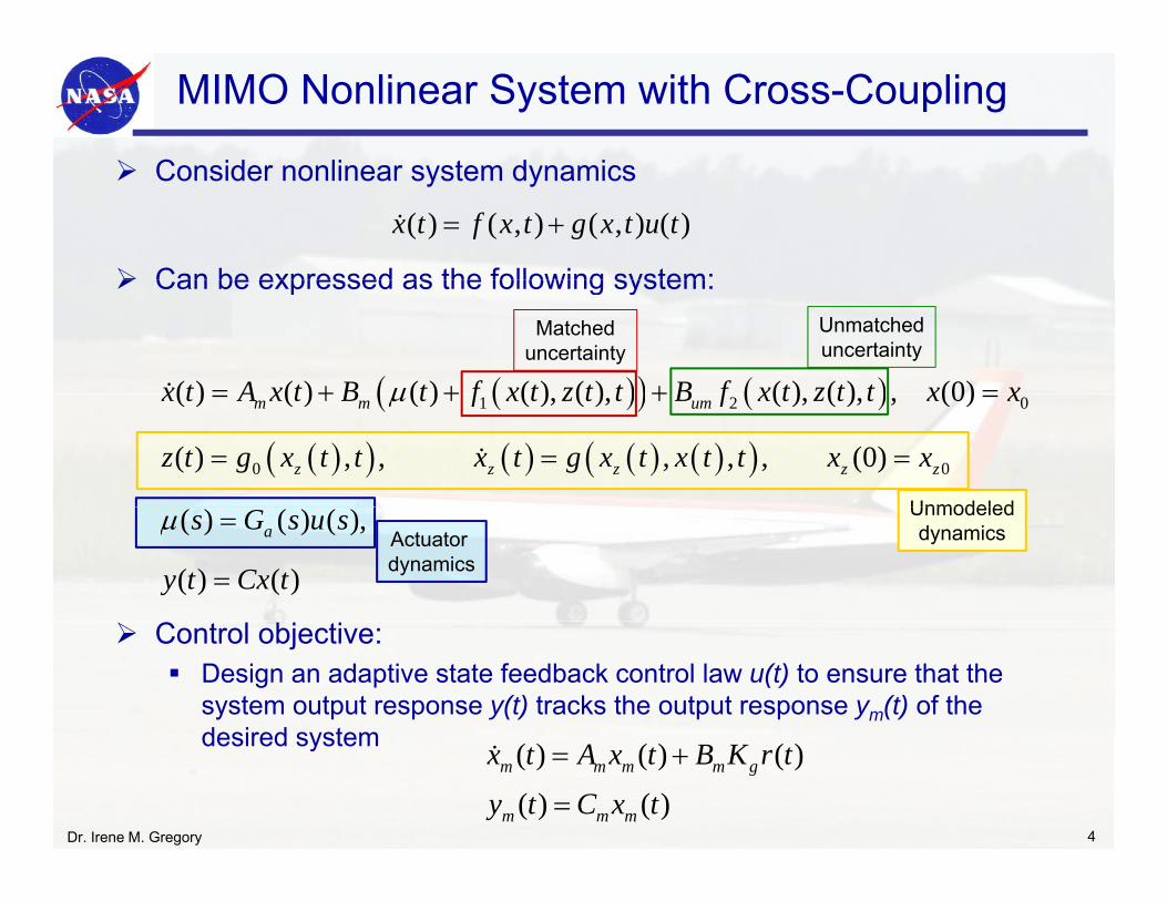
Consider nonlinear system dynamics
MIMO Nonlinear System with Cross-Coupling
Consider nonlinear system dynamics
Can be expressed as the following system:
( ) ( , ) ( , ) ( )x t f x t g x t u t= +
Can be expressed as the following system:
( )( ) ( )( ) ( ) ( ) ( ) ( ) ( ) ( ) (0)x t A x t B t f x t z t t B f x t z t t x xμ= + + + =
Matcheduncertainty
Unmatcheduncertainty
( )( ) ( )
( )( ) ( ) ( ) ( )( )1 2 0
0 0
( ) ( ) ( ) ( ), ( ), ( ), ( ), , (0)
( ) , , , , , (0)
m m um
z z z z z
x t A x t B t f x t z t t B f x t z t t x x
z t g x t t x t g x t x t t x x
μ= + + + =
= = =
Unmodeled( ) ( ) ( ),
( ) ( )
as G s u s
y t Cx t
μ =
=
UnmodeleddynamicsActuator
dynamics
Control objective:Design an adaptive state feedback control law u(t) to ensure that the system output response y(t) tracks the output response ym(t) of the desired systemdesired system
Dr. Irene M. Gregory 4
( ) ( ) ( )
( ) ( )m m m m g
m m m
x t A x t B K r t
y t C x t
= +
=
L1 All-adaptive Controller Architecture
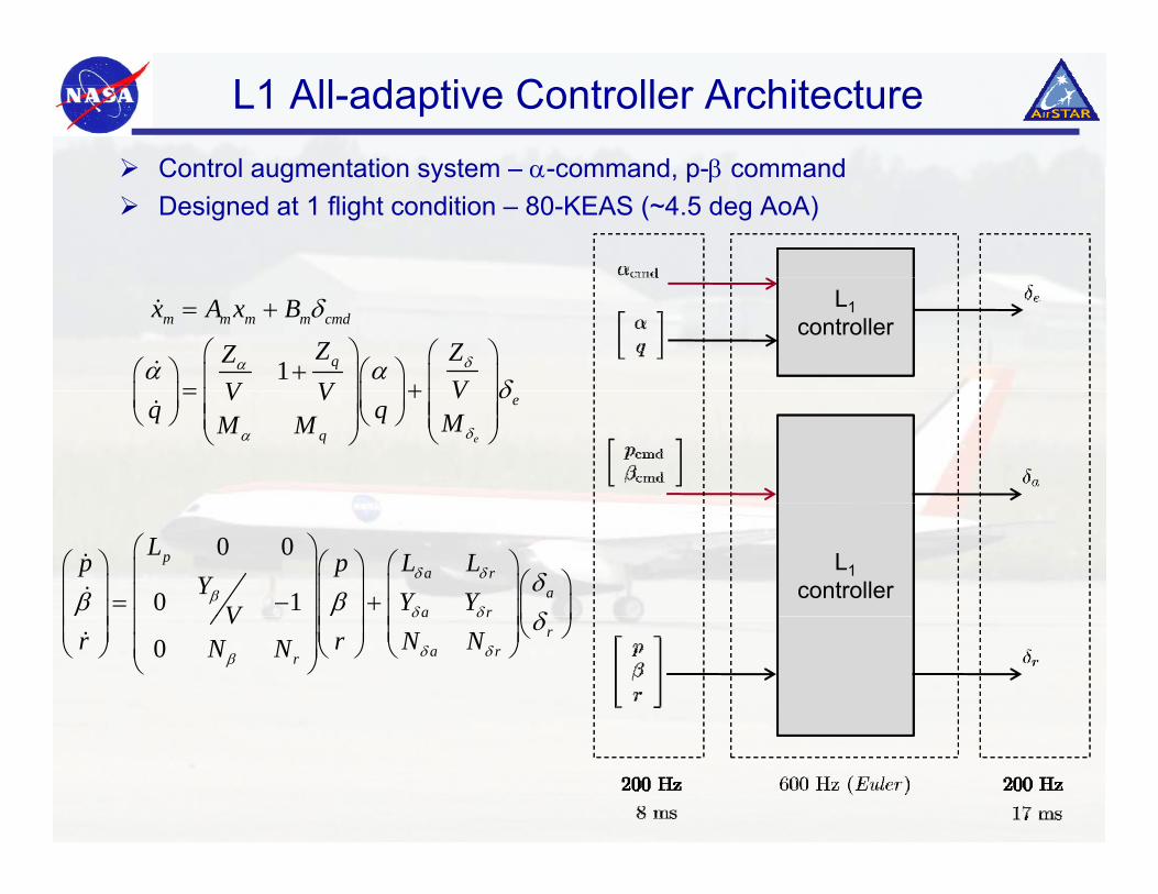
Control augmentation system α command p β commandControl augmentation system – α-command, p-β commandDesigned at 1 flight condition – 80-KEAS (~4.5 deg AoA)
L1controller
1
m m m m cmd
q
x A x BZ ZZ
VV Vδα
δ
α αδ
= +
⎛ ⎞ ⎛ ⎞+⎛ ⎞ ⎛ ⎞⎜ ⎟ ⎜ ⎟= +⎜ ⎟ ⎜ ⎟⎜ ⎟ ⎜ ⎟
e
e
q
VV Vq q MM M δα
δ= +⎜ ⎟ ⎜ ⎟⎜ ⎟ ⎜ ⎟⎝ ⎠ ⎝ ⎠ ⎜ ⎟⎜ ⎟ ⎝ ⎠⎝ ⎠
L1controller
0 0
0 1
pa r
aa r
Lp p L LY Y YV
δ δβ
δ δ
δβ β
δ
⎛ ⎞⎛ ⎞⎛ ⎞ ⎛ ⎞⎜ ⎟ ⎛ ⎞⎜ ⎟⎜ ⎟ ⎜ ⎟⎜ ⎟= − + ⎜ ⎟⎜ ⎟⎜ ⎟ ⎜ ⎟⎜ ⎟ ⎝ ⎠⎜ ⎟ ⎜ ⎟ ⎜ ⎟
0a r
ra rr
Vr r N NN N
δ δ
δ δβ
δ⎜ ⎟⎜ ⎟⎜ ⎟ ⎜ ⎟⎜ ⎟ ⎝ ⎠⎜ ⎟ ⎜ ⎟ ⎜ ⎟⎜ ⎟⎝ ⎠ ⎝ ⎠ ⎝ ⎠⎝ ⎠
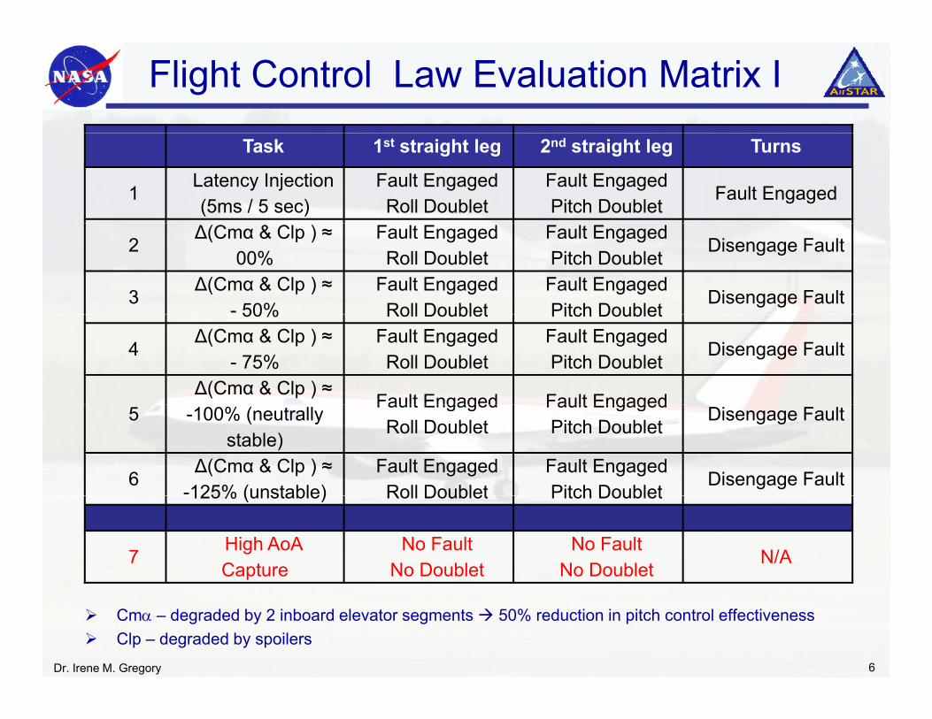
Flight Control Law Evaluation Matrix I
Task 1st straight leg 2nd straight leg Turns
1Latency Injection (5ms / 5 sec)
Fault EngagedRoll Doublet
Fault EngagedPitch Doublet
Fault Engaged
2Δ(Cmα & Clp ) ≈
00%Fault EngagedRoll Doublet
Fault EngagedPitch Doublet
Disengage Fault
3Δ(Cmα & Clp ) ≈
- 50%Fault EngagedRoll Doublet
Fault EngagedPitch Doublet
Disengage Fault50% Roll Doublet Pitch Doublet
4Δ(Cmα & Clp ) ≈
- 75%Fault EngagedRoll Doublet
Fault EngagedPitch Doublet
Disengage Fault
Δ(Cmα & Clp ) ≈ Fault Engaged Fault Engaged
5 -100% (neutrally stable)
Fault EngagedRoll Doublet
Fault EngagedPitch Doublet
Disengage Fault
6Δ(Cmα & Clp ) ≈
-125% (unstable)Fault EngagedRoll Doublet
Fault EngagedPitch Doublet
Disengage Fault125% (unstable) Roll Doublet Pitch Doublet
7High AoACapture
No FaultNo Doublet
No FaultNo Doublet
N/A
Dr. Irene M. Gregory 6
Cmα – degraded by 2 inboard elevator segments 50% reduction in pitch control effectiveness Clp – degraded by spoilers
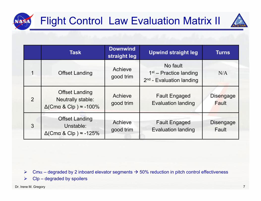
Flight Control Law Evaluation Matrix II
Task Downwindstraight leg Upwind straight leg Turns
1 Offset LandingAchieve
good trim
No fault 1st – Practice landing
2nd - Evaluation landing N/A
2Offset Landing
Neutrally stable: Δ(Cmα & Clp ) ≈ -100%
Achieve good trim
Fault EngagedEvaluation landing
Disengage Fault
3Offset Landing
Unstable:Δ(Cmα & Clp ) ≈ -125%
Achieve good trim
Fault EngagedEvaluation landing
Disengage Fault
Dr. Irene M. Gregory 7
Cmα – degraded by 2 inboard elevator segments 50% reduction in pitch control effectiveness Clp – degraded by spoilers
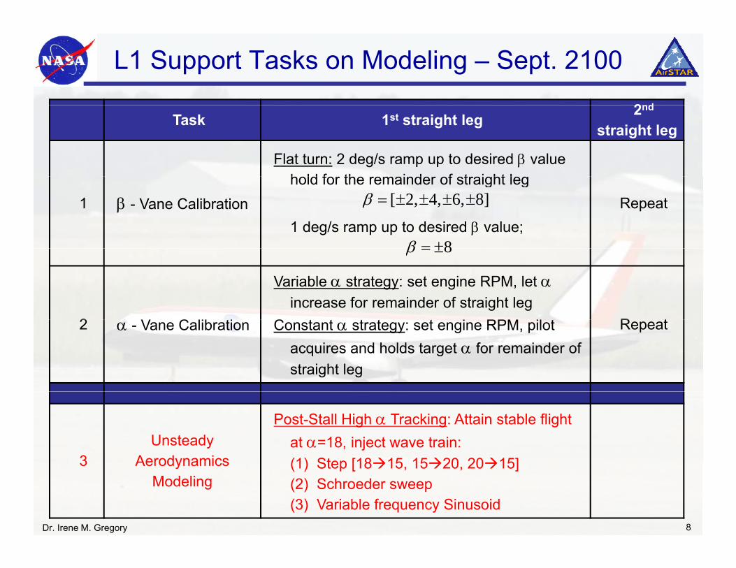
L1 Support Tasks on Modeling – Sept. 2100
2ndTask 1st straight leg 2nd
straight leg
Flat turn: 2 deg/s ramp up to desired β value hold for the remainder of straight leg
1 β - Vane Calibrationhold for the remainder of straight leg
1 deg/s ramp up to desired β value;Repeat[ 2, 4, 6, 8]β = ± ± ± ±
8β = ±
2 V C lib ti
Variable α strategy: set engine RPM, let αincrease for remainder of straight leg
C t t t t t i RPM il t R t
8β = ±
2 α - Vane Calibration Constant α strategy: set engine RPM, pilot acquires and holds target α for remainder of straight leg
Repeat
3Unsteady
Aerodynamics
Post-Stall High α Tracking: Attain stable flight at α=18, inject wave train:(1) Step [18 15 15 20 20 15]3 Aerodynamics
Modeling(1) Step [18 15, 15 20, 20 15](2) Schroeder sweep(3) Variable frequency Sinusoid
Dr. Irene M. Gregory 8
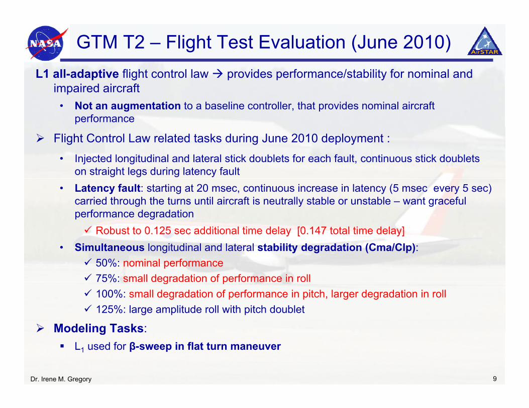
GTM T2 – Flight Test Evaluation (June 2010)L1 all-adaptive flight control law provides performance/stability for nominal andL1 all-adaptive flight control law provides performance/stability for nominal and
impaired aircraft• Not an augmentation to a baseline controller, that provides nominal aircraft
performance
Flight Control Law related tasks during June 2010 deployment :• Injected longitudinal and lateral stick doublets for each fault, continuous stick doublets
on straight legs during latency fault • Latency fault: starting at 20 msec, continuous increase in latency (5 msec every 5 sec)
carried through the turns until aircraft is neutrally stable or unstable – want graceful performance degradation
Robust to 0 125 sec additional time delay [0 147 total time delay]Robust to 0.125 sec additional time delay [0.147 total time delay]• Simultaneous longitudinal and lateral stability degradation (Cma/Clp):
50%: nominal performance75%: small degradation of performance in roll75%: small degradation of performance in roll100%: small degradation of performance in pitch, larger degradation in roll125%: large amplitude roll with pitch doublet
Modeling Tasks:gL1 used for β-sweep in flat turn maneuver
Dr. Irene M. Gregory 9
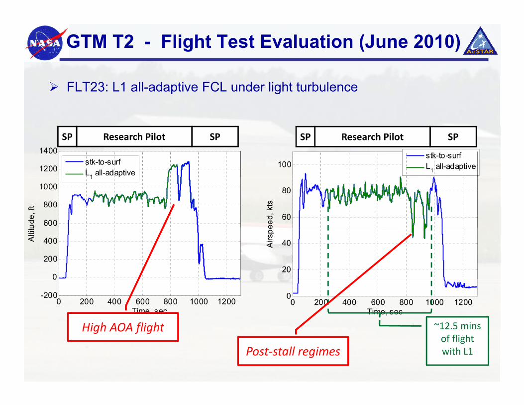
GTM T2 - Flight Test Evaluation (June 2010)
FLT23: L1 all-adaptive FCL under light turbulence
100
stk-to-surfL1 all-adaptive1200
1400
stk-to-surfL1 all-adaptive
Research Pilot SPSP Research Pilot SPSP
60
80
eed,
kts
600
800
1000
ude,
ft
1
20
40Airs
pe0
200
400Alti
tu
0 200 400 600 800 1000 12000
Time, sec
0 200 400 600 800 1000 1200
-200
0
Time, sec
~12.5 minsHigh AOA flightof flightwith L1
High AOA flight
Post‐stall regimes
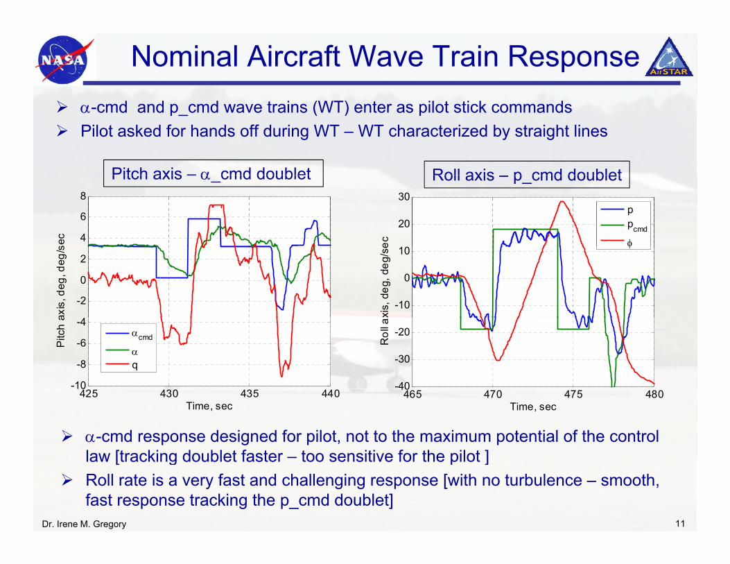
Nominal Aircraft Wave Train Responsecmd and p cmd wave trains (WT) enter as pilot stick commands
Pitch axis – α cmd doublet Roll axis p cmd doublet
α-cmd and p_cmd wave trains (WT) enter as pilot stick commandsPilot asked for hands off during WT – WT characterized by straight lines
4
6
8
sec
20
30
ec
ppcmd
φ
Pitch axis – α_cmd doublet Roll axis – p_cmd doublet
-2
0
2
axis
, deg
, deg
/s
-10
0
10
xis,
deg
, deg
/se φ
-10
-8
-6
-4
Pitc
h a
αcmd
αq
-40
-30
-20
Rol
l a
α-cmd response designed for pilot, not to the maximum potential of the control law [tracking doublet faster – too sensitive for the pilot ]
425 430 435 44010
Time, sec465 470 475 480
40
Time, sec
law [tracking doublet faster too sensitive for the pilot ]Roll rate is a very fast and challenging response [with no turbulence – smooth, fast response tracking the p_cmd doublet]
Dr. Irene M. Gregory 11
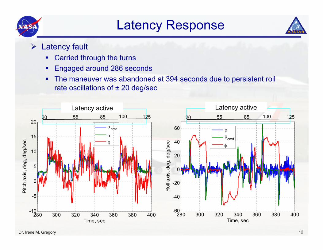
Latency ResponseLatency faultLatency fault
Carried through the turnsEngaged around 286 secondsThe maneuver was abandoned at 394 seconds due to persistent rollThe maneuver was abandoned at 394 seconds due to persistent roll rate oscillations of ± 20 deg/sec
Latency active Latency active
15
20
c
αcmd
αq
Latency active20 12510055 85
40
60
c
ppcmd
Latency active20 12510055 85
5
10
s, d
eg, d
eg/s
ec q
0
20
40
, deg
, deg
/sec φ
-5
0
Pitc
h ax
is
-40
-20
Rol
l axi
s
Dr. Irene M. Gregory 12
280 300 320 340 360 380 400-10
Time, sec
280 300 320 340 360 380 400
-60
Time, sec
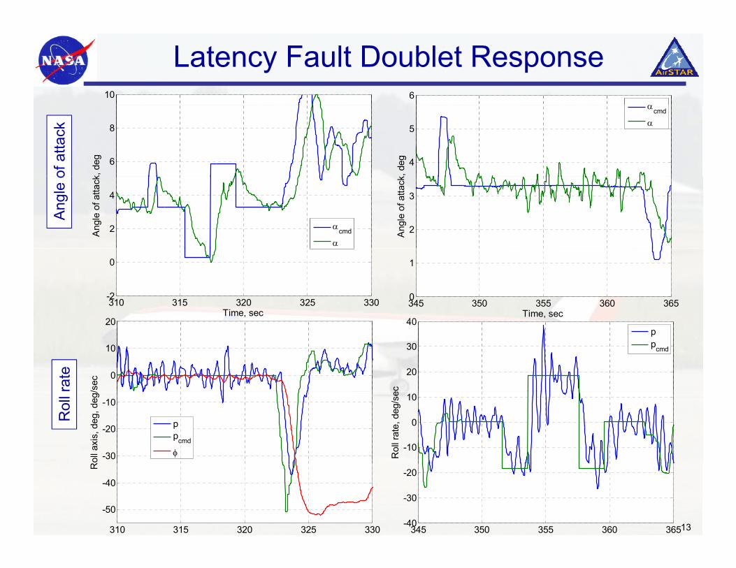
Latency Fault Doublet Response10 6
α
6
8
k, d
eg
of a
ttack
4
5
k, d
eg
αcmd
α
2
4
Ang
le o
f atta
ck
αcmd
α
Angl
e o
2
3
Ang
le o
f atta
ck
40
310 315 320 325 330-2
0
Time, sec
20
345 350 355 360 3650
1
Time, sec
20
30
40
ec
ppcmd
0
10
20
/secrate
-10
0
10R
oll r
ate,
deg
/se
-30
-20
-10
Rol
l axi
s, d
eg, d
eg/
ppcmd
φ
Rol
l
13345 350 355 360 365-40
-30
-20
310 315 320 325 330
-50
-40
R
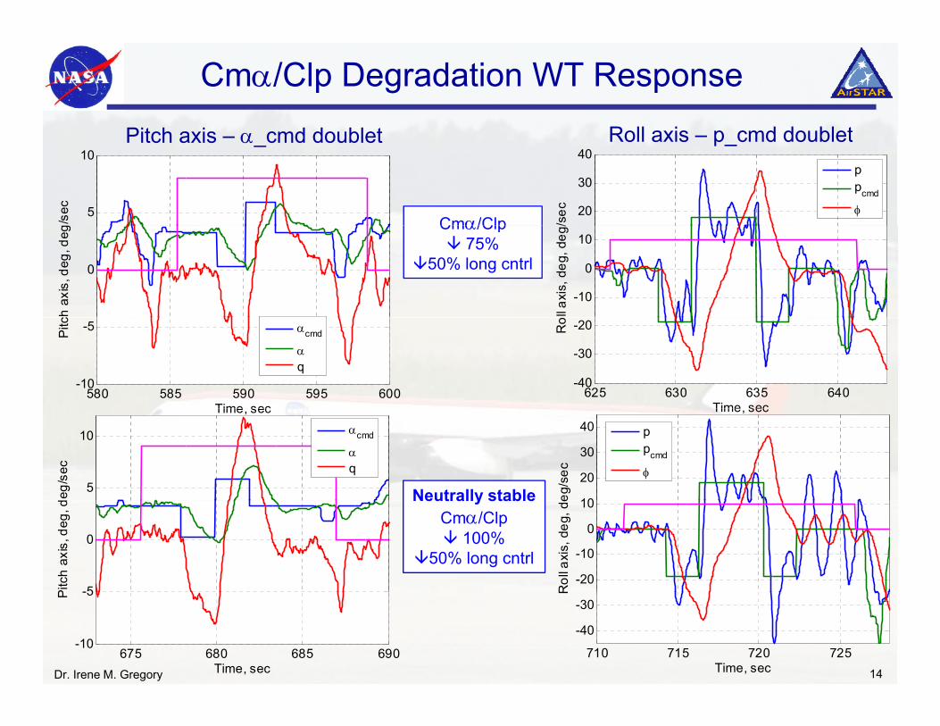
Cmα/Clp Degradation WT Response
Pitch axis α cmd doublet Roll axis p cmd doubletPitch axis – α_cmd doublet Roll axis – p_cmd doublet
5
10
g/se
c
20
30
40
/sec
ppcmd
φCmα/Clp
0
ch a
xis,
deg
, deg
-10
0
10
ll axi
s, d
eg, d
eg/Cmα/Clp
75%50% long cntrl
580 585 590 595 600-10
-5
Time sec
Pitc
αcmd
αq
625 630 635 640-40
-30
-20
Time sec
Ro
Time, sec Time, sec
Neutrally stable5
10
deg/
sec
αcmd
αq
10
20
30
40
eg/s
ec
ppcmd
φ
Neutrally stableCmα/Clp
100%50% long cntrl
-5
0
Pitc
h ax
is, d
eg, d
-20
-10
0
10
Rol
l axi
s, d
eg, d
e
Dr. Irene M. Gregory 14
675 680 685 690-10
-5
Time, sec
P
710 715 720 725
-40
-30
Time, sec
R
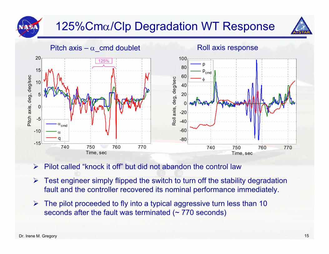
125%Cmα/Clp Degradation WT Response
Pitch axis α cmd doublet Roll axis responsePitch axis – α_cmd doublet Roll axis response
15
20
ec
60
80
100
c
ppcmd
φ
125%
0
5
10
xis,
deg
, deg
/se
20
0
20
40
xis,
deg
, deg
/se φ
15
-10
-5
Pitc
h ax
αcmd
αq -80
-60
-40
-20
Rol
l ax
740 750 760 770-15
Time, sec
740 750 760 770
Time, sec
Pilot called “knock it off” but did not abandon the control law
Test engineer simply flipped the switch to turn off the stability degradation fault and the controller recovered its nominal performance immediately.
The pilot proceeded to fly into a typical aggressive turn less than 10
Dr. Irene M. Gregory 15
p p y yp ggseconds after the fault was terminated (~ 770 seconds)
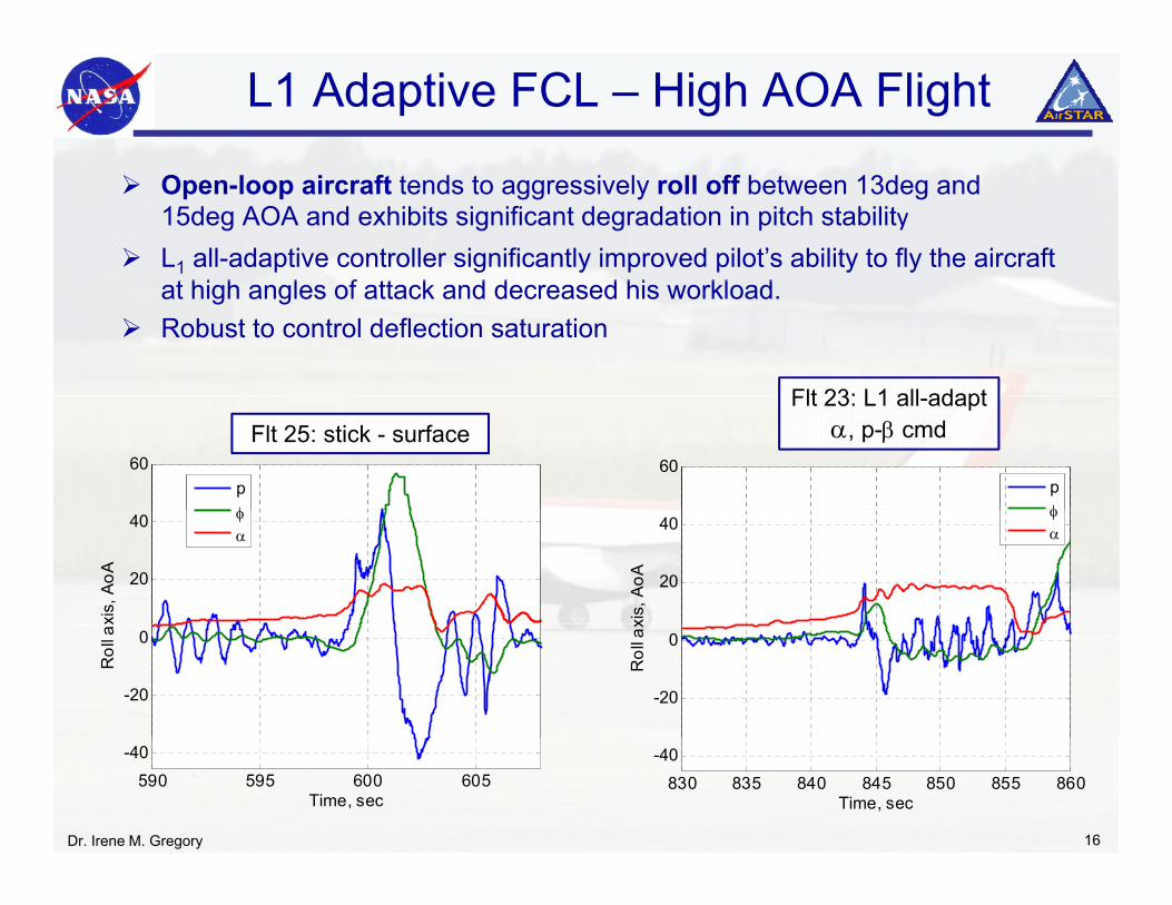
L1 Adaptive FCL – High AOA Flight
Open-loop aircraft tends to aggressively roll off between 13deg and 15deg AOA and exhibits significant degradation in pitch stabilityL1 all-adaptive controller significantly improved pilot’s ability to fly the aircraft
t hi h l f tt k d d d hi kl d
Flt 23: L1 all adapt
at high angles of attack and decreased his workload. Robust to control deflection saturation
Flt 25: stick - surfaceFlt 23: L1 all-adapt
α, p-β cmd60
pφ
60
pφ
20
40
xis,
AoA
φα
20
40
xis,
AoA
φα
-20
0R
oll a
x
-20
0
Rol
l ax
Dr. Irene M. Gregory 16
830 835 840 845 850 855 860
-40
Time, sec
590 595 600 605
-40
Time, sec
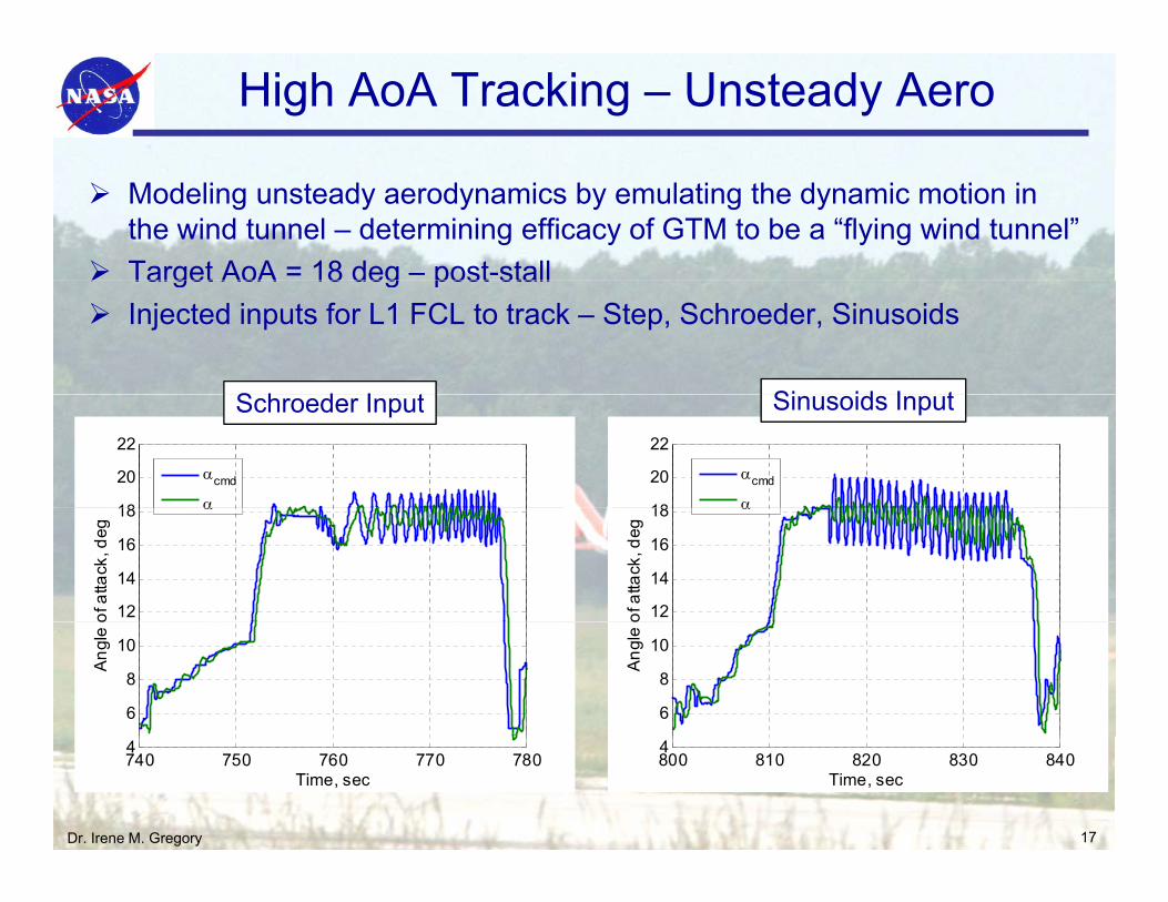
High AoA Tracking – Unsteady Aero
Modeling unsteady aerodynamics by emulating the dynamic motion in the wind tunnel – determining efficacy of GTM to be a “flying wind tunnel”Target AoA = 18 deg – post-stallTarget AoA 18 deg post stallInjected inputs for L1 FCL to track – Step, Schroeder, Sinusoids
S h d I t Si id I t
18
20
22
αcmd
α18
20
22
αcmd
α
Schroeder Input Sinusoids Input
12
14
16
18
of a
ttack
, deg
α
12
14
16
18
of a
ttack
, deg
α
6
8
10A
ngle
o
6
8
10
Ang
le o
Dr. Irene M. Gregory 17
800 810 820 830 8404
Time, sec
740 750 760 770 7804
Time, sec
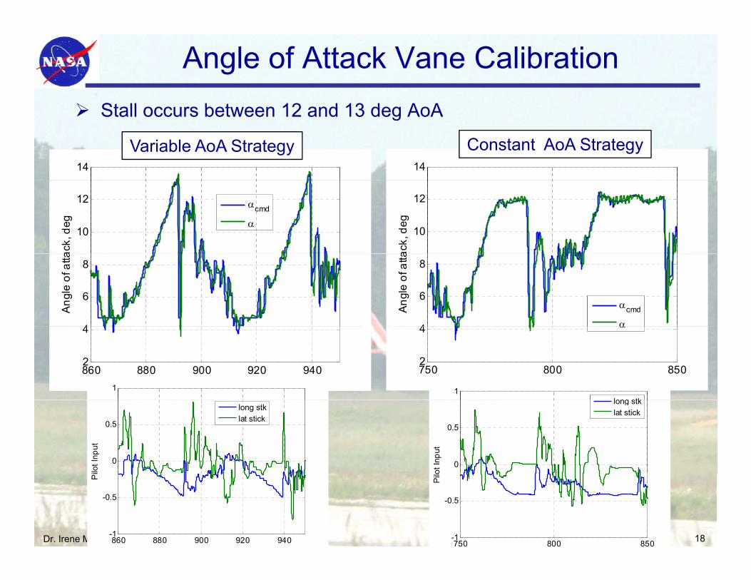
Angle of Attack Vane CalibrationStall occurs between 12 and 13 deg AoAStall occurs between 12 and 13 deg AoA
14 14
Variable AoA Strategy Constant AoA Strategy
10
12
ack,
deg
αcmd
α10
12
ack,
deg
4
6
8
Ang
le o
f atta
4
6
8
Ang
le o
f atta
αcmd
α
860 880 900 920 9402
4
Time, sec
1
750 800 8502
4
Time, sec
α
1
long stk
0
0.5
lot I
nput
long stklat stick
0
0.5ot
Inpu
t
long stklat stick
Dr. Irene M. Gregory 18860 880 900 920 940-1
-0.5
Pi
750 800 850-1
-0.5
Pilo
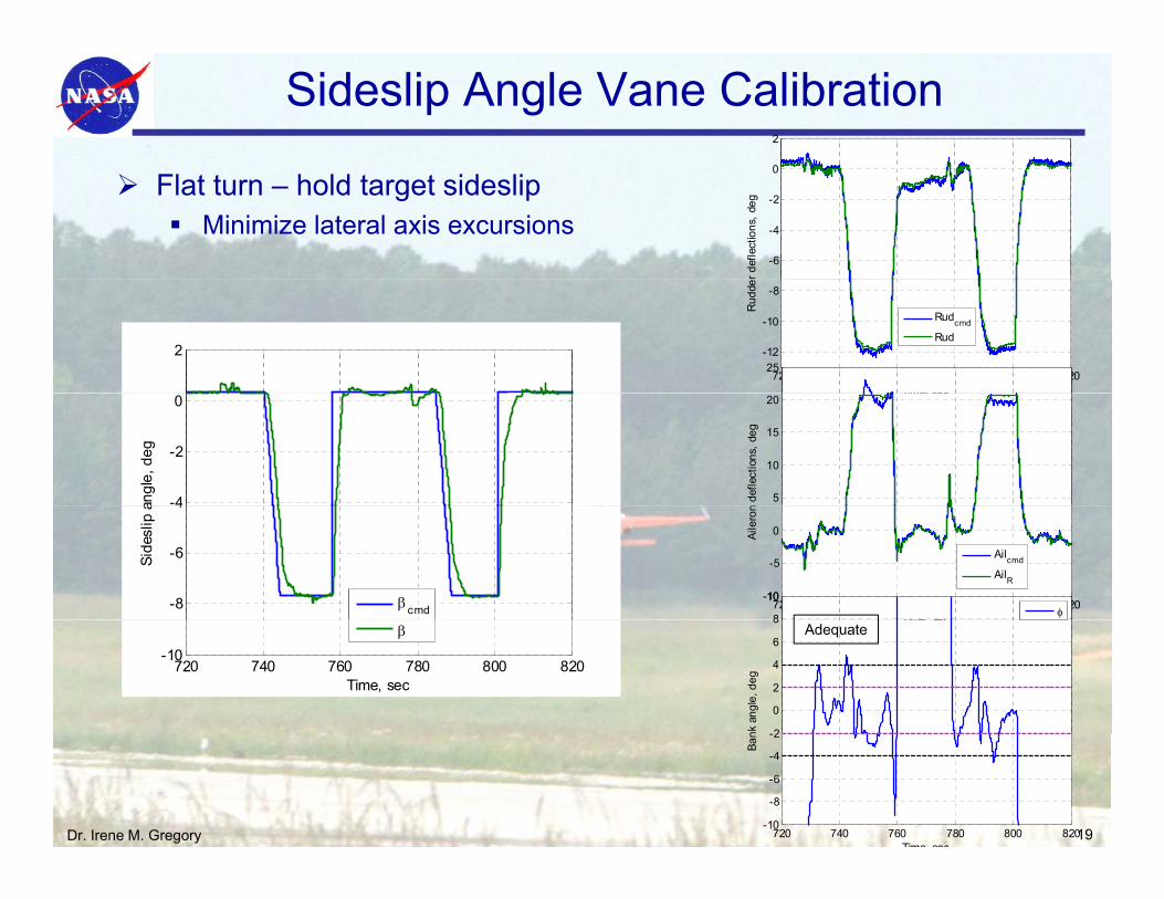
Sideslip Angle Vane Calibration0
2
Flat turn – hold target sideslipMinimize lateral axis excursions
-6
-4
-2
0
r def
lect
ions
, deg
2
720 740 760 780 800 820
-12
-10
-8
Time, sec
Rud
de
Rudcmd
Rud
25
-4
-2
0
angl
e, d
eg
Time, sec
5
10
15
20
n de
flect
ions
, deg
-8
-6
4
Side
slip
a
βcmd 720 740 760 780 800 820-10
-5
0
Time sec
Aile
ron
Ailcmd
AilR
8
10
φ
720 740 760 780 800 820-10
Time, sec
βTime, sec
2
0
2
4
6
8
nk a
ngle
, deg
Adequate
Dr. Irene M. Gregory 19720 740 760 780 800 820-10
-8
-6
-4
-2
Time sec
Ban
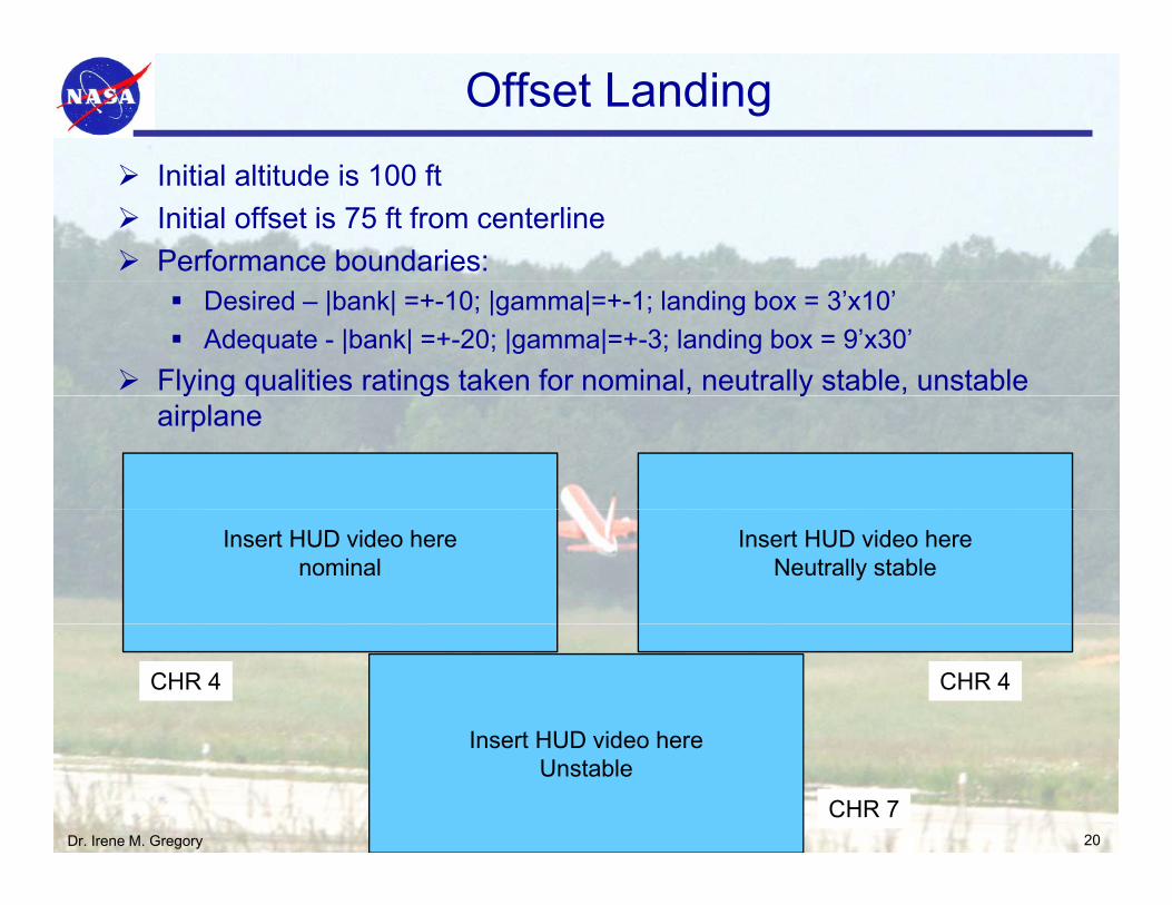
Offset Landing
I iti l ltit d i 100 ftInitial altitude is 100 ftInitial offset is 75 ft from centerlinePerformance boundaries:
Desired – |bank| =+-10; |gamma|=+-1; landing box = 3’x10’Adequate - |bank| =+-20; |gamma|=+-3; landing box = 9’x30’
Flying qualities ratings taken for nominal, neutrally stable, unstable y g q g yairplane
Insert HUD video herenominal
Insert HUD video hereNeutrally stable
Insert HUD video here
CHR 4 CHR 4
Dr. Irene M. Gregory 20
Insert HUD video hereUnstable
CHR 7
L1 Adaptive Controller Flight Test Summary
An all adaptive controller that provides both nominal aircraft performance andAn all adaptive controller that provides both nominal aircraft performance and takes care of large changes in aircraft dynamics
• No gain scheduling, no baseline to assist
One controller designed at nominal flight condition (80KEAS, 4 deg AOA) to provide satisfactory FQ and robustness
Controller able to handle large additional latency in the system (robustness measure) and provide nominal to slightly degraded performance for stability degraded cases (doublet tracking with neutrally stable aircraft).
Controller provided predictable response to the pilot under stability degradation and graceful performance degradation once nominal response was unachievable
Improved response in post-stall flight providing controllable aircraft to the pilot and facilitating safe return to normal flight
The classical tradeoff between robustness to system latency vs. performance was found to be consistent with the theory.
Dr. Irene M. Gregory 21
QUESTION?
Dr. Irene M. Gregory 22


