Embed Size (px)
Citation preview
IEEE JOURNAL ON SELECTED AREAS IN COMMUNICATIONS, VOL. 17, NO. 5, MAY 1999 793
Adaptive Radio for Multimedia Wireless LinksCharles Chien,Member, IEEE, Mani B. Srivastava, Rajeev Jain,Fellow, IEEE,
Paul Lettieri, Vipin Aggarwal, and Robert Sternowski,Member, IEEE
Abstract—The quality of wireless links suffers from time-varying channel degradations such as interference, flat-fading,and frequency-selective fading. Current radios are limited intheir ability to adapt to these channel variations because theyare designed with fixed values for most system parameters suchas frame length, error control, and processing gain. The valuesfor these parameters are usually a compromise between therequirements for worst-case channel conditions and the need forlow implementation cost. Therefore, in benign channel conditionsthese commercial radios can consume more battery energy thanneeded to maintain a desired link quality, while in a severelydegraded channel they can consume energy without providingany quality-of-service (QoS). While techniques for adapting radioparameters to channel variations have been studied to improvelink performance, in this paper they are applied to minimizebattery energy. Specifically, an adaptive radio is being designedthat adapts the frame length, error control, processing gain, andequalization to different channel conditions, while minimizingbattery energy consumption. Experimental measurements andsimulation results are presented in this paper to illustrate theadaptive radio’s energy savings.
Index Terms—Adaptive radio, hybrid automatic repeat request(ARQ), maximum likelihood sequence estimation (MLSE), spreadspectrum, wireless.
I. INTRODUCTION
A key problem in wireless multimedia networks is to main-tain acceptable throughput and delay over time-varying
channels, while operating with limited energy resources. Thechannel variations are inherently uncontrollable, and theirdynamic range is so large (e.g., fades can be as deep as20–30 dB) that it is not energy efficient to design the radiofor the worst case. In this paper, an adaptive radio designis presented that minimizes the battery energy required tomeet an application requirement under widely varying channelconditions, including interference, flat-fading, and frequency-selective fading.
Recent research [2]–[6] has demonstrated that adaptationcan be performed at all layers of the protocol stack to ac-commodate the dynamics of wireless channels. Adaptation ofreceiver buffering and playout policy [7] in applications [e.g.,
Manuscript received January 1997; revised January 1999. This work wassupported in part under DARPA/ITO Contract DABT63-95-C-0100.
C. Chien is with the Rockwell Science Center, Thousand Oaks, CA 91360USA (e-mail: [email protected]).
M. B. Srivastava, R. Jain, P. Lettieri, and V. Aggarwal are with theDepartment of Electrical Engineering, University of California, Los Ange-les, CA 90095-1594 USA (e-mail: [email protected]; [email protected];[email protected]; [email protected]).
R. Sternowski is with the Collins Aviation and Communications Division,Rockwell International Corporation, Cedar Rapids, IA 25498 USA (e-mail:[email protected]).
Publisher Item Identifier S 0733-8716(99)03085-1.
NeVot (http://www.cs.columbia.edu/hgs/rtp/nevot.html) andother similar internet audio and video conferencing applica-tions] addresses a very limited range of channel variations.Without adaptation at the (medium access control) MAC,link, and physical layers, the channel variations would rendermeaningless the QoS guarantees made to applications in themultimedia network by resource reservation protocols such asATM and reservation protocol (RSVP) [1]. Results reportedin [2]–[4] show that adapting the MAC layer packet scheduleby deferring transmission when the radio channel is in fadesignificantly improves link efficiency. Similarly, results in [5]and [6] demonstrate that continuous adaptation of link-layererror control and packet length of the sender, in responseto feedback from the radio receiver at the destination, cansignificantly improve the energy efficiency of data transport.
More recently, it has also been shown that significantimprovements in throughput can result from letting the higherlayers control radio parameters such as the processing gain [8],[9] when an increase in channel interference is indicated bythroughput degradation. However, current commercial radiossupport limited dynamic adaptation. For example, with powercontrol, an IS-95 handset can dynamically adjust the transmitpower level needed to achieve a given link quality; however,other parameters such as processing gain and error control arenot adapted, but set only once during the initial call setup. Fur-thermore, the frame length is permanently fixed in the system.
While adaptation in general can provide performance im-provements, for a practical radio design it is critical to selectadaptive techniques that also reduce battery power consump-tion and successfully adapt to the many different types ofdegradations suffered in a wireless channel. Prior research inlow power wireless systems has mainly been focused on hard-ware design techniques [10]–[12], or on adaptive algorithms[4]–[6], [13]–[17] for limited types of channel degradations.This paper presents a practical adaptive radio design thatimplements a combination of link layer and physical layer al-gorithms to adapt to a wide range of channel degradations, i.e.,flat-fading, frequency selective fading, interference, and noise.Simulations with detailed channel models have been used tovalidate the effectiveness of the proposed adaptive techniquesin maintaining QoS requirements (e.g., delay and throughput).Furthermore, in contrast to prior research, the battery poweris minimized by selecting algorithmic parameters that reducethe total battery-energy/bit required for transmission as well asfor software and/or hardware implementation of the adaptivealgorithms.
The rest of the paper is organized as follows. Section IIsummarizes different types of wireless channel degradations
0733–8716/99$10.00 1999 IEEE
794 IEEE JOURNAL ON SELECTED AREAS IN COMMUNICATIONS, VOL. 17, NO. 5, MAY 1999
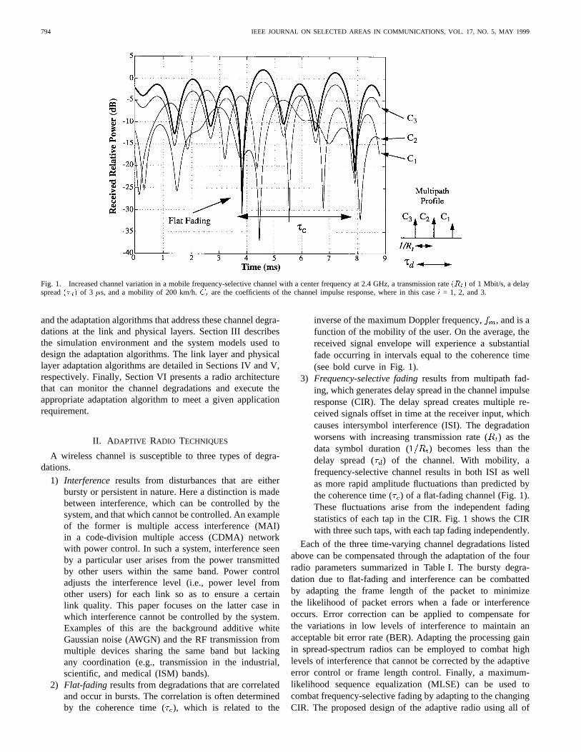
Fig. 1. Increased channel variation in a mobile frequency-selective channel with a center frequency at 2.4 GHz, a transmission rate(Rt) of 1 Mbit/s, a delayspread(�d) of 3 �s, and a mobility of 200 km/h.Ci are the coefficients of the channel impulse response, where in this casei = 1, 2, and 3.
and the adaptation algorithms that address these channel degra-dations at the link and physical layers. Section III describesthe simulation environment and the system models used todesign the adaptation algorithms. The link layer and physicallayer adaptation algorithms are detailed in Sections IV and V,respectively. Finally, Section VI presents a radio architecturethat can monitor the channel degradations and execute theappropriate adaptation algorithm to meet a given applicationrequirement.
II. A DAPTIVE RADIO TECHNIQUES
A wireless channel is susceptible to three types of degra-dations.
1) Interference results from disturbances that are eitherbursty or persistent in nature. Here a distinction is madebetween interference, which can be controlled by thesystem, and that which cannot be controlled. An exampleof the former is multiple access interference (MAI)in a code-division multiple access (CDMA) networkwith power control. In such a system, interference seenby a particular user arises from the power transmittedby other users within the same band. Power controladjusts the interference level (i.e., power level fromother users) for each link so as to ensure a certainlink quality. This paper focuses on the latter case inwhich interference cannot be controlled by the system.Examples of this are the background additive whiteGaussian noise (AWGN) and the RF transmission frommultiple devices sharing the same band but lackingany coordination (e.g., transmission in the industrial,scientific, and medical (ISM) bands).
2) Flat-fading results from degradations that are correlatedand occur in bursts. The correlation is often determinedby the coherence time (), which is related to the
inverse of the maximum Doppler frequency,, and is afunction of the mobility of the user. On the average, thereceived signal envelope will experience a substantialfade occurring in intervals equal to the coherence time(see bold curve in Fig. 1).
3) Frequency-selective fadingresults from multipath fad-ing, which generates delay spread in the channel impulseresponse (CIR). The delay spread creates multiple re-ceived signals offset in time at the receiver input, whichcauses intersymbol interference (ISI). The degradationworsens with increasing transmission rate () as thedata symbol duration ( ) becomes less than thedelay spread ( ) of the channel. With mobility, afrequency-selective channel results in both ISI as wellas more rapid amplitude fluctuations than predicted bythe coherence time () of a flat-fading channel (Fig. 1).These fluctuations arise from the independent fadingstatistics of each tap in the CIR. Fig. 1 shows the CIRwith three such taps, with each tap fading independently.
Each of the three time-varying channel degradations listedabove can be compensated through the adaptation of the fourradio parameters summarized in Table I. The bursty degra-dation due to flat-fading and interference can be combattedby adapting the frame length of the packet to minimizethe likelihood of packet errors when a fade or interferenceoccurs. Error correction can be applied to compensate forthe variations in low levels of interference to maintain anacceptable bit error rate (BER). Adapting the processing gainin spread-spectrum radios can be employed to combat highlevels of interference that cannot be corrected by the adaptiveerror control or frame length control. Finally, a maximum-likelihood sequence equalization (MLSE) can be used tocombat frequency-selective fading by adapting to the changingCIR. The proposed design of the adaptive radio using all of
CHIEN et al.: ADAPTIVE RADIO FOR MULTIMEDIA WIRELESS LINKS 795
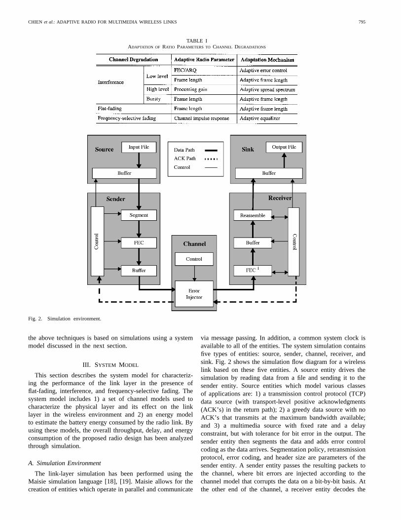
TABLE IADAPTATION OF RATIO PARAMETERS TO CHANNEL DEGRADATIONS
Fig. 2. Simulation environment.
the above techniques is based on simulations using a systemmodel discussed in the next section.
III. SYSTEM MODEL
This section describes the system model for characteriz-ing the performance of the link layer in the presence offlat-fading, interference, and frequency-selective fading. Thesystem model includes 1) a set of channel models used tocharacterize the physical layer and its effect on the linklayer in the wireless environment and 2) an energy modelto estimate the battery energy consumed by the radio link. Byusing these models, the overall throughput, delay, and energyconsumption of the proposed radio design has been analyzedthrough simulation.
A. Simulation Environment
The link-layer simulation has been performed using theMaisie simulation language [18], [19]. Maisie allows for thecreation of entities which operate in parallel and communicate
via message passing. In addition, a common system clock isavailable to all of the entities. The system simulation containsfive types of entities: source, sender, channel, receiver, andsink. Fig. 2 shows the simulation flow diagram for a wirelesslink based on these five entities. A source entity drives thesimulation by reading data from a file and sending it to thesender entity. Source entities which model various classesof applications are: 1) a transmission control protocol (TCP)data source (with transport-level positive acknowledgments(ACK’s) in the return path); 2) a greedy data source with noACK’s that transmits at the maximum bandwidth available;and 3) a multimedia source with fixed rate and a delayconstraint, but with tolerance for bit error in the output. Thesender entity then segments the data and adds error controlcoding as the data arrives. Segmentation policy, retransmissionprotocol, error coding, and header size are parameters of thesender entity. A sender entity passes the resulting packets tothe channel, where bit errors are injected according to thechannel model that corrupts the data on a bit-by-bit basis. Atthe other end of the channel, a receiver entity decodes the
796 IEEE JOURNAL ON SELECTED AREAS IN COMMUNICATIONS, VOL. 17, NO. 5, MAY 1999
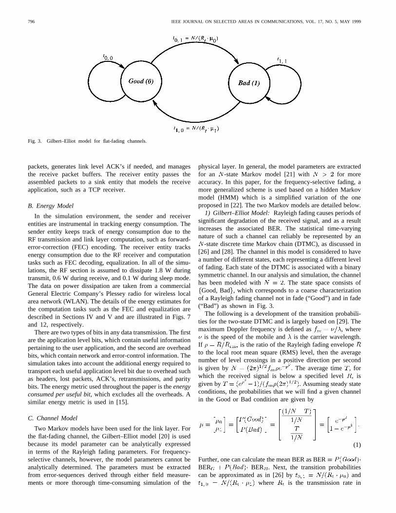
Fig. 3. Gilbert–Elliot model for flat-fading channels.
packets, generates link level ACK’s if needed, and managesthe receive packet buffers. The receiver entity passes theassembled packets to a sink entity that models the receiveapplication, such as a TCP receiver.
B. Energy Model
In the simulation environment, the sender and receiverentities are instrumental in tracking energy consumption. Thesender entity keeps track of energy consumption due to theRF transmission and link layer computation, such as forward-error-correction (FEC) encoding. The receiver entity tracksenergy consumption due to the RF receiver and computationtasks such as FEC decoding, equalization. In all of the simu-lations, the RF section is assumed to dissipate 1.8 W duringtransmit, 0.6 W during receive, and 0.1 W during sleep mode.The data on power dissipation are taken from a commercialGeneral Electric Company’s Plessey radio for wireless localarea network (WLAN). The details of the energy estimates forthe computation tasks such as the FEC and equalization aredescribed in Sections IV and V and are illustrated in Figs. 7and 12, respectively.
There are two types of bits in any data transmission. The firstare the application level bits, which contain useful informationpertaining to the user application, and the second are overheadbits, which contain network and error-control information. Thesimulation takes into account the additional energy required totransport each useful application level bit due to overhead suchas headers, lost packets, ACK’s, retransmissions, and paritybits. The energy metric used throughout the paper is theenergyconsumed per useful bit, which excludes all the overheads. Asimilar energy metric is used in [15].
C. Channel Model
Two Markov models have been used for the link layer. Forthe flat-fading channel, the Gilbert–Elliot model [20] is usedbecause its model parameter can be analytically expressedin terms of the Rayleigh fading parameters. For frequency-selective channels, however, the model parameters cannot beanalytically determined. The parameters must be extractedfrom error-sequences derived through either field measure-ments or more thorough time-consuming simulation of the
physical layer. In general, the model parameters are extractedfor an -state Markov model [21] with for moreaccuracy. In this paper, for the frequency-selective fading, amore generalized scheme is used based on a hidden Markovmodel (HMM) which is a simplified variation of the oneproposed in [22]. The two Markov models are detailed below.
1) Gilbert–Elliot Model: Rayleigh fading causes periods ofsignificant degradation of the received signal, and as a resultincreases the associated BER. The statistical time-varyingnature of such a channel can reliably be represented by an
-state discrete time Markov chain (DTMC), as discussed in[26] and [28]. The channel in this model is considered to havea number of different states, each representing a different levelof fading. Each state of the DTMC is associated with a binarysymmetric channel. In our analysis and simulation, the channelhas been modeled with . The state space consists ofGood, Bad, which corresponds to a coarse characterization
of a Rayleigh fading channel not in fade (“Good”) and in fade(“Bad”) as shown in Fig. 3.
The following is a development of the transition probabili-ties for the two-state DTMC and is largely based on [29]. Themaximum Doppler frequency is defined as , where
is the speed of the mobile andis the carrier wavelength.If is the ratio of the Rayleigh fading envelopeto the local root mean square (RMS) level, then the averagenumber of level crossings in a positive direction per secondis given by . The average time , forwhich the received signal is below a specified level, isgiven by . Assuming steady stateconditions, the probabilities that we will find a given channelin the Good or Bad condition are given by
(1)
Further, one can calculate the mean BER as BERBER BER . Next, the transition probabilitiescan be approximated as in [26] by and
where is the transmission rate in
CHIEN et al.: ADAPTIVE RADIO FOR MULTIMEDIA WIRELESS LINKS 797
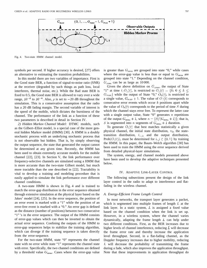
Fig. 4. Two-state HMM channel model.
symbols per second. If higher accuracy is desired, [27] offersan alternative to estimating the transition probabilities.
In this model there are two variables of importance. First isthe Good state BER, a function of signal-to-noise ratio (SNR)at the receiver (degraded by such things as path loss, localinterferers, thermal noise, etc.). While the Bad state BER isfixed to 0.5, the Good state BER is allowed to vary over a widerange, to . Also, is set to 20 dB throughout thesimulation. This is a conservative assumption that the radiohas a 20 dB fading margin. The second variable of interest isthe speed of the mobile, which dictates the burstiness of thechannel. The performance of the link as a function of thesetwo parameters is described in detail in Section IV.
2) Hidden Markov Channel Model:DTMC models, suchas the Gilbert–Elliot model, is a special case of the more gen-eral hidden Markov model (HMM) [30]. A HMM is a doublystochastic process with an underlying stochastic process thatis not observable but hidden. That is, by simply observingthe output sequence, the state that generated the output cannotbe determined at any given time. Recently, the HMM hasbeen used to obtain extremely accurate models for the mobilechannel [22], [23]. In Section V, the link performance overfrequency-selective channels are simulated using a HMM thatis more accurate than the two-state Gilbert model, but muchmore tractable than the one described in [22]. Tractability isvital to develop a training and modeling procedure that iseasily applied to simulate the link performance over differentchannel conditions.
A two-state HMM is shown in Fig. 4 and is trained tomatch the error-gap distribution in the error sequence obtainedthrough extensive simulation at the physical layer based on theJakes’ model [24], [25]. In the error sequence, the position ofan error event is marked with a “1” while the position of anerror-free event is marked with a “0.” An error gap is definedas the distance (number of positions) between two consecutive“1” ’s in the error sequence. The output of the HMM consistsof error-gap values which can then be inverted to obtain theactual error sequence. Confining the outputs of the HMM toerror-gap sequences helps to stabilize the training algorithm,which can diverge if the training sequence is taken directlyfrom the error-sequence.
For the two-state HMM, state “0” represents the channelstate with no error while state “1” represents the channel statewith error. Specifically, the two channel conditions are definedby a threshold value . Cases where the error-gap value
is greater than are grouped into state “0,” while caseswhere the error-gap value is less than or equal to aregrouped into state “1.” Depending on the channel condition,
can be as large as 10 000.Given the above definition on , the output of State
“1” at time , is restricted towhile the output of State “0,” , is restricted to
a single value, . The value of corresponds toconsecutive error events which occurpositions apart whilethe value of corresponds to the period of timeduringwhich the channel stays error free. To represent the latter casewith a single output value, State “0” generatesrepetitionsof the output , where that is,
is segmented into segments of duration.To generate that best matches statistically a given
physical channel, the initial state distribution,, the state-transition distribution, , and the output distribution,Prob , must be determined for by trainingthe HMM. In this paper, the Baum–Welch algorithm [30] hasbeen used to train the HMM using the error sequence derivedfrom detailed physical-layer simulations.
The system, energy, and channel models presented abovehave been used to develop the adaptive techniques presentedbelow.
IV. A DAPTIVE LINK-LAYER CONTROL
The following subsections present the design of the linklayer control in the radio to adapt to interference and flat-fading in the wireless channel.
A. Energy-Efficient Frame Length Control
In most networks, the transport layer generates a packet,which is segmented into multiple frames of lengthat thelink layer. In a static system, is assigned a fixed valuebased on the channel condition when the link is set up.However, in a wireless system, where the channel variesdynamically, adapting the frame length can help undertwo different conditions. First, as the BER increases due tohigher levels of channel interference, reducingwill decreasethe frame error rate and thereby increase the applicationlevel throughput. Second, in a flat-fading channel, as theDoppler frequency increases due to higher mobility, reducing
will decrease the probability of transmitting the frameduring a fade, which also improves the application throughput.Note that these improvements in application throughput do
798 IEEE JOURNAL ON SELECTED AREAS IN COMMUNICATIONS, VOL. 17, NO. 5, MAY 1999
not require an increase in the radio transmission rate,and also minimize the energy consumption of the radio.Furthermore, unlike other link layer techniques for adapting tointerference and flat-fading (such as forward error correction),frame length adaptation has the advantage of consuming littlebattery energy, since it only requires a modification to theexisting segmentation and reassembly software in the protocolstack. Based on the simulation model in Section III as wellas measurements, quantitative analysis is presented below todetermine the frame length adaptation strategy that minimizesenergy consumption for a given system.
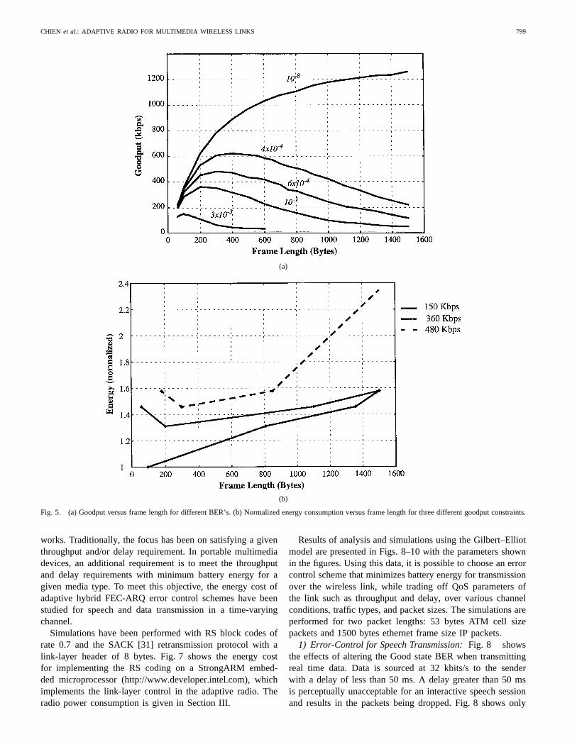
1) Frame Length Adaptation to Changing Interference:When the BER due to random noise and interference changes,so does the frame error rate, which in turn determines theapplication level throughput, orgoodput. Regardless of thetransmission rate , with large frame length the goodputof a link can drop to zero if every packet gets corrupted.Note that the radio will still be transmitting and thereforewasting battery energy. Reducing frame lengths can improvethe goodput and therefore energy efficiency by reducing theprobability of frame errors for a given BER. However, therelative overhead of the frame header also increases, therebyoffsetting the improvement in goodput. Therefore, an optimumframe length exists that maximizes goodput for a given BER asshown by the measurements in Fig. 5(a). These measurementshave been obtained with a peer-to-peer wireless link using the900-MHz WaveLAN (WLAN) radios under varying channelinterference introduced using an AWGN noise generator. Alink-layer header of 8 bytes has been used.
Conventionally, the relationship in Fig. 5(a) is used to adaptthe frame length to maximize the goodput for a given BER.However, in the proposed adaptive radio, the frame lengthadaptation is applied for reducing energy consumption undera given constraint on goodput. The radio selects the framelength that maximizes the BER required to meet the goodputconstraint, thereby minimizing the required transmit energy perbit ( ). The reduction in the required is exploitedto reduce the transmitter power to obtain energy saving.Note that in most radios the transmitter energy consumptiondominates as indicated in the energy model in Section III. Thisadaptation approach is illustrated in Fig. 5(b), which is derivedfrom the measurements in Fig. 5(a), and shows the relativeenergy versus frame length for different goodput constraints.
For a given goodput constraint the radio selects the framelength that minimizes energy according to the correspondingcurve in Fig. 5(b). The radio monitors the BER and adjuststhe transmit power to hold the BER constant at the maximumallowable value. For example, for the best case in Fig. 5(b),if the desired goodput is 150 kbit/s, which is 7.5% of thetransmission rate in this experiment, then a 30% reductionin battery energy consumption is achieved by reducing framesize from the 1500 bytes ethernet standard to 100 bytes. Theabove discussion holds for the general case but the amountof energy saving will depend on the required fora particular modulation. The results in Fig. 5 are valid forquadrature phase shift key (QPSK-modulation).
2) Frame Length Adaptation in Flat-Fading Channel:Simulations have been performed to determine the frame
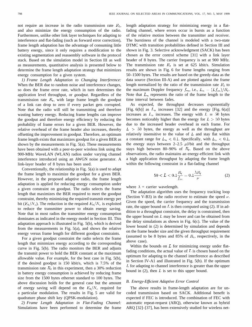
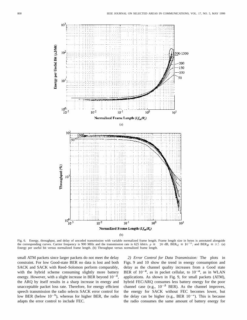
length adaptation strategy for minimizing energy in a flat-fading channel, where errors occur in bursts as a functionof the relative motion between the transmitter and receiver.The burstiness of the channel is modeled with a two-stateDTMC with transition probabilities defined in Section III andshown in Fig. 3. Selective acknowledgment (SACK) has beenchosen as the error control scheme [31] with a link layerheader of 8 bytes. The carrier frequency is set at 900 MHz.The transmission rate is set at 625 kbit/s. Simulationresults are shown in Fig. 6 for frame lengths ranging from50–1500 bytes. The results are based on the greedy-data as thedata source (Section III-A) and are plotted against the framelength normalized by the ratio of the transmission ratetothe maximum Doppler frequency , i.e., .Note that represents the ratio of the frame length to thetime interval between fades.
As expected, the throughput decreases exponentially[Fig. 6(b)] as increases [32] and the energy [Fig. 6(a)]increases as increases. The energy with bytesbecomes noticeably higher than the energy for bytesdue to the increased header overhead in each frame. For
bytes, the energy as well as the throughput arerelatively insensitive to the value of and stay flat withina constant range for . Specifically, with ,the energy stays between 2–2.5J/bit and the throughputstays high between 80–90% of . Based on the aboveobservations, the radio maintains an energy-efficient link witha high application throughput by adapting the frame lengthwithin the following constraint in a flat-fading channel
(2)
where = carrier wavelength.The adaptation algorithm uses the frequency tracking loop
(Section V-B3) in the radio receiver to estimate the speed.Given the speed, the carrier frequency and the transmissionrate, the upper bound onis then computed using (2). If in ad-dition to a throughput constraint, the delay is constrained, thenthe upper bound on may be lower and can be obtained fromthe delay simulations as shown in Fig. 6(c). The value of thelower bound in (2) is determined by simulation and dependson the frame header size and the given throughput requirement(assumed to be 8 bytes and 85% of, respectively, in theabove case).
Within the bounds on for minimizing energy under flat-fading conditions, the actual value ofis chosen based on theoptimum for adapting to the channel interference as describedin Section IV-A1 and illustrated in Fig. 5(b). If the optimum
for adapting to channel interference is greater than the upperbound in (2), then is set to this upper bound.
B. Energy-Efficient Adaptive Error Control
The above results in frame-length adaptation are for un-coded transmission based on SACK. Additional benefit isexpected if FEC is introduced. The combination of FEC withautomatic repeat-request (ARQ), otherwise known as hybridARQ [32]–[37], has been extensively studied for wireless net-
CHIEN et al.: ADAPTIVE RADIO FOR MULTIMEDIA WIRELESS LINKS 799
(a)
(b)
Fig. 5. (a) Goodput versus frame length for different BER’s. (b) Normalized energy consumption versus frame length for three different goodput constraints.
works. Traditionally, the focus has been on satisfying a giventhroughput and/or delay requirement. In portable multimediadevices, an additional requirement is to meet the throughputand delay requirements with minimum battery energy for agiven media type. To meet this objective, the energy cost ofadaptive hybrid FEC-ARQ error control schemes have beenstudied for speech and data transmission in a time-varyingchannel.
Simulations have been performed with RS block codes ofrate 0.7 and the SACK [31] retransmission protocol with alink-layer header of 8 bytes. Fig. 7 shows the energy costfor implementing the RS coding on a StrongARM embed-ded microprocessor (http://www.developer.intel.com), whichimplements the link-layer control in the adaptive radio. Theradio power consumption is given in Section III.
Results of analysis and simulations using the Gilbert–Elliotmodel are presented in Figs. 8–10 with the parameters shownin the figures. Using this data, it is possible to choose an errorcontrol scheme that minimizes battery energy for transmissionover the wireless link, while trading off QoS parameters ofthe link such as throughput and delay, over various channelconditions, traffic types, and packet sizes. The simulations areperformed for two packet lengths: 53 bytes ATM cell sizepackets and 1500 bytes ethernet frame size IP packets.
1) Error-Control for Speech Transmission:Fig. 8 showsthe effects of altering the Good state BER when transmittingreal time data. Data is sourced at 32 kbits/s to the senderwith a delay of less than 50 ms. A delay greater than 50 msis perceptually unacceptable for an interactive speech sessionand results in the packets being dropped. Fig. 8 shows only
800 IEEE JOURNAL ON SELECTED AREAS IN COMMUNICATIONS, VOL. 17, NO. 5, MAY 1999
(a)
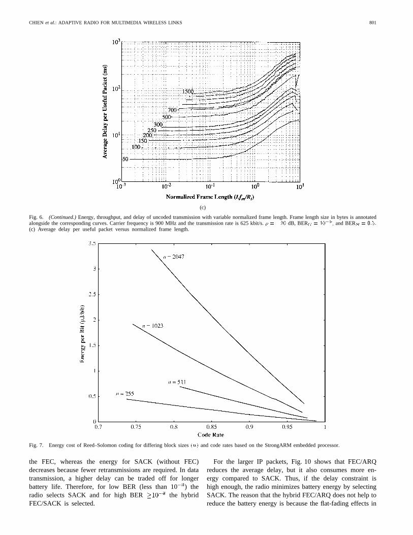
(b)
Fig. 6. Energy, throughput, and delay of uncoded transmission with variable normalized frame length. Frame length size in bytes is annotated alongsidethe corresponding curves. Carrier frequency is 900 MHz and the transmission rate is 625 kbit/s.� = �20 dB, BERG = 10
�5; and BERB = 0:5: (a)
Energy per useful bit versus normalized frame length. (b) Throughput versus normalized frame length.
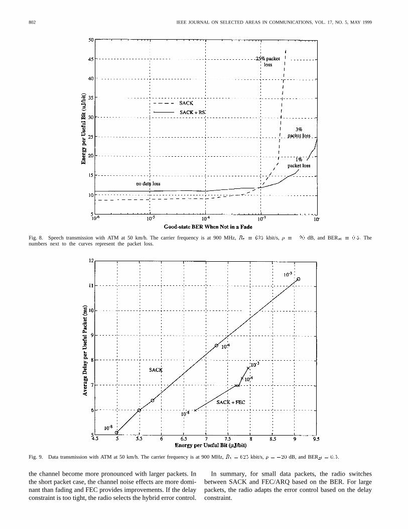
small ATM packets since larger packets do not meet the delayconstraint. For low Good-state BER no data is lost and bothSACK and SACK with Reed–Solomon perform comparably,with the hybrid scheme consuming slightly more batteryenergy. However, with a slight increase in BER beyond 10,the ARQ by itself results in a sharp increase in energy andunacceptable packet loss rate. Therefore, for energy efficientspeech transmission the radio selects SACK error control forlow BER (below 10 ), whereas for higher BER, the radioadapts the error control to include FEC.
2) Error Control for Data Transmission:The plots inFigs. 9 and 10 show the trend in energy consumption anddelay as the channel quality increases from a Good stateBER of 10 , as in packet cellular, to 10 , as in WLANapplications. As shown in Fig. 9, for small packets (ATM),hybrid FEC/ARQ consumes less battery energy for the poorchannel case (e.g., 10 BER). As the channel improves,the energy for SACK without FEC becomes lower, butthe delay can be higher (e.g., BER 10). This is becausethe radio consumes the same amount of battery energy for
CHIEN et al.: ADAPTIVE RADIO FOR MULTIMEDIA WIRELESS LINKS 801
(c)
Fig. 6. (Continued.)Energy, throughput, and delay of uncoded transmission with variable normalized frame length. Frame length size in bytes is annotatedalongside the corresponding curves. Carrier frequency is 900 MHz and the transmission rate is 625 kbit/s.� = �20 dB, BERG = 10�5; and BERB = 0:5:(c) Average delay per useful packet versus normalized frame length.
Fig. 7. Energy cost of Reed–Solomon coding for differing block sizes(n) and code rates based on the StrongARM embedded processor.
the FEC, whereas the energy for SACK (without FEC)decreases because fewer retransmissions are required. In datatransmission, a higher delay can be traded off for longerbattery life. Therefore, for low BER (less than 10) theradio selects SACK and for high BER the hybridFEC/SACK is selected.
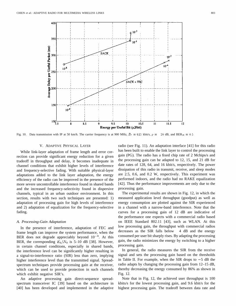
For the larger IP packets, Fig. 10 shows that FEC/ARQreduces the average delay, but it also consumes more en-ergy compared to SACK. Thus, if the delay constraint ishigh enough, the radio minimizes battery energy by selectingSACK. The reason that the hybrid FEC/ARQ does not help toreduce the battery energy is because the flat-fading effects in
802 IEEE JOURNAL ON SELECTED AREAS IN COMMUNICATIONS, VOL. 17, NO. 5, MAY 1999
Fig. 8. Speech transmission with ATM at 50 km/h. The carrier frequency is at 900 MHz,Rt = 625 kbit/s, � = �20 dB, and BERB = 0:5: Thenumbers next to the curves represent the packet loss.
Fig. 9. Data transmission with ATM at 50 km/h. The carrier frequency is at 900 MHz,Rt = 625 kbit/s, � = �20 dB, and BERB = 0:5:
the channel become more pronounced with larger packets. Inthe short packet case, the channel noise effects are more domi-nant than fading and FEC provides improvements. If the delayconstraint is too tight, the radio selects the hybrid error control.
In summary, for small data packets, the radio switchesbetween SACK and FEC/ARQ based on the BER. For largepackets, the radio adapts the error control based on the delayconstraint.
CHIEN et al.: ADAPTIVE RADIO FOR MULTIMEDIA WIRELESS LINKS 803
Fig. 10. Data transmission with IP at 50 km/h. The carrier frequency is at 900 MHz,Rt = 625 kbit/s, � = �20 dB, and BERB = 0:5:
V. ADAPTIVE PHYSICAL LAYER
While link-layer adaptation of frame length and error cor-rection can provide significant energy reduction for a giventradeoff in throughput and delay, it becomes inadequate inchannel conditions that exhibit higher levels of interferenceand frequency-selective fading. With suitable physical-layeradaptations added to the link layer adaptation, the energyefficiency of the radio can be improved in the presence of themore severe uncontrollable interference found in shared bandsand the increased frequency-selectivity found in dispersivechannels, typical in an urban outdoor environment. In thissection, results with two such techniques are presented: 1)adaptation of processing gain for high levels of interferenceand 2) adaptation of equalization for the frequency-selectivefading.
A. Processing-Gain Adaptation
In the presence of interference, adaptation of FEC andframe length can improve the system performance, when theBER does not degrade appreciably beyond 10. At thisBER, the corresponding is 5–10 dB [38]. However,in certain channel conditions, especially in shared bands,the interference level can be significantly higher resulting ina signal-to-interference ratio (SIR) less than zero, implyinghigher interference level than the transmitted signal. Spread-spectrum techniques provide processing gain at the receiver,which can be used to provide protection in such channelswhich exhibit negative SIR’s.
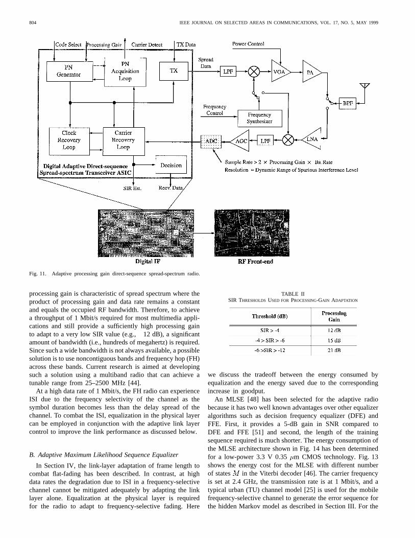
An adaptive processing gain direct-sequence spread-spectrum transceiver IC [39] based on the architecture in[40] has been developed and implemented in the adaptive
radio (see Fig. 11). An adaptation interface [41] for this radiohas been built to enable the link layer to control the processinggain (PG). The radio has a fixed chip rate of 2 Mchips/s andthe processing gain can be adapted to 12, 15, and 21 dB fordate rates of 128, 64, and 16 kbit/s, respectively. The powerdissipation of this radio in transmit, receive, and sleep modesare 2.5, 0.6, and 0.2 W, respectively. This experiment wasperformed indoors, and the radio had no RAKE equalization[42]. Thus the performance improvements are only due to theprocessing gain.
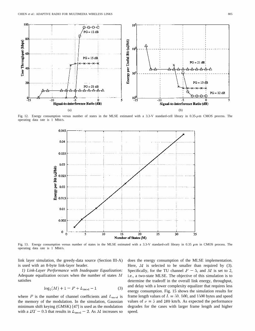
The experimental results are shown in Fig. 12, in which themeasured application level throughput (goodput) as well asenergy consumption are plotted against the SIR experiencedin a channel with a narrow-band interference. Note that thecurves for a processing gain of 12 dB are indicative ofthe performance one expects with a commercial radio basedon IEEE Standard 802.11 [43], such as WLAN. At thislow processing gain, the throughput with commercial radiosdecreases as the SIR falls below4 dB and the energyconsumed per user bit sharply rises. By adapting the processinggain, the radio minimizes the energy by switching to a higherprocessing gain.
In general, the radio measures the SIR from the receivesignal and sets the processing gain based on the thresholdsin Table II. For example, when the SIR drops to5 dB theradio adapts by changing the processing gain from 12–15 dB,thereby decreasing the energy consumed by 86% as shown inFig. 12.
Note that in Fig. 12, the achieved user throughput is 100kbits/s for the lowest processing gain, and 9.6 kbit/s for thehighest processing gain. The tradeoff between data rate and
804 IEEE JOURNAL ON SELECTED AREAS IN COMMUNICATIONS, VOL. 17, NO. 5, MAY 1999
Fig. 11. Adaptive processing gain direct-sequence spread-spectrum radio.
processing gain is characteristic of spread spectrum where theproduct of processing gain and data rate remains a constantand equals the occupied RF bandwidth. Therefore, to achievea throughput of 1 Mbit/s required for most multimedia appli-cations and still provide a sufficiently high processing gainto adapt to a very low SIR value (e.g.,12 dB), a significantamount of bandwidth (i.e., hundreds of megahertz) is required.Since such a wide bandwidth is not always available, a possiblesolution is to use noncontiguous bands and frequency hop (FH)across these bands. Current research is aimed at developingsuch a solution using a multiband radio that can achieve atunable range from 25–2500 MHz [44].
At a high data rate of 1 Mbit/s, the FH radio can experienceISI due to the frequency selectivity of the channel as thesymbol duration becomes less than the delay spread of thechannel. To combat the ISI, equalization in the physical layercan be employed in conjunction with the adaptive link layercontrol to improve the link performance as discussed below.
B. Adaptive Maximum Likelihood Sequence Equalizer
In Section IV, the link-layer adaptation of frame length tocombat flat-fading has been described. In contrast, at highdata rates the degradation due to ISI in a frequency-selectivechannel cannot be mitigated adequately by adapting the linklayer alone. Equalization at the physical layer is requiredfor the radio to adapt to frequency-selective fading. Here
TABLE IISIR THRESHOLDS USED FOR PROCESSING-GAIN ADAPTATION
we discuss the tradeoff between the energy consumed byequalization and the energy saved due to the correspondingincrease in goodput.
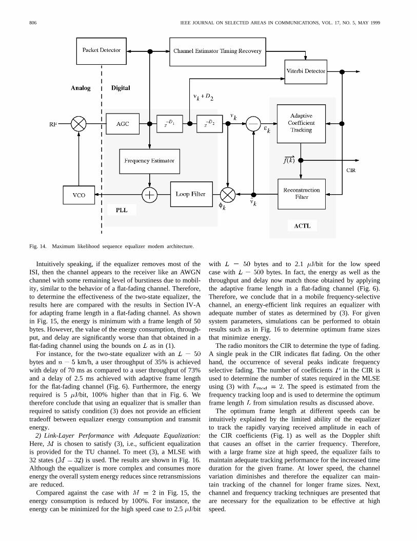
An MLSE [48] has been selected for the adaptive radiobecause it has two well known advantages over other equalizeralgorithms such as decision frequency equalizer (DFE) andFFE. First, it provides a 5-dB gain in SNR compared toDFE and FFE [51] and second, the length of the trainingsequence required is much shorter. The energy consumption ofthe MLSE architecture shown in Fig. 14 has been determinedfor a low-power 3.3 V 0.35 m CMOS technology. Fig. 13shows the energy cost for the MLSE with different numberof states in the Viterbi decoder [46]. The carrier frequencyis set at 2.4 GHz, the transmission rate is at 1 Mbit/s, and atypical urban (TU) channel model [25] is used for the mobilefrequency-selective channel to generate the error sequence forthe hidden Markov model as described in Section III. For the
CHIEN et al.: ADAPTIVE RADIO FOR MULTIMEDIA WIRELESS LINKS 805
(a) (b)
Fig. 12. Energy consumption versus number of states in the MLSE estimated with a 3.3-V standard-cell library in 0.35-�m CMOS process. Theoperating data rate is 1 Mbit/s.
Fig. 13. Energy consumption versus number of states in the MLSE estimated with a 3.3-V standard-cell library in 0.35�m in CMOS process. Theoperating data rate is 1 Mbit/s.
link layer simulation, the greedy-data source (Section III-A)is used with an 8-byte link-layer header.
1) Link-Layer Performance with Inadequate Equalization:Adequate equalization occurs when the number of statessatisfies
(3)
where is the number of channel coefficients and isthe memory of the modulation. In the simulation, Gaussianminimum shift keying (GMSK) [47] is used as the modulationwith a that results in . As increases so
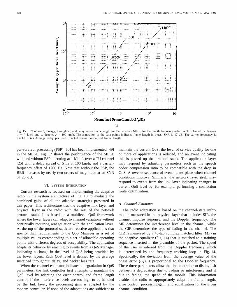
does the energy consumption of the MLSE implementation.Here, is selected to be smaller than required by (3).Specifically, for the TU channel , and is set to 2,i.e., a two-state MLSE. The objective of this simulation is todetermine the tradeoff in the overall link energy, throughput,and delay with a lower complexity equalizer that requires lessenergy consumption. Fig. 15 shows the simulation results forframe length values of , and bytes and speedvalues of and km/h. As expected the performancedegrades for the cases with larger frame length and higherspeed.
806 IEEE JOURNAL ON SELECTED AREAS IN COMMUNICATIONS, VOL. 17, NO. 5, MAY 1999
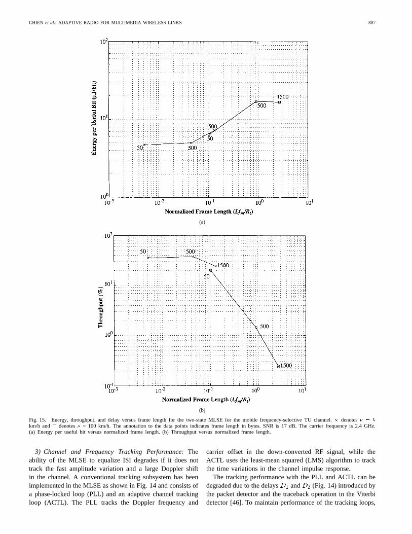
Fig. 14. Maximum likelihood sequence equalizer modem architecture.
Intuitively speaking, if the equalizer removes most of theISI, then the channel appears to the receiver like an AWGNchannel with some remaining level of burstiness due to mobil-ity, similar to the behavior of a flat-fading channel. Therefore,to determine the effectiveness of the two-state equalizer, theresults here are compared with the results in Section IV-Afor adapting frame length in a flat-fading channel. As shownin Fig. 15, the energy is minimum with a frame length of 50bytes. However, the value of the energy consumption, through-put, and delay are significantly worse than that obtained in aflat-fading channel using the bounds onas in (1).
For instance, for the two-state equalizer with anbytes and km/h, a user throughput of 35% is achievedwith delay of 70 ms as compared to a user throughput of 73%and a delay of 2.5 ms achieved with adaptive frame lengthfor the flat-fading channel (Fig. 6). Furthermore, the energyrequired is 5 J/bit, 100% higher than that in Fig. 6. Wetherefore conclude that using an equalizer that is smaller thanrequired to satisfy condition (3) does not provide an efficienttradeoff between equalizer energy consumption and transmitenergy.
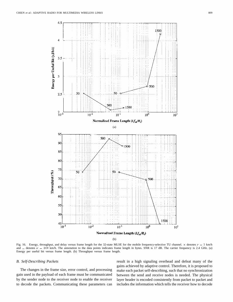
2) Link-Layer Performance with Adequate Equalization:Here, is chosen to satisfy (3), i.e., sufficient equalizationis provided for the TU channel. To meet (3), a MLSE with32 states ( ) is used. The results are shown in Fig. 16.Although the equalizer is more complex and consumes moreenergy the overall system energy reduces since retransmissionsare reduced.
Compared against the case with in Fig. 15, theenergy consumption is reduced by 100%. For instance, theenergy can be minimized for the high speed case to 2.5J/bit
with bytes and to 2.1 J/bit for the low speedcase with bytes. In fact, the energy as well as thethroughput and delay now match those obtained by applyingthe adaptive frame length in a flat-fading channel (Fig. 6).Therefore, we conclude that in a mobile frequency-selectivechannel, an energy-efficient link requires an equalizer withadequate number of states as determined by (3). For givensystem parameters, simulations can be performed to obtainresults such as in Fig. 16 to determine optimum frame sizesthat minimize energy.
The radio monitors the CIR to determine the type of fading.A single peak in the CIR indicates flat fading. On the otherhand, the occurrence of several peaks indicate frequencyselective fading. The number of coefficientsin the CIR isused to determine the number of states required in the MLSEusing (3) with . The speed is estimated from thefrequency tracking loop and is used to determine the optimumframe length from simulation results as discussed above.
The optimum frame length at different speeds can beintuitively explained by the limited ability of the equalizerto track the rapidly varying received amplitude in each ofthe CIR coefficients (Fig. 1) as well as the Doppler shiftthat causes an offset in the carrier frequency. Therefore,with a large frame size at high speed, the equalizer fails tomaintain adequate tracking performance for the increased timeduration for the given frame. At lower speed, the channelvariation diminishes and therefore the equalizer can main-tain tracking of the channel for longer frame sizes. Next,channel and frequency tracking techniques are presented thatare necessary for the equalization to be effective at highspeed.
CHIEN et al.: ADAPTIVE RADIO FOR MULTIMEDIA WIRELESS LINKS 807
(a)
(b)
Fig. 15. Energy, throughput, and delay versus frame length for the two-state MLSE for the mobile frequency-selective TU channel.� denotes� = 5
km/h and denotes� = 100 km/h. The annotation to the data points indicates frame length in bytes. SNR is 17 dB. The carrier frequency is 2.4 GHz.(a) Energy per useful bit versus normalized frame length. (b) Throughput versus normalized frame length.
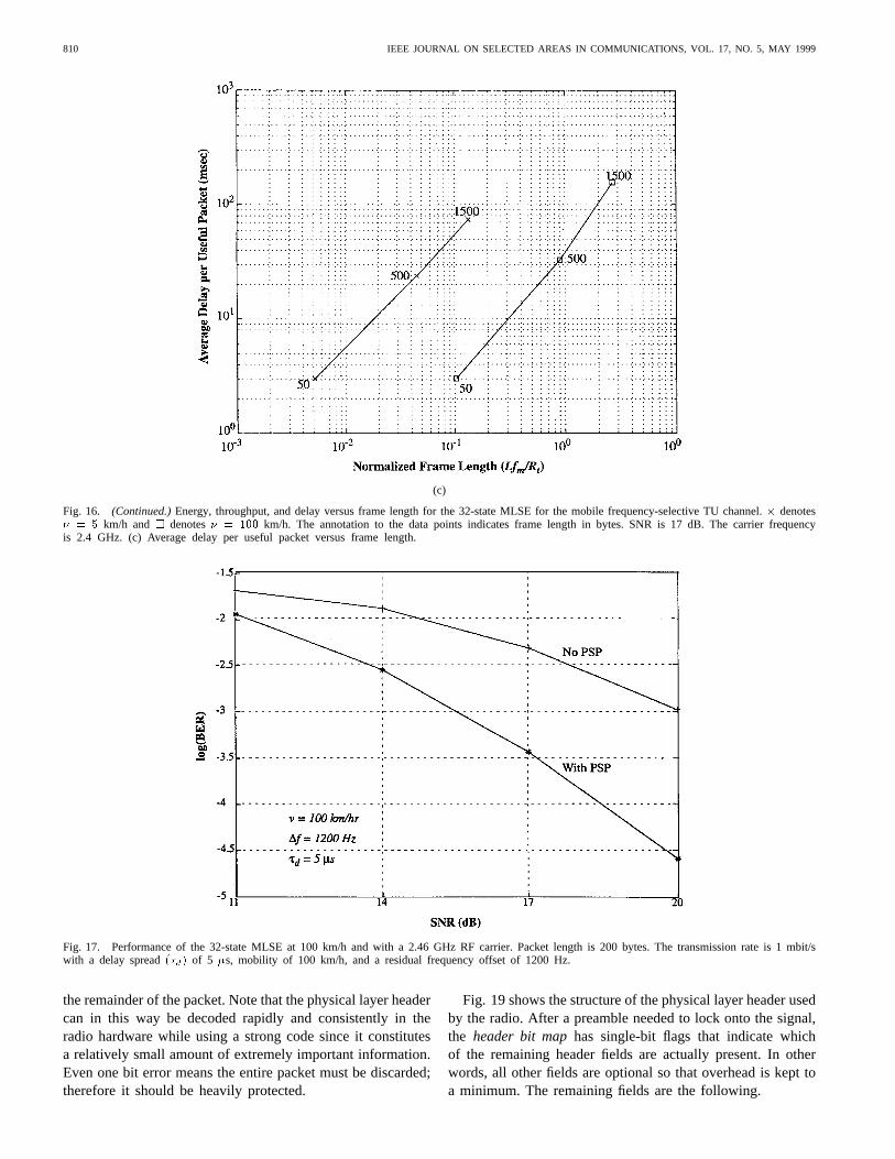
3) Channel and Frequency Tracking Performance:Theability of the MLSE to equalize ISI degrades if it does nottrack the fast amplitude variation and a large Doppler shiftin the channel. A conventional tracking subsystem has beenimplemented in the MLSE as shown in Fig. 14 and consists ofa phase-locked loop (PLL) and an adaptive channel trackingloop (ACTL). The PLL tracks the Doppler frequency and
carrier offset in the down-converted RF signal, while theACTL uses the least-mean squared (LMS) algorithm to trackthe time variations in the channel impulse response.
The tracking performance with the PLL and ACTL can bedegraded due to the delays and (Fig. 14) introduced bythe packet detector and the traceback operation in the Viterbidetector [46]. To maintain performance of the tracking loops,
808 IEEE JOURNAL ON SELECTED AREAS IN COMMUNICATIONS, VOL. 17, NO. 5, MAY 1999
(c)
Fig. 15. (Continued.)Energy, throughput, and delay versus frame length for the two-state MLSE for the mobile frequency-selective TU channel.� denotes� = 5 km/h and denotes� = 100 km/h. The annotation to the data points indicates frame length in bytes. SNR is 17 dB. The carrier frequency is2.4 GHz. (c) Average delay per useful packet versus normalized frame length.
per-survivor processing (PSP) [50] has been implemented [49]in the MLSE. Fig. 17 shows the performance of the MLSEwith and without PSP operating at 1 Mbit/s over a TU channel[25] with a delay spread of 5 s at 100 km/h, and a carrier-frequency offset of 1200 Hz. Note that without the PSP, theBER increases by nearly two-orders of magnitude at an SNRof 20 dB.
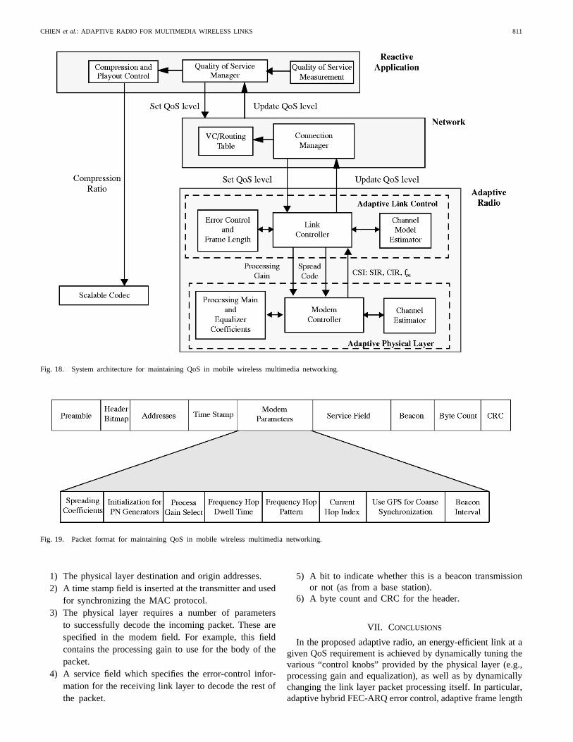
VI. SYSTEM INTEGRATION
Current research is focused on implementing the adaptiveradio in the system architecture of Fig. 18 to evaluate thecombined gains of all the adaptive strategies presented inthis paper. This architecture ties the adaptive link layer andphysical layer in the radio with the rest of the networkprotocol stack. It is based on a multilevel QoS frameworkwhere the lower layers can adapt to channel variations withoutcontinually requiring renegotiation with the application layer.At the top of the protocol stack are reactive applications thatspecify their requirements to the QoS Manager as a set ofmultiple values corresponding to a set of allowable operatingpoints with different degrees of acceptability. The applicationadapts its behavior by reacting to events from a QoS Managerindicating a change in the level of QoS being provided bythe lower layers. Each QoS level is defined by the averagesustained throughput, delay, and packet loss rate.
When the channel estimator indicates a degradation in QoSparameters, the link controller first attempts to maintain theQoS level by adapting the error control and frame lengthcontrol. If the interference levels are too high to be handledby the link layer, the processing gain is adapted by themodem controller. If none of the adaptations are sufficient to
maintain the current QoS, the level of service quality for oneor more of applications is reduced, and an event indicatingthis is passed up the protocol stack. The application layermay respond by adjusting parameters such as the speechcodec compression ratio to be compatible with the drop inQoS. A reverse sequence of events takes place when channelconditions improve. Similarly, the network layer itself mayrespond to events from the link layer indicating changes incurrent QoS level by, for example, performing a connectionroute optimization.
A. Channel Estimates
The radio adaptation is based on the channel-state infor-mation measured in the physical layer that includes SIR, thechannel impulse response, and the Doppler frequency. TheSIR determines the interference level in the channel, whilethe CIR determines the type of fading in the channel. TheCIR is measured by a 48-tap complex matched filter (MF) inthe adaptive equalizer (Fig. 14) that is matched to a trainingsequence inserted in the preamble of the packet. The speedof the user is inferred from the Doppler frequency whichis determined by the frequency tracking loop in Fig. 14.Specifically, the deviation from the average value of thephase error ( ) is proportional to the Doppler frequency.These three parameters allow the link controller to distinguishbetween a degradation due to fading or interference and ifdue to fading, the speed of the mobile. This informationenables the radio to appropriately adapt the frame length,error control, processing-gain, and equalization for the givenchannel condition.
CHIEN et al.: ADAPTIVE RADIO FOR MULTIMEDIA WIRELESS LINKS 809
(a)
(b)
Fig. 16. Energy, throughput, and delay versus frame length for the 32-state MLSE for the mobile frequency-selective TU channel.� denotes� = 5 km/hand denotes� = 100 km/h. The annotation to the data points indicates frame length in bytes. SNR is 17 dB. The carrier frequency is 2.4 GHz. (a)Energy per useful bit versus frame length. (b) Throughput versus frame length.
B. Self-Describing Packets
The changes in the frame size, error control, and processinggain used in the payload of each frame must be communicatedby the sender node to the receiver node to enable the receiverto decode the packets. Communicating these parameters can
result in a high signaling overhead and defeat many of thegains achieved by adaptive control. Therefore, it is proposed tomake each packet self-describing, such that no synchronizationbetween the send and receive nodes is needed. The physicallayer header is encoded consistently from packet to packet andincludes the information which tells the receiver how to decode
810 IEEE JOURNAL ON SELECTED AREAS IN COMMUNICATIONS, VOL. 17, NO. 5, MAY 1999
(c)
Fig. 16. (Continued.)Energy, throughput, and delay versus frame length for the 32-state MLSE for the mobile frequency-selective TU channel.� denotes� = 5 km/h and denotes� = 100 km/h. The annotation to the data points indicates frame length in bytes. SNR is 17 dB. The carrier frequencyis 2.4 GHz. (c) Average delay per useful packet versus frame length.
Fig. 17. Performance of the 32-state MLSE at 100 km/h and with a 2.46 GHz RF carrier. Packet length is 200 bytes. The transmission rate is 1 mbit/swith a delay spread(�d) of 5 �s, mobility of 100 km/h, and a residual frequency offset of 1200 Hz.
the remainder of the packet. Note that the physical layer headercan in this way be decoded rapidly and consistently in theradio hardware while using a strong code since it constitutesa relatively small amount of extremely important information.Even one bit error means the entire packet must be discarded;therefore it should be heavily protected.
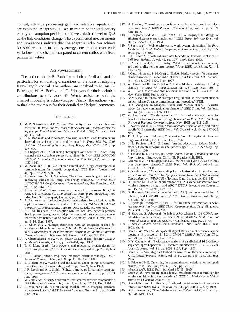
Fig. 19 shows the structure of the physical layer header usedby the radio. After a preamble needed to lock onto the signal,the header bit maphas single-bit flags that indicate whichof the remaining header fields are actually present. In otherwords, all other fields are optional so that overhead is kept toa minimum. The remaining fields are the following.
CHIEN et al.: ADAPTIVE RADIO FOR MULTIMEDIA WIRELESS LINKS 811
Fig. 18. System architecture for maintaining QoS in mobile wireless multimedia networking.
Fig. 19. Packet format for maintaining QoS in mobile wireless multimedia networking.
1) The physical layer destination and origin addresses.2) A time stamp field is inserted at the transmitter and used
for synchronizing the MAC protocol.3) The physical layer requires a number of parameters
to successfully decode the incoming packet. These arespecified in the modem field. For example, this fieldcontains the processing gain to use for the body of thepacket.
4) A service field which specifies the error-control infor-mation for the receiving link layer to decode the rest ofthe packet.
5) A bit to indicate whether this is a beacon transmissionor not (as from a base station).
6) A byte count and CRC for the header.
VII. CONCLUSIONS
In the proposed adaptive radio, an energy-efficient link at agiven QoS requirement is achieved by dynamically tuning thevarious “control knobs” provided by the physical layer (e.g.,processing gain and equalization), as well as by dynamicallychanging the link layer packet processing itself. In particular,adaptive hybrid FEC-ARQ error control, adaptive frame length
812 IEEE JOURNAL ON SELECTED AREAS IN COMMUNICATIONS, VOL. 17, NO. 5, MAY 1999
control, adaptive processing gain and adaptive equalizationare exploited. Adaptivity is used to minimize the total batteryenergy-consumption per bit, to achieve a desired level of QoSas the link conditions change. The experimental measurementsand simulations indicate that the adaptive radio can achieve30–80% reduction in battery energy consumption over widevariations in the channel compared to current radios with fixedparameter values.
ACKNOWLEDGMENT
The authors thank R. Ruth for technical feedback and, inparticular, for stimulating discussions on the ideas of adaptingframe length control. The authors are indebted to R. Au, G.Behringer, W. A. Boring, and C. Schurgers for their technicalcontributions to this work. G. Wen’s assistance with thechannel modeling is acknowledged. Finally, the authors wishto thank the reviewers for their detailed and helpful comments.
REFERENCES
[1] M. B. Srivastava and P. Mishra, “On quality of service in mobile andwireless,” in Proc. 7th Int. Workshop Network and Operating SystemsSupport for Digital Audio and Video(NOSSDAV ’97), St. Louis, MO,pp. 147–158.
[2] B. R. Badrinath and P. Sudame, “To send or not to send: Implementingdeferred transmissions in a mobile host,” inProc. 16th Int. Conf.Distributed Computing Systems,Hong Kong, May 27–30, 1996, pp.327–333.
[3] P. Bhagwatet al., “Enhancing throughput over wireless LAN’s usingchannel state dependent packet scheduling,” inProc. IEEE INFOCOM’96 Conf. Computer Communications,San Francisco, CA, vol. 3, pp.1133–1140.
[4] M. Zorzi and R. R. Rao, “Error control and energy consumption incommunications for nomadic computing,”IEEE Trans. Comput.,vol.46, pp. 279–289, Mar. 1997.
[5] P. Lettieri and M. B. Srivastava, “Adaptive frame length control forimproving wireless link range and energy efficiency,” inProc. IEEEINFOCOM ’98 Conf. Computer Communications,San Francisco, CA,vol. 2, pp. 564–571.
[6] P. Lettieri et al., “Low power error control for wireless links,” inProc. 3rd ACM/IEEE Int. Conf. Mobile Computing and Networking 1997(MobiCom’97), Budapest, Hungary, pp. 139–150.
[7] R. Ramjeeet al., “Adaptive playout mechanisms for packetized audioapplications in wide-area networks,”in Proc. IEEE INFOCOM ’94 Conf.Computer Communications,Toronto, Ont., Canada, pp. 680–688.
[8] B. E. Mullins et al., “An adaptive wireless local area network protocolthat improves throughput via adaptive control of direct sequence spreadspectrum parameters,”ACM Mobile Computing Commun. Rev.,vol. 1,pp. 9–16, Sept. 1997.
[9] C. Chien et al., “Design experience with an integrated testbed forwireless multimedia computing,” inMobile Multimedia Communica-tions: Proceedings of 3rd International Workshop on Mobile MultimediaCommunications. Princeton, NJ: Plenum, 1997, pp. 231–238.
[10] P. Chandrakasanet al., “Low power CMOS digital design,”IEEE J.Solid-State Circuits,vol. 27, pp. 473–484, Apr. 1992.
[11] T. H. Meng et al., “Low-power signal processing system design forwireless applications,”IEEE Personal Commun.,vol. 5, pp. 20–31, June1998.
[12] L. E. Larson, “Radio frequency integrated circuit technology,”IEEEPersonal Commun. Mag.,vol. 5, pp. 11–19, June 1998.
[13] E. Biglieri et al., “Coding and modulation under power constraints,”IEEE Personal Commun. Mag.,vol. 5, pp. 32–39, June 1998.
[14] J. R. Lorch and A. J. Smith, “Software strategies for portable computerenergy management,”IEEE Personal Commun. Mag.,vol. 5, pp. 60–73,June 1998.
[15] M. Zorzi et al., “Energy constrained error control for wireless channels,”IEEE Personal Commun. Mag.,vol. 4, no. 6, pp. 27–33, Dec. 1997.
[16] H. Woesneret al., “Power-saving mechanisms in emerging standardsfor wireless LAN’s,” IEEE Personal Commun. Mag.,vol. 5, pp. 40–48,June 1998.
[17] N. Bambos, “Toward power-sensitive network architectures in wirelesscommunications,”IEEE Personal Commun. Mag.,vol. 5, pp. 50–59,June 1998.
[18] R. Bagrodia and W.-L. Liao, “MAISIE: A language for design ofefficient discrete-event simulations,”IEEE Trans. Software Eng.,vol.20, pp. 225–38, Apr. 1994.
[19] J. Shortet al., “Mobile wireless network system simulation,” inProc.1st Annu. Int. Conf. Mobile Computing and Networking,Berkeley, CA,1995, pp. 195–209.
[20] E. O. Elliott, “Estimates of error rates for codes on burst-noise channels,”Bell Syst. Technol. J.,vol. 42, pp. 1977–1997, Sept. 1963.
[21] L. N. Kanal and A. R. K. Sastry, “Models for channels with memoryand their applications to error control,”Proc. IEEE,vol. 66, pp. 724–44,July 1978.
[22] J. Garcia-Frias and P. M. Crespo, “Hidden Markov models for burst errorcharacterization in indoor radio channels,”IEEE Trans. Veh. Technol.,vol. 46, pp. 1006–1020, Nov. 1997.
[23] W. Turin and R. van Nobelen, “Hidden Markov modeling of fadingchannels,” inIEEE Veh. Technol. Conf.,pp. 1234–1238, May 1998.
[24] W. C. Jakes,Microwave Mobile Communications,W. C. Jakes, Jr., Ed.New York: IEEE Press, 1994.
[25] GSM 5.05 (ETS 300 577): “European digital cellular telecommunicationsystem (phase 2); radio transmission and reception,” ETSI.
[26] H. S. Wang and N. Moayeri, “Finite-state Markov channel—A usefulmodel for radio communication channels,”IEEE Trans. Veh. Technol.,vol. 44, pp. 163–171, Feb. 1995.
[27] M. Zorzi et al., “On the accuracy of a first-order Markov model fordata block transmission on fading channels,” inProc. IEEE Int. Conf.Universal Personal Communications,Nov. 1995, pp. 211–215.
[28] F. Swarts and H. C. Ferreira, “Markov characterization of digital fadingmobile VHF channels,”IEEE Trans. Veh. Technol.,vol. 43, pp. 977–985,Nov. 1994.
[29] T. S. Rappaport,Wireless Communications: Principles & Practice.Englewood Cliffs, NJ: Prentice-Hall, 1996.
[30] L. R. Rabiner and B. H. Juang, “An introduction to hidden Markovmodels (speech recognition and processing),”IEEE ASSP Mag.,pp.4–16, Jan. 1986.
[31] S. Lin and D. J. Costello, Jr.,Error Control Coding: Fundamentals andApplications. Englewood Cliffs, NJ: Prentice-Hall, 1983.
[32] Comreoet al., “Throughput analysis method for hybrid ARQ schemesover burst error channels,”IEEE Trans. Veh. Technol.,vol. 42, pp.110–118, Feb. 1998.
[33] S. Yajnik et al., “Adaptive coding for packetized data in wireless net-works,” in Proc. 6th IEEE Int. Symp. Personal, Indoor and Mobile RadioCommunications (PIMRC’95),Toronto, Ont., Canada, pp. 338–342.
[34] H. Liu and M. El Zarki, “Performance of H.263 video transmission overwireless channels using hybrid ARQ,”IEEE J. Select. Areas Commun.,vol. 15, pp. 1775–1786, Dec. 1997.
[35] D. Haccoun, “Sequential decoding with ARQ and code combining: Arobust hybrid FEC/ARQ system,”IEEE Trans. Commun.,vol. 36, pp.773–780, July 1988.
[36] E. Ayanoglu, “Adaptive ARQ/FEC for multitone transmission in wire-less networks,” inProc. IEEE Global Communications Conf.,Singapore,1995, vol. 3, pp. 2278–2283.
[37] H. Zhao and S. Uebayashi, “A hybrid ARQ scheme for DS-CDMA mo-bile data communications,” inProc. 1996 5th IEEE Int. Conf. UniversalPersonal Communications (ICUPC),Cambridge, MA, pp. 71–75.
[38] R. Steele,Mobile Radio Communications.New York: IEEE Press,1992, ch. 4.
[39] Chienet al., “A 12.7 Mchips/s all-digital BPSK direct-sequence spreadspectrum IF transceiver in 1.2-m CMOS,”IEEE J. Solid-State Circ.,vol. 29, pp. 1614–1623, Dec. 1994.
[40] B. Y. Chunget al., “Performance analysis of an all-digital BPSK direct-sequence spread-spectrum IF receiver architecture,”IEEE J. Select.Areas Commun.,vol. 11, pp. 1096–1107, Sept. 1993.
[41] Chienet al., “An integrated testbed for wireless multimedia computing,”J. VLSI Signal Processing Syst.,vol. 13, no. 2/3, pp. 105–124, Aug./Sept.1996.
[42] R. Price and P. E. Green, Jr., “A communication technique for multipathchannels,” inProc. IRE, vol. 46, 1958, pp. 555–570.
[43] Wireless LAN,IEEE Draft Standard 802.11, 1995.[44] Chien et al., “Processing-gain adaptive multiband radio technology for
wireless multimedia communications,”IEEE Int. Workshop on MobileMultimedia Communications,1997.
[45] Duel-Hallen and C. Heegard, “Delayed decision-feedback sequenceestimation,”IEEE Trans. Commun.,vol. 37, pp. 428–435, May 1989.
[46] G. D. Forney Jr., “The Viterbi algorithm,”Proc. IEEE, vol. 61, pp.268–78, Mar. 1973.
CHIEN et al.: ADAPTIVE RADIO FOR MULTIMEDIA WIRELESS LINKS 813
[47] K. Murota and K. Hirade, “GMSK modulation for digital mobile radiotelephony,”IEEE Trans. Commun.,vol. COM-29, pp. 1044–1050, July1981.
[48] G. D. Forney Jr., “Maximum-likelihood sequence estimation of digitalsequences in the presence of intersymbol interference,”IEEE Trans.Inform. Theory,vol. IT-18, pp. 363–378, May 1972.
[49] V. Aggarwal and C. Chien, “Frequency tracking techniques for maxi-mum likelihood equalizers for high speed wireless mobile networking ina doubly faded outdoor channel,” inProc. IEEE Global CommunicationsConf., Phoenix, AZ, Nov. 1997, vol. 3, pp. 1295–1299.
[50] R. Raheli et al., “Per-survivor processing: A general approach toMLSE in uncertain environments,”IEEE Trans. Commun.,vol. 43,Feb./Mar./Apr. 1995.
[51] J. G. Proakis,Digital Communications,3rd ed. New York: McGraw-Hill, 1995, ch. 10.
Charles Chien (S’89–M’89) received the B.S.E.E.degree from the University of California, Berkeley,in 1989 and the M.S.E.E. and Ph.D. degrees fromthe University of California, Los Angeles (UCLA),in 1991 and 1995, respectively.
In 1988 and 1989, he was with Bell Communica-tions Research, Red Bank, NJ, where he worked ona transmission system capable of carrying digitalSONET-like HDTV on fiber at the rate of 622Mbit/s. From 1989 to 1995, he was a ResearchAssistant at the Department of Electrical Engineer-
ing, UCLA, where he is currently an Assistant Adjunct Professor. Since1997, he has been with Rockwell Science Center, Thousand Oaks, CA, asa Principal Scientist in the Information Technology Division, and ActingManager of the Wireless Systems Department. His research interests aredigital communications, digital signal processing, high-speed integrated circuitdesigns, and VLSI implementation of DSP and communication systems.
Dr. Chien is a member of Tau Beta Pi and Eta Kappa Nu. He receivedthe Outstanding Master Student Award in the School of Engineering andApplied Sciences, UCLA, in 1991 and the AT&T Bell Laboratories DoctoralScholarship for the duration of his Ph.D. studies.
Mani B. Srivastava received the B.Tech. degree in electrical engineeringfrom IIT Kanpur, India, and the M.S. and Ph.D. degrees from the Universityof California, Berkeley.
From 1992 through 1996, he was a Member of Technical Staff at BellLaboratories in Networked Computing Research. He is currently an AssociateProfessor of Electrical Engineering at the University of California, LosAngeles. His current research interests are in mobile and wireless networkedcomputing systems, low power systems, and hardware and software synthesisof embedded systems.
Dr. Srivastava received the Okawa Foundation Award in 1998, the NSFCareer award in 1997, and the President of India Gold Medal in 1985.
Rajeev Jain (S’83–M’84–SM’97–F’99) receivedthe B.Tech. degree from India Institute of Tech-nology (ITT), Delhi, India, in 1978 and the Ph.D.degree from Katholieke Universiteit, Leuven, Bel-gium, in 1985.
He is a Professor of Electrical Engineering at theUniversity of California, Los Angeles, and ChiefScientist of Angeles Design Systems. He has alsoworked at Associated Instruments, New Delhi, In-dia; Siemens AG, Munich, Germany; IMEC, Leu-ven, Belgium; and the University of California,
Berkeley. His interests are in computer-aided design and analysis of signalprocessing, and communication systems and circuits.
Dr. Jain has received the Senior Award of the IEEE Signal ProcessingSociety, as well as faculty research awards from TRW and Allied Signal.
Paul Lettieri received the B.S.E.E. degree (magnacum laude) from Rensselaer Polytechnic Institute,Troy, NY, in 1995. While pursuing the degree, hedid an internship with Pitney Bowes in Shelton,CT, designing and evaluating embedded systems.Funded in part by a MICRO fellowship, he receivedthe M.S.E.E. degree at the University of California,Los Angeles, in 1997, where he now continues hisstudies working toward the Ph.D. degree.
His current research focus is on wireless systemsand node design with an emphasis on link layer
protocols. Additional interests include embedded systems and reconfigurablecomputing.
Vipin Aggarwal received the B.S.E.E degree(magna cum laude) from Rensselaer PolytechnicInstitute, Troy, NY, in 1992. He received theM.S.E. degree from the University of California,Los Angeles (UCLA), in 1997.
He was a Member of Technical Staff at theHughes Aircraft Space and CommunicationsDivision from 1992 to 1995. He is currently aGraduate Student Researcher with the Departmentof Electrical Engineering at UCLA, where he ispresently pursuing the Ph.D. degree. His research
interests include wireless communications and low power VLSI design.Mr. Aggarwal is a member of Tau Beta Pi.
Robert Sternowski (S’67–M’72) received theB.S.E.E. degree from the University of Dayton,Dayton, OH, in 1969, the M.S. degree in commercefrom the University of Richmond, VA, in 1972, andthe M.S.E.E. degree from Iowa State University,Ames, in 1977.
He is the Director for the Government Unit ofAdvanced Communications Systems & Technolo-gies Engineering at Rockwell Collins, Inc., CedarRapids, IA. He was previously Programs Manager,Engineering Group Head, and Design Engineer. His
prior experience includes Broadcast Maintenance Technician and ProductionLine Foreman.
Mr. Sternowski is a registered Professional Engineer and a member of TauBeta Pi. IEEE activities have included the posts of Treasurer, Publicity andMembership Chairman, and Fall Conference Chairman and Vice-Chairman.


