Embed Size (px)
Citation preview

Adsorption of Argon on MFI Nanosheets: Experiments andSimulationsSondre K. Schnell,† Leilei Wu,‡ Arjan J. J. Koekkoek,‡ Signe Kjelstrup,§,† Emiel J. M. Hensen,‡
and Thijs J. H. Vlugt*,†
†Process and Energy Department, Delft University of Technology, Leeghwaterstraat 44, 2628 CA Delft, The Netherlands‡Schuit Institute of Catalysis, Eindhoven University of Technology, P. O. Box 513, 5600 MB Eindhoven, The Netherlands§Department of Chemistry, Norwegian University of Science and Technology, Trondheim 7491, Norway
ABSTRACT: Argon adsorption on zeolite nanosheets has been studiedusing molecular simulations and experiments. Zeolite nanosheets are thinsheets of zeolite, with a thickness on the nanometer length scale. Zeolitenanosheets have a large surface area compared to the mass of the zeolitecrystal. No part of the zeolite nanosheet can be characterized as bulk zeolite.The pores, channels, and cages of the zeolite are still present, so adsorptioncan take place inside the nanosheet as well as on the external surface of thezeolite nanosheet. Capillary condensation can take place between parallelzeolite nanosheets, and this can occur at pressures below saturation pressureof the adsorbent. The large space on the external surfaces, as well as void space between surfaces of different nanosheets, cansignificantly increase the porosity of the system. This results in a different adsorption isotherm compared to the regular bulkzeolite structure, where adsorption on the external surfaces has only a minor contribution to the overall adsorption. In this paper,we develop a simulation model for studying adsorption of argon on the external surface of zeolite nanosheets and betweenlayered zeolite nanosheets. Using molecular simulation, we study the effect of capillary condensation with different distancesbetween the nanosheets. Results from molecular simulations are compared to adsorption isotherms from experiments. Thecomparison between bulk zeolite and zeolite nanosheets helps to distinguish adsorption on external surfaces from adsorption inthe zeolite framework. We find that experimental data can be described using a simple nanosheet model in molecular simulations.In addition, the density profile around the external surface of the zeolite is studied. The density profile across the external surfaceis calculated and used to determine the Gibbs surface excess concentration of the gas/zeolite interface.
1. INTRODUCTION
Zeolites are crystalline microporous aluminosilicates, exten-sively used in industry as solid acid catalyst.1−3 Transport andadsorption properties of zeolites are important for improvingtheir performance in catalysis and separation applications.4−7
Transport of adsorbed molecules in zeolites can be severelyhampered by the slow rate of diffusion in micropores andbetween cages.8−12 Transport in nanoporous materials has beenstudied by many authors.12−19 The recent book by Karger etal.20 provides an excellent overview of theory, experimentalmethods, and simulation methods used to study transport ofadsorbed molecules in microporous materials.The observed selectivity of zeolites makes them very
interesting for separation and catalysis applications.21−24 Thehigh selectivity is caused by the structure of the zeolite, wherechannels with diameter on a molecular scale can completelyexclude molecules from diffusing inside the zeolite frame-work.25 This can strongly reduce the diffusivity of moleculesthat do in fact fit inside the zeolite. For many applications thiscan be a limiting factor. One approach to cope with slowdiffusion is to synthesize zeolites with larger pores, introducingsubstantial mesoporosity (thereby reducing the total diffusionlength inside the framework).26−31 Nanostructuring of zeolitesinto sheet-like crystals is explored as an alternative to
synthesizing mesoporous structures. The well-known zeoliteZSM-5 (MFI-type) is the focus of the work by Choi et al.,13
Koekkoek et al.,32 and Na et al.33,34 The surface area to massratio is maximized for thin zeolite sheets. At the same time,diffusion length for molecules inside the crystal is reduced.35
Zeolite nanosheets typically have a thickness of about 1 unitcell.13 The thickness of a zeolite/gas interface is usually 0.5−1unit cell.36,37 Therefore, most of the zeolite nanosheet mass willbe in contact with the solid/gas interfaces, the so-called externalsurface. No part can be considered as a bulk zeolite, i.e., azeolite where the surface does not influence the localproperties, like density, to any extent. Therefore, zeolitenanosheets must be described based on the surface propertiesand not the bulk properties of the zeolite. The properties of theexternal surface are best described by excess variables.38 Usingthe Gibbs definition of the surface,39 the surface properties, e.g.densities, can be described in a consistent way.Application of thin zeolites is impeded by the problem of
synthesizing a uniform layer, a thin sheet with oriented zeolitecrystal.13,32−34,40 The work of Choi et al.13 has shown that it is
Received: September 18, 2013Revised: October 25, 2013Published: October 28, 2013
Article
pubs.acs.org/JPCC
© 2013 American Chemical Society 24503 dx.doi.org/10.1021/jp409316a | J. Phys. Chem. C 2013, 117, 24503−24510

possible to construct zeolite nanosheets of MFI-type zeolitewith a thickness of only 1 unit cell. The nanosheet is orientedsuch that the straight channels are oriented perpendicular to thenanosheet surface. For adsorption or molecular sievingpurposes this orientation of silicalite-1 is an advantage asdiffusion of adsorbed molecules in the straight channels is muchfaster than in the sinusoidal channels.11,41−43 As shown by Choiet al.,13 Na et al.,33 and Koekkoek et al.,32 zeolite nanosheetsmay strongly improve catalytic properties of zeolites. This iscaused by both the availability of catalytic sites, either beingexposed on the external surface, or more easily accessiblecatalytic sites through shorter diffusion in channels. This mayalso reduce the problem of coking on the external surfaces andin channels.32 In zeolite crystals, coking of the surface can bothblock catalytic sites on the surface and restrict access to theinterior of the zeolite. Zeolite nanosheets will to a lesser extentbe affected by this.32
A description of equilibrium and transport properties for theexternal zeolite surface was presented by Inzoli et al.36,44
Equilibrium properties, e.g. adsorption isotherms, surface excessadsorption isotherms, and surface tension, were determined forn-butane at the external surface of silicalite-1 (MFI-type)zeolite. In addition, using nonequilibrium molecular dynamicssimulations, the resistance to heat and mass transfer and thecoupling coefficients for heat and mass transfer at the externalsurface were computed. These transport coefficients showedthat the coupling of heat and mass transport at the externalzeolite surface can be significant. Schnell et al.45 used thesecoefficients to model transport of n-butane in a zeolitemembrane. It was found that increasing the sweep-gastemperature increases the flux of molecules through a zeolitemembrane, and the explicit modeling of the surface led totemperature jumps at the surface. Accurate models andincreased understanding of transport properties, selectivity,and surface heat effects will help increase the understanding offundamental transport properties and help optimize zeolite-based systems for separation purposes.Another equilibrium study of the external zeolite surface is
the work of Garcia-Perez et al.,37 focusing on binary surfaceadsorption and the applicability of ideal adsorbed solutiontheory (IAST)46 for adsorption on silicalite-1 surfaces. Theseauthors calculated adsorption isotherms of ethane and propaneat the external zeolite surface and determined the surface excessadsorption. The work of Inzoli et al.36,44 and Garcia-Perez etal.37 use a definition of the external surface proposed byGibbs,39 in which the surface is a plane where the equilibriumintensive properties (e.g., density) are different from theneighboring bulk phases.38,39 The Gibbs surface definition is anefficient way to define the external surface in a consistentthermodynamic analysis.38 This is especially useful in molecularsimulations, where the local density can be computed across theexternal surface. Zimmermann et al.47−49 studied transportacross external zeolite surfaces and described the resistance tomass transport across this gas/zeolite interface. These authorsdid not use the Gibbs surface definition but used instead thecritical crystal length50 to define the extent of the externalsurface. The critical crystal length is the distance between thefree-energy minima on the gas side of the crystallographicsurface and the local free-energy minima on the zeolite side ofthe crystallographic surface. Determining the critical crystallength requires simulations to determine free-energy profilesaround the external surface. The size of the surface is also fixed,and thermodynamic properties of the surface depend on the
position of the free-energy minima. This is a disadvantagecompared to the Gibbs surface definition, which have beenshown to be gauge-invariant for transport properties (thoughnot for density).51 Zimmermann et al.52 also investigated thetransport across thin nanosheets of AFI-type and LTA-typezeolite, using nonequilibrium molecular dynamics to simulatetransport across the zeolite nanosheet. This study provideddirect access to transport properties of zeolite nanosheets butdoes not require an explicit definition of the external surface.In this work, we have studied adsorption of argon on
silicalite-1 (MFI-type) nanosheets with the aim to increase ourunderstanding of the adsorption process. For an initial study,and for convenient comparison with experimental data, argonin chosen as adsorbent. Experiments and molecular simulationswith classical force fields have been used to obtain adsorptionisotherms. From molecular simulations, the density profile ofargon around the external zeolite surface was determined. Thedensity profile is the local density as a function of positionalong one of the axis in the system. Studying external surfaces,usually this axis is chosen to be perpendicular to the externalsurface. The density profile has been used to calculate thesurface excess adsorption on the external surface. In experi-ments, capillary condensation occurs at low pressure and can bedifficult to distinguish from adsorption in pores. We study how
the effect of layered zeolite nanosheets influence the capillarycondensation between the layers and how this can be observedin the adsorption isotherms. This layered structure isschematically illustrated in Figure 2 (see also Figure 3). Inthe caption it is described how the intersheet distance iscalculated. The adsorption between zeolite nanosheets withdifferent intersheet distances has been studied using molecularsimulations. Condensation at the external surface is studied atpressures below saturation pressure. Capillary condensationbetween surfaces with different intersheet distances has beenstudied at pressures below the saturation pressure for argon.
Figure 1. Schematic illustration of the zeolite surface. The position ofthe dividing surface s is chosen to be the crystallographic surface. Theintegration of the local density (see eq 2) is performed from a positionin the gas phase, over the crystallographic surface, and into the zeolite.Because of the heterogeneous structure of the zeolite, the limit of theintegral inside the zeolite should be selected carefully, and one shouldtake into account the periodic structure of the zeolite framework. Thesurface excess adsorption is shown as the gray area.
The Journal of Physical Chemistry C Article
dx.doi.org/10.1021/jp409316a | J. Phys. Chem. C 2013, 117, 24503−2451024504

The surface excess adsorption of argon on silicalite-1nanosheets can be calculated for various layered structures ofzeolite nanosheets. Surface excess adsorption isotherms for thezeolite nanosheet are found to be in good agreement withpreviously published results for the external zeolite surface.This paper is organized as follows: in section 2, we describe
the difference between excess adsorption and surface excessadsorption, focusing on the Gibbs definition of the externalsurface. In section 3, we describe the experimental setup. Themolecular simulations are described in section 4, while in
section 5 the results from both experiments and simulations arepresented and discussed. In section 6, our findings aresummarized.
2. EXCESS ADSORPTION AND SURFACE EXCESSADSORPTION
We distinguish between surface excess adsorption and excessadsorption. These are different thermodynamic quantities, eventhough the names are confusingly similar. Excess adsorptionrefers to the amount of adsorbed molecules in a sample, wherethe volume of the sample is subtracted from the volume of thecontainer used to hold the sample.53 The absolute adsorptioncan be directly determined from molecular simulations andgives the total amount of gas adsorbed in the system, i.e., theaverage number of particles in one simulation. Excess andabsolute adsorption have the same units. In this work, toquantify adsorption, we use volume adsorbate at standardtemperature and pressure per gram of adsorbent, cm3 STP/gzeolite. The excess adsorption nexcess can be related to theabsolute adsorption as54
ρ= −n n Vexcess absolute pore g (1)
where Vpore is the pore volume of the zeolite, calculated fromsimulations using helium as guest molecules at 298 K,54 and ρg
is the density of argon as gas at the given temperature andpressure. To compare adsorption isotherms from experimentswith adsorption isotherms from simulations, it is necessary toconvert absolute adsorption isotherms into excess adsorptionisotherms. For pressures above the saturation pressure of theadsorbate, the excess adsorption isotherm has a significantlysmaller loading than the corresponding loading from theabsolute adsorption isotherm. This is caused by the termVporeρg, which can become large if the pore volume is large. Theexcess adsorption isotherm can even become negative if thepressure is above saturation pressure.54 In this work argon isused as guest molecule at a temperature of 87 K. Since excessadsorption will become negative above the saturation pressure,we restrict ourselves to pressures below 68 kPa.55
The surface excess adsorption is calculated from the densityprofile of the adsorbate across the external surface. The densityprofile is calculated in molecular simulations as the density in avolume element along an axis parallel to the external surface.Using the Gibbs definition of a surface,38,39 the surface isdefined as a distinct thermodynamic system, and the surfaceexcess adsorption can be determined by
∫ θ θΓ = − − − −c y c y s y c b y s y[ ( ) ( ) ( ) ( ) ( )] da
bg z
(2)
where Γ is the surface excess adsorption (in units of moles perarea), θ is the Heaviside step function (θ(y) = 0 for y < 0 andθ(y) = 1 for y > 0), and c(y) is the concentration profile (inunits of adsorbents per volume), and y is the positionperpendicular to the gas−zeolite interface. The dividing surfaceis denoted by s. The limits for the integration, a and b, arepositions in the bulk phases. The exact positions are notimportant, as long as they are in the bulk phases. The dividingsurface is denoted s and can be chosen arbitrarily.38,39,51 cg(a)and cz(b) are the bulk-phase concentrations, i.e., theconcentration in the bulk phases next to the surface (inpositions a and b). The notation and interpretation of thesurface excess adsorption at the external surface are schemati-cally shown in Figure 1.
Figure 2. Schematic illustration of the systems studied in oursimulations. The distance d is the surface-to-surface distance anddenotes the size of the gas phase. The argon molecules are show asblack circles. In the nanosheet simulations, the size of the gas phase islarge, d = 40 Å, so argon could be in the gas phase without having anyinteraction with the zeolite or molecules adsorbed on the surface ofthe zeolite. The system has periodic boundary conditions in alldirections, so the zeolite slab will appear to be an infinitely large sheetof zeolite. In the layered structure, the size of the gas phase is d = 5 Åand incremented up to 40 Å. We find that this is a sufficiently largesystem to represent the nanosheet structure. Argon in the gas phasecan interact with one or both surfaces of the zeolite. This can lead tocapillary condensation at pressures below saturation pressure.
Figure 3. Typical simulation snapshot of argon adsorption betweenzeolite nanosheets at 30 kPa and 87 K. The zeolite framework isshown as rods (red is oxygen and yellow is silicon). Argon is shown asblue spheres. The surface-to-surface distance is d = 5 Å. This snapshotis comparable to the schematic representation shown in Figure 2
The Journal of Physical Chemistry C Article
dx.doi.org/10.1021/jp409316a | J. Phys. Chem. C 2013, 117, 24503−2451024505

3. EXPERIMENTAL SECTION
A nanolayered HZSM-5 zeolite was prepared using [C22H45−N+(CH3)2−C6H12−N+(CH3)2−C6H13]Br2 (C22−6−6Br2) as thestructure directing agent (SDA). The SDA was synthesizedusing established procedures.56 The molar gel composition wasC22− 6− 6Br2 :TEOS:Al 2(SO4)3 :NaOH:H2SO4:H2O =10:100:1:60:18:4000. An amount of 0.48 g of NaOH and0.13 g of Al2(SO4)3·18H2O was dissolved in 13.6 g of distilledwater followed by addition of the surfactant under stirring at 60°C. The solution was stirred for 1 h. After cooling to roomtemperature, 1.17 g of H2SO4(30%) was added under stirring.Then, 4.16 g of tetraethyl orthosilicate (TEOS, Sigma-Aldrich,98% (w/w)) was rapidly added. The solution was again heatedto 60 °C and stirred for 30 min. The homogeneous gel wasfinally transformed to a Teflon-lined autoclave and heated to150 °C under rotation. The proton forms of the zeolites wereobtained by triple ion exchange of the calcined zeolite with 1 MNH4NO3 at 80 °C for 2 h and calcination in static air at 550 °Cfor 4 h. Argon adsorption experiments were determined at 87.6K on a Micromeritics ASAP 2020 instrument in static mode.The samples were outgassed at 350 °C for 8 h prior to thesorption measurements.
4. SIMULATIONS
Grand-canonical Monte Carlo (GCMC) simulations wereperformed using classical force fields. Interactions are describedwith Lennard-Jones (LJ) potentials between guest−host andguest−guest molecules. The force field parameters were takenfrom the work of Garcia-Perez et al.57 Interactions betweenargon and the zeolite framework are determined from argonand oxygen atoms in the framework.58 The LJ pair potentialwere truncated at shifted at a distance of 12 Å. The zeoliteframework was modeled as a rigid structure, as frameworkflexibility is not important for equilibrium adsorption of smallmolecules.59 Following Garcia-Perez,57 electrostatic interactionswere not included. In this work, the pressure in the gas phaseranged between 0.01 Pa and almost 70 kPa, and thetemperature were kept at 87 K. For more details on GCMCsimulation, we refer the reader to refs 58, 60, and 61.Coordinates of oxygen and silicon in the zeolite framework
were taken from crystallographic data by van Koningsveld etal.62 Bulk and nanosheet zeolite systems were simulated. Thesystems were defined as follows:1. Bulk zeolite: A zeolite crystal (2 × 2 × 2 unitcells, or
39.798 Å, 40.044 Å, and 26.766 Å, respectively) that spans thesystem in all three directions. The system is thereforecontinuous, and there are no surface or gas phase present.This system will be used as a reference and for calculatingsurface excess adsorption isotherms. It is necessary to comparethe adsorption on zeolite nanosheet with the adsorption in thepure zeolite phase.2. Zeolite nanosheet: The zeolite is placed in the center of a
simulation box (2 × 1 × 3 unitcells). The crystal spans thesimulation box in the crystallographic a- and c-directions(corresponding to the Cartesian x and z directions in thesimulation box; the dimensions of the zeolite unitcell in thesedirections are 19.899 Å, 20.022 Å, and 13.383 Å,respectively62). The gas phase is parallel to the zeolite b-direction (simulation box y-direction) and is created byincreasing the size of the simulation box (in the y-direction),while keeping the center of mass for the zeolite crystal at thecenter of the simulation box. Periodic boundary conditions are
used in all directions. Therefore, the intersheet distance d is thelength of the simulation box minus the thickness of the zeoliteslab in the y-direction. This zeolite slab model is shownschematically in Figure 2. The distance d between the surfacesis varied to study the effect of layering and how capillarycondensation between zeolite nanosheets contributes to excessadsorption isotherms. To have a bulk-type gas phase, amolecule in the gas phase should have no interactions withthe surface or molecules on the surface. In this work, thesurface-to-surface distance of 40 Å is found to be large enoughto accomplish this. This will be denoted by “nanosheet”, as itcan be viewed as a single sheet of MFI-type zeolite, 1 unit cellthick. As interactions ranging longer than 12 Å will be cut off,there will be a significant gas phase where the molecules cannotinteract with either surface or molecules adsorbed on thesurface. The extent of the adsorbed layer on the external surfaceinto the gas phase was determined from the density profile.When the density deviated by more than 3% from the averagegas-phase density, it was assumed the adsorbed layer hadbegun.Since the periodic structure of the zeolite framework is
discontinued at the gas/zeolite interface, it is important toconsider exactly where the external surface is introduced in theframework. Inzoli et al.36,44 consider this in their work anddescribe two ways of introducing a surface in the xz-plane ofsilicalite-1 zeolite:1. A cut between two sinusoidal channels in the zeolite. This
introduces a “flat” structure on the surface, and the straightchannels protrude on this surface.2. A cut in the sinusoidal channels in the zeolite, creating a
“rough” structure on the surface. The straight channelsprotrude into the remainder of the sinusoidal channels.Inzoli et al.36,44 observed minor differences in the adsorption
isotherms of n-butane on the external surface between thesesurface structures. The second alternative, a “rough” structure,has been used for the simulations in this work.In reality, zeolite surfaces are terminated with silanol groups
that have a dipole moment. In our simulations, these groups arenot included. The work of Inzoli et al.,36,44 Zimmermann etal.,47−49 and Garcia-Perez et al.37 also exclude these externalsurface groups. Argon does not have electrostatic interactions inthe model; this will probably have a minor influence on theadsorption isotherms for nonpolar particles like argon.
5. RESULTS AND DISCUSSION5.1. Adsorption Isotherms. Adsorption isotherms for
argon in a bulk zeolite, experimental results for a zeolitenanosheet, and simulation results from a nanosheet are shownin Figure 4. For pressures below 10 kPa, the nanosheet modelresults in an isotherm with systematically lower adsorption thanthe experimental isotherm. Some of the differences can beattributed to capillary condensation between nanosheets in theexperiments. In the experimental setup, overlap between sheetsand nooks between sheets perpendicular to each other maycreate favorable adsorption sites. In the simulations, there areno overlap between sheets, defects, impurities in the zeoliteframework, or defects at the surface of the nanosheets that mayincrease adsorption at low pressures. The adsorption isothermfor a bulk zeolite shows that more argon is adsorbed than inexperiments for pressures above 10 Pa and below 2 kPa. Athigher pressures, the bulk zeolite is saturated with gas. In thisrange (between 10 Pa and 2 kPa), argon prefers the inside ofthe zeolite, and there is sufficient space inside the zeolite to
The Journal of Physical Chemistry C Article
dx.doi.org/10.1021/jp409316a | J. Phys. Chem. C 2013, 117, 24503−2451024506

allow the gas to adsorb. With a zeolite nanosheet of 1 unit cellthick, no part of the zeolite can be characterized as a bulkzeolite, but argon will still prefer to adsorb inside the zeolite asmuch as possible.The adsorption isotherm for the bulk zeolite reaches a
maximum loading around a pressure of 1 kPa, corresponding toa loading of 124 cm3 STP/(g zeolite). This corresponds wellwith the simulation results of Garcia-Perez et al.57 (at 77 K) andexperimental results of Saito and Foley63 (at 87 K). For theexperimental adsorption isotherm for zeolite nanosheet as wellas the simulation for a nanosheet, however, we observe that theloading (in units of cm3 STP/(g zeolite)) can increasesignificantly compared to the bulk adsorption. For pressuresabove 10 kPa and higher, adsorption in surface layers at theexternal surface takes place and increases the adsorption in thesystem. The increase observed in the experimental adsorptioncan be attributed to capillary condensation between zeolitenanosheets and condensation on the external surface. Theadsorption isotherm for the zeolite nanosheet from simulationis, however, not affected by capillary condensation. At higherpressure, argon condenses at the external surface of thenanosheet. For pressures above 10 kPa, experimental andsimulation adsorption isotherms are almost identical. In theexperiments, silanol groups can contribute to the surfaceadsorption. This would probably be observed at lowerpressures, before condensation becomes important at theexternal surface, but also during condensation the presence ofsilanol groups could be important. To investigate their role inadsorption would require further investigations beyond thepresent study, however.In Figure 5, the adsorption isotherms for argon in different
layered arrangements are shown. As described in section 4, theintersheet distance is denoted by d, and the legend in Figure 5indicates what this intersheet distance is. The nanosheet hasintersheet distance d = 40 Å, and no capillary condensationoccurs for pressures below saturation pressure. For all thesecases, the adsorption is seemingly not affected by increasing the
pressure until 1 kPa. Up to this pressure, adsorption takes placeinside the channels in the zeolite. In this work, the zeolite in thenanosheets are always the same, and adsorption should not beaffected until capillary condensation becomes important. At apressure of 1 kPa, the layered structure with intersheet distanced = 5 Å, being the shortest intersheet distance, shows a rapidincrease in the loading as argon condenses between thesurfaces. At around 10 kPa, the same is observed for d = 10 Å,and similar steps are observed for the different layeredstructures at increasing pressures. For the system with d = 5Å, the loading reaches a plateau value, as the space between thesurfaces are completely filled. Increasing the pressure furtheronly shows a small increase in the adsorption, as the liquidphase is almost incompressible. The isotherms in Figure 5confirm that the experimental results can be described by thenanosheet model used in the simulations. For an intersheetdistance of d = 20 Å the rapid increase associated with capillarycondensation is very close to the saturation pressure of argon at87 K; increasing this distance to 40 Å should safely shift thecapillary condensation pressure for this spacing very close tothe saturation pressure.
5.2. Argon Density Profiles. In Figure 6, we have plottedthe density profile of argon around the external surface for twolayered structures and for the nanosheet. Two pressures areshown, 1 and 30 kPa. The crystallographic surface is shown as avertical, dashed line. The gas phase is to the left of thecrystallographic surface, while the zeolite phase is to the right.From the density profile in Figure 6 it can be observed that atlow pressures the difference between the three systems isminor. Argon molecules prefer to reside inside the zeolite. Athigher pressures there is a clear difference among theadsorption profiles of the surfaces. The nanosheet has a quitesmall adsorption on the surface, and the density profileindicates that the concentration on the outer part of the surfaceis close to the gas-phase concentration. The density profileindicates that there is one adsorbed layer on the external
Figure 4. Excess adsorption isotherm of argon inside and on theexternal surface of silicalite-1 nanosheets and for a bulk zeolite. In thelegend, we distinguish between simulation results (Sim) andexperiments (Exp). The bulk zeolite has no surfaces, so this systemhas a clear maximum for adsorption that is reached around 1 kPa. Atthis point, the zeolite is fully loaded with argon, and increasing thepressure will not increase the amount of argon adsorbed in the zeolite.The error bars from the simulations are smaller than the symbol size.
Figure 5. Computed excess adsorption isotherms of argon determinedfor various layered structures of zeolite nanosheets; see also Figure 2for the definition of the intersheet distance d. Significant steps in theadsorption isotherms can be observed, which can be directly related tothe capillary condensation between the layers of zeolite. For smallerdistances d, the surface-to-surface distance have a length scalecomparable to typical mesopores. This results in a significant increasedadsorption, as the gas will condense easily between the surfaces atpressures below saturation pressure. The error bars from thesimulations are smaller than the symbol size.
The Journal of Physical Chemistry C Article
dx.doi.org/10.1021/jp409316a | J. Phys. Chem. C 2013, 117, 24503−2451024507
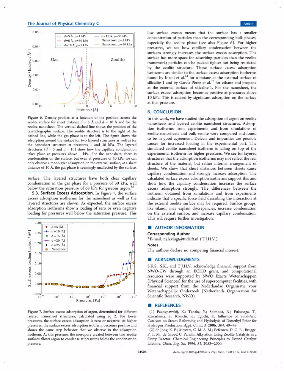
surface. The layered structures have both clear capillarycondensation in the gas phase for a pressure of 30 kPa, wellbelow the saturation pressure of 68 kPa for gaseous argon.55
5.3. Surface Excess Adsorption. In Figure 7, the surfaceexcess adsorption isotherms for the nanosheet as well as thelayered structures are shown. As expected, the surface excessadsorption isotherms show a loading of zero or even negativeloading for pressures well below the saturation pressure. This
low surface excess means that the surface has a smallerconcentration of particles than the corresponding bulk phases,especially the zeolite phase (see also Figure 6). For higherpressures, we see how capillary condensation between thesurfaces strongly increases the surface excess adsorption. Thesurface has more space for adsorbing particles than the zeoliteframework; particles can be packed tighter not being restrictedby the zeolite structure. These surface excess adsorptionisotherms are similar to the surface excess adsorption isothermsfound by Inzoli et al.44 for n-butane at the external surface ofsilicalite-1 and by Garcia-Perez et al.37 for ethane and propaneat the external surface of silicalite-1. For the nanosheet, thesurface excess adsorption becomes positive at pressures above10 kPa. This is caused by significant adsorption on the surfaceat this pressure.
6. CONCLUSIONIn this work, we have studied the adsorption of argon on zeolitenanosheets and layered zeolite nanosheet structures. Adsorp-tion isotherms from experiments and from simulations ofzeolite nanosheets and bulk zeolite were compared and foundto be in good agreement. Defects and impurities are possiblecauses for increased loading in the experimental part. Thesimulated zeolite nanosheet isotherm is falling on top of theexperimental isotherm for higher pressures. We see for layeredstructures that the adsorption isotherms may not reflect the realstructure of the material, but rather internal arrangement ofsheets. We show that short distances between sheets causecapillary condensation and strongly increase adsorption. Thecalculated surface excess adsorption isotherms support this andshow how the capillary condensation increases the surfaceexcess adsorption strongly. The differences between theisotherm obtained from simulations and from experimentsindicate that a specific force field describing the interaction atthe external zeolite surface may be required. Surface groups,like silanol, may explain discrepancies, increase condensationon the external surface, and increase capillary condensation.This will require further investigation.
■ AUTHOR INFORMATIONCorresponding Author*E-mail: [email protected] (T.J.H.V.).NotesThe authors declare no competing financial interest.
■ ACKNOWLEDGMENTSS.K.S., S.K., and T.J.H.V. acknowledge financial support fromNWO-CW through an ECHO grant, and computationalresources were supported by NWO Exacte Wetenschappen(Physical Sciences) for the use of supercomputer facilities, withfinancial support from the Nederlandse Organisatie voorWetenschappelijk Onderzoek (Netherlands Organization forScientific Research, NWO).
■ REFERENCES(1) Faungnawakij, K.; Tanaka, Y.; Shimoda, N.; Fukunaga, T.;Kawashima, S.; Kikuchi, R.; Eguchi, K. Influence of Solid-AcidCatalysts on Steam Reforming and Hydrolysis of Dimethyl Ether forHydrogen Production. Appl. Catal., A 2006, 304, 40−48.(2) de Jong, K. P.; Mesters, C. M. A. M.; Peferoen, D. G. R.; Brugge,P. T. M.; de Groot, C. Paraffin Alkylation Using Zeolite Catalysts in aSlurry Reactor: Chemical Engineering Principles to Extend CatalystLifetime. Chem. Eng. Sci. 1996, 51, 2053−2060.
Figure 6. Density profiles as a function of the position across thezeolite surface for sheet distance d = 5 Å and d = 10 Å and for thezeolite nanosheet. The vertical dashed line shows the position of thecrystallographic surface. The zeolite structure is to the right of thedashed line, while the gas phase is to the left. The figure shows theadsorption around the surface for two layered structures as well as forthe nanosheet structure at pressures 1 and 30 kPa. The layeredstructures (d = 5 and d = 10) show how the capillary condensationtakes place at pressures above 1 kPa. For the nanosheet, there iscondensation on the surface, but even at pressures of 30 kPa, we canonly observe a monolayer adsorption on the external surface; at a sheetdistance of 10 Å, the gas phase is seemingly unaffected by the surface.
Figure 7. Surface excess adsorption of argon, determined for differentlayered nanosheet structures, calculated using eq 2. For lowerpressures, the surface excess adsorption is zero or negative. At higherpressures, the surface excess adsorption isotherm becomes positive andshows the same step behavior that we observe in the adsorptionisotherm. At this pressure, the mesopore created between two zeolitesurfaces allows argon to condense at pressures below the condensationpressure.
The Journal of Physical Chemistry C Article
dx.doi.org/10.1021/jp409316a | J. Phys. Chem. C 2013, 117, 24503−2451024508

(3) Limtrakul, J.; Tantanak, D. Cationic, Structural, and Composi-tional Effects on the Surface Structure of Zeolitic AluminosilicateCatalysts. Chem. Phys. 1996, 208, 331−340.(4) Skorpa, R.; Bordiga, S.; Bleken, F.; Olsbye, U.; Arstad, B.;Tolchard, J.; Mathisen, K.; Svelle, S.; Bjørgen, M. Assessing the SurfaceSites of the Large Pore 3-Dimensional Microporous Material H-ITQ-7Using Ft-Ir Spectroscopy and Molecular Probes. MicroporousMesoporous Mater. 2011, 141, 146−156.(5) Gora-Marek, K.; Datka, J. IR Studies of OH Groups inMesoporous Aluminosilicates. Appl. Catal., A 2006, 302, 104−109.(6) Busca, G.; Ramis, G.; Lorenzelli, V. FT-IR Study of the SurfaceProperties of Polycrystalline Vanadia. J. Mol. Catal. 1989, 50, 231−240.(7) Martucci, A.; Cruciani, G.; Alberti, A.; Ritter, A.; Ciambelli, P.;Rapacciuolo, M. Location of Brønsted Sites in D-mordenites byNeutron Powder Diffraction. Microporous Mesoporous Mater. 2000,35–36, 405−412.(8) Abouelnasr, M. K. F.; Smit, B. Diffusion in Confinement: KineticSimulations of Self- and Collective Diffusion Behavior of AdsorbedGases. Phys. Chem. Chem. Phys. 2012, 14, 11600.(9) Krishna, R.; van Baten, J. M. Insights Into Diffusion of Gases inZeolites Gained From Molecular Dynamics Simulations. MicroporousMesoporous Mater. 2008, 109, 90−108.(10) Krishna, R.; Van Baten, J. M.; García-Perez, E.; Calero, S.Diffusion of CH4 and CO2 in MFI, CHA and DDR Zeolites. Chem.Phys. Lett. 2006, 429, 219−224.(11) van den Bergh, J.; Ban, S.; Vlugt, T. J. H.; Kapteijn, F. Modelingthe Loading Dependency of Diffusion in Zeolites: The Relevant SiteModel Extended to Mixtures in DDR-type Zeolite. J. Phys. Chem. C2009, 113, 21856−21865.(12) Smit, B.; Maesen, T. L. M. Molecular Simulations of Zeolites:Adsorption, Diffusion, and Shape Selectivity. Chem. Rev. 2008, 108,4125−4184.(13) Choi, M.; Na, K.; Kim, J.; Sakamoto, Y.; Terasaki, O.; Ryoo, R.Stable Single-Unit-Cell Nanosheets of Zeolite MFI As Active andLong-Lived Catalysts. Nature 2009, 461, 246−249.(14) Caro, J.; Noack, M. Zeolite Membranes - Recent Developmentsand Progress. Microporous Mesoporous Mater. 2008, 115, 215−233.(15) Cejka, J., van Bekkum, H., Corma, A., Schoth, F., Eds.;Introduction to Zeolite Science and Practice; Elsevier: Amsterdam, 2007.(16) Van de Graaf, J.; Kapteijn, F.; Moulijn, J. Modeling Permeationof Binary Mixtures Through Zeolite Membranes. AIChE J. 1999, 45,497−511.(17) Coronas, J.; Santamaria, J. State-of-the-Art in Zeolite MembraneReactors. Top. Catal. 2004, 29, 29−44.(18) Schenk, M.; Calero, S.; Maesen, T. L. M.; van Benthem, L. L.;Verbeek, M. G.; Smit, B. Understanding Zeolite Catalysis: InverseShape Selectivity Revised. Angew. Chem., Int. Ed. 2002, 41, 2500−2502.(19) Sanborn, M. J.; Snurr, R. Q. Diffusion of Binary Mixtures of CF4and n-Alkanes in Faujasite. Sep. Purif. Technol. 2000, 20, 1−13.(20) Karger, J.; Ruthven, D. M.; Theodorou, D. N. Diffusion inNanoporous Materials; Wiley: New York, 2012.(21) Maesen, T. L. M.; Krishna, R.; van Baten, J. M.; Smit, B.; Calero,S.; Sanchez, J. M. C. Shape-Selective n-Alkane Hydroconversion atExterior Zeolite Surfaces. J. Catal. 2008, 256, 95−107.(22) van Erp, T.; Caremans, T. P.; Dubbeldam, D.; Martin-Calvo, A.;Calero, S.; Martens, J. A. Enantioselective Adsorption in AchiralZeolites. Angew. Chem., Int. Ed. 2010, 49, 3010−3013.(23) Weitkamp, J. Zeolites and Catalysis. Solid State Ionics 2000, 131,175−188.(24) Vejka, J.; Centi, G.; Perez-Pariente, J.; Roth, W. J. Zeolite-BasedMaterials for Novel Catalytic Applications: Opportunities, Perspectivesand Open Problems. Catal. Today 2012, 179, 2−15.(25) Caro, J.; Noack, M.; Kolsch, P. Zeolite Membranes: From theLaboratory Scale to Technical Applications. Adsorption 2005, 11, 215−227.(26) Perez-Ramirez, J.; Christensen, C. H.; Egeblad, K.; Christensen,C. H.; Groen, J. C. Hierarchical Zeolites: Enhanced Utilisation of
Microporous Crystals in Catalysis by Advances in Materials Design.Chem. Soc. Rev. 2008, 37, 2530−2542.(27) van Donk, S.; Janssen, A. H.; Bitter, J. H.; de Jong, K.Generation, Characterization, and Impact of Mesopores in ZeoliteCatalysts. Catal. Rev.Sci. Eng. 2003, 45, 297−319.(28) Ban, S.; van Laak, A. N. C.; Landers, J.; Neimark, A.; de Jongh,P. E.; de Jong, K. P.; Vlugt, T. J. H. Insight Into the Effect ofDealumination on Mordenite Using Experimentally ValidatedSimulations. J. Phys. Chem. C 2010, 114, 2056−2065.(29) Tao, Y.; Kanoh, H.; Kaneko, K. ZSM-5 Monolith of UniformMesoporous Channels. J. Am. Chem. Soc. 2003, 125, 6044−6045.(30) Tao, Y.; Kanoh, H.; Abrams, L.; Kaneko, K. Mesopore-ModifiedZeolites: Preparation, Characterization, and Applications. Chem. Rev.2006, 106, 896−910.(31) Egeblad, K.; Christensen, C. H.; Kustova, M.; Christensen, C. H.Templating Mesoporous Zeolites. Chem. Mater. 2008, 20, 946−960.(32) Koekkoek, A. J. J.; Kim, W.; Degirmenci, V.; Xin, H.; Ryoo, R.;Hensen, E. J. M. Catalytic Performance of Sheet-Like Fe/ZSM-5Zeolites for the Selective Oxidation of Benzene With Nitrous Oxide. J.Catal. 2013, 299, 81−89.(33) Na, K.; Choi, M.; Park, W.; Sakamoto, Y.; Terasaki, O.; Ryoo, R.Pillared MFI Zeolite Nanosheets of a Single-Unit-Cell Thickness. J.Am. Chem. Soc. 2010, 132, 4169−4177.(34) Na, K.; Choi, M.; Ryoo, R. Recent Advances in the Synthesis ofHierarchically Nanoporous Zeolites. Microporous Mesoporous Mater.2013, 166, 3−19.(35) Lee, I.; Jeong, H. K. Synthesis and Gas Permeation Properties ofHighly b-oriented MFI Silicalite-1 Thin Membranes with ControlledMicrostructure. Microporous Mesoporous Mater. 2011, 141, 175−183.(36) Inzoli, I.; Kjelstrup, S.; Bedeaux, D.; Simon, J.-M. TransportCoefficients of n-Butane Into and Through the Surface of Silicalite-1From Non-Equilibrium Molecular Dynamics Study. MicroporousMesoporous Mater. 2009, 125, 112−125.(37) García-Perez, E.; Schnell, S. K.; Castillo, J. M.; Calero, S.;Kjelstrup, S.; Dubbeldam, D.; Vlugt, T. J. H. External SurfaceAdsorption on Silicalite-1 Zeolite Studied by Molecular Simulation. J.Phys. Chem. C 2011, 115, 15355−15360.(38) Kjelstrup, S.; Bedeaux, D. Non-Equilibrium Thermodynamics ofHeterogeneous Systems; World Scientific: Singapore, 2008.(39) Gibbs, J. W. Scientific Papers: Thermodynamics; DoverPublications, Inc: Mineola, NY, 1961.(40) Lew, C. M.; Cai, R.; Yan, Y. Zeolite Thin Films: FromComputer Chips to Space Stations. Acc. Chem. Res. 2010, 43, 210−219.(41) Karger, J. Random Walk Through Two-Channel Networks: ASimple Means to Correlate the Coefficients of Anisotropic Diffusion inZSM-5 Type Zeolites. J. Phys. Chem. 1991, 95, 5558−5560.(42) Krishna, R. Describing the Diffusion of Guest Molecules InsidePorous Structures. J. Phys. Chem. C 2009, 113, 19756−19781.(43) van den Bergh, J.; Ban, S.; Vlugt, T. J. H.; Kapteijn, F. Modelingthe Loading Dependency of Diffusion in Zeolites: The Relevant SiteModel. J. Phys. Chem. C 2009, 113, 17840−17850.(44) Inzoli, I.; Simon, J.-M.; Kjelstrup, S. Surface AdsorptionIsotherms and Surface Excess Densities of n-Butane in Silicalite-1.Langmuir 2009, 25, 1518−1525.(45) Schnell, S. K.; Vlugt, T. J. H.; Kjelstrup, S. In Handbook onMembrane Reactors; Basile, A., Ed.; Woodhead: Cambridge, UK2013;Vol. 1, Chapter Non-Equilibrium Thermodynamics for the Descrip-tion of Transport of Heat and Mass across a Zeolite Membrane, pp627−646.(46) Myers, A. L.; Prausnitz, J. M. Thermodynamics of Mixed GasAdsorption. AIChE J. 1965, 11, 121−130.(47) Zimmermann, N. E. R.; Smit, B.; Keil, F. J. On the Effects of theExternal Surface on Equilibrium Transport in Zeolite Crystals. J. Phys.Chem. C 2010, 114, 300−310.(48) Zimmermann, N. E. R.; Balaji, S. P.; Keil, F. J. Surface Barriers ofHydrocarbon Transport Triggered by Ideal Zeolite Structures. J. Phys.Chem. C 2012, 116, 3677−3683.
The Journal of Physical Chemistry C Article
dx.doi.org/10.1021/jp409316a | J. Phys. Chem. C 2013, 117, 24503−2451024509

(49) Zimmermann, N. E. R.; Smit, B.; Keil, F. J. Predicting LocalTransport Coefficients at Solid–Gas Interfaces. J. Phys. Chem. C 2012,116, 18878−18883.(50) Arya, G.; Maginn, E. J.; Chang, H. C. Effect of the SurfaceEnergy Barrier on Sorbate Diffusion in AlPO4-5. J. Phys. Chem. B 2001,105, 2725−2735.(51) Savin, T.; Glavatskiy, K. S.; Kjelstrup, S.; Ottinger, H. C.;Bedeaux, D. Local Equilibrium of the Gibbs Interface in Two-PhaseSystems. EPL (Europhys. Lett.) 2012, 97, 40002.(52) Zimmermann, N. E. R.; Zabet, T. J.; Keil, F. J. Transport IntoNanosheets: Diffusion Equations Put to Test. J. Phys. Chem. C 2013,117, 7384−7390.(53) Gumma, S.; Talu, O. Net Adsorption: A ThermodynamicFramework for Supercritical Gas Adsorption and Storage in PorousSolids. Langmuir 2010, 26, 17013−17023.(54) Duren, T.; Sarkisov, L.; Yaghi, O.; Snurr, R. Design of NewMaterials for Methane Storage. Langmuir 2004, 20, 2683−2689.(55) Stewart, R. B.; Jacobsen, R. T. Thermodynamic Properties ofArgon from the Triple Point to 1200 K with Pressures to 1000 MPa. J.Phys. Chem. Ref. Data 1989, 18, 639−798.(56) Wu, L.; Degirmenci, V.; Magusin, P. C. M. M.; Lousberg, N. J.G. M.; Hensen, E. J. M. Mesoporous SSZ-13 Zeolite Prepared by aDual-Template Method with Improved Performance in the Methanol-to-Olefins Reaction. J. Catal. 2013, 298, 27−40.(57) García-Perez, E.; Parra, J. B.; Ania, C. O.; Dubbeldam, D.; Vlugt,T. J. H.; Castillo, J. M.; Merkling, P. J.; Calero, S. Unraveling theArgon Adsorption Processes in MFI-Type Zeolite. J. Phys. Chem. C2008, 112, 9976−9979.(58) Dubbeldam, D.; Calero, S.; Vlugt, T. J. H.; Krishna, R.; Maesen,T. L. M.; Smit, B. United Atom Force Field for Alkanes inNanoporous Materials. J. Phys. Chem. B 2004, 108, 12301−12313.(59) Vlugt, T. J. H.; Schenk, M. Influence of Framework Flexibilityon the Adsorption Properties of Hydrocarbons in the Zeolite Silicalite.J. Phys. Chem. B 2002, 106, 12757−12763.(60) Frenkel, D.; Smit, B. Understanding Molecular Simulations;Academic Press: New York, 2002.(61) Vlugt, T. J. H.; Krishna, R.; Smit, B. Molecular Simulations ofAdsorption Isotherms for Linear and Branched Alkanes and theirMixtures in Silicalite. J. Phys. Chem. B 1999, 103, 1102−1118.(62) van Koningsveld, H.; van Bekkum, H.; Jansen, J. C. On theLocation and Disorder of the Tetrapropylammonium (TPA) Ion inZeolite ZSM-5 with Improved Framework Accuracy. Acta Crystallogr.1987, B43, 127−132.(63) Saito, A.; Foley, H. C. High-Resolution Nitrogen and ArgonAdsorption on ZSM-5 Zeolites: Effects of Cation Exchange and Si/AlRatio. Microporous Mater. 1995, 3, 543−556.
The Journal of Physical Chemistry C Article
dx.doi.org/10.1021/jp409316a | J. Phys. Chem. C 2013, 117, 24503−2451024510


![[argon]Cortical evoked response and inert gas narcosis 4](https://img.pdfslide.net/doc/110x75/633339dea6138719eb0a82a9/argoncortical-evoked-response-and-inert-gas-narcosis-4-.jpg)


