Embed Size (px)
Citation preview

Peer-reviewed by international ex-perts and accepted for publication by SEI Editorial Board
Paper received July 12 2013Paper accepted November 20 2013
Structural Engineering International 22014 Scientific Paper 211
Advanced Numerical Simulations for Prediction of Bearing Capacity and Failure of Complex RC Structures Nguyen Viet Tue Prof Dr-Ing Jiabin Li Dr-Ing Katrin Turner Dipl-Ing Institute for Structural Concrete
Graz University of Technology Graz Austria Contact litugrazat
DOI 102749101686614X13830790993447
Abstract
Advanced numerical simulations using computers provide a robust tool for assessing the structural integrity of existing reinforced concrete (RC) structures This paper presents an application of modern computer simulation in the con-text of nonlinear finite element method (nonlinear FEM) to predict the load-bearing capacity and failure behavior of different types of RC columnndashslab connections strengthened by steel profiles in an existing complex industrial RC structure in Austria Two typical connections are subjected to primary numeri-cal investigation using nonlinear three-dimensional FEM with a newly deve-loped constitutive model for concrete Subsequent verification tests indicate that the primary numerical analyses are quite consistent with the test observations Post-numerical analyses of the verification tests are also carried out taking into account the measured material properties The simulation results are in very good agreement with the test data Based on the numerical results the load-flow mechanisms and the load-sharing portions in the connections are identified The ultimate loads of the rest of the connections are then determined using numeri-cal analysis hence no further tests are necessary On the basis of the numerical simulations rational decisions on the structure are made
Keywords numerical simulation finite element method reinforced concrete load-bearing capacity failure
of modern advanced numerical analysis in predicting the failure behavior and ultimate bearing capacity of different types of reinforced concrete (RC) col-umnndashslab connections strengthened by steel profiles in an existing structure in Graz Austria The safety of this struc-ture has been an unsolved problem in Austria for several years
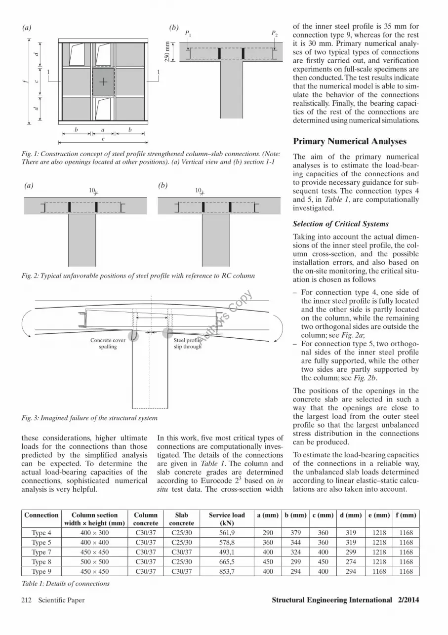
In one of the buildings in the Public Hospital (LKH West) in Graz Austria steel profiles were used to strengthen the RC columnndashslab connections for improving the load transmissions among different structural compo-nents Figure 1 illustrates the construc-tion concept The inner steel profile has a rectangular cross-section (width 30 or 35 mm height 150 mm) while the outer steel profile has a U-shaped cross-section which is U120556mm according to DIN 1026-12 No shear connectors were provided between the steel profiles and the columnndashslab concretes The slab concrete which was filled into the steel profiles outside the column-slab connection region was unreinforced The basic design consid-eration is that the steel profile gets the (unbalanced) slab loads and then trans-fers them to the RC column
An inefficient design however is that the inner steel profile was placed more or less directly onto the RC column cover Due to constructioninstallation error and tolerance many steel pro-files are located at various unfavorable positions Some typical cases are shown in Fig 2 There are several types of con-nections in the structure They differ in the structural dimensions the column and slab concrete strength grades and the service-load levels A simplified analysis using the assumption that the slab loads are completely transferred to the column concrete cover indicated that under the service-slab load a high splitting stress develops in the column cover concrete thus formation of lon-gitudinal cracks in the cover concrete is inevitable Based on this analysis an opinion was formed that under the ultimate load a spalling of the column cover would occur and the steel pro-files would then fall on to the ground as illustrated in Fig 3 Accordingly a rehabilitation of the structure was con-sidered necessary
The structure has been in service for about 10 years However on-site moni-toring indicated no visible longitudinal cracks in the column cover concrete This is inconsistent with the result of the simplified analysis In fact due to the absence of shear studs between the concretes and the surrounding steel profiles a relative slip between these two bodies under the slab load is permitted Because of the slip and the bending deformation of the inner steel profile the interfacial friction between the steel and concrete surfaces is acti-vated Thus a part of the slab load is transferred to the column core concrete between the steel profiles Moreover the concrete slab under the steel profiles is also able to sustain some amount of the slab load before it fails This implies that the load trans-mitted to the column cover concrete can be significantly smaller than the total slab load In addition the bend-ing of the concrete slab under the steel profile can provide some lateral con-finements to the column Based on
Introduction
Recent surge of advances in compu-tational capabilities both in hardware and in software have greatly expanded the size and the complexity of engineer-ing problems that can be analyzed using computational methods This has made numerical simulations using computers a prominent tool for designing and ver-ifying structures1 Numerical modeling in the context of nonlinear finite element method (nonlinear FEM) is of particu-lar interest in the assessment of existing structures and finds significant use in determining the actual structural integ-rity (eg in the case of new or increased loads) and in evaluating the remaining service life of the structures The com-putational expense is more than offset by avoiding unnecessary demolitions or rehabilitations and by extending the life of the structure through rational strate-gies This paper presents an application
Authors
Cop
y
212 Scientific Paper Structural Engineering International 22014
these considerations higher ultimate loads for the connections than those predicted by the simplified analysis can be expected To determine the actual load-bearing capacities of the connections sophisticated numerical analysis is very helpful
In this work five most critical types of connections are computationally inves-tigated The details of the connections are given in Table 1 The column and slab concrete grades are determined according to Eurocode 23 based on in situ test data The cross-section width
of the inner steel profile is 35 mm for connection type 9 whereas for the rest it is 30 mm Primary numerical analy-ses of two typical types of connections are firstly carried out and verification experiments on full-scale specimens are then conducted The test results indicate that the numerical model is able to sim-ulate the behavior of the connections realistically Finally the bearing capaci-ties of the rest of the connections are determined using numerical simulations
Primary Numerical Analyses
The aim of the primary numerical analyses is to estimate the load-bear-ing capacities of the connections and to provide necessary guidance for sub-sequent tests The connection types 4 and 5 in Table 1 are computationally investigated
Selection of Critical Systems
Taking into account the actual dimen-sions of the inner steel profile the col-umn cross-section and the possible installation errors and also based on the on-site monitoring the critical situ-ation is chosen as follows
ndash For connection type 4 one side of the inner steel profi le is fully located and the other side is partly located on the column while the remaining two orthogonal sides are outside the column see Fig 2a
ndash For connection type 5 two orthogo-nal sides of the inner steel profi le are fully supported while the other two sides are partly supported by the column see Fig 2b
The positions of the openings in the concrete slab are selected in such a way that the openings are close to the largest load from the outer steel profile so that the largest unbalanced stress distribution in the connections can be produced
To estimate the load-bearing capacities of the connections in a reliable way the unbalanced slab loads determined according to linear elasticndashstatic calcu-lations are also taken into account
250
mm
P1
(a) (b)P2
e
b a b
11
dc
d
f
Fig 1 Construction concept of steel profile strengthened columnndashslab connections (Note There are also openings located at other positions) (a) Vertical view and (b) section 1-1
10(a) (b)
10
Fig 2 Typical unfavorable positions of steel profile with reference to RC column
Concrete coverspalling
Steel profileslip through
Fig 3 Imagined failure of the structural system
Connection Column section width times height (mm)
Column concrete
Slab concrete
Service load (kN)
a (mm) b (mm) c (mm) d (mm) e (mm) f (mm)
Type 4 400 times 300 C3037 C2530 5619 290 379 360 319 1218 1168Type 5 400 times 400 C3037 C2530 5788 360 344 360 319 1218 1168Type 7 450 times 450 C3037 C3037 4931 400 324 400 299 1218 1168Type 8 500 times 500 C3037 C2530 6655 450 299 450 274 1218 1168Type 9 450 times 450 C3037 C3037 8537 400 294 400 294 1168 1168
Table 1 Details of connections
Authors
Cop
y
Structural Engineering International 22014 Scientific Paper 213
Numerical Modeling
The load-transfer mechanism in the connections is very complex due to the position of the steel profile and the imbalance of the slab loads Hence in the simulation of the connections the modeling of the nonlinear material behavior of the column and slab con-cretes and the interface between the concrete and steel profile are the two decisive issues
To represent realistically the nonlin-ear material behavior of concrete the microplane-constitutive model M4L for concrete which has been recently developed as in Ref [4] is used In this model the concrete material behav-ior is characterized not by the macro-scopic (continuum) tensor and their invariants but by the stress and strain components on the planes of vari-ous orientations (microplanes) in the material5 The macroscopic material behavior is then derived by homog-enization of the contributions from the microplanes of all possible orien-tations The concept of stressndashstrain boundaries (ie strain-dependent-yielding limits) is used in the model to describe the inelastic behavior of the concrete Within the boundar-ies the model response is incremen-tally elastic If the stress magnitude exceeds the boundary value then there would be a vertical drop in the boundary value at the current strain ensuring the microplane energy dissi-pation Thus this model enables cap-turing the concrete material behavior subjected to various loadings such as tension compression and shear as well as their various combinations An extensive validation of the model against numerous material test data can be found in Ref [6] In the pri-mary numerical simulations of the connections the characteristic values for concrete according to Eurocode 2 were used The microplane model M4L is an advanced constitutive model for concrete but the computa-tional cost of the simulations with this model is higher than those with classic macro-mechanical models However with todayrsquos computational power large-scale FEM calculations with the model M4L are no longer computa-tionally forbidding
The von Mises yield criterion with iso-tropic strain hardening and an associ-ated flow rule was used to simulate the constitutive behavior of the steel material The uniaxial behavior of the steel is similar to that of the bars and described by an elasticndashperfect-plastic
model represented by the modulus of elasticity Es and the yielding strength fy of the material Under multiaxial stress state the elastic limit is defined by
fy=minus+minus+minus= 1 22 2 1 332 2 2)()()(
2
13J σσσσσσ
(1)
where J2 is the second invariant of the stress deviator tensor s 1 s 2 and s 3 are the first second and third princi-pal stresses respectively If the stresses in the steel profile reach the yield level the material becomes perfectly plastic In the numerical analysis fy = 355 MPa and Es = 21 times 105 MPa according to the design document and Poissonrsquos ratio υ is assumed to be 03
The discrete contact spring model described in Ref [7] is used to simu-late the interface behavior between the columnndashslab concretes and the steel profiles The composite nodes of the concrete and steel profiles are connected by nonlinear spring ele-ments These elements exhibit linear elastic behavior in the normal direc-tion while in the tangential direction the MohrndashCoulomb friction model is employed The coefficient of friction m is used to simulate the friction and sliding between the concrete and steel profile surfaces The normal stiffness of the spring elements is set to zero when they are subjected to tensile loadings to represent the separation of the concrete and the steel profiles and a ldquohard contactrdquo behavior is assumed The magnitudes of the normal and tangential stiffness of the springs are numerically determined in such a way that their relative deformations are sufficiently small compared to their nodal displacements Because the fric-tion behavior between the concrete and the steel profile surfaces plays an important role in this numerical simu-lation an intensive literature survey is carried out to select the reason-able value of m Based on the numeri-cal analyses in Refs [8] and [9] m is assumed to be 06 in this work The column reinforcements are not mod-eled as the columns are only lightly reinforced and the reinforcements do not play any significant role
The numerical analyses were carried out using a commercial FEM program in which the microplane model M4L for concrete was implemented To sim-plify the modeling the outer U-shaped profiles were replaced by rectangular profiles having identical bending stiff-ness and height This simplification had no significant effect on the numerical
results Both the concretes and steel profiles were discretized into 8-node solid elements with 2 times 2 times 2 inte-gration points As mentioned above owing to the absence of shear studs the bond slip at the concrete and steel profile interface plays a crucial role To reduce the computational cost how-ever only the interfaces between the column core concrete and surround-ing inner steel profile were modeled with nonlinear spring elements For all other contacting surfaces a rigid connection was assumed Such a sim-plification does not yield a significant overestimation of the load-carrying capacity when the actual tensile stressndashcrack opening relationship of the con-crete is taken into consideration This is because after the cracking of the concrete in the vicinity of the steel pro-files only a very small amount of load can be transferred between the con-crete and the steel profile in the region outside of the column All deformation components of the nodes on the col-umn bottom surfaces were fixed in the three orthogonal directions namely u = v = w = 0 Figure 4 shows the finite element meshes of the two connec-tions The total slab load was simulated by four concentrated loads applied on the outer steel profile
The modified NewtonndashRaphson method was employed to solve the nonlinear equations No updating of the stiffness matrix was required prior to a new loading step The analy-sis employed the total Lagrangian approach with small strains
Numerical Results
The numerical simulations yielded the following interesting findings
ndash Under the service slab load the tensile splitting stress in the col-umn cover concrete is signifi cantly smaller than the concrete tensile strength and no cracking in the con-crete occurs This is consistent with the on-site observations
ndash The load-bearing capacities of the connections are much higher than that predicted by the simplifi ed analysis and are about 26 times of the slab service loads This indicates that the connections are suffi ciently safe according to Eurocode 2
ndash The failure of the connections is due to the yielding of the steel pro-fi le rather than the spalling of the column cover concrete A falling of the steel profi le to the ground at the maximum load is not detected
Authors
Cop
y
214 Scientific Paper Structural Engineering International 22014
More results and discussions of the pri-mary numerical analyses can be found in Ref [10]
Verification Tests and Post Analyses
Test Details and Results
To validate the primary numerical anal-yses full-scale tests are carried out at the Laboratory of Structural Engineering Graz University of Technology The specimens were designed to be in the same critical state as mentioned in the above section however the positions of the openings in the concrete slab were changed according to the actual structure A detailed description of the
tests including the specimen prepara-tion the concrete mixtures and the load application as well as the measurement devices and so on is presented in Ref [11] Figure 5 shows the test setup and the specimens The measured mate-rial properties for the column and the slab concretes including the modulus of elasticity (Ec) the cylinder compressive strength (fc) and the tensile splitting strength (fct sp) are presented in Table 2
The objectives of the tests were to observe the structural behavior of the specimens under monotonic service slab load and to determine the magni-tude of the ultimate load The load-his-tory diagram for the specimens is shown in Fig 6a Upon the maximum load the
loading of the specimens was stopped The observed loadndashdeformation curve of the specimen for connection type 4 from the test is shown in Fig 6b It can be seen that the ultimate load is signifi-cantly higher than the slab service load The failure of the specimen is due to the large plastic deformation of the steel profiles after yielding No cracking was detected in the column cover concrete during the test until the maximum load was reached In addition no spalling of the concrete cover and no falling of the steel profile to the ground occurred
Figure 6b also presents the loadndashdefor-mation curve of the specimen for con-nection type 5 derived from the test This specimen had a slightly higher ulti-mate load compared to the specimen for connection type 4 however its gen-eral failure process and failure mode were quite similar to those of connec-tion type 4 Overall the test results are consistent with the predictions of the primary numerical analyses
Post-Analyses and Results
To determine the load-bearing capac-ity of the rest of connections in a reli-able way the accuracy of the numerical model was further evaluated through post-analyzing the test specimens with the measured concrete material properties and the exact specimen dimensions The position and the size of the openings in the concrete slab as well as the load applications were precisely modeled as in the test The basic modeling concepts were simi-lar to those in the primary numerical analysis However all contacting sur-faces between the concretes and steel profiles were modeled with discrete nonlinear spring elements to inves-tigate the load-flow mechanism and the load-sharing portions between dif-ferent components Figure 7 presents the finite element model for the speci-men for connection type 5 and the deformed mesh at the maximum load
Figure 8 presents a comparison of the predicted loadndashdeformation curve with the test data for connection type 5 It can be seen that the ultimate load from the numerical analysis is very close to that observed in the test The predicted ultimate load is 1588 kN which is only 38 higher than the test value After the yielding of the steel profiles numerical convergence is very difficult to achieve Therefore the post-peak branch of the loadndash deformation curve was not simulated To illustrate the load flow in the region
(a) (b)
zz
Fig 4 Finite element mesh for connections in primary numerical analyses (a) Connection type 4 and (b) connection type 5
(a) (b)
Fig 5 Test specimen and setup (a) Connection type 4 and (b) connection type 5
Connection Concrete Ec (MPa) fc (MPa) fct sp (MPa)
Type 4Column 22 099 404 275
Slab 21 197 285 283
Type 5Column 27 968 409 284
Slab 26 734 290 262
Table 2 Measured material properties
Authors
Cop
y
Structural Engineering International 22014 Scientific Paper 215
ndash Load transferred from the steel profi le to the slab concrete under the steel profi le (and further to the RC column) denoted as slab portion
The portions of the above three load-sharing components as a function of the total slab load are illustrated in Fig 10 It can be seen that when the slab load is small the load from the outer steel profile is mainly transmit-ted via the concrete slab under the steel profiles As the slab load increases the slab portion begins to decrease and accordingly the steel profile and the friction portions increase Because of the finite magnitude of the coef-ficient of friction (which is 06 in the numerical analysis) and the decrease in the contacting surfaces owing to the deformation of the steel profiles the friction portion firstly increases with the increase of the slab load up to a certain load level and then tends to decrease It is worth noting that the friction and slab portions still account for about 50 of the total slab load at the maximum load This explains the significant higher load-bearing capac-ity of the specimen in comparison to that predicted from the simplified analysis
Based on the deformation of the inner steel profile (Fig 9) three load-flow mechanisms can be identified
ndash Load directly transferred from the steel profi le to the column con-crete cover denoted as steel profi le portion
ndash Load transferred to the column core and the slab through the friction between the concrete and the steel profi les denoted as friction portion
of the slabndashcolumn connection the deformation of the inner steel pro-file is shown in Fig 9 The deformed shape of the steel profile indicates that the stress in the RC column section is significantly uneven and stress concen-trations occur in the corner of the col-umn cross-section This indicates the necessity of using advanced numerical analysis to investigate the real struc-tural behavior and the stress distribu-tion in the connections
300
600
900
1200
1500
1800(a) (b)
0 10 20 30 40 50 60 70 80 90 100
Loa
d (k
N)
Time (min)
Connection type 5Connection type 4
0
300
600
900
1200
1500
1800
0 25 50 75 100 125 150
Slab
load
(kN
)
Deformation (mm)
Connection type 5Connection type 4
Fig 6 Load-history diagram (a) and loadndashdeformation curve (b) in the test
(a) (b)
z
z
Fig 7 Numerical model for connections in post analyses (a) Finite element mesh and (b) deformed mesh at the maximum load
0 25 50 75 100 125
Deformation (mm)
300
600
900
1200
1500
1800
Loa
d (k
N)
TestSimulation
Fig 8 Comparison of the loadndashdeformation curve from numerical simulations and from test
Fig 9 Deformed shape of the inner steel profile at the maximum load
Authors
Cop
y
216 Scientific Paper Structural Engineering International 22014
Fig 10 Load-sharing portions versus total slab load
0
20
40
60
80
100
0 200 400 600 800 1000 1200 1400 1600
Per
cent
age
()
Total slab load (kN)
Steel profile portionFriction portionSlab portion
The numerical results of the post-anal-ysis of specimen for connection type 4 are also in good agreement with the test observations The details of the simulation results can be found in Ref [12] Therefore it can be concluded that the numerical model in this paper is able to adequately describe the behavior of the connections
Determination of Bearing Capacity of the Rest of the Connections through Modeling
The validated numerical model was subsequently used to determine the load-bearing capacities of the rest of the connections shown in Table 1 that is types 7 8 and 9 and no further tests were carried out The same modeling concepts as those in the post-analyses of the test specimens were employed and the characteristics material prop-erties of the concrete according to Eurocode 2 were used The simulation results indicate that for all the rest of the connections the predicted ultimate loads exceed 26 times the service load The details of the numerical modeling and results can be found in Ref [12] This implies that these connections have sufficient load-carrying capaci-ties Therefore no repairs or rehabili-tations of the connections is necessary
The numerical results convinced all parties involved in this project bring-ing to an end the argument of more than 10 years in Austria The avoid-ance of unnecessary repairsretrofits not only leads to significant cost-sav-ing (about euro1 million) but also reduces the environmental impact related with the retrofits
Conclusions and Remarks
This paper presents a successful appli-cation of advanced numerical analy-sis in the context of nonlinear FEM to predict the load-bearing capacities of various steel profile strengthened RC columnndashslab connections at LKH West in Graz Austria The numeri-cal analysis was validated by subse-quent tests Through post-analyses of the test specimens the load-flow mechanisms and the load-sharing portions in the connections were identified The load-bearing capaci-ties of the rest of the connections were then determined using numeri-cal simulations and no further tests were necessary Based on the numeri-cal simulations rational decisions to the connections were made This case study illustrates the great potential of advanced numerical techniques for realistic simulation of the behavior of complex RC structures especially in
the assessment of the safety of exist-ing structures
References
[1] fib Ta s k Group 44 Practitionersrsquo guide to finite element modeling of reinforced concrete structures Bulletin 45 International Federation for Structural Concrete (fib) 2008
[2] DIN 1026-1 Warm gewalzter U-Profilstahl March 2000
[3] Europea n Co mmittee for Standardization (CEN) EN 1992-1-1 Eurocode 2 ndash Design of Concrete Structures Part 1-1 General Rules and Rules for Buildings CEN Brussels 2004
[4] Tue NV Li J Ca ner FC Microplane constitu-tive model M4L for concrete I Theory Comput Struct 2013 128 219ndash229
[5] Bažant ZP Caner FC Carol I Akers SA Adley MD Microplane mode M4 for con-crete Part I formulation with work-conjugate deviatoric ASCEmdashJ Eng Mech 2000 126(9) 944ndash953
[6] Li J Tue NV Cane r FC Microplane constitu-tive model M4L for concrete II calibration and validation Comput Struct 2013 128 146ndash159
[7] Goto Y Mizuno K Kumar GP Nonlinear finite element analysis for cyclic behavior of thin-walled stiffened rectangular steel columns with in-filled concrete ASCEmdashJ Struct Eng 2012 138(5) 571ndash584
[8] Johansson M Aringkess on M Finite element study of concrete-filled steel tubes using a new confinement-sensitive concrete compression model Nodric Concr Res 2002 27(2) 43ndash62
[9] Han L-H Yao G-H Tao Z Performance of concrete-filled thin-walled steel tubes under pure torsion Thin Walled Struct 2007 45(1) 24ndash36
[10] Tue NV Li J FE B erechung zur Ermittlung der Traglast von StuumltzenDeckenknoten Bauwerk LKH Graz West Forschungsbericht Institut fuumlr Betonbau TU Graz 2011
[11] Tue NV Turner K V ersuchsbericht zum Durchschlupfwiderstand von ausgewaumlhlten stahl-pilzverstaumlrkten Deckenknoten des LKH Graz West Forschungsbericht Institut fuumlr Betonbau TU Graz 2012
[12] Tue NV Li J FE Berech nung zur Ermittlung der Traglast von Deckenknoten mit Pilztyp 7 8 und 9 Bauwerk LKH Graz West Forschungsbericht Institut fuumlr Betonbau TU Graz 2012
Authors
Cop
y