Embed Size (px)
Citation preview
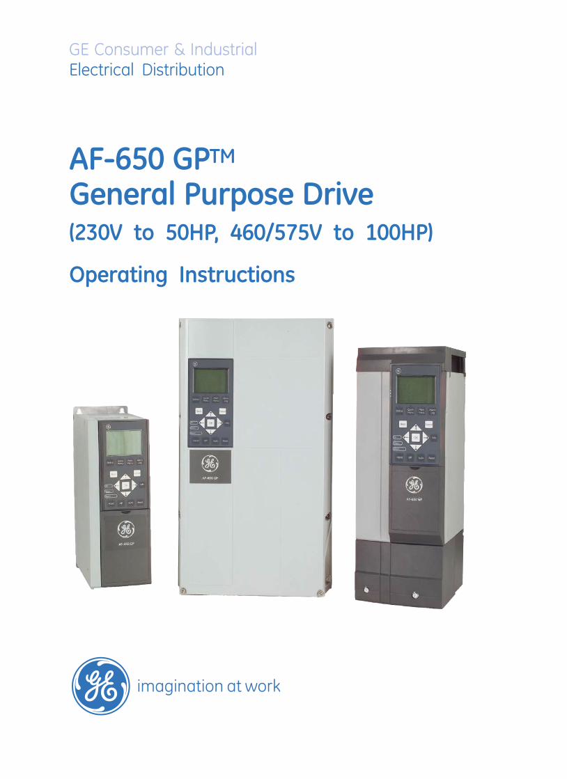
GE Consumer & IndustrialElectrical Distribution
AF-650 GPTM
General Purpose Drive(230V to 50HP, 460/575V to 100HP)
Operating Instructions
The instructions do not purport to cover all details or variations in equipment nor to provide for every possiblecontingency to be met in connection with installation, operation or maintenance. Should further information bedesired or should particular problems arise which are not covered sufficiently for the purchaser’s purposes, thematter should be referred to the GE company.
AF-650 GP is a trademark of the General Electric Company.
GE Consumer & Industrial41 Woodford AvenuePlainville, CT 06062
www.geelectrical.com/drives
130R0356 MG34F102 *MG34F102*DET-607

Contents
1 How to Read these Operating Instructions 3
Approvals 3
Symbols 4
Abbreviations 4
2 Safety Instructions and General Warning 5
High Voltage 5
Avoid Unintended Start 7
Safe Stop of AF-650 GP 7
Safe Stop Installation 8
IT Mains 8
3 How to Install 9
Mechanical Installation 14
Electrical Installation 16
Connection to Mains and Earthing 17
Motor Connection 19
Fuses 22
Electrical Installation, Control Terminals 26
Connection Examples 27
Electrical Installation, Control Cables 28
Switches S201, S202, and S801 31
Additional Connections 34
Mechanical Brake Control 34
Motor Thermal Protection 34
How to Connect a PC to the frequency converter 35
The AF-650 GP PC Software 35
4 How to Program 37
The Graphical Keypad 37
How to Program on the Graphical Keypad 37
Quick Setup Parameter List 39
Parameter Lists 46
K-## Keypad Set-up 47
F-## Fundamental Parameters 48
E-## Digital In/Outs 49
C-## Frequency Control Functions 51
P-## Motor Data 52
H-## High Perf Parameters 53
AN-## Analog In / Out 55
SP-## Special Functions 56
AF-650 GP Operating Instructions
1

O-## Options/Comms 57
DN-## DevicNet 58
PB-## Profibus 59
ID-## Drive Information 60
DR-## Data Readouts 62
LC-## Logic Controller 64
B-## Braking Functions 65
PI-## PID Controls 66
EC-## Feedback Option 67
RS-## Resolver Interface 68
5 General Specifications 69
Electrical Data - 200-240 V 69
Electrical Data - 380-500 V 71
Electrical Data - 525-600 V 74
6 Troubleshooting 83
Warnings/Alarm Messages 83
Index 90
AF-650 GP Operating Instructions
2
1 How to Read these Operating Instructions
1.1.1 How to Read these Operating Instructions
AF-650 GP is designed to provide high shaft performance on electrical motors. Please read this manual carefully for proper use. Incorrect handling of the frequency
converter may cause improper operation of the frequency converter or related equipment, shorten lifetime or cause other troubles.
These Operating Instructions will help you get started, install, program, and troubleshoot your AF-650 GP.
. AF-650 GP is a high performance frequency converter for asynchronous as well as permanent motors and handles various kinds of motor control principles such
as volts/hertz, advanced vector control, sensorless vector, and full flux vector control.
Chapter 1, How to Read these Operating Instructions, introduces the manual and informs you about the approvals, symbols, and abbreviations used in this
literature.
Chapter 2, Safety Instructions and General Warnings, entails instructions on how to handle the AF-650 GP correctly.
Chapter 3, How to Install, guides you through mechanical and technical installation.
Chapter 4, How to Program, shows you how to operate and program the AF-650 GP via the Keypad.
Chapter 5, General Specifications, contains technical data about AF-650 GP.
Chapter 6, Troubleshooting, assists you in solving problems that may occur when using AF-650 GP.
Available Literature for AF-650 GP
- The AF-650 GP Design Guide entails all technical information about the drive design and applications including encoder, resolver and relay options.
- The AF-650 GP Profibus Operating Instructions provide the information required for controlling, monitoring and programming the drive via a Profibus
network.
- The AF-650 GP DeviceNet Operating Instructions provide the information required for controlling, monitoring and programming the drive via a DeviceNet
network.
- The AF-650 GP DCT 10 Operating Instructions provide information for installation and use of the software on a PC.
- The AF-650 GP IP21 / Nema 1 kit Instruction provides information for installing the IP21 / Nema 1 field installed option kits..
- The AF-650 GP 24 V DC Backup Instruction provides information for installing the 24 V DC Backup option.
GE technical literature is also available online at www.geelectrical/drives.
1.1.2 Approvals
AF-650 GP Operating Instructions
3
1
1.1.3 Symbols
Symbols used in this Operating Instructions.
NB!
Indicates something to be noted by the reader.
Indicates a general warning.
Indicates a high-voltage warning.
∗ Indicates default setting
1.1.4 Abbreviations
Alternating current ACAmerican wire gauge AWGAmpere/AMP ACurrent limit ILIM
Degrees Celsius °CDirect current DCDrive Control Tool PC Software DCT 10Drive Dependent D-TYPEElectro Magnetic Compatibility EMCElectronic Thermal Overload Elec. OLGram gHertz HzKilohertz kHzMeter mMillihenry Inductance mHMilliampere mAMillisecond msMinute minNanofarad nFNewton Meters NmNominal motor current IM,N
Nominal motor frequency fM,N
Nominal motor power PM,N
Nominal motor voltage UM,N
Parameter par.Protective Extra Low Voltage PELVPrinted Circuit Board PCBRated Inverter Output Current IINV
Revolutions Per Minute RPMRegenerative terminals RegenSecond sSynchronous Motor Speed ns
Torque limit TLIM
Volts V
AF-650 GP Operating Instructions
4
1

2 Safety Instructions and General Warning
Equipment containing electrical components may not be disposed of together with domestic waste.It must be separately collected with electrical and electronic waste according to local and currently valid legislation.
The DC link capacitors remain charged after power has been disconnected. To avoid electrical shock hazard, disconnect the frequency con-
verter from mains before carrying out maintenance. When using a PM-motor, make sure it is disconnected. Before doing service on the
frequency converter wait at least the amount of time indicated below:
380 - 500 V 0.25 - 7.5 kW 4 minutes 11 - 75 kW 15 minutes 90 - 200 kW 20 minutes 250 - 800 kW 40 minutes525 - 690 V 37 - 315 kW 20 minutes 355 - 1000 kW 30 minutes
AF-650 GP
Operating Instructions
Software version: 4.9x
These Operating Instructions can be used for all AF-650 GP frequency converters with software version 4.9x.
The software version number can be seen from par. ID-43 Software Version.
2.1.1 High Voltage
The voltage of the frequency converter is dangerous whenever the frequency converter is connected to mains. Incorrect installation or oper-
ation of the motor or frequency converter may cause damage to the equipment, serious personal injury or death. The instructions in this
manual must consequently be observed, as well as applicable local and national rules and safety regulations.
AF-650 GP Operating Instructions
5
2
Installation in high altitudes
380 - 500 V: At altitudes above 3 km, please contact GE regarding PELV.
525 - 690 V: At altitudes above 2 km, please contact GE regarding PELV.
The voltage of the frequency converter is dangerous whenever connected to mains. Incorrect installation of the motor, frequency converter
or network may cause damage to the equipment, serious personal injury or death. Consequently, the instructions in this manual, as well as
national and local rules and safety regulations, must be complied with.
Safety Regulations
1. The mains supply to the frequency converter must be disconnected whenever repair work is to be carried out. Check that the mains supply has been
disconnected and that the necessary time has elapsed before removing motor and mains supply plugs.
2. The [OFF] button on the control panel of the frequency converter does not disconnect the mains supply and consequently it must not be used as a safety
switch.
3. The equipment must be properly earthed, the user must be protected against supply voltage and the motor must be protected against overload in
accordance with applicable national and local regulations.
4. The earth leakage current exceeds 3.5 mA.
5. Protection against motor overload is not included in the factory setting. If this function is desired, set par. F-10 Electronic Overload to data value Elec.
OL trip 1 [4] or data value Elec. OL warning 1 [3].
6. Do not remove the plugs for the motor and mains supply while the frequency converter is connected to mains. Check that the mains supply has been
disconnected and that the necessary time has elapsed before removing motor and mains plugs.
7. Please note that the frequency converter has more voltage sources than L1, L2 and L3, when load sharing (linking of DC intermediate circuit) or external
24 V DC are installed. Check that all voltage sources have been disconnected and that the necessary time has elapsed before commencing repair work.
2.1.2 General Warning
Warning:
Touching the electrical parts may be fatal - even after the equipment has been disconnected from mains.
Also make sure that other voltage inputs have been disconnected, such as load-sharing (linkage of DC intermediate circuit), as well as the
motor connection for kinetic back-up.
Using AF-650 GP: wait at least 15 minutes.
Shorter time is allowed only if indicated on the nameplate for the specific unit.
Leakage Current
The earth leakage current from the frequency converter exceeds 3.5 mA. To ensure that the earth cable has a good mechanical connection
to the earth connection (terminal 95), the cable cross section must be at least 10 mm2 or 2 times rated earth wires terminated separately.
Residual Current Device
This product can cause a D.C. current in the protective conductor. Where a residual current device (RCD) is used for extra protection, only an
RCD of Type B (time delayed) shall be used on the supply side of this product.
Protective earthing of the AF-650 GP and the use of RCD's must always follow national and local regulations.
NB!
For vertical lifting or hoisting applications it is strongly recommended to ensure that the load can be stopped in case of an emergency or a malfunction of a
single part such as a contactor, etc.
If the frequency converter is in alarm mode or in an over voltage situation, the mechanical brake cuts in.
AF-650 GP Operating Instructions
6
2
2.1.3 Before Commencing Repair Work
1. Disconnect the frequency converter from mains
2. Disconnect DC bus terminals 88 and 89 from load share applications
3. Wait for discharge of the DC-link. See period of time on the warning label
4. Remove motor cable
2.1.4 Avoid Unintended Start
While the frequency converter is connected to mains, the motor can be started/stopped using digital commands, bus commands, references or via the Keypad.
• Disconnect the frequency converter from mains whenever personal safety considerations make it necessary to avoid unintended start.
• To avoid unintended start, always activate the [OFF] key before changing parameters.
• An electronic fault, temporary overload, a fault in the mains supply, or lost motor connection may cause a stopped motor to start. Frequency converter
with Safe Stop provides protection against unintended start, if the Safe Stop Terminal 37 is on low voltage level or disconnected.
2.1.5 Safe Stop of AF-650 GP
The AF-650 GP can perform the safety function Safe Torque Off (As defined by IEC 61800-5-2) or Stop Category 0 (as defined in EN 60204-1).
It is designed and approved suitable for the requirements of Safety Category 3 in EN 954-1. This functionality is called Safe Stop. Prior to integration and use of
Safe Stop in an installation, a thorough risk analysis on the installation must be carried out in order to determine whether the Safe Stop functionality and safety
category are appropriate and sufficient. In order to install and use the Safe Stop function in accordance with the requirements of Safety Category 3 in EN 954-1,
the related information and instructions of the AF-650 GP Design Guide must be followed! The information and instructions of the Operating Instructions are not
sufficient for a correct and safe use of the Safe Stop functionality!
AF-650 GP Operating Instructions
7
2
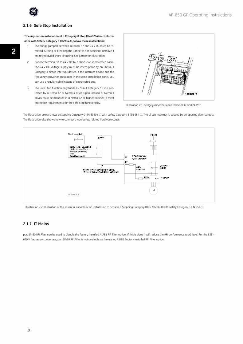
2.1.6 Safe Stop Installation
To carry out an installation of a Category 0 Stop (EN60204) in conform-
ance with Safety Category 3 (EN954-1), follow these instructions:
1. The bridge (jumper) between Terminal 37 and 24 V DC must be re-
moved. Cutting or breaking the jumper is not sufficient. Remove it
entirely to avoid short-circuiting. See jumper on illustration.
2. Connect terminal 37 to 24 V DC by a short-circuit protected cable.
The 24 V DC voltage supply must be interruptible by an EN954-1
Category 3 circuit interrupt device. If the interrupt device and the
frequency converter are placed in the same installation panel, you
can use a regular cable instead of a protected one.
3. The Safe Stop function only fulfills EN 954-1 Category 3 if it is pro-
tected by a Nema 12 or Nema 4 drive. Open Chassis or Nema 1
drives must be mounted in a Nema 12 or higher cabinet to meet
protection requirements for the Safe Stop functionality.Illustration 2.1: Bridge jumper between terminal 37 and 24 VDC
The illustration below shows a Stopping Category 0 (EN 60204-1) with safety Category 3 (EN 954-1). The circuit interrupt is caused by an opening door contact.
The illustration also shows how to connect a non-safety related hardware coast.
Illustration 2.2: Illustration of the essential aspects of an installation to achieve a Stopping Category 0 (EN 60204-1) with safety Category 3 (EN 954-1).
2.1.7 IT Mains
par. SP-50 RFI Filter can be used to disable the factory installed A1/B1 RFI filter option. If this is done it will reduce the RFI performance to A2 level. For the 525 -
690 V frequency converters, par. SP-50 RFI Filter is not available as there is no A1/B1 Factory Installed RFI Filter option.
AF-650 GP Operating Instructions
8
2
3 How to Install
3.1.1 About How to Install
This chapter covers mechanical and electrical installations to and from power terminals and control card terminals.
Electrical installation of options is described in the relevant Operating Instructions and Design Guide.
3.1.2 How to Get Started
AF-650 GP is designed to achieve a quick installation by following the steps described below.
Read the safety instructions before installing the unit.
Mechanical Installation
• Mechanical mounting
Electrical Installation
• Connection to Mains and Protecting Earth
• Motor connection and cables
• Fuses and circuit breakers
• Control terminals - cables
Quick setup
• Keypad
• Auto Tuning of drive
• Programming
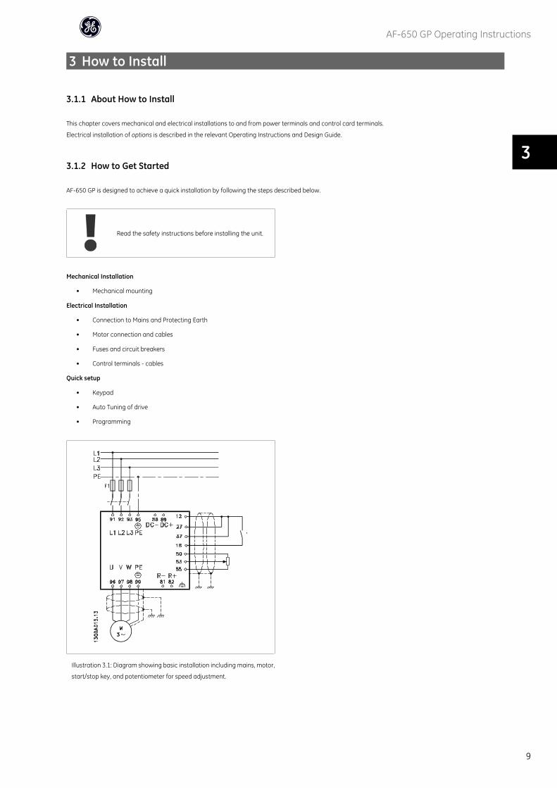
Illustration 3.1: Diagram showing basic installation including mains, motor,
start/stop key, and potentiometer for speed adjustment.
AF-650 GP Operating Instructions
9
3
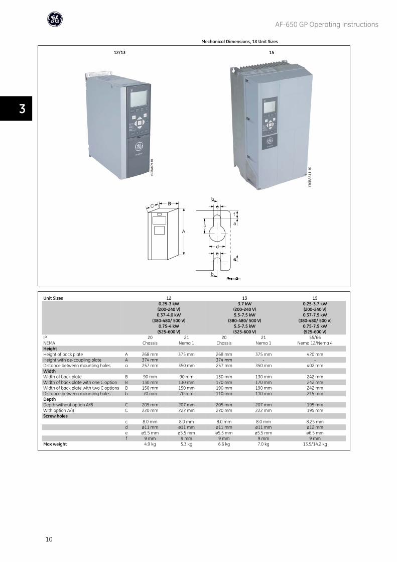
Mechanical Dimensions, 1X Unit Sizes
12/13 15
Unit Sizes 12 13 150.25-3 kW(200-240 V)0.37-4.0 kW
(380-480/ 500 V)0.75-4 kW(525-600 V)
3.7 kW(200-240 V)5.5-7.5 kW
(380-480/ 500 V)5.5-7.5 kW(525-600 V)
0.25-3.7 kW(200-240 V)0.37-7.5 kW
(380-480/ 500 V)0.75-7.5 kW(525-600 V)
IPNEMA
20Chassis
21Nema 1
20Chassis
21Nema 1
55/66Nema 12/Nema 4
HeightHeight of back plate A 268 mm 375 mm 268 mm 375 mm 420 mmHeight with de-coupling plate A 374 mm 374 mm - -Distance between mounting holes a 257 mm 350 mm 257 mm 350 mm 402 mmWidthWidth of back plate B 90 mm 90 mm 130 mm 130 mm 242 mmWidth of back plate with one C option B 130 mm 130 mm 170 mm 170 mm 242 mmWidth of back plate with two C options B 150 mm 150 mm 190 mm 190 mm 242 mmDistance between mounting holes b 70 mm 70 mm 110 mm 110 mm 215 mmDepthDepth without option A/B C 205 mm 207 mm 205 mm 207 mm 195 mmWith option A/B C 220 mm 222 mm 220 mm 222 mm 195 mmScrew holes
c 8.0 mm 8.0 mm 8.0 mm 8.0 mm 8.25 mmd ø11 mm ø11 mm ø11 mm ø11 mm ø12 mme ø5.5 mm ø5.5 mm ø5.5 mm ø5.5 mm ø6.5 mmf 9 mm 9 mm 9 mm 9 mm 9 mm
Max weight 4.9 kg 5.3 kg 6.6 kg 7.0 kg 13.5/14.2 kg
AF-650 GP Operating Instructions
10
3
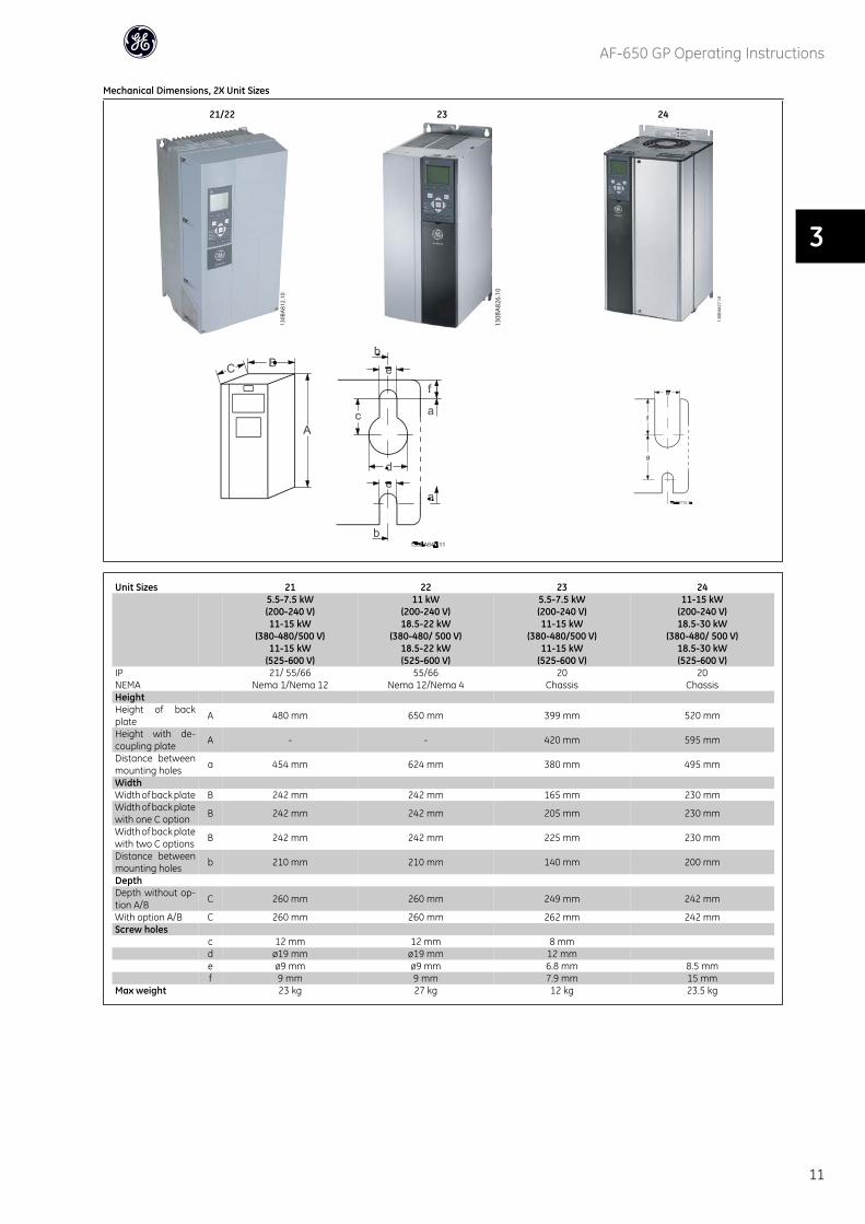
Mechanical Dimensions, 2X Unit Sizes
21/22 23 24
Unit Sizes 21 22 23 245.5-7.5 kW(200-240 V)11-15 kW
(380-480/500 V)11-15 kW
(525-600 V)
11 kW(200-240 V)18.5-22 kW
(380-480/ 500 V)18.5-22 kW(525-600 V)
5.5-7.5 kW(200-240 V)11-15 kW
(380-480/500 V)11-15 kW
(525-600 V)
11-15 kW(200-240 V)18.5-30 kW
(380-480/ 500 V)18.5-30 kW(525-600 V)
IPNEMA
21/ 55/66Nema 1/Nema 12
55/66Nema 12/Nema 4
20Chassis
20Chassis
HeightHeight of backplate A 480 mm 650 mm 399 mm 520 mm
Height with de-coupling plate A - - 420 mm 595 mm
Distance betweenmounting holes a 454 mm 624 mm 380 mm 495 mm
WidthWidth of back plate B 242 mm 242 mm 165 mm 230 mmWidth of back platewith one C option B 242 mm 242 mm 205 mm 230 mm
Width of back platewith two C options B 242 mm 242 mm 225 mm 230 mm
Distance betweenmounting holes b 210 mm 210 mm 140 mm 200 mm
DepthDepth without op-tion A/B C 260 mm 260 mm 249 mm 242 mm
With option A/B C 260 mm 260 mm 262 mm 242 mmScrew holes
c 12 mm 12 mm 8 mmd ø19 mm ø19 mm 12 mme ø9 mm ø9 mm 6.8 mm 8.5 mmf 9 mm 9 mm 7.9 mm 15 mm
Max weight 23 kg 27 kg 12 kg 23.5 kg
AF-650 GP Operating Instructions
11
3
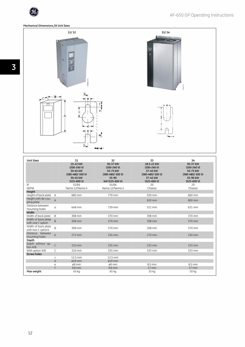
Mechanical Dimensions,3X Unit Sizes
31/ 32 33/ 34
Unit Sizes 31 32 33 3415-22 kW
(200-240 V)30-45 kW
(380-480/ 500 V)30-45 kW
(525-600 V)
30-37 kW(200-240 V)55-75 kW
(380-480/ 500 V)55-90
kW (525-600 V)
18.5-22 kW(200-240 V)37-45 kW
(380-480/ 500 V)37-45 kW
(525-600 V)
30-37 kW(200-240 V)55-75 kW
(380-480/ 500 V)55-90 kW
(525-600 V)IPNEMA
55/66Nema 12/Nema 4
55/66Nema 12/Nema 4
20Chassis
20Chassis
HeightHeight of back plate A 680 mm 770 mm 550 mm 660 mmHeight with de-cou-pling plate A 630 mm 800 mm
Distance betweenmounting holes a 648 mm 739 mm 521 mm 631 mm
WidthWidth of back plate B 308 mm 370 mm 308 mm 370 mmWidth of back platewith one C option B 308 mm 370 mm 308 mm 370 mm
Width of back platewith two C options B 308 mm 370 mm 308 mm 370 mm
Distance betweenmounting holes b 272 mm 334 mm 270 mm 330 mm
DepthDepth without op-tion A/B C 310 mm 335 mm 333 mm 333 mm
With option A/B C 310 mm 335 mm 333 mm 333 mmScrew holes
c 12.5 mm 12.5 mmd ø19 mm ø19 mme ø9 mm ø9 mm 8.5 mm 8.5 mmf 9.8 mm 9.8 mm 17 mm 17 mm
Max weight 45 kg 65 kg 35 kg 50 kg
AF-650 GP Operating Instructions
12
3
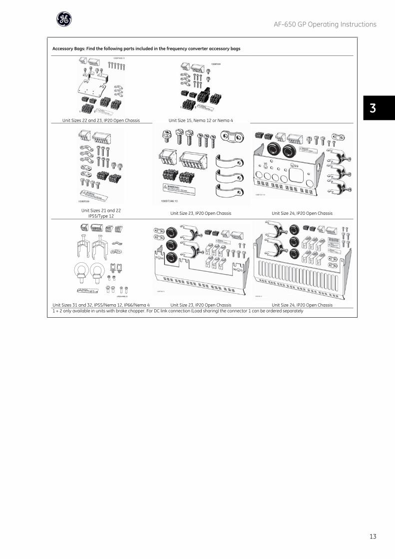
Accessory Bags: Find the following parts included in the frequency converter accessory bags
Unit Sizes 22 and 23, IP20 Open Chassis Unit Size 15, Nema 12 or Nema 4
Unit Sizes 21 and 22IP55/Type 12 Unit Size 23, IP20 Open Chassis Unit Size 24, IP20 Open Chassis
Unit Sizes 31 and 32, IP55/Nema 12, IP66/Nema 4 Unit Size 23, IP20 Open Chassis Unit Size 24, IP20 Open Chassis1 + 2 only available in units with brake chopper. For DC link connection (Load sharing) the connector 1 can be ordered separately
AF-650 GP Operating Instructions
13
3
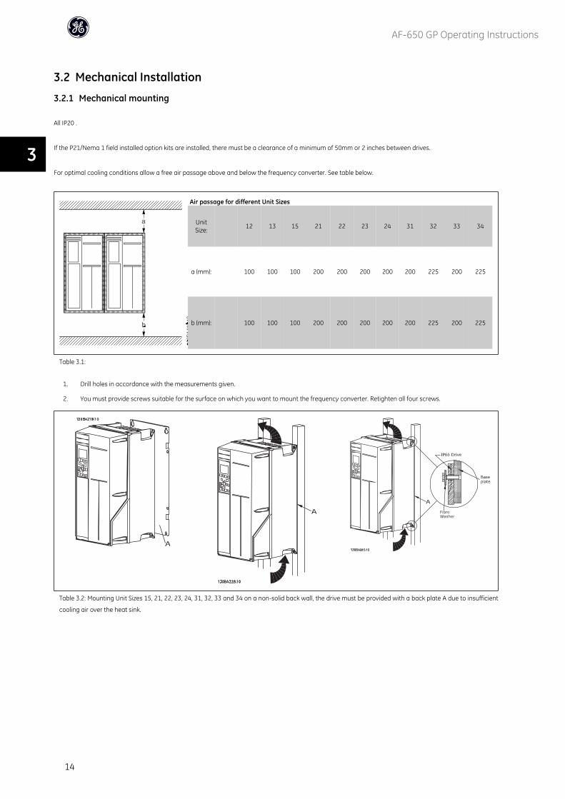
3.2 Mechanical Installation
3.2.1 Mechanical mounting
All IP20 .
If the P21/Nema 1 field installed option kits are installed, there must be a clearance of a minimum of 50mm or 2 inches between drives.
For optimal cooling conditions allow a free air passage above and below the frequency converter. See table below.
Air passage for different Unit Sizes
UnitSize: 12 13 15 21 22 23 24 31 32 33 34
a (mm): 100 100 100 200 200 200 200 200 225 200 225
b (mm): 100 100 100 200 200 200 200 200 225 200 225
Table 3.1:
1. Drill holes in accordance with the measurements given.
2. You must provide screws suitable for the surface on which you want to mount the frequency converter. Retighten all four screws.
Table 3.2: Mounting Unit Sizes 15, 21, 22, 23, 24, 31, 32, 33 and 34 on a non-solid back wall, the drive must be provided with a back plate A due to insufficient
cooling air over the heat sink.
AF-650 GP Operating Instructions
14
3

3.2.2 Panel Through Mounting
A Panel Through Mount Kit is available for frequency converter series AF-600 FP, .
In order to increase heatsink cooling and reduce panel depth, the frequency converter may be mounted in a through panel. Furthermore the in-built fan can then
be removed.
The kit is available for Unit Sizes 15 through 32 (230V, 1/3 to 50HP and 460V/575V 1/2 to 100HP) .
NB!
This kit cannot be used with cast front covers. No cover or imminent plastic cover must be used instead.
For more information please contact GE.
AF-650 GP Operating Instructions
15
3
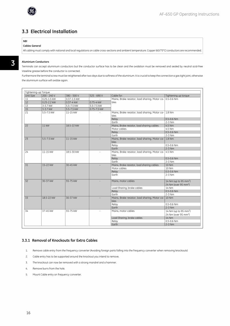
3.3 Electrical Installation
NB!
Cables General
All cabling must comply with national and local regulations on cable cross-sections and ambient temperature. Copper (60/75°C) conductors are recommended.
Aluminium Conductors
Terminals can accept aluminium conductors but the conductor surface has to be clean and the oxidation must be removed and sealed by neutral acid-free
Vaseline grease before the conductor is connected.
Furthermore the terminal screw must be retightened after two days due to softness of the aluminium. It is crucial to keep the connection a gas tight joint, otherwise
the aluminium surface will oxidize again.
Tightening-up TorqueUnit Size 200 - 240 V 380 - 500 V 525 - 690 V Cable for: Tightening up torque11 0.25-1.5 kW 0.37-1.5 kW - Mains, Brake resistor, load sharing, Motor ca-
bles0.5-0.6 Nm
12 0.25-2.2 kW 0.37-4 kW 0.75-4 kW13 3-3.7 kW 5.5-7.5 kW 5.5-7.5 kW15 3-3.7 kW 5.5-7.5 kW 0.75-7.5 kW21 5.5-7.5 kW 11-15 kW - Mains, Brake resistor, load sharing, Motor ca-
bles1.8 Nm
Relay 0.5-0.6 NmEarth 2-3 Nm
22 11 kW 18.5-22 kW - Mains, Brake resistor, load sharing cables 4.5 NmMotor cables 4.5 NmRelay 0.5-0.6 NmEarth 2-3 Nm
23 5.5-7.5 kW 11-15 kW - Mains, Brake resistor, load sharing, Motor ca-bles
1.8 Nm
Relay 0.5-0.6 NmEarth 2-3 Nm
24 11-15 kW 18.5-30 kW - Mains, Brake resistor, load sharing, Motor ca-bles
4.5 Nm
Relay 0.5-0.6 NmEarth 2-3 Nm
31 15-22 kW 30-45 kW - Mains, Brake resistor, load sharing cables 10 NmMotor cables 10 NmRelay 0.5-0.6 NmEarth 2-3 Nm
32 30-37 kW 55-75 kW - Mains, motor cables 14 Nm (up to 95 mm2)24 Nm (over 95 mm2)
Load Sharing, brake cables 14 NmRelay 0.5-0.6 NmEarth 2-3 Nm
33 18.5-22 kW 30-37 kW - Mains, Brake resistor, load sharing, Motor ca-bles
10 Nm
Relay 0.5-0.6 NmEarth 2-3 Nm
34 37-45 kW 55-75 kW - Mains, motor cables 14 Nm (up to 95 mm2)24 Nm (over 95 mm2)
Load Sharing, brake cables 14 NmRelay 0.5-0.6 NmEarth 2-3 Nm
3.3.1 Removal of Knockouts for Extra Cables
1. Remove cable entry from the frequency converter (Avoiding foreign parts falling into the frequency converter when removing knockouts)
2. Cable entry has to be supported around the knockout you intend to remove.
3. The knockout can now be removed with a strong mandrel and a hammer.
4. Remove burrs from the hole.
5. Mount Cable entry on frequency converter.
AF-650 GP Operating Instructions
16
3
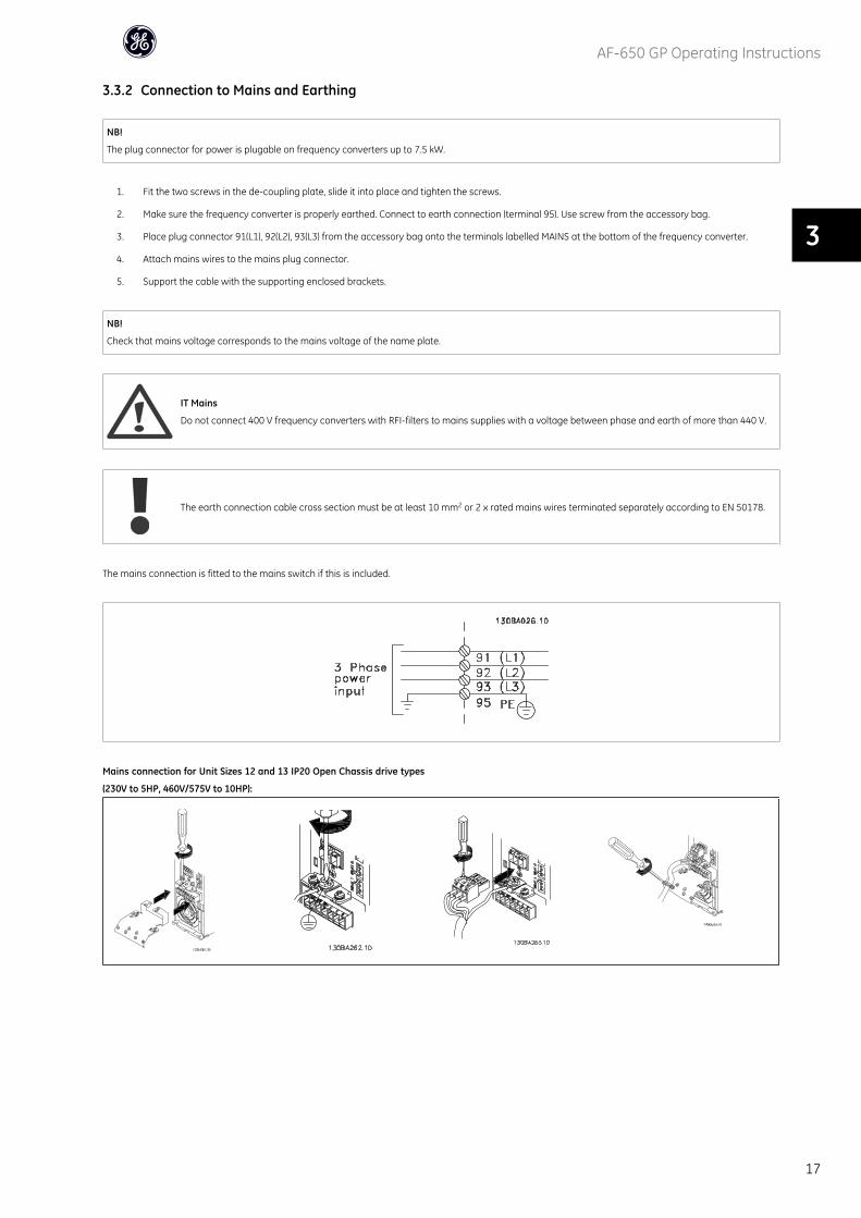
3.3.2 Connection to Mains and Earthing
NB!
The plug connector for power is plugable on frequency converters up to 7.5 kW.
1. Fit the two screws in the de-coupling plate, slide it into place and tighten the screws.
2. Make sure the frequency converter is properly earthed. Connect to earth connection (terminal 95). Use screw from the accessory bag.
3. Place plug connector 91(L1), 92(L2), 93(L3) from the accessory bag onto the terminals labelled MAINS at the bottom of the frequency converter.
4. Attach mains wires to the mains plug connector.
5. Support the cable with the supporting enclosed brackets.
NB!
Check that mains voltage corresponds to the mains voltage of the name plate.
IT Mains
Do not connect 400 V frequency converters with RFI-filters to mains supplies with a voltage between phase and earth of more than 440 V.
The earth connection cable cross section must be at least 10 mm2 or 2 x rated mains wires terminated separately according to EN 50178.
The mains connection is fitted to the mains switch if this is included.
Mains connection for Unit Sizes 12 and 13 IP20 Open Chassis drive types
(230V to 5HP, 460V/575V to 10HP):
AF-650 GP Operating Instructions
17
3
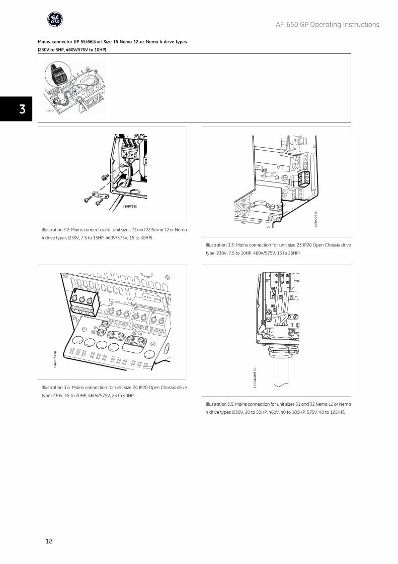
Mains connector (IP 55/66)Unit Size 15 Nema 12 or Nema 4 drive types
(230V to 5HP, 460V/575V to 10HP)
Illustration 3.2: Mains connection for unit sizes 21 and 22 Nema 12 or Nema
4 drive types (230V, 7.5 to 15HP, 460V/575V, 15 to 30HP).Illustration 3.3: Mains connection for unit size 23 IP20 Open Chassis drive
type (230V, 7.5 to 10HP, 460V/575V, 15 to 25HP).
Illustration 3.4: Mains connection for unit size 24 IP20 Open Chassis drive
type (230V, 15 to 20HP, 460V/575V, 25 to 40HP).
Illustration 3.5: Mains connection for unit sizes 31 and 32 Nema 12 or Nema
4 drive types (230V, 20 to 50HP, 460V, 40 to 100HP, 575V, 40 to 125HP).
AF-650 GP Operating Instructions
18
3
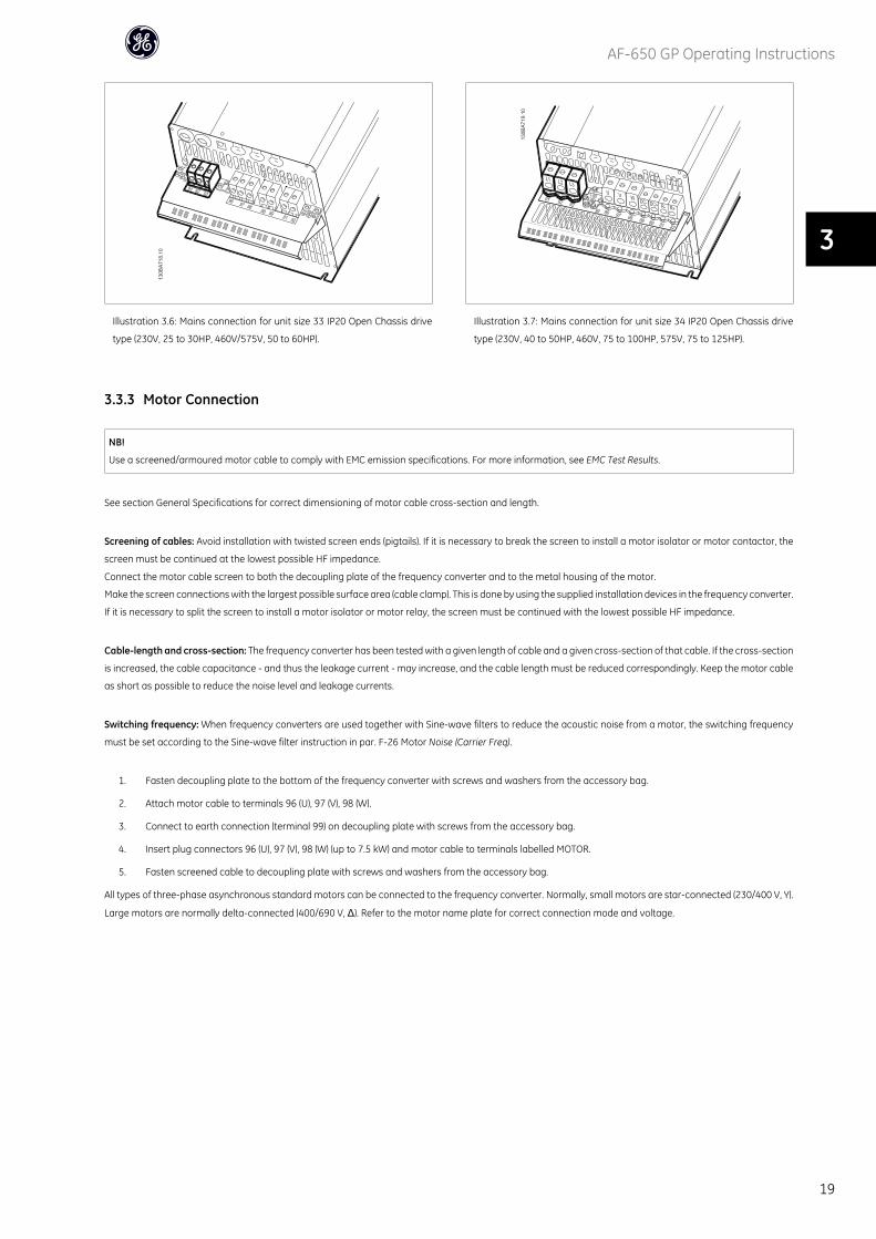
Illustration 3.6: Mains connection for unit size 33 IP20 Open Chassis drive
type (230V, 25 to 30HP, 460V/575V, 50 to 60HP).
Illustration 3.7: Mains connection for unit size 34 IP20 Open Chassis drive
type (230V, 40 to 50HP, 460V, 75 to 100HP, 575V, 75 to 125HP).
3.3.3 Motor Connection
NB!
Use a screened/armoured motor cable to comply with EMC emission specifications. For more information, see EMC Test Results.
See section General Specifications for correct dimensioning of motor cable cross-section and length.
Screening of cables: Avoid installation with twisted screen ends (pigtails). If it is necessary to break the screen to install a motor isolator or motor contactor, the
screen must be continued at the lowest possible HF impedance.
Connect the motor cable screen to both the decoupling plate of the frequency converter and to the metal housing of the motor.
Make the screen connections with the largest possible surface area (cable clamp). This is done by using the supplied installation devices in the frequency converter.
If it is necessary to split the screen to install a motor isolator or motor relay, the screen must be continued with the lowest possible HF impedance.
Cable-length and cross-section: The frequency converter has been tested with a given length of cable and a given cross-section of that cable. If the cross-section
is increased, the cable capacitance - and thus the leakage current - may increase, and the cable length must be reduced correspondingly. Keep the motor cable
as short as possible to reduce the noise level and leakage currents.
Switching frequency: When frequency converters are used together with Sine-wave filters to reduce the acoustic noise from a motor, the switching frequency
must be set according to the Sine-wave filter instruction in par. F-26 Motor Noise (Carrier Freq).
1. Fasten decoupling plate to the bottom of the frequency converter with screws and washers from the accessory bag.
2. Attach motor cable to terminals 96 (U), 97 (V), 98 (W).
3. Connect to earth connection (terminal 99) on decoupling plate with screws from the accessory bag.
4. Insert plug connectors 96 (U), 97 (V), 98 (W) (up to 7.5 kW) and motor cable to terminals labelled MOTOR.
5. Fasten screened cable to decoupling plate with screws and washers from the accessory bag.
All types of three-phase asynchronous standard motors can be connected to the frequency converter. Normally, small motors are star-connected (230/400 V, Y).
Large motors are normally delta-connected (400/690 V, Δ). Refer to the motor name plate for correct connection mode and voltage.
AF-650 GP Operating Instructions
19
3
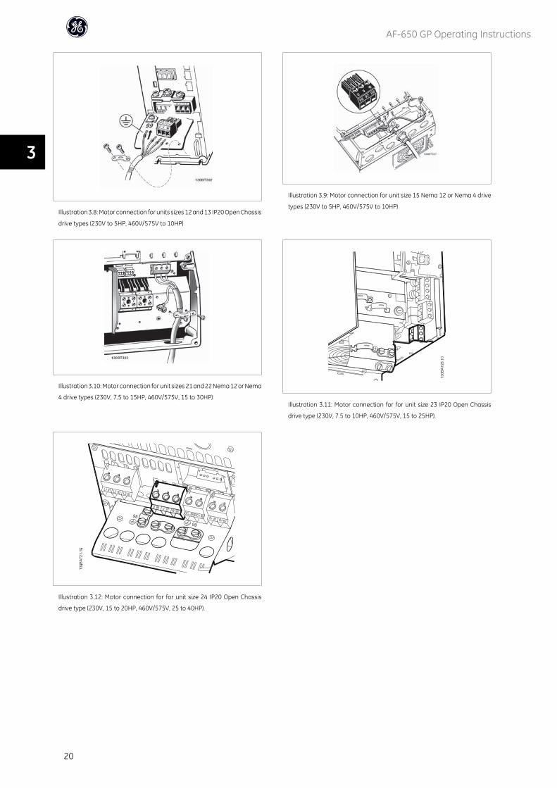
Illustration 3.8: Motor connection for units sizes 12 and 13 IP20 Open Chassis
drive types (230V to 5HP, 460V/575V to 10HP)
Illustration 3.9: Motor connection for unit size 15 Nema 12 or Nema 4 drive
types (230V to 5HP, 460V/575V to 10HP)
Illustration 3.10: Motor connection for unit sizes 21 and 22 Nema 12 or Nema
4 drive types (230V, 7.5 to 15HP, 460V/575V, 15 to 30HP)Illustration 3.11: Motor connection for for unit size 23 IP20 Open Chassis
drive type (230V, 7.5 to 10HP, 460V/575V, 15 to 25HP).
Illustration 3.12: Motor connection for for unit size 24 IP20 Open Chassis
drive type (230V, 15 to 20HP, 460V/575V, 25 to 40HP).
AF-650 GP Operating Instructions
20
3
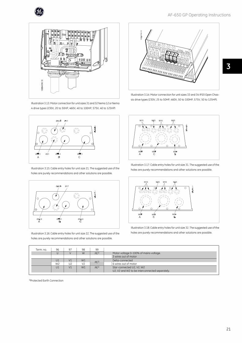
Illustration 3.13: Motor connection for unit sizes 31 and 32 Nema 12 or Nema
4 drive types (230V, 20 to 50HP, 460V, 40 to 100HP, 575V, 40 to 125HP)
Illustration 3.14: Motor connection for unit sizes 33 and 34 IP20 Open Chas-
sis drive types (230V, 25 to 50HP, 460V, 50 to 100HP, 575V, 50 to 125HP).
Illustration 3.15: Cable entry holes for unit size 21. The suggested use of the
holes are purely recommendations and other solutions are possible.
Illustration 3.16: Cable entry holes for unit size 22. The suggested use of the
holes are purely recommendations and other solutions are possible.
Illustration 3.17: Cable entry holes for unit size 31. The suggested use of the
holes are purely recommendations and other solutions are possible.
Illustration 3.18: Cable entry holes for unit size 32. The suggested use of the
holes are purely recommendations and other solutions are possible.
Term. no. 96 97 98 99 U V W PE1) Motor voltage 0-100% of mains voltage.
3 wires out of motor U1 V1 W1
PE1) Delta-connectedW2 U2 V2 6 wires out of motor
U1 V1 W1 PE1) Star-connected U2, V2, W2U2, V2 and W2 to be interconnected separately.
1)Protected Earth Connection
AF-650 GP Operating Instructions
21
3
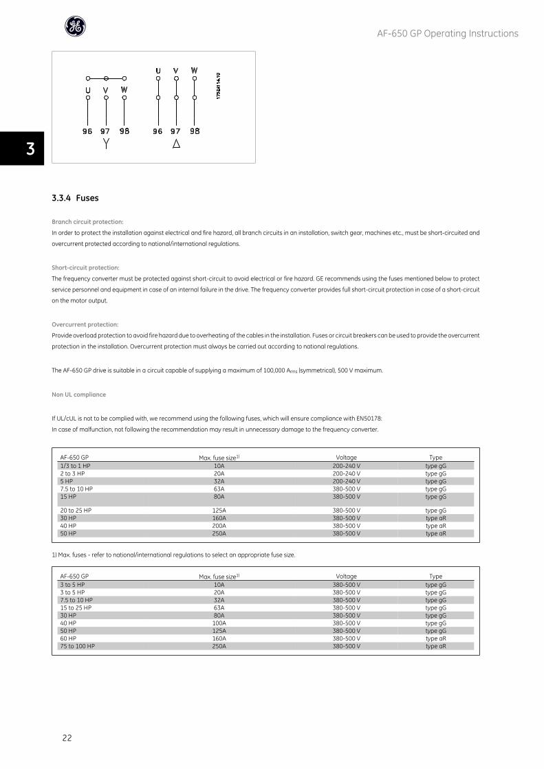
3.3.4 Fuses
Branch circuit protection:
In order to protect the installation against electrical and fire hazard, all branch circuits in an installation, switch gear, machines etc., must be short-circuited and
overcurrent protected according to national/international regulations.
Short-circuit protection:
The frequency converter must be protected against short-circuit to avoid electrical or fire hazard. GE recommends using the fuses mentioned below to protect
service personnel and equipment in case of an internal failure in the drive. The frequency converter provides full short-circuit protection in case of a short-circuit
on the motor output.
Overcurrent protection:
Provide overload protection to avoid fire hazard due to overheating of the cables in the installation. Fuses or circuit breakers can be used to provide the overcurrent
protection in the installation. Overcurrent protection must always be carried out according to national regulations.
The AF-650 GP drive is suitable in a circuit capable of supplying a maximum of 100,000 Arms (symmetrical), 500 V maximum.
Non UL compliance
If UL/cUL is not to be complied with, we recommend using the following fuses, which will ensure compliance with EN50178:
In case of malfunction, not following the recommendation may result in unnecessary damage to the frequency converter.
AF-650 GP Max. fuse size1) Voltage Type1/3 to 1 HP 10A 200-240 V type gG2 to 3 HP 20A 200-240 V type gG5 HP 32A 200-240 V type gG7.5 to 10 HP 63A 380-500 V type gG15 HP 80A 380-500 V type gG
20 to 25 HP 125A 380-500 V type gG30 HP 160A 380-500 V type aR40 HP 200A 380-500 V type aR50 HP 250A 380-500 V type aR
1) Max. fuses - refer to national/international regulations to select an appropriate fuse size.
AF-650 GP Max. fuse size1) Voltage Type3 to 5 HP 10A 380-500 V type gG3 to 5 HP 20A 380-500 V type gG7.5 to 10 HP 32A 380-500 V type gG15 to 25 HP 63A 380-500 V type gG30 HP 80A 380-500 V type gG40 HP 100A 380-500 V type gG50 HP 125A 380-500 V type gG60 HP 160A 380-500 V type aR75 to 100 HP 250A 380-500 V type aR
AF-650 GP Operating Instructions
22
3
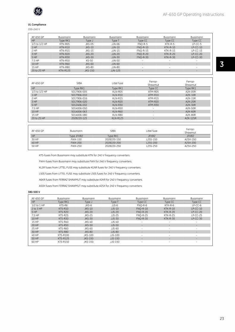
UL Compliance
200-240 V
AF-650 GP Bussmann Bussmann Bussmann Bussmann Bussmann BussmannHP Type RK1 Type J Type T Type CC Type CC Type CC1/3 to 1/2 HP KTN-R05 JKS-05 JJN-06 FNQ-R-5 KTK-R-5 LP-CC-51 HP KTN-R10 JKS-10 JJN-10 FNQ-R-10 KTK-R-10 LP-CC-102 HP KTN-R15 JKS-15 JJN-15 FNQ-R-15 KTK-R-15 LP-CC-153 HP KTN-R20 JKS-20 JJN-20 FNQ-R-20 KTK-R-20 LP-CC-205 HP KTN-R30 JKS-30 JJN-30 FNQ-R-30 KTK-R-30 LP-CC-307.5 HP KTN-R50 KS-50 JJN-50 - - -10 HP KTN-R60 JKS-60 JJN-60 - - -15 HP KTN-R80 JKS-80 JJN-80 - - -20 to 25 HP KTN-R125 JKS-150 JJN-125 - - -
AF-650 GP SIBA Littel fuse Ferraz-Shawmut
Ferraz-Shawmut
HP Type RK1 Type RK1 Type CC Type RK11/3 to 1/2 HP 5017906-005 KLN-R05 ATM-R05 A2K-05R1 HP 5017906-010 KLN-R10 ATM-R10 A2K-10R2 HP 5017906-016 KLN-R15 ATM-R15 A2K-15R3 HP 5017906-020 KLN-R20 ATM-R20 A2K-20R5 HP 5012406-032 KLN-R30 ATM-R30 A2K-30R7.5 HP 5014006-050 KLN-R50 - A2K-50R10 HP 5014006-063 KLN-R60 - A2K-60R15 HP 5014006-080 KLN-R80 - A2K-80R20 to 25 HP 2028220-125 KLN-R125 - A2K-125R
AF-650 GP Bussmann SIBA Littel fuse Ferraz-Shawmut
HP Type JFHR2 Type RK1 JFHR2 JFHR230 HP FWX-150 2028220-150 L25S-150 A25X-15040 HP FWX-200 2028220-200 L25S-200 A25X-20050 HP FWX-250 2028220-250 L25S-250 A25X-250
KTS-fuses from Bussmann may substitute KTN for 240 V frequency converters.
FWH-fuses from Bussmann may substitute FWX for 240 V frequency converters.
KLSR fuses from LITTEL FUSE may substitute KLNR fuses for 240 V frequency converters.
L50S fuses from LITTEL FUSE may substitute L50S fuses for 240 V frequency converters.
A6KR fuses from FERRAZ SHAWMUT may substitute A2KR for 240 V frequency converters.
A50X fuses from FERRAZ SHAWMUT may substitute A25X for 240 V frequency converters.
380-500 V
AF-650 GP Bussmann Bussmann Bussmann Bussmann Bussmann BussmannHP Type RK1 Type J Type T Type CC Type CC Type CC1/2 to 1 HP KTS-R6 JKS-6 JJS-6 FNQ-R-6 KTK-R-6 LP-CC-62 to 3 HP KTS-R10 JKS-10 JJS-10 FNQ-R-10 KTK-R-10 LP-CC-105 HP KTS-R20 JKS-20 JJS-20 FNQ-R-20 KTK-R-20 LP-CC-207.5 HP KTS-R25 JKS-25 JJS-25 FNQ-R-25 KTK-R-25 LP-CC-2510 HP KTS-R30 JKS-30 JJS-30 FNQ-R-30 KTK-R-30 LP-CC-3015 HP KTS-R40 JKS-40 JJS-40 - - -20 HP KTS-R50 JKS-50 JJS-50 - - -25 HP KTS-R60 JKS-60 JJS-60 - - -30 HP KTS-R80 JKS-80 JJS-80 - - -40 HP KTS-R100 JKS-100 JJS-100 - - -50 HP KTS-R125 JKS-150 JJS-150 - - -60 HP KTS-R150 JKS-150 JJS-150 - - -
AF-650 GP Operating Instructions
23
3
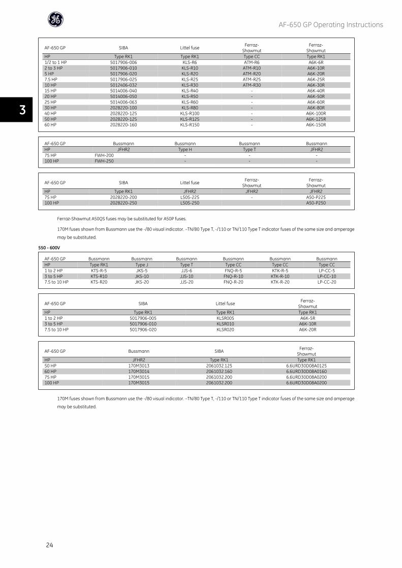
AF-650 GP SIBA Littel fuse Ferraz-Shawmut
Ferraz-Shawmut
HP Type RK1 Type RK1 Type CC Type RK11/2 to 1 HP 5017906-006 KLS-R6 ATM-R6 A6K-6R2 to 3 HP 5017906-010 KLS-R10 ATM-R10 A6K-10R5 HP 5017906-020 KLS-R20 ATM-R20 A6K-20R7.5 HP 5017906-025 KLS-R25 ATM-R25 A6K-25R10 HP 5012406-032 KLS-R30 ATM-R30 A6K-30R15 HP 5014006-040 KLS-R40 - A6K-40R20 HP 5014006-050 KLS-R50 - A6K-50R25 HP 5014006-063 KLS-R60 - A6K-60R30 HP 2028220-100 KLS-R80 - A6K-80R40 HP 2028220-125 KLS-R100 - A6K-100R50 HP 2028220-125 KLS-R125 - A6K-125R60 HP 2028220-160 KLS-R150 - A6K-150R
AF-650 GP Bussmann Bussmann Bussmann BussmannHP JFHR2 Type H Type T JFHR275 HP FWH-200 - - -100 HP FWH-250 - - -
AF-650 GP SIBA Littel fuse Ferraz-Shawmut
Ferraz-Shawmut
HP Type RK1 JFHR2 JFHR2 JFHR275 HP 2028220-200 L50S-225 - A50-P225100 HP 2028220-250 L50S-250 A50-P250
Ferraz-Shawmut A50QS fuses may be substituted for A50P fuses.
170M fuses shown from Bussmann use the -/80 visual indicator. –TN/80 Type T, -/110 or TN/110 Type T indicator fuses of the same size and amperage
may be substituted.
550 - 600V
AF-650 GP Bussmann Bussmann Bussmann Bussmann Bussmann BussmannHP Type RK1 Type J Type T Type CC Type CC Type CC1 to 2 HP KTS-R-5 JKS-5 JJS-6 FNQ-R-5 KTK-R-5 LP-CC-53 to 5 HP KTS-R10 JKS-10 JJS-10 FNQ-R-10 KTK-R-10 LP-CC-107.5 to 10 HP KTS-R20 JKS-20 JJS-20 FNQ-R-20 KTK-R-20 LP-CC-20
AF-650 GP SIBA Littel fuse Ferraz-Shawmut
HP Type RK1 Type RK1 Type RK11 to 2 HP 5017906-005 KLSR005 A6K-5R3 to 5 HP 5017906-010 KLSR010 A6K-10R7.5 to 10 HP 5017906-020 KLSR020 A6K-20R
AF-650 GP Bussmann SIBA Ferraz-Shawmut
HP JFHR2 Type RK1 Type RK150 HP 170M3013 2061032.125 6.6URD30D08A012560 HP 170M3014 2061032.160 6.6URD30D08A016075 HP 170M3015 2061032.200 6.6URD30D08A0200100 HP 170M3015 2061032.200 6.6URD30D08A0200
170M fuses shown from Bussmann use the -/80 visual indicator. –TN/80 Type T, -/110 or TN/110 Type T indicator fuses of the same size and amperage
may be substituted.
AF-650 GP Operating Instructions
24
3
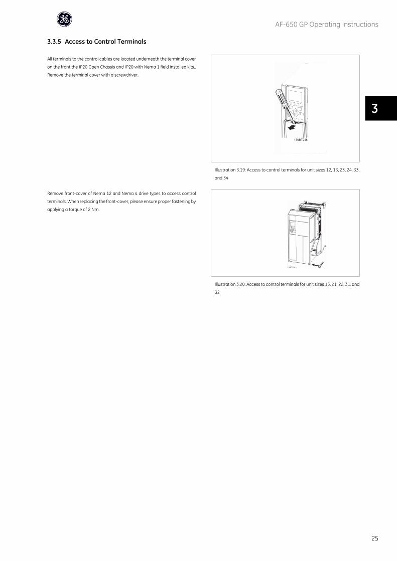
3.3.5 Access to Control Terminals
All terminals to the control cables are located underneath the terminal cover
on the front the IP20 Open Chassis and IP20 with Nema 1 field installed kits..
Remove the terminal cover with a screwdriver.
130BT248
Illustration 3.19: Access to control terminals for unit sizes 12, 13, 23, 24, 33,
and 34
Remove front-cover of Nema 12 and Nema 4 drive types to access control
terminals. When replacing the front-cover, please ensure proper fastening by
applying a torque of 2 Nm.
130BT334.11
Illustration 3.20: Access to control terminals for unit sizes 15, 21, 22, 31, and
32
AF-650 GP Operating Instructions
25
3
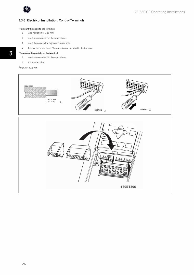
3.3.6 Electrical Installation, Control Terminals
To mount the cable to the terminal:
1. Strip insulation of 9-10 mm
2. Insert a screwdriver1) in the square hole.
3. Insert the cable in the adjacent circular hole.
4. Remove the screw driver. The cable is now mounted to the terminal.
To remove the cable from the terminal:
1. Insert a screwdriver1) in the square hole.
2. Pull out the cable.
1) Max. 0.4 x 2.5 mm
1.
2. 3.
AF-650 GP Operating Instructions
26
3
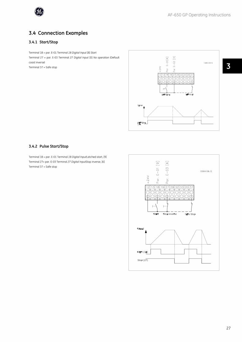
3.4 Connection Examples
3.4.1 Start/Stop
Terminal 18 = par. E-01 Terminal 18 Digital Input [8] Start
Terminal 27 = par. E-03 Terminal 27 Digital Input [0] No operation (Default
coast inverse)
Terminal 37 = Safe stop
3.4.2 Pulse Start/Stop
Terminal 18 = par. E-01 Terminal 18 Digital InputLatched start, [9]
Terminal 27= par. E-03 Terminal 27 Digital InputStop inverse, [6]
Terminal 37 = Safe stop
AF-650 GP Operating Instructions
27
3
3.4.3 Speed Up/Down
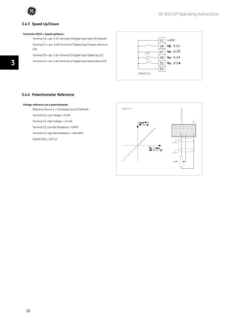
Terminals 29/32 = Speed up/down:.
Terminal 18 = par. E-01 Terminal 18 Digital Input Start [9] (default)
Terminal 27 = par. E-03 Terminal 27 Digital Input Freeze reference
[19]
Terminal 29 = par. E-04 Terminal 29 Digital Input Speed up [21]
Terminal 32 = par. E-05 Terminal 32 Digital Input Speed down [22]
3.4.4 Potentiometer Reference
Voltage reference via a potentiometer:
Reference Source 1 = [1] Analog input 53 (default)
Terminal 53, Low Voltage = 0 Volt
Terminal 53, High Voltage = 10 Volt
Terminal 53, Low Ref./Feedback = 0 RPM
Terminal 53, High Ref./Feedback = 1500 RPM
Switch S201 = OFF (U)
AF-650 GP Operating Instructions
28
3
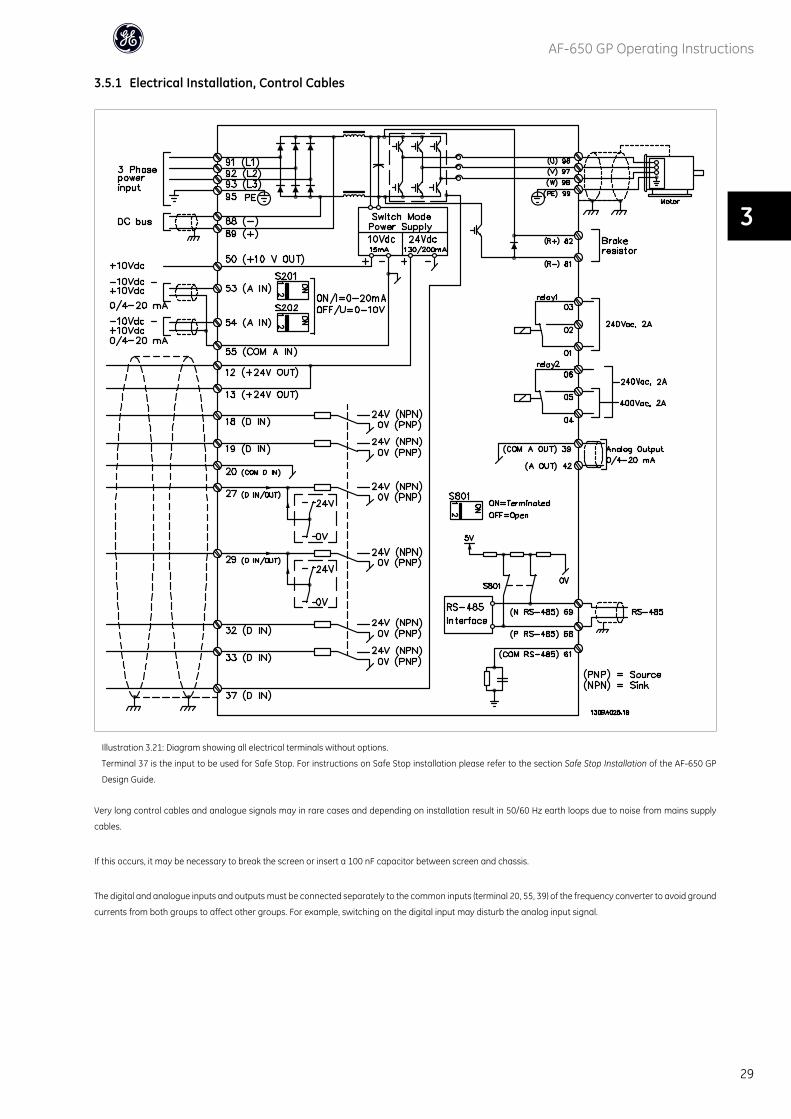
3.5.1 Electrical Installation, Control Cables
Illustration 3.21: Diagram showing all electrical terminals without options.
Terminal 37 is the input to be used for Safe Stop. For instructions on Safe Stop installation please refer to the section Safe Stop Installation of the AF-650 GP
Design Guide.
Very long control cables and analogue signals may in rare cases and depending on installation result in 50/60 Hz earth loops due to noise from mains supply
cables.
If this occurs, it may be necessary to break the screen or insert a 100 nF capacitor between screen and chassis.
The digital and analogue inputs and outputs must be connected separately to the common inputs (terminal 20, 55, 39) of the frequency converter to avoid ground
currents from both groups to affect other groups. For example, switching on the digital input may disturb the analog input signal.
AF-650 GP Operating Instructions
29
3
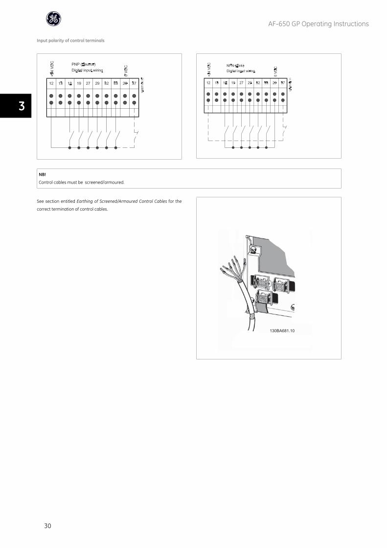
Input polarity of control terminals
NB!
Control cables must be screened/armoured.
See section entitled Earthing of Screened/Armoured Control Cables for the
correct termination of control cables.130BA681.10
130BA681.10
AF-650 GP Operating Instructions
30
3
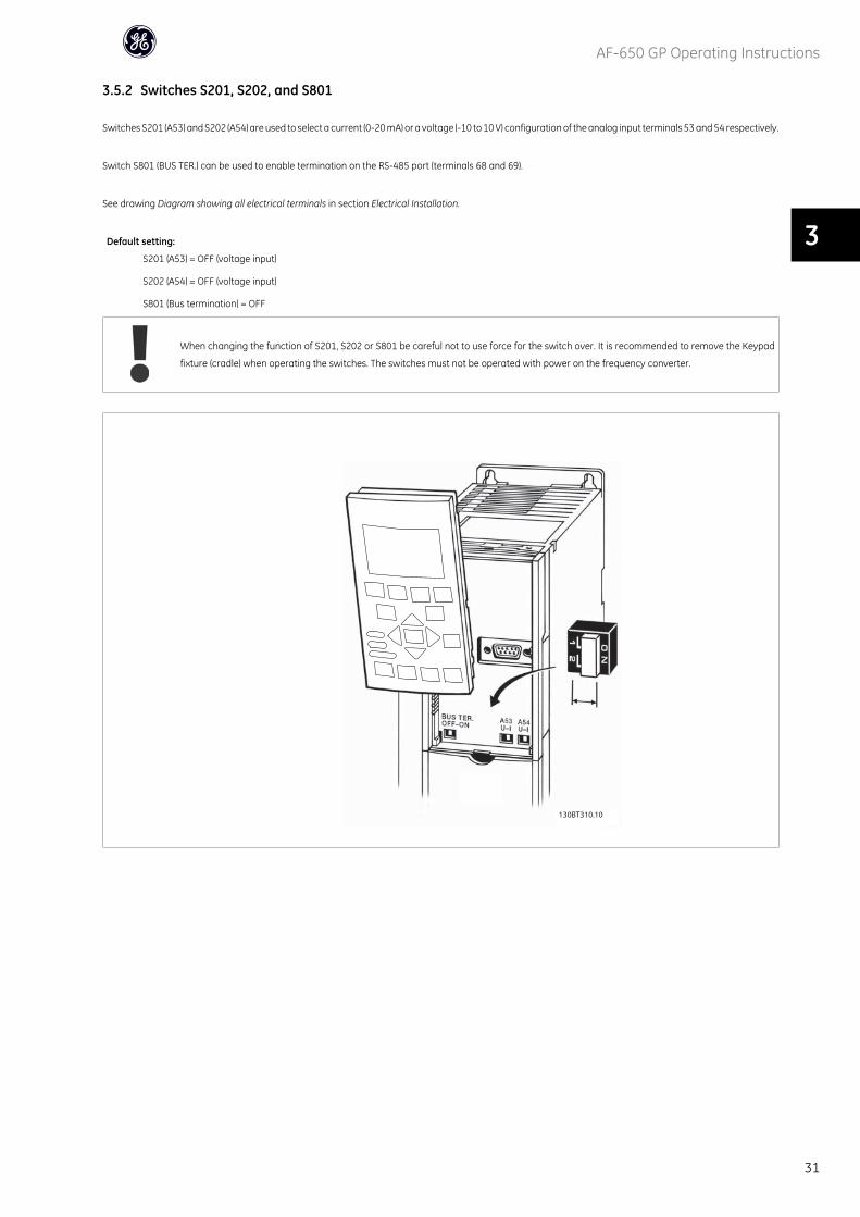
3.5.2 Switches S201, S202, and S801
Switches S201 (A53) and S202 (A54) are used to select a current (0-20 mA) or a voltage (-10 to 10 V) configuration of the analog input terminals 53 and 54 respectively.
Switch S801 (BUS TER.) can be used to enable termination on the RS-485 port (terminals 68 and 69).
See drawing Diagram showing all electrical terminals in section Electrical Installation.
Default setting:
S201 (A53) = OFF (voltage input)
S202 (A54) = OFF (voltage input)
S801 (Bus termination) = OFF
When changing the function of S201, S202 or S801 be careful not to use force for the switch over. It is recommended to remove the Keypad
fixture (cradle) when operating the switches. The switches must not be operated with power on the frequency converter.
130BT310.10
AF-650 GP Operating Instructions
31
3
3.6.1 Final Set-Up and Test
To test the set-up and ensure that the frequency converter is running, follow these steps.
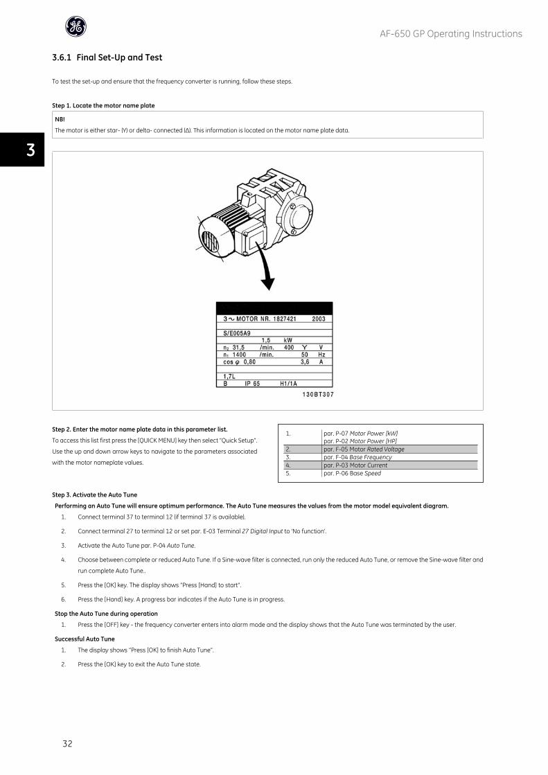
Step 1. Locate the motor name plate
NB!
The motor is either star- (Y) or delta- connected (∆). This information is located on the motor name plate data.
Step 2. Enter the motor name plate data in this parameter list.
To access this list first press the [QUICK MENU] key then select “Quick Setup”.
Use the up and down arrow keys to navigate to the parameters associated
with the motor nameplate values.
1. par. P-07 Motor Power [kW]par. P-02 Motor Power [HP]
2. par. F-05 Motor Rated Voltage3. par. F-04 Base Frequency4. par. P-03 Motor Current5. par. P-06 Base Speed
Step 3. Activate the Auto Tune
Performing an Auto Tune will ensure optimum performance. The Auto Tune measures the values from the motor model equivalent diagram.
1. Connect terminal 37 to terminal 12 (if terminal 37 is available).
2. Connect terminal 27 to terminal 12 or set par. E-03 Terminal 27 Digital Input to 'No function'.
3. Activate the Auto Tune par. P-04 Auto Tune.
4. Choose between complete or reduced Auto Tune. If a Sine-wave filter is connected, run only the reduced Auto Tune, or remove the Sine-wave filter and
run complete Auto Tune..
5. Press the [OK] key. The display shows “Press [Hand] to start”.
6. Press the [Hand] key. A progress bar indicates if the Auto Tune is in progress.
Stop the Auto Tune during operation
1. Press the [OFF] key - the frequency converter enters into alarm mode and the display shows that the Auto Tune was terminated by the user.
Successful Auto Tune
1. The display shows “Press [OK] to finish Auto Tune”.
2. Press the [OK] key to exit the Auto Tune state.
AF-650 GP Operating Instructions
32
3
Unsuccessful Auto Tune
1. The frequency converter enters into alarm mode. A description of the alarm can be found in the Warnings and Alarms chapter.
2. "Report Value” in the [Alarm Log] shows the last measuring sequence carried out by the Auto Tune, before the frequency converter entered alarm mode.
This number along with the description of the alarm will assist you in troubleshooting. If you contact GE for service, make sure to mention number and
alarm description.
NB!
Unsuccessful Auto Tune is often caused by incorrectly entering motor name plate data or a too big difference between the motor power size and the frequency
converter power size.
Step 4. Set speed limit and accel/decel times
par. F-52 Minimum Referencepar. F-53 Maximum Reference
Table 3.3: Set up the desired limits for speed and ramp time.
par. F-18 Motor Speed Low Limit [RPM] or par. F-16 Motor Speed LowLimit [Hz]par. F-17 Motor Speed High Limit [RPM] or par. F-15 Motor Speed HighLimit [Hz]
par. F-07 Accel Time 1par. F-08 Decel Time 1
AF-650 GP Operating Instructions
33
3

3.7 Additional Connections
3.7.1 Mechanical Brake Control
In hoisting/lowering applications, it is necessary to be able to control an electro-mechanical brake:
• Control the brake using any relay output or digital output (terminal 27 or 29).
• Keep the output closed (voltage-free) as long as the frequency converter is unable to ‘support’ the motor, for example due to the load being too heavy.
• Select Mechanical brake control [32] in E-2# for applications with an electro-mechanical brake.
• The brake is released when the motor current exceeds the preset value in par. B-20 Release Brake Current.
• The brake is engaged when the output frequency is less than the frequency set in par. B-21 Activate Brake Speed [RPM]or par. B-22 Activate Brake Speed
[Hz], and only if the frequency converter carries out a stop command.
If the frequency converter is in alarm mode or in an over-voltage situation, the mechanical brake immediately cuts in.
3.7.2 Parallel Connection of Motors
The frequency converter can control several parallel-connected motors. The
total current consumption of the motors must not exceed the rated output
current IM,N for the frequency converter.
NB!
Installations with cables connected in a common joint as in the illustration
below, is only recommended for short cable lengths.
NB!
When motors are connected in parallel, par. P-04 Auto Tune cannot be used.
NB!
The electronic thermal overload of the frequency converter cannot be used
as motor protection for the individual motor in systems with parallel-con-
nected motors. Provide further motor protection by e.g. thermistors in each
motor or individual thermal relays (circuit breakers are not suitable as pro-
tection).
Problems may arise at start and at low RPM values if motor sizes are widely different because small motors' relatively high ohmic resistance in the stator calls for
a higher voltage at start and at low RPM values.
3.7.3 Motor Thermal Protection
The electronic thermal overload in the frequency converter has received UL-approval for single motor protection, when par. F-10 Electronic Overloadis set for
Elec. OL Trip and par. P-03 Motor Current is set to the rated motor current (see motor name plate).
AF-650 GP Operating Instructions
34
3
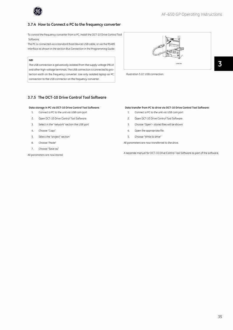
3.7.4 How to Connect a PC to the frequency converter
To control the frequency converter from a PC, install the DCT-10 Drive Control Tool
Software.
The PC is connected via a standard (host/device) USB cable, or via the RS485
interface as shown in the section Bus Connection in the Programming Guide.
NB!
The USB connection is galvanically isolated from the supply voltage (PELV)
and other high-voltage terminals. The USB connection is connected to pro-
tection earth on the frequency converter. Use only isolated laptop as PC
connection to the USB connector on the frequency converter.
Illustration 3.22: USB connection.
3.7.5 The DCT-10 Drive Control Tool Software
Data storage in PC via DCT-10 Drive Control Tool Software:
1. Connect a PC to the unit via USB com port
2. Open DCT-10 Drive Control Tool Software
3. Select in the “network” section the USB port
4. Choose “Copy”
5. Select the “project” section
6. Choose “Paste”
7. Choose “Save as”
All parameters are now stored.
Data transfer from PC to drive via DCT-10 Drive Control Tool Software:
1. Connect a PC to the unit via USB com port
2. Open DCT-10 Drive Control Tool Software
3. Choose “Open”– stored files will be shown
4. Open the appropriate file
5. Choose “Write to drive”
All parameters are now transferred to the drive.
A separate manual for DCT-10 Drive Control Tool Software as part of the software.
AF-650 GP Operating Instructions
35
3

AF-650 GP Operating Instructions
36
4
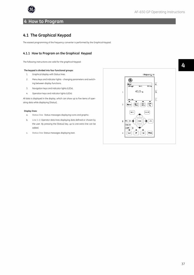
4 How to Program
4.1 The Graphical KeypadThe easiest programming of the frequency converter is performed by the Graphical Keypad.
4.1.1 How to Program on the Graphical Keypad
The following instructions are valid for the graphical Keypad:
The keypad is divided into four functional groups:
1. Graphical display with Status lines.
2. Menu keys and indicator lights - changing parameters and switch-
ing between display functions.
3. Navigation keys and indicator lights (LEDs).
4. Operation keys and indicator lights (LEDs).
All data is displayed in the display, which can show up to five items of oper-
ating data while displaying [Status].
Display lines:
a. Status line: Status messages displaying icons and graphic.
b. Line 1-2: Operator data lines displaying data defined or chosen by
the user. By pressing the [Status] key, up to one extra line can be
added.
c. Status line: Status messages displaying text.
AF-650 GP Operating Instructions
37
4
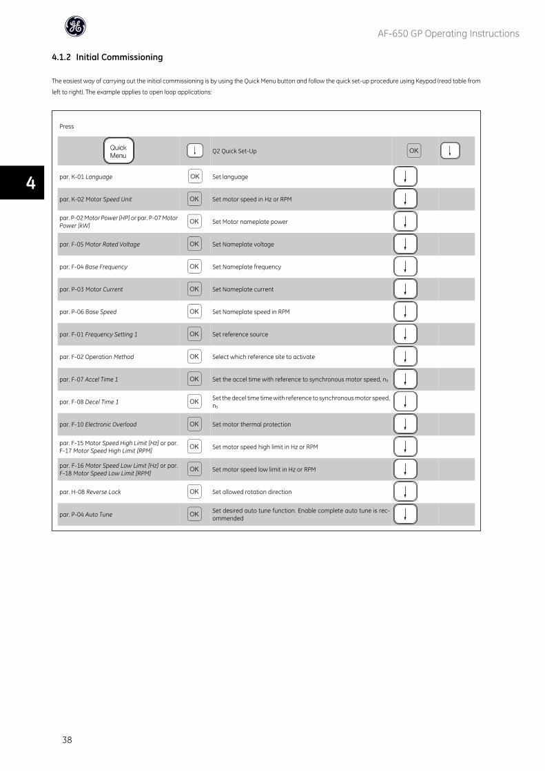
4.1.2 Initial Commissioning
The easiest way of carrying out the initial commissioning is by using the Quick Menu button and follow the quick set-up procedure using Keypad (read table from
left to right). The example applies to open loop applications:
Press
Q2 Quick Set-Up
par. K-01 Language Set language
par. K-02 Motor Speed Unit Set motor speed in Hz or RPM
par. P-02 Motor Power [HP] or par. P-07 MotorPower [kW]
Set Motor nameplate power
par. F-05 Motor Rated Voltage Set Nameplate voltage
par. F-04 Base Frequency Set Nameplate frequency
par. P-03 Motor Current Set Nameplate current
par. P-06 Base Speed Set Nameplate speed in RPM
par. F-01 Frequency Setting 1 Set reference source
par. F-02 Operation Method Select which reference site to activate
par. F-07 Accel Time 1 Set the accel time with reference to synchronous motor speed, ns
par. F-08 Decel Time 1Set the decel time time with reference to synchronous motor speed,ns
par. F-10 Electronic Overload Set motor thermal protection
par. F-15 Motor Speed High Limit [Hz] or par.F-17 Motor Speed High Limit [RPM]
Set motor speed high limit in Hz or RPM
par. F-16 Motor Speed Low Limit [Hz] or par.F-18 Motor Speed Low Limit [RPM]
Set motor speed low limit in Hz or RPM
par. H-08 Reverse Lock Set allowed rotation direction
par. P-04 Auto TuneSet desired auto tune function. Enable complete auto tune is rec-ommended
AF-650 GP Operating Instructions
38
4
4.2 Quick Setup Parameter List
K-01 Language
Option: Function:
Defines the language to be used in the display.
The frequency converter is delivered with 4 different languages.
[0] * English Part of Language packages 1 - 4
K-02 Motor Speed Unit
Option: Function:
This parameter cannot be adjusted while the motor is running.
The display showing depends on settings in par. K-02 Motor Speed Unit and par. K-03 Regional Settings.
The default setting of par. K-02 Motor Speed Unit and par. K-03 Regional Settings depends on which region
of the world the frequency converter is supplied to, but can be re-programmed as required.
NB!
Changing the Motor Speed Unit will reset certain parameters to their initial value. It is recommended to
select the motor speed unit first, before modifying other parameters.
[0] RPM Selects display of motor speed variables and parameters (i.e. references, feedbacks and limits) in terms
of motor speed (RPM).
[1] * Hz Selects display of motor speed variables and parameters (i.e. references, feedbacks and limits) in terms
of output frequency to the motor (Hz).
P-02 Motor Power [HP]
Range: Function:
4.00 hp* [0.09 - 3000.00 hp] Enter the nominal motor power in HP according to the motor nameplate data. The default value corre-
sponds to the nominal rated output of the unit. This parameter is visible in Keypad if par. K-03 Region-
al Settings is US [1]
P-07 Motor Power [kW]
Range: Function:
4.00 kW* [0.09 - 3000.00 kW] Enter the nominal motor power in kW according to the motor nameplate data. The default value corre-
sponds to the nominal rated output of the unit.
This parameter cannot be adjusted while the motor is running. This parameter is visible in Keypad if par.
K-03 Regional Settings is International [0].
F-05 Motor Rated Voltage
Range: Function:
400. V* [10. - 1000. V] Enter the nominal motor voltage according to the motor nameplate data. The default value corresponds
to the nominal rated output of the unit.
This parameter cannot be adjusted while the motor is running.
F-04 Base Frequency
Range: Function:
50. Hz* [20 - 1000 Hz] Min - Max motor frequency: 20 - 1000 Hz.
Select the motor frequency value from the motor nameplate data. If a value different from 50 Hz or 60
Hz is selected, it is necessary to adapt the load independent settings in par. H-50 Motor Magnetisation at
Zero Speed to par. H-53 Model Shift Frequency. For 87 Hz operation with 230/400 V motors, set the name-
plate data for 230 V/50 Hz. Adapt par. F-17 Motor Speed High Limit [RPM] and par. F-53 Maxi-
mum Reference to the 87 Hz application.
AF-650 GP Operating Instructions
39
4
P-03 Motor Current
Range: Function:
7.20 A* [0.10 - 10000.00 A] Enter the nominal motor current value from the motor nameplate data. This data is used for calculating
motor torque, motor thermal protection etc.
NB!
This parameter cannot be adjusted while the motor is running.
P-06 Base Speed
Range: Function:
1420. RPM* [100 - 60000 RPM] Enter the nominal motor speed value from the motor nameplate data. This data is used for calculating
automatic motor compensations.
NB!
This parameter cannot be changed while the motor is running.
F-01 Frequency Setting 1
Option: Function:
Select the reference input to be used for the first reference signal. par. F-01 Frequency Setting 1, par.
C-30 Frequency Command 2 and par. C-34 Frequency Command 3 define up to three different reference
signals. The sum of these reference signals defines the actual reference.
[0] No function
[1] * Analog Input 53
[2] Analog Input 54
[7] Frequency input 29
[8] Frequency input 33
[11] Local bus reference
[20] Digital Potentiometer
[21] Analog input X30-11 (OPCGPIO - General Purpose I/O Option Module)
[22] Analog input X30-12 (OPCGPIO - General Purpose I/O Option Module)
F-02 Operation Method
Option: Function:
Select which reference site to activate.
[0] * Linked to Hand / Auto Use local reference when in Hand mode; or remote reference when in Auto mode.
[1] Remote Use remote reference in both Hand mode and Auto mode.
[2] Local Use local reference in both Hand mode and Auto mode.
NB!
When set to Local [2], the frequency converter will start with this setting again following a 'power down'.
F-07 Accel Time 1
Range: Function:
3.00 s* [0.01 - 3600.00 s] Enter the accel time, i.e. the acceleration time from 0 RPM to the synchronous motor speed nS. Choose a
accel time such that the output current does not exceed the current limit in par. F-43 Current Limit during
ramping. The value 0.00 corresponds to 0.01 sec. in speed mode. See decel time in par. F-08 Decel Time
1.
AF-650 GP Operating Instructions
40
4
Par. F − 07 = tacc s x ns RPM
ref RPM
F-08 Decel Time 1
Range: Function:
3.00 s* [0.01 - 3600.00 s] Enter the decel time, i.e. the deceleration time from the synchronous motor speed ns to 0 RPM. Choose a
decel time such that no over-voltage arises in the inverter due to regenerative operation of the motor,
and such that the generated current does not exceed the current limit set in par. F-43 Current Limit. The
value 0.00 corresponds to 0.01 s in speed mode. See accel time in par. F-07 Accel Time 1.
Par. F − 08 = tdec s x ns RPM
ref RPM
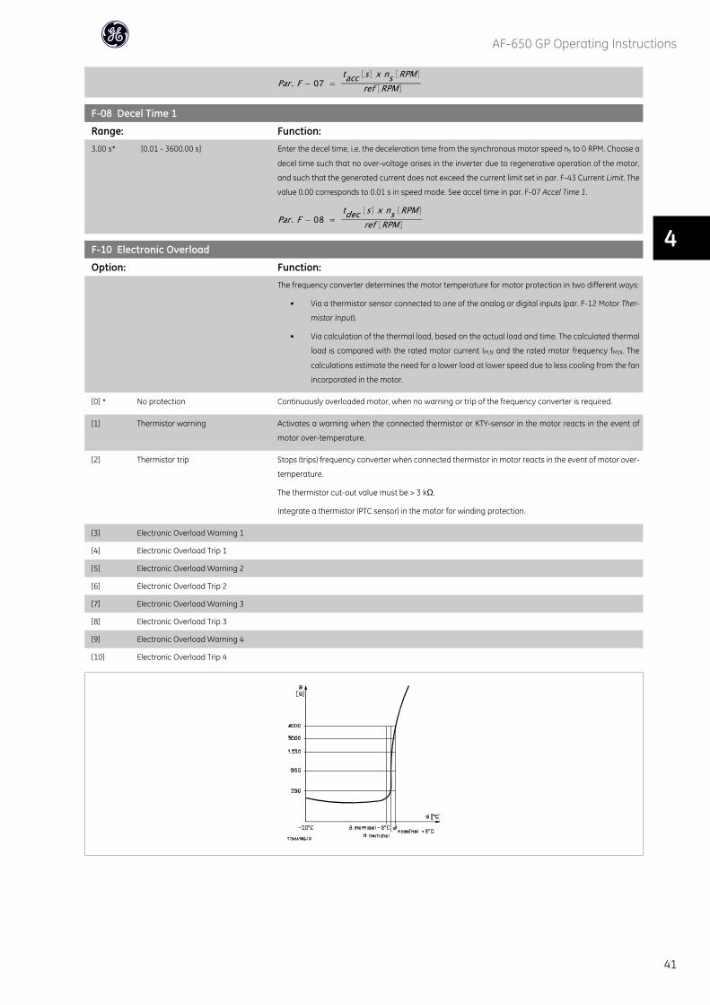
F-10 Electronic Overload
Option: Function:
The frequency converter determines the motor temperature for motor protection in two different ways:
• Via a thermistor sensor connected to one of the analog or digital inputs (par. F-12 Motor Ther-
mistor Input).
• Via calculation of the thermal load, based on the actual load and time. The calculated thermal
load is compared with the rated motor current IM,N and the rated motor frequency fM,N. The
calculations estimate the need for a lower load at lower speed due to less cooling from the fan
incorporated in the motor.
[0] * No protection Continuously overloaded motor, when no warning or trip of the frequency converter is required.
[1] Thermistor warning Activates a warning when the connected thermistor or KTY-sensor in the motor reacts in the event of
motor over-temperature.
[2] Thermistor trip Stops (trips) frequency converter when connected thermistor in motor reacts in the event of motor over-
temperature.
The thermistor cut-out value must be > 3 kΩ.
Integrate a thermistor (PTC sensor) in the motor for winding protection.
[3] Electronic Overload Warning 1
[4] Electronic Overload Trip 1
[5] Electronic Overload Warning 2
[6] Electronic Overload Trip 2
[7] Electronic Overload Warning 3
[8] Electronic Overload Trip 3
[9] Electronic Overload Warning 4
[10] Electronic Overload Trip 4
AF-650 GP Operating Instructions
41
4
Motor protection can be implemented using a range of techniques: PTC or KTY sensor (see also section KTY Sensor Connection) in motor windings; mechanical
thermal switch (Klixon type); or Electronic Thermal Overload.
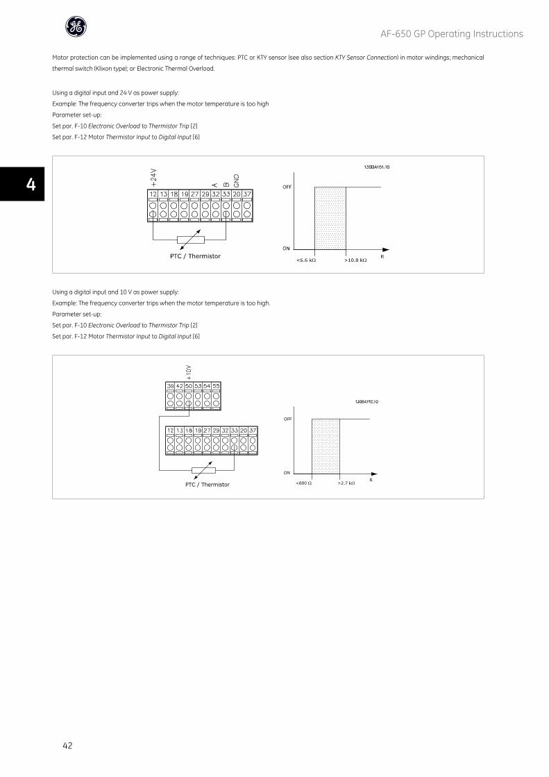
Using a digital input and 24 V as power supply:
Example: The frequency converter trips when the motor temperature is too high
Parameter set-up:
Set par. F-10 Electronic Overload to Thermistor Trip [2]
Set par. F-12 Motor Thermistor Input to Digital Input [6]
Using a digital input and 10 V as power supply:
Example: The frequency converter trips when the motor temperature is too high.
Parameter set-up:
Set par. F-10 Electronic Overload to Thermistor Trip [2]
Set par. F-12 Motor Thermistor Input to Digital Input [6]
AF-650 GP Operating Instructions
42
4
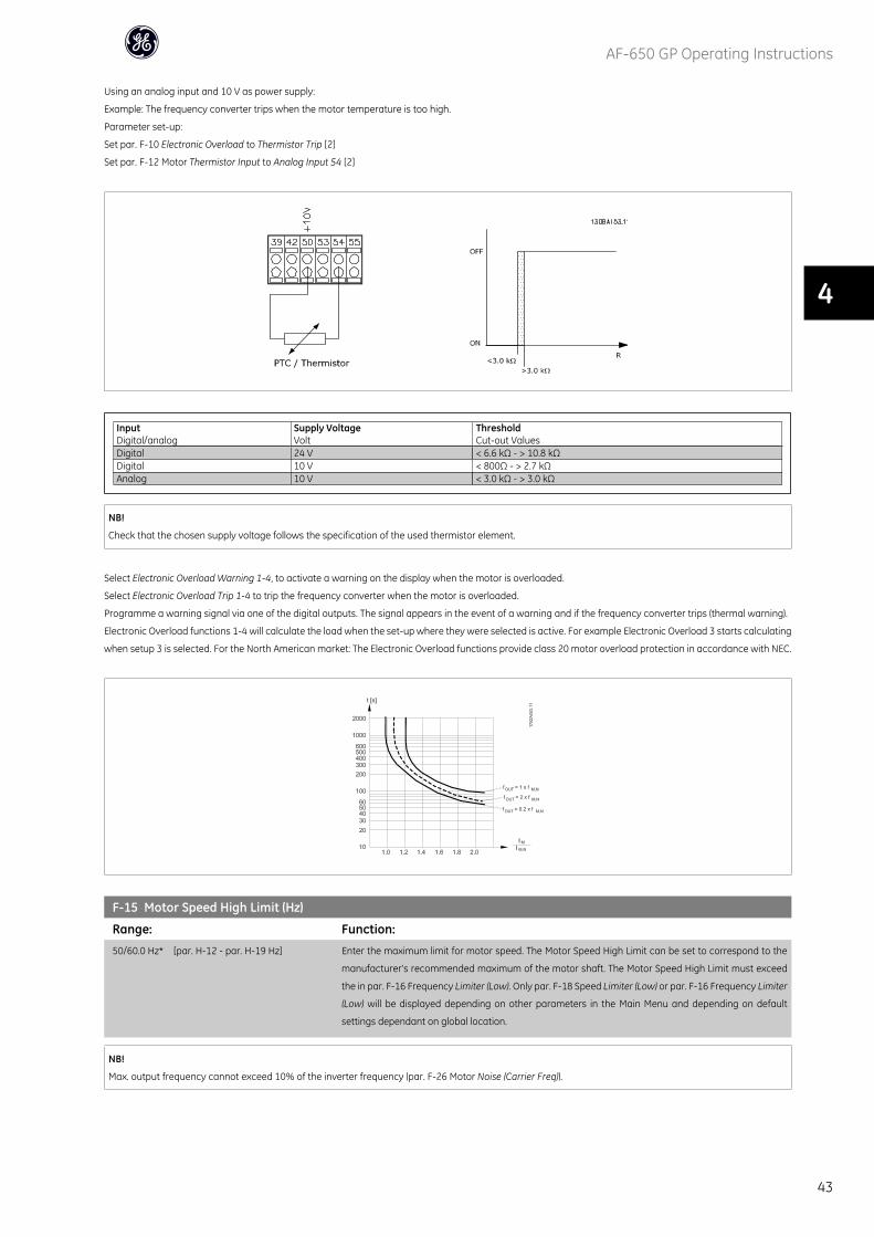
Using an analog input and 10 V as power supply:
Example: The frequency converter trips when the motor temperature is too high.
Parameter set-up:
Set par. F-10 Electronic Overload to Thermistor Trip [2]
Set par. F-12 Motor Thermistor Input to Analog Input 54 [2]
InputDigital/analog
Supply VoltageVolt
ThresholdCut-out Values
Digital 24 V < 6.6 kΩ - > 10.8 kΩDigital 10 V < 800Ω - > 2.7 kΩAnalog 10 V < 3.0 kΩ - > 3.0 kΩ
NB!
Check that the chosen supply voltage follows the specification of the used thermistor element.
Select Electronic Overload Warning 1-4, to activate a warning on the display when the motor is overloaded.
Select Electronic Overload Trip 1-4 to trip the frequency converter when the motor is overloaded.
Programme a warning signal via one of the digital outputs. The signal appears in the event of a warning and if the frequency converter trips (thermal warning).
Electronic Overload functions 1-4 will calculate the load when the set-up where they were selected is active. For example Electronic Overload 3 starts calculating
when setup 3 is selected. For the North American market: The Electronic Overload functions provide class 20 motor overload protection in accordance with NEC.
F-15 Motor Speed High Limit (Hz)
Range: Function:
50/60.0 Hz* [par. H-12 - par. H-19 Hz] Enter the maximum limit for motor speed. The Motor Speed High Limit can be set to correspond to the
manufacturer’s recommended maximum of the motor shaft. The Motor Speed High Limit must exceed
the in par. F-16 Frequency Limiter (Low). Only par. F-18 Speed Limiter (Low) or par. F-16 Frequency Limiter
(Low) will be displayed depending on other parameters in the Main Menu and depending on default
settings dependant on global location.
NB!
Max. output frequency cannot exceed 10% of the inverter frequency (par. F-26 Motor Noise (Carrier Freq)).
AF-650 GP Operating Instructions
43
4
F-16 Motor Speed Low Limit [Hz]
Range: Function:
0 Hz* [0.0 - par. H-14 Hz] Enter the minimum limit for motor speed. The Motor Speed Low Limit can be set to correspond to the
minimum output frequency of the motor shaft. The Motor Speed Low Limit must not exceed the setting
in par. F-15 Motor Speed High Limit (Hz).
F-17 Motor Speed High Limit [RPM]
Range: Function:
3600. RPM* [par. H-11 - 60000. RPM] Enter the maximum limit for motor speed. The Motor Speed High Limit can be set to correspond to the
manufacturer’s maximum rated motor speed. The Motor Speed High Limit must exceed the setting in
par. F-18 Motor Speed Low Limit [RPM].
NB!
Max. output frequency cannot exceed 10% of the inverter switching frequency (par. F-26 Motor Noise (Carrier Freq)).
F-18 Motor Speed Low Limit [RPM]
Range: Function:
0 RPM* [0 - par. H-13 RPM] Enter the minimum limit for motor speed. The Motor Speed Low Limit can be set to correspond to the
manufacturer’s recommended minimum motor speed. The Motor Speed Low Limit must not exceed the
setting in par. F-17 Motor Speed High Limit [RPM].
H-08 Reverse Lock
Option: Function:
Select the motor speed direction(s) required. Use this parameter to prevent unwanted reversing. When
par. H-40 Configuration Mode is set to Process [3], par. H-08 Reverse Lock is set to Clockwise [0] as default.
The setting in par. H-08 Reverse Lock does not limit options for setting par. F-15 Motor Speed High Limit
(Hz) or par. F-17 Motor Speed High Limit [RPM].
This parameter cannot be adjusted while the motor is running.
[0] * Clockwise
[1] Counter clockwise
[2] Both directions
P-04 Auto Tune
Option: Function:
The Auto Tune function optimises dynamic motor performance by automatically optimising the advanced
motor parameters (par. P-30 Stator Resistance (Rs) to par. P-35 Main Reactance (Xh)) at motor standstill.
Activate the Auto Tune function by pressing [Hand] after selecting [1] or [2]. See also the section Auto
Tuning in the AF-650 GP Design Guide. After a normal sequence, the display will read: "Press [OK] to finish
Auto Tune". After pressing the [OK] key the frequency converter is ready for operation.
This parameter cannot be adjusted while the motor is running.
[0] * Off
[1] Enable complete Auto Tune
[2] Enable reduced Auto Tune
Note:
• For the best results run Auto Tune on a cold motor.
• Auto Tune cannot be performed while the motor is running.
• Auto Tune cannot be performed on permanent magnet motors.
AF-650 GP Operating Instructions
44
4

NB!
It is important to set motor par. F-04, F-05, and P-02 to P-08 correctly, since these form part of the Auto Tune algorithm. An Auto Tune should be performed to
achieve optimum dynamic motor performance. It may take up to 10 min, depending on the power rating of the motor.
NB!
Avoid generating external torque during Auto Tune.
NB!
If one of the settings in par. F-04, F-05, or P-02 to P-08 is changed, par. P-30 Stator Resistance (Rs) to par. P-01 Motor Poles, the advanced motor parameters,
will return to default setting.
NB!
Auto Tune will work problem-free on 1 motor size down, typically work on 2 motor sizes down, rarely work on 3 sizes down and never work on 4 sizes down.
Please keep in mind that the accuracy of the measured motor data will be poorer when you operate on motors smaller than nominal drive size.
AF-650 GP Operating Instructions
45
4

4.3 Parameter Lists
AF-650 GP Operating Instructions
46
4
Par.
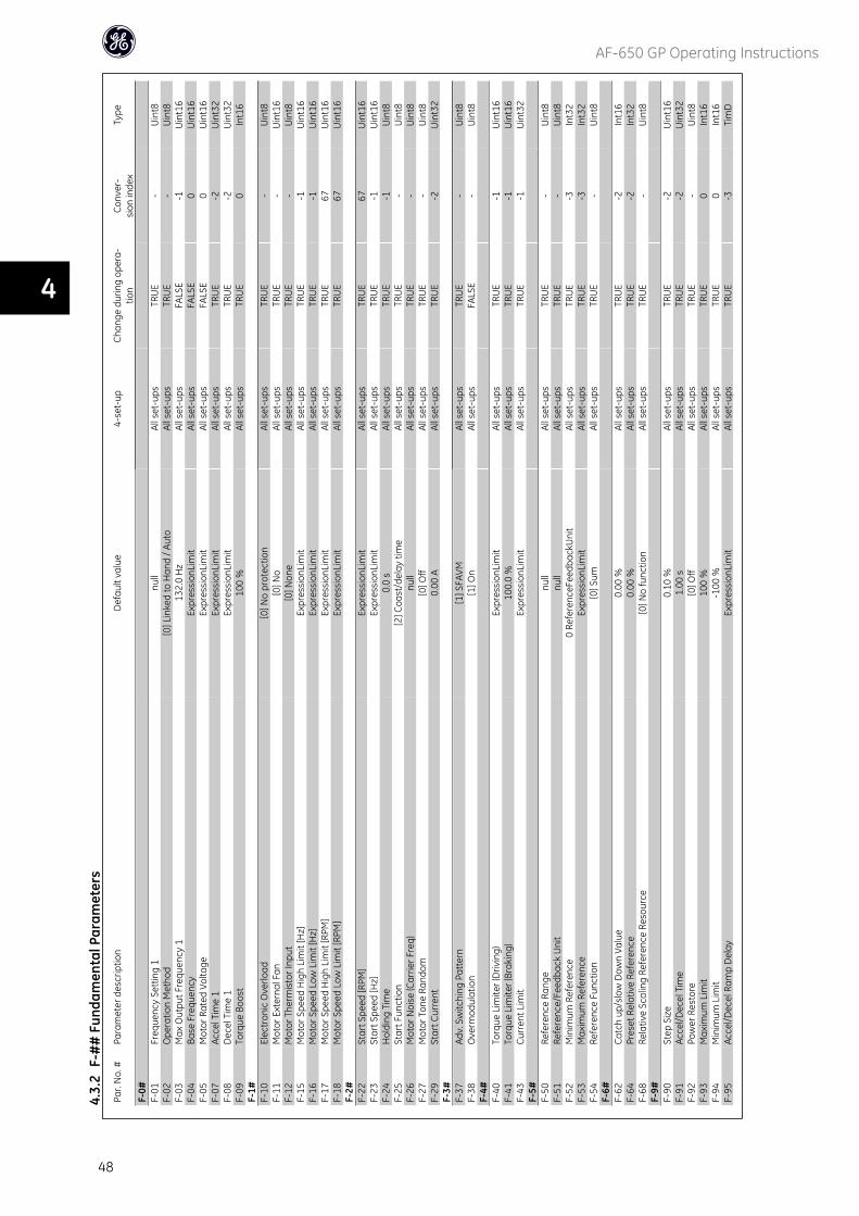
No.
#Pa
ram
eter
des
crip
tion
Def
ault
valu
e4-
set-
upCh
ange
dur
ing
oper
a-tio
nCo
nver
-si
on in
dex
Type
K-0#
K-01
Lang
uage
[0] E
nglis
h1
set-
upTR
UE
-U
int8
K-02
Mot
or S
peed
Uni
t[0
] RPM
2 se
t-up
sFA
LSE
-U
int8
K-03
Regi
onal
Set
tings
[1] U
S2
set-
ups
FALS
E-
Uin
t8K-
04O
pera
ting
Stat
e at
Pow
er-u
p[1
] For
ced
stop
, ref
=old
All s
et-u
psTR
UE
-U
int8
K-1#
K-10
Activ
e Se
t-up
[1] S
et-u
p 1
1 se
t-up
TRU
E-
Uin
t8K-
11Ed
it Se
t-up
[1] S
et-u
p 1
All s
et-u
psTR
UE
-U
int8
K-12
This
Set
-up
Link
ed to
[0] N
ot li
nked
All s
et-u
psFA
LSE
-U
int8
K-13
Read
out:
Link
ed S
et-u
ps0
N/A
All s
et-u
psFA
LSE
0U
int1
6K-
14Re
adou
t: Ed
it Se
t-up
s / C
hann
el0
N/A
All s
et-u
psTR
UE
0In
t32
K-2#
K-20
Dis
play
Lin
e 1.
1 Sm
all
Expr
essi
onLi
mit
All s
et-u
psTR
UE
-U
int1
6K-
21D
ispl
ay L
ine
1.2
Smal
lEx
pres
sion
Lim
itAl
l set
-ups
TRU
E-
Uin
t16
K-22
Dis
play
Lin
e 1.
3 Sm
all
Expr
essi
onLi
mit
All s
et-u
psTR
UE
-U
int1
6K-
23D
ispl
ay L
ine
2 La
rge
Expr
essi
onLi
mit
All s
et-u
psTR
UE
-U
int1
6K-
24D
ispl
ay L
ine
3 La
rge
Expr
essi
onLi
mit
All s
et-u
psTR
UE
-U
int1
6K-
25Q
uick
Sta
rtEx
pres
sion
Lim
it1
set-
upTR
UE
0U
int1
6K-
3#K-
30U
nit f
or C
usto
m R
eado
ut[0
] Non
eAl
l set
-ups
TRU
E-
Uin
t8K-
31M
in V
alue
of C
usto
m R
eado
ut0.
00 C
usto
mRe
adou
tUni
tAl
l set
-ups
TRU
E-2
Int3
2K-
32M
ax V
alue
of C
usto
m R
eado
ut10
0.00
Cus
tom
Read
outU
nit
All s
et-u
psTR
UE
-2In
t32
K-4#
K-40
[Han
d] B
utto
n on
Key
pad
[1] E
nabl
edAl
l set
-ups
TRU
E-
Uin
t8K-
41[O
ff] B
utto
n on
Key
pad
[1] E
nabl
edAl
l set
-ups
TRU
E-
Uin
t8K-
42[A
uto]
But
ton
on K
eypa
d[1
] Ena
bled
All s
et-u
psTR
UE
-U
int8
K-43
[Res
et] B
utto
n on
Key
pad
[1] E
nabl
edAl
l set
-ups
TRU
E-
Uin
t8K-
5#K-
50Ke
ypad
Cop
y[0
] No
copy
All s
et-u
psFA
LSE
-U
int8
K-51
Set-
up C
opy
[0] N
o co
pyAl
l set
-ups
FALS
E-
Uin
t8K-
6#K-
60M
ain
Men
u Pa
ssw
ord
100
N/A
1 se
t-up
TRU
E0
Int1
6K-
61Ac
cess
to M
ain
Men
u w
/o P
assw
ord
[0] F
ull a
cces
s1
set-
upTR
UE
-U
int8
K-65
Qui
ck M
enu
Pass
wor
d20
0 N
/A1
set-
upTR
UE
0In
t16
K-66
Acce
ss to
Qui
ck M
enu
w/o
Pas
swor
d[0
] Ful
l acc
ess
1 se
t-up
TRU
E-
Uin
t8K-
67Bu
s Pa
ssw
ord
Acce
ss0
N/A
All s
et-u
psTR
UE
0U
int1
6
4.3.
1K-
##
Key
pad
Set-
up
AF-650 GP Operating Instructions
47
4
Par.
No.
#Pa
ram
eter
des
crip
tion
Def
ault
valu
e4-
set-
upCh
ange
dur
ing
oper
a-tio
nCo
nver
-si
on in
dex
Type
F-0#
F-01
Freq
uenc
y Se
ttin
g 1
null
All s
et-u
psTR
UE
-U
int8
F-02
Ope
ratio
n M
etho
d[0
] Lin
ked
to H
and
/ Aut
oAl
l set
-ups
TRU
E-
Uin
t8F-
03M
ax O
utpu
t Fre
quen
cy 1
132.
0 H
zAl
l set
-ups
FALS
E-1
Uin
t16
F-04
Base
Fre
quen
cyEx
pres
sion
Lim
itAl
l set
-ups
FALS
E0
Uin
t16
F-05
Mot
or R
ated
Vol
tage
Expr
essi
onLi
mit
All s
et-u
psFA
LSE
0U
int1
6F-
07Ac
cel T
ime
1Ex
pres
sion
Lim
itAl
l set
-ups
TRU
E-2
Uin
t32
F-08
Dec
el T
ime
1Ex
pres
sion
Lim
itAl
l set
-ups
TRU
E-2
Uin
t32
F-09
Torq
ue B
oost
100
%Al
l set
-ups
TRU
E0
Int1
6F-
1#F-
10El
ectr
onic
Ove
rload
[0] N
o pr
otec
tion
All s
et-u
psTR
UE
-U
int8
F-11
Mot
or E
xter
nal F
an[0
] No
All s
et-u
psTR
UE
-U
int1
6F-
12M
otor
The
rmis
tor I
nput
[0] N
one
All s
et-u
psTR
UE
-U
int8
F-15
Mot
or S
peed
Hig
h Li
mit
[Hz]
Expr
essi
onLi
mit
All s
et-u
psTR
UE
-1U
int1
6F-
16M
otor
Spe
ed L
ow L
imit
[Hz]
Expr
essi
onLi
mit
All s
et-u
psTR
UE
-1U
int1
6F-
17M
otor
Spe
ed H
igh
Lim
it [R
PM]
Expr
essi
onLi
mit
All s
et-u
psTR
UE
67U
int1
6F-
18M
otor
Spe
ed L
ow L
imit
[RPM
]Ex
pres
sion
Lim
itAl
l set
-ups
TRU
E67
Uin
t16
F-2#
F-22
Star
t Spe
ed [R
PM]
Expr
essi
onLi
mit
All s
et-u
psTR
UE
67U
int1
6F-
23St
art S
peed
[Hz]
Expr
essi
onLi
mit
All s
et-u
psTR
UE
-1U
int1
6F-
24H
oldi
ng T
ime
0.0
sAl
l set
-ups
TRU
E-1
Uin
t8F-
25St
art F
unct
ion
[2] C
oast
/del
ay ti
me
All s
et-u
psTR
UE
-U
int8
F-26
Mot
or N
oise
(Car
rier F
req)
null
All s
et-u
psTR
UE
-U
int8
F-27
Mot
or T
one
Rand
om[0
] Off
All s
et-u
psTR
UE
-U
int8
F-29
Star
t Cur
rent
0.00
AAl
l set
-ups
TRU
E-2
Uin
t32
F-3#
F-37
Adv.
Sw
itchi
ng P
atte
rn[1
] SFA
VMAl
l set
-ups
TRU
E-
Uin
t8F-
38O
verm
odul
atio
n[1
] On
All s
et-u
psFA
LSE
-U
int8
F-4#
F-40
Torq
ue L
imite
r (D
rivin
g)Ex
pres
sion
Lim
itAl
l set
-ups
TRU
E-1
Uin
t16
F-41
Torq
ue L
imite
r (Br
akin
g)10
0.0
%Al
l set
-ups
TRU
E-1
Uin
t16
F-43
Curr
ent L
imit
Expr
essi
onLi
mit
All s
et-u
psTR
UE
-1U
int3
2F-
5#F-
50Re
fere
nce
Rang
enu
llAl
l set
-ups
TRU
E-
Uin
t8F-
51Re
fere
nce/
Feed
back
Uni
tnu
llAl
l set
-ups
TRU
E-
Uin
t8F-
52M
inim
um R
efer
ence
0 Re
fere
nceF
eedb
ackU
nit
All s
et-u
psTR
UE
-3In
t32
F-53
Max
imum
Ref
eren
ceEx
pres
sion
Lim
itAl
l set
-ups
TRU
E-3
Int3
2F-
54Re
fere
nce
Func
tion
[0] S
umAl
l set
-ups
TRU
E-
Uin
t8F-
6#F-
62Ca
tch
up/s
low
Dow
n Va
lue
0.00
%Al
l set
-ups
TRU
E-2
Int1
6F-
64Pr
eset
Rel
ativ
e Re
fere
nce
0.00
%Al
l set
-ups
TRU
E-2
Int3
2F-
68Re
lativ
e Sc
alin
g Re
fere
nce
Reso
urce
[0] N
o fu
nctio
nAl
l set
-ups
TRU
E-
Uin
t8F-
9#F-
90St
ep S
ize
0.10
%Al
l set
-ups
TRU
E-2
Uin
t16
F-91
Acce
l/Dec
el T
ime
1.00
sAl
l set
-ups
TRU
E-2
Uin
t32
F-92
Pow
er R
esto
re[0
] Off
All s
et-u
psTR
UE
-U
int8
F-93
Max
imum
Lim
it10
0 %
All s
et-u
psTR
UE
0In
t16
F-94
Min
imum
Lim
it-1
00 %
All s
et-u
psTR
UE
0In
t16
F-95
Acce
l/Dec
el R
amp
Del
ayEx
pres
sion
Lim
itAl
l set
-ups
TRU
E-3
Tim
D
4.3.
2F-
##
Fun
dam
enta
l Par
amet
ers
AF-650 GP Operating Instructions
48
4
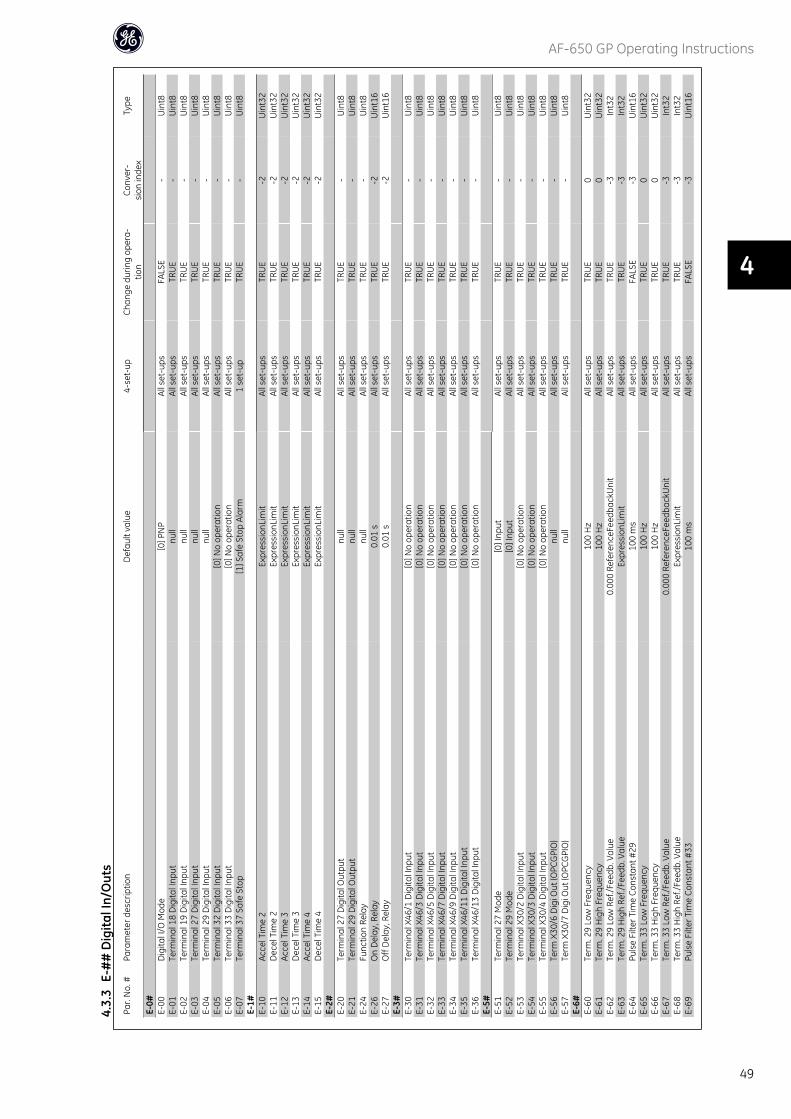
Par.
No.
#Pa
ram
eter
des
crip
tion
Def
ault
valu
e4-
set-
upCh
ange
dur
ing
oper
a-tio
nCo
nver
-si
on in
dex
Type
E-0#
E-00
Dig
ital I
/O M
ode
[0] P
NP
All s
et-u
psFA
LSE
-U
int8
E-01
Term
inal
18
Dig
ital I
nput
null
All s
et-u
psTR
UE
-U
int8
E-02
Term
inal
19
Dig
ital I
nput
null
All s
et-u
psTR
UE
-U
int8
E-03
Term
inal
27
Dig
ital I
nput
null
All s
et-u
psTR
UE
-U
int8
E-04
Term
inal
29
Dig
ital I
nput
null
All s
et-u
psTR
UE
-U
int8
E-05
Term
inal
32
Dig
ital I
nput
[0] N
o op
erat
ion
All s
et-u
psTR
UE
-U
int8
E-06
Term
inal
33
Dig
ital I
nput
[0] N
o op
erat
ion
All s
et-u
psTR
UE
-U
int8
E-07
Term
inal
37
Safe
Sto
p[1
] Saf
e St
op A
larm
1 se
t-up
TRU
E-
Uin
t8E-
1#E-
10Ac
cel T
ime
2Ex
pres
sion
Lim
itAl
l set
-ups
TRU
E-2
Uin
t32
E-11
Dec
el T
ime
2Ex
pres
sion
Lim
itAl
l set
-ups
TRU
E-2
Uin
t32
E-12
Acce
l Tim
e 3
Expr
essi
onLi
mit
All s
et-u
psTR
UE
-2U
int3
2E-
13D
ecel
Tim
e 3
Expr
essi
onLi
mit
All s
et-u
psTR
UE
-2U
int3
2E-
14Ac
cel T
ime
4Ex
pres
sion
Lim
itAl
l set
-ups
TRU
E-2
Uin
t32
E-15
Dec
el T
ime
4Ex
pres
sion
Lim
itAl
l set
-ups
TRU
E-2
Uin
t32
E-2#
E-20
Term
inal
27
Dig
ital O
utpu
tnu
llAl
l set
-ups
TRU
E-
Uin
t8E-
21Te
rmin
al 2
9 D
igita
l Out
put
null
All s
et-u
psTR
UE
-U
int8
E-24
Func
tion
Rela
ynu
llAl
l set
-ups
TRU
E-
Uin
t8E-
26O
n D
elay
, Rel
ay0.
01 s
All s
et-u
psTR
UE
-2U
int1
6E-
27O
ff D
elay
, Rel
ay0.
01 s
All s
et-u
psTR
UE
-2U
int1
6E-
3#E-
30Te
rmin
al X
46/1
Dig
ital I
nput
[0] N
o op
erat
ion
All s
et-u
psTR
UE
-U
int8
E-31
Term
inal
X46
/3 D
igita
l Inp
ut[0
] No
oper
atio
nAl
l set
-ups
TRU
E-
Uin
t8E-
32Te
rmin
al X
46/5
Dig
ital I
nput
[0] N
o op
erat
ion
All s
et-u
psTR
UE
-U
int8
E-33
Term
inal
X46
/7 D
igita
l Inp
ut[0
] No
oper
atio
nAl
l set
-ups
TRU
E-
Uin
t8E-
34Te
rmin
al X
46/9
Dig
ital I
nput
[0] N
o op
erat
ion
All s
et-u
psTR
UE
-U
int8
E-35
Term
inal
X46
/11
Dig
ital I
nput
[0] N
o op
erat
ion
All s
et-u
psTR
UE
-U
int8
E-36
Term
inal
X46
/13
Dig
ital I
nput
[0] N
o op
erat
ion
All s
et-u
psTR
UE
-U
int8
E-5#
E-51
Term
inal
27
Mod
e[0
] Inp
utAl
l set
-ups
TRU
E-
Uin
t8E-
52Te
rmin
al 2
9 M
ode
[0] I
nput
All s
et-u
psTR
UE
-U
int8
E-53
Term
inal
X30
/2 D
igita
l Inp
ut[0
] No
oper
atio
nAl
l set
-ups
TRU
E-
Uin
t8E-
54Te
rmin
al X
30/3
Dig
ital I
nput
[0] N
o op
erat
ion
All s
et-u
psTR
UE
-U
int8
E-55
Term
inal
X30
/4 D
igita
l Inp
ut[0
] No
oper
atio
nAl
l set
-ups
TRU
E-
Uin
t8E-
56Te
rm X
30/6
Dig
i Out
(OPC
GPI
O)
null
All s
et-u
psTR
UE
-U
int8
E-57
Term
X30
/7 D
igi O
ut (O
PCG
PIO
)nu
llAl
l set
-ups
TRU
E-
Uin
t8E-
6#E-
60Te
rm. 2
9 Lo
w F
requ
ency
100
Hz
All s
et-u
psTR
UE
0U
int3
2E-
61Te
rm. 2
9 H
igh
Freq
uenc
y10
0 H
zAl
l set
-ups
TRU
E0
Uin
t32
E-62
Term
. 29
Low
Ref
./Fee
db. V
alue
0.00
0 Re
fere
nceF
eedb
ackU
nit
All s
et-u
psTR
UE
-3In
t32
E-63
Term
. 29
Hig
h Re
f./Fe
edb.
Val
ueEx
pres
sion
Lim
itAl
l set
-ups
TRU
E-3
Int3
2E-
64Pu
lse
Filte
r Tim
e Co
nsta
nt #
2910
0 m
sAl
l set
-ups
FALS
E-3
Uin
t16
E-65
Term
. 33
Low
Fre
quen
cy10
0 H
zAl
l set
-ups
TRU
E0
Uin
t32
E-66
Term
. 33
Hig
h Fr
eque
ncy
100
Hz
All s
et-u
psTR
UE
0U
int3
2E-
67Te
rm. 3
3 Lo
w R
ef./F
eedb
. Val
ue0.
000
Refe
renc
eFee
dbac
kUni
tAl
l set
-ups
TRU
E-3
Int3
2E-
68Te
rm. 3
3 H
igh
Ref./
Feed
b. V
alue
Expr
essi
onLi
mit
All s
et-u
psTR
UE
-3In
t32
E-69
Puls
e Fi
lter T
ime
Cons
tant
#33
100
ms
All s
et-u
psFA
LSE
-3U
int1
6
4.3.
3E-
##
Dig
ital I
n/O
uts
AF-650 GP Operating Instructions
49
4
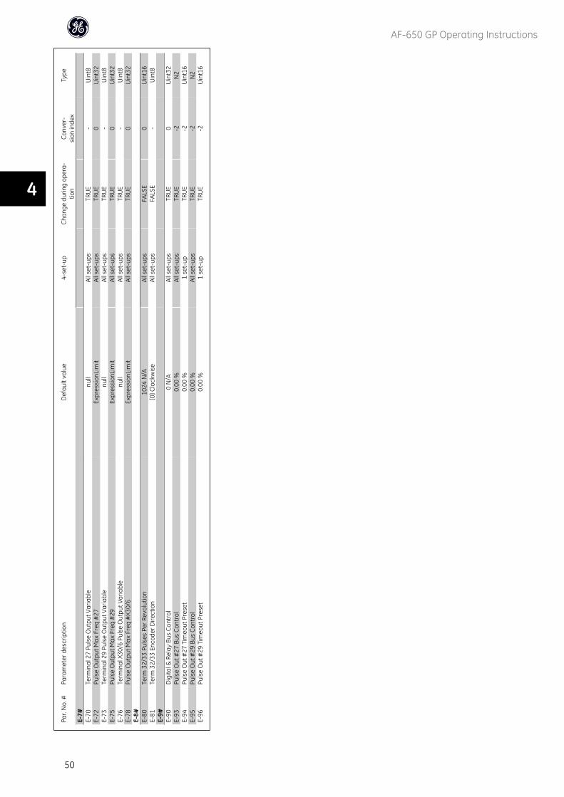
Par.
No.
#Pa
ram
eter
des
crip
tion
Def
ault
valu
e4-
set-
upCh
ange
dur
ing
oper
a-tio
nCo
nver
-si
on in
dex
Type
E-7#
E-70
Term
inal
27
Puls
e O
utpu
t Var
iabl
enu
llAl
l set
-ups
TRU
E-
Uin
t8E-
72Pu
lse
Out
put M
ax F
req
#27
Expr
essi
onLi
mit
All s
et-u
psTR
UE
0U
int3
2E-
73Te
rmin
al 2
9 Pu
lse
Out
put V
aria
ble
null
All s
et-u
psTR
UE
-U
int8
E-75
Puls
e O
utpu
t Max
Fre
q #2
9Ex
pres
sion
Lim
itAl
l set
-ups
TRU
E0
Uin
t32
E-76
Term
inal
X30
/6 P
ulse
Out
put V
aria
ble
null
All s
et-u
psTR
UE
-U
int8
E-78
Puls
e O
utpu
t Max
Fre
q #X
30/6
Expr
essi
onLi
mit
All s
et-u
psTR
UE
0U
int3
2E-
8#E-
80Te
rm 3
2/33
Pul
ses
Per R
evol
utio
n10
24 N
/AAl
l set
-ups
FALS
E0
Uin
t16
E-81
Term
32/
33 E
ncod
er D
irect
ion
[0] C
lock
wis
eAl
l set
-ups
FALS
E-
Uin
t8E-
9#E-
90D
igita
l & R
elay
Bus
Con
trol
0 N
/AAl
l set
-ups
TRU
E0
Uin
t32
E-93
Puls
e O
ut #
27 B
us C
ontr
ol0.
00 %
All s
et-u
psTR
UE
-2N
2E-
94Pu
lse
Out
#27
Tim
eout
Pre
set
0.00
%1
set-
upTR
UE
-2U
int1
6E-
95Pu
lse
Out
#29
Bus
Con
trol
0.00
%Al
l set
-ups
TRU
E-2
N2
E-96
Puls
e O
ut #
29 T
imeo
ut P
rese
t0.
00 %
1 se
t-up
TRU
E-2
Uin
t16
AF-650 GP Operating Instructions
50
4
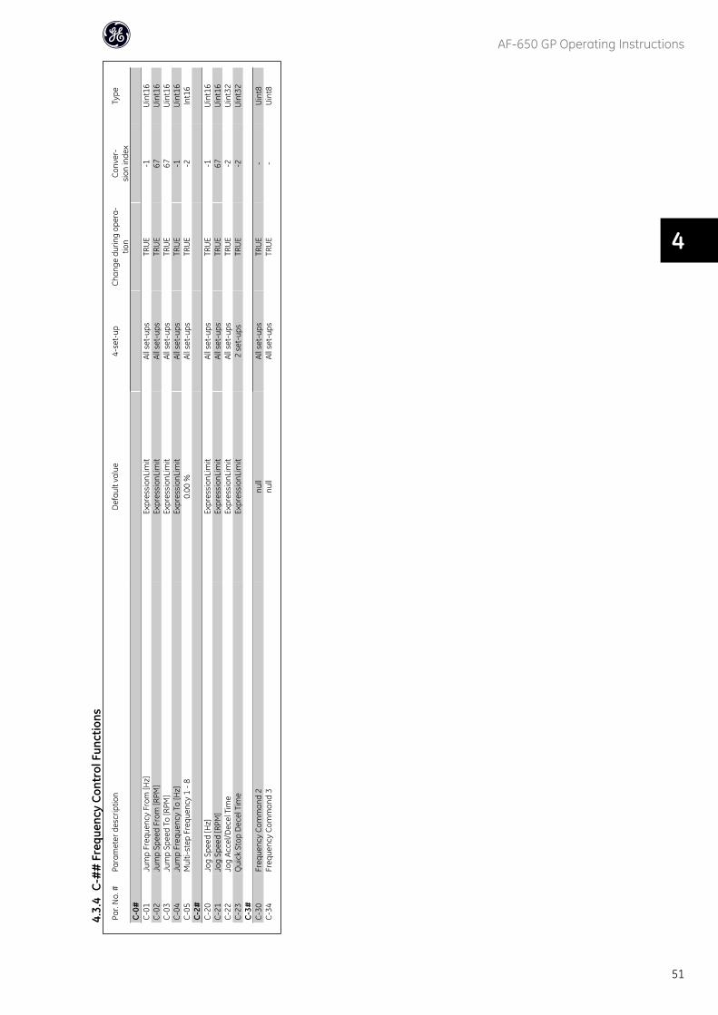
Par.
No.
#Pa
ram
eter
des
crip
tion
Def
ault
valu
e4-
set-
upCh
ange
dur
ing
oper
a-tio
nCo
nver
-si
on in
dex
Type
C-0#
C-01
Jum
p Fr
eque
ncy
From
[Hz]
Expr
essi
onLi
mit
All s
et-u
psTR
UE
-1U
int1
6C-
02Ju
mp
Spee
d Fr
om [R
PM]
Expr
essi
onLi
mit
All s
et-u
psTR
UE
67U
int1
6C-
03Ju
mp
Spee
d To
[RPM
]Ex
pres
sion
Lim
itAl
l set
-ups
TRU
E67
Uin
t16
C-04
Jum
p Fr
eque
ncy
To [H
z]Ex
pres
sion
Lim
itAl
l set
-ups
TRU
E-1
Uin
t16
C-05
Mul
ti-st
ep F
requ
ency
1 -
80.
00 %
All s
et-u
psTR
UE
-2In
t16
C-2#
C-20
Jog
Spee
d [H
z]Ex
pres
sion
Lim
itAl
l set
-ups
TRU
E-1
Uin
t16
C-21
Jog
Spee
d [R
PM]
Expr
essi
onLi
mit
All s
et-u
psTR
UE
67U
int1
6C-
22Jo
g Ac
cel/D
ecel
Tim
eEx
pres
sion
Lim
itAl
l set
-ups
TRU
E-2
Uin
t32
C-23
Qui
ck S
top
Dec
el T
ime
Expr
essi
onLi
mit
2 se
t-up
sTR
UE
-2U
int3
2C-
3#C-
30Fr
eque
ncy
Com
man
d 2
null
All s
et-u
psTR
UE
-U
int8
C-34
Freq
uenc
y Co
mm
and
3nu
llAl
l set
-ups
TRU
E-
Uin
t8
4.3.
4C-
##
Fre
quen
cy C
ontr
ol F
unct
ions
AF-650 GP Operating Instructions
51
4
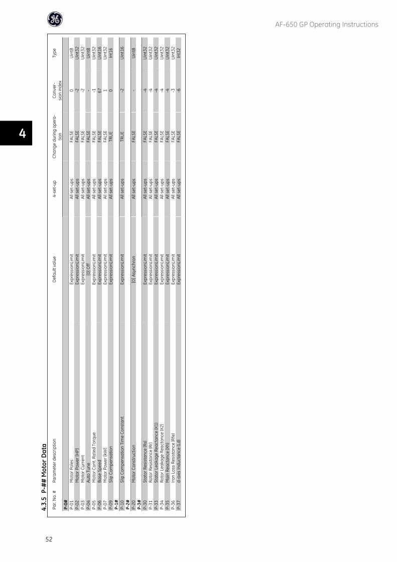
Par.
No.
#Pa
ram
eter
des
crip
tion
Def
ault
valu
e4-
set-
upCh
ange
dur
ing
oper
a-tio
nCo
nver
-si
on in
dex
Type
P-0#
P-01
Mot
or P
oles
Expr
essi
onLi
mit
All s
et-u
psFA
LSE
0U
int8
P-02
Mot
or P
ower
[HP]
Expr
essi
onLi
mit
All s
et-u
psFA
LSE
-2U
int3
2P-
03M
otor
Cur
rent
Expr
essi
onLi
mit
All s
et-u
psFA
LSE
-2U
int3
2P-
04Au
to T
une
[0] O
ffAl
l set
-ups
FALS
E-
Uin
t8P-
05M
otor
Con
t. Ra
ted
Torq
ueEx
pres
sion
Lim
itAl
l set
-ups
FALS
E-1
Uin
t32
P-06
Base
Spe
edEx
pres
sion
Lim
itAl
l set
-ups
FALS
E67
Uin
t16
P-07
Mot
or P
ower
[kW
]Ex
pres
sion
Lim
itAl
l set
-ups
FALS
E1
Uin
t32
P-09
Slip
Com
pens
atio
nEx
pres
sion
Lim
itAl
l set
-ups
TRU
E0
Int1
6P-
1#P-
10Sl
ip C
ompe
nsat
ion
Tim
e Co
nsta
ntEx
pres
sion
Lim
itAl
l set
-ups
TRU
E-2
Uin
t16
P-2#
P-20
Mot
or C
onst
ruct
ion
[0] A
sync
hron
All s
et-u
psFA
LSE
-U
int8
P-3#
P-30
Stat
or R
esis
tanc
e (R
s)Ex
pres
sion
Lim
itAl
l set
-ups
FALS
E-4
Uin
t32
P-31
Roto
r Res
ista
nce
(Rr)
Expr
essi
onLi
mit
All s
et-u
psFA
LSE
-4U
int3
2P-
33St
ator
Lea
kage
Rea
ctan
ce (X
1)Ex
pres
sion
Lim
itAl
l set
-ups
FALS
E-4
Uin
t32
P-34
Roto
r Lea
kage
Rea
ctan
ce (X
2)Ex
pres
sion
Lim
itAl
l set
-ups
FALS
E-4
Uin
t32
P-35
Mai
n Re
acta
nce
(Xh)
Expr
essi
onLi
mit
All s
et-u
psFA
LSE
-4U
int3
2P-
36Iro
n Lo
ss R
esis
tanc
e (R
fe)
Expr
essi
onLi
mit
All s
et-u
psFA
LSE
-3U
int3
2P-
37d-
axis
Indu
ctan
ce (L
d)Ex
pres
sion
Lim
itAl
l set
-ups
FALS
E-6
Int3
2
4.3.
5P-
##
Mot
or D
ata
AF-650 GP Operating Instructions
52
4
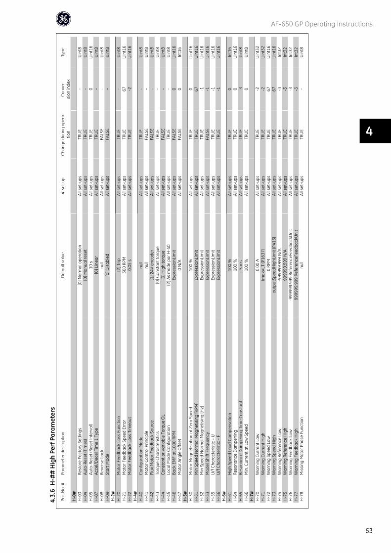
Par.
No.
#Pa
ram
eter
des
crip
tion
Def
ault
valu
e4-
set-
upCh
ange
dur
ing
oper
a-tio
nCo
nver
-si
on in
dex
Type
H-0
#H
-03
Rest
ore
Fact
ory
Sett
ings
[0] N
orm
al o
pera
tion
All s
et-u
psTR
UE
-U
int8
H-0
4Au
to-R
eset
(Tim
es)
[0] M
anua
l res
etAl
l set
-ups
TRU
E-
Uin
t8H
-05
Auto
-Res
et (R
eset
Inte
rval
)10
sAl
l set
-ups
TRU
E0
Uin
t16
H-0
7Ac
cel/D
ecel
Tim
e 1
Type
[0] L
inea
rAl
l set
-ups
TRU
E-
Uin
t8H
-08
Reve
rse
Lock
null
All s
et-u
psFA
LSE
-U
int8
H-0
9St
art M
ode
[0] D
isab
led
All s
et-u
psFA
LSE
-U
int8
H-2
#H
-20
Mot
or F
eedb
ack
Loss
Fun
ctio
n[2
] Trip
All s
et-u
psTR
UE
-U
int8
H-2
1M
otor
Fee
dbac
k Sp
eed
Erro
r30
0 RP
MAl
l set
-ups
TRU
E67
Uin
t16
H-2
2M
otor
Fee
dbac
k Lo
ss T
imeo
ut0.
05 s
All s
et-u
psTR
UE
-2U
int1
6H
-4#
H-4
0Co
nfig
urat
ion
Mod
enu
llAl
l set
-ups
TRU
E-
Uin
t8H
-41
Mot
or C
ontr
ol P
rinci
ple
null
All s
et-u
psFA
LSE
-U
int8
H-4
2Fl
ux M
otor
Fee
dbac
k So
urce
[1] 2
4V e
ncod
erAl
l set
-ups
FALS
E-
Uin
t8H
-43
Torq
ue C
hara
cter
istic
s[0
] Con
stan
t tor
que
All s
et-u
psTR
UE
-U
int8
H-4
4Co
nsta
nt o
r Var
iabl
e To
rque
OL
[0] H
igh
torq
ueAl
l set
-ups
FALS
E-
Uin
t8H
-45
Loca
l Mod
e Co
nfig
urat
ion
[2] A
s m
ode
par H
-40
All s
et-u
psTR
UE
-U
int8
H-4
6Ba
ck E
MF
at 1
000
RPM
Expr
essi
onLi
mit
All s
et-u
psFA
LSE
0U
int1
6H
-47
Mot
or A
ngle
Offs
et0
N/A
All s
et-u
psFA
LSE
0In
t16
H-5
#H
-50
Mot
or M
agne
tisat
ion
at Z
ero
Spee
d10
0 %
All s
et-u
psTR
UE
0U
int1
6H
-51
Min
Spe
ed N
orm
al M
agne
tisin
g [R
PM]
Expr
essi
onLi
mit
All s
et-u
psTR
UE
67U
int1
6H
-52
Min
Spe
ed N
orm
al M
agne
tisin
g [H
z]Ex
pres
sion
Lim
itAl
l set
-ups
TRU
E-1
Uin
t16
H-5
3M
odel
Shi
ft Fr
eque
ncy
Expr
essi
onLi
mit
All s
et-u
psFA
LSE
-1U
int1
6H
-55
U/f
Cha
ract
eris
tic -
UEx
pres
sion
Lim
itAl
l set
-ups
TRU
E-1
Uin
t16
H-5
6U
/f C
hara
cter
istic
- F
Expr
essi
onLi
mit
All s
et-u
psTR
UE
-1U
int1
6H
-6#
H-6
1H
igh
Spee
d Lo
ad C
ompe
nsat
ion
100
%Al
l set
-ups
TRU
E0
Int1
6H
-64
Reso
nanc
e D
ampe
ning
100
%Al
l set
-ups
TRU
E0
Uin
t16
H-6
5Re
sona
nce
Dam
peni
ng T
ime
Cons
tant
5 m
sAl
l set
-ups
TRU
E-3
Uin
t8H
-66
Min
. Cur
rent
at L
ow S
peed
100
%Al
l set
-ups
TRU
E0
Uin
t8H
-7#
H-7
0W
arni
ng C
urre
nt L
ow0.
00 A
All s
et-u
psTR
UE
-2U
int3
2H
-71
War
ning
Cur
rent
Hig
hIm
axVL
T (P
1637
)Al
l set
-ups
TRU
E-2
Uin
t32
H-7
2W
arni
ng S
peed
Low
0 RP
MAl
l set
-ups
TRU
E67
Uin
t16
H-7
3W
arni
ng S
peed
Hig
hou
tput
Spee
dHig
hLim
it (P
413)
All s
et-u
psTR
UE
67U
int1
6H
-74
War
ning
Ref
eren
ce L
ow-9
9999
9.99
9 N
/AAl
l set
-ups
TRU
E-3
Int3
2H
-75
War
ning
Ref
eren
ce H
igh
9999
99.9
99 N
/AAl
l set
-ups
TRU
E-3
Int3
2H
-76
War
ning
Fee
dbac
k Lo
w-9
9999
9.99
9 Re
fere
nceF
eedb
ackU
nit
All s
et-u
psTR
UE
-3In
t32
H-7
7W
arni
ng F
eedb
ack
Hig
h99
9999
.999
Ref
eren
ceFe
edba
ckU
nit
All s
et-u
psTR
UE
-3In
t32
H-7
8M
issi
ng M
otor
Pha
se F
unct
ion
null
All s
et-u
psTR
UE
-U
int8
4.3.
6H
-##
Hig
h Pe
rf P
aram
eter
s
AF-650 GP Operating Instructions
53
4
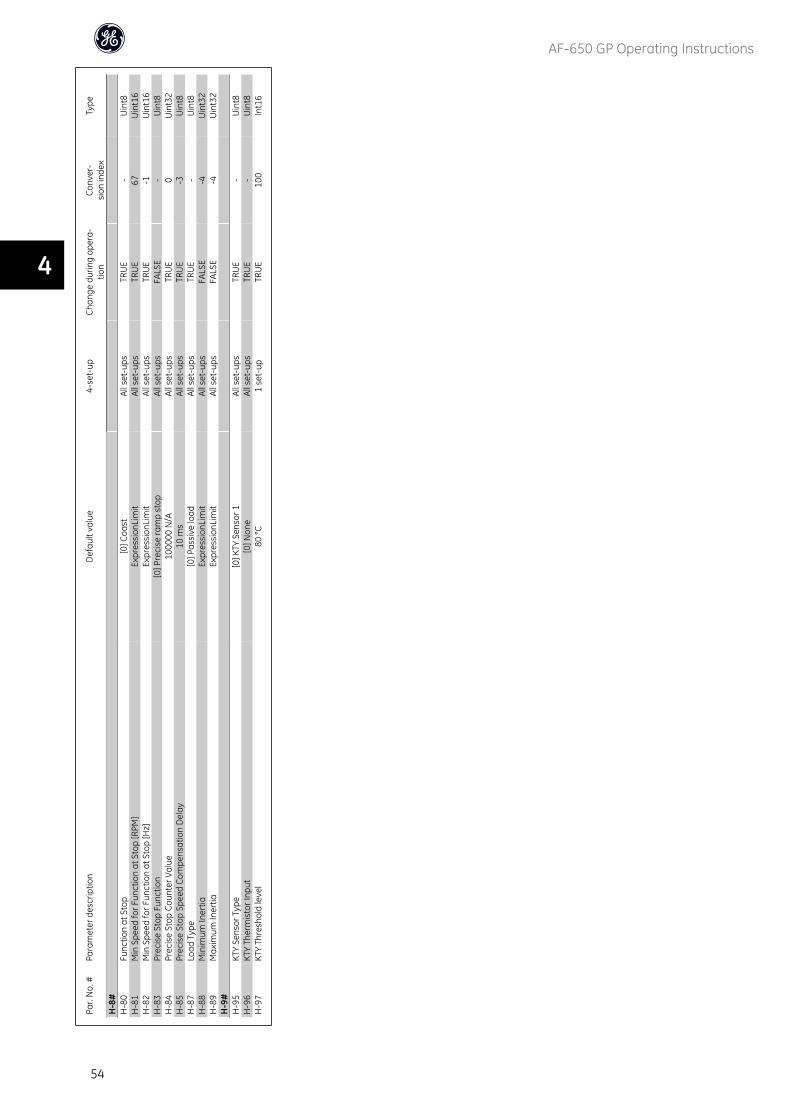
Par.
No.
#Pa
ram
eter
des
crip
tion
Def
ault
valu
e4-
set-
upCh
ange
dur
ing
oper
a-tio
nCo
nver
-si
on in
dex
Type
H-8
#H
-80
Func
tion
at S
top
[0] C
oast
All s
et-u
psTR
UE
-U
int8
H-8
1M
in S
peed
for F
unct
ion
at S
top
[RPM
]Ex
pres
sion
Lim
itAl
l set
-ups
TRU
E67
Uin
t16
H-8
2M
in S
peed
for F
unct
ion
at S
top
[Hz]
Expr
essi
onLi
mit
All s
et-u
psTR
UE
-1U
int1
6H
-83
Prec
ise
Stop
Fun
ctio
n[0
] Pre
cise
ram
p st
opAl
l set
-ups
FALS
E-
Uin
t8H
-84
Prec
ise
Stop
Cou
nter
Val
ue10
0000
N/A
All s
et-u
psTR
UE
0U
int3
2H
-85
Prec
ise
Stop
Spe
ed C
ompe
nsat
ion
Del
ay10
ms
All s
et-u
psTR
UE
-3U
int8
H-8
7Lo
ad T
ype
[0] P
assi
ve lo
adAl
l set
-ups
TRU
E-
Uin
t8H
-88
Min
imum
Iner
tiaEx
pres
sion
Lim
itAl
l set
-ups
FALS
E-4
Uin
t32
H-8
9M
axim
um In
ertia
Expr
essi
onLi
mit
All s
et-u
psFA
LSE
-4U
int3
2H
-9#
H-9
5KT
Y Se
nsor
Typ
e[0
] KTY
Sen
sor 1
All s
et-u
psTR
UE
-U
int8
H-9
6KT
Y Th
erm
isto
r Inp
ut[0
] Non
eAl
l set
-ups
TRU
E-
Uin
t8H
-97
KTY
Thre
shol
d le
vel
80 °C
1 se
t-up
TRU
E10
0In
t16
AF-650 GP Operating Instructions
54
4
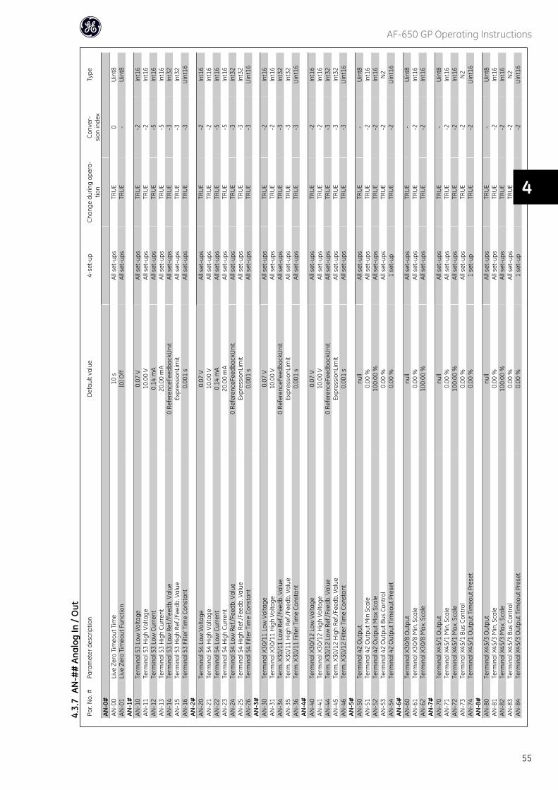
Par.
No.
#Pa
ram
eter
des
crip
tion
Def
ault
valu
e4-
set-
upCh
ange
dur
ing
oper
a-tio
nCo
nver
-si
on in
dex
Type
AN-0
#AN
-00
Live
Zer
o Ti
meo
ut T
ime
10 s
All s
et-u
psTR
UE
0U
int8
AN-0
1Li
ve Z
ero
Tim
eout
Fun
ctio
n[0
] Off
All s
et-u
psTR
UE
-U
int8
AN-1
#AN
-10
Term
inal
53
Low
Vol
tage
0.07
VAl
l set
-ups
TRU
E-2
Int1
6AN
-11
Term
inal
53
Hig
h Vo
ltage
10.0
0 V
All s
et-u
psTR
UE
-2In
t16
AN-1
2Te
rmin
al 5
3 Lo
w C
urre
nt0.
14 m
AAl
l set
-ups
TRU
E-5
Int1
6AN
-13
Term
inal
53
Hig
h Cu
rren
t20
.00
mA
All s
et-u
psTR
UE
-5In
t16
AN-1
4Te
rmin
al 5
3 Lo
w R
ef./F
eedb
. Val
ue0
Refe
renc
eFee
dbac
kUni
tAl
l set
-ups
TRU
E-3
Int3
2AN
-15
Term
inal
53
Hig
h Re
f./Fe
edb.
Val
ueEx
pres
sion
Lim
itAl
l set
-ups
TRU
E-3
Int3
2AN
-16
Term
inal
53
Filte
r Tim
e Co
nsta
nt0.
001
sAl
l set
-ups
TRU
E-3
Uin
t16
AN-2
#AN
-20
Term
inal
54
Low
Vol
tage
0.07
VAl
l set
-ups
TRU
E-2
Int1
6AN
-21
Term
inal
54
Hig
h Vo
ltage
10.0
0 V
All s
et-u
psTR
UE
-2In
t16
AN-2
2Te
rmin
al 5
4 Lo
w C
urre
nt0.
14 m
AAl
l set
-ups
TRU
E-5
Int1
6AN
-23
Term
inal
54
Hig
h Cu
rren
t20
.00
mA
All s
et-u
psTR
UE
-5In
t16
AN-2
4Te
rmin
al 5
4 Lo
w R
ef./F
eedb
. Val
ue0
Refe
renc
eFee
dbac
kUni
tAl
l set
-ups
TRU
E-3
Int3
2AN
-25
Term
inal
54
Hig
h Re
f./Fe
edb.
Val
ueEx
pres
sion
Lim
itAl
l set
-ups
TRU
E-3
Int3
2AN
-26
Term
inal
54
Filte
r Tim
e Co
nsta
nt0.
001
sAl
l set
-ups
TRU
E-3
Uin
t16
AN-3
#AN
-30
Term
inal
X30
/11
Low
Vol
tage
0.07
VAl
l set
-ups
TRU
E-2
Int1
6AN
-31
Term
inal
X30
/11
Hig
h Vo
ltage
10.0
0 V
All s
et-u
psTR
UE
-2In
t16
AN-3
4Te
rm. X
30/1
1 Lo
w R
ef./F
eedb
. Val
ue0
Refe
renc
eFee
dbac
kUni
tAl
l set
-ups
TRU
E-3
Int3
2AN
-35
Term
. X30
/11
Hig
h Re
f./Fe
edb.
Val
ueEx
pres
sion
Lim
itAl
l set
-ups
TRU
E-3
Int3
2AN
-36
Term
. X30
/11
Filte
r Tim
e Co
nsta
nt0.
001
sAl
l set
-ups
TRU
E-3
Uin
t16
AN-4
#AN
-40
Term
inal
X30
/12
Low
Vol
tage
0.07
VAl
l set
-ups
TRU
E-2
Int1
6AN
-41
Term
inal
X30
/12
Hig
h Vo
ltage
10.0
0 V
All s
et-u
psTR
UE
-2In
t16
AN-4
4Te
rm. X
30/1
2 Lo
w R
ef./F
eedb
. Val
ue0
Refe
renc
eFee
dbac
kUni
tAl
l set
-ups
TRU
E-3
Int3
2AN
-45
Term
. X30
/12
Hig
h Re
f./Fe
edb.
Val
ueEx
pres
sion
Lim
itAl
l set
-ups
TRU
E-3
Int3
2AN
-46
Term
. X30
/12
Filte
r Tim
e Co
nsta
nt0.
001
sAl
l set
-ups
TRU
E-3
Uin
t16
AN-5
#AN
-50
Term
inal
42
Out
put
null
All s
et-u
psTR
UE
-U
int8
AN-5
1Te
rmin
al 4
2 O
utpu
t Min
Sca
le0.
00 %
All s
et-u
psTR
UE
-2In
t16
AN-5
2Te
rmin
al 4
2 O
utpu
t Max
Sca
le10
0.00
%Al
l set
-ups
TRU
E-2
Int1
6AN
-53
Term
inal
42
Out
put B
us C
ontr
ol0.
00 %
All s
et-u
psTR
UE
-2N
2AN
-54
Term
inal
42
Out
put T
imeo
ut P
rese
t0.
00 %
1 se
t-up
TRU
E-2
Uin
t16
AN-6
#AN
-60
Term
inal
X30
/8 O
utpu
tnu
llAl
l set
-ups
TRU
E-
Uin
t8AN
-61
Term
inal
X30
/8 M
in. S
cale
0.00
%Al
l set
-ups
TRU
E-2
Int1
6AN
-62
Term
inal
X30
/8 M
ax. S
cale
100.
00 %
All s
et-u
psTR
UE
-2In
t16
AN-7
#AN
-70
Term
inal
X45
/1 O
utpu
tnu
llAl
l set
-ups
TRU
E-
Uin
t8AN
-71
Term
inal
X45
/1 M
in. S
cale
0.00
%Al
l set
-ups
TRU
E-2
Int1
6AN
-72
Term
inal
X45
/1 M
ax. S
cale
100.
00 %
All s
et-u
psTR
UE
-2In
t16
AN-7
3Te
rmin
al X
45/1
Bus
Con
trol
0.00
%Al
l set
-ups
TRU
E-2
N2
AN-7
4Te
rmin
al X
45/1
Out
put T
imeo
ut P
rese
t0.
00 %
1 se
t-up
TRU
E-2
Uin
t16
AN-8
#AN
-80
Term
inal
X45
/3 O
utpu
tnu
llAl
l set
-ups
TRU
E-
Uin
t8AN
-81
Term
inal
X45
/3 M
in. S
cale
0.00
%Al
l set
-ups
TRU
E-2
Int1
6AN
-82
Term
inal
X45
/3 M
ax. S
cale
100.
00 %
All s
et-u
psTR
UE
-2In
t16
AN-8
3Te
rmin
al X
45/3
Bus
Con
trol
0.00
%Al
l set
-ups
TRU
E-2
N2
AN-8
4Te
rmin
al X
45/3
Out
put T
imeo
ut P
rese
t0.
00 %
1 se
t-up
TRU
E-2
Uin
t16
4.3.
7AN
-##
Ana
log
In /
Out
AF-650 GP Operating Instructions
55
4
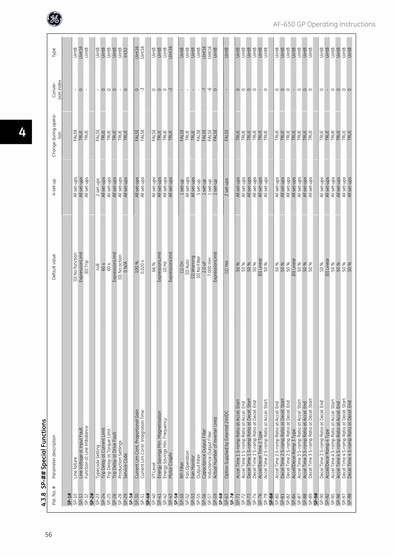
Par.
No.
#Pa
ram
eter
des
crip
tion
Def
ault
valu
e4-
set-
upCh
ange
dur
ing
oper
a-tio
nCo
nver
-si
on in
dex
Type
SP-1
#SP
-10
Line
failu
re[0
] No
func
tion
All s
et-u
psFA
LSE
-U
int8
SP-1
1Li
ne V
olta
ge a
t Inp
ut F
ault
Expr
essi
onLi
mit
All s
et-u
psTR
UE
0U
int1
6SP
-12
Func
tion
at L
ine
Imba
lanc
e[0
] Trip
All s
et-u
psTR
UE
-U
int8
SP-2
#SP
-23
Type
code
Set
ting
null
2 se
t-up
sFA
LSE
-U
int8
SP-2
4Tr
ip D
elay
at C
urre
nt L
imit
60 s
All s
et-u
psTR
UE
0U
int8
SP-2
5Tr
ip D
elay
at T
orqu
e Li
mit
60 s
All s
et-u
psTR
UE
0U
int8
SP-2
6Tr
ip D
elay
at D
rive
Faul
tEx
pres
sion
Lim
itAl
l set
-ups
TRU
E0
Uin
t8SP
-28
Prod
uctio
n Se
ttin
gs[0
] No
actio
nAl
l set
-ups
TRU
E-
Uin
t8SP
-29
Serv
ice
Code
0 N
/AAl
l set
-ups
TRU
E0
Int3
2SP
-3#
SP-3
0Cu
rren
t Lim
Con
t, Pr
opor
tiona
l Gai
n10
0 %
All s
et-u
psFA
LSE
0U
int1
6SP
-31
Curr
ent L
im C
ontr
, Int
egra
tion
Tim
e0.
020
sAl
l set
-ups
FALS
E-3
Uin
t16
SP-4
#SP
-40
VT L
evel
66 %
All s
et-u
psFA
LSE
0U
int8
SP-4
1En
ergy
Sav
ings
Min
. Mag
netis
atio
nEx
pres
sion
Lim
itAl
l set
-ups
TRU
E0
Uin
t8SP
-42
Ener
gy S
avin
gs M
in. F
requ
ency
10 H
zAl
l set
-ups
TRU
E0
Uin
t8SP
-43
Mot
or C
osph
iEx
pres
sion
Lim
itAl
l set
-ups
TRU
E-2
Uin
t16
SP-5
#SP
-50
RFI F
ilter
[1] O
n1
set-
upFA
LSE
-U
int8
SP-5
2Fa
n O
pera
tion
[0] A
uto
All s
et-u
psTR
UE
-U
int8
SP-5
3Fa
n M
onito
r[1
] War
ning
All s
et-u
psTR
UE
-U
int8
SP-5
5O
utpu
t Filt
er[0
] No
Filte
r1
set-
upFA
LSE
-U
int8
SP-5
6Ca
paci
tanc
e O
utpu
t Filt
er2.
0 uF
1 se
t-up
FALS
E-7
Uin
t16
SP-5
7In
duct
ance
Out
put F
ilter
7.00
0 m
H1
set-
upFA
LSE
-6U
int1
6SP
-59
Actu
al N
umbe
r of I
nver
ter U
nits
Expr
essi
onLi
mit
1 se
t-up
FALS
E0
Uin
t8SP
-6#
SP-6
3O
ptio
n Su
pplie
d by
Ext
erna
l 24V
DC
[1] Y
es2
set-
ups
FALS
E-
Uin
t8SP
-7#
SP-7
1Ac
cel T
ime
1 S-
ram
p Ra
tio a
t Acc
el. S
tart
50 %
All s
et-u
psTR
UE
0U
int8
SP-7
2Ac
cel T
ime
1 S-
ram
p Ra
tio a
t Acc
el. E
nd50
%Al
l set
-ups
TRU
E0
Uin
t8SP
-73
Dec
el T
ime
1 S-
ram
p Ra
tio a
t Dec
el. S
tart
50 %
All s
et-u
psTR
UE
0U
int8
SP-7
4D
ecel
Tim
e 1
S-ra
mp
Ratio
at D
ecel
. End
50 %
All s
et-u
psTR
UE
0U
int8
SP-7
6Ac
cel/D
ecel
Tim
e 2
Type
[0] L
inea
rAl
l set
-ups
TRU
E-
Uin
t8SP
-79
Acce
l Tim
e 2
S-ra
mp
Ratio
at A
ccel
. Sta
rt50
%Al
l set
-ups
TRU
E0
Uin
t8SP
-8#
SP-8
0Ac
cel T
ime
2 S-
ram
p Ra
tio a
t Acc
el. E
nd50
%Al
l set
-ups
TRU
E0
Uin
t8SP
-81
Dec
el T
ime
2 S-
ram
p Ra
tio a
t Dec
el. S
tart
50 %
All s
et-u
psTR
UE
0U
int8
SP-8
2D
ecel
Tim
e 2
S-ra
mp
Ratio
at D
ecel
. End
50 %
All s
et-u
psTR
UE
0U
int8
SP-8
4Ac
cel/D
ecel
Ram
p 3
Type
[0] L
inea
rAl
l set
-ups
TRU
E-
Uin
t8SP
-87
Acce
l Tim
e 3
S-ra
mp
Ratio
at A
ccel
. Sta
rt50
%Al
l set
-ups
TRU
E0
Uin
t8SP
-88
Acce
l Tim
e 3
S-ra
mp
Ratio
at A
ccel
. End
50 %
All s
et-u
psTR
UE
0U
int8
SP-8
9D
ecel
Tim
e 3
S-ra
mp
Ratio
at D
ecel
. Sta
rt50
%Al
l set
-ups
TRU
E0
Uin
t8SP
-9#
SP-9
0D
ecel
Tim
e 3
S-ra
mp
Ratio
at D
ecel
. End
50 %
All s
et-u
psTR
UE
0U
int8
SP-9
2Ac
cel/D
ecel
Ram
p 4
Type
[0] L
inea
rAl
l set
-ups
TRU
E-
Uin
t8SP
-95
Acce
l Tim
e 4
S-ra
mp
Ratio
at A
ccel
. Sta
rt50
%Al
l set
-ups
TRU
E0
Uin
t8SP
-96
Acce
l Tim
e 4
S-ra
mp
Ratio
at A
ccel
. End
50 %
All s
et-u
psTR
UE
0U
int8
SP-9
7D
ecel
Tim
e 4
S-ra
mp
Ratio
at D
ecel
. Sta
rt50
%Al
l set
-ups
TRU
E0
Uin
t8SP
-98
Dec
el T
ime
4 S-
ram
p Ra
tio a
t Dec
el. E
nd50
%Al
l set
-ups
TRU
E0
Uin
t8
4.3.
8SP
-##
Spe
cial
Fun
ctio
ns
AF-650 GP Operating Instructions
56
4
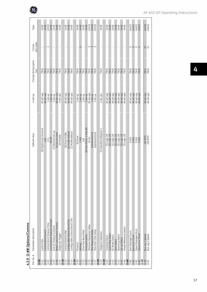
Par.
No.
#Pa
ram
eter
des
crip
tion
Def
ault
valu
e4-
set-
upCh
ange
dur
ing
oper
a-tio
nCo
nver
-si
on in
dex
Type
O-0
#O
-01
Cont
rol S
ite[0
] Dig
ital a
nd c
trl.w
ord
All s
et-u
psTR
UE
-U
int8
O-0
2Co
ntro
l Wor
d So
urce
null
All s
et-u
psTR
UE
-U
int8
O-0
3Co
ntro
l Wor
d Ti
meo
ut T
ime
1.0
s1
set-
upTR
UE
-1U
int3
2O
-04
Cont
rol W
ord
Tim
eout
Fun
ctio
n[0
] Off
1 se
t-up
TRU
E-
Uin
t8O
-05
End-
of-T
imeo
ut F
unct
ion
[1] R
esum
e se
t-up
1 se
t-up
TRU
E-
Uin
t8O
-06
Rese
t Con
trol
Wor
d Ti
meo
ut[0
] Do
not r
eset
All s
et-u
psTR
UE
-U
int8
O-0
7D
iagn
osis
Trig
ger
[0] D
isab
le2
set-
ups
TRU
E-
Uin
t8O
-1#
O-1
0Co
ntro
l Wor
d Pr
ofile
[0] D
rive
Prof
ileAl
l set
-ups
TRU
E-
Uin
t8O
-13
Conf
igur
able
Sta
tus
Wor
d ST
W[1
] Pro
file
Def
ault
All s
et-u
psTR
UE
-U
int8
O-1
4Co
nfig
urab
le C
ontr
ol W
ord
CTW
[1] P
rofil
e de
faul
tAl
l set
-ups
TRU
E-
Uin
t8O
-3#
O-3
0Pr
otoc
ol[0
] Driv
e1
set-
upTR
UE
-U
int8
O-3
1Ad
dres
s1
N/A
1 se
t-up
TRU
E0
Uin
t8O
-32
Driv
e Po
rt B
aud
Rate
null
1 se
t-up
TRU
E-
Uin
t8O
-33
Driv
e po
rt p
arity
[0] E
ven
Parit
y, 1
Sto
p Bi
t1
set-
upTR
UE
-U
int8
O-3
5M
inim
um R
espo
nse
Del
ay10
ms
All s
et-u
psTR
UE
-3U
int1
6O
-36
Max
Res
pons
e D
elay
Expr
essi
onLi
mit
1 se
t-up
TRU
E-3
Uin
t16
O-3
7M
ax In
ter-
Char
Del
ayEx
pres
sion
Lim
it1
set-
upTR
UE
-5U
int1
6O
-4#
O-4
0Te
legr
am S
elec
tion
[1] S
tand
ard
tele
gram
12
set-
ups
TRU
E-
Uin
t8O
-5#
O-5
0Co
astin
g Se
lect
[3] L
ogic
OR
All s
et-u
psTR
UE
-U
int8
O-5
1Q
uick
Sto
p Se
lect
[3] L
ogic
OR
All s
et-u
psTR
UE
-U
int8
O-5
2D
C Br
ake
Sele
ct[3
] Log
ic O
RAl
l set
-ups
TRU
E-
Uin
t8O
-53
Star
t Sel
ect
[3] L
ogic
OR
All s
et-u
psTR
UE
-U
int8
O-5
4Re
vers
ing
Sele
ct[3
] Log
ic O
RAl
l set
-ups
TRU
E-
Uin
t8O
-55
Set-
up S
elec
t[3
] Log
ic O
RAl
l set
-ups
TRU
E-
Uin
t8O
-56
Pres
et R
efer
ence
Sel
ect
[3] L
ogic
OR
All s
et-u
psTR
UE
-U
int8
O-8
#O
-80
Bus
Mes
sage
Cou
nt0
N/A
All s
et-u
psTR
UE
0U
int3
2O
-81
Bus
Erro
r Cou
nt0
N/A
All s
et-u
psTR
UE
0U
int3
2O
-82
Slav
e M
essa
ges
Rcvd
0 N
/AAl
l set
-ups
TRU
E0
Uin
t32
O-8
3Sl
ave
Erro
r Cou
nt0
N/A
All s
et-u
psTR
UE
0U
int3
2O
-9#
O-9
0Bu
s Jo
g 1
Spee
d10
0 RP
MAl
l set
-ups
TRU
E67
Uin
t16
O-9
1Bu
s Jo
g 2
Spee
d20
0 RP
MAl
l set
-ups
TRU
E67
Uin
t16
4.3.
9O
-##
Opt
ions
/Com
ms
AF-650 GP Operating Instructions
57
4
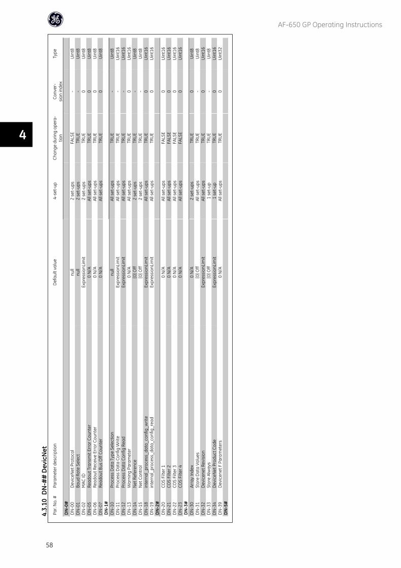
Par.
No.
#Pa
ram
eter
des
crip
tion
Def
ault
valu
e4-
set-
upCh
ange
dur
ing
oper
a-tio
nCo
nver
-si
on in
dex
Type
DN
-0#
DN
-00
Dev
iceN
et P
roto
col
null
2 se
t-up
sFA
LSE
-U
int8
DN
-01
Baud
Rat
e Se
lect
null
2 se
t-up
sTR
UE
-U
int8
DN
-02
MAC
IDEx
pres
sion
Lim
it2
set-
ups
TRU
E0
Uin
t8D
N-0
5Re
adou
t Tra
nsm
it Er
ror C
ount
er0
N/A
All s
et-u
psTR
UE
0U
int8
DN
-06
Read
out R
ecei
ve E
rror
Cou
nter
0 N
/AAl
l set
-ups
TRU
E0
Uin
t8D
N-0
7Re
adou
t Bus
Off
Coun
ter
0 N
/AAl
l set
-ups
TRU
E0
Uin
t8D
N-1
#D
N-1
0Pr
oces
s D
ata
Type
Sel
ectio
nnu
llAl
l set
-ups
TRU
E-
Uin
t8D
N-1
1Pr
oces
s D
ata
Conf
ig W
rite
Expr
essi
onLi
mit
All s
et-u
psTR
UE
-U
int1
6D
N-1
2Pr
oces
s D
ata
Conf
ig R
ead
Expr
essi
onLi
mit
All s
et-u
psTR
UE
-U
int1
6D
N-1
3W
arni
ng P
aram
eter
0 N
/AAl
l set
-ups
TRU
E0
Uin
t16
DN
-14
Net
Ref
eren
ce[0
] Off
2 se
t-up
sTR
UE
-U
int8
DN
-15
Net
Con
trol
[0] O
ff2
set-
ups
TRU
E-
Uin
t8D
N-1
8in
tern
al_p
roce
ss_d
ata_
conf
ig_w
rite
Expr
essi
onLi
mit
All s
et-u
psTR
UE
0U
int1
6D
N-1
9in
tern
al_p
roce
ss_d
ata_
conf
ig_r
ead
Expr
essi
onLi
mit
All s
et-u
psTR
UE
0U
int1
6D
N-2
#D
N-2
0CO
S Fi
lter 1
0 N
/AAl
l set
-ups
FALS
E0
Uin
t16
DN
-21
COS
Filte
r 20
N/A
All s
et-u
psFA
LSE
0U
int1
6D
N-2
2CO
S Fi
lter 3
0 N
/AAl
l set
-ups
FALS
E0
Uin
t16
DN
-23
COS
Filte
r 40
N/A
All s
et-u
psFA
LSE
0U
int1
6D
N-3
#D
N-3
0Ar
ray
Inde
x0
N/A
2 se
t-up
sTR
UE
0U
int8
DN
-31
Stor
e D
ata
Valu
es[0
] Off
All s
et-u
psTR
UE
-U
int8
DN
-32
Dev
icen
et R
evis
ion
Expr
essi
onLi
mit
All s
et-u
psTR
UE
0U
int1
6D
N-3
3St
ore
Alw
ays
[0] O
ff1
set-
upTR
UE
-U
int8
DN
-34
Dev
iceN
et P
rodu
ct C
ode
Expr
essi
onLi
mit
1 se
t-up
TRU
E0
Uin
t16
DN
-39
Dev
icen
et F
Par
amet
ers
0 N
/AAl
l set
-ups
TRU
E0
Uin
t32
DN
-5#
4.3.
10D
N-#
# D
evic
Net
AF-650 GP Operating Instructions
58
4
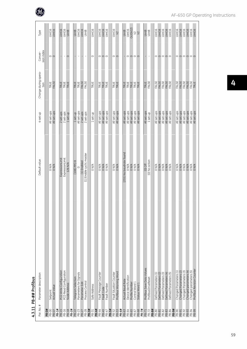
Par.
No.
#Pa
ram
eter
des
crip
tion
Def
ault
valu
e4-
set-
upCh
ange
dur
ing
oper
a-tio
nCo
nver
-si
on in
dex
Type
PB-0
#PB
-00
Setp
oint
0 N
/AAl
l set
-ups
TRU
E0
Uin
t16
PB-0
7Ac
tual
Val
ue0
N/A
All s
et-u
psFA
LSE
0U
int1
6PB
-1#
PB-1
5PC
D W
rite
Conf
igur
atio
nEx
pres
sion
Lim
it2
set-
ups
TRU
E-
Uin
t16
PB-1
6PC
D R
ead
Conf
igur
atio
nEx
pres
sion
Lim
it2
set-
ups
TRU
E-
Uin
t16
PB-1
8N
ode
Addr
ess
126
N/A
1 se
t-up
TRU
E0
Uin
t8PB
-2#
PB-2
2Te
legr
am S
elec
tion
[108
] PPO
81
set-
upTR
UE
-U
int8
PB-2
3Pa
ram
eter
s fo
r Sig
nals
0Al
l set
-ups
TRU
E-
Uin
t16
PB-2
7Pa
ram
eter
Edi
t[1
] Ena
bled
2 se
t-up
sFA
LSE
-U
int1
6PB
-28
Proc
ess
Cont
rol
[1] E
nabl
e cy
clic
mas
ter
2 se
t-up
sFA
LSE
-U
int8
PB-3
#PB
-31
Safe
Add
ress
0 N
/A1
set-
upTR
UE
0U
int1
6PB
-4#
PB-4
4Fa
ult M
essa
ge C
ount
er0
N/A
All s
et-u
psTR
UE
0U
int1
6PB
-45
Faul
t Cod
e0
N/A
All s
et-u
psTR
UE
0U
int1
6PB
-47
Faul
t Num
ber
0 N
/AAl
l set
-ups
TRU
E0
Uin
t16
PB-5
#PB
-52
Faul
t Situ
atio
n Co
unte
r0
N/A
All s
et-u
psTR
UE
0U
int1
6PB
-53
Prof
ibus
War
ning
Wor
d0
N/A
All s
et-u
psTR
UE
0V2
PB-6
#PB
-63
Actu
al B
aud
Rate
[255
] No
baud
rate
foun
dAl
l set
-ups
TRU
E-
Uin
t8PB
-64
Dev
ice
Iden
tific
atio
n0
N/A
All s
et-u
psTR
UE
0U
int1
6PB
-65
Prof
ile N
umbe
r0
N/A
All s
et-u
psTR
UE
0O
ctSt
r[2]
PB-6
7Co
ntro
l Wor
d 1
0 N
/AAl
l set
-ups
TRU
E0
V2PB
-68
Stat
us W
ord
10
N/A
All s
et-u
psTR
UE
0V2
PB-7
#PB
-71
Prof
ibus
Sav
e D
ata
Valu
es[0
] Off
All s
et-u
psTR
UE
-U
int8
PB-7
2Pr
ofib
usD
riveR
eset
[0] N
o ac
tion
1 se
t-up
FALS
E-
Uin
t8PB
-8#
PB-8
0D
efin
ed P
aram
eter
s (1
)0
N/A
All s
et-u
psFA
LSE
0U
int1
6PB
-81
Def
ined
Par
amet
ers
(2)
0 N
/AAl
l set
-ups
FALS
E0
Uin
t16
PB-8
2D
efin
ed P
aram
eter
s (3
)0
N/A
All s
et-u
psFA
LSE
0U
int1
6PB
-83
Def
ined
Par
amet
ers
(4)
0 N
/AAl
l set
-ups
FALS
E0
Uin
t16
PB-8
4D
efin
ed P
aram
eter
s (5
)0
N/A
All s
et-u
psFA
LSE
0U
int1
6PB
-9#
PB-9
0Ch
ange
d Pa
ram
eter
s (1
)0
N/A
All s
et-u
psFA
LSE
0U
int1
6PB
-91
Chan
ged
Para
met
ers
(2)
0 N
/AAl
l set
-ups
FALS
E0
Uin
t16
PB-9
2Ch
ange
d Pa
ram
eter
s (3
)0
N/A
All s
et-u
psFA
LSE
0U
int1
6PB
-93
Chan
ged
para
met
ers
(4)
0 N
/AAl
l set
-ups
FALS
E0
Uin
t16
PB-9
4Ch
ange
d pa
ram
eter
s (5
)0
N/A
All s
et-u
psFA
LSE
0U
int1
6PB
-99
Prof
ibus
Rev
isio
n Co
unte
r0
N/A
All s
et-u
psTR
UE
0U
int1
6
4.3.
11PB
-##
Pro
fibus
AF-650 GP Operating Instructions
59
4
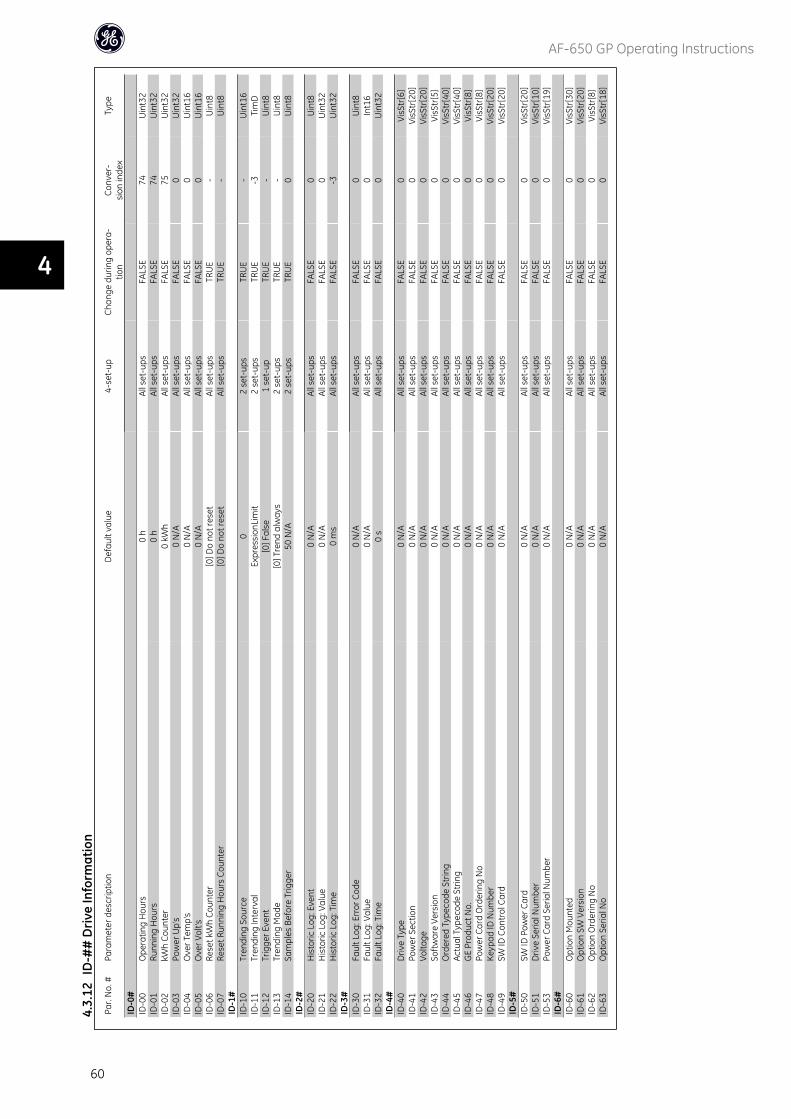
Par.
No.
#Pa
ram
eter
des
crip
tion
Def
ault
valu
e4-
set-
upCh
ange
dur
ing
oper
a-tio
nCo
nver
-si
on in
dex
Type
ID-0
#ID
-00
Ope
ratin
g H
ours
0 h
All s
et-u
psFA
LSE
74U
int3
2ID
-01
Runn
ing
Hou
rs0
hAl
l set
-ups
FALS
E74
Uin
t32
ID-0
2kW
h Co
unte
r0
kWh
All s
et-u
psFA
LSE
75U
int3
2ID
-03
Pow
er U
p's
0 N
/AAl
l set
-ups
FALS
E0
Uin
t32
ID-0
4O
ver T
emp'
s0
N/A
All s
et-u
psFA
LSE
0U
int1
6ID
-05
Ove
r Vol
t's0
N/A
All s
et-u
psFA
LSE
0U
int1
6ID
-06
Rese
t kW
h Co
unte
r[0
] Do
not r
eset
All s
et-u
psTR
UE
-U
int8
ID-0
7Re
set R
unni
ng H
ours
Cou
nter
[0] D
o no
t res
etAl
l set
-ups
TRU
E-
Uin
t8ID
-1#
ID-1
0Tr
endi
ng S
ourc
e0
2 se
t-up
sTR
UE
-U
int1
6ID
-11
Tren
ding
Inte
rval
Expr
essi
onLi
mit
2 se
t-up
sTR
UE
-3Ti
mD
ID-1
2Tr
igge
r Eve
nt[0
] Fal
se1
set-
upTR
UE
-U
int8
ID-1
3Tr
endi
ng M
ode
[0] T
rend
alw
ays
2 se
t-up
sTR
UE
-U
int8
ID-1
4Sa
mpl
es B
efor
e Tr
igge
r50
N/A
2 se
t-up
sTR
UE
0U
int8
ID-2
#ID
-20
His
toric
Log
: Eve
nt0
N/A
All s
et-u
psFA
LSE
0U
int8
ID-2
1H
isto
ric L
og: V
alue
0 N
/AAl
l set
-ups
FALS
E0
Uin
t32
ID-2
2H
isto
ric L
og: T
ime
0 m
sAl
l set
-ups
FALS
E-3
Uin
t32
ID-3
#ID
-30
Faul
t Log
: Err
or C
ode
0 N
/AAl
l set
-ups
FALS
E0
Uin
t8ID
-31
Faul
t Log
: Val
ue0
N/A
All s
et-u
psFA
LSE
0In
t16
ID-3
2Fa
ult L
og: T
ime
0 s
All s
et-u
psFA
LSE
0U
int3
2ID
-4#
ID-4
0D
rive
Type
0 N
/AAl
l set
-ups
FALS
E0
VisS
tr[6
]ID
-41
Pow
er S
ectio
n0
N/A
All s
et-u
psFA
LSE
0Vi
sStr
[20]
ID-4
2Vo
ltage
0 N
/AAl
l set
-ups
FALS
E0
VisS
tr[2
0]ID
-43
Softw
are
Vers
ion
0 N
/AAl
l set
-ups
FALS
E0
VisS
tr[5
]ID
-44
Ord
ered
Typ
ecod
e St
ring
0 N
/AAl
l set
-ups
FALS
E0
VisS
tr[4
0]ID
-45
Actu
al T
ypec
ode
Strin
g0
N/A
All s
et-u
psFA
LSE
0Vi
sStr
[40]
ID-4
6G
E Pr
oduc
t No.
0 N
/AAl
l set
-ups
FALS
E0
VisS
tr[8
]ID
-47
Pow
er C
ard
Ord
erin
g N
o0
N/A
All s
et-u
psFA
LSE
0Vi
sStr
[8]
ID-4
8Ke
ypad
ID N
umbe
r0
N/A
All s
et-u
psFA
LSE
0Vi
sStr
[20]
ID-4
9SW
ID C
ontr
ol C
ard
0 N
/AAl
l set
-ups
FALS
E0
VisS
tr[2
0]ID
-5#
ID-5
0SW
ID P
ower
Car
d0
N/A
All s
et-u
psFA
LSE
0Vi
sStr
[20]
ID-5
1D
rive
Seria
l Num
ber
0 N
/AAl
l set
-ups
FALS
E0
VisS
tr[1
0]ID
-53
Pow
er C
ard
Seria
l Num
ber
0 N
/AAl
l set
-ups
FALS
E0
VisS
tr[1
9]ID
-6#
ID-6
0O
ptio
n M
ount
ed0
N/A
All s
et-u
psFA
LSE
0Vi
sStr
[30]
ID-6
1O
ptio
n SW
Ver
sion
0 N
/AAl
l set
-ups
FALS
E0
VisS
tr[2
0]ID
-62
Opt
ion
Ord
erin
g N
o0
N/A
All s
et-u
psFA
LSE
0Vi
sStr
[8]
ID-6
3O
ptio
n Se
rial N
o0
N/A
All s
et-u
psFA
LSE
0Vi
sStr
[18]
4.3.
12ID
-##
Dri
ve In
form
atio
n
AF-650 GP Operating Instructions
60
4
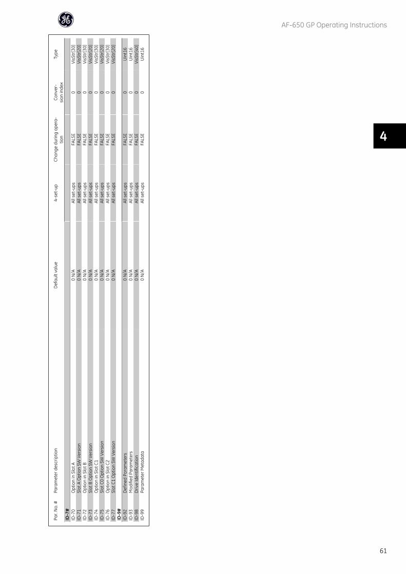
Par.
No.
#Pa
ram
eter
des
crip
tion
Def
ault
valu
e4-
set-
upCh
ange
dur
ing
oper
a-tio
nCo
nver
-si
on in
dex
Type
ID-7
#ID
-70
Opt
ion
in S
lot A
0 N
/AAl
l set
-ups
FALS
E0
VisS
tr[3
0]ID
-71
Slot
A O
ptio
n SW
Ver
sion
0 N
/AAl
l set
-ups
FALS
E0
VisS
tr[2
0]ID
-72
Opt
ion
in S
lot B
0 N
/AAl
l set
-ups
FALS
E0
VisS
tr[3
0]ID
-73
Slot
B O
ptio
n SW
Ver
sion
0 N
/AAl
l set
-ups
FALS
E0
VisS
tr[2
0]ID
-74
Opt
ion
in S
lot C
10
N/A
All s
et-u
psFA
LSE
0Vi
sStr
[30]
ID-7
5Sl
ot C
0 O
ptio
n SW
Ver
sion
0 N
/AAl
l set
-ups
FALS
E0
VisS
tr[2
0]ID
-76
Opt
ion
in S
lot C
20
N/A
All s
et-u
psFA
LSE
0Vi
sStr
[30]
ID-7
7Sl
ot C
1 O
ptio
n SW
Ver
sion
0 N
/AAl
l set
-ups
FALS
E0
VisS
tr[2
0]ID
-9#
ID-9
2D
efin
ed P
aram
eter
s0
N/A
All s
et-u
psFA
LSE
0U
int1
6ID
-93
Mod
ified
Par
amet
ers
0 N
/AAl
l set
-ups
FALS
E0
Uin
t16
ID-9
8D
rive
Iden
tific
atio
n0
N/A
All s
et-u
psFA
LSE
0Vi
sStr
[40]
ID-9
9Pa
ram
eter
Met
adat
a0
N/A
All s
et-u
psFA
LSE
0U
int1
6
AF-650 GP Operating Instructions
61
4
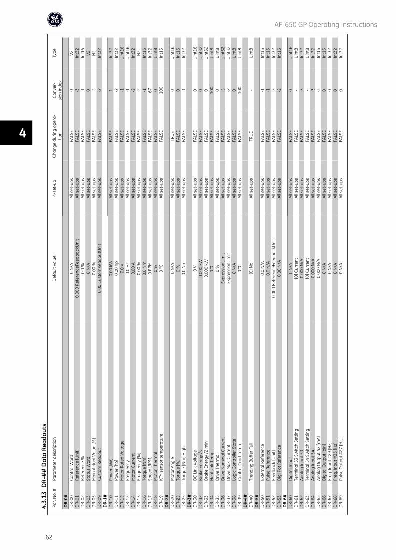
Par.
No.
#Pa
ram
eter
des
crip
tion
Def
ault
valu
e4-
set-
upCh
ange
dur
ing
oper
a-tio
nCo
nver
-si
on in
dex
Type
DR-
0#D
R-00
Cont
rol W
ord
0 N
/AAl
l set
-ups
FALS
E0
V2D
R-01
Refe
renc
e [U
nit]
0.00
0 Re
fere
nceF
eedb
ackU
nit
All s
et-u
psFA
LSE
-3In
t32
DR-
02Re
fere
nce
%0.
0 %
All s
et-u
psFA
LSE
-1In
t16
DR-
03St
atus
Wor
d0
N/A
All s
et-u
psFA
LSE
0V2
DR-
05M
ain
Actu
al V
alue
[%]
0.00
%Al
l set
-ups
FALS
E-2
N2
DR-
09Cu
stom
Rea
dout
0.00
Cus
tom
Read
outU
nit
All s
et-u
psFA
LSE
-2In
t32
DR-
1#D
R-10
Pow
er [k
W]
0.00
kW
All s
et-u
psFA
LSE
1In
t32
DR-
11Po
wer
[hp]
0.00
hp
All s
et-u
psFA
LSE
-2In
t32
DR-
12M
otor
Rat
ed V
olta
ge0.
0 V
All s
et-u
psFA
LSE
-1U
int1
6D
R-13
Freq
uenc
y0.
0 H
zAl
l set
-ups
FALS
E-1
Uin
t16
DR-
14M
otor
Cur
rent
0.00
AAl
l set
-ups
FALS
E-2
Int3
2D
R-15
Freq
uenc
y [%
]0.
00 %
All s
et-u
psFA
LSE
-2N
2D
R-16
Torq
ue [N
m]
0.0
Nm
All s
et-u
psFA
LSE
-1In
t16
DR-
17Sp
eed
[RPM
]0
RPM
All s
et-u
psFA
LSE
67In
t32
DR-
18M
otor
The
rmal
0 %
All s
et-u
psFA
LSE
0U
int8
DR-
19KT
Y se
nsor
tem
pera
ture
0 °C
All s
et-u
psFA
LSE
100
Int1
6D
R-2#
DR-
20M
otor
Ang
le0
N/A
All s
et-u
psTR
UE
0U
int1
6D
R-22
Torq
ue [%
]0
%Al
l set
-ups
FALS
E0
Int1
6D
R-25
Torq
ue [N
m] H
igh
0.0
Nm
All s
et-u
psFA
LSE
-1In
t32
DR-
3#D
R-30
DC
Link
Vol
tage
0 V
All s
et-u
psFA
LSE
0U
int1
6D
R-32
Brak
e En
ergy
/s0.
000
kWAl
l set
-ups
FALS
E0
Uin
t32
DR-
33Br
ake
Ener
gy /2
min
0.00
0 kW
All s
et-u
psFA
LSE
0U
int3
2D
R-34
Hea
tsin
k Te
mp.
0 °C
All s
et-u
psFA
LSE
100
Uin
t8D
R-35
Driv
e Th
erm
al0
%Al
l set
-ups
FALS
E0
Uin
t8D
R-36
Driv
e N
omin
al C
urre
ntEx
pres
sion
Lim
itAl
l set
-ups
FALS
E-2
Uin
t32
DR-
37D
rive
Max
. Cur
rent
Expr
essi
onLi
mit
All s
et-u
psFA
LSE
-2U
int3
2D
R-38
Logi
c Co
ntro
ller S
tate
0 N
/AAl
l set
-ups
FALS
E0
Uin
t8D
R-39
Cont
rol C
ard
Tem
p.0
°CAl
l set
-ups
FALS
E10
0U
int8
DR-
4#D
R-40
Tren
ding
Buf
fer F
ull
[0] N
oAl
l set
-ups
TRU
E-
Uin
t8D
R-5#
DR-
50Ex
tern
al R
efer
ence
0.0
N/A
All s
et-u
psFA
LSE
-1In
t16
DR-
51Pu
lse
Refe
renc
e0.
0 N
/AAl
l set
-ups
FALS
E-1
Int1
6D
R-52
Feed
back
[Uni
t]0.
000
Refe
renc
eFee
dbac
kUni
tAl
l set
-ups
FALS
E-3
Int3
2D
R-53
Dig
i Pot
Ref
eren
ce0.
00 N
/AAl
l set
-ups
FALS
E-2
Int1
6D
R-6#
DR-
60D
igita
l Inp
ut0
N/A
All s
et-u
psFA
LSE
0U
int1
6D
R-61
Term
inal
53
Switc
h Se
tting
[0] C
urre
ntAl
l set
-ups
FALS
E-
Uin
t8D
R-62
Anal
og In
put 5
30.
000
N/A
All s
et-u
psFA
LSE
-3In
t32
DR-
63Te
rmin
al 5
4 Sw
itch
Setti
ng[0
] Cur
rent
All s
et-u
psFA
LSE
-U
int8
DR-
64An
alog
Inpu
t 54
0.00
0 N
/AAl
l set
-ups
FALS
E-3
Int3
2D
R-65
Anal
og O
utpu
t 42
[mA]
0.00
0 N
/AAl
l set
-ups
FALS
E-3
Int1
6D
R-66
Dig
ital O
utpu
t [bi
n]0
N/A
All s
et-u
psFA
LSE
0In
t16
DR-
67Fr
eq. I
nput
#29
[Hz]
0 N
/AAl
l set
-ups
FALS
E0
Int3
2D
R-68
Freq
. Inp
ut #
33 [H
z]0
N/A
All s
et-u
psFA
LSE
0In
t32
DR-
69Pu
lse
Out
put #
27 [H
z]0
N/A
All s
et-u
psFA
LSE
0In
t32
4.3.
13D
R-#
# D
ata
Read
outs
AF-650 GP Operating Instructions
62
4
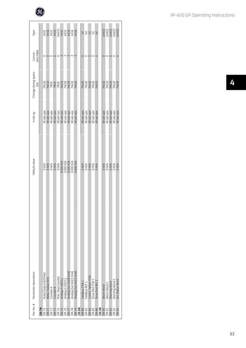
Par.
No.
#Pa
ram
eter
des
crip
tion
Def
ault
valu
e4-
set-
upCh
ange
dur
ing
oper
a-tio
nCo
nver
-si
on in
dex
Type
DR-
7#D
R-70
Puls
e O
utpu
t #29
[Hz]
0 N
/AAl
l set
-ups
FALS
E0
Int3
2D
R-71
Rela
y O
utpu
t [bi
n]0
N/A
All s
et-u
psFA
LSE
0In
t16
DR-
72Co
unte
r A0
N/A
All s
et-u
psTR
UE
0In
t32
DR-
73Co
unte
r B0
N/A
All s
et-u
psTR
UE
0In
t32
DR-
74Pr
ec. S
top
Coun
ter
0 N
/AAl
l set
-ups
TRU
E0
Uin
t32
DR-
75An
alog
In X
30/1
10.
000
N/A
All s
et-u
psFA
LSE
-3In
t32
DR-
76An
alog
In X
30/1
20.
000
N/A
All s
et-u
psFA
LSE
-3In
t32
DR-
77An
alog
Out
X30
/8 [m
A]0.
000
N/A
All s
et-u
psFA
LSE
-3In
t16
DR-
78An
alog
Out
X45
/1 [m
A]0.
000
N/A
All s
et-u
psFA
LSE
-3In
t16
DR-
79An
alog
Out
X45
/3 [m
A]0.
000
N/A
All s
et-u
psFA
LSE
-3In
t16
DR-
8#D
R-80
Fiel
dbus
CTW
10
N/A
All s
et-u
psFA
LSE
0V2
DR-
82Fi
eldb
us R
EF 1
0 N
/AAl
l set
-ups
FALS
E0
N2
DR-
84Co
mm
. Opt
ion
STW
0 N
/AAl
l set
-ups
FALS
E0
V2D
R-85
Driv
e Po
rt C
TW 1
0 N
/AAl
l set
-ups
FALS
E0
V2D
R-86
Driv
e Po
rt R
EF 1
0 N
/AAl
l set
-ups
FALS
E0
N2
DR-
9#D
R-90
Alar
m W
ord
0 N
/AAl
l set
-ups
FALS
E0
Uin
t32
DR-
91Al
arm
Wor
d 2
0 N
/AAl
l set
-ups
FALS
E0
Uin
t32
DR-
92W
arni
ng W
ord
0 N
/AAl
l set
-ups
FALS
E0
Uin
t32
DR-
93W
arni
ng W
ord
20
N/A
All s
et-u
psFA
LSE
0U
int3
2D
R-94
Ext.
Stat
us W
ord
0 N
/AAl
l set
-ups
FALS
E0
Uin
t32
AF-650 GP Operating Instructions
63
4
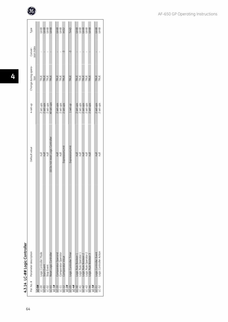
Par.
No.
#Pa
ram
eter
des
crip
tion
Def
ault
valu
e4-
set-
upCh
ange
dur
ing
oper
a-tio
nCo
nver
-si
on in
dex
Type
LC-0
#LC
-00
Logi
c Co
ntro
ller M
ode
null
2 se
t-up
sTR
UE
-U
int8
LC-0
1St
art E
vent
null
2 se
t-up
sTR
UE
-U
int8
LC-0
2St
op E
vent
null
2 se
t-up
sTR
UE
-U
int8
LC-0
3Re
set L
ogic
Con
trol
ler
[0] D
o no
t res
et L
ogic
Con
trol
ler
All s
et-u
psTR
UE
-U
int8
LC-1
#LC
-10
Com
para
tor O
pera
ndnu
ll2
set-
ups
TRU
E-
Uin
t8LC
-11
Com
para
tor O
pera
tor
null
2 se
t-up
sTR
UE
-U
int8
LC-1
2Co
mpa
rato
r Val
ueEx
pres
sion
Lim
it2
set-
ups
TRU
E-3
Int3
2LC
-2#
LC-2
0Lo
gic
Cont
rolle
r Tim
erEx
pres
sion
Lim
it1
set-
upTR
UE
-3Ti
mD
LC-4
#LC
-40
Logi
c Ru
le B
oole
an 1
null
2 se
t-up
sTR
UE
-U
int8
LC-4
1Lo
gic
Rule
Ope
rato
r 1nu
ll2
set-
ups
TRU
E-
Uin
t8LC
-42
Logi
c Ru
le B
oole
an 2
null
2 se
t-up
sTR
UE
-U
int8
LC-4
3Lo
gic
Rule
Ope
rato
r 2nu
ll2
set-
ups
TRU
E-
Uin
t8LC
-44
Logi
c Ru
le B
oole
an 3
null
2 se
t-up
sTR
UE
-U
int8
LC-5
#LC
-51
Logi
c Co
ntro
ller E
vent
null
2 se
t-up
sTR
UE
-U
int8
LC-5
2Lo
gic
Cont
rolle
r Act
ion
null
2 se
t-up
sTR
UE
-U
int8
4.3.
14LC
-##
Log
ic C
ontr
olle
r
AF-650 GP Operating Instructions
64
4
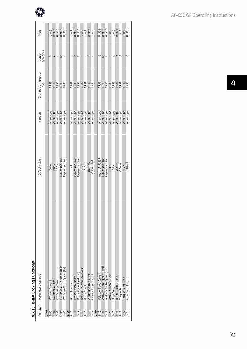
Par.
No.
#Pa
ram
eter
des
crip
tion
Def
ault
valu
e4-
set-
upCh
ange
dur
ing
oper
a-tio
nCo
nver
-si
on in
dex
Type
B-0#
B-00
DC
Hol
d Cu
rren
t50
%Al
l set
-ups
TRU
E0
Uin
t8B-
01D
C Br
ake
Curr
ent
50 %
All s
et-u
psTR
UE
0U
int1
6B-
02D
C Br
akin
g Ti
me
10.0
sAl
l set
-ups
TRU
E-1
Uin
t16
B-03
DC
Brak
e Cu
t In
Spee
d [R
PM]
Expr
essi
onLi
mit
All s
et-u
psTR
UE
67U
int1
6B-
04D
C Br
ake
Cut I
n Sp
eed
[Hz]
Expr
essi
onLi
mit
All s
et-u
psTR
UE
-1U
int1
6B-
1#B-
10Br
ake
Func
tion
null
All s
et-u
psTR
UE
-U
int8
B-11
Brak
e Re
sist
or (o
hm)
Expr
essi
onLi
mit
All s
et-u
psTR
UE
-2U
int3
2B-
12Br
ake
Pow
er L
imit
(kW
)Ex
pres
sion
Lim
itAl
l set
-ups
TRU
E0
Uin
t32
B-13
Brak
ing
Ther
mal
Ove
rload
[0] O
ffAl
l set
-ups
TRU
E-
Uin
t8B-
15Br
ake
Chec
k[0
] Off
All s
et-u
psTR
UE
-U
int8
B-16
AC b
rake
Max
. Cur
rent
100.
0 %
All s
et-u
psTR
UE
-1U
int3
2B-
17O
ver-
volta
ge C
ontr
ol[0
] Dis
able
dAl
l set
-ups
TRU
E-
Uin
t8B-
2#B-
20Re
leas
e Br
ake
Curr
ent
Imax
VLT
(P16
37)
All s
et-u
psTR
UE
-2U
int3
2B-
21Ac
tivat
e Br
ake
Spee
d [R
PM]
Expr
essi
onLi
mit
All s
et-u
psTR
UE
67U
int1
6B-
22Ac
tivat
e Br
ake
Spee
d [H
z]Ex
pres
sion
Lim
itAl
l set
-ups
TRU
E-1
Uin
t16
B-23
Activ
ate
Brak
e D
elay
0.0
sAl
l set
-ups
TRU
E-1
Uin
t8B-
24St
op D
elay
0.0
sAl
l set
-ups
TRU
E-1
Uin
t8B-
25Br
ake
Rele
ase
Tim
e0.
20 s
All s
et-u
psTR
UE
-2U
int1
6B-
26To
rque
Ref
0.00
%Al
l set
-ups
TRU
E-2
Int1
6B-
27To
rque
Ram
p Ti
me
0.2
sAl
l set
-ups
TRU
E-1
Uin
t8B-
28G
ain
Boos
t Fac
tor
1.00
N/A
All s
et-u
psTR
UE
-2U
int1
6
4.3.
15B-
##
Bra
king
Fun
ctio
ns
AF-650 GP Operating Instructions
65
4
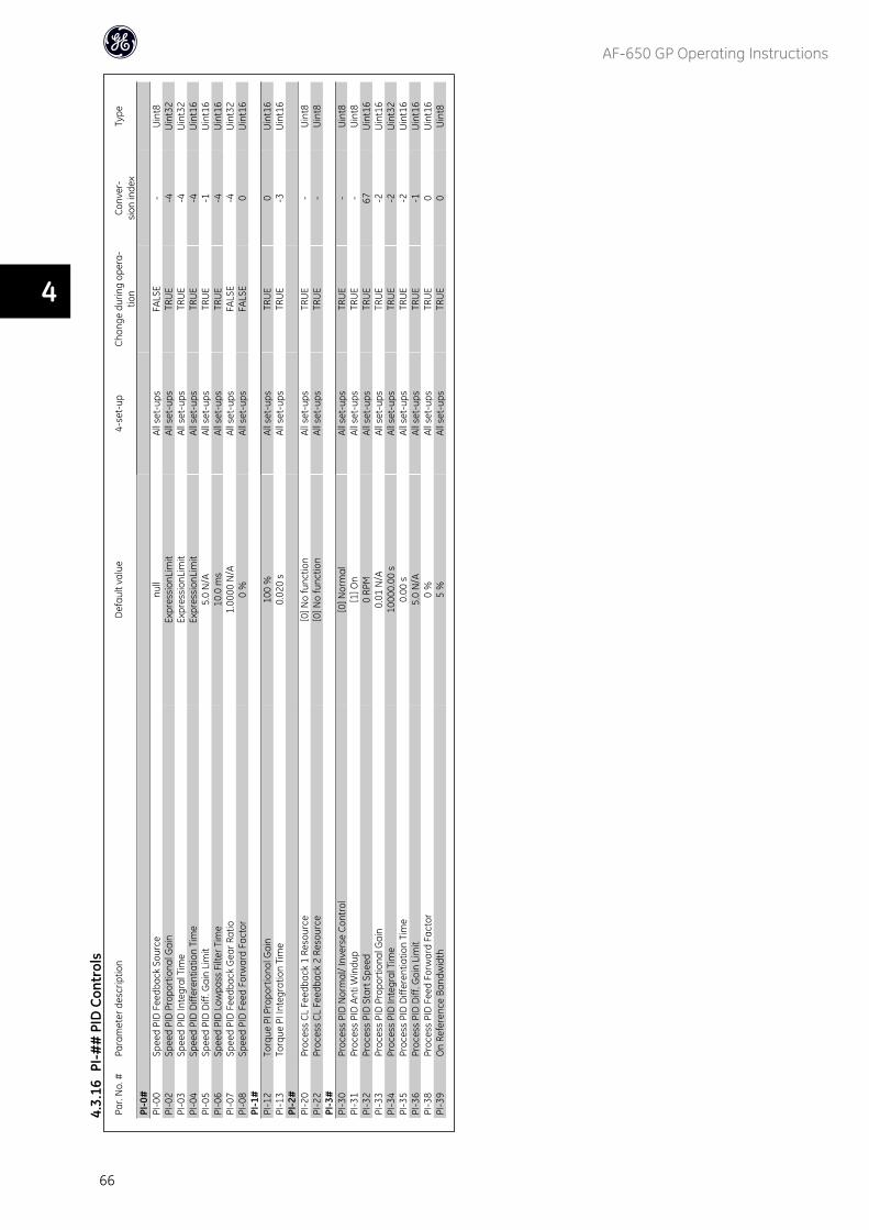
Par.
No.
#Pa
ram
eter
des
crip
tion
Def
ault
valu
e4-
set-
upCh
ange
dur
ing
oper
a-tio
nCo
nver
-si
on in
dex
Type
PI-0
#PI
-00
Spee
d PI
D F
eedb
ack
Sour
cenu
llAl
l set
-ups
FALS
E-
Uin
t8PI
-02
Spee
d PI
D P
ropo
rtio
nal G
ain
Expr
essi
onLi
mit
All s
et-u
psTR
UE
-4U
int3
2PI
-03
Spee
d PI
D In
tegr
al T
ime
Expr
essi
onLi
mit
All s
et-u
psTR
UE
-4U
int3
2PI
-04
Spee
d PI
D D
iffer
entia
tion
Tim
eEx
pres
sion
Lim
itAl
l set
-ups
TRU
E-4
Uin
t16
PI-0
5Sp
eed
PID
Diff
. Gai
n Li
mit
5.0
N/A
All s
et-u
psTR
UE
-1U
int1
6PI
-06
Spee
d PI
D L
owpa
ss F
ilter
Tim
e10
.0 m
sAl
l set
-ups
TRU
E-4
Uin
t16
PI-0
7Sp
eed
PID
Fee
dbac
k G
ear R
atio
1.00
00 N
/AAl
l set
-ups
FALS
E-4
Uin
t32
PI-0
8Sp
eed
PID
Fee
d Fo
rwar
d Fa
ctor
0 %
All s
et-u
psFA
LSE
0U
int1
6PI
-1#
PI-1
2To
rque
PI P
ropo
rtio
nal G
ain
100
%Al
l set
-ups
TRU
E0
Uin
t16
PI-1
3To
rque
PI I
nteg
ratio
n Ti
me
0.02
0 s
All s
et-u
psTR
UE
-3U
int1
6PI
-2#
PI-2
0Pr
oces
s CL
Fee
dbac
k 1
Reso
urce
[0] N
o fu
nctio
nAl
l set
-ups
TRU
E-
Uin
t8PI
-22
Proc
ess
CL F
eedb
ack
2 Re
sour
ce[0
] No
func
tion
All s
et-u
psTR
UE
-U
int8
PI-3
#PI
-30
Proc
ess
PID
Nor
mal
/ Inv
erse
Con
trol
[0] N
orm
alAl
l set
-ups
TRU
E-
Uin
t8PI
-31
Proc
ess
PID
Ant
i Win
dup
[1] O
nAl
l set
-ups
TRU
E-
Uin
t8PI
-32
Proc
ess
PID
Sta
rt S
peed
0 RP
MAl
l set
-ups
TRU
E67
Uin
t16
PI-3
3Pr
oces
s PI
D P
ropo
rtio
nal G
ain
0.01
N/A
All s
et-u
psTR
UE
-2U
int1
6PI
-34
Proc
ess
PID
Inte
gral
Tim
e10
000.
00 s
All s
et-u
psTR
UE
-2U
int3
2PI
-35
Proc
ess
PID
Diff
eren
tiatio
n Ti
me
0.00
sAl
l set
-ups
TRU
E-2
Uin
t16
PI-3
6Pr
oces
s PI
D D
iff. G
ain
Lim
it5.
0 N
/AAl
l set
-ups
TRU
E-1
Uin
t16
PI-3
8Pr
oces
s PI
D F
eed
Forw
ard
Fact
or0
%Al
l set
-ups
TRU
E0
Uin
t16
PI-3
9O
n Re
fere
nce
Band
wid
th5
%Al
l set
-ups
TRU
E0
Uin
t8
4.3.
16PI
-##
PID
Con
trol
s
AF-650 GP Operating Instructions
66
4

Par.
No.
#Pa
ram
eter
des
crip
tion
Def
ault
valu
e4-
set-
upCh
ange
dur
ing
oper
a-tio
nCo
nver
-si
on in
dex
Type
EC-1
#EC
-10
Sign
al T
ype
[1] R
S422
(5V
TTL)
All s
et-u
psFA
LSE
-U
int8
EC-1
1Re
solu
tion
(PPR
)10
24 N
/AAl
l set
-ups
FALS
E0
Uin
t16
EC-2
#EC
-20
Prot
ocol
Sel
ectio
n[0
] Non
eAl
l set
-ups
FALS
E-
Uin
t8EC
-21
Reso
lutio
n (P
ositi
ons/
Rev)
Expr
essi
onLi
mit
All s
et-u
psFA
LSE
0U
int3
2EC
-24
SSI D
ata
Leng
th13
N/A
All s
et-u
psFA
LSE
0U
int8
EC-2
5Cl
ock
Rate
Expr
essi
onLi
mit
All s
et-u
psFA
LSE
3U
int1
6EC
-26
SSI D
ata
Form
at[0
] Gra
y co
deAl
l set
-ups
FALS
E-
Uin
t8EC
-34
HIP
ERFA
CE B
audr
ate
[4] 9
600
All s
et-u
psFA
LSE
-U
int8
EC-6
#EC
-60
Feed
back
Dire
ctio
n[0
] Clo
ckw
ise
All s
et-u
psFA
LSE
-U
int8
EC-6
1Fe
edba
ck S
igna
l Mon
itorin
g[1
] War
ning
All s
et-u
psTR
UE
-U
int8
4.3.
17EC
-##
Fee
dbac
k O
ptio
n
AF-650 GP Operating Instructions
67
4
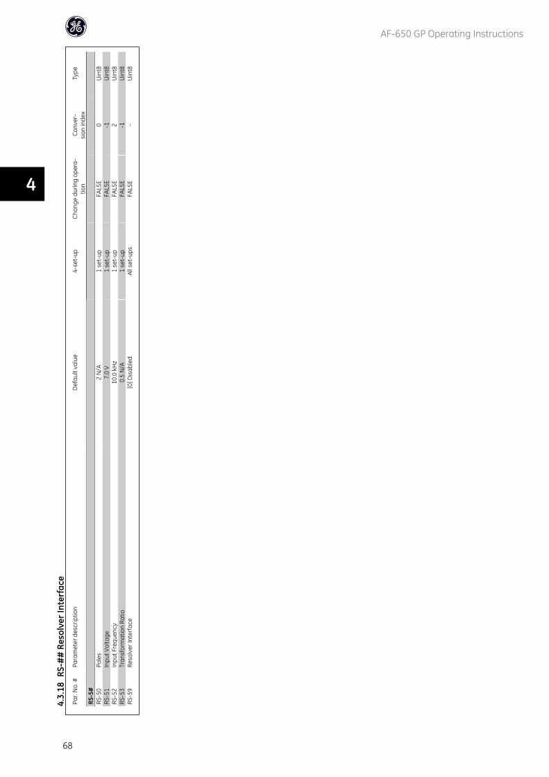
Par.
No.
#Pa
ram
eter
des
crip
tion
Def
ault
valu
e4-
set-
upCh
ange
dur
ing
oper
a-tio
nCo
nver
-si
on in
dex
Type
RS-5
#RS
-50
Pole
s2
N/A
1 se
t-up
FALS
E0
Uin
t8RS
-51
Inpu
t Vol
tage
7.0
V1
set-
upFA
LSE
-1U
int8
RS-5
2In
put F
requ
ency
10.0
kH
z1
set-
upFA
LSE
2U
int8
RS-5
3Tr
ansf
orm
atio
n Ra
tio0.
5 N
/A1
set-
upFA
LSE
-1U
int8
RS-5
9Re
solv
er In
terf
ace
[0] D
isab
led
All s
et-u
psFA
LSE
-U
int8
4.3.
18RS
-##
Res
olve
r Int
erfa
ce
AF-650 GP Operating Instructions
68
4
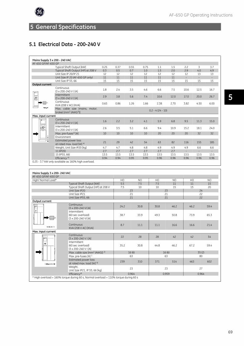
5 General Specifications
5.1 Electrical Data - 200-240 V
Mains Supply 3 x 200 - 240 VACAF-650 GP/AF-650 GP
Typical Shaft Output [kW] 0.25 0.37 0.55 0.75 1.1 1.5 2.2 3 3.7Typical Shaft Output [HP] at 208 V 0.3 0.5 0.7 1.0 1.5 2.0 2.9 4.0 4.9Unit Size IP 20/IP 21 12 12 12 12 12 12 12 13 13Unit Size IP 20 (AF-650 GP only) 11 11 11 11 11 11 - - -Unit Size IP 55, 66 15 15 15 15 15 15 15 15 15
Output currentContinuous(3 x 200-240 V ) [A] 1.8 2.4 3.5 4.6 6.6 7.5 10.6 12.5 16.7
Intermittent(3 x 200-240 V ) [A] 2.9 3.8 5.6 7.4 10.6 12.0 17.0 20.0 26.7
ContinuousKVA (208 V AC) [KVA] 0.65 0.86 1.26 1.66 2.38 2.70 3.82 4.50 6.00
Max. cable size (mains, motor,brake) [mm2 (AWG2))]
0.2 - 4 (24 - 10)
Max. input currentContinuous(3 x 200-240 V ) [A] 1.6 2.2 3.2 4.1 5.9 6.8 9.5 11.3 15.0
Intermittent(3 x 200-240 V ) [A] 2.6 3.5 5.1 6.6 9.4 10.9 15.2 18.1 24.0
Max. pre-fuses1) [A] 10 10 10 10 20 20 20 32 32EnvironmentEstimated power lossat rated max. load [W] 4) 21 29 42 54 63 82 116 155 185
Weight, Unit Size IP20 [kg] 4.7 4.7 4.8 4.8 4.9 4.9 4.9 6.6 6.611 (IP20) 2.7 2.7 2.7 2.7 2.7 2.7 - - -15 (IP55, 66) 13.5 13.5 13.5 13.5 13.5 13.5 13.5 13.5 13.5Efficiency 4) 0.94 0.94 0.95 0.95 0.96 0.96 0.96 0.96 0.96
0.25 - 3.7 kW only available as 160% high overload.
Mains Supply 3 x 200- 240 VACAF-650 GP/AF-650 GPHigh/ Normal Load* HO NO HO NO HO NO Typical Shaft Output [kW] 5.5 7.5 7.5 11 11 15 Typical Shaft Output [HP] at 208 V 7.5 10 10 15 15 20
Unit Size IP20 23 23 24Unit Size IP21 21 21 22
Unit Size IP55, 66 21 21 22Output current
Continuous(3 x 200-240 V) [A] 24.2 30.8 30.8 46.2 46.2 59.4
Intermittent(60 sec overload)(3 x 200-240 V) [A]
38.7 33.9 49.3 50.8 73.9 65.3
ContinuousKVA (208 V AC) [KVA]
8.7 11.1 11.1 16.6 16.6 21.4
Max. input currentContinuous(3 x 200-240 V ) [A] 22 28 28 42 42 54
Intermittent(60 sec overload)(3 x 200-240 V ) [A]
35.2 30.8 44.8 46.2 67.2 59.4
Max. cable size [mm2 (AWG)] 2) 16 (6) 16 (6) 35 (2)Max. pre-fuses [A] 1 63 63 80Estimated power lossat rated max. load [W] 4) 239 310 371 514 463 602
Weight,Unit Size IP21, IP 55, 66 [kg] 23 23 27
Efficiency4) 0.964 0.959 0.964* High overload = 160% torque during 60 s, Normal overload = 110% torque during 60 s
AF-650 GP Operating Instructions
69
5
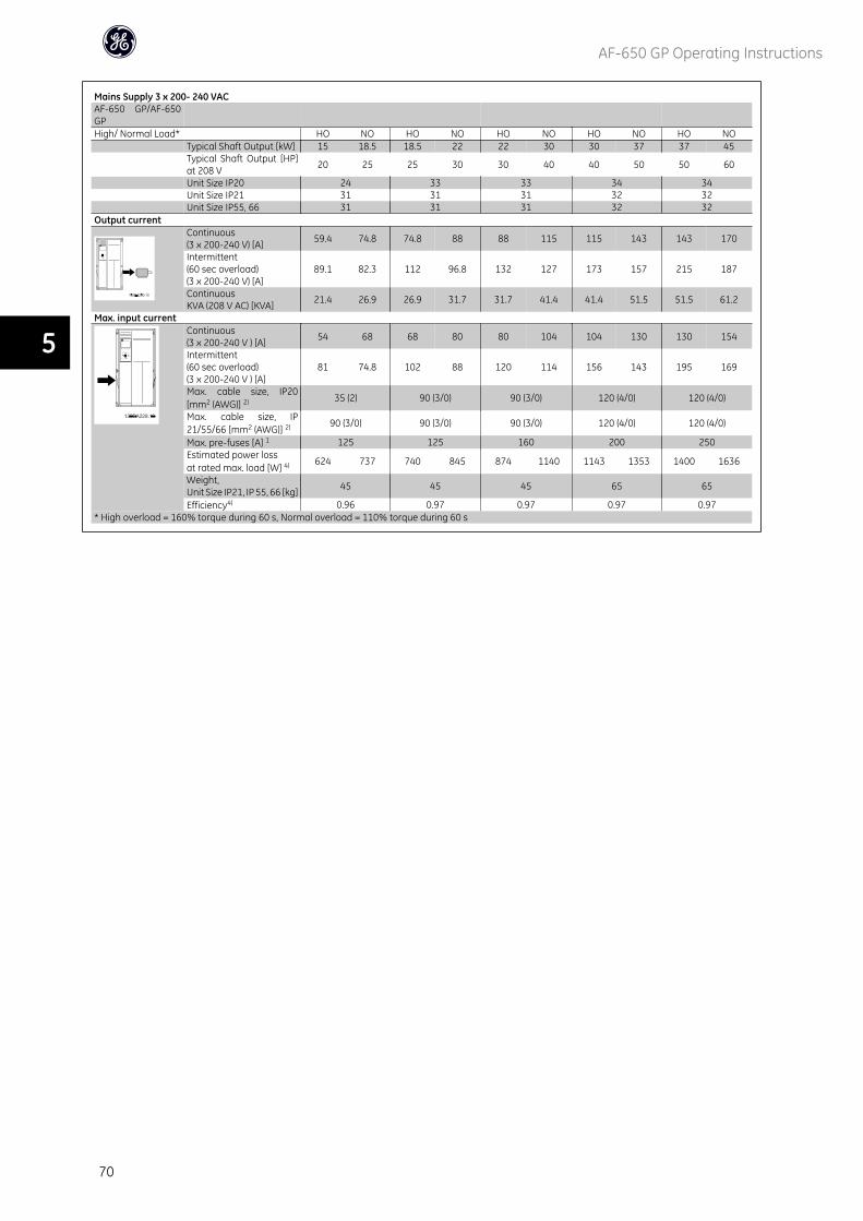
Mains Supply 3 x 200- 240 VACAF-650 GP/AF-650GPHigh/ Normal Load* HO NO HO NO HO NO HO NO HO NO Typical Shaft Output [kW] 15 18.5 18.5 22 22 30 30 37 37 45
Typical Shaft Output [HP]at 208 V 20 25 25 30 30 40 40 50 50 60
Unit Size IP20 24 33 33 34 34Unit Size IP21 31 31 31 32 32
Unit Size IP55, 66 31 31 31 32 32Output current
Continuous(3 x 200-240 V) [A] 59.4 74.8 74.8 88 88 115 115 143 143 170
Intermittent(60 sec overload)(3 x 200-240 V) [A]
89.1 82.3 112 96.8 132 127 173 157 215 187
ContinuousKVA (208 V AC) [KVA] 21.4 26.9 26.9 31.7 31.7 41.4 41.4 51.5 51.5 61.2
Max. input currentContinuous(3 x 200-240 V ) [A] 54 68 68 80 80 104 104 130 130 154
Intermittent(60 sec overload)(3 x 200-240 V ) [A]
81 74.8 102 88 120 114 156 143 195 169
Max. cable size, IP20[mm2 (AWG)] 2) 35 (2) 90 (3/0) 90 (3/0) 120 (4/0) 120 (4/0)
Max. cable size, IP21/55/66 [mm2 (AWG)] 2) 90 (3/0) 90 (3/0) 90 (3/0) 120 (4/0) 120 (4/0)
Max. pre-fuses [A] 1 125 125 160 200 250Estimated power lossat rated max. load [W] 4) 624 737 740 845 874 1140 1143 1353 1400 1636
Weight,Unit Size IP21, IP 55, 66 [kg] 45 45 45 65 65
Efficiency4) 0.96 0.97 0.97 0.97 0.97* High overload = 160% torque during 60 s, Normal overload = 110% torque during 60 s
AF-650 GP Operating Instructions
70
5
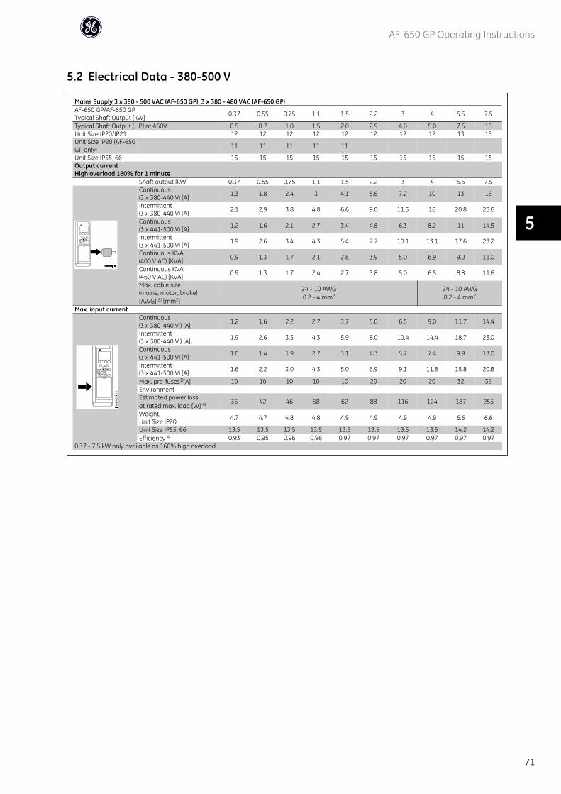
5.2 Electrical Data - 380-500 V
Mains Supply 3 x 380 - 500 VAC (AF-650 GP), 3 x 380 - 480 VAC (AF-650 GP)AF-650 GP/AF-650 GPTypical Shaft Output [kW] 0.37 0.55 0.75 1.1 1.5 2.2 3 4 5.5 7.5
Typical Shaft Output [HP] at 460V 0.5 0.7 1.0 1.5 2.0 2.9 4.0 5.0 7.5 10Unit Size IP20/IP21 12 12 12 12 12 12 12 12 13 13Unit Size IP20 (AF-650GP only) 11 11 11 11 11
Unit Size IP55, 66 15 15 15 15 15 15 15 15 15 15Output currentHigh overload 160% for 1 minute Shaft output [kW] 0.37 0.55 0.75 1.1 1.5 2.2 3 4 5.5 7.5
Continuous(3 x 380-440 V) [A] 1.3 1.8 2.4 3 4.1 5.6 7.2 10 13 16
Intermittent(3 x 380-440 V) [A] 2.1 2.9 3.8 4.8 6.6 9.0 11.5 16 20.8 25.6
Continuous(3 x 441-500 V) [A] 1.2 1.6 2.1 2.7 3.4 4.8 6.3 8.2 11 14.5
Intermittent(3 x 441-500 V) [A] 1.9 2.6 3.4 4.3 5.4 7.7 10.1 13.1 17.6 23.2
Continuous KVA(400 V AC) [KVA] 0.9 1.3 1.7 2.1 2.8 3.9 5.0 6.9 9.0 11.0
Continuous KVA(460 V AC) [KVA] 0.9 1.3 1.7 2.4 2.7 3.8 5.0 6.5 8.8 11.6
Max. cable size(mains, motor, brake)[AWG] 2) [mm2]
24 - 10 AWG0.2 - 4 mm2
24 - 10 AWG0.2 - 4 mm2
Max. input currentContinuous(3 x 380-440 V ) [A] 1.2 1.6 2.2 2.7 3.7 5.0 6.5 9.0 11.7 14.4
Intermittent(3 x 380-440 V ) [A] 1.9 2.6 3.5 4.3 5.9 8.0 10.4 14.4 18.7 23.0
Continuous(3 x 441-500 V) [A] 1.0 1.4 1.9 2.7 3.1 4.3 5.7 7.4 9.9 13.0
Intermittent(3 x 441-500 V) [A] 1.6 2.2 3.0 4.3 5.0 6.9 9.1 11.8 15.8 20.8
Max. pre-fuses1)[A] 10 10 10 10 10 20 20 20 32 32EnvironmentEstimated power lossat rated max. load [W] 4) 35 42 46 58 62 88 116 124 187 255
Weight,Unit Size IP20 4.7 4.7 4.8 4.8 4.9 4.9 4.9 4.9 6.6 6.6
Unit Size IP55, 66 13.5 13.5 13.5 13.5 13.5 13.5 13.5 13.5 14.2 14.2Efficiency 4) 0.93 0.95 0.96 0.96 0.97 0.97 0.97 0.97 0.97 0.97
0.37 - 7.5 kW only available as 160% high overload.
AF-650 GP Operating Instructions
71
5
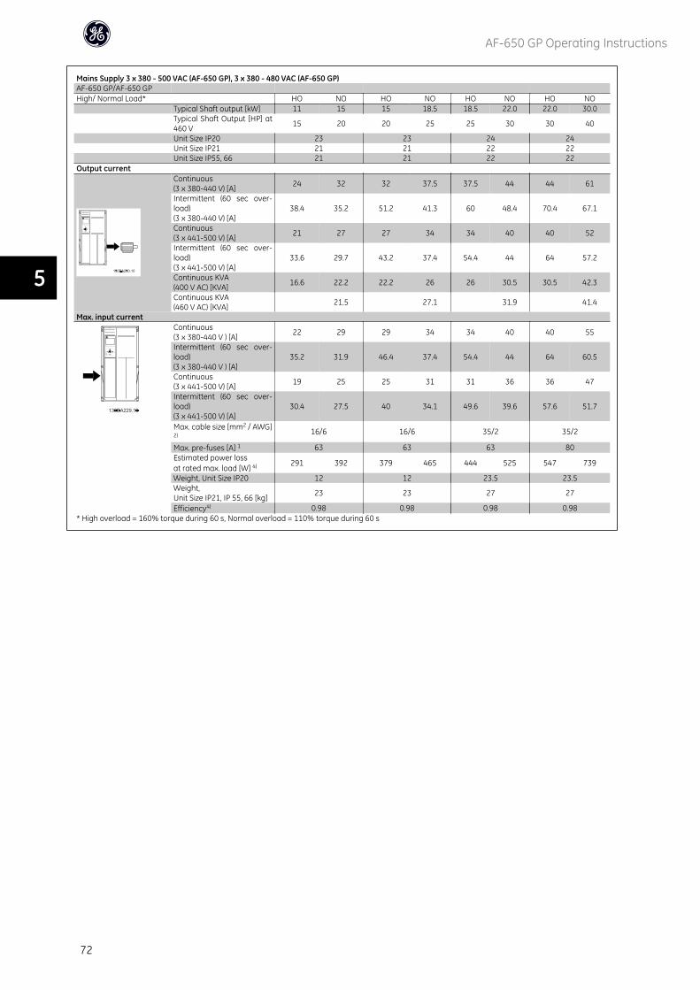
Mains Supply 3 x 380 - 500 VAC (AF-650 GP), 3 x 380 - 480 VAC (AF-650 GP)AF-650 GP/AF-650 GPHigh/ Normal Load* HO NO HO NO HO NO HO NO Typical Shaft output [kW] 11 15 15 18.5 18.5 22.0 22.0 30.0
Typical Shaft Output [HP] at460 V 15 20 20 25 25 30 30 40
Unit Size IP20 23 23 24 24 Unit Size IP21 21 21 22 22 Unit Size IP55, 66 21 21 22 22Output current
Continuous(3 x 380-440 V) [A] 24 32 32 37.5 37.5 44 44 61
Intermittent (60 sec over-load)(3 x 380-440 V) [A]
38.4 35.2 51.2 41.3 60 48.4 70.4 67.1
Continuous(3 x 441-500 V) [A] 21 27 27 34 34 40 40 52
Intermittent (60 sec over-load)(3 x 441-500 V) [A]
33.6 29.7 43.2 37.4 54.4 44 64 57.2
Continuous KVA(400 V AC) [KVA] 16.6 22.2 22.2 26 26 30.5 30.5 42.3
Continuous KVA(460 V AC) [KVA] 21.5 27.1 31.9 41.4
Max. input currentContinuous(3 x 380-440 V ) [A] 22 29 29 34 34 40 40 55
Intermittent (60 sec over-load)(3 x 380-440 V ) [A]
35.2 31.9 46.4 37.4 54.4 44 64 60.5
Continuous(3 x 441-500 V) [A] 19 25 25 31 31 36 36 47
Intermittent (60 sec over-load)(3 x 441-500 V) [A]
30.4 27.5 40 34.1 49.6 39.6 57.6 51.7
Max. cable size [mm2 / AWG]2) 16/6 16/6 35/2 35/2
Max. pre-fuses [A] 1 63 63 63 80Estimated power lossat rated max. load [W] 4) 291 392 379 465 444 525 547 739
Weight, Unit Size IP20 12 12 23.5 23.5Weight,Unit Size IP21, IP 55, 66 [kg] 23 23 27 27
Efficiency4) 0.98 0.98 0.98 0.98* High overload = 160% torque during 60 s, Normal overload = 110% torque during 60 s
AF-650 GP Operating Instructions
72
5
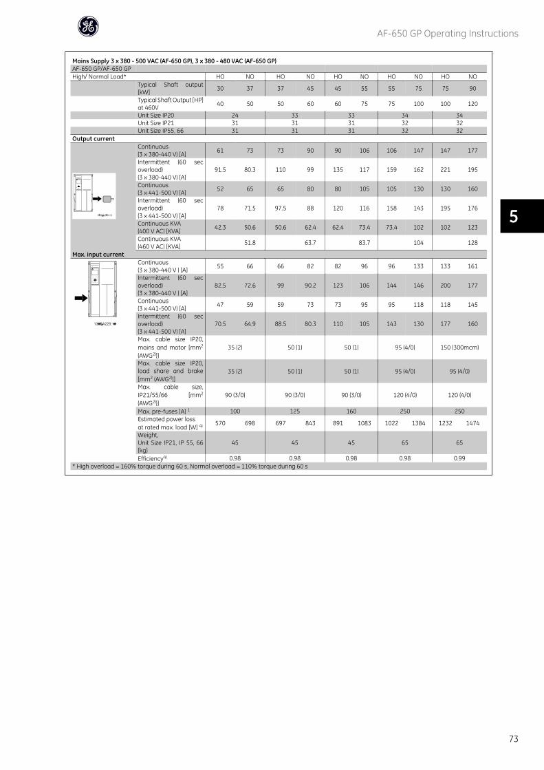
Mains Supply 3 x 380 - 500 VAC (AF-650 GP), 3 x 380 - 480 VAC (AF-650 GP)AF-650 GP/AF-650 GPHigh/ Normal Load* HO NO HO NO HO NO HO NO HO NO
Typical Shaft output[kW] 30 37 37 45 45 55 55 75 75 90
Typical Shaft Output [HP]at 460V 40 50 50 60 60 75 75 100 100 120
Unit Size IP20 24 33 33 34 34 Unit Size IP21 31 31 31 32 32 Unit Size IP55, 66 31 31 31 32 32Output current
Continuous(3 x 380-440 V) [A] 61 73 73 90 90 106 106 147 147 177
Intermittent (60 secoverload)(3 x 380-440 V) [A]
91.5 80.3 110 99 135 117 159 162 221 195
Continuous(3 x 441-500 V) [A] 52 65 65 80 80 105 105 130 130 160
Intermittent (60 secoverload)(3 x 441-500 V) [A]
78 71.5 97.5 88 120 116 158 143 195 176
Continuous KVA(400 V AC) [KVA] 42.3 50.6 50.6 62.4 62.4 73.4 73.4 102 102 123
Continuous KVA(460 V AC) [KVA] 51.8 63.7 83.7 104 128
Max. input currentContinuous(3 x 380-440 V ) [A] 55 66 66 82 82 96 96 133 133 161
Intermittent (60 secoverload)(3 x 380-440 V ) [A]
82.5 72.6 99 90.2 123 106 144 146 200 177
Continuous(3 x 441-500 V) [A] 47 59 59 73 73 95 95 118 118 145
Intermittent (60 secoverload)(3 x 441-500 V) [A]
70.5 64.9 88.5 80.3 110 105 143 130 177 160
Max. cable size IP20,mains and motor [mm2
(AWG2))]35 (2) 50 (1) 50 (1) 95 (4/0) 150 (300mcm)
Max. cable size IP20,load share and brake[mm2 (AWG2))]
35 (2) 50 (1) 50 (1) 95 (4/0) 95 (4/0)
Max. cable size,IP21/55/66 [mm2
(AWG2))]90 (3/0) 90 (3/0) 90 (3/0) 120 (4/0) 120 (4/0)
Max. pre-fuses [A] 1 100 125 160 250 250Estimated power lossat rated max. load [W] 4) 570 698 697 843 891 1083 1022 1384 1232 1474
Weight,Unit Size IP21, IP 55, 66[kg]
45 45 45 65 65
Efficiency4) 0.98 0.98 0.98 0.98 0.99* High overload = 160% torque during 60 s, Normal overload = 110% torque during 60 s
AF-650 GP Operating Instructions
73
5
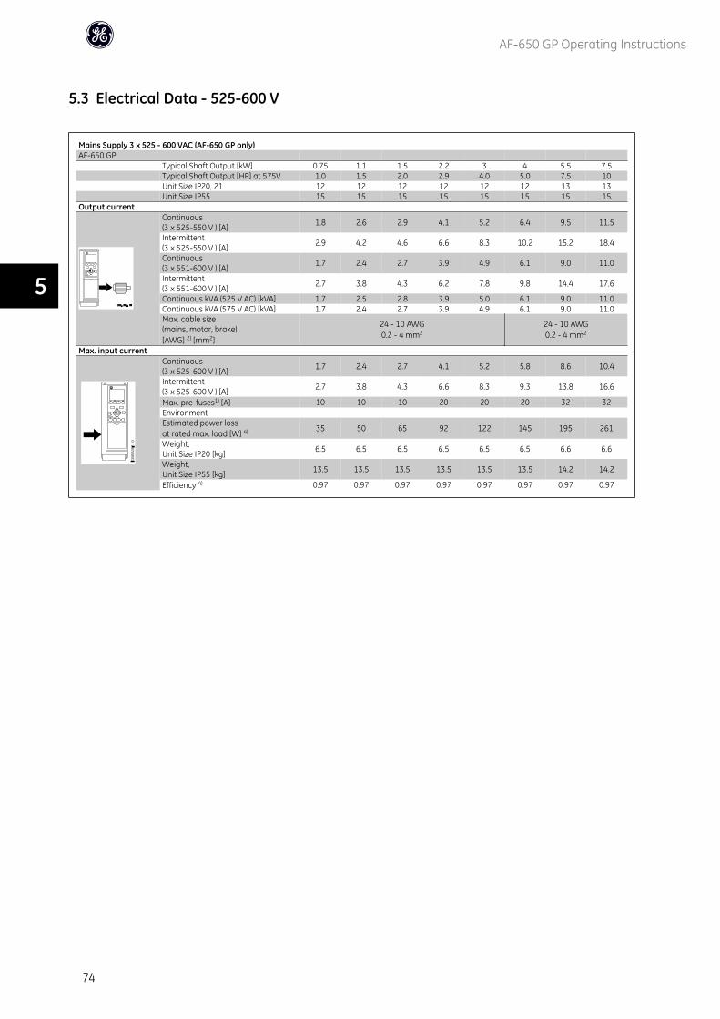
5.3 Electrical Data - 525-600 V
Mains Supply 3 x 525 - 600 VAC (AF-650 GP only)AF-650 GP
Typical Shaft Output [kW] 0.75 1.1 1.5 2.2 3 4 5.5 7.5Typical Shaft Output [HP] at 575V 1.0 1.5 2.0 2.9 4.0 5.0 7.5 10Unit Size IP20, 21 12 12 12 12 12 12 13 13Unit Size IP55 15 15 15 15 15 15 15 15
Output currentContinuous(3 x 525-550 V ) [A] 1.8 2.6 2.9 4.1 5.2 6.4 9.5 11.5
Intermittent(3 x 525-550 V ) [A] 2.9 4.2 4.6 6.6 8.3 10.2 15.2 18.4
Continuous(3 x 551-600 V ) [A] 1.7 2.4 2.7 3.9 4.9 6.1 9.0 11.0
Intermittent(3 x 551-600 V ) [A] 2.7 3.8 4.3 6.2 7.8 9.8 14.4 17.6
Continuous kVA (525 V AC) [kVA] 1.7 2.5 2.8 3.9 5.0 6.1 9.0 11.0Continuous kVA (575 V AC) [kVA] 1.7 2.4 2.7 3.9 4.9 6.1 9.0 11.0Max. cable size(mains, motor, brake)[AWG] 2) [mm2]
24 - 10 AWG0.2 - 4 mm2
24 - 10 AWG0.2 - 4 mm2
Max. input currentContinuous(3 x 525-600 V ) [A] 1.7 2.4 2.7 4.1 5.2 5.8 8.6 10.4
Intermittent(3 x 525-600 V ) [A] 2.7 3.8 4.3 6.6 8.3 9.3 13.8 16.6
Max. pre-fuses1) [A] 10 10 10 20 20 20 32 32EnvironmentEstimated power lossat rated max. load [W] 4) 35 50 65 92 122 145 195 261
Weight,Unit Size IP20 [kg] 6.5 6.5 6.5 6.5 6.5 6.5 6.6 6.6
Weight,Unit Size IP55 [kg] 13.5 13.5 13.5 13.5 13.5 13.5 14.2 14.2
Efficiency 4) 0.97 0.97 0.97 0.97 0.97 0.97 0.97 0.97
AF-650 GP Operating Instructions
74
5
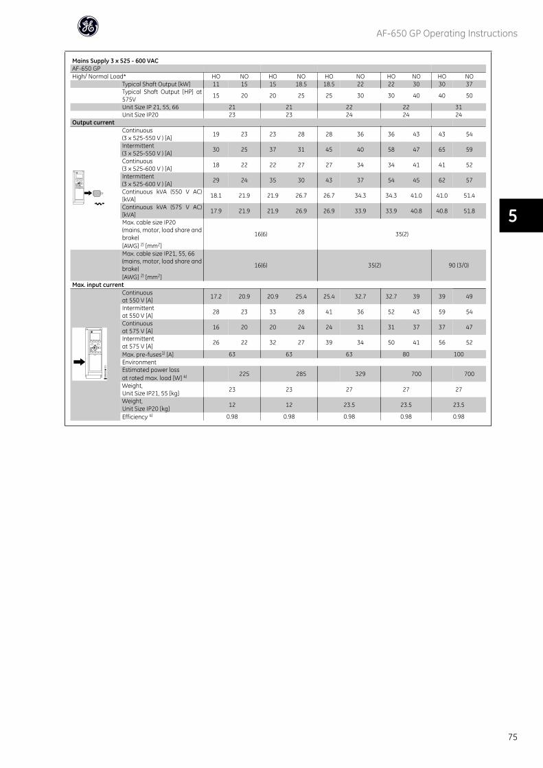
Mains Supply 3 x 525 - 600 VACAF-650 GPHigh/ Normal Load* HO NO HO NO HO NO HO NO HO NO
Typical Shaft Output [kW] 11 15 15 18.5 18.5 22 22 30 30 37Typical Shaft Output [HP] at575V 15 20 20 25 25 30 30 40 40 50
Unit Size IP 21, 55, 66 21 21 22 22 31Unit Size IP20 23 23 24 24 24
Output currentContinuous(3 x 525-550 V ) [A] 19 23 23 28 28 36 36 43 43 54
Intermittent(3 x 525-550 V ) [A] 30 25 37 31 45 40 58 47 65 59
Continuous(3 x 525-600 V ) [A] 18 22 22 27 27 34 34 41 41 52
Intermittent(3 x 525-600 V ) [A] 29 24 35 30 43 37 54 45 62 57
Continuous kVA (550 V AC)[kVA] 18.1 21.9 21.9 26.7 26.7 34.3 34.3 41.0 41.0 51.4
Continuous kVA (575 V AC)[kVA] 17.9 21.9 21.9 26.9 26.9 33.9 33.9 40.8 40.8 51.8
Max. cable size IP20(mains, motor, load share andbrake)[AWG] 2) [mm2]
16(6) 35(2)
Max. cable size IP21, 55, 66(mains, motor, load share andbrake)[AWG] 2) [mm2]
16(6) 35(2) 90 (3/0)
Max. input currentContinuousat 550 V [A] 17.2 20.9 20.9 25.4 25.4 32.7 32.7 39 39 49
Intermittentat 550 V [A] 28 23 33 28 41 36 52 43 59 54
Continuousat 575 V [A] 16 20 20 24 24 31 31 37 37 47
Intermittentat 575 V [A] 26 22 32 27 39 34 50 41 56 52
Max. pre-fuses1) [A] 63 63 63 80 100EnvironmentEstimated power lossat rated max. load [W] 4) 225 285 329 700 700
Weight,Unit Size IP21, 55 [kg] 23 23 27 27 27
Weight,Unit Size IP20 [kg] 12 12 23.5 23.5 23.5
Efficiency 4) 0.98 0.98 0.98 0.98 0.98
AF-650 GP Operating Instructions
75
5
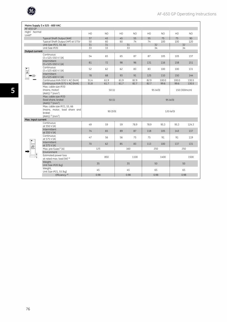
Mains Supply 3 x 525 - 600 VACAF-650 GPHigh/ NormalLoad* HO NO HO NO HO NO HO NO
Typical Shaft Output [kW] 37 45 45 55 55 75 75 90Typical Shaft Output [HP] at 575V 50 60 60 74 74 100 100 120Unit Size IP21, 55, 66 31 31 31 32 32Unit Size IP20 33 33 33 34 34
Output currentContinuous(3 x 525-550 V ) [A] 54 65 65 87 87 105 105 137
Intermittent(3 x 525-550 V ) [A] 81 72 98 96 131 116 158 151
Continuous(3 x 525-600 V ) [A] 52 62 62 83 83 100 100 131
Intermittent(3 x 525-600 V ) [A] 78 68 93 91 125 110 150 144
Continuous kVA (550 V AC) [kVA] 51.4 61.9 61.9 82.9 82.9 100.0 100.0 130.5Continuous kVA (575 V AC) [kVA] 51.8 61.7 61.7 82.7 82.7 99.6 99.6 130.5Max. cable size IP20(mains, motor)[AWG] 2) [mm2]
50 (1) 95 (4/0) 150 (300mcm)
Max. cable size IP20(load share, brake)[AWG] 2) [mm2]
50 (1) 95 (4/0)
Max. cable size IP21, 55, 66(mains, motor, load share andbrake)[AWG] 2) [mm2]
90 (3/0) 120 (4/0)
Max. input currentContinuousat 550 V [A] 49 59 59 78.9 78.9 95.3 95.3 124.3
Intermittentat 550 V [A] 74 65 89 87 118 105 143 137
Continuousat 575 V [A] 47 56 56 75 75 91 91 119
Intermittentat 575 V [A] 70 62 85 83 113 100 137 131
Max. pre-fuses1) [A] 125 160 250 250EnvironmentEstimated power lossat rated max. load [W] 4) 850 1100 1400 1500
Weight,Unit Size IP20 [kg] 35 35 50 50
Weight,Unit Size IP21, 55 [kg] 45 45 65 65
Efficiency 4) 0.98 0.98 0.98 0.98
AF-650 GP Operating Instructions
76
5
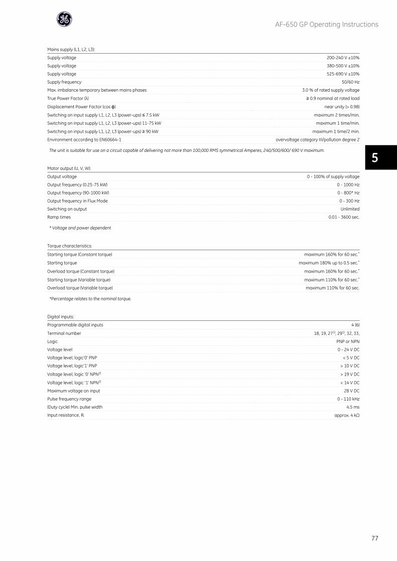
Mains supply (L1, L2, L3):
Supply voltage 200-240 V ±10%
Supply voltage 380-500 V ±10%
Supply voltage 525-690 V ±10%
Supply frequency 50/60 Hz
Max. imbalance temporary between mains phases 3.0 % of rated supply voltage
True Power Factor (λ) ≥ 0.9 nominal at rated load
Displacement Power Factor (cos ϕ) near unity (> 0.98)
Switching on input supply L1, L2, L3 (power-ups) ≤ 7.5 kW maximum 2 times/min.
Switching on input supply L1, L2, L3 (power-ups) 11-75 kW maximum 1 time/min.
Switching on input supply L1, L2, L3 (power-ups) ≥ 90 kW maximum 1 time/2 min.
Environment according to EN60664-1 overvoltage category III/pollution degree 2
The unit is suitable for use on a circuit capable of delivering not more than 100,000 RMS symmetrical Amperes, 240/500/600/ 690 V maximum.
Motor output (U, V, W):
Output voltage 0 - 100% of supply voltage
Output frequency (0.25-75 kW) 0 - 1000 Hz
Output frequency (90-1000 kW) 0 - 800* Hz
Output frequency in Flux Mode 0 - 300 Hz
Switching on output Unlimited
Ramp times 0.01 - 3600 sec.
* Voltage and power dependent
Torque characteristics:
Starting torque (Constant torque) maximum 160% for 60 sec.*
Starting torque maximum 180% up to 0.5 sec.*
Overload torque (Constant torque) maximum 160% for 60 sec.*
Starting torque (Variable torque) maximum 110% for 60 sec.*
Overload torque (Variable torque) maximum 110% for 60 sec.
*Percentage relates to the nominal torque.
Digital inputs:
Programmable digital inputs 4 (6)
Terminal number 18, 19, 271), 291), 32, 33,
Logic PNP or NPN
Voltage level 0 - 24 V DC
Voltage level, logic'0' PNP < 5 V DC
Voltage level, logic'1' PNP > 10 V DC
Voltage level, logic '0' NPN2) > 19 V DC
Voltage level, logic '1' NPN2) < 14 V DC
Maximum voltage on input 28 V DC
Pulse frequency range 0 - 110 kHz
(Duty cycle) Min. pulse width 4.5 ms
Input resistance, Ri approx. 4 kΩ
AF-650 GP Operating Instructions
77
5
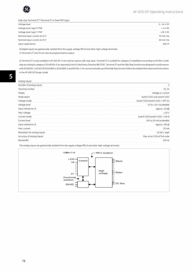
Safe stop Terminal 372) (Terminal 37 is fixed PNP logic):
Voltage level 0 - 24 V DC
Voltage level, logic'0' PNP < 4 V DC
Voltage level, logic'1' PNP >20 V DC
Nominal input current at 24 V 50 mA rms
Nominal input current at 20 V 60 mA rms
Input capacitance 400 nF
All digital inputs are galvanically isolated from the supply voltage (PELV) and other high-voltage terminals.
1) Terminals 27 and 29 can also be programmed as output.
2) Terminal 37 is only available in AF-650 GP. It can only be used as safe stop input. Terminal 37 is suitable for category 3 installations according to EN 954-1 (safe
stop according to category 0 EN 60204-1) as required by the EU Machinery Directive 98/37/EC. Terminal 37 and the Safe Stop function are designed in conformance
with EN 60204-1, EN 50178, EN 61800-2, EN 61800-3, and EN 954-1. For correct and safe use of the Safe Stop function follow the related information and instructions
in the AF-650 GP Design Guide.
Analog inputs:
Number of analog inputs 2
Terminal number 53, 54
Modes Voltage or current
Mode select Switch S201 and switch S202
Voltage mode Switch S201/switch S202 = OFF (U)
Voltage level -10 to +10 V (scaleable)
Input resistance, Ri approx. 10 kΩ
Max. voltage ± 20 V
Current mode Switch S201/switch S202 = ON (I)
Current level 0/4 to 20 mA (scaleable)
Input resistance, Ri approx. 200 Ω
Max. current 30 mA
Resolution for analog inputs 10 bit (+ sign)
Accuracy of analog inputs Max. error 0.5% of full scale
Bandwidth 100 Hz
The analog inputs are galvanically isolated from the supply voltage (PELV) and other high-voltage terminals.
AF-650 GP Operating Instructions
78
5
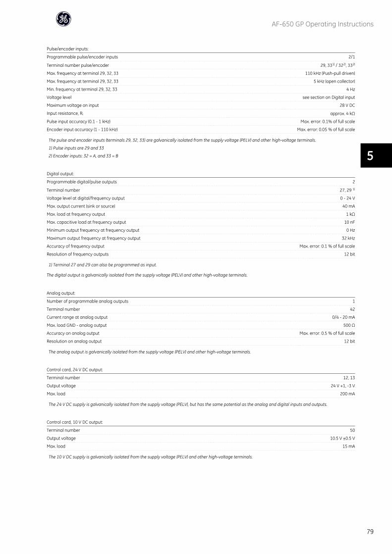
Pulse/encoder inputs:
Programmable pulse/encoder inputs 2/1
Terminal number pulse/encoder 29, 331) / 322), 332)
Max. frequency at terminal 29, 32, 33 110 kHz (Push-pull driven)
Max. frequency at terminal 29, 32, 33 5 kHz (open collector)
Min. frequency at terminal 29, 32, 33 4 Hz
Voltage level see section on Digital input
Maximum voltage on input 28 V DC
Input resistance, Ri approx. 4 kΩ
Pulse input accuracy (0.1 - 1 kHz) Max. error: 0.1% of full scale
Encoder input accuracy (1 - 110 kHz) Max. error: 0.05 % of full scale
The pulse and encoder inputs (terminals 29, 32, 33) are galvanically isolated from the supply voltage (PELV) and other high-voltage terminals.
1) Pulse inputs are 29 and 33
2) Encoder inputs: 32 = A, and 33 = B
Digital output:
Programmable digital/pulse outputs 2
Terminal number 27, 29 1)
Voltage level at digital/frequency output 0 - 24 V
Max. output current (sink or source) 40 mA
Max. load at frequency output 1 kΩ
Max. capacitive load at frequency output 10 nF
Minimum output frequency at frequency output 0 Hz
Maximum output frequency at frequency output 32 kHz
Accuracy of frequency output Max. error: 0.1 % of full scale
Resolution of frequency outputs 12 bit
1) Terminal 27 and 29 can also be programmed as input.
The digital output is galvanically isolated from the supply voltage (PELV) and other high-voltage terminals.
Analog output:
Number of programmable analog outputs 1
Terminal number 42
Current range at analog output 0/4 - 20 mA
Max. load GND - analog output 500 Ω
Accuracy on analog output Max. error: 0.5 % of full scale
Resolution on analog output 12 bit
The analog output is galvanically isolated from the supply voltage (PELV) and other high-voltage terminals.
Control card, 24 V DC output:
Terminal number 12, 13
Output voltage 24 V +1, -3 V
Max. load 200 mA
The 24 V DC supply is galvanically isolated from the supply voltage (PELV), but has the same potential as the analog and digital inputs and outputs.
Control card, 10 V DC output:
Terminal number 50
Output voltage 10.5 V ±0.5 V
Max. load 15 mA
The 10 V DC supply is galvanically isolated from the supply voltage (PELV) and other high-voltage terminals.
AF-650 GP Operating Instructions
79
5
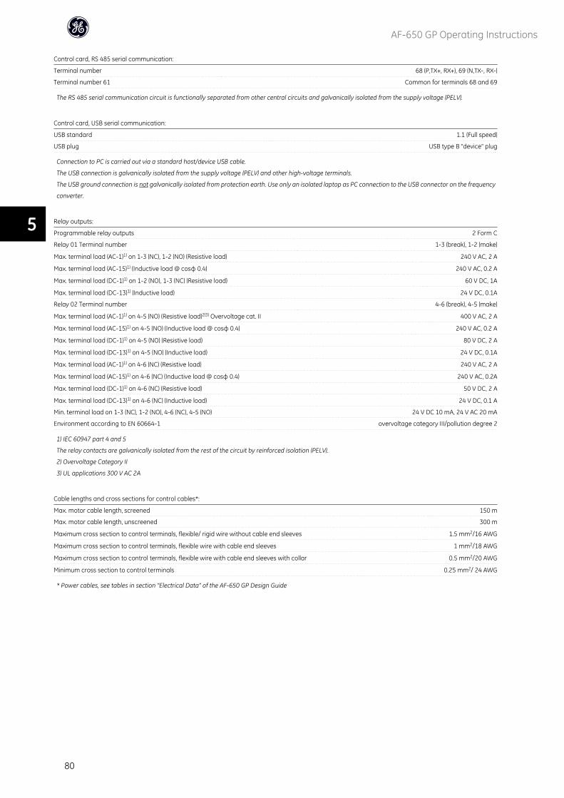
Control card, RS 485 serial communication:
Terminal number 68 (P,TX+, RX+), 69 (N,TX-, RX-)
Terminal number 61 Common for terminals 68 and 69
The RS 485 serial communication circuit is functionally separated from other central circuits and galvanically isolated from the supply voltage (PELV).
Control card, USB serial communication:
USB standard 1.1 (Full speed)
USB plug USB type B “device” plug
Connection to PC is carried out via a standard host/device USB cable.
The USB connection is galvanically isolated from the supply voltage (PELV) and other high-voltage terminals.
The USB ground connection is not galvanically isolated from protection earth. Use only an isolated laptop as PC connection to the USB connector on the frequency
converter.
Relay outputs:
Programmable relay outputs 2 Form C
Relay 01 Terminal number 1-3 (break), 1-2 (make)
Max. terminal load (AC-1)1) on 1-3 (NC), 1-2 (NO) (Resistive load) 240 V AC, 2 A
Max. terminal load (AC-15)1) (Inductive load @ cosφ 0.4) 240 V AC, 0.2 A
Max. terminal load (DC-1)1) on 1-2 (NO), 1-3 (NC) (Resistive load) 60 V DC, 1A
Max. terminal load (DC-13)1) (Inductive load) 24 V DC, 0.1A
Relay 02 Terminal number 4-6 (break), 4-5 (make)
Max. terminal load (AC-1)1) on 4-5 (NO) (Resistive load)2)3) Overvoltage cat. II 400 V AC, 2 A
Max. terminal load (AC-15)1) on 4-5 (NO) (Inductive load @ cosφ 0.4) 240 V AC, 0.2 A
Max. terminal load (DC-1)1) on 4-5 (NO) (Resistive load) 80 V DC, 2 A
Max. terminal load (DC-13)1) on 4-5 (NO) (Inductive load) 24 V DC, 0.1A
Max. terminal load (AC-1)1) on 4-6 (NC) (Resistive load) 240 V AC, 2 A
Max. terminal load (AC-15)1) on 4-6 (NC) (Inductive load @ cosφ 0.4) 240 V AC, 0.2A
Max. terminal load (DC-1)1) on 4-6 (NC) (Resistive load) 50 V DC, 2 A
Max. terminal load (DC-13)1) on 4-6 (NC) (Inductive load) 24 V DC, 0.1 A
Min. terminal load on 1-3 (NC), 1-2 (NO), 4-6 (NC), 4-5 (NO) 24 V DC 10 mA, 24 V AC 20 mA
Environment according to EN 60664-1 overvoltage category III/pollution degree 2
1) IEC 60947 part 4 and 5
The relay contacts are galvanically isolated from the rest of the circuit by reinforced isolation (PELV).
2) Overvoltage Category II
3) UL applications 300 V AC 2A
Cable lengths and cross sections for control cables*:
Max. motor cable length, screened 150 m
Max. motor cable length, unscreened 300 m
Maximum cross section to control terminals, flexible/ rigid wire without cable end sleeves 1.5 mm2/16 AWG
Maximum cross section to control terminals, flexible wire with cable end sleeves 1 mm2/18 AWG
Maximum cross section to control terminals, flexible wire with cable end sleeves with collar 0.5 mm2/20 AWG
Minimum cross section to control terminals 0.25 mm2/ 24 AWG
* Power cables, see tables in section “Electrical Data” of the AF-650 GP Design Guide
AF-650 GP Operating Instructions
80
5
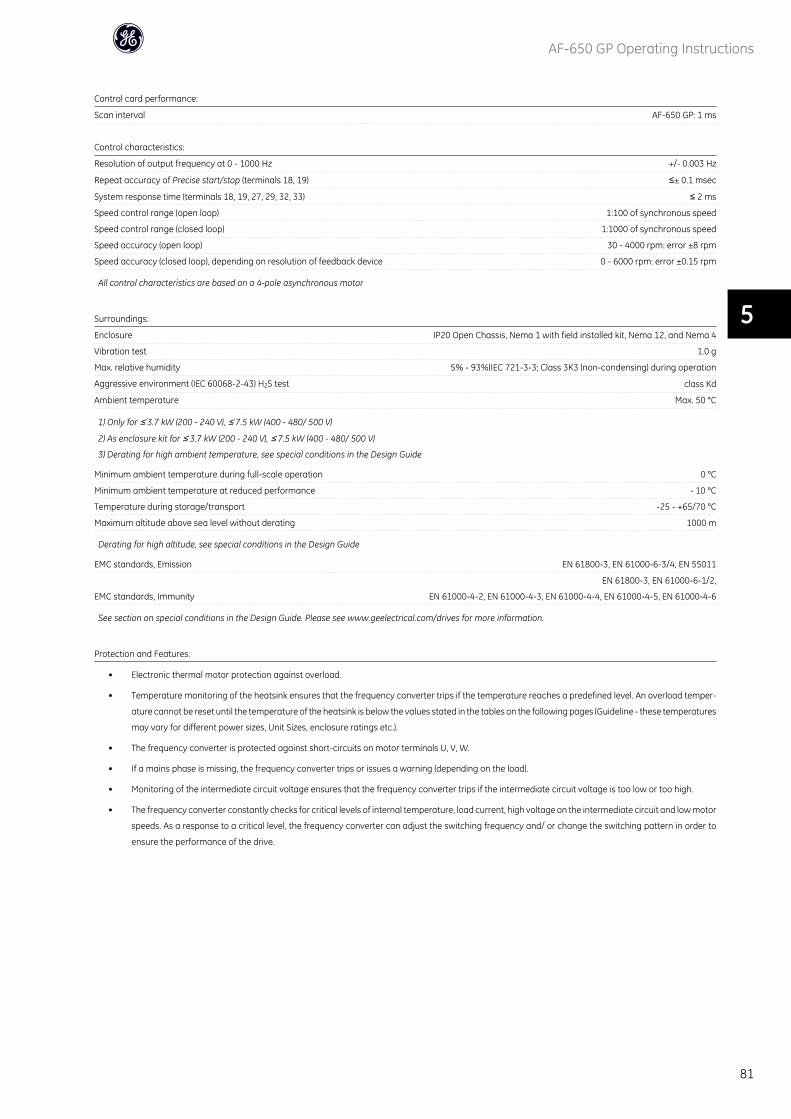
Control card performance:
Scan interval AF-650 GP: 1 ms
Control characteristics:
Resolution of output frequency at 0 - 1000 Hz +/- 0.003 Hz
Repeat accuracy of Precise start/stop (terminals 18, 19) ≤± 0.1 msec
System response time (terminals 18, 19, 27, 29, 32, 33) ≤ 2 ms
Speed control range (open loop) 1:100 of synchronous speed
Speed control range (closed loop) 1:1000 of synchronous speed
Speed accuracy (open loop) 30 - 4000 rpm: error ±8 rpm
Speed accuracy (closed loop), depending on resolution of feedback device 0 - 6000 rpm: error ±0.15 rpm
All control characteristics are based on a 4-pole asynchronous motor
Surroundings:
Enclosure IP20 Open Chassis, Nema 1 with field installed kit, Nema 12, and Nema 4
Vibration test 1.0 g
Max. relative humidity 5% - 93%(IEC 721-3-3; Class 3K3 (non-condensing) during operation
Aggressive environment (IEC 60068-2-43) H2S test class Kd
Ambient temperature Max. 50 °C
1) Only for ≤ 3.7 kW (200 - 240 V), ≤ 7.5 kW (400 - 480/ 500 V)
2) As enclosure kit for ≤ 3.7 kW (200 - 240 V), ≤ 7.5 kW (400 - 480/ 500 V)
3) Derating for high ambient temperature, see special conditions in the Design Guide
Minimum ambient temperature during full-scale operation 0 °C
Minimum ambient temperature at reduced performance - 10 °C
Temperature during storage/transport -25 - +65/70 °C
Maximum altitude above sea level without derating 1000 m
Derating for high altitude, see special conditions in the Design Guide
EMC standards, Emission EN 61800-3, EN 61000-6-3/4, EN 55011
EMC standards, Immunity
EN 61800-3, EN 61000-6-1/2,
EN 61000-4-2, EN 61000-4-3, EN 61000-4-4, EN 61000-4-5, EN 61000-4-6
See section on special conditions in the Design Guide. Please see www.geelectrical.com/drives for more information.
Protection and Features:
• Electronic thermal motor protection against overload.
• Temperature monitoring of the heatsink ensures that the frequency converter trips if the temperature reaches a predefined level. An overload temper-
ature cannot be reset until the temperature of the heatsink is below the values stated in the tables on the following pages (Guideline - these temperatures
may vary for different power sizes, Unit Sizes, enclosure ratings etc.).
• The frequency converter is protected against short-circuits on motor terminals U, V, W.
• If a mains phase is missing, the frequency converter trips or issues a warning (depending on the load).
• Monitoring of the intermediate circuit voltage ensures that the frequency converter trips if the intermediate circuit voltage is too low or too high.
• The frequency converter constantly checks for critical levels of internal temperature, load current, high voltage on the intermediate circuit and low motor
speeds. As a response to a critical level, the frequency converter can adjust the switching frequency and/ or change the switching pattern in order to
ensure the performance of the drive.
AF-650 GP Operating Instructions
81
5

AF-650 GP Operating Instructions
82
6
6 Troubleshooting
6.1.1 Warnings/Alarm Messages
A warning or an alarm is signalled by the relevant LED on the front of the frequency converter and indicated by a code on the display.
A warning remains active until its cause is no longer present. Under certain circumstances operation of the motor may still be continued. Warning messages may
be critical, but are not necessarily so.
In the event of an alarm, the frequency converter will have tripped. Alarms must be reset to restart operation once their cause has been rectified.
This may be done in three ways:
1. By using the [RESET] control button on the Keypad control panel.
2. Via a digital input with the “Reset” function.
3. Via serial communication/optional network.
NB!
After a manual reset using the [RESET] button on the Keypad, the [AUTO] button must be pressed to restart the motor.
If an alarm cannot be reset, the reason may be that its cause has not been rectified, or the alarm is trip-locked (see also table on following page).
Alarms that are trip-locked offer additional protection, meaning that the mains supply must be switched off before the alarm can be reset. After being switched
back on, the frequency converter is no longer blocked and may be reset as described above once the cause has been rectified.
Alarms that are not trip-locked can also be reset using the automatic reset function in par. H-04 Auto-Reset (Times) (Warning: automatic wake-up is possible!)
If a warning and alarm is marked against a code in the table on the following page, this means that either a warning occurs before an alarm, or else that you can
specify whether it is a warning or an alarm that is to be displayed for a given fault.
This is possible, for instance, in par. F-10 Electronic Overload. After an alarm or trip, the motor carries on coasting, and the alarm and warning flash. Once the
problem has been rectified, only the alarm continues flashing until the frequency converter is reset.
AF-650 GP Operating Instructions
83
6
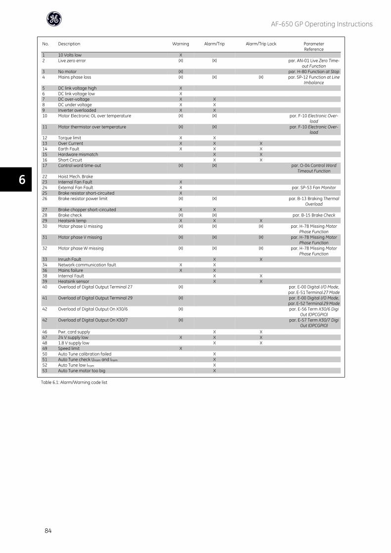
No. Description Warning Alarm/Trip Alarm/Trip Lock ParameterReference
1 10 Volts low X 2 Live zero error (X) (X) par. AN-01 Live Zero Time-
out Function3 No motor (X) par. H-80 Function at Stop4 Mains phase loss (X) (X) (X) par. SP-12 Function at Line
Imbalance5 DC link voltage high X 6 DC link voltage low X7 DC over-voltage X X 8 DC under voltage X X9 Inverter overloaded X X 10 Motor Electronic OL over temperature (X) (X) par. F-10 Electronic Over-
load11 Motor thermistor over temperature (X) (X) par. F-10 Electronic Over-
load12 Torque limit X X13 Over Current X X X 14 Earth Fault X X X15 Hardware mismatch X X16 Short Circuit X X17 Control word time-out (X) (X) par. O-04 Control Word
Timeout Function22 Hoist Mech. Brake23 Internal Fan Fault X24 External Fan Fault X par. SP-53 Fan Monitor25 Brake resistor short-circuited X26 Brake resistor power limit (X) (X) par. B-13 Braking Thermal
Overload27 Brake chopper short-circuited X X28 Brake check (X) (X) par. B-15 Brake Check29 Heatsink temp X X X30 Motor phase U missing (X) (X) (X) par. H-78 Missing Motor
Phase Function31 Motor phase V missing (X) (X) (X) par. H-78 Missing Motor
Phase Function32 Motor phase W missing (X) (X) (X) par. H-78 Missing Motor
Phase Function33 Inrush Fault X X34 Network communication fault X X36 Mains failure X X38 Internal Fault X X39 Heatsink sensor X X40 Overload of Digital Output Terminal 27 (X) par. E-00 Digital I/O Mode,
par. E-51 Terminal 27 Mode41 Overload of Digital Output Terminal 29 (X) par. E-00 Digital I/O Mode,
par. E-52 Terminal 29 Mode42 Overload of Digital Output On X30/6 (X) par. E-56 Term X30/6 Digi
Out (OPCGPIO)42 Overload of Digital Output On X30/7 (X) par. E-57 Term X30/7 Digi
Out (OPCGPIO)46 Pwr. card supply X X47 24 V supply low X X X48 1.8 V supply low X X49 Speed limit X50 Auto Tune calibration failed X51 Auto Tune check Unom and Inom X52 Auto Tune low Inom X53 Auto Tune motor too big X
Table 6.1: Alarm/Warning code list
AF-650 GP Operating Instructions
84
6
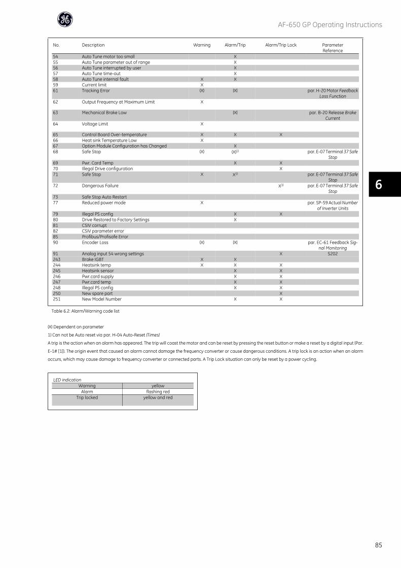
No. Description Warning Alarm/Trip Alarm/Trip Lock ParameterReference
54 Auto Tune motor too small X55 Auto Tune parameter out of range X56 Auto Tune interrupted by user X57 Auto Tune time-out X58 Auto Tune internal fault X X59 Current limit X61 Tracking Error (X) (X) par. H-20 Motor Feedback
Loss Function62 Output Frequency at Maximum Limit X
63 Mechanical Brake Low (X) par. B-20 Release BrakeCurrent
64 Voltage Limit X
65 Control Board Over-temperature X X X66 Heat sink Temperature Low X67 Option Module Configuration has Changed X68 Safe Stop (X) (X)1) par. E-07 Terminal 37 Safe
Stop69 Pwr. Card Temp X X70 Illegal Drive configuration X71 Safe Stop X X1) par. E-07 Terminal 37 Safe
Stop72 Dangerous Failure X1) par. E-07 Terminal 37 Safe
Stop73 Safe Stop Auto Restart77 Reduced power mode X par. SP-59 Actual Number
of Inverter Units79 Illegal PS config X X80 Drive Restored to Factory Settings X81 CSIV corrupt82 CSIV parameter error85 Profibus/Profisafe Error90 Encoder Loss (X) (X) par. EC-61 Feedback Sig-
nal Monitoring91 Analog input 54 wrong settings X S202243 Brake IGBT X X244 Heatsink temp X X X245 Heatsink sensor X X246 Pwr.card supply X X247 Pwr.card temp X X248 Illegal PS config X X250 New spare part X251 New Model Number X X
Table 6.2: Alarm/Warning code list
(X) Dependent on parameter
1) Can not be Auto reset via par. H-04 Auto-Reset (Times)
A trip is the action when an alarm has appeared. The trip will coast the motor and can be reset by pressing the reset button or make a reset by a digital input (Par.
E-1# [1]). The origin event that caused an alarm cannot damage the frequency converter or cause dangerous conditions. A trip lock is an action when an alarm
occurs, which may cause damage to frequency converter or connected parts. A Trip Lock situation can only be reset by a power cycling.
LED indicationWarning yellow
Alarm flashing redTrip locked yellow and red
AF-650 GP Operating Instructions
85
6
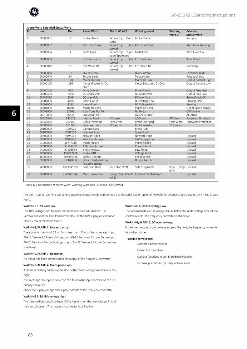
Alarm Word Extended Status WordBit Hex Dec Alarm Word Alarm Word 2 Warning Word Warning
Word 2ExtendedStatus Word
0 00000001 1 Brake Check ServiceTrip, Read/Write
Brake Check Ramping
1 00000002 2 Pwr. Card Temp ServiceTrip, (re-served)
Pwr. Card Temp Auto Tune Running
2 00000004 4 Earth Fault ServiceTrip, Type-code/Sparepart
Earth Fault Start CW/CCW
3 00000008 8 Ctrl.Card Temp ServiceTrip, (re-served)
Ctrl.Card Temp Slow Down
4 00000010 16 Ctrl. Word TO ServiceTrip, (re-served)
Ctrl. Word TO Catch Up
5 00000020 32 Over Current Over Current Feedback High6 00000040 64 Torque Limit Torque Limit Feedback Low7 00000080 128 Motor Th Over Motor Th Over Output Current High8 00000100 256 Motor Electronic OL
OverMotor Electronic OL Over Output Current Low
9 00000200 512 Drive Overld. Drive Overld. Output Freq High10 00000400 1024 DC under Volt DC under Volt Output Freq Low11 00000800 2048 DC over Volt DC over Volt Brake Check OK12 00001000 4096 Short Circuit DC Voltage Low Braking Max13 00002000 8192 Inrush Fault DC Voltage High Braking14 00004000 16384 Mains ph. Loss Mains ph. Loss Out of Speed Range15 00008000 32768 Auto Tune Not OK No Motor OVC Active16 00010000 65536 Live Zero Error Live Zero Error AC Brake17 00020000 131072 Internal Fault KTY error 10V Low KTY Warn Password Timelock18 00040000 262144 Brake Overload Fans error Brake Overload Fans Warn Password Protection19 00080000 524288 U phase Loss ECB error Brake Resistor ECB Warn 20 00100000 1048576 V phase Loss Brake IGBT21 00200000 2097152 W phase Loss Speed Limit 22 00400000 4194304 Network Fault Network Fault Unused23 00800000 8388608 24 V Supply Low 24V Supply Low Unused24 01000000 16777216 Mains Failure Mains Failure Unused25 02000000 33554432 1.8V Supply Low Current Limit Unused26 04000000 67108864 Brake Resistor Low Temp Unused27 08000000 134217728 Brake IGBT Voltage Limit Unused28 10000000 268435456 Option Change Encoder loss Unused29 20000000 536870912 Drive Restored to
factory settings Output freq. lim. Unused
30 40000000 1073741824 Safe Stop (A68) Safe Stop (A71) Safe Stop (W68) Safe Stop(W71)
Unused
31 80000000 2147483648 Mech. brake low Dangerous Failure(A72)
Extended Status Word Unused
Table 6.3: Description of Alarm Word, Warning Word and Extended Status Word
The alarm words, warning words and extended status words can be read out via serial bus or optional network for diagnose. See alsopar. DR-94 Ext. Status
Word.
WARNING 1, 10 Volts low:
The 10 V voltage from terminal 50 on the control card is below 10 V.
Remove some of the load from terminal 50, as the 10 V supply is overloaded.
Max. 15 mA or minimum 590 Ω.
WARNING/ALARM 2, Live zero error:
The signal on terminal 53 or 54 is less than 50% of the value set in par.
AN-10 Terminal 53 Low Voltage, par. AN-12 Terminal 53 Low Current, par.
AN-20 Terminal 54 Low Voltage, or par. AN-22 Terminal 54 Low Current re-
spectively.
WARNING/ALARM 3, No motor:
No motor has been connected to the output of the frequency converter.
WARNING/ALARM 4, Mains phase loss:
A phase is missing on the supply side, or the mains voltage imbalance is too
high.
This message also appears in case of a fault in the input rectifier on the fre-
quency converter.
Check the supply voltage and supply currents to the frequency converter.
WARNING 5, DC link voltage high:
The intermediate circuit voltage (DC) is higher than the overvoltage limit of
the control system. The frequency converter is still active.
WARNING 6, DC link voltage low
The intermediate circuit voltage (DC) is below the undervoltage limit of the
control system. The frequency converter is still active.
WARNING/ALARM 7, DC over voltage:
If the intermediate circuit voltage exceeds the limit, the frequency converter
trips after a time.
Possible corrections:
Connect a brake resistor
Extend the ramp time
Activate functions in par. B-10 Brake Function
Increase par. SP-26 Trip Delay at Drive Fault
AF-650 GP Operating Instructions
86
6
Alarm/warning limits:3 x 200 - 240 V 3 x 380 - 500 V 3 x 525 - 600 V
[VDC] [VDC] [VDC]Undervoltage 185 373 532Voltage warning low 205 410 585Voltage warninghigh (w/o brake - w/brake)
390/405 810/840 943/965
Overvoltage 410 855 975 The voltages stated are the intermediate circuit voltage of the frequencyconverter with a tolerance of ± 5 %. The corresponding mains voltageis the intermediate circuit voltage (DC-link) divided by 1.35
WARNING/ALARM 8, DC under voltage:
If the intermediate circuit voltage (DC) drops below the “voltage warning low”
limit (see table above), the frequency converter checks if 24 V backup supply
is connected.
If no 24 V backup supply is connected, the frequency converter trips after a
given time depending on the unit.
To check whether the supply voltage matches the frequency converter, see
General Specifications.
WARNING/ALARM 9, Drive overloaded:
The frequency converter is about to cut out because of an overload (too high
current for too long). The counter for electronic, thermal inverter protection
gives a warning at 98% and trips at 100%, while giving an alarm. You can-
not reset the frequency converter until the counter is below 90%.
The fault is that the frequency converter is overloaded by more than 100%
for too long.
WARNING/ALARM 10, Motor electronic overload over temperature:
According to the electronic thermal protection, the motor is too hot. You can
choose if you want the frequency converter to give a warning or an alarm
when the counter reaches 100% in par. F-10 Electronic Overload. The fault is
that the motor is overloaded by more than 100% for too long. Check that the
motor par. P-03 Motor Current is set correctly.
WARNING/ALARM 11, Motor thermistor over temp:
The thermistor or the thermistor connection is disconnected. You can choose
if you want the frequency converter to give a warning or an alarm when the
counter reaches 100% in par. F-10 Electronic Overload. Check that the ther-
mistor is connected correctly between terminal 53 or 54 (analog voltage input)
and terminal 50 (+ 10 V supply), or between terminal 18 or 19 (digital input
PNP only) and terminal 50. If aKTY sensoris used, check for correct connection
between terminal 54 and 55.
WARNING/ALARM 12, Torque limit:
The torque is higher than the value in par. F-40 Torque Limiter (Driving) (in
motor operation) or the torque is higher than the value in par. F-41 Tor-
que Limiter (Braking) (in regenerative operation).
WARNING/ALARM 13, Over Current:
The inverter peak current limit (approx. 200% of the rated current) is exceeded.
The warning will last approx. 8-12 sec., then the frequency converter trips and
issues an alarm. Turn off the frequency converter and check if the motor shaft
can be turned and if the motor size matches the frequency converter.
If extended mechanical brake control is selected, trip can be reset externally.
ALARM 14, Earth fault:
There is a discharge from the output phases to earth, either in the cable be-
tween the frequency converter and the motor or in the motor itself.
Turn off the frequency converter and remove the earth fault.
ALARM 15, Incomplete hardware:
A fitted option is not handled by the present control board (hardware or soft-
ware).
ALARM 16, Short-circuit
There is short-circuiting in the motor or on the motor terminals.
Turn off the frequency converter and remove the short-circuit.
WARNING/ALARM 17, Control word timeout:
There is no communication to the frequency converter.
The warning will only be active when par. O-04 Control Word Timeout Func-
tion is NOT set to OFF.
If par. O-04 Control Word Timeout Function is set to Stop and Trip, a warning
appears and the frequency converter ramps down until it trips, while giving
an alarm.
par. O-03 Control Word Timeout Time could possibly be increased.
WARNING 23, Internal fan fault:
The fan warning function is an extra protection function that checks if the fan
is running / mounted. The fan warning can be disabled in par.
SP-53 Fan Monitor (set to [0] Disabled).
WARNING 24, External fan fault:
The fan warning function is an extra protection function that checks if the fan
is running / mounted. The fan warning can be disabled in par.
SP-53 Fan Monitor (set to [0] Disabled).
WARNING 25, Brake resistor short-circuited:
The brake resistor is monitored during operation. If it short-circuits, the brake
function is disconnected and the warning appears. The frequency converter
still works, but without the brake function. Turn off the frequency converter
and replace the brake resistor (see par. B-15 Brake Check).
ALARM/WARNING 26, Brake resistor power limit:
The power transmitted to the brake resistor is calculated as a percentage, as
a mean value over the last 120 s, on the basis of the resistance value of the
brake resistor (par. B-11 Brake Resistor (ohm)) and the intermediate circuit
voltage. The warning is active when the dissipated braking power is higher
than 90%. If Trip [2] has been selected in par. B-13 Braking Thermal Over-
load, the frequency converter cuts out and issues this alarm, when the
dissipated braking power is higher than 100%.
ALARM/ WARNING 27, Brake chopper fault:
The brake transistor is monitored during operation and if it short-circuits, the
brake function disconnects and the warning comes up. The frequency con-
verter is still able to run, but since the brake transistor has short-circuited,
substantial power is transmitted to the brake resistor, even if it is inactive.
Turn off the frequency converter and remove the brake resistor.
This alarm/ warning could also occur should the brake resistor overheat. Ter-
minal 104 to 106 are available as brake resistor. Klixon inputs, see section
Brake Resistor Temperature Switch.
Warning: There is a risk of substantial power being trans-
mitted to the brake resistor if the brake transistor is short-
circuited.
ALARM/WARNING 28, Brake check failed:
Brake resistor fault: the brake resistor is not connected/working.
ALARM 29, Drive over temperature:
If the drive type is IP20 Open Chassis, IP20 with Nema 1 kit, or Nema 1 the
cut-out temperature of the heat-sink is 95 oC +5 oC. The temperature fault
cannot be reset, until the temperature of the heatsink is below 70 oC +5 oC.
AF-650 GP Operating Instructions
87
6
The fault could be:
- Ambient temperature too high
- Too long motor cable
ALARM 30, Motor phase U missing:
Motor phase U between the frequency converter and the the motor is missing.
Turn off the frequency converter and check motor phase U.
ALARM 31, Motor phase V missing:
Motor phase V between the frequency converter and the motor is missing.
Turn off the frequency converter and check motor phase V.
ALARM 32, Motor phase W missing:
Motor phase W between the frequency converter and the motor is missing.
Turn off the frequency converter and check motor phase W.
ALARM 33, Inrush fault:
Too many power ups have occured within a short time period. See the chapter
General Specifications for the allowed number of power ups within one mi-
nute.
WARNING/ALARM 34, Network communication fault:
The network option card is not working correctly. Please check parameters
associated with the module and make sure module is properly inserted in Slot
A of the drive.
WARNING/ALARM 36, Mains failure:
This warning/alarm is only active if the supply voltage to the frequency con-
verter is lost and par. SP-10 Line failure is NOT set to OFF. Possible correction:
check the fuses/circuit breaker connected to the frequency converter
ALARM 38, Internal fault:
Internal drive fault. Please contact your GE supplier. Some typical alarm mes-
sages:
0 The serial port cannot be initialized. Serious hardware fail-ure
256 The power EEPROM data is defected or outdated.512 The control board EEPROM data is defected or outdated.513 Communication time out Reading EEPROM data514 Communication time out Reading EEPROM data515 The Application Orientated Control cannot recognize the
EEPROM data516 Cannot write write to the EEPROM because a write com-
mand is on progress517 The write command is under time out518 Failure in the EEPROM519 Missing or invalid BarCode data in EEPROM 1024 – 1279
CAN telegram cannot be sent. (1027 indicate a possiblehardware failure)
1281 Digital Signal Processor flash time-out1282 Power micro software version mismatch1283 Power EEPROM data version mismatch1284 Cannot read Digital Signal Processor software version1299 Option SW in slot A is outdated1300 Option SW in slot B is outdated1311 Option SW in slot C0 is outdated1312 Option SW in slot C1 is outdated1315 Option SW in slot A is not supported (not allowed)1316 Option SW in slot B is not supported (not allowed)1317 Option SW in slot C0 is not supported (not allowed)1318 Option SW in slot C1 is not supported (not allowed)1536 An exception in the Application Orientated Control is reg-
istered. Debug information written in Keypad1792 DSP watchdog is active. Debugging of power part data
Motor Orientated Control data not transferred correctly2049 Power data restarted2315 Missing SW version from power unit2816 Stack overflow Control board module2817 Scheduler slow tasks2818 Fast tasks2819 Parameter thread2820 Keypad stack overflow
2821 Serial port overflow2822 USB port overflow
3072-5122
Parameter value is outside its limits. Perform a initialization.Parameter number causing the alarm: Subtract the codefrom 3072. Ex Error code 3238: 3238-3072 = 166 is outsidethe limit
5123 Option in slot A: Hardware incompatible with Control boardhardware
5124 Option in slot B: Hardware incompatible with Control boardhardware
5125 Option in slot C0: Hardware incompatible with Controlboard hardware
5126 Option in slot C1: Hardware incompatible with Controlboard hardware
5376-6231
Out of memory
WARNING 40, Overload of Digital Output Terminal 27
Check the load connected to terminal 27 or remove short-circuit connection.
Check par. E-00 Digital I/O Mode and par. E-51 Terminal 27 Mode.
WARNING 41, Overload of Digital Output Terminal 29:
Check the load connected to terminal 29 or remove short-circuit connection.
Check par. E-00 Digital I/O Mode and par. E-52 Terminal 29 Mode.
WARNING 42, Overload of Digital Output On X30/6 :
Check the load connected to X30/6 or remove short-circuit connection. Check
par. E-56 Term X30/6 Digi Out (OPCGPIO).
WARNING 42, Overload of Digital Output On X30/7 :
Check the load connected to X30/7 or remove short-circuit connection. Check
par. E-57 Term X30/7 Digi Out (OPCGPIO).
WARNING 47, 24 V supply low:
The external 24 V DC backup power supply may be overloaded, otherwise
Contact your GE supplier.
WARNING 48, 1.8 V supply low:
Contact your GE supplier.
WARNING 49, Speed limit:
The speed is not within the specified range in par. F-18 Motor Speed Low Limit
[RPM] and par. F-17 Motor Speed High Limit [RPM].
ALARM 50, Auto Tune calibration failed:
Contact your GE supplier.
ALARM 51, Auto Tune check Unom and Inom:
The setting of motor voltage, motor current, and motor power are set set
correctly. Please check parameters (P-##).
ALARM 52, Auto Tune low Inom:
The motor current is too low. Check the settings.
ALARM 53, Auto Tune motor too big:
The motor is too big for the Auto Tune to be carried out.
ALARM 54, Auto Tune motor too small:
The motor is too small for the Auto Tune to be carried out.
ALARM 55, Auto Tune par. out of range:
The motor parameter values set for the motor are outside acceptable range.
ALARM 56, Auto Tune interrupted by user:
The Auto Tune has been interrupted by the user.
ALARM 57, Auto Tune timeout:
Try to start the Auto Tune again a number of times, until the Auto Tune is
carried out. Please note that repeated runs may heat the motor to a level
where the resistance Rs and Rr are increased. In most cases, however, this is
not critical.
AF-650 GP Operating Instructions
88
6
ALARM 58, Auto Tune internal fault:
Contact your GE supplier.
WARNING 59, Current limit:
The current is higher than the value in par. F-43 Current Limit.
WARNING 61, Tracking Error:
An error has been detected between calculated speed and speed measure-
ment from feedback device. The function Warning/Alarm/Disabling setting is
in par. H-20 Motor Feedback Loss Function. Accepted error setting in par.
H-21 Motor Feedback Speed Error and the allowed time the error occur setting
in par. H-22 Motor Feedback Loss Timeout. During a commissioning procedure
the function may be effective.
WARNING 62, Output Frequency at Maximum Limit:
The output frequency is higher than the value set in par. F-03 Max Output
Frequency 1
ALARM 63, Mechanical Brake Low:
The actual motor current has not exceeded the “release brake” current within
the “Start delay” time window.
WARNING 64, Voltage Limit:
The load and speed combination demands a motor voltage higher than the
actual DC link voltage.
WARNING/ALARM/TRIP 65, Control Card Over Temperature:
Control card over temperature: The cut-out temperature of the control card
is 80° C.
WARNING 66, Heatsink Temperature Low:
The heat sink temperature is measured as 0° C. This could indicate that the
temperature sensor is defect and thus the fan speed is increased to the max-
imum in case the power part or control card is very hot.
ALARM 67, Option Module Configuration has Changed:
One or more options modules have either been added or removed since the
last power down.
ALARM 68, Safe Stop:
Safe Stop has been activated. To resume normal operation, apply 24 V DC to
terminal # 37,, then send a reset signal (via Bus, Digital I/O, or by pressing
[RESET]).
WARNING 68, Safe Stop:
Safe Stop has been activated. Normal operation is resumed when Safe Stop
is disabled. Warning: Automatic Restart!
ALARM 70, Illegal Drive Configuration:
Actual combination of control board and power board is illegal.
ALARM 71, 1 Safe Stop:
Safe Stop has been activated from external source. Normal operation can be
resumed when 24V dc is applied to terminal # 37. When that happens, a reset
signal must be is be sent (via Bus, Digital I/O, or by pressing [RESET]).
WARNING 71, Safe Stop:
Safe Stop has been activated from external source. Normal operation can be
resumed when 24V dc is applied to terminal # 37.. Warning: Automatic Re-
start.
ALARM 72, Dangerous Failure:
Safe Stop with Trip Lock. Unexpected signal levels on Safe Stop.
ALARM 80, Drive Restored to Factory Settings:
Parameter settings are restored to factory settings after a manual (three-
finger) reset.
ALARM 90, Encoder loss:
Check the connection to encoder option and eventually replace the OPCENC
or MCB 103.
ALARM 91, Analogue Input 54 Wrong Settings:
Switch S202 has to be set in position OFF (voltage input) when a KTY sensor
is connected to analogue input terminal 54.
ALARM 250, New Spare Part:
The power or Switch Mode Power Supply has been exchanged. The frequency
converter model number must be restored in the EEPROM. Remember to se-
lect ‘Save to EEPROM’ to complete.
ALARM 251, New Model Number:
The Frequency Converter has got a new model number.
AF-650 GP Operating Instructions
89
6
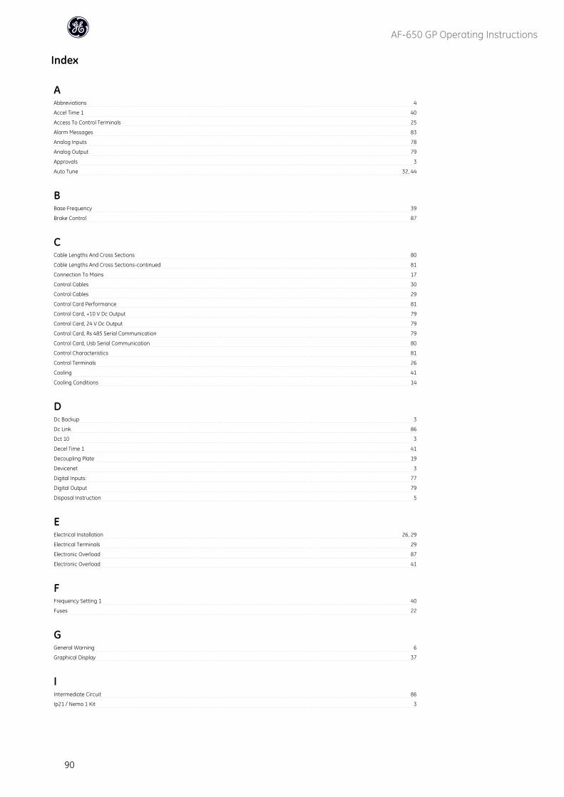
Index
AAbbreviations 4
Accel Time 1 40
Access To Control Terminals 25
Alarm Messages 83
Analog Inputs 78
Analog Output 79
Approvals 3
Auto Tune 32, 44
BBase Frequency 39
Brake Control 87
CCable Lengths And Cross Sections 80
Cable Lengths And Cross Sections-continued 81
Connection To Mains 17
Control Cables 30
Control Cables 29
Control Card Performance 81
Control Card, +10 V Dc Output 79
Control Card, 24 V Dc Output 79
Control Card, Rs 485 Serial Communication 79
Control Card, Usb Serial Communication 80
Control Characteristics 81
Control Terminals 26
Cooling 41
Cooling Conditions 14
DDc Backup 3
Dc Link 86
Dct 10 3
Decel Time 1 41
Decoupling Plate 19
Devicenet 3
Digital Inputs: 77
Digital Output 79
Disposal Instruction 5
EElectrical Installation 26, 29
Electrical Terminals 29
Electronic Overload 87
Electronic Overload 41
FFrequency Setting 1 40
Fuses 22
GGeneral Warning 6
Graphical Display 37
IIntermediate Circuit 86
Ip21 / Nema 1 Kit 3
AF-650 GP Operating Instructions
90
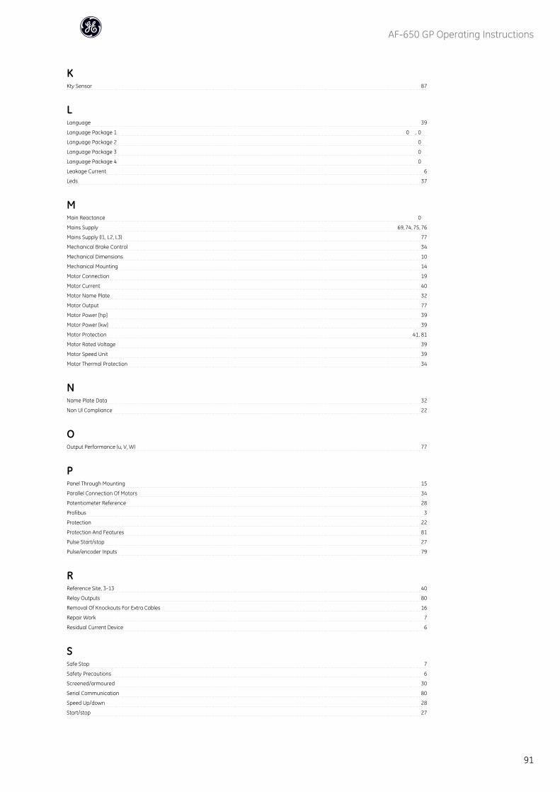
KKty Sensor 87
LLanguage 39
Language Package 1 0 , 0
Language Package 2 0
Language Package 3 0
Language Package 4 0
Leakage Current 6
Leds 37
MMain Reactance 0
Mains Supply 69, 74, 75, 76
Mains Supply (l1, L2, L3) 77
Mechanical Brake Control 34
Mechanical Dimensions 10
Mechanical Mounting 14
Motor Connection 19
Motor Current 40
Motor Name Plate 32
Motor Output 77
Motor Power [hp] 39
Motor Power [kw] 39
Motor Protection 41, 81
Motor Rated Voltage 39
Motor Speed Unit 39
Motor Thermal Protection 34
NName Plate Data 32
Non Ul Compliance 22
OOutput Performance (u, V, W) 77
PPanel Through Mounting 15
Parallel Connection Of Motors 34
Potentiometer Reference 28
Profibus 3
Protection 22
Protection And Features 81
Pulse Start/stop 27
Pulse/encoder Inputs 79
RReference Site, 3-13 40
Relay Outputs 80
Removal Of Knockouts For Extra Cables 16
Repair Work 7
Residual Current Device 6
SSafe Stop 7
Safety Precautions 6
Screened/armoured 30
Serial Communication 80
Speed Up/down 28
Start/stop 27
AF-650 GP Operating Instructions
91

Stator Leakage Reactance 0
Status Messages 37
Surroundings 81
Switches S201, S202, And S801 31
Symbols 4
TThermistor 41
Torque Characteristics 77
UUnintended Start 7
VVoltage Level 77
Voltage Reference Via A Potentiometer 28
WWarnings 83
AF-650 GP Operating Instructions
92