Embed Size (px)
Citation preview
1703-2C1610
Air Cooled Chillers & AC Fan Coil Units
iOS Version Android Version
Midea CAC After-service Application
iOS Version
Midea CAC News Application
Add.: Midea Headquarters Building, 6 Midea Avenue, Shunde, Foshan, Guangdong, China
Postal code: 528311
Tel: +86-757-26338346 Fax: +86-757-22390205
cac.midea.com global.midea.com
Note: Product speci�cations change from time to time as product improvements and
developments are released and may vary from those in this document.
Commercial Air Conditioner Division
Midea Group
Commercial Air Conditioners 2017/2018
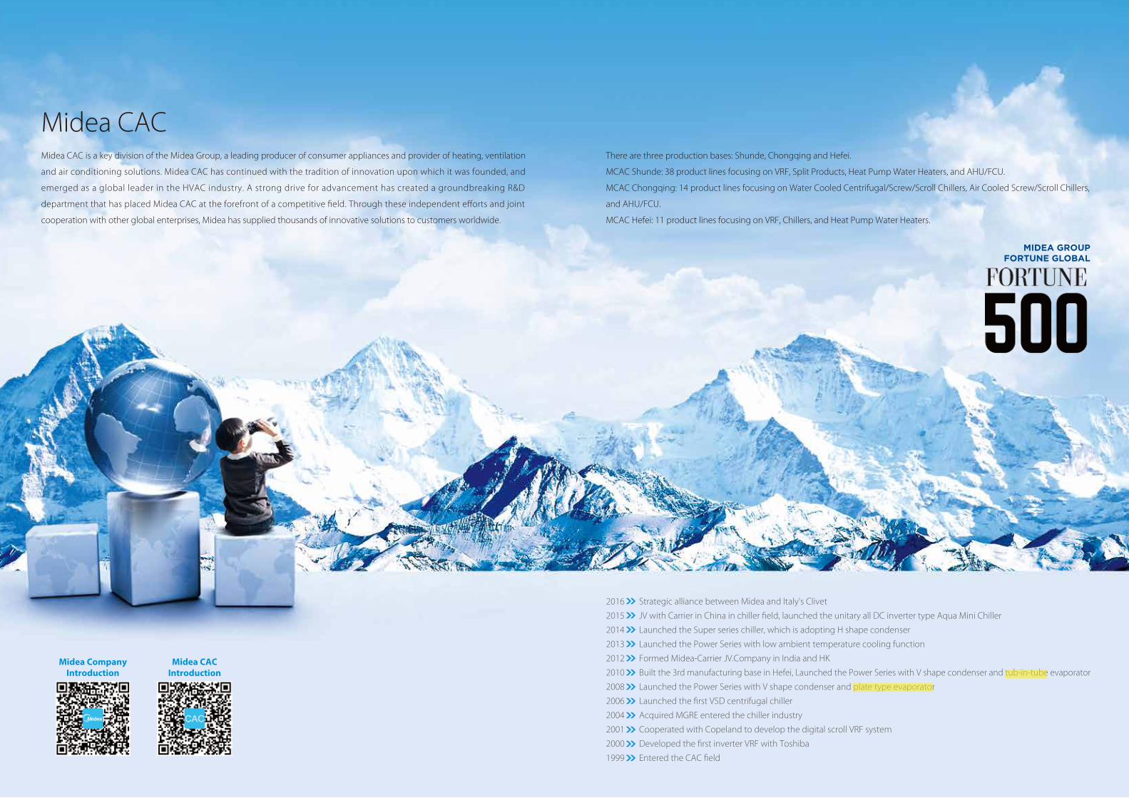
There are three production bases: Shunde, Chongqing and Hefei.
MCAC Shunde: 38 product lines focusing on VRF, Split Products, Heat Pump Water Heaters, and AHU/FCU.
MCAC Chongqing: 14 product lines focusing on Water Cooled Centrifugal/Screw/Scroll Chillers, Air Cooled Screw/Scroll Chillers,
and AHU/FCU.
MCAC Hefei: 11 product lines focusing on VRF, Chillers, and Heat Pump Water Heaters.
Midea CACMidea CAC is a key division of the Midea Group, a leading producer of consumer appliances and provider of heating, ventilation
and air conditioning solutions. Midea CAC has continued with the tradition of innovation upon which it was founded, and
emerged as a global leader in the HVAC industry. A strong drive for advancement has created a groundbreaking R&D
department that has placed Midea CAC at the forefront of a competitive field. Through these independent efforts and joint
cooperation with other global enterprises, Midea has supplied thousands of innovative solutions to customers worldwide.
2016 Strategic alliance between Midea and Italy's Clivet
2015 JV with Carrier in China in chiller field, launched the unitary all DC inverter type Aqua Mini Chiller
2014 Launched the Super series chiller, which is adopting H shape condenser
2013 Launched the Power Series with low ambient temperature cooling function
2012 Formed Midea-Carrier JV.Company in India and HK
2010 Built the 3rd manufacturing base in Hefei, Launched the Power Series with V shape condenser and tub-in-tube evaporator
2008 Launched the Power Series with V shape condenser and plate type evaporator
2006 Launched the first VSD centrifugal chiller
2004 Acquired MGRE entered the chiller industry
2001 Cooperated with Copeland to develop the digital scroll VRF system
2000 Developed the first inverter VRF with Toshiba
1999 Entered the CAC field
Midea Company Introduction
Midea CAC Introduction
03 04
Intr
oduc
tion
Intr
oduc
tion
Aqua Tempo Power Series
Aqua Tempo Super Series
Fan Coil Units
09
19
31
ContentsIntroductionMidea air-cooled scroll chiller adopts air as the cooling/heating source and water as the cooling/heating medium
to cooling/heating the indoor ambient temperatures through the indoor terminals (AHUs/FCUs). They are
environment friendly products for the R410A refrigerant adopted, which does no harm to ozone layer. The chiller
system always works at the most high efficiency stage thanks to the advanced technology. Also, the air cooled
chiller system has a lower initial investment cost than water cooled system. It does not require cooling tower,
condenser water pump and associated condenser water chemical treatment system.
Midea air-cooled scroll chillers are divided to Tempo Power series and Tempo Super series according to their
structure and capacity. Single unit’s capacity range is from 30kW to 250kW. Modular design concept makes the
application from single unit to multiple units. Maximum combination air-cooled scroll system’s cooling capacity
ups to 2080kW.
Midea fan coil units are divided to ceiling exposed type, ceiling concealed type, wall-mounted type and
floor-standing type according to their structure design and installation method. The air volume ranges from
150CFM to 2200CFM (255m3/h~3740m3/h). It is a highly versatile product suitable for hospitals, office buildings,
hotels, airports and various other applications.
05 06
Refe
renc
e Pr
ojec
ts
Refe
renc
e Pr
ojec
ts
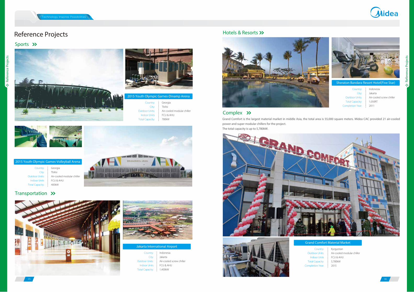
Reference ProjectsSports
Hotels & Resorts
Complex
Transportation
2015 Youth Olympic Games-Dinamp Arena
Country:
City:
Outdoor Units:
Indoor Units
Total Capacity:
Georgia
Tbilisi
Air-cooled modular chiller
FCU & AHU
780kW
2015 Youth Olympic Games-Volleyball Arena
Country:
City:
Outdoor Units:
Indoor Units
Total Capacity:
Georgia
Tbilisi
Air-cooled modular chiller
FCU & AHU
400kW
Jakarta International Airport
Country:
City:
Outdoor Units:
Indoor Units
Total Capacity:
Indonesia
Jakarta
Air-cooled screw chiller
FCU & AHU
1,400kW
Sheraton Bandara Resort Hotel(Five Star)
Country:
City:
Outdoor Units:
Total Capacity:
Completion Year:
Indonesia
Jakarta
Air-cooled screw chiller
1,050RT
2011
Grand Comfort Material Market
Country:
Outdoor Units:
Indoor Units
Total Capacity:
Completion Year:
Kyrgyzstan
Air-cooled modular chiller
FCU & AHU
5,780kW
2015
Grand Comfort is the largest material market in middle Asia, the total area is 55,000 square meters. Midea CAC provided 21 air-cooled
power and super modular chillers for the project.
The total capacity is up to 5,780kW.
07 08
Refe
renc
e Pr
ojec
ts
Refe
renc
e Pr
ojec
ts
Industry
Education
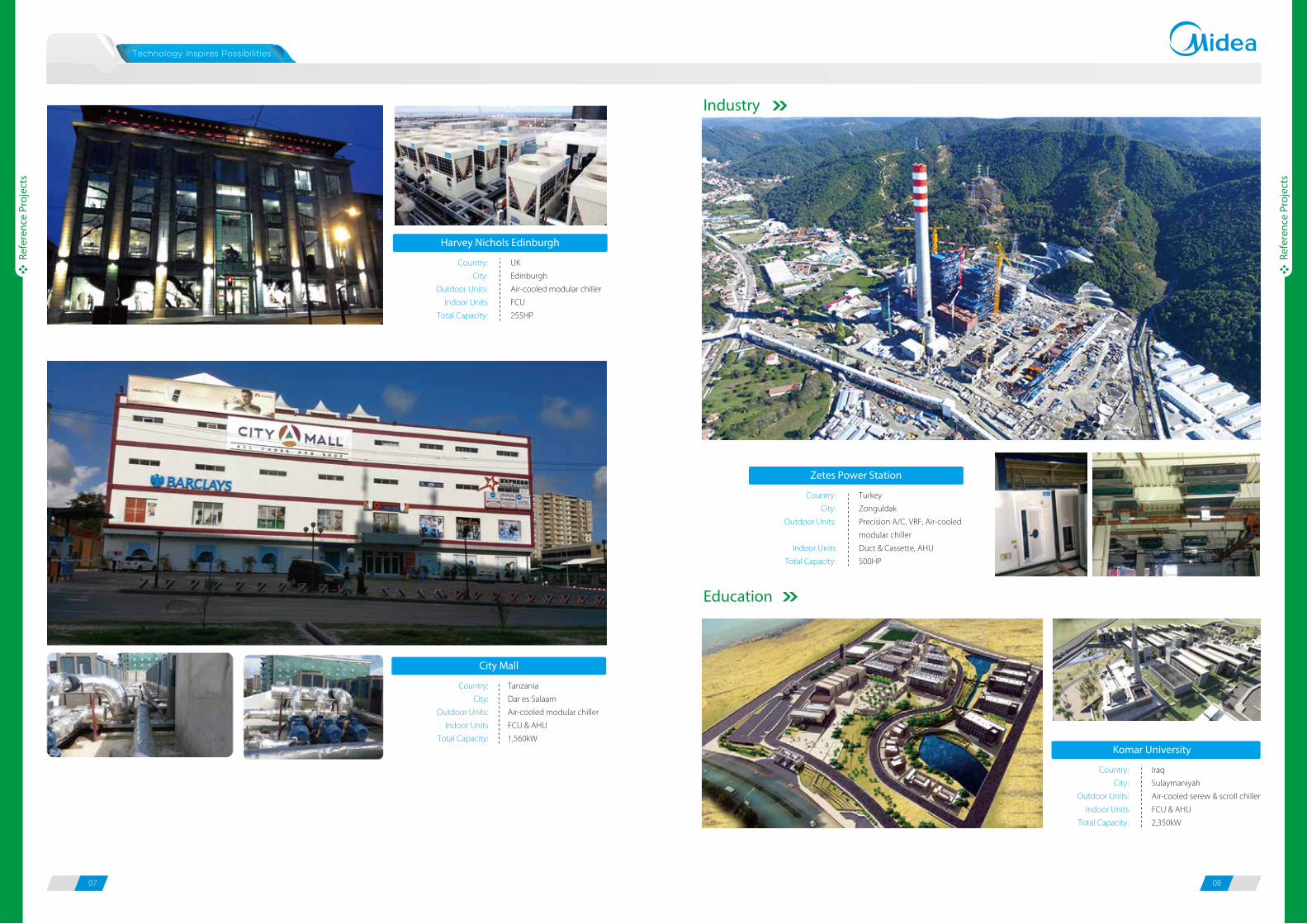
Harvey Nichols Edinburgh
Country:
City:
Outdoor Units:
Indoor Units
Total Capacity:
UK
Edinburgh
Air-cooled modular chiller
FCU
255HP
City Mall
Country:
City:
Outdoor Units:
Indoor Units
Total Capacity:
Tanzania
Dar es Salaam
Air-cooled modular chiller
FCU & AHU
1,560kW
Zetes Power Station
Country:
City:
Outdoor Units:
Indoor Units
Total Capacity:
Turkey
Zonguldak
Precision A/C, VRF, Air-cooled
modular chiller
Duct & Cassette, AHU
500HP
Komar University
Country:
City:
Outdoor Units:
Indoor Units
Total Capacity:
Iraq
Sulaymaniyah
Air-cooled serew & scroll chiller
FCU & AHU
2,350kW
09 10
Aqu
a Te
mpo
Pow
er
Aqu
a Te
mpo
Pow
er
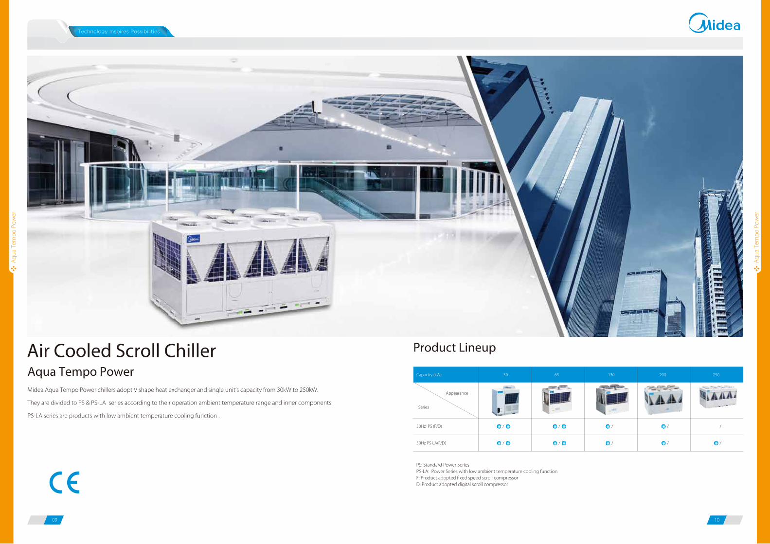
Midea Aqua Tempo Power chillers adopt V shape heat exchanger and single unit’s capacity from 30kW to 250kW.
They are divided to PS & PS-LA series according to their operation ambient temperature range and inner components.
PS-LA series are products with low ambient temperature cooling function .
Product Lineup
Aqua Tempo PowerAir Cooled Scroll Chiller
Series
Appearance
Capacity (kW) 30 65 130 200 250
50Hz PS (F/D) / / / / /
50Hz PS-LA(F/D) / / / / /
PS: Standard Power Series PS-LA: Power Series with low ambient temperature cooling functionF: Product adopted fixed speed scroll compressorD: Product adopted digital scroll compressor
11 12
Aqu
a Te
mpo
Pow
er
Aqu
a Te
mpo
Pow
er
The basic models with cooling capacity ranging from 30kW to 250kW, combination model’s maximum capacity
ups to 2000kW.
Freely combine with fan coil units and air handling units. Project owners may choose the best types according to their design
taste (for interior) or functional needs.
Wide operation ambient temperature range
For the Aqua Tempo Power chillers with low ambient temperature cooling function, the running ambient temperature down
to -10°C both in cooling and heating.
FeaturesWide application range
250kW 250kW 2000kW
Max 8 modules
Cassette type
Air handling units
Celling & Floor
Floor standing
Wall mounted
Duct type
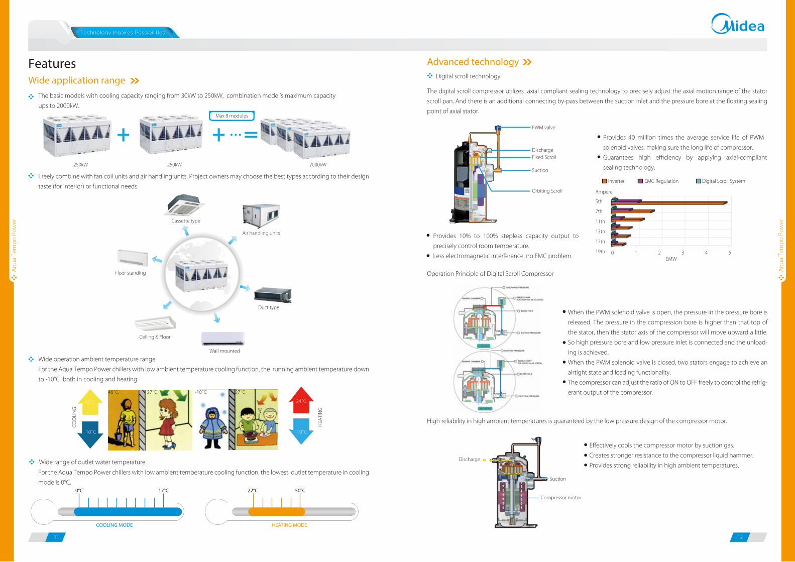
Advanced technologyDigital scroll technology
PWM valve
DischargeFixed Scroll
Suction
Orbiting Scroll
The digital scroll compressor utilizes axial compliant sealing technology to precisely adjust the axial motion range of the stator
scroll pan. And there is an additional connecting by-pass between the suction inlet and the pressure bore at the floating sealing
point of axial stator.
Operation Principle of Digital Scroll Compressor
When the PWM solenoid valve is open, the pressure in the pressure bore is
released. The pressure in the compression bore is higher than that top of
the stator, then the stator axis of the compressor will move upward a little.
So high pressure bore and low pressure inlet is connected and the unload-
ing is achieved.
When the PWM solenoid valve is closed, two stators engage to achieve an
airtight state and loading functionality.
The compressor can adjust the ratio of ON to OFF freely to control the refrig-
erant output of the compressor.
Provides 40 million times the average service life of PWM
solenoid valves, making sure the long life of compressor.
Guarantees high efficiency by applying axial-compliant
sealing technology.
Provides 10% to 100% stepless capacity output to
precisely control room temperature.
Less electromagnetic interference, no EMC problem.
Compressor motor
Suction
Discharge
High reliability in high ambient temperatures is guaranteed by the low pressure design of the compressor motor.
Effectively cools the compressor motor by suction gas.
Creates stronger resistance to the compressor liquid hammer.
Provides strong reliability in high ambient temperatures.
Inverter EMC Regulation Digital Scroll System
5th
7th
11th
13th
17th
19th 0 1 2 3 4 5
Ampere
EMW
Wide range of outlet water temperature
For the Aqua Tempo Power chillers with low ambient temperature cooling function, the lowest outlet temperature in cooling
mode is 0°C.17°C0°C
COOLING MODE
50°C22°C
HEATING MODE
CO
OLI
NG
HEA
TIN
G
-10˚C
46˚C
-10˚C
24˚C
46˚C 27˚C 27˚C-10˚C
13 14
Aqu
a Te
mpo
Pow
er
Aqu
a Te
mpo
Pow
er
The new designed window fins enlarge the heat-exchanging area, decrease the air resistance, save more power and enhance heat
exchange performance.
Hydrophilic film fins and inner-threaded copper pipes optimize heat exchange efficiency.
The specially coated blue fins enhance durability and protect against corrosion from air, water and other corrosive agents, assures
a longer coil service life.
Touch key wire controller as standard accessory to control the chillers.
Remote control functions for convenient operation.
There are ON/OFF, Heat/Cool and Alarm terminals ports on PCB, connect switches from these terminal ports and remote
control functions can be easily realized.
In a combination system, if one module failed, other modules can be back-up instead of the failed one for continuing operation.
30kW and 65kW products are compliance with ErP directive, including both PS series and PS-LA series. The seasonal space heating
energy efficiency classes for 30kW models are A rated and 65kW models are A+ rated.
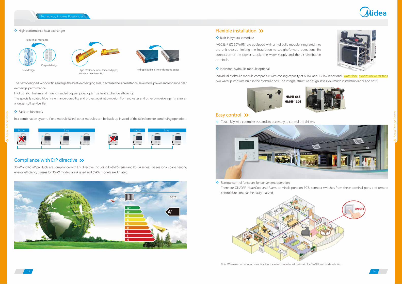
Individual hydraulic module compatible with cooling capacity of 65kW and 130kw is optional. Water box, expansion water tank,
two water pumps are built in the hydraulic box. The integral structure design saves you much installation labor and cost.
Flexible installation
Compliance with ErP directive
Easy control
High performance heat exchanger
Back-up functions
Individual hydraulic module optional New design
Original design
High efficiency inner-threaded pipe, enhance heat transfer.
Reduce air resistance
Hydrophilic fins + inner-threaded pipes
Master SlaveMaster Slave
MGCSL-F (D) 30W/RN1are equipped with a hydraulic module integrated into
the unit chassis, limiting the installation to straight-forward operations like
connection of the power supply, the water supply and the air distribution
terminals.
Built-in hydraulic module
HM/II-65S
HM/II-130S
Note: When use the remote control function, the wired controller will be invalid for ON/OFF and mode selection.
15 16
Aqu
a Te
mpo
Pow
er
Aqu
a Te
mpo
Pow
er
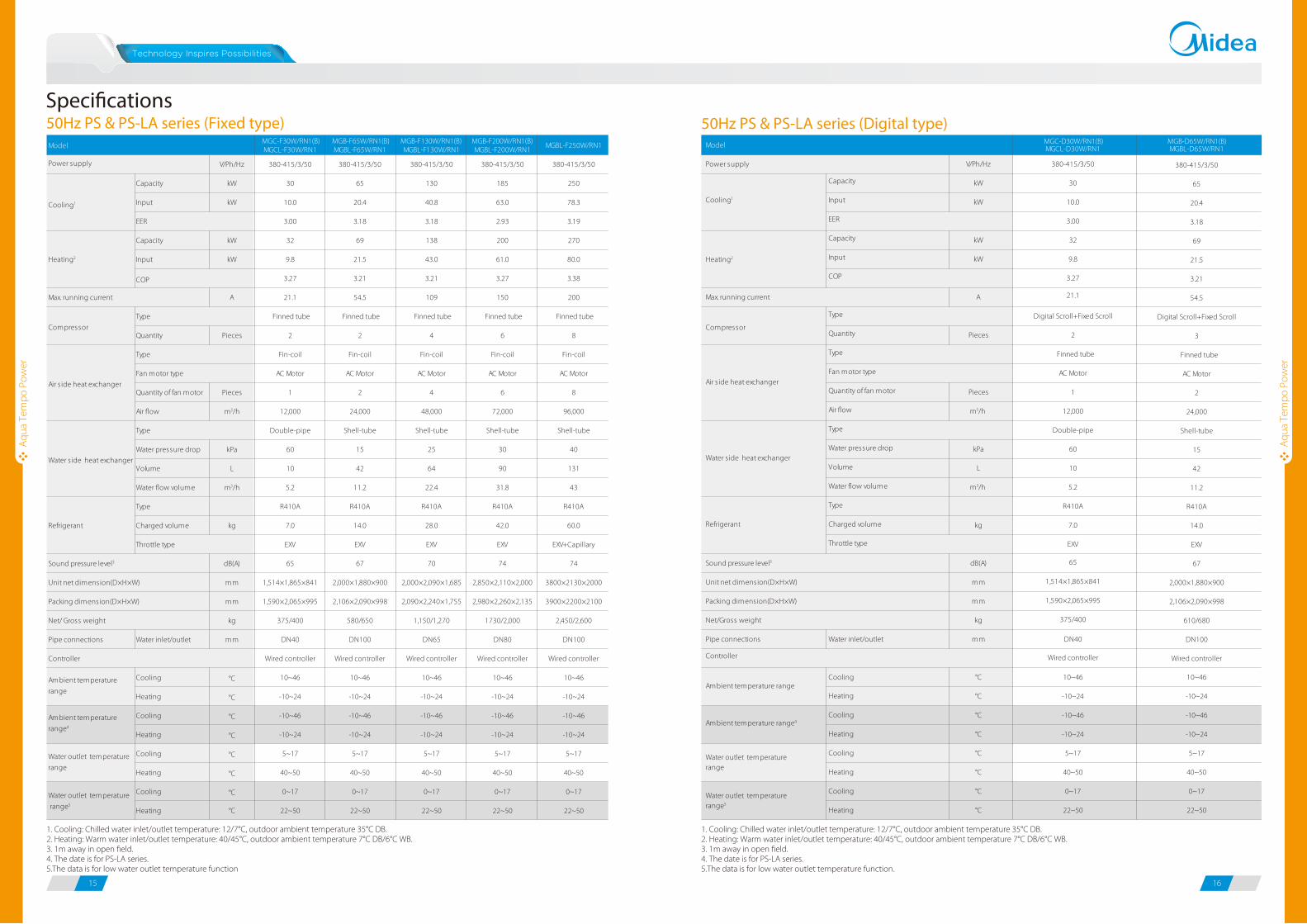
50Hz PS & PS-LA series (Fixed type)Speci�cations
1. Cooling: Chilled water inlet/outlet temperature: 12/7°C, outdoor ambient temperature 35°C DB.2. Heating: Warm water inlet/outlet temperature: 40/45°C, outdoor ambient temperature 7°C DB/6°C WB.3. 1m away in open field.4. The date is for PS-LA series.5.The data is for low water outlet temperature function.
1. Cooling: Chilled water inlet/outlet temperature: 12/7°C, outdoor ambient temperature 35°C DB.2. Heating: Warm water inlet/outlet temperature: 40/45°C, outdoor ambient temperature 7°C DB/6°C WB.3. 1m away in open field.4. The date is for PS-LA series.5.The data is for low water outlet temperature function
50Hz PS & PS-LA series (Digital type)MGC-F30W/RN1(B)MGCL-F30W/RN1
MGB-F65W/RN1(B)MGBL-F65W/RN1
MGB-F130W/RN1(B)MGBL-F130W/RN1
MGB-F200W/RN1(B)MGBL-F200W/RN1
MGBL-F250W/RN1
V/Ph/Hz 380-415/3/50 380-415/3/50 380-415/3/50 380-415/3/50 380-415/3/50
Capacity kW 30 65 130 185 250
Input kW 10.0 20.4 40.8 63.0 78.3
3.00 3.18 3.18 2.93 3.19
Capacity kW 32 69 138 200 270
Input kW 9.8 21.5 43.0 61.0 80.0
3.27 3.21 3.21 3.27 3.38
A 21.1 54.5 109 150 200
Finned tube Finned tube Finned tube Finned tube Finned tube
Quantity Pieces 2 2 4 6 8
Fin-coil Fin-coil Fin-coil Fin-coil Fin-coil
AC Motor AC Motor AC Motor AC Motor AC Motor
Quantity of fan motor Pieces 1 2 4 6 8
Air flow m3/h 12,000 24,000 48,000 72,000 96,000
Double-pipe Shell-tube Shell-tube Shell-tube Shell-tube
Water pressure drop kPa 60 15 25 30 40
Volume L 10 42 64 90 131
Water flow volume m3/h 5.2 11.2 22.4 31.8 43
Type R410A R410A R410A R410A R410A
Charged volume kg 7.0 14.0 28.0 42.0 60.0
EXV EXV EXV EXV EXV+Capillary
dB(A) 65 67 70 74 74
mm 1,514×1,865×841 2,000×1,880×900 2,000×2,090×1,685 2,850×2,110×2,000 3800×2130×2000
mm 1,590×2,065×995 2,106×2,090×998 2,090×2,240×1,755 2,980×2,260×2,135 3900×2200×2100
kg 375/400 580/650 1,150/1,270 1730/2,000 2,450/2,600
Pipe connections Water inlet/outlet mm DN40 DN100 DN65 DN80 DN100
Wired controller Wired controller Wired controller Wired controller Wired controller
Cooling °C 10~46
Heating °C -10~24
Cooling °C -10~46
Heating °C -10~24
Cooling °C 5~17
Heating °C 40~50
Cooling °C 0~17
Heating °C 22~50
10~46
-10~24
-10~46
-10~24
5~17
40~50
0~17
22~50
10~46
-10~24
-10~46
-10~24
5~17
40~50
0~17
22~50
10~46
-10~24
-10~46
-10~24
5~17
40~50
0~17
22~50
10~46
-10~24
-10~46
-10~24
5~17
40~50
0~17
22~50
Model
Cooling1
Heating2
Power supply
Max. running current
EER
COP
Net/ Gross weight
Type
Water s ide heat exchanger
Type
CompressorType
Fan motor type
Refrigerant
Sound pressure level3
Air s ide heat exchanger
Throttle type
Unit net dimension(D×H×W)
Packing dimension(D×H×W)
Ambient temperature
range
Ambient temperature
range4
Water outlet temperature
range
Water outlet temperature
range5
Controller
MGC-D30W/RN1(B)MGCL-D30W/RN1
MGB-D65W/RN1(B)MGBL-D65W/RN1
V/Ph/Hz 380-415/3/50 380-415/3/50
Capacity kW 30 65
Input kW 10.0 20.4
3.00 3.18
Capacity kW 32 69
Input kW 9.8 21.5
3.27 3.21
A 21.1 54.5
Digital Scroll+Fixed Scroll Digital Scroll+Fixed Scroll
Quantity Pieces 2 3
Finned tube Finned tube
AC Motor AC Motor
Quantity of fan motor Pieces 1 2
Air flow m3/h 12,000 24,000
Double-pipe Shell-tube
Water pressure drop kPa 60 15
Volume L 10 42
Water flow volume m3/h 5.2 11.2
Type R410A R410A
Charged volume kg 7.0 14.0
EXV EXV
dB(A) 65 67
mm 1,514×1,865×841 2,000×1,880×900
mm 1,590×2,065×995 2,106×2,090×998
kg 375/400 610/680
Pipe connections Water inlet/outlet mm DN40 DN100
Wired controller Wired controller
Cooling °C
Heating °C
Cooling °C
Heating °C
Cooling °C
Heating °C
Cooling °C
Heating °C
Model
Power supply
Max. running current
Throttle type
Type
Water s ide heat exchanger
Type
Compressor
Type
Fan motor type
Refrigerant
Cooling1
Heating2
COP
EER
Air s ide heat exchanger
Controller
Water outlet temperaturerange
Water outlet temperaturerange5
Net/Gross weight
Unit net dimension(D×H×W)
Packing dimension(D×H×W)
Ambient temperature range
Ambient temperature range4
Sound pressure level3
10~46
-10~24
-10~46
-10~24
5~17
40~50
0~17
22~50
10~46
-10~24
-10~46
-10~24
5~17
40~50
0~17
22~50
Aqu
a Te
mpo
Pow
er
Aqu
a Te
mpo
Pow
er
17 18
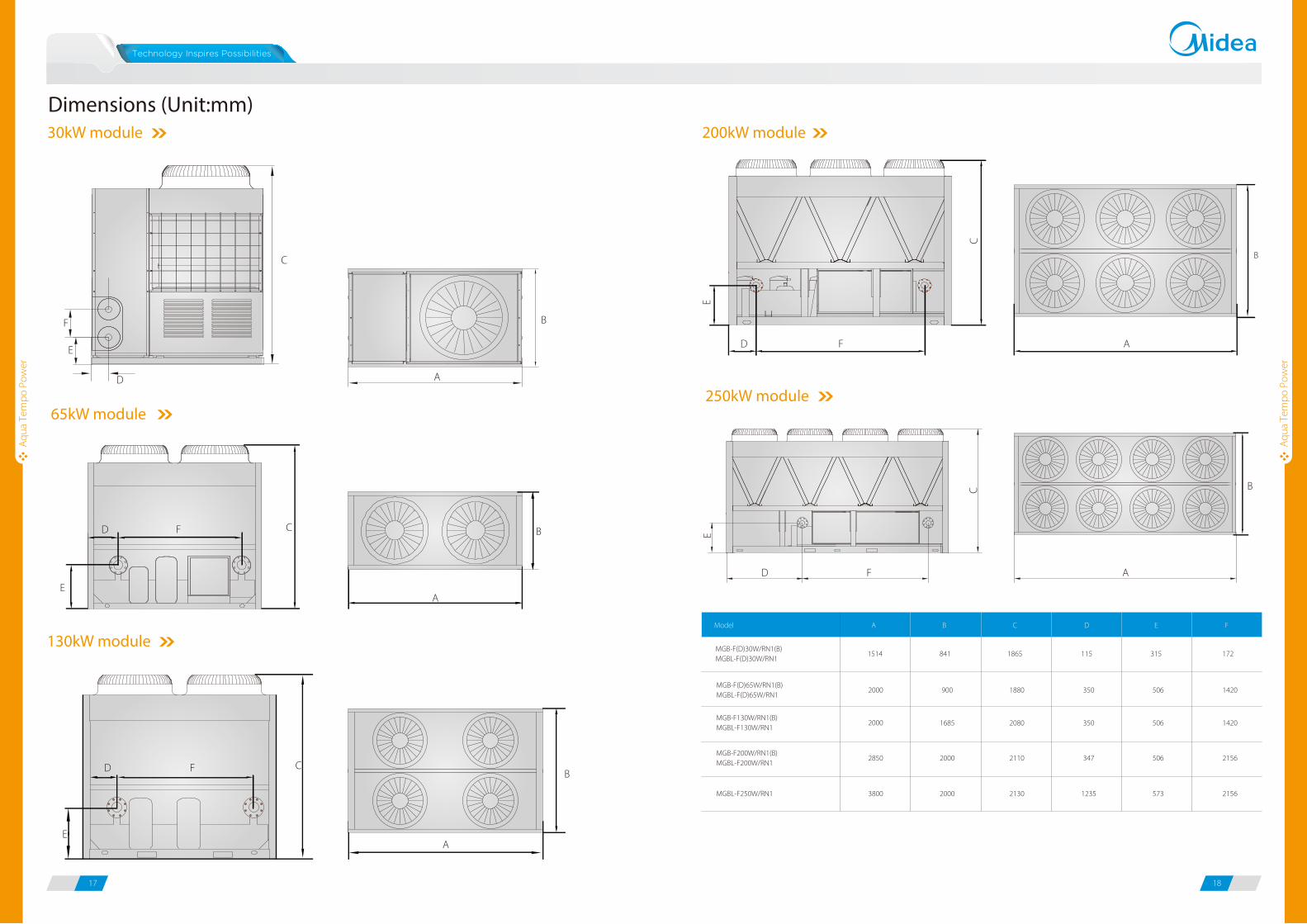
200kW module
B
AF
C
E
D
250kW module
B
AF
C
E
D
65kW module
CFD
EA
B
Dimensions (Unit:mm)30kW module
D
E
F
C
B
A
Model A B C D E F
MGB-F(D)30W/RN1(B)MGBL-F(D)30W/RN1
1514 841 1865 115 315 172
MGB-F(D)65W/RN1(B)MGBL-F(D)65W/RN1
2000 900 1880 350 506 1420
MGB-F130W/RN1(B)MGBL-F130W/RN1
2000 1685 2080 350 506 1420
MGB-F200W/RN1(B)MGBL-F200W/RN1
2850 2000 2110 347 506 2156
MGBL-F250W/RN1 3800 2000 2130 1235 573 2156
130kW module
D F C
EA
B
19 20
Aqu
a Te
mpo
Sup
er
Aqu
a Te
mpo
Sup
er
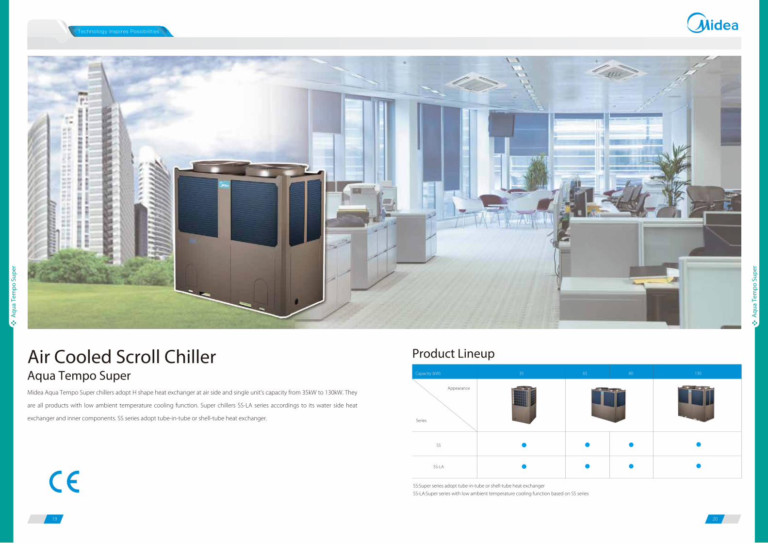
Air Cooled Scroll Chiller
Midea Aqua Tempo Super chillers adopt H shape heat exchanger at air side and single unit’s capacity from 35kW to 130kW. They
are all products with low ambient temperature cooling function. Super chillers SS-LA series accordings to its water side heat
exchanger and inner components. SS series adopt tube-in-tube or shell-tube heat exchanger.
Product Lineup
Aqua Tempo Super
Series
Appearance
Capacity (kW)
SS
SS-LA
35 65 80 130
SS:Super series adopt tube-in-tube or shell-tube heat exchanger
SS-LA:Super series with low ambient temperature cooling function based on SS series
21 22
Aqu
a Te
mpo
Sup
er
Aqu
a Te
mpo
Sup
er
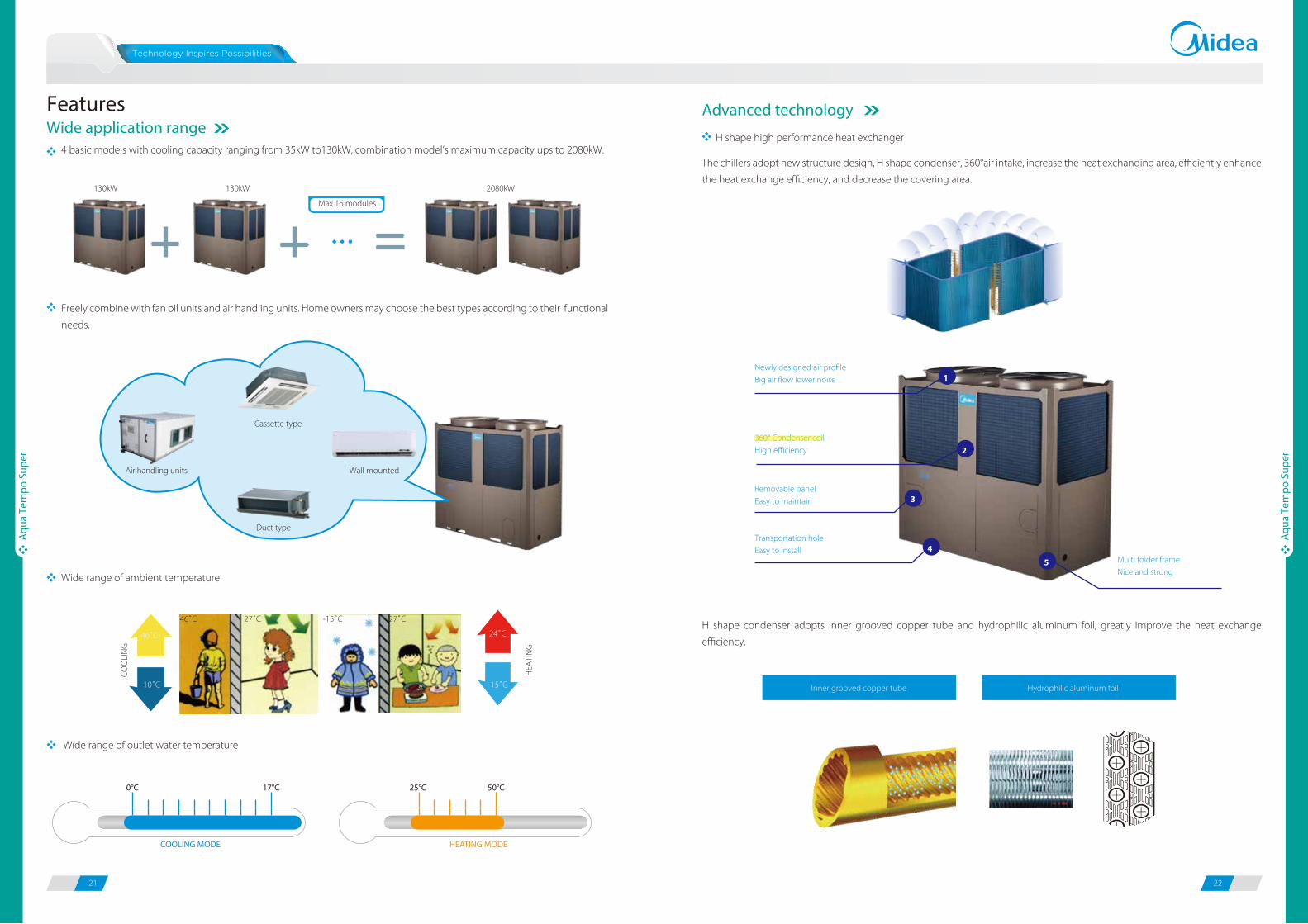
4 basic models with cooling capacity ranging from 35kW to130kW, combination model’s maximum capacity ups to 2080kW.The chillers adopt new structure design, H shape condenser, 360°air intake, increase the heat exchanging area, efficiently enhance
the heat exchange efficiency, and decrease the covering area.
H shape condenser adopts inner grooved copper tube and hydrophilic aluminum foil, greatly improve the heat exchange
efficiency.
Freely combine with fan oil units and air handling units. Home owners may choose the best types according to their functional
needs.
FeaturesWide application range
Advanced technology
H shape high performance heat exchanger
Max 16 modules
130kW 130kW 2080kW
Cassette type
Wall mounted
Duct type
Air handling units
Wide range of ambient temperature
CO
OLI
NG
HEA
TIN
G
-10˚C
46˚C
-15˚C
24˚C
46˚C 27˚C 27˚C-15˚C
Wide range of outlet water temperature
Newly designed air profileBig air flow lower noise
360° Condenser coilHigh efficiency
Removable panelEasy to maintain
Transportation holeEasy to install
Multi folder frameNice and strong
4
3
2
1
5
Hydrophilic aluminum foilInner grooved copper tube
17°C0°C
COOLING MODE
50°C25°C
HEATING MODE
23 24
Aqu
a Te
mpo
Sup
er
Aqu
a Te
mpo
Sup
er
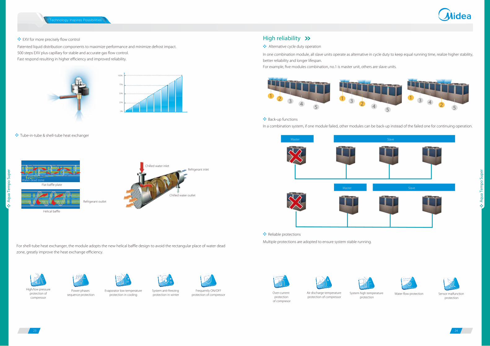
Patented liquid distribution components to maximize performance and minimize defrost impact.
500 steps EXV plus capillary for stable and accurate gas flow control.
Fast respond resulting in higher efficiency and improved reliability.In one combination module, all slave units operate as alternative in cycle duty to keep equal running time, realize higher stability,
better reliability and longer lifespan.
For example, five modules combination, no.1 is master unit, others are slave units.
High reliabilityEXV for more precisely flow control
Alternative cycle duty operation
Back-up functions
Reliable protections
Tube-in-tube & shell-tube heat exchanger
0%
25%
50%
75%
100%
For shell-tube heat exchanger, the module adopts the new helical baffle design to avoid the rectangular place of water dead
zone, greatly improve the heat exchange efficiency.
Chilled water inletRefrigerant inlet
Chilled water outlet
Refrigerant outlet
Flat baffle plate
Helical baffle
Water dead zone
1 3 452
1 2 3 45
1 3 2 45
In a combination system, if one module failed, other modules can be back-up instead of the failed one for continuing operation.
Slave
Master Slave
Master
Multiple protections are adopted to ensure system stable running.
Power phases sequence protection
Frequently ON/OFF protection of compressor
System anti-freezing protection in winter
Evaporator low temperature protection in cooling
Over-current protection
of compresor
Air discharge temperature protection of compressor
Sensor malfunction protection
Water flow protectionSystem high temperature protection
High/low pressure protection of compressor
25 26
Aqu
a Te
mpo
Sup
er
Aqu
a Te
mpo
Sup
er
Flexible installation
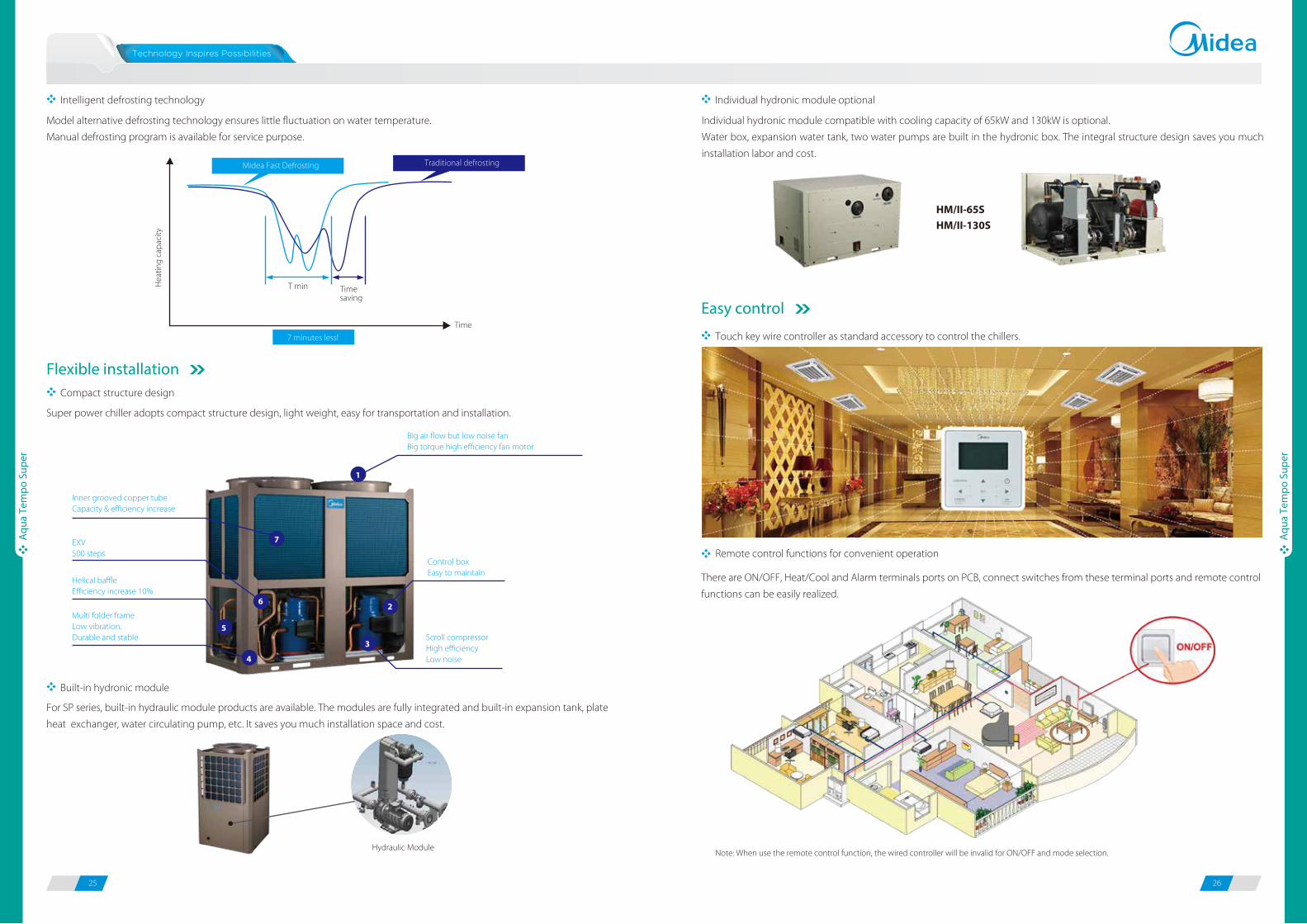
Intelligent defrosting technology Individual hydronic module optional
Compact structure design
Model alternative defrosting technology ensures little fluctuation on water temperature.
Manual defrosting program is available for service purpose.
Super power chiller adopts compact structure design, light weight, easy for transportation and installation.
For SP series, built-in hydraulic module products are available. The modules are fully integrated and built-in expansion tank, plate
heat exchanger, water circulating pump, etc. It saves you much installation space and cost.
T min Time saving
Time
Hea
ting
capa
city
Midea Fast Defrosting Traditional defrosting
7 minutes less!
Built-in hydronic module
Inner grooved copper tubeCapacity & efficiency increase
Big air flow but low noise fanBig torque high efficiency fan motor
Control boxEasy to maintain
Scroll compressorHigh efficiencyLow noise
EXV500 steps
Helical baffle Efficiency increase 10%
Multi folder frameLow vibration. Durable and stable
7
1
6
5
4
3
2
Touch key wire controller as standard accessory to control the chillers.
There are ON/OFF, Heat/Cool and Alarm terminals ports on PCB, connect switches from these terminal ports and remote control
functions can be easily realized.
Individual hydronic module compatible with cooling capacity of 65kW and 130kW is optional.
Water box, expansion water tank, two water pumps are built in the hydronic box. The integral structure design saves you much
installation labor and cost.
Easy control
HM/II-65S
HM/II-130S
Hydraulic Module
Remote control functions for convenient operation
Note: When use the remote control function, the wired controller will be invalid for ON/OFF and mode selection.
27 28
Aqu
a Te
mpo
Sup
er
Aqu
a Te
mpo
Sup
er
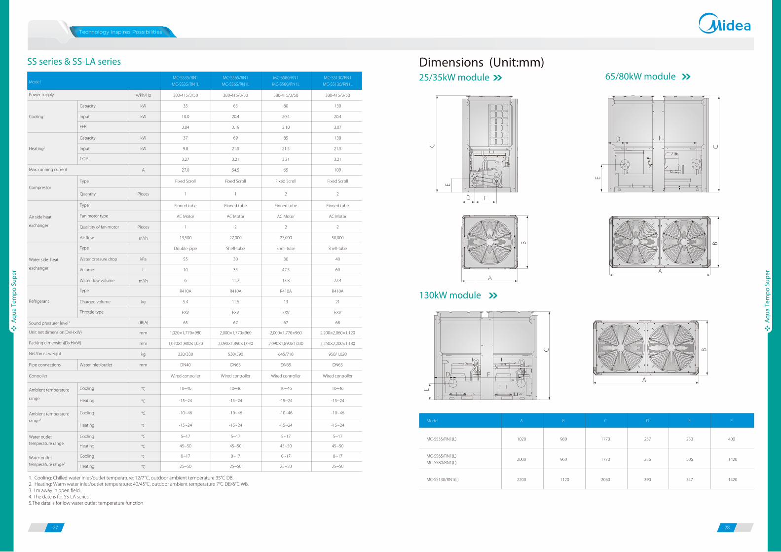
Dimensions (Unit:mm)25/35kW module 65/80kW module
C
FD
E
F
C
E
D
130kW module
A
B
A
B
B
AF
C
E
D
MC-SS130/RN1(L)
MC-SS35/RN1(L)
MC-SS65/RN1(L)
MC-SS80/RN1(L)
Model A B C D E F
1020 980 1770 237 250 400
2000 960 1770 336 506 1420
2200 1120 2060 390 347 1420
SS series & SS-LA series
1. Cooling: Chilled water inlet/outlet temperature: 12/7°C, outdoor ambient temperature 35°C DB.2. Heating: Warm water inlet/outlet temperature: 40/45°C, outdoor ambient temperature 7°C DB/6°C WB.3. 1m away in open field.4. The date is for SS-LA series .5.The data is for low water outlet temperature function
MC-SS35/RN1
MC-SS35/RN1L
MC-SS65/RN1
MC-SS65/RN1L
MC-SS80/RN1
MC-SS80/RN1L
MC-SS130/RN1
MC-SS130/RN1L
V/Ph/Hz 380-415/3/50 380-415/3/50 380-415/3/50 380-415/3/50
Capacity kW 35 65 80 130
Input kW 10.0 20.4 20.4 20.4
3.04 3.19 3.10 3.07
Capacity kW 37 69 85 138
Input kW 9.8 21.5 21.5 21.5
3.27 3.21 3.21 3.21
A 27.0 54.5 65 109
Fixed Scroll Fixed Scroll Fixed Scroll Fixed Scroll
Quantity Pieces 1 1 2 2
Finned tube Finned tube Finned tube Finned tube
AC Motor AC Motor AC Motor AC Motor
Qualitity of fan motor Pieces 1 2 2 2
Air flow m3/h 13,500 27,000 27,000 50,000
Double-pipe Shell-tube Shell-tube Shell-tube
Water pressure drop kPa 55 30 30 40
Volume L 10 35 47.5 60
Water flow volume m3/h 6 11.2 13.8 22.4
R410A R410A R410A R410A
Charged volume kg 5.4 11.5 13 21
EXV EXV EXV EXV
dB(A) 65 67 67 68
mm 1,020×1,770×980 2,000×1,770×960 2,000×1,770×960 2,200×2,060×1,120
mm 1,070×1,900×1,030 2,090×1,890×1,030 2,090×1,890×1,030 2,250×2,200×1,180
kg 320/330 530/590 645/710 950/1,020
Pipe connections Water inlet/outlet mm DN40 DN65 DN65 DN65
Wired controller Wired controller Wired controller Wired controller
Cooling °C 10~46
Heating °C -15~24
Cooling °C -10~46
Heating °C -15~24
Cooling °C 5~17
Heating °C 45~50
Cooling °C 0~17
Heating °C 25~50
10~46
-15~24
-10~46
-15~24
5~17
45~50
0~17
25~50
10~46
-15~24
-10~46
-15~24
5~17
45~50
0~17
25~50
10~46
-15~24
-10~46
-15~24
5~17
45~50
0~17
25~50
Ambient temperature
range
Ambient temperature
range4
Model
Power supply
Max. running current
Type
Refrigerant
Fan motor typeAir side heat
exchanger
Type
Water outlet
temperature range
Water outlet
temperature range5
Cooling1
Heating2
EER
COP
Type
Throttle type
Unit net dimension(D×H×W)
Packing dimension(D×H×W)
Water side heat
exchanger
Type
Controller
Sound pressurer level3
Net/Gross weight
Compressor
29 30
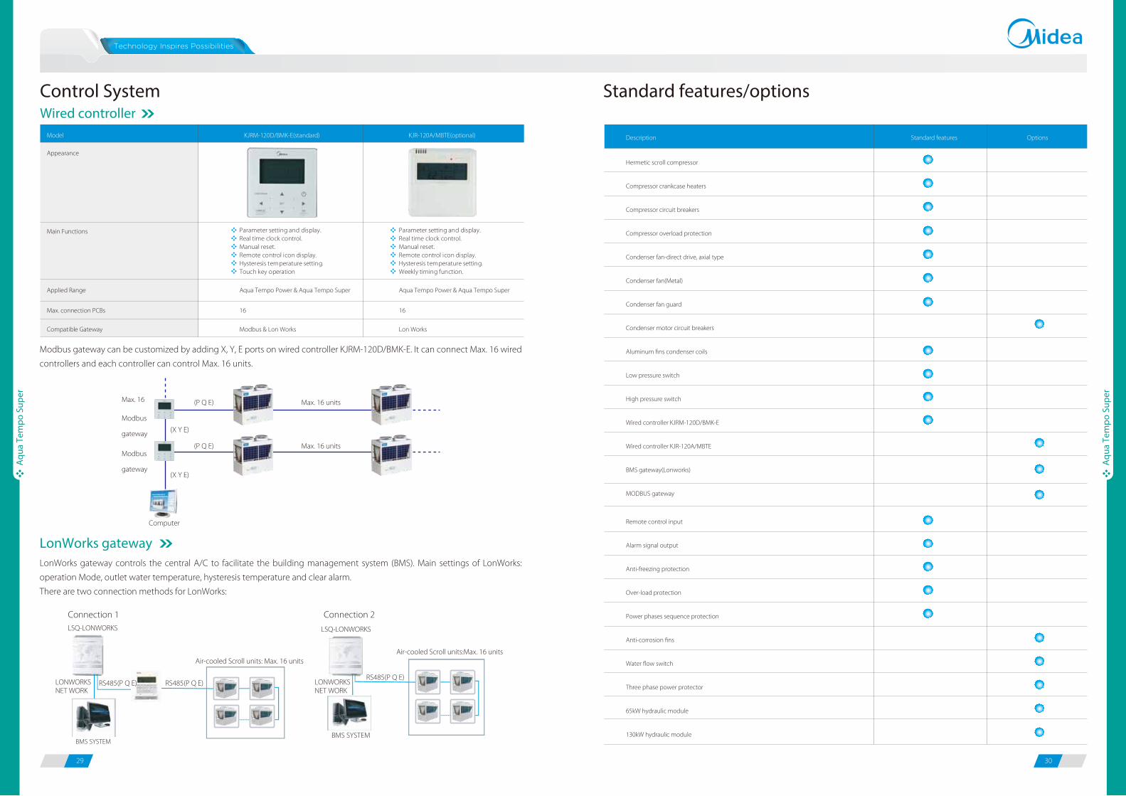
Standard features/optionsWired controllerControl System
Hermetic scroll compressor
Compressor crankcase heaters
Compressor circuit breakers
Compressor overload protection
Condenser fan-direct drive, axial type
Condenser fan(Metal)
Condenser fan guard
Condenser motor circuit breakers
Aluminum fins condenser coils
Low pressure switch
High pressure switch
Wired controller KJRM-120D/BMK-E
Wired controller KJR-120A/MBTE
BMS gateway(Lonworks)
MODBUS gateway
Description Standard features Options
Remote control input
Alarm signal output
Anti-freezing protection
Over-load protection
Power phases sequence protection
Anti-corrosion fins
Water flow switch
Three phase power protector
65kW hydraulic module
130kW hydraulic module
Aqu
a Te
mpo
Sup
er
Aqu
a Te
mpo
Sup
er
Model KJRM-120D/BMK-E(standard) KJR-120A/MBTE(optional)
Appearance
Main Functions Parameter setting and display. Real time clock control.Manual reset.Remote control icon display.Hysteresis temperature setting.Touch key operation
Parameter setting and display.Real time clock control.Manual reset.Remote control icon display.Hysteresis temperature setting. Weekly timing function.
Applied Range Aqua Tempo Power & Aqua Tempo Super Aqua Tempo Power & Aqua Tempo Super
Max. connection PCBs 16 16
Compatible Gateway Modbus & Lon Works Lon Works
Max. 16 (P Q E)
(P Q E)
Modbus
gateway
Modbus
gateway
Computer
(X Y E)
(X Y E)
Max. 16 units
Max. 16 units
LonWorks gateway controls the central A/C to facilitate the building management system (BMS). Main settings of LonWorks:
operation Mode, outlet water temperature, hysteresis temperature and clear alarm.
There are two connection methods for LonWorks:
Modbus gateway can be customized by adding X, Y, E ports on wired controller KJRM-120D/BMK-E. It can connect Max. 16 wired
controllers and each controller can control Max. 16 units.
LonWorks gateway
Air-cooled Scroll units: Max. 16 units
LONWORKSNET WORK
LSQ-LONWORKS
BMS SYSTEM
RS485(P Q E)
Air-cooled Scroll units:Max. 16 units
LSQ-LONWORKS
BMS SYSTEM
RS485(P Q E)
Connection 1 Connection 2
RS485(P Q E) LONWORKSNET WORK
31 32
Fan
Coil
Uni
ts
Fan
Coil
Uni
ts
Midea Fan Coil Units have ceiling exposed type, ceiling concealed type, wall-mounted type and floor-standing type. The air
volume ranges from 150CFM to 2200CFM. It is a highly versatile product suitable for hospitals, office buildings, hotels, airports and
various other applications.
Fan Coil UnitsM -K T3 E2200 G100
Type Code
Midea
Static PressureG12: 12Pa; G:30: 30Pa; G50: 50Pa;G70: 70Pa; G100: 100Pa;
Fuction Code
Nominal Air Volume (CFM)
Chilled Fan Coil Unit
Nomenclature
33 34
Fan
Coil
Uni
ts
Fan
Coil
Uni
ts
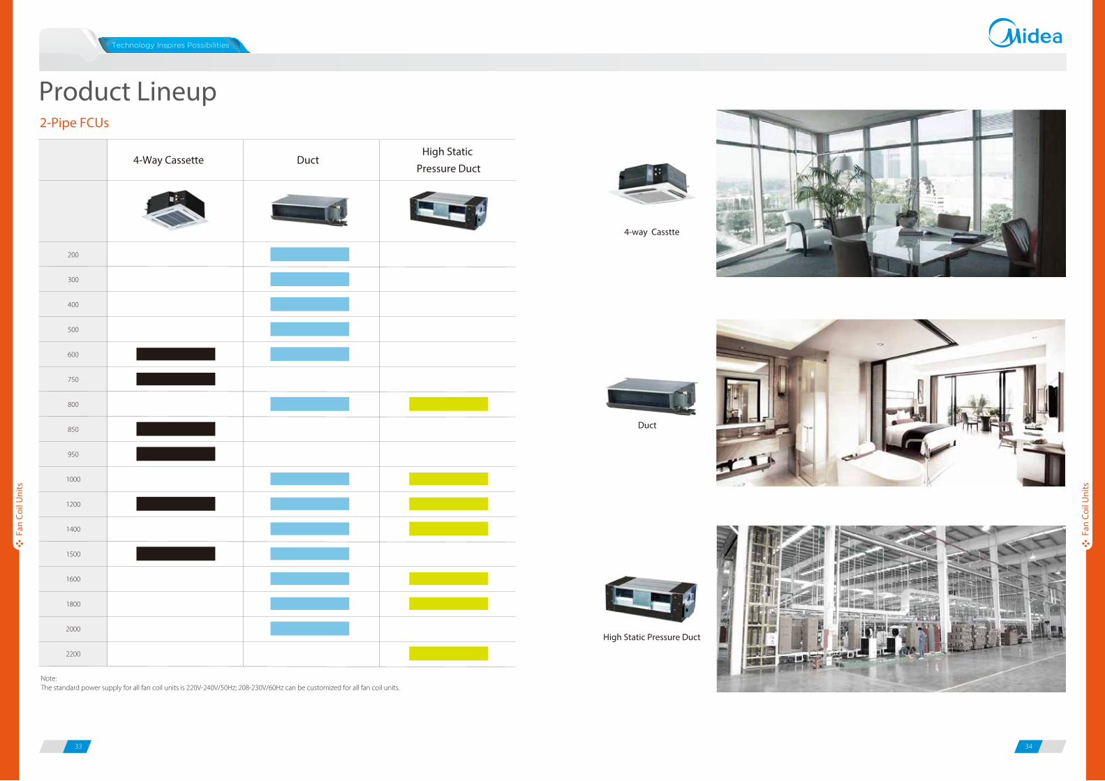
Product Lineup2-Pipe FCUs
Note:The standard power supply for all fan coil units is 220V-240V/50Hz; 208-230V/60Hz can be customized for all fan coil units.
200
300
400
500
600
750
800
850
950
1000
1200
1400
1500
1600
1800
2000
2200
4-Way Cassette DuctHigh Static
Pressure Duct
Duct
High Static Pressure Duct
4-way Casstte
35 36
Fan
Coil
Uni
ts
Fan
Coil
Uni
ts
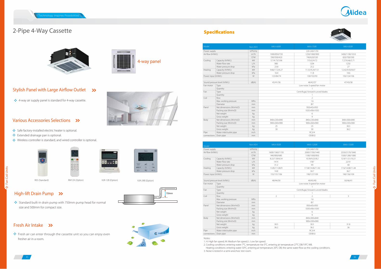
Notes:1. H: High fan speed; M: Medium fan speed; L: Low fan speed.2. Cooling conditions: entering water 7°C, temperature rise 5°C, entering air temperature 27°C DB/19°C WB. Heating conditions: entering water 50°C, entering air temperature 20°C DB, the same water flow as the cooling conditions.3. Noise is tested in a semi-anechoic test room.
Power supplyAir flow (H/M/L)
Cooling
Heating
Power input (H/M/L)
Sound pressure level (H/M/L)Fan motor
Fan
Coil
Panel
Body
Pipe connections
Capacity (H/M/L)Water flow rateWater pressure dropCapacity (H/M/L)Water pressure drop
TypeQuantityTypeQuantityRowMax. working pressureDiameterNet dimensions (W×H×D)Packing size (W×H×D)Net weightGross weightNet dimensions (W×H×D)Packing size (W×H×D)Net weightGross weight Water inlet/outlet pipeDrain pipe
V/Ph/Hzm3/hCFMkWL/hkPakWkPaW
dB(A)
MPammmmmmkgkg
mmmmkgkg
inchmm
1000/850/720590/500/4205.7/4.73/3.96
980 23.8
9.66/7.72/6.2716.4
125/84/74
45/41/36
840×230×840900×260×900
2530
220-240/1/501250/1060/900
740/620/5307/5.62/4.72
1204 25.2
11.55/9.24/7.5111.8
130/102/93
46/42/37Low noise 3-speed fan motor
1Centrifugal, forward-curved blades
12
1.6Φ7
950×45×9501035×90×1035
69
840×230×840900×260×900
2530
RC3/4ODΦ32
1400/1190/1010820/700/590
7.27/6.46/5.711250
2712.42/9.93/8.07
14.6150/124/106
47/43/38
840×300×840900×330×900
30.536.2
Model Non-AEH MKA-600R MKA-750R MKA-850R
ModelPower supplyAir flow (H/M/L)
Cooling
Heating
Power input (H/M/L)
Sound pressure level (H/M/L)Fan motor
Fan
Coil
Panel
Body
Pipe connections
Capacity (H/M/L)Water flow rateWater pressure dropCapacity (H/M/L)Water pressure drop
TypeQuantityTypeQuantityRowMax. working pressureDiameterNet dimensions (W×H×D)Packing size (W×H×D)Net weightGross weightNet dimensions (W×H×D)Packing size (W×H×D)Net weight Gross weight Water inlet/outlet pipeDrain pipe
V/Ph/Hzm3/hCFMkWL/hkPakWkPaW
dB(A)
MPammmmmmkgkg
mmmmkgkg
inchmm
1600/1360/1150940/800/680
8.22/7.39/6.541414 31.2
13.85/11.08/914.8
155/131/106
48/44/39
2
30.536.2
220-240/1/502000/1700/14401180/1000/85010.39/9.25/8.2
1787 44
17.58/14.06/11.4234.7
190/127/109
49/45/40Low noise 3-speed fan motor
1Centrifugal, forward-curved blades
12
1.6Φ7
950×45×9501035×90×1035
69
840×300×840900×330×900
30.536.2
RC3/4ODΦ32
2550/2170/18401500/1280/108012.9/11.51/10.21
2219 40
17.6/14.08/11.4436.7
190/136/109
50/46/41
3
31.836
Non-AEH MKA-950R MKA-1200R MKA-1500R
4-way air supply panel is standard for 4-way cassette.
Stylish Panel with Large Air�ow Outlet
4-way panel
Safe factory-installed electric heater is optional.
Extended drainage pan is optional.
Wireless controller is standard, and wired controller is optional.
Standard built-in drain pump with 750mm pump head for normal
size and 500mm for compact size.
Various Accessories Selections
High-lift Drain Pump
Fresh air can enter through the cassette unit so you can enjoy even
fresher air in a room.
Fresh Air Intake
750mm
2-Pipe 4-Way Cassette
R05 (Standard) KJR-12B (Option) KJR-29B (Option)RM12A (Option)
Specifications
37 38
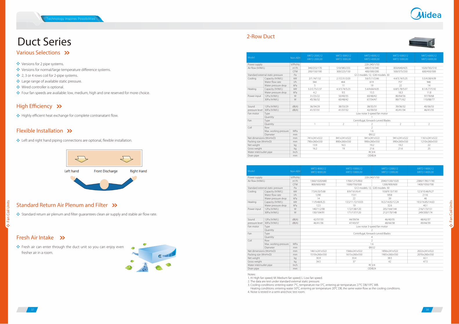
Various Selections
Versions for 2 pipe systems.
Versions for normal/large temperature difference systems.
2, 3 or 4 rows coil for 2-pipe systems.
Large range of available static pressure.
Wired controller is optional.
Four fan speeds are avaliable: low, medium, high and one reserved for more choice.
High E�ciency
Standard Return Air Plenum and Filter
Fresh air can enter through the duct unit so you can enjoy even
fresher air in a room.
Fresh Air Intake
Left and right hand piping connections are optional, flexible installation.
Flexible Installation
Duct Series
Standard return air plenum and filter guarantees clean air supply and stable air flow rate.
Fan
Coil
Uni
ts
Fan
Coil
Uni
ts
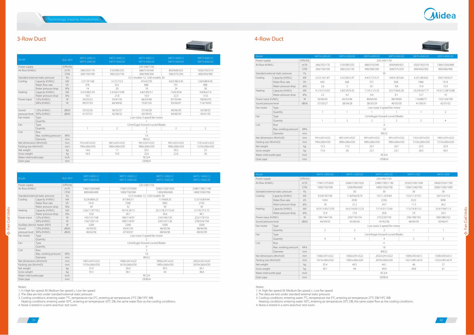
2-Row Duct
Notes:1. H: High fan speed; M: Medium fan speed; L: Low fan speed.2. The data are test under standard external static pressure. 3. Cooling conditions: entering water 7°C, temperature rise 5°C, entering air temperature 27°C DB/19°C WB. Heating conditions: entering water 50°C, entering air temperature 20°C DB, the same water flow as the cooling conditions.4. Noise is tested in a semi-anechoic test room.
Power supplyAir flow (H/M/L)
Standard external static pressureCooling
Heating
Power input
Sound pressure levelFan motor
Fan
Coil
Net dimensions (W×H×D)Packing size (W×H×D)Net weight Gross weight Water inlet/outlet pipeDrain pipe
Capacity (H/M/L)Water flow rateWater pressure dropCapacity (H/M/L)Water pressure drop12Pa (H/M/L)30Pa (H/M/L)
12Pa (H/M/L)30Pa (H/M/L)TypeQuantityTypeQuantityRowMax. working pressureDiameter
V/Ph/Hzm3/hCFMPakWl/hkPakWkPaWW
dB(A)dB(A)
MPammmmmmkgkg
Inchmm
340/255/170200/150/100
2/1.74/1.52344
53.2/2.75/2.37
4.231/25/2245/36/32
36/34/2941/37/31
1
741×241×522790×260×550
13.916.2
510/385/255300/225/150
2.7/2.31/2.03464 11
4.3/3.74/3.239.5
50/40/3560/48/42
38/33/2941/37/32
2
841×241×522890×260×550
16.519
220-240/1/50680/510/340400/300/200
G12 models: 12; G30 models: 303.6/3.11/2.66
619 19
5.4/4.64/4.0515.5
60/48/4267/54/47
38/35/3142/39/33
Low noise 3-speed fan motor1
Centrifugal, forward-curved Blades22
1.6Φ9.52
941×241×522990×260×550
19.221.6
RC3/4ODΦ24
850/640/425500/375/250
4.4/3.74/3.25757 22
6.8/5.78/5.0718.3
80/64/5689/71/62
39/36/3245/41/34
2
941×241×522990×260×550
19.221.6
1020/765/510600/450/300
5.5/4.58/4.09946 14
8.1/6.77/5.9211.8
97/78/68110/88/77
40/36/3346/41/35
2
1161×241×5221210×260×550
2225
MKT2-200G12MKT2-200G30
MKT2-300G12MKT2-300G30
MKT2-400G12MKT2-400G30
MKT2-500G12MKT2-500G30
MKT2-600G12MKT2-600G30
Model Non-AEH
Power supplyAir flow (H/M/L)
Standard external static pressureCooling
Heating
Power input
Sound pressure levelFan motor
Fan
Coil
Net dimensions (W×H×D)Packing size (W×H×D)Net weight Gross weight Water inlet/outlet pipeDrain pipe
Capacity (H/M/L)Water flow rateWater pressure dropCapacity (H/M/L)Water pressure drop12Pa (H/M/L)30Pa (H/M/L)
12Pa (H/M/L)30Pa (H/M/L)TypeQuantityTypeQuantityRowMax. working pressureDiameter
V/Ph/Hzm3/hCFMPakWl/hkPakWkPaWW
dB(A)dB(A)
MPammmmmmkgkg
Inchmm
MKT2-800G12MKT2-800G30
MKT2-1000G12MKT2-1000G30
MKT2-1200G12MKT2-1200G30
MKT2-1400G12MKT2-1400G30Model
1360/1020/680800/600/400
7.5/6.33/5.681290
1411/9.48/8.25
12.5140/112/98130/104/91
42/37/3346/41/36
1461×241×5221510×260×550
30.934.5
1700/1275/8501000/750/500
8.9/7.61/6.411531
2213.5/11.72/10.03
19172/138/120171/137/120
44/39/3447/43/37
1566×241×5221615×260×550
33.437
2040/1530/10201200/900/600
10.8/9.13/7.931858
3916.5/14.05/12.24
32.6205/164/144212/170/148
46/40/3548/44/38
1856×241×5221905×260×550
38.542
2380/1785/11901400/1050/700
12.3/10.46/9.272116
4619.5/16.85/14.63
40.1216/173/151249/200/174
48/42/3749/44/39
2022×241×5222070×260×550
42.147.5
220-240/1/50
G12 models: 12; G30 models: 30
Low noise 3-speed fan motor2
Centrifugal, forward-curved Blades42
1.6Φ9.52
RC3/4ODΦ24
Non-AEH
Highly efficient heat exchange for complete contranatant flow.
39 40
4-Row Duct
Notes:1. H: High fan speed; M: Medium fan speed; L: Low fan speed.2. The data are test under standard external static pressure. 3. Cooling conditions: entering water 7°C, temperature rise 5°C, entering air temperature 27°C DB/19°C WB. Heating conditions: entering water 50°C, entering air temperature 20°C DB, the same water flow as the cooling conditions.4. Noise is tested in a semi-anechoic test room.
3-Row Duct
Non-AEH
Power supplyAir flow (H/M/L)
Standard external static pressureCooling
Heating
Power input
Sound pressure levelFan motor
Fan
Coil
Net dimensions (W×H×D)Packing size (W×H×D)Net weight Gross weightWater inlet/outlet pipeDrain pipe
Capacity (H/M/L)Water flow rateWater pressure dropCapacity (H/M/L)Water pressure drop12Pa (H/M/L)30Pa (H/M/L)
12Pa (H/M/L)30Pa (H/M/L)TypeQuantityTypeQuantityRowMax. working pressureDiameter
V/Ph/Hzm3/hCFMPakWl/hkPakWkPaWW
dB(A)dB(A)
MPammmmmmkgkg
Inchmm
340/255/170200/150/100
2.2/1.9/1.68378 14
3.5/3.08/2.5910.5
33/25/2249/37/33
35/32/2641/37/31
1
741×241×522790×260×550
14.616.9
510/385/255300/225/150
3.1/2.7/2.3533 26
5.3/4.61/3.9821.8
53/41/3564/49/42
36/33/2742/38/32
2
841×241×522890×260×550
1719.5
220-240/1/50680/510/340400/300/200
G12 models: 12; G30 models: 304/3.4/2.95
688 18
6.8/5.85/5.116.9
66/53/4875/61/54
37/34/2843/39/33
Low noise 3-speed fan motor1
Centrifugal, forward-curved Blades23
1.6Φ9.52
941×241×522990×260×550
20.222.6
RC3/4ODΦ24
850/640/425500/375/250
4.6/3.96/3.45791 24
7.9/6.95/622.3
87/53/4493/56/47
40/36/3044/40/34
2
941×241×522990×260×550
20.222.6
1020/765/510600/450/300
5.8/4.88/4.45998 36
9.8/8.6/7.431.6
100/65/55114/74/63
42/38/3245/41/35
2
1161×241×5221210×260×550
2326
MKT3-200G12MKT3-200G30
MKT3-300G12MKT3-300G30
MKT3-400G12MKT3-400G30
MKT3-500G12MKT3-500G30
MKT3-600G12MKT3-600G30
Model
Non-AEH
Power supplyAir flow (H/M/L)
Standard external static pressureCooling
Heating
Power input
Auxiliary electric heater (AEH)Sound pressure levelFan motor
Fan
Coil
Net dimensions (W×H×D)Packing size (W×H×D)Net weight Gross weight Water inlet/outlet pipeDrain pipe
Capacity (H/M/L)Water flow rateWater pressure dropCapacity (H/M/L)Water pressure drop12Pa (H/M/L)30Pa (H/M/L)
12Pa (H/M/L)30Pa (H/M/L)TypeQuantityTypeQuantityRowMax. working pressureDiameter
V/Ph/Hzm3/hCFMPakWl/hkPakWkPaWWW
dB(A)dB(A)
MPammmmmmkgkg
Inchmm
MKT3-800G12MKT3-800G30
MKT3-1000G12MKT3-1000G30
MKT3-1200G12MKT3-1200G30
MKT3-1400G12MKT3-1400G30Model
1360/1020/680800/600/400
8.2/6.88/6.251410
3913.6/11.97/10.2
33.8145/121/108154/129/114
220043/39/3346/42/36
1461×241×5221510×260×550
31.935.5
1700/1275/8501000/750/500
9/7.8/6.571548
3216/14.24/12
30.7180/114/97180/114/97
220045/41/3547/43/37
1566×241×5221615×260×550
34.438.1
2040/1530/10201200/900/600
11/9.8/8.351892
3920.1/18.27/15.43
34.6210/140/120220/147/126
320046/42/3648/44/38
1856×241×5221905×260×550
39.543
2380/1785/11901400/1050/700
12.5/10.8/9.442150
4521/18.7/15.75
40.1222/179/155278/224/194
320048/44/3849/45/39
2022×241×5222070×260×550
43.148.4
220-240/1/50
G12 models: 12; G30 models: 30
Low noise 3-speed fan motor2
Centrifugal, forward-curved Blades43
1.6Φ9.52
RC3/4ODΦ24
Notes:1. H: High fan speed; M: Medium fan speed; L: Low fan speed.2. The data are test under standard external static pressure. 3. Cooling conditions: entering water 7°C, temperature rise 5°C, entering air temperature 27°C DB/19°C WB. Heating conditions: entering water 50°C, entering air temperature 20°C DB, the same water flow as the cooling conditions.4. Noise is tested in a semi-anechoic test room.
Fan
Coil
Uni
ts
Fan
Coil
Uni
ts
Model
Power supply
Air flow (H/M/L)
Standard external static pressure
Cooling
Heating
Power input (H/M/L)
Sound pressure level
Fan motor
Fan
Coil
Net dimensions (W×H×D)
Packing size (W×H×D)
Net weight
Gross weight
Water inlet/outlet pipe
Drain pipe
Capacity (H/M/L)
Water flow rate
Water pressure drop
Capacity (H/M/L)
Water pressure drop
Type
Quantity
Type
Quantity
Row
Max. working pressure
Diameter
V/Ph/Hz
m3/h
CFM
Pa
kW
l/h
kPa
kW
kPa
W
dB(A)
MPa
mm
mm
mm
kg
kg
Inch
mm
MKT4-1200G30
2040/1530/1020
1200/900/600
30
11.8/9.82/8.74
2030
21.2
16.5/14.05/12.23
17.6
220/176/154
45/40/34
2
4
1856×241×522
1905×260×550
40.5
44
MKT4-1400G30
2380/1785/1190
1400/1050/700
30
13/11.23/9.83
2236
24.7
17/14.31/12.69
20.8
275/220/193
47/42/36
2
4
2022×241×522
2070×260×550
44.1
49.4
MKT4-1500
2550/2100/1300
1500/1240/760
30
13.5/11.5/10.1
2322
11.5
17.5/14.9/13.2
10
236/189/165
48/44/39
1
2
1369×342×612
1421×381×619
46
49.8
MKT4-2000
3400/2550/1700
2000/1500/1000
30
18/15.3/13.5
3096
26.2
23.4/19.8/17.5
24.3
360/288/252
50/46/41
1
3
1500×342×612
1552×381×619
57
61
220-240/1/50
Low noise 3-speed fan motor
Centrifugal, forward-curved Blades
4
1.6
Φ9.52
RC3/4
ODΦ24
MKT4-1000G30
1700/1275/850
1000/750/500
9.5/8.18/7.06
1634
18
16.3/13.45/12.05
15.4
180/144/126
44/39/33
2
4
1566×241×522
1615×260×550
35.4
39.1
Model
Power supply
Air flow (H/M/L)
Standard external static pressure
Cooling
Heating
Power input (H/M/L)
Sound pressure level
Fan motor
Fan
Coil
Net dimensions (W×H×D)
Packing size (W×H×D)
Net weight
Gross weight
Water inlet/outlet pipe
Drain pipe
Capacity (H/M/L)
Water flow rate
Water pressure drop
Capacity (H/M/L)
Water pressure drop
Type
Quantity
Type
Quantity
Row
Max. working pressure
Diameter
V/Ph/Hz
m3/h
CFM
Pa
kW
l/h
kPa
kW
kPa
W
dB(A)
MPa
mm
mm
mm
kg
kg
Inch
mm
MKT4-200G30
340/255/170
200/150/100
2.5/2.16/1.87
430
2.6
4.1/3.51/3.03
2.2
50/40/35
37/33/27
1
1
741×241×522
790×260×550
15.3
17.6
MKT4-300G30
510/385/255
300/225/150
3.3/2.85/2.47
568
5
5.8/5.05/4.35
4.2
65/52/46
38/34/28
1
2
841×241×522
890×260×550
17.5
20
MKT4-400G30
680/510/340
400/300/200
4.4/3.72/3.22
757
8.1
7.1/6.11/5.33
6.9
80/64/56
38/35/29
1
2
941×241×522
990×260×550
20.7
23.1
MKT4-500G30
850/640/425
500/375/250
4.8/4.18/3.64
826
9.8
8.5/7.04/6.28
8.1
98/78/69
40/35/30
1
2
941×241×522
990×260×550
20.7
23.1
MKT4-600G30
1020/765/510
600/450/300
6.2/5.38/4.65
1066
15.4
10.5/9.03/7.77
12.7
110/88/77
41/36/31
1
2
1161×241×522
1210×260×550
23.5
26.5
MKT4-800G30
1360/1020/680
800/600/400
8.8/7.43/6.57
1514
12.3
14.5/12.38/10.88
10
155/124/109
42/37/32
2
4
1461×241×522
1510×260×550
32.9
36.5
220-240/1/50
30
Low noise 3-speed fan motor
Centrifugal, forward-curved Blades
4
1.6
Φ9.52
RC3/4
ODΦ24
41 42
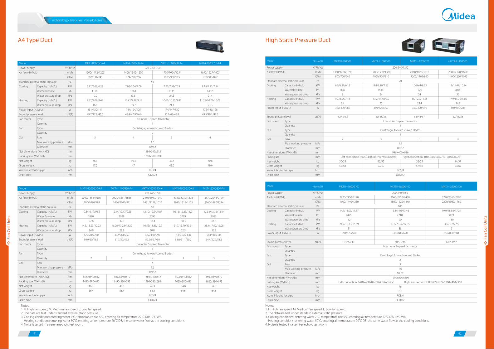
A4 Type Duct High Static Pressure Duct
220-240/1/50
70
Low noise 3-speed fan motor
1
Centrifugal, forward-curved Blades
1
1.6
Φ9.52
946×400×816
Left connection: 1075×480×857/1075×480×925 Right connection: 1015×480×857/1015×480×925
RC3/4
ODΦ32
Power supply
Air flow (H/M/L)
Standard external static pressure
Cooling
Heating
Power input (H/M/L)
Sound pressure level
Fan motor
Fan
Coil
Net dimensions (W×H×D)
Packing size
Net weight
Gross weight
Water inlet/outlet pipe
Drain pipe
Capacity (H/M/L)
Water flow rate
Water pressure drop
Capacity (H/M/L)
Water pressure drop
Type
Quantity
Type
Quantity
Row
Max. working pressure
Diameter
V/Ph/Hz
m3/h
CFM
Pa
kW
l/h
kPa
kW
kPa
W
dB(A)
MPa
mm
mm
mm
kg
kg
Inch
mm
1360/1220/1090
800/720/640
6.6/6.37/6.12
1135
8
9.7/8.54/7.18
8.4
320/300/285
49/42/35
2
50/53
55/58
1700/1530/1380
1000/900/810
8.8/8.19/7.57
1514
24
13.2/11.48/9.9
25
350/320/300
50/43/36
3
52/55
57/60
2040/1880/1610
1200/1105/950
10/9.44/8.53
1720
24
15/12.9/11.25
23.4
350/320/290
51/44/37
3
52/55
57/60
2380/2120/1860
1400/1250/1095
12/11.47/10.24
2064
36
17.9/15.75/13.6
34.2
350/300/285
52/45/38
4
54/57
59/62
Non-AEH MKT3H-800G70 MKT3H-1000G70 MKT3H-1200G70 MKT3H-1400G70Model
Model
Power supply
Air flow (H/M/L)
Standard external static pressure
Cooling
Heating
Power input (H/M/L)
Sound pressure level
Fan motor
Fan
Coil
Net dimensions (W×H×D)
Packing size (W×H×D)
Net weight
Gross weight
Water inlet/outlet pipe
Drain pipe
Capacity (H/M/L)
Water flow rate
Water pressure drop
Capacity (H/M/L)
Water pressure drop
Type
Quantity
Type
Quantity
Row
Max. working pressure
Diameter
V/Ph/Hz
m3/h
CFM
Pa
kW
l/h
kPa
kW
kPa
W
dB(A)
MPa
mm
mm
mm
kg
kg
Inch
mm
MKT4-1200G50-A4
2040/1851/1666
1200/1090/981
10.8/10.17/9.55
1890
27.8
14.3/13.23/12.22
24.8
320/284/250
50.9/50/48.5
2
1369x340x612
1490x380x693
46.3
56.4
MKT4-1400G50-A4
2420/1851/1666
1424/1090/981
12.14/10.17/9.55
2089
32.5
16.08/13.23/12.22
29.2
392/284/250
51.7/50/49.5
2
1369x340x612
1490x380x693
46.3
56.4
MKT4-1600G50-A4
220-240/1/50
2430/1917/1742
1431/1128/1025
50
12.19/10.54/9.87
2096
33.4
16.55/13.83/12.9
30.0
482/338/296
52.9/50.7/50
Low noise 3-speed fan motor
1
Centrifugal, forward-curved Blades
2
4
1.6
Φ9.52
1369x340x612
1490x380x693
46.3
56.4
RC3/4
ODΦ24
MKT4-1800G50-A4
3380/2239/1878
1990/1318/1105
16.16/12.35/11.01
2779
58.3
21.7/15.79/13.91
52.3
538/358/308
53.6/51.1/50.2
3
1500x340x612
1620x380x693
54.8
64.6
MKT4-2000G50-A4
3670/2544/2199
2160/1497/1294
17.34/13.75/12.44
2983
61.5
23.4/17.92/16.08
52.9
583/387/334
54.4/52.7/51.6
3
1500x340x612
1620x380x693
54.8
64.6
Notes:1. H: High fan speed; M: Medium fan speed; L: Low fan speed.2. The data are test under standard external static pressure. 3. Cooling conditions: entering water 7°C, temperature rise 5°C, entering air temperature 27°C DB/19°C WB. Heating conditions: entering water 50°C, entering air temperature 20°C DB, the same water flow as the cooling conditions.4. Noise is tested in a semi-anechoic test room.
Non-AEH MKT3H-1600G100 MKT3H-1800G100 MKT3H-2200G100
Power supply
Air flow (H/M/L)
Standard external static pressure
Cooling
Heating
Power input (H/M/L)
Sound pressure level
Fan motor
Fan
Coil
Net dimensions (W×H×D)
Packing size (W×H×D)
Net weight
Gross weight
Water inlet/outlet pipe
Drain pipe
Capacity (H/M/L)
Water flow rate
Water pressure drop
Capacity (H/M/L)
Water pressure drop
Type
Quantity
Type
Quantity
Row
Max. working pressure
Diameter
V/Ph/Hz
m3/h
CFM
Pa
kW
l/h
kPa
kW
kPa
W
dB(A)
MPa
mm
mm
mm
kg
kg
Inch
mm
2720/2450/2170
1600/1440/1280
14.1/13.03/11.87
2425
52
21.2/18.23/15.69
51
550/520/500
54/47/40
220-240/1/50
3060/2750/2450
1800/1620/1440
100
15.8/14.6/13.46
2718
90
23.8/20.94/17.85
85
800/680/620
60/53/46
Low noise 3-speed fan motor
1
Centrifugal, forward-curved Blades
2
3
1.6
Φ9.52
1290×400×809
Left connection: 1448×460×877/1448×460×950 Right connection: 1383×422×877/1368×460×950
76
83
RC3/4
ODΦ32
3740/3360/2990
2200/1980/1760
19.9/18.58/17.24
3423
130
30/26.7/22.5
121
950/860/760
61/54/47
Model
Notes:1. H: High fan speed; M: Medium fan speed; L: Low fan speed.2. The data are test under standard external static pressure. 3. Cooling conditions: entering water 7°C, temperature rise 5°C, entering air temperature 27°C DB/19°C WB. Heating conditions: entering water 50°C, entering air temperature 20°C DB, the same water flow as the cooling conditions.4. Noise is tested in a semi-anechoic test room.
Fan
Coil
Uni
ts
Fan
Coil
Uni
ts
220-240/1/50
50
Low noise 3-speed fan motor
1
Centrifugal, forward-curved Blades
2
1.6
Φ9.52
1180x340x612
1310x380x693
RC3/4
ODΦ24
Model
Power supply
Air flow (H/M/L)
Standard external static pressure
Cooling
Heating
Power input (H/M/L)
Sound pressure level
Fan motor
Fan
Coil
Net dimensions (W×H×D)
Packing size (W×H×D)
Net weight
Gross weight
Water inlet/outlet pipe
Drain pipe
Capacity (H/M/L)
Water flow rate
Water pressure drop
Capacity (H/M/L)
Water pressure drop
Type
Quantity
Type
Quantity
Row
Max. working pressure
Diameter
V/Ph/Hz
m3/h
CFM
Pa
kW
l/h
kPa
kW
kPa
W
dB(A)
MPa
mm
mm
mm
kg
kg
Inch
mm
MKT3-800G50-A4
1500/1412/1265
882/831/745
6.97/6.66/6.28
1198
19.0
9.57/9.09/8.43
16.9
151/130/111
49.7/47.8/45.6
3
38.3
47.2
MKT4-800G50-A4
1400/1342/1200
824/790/706
7.92/7.56/7.09
1363
13.5
10.42/9.89/9.12
39.7
144/124/105
48.4/47.9/46.6
4
39.3
47
MKT3-1000G50-A4
1700/1664/1554
1000/980/915
7.77/7.58/7.33
1336
24.5
10.61/10.25/9.82
21.1
174/147/130
50.1/48/45.8
3
39.8
48.6
MKT4-1000G50-A4
1650/1527/1405
970/900/827
8.15/7.93/7.54
1402
21.4
11.25/10.72/10.06
23.3
176/146/128
49.5/48.1/47.3
4
40.8
49.6
43 44
Fan
Coil
Uni
ts
Fan
Coil
Uni
ts
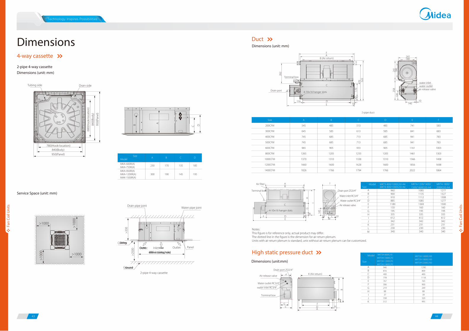
Service Space (unit: mm)
2-pipe 4-way cassetteDimensions (unit: mm)
300 190 145 195
SizeModel
230 170 135 185
A B C D
MKA-950R(A)MKA-1200R(A)MAK-1500R(A)
MKA-600R(A)MKA-750R(A)
Dimensions4-way cassette
B A
C D
680(
Hoo
k-lo
catio
n)
840(
Body
)
950(
Pane
l)
780(Hook-location)840(Body)
950(Panel)
Drain sideTubing side
>1000
>1000
>10
00
>10
00
Ceiling
600mm (ceiling hole)
Ground
PanelInletOutlet Outlet
880 (ceiling hole)
>25
00
Water pipe jointDrain pipe joint
Ceiling
Ground
InletOutlet
2-pipe 4-way cassette
>33
0
Model Size
AB
EDC
F
IHG
J
LK
M
900960
910885
1180150195335612342231230340
13271277
130812771500160195335612342231230340
MKT3-800/1000G50-A4
11351085
111210851369160195335612342231230340
MKT4-1200/1400/1500/1600G50-A4
MKT4-1800/2000G50-A4MKT4-800/1000G50-A4
0
0
0
0
J
58
145
HG
I
4-10×16 hanger slots
AB
40 19M
10L
K
EDF
Air filter
Terminal box
C
Water inlet RC3/4”
Water outlet RC3/4”
Air release valve
Drain port ZG3/4”
Size
200CFM
300CFM
400CFM
500CFM
600CFM
800CFM
1000CFM
1200CFM
1400CFM
A
545
645
745
745
965
1265
1370
1660
1826
B
485
585
685
685
905
1205
1310
1600
1766
C
513
613
713
713
933
1233
1338
1628
1794
D
485
585
685
685
905
1205
1310
1600
1766
E
741
841
941
941
1161
1461
1566
1856
2022
F
583
683
783
783
1003
1303
1408
1698
1864
Model
Size
AB
EDC
F
IHG
JK
816
946
400
778
767
306
219
88
37
338
512
MKT3H-800G70MKT3H-1000G70MKT3H-1200G70MKT3H-1400G70
MKT3H-1600G100MKT3H-1800G100MKT3H-2200G100
809
1290
400
1118
765
900
249
88
39
320
995
2-pipe duct
F241
water inletwater outlet
air release valve
10140
180
262
5617
047
0 522
241
180
258
128
AB (Air return)
Terminal box
4-10×16 hanger slots
C
DE
11650
Drain port
Dimensions (unit: mm)
Duct
Notes:This figure is for reference only, actual product may differ.The dotted line in the figure is the dimension for air return plenum.Units with air return plenum is standard, unis without air return plenum can be customized.
Dimensions (unit:mm)
E B
K (Air return)
FDA
HG
C
Terminal box
water inlet RC3/4”
Water outlet RC3/4”
Air release valve
Drain port ZG5/4”
High static pressure duct
45 46
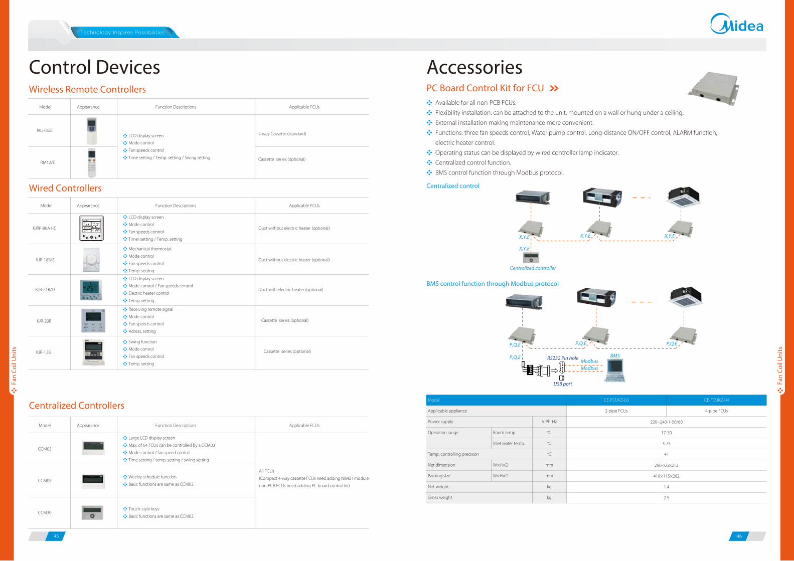
PC Board Control Kit for FCUWireless Remote ControllersAvailable for all non-PCB FCUs.
Flexibility installation: can be attached to the unit, mounted on a wall or hung under a ceiling.
External installation making maintenance more convenient.
Functions: three fan speeds control, Water pump control, Long-distance ON/OFF control, ALARM function,
electric heater control.
Operating status can be displayed by wired controller lamp indicator.
Centralized control function.
BMS control function through Modbus protocol.
Centralized control
BMS control function through Modbus protocol
X,Y,E
X,Y,E
Centralized controller
X,Y,E X,Y,E
P,Q,E
P,Q,E RS232 Pin hole BMSModbusModbus
USB port
P,Q,E P,Q,E
EPQ R+R-
E
FCUKZ-03 FCUKZ-04
Model
Applicable appliance
Power supply
Operation range
Temp. controlling precision
Net dimension
Packing size
Net weight
Gross weight
Room temp.
Inlet water temp.
W×H×D
W×H×D
V-Ph-Hz
oC
oC
oC
mm
mm
kg
kg
CE-FCUKZ-03
2-pipe FCUs
CE-FCUKZ-04
4-pipe FCUs
220~240-1-50/60
17-30
3-75
±1
296×66×212
410×115×262
1.4
2.5
Model Appearance
R05/BGE
RM12/E
Function Descriptions Applicable FCUs
4-way Cassette (standard)
Wired Controllers
Centralized Controllers
LCD display screen
Mode control
Fan speeds control
Time setting / Temp. setting / Swing setting
Model Appearance
KJRP-86A1-E
KJR-18B/E
Function Descriptions Applicable FCUs
Duct without electric heater (optional)
Duct without electric heater (optional)
KJR-21B/D Duct with electric heater (optional)
LCD display screen
Mode control
Fan speeds control
Timer setting / Temp. setting
Mechanical thermostat
Mode control
Fan speeds control
Temp. setting
LCD display screen
Mode control / Fan speeds control
Electric heater control
Temp. setting
KJR-29B
Cassette series (optional)
Receiving remote signal
Mode control
Fan speeds control
Adress. setting
KJR-12B
Swing function
Mode control
Fan speeds control
Temp. setting
Cassette series (optional)
Cassette series (optional)
Control Devices Accessories
Fan
Coil
Uni
ts
Fan
Coil
Uni
ts
Model Appearance
CCM03
CCM09
Function Descriptions Applicable FCUs
CCM30
Large LCD display screen
Max. of 64 FCUs can be controlled by a CCM03
Mode control / fan speed control
Time setting / temp. setting / swing setting
Weekly schedule function
Basic functions are same as CCM03
Touch-style keys
Basic functions are same as CCM03
All FCUs
(Compact 4-way cassette FCUs need adding NIM01 module,
non-PCB FCUs need adding PC board control kit)
Centralized wiring
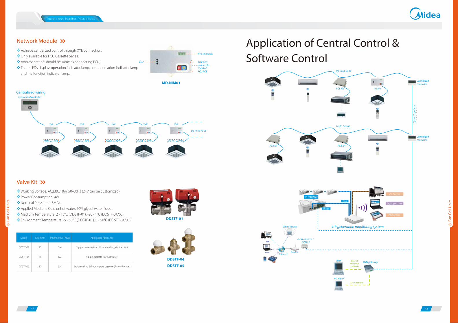
Valve KitWorking Voltage: AC230±10%, 50/60Hz (24V can be customized).
Power Consumption: 4W
Nominal Pressure: 1.6MPa.
Applied Medium: Cold or hot water, 50% glycol water liquor.
Medium Temperature: 2 - 15°C (DDSTF-01), -20 - 1°C (DDSTF-04/05).
Environment Temperature: -5 - 50°C (DDSTF-01), 0 - 50°C (DDSTF-04/05).
Model
DDSTF-01
DDSTF-04
DDSTF-05
DN(mm)
20
15
20
Inner Screw Thead
3/4”
1/2”
3/4”
Applicable Appliance
2-pipe cassette/duct/floor standing, 4-pipe duct
4-pipe cassette (for hot water)
2-pipe ceiling & floor, 4-pipe cassette (for cold water)
DDSTF-01
DDSTF-04
DDSTF-05
47 48
Application of Central Control & Software Control
Address setting
LED
XYE terminals
Side port connect to CN20 of FCU PCB
Network Module
Achieve centralized control through XYE connection;
Only available for FCU Cassette Series;
Address setting should be same as connecting FCU;
There LEDs display: operation indicator lamp, communication indicator lamp
and malfunction indicator lamp.
MD-NIM01Centralized controller
Centralized controller
BMS gatewayBMS
PC in LAN
BACnetModubusLonWorks
TCP/IP network
LAN
M-interface
Laptop Access
Pad Access
M-net
PC Access
PC
Cloud Servers
InternetRouter
Data converter CCM15
4th generation monitoring system
Up to 64 units
Up
to 1
6 sy
stem
s
Up to 64 units
PCB Kit NIM01
PCB Kit PCB Kit
Fan
Coil
Uni
ts
Fan
Coil
Uni
ts
Centralized controller
XYE XYE XYE XYE XYE
Up to 64 FCUs
CN20 on PCB CN20 on PCB CN20 on PCB CN20 on PCB CN20 on PCB
49 50
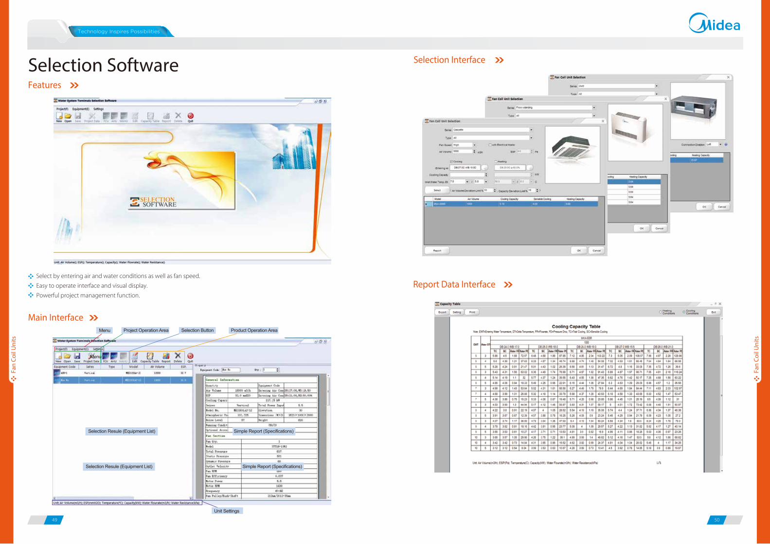
Select by entering air and water conditions as well as fan speed.
Easy to operate interface and visual display.
Powerful project management function.
Features
Main Interface
Selection Interface
Report Data Interface
Selection Software
Fan
Coil
Uni
ts
Fan
Coil
Uni
ts


