Embed Size (px)
Citation preview

AIR TECHMADE EASY
June 2019 www.broomwade.com

SCREW COMPRESSORS 2.2 - 90kW 4 - 33KA Series 6 - 9FM Fixed Speed - FM RS Variable Speed Series 10 - 23FM Fixed Speed - FM RS Variable Speed Series 30 - 75kW Series 24 - 31KSA / KSV 90 Series 32 - 35SEQUENCE MULTIPLE COMPRESSORS 36 - 39PISTON COMPRESSORS 40 - 51RECIPROCATING CAST IRON COMPRESSORS 52 - 55ROTARY AIR VANE COMPRESSORS 56 - 59SCROLL COMPRESSORS 60 - 67DENTAL COMPRESSORS 68 - 73BREATHING AIR COMPRESSORS 74 - 77 PORTABLE SCREW COMPRESSORS 78 - 81COMPRESSED AIR TREATMENT 82 -117Compressed Air Filters 86 - 89Condensate Separators 90 - 91Refrigeration Compressed Air Dryers 92 - 93Adsorption Compressed Air Dryers 94 - 98Membrane Dryers 99Air Cooled Aftercoolers 100 - 101Activated Carbon Towers 102 - 103Compressed Air Equipment 104 - 105Breathing Air Filter 106 - 107Breathing Air Filter Plus 108 - 109Heat Recovery Units 110Condensate Drains 112 - 113Oil/Water Separation Equipment 114 - 115Generators 116AFTERMARKET 118 - 139 KA02 - KA5 Service Schedule 121FM7 - FM22 Service Schedule 122FM30 - FM75 Service Schedule 123Vane Compressors Service Schedule 124Scroll Compressors Service Schedule 125Portables Service Schedule 126 Piston Compressors Service Schedule 127Compressor Service Kits 128 - 129Dryer Service Kits 130 - 133Activated Carbon Towers 134Filter Guide 135 - 136Nitrogen Generator Service Kits 137Service Kits For Legacy Products 138
2
CONTENTS

3

• Oil flooded• Single stage rotary screw compressor• Fixed and variable speed models• Star / Delta starting• Pressure range 5 - 13 bar• Electric motor 2.2kW to 90kW - IE3• Modular design including receivers and dryers• C-PRO 1.0, C-PRO 2.0 & C- MASTER• Extended warranties available
FIXED & VARIABLE SPEED
4
SCREW COMPRESSORS2.2 - 90kW

5

6
KA SeriesA series of technologically advanced compressors, resulting from an accurate research and development processThe result is an extremely quiet compressor, environmentally friendly thanks to a reduced power consumption and the use of easily recyclable materials.
Noise levelsVery low noise levels have been reached (61 - 66 dB(A)) thanks to optimised air and cooling, allowing the installation of the compressor at the point of use.
Start/Stop operationThe Start/Stop mode reduces the energy consumption as the compressor runs only when needed.
C-PRO 1.0 control unit (optional for KA 4 and 5)The C-PRO 1.0 electronic controller provides the user with data on total hours of operation, operating temperature and additional information such as:
Air/Oil separation systemIncreased reliability combined with reduced piping and connections is made possible by an integrated block acting as air-oil separation and filter. The effectiveness of filtering ensures extremely low levels of residual oil, equal to 3 ppm max. This block houses oil filter, oil separation filter, minimum pressure valve, safety valve, oil thermostat and check valve.
Suction valve Improved fluid-mechanical efficiency is ensured by a new vertical design suction valve. Intake-air flows through a straight-line path, which guarantees lower load loss. ON / OFF operation and unloading is controlled via a solenoid valve. This valve concept has been specially designed to keep the number of components to a minimum, so as to ensure long-lasting durability and low maintenance requirements.
KA SERIES
SMART COMPRESSOR DESIGN
Nominal Pressure 10 bar g
At a glance…
Volume Flow 0.24 - 0.67 m3/min
Motor Power 2.2 - 5.5kW
• Air filter replacement• Oil filter replacement• Separator filter replacement• Oil change
• Regular maintenance advice• Pressure setting adjustment can be easily adjusted via the controller

7
TransmissionThe pre-tested belt transmission is installed with balanced cast iron pulleys and bevel bearing. Belts are of quality construction to ensure the utmost reliability. The belt tensioning system has been simplified thanks to a single adjustment screw, which guarantees easier control and replacement.
Standard equipment• Star / Delta start (Premium versions)• C-PRO 1.0 control unit (Premium versions)• Overload relay• Start / Stop control key with pressure switch (KA2-KA5)• Start / Stop push-button. ON / OFF main switch (premium versions)• IE 3 electric motors, insulation class: F• Oil level monitoring, visual level indicator• Transmission belt• Oil thermostat• Safety devices for:
– Motor overheating – Compressor overheating, automatic stop at 110 °C
• Indicators of the operating conditions: – Pressure – Hour meter
• Enclosure with epoxy powder coating
KA package compressors with cooling cycle dryer, filters and tankThe KA package compressors can be easily and quickly installed in any environment.
OptionalA series of options are available to ensure a complete and integrated solution. The KA Package compressors can be fitted with a kit of filters complete with by-pass, which guarantee that air is treated before entering the plant, in turn reducing the creation of condensate in the network.
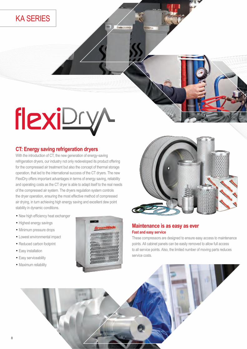
CT: Energy saving refrigeration dryersWith the introduction of CT, the new generation of energy-saving refrigeration dryers, our industry not only redeveloped its product offering for the compressed air treatment but also the concept of thermal storage operation, that led to the international success of the CT dryers. The new FlexiDry offers important advantages in terms of energy saving, reliability and operating costs as the CT dryer is able to adapt itself to the real needs of the compressed air system. The dryers regulation system controls the dryer operation, ensuring the most effective method of compressed air drying, in turn achieving high energy saving and excellent dew point stability in dynamic conditions.
• New high efficiency heat exchanger• Highest energy savings• Minimum pressure drops• Lowest environmental impact• Reduced carbon footprint• Easy installation• Easy serviceability• Maximum reliability
Maintenance is as easy as everFast and easy service These compressors are designed to ensure easy access to maintenance points. All cabinet panels can be easily removed to allow full access to all service points. Also, the limited number of moving parts reduces service costs.
8
KA SERIES

Technical data
9
KA 2 – 5 Series: Screw CompressorsDesign: Oil flooded, single stage rotary screw compressor, belt drive, direct start or star / delta startingPressure Range: 10 barElectric motor: 2.2 to 5.5kW – IE3
KA SERIES TYPE KA2 230V AC-50 hz - 1 Phase KA 2 KA 3 KA 4 KA 5
CODE CMP1049082B1 CMP1026757B1 CMP1026766B1 CMP1026767B1 CMP1026756B1Maximum pressure bar 10 10 10 10 10Capacity at maximum pressure m3/min 0.24 0.24 0.36 0.53 0.67Drive motor IP 55 / class F – IE3 kW 2.2 2.2 3 4 5.5Operating voltage, 50 – 60Hz 380 – 400V – • • • •Noise level dB(A) 61 61 61 62 66Air cooled • • • • •Weight kg 106 106 106 106 119Dimensions [L x W x H] mm 620 x 600 x 840 620 x 600 x 840 620 x 600 x 840 620 x 600 x 840 620 x 600 x 840OUT BSP 1/2" 1/2" 1/2" 1/2" 1/2"
COMPRESSOR MOUNTED ON 270 LT TANK Code CC1049084B1 CMP1026758B1 CMP1026759B1 CMP1026760B1 CMP1026761B1Weight kg 191 191 191 191 204Dimensions [L x W x H] mm 1,540 x 600 x 1,400 1,540 x 600 x 1,400 1,540 x 600 x 1,400 1,540 x 600 x 1,400 1,540 x 600 x 1,400COMPRESSOR MOUNTED ON 500 LT TANK Code – – – CMP1026739B1 CMP1026740B1Weight kg – – – 251 264Dimensions [L x W x H] mm – – – 1,950 x 680 x 1,5201,950 x 680 x 1,520PACKAGE VERSION, KA / CT / 2701] Code CMP1194504 CMP1026762BE2 CMP1026763BE2 CMP1026764BE2 CMP1026765BE2Weight kg 213 213 213 220 231Dimensions [L x W x H] mm 1,540 x 600 x 1,400 1,540 x 600 x 1,400 1,540 x 600 x 1,400 1,540 x 600 x 1,400 1,540 x 600 x 1,400PACKAGE VERSION, KA / CT / 5001] Code – – – CMP1026741BE2 CMP1026742BE2Weight kg – – – 280 291Dimensions [L x W x H] mm – – – 1,950 x 680 x 1,520 1,950 x 680 x 1,520PREMIUM VERSION [COMPLETE WITH C-PRO 1.0 ELECTRONIC CONTROLLER]COMPRESSOR BASE LOAD Code – – – CMP1031244B1 CMP1031242B1COMPRESSOR MOUNTED ON 270 LT TANK Code – – – CMP1034065B1 CMP1034068B1COMPRESSOR MOUNTED ON 500 LT TANK Code – – – CMP1034066B1 CMP1034069B1PACKAGE VERSION, KA / CT / 2701] Code – – – CMP1034071BE2 CMP1034074BE2PACKAGE VERSION, KA / CT / 5001] Code – – – CMP1034072BE2 CMP1034075BE2OPTIONALAlternative voltage, 230V / 50 - 60Hz3]
Filter Kit with bypass for dryer CT2] 4] CC1179488Filter Kit with bypass for dryer CT2] 4] CC1179489Retro Fit Filter Kit CC1199110Retro Fit Filter Kit CC1199111Food grade Oil (19 Litres) 3)
Automatic drain discharge for tank CC1032413Anti-corrosion % SERVICE & PARTSService Kit for every 4000h or 12 months CC1089649Service Kit for every 8000h or 24 months CC1089650ChampLUBE Screw Food grade lubricant 4 x 4 Litres CC1180019
1] Compressor mounted on tank with refrigeration cycle dryer (CT). Dew point + 3° C with compressor air inlet temperature + 35° and per ISO 7183. 2] Kit includes ceramic filter & coalescent filter.3] Only for KA 2–3 and KA 4–5 Premium. 4] Factory fitted or retrofit kit.

COMPACT & RELIABLE ROTARY SCREW COMPRESSORS - FM SERIES
FM FIXED SPEED, FM RS VARIABLE SPEED
FM & FM RS Screw Compressors up to 46ºC ambient temperatureThe generously sized ventilation system ensures optimum cooling, low outlet air temperatures best performance and reliability under harshest conditions
Premium Quality Airends FM series feature high quality airends manufactured in Finland using state of the art manufacturing techniques. The airends are designed with focus on reliability and efficiency. The rotors are accurate and thoroughly checked and measured by a computerised control system. Enduro airends have a flat specific power consumption curve, which enables efficient use of the airend in wide rpm. For models FM15-22 the Tamrotor Enduro airend features integrated air - oil separator and oil filter which offers a very compact design and improved maintenance.
FM & FM RS package compressors with dryer and tankBased up on the individual customer requirements the compressors can be combined with different options to provide options from a stand alone compressor to the complete package.• Compressor base mounted• Tank mounted compressor• Complete package including compressor, dryer and tank
New advanced controller C-PRO 2.0 ensures reliable operation and protects your investment by continuously monitoring the operational parameters✓ 3 analog inputs
✓ Multi-language: English/German/French/Italian/Spanish
✓ Standard sequence control up to 8 units (up to 7 units fixed speed & 1 variable speed)
✓ Standard Modbus
✓ 15 failure records in memory
✓ Continuous system monitoring
Nominal Pressure 5 - 13 bar g
At a glance…
Volume Flow 0.45 - 3.50 m3/min
Motor Power 7 - 22kW
10
Traditional air ends
Enduro Air Ends
Specific power consumpution kW/m3min
Speed of rotation (r.p.m)
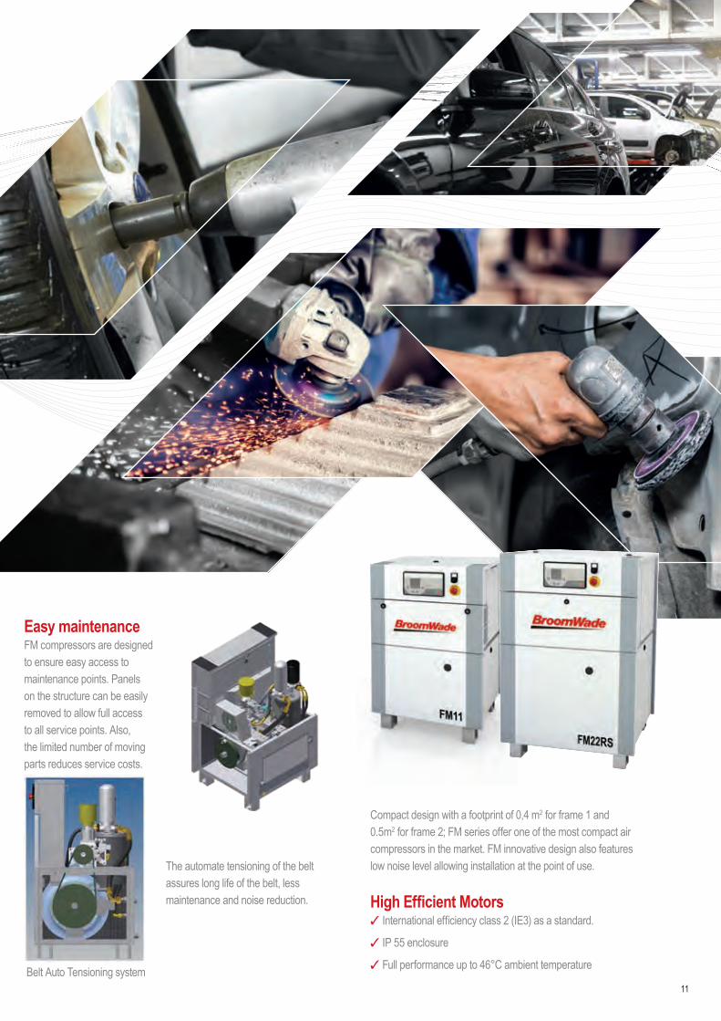
Easy maintenanceFM compressors are designed to ensure easy access to maintenance points. Panels on the structure can be easily removed to allow full access to all service points. Also, the limited number of moving parts reduces service costs.
The automate tensioning of the belt assures long life of the belt, less maintenance and noise reduction.
Easy Installation at the point of use
Compact design with a footprint of 0,4 m2 for frame 1 and 0.5m2 for frame 2; FM series offer one of the most compact air compressors in the market. FM innovative design also features low noise level allowing installation at the point of use.
High Efficient Motors✓ International efficiency class 2 (IE3) as a standard.
✓ IP 55 enclosure
✓ Full performance up to 46°C ambient temperature
11Belt Auto Tensioning system

= Energy savings and lower CO2 emissions into the environment.
FM RS
12
Allows substantial energy savings of at least 25% of the energy cost
FM RS
Compressor energy cost example
Cost of compressed air over 5 years
Purchase cost 8%
Service, repair & maintenance cost 6%
Energy cost 86%
6%
86%8%
FM FIXED SPEED, FM RS VARIABLE SPEED
The variable speed compressor: One smart solutionVariable speed compressors can efficiently and reliably handle the varying air demand found in most plant air systems. These compressors speed up and slow down to match air supply to air demand as it fluctuates. The right variable speed compressor in the right application delivers significant energy savings and a stable, consistent air supply.
The intelligent C-PRO 2.0 controllerSimplicity The C-PRO 2.0 controller was designed to make the operators’ interface with the variable speed drive transparent. This new generation controller features extra functions for variable speed compressors like drive status display and flexible PID setting according the application. You don’t need to be an expert on variable speed drives to operate your compressor. The controller takes care of the details and automatically adjusts the compressor performance to meet your changing air system demands - saving you energy. Changing the discharge pressure is as easy as pressing a button.
FM package compressorsWith dryer, filters and tankThe FM Package compressors can be easily and rapidly installed in any installation.
NOMINAL kW
OPERATING COST PER YEAR (5000 HOURS) AT COST PER KWH (€)
0.06 0.08 0.10 0.12 0.14 0.1615 4,495 5,990 7,490 8,985 10,483 11,98018 5,540 7,390 9,235 11,080 12,930 14,77522 6,590 8,785 10,980 13,180 15,375 17,570
Note: Hours of operation based on two 8hrs-shifts, 6 days per week. Calculations based on nominal kW.

13
FM 7 Series: Screw CompressorsDesign: Oil flooded, Single stage rotary screw compressor, belt drive, air cooledPressure Range: 7-8-10-13 barElectric motor: 7,5 kW - IE3
FM SERIES TYPE FM7CODE CC1184130 CC1184131 CC1183626 CC1184132Maximum pressure bar 7 8 10 13Capacity at maximum pressure m3/min 1.14 0.99 0.97 0.80Drive motor IP 55 / class F – IE3 kW 7.5 7.5 7.5 7.5Operating Voltage, 50Hz 400 V • • • •Control voltage 24 V • • • •C-Pro 2.0 electronic controller • • • •Noise Level db(A) 70 70 70 70After-cooler • • • •Weight kg 205 205 205 205Dimensions (L x W x H) mm 667 x 630 x 1050 667 x 630 x 1050 667 x 630 x 1050 667 x 630 x 1050Outlet connection EN 10266 (DIN 2999) 3/4'' 3/4'' 3/4'' 3/4''
COMPRESSOR MOUNTED ON 270 LT TANK Code CC1186380 CC1186381 CC1186382 CC1186383Weight kg 300 300 300 300Dimensions (L x W x H) mm 1600 x 700 x 1600 1600 x 700 x 1600 1600 x 700 x 1600 1600 x 700 x 1600COMPRESSOR MOUNTED ON 500 LT TANK Code CC1186394 CC1186395 CC1186396 CC1186397Weight kg 365 365 365 365Dimensions (L x W x H) mm 2000 x 700 x 1700 2000 x 700 x 1700 2000 x 700 x 1700 2000 x 700 x 1700PACKAGE VERSION, FM / CT / 270 1) Code CC1186422 CC1186423 CC1186424 CC1186425Weight kg 340 340 340 340Dimensions (L x W x H) mm 1600 x 700 x 1600 1600 x 700 x 1600 1600 x 700 x 1600 1600 x 700 x 1600PACKAGE VERSION, FM / CT / 500 1) Code CC1186426 CC1186427 CC1186428 CC1186429Weight kg 405 405 405 405Dimensions (L x W x H) mm 2000 x 700 x 1700 2000 x 700 x 1700 2000 x 700 x 1700 2000 x 700 x 1700OPTIONALAlternative Voltage, 230V / 50-60 Hz 3)
Alternative Voltage, 380V / 60 Hz 3)
Filter Kit with bypass for dryer 2) 3) Retro Fit Filter Kit CC1199112Automatic drain discharge for tank 3)
Anticorrosion % 3)
Food grade Oil (19 Litres) 3)
Internal Vessel acc AD 2000Extended 5 year warranty CC1180791SERVICE & PARTSService Kit for every 4000 h or 12 months CC1180671Service Kit for every 8000 h or 24 months CC1180677ChampLube Lubricant 4 x 4 Litres CC1180019
1) Compressor mounted on tank with refrigeration cycle dryer (CT). Dew point + 3° C with compressor air inlet temperature + 35° and per ISO 71832) Kit includes water separator, ceramic filter and bypass kit 3) Must be clearly mentioned in the order
Technical data

14
FM FIXED SPEED, FM RS VARIABLE SPEED
FM 11 Series: Screw CompressorsDesign: Oil flooded, Single stage rotary screw compressor, belt drive, air cooledPressure Range: 7 to 13 barElectric motor: 11 kW - IE3
FM SERIES TYPE FM11CODE CC1184133 CC1184154 CC1183627 CC1184155Maximum pressure bar 7 8 10 13Capacity at maximum pressure m3/min 1.59 1.41 1.39 1.14Drive motor IP 55 / class F – IE3 kW 11 11 11 11Operating Voltage, 50Hz 400 V • • • •Control voltage 24 V • • • •C-Pro 2.0 electronic controller • • • •Noise Level db(A) 70 70 70 70After-cooler • • • •Weight kg 219 219 219 219Dimensions (L x W x H) mm 667 x 630 x 1050 667 x 630 x 1050 667 x 630 x 1050 667 x 630 x 1050Outlet connection EN 10266 (DIN 2999) 3/4'' 3/4'' 3/4'' 3/4''
COMPRESSOR MOUNTED ON 270 LT TANK Code CC1186398 CC1186399 CC1186400 CC1186401Weight kg 314 314 314 314Dimensions (L x W x H) mm 1600 x 700 x 1600 1600 x 700 x 1600 1600 x 700 x 1600 1600 x 700 x 1600COMPRESSOR MOUNTED ON 500 LT TANK Code CC1186402 CC1186403 CC1186404 CC1186405Weight kg 379 379 379 379Dimensions (L x W x H) mm 2000 x 700 x 1700 2000 x 700 x 1700 2000 x 700 x 1700 2000 x 700 x 1700PACKAGE VERSION, FM / CT / 270 1) Code CC1186430 CC1186431 CC1186432 CC1186433Weight kg 354 354 354 354Dimensions (L x W x H) mm 1600 x 700 x 1600 1600 x 700 x 1600 1600 x 700 x 1600 1600 x 700 x 1600PACKAGE VERSION, FM / CT / 500 1) Code CC1186434 CC1186435 CC1186436 CC1186437Weight kg 419 419 419 419Dimensions (L x W x H) mm 2000 x 700 x 1700 2000 x 700 x 1700 2000 x 700 x 1700 2000 x 700 x 1700OPTIONALAlternative Voltage, 230V / 50 – 60 Hz 3)
Alternative Voltage, 380V / 60 Hz 3)
Filter Kit with bypass for dryer 2) 3) Retro Fit Filter Kit CC1199113Automatic drain discharge for tank 3)
Anticorrosion % 3)
Food grade Oil (19 Litres) 3)
Internal Vessel acc AD 2000Extended 5 year warranty CC1180791SERVICE & PARTSService Kit for every 4000 h or 12 months CC1180671Service Kit for every 8000 h or 24 months CC1180677ChampLube Lubricant 4 x 4 Litres CC1180019
1) Compressor mounted on tank with refrigeration cycle dryer (CT). Dew point + 3° C with compressor air inlet temperature + 35° and per ISO 71832) Kit includes water separator, ceramic filter and bypass kit 3) Must be clearly mentioned in the order

15
FM 7 RS Series: Screw CompressorsDesign: Oil flooded, Single stage rotary screw compressor, variable speed, air cooledPressure Range: 5 to 13 barElectric motor: 7.5 kW - IE3
FM SERIES TYPE FM7RSCODE CC1184156 CC1184157 CC1184158 CC1184159Maximum pressure bar 7 8 10 13Capacity at maximum pressure m3/min 1.13 0.98 0.95 0.80Drive motor IP 55 / class F – IE3 kW 7.5 7.5 7.5 7.5Operating Voltage, 50Hz 400 V • • • •Control voltage 24 V • • • •C-Pro 2.0 electronic controller • • • •Noise Level db(A) 67 67 67 67After-cooler • • • •Weight kg 225 225 225 225Dimensions (L x W x H) mm 667 x 630 x1050 667 x 630 x 1050 667 x 630 x 1050 667 x 630 x 1050Outlet connection EN 10266 (DIN 2999) 3/4'' 3/4'' 3/4'' 3/4''
COMPRESSOR MOUNTED ON 270 LT TANK Code CC1186406 CC1186407 CC1186408 CC1186409Weight kg 320 320 320 320Dimensions (L x W x H) mm 1600 x 700 x 1600 1600 x 700 x 1600 1600 x 700 x 1600 1600 x 700 x 1600COMPRESSOR MOUNTED ON 500 LT TANK Code CC1186410 CC1186411 CC1186412 CC1186413Weight kg 385 385 385 385Dimensions (L x W x H) mm 2000 x 700 x 1700 2000 x 700 x 1700 2000 x 700 x 1700 2000 x 700 x 1700PACKAGE VERSION, FM / CT / 270 1) Code CC1186438 CC1186439 CC1186440 CC1186441Weight kg 360 360 360 360Dimensions (L x W x H) mm 1600 x 700 x 1600 1600 x 700 x 1600 1600 x 700 x 1600 1600 x 700 x 1600PACKAGE VERSION, FM / CT / 500 1) Code CC1186442 CC1186443 CC1186444 CC1186445Weight kg 425 425 425 425Dimensions (L x W x H) mm 2000 x 700 x 1700 2000 x 700 x 1700 2000 x 700 x 1700 2000 x 700 x 1700OPTIONALAlternative Voltage, 230V / 50-60 Hz 3)
Alternative Voltage, 380V / 60 Hz 3)
Filter Kit with bypass for dryer 2) 3) Retro Fit Filter Kit CC1199112Automatic drain discharge for tank 3)
Anticorrosion % 3)
Food grade Oil (19 Litres) 3)
Internal Vessel acc AD 2000Extended 5 year warranty CC1180791SERVICE & PARTSService Kit for every 4000 h or 12 months CC1180672Service Kit for every 8000 h or 24 months CC1180678ChampLube Lubricant 4 x 4 Litres CC1180019
1) Compressor mounted on tank with refrigeration cycle dryer (CT). Dew point + 3° C with compressor air inlet temperature + 35° and per ISO 71832) Kit includes water separator, ceramic filter and bypass kit 3) Must be clearly mentioned in the order

16
FM FIXED SPEED, FM RS VARIABLE SPEED
FM 11 RS Series: Screw CompressorsDesign: Oil flooded, Single stage rotary screw compressor, variable speed, air cooledPressure Range: 5 to 13 barElectric motor: 11 kW - IE3
FM SERIES TYPE FM11RSCODE CC1184160 CC1184161 CC1184162 CC1184163Maximum pressure bar 7 8 10 13Capacity at maximum pressure and 100% load m3/min 1.58 1.41 1.39 1.07Drive motor IP 55 / class F – IE3 kW 11 11 11 11Operating Voltage, 50Hz 400 V • • • •Control voltage 24 V • • • •C-Pro 2.0 electronic controller • • • •Noise Level at 70% load db(A) 67 67 67 67After-cooler • • • •Weight kg 234 234 234 234Dimensions (L x W x H) mm 667 x 630 x 1050 667 x 630 x 1050 667 x 630 x 1050 667 x 630 x 1050Outlet connection EN 10266 (DIN 2999) 3/4'' 3/4'' 3/4'' 3/4''
COMPRESSOR MOUNTED ON 270 LT TANK Code CC1186414 CC1186415 CC1186416 CC1186417Weight kg 329 329 329 329Dimensions (L x W x H) mm 1600 x 700 x 1600 1600 x 700 x 1600 1600 x 700 x 1600 1600 x 700 x 1600COMPRESSOR MOUNTED ON 500 LT TANK Code CC1186418 CC1186419 CC1186420 CC1186421Weight kg 394 394 394 394Dimensions (L x W x H) mm 2000 x 700 x 1700 2000 x 700 x 1700 2000 x 700 x 1700 2000 x 700 x 1700PACKAGE VERSION, FM / CT / 270 1) Code CC1186446 CC1186447 CC1186448 CC1186449Weight kg 369 369 369 369Dimensions (L x W x H) mm 1600 x 700 x 1600 1600 x 700 x 1600 1600 x 700 x 1600 1600 x 700 x 1600PACKAGE VERSION, FM / CT / 500 1) Code CC1186450 CC1186451 CC1186452 CC1186453Weight kg 434 434 434 434Dimensions (L x W x H) mm 2000 x 700 x 1700 2000 x 700 x 1700 2000 x 700 x 1700 2000 x 700 x 1700OPTIONALAlternative Voltage, 380V / 60 Hz 3)
Filter Kit with bypass for dryer 2) 3) Retro Fit Filter Kit CC1199113Automatic drain discharge for tank 3)
Anticorrosion % 3)
Food grade Oil (19 Litres) 3)
Internal Vessel acc AD 2000Extended 5 year warranty CC1180791SERVICE & PARTSService Kit for every 4000 h or 12 months CC1180672Service Kit for every 8000 h or 24 months CC1180678ChampLube Lubricant 4 x 4 Litres CC1180019
1) Compressor mounted on tank with refrigeration cycle dryer (CT). Dew point + 3° C with compressor air inlet temperature + 35° and per ISO 71832) Kit includes water separator, ceramic filter and bypass kit 3) Must be clearly mentioned in the order

17
FM 15 Series: Screw CompressorsDesign: Oil flooded, Single stage rotary screw compressor, belt drive, air cooledPressure Range: 7 to 13 barElectric motor: 15 kW - IE3
FM SERIES TYPE FM15CODE CC1184171 CC1184172 CC1184173 CC1184264Maximum pressure bar 7 8 10 13Capacity at maximum pressure m3/min 2.64 2.46 2.20 1.79Drive motor IP 55 / class F – IE3 kW 15 15 15 15Operating Voltage, 50Hz 400 V • • • •Control voltage 24 V • • • •C-Pro 2.0 electronic controller • • • •Noise Level db(A) 73 73 73 73After-cooler • • • •Weight kg 335 335 335 335Dimensions (L x W x H) mm 787 x 698 x 1202 787 x 698 x 1202 787 x 698 x 1202 787 x 698 x 1202Outlet connection EN 10266 (DIN 2999) 1'' 1'' 1'' 1''
COMPRESSOR MOUNTED ON 500 LT TANK Code CC1186466 CC1186467 CC1186468 CC1186469Weight kg 495 495 495 495Dimensions (L x W x H) mm 2000 x 800 x 1850 2000 x 800 x 1850 2000 x 800 x 1850 2000 x 800 x 1850PACKAGE VERSION, FM / CT / 500 1) Code CC1186497 CC1186498 CC1186499 CC1186500Weight kg 545 545 545 545Dimensions (L x W x H) mm 2000 x 850 x 1850 2000 x 850 x 1850 2000 x 850 x 1850 2000 x 850 x 1850OPTIONALAlternative Voltage, 380V / 60 Hz 3)
Filter Kit with bypass for dryer 2)3) Retro Fit Filter Kit CC1199134Automatic drain discharge for tank 3)
Anticorrosion % 3)
Food grade Oil (19 Litres) 3)
Extended 5 year warranty CC1180791SERVICE & PARTSService Kit for every 4000 h or 12 months CC1180685Service Kit for every 8000 h or 24 months CC1180689ChampLube Lubricant 4 x 4 Litres CC1180019
1) Compressor mounted on tank with refrigeration cycle dryer (CT). Dew point + 3° C with compressor air inlet temperature + 35° and per ISO 71832) Kit includes water separator, ceramic filter and bypass kit 3) Must be clearly mentioned in the order
18
FM FIXED SPEED, FM RS VARIABLE SPEED
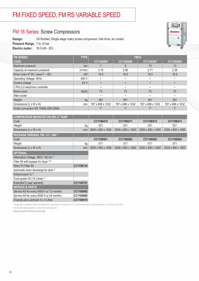
FM 18 Series: Screw CompressorsDesign: Oil flooded, Single stage rotary screw compressor, belt drive, air cooledPressure Range: 7 to 13 barElectric motor: 18.5 kW - IE3
FM SERIES TYPE FM18CODE CC1184265 CC1184266 CC1184267 CC1184268Maximum pressure bar 7 8 10 13Capacity at maximum pressure m3/min 3.15 2.96 2.71 2.38Drive motor IP 55 / class F – IE3 kW 18.5 18.5 18.5 18.5Operating Voltage, 50Hz 400 V • • • •Control voltage 24 V • • • •C-Pro 2.0 electronic controller • • • •Noise Level db(A) 73 73 73 73After-cooler • • • •Weight kg 361 361 361 361Dimensions (L x W x H) mm 787 x 698 x 1202 787 x 698 x 1202 787 x 698 x 1202 787 x 698 x 1202Outlet connection EN 10266 (DIN 2999) 1'' 1'' 1'' 1''
COMPRESSOR MOUNTED ON 500 LT TANK Code CC1186470 CC1186471 CC1186472 CC1186473Weight kg 521 521 521 521Dimensions (L x W x H) mm 2000 x 800 x 1850 2000 x 800 x 1850 2000 x 800 x 1850 2000 x 800 x 1850PACKAGE VERSION, FM / CT / 500 1) Code CC1186501 CC1186502 CC1186503 CC1186504Weight kg 571 571 571 571Dimensions (L x W x H) mm 2000 x 850 x 1850 2000 x 850 x 1850 2000 x 850 x 1850 2000 x 850 x 1850OPTIONALAlternative Voltage, 380V / 60 Hz 3)
Filter Kit with bypass for dryer 2)3) Retro Fit Filter Kit CC1199134Automatic drain discharge for tank 3)
Anticorrosion % 3)
Food grade Oil (19 Litres) 3)
Extended 5 year warranty CC1180791SERVICE & PARTSService Kit for every 4000 h or 12 months CC1180685Service Kit for every 8000 h or 24 months CC1180689ChampLube Lubricant 4 x 4 Litres CC1180019
1) Compressor mounted on tank with refrigeration cycle dryer (CT). Dew point + 3° C with compressor air inlet temperature + 35° and per ISO 71832) Kit includes water separator, ceramic filter and bypass kit 3) Must be clearly mentioned in the order

19
FM 22 Series: Screw CompressorsDesign: Oil flooded, Single stage rotary screw compressor, belt drive, air cooledPressure Range: 7 to 13 barElectric motor: 22 kW - IE3
FM SERIES TYPE FM22CODE CC1184269 CC1184270 CC1184169 CC1184271Maximum pressure bar 7 8 10 13Capacity at maximum pressure m3/min 3.50 3.23 3.06 2.59Drive motor IP 55 / class F – IE3 kW 22 22 22 22Operating Voltage, 50Hz 400 V • • • •Control voltage 24 V • • • •C-Pro 2.0 electronic controller • • • •Noise Level db(A) 74 74 74 74After-cooler • • • •Weight kg 367 367 367 367Dimensions (L x W x H) mm 787 x 698 x 1202 787 x 698 x 1202 787 x 698 x 1202 787 x 698 x 1202Outlet connection EN 10266 (DIN 2999) 1'' 1'' 1'' 1''
COMPRESSOR MOUNTED ON 500 LT TANK Code CC1186484 CC1186485 CC1186486 CC1186487Weight kg 527 527 527 527Dimensions (L x W x H) mm 2000 x 800 x 1850 2000 x 800 x 1850 2000 x 800 x 1850 2000 x 800 x 1850PACKAGE VERSION, FM / CT / 500 1) Code CC1186505 CC1186506 CC1186507 CC1186508Weight kg 577 577 577 577Dimensions (L x W x H) mm 2000 x 850 x 1850 2000 x 850 x 1850 2000 x 850 x 1850 2000 x 850 x 1850OPTIONALAlternative Voltage, 380V / 60 Hz 3)
Filter Kit with bypass for dryer 2)3) Retro Fit Filter Kit CC1199134Automatic drain discharge for tank 3)
Anticorrosion % 3)
Food grade Oil (19 Litres) 3)
Extended 5 year warranty CC1180791SERVICE & PARTSService Kit for every 4000 h or 12 months CC1180685Service Kit for every 8000 h or 24 months CC1180689ChampLube Lubricant 4 x 4 Litres CC1180019
1) Compressor mounted on tank with refrigeration cycle dryer (CT). Dew point + 3° C with compressor air inlet temperature + 35° and per ISO 71832) Kit includes water separator, ceramic filter and bypass kit 3) Must be clearly mentioned in the order

20
FM FIXED SPEED, FM RS VARIABLE SPEED
FM 15 RS Series: Screw CompressorsDesign: Oil flooded, Single stage rotary screw compressor, variable speed, air cooledPressure Range: 5 to 13 barElectric motor: 15 kW - IE3
FM SERIES TYPE FM15RSCODE CC1184272 CC1184273 CC1184274 CC1184275Maximum pressure bar 7 8 10 13Capacity at maximum pressure and 100% load m3/min 2.64 2.46 2.20 1.73Drive motor IP 55 / class F – IE3 kW 15 15 15 15Operating Voltage, 50Hz 400 V • • • •Control voltage 24 V • • • •C-Pro 2.0 electronic controller • • • •Noise Level at 70% load db(A) 70 70 70 70After-cooler • • • •Weight kg 360 360 360 360Dimensions (L x W x H) mm 787 x 698 x 1202 787 x 698 x 1202 787 x 698 x 1202 787 x 698 x 1202Outlet connection EN 10266 (DIN 2999) 1'' 1'' 1'' 1''
COMPRESSOR MOUNTED ON 500 LT TANK Code CC1186475 CC1186476 CC1186477 CC1186478Weight kg 520 520 520 520Dimensions (L x W x H) mm 2000 x 800 x 1850 2000 x 800 x 1850 2000 x 800 x 1850 2000 x 800 x 1850PACKAGE VERSION, FM / CT / 500 1) Code CC1186509 CC1186510 CC1186511 CC1186512Weight kg 570 570 570 570Dimensions (L x W x H) mm 2000 x 850 x 1850 2000 x 850 x 1850 2000 x 850 x 1850 2000 x 850 x 1850OPTIONALAlternative Voltage, 380V / 60 Hz 3)
Filter Kit with bypass for dryer 2)3) Retro Fit Filter Kit CC1199134Automatic drain discharge for tank 3)
Anticorrosion % 3)
Food grade Oil (19 Litres) 3)
Extended 5 year warranty CC1180791SERVICE & PARTSService Kit for every 4000 h or 12 months CC1180686Service Kit for every 8000 h or 24 months CC1180690ChampLube Lubricant 4 x 4 Litres CC1180019
1) Compressor mounted on tank with refrigeration cycle dryer (CT). Dew point + 3° C with compressor air inlet temperature + 35° and per ISO 71832) Kit includes water separator, ceramic filter and bypass kit 3) Must be clearly mentioned in the order

21
FM 18 RS Series: Screw CompressorsDesign: Oil flooded, Single stage rotary screw compressor, variable speed, air cooledPressure Range: 5 to 13 barElectric motor: 18.5 kW - IE3
FM SERIES TYPE FM18RSCODE CC1184277 CC1184278 CC1184279 CC1184280Maximum pressure bar 7 8 10 13Capacity at maximum pressure m3/min 3.15 2.96 2.66 2.25Drive motor IP 55 / class F – IE3 kW 18.5 18.5 18.5 18.5Operating Voltage, 50Hz 400 V • • • •Control voltage 24 V • • • •C-Pro 2.0 electronic controller • • • •Noise Level db(A) 71 71 71 71After-cooler • • • •Weight kg 380 380 380 380Dimensions (L x W x H) mm 787 x 698 x 1202 787 x 698 x 1202 787 x 698 x 1202 787 x 698 x 1202Outlet connection EN 10266 (DIN 2999) 1'' 1'' 1'' 1''
COMPRESSOR MOUNTED ON 500 LT TANK Code CC1186479 CC1186480 CC1186481 CC1186482Weight kg 540 540 540 540Dimensions (L x W x H) mm 2000 x 800 x 1850 2000 x 800 x 1850 2000 x 800 x 1850 2000 x 800 x 1850PACKAGE VERSION, FM / CT / 500 1) Code CC1186513 CC1186514 CC1186515 CC1186516Weight kg 590 590 590 590Dimensions (L x W x H) mm 2000 x 850 x 1850 2000 x 850 x 1850 2000 x 850 x 1850 2000 x 850 x 1850OPTIONALAlternative Voltage, 380V / 60 Hz 3)
Filter Kit with bypass for dryer 2)3) Retro Fit Filter Kit CC1199134Automatic drain discharge for tank 3)
Anticorrosion % 3)
Food grade Oil (19 Litres) 3)
Extended 5 year warranty CC1180791SERVICE & PARTSService Kit for every 4000 h or 12 months CC1180686Service Kit for every 8000 h or 24 months CC1180690ChampLube Lubricant 4 x 4 Litres CC1180019
1) Compressor mounted on tank with refrigeration cycle dryer (CT). Dew point + 3° C with compressor air inlet temperature + 35° and per ISO 71832) Kit includes water separator, ceramic filter and bypass kit 3) Must be clearly mentioned in the order

22
FM FIXED SPEED, FM RS VARIABLE SPEED
FM 22 RS Series: Screw CompressorsDesign: Oil flooded, Single stage rotary screw compressor, variable speed, air cooledPressure Range: 5 to 13 barElectric motor: 22 kW - IE3
FM SERIES TYPE FM22RSCODE CC1184281 CC1184282 CC1183666 CC1184283Maximum pressure bar 7 8 10 13Capacity at maximum pressure and 100% load m3/min 3.50 3.23 3.06 2.59Drive motor IP 55 / class F – IE3 kW 22 22 22 22Operating Voltage, 50Hz 400 V • • • •Control voltage 24 V • • • •C-Pro 2.0 electronic controller • • • •Noise Level at 70% load db(A) 71 71 71 71After-cooler • • • •Weight kg 395 395 395 395Dimensions (L x W x H) mm 787 x 698 x 1202 787 x 698 x 1202 787 x 698 x 1202 787 x 698 x 1202Outlet connection EN 10266 (DIN 2999) 1'' 1'' 1'' 1''
COMPRESSOR MOUNTED ON 500 LT TANK Code CC1186483 CC1186494 CC1186495 CC1186496Weight kg 555 555 555 555Dimensions (L x W x H) mm 2000 x 800 x 1850 2000 x 800 x 1850 2000 x 800 x 1850 2000 x 800 x 1850
14480.00 13920.00 13920.00 14760.00
PACKAGE VERSION, FM / CT / 500 1) Code CC1186517 CC1186518 CC1186519 CC1186520Weight kg 605 605 605 605Dimensions (L x W x H) mm 2000 x 850 x 1850 2000 x 850 x 1850 2000 x 850 x 1850 2000 x 850 x 1850OPTIONALAlternative Voltage, 380V / 60 Hz 3)
Filter Kit with bypass for dryer 2)3) Retro Fit Filter Kit CC1199134Automatic drain discharge for tank 3)
Anticorrosion % 3)
Food grade Oil (19 Litres) 3)
Extended 5 year warranty CC1180791SERVICE & PARTSService Kit for every 4000 h or 12 months CC1180686Service Kit for every 8000 h or 24 months CC1180690ChampLube Lubricant 4 x 4 Litres CC1180019
1) Compressor mounted on tank with refrigeration cycle dryer (CT). Dew point + 3° C with compressor air inlet temperature + 35° and per ISO 71832) Kit includes water separator, ceramic filter and bypass kit 3) Must be clearly mentioned in the order

23
Notes
FILTER N.1 FILTER N.2COMPRESSOR
MODELKIT FILTER FACTORY
INSTALLED MODEL P/N FILTER P/N CARTRIDGE MODEL P/N FILTER P/N
CARTRIDGEFM 07 via configurator F010 P 223053A 223173 F010 S 223072A 223193FM 11 via configurator F010 P 223053A 223173 F010 S 223072A 223193FM 15 via configurator F018 P 223054A 223174 F018 S 223073A 223194FM 18 via configurator F018 P 223054A 223174 F018 S 223073A 223194FM 22 via configurator F018 P 223054A 223174 F018 S 223073A 223194
Service element for factory fitted kits
FILTER N.1 FILTER N.2COMPRESSOR
MODELKIT FILTER FACTORY
INSTALLED MODEL P/N FILTER P/N CARTRIDGE MODEL P/N FILTER P/N
CARTRIDGEKA 2 CC1179488 F005 P 223051A 223171 F005 S 223070A 223191KA 3 CC1179488 F005 P 223051A 223171 F005 S 223070A 223191KA 4 CC1179489 F007 P 223052A 223172 F007 S 223071A 223192KA 5 CC1179489 F007 P 223052A 223172 F007 S 223071A 223192
NOTE 1: contains filter "P" + Filter "S"

Premium efficiency airendNew FM series 30-75 kW features premium quality airends designed and manufactured in house. The manufacturing process is using the latest CNC rotor grinding machinery, coupled with on-line laser technology, in order to maintain precise manufacturing tolerances.
Our state of art airends are focused on high efficiency and reliability.
Their integrated design offers a very compact solution that ease service and minimises leakage risks.
High efficiency cooling systemThanks to the optimum cooling system, the compressor can work in high ambient temperatures of up to 46°C.
Maximum durabilityWe maximise service life and durability by eliminating elastomer and thermoplastic pipe and tube in system pressure lines, replacing them with corrosion resistant stainless steel tubing and passive zinc coated carbon steel piping.
For ease of maintenance we complete the connection with viton sealed, grooved couplings and self-sealing high pressure compression fittings.
Designed for serviceability Maintenance personnel welcome the FM series compressor range. Service access is quick and easy with all doors able to be removed in seconds. We’ve also made sure serviceable components including filters are easily accessible and no piping needs to be disconnected to service the separator.
Optimised drive conceptWith direct or gear drive coupling, the belt free FM 30-75 Series compressor range not only reduces transmission losses, it improves efficiency and reduces noise. Most importantly, it delivers greater reliability and reduced maintenance costs.
Energy efficient motorHigh efficiency TEFC IE3 electric motors are fitted as standard to the entire FM 30-75 Series screw compressor range, reducing not only power consumption but also CO2 emissions.
FM FIXED SPEED - FMRS VARIABLE SPEED SERIES
NEW GENERATION HIGHLY EFFICIENT SCREW COMPRESSORS
Nominal Pressure 5 - 13 bar g
At a glance…
Volume Flow 1.19 - 13.5 m3/min
Motor Power 30 - 75kW
24
Semi Integrated VersionOil Filter
Thermostatic ValveDischarge on Top
Integrated Intake Valve

New advanced controller C-PRO 2.0 ensures reliable operation and protects your investment by continuously monitoring the operational parameters✓ 3 analog inputs
✓ Multi-language: English/German/French/Italian/Spanish
✓ Standard sequence control up to 8 units (up to 7 units fixed speed & 1 variable speed)
✓ Standard Modbus
✓ 15 failure records in memory
✓ Continuous system monitoring
iConn Industry 4.0 option The C- PRO 2.0 has the possibility to connect with iConn monitoring device iConn is the smart, proactive real-time monitoring service that delivers in-depth and real-time knowledge on the system to our compressed air users.
It enables accurate production planning and total peace-of-mind protection.
It keeps users informed on performance, at the same time highlighting potential issues before they become a problem.
• Condition based monitoring
• Predictive maintenance required
• Full Air Manufacturing Control Optimisation
• External data pattern integration
25

= Energy savings and lower CO2 emissions into the environment.
FM RS
Allows substantial energy savings of at least 25% of the energy cost
FM RS
Compressor energy cost example
Cost of compressed air over 5 years
Purchase cost 8%
Service, repair & maintenance cost 6%
Energy cost 86%
6%
86%8%
The variable speed compressor: One smart solutionVariable speed compressors can efficiently and reliably handle the varying air demand found in most plant air systems. These compressors speed up and slow down to match air supply to air demand as it fluctuates. The right variable speed compressor in the right application delivers significant energy savings and a stable, consistent air supply.
The intelligent C-PRO 2.0 controllerSimplicity The C-PRO 2.0 controller was designed to make the operators’ interface with the variable speed drive transparent. This new generation controller features extra functions for variable speed compressors like drive status display and flexible PID setting according the application. You don’t need to be an expert on variable speed drives to operate your compressor. The controller takes care of the details and automatically adjusts the compressor performance to meet your changing air system demands - saving you energy. Changing the discharge pressure is as easy as pressing a button.
FM package compressorsWith dryer, filters and tankThe FM Package compressors can be easily and rapidly installed in any installation.
26
FM FIXED SPEED - FMRS VARIABLE SPEED SERIES
NOMINAL kW
OPERATING COST PER YEAR (5000 HOURS) AT COST PER KWh (€)
0.06 0.08 0.10 0.12 0.14 0.1655 16,500 22,000 27,500 33,000 38,500 44,00075 22,500 30,000 37,500 45,000 52,500 60,000Note: Hours of operation based on two 8hrs-shifts, 6 days per week. Calculations based on nominal kW.

FM 30 – 45 Series: Screw Compressors, Fixed SpeedDesign: Oil flooded, Single stage rotary screw compressor, direct drive, star / delta startingPressure Range: 8 to 13 barElectric motor: 30 - 45kW - IE3
FM SERIES TYPE FM 30 FM 37 FM 45CODE CC1195721 CC1195722 CC1195723 CC1195342 CC1195734 CC1195735 CC1195736 CC1195737 CC1195738Max. Pressure bar 8 10 13 8 10 13 8 10 13Capacity at working pressure m3/min 4.87 4.67 4.08 6.4 5.49 5.05 7.52 6.75 5.4Drive Motor IP55 / Class IE3 kW 30 30 30 37 37 37 45 45 45Operating Voltage, 50 Hz 400 V • • • • • • • • •
Control Voltage 24V • • • • • • • • •
C-PRO 2.0 Controller • • • • • • • • •
Noise Level dB(A) 71 71 71 71 71 71 72 72 72
Weight kg 700 780 850
Dimensions (LxWxH) mm 1554 x 894 x 1405 1554 x 894 x 1405 1554 x 894 x 1405Compressered Air Delivery Connection EN 10226 G1 1/4 (DIN 2999-G1 1/4) female
OPTIONALAltern. Voltage 380V/60Hz & 230V/50HZExtended 5 years Warranty CC1180793
Anti - corrosion %
Food Grade Oil Kit for external heat recovery (heat recovery unit not included)iConn factory Fitted
iConn retrofit kit ZS1184985
Oil Heater Internal Pressure vessel acc AD2000SERVICE & PARTSService Kit for 4000h or 12 months FM30 CC1198084
Service Kit for 8000h or 24 months FM30 CC1198090
Service Kit for 4000h or 12 months FM37-45 CC1198085
Service Kit for 8000h or 24 months FM37-45 CC1198091
ChampLUBE Screw Lubricant 20Lt CC1180020
Technical data
27
* Service intervals are by calendar months or operating hours, whichever occurs first. In dirty ambient conditions service interval must be halved.
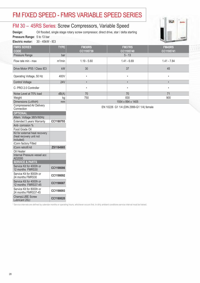
FM 30 – 45RS Series: Screw Compressors, Variable Speed Design: Oil flooded, single stage rotary screw compressor, direct drive, star / delta starting Pressure Range: 5 to 13 barElectric motor: 30 - 45kW - IE3FMRS SERIES TYPE FM30RS FM37RS FM45RSCODE CC1195739 CC1195740 CC1195741Pressure Range bar 5 - 13
Flow rate min - max m3/min 1.19 - 5.60 1.41 - 6.69 1.41 - 7.84
Drive Motor IP55 / Class IE3 kW 30 37 45
Operating Voltage, 50 Hz 400V • • •
Control Voltage 24V • • •
C- PRO 2.0 Controller • • •
Noise Level at 70% load dB(A) 70 70 71Weight kg 750 830 900Dimensions (LxWxH) mm 1554 x 894 x 1405Compressered Air Delivery Connection EN 10226 G1 1/4 (DIN 2999-G1 1/4) female
OPTIONALAltern. Voltage 380V/60Hz Extended 5 years Warranty CC1180793Anti- corrosion %Food Grade Oil Kit for external heat recovery (heat recovery unit not included) iConn factory Fitted iConn retrofit kit ZS1184985Oil Heater Internal Pressure vessel acc AD2000SERVICE & PARTSService Kit for 4000h or 12 months FMRS30 CC1198086
Service Kit for 8000h or 24 months FMRS30 CC1198092
Service Kit for 4000h or 12 months FMRS37-45 CC1198087
Service Kit for 8000h or 24 months FMRS37-45 CC1198093
ChampLUBE Screw Lubricant 20Lt CC1180020
* Service intervals are defined by calendar months or operating hours, whichever occurs first. In dirty ambient conditions service interval must be halved.
28
FM FIXED SPEED - FMRS VARIABLE SPEED SERIES

FM 55 – 75 Series: Screw Compressors, Fixed Speed Design: Oil flooded, single stage rotary screw compressor, direct drive, star / delta starting Pressure Range: 8 to 13 barElectric motor: 55 - 75kW - IE3FM SERIES TYPE FM55 FM75CODE CC1195745 CC1195747 CC1195748 CC1195749 CC1195750 CC1195751Pressure Range bar 8 10 13 8 10 13
Capacity at working pressure m3/min 10.55 9.14 7.9 12.15 10.26 8.91
Drive Motor IP55 / Class IE3 kW 55 55 55 75 75 75
Operating Voltage, 50 Hz 400V • • • • • •
Control Voltage 24V • • • • • •
C- PRO 2.0 Controller • • • • • •
Noise Level at 70% load dB(A) 73 73 73 74 74 74Weight kg 1150 1210Dimensions (LxWxH) mm 2004 x 1179 x 1505 2004 x 1179 x 1505Compressered Air Delivery Connection EN 10226 G2 (DIN 2999-G2) female
OPTIONALAltern. Voltage 380V/60Hz & 230V/50HZExtended 5 years Warranty CC1180793Anti- corrosion %Food Grade Oil Kit for external heat recovery (heat recovery unit not included) iConn factory Fitted iConn retrofit kit ZS1184985Oil Heater Internal Pressure vessel acc AD2000SERVICE & PARTSService Kit for 4000h or 12 months CC1198088
Service Kit for 8000h or 24 months CC1198094
ChampLUBE Screw Lubricant 20Lt (2x 20Lt needed) CC1180020
* Service intervals are defined by calendar months or operating hours, whichever occurs first. In dirty ambient conditions service interval must be halved.
29
30
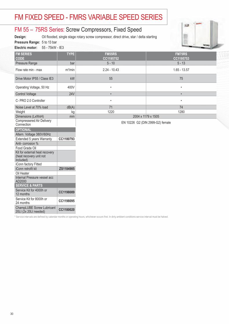
FM FIXED SPEED - FMRS VARIABLE SPEED SERIESFM 55 – 75RS Series: Screw Compressors, Fixed Speed Design: Oil flooded, single stage rotary screw compressor, direct drive, star / delta starting Pressure Range: 5 to 13 barElectric motor: 55 - 75kW - IE3FM SERIES TYPE FM55RS FM75RSCODE CC1195752 CC1195753Pressure Range bar 5 - 10 5 - 13
Flow rate min - max m3/min 2.24 - 10.43 1.65 - 13.57
Drive Motor IP55 / Class IE3 kW 55 75
Operating Voltage, 50 Hz 400V • •
Control Voltage 24V • •
C- PRO 2.0 Controller • •
Noise Level at 70% load dB(A) 71 74Weight kg 1220 1280Dimensions (LxWxH) mm 2004 x 1179 x 1505Compressered Air Delivery Connection EN 10226 G2 (DIN 2999-G2) female
OPTIONALAltern. Voltage 380V/60Hz Extended 5 years Warranty CC1180793Anti- corrosion %Food Grade Oil Kit for external heat recovery (heat recovery unit not included) iConn factory Fitted iConn retrofit kit ZS1184985Oil Heater Internal Pressure vessel acc AD2000SERVICE & PARTSService Kit for 4000h or 12 months CC1198089
Service Kit for 8000h or 24 months CC1198095
ChampLUBE Screw Lubricant 20Lt (2x 20Lt needed) CC1180020
* Service intervals are defined by calendar months or operating hours, whichever occurs first. In dirty ambient conditions service interval must be halved.

31
Notes

The New GenerationIndustries across the globe rely on BroomWade rotary screw compressors for the supply of high quality compressed airThe KSA / KSV 90 Series air compressor range incorporates the best of BroomWade technology, design and quality, to deliver reliable, economical and efficient performance in a completely new package.
High efficiency air endKSA / KSV Series screw compression elements are manufactured in-house using the latest CNC rotor grinding machinery, coupled with on-line laser technology, in order to maintain precise manufacturing tolerances.
BroomWade’s commitment to quality ensures KSA / KSV Series compressors offer the highest levels of reliability and performance with low operating costs throughout the compressor’s life.
Maximum durability We maximise service life and durability by eliminating elastomer and thermoplastic pipe and tube in system pressure lines, replacing them with corrosion resistant stainless steel tubing and passive zinc coated carbon steel piping. For ease of maintenance we complete the connection with viton sealed, grooved couplings and self-sealing high pressure compression fittings.
Optimised drive conceptWith direct or gear drive coupling, the belt free drive KSA / KSV 90 Series compressor range not only reduces transmission losses, it improves efficiency and reduces noise. Most importantly, it delivers greater reliability and reduced maintenance costs.
Energy efficient motorHigh efficiency TEFC IE3 electric motors are fitted as standard to the enitre KSA / KSV 90 Series screw compressor range, reducing not only your power consumption but also your CO2 emissions.
KSA / KSV SCREW COMPRESSORS
Nominal Pressure 5 - 10bar g
At a glance…
Volume Flow 4.3 - 15.6 m3/min
Motor Power 90kW
32
KSA / KSV 90 SERIES
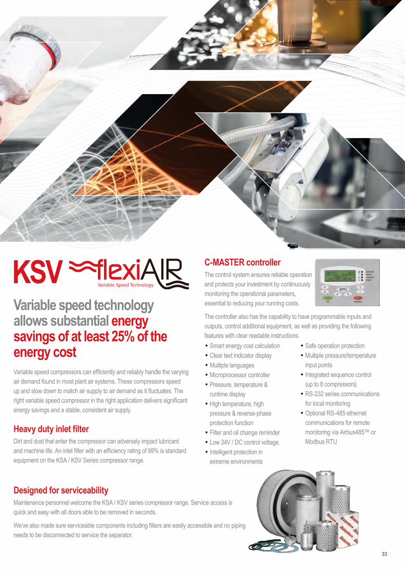
KSVVariable speed technology allows substantial energy savings of at least 25% of the energy costVariable speed compressors can efficiently and reliably handle the varying air demand found in most plant air systems. These compressors speed up and slow down to match air supply to air demand as it fluctuates. The right variable speed compressor in the right application delivers significant energy savings and a stable, consistent air supply.
Heavy duty inlet filterDirt and dust that enter the compressor can adversely impact lubricant and machine life. An inlet filter with an efficiency rating of 99% is standard equipment on the KSA / KSV Series compressor range.
C-MASTER controllerThe control system ensures reliable operation and protects your investment by continuously monitoring the operational parameters, essential to reducing your running costs.
The controller also has the capability to have programmable inputs and outputs, control additional equipment, as well as providing the following features with clear readable instructions.• Smart energy cost calculation• Clear text indicator display• Multiple languages• Microprocessor controller• Pressure, temperature &
runtime display• High temperature, high
pressure & reverse-phase protection function
• Filter and oil change reminder• Low 24V / DC control voltage.• Intelligent protection in
extreme environments
• Safe operation protection• Multiple pressure/temperature
input points• Integrated sequence control
(up to 8 compressors)• RS-232 series communications
for local monitoring• Optional RS-485 ethernet
communications for remote monitoring via Airbus485™ or Modbus RTU
33
Designed for serviceabilityMaintenance personnel welcome the KSA / KSV series compressor range. Service access is quick and easy with all doors able to be removed in seconds.
We’ve also made sure serviceable components including filters are easily accessible and no piping needs to be disconnected to service the separator.

KSA 90 Series: Screw Compressors, Fixed Speed Design: Oil flooded, single stage rotary screw compressor, direct drive, star / delta starting Pressure Range: 7.5 - 10 barElectric motor: 90kW - IE3
KSA SERIES TYPE KSA 90CODE CMP1165285 CMP1165286Maximum pressure bar 7.5 10Capacity at working pressure m3/min 15.3 13.8Operating Voltage, 50 Hz 400V • •C-Master Controller • •Noise Level dB(A) 75 75Weight kg 1500Dimensions (LxWxH) mm 2100 x 1300 x 1580Compressered Air Delivery Connection EN 10226 G2''
OPTIONALAltern. Voltage 380V/60HzExtended 5 years Warranty CC1180793Anti- corrosion %Food Grade Oil Kit for external heat recovery (heat recovery unit not included) iConn retrofit kit ZS1185504Oil Heater SERVICE & PARTSStandard Service Kit KSA90 CC1154033
Advanced Service Kit KSA90 CC1154034ChampLUBE Screw Lubricant 20Lt (2x20Lt needed) CC1180020
* Service intervals are defined by calendar months or operating hours, whichever occurs first. In dirty ambient conditions service interval must be halved.
34
KSA / KSV 90 SERIES

KSV 90 Series: Variable Speed Screw Compressors Design: Oil flooded, Single stage rotary screw compressor, direct drivePressure Range: 5 - 10 barElectric motor: 90kW - IE3
KSV SERIES TYPE KSV 90CODE CMP1164880Pressure range bar 5 - 10Flow rate min - max m3/min 4.3 - 15.6Operating Voltage, 50 Hz 400V •Control voltage 24V •C-Master Controller •Noise level at 100% load dB(A) 77Weight kg 1640Dimensions (LxWxH) mm 2104 x 1300 x 1580Compressered Air Delivery Connection EN 10226 G2 ''
OPTIONALAltern. Voltage 380V/60HzExtended 5 years Warranty CC1180793Anti- corrosion %Food Grade Oil Kit for external heat recovery (heat recovery unit not included) iConn retrofit kit ZS1185504Oil Heater SERVICE & PARTSStandard Service Kit KSV90 CC1154035
Advanced Service Kit KSV90 CC1154036ChampLUBE Screw Lubricant 20Lt (2x20Lt needed) CC1180020
* Service intervals are defined by calendar months or operating hours, whichever occurs first. In dirty ambient conditions service interval must be halved.
35

36
SEQUENCE MULTIPLE COMPRESSORS
SEQUENCE MULTIPLE COMPRESSORS• C-PRO 1• C-PRO 2• C-MASTER

37

SEQUENCE MULTIPLE COMPRESSORS
SEQUENCE MULTIPLE COMPRESSORS All the BroomWade controllers offer extra communication modules that allow several units to talk to each other and optimise system efficiency. Our controllers allow the system to truly optimise efficiency as they recognise the capabilities of other machines and their operation. Depending on the controller and the type of the machine there are the following options :
UNITS TO SEQUENCE FIXED SPEED ONLY VARIABLE SPEED ONLYQTY 1-2 1-3 1-4 1-12
Fixed Speed with C- Pro 1.0 or C- Master controller
ID number 211759A CC1094891 ZS1071505 ZS1060135 —Module 2U 3U Connect 4 Connect 12 —
Variable speed with C- Master controller
QTY — — — — 1-12ID number — — — — ZS1060135
Module — — — — Connect 12
Variable and fixed speed compressors in a unique system with C-PRO 1.0 and / or C- Master
UNITS / QTY 1-12 FIXED & VARIABLE SPEEDID number ZS1060135
Module Connect 12
Fixed speed compressors in a unique system with C-PRO 2.0 - FM series
UNITS / QTY SEQUENCE 1-8 FIXED SPEED COMPRESSORS OR 1-7 FIXED SPEED & 1 VARIABLE SPEEDID number Standard module - included in C-PRO 2.0
Module —
38

Notes
39

40
• Coaxial version, single phase
• Belt driven, with canopy version
• Belt driven, three phase
• Pressure range 8 - 15 bar
• Electric motor 1.5kW - 22kW
• Voltage 230V & 400V
BASE, LINE, PRO & ADVANCED SERIES
PISTON COMPRESSORS1.5 - 22 kW

41

Nominal Pressure 8 - 15 bar g
At a glance…
Motor Power 22 kW
Volume Flow 190 - 3030 l/min6.7 - 106.4 cfm
Power Sound level 68 - 82 dB(A)
RELIABLE, STRONG SUITABLE FOR PROFESSIONAL USES
Our company has always been associated with long-lasting high-quality products.
This range of piston compressors includes:
• Single-cylinder single-stage with direct transmission for small power outputs suitable for semi-professional uses
• Two-cylinder, single-stage with belt transmission for use in workshops
• Two-cylinder, two-stage with belt transmission for industrial use
Choosing the two-stage model will guarantee lower working temperatures thanks to a cooling manifold between the first and the second compression stage and consequently a higher air delivery. This is achieved by dividing the compression phase into two stages (two cylinders with different volumes).
Other important characteristics that distinguish this range of compressors are:
• Low number of RPM of the pumping unit
• Low noise level
• Correct ratio between the size of the unit, motor power and tank capacity
42
Base Series This range of lubricated direct drive compressors are ideal for hobby and semi-professional applications. Choose from a power range of 1.5 to 3 HP with receiver capacities ranging from 3 to 100 litres and working pressures up to 9 Bar.
Line Series This range of belt driven lubricated compressors for semi-professional, professional and light industrial use. The series is entirely manufactured in the EU and is available in power range 2 to 20 HP with tank capacity ranging from 25 to 900 litres and pressures up to 11 Bar.
BASE, LINE, PRO & ADVANCED SERIES

43
Advanced Series This range offers the best in class option to satisfy the demand of professional and industrial applications. The series represents the best in range and stands out in terms of strong assembly, innovative technical solutions and excellence in detail and design. Power range from 2 to 30 HP with tank capacity ranging from 22 to 900 litres and pressures up to 15 Bar.
Direct Drive Aluminium Pump
• Simple utilisation• Oil flutter lubrication• Cast iron cylinders• Aluminium piston with 3 rings• Special inox steel valves• High efficient ventilation
Engine Series A comprehensive range of Honda petrol engine driven lubricated compressors incorporating the cast iron pump unit. Made in the EU with power ranges from 4 to 9 HP and tank capacities of 22 to 270 litres and pressures up to 10 Bar.
Silenced Series This series of silenced belt driven lubricated compressors are designed to meet the needs of professional and industrial applications where low noise levels are critical. Available in a power range of 5.5 to 15 HP and working pressures up to 11 Bar with or without a refrigerated dryer
Pro Series This range is a comprehensive range of belt driven lubricated compressors for professional and industrial use. The series is manufactured in the EU and is defined by superior longevity and high construction quality. Available in power range of 2 to 30 HP with tank capacity ranging from 25 to 900 litres and pressures up to 11 Bar.
Choose the RIGHT solution
Belt Driven Cast Aluminium Pump
• Superior volumetric efficiency• Aluminium finned cylinders with
cast iron liners• Fast dissipation of heat through
the use after coolers• High air flow flywheels• Oil sight glass
Belt Driven Cast Iron Cylinder Pump
• Superior volumetric efficiency• Cast iron cylinders for longer life• Fast dissipation of heat through
the use after coolers• High air flow flywheels• Oil sight glass

44
Lubricated compressors Pumping units with cast iron lined and cast iron cylinders, provide excellent wear resistance guaranteeing a long working life and very high reliability. They are suitable for heavy-duty use and are an ideal work tool for professionals and craftsmen. Some vertical models are also available for applications requiring a small footprint.
Silent compressors Have been developed to satisfy market demand for compressors that are silenced, reliable, economic and easy to maintain. This new series has been designed to provide the user with a highly reliable product and an excellent price/quality ratio. They are available on a base or on a tank and with an integrated dryer.
Engine driven compressors The range of engine driven compressors has been developed to offer portable compressed air powered by a Honda petrol engine. Where the need for total mobility is essential these robust, heavy-duty construction, low power consumption air compressor are ideal. Available in highly portable versions these compressors are ideal for commercial, automotive and agricultural applications. Features include self-adjusting acceleration function, easy start-up, cast iron cylinder pump units and rear rubber and front swivel wheels.
Principal characteristics • High noise reduction
• Forced ventilation
• Integrated control panel (if star-delta start, with electronic board)
• Pumping unit with cast-iron cylinder for a long working life
• Finned manifold for air cooling
• Silencer on suction
• Robust steel guards to added protection (Advanced Series)
• Full accessibility of mechanical parts
• Versions on tank with two fixed rear wheels, two front swivel wheels and a convenient handle for easy transport
Base plate compressors A range of base plate and base mounted lubricated belt driven compressor. Available in Line, Pro and Advance series variants.
BASE, LINE, PRO & ADVANCED SERIES

Technical data
45
Direct Drive Piston Compressors Single Phase Lubricated Design: Direct drive, single phase Pressure Range: 8 - 9 barElectric motor: 1.1 to 2.2kW Voltage: 230V / 50Hz
MODEL SERIES START VOLT m3/min CFM KW HP RPM BAR PSI TANK LWA dB(A) DIMENSIONS KG CODE
CB-3-CF2 C-Base DOL 230 0.19 6.7 1.5 2 2850 8 116 3 90 76 470x360x530 19 CC55899017NCCB-24-CM2 C-Base DOL 230 0.19 6.7 1.5 2 2850 8 116 24 90 76 610x270x600 25 CC55898878NCCB-50-CM2 C-Base DOL 230 0.19 6.7 1.5 2 2850 8 116 50 90 76 850x330x720 34 CC55898969NCCB-100-CM2 C-Base DOL 230 0.19 6.7 1.5 2 2850 8 116 100 90 76 1000x400x800 44 CC55899249NCCB-24-CM25 C-Base DOL 230 0.24 8.4 1.8 2.5 2850 9 130 24 94 79 610x280x630 28 CC55900391NCCB-50-CM25 C-Base DOL 230 0.24 8.4 1.8 2.5 2850 9 130 50 94 79 850x330x720 37 CC55899660NCCB-100-CM25 C-Base DOL 230 0.24 8.4 1.8 2.5 2850 9 130 100 94 79 1000x400x800 47 CC55899678NCCB-24-WB3 C-Base DOL 230 0.34 12 2.2 3 2850 9 130 24 96 82 600x440x750 34 CC55900383NCCB-50-CM3 C-Base DOL 230 0.34 12 2.2 3 2850 9 130 50 96 82 850x330x720 43 CC55899041NCCB-100-CM3 C-Base DOL 230 0.34 12 2.2 3 2850 9 130 100 96 82 1000x400x800 52 CC55899058NCCB-50V-CM3 C-Base DOL 230 0.34 12 2.2 3 2850 9 130 50V 96 82 550x630x1030 42 CC55900399NC
Direct Drive Piston Compressors Single Phase Oil Free Design: Direct drive, single phase Pressure Range: 8 barElectric motor: 1.1kW Voltage: 230V / 50Hz
MODEL SERIES START VOLT m3/min CFM KW HP RPM BAR PSI TANK LWA dB(A) DIMENSIONS KG CODE
CB-OF-6-CF15 C-Base DOL 230 0.12 4.2 1.1 1.5 3400 8 116 6 97 82 350x320x310 8 CC55906039NC

46
BASE, LINE, PRO & ADVANCED SERIESBelt Driven Single Stage Compressors Single Phase Lubricated Design: Belt Driven, single phase Pressure Range: 10 barElectric motor: 1.5 to 2.2 kW Voltage: 230-400V / 50Hz
MODEL SERIES START VOLT m3/min CFM KW HP RPM BAR PSI TANK LWA dB(A) DIMENSIONS KG CODE
CL28B-25-CM2 C-Line DOL 230 0.25 8.9 1.5 2 1400 10 145 25 91 77 770x350x690 38 CC97242549NCCP28B-25-CM2 C-Pro DOL 230 0.25 8.9 1.5 2 1400 10 145 25 90 76 770x350x590 40 CC55895072NCCL28-50-CM2 C-Line DOL 230 0.25 8.9 1.5 2 1400 10 145 50 91 77 850x380x730 39 CC55901999NCCP28B-50-CM2 C-Pro DOL 230 0.25 8.9 1.5 2 1400 10 145 50 90 76 850x380x730 43 CC55894984NCCL28-100-CM2 C-Line DOL 230 0.25 8.9 1.5 2 1400 10 145 100 91 77 1000x400x800 51 CC55902007NCCP28-100-CM2 C-Pro DOL 230 0.25 8.9 1.5 2 1400 10 145 100 90 76 1000x400x800 53 CC55902391NCCL28-150-CM2 C-Line DOL 230 0.25 8.9 1.5 2 1400 10 145 150 91 77 1320x450x920 69 CC55903919NCCP28-150-CM2 C-Pro DOL 230 0.25 8.9 1.5 2 1400 10 145 150 90 76 1320x450x920 71 CC55903999NCCP28B-50-CM3 C-Pro DOL 230 0.29 10.4 2.2 3 1620 10 145 50 90 76 850x380x730 45 CC55900015NCCA28B-50-CM3 C-Advanced DOL 230 0.29 10.4 2.2 3 1620 10 145 50 90 76 850x380x730 47 CC55901127NCCL28-100-CM3 C-Line DOL 230 0.29 10.4 2.2 3 1620 10 145 100 91 77 1000x400x800 54 CC55903143NCCL28-100-CT3 C-Line DOL 400 0.29 10.4 2.2 3 1620 10 145 100 91 77 1000x400x800 54 CC55903647NCCP28B-100-CM3 C-Pro DOL 230 0.29 10.4 2.2 3 1620 10 145 100 90 76 1080x400x800 60 CC55900023NCCA28B-100-CM3 C-Advanced DOL 230 0.29 10.4 2.2 3 1620 10 145 100 90 76 1080x400x800 62 CC55901135NCCL28-150-CM3 C-Line DOL 230 0.29 10.4 2.2 3 1620 10 145 150 91 77 1320x450x920 72 CC55903959NCCL28-150-CT3 C-Line DOL 400 0.29 10.4 2.2 3 1620 10 145 150 91 77 1320x450x920 72 CC55903975NCCP28B-150-CM3 C-Pro DOL 230 0.29 10.4 2.2 3 1620 10 145 150 90 76 1320x450x920 75 CC55900031NCCA28B-150-CM3 C-Advanced DOL 230 0.29 10.4 2.2 3 1620 10 145 150 90 76 1320x450x920 77 CC55901143NCCA28B-150-CT3 C-Advanced DOL 400 0.29 10.4 2.2 3 1620 10 145 150 90 76 1320x450x920 77 CC55901175NCCA3-150-CM3 C-Advanced DOL 230 0.31 11.1 2.2 3 1400 10 145 150 89 75 1320x450x920 80 CC55901207NCCA3-150-CT3 C-Advanced DOL 400 0.31 11.1 2.2 3 1400 10 145 150 89 75 1320x450x920 80 CC55901247NCCL28-200-CT3 C-Line DOL 400 0.29 10.4 2.2 3 1620 10 145 200 91 77 1450x460x940 87 CC55903983NCCL28B-200-FM3 C-Line DOL 230 0.29 10.4 2.2 3 1620 10 145 200 91 77 1450x460x940 88 CC55879902NCCP28B-200-CM3 C-Pro DOL 230 0.29 10.4 2.2 3 1620 10 145 200 90 76 1450x460x940 90 CC55900039NCCP3-200-CM3 C-Pro DOL 230 0.31 11.1 2.2 3 1400 10 145 200 92 78 1450x460x940 93 CC55894653NCCP3-200-CT3 C-Pro DOL 400 0.31 11.1 2.2 3 1400 10 145 200 92 78 1450x460x940 93 CC55895213NCCA28B-200-CM3 C-Advanced DOL 230 0.29 10.4 2.2 3 1620 10 145 200 90 76 1450x460x940 92 CC55901151NCCA28B-200-CT3 C-Advanced DOL 400 0.29 10.4 2.2 3 1620 10 145 200 90 76 1450x460x940 92 CC55901183NCCA3-200-CM3 C-Advanced DOL 230 0.31 11.1 2.2 3 1400 10 145 200 89 75 1450x460x940 95 CC55901215NCCA3-200-CT3 C-Advanced DOL 400 0.31 11.1 2.2 3 1400 10 145 200 89 75 1450x460x940 95 CC55901255NCCL28B-270-CM3 C-Line DOL 230 0.29 10.4 2.2 3 1620 10 145 270 91 77 1550x570x1120 106 CC55900247NCCL3-270-CT3 C-Line DOL 400 0.31 11.1 2.2 3 1400 10 145 270 91 77 1550x570x1120 108 CC55896393NCCP3-270-CM3 C-Pro DOL 230 0.31 11.1 2.2 3 1400 10 145 270 92 78 1550x570x1120 111 CC55896419NCCP3-270-CT3 C-Pro DOL 400 0.31 11.1 2.2 3 1400 10 145 270 92 78 1550x570x1120 111 CC55896427NCCL4-270-FM3 C-Line DOL 230 0.42 14.9 2.2 3 1100 10 145 270 91 77 1550x570x1120 114 CC55904199NCCP4-270-FT3 C-Pro DOL 400 0.42 14.9 2.2 3 1100 10 145 270 88 74 1550x570x1120 114 CC55901975NCCA4-270-FT3 C-Advanced DOL 400 0.42 14.9 2.2 3 1100 10 145 270 88 74 1550x570x1120 116 CC55900887NC

47
Belt Driven Two Stage Compressors Three Phase LubricatedDesign: Belt driven, three phase Pressure Range: 10 - 11 barElectric motor: 3 to 11 kW Voltage: 400V / 50Hz
MODEL SERIES START VOLT m3/min CFM KW HP RPM BAR PSI TANK LWA dB(A) DIMENSIONS KG CODE
CL4-200-FT4 C-Line DOL 400 0.54 19.1 3 4 1400 10 145 200 89 75 1450x500x1070 96 CC97242564NCCP4-200-FT4 C-Pro DOL 400 0.54 19.1 3 4 1400 10 145 200 88 74 1450x500x1070 100 CC55895270NCCA4-200-FT4 C-Advanced DOL 400 0.54 19.1 3 4 1400 10 145 200 88 74 1450x500x1070 102 CC55901295NCCL4-270-FT4 C-Line DOL 400 0.54 19.1 3 4 1400 10 145 270 89 75 1550x570x1120 113 CC97239214NCCP4-270-CT4 C-Pro DOL 400 0.54 19.1 3 4 1400 10 145 270 97 82 1550x570x1120 120 CC55895296NCCL5-200-FT55 C-Line DOL 400 0.61 21.4 4 5.5 1400 11 159 200 97 82 1450x500x1070 119 CC55896054NCCP5-200-FT55 C-Pro DOL 400 0.61 21.4 4 5.5 1400 11 159 200 96 81 1450x500x1070 124 CC55895346NCCA5-200-FT55 C-Advanced DOL 400 0.61 21.4 4 5.5 1400 11 159 200 96 81 1450x500x1070 126 CC55901335NCCL5-500-FT55 C-Line DOL 400 0.61 21.4 4 5.5 1400 11 159 500 97 82 2030x680x1310 205 CC97247704NCCL6-200-FT75 C-Line DOL 400 0.80 28.2 5.5 7.5 1400 11 159 200 97 82 1450x500x1070 126 CC55897441NCCP6-200-FT75 C-Pro DOL 400 0.80 28.2 5.5 7.5 1400 11 159 200 96 81 1450x500x1070 131 CC55904735NCCA6-200-FT75 C-Advanced DOL 400 0.80 28.2 5.5 7.5 1400 11 159 200 96 81 1450x500x1070 132 CC55904743NCCL6-270-FT75 C-Line DOL 400 0.80 28.2 5.5 7.5 1400 11 159 270 97 82 1550x570x1200 143 CC97239230NCCP6-270-FT75 C-Pro DOL 400 0.80 28.2 5.5 7.5 1400 11 159 270 96 81 1550x570x1200 148 CC55895601NCCP6-500-CT75 C-Pro DOL 400 0.80 28.2 5.5 7.5 1400 11 159 500 97 82 2030x680x1310 222 CC55895627NCCA6-270-CT75 C-Advanced DOL 400 0.80 28.2 5.5 7.5 1400 11 159 270 96 81 1550x570x1200 153 CC55901375NCCL5-500-FT75 C-Line DOL 400 0.61 21.4 5.5 7.5 1400 11 159 500 97 82 2030x680x1310 211 CC55904943NCCL10-270-FT10 C-Line DOL 400 1.25 44.1 7.5 10 1320 11 159 270 97 82 1550x570x1200 166 CC55896245NCCL10-270-FT10 SDS C-Line SDS 400 1.25 44.1 7.5 10 1320 11 159 270 97 82 1550x570x1200 166 CC55904223NCCP10-270-FT10 C-Pro DOL 400 1.25 44.1 7.5 10 1320 11 159 270 96 81 1550x570x1200 176 CC55895700NCCP10-270-FT10 SDS C-Pro SDS 400 1.25 44.1 7.5 10 1320 11 159 270 96 81 1550x570x1200 193 CC55897466NCCL10-500-FT10 C-Line DOL 400 1.25 44.1 7.5 10 1320 11 159 500 97 82 2030x680x1310 236 CC55880223NCCA6-500-FT10 C-Advanced DOL 400 0.80 28.2 7.5 10 1400 11 159 500 96 81 2030x680x1310 234 CC55905023NCCL10-900-FT10 C-Line DOL 400 1.25 44.1 7.5 10 1320 11 159 900 97 82 2120x900x1580 326 CC55900407NCCA15-500-FT155 C-Advanced DOL 400 1.51 53.2 11 15 1320 11 159 500 96 81 2030x680x1310 258 CC55895759NCCA15-500-FT155 SDS C-Advanced SDS 400 1.51 53.2 11 15 1320 11 159 500 96 81 2030x680x1310 275 CC55897821NCCA15-900-FT155 C-Advanced DOL 400 1.51 53.2 11 15 1320 11 159 900 96 81 2120x900x1580 348 CC55895575NCCA15-900-FT155 SDS C-Advanced SDS 400 1.51 53.2 11 15 1320 11 159 900 96 81 2120x900x1580 365 CC55900735NC

48
BASE, LINE, PRO & ADVANCED SERIES
Belt Driven Vertical Receiver Compressors Single & Three Phase LubricatedDesign: Belt Driven, single & three phase Pressure Range: 10 - 11 barElectric motor: 2.2 to 7.5 kW Voltage: 230-400V / 50Hz
MODEL SERIES START VOLT m3/min CFM KW HP RPM BAR PSI TANK LWA dB(A) DIMENSIONS KG CODE
CA3-150V-FM3 C-Advanced DOL 230 0.31 11.1 2.2 3 1400 10 145 150V 89 75 770x560x1690 90 CC55901923NCCA3-150V-FT3 C-Advanced DOL 400 0.31 11.1 2.2 3 1400 10 145 150V 89 75 770x560x1690 90 CC55901431NCCA4-150V-FT4 C-Advanced DOL 400 0.54 19.1 3 4 1400 10 145 150V 88 74 770x560x1690 99 CC55901439NCCA5-270V-FT55 C-Advanced DOL 400 0.61 21.4 4 5.5 1400 11 159 270V 96 81 900x630x1950 151 CC55901447NCCA6-270V-FT75 C-Advanced DOL 400 0.80 28.2 5.5 7.5 1400 11 159 270V 96 81 900x630x1950 158 CC55901455NCCA10-270V-FT10 SDS C-Advanced SDS 400 1.25 44.1 7.5 10 1320 11 159 270V 96 81 900x630x1950 201 CC55900863NC
Belt Driven Tandem Compressors Single & Three Phase LubricatedDesign: Belt Driven, single & three phase Pressure Range: 11 barElectric motor: 4.4 to 22 kW Voltage: 230-400V / 50Hz
MODEL SERIES START VOLT m3/min CFM KW HP RPM BAR PSI TANK LWA dB(A) DIMENSIONS KG CODE
CL4-300-FM3 TD C-Line DOL 230 0.85 29.9 2.2 + 2.2 3 + 3 1100 11 159 300 97 82 1700x570x1120 150 CC55904703NCCP4-300-FM3 TD C-Pro DOL 230 0.85 29.9 2.2 + 2.2 3 + 3 1400 11 159 300 96 81 1700x570x1120 160 CC55904383NCCA4-300-FT4 TD C-Advanced DOL 400 1.08 38.3 3 + 3 4 + 4 1400 11 159 300 96 81 1700x570x1120 164 CC55904727NCCL5-500-FT55 TD C-Line DOL 400 1.20 42.5 4 + 4 5.5 + 5.5 1400 11 159 500 97 82 2030x680x1310 270 CC55883656NCCP5-500-FT55 TD C-Pro DOL 400 1.20 42.5 4 + 4 5.5 + 5.5 1400 11 159 500 97 82 2030x680x1310 280 CC55895809NCCA5-500-FT55 TD C-Advanced DOL 400 1.20 42.5 4 + 4 5.5 + 5.5 1400 11 159 500 96 81 2030x680x1310 284 CC55901463NCCL6-500-FT75 TD C-Line DOL 400 1.60 56.4 5.5 + 5.5 7.5 + 7.5 1400 11 159 500 97 82 2030x680x1310 290 CC55876080NCCP6-500-FT75 TD C-Pro DOL 400 1.60 56.4 5.5 + 5.5 7.5 + 7.5 1400 11 159 500 97 82 2030x680x1310 300 CC55895841NCCA6-500-FT75 TD C-Advanced DOL 400 1.60 56.4 5.5 + 5.5 7.5 + 7.5 1400 11 159 500 96 81 2030x680x1310 304 CC55890147NCCL6-900-FT75 TD C-Line DOL 400 1.60 56.4 5.5 + 5.5 7.5 + 7.5 1400 11 159 900 97 82 2120x900x1580 380 CC97241772NCCP6-900-FT75 TD C-Pro DOL 400 1.60 56.4 5.5 + 5.5 7.5 + 7.5 1400 11 159 900 97 82 2120x900x1580 390 CC55895866NCCA6-900-FT75 TD C-Advanced DOL 400 1.60 56.4 5.5 + 5.5 7.5 + 7.5 1400 11 159 900 96 81 2120x900x1580 394 CC55901479NCCA10-500-FT10 TD C-Advanced DOL 400 2.49 88.1 7.5 + 7.5 10 + 10 1320 11 159 500 96 81 2030x680x1310 361 CC55895882NCCL10-900-FT10 TD C-Line DOL 400 2.49 88.1 7.5 + 7.5 10 + 10 1320 11 159 900 97 82 2120x900x1580 431 CC97241780NCCA10-900-FT10 TD C-Advanced DOL 400 2.49 88.1 7.5 + 7.5 10 + 10 1320 11 159 900 96 81 2120x900x1580 451 CC55895890NCCP15-900-FT155 TD C-Pro DOL 400 3.01 106.4 11 + 11 15 + 15 1320 11 159 900 96 81 2120x900x1580 475 CC55895916NC

49
Belt Driven Base Mounted Compressors Single Phase LubricatedDesign: Belt Driven, single & three phase Pressure Range: 10 - 11 barElectric motor: 1.5 to 11 kW Voltage: 230-400V / 50Hz
MODEL SERIES START VOLT m3/min CFM KW HP RPM BAR PSI TANK LWA dB(A) DIMENSIONS KG CODE
CA28B-BP-FM2 C-Advanced DOL 230 0.25 8.9 1.5 2 1400 10 145 Base Plate 90 76 700x360x400 27 CC55901487NCCA3-BP-FM3 C-Advanced DOL 230 0.31 11.1 2.2 3 1400 10 145 Base Plate 89 75 700x400x480 32 CC55901495NCCA3-BP-FT3 C-Advanced DOL 400 0.31 11.1 2.2 3 1400 10 145 Base Plate 89 75 700x400x480 32 CC55901511NCCA4-BP-FT4 C-Advanced DOL 400 0.54 19.1 3 4 1400 10 145 Base Plate 88 74 840x420x520 40 CC55901519NCCA5-BP-FT55 C-Advanced DOL 400 0.61 21.4 4 5.5 1400 11 159 Base Plate 96 81 1050x550x650 70 CC55901527NCCP5-BM-FT75 C-Pro DOL 400 0.80 28.2 5.5 7.5 1400 11 159 Base Mount 96 81 1050x550x650 81 CC55900439NCCA6-BP-FT75 C-Advanced DOL 400 0.80 28.2 5.5 7.5 1400 11 159 Base Plate 96 81 1050x550x650 78 CC55901535NCCA6-BM-FT75 C-Advanced DOL 400 0.80 28.2 5.5 7.5 1400 11 159 Base Mount 96 81 1050x550x650 83 CC55901543NCCP10-BP-FT10 C-Pro DOL 400 1.25 44.1 7.5 10 1320 11 159 Base Plate 96 81 1050x550x650 104 CC55896351NCCP10-BM-FT10 C-Pro DOL 400 1.25 44.1 7.5 10 1320 11 159 Base Mount 96 81 1050x550x650 109 CC55900447NCCP15-BP-FT155 C-Pro DOL 400 1.51 53.2 11 15 1320 11 159 Base Mount 96 81 1050x550x650 121 CC55900455NCCA15-BP-FT155 C-Advanced DOL 400 1.51 53.2 11 15 1320 11 159 Base Plate 96 81 1050x550x650 116 CC55896369NC
Belt Driven 15 Bar Compressors Three Phase LubricatedDesign: Belt Driven, three phase Pressure Range: 15 barElectric motor: 4 to 5.5 kW Voltage: 230-400V / 50Hz
MODEL SERIES START VOLT m3/min CFM KW HP RPM BAR PSI TANK LWA dB(A) DIMENSIONS KG CODE
CA5-270-15-FT55 C-Advanced DOL 400 0.43 15.3 4 5.5 1000 15 218 270 96 81 1550x570x1200 143 CC55904303NCCA6-270-15-FT75 C-Advanced DOL 400 0.57 20.1 5.5 7.5 1000 15 218 270 96 81 1550x570x1200 150 CC55903639NCCA10-500-15-FT10 C-Advanced DOL 400 0.94 33.3 7.5 10 1000 15 218 500 96 81 2030x680x1310 246 CC55900431NCCA10-500-15-FT10 SDS C-Advanced SDS 400 0.94 33.3 7.5 10 1000 15 218 500 96 81 2030x680x1310 263 CC55900847NCCA10-BM-15-FT10 C-Advanced DOL 400 0.94 33.3 7.5 10 1400 15 218 Base Mount 96 81 1050x550x650 109 CC55901767NCCA15-500-15-FT155 SDS C-Advanced SDS 400 1.14 40.3 11 15 1000 15 218 500 96 81 2030x680x1310 275 CC55900839NCCS6-15-FT75 C-Silenced DOL 400 0.57 20.2 5.5 7.5 1400 15 218 Floor 90 68 960x660x800 165 CC55905063NCCS6-500-15-FT75 SDS C-Silenced SDS 400 0.57 20.2 5.5 7.5 1400 15 218 500 90 68 2120x900x1580 289 CC55905039NC

50
BASE, LINE, PRO & ADVANCED SERIES
Belt Driven Silenced Compressors Single & Three Phase LubricatedDesign: Belt Driven, single & three phase Pressure Range: 10 - 11 barElectric motor: 2.2 to 11 kW Voltage: 230-400V / 50Hz
MODEL SERIES START VOLT m3/min CFM KW HP RPM BAR PSI TANK LWA dB(A) DIMENSIONS KG CODE
CS3-24-FM3 C-Silenced DOL 230 0.31 11.1 2.2 3 1400 10 145 24 78 62 840x600x1140 104 CC55903823NCCS3-24-FT3 C-Silenced DOL 400 0.31 11.1 2.2 3 1400 10 145 24 78 62 840x600x1140 104 CC55903831NCCS3-200-CM3 C-Silenced DOL 230 0.31 11.1 2.2 3 1400 11 159 200 78 62 1550x750x1510 154 CC55904623NCCS3-200-FT3 C-Silenced DOL 400 0.31 11.1 2.2 3 1400 11 159 200 78 62 1550x750x1510 152 CC55904647NCCS4-FT4 C-Silenced DOL 400 0.54 19.1 3 4 1400 10 145 Floor 83 68 840x640x910 112 CC55901631NCCS4-200-FT4 C-Silenced DOL 400 0.54 19.1 3 4 1400 11 159 200 83 68 1550x750x1510 160 CC55904671NCCS6-FT55 C-Silenced DOL 400 0.66 23.2 4 5.5 1150 11 159 Floor 83 68 960x660x800 153 CC55903839NCCS6-270-FT55 C-Silenced DOL 400 0.66 23.2 4 5.5 1150 11 159 270 83 68 1550x750x1510 228 CC55903847NCCS6-FT75 C-Silenced DOL 400 0.80 28.2 5.5 7.5 1400 11 159 Floor 83 68 960x660x800 165 CC97249528NCCS6-270-FT75 C-Silenced DOL 400 0.80 28.2 5.5 7.5 1400 11 159 270 83 68 1550x750x1510 240 CC97249502NCCS10-FT10 C-Silenced DOL 400 1.25 44.1 7.5 10 1320 11 159 Floor 83 68 1040x740x870 190 CC97249536NCCS10-FT10 SDS C-Silenced SDS 400 1.25 44.1 7.5 10 1320 11 159 Floor 83 68 1040x740x870 194 CC97249593NCCS10-500-FT10 C-Silenced DOL 400 1.25 44.1 7.5 10 1320 11 159 500 83 68 2120x900x1580 310 CC97249569NCCS10-500-FT10 SDS C-Silenced SDS 400 1.25 44.1 7.5 10 1320 11 159 500 83 68 2120x900x1580 314 CC97249627NCCS15-FT155 C-Silenced DOL 400 1.51 53.2 11 15 1320 11 159 Floor 83 68 1040x740x870 200 CC97249478NCCS15-FT155 SDS C-Silenced SDS 400 1.51 53.2 11 15 1320 11 159 Floor 83 68 1040x740x870 204 CC97249486NCCS15-500-FT155 C-Silenced DOL 400 1.51 53.2 11 15 1320 11 159 500 83 68 2120x900x1580 320 CC97249635NCCS15-500-FT155 SDS C-Silenced SDS 400 1.51 53.2 11 15 1320 11 159 500 83 68 2120x900x1580 324 CC97249494NC
Belt Driven Engine Driven Compressors Honda PetrolDesign: Belt Driven, portable Pressure Range: 10 barEngine: 4 to 9 HP
MODEL SERIES START VOLT m3/min CFM KW HP RPM BAR PSI TANK LWA dB(A) DIMENSIONS KG CODE
CA3-11+11-C4 C-Engine - Honda 0.30 10.5 3 4 1310 10 145 11+11 89 75 750x700x700 63 CC55900463NCCA4-100-C55 C-Engine - Honda 0.42 14.9 4 5.5 1100 10 145 100 88 74 1080X400X800 82 CC55900495NCCA4-150-C55 C-Engine - Honda 0.42 14.9 4 5.5 1100 10 145 150 88 74 1320x500x1030 97 CC55904207NCCA4-200-C55 C-Engine - Honda 0.42 14.9 4 5.5 1100 10 145 200 88 74 1450x500x1070 107 CC55900519NCCA5-270-C9 C-Engine - Honda 0.56 19.7 7.1 9 1300 10 145 270 96 81 1550X570X1200 160 CC55900503NCCA6-270-C9 C-Engine - Honda 0.68 24.1 7.1 9 1200 10 145 270 96 81 1550X570X1200 165 CC55900511NC

51
Belt Driven Silenced Compressors + Refrigerated Dryer Single & Three Phase LubricatedDesign: Belt Driven, single & three phase Pressure Range: 11 barElectric motor: 4 to 11 kW Voltage: 230-400V / 50Hz
MODEL SERIES START VOLT m3/min CFM KW HP RPM BAR PSI TANK LWA dB(A) DIMENSIONS KG CODE
CS5-270-E-FT55 C-Silenced DOL 400 0.61 21.4 4 5.5 1400 11 159 270 83 68 1550x750x1510 255 CC55902263NCCS6-270-E-FT75 C-Silenced DOL 400 0.80 28.2 5.5 7.5 1400 11 159 270 83 68 1550x750x1510 270 CC55902367NCCS10-500-E-FT10 C-Silenced DOL 400 1.25 44.1 7.5 10 1320 11 159 500 83 68 2120x900x1580 340 CC55880181NCCS10-500-E-FT10 SDS C-Silenced SDS 400 1.25 44.1 7.5 10 1320 11 159 500 83 68 2120x900x1580 344 CC97254213NCCS15-500-E-FT155 C-Silenced DOL 400 1.51 53.2 11 15 1320 11 159 500 83 68 2120x900x1580 350 CC55880165NCCS15-500-E-FT155 SDS C-Silenced SDS 400 1.51 53.2 11 15 1320 11 159 500 83 68 2120x900x1580 354 CC55880157NC
SERVICE KITS PISTON COMPRESSORSC-Base, C-Line, C-Advanced, C-Pro, C-Engine series
MODEL RANGESGASKET KIT VALVE PLATE KIT INTAKE FILTER NRV
CODE CODE CODE CODECA3 ; CL3 ; CS3 CC55886980 CC91894881 CC55875132 CC55894513CA4 ; CP4 ; CS4 CC92060037 CC97155576 CC55875132 CC55894513
CA5 ; CL5 CC55893648 CC55893622 CC55898936 CC55894521CA6; CP6 ; CS6 CC97241376 CC97159594 CC55898936 CC55894521
CA10 ; CL10 ; CP10 ; CS10 CC55893655 CC55894133 CC55898936 CC55894521CA15 ; CP15 ; CS15 CC55894224 CC55894141 CC55898936 CC55894521CA28 ; CL28 ; CP28 CC97251615 CC91894881 CC55875140 CC97160634
CB-100-CM2CB-24-CM2CB-3-CF2
CB-50-CM2
CC55899108 CC55899090 CC55899132 CC97160634
CB-100-CM3CB-24-WB3CB-50-CM3
CB-50V-CM3
CC55899405 CC55899090 CC55899132 CC55904375
CB-100-CM25CB-24-CM25CB-50-CM25
CC55899090 CC55890079 CC97160634
CB6 CC55890087
Only the following lubricants are allowed to be used
• SAE40 - Viscosity 100
CM Portable Single Phase CT Portable 3 Phase FM Static Single Phase FT Static 3 Phase PM Carry Single Phase CF Carry Frame Design WB Wheel Barrow Design BP Base Plate BM Base Mount
SDS Start Delta Start TD Tandem (Electric Cabinet) E Refrigeratred Dryer
BroomWade have over 420 models in the range - contact the sales team for other variantsOptional SDS electric panel available All capacities shown are displacement figures Alternative frequency of 60Hz - specific on order Optional Rubber Mounts (AV) CC97221022
52
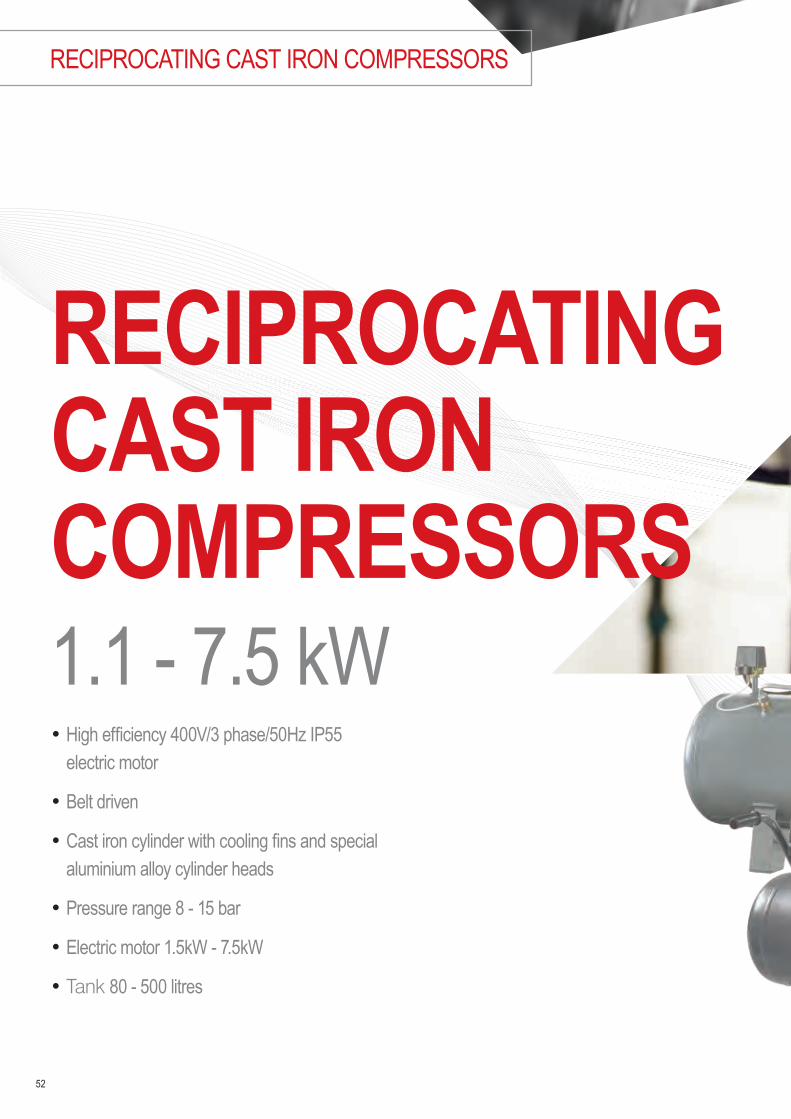
• High efficiency 400V/3 phase/50Hz IP55 electric motor
• Belt driven
• Cast iron cylinder with cooling fins and special aluminium alloy cylinder heads
• Pressure range 8 - 15 bar
• Electric motor 1.5kW - 7.5kW
• Tank 80 - 500 litres
RECIPROCATING CAST IRON COMPRESSORS
RECIPROCATING CAST IRON COMPRESSORS1.1 - 7.5 kW

53

Nominal Pressure 8 - 15 bar g
At a glance…
Motor Power 1.1 - 7.5 kW
Volume Flow 205 - 1657 l/min7.2 - 58.5 cfm
Power Sound level 68 - 82 dB(A)
TROUBLE FREE AND A LONG SERVICE LIFE
BroomWade, the smart and affordable compressed air solution, make available a range of reciprocating cast iron compressors. Trouble free and with a long service life, these can be used safely in many applications with single and double stage options. Choose from base plate or receiver mounted with 230 volt options on selected models.
54
RECIPROCATING CAST IRON COMPRESSORS
Main motor and drive system • High efficiency 400V/3 phase/50Hz IP55 electric motor• Special loadless start system• Automatic discharge system for loadless start• Belt Driven• Specially designed fan type pulleys• Easy tensioning of belt
Compressor block • Cast iron cylinder with cooling fins and special aluminium alloy
cylinder heads• Specially designed high-speed stainless steel concentric valves• Cast iron crankcases with high strength• Dynamically-balanced cast steel crankshaft and counterweight• Special alloy aluminium pistons and steel cast connecting rods• Specially designed finger-type, high-capacity stainless steel
suction-discharge valves• Stainless steel suction-discharge valves, specially designed for high
pressure strength
Safety systems• Solenoid discharge valve for loadless start (on models over 4 kW)• Pressure switch• Check valve• Belt pulley guard• Relief valve• Easy tensioning of belt
Other features• CE Certified air tanks complying with SPVD (Simple Pressure
Vessel Directive) and designed as per EN 286-1 standard• Bearings with a long service life• Air suction filter and silencer• Impact lubrication system• Starting panel (For 1.1 - 4 kW models)
Options• Automatic Condensate Discharge• Valve for the Air Tank• Star delta motor starting panel (5.5-7.5 kW models)

55
Belt Driven Cast Iron Compressors Lubricated Single & Three Phase Design: Belt Drive, single and three phase Pressure Range: 8 - 15 barTank: 80 - 500 Litres Capacity: 7.2 to 58.5 CFM
MODELPRESSURE CAPACITY MOTOR
POWER VOLT GAS DIMENSIONS WEIGHT TANKCODE
BAR PSI L/MIN SCFM KW HP V PORT W x L x H KG L
CPI-80-FM15 8 115 205 7.2 1.1 1.5 230 1/2” 1202 x 426 x 894 93 80 CC1197241CPI-80-FT15 8 115 205 7.2 1.1 1.5 400 1/2” 1202 x 426 x 894 93 80 CC1197240CPI-80-FT2 8 115 327 11.5 1.5 2 400 1/2” 1202 x 426 x 914 106 80 CC1197242CPI-80-FM2 8 115 327 11.5 1.5 2 230 1/2” 1202 x 426 x 914 106 80 CC1197243CPI-200-FT3 8 115 410 14.5 2.2 3 400 1/2” 1531 x 450 x 1037 135 200 CC1197284CPI-200-FM3 8 115 410 14.5 2.2 3 230 1/2” 1531 x 450 x 1037 135 200 CC1197285CPI-250-FT55 8 115 607 21.4 4 5.5 400 1/2” 1830 x 466 x 1145 209 250 CC1197286CPI-500-FT55 8 115 607 21.4 4 5.5 400 1/2” 1830 x 466 x 1145 209 500 CC1197287CPI-500-FT75 8 115 1013 35.8 5.5 7.5 400 3/4” 1927 x 664 x 1291 308 500 CC1197288CPI-500-FT10 8 115 1657 58.5 7.5 10 400 3/4” 1926 x 668 x 1413 390 500 CC1197289CPI-200-FM2-12 12 175 205 7.2 1.5 2 230 1/2” 1532 x 450 x 983 145 200 CC1197291CPI-200-FT2-12 12 175 205 7.2 1.5 2 400 1/2” 1532 x 450 x 983 145 200 CC1197290CPI-250-FT55-15 15 215 507 17.9 4 5.5 400 3/4” 1832 x 474 x 1097 230 250 CC1197292CPI-500-FT10-12 12 175 856 30.2 7.5 10 400 3/4” 1920 x 658 x 1298 374 500 CC1197293CPI-500-FT10-15 15 215 828 29.2 7.5 10 400 3/4” 1925 x 669 x 1406 439 500 CC1197294
Technical data
12 & 15 bar models are 2-stage pistonCPI-80 models are portable (wheels & handle)Star Delta Start standard on 10HP modelsStar Delta Start optional on 5.5 kW modelsBase Plate and bare pumps available

• Exceptional reliability• 2 year standard warranty• Sophisticated simple design• High quality air• No gears• Low noise levels• No belts• Direct drive
ROTARY VANE AIR COMPRESSORS
ROTARY VANE AIR
56

57

The right compressor for your business
ROTARY VANE AIR
ROTARY VANE AIR COMPRESSORS
Nominal Pressure 10 bar
At a glance…
Voltage 50 / 60Hz
Volume Flow 0.1 - 0.6 m3/min
58
Reliable by DesignDirect drive No gears. No belts. Up to 100,000+ operating hours due to its simple integral design.
High quality air Clean, dry and pulse free straight from the outlet means less downstream equipment required.
Slow speed 1450 - 1760 rpm speed operation results in low noise, low stresses and long life.
Common replacement parts Quick, cost-effective servicing, with minimal downtime.
Guaranteed2 years standard warranty is now available for total peace of mind on all BroomWade Vane models.
High quality starterA high quality starter with a robust control circuit, including over-temperature protection.
BroomWade Vanes can be combined with membrane dryers and aftercooler kits. (Both solutions are offered as retrofit kits or factory fitted).
The membrane dryer kits integrate perfectly with BroomWade vanes to provide a compact and efficient air drying and filtration solution. The Dryer kits include: Membrane dryer , after cooler, manual water drain, tap, 0.1 micron & 0.01 micron filters.
The after cooler kits are designed to efficiency cool the outlet air and to reduce moisture. The after cooler kits also include a manual drain tap.

Rotary Vane Air CompressorsDesign: Open - fixed speedPressure Range: 10 barElectric motor: 1.1 - 4kW
CODE MODEL VOLTAGE PHASE COMPRESSED AIR OUTPUT
MAX. WORKING PRESSURE
MOTOR POWER
NOISE LEVEL
DIMENSIONSL x W x H WEIGHT
AIR OUTLET
SIZE[m3/ min] [CFM] [bar (g)] [psi (g)] [kW] [dB(A)] [mm] [kg]
501PUTS10-4035D40C CMPV01 Tripod 400V /
50Hz 3 0.12 4.2 10 145 1.1 62 700 x 270 x 470 41 3/8‘‘ F-BSP
501PUTS10-2415D40C CMPV01 Tripod 230V /
50Hz 1 0.12 4.2 10 145 1.1 62 700 x 270 x 470 41 3/8‘‘ F-BSP
501PURS10-4035D40C
CMPV01 RM on a 75 Ltr Tank
400V / 50Hz 3 0.12 4.2 10 145 1.1 62 1,120 x 300 x 730 77 3/8‘‘ F-BSP
501PURS10-2415D40C
CMPV01 RM on a 75 Ltr Tank
230V / 50Hz 1 0.12 4.2 10 145 1.1 62 1,120 x 300 x 730 77 3/8‘‘ F-BSP
502PUTS10-4035D40C CMPV02 Tripod 400V /
50Hz 3 0.23 8.1 10 145 2.2 69 700 x 270 x 470 41 3/8‘‘ F-BSP
502PUTS10-2415D40C
CMPV02 Tripod
230V / 50Hz 1 0.23 8.1 10 145 2.2 69 700 x 270 x 470 41 3/8‘‘ F-BSP
502PURS10-4035D40C
CMPV02 RM on a 75 Ltr Tank
400V / 50Hz 3 0.23 8.1 10 145 2.2 69 1,120 x 300 x 730 77 3/8‘‘ F-BSP
502PURS10-2415D40C
CMPV02 RM on a 75 Ltr Tank
230V / 50Hz 1 0.23 8.1 10 145 2.2 69 1,120 x 300 x 730 77 3/8‘‘ F-BSP
504PURS10-4035D20C
CMPV04 RM on a 200 Ltr Tank
400V / 50Hz 3 0.57 20.1 10 145 4 73 1,410 x 455 x 990 145 1/2‘‘ F-BSP
SERVICE KITS DESCRIPTION C-AK0102 Annual service kit for CMPV01 / CMPV02C-AK04 Annual service kit for CMPV04C-OK0102 Maintenance kit for every 20000 hours or 5 years for CMPV01 / CMPV02C-OK04 Maintenance kit for every 20000 hours or 5 years for CMPV04CC1180033 ChampLube Vane lubricant 1 Ltr* (Box of 20 Available CC1180033-BOX)
AFTER COOLERS AND DRYERS FOR BROOMWADE VANES CODE DESCRIPTIONACA-501BD-PC Aftercooler & dryer kit for 501PURSACA-502BD-PC Aftercooler & dryer kit for 502PURSACA-504BD-300C Aftercooler & dryer kit for 504PURSACA-5-BC Aftercooler kit for 501PURS/502PURSACA-504-WEGC Aftercooler kit for 504PURS
* for CMPV04 2 litres needed. * Service intervals are defined by calendar months or operating hours, whichever occurs first. In dirty ambient conditions service interval must be halved.
59

• 100% oil-free design
• High reliability
• Continuous operation, 100% duty cycle
• Energy efficient
• Low vibration and sound levels
• Compact design
• Low maintenance due to less moving parts
S SERIES
60
100% OIL-FREE GUARANTEED PREMIUM OIL-FREE ROTARY SCROLL COMPRESSORS

61
100% OIL-FREE GUARANTEED PREMIUM OIL-FREE ROTARY SCROLL COMPRESSORS

Nominal Pressure 8 - 10 bar g
At a glance…
Motor Power 4 - 15kW
Volume Flow 21.2 - 106 m3/hr
62
SPECIALIST IN OIL-FREE TECHNOLOGIES
Cutting edge technology developmentCommitted to developing environmentally friendly solutions, we ensure that our customers meet the demands of climate change legislation - reducing their carbon footprints by cutting energy bills and simply operating more efficiently.
Contaminant free. Risk free. 100% Oil-freeCompressed air purity is crucial for many industry sectors, such as medical, research and biotechnology. The new S-Series of oil-free scroll compressors from BroomWade does not use any oil anywhere in the compressor and has been certified ISO 8573-1 Class 0 and silicone free, which represents the highest air quality level possible.In addition to the fulfilment of legal requirements, the oil-free scroll technology reduces the costs of ownership by avoiding oil filter replacements, oil condensate treatment and energy to combat the pressure loss caused by filtration.
Compressor configurationDepending on the application requirements, the versatile S-Series from BroomWade is available in various kW sizes. The scroll compressor range starts with Simplex units at 4, 6 and 8 kW and the Duplex units with 7, 11 and 15 kW. The compressor design features a very clean, simple and serviceable layout.
CLASS CONCENTRATION TOTAL OIL (AEROSOL, LIQUID, VAPOUR) MG/M3
0 As specified by the equipment user or supplier and more stringent than class 1
1 ≤ 0.012 ≤ 0.13 ≤ 14 ≤ 5
S SERIES

63
Industries with applications requiring oil-free air: • Transportation - traditional and hybrid trucks, transit buses, school buses and trains
• Medical/Healthcare - instrument air and breathing air
• Biotechnology - laboratory equipment
• Automotive - painting
• Food & Beverage
• Electronics
• Commercial Printing
• Drug Manufacture
Innovative designScroll compression explained• An orbiting (rotating) scroll and fixed scroll housing are mated to create
the compression chambers• The continual movement of the orbiting scroll moves atmospheric air
from the intake toward the center, compressing the air into progressively smaller areas
• The compressed air is directed to the center discharge port of the compressor
• Discharge pressure is accomplished during multiple stages of compression, resulting in a continuous intake suction and discharge
Fan ShroudDrive Pulley
Cooling Fan
Housing
Crank Pin
Crankshaft
Orbiting ScrollFixed Scroll
Compression
IntakeFixed Scroll
Orbiting Scroll
Outlet
Compressor Chamber
Suction Process
Compression Process
Discharging Process
AIR

64
S SERIES
Simplex
Duplex
1
2
3
4
5
6
7
9
8
10
3
4
6
7
8
9
10
Automatic Condensate Drain
Rigid Framework
5 Micron Inlet Filter
Fork Slots for Easy Handling
Unique Chambered Design - Maximised Cooling and Serviceability
Large Industrial Aftercoolers
Premium Efficient TEFC Motor
High Volume Cooling Fan
Low Noise Sound Enclosure
Internal Vibration Isolators
BroomWade S-Series
5
1
2

65
Controlling and monitoringThe S-Series from BroomWade is available with different controller options. The Simplex versions can be either equipped with the basic relay panel or optionally with the Deluxe HMI electronic controller.
The optional Deluxe HMI control from BroomWade has easy to use navigation and friendly graphics that deliver interactive and intuitive information at your fingertips. With a built in integral webserver, via ModBus TCP Ethernet connection, these controllers provide visibility to the scroll compressor system from any computer or mobile device with internet connection.
• NEMA 1, UL508A Labeled Panel• Magnetic Contactor with Overload Protection• 115V Control Circuit Transformer with Fusing• Door Mounted TOA Switch
• Green Power On Light• Emergency Stop• Reset Button• Run Time Meter• Pressure Gauge
Deluxe HMI• 3.5” Full Color Touch Screen• PLC Controlled• Lead/Lag Control with Forced Alternation• System Capacity and Operation Trending• 26 Language Options• 24V / DC Power Supply with Fusing
• System Run Time Meter• Alarm/Fault Log• System Discharge Pressure• Pump Discharge Temperature• System Maintenance Timers• Integral Webserver• Modbus TCP Interface over Ethernet

66
S4 – S8 Simplex Series: Oil free, Scroll compressorsDesign: 100% oil free, scroll compressor, direct drivePressure Range: from 8 to 10 barElectric motor: from 4 to 7.5kWS SERIES TYPE S4 S6 S8Maximum pressure bar 8 10 8 10 8 10Capacity1] m3/h 23.6 21.2 34.5 26.0 53.0 41.3Drive motor IP 55 / class F / IE3 kW 4 5.5 7.5Control voltage 24V • • •Acoustic enclosure • • •Air cooled • • •RS485:1 Module for ModBus-RTU remote monitoring • • •
230V 50 / 60 Hz / Std. (DOL) / Basic Relay ControlMAT. NO. SQ4-30A03C SQ4-30A04C SQ4-30A07C SQ4-30A08C SQ4-30A48C SQ4-30A49C
230 V 50 / 60 Hz / Std. (DOL) / Deluxe HMI electronic controllerMAT. NO. SQ4-30A05C SQ4-30A06C SQ4-30A09C SQ4-30A10C SQ4-30A50C SQ4-30A51C
400 V 50 / 60 Hz / Std. (DOL) / Basic Relay ControlMAT. NO. SQ4-30A11C SQ4-30A12C SQ4-30A58C SQ4-30A59C SQ4-30A62C SQ4-30A47C
400 V 50 / 60 Hz / Std. (DOL) / Deluxe HMI electronic controllerMAT. NO. SQ4-30A13C SQ4-30A14C SQ4-30A60C SQ4-30A61C SQ4-30A63C SQ4-30A64C
400 V 50 / 60 Hz / Soft Start / Basic Relay ControlMAT. NO. N/A N/A SQ4-30A15C SQ4-30A16C SQ4-30A19C SQ4-30A20C
400 V 50 / 60 Hz / Soft Start / Deluxe HMI electronic controllerMAT. NO. N/A N/A SQ4-30A17C SQ4-30A18C SQ4-30A21C SQ4-30A22C
1] Data measured and stated in accordance with ISO 1.217 Edition 4, Annex C & E at the following conditions: Air Intake Pressure 1 bar a / 14,5 psi; Air Intake Temperature 20° C / 68° F; Humidity 0 % (dry)
S7D – S15D Duplex Series: Oil free, Scroll compressorsDesign: 100% oil free, scroll compressor, direct drivePressure Range: from 8 to 10 barElectric motor: from 7 to 15kWS SERIES TYPE S7D S11D S15DMaximum pressure bar 8 10 8 10 8 10Capacity1] m3/h 47.2 42.5 69.0 52.0 106.0 82.6Drive motor IP 55 / class F / IE3 kW 7 11 15Control voltage 24V • • •Acoustic enclosure • • •Air cooled • • •RS485:1 Module for ModBus-RTU remote monitoring • • •
400 V 50 / 60 Hz / Std. (DOL) / Deluxe HMI electronic controllerMAT. NO. SQ4-30A23C SQ4-30A24C SQ4-30A65C SQ4-30A66C SQ4-30A67C SQ4-30A68C
400 V 50 / 60 Hz / Soft Start / Deluxe HMI electronic controllerMAT. NO. N/A N/A SQ4-30A25C SQ4-30A26C SQ4-30A27C SQ4-30A28C
1] Data measured and stated in accordance with ISO 1217 Edition 4, Annex C & E at the following conditions: Air Intake Pressure 1 bar a / 14,5 psi; Air Intake Temperature 20° C / 68° F; Humidity 0 % (dry)
SERVICE KITSMAT. ID DESCRIPTION 300SMB1445 Air filter kit (4kW x1, 6 & 8kW x2)300SIA6003 Service kit 6kW (includes tip seal, face seal & grease)301SIA6003 Service kit 7kW (includes tip seal, face seal & grease)300SMB6031 Grease gun

67
Notes

• 100% oil-free• Many variants including open frame,
silenced cabinet and membrane dryer• High reliability• Low noise levels• High air quality
68
DENTAL COMPRESSORS
OIL-FREE DENTAL COMPRESSORSReliabilty. Simplicity. Performance.

69
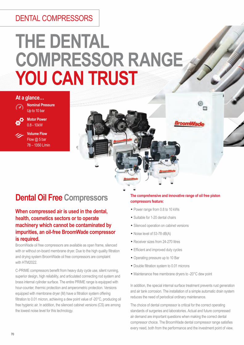
70
Dental Oil Free CompressorsWhen compressed air is used in the dental, health, cosmetics sectors or to operate machinery which cannot be contaminated by impurities, an oil-free BroomWade compressor is required.BroomWade oil free compressors are available as open frame, silenced with or without on-board membrane dryer. Due to the high quality filtration and drying system BroomWade oil free compressors are complaint with HTM2022.
C-PRIME compressors benefit from heavy duty cycle use, silent running, superior design, high reliability, and articulated connecting rod system and brass internal cylinder surface. The entire PRIME range is equipped with hour-counter, thermic protection and amperometric protection. Versions equipped with membrane dryer (M) have a filtration system offering filtration to 0.01 micron, achieving a dew point value of -20°C, producing oil free hygienic air. In addition, the silenced cabinet versions (CS) are among the lowest noise level for this technology.
The comprehensive and innovative range of oil free piston compressors feature:
• Power range from 0.8 to 10 kWs
• Suitable for 1-20 dental chairs
• Silenced operation on cabinet versions
• Noise level of 53-78 dB(A)
• Receiver sizes from 24-270 litres
• Efficient and improved duty cycles
• Operating pressure up to 10 Bar
• Double filtration system to 0.01 microns
• Maintenance free membrane dryers to -20°C dew point
In addition, the special internal surface treatment prevents rust generation and air tank corrosion. The installation of a simple automatic drain system reduces the need of periodical ordinary maintenance.
The choice of dental compressor is critical for the correct operating standards of surgeries and laboratories. Actual and future compressed air demand are important questions when making the correct dental compressor choice. The BroomWade dental compressor range satisfies every need, both from the performance and the investment point of view.
THE DENTAL COMPRESSOR RANGE YOU CAN TRUST
Nominal Pressure Up to 10 bar
At a glance…
Volume Flow Flow @ 5 bar78 – 1350 L/min
Motor Power 0.8 - 10kW
DENTAL COMPRESSORS

71
Technical dataC-Prime Open Frame: Oil free, Dental compressorsDesign: 100% oil-free, dental piston compressorsPressure Range: up to 10 bar
CODE MODEL CHAIRS FAD @ 5 BAR MOTOR POWER
NOISE LEVEL
DIMENSIONSL x W x H WEIGHT
[CFM] [L/ min] [HP] [kW] [V] [REC] [dB(A)] [mm] [kg]CC1189691 C-Prime 30-7 S 1 3.0 85 1 0.8 230 24 65 430 x 400 x 600 29CC1189692 C-Prime 50-15 S 3 6.0 170 2 1.5 230 40 66 600 x 410 x 770 46CC1189693 C-Prime 50-25 S 4 8.8 250 3 2.2 230 90 69 600 x 410 x 810 54CC1189714 C-Prime 100-30 Tandem S 6 12.0 340 4 3 230 90 69 1100 x 600 x 810 97CC1189715 C-Prime 100-50 Tandem S 8 17.6 500 6 4.4 400 90 69 1100 x 600 x 820 113CC1189716 C-Prime 200-75 Tandem S 10 25.4 750 9 6.6 400 200 72 1550 x 1000 x 1030 173CC1189717 C-Prime 270-100 Tandem S 15 31.6 900 13 10 400 270 75 1560 x 1000 x 1030 220CC1189718 C-Prime 500-150 Tandem S 20 47.4 1350 20 15 400 500 78 1980 x 780 x 1050 330
C-Prime Silenced Cabinet: Oil free, Dental compressorsDesign: 100% oil-free, dental piston compressorsPressure Range: up to 10 bar
CODE MODEL CHAIRS FAD @ 5 BAR MOTOR POWER
NOISE LEVEL
DIMENSIONSL x W x H WEIGHT
[CFM] [L/ min] [HP] [kW] [V] [REC] [dB(A)] [mm] [kg]CC1189719 C-Prime 30-15 CS 2 5.9 170 2 1.5 230 40 53 490 x 720 x 890 94CC1189720 C-Prime 50-25 CS 4 8.8 250 3 2.2 230 40 53 490 x 720 x 890 102CC1189721 C-Prime 100-30 Tandem CS 6 11.8 340 4 5 230 90 56 1245 x 725 x 1020 210CC1189722 C-Prime 100-50 Tandem CS 8 17.6 500 6 4.4 400 90 56 1245 x 725 x 1020 220
Models can be configurated to 10 Bar maximum pressure offering on average 33% lower FAD @ 8 Bar
Models can be configurated to 10 Bar maximum pressure offering on average 33% lower FAD @ 8 Bar

72
DENTAL COMPRESSORS
C-Prime Open Frame with Membrane Dryer: Oil free, Dental compressorsDesign: 100% oil-free, dental piston compressorsPressure Range: up to 10 bar
CODE MODEL CHAIRS FAD @ 5 BAR MOTOR POWER
NOISE LEVEL
DIMENSIONSL x W x H WEIGHT
[CFM] [L/ min] [HP] [kW] [V] [REC] [dB(A)] [mm] [kg]CC1189725 C-Prime 30-7 SM 1 2.8 78 1 0.75 230 24 65 500 x 470 x 600 36CC1189726 C-Prime 50-15 SM 3 5.4 152 2 1.5 230 40 66 710 x 410 x 770 50CC1189727 C-Prime 50-25 SM 4 7.9 225 3 2.2 230 40 66 710 x 410 x 810 58CC1189728 C-Prime 100-30 Tandem SM 5 10.8 305 4 3 230 90 69 1100 x 630 x 810 102CC1189729 C-Prime 100-50 Tandem SM 7 15.8 450 6 4.4 400 90 69 1100 x 630 x 820 118CC1189730 C-Prime 200-75 Tandem SM 9 23.0 660 9 6.6 400 200 72 1450 x 820 x 900 183CC1189731 C-Prime 270-100 Tandem SM 14 27.5 780 13 10 400 270 75 1560 x 1000 x 1030 240
C-Prime Silenced Cabinet with Membrane Dryer: Oil free, Dental compressorsDesign: 100% oil-free, dental piston compressorsPressure Range: up to 10 bar
CODE MODEL CHAIRS FAD @ 5 BAR MOTOR POWER
NOISE LEVEL
DIMENSIONSL x W x H WEIGHT
[CFM] [L/ min] [HP] [kW] [V] [REC] [dB(A)] [mm] [kg]CC1189732 C-Prime 30-15 CSM 2 5.4 152 2 1.5 230 40 53 490 x 720 x 890 98CC1189733 C-Prime 50-25 CSM 4 7.9 225 3 2.2 230 40 53 490 x 720 x 890 106CC1189744 C-Prime 100-30 Tandem CSM 5 10.8 305 4 3 230 90 56 1245 x 725 x 1020 215CC1189745 C-Prime 100-50 Tandem CSM 7 15.8 450 6 4.4 400 90 56 1245 x 725 x 1020 225
Models can be configurated to 10 Bar maximum pressure offering on average 33% lower FAD @ 8 Bar
Models can be configurated to 10 Bar maximum pressure offering on average 33% lower FAD @ 8 Bar

73
Notes

• Quick charging times• Safe operation• Various drive motors• Easy to use• High reliability• Including range of accessories
74
BREATHING AIR COMPRESSORS
BREATHING AIR COMPRESSORSVersatile. Reliable. Flexible.

7575

76
The Range of Breathing Air CompressorsBroomWade offer a range of breathing air and technical gas compressors from the small portable CBA6 series with a flow rate of 100 l/min and a pressure of 300 bars to the more powerful models for large refilling centres such as the CBA36 with a flow rate of 600 l/min and a maximum pressure of 330 bar. Compressors such as the CBA36 meet the needs of large refilling centres as it charges a 10 litre single-cylinder at 200 atmospheres in 3.3 minutes with noise levels as low as 75 dB(A). The range is compliant to EN 12021 CGA E.
BroomWade compressors are available with single and 3-phase electric motors as well as petrol or diesel engines. Additionally, BroomWade offer a series of important accessories, such as filling panels, transfer hoses, oxygen carbon dioxide and helium analysers, pressure reducers with safety valves and other useful accessories.
POWER RANGE: 2.2 to 11 kW
CAPACITY: 80 to 600 l/min
CHARGE TIME: 3 to 25 mins (based on charging a 10 litre cylinder)
PRESSURE: 232 to 330 bar
NOISE LEVEL: 70 to 96 dB(A)
VOLTAGE: 230 / 1 / 50 / 60, 400 / 3 / 50, 440 / 3 / 60
RELIABLE BREATHING AIR COMPRESSORS
Nominal Pressure 232 - 330 bar
At a glance…
Volume Flow 80 - 600 L/min
Motor Power 2.2 - 11kW
BREATHING AIR COMPRESSORS

77
Technical dataBreathing Air: CompressorsDesign: High pressure pistonPressure Range: 232 - 330 barg
CODE MODEL VARIANT VOLT CHARGE TIME
DIMENSIONSL x W x H
[kW] [HP] [L/min] [cfm] [Bar] [mm] [dB(A)] [kg]CC1189900 CBA 6 EM Open 230 2.2 3 80 2.8 232/300 25 min 650 x 350 x 390 91 39CC1189901 CBA 6 ET Open 400 3 4 100 3.5 232/300 20 min 650 x 350 x 390 95 39CC1189902 CBA 13 ET STANDARD Open 230 4 5.5 235 8.3 232/330 8min 30sec 880 x 480 x 640 77 117CC1189903 CBA 13 ET COMPACT Cabinet 230 4 5.5 235 8.3 232/330 8min 30sec 920 x 610 x 880 75 153CC1189904 CBA 16 ET STANDARD Open 400 5.5 7.5 315 11.1 232/330 6min 20sec 880 x 480 x 640 77 117CC1189905 CBA 16 ET COMPACT Cabinet 400 5.5 7.5 315 11.1 232/330 6min 20sec 920 x 610 x 880 75 163CC1189906 CBA 22 OPEN Open 400 7.5 10 400 14.1 232/330 5 min 790 x 1025 x 1545 76 415CC1189907 CBA 22 SILENCED Cabinet 400 7.5 10 400 14.1 232/330 5 min 800 x 1290 x 1740 70 420CC1189908 CBA 30 OPEN Open 400 9.2 12.5 500 17.7 232/330 4 min 790 x 1025 x 1545 76 415CC1189909 CBA 30 SILENCED Cabinet 400 9.2 12.5 500 17.7 232/330 4 min 800 x 1290 x 1740 70 420CC1189910 CBA 36 OPEN Open 400 11 15 600 21.2 232/330 3 min 790 x 1025 x 1545 76 415CC1189911 CBA 36 SILENCED Cabinet 400 11 15 600 21.2 232/330 3 min 800 x 1290 x 1740 70 420CC1189912 CBA 6 SH Open Honda 4 5.5 100 3.5 232/300 20 min 780 x 350 x 320 101 37CC1189913 CBA 13 SH MINI TECH Open Honda 6.3 8.4 235 8.3 232/330 8min 30sec 1130 x 540 x 640 96 135CC1189914 CBA 16 SH MINI TECH Open Honda 6.3 8.4 315 11.1 232/330 8min 30sec 1130 x 540 x 640 96 135CC1189915 CBA 13 DY MINI TECH Open Yanmar 6.6 9 235 8.3 232/330 6min 20sec 1130 x 540 x 640 96 135CC1189916 CBA 16 DY MINI TECH Open Yanmar 6.6 9 315 11.1 232/330 6min 20sec 1130 x 540 x 640 96 135
Breathing Air: Accessories
CODE MODEL
CC1189917 CBA 6 Auto Drain TimerCC1189918 CBA 6 Auto StopCC1189919 Safety Valve 330 BarCC1189920 Safety Valve 300 BarCC1189921 Safety Valve 225 BarCC1189922 CBA 6 - Air Filter CartridgeCC1189923 CBA 13-16 Intake Air Filter CartridgeCC1189924 CBA 22-36 hyperfilter Filter CartridgeCC1189925 CBA 22-36 + 13-18 Tropical Oil Filter CartridgeCC1189926 Breathing Compressor Oil 1/2LtCC1189927 Breathing Compressor Oil 1Lt
Other model variants and a wide range of additional accessories available

• Mobile compressed air solution
• Independent from power source
• Compact and lightweight
• Low emissions
• Easy to operate
• Energy efficient
CMP- SERIES
78
ONE STEP AHEAD PORTABLE SCREW COMPRESSORS
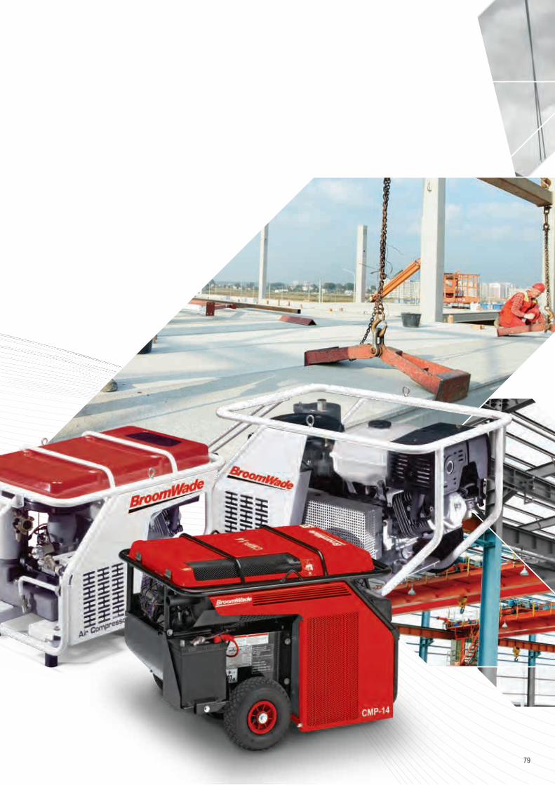
79

80
DESIGNED TO LAST
Compressor The BroomWade range of self-contained compressors uses lubricated screw air ends with high airflow. The progressive adjustment of the airflow constantly maintains an operating pressure between 7 and 8 bar, thus avoiding the use of a cumbersome air tank.
Protection The “ROLL BAR” system fully protects the compressor and facilitates maintenance. The anti-vibration pads provide excellent stability and limit vibration.
Thermic engine Our choice of HONDA petrol engines, known for their high reliability and excellent sound levels, guarantees the longevity of our compressors and a great ease of use. The engine speed is reduced automatically when the compressor is not stressed (control valve + pneumatic jack group).
Oil Separator Our compressors are equipped with an improved cooling system. Temperature control guarantees optimum longevity.
CMP- SERIES
Operating Pressure 6 - 7 bar g
At a glance…
Motor Power 6.3 - 8.7 kW
Volume Flow 0.8 - 1.2 m3/min
Portable CompressorsCMP Series P6 - B9 Design: Engine Driven Rotary Screw Pressure Range: 6 - 7 barPower Range: 9 - 13 HP Mobile Fuel Tank: 5.3 - 6.1 Litres
MODEL FLOW1) ADJUSTMENT PRESSURE3)
HONDA PETROL ENGINE
ELECTRIC START-UP BATTERY
INCLUDED
PROGRESSIVE ADJUSTMENT OF ENGINE SPEED
SOUND POWER LEVEL LwA2)
MOBILE FUEL TANK
DIMENSIONS WEIGHT CODE
L/M CFM m3/min BAR kW/HP MODEL RPM dB(A) LITRES MM KGCMP-P6R 800 28 0.8 6 6.3/9 GX 270 - 2500 - 3500 97 5.3 820x560x610 69 CC1198063CMP-P6 800 28 0.8 7 6.3/9 GX 270 Yes 2500 - 3500 97 5.3 820x560x610 79 CC1198074CMP-P7R 1200 42 1.2 7 8.7/13 GX 390 - 2400 - 3500 97 6.1 820x560x610 80 CC1198075CMP-P7 1200 42 1.2 7 8.7/13 GX 390 Yes 2400 - 3500 97 6.1 820x560x610 90 CC1198076CMP-P8R 800 28 0.8 6 6.3/9 GX 270 - 2500 - 3500 97 5.3 820x560x610 79 CC1198077CMP-P8 800 28 0.8 7 6.3/9 GX 270 Yes 2500 - 3500 97 5.3 820x560x610 89 CC1198078CMP-P9R 800 28 0.8 7 8.7/13 GX 390 - 2400 - 3500 97 6.1 820x560x610 100 CC1198079CMP-P9 1200 42 1.2 7 8.7/13 GX 390 Yes 2400 - 3500 97 6.1 820x560x610 110 CC1198080CMP-B8 800 28 0.8 7 6.3/9 GX 270 Yes 2500 - 3500 97 5.3 740x540x530 59 CC1198081CMP-B9 1200 42 1.2 7 8.7/13 GX 390 Yes 2500 - 3500 97 6.1 740x540x530 65 CC1198082
1) Flow according to CE standard 1217 Annex C. 2) Sound level according to EU 2000/14 Annexe 8. 3) Pressure of 9-12 bar available upon requestOption: Models P8-P9 - static version avaiable - kit consists of 4 AV mounts + 4 mounting plates for commercial vehicles

81
The CMP-Series is a powerful alternative to electrical tools Small, compact and lightweight, at only 165kg weight with 1.4 m³/min at 7 bar. Perfect for a wide-range of repair and installation jobs.
Electric Start as StandardEasy to start and flexible operation.
Honda GX 630VAir cooled petrol engine.
BroomWade Genuine PartsEnjoy complete peace of mind. Genuine BroomWade parts and lubricants ensure best performance and reliability is maintained.• Minimum losses contributing to energy savings• Long service life, even under
harsh conditions• High reliability
Operating Pressure 7 - 12 bar g
At a glance…
Motor Power 15.5kW
Volume Flow 1.0 - 1.4 m3/min
SERVICE KITS DESCRIPTIONS
CC1186378 600 hrs or 6 months compressor service kit C10-C14
CC1186379 Annual engine service kit C10-C14SCUO2000-5GT3 Lubricant (pack of 3 x 5L)
BroomWade codes relates to power sound level (LwA) of 97 decibels. Clearly mark on your order if the lower noise level of 93 decibels is required
CMP SERIES TYPE CMP-P10 CMP-P12 CMP-P14CODE A60141201 A60141001 A60140701 ENGINE HONDA GX630 HONDA GX630 HONDA GX630MOTOR POWER [KW] 15.5 15.5 15.5OPERATING PRESSURE
[bar g] 12 10 7[psi g] 174 145 102
VOLUME FLOW [m3/min] 1.4 1.8 1.8[cfm] 50 64 64
ENGINE SPEED OFF LOAD [rpm] 2200 - 3550
SOUND POWER LEVEL 1) [LwA] 97 (dB)
VOLUME FLOW [m3/min] 1.0 1.4 1.4[cfm] 35 50 50
ENGINE SPEED OFF LOAD/LOAD [rpm] 2200 - 2900
SOUND POWER LEVEL1) [LwA] 93 (dB)AIR OUTLET SIZE 1'' x 3/4''DIMENSIONS L X W X H [mm] 890 x 635 x 670WEIGHT (WITHOUT FUEL) [Kg] 150
1] Legal Limiting values of EC directive acc to 2000/14/EC

• Basic Principals• Air Filters• Cyclone Separators• Refrigeration Dryers• Adsorption Dryers• Air Receiver Tanks• Condensate Drains• Oil / Water Separators• Nitrogen Generators
COMPRESSED AIR TREATMENT
82
COMPRESSED AIR TREATMENT

83
Compressed air quality classes according to ISO 8573-1:2010
CLASS
SOLID PARTICLES HUMIDITY AND LIQUID WATER OILMAXIMUM NUMBER OF PARTICLES PER CUBIC METER
AS A FUNCTION OF PARTICLE SIZE, D2] PRESSURE DEW POINT CONCENTRATION OF TOTAL OIL2]
(LIQUID, AEROSOL AND VAPOUR)[0.1 μm < d ≤ 0.5 μm] [0.5 μm < d ≤ 1.0 μm] [1.0 μm < d ≤ 5.0 μm] [°C] [°F] [mg/m3] [ppm / w / w]
0 As specified by the equipment user or supplier and more stringent than class1]
1 ≤ 20,000 ≤ 400 ≤ 10 ≤ -70 -94 ≤ 0.01 ≤ 0.0082 ≤ 400,000 ≤ 6,000 ≤ 100 ≤ -40 -40 ≤ 0.1 ≤ 0.083 Not specified ≤ 90,000 ≤ 1,000 ≤ -20 -4 ≤ 1 ≤ 0.84 Not specified Not specified ≤ 10,000 ≤ +3 38 ≤ 5 ≤ 45 Not specified Not specified ≤ 100,000 ≤ +7 45 Not specified Not specified6 ≤ ±10 50
MASS CONCENTRATION2] - CP LIQUID WATER CONTENT2] - CW[mg/m3] [g/m3]
6 0 < Cp ≤ 5 Not specified Not specified7 5 < Cp ≤ 10 CW ≤ 0.5 Not specified Not specified8 Not specified 0.5 ≤ CW ≤ 5 Not specified Not specified9 Not specified Not specified Not specifiedX Cp > 10 > 5 > 4
1] To qualify for a class designation, each size range and particle number within a class shall be met. 2] At reference conditions: air temperature of 20° C, absolute air pressure of 100 kPa (1 bar), 0 relative water vapour pressure.

1. Compressor: The basic working principle of an air compressor is to compress atmospheric air, which is then used as per the requirements. In the process, atmospheric air is drawn in through an intake valve; more and more air is pulled inside a limited space mechanically by means of piston, impeller, or vane. Since the amount of pulled atmospheric air is increased in the receiver or storage tank, volume is reduced and pressure is raised automatically. In simpler terms, free or atmospheric air is compressed after reducing its volume and at the same time, increasing its pressure.BroomWade can provide many types of compressor to suit your needs.
2. Cyclone condensate separator: Cyclone condensate separators use centrifugal motion to force liquid water out of compressed air. The spinning causes the condensate to join together on the centrifugal separators walls when the condensate gains enough mass it falls to the bottom of the separators bowl where it pools in the sump until it is flushed out of the system by the automatic float drain valve. They are installed following aftercoolers to remove the condensed moisture.
3. Pressure vessel: Pressure vessel plays very important role in compressed air system:• Damping pulsations caused by reciprocating compressors• Providing a location for free water and lubricant to settle from the compressed air stream• Supplying peak demands from stored air without needing to run an extra compressor• Reducing load/unload or start/stop cycle frequencies to help screw compressors run more efficiently and reduce motor starts• Slowing system pressure changes to allow better compressor control and more stable system pressures
4. Compressed air dryer : Compressed air leaving the compressor aftercooler and moisture separator is normally warmer than the ambient air and fully saturated with moisture. As the air cools the moisture will condense in the compressed air lines. Excessive entrained moisture can result in undesired pipe corrosion and contamination at point of end use. For this reason some sort of air dryer is normally required.Some end use applications require very dry air, such as compressed air distribution systems where pipes are exposed to winter conditions. Drying the air to dew points below ambient conditions is necessary to prevent ice buildup. Common types:• Refrigerant • Dessicant • Membrane
BASIC PRINCIPLES OF MOST TYPICAL COMPRESSED AIR APPLICATION
4
P M
MAX PRESS: 16 BAR
MAX TEMP: 65°C BAR
PROD. YEAR: 2013
MAX PRESS: 16 BAR
MAX TEMP: 65°C BAR
PROD. YEAR: 2013
MAX PRESS: 16 BAR
MAX TEMP: 65°C BAR
PROD. YEAR: 2013
1 1
5 5
2 23
5
55
5
6 6
COMPRESSED AIR TREATMENT
84

5. Condensate drain: Drains are needed at all separators, filters, dryers and receivers in order to remove the liquid condensate from the compressed air system. Failed drains can allow slugs of moisture to flow downstream that can overload the air dryer and foul end use equipment.
6. Filter: Compressed air filters are used for high efficient removal of solid particles, water, oil aerosols, hydrocarbons, odour and vapours from compressed air systems. To meet the required compressed air quality appropriate filter element must be installed into filter housing.
7. Activated carbon tower: Activated carbon tower eliminates hydrocarbon vapours and odours from compressed air. Towers are filled with activated carbon adsorbent that adsorbs contaminants onto the surface of its internal pores. Activated carbon towers are used at applications where content of oil vapours needs to be reduced to minimum.Activated carbon towers can be incorporated in existing compressed air systems significantly minimising the risks of contamination.They are able to absorb oil carry-over (both liquid and vapour) to provide the plant with technically oil-free compressed air.
8. Oil/water separator: Local environmental laws and regulations state that condensate drained from compressed air systems cannot be returned to the sewage system due to the content of compressor lubricating oil. Water/oil separators are one of the most efective and economical solution. Multi-stage separation process using oleophilic filters and activated carbon, ensures exceptional performance and trouble free operation.
9. Nitrogen generator: The nitrogen generators extract the available nitrogen in the ambient air from the other gases by applying the Pressure Swing Adsorption (PSA) technology. During the PSA process compressed, cleaned ambient air is led to a molecular sieve bed, which allows the nitrogen to pass through as a product gas, but adsorbs other gases.
End user advice • Replace inappropriate end use applications with efficient models (vortex nozzles, atomizers)• Install a flow controller to lower plant pressure and reduce artificial demand caused by higher than required pressures• Turn off air consuming equipment, using electric solenoids or manual shutoff valves• Avoid operation of air tools without a load, as this consumes more air than a tool under load• Replace worn tools, as they often require higher pressure and consume excess compressed air than tools in good shape• Lubricate air tools as recommended by the manufacturer. Keep air
used by all end uses free of condensate in order to maximize tool life and effectiveness
• Where possible and practical, group end use air equipment that has similar air requirements of pressure and air quality
MSMAX PRESS: 16 BAR
MAX TEMP: 65°C BAR
PROD. YEAR: 2013
MAX PRESS: 16 BAR
MAX TEMP: 65°C BAR
PROD. YEAR: 2013
MAX PRESS: 16 BAR
MAX TEMP: 65°C BAR
PROD. YEAR: 2013
45
6
8
7
6
MAX PRESS: 16 BAR
MAX TEMP: 65 °C BAR
PROD. YEAR: 2013
M
Nitrogen line
N-GE
N9
85

MCD SAC 70 SAC 120
SAC 160 ECD 15B EMD12
F filter housings are designed for high efficient removal of solid particles, water, oil aerosols, hydrocarbons, odour and vapours from compressed air(1) systems. To meet the required compressed air quality appropriate filter element (P, M S, A) must be installed into filter housing.(1) For any other technical gas please contact producer or your local distributor.
Float drain provided as standard
IED
SG
P (3 μm) M (0,1 μm) S (0,01 μm) A act. carbon
EPG60MDA60MDM60 series
Applications• General industrial applications• Automotive• Electronics• Food and beverage
• Chemical• Petrochemical• Plastics• Paint
F SERIES ALUMINUM COMPRESSED AIR FILTERS
WS/WM 2S, 3S, 2M, 3M AK
At a glance…Operating Pressure 16 bar
Volume Flow 60 - 2760 Nm3/h
Connections 3/8″ - 3″
Operating Temp. Range 1.5 - 65°C
COMPRESSED AIR FILTERS
86

P PREFILTER [3 µm]
FILTER HOUSING1)
PART NUMBER
MAX. OPERAT. PRESSURE
FLOW RATE AT 7 bar(g), 20 °C DIMENSONS [mm] WEIGHT FILTER ELEMENT
[bar / psi] [Nm3/h] [scfm] A B C D [kg]F 005 P 223051A 16 / 232 60 35 187 88 20 60 0.7 223171F 007 P 223052A 16 / 232 78 46 187 88 20 60 0.7 223172F 010 P 223053A 16 / 232 120 70 257 88 20 80 0.8 223173F 018 P 223054A 16 / 232 198 116 263 125 32 100 1.8 223174F 030 P 223055A 16 / 232 335 197 363 125 32 120 2.5 223175F 047 P 223056A 16 / 232 510 300 461 125 32 140 2.5 223176F 070 P 223057A 16 / 232 780 459 640 125 32 160 3.2 223177F 094 P 223058A 16 / 232 1000 588 684 163 43 520 5.1 223178F 150 P 223059A 16 / 232 1500 882 935 163 43 770 7.1 223179F 200 P CC1182427 16 / 232 2160 1270 795 240 59 630 12.9 CC1183012F 240 P 223060A 16 / 232 2760 1620 1,000 240 59 780 14.0 223180
QUALITY CLASS - SOLIDS
[ISO 8573-1]
RESIDUAL OIL
CONTENT [mg/m3]
QUALITY CLASS -
OILS [ISO 8573-1]
PRESSURE DROP - NEW
ELEMENT [mbar/psi]
CHANGE FILTER ELEM. AT PRESS. DROP [mbar/psi]
FILTER MATERIAL
PLEATED VERSION
WRAPPED VERSION
SINTERED VERSION
OPERATING TEMPERATURE
MIN MAX
6 - - 10 / 0.145 350 / 5.07 acrylic fibres, cellulose - - 1.5 / 35 65 / 149
1) Standard filters with screw connections. Flange version only upon request.
87

QUALITY CLASS - SOLIDS
[ISO 8573-1]
RESIDUAL OIL
CONTENT [mg/m3]
QUALITY CLASS -
OILS [ISO 8573-1]
PRESSURE DROP - NEW
ELEMENT [mbar/psi]
CHANGE FILTER ELEM. AT PRESS. DROP [mbar/psi]
FILTER MATERIAL
PLEATED VERSION
WRAPPED VERSION
SINTERED VERSION
OPERATING TEMPERATURE
MIN MAX
2 <0.01 2 50/0.725 350/5.07 borosilicate micro fibres - - 1.5 / 35 65 / 149
QUALITY CLASS - SOLIDS
[ISO 8573-1]
RESIDUAL OIL
CONTENT [mg/m3]
QUALITY CLASS -
OILS [ISO 8573-1]
PRESSURE DROP - NEW
ELEMENT [mbar/psi]
CHANGE FILTER ELEM. AT PRESS. DROP [mbar/psi]
FILTER MATERIAL
PLEATED VERSION
WRAPPED VERSION
SINTERED VERSION
OPERATING TEMPERATURE
MIN MAX
2 <0.1 2 50 / 0.725 350 / 5.07 borosilicate micro fibres - - 1.5 / 35 65 / 149
R MICROFILTER [1 µm]
FILTER HOUSING
PART NUMBER
MAX. OPERAT. PRESSURE
FLOW RATE AT 7 bar(g), 20 °C DIMENSONS [mm] WEIGHT FILTER ELEMENT
[bar/psi] [Nm3/h] [scfm] A B C D [kg]F 005 R CC1185088 16 / 232 60 35 187 88 20 60 0.7 CC1185073F 007 R CC1185089 16 / 232 78 46 187 88 20 60 0.7 CC1185074F 010 R CC1185090 16 / 232 120 70 257 88 20 80 0.8 CC1185075F 018 R CC1185091 16 / 232 198 116 263 125 32 100 1.8 CC1185076F 030 R CC1185092 16 / 232 335 197 363 125 32 120 2.5 CC1185077F 047 R CC1185093 16 / 232 510 300 461 125 32 140 2.5 CC1185078F 070 R CC1185094 16 / 232 780 459 640 125 32 160 3.2 CC1185079F 094 R CC1185095 16 / 232 1000 588 684 163 43 520 5.1 CC1185080F 150 R CC1185096 16 / 232 1500 882 935 163 43 770 7.1 CC1185081F 200 R CC1185097 16 / 232 2160 1270 795 240 59 630 12.9 CC1185082F 240 R CC1185098 16 / 232 2760 1620 1000 240 59 780 14 CC1185083
M MICROFILTER [0.1 µm]
FILTER HOUSING
PART NUMBER
MAX. OPERAT. PRESSURE
FLOW RATE AT 7 bar(g), 20 °C DIMENSONS [mm] WEIGHT FILTER ELEMENT
[bar/psi] [Nm3/h] [scfm] A B C D [kg]F 005 M 223061A 16 / 232 60 35 187 88 20 60 0.7 223181F 007 M 223062A 16 / 232 78 46 187 88 20 60 0.7 223182F 010 M 223063A 16 / 232 120 70 257 88 20 80 0.8 223183F 018 M 223065A 16 / 232 198 116 263 125 32 100 1.8 223184F 030 M 223066A 16 / 232 335 197 363 125 32 120 2.5 223185F 047 M 223067A 16 / 232 510 300 461 125 32 140 2.5 223186F 070 M 223068A 16 / 232 780 459 640 125 32 160 3.2 223187F 094 M 223069A 16 / 232 1000 588 684 163 43 520 5.1 223188F 150 M 223081A 16 / 232 1500 882 935 163 43 770 7.1 223189F 200 M CC1182428 16 / 232 2160 1270 795 240 59 630 12.9 CC1183034F 240 M 223064A 16 / 232 2760 1620 1,000 240 59 780 14.0 223190
COMPRESSED AIR FILTERS
88

S MICROFILTER [0.01 µm]
FILTER HOUSING
PART NUMBER
MAX. OPERAT. PRESSURE
FLOW RATE AT 7 bar(g), 20 °C DIMENSONS [mm] WEIGHT FILTER ELEMENT
[bar/psi] [Nm3/h] [scfm] A B C D [kg]F 005 S 223070A 16 / 232 60 35 187 88 20 60 0.7 223191F 007 S 223071A 16 / 232 78 46 187 88 20 60 0.7 223192F 010 S 223072A 16 / 232 120 70 257 88 20 80 0.8 223193F 018 S 223073A 16 / 232 198 116 263 125 32 100 1.8 223194F 030 S 223074A 16 / 232 335 197 363 125 32 120 2.5 223195F 047 S 223075A 16 / 232 510 300 461 125 32 140 2.5 223196F 070 S 223076A 16 / 232 780 459 640 125 32 160 3.2 223197F 094 S 223077A 16 / 232 1000 588 684 163 43 520 5.1 223198F 150 S 223078A 16 / 232 1500 882 935 163 43 770 7.1 223199F 200 S CC1182429 16 / 232 2160 1270 795 240 59 630 12.9 CC1183035F 240 S 223079A 16 / 232 2760 1620 1,000 240 59 780 14.0 223200
A ACTIVATED CARBON
FILTER HOUSING
PART NUMBER
MAX. OPERAT. PRESSURE
FLOW RATE AT 7 bar(g), 20 °C DIMENSONS [mm] WEIGHT FILTER ELEMENT
[bar/psi] [Nm3/h] [scfm] A B C D [kg]F 005 A 223090A 16 / 232 60 35 187 88 20 60 0.7 223211F 007 A 223091A 16 / 232 78 46 187 88 20 60 0.7 223212F 010 A 223092A 16 / 232 120 70 257 88 20 80 0.8 223213F 018 A 223093A 16 / 232 198 116 263 125 32 100 1.8 223214F 030 A 223094A 16 / 232 335 197 363 125 32 120 2.5 223215F 047 A 223095A 16 / 232 510 300 461 125 32 140 2.5 223216F 070 A 223096A 16 / 232 780 459 640 125 32 160 3.2 223217F 094 A 223097A 16 / 232 1000 588 684 163 43 520 5.1 223218F 150 A 223098A 16 / 232 1500 882 935 163 43 770 7.1 223219F 200 A CC1182430 16 / 232 2160 1270 795 240 59 630 12.9 CC1183036F 240 A 223099A 16 / 232 2760 1620 1,000 240 59 780 14.0 223220
CORRECTION FACTORSOPERATING PRESSURE [bar] 2 3 4 5 6 7 8 9 10 11 12 13 14 15 16OPERATING PRESSURE [psi] 29 44 58 72 87 100 115 130 145 160 174 189 203 218 232CORRECTION FACTOR 0.38 0.50 0.63 0.75 0.88 1 1.13 1.25 1.38 1.50 1.63 1.75 1.88 2.00 2.13
1] Filter elements ’’A’’, must be changed periodically to suit application, but at least every 6 months. Activated carbon filters must not operate in oil saturated conditions. 2] Valid if ''S'' filter cartridge is installed upstream.NOTE: For port sizes please refer to pages 135 and 136.
QUALITY CLASS - SOLIDS
[ISO 8573-1]
RESIDUAL OIL
CONTENT [mg/m3]
QUALITY CLASS -
OILS [ISO 8573-1]
PRESSURE DROP - NEW
ELEMENT [mbar/psi]
CHANGE FILTER ELEM. AT PRESS. DROP [mbar/psi]
FILTER MATERIAL
PLEATED VERSION
WRAPPED VERSION
SINTERED VERSION
OPERATING TEMPERATURE
MIN MAX
1 <0.01 1 80 / 1.160 350 / 5.07 borosilicate micro fibres - - 1.5 / 35 65 / 149
QUALITY CLASS - SOLIDS
[ISO 8573-1]
RESIDUAL OIL
CONTENT [mg/m3]
QUALITY CLASS -
OILS [ISO 8573-1]
PRESSURE DROP - NEW
ELEMENT [mbar/psi]
CHANGE FILTER ELEM. AT PRESS. DROP [mbar/psi]
FILTER MATERIAL
PLEATED VERSION
WRAPPED VERSION
SINTERED VERSION
OPERATING TEMPERATURE
MIN MAX
12] <0.005 1 60 / 0.870 6 months1]borosilic.
micro fibres, act. carbon
- - 1.5 / 35 65 / 113
89

F-W SERIES ALUMINIUM CYCLONE CONDENSATE SEPARATORS
FILTER HOUSING
PART NUMBER
MAX.OPER. PRESSURE
FLOW RATE AT 7 bar(g), 20 °C
TEMPERATUREOPERATING RANGE DIMENSIONS [mm] WEIGHT FILTER
ELEMENT[bar/psi] [Nm3/h] [SCFM] [°C] [°F] A B C D [kg]
F 05 W CC1177720 16 / 232 60 35 1.5 - 65 35 - 149 187 88 20 60 0.7 CC1188141F 07 W CC1177721 16 / 232 78 46 1.5 - 65 35 - 149 187 88 20 60 0.7 CC1188142F 010 W 223101A 16 / 232 120 70 1.5 - 65 35 - 149 257 88 20 80 0.8 CC1183037F 030 W 223102A 16 / 232 198 116 1.5 - 65 35 - 149 263 125 32 100 1.8 CC1183038F 070 W 223103A 16 / 232 510 300 1.5 - 65 35 - 149 461 125 32 140 2.5 CC1183039F 094 W CC1181853 16 / 232 1000 588 1.5 - 65 35 - 149 684 163 43 520 5.1 CC1183040F 150 W 223104A 16 / 232 1500 882 1.5 - 65 35 - 149 684 163 43 520 5.1 CC1183041F 200 W CC1182432 16 / 232 2160 1270 1.5 - 65 35 - 149 795 240 59 630 12.9 CC1183042
EMD12ECD 15B
SAC 160
SAC 120SAC 70
CORRECTION FACTORSOPERATING PRESSURE [bar] 2 3 4 5 6 7 8 9 10 11 12 13 14 15 16OPERATING PRESSURE [psi] 29 44 58 72 87 100 115 130 145 160 174 189 203 218 232CORRECTION FACTOR 0.38 0.50 0.63 0.75 0.88 1 1.13 1.25 1.38 1.50 1.63 1.75 1.88 2.00 2.13
At a glance…Operating Pressure 16 bar
Volume Flow 60 - 2160 Nm3/h
Connections 3/8″ - 3″
Operating Temp. Range 1.5 - 65°C
F-W condensate separators are designed for high efficient removal of bulk liquids from compressed air and vacuum systems. Inside the housing there is an insert with vanes that creates controlled rotation of the air. As a result of centrifugal action liquids (water, oil) and large particles are forced to the housing wall, slowed down and accumulated at the bottom of separator housing as condensate. The turbulent free zone in the lower part of the filter housing prevents condensate from being picked up and “carried over” into the airstream.
QUALITY CLASS - SOLIDS [ISO 8573-1] -QUALITY CLASS - WATER [ISO 8573-1] 8
QUALITY CLASS - OILS [ISO 8573-1] -EFFICIENCY >98%
B
C
AD R 1/2″
To discharge condensate from the F-W cyclone separator it is essential to install automatic or electronic condensate drain.
90
CONDENSATE SEPARATORS

Differential pressure indicators & accessories
WS/WM WALL MOUNTING KIT FOR FILTERS
AK ASSEMBLY KIT FOR FILTERS
2S, 3S, 2M, 3M ASSEMBLY KIT FOR FILTERSPDI 16 DIFFERENTIAL PRESS. INDICATOR
MDM 60 DIFFERENTIAL PRESS. INDICATOR
SG SIGHT GLASSMDA60 DIFFERENTIAL PRESS. INDICATOR
EPG 60 DIFFERENTIAL PRESS. INDICATOR
OPERAT. PRESS. RANGE 0 - 16 bar [0 - 232 psi]
OPERAT. TEMP. RANGE 1.5 - 65°C [35 - 149°F]
MASS 0.33 kgMEASURING RANGE 0 - 0.9 bar [0 - 13 psi]DIMENSIONS [L x B x H] φ40 x 35 mmPART NUMBER CC1183801
OPERAT. PRESS. RANGE 0 - 16 bar [0 - 232 psi]OPERAT. TEMP. RANGE 1.5 - 65°C [35 - 149°F]MASS 0.15 kgMEASURING RANGE 0.9 bar [13 psi]DIMENSIONS [L x B x H] 72 x 64 x 68 mmPART NUMBER CC1032412
TYPE SGOPERATING PRESSURE 0 - 16 bar [0 - 232 psi]OPERATING TEMPERATURE 1.5 - +65°C [35 - 149°F]OPERATING FLUID Air, water, oilMATERIAL PA12DIMENSIONS [mm] 59.0 x 20.5 x 11.0PART NUMBER CC1183816
OPERAT. PRESS RANGE 0 - 20 bar [0 - 290 psi]OPERAT. TEMP. RANGE 1.5 - 65°C [35 - 149°F]MASS 0.36 kgMEASURING RANGE 2 bar [29 psi]DIMENSIONS [LxBxH] 84 x ø80 x 78 mmPART NUMBER CC1151396
EPGSERVICE NETWORK CONNEC. no
SYSTEM PRESS. RANGE 0 - 16 bar [0 - 232 psi]
DIFFERENTIAL PRESS. RANGE 0.07 - 1.00 bar
MAX. DIFFERENTIAL PRESS. 1 bar [14.7 psi]
AMBIENT OPER. TEMP. 1.5°C - 40°CCOMPR. AIR OPER. TEMP. 1.5°C - 65°C
MASS 130 g (without batt.)DIMENSIONS [LxBxH] 61.5 x 81 x 62 mmPART NUMBER CC1183799
TYPE WS WSFITS TO FILTER HOUSINGS F005 – F010 F018 – F070
OPERATING TEMP. -20 - +120°C [-4 - 248°F]MAX. LOAD/CONSOLE 6 kg 15 kgMASS [kg] 0.35 0.6MATERIAL Stainless steelPART NUMBER CC1183818 CC1183820
TYPE CONNEC. OPERAT. TEMP.
OPERAT. PRESS.
MAX. LOAD/CONSOLE
PART NUMBER
AK 3/8″ 3/8″ 1.5 - 65°C 0 - 20 bar 0.47 CC1183821AK 1/2″ 1/2″ 1.5 - 65°C 0 - 20 bar 0.47 CC1169902AK 3/4″ 3/4″ 1.5 - 65°C 0 - 20 bar 0.47 CC1151673AK 1″ 1″ 1.5 - 65°C 0 - 20 bar 0.47 CC1166431AK 1 1/2″ 1 1/2″ 1.5 - 65°C 0 - 20 bar 0.47 CC1183822AK 2″ 2″ 1.5 - 65°C 0 - 20 bar 0.47 CC1166432AK 2 1/2″ 2 1/2″ 1.5 - 65°C 0 - 20 bar 0.47 CC1183824AK 3″ 3″ 1.5 - 65°C 0 - 20 bar 0.47 CC1166433
CONSOLE TYPE
FOR FILTER TYPE
PART NUMBER
2S 2 x F005 to F010 CC1183802
3S 3 x F005 to F010 CC1183803
2M 2 x F018 to F070 CC1183814
3M 3 x F018 to F070 CC1183815
To discharge condensate from the F-W cyclone separator it is essential to install automatic or electronic condensate drain.
91
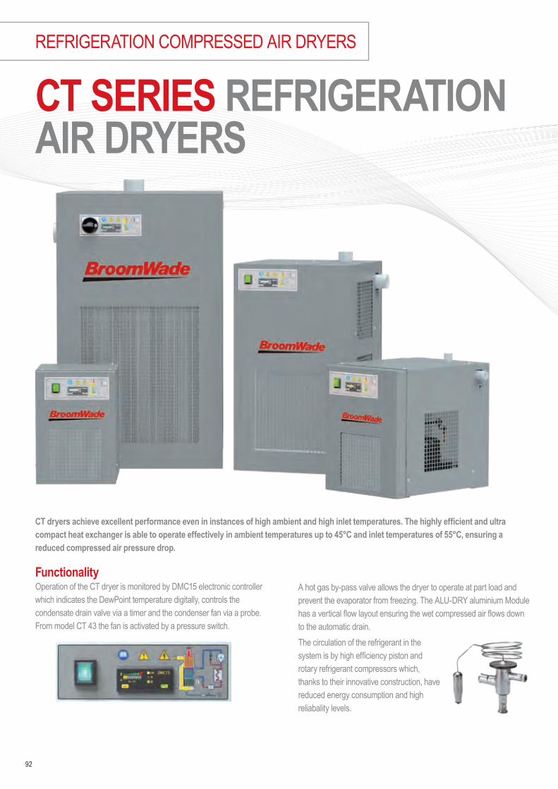
CT SERIES REFRIGERATION AIR DRYERS
FunctionalityOperation of the CT dryer is monitored by DMC15 electronic controller which indicates the DewPoint temperature digitally, controls the condensate drain valve via a timer and the condenser fan via a probe. From model CT 43 the fan is activated by a pressure switch.
A hot gas by-pass valve allows the dryer to operate at part load and prevent the evaporator from freezing. The ALU-DRY aluminium Module has a vertical flow layout ensuring the wet compressed air flows down to the automatic drain.The circulation of the refrigerant in the system is by high efficiency piston and rotary refrigerant compressors which, thanks to their innovative construction, have reduced energy consumption and high reliabality levels.
CT dryers achieve excellent performance even in instances of high ambient and high inlet temperatures. The highly efficient and ultra compact heat exchanger is able to operate effectively in ambient temperatures up to 45°C and inlet temperatures of 55°C, ensuring a reduced compressed air pressure drop.
92
REFRIGERATION COMPRESSED AIR DRYERS
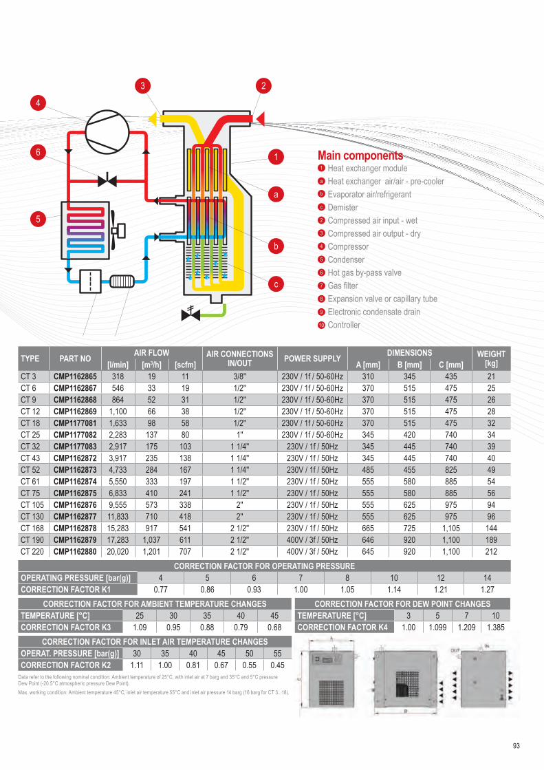
CORRECTION FACTOR FOR OPERATING PRESSUREOPERATING PRESSURE [bar(g)] 4 5 6 7 8 10 12 14CORRECTION FACTOR K1 0.77 0.86 0.93 1.00 1.05 1.14 1.21 1.27
TYPE PART NO AIR FLOW AIR CONNECTIONS IN/OUT POWER SUPPLY DIMENSIONS WEIGHT
[kg][l/min] [m3/h] [scfm] A [mm] B [mm] C [mm]CT 3 CMP1162865 318 19 11 3/8'' 230V / 1f / 50-60Hz 310 345 435 21CT 6 CMP1162867 546 33 19 1/2'' 230V / 1f / 50-60Hz 370 515 475 25CT 9 CMP1162868 864 52 31 1/2'' 230V / 1f / 50-60Hz 370 515 475 26CT 12 CMP1162869 1,100 66 38 1/2'' 230V / 1f / 50-60Hz 370 515 475 28CT 18 CMP1177081 1,633 98 58 1/2'' 230V / 1f / 50-60Hz 370 515 475 32CT 25 CMP1177082 2,283 137 80 1'' 230V / 1f / 50-60Hz 345 420 740 34CT 32 CMP1177083 2,917 175 103 1 1/4'' 230V / 1f / 50Hz 345 445 740 39CT 43 CMP1162872 3,917 235 138 1 1/4'' 230V / 1f / 50Hz 345 445 740 40CT 52 CMP1162873 4,733 284 167 1 1/4'' 230V / 1f / 50Hz 485 455 825 49CT 61 CMP1162874 5,550 333 197 1 1/2'' 230V / 1f / 50Hz 555 580 885 54CT 75 CMP1162875 6,833 410 241 1 1/2'' 230V / 1f / 50Hz 555 580 885 56CT 105 CMP1162876 9,555 573 338 2'' 230V / 1f / 50Hz 555 625 975 94CT 130 CMP1162877 11,833 710 418 2'' 230V / 1f / 50Hz 555 625 975 96CT 168 CMP1162878 15,283 917 541 2 1/2'' 230V / 1f / 50Hz 665 725 1,105 144CT 190 CMP1162879 17,283 1,037 611 2 1/2'' 400V / 3f / 50Hz 646 920 1,100 189CT 220 CMP1162880 20,020 1,201 707 2 1/2'' 400V / 3f / 50Hz 645 920 1,100 212
Data refer to the following nominal condition: Ambient temperature of 25°C, with inlet air at 7 barg and 35°C and 5°C pressure Dew Point (-20.5°C atmospheric pressure Dew Point). Max. working condition: Ambient temperature 45°C, inlet air temperature 55°C and inlet air pressure 14 barg (16 barg for CT 3...18).
4
6
5
3 2
a
b
c
1Heat exchanger moduleHeat exchanger air/air - pre-cooler Evaporator air/refrigerantDemisterCompressed air input - wetCompressed air output - dryCompressorCondenserHot gas by-pass valveGas filterExpansion valve or capillary tubeElectronic condensate drainController
Main components1
a
b
c
2
3
4
5
6
7
8
9
10
CORRECTION FACTOR FOR AMBIENT TEMPERATURE CHANGESTEMPERATURE [°C] 25 30 35 40 45CORRECTION FACTOR K3 1.09 0.95 0.88 0.79 0.68
CORRECTION FACTOR FOR INLET AIR TEMPERATURE CHANGESOPERAT. PRESSURE [bar(g)] 30 35 40 45 50 55CORRECTION FACTOR K2 1.11 1.00 0.81 0.67 0.55 0.45
CORRECTION FACTOR FOR DEW POINT CHANGESTEMPERATURE [°C] 3 5 7 10CORRECTION FACTOR K4 1.00 1.099 1.209 1.385
93

Applications• Compressed air systems
CHA-DRY SERIES HEATLESS ADSORPTION DRYERS
CHA-DRY desiccant adsorption dryer has been designed to separate water moisture from compressed air thus reducing the dew point in the system. CHA-DRY is a range of products offering our customers a wide array of dried air solutions with volumetric flow rates ranging from 6 to 600 Nm3/h.An innovative new design of CHA-DRY adsorption dryers, developed with consideration of our customers, enables fast and reliable installation, use and servicing. Installation is simple with our ready to use controller while minimising the number of parts and motions required for assembly and disassembly makes servicing fast and reliable.Filtration included as standard
At a glance…Operating Pressure 4 - 16 bar
Flow Rate 6 - 600 Nm3/h
Pressure Dew Points -40°C (-25°C / -70°C)
Operating Temp. Range 1.5 - 50°C
2
3
1
94
ADSORPTION COMPRESSED AIR DRYERS

CORRECTION FACTORS - F1OPERATING PRESSURE [bar] 4 5 6 7 8 9 10 11 12 13 14 15 16OPERATING PRESSURE [psi] 58 72 87 100 115 130 145 160 174 189 203 218 232CORRECTION FACTOR 0.63 0.75 0.88 1 1.13 1.25 1.38 1.50 1.63 1.75 1.88 2.00 2.13
CORRECTION FACTORS - F2 DEW POINTINLET TEMPERATURE [°C] 25 30 35 40 45 50 [°C] -25 -40 -70CORRECTION FACTOR 1.00 1.00 1.00 0.97 0.87 0.80 CD 1.1 1 0.7
1] Refers to 1 bar(a) and 20 °C at 7 bar operating pressure, inlet temperature 35 °C and pressure dew point at outlet -40 °C.2] Outlet flow refers to typical assumption during regeneration phase for operating at nominal inlet flow conditions. Outlet flow includes average air losses of approximately 17.3%.* If dryer is supplied without inlet filter compressed air class 1 (ISO 8753-1) for solid particles and oil should be provided to the inlet of the dryer.
TYPE PART NO CONNECTION IN/OUT
NOMINAL VOLUME FLOW DIMENSIONS WEIGHTINLET1] OUTLET2]
[Nm3/h] [Nm3/h] A [mm] A* [mm] B [mm] B* [mm] C [mm] C* [mm] D [mm] [kg]CHA-DRY 06 CC1148763 G3/8'' 6 4.7 339 520 280 480 100 130 354 10.5CHA-DRY 12 CC1148765 G3/8'' 12 9.5 573 715 280 480 100 130 354 13.5CHA-DRY 24 CC1148766 G3/8'' 24 19.0 1,041 1,105 280 480 100 130 354 19.0CHA-DRY 36 CC1148767 G3/8'' 36 28.4 1,509 1,495 280 480 100 130 354 27.5CHA-DRY 60 CC1148768 G3/4'' 60 47.4 972 1,105 370 570 148 170 434 45.0CHA-DRY 75 CC1148769 G3/4'' 75 59.3 1,167 1,300 370 570 148 170 434 53.0CHA-DRY 105 CC1148770 G3/4'' 117 83 1,567 1,700 370 570 148 170 434 70.0CHA-DRY 150 CC1148771 G1'' 150 118 1,345 1,440 440 725 198 240 570 170.5CHA-DRY 200 CC1148772 G1'' 200 158 1,538 1,655 440 725 198 240 570 182.2
A*
A
C
C*D
BB*
OPERATING PRESS. RANGE 4 to 16 bar[g] [CHA-DRY 06-200]; 4 to 10 bar[g] [CHA-DRY 250-600]OPERATING TEMP. RANGE +1.5 °C to +50 °CPRESSURE DEW POINTS -25 °C / -40 °C / -70 °CVOLTAGE, FREQUENCY 230V, 50/60 Hz POWER CONSUMPTION <35 WPROTECTION CLASS IP 65FILTER (INLET)* Super fine; 0.01 µmFILTER (OUTLET) Dust filter; 1 µm
95
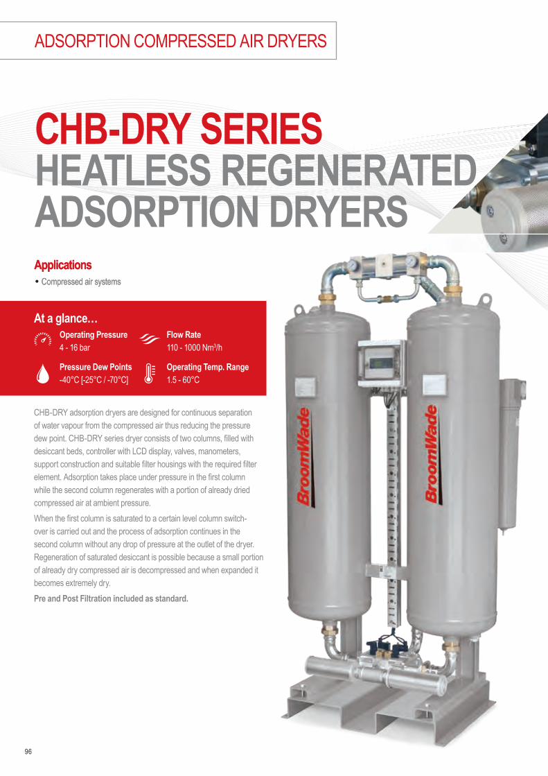
Applications• Compressed air systemsApplications• Compressed air systems
CHB-DRY SERIES HEATLESS REGENERATED ADSORPTION DRYERS
CHB-DRY adsorption dryers are designed for continuous separation of water vapour from the compressed air thus reducing the pressure dew point. CHB-DRY series dryer consists of two columns, filled with desiccant beds, controller with LCD display, valves, manometers, support construction and suitable filter housings with the required filter element. Adsorption takes place under pressure in the first column while the second column regenerates with a portion of already dried compressed air at ambient pressure. When the first column is saturated to a certain level column switch-over is carried out and the process of adsorption continues in the second column without any drop of pressure at the outlet of the dryer. Regeneration of saturated desiccant is possible because a small portion of already dry compressed air is decompressed and when expanded it becomes extremely dry. Pre and Post Filtration included as standard.
At a glance…Operating Pressure 4 - 16 bar
Flow Rate 110 - 1000 Nm3/h
Pressure Dew Points -40°C [-25°C / -70°C]
Operating Temp. Range 1.5 - 60°C
96
ADSORPTION COMPRESSED AIR DRYERS

TYPE PART NO CONNECTION IN/OUT
NOMINAL VOLUME FLOW DIMENSIONS WEIGHTINLET1] OUTLET2]
[Nm3/h] [Nm3/h] A [mm] B [mm] C [mm] [kg]CHB-DRY 110 CC1148781 G 1'' 110 86.0 719 ±5 422 1,647 140CHB-DRY 150 CC1148782 G 1'' 150 117.5 707 ±5 422 1,897 156CHB-DRY 200 CC1148783 G 1'' 200 157.0 707 ±5 471 1,664 196CHB-DRY 250 CC1148784 G 1'' 260 204.0 707 ±5 471 1,914 236CHB-DRY 300 CC1148785 G 1 1/2'' 320 251.0 860 ±5 535 1,742 274CHB-DRY 400 CC1148786 G 1 1/2'' 410 321.5 854 ±5 535 1,989 295CHB-DRY 600 CC1148787 G 1 1/2'' 590 462.5 854 ±5 671 2,051 392CHB-DRY 800 CC1148788 G 2'' 770 603.5 1051 ±10 701 2,080 507CHB-DRY 1000 CC1148789 G 2'' 1000 784.0 1051 ±10 701 2,140 597
DEW POINT - CORRECTION FACTORS - CDOPERAT. TEMP. [°C] -25 -40 -70OPERAT. TEMP. [F] -13 -40 -94CORRECTION FACTOR CD 1.1 1 0.7
OPERATING TEMPERATURE - CORRECTION FACTORS - COTOPERAT. TEMP. [°C] 25 30 35 40 45 50 55 60OPERAT. TEMP. [F] 77 86 95 104 113 122 131 140CORRECTION FACTOR COT 1 1 1 0.97 0.87 0.80 0.64 0.51
BA
C
OPERATING PRESSURE - CORRECTION FACTORS - COPOPERATING PRESS. [bar] 2 3 4 5 6 7 8 9 10 11 12 13 14 15 16OPERATING PRESS. [psi] 29 44 58 72 87 100 115 130 145 160 174 189 203 218 232CORRECTION FACTOR COP 0.38 0.5 0.63 0.75 0.88 1 1.13 1.25 1.38 1.50 1.63 1.75 1.88 2.00 2.13
1] Refers to 1bar(a) and 20°C at 7 bar operating pressure, inlet temperature 35°C and pressure dew point at outlet -40°C.2] Outlet flow refers to typical assumption during regeneration phase for operating at nominal inlet flow conditions. Outlet flow includes average air losses of approximately 17.3 %.* If dryer is supplied without inlet filter compressed air class 1 (ISO 8753-1) for solid particles and oil should be provided to the inlet of the dryer.
VOLTAGE, FREQUENCY 230V, 50/60 Hz POWER CONSUMPTION <60 WPROTECTION CLASS IP 65FILTER (INLET)* Super fine - 0.01 µmFILTER (OUTLET) Dust filter; 1 µmDPD CONTROL OptionalINPUT FOR STAND-BY StandardFILTER (OUTLET) Dust filter; 1 µm
97

CORRECTION FACTORS - F1OPERATING PRESS. [bar] 2 3 4 5 6 7 8 9 10 11 12 13 14 15 16OPERATING PRESS. [psi] 29 44 58 72 87 100 115 130 145 160 174 189 203 218 232CORRECTION FACTOR 0.38 0.5 0.63 0.75 0.88 1 1.13 1.25 1.38 1.50 1.63 1.75 1.88 2.00 2.13
CORRECTION FACTORS - F2 DEW POINTINLET TEMPERATURE [°C] 25 30 35 40 45 50 55 60 [°C] -25 -40 -70CORRECTION FACTOR 1.00 1.00 1.00 0.97 0.87 0.80 0.64 0.51 CD 1.1 1 0.7
TYPE PART NOCONNECTION
IN/OUT3]NOMINAL VOLUME FLOW DIMENSIONS WEIGHTINLET1] OUTLET2]
[Nm3/h] [Nm3/h] A [mm] B [mm] C [mm] [kg]CHX-DRY 300 CC1148774 G 2'' 300 237 1,515 674 686 350CHX-DRY 450 CC1148775 G 2'' 450 255.5 1,515 674 886 520CHX-DRY 600 CC1148776 G 2'' 600 474 1,515 674 1,086 690CHX-DRY 750 CC1148778 G 2'' 750 592.5 1,515 674 1,286 860CHX-DRY 900 CC1148779 G 2'' 900 711 1,515 674 1,486 1030CHX-DRY1050 CC1148780 G 2'' 1,050 829.5 1,515 674 1,686 1200OPERATING PRESS. RANGE 4 to 16 barOPERATING TEMP. RANGE +1.5°C to +60°CPRESSURE DEW POINTS -40°C [-25°C / -70°C]VOLTAGE, FREQUENCY 230V, 50/60 Hz POWER CONSUMPTION <60 WPROTECTION CLASS IP 65FILTER (INLET)* Super fine - 0.01 µmFILTER (OUTLET) Dust filter; 1 µm1] Refers to 1bar(a) and 20°C at 7 bar operating pressure, inlet temperature 35°C and pressure dew point at outlet -40°C.2] Outlet flow refers to typical assumption during regeneration phase for operating at nominal inlet flow conditions. Outlet flow includes average air losses of approximately 17.3%.3] Refers to inlet and outlet filter housing.
B
C
A
At a glance…Operating Pressure 4 - 16 bar
Flow Rate 300 - 1050 Nm3/h
Pressure Dew Points -40°C [-25°C/ -70°C]
Operating Temp. Range 1.5 - 60°C
CHX-DRY SERIES HEATLESS REGENERATED MODULAR ADSORPTION DRYERS
CHX-DRY 300-1050 modular adsorption dryers are designed for continuous separation of water vapour from compressed air thus reducing dew point. Operation of dryer requires two columns operated alternately. Adsorption takes place under pressure in first column while second column regenerates with a portion of already dried compressed air at ambient pressure. A dryer consists of two columns, filled with desiccant beads, controller with LCD dicplay, valves, manometers, support construction and suitable filter housings with the required filter element. Proven robust design enables efficient and reliable operation, fast installation and simple maintenance.
98
ADSORPTION COMPRESSED AIR DRYERS

Applications[1
• Automotive painting• Industrial ‘’Point-Of-Use’’ drying• Low dew point instrument air• Pneumatics
• Medical air• Analytical Equipment• Pressurising electrical cabinets
* At 7 bar, inlet dew point 35 °C, outlet dew point 15 °C.Prices includes complete kit.
B
D
A
C
TYPE PART NOPIPE SIZE
OPERATING PRESSURE
FLOW RATE * DIMENSIONS
[inch] [bar] [m3/min] [cfm] A [mm] B [mm] C [mm] D [mm]CHM-DRY 3 CC1189577 ¼ 12 0.05 1.8 224 43.7 325 175CHM-DRY 6 CC1189578 ¼ 12 0.1 3.5 325 43.7 453 175CHM-DRY 9 CC1189579 ¼ 12 0.15 5.3 427 43.7 555 175CHM-DRY 12 CC1189580 ¼ 12 0.2 7.1 503 43.7 611 175CHM-DRY 18 CC1189581 ½ 12 0.3 10.6 312 61 476 208CHM-DRY 24 CC1189582 ½ 12 0.4 14.1 376 61 540 208CHM-DRY 32 CC1189583 ½ 12 0.6 21.2 465 61 661 208CHM-DRY 44 CC1189584 ½ 12 0.8 28.3 592 61 788 208CHM-DRY 63 CC1189585 ½ 12 1.05 37.1 411 89 607 208CHM-DRY 90 CC1189586 ½ 12 1.5 53.0 551 89 755 284CHM-DRY 123 CC1189587 ½ 12 2.05 72.4 551 89 577 284CHM-DRY 180 CC1189588 1 12 3 106.6 607 114 1.805 290
OPERATING PRESSURE - CORRECTION FACTORS - COPERATING PRESSURE [bar] 4 5 6 7 8 9 10 11 12OPERATING PRESSURE [psi] 58 72 87 100 115 130 145 160 174CORRECTION FACTOR 0.41 0.56 0.76 1 1.22 1.48 1.76 1.86 2.22
CHM-DRY membrane air dryers have been developed for high efficient removal of water vapours from compressed air.
At a glance…Operating Pressure 12 bar
Flow Rate 0.05 - 3 m3/min
Pipe Size ¼ - 1"
Operating Temp. Range 1.5 - 60°C
99
CHM-DRY SERIES MEMBRANE DRYERS

AIRCOOLED AFTERCOOLERS
B C
A
CHACA SERIES AIR COOLED AFTERCOOLERS
Air cooled aftercoolers series CHACA have been designed to reduce compressed air temperature and water vapour dew point in compressed air system. A high efficiency axial fan forces ambient air over the heat exchangers copper tubes supported by aluminium fins, which provides the necessary cooling effect. The compressed air is cooled down to approximately 10°C above ambient temperature. CHACA aftercoolers ensures the maximum performance and protection of all equipment, such as refrigeration dryers, adsorption dryers and filters, positioned downstream of this unit.
TYPE PART NO FLOW RATE PIPE SIZE
POWER SUPPLY FAN DIMENSIONS WEIGHT
[m3/min] [cfm] [ph/V/Hz] [ø mm/ W] A [mm] B [mm] C [mm] [kg]CHACA 3 CC1189498 1.1 39 G 1'' 1/230/50 ø250-45W 850 300 715 19CHACA 7 CC1189499 2.1 74 G 1'' 1/230/50 ø250-45W 850 300 715 20CHACA 10 CC1189500 3.7 131 G 1 1/2'' 3/400/50 ø350-110W 990 310 845 27CHACA 18 CC1189501 4.9 173 G 1 1/2'' 3/400/50 ø400-130W 990 310 845 29CHACA 30 CC1189504 6.5 230 G 2'' 3/400/50 ø500-750W 1175 440 980 44CHACA 47 CC1189505 8.7 307 G 2'' 3/400/50 ø500-750W 1175 440 980 48CHACA 70 CC1189506 12.9 456 G 2'' 3/400/50 ø600-370W 1325 490 1130 61CHACA 94 CC1189507 16.5 583 G 2 1/2'' 3/400/50 ø600-370W 1325 490 1130 66CHACA 150 CC1189508 21 742 DN100 3/400/50 ø800-1470W 1800 660 1590 127CHACA 175 CC1189509 26 918 DN100 3/400/50 ø800-1470W 1800 660 1590 143CHACA 240 CC1189510 31.5 1112 DN100 3/400/50 ø800-1470W 1800 790 1560 148CHACA 300 CC1189511 42 1483 DN100 3/400/50 ø800-1470W 2000 795 1740 166CHACA 450 CC1189512 51.5 1819 DN125 3/400/50 2x ø800-1470W 2090 830 1850 212CHACA 600 CC1189513 75 2649 DN125 3/400/50 2x ø800-1470W 2300 850 2010 315
At a glance…Operating Pressure 7 - 15 bar
Flow Rate 1.1 - 75 m3/min
Operating Temp. Range 25 - 120°C
100
Pipe Size 1 - 2½"

Applications• Automotive• Electronics• Food & Beverage• Chemical
• Petrochemical• Plastics• Paint• General industrial application
CHACW SERIES WATER COOLED AFTERCOOLERS
Water-cooled aftercoolers series CHACW have been designed, to reduce compressed air temperature thus water vapour content in compressed air system. Hot compressed air/gas passes through the tubes. Cooling water passes around the tubes in counter flow. CHACW aftercooler ensures the maximum performance and protection of all equipment, such as refrigeration dryers, adsorption dryers and filters, positioned downstream of this unit.
TYPE PART NO CONNECTIONS OPERATING PRESSURE FLOW RATE DIMENSIONS
[Air] [Water] [bar] [m3/min] [cfm] A [mm] B [mm]CHACW 10 CC1189520 DN50 DN20 0 - 16 2.2 78 806 60.3CHACW 18 CC1189521 DN50 DN20 0 - 16 3.92 138 816 60.3CHACW 30 CC1189522 DN50 DN20 0 - 16 6.12 216 816 60.3CHACW 47 CC1189523 DN50 DN20 0 - 16 11.02 389 870 60.3CHACW 70 CC1189534 DN50 DN20 0 - 16 15.92 562 870 60.3CHACW 94 CC1189535 DN80 DN20 0 - 16 22.05 779 1500 88.9CHACW 150 CC1189536 DN80 DN20 0 - 16 36.75 1298 1510 88.9CHACW 200 CC1189537 DN100 DN40 0 - 16 44.17 1560 1500 114.3CHACW 240 CC1189538 DN125 DN32 0 - 16 51.45 1817 1300 139.7CHACW 300 CC1189539 DN125 DN32 0 - 16 66.15 2336 1300 139.7CHACW 375 CC1189540 DN150 DN65 0 - 16 86.67 3060 1300 168.3CHACW 450 CC1189541 DN200 DN50 0 - 16 117.6 4153 1300 219CHACW 600 CC1189542 DN200 DN65 0 - 16 149.45 5278 1300 219CHACW 900 CC1189543 DN250 DN80 0 - 10 183.75 6489 1300 273CHACW 1200 CC1189544 DN300 DN80 0 - 10 269.5 9517 1300 323.9CHACW 1500 CC1189545 DN400 DN100 0 - 10 367.5 12978 1300 406CHACW 1800 CC1189546 DN400 DN150 0 - 10 441 15574 1300 406CHACW 2500 CC1189547 DN450 DN200 0 - 10 563.5 19900 1300 457CHACW 3000 CC1189548 DN500 DN200 0 - 10 759.5 26821 1300 508
A
øB
At a glance…Operating Pressure 0 - 16 bar
Flow Rate 2.2 - 759.5 m3/min
Operating Temp. Range 1.5 - 200°C
101

Applications• Automotive• Electronics• Food and beverage• Chemical
• Petrochemical• Plastics• Paint• General industrial application
102
ACTIVATED CARBON TOWERS
ACTIVATED CARBON TOWER CH-TAC SERIESAt a glance…
Operating Pressure 16 bar
Flow Rate 0.1 - 108.33 m3/min
Operating Temp. Range 1.5 - 45°C
TACm TAC
QUALITY CLASS - SOLIDS (ISO 8573-1) -QUALITY CLASS - WATER (ISO 8573-1) -QUALITY CLASS - OILS (ISO 8573-1) 0/1PRESSURE DROP - NEW ELEMENT-DRY [MBAR / PSI] 20 / 0,29FILTER MEDIA act. carbonRESIDUAL OIL VAPOUR CONTENT (NOMINAL) [MG/M3] <0,003
CH-TAC activated carbon towers have been developed for separating oil vapours from compressed air (dry type separation). CH-TAC is made from high quality carbon steel. CH-TACm series is made from aluminium. Flow distributors ensure uniform distribution of air flow through activated carbon bed. Oil vapours as well as some other hydrocarbons are separated due to adsorption process. Super fine coalescing filter is required upstream TAC and 1μm dust filter is recommended downstream to intercept activated carbon dust. High pressure version is available on request.Stainless steel version available on request.High pressure version is available on request.
Pipe Size ³⁄8 - 2"

103
TAC SERIES TAC Service Kits
TYPE PART NOPIPE SIZE
OPERATING PRESSURE
FLOW RATE AT 7 BAR(G), 20 °C DIMENSIONS WEIGHT
[bar] [m3/min] [cfm] A [mm] B [mm] C [mm] [kg]CH-TACm 6 CC1189549 3/8’’ 16 0.1 3.5 404 188 100 3.5CH-TACm 12 CC1189550 3/8’’ 16 0.2 7.0 638 188 100 5.3CH-TACm 23 CC1189551 3/8’’ 16 0.4 14.1 1106 188 100 6.5CH-TACm 35 CC1189552 3/8’’ 16 0.6 21.1 1574 188 100 12CH-TACm 56 CC1189553 1/2’’ 16 1 35.3 1106 270 148 15CH-TACm 70 CC1189554 1/2’’ 16 1.25 44.1 1340 270 148 18CH-TACm 105 CC1189555 1/2’’ 16 1.75 61.8 1808 270 148 22CH-TAC 110 CC1189556 1’’ 16 1.83 86 1522 350 252 45CH-TAC 150 CC1189557 1’’ 16 2.5 117 1766 350 252 52CH-TAC 200 CC1189558 1’’ 16 3.33 157 1532 400 303 71CH-TAC 250 CC1189559 1’’ 16 4.33 204 1784 400 303 83CH-TAC 300 CC1189560 1 1/2’’ 16 5.33 251 1551 450 357 97CH-TAC 400 CC1189561 1 1/2’’ 16 6.83 321 1798 450 357 114CH-TAC 600 CC1189562 1 1/2’’ 16 9.83 462 1893 650 424 160CH-TAC 800 CC1189563 2’’ 16 12.83 603 1877 650 468 201CH-TAC 1000 CC1189564 2’’ 16 16.67 784 1961 650 506 242CH-TAC 1200 CC1189565 DN50 16 20 936 2170 550 550 280CH-TAC 1500 CC1189566 DN65 16 25 1170 2210 620 620 355CH-TAC 2000 CC1189567 DN65 16 33.33 1560 2330 700 700 420CH-TAC 2500 CC1189568 DN80 16 41.67 1950 2260 760 760 510CH-TAC 3000 CC1189569 DN80 16 50 2340 2400 800 800 595CH-TAC 3750 CC1189570 DN100 16 62.5 2925 2490 920 920 745CH-TAC 5000 CC1189571 DN100 16 83.33 3900 2600 1050 1050 960CH-TAC 6500 CC1189572 DN125 16 108.33 5070 2730 1150 1150 1300
TYPE PART NO
CH-TACm 6 CC1189474CH-TACm 12 CC1189475CH-TACm 23 CC1189476CH-TACm 35 CC1189477CH-TACm 56 CC1189478CH-TACm 70 CC1189479CH-TACm 105 CC1189480CH-TAC 110 CC1189481CH-TAC 150 CC1189482CH-TAC 200 CC1189483CH-TAC 250 CC1189484CH-TAC 300 CC1189485CH-TAC 400 CC1189486CH-TAC 600 CC1189487CH-TAC 800 CC1189488CH-TAC 1000 CC1189489CH-TAC 1200 CC1189490CH-TAC 1500 CC1189491CH-TAC 2000 CC1189492CH-TAC 2500 CC1189493CH-TAC 3000 CC1189494CH-TAC 3750 CC1189495CH-TAC 5000 CC1189496CH-TAC 6500 CC1189497
Replace activated carbon every 12 months or sooner if required. Check residual oil content with oil indicator monthly.
CORRECTION FACTORSOPERATING PRESSURE [BAR] 2 3 4 5 6 7 8 9 10 11 12 13 14 15 16OPERATING PRESSURE [PSI] 29 44 58 72 87 100 115 130 145 160 174 189 203 218 232CORRECTION FACTOR 0,38 0,5 0,63 0,75 0,88 1 1,13 1,25 1,38 1,50 1,63 1,75 1,88 2,0 2,13
CORRECTION FACTORSOPERATING TEMPERATURE [°C] 20 25 30 35 40 45CORRECTION FACTOR 1 0,98 0,97 0,92 0,86 0,75
CB
A
TAC
CB
A
TAC F

104
COMPRESSED AIR EQUIPMENT
Applications• Chemical• Petrochemical• Paint
• General industrial applications• Breathing air
CH-PP SERIES PAINTING AIR FILTRATIONAt a glance…
Operating Pressure 16 bar
Flow Rate 0.1 - 108.33 m3/min
Operating Temp. Range 1.5 - 65°C
CH-PP pro paint system is specifically designed for purifying compressed air from solid, liquid and partially gaseous components. Protecting air equipment in addition to providing clean air for worker health protection. PP pro paint system is easy for wall mount.
Available modular combinations:1. Comp. air for lower quality demands (down to 15 μm)2. Comp. air for basic quality demands (down to 0,1 μm)3. Comp. air for high quality demands (down to 0,01 μm)
4. Technical absolutely clean air (down to 0,1 μm, activated carbon)5. Technical and breathable air6. Compressed air for highest demands (all in one unit)
Pipe Size ½"

105
0.1 MICRON MICROFILTER
FILTERELEMENTTYPE
PART NO
Filter Cartridge F007M 223182
Filter Cartridge F010M 223183
0.1 MICRON A ACTIVATED CARBON
FILTERELEMENTTYPE
PART NO
Filter Cartridge F007A 223212
Filter Cartridge F010A 223213
TYPE PART NO
PIPE SIZE
FLOW RATE AT 7 BAR(G), 20 °C DIMENSIONS
SEPA
RATO
R C
KL-P
P
MICR
OFILT
ER M
0,1Μ
M
MICR
OFILT
ER S
0,01
ΜM
ACTI
VE C
ARBO
N A
STER
ILE
FILT
ER W
ITH
ACTI
VE C
ARBO
N SF
AAD
SORP
TION
DRY
ER
A-DR
Y 10
5
PRES
SURE
REG
ULAT
OR
QUIC
K CO
UPLI
NG N
O.
[inch] [m3/min] [cfm] A [mm] B [mm] C [mm]
CH-PP-107 CC1189591 1/2’’ 1.3 46 270 135 276 2CH-PP-110 CC1189592 1/2’’ 2 71 270 135 345 2CH-PP-207 CC1189593 1/2’’ 1.3 46 380 135 276 2CH-PP-210 CC1189594 1/2’’ 2 71 380 135 345 2CH-PP-307 CC1189595 1/2’’ 1.3 46 490 135 276 2CH-PP-310 CC1189596 1/2’’ 2 71 490 135 345 2CH-PP-407 CC1189597 1/2’’ 1.3 46 580 135 276 4CH-PP-410 CC1189598 1/2’’ 2 71 580 135 345 4CH-PP-507 CC1189599 1/2’’ 1.3 46 612 135 370 4CH-PP-510 CC1189600 1/2’’ 2 71 612 135 440 4CH-PP-607 CC1189601 1/2’’ 1.3 46 1150 335 917 4CH-PP-610 CC1189602 1/2’’ 2 71 1150 335 917 4
CORRECTION FACTORSOPERATING PRESSURE [bar] 2 3 4 5 6 7 8 9 10 11 12 13 14 15 16OPERATING PRESSURE [psi] 29 44 58 72 87 100 115 130 145 160 174 189 203 218 232CORRECTION FACTOR 0,38 0,50 0,63 0,75 0,88 1 1,13 1,25 1,38 1,50 1,63 1,75 1,88 2,00 2,13
0.1 MICRON FINEFILTER
FILTERELEMENTTYPE
PART NO
Filter Cartridge F007S 223192
Filter Cartridge F010S 223193
CKL-PP SEPARATOR
FILTERELEMENTTYPE
PART NO
Filter Cartridge F007-CKL-PP CC1189457
Filter Cartridge F010-CKL-PP CC1189458

106
BREATHING AIR FILTER
CHB-AIR BREATHING AIR FILTER
Applications• Breathing air
At a glance…Operating Pressure 16 bar
Flow Rate 1.3 - 13 m3/min
Operating Temp. Range 1.5 - 45°C
CHB-AIR point of use filter set has been specifically developed for high efficient preparation of top quality breathing air. On request CHB-AIR filter set can be supplied with wall mounting brackets, pressure regulator and quick couplings.
WARNING! Breathing air filter set CHB-AIR is not declared as CO2 and CO removal filter. Despite that CHB-AIR comprises filter element which can reduce CO content.
Pipe Size ½ - 1½"

FMFILTERELEMENTTYPE
PART NO
Filter Cartridge F007M 223182
Filter Cartridge F010M 223183
Filter Cartridge F018M 223184
Filter Cartridge F030M 223185
Filter Cartridge F047M 223186
Filter Cartridge F070M 223187
FA²FILTERELEMENTTYPE
PART NO
Filter Cartridge F007A2 CC1189354
Filter Cartridge F010A2 CC1189434
Filter Cartridge F018A2 CC1189435
Filter Cartridge F030A2 CC1189437
Filter Cartridge F047A2 CC1189438
Filter Cartridge F070A2 CC1189439
FH²FILTERELEMENTTYPE
PART NO
Filter Cartridge F007H2 CC1189441
Filter Cartridge F010H2 CC1189442
Filter Cartridge F018H2 CC1189443
Filter Cartridge F030H2 CC1189454
Filter Cartridge F047H2 CC1189455
Filter Cartridge F070H2 CC1189456
107
CORRECTION FACTORSOPERATING PRESSURE [bar] 2 3 4 5 6 7 8 9 10 11 12 13 14 15 16OPERATING PRESSURE [psi] 29 44 58 72 87 100 115 130 145 160 174 189 203 218 232CORRECTION FACTOR 0,38 0,50 0,63 0,75 0,88 1 1,13 1,25 1,38 1,50 1,63 1,75 1,88 2,00 2,13
Prices are for complete set.- Set includes 3 filter housings, 3 filter elements, 2 AOK16B condensate drains, 1 MCD drain and 1 PDI 16 di%erential pressure indicator.
TYPE PART NO PIPE SIZE FLOW RATE AT 7 BAR(G), 20 °C DIMENSIONS WEIGHT FILTER
ELEMENT TYPE
[inch] [m3/min] [cfm] A [mm] B [mm] C [mm] D [mm] [kg]CHB-AIR 76 CC1189704 1/2'' 1.3 46 187 88 20 60 1.41 F007 M/H2/A2CHB-AIR 106 CC1189705 3/4'' 2 70 257 88 20 80 1.8 F010 M/H2/A2CHB-AIR 186 CC1189706 1'' 3.3 116 263 125 32 100 4.71 F018 M/H2/A2CHB-AIR 306 CC1189707 1'' 5.58 197 363 125 32 120 6.6 F030 M/H2/A2CHB-AIR 476 CC1189708 1 1/2'' 8.5 300 461 125 32 140 8.4 F047 M/H2/A2CHB-AIR 706 CC1189709 1 1/2'' 13 459 640 125 32 160 11.7 F070 M/H2/A2
B
C
AD R 1/2’’

108
BREATHING AIR FILTER PLUS
CHB-AIR PLUS BREATHING AIR FILTER
Applications• Breathing air
Advantages• High quality breathing air for up to 5 people• Air quality monitoring (EN 12021, BS 4275:1997)• Compact & light weight
At a glance…Operating Pressure 16 bar
Flow Rate 1.3 - 13 m3/min
Operating Temp. Range 1.5 - 45°C
CHB-AIR PLUS system has been specifically designed for applications where high quality breathing air and monitoring of breathing air supply are needed. CHB-AIR PLUS is a combination of our CHB-AIR PLUS 0106 breathing air filter set combined with gas concentration analysers, fitted with pressure regulator and quick couplings, all packed in a compact and robust casing.Gas concentration analysers constantly monitor CO, CO2 and O2 concentrations and trigger an alarm if concentrations exceed the EN12021 and BS4275:1997 standard compliant values. In this way CHB-AIR PLUS can safely provide high quality breathing air for up to 5 people(1.Small dimensions and low weight enable the use of CHB-AIR PLUS in many applications as it can be transported and set up with ease.
Pipe Size ½"

109
508
460 160
FMFILTERELEMENTTYPE
PART NO
Filter Cartridge F007M 223182
FH²FILTERELEMENTTYPE
PART NO
Filter Cartridge F007H2 CC1189441
FA²FILTERELEMENTTYPE
PART NO
Filter Cartridge F007A2 CC1189354
CORRECTION FACTORSOPERATING PRESSURE [bar] 2 3 4 5 6 7 8 9 10 11 12 13 14 15 16OPERATING PRESSURE [psi] 29 44 58 72 87 100 115 130 145 160 174 189 203 218 232CORRECTION FACTOR 0,38 0,50 0,63 0,75 0,88 1 1,13 1,25 1,38 1,50 1,63 1,75 1,88 2,00 2,13
TYPE PART NO PIPE SIZE FLOW RATE AT 7 BAR(G), 20 °C DIMENSIONS WEIGHT FILTER
ELEMENT TYPE
[inch] [m3/min] [cfm] A [mm] B [mm] C [mm] [kg]CHB-AIR PLUS CC1189710 1/2'' 2 71 508 460 160 12
Prices are for complete set.

110
HEAT RECOVERY UNITS
CH-AIRWATT SERIES HEAT RECOVERY UNITSAt a glance…
Operating Pressure 1 - 16 bar
Flow Rate 1.3 - 13 m3/min
Operating Temp. Range 5 - 120°C
External heat recovery unit - CH-AIRWATT is designed to efficiently exploit the waste heat, generated during compression of air in rotary screw compressors.Sometimes this represents more than 70% of energy consumed by the rotary screw compressor for the operation. This heat can then be used to heat domestic water or for heating, at almost no additional costs. This does not only help save money, but is also environmentally friendly. Unit has two separate piping systems with counter flow. Energy exchange from compressor to sanitary water occurs in plate heat exchanger, where compressor oil and sanitary water meets. Unit is controlled by thermostatic valve, which prevents compressor system getting to cold and damaging compressor.
Applications• Heat recovery in oil lubricated rotary screw compressors
Ambient Air Temp. Range 5 - 45°C
OPERATING PRESSURE (OIL) 1 - 16 barMAXIMUM WATER PRESSURE 10 barOPERATING TEMPERATURE 5°C - 120°CMAX. OUTLET WATER TEMPERATURE 70°CPRESSURE DROP (OIL) ~ 100 mbarAMBIENT TEMPERATURE 5°C - 45°CWATER TEMPERATURE INDICATOR Analog mechanical
TYPE PART NO MOTOR POWER
HEAT CAPACITY
OIL CONNECTION
WATER CONNECTION DIMENSIONS WEIGHT
[kW] [kW] [G] [G] A [mm] B [mm] C [mm] [kg]CH-AIRWATT 22 CC1189573 15 - 22 12 - 17.6 1 1/4" 1" 360 500 760 33CH-AIRWATT 37 CC1189574 26 - 37 20.8 - 29.6 1 1/4" 1" 360 500 760 35CH-AIRWATT 75 CC1189575 45 - 75 36 - 60 1 1/4" 1" 360 500 760 42CH-AIRWATT 100 CC1189576 90 - 132 72 - 100 2" 2" 450 600 860 58
B
C
A
water inlet
water outlet
oil outlet
oil inlet

111
VERTICAL AIR RECEIVERS
Air receivers are an important part of the compressed air system, evening out peaks and troughs in air demand, minimising pulsations from piston compressors and protecting your air compressor from over frequent load/unload or start stop cycles.
VERTICAL TANKS1] Ø X H WEIGHT IN / OUT MAXIMUM PRESSURE REG. PACKING CODE
[mm] [kg] [bar]TANK 270 L 490 x 1,664 70 1" / 1" 11 CE 87 / 404 + 2 % 220662KTANK 500 L 600 x 2,055 125 1" / 1" 11 CE 87 / 404 + 2 % 220663KTANK 500 L 15 BAR 600 x 2,055 145 1" / 1" 15 CE 87 / 404 + 2 % 220749KTANK 720 L 750 x 2,030 195 1"/ 1" 11 CE 87 / 404 + 2 % 220713KTANK 1000 L 800 x 2,335 270 2" / 2" 12 CE 97 / 23 + 1.5 % 220664KTANK 2000 L 1,100 x 2,485 360 2" / 2" 12 CE 97 / 23 + 1.5 % 220665CKTANK 3000 L 1,200 x 2,980 530 2" / 2" 12 CE 97 / 23 + 1.5 % 220668CK
1] Including paint, support legs, pressure gauge, safety valve and inlet and outlet nozzles.
NOTE: Further receiver types available on request.
At a glance…Operating Pressure 11 - 15 bar
Capacity 270 - 3000l

IED SERIES ELECTRONIC CONDENSATE DRAINS
EMD SERIES ELECTRONIC CONDENSATE DRAINS
ECD-B SERIES ELECTRONIC CONDENSATE DRAINS
TECHNICAL DATA IEDVOLTAGE 230 VAC 115 VACFREQUENCY 50-60 Hz 50-60 HzINTERNAL FUSE 5 x 20 1A TPOWER 10 VAOPERATING PRESSURE RANGE 0-16 bar [0-232 psi]DRAIN CAPACITY [AT 7 bar/101 PSI] 8 l/h at 7 bar [0,005 cfm at 101 psi]OPERATING TEMPERATURE RANGE 1.5-65 °C [35-149°F]INLET CONNECTION G 1/2'' parallel threadPROTECTION CLASS IP54MASS [kg] 0.3OPERATING TEMPERATURE RANGE 1.5 to 65°CDIMENSIONS [L x B x H] 61 x 60 x 161 mmSERVICE NETWORK CONNECTION - -ALARM OUTPUT - -PART NUMBER CC1182025
TECHNICAL DATA EMD12230 V
SERVICE NETWORK CONNECTION -
ALARM OUTPUT -VOLTAGE 230 VAC, 50-60 HzINTERNAL FUSE 5 x 20 1A TPOWER 10 VAOPERATING PRESS. RANGE 0-16 bar [0-232 psi]DRAIN CAPACITY [AT 7 bar/101 PSI] 12 l/h [0.007cfm]
OPERATING TEMP. RANGE 1.5-65°C [35-149°F]INLET CONNECTION G 1/2''OUTLET CONNECTION Push connection for tube ø8PROTECTION CLASS IP54MASS [kg] 0.55DIMENSIONS A x B x C [mm] 133 x 76 x 147
PART NUMBER CC1112242
TECHNICAL DATA ECD 15B ECD 40B ECD 90B ECD 150B
VOLTAGE 115 VAC 115 V ± 10 % 115 V ± 10 % 115 V ± 10 % 115 V ± 10 %230 VAC 230 V ± 10 % 230 V ± 10 % 230 V ± 10 % 230 V ± 10 %
POWER 115 VAC 24 VA 24 VA 24 VA 24 VA230 VAC 24 VA 24 VA 24 VA 24 VA
FREQUENCY 50-60 HzOPERATING PRESSURE 0-16 bar (0 - 232 psi)DRAIN CAPACITY [AT 7 bar/101 PSI] 15 l/h 40 l/h 90 l/h 150 l/h OPERATING TEMPERATURE RANGE 1.5 - 65 °C (35-149 °F)INLET CONNECTION R 1/2’’ R 1/2’’ R 1/2’’ R 1/2’’OUTLET CONNECTION R 1/8’’ R 1/8’’ R 1/8’’ R 1/8’’POWER INTERFACE 3 x 0.75 mm2 3 x 0.75 mm2 3 x 0.75 mm2 3 x 0.75 mm2
PROTECTION CLASS IP54 IP54 IP54 IP54MASS [kg] 0.9 0.9 1.05 1.15DIMENSIONS A x B x C [mm] 120 x 82 x 125 120 x 82 x 125 120 x 82 x 135 120 x 82 x 150PART NUMBER CC1150763 CC1164401 CC1183827 CC1183828
112
CONDENSATE DRAINS
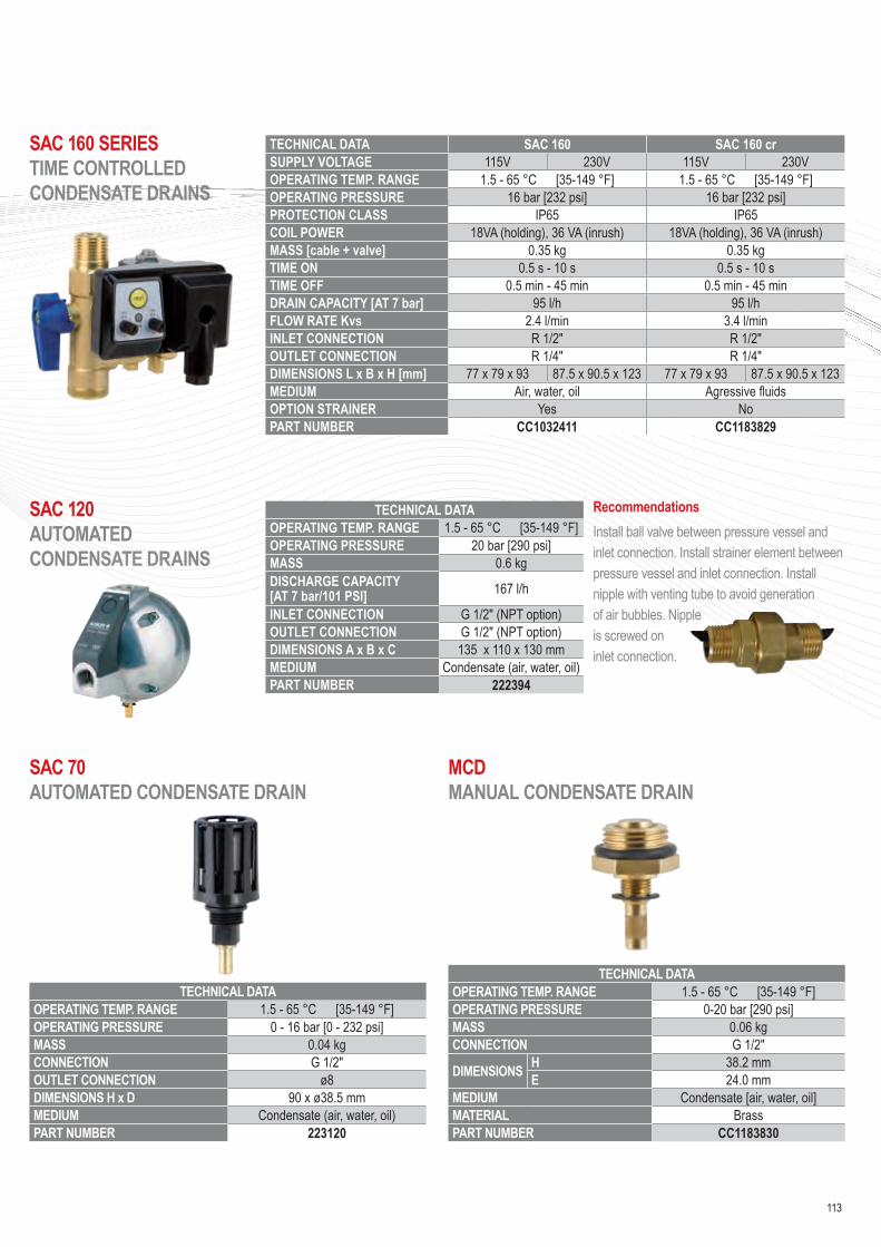
SAC 160 SERIES TIME CONTROLLED CONDENSATE DRAINS
SAC 120 AUTOMATED CONDENSATE DRAINS
SAC 70 AUTOMATED CONDENSATE DRAIN
MCD MANUAL CONDENSATE DRAIN
113
TECHNICAL DATAOPERATING TEMP. RANGE 1.5 - 65 °C [35-149 °F]OPERATING PRESSURE 20 bar [290 psi]MASS 0.6 kgDISCHARGE CAPACITY [AT 7 bar/101 PSI] 167 l/h
INLET CONNECTION G 1/2″ (NPT option)OUTLET CONNECTION G 1/2″ (NPT option)DIMENSIONS A x B x C 135 x 110 x 130 mmMEDIUM Condensate (air, water, oil)PART NUMBER 222394
RecommendationsInstall ball valve between pressure vessel and inlet connection. Install strainer element between pressure vessel and inlet connection. Install nipple with venting tube to avoid generation of air bubbles. Nipple is screwed on inlet connection.
TECHNICAL DATAOPERATING TEMP. RANGE 1.5 - 65 °C [35-149 °F]OPERATING PRESSURE 0 - 16 bar [0 - 232 psi]MASS 0.04 kgCONNECTION G 1/2″OUTLET CONNECTION ø8DIMENSIONS H x D 90 x ø38.5 mmMEDIUM Condensate (air, water, oil)PART NUMBER 223120
TECHNICAL DATAOPERATING TEMP. RANGE 1.5 - 65 °C [35-149 °F]OPERATING PRESSURE 0-20 bar [290 psi]MASS 0.06 kgCONNECTION G 1/2″
DIMENSIONS H 38.2 mmE 24.0 mm
MEDIUM Condensate [air, water, oil]MATERIAL BrassPART NUMBER CC1183830
TECHNICAL DATA SAC 160 SAC 160 crSUPPLY VOLTAGE 115V 230V 115V 230VOPERATING TEMP. RANGE 1.5 - 65 °C [35-149 °F] 1.5 - 65 °C [35-149 °F]OPERATING PRESSURE 16 bar [232 psi] 16 bar [232 psi]PROTECTION CLASS IP65 IP65COIL POWER 18VA (holding), 36 VA (inrush) 18VA (holding), 36 VA (inrush)MASS [cable + valve] 0.35 kg 0.35 kgTIME ON 0.5 s - 10 s 0.5 s - 10 sTIME OFF 0.5 min - 45 min 0.5 min - 45 minDRAIN CAPACITY [AT 7 bar] 95 l/h 95 l/hFLOW RATE Kvs 2.4 l/min 3.4 l/minINLET CONNECTION R 1/2″ R 1/2″OUTLET CONNECTION R 1/4″ R 1/4″DIMENSIONS L x B x H [mm] 77 x 79 x 93 87.5 x 90.5 x 123 77 x 79 x 93 87.5 x 90.5 x 123MEDIUM Air, water, oil Agressive fluidsOPTION STRAINER Yes NoPART NUMBER CC1032411 CC1183829

TECHNICAL DATAOPERATING TEMPERATURE 1.5 - 45 °C [max 65 °C]1]; 35 - 113 °F [max. 149 °F]1]
OPERATING MEDIA Condensate (air, water, oil); Non agresive; Not suitable for emulsion
RESIDUAL OIL CONTENT < 20ppmSERVICE INTERVAL When first of following parametres appears:
- 4000 operating hours of compressor2]
- 12 months regardless of compressor operating hours- when all white polypropylene media becomes yellow
COLD CLIMATE
ZONE 15°C 60% RH
MILD CLIMATE
ZONE25°C 60% RH
HOT CLIMATE
ZONE 40°C 100% RH
DIMENSIONS [mm] PART NO
H φ
CHWOSm1MAX OIL ADSORPTION [g] 740 650 370
483 106 CC1148194MAX FAD [Nm3/min]/[scfm] 1.23 / 43.05 1.08 / 37.8 0.62 / 21.9MAX CONDENSATE FLOW [l/h] 0.57 0.90 1.91
CHWOSm2MAX OIL ADSORPTION [g] 1520 1340 770
816 106 CC1148195MAX FAD [Nm3/min]/[scfm] 2.54 / 88.9 2.23 / 78.05 1.28 / 45.2MAX CONDENSATE FLOW [l/h] 1.19 1.87 3.96
1] Max. operating temperature is 65 °C, but when temperature is over 45 °C, performance may decrease.2] At compressor oil carryover 2,5 mg/m3. Lower/higher oil carry over means proportionally longer/shorter lifetime (e.g. if oil carryover is 5 mg/m3 lifetime reduces to 2000 operating hours).
CHWOSM SERIES WATER - OIL SEPARATORS
114
OIL/WATER SEPARATION EQUIPMENT

TECHNICAL DATAOPERATING TEMPERATURE 1.5 - 45 °C [max 65 °C]; 35 - 113 °F [max. 149 °F]
OPERATING MEDIA Condensate (air, water, oil); Non agresive; Not suitable for emulsion
RESIDUAL OIL CONTENT < 10ppmSERVICE INTERVAL When first of following parametres appears:
- 4000 operating hours of compressor - 12 months regardless of compressor operating hours- Outlet oil concentration reaches conc. determined with local directives
TECHNICAL DATACOLD
CLIMATE ZONE 15°C
60%RH
MILD CLIMATE
ZONE 25°C 60%RH
HOT CLIMATE
ZONE 40°C 100%RH
DIMENSIONS [mm]PART NO
A B C
CHWOS4MAX OIL ADSORPTION [kg] 2.89 2.43 1.23
416 243 411 CC1148196MAX FAD [Nm3/min]/[scfm] 4.82 / 170 4.04 / 142 2.05 / 72.3MAX CONDENSATE FLOW [l/h] 2.3 3.4 6.3
CHWOS8MAX OIL ADSORPTION [kg] 6.01 5.04 2.55
730 343 680 CC1148197MAX FAD [Nm3/min]/[scfm] 10.0 / 353 8.4 / 296 4.25 / 150MAX CONDENSATE FLOW [l/h] 4.7 7.1 13.1
CHWOS20MAX OIL ADSORPTION [kg] 14.64 12.28 6.22
820 366 940 CC1148198MAX FAD [Nm3/min]/[scfm] 24.4 / 861 20.5 / 723 10.37 / 366MAX CONDENSATE FLOW [l/h] 11.4 17,2 32.0
CHWOS35MAX OIL ADSORPTION [kg] 25.4 21.31 10.79
960 386 1,137 CC1148199MAX FAD [Nm3/min]/[scfm] 42.3 / 1495 35.5 / 1254 17.99 / 635MAX CONDENSATE FLOW [l/h] 19.8 29.8 55.6
CHWOS SERIES WATER - OIL SEPARATORS
115

CHNP SERIES NITROGEN GENERATORSAt a glance…
Operating Pressure 6 - 10 bar
Ambient Air Temp. Range up to 40°C
Capacity 3 - 442.5 Nm3/h
Operating Temp. Range 5 - 35°C
The CHNP nitrogen generators extract the available nitrogen in the ambient air from the other gases by applying the Pressure Swing Adsorption (PSA) technology. During the PSA process compressed, cleaned ambient air is led to a molecular sieve bed, which allows the nitrogen to pass through as a product gas, but adsorbs other gases. The sieve releases the adsorbed gases to the atmosphere, when the outlet valve is closed and the bed pressure returns to ambient pressure.Subsequently the bed will be purged with nitrogen before fresh compressed air will enter for a new production cycle. In order to guarantee a constant product flow NP nitrogen generators use two molecular sieve beds, which alternatively switch between the adsorption and the regeneration phase.
TYPE PART NOFLOW RATE AT 7 BAR(G), 20 °C DIMENSIONS WEIGHT
[m3/min] [cfm] A [mm] B [mm] C [mm] [kg]CHNP 03 CC1182437
Variable / Depending on purity
635 530 1650 110CHNP 05 CC1182024 635 530 1650 130CHNP 10 CC1182307 685 530 1650 190CHNP 15 CC1182438 795 545 1650 230CHNP 20 CC1182439 795 585 1920 295CHNP 25 CC1182440 845 660 1975 410CHNP 35 CC1182441 1040 780 2005 585CHNP 50 CC1182442 1040 795 2250 740CHNP 65 CC1182443 1150 795 2335 835CHNP 100 CC1182444 1425 945 2480 1,260CHNP 150 CC1182445 1650 1100 2550 1,590CHNP 200 CC1182446 1805 1160 2615 1,905CHNP 250 CC1182447 2020 1190 2780 2,430CHNP 300 CC1182448 2255 1280 2780 2,810CHNP 400 CC1182449 2720 1470 2880 3,640
116
GENERATORS

Notes
117

AFTERMARKET
118
SERVICE & SPARE PARTS• Standard & Extended Warranty• Service schedule• Spare part kits

119

AFTERMARKET
1] - The complete machine will have a warranty period of as mentioned above from date of commissioning or an additional 6 months from date of despatch ex BroomWade which ever is the soonest. BroomWade recommends that only genuine BroomWade or approved parts be used, and that service be carried out by a authorised BroomWade trained service engineer.
• Replacement spare partsThe warranty period for replacement parts excluding air ends, motors and consumable spare parts shall be 12 months ex BroomWade The extent of this will be replacement part only.
BroomWade will not warrant adjacent components to the replacement part
Any defective spare part found prior to installation should be processed directly with the BroomWade parts department, not as a warranty claim.
• Extended warranty
WARRANTY DURATION AND OPTIONS• Warranty overview by model - range
CODE DESCRIPTION
CC1180791 Extended Warranty 5 years for screw compressors 7.5 - 22 kWCC1180793 Extended Warranty for screw compressors 30 - 75 kWCC1180791 Extended Warranty for dryers CC1180793 Extended Warranty for nitrogen generators
BroomWade offer an Extended Warranty programme on selected models. Additional fees and terms & conditions apply. Please refer to the terms and conditions of the Extended Warranty Programmes.Extended warranty prices are nett each, no extra discount can be applied.For more information please see document : "Standard Warranty / Extended Warranty Terms & Conditions"
MODEL - RANGE WARRANTY DURATION EXTENDED WARRANTY AVAILABLE
FM 7- 75 series Screw Compressors 24 Months1]
KA 2-7 Series Screw Compressors 24 Months1]
KSB / KBV 15-22 Series Srew Compressors 24 Months1]
KSA / KSV 11, 30-90 Series Screw Compressors 24 Months1]
BroomWade Vane Compressors CMPV01-V04 24 Months1]
BroomWade Portable Screw Compressors 12 Months
BroomWade Piston Compressors (C-Series) 12 Months
BroomWade Breathing Air Compressors 12 Months
BroomWade Dental Compressors 12 Months
BroomWade S Series Scroll Compressors 12 Months
BroomWade Dryers (CHA-DRY, CHB DRY, CHX DRY, CT) 24 Months1]
BroomWade Nitrogen Generators CHNP03-400 24 Months1]
BroomWade Filters, Water Separators & Accessories 12 Months
Replacement Spare Parts 12 Months
120
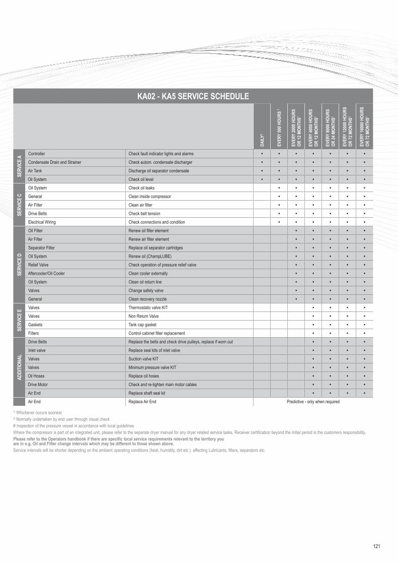
1] Whichever occurs soonest2] Normally undertaken by end user through visual check# Inspection of the pressure vessel in accordance with local guidelinesWhere the compressor is part of an integrated unit, please refer to the separate dryer manual for any dryer related service tasks. Receiver certification beyond the initial period is the customers responsibility.Please refer to the Operators handbook if there are specific local service requirements relevant to the territory you are in e.g. Oil and Filter change intervals which may be different to those shown above.Service intervals will be shorter depending on the ambient operating conditions (heat, humidity, dirt etc.), effecting Lubricants, filters, separators etc.
KA02 - KA5 SERVICE SCHEDULE
DAILY
2
EVER
Y 50
0 HOU
RS 1
EVER
Y 20
00 H
OURS
OR
12 M
ONTH
S1
EVER
Y 40
00 H
OURS
OR
12 M
ONTH
S1
EVER
Y 80
00 H
OURS
OR
24 M
ONTH
S1
EVER
Y 12
000 H
OURS
OR
72 M
ONTH
S1
EVER
Y 16
000 H
OURS
OR
72 M
ONTH
S1
SERV
ICE A
Controller Check fault indicator lights and alarms • • • • • • • Condensate Drain and Strainer Check autom. condensate discharger • • • • • • • Air Tank Discharge oil separator condensate • • • • • • • Oil System Check oil level • • • • • • •
SERV
ICE
C
Oil System Check oil leaks • • • • • • General Clean inside compressor • • • • • • Air Filter Clean air filter • • • • • • Drive Belts Check belt tension • • • • • • Electrical Wiring Check connections and condition • • • • • •
SERV
ICE
D
Oil Filter Renew oil filter element • • • • • Air Filter Renew air filter element • • • • • Separator Filter Replace oil separator cartridges • • • • • Oil System Renew oil (ChampLUBE) • • • • • Relief Valve Check operation of pressure relief valve • • • • • Aftercooler/Oil Cooler Clean cooler externally • • • • • Oil System Clean oil return line • • • • • Valves Change safety valve • • • • • General Clean recovery nozzle • • • • •
SERV
ICE
E Valves Thermostatic valve KIT • • • • Valves Non Return Valve • • • • Gaskets Tank cap gasket • • • • Filters Control cabinet filter replacement • • • •
ADDI
TIONA
L
Drive Belts Replace the belts and check drive pulleys, replace if worn out • • • • Inlet valve Replace seal kits of inlet valve • • • • Valves Suction valve KIT • • • • Valves Minimum pressure valve KIT • • • • Oil Hoses Replace oil hoses • • • • Drive Motor Check and re-tighten main motor cables • • • • Air End Replace shaft seal kit • • • • Air End Replace Air End Predictive - only when required
121

AFTERMARKET
1] Whichever occurs soonest2] Normally undertaken by end user through visual check3] If applicable# Inspection of the pressure vessel in accordance with local guidelinesWhere the compressor is part of an integrated unit, please refer to the separate dryer manual for any dryer related service tasks. Receiver certification beyond the initial period is the customers responsibility.Please refer to the Operators handbook if there are specific local service requirements relevant to the territory you are in e.g. Oil and Filter change intervals which may be different to those shown above.Service intervals will be shorter depending on the ambient operating conditions (heat, humidity, dirt etc.), effecting Lubricants, filters, separators etc.
FM7 - FM22 SERVICE SCHEDULE
DAILY
2
WEE
KLY2
EVER
Y 40
00 H
OURS
OR
12 M
ONTH
S1
EVER
Y 80
00 H
OURS
OR
24 M
ONTH
S1
EVER
Y 20
000 H
OURS
OR
60 M
ONTH
S1
EVER
Y 24
000 H
OURS
OR
72 M
ONTH
S1
SERV
ICE A
Controller Note and record sump pressure • • • • • • Controller Note and record discharge pressure • • • • • • Controller Note and record discharge temperature • • • • • • Enclosure Filters Check condition, clean if required • • • • • •Scavenge oil system Check operation • • • • • •
SERV
ICE
B Controller Check fault history • • • • • Controller Check for any service requirements • • • • • Oil System Check oil level and top up if required • • • • • Aftercooler/Oil Cooler Check condition, clean if required • • • • •
SERV
ICE
C
Oil Filter Renew oil filter element • • • • Air Filter Renew air filter element • • • • Oil System Renew oil (ChampLUBE) • • • • Dryer Cooling Air Inlet Filter3 Renew cooling air inlet filter • • • • Control System Check operation • • • • Blowdown System Check operation • • • • Electrical Wiring Check connections and condition • • • • Controller Check connections and plugs • • • • Separator Filter Renew separator filter • • • • Oil Scavenge System Clean and check operation • • • • Relief Valve Functionally test • • • • Drive Belts3 Check condition of belts and renew if required • • • •
SERV
ICE
D Minimum Pressure Valve Renew minimum pressure valve • • Intake Valve Overhaul intake valve • • • Emergency Stop Button Test emergency stop button • • • VSD Drive/Starter Check condition of contacts and renew if required • • •
ADDI
TIONA
L
Air End Renew air end shaft seal • Shaft Seal Oil Return Tube Renew shaft seal oil return tube • Oil Hoses Check condition and renew if required • • Control Solenoids Renew control solenoids • • Drive Belts Renew drive belts • • Drive Motor Bearings Renew drive motor bearings • Drive Motor AVM's Check drive motor Anti Vibration Mounts • Air End Discharge Temperature Sensor Renew temperature sensor • Oil Bypass Element Renew oil bypass element • Air End AVM's Check air end Anti Vibration Mounts • Air End Renew Air End Predictive - only when required
122

1] Whichever occurs soonest2] Normally undertaken by end user through visual check3] If applicable# Inspection of the pressure vessel in accordance with local guidelinesWhere the compressor is part of an integrated unit, please refer to the separate dryer manual for any dryer related service tasks. Receiver certification beyond the initial period is the customers responsibility.Please refer to the Operators handbook if there are specific local service requirements relevant to the territory you are in e.g. Oil and Filter change intervals which may be different to those shown above.Service intervals could be shorter depending on the ambient operating conditions (heat, humidity, dirt etc.), effecting Lubricants, filters, separators etc. Service intervals could be shorter depending on the ambient operating conditions (heat, humidity, dirt etc.), effecting Lubricants, filters, separators etc.
FM 30 - 75 SERVICE SCHEDULE
DAILY
2
WEE
KLY2
EVER
Y 40
00 H
OURS
OR
12 M
ONTH
S1
EVER
Y 80
00 H
OURS
OR
24 M
ONTH
S1
EVER
Y 20
000 H
OURS
OR
60 M
ONTH
S1
EVER
Y 24
000 H
OURS
OR
72 M
ONTH
S1
SERV
ICE A
Controller Note and record sump pressure • • • • • •Controller Note and record discharge pressure • • • • • •Controller Note and record discharge temperature • • • • • •Enclosure Filters Check condition, clean if required • • • • • •Scavenge oil system Check operation • • • • • •
SERV
ICE
B Controller Check fault history • • • • •Controller Check for any service requirements • • • • •Oil System Check oil level and top up if required • • • • •Aftercooler/Oil Cooler Check condition, clean if required • • • • •
SERV
ICE
C
Oil Filter Renew oil filter element • • • •Air Filter Renew air filter element • • • •Oil System Renew oil (Mineral or Foodgrade) • • • •Oil System 5 Renew oil (Synthetic) AEON9000 • • •Dryer Cooling Air Inlet Filter3 Renew cooling air inlet filter • • • •Control System Check operation • • • •Blowdown System Check operation • • • •Electrical Wiring Check connections and condition • • • •Controller Check connections and plugs • • • •Inlet Water Strainer4 Check condition, clean if required • • • •Separator Filter Renew separator filter • • • •Pipe work Replace Victaulic Couplings • • • •Oil Scavenge System Clean and check operation • • • •Relief Valve Functionally test • • • •
SERV
ICE
D
Oil Scavenge System Renew oil scavenge tubing • •Minimum Pressure Valve Renew minimum pressure valve • •Intake Valve Overhaul intake valve • •Emergency Stop Button Test emergency stop button • •Motor Drive Coupling Insert Check condition and renew if required • •VSD Drive/Starter Check condition of contacts and renew if required • •
ADDI
TIONA
L
Air End Renew air end shaft seal •Shaft Seal Oil Return Tube Renew shaft seal oil return tube •Oil Hoses Check condition and renew if required • •Control Solenoids Renew control solenoids • •Drive Belts3 Renew drive belts • •Drive Motor Bearings Renew drive motor bearings •Drive Motor AVM's Check drive motor Anti Vibration Mounts •Air End Discharge Temperature Sensor Renew temperature sensor •Oil Bypass Element Renew oil bypass element •Air End AVM's Check air end Anti Vibration Mounts •Air End Renew Air End Predictive - only when required
123

AFTERMARKET
1] Whichever occurs soonest2] Normally undertaken by end user through visual check# Inspection of the pressure vessel in accordance with local guidelinesPlease refer to the Operators handbook if there are specific local service requirements relevant to the territory you are in e.g. Oil and Filter change intervals which may be different to those shown above.Service intervals could be shorter depending on the ambient operating conditions (heat, humidity, dirt etc.), effecting Lubricants, filters, separators etc. Service intervals could be shorter depending on the ambient operating conditions (heat, humidity, dirt etc.), effecting Lubricants, filters, separators etc.
VANE CMPV01-04 KW SERVICE SCHEDULE
DAILY
2
WEE
KLY2
EVER
Y 20
00 H
OURS
OR
12 M
ONTH
S1
EVER
Y 40
00 H
OURS
EVER
Y 24
000 H
OURS
SERV
ICE A
Site-Adequate ventilation • • • • •Site-Ambient temperature within limit • • • • •Site-dust free ambient • • • • •Check oil level at filler plug/sight glass • • • • •
SERV
ICE
B
Check for air leaks • • • •Check for oil leaks • • • •Check air intake filter/clean if necessary • • • •Check oil temperature • • • •Check RSU temperature • • • •Clean any external dirt from compressor • • • •Clean any external dirt from motor • • • •
SERV
ICE
D
Change Separator cartridge • • •Change 2000 hour oil • • •Change air intake filter • • •Check/Torque electrical connections • • •Check power on load • • •Check power off load • • •Check servo pressure Off load • • •Check motor gland/cables secure • • •Check motor for damage • • •Check motor / starter for loose connections • • •Check motor cables and earth • • •Check motor for vibration • • •Check oil seal for leakage • • •
EXTR
A Grease motor bearings • •Check starter contactors • •
OVER
HAUL
SER
VICE
Change unloader valve seals •Change MPV seals •Change vacuum valve seals •Change thermal motor •Change drive media/key •Change oil seal •Change pressure gauge •Change motor bearings •Full Air End Inspection (internal) •Clean servo filter •Check correct drive rotation •Check motor insulation resistance •
124

SCROLL S04 & S07D UNITS SERVICE SCHEDULE
DAILY
2
EVER
Y 50
0 HOU
RS
OR 2
MONT
HS1
EVER
Y 20
00 H
OURS
OR
6 MO
NTHS
1
EVER
Y 50
00 H
OURS
OR
12 M
ONTH
S1
EVER
Y 10
000 H
OURS
OR
24 M
ONTH
S1
10 Bar 8 Bar
Complete Scroll Air End Inspect for excessive noise and vibration •Complete Scroll Check for air Leaks •Intake Air Filter Clean and inspect •V-Belts Inspect and adjust V-Belts •Intake Air Filter Replace intake air filter • • •Cooling Inspect and clean cooler • • •Sirocco Fan Clean & inspect • • •Airend Fin Clean & inspect • •Scroll Bearings Re-grease the bearing • •Tip Seals & Face Seals Replace the seals • •
SCROLL S06, S08, S11D, S15D UNITS SERVICE SCHEDULE
DAILY
2
EVER
Y 50
0 HOU
RS
OR 2
MONT
HS1
EVER
Y 20
00 H
OURS
OR
12 M
ONTH
S1
EVER
Y 50
00 H
OURS
OR
24 M
ONTH
S1
EVER
Y 10
000 H
OURS
OR
48 M
ONTH
S1
EVER
Y 20
000 H
OURS
OR
8 YE
ARS1
EVER
Y 15
000 H
OURS
OR
6 YE
ARS1
10 Bar 8 Bar 10 Bar
Complete Scroll Inspect for excessive noise and vibration •Complete Scroll Check for air leaks •Intake Air Filter Clean and inspect •V-Beltss Inspect and adjust V-Belts •Intake Air Filter Replace intake air filter • • •Cooling Inspect and clean cooler • • •Cooling Fan & Scroll Fin Clean & inspect • • •Scroll Bearings Re-grease the bearing • •Tip Seals & Face Seals Replace the seals • •Brushes (7.5 Kw only) Replace the Drum • •Scroll Airend Replace the scroll airend • •
1 Maintenance time intervals are based on operating hours or calendar date, whichever occurs first. If the compressor is operating at full pressure and is constantly running, reduce the service intervals by 25%
2 Performed by the end user# Inspection of the pressure vessel in accordance with local guidelines
1] Maintenance time intervals are based on operating hours or calendar date, whichever occurs first. If the compressor is operating at full pressure and is constantly running, reduce the service intervals by 25% For operating conditions where ambient temperature is higher than 77°F or 25°C the maintenance intervals are greatly reduced, please refer to the manual for more information
2] Performed by the end user# Inspection of the pressure vessel in accordance with local guidelines
125

AFTERMARKET
PORTABLES CMP SERIES SERVICE SCHEDULE
EACH
STA
RT U
P
FIRS
T 20
HOU
RS O
F OP
ERAT
ION
EVER
Y 10
0 HOU
RS
OR 6
MONT
HS1
EVER
Y 30
0 HOU
RS
OR 12
MON
THS1
EVER
Y 24
MON
THS1
Compressor Check safety valve • • • • •Compressor Check retaining bolts & nuts (adjust if necessary) • • • •Compressor Check & clean oil filter • • • •Compressor Check & clean air filter • • •Compressor Clean oil cooler • • •Compressor Check the 2 belts tension (adjust if necessary) • • •Compressor Drain & replace compressor oil • • • •Compressor Replace separator cartridge • •Compressor Replace air filter • •Compressor Replace belts •Engine Drain & replace engine oil • • • •Engine Replace engine oil filter • • •Engine Replace engine oil filler gasket • •Engine Replace engine air filter • •Engine Replace engine fuel filter • •Engine Replace engine spark plugs • •
1] Maintenance time intervals are based on operating hours or calendar date, whichever occurs first.
Recommended oils -The engine oil (2 liter) is included in the service kits. BroomWade only recommends this oil.The compressor oil that is recommended is SCUO2000-5GT. Please ask your distributor for further information.Fuel:- Use automotive gasoline (unleaded)
126

OIL LUBRICATED PISTON COMPRESSOR SERVICE SCHEDULEC-Base, C-Line, C-Advanced, C-Pro, C-Engine series
EVER
Y 50
HOU
RS
FEVE
RY 10
0 HOU
RS
WEE
KLY
FULL
MAI
NTEN
ANCE
/SE
RVIC
E
Clean suction filter element • •Change oil in oil pump •Drain condensate tank • •Check oil level - top up if required • •Replace filter element •
SILENT PISTON COMPRESSOR SERVICE SCHEDULECS3, CS4, CS6, CS10, CS15 range
EVER
Y 10
0 HO
URS
FEVE
RY 50
0 HO
URS
WEE
KLY
MONT
HLY
YEAR
LYDrain condensate tank • • •Drain condensate - pressure switch • • •Clean suction filter element • • •Check oil level - top up if required •Change oil in oil pump •Replace filter element •
C-SILENCED REFRIGERATION DRYER SERVICE SCHEDULE
DAILY
2
WEE
KLY
EVER
Y 4
MONT
HS
EVER
Y 12
MO
NTHS
Controller •Controller •Condensate drain • • •Fins • •Electrical • •Refrigerant •Drain •Filtration •
127
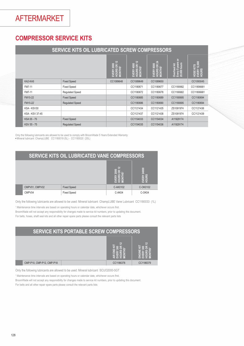
AFTERMARKET
COMPRESSOR SERVICE KITS
1 Maintenance time intervals are based on operating hours or calendar date, whichever occurs first.BroomWade will not accept any responsibility for changes made to service kit numbers, prior to updating this document.For belts, hoses, shaft seal kits and all other repair spare parts please consult the relevant parts lists
Only the following lubricants are allowed to be used to comply with BroomWade 5 Years Extended Warranty:• Mineral lubricant ChampLUBE CC1180019 (5L) - CC1180020 (20L)
SERVICE KITS OIL LUBRICATED SCREW COMPRESSORS
EVER
Y 20
00
HOUR
S OR
12
MONT
HS1
EVER
Y 40
00
HOUR
S OR
12
MONT
HS1
EVER
Y 80
00
HOUR
S OR
24
MONT
HS1
Over
haul
kit
Ever
y 5 ye
ars o
r 20
.000 h
ours
HOSE
KIT
S EV
ERY
12,00
0 HO
URS
KA2-KA5 Fixed Speed CC1089648 CC1089649 CC1089650 CC1093045
FM7-11 Fixed Speed CC1180671 CC1180677 CC1180682 CC11806681
FM7-11 Regulated Speed CC1180672 CC1180678 CC1180682 CC11806681
FM15-22 Fixed Speed CC1180685 CC1180689 CC1180695 CC1180694
FM15-22` Regulated Speed CC1180686 CC1180690 CC1180695 CC1180694
KSA - KSV30 CC1121434 CC1121435 ZS1091974 CC1121436
KSA - KSV 37-45 CC1121437 CC1121438 ZS1091974 CC1121439
KSA 55 - 75 Fixed Speed CC1154033 CC1154034 A11929174
KSV 55 - 75 Regulated Speed CC1154035 CC1154036 A11929174
SERVICE KITS OIL LUBRICATED VANE COMPRESSORS
EVER
Y 20
00
HOUR
S OR
12
MONT
HS1
EVER
Y 24
000
HOUR
S
CMPV01, CMPV02 Fixed Speed C-AK0102 C-OK0102
CMPV04 Fixed Speed C-AK04 C-OK04
SERVICE KITS PORTABLE SCREW COMPRESSORS
AIR
END
KIT
EV
ERY
300
HOUR
S OR
12
MONT
HS1
ENGI
NE K
IT
EV
ERY
300
HOUR
S OR
12
MONT
HS1
CMP-P10, CMP-P12, CMP-P18 CC1186378 CC1186379
1 Maintenance time intervals are based on operating hours or calendar date, whichever occurs first.BroomWade will not accept any responsibility for changes made to service kit numbers, prior to updating this document.For belts and all other repair spare parts please consult the relevant parts lists
Only the following lubricants are allowed to be used: Mineral lubricant ChampLUBE Vane Lubricant CC1180033 (1L)
Only the following lubricants are allowed to be used: Mineral lubricant SCUO2000-5GT
128

SERVICE KITS PISTON COMPRESSORSC-Base, C-Line, C-Advanced, C-Pro, C-Engine series
MODEL RANGES GASKET KIT VALVE PLATE KIT INTAKE FILTER NRV
CA3 ; CL3 ; CS3 CC55886980 CC91894881 CC55875132 CC55894513
CA4 ; CP4 ; CS4 CC92060037 CC97155576 CC55875132 CC55894513
CA5 ; CL5 CC55893648 CC55893622 CC55898936 CC55894521
CA6; CP6 ; CS6 CC97241376 CC97159594 CC55898936 CC55894521
CA10 ; CL10 ; CP10 ; CS10 CC55893655 CC55894133 CC55898936 CC55894521
CA15 ; CP15 ; CS15 CC55894224 CC55894141 CC55898936 CC55894521
CA28 ; CL28 ; CP28 CC97251615 CC91894881 CC55875140 CC97160634
CB-100-CM2CB-24-CM2CB-3-CF2
CB-50-CM2
CC55899108 CC55899090 CC55899132 CC97160634
CB-100-CM3CB-24-WB3CB-50-CM3
CB-50V-CM3
CC55899405 CC55899090 CC55899132 CC55904375
CB-100-CM25CB-24-CM25CB-50-CM25
CC55899090 CC55890079 CC97160634
CB6 CC55890087
SERVICE KITS OIL FREE SCROLL COMPRESSORS
S04,
S06,
S08
S07D
, S11
D, S
15D
300SMB1445 Air Filter (4kW x 1, 6 & 8kW x 2) x 1 x 2
300SMB6029 Tip seal kit 2 & 4kW x 1 x 2
300SMB6022 Grease 80 grams Refer to manual for quantites
302SIA6003 Kit 6kW Bushing & spring x 1 x 2
300SIA6003 Kit 6kW Service kit (includes tip seal, face seal & grease) x 1 x 2
301SIA6003 Kit 7kW Service kit (includes tip seal, face seal & grease) x 1 x 2
300SMB6031 Grease gun
Only the following lubricants are allowed to be used
• SAE40 - Viscosity 100
129
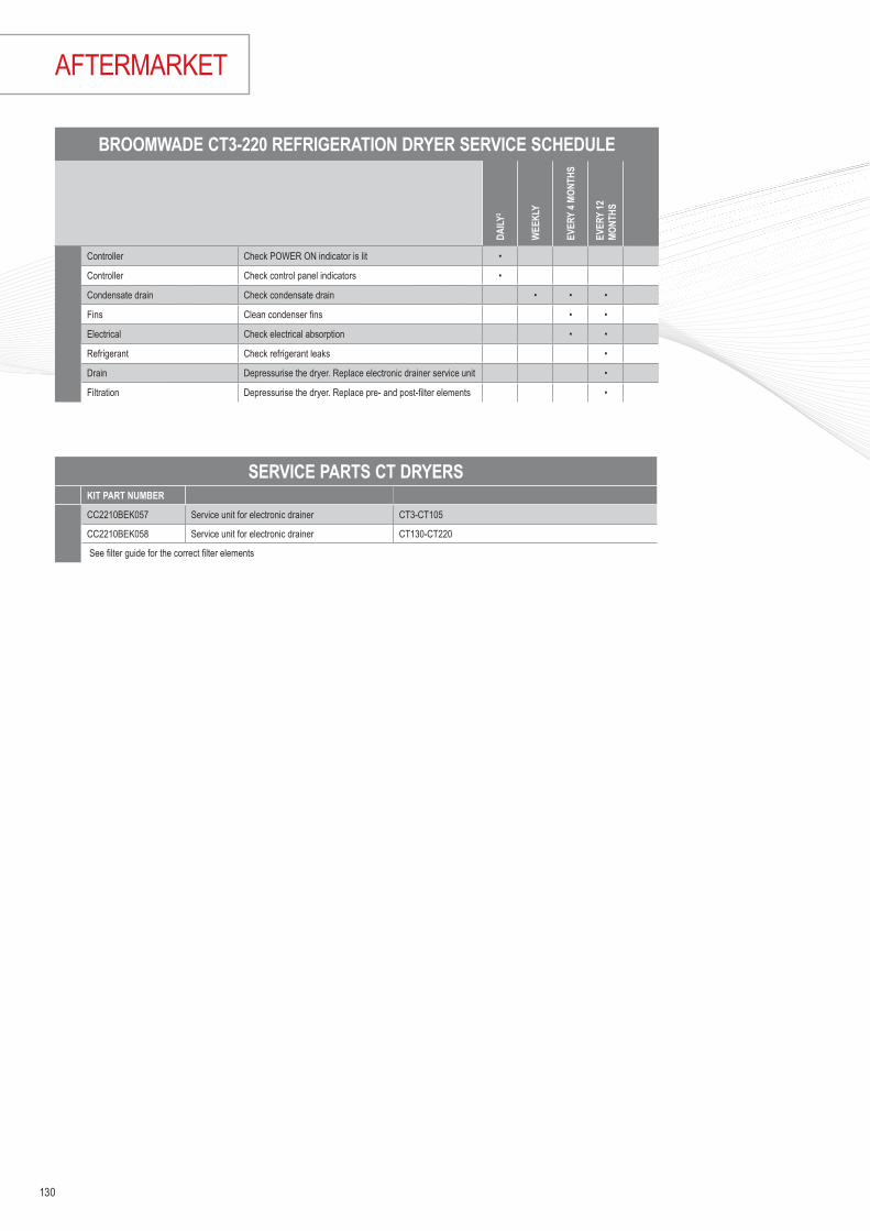
AFTERMARKET
BROOMWADE CT3-220 REFRIGERATION DRYER SERVICE SCHEDULE
DAILY
2
WEE
KLY
EVER
Y 4 M
ONTH
S
EVER
Y 12
MO
NTHS
Controller Check POWER ON indicator is lit •
Controller Check control panel indicators •
Condensate drain Check condensate drain • • •
Fins Clean condenser fins • •
Electrical Check electrical absorption • •
Refrigerant Check refrigerant leaks •
Drain Depressurise the dryer. Replace electronic drainer service unit •
Filtration Depressurise the dryer. Replace pre- and post-filter elements •
SERVICE PARTS CT DRYERSKIT PART NUMBER
CC2210BEK057 Service unit for electronic drainer CT3-CT105
CC2210BEK058 Service unit for electronic drainer CT130-CT220
See filter guide for the correct filter elements
130

ADSORPTION AIR DRYERS BROOMWADE CHA-DRY SERVICE SCHEDULE
DAILY
2
EVER
Y 20
00
HOUR
S OR
3 MO
NTHS
1
EVER
Y 80
00
HOUR
S OR
12
MONT
HS1
EVER
Y 16
000
HOUR
S OR
24
MONT
HS1
EVER
Y 56
000
HOUR
S OR
48
MONT
HS1
Dryer Check POWER ON indicator is illuminated •
Dryer Check STATUS / FAULT indicators located on the controller. •
Dryer Check for air leaks •
Dryer Check the condition of electrical supply cables and conduits. • • • •
Dryer Check for cyclic operation. • • •
Filtration Check Drain operation • • • •
A Dryer Replace active exhaust silencers Recommended Service A † † †
B Filtration Replace the inlet and outlet air filters and service drains. Recommended Service B † † †
D Dryer Replace valves Recommended Service C † †
E Dryer Replace the Desiccant. Recommended Service E †
KITS FOR CHA-DRY 6 - 200KIT PART NUMBER
A
CC1182876 1 year silencer replacement kit 06-36 2 x purge exhaust silencer
CC1182877 1 year silencer replacement kid 75-105 2 x purge exhaust silencer
CC1182878 1 year silencer replacement kid 150-200 2 x purge exhaust silencer
D
CC1182832 2 year replacement kit 06 4 x replacement control valves
CC1182835 2 year replacement kit 12 2 x replacement non-return valves
CC1182818 2 year replacement kit 24 4 x sealing O-ring
CC1182820 2 year replacement kit 36 2 x nozzle
2 x purge exhaust silencer
CC1182821 2 year replacement kit 60 4 x replacement control valves
CC1182822 2 year replacement kit 75 2 x replacement non-return valves
CC1182823 2 year replacement kit 105 4 x sealing O-ring
2 x nozzle
2 x purge exhaust silencer
CC1182854 2 year replacement kit 150 4 x replacement control valves
CC1182855 2 year replacement kit 200 4 x replacement non-return valves
4 x sealing O-ring
2 x nozzle
2 x purge exhaust silencer
E
CC1182857 KIT Service CHA-DRY 06/48 1 x 2 year replacement kit 06-36
48 months replacement kit 2 x tower tubes including molecular sieve for A-DRY 06
CC1182858 KIT Service CHA-DRY 12/48 1 x 2 year replacement kit 06-36
48 months replacement kit 2 x tower tubes including molecular sieve for A-DRY 12
CC1182859 KIT Service CHA-DRY 24/48 1 x 2 year replacement kit 06-36
48 months replacement kit 2 x tower tubes including molecular sieve for A-DRY 24
CC1182860 KIT Service CHA-DRY 36/48 1 x 2 year replacement kit 06-36
48 months replacement kit 2 x tower tubes including molecular sieve for A-DRY 32
CC1182861 KIT Service CHA-DRY 60/48 1 x 2 year replacement kit 60-105
48 months replacement kit 2 x tower tubes including molecular sieve for A-DRY 60
CC1182862 KIT Service CHA-DRY 75/48 1 x 2 year replacement kit 60-105
48 months replacement kit 2 x tower tubes including molecular sieve for A-DRY 75
CC1182863 KIT Service CHA-DRY 105/48 1 x 2 year replacement kit 60-105
48 months replacement kit 2 x tower tubes including molecular sieve for A-DRY 105
CC1182874 KIT Service CHA-DRY 150/48 1 x 2 year replacement kit 150-200
48 months replacement kit 2 x tower tubes including molecular sieve for A-DRY 150
CC1182875 KIT Service CHA-DRY 200/48 1 x 2 year replacement kit 150-200
48 months replacement kit 2 x tower tubes including molecular sieve for A-DRY 200
1 Maintenance time intervals are based on operating hours or calendar date, whichever occurs first. • Performed by the operator † Essential maintenance - Service personnel only
131

AFTERMARKET
1] Maintenance time intervals are based on operating hours or calendar date, whichever occurs first. • Performed by the operator † Essential maintenance - Service personnel only
ADSORPTION AIR DRYERS BROOMWADE CHB-DRY SERVICE SCHEDULE
DAILY
2
EVER
Y 20
00 H
OURS
OR
3 MO
NTHS
1
EVER
Y 80
00 H
OURS
OR
12 M
ONTH
S1
EVER
Y 16
000
HOUR
S OR
24
MONT
HS1
EVER
Y 56
000
HOUR
S OR
48
MONT
HS1
Dryer Check POWER ON indicator is illuminated •Dryer Check STATUS / FAULT indicators located on the controller. •Dryer Check for air leaks •Dryer Check the condition of electrical supply cables and conduits. • • • •Dryer Check for cyclic operation • • •Filtration Check Drain operation • • • •
A Dryer Replace active exhaust silencers Recommended Service A † † †
B Filtration Replace the inlet and outlet air filters and service drains. Recommended Service B † † †
D Dryer Replace valves Recommended Service C † †
E
Dryer Replace the Desiccant. Recommended Service E †Dryer Clean/Replace Strainers †Dryer Calibrate Dew-point sensor (optional) †
KITS FOR CHB-DRY 110 - 1000KIT PART NUMBER
A
CC1182775 Silencer kit CHB-DRY 110-250 Silencer service kit for B-DRY 110/150/200/250
CC1182776 Silencer kit CHB-DRY 300-600 Silencer service kit for B-DRY 300/400/600
CC1182777 Silencer kit CHB-DRY 800-1000 Silencer service kit for B-DRY 800/1000
D
CC1182893 KIT SERVIS CHB-DRY 110-250/24 Control valves replacement components
24 months replacement kit
CC1182894 KIT SERVIS CHB-DRY 300-600/24 Check valves replacement components
24 months replacement kit Silencer service kit
CC1182895 KIT SERVIS CHB-DRY 800-1000/24 Check valves replacement components
24 months replacement kit Silencer service kit
E
CC1182746 KIT SERVIS CHB-DRY 110/48 Control valves replacement components
48 months replacement kit Check valves replacement components Silencer service kit
CC1182747 KIT SERVIS CHB-DRY 150/48 Control valves replacement components
48 months replacement kit Check valves replacement components Silencer service kit
CC1182748 KIT SERVIS CHB-DRY 200/48 Control valves replacement components
48 months replacement kit Check valves replacement components Silencer service kit
CC1182749 KIT SERVIS CHB-DRY 250/48 Control valves replacement components
48 months replacement kit Check valves replacement components Silencer service kit
CC1182750 KIT SERVIS CHB-DRY 300/48 Control valves replacement components
48 months replacement kit Check valves replacement components Silencer service kit
CC1182751 KIT SERVIS CHB-DRY 400/48 Control valves replacement components
48 months replacement kit Check valves replacement components Silencer service kit
CC1182752 KIT SERVIS CHB-DRY 600/48 Control valves replacement components
48 months replacement kit Check valves replacement components Silencer service kit
CC1182753 KIT SERVIS CHB-DRY 800/48 Control valves replacement components
48 months replacement kit Check valves replacement components Silencer service kit
CC1182774 KIT SERVIS CHB-DRY 1000/48 Control valves replacement components
48 months replacement kit Check valves replacement components Silencer service kit
132

1] Maintenance time intervals are based on operating hours or calendar date, whichever occurs first. • Performed by the operator † Essential maintenance - Service personnel only
ADSORPTION AIR DRYERS BROOMWADE CHX-DRY SERVICE SCHEDULE
DAILY
2
EVER
Y 20
00 H
OURS
OR
3 MO
NTHS
1
EVER
Y 80
00 H
OURS
OR
12 M
ONTH
S1
EVER
Y 16
000 H
OURS
OR
24 M
ONTH
S1
EVER
Y 56
000 H
OURS
OR
48 M
ONTH
S1
Dryer Check POWER ON indicator is illuminated •
Dryer Check STATUS / FAULT indicators located on the controller. •
Dryer Check for air leaks •
Dryer Check the condition of electrical supply cables and conduits. • • • •
Dryer Check for cyclic operation. • • •
Filtration Check Drain operation • • • •
A Dryer Replace active exhaust silencers Recommended Service A † † †
B Filtration Replace the inlet and outlet air filters and service drains. Recommended Service B † † †
D Dryer Replace valves Recommended Service C † †
E
Dryer Replace the Desiccant. Recommended Service E †Dryer Clean/Replace Strainers †Dryer Calibrate Dew-point sensor (optional) †
KITS FOR CHX-DRY 350 - 1050KIT PART NUMBER
A CC1182891 Silencer CHX-DRY 300-1050 Silencer service X-DRY 300-1050
D
CC1182879 KIT Service CHX-DRY 300/24 Control and check valves replacement components
24 months replacement kit Silencer service kit
CC1182880 KIT Service CHX-DRY 450/24 Control and check valves replacement components
24 months replacement kit Silencer service kit
CC1182881 KIT Service CHX-DRY 600/24 Control and check valves replacement components
24 months replacement kit Silencer service kit
CC1182882 KIT Service CHX-DRY 750/24 Control and check valves replacement components
24 months replacement kit Silencer service kit
CC1182883 KIT Service CHX-DRY 900/24 Control and check valves replacement components
24 months replacement kit Silencer service kit
CC1182884 KIT Service CHX-DRY 1050/24 Control and check valves replacement components
24 months replacement kit Silencer service kit
E
CC1182885 KIT Service CHX-DRY 300/48 Control and check valves replacement components
48 months replacement kit Silencer service kit Adsorbent
CC1182886 KIT Service CHX-DRY 450/48 Control and check valves replacement components
48 months replacement kit Silencer service kit Adsorbent
CC1182887 KIT Service CHX-DRY 600/48 Control and check valves replacement components
48 months replacement kit Silencer service kit Adsorbent
CC1182888 KIT Service CHX-DRY 750/48 Control and check valves replacement components
48 months replacement kit Silencer service kit Adsorbent
CC1182889 KIT Service CHX-DRY 900/48 Control and check valves replacement components
48 months replacement kit Silencer service kit Adsorbent
CC1182890 KIT Service CHX-DRY 1050/48 Control and check valves replacement components
48 months replacement kit Silencer service kit Adsorbent
133

AFTERMARKET
KITS FOR CH-TAC ACTIVATED CARBON TOWERSKIT PART NUMBER
CH-TACm 6 CC1189474 Service Kit CH-TACm 6
CH-TACm 12 CC1189475 Service Kit CH-TACm 12
CH-TACm 23 CC1189476 Service Kit CH-TACm 23
CH-TACm 35 CC1189477 Service Kit CH-TACm 35
CH-TACm 56 CC1189478 Service Kit CH-TACm 56
CH-TACm 70 CC1189479 Service Kit CH-TACm 70
CH-TACm 105 CC1189480 Service Kit CH-TACm 105
CH-TAC 110 CC1189481 Service Kit CH-TAC 110
CH-TAC 150 CC1189482 Service Kit CH-TAC 150
CH-TAC 200 CC1189483 Service Kit CH-TAC 200
CH-TAC 250 CC1189484 Service Kit CH-TAC 250
CH-TAC 300 CC1189485 Service Kit CH-TAC 300
CH-TAC 400 CC1189486 Service Kit CH-TAC 400
CH-TAC 600 CC1189487 Service Kit CH-TAC 600
CH-TAC 800 CC1189488 Service Kit CH-TAC 800
CH-TAC 1000 CC1189489 Service Kit CH-TAC 1000
CH-TAC 1200 CC1189490 Service Kit CH-TAC 1200
CH-TAC 1500 CC1189491 Service Kit CH-TAC 1500
CH-TAC 2000 CC1189492 Service Kit CH-TAC 2000
CH-TAC 2500 CC1189493 Service Kit CH-TAC 2500
CH-TAC 3000 CC1189494 Service Kit CH-TAC 3000
CH-TAC 3750 CC1189495 Service Kit CH-TAC 3750
CH-TAC 5000 CC1189496 Service Kit CH-TAC 5000
CH-TAC 6500 CC1189497 Service Kit CH-TAC 6500
134

FILTER GUIDEFILTER TYPE M3/MIN SIZE FILTER ID NO FILTER ELEMENT ELEMENT NO
CERAMIC PRE-FILTERS 3 MICRONF 005 P 1 3/8" 223051A Filter Cartridge F005P 223171F 007 P 1.3 1/2" 223052A Filter Cartridge F007P 223172F 010 P 2 3/4" 223053A Filter Cartridge F010P 223173F 018 P 3.3 1 " 223054A Filter Cartridge F018P 223174F 030 P 5.5 1 " 223055A Filter Cartridge F030P 223175F 047 P 8.5 1 1/2" 223056A Filter Cartridge F047P 223176F 070 P 13 1 1/2" 223057A Filter Cartridge F070P 223177F 094 P 16.6 2" 223058A Filter Cartridge F094P 223178F 150 P 25 2" 223059A Filter Cartridge F150P 223179F 200 P 36 3" CC1182427 Filter Cartridge F200P CC1183012F 240 P 46 3" 223060A Filter Cartridge F240P 223180COALESCENT FILTERS 0.1 MICRONF 005 R 1 3/8" CC1185088 Filter Cartridge F005R CC1185073F 007 R 1.3 1/2" CC1185089 Filter Cartridge F007R CC1185074F 010 R 2 3/4" CC1185090 Filter Cartridge F010R CC1185075F 018 R 3.3 1 " CC1185091 Filter Cartridge F018R CC1185076F 030 R 5.5 1 " CC1185092 Filter Cartridge F030R CC1185077F 047 R 8.5 1 1/2" CC1185093 Filter Cartridge F047R CC1185078F 070 R 13 1 1/2" CC1185094 Filter Cartridge F070R CC1185079F 094 R 16.6 2" CC1185095 Filter Cartridge F094R CC1185080F 150 R 25 2" CC1185096 Filter Cartridge F150R CC1185081F 200 R 36 3" CC1185097 Filter Cartridge F200R CC1185082F 240 R 46 3" CC1185098 Filter Cartridge F240R CC1185083COALESCENT FILTERS 0.1 MICRONF 005 M 1 3/8" 223061A Filter Cartridge F005M 223181F 007 M 1.3 1/2" 223062A Filter Cartridge F007M 223182F 010 M 2 3/4" 223063A Filter Cartridge F010M 223183F 018 M 3.3 1" 223065A Filter Cartridge F018M 223184F 030 M 5.5 1" 223066A Filter Cartridge F030M 223185F 047 M 8.5 1 1/2" 223067A Filter Cartridge F047M 223186F 070 M 13 1 1/2" 223068A Filter Cartridge F070M 223187F 094 M 16.6 2" 223069A Filter Cartridge F094M 223188F 150 M 25 2" 223081A Filter Cartridge F150M 223189F 200 M 36 3" CC1182428 Filter Cartridge F200M CC1183034F 240 M 46 3" 223064A Filter Cartridge F240M 223190COALESCENT FILTERS 0.01 MICRONF 005 S 1 3/8" 223070A Filter Cartridge F005S 223191F 007 S 1.3 1/2" 223071A Filter Cartridge F007S 223192F 010 S 2 3/4" 223072A Filter Cartridge F010S 223193F 018 S 3.3 1" 223073A Filter Cartridge F018S 223194F 030 S 5.5 1" 223074A Filter Cartridge F030S 223195F 047 S 8.5 1 1/2" 223075A Filter Cartridge F047S 223196F 070 S 13 1 1/2" 223076A Filter Cartridge F070S 223197F 094 S 16.6 2" 223077A Filter Cartridge F094S 223198F 150 S 25 2" 223078A Filter Cartridge F150S 223199F 200 S 36 2 1/2” CC1182429 Filter Cartridge F200S CC1183035F 240 S 46 3" 223079A Filter Cartridge F240S 223200ACTIVATED CARBON FILTERS 0.005 MICRONF 005 A 1 3/8" 223090A Filter Cartridge F005A 223211F 007 A 1.3 1/2" 223091A Filter Cartridge F007A 223212F 010 A 2 3/4" 223092A Filter Cartridge F010A 223213F 018 A 3.3 1" 223093A Filter Cartridge F018A 223214F 030 A 5.5 1" 223094A Filter Cartridge F030A 223215F 047 A 8.5 1 1/2" 223095A Filter Cartridge F047A 223216F 070 A 13 1 1/2" 223096A Filter Cartridge F070A 223217F 094 A 16.6 2" 223097A Filter Cartridge F094A 223218F 150 A 25 2" 223098A Filter Cartridge F150A 223219F 200 A 36 3" CC1182430 Filter Cartridge F200A CC1183036F 240 A 46 3" 223099A Filter Cartridge F240A 223220
FILTER ELEMENTS MUST BE REPLACED AT LEAST EVERY 12 MONTHS
135

AFTERMARKET
FILTER ELEMENTS MUST BE REPLACED AT LEAST EVERY 12 MONTHS
FILTER GUIDEFILTER TYPE M3/MIN SIZE FILTER ID NO FILTER ELEMENT ELEMENT NO
CONDENSATION SEPARATING FILTERSF 005 W 1 3/8" CC1177720 Filter Cartridge F 005W CC1188141F 007 W 1.3 1/2" CC1177721 Filter Cartridge F 007W CC1188142F 010 W 2 3/4" 223101A Filter Cartridge F 010W CC1183037F 030 W 3.3 1" 223102A Filter Cartridge F 030W CC1183038F 070 W 8.5 1 1/2" 223103A Filter Cartridge F 070W CC1183039F 094 W 16.6 2" CC1181853 Filter Cartridge F 094W CC1183040F 150 W 25 2" 223104A Filter Cartridge F 150W CC1183041F 200 W 36 2 1/2" CC1182432 Filter Cartridge F 200W CC1183042CH-MDRY MEMBRANE FILTERSCHM-DRY 3 0.05 1/4" CC1189577 Membrane CHM-DRY 3 CC1189462CHM-DRY 6 0.1 1/4” CC1189578 Membrane CHM-DRY 6 CC1189463CHM-DRY 9 0.15 1/4” CC1189579 Membrane CHM-DRY 9 CC1189464CHM-DRY 12 0.2 1/4” CC1189580 Membrane CHM-DRY 12 CC1189465CHM-DRY 18 0.3 1/2" CC1189581 Membrane CHM-DRY 18 CC1189466CHM-DRY 24 0.4 1/2” CC1189582 Membrane CHM-DRY 24 CC1189467CHM-DRY 32 0.6 1/2” CC1189583 Membrane CHM-DRY 32 CC1189468CHM-DRY 44 0.8 1/2" CC1189584 Membrane CHM-DRY 44 CC1189469CHM-DRY 63 1.05 1/2” CC1189585 Membrane CHM-DRY 63 CC1189470CHM-DRY 90 1.5 1/2” CC1189586 Membrane CHM-DRY 90 CC1189471CHM-DRY 123 2.05 1/2” CC1189587 Membrane CHM-DRY 123 CC1189472CHM-DRY 180 3 1/2” CC1189588 Membrane CHM-DRY 180 CC1189473
CHB-AIR BREATING AIR FILTRATON SYSTEMS
FILTER TYPE ELEMENT TYPE (FM) ELEMENT NO ELEMENT TYPE (F-H2M) ELEMENT NO ELEMENT TYPE (F-A2) ELEMENT NO
CHB-AIR 76 Filter Cartridge F007M 223182 Filter Cartridge F007H2 CC1189441 Filter Cartridge F007A2 CC1189354CHB-AIR 106 Filter Cartridge F010M 223183 Filter Cartridge F010H2 CC1189442 Filter Cartridge F010A2 CC1189434CHB-AIR 186 Filter Cartridge F018M 223184 Filter Cartridge F018H2 CC1189443 Filter Cartridge F018A2 CC1189435CHB-AIR 306 Filter Cartridge F030M 223185 Filter Cartridge F030H2 CC1189454 Filter Cartridge F030A2 CC1189437CHB-AIR 476 Filter Cartridge F047M 223186 Filter Cartridge F047H2 CC1189455 Filter Cartridge F047A2 CC1189438CHB-AIR 706 Filter Cartridge F070M 223187 Filter Cartridge F070H2 CC1189456 Filter Cartridge F070A2 CC1189439
CHB-AIR PLUS PORTABLE BREATING AIR FILTRATON SYSTEMSFILTER TYPE ELEMENT TYPE (FM) ELEMENT NO ELEMENT TYPE (F-H2M) ELEMENT NO ELEMENT TYPE (F-A2) ELEMENT NO
CHB-AIR plus Filter Cartridge F007M 223182 Filter Cartridge F007H2 CC1189441 Filter Cartridge F007A2 CC1189354
CH-PP SERIES PAINTING AIR FILTRATION SYSTEMS
FILTER TYPE ELEMENT TYPE (FM) ELEMENT NO ELEMENT TYPE (F-S) ELEMENT NO ELEMENT TYPE (F-A) ELEMENT NO ELEMENT TYPE (CKL-PP) ELEMENT NO
CH-PP-107 Filter Cartridge F007-CKL-PP CC1189457
CH-PP-110 Filter Cartridge F010-CKL-PP CC1189458
CH-PP-207 Filter Cartridge F007M 223182 Filter Cartridge F007-CKL-PP CC1189457
CH-PP-210 Filter Cartridge F010M 223183 Filter Cartridge F010-CKL-PP CC1189458
CH-PP-307 Filter Cartridge F007M 223182 Filter Cartridge F007S 223192 Filter Cartridge F007-CKL-PP CC1189457
CH-PP-310 Filter Cartridge F010M 223183 Filter Cartridge F010S 223193 Filter Cartridge F010-CKL-PP CC1189458
CH-PP-407 Filter Cartridge F007M 223182 Filter Cartridge F007S 223192 Filter Cartridge F007A 223212
CH-PP-410 Filter Cartridge F010M 223183 Filter Cartridge F010S 223193 Filter Cartridge F010A 223213
CH-PP-507 Filter Cartridge F007M 223182 Filter Cartridge F007S 223192
CH-PP-510 Filter Cartridge F010M 223183 Filter Cartridge F010S 223193
CH-PP-607 Filter Cartridge F007M 223182 Filter Cartridge F007S 223192
CH-PP-610 Filter Cartridge F010M 223183 Filter Cartridge F010S 223193
136

1 Maintenance time intervals are based on operating hours or calendar date, whichever occurs first. • Performed by the operator ∆ Essential procedure - Service personnel only † Essential maintenance - Service personnel only
BROOMWADE CHNP 3 - 400 NITROGEN GENERATORS SERVICE SCHEDULE
DAILY
2
EVER
Y 20
00 H
OURS
OR
3 MO
NTHS
1
EVER
Y 40
00 H
OURS
OR
6 MO
NTHS
1
EVER
Y 80
00 H
OURS
OR
12 M
ONTH
S1
EVER
Y 16
000 H
OURS
OR
24 M
ONTH
S1
EVER
Y 24
000 H
OURS
OR
36 M
ONTH
S1
EVER
Y 40
000 H
OURS
OR
60 M
ONTH
S1
Generator Check the status indicators located on the front panel. •System Check the inlet air quality • • • • • •Generator Check for air leaks • • • • • •Generator Check the pressure gauges during purging for excessive back pressure • • • • • •Generator Check the condition of the electrical supply cables and conduits • • • • • •Generator Check oxygen sensor(s) and calibrate if necessary ∆ ∆ ∆ ∆ ∆ ∆Generator Check for cyclic operation • • • • •
A Filtration Replace Exhaust silencer and filter element(s) Recommended Service A † † † †
B Generator Replace Oxygen sensor(s) Recommended Service B † † †
C Generator Replace control valves Recommended Service C † †
D Generator Replace cylinder and solenoid valves Recommended Service D †
KITS FOR CHNP NITROGEN GENERATORSKIT PART NUMBER
A
CC1182786 Silencer CHNP 110-250
CC1182787 Silencer CHNP 300-400
D
CC1182778 CHNP-GEN 05-15/12 Silencer, cartridges
CC1182779 CHNP-GEN 20-35/12 Silencer, cartridges
CC1182780 CHNP-GEN 60-100/12 Silencer, cartridges
CC1182781 CHNP-GEN 200/12 Silencer, cartridges
CC1182782 CHNP-GEN 300/12 Silencer, cartridges
CC1182783 CHNP-GEN 400/12 Silencer, cartridges
E
CC1182789 CHNP-GEN 03/48 Valve, silencers, adsorbent
CC1182790 CHNP-GEN 05/48 Valve, silencers, adsorbent
CC1182792 CHNP-GEN 10/48 Valve, silencers, adsorbent
CC1182794 CHNP-GEN 15/48 Valve, silencers, adsorbent
CC1182795 CHNP-GEN 20/48 Valve, silencers, adsorbent
CC1182797 CHNP-GEN 25/48 Valve, silencers, adsorbent
CC1182798 CHNP-GEN 35/48 Valve, silencers, adsorbent
CC1182800 CHNP-GEN 50/48 Valve, silencers, adsorbent
CC1182801 CHNP-GEN 65/48 Valve, silencers, adsorbent
CC1182803 CHNP-GEN 100/48 Valve, silencers, adsorbent
CC1182804 CHNP-GEN 150/48 Valve, silencers, adsorbent
CC1182805 CHNP-GEN 200/48 Valve, silencers, adsorbent
CC1182807 CHNP-GEN 250/48 Valve, silencers, adsorbent
CC1182808 CHNP-GEN 300/48 Valve, silencers, adsorbent
CC1182810 CHNP-GEN 400/48 Valve, silencers, adsorbent
TBA Oxygen Anaylzer 0-1.000 ppm Service Kit
TBA Oxygen Anaylzer 0-25% Service Kit
137

SERVICE KITS FOR LEGACY PRODUCTS
MODEL BASIC STANDARD ADVANCED
KA2-KA5 CC1089648 CC1089649 CC1089650KA6 CC1089648 CC1125182 CC1125184KA7 Plus CC1089652 CC1125190 CC1125192KSA11-KSA15 CC1089656 CC1089657 CC1089658KSA18-KSA22 CC1089661 CC1089662 CC1089663KSA 30 CC1090691 CC1121434 CC1121435KSA 37 - CC1121437 CC1121438KSA55-KSA75 CC1154032 CC1154033 CC1154034KS97 CC1090695 CC1090696 CC1090697KSV11-KSV15 CC1089656 CC1089657 CC1089658KSV18-KSV22 CC1089661 CC1089662 CC1089663KSV30 CC1090691 CC1121434 CC1121435KSV37-KSV45 - CC1121437 CC1121438KSV55-KSV75 CC1154032 CC1154035 CC1154036KSB15-KSB22 - CC1178518 CC1180296KBV15-KBV22 - CC1178518 CC1180296
138

Notes
139

SALES CONDITIONS
SALES CONDITIONS & PRICESPrices are valid for orders received on or after 1st June 2019Prices shown are in the currency indicated ex-works (Incoterms 2000) Lonate, Pozzolo, Italy with the following exceptions:
In the case of a discrepancy in price, the BroomWade system is the system of record containing the correct price.
Individual quotations and orders are subject to the standard terms and conditions.
The products contained within the price list are manufactured in compliance with EU directives and other national standards.
BroomWade reserve the right to make changes to the design and execution and accept no liability for errors or misprints.
BroomWade reserves the right to modify these prices at any time providing 30 days written notification.
Technical details in price book are for reference only and subject to change. For full technical details and in case of discrepancy the technical data sheets contain the correct information.
[email protected] for sales requests, enquiries & quotations
[email protected] for all aftermarket requests
[email protected] for orders
[email protected] customer feedback
Website: www.broomwade.com
• Vane & Portable Compressors - Redditch, UK• Scroll Oil-Free Compressors - Simmern, Germany
• Spares Parts – Ghent, Belgium
140

Notes
141

Notes
142

Notes
143

A modern production system and process demands increased levels of air quality.
Our complete Air Treatment Range ensures product quality and efficient operation.
YOUR COMPRESSED AIR PARTNER
BroomWade also design and manufacture an enviable range of Rotary Scroll, Rotary Vane and Portable Rotary Screw compressors. All designed to provide efficiency and reliability in the most demanding applications and conditions, these compressors set new standards.
BroomWade's piston compressor range is designed to cover all the possible professional uses of compressed
air. Our piston compressors come in various forms and sizes, providing a truly complete range of choices.
COMPRESSED AIR SOLUTIONS
For additional information please contact your local representative.
Specifications subject to change without notice.
www.broomwade.com
Copyright 2019 BroomWade Air Tech.
BroomWade stationary rotary screw compressors, both fixed and variable speed drive, are the answer to the needs of small and medium-sized companies.


