Embed Size (px)
Citation preview
VRF CATALOGUEHEAT PUMP & HEAT RECOVERY
Variable Refrigerant Flow System
DESIGN for COMFORT
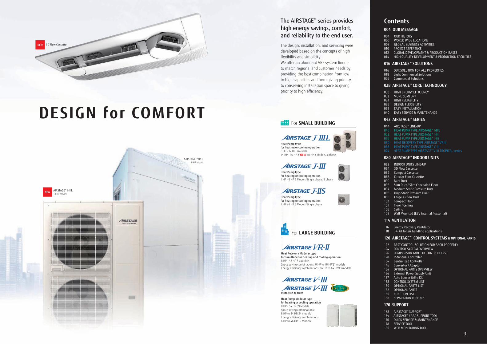
The AIRSTAGE™ series provides high energy savings, comfort, and reliability to the end user.
The design, installation, and servicing were developed based on the concepts of high flexibility and simplicity.We offer an abundant VRF system lineup to match regional and customer needs by providing the best combination from low to high capacities and from giving priority to conserving installation space to giving priority to high efficiency.
NEW AIRSTAGE™ J-IIIL18 HP model
AIRSTAGE™ VR-II8 HP model
Contents004 OUR MESSAGE004 OUR HISTORY006 WORLD WIDE LOCATIONS008 GLOBAL BUSINESS ACTIVITIES010 PROJECT REFERENCE 012 GLOBAL DEVELOPMENT & PRODUCTION BASES 014 HIGH QUALITY DEVELOPMENT & PRODUCTION FACILITIES
016 AIRSTAGE™ SOLUTIONS016 OUR SOLUTION FOR ALL PROPERTIES018 Light Commercial Solutions026 Commercial Solutions
028 AIRSTAGE™ CORE TECHNOLOGY030 HIGH ENERGY EFFICIENCY032 MORE COMFORT034 HIGH RELIABILITY036 DESIGN FLEXIBILITY038 EASY INSTALLATION040 EASY SERVICE & MAINTENANCE
042 AIRSTAGE™ SERIES044 AIRSTAGE™ LINE-UP046 HEAT PUMP TYPE AIRSTAGE™ J-IIIL052 HEAT PUMP TYPE AIRSTAGE™ J-III056 HEAT PUMP TYPE AIRSTAGE™ J-IIS060 HEAT RECOVERY TYPE AIRSTAGE™ VR-II068 HEAT PUMP TYPE AIRSTAGE™ V-III074 HEAT PUMP TYPE AIRSTAGE™ V-III TROPICAL series
080 AIRSTAGE™ INDOOR UNITS082 INDOOR UNITS LINE-UP084 3D Flow Cassette086 Compact Cassette088 Circular Flow Cassette090 Mini Duct092 Slim Duct / Slim Concealed Floor094 Medium Static Pressure Duct096 High Static Pressure Duct098 Large Airflow Duct102 Compact Floor104 Floor / Ceiling106 Ceiling108 Wall Mounted (EEV Internal / external)
114 VENTILATION116 Energy Recovery Ventilator118 DX-Kit for air handling applications
120 AIRSTAGE™ CONTROL SYSTEMS & OPTIONAL PARTS
122 BEST CONTROL SOLUTION FOR EACH PROPERTY124 CONTROL SYSTEM OVERVIEW126 COMPARISON TABLE OF CONTROLLERS128 Individual Controller134 Centralized Controller146 Convertor / Adaptor154 OPTIONAL PARTS OVERVIEW156 External Power Supply Unit157 Auto Louver Grille Kit158 CONTROL SYSTEM LIST160 OPTIONAL PARTS LIST162 OPTIONAL PARTS166 FUNCTION LIST168 SEPARATION TUBE etc.
170 SUPPORT172 AIRSTAGE™ SUPPORT174 AIRSTAGE™ / RAC SUPPORT TOOL176 QUICK SERVICE & MAINTENANCE178 SERVICE TOOL180 WEB MONITORING TOOL
NEW 3D Flow Cassette
For SMALL BUILDING
Heat Pump type for heating or cooling operation4 HP - 6 HP 6 Models/Single phase, 3 phase
Heat Pump type for heating or cooling operation4 HP - 6 HP 3 Models/Single phase
Heat Pump type for heating or cooling operation8 HP - 12 HP 3 Models14 HP - 16 HP & NEW 18 HP 3 Models/3 phase
Heat Recovery Modular typefor simultaneous heating and cooling operation8 HP - 48 HP 34 ModelsSpace saving combinations: 8 HP to 48 HP/21 modelsEnergy efficiency combinations: 16 HP to 44 HP/13 models
Heat Pump Modular typefor heating or cooling operation8 HP - 54 HP 39 ModelsSpace saving combinations: 8 HP to 54 HP/24 modelsEnergy efficiency combinations: 6 HP to 46 HP/15 models
For LARGE BUILDING
Production by order
32
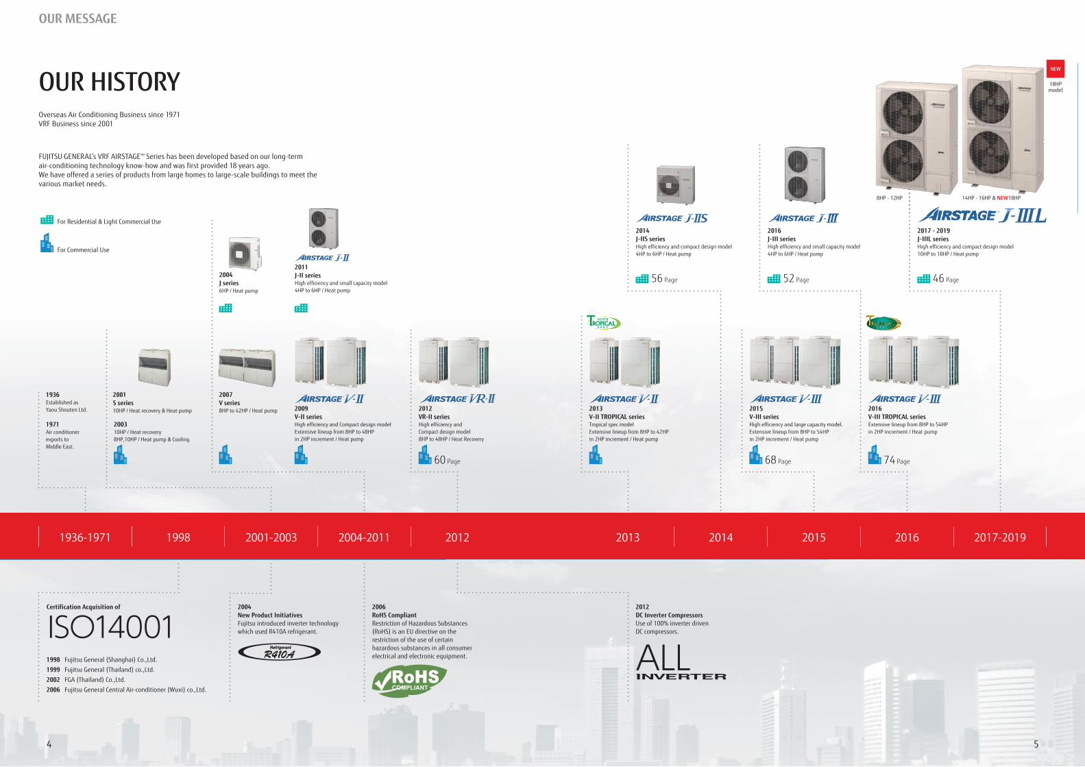
2009V-II seriesHigh efficiency and Compact design modelExtensive lineup from 8HP to 48HP in 2HP increment / Heat pump
200310HP / Heat recovery8HP,10HP / Heat pump & Cooling
2004J series 6HP / Heat pump
2007V series8HP to 42HP / Heat pump
1936Established as Yaou Shouten Ltd.
1971Air conditioner exports to Middle East.
2012VR-II seriesHigh efficiency and Compact design model8HP to 48HP / Heat Recovery
2013V-II TROPICAL seriesTropical spec modelExtensive lineup from 8HP to 42HP in 2HP increment / Heat pump
2014J-IIS seriesHigh efficiency and compact design model4HP to 6HP / Heat pump
2015V-III seriesHigh efficiency and large capacity model. Extensive lineup from 8HP to 54HP in 2HP increment / Heat pump
2016V-III TROPICAL seriesExtensive lineup from 8HP to 54HP in 2HP increment / Heat pump
2016J-III seriesHigh efficiency and small capacity model4HP to 6HP / Heat pump
2011J-II seriesHigh efficiency and small capacity model4HP to 6HP / Heat pump
56 Page
60 Page 68 Page 74 Page
52 Page 46 Page
2017 - 2019J-IIIL seriesHigh efficiency and compact design model10HP to 18HP / Heat pump
Certification Acquisition of 2012DC Inverter CompressorsUse of 100% inverter driven DC compressors.
1998 Fujitsu General (Shanghai) Co.,Ltd.
1999 Fujitsu General (Thailand) co.,Ltd.
2002 FGA (Thailand) Co.,Ltd.
2006 Fujitsu General Central Air-conditioner (Wuxi) co.,Ltd.
For Residential & Light Commercial Use
For Commercial Use
FUJITSU GENERAL’s VRF AIRSTAGETM Series has been developed based on our long-term air-conditioning technology know-how and was first provided 18 years ago.We have offered a series of products from large homes to large-scale buildings to meet the various market needs.
20122004-20112001-200319981936-1971 2013 2014 2015 2016 2017-2019
2006RoHS CompliantRestriction of Hazardous Substances (RoHS) is an EU directive on the restriction of the use of certain hazardous substances in all consumer electrical and electronic equipment.
2004New Product InitiativesFujitsu introduced inverter technology which used R410A refrigerant.
18HPmodel
NEW
2001S series 10HP / Heat recovery & Heat pump
14HP - 16HP & NEW18HP8HP - 12HP
Overseas Air Conditioning Business since 1971VRF Business since 2001
OUR MESSAGE
OUR HISTORY
54
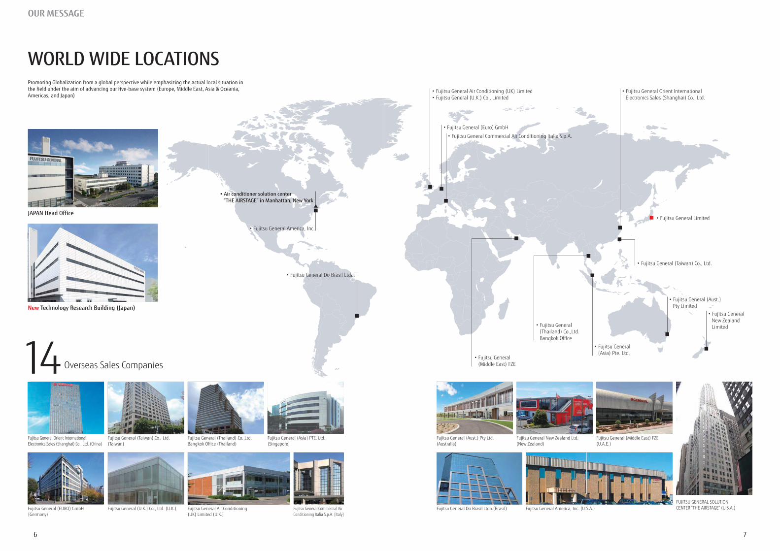
Overseas Sales Companies14 Bangkok Office
“THE AIRSTAGE” in Manhattan, New York
JAPAN Head Office
New Technology Research Building (Japan)
76
WORLD WIDE LOCATIONSPromoting Globalization from a global perspective while emphasizing the actual local situation in the field under the aim of advancing our five-base system (Europe, Middle East, Asia & Oceania, Americas, and Japan)
OUR MESSAGE
98
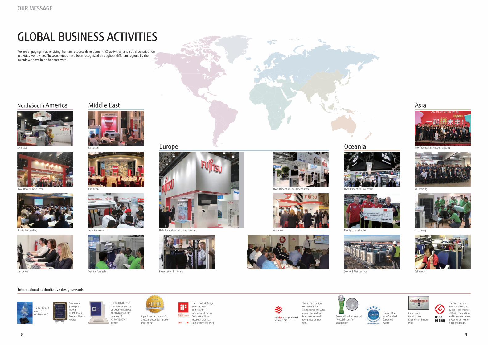
GLOBAL BUSINESS ACTIVITIESWe are engaging in advertising, human resource development, CS activities, and social contribution activities worldwide. These activities have been recognized throughout different regions by the awards we have been honored with.
OUR MESSAGE
industrial products from around the world.
International authoritative design awards
North/South America Middle East
EuropeExhibition
Exhibition
Technical seminar
Presentation & training Training for dealersCall center
Reader’s Choice category of
division
The product design competition has
is an internationally recognized quality seal.
and is awarded once a year for an item of excellent design.
Oceania
Asia
VRF training
Service & Maintenance
SE training
Call center
Super brand is the world’slargest independent arbiterof branding
b d h ld’
2018
UAE’S CHOICE
China State Construction
Prize
Canstar Blue Most Satisfied Customers
Conditioner"
1110
PROJECT REFERENCE
OUR MESSAGE
14
8
11
12
15 16
13
1
2 3
5
4
6 7
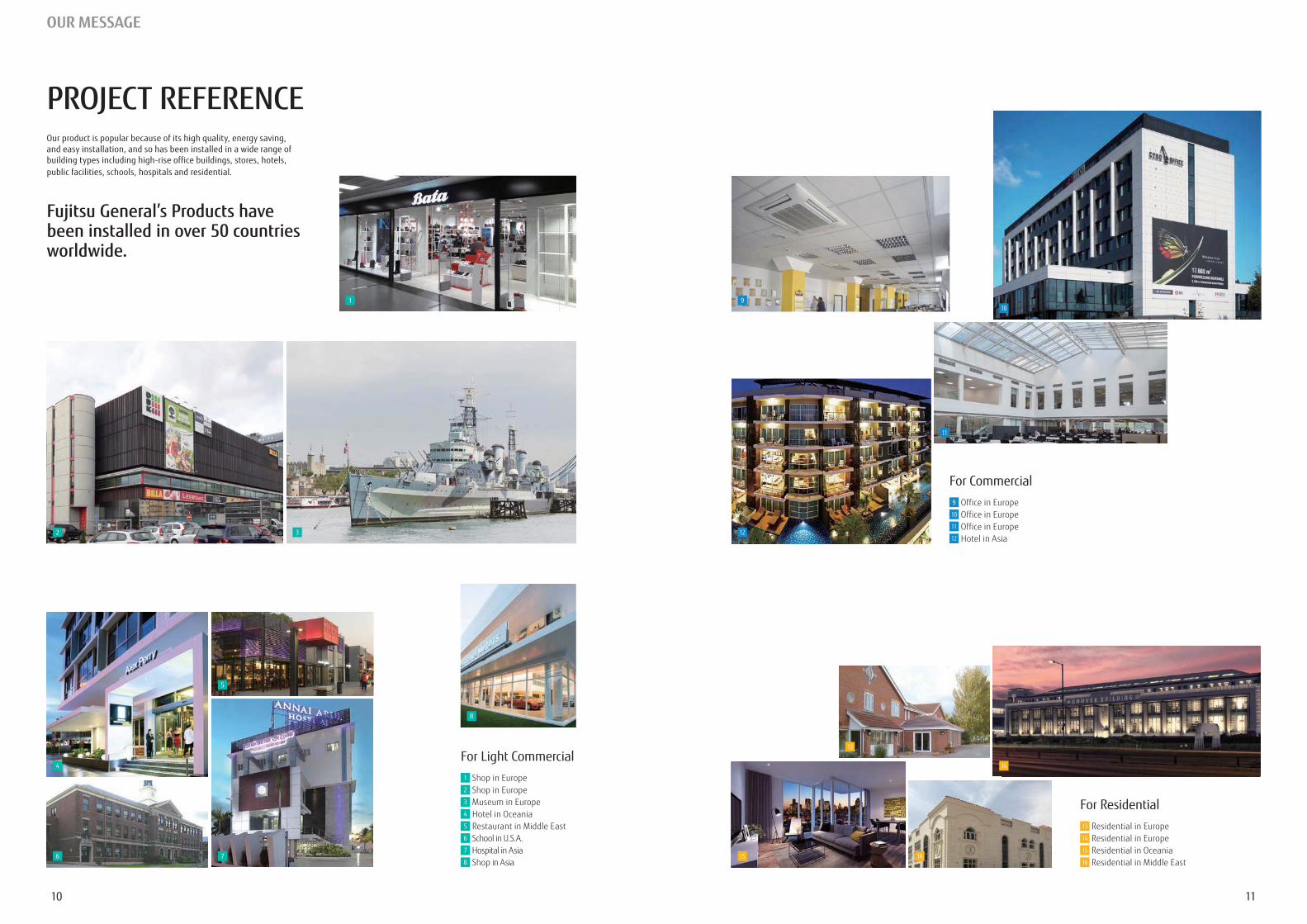
For Light Commercial1 Shop in Europe2 Shop in Europe3 Museum in Europe4 Hotel in Oceania5 Restaurant in Middle East6
7
8
For Commercial9 Office in Europe10 Office in Europe11 Office in Europe12
For Residential13 Residential in Europe14 Residential in Europe15 Residential in Oceania 16 Residential in Middle East
Our product is popular because of its high quality, energy saving, and easy installation, and so has been installed in a wide range of building types including high-rise office buildings, stores, hotels, public facilities, schools, hospitals and residential.
Fujitsu General’s Products have been installed in over 50 countries worldwide.
910
1312
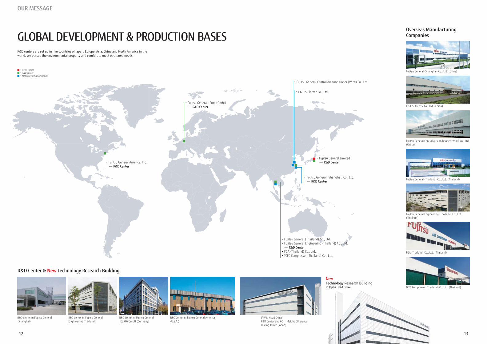
GLOBAL DEVELOPMENT & PRODUCTION BASESR&D centers are set up in five countries of Japan, Europe, Asia, China and North America in the world. We pursue the environmental property and comfort to meet each area needs.
OUR MESSAGE
Overseas Manufacturing Companies
R&D Center & New Technology Research Building
- R&D Center
- R&D Center
New Technology Research Building in Japan Head Office
- R&D Center
- R&D Center
- R&D Center
HIGH QUALITY DEVELOPMENT & PRODUCTION FACILITIES
CalorimeterMeasure the cooling/heating capacity by measuring the inlet and outlet temperatures, humidity, and air volume of the air conditioner.
Silent RoomMeasure the operating sounds of air conditioners with the sound reflection-proof walls and ceiling.
Air Volume Measurement RoomMeasure air volumes of the air
models to VRF.
Compressibility testing
Vibration testing
Fujitsu General EMC Laboratory Limited
60 m Height Difference Testing Tower
New Technology Research
Building in Japan Head Office
compressor for reliability
Shower Test RoomCheck on whether the electrical box of the outdoor unit is protected by rain waters with Typhoon like wind.
Practical Test RoomCheck on whether the air conditioners performance under the actual house conditions is sustainable.
Constant Temperature RoomCheck on the product performance in cooling/heating operation under the various temperature and humidity conditions.
Parts & Material
Assembly
Packing
Product quality inspections
Receiving inspections
Completed product inspection
Europe Sales subsidiary (3)
Japan
Oceania
Middle East Sales subsidiary (1)
North America Sales subsidiary (1)
South America Sales subsidiary (1)
Asia
Advanced Research Facility and Equipment
Testing Laboratory
Performance Testing
Transportation & Handling
Reliability Testing
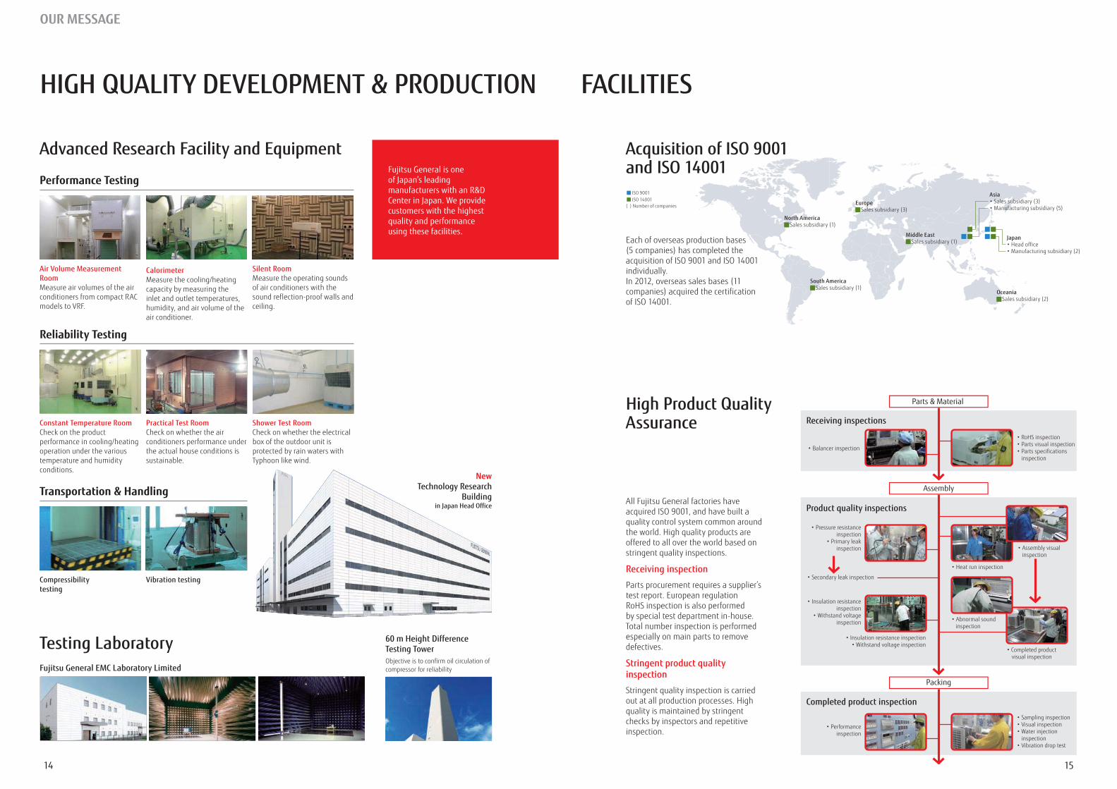
Acquisition of ISO 9001 and ISO 14001
Each of overseas production bases
individually.
quality control system common around the world. High quality products are offered to all over the world based on stringent quality inspections.
Receiving inspection
Parts procurement requires a supplier’s test report. European regulation RoHS inspection is also performed by special test department in-house. Total number inspection is performed especially on main parts to remove defectives.
Stringent product quality inspection
Stringent quality inspection is carried out at all production processes. High quality is maintained by stringent checks by inspectors and repetitive inspection.
High Product Quality Assurance
Fujitsu General is one of Japan’s leading manufacturers with an R&D Center in Japan. We provide customers with the highest quality and performance using these facilities.
1514
OUR MESSAGE
AIRSTAGE™ Solutions
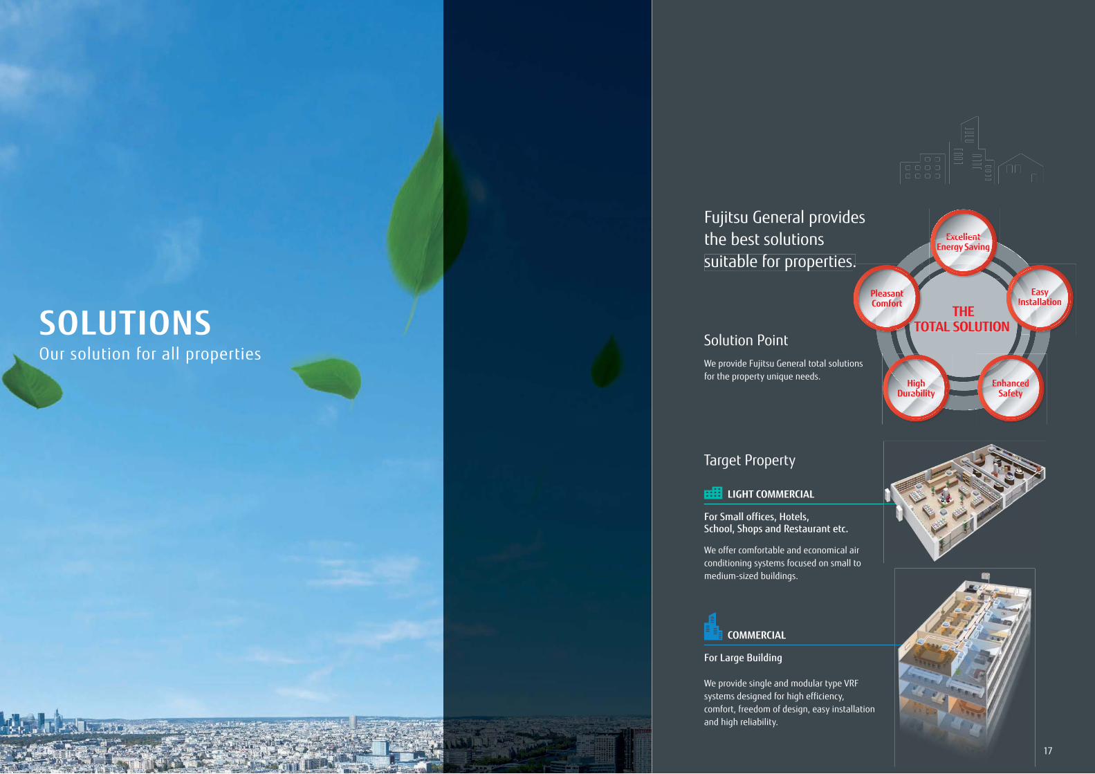
Fujitsu General provides the best solutions suitable for properties.
LIGHT COMMERCIAL
COMMERCIAL
For Small offices, Hotels, School, Shops and Restaurant etc.
For Large Building
We offer comfortable and economical air conditioning systems focused on small to medium-sized buildings.
We provide single and modular type VRF systems designed for high efficiency, comfort, freedom of design, easy installation and high reliability.
HighDurability
EnhancedSafety
ExcellentEnergy Saving
EasyInstallation
THETOTAL SOLUTION
ExcellentExcellentEnergynergy SavingSavin
.
TO
ghHighDurabilityurability
Enha ednhancedEnafetySafety
EasyEasyInstallationallatIns
N
PleasantComfort
SOLUTIONSSolution Point
Target Property
We provide Fujitsu General total solutionsfor the property unique needs.
Our solution for all properties
1716
AIRSTAGE™ SOLUTIONS
1918
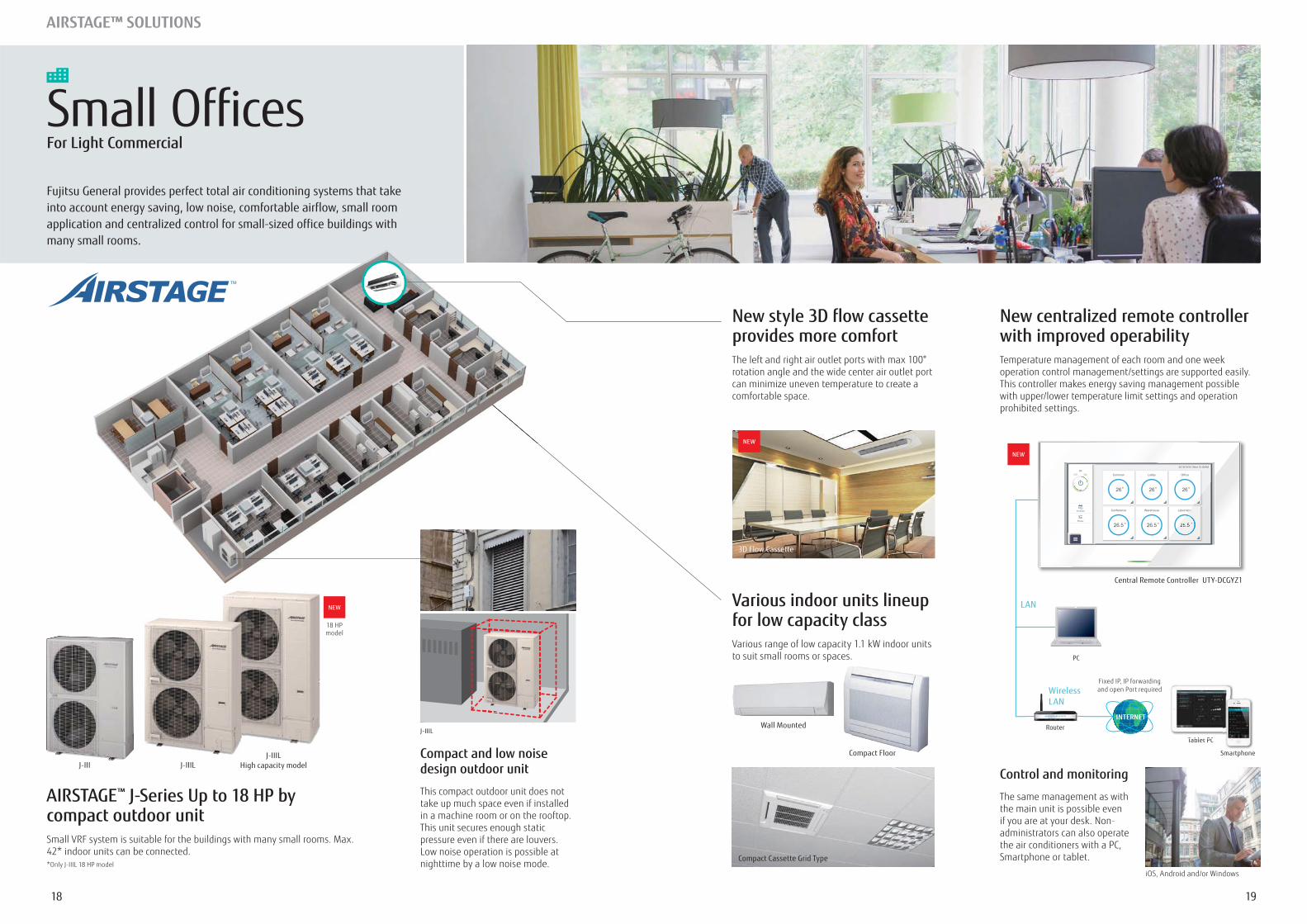
Various indoor units lineup for low capacity classVarious range of low capacity 1.1 kW indoor units to suit small rooms or spaces.
3D Flow Cassette
Wall Mounted
Compact Floor
Compact Cassette Grid Type
Compact and low noise design outdoor unit
This compact outdoor unit does not take up much space even if installed in a machine room or on the rooftop. This unit secures enough static pressure even if there are louvers.
nighttime by a low noise mode.
New style 3D flow cassette provides more comfort
rotation angle and the wide center air outlet port can minimize uneven temperature to create a comfortable space.
NEW
NEW
J-III J-IIILJ-IIIL
High capacity model
18 HPmodel
J-IIIL
AIRSTAGE™ J-Series Up to 18 HP by compact outdoor unitSmall VRF system is suitable for the buildings with many small rooms. Max. 42* indoor units can be connected.
Small OfficesFor Light Commercial
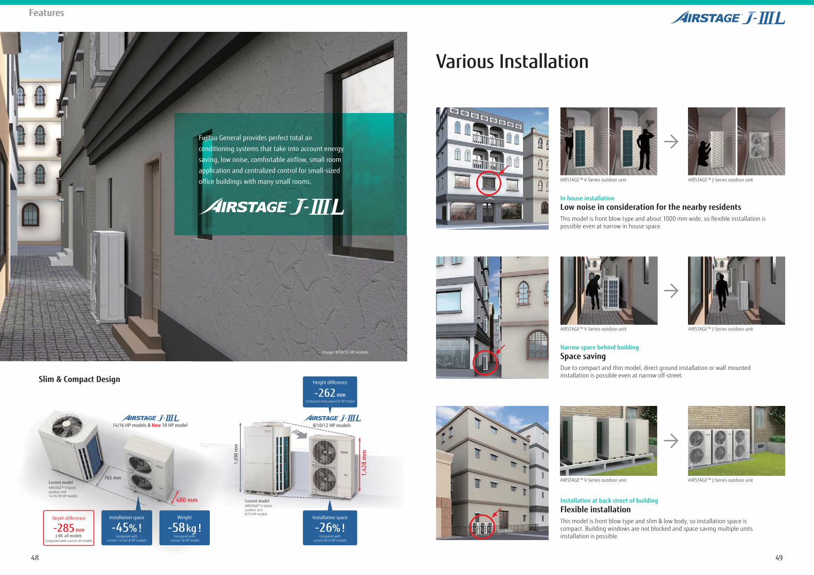
Fujitsu General provides perfect total air conditioning systems that take into account energy saving, low noise, comfortable airflow, small room application and centralized control for small-sized office buildings with many small rooms.
LAN
Wireless LAN
New centralized remote controller with improved operabilityTemperature management of each room and one week operation control management/settings are supported easily. This controller makes energy saving management possible with upper/lower temperature limit settings and operation prohibited settings.
Control and monitoring
The same management as with the main unit is possible even
administrators can also operate the air conditioners with a PC, Smartphone or tablet.
Tablet PC
Smartphone
NEW
T bl t PC
PC
Router
and open Port required
INTERNET
Central Remote Controller UTY-DCGYZ1
2120
AIRSTAGE™ SOLUTIONS
Large space air conditioning in the reception and lobby
system suitable for large spaces with high ceilings
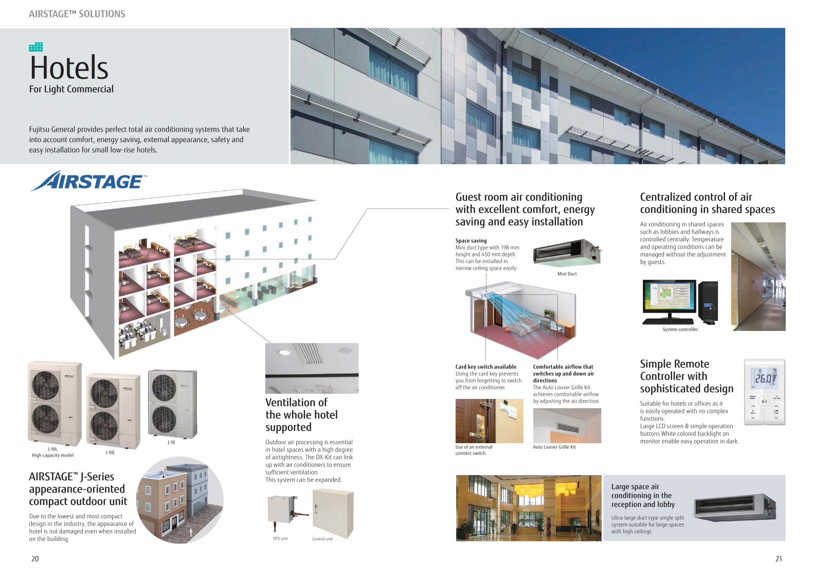
Centralized control of air conditioning in shared spaces
such as lobbies and hallways is controlled centrally. Temperature and operating conditions can be
by guests.
Simple Remote Controller with sophisticated designSuitable for hotels or offices as it is easily operated with no complex functions.
buttons White colored backlight on monitor enable easy operation in dark.
Use of an external connect switch
Auto Louver Grille Kit
Card key switch available
you from forgetting to switch off the air conditioner.
Comfortable airflow that switches up and down air directions
achieves comfortable airflow
AIRSTAGE™ J-Series appearance-oriented compact outdoor unit
design in the industry, the appearance of hotel is not damaged even when installed on the building.
Guest room air conditioning with excellent comfort, energy saving and easy installation
Mini Duct
Space savingMini duct type with 198 mm
This can be installed in narrow ceiling space easily.
EEV unit Control unit
Ventilation of the whole hotel supportedOutdoor air processing is essential in hotel spaces with a high degree
up with air conditioners to ensure sufficient ventilation. This system can be expanded.
System controller
HotelsFor Light Commercial
Fujitsu General provides perfect total air conditioning systems that take into account comfort, energy saving, external appearance, safety and easy installation for small low-rise hotels.
J-IIIJ-IIIL
High capacity model J-IIILJ IIIL
J IIIL
2322
AIRSTAGE™ SOLUTIONS
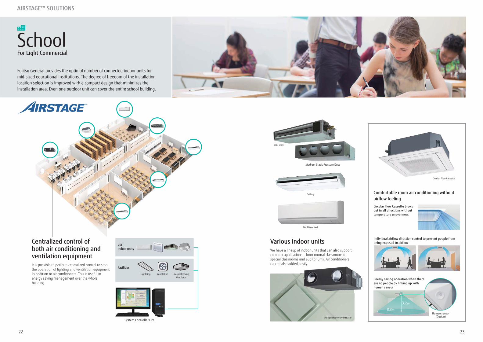
Centralized control of both air conditioning and ventilation equipment
the operation of lighting and ventilation equipment in addition to air conditioners. This is useful in energy saving management over the whole building.
SchoolFor Light Commercial
Fujitsu General provides the optimal number of connected indoor units for mid-sized educational institutions. The degree of freedom of the installation location selection is improved with a compact design that minimizes the installation area. Even one outdoor unit can cover the entire school building.
System Controller Lite
VRF indoor units
Facilities
Lightning Ventilation Energy RecoveryVentilator
Various indoor unitsWe have a lineup of indoor units that can also support complex applications – from normal classrooms to
can be also added easily.
3.2m8.8m
Circular Flow Cassette blows out in all directions without temperature unevenness
Energy saving operation when there are no people by linking up with human sensor
Comfortable room air conditioning without airflow feeling
Human sensor(Option)
Individual airflow direction control to prevent people from being exposed to airflow
eas y.
Mini Duct
Ceiling
Wall Mounted
Energy Recovery Ventilator
Circular Flow Cassette
Medium Static Pressure Duct
2524
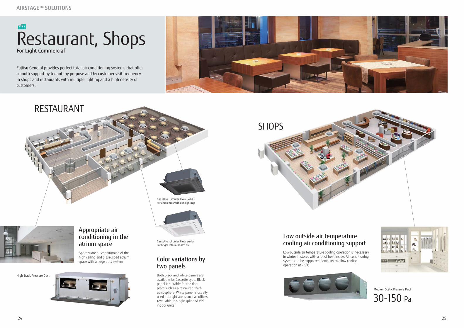
Restaurant, ShopsFor Light Commercial
Fujitsu General provides perfect total air conditioning systems that offer smooth support by tenant, by purpose and by customer visit frequency in shops and restaurants with multiple lighting and a high density of customers.
30-150 Pa
Appropriate air conditioning in the atrium space
high ceiling and glass-sided atrium space with a large duct system
Low outside air temperature cooling air conditioning support
system can be supported flexibility to allow cooling Color variations by two panelsBoth black and white panels are available for Cassette type. Black panel is suitable for the dark place such as a restaurant with atmosphere. White panel is usually used at bright areas such as offices.
High Static Pressure Duct
Medium Static Pressure Duct
Cassette Circular Flow Series For ambiences with dim lightings
Cassette Circular Flow Series For bright Interior rooms etc.
AIRSTAGE™ SOLUTIONS
RESTAURANT
SHOPS
2726
AIRSTAGE™ SOLUTIONS
InstallationExample
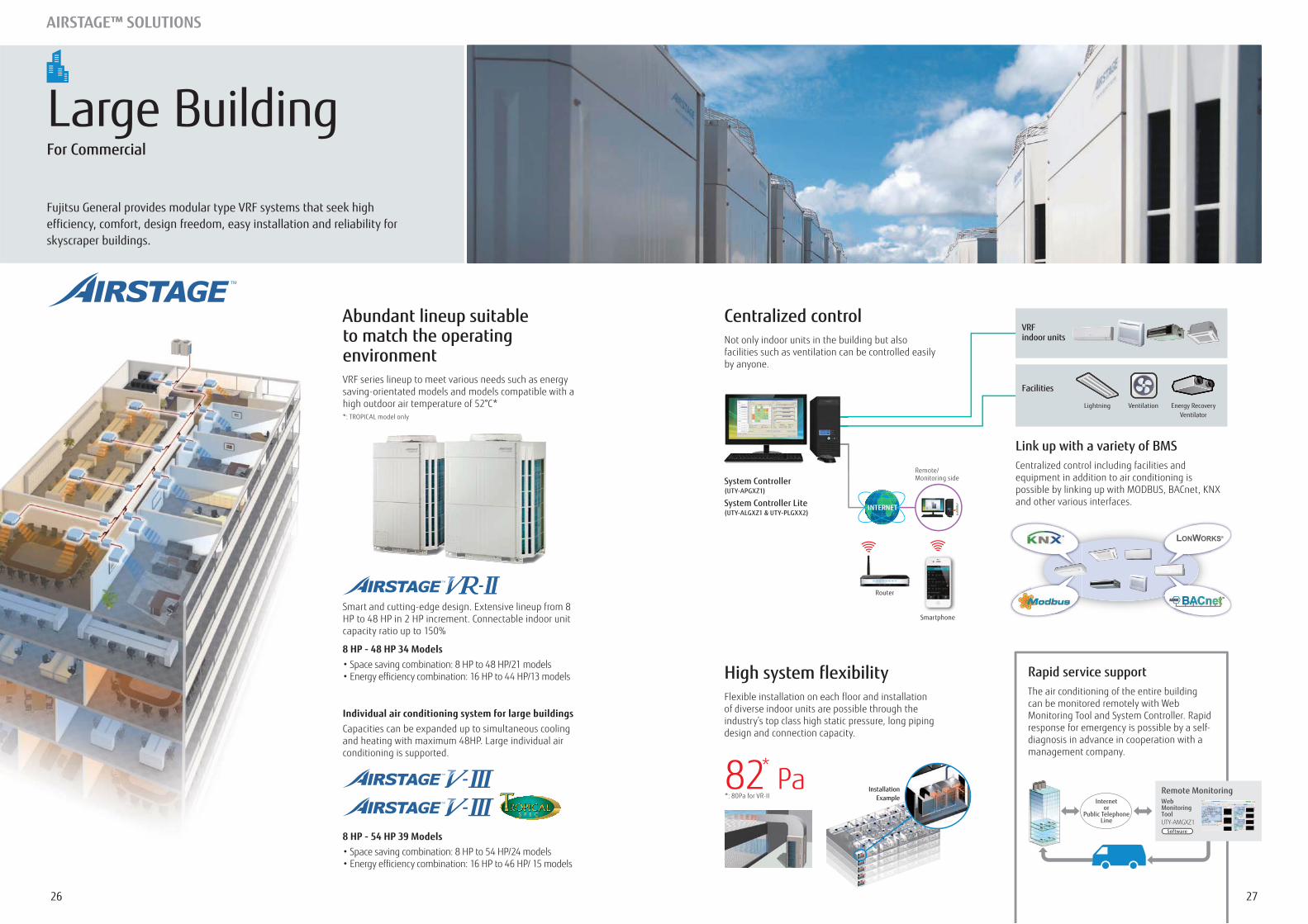
High system flexibilityFlexible installation on each floor and installation of diverse indoor units are possible through the industry’s top class high static pressure, long piping design and connection capacity.
Link up with a variety of BMSCentralized control including facilities and equipment in addition to air conditioning is
and other various interfaces.
Rapid service supportThe air conditioning of the entire building can be monitored remotely with Web Monitoring Tool and System Controller. Rapid response for emergency is possible by a self-diagnosis in advance in cooperation with a management company.
Smart and cutting-edge design. Extensive lineup from 8 HP to 48 HP in 2 HP increment. Connectable indoor unit
8 HP - 48 HP 34 Models
Internetor
Public TelephoneLine
Web MonitoringToolUTY-AMGXZ1
Remote Monitoring
Software8 HP - 54 HP 39 Models
Individual air conditioning system for large buildingsCapacities can be expanded up to simultaneous cooling
conditioning is supported.
Abundant lineup suitable to match the operating environmentVRF series lineup to meet various needs such as energy saving-orientated models and models compatible with a
82* Pa
Large BuildingFor Commercial
Fujitsu General provides modular type VRF systems that seek high efficiency, comfort, design freedom, easy installation and reliability for skyscraper buildings.
Centralized control
facilities such as ventilation can be controlled easily by anyone.
VRF indoor units
Facilities
Lightning Ventilation Energy RecoveryVentilator
System Controller (UTY-APGXZ1)
System Controller Lite (UTY-ALGXZ1 & UTY-PLGXX2)
Remote/Monitoring side
INTERNET
Smartphone
Router
2928
AIRSTAGE™ VRF SYSTEMS CAN BE DESIGNED TOCREATE AN AIR CONDITIONING SOLUTION TOSUIT MOST BUILDINGS REQUIREMENTS.
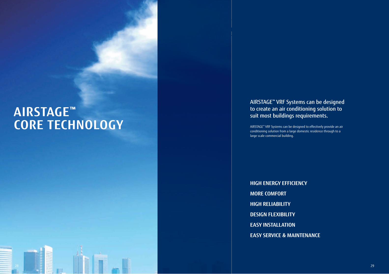
AIRSTAGE™
CORE TECHNOLOGY
AIRSTAGE™ VRF Systems can be designed to create an air conditioning solution to suit most buildings requirements.
AIRSTAGE™ VRF Systems can be designed to effectively provide an air conditioning solution from a large domestic residence through to a large scale commercial building.
HIGH ENERGY EFFICIENCY
MORE COMFORT
HIGH RELIABILITY
DESIGN FLEXIBILITY
EASY INSTALLATION
EASY SERVICE & MAINTENANCE
3130
AIRSTAGETM CORE TECHNOLOGY
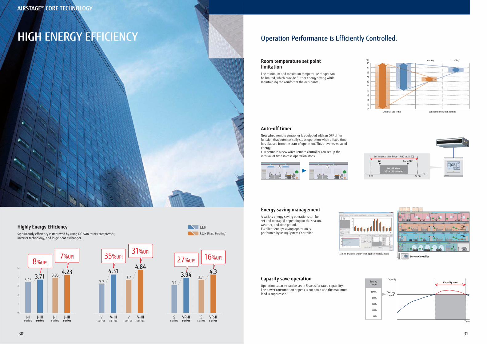
HIGH ENERGY EFFICIENCY Operation Performance is Efficiently Controlled.
Highly Energy EfficiencySignificantly efficiency is improved by using DC twin rotary compressor, inverter technology, and large heat exchanger.
3.2
4.313.7
4.84
31%UP!35%UP!
V-IIIseries
Vseries
V-IIIseries
Vseries
3.1
3.94 3.714.3
16%UP!27%UP!
VR-IIseries
Sseries
VR-IIseries
Sseries
0
1
2
3
4
5
3.713.45
4.233.95
7%UP!8%UP!
J-IIIseries
J-IIseries
J-IIIseries
J-IIseries
EER
COP (Max. Heating)
Room temperature set point limitation
Auto-off timer
Energy saving management
Capacity save operation
The minimum and maximum temperature ranges can be limited, which provide further energy saving while maintaining the comfort of the occupants.
New wired remote controller is equipped with an OFF timerfunction that automatically stops operation when a fixed timehas elapsed from the start of operation. This prevents waste ofenergy.Furthermore a new wired remote controller can set up theinterval of time in case operation stops.
A variety energy saving operations can be set and managed depending on the season, weather, and time period.Excellent energy saving operation is performed by using System Controller.
Operation capacity can be set in 5 steps for rated capability. The power consumption at peak is cut down and the maximum load is suppressed.
Heating Cooling
Original Set Temp Set point limitation setting
30
28
26
24
22
20
18
16
14
12
10
(°C)
Set interval time hour (17:00 to 24:00)
Set off time (30 to 240 minutes)
17:00 24:00
ON Auto OFF
OFF
System Controller(Screen image is Energy manager software(Option))
Time
Capacity
Settinglevel
Capacity saveSettingrange
100%
80%
60%
40%
0%
3332
AIRSTAGETM CORE TECHNOLOGY
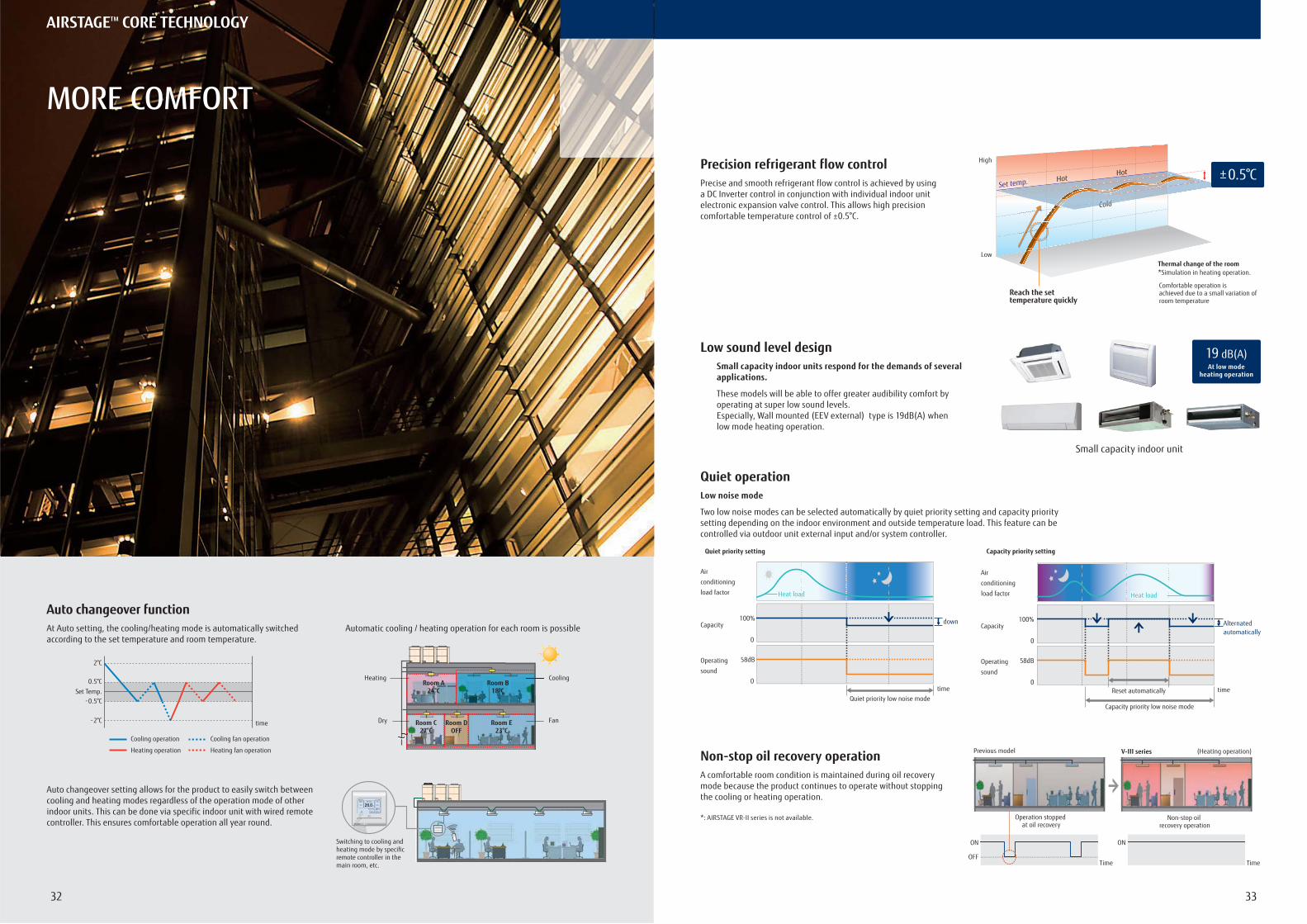
MORE COMFORT
Auto changeover functionAt Auto setting, the cooling/heating mode is automatically switched according to the set temperature and room temperature.
Auto changeover setting allows for the product to easily switch between cooling and heating modes regardless of the operation mode of other indoor units. This can be done via specific indoor unit with wired remote controller. This ensures comfortable operation all year round.
Automatic cooling / heating operation for each room is possible
Precision refrigerant flow control
Quiet operation
Non-stop oil recovery operation
Precise and smooth refrigerant flow control is achieved by using a DC Inverter control in conjunction with individual indoor unit electronic expansion valve control. This allows high precision comfortable temperature control of ±0.5°C.
Low noise mode
Two low noise modes can be selected automatically by quiet priority setting and capacity priority setting depending on the indoor environment and outside temperature load. This feature can be controlled via outdoor unit external input and/or system controller.
A comfortable room condition is maintained during oil recovery mode because the product continues to operate without stopping the cooling or heating operation.
*: AIRSTAGE VR-II series is not available.
time
Set Temp.0.5°C
-0.5°C
2°C
-2°C
Cooling operation
Heating operation
Cooling fan operation
Heating fan operation
Heating
Dry Fan
Room A24°C
Room C27°C
Room DOFF
Room E23°C
Room B18°C
ach room is possible
BCooling
Switching to cooling and heating mode by specific remote controller in the main room, etc.
Reach the set temperature quickly
Low
High
Set temp.
ColdColdC ld
HotHot
Thermal change of the room*Simulation in heating operation.
Comfortable operation is achieved due to a small variation of room temperature
±0.5°C
Low sound level designSmall capacity indoor units respond for the demands of several applications.
These models will be able to offer greater audibility comfort by operating at super low sound levels.Especially, Wall mounted (EEV external) type is 19dB(A) when low mode heating operation.
Small capacity indoor unit
19 dB(A)At low mode
heating operation
Air
conditioning
load factor
Capacity
Operating
sound
Air
conditioning
load factor
Capacity
Operating
sound
time
100%
58dB
0
0
Heat load
down
Quiet priority low noise mode
Quiet priority setting
Capacity priority low noise mode
time
100%
58dB
0
0Reset automatically
Alternatedautomatically
Capacity priority setting
Heat loadHeat load
Previous model V-III series (Heating operation)
Time
ON
OFF
Operation stopped at oil recovery
Time
ON
Non-stop oil recovery operation
AAIRSTAGETM CORRE TTEEEECCCCCCCCHHHHHHHHNNNNNNNNNOOOOOOOOOOOOOLLLLLLLLLLOOOOOOOOOOOOOGGGGGGGGGGGYYYYYYYYYY
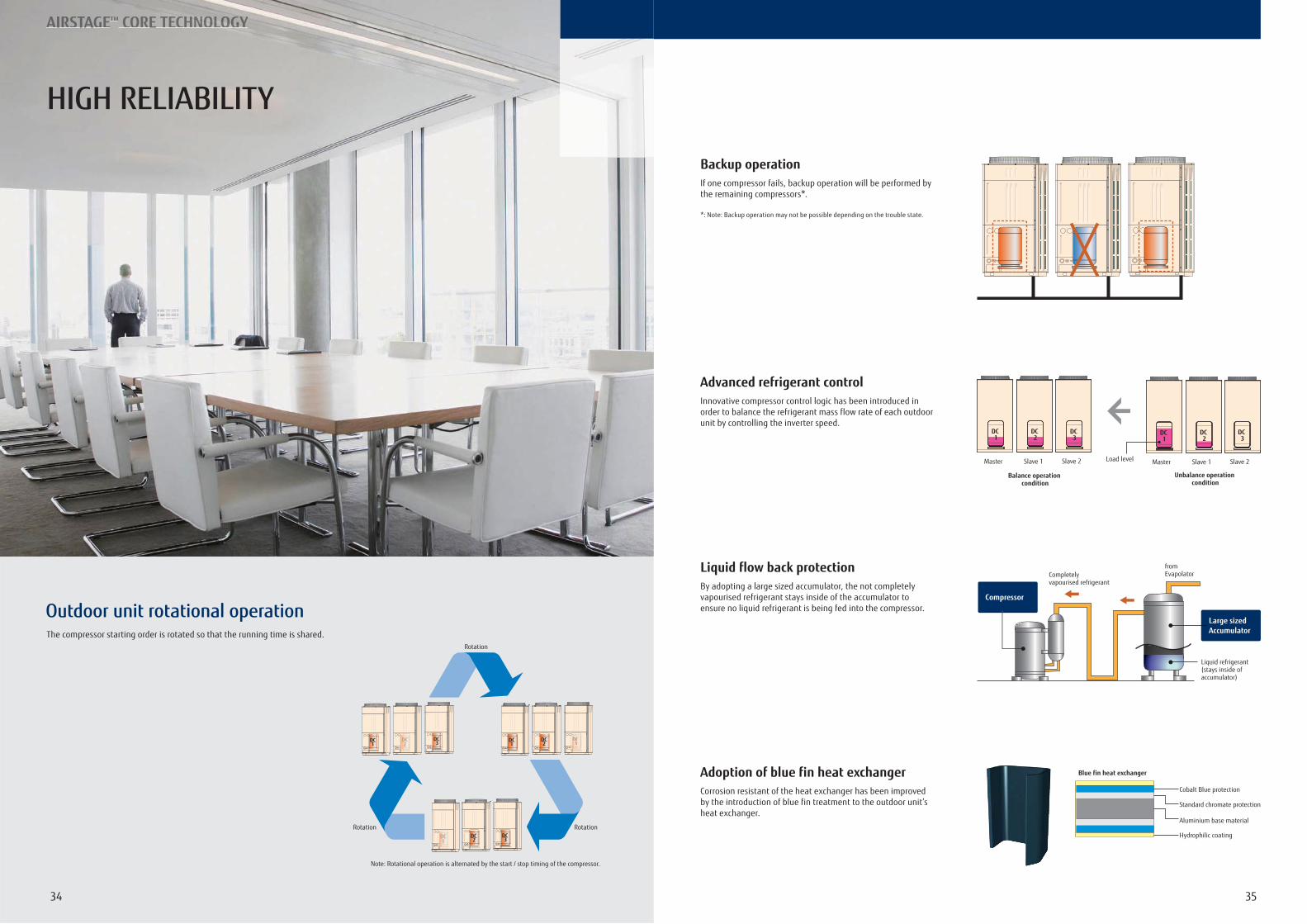
HIGH RELIABILITY
Outdoor unit rotational operation
fromEvapolator
Liquid refrigerant(stays inside of accumulator)
Completely vapourised refrigerant
Large sizedAccumulator
Compressor
3534
The compressor starting order is rotated so that the running time is shared.
Backup operation
Liquid flow back protection
Adoption of blue fin heat exchanger
If one compressor fails, backup operation will be performed by the remaining compressors*.
*: Note: Backup operation may not be possible depending on the trouble state.
By adopting a large sized accumulator, the not completely vapourised refrigerant stays inside of the accumulator to ensure no liquid refrigerant is being fed into the compressor.
Corrosion resistant of the heat exchanger has been improved by the introduction of blue fin treatment to the outdoor unit’s heat exchanger.
Advanced refrigerant controlInnovative compressor control logic has been introduced in order to balance the refrigerant mass flow rate of each outdoor unit by controlling the inverter speed.
CCDCCCCCCCCDCDDDDDDD3333333
DC2
DC1
DC3
DC2DC
1
DC3DC
1DC2
Note: Rotational operation is alternated by the start / stop timing of the compressor.
Rotation
Rotation Rotation
Balance operation condition
Unbalance operation condition
ON ON ON ON ON OFF
Master Slave 1 Slave 2
DC3
DC2
DC1
Master Slave 1 Slave 2
DC3
DC2
DC1
Load level
Hydrophilic coating
Cobalt Blue protection
Standard chromate protection
Aluminium base material
Blue fin heat exchanger
3736
AIRSTAGETM CORE TECHNOLOGY
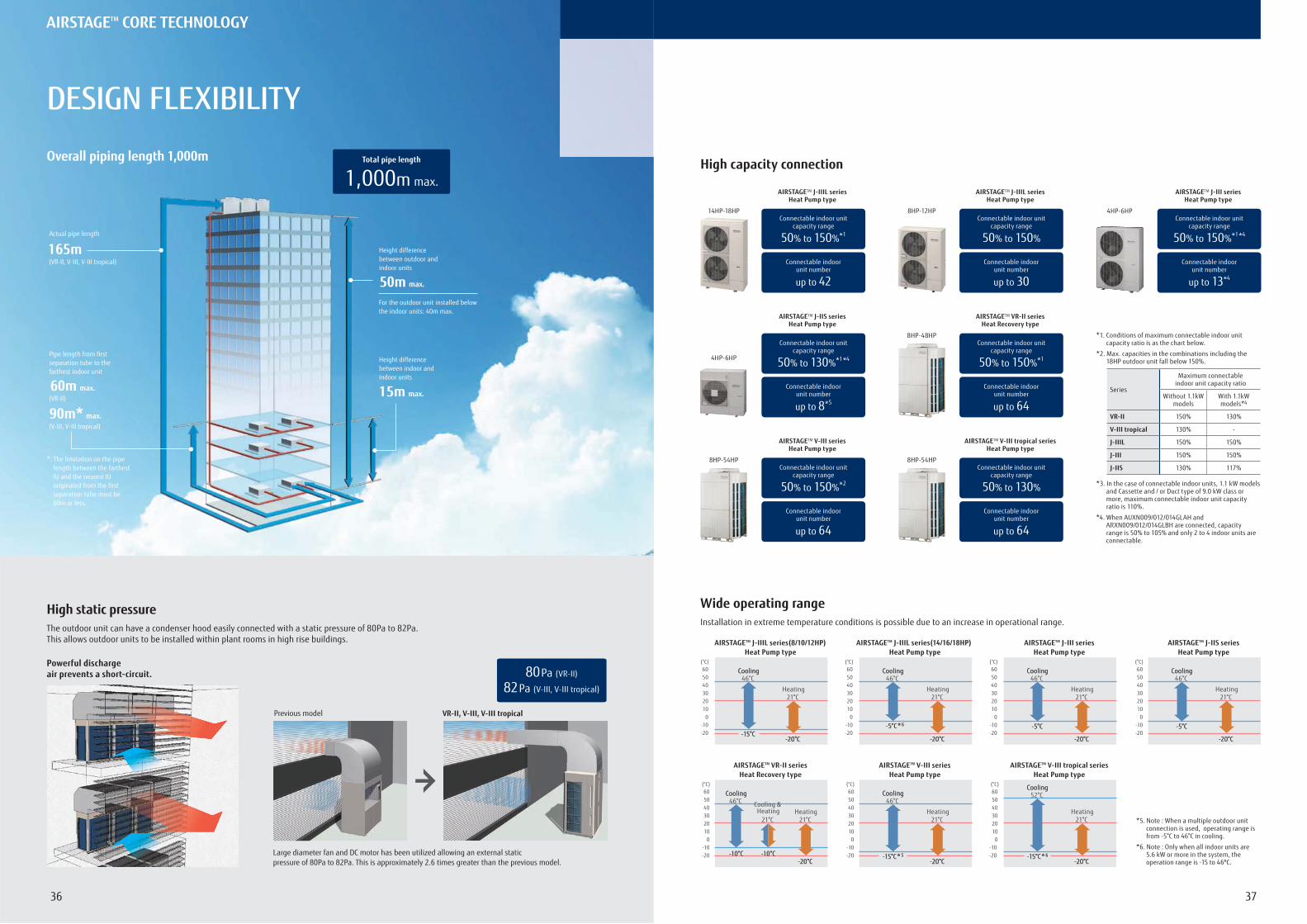
DESIGN FLEXIBILITY
High capacity connection
*1. Conditions of maximum connectable indoor unit capacity ratio is as the chart below.
*2. Max. capacities in the combinations including the 18HP outdoor unit fall below 150%.
*3. In the case of connectable indoor units, 1.1 kW models and Cassette and / or Duct type of 9.0 kW class or more, maximum connectable indoor unit capacity ratio is 110%.
*4. When AUXN009/012/014GLAH and ARXN009/012/014GLBH are connected, capacity range is 50% to 105% and only 2 to 4 indoor units are connectable.
Wide operating rangeInstallation in extreme temperature conditions is possible due to an increase in operational range.
High static pressureThe outdoor unit can have a condenser hood easily connected with a static pressure of 80Pa to 82Pa.This allows outdoor units to be installed within plant rooms in high rise buildings.
Powerful discharge air prevents a short-circuit.
50m max.
Height difference between outdoor and indoor units
15m max.
Height difference between indoor and indoor units
165mActual pipe length
For the outdoor unit installed below the indoor units: 40m max.
*: The limitation on the pipe length between the farthest IU and the nearest IU originated from the first separation tube must be 60m or less.
(VR-II, V-III, V-III tropical)
60m max.
90m* max.
Pipe length from first separation tube to the farthest indoor unit
(VR-II)
(V-III, V-III tropical)
1,000m max.
Total pipe lengthOverall piping length 1,000m
Large diameter fan and DC motor has been utilized allowing an external static pressure of 80Pa to 82Pa. This is approximately 2.6 times greater than the previous model.
Previous model VR-II, V-III, V-III tropical
80 Pa (VR-II)
82 Pa (V-III, V-III tropical)
8HP-48HP
AIRSTAGETM VR-II series Heat Recovery type
Connectable indoor unit capacity range
50% to 150%*1
Connectable indoorunit number
up to 64
14HP-18HP
AIRSTAGETM J-IIIL series Heat Pump type
Connectable indoor unit capacity range
50% to 150%*1
Connectable indoorunit number
up to 42
4HP-6HP
AIRSTAGETM J-III series Heat Pump type
Connectable indoor unit capacity range
50% to 150%*1 *4
Connectable indoorunit number
up to 13*4
8HP-54HP
AIRSTAGETM V-III series Heat Pump type
Connectable indoor unit capacity range
50% to 150%*2
Connectable indoorunit number
up to 64
8HP-12HP
AIRSTAGETM J-IIIL series Heat Pump type
Connectable indoor unit capacity range
50% to 150%
Connectable indoorunit number
up to 30
4HP-6HP
AIRSTAGETM J-IIS series Heat Pump type
Connectable indoor unit capacity range
50% to 130%*1 *4
Connectable indoorunit number
up to 8*5
8HP-54HP
AIRSTAGETM V-III tropical series Heat Pump type
Connectable indoor unit capacity range
50% to 130%
Connectable indoorunit number
up to 64
Series
Maximum connectableindoor unit capacity ratio
Without 1.1kWmodels
With 1.1kWmodels*4
VR-II 150% 130%
V-III tropical 130% -
J-IIIL 150% 150%
J-III 150% 150%
J-IIS 130% 117%
AIRSTAGETM VR-II series Heat Recovery type
(°C)
21°C
-20°C -20°C
Heating21°C
-10°C-10°C
Cooling & Heating
CoolingCooling46°C
-10°C-10°C
605040302010
0-10-20
AIRSTAGETM V-III series Heat Pump type
(°C)605040302010
0-10-20
21°C
-20°C -20°C
Heating
CoolingCooling46°C
-15°C*5-15°C*5
(°C)605040302010
0-10-20
21°C
-20°C -20°C
Heating
CoolingCooling52°C
-15°C*6-15°C*6
AIRSTAGETM V-III tropical series Heat Pump type
(°C)605040302010
0-10-20
21°C
-20°C -20°C
Heating
CoolingCooling46°C
-15°C-15°C
AIRSTAGETM J-IIIL series(8/10/12HP) Heat Pump type
(°C)605040302010
0-10-20
21°C
-20°C -20°C
Heating
CoolingCooling46°C
-5°C-5°C
AIRSTAGETM J-III series Heat Pump type
(°C)605040302010
0-10-20
21°C
-20°C -20°C
Heating
CoolingCooling46°C
-5°C*6-5°C*6
AIRSTAGETM J-IIIL series(14/16/18HP) Heat Pump type
(°C)605040302010
0-10-20
21°C
-20°C -20°C
Heating
CoolingCooling46°C
-5°C-5°C
AIRSTAGETM J-IIS series Heat Pump type
*5. Note : When a multiple outdoor unit connection is used, operating range is from -5°C to 46°C in cooling.
*6. Note : Only when all indoor units are 5.6 kW or more in the system, the operation range is -15 to 46ºC.
AIRSTAGETM CORE TECHNOLOGY
3938
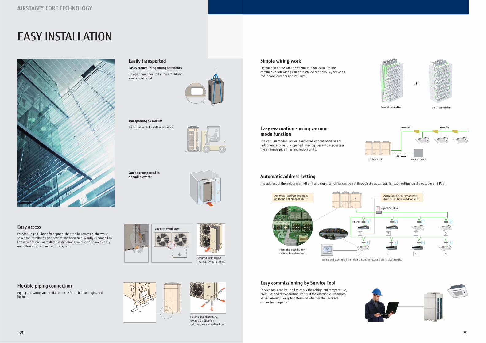
Easily transportedEasily craned using lifting belt hooks
Design of outdoor unit allows for lifting straps to be used
Transporting by forklift
Transport with forklift is possible.
Can be transported in a small elevator
Easy access
Flexible piping connection
By adopting a L-Shape front panel that can be removed, the work space for installation and service has been significantly expanded by this new design. For multiple installations, work is performed easily and efficiently even in a narrow space.
Piping and wiring are available to the front, left and right, and bottom.
Reduced installation intervals by front access
Expansion of work space
Flexible installation by 4 way pipe direction(J-IIIL is 3 way pipe direction.)
Simple wiring work
Automatic address setting
Easy commissioning by Service Tool
Installation of the wiring systems is made easier as the communication wiring can be installed continuously between the indoor, outdoor and RB units.
The address of the indoor unit, RB unit and signal amplifier can be set through the automatic function setting on the outdoor unit PCB.
Service tools can be used to check the refrigerant temperature, pressure, and the operating status of the electronic expansion valve, making it easy to determine whether the units are connected properly.
Easy evacuation - using vacuum mode functionThe vacuum mode function enables all expansion valves of indoor units to be fully opened, making it easy to evacuate all the air inside pipe lines and indoor units.
Serial connectionParallel connection
or
Outdoor unit Vacuum pump
Air
Air
Air
Automatic address setting is performed at outdoor unit
Addresses are automaticallydistributed from outdoor unit.
Manual address setting from indoor unit and remote controller is also possible.
7 1 0
62 4 5Press the push button switch of outdoor unit.
3
1
2
1
4 5
0
6
3 7
Signal Amplifier
RB unit
EASY INSTALLATION
4140
AIRSTAGETM CORE TECHNOLOGY
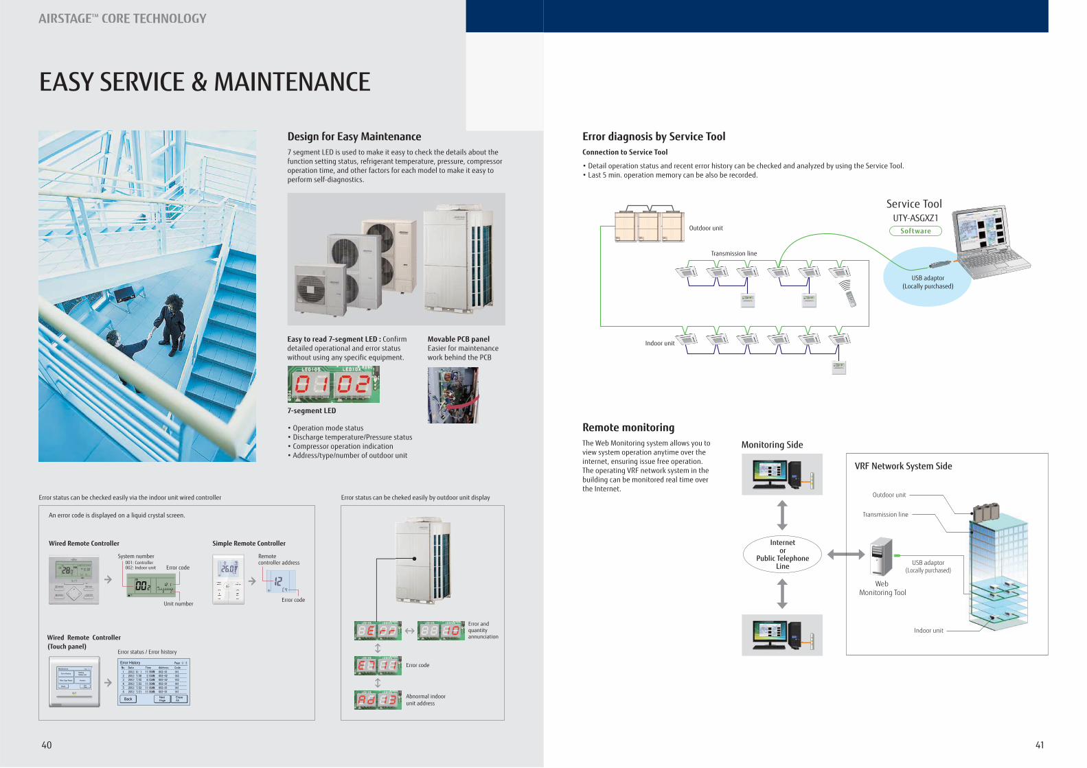
EASY SERVICE & MAINTENANCE
Design for Easy Maintenance7 segment LED is used to make it easy to check the details about the function setting status, refrigerant temperature, pressure, compressor operation time, and other factors for each model to make it easy to perform self-diagnostics.
Easy to read 7-segment LED : Confirm detailed operational and error status without using any specific equipment.
7-segment LED
Movable PCB panelEasier for maintenance work behind the PCB
Error status can be checked easily via the indoor unit wired controller Error status can be cheked easily by outdoor unit display
Wired Remote Controller Simple Remote Controller
An error code is displayed on a liquid crystal screen.
Remote controller address
Error code
Wired Remote Controller(Touch panel)
Error status / Error history
Abnormal indoor unit address
Error and quantity annunciation
Error code
System number001: Controller002: Indoor unit Error code
Unit number
Error diagnosis by Service Tool
Remote monitoring
Connection to Service Tool
The Web Monitoring system allows you to view system operation anytime over the internet, ensuring issue free operation.The operating VRF network system in the building can be monitored real time over the Internet.
Indoor unit
USB adaptor(Locally purchased)
Service Tool
Transmission line
Outdoor unit Software
UTY-ASGXZ1
Internetor
Public TelephoneLine
Monitoring Side
Indoor unit
Transmission line
Outdoor unit
Web Monitoring Tool
USB adaptor(Locally purchased)
VRF Network System Side
4342
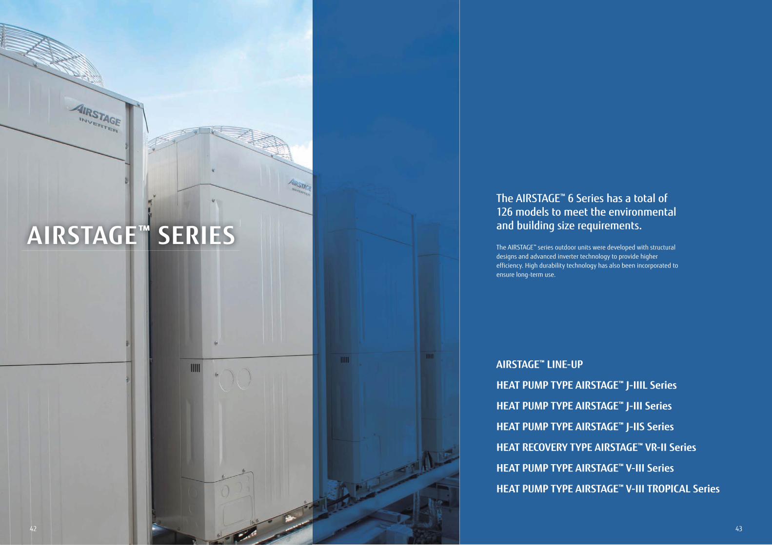
AIRSTAGE™ SERIES
The AIRSTAGE™ 6 Series has a total of 126 models to meet the environmental and building size requirements.
The AIRSTAGE™ series outdoor units were developed with structural designs and advanced inverter technology to provide higher efficiency. High durability technology has also been incorporated to ensure long-term use.
AIRSTAGE™ LINE-UP
HEAT PUMP TYPE AIRSTAGE™ J-IIIL Series
HEAT PUMP TYPE AIRSTAGE™ J-III Series
HEAT PUMP TYPE AIRSTAGE™ J-IIS Series
HEAT RECOVERY TYPE AIRSTAGE™ VR-II Series
HEAT PUMP TYPE AIRSTAGE™ V-III Series
HEAT PUMP TYPE AIRSTAGE™ V-III TROPICAL Series
4544
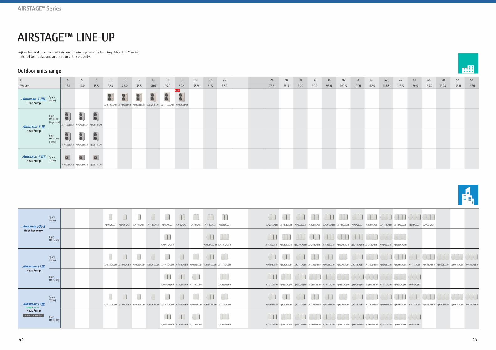
AIRSTAGE™ LINE-UP
AIRSTAGETM Series
Fujitsu General provides multi air conditioning systems for buildings AIRSTAGE™ Series matched to the size and application of the property.
Outdoor units range
HP 4 5 6 8 10 12 14 16 18 20 22 24 26 28 30 32 34 36 38 40 42 44 46 48 50 52 54
kW class 12.1 14.0 15.5 22.4 28.0 33.5 40.0 45.0 50.4 55.9 61.5 67.0 73.5 78.5 85.0 90.0 95.0 100.5 107.0 112.0 118.5 123.5 130.0 135.0 139.0 143.0 147.0
Heat Pump
Space saving
AJY072LELAH AJY090LELAH AJY108LELAH AJY126LELAH AJY144LELAH AJY162LELAH
Heat Pump
High Efficiency(Single phase)
AJY040LBLAH AJY045LBLAH AJY054LBLAH
High Efficiency(3 phase)
AJY040LELAH AJY045LELAH AJY054LELAH
Heat Pump
Space saving
AJY040LCLAH AJY045LCLAH AJY054LCLAH
Heat Recovery
Space saving
AJYA72GALH AJYA90GALH AJY108GALH AJY126GALH AJY144GALH AJY162GALH AJY180GALH AJY198GALH AJY216GALH AJY234GALH AJY252GALH AJY270GALH AJY288GALH AJY306GALH AJY324GALH AJY342GALH AJY360GALH AJY378GALH AJY396GALH AJY414GALH AJY432GALH
High Efficiency
AJY144GALHH AJY198GALHH AJY216GALHH AJY234GALHH AJY252GALHH AJY270GALHH AJY288GALHH AJY306GALHH AJY324GALHH AJY342GALHH AJY360GALHH AJY378GALHH AJY396GALHH
Heat Pump
Space saving
AJY072LALBH AJY090LALBH AJY108LALBH AJY126LALBH AJY144LALBH AJY162LALBH AJY180LALBH AJY198LALBH AJY216LALBH AJY234LALBH AJY252LALBH AJY270LALBH AJY288LALBH AJY306LALBH AJY324LALBH AJY342LALBH AJY360LALBH AJY378LALBH AJY396LALBH AJY414LALBH AJY432LALBH AJY450LALBH AJY468LALBH AJY486LALBH
High Efficiency
AJY144LALBHH AJY162LALBHH AJY180LALBHH AJY216LALBHH AJY234LALBHH AJY252LALBHH AJY270LALBHH AJY288LALBHH AJY306LALBHH AJY324LALBHH AJY342LALBHH AJY360LALBHH AJY378LALBHH AJY396LALBHH AJY414LALBHH
Heat Pump
Space saving
AJY072LNLBH AJY090LNLBH AJY108LNLBH AJY126LNLBH AJY144LNLBH AJY162LNLBH AJY180LNLBH AJY198LNLBH AJY216LNLBH AJY234LNLBH AJY252LNLBH AJY270LNLBH AJY288LNLBH AJY306LNLBH AJY324LNLBH AJY342LNLBH AJY360LNLBH AJY378LNLBH AJY396LNLBH AJY414LNLBH AJY432LNLBH AJY450LNLBH AJY468LNLBH AJY486LNLBH
High Efficiency
AJY144LNLBHH AJY162LNLBHH AJY180LNLBHH AJY216LNLBHH AJY234LNLBHH AJY252LNLBHH AJY270LNLBHH AJY288LNLBHH AJY306LNLBHH AJY324LNLBHH AJY342LNLBHH AJY360LNLBHH AJY378LNLBHH AJY396LNLBHH AJY414LNLBHH
4746
Features
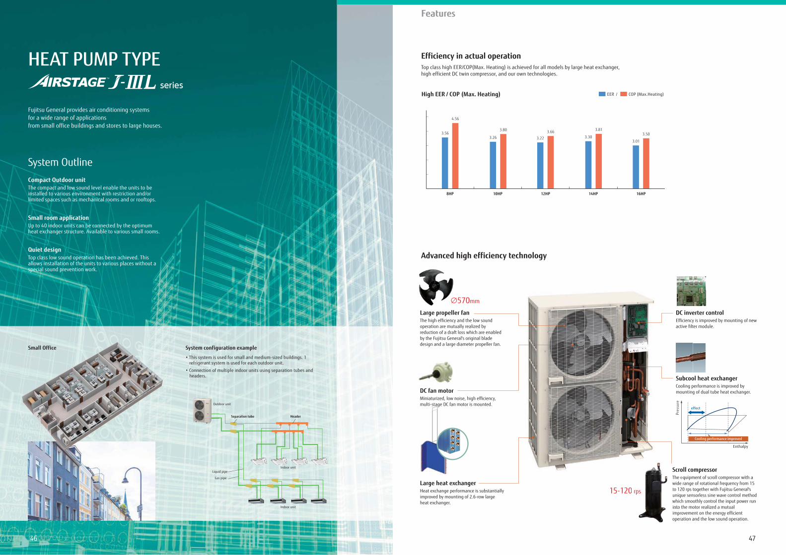
HEAT PUMP TYPE
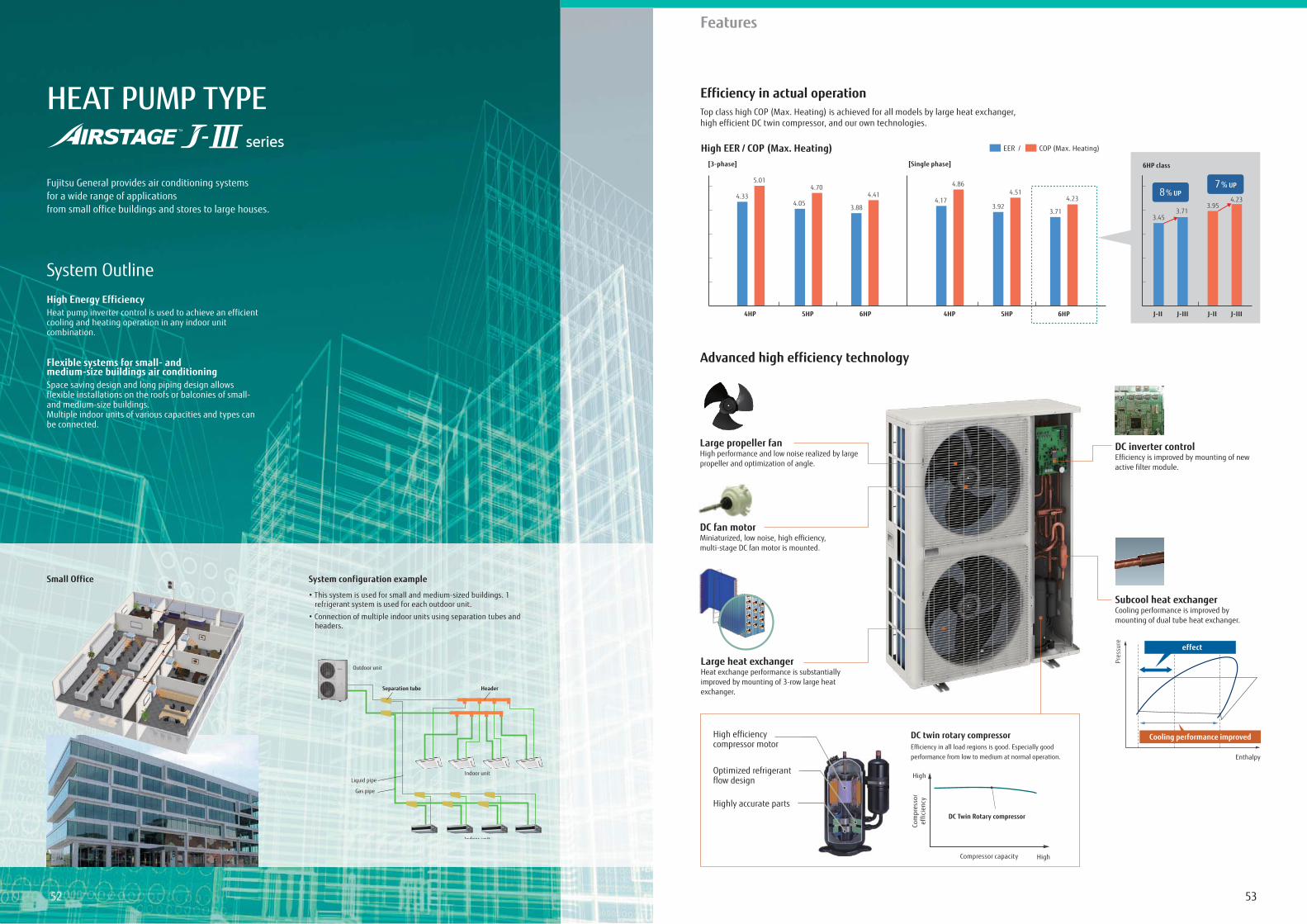
Fujitsu General provides air conditioning systemsfor a wide range of applicationsfrom small office buildings and stores to large houses.
Compact Outdoor unitThe compact and low sound level enable the units to beinstalled to various environment with restriction and/orlimited spaces such as mechanical rooms and or rooftops.
Small room applicationUp to 40 indoor units can be connected by the optimumheat exchanger structure. Available to various small rooms.
Quiet designTop class low sound operation has been achieved. Thisallows installation of the units to various places without aspecial sound prevention work.
System Outline
System configuration example
refrigerant system is used for each outdoor unit.
headers.
Small Office
Indoor unit
Outdoor unit
Indoor unit
Gas pipe
Liquid pipe
Separation tube Header
Outd
Advanced high efficiency technology
Large propeller fanThe high efficiency and the low sound operation are mutually realized by reduction of a draft loss which are enabled by the Fujitsu General's original blade design and a large diameter propeller fan.
Large heat exchangerHeat exchange performance is substantially improved by mounting of 2.6-row large heat exchanger.
DC fan motorMiniaturized, low noise, high efficiency, multi-stage DC fan motor is mounted.
Scroll compressorThe equipment of scroll compressor with a wide range of rotational frequency from 15 to 120 rps together with Fujitsu General's unique sensorless sine wave control method which smoothly control the input power run into the motor realized a mutual improvement on the energy efficient operation and the low sound operation.
15-120 rps
ll f
ScroThe ewide to 12uniquwhichinto timproopera
20 rps
570mm
Pres
sure
Enthalpy
effect
Cooling performance improved
Subcool heat exchangerCooling performance is improved by mounting of dual tube heat exchanger.
DC inverter controlEfficiency is improved by mounting of new active filter module.
Efficiency in actual operationTop class high EER/COP(Max. Heating) is achieved for all models by large heat exchanger, high efficient DC twin compressor, and our own technologies.
High EER / COP (Max. Heating) EER / COP (Max.Heating)
4.56
3.563.80
3.263.66
3.22
3.81
3.303.50
3.01
8HP 10HP 12HP 14HP 16HP
4948
Features
Low noise in consideration for the nearby residentsThis model is front blow type and about 1000 mm wide, so flexible installation is possible even at narrow in house space.
In house installation
AIRSTAGETM J-Series outdoor unitAIRSTAGETM V-Series outdoor unit
Space savingDue to compact and thin model, direct ground installation or wall mounted installation is possible even at narrow off-street.
Narrow space behind building
AIRSTAGETM J-Series outdoor unitAIRSTAGETM V-Series outdoor unit
Flexible installationThis model is front blow type and slim & low body, so installation space is compact. Building windows are not blocked and space saving multiple units installation is possible.
Installation at back street of building
AIRSTAGETM J-Series outdoor unitAIRSTAGETM V-Series outdoor unit
Various Installation
48
765 mm
480 mm
1,42
8 m
m
1,69
0 m
m
Current modelAIRSTAGETM V-Seriesoutdoor unit14/16/18 HP models
14/16 HP models & New 18 HP model
Installation space
Compared withcurrent 14/16/18 HP models
-45% !Weight
Compared withcurrent 18 HP model
-58 kg !Installation space
Compared withcurrent 8/10 HP models
-26% !
Height difference
Compared with current 8 HP model
-262 mm
Depth difference
Compared with current all modelsJ-IIIL all models-285 mm
Current modelAIRSTAGETM V-Seriesoutdoor unit8/10 HP models
8/10/12 HP models
Slim & Compact Design
Image: 8/10/12 HP models
Fujitsu General provides perfect total air
conditioning systems that take into account energy
saving, low noise, comfortable airflow, small room
application and centralized control for small-sized
office buildings with many small rooms.
5150
Features
Specifications
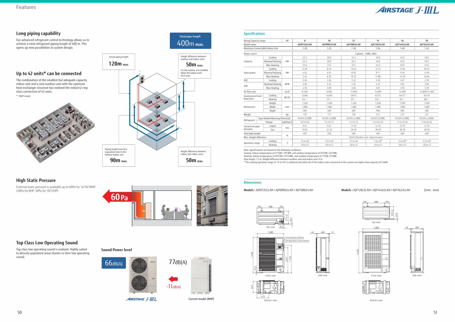
Note: Specifications are based on the following conditions.Cooling: Indoor temperature of 27°CDB / 19°CWB, and outdoor temperature of 35°CDB / 24°CWB.Heating: Indoor temperature of 20°CDB / (15°CWB), and outdoor temperature of 7°CDB / 6°CWB.Pipe length: 7.5 m; Height difference between outdoor unit and indoor unit: 0 m.* The cooling operation range of -15 to 46°C is allowed only when all of the indoor units connected to the system are higher than capacity of 5.6kW.
Dimensions
Rating Capacity range HP 8 10 12 14 16 18
Model name AJY072LELAH AJY090LELAH AJY108LELAH AJY126LELAH AJY144LELAH AJY162LELAH
Maximum Connectable Indoor Unit 1-20 1-25 1-30 1-36 1-40 1-42
Power source 3-phase, ~400V, 50Hz
Capacity
Cooling
kW
22.4 28.0 33.5 40.0 45.0 50.0
Nominal Heating 22.4 28.0 33.5 40.0 45.0 50.0
Max Heating 25.0 31.5 37.5 45.0 50.0 55.0
Input power
Cooling
kW
6.30 8.59 10.42 12.12 14.96 18.52
Nominal Heating 4.65 6.61 8.18 9.71 11.81 13.66
Max Heating 5.45 8.29 10.25 11.80 14.29 16.66
EER Cooling
W/W
3.56 3.26 3.22 3.30 3.01 2.70
COPNominal Heating 4.82 4.24 4.10 4.12 3.81 3.66
Max Heating 4.56 3.80 3.66 3.81 3.50 3.30
Air flow rate m3/h 8,400 9,000 11,000 13,000 14,000 14,800/15,300
Sound pressure level / Power level
CoolingdB (A)
52/66 54/69 59/73 62/75 64/77 65/79
Heating 54/- 57/- 61/- 63/- 65/- 68/-
Dimensions
Height
mm
1,428 1,428 1,428 1,638 1,638 1,638
Width 1,080 1,080 1,080 1,080 1,080 1,080
Depth 480 480 480 480 480 480
Weight kg 170 177 178 213 213 217
RefrigerantType (Global Warming Potential) R410A (2,088) R410A (2,088) R410A (2,088) R410A (2,088) R410A (2,088) R410A (2,088)
Charge kg(CO2eq-T) 7.0 (14.6) 7.5 (15.7) 7.5 (15.7) 11.0 (22.9) 11.0 (22.9) 11.8 (24.6)
Connection pipe diameter
Liquidmm
9.52 9.52 12.70 12.70 12.70 12.70
Gas 19.05 22.20 28.58 28.58 28.58 28.58
Total pipe lengthm
400 400 400 400 400 400
Max. Height difference 50/40 (Outdoor unit: Upper/Lower)
Operation rangeCooling -15 to 46 -15 to 46 -15 to 46 -5 to 46* -5 to 46* -5 to 46*
Heating -20 to 21 -20 to 21 -20 to 21 -20 to 21 -20 to 21 -20 to 21
Models : AJY072LELAH / AJY090LELAH / AJY108LELAH Models : AJY126LELAH / AJY144LELAH / AJY162LELAH (Unit : mm)
Top view
Front view
1,080 40 480
688 196196
Side view
Bottom view
(515
.5)
40.5
1,63
8
Top view
Front view
1,080 40 480 12
688 196196
Side view
Terminal blocks (Power)
39
40.5
(515
.5)
Terminal blocks (Transmission)
Bottom view
479
447
23.5
1,01
71,
1021,
428
Long piping capabilityOur advanced refrigerant control technology allows us to achieve a total refrigerant piping length of 400 m. This opens up new possibilities in system design.
Up to 42 units* can be connectedThe combination of the smallest but adequate capacity indoor unit and a new outdoor unit with the optimum heat exchanger structure has realized the industry’s top class connection of 42 units. *: 18HP model
High Static Pressure
Top Class Low Operating Sound
External static pressure is available up to 60Pa for 14/16/18HP. (20Pa for 8HP, 30Pa for 10/12HP)
Top class low operating sound is realized. Highly suited to densely populated areas thanks to their low operating sound.
77dB(A)
Height difference between outdoor and indoor units
For the outdoor unit installed below the indoor units:40 m max.
50m max.
Height difference between indoor and indoor units
50m max.
Actual piping length
120m max.
Piping length from first separation tube to the farthest indoor unit
90m max.
400m max.
Total pipe length
60Pa
66dB(A)
Sound Power level
Current model (8HP)
-11dB(A)
5352
Features
HEAT PUMP TYPE
Fujitsu General provides air conditioning systems for a wide range of applications from small office buildings and stores to large houses.
High Energy EfficiencyHeat pump inverter control is used to achieve an efficient cooling and heating operation in any indoor unit combination.
Flexible systems for small- and medium-size buildings air conditioningSpace saving design and long piping design allows flexible installations on the roofs or balconies of small- and medium-size buildings.Multiple indoor units of various capacities and types can be connected.
System Outline
System configuration example
refrigerant system is used for each outdoor unit.
headers.
Efficiency in actual operation
Advanced high efficiency technology
Top class high COP (Max. Heating) is achieved for all models by large heat exchanger, high efficient DC twin compressor, and our own technologies.
Small Office
Indoor unit
Outdoor unit
Indoor unit
Gas pipe
Liquid pipe
Separation tube Header
High EER / COP (Max. Heating)[Single phase][3-phase]
EER / COP (Max. Heating)
6HP class
5.01
4.334.70
4.054.41
3.88
4.86
4.174.51
3.924.23
3.71
4HP 5HP 6HP 4HP 5HP 6HP J-IIIJ-II J-IIIJ-II
3.713.45
4.233.95
8% UP7% UP
Com
pres
sor
effic
ienc
y
High
HighCompressor capacity
DC Twin Rotary compressor
Optimized refrigerantflow design
High efficiency compressor motor
DC twin rotary compressorEfficiency in all load regions is good. Especially good performance from low to medium at normal operation.
Large propeller fanHigh performance and low noise realized by large propeller and optimization of angle.
DC inverter controlEfficiency is improved by mounting of new active filter module.
Subcool heat exchangerCooling performance is improved by mounting of dual tube heat exchanger.
DC fan motorMiniaturized, low noise, high efficiency, multi-stage DC fan motor is mounted.
Large heat exchangerHeat exchange performance is substantially improved by mounting of 3-row large heat exchanger.
Pres
sure
Enthalpy
effect
Cooling performance improved
Highly accurate parts
5554
Specifications
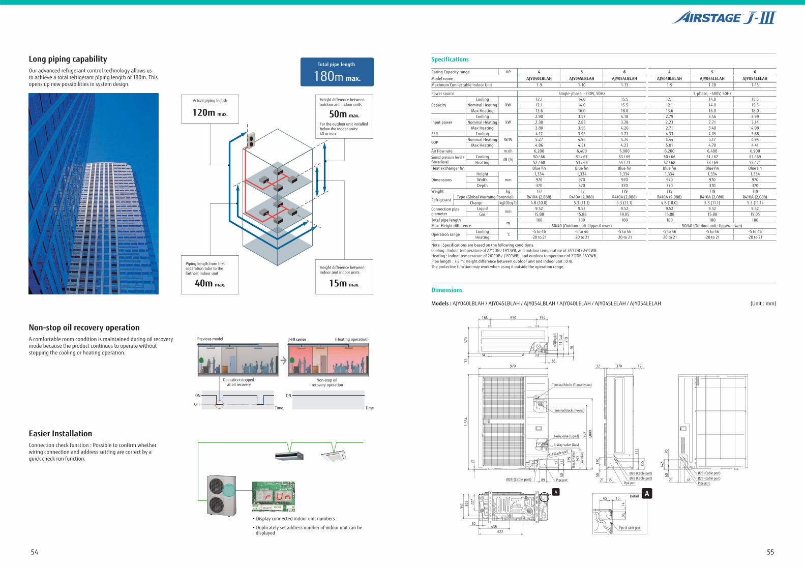
Note : Specifications are based on the following conditions.Cooling : Indoor temperature of 27°CDB / 19°CWB, and outdoor temperature of 35°CDB / 24°CWB.Heating : Indoor temperature of 20°CDB / (15°CWB), and outdoor temperature of 7°CDB / 6°CWB.Pipe length : 7.5 m; Height difference between outdoor unit and indoor unit : 0 m.The protective function may work when using it outside the operation range.
Dimensions
Rating Capacity range HP 4 5 6 4 5 6
Model name AJY040LBLAH AJY045LBLAH AJY054LBLAH AJY040LELAH AJY045LELAH AJY054LELAHMaximum Connectable Indoor Unit 1-9 1-10 1-13 1-9 1-10 1-13
Power source Single-phase, ~230V, 50Hz 3-phase, ~400V, 50Hz
CapacityCooling
kW12.1 14.0 15.5 12.1 14.0 15.5
Nominal Heating 12.1 14.0 15.5 12.1 14.0 15.5Max Heating 13.6 16.0 18.0 13.6 16.0 18.0
Input powerCooling
kW2.90 3.57 4.18 2.79 3.46 3.99
Nominal Heating 2.30 2.83 3.28 2.23 2.71 3.14Max Heating 2.80 3.55 4.26 2.71 3.40 4.08
EER CoolingW/W
4.17 3.92 3.71 4.33 4.05 3.88
COPNominal Heating 5.27 4.96 4.74 5.44 5.17 4.94
Max Heating 4.86 4.51 4.23 5.01 4.70 4.41Air flow rate m3/h 6,200 6,400 6,900 6,200 6,400 6,900Sound pressure level / Power level
CoolingdB (A)
50 / 66 51 / 67 53 / 69 50 / 66 51 / 67 53 / 69Heating 52 / 68 53 / 69 55 / 71 52 / 68 53 / 69 55 / 71
Heat exchanger fin Blue fin Blue fin Blue fin Blue fin Blue fin Blue fin
DimensionsHeight
mm1,334 1,334 1,334 1,334 1,334 1,334
Width 970 970 970 970 970 970Depth 370 370 370 370 370 370
Weight kg 117 117 119 119 119 119
RefrigerantType (Global Warming Potential) R410A (2,088) R410A (2,088) R410A (2,088) R410A (2,088) R410A (2,088) R410A (2,088)
Charge kg(CO2eq-T) 4.8 (10.0) 5.3 (11.1) 5.3 (11.1) 4.8 (10.0) 5.3 (11.1) 5.3 (11.1)Connection pipe diameter
Liquidmm
9.52 9.52 9.52 9.52 9.52 9.52Gas 15.88 15.88 19.05 15.88 15.88 19.05
Total pipe lengthm
180 180 180 180 180 180Max. Height difference 50/40 (Outdoor unit: Upper/Lower) 50/40 (Outdoor unit: Upper/Lower)
Operation rangeCooling -5 to 46 -5 to 46 -5 to 46 -5 to 46 -5 to 46 -5 to 46Heating -20 to 21 -20 to 21 -20 to 21 -20 to 21 -20 to 21 -20 to 21
Models : AJY040LBLAH / AJY045LBLAH / AJY054LBLAH / AJY040LELAH / AJY045LELAH / AJY054LELAH (Unit : mm)
Detail
650
970 32 12370
Terminal blocks (Transmission)
Terminal blocks (Power)
3-Way valve (Liquid)
3-Way valve (Gas)
Ø28 (Cable port)
Pipe portPipe port
Pipe & cable port
Pipe port89
50438
622
65 15
1450
21 55 21 65
166
370
43(L
iqui
d)
51(G
as)
(410
)40
321,
334
907
297
(Gas
valve
)
279
5095 12
050 50
2587131
(Liq
uid v
alve)
1,00
0
111
70
155
14221
227
305
341
154
36
Ø28 (Cable port)Ø28 (Cable port)
Ø28 (Cable port)Ø28 (Cable port)
AA
Ø28 (Cable port)
Long piping capabilityOur advanced refrigerant control technology allows us to achieve a total refrigerant piping length of 180m. This opens up new possibilities in system design.
Non-stop oil recovery operation
Easier Installation
A comfortable room condition is maintained during oil recovery mode because the product continues to operate without stopping the cooling or heating operation.
Connection check function : Possible to confirm whether wiring connection and address setting are correct by a quick check run function.
Height difference between outdoor and indoor units
For the outdoor unit installed below the indoor units:40 m max.
50m max.
Height difference between indoor and indoor units
15m max.
Actual piping length
120m max.
Piping length from first separation tube to the farthest indoor unit
40m max.
180m max.
Total pipe length
Previous model J-III series (Heating operation)
Time
ON
OFF
Operation stopped at oil recovery
Time
ON
Non-stop oil recovery operation
5756
Features
HEAT PUMP TYPE
Fujitsu General provides air conditioning systems for a wide range of applications from small office buildings and stores to large houses.
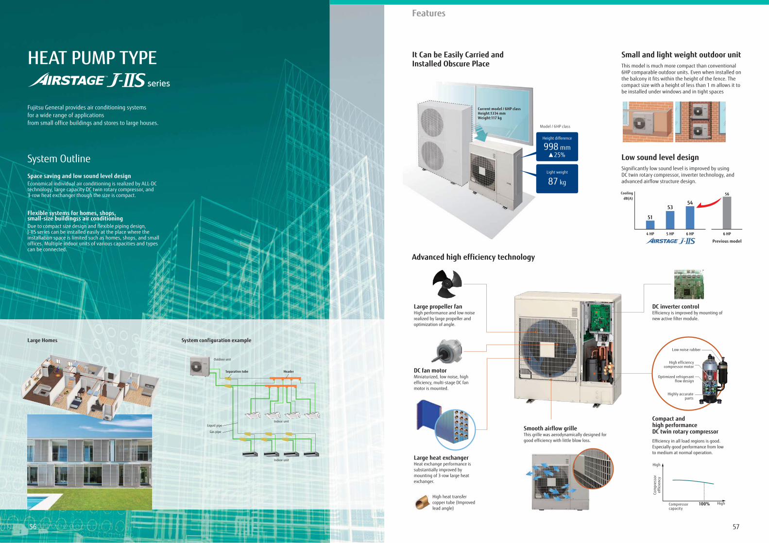
Space saving and low sound level designEconomical individual air conditioning is realized by ALL-DC technology, large capacity DC twin rotary compressor, and 3-row heat exchanger though the size is compact.
Flexible systems for homes, shops, small-size buildingss air conditioningDue to compact size design and flexible piping design, J-IIS series can be installed easily at the place where the installation space is limited such as homes, shops, and small offices. Multiple indoor units of various capacities and types can be connected.
System Outline
System configuration example
It Can be Easily Carried and Installed Obscure Place
Small and light weight outdoor unit
Low sound level design
Advanced high efficiency technology
This model is much more compact than conventional 6HP comparable outdoor units. Even when installed on the balcony it fits within the height of the fence. The compact size with a height of less than 1 m allows it to be installed under windows and in tight spaces
Significantly low sound level is improved by using DC twin rotary compressor, inverter technology, and advanced airflow structure design.
Large Homes
Indoor unit
Outdoor unit
Indoor unit
Gas pipe
Liquid pipe
Separation tube Header
Current model / 6 HP classHeight:1334 mmWeight:117 kg
Model / 6 HP class
Height difference
25%998 mm
Light weight
87 kg
4 HP
51
5 HP
53
6 HP
54
6 HP
Previous model
CoolingdB(A)
56
High efficiencycompressor motor
Optimized refrigerant flow design
Com
pres
sor
effic
ienc
y
High
HighCompressor capacity
Efficiency in all load regions is good. Especially good performance from low to medium at normal operation.
Large propeller fanHigh performance and low noise realized by large propeller and optimization of angle.
DC inverter controlEfficiency is improved by mounting of new active filter module.
DC fan motorMiniaturized, low noise, high efficiency, multi-stage DC fan motor is mounted.
Smooth airflow grilleThis grille was aerodynamically designed for good efficiency with little blow loss.
Large heat exchangerHeat exchange performance is substantially improved by mounting of 3-row large heat exchanger.
High heat transfer copper tube (Improved lead angle)
Highly accurate parts
Low noise rubber
100%
Compact and high performance DC twin rotary compressor
5958
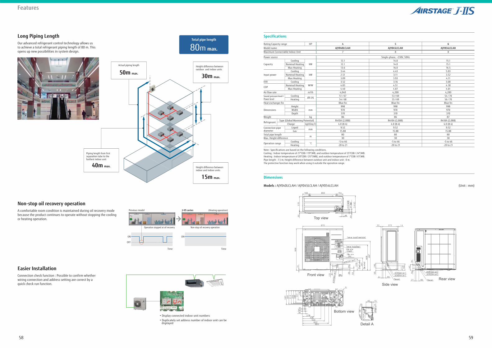
Specifications
Note : Specifications are based on the following conditions.Cooling : Indoor temperature of 27°CDB / 19°CWB, and outdoor temperature of 35°CDB / 24°CWB.Heating : Indoor temperature of 20°CDB / (15°CWB), and outdoor temperature of 7°CDB / 6°CWB.Pipe length : 7.5 m; Height difference between outdoor unit and indoor unit : 0 m.The protective function may work when using it outside the operation range.
Dimensions
Rating Capacity range HP 4 5 6
Model name AJY040LCLAH AJY045LCLAH AJY054LCLAHMaximum Connectable Indoor Unit 7 8 8
Power source Single-phase, ~230V, 50Hz
CapacityCooling
kW12.1 14.0 15.1
Nominal Heating 12.1 14.0 15.1 Max Heating 13.6 16.0 16.5
Input powerCooling
kW3.44 4.43 5.03
Nominal Heating 2.51 3.11 3.52Max Heating 3.09 3.93 4.11
EER CoolingW/W
3.52 3.16 3.00
COPNominal Heating 4.83 4.51 4.30
Max Heating 4.40 4.07 4.01Air flow rate m3/h 4,040 4,200 4,200Sound pressure level / Power level
CoolingdB (A)
51 / 67 53 / 69 54 / 70Heating 54 / 68 55 / 69 56 / 70
Heat exchanger fin Blue fin Blue fin Blue fin
DimensionsHeight
mm998 998 998
Width 970 970 970Depth 370 370 370
Weight kg 86 86 87
RefrigerantType (Global Warming Potential) R410A (2,088) R410A (2,088) R410A (2,088)
Charge kg(CO2eq-T) 4.0 (8.4) 4.0 (8.4) 4.0 (8.4)Connection pipe diameter
Liquidmm
9.52 9.52 9.52Gas 15.88 15.88 15.88
Total pipe lengthm
80 80 80Max. Height difference 30 30 30
Operation rangeCooling -5 to 46 -5 to 46 -5 to 46Heating -20 to 21 -20 to 21 -20 to 21
Models : AJY040LCLAH / AJY045LCLAH / AJY054LCLAH (Unit : mm)
Top view
Front viewRear view
Side view
Detail A
Bottom view
Features
Long Piping LengthOur advanced refrigerant control technology allows us to achieve a total refrigerant piping length of 80 m. This opens up new possibilities in system design.
Non-stop oil recovery operation
Easier Installation
A comfortable room condition is maintained during oil recovery mode because the product continues to operate without stopping the cooling or heating operation.
Connection check function : Possible to confirm whether wiring connection and address setting are correct by a quick check run function.
Height difference between outdoor and indoor units
30m max.
Height difference between indoor and indoor units
15m max.
Actual piping length
50m max.
Piping length from first separation tube to the farthest indoor unit
40m max.
80m max.
Total pipe length
Previous model J-IIS series (Heating operation)
Time
ON
OFF
Operation stopped at oil recovery
Time
ON
Non-stop oil recovery operation
*1
6160
Features
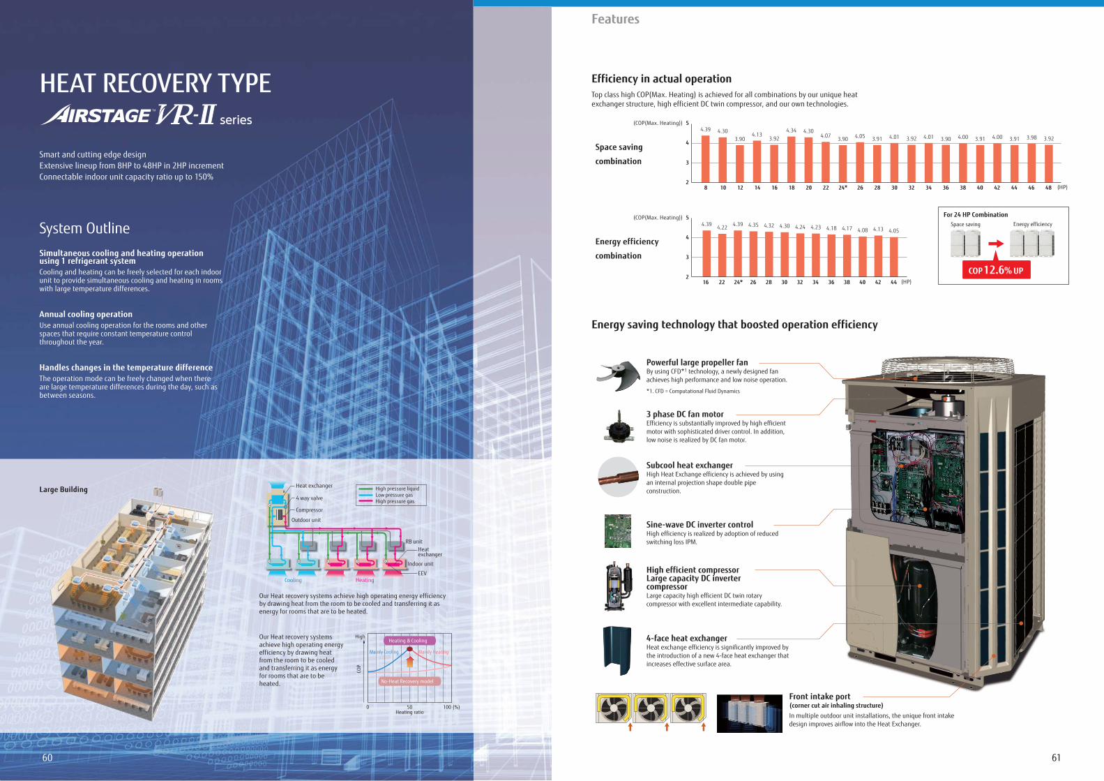
HEAT RECOVERY TYPE
Smart and cutting edge designExtensive lineup from 8HP to 48HP in 2HP incrementConnectable indoor unit capacity ratio up to 150%
Simultaneous cooling and heating operation using 1 refrigerant systemCooling and heating can be freely selected for each indoor unit to provide simultaneous cooling and heating in rooms with large temperature differences.
Annual cooling operationUse annual cooling operation for the rooms and other spaces that require constant temperature control throughout the year.
Handles changes in the temperature differenceThe operation mode can be freely changed when there are large temperature differences during the day, such as between seasons.
System Outline
Large Building High pressure liquidLow pressure gasHigh pressure gas
Indoor unit
Outdoor unit
Cooling Heating
RB unitHeat exchanger
EEV
Heat exchanger
Compressor
4 way valve
Our Heat recovery systems achieve high operating energy efficiency by drawing heat from the room to be cooled and transferring it as energy for rooms that are to be heated.
Our Heat recovery systems achieve high operating energy efficiency by drawing heat from the room to be cooled and transferring it as energy for rooms that are to be heated.
0 50
COP
Heating ratio
High
100 (%)
No-Heat Recovery model
Heating & Cooling
Mainly HeatingMainly Cooling
Efficiency in actual operation
Energy saving technology that boosted operation efficiency
Top class high COP(Max. Heating) is achieved for all combinations by our unique heat exchanger structure, high efficient DC twin compressor, and our own technologies.
For 24 HP CombinationSpace saving Energy efficiency
COP 12.6% UP
Space saving
combination
Energy efficiency
combination
(COP(Max. Heating))
8 10 12 14 16 18 20 22 24* 363432302826 38 40 42 44 46 482
3
4
5
(HP)
(COP(Max. Heating))
16 22 24* 26 28 30 32 34 36 38 444240 (HP)2
3
4
5
4.304.39
3.904.13
3.924.34 4.30
4.07 3.90 4.05 3.91 4.01 3.92 4.01 3.90 4.00 3.91 4.00 3.91 3.98 3.92
4.39 4.22 4.39 4.35 4.32 4.30 4.24 4.23 4.18 4.17 4.08 4.13 4.05
4-face heat exchanger Heat exchange efficiency is significantly improved bythe introduction of a new 4-face heat exchanger thatincreases effective surface area.
Front intake port(corner cut air inhaling structure)In multiple outdoor unit installations, the unique front intake design improves airflow into the Heat Exchanger.
3 phase DC fan motor Efficiency is substantially improved by high efficientmotor with sophisticated driver control. In addition,low noise is realized by DC fan motor.
Sine-wave DC inverter controlHigh efficiency is realized by adoption of reducedswitching loss IPM.
Subcool heat exchangerHigh Heat Exchange efficiency is achieved by usingan internal projection shape double pipeconstruction.
High efficient compressorLarge capacity DC invertercompressorLarge capacity high efficient DC twin rotarycompressor with excellent intermediate capability.
Powerful large propeller fanBy using CFD*1 technology, a newly designed fanachieves high performance and low noise operation.
*1. CFD = Computational Fluid Dynamics
6362
Features
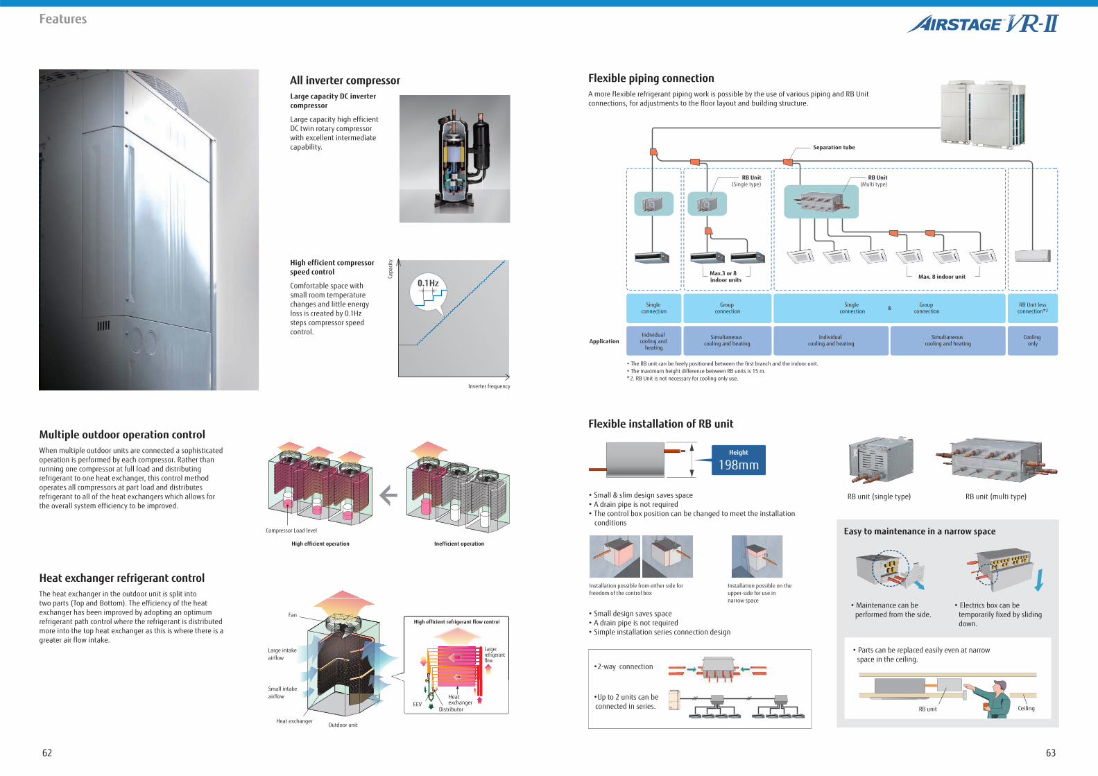
All inverter compressorLarge capacity DC inverter compressor
Large capacity high efficient DC twin rotary compressor with excellent intermediate capability.
High efficient compressor speed control
Comfortable space with small room temperature changes and little energy loss is created by 0.1Hz steps compressor speed control.
Capa
city
Inverter frequency
0.1Hz
Multiple outdoor operation control
Heat exchanger refrigerant control
When multiple outdoor units are connected a sophisticated operation is performed by each compressor. Rather than running one compressor at full load and distributing refrigerant to one heat exchanger, this control method operates all compressors at part load and distributesrefrigerant to all of the heat exchangers which allows for the overall system efficiency to be improved.
The heat exchanger in the outdoor unit is split into two parts (Top and Bottom). The efficiency of the heat exchanger has been improved by adopting an optimum refrigerant path control where the refrigerant is distributed more into the top heat exchanger as this is where there is a greater air flow intake.
High efficient operation Inefficient operation
Compressor Load level
Heat exchangerOutdoor unit
Large intakeairflow
Fan
Small intakeairflow
High efficient refrigerant flow control
Largerrefrigerantflow
High efficient refrigerant flow control
Largerrefrigerantflow
EEVHeat exchanger
Distributor
Flexible piping connection
Flexible installation of RB unit
A more flexible refrigerant piping work is possible by the use of various piping and RB Unit connections, for adjustments to the floor layout and building structure.
conditions
RB unit (single type) RB unit (multi type)
*
RB Unit
Max. 8 indoor unit indoor unitsMax.3 or 8
Separation tube
&
Application
2
RB Unit
Height
198mm
Installation possible from either side for freedom of the control box
Installation possible on the upper-side for use in narrow space
RB unit Ceiling
performed from the side.down.
Easy to maintenance in a narrow space
6564
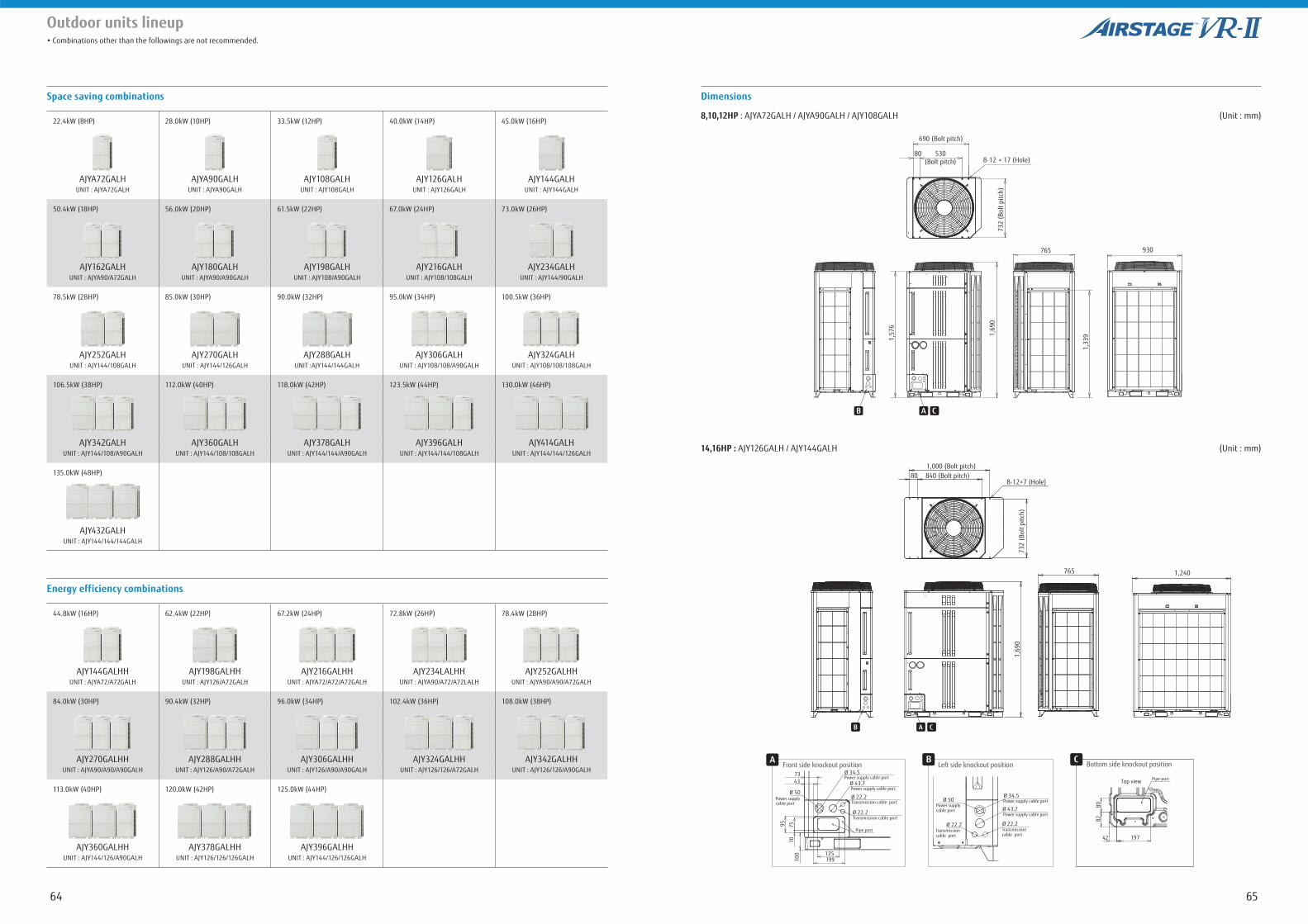
Outdoor units lineup
Space saving combinations Dimensions
14,16HP : AJY126GALH / AJY144GALH (Unit : mm)
8,10,12HP : AJYA72GALH / AJYA90GALH / AJY108GALH (Unit : mm)
Energy efficiency combinations
22.4kW (8HP) 28.0kW (10HP) 33.5kW (12HP) 40.0kW (14HP) 45.0kW (16HP)
AJYA72GALH AJYA90GALH AJY108GALH AJY126GALH AJY144GALHUNIT : AJYA72GALH UNIT : AJYA90GALH UNIT : AJY108GALH UNIT : AJY126GALH UNIT : AJY144GALH
50.4kW (18HP) 56.0kW (20HP) 61.5kW (22HP) 67.0kW (24HP) 73.0kW (26HP)
AJY162GALH AJY180GALH AJY198GALH AJY216GALH AJY234GALHUNIT : AJYA90/A72GALH UNIT : AJYA90/A90GALH UNIT : AJY108/A90GALH UNIT : AJY108/108GALH UNIT : AJY144/90GALH
78.5kW (28HP) 85.0kW (30HP) 90.0kW (32HP) 95.0kW (34HP) 100.5kW (36HP)
AJY252GALH AJY270GALH AJY288GALH AJY306GALH AJY324GALHUNIT : AJY144/108GALH UNIT : AJY144/126GALH UNIT :AJY144/144GALH UNIT : AJY108/108/A90GALH UNIT : AJY108/108/108GALH
106.5kW (38HP) 112.0kW (40HP) 118.0kW (42HP) 123.5kW (44HP) 130.0kW (46HP)
AJY342GALH AJY360GALH AJY378GALH AJY396GALH AJY414GALHUNIT : AJY144/108/A90GALH UNIT : AJY144/108/108GALH UNIT : AJY144/144/A90GALH UNIT : AJY144/144/108GALH UNIT : AJY144/144/126GALH
135.0kW (48HP)
AJY432GALHUNIT : AJY144/144/144GALH
44.8kW (16HP) 62.4kW (22HP) 67.2kW (24HP) 72.8kW (26HP) 78.4kW (28HP)
AJY144GALHH AJY198GALHH AJY216GALHH AJY234LALHH AJY252GALHHUNIT : AJYA72/A72GALH UNIT : AJY126/A72GALH UNIT : AJYA72/A72/A72GALH UNIT : AJYA90/A72/A72LALH UNIT : AJYA90/A90/A72GALH
84.0kW (30HP) 90.4kW (32HP) 96.0kW (34HP) 102.4kW (36HP) 108.0kW (38HP)
AJY270GALHH AJY288GALHH AJY306GALHH AJY324GALHH AJY342GALHHUNIT : AJYA90/A90/A90GALH UNIT : AJY126/A90/A72GALH UNIT : AJY126/A90/A90GALH UNIT : AJY126/126/A72GALH UNIT : AJY126/126/A90GALH
113.0kW (40HP) 120.0kW (42HP) 125.0kW (44HP)
AJY360GALHH AJY378GALHH AJY396GALHHUNIT : AJY144/126/A90GALH UNIT : AJY126/126/126GALH UNIT : AJY144/126/126GALH
Front side knockout positionA
Power supply cable port
Pipe port
Transmission cable port
Transmission cable port
7343 Ø 43.7
Ø 22.2
Ø 22.2
95 7
510
100 125
199
Ø 34.5
Power supply cable port
Power supply cable port
Ø 50
Left side knockout position
Transmission cable port
Transmission cable port
Ø 43.7
Ø 22.2Ø 22.2
Ø 34.5Power supply cable port
Power supply cable port
Power supply cable port
Ø 50
B Bottom side knockout position
Top view Pipe port
80
197
82
42
C
8-12 × 17 (Hole)
1,69
0
1,57
6
1,33
9
765 930
530(Bolt pitch)
80
690 (Bolt pitch)
732
(Bol
t pitc
h)
B CA
8-12×7 (Hole)
1,240
1,69
073
2 (B
olt p
itch)
1,000 (Bolt pitch)840 (Bolt pitch)80
B CA
765
6766
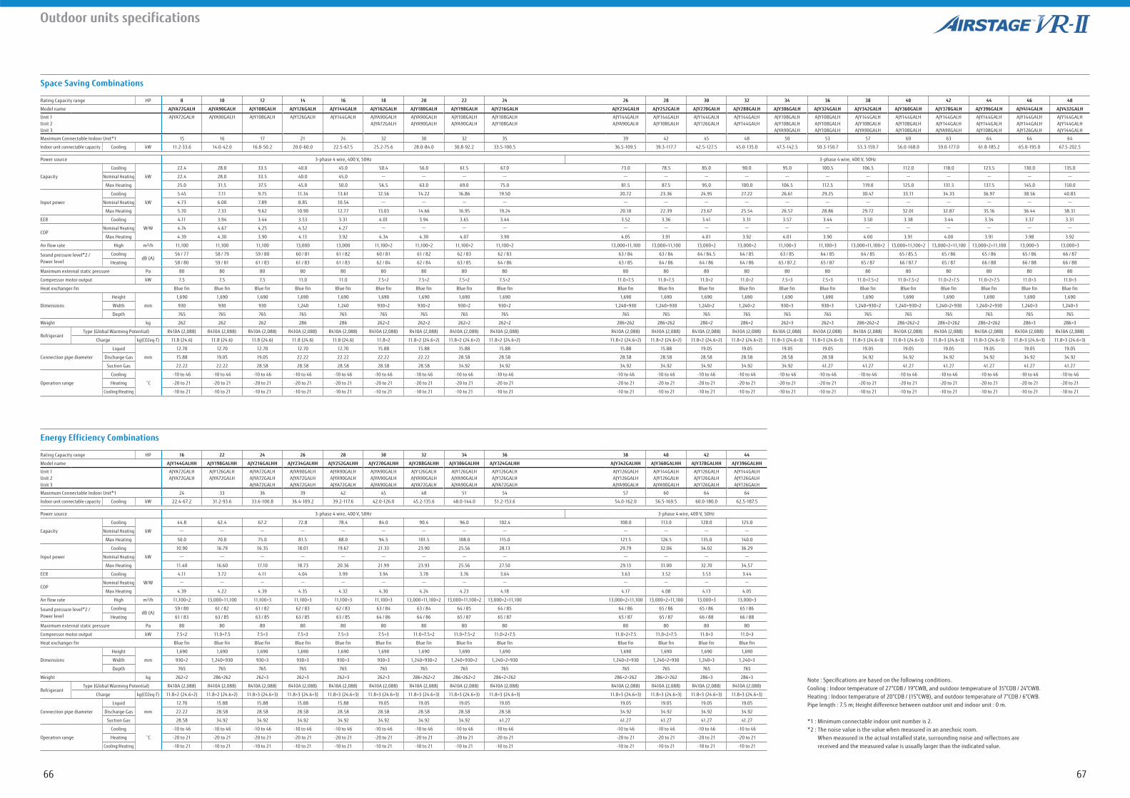
Outdoor units specifications
Space Saving Combinations
Energy Efficiency Combinations
Note : Specifications are based on the following conditions.Cooling : Indoor temperature of 27°CDB / 19°CWB, and outdoor temperature of 35°CDB / 24°CWB.Heating : Indoor temperature of 20°CDB / (15°CWB), and outdoor temperature of 7°CDB / 6°CWB.Pipe length : 7.5 m; Height difference between outdoor unit and indoor unit : 0 m.
*1 : Minimum connectable indoor unit number is 2.*2 : The noise value is the value when measured in an anechoic room. When measured in the actual installed state, surrounding noise and reflections are received and the measured value is usually larger than the indicated value.
Rating Capacity range HP 8 10 12 14 16 18 20 22 24 26 28 30 32 34 36 38 40 42 44 46 48
Model name AJYA72GALH AJYA90GALH AJY108GALH AJY126GALH AJY144GALH AJY162GALH AJY180GALH AJY198GALH AJY216GALH AJY234GALH AJY252GALH AJY270GALH AJY288GALH AJY306GALH AJY324GALH AJY342GALH AJY360GALH AJY378GALH AJY396GALH AJY414GALH AJY432GALH
Unit 1Unit 2Unit 3
AJYA72GALH AJYA90GALH AJY108GALH AJY126GALH AJY144GALH AJYA90GALHAJYA72GALH
AJYA90GALHAJYA90GALH
AJY108GALHAJYA90GALH
AJY108GALHAJY108GALH
AJY144GALHAJYA90GALH
AJY144GALHAJY108GALH
AJY144GALHAJY126GALH
AJY144GALHAJY144GALH
AJY108GALHAJY108GALHAJYA90GALH
AJY108GALHAJY108GALHAJY108GALH
AJY144GALHAJY108GALHAJYA90GALH
AJY144GALHAJY108GALHAJY108GALH
AJY144GALHAJY144GALHAJYA90GALH
AJY144GALHAJY144GALHAJY108GALH
AJY144GALHAJY144GALHAJY126GALH
AJY144GALHAJY144GALHAJY144GALH
Maximum Connectable Indoor Unit*1 15 16 17 21 24 32 30 32 35 39 42 45 48 50 53 57 60 63 64 64 64
Indoor unit connectable capacity Cooling kW 11.2-33.6 14.0-42.0 16.8-50.2 20.0-60.0 22.5-67.5 25.2-75.6 28.0-84.0 30.8-92.2 33.5-100.5 36.5-109.5 39.3-117.7 42.5-127.5 45.0-135.0 47.5-142.5 50.3-150.7 53.3-159.7 56.0-168.0 59.0-177.0 61.8-185.2 65.0-195.0 67.5-202.5
Power source 3-phase 4 wire, 400 V, 50Hz 3-phase 4 wire, 400 V, 50Hz
Capacity
Cooling
kW
22.4 28.0 33.5 40.0 45.0 50.4 56.0 61.5 67.0 73.0 78.5 85.0 90.0 95.0 100.5 106.5 112.0 118.0 123.5 130.0 135.0
Nominal Heating 22.4 28.0 33.5 40.0 45.0 - - - - - - - - - - - - - - - -
Max Heating 25.0 31.5 37.5 45.0 50.0 56.5 63.0 69.0 75.0 81.5 87.5 95.0 100.0 106.5 112.5 119.0 125.0 131.5 137.5 145.0 150.0
Input power
Cooling
kW
5.45 7.11 9.75 11.34 13.61 12.56 14.22 16.86 19.50 20.72 23.36 24.95 27.22 26.61 29.25 30.47 33.11 34.33 36.97 38.56 40.83
Nominal Heating 4.73 6.00 7.89 8.85 10.54 - - - - - - - - - - - - - - - -
Max Heating 5.70 7.33 9.62 10.90 12.77 13.03 14.66 16.95 19.24 20.10 22.39 23.67 25.54 26.57 28.86 29.72 32.01 32.87 35.16 36.44 38.31
EER Cooling
W/W
4.11 3.94 3.44 3.53 3.31 4.01 3.94 3.65 3.44 3.52 3.36 3.41 3.31 3.57 3.44 3.50 3.38 3.44 3.34 3.37 3.31
COPNominal Heating 4.74 4.67 4.25 4.52 4.27 - - - - - - - - - - - - - - - -
Max Heating 4.39 4.30 3.90 4.13 3.92 4.34 4.30 4.07 3.90 4.05 3.91 4.01 3.92 4.01 3.90 4.00 3.91 4.00 3.91 3.98 3.92
Air flow rate High m3/h 11,100 11,100 11,100 13,000 13,000 11,100×2 11,100×2 11,100×2 11,100×2 13,000+11,100 13,000+11,100 13,000×2 13,000×2 11,100×3 11,100×3 13,000+11,100×2 13,000+11,100×2 13,000×2+11,100 13,000×2+11,100 13,000×3 13,000×3
Sound pressure level*2 /Power level
CoolingdB (A)
56 / 77 58 / 79 59 / 80 60 / 81 61 / 82 60 / 81 61 / 82 62 / 83 62 / 83 63 / 84 63 / 84 64 / 84.5 64 / 85 63 / 85 64 / 85 64 / 85 65 / 85.5 65 / 86 65 / 86 65 / 86 66 / 87
Heating 58 / 80 59 / 81 61 / 83 61 / 83 61 / 83 62 / 84 62 / 84 63 / 85 64 / 86 63 / 85 64 / 86 64 / 86 64 / 86 65 / 87.2 65 / 87 65 / 87 66 / 87.7 65 / 87 66 / 88 66 / 88 66 / 88
Maximum external static pressure Pa 80 80 80 80 80 80 80 80 80 80 80 80 80 80 80 80 80 80 80 80 80
Compressor motor output kW 7.5 7.5 7.5 11.0 11.0 7.5×2 7.5×2 7.5×2 7.5×2 11.0+7.5 11.0+7.5 11.0×2 11.0×2 7.5×3 7.5×3 11.0+7.5×2 11.0+7.5×2 11.0×2+7.5 11.0×2+7.5 11.0×3 11.0×3
Heat exchanger fin Blue fin Blue fin Blue fin Blue fin Blue fin Blue fin Blue fin Blue fin Blue fin Blue fin Blue fin Blue fin Blue fin Blue fin Blue fin Blue fin Blue fin Blue fin Blue fin Blue fin Blue fin
Dimensions
Height
mm
1,690 1,690 1,690 1,690 1,690 1,690 1,690 1,690 1,690 1,690 1,690 1,690 1,690 1,690 1,690 1,690 1,690 1,690 1,690 1,690 1,690
Width 930 930 930 1,240 1,240 930×2 930×2 930×2 930×2 1,240+930 1,240+930 1,240×2 1,240×2 930×3 930×3 1,240+930×2 1,240+930×2 1,240×2+930 1,240×2+930 1,240×3 1,240×3
Depth 765 765 765 765 765 765 765 765 765 765 765 765 765 765 765 765 765 765 765 765 765
Weight kg 262 262 262 286 286 262×2 262×2 262×2 262×2 286+262 286+262 286×2 286×2 262×3 262×3 286+262×2 286+262×2 286×2+262 286×2+262 286×3 286×3
RefrigerantType (Global Warming Potential) R410A (2,088) R410A (2,088) R410A (2,088) R410A (2,088) R410A (2,088) R410A (2,088) R410A (2,088) R410A (2,088) R410A (2,088) R410A (2,088) R410A (2,088) R410A (2,088) R410A (2,088) R410A (2,088) R410A (2,088) R410A (2,088) R410A (2,088) R410A (2,088) R410A (2,088) R410A (2,088) R410A (2,088)
Charge kg(CO2eq-T) 11.8 (24.6) 11.8 (24.6) 11.8 (24.6) 11.8 (24.6) 11.8 (24.6) 11.8×2 11.8×2 (24.6×2) 11.8×2 (24.6×2) 11.8×2 (24.6×2) 11.8×2 (24.6×2) 11.8×2 (24.6×2) 11.8×2 (24.6×2) 11.8×2 (24.6×2) 11.8×3 (24.6×3) 11.8×3 (24.6×3) 11.8×3 (24.6×3) 11.8×3 (24.6×3) 11.8×3 (24.6×3) 11.8×3 (24.6×3) 11.8×3 (24.6×3) 11.8×3 (24.6×3)
Connection pipe diameter
Liquid
mm
12.70 12.70 12.70 12.70 12.70 15.88 15.88 15.88 15.88 15.88 15.88 19.05 19.05 19.05 19.05 19.05 19.05 19.05 19.05 19.05 19.05
Discharge Gas 15.88 19.05 19.05 22.22 22.22 22.22 22.22 28.58 28.58 28.58 28.58 28.58 28.58 28.58 28.58 34.92 34.92 34.92 34.92 34.92 34.92
Suction Gas 22.22 22.22 28.58 28.58 28.58 28.58 28.58 34.92 34.92 34.92 34.92 34.92 34.92 34.92 41.27 41.27 41.27 41.27 41.27 41.27 41.27
Operation range
Cooling -10 to 46 -10 to 46 -10 to 46 -10 to 46 -10 to 46 -10 to 46 -10 to 46 -10 to 46 -10 to 46 -10 to 46 -10 to 46 -10 to 46 -10 to 46 -10 to 46 -10 to 46 -10 to 46 -10 to 46 -10 to 46 -10 to 46 -10 to 46 -10 to 46
Heating -20 to 21 -20 to 21 -20 to 21 -20 to 21 -20 to 21 -20 to 21 -20 to 21 -20 to 21 -20 to 21 -20 to 21 -20 to 21 -20 to 21 -20 to 21 -20 to 21 -20 to 21 -20 to 21 -20 to 21 -20 to 21 -20 to 21 -20 to 21 -20 to 21
Cooling/Heating -10 to 21 -10 to 21 -10 to 21 -10 to 21 -10 to 21 -10 to 21 -10 to 21 -10 to 21 -10 to 21 -10 to 21 -10 to 21 -10 to 21 -10 to 21 -10 to 21 -10 to 21 -10 to 21 -10 to 21 -10 to 21 -10 to 21 -10 to 21 -10 to 21
Rating Capacity range HP 16 22 24 26 28 30 32 34 36 38 40 42 44
Model name AJY144GALHH AJY198GALHH AJY216GALHH AJY234GALHH AJY252GALHH AJY270GALHH AJY288GALHH AJY306GALHH AJY324GALHH AJY342GALHH AJY360GALHH AJY378GALHH AJY396GALHH
Unit 1Unit 2Unit 3
AJYA72GALHAJYA72GALH
AJY126GALHAJYA72GALH
AJYA72GALHAJYA72GALHAJYA72GALH
AJYA90GALHAJYA72GALHAJYA72GALH
AJYA90GALHAJYA90GALHAJYA72GALH
AJYA90GALHAJYA90GALHAJYA90GALH
AJY126GALHAJYA90GALHAJYA72GALH
AJY126GALHAJYA90GALHAJYA90GALH
AJY126GALHAJY126GALHAJYA72GALH
AJY126GALHAJY126GALHAJYA90GALH
AJY144GALHAJY126GALHAJYA90GALH
AJY126GALHAJY126GALHAJY126GALH
AJY144GALHAJY126GALHAJY126GALH
Maximum Connectable Indoor Unit*1 24 33 36 39 42 45 48 51 54 57 60 64 64
Indoor unit connectable capacity Cooling kW 22.4-67.2 31.2-93.6 33.6-100.8 36.4-109.2 39.2-117.6 42.0-126.0 45.2-135.6 48.0-144.0 51.2-153.6 54.0-162.0 56.5-169.5 60.0-180.0 62.5-187.5
Power source 3-phase 4 wire, 400 V, 50Hz 3-phase 4 wire, 400 V, 50Hz
Capacity
Cooling
kW
44.8 62.4 67.2 72.8 78.4 84.0 90.4 96.0 102.4 108.0 113.0 120.0 125.0
Nominal Heating - - - - - - - - - - - - -
Max Heating 50.0 70.0 75.0 81.5 88.0 94.5 101.5 108.0 115.0 121.5 126.5 135.0 140.0
Input power
Cooling
kW
10.90 16.79 16.35 18.01 19.67 21.33 23.90 25.56 28.13 29.79 32.06 34.02 36.29
Nominal Heating - - - - - - - - - - - - -
Max Heating 11.40 16.60 17.10 18.73 20.36 21.99 23.93 25.56 27.50 29.13 31.00 32.70 34.57
EER Cooling
W/W
4.11 3.72 4.11 4.04 3.99 3.94 3.78 3.76 3.64 3.63 3.52 3.53 3.44
COPNominal Heating - - - - - - - - - - - - -
Max Heating 4.39 4.22 4.39 4.35 4.32 4.30 4.24 4.23 4.18 4.17 4.08 4.13 4.05
Air flow rate High m3/h 11,100×2 13,000+11,100 11,100×3 11,100×3 11,100×3 11,100×3 13,000+11,100×2 13,000+11,100×2 13,000×2+11,100 13,000×2+11,100 13,000×2+11,100 13,000×3 13,000×3
Sound pressure level*2 /Power level
CoolingdB (A)
59 / 80 61 / 82 61 / 82 62 / 83 62 / 83 63 / 84 63 / 84 64 / 85 64 / 85 64 / 86 65 / 86 65 / 86 65 / 86
Heating 61 / 83 63 / 85 63 / 85 63 / 85 63 / 85 64 / 86 64 / 86 65 / 87 65 / 87 65 / 87 65 / 87 66 / 88 66 / 88
Maximum external static pressure Pa 80 80 80 80 80 80 80 80 80 80 80 80 80
Compressor motor output kW 7.5×2 11.0+7.5 7.5×3 7.5×3 7.5×3 7.5×3 11.0+7.5×2 11.0+7.5×2 11.0×2+7.5 11.0×2+7.5 11.0×2+7.5 11.0×3 11.0×3
Heat exchanger fin Blue fin Blue fin Blue fin Blue fin Blue fin Blue fin Blue fin Blue fin Blue fin Blue fin Blue fin Blue fin Blue fin
Dimensions
Height
mm
1,690 1,690 1,690 1,690 1,690 1,690 1,690 1,690 1,690 1,690 1,690 1,690 1,690
Width 930×2 1,240+930 930×3 930×3 930×3 930×3 1,240+930×2 1,240+930×2 1,240×2+930 1,240×2+930 1,240×2+930 1,240×3 1,240×3
Depth 765 765 765 765 765 765 765 765 765 765 765 765 765
Weight kg 262×2 286+262 262×3 262×3 262×3 262×3 286+262×2 286+262×2 286×2+262 286×2+262 286×2+262 286×3 286×3
RefrigerantType (Global Warming Potential) R410A (2,088) R410A (2,088) R410A (2,088) R410A (2,088) R410A (2,088) R410A (2,088) R410A (2,088) R410A (2,088) R410A (2,088) R410A (2,088) R410A (2,088) R410A (2,088) R410A (2,088)
Charge kg(CO2eq-T) 11.8×2 (24.6×2) 11.8×2 (24.6×2) 11.8×3 (24.6×3) 11.8×3 (24.6×3) 11.8×3 (24.6×3) 11.8×3 (24.6×3) 11.8×3 (24.6×3) 11.8×3 (24.6×3) 11.8×3 (24.6×3) 11.8×3 (24.6×3) 11.8×3 (24.6×3) 11.8×3 (24.6×3) 11.8×3 (24.6×3)
Connection pipe diameter
Liquid
mm
12.70 15.88 15.88 15.88 15.88 19.05 19.05 19.05 19.05 19.05 19.05 19.05 19.05
Discharge Gas 22.22 28.58 28.58 28.58 28.58 28.58 28.58 28.58 28.58 34.92 34.92 34.92 34.92
Suction Gas 28.58 34.92 34.92 34.92 34.92 34.92 34.92 34.92 41.27 41.27 41.27 41.27 41.27
Operation range
Cooling -10 to 46 -10 to 46 -10 to 46 -10 to 46 -10 to 46 -10 to 46 -10 to 46 -10 to 46 -10 to 46 -10 to 46 -10 to 46 -10 to 46 -10 to 46
Heating -20 to 21 -20 to 21 -20 to 21 -20 to 21 -20 to 21 -20 to 21 -20 to 21 -20 to 21 -20 to 21 -20 to 21 -20 to 21 -20 to 21 -20 to 21
Cooling/Heating -10 to 21 -10 to 21 -10 to 21 -10 to 21 -10 to 21 -10 to 21 -10 to 21 -10 to 21 -10 to 21 -10 to 21 -10 to 21 -10 to 21 -10 to 21
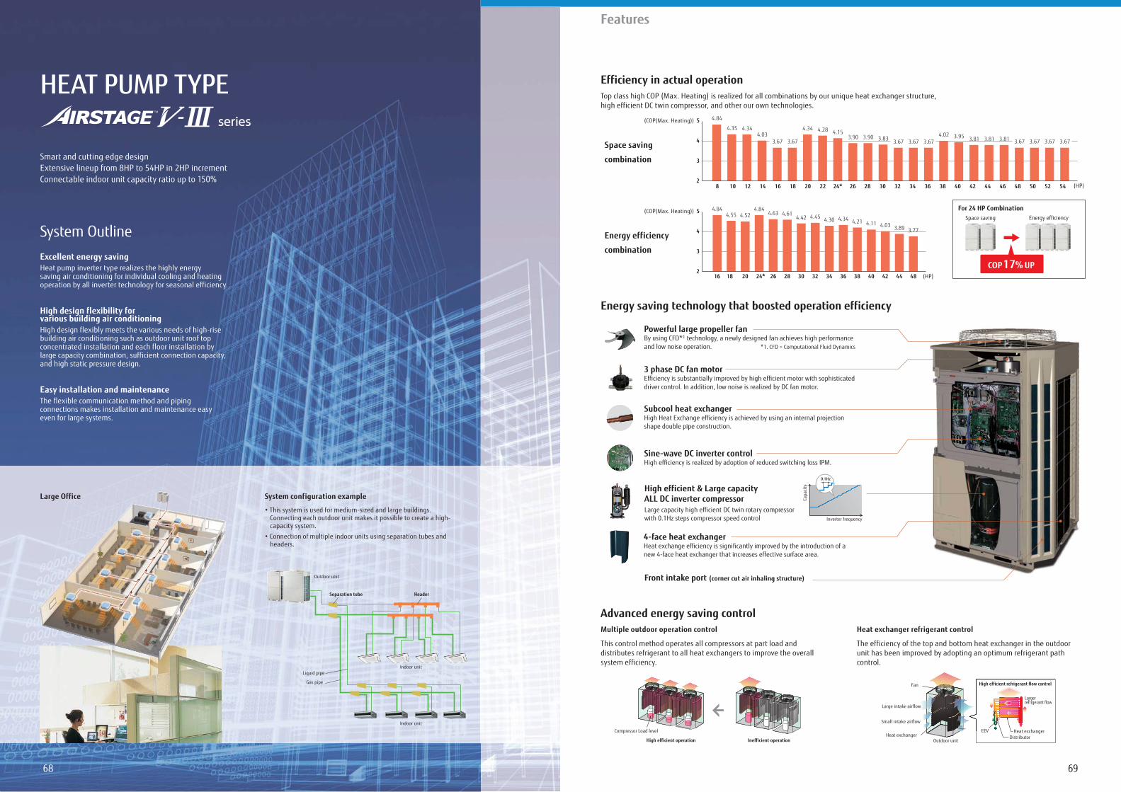
6968
Features
HEAT PUMP TYPE
Smart and cutting edge designExtensive lineup from 8HP to 54HP in 2HP incrementConnectable indoor unit capacity ratio up to 150%
Excellent energy savingHeat pump inverter type realizes the highly energy saving air conditioning for individual cooling and heating operation by all inverter technology for seasonal efficiency.
High design flexibility for various building air conditioningHigh design flexibly meets the various needs of high-rise building air conditioning such as outdoor unit roof top concentrated installation and each floor installation by large capacity combination, sufficient connection capacity, and high static pressure design.
Easy installation and maintenanceThe flexible communication method and piping connections makes installation and maintenance easy even for large systems.
System Outline
Large Office System configuration example
Connecting each outdoor unit makes it possible to create a high-capacity system.
headers.
Efficiency in actual operation
Advanced energy saving control
Energy saving technology that boosted operation efficiency
Top class high COP (Max. Heating) is realized for all combinations by our unique heat exchanger structure, high efficient DC twin compressor, and other our own technologies.
Indoor unit
Outdoor unit
Indoor unit
Gas pipe
Liquid pipe
Separation tube Header
For 24 HP CombinationSpace saving Energy efficiency
COP 17% UP
Space saving
combination
Energy efficiency
combination
(COP(Max. Heating))
2
3
4
5
(HP)
(COP(Max. Heating))
(HP)2
3
4
5
16 18 20 24* 26 28 30 32 34 36 424038 4844
4.84 4.844.55 4.52 4.63 4.61
4.42 4.45 4.30 4.34 4.21 4.11 4.03 3.89 3.77
4.35
4.84
4.344.03
3.67 3.67
4.34 4.28 4.153.90 3.90 3.83 3.67 3.67 3.67
4.02 3.95 3.81 3.81 3.81 3.67 3.673.67 3.67
8 10 12 14 16 18 20 22 24* 363432302826 38 40 42 44 46 54525048
Sine-wave DC inverter controlHigh efficiency is realized by adoption of reduced switching loss IPM.
Powerful large propeller fanBy using CFD*1 technology, a newly designed fan achieves high performance and low noise operation. *1. CFD = Computational Fluid Dynamics
3 phase DC fan motor Efficiency is substantially improved by high efficient motor with sophisticated driver control. In addition, low noise is realized by DC fan motor.
Subcool heat exchangerHigh Heat Exchange efficiency is achieved by using an internal projection shape double pipe construction.
Front intake port (corner cut air inhaling structure)
4-face heat exchanger Heat exchange efficiency is significantly improved by the introduction of a new 4-face heat exchanger that increases effective surface area.
High efficient & Large capacity ALL DC inverter compressorLarge capacity high efficient DC twin rotary compressor with 0.1Hz steps compressor speed control
Capa
city
Inverter frequency
0.1Hz
Multiple outdoor operation control
This control method operates all compressors at part load and distributes refrigerant to all heat exchangers to improve the overall system efficiency.
Heat exchanger refrigerant control
The efficiency of the top and bottom heat exchanger in the outdoor unit has been improved by adopting an optimum refrigerant path control.
High efficient operation Inefficient operation
Compressor Load levelHeat exchanger
Outdoor unit
Large intake airflow
Fan
Small intake airflow
High efficient refrigerant flow control
Largerrefrigerant flow
ng an optimum refrigerant pa
High efficient refrigerag nt flow control
Largerrefrigerant flow
gg
EEV Heat exchangerDistributor
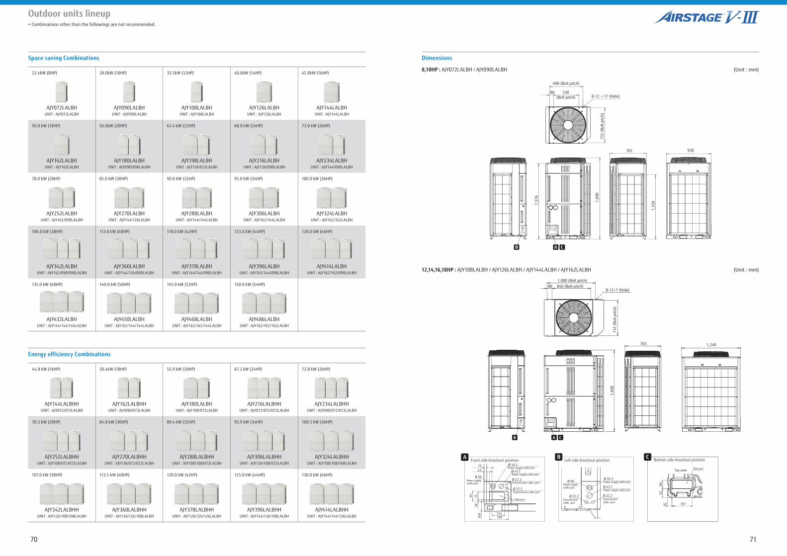
7170
Outdoor units lineup
Space saving Combinations Dimensions
12,14,16,18HP : AJY108LALBH / AJY126LALBH / AJY144LALBH / AJY162LALBH (Unit : mm)
8,10HP : AJY072LALBH / AJY090LALBH (Unit : mm)
Energy efficiency Combinations
22.4kW (8HP) 28.0kW (10HP) 33.5kW (12HP) 40.0kW (14HP) 45.0kW (16HP)
AJY072LALBH AJY090LALBH AJY108LALBH AJY126LALBH AJY144LALBHUNIT : AJY072LALBH UNIT : AJY090LALBH UNIT : AJY108LALBH UNIT : AJY126LALBH UNIT : AJY144LALBH
50.0 kW (18HP) 56.0kW (20HP) 62.4 kW (22HP) 68.0 kW (24HP) 73.0 kW (26HP)
AJY162LALBH AJY180LALBH AJY198LALBH AJY216LALBH AJY234LALBHUNIT : AJY162LALBH UNIT : AJY090/090LALBH UNIT : AJY126/072LALBH UNIT : AJY126/090LALBH UNIT : AJY144/090LALBH
78.0 kW (28HP) 85.0 kW (30HP) 90.0 kW (32HP) 95.0 kW (34HP) 100.0 kW (36HP)
AJY252LALBH AJY270LALBH AJY288LALBH AJY306LALBH AJY324LALBHUNIT : AJY162/090LALBH UNIT : AJY144/126LALBH UNIT : AJY144/144LALBH UNIT : AJY162/144LALBH UNIT : AJY162/162LALBH
106.0 kW (38HP) 113.0 kW (40HP) 118.0 kW (42HP) 123.0 kW (44HP) 128.0 kW (46HP)
AJY342LALBH AJY360LALBH AJY378LALBH AJY396LALBH AJY414LALBHUNIT : AJY162/090/090LALBH UNIT : AJY144/126/090LALBH UNIT : AJY144/144/090LALBH UNIT : AJY162/144/090LALBH UNIT : AJY162/162/090LALBH
135.0 kW (48HP) 140.0 kW (50HP) 145.0 kW (52HP) 150.0 kW (54HP)
AJY432LALBH AJY450LALBH AJY468LALBH AJY486LALBHUNIT : AJY144/144/144LALBH UNIT : AJY162/144/144LALBH UNIT : AJY162/162/144LALBH UNIT : AJY162/162/162LALBH
44.8 kW (16HP) 50.4kW (18HP) 55.9 kW (20HP) 67.2 kW (24HP) 72.8 kW (26HP)
AJY144LALBHH AJY162LALBHH AJY180LALBH AJY216LALBHH AJY234LALBHHUNIT : AJY072/072LALBH UNIT : AJY090/072LALBH UNIT : AJY108/072LALBH UNIT : AJY072/072/072LALBH UNIT : AJY090/072/072LALBH
78.3 kW (28HP) 84.8 kW (30HP) 89.4 kW (32HP) 95.9 kW (34HP) 100.5 kW (36HP)
AJY252LALBHH AJY270LALBHH AJY288LALBHH AJY306LALBHH AJY324LALBHHUNIT : AJY108/072/072LALBH UNIT : AJY126/072/072LALBH UNIT : AJY108/108/072LALBH UNIT : AJY126/108/072LALBH UNIT : AJY108/108/108LALBH
107.0 kW (38HP) 113.5 kW (40HP) 120.0 kW (42HP) 125.0 kW (44HP) 130.0 kW (46HP)
AJY342LALBHH AJY360LALBHH AJY378LALBHH AJY396LALBHH AJY414LALBHHUNIT : AJY126/108/108LALBH UNIT : AJY126/126/108LALBH UNIT : AJY126/126/126LALBH UNIT : AJY144/126/108LALBH UNIT : AJY144/144/126LALBH
Front side knockout positionA
Power supply cable port
Pipe port
Transmission cable port
Transmission cable port
7343 Ø 43.7
Ø 22.2
Ø 22.2
95 7
510
100 125
199
Ø 34.5
Power supply cable port
Power supply cable port
Ø 50
Left side knockout position
Transmission cable port
Transmission cable port
Ø 43.7
Ø 22.2Ø 22.2
Ø 34.5Power supply cable port
Power supply cable port
Power supply cable port
Ø 50
B Bottom side knockout position
Top view Pipe port
80
197
82
42
C
8-12 × 17 (Hole)
1,69
0
1,57
6
1,33
9
765 930
530(Bolt pitch)
80
690 (Bolt pitch)
732
(Bol
t pitc
h)
B CA
8-12×7 (Hole)
1,240
1,69
073
2 (B
olt p
itch)
1,000 (Bolt pitch)840 (Bolt pitch)80
B CA
765
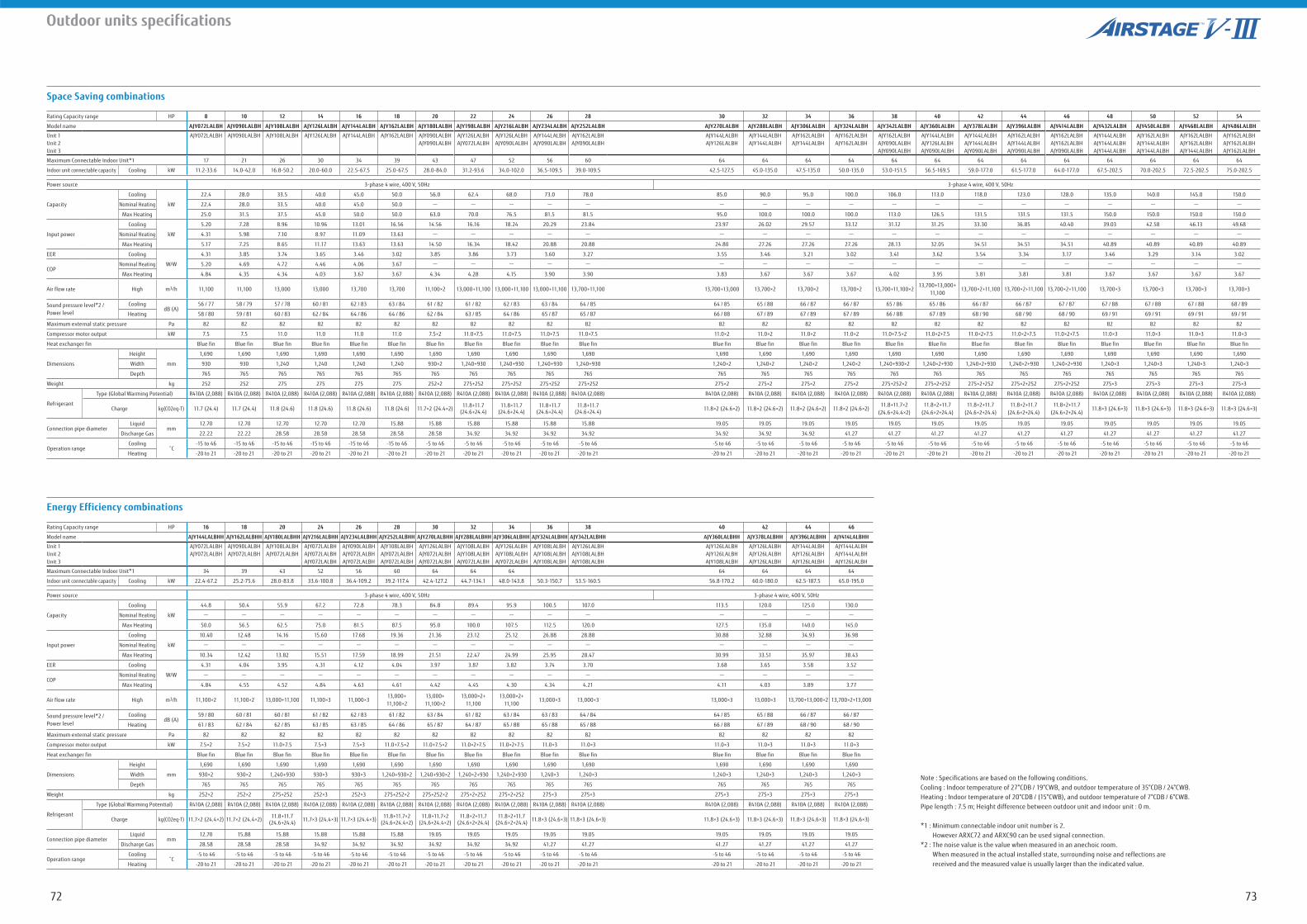
7372
Outdoor units specifications
Space Saving combinations
Energy Efficiency combinations
Note : Specifications are based on the following conditions.Cooling : Indoor temperature of 27°CDB / 19°CWB, and outdoor temperature of 35°CDB / 24°CWB.Heating : Indoor temperature of 20°CDB / (15°CWB), and outdoor temperature of 7°CDB / 6°CWB.Pipe length : 7.5 m; Height difference between outdoor unit and indoor unit : 0 m.
*1 : Minimum connectable indoor unit number is 2. However ARXC72 and ARXC90 can be used signal connection.*2 : The noise value is the value when measured in an anechoic room. When measured in the actual installed state, surrounding noise and reflections are received and the measured value is usually larger than the indicated value.
Rating Capacity range HP 8 10 12 14 16 18 20 22 24 26 28 30 32 34 36 38 40 42 44 46 48 50 52 54
Model name AJY072LALBH AJY090LALBH AJY108LALBH AJY126LALBH AJY144LALBH AJY162LALBH AJY180LALBH AJY198LALBH AJY216LALBH AJY234LALBH AJY252LALBH AJY270LALBH AJY288LALBH AJY306LALBH AJY324LALBH AJY342LALBH AJY360LALBH AJY378LALBH AJY396LALBH AJY414LALBH AJY432LALBH AJY450LALBH AJY468LALBH AJY486LALBH
Unit 1Unit 2Unit 3
AJY072LALBH AJY090LALBH AJY108LALBH AJY126LALBH AJY144LALBH AJY162LALBH AJY090LALBHAJY090LALBH
AJY126LALBHAJY072LALBH
AJY126LALBHAJY090LALBH
AJY144LALBHAJY090LALBH
AJY162LALBHAJY090LALBH
AJY144LALBHAJY126LALBH
AJY144LALBHAJY144LALBH
AJY162LALBHAJY144LALBH
AJY162LALBHAJY162LALBH
AJY162LALBHAJY090LALBHAJY090LALBH
AJY144LALBHAJY126LALBHAJY090LALBH
AJY144LALBHAJY144LALBHAJY090LALBH
AJY162LALBHAJY144LALBHAJY090LALBH
AJY162LALBHAJY162LALBHAJY090LALBH
AJY144LALBHAJY144LALBHAJY144LALBH
AJY162LALBHAJY144LALBHAJY144LALBH
AJY162LALBHAJY162LALBHAJY144LALBH
AJY162LALBHAJY162LALBHAJY162LALBH
Maximum Connectable Indoor Unit*1 17 21 26 30 34 39 43 47 52 56 60 64 64 64 64 64 64 64 64 64 64 64 64 64
Indoor unit connectable capacity Cooling kW 11.2-33.6 14.0-42.0 16.8-50.2 20.0-60.0 22.5-67.5 25.0-67.5 28.0-84.0 31.2-93.6 34.0-102.0 36.5-109.5 39.0-109.5 42.5-127.5 45.0-135.0 47.5-135.0 50.0-135.0 53.0-151.5 56.5-169.5 59.0-177.0 61.5-177.0 64.0-177.0 67.5-202.5 70.0-202.5 72.5-202.5 75.0-202.5
Power source 3-phase 4 wire, 400 V, 50Hz 3-phase 4 wire, 400 V, 50Hz
Capacity
Cooling
kW
22.4 28.0 33.5 40.0 45.0 50.0 56.0 62.4 68.0 73.0 78.0 85.0 90.0 95.0 100.0 106.0 113.0 118.0 123.0 128.0 135.0 140.0 145.0 150.0
Nominal Heating 22.4 28.0 33.5 40.0 45.0 50.0 - - - - - - - - - - - - - - - - - -
Max Heating 25.0 31.5 37.5 45.0 50.0 50.0 63.0 70.0 76.5 81.5 81.5 95.0 100.0 100.0 100.0 113.0 126.5 131.5 131.5 131.5 150.0 150.0 150.0 150.0
Input power
Cooling
kW
5.20 7.28 8.96 10.96 13.01 16.56 14.56 16.16 18.24 20.29 23.84 23.97 26.02 29.57 33.12 31.12 31.25 33.30 36.85 40.40 39.03 42.58 46.13 49.68
Nominal Heating 4.31 5.98 7.10 8.97 11.09 13.63 - - - - - - - - - - - - - - - - - -
Max Heating 5.17 7.25 8.65 11.17 13.63 13.63 14.50 16.34 18.42 20.88 20.88 24.80 27.26 27.26 27.26 28.13 32.05 34.51 34.51 34.51 40.89 40.89 40.89 40.89
EER Cooling
W/W
4.31 3.85 3.74 3.65 3.46 3.02 3.85 3.86 3.73 3.60 3.27 3.55 3.46 3.21 3.02 3.41 3.62 3.54 3.34 3.17 3.46 3.29 3.14 3.02
COPNominal Heating 5.20 4.69 4.72 4.46 4.06 3.67 - - - - - - - - - - - - - - - - - -
Max Heating 4.84 4.35 4.34 4.03 3.67 3.67 4.34 4.28 4.15 3.90 3.90 3.83 3.67 3.67 3.67 4.02 3.95 3.81 3.81 3.81 3.67 3.67 3.67 3.67
Air flow rate High m3/h 11,100 11,100 13,000 13,000 13,700 13,700 11,100×2 13,000+11,100 13,000+11,100 13,000+11,100 13,700+11,100 13,700+13,000 13,700×2 13,700×2 13,700×2 13,700+11,100×213,700+13,000+
11,10013,700×2+11,100 13,700×2+11,100 13,700×2+11,100 13,700×3 13,700×3 13,700×3 13,700×3
Sound pressure level*2 /Power level
CoolingdB (A)
56 / 77 58 / 79 57 / 78 60 / 81 62 / 83 63 / 84 61 / 82 61 / 82 62 / 83 63 / 84 64 / 85 64 / 85 65 / 88 66 / 87 66 / 87 65 / 86 65 / 86 66 / 87 66 / 87 67 / 87 67 / 88 67 / 88 67 / 88 68 / 89
Heating 58 / 80 59 / 81 60 / 83 62 / 84 64 / 86 64 / 86 62 / 84 63 / 85 64 / 86 65 / 87 65 / 87 66 / 88 67 / 89 67 / 89 67 / 89 66 / 88 67 / 89 68 / 90 68 / 90 68 / 90 69 / 91 69 / 91 69 / 91 69 / 91
Maximum external static pressure Pa 82 82 82 82 82 82 82 82 82 82 82 82 82 82 82 82 82 82 82 82 82 82 82 82
Compressor motor output kW 7.5 7.5 11.0 11.0 11.0 11.0 7.5×2 11.0+7.5 11.0+7.5 11.0+7.5 11.0+7.5 11.0×2 11.0×2 11.0×2 11.0×2 11.0+7.5×2 11.0×2+7.5 11.0×2+7.5 11.0×2+7.5 11.0×2+7.5 11.0×3 11.0×3 11.0×3 11.0×3
Heat exchanger fin Blue fin Blue fin Blue fin Blue fin Blue fin Blue fin Blue fin Blue fin Blue fin Blue fin Blue fin Blue fin Blue fin Blue fin Blue fin Blue fin Blue fin Blue fin Blue fin Blue fin Blue fin Blue fin Blue fin Blue fin
Dimensions
Height
mm
1,690 1,690 1,690 1,690 1,690 1,690 1,690 1,690 1,690 1,690 1,690 1,690 1,690 1,690 1,690 1,690 1,690 1,690 1,690 1,690 1,690 1,690 1,690 1,690
Width 930 930 1,240 1,240 1,240 1,240 930×2 1,240+930 1,240+930 1,240+930 1,240+930 1,240×2 1,240×2 1,240×2 1,240×2 1,240+930×2 1,240×2+930 1,240×2+930 1,240×2+930 1,240×2+930 1,240×3 1,240×3 1,240×3 1,240×3
Depth 765 765 765 765 765 765 765 765 765 765 765 765 765 765 765 765 765 765 765 765 765 765 765 765
Weight kg 252 252 275 275 275 275 252×2 275+252 275+252 275+252 275+252 275×2 275×2 275×2 275×2 275+252×2 275×2+252 275×2+252 275×2+252 275×2+252 275×3 275×3 275×3 275×3
Refrigerant
Type (Global Warming Potential) R410A (2,088) R410A (2,088) R410A (2,088) R410A (2,088) R410A (2,088) R410A (2,088) R410A (2,088) R410A (2,088) R410A (2,088) R410A (2,088) R410A (2,088) R410A (2,088) R410A (2,088) R410A (2,088) R410A (2,088) R410A (2,088) R410A (2,088) R410A (2,088) R410A (2,088) R410A (2,088) R410A (2,088) R410A (2,088) R410A (2,088) R410A (2,088)
Charge kg(CO2eq-T) 11.7 (24.4) 11.7 (24.4) 11.8 (24.6) 11.8 (24.6) 11.8 (24.6) 11.8 (24.6) 11.7×2 (24.4×2) 11.8+11.7 (24.6+24.4)
11.8+11.7 (24.6+24.4)
11.8+11.7 (24.6+24.4)
11.8+11.7 (24.6+24.4) 11.8×2 (24.6×2) 11.8×2 (24.6×2) 11.8×2 (24.6×2) 11.8×2 (24.6×2)
11.8+11.7×2 (24.6+24.4×2)
11.8×2+11.7 (24.6×2+24.4)
11.8×2+11.7 (24.6×2+24.4)
11.8×2+11.7 (24.6×2+24.4)
11.8×2+11.7 (24.6×2+24.4)
11.8×3 (24.6×3) 11.8×3 (24.6×3) 11.8×3 (24.6×3) 11.8×3 (24.6×3)
Connection pipe diameterLiquid
mm12.70 12.70 12.70 12.70 12.70 15.88 15.88 15.88 15.88 15.88 15.88 19.05 19.05 19.05 19.05 19.05 19.05 19.05 19.05 19.05 19.05 19.05 19.05 19.05
Discharge Gas 22.22 22.22 28.58 28.58 28.58 28.58 28.58 34.92 34.92 34.92 34.92 34.92 34.92 34.92 41.27 41.27 41.27 41.27 41.27 41.27 41.27 41.27 41.27 41.27
Operation rangeCooling -15 to 46 -15 to 46 -15 to 46 -15 to 46 -15 to 46 -15 to 46 -5 to 46 -5 to 46 -5 to 46 -5 to 46 -5 to 46 -5 to 46 -5 to 46 -5 to 46 -5 to 46 -5 to 46 -5 to 46 -5 to 46 -5 to 46 -5 to 46 -5 to 46 -5 to 46 -5 to 46 -5 to 46
Heating -20 to 21 -20 to 21 -20 to 21 -20 to 21 -20 to 21 -20 to 21 -20 to 21 -20 to 21 -20 to 21 -20 to 21 -20 to 21 -20 to 21 -20 to 21 -20 to 21 -20 to 21 -20 to 21 -20 to 21 -20 to 21 -20 to 21 -20 to 21 -20 to 21 -20 to 21 -20 to 21 -20 to 21
Rating Capacity range HP 16 18 20 24 26 28 30 32 34 36 38 40 42 44 46
Model name AJY144LALBHH AJY162LALBHH AJY180LALBHH AJY216LALBHH AJY234LALBHH AJY252LALBHH AJY270LALBHH AJY288LALBHH AJY306LALBHH AJY324LALBHH AJY342LALBHH AJY360LALBHH AJY378LALBHH AJY396LALBHH AJY414LALBHH
Unit 1Unit 2Unit 3
AJY072LALBHAJY072LALBH
AJY090LALBHAJY072LALBH
AJY108LALBHAJY072LALBH
AJY072LALBHAJY072LALBHAJY072LALBH
AJY090LALBHAJY072LALBHAJY072LALBH
AJY108LALBHAJY072LALBHAJY072LALBH
AJY126LALBHAJY072LALBHAJY072LALBH
AJY108LALBHAJY108LALBHAJY072LALBH
AJY126LALBHAJY108LALBHAJY072LALBH
AJY108LALBHAJY108LALBHAJY108LALBH
AJY126LALBHAJY108LALBHAJY108LALBH
AJY126LALBHAJY126LALBHAJY108LALBH
AJY126LALBHAJY126LALBHAJY126LALBH
AJY144LALBHAJY126LALBHAJY126LALBH
AJY144LALBHAJY144LALBHAJY126LALBH
Maximum Connectable Indoor Unit*1 34 39 43 52 56 60 64 64 64 64 64 64 64
Indoor unit connectable capacity Cooling kW 22.4-67.2 25.2-75.6 28.0-83.8 33.6-100.8 36.4-109.2 39.2-117.4 42.4-127.2 44.7-134.1 48.0-143.8 50.3-150.7 53.5-160.5 56.8-170.2 60.0-180.0 62.5-187.5 65.0-195.0
Power source 3-phase 4 wire, 400 V, 50Hz 3-phase 4 wire, 400 V, 50Hz
Capacity
Cooling
kW
44.8 50.4 55.9 67.2 72.8 78.3 84.8 89.4 95.9 100.5 107.0 113.5 120.0 125.0 130.0
Nominal Heating - - - - - - - - - - - - - - -
Max Heating 50.0 56.5 62.5 75.0 81.5 87.5 95.0 100.0 107.5 112.5 120.0 127.5 135.0 140.0 145.0
Input power
Cooling
kW
10.40 12.48 14.16 15.60 17.68 19.36 21.36 23.12 25.12 26.88 28.88 30.88 32.88 34.93 36.98
Nominal Heating - - - - - - - - - - - - - - -
Max Heating 10.34 12.42 13.82 15.51 17.59 18.99 21.51 22.47 24.99 25.95 28.47 30.99 33.51 35.97 38.43
EER Cooling
W/W
4.31 4.04 3.95 4.31 4.12 4.04 3.97 3.87 3.82 3.74 3.70 3.68 3.65 3.58 3.52
COPNominal Heating - - - - - - - - - - - - - - -
Max Heating 4.84 4.55 4.52 4.84 4.63 4.61 4.42 4.45 4.30 4.34 4.21 4.11 4.03 3.89 3.77
Air flow rate High m3/h 11,100×2 11,100×2 13,000+11,100 11,100×3 11,000×313,000+11,100×2
13,000+11,100×2
13,000×2+11,100
13,000×2+11,100
13,000×3 13,000×3 13,000×3 13,000×3 13,700+13,000×2 13,700×2+13,000
Sound pressure level*2 /Power level
CoolingdB (A)
59 / 80 60 / 81 60 / 81 61 / 82 62 / 83 61 / 82 63 / 84 61 / 82 63 / 84 63 / 83 64 / 84 64 / 85 65 / 88 66 / 87 66 / 87
Heating 61 / 83 62 / 84 62 / 85 63 / 85 63 / 85 64 / 86 65 / 87 64 / 87 65 / 88 65 / 88 65 / 88 66 / 88 67 / 89 68 / 90 68 / 90
Maximum external static pressure Pa 82 82 82 82 82 82 82 82 82 82 82 82 82 82 82
Compressor motor output kW 7.5×2 7.5×2 11.0+7.5 7.5×3 7.5×3 11.0+7.5×2 11.0+7.5×2 11.0×2+7.5 11.0×2+7.5 11.0×3 11.0×3 11.0×3 11.0×3 11.0×3 11.0×3
Heat exchanger fin Blue fin Blue fin Blue fin Blue fin Blue fin Blue fin Blue fin Blue fin Blue fin Blue fin Blue fin Blue fin Blue fin Blue fin Blue fin
Dimensions
Height
mm
1,690 1,690 1,690 1,690 1,690 1,690 1,690 1,690 1,690 1,690 1,690 1,690 1,690 1,690 1,690
Width 930×2 930×2 1,240+930 930×3 930×3 1,240+930×2 1,240+930×2 1,240×2+930 1,240×2+930 1,240×3 1,240×3 1,240×3 1,240×3 1,240×3 1,240×3
Depth 765 765 765 765 765 765 765 765 765 765 765 765 765 765 765
Weight kg 252×2 252×2 275+252 252×3 252×3 275+252×2 275+252×2 275×2+252 275×2+252 275×3 275×3 275×3 275×3 275×3 275×3
Refrigerant
Type (Global Warming Potential) R410A (2,088) R410A (2,088) R410A (2,088) R410A (2,088) R410A (2,088) R410A (2,088) R410A (2,088) R410A (2,088) R410A (2,088) R410A (2,088) R410A (2,088) R410A (2,088) R410A (2,088) R410A (2,088) R410A (2,088)
Charge kg(CO2eq-T) 11.7×2 (24.4×2) 11.7×2 (24.4×2) 11.8+11.7 (24.6+24.4) 11.7×3 (24.4×3) 11.7×3 (24.4×3) 11.8+11.7×2
(24.6+24.4×2)11.8+11.7×2
(24.6+24.4×2)11.8×2+11.7
(24.6×2+24.4)11.8×2+11.7
(24.6×2+24.4) 11.8×3 (24.6×3) 11.8×3 (24.6×3) 11.8×3 (24.6×3) 11.8×3 (24.6×3) 11.8×3 (24.6×3) 11.8×3 (24.6×3)
Connection pipe diameterLiquid
mm12.70 15.88 15.88 15.88 15.88 15.88 19.05 19.05 19.05 19.05 19.05 19.05 19.05 19.05 19.05
Discharge Gas 28.58 28.58 28.58 34.92 34.92 34.92 34.92 34.92 34.92 41.27 41.27 41.27 41.27 41.27 41.27
Operation rangeCooling -5 to 46 -5 to 46 -5 to 46 -5 to 46 -5 to 46 -5 to 46 -5 to 46 -5 to 46 -5 to 46 -5 to 46 -5 to 46 -5 to 46 -5 to 46 -5 to 46 -5 to 46
Heating -20 to 21 -20 to 21 -20 to 21 -20 to 21 -20 to 21 -20 to 21 -20 to 21 -20 to 21 -20 to 21 -20 to 21 -20 to 21 -20 to 21 -20 to 21 -20 to 21 -20 to 21
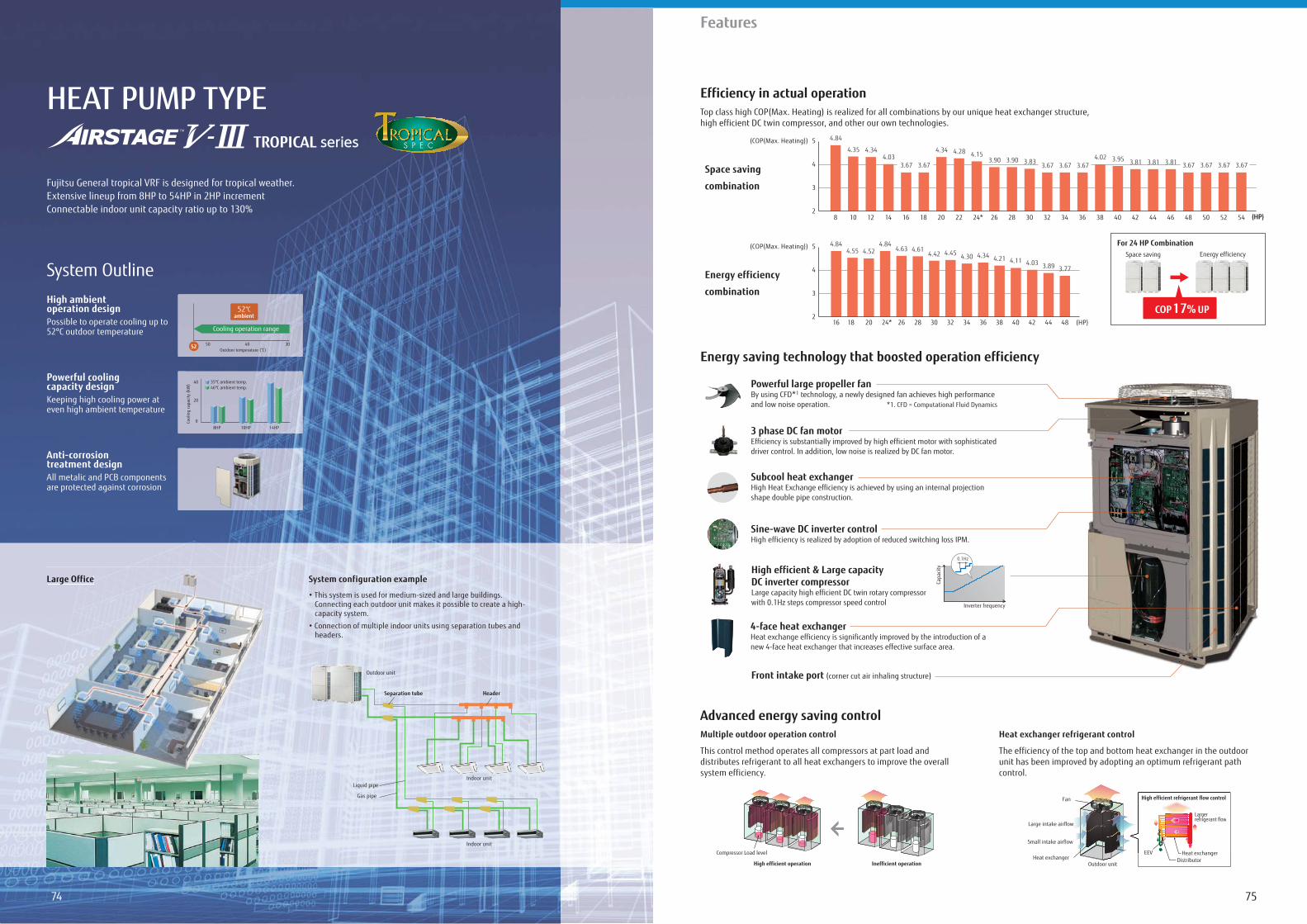
7574
Features
HEAT PUMP TYPE
Fujitsu General tropical VRF is designed for tropical weather.Extensive lineup from 8HP to 54HP in 2HP incrementConnectable indoor unit capacity ratio up to 130%
High ambient operation designPossible to operate cooling up to 52ºC outdoor temperature
Powerful cooling capacity designKeeping high cooling power at even high ambient temperature
Anti-corrosion treatment designAll metalic and PCB components are protected against corrosion
System Outline
Large Office System configuration example
Connecting each outdoor unit makes it possible to create a high-capacity system.
headers.
Efficiency in actual operation
Advanced energy saving control
Energy saving technology that boosted operation efficiency
Top class high COP(Max. Heating) is realized for all combinations by our unique heat exchanger structure, high efficient DC twin compressor, and other our own technologies.
Large Officeece
Indoor unit
Outdoor unit
Indoor unit
Gas pipe
Liquid pipe
Separation tube Header
Multiple outdoor operation control
This control method operates all compressors at part load and distributes refrigerant to all heat exchangers to improve the overall system efficiency.
Heat exchanger refrigerant control
The efficiency of the top and bottom heat exchanger in the outdoor unit has been improved by adopting an optimum refrigerant path control.
High efficient operation Inefficient operation
Compressor Load levelHeat exchanger
Outdoor unit
Large intake airflow
Fan
Small intake airflow
High efficient refrigerant flow control
Largerrefrigerant flow
ng an optimum refrigerant pa
High efficient refrigerag nt flow control
Largerrefrigerant flow
gg
EEV Heat exchangerDistributor
Outdoor temperature (°C)50 40 30
Cooling operation range
52 °Cambient
52
0
40
20
Cool
ing
capa
city
(kW
)
8HP 10HP 14HP
35ºC ambient temp.46ºC ambient temp.
(HP)
For 24 HP CombinationSpace saving Energy efficiency
COP 17% UP
Space saving
combination
Energy efficiency
combination
(COP(Max. Heating))
2
3
4
5
(HP)
(COP(Max. Heating))
(HP)2
3
4
5
16 18 20 24* 26 28 30 32 34 36 424038 4844
4.84 4.844.55 4.52 4.63 4.61
4.42 4.45 4.30 4.34 4.21 4.11 4.03 3.89 3.77
4.35
4.84
4.344.03
3.67 3.67
4.34 4.28 4.153.90 3.90 3.83 3.67 3.67 3.67
4.02 3.95 3.81 3.81 3.81 3.67 3.673.67 3.67
8 10 12 14 16 18 20 22 24* 363432302826 38 40 42 44 46 54525048
Sine-wave DC inverter controlHigh efficiency is realized by adoption of reduced switching loss IPM.
Powerful large propeller fanBy using CFD*1 technology, a newly designed fan achieves high performance and low noise operation. *1. CFD = Computational Fluid Dynamics
3 phase DC fan motor Efficiency is substantially improved by high efficient motor with sophisticated driver control. In addition, low noise is realized by DC fan motor.
Subcool heat exchangerHigh Heat Exchange efficiency is achieved by using an internal projection shape double pipe construction.
Front intake port (corner cut air inhaling structure)
4-face heat exchanger Heat exchange efficiency is significantly improved by the introduction of a new 4-face heat exchanger that increases effective surface area.
High efficient & Large capacity DC inverter compressorLarge capacity high efficient DC twin rotary compressor with 0.1Hz steps compressor speed control
Capa
city
Inverter frequency
0.1Hz
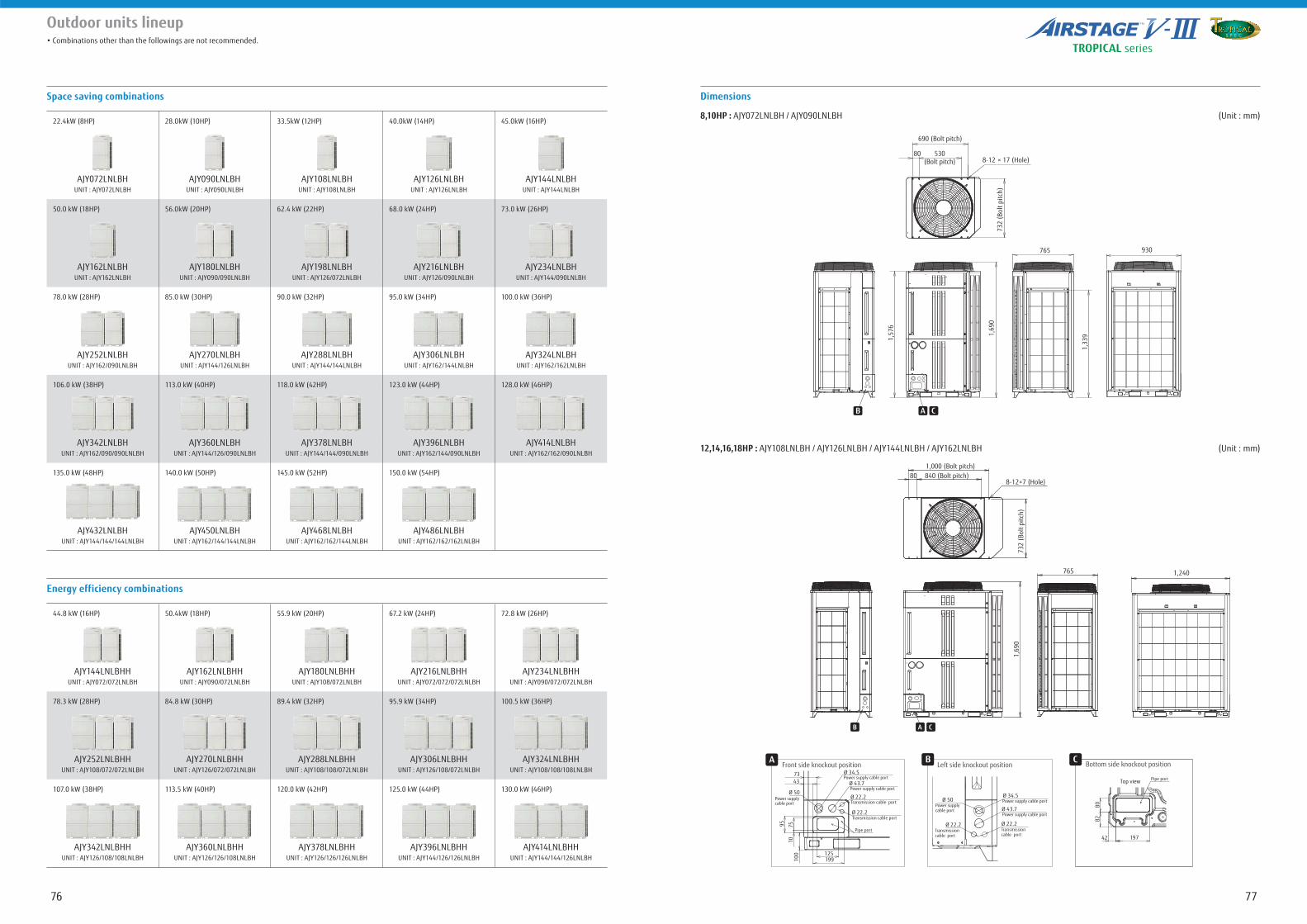
7776
Outdoor units lineup
Space saving combinations Dimensions
12,14,16,18HP : AJY108LNLBH / AJY126LNLBH / AJY144LNLBH / AJY162LNLBH (Unit : mm)
8,10HP : AJY072LNLBH / AJY090LNLBH (Unit : mm)
Energy efficiency combinations
22.4kW (8HP) 28.0kW (10HP) 33.5kW (12HP) 40.0kW (14HP) 45.0kW (16HP)
AJY072LNLBH AJY090LNLBH AJY108LNLBH AJY126LNLBH AJY144LNLBHUNIT : AJY072LNLBH UNIT : AJY090LNLBH UNIT : AJY108LNLBH UNIT : AJY126LNLBH UNIT : AJY144LNLBH
50.0 kW (18HP) 56.0kW (20HP) 62.4 kW (22HP) 68.0 kW (24HP) 73.0 kW (26HP)
AJY162LNLBH AJY180LNLBH AJY198LNLBH AJY216LNLBH AJY234LNLBHUNIT : AJY162LNLBH UNIT : AJY090/090LNLBH UNIT : AJY126/072LNLBH UNIT : AJY126/090LNLBH UNIT : AJY144/090LNLBH
78.0 kW (28HP) 85.0 kW (30HP) 90.0 kW (32HP) 95.0 kW (34HP) 100.0 kW (36HP)
AJY252LNLBH AJY270LNLBH AJY288LNLBH AJY306LNLBH AJY324LNLBHUNIT : AJY162/090LNLBH UNIT : AJY144/126LNLBH UNIT : AJY144/144LNLBH UNIT : AJY162/144LNLBH UNIT : AJY162/162LNLBH
106.0 kW (38HP) 113.0 kW (40HP) 118.0 kW (42HP) 123.0 kW (44HP) 128.0 kW (46HP)
AJY342LNLBH AJY360LNLBH AJY378LNLBH AJY396LNLBH AJY414LNLBHUNIT : AJY162/090/090LNLBH UNIT : AJY144/126/090LNLBH UNIT : AJY144/144/090LNLBH UNIT : AJY162/144/090LNLBH UNIT : AJY162/162/090LNLBH
135.0 kW (48HP) 140.0 kW (50HP) 145.0 kW (52HP) 150.0 kW (54HP)
AJY432LNLBH AJY450LNLBH AJY468LNLBH AJY486LNLBHUNIT : AJY144/144/144LNLBH UNIT : AJY162/144/144LNLBH UNIT : AJY162/162/144LNLBH UNIT : AJY162/162/162LNLBH
44.8 kW (16HP) 50.4kW (18HP) 55.9 kW (20HP) 67.2 kW (24HP) 72.8 kW (26HP)
AJY144LNLBHH AJY162LNLBHH AJY180LNLBHH AJY216LNLBHH AJY234LNLBHHUNIT : AJY072/072LNLBH UNIT : AJY090/072LNLBH UNIT : AJY108/072LNLBH UNIT : AJY072/072/072LNLBH UNIT : AJY090/072/072LNLBH
78.3 kW (28HP) 84.8 kW (30HP) 89.4 kW (32HP) 95.9 kW (34HP) 100.5 kW (36HP)
AJY252LNLBHH AJY270LNLBHH AJY288LNLBHH AJY306LNLBHH AJY324LNLBHHUNIT : AJY108/072/072LNLBH UNIT : AJY126/072/072LNLBH UNIT : AJY108/108/072LNLBH UNIT : AJY126/108/072LNLBH UNIT : AJY108/108/108LNLBH
107.0 kW (38HP) 113.5 kW (40HP) 120.0 kW (42HP) 125.0 kW (44HP) 130.0 kW (46HP)
AJY342LNLBHH AJY360LNLBHH AJY378LNLBHH AJY396LNLBHH AJY414LNLBHHUNIT : AJY126/108/108LNLBH UNIT : AJY126/126/108LNLBH UNIT : AJY126/126/126LNLBH UNIT : AJY144/126/126LNLBH UNIT : AJY144/144/126LNLBH
Front side knockout positionA
Power supply cable port
Pipe port
Transmission cable port
Transmission cable port
7343 Ø 43.7
Ø 22.2
Ø 22.2
95 7
510
100 125
199
Ø 34.5
Power supply cable port
Power supply cable port
Ø 50
Left side knockout position
Transmission cable port
Transmission cable port
Ø 43.7
Ø 22.2Ø 22.2
Ø 34.5Power supply cable port
Power supply cable port
Power supply cable port
Ø 50
B Bottom side knockout position
Top view Pipe port
80
197
82
42
C
8-12 × 17 (Hole)
1,69
0
1,57
6
1,33
9
765 930
530(Bolt pitch)
80
690 (Bolt pitch)
732
(Bol
t pitc
h)
B CA
8-12×7 (Hole)
1,240
1,69
073
2 (B
olt p
itch)
1,000 (Bolt pitch)840 (Bolt pitch)80
B CA
765
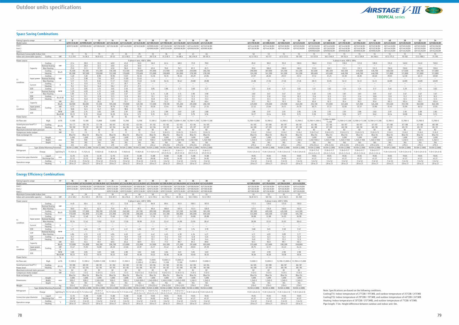
7978
Outdoor units specifications
Space Saving Combinations
Energy Efficiency Combinations
Note: Specifications are based on the following conditions.Cooling(T1): Indoor temperature of 27°CDB / 19°CWB, and outdoor temperature of 35°CDB / 24°CWBCooling(T3): Indoor temperature of 29°CDB / 19°CWB, and outdoor temperature of 46°CDB / 24°CWBHeating: Indoor temperature of 20°CDB / (15°CWB), and outdoor temperature of 7°CDB / 6°CWB.Pipe length: 7.5m. Height difference between outdoor and indoor unit: 0m.
Rating Capacity range HP 8 10 12 14 16 18 20 22 24 26 28 30 32 34 36 38 40 42 44 46 48 50 52 54Model name AJY072LNLBH AJY090LNLBH AJY108LNLBH AJY126LNLBH AJY144LNLBH AJY162LNLBH AJY180LNLBH AJY198LNLBH AJY216LNLBH AJY234LNLBH AJY252LNLBH AJY270LNLBH AJY288LNLBH AJY306LNLBH AJY324LNLBH AJY342LNLBH AJY360LNLBH AJY378LNLBH AJY396LNLBH AJY414LNLBH AJY432LNLBH AJY450LNLBH AJY468LNLBH AJY486LNLBHUnit 1Unit 2Unit 3
AJY072LNLBH AJY090LNLBH AJY108LNLBH AJY126LNLBH AJY144LNLBH AJY162LNLBH AJY090LNLBHAJY090LNLBH
AJY126LNLBHAJY072LNLBH
AJY126LNLBHAJY090LNLBH
AJY144LNLBHAJY090LNLBH
AJY162LNLBHAJY090LNLBH
AJY144LNLBHAJY126LNLBH
AJY144LNLBHAJY144LNLBH
AJY162LNLBHAJY144LNLBH
AJY162LNLBHAJY162LNLBH
AJY162LNLBHAJY090LNLBHAJY090LNLBH
AJY144LNLBHAJY126LNLBHAJY090LNLBH
AJY144LNLBHAJY144LNLBHAJY090LNLBH
AJY162LNLBHAJY144LNLBHAJY090LNLBH
AJY162LNLBHAJY162LNLBHAJY090LNLBH
AJY144LNLBHAJY144LNLBHAJY144LNLBH
AJY162LNLBHAJY144LNLBHAJY144LNLBH
AJY162LNLBHAJY162LNLBHAJY144LNLBH
AJY162LNLBHAJY162LNLBHAJY162LNLBH
Maximum Connectable Indoor Unit 13 16 19 23 26 29 33 36 40 43 46 50 53 55 55 55 55 55 55 55 55 55 55 55Indoor unit connectable capacity Cooling kW 11.2-29.1 14-36.4 16.8-43.5 20-52 22.5-58.5 25-65 28-72.8 31.2-81.1 34-88.4 36.5-94.9 39-101.4 42.5-110.5 45-117 47.5-123.5 50-130 53-137.8 56.5-146.9 59-153.4 61.5-159.9 64-166.4 67.5-175.5 70-182 72.5-188.5 75-195
Power source 3-phase 4 wire, 400 V, 50Hz 3-phase 4 wire, 400 V, 50Hz
T1condition
Capacity
CoolingkW
22.4 28.0 33.5 40.0 45.0 50.0 56.0 62.4 68.0 73.0 78.0 85.0 90.0 95.0 100.0 106.0 113.0 118.0 123.0 128.0 135.0 140.0 145.0 150.0Nominal Heating 22.4 28.0 33.5 40.0 45.0 50.0 - - - - - - - - - - - - - - - - - -
Max Heating 25.0 31.5 37.5 45.0 50.0 50.0 63.0 70.0 76.5 81.5 81.5 95.0 100.0 100.0 100.0 113.0 126.5 131.5 131.5 131.5 150.0 150.0 150.0 150.0Cooling
Btu/h76,400 95,500 114,300 136,500 153,500 170,600 191,000 212,900 232,000 249,000 266,100 290,000 307,000 324,100 341,200 361,600 385,500 402,500 419,600 436,700 460,500 477,600 494,700 511,800
Heating 85,300 107,500 128,000 153,500 170,600 170,600 215,000 238,800 261,000 278,100 278,100 324,100 341,200 341,200 341,200 385,600 431,600 448,700 448,700 448,700 511,800 511,800 511,800 511,800
Input powerCooling
kW5.20 7.28 8.96 10.96 13.01 16.56 14.56 16.16 18.24 20.29 23.84 23.97 26.02 29.57 33.12 31.12 31.25 33.30 36.85 40.40 39.03 42.58 46.13 49.68
Nominal Heating 4.31 5.98 7.10 8.97 11.09 13.63 - - - - - - - - - - - - - - - - - -Max Heating 5.17 7.25 8.65 11.17 13.63 13.63 14.50 16.34 18.42 20.88 20.88 24.80 27.26 27.26 27.26 28.13 32.05 34.51 34.51 34.51 40.89 40.89 40.89 40.89
CurrentCooling
A9.2 12.0 15.0 17.7 20.7 26.1 - - - - - - - - - - - - - - - - - -
Heating 9.2 12.2 14.6 18.2 21.5 21.5 - - - - - - - - - - - - - - - - - -EER Cooling
W/W4.31 3.85 3.74 3.65 3.46 3.02 3.85 3.86 3.73 3.60 3.27 3.55 3.46 3.21 3.02 3.41 3.62 3.54 3.34 3.17 3.46 3.29 3.14 3.02
COPNominal Heating 5.20 4.69 4.72 4.46 4.06 3.67 - - - - - - - - - - - - - - - - - -
Max Heating 4.84 4.35 4.34 4.03 3.67 3.67 4.34 4.28 4.15 3.90 3.90 3.83 3.67 3.67 3.67 4.02 3.95 3.81 3.81 3.81 3.67 3.67 3.67 3.67EER Cooling
Btu/h/W14.7 13.1 12.8 12.5 11.8 10.3 13.1 13.2 12.7 12.3 11.2 12.1 11.8 11.0 10.3 11.6 12.3 12.1 11.4 10.8 11.8 11.2 10.7 10.3
COP Heating 16.5 14.8 14.8 13.7 12.5 12.5 14.8 14.6 14.2 13.3 13.3 13.1 12.5 12.5 12.5 13.7 13.5 13.0 13.0 13.0 12.5 12.5 12.5 12.5
T3condition
Capacity
Cooling
kW 20.2 25.2 28.5 32 35.1 35.2 50.4 52.2 57.2 60.3 60.4 67.1 70.2 70.3 70.4 85.6 92.3 95.4 95.5 95.6 105.3 105.4 105.5 105.6Btu/h 68,900 86,000 97,200 109,200 119,800 120,100 172,000 178,100 195,200 205,800 206,100 229,000 239,600 239,900 240,200 292,100 315,000 325,600 325,900 326,200 359,400 359,700 360,000 360,300
Input power kW 6.73 9.20 9.34 10.70 11.82 12.35 18.39 17.44 19.90 21.02 21.55 22.52 23.64 24.17 24.70 30.75 31.72 32.83 33.37 33.90 35.45 35.99 36.52 37.05Current A 10.8 14.5 14.7 16.9 18.6 19.2 - - - - - - - - - - - - - - - - - -
EERW/W 3.00 2.74 3.05 2.99 2.97 2.85 2.74 2.99 2.87 2.87 2.80 2.98 2.97 2.91 2.85 2.78 2.91 2.91 2.86 2.82 2.97 2.93 2.89 2.85
Btu/h/W 10.23 9.35 10.40 10.20 10.14 9.72 9.35 10.21 9.81 9.79 9.56 10.17 10.14 9.93 9.72 9.50 9.93 9.92 9.77 9.62 10.14 10.00 9.86 9.72Power factor % 90 92 92 92 92 93 - - - - - - - - - - - - - - - - - -
Air flow rate High m3/h 11,100 11,100 13,000 13,000 13,700 13,700 11,100×2 13,000+11,100 13,000+11,100 13,700+11,100 13,700+11,100 13,700+13,000 13,700×2 13,700×2 13,700×2 13,700+11,100×2 13,700+13,000+11,100 13,700×2+11,100 13,700×2+11,100 13,700×2+11,100 13,700×3 13,700×3 13,700×3 13,700×3
Sound pressure level*2 /Power level
CoolingdB (A)
56 / 77 58 / 79 57 / 78 60 / 81 62 / 83 63 / 84 61 / 82 61 / 82 62 / 83 63 / 84 64 / 85 64 / 85 65 / 88 66 / 87 66 / 87 65 / 86 65 / 86 66 / 87 66 / 87 67 / 87 67 / 88 67 / 88 67 / 88 68 / 89Heating 58 / 80 59 / 81 60 / 83 62 / 84 64 / 86 64 / 86 62 / 84 63 / 85 64 / 86 65 / 87 65 / 87 66 / 88 67 / 89 67 / 89 67 / 89 66 / 88 67 / 89 68 / 90 68 / 90 68 / 90 69 / 91 69 / 91 69 / 91 69 / 91
Maximum external static pressure Pa 82 82 82 82 82 82 82 82 82 82 82 82 82 82 82 82 82 82 82 82 82 82 82 82Compressor motor output kW 7.5 7.5 11 11 11 11 7.5×2 11.0+7.5 11.0+7.5 11.0+7.5 11.0+7.5 11.0×2 11.0×2 11.0×2 11.0×2 11.0+7.5×2 11.0×2+7.5 11.0×2+7.5 11.0×2+7.5 11.0×2+7.5 11.0×3 11.0×3 11.0×3 11.0×3Heat exchanger fin Blue fin Blue fin Blue fin Blue fin Blue fin Blue fin Blue fin Blue fin Blue fin Blue fin Blue fin Blue fin Blue fin Blue fin Blue fin Blue fin Blue fin Blue fin Blue fin Blue fin Blue fin Blue fin Blue fin Blue fin
DimensionsHeight
mm1,690 1,690 1,690 1,690 1,690 1,690 1,690 1,690 1,690 1,690 1,690 1,690 1,690 1,690 1,690 1,690 1,690 1,690 1,690 1,690 1,690 1,690 1,690 1,690
Width 930 930 1,240 1,240 1,240 1,240 930×2 1,240+930 1,240+930 1,240+930 1,240+930 1,240×2 1,240×2 1,240×2 1,240×2 1,240+930×2 1,240×2+930 1,240×2+930 1,240×2+930 1,240×2+930 1,240×3 1,240×3 1,240×3 1,240×3Depth 765 765 765 765 765 765 765 765 765 765 765 765 765 765 765 765 765 765 765 765 765 765 765 765
Weight kg 255 255 279 279 279 279 255×2 279+255 279+255 279+255 279+255 279×2 279×2 279×2 279×2 279+255×2 279×2+255 279×2+255 279×2+255 279×2+255 279×3 279×3 279×3 279×3
RefrigerantType (Global Warming Potential) R410A (2,088) R410A (2,088) R410A (2,088) R410A (2,088) R410A (2,088) R410A (2,088) R410A (2,088) R410A (2,088) R410A (2,088) R410A (2,088) R410A (2,088) R410A (2,088) R410A (2,088) R410A (2,088) R410A (2,088) R410A (2,088) R410A (2,088) R410A (2,088) R410A (2,088) R410A (2,088) R410A (2,088) R410A (2,088) R410A (2,088) R410A (2,088)
Charge kg(CO2eq-T) 11.7(24.4) 11.7(24.4) 11.8(24.6) 11.8(24.6) 11.8(24.6) 11.8(24.6) 11.7×2(24.4×2) 11.8+11.7 (24.6+24.4)
11.8+11.7 (24.6+24.4)
11.8+11.7 (24.6+24.4)
11.8+11.7 (24.6+24.4) 11.8×2 (24.6×2) 11.8×2 (24.6×2) 11.8×2 (24.6×2) 11.8×2 (24.6×2)
11.8+11.7×2 (24.6+24.4×2)
11.8×2+11.7 (24.6×2+24.4)
11.8×2+11.7 (24.6×2+24.4)
11.8×2+11.7 (24.6×2+24.4)
11.8×2+11.7 (24.6×2+24.4)
11.8×3 (24.6×3) 11.8×3 (24.6×3) 11.8×3 (24.6×3) 11.8×3 (24.6×3)
Connection pipe diameterLiquid
mm12.70 12.70 12.70 12.70 12.70 15.88 15.88 15.88 15.88 15.88 15.88 19.05 19.05 19.05 19.05 19.05 19.05 19.05 19.05 19.05 19.05 19.05 19.05 19.05
Discharge Gas 22.22 22.22 28.58 28.58 28.58 28.58 28.58 34.92 34.92 34.92 34.92 34.92 34.92 34.92 41.27 41.27 41.27 41.27 41.27 41.27 41.27 41.27 41.27 41.27
Operation rangeCooling -15 to 52 -15 to 52 -15 to 52 -15 to 52 -15 to 52 -15 to 52 -5 to 52 -5 to 52 -5 to 52 -5 to 52 -5 to 52 -5 to 52 -5 to 52 -5 to 52 -5 to 52 -5 to 52 -5 to 52 -5 to 52 -5 to 52 -5 to 52 -5 to 52 -5 to 52 -5 to 52 -5 to 52Heating -20 to 21 -20 to 21 -20 to 21 -20 to 21 -20 to 21 -20 to 21 -20 to 21 -20 to 21 -20 to 21 -20 to 21 -20 to 21 -20 to 21 -20 to 21 -20 to 21 -20 to 21 -20 to 21 -20 to 21 -20 to 21 -20 to 21 -20 to 21 -20 to 21 -20 to 21 -20 to 21 -20 to 21
Rating Capacity range HP 16 18 20 24 26 28 30 32 34 36 38 40 42 44 46Model name AJY144LNLBHH AJY162LNLBHH AJY180LNLBHH AJY216LNLBHH AJY234LNLBHH AJY252LNLBHH AJY270LNLBHH AJY288LNLBHH AJY306LNLBHH AJY324LNLBHH AJY342LNLBHH AJY360LNLBHH AJY378LNLBHH AJY396LNLBHH AJY414LNLBHHUnit 1Unit 2Unit 3
AJY072LNLBHAJY072LNLBH
AJY090LNLBHAJY072LNLBH
AJY108LNLBHAJY072LNLBH
AJY072LNLBHAJY072LNLBHAJY072LNLBH
AJY090LNLBHAJY072LNLBHAJY072LNLBH
AJY108LNLBHAJY072LNLBHAJY072LNLBH
AJY126LNLBHAJY072LNLBHAJY072LNLBH
AJY108LNLBHAJY108LNLBHAJY072LNLBH
AJY126LNLBHAJY108LNLBHAJY072LNLBH
AJY108LNLBHAJY108LNLBHAJY108LNLBH
AJY126LNLBHAJY108LNLBHAJY108LNLBH
AJY126LNLBHAJY126LNLBHAJY108LNLBH
AJY126LNLBHAJY126LNLBHAJY126LNLBH
AJY144LNLBHAJY126LNLBHAJY126LNLBH
AJY144LNLBHAJY144LNLBHAJY126LNLBH
Maximum Connectable Indoor Unit 26 29 33 39 43 46 50 52 55 55 55 55 55 55 55Indoor unit connectable capacity Cooling kW 22.4-58.2 25.2-65.5 28-72.6 33.6-87.3 36.4-94.6 39.2-101.7 42.4-110.2 44.7-116.2 48-124.6 50.3-130.6 53.5-139.1 56.8-147.5 60-156 62.5-162.5 65-169
Power source 3-phase 4 wire, 400 V, 50Hz 3-phase 4 wire, 400 V, 50Hz
T1condition
Capacity
CoolingkW
44.8 50.4 55.9 67.2 72.8 78.3 84.8 89.4 95.9 100.5 107.0 113.5 120.0 125.0 130.0Nominal Heating - - - - - - - - - - - - - - -
Max Heating 50.0 56.5 62.5 75.0 81.5 87.5 95.0 100.0 107.5 112.5 120.0 127.5 135.0 140.0 145.0Cooling
Btu/h152,800 171,900 190,700 229,200 248,300 267,100 289,300 305,000 327,200 342,900 365,100 387,300 409,500 426,500 443,500
Heating 170,600 192,800 213,300 255,900 278,100 298,600 324,100 341,300 366,800 384,000 409,500 435,000 460,500 477,600 494,700
Input powerCooling
kW10.40 12.48 14.16 15.60 17.68 19.36 21.36 23.12 25.12 26.88 28.88 30.88 32.88 34.93 36.98
Nominal Heating - - - - - - - - - - - - - - -Max Heating 10.34 12.42 13.82 15.51 17.59 18.99 21.51 22.47 24.99 25.95 28.47 30.99 33.51 35.97 38.43
CurrentCooling
A- - - - - - - - - - - - - - -
Heating - - - - - - - - - - - - - - -EER Cooling
W/W4.31 4.04 3.95 4.31 4.12 4.04 3.97 3.87 3.82 3.74 3.70 3.68 3.65 3.58 3.52
COPNominal Heating - - - - - - - - - - - - - - -
Max Heating 4.84 4.55 4.52 4.84 4.63 4.61 4.42 4.45 4.30 4.34 4.21 4.11 4.03 3.89 3.77EER Cooling
Btu/h/W14.7 13.8 13.5 14.7 14.0 13.8 13.5 13.2 13.0 12.8 12.6 12.5 12.5 12.2 12.0
COP Heating 16.5 15.5 15.4 16.5 15.8 15.7 15.1 15.2 14.7 14.8 14.4 14.0 13.7 13.3 12.9
T3condition
Capacity
Cooling
kW 40.4 45.4 48.7 60.6 65.6 68.9 72.4 77.2 80.7 85.5 89.0 92.5 96.0 99.1 102.2Btu/h 137,800 154,900 166,100 206,700 223,800 235,000 247,000 263,300 275,300 291,600 303,600 315,600 327,600 338,200 348,800
Input power kW 13.47 15.93 16.08 20.20 22.66 22.81 24.17 25.42 26.78 28.03 29.39 30.75 32.11 33.22 34.34Current A - - - - - - - - - - - - - - -
EERW/W 3.00 2.85 3.03 3.00 2.89 3.02 3.00 3.04 3.01 3.05 3.03 3.01 2.99 2.98 2.98
Btu/h/W 10.23 9.72 10.33 10.23 9.87 10.30 10.22 10.36 10.28 10.40 10.33 10.26 10.20 10.18 10.16Power factor % - - - - - - - - - - - - - - -
Air flow rate High m3/h 11,100×2 11,100×2 13,000+11,100 11,100×3 11,100×3 13,000+11,100×2
13,000+11,100×2
13,000×2+11,100
13,000×2+11,100 13,000×3 13,000×3 13,000×3 13,000×3 13,700+13,000×2 13,700×2+13,000
Sound pressure level*2 /Power level
CoolingdB (A)
59 / 80 60 / 81 60 / 81 61 / 82 62 / 83 61 / 82 63 / 84 61 / 82 63 / 84 62 / 83 63 / 84 64 / 85 65 / 88 66 / 87 66 / 87Heating 61 / 83 62 / 84 62 / 85 63 / 85 63 / 85 64 / 86 65 / 87 64 / 87 65 / 88 65 / 88 66 / 88 66 / 88 67 / 89 68 / 90 68 / 90
Maximum external static pressure Pa 82 82 82 82 82 82 82 82 82 82 82 82 82 82 82Compressor motor output kW 7.5×2 7.5×2 11.0+7.5 7.5×3 7.5×3 11.0+7.5×2 11.0+7.5×2 11.0×2+7.5 11.0×2+7.5 11.0×3 11.0×3 11.0×3 11.0×3 11.0×3 11.0×3Heat exchanger fin Blue fin Blue fin Blue fin Blue fin Blue fin Blue fin Blue fin Blue fin Blue fin Blue fin Blue fin Blue fin Blue fin Blue fin Blue fin
DimensionsHeight
mm1,690 1,690 1,690 1,690 1,690 1,690 1,690 1,690 1,690 1,690 1,690 1,690 1,690 1,690 1,690
Width 930×2 930×2 1,240+930 930×3 930×3 1,240+930×2 1,240+930×2 1,240×2+930 1,240×2+930 1,240×3 1,240×3 1,240×3 1,240×3 1,240×3 1,240×3Depth 765 765 765 765 765 765 765 765 765 765 765 765 765 765 765
Weight kg 255×2 255×2 279+255 255×3 255×3 279+255×2 279+255×2 279×2+255 279×2+255 279×3 279×3 279×3 279×3 279×3 279×3
RefrigerantType (Global Warming Potential) R410A (2,088) R410A (2,088) R410A (2,088) R410A (2,088) R410A (2,088) R410A (2,088) R410A (2,088) R410A (2,088) R410A (2,088) R410A (2,088) R410A (2,088) R410A (2,088) R410A (2,088) R410A (2,088) R410A (2,088)
Charge kg(CO2eq-T) 11.7×2 (24.4×2) 11.7×2 (24.4×2) 11.8+11.7 (24.6+24.4) 11.7×3 (24.4×3) 11.7×3 (24.4×3) 11.8+11.7×2
(24.6+24.4×2)11.8+11.7×2
(24.6+24.4×2)11.8×2+11.7
(24.6×2+24.4)11.8×2+11.7
(24.6×2+24.4) 11.8×3 (24.6×3) 11.8×3 (24.6×3) 11.8×3 (24.6×3) 11.8×3 (24.6×3) 11.8×3 (24.6×3) 11.8×3 (24.6×3)
Connection pipe diameterLiquid
mm12.70 15.88 15.88 15.88 15.88 15.88 19.05 19.05 19.05 19.05 19.05 19.05 19.05 19.05 19.05
Discharge Gas 28.58 28.58 28.58 34.92 34.92 34.92 34.92 34.92 34.92 41.27 41.27 41.27 41.27 41.27 41.27
Operation rangeCooling -5 to 52 -5 to 52 -5 to 52 -5 to 52 -5 to 52 -5 to 52 -5 to 52 -5 to 52 -5 to 52 -5 to 52 -5 to 52 -5 to 52 -5 to 52 -5 to 52 -5 to 52Heating -20 to 21 -20 to 21 -20 to 21 -20 to 21 -20 to 21 -20 to 21 -20 to 21 -20 to 21 -20 to 21 -20 to 21 -20 to 21 -20 to 21 -20 to 21 -20 to 21 -20 to 21
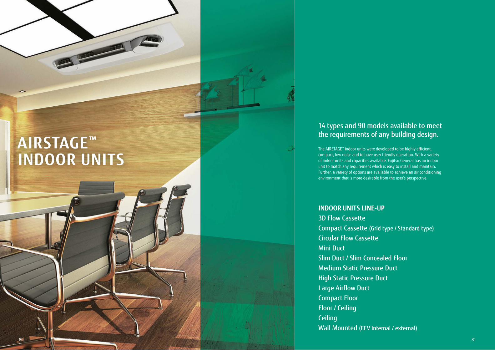
8180
AIRSTAGE™
INDOOR UNITS
14 types and 90 models available to meet the requirements of any building design.
The AIRSTAGE™ indoor units were developed to be highly efficient, compact, low noise and to have user friendly operation. With a variety of indoor units and capacities available, Fujitsu General has an indoor unit to match any requirement which is easy to install and maintain. Further, a variety of options are available to achieve an air conditioning environment that is more desirable from the user’s perspective.
INDOOR UNITS LINE-UP3D Flow CassetteCompact Cassette (Grid type / Standard type)
Circular Flow CassetteMini DuctSlim Duct / Slim Concealed FloorMedium Static Pressure DuctHigh Static Pressure DuctLarge Airflow DuctCompact FloorFloor / CeilingCeilingWall Mounted (EEV Internal / external)
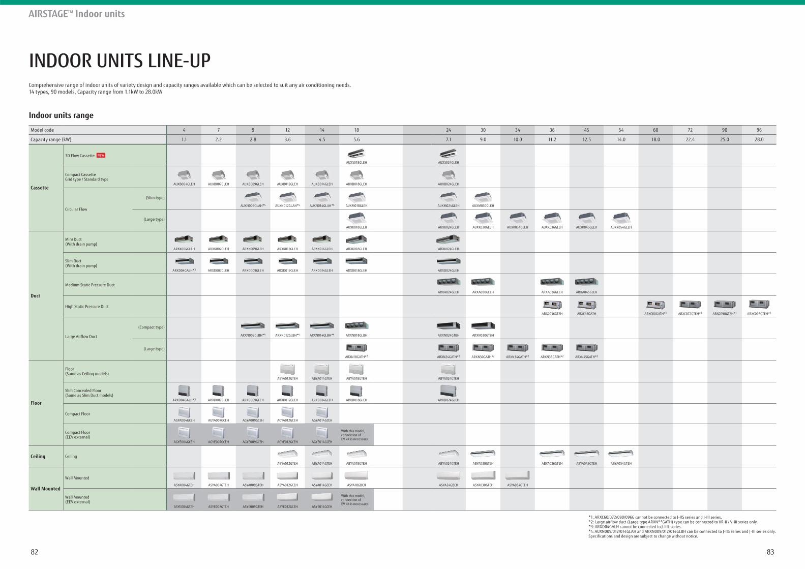
8382
INDOOR UNITS LINE-UP
AIRSTAGETM Indoor units
Comprehensive range of indoor units of variety design and capacity ranges available which can be selected to suit any air conditioning needs.14 types, 90 models, Capacity range from 1.1kW to 28.0kW
Indoor units range
Model code 4 7 9 12 14 18 24 30 34 36 45 54 60 72 90 96
Capacity range (kW) 1.1 2.2 2.8 3.6 4.5 5.6 7.1 9.0 10.0 11.2 12.5 14.0 18.0 22.4 25.0 28.0
Cassette
3D Flow Cassette
AUXS018GLEH AUXS024GLEH
Compact CassetteGrid type / Standard type
AUXB004GLEH AUXB007GLEH AUXB009GLEH AUXB012GLEH AUXB014GLEH AUXB018GLEH AUXB024GLEH
Circular Flow
(Slim type)
AUXN009GLAH*4 AUXN012GLAH*4 AUXN014GLAH*4 AUXM018GLEH AUXM024GLEH AUXM030GLEH
(Large type)
AUXK018GLEH AUXK024GLEH AUXK030GLEH AUXK034GLEH AUXK036GLEH AUXK045GLEH AUXK054GLEH
Duct
Mini Duct(With drain pump)
ARXK004GLEH ARXK007GLEH ARXK009GLEH ARXK012GLEH ARXK014GLEH ARXK018GLEH ARXK024GLEH
Slim Duct(With drain pump)
ARXD04GALH*3 ARXD007GLEH ARXD009GLEH ARXD012GLEH ARXD014GLEH ARXD018GLEH ARXD024GLEH
Medium Static Pressure Duct
ARXA024GLEH ARXA030GLEH ARXA036GLEH ARXA045GLEH
High Static Pressure Duct
ARXC036GTEH ARXC45GATH ARXC60GATH*1 ARXC072GTEH*1 ARXC090GTEH*1 ARXC096GTEH*1
Large Airflow Duct
(Compact type)
ARXN009GLBH*4 ARXN012GLBH*4 ARXN014GLBH*4 ARXN018GLBH ARXN024GTBH ARXN030GTBH
(Large type)
ARXN18GATH*2 ARXN24GATH*2 ARXN30GATH*2 ARXN34GATH*2 ARXN36GATH*2 ARXN45GATH*2
Floor
Floor(Same as Ceiling models)
ABYA012GTEH ABYA014GTEH ABYA018GTEH ABYA024GTEH
Slim Concealed Floor (Same as Slim Duct models)
ARXD04GALH*3 ARXD007GLEH ARXD009GLEH ARXD012GLEH ARXD014GLEH ARXD018GLEH ARXD024GLEH
Compact Floor
AGYA004GCEH AGYA007GCEH AGYA009GCEH AGYA012GCEH AGYA014GCEH
Compact Floor (EEV external)
With this model, connection of EV kit is necessary.
AGYE004GCEH AGYE007GCEH AGYE009GCEH AGYE012GCEH AGYE014GCEH
Ceiling Ceiling
ABYA012GTEH ABYA014GTEH ABYA018GTEH ABYA024GTEH ABYA030GTEH ABYA036GTEH ABYA045GTEH ABYA054GTEH
Wall Mounted
Wall Mounted
ASYA004GTEH ASYA007GTEH ASYA009GTEH ASYA012GCEH ASYA014GCEH ASYA18GBCH ASYA24GBCH ASYA030GTEH ASYA034GTEH
Wall Mounted(EEV external)
With this model, connection of EV kit is necessary.
ASYE004GTEH ASYE007GTEH ASYE009GTEH ASYE012GCEH ASYE014GCEH
*1: ARXC60/072/090/096G cannot be connected to J-IIS series and J-III series.*2: Large airflow duct (Large type ARXN**GATH) type can be connected to VR-II / V-III series only.*3: ARXD04GALH cannot be connected to J-IIIL series.*4: AUXN009/012/014GLAH and ARXN009/012/014GLBH can be connected to J-IIS series and J-III series only.Specifications and design are subject to change without notice.
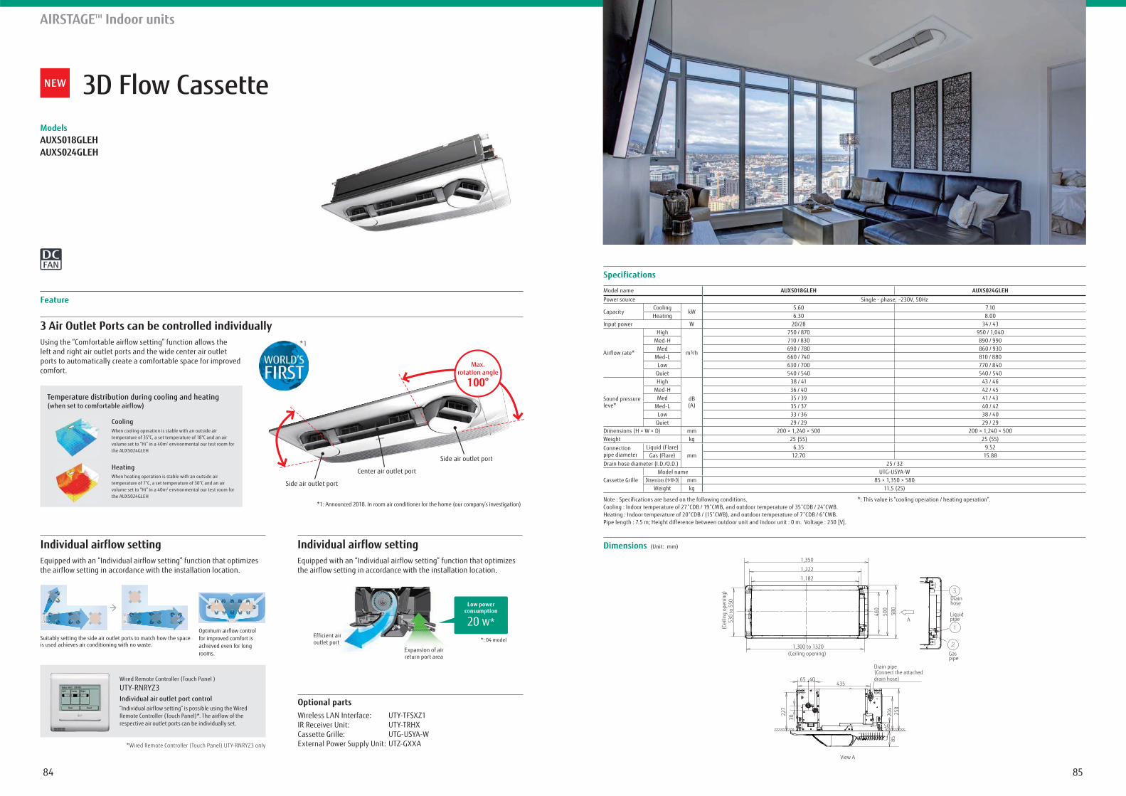
8584
3D Flow CassetteModelsAUXS018GLEHAUXS024GLEH
AIRSTAGETM Indoor units
Specifications
Dimensions (Unit: mm)
Model name AUXS018GLEH AUXS024GLEHPower source Single - phase, ~230V, 50Hz
CapacityCooling
kW5.60 7.10
Heating 6.30 8.00Input power W 20/28 34 / 43
Airflow rate*
High
m3/h
750 / 870 950 / 1,040Med-H 710 / 830 890 / 990
Med 690 / 780 860 / 930Med-L 660 / 740 810 / 880
Low 630 / 700 770 / 840Quiet 540 / 540 540 / 540
Sound pressure leve*
High
dB(A)
38 / 41 43 / 46Med-H 36 / 40 42 / 45
Med 35 / 39 41 / 43Med-L 35 / 37 40 / 42
Low 33 / 36 38 / 40Quiet 29 / 29 29 / 29
Dimensions (H × W × D) mm 200 × 1,240 × 500 200 × 1,240 × 500Weight kg 25 (55) 25 (55)
Connection pipe diameter
Liquid (Flare)mm
6.35 9.52Gas (Flare) 12.70 15.88
Drain hose diameter (I.D./O.D.) 25 / 32
Cassette GrilleModel name UTG-USYA-W
Dimensions (H×W×D) mm 85 × 1,350 × 580Weight kg 11.5 (25)
Note : Specifications are based on the following conditions.
Pipe length : 7.5 m; Height difference between outdoor unit and indoor unit : 0 m. Voltage : 230 [V].
*: This value is “cooling operation / heating operation”.
Optional partsWireless LAN Interface: UTY-TFSXZ1IR Receiver Unit: UTY-TRHXCassette Grille: UTG-USYA-WExternal Power Supply Unit: UTZ-GXXA
3 Air Outlet Ports can be controlled individuallyUsing the “Comfortable airflow setting” function allows the left and right air outlet ports and the wide center air outlet ports to automatically create a comfortable space for improved comfort.
Individual airflow setting Individual airflow settingEquipped with an “Individual airflow setting” function that optimizes the airflow setting in accordance with the installation location.
Equipped with an “Individual airflow setting” function that optimizes the airflow setting in accordance with the installation location.
Feature
*1
Side air outlet port
Side air outlet port
Center air outlet port
Max.rotation angle
100°
*1: Announced 2018. In room air conditioner for the home (our company’s investigation)
Suitably setting the side air outlet ports to match how the space is used achieves air conditioning with no waste.
Optimum airflow control for improved comfort is achieved even for long rooms.
Individual air outlet port control“Individual airflow setting” is possible using the Wired Remote Controller (Touch Panel)*. The airflow of the respective air outlet ports can be individually set.
Wired Remote Controller (Touch Panel )
UTY-RNRYZ3
*Wired Remote Controller (Touch Panel) UTY-RNRYZ3 only
Expansion of air return port area
*: 04 modelEfficient air outlet port
CoolingWhen cooling operation is stable with an outside air temperature of 35°C, a set temperature of 18°C and an air volume set to “Hi” in a 40m2 environmental our test room for the AUXS024GLEH
HeatingWhen heating operation is stable with an outside air temperature of 7°C, a set temperature of 30°C and an air volume set to “Hi” in a 40m2 environmental our test room for the AUXS024GLEH
Temperature distribution during cooling and heating (when set to comfortable airflow)
20 W*
Low power consumption
A
1,300 to 1320(Ceiling opening)
1,222
460
580
530
to 5
50(C
eilin
g op
enin
g)
500
1,182
1,350
Gas pipe
Liquid pipe
Drain hose
50
227
204
250
85
30
Drain pipe(Connect the attached drain hose)
4354065
View A
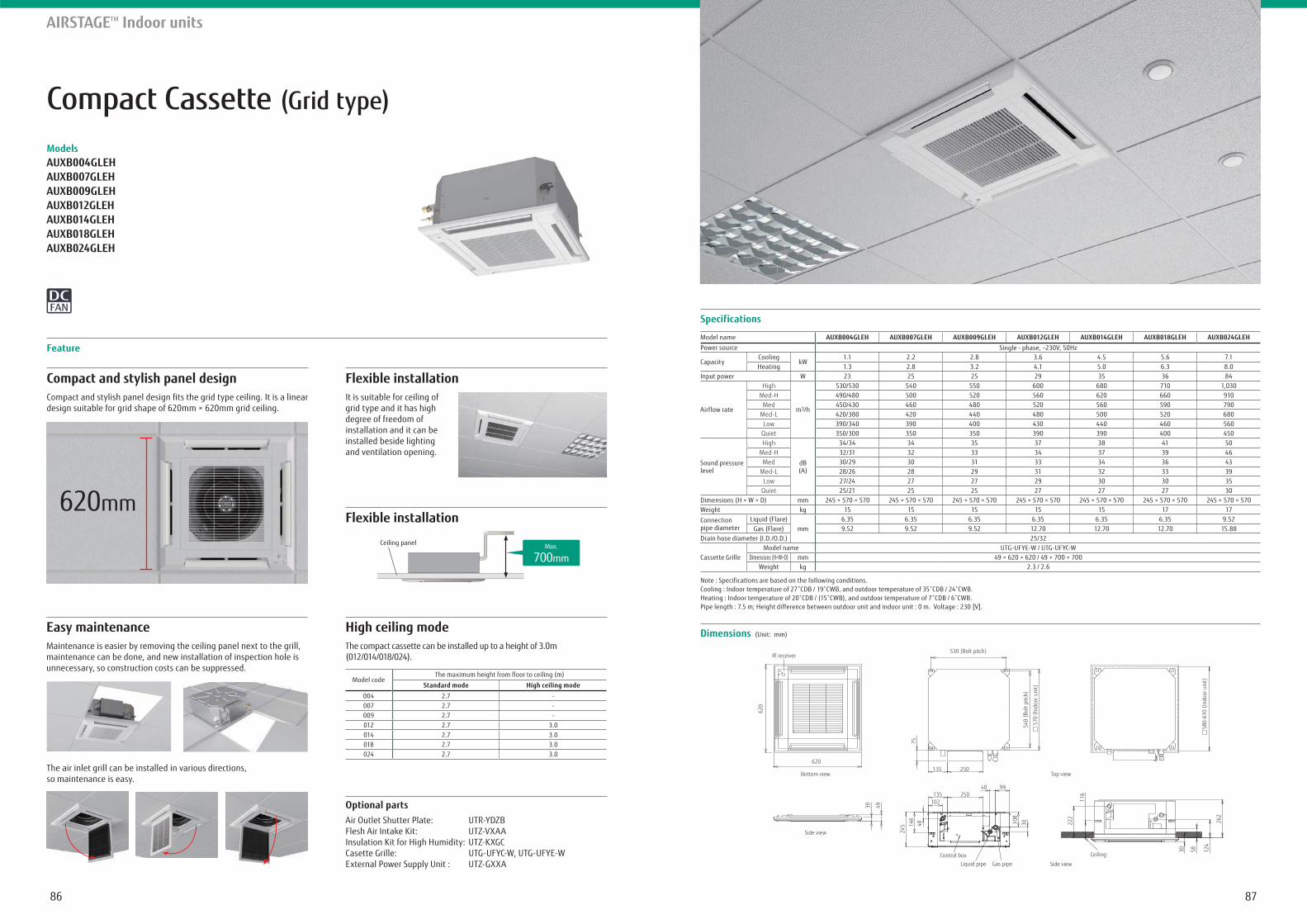
8786
Compact Cassette (Grid type)
ModelsAUXB004GLEHAUXB007GLEHAUXB009GLEHAUXB012GLEHAUXB014GLEHAUXB018GLEHAUXB024GLEH
AIRSTAGETM Indoor units
Specifications
Dimensions (Unit: mm)
530 (Bolt pitch)
540
(Bol
t pitc
h)
570
(Ind
oor u
nit)
75
30 58 124
262
116
222
135 250
Control boxLiquid pipe Gas pipe
Ceiling
Side view
Top view
Side view
30
9940250135
102
108
146
40
245
Bottom view
IR receiver
620
620
30 49
580-
610
(Ind
oor u
nit)
Model name AUXB004GLEH AUXB007GLEH AUXB009GLEH AUXB012GLEH AUXB014GLEH AUXB018GLEH AUXB024GLEHPower source Single - phase, ~230V, 50Hz
CapacityCooling
kW1.1 2.2 2.8 3.6 4.5 5.6 7.1
Heating 1.3 2.8 3.2 4.1 5.0 6.3 8.0Input power W 23 25 25 29 35 36 84
Airflow rate
High
m3/h
530/530 540 550 600 680 710 1,030Med-H 490/480 500 520 560 620 660 910
Med 450/430 460 480 520 560 590 790 Med-L 420/380 420 440 480 500 520 680
Low 390/340 390 400 430 440 460 560 Quiet 350/300 350 350 390 390 400 450
Sound pressure level
High
dB(A)
34/34 34 35 37 38 41 50 Med-H 32/31 32 33 34 37 39 46
Med 30/29 30 31 33 34 36 43 Med-L 28/26 28 29 31 32 33 39
Low 27/24 27 27 29 30 30 35 Quiet 25/21 25 25 27 27 27 30
Dimensions (H × W × D) mm 245 × 570 × 570 245 × 570 × 570 245 × 570 × 570 245 × 570 × 570 245 × 570 × 570 245 × 570 × 570 245 × 570 × 570Weight kg 15 15 15 15 15 17 17
Connection pipe diameter
Liquid (Flare)mm
6.35 6.35 6.35 6.35 6.35 6.35 9.52Gas (Flare) 9.52 9.52 9.52 12.70 12.70 12.70 15.88
Drain hose diameter (I.D./O.D.) 25/32
Cassette GrilleModel name UTG-UFYE-W / UTG-UFYC-W
Dimensions (H×W×D) mm 49 × 620 × 620 / 49 × 700 × 700Weight kg 2.3 / 2.6
Note : Specifications are based on the following conditions.
Pipe length : 7.5 m; Height difference between outdoor unit and indoor unit : 0 m. Voltage : 230 [V].
Compact and stylish panel design
design suitable for grid shape of 620mm × 620mm grid ceiling.
Flexible installationIt is suitable for ceiling of grid type and it has high degree of freedom of installation and it can be installed beside lighting and ventilation opening.
Flexible installation
Feature
The air inlet grill can be installed in various directions, so maintenance is easy.
Optional partsAir Outlet Shutter Plate: UTR-YDZBFlesh Air Intake Kit: UTZ-VXAAInsulation Kit for High Humidity: UTZ-KXGCCasette Grille: UTG-UFYC-W, UTG-UFYE-WExternal Power Supply Unit : UTZ-GXXA
Easy maintenanceMaintenance is easier by removing the ceiling panel next to the grill, maintenance can be done, and new installation of inspection hole is unnecessary, so construction costs can be suppressed.
Ceiling panel Max.
700mm
High ceiling modeThe compact cassette can be installed up to a height of 3.0m (012/014/018/024).
Model codeThe maximum height from floor to ceiling (m)
Standard mode High ceiling mode
004 2.7 -007 2.7 -009 2.7 -012 2.7 3.0014 2.7 3.0018 2.7 3.0024 2.7 3.0
620mm
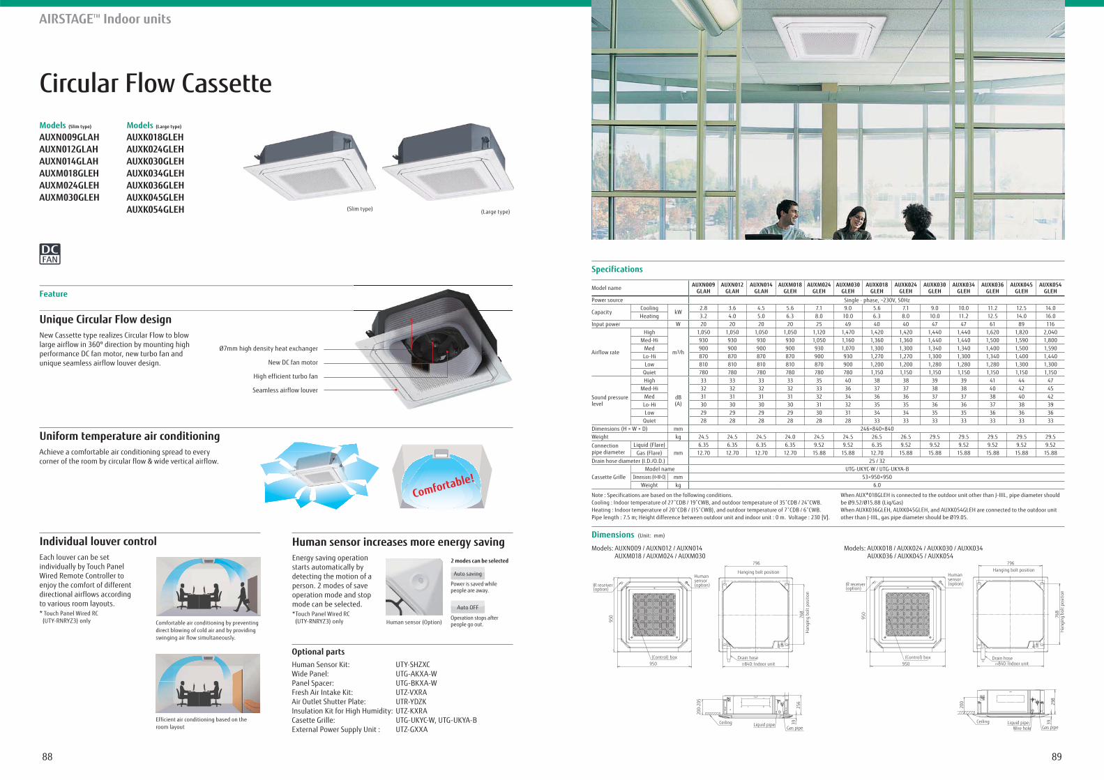
8988
Circular Flow CassetteModels (Slim type)
AUXN009GLAHAUXN012GLAHAUXN014GLAHAUXM018GLEHAUXM024GLEHAUXM030GLEH
Models (Large type)
AUXK018GLEHAUXK024GLEHAUXK030GLEHAUXK034GLEHAUXK036GLEHAUXK045GLEH AUXK054GLEH
Unique Circular Flow design
Uniform temperature air conditioning
New Cassette type realizes Circular Flow to blow large airflow in 360º direction by mounting high performance DC fan motor, new turbo fan and unique seamless airflow louver design.
Achieve a comfortable air conditioning spread to every corner of the room by circular flow & wide vertical airflow.
Feature
AIRSTAGETM Indoor units
Specifications
Dimensions (Unit: mm)
Model name AUXN009GLAH
AUXN012GLAH
AUXN014GLAH
AUXM018GLEH
AUXM024GLEH
AUXM030GLEH
AUXK018GLEH
AUXK024GLEH
AUXK030GLEH
AUXK034GLEH
AUXK036GLEH
AUXK045GLEH
AUXK054GLEH
Power source Single - phase, ~230V, 50Hz
CapacityCooling
kW2.8 3.6 4.5 5.6 7.1 9.0 5.6 7.1 9.0 10.0 11.2 12.5 14.0
Heating 3.2 4.0 5.0 6.3 8.0 10.0 6.3 8.0 10.0 11.2 12.5 14.0 16.0Input power W 20 20 20 20 25 49 40 40 47 47 61 89 116
Airflow rate
High
m3/h
1,050 1,050 1,050 1,050 1,120 1,470 1,420 1,420 1,440 1,440 1,620 1,820 2,040Med-Hi 930 930 930 930 1,050 1,160 1,360 1,360 1,440 1,440 1,500 1,590 1,800
Med 900 900 900 900 930 1,070 1,300 1,300 1,340 1,340 1,400 1,500 1,590Lo-Hi 870 870 870 870 900 930 1,270 1,270 1,300 1,300 1,340 1,400 1,440Low 810 810 810 810 870 900 1,200 1,200 1,280 1,280 1,280 1,300 1,300
Quiet 780 780 780 780 780 780 1,150 1,150 1,150 1,150 1,150 1,150 1,150
Sound pressure level
High
dB(A)
33 33 33 33 35 40 38 38 39 39 41 44 47Med-Hi 32 32 32 32 33 36 37 37 38 38 40 42 45
Med 31 31 31 31 32 34 36 36 37 37 38 40 42Lo-Hi 30 30 30 30 31 32 35 35 36 36 37 38 39Low 29 29 29 29 30 31 34 34 35 35 36 36 36
Quiet 28 28 28 28 28 28 33 33 33 33 33 33 33Dimensions (H × W × D) mm 246×840×840Weight kg 24.5 24.5 24.5 24.0 24.5 24.5 26.5 26.5 29.5 29.5 29.5 29.5 29.5
Connection pipe diameter
Liquid (Flare)mm
6.35 6.35 6.35 6.35 9.52 9.52 6.35 9.52 9.52 9.52 9.52 9.52 9.52Gas (Flare) 12.70 12.70 12.70 12.70 15.88 15.88 12.70 15.88 15.88 15.88 15.88 15.88 15.88
Drain hose diameter (I.D./O.D.) 25 / 32
Cassette GrilleModel name UTG-UKYC-W / UTG-UKYA-B
Dimensions (H×W×D) mm 53×950×950Weight kg 6.0
Note : Specifications are based on the following conditions.
Pipe length : 7.5 m; Height difference between outdoor unit and indoor unit : 0 m. Voltage : 230 [V].
Models: AUXN009 / AUXN012 / AUXN014 AUXM018 / AUXM024 / AUXM030
Models: AUXK018 / AUXK024 / AUXK030 / AUXK034 AUXK036 / AUXK045 / AUXK054
When AUX*018GLEH is connected to the outdoor unit other than J-IIIL, pipe diameter should be Ø9.52/Ø15.88 (Liq/Gas)When AUXK036GLEH, AUXK045GLEH, and AUXK054GLEH are connected to the outdoor unit other than J-IIIL, gas pipe diameter should be Ø19.05.
(Slim type) (Large type)
Comfortable!
Individual louver control Human sensor increases more energy savingEach louver can be set individually by Touch Panel Wired Remote Controller to enjoy the comfort of different directional airflows according to various room layouts. * Touch Panel Wired RC (UTY-RNRYZ3) only
Energy saving operation starts automatically by detecting the motion of a person. 2 modes of save operation mode and stop mode can be selected.*Touch Panel Wired RC (UTY-RNRYZ3) onlyComfortable air conditioning by preventing
direct blowing of cold air and by providing swinging air flow simultaneously.
Efficient air conditioning based on the room layout
Humansensor(option)
(Control) box
Hanging bolt position
Drain hoseIndoor unit
Gas pipeLiquid pipeCeiling
Han
ging
bol
t pos
ition
840:
IR receiver(option)
796
768
200-
205
256
39
950
950
Humansensor(option)
(Control) box
Gas pipeLiquid pipe
Wire hole
Drain hoseIndoor unit840:
IR receiver(option)
Hanging bolt position
Han
ging
bol
t pos
ition
796
768
950
298
39
950
200
Ceiling
Optional partsHuman Sensor Kit: UTY-SHZXCWide Panel: UTG-AKXA-WPanel Spacer: UTG-BKXA-WFresh Air Intake Kit: UTZ-VXRAAir Outlet Shutter Plate: UTR-YDZKInsulation Kit for High Humidity: UTZ-KXRACasette Grille: UTG-UKYC-W, UTG-UKYA-BExternal Power Supply Unit : UTZ-GXXA
Ø7mm high density heat exchanger
New DC fan motor
High efficient turbo fan
Seamless airflow louver
Human sensor (Option)
2 modes can be selected
Auto saving
Auto OFF
Power is saved whilepeople are away.
Operation stops after people go out.
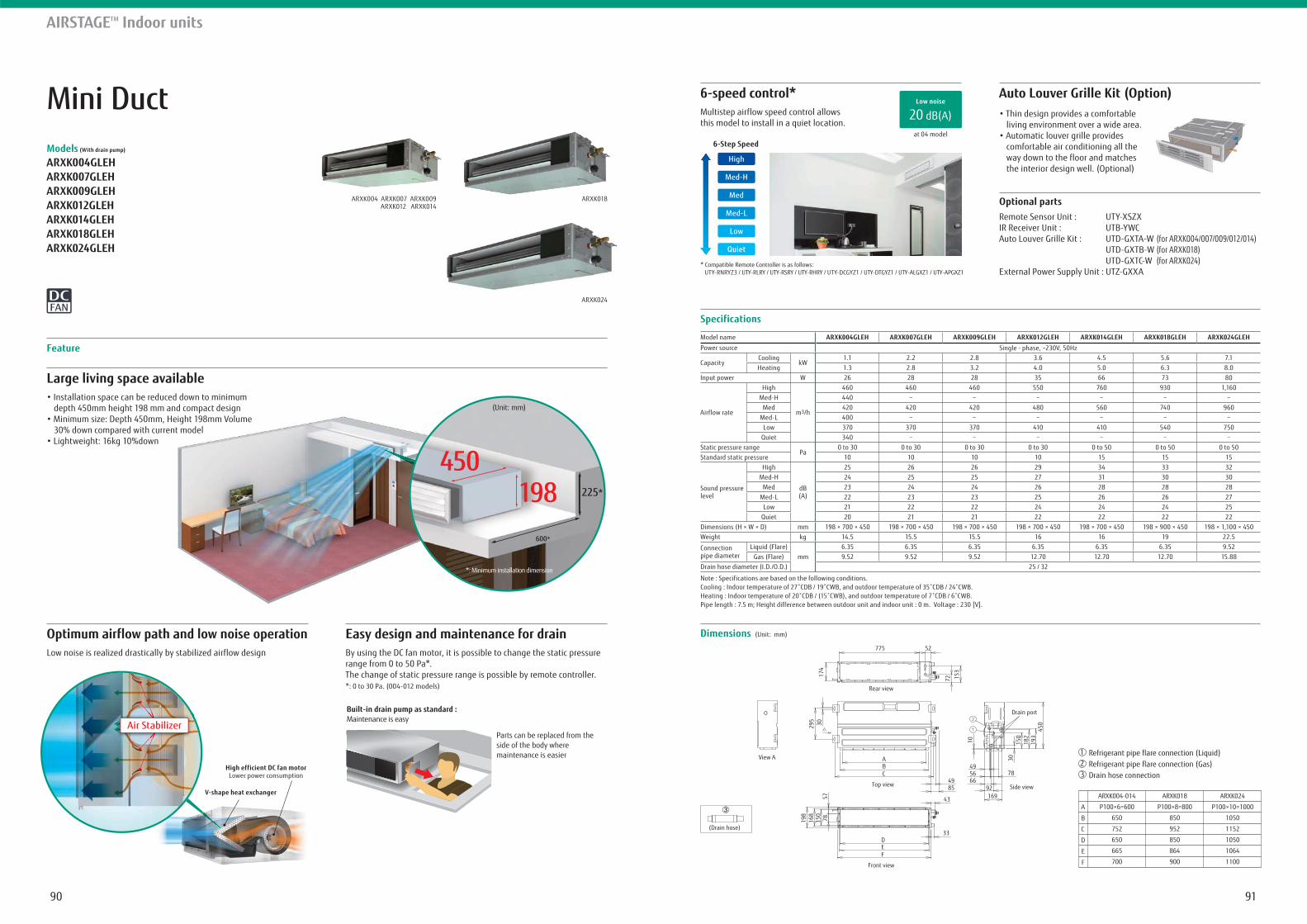
9190
450198
600*
225*
(Unit: mm)
*: Minimum installation dimension
Mini DuctModels (With drain pump)
ARXK004GLEH ARXK007GLEHARXK009GLEHARXK012GLEHARXK014GLEHARXK018GLEHARXK024GLEH
Large living space available
depth 450mm height 198 mm and compact design
30% down compared with current model
Easy design and maintenance for drainBy using the DC fan motor, it is possible to change the static pressure range from 0 to 50 Pa*.The change of static pressure range is possible by remote controller.*: 0 to 30 Pa. (004-012 models)
Optimum airflow path and low noise operationLow noise is realized drastically by stabilized airflow design
Feature
Specifications
Dimensions (Unit: mm)
Model name ARXK004GLEH ARXK007GLEH ARXK009GLEH ARXK012GLEH ARXK014GLEH ARXK018GLEH ARXK024GLEHPower source Single - phase, ~230V, 50Hz
CapacityCooling
kW1.1 2.2 2.8 3.6 4.5 5.6 7.1
Heating 1.3 2.8 3.2 4.0 5.0 6.3 8.0Input power W 26 28 28 35 66 73 80
Airflow rate
High
m3/h
460 460 460 550 760 930 1,160Med-H 440
Med 420 420 420 480 560 740 960Med-L 400
Low 370 370 370 410 410 540 750Quiet 340
Static pressure rangePa
0 to 30 0 to 30 0 to 30 0 to 30 0 to 50 0 to 50 0 to 50Standard static pressure 10 10 10 10 15 15 15
Sound pressure level
High
dB(A)
25 26 26 29 34 33 32Med-H 24 25 25 27 31 30 30
Med 23 24 24 26 28 28 28Med-L 22 23 23 25 26 26 27
Low 21 22 22 24 24 24 25Quiet 20 21 21 22 22 22 22
Dimensions (H × W × D) mm 198 × 700 × 450 198 × 700 × 450 198 × 700 × 450 198 × 700 × 450 198 × 700 × 450 198 × 900 × 450 198 × 1,100 × 450Weight kg 14.5 15.5 15.5 16 16 19 22.5
Connection pipe diameter
Liquid (Flare)mm
6.35 6.35 6.35 6.35 6.35 6.35 9.52Gas (Flare) 9.52 9.52 9.52 12.70 12.70 12.70 15.88
Drain hose diameter (I.D./O.D.) 25 / 32
Note : Specifications are based on the following conditions.
Pipe length : 7.5 m; Height difference between outdoor unit and indoor unit : 0 m. Voltage : 230 [V].
6-speed control* Auto Louver Grille Kit (Option)Multistep airflow speed control allows this model to install in a quiet location.
* Compatible Remote Controller is as follows: UTY-RNRYZ3 / UTY-RLRY / UTY-RSRY / UTY-RHRY / UTY-DCGYZ1 / UTY-DTGYZ1 / UTY-ALGXZ1 / UTY-APGXZ1
living environment over a wide area.
comfortable air conditioning all the way down to the floor and matches the interior design well. (Optional)
Optional partsRemote Sensor Unit : UTY-XSZXIR Receiver Unit : UTB-YWCAuto Louver Grille Kit : UTD-GXTA-W (for ARXK004/007/009/012/014) UTD-GXTB-W (for ARXK018) UTD-GXTC-W (for ARXK024)External Power Supply Unit : UTZ-GXXA
AIRSTAGETM Indoor units
High efficient DC fan motorLower power consumption
Air Stabilizer
V-shape heat exchanger
Built-in drain pump as standard : Maintenance is easy
Parts can be replaced from the side of the body where maintenance is easier
ARXK004 ARXK007 ARXK009 ARXK012 ARXK014
ARXK018
ARXK024
at 04 model
20 dB(A)Low noise
Refrigerant pipe flare connection (Liquid)Refrigerant pipe flare connection (Gas)Drain hose connection
21
3
ARXK004-014
P100×6=600
650
752
650
665
700
ARXK018
P100×8=800
850
952
850
864
900
ARXK024
P100×10=1000
1050
1152
1050
1064
1100
A
B
C
D
E
F
(Drain hose)
Rear view
View A
Top view
ABC
DEF
Side view
Drain port
Front view
775 52
153
10
174
295
49
43
33
85
4978
3015
018
219
345
0
92169
5666
3057
78150
168
198
72
6-Step Speed
Quiet
Low
Med-L
Med
Med-H
High
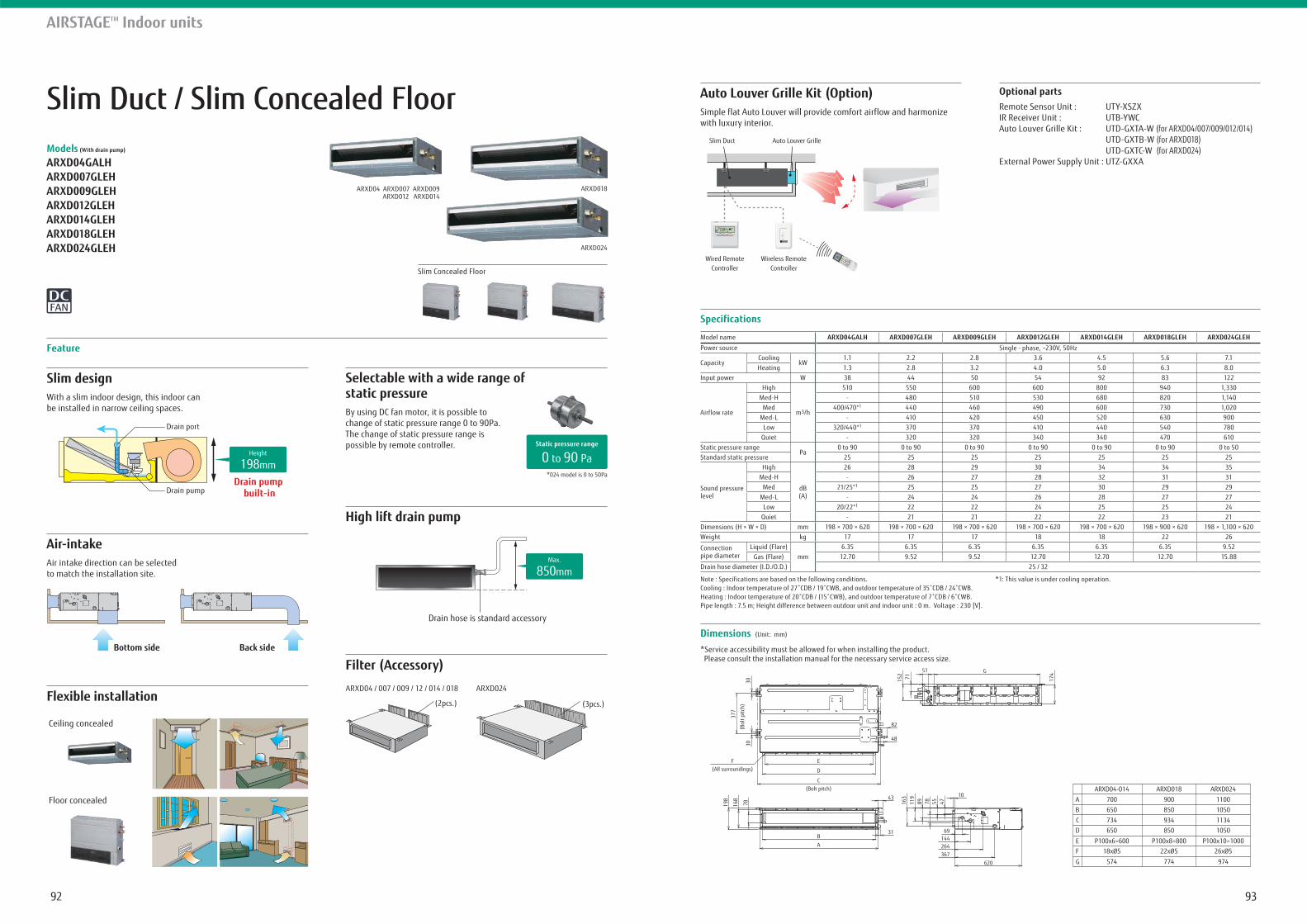
9392
Slim Duct / Slim Concealed FloorModels (With drain pump)
ARXD04GALHARXD007GLEHARXD009GLEHARXD012GLEHARXD014GLEHARXD018GLEHARXD024GLEH
Slim designWith a slim indoor design, this indoor can be installed in narrow ceiling spaces.
Selectable with a wide range of static pressureBy using DC fan motor, it is possible to change of static pressure range 0 to 90Pa. The change of static pressure range is possible by remote controller.
High lift drain pump
Filter (Accessory)
Feature
Specifications
Dimensions (Unit: mm)
Model name ARXD04GALH ARXD007GLEH ARXD009GLEH ARXD012GLEH ARXD014GLEH ARXD018GLEH ARXD024GLEHPower source Single - phase, ~230V, 50Hz
CapacityCooling
kW1.1 2.2 2.8 3.6 4.5 5.6 7.1
Heating 1.3 2.8 3.2 4.0 5.0 6.3 8.0Input power W 38 44 50 54 92 83 122
Airflow rate
High
m3/h
510 550 600 600 800 940 1,330Med-H - 480 510 530 680 820 1,140
Med 400/470*1 440 460 490 600 730 1,020Med-L - 410 420 450 520 630 900
Low 320/440*1 370 370 410 440 540 780Quiet - 320 320 340 340 470 610
Static pressure rangePa
0 to 90 0 to 90 0 to 90 0 to 90 0 to 90 0 to 90 0 to 50Standard static pressure 25 25 25 25 25 25 25
Sound pressure level
High
dB(A)
26 28 29 30 34 34 35 Med-H - 26 27 28 32 31 31
Med 21/25*1 25 25 27 30 29 29 Med-L - 24 24 26 28 27 27
Low 20/22*1 22 22 24 25 25 24 Quiet - 21 21 22 22 23 21
Dimensions (H × W × D) mm 198 × 700 × 620 198 × 700 × 620 198 × 700 × 620 198 × 700 × 620 198 × 700 × 620 198 × 900 × 620 198 × 1,100 × 620Weight kg 17 17 17 18 18 22 26
Connection pipe diameter
Liquid (Flare)mm
6.35 6.35 6.35 6.35 6.35 6.35 9.52Gas (Flare) 12.70 9.52 9.52 12.70 12.70 12.70 15.88
Drain hose diameter (I.D./O.D.) 25 / 32
Note : Specifications are based on the following conditions.
Pipe length : 7.5 m; Height difference between outdoor unit and indoor unit : 0 m. Voltage : 230 [V].
*1: This value is under cooling operation.
Auto Louver Grille Kit (Option)Simple flat Auto Louver will provide comfort airflow and harmonize with luxury interior.
Optional partsRemote Sensor Unit : UTY-XSZXIR Receiver Unit : UTB-YWCAuto Louver Grille Kit : UTD-GXTA-W (for ARXD04/007/009/012/014) UTD-GXTB-W (for ARXD018) UTD-GXTC-W (for ARXD024)External Power Supply Unit : UTZ-GXXA
AIRSTAGETM Indoor units
ARXD04 ARXD007 ARXD009 ARXD012 ARXD014
ARXD018
ARXD024
Slim Concealed Floor
Drain port
Drain pump built-inDrain pump
Height
198mm
Air-intakeAir intake direction can be selected to match the installation site.
Back sideBottom side
Flexible installation
Drain hose is standard accessory
Max.
850mm
(2pcs.) (3pcs.)
Slim Duct
Wired RemoteController
Wireless RemoteController
Auto Louver Grille
*Service accessibility must be allowed for when installing the product. Please consult the installation manual for the necessary service access size.
ARXD04-014 ARXD018 ARXD024
700A
B
CD
EF
G
900 1100
650 850 1050
734 934 1134650 850 1050
P100x6=600 P100x8=800 P100x10=100018xØ5 22xØ5 26xØ5
574 774 974
(Bol
t pitc
h)
G51
152
377
174
71
3030
F(All surroundings)
82
48
E
D
C(Bolt pitch)
43
31
198
168
78
B
A
10
69144264367
620
47557889119
163
ARXD04 / 007 / 009 / 12 / 014 / 018 ARXD024
Ceiling concealed
Floor concealed
*024 model is 0 to 50Pa
0 to 90 PaStatic pressure range
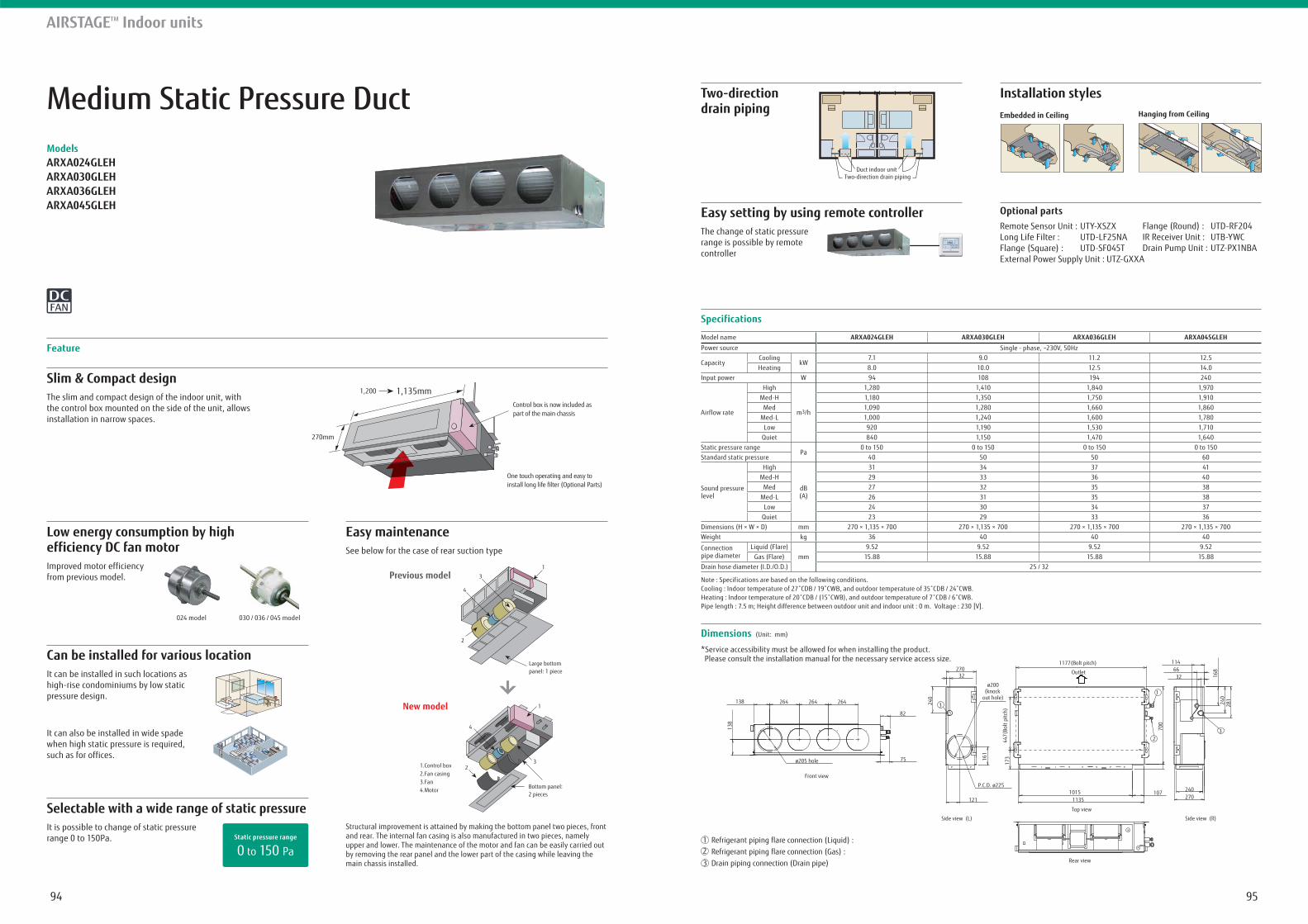
9594
Medium Static Pressure DuctModelsARXA024GLEHARXA030GLEHARXA036GLEHARXA045GLEH
Slim & Compact designThe slim and compact design of the indoor unit, with the control box mounted on the side of the unit, allows installation in narrow spaces.
Feature
Specifications
Dimensions (Unit: mm)
Model name ARXA024GLEH ARXA030GLEH ARXA036GLEH ARXA045GLEHPower source Single - phase, ~230V, 50Hz
CapacityCooling
kW7.1 9.0 11.2 12.5
Heating 8.0 10.0 12.5 14.0Input power W 94 108 194 240
Airflow rate
High
m3/h
1,280 1,410 1,840 1,970Med-H 1,180 1,350 1,750 1,910
Med 1,090 1,280 1,660 1,860Med-L 1,000 1,240 1,600 1,780
Low 920 1,190 1,530 1,710Quiet 840 1,150 1,470 1,640
Static pressure rangePa
0 to 150 0 to 150 0 to 150 0 to 150Standard static pressure 40 50 50 60
Sound pressure level
High
dB(A)
31 34 37 41 Med-H 29 33 36 40
Med 27 32 35 38 Med-L 26 31 35 38
Low 24 30 34 37 Quiet 23 29 33 36
Dimensions (H × W × D) mm 270 × 1,135 × 700 270 × 1,135 × 700 270 × 1,135 × 700 270 × 1,135 × 700Weight kg 36 40 40 40
Connection pipe diameter
Liquid (Flare)mm
9.52 9.52 9.52 9.52Gas (Flare) 15.88 15.88 15.88 15.88
Drain hose diameter (I.D./O.D.) 25 / 32
Note : Specifications are based on the following conditions.
Pipe length : 7.5 m; Height difference between outdoor unit and indoor unit : 0 m. Voltage : 230 [V].
Two-direction drain piping
Installation styles
AIRSTAGETM Indoor units
*Service accessibility must be allowed for when installing the product. Please consult the installation manual for the necessary service access size.
1,200 1,135mm
270mm
Control box is now included as part of the main chassis
One touch operating and easy to install long life filter (Optional Parts)
Selectable with a wide range of static pressureStructural improvement is attained by making the bottom panel two pieces, front and rear. The internal fan casing is also manufactured in two pieces, namely upper and lower. The maintenance of the motor and fan can be easily carried out by removing the rear panel and the lower part of the casing while leaving the main chassis installed.
It is possible to change of static pressure range 0 to 150Pa.
Low energy consumption by high efficiency DC fan motorImproved motor efficiency from previous model.
024 model 030 / 036 / 045 model
Can be installed for various locationIt can be installed in such locations as high-rise condominiums by low static pressure design.
It can also be installed in wide spade when high static pressure is required, such as for offices.
Easy maintenanceSee below for the case of rear suction type
0 to 150 Pa Static pressure range
1.Control box2.Fan casing3.Fan4.Motor
Previous model
2
4
1
3
Large bottom panel: 1 piece
New model 1
4
32
Bottom panel: 2 pieces
Embedded in Ceiling Hanging from Ceiling
Two-direction drain pipingDuct indoor unit
Easy setting by using remote controllerThe change of static pressure range is possible by remote controller
Optional partsRemote Sensor Unit : UTY-XSZXLong Life Filter : UTD-LF25NA Flange (Square) : UTD-SF045TExternal Power Supply Unit : UTZ-GXXA
21
3 Rear view
Top view
Side view (R)Side view (L)
Front view
240270
10710151135
17316
1
447(
Bolt
pitc
h)
1177(Bolt pitch)
Outlet27032
ø200(knock
out hole)
240
121
P.C.D. ø225
1146632
1
3
3
2
168
281240
700
138
138
264 264 264
ø205 hole
82
75
Refrigerant piping flare connection (Liquid) : Refrigerant piping flare connection (Gas) : Drain piping connection (Drain pipe)
Flange (Round) : UTD-RF204 IR Receiver Unit : UTB-YWCDrain Pump Unit : UTZ-PX1NBA
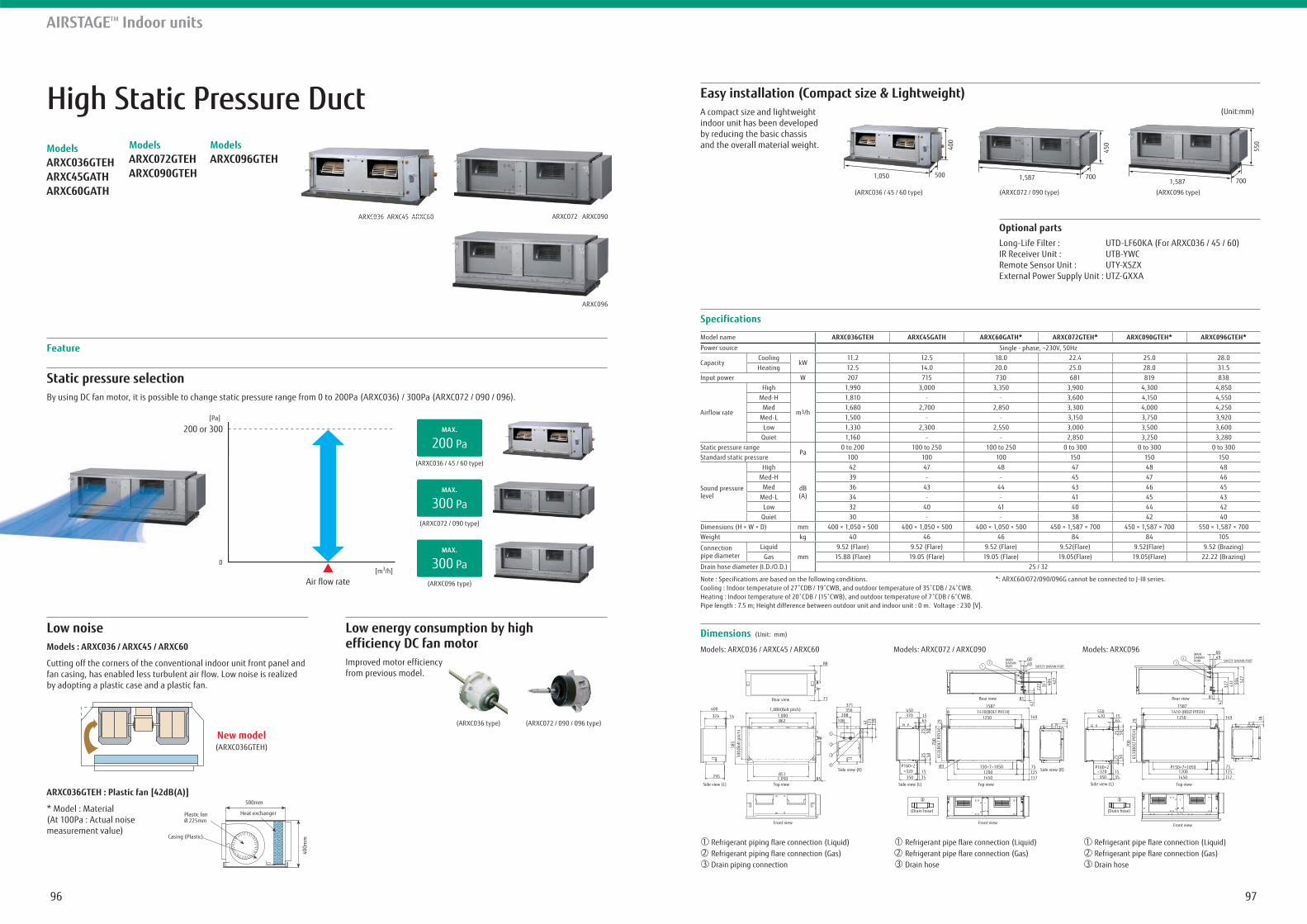
9796
High Static Pressure DuctModelsARXC036GTEHARXC45GATHARXC60GATH
ModelsARXC072GTEHARXC090GTEH
ModelsARXC096GTEH
Static pressure selectionBy using DC fan motor, it is possible to change static pressure range from 0 to 200Pa (ARXC036) / 300Pa (ARXC072 / 090 / 096).
Feature
Specifications
Dimensions (Unit: mm)
Model name ARXC036GTEH ARXC45GATH ARXC60GATH* ARXC072GTEH* ARXC090GTEH* ARXC096GTEH*Power source Single - phase, ~230V, 50Hz
CapacityCooling
kW11.2 12.5 18.0 22.4 25.0 28.0
Heating 12.5 14.0 20.0 25.0 28.0 31.5Input power W 207 715 730 681 819 838
Airflow rate
High
m3/h
1,990 3,000 3,350 3,900 4,300 4,850Med-H 1,810 - - 3,600 4,150 4,550
Med 1,680 2,700 2,850 3,300 4,000 4,250Med-L 1,500 - - 3,150 3,750 3,920
Low 1,330 2,300 2,550 3,000 3,500 3,600Quiet 1,160 - - 2,850 3,250 3,280
Static pressure rangePa
0 to 200 100 to 250 100 to 250 0 to 300 0 to 300 0 to 300Standard static pressure 100 100 100 150 150 150
Sound pressure level
High
dB(A)
42 47 48 47 48 48 Med-H 39 - - 45 47 46
Med 36 43 44 43 46 45 Med-L 34 - - 41 45 43
Low 32 40 41 40 44 42 Quiet 30 - - 38 42 40
Dimensions (H × W × D) mm 400 × 1,050 × 500 400 × 1,050 × 500 400 × 1,050 × 500 450 × 1,587 × 700 450 × 1,587 × 700 550 × 1,587 × 700Weight kg 40 46 46 84 84 105
Connection pipe diameter
Liquidmm
9.52 (Flare) 9.52 (Flare) 9.52 (Flare) 9.52(Flare) 9.52(Flare) 9.52 (Brazing)Gas 15.88 (Flare) 19.05 (Flare) 19.05 (Flare) 19.05(Flare) 19.05(Flare) 22.22 (Brazing)
Drain hose diameter (I.D./O.D.) 25 / 32
Note : Specifications are based on the following conditions.
Pipe length : 7.5 m; Height difference between outdoor unit and indoor unit : 0 m. Voltage : 230 [V].
*: ARXC60/072/090/096G cannot be connected to J-III series.
AIRSTAGETM Indoor units
Models: ARXC036 / ARXC45 / ARXC60 Models: ARXC072 / ARXC090 Models: ARXC096
Low noise Low energy consumption by highefficiency DC fan motorModels : ARXC036 / ARXC45 / ARXC60
Cutting off the corners of the conventional indoor unit front panel and fan casing, has enabled less turbulent air flow. Low noise is realized by adopting a plastic case and a plastic fan.
Improved motor efficiency from previous model.
ARXC036GTEH : Plastic fan [42dB(A)]
* Model : Material(At 100Pa : Actual noise measurement value)
New model(ARXC036GTEH)
Easy installation (Compact size & Lightweight)A compact size and lightweight indoor unit has been developed by reducing the basic chassis and the overall material weight.
Optional partsLong-Life Filter : UTD-LF60KA (For ARXC036 / 45 / 60)IR Receiver Unit : UTB-YWCRemote Sensor Unit : UTY-XSZXExternal Power Supply Unit : UTZ-GXXA
[m30
(ARXC036 / 45 / 60 type)
200 PaMAX.
(ARXC072 / 090 type)
300 PaMAX.
(ARXC096 type)
300 PaMAX.
500mm
400m
m
Plastic fanØ 225mm
Heat exchanger
Casing (Plastic)
(ARXC072 / 090 / 096 type)(ARXC036 type)
(Unit:mm)
1,050 500
400
450
1,587 700
550
1,587 700
Front view Front view Front view
Top view Top view Top viewSide view (L) Side view (L) Side view (L)
Side view (R) Side view (R)
Rear view Rear view Rear view
SAFETY DARAIN PORT
SAFETY DARAIN PORTMAIN DARAIN PORT
MAIN DARAIN PORT
88
400 1,080(Bolt pitch)1,000862
8511,050 85
371356
208
41 123
139108
1
2
3
4
324 14
295
585
500(
Bolt
pitc
h)
71
Refrigerant piping flare connection (Liquid)Refrigerant piping flare connection (Gas)Drain piping connection
21
3
))
Drain hose21
3
))
Drain hose21
3
(Drain hose) (Drain hose)
6049
81
450370 15
65
P160×2=320
350 3515
15871410(BOLT PITCH)
1250
150×7=105012001450
75125117
149
Ø3
38
42
2
27 311 40
442
7
700
653(
BOLT
PIT
CH)
2525
5050
8
29
12 1
2
327
411 50
452
7
550470 15
65
25 505025
1535
P160×2=320350
700
653(
BOLT
PIT
CH)
29
12501410 (BOLT PITCH)
1587
81
42
149
75125117
P150×7=105012001450
38
6049
8
ARXC036 ARXC45 ARXC60 ARXC072 ARXC090
ARXC096
ARXC036 ARXC45 ARXC60
(ARXC036 / 45 / 60 type) (ARXC072 / 090 type) (ARXC096 type)
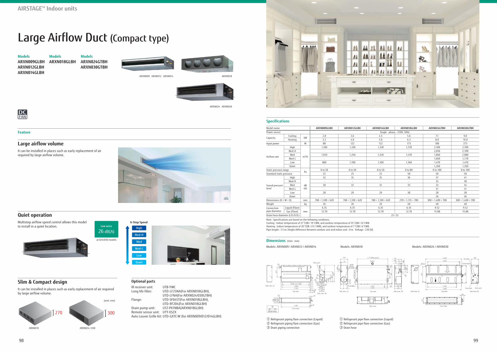
9998
Large Airflow Duct (Compact type)
Large airflow volumeIt can be installed in places such as early replacement of air required by large airflow volume.
Feature
AIRSTAGETM Indoor units
Quiet operationMultistep airflow speed control allows this model to install in a quiet location.
at 024/030 models
26 dB(A)Low noise
Specifications
Model name ARXN009GLBH ARXN012GLBH ARXN014GLBH ARXN018GLBH ARXN024GTBH ARXN030GTBHPower source Single - phase, ~230V, 50Hz
CapacityCooling
kW2.8 3.6 4.5 5.6 7.1 9.0
Heating 3.2 4.0 5.0 6.3 8.0 10.0Input power W 88 122 122 173 180 273
Airflow rate
High
m3/h
1,100 1,330 1,330 1,720 2,100 2,700Med-H - - - - 2,050 2,390
Med 1,010 1,240 1,240 1,470 1,860 2,080Med-L - - - - 1,660 1,770
Low 880 1,100 1,100 1,360 1,470 1,470Quiet - - - - 1,260 1,260
Static pressure rangePa
0 to 50 0 to 50 0 to 50 0 to 80 0 to 100 0 to 100Standard static pressure 25 25 25 50 50 50
Sound pressure level
High
dB(A)
32 35 35 36 37 41Med-H - - - - 35 38
Med 30 32 32 33 33 34Med-L - - - - 31 31
Low 28 29 29 30 28 28Quiet - - - - 26 26
Dimensions (H × W × D) mm 198 × 1,100 × 620 198 × 1,100 × 620 198 × 1,100 × 620 270 × 1,135 × 700 300 × 1,400 × 700 300 × 1,400 × 700Weight kg 26 26 26 40 48 48
Connection pipe diameter
Liquid (Flare)mm
6.35 6.35 6.35 6.35 9.52 9.52Gas (Flare) 12.70 12.70 12.70 12.70 15.88 15.88
Drain hose diameter (I.D./O.D.) 25 / 32
Note : Specifications are based on the following conditions.
Pipe length : 7.5 m; Height difference between outdoor unit and indoor unit : 0 m. Voltage : 230 [V].
Slim & Compact designIt can be installed in places such as early replacement of air required by large airflow volume.
ARXN018
270
ARXN024 / 030
300
(unit: mm)
Optional partsIR receiver unit: UTB-YWCLong life filter: UTD-LF25NA(For ARXN018GLBH), UTD-LFNA(For ARXN024/030GTBH)Flange: UTD-SF045T(For ARXN018GLBH), UTD-RF204(For ARXN018GLBH)Drain pump unit: UTZ-PX1NBA(ARXN018GLBH)Remote sensor unit: UTY-XSZXAuto Louver Grille Kit: UTD-GXTC-W (for ARXN009/012/014GLBH)
ModelsARXN009GLBH ARXN012GLBH ARXN014GLBH
ModelsARXN018GLBH
ModelsARXN024GTBH ARXN030GTBH
ARXN009 ARXN012 ARXN014 ARXN018
ARXN024 ARXN030
Dimensions (Unit: mm)
Models: ARXN009 / ARXN012 / ARXN014 Models: ARXN018 Models: ARXN024 / ARXN030
Rear view
Top viewTop view Side view (R)Side view (R)
Side view (L)
Side view (L) 240270
1071,0151,135
17316
1
447(
Bolt
pitc
h)
1,177(Bolt pitch)
Outlet
270
32
ø200(knock
out hole)
240
69 144 26
4 367
620
121P.C.D. ø225
1146632
1
3
3
2
168
281
240
700
217
Top ViewSide View (L) Side View (R)
1,400
1,162
631
700
Ø125
1,440 300
1,295
98
Drain port Drain port
Gas pipe
Liquid pipe
Front ViewFront View
Air
Refrigerant piping flare connection (Liquid)Refrigerant piping flare connection (Gas)Drain piping connection
21
3
))
Drain hose21
3
Drain port
7889
87
557815
116
819
8
119163
47
10
377
30
55
43
1,100
1,134
P100×10=1,0001,050
31
56
1
2
(Drain hose)
3
6-Step Speed
Quiet
Low
Med-L
Med
Med-H
High
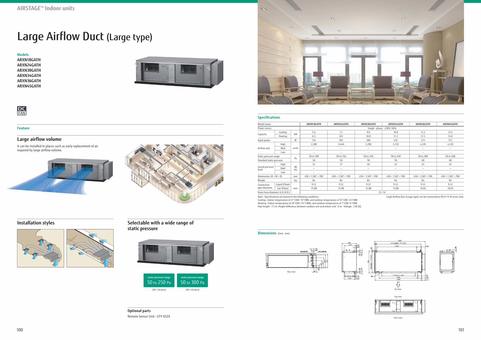
101100
Large Airflow Duct (Large type)
ModelsARXN18GATHARXN24GATHARXN30GATHARXN34GATHARXN36GATHARXN45GATH
Installation styles
Large airflow volumeIt can be installed in places such as early replacement of air required by large airflow volume.
Feature
AIRSTAGETM Indoor units
Selectable with a wide range of static pressure
Dimensions (Unit: mm)
Specifications
Model name ARXN18GATH ARXN24GATH ARXN30GATH ARXN34GATH ARXN36GATH ARXN45GATH
Power source Single - phase, ~230V, 50Hz
CapacityCooling
kW5.6 7.1 9.0 10.0 11.2 12.5
Heating 6.3 8.0 10.0 11.2 12.5 14.0
Input power W 154 205 306 432 572 572
Airflow rate
High
m3/h
2,280 2,640 3,200 3,720 4,120 4,120
Med
Low
Static pressure rangePa
50 to 100 50 to 150 50 to 250 50 to 250 50 to 300 50 to 300
Standard static pressure 50 50 50 50 60 60
Sound pressure level
HighdB(A)
35 37 40 43 45 45
Med
Low
Dimensions (H × W × D) mm 450 × 1,587 × 700 450 × 1,587 × 700 450 × 1,587 × 700 450 × 1,587 × 700 450 × 1,587 × 700 450 × 1,587 × 700
Weight kg 84 84 84 84 84 84
Connection pipe diameter
Liquid (Flare)
mm
9.52 9.52 9.52 9.52 9.52 9.52
Gas (Flare) 15.88 15.88 15.88 15.88 19.05 19.05
Drain hose diameter (I.D./O.D.) 25 / 32
Note : Specifications are based on the following conditions.
Pipe length : 7.5 m; Height difference between outdoor unit and indoor unit : 0 m. Voltage : 230 [V].
Large Airflow Duct (Large type) can be connected to VR-II / V-III series only.
Rear view
Air Flow
Top view
Front view
(30 / 34class) (36 / 45class)
50 to 250 Pastatic pressure range
50 to 300 Pastatic pressure range
Optional partsRemote Sensor Unit : UTY-XSZX
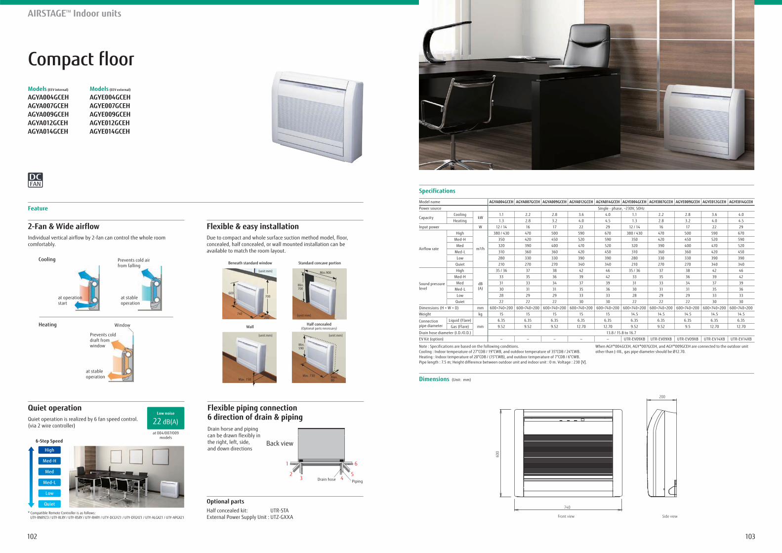
103102
Compact floorModels (EEV internal)
AGYA004GCEH AGYA007GCEH AGYA009GCEH AGYA012GCEH AGYA014GCEH
Models (EEV external)
AGYE004GCEH AGYE007GCEH AGYE009GCEH AGYE012GCEH AGYE014GCEH
Quiet operation
2-Fan & Wide airflowIndividual vertical airflow by 2-fan can control the whole room comfortably.
* Compatible Remote Controller is as follows: UTY-RNRYZ3 / UTY-RLRY / UTY-RSRY / UTY-RHRY / UTY-DCGYZ1 / UTY-DTGYZ1 / UTY-ALGXZ1 / UTY-APGXZ1
Flexible & easy installationDue to compact and whole surface suction method model, floor, concealed, half concealed, or wall mounted installation can be available to match the room layout.
Feature
AIRSTAGETM Indoor units
Flexible piping connection 6 direction of drain & pipingDrain horse and piping can be drawn flexibly in the right, left, side,and down directions
Quiet operation is realized by 6 fan speed control.(via 2 wire controller)
at 004/007/009models
22 dB(A)Low noise
Specifications
Dimensions (Unit: mm)
Model name AGYA004GCEH AGYA007GCEH AGYA009GCEH AGYA012GCEH AGYA014GCEH AGYE004GCEH AGYE007GCEH AGYE009GCEH AGYE012GCEH AGYE014GCEH
Power source Single - phase, ~230V, 50Hz
CapacityCooling
kW1.1 2.2 2.8 3.6 4.0 1.1 2.2 2.8 3.6 4.0
Heating 1.3 2.8 3.2 4.0 4.5 1.3 2.8 3.2 4.0 4.5
Input power W 12 / 14 16 17 22 29 12 / 14 16 17 22 29
Airflow rate
High
m3/h
380 / 430 470 500 590 670 380 / 430 470 500 590 670
Med-H 350 420 450 520 590 350 420 450 520 590
Med 320 390 400 470 520 320 390 400 470 520
Med-L 310 360 360 420 450 310 360 360 420 450
Low 280 330 330 390 390 280 330 330 390 390
Quiet 210 270 270 340 340 210 270 270 340 340
Sound pressure level
High
dB(A)
35 / 36 37 38 42 46 35 / 36 37 38 42 46
Med-H 33 35 36 39 42 33 35 36 39 42
Med 31 33 34 37 39 31 33 34 37 39
Med-L 30 31 31 35 36 30 31 31 35 36
Low 28 29 29 33 33 28 29 29 33 33
Quiet 22 22 22 30 30 22 22 22 30 30
Dimensions (H × W × D) mm 600×740×200 600×740×200 600×740×200 600×740×200 600×740×200 600×740×200 600×740×200 600×740×200 600×740×200 600×740×200
Weight kg 15 15 15 15 15 14.5 14.5 14.5 14.5 14.5
Connection pipe diameter
Liquid (Flare)
mm
6.35 6.35 6.35 6.35 6.35 6.35 6.35 6.35 6.35 6.35
Gas (Flare) 9.52 9.52 9.52 12.70 12.70 9.52 9.52 9.5 12.70 12.70
Drain hose diameter (I.D./O.D.) 13.8 / 15.8 to 16.7
EV Kit (option) - - - - - UTR-EV09XB UTR-EV09XB UTR-EV09XB UTR-EV14XB UTR-EV14XB
Note : Specifications are based on the following conditions.Cooling : Indoor temperature of 27°CDB / 19°CWB, and outdoor temperature of 35°CDB / 24°CWB.Heating : Indoor temperature of 20°CDB / (15°CWB), and outdoor temperature of 7°CDB / 6°CWB.Pipe length : 7.5 m; Height difference between outdoor unit and indoor unit : 0 m. Voltage : 230 [V].
When AGY*004GCEH, AGY*007GCEH, and AGY*009GCEH are connected to the outdoor unit other than J-IIIL, gas pipe diameter should be Ø12.70.
Standard concave portion
Half concealed(Optional parts necessary)
(unit:mm)
Min.700
Min.900
(unit:mm)
Min. 590
Min. 730 Max. 80
Beneath standard window
Wall
(unit:mm)
Max. 150
(unit:mm)
600
740200
700
200
600
740
Front view Side view
Optional partsHalf concealed kit: UTR-STAExternal Power Supply Unit : UTZ-GXXA
6-Step Speed
Quiet
Low
Med-L
Med
Med-H
High
at operationstart
at stableoperation
Prevents cold air from falling
Window
Cooling
Heating
Prevents cold draft from window
at stableoperation
61
Back view
PipingDrain hose 4352
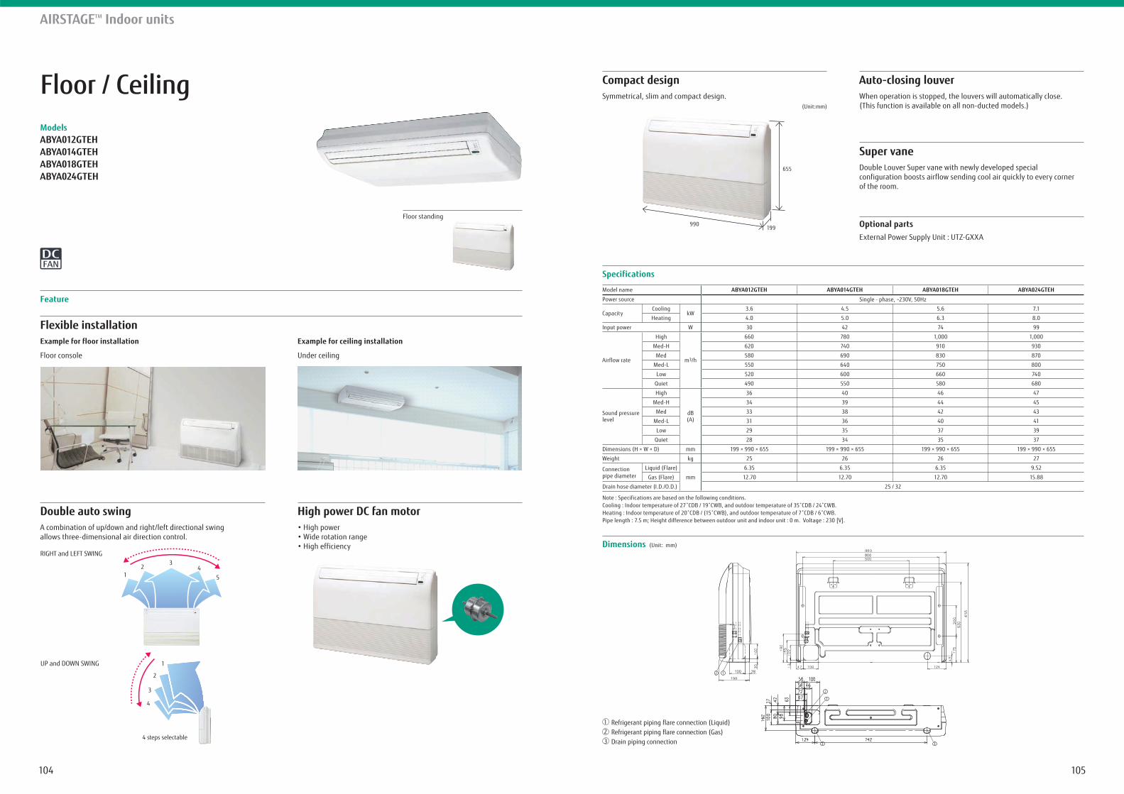
105104
Floor / CeilingModelsABYA012GTEHABYA014GTEHABYA018GTEHABYA024GTEH
Flexible installationExample for floor installation
Floor console
Example for ceiling installation
Under ceiling
Feature
Specifications
Dimensions (Unit: mm)
Model name ABYA012GTEH ABYA014GTEH ABYA018GTEH ABYA024GTEH
Power source Single - phase, ~230V, 50Hz
CapacityCooling
kW3.6 4.5 5.6 7.1
Heating 4.0 5.0 6.3 8.0
Input power W 30 42 74 99
Airflow rate
High
m3/h
660 780 1,000 1,000
Med-H 620 740 910 930
Med 580 690 830 870
Med-L 550 640 750 800
Low 520 600 660 740
Quiet 490 550 580 680
Sound pressure level
High
dB(A)
36 40 46 47
Med-H 34 39 44 45
Med 33 38 42 43
Med-L 31 36 40 41
Low 29 35 37 39
Quiet 28 34 35 37
Dimensions (H × W × D) mm 199 × 990 × 655 199 × 990 × 655 199 × 990 × 655 199 × 990 × 655
Weight kg 25 26 26 27
Connection pipe diameter
Liquid (Flare)
mm
6.35 6.35 6.35 9.52
Gas (Flare) 12.70 12.70 12.70 15.88
Drain hose diameter (I.D./O.D.) 25 / 32
Note : Specifications are based on the following conditions.
Pipe length : 7.5 m; Height difference between outdoor unit and indoor unit : 0 m. Voltage : 230 [V].
AIRSTAGETM Indoor units
Double auto swingA combination of up/down and right/left directional swing allows three-dimensional air direction control.
High power DC fan motor
Compact designSymmetrical, slim and compact design.
Auto-closing louver
Super vane
When operation is stopped, the louvers will automatically close. (This function is available on all non-ducted models.)
Double Louver Super vane with newly developed special configuration boosts airflow sending cool air quickly to every corner of the room.
Floor standing
UP and DOWN SWING
RIGHT and LEFT SWING
4
3
2
1
4 steps selectable
45
32
1
5 steps selectable
Refrigerant piping flare connection (Liquid)Refrigerant piping flare connection (Gas)Drain piping connection
21
3
12
1
2
33
Optional partsExternal Power Supply Unit : UTZ-GXXA
990199
655
(Unit:mm)
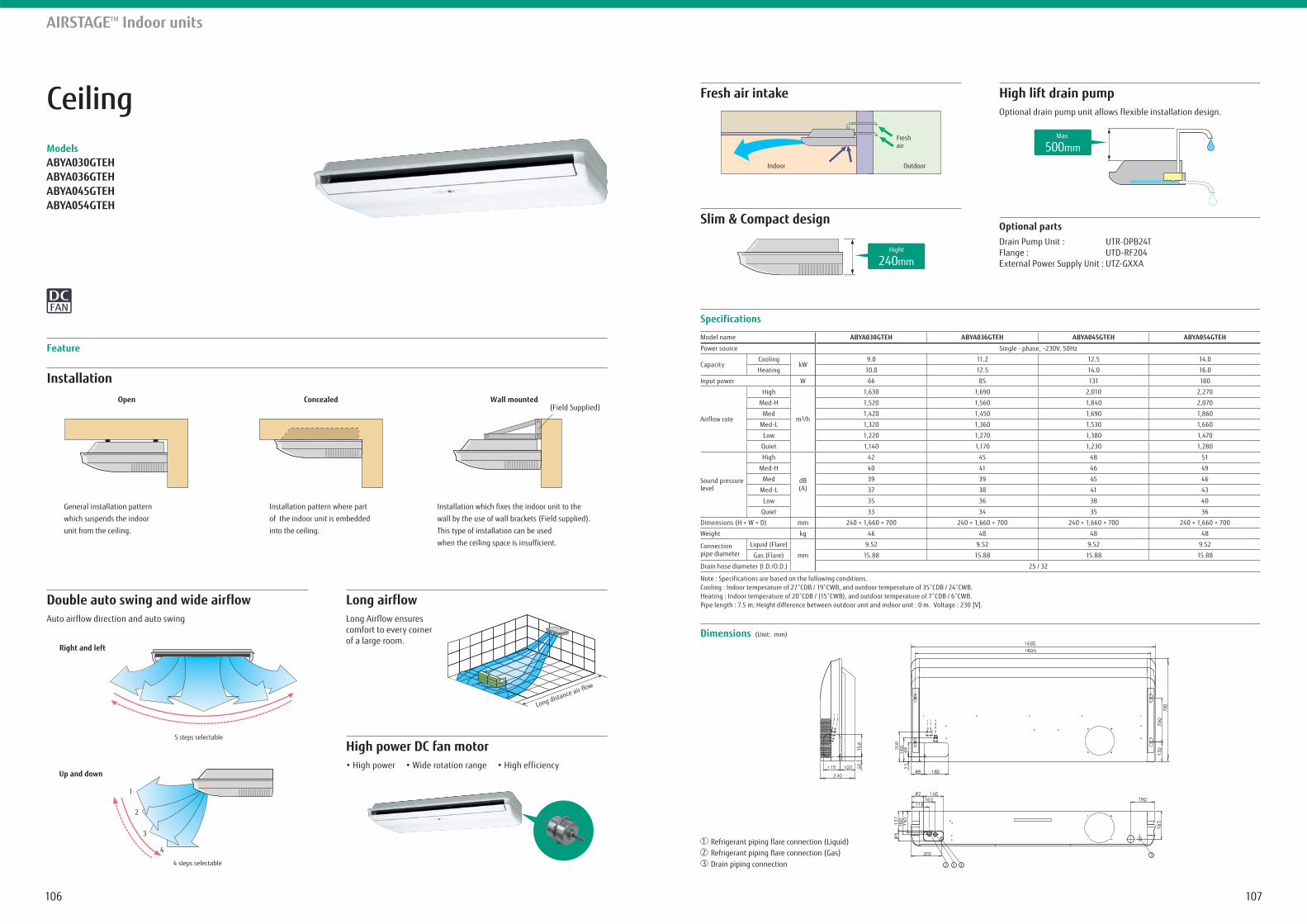
107106
CeilingModelsABYA030GTEHABYA036GTEHABYA045GTEHABYA054GTEH
Installation
Feature
Specifications
Dimensions (Unit: mm)
Model name ABYA030GTEH ABYA036GTEH ABYA045GTEH ABYA054GTEH
Power source Single - phase, ~230V, 50Hz
CapacityCooling
kW9.0 11.2 12.5 14.0
Heating 10.0 12.5 14.0 16.0
Input power W 66 85 131 180
Airflow rate
High
m3/h
1,630 1,690 2,010 2,270
Med-H 1,520 1,560 1,840 2,070
Med 1,420 1,450 1,690 1,860
Med-L 1,320 1,360 1,530 1,660
Low 1,220 1,270 1,380 1,470
Quiet 1,140 1,170 1,230 1,280
Sound pressure level
High
dB(A)
42 45 48 51
Med-H 40 41 46 49
Med 39 39 45 46
Med-L 37 38 41 43
Low 35 36 38 40
Quiet 33 34 35 36
Dimensions (H × W × D) mm 240 × 1,660 × 700 240 × 1,660 × 700 240 × 1,660 × 700 240 × 1,660 × 700
Weight kg 46 48 48 48
Connection pipe diameter
Liquid (Flare)
mm
9.52 9.52 9.52 9.52
Gas (Flare) 15.88 15.88 15.88 15.88
Drain hose diameter (I.D./O.D.) 25 / 32
Note : Specifications are based on the following conditions.
Pipe length : 7.5 m; Height difference between outdoor unit and indoor unit : 0 m. Voltage : 230 [V].
AIRSTAGETM Indoor units
Double auto swing and wide airflowAuto airflow direction and auto swing
Long airflowLong Airflow ensures comfort to every corner of a large room.
High power DC fan motor
Fresh air intake
Slim & Compact design
High lift drain pumpOptional drain pump unit allows flexible installation design.
General installation pattern
which suspends the indoor
unit from the ceiling.
Open
Installation pattern where part
of the indoor unit is embedded
into the ceiling.
Concealed
Installation which fixes the indoor unit to the
wall by the use of wall brackets (Field supplied).
This type of installation can be used
when the ceiling space is insufficient.
(Field Supplied)Wall mounted
4
3
2
1
4 steps selectable
5 steps selectable
Up and down
Right and left
Long distance air-flow
OutdoorIndoor
Freshair
Hight
240mm
Max.
500mm
Optional partsDrain Pump Unit : UTR-DPB24TFlange : UTD-RF204External Power Supply Unit : UTZ-GXXA
Refrigerant piping flare connection (Liquid)Refrigerant piping flare connection (Gas)Drain piping connection
21
3 1 32
3
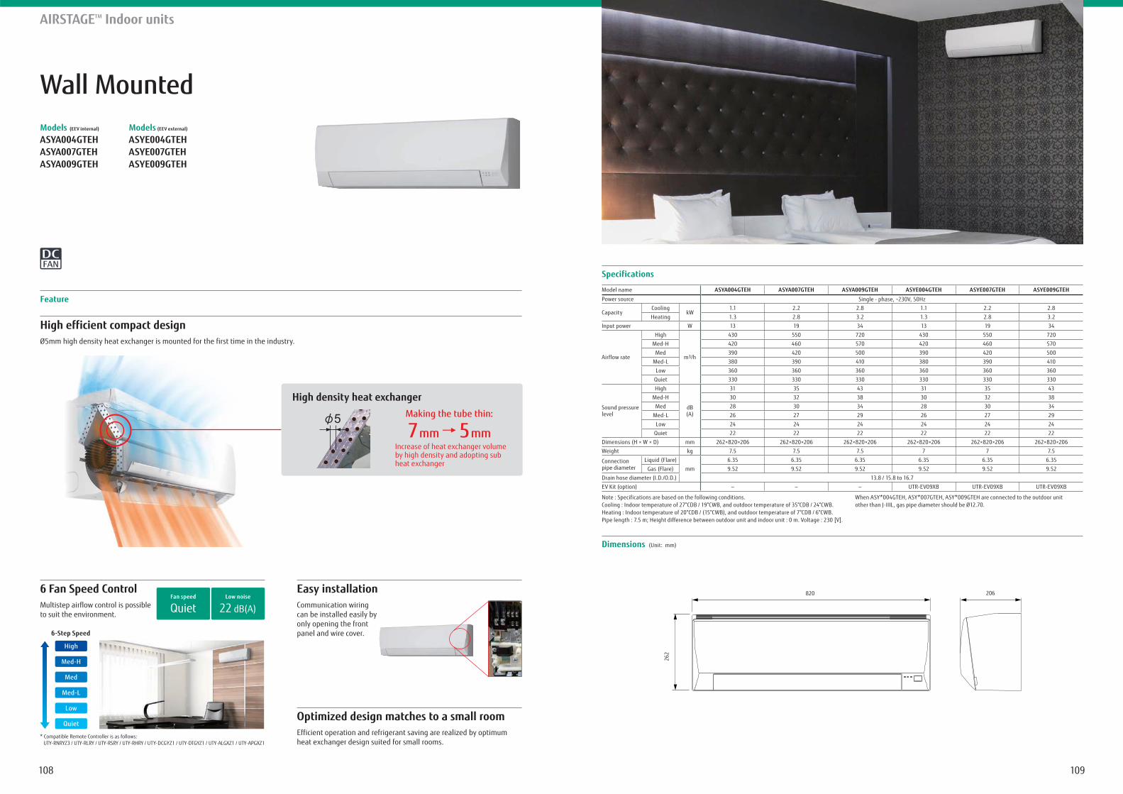
109108
Wall MountedModels (EEV internal)
ASYA004GTEH ASYA007GTEH ASYA009GTEH
Models (EEV external)
ASYE004GTEH ASYE007GTEH ASYE009GTEH
6 Fan Speed Control
High efficient compact designØ5mm high density heat exchanger is mounted for the first time in the industry.
Feature
AIRSTAGETM Indoor units
Easy installationCommunication wiring can be installed easily by only opening the front panel and wire cover.
Multistep airflow control is possibleto suit the environment.
Optimized design matches to a small roomEfficient operation and refrigerant saving are realized by optimum heat exchanger design suited for small rooms.
22 dB(A)Low noise
QuietFan speed
Specifications
Dimensions (Unit: mm)
820 206
262
Model name ASYA004GTEH ASYA007GTEH ASYA009GTEH ASYE004GTEH ASYE007GTEH ASYE009GTEH
Power source Single - phase, ~230V, 50Hz
CapacityCooling
kW1.1 2.2 2.8 1.1 2.2 2.8
Heating 1.3 2.8 3.2 1.3 2.8 3.2
Input power W 13 19 34 13 19 34
Airflow rate
High
m3/h
430 550 720 430 550 720
Med-H 420 460 570 420 460 570
Med 390 420 500 390 420 500
Med-L 380 390 410 380 390 410
Low 360 360 360 360 360 360
Quiet 330 330 330 330 330 330
Sound pressure level
High
dB(A)
31 35 43 31 35 43
Med-H 30 32 38 30 32 38
Med 28 30 34 28 30 34
Med-L 26 27 29 26 27 29
Low 24 24 24 24 24 24
Quiet 22 22 22 22 22 22
Dimensions (H × W × D) mm 262×820×206 262×820×206 262×820×206 262×820×206 262×820×206 262×820×206
Weight kg 7.5 7.5 7.5 7 7 7.5
Connection pipe diameter
Liquid (Flare)
mm
6.35 6.35 6.35 6.35 6.35 6.35
Gas (Flare) 9.52 9.52 9.52 9.52 9.52 9.52
Drain hose diameter (I.D./O.D.) 13.8 / 15.8 to 16.7
EV Kit (option) - - - UTR-EV09XB UTR-EV09XB UTR-EV09XB
Note : Specifications are based on the following conditions.Cooling : Indoor temperature of 27°CDB / 19°CWB, and outdoor temperature of 35°CDB / 24°CWB.Heating : Indoor temperature of 20°CDB / (15°CWB), and outdoor temperature of 7°CDB / 6°CWB.Pipe length : 7.5 m; Height difference between outdoor unit and indoor unit : 0 m. Voltage : 230 [V].
When ASY*004GTEH, ASY*007GTEH, ASY*009GTEH are connected to the outdoor unit other than J-IIIL, gas pipe diameter should be Ø12.70.
High density heat exchangerMaking the tube thin:
7 mm 5 mmIncrease of heat exchanger volumeby high density and adopting subheat exchanger
* Compatible Remote Controller is as follows: UTY-RNRYZ3 / UTY-RLRY / UTY-RSRY / UTY-RHRY / UTY-DCGYZ1 / UTY-DTGYZ1 / UTY-ALGXZ1 / UTY-APGXZ1
6-Step Speed
Quiet
Low
Med-L
Med
Med-H
High
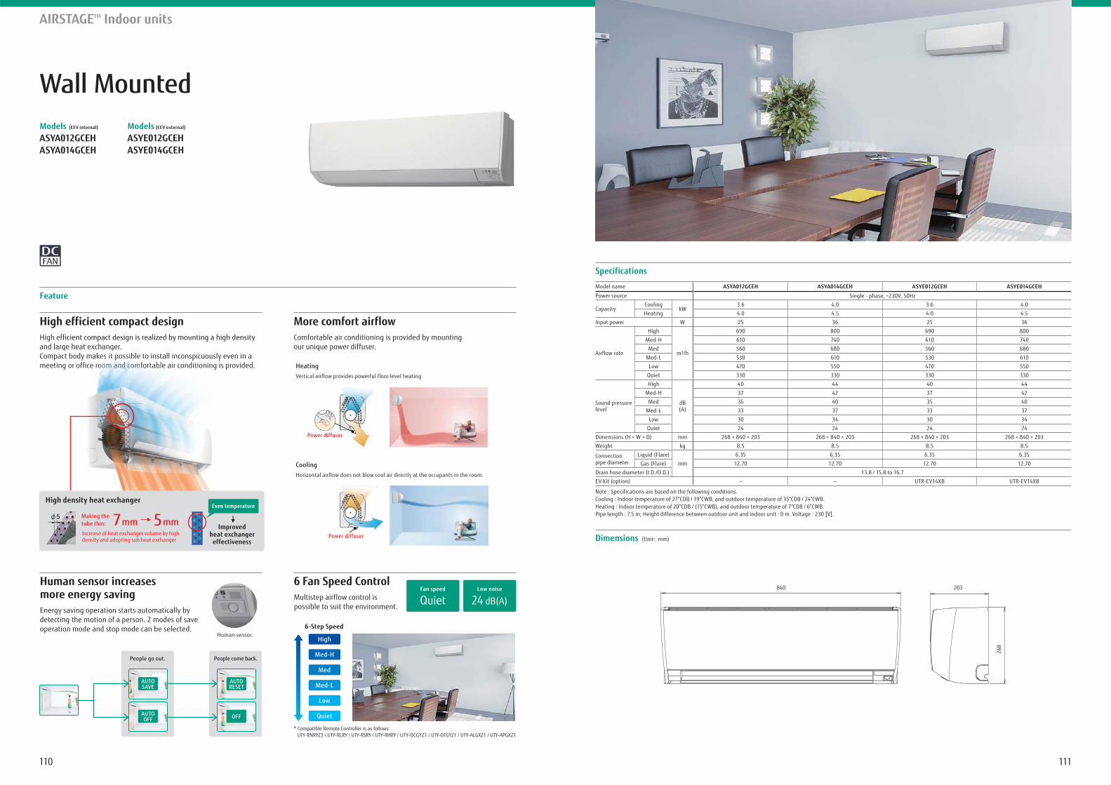
111110
AIRSTAGETM Indoor units
Feature
Wall MountedModels (EEV internal)
ASYA012GCEH ASYA014GCEH
Models (EEV external)
ASYE012GCEH ASYE014GCEH
Specifications
Dimensions (Unit: mm)
840 203
268
Model name ASYA012GCEH ASYA014GCEH ASYE012GCEH ASYE014GCEH
Power source Single - phase, ~230V, 50Hz
CapacityCooling
kW3.6 4.0 3.6 4.0
Heating 4.0 4.5 4.0 4.5
Input power W 25 36 25 36
Airflow rate
High
m3/h
690 800 690 800
Med-H 610 740 610 740
Med 560 680 560 680
Med-L 530 610 530 610
Low 470 550 470 550
Quiet 330 330 330 330
Sound pressure level
High
dB(A)
40 44 40 44
Med-H 37 42 37 42
Med 35 40 35 40
Med-L 33 37 33 37
Low 30 34 30 34
Quiet 24 24 24 24
Dimensions (H × W × D) mm 268 × 840 × 203 268 × 840 × 203 268 × 840 × 203 268 × 840 × 203
Weight kg 8.5 8.5 8.5 8.5
Connection pipe diameter
Liquid (Flare)
mm
6.35 6.35 6.35 6.35
Gas (Flare) 12.70 12.70 12.70 12.70
Drain hose diameter (I.D./O.D.) 13.8 / 15.8 to 16.7
EV Kit (option) - - UTR-EV14XB UTR-EV14XB
Note : Specifications are based on the following conditions.Cooling : Indoor temperature of 27°CDB / 19°CWB, and outdoor temperature of 35°CDB / 24°CWB.Heating : Indoor temperature of 20°CDB / (15°CWB), and outdoor temperature of 7°CDB / 6°CWB.Pipe length : 7.5 m; Height difference between outdoor unit and indoor unit : 0 m. Voltage : 230 [V].
High efficient compact designHigh efficient compact design is realized by mounting a high density and large heat exchanger. Compact body makes it possible to install inconspicuously even in a meeting or office room and comfortable air conditioning is provided.
Human sensor increases more energy savingEnergy saving operation starts automatically by detecting the motion of a person. 2 modes of save operation mode and stop mode can be selected.
Human sensor
People go out. People come back.
6 Fan Speed ControlMultistep airflow control is possible to suit the environment.
24 dB(A)Low noise
QuietFan speed
More comfort airflowComfortable air conditioning is provided by mountingour unique power diffuser.
HeatingVertical airflow provides powerful floor level heating
* Compatible Remote Controller is as follows: UTY-RNRYZ3 / UTY-RLRY / UTY-RSRY / UTY-RHRY / UTY-DCGYZ1 / UTY-DTGYZ1 / UTY-ALGXZ1 / UTY-APGXZ1
6-Step Speed
Quiet
Low
Med-L
Med
Med-H
High
AUTOOFF
AUTOSAVE
AUTORESET
OFF
CoolingHorizontal airflow does not blow cool air directly at the occupants in the room.
Power diffuser
Power diffuser
ficient compact design is realized by mounting a high density ge heat exchanangerer.ct body makekeeses ititit popopp ssissibleble toto install inconspicuously even in a g or office rooooooooooooooooomm am aam aammm am ndndndndndnddd cccomcommcccomcccc forfortabblele aira conditioning is provided.
High density heat exchanger
Improved heat exchanger
effectiveness
Making the tube thin: 7 mm 5 mmIncrease of heat exchanger volume by high density and adopting sub heat exchanger
Even temperature
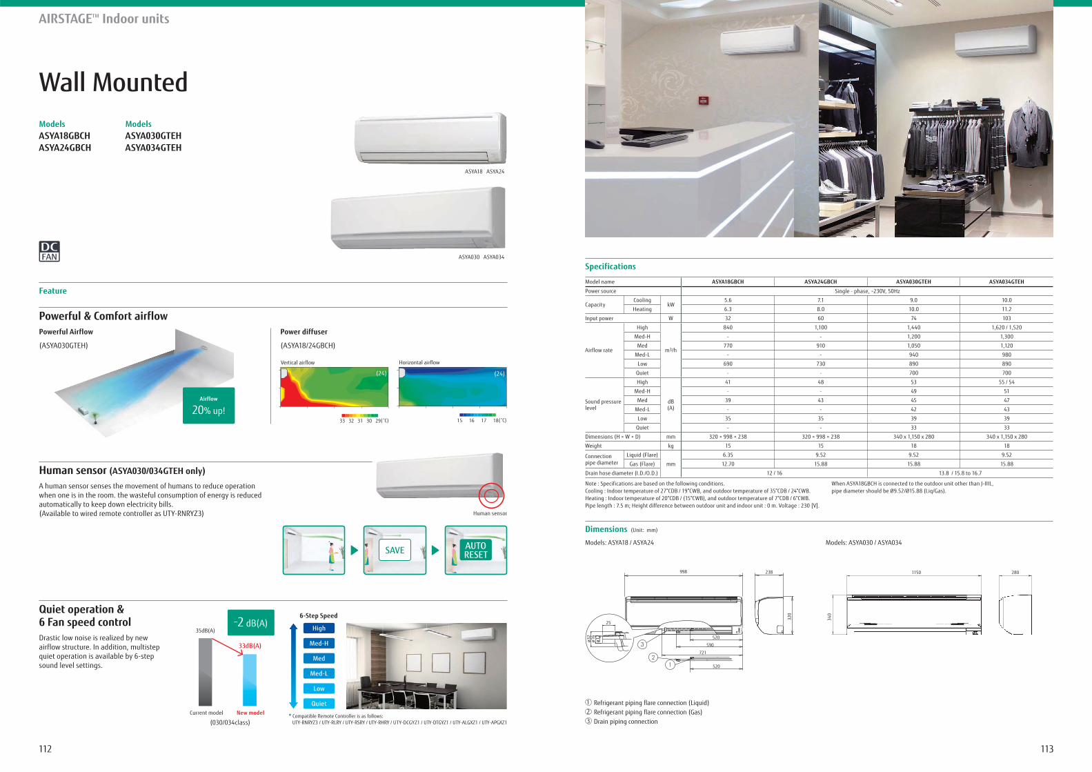
113112
Wall MountedModelsASYA18GBCH ASYA24GBCH
ModelsASYA030GTEH ASYA034GTEH
Powerful & Comfort airflow
Human sensor (ASYA030/034GTEH only)
Powerful Airflow
(ASYA030GTEH)
A human sensor senses the movement of humans to reduce operationwhen one is in the room. the wasteful consumption of energy is reducedautomatically to keep down electricity bills.(Available to wired remote controller as UTY-RNRYZ3)
Power diffuser
(ASYA18/24GBCH)
Feature
AIRSTAGETM Indoor units
Quiet operation & 6 Fan speed controlDrastic low noise is realized by newairflow structure. In addition, multistepquiet operation is available by 6-stepsound level settings.
Specifications
Dimensions (Unit: mm)
Model name ASYA18GBCH ASYA24GBCH ASYA030GTEH ASYA034GTEH
Power source Single - phase, ~230V, 50Hz
CapacityCooling
kW5.6 7.1 9.0 10.0
Heating 6.3 8.0 10.0 11.2
Input power W 32 60 74 103
Airflow rate
High
m3/h
840 1,100 1,440 1,620 / 1,520
Med-H - - 1,200 1,300
Med 770 910 1,050 1,120
Med-L - - 940 980
Low 690 730 890 890
Quiet - - 700 700
Sound pressure level
High
dB(A)
41 48 53 55 / 54
Med-H - - 49 51
Med 39 43 45 47
Med-L - - 42 43
Low 35 35 39 39
Quiet - - 33 33
Dimensions (H × W × D) mm 320 × 998 × 238 320 × 998 × 238 340 x 1,150 x 280 340 x 1,150 x 280
Weight kg 15 15 18 18
Connection pipe diameter
Liquid (Flare)
mm
6.35 9.52 9.52 9.52
Gas (Flare) 12.70 15.88 15.88 15.88
Drain hose diameter (I.D./O.D.) 12 / 16 13.8 / 15.8 to 16.7
Note : Specifications are based on the following conditions.Cooling : Indoor temperature of 27°CDB / 19°CWB, and outdoor temperature of 35°CDB / 24°CWB.Heating : Indoor temperature of 20°CDB / (15°CWB), and outdoor temperature of 7°CDB / 6°CWB.Pipe length : 7.5 m; Height difference between outdoor unit and indoor unit : 0 m. Voltage : 230 [V].
When ASYA18GBCH is connected to the outdoor unit other than J-IIIL, pipe diameter should be Ø9.52/Ø15.88 (Liq/Gas).
20% up!Airflow
(24)
33 32 31 30 29( C)
Vertical airflow
(24)
Horizontal airflow
( C)15 16 17 18
ASYA18 ASYA24
ASYA030 ASYA034
Models: ASYA18 / ASYA24 Models: ASYA030 / ASYA034
Refrigerant piping flare connection (Liquid)Refrigerant piping flare connection (Gas)Drain piping connection
21
3
998 238
320
520
520
590
721
25
ø32
ø16
ø12
1150 280
340
Current model
(030/034class)
35dB(A)
33dB(A)
New model
SAVE AUTORESET
Human sensor
* Compatible Remote Controller is as follows: UTY-RNRYZ3 / UTY-RLRY / UTY-RSRY / UTY-RHRY / UTY-DCGYZ1 / UTY-DTGYZ1 / UTY-ALGXZ1 / UTY-APGXZ1
6-Step Speed
Quiet
Low
Med-L
Med
Med-H
High-2 dB(A)
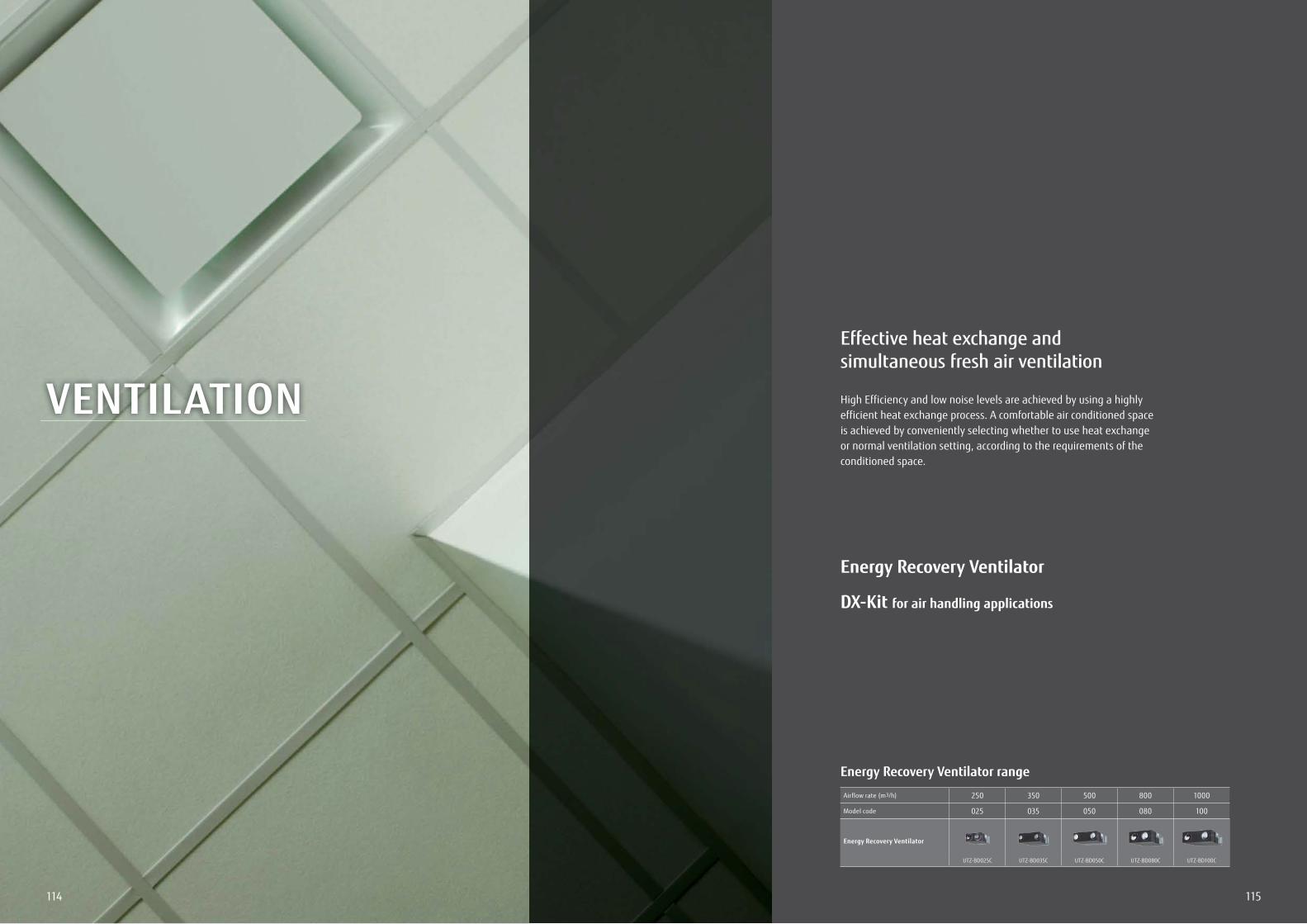
115114
Energy Recovery Ventilator range
Airflow rate (m3/h) 250 350 500 800 1000
Model code 025 035 050 080 100
Energy Recovery Ventilator
UTZ-BD025C UTZ-BD035C UTZ-BD050C UTZ-BD080C UTZ-BD100C
VENTILATION
Effective heat exchange and simultaneous fresh air ventilation
High Efficiency and low noise levels are achieved by using a highly efficient heat exchange process. A comfortable air conditioned space is achieved by conveniently selecting whether to use heat exchange or normal ventilation setting, according to the requirements of the conditioned space.
Energy Recovery Ventilator
DX-Kit for air handling applications
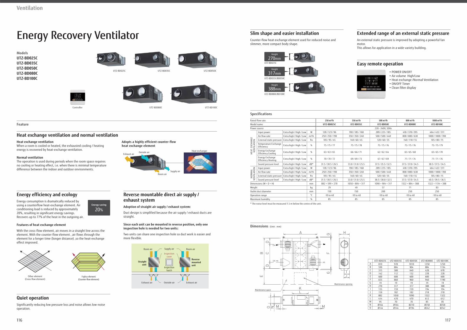
117116
Ventilation
Energy Recovery VentilatorModelsUTZ-BD025CUTZ-BD035CUTZ-BD050CUTZ-BD080CUTZ-BD100C
UTZ-BD100CUTZ-BD080CController
Energy efficiency and ecology
Quiet operation
Heat exchange ventilation and normal ventilationHeat exchange ventilationWhen a room is cooled or heated, the exhausted cooling / heating energy is recovered by heat-exchange ventilation.
Normal ventilationThe operation is used during periods when the room space requires no cooling or heating effect, i.e. when there is minimal temperature difference between the indoor and outdoor environments.
Feature
Energy consumption is dramatically reduced by using a counterflow heat-exchange element. Air conditioning load is reduced by approximately 20%, resulting in significant energy savings. Recovers up to 77% of the heat in the outgoing air.
Features of heat exchange element
With the cross-flow element, air moves in a straight line across the element. With the counter-flow element , air flows through the element for a longer time (longer distance) ,so the heat-exchange effect improved.
Reverse mountable direct air supply / exhaust system Adoption of straight air supply / exhaust system:
Duct design is simplified because the air supply / exhaust ducts are straight.
Since each unit can be mounted in reverse position, only one inspection hole is needed for two units:
Two units can share one inspection hole so duct work is easier and more flexible.
Significantly reducing low pressure loss and noise allows low-noise operation.
Specifications
Dimensions (Unit: mm)
Slim shape and easier installation Extended range of an external static pressure
Easy remote operation
Counter-flow heat exchange element used for reduced noise and slimmer, more compact body shape.
An external static pressure is improved by adopting a powerful fan motor.This allows for application in a wide variety building.
* The noise level must be measured 1.5 m below the centre of the unit.
Adopts a highly efficient counter-flow heat exchange element
Heat exchanger Outside airExhaust air
Supply airRoom air
20%Energy saving
Other element(Cross-flow element)
Fujitsu element(Counter-flow element)
Straightunit
Reversemounted unit
Outside airExhaust air Exhaust air
Supply airRoom air Room air
Inspectionhatch
Inspectioncover
UTZ-BD025C
Height
270mm
UTZ-BD035C/BD050C
Height
317mm
UTZ-BD080C/BD100C
Height
388mm
81059931514260065519
27013515988241495
Ø164Ø144
97880458011260086019
317159182
105047070
Ø164Ø144
101890464013260096019
317159182
109047070
Ø210Ø194
125088442822860094019
388194218
132261285
Ø258Ø242
12501134678228600
119019
388194218
132261285
Ø258Ø242
Maintenance space
Maintenance opening
UTZ-BD025CABCDEFGHIJKLMNO
UTZ-BD035C UTZ-BD050C UTZ-BD080C UTZ-BD100C
UTZ-BD050CUTZ-BD035CUTZ-BD025C
Rated flow rate 250 m3/h 350 m3/h 500 m3/h 800 m3/h 1000 m3/h
Model name UTZ-BD025C UTZ-BD035C UTZ-BD050C UTZ-BD080C UTZ-BD100C
W 128 / 123 / 96 190 / 185 / 168 289 / 225 / 185 418 / 378 / 295 464 / 432 / 311
Air flow rate m3/h 250 / 250 / 190 350 / 350 / 240 500 / 500 / 440 800 / 800 / 630 1000 / 1000 / 700
External static pressure 105 / 95 / 45 140 / 60 / 45 120 / 60 / 35 140 / 110 / 55 105 / 80 / 75
Temperature ExchangeEfficiency % 75 / 75 / 77 75 / 75 / 78 75 / 75 / 76 75 / 75 / 76 75 / 75 / 79
Energy ExchangeEfficiency Cooling % 63 / 63 / 65 66 / 66 / 71 62 / 62 / 64 65 / 65 / 68 65 / 65 / 70
Energy ExchangeEfficiency Heating % 70 / 70 / 72 69 / 69 / 73 67 / 67 / 69 71 / 71 / 74 71 / 71 / 76
Sound pressure level dB* 31.5 / 30.5 / 26.5 33.0 / 31.0 / 25.5 37.5 / 35.5 / 32.5 37.5 / 37.0 / 34.5 38.5 / 37.5 / 34.5
W 128 / 123 / 96 190 / 185 / 168 289 / 225 / 185 418 / 378 / 295 464 / 432 / 311
Air flow rate m3/h 250 / 250 / 190 350 / 350 / 240 500 / 500 / 440 800 / 800 / 630 1000 / 1000 / 700
External static pressure 105 / 95 / 45 140 / 60 / 45 120 / 60 / 35 140 / 110 / 55 105 / 80 / 75
Sound pressure level dB* 31.5 / 30.5 / 26.5 33.0 / 31.0 / 25.5 38.5 / 38.0 / 32.5 37.5 / 37.0 / 34.5 40.5 / 39.5 / 36.5
Dimensions (W × D × H) mm 882 × 599 × 270 1050 × 804 × 317 1090 × 904 × 317 1322 × 884 × 388 1322 × 1134 × 388
Weight kg 29 49 57 71 83
mm 150 150 200 250 250
°C -10 to 40 -10 to 40 -10 to 40 -10 to 40 -10 to 40
Maximum humidity % 85 85 85 85 85
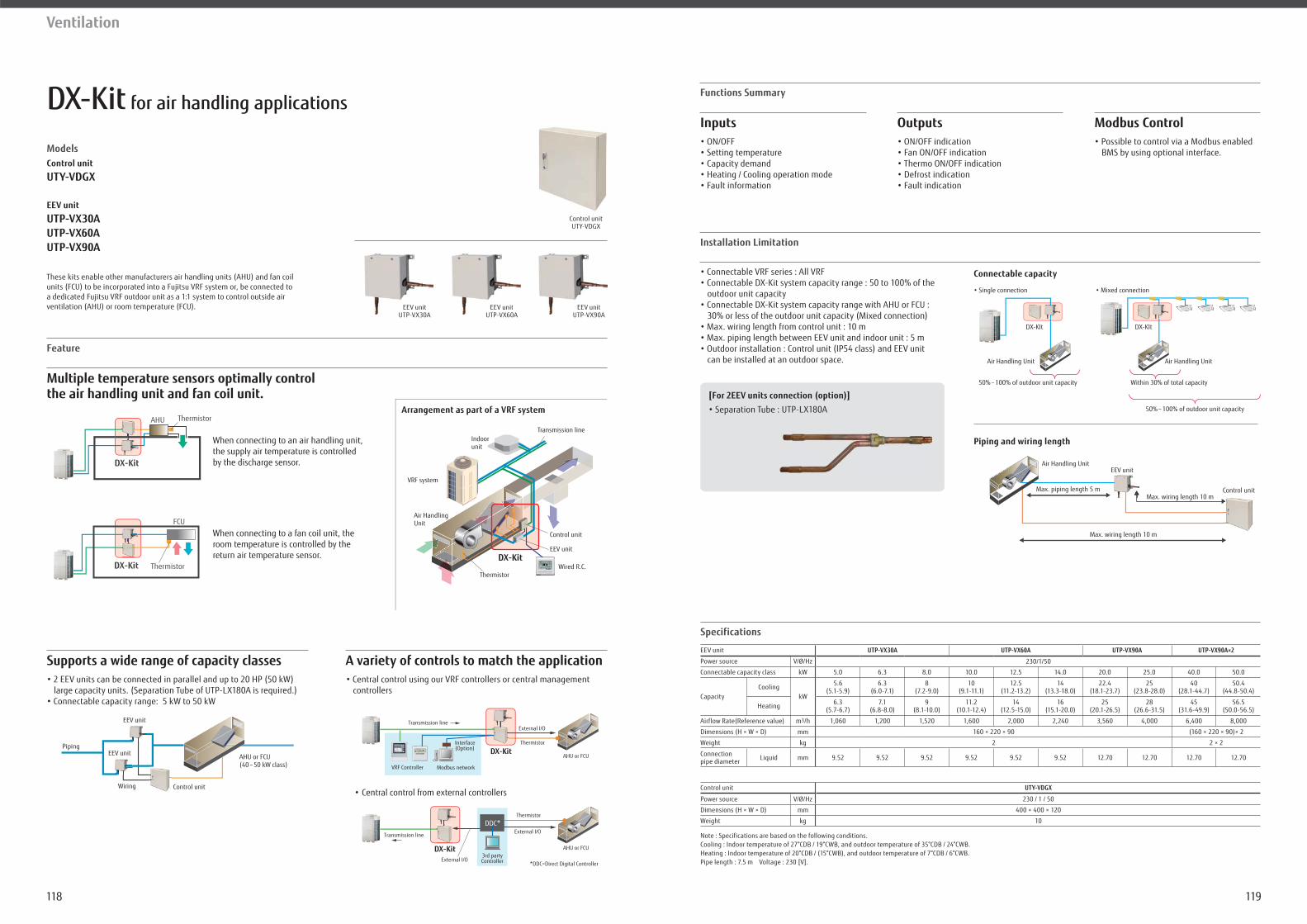
119118
Ventilation
DX-Kit for air handling applications
Models
Control unit
UTY-VDGX
EEV unit
UTP-VX30A UTP-VX60AUTP-VX90A
Supports a wide range of capacity classes
Multiple temperature sensors optimally control the air handling unit and fan coil unit.
Feature
A variety of controls to match the application
controllers
Control unit
Specifications
UTP-VX30A UTP-VX60A UTP-VX90A UTP-VX90A×2
230/1/50
Connectable capacity class kW 5.0 6.3 8.0 10.0 12.5 14.0 20.0 25.0 40.0 50.0
CapacityCooling
kW
5.6(5.1-5.9)
6.3(6.0-7.1)
8(7.2-9.0)
10(9.1-11.1)
12.5(11.2-13.2)
14(13.3-18.0)
22.4(18.1-23.7)
25(23.8-28.0)
40(28.1-44.7)
50.4(44.8-50.4)
Heating 6.3(5.7-6.7)
7.1(6.8-8.0)
9(8.1-10.0)
11.2(10.1-12.4)
14(12.5-15.0)
16(15.1-20.0)
25(20.1-26.5)
28(26.6-31.5)
45(31.6-49.9)
56.5(50.0-56.5)
Airflow Rate(Reference value) m3/h 1,060 1,200 1,520 1,600 2,000 2,240 3,560 4,000 6,400 8,000
Dimensions (H × W × D) mm 160 × 220 × 90 (160 × 220 × 90)× 2
Weight kg 2 2 × 2
Connection pipe diameter mm 9.52 9.52 9.52 9.52 9.52 9.52 12.70 12.70 12.70 12.70
Control unit UTY-VDGX
230 / 1 / 50
Dimensions (H × W × D) mm 400 × 400 × 120
Weight kg 10
These kits enable other manufacturers air handling units (AHU) and fan coil
Wired R.C.
VRF system
Indoorunit
EEV unit
Control unit
DX-Kit
Transmission line
Thermistor
Air HandlingUnit
Arrangement as part of a VRF systemAHU Thermistor
DX-Kit
ThermistorDX-Kit
FCU
When connecting to an air handling unit, the supply air temperature is controlled by the discharge sensor.
When connecting to a fan coil unit, the room temperature is controlled by the return air temperature sensor.
Central control from external controllers
Thermistor
External I/OTransmission line
VRF Controller Modbus network
Interface(Option)
AHU or FCUDX-Kit
External I/O
External I/O3rd partyController
Transmission line
AHU or FCU
ThermistorDDC*
*DDC=Direct Digital Controller
DX-Kit
AHU or FCU(40 – 50 kW class)
Control unit
EEV unit
EEV unit
Piping
Wiring
Functions Summary
Installation Limitation
Inputs
outdoor unit capacity
30% or less of the outdoor unit capacity (Mixed connection)
can be installed at an outdoor space.
Modbus Control
BMS by using optional interface.
Outputs
Air Handling Unit
Connectable capacity
50%–
50%–
Air Handling Unit
DX-KIt DX-KIt
Air Handling Unit
Piping and wiring length
[For 2EEV units connection (option)]
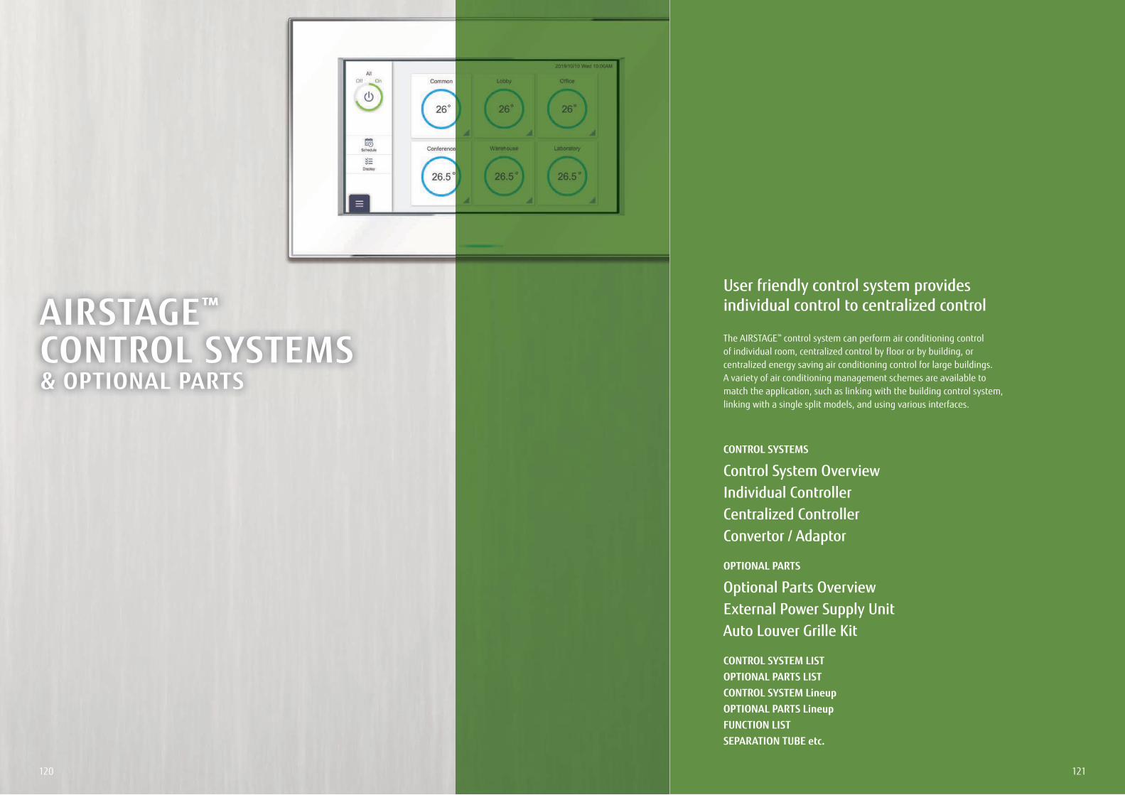
121120
AIRSTAGE™ CONTROL SYSTEMS& OPTIONAL PARTS
User friendly control system provides individual control to centralized control
The AIRSTAGE™ control system can perform air conditioning control of individual room, centralized control by floor or by building, or centralized energy saving air conditioning control for large buildings.A variety of air conditioning management schemes are available to match the application, such as linking with the building control system, linking with a single split models, and using various interfaces.
CONTROL SYSTEMS
Control System OverviewIndividual ControllerCentralized ControllerConvertor / Adaptor
OPTIONAL PARTS
Optional Parts OverviewExternal Power Supply UnitAuto Louver Grille Kit
CONTROL SYSTEM LISTOPTIONAL PARTS LISTCONTROL SYSTEM LineupOPTIONAL PARTS LineupFUNCTION LISTSEPARATION TUBE etc.
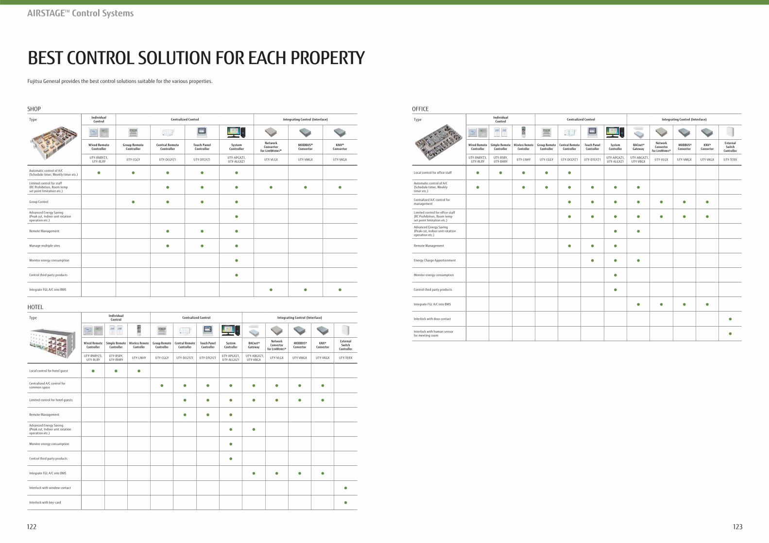
123122
BEST CONTROL SOLUTION FOR EACH PROPERTY
AIRSTAGETM Control Systems
Fujitsu General provides the best control solutions suitable for the various properties.
SHOP
Type IndividualControl Centralized Control Integrating Control (Interface)
Wired RemoteController
Group RemoteController
Central RemoteController
Touch PanelController
SystemController
NetworkConvertor
for LONWORKS®
MODBUS®Convertor
KNX®Convertor
UTY-RNRYZ3,UTY-RLRY UTY-CGGY UTY-DCGYZ1 UTY-DTGYZ1 UTY-APGXZ1,
UTY-ALGXZ1 UTY-VLGX UTY-VMGX UTY-VKGX
Automatic control of A/C(Schedule timer, Weekly timer etc.)
Limited control for staff(RC Prohibition, Room tempset point limitation etc.)
Group Control
Advanced Energy Saving(Peak cut, Indoor unit rotationoperation etc.)
Remote Management
Manage multiple sites
Monitor energy consumption
Control third party products
Integrate FGL A/C into BMS
HOTEL
Type IndividualControl Centralized Control Integrating Control (Interface)
Wired RemoteController
Simple RemoteController
Wireless RemoteController
Group RemoteController
Central RemoteController
Touch PanelController
SystemController
BACnet®Gateway
NetworkConvertor
for LONWORKS®
MODBUS®Convertor
KNX®Convertor
ExternalSwitch
Controller
UTY-RNRYZ3,UTY-RLRY
UTY-RSRY,UTY-RHRY UTY-LNHY UTY-CGGY UTY-DCGYZ1 UTY-DTGYZ1 UTY-APGXZ1,
UTY-ALGXZ1 UTY-ABGXZ1,
UTY-VBGX UTY-VLGX UTY-VMGX UTY-VKGX UTY-TERX
Local control for hotel guest
Centralized A/C control forcommon space
Limited control for hotel guests
Remote Management
Advanced Energy Saving(Peak cut, Indoor unit rotationoperation etc.)
Monitor energy consumption
Control third party products
Integrate FGL A/C into BMS
Interlock with window contact
Interlock with key-card
OFFICE
Type IndividualControl Centralized Control Integrating Control (Interface)
Wired RemoteController
Simple RemoteController
Wireless RemoteController
Group RemoteController
Central RemoteController
Touch PanelController
SystemController
BACnet®Gateway
NetworkConvertor
for LONWORKS®
MODBUS®Convertor
KNX®Convertor
ExternalSwitch
Controller
UTY-RNRYZ3,UTY-RLRY
UTY-RSRY,UTY-RHRY UTY-LNHY UTY-CGGY UTY-DCGYZ1 UTY-DTGYZ1 UTY-APGXZ1,
UTY-ALGXZ1 UTY-ABGXZ1,
UTY-VBGX UTY-VLGX UTY-VMGX UTY-VKGX UTY-TERX
Local control for office staff
Automatic control of A/C(Schedule timer, Weeklytimer etc.)
Centralized A/C control formanagement
Limited control for office staff(RC Prohibition, Room tempset point limitation etc.)
Advanced Energy Saving(Peak cut, Indoor unit rotationoperation etc.)
Remote Management
Energy Charge Apportionment
Monitor energy consumption
Control third party products
Integrate FGL A/C into BMS
Interlock with door contact
Interlock with human sensorfor meeting room
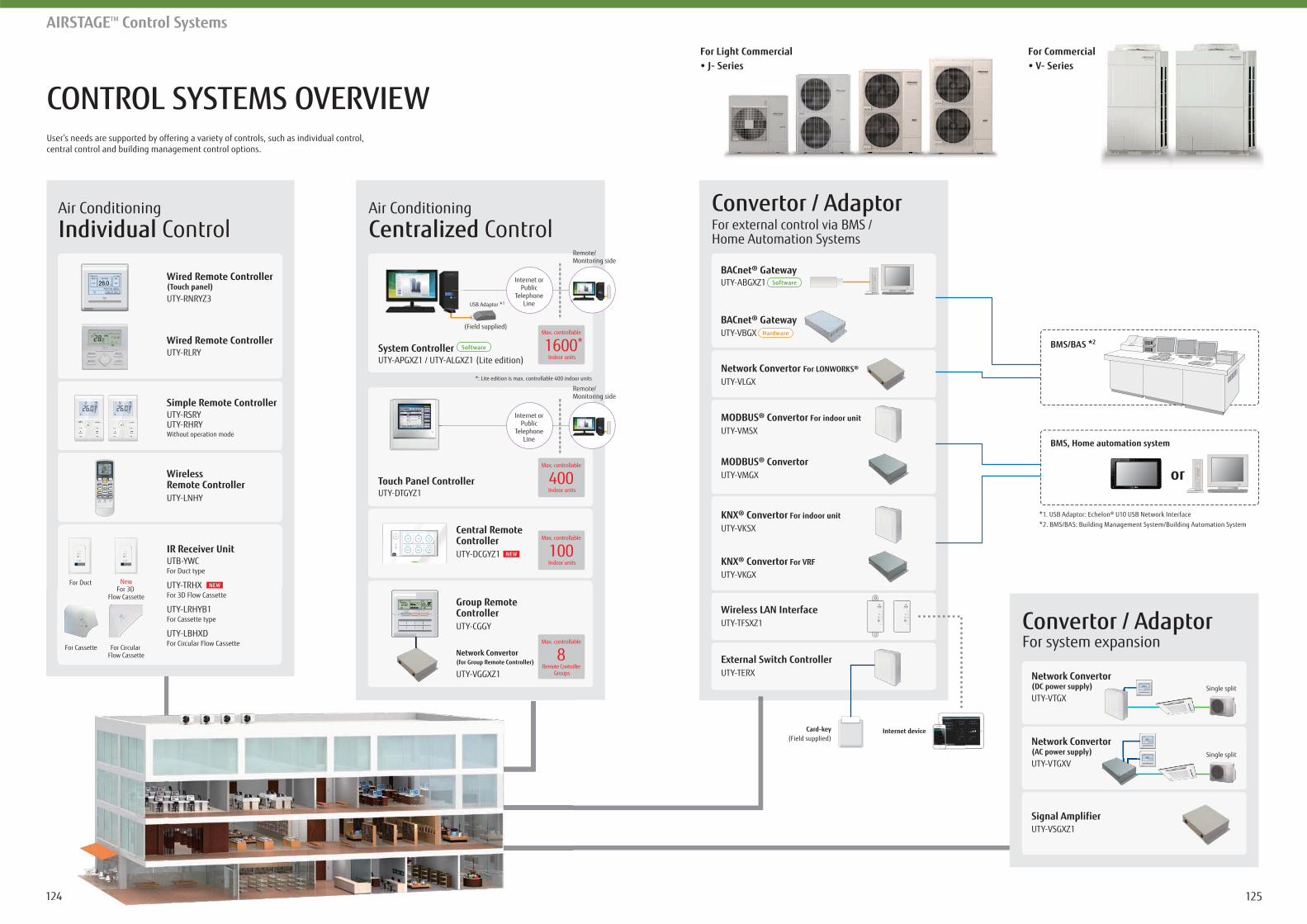
125124
CONTROL SYSTEMS OVERVIEW
AIRSTAGETM Control Systems
User’s needs are supported by offering a variety of controls, such as individual control,central control and building management control options.
BMS/BAS *2
BMS, Home automation system
*1. USB Adaptor: Echelon® U10 USB Network Interface*2. BMS/BAS: Building Management System/Building Automation System
or
124
Air ConditioningIndividual Control
For system expansionConvertor / Adaptor
Air ConditioningCentralized Control
Central RemoteControllerUTY-DCGYZ1
Group RemoteControllerUTY-CGGY
Network Convertor(for Group Remote Controller)
UTY-VGGXZ1
System ControllerUTY-APGXZ1 / UTY-ALGXZ1 (Lite edition)
USB Adaptor *1
*: Lite edition is max. controllable 400 indoor units
(Field supplied)
Remote/Monitoring side
Internet orPublic
TelephoneLine
Remote/Monitoring side
Internet orPublic
TelephoneLine
Software
Max. controllable
Indoor units1600*
Touch Panel ControllerUTY-DTGYZ1
Max. controllable
Indoor units400
Max. controllable
Indoor units100
Max. controllable
Remote Controller Groups
8Network Convertor(DC power supply)UTY-VTGX
Network Convertor(AC power supply)UTY-VTGXV
Signal AmplifierUTY-VSGXZ1
For external control via BMS /Home Automation Systems
Convertor / Adaptor
Single split
Single split
BACnet® Gateway
BACnet® Gateway
UTY-ABGXZ1 Software
UTY-VBGX Hardware
MODBUS® Convertor For indoor unit
UTY-VMSX
MODBUS® ConvertorUTY-VMGX
Wireless LAN InterfaceUTY-TFSXZ1
KNX® Convertor For indoor unit
UTY-VKSX
KNX® Convertor For VRF
UTY-VKGX
Network Convertor For LONWORKS®
UTY-VLGX
External Switch ControllerUTY-TERX
Internet deviceeviceCard-key(Field supplied)
NEW
Wired Remote Controller(Touch panel)UTY-RNRYZ3
Wired Remote ControllerUTY-RLRY
WirelessRemote ControllerUTY-LNHY
Simple Remote ControllerUTY-RSRYUTY-RHRYWithout operation mode
For Duct NewFor 3D
Flow Cassette
For Circular Flow Cassette
For Cassette
IR Receiver UnitUTB-YWC For Duct type
UTY-TRHX For 3D Flow Cassette
UTY-LRHYB1 For Cassette type
UTY-LBHXD For Circular Flow Cassette
NEW
For Light Commercial For Commercial
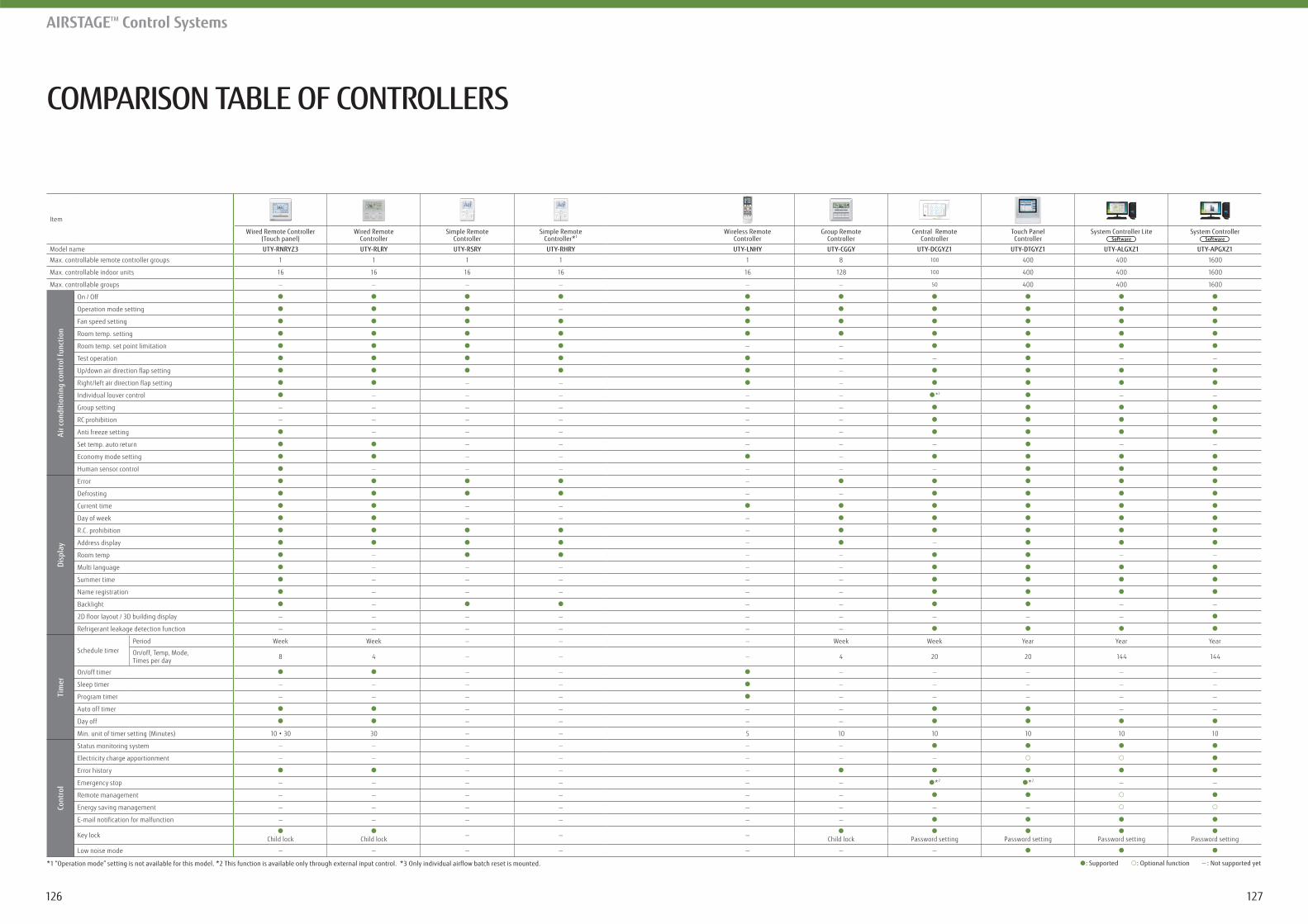
127126
COMPARISON TABLE OF CONTROLLERS
AIRSTAGETM Control Systems
Item
Wired Remote Controller(Touch panel)
Wired RemoteController
Simple RemoteController
Simple RemoteController*1
Wireless RemoteController
Group RemoteController
Central RemoteController
Touch PanelController
System Controller LiteSoftware
System ControllerSoftware
Model name UTY-RNRYZ3 UTY-RLRY UTY-RSRY UTY-RHRY UTY-LNHY UTY-CGGY UTY-DCGYZ1 UTY-DTGYZ1 UTY-ALGXZ1 UTY-APGXZ1
Max. controllable remote controller groups 1 1 1 1 1 8 100 400 400 1600
Max. controllable indoor units 16 16 16 16 16 128 100 400 400 1600
Max. controllable groups — — — — — — 50 400 400 1600
Air c
ondi
tion
ing
cont
rol f
unct
ion
On / Off
Operation mode setting —
Fan speed setting
Room temp. setting
Room temp. set point limitation — —
Test operation — — — —
—
— — —
Individual louver control — — — — — *3 — —
Group setting — — — — — —
RC prohibition — — — — — —
Anti freeze setting — — — — —
Set temp. auto return — — — — — — —
Economy mode setting — — —
Human sensor control — — — — — —
Disp
lay
Error —
Defrosting — —
Current time — —
Day of week — — —
R.C. prohibition —
Address display — —
Room temp — — — — —
Multi language — — — — —
Summer time — — — — —
Name registration — — — — —
Backlight — — — — —
— — — — — — — — —
Refrigerant leakage detection function — — — — — —
Tim
er
Schedule timerPeriod Week Week — — — Week Week Year Year Year
On/off, Temp, Mode, Times per day 8 4 — — — 4 20 20 144 144
On/off timer — — — — — — —
Sleep timer — — — — — — — — —
Program timer — — — — — — — — —
Auto off timer — — — — — —
Day off — — — —
Min. unit of timer setting (Minutes) 30 — — 5 10 10 10 10 10
Cont
rol
Status monitoring system — — — — — —
Electricity charge apportionment — — — — — — —
Error history — — —
Emergency stop — — — — — — *2 *2 — —
Remote management — — — — — —
Energy saving management — — — — — — — —
— — — — — —
Key lock Child lock Child lock — — — Child lock Password setting Password setting Password setting Password setting
Low noise mode — — — — — — —
: Supported : Optional function — : Not supported yet*1 “Operation mode” setting is not available for this model. *2 This function is available only through external input control. *3 Only individual airflow batch reset is mounted.
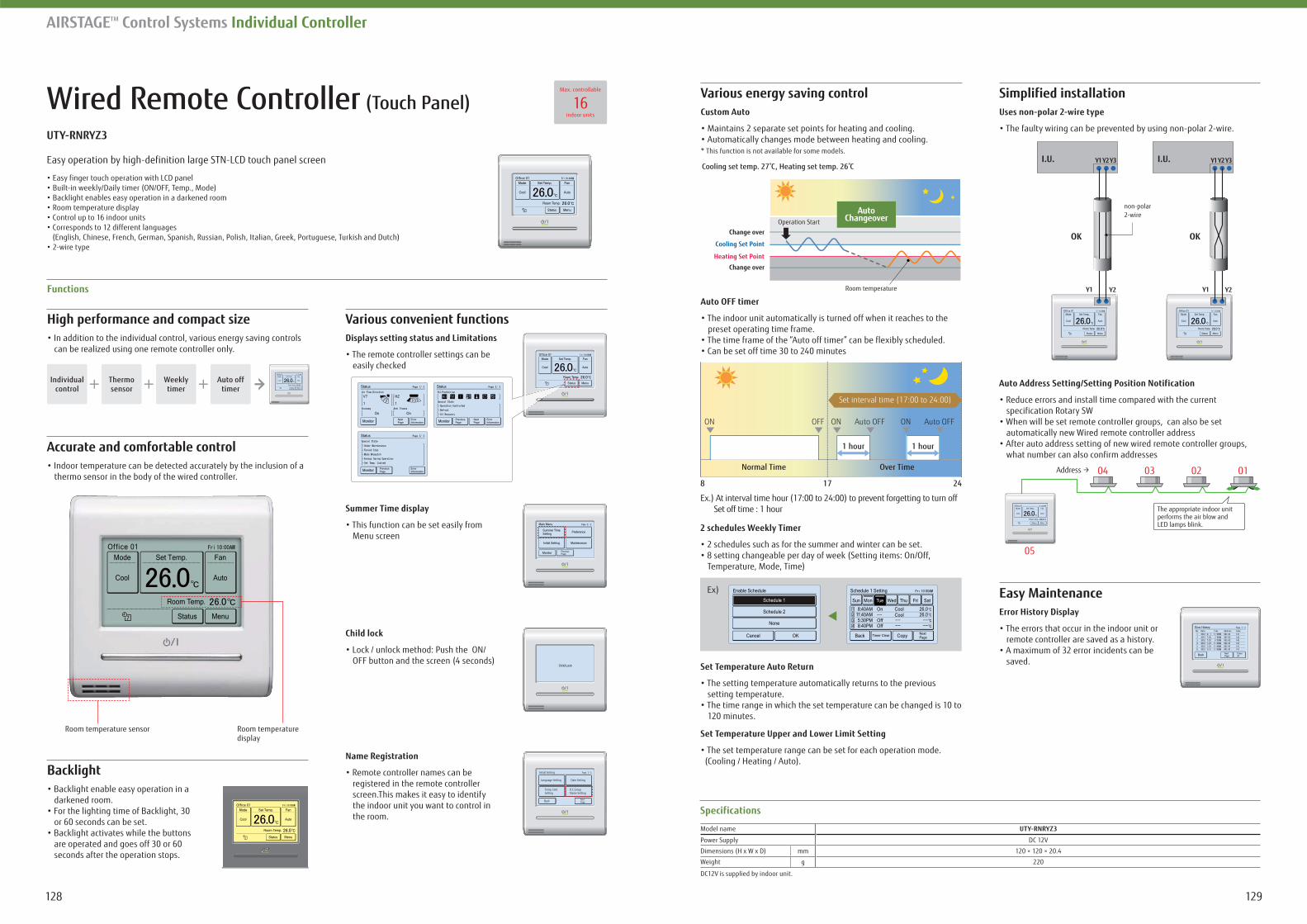
129128
AIRSTAGETM Control Systems Individual Controller
Wired Remote Controller (Touch Panel)
Easy operation by high-definition large STN-LCD touch panel screen
(English, Chinese, French, German, Spanish, Russian, Polish, Italian, Greek, Portuguese, Turkish and Dutch)
High performance and compact size
can be realized using one remote controller only.
Custom Auto
* This function is not available for some models.
Auto OFF timer
preset operating time frame.
2 schedules Weekly Timer
Temperature, Mode, Time)
Set Temperature Auto Return
setting temperature.
120 minutes.
Set Temperature Upper and Lower Limit Setting
(Cooling / Heating / Auto).
Simplified installation
Easy Maintenance
Displays setting status and Limitations
easily checked
Error History Display
remote controller are saved as a history.
saved.
Auto Address Setting/Setting Position Notification
specification Rotary SW
automatically new Wired remote controller address
what number can also confirm addresses
Backlight
darkened room.
or 60 seconds can be set.
are operated and goes off 30 or 60 seconds after the operation stops.
Accurate and comfortable control
thermo sensor in the body of the wired controller.
Functions
Back NextPage
Page 1/ 3Initial Setting
Language Setting Date Setting
R.C.GroupName Setting
Temp. Unit Setting
Summer Time display
Menu screen
Child lock
OFF button and the screen (4 seconds)
Name Registration
registered in the remote controller screen. This makes it easy to identify the indoor unit you want to control in the room.
Room temperature
Change over
Change over
Operation Start
Cooling set temp. 27 C, Heating set temp. 26 C
Heating Set Point
Cooling Set Point
AutoChangeover
Normal Time
ON
8 17 24
Over Time
ONOFF Auto OFF
Set interval time (17:00 to 24:00)
1 hour 1 hour
ON Auto OFF
Ex.) At interval time hour (17:00 to 24:00) to prevent forgetting to turn off Set off time : 1 hour
Ex)
Specifications
Model name
Power Supply DC 12V
Dimensions (H x W x D) mm 120 × 120 × 20.4
Weight g 220
DC12V is supplied by indoor unit.
OK OK
non-polar 2-wire
Y1 Y2 Y1 Y2
I.U. Y1Y2Y3 I.U. Y1Y2Y3
04
05
03 02 01
The appropriate indoor unitperforms the air blow and LED lamps blink.
16Max. controllable
indoor units
Individualcontrol
Thermosensor
Weeklytimer
Auto off timer
Room temperature sensor Room temperature display
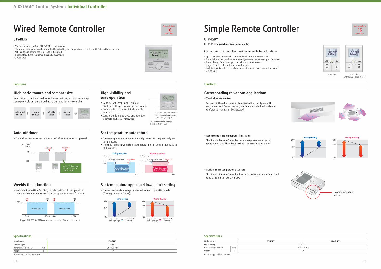
131130
AIRSTAGETM Control Systems Individual Controller
Wired Remote Controller Simple Remote Controller
High performance and compact sizeIn addition to the individual control, weekly timer, and various energy saving controls can be realized using only one remote controller.
Corresponding to various applications
Vertical air flow direction can be adjusted for Duct types with auto louver and Cassette types, which are installed in hotels and conference rooms, can be adjusted.
The Simple Remote Controller can manage to energy saving operation in small buildings without the central control unit.
The Simple Remote Controller detects actual room temperature and controls room climate accuracy.
High visibility and easy operation
displayed at large size on the top screen.
an icon.
is simple and straightforward.
Functions Functions
Specifications Specifications
Model name
Power Supply DC 12V
Dimensions (H x W x D) mm 120 × 120 × 17
Weight g 170
Model name
Power Supply DC 12V
Dimensions (H x W x D) mm 120 × 75 × 19.4
Weight g 120
DC12V is supplied by indoor unit. DC12V is supplied by indoor unit.
Set temperature auto return
temperature.
240 minutes.
Weekly timer function
mode and set temperature can be set by Weekly timer function.
Set temperature upper and lower limit setting
(Cooling / Heating / Auto)
Setting temp.Cooling operation
24°C22°C
Set temperature change Auto return
Time
Settable time range30 to 240 minutes
Setting temp.Heating operation
25°C
23°C
Set temperature change Auto return
Time
Settable time range30 to 240 minutes
Original temp.setting range
Lower limitsetting
During Cooling30°C
25°C
18°COriginal temp.setting range
Upper limitsetting
During Heating30°C
25°C
16°C
(Without Operation mode)
Compact remote controller provides access to basic functions
UTY-RHRYWithout Operation mode
UTY-RSRY
During Cooling30°C
25°C
18°C
During Heating30°C
25°C
16°C
Room temperaturesensor
16Max. controllable
indoor units16
Max. controllable
indoor units
Individualcontrol
Thermosensor
Weeklytimer
Auto off timer
Auto OFF Auto OFF
OFF
ON
Operationstatus
Auto-off timer can be set from 30 to 240 minutes
ON ONOFF
8:00
4 types (ON, OFF, ON, OFF) can be set on every day of the week in a week.
24°COFF
12:00 13:00 17:00
Working hour Working hour
Sophisticated control buttonsSimple operation with easy 4-way navigation pad
Set contents can be displayed clearer with large LCD.
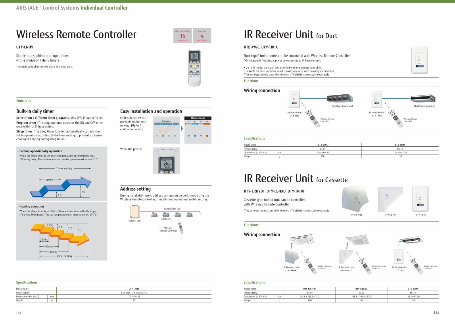
133132
AIRSTAGETM Control Systems Individual Controller
Wireless Remote Controller
On / Off / Program / Sleep
The program timer operates the ON and OFF timer once within a 24 hour period.
The sleep timer function automatically corrects the set temperature according to the time setting to prevent excessive cooling or heating during sleep hours.
Easy installation and operationCode selector switch prevents indoor unit mix-up. (Up to 4 codes can be set.)
Wide and precise
Functions
Specifications
Model name
Power Supply 1.5V (R03 / LR03 / AAA) × 2
Dimensions (H x W x D) mm 170 × 56 × 19
Weight g 85
Address settingDuring installation work, address setting can be performed using the Wireless Remote Controller, thus eliminating manual switch setting.
Simple and sophisticated operations with a choice of 4 daily timers
Cooling operation/dry operation
60min.
1 2
When the sleep timer is set, the set temperature automatically rises
Heating operationWhen the sleep timer is set, the set temperature automatically drops
1
60min.
90min.
2
imer setting
imer setting
Transmission line
Outdoor unit
WirelessRemote Controller
Indoor unit
IR Receiver Unit for Duct
Wiring connection
Functions
Specifications
Model name
Power Supply DC 5V DC 5V
Dimensions (H x W x D) mm 145 × 90 × 30 145 × 90 × 30
Weight g 150 150
Duct type* indoor units can be controlled with Wireless Remote Controller*Only Large Airflow Duct can not be connected to IR Receiver Unit.
*The wireless remote controller (Model: UTY-LNHY) is necessary separately
IR Receiver Unit for Cassette
Specifications
Model name
Power Supply DC 5V DC 5V DC 5V
Dimensions (H x W x D) mm 193.9 × 193.9 × 31.2 193.9 × 193.9 × 31.2 145 × 90 × 30
Weight g 140 140 150
Cassette type indoor unit can be controlledwith Wireless Remote Controller
4Selectable
daily timers16
Max. controllable
indoor units
Wiring connection
Functions
Wireless Remote Controller
Duct type indoor unit Duct type indoor unit
Wireless Remote Controller IR Receiver Unit
UTY-LRHYB1
IR Receiver UnitUTB-YWC
IR Receiver UnitUTY-LBHXD
IR Receiver UnitUTY-TRHX
IR Receiver UnitUTY-TRHX
UTY-LBHXDUTY-LRHYB1 UTY-TRHX
Wireless Remote Controller
Wireless Remote Controller
Wireless Remote Controller
*The wireless remote controller (Model: UTY-LNHY) is necessary separately
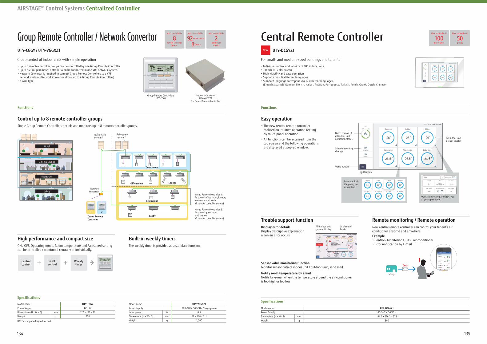
135134
AIRSTAGETM Control Systems Centralized Controller
Group Remote Controller / Network Convertor Central Remote Controller
Group control of indoor units with simple operation For small- and medium-sized buildings and tenants
network system. (Network Convertor allows up to 4 Group Remote Controllers)
(English, Spanish, German, French, Italian, Russian, Portuguese, Turkish, Polish, Greek, Dutch, Chinese)
Control up to 8 remote controller groups Easy operationSingle Group Remote Controller controls and monitors up to 8 remote controller groups.
realized an intuitive operation feeling by touch panel operation.
top screen and the following operations are displayed at pop-up window.
High performance and compact size
Trouble support function Remote monitoring / Remote operation
ON / OFF, Operating mode, Room temperature and Fan speed setting can be controlled / monitored centrally or individually.
Display error detailsDisplay descriptive explanation when an error occurs
Sensor value monitoring functionMonitor sensor data of indoor unit / outdoor unit, send mail
Notify room temperature by emailNotify by e-mail when the temperature around the air conditioner is too high or too low
New central remote controller can control your tenant’s air conditioner anytime and anywhere.Example
The weekly timer is provided as a standard function.
Functions Functions
SpecificationsSpecifications
Model name
Power Supply DC 12V
Dimensions (H x W x D) mm 120 × 120 × 18
Weight g 200
Model name
Power Supply 208-240V 50/60Hz, Single phase
Input power W 8.5
Dimensions (H x W x D) mm 67 × 288 × 211
Weight g 1,500
Model name
Power Supply 100-240 V 50/60 Hz
Dimensions (H x W x D) mm 134.6 × 216.2 × 37.9
Weight g 800DC12V is supplied by indoor unit.
Refrigerantsystem 2
Refrigerantsystem 1
Hotel
Restaurant
Lobby
21
LoungeOffice room
Guest room
Group RemoteController
NetworkConvertor
Restaurant
Lobby
Office & Lounge
Group Remote Controller 1: To control office room, lounge, restaurant and lobby (8 remote controller groups)
Group Remote Controller 2: To control guest room and launge (7 remote controller groups)
50Max. controllable
groups100
Max. controllable
indoor units92Max. controllable
2Max. controllable
refrigerant circuits
8Max. controllable
remote controllergroups
indoor units in
8 Groups
Network ConvertorUTY-VGGXZ1
For Group Remote Controller
Group Remote ControllersUTY-CGGY
Shop
Error!
Batch control of all indoor unit operation status All indoor unit
groups display
Indoor units in the group are expanded.
Operation setting are displayed at pop-up window.
Schedule setting change
Menu button
Top Display
All indoor unit groups display
Display error details
NEW
Centralcontrol
ON/OFFcontrol
Weeklytimer
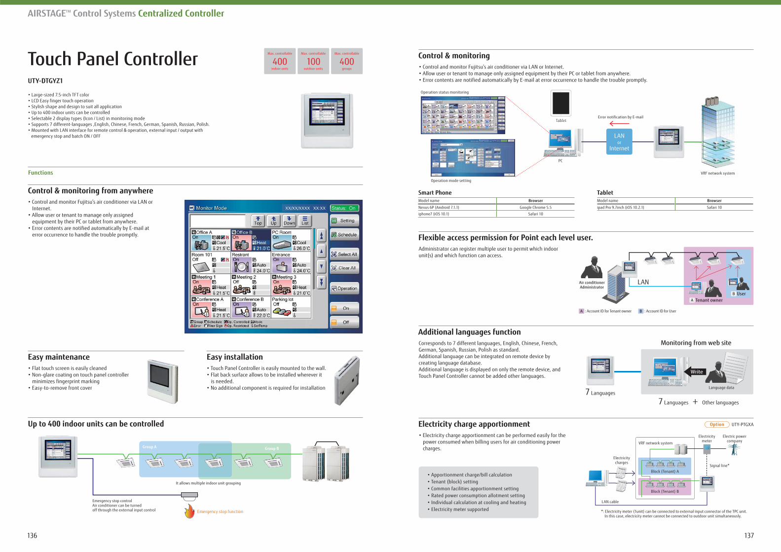
137136
AIRSTAGETM Control Systems Centralized Controller
Touch Panel Controller
Control & monitoring from anywhere
Internet.
error occurrence to handle the trouble promptly.
Easy maintenance Easy installation
minimizes fingerprint marking is needed.
Up to 400 indoor units can be controlled
Functions
Smart Phone TabletModel name Browser
Nexus 6P (Android 7.1.1) Google Chrome 5.5
iphone7 (iOS 10.1) Safari 10
Model name Browser
ipad Pro 9.7inch (iOS 10.2.1) Safari 10
emergency stop and batch ON / OFF
Control & monitoring
Flexible access permission for Point each level user.
Additional languages function
Electricity charge apportionment
Administrator can register multiple user to permit which indoor unit(s) and which function can access.
Corresponds to 7 different languages, English, Chinese, French, German, Spanish, Russian, Polish as standard.Additional language can be integrated on remote device by creating language database.Additional language is displayed on only the remote device, and Touch Panel Controller cannot be added other languages.
power consumed when billing users for air conditioning power charges.
400Max. controllable
indoor units100
Max. controllable
outdoor units400
Max. controllable
groups
UTY-PTGXA
Group A
It allows multiple indoor unit grouping
Emergency stop controlAir conditioner can be turned off through the external input control Emergency stop function
Group B
Operation status monitoring
Operation mode setting
PC
VRF network system
Error notification by E-mailTabletTablet
LANor
Internet
UserTenant owner
LANAir conditionerAdministrator
: Account ID for Tenant owner : Account ID for User
7 Languages
7 Languages + Other languages
Monitoring from web site
Write
Language data
LAN cable
Electricitycharges
Electricitymeter
Electric power company
Signal line*
*: Electricity meter (1unit) can be connected to external input connector of the TPC unit. In this case, electricity meter cannot be connected to outdoor unit simultaneously.
Block (Tenant) A
Block (Tenant) B
VRF network system
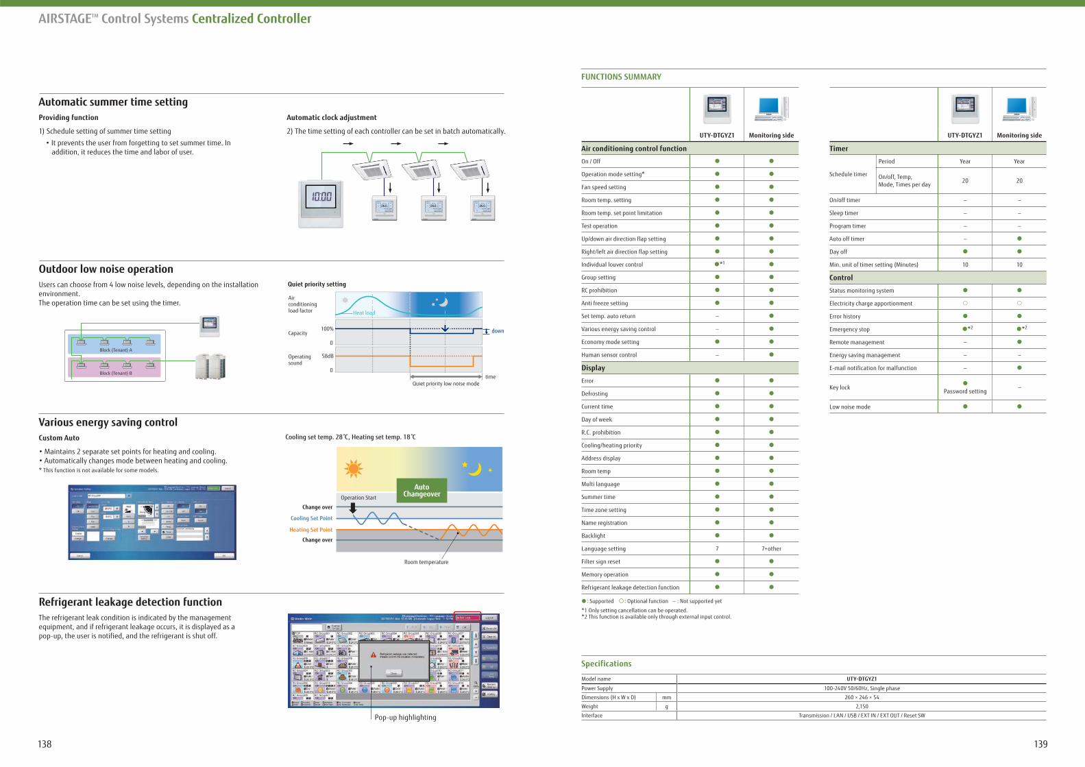
139138
AIRSTAGETM Control Systems Centralized Controller
Automatic summer time settingProviding function
1) Schedule setting of summer time setting
addition, it reduces the time and labor of user.
Automatic clock adjustment
2) The time setting of each controller can be set in batch automatically.
FUNCTIONS SUMMARY
Monitoring side
Air conditioning control function
On / Off
Operation mode setting*
Fan speed setting
Room temp. setting
Room temp. set point limitation
Test operation
Up/down air direction flap setting
Right/left air direction flap setting
Individual louver control *1
Group setting
RC prohibition
Anti freeze setting
Set temp. auto return -
Various energy saving control -
Economy mode setting
Human sensor control -
Display
Error
Defrosting
Current time
Day of week
R.C. prohibition
Cooling/heating priority
Address display
Room temp
Multi language
Summer time
Time zone setting
Name registration
Backlight
Language setting 7 7+other
Filter sign reset
Memory operation
Refrigerant leakage detection function
Monitoring side
Timer
Schedule timer
Period Year Year
On/off, Temp,Mode, Times per day
20 20
On/off timer - -
Sleep timer - -
Program timer - -
Auto off timer -
Day off
Min. unit of timer setting (Minutes) 10 10
Control
Status monitoring system
Electricity charge apportionment
Error history
Emergency stop *2 *2
Remote management -
Energy saving management - -
E-mail notification for malfunction -
Key lockPassword setting
-
Low noise mode
: Supported : Optional function - : Not supported yet
*1 Only setting cancellation can be operated.*2 This function is available only through external input control.
Specifications
Model name
Power Supply 100-240V 50/60Hz, Single phase
Dimensions (H x W x D) mm 260 × 246 × 54
Weight g 2,150
Interface Transmission / LAN / USB / EXT IN / EXT OUT / Reset SW
Refrigerant leakage detection functionThe refrigerant leak condition is indicated by the management
pop-up, the user is notified, and the refrigerant is shut off.
Custom Auto
* This function is not available for some models.
Room temperature
Change over
Change over
Operation Start
Cooling set temp. 28 C, Heating set temp. 18 C
Heating Set Point
Cooling Set Point
AutoChangeover
Outdoor low noise operationUsers can choose from 4 low noise levels, depending on the installation environment.The operation time can be set using the timer.
Air conditioning load factor
Capacity
Operating sound
time
100%
58dB
0
0
Heat load
down
Quiet priority low noise mode
Quiet priority setting
Pop-up highlighting
Block (Tenant) A
Block (Tenant) B
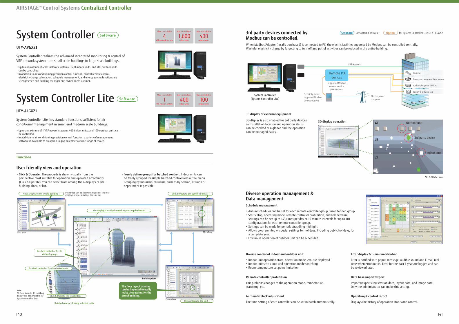
141140
AIRSTAGETM Control Systems Centralized Controller
User friendly view and operationClick & Operate : The property is shown visually from the perspective most suitable for operation and operated accordingly
building, floor, or list.
Freely define groups for batched control : Indoor units can be freely grouped for simple batched control from a tree menu. Grouping by hierarchal structure, such as by section, division or department is possible.
Functions
Modbus can be controlled.When Modbus Adaptor (locally purchased) is connected to PC, the electric facilities supported by Modbus can be controlled centrally.Wasteful electricity charge by forgetting to turn off and patrol activities can be reduced in the entire building.
3D display is also enabled for 3rd party devices, so Installation location and operation status can be checked at a glance and the operation can be managed easily.
System Controller
VRF network system from small scale buildings to large scale buildings.
can be controlled.
electricity charge calculation, schedule management, and energy saving functions are strengthened and building manager and owner needs are met.
System Controller Lite
System Controller Lite has standard functions sufficient for airconditioner management in small and medium scale buildings.
be controlled.
software is available as an option to give customers a wide range of choice.
Site view
Building view
Floor view
List view
Properties can be shown using one of the four displays of site, building, floor, or list.
The floor layout drawing can be imported to easily make the settings for the actual building.
Site view List view
Floor view
Building view
Batched control of freelydefined groups
Click & Operate the whole building ! Click & Operate any specified unit(s)!
Click & Operate the unit !
The display is easily changed by pressing the button.
Batched control of freely selected units
Click & Operate the whole floor !
Batched control of freely selected units
Note: 2D floor layout / 3D building display are not available for System Controller Lite.
Facilities
Energy recovery ventilator system
Air handling unit (DX kit)
Supply & Exhaust fan
Remote I/Odevices
Supported Modbuscommunication(Field supply)
System Controller(System Controller Lite)
Electricity meter supported Modbus communication
Electric powercompany
VRF Network
Diverse operation management & Data managementSchedule management
settings can be set up to 143 times per day at 10 minute intervals for up to 101 configurations for each remote controller group.
a complete year.
Diverse control of indoor and outdoor unit
Remote controller prohibition
This prohibits changes to the operation mode, temperature, start/stop, etc.
Automatic clock adjustment
The time setting of each controller can be set in batch automatically.
Error is notified with popup message, audible sound and E-mail real time when error occurs. Error for the past 1 year are logged and can be reviewed later.
Data base import/export
Imports/exports registration data, layout data, and image data.Only the administrator can make this setting.
Operating & control record
Displays the history of operation status and control.
for System Controller for System Controller Lite UTY-PLGXX24
Max. controllable
VRF network systems1,600
Max. controllable
indoor units400
Max. controllable
outdoor units
1Max. controllable
VRF network system400
Max. controllable
indoor units100
Max. controllable
outdoor units
*UTY-APGXZ1 only
4F
3F
2FIndoor unit
Outdoor unit
3rd party device
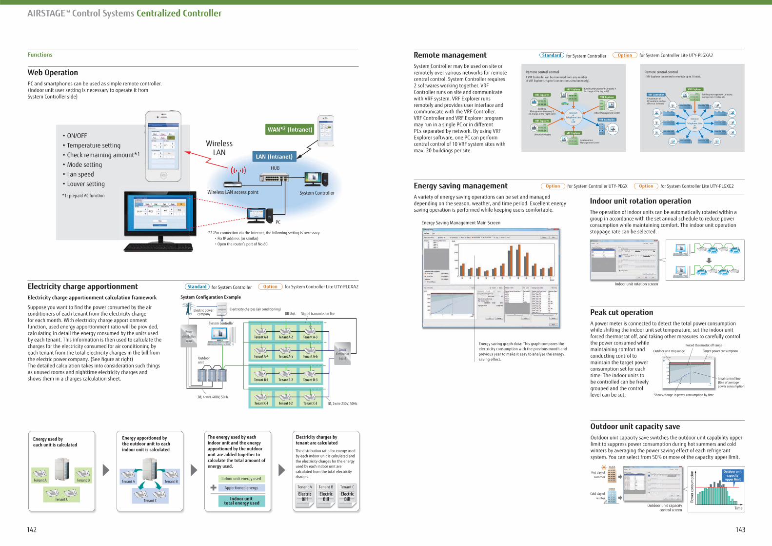
143142
Functions for System Controller for System Controller Lite UTY-PLGXA2Remote managementSystem Controller may be used on site or remotely over various networks for remote
2 softwares working together. VRF Controller runs on site and communicate with VRF system. VRF Explorer runs remotely and provides user interface and communicate with the VRF Controller. VRF Controller and VRF Explorer program may run in a single PC or in different PCs separated by network. By using VRF Explorer software, one PC can perform central control of 10 VRF system sites with max. 20 buildings per site.
Remote central control1 VRF Controller can be monitored from any number of VRF Explorers (Up to 5 connections simultaneously).
Building Management Company A (In charge of the day shift)
BuildingManagement Company B
(In charge of the night shift)
Security Company
Headquarters Management Center
Office Management Center
VRF Explorer
VRF Explorer
VRF ExplorerVRF Explorer
VRF Explorer VRF Controller
1 VRF Explorer can control or monitor up to 10 sites.
Internetor
Telephone Lineor
LAN
Building management company,management center, etc.
A maximum of 10 locations, such as offices or factories
VRF Explorer
VRF Controller
Internetor
Telephone Lineor
LAN
Remote central control
Energy saving management for System Controller UTY-PEGX for System Controller Lite UTY-PLGXE2
A variety of energy saving operations can be set and managed depending on the season, weather, and time period. Excellent energy saving operation is performed while keeping users comfortable.
Indoor unit rotation operationThe operation of indoor units can be automatically rotated within a group in accordance with the set annual schedule to reduce power consumption while maintaining comfort. The indoor unit operation stoppage rate can be selected.
Indoor unit rotation screenI d it t ti
Outdoor unit capacity saveOutdoor unit capacity save switches the outdoor unit capability upper limit to suppress power consumption during hot summers and cold winters by averaging the power saving effect of each refrigerant system. You can select from 50% or more of the capacity upper limit.
Peak cut operationA power meter is connected to detect the total power consumption while shifting the indoor unit set temperature, set the indoor unit forced thermostat off, and taking other measures to carefully control the power consumed while maintaining comfort and conducting control to maintain the target power consumption set for each time. The indoor units to be controlled can be freely grouped and the control level can be set.
Forced thermostat off range
Target power consumption
Shows change in power consumption by time
Outdoor unit stop range
Ideal control line (Use of average power consumption)
Outdoor unit capacitycontrol screen
O d i i
Pow
er c
onsu
mpt
ion
Time
Outdoor unit capacity
upper limit
Hot day ofsummer
Cold day ofwinter
AIRSTAGETM Control Systems Centralized Controller
Web Operation PC and smartphones can be used as simple remote controller.(Indoor unit user setting is necessary to operate it from System Controller side)
*2:For connection via the Internet, the following setting is necessary. ・ Fix IP address (or similar) ・ Open the router’s port of No.80.
LAN (Intranet)
WAN*2 (Intranet)
System Controller
PC
HUB
WirelessLAN
Wireless LAN access pointss LAN acces
ON/OFF Temperature setting Check remaining amount*1
Mode setting Fan speed Louver setting
*1: prepaid AC function
Electricity charge apportionment for System Controller for System Controller Lite UTY-PLGXA2
Electricity charge apportionment calculation framework
Suppose you want to find the power consumed by the air conditioners of each tenant from the electricity charge for each month. With electricity charge apportionment function, used energy apportionment ratio will be provided, calculating in detail the energy consumed by the units used by each tenant. This information is then used to calculate the charges for the electricity consumed for air conditioning by each tenant from the total electricity charges in the bill from the electric power company. (See figure at right)The detailed calculation takes into consideration such things as unused rooms and nighttime electricity charges and shows them in a charges calculation sheet.
System Configuration Example
3Ø, 4 wire 400V, 50Hz
Signal transmission lineRB Unit
1Ø, 2wire 230V, 50Hz
System Controller
Outdoorunit
Tenant A-1 Tenant A-2 Tenant A-3
Tenant A-4 Tenant A-5 Tenant A-6
Tenant B-1 Tenant B-2 Tenant B-3
Tenant C-1 Tenant C-2 Tenant C-3
PowPoweP rdistriburibubutiontion
boardd
PowPoweP rdistribuibubutiontion
boardd
Electricity charges (air conditioning)Electric power company
Energy apportioned by the outdoor unit to each indoor unit is calculated
Tenant A Tenant B
Tenant C
Indoor unit energy used
Apportioned energy
Indoor unit total energy used
The energy used by each indoor unit and the energy apportioned by the outdoor unit are added together to calculate the total amount of energy used.
Energy used by each unit is calculated
Tenant B
Tenant C
Tenant A
Tenant A
ElectricBill
Tenant B
ElectricBill
Tenant C
ElectricBill
Electricity charges by tenant are calculated
The distribution ratio for energy used by each indoor unit is calculated and the electricity charges for the energy used by each indoor unit are calculated from the total electricity charges.
Energy saving graph data: This graph compares the electricity consumption with the previous month and previous year to make it easy to analyze the energy saving effect.
Energy Saving Management Main Screen
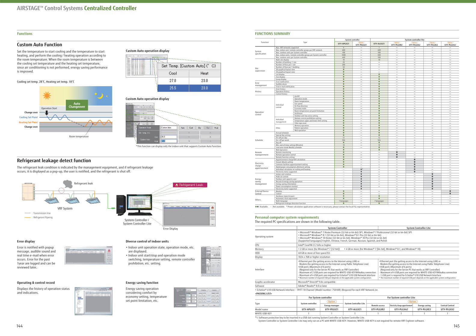
145144
AIRSTAGETM Control Systems Centralized Controller
Functions FUNCTIONS SUMMARY
Function TypeSystem controller System controller lite
System specification
Max. VRF networks supported 4 1Max. indoor unit / remote controller groups per VRF network 400 400Max. outdoor units per System controller 100 100Max. indoor units / remote controller groups per System controller 1600 400Max. outdoor units per System controller 400 100
Sitesupervision
Multi site display 10 10Number of building / 1 site 20Number of floor per 1 site 200Number of floor per 1 building 503D graphical layout view2D graphical layout viewList displayTree displayGroup display
Errormanagement
Error notificationAudible alarmError e-mail notification
HistoryError historyOperation historyControl history
Operationcontrol
Individualcontrol
On/OffOperation modeRoom temperatureFan speedAir flow directionEconomy modeRoom temperature set point limitationAntifreezeOutdoor unit low noise setting
Individual management
Remote control prohibition settingTemperature upper and lower limit settingFilter sign reset
OtherMemory operationPattern operationWeb operation
Schedule
Annual ScheduleSpecial day settingOn /off per day 72 72On / off per week 504 504Day offMin. unit of timer setting (Minutes) 10 10Low noise mode Weekly schedule
Remotemanagemment
Web OperationRemote monitoringRemote operation controlRemote function setting
Electricitychargeapportionment
Apportionment charge/bill calculationTenant (block) settingCommon facilities apportionment settingRated power consumption allotment settingIndividual calculation at cooling and heating - *Electricity meter supported -
Energysavingmanagement
Indoor unit rotation -Peak cut control -Outdoor unit capacity save -Record of energy saving operation -Energy saving information -Power consumption monitor -Electricity meter supported
External DeviceControl
MonitorControl
Others
Database import/exportAutomatic clock adjustmentMulti language 7 languages 7 languagesRefrigerant leakage detection function
: Available. - : Not available. *:Power calculation application software is necessary, please contact the local FGL representative.
*1: Software protection key to be inserted in a USB slot running System Controller or System Controller Lite.
AIRSTAGETM Control Systems Centralized Controller
System Controller System Controller Lite
Operating system
[Supported languages] English, Chinese, French, German, Russian, Spanish, and Polish
CPU
Memory
HDD 40 GB or more of free space355
Display 1024 x 768 or higher resolution
Interface
Modem (for getting access to the Internet using Public Telephone Line) Modem (for getting access to the Internet using Public Telephone Line)
Graphic accelerator
Software
<PACKING LIST>
For System controller For System controller Lite
Type System controller System Controller LiteEnergy manager Remote access Electricity charge apportionment Energy saving Central Control
Model name
WHITE-USB-KEY 1 1 1 1 1 1 1
Error display
Error is notified with popup message, audible sound and real time e-mail when error occurs. Error for the past 1year are logged and can be reviewed later.
Operating & control record
Displays the history of operation status and indications.
Diverse control of indoor units
are displayed.
switching, temperature setting, remote controller prohibition, etc. setting.
Energy saving function
Energy saving operation considering comfort by economy setting, temperature set point limitation, etc.
Custom Auto Function
Refrigerant leakage detect function
Set the temperature to start cooling and the temperature to start heating, and perform the cooling / heating operation according to the room temperature. When the room temperature is between the cooling set temperature and the heating set temperature, since air conditioning is not performed, energy saving performance is improved.
occurs, it is displayed as a pop-up, the user is notified, and the refrigerant is shut off.
Custom Auto operation display
*This function can display only the indoor unit that supports Custom Auto Function.
Custom Auto operation display
Room temperature
Change over
Change over
Operation Start
Cooling set temp. 28 C, Heating set temp. 18 C
Heating Set Point
Cooling Set Point
AutoChangeover
Refrigerant leak
Error Display
System Controller / System Controller Lite
VRF System
: Refrigerant Pipeing
: Transmission line
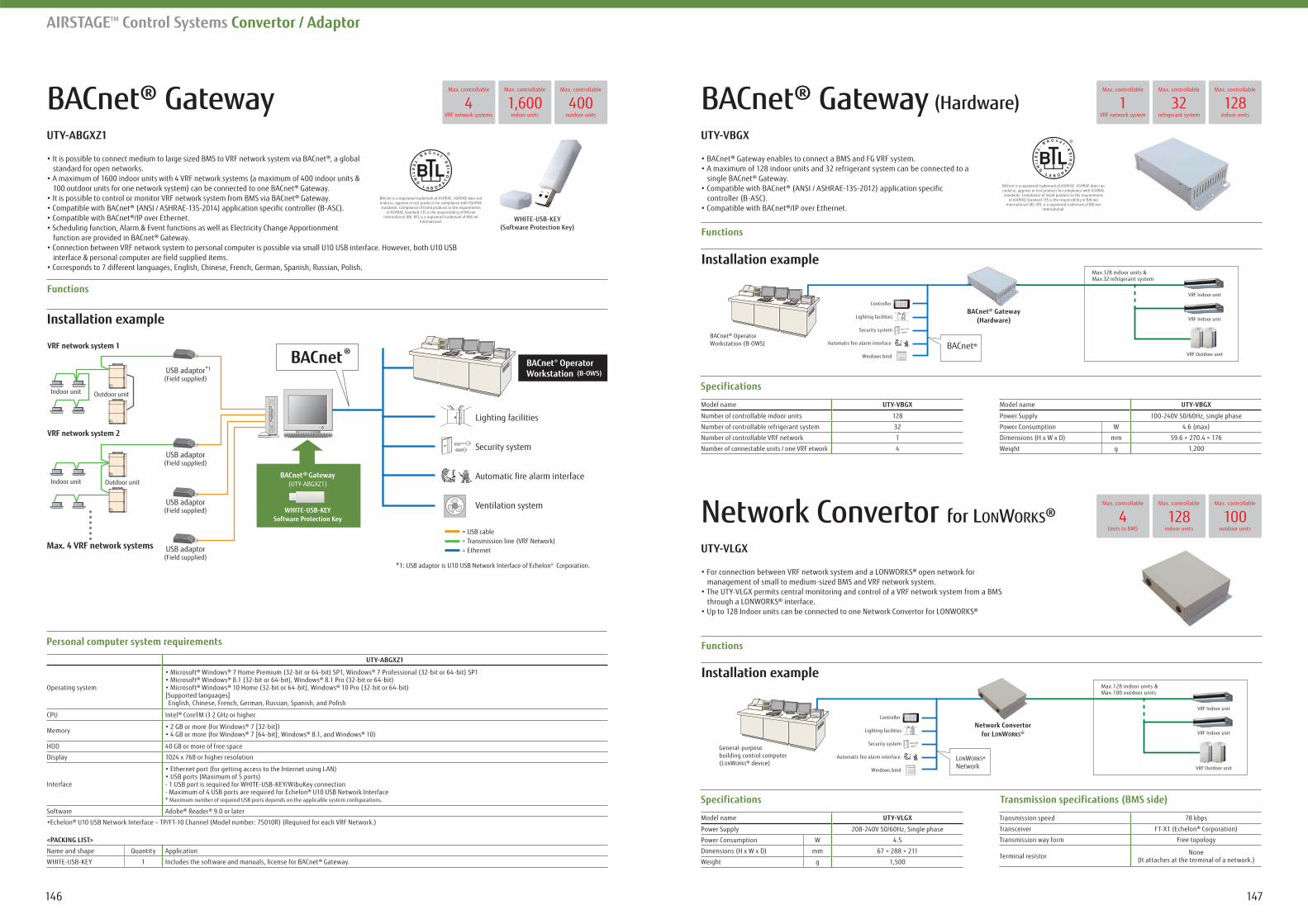
147146
AIRSTAGETM Control Systems Convertor / Adaptor
BACnet® Gateway
Installation example
Functions
standard for open networks.
Lighting facilities
Security system
Automatic fire alarm interface
Ventilation system
BACnet® Operator Workstation (B-OWS)USB adaptor
(Field supplied)
USB adaptor(Field supplied)
USB adaptor(Field supplied)
USB adaptor(Field supplied)
VRF network system 1
VRF network system 2
Indoor unit
BACnet
Max. 4 VRF network systems
*1: USB adaptor is U10 USB Network Interface of Echelon® Corporation.
®
= USB cable= Transmission line (VRF Network)= Ethernet
*1
Indoor unit
Outdoor unit
Outdoor unit
WHITE-USB-KEYSoftware Protection Key
(UTY-ABGXZ1)BACnet® Gateway
Operating system[Supported languages] English, Chinese, French, German, Russian, Spanish, and Polish
CPU
Memory
HDD 40 GB or more of free space
Display 1024 x 768 or higher resolution
Interface
Software
<PACKING LIST>
Name and shape Quantity Application
WHITE-USB-KEY 1
BACnet® Gateway (Hardware)
Installation example
Functions
Functions
Specifications
Model name
Number of controllable indoor units 128
Number of controllable refrigerant system 32
Number of controllable VRF network 1
Number of connectable units / one VRF etwork 4
Model name
Power Supply 100-240V 50/60Hz, single phase
Power Consumption W 4.6 (max)
Dimensions (H x W x D) mm 59.6 × 270.4 × 176
Weight g 1,200
Specifications Transmission specifications (BMS side)
Transmission speed 78 kbps
Transceiver
Transmission way form Free topology
Terminal resistor None(It attaches at the terminal of a network.)
Model name
Power Supply 208-240V 50/60Hz, Single phase
Power Consumption W 4.5
Dimensions (H x W x D) mm 67 × 288 × 211
Weight g 1,500
controller (B-ASC).
Network Convertor for LONWORKS®
management of small to medium-sized BMS and VRF network system.
VRF Indoor unit
VRF Indoor unit
VRF Outdoor unit
BACnet® Gateway(Hardware)
BACnet®
Controller
Lighting facilities
Security system
Automatic fire alarm interface
Windows bind
Max.128 indoor units & Max.32 refrigerant system
BACnet® OperatorWorkstation (B-OWS)
Installation example
VRF Indoor unit
VRF Indoor unit
VRF Outdoor unit
Network Convertorfor LONWORKS®
LONWORKS® Network
Controller
Lighting facilities
Security system
Automatic fire alarm interface
Windows bind
General-purposebuilding control computer(LONWORKS® device)
Max.128 indoor units & Max.100 outdoor units
1Max. controllable
VRF network system32
Max. controllable
refrigerant system128
Max. controllable
indoor units4
Max. controllable
VRF network systems1,600
Max. controllable
indoor units400
Max. controllable
outdoor units
4Max. controllable
Units to BMS128
Max. controllable
indoor units100
Max. controllable
outdoor units
BACnet is a registered trademark of ASHRAE. ASHRAE does not endorse, approve or test products for compliance with ASHRAE standards. Compliance of listed products to the requirements
of ASHRAE Standard 135 is the responsibility of BACnet International (BI). BTL is a registered trademark of BACnet
International.
WHITE-USB-KEY(Software Protection Key)
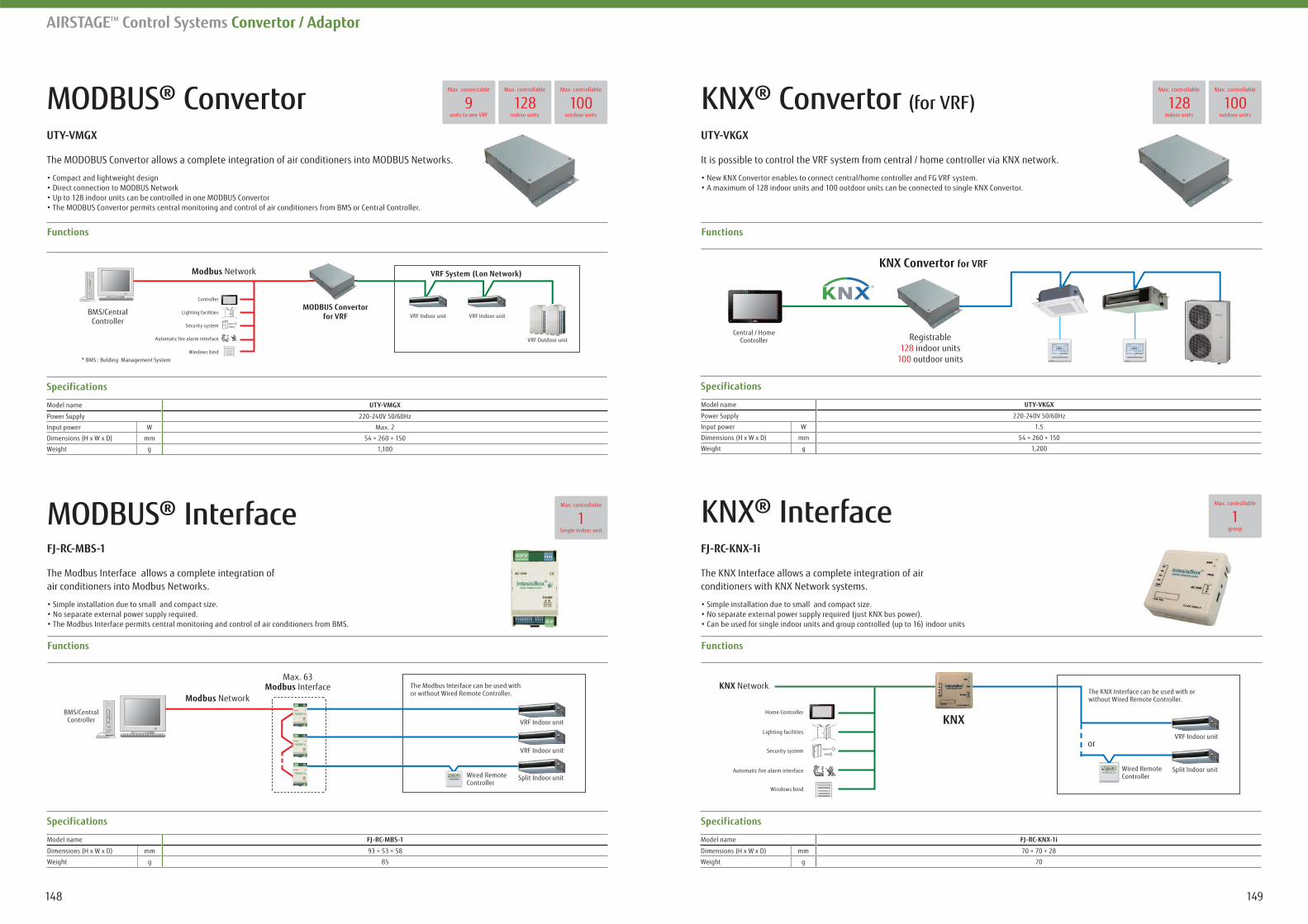
149148
AIRSTAGETM Control Systems Convertor / Adaptor
MODBUS® Convertor
Functions
KNX® Interface
The MODOBUS Convertor allows a complete integration of air conditioners into MODBUS Networks.
Functions
Specifications
Model name
Power Supply 220-240V 50/60Hz
Input power W Max. 2
Dimensions (H x W x D) mm 54 × 260 × 150
Weight g 1,100
The KNX Interface allows a complete integration of air conditioners with KNX Network systems.
Specifications
Model name
Dimensions (H x W x D) mm 70 × 70 × 28
Weight g 70
9Max. connectable
units to one VRF128
Max. controllable
indoor units100
Max. controllable
outdoor units
MODBUS® Interface
Functions
The Modbus Interface allows a complete integration of air conditioners into Modbus Networks.
Specifications
Model name
Dimensions (H x W x D) mm 93 × 53 × 58
Weight g 85
1Max. controllable
Single indoor unit
1Max. controllable
group
KNX® Convertor (for VRF)
Functions
It is possible to control the VRF system from central / home controller via KNX network.
Specifications
Model name
Power Supply 220-240V 50/60Hz
Input power W 1.5
Dimensions (H x W x D) mm 54 × 260 × 150
Weight g 1,200
100Max. controllable
outdoor units128
Max. controllable
indoor units
KNX Network
KNXHome Controller
The KNX Interface can be used with or without Wired Remote Controller.
VRF Indoor unitor
Split Indoor unitWired Remote Controller
Security system
Lighting facilities
Automatic fire alarm interface
Windows bind
Max. 63Modbus Interface
Modbus NetworkBMS/Central
Controller
The Modbus Interface can be used withor without Wired Remote Controller.
VRF Indoor unit
VRF Indoor unit
Split Indoor unitWired Remote Controller
KNX Convertor
Registrable128 indoor units
100 outdoor units
Central / HomeController
Modbus Network
MODBUS ConvertorController
VRF Indoor unit VRF Indoor unit
VRF Outdoor unit
Security system
Lighting facilities
Automatic fire alarm interface
Windows bind
* BMS : Bulding Management System
BMS/CentralController
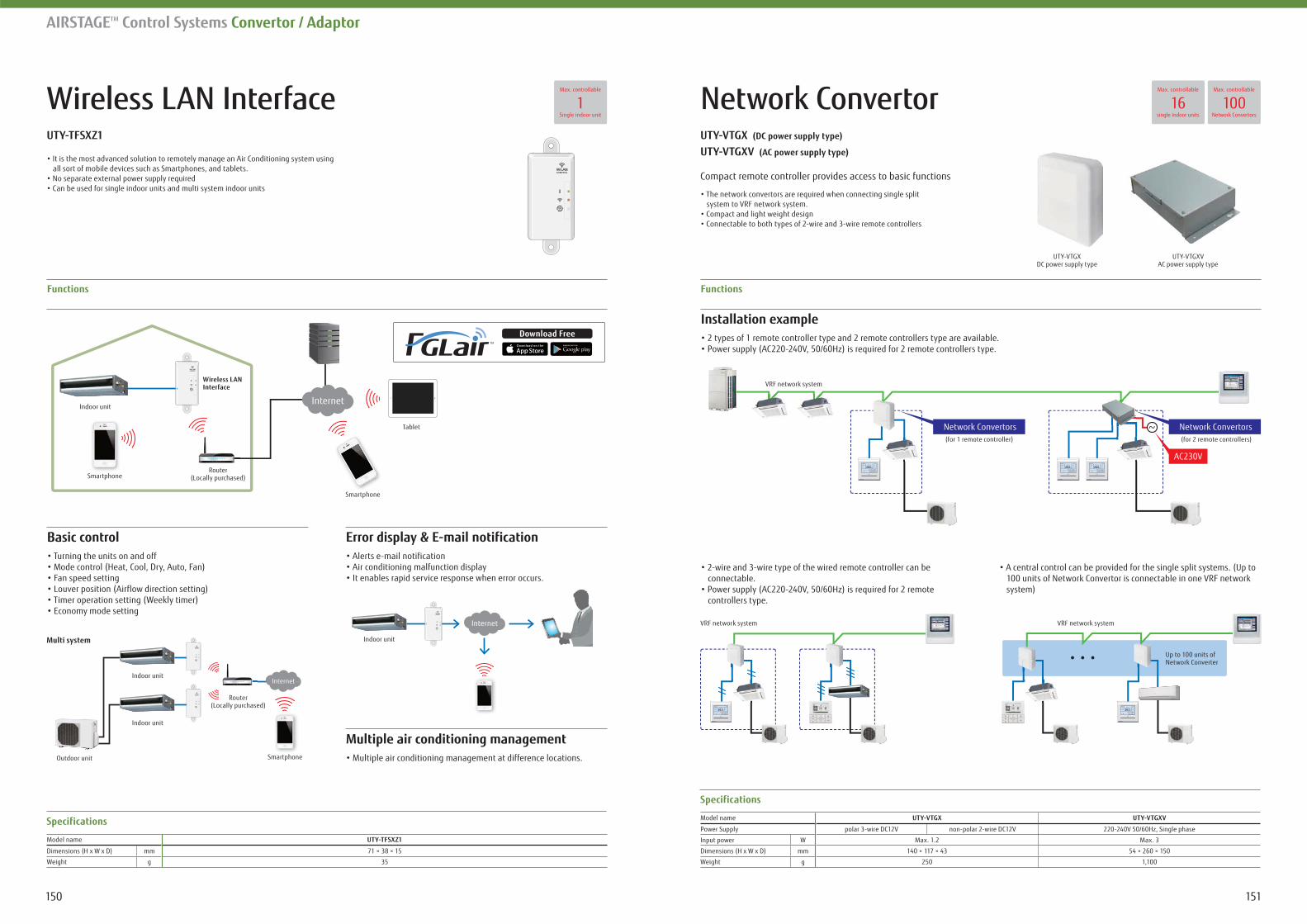
151150
AIRSTAGETM Control Systems Convertor / Adaptor
Wireless LAN Interface
Functions
all sort of mobile devices such as Smartphones, and tablets.
Basic control
Multiple air conditioning management
Specifications
Model name
Dimensions (H x W x D) mm 71 × 38 × 15
Weight g 35
1Max. controllable
Single indoor unitNetwork Convertor
Installation example
connectable.
controllers type.
100 units of Network Convertor is connectable in one VRF network system)
Functions
Specifications
Model name
Power Supply polar 3-wire DC12V non-polar 2-wire DC12V 220-240V 50/60Hz, Single phase
Input power W Max. 1.2 Max. 3
Dimensions (H x W x D) mm 140 × 117 × 43 54 × 260 × 150
Weight g 250 1,100
(DC power supply type)
(AC power supply type)
Compact remote controller provides access to basic functions
system to VRF network system.
16Max. controllable
single indoor units100
Max. controllable
Network Convertors
UTY-VTGXVAC power supply type
UTY-VTGXDC power supply type
VRF network system
VRF network system
VRF network system
Router(Locally purchased)
Indoor unit
Indoor unitMulti system
Indoor unit
Outdoor unit Smartphone
Up to 100 units ofNetwork Converter
(for 2 remote controllers)(for 1 remote controller)
Network ConvertorsNetwork Convertors
AC230V
Internet
Internet
Indoor unit
Smartphone
Wireless LANInterface
Router(Locally purchased)
Router
Smartphone
Tablet
Internet
Download Free
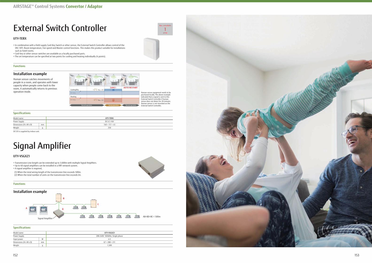
153152
AIRSTAGETM Control Systems Convertor / Adaptor
External Switch Controller
Functions
Signal Amplifier
ON / OFF, Room temperature, Fan speed and Master control functions. This makes this product suitable for installations such as hotel rooms.
(1) When the total wiring length of the transmission line exceeds 500m. (2) When the total number of units on the transmission line exceeds 64.
Specifications
Model name
Power Supply DC 6.5-16V
Dimensions (H x W x D) mm 140 × 117 × 43
Weight g 250
Specifications
Model name
Power Supply 208-240V 50/60Hz, Single phase
Input power W 4.5
Dimensions (H x W x D) mm 67 × 288 × 211
Weight g 1,500
1Max. controllable
group
DC12V is supplied by indoor unit.
Installation exampleHuman sensor catches movements of people in a room, and operates with lower capacity when people come back to the room, it automatically returns to previous operation mode.
SAVE ! AUTO RESTART+2°C *Max. 30°CCooling/Dry
Heating
-4°C *Max. 16°C
Saving operation
Set temp.
Set temp.
Normal operation Normal operation
Human sensor equipment needs to be purchased locally. The above example indicated that a signal is sent to this External Switch Controller if human sensor does not detect for 20 minutes. Human sensor is not mounted on the External Switch Controller.
Functions
Installation example
Signal Amplifier
A D
B
C
D
AB+BD+BC < 500m
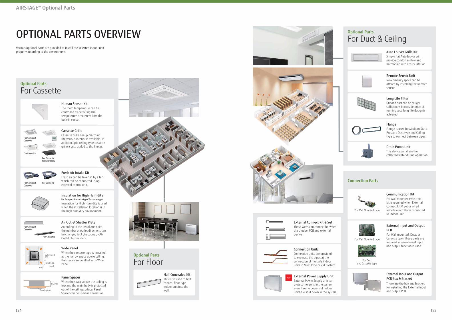
155154
AIRSTAGETM Optional Parts
OPTIONAL PARTS OVERVIEW Various optional parts are provided to install the selected indoor unit properly according to the environment.
Human Sensor KitThe room temperature can be controlled by detecting the temperature accurately from the built-in sensor
Cassette GrilleCassette grille lineup matching the various interior is available. In addition, grid ceiling type cassette grille is also added to the lineup.
Wide PanelWhen the cassette type is installed at the narrow space above ceiling, the space can be filled in by Wide Panel.
Panel SpacerWhen the space above the ceiling is low and the main body is projected out of the ceiling surface, Panel Spacer can be used as decoration
Fresh Air Intake KitFresh air can be taken in by a fan which can be connected using external control unit.
Insulation for High HumidityFor Compact Cassette type/ Cassette type
Insulation for High Humidity is used when the installation location is in the high humidity environment.
Air Outlet Shutter PlateAccording to the installation site, the number of outlet directions can be changed to 3 directions by Air Outlet Shutter Plate.
Optional Parts
For Cassette
Optional Parts
For Duct & Ceiling
Connection Parts
Optional Parts
For FloorIndoor unit950
Panel 600
600(mm)
Panel spacer
242 mm
For Compact Cassette
For Compact Cassette
For Compact Cassette
For Cassette
For Cassette
For CassetteCircular Flow
For Cassette
Remote Sensor UnitNew amenity space can be offered by installing the Remote sensor.
Auto Louver Grille KitSimple flat Auto louver will provide comfort airflow and harmonize with luxury Interior
Communication KitFor wall mounted type, this kit is required when External Connect kit & Set or wired remote controller is connected to indoor unit.
External Input and Output PCB Box & BracketThese are the box and bracket for installing the External input and output PCB
Connection UnitsConnection units are provided to separate the pipes at the connection of multiple indoor units in Multi type or VRF system.
External Power Supply UnitExternal Power Supply Unit can protect the units in the system even if some powers of indoor units are shut down in the system.
External Input and Output PCBFor Wall mounted, Duct, or Cassette type, these parts are required when external input and output function is used.
External Connect Kit & SetThese wires can connect between the product PCB and external device.
Long Life FilterGrit and dust can be caught sufficiently. In consideration of running cost, long-life design is achieved.
FlangeFlange is used for Medium Static Pressure Duct type and Ceiling type to connect between pipes.
Drain Pump UnitThis device can drain the collected water during operation.
Half Concealed KitThis kit is used to half conceal floor type indoor unit into the wall.
For Wall Mounted type
For Wall Mounted type
For Ductand Cassette type
m the
ng ble. In assette eup.
a fan ng
idityt
NEW
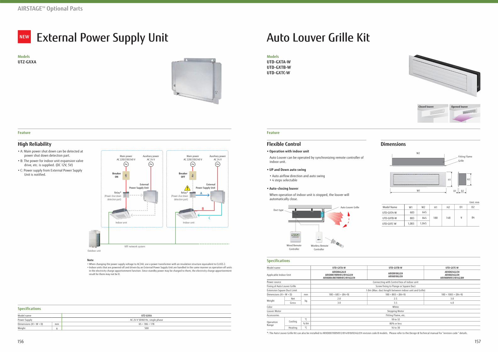
Auto Louver Grille KitModels
Flexible Control Dimensions
Auto Louver can be operated by synchronizing remote controller of indoor unit.
When operation of indoor unit is stopped, the louver will automatically close.
Feature
Specifications
Model name
Applicable Indoor UnitARXD04GALH ARXD024GLEH
ARXK024GLEH
Power source Connecting with Control box of indoor unit
Fixing of Auto Louver Grille
1.0m (Max. duct length between indoor unit and Grille)
Dimensions (H × W × D) mm 180 × 683 × (84+9) 180 × 883 × (84+9) 180 × 1083 × (84+9)
WeightNet
kg2.0 2.5 3.0
Gross 3.0 3.5 4.0
Color White
Louver Motor Stepping Motor
Accessories Fitting Flame, etc.
Operation Range
Cooling°C 18 to 32
% RH 80% or less
Heating °C 16 to 30
Controller Controller
Duct type
Wired Remote Wireless Remote
Auto Louver Grille
UTD-GXTA-W
W1 W2
683
883
1,083
645
845
1,045
180 148 9 84
Unit: mm
Model Name H1 H2 D1 D2
UTD-GXTB-W
UTD-GXTC-W
W1
W2
D2D1
H1 H2
Fitting Flame
Grille
Closed louver Opened louver
AIRSTAGETM Optional Parts
Models
High Reliability
power shut down detection part.
drive, etc. is supplied. (DC 12V, 5V)
Unit is notified.
Note
in the electricity charge apportionment function. Since standby power may be charged to them, the electricity charge apportionment result for them may not be 0.
Feature
Specifications
Model name
Power Supply AC 24 V 50/60 Hz, single phase
Dimensions (H × W × D) mm 65 × 186 × 178
Weight g 500
VRF network system
Outdoor unit
Indoor unit Indoor unit
Main powerAC 220/230/240 V
Relay*(Power shut down
detection part)
ExternalPower Supply Unit
ExternalPower Supply Unit
Relay*(Power shut down
detection part)
Auxiliary powerAC 24 V
Main powerAC 220/230/240 V
Auxiliary powerAC 24 V
BreakerON
BreakerOFF
A
B
C
External Power Supply Unit
157156
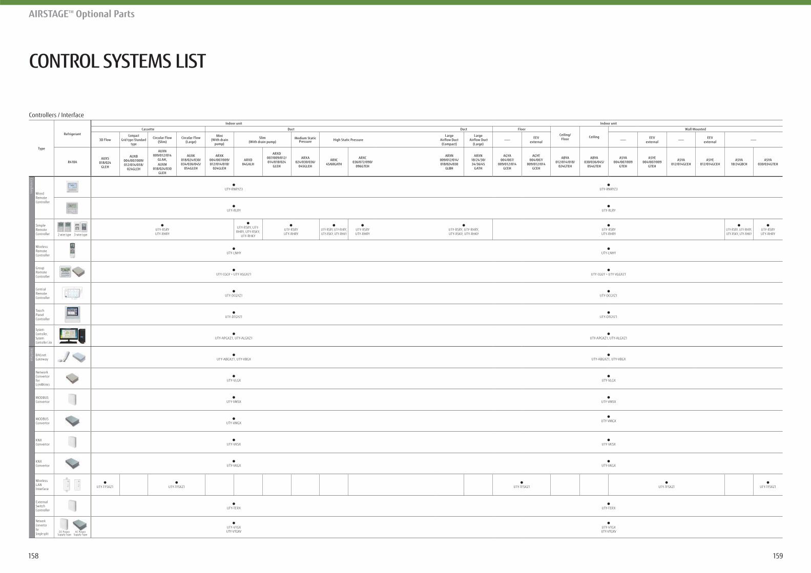
CONTROL SYSTEMS LIST
AIRSTAGETM Optional Parts
Controllers / Interface
Type
Refrigerant
Indoor unit Indoor unit
Cassette Duct Duct Floor
Ceiling/ Floor Ceiling
Wall Mounted
3D FlowCompact
Grid type /Standard type
Circular Flow(Slim)
Circular Flow(Large)
Mini(With drain
pump)
Slim(With drain pump)
Medium Static Pressure High Static Pressure
Large Airflow Duct (Compact)
Large Airflow Duct
(Large)
EEVexternal
EEVexternal
EEVexternal
R410AAUXS
018/024GLEH
AUXB004/007/009/012/014/018/
024GLEH
AUXN009/012/014
GLAH,AUXM
018/024/030GLEH
AUXK018/024/030/034/036/045/
054GLEH
ARXK004/007/009/012/014/018/
024GLEH
ARXD04GALH
ARXD007/009/012/014/018/024
GLEH
ARXA024/030/036/
045GLEH
ARXC45/60GATH
ARXC036/072/090/
096GTEH
ARXN009/012/014/018/024/030
GLBH
ARXN18/24/30/34/36/45
GATH
AGYA004/007/
009/012/014GCEH
AGYE004/007/
009/012/014GCEH
ABYA012/014/018/
024GTEH
ABYA030/036/045/
054GTEH
ASYA004/007/009
GTEH
ASYE004/007/009
GTEH
ASYA012/014GCEH
ASYE012/014GCEH
ASYA18/24GBCH
ASYA030/034GTEH
Controllers
Wired Remote Controller
UTY-RNRYZ3 UTY-RNRYZ3
UTY-RLRY UTY-RLRY
Simple Remote Controller 3-wire type2-wire type
UTY-RSRYUTY-RHRY
UTY-RSRY, UTY-RHRY, UTY-RSKY,
UTY-RHKY
UTY-RSRYUTY-RHRY
UTY-RSRY, UTY-RHRY, UTY-RSKY, UTY-RHKY
UTY-RSRYUTY-RHRY
UTY-RSRY, UTY-RHRY, UTY-RSKY, UTY-RHKY
UTY-RSRYUTY-RHRY
UTY-RSRY, UTY-RHRY, UTY-RSKY, UTY-RHKY
UTY-RSRYUTY-RHRY
Wireless Remote Controller
UTY-LNHY UTY-LNHY
Group Remote Controller
UTY-CGGY + UTY-VGGXZ1 UTY-CGGY + UTY-VGGXZ1
Central Remote Controller
UTY-DCGYZ1 UTY-DCGYZ1
Touch Panel Controller
UTY-DTGYZ1 UTY-DTGYZ1
System Controller, System Controller Lite
UTY-APGXZ1, UTY-ALGXZ1 UTY-APGXZ1, UTY-ALGXZ1
Interface
BACnet Gateway UTY-ABGXZ1, UTY-VBGX UTY-ABGXZ1, UTY-VBGX
Network ConvertorforLONWORKS
UTY-VLGX UTY-VLGX
MODBUS Convertor UTY-VMSX UTY-VMSX
MODBUS Convertor UTY-VMGX UTY-VMGX
KNX Convertor UTY-VKSX UTY-VKSX
KNX Convertor UTY-VKGX UTY-VKGX
Wireless LAN Interface UTY-TFSXZ1 UTY-TFSXZ1 UTY-TFSXZ1 UTY-TFSXZ1 UTY-TFSXZ1
External Switch Controller UTY-TERX UTY-TERX
Network ConvertorforSingle split
DC PowerSupply Type
AC PowerSupply Type
UTY-VTGXUTY-VTGXV
UTY-VTGXUTY-VTGXV
159158
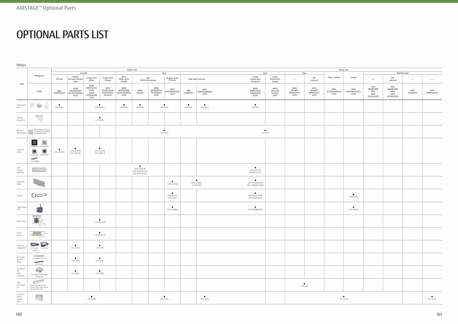
OPTIONAL PARTS LIST
AIRSTAGETM Optional Parts
Others
Type
Refrigerant
Indoor unit Indoor unit
Cassette Duct Duct Floor
Floor / Ceiling Ceiling
Wall Mounted
3D FlowCompact
Grid type /Standard type
Circular Flow(Slim)
Circular Flow(Large)
Mini(With drain
pump)
Slim(With drain pump)
Medium Static Pressure High Static Pressure
Large Airflow Duct (Compact)
Large Airflow Duct
(Large)
EEVexternal
EEVexternal
R410A AUXS018/024GLEH
AUXB004/007/009/
012/014/018/024GLEH
AUXN009/012/014
GLAH,AUXM
018/024/030GLEH
AUXK018/024/030/034/036/045/
054GLEH
ARXK004/007/009/
012/014/018/024GLEH
ARXD04GALH
ARXD007/009/012/014/018/024
GLEH
ARXA024/030/036/045
GLEH
ARXC45/60GATH
ARXC036/072/090/096
GTEH
ARXN009/012/014/018/024/030
GLBH
ARXN18/24/30/34/36/45
GATH
AGYA004/007/
009/012/014GCEH
AGYE004/007/
009/012/014GCEH
ABYA012/014/018/024
GTEH
ABYA030/036/045/054
GTEH
ASYA004/007/009
GTEH, ASYA
012/014GCEH
ASYE004/007/009
GTEH, ASYE
012/014GCEH
ASYA18/24GBCH
ASYA030/034GTEH
IR Receiver Unit UTY-TRHX UTY-LBHXD UTY-TRHX UTB-YWC UTY-TRHX UTB-YWC UTY-TRHX UTB-YWC
Human Sensor Kit UTY-SHZXC
Remote Sensor Unit
New amenity space can be offered by installing the Remote sensor. UTY-XSZX UTY-XSZX
Cassette Grille
UTG-USYA-W
UTG-UKYA-B UTG-UKYC-W
UTG-UFYC-W UTG-UFYE-W
UTG-USYA-WUTG-UFYE-WUTG-UFYC-W
UTG-UKYC-WUTG-UKYA-B
Auto Louver Grille Kit
UTD-GXTA-W, UTD-GXTB-W (18), UTD-GXTC-W (24)
UTD-GXTC-W(009/012/014)
Long Life Filter UTD-LF25NA
UTD-LF60KA(45/60/036)
UTD-LF25NA(018)UTD-LFNA(024/030)
Flange UTD-SF045T UTD-RF204
UTD-SF045T(018)UTD-RF204(018)
UTD-RF204
Drain PumpUnit UTZ-PX1NBA UTZ-PX1NBA(018) UTR-DPB24T
Wide PanelIndoor unit950
Panel 600
600(mm)
UTG-AKXA-W
Panel Spacer
Panel spacer
242 mm
UTG-BKXA-W
Fresh Air Intake Kit*1 For Compact
CassetteFor Cassette UTZ-VXAA UTZ-VXRA
Air Outlet Shutter Plate
For Compact Cassette
For Cassette
UTR-YDZB UTR-YDZK
Insulation for High Humidity
For Compact Cassette type/ Cassette type
UTZ-KXGC UTZ-KXRA
Half Concealed Kit
This kit is used to half
unit into the wall.
UTR-STA
External Power Supply Unit
UTZ-GXXA UTZ-GXXA UTZ-GXXA UTZ-GXXA UTZ-GXXA
161160
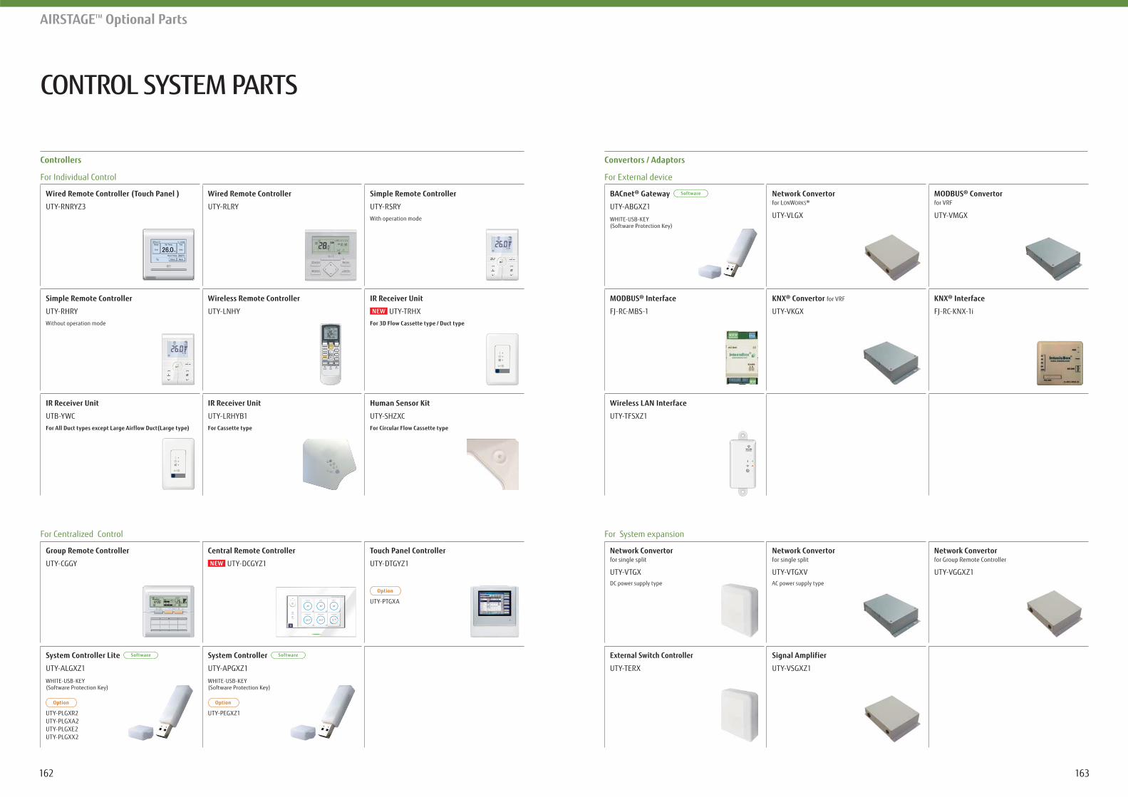
CONTROL SYSTEM PARTS
AIRSTAGETM Optional Parts
Controllers
For Individual Control
For Centralized Control
Wired Remote Controller (Touch Panel )
UTY-RNRYZ3
Wireless LAN Interface
UTY-TFSXZ1
MODBUS® Interface
FJ-RC-MBS-1
KNX® Convertor for VRF
UTY-VKGX
KNX® Interface
FJ-RC-KNX-1i
Network Convertor for LONWORKS
UTY-VLGX
MODBUS® Convertor for VRF
UTY-VMGX
Convertors / Adaptors
For External device
BACnet® Gateway
UTY-ABGXZ1
WHITE-USB-KEY (Software Protection Key)
For System expansion
Network Convertor for single split
UTY-VTGXDC power supply type
Network Convertor for single split
UTY-VTGXVAC power supply type
Network Convertor for Group Remote Controller
UTY-VGGXZ1
Signal Amplifier
UTY-VSGXZ1
External Switch Controller
UTY-TERX
Simple Remote Controller
UTY-RHRYWithout operation mode
Wired Remote Controller
UTY-RLRY
Wireless Remote Controller
UTY-LNHY
IR Receiver Unit
UTY-LRHYB1For Cassette type
Human Sensor Kit
UTY-SHZXCFor Circular Flow Cassette type
Simple Remote Controller
UTY-RSRYWith operation mode
Group Remote Controller
UTY-CGGY
Central Remote Controller
UTY-DCGYZ1
Touch Panel Controller
UTY-DTGYZ1
UTY-PTGXA
IR Receiver Unit
UTY-TRHX
IR Receiver Unit
UTB-YWCFor All Duct types except Large Airflow Duct(Large type)
System Controller
UTY-APGXZ1
WHITE-USB-KEY (Software Protection Key)
UTY-PEGXZ1
System Controller Lite
UTY-ALGXZ1
WHITE-USB-KEY (Software Protection Key)
UTY-PLGXR2UTY-PLGXA2UTY-PLGXE2UTY-PLGXX2
163162
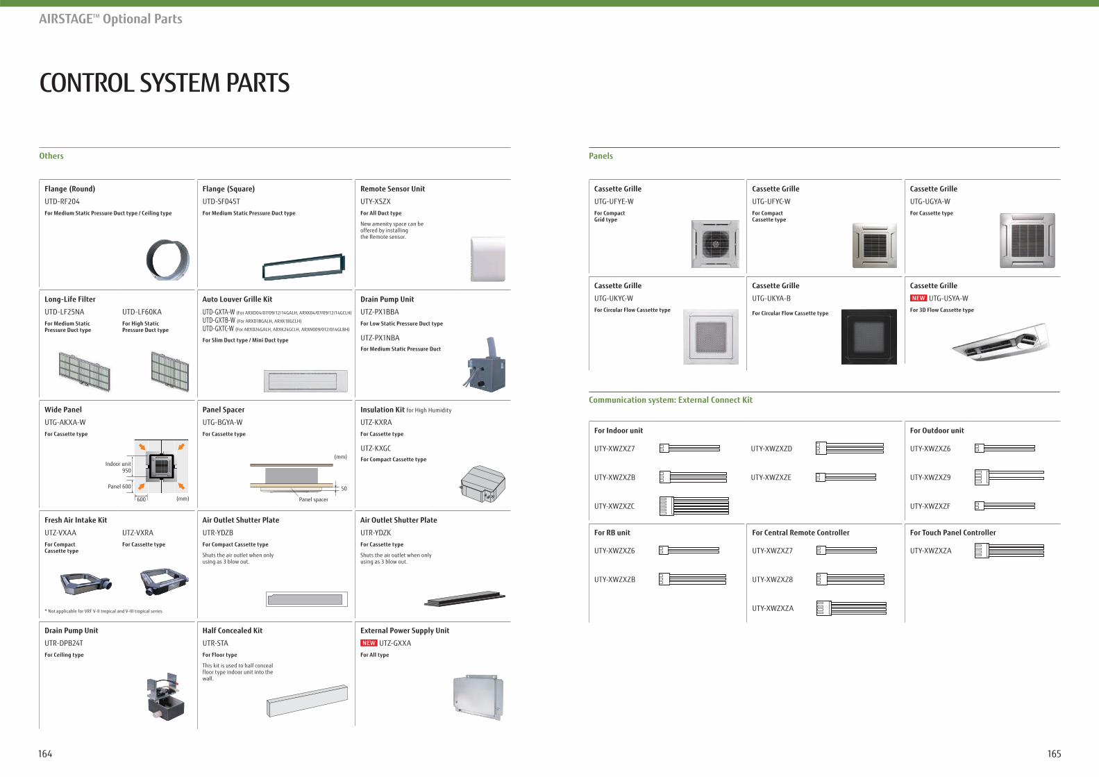
CONTROL SYSTEM PARTS
AIRSTAGETM Optional Parts
Drain Pump Unit
UTR-DPB24TFor Ceiling type
Half Concealed Kit
UTR-STAFor Floor type
This kit is used to half conceal floor type indoor unit into the wall.
Flange (Round)
UTD-RF204For Medium Static Pressure Duct type / Ceiling type
UTD-LF25NA UTD-LF60KAFor Medium Static Pressure Duct type
For High Static Pressure Duct type
UTD-SF045TFor Medium Static Pressure Duct type
Auto Louver Grille Kit
UTD-GXTA-W (For ARXD04/07/09/12/14GALH, ARXK04/07/09/12/14GCLH)
UTD-GXTB-W (For ARXD18GALH, ARXK18GCLH)
UTD-GXTC-W (For ARXD24GALH, ARXK24GCLH, ARXN009/012/014GLBH)
For Slim Duct type / Mini Duct type
Remote Sensor Unit
UTY-XSZXFor All Duct type
New amenity space can be offered by installing the Remote sensor.
Drain Pump Unit
UTZ-PX1BBAFor Low Static Pressure Duct type
UTZ-PX1NBAFor Medium Static Pressure Duct
Others
Wide Panel
UTG-AKXA-WFor Cassette type
Indoor unit950
Panel 600
600 (mm)
Fresh Air Intake Kit
UTZ-VXAA UTZ-VXRAFor Compact Cassette type
For Cassette type
* Not applicable for VRF V-II tropical and V-III tropical series
Panel Spacer
UTG-BGYA-WFor Cassette type
(mm)
Panel spacer
50
Insulation Kit for High Humidity
UTZ-KXRAFor Cassette type
UTZ-KXGCFor Compact Cassette type
Air Outlet Shutter Plate
UTR-YDZBFor Compact Cassette type
Shuts the air outlet when only using as 3 blow out.
Air Outlet Shutter Plate
UTR-YDZKFor Cassette type
Shuts the air outlet when only using as 3 blow out.
Panels
For Indoor unit
UTY-XWZXZ7 UTY-XWZXZD
UTY-XWZXZB UTY-XWZXZE
UTY-XWZXZC
For Outdoor unit
UTY-XWZXZ6
UTY-XWZXZ9
UTY-XWZXZF
For Central Remote Controller
UTY-XWZXZ7
UTY-XWZXZ8
UTY-XWZXZA
For Touch Panel Controller
UTY-XWZXZA
For RB unit
UTY-XWZXZ6
UTY-XWZXZB
Cassette Grille
UTG-UFYE-WFor Compact Grid type
Cassette Grille
UTG-UKYA-B
For Circular Flow Cassette type
Cassette Grille
UTG-UFYC-WFor Compact Cassette type
Cassette Grille
UTG-UGYA-WFor Cassette type
Cassette Grille
UTG-UKYC-WFor Circular Flow Cassette type
Cassette Grille
UTG-USYA-W
External Power Supply Unit
UTZ-GXXAFor All type
165164
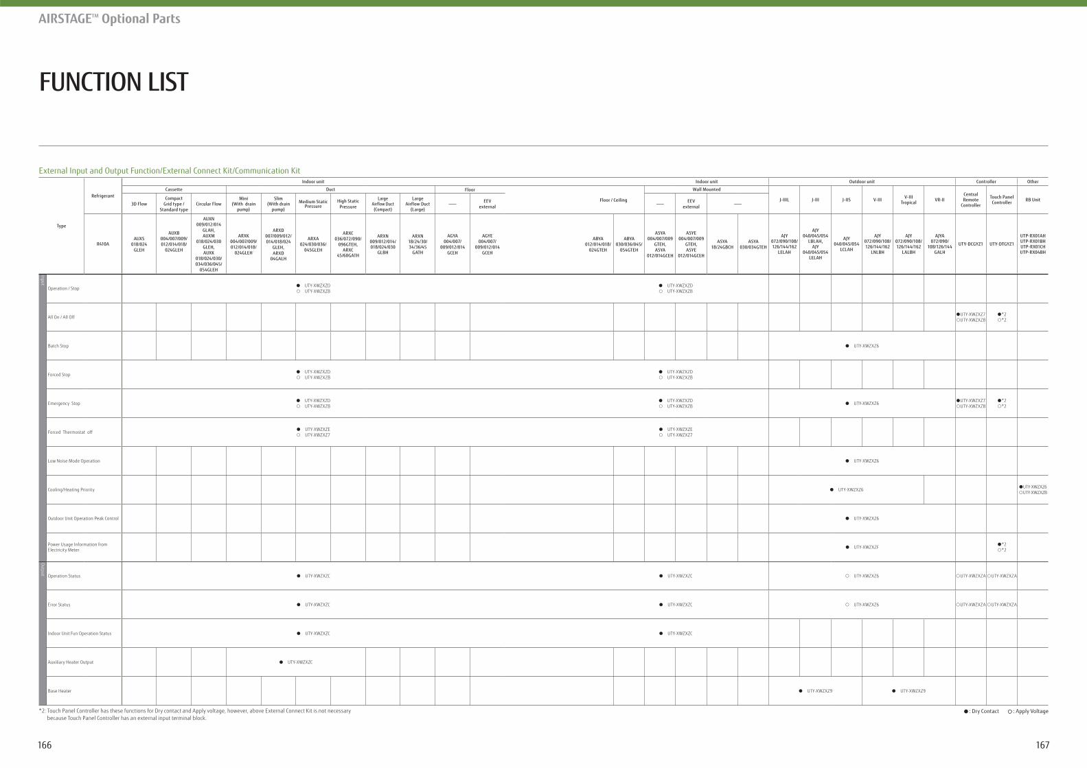
FUNCTION LIST
AIRSTAGETM Optional Parts
External Input and Output Function/External Connect Kit/Communication Kit
Type
Refrigerant
Indoor unit Indoor unit Outdoor unit Controller Other
Cassette Duct Floor
Floor / Ceiling
Wall Mounted
J-IIIL J-III J-IIS V-III V-IIITropical VR-II
Central Remote
Controller
Touch PanelController RB Unit
3D FlowCompact
Grid type /Standard type
Circular FlowMini
(With drain pump)
Slim(With drain
pump)
Medium Static Pressure
High Static Pressure
Large Airflow Duct(Compact)
Large Airflow Duct
(Large)
EEVexternal
EEVexternal
R410AAUXS
018/024GLEH
AUXB004/007/009/012/014/018/
024GLEH
AUXN009/012/014
GLAH,AUXM
018/024/030GLEH, AUXK
018/024/030/034/036/045/
054GLEH
ARXK004/007/009/012/014/018/
024GLEH
ARXD007/009/012/014/018/024
GLEH,ARXD
04GALH
ARXA024/030/036/
045GLEH
ARXC036/072/090/
096GTEH,ARXC
45/60GATH
ARXN009/012/014/018/024/030
GLBH
ARXN18/24/30/34/36/45
GATH
AGYA004/007/
009/012/014GCEH
AGYE004/007/
009/012/014GCEH
ABYA012/014/018/
024GTEH
ABYA030/036/045/
054GTEH
ASYA004/007/009
GTEH, ASYA
012/014GCEH
ASYE004/007/009
GTEH,ASYE
012/014GCEH
ASYA18/24GBCH
ASYA030/034GTEH
AJY072/090/108/126/144/162
LELAH
AJY040/045/054
LBLAH,AJY
040/045/054LELAH
AJY040/045/054
LCLAH
AJY072/090/108/126/144/162
LNLBH
AJY072/090/108/126/144/162
LALBH
AJYA072/090/
108/126/144GALH
UTY-DCGYZ1 UTY-DTGYZ1
UTP-RX01AH UTP-RX01BH UTP-RX01CH UTP-RX04BH
Input
Operation / StopUTY-XWZXZDUTY-XWZXZB
UTY-XWZXZDUTY-XWZXZB
All On / All OffUTY-XWZXZ7UTY-XWZXZ8
*2 *2
Batch Stop UTY-XWZXZ6
Forced StopUTY-XWZXZD UTY-XWZXZB
UTY-XWZXZD UTY-XWZXZB
Emergency StopUTY-XWZXZD UTY-XWZXZB
UTY-XWZXZD UTY-XWZXZB
UTY-XWZXZ6UTY-XWZXZ7UTY-XWZXZ8
*2 *2
Forced Thermostat offUTY-XWZXZE UTY-XWZXZ7
UTY-XWZXZE UTY-XWZXZ7
Low Noise Mode Operation UTY-XWZXZ6
Cooling/Heating Priority UTY-XWZXZ6UTY-XWZXZ6 UTY-XWZXZB
Outdoor Unit Operation Peak Control UTY-XWZXZ6
Power Usage Information fromElectricity Meter UTY-XWZXZF
*2 *2
Output
Operation Status UTY-XWZXZC UTY-XWZXZC UTY-XWZXZ6 UTY-XWZXZA UTY-XWZXZA
Error Status UTY-XWZXZC UTY-XWZXZC UTY-XWZXZ6 UTY-XWZXZA UTY-XWZXZA
Indoor Unit Fun Operation Status UTY-XWZXZC UTY-XWZXZC
Auxiliary Heater Output UTY-XWZXZC
Base Heater UTY-XWZXZ9 UTY-XWZXZ9
*2: Touch Panel Controller has these functions for Dry contact and Apply voltage, however, above External Connect Kit is not necessary because Touch Panel Controller has an external input terminal block.
: Dry Contact : Apply Voltage
167166
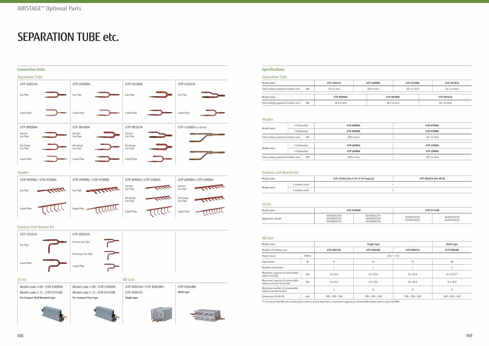
SEPARATION TUBE etc.
AIRSTAGETM Optional Parts
*1: In case of two RB units connected in series ( total 8-branches ), maximum capacity of connectable indoor units is up to 56.0kW.
SpecificationsConnection Units
Separation Tube
RB Unit
Header
Outdoor unit Branch kit
EV Kit
Model name
Total cooling capacity of indoor unit kW 19.6 or less 28.0 or less 28.1 to 56.0 56.1 or more
Model name Single type Multi type
Number of Outdoor unit
Power source V/Ø/Hz 230 / 1 / 50
Input power W 17 24 31 96
Number of branches 1 1 1 4
Maximum capacity of connectableindoor units(Q) kW Q 8.0 Q 18.0 Q 28.0 Q 56.0*1
Maximum capacity of connectableindoor units per branch(Q) kW Q 8.0 Q 18.0 Q 28.0 Q 18.0
Maximum number of connectableindoor units per branch 3 8 8 8
Dimensions (H×W×D) mm 198 × 298 × 268 198 × 298 × 268 198 × 298 × 268 260 × 658 × 428
Model name3-6 Branches
3-8 Branches
Total cooling capacity of indoor unit kW 28.0 or less 28.1 to 56.0
Model name
Model name2 outdoor units 1
3 outdoor units 2
Model name
Application Model ASYE004GTEHASYE007GTEHASYE009GTEH
AGYE004GTEHAGYE007GTEHAGYE009GTEH
ASYE012GCEHASYE014GCEH
AGYE012GCEHAGYE014GCEH
Model name3-6 Branches
3-8 Branches
Total cooling capacity of indoor unit kW 28.0 or less 28.1 to 56.0
Model name
Total cooling capacity of indoor unit kW 28.0 or less 28.1 to 56.0 56.1 or more
Separation Tube
UTP-AX054A
Gas Pipe
UTP-AX090A
Gas Pipe
UTP-AX180A
Gas Pipe
UTP-AX567A
Gas Pipe
UTP-LX180A for DX-KitUTP-BX090A
SuctionGas Pipe
DischargeGas Pipe
UTP-BX180A
SuctionGas Pipe
DischargeGas Pipe
UTP-BX567A
SuctionGas Pipe
DischargeGas Pipe
Header
UTR-H0906L / UTR-H1806L
Gas Pipe
UTR-H0908L / UTR-H1808L
Gas Pipe
UTP-J0906A / UTP-J1806A
SuctionGas Pipe
DischargeGas Pipe
UTP-J0908A / UTP-J1808A
SuctionGas Pipe
DischargeGas Pipe
Outdoor Unit Branch Kit
UTP-CX567A
Gas Pipe
UTP-DX567A
Suction Gas Pipe
Discharge Gas Pipe
EV Kit RB Unit
Model code 09 : UTR-EV09XB
Model code 12 : UTR-EV14XB For Compact Wall Mounted type
Model code 09 : UTR-EV09XB
Model code 12 : UTR-EV14XB For Compact Floor type
UTP-RX01AH / UTP-RX01BH /
UTP-RX01CHSingle type
UTP-RX04BHMulti type
169168

SUPPORT
Our know-how supports you not only during the product release but also from guiding implementation to product maintenance.
AIRSTAGE™ SUPPORT
AIRSTAGE™ / RAC SUPPORT TOOL
QUICK SERVICE & MAINTENANCE
SERVICE TOOL
WEB MONITORING TOOL
Category Information Material Tool
Product Sales Training Material
Product Technical Training Material
Product news
Brochures
Feature Promotion M
ovie
Operating M
anual
Design &
Technical Manual
Certificate Data
2D CAD Data
3D CAD (Revit) Data
Installation Manual
Service Manual
Design Sim
ulator (RAC, PAC, VRF)
CFD Simulation
Service Tool / Web M
onitoring Tool
Mobile Technician
Product Training
Product Information Seek
Technical Information Seek
Model Selection
Design
Verification
Installation
After sales and Service
171170
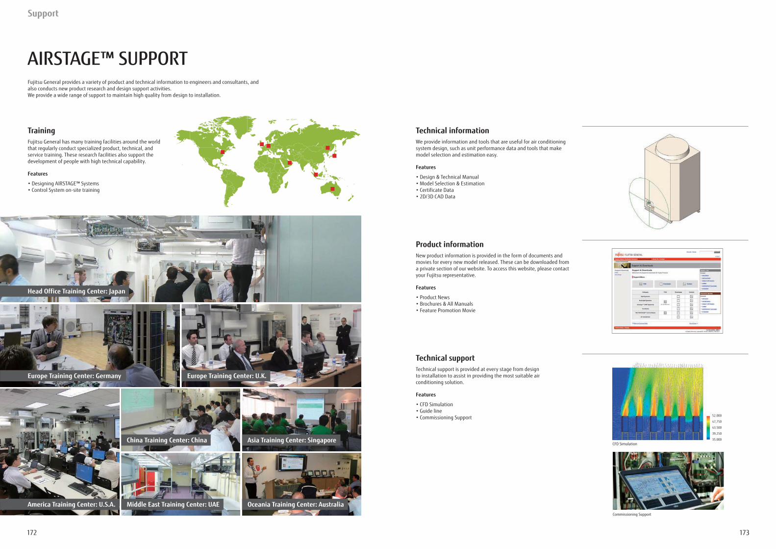
173172
Support
AIRSTAGE™ SUPPORTFujitsu General provides a variety of product and technical information to engineers and consultants, and also conducts new product research and design support activities. We provide a wide range of support to maintain high quality from design to installation.
Training Fujitsu General has many training facilities around the world that regularly conduct specialized product, technical, and service training. These research facilities also support the development of people with high technical capability.
Features
Technical informationWe provide information and tools that are useful for air conditioning system design, such as unit performance data and tools that make model selection and estimation easy.
Features
Product informationNew product information is provided in the form of documents and movies for every new model released. These can be downloaded from a private section of our website. To access this website, please contact your Fujitsu representative.
Features
Technical supportTechnical support is provided at every stage from design to installation to assist in providing the most suitable air conditioning solution.
Features
Head Office Training Center: Japan
Europe Training Center: Germany
America Training Center: U.S.A.
Europe Training Center: U.K.
China Training Center: China
Middle East Training Center: UAE
Asia Training Center: Singapore
Oceania Training Center: Australia
52.000
47,750
43.500
39.250
35.000CFD Simulation
Commissioning Support
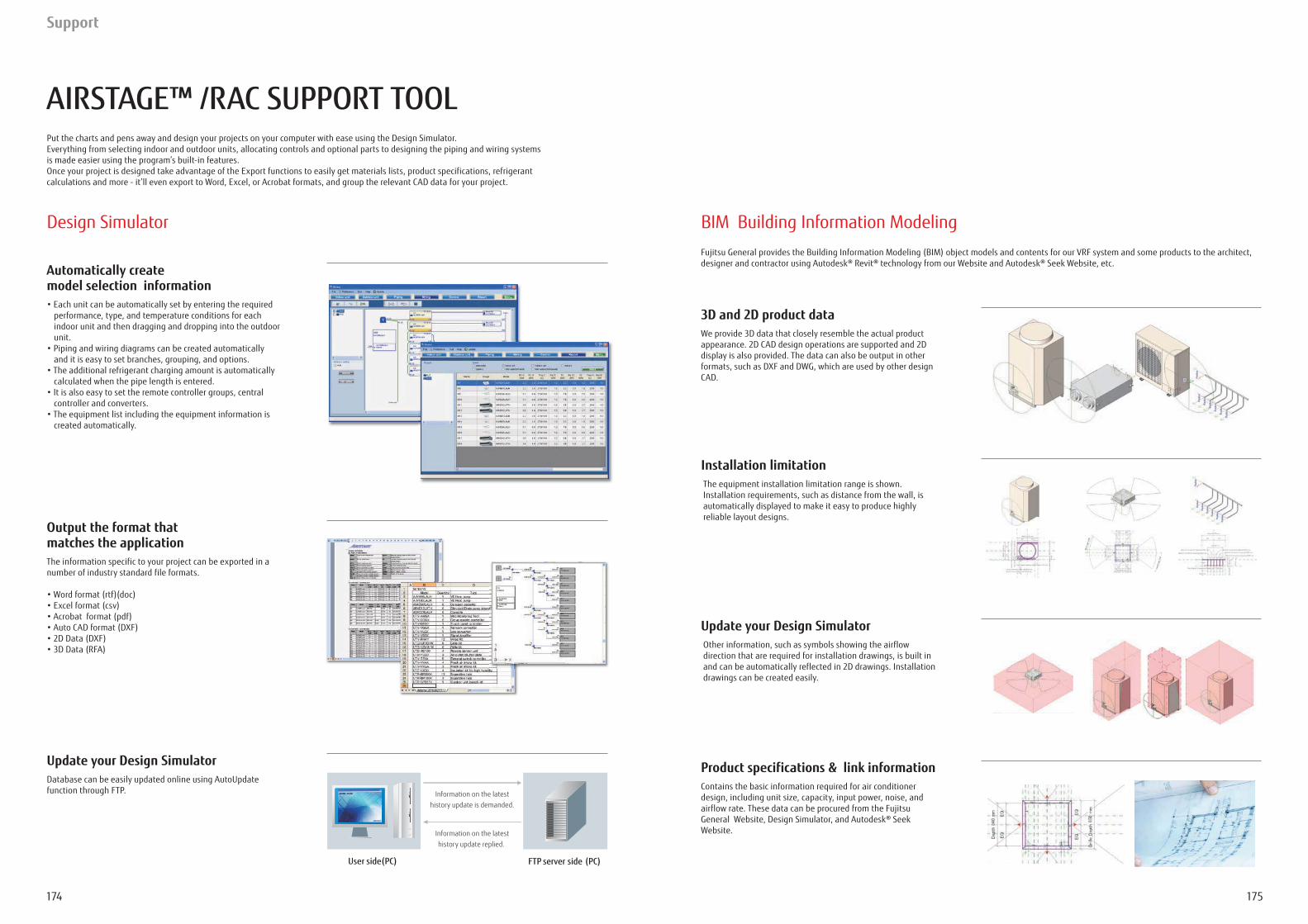
175174
Support
AIRSTAGE™ /RAC SUPPORT TOOLPut the charts and pens away and design your projects on your computer with ease using the Design Simulator.
Automatically createmodel selection information
Fujitsu General provides the Building Information Modeling (BIM) object models and contents for our VRF system and some products to the architect, designer and contractor using Autodesk® Revit® technology from our Website and Autodesk® Seek Website, etc.
performance, type, and temperature conditions for each indoor unit and then dragging and dropping into the outdoor unit.
and it is easy to set branches, grouping, and options.
calculated when the pipe length is entered.
controller and converters.
created automatically.
Output the format that matches the application
number of industry standard file formats.
Update your Design SimulatorDatabase can be easily updated online using AutoUpdate function through FTP.
Product specifications & link informationContains the basic information required for air conditioner design, including unit size, capacity, input power, noise, and airflow rate. These data can be procured from the Fujitsu General Website, Design Simulator, and Autodesk® Seek Website.
3D and 2D product dataWe provide 3D data that closely resemble the actual product appearance. 2D CAD design operations are supported and 2D display is also provided. The data can also be output in other
CAD.
Installation limitationThe equipment installation limitation range is shown. Installation requirements, such as distance from the wall, is automatically displayed to make it easy to produce highly reliable layout designs.
Update your Design SimulatorOther information, such as symbols showing the airflow direction that are required for installation drawings, is built in and can be automatically reflected in 2D drawings. Installation drawings can be created easily.
Design Simulator BIM Building Information Modeling
Information on the latest history update is demanded.
Information on the latest history update replied.
User side(PC) FTP server side (PC)
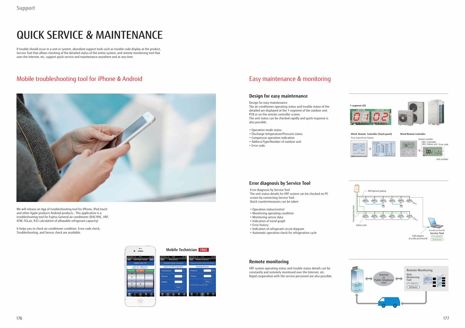
177176
Support
QUICK SERVICE & MAINTENANCEIf trouble should occur in a unit or system, abundant support tools such as trouble code display at the product, Service Tool that allows checking of the detailed status of the entire system, and remote monitoring tool that uses the internet, etc. support quick service and maintenance anywhere and at any time.
We will release an App of troubleshooting tool for iPhone, iPod touch and other Apple products Android products.. This application is a troubleshooting tool for Fujitsu General air conditioner (RAC/PAC, VRF, ATW, FGLair, R32 calculation of allowable refrigerant capacity)
Troubleshooting, and Sensor check are available.
Remote monitoringVRF system operating status and trouble status details can be constantly and remotely monitored over the Internet, etc. Rapid cooperation with the service personnel are also possible.
Design for easy maintenanceDesign for easy maintenanceThe air conditioner operating status and trouble status of the
PCB or on the remote controller screen. The unit status can be checked rapidly and quick response is also possible.
Error diagnosis by Service Tool
The unit status details for VRF system can be checked on PC screen by connecting Service Tool. Quick countermeasures can be taken
Mobile troubleshooting tool for iPhone & Android
Mobile Technician FREE
System number001: Controller002: Indoor unit Error code
Unit number
7-segment LED
Wired Remote ControllerWired Remote Controller (Touch panel)Error status/Error history
(Locally purchased)
Refrigerant piping
Tran
smis
sion
line
Indoor unit
USB adaptor(Locally purchased)
Service ToolUTY-ASGXZ1
Software
Internetor
Public TelephoneLine
Web MonitoringToolUTY-AMGXZ1
Remote Monitoring
Software
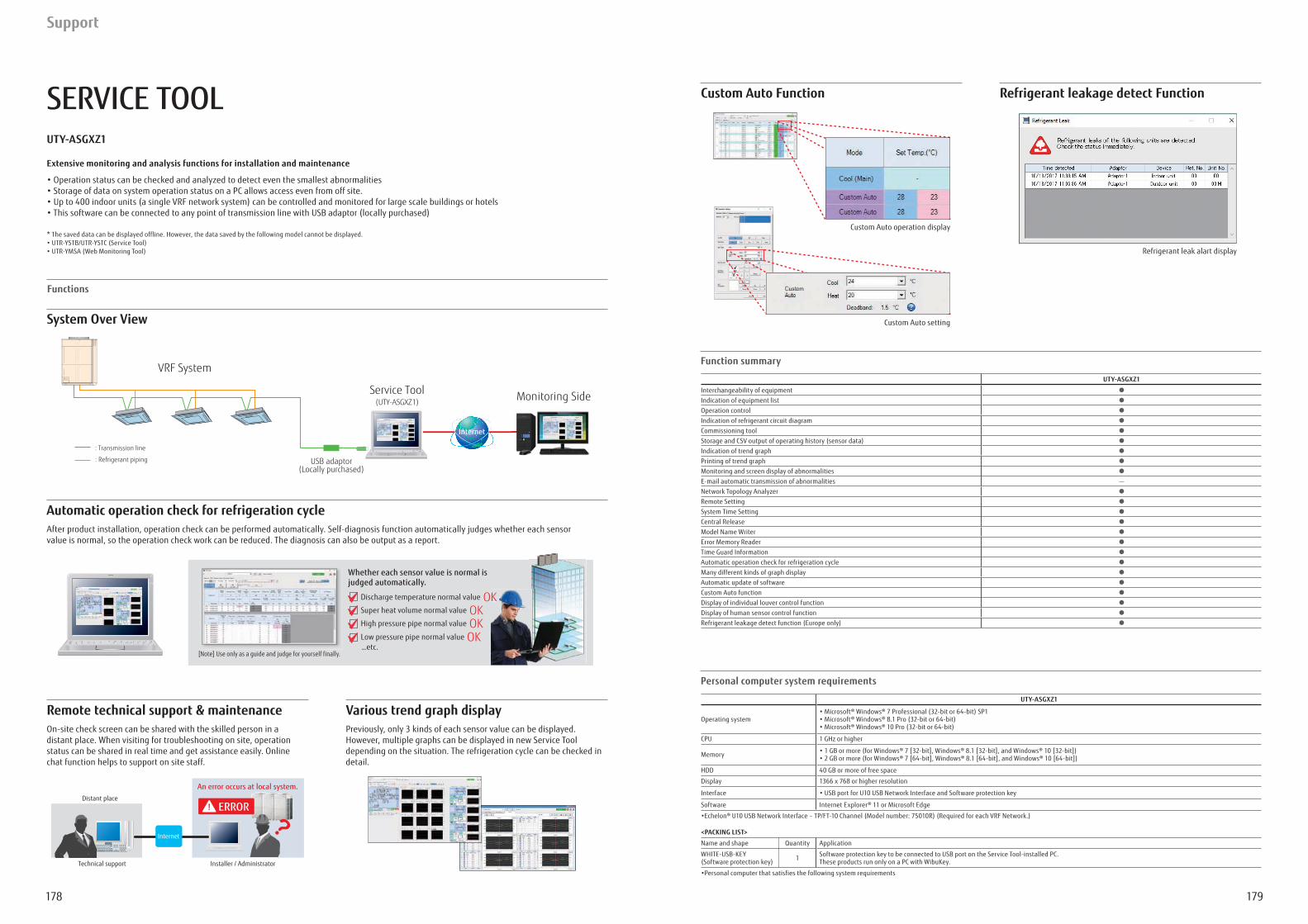
179178
Support
SERVICE TOOLUTY-ASGXZ1
Extensive monitoring and analysis functions for installation and maintenance
* The saved data can be displayed offline. However, the data saved by the following model cannot be displayed.
<PACKING LIST>
Name and shape Quantity Application
(Software protection key) 1
Personal computer system requirements
UTY-ASGXZ1
Operating system
CPU 1 GHz or higher
Memory
HDD 40 GB or more of free space
Display
Interface
Software
Function summary
UTY-ASGXZ1
Interchangeability of equipmentIndication of equipment listOperation controlIndication of refrigerant circuit diagramCommissioning toolStorage and CSV output of operating history (sensor data)Indication of trend graphPrinting of trend graphMonitoring and screen display of abnormalities
Network Topology AnalyzerRemote SettingSystem Time SettingCentral ReleaseModel Name Writer
Time Guard InformationAutomatic operation check for refrigeration cycleMany different kinds of graph displayAutomatic update of softwareCustom Auto functionDisplay of individual louver control functionDisplay of human sensor control function
Remote technical support & maintenance Various trend graph display
distant place. When visiting for troubleshooting on site, operation status can be shared in real time and get assistance easily. Online chat function helps to support on site staff.
Previously, only 3 kinds of each sensor value can be displayed. However, multiple graphs can be displayed in new Service Tool depending on the situation. The refrigeration cycle can be checked in detail.
Automatic operation check for refrigeration cycle
value is normal, so the operation check work can be reduced. The diagnosis can also be output as a report.
Whether each sensor value is normal is judged automatically.
Discharge temperature normal value OKSuper heat volume normal value OKHigh pressure pipe normal value OKLow pressure pipe normal value OK…etc.
K
[Note] Use only as a guide and judge for yourself finally.
USB adaptor(Locally purchased)
Monitoring SideService Tool(UTY-ASGXZ1)
VRF System
: Refrigerant piping
: Transmission line
Internet
Distant place
Technical support Installer / Administrator
An error occurs at local system.
Internet
ERROR
Functions
System Over View
Refrigerant leak alart display
Custom Auto operation display
Custom Auto setting
Custom Auto Function Refrigerant leakage detect Function
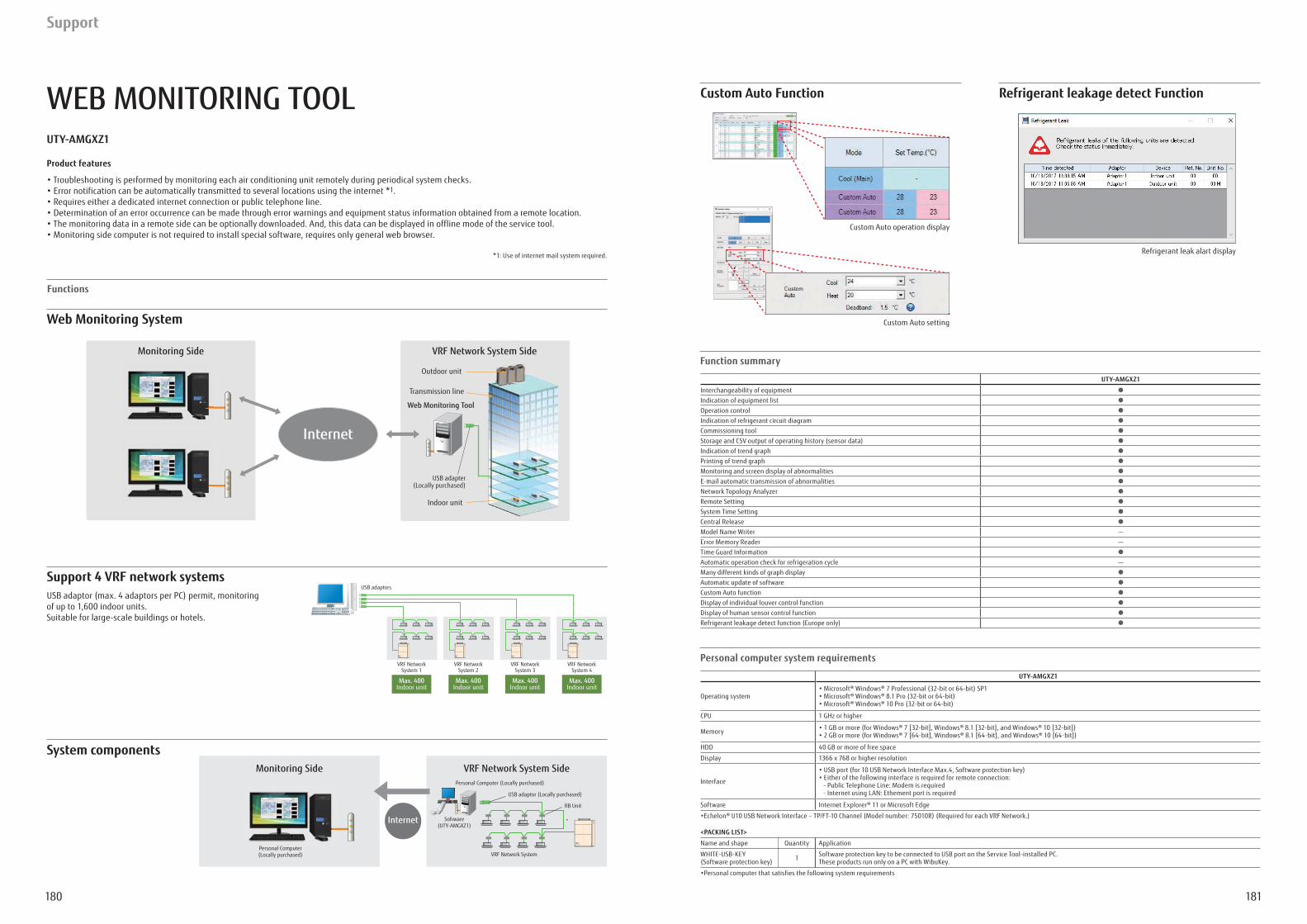
181180
WEB MONITORING TOOLUTY-AMGXZ1
Product features
1.
Support 4 VRF network systems
of up to 1,600 indoor units.
System components
Personal computer system requirements
UTY-AMGXZ1
Operating system
CPU 1 GHz or higher
Memory
HDD 40 GB or more of free space
Display
Interface
Software
<PACKING LIST>
Name and shape Quantity Application
(Software protection key) 1
Indoor unit
Transmission line
USB adapter(Locally purchased)
Outdoor unit
Web Monitoring Tool
VRF Network System SideMonitoring Side
Internet
Indoor unitMax. 400
VRF NetworkSystem 2
Indoor unitMax. 400
VRF NetworkSystem 3
Indoor unitMax. 400
VRF NetworkSystem 4
Indoor unitMax. 400
VRF NetworkSystem 1
USB adaptors
Personal Computer(Locally purchased)
Personal Computer (Locally purchased)
USB adaptor (Locally purchased)
Internet Software(UTY-AMGXZ1)
VRF Network System
RB Unit
VRF Network System SideMonitoring Side
P l C
Soft
Function summary
UTY-AMGXZ1
Interchangeability of equipmentIndication of equipment listOperation controlIndication of refrigerant circuit diagramCommissioning toolStorage and CSV output of operating history (sensor data)Indication of trend graphPrinting of trend graphMonitoring and screen display of abnormalities
Network Topology AnalyzerRemote SettingSystem Time SettingCentral ReleaseModel Name Writer
Time Guard InformationAutomatic operation check for refrigeration cycleMany different kinds of graph displayAutomatic update of softwareCustom Auto functionDisplay of individual louver control functionDisplay of human sensor control function
Refrigerant leak alart display
Custom Auto operation display
Custom Auto setting
Custom Auto Function Refrigerant leakage detect Function
Functions
Web Monitoring System
Support
Fujitsu General (Thailand) Co., Ltd.
Fujitsu General (Shanghai) Co., Ltd.
SATISFACTION
183182
• Actual products’ colors may be different from the colors shown in this printed material.
Distributed by :
Copyright© 2008-2019 Fujitsu General Limited. All rights reserved.6EF012-1903E
3-3-17, Suenaga, Takatsu-ku, Kawasaki 213-8502, Japanhttps://www.fujitsu-general.com/
VRF CATALOGUEHEAT PUMP & HEAT RECOVERY
Variable Refrigerant Flow System


