Embed Size (px)
Citation preview

Table of Contents
Cover photo may show optional equipment not supplied with standard unit. For an Operator’s Manual and Decal Kit in French Language, please see your Land Pride dealer.
Read the Operator’s Manual entirely. When you see this symbol, the subsequent instructions and warnings are serious - follow without exception. Your life and the lives of others depend on it!
!
All-Flex Grooming MowersAFM4214 and AFM4216
315-587MOperator’s Manual
Printed 11/19/21
26560

11/19/21AFM4214 and AFM4216 All-Flex Grooming Mowers 315-587MI
Machine IdentificationRecord your machine details in the log below. If you replace this manual, be sure to transfer this information to the new manual.
If you, or the dealer, have added Options not originally ordered with the machine, or removed Options that were originally ordered, the weights and measurements are no longer accurate for your machine. Update the record by adding the machine weight and measurements provided in the Specifications & Capacities Section of this manual with the Option(s) weight and measurements.
Dealer Contact Information
Model Number
Serial Number
Machine Height
Machine Length
Machine Width
Machine Weight
Delivery Date
First Operation
Accessories
Name:
Street:
City/State:
Telephone:
Email:
California Proposition 65
WARNING: Cancer and reproductive harm - www.P65Warnings.ca.gov!

Table of Contents
11/19/21
© Copyright 2021 All rights Reserved
Land Pride provides this publication “as is” without warranty of any kind, either expressed or implied. While every precaution has been taken in thepreparation of this manual, Land Pride assumes no responsibility for errors or omissions. Neither is any liability assumed for damages resulting from the useof the information contained herein. Land Pride reserves the right to revise and improve its products as it sees fit. This publication describes the state of thisproduct at the time of its publication, and may not reflect the product in the future.
Land Pride is a registered trademark.
All other brands and product names are trademarks or registered trademarks of their respective holders.
Printed in the United States of America.
AFM4214 and AFM4216 All-Flex Grooming Mowers 315-587M II
Table of ContentsImportant Safety Information . . . . . . . . . . . . . 1
Safety at All Times . . . . . . . . . . . . . . . . . . . . . . . . . 1Look for the Safety Alert Symbol . . . . . . . . . . . . . . . 1Safety Labels . . . . . . . . . . . . . . . . . . . . . . . . . . . . . 6
Introduction . . . . . . . . . . . . . . . . . . . . . . . . . . 15Application . . . . . . . . . . . . . . . . . . . . . . . . . . . . . . 15Using This Manual . . . . . . . . . . . . . . . . . . . . . . . . 15Owner Assistance . . . . . . . . . . . . . . . . . . . . . . . . . 15
Section 1: Assembly & Set-Up . . . . . . . . . . . 16Tractor Requirements . . . . . . . . . . . . . . . . . . . . . . 16Electrical Hook-up . . . . . . . . . . . . . . . . . . . . . . . . . 16Drawbar Set-Up . . . . . . . . . . . . . . . . . . . . . . . . . . 16Dealer Preparations . . . . . . . . . . . . . . . . . . . . . . . 17Hardware Torque Information . . . . . . . . . . . . . . . . 17Tractor Shutdown Procedure . . . . . . . . . . . . . . . . 17Tractor Hook-Up . . . . . . . . . . . . . . . . . . . . . . . . . . 18Main Driveline Hook-up . . . . . . . . . . . . . . . . . . . . . 18Hydraulic Hook-Up . . . . . . . . . . . . . . . . . . . . . . . . 19Hook-up Transport Lights . . . . . . . . . . . . . . . . . . . 19Check Driveline Collapsible Length . . . . . . . . . . . . 20
Assemble Inner & Outer Driveline Halves . . . . . 20Pull Rope Hook-Up . . . . . . . . . . . . . . . . . . . . . . . . 21Gauge Wheel Assembly . . . . . . . . . . . . . . . . . . . . 21Purge Hydraulic System . . . . . . . . . . . . . . . . . . . . 22Belt Tension . . . . . . . . . . . . . . . . . . . . . . . . . . . . . 23
Section 2: Adjustments . . . . . . . . . . . . . . . . . 23Center & Wing Deck Cutting Heights . . . . . . . . . . 24Hydraulic Transport Locks, Optional . . . . . . . . . . . 26
Section 3: Operating Instructions . . . . . . . . 27Introduction . . . . . . . . . . . . . . . . . . . . . . . . . . . . . . 27General Safety . . . . . . . . . . . . . . . . . . . . . . . . . . . 27Tractor & Mower Inspection . . . . . . . . . . . . . . . . . 28U-Joint Timing . . . . . . . . . . . . . . . . . . . . . . . . . . . . 29Fold Mower Decks . . . . . . . . . . . . . . . . . . . . . . . . 29Unfold Mower Decks . . . . . . . . . . . . . . . . . . . . . . . 30
Unfold Decks With Pull Rope Locks . . . . . . . . . . 30Unfold Decks With Hydraulic Locks . . . . . . . . . . 30
Transporting . . . . . . . . . . . . . . . . . . . . . . . . . . . . . 31Constant Velocity Driveline Angle . . . . . . . . . . . . . 31Unhook Mower . . . . . . . . . . . . . . . . . . . . . . . . . . . 32Special Operating Instructions . . . . . . . . . . . . . . . 32General Operating Instructions . . . . . . . . . . . . . . . 33
Section 4: Accessories . . . . . . . . . . . . . . . . . 34Ball Swivel Hitch . . . . . . . . . . . . . . . . . . . . . . . . . . 34
Slow Moving Vehicle Sign (Accessory) . . . . . . . 34Cutting Blades . . . . . . . . . . . . . . . . . . . . . . . . . . . . 34
Low Lift Blades (Standard) . . . . . . . . . . . . . . . . . 34Medium Lift Blades . . . . . . . . . . . . . . . . . . . . . . . 34High Lift Blades . . . . . . . . . . . . . . . . . . . . . . . . . 34Mulching Blades . . . . . . . . . . . . . . . . . . . . . . . . . 34
Section 5: Maintenance & Lubrication . . . . . 35Maintenance . . . . . . . . . . . . . . . . . . . . . . . . . . . . . 35Hydraulic System . . . . . . . . . . . . . . . . . . . . . . . . . 35Transport Tires . . . . . . . . . . . . . . . . . . . . . . . . . . . 35V-Belt Installation . . . . . . . . . . . . . . . . . . . . . . . . . 36Servicing Mower Blades . . . . . . . . . . . . . . . . . . . . 36
Blade Inspection . . . . . . . . . . . . . . . . . . . . . . . . . 36Blade Removal & Installation . . . . . . . . . . . . . . . 37Blade Sharpening . . . . . . . . . . . . . . . . . . . . . . . . 38
Driveline Protection . . . . . . . . . . . . . . . . . . . . . . . . 38Clutch Run-in . . . . . . . . . . . . . . . . . . . . . . . . . . . . 38Inspect Friction Disc . . . . . . . . . . . . . . . . . . . . . . . 39Replace Friction Disc . . . . . . . . . . . . . . . . . . . . . . 39
Remove Driveline . . . . . . . . . . . . . . . . . . . . . . . . 39Disassemble Clutch . . . . . . . . . . . . . . . . . . . . . . 39Inspect Clutch . . . . . . . . . . . . . . . . . . . . . . . . . . 39Assemble Clutch . . . . . . . . . . . . . . . . . . . . . . . . 39Reattach Driveline to Implement . . . . . . . . . . . . 39
Clutch Adjustment . . . . . . . . . . . . . . . . . . . . . . . . . 39Long-Term Storage . . . . . . . . . . . . . . . . . . . . . . . . 40Ordering Replacement Parts . . . . . . . . . . . . . . . . . 40Lubrication Points . . . . . . . . . . . . . . . . . . . . . . . . . 41
Driveline Constant Velocity Shaft . . . . . . . . . . . . 41Driveline Shafts . . . . . . . . . . . . . . . . . . . . . . . . . 41Inner Tube of Driveline . . . . . . . . . . . . . . . . . . . . 41Wheel Support Bushings . . . . . . . . . . . . . . . . . . 42Wheel Bearings (15" Gauge Wheels) . . . . . . . . . 42Wheel Bearings (18" Gauge Wheels) . . . . . . . . . 42Wheel Bushings (Transport Hubs) . . . . . . . . . . . 42Blade Spindle Bearings . . . . . . . . . . . . . . . . . . . 43Tool Bar to Deck Pivot Pin . . . . . . . . . . . . . . . . . 43Transport Locks . . . . . . . . . . . . . . . . . . . . . . . . . 43Wing Deck Pivot Bushings . . . . . . . . . . . . . . . . . 44Rear Deck Pivot Half Clamps . . . . . . . . . . . . . . . 44Wing Flex Pivot Lugs . . . . . . . . . . . . . . . . . . . . . 444-Way Gearbox . . . . . . . . . . . . . . . . . . . . . . . . . 45Mower Deck Gearbox . . . . . . . . . . . . . . . . . . . . . 45
Continue Table of Contents on the next page

Table of Contents Continued
11/19/21AFM4214 and AFM4216 All-Flex Grooming Mowers 315-587M
Table of Contents
III
Parts Manual QR LocatorThe QR (Quick Reference) codes above will take you to the Parts Manual for this equipment. Download the appropriate App on your smart phone, open the App, point your phone on the QR code and take a picture.
Dealer QR LocatorThe QR code above will link you to available dealers for Land Pride products. Download the appropriate App on your smart phone, open the App, point your phone on the QR code and take a picture.
Section 6: Specifications & Capacities . . . . 46Section 7: Features & Benefits . . . . . . . . . . . 50Section 8: Troubleshooting . . . . . . . . . . . . . 52Section 9: Torque & Tire Inflation Charts . . 54Section 10: Warranty . . . . . . . . . . . . . . . . . . . 55
AFM4216AFM4214
Important Safety Information
11/19/21 1
Important Safety InformationListed below are common practices that may or may not be applicable to the products described in this manual.
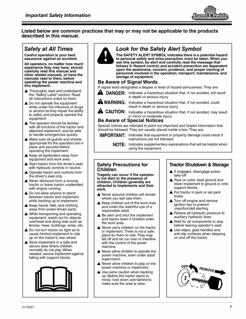
Tractor Shutdown & Storage If engaged, disengage power
take-off. Park on solid, level ground and
lower implement to ground or onto support blocks.
Put tractor in park or set park brake.
Turn off engine and remove ignition key to prevent unauthorized starting.
Relieve all hydraulic pressure to auxiliary hydraulic lines.
Wait for all components to stop before leaving operator’s seat.
Use steps, grab-handles and anti-slip surfaces when stepping on and off the tractor.
OFF REMOVE
Look for the Safety Alert SymbolThe SAFETY ALERT SYMBOL indicates there is a potential hazard to personal safety and extra precaution must be taken. When you see this symbol, be alert and carefully read the message that follows it. Hazard control, and accident prevention are dependent upon the awareness, concern, prudence, and proper training of personnel involved in the operation, transport, maintenance, and storage of equipment.
Safety Precautions for ChildrenTragedy can occur if the operator is not alert to the presence of children, Children generally are attracted to implements and their work. Never assume children will remain
where you last saw them. Keep children out of the work area
and under the watchful eye of a responsible adult.
Be alert and shut the implement and tractor down if children enter the work area.
Never carry children on the tractor or implement. There is not a safe place for them to ride. They may fall off and be run over or interfere with the control of the power machine.
Never allow children to operate the power machine, even under adult supervision.
Never allow children to play on the power machine or implement.
Use extra caution when backing up. Before the tractor starts to move, look down and behind to make sure the area is clear.
Safety at All TimesCareful operation is your best assurance against an accident. All operators, no matter how much experience they may have, should carefully read this manual and other related manuals, or have the manuals read to them, before operating the power machine and this implement. Thoroughly read and understand
the “Safety Label” section. Read all instructions noted on them.
Do not operate the equipment while under the influence of drugs or alcohol as they impair the ability to safely and properly operate the equipment.
The operator should be familiar with all functions of the tractor and attached implement, and be able to handle emergencies quickly.
Make sure all guards and shields appropriate for the operation are in place and secured before operating the implement.
Keep all bystanders away from equipment and work area.
Start tractor from the driver’s seat with hydraulic controls in neutral.
Operate tractor and controls from the driver’s seat only.
Never dismount from a moving tractor or leave tractor unattended with engine running.
Do not allow anyone to stand between tractor and implement while backing up to implement.
Keep hands, feet, and clothing away from power-driven parts.
While transporting and operating equipment, watch out for objects overhead and along side such as fences, trees, buildings, wires, etc.
Do not turn tractor so tight as to cause hitched implement to ride up on the tractor’s rear wheel.
Store implement in a safe and secure area where children normally do not play. When needed, secure implement against falling with support blocks.
!
Be Aware of Signal WordsA signal word designates a degree or level of hazard seriousness. They are:
DANGER:!
WARNING:
CAUTION:!
!
Indicates a hazardous situation that, if not avoided, will result in death or serious injury.
Indicates a hazardous situation that, if not avoided, could result in death or serious injury.
Indicates a hazardous situation that, if not avoided, may result in minor or moderate injury.
Be Aware of Special NoticesSpecial notices are intended to point out important and helpful information that should be followed. They are usually placed inside a box. They are:
Indicates that equipment or property damage could result if instructions are not followed.Indicates supplementary explanations that will be helpful when using the equipment.
IMPORTANT:
NOTE:

Important Safety Information
11/19/212
Listed below are common practices that may or may not be applicable to the products described in this manual.
Use A Safety Chain A safety chain will help control
drawn machinery should it separate from the tractor drawbar.
Use a chain with the strength rating equal to or greater than the gross weight of the towed implement.
Attach the chain to the tractor drawbar support or other specified anchor location. Allow only enough slack in the chain to permit turning.
Always hitch the implement to the machine towing it. Do not use the safety chain to tow the implement.
Practice Safe Maintenance Understand procedure before doing
work. Refer to the Operator’s Manual for additional information.
Work on a level surface in a clean dry area that is well-lit.
Lower implement to the ground and follow all shutdown procedures before leaving the operator’s seat to perform maintenance.
Do not work under any hydraulically supported equipment. It can settle, suddenly leak down, or be lowered accidentally. If it is necessary to work under the equipment, securely support it with stands or suitable blocking beforehand.
Use properly grounded electrical outlets and tools.
Use correct tools and equipment for the job that are in good condition.
Allow equipment to cool before working on it.
Disconnect battery ground cable (-) before servicing or adjusting electrical systems or before welding on implement.
Inspect all parts. Make certain parts are in good condition & installed properly.
Replace parts on this implement with genuine Land Pride parts only. Do not alter this implement in a way which will adversely affect its performance.
Do not grease or oil implement while it is in operation.
Remove buildup of grease, oil, or debris.
Always make sure any material and waste products from the repair and maintenance of the implement are properly collected and disposed.
Remove all tools and unused parts from equipment before operation.
Do not weld or torch on galvanized metal as it will release toxic fumes.
Tire Safety Tire changing
can be dangerous and must be performed by trained personnel using the correct tools and equipment.
Always properly match the wheel size to the properly sized tire.
Always maintain correct tire pressure. Do not inflate tires above recommended pressures shown in the Operator’s Manual.
When inflating tires, use a clip-on chuck and extension hose long enough to allow you to stand to one side and NOT in front of or over the tire assembly. Use a safety cage if available.
Securely support the implement when changing a wheel.
When removing and installing wheels, use wheel handling equipment adequate for the weight involved.
Make sure wheel bolts have been tightened to the specified torque.
Transport Safely Comply with federal, state, and
local laws. Use towing vehicle and trailer of
adequate size and capacity. Secure equipment towed on a trailer with tie downs and chains.
Sudden braking can cause a towed trailer to swerve unexpectedly. Reduce speed if towed trailer is not equipped with brakes.
Avoid contact with any overhead utility lines or electrically charged conductors.
Always drive with load on end of loader arms low to the ground.
Always drive straight up and down steep inclines with heavy end of skid steer on the “uphill” side.
Engage park brake when stopped on an incline.
Maximum transport speed for an attached equipment is 20 mph (32 km/h). DO NOT EXCEED. Never travel at a speed which does not allow adequate control of steering and stopping. Some rough terrains require a slower speed.
As a guideline, use the following maximum speed weight ratios for attached equipment:
20 mph (32 km/h) when weight of attached equipment is less than or equal to the weight of machine towing the equipment.10 mph (16 km/h) when weight of attached equipment exceeds weight of machine towing equipment but not more than double the weight.
IMPORTANT: Do not tow a load that is more than double the weight of the vehicle towing the load.

Important Safety Information
11/19/21 3
Listed below are common practices that may or may not be applicable to the products described in this manual.
Use Seat Belt and ROPS Land Pride recommends the use
of a CAB or roll-over-protective-structures (ROPS) and seat belt in almost all power machines. Combination of a CAB or ROPS and seat belt will reduce the risk of serious injury or death if the power machine should be upset.
If ROPS is in the locked-up position, fasten seat belt snugly and securely to help protect against serious injury or death from falling and machine overturn.
Keep Riders Off Machinery Never carry riders on the tractor or
implement. Riders obstruct operator’s view
and interfere with the control of the power machine.
Riders can be struck by objects or thrown from the equipment.
Never use the tractor or implement to lift or transport riders.
Prepare for Emergencies Be prepared if a fire starts. Keep a first aid kit and fire
extinguisher handy. Keep emergency numbers for
doctor, ambulance, hospital, and fire department near the phone.
911
Use Safety Lights and Devices A Slow moving power machine
can create a hazard when driven on public roads. They are difficult to see, especially at night. Use the Slow Moving Vehicle (SMV) sign when on public roads.
Flashing warning lights and turn signals are recommended whenever driving on public roads.
Avoid High Pressure Fluids Escaping fluid
under pressure will penetrate the skin or eyes causing serious injury.
Relieve all residual pressure before disconnecting hydraulic lines or performing work on the hydraulic system.
Make sure all hydraulic fluid connections are properly tightened/torqued and all hydraulic hoses and lines are in good condition before applying pressure to the system.
Use a piece of paper or cardboard, NOT BODY PARTS, to check for suspected leaks.
Wear protective gloves and safety glasses or goggles when working with hydraulic systems.
DO NOT DELAY. If an accident occurs, seek immediate emergency medical care or gangrene may result.
Wear Personal Protective Equipment (PPE) Wear protective clothing and
equipment appropriate for the job such as safety shoes, safety, glasses, hard hat, dust mask, and ear plugs.
Clothing should fit snug without fringes and pull strings to avoid entanglement with moving parts.
Prolonged exposure to loud noise can cause hearing impairment or hearing loss. Wear suitable hearing protection such as earmuffs or earplugs.
Operating a machine safely requires the operator’s full attention. Avoid wearing headphones while operating equipment.

Important Safety Information
11/19/214
Handle Chemicals Properly Protective clothing should be
worn. Handle all chemicals with care. Follow instructions on container
label. Agricultural chemicals can be
dangerous. Improper use can seriously injure persons, animals, plants, soil, and property.
Inhaling smoke from any type of chemical fire can be a serious health hazard.
Store or dispose of unused chemicals as specified by the chemical manufacturer.
Dig Safe - Avoid Underground Utilities USA: Call 811
CAN: digsafecanada.ca Always contact your local utility companies (electrical, telephone, gas, water, sewer, and others) before digging so that they may mark the location of any underground services in the area.
Be sure to ask how close you can work to the marks they positioned.
Listed below are common practices that may or may not be applicable to the products described in this manual.
Avoid crystalline Silica (quartz) DustBecause crystalline silica is a basic component of sand and granite, many activities at construction sites produce dust containing crystalline silica. Trenching, sawing, and boring of material containing crystalline silica can produce dust containing crystalline silica particles. This dust can cause serious injury to the lungs (silicosis).There are guidelines which should be followed if crystalline silica (quartz) is present in the dust.
Be aware of and follow OSHA (or other local, State, or Federal) guidelines for exposure to airborne crystalline silica.
Know the work operations where exposure to crystalline silica may occur.
Participate in air monitoring or training programs offered by the employer.
Be aware of and use optional equipment controls such as water sprays, local exhaust ventilation, and enclosed cabs with positive pressure air conditioning if the machine has such equipment. Otherwise respirators shall be worn.
Where respirators are required, wear a respirator approved for protection against crystalline silica containing dust. Do not alter respirator in any way. Workers who use tight-fitting respirators can not have beards/mustaches which interfere with the respirator seal to the face.
If possible, change into disposable or washable work clothes at the work site; shower and change into clean clothing before leaving the work site.
Do not eat, drink, use tobacco products, or apply cosmetics in areas where there is dust containing crystalline silica.
Store food, drink, and personal belongings away from the work area.
Wash hands and face before eating, drinking, smoking, or applying cosmetics after leaving the exposure area.

Important Safety Information
11/19/21 5
This page left blank intentionally.

Important Safety InformationTable of Contents
AFM4214 and AFM4216 All-Flex Grooming Mowers 315-587M 11/19/216
Safety LabelsYour All-Flex Grooming Mower comes equipped with all safety labels in place. They were designed to help you safely operate your implement. Read and follow their directions.1. Keep all safety labels clean and legible.2. Refer to this section for proper label placement. Replace
all damaged or missing labels. Order new labels from your nearest Land Pride dealer. To find your nearest dealer, visit our dealer locator at www.landpride.com.
3. Some new equipment installed during repair requires safety labels to be affixed to the replaced component as specified by Land Pride. When ordering new components
make sure the correct safety labels are included in the request.
4. Refer to this section for proper label placement.To install new labels:a. Clean surface area where label is to be placed.b. Spray soapy water onto the cleaned area.c. Peel backing from label and press label firmly onto the
surface.d. Squeeze out air bubbles with edge of a credit card or
with a similar type of straight edge.
26563
818-558CWarning: General Mower Hazard1 Place: On the tongue
70269
Important Safety Information
Important Safety InformationTable of Contents
AFM4214 and AFM4216 All-Flex Grooming Mowers 315-587M11/19/21 7
26563
26563
26563
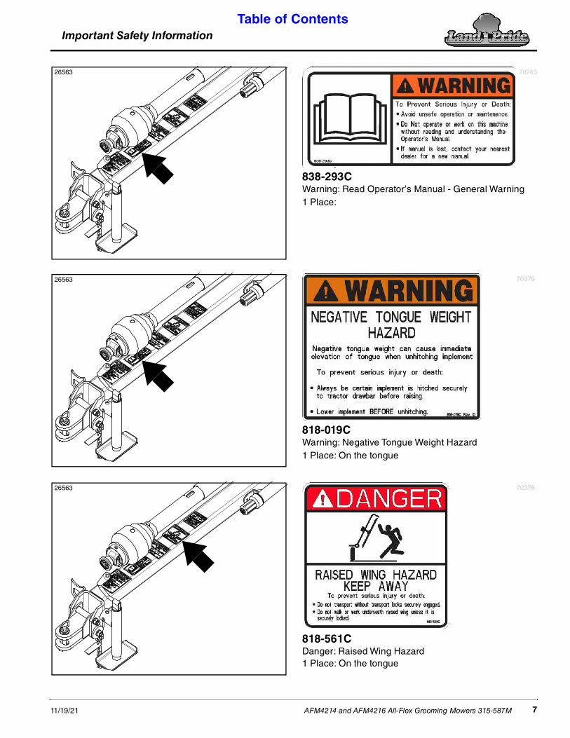
838-293CWarning: Read Operator’s Manual - General Warning1 Place:
70243
818-019CWarning: Negative Tongue Weight Hazard1 Place: On the tongue
70379
818-561CDanger: Raised Wing Hazard1 Place: On the tongue
70378

Important Safety InformationTable of Contents
AFM4214 and AFM4216 All-Flex Grooming Mowers 315-587M 11/19/218
26563
26621
26621
818-339CWarning: High Pressure Fluid Hazard1 Place: On the tongue
70372
818-565CNotice: Driveline U-Joint Timing Instructions1 Place: On the splitter gearbox shield
72378
818-560CNotice: Read Operator’s Manual and Safety Messages1 Place: On the splitter gearbox shield
70377
Important Safety InformationTable of Contents
AFM4214 and AFM4216 All-Flex Grooming Mowers 315-587M11/19/21 9
30262
26621
26563
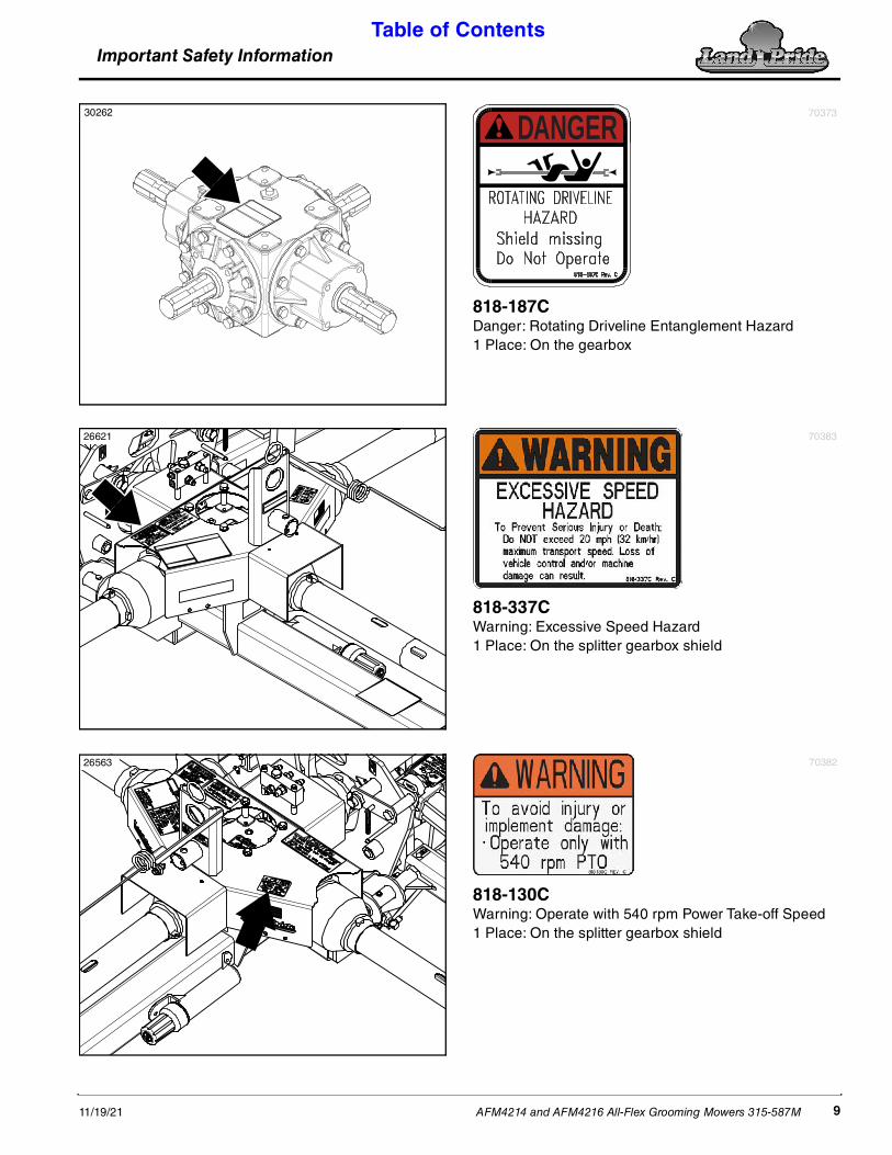
818-187CDanger: Rotating Driveline Entanglement Hazard1 Place: On the gearbox
DANGER70373
818-337CWarning: Excessive Speed Hazard1 Place: On the splitter gearbox shield
70383
818-130CWarning: Operate with 540 rpm Power Take-off Speed1 Place: On the splitter gearbox shield
70382

Important Safety InformationTable of Contents
AFM4214 and AFM4216 All-Flex Grooming Mowers 315-587M 11/19/2110
26563
26563
26565
818-353CCaution: Disengage Transport Locks/Pins Hazard1 Place: On the splitter gearbox shield
70380
818-351CCaution: Engage Transport Locks/Pins Hazard1 Place: Above the park jack storage mount
70381
70375
818-552CDanger: Rotating Driveline - Keep Away1 Place: At the back of the tongue

Important Safety InformationTable of Contents
AFM4214 and AFM4216 All-Flex Grooming Mowers 315-587M11/19/21 11
26566
26566
26566
818-555CDanger: Rotating Blade Hazard3 Places: On the back of all three decks
70266
818-556CDanger: Thrown Object Hazard3 Places: On the back of all three decks
70376
818-045CWarning: Pinch Point or Crushing Hazard3 Places: On the back of all three decks
70312

Important Safety InformationTable of Contents
AFM4214 and AFM4216 All-Flex Grooming Mowers 315-587M 11/19/2112
26566
26566
818-513CCaution: V-Belt Installation - Tension Hazard2 Places: Beneath the guard on the center and right-hand decks
818-514CCaution: V-Belt Installation - Tension Hazard1 Place: Beneath guard on the left-hand deck
818-543CDanger: Guard Missing Hazard - Do not Operate6 Places: Beneath both guards on all three decks
70358

Important Safety InformationTable of Contents
AFM4214 and AFM4216 All-Flex Grooming Mowers 315-587M11/19/21 13
26562
26561
838-614CRed Reflector: 2" x 9"4 Places: (2 Places on back of wing deck guards)(2 Places on center deck, back side of light brackets)
858-096CAmber Reflector 2" x 4 1/2" 4 places: On the front of the left-hand & right-hand decks
73129

Important Safety InformationTable of Contents
AFM4214 and AFM4216 All-Flex Grooming Mowers 315-587M 11/19/2114
13314
13314
818-540CDanger: Guard Missing - DO NOT Operate4 Places: On all driveline inner profiles
70374
818-552CDanger: Rotating Driveline - Keep Away4 Places: On all driveline outer shields
70375

Introduction Table of Contents
AFM4214 and AFM4216 All-Flex Grooming Mowers 315-587M11/19/21 15
IntroductionThe parts on your All-Flex Grooming Mower have been specially designed by Land Pride and should only be replaced with genuine Land Pride parts. Contact a Land Pride dealer if customer service or repair parts are required. Your Land Pride dealer has trained personnel, repair parts, and equipment needed to service the implement.
Serial NumberFor quick reference and prompt service, record model and serial number on the inside cover page and again on the warranty page. Always provide model number and serial number when ordering parts and in all correspondences with your Land Pride dealer. For location of your serial number plate, see Figure 1.
Serial Number Plate LocationFigure 1
Further AssistanceYour dealer wants you to be satisfied with your new All-Flex Grooming mower. If for any reason you do not understand any part of this manual or are not satisfied with the service received, the following actions are suggested:
1. Discuss any problems you have with your implement with your dealership service personnel so they can address the problem.
2. If you are still not satisfied, seek out the owner or general manager of the dealership, explain the question/problem, and request assistance.
3. For further assistance write to:
Land Pride Service Department1525 East North Street
P.O. Box 5060Salina, Ks. 67402-5060
E-mail [email protected]
26563
Land Pride welcomes you to the growing family of new product owners. This All-Flex Grooming Mower has been designed with care and built by skilled workers using quality materials. Proper assembly, maintenance, and safe operating practices will help you get years of satisfactory use from this product
ApplicationThe AFM4214 and AFM4216 All-Flex Mowers are designed and built by Land Pride to provide excellent cutting quality and performance on lush type turf grasses that are located on expansive and well manicured areas such as sports fields, theme parks, fairways, turf farms, and large estates.
They will deliver excellent performance when attached to 40-70 hp (30-52 kW) tractors with 540 rpm power take-off speed and pull-type draw bar. The hydraulic cylinders will easily lift up the wing decks for a 7'-11" (2.41 m) or 8'-5" (2.57 m) overall transport width when moving from one site to another on public streets or on right-of-ways.
The contour following capability, highly productive cutting widths and rear discharge design of the floating cutting decks will greatly reduce wide-area cutting times and still deliver finely groomed surfaces at mowing speeds from 2-6 mph (3-10 kph). The AFM4214 and AFM4216 All-Flex Mower can be ordered with slip-clutch or conventional wing driveline configurations and a choice of 15 inch or 18 inch deck tires.
See “Specifications & Capacities” on page 46 and “Features & Benefits” on page 50 for additional information and performance enhancing options.
Using This Manual• This Operator’s Manual is designed to help familiarize
the operator with safety, assembly, operation, adjustments, troubleshooting, and maintenance. Read this manual and follow the recommendations to help ensure safe and efficient operation.
• The information contained within this manual was current at the time of printing. Some parts may change slightly to assure you of the best performance.
• To order a new Operator’s or Parts Manual, contact your authorized dealer. Manuals can also be downloaded, free-of-charge, from our website at www.landpride.com
Terminology“Right” or “Left” as used in this manual is determined by the direction the operator faces while sitting in the operator’s seat looking forward unless otherwise stated.
Owner AssistanceThe dealer should complete the Online Warranty Registration at the time of purchase. This information is necessary to provide you with quality customer service.

Section 1: Assembly & Set-Up Table of Contents
AFM4214 and AFM4216 All-Flex Grooming Mowers 315-587M 11/19/2116
Section 1: Assembly & Set-Up
Tractor Requirements
WARNING!To avoid serious injury or death: Lightweight tractors with rear attached implements may need weights added to the front to maintain steering control. Consult your tractor Operator’s Manual to determine proper weight requirements and maximum weight limitations. Tractor horsepower should be within the range noted below. Tractors outside the horsepower range must not be used.
Horsepower Rating. . . . . . . . . . . 40-70 hp (30-52 kW)Rear power take-off Shaft Type. . . . . . 1 3/8"-6 SplineRear power take-off Speed . . . . . . . . . . . . . . 540 rpm Hitch Type. . . . . . . . . . . . . . . . . . . . . . . . . . . DrawbarHydraulic Outlets . . . . . . . . . . . . . . One duplex outletElectrical Hook-up (See Figure 1-1) . . . . . 7-Pin outletTractor Weight . . . . . . . . . . . . . . . See warning abovePositive Hitch Weight on Tractor Drawbar
AFM4214. . . . . . . . Approximately 540 lbs (245 kg)AFM4216. . . . . . . . Approximately 580 lbs. (263 kg)
Electrical Hook-upRefer to Figure 1-1:The LED wire harness is equipped with a 7-way round pin connector for connecting to the tractor’s 7-pin electrical outlet shown in Figure 1-3.
Tractor 7-Pin Electrical OutletFigure 1-1
11640
Drawbar Set-UpRefer to Figure 1-2:
DANGER!To avoid serious injury or death: Do not use a power take-off adapter. The adapter will increase strain on the tractor’s power take-off shaft causing possible damage to shaft and driveline. It will also defeat the purpose of the tractor’s power take-off shield.
WARNING!To avoid serious injury or death: • Do not use a tractor that is too small or too large. Small
tractors can be pushed around and flipped over. Large tractors can damage the attached implement.
• Power take-off damage may occur if distances are not properly maintained.
The 14" (36 cm) between center of drawbar hitch pin hole to end of power take-off shaft and 8" (20 cm) from top of drawbar hitch to center of power take-off shaft must be maintained.
Power Take-Off to Drawbar DistancesFigure 1-2
2227314"
36 cm
Power Take-Off Shaft
Drawbar8" (20 cm)
Ground Level
18" to 21"46 to 53 cm

Section 1: Assembly & Set-Up Table of Contents
AFM4214 and AFM4216 All-Flex Grooming Mowers 315-587M11/19/21 17
Dealer PreparationsThis mower has been partially assembled at the factory. some additional preparations will be necessary to finish assembling the mower and to attach it to the customer’s tractor. Ensure that the intended tractor conforms to the requirements stated under “Tractor Requirements” on page 16.
Go through the “Pre-Assembly Checklist” below before assembling the mower. To speed up your assembly task and make the job safer, have all needed parts and equipment readily at hand.
Pre-Assembly Checklist Check Ref.
Make sure miscellaneous assembly tools are on hand: Hammer, tape measure, and assortment of wrenches.
Have a forklift or hoist with properly sized chains and safety stands on hand capable of lifting 2500 lbs.
Have a minimum of two people available during assembly.
Check to see if auxiliary tractor weights are needed.
Check to make sure all fasteners and pins are installed in the correct location. Refer to the Parts Manual if unsure. NOTE: Remember location of a part or fastener if removed. Keep parts separated.
Parts Manual
Make sure all major components and loose parts are shipped with the machine.
Operator’sManual
Make sure working parts move freely, bolts are tight and cotter pins are spread.
Operator’sManual
Make sure all safety labels are correctly located and legible. Make sure red and amber reflectors are correctly located and visible when machine is in transport position. Replace damaged labels.
Page 6
80-90 EP Gear Lube must be added to the gearbox and motor as indicated in the “Maintenance & Lubrication”.
Page 41
Make sure all tires are inflated to the specified psi air pressure. Page 54
Make sure all wheel bolts and axle nuts are tightened to the specified torque. Page 54
Hardware Torque InformationWhen tightening hardware, refer to “Torque Values Chart for Common Bolt Sizes” on page 54 to determine standard torque values. Refer to “Additional Torque Values” at the bottom of the chart for exceptions to the standard torque values.
Tractor Shutdown ProcedureThe following are basic tractor shutdown procedures. Follow these procedures and any additional shutdown procedures provided in your tractor Operator’s Manual before leaving the operator’s seat.
1. Reduce engine speed and disengage power take-off if engaged.
2. Park tractor and implement on level, solid ground.
3. Lower implement to ground or onto non-concrete support blocks.
4. Put tractor in park or set park brake, turn off engine, and remove switch key to prevent unauthorized starting.
5. Relieve all hydraulic pressure to auxiliary hydraulic lines.
6. Wait for all components to come to a complete stop before leaving the operator’s seat.
7. Use steps, grab-handles and anti-slip surfaces when stepping on and off the tractor.

Section 1: Assembly & Set-Up Table of Contents
AFM4214 and AFM4216 All-Flex Grooming Mowers 315-587M 11/19/2118
Tractor Hook-Up
DANGER!To avoid serious injury or death: A crushing hazard exists while hooking-up and unhooking the implement. Keep people and animals away while backing-up to the implement or pulling away from the implement. Do not operate hydraulic controls while a person or animal is directly behind the power machine or near the implement.Refer to Refer to Figure 1-3:1. Make certain park stand (#1) is attached to the
mower hitch and secured with retaining pin (#2).
2. Check drawbar set-up. Refer to “Drawbar Set-Up” on page 16.
3. Back tractor within close proximity of clevis (#3).
4. Raise or lower park stand (#1) to align clevis (#3) with tractor drawbar. Drawbar should fit between lower and upper plates of clevis.
5. Back tractor up to mower hitch until holes in tractor drawbar and clevis are aligned.
6. Attach mower with a 3/4" hitch pin (#4) and flat washer(#5) as shown. Secure hitch pin with hairpin (#6). Always use a hitch pin that contains a safety locking device to prevent it from coming out.
7. Retract park stand (#1) until weight of mower is fully removed from the stand. Remove stand and store on storage tube (#7) located on divider gearbox shield.
8. Attach safety chain (#8) on the hitch to the tractor. Adjust chain length to remove all slack except what is necessary to permit turning of mower. Lock chain hook securely onto the chain.
Main Driveline Hook-up
DANGER!To avoid serious injury or death: • All guards and shields must be installed and in good
working condition while operating the implement.• Do not use a power take-off adapter. The adapter will
increase strain on the tractor’s power take-off shaft causing
possible damage to shaft and driveline. It will also defeat the purpose of the tractor’s power take-off shield.
WARNING!To avoid serious injury or death: • Do not operate a broken or bent driveline. Such a driveline
will break apart while rotating at high speeds. Always remove the implement from use until the damaged driveline can be repaired or replaced.
• Always follow “Tractor Shutdown Procedure” provided in this manual before dismounting the tractor.
• Some tractors are equipped with two power take-off speeds. Be certain your tractor’s power take-off shaft is set-up to operate at 540 rpm. Do not exceed 540 rpm power take-off speed. Excessive speed can damage drive components, cutter blades, and/or increase the risk of a thrown object hazard.
Refer to Figure 1-31. If driveline collapsible length has not been checked,
go to “Check Driveline Collapsible Length” on page 20. Otherwise, continue with step 2 below.
2. Place tractor gear selector in park, shut tractor engine off, set park brake, and remove switch key.
3. Pull main driveline profiles apart, apply multi-purpose grease to the inside of the outer profile and reassemble the two profiles.
4. If needed, attach driveline to the gearbox input shaft:
IMPORTANT: The driveline must be lubricated before putting it into service. Refer to “Lubrication Points” on page 41.
NOTE: Refer to Figure 1-3 on page 18: Driveline (#9) should rest on driveline support (#10) when mower and driveline are not hitched to a tractor.
NOTE: Always engage power take-off at low engine
Mower to Tractor Hook-UpFigure 1-3
37298 70105

Section 1: Assembly & Set-Up Table of Contents
AFM4214 and AFM4216 All-Flex Grooming Mowers 315-587M11/19/21 19
Hook-up Transport LightsRefer to Figure 1-5:The lead wiring harness (#6) is equipped with a 7-way round pin connector for connecting to the tractor’s 7-pin electrical outlet shown in Figure 1-1 on page 16.
1. Route lead wire harness (#6) through spring hose loop as shown.
2. Connect wire harness (#6) to the tractor’s 7-pin electrical outlet.
Enhance Module Wire Connections For LED LightsFigure 1-5
3. Check LED lights to make certain they are operating correctly.
4. It is best to have a second person available for this operation. Start tractor and operate lights as follows:
a. Turn on head lights to verify red lights illuminate.
b. Turn on flasher lights to verify amber light are blinking on and off.
5. If lights did not operate properly, recheck hook-up of wire harness (#1, #2, & #4) to enhance module (#3).
• Make sure connector (#1D) with a red wire is connected to the right-hand wire harness (#1).
• Make sure connector (#2D) with a yellow wire is connected to the left-hand wire harness (#2).
• Make sure connector (#3B) on the lead wire harness (#4) is connected to connector (#3A) on enhancer module (#3).
6. Check wire harness routing to make sure wires will not be pinched as the decks are folded and unfolded and while raising and lowering mower height.
7. Add cable ties to wire harness (#1, #2, & #4) as needed to secure them in place.
8. Continue with “Pull Rope Hook-Up” on page 21.
70482
IMPORTANT: Connectors on wire harness (#1 & #2) are labeled “Light” on one end and “Enhancer” on the other end. Ends labeled “Light” connect to the LED lights. Ends labeled “Enhancer” connect to enhance module (#3).
IMPORTANT: Connector (#1D) has a Red wire and connects to wire harness (#1) on the right side of the implement. Connector (#2D) has a yellow wire and connects to wire harness (#2) on the left side.
a. Pull back on inner driveline yoke lock collar and slide yoke over the mower’s gearbox input shaft.
b. Release lock collar and continue to push yoke onto the gearbox input shaft until pull collar snaps in place.
5. Attach driveline to the power take-off shaft:
a. Pull back on outer driveline yoke lock collar and slide yoke over the tractor’s power take-off shaft.
b. Release lock collar and continue to push yoke onto the power take-off shaft until pull collar snaps in place.
c. Move driveline back and forth to ensure both ends are secured. Reattach any end that is loose.
6. Continue with “Hydraulic Hook-Up” below.
Hydraulic Hook-UpFigure 1-4
Hydraulic Hook-UpRefer to Figure 1-4:This mower is equipped and plumbed from the factory with double acting cylinders, hydraulic hoses, and couplings for folding the wings and center deck.
1. Cut plastic ties securing hydraulic hoses (#1) to hose support loop (#2). Be careful not to cut plastic tie securing the ten linchpins (#5) to the support loop.
2. Route hoses (#1) through hose support loop (#2) and connect to tractor remote outlets. Quick disconnect hydraulic fittings for your tractor are supplied attached to the hoses.
3. Locate carbon steel wire (#3) attached between wing cylinders (#4). This wire secures the wing decks in the folded position during shipment. Remove wire and dispose of it in a trash container.
26622

Section 1: Assembly & Set-Up Table of Contents
AFM4214 and AFM4216 All-Flex Grooming Mowers 315-587M 11/19/2120
Shorten Driveline LengthFigure 1-7
9. Shorten driveline as follows:
a. Measure 1" (2.5 cm) (“B1” dimension) back from outer driveline shield and make a mark at this location on the inner driveline shield.
b. Measure 1" (2.5 cm) (“B2” dimension) back from the inner driveline shield and make a mark at this location on the outer driveline shield.
10. Remove outer driveline from the tractor power take-off shaft and inner driveline from the implement’s gearbox shaft.
11. Cut off non-yoke end of inner driveline as follows:
a. Measure from end of inner shield to scribed mark (“X” dimension) and record.
b. Cut off inner shield at the mark. Cut same amount off the inner shaft (“X1” dimension).
12. Cut off non-yoke end of outer driveline as follows:
a. Measure from end of outer shield to scribed mark (“Y” dimension) and record.
b. Cut off outer shield at the mark. Cut same amount off the outer shaft (“Y1” dimension).
13. Remove all burrs and cuttings.
14. Continue with “Assemble Inner & Outer Driveline Halves” below.
Assemble Inner & Outer Driveline HalvesRefer to Figure 1-6:1. Apply multi-purpose grease to the inside of the outer
shaft and reassemble the driveline halves.
2. Continue attaching the driveline to the mower and tractor. Refer to steps 4-5 on the left side of page 18.
23557
Check Driveline Minimum LengthFigure 1-6
Check Driveline Collapsible Length
1. Do not attach driveline to the tractor. Instead, make sure it is removed or secured to the mower before moving the mower to a level surface.
2. If parked on an uneven surface, start tractor and move mower and tractor to a level, flat surface.
3. Continue to pull mower straight forward until the driveline makes a straight line between the tractor power take-off shaft and the gearbox input shaft.
4. Shut tractor down according to “Tractor Shutdown Procedure” on page 17.
Refer to Figure 1-6:5. With driveline attached only to the cutter, remove
outer driveline (tractor end) from inner driveline to separate the two profiles as shown in Figure 1-6.
6. If needed, attach inner driveline to the mower’s input shaft. Refer to step 4 on the left side of page 18.
7. Attach outer driveline to the tractor’s power take-off shaft. Refer to step 5 on the left side of page 18.
8. Hold inner and outer drivelines parallel to each other as shown in Figure 1-6. Measure dimension “A”.
• If “A” is less than 1" (2.5 cm), continue with step 9. • If “A” is greater than or equal to 1" (2.5 cm), skip to
“Assemble Inner & Outer Driveline Halves” on this page.
23557
IMPORTANT: A driveline that is too long can bottom out causing structural damage to the tractor and implement. Always check driveline minimum length during initial setup, and when connecting to a different tractor. More than one driveline may be required to fit all applications.

Section 1: Assembly & Set-Up Table of Contents
AFM4214 and AFM4216 All-Flex Grooming Mowers 315-587M11/19/21 21
Pull Rope Hook-UpSkip to “Gauge Wheel Assembly” below if mower is equipped with “Hydraulic Wing Unlock Option”.
Refer to Figure 1-8:The operator on the tractor seat will need to be able to access the pull rope from the tractor seat when lowering the folded decks to ground level.
1. Attach pull rope (#3) to an area within the operator’s reach. Make sure the pull rope can not become tangled with the operator and driveline.
2. See “Unfold Mower Decks” on page 30 for detailed unfolding instructions.
Gauge Wheel AssemblyRefer to Figure 1-9:
Center deck gauge wheels (#4) are mounted in the carrier frames spindle support tubes upside down.
1. Remove nuts (#7) and bolts (#6) from the center deck carrier frames and remove gauge wheels from the frames.
2. Check spacer location on the other gauge wheels. Note how many and what sizes are above and below the gauge wheel spindle support tube and then place an equal number of spacers (#1, 2, & 3) and sizes above and below the spindle support tube while inserting the gauge wheel spindle into the spindle support tubes.
3. Raise center deck up just enough to insert gauge wheel spindles into the carrier frame spindle support tubes as shown in Figure 1-9.
Refer to Figure 1-10:4. Secure gauge wheels with linchpins (#8) supplied
attached to the support loop with plastic ties. Insert linchpins from the front and flip clasp shut over the spindles towards the back. Attaching linchpin in this manner will prevent vegetation from catching on the clasp and flipping it open while traveling forward.
5. Lower all mower decks fully down. Decks should be supported by the gauge wheels with gauge wheels on the ground.
6. Remove bolts (#6) from the remaining gauge wheel spindles and replace with remaining linchpins (#8). Insert linchpins from the front and flip clasp shut over the spindles towards the back.
IMPORTANT: Do not bend spring steel mounting bracket supporting the slow moving vehicle sign. This bracket is purposely angled back to cause the sign to be vertical when the rear deck is folded-up for transporting on public roads.
Pull RopesFigure 1-8
Center Deck Rear Gauge WheelsFigure 1-9
Center Deck Rear Gauge WheelsFigure 1-10
13660
26620
Leave Slow Moving Vehicle Sign angled. This sign should face traffic when deck is folded up for transporting.
26620

Section 1: Assembly & Set-Up Table of Contents
AFM4214 and AFM4216 All-Flex Grooming Mowers 315-587M 11/19/2122
Purge Hydraulic SystemRefer to Figure 1-11:
DANGER!To avoid serious injury or death: Hydraulic fluid under high pressure will penetrate the skin or eyes causing a serious injury. Wear protective gloves and safety glasses or goggles when working with hydraulic systems. Use a piece of cardboard or wood rather than hands when searching for leaks. If an accident occurs, seek immediate emergency medical care or gangrene may result. DO NOT DELAY.Hydraulic hoses and cylinders are supplied fully charged with oil from the factory and should not require bleeding. If any deck raises or lowers in a jerking motion, then bleed hydraulics as follows:
1. With mower decks lowered onto the ground, remove connecting pins (#1) from rod end of the two wing cylinders (#2) and center deck cylinder (#3).
2. Support cylinders vertically with rod end up.
3. Cycle hydraulic system to extend both wing cylinders and center deck cylinder. Retract cylinders and repeat this process 2 times.
4. On each cylinder, crack rod end cylinder fitting (#4) and apply hydraulic pressure until air free oil leaks from fitting and then retighten fitting.
5. Support cylinders in a vertical position with base end of cylinder up and repeat bleeding process on the base end fitting (#5).
6. Re-pin all clevises. Secure pins with cotter pins (#6) by bending one or more legs of the cotter pin.
7. Slowly cycle all decks to transport position checking to make sure hydraulic hoses are not pinched in the process.
Transport Fold Hydraulic PlumbingFigure 1-11
13658
Section 2: Adjustments Table of Contents
AFM4214 and AFM4216 All-Flex Grooming Mowers 315-587M11/19/21 23
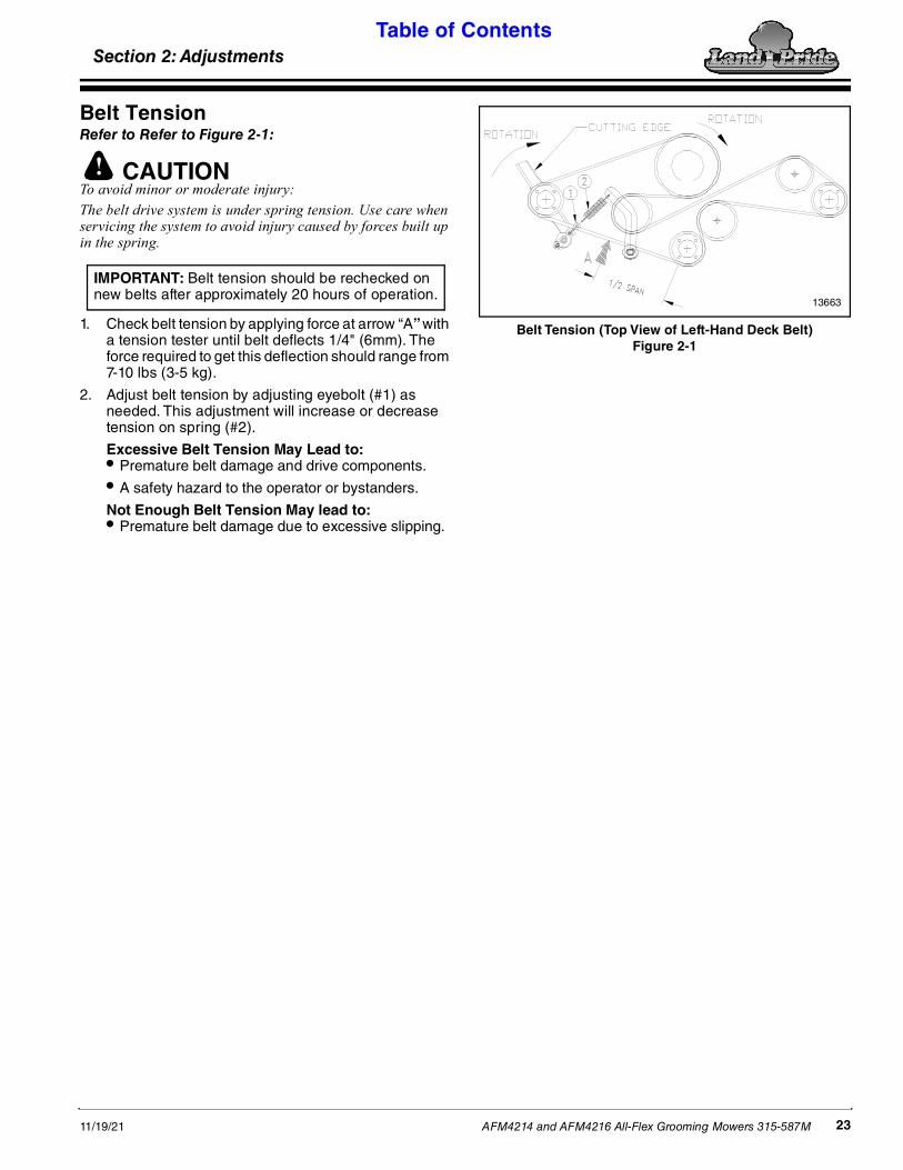
Belt TensionRefer to Refer to Figure 2-1:
CAUTION!To avoid minor or moderate injury: The belt drive system is under spring tension. Use care when servicing the system to avoid injury caused by forces built up in the spring.
1. Check belt tension by applying force at arrow “A” with a tension tester until belt deflects 1/4" (6mm). The force required to get this deflection should range from 7-10 lbs (3-5 kg).
2. Adjust belt tension by adjusting eyebolt (#1) as needed. This adjustment will increase or decrease tension on spring (#2).
Excessive Belt Tension May Lead to:• Premature belt damage and drive components.
• A safety hazard to the operator or bystanders.
Not Enough Belt Tension May lead to:• Premature belt damage due to excessive slipping.
IMPORTANT: Belt tension should be rechecked on new belts after approximately 20 hours of operation.
Belt Tension (Top View of Left-Hand Deck Belt)Figure 2-1
13663
Section 2: Adjustments

Section 2: Adjustments Table of Contents
AFM4214 and AFM4216 All-Flex Grooming Mowers 315-587M 11/19/2124
Center & Wing Deck Cutting HeightsThese adjustments should be made with mower hooked to the tractor that will be used for field operations or one having the same drawbar height.
DANGER!To avoid serious injury or death: Always disconnect driveline from the tractor before servicing the drivetrain and components powered by the drivetrain. A person can become entangled in the drivetrain if the tractor is started and the power take-off is engaged.
WARNING!To avoid serious injury or death: • Block decks up before making cutting height adjustments.• Always follow “Tractor Shutdown Procedure” provided in
this manual before dismounting the tractor.
IMPORTANT: When going over a raised area, make sure main driveline does not make contact with mower tongue, especially near hitch end of tongue.
IMPORTANT: Before continuing, read instructions on raising and lowering decks starting with “U-Joint Timing” on page 29.
Refer to Figure 2-2:1. Position mower on a level surface and adjust hitch
clevis up or down on end of tongue until tongue is close to level with the ground. Tire pressure will affect mowing height. Make sure all tires have proper pressure. See “Tire Inflation Chart” on page 54.
2. Lower mower decks fully down on a flat level surface.
3. Make measurement (A) (top of deck to ground) on all three decks. Check measurements in Cutting Height Chart to determine if the decks need to be raised or lowered to obtain preferred cutting height (B).
4. Raise all three mower decks up to an adequate height and block under the decks to prevent them from falling during gauge wheel height adjustments.
Refer to Figure 2-4 on page 25:5. Add or remove spacers below the spindle tubes
equal to the number of inches the gauge wheel needs to be adjusted. Adding spacers will raise the cutting height and removing spacers will lower the cutting height. When finished, all 10 gauge wheels will usually have an equal number of spacers below the spindle tubes. See note below.
NOTE: Due to manufacturing tolerances and tire size differences, it may be necessary to readjust some spacers. Because of this, you may not end up with equal number of spacers on all gauge wheels.
Cutting Height ProfileFigure 2-2
Cutting Height ChartA
inches (cm)B
inches (cm)A
inches (cm)B
inches (cm)
4 7/8 (12.4) 1 (2.5) 7 3/8 (18.7) 3 1/2 (8.9)
5 3/8 (13.7) 1 1/2 (3.8) 8 3/8 (21.3) 4 1/2 (11.4)
6 3/8 (16.2) 2 1/2 (6.4) 9 3/8 (23.8) 5 1/2 (14)
12742
Top of Deck Deck RearDeck Front
Front Blade Tip Rear Blade TipDim. A
Dim. B
1/4" (6 mm)

Section 2: Adjustments Table of Contents
AFM4214 and AFM4216 All-Flex Grooming Mowers 315-587M11/19/21 25
6. After making height adjustments, always replace linchpins by inserting them into the gauge wheel spindle pin holes from the front to keep from loosing the pins and gauge wheels.
7. Lower mower decks to the field position making sure all fold cylinders are fully extended.
Refer to Figure 2-5:
8. Adjust front of center deck height to match height at rear of center deck:
a. Attach jack stand to jack mount located in front of the center gearbox channel. Make sure stand is secured with attachment pin.
b. Screw jack out to lift front of mower deck and in to lower deck front.
c. Place same number and thickness of C-spacers below the spindle tube as what was placed below the rear gauge wheel spindle tubes.
d. There is a groove in the carrier rod for adding or removing C-spacers. Turn the C-spacer so that the open end will slide in or off the groove as needed.
e. Remove jack stand and return it to the storage tube located in front of the divider gearbox.
f. Place additional C-spacers above metal spindle tubes.
IMPORTANT: Linchpins should always be inserted into the gauge wheel spindle from the front with the locking clasp flipped shut over the spindle toward the back. Attaching the pin in this manner will prevent vegetation from catching on the clasp and flipping it open while traveling forward.
IMPORTANT: Slide-on spacers are 1/2" thick. Use two 1/2" slide-on spacers at the front of the rear deck for every 1" spacer used at the back of the rear deck.
9. Take measurements at the same location on all three decks to verify they are all at the same cutting height.
10. Additional fine tuning adjustments may be needed after a test mowing run.
Adding or Replacing SpacersFigure 2-5
Some mower items not shown for clarity
Additional C-Spacers on Top
C-Spacers
Jack Mount
Screw Jack
Groove on Rod to Add or Remove C-Spacers
19034
Figure 2-4
12717 12716
Minimum Cutting Height Set-upNo Spacers Located Below Wheel Spindle Tube
Approximately 3/4" (1.9 cm)
Maximum Cutting Height Set-upAll Spacers Located Below Wheel Spindle Tube
Approximately 5 1/4" (13.3 cm)
Spindle TubeLinchpinInsert From the Front
Gauge Wheel Spacers
Gauge Wheel Spacers
Spindle Tube
C-SpacersC-Spacers
LinchpinInsert From the Front

Section 2: Adjustments Table of Contents
AFM4214 and AFM4216 All-Flex Grooming Mowers 315-587M 11/19/2126
Hydraulic Transport Locks, OptionalRefer to Figure 2-6:When transport locking cylinder (#6) is fully retracted, transport locks (#1) should be fully seated in tool bar locking lugs (#2) and aircraft cables (#5) should have a small amount of slack. If cables hang loosely or are tight, then shorten or lengthen cables (#5) as follows:
1. Fully retract deck lifting cylinders (#7) and transport lock cylinder (#6).
2. Check slack in all three aircraft cables (#5):
a. They should have slight slack and not be tight.
b. They should not be too slack or cables (#5) will not be able to pull transport locks (#1) out of tool bar
NOTE: Figure 2-6 is shown with mower decks down for clarity. Mower decks will need to be folded up and locked in the transport locks to check for adjustment of transport locks.
locking lugs (#2).
3. If needed, adjust aircraft cables (#5) as follows:
a. Loosen cable clamps (#4A & #4B) and pull or let out aircraft cable (#5) to create slight slack in cable.
b. Use cable clamp (#4A) closest to the spring to create a loop about 1 1/4" in (3 cm) diameter. The loop should be big enough to allow rotation around the spring but small enough not to come off the washers.
c. Tighten cable clamp (#4A).
d. Secure excess cable with remaining clamp (#4B) and then tighten clamp (#4B).
Wire Rope AdjustmentFigure 2-6
35473

Section 3: Operating Instructions Table of Contents
AFM4214 and AFM4216 All-Flex Grooming Mowers 315-587M11/19/21 27
• Do not allow anyone near the tractor or implement while operating. Stop operation if bystanders are too close. They can be hit by flying projectiles, become entangled in the equipment, or ran over.
• All guards and shields must be installed and in good working condition while operating the implement.
• Keep all persons away from the blades while they are rotating. Never place hands or feet under the deck with blades rotating or when tractor engine is running. Do not operate the implement or tractor if bystanders are in the area.
• Do not transport without transport locks securely engaged. Do not walk or work underneath a raised wing unless all transport locks are securely engaged. Wings can drop suddenly if a transport lock is not securely engaged.
• Do not use a power take-off adapter. The adapter will increase strain on the tractor’s power take-off shaft causing possible damage to shaft and driveline. It will also defeat the purpose of the tractor’s power take-off shield.
WARNING!To avoid serious injury or death: • Always follow “Tractor Shutdown Procedure” provided in
this manual before dismounting the tractor.• Allow only persons to operate this implement who have
fully read and comprehended this manual, and who have been properly trained in the safe operation of this implement. Serious injury or death can result from the inability to read, understand, and follow instructions provided in this manual.
• Operate only power machines equipped with a certified Roll-Over Protective Structure (ROPS) and seat belt. Keep folding ROPS in the “locked up” position when appropriate. If ROPS is in the locked up position, fasten seat belt snugly and securely to help protect against serious injury or death from falling and machine overturn.
• Never carry riders on the implement or tractor. Riders can obstruct the operator’s view, interfere with controls, be pinched by moving components, become entangled in rotating components, struck by objects, thrown about, fall off and be run over, etc.
• Select a safe ground speed that will allow adequate control of steering and stopping. Never exceed 20 mph (32.2 km/h) with attached equipment. Rough terrain requires a slower speed.
• Slow down when traveling over rough or hilly terrain. Shift to a lower gear to maintain engine rpm while traveling slower.
• Do not operate and/or travel across inclines where the tractor and/or implement can rollover. Consult your tractor’s manual for acceptable inclines the tractor is capable of traveling across.
• Do not engage power take-off with AFM decks in the raised position or with engine speed above idle. Doing so will damage power train components.
Section 3: Operating Instructions
IntroductionHazard control and accident prevention are dependent upon the awareness, concern, prudence, and proper training involved in the operation, transport, storage, and maintenance of the Grooming Mower. Therefore, it is absolutely essential that no one operates the mower unless they have fully read, understood, and are totally familiar with the Operator’s Manual. Make sure the operator has paid particular attention to:
• Important Safety Information, pages 1
• Section 1: Assembly & Set-Up, page 16
• Section 3: Operating Instructions, page 27
• Section 2: Adjustments, page 23
• Section 5: Maintenance & Lubrication, page 35
Perform the following inspections before using your mower.
General Safety
DANGER!To avoid serious injury or death: • Clear area to be cut of debris and other unforeseen
removable objects before cutting. Mark non-removable hazards such as tree stumps, post stubs, protruding objects, rocks, drop-offs, holes, etc. with a visible flag.
• Tractor power take-off shaft shield, driveline shields, and gearbox shaft shields must be installed and in good working condition to avoid driveline entanglement and projectiles flying off of the driveline.
Operating Checklist Check Ref.
Read and follow all Safety Rules carefully. Refer to “Important Safety Information”. 1
Make sure all guards and shields are in place. Refer to “Important Safety Information”. 1
Make sure their are no hydraulic leaks. Refer to “Avoid High Pressure Fluids Hazard”. 3
Read and follow hook-up and preparation instructions. See “Section 1: Assembly & Set-Up”. 18
Make sure the hitch safety chain is securely attached to the mower hitch and tractor 18
Make a thorough examination of drivelines. Check all driveline connections. 18
Read and make all required adjustments. Refer to “Section 2: Adjustments”. 23
Inspect blades for wear and sharpness. 36
Read and follow all Maintenance Instructions. Refer to “Section 5: Maintenance & Lubrication”. 35
Read and follow all Lubrication Instructions. Refer to “Lubrication Points”. 41
Check mower initially and periodically for loose bolts and pins. Refer to “Torque Values Chart”. 54
Check tire pressure. Add air if needed. 54

Section 3: Operating Instructions Table of Contents
AFM4214 and AFM4216 All-Flex Grooming Mowers 315-587M 11/19/2128
• Always disengage tractor PTO before raising mower decks to transport position to avoid power train damage, injury from thrown objects, or blade contact.
• Do not operate a broken or bent driveline. Such a driveline will break apart while rotating at high speeds. Always remove the implement from use until the damaged driveline can be repaired or replaced.
• Do not alter implement or replace parts on the implement with other brands. Other brands may not fit properly or meet OEM (Original Equipment Manufacturer) specifications. They can weaken the integrity and impair the safety, function, performance, and life of the implement. Replace parts only with genuine OEM parts.
• Do not use implement as a man lift, work platform or as a wagon to carry objects. It is not properly designed or guarded for this use.
• Do not use implement to lift objects; to pull objects such as fence posts, stumps, etc; or to push objects. The unit is not designed or guarded for these uses.
• High wear may occur to mower blades when mowing in areas with sandy soil. Frequent inspection should be made and blades replaced if worn excessively or damaged.
• Buildup of debris around moving components and gearboxes is a fire hazard. Keep rotating parts and gearboxes free from debris.
• Improper oil level can cause bearing failure and be a fire hazard. Maintain proper gearbox oil level.
• Avoid catching hydraulic hoses on brush, posts, tree limbs, and other protrusions that could damage and/or break them.
• Use mower to cut only turf grasses. Cutting other materials can damage drive components, cutting blades, and deck.
• Some tractors are equipped with two power take-off speeds. Be certain your tractor’s power take-off shaft is set-up to operate at 540 rpm. Do not exceed 540 rpm power take-off speed. Excessive speed can damage drive components, cutter blades, and/or increase the risk of a thrown object hazard.
Tractor & Mower InspectionMake the following inspections with mower attached to a tractor, with tractor and mower parked on a level surface, power take-off disengaged, and mower blades stopped.
1. Complete “Operating Checklist” above.
2. Make sure hitch safety chain is securely attached to mower and tractor.
3. Grease driveline shaft and all other grease fittings.
4. Check oil level in gearboxes. Refer to “4-Way Gearbox” and “Mower Deck Gearbox” on page 45.
5. Check all plugs and caps in gearboxes to make certain that they have been replaced and tightened properly.
6. Check mower blades for sharpness and damage. See “Blade Inspection” on page 36.
7. Be sure blades are installed properly on each deck with the cutting edge leading in rotation. See “Blade Removal & Installation” on page 37.
8. Make sure all blade bolts are tight. Know which center blade bolts are left-hand threaded and which are right-hand threaded when checking for tightness. See “Blade Removal & Installation” on page 37.
9. Be sure all bolts and nuts are tight.
10. Be certain all guards and shields are in place and secure.
11. If the deck drivelines do not have slip clutches, then check U-joint timing. Refer to “U-Joint Timing” on page 29.
12. Slowly cycle all decks to transport position checking to make sure hydraulic hoses and wire harness are not pinched in the process.
13. Check LED lights to make sure they are hooked-up correctly and functioning:
a. Check all electrical connections on the wire harness. Refer to “Hook-up Transport Lights” on page 19.
b. Check wire harness to make sure the wires are not pinched, bare, or broken and connectors are not damaged. Replace wire harness if damaged.
c. Check lens modules for broken lens and/or burnt out LED lights. Replace module if needed. Modules are available in amber, red, and black.
d. Make necessary repairs and repeat step 13 above.
14. Clear area to be mowed of objects and debris that might be picked up and thrown by the mower blades
15. Operate with 540 rpm power take-off tractor.
16. Refer to your tractor’s operator manual for engaging and disengaging the power take-off.
17. In case of emergency, learn to stop tractor and mower quickly.

Section 3: Operating Instructions Table of Contents
AFM4214 and AFM4216 All-Flex Grooming Mowers 315-587M11/19/21 29
U-Joint TimingFigure 3-1
U-Joint TimingRefer to Refer to Figure 3-1:
If the deck drivelines do not have slip clutches, then check U-joint timing before folding the decks up. Disconnect the left-hand and/or right-hand U-joints that are out-of-time and reconnect them in-time with each other.
Fold Mower DecksRefer to Figure 3-2 or Figure 3-3:1. If the deck drivelines do not have slip clutches, then
check U-joint timing before folding the decks up. Refer to “U-Joint Timing” on this page.
2. Using tractor’s hydraulic control lever, raise all three mower decks to transport position by retracting all three hydraulic cylinders (#2) completely.
3. As the mower decks are raising, the three transport locks (#1) will automatically lock in place. Make sure they have locked in place before transporting.
Refer to Figure 3-4:4. Deck float pins are provided with the AFM4216
model only. If a narrow transport width is required or if transporting long distances, the deck float pins on the AFM4216 should be inserted as follows:
a. Remove deck float pin (#2) from storage tube (#1) and insert through lock holes (#3) located to the outside of both mower wing decks.
b. Make sure deck float pin is fully inserted.
IMPORTANT: If deck drivelines (3 each) do not have slip clutches, then the driveline u-joints at the splitter box must be in time to avoid driveline damage when folding and unfolding the decks.
IMPORTANT: Make sure deck floating pins are removed before unfolding AFM4216 mower decks.
Manual Release Transport LocksFigure 3-2
Hydraulic Release Transport LocksFigure 3-3
Model AFM4216 Deck Float PinFigure 3-4
13660
35472
26567
Section 3: Operating Instructions Table of Contents
AFM4214 and AFM4216 All-Flex Grooming Mowers 315-587M 11/19/2130
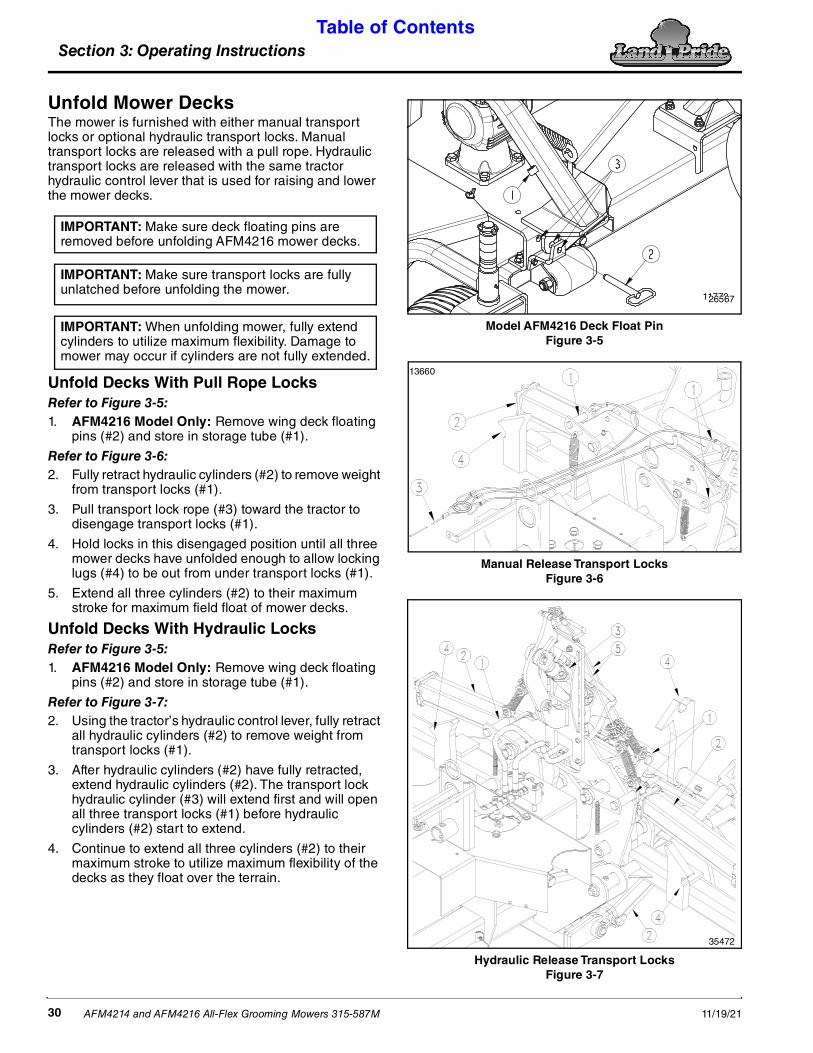
Unfold Mower DecksThe mower is furnished with either manual transport locks or optional hydraulic transport locks. Manual transport locks are released with a pull rope. Hydraulic transport locks are released with the same tractor hydraulic control lever that is used for raising and lower the mower decks.
Unfold Decks With Pull Rope LocksRefer to Figure 3-5:1. AFM4216 Model Only: Remove wing deck floating
pins (#2) and store in storage tube (#1).
Refer to Figure 3-6:2. Fully retract hydraulic cylinders (#2) to remove weight
from transport locks (#1).
3. Pull transport lock rope (#3) toward the tractor to disengage transport locks (#1).
4. Hold locks in this disengaged position until all three mower decks have unfolded enough to allow locking lugs (#4) to be out from under transport locks (#1).
5. Extend all three cylinders (#2) to their maximum stroke for maximum field float of mower decks.
Unfold Decks With Hydraulic LocksRefer to Figure 3-5:1. AFM4216 Model Only: Remove wing deck floating
pins (#2) and store in storage tube (#1).
Refer to Figure 3-7:2. Using the tractor’s hydraulic control lever, fully retract
all hydraulic cylinders (#2) to remove weight from transport locks (#1).
3. After hydraulic cylinders (#2) have fully retracted, extend hydraulic cylinders (#2). The transport lock hydraulic cylinder (#3) will extend first and will open all three transport locks (#1) before hydraulic cylinders (#2) start to extend.
4. Continue to extend all three cylinders (#2) to their maximum stroke to utilize maximum flexibility of the decks as they float over the terrain.
IMPORTANT: Make sure deck floating pins are removed before unfolding AFM4216 mower decks.
IMPORTANT: Make sure transport locks are fully unlatched before unfolding the mower.
IMPORTANT: When unfolding mower, fully extend cylinders to utilize maximum flexibility. Damage to mower may occur if cylinders are not fully extended.
Model AFM4216 Deck Float PinFigure 3-5
Manual Release Transport LocksFigure 3-6
Hydraulic Release Transport LocksFigure 3-7
1177026567
13660
35472

Section 3: Operating Instructions Table of Contents
AFM4214 and AFM4216 All-Flex Grooming Mowers 315-587M11/19/21 31
Transporting
WARNING!To avoid serious injury or death: • Select a safe ground speed that will allow adequate control
of steering and stopping. Never exceed 20 mph (32.2 km/h) with attached equipment. Rough terrain requires a slower speed.
• When traveling on public roads, use LED lights, slow moving vehicle sign, clean reflectors, and other adequate devices to warn operators in other vehicles of your presence. If implement blocks visibility of slow moving vehicle sign, relocate sign so it is visible from the back at all times. Always comply with all federal, state, and local laws.
• Reduce ground speed when turning and leave enough clearance to avoid making contact with obstacles such as buildings, trees, fences, etc.
• Slow down when traveling over rough or hilly terrain. Shift to a lower gear to maintain engine rpm while traveling slower.
• Operate only power machines equipped with a certified Roll-Over Protective Structure (ROPS) and seat belt. Keep folding ROPS in the “locked up” position when appropriate. If ROPS is in the locked up position, fasten seat belt snugly and securely to help protect against serious injury or death from falling and machine overturn.
• When implement is wider than the tractor, take care to make sure it does not make contact with oncoming traffic and roadside obstructions.
• Always disengage tractor PTO before raising mower decks to transport position to avoid power train damage, injury from thrown objects, or blade contact.
1. Refer to Figure 3-8: Relocate slow moving vehicle Safety sign (#1) from back of your tractor to mounting bracket (#2) on the back of the mower. If needed, the slow moving vehicle sign can be purchased from your nearest Land Pride dealer. Refer to “Slow Moving Vehicle Sign (Accessory)” on page 34.
2. Select a safe ground speed when transporting from one area to another. Maximum transport speed for the All-Flex Mowers is 20 mph. DO NOT EXCEED.
3. Be sure to reduce tractor ground speed when turning and leave enough clearance so the mower does not contact obstacles such as buildings, trees, or fences.
4. Always raise wings and set transport locks before traveling on public roadways.
5. When traveling on roadways, transport in such a way that faster moving vehicles may pass you safely. Use LED lights on the mower to make yourself more visible on roadways.
6. Shift tractor to a lower gear when traveling over rough or hilly terrain.
Relocate Slow Moving Vehicle Sign to Back of MowerFigure 3-8
Constant Velocity Driveline AngleRefer to Figure 3-9:The main driveline is equipped with a constant velocity (CV) joint that allows the unit to run at angles up to 80 degrees with no vibration.
Constant Velocity Driveline AngleFigure 3-9
The constant velocity joint must be greased every 8 hours of operation. Refer to Page 41 “Driveline Constant Velocity Shaft”.
19626
IMPORTANT: Do not make turns that will subject the CV joint to angles greater than 80 degrees. Angles greater than 80 degrees will damage the driveline.

Section 3: Operating Instructions Table of Contents
AFM4214 and AFM4216 All-Flex Grooming Mowers 315-587M 11/19/2132
Unhook MowerFigure 3-10
Unhook MowerRefer to Figure 3-10:1. See “Long-Term Storage” on page 40 before
parking mower for a long period.
2. Shutdown tractor properly before dismounting. Refer to “Tractor Shutdown Procedure” on page 17.
3. Move hydraulic control levers back and forth several times to relieve all hydraulic pressure in hydraulic hoses and at the couplers.
4. Attach park jack (#1) to jack mount (#12) and secure with detent pin (#2). Make sure detent pin is fully inserted.
5. Adjust height of park jack (#1) until hitch is supported by the park jack.
6. Unhook wire harness (#3) from the tractor electrical outlet. Coil wire harness up and store on the spring hose loop. Keep wire harness pin connector (#3) out of the dirt.
7. Unhook hydraulic hoses (#4) from tractor duplex outlet. Insert couplers through spring hose loop to keep couplers out of the dirt.
8. Pull back on driveline lock collar (#5) and pull driveline (#6) from tractor power take-off shaft.
9. Collapse driveline (#6) by pushing tractor end of driveline toward the splitter gearbox.
10. Store yoke end of driveline (#5) on driveline support rest (#13). Do not store yoke end in the dirt.
11. Unhook transport safety chain(#7) from the tractor and stow on the hitch.
12. Adjust park jack (#1) until hitch weight is removed from tractor drawbar.
70108 13. Remove hairpin cotter (#8), flat washer (#10), and hitch pin (#9).
14. Start tractor and drive slowly forward several feet while watching to make sure no mower components are connected to or catching on the tractor.
15. Shut tractor down properly before dismounting.
16. Replace hitch pin (#9) with flat washer (#10) in mower hitch clevis (#11). Secure hitch pin with hairpin (#8).
Refer to Figure 3-8 on page 31:17. Remove slow moving vehicle sign (#1) from
mounting bracket (#2).
18. Reinsert slow moving vehicle sign in mounting bracket on the back of the tractor.
Special Operating Instructions1. After attaching the tractor to the mower, carefully
check all hoses and wires to be sure they will not contact the power take-off driveline.
2. Check power take-off guards to make sure they are in good condition and in place.
3. Inspect hydraulic hoses for wear, damage, and hydraulic leaks. See “Avoid High Pressure Fluids Hazard” on page 3 Replace damaged and worn hoses with genuine Land Pride parts.
4. Check the following after the power take-off has been disengaged and comes to a complete stop.
• Check mower blades for sharpness.
• Make sure bolts and nuts are tight.
• Check tractor safety equipment. Be sure they are in good working condition.
5. Set tractor throttle at an idle. Engage the power take-off to start blades rotating.
6. Begin mowing at a slow forward speed and shift up until desired speed is achieved - maintaining 540 power take-off rpm. Mower blades will cut better at 540 power take-off blade speed than at reduced throttle.
7. After mowing the first 50 feet, stop and check to see that mower is adjusted properly.
8. Grass is best cut when it is dry. Mowing wet grass can cause plugging resulting in grass clumps behind the mower.
9. Grass should be mowed frequently as shorter clippings deteriorate faster.
10. Mow areas with extremely tall grass twice. Raise mower high for the first cutting and then set mower at finished cutting height for the second cutting.

Section 3: Operating Instructions Table of Contents
AFM4214 and AFM4216 All-Flex Grooming Mowers 315-587M11/19/21 33
General Operating InstructionsBy now you should have familiarized yourself with the Operator’s Manual, completed the Operator’s Checklist, set-up the unit properly and attached your Land Pride All-Flex Mower to your tractor.
With the tractor’s park brake engaged and the power take-off disengaged, start the tractor. Using the tractor’s hydraulic control levers, retract the hydraulic deck-lift cylinders all the way in and pull the ropes leading to your transport locks to release them. With the same control levers, slowly lower your mowing decks from transport position to working position on the ground. Having lowered the decks, shut the tractor off, check to make sure the park brake is set, and remove the switch key. Dismount from the tractor and preset your mower to the desired cutting height.
It’s now time to do a running operational safety check. It is extremely important that if at any time during this safety check you detect a malfunction in either the mower or tractor that you immediately shut the tractor off, remove the key, and set the park brake. Make necessary repairs and/or adjustments before continuing on.
Make sure before starting the tractor that the mower is properly attached to the draw bar with both wings down resting on the ground. Also make sure the driveline is securely coupled to the tractor’s power take-off shaft, the hydraulic hoses are properly attached to the tractor’s hydraulics, the tractor’s park brake is engaged, and the tractor’s power take-off drive is disengaged. Starting the tractor and set the engine throttle speed at a low idle. Engage the tractor’s power take-off drive. If everything is running smoothly, slowly increase the engine rpm until the tractor’s engine reaches full power take-off operating speed of 540 rpm. If everything is still running as it should, then return the engine to low idle and disengage power to the power take-off. Under no circumstances should you ever raise the cutting decks into transport position with the power take-off drive engaged. Personal injury and equipment damage could result.
You should now be ready to move to your cutting site to begin mowing. On roadway transport in such a manner that faster moving vehicles can easily see you and pass you safely. Reduce your speed when traveling over rough and hilly terrain. Avoid quick or sharp steering corrections. Take extra care to ensure that the mower doesn’t come into contact with obstacles such as trees, buildings, or fences. Use accessory lights and appropriate reflective devices to provide adequate warning to pedestrians and other vehicle operators when traveling on public roads and in the dark of night. Comply with all local, state, and federal laws.
It is important that you inspect the area where you will be cutting and clear it of safety hazards and foreign objects either before or after you arrive at the cutting site. Never assume the area is clear. Cut only in areas you are familiar with and are free of debris and unseen objects. In the event you do strike an object, stop the mower and
tractor immediately to inspect and make any necessary repairs before resuming operation. It really pays to inspect a new area and to develop a safe plan before mowing.
You will need to maintain a ground speed between 2-6 mph and 540 rpm power take-off speed to produce a clean cut. Make a tractor gear and range selection that will enable you to maintain these speed combinations. Generally the quality of cut is better at lower ground speeds. Dense ground cover will create the need to slow down even more. In certain conditions tractor tires will roll grass down resulting in an uneven cut when the grass fails to rebound. Should this happen you may try reversing the direction of cut and/or double cut to achieve the desired finish.
Avoid very low cutting heights especially on extremely uneven terrain. Always cut downward on slopes and avoid crossing the face of steep slopes. Avoid sharp drops and cross diagonally through dips to prevent hanging up the tractor and mower. Slow down in turns and avoid sharp turns if at all possible. Remember to look back often.
Now you’re prepared and well briefed you may begin cutting. Begin cutting by doing the following:
• Reducing the tractor’s engine rpm.
• Make sure the mower is on the ground in cutting position.
• Engage the power take-off.
• Raise the engine rpm to the appropriate power take-off speed.
• Begin mowing.
Make wide turns when possible. Operators of pull-type models must plan ahead and choose a cutting pattern that allows for wider turns. Try increasing or decreasing ground speed to determine the effect on quality of cut. With a little practice you will be pleased with what you and your Land Pride All-Flex Mower can do.
Whether you are done mowing, need to take a break, or just need to make a few adjustments to the mower, remember to always do the following:
• Reduce the tractor’s engine rpm.
• Disengage the power take-off.
• Stop on level ground.
• Set the park brake.
• Turn off the engine and remove the key.
• Stay on the tractor until the mower blades have come to a complete stop.

Section 4: Accessories Table of Contents
AFM4214 and AFM4216 All-Flex Grooming Mowers 315-587M 11/19/2134
Ball Swivel HitchRefer to Figure 4-1:The ball swivel hitch clamps firmly to your tractor’s drawbar. With this accessory the center deck can pivot about the drawbar in all directions reducing twisting torque and allowing the deck to mow a more even height. Hillsides and uneven terrain are ideal for its use. See your local Land Pride dealer for the ball swivel hitch.
Ball Swivel HitchFigure 4-1
Slow Moving Vehicle SignFigure 4-2
Slow Moving Vehicle Sign (Accessory)Refer to Figure 4-2:If your tractor does not have a movable sign that fits Land Pride’s mounting socket (#4), you can purchase the slow moving vehicle sign (#1) to fit the socket. If you have need for mounting this sign on other equipment, you can purchase items (#2, #3, & #4) for mounting the sign.
22358
37431
Item Part No. Description
1 316-362S Slow Moving Vehicle Sign2 802-092C RHSNB 5/16-18X3/4 GR53 803-177C NUT HEX FLG TP LK 5/16-18ZNYCR4 890-401C MOUNTING SOCKET
Section 4: Accessories
Cutting BladesThere are four blade choices to select from based upon soil condition, density of grass, and tractor horsepower. The appearance of the finish cut may vary between low lift and high lift blades. See your Land Pride dealer for blade availability.
Low Lift Blades (Standard)Land Pride’s low lift blades are designed for mowing over sandy soil terrain where high suction lift is not crucial. Sand drawn into the blades accelerates blade wear more than normal. Low lift blades are recommended because they produce a lower suction keeping sand uplift and blade wear to a minimum.
Medium Lift BladesLand Pride’s medium lift blades are great when horsepower is a concern. They produce a medium suction for lifting grass requiring less horsepower than high lift blades.
High Lift BladesLand Pride’s high lift blades develop the greatest suction for lifting grass before cutting for that fresh clean cut look. However, they may require more horsepower especially when cutting tall dense grass. They are not recommended for sandy soil conditions.
Mulching BladesLand Pride’s mulching blades are designed to chop leaves and/or grass into smaller parts leaving your lawn looking fresher and cleaner than ever before.
Accessory Part Numbers
Land Pride All-Flex Mower AccessoriesPart No. Part Description
Ball Swivel Hitch315-370A Ball Swivel Hitch
Low Lift Blades Kit for 1 unit (9 blades)315-262A AFM4214 (Kit)315-259A AFM4216 (Kit)
Medium Lift Blades Kit for 1 unit (9 blades)315-263A AFM4214 (Kit)315-260A AFM4216 (Kit)
High Lift Blades Kit for 1 unit (9 blades)315-264A AFM4214 (Kit)315-261A AFM4216 (Kit)
Mulching Blades Kit for 1 unit (9 blades)315-467A AFM4214 (Kit)315-468A AFM4216 (Kit)

Section 5: Maintenance & Lubrication Table of Contents
AFM4214 and AFM4216 All-Flex Grooming Mowers 315-587M11/19/21 35
Section 5: Maintenance & Lubrication
MaintenanceProper servicing and adjustments are key to the long life of any implement. With careful inspection and routine maintenance, you can avoid costly downtime and repair.
DANGER!To avoid serious injury or death: • Always secure equipment with solid, non-concrete supports
before working under it. Never go under equipment supported by concrete blocks or hydraulics. Concrete can break, hydraulic lines can burst, and/or hydraulic controls can be actuated even when power to hydraulics is off.
• Always disconnect driveline from the tractor before servicing the drivetrain and components powered by the drivetrain. A person can become entangled in the drivetrain if the tractor is started and the power take-off is engaged.
WARNING!To avoid serious injury or death: • Make sure controls are all in neutral position or park before
starting the power machine.• Always follow “Tractor Shutdown Procedure” provided in
this manual before dismounting the tractor.• For safety reasons, each maintenance operation must be
performed with tractor PTO disengaged, mower lowered completely to the ground or folded with transport locks engaged and tractor engine shut off with ignition key removed.
• Perform scheduled maintenance. Check for loose hardware, missing parts, broken parts, structural cracks, and excessive wear. Make repairs before putting the implement back into service.
• Do not alter implement or replace parts on the implement with other brands. Other brands may not fit properly or meet OEM (Original Equipment Manufacturer) specifications. They can weaken the integrity and impair the safety, function, performance, and life of the implement. Replace parts only with genuine OEM parts.
• Buildup of debris around moving components and gearboxes is a fire hazard. Keep rotating parts and gearboxes free from debris.
• Improper oil level can cause bearing failure and be a fire hazard. Maintain proper gearbox oil level.
1. Frequently inspect mower for loose bolts and nuts. See “Blade Removal & Installation” on page 37 to identify left-hand threaded bolts. Tighten all hardware as indicated in the “Torque Values Chart” on page 54.
2. Check drive belt tension after several hours of mowing. Refer to “Belt Tension” on page 23.
3. Lubricate components as listed under “Lubrication Points” starting on page 35.
4. Always maintain proper air pressure in the tires. Refer to “Tire Inflation Chart” on page 54.
5. Replace worn, damaged, or illegible safety labels by obtaining new labels from your Land Pride dealer. See Information about “Safety Labels” starting on page 6.
Hydraulic System
WARNING!To avoid serious injury or death: Hydraulic fluid under high pressure will penetrate the skin or eyes causing a serious injury. Wear protective gloves and safety glasses or goggles when working with hydraulic systems. Use a piece of cardboard or wood rather than hands when searching for leaks. If an accident occurs, seek immediate emergency medical care or gangrene may result. DO NOT DELAY.One of the most important things you can do to prevent hydraulic system problems is to ensure your tractor's hydraulic reservoir remains free of dirt and other contaminations.
Use a clean cloth to wipe hose ends clean before attaching them to your tractor. Replace tractor hydraulic filter element at the prescribed intervals. These simple maintenances will go a long way to prevent occurrence of control valve and hydraulic cylinder problems.
Check for signs of damaged or worn hydraulic hoses, fittings and cylinders before each use of the cutter. Replace damaged components as needed.
Transport Tires
WARNING!To avoid serious injury or death: • Tire changing can be dangerous and should be performed
by trained personnel using correct tools and equipment. When removing and installing wheels, use wheel handling equipment adequate for the weight involved.
• When inflating tires, use a clip-on chuck and extension hose long enough to allow you to stand to one side and NOT in front of or over the tire assembly. Use a safety cage if available. Do not over inflate tires.
• Do not weld on or heat a rim. High heat can weaken and/or warp the rim and damage the tire. Air pressure inside the tire can increase enough to cause an explosion.
Heavy-duty tire sealant has been added in transport tires to reduce air loss from punctures due to nails/thorns etc.
1. Check tires for low air pressure, missing nuts, missing lug bolts, wear, separated rubber, and bent, broken, or cracked wheel rims.
2. Inflate air-filled tires to the proper pressure. Refer to “Tire Inflation Chart” on page 54.
NOTE: Under inflated tires can roll off of the rim. Maintaining air pressure within 5 psi (34 kPa) of maximum tire pressure reduces this risk. See “Tire Inflation Chart” on page 54 for recommended tire pressure. See tire sidewall for optimum pressure.

Section 5: Maintenance & Lubrication Table of Contents
AFM4214 and AFM4216 All-Flex Grooming Mowers 315-587M 11/19/2136
V-Belt Installation
CAUTION!To avoid minor or moderate injury: The belt drive system is under spring tension. Use care when servicing the system to avoid injury caused by forces built up in the spring.Refer to Figure 5-1 & Figure 5-2:These illustrations are also on the labels located on the top of the mower decks.
1. Remove right-hand and left-hand belt covers.
2. Disengage belt tensioning latch by turning release nut with a 3/4" wrench.
3. Replace old belt with a new Land Pride belt making sure the new belt is positioned correctly in all the pulley grooves.
4. Engage belt tensioning latch by turning the release nut with a 3/4" wrench.
5. Check for correct belt tension. Refer to “Belt Tension” on page 23.
6. Reinstall all belt covers and secure with hardware.
Servicing Mower Blades
DANGER!To avoid serious injury or death: • Always disconnect driveline from the tractor and secure the
implement in the up position with solid, non-concrete supports before servicing the underside. A person can become entangled in the drivetrain if the tractor is started and power take-off is engaged or crushed by an unsupported implement.
• Bent, deformed, or cracked blades should be removed from unit and discarded. Never weld a broken or cracked blade. DO NOT attempt to straighten or reuse such blades. ALWAYS replace with a new OEM blade to assure safety.
WARNING!To avoid serious injury or death: Exercise caution when working under the deck as the mower cutting blades are extremely sharp. Wear a pair of gloves when checking blades. Avoid direct contact with cutting edge of blades.
Blade InspectionRefer to Figure 5-3:Blade Wear: Blade performance is reduced as blades wear and are sharpened for reuse. Excessively high wear can occur to your mower blades when mowing in sandy soil areas. Frequent inspection should be made and blades replaced if damaged.
Bent, Deformed or Split Blades should be removed from unit and discarded. DO NOT attempt to straighten a blade for reuse.
Top View of Left-Hand Deck Belt DriveFigure 5-1
Top View of Center and Right-Hand Deck Belt DriveFigure 5-2
Blade PlacementFigure 5-3
CW Blades Rotation / R.H. Blade Bolt Threads
13662
CCW Blades Rotation / L.H. Blade Bolt Threads
13661
39325

Section 5: Maintenance & Lubrication Table of Contents
AFM4214 and AFM4216 All-Flex Grooming Mowers 315-587M11/19/21 37
Blade Removal & Installation
CAUTION!To avoid minor or moderate injury: Depending on blade rotation, bolts attaching mower blades to their respective spindles may be either left-hand or right-hand thread. Prevent spindle and/or bolt damage by knowing which hand the threads are before removing and/or tightening any blade mounting bolts.Refer to Figure 5-1 & Figure 5-2 on page 36:1. Verify blade rotation and bolt thread type (right-hand
or left-hand) before loosening center blade bolts and removing blades to be sharpened or replaced.
Refer to Figure 5-4 & Figure 5-5:2. Remove blades by grasping blade end (#1) with a rag
or thick padded glove while loosening the blade mounting bolt (#4).
3. Remove blade bolt (#4) and Washer (#5) from blade being replaced.
4. (Model AFM4216 Only.) Remove two outside bolts (#6) from blade bar (#2).
5. Reinstall blade (#1), blade washer (#5), and bolt (#4). Care should be taken when installing the blade bolt to not get it cross threaded and to know if the bolt is right-hand or left-hand. Torque bolt to 75 ft.-lbs.
6. (Model AFM4216 Only.) Reinstall the two outside bolts. Tighten to correct torque listed in The “Torque Values Chart” on page 54.
NOTE: Blade bolt on the left-hand deck is right-hand threads. Blade bolts on the right-hand and center decks are left-hand threads.
Refer to Figure 5-5, Model AFM4216 only: The two outside blade bar bolts (#6) are always right-hand threads.
IMPORTANT: Replace mower blades with genuine Land Pride blades only.
IMPORTANT: Always install blade with cutting edge facing direction of rotation and wing tips pointing up.
IMPORTANT: (AFM4216 ONLY, See Figure 5-5) Loctite is not required if blade bar (#2) is not removed. However, If blade bar (#2) is removed from spindle shaft (#3), apply “Loctite 243” to external spindle shaft threads and to center bolt threads (#4).
Model 4214 Blade RemovalFigure 5-4
Model 4216 Blade and Blade Bar RemovalFigure 5-5
22374
22373

Section 5: Maintenance & Lubrication Table of Contents
AFM4214 and AFM4216 All-Flex Grooming Mowers 315-587M 11/19/2138
Blade Sharpening
WARNING!To avoid serious injury or death: Wear eye protection and gloves while inspecting, removing, sharpening, and replacing a blade.
1. A cutting blade should be replaced or sharpened if it is dull or nicked.
2. Clean blade washer and blade mounting surface before installing a new blade. Also clean the old blade if you plan to sharpen it for reuse.
Refer to Figure 5-6:3. Maintain sharpness by grinding only the top of the
cutting edge at the same bevel as the original edge.
Blade SharpeningFigure 5-6
Refer to Figure 5-7:4. Check blade balance by positioning the blade
horizontally on a nail or shaft through the blade’s center hole. If either end of blade rotates downward, grind (remove) metal on that end until blade will balance horizontally on the nail. The blade is properly balanced when neither end drops. Balance of a blade is generally maintained by removing an equal amount of material from each end of the blade.
Blade BalancingFigure 5-7
NOTE: Care should be taken to not remove more material than necessary when sharpening blades.
19327
NAIL OR SHAFT
HORIZONTAL
19046
Driveline Protection
DANGER!To avoid serious injury or death: Always disconnect driveline from the tractor before servicing the drivetrain and components powered by the drivetrain. A person can become entangled in the drivetrain if the tractor is started and the power take-off is engaged.
WARNING!To avoid serious injury or death: A slip clutch that has been in use or has slipped for as little as only two or three seconds during run-in may be too hot to touch. Allow a hot clutch to cool before working on it.The drivetrain and mower is protected from shock loads with a friction slip clutch on the main driveline. Oxidation caused by moisture and condensation on the clutch friction surfaces can seize the inner frictions plates. To remove oxidation, run the clutches through a “run-in” cycle prior to initial operation, at the start of each season, and when the clutch has not be used for approximately 60 days.
Clutch Run-inRefer to Figure 5-8 on page 39:1. With implement and driveline attached to the tractor,
shut tractor down according to “Tractor Shutdown Procedure” on page 17.
2. Disconnect driveline from the tractor.
3. Loosen all nuts (#1), draw nuts up snug, and then tighten nuts one-half turn.
4. Reconnect driveline to the tractor. Refer to “Main Driveline Hook-up” on page 18.
5. Keep all bystanders away from the tractor and implement.
6. From the tractor seat, start the tractor, and set the engine speed at half throttle.
7. Cycle the clutch on and off 5 or 6 times (15 seconds on and 15 seconds off) or until the clutch visibly smokes.
8. Shut tractor down according to “Tractor Shutdown Procedure” on page 17.
9. Disconnect the driveline from the tractor.
10. Tighten all nuts (#1) until spacers (#3) cannot be rotated by hand and then back-off the nuts until the spacers will rotate by hand.
11. Reconnect driveline to the tractor. Refer to “Main Driveline Hook-up” on page 18.
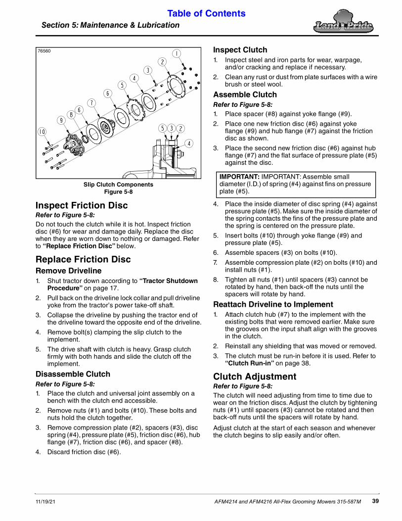
Section 5: Maintenance & Lubrication Table of Contents
AFM4214 and AFM4216 All-Flex Grooming Mowers 315-587M11/19/21 39
Slip Clutch ComponentsFigure 5-8
Inspect Friction DiscRefer to Figure 5-8:Do not touch the clutch while it is hot. Inspect friction disc (#6) for wear and damage daily. Replace the disc when they are worn down to nothing or damaged. Refer to “Replace Friction Disc” below.
Replace Friction DiscRemove Driveline1. Shut tractor down according to “Tractor Shutdown
Procedure” on page 17.
2. Pull back on the driveline lock collar and pull driveline yoke from the tractor’s power take-off shaft.
3. Collapse the driveline by pushing the tractor end of the driveline toward the opposite end of the driveline.
4. Remove bolt(s) clamping the slip clutch to the implement.
5. The drive shaft with clutch is heavy. Grasp clutch firmly with both hands and slide the clutch off the implement.
Disassemble ClutchRefer to Figure 5-8:1. Place the clutch and universal joint assembly on a
bench with the clutch end accessible.
2. Remove nuts (#1) and bolts (#10). These bolts and nuts hold the clutch together.
3. Remove compression plate (#2), spacers (#3), disc spring (#4), pressure plate (#5), friction disc (#6), hub flange (#7), friction disc (#6), and spacer (#8).
4. Discard friction disc (#6).
76560 Inspect Clutch1. Inspect steel and iron parts for wear, warpage,
and/or cracking and replace if necessary.
2. Clean any rust or dust from plate surfaces with a wire brush or steel wool.
Assemble ClutchRefer to Figure 5-8:1. Place spacer (#8) against yoke flange (#9).
2. Place one new friction disc (#6) against yoke flange (#9) and hub flange (#7) against the friction disc as shown.
3. Place the second new friction disc (#6) against hub flange (#7) and the flat surface of pressure plate (#5) against the disc.
4. Place the inside diameter of disc spring (#4) against pressure plate (#5). Make sure the inside diameter of the spring contacts the fins of the pressure plate and the spring is centered on the pressure plate.
5. Insert bolts (#10) through yoke flange (#9) and pressure plate (#5).
6. Assemble spacers (#3) on bolts (#10).
7. Assemble compression plate (#2) on bolts (#10) and install nuts (#1).
8. Tighten all nuts (#1) until spacers (#3) cannot be rotated by hand, then back-off the nuts until the spacers will rotate by hand.
Reattach Driveline to Implement1. Attach clutch hub (#7) to the implement with the
existing bolts that were removed earlier. Make sure the grooves on the input shaft align with the grooves in the clutch.
2. Reinstall any shielding that was moved or removed.
3. The clutch must be run-in before it is used. Refer to “Clutch Run-in” on page 38.
Clutch AdjustmentRefer to Figure 5-8:The clutch will need adjusting from time to time due to wear on the friction discs. Adjust the clutch by tightening nuts (#1) until spacers (#3) cannot be rotated and then back-off nuts until the spacers will rotate by hand.
Adjust clutch at the start of each season and whenever the clutch begins to slip easily and/or often.
IMPORTANT: IMPORTANT: Assemble small diameter (I.D.) of spring (#4) against fins on pressure plate (#5).

Section 5: Maintenance & Lubrication Table of Contents
AFM4214 and AFM4216 All-Flex Grooming Mowers 315-587M 11/19/2140
Long-Term StorageClean, inspect, service, and make necessary repairs to the implement when storing it for long periods and at the end of the season. This will help ensure the unit is ready for field use the next time you hook-up to it.
DANGER!To avoid serious injury or death: Always disconnect driveline from the tractor and secure the implement in the up position with solid, non-concrete supports before servicing the underside. A person can become entangled in the drivetrain if the tractor is started and power take-off is engaged or crushed by an unsupported implement.1. Clean off any dirt and grease that may have
accumulated on the mower and moving parts. Scrape off compacted dirt from the bottom of the deck and then wash surface thoroughly with a garden hose. A coating of oil may also be applied to the lower deck area to minimize oxidation.
2. Check blades for wear and replace or sharpen as needed. Refer to “Blade Sharpening” on page 38.
3. Inspect mower for loose, damaged, or worn parts and adjust or replace as needed.
4. Lubricate as noted in “Lubrication Points” starting on page 41.
5. A light coat of oil or grease may be applied to the deck and to any exposed hydraulic cylinder rods to minimize oxidation.
6. Release spring tension from drive belt. Refer to “Blade Removal & Installation” on page 37.
7. Repaint parts where paint is worn or scratched to prevent rust. Ask your dealer for Land Pride aerosol touch-up paint. They are also available in touch-up bottles with brush, quarts, and gallon sizes by adding TU, QT, or GL to the end of the aerosol part number.
8. Replace all damaged or missing decals.
9. Store mower on a level surface in a clean, dry place. Inside storage will reduce maintenance and make for a longer mower life.
10. Store driveline end off the ground.
Land Pride Touch-up PaintPart No. Part Description
821-011C PAINT LP BEIGE SPRAY CAN821-066C PAINT ORANGE SPRAY CAN821-070C PAINT GP GLOSS BLACK SPRAY CAN
Ordering Replacement PartsLand Pride offers equipment in factory standard Beige with black highlights. This implement is also available in Orange.
When ordering an optional color, the suffix number corresponding to the color must be added at the end of the part number. Parts ordered without the suffix number will be supplied in factory standard colors.
For example, if you are ordering a replacement part with part number 555-555C and the existing part is orange, then add the suffix 82 to the end of the number to make the part number read 555-555C82.
82 . . . . . . . Orange 85. . . . . . . Black

Section 5: Maintenance & Lubrication Table of Contents
AFM4214 and AFM4216 All-Flex Grooming Mowers 315-587M11/19/21 41
Lubrication Points
Driveline Constant Velocity ShaftType of Lubrication: Multi-purpose Grease
Quantity = See drawing
IMPORTANT: Extensive lubrication must be performed every 8 hours of operation to extend the life of the constant velocity joint.
• Grease constant velocity joint in a straight position to force grease through its passages and into the cavity. Grease should be visible around ball joints.
• Grease fittings in the outer telescoping member, u-joints, and driveline shields every 8 hours of operation to prevent premature break down.
8Hours
Driveline Shafts
Type of Lubrication: Multi-purpose Grease
Quantity = See drawing
25Hours
12726
13667
12729
Inner Tube
Inner Tube of Driveline
Type of Lubrication: Wheel Bearing Grease
Clean and coat all inner tubes of the Drivelines with a light film of grease and then reassemble.
50Hours
50Hrs
Multi-purpose spray lube
Multi-purpose grease lube
Multi-purpose oil lube
Intervals in hours at whichlubrication is required
LubricationLegend

Section 5: Maintenance & Lubrication Table of Contents
AFM4214 and AFM4216 All-Flex Grooming Mowers 315-587M 11/19/2142
Wheel Support Bushings
Type of Lubrication: Multi-purpose Grease
Quantity = As required
25Hours
26567
26574
26574
26574
Wheel Bearings (15" Gauge Wheels)
Type of Lubrication: Multi-purpose Grease
Quantity = Repack wheel bearings annually
NOTE: A grease zerk is provided in wheel hubs, but care should be used as grease gun pressure can force dust cap to come off. Land Pride recommends repacking wheel bearings annually.
Wheel Bushings (Transport Hubs)
Type of Lubrication: Wheel Bearing Grease
Quantity = As required
Wheel Bearings (18" Gauge Wheels)
Type of Lubrication: Multi-purpose Grease
Quantity = Repack wheel bearings annually
NOTE: A grease zerk is provided in wheel hubs, but care should be used as grease gun pressure can force dust cap to come off. Land Pride recommends repacking wheel bearings annually.
RepackAnnually
RepackAnnually
RepackAnnually

Section 5: Maintenance & Lubrication Table of Contents
AFM4214 and AFM4216 All-Flex Grooming Mowers 315-587M11/19/21 43
Transport Locks
Type of Lubrication: Multi-purpose Grease
Quantity = As required
25Hours
Tool Bar to Deck Pivot Pin
Type of Lubrication: Multi-purpose Grease
Quantity = As required
25Hours
26574
26574
26572
Blade Spindle Bearings
Type of Lubrication: Multi-purpose Grease
Quantity = As required
25Hours

Section 5: Maintenance & Lubrication Table of Contents
AFM4214 and AFM4216 All-Flex Grooming Mowers 315-587M 11/19/2144
26572
26572
26573
Rear Deck Pivot Half Clamps
Type of Lubrication: Multi-purpose Grease
Quantity = As required
25Hours
Wing Flex Pivot Lugs
Type of Lubrication: Multi-purpose Grease
Quantity = As required
25Hours
Wing Deck Pivot Bushings
Type of Lubrication: Multi-purpose Grease
Quantity = As required
25Hours

Section 5: Maintenance & Lubrication Table of Contents
AFM4214 and AFM4216 All-Flex Grooming Mowers 315-587M11/19/21 45
4-Way Gearbox
Unscrew and remove dipstick (#1). Wipe oil from dipstick and screw dipstick back in without tightening. Unscrew dipstick and check oil level on dipstick. If oil is near the bottom of the dipstick or below the dipstick, add recommended gear lube through the top plug hole until oil reaches top mark on dipstick. Reinstall top plug with dipstick and tighten.
Type of Lubrication: Gear Lube EP 80-90W
Quantity = Fill until oil reaches full mark on dipstick.
IMPORTANT: Do not overfill with oil! Unit should be level when checking oil. Oil expands when hot, therefore, always check oil level when cold. Take your gearbox to a Land Pride dealer if it requires service.
Mower Deck Gearbox
Method 1: Unscrew top plug to remove dipstick (#1). Wipe oil from dipstick and screw dipstick back in without tightening. Unscrew dipstick and check dipstick. If oil level is at or below the bottom level mark, add recommended gear lube through top plug hole until oil reaches top mark on dipstick. Reinstall top plug with dipstick and tighten.
Method 2: Remove side oil plug (#2). If oil is below bottom of plug hole, add recommended gear lube through top dipstick hole until oil flows out of side plug hole. Reinstall and tighten side oil plug (#2) and vented dipstick (#1).
Type of Lubrication: 80-90W EP Gear Lube
Quantity = Fill until oil reaches top mark on dipstick or begins to flow out side plug hole in gearbox.
IMPORTANT: Do not overfill with oil! Unit should be level when checking oil. Oil expands when hot, therefore, always check oil level when cold. Take your gearbox to a Land Pride dealer if it requires service.
AsRequired
AsRequired
26575
Do Not Overfill
Optional Vent Plug
Fill with oil to groove on dipstick. Add oil if oil level is at or below bottom of dipstick.
NOTE: Use a suction or siphon pump to drain gearboxes of oil when there is not an oil drain plug.
30215Do Not Overfill
NOTE: Use a suction or siphon pump to drain gearboxes of oil when there is not an oil drain plug.

Section 6: Specifications & Capacities Table of Contents
AFM4214 and AFM4216 All-Flex Grooming Mowers 315-587M 11/19/2146
Model 4214 Specification Drawing 14043
AFM4214 SeriesDescription Specifications & Capacities Description Specifications & Capacities
Discharge type Rear Blade spindle speed 3362 rpm
Cutting width 14'-0" (4.52 m) Blade tips speed 18396 fpm (5607 mpm)
Overall width 14'-3" (4.34 m) Blade drive belt 1 B-section
Transport height 7'-7 1/2" (2.32m) Drive belt tension 1 1/4" (3.2 cm)
Transport width 7' - 11" (2.41m) Blade bearing Sealed Ball Bearings
Overall length14'-10" (4.52 m) Mowing position 12'-11" (3.94 m) Transport position
Blade overlapSpring loaded idler with over-center release
WeightW/15" tires = 3,000 lbs.W/18" tires = 3,150 lbs.
Blades 3 each per deck
Low lift (5/16" x 2 1/2" x 20 29/32")Optional blades: Medium lift, high Lift and mulching
Tractor horsepower Minimum 40 hp (30 kW)Maximum 70 hp (52 kW)
Cutting height 3/4" to 5 1/4" (In 1/4" increments)2 cm to 13 cm (in 6 mm increments)
HitchPull type with adjustable clevis and safety tow chain
Deck tires10 Each, air tires with sealant 18 x 9.5 or 15 x 6.6
Tongue support 2,200 lb (1000 kg) capacity screw jack Deck wheel spindles 1 1/4" (3.2 cm) With nylon bushings
Gearbox support 3/8" Steel channel Transport tires 2 each, 23 x 10.5 with sealant
Gearboxes 540 rpm (1)-splitter and (3)-wing Transport locks Automatic with pull rope release
Gearbox lubrication Gear lube 80-90W EP Turning radius Zero turning radius
Gearbox oil capacity3 - Wings: 3.5 pints (1.7 L)SD splitter: 2.125 pints (1.0 L) or OMNI splitter: 2.5 pints (1.2 L)
Mowing capacity@mph= Acres/hour@km/hr= Hectares/hr
@ 2 mph = 3.4 @3 km/h = 1.3@ 4 mph = 6.8 @6 km/h = 2.5@ 6 mph = 10.2 @10 km/h = 4.3
Anti-scalp rollerFront center and outside deck corners
Wing deck flex23 Degrees left to right 22 Degrees front to back
Main driveline (1)Cat. lV constant velocity with slip clutch
Center deck flex10 Degrees left to right 22 Degrees front to back
Deck drivelines (3) Cat. II Hydraulic outlets 1 Set required
Deck size & quantity 3 each / 60" (1.52 m) Deck cylinders Dual acting
Deck overlap 6" (15 cm) Gauge wheel arms 1/4" (6 mm) Wall square tubing
Deck thickness 3/16" (5 mm)Signal lights7 Pin connector
LED (light-emitting diode)SAE J560 pin configuration
Section 6: Specifications & Capacities
7'-11" (2.41 m) Minimum
7'-7 1/2"(2.32 m)
4'-4"(1.32 m) 11 1/4" (29 cm)
12'-11" (3.94 m)9'-0" (2.74 m)

Section 6: Specifications & Capacities Table of Contents
AFM4214 and AFM4216 All-Flex Grooming Mowers 315-587M11/19/21 47
Model 4214 Specification Drawing
14044
14'-0" (4.27 m) Cutting Width
14'-3" (4.34 m)
14'-10"(4.52 m)

Section 6: Specifications & Capacities Table of Contents
AFM4214 and AFM4216 All-Flex Grooming Mowers 315-587M 11/19/2148
Model 4216 Specification Drawing 17853
AFM4216 SeriesDescription Specifications & Capacities Description Specifications & Capacities
Discharge type Rear Blade spindle speed 2802 rpm
Cutting width 16'- 8" (5.08 m) Blade tips speed 18340 fpm (5590 mpm)
Overall width 16'-10" (5.13 m) Blade drive belt 1 B-section
Transport height 8'-10" (2.69 m) Drive belt tensionSpring loaded idler with over-center release
Transport width 8'-5" (2.57 m) with lock pins Installed Blade bearing Sealed Ball Bearings
Overall length15'-0" (4.57 m) Mowing position13'-4" (4.06 m) Transport position
Blade overlap 1 1/4"
WeightWith 15" tires = 3,315 lbs (1504 kg)With 18" tires = 3,465 lbs (1572 kg)
Blades 3 each per deck
Low lift (5/16" x 2 1/2" x 25")Optional blades: Medium lift, high Lift and mulching
Tractor horsepower Minimum 40 hp (30 kW)Maximum 70 hp (52 kW)
Cutting height 3/4" to 5 1/4" (In 1/4" increments)2 cm to 13 cm (in 6 mm increments)
HitchPull type with adjustable clevis and safety tow chain
Deck tires10 Each, air tires with sealant 18 x 9.5 or 15 x 6.6
Tongue support 2,200 lb. (998 kg) Capacity screw jack Deck wheel spindles 1 1/4" (3.2 cm) With nylon bushings
Gearbox support 3/8" (10 cm) Steel channel Transport tires 2 each, 23 x 10.5 with sealant
Gearboxes 540 rpm (1)-splitter and (3)-wing Transport locks Automatic with pull rope release
Gearbox lubrication Gear lube 80-90W EP Turning radius Zero turning radius
Gearbox oil capacity3 - Wings: 3.5 pints (1.7 L)SD splitter: 2.125 pints (1.0 L) or OMNI splitter: 2.5 pints (1.2 L)
Mowing capacity@mph= Acres/hour@km/hr= Hectares/hr
@ 2 mph = 4.0 @ 3 km/hr = 1.5@ 4 mph = 8.1 @ 6 km/hr = 3.0 @ 6 mph = 12.1 @ 10 km/hr = 5.1
Anti-scalp rollerFront center and outside deck corners
Wing deck flex23 Degrees left to right 22 Degrees front to back
Main driveline (1)Cat. lV constant velocity with slip clutch
Center deck flex10 Degrees left to right 22 Degrees front to back
Deck drivelines (3) Cat. II Hydraulic outlets 1 Set required
Deck size & quantity 3 each / 72" (1.83 m) Deck cylinders Dual acting
Deck overlap 8" (20.3 cm) Gauge wheel arms 1/4" (6 mm) Wall square tubing
Deck thickness 3/16" (21 mm)Signal lights7 Pin connector
LED (light-emitting diode)SAE J560 pin configuration
8'-5" (2.57 m) Minimum
8'-10"(2.69 m)
5'-0"(1.52 m)
11" (27 cm)
13'-6" (4.11 m)9'-0" (2.74 m)

Section 6: Specifications & Capacities Table of Contents
AFM4214 and AFM4216 All-Flex Grooming Mowers 315-587M11/19/21 49
Model 4216 Specification Drawing 13665
16'-8" (5.08 m) Cutting Width
16'-10" (5.13 m)
15'-0"(4.57 m)

Section 7: Features & Benefits Table of Contents
AFM4214 and AFM4216 All-Flex Grooming Mowers 315-587M 11/19/2150
Section 7: Features & Benefits
AFM4214 & AFM4216 All-Flex Grooming MowerFeatures Benefits
LED Signal lightsLED lights are bright, long lasting, and resistant to vibration, unlike incandescent counterparts.
Counter rotation on left-hand deckSpreads grass clippings more evenly. Wing decks throw grass away from the rear deck. Rear deck doesn’t get covered up nor does it get bogged down by cut grass.
Narrow transport width AFM4214 = 7'-11" (2.41 m) AFM4216 = 8'-5" (2.57 m)
Not much wider than most tractors, making for safer transport. Meets most city/county codes for transport width
6" Deck overlap (AFM4214)8" Deck overlap (AFM4216)
Eliminates blade skips when turning. Tighter turns can be made. Allows for maximum amount of wing deck flex.
Sleek frame design, including single beam hitch and compact deck overlap
Design allows operator to make tighter turns without leaving windrows and skips. The AFM virtually becomes a zero turn mower.
Automatic transport wing locks When wings are raised in the full transport position, the wings lock in place, no need to get off the tractor to lock. Pull rope from tractor seat to unlock.
23" Transport tires with tapered bearings
23" Transport tires offer smooth roading and less grass compaction. Allows grass to stand up. Tapered roller bearings offer longevity.
Removable transportation tire spindles Allows a spindle to be replaced by simply removing two bolts.Back wheels on side decks even with transportation tires
Allows tighter turns without skips.
Rigid rear side deck tires Rigid wheel yokes holds hills and slopes better. Safer unit than the competition.
Large deck flotation tires with sealantOptional 15" tires for great flotation or 18" tires for even greater flotation. The larger the tire the less compaction in pounds per square inch allowing grass to stand up. Sealant in the tires minimizes flats.
1/4" (6 mm) Gauge wheel arms Gives the mower gauge wheel arms a great deal of “hidden” strength.
Low pivot points on deck The lower the pivot points are to the ground, the more side to side swing, allowing for excellent flotation from each deck.
Deflectors built into mower decksSafety features meet ANSI standards. Many competitors use chains for protection. Once chains are removed the unit may not meet ANSI specifications.
Rear discharge Even dispersal, discharged items are always aimed downward. No rear chains are needed, which tend to clump damp grass.
Cat. 4 CV main drivelineConstant velocity main driveline allows for tighter turns without harming U-joints in driveline, includes slip clutch.
Slip clutch protection Guards against premature gearbox failure. Protects mower deck spindles.Cat. 2 wing drivelines Reduces start-up torque that is put on the driveline, gearbox, and gearbox support.Heavy gearbox mounts on center and side mower decks
Handles start up torque.
Gearbox horsepower rating 40-70 hp (30-52 kW)
Gearbox warranty5 years on parts and labor. Demonstrates our confidence in the gearbox’s quality and lasting performance.
Easy to grease blade spindles No guards to remove for routine greasing of blade spindles.Middle spindle sits towards the back of the mower deck.
Uses less horsepower and allows material to escape the mower deck easier. The discharge of material is more even. Design eliminates windrowing.
Spring loaded idlers Applies constant tension to belt to run efficiently.Easy belt tension release Easily release belt tension for changing belt or for winter storage.High blade tip speed AFM4214 = 18340 fpm (5590 mpm) AFM4216 = 18396 fpm (5607 mpm)
Lifts grass up for a clean cut and efficient discharge of material. Tip rates as high or higher than the competition.
Choice of blade(Low lift standard)Others available through parts dept.
Low Lift - Highly recommended in sandy soils where grass lift isn’t crucial. Disturbs the soil very little, allowing blades to wear longer.Medium Lift - Medium suction for lifting grass before cutting. Requires less horsepower than high lift.High Lift - Greatest suction for lifting grass before cutting. Can take higher horsepower in tall dense grass. Not recommended in sandy soils.Mulching - Perfect for leaf mulching.
Optional hydraulic operated transport locks
Transports locks can be released easily from the tractor seat while operating the same tractor control lever that raises and lowers the mower decks. Eliminates pulling a rope to release transport locks.

Section 7: Features & Benefits Table of Contents
AFM4214 and AFM4216 All-Flex Grooming Mowers 315-587M11/19/21 51
This page left blank intentionally.

Section 8: Troubleshooting Table of Contents
AFM4214 and AFM4216 All-Flex Grooming Mowers 315-587M 11/19/2152
Troubleshooting Chart
Problem Cause Solution
Oil seal leaking
Gearbox overfilled Drain to level fill hole
Seals damaged Replace seals
Grass or wire wrapped on shaft in seal area Clean off wrapped material and check seal areas daily
Slip clutches slip even with a light load
Scalping the ground Raise cutting height.
Clutch is not properly adjusted Adjust clutch. See “Driveline Protection” on page 38.
Clutch plates are worn out Replace clutch plates. See “Driveline Protection” on page 38.
Foreign object caught between clutch plates Remove foreign object.
Driveline yoke or cross failing
Shock load Avoid hitting solid objects
Bottoming out Shorten driveline profiles
Front constant velocity driveline mounted wrong
Be sure constant velocity joint is to tractor power take-off output shaft
Folding mower with drive engaged Never fold mower decks with power take-off engaged
Needs lubrication Lubricate every 25 hours
Bent driveline (NOTE: driveline should be repaired or replaced if bent)
Contacting drawbar Reposition drawbar
Bottoming out Shorten driveline profiles
Driveline telescoping profile failing Shock load Avoid hitting solid objects
Driveline telescoping profile wearing Needs lubrication Lubricate every 50 hours
Unable to turn sharply with mower engaged
Front constant velocity driveline mounted wrong
Be sure constant velocity joint is attached to tractor power take-off output shaft
Blades wearing excessively
Cutting on sandy ground Raise cutting height. Change to low lift blades
Contacting ground frequently Raise cutting height
Blades breaking Hitting solid objects Avoid solid objects
Excessive vibration
Driveline bent Replace bent drivelines
Blade broken or bent Replace blade
Cross not centered with yoke Disassemble and inspect for incorrectly located needles or damaged bearing cap
Debris in sheaves or on mower deck
Remove belt guard shield and clean debris from belt area and sheaves
Sheaves damaged or out of alignment Replace sheaves or align
Drive belt damaged Replace drive belt - check for belt contacting deck component.
Inadequate clearance between belt guard shields and belt
Remove belt guard shields and clean debris from belt area and sheaves
Section 8: Troubleshooting

Section 8: Troubleshooting Table of Contents
AFM4214 and AFM4216 All-Flex Grooming Mowers 315-587M11/19/21 53
Belt slipping
Plugged grooming mower Unplug and clean mower deck
Debris in sheave Remove belt guard shields and clean sheaves
Low belt spring tension Retighten spring take-up bolt
Worn belt Replace belt
Patches of uncut grass
rpm of tractor too low Mow at full throttle (540 power take-off rpm). Check power take-off speed and tractor engine.
Ground speed too fast Shift transmission to a lower gear
Blade damaged or dull Sharpen and balance or replace blade
Blade rotation wrong Install correct rotation blade
Gearbox noisy Low lubricant level Check lubricant level
Blades scalping grass
Cutting too low Raise cutting height by adjusting wheels
Ridges in terrain Change mowing pattern
Fast turning speed Reduce speed on turns
Uneven cut
Ground speed too fast Shift to a lower gear
Mower not level Level mower
Dull blades Sharpen blades and balance or replace
Tractor loaded down by the mower
Tractor rpm too low Mow at tractor’s rated power take-off rpm (540 power take-off rpm)
Ground speed too fast Shift to a lower gear
Grass too wet Wait until grass dries.
Grass too tall Raise cutting height of mower and cut grass twice.
Debris wrapped around mower spindles or blades Clean mower
Tractor power take-off horsepower rating too low
Raise cutting height of the mower and cut the grass twice. Shift to a lower gear. Use a tractor with more horsepower
Blades lift too high Change to lower lift blades if they will cut the grass satisfactorily
Optional hydraulic transport locks won’t release properly
Wire ropes are too long. Shorten wire ropes. See “Hydraulic Transport Locks, Optional” on page 26
Optional hydraulic transport locks won’t seat in locking lugs
Wire ropes are too short Lengthen wire ropes. see “Hydraulic Transport Locks, Optional” on page 26
Troubleshooting Chart
Problem Cause Solution

Section 9: Torque & Tire Inflation Charts Table of Contents
AFM4214 and AFM4216 All-Flex Grooming Mowers 315-587M 11/19/2154
Section 9: Torque & Tire Inflation Charts
Torque Values Chart for Common Bolt SizesBolt Head Identification Bolt Head Identification
Bolt Size (inches) Grade 2 Grade 5 Grade 8
Bolt Size(Metric) Class 5.8 Class 8.8 Class 10.9
in-tpi 1 N · m 2 ft-lb 3 N · m ft-lb N · m ft-lb mm x pitch 4 N · m ft-lb N · m ft-lb N · m ft-lb
1/4" - 20 7.4 5.6 11 8 16 12 M 5 X 0.8 4 3 6 5 9 7
1/4" - 28 8.5 6 13 10 18 14 M 6 X 1 7 5 11 8 15 11
5/16" - 18 15 11 24 17 33 25 M 8 X 1.25 17 12 26 19 36 27
5/16" - 24 17 13 26 19 37 27 M 8 X 1 18 13 28 21 39 29
3/8" - 16 27 20 42 31 59 44 M10 X 1.5 33 24 52 39 72 53
3/8" - 24 31 22 47 35 67 49 M10 X 0.75 39 29 61 45 85 62
7/16" - 14 43 32 67 49 95 70 M12 X 1.75 58 42 91 67 125 93
7/16" - 20 49 36 75 55 105 78 M12 X 1.5 60 44 95 70 130 97
1/2" - 13 66 49 105 76 145 105 M12 X 1 90 66 105 77 145 105
1/2" - 20 75 55 115 85 165 120 M14 X 2 92 68 145 105 200 150
9/16" - 12 95 70 150 110 210 155 M14 X 1.5 99 73 155 115 215 160
9/16" - 18 105 79 165 120 235 170 M16 X 2 145 105 225 165 315 230
5/8" - 11 130 97 205 150 285 210 M16 X 1.5 155 115 240 180 335 245
5/8" - 18 150 110 230 170 325 240 M18 X 2.5 195 145 310 230 405 300
3/4" - 10 235 170 360 265 510 375 M18 X 1.5 220 165 350 260 485 355
3/4" - 16 260 190 405 295 570 420 M20 X 2.5 280 205 440 325 610 450
7/8" - 9 225 165 585 430 820 605 M20 X 1.5 310 230 650 480 900 665
7/8" - 14 250 185 640 475 905 670 M24 X 3 480 355 760 560 1050 780
1" - 8 340 250 875 645 1230 910 M24 X 2 525 390 830 610 1150 845
1" - 12 370 275 955 705 1350 995 M30 X 3.5 960 705 1510 1120 2100 1550
1-1/8" - 7 480 355 1080 795 1750 1290 M30 X 2 1060 785 1680 1240 2320 1710
1-1/8" - 12 540 395 1210 890 1960 1440 M36 X 3.5 1730 1270 2650 1950 3660 2700
1-1/4" - 7 680 500 1520 1120 2460 1820 M36 X 2 1880 1380 2960 2190 4100 3220
1-1/4" - 12 750 555 1680 1240 2730 2010 1 in-tpi = nominal thread diameter in inches-threads per inch
1-3/8" - 6 890 655 1990 1470 3230 2380 2 N· m = newton-meters
1-3/8" - 12 1010 745 2270 1670 3680 2710 3 ft-lb= foot pounds
1-1/2" - 6 1180 870 2640 1950 4290 3160 4 mm x pitch = nominal thread diameter in millimeters x thread pitch1-1/2" - 12 1330 980 2970 2190 4820 3560
Torque tolerance + 0%, -15% of torquing values. Unless otherwise specified use torque values listed above.All locknuts or lubricated fasteners: Use 75% of torque value. (i.e. 1/2"-13 GR5 = 76 ft-lb; 75% of 76 or .75 x 76 = 57 ft-lb)
Additional Torque ValuesBlade Bolt 1/2"-20 UNF Gr 8 Torque bolt to 75 ft-lbs.
Tire Inflation ChartTire Size Inflation PSI
23 x 10.50 - 12 x 4-Ply 20
15 x 6.00 - 6 x 4-Ply 28
18 x 9.50 - 8 x 4-Ply 24
5.8 8.8 10.9

Section 10: Warranty Table of Contents
AFM4214 and AFM4216 All-Flex Grooming Mowers 315-587M11/19/21 55
WarrantyLand Pride warrants to the original purchaser that this Land Pride product will
be free from defects in material and workmanship beginning on the date ofpurchase by the end user according to the following schedule when used asintended and under normal service and conditions for personal use.
Overall Unit and Driveline: One year Parts and Labor.
Gearbox: 5 years on Parts and Labor.
Hydraulic Cylinders: One year Parts and Labor. Hoses and seals are considered wear items.
Belts, Blades and Friction Discs in Slip-Clutches: Considered wear items.
Tires: Considered wear items.
This Warranty is limited to the repair or replacement of any defective part byLand Pride and the installation by the dealer of any such replacement part, anddoes not cover common wear items such as blades, belts, tines, etc. Land Pridereserves the right to inspect any equipment or parts which are claimed to havebeen defective in material or workmanship.
This Warranty does not apply to any part or product which in Land Pride’sjudgment shall have been misused or damaged by accident or lack of normalmaintenance or care, or which has been repaired or altered in a way whichadversely affects its performance or reliability, or which has been used for apurpose for which the product is not designed. Misuse also specifically includesfailure to properly maintain oil levels, grease points, and driveline shafts.
Claims under this Warranty should be made to the dealer which originally soldthe product and all warranty adjustments must be made through an authorizedLand Pride dealer. Land Pride reserves the right to make changes in materials ordesign of the product at any time without notice.
This Warranty shall not be interpreted to render Land Pride liable for damagesof any kind, direct, consequential, or contingent to property. Furthermore, LandPride shall not be liable for damages resulting from any cause beyond itsreasonable control. This Warranty does not extend to loss of crops, any expenseor loss for labor, supplies, rental machinery or for any other reason.
No other warranty of any kind whatsoever, express or implied, is madewith respect to this sale; and all implied warranties of merchantability andfitness for a particular purpose which exceed the obligations set forth in thiswritten warranty are hereby disclaimed and excluded from this sale.
This Warranty is not valid unless registered with Land Pride within 30 days fromthe date of purchase.
Section 10: Warranty
IMPORTANT: The Online Warranty Registration should be completed by the dealer at the time of purchase. This information is necessary to provide you with quality customer service.
Model Number ____________________ Serial Number ____________________

Corporate Office: P.O. Box 5060Salina, Kansas 67402-5060 USA
www.landpride.com


