Embed Size (px)
Citation preview
1
Abstract— This paper gives an overview of recent demonstrations of optical 2R regeneration achieved by vertical microcavity mirror based multiple-quantum-well Saturable Absorber (SA). The1 potential of the device to perform WDM regeneration is firstly demonstrated through the first pigtailed saturable absorber chip implemented with 8 independent fibres using a cost effective coupling technique. The cascadability and wavelength tunability assessment of this module associated to a power limiter fibre-based function has been experimentally demonstrated at 42.6 Gbit/s. Because this method of power limiting is not a suitable solution for all-optical multichannel 2R regeneration, a new SA structure allowing a power limiting function was proposed. We describe and characterize such a structure in this paper. This new SA opens the door to a complete passive all-optical 2R regeneration relying upon a single technology, as shown in this paper through the use of two SA: SA.0 for extinction ratio enhancement and SA.1 for power level equalization allowing receiver sensitivity (up to 3.5 dB) and Q factor (up to 1.4 dB) improvement for a RZ signal at 42.6 Gbit/s. The limitation of SA.1 when the regenerator must be cascaded a large number of times is also described, leading to the observation that SA.1 should be more suitable for phase encoded formats which are more spectrally efficient than OOK formats. A SA.1 used as a phase-preserving amplitude regenerator in a 42.6 Gbit/s RZ-DPSK transmission system is therefore assessed. A fibre launched power margin of 2 dB and a receiver sensitivity improvement of 5.5 dB are obtained. Finally, we use, for the first time an SA.1 as a phase-preserving amplitude regenerator of RZ DQPSK signals. The regenerator is assessed in a recirculating loop at 28 Gbaud. The system tolerance to nonlinear phase noise is enhanced by 3 dB and the distance improvement factor was 1.3 for a BER=10-4. Index Terms—All-optical regeneration, Optical signal
This work has been carried out in the framework of the national projects
ASTERIX, FUTUR and PERSYST II supported by French Government. We thank also the Region Bretagne and the European Union for their supports.
L. Bramerie, M. Gay, S. Lobo, M. Joindot, and J.-C. Simon are with Université Européenne de Bretagne, Enssat, CNRS, UMR 6082 Foton, 6 rue de Kerampont, BP 80518, 22 305 Lannion Cedex, France (email: [email protected]).
Q-T Le was with Université Européenne de Bretagne, Enssat, CNRS, UMR 6082 Foton. He is now with Orange Labs, 2 Avenue Pierre Marzin, 22300, Lannion, France.
Arthur O’Hare is with SCHOOL OF PHYSICS, Dublin Institute of Technology, Kevin St., DUBLIN 8, Ireland
H. T. Nguyen and J.-L. Oudar are with LPN-CNRS, Route de Nozay, 91460 Marcoussis, France (email: [email protected]).
processing , Optical fibre communication, saturable absorber
I. INTRODUCTION
n all optical regenerator could be one of the key devices for future optical networks as it allows the reduction of
transmission impairments and thus the enhancement of transmission distance. In order to qualify as a viable alternative to the state-of-the-art optoelectronic regenerators, an all-optical regenerator must satisfy several conditions.
The first condition is its ability to treat a wavelength division multiplexing (WDM) signal. The erbium-doped fibre amplifier (EDFA) is the most deployed regenerator since it allows the first step of regeneration called Reamplifying (1R). The EDFA established itself in optical communication thanks to its capability to amplify a WDM signal. In future high capacity optical networks, this WDM handling condition becomes essential for inserting an all optical regenerator in an optical network. To this end, all-optical multichannel 2R (Reamplifying and Reshaping) regeneration in a fibre-based device [1]-[2] or semi-conductor based [3]-[4] device has been demonstrated.
The second condition is modulation-format transparency. Indeed, the continuing growth in data throughput and the demand for network flexibility makes it necessary to increase the spectral efficiency (ratio of transmitted data rate to corresponding physical bandwidth) well beyond the value obtained with basic on-off keying (OOK) modulation which has, up to now, been the format classically used in optical transmission. Phase-shift keying (PSK) has recently emerged as a promising alternative to this conventional on-off keying format for fibre-optic communication systems [5]. However, unlike an OOK signal, a PSK signal is severely impaired by the accumulation of phase noise, limiting the system reach. Besides the linear phase noise resulting from amplified spontaneous emission (ASE) accumulation in optical amplifiers, the nonlinear phase noise resulting from the Kerr nonlinearity, known as Gordon-Mollenauer effect that converts amplitude noise into phase noise, has to be taken into account [6]. All-optical regeneration that aims to enhance the signal quality would be attractive for improving the performance of PSK systems. However, most of the regenerators studied so far have been designed to regenerate OOK signals without particular attention to the preservation of the signal phase,
All-optical 2R regeneration with a vertical microcavity based saturable absorber
Laurent Bramerie, Quang Trung Le, Mathilde Gay, Arthur O’Hare, Sébastien Lobo, Michel Joindot, Jean-Claude Simon, Hoang-Trung Nguyen and Jean-Louis Oudar.
A
hal-0
0721
069,
ver
sion
1 -
26 J
ul 2
012
Author manuscript, published in "IEEE Journal of Selected Topics in Quantum Electronics 18, 2 (2011) 870" DOI : 10.1109/JSTQE.2011.2125779
2
which does not carry any information. An interesting solution for phase regeneration, based on a combined Sagnac-SOA structure, has been recently proposed [7]. Another solution using interferometric phase-sensitive amplifiers has also been experimentally demonstrated [8]-[9]-[10] although this technique is rather complex to be implemented with current technologies. Some recent work has focused on phase-preserving amplitude regeneration that can prevent the accumulation of nonlinear phase noise during transmission [11]-[12].
The third condition concerns an important question which is a major challenge for the future of our society: how to obtain new photonic devices with very fast response times to cope with the increase in network bandwidth with, at the same time, reduced energy consumption. In order to reach these targets relating to speed and consumption, it is today necessary to research new materials. Photonic integrated circuits for all-optical signal processing [13]-[14] still need substantial development to meet the demanding challenges of high energy efficiency (low power operation) simultaneously with ultra-high bandwidth capability [15]-[16].
Vertical microcavity mirror based Saturable Absorbers (SA) are of great interest for all-optical regeneration. The non-linear phenomenon exploited in a SA is the saturation of the absorption due to excitonic absorption bleaching (EAB) in multiple quantum well (MQW) materials [17]. Thus, the SA reflectivity increases with the incident power, so that low power levels are significantly attenuated while high power levels are much less attenuated.
The microcavity saturable absorber device addresses the conditions listed previously for an all optical regeneration.
Firstly, the microcavity structure is potentially compatible with regeneration of a WDM signal. Indeed, it is possible to exploit the whole surface of the component to treat several wavelengths in parallel. To do this, the WDM signal must be separated spatially using a wavelength demultiplexer so that each wavelength is treated in a distinct zone of the component (Fig. 1).
EDFA OC
Vertical microcavititySaturable absorber
WavellengthMultilexer/Demultiplexer
λ1 … λN
Input WDM signal
Output WDM signal
λ1 λNλ1 λN
Fig. 1. WDM configuration of vertical microcavity saturable absorber
Regeneration of several WDM channels has been shown
with spatial demultiplexing up to 40 Gbit/s [18]-[19]-[20]. Secondly, SAs are particularly attractive because of their
small size, passive behavior and large bandwidth. A short time response is obtained thanks to capture and recombination centers introduced during or after crystal growth by means of low-temperature molecular beam epitaxy [21], ion implantation [22], heavy ion irradiation [23], or Be or Fe doping [24]-[25]. These methods of damage creation have been reported to provide recovery times in the sub-picosecond
range [26], [27]. The strong potential of SA for high bit-rate optical
regeneration has been demonstrated at 10 Gbit/s, 40 Gbit/s and 170 Gbit/s [28]- [29].
In spite of these attractive assets, the reported microcavity SA mainly enhances the extinction ratio of the signal without any improvement on high power levels. Consequently, a complementary function acting on high power levels is required to achieve a complete 2R regeneration Some workers have proposed using a soliton filtering technique in fibre [30]-[31]- [32]
The recent investigation of a SA-based microcavity passive all-optical device, which can provide amplitude stabilization and thus a noise reduction on high power levels, allows a solution for passive all optical regeneration based on SA only [33]. The advantage of this approach is to make a complete passive all-optical high-bit-rate 2R regenerator relying upon a single technology [34]. Moreover, this new structure has been recently used for phase-preserving amplitude regeneration of a PSK signal [35].
The first part of this paper is a synthesis of our main results on optical 2R regeneration using vertical microcavity mirror based multiple-quantum-well Saturable Absorber. These results demonstrate the potential of SAs structures for in-line all optical 2R regeneration.
The second part of this paper is devoted to the 2R regeneration assessment of the first pigtailed chip SA with 8 independent fibres associated with a fibre-based power limiter function. We show measurements of signal extinction ratio enhancement on each channel, and experimentally demonstrate at 42.6 Gbit/s the cascadability and wavelength tunability of this 2R module in a recirculation loop.
The third part is dedicated to the regenerative properties and efficiency of an all-optical 2R regenerator based on a tandem of saturable absorber (SA) chips. A new SA structure allowing a power limiter function, which is complementary to the function of extinction ratio enhancement of the standard SA structure, is described. The system performance of this optical regenerator is studied.
In the final part, we report on a phase-preserving all-optical regenerator for PSK signal using SA. The first section is dedicated to the cascadability assessment of the SA.1 based phase-preserving amplitude regenerator in a recirculating loop using conventional return-to-zero differential quadrature phase-shift keying (RZ-DPSK) at 42.6Gbit/s. The numerical and experimental results demonstrate that the tolerance of phase-encoded signals to Non-Linear Phase Noise (NLPN) is considerably increased thanks to the regenerator. An improvement of bit error rate and of transmission distance can be achieved. The second section presents recent results on the efficiency of all-optical phase-preserving amplitude regeneration using SA in a Differential Quadrature Phase-Shift Keying (DQPSK) transmission system. The SA-based regenerator is concatenated in a recirculating loop at 28 Gbaud. The tolerance of DQPSK signals to NLPN with the
hal-0
0721
069,
ver
sion
1 -
26 J
ul 2
012
3
regenerator is experimentally studied.
II. WDM COMPATIBLE 2R REGENERATION DEVICE
A. Saturable absorber structure
The saturable absorber chip contains 7 MOCVD-grown InGaAs/InP quantum wells embedded in a microresonator. The quantum wells are located at the antinodes of intracavity intensity (Fig. 2). The bottom mirror is a broadband high-reflectivity metallic based mirror (Ag) and the top mirror is a multilayer dielectric mirror (2×[TiO2/SiO2]). A heavy-ion-irradiation shortens the absorption recovery time down to 5 ps. The device operates in a reflective mode, the reflectivity being small at low signal level, and high at high signal level. More details on the device fabrication can be found in [36]-[37].
Substrate (Si)
Back mirror (Ag)
Phase layer 1 (InP)
Front mirror (2x[TiO2/SiO2])
Phase layer 2 (InP)
MQW (7x[InGaAs/InP])
Incidentsignal
Reflectivesignal
Substrate (Si)
Back mirror (Ag)
Phase layer 1 (InP)
Front mirror (2x[TiO2/SiO2])
Phase layer 2 (InP)
MQW (7x[InGaAs/InP])
Incidentsignal
Reflectivesignal
Fig. 2. Saturable absorber structure
B. 8-channel saturable absorber module
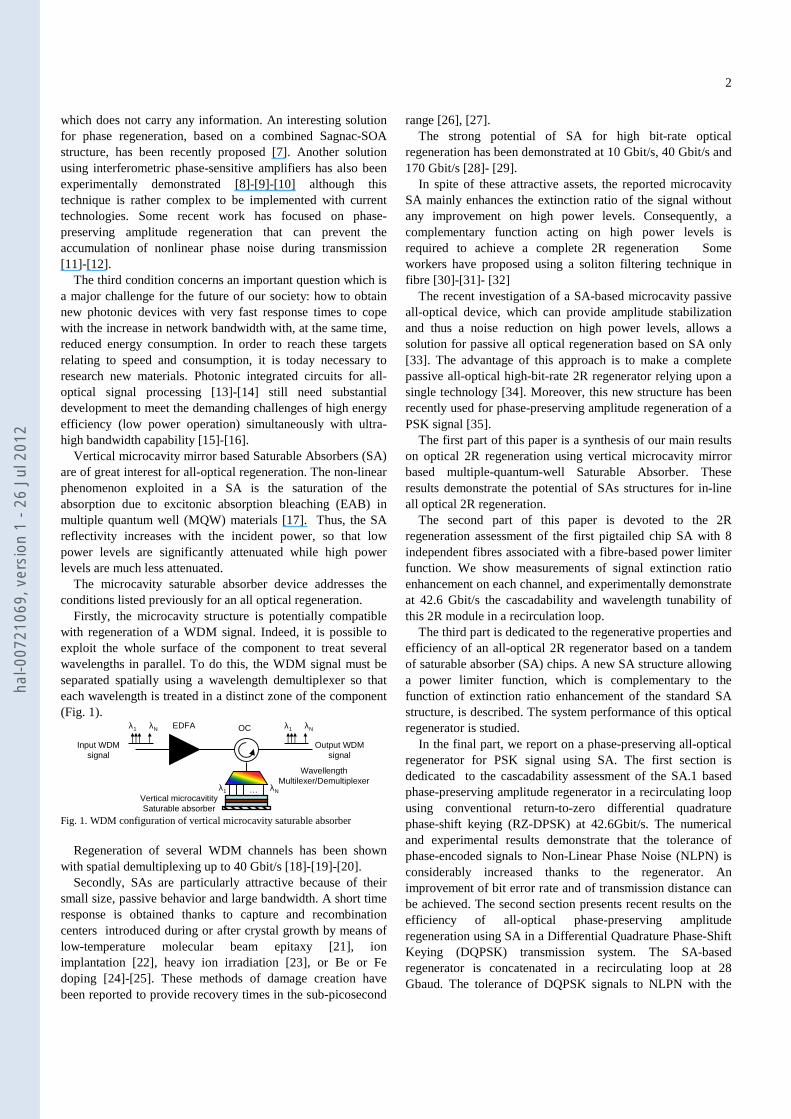
A special fibre array has been developed by YENISTA OPTICS for efficiently interfacing the saturable absorber chip to 8 standard single mode fibres with 250 µm spacing (Fig. 3).
Fig. 3. Photograph of SA chip, Fibre array (left) and SA module (right)
The fibre array is fixed to the mirror with an adhesive so
that each of the 8 outcoming beams typically has a Mode Field Diameter (MFD) of 4.5 µm on the surface of the mirror. Focusing the beams on the mirror reduces the input power threshold required for the nonlinear effect of the mirror. This compact and low cost technique does not need any coupling optimization (Fig. 3).
C. Module characterization
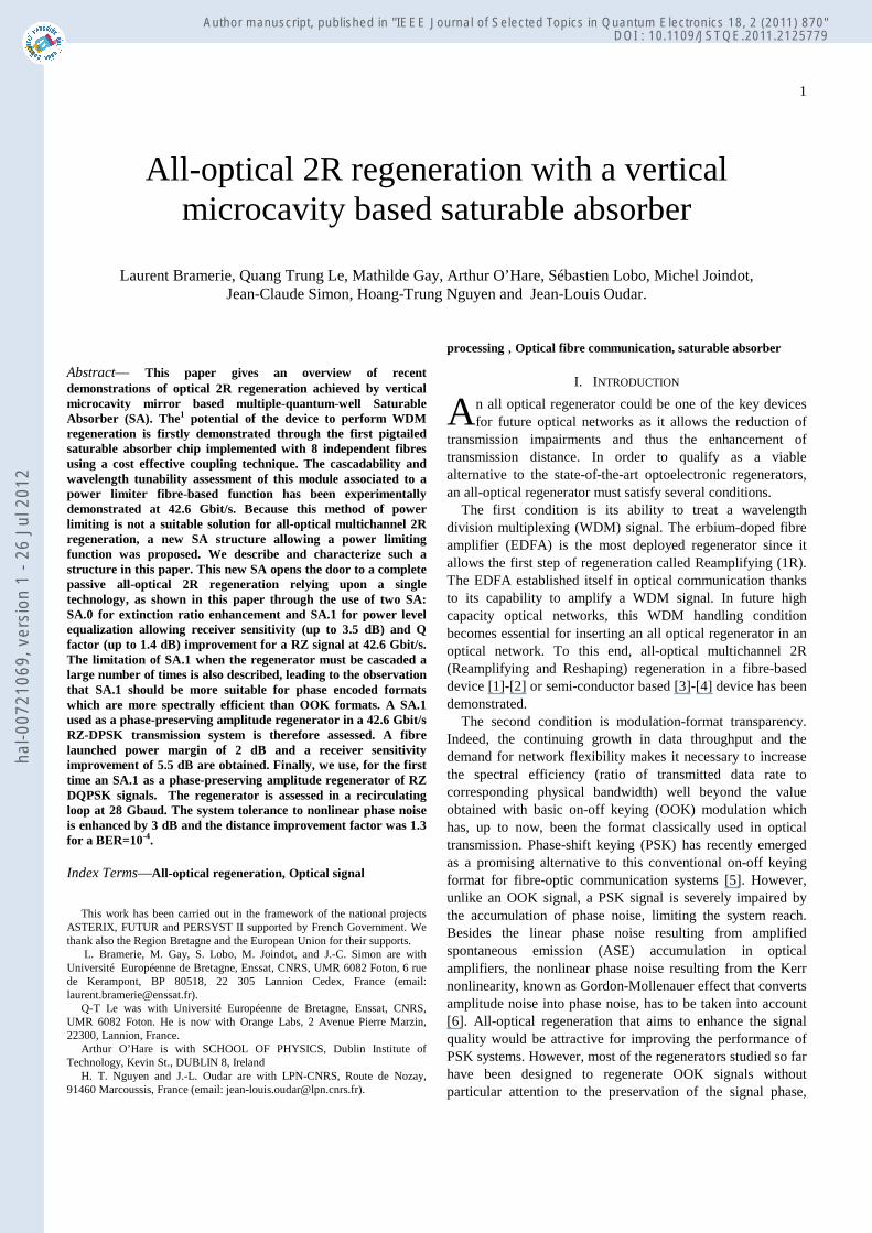
Fig. 4 shows the optical reflectivity spectra measured for each input fibre of the SA module. These curves were obtained with an Amplified Spontaneous Emission (ASE) source with low input power to the SA module. The spectral position of minimum reflectivity is 1546.6 nm averaged over all inputs, with a standard deviation of 1 nm.
-21
-19
-17
-15
-13
-11
-9
-7
-5
1520 1530 1540 1550 1560 1570 1580
Wavelength (nm)
Ref
lect
ivit
y (d
B)
Ch1Ch2Ch3Ch4Ch5Ch6Ch7Ch8
-21
-19
-17
-15
-13
-11
-9
-7
-5
1520 1530 1540 1550 1560 1570 1580
Wavelength (nm)
Ref
lect
ivit
y (d
B)
Ch1Ch2Ch3Ch4Ch5Ch6Ch7Ch8
Ch1Ch2Ch3Ch4Ch5Ch6Ch7Ch8
Fig. 4. Optical reflectivity spectra of each input fibre of the SA module
After static characterization, we have measured the
switching contrast using an experimental setup derived from classical pump-probe measurement [27]. The switching contrast is obtained from the measurement of the mark-space extinction ratio of the probe signal. It corresponds to the extinction ratio enhancement in the self saturation regime. The pump at 1532 nm is a RZ (33%) signal modulated at 42.6 Gbit/s with sequence length of 215-1 bits. The probe is delivered by a CW laser source at 1546.6 nm corresponding to the minimum reflectivity of the SA module. With a high input pump signal power level, we obtain a cross modulation of SA absorption onto the probe signal.
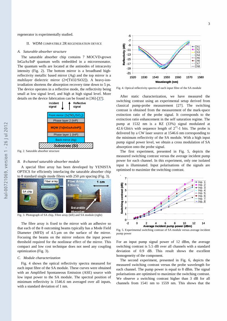
The first experiment, presented in Fig. 5, depicts the measured switching contrast versus the average incident pump power for each channel. In this experiment, only one isolated input is illuminated. Input polarisations of the signals are optimised to maximize the switching contrast.
.
0
1
2
3
4
5
6
7
-2 0 2 4 6 8 10 12 14Average incident pump power (dBm)
Sw
itch
ing
con
tras
t(d
B) Inp. 1
Inp. 2Inp. 3Inp. 4Inp. 5Inp. 6Inp. 7Inp. 8
0
1
2
3
4
5
6
7
-2 0 2 4 6 8 10 12 14Average incident pump power (dBm)
Sw
itch
ing
con
tras
t(d
B) Inp. 1
Inp. 2Inp. 3Inp. 4Inp. 5Inp. 6Inp. 7Inp. 8
Inp. 1Inp. 2Inp. 3Inp. 4Inp. 5Inp. 6Inp. 7Inp. 8
Fig. 5. Experimental switching contrast of SA module versus average incident pump power
For an input pump signal power of 12 dBm, the average switching contrast is 5.5 dB over all channels with a standard deviation of 0.9 dB. This result shows the excellent homogeneity of the component.
The second experiment, presented in Fig. 6, depicts the measured switching contrast versus the probe wavelength for each channel. The pump power is equal to 8 dBm. The signal polarisations are optimised to maximize the switching contrast. We observe a switching contrast higher than 3 dB for all channels from 1541 nm to 1559 nm. This shows that the
hal-0
0721
069,
ver
sion
1 -
26 J
ul 2
012
4
module is functional over a very wide-band signal spectrum, and so potentially constitutes a good candidate for WDM regeneration.
0,00
1,00
2,00
3,00
4,00
5,00
6,00
7,00
8,00
1535 1540 1545 1550 1555 1560
Probe wavelength (nm)
Sw
itch
ing
co
ntr
ast
(dB
)
Inp.1
Inp.2
Inp.3
Inp.4
Inp.5
Inp.6
Inp.7
Inp.8
0,00
1,00
2,00
3,00
4,00
5,00
6,00
7,00
8,00
1535 1540 1545 1550 1555 1560
Probe wavelength (nm)
Sw
itch
ing
co
ntr
ast
(dB
)
Inp.1
Inp.2
Inp.3
Inp.4
Inp.5
Inp.6
Inp.7
Inp.8
Fig. 6. Experimental switching contrast of SA module versus probe wavelength
However, the polarisation scrambling of signals implied a variation of more than 2 dB of the switching contrast between channels observed in Fig. 5 and Fig 6 which demonstrate a switching contrast polarisation dependence.
D. System characterization
The 42.6 Gbit/s transmission experiment is carried out with a 100 km long recirculating loop (Fig. 7). Non-Zero Dispersion Shifted Fibre (NZ-DSF) is used and chromatic dispersion is partially compensated for by a Dispersion Compensating Fibre (DCF). Losses are compensated for essentially with Erbium amplification. The transmitter produces an RZ (33 %) signal modulated at 42.6 Gbit/s with a 231-1 pseudo random bit sequence (PRBS).
Tx
EDFA
100 km
NZ DSF
EDFAOC
Rx
ATT
5 nm
EDFA DCF
1 km 1 km
NZ DSF DSF
1.2 nm
SA module 2R Regenerator
Tx
EDFA
100 km
NZ DSF
EDFAOC
Rx
ATT
5 nm
EDFA DCF
1 km 1 km
NZ DSF DSF
1.2 nm
SA module 2R Regenerator
Fig. 7. Experimental loop setup for characterization in 2R regeneration configuration
As complete 2R regeneration with limitation on high power
fluctuations is not ensured by the SA alone, the regeneration requires another non-linear function [32]. In this experiment, a fibre-based solution is used. The passive 2R regenerator is thus made up of two stages: the first pulse compression stage comprising a nonlinear fibre (NLF) followed by an optical filter for equalization of high power levels [19]-[19], and the second stage made up of the SA module for attenuation of the low power levels. The nonlinear fibre in the pulse compression stage consists of a 1 km span of DSF (dispersion 0.1 ps.nm-
1.km-1) followed by a 1 km span of standard NZ-DSF
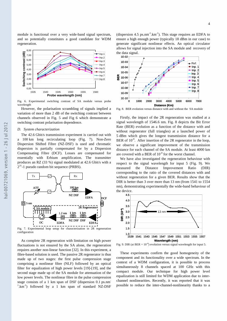
(dispersion 4.5 ps.nm-1.km-1). This stage requires an EDFA to ensure a high enough power (typically 18 dBm in our case) to generate significant nonlinear effects. An optical circulator allows for signal injection into the SA module and recovery of the data signal.
1E-10
1E-09
1E-08
1E-07
1E-06
1E-05
1E-04
1E-03
1E-02
0 1000 2000 3000 4000 5000 6000 7000
Distance (Km)
BE
R
Ref.
Inp. 7
Inp. 5
Inp. 3Inp. 2Inp. 1
Inp. 8
Inp. 4
Inp. 6
1E-10
1E-09
1E-08
1E-07
1E-06
1E-05
1E-04
1E-03
1E-02
0 1000 2000 3000 4000 5000 6000 7000
Distance (Km)
BE
R
Ref.
Inp. 7Inp. 7
Inp. 5Inp. 5
Inp. 3Inp. 3Inp. 2Inp. 2Inp. 1Inp. 1
Inp. 8Inp. 8
Inp. 4Inp. 4
Inp. 6Inp. 6
Fig. 8. BER evolution versus distance with and without the SA module
Firstly, the impact of the 2R regeneration was studied at a
signal wavelength of 1546.6 nm. Fig. 8 depicts the Bit Error Rate (BER) evolution as a function of the distance with and without regenerator (full triangles) at a launched power of 5 dBm which gives the longest transmission distance for a BER of 10-9. After insertion of the 2R regenerator in the loop, we observe a significant improvement of the transmission distance for each channel of the SA module. At least 4000 km are covered with a BER of 10-4 for the worst channel.
We have also investigated the regeneration behaviour with respect to the signal wavelength for input 5 (Fig. 9). We measured the Distance Improvement Ratio (DIR) corresponding to the ratio of the covered distances with and without regeneration for a given BER. Results show that the DIR is better than 3 over more than 13 nm (from 1541 to 1554 nm), demonstrating experimentally the wide-band behaviour of the device.
1.0
1.5
2.0
2.5
3.0
3.5
4.0
4.5
1539 1541 1543 1545 1547 1549 1551 1553 1555 1557
Wavelength (nm)
DIR
(10
-4)
13 nm
1.0
1.5
2.0
2.5
3.0
3.5
4.0
4.5
1539 1541 1543 1545 1547 1549 1551 1553 1555 1557
Wavelength (nm)
DIR
(10
-4)
13 nm
Fig. 9. DIR (at BER = 10-4) evolution versus signal wavelength for input 5.
These experiments confirm the good homogeneity of the
component and its functionality over a wide spectrum. In the context of a WDM configuration, it is possible to process simultaneously 8 channels spaced at 100 GHz with this compact module. Our technique for high power level equalization is still limited for WDM application due to inter-channel nonlinearities. Recently, it was reported that it was possible to reduce the inter-channel-nonlinearity thanks to a
hal-0
0721
069,
ver
sion
1 -
26 J
ul 2
012
5
specific dispersion map enabled by periodic group-delay devices [1]. Moreover, a new design of the same type of nonlinear microcavity device was proposed [33] in order to reduce high power levels fluctuations on several channels simultaneously. This new device would avoid the use of the fiber based solution.
In the next part, we describe the modified SA structure allowing high power level fluctuation reduction. Using this, a complete all optical 2R regeneration using two microcavity saturable absorbers will be demonstrated.
III. ALL OPTICAL 2R REGENERATION USING PASSIVE
SATURABLE ABSORPTION
The SA role is to suppress amplitude noise at low power levels and thus to enhance the extinction ratio of the signal but without giving any improvement on high power levels. This structure will be named as “SA.0” from now. Of course, to have a complete 2R regeneration function, a function complementary to the SA.0’s operation, that is to say, equalization of the high power levels fluctuations, must be used. A new SA structure, based on the same technology as the SA.0, but with some modification in the cavity parameters, showed a promising power limiter function (or amplitude fluctuation reduction); we will name this structure “SA.1”. In this part, we report on the regenerative properties of a tandem consisting of a SA.0 followed by a SA.1. In the next section, we introduce the new SA.1 structure that provides the power stabilization function.
A. Saturable absorber for power limiting function
1) Structure The SA.1 is based on the same structure, but with some
parameter modifications to obtain the complementary function to the SA.0. The principle of parameter modifications in the SA.1 structure will now be briefly described.
The SA structure consists of several multi-quantum wells (QWs) embedded in a microcavity. At the resonance wavelength, the cavity reflection at normal incidence can be expressed as [33]:
2
@1
−
−=
effbf
effbf
rescavRR
RRR ; Γ−= N
beffb eRR η2 (1)
where fR and bR are the reflectivities of the front and
back mirrors respectively, effbR is the effective back mirror
reflectivity accounting for the presence of QWs, η is the single pass absorption per QW, N is the number of QWs, and Γ is the longitudinal confinement factor. We note that when the incident power increases, the absorbing layers become more
transparent (η decreases) which induces the increase of effbR .
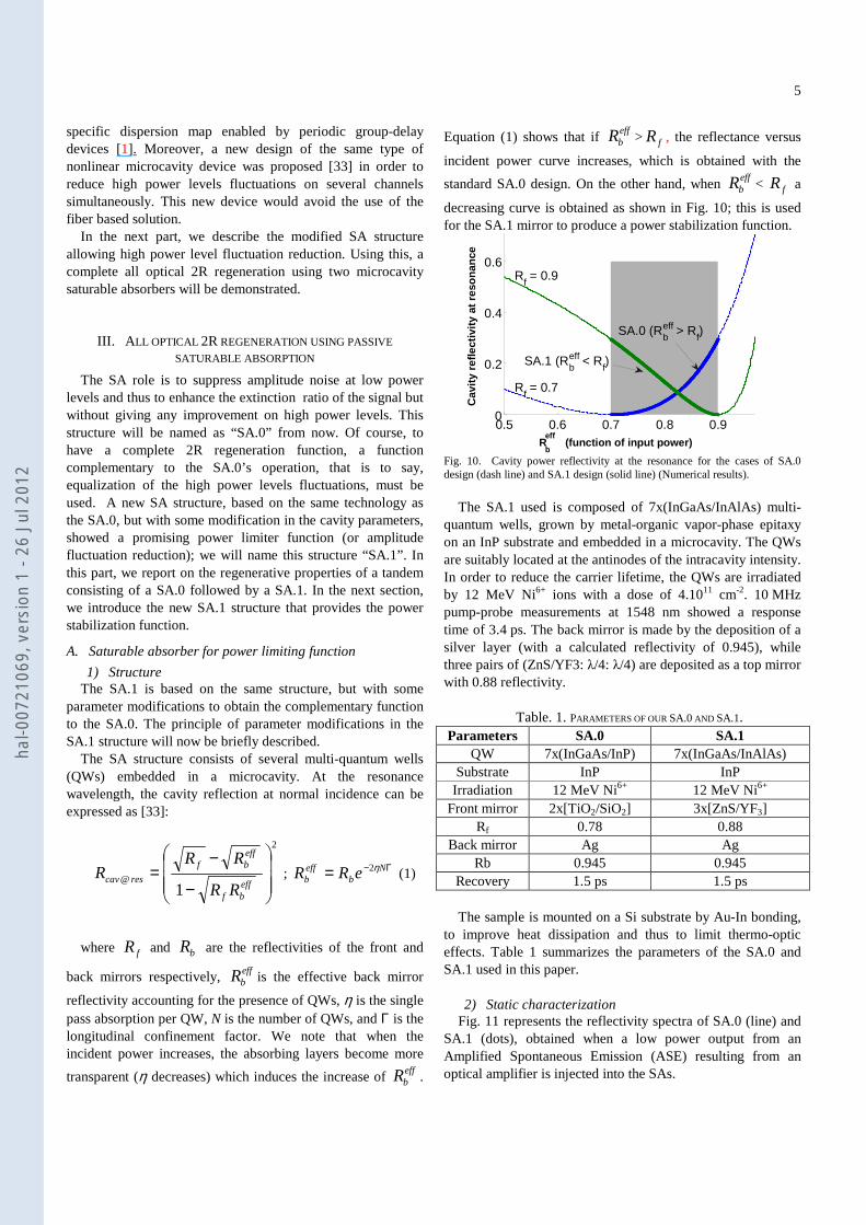
Equation (1) shows that if effbR > fR , the reflectance versus
incident power curve increases, which is obtained with the
standard SA.0 design. On the other hand, when effbR < fR a
decreasing curve is obtained as shown in Fig. 10; this is used for the SA.1 mirror to produce a power stabilization function.
0.5 0.6 0.7 0.8 0.90
0.2
0.4
0.6
0.5 0.6 0.7 0.8 0.90
0.2
0.4
0.6
SA.0 (Rbeff > R
f)
SA.1 (Rbeff < R
f)
Rf= 0.7
Rf= 0.9
Rb
eff(function of input power)
Cav
ity
refl
ecti
vity
at
reso
nan
ce
Fig. 10. Cavity power reflectivity at the resonance for the cases of SA.0 design (dash line) and SA.1 design (solid line) (Numerical results).
The SA.1 used is composed of 7x(InGaAs/InAlAs) multi-
quantum wells, grown by metal-organic vapor-phase epitaxy on an InP substrate and embedded in a microcavity. The QWs are suitably located at the antinodes of the intracavity intensity. In order to reduce the carrier lifetime, the QWs are irradiated by 12 MeV Ni6+ ions with a dose of 4.1011 cm-2. 10 MHz pump-probe measurements at 1548 nm showed a response time of 3.4 ps. The back mirror is made by the deposition of a silver layer (with a calculated reflectivity of 0.945), while three pairs of (ZnS/YF3: λ/4: λ/4) are deposited as a top mirror with 0.88 reflectivity.
Table. 1. PARAMETERS OF OUR SA.0 AND SA.1.
Parameters SA.0 SA.1 QW 7x(InGaAs/InP) 7x(InGaAs/InAlAs)
Substrate InP InP Irradiation 12 MeV Ni6+ 12 MeV Ni6+
Front mirror 2x[TiO2/SiO2] 3x[ZnS/YF3] Rf 0.78 0.88
Back mirror Ag Ag Rb 0.945 0.945
Recovery 1.5 ps 1.5 ps The sample is mounted on a Si substrate by Au-In bonding,
to improve heat dissipation and thus to limit thermo-optic effects. Table 1 summarizes the parameters of the SA.0 and SA.1 used in this paper.
2) Static characterization
Fig. 11 represents the reflectivity spectra of SA.0 (line) and SA.1 (dots), obtained when a low power output from an Amplified Spontaneous Emission (ASE) resulting from an optical amplifier is injected into the SAs.
hal-0
0721
069,
ver
sion
1 -
26 J
ul 2
012
6
-22
-20
-18
-16
-14
-12
-10
-8
-6
1535 1540 1545 1550 1555 1560 1565
Wavelength (nm)
Ref
lect
ivit
y (d
B)
SA.0
SA.1
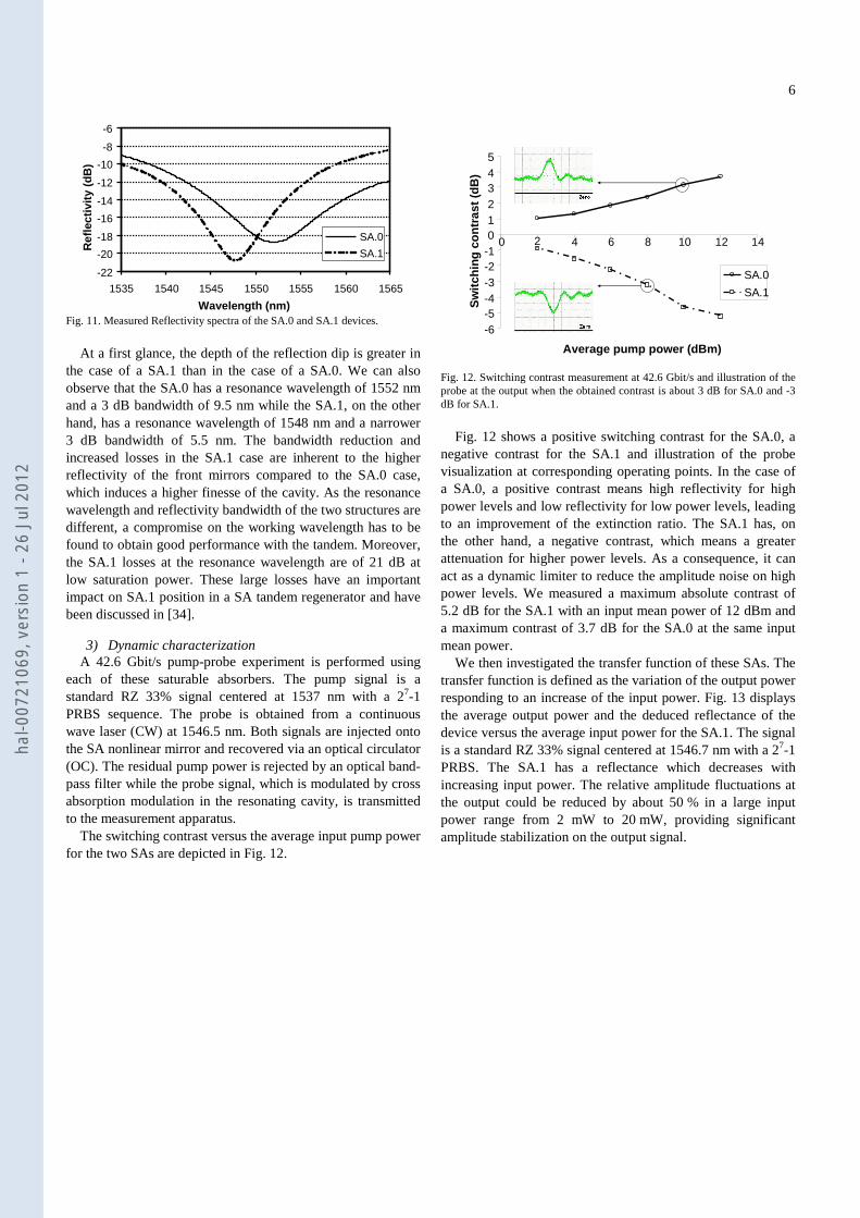
Fig. 11. Measured Reflectivity spectra of the SA.0 and SA.1 devices.
At a first glance, the depth of the reflection dip is greater in
the case of a SA.1 than in the case of a SA.0. We can also observe that the SA.0 has a resonance wavelength of 1552 nm and a 3 dB bandwidth of 9.5 nm while the SA.1, on the other hand, has a resonance wavelength of 1548 nm and a narrower 3 dB bandwidth of 5.5 nm. The bandwidth reduction and increased losses in the SA.1 case are inherent to the higher reflectivity of the front mirrors compared to the SA.0 case, which induces a higher finesse of the cavity. As the resonance wavelength and reflectivity bandwidth of the two structures are different, a compromise on the working wavelength has to be found to obtain good performance with the tandem. Moreover, the SA.1 losses at the resonance wavelength are of 21 dB at low saturation power. These large losses have an important impact on SA.1 position in a SA tandem regenerator and have been discussed in [34].
3) Dynamic characterization A 42.6 Gbit/s pump-probe experiment is performed using
each of these saturable absorbers. The pump signal is a standard RZ 33% signal centered at 1537 nm with a 27-1 PRBS sequence. The probe is obtained from a continuous wave laser (CW) at 1546.5 nm. Both signals are injected onto the SA nonlinear mirror and recovered via an optical circulator (OC). The residual pump power is rejected by an optical band-pass filter while the probe signal, which is modulated by cross absorption modulation in the resonating cavity, is transmitted to the measurement apparatus.
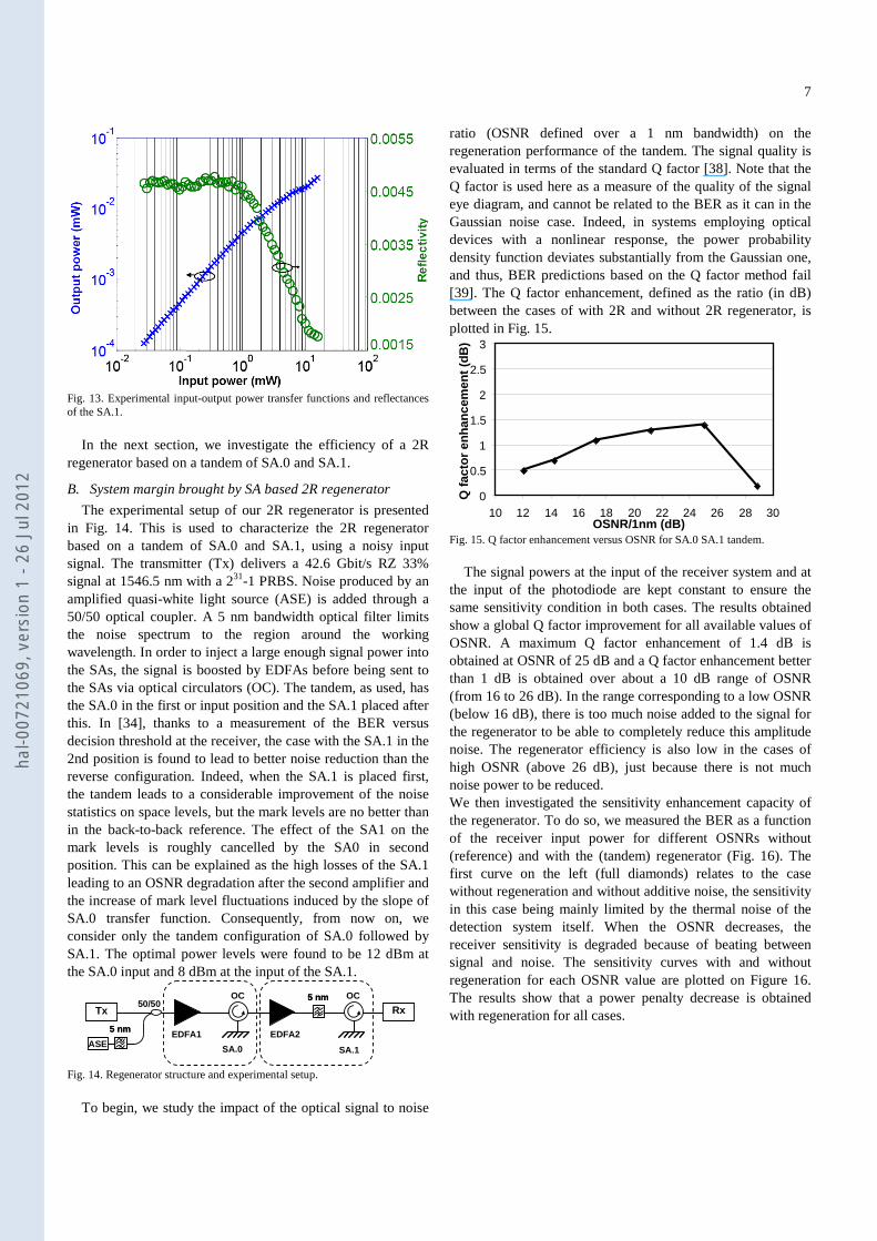
The switching contrast versus the average input pump power for the two SAs are depicted in Fig. 12.
-6-5-4-3-2-1012345
0 2 4 6 8 10 12 14
Average pump power (dBm)
Sw
itch
ing
co
ntr
ast
(dB
)
SA.0
SA.1
Fig. 12. Switching contrast measurement at 42.6 Gbit/s and illustration of the probe at the output when the obtained contrast is about 3 dB for SA.0 and -3 dB for SA.1.
Fig. 12 shows a positive switching contrast for the SA.0, a
negative contrast for the SA.1 and illustration of the probe visualization at corresponding operating points. In the case of a SA.0, a positive contrast means high reflectivity for high power levels and low reflectivity for low power levels, leading to an improvement of the extinction ratio. The SA.1 has, on the other hand, a negative contrast, which means a greater attenuation for higher power levels. As a consequence, it can act as a dynamic limiter to reduce the amplitude noise on high power levels. We measured a maximum absolute contrast of 5.2 dB for the SA.1 with an input mean power of 12 dBm and a maximum contrast of 3.7 dB for the SA.0 at the same input mean power.
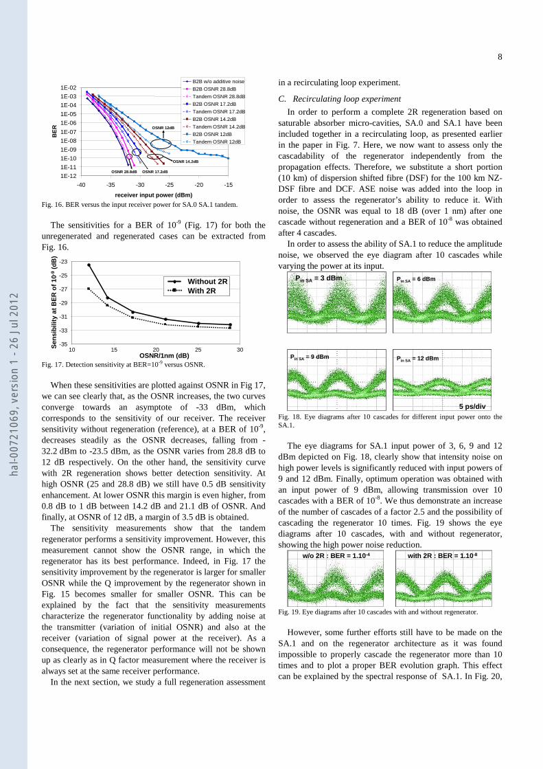
We then investigated the transfer function of these SAs. The transfer function is defined as the variation of the output power responding to an increase of the input power. Fig. 13 displays the average output power and the deduced reflectance of the device versus the average input power for the SA.1. The signal is a standard RZ 33% signal centered at 1546.7 nm with a 27-1 PRBS. The SA.1 has a reflectance which decreases with increasing input power. The relative amplitude fluctuations at the output could be reduced by about 50 % in a large input power range from 2 mW to 20 mW, providing significant amplitude stabilization on the output signal.
hal-0
0721
069,
ver
sion
1 -
26 J
ul 2
012
7
Fig. 13. Experimental input-output power transfer functions and reflectances of the SA.1.
In the next section, we investigate the efficiency of a 2R
regenerator based on a tandem of SA.0 and SA.1.
B. System margin brought by SA based 2R regenerator
The experimental setup of our 2R regenerator is presented in Fig. 14. This is used to characterize the 2R regenerator based on a tandem of SA.0 and SA.1, using a noisy input signal. The transmitter (Tx) delivers a 42.6 Gbit/s RZ 33% signal at 1546.5 nm with a 231-1 PRBS. Noise produced by an amplified quasi-white light source (ASE) is added through a 50/50 optical coupler. A 5 nm bandwidth optical filter limits the noise spectrum to the region around the working wavelength. In order to inject a large enough signal power into the SAs, the signal is boosted by EDFAs before being sent to the SAs via optical circulators (OC). The tandem, as used, has the SA.0 in the first or input position and the SA.1 placed after this. In [34], thanks to a measurement of the BER versus decision threshold at the receiver, the case with the SA.1 in the 2nd position is found to lead to better noise reduction than the reverse configuration. Indeed, when the SA.1 is placed first, the tandem leads to a considerable improvement of the noise statistics on space levels, but the mark levels are no better than in the back-to-back reference. The effect of the SA1 on the mark levels is roughly cancelled by the SA0 in second position. This can be explained as the high losses of the SA.1 leading to an OSNR degradation after the second amplifier and the increase of mark level fluctuations induced by the slope of SA.0 transfer function. Consequently, from now on, we consider only the tandem configuration of SA.0 followed by SA.1. The optimal power levels were found to be 12 dBm at the SA.0 input and 8 dBm at the input of the SA.1.
ASE
5 nm5 nm
5 nm5 nm
Tx50/50
OC OC
SA.0 SA.1
EDFA1 EDFA2
Rx
Fig. 14. Regenerator structure and experimental setup.
To begin, we study the impact of the optical signal to noise
ratio (OSNR defined over a 1 nm bandwidth) on the regeneration performance of the tandem. The signal quality is evaluated in terms of the standard Q factor [38]. Note that the Q factor is used here as a measure of the quality of the signal eye diagram, and cannot be related to the BER as it can in the Gaussian noise case. Indeed, in systems employing optical devices with a nonlinear response, the power probability density function deviates substantially from the Gaussian one, and thus, BER predictions based on the Q factor method fail [39]. The Q factor enhancement, defined as the ratio (in dB) between the cases of with 2R and without 2R regenerator, is plotted in Fig. 15.
0
0.5
1
1.5
2
2.5
3
10 12 14 16 18 20 22 24 26 28 30OSNR/1nm (dB)
Q f
acto
r en
han
cem
ent
(dB
)
Fig. 15. Q factor enhancement versus OSNR for SA.0 SA.1 tandem.
The signal powers at the input of the receiver system and at
the input of the photodiode are kept constant to ensure the same sensitivity condition in both cases. The results obtained show a global Q factor improvement for all available values of OSNR. A maximum Q factor enhancement of 1.4 dB is obtained at OSNR of 25 dB and a Q factor enhancement better than 1 dB is obtained over about a 10 dB range of OSNR (from 16 to 26 dB). In the range corresponding to a low OSNR (below 16 dB), there is too much noise added to the signal for the regenerator to be able to completely reduce this amplitude noise. The regenerator efficiency is also low in the cases of high OSNR (above 26 dB), just because there is not much noise power to be reduced. We then investigated the sensitivity enhancement capacity of the regenerator. To do so, we measured the BER as a function of the receiver input power for different OSNRs without (reference) and with the (tandem) regenerator (Fig. 16). The first curve on the left (full diamonds) relates to the case without regeneration and without additive noise, the sensitivity in this case being mainly limited by the thermal noise of the detection system itself. When the OSNR decreases, the receiver sensitivity is degraded because of beating between signal and noise. The sensitivity curves with and without regeneration for each OSNR value are plotted on Figure 16. The results show that a power penalty decrease is obtained with regeneration for all cases.
hal-0
0721
069,
ver
sion
1 -
26 J
ul 2
012
8
OSNR 28.8dB OSNR 17.2dB
OSNR 14.2dB
OSNR 12dB
1E-12
1E-11
1E-10
1E-09
1E-08
1E-07
1E-06
1E-05
1E-04
1E-03
1E-02
-40 -35 -30 -25 -20 -15
receiver input power (dBm)
BE
R
B2B w/o additive noise
B2B OSNR 28.8dB
Tandem OSNR 28.8dB
B2B OSNR 17.2dB
Tandem OSNR 17.2dB
B2B OSNR 14.2dB
Tandem OSNR 14.2dB
B2B OSNR 12dB
Tandem OSNR 12dB
Fig. 16. BER versus the input receiver power for SA.0 SA.1 tandem.
The sensitivities for a BER of 10-9 (Fig. 17) for both the
unregenerated and regenerated cases can be extracted from Fig. 16.
Asymptote
-35
-33
-31
-29
-27
-25
-23
10 15 20 25 30OSNR/1nm (dB)
Sen
sib
ility
at
BE
R o
f 10
-9(d
B)
Without 2RWith 2RWithout 2RWith 2R
Fig. 17. Detection sensitivity at BER=10-9 versus OSNR.
When these sensitivities are plotted against OSNR in Fig 17,
we can see clearly that, as the OSNR increases, the two curves converge towards an asymptote of -33 dBm, which corresponds to the sensitivity of our receiver. The receiver sensitivity without regeneration (reference), at a BER of 10-9, decreases steadily as the OSNR decreases, falling from -32.2 dBm to -23.5 dBm, as the OSNR varies from 28.8 dB to 12 dB respectively. On the other hand, the sensitivity curve with 2R regeneration shows better detection sensitivity. At high OSNR (25 and 28.8 dB) we still have 0.5 dB sensitivity enhancement. At lower OSNR this margin is even higher, from 0.8 dB to 1 dB between 14.2 dB and 21.1 dB of OSNR. And finally, at OSNR of 12 dB, a margin of 3.5 dB is obtained.
The sensitivity measurements show that the tandem regenerator performs a sensitivity improvement. However, this measurement cannot show the OSNR range, in which the regenerator has its best performance. Indeed, in Fig. 17 the sensitivity improvement by the regenerator is larger for smaller OSNR while the Q improvement by the regenerator shown in Fig. 15 becomes smaller for smaller OSNR. This can be explained by the fact that the sensitivity measurements characterize the regenerator functionality by adding noise at the transmitter (variation of initial OSNR) and also at the receiver (variation of signal power at the receiver). As a consequence, the regenerator performance will not be shown up as clearly as in Q factor measurement where the receiver is always set at the same receiver performance.
In the next section, we study a full regeneration assessment
in a recirculating loop experiment.
C. Recirculating loop experiment
In order to perform a complete 2R regeneration based on saturable absorber micro-cavities, SA.0 and SA.1 have been included together in a recirculating loop, as presented earlier in the paper in Fig. 7. Here, we now want to assess only the cascadability of the regenerator independently from the propagation effects. Therefore, we substitute a short portion (10 km) of dispersion shifted fibre (DSF) for the 100 km NZ-DSF fibre and DCF. ASE noise was added into the loop in order to assess the regenerator’s ability to reduce it. With noise, the OSNR was equal to 18 dB (over 1 nm) after one cascade without regeneration and a BER of 10-8 was obtained after 4 cascades.
In order to assess the ability of SA.1 to reduce the amplitude noise, we observed the eye diagram after 10 cascades while varying the power at its input.
Pin SA = 3 dBm
Pin SA = 12 dBmPin SA = 9 dBm
Pin SA = 6 dBm
5 ps/div Fig. 18. Eye diagrams after 10 cascades for different input power onto the SA.1.
The eye diagrams for SA.1 input power of 3, 6, 9 and 12
dBm depicted on Fig. 18, clearly show that intensity noise on high power levels is significantly reduced with input powers of 9 and 12 dBm. Finally, optimum operation was obtained with an input power of 9 dBm, allowing transmission over 10 cascades with a BER of 10-8. We thus demonstrate an increase of the number of cascades of a factor 2.5 and the possibility of cascading the regenerator 10 times. Fig. 19 shows the eye diagrams after 10 cascades, with and without regenerator, showing the high power noise reduction.
w/o 2R : BER = 1.10-4 with 2R : BER = 1.10-8
Fig. 19. Eye diagrams after 10 cascades with and without regenerator.
However, some further efforts still have to be made on the
SA.1 and on the regenerator architecture as it was found impossible to properly cascade the regenerator more than 10 times and to plot a proper BER evolution graph. This effect can be explained by the spectral response of SA.1. In Fig. 20,
hal-0
0721
069,
ver
sion
1 -
26 J
ul 2
012
9
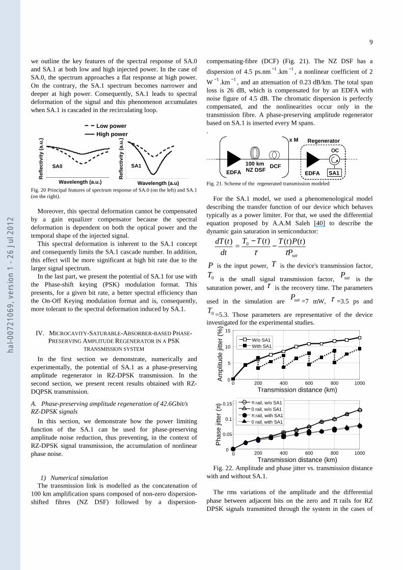
we outline the key features of the spectral response of SA.0 and SA.1 at both low and high injected power. In the case of SA.0, the spectrum approaches a flat response at high power. On the contrary, the SA.1 spectrum becomes narrower and deeper at high power. Consequently, SA.1 leads to spectral deformation of the signal and this phenomenon accumulates when SA.1 is cascaded in the recirculating loop.
Wavelength (a.u)
Ref
lect
ivit
y (a
.u.)
Wavelength (a.u.)
Ref
lect
ivit
y (a
.u.)
Low powerHigh power
SA0 SA1
Fig. 20 Principal features of spectrum response of SA.0 (on the left) and SA.1 (on the right).
Moreover, this spectral deformation cannot be compensated
by a gain equalizer compensator because the spectral deformation is dependent on both the optical power and the temporal shape of the injected signal.
This spectral deformation is inherent to the SA.1 concept and consequently limits the SA.1 cascade number. In addition, this effect will be more significant at high bit rate due to the larger signal spectrum.
In the last part, we present the potential of SA.1 for use with the Phase-shift keying (PSK) modulation format. This presents, for a given bit rate, a better spectral efficiency than the On-Off Keying modulation format and is, consequently, more tolerant to the spectral deformation induced by SA.1.
IV. MICROCAVITY-SATURABLE-ABSORBER-BASED PHASE-PRESERVING AMPLITUDE REGENERATOR IN A PSK
TRANSMISSION SYSTEM
In the first section we demonstrate, numerically and experimentally, the potential of SA.1 as a phase-preserving amplitude regenerator in RZ-DPSK transmission. In the second section, we present recent results obtained with RZ-DQPSK transmission.
A. Phase-preserving amplitude regeneration of 42.6Gbit/s RZ-DPSK signals
In this section, we demonstrate how the power limiting function of the SA.1 can be used for phase-preserving amplitude noise reduction, thus preventing, in the context of RZ-DPSK signal transmission, the accumulation of nonlinear phase noise.
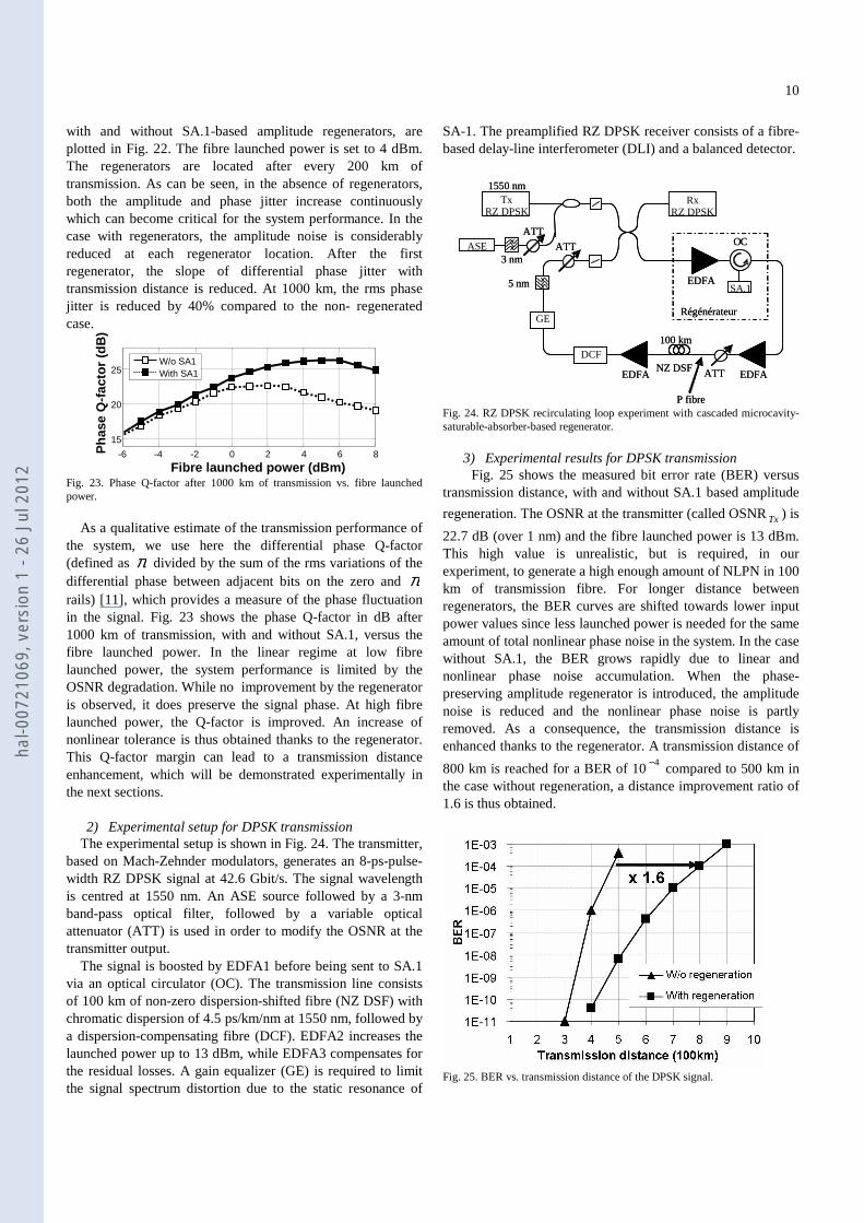
1) Numerical simulation
The transmission link is modelled as the concatenation of 100 km amplification spans composed of non-zero dispersion-shifted fibres (NZ DSF) followed by a dispersion-
compensating-fibre (DCF) (Fig. 21). The NZ DSF has a
dispersion of 4.5 ps.nm1− .km 1− , a nonlinear coefficient of 2
W 1− .km 1− , and an attenuation of 0.23 dB/km. The total span loss is 26 dB, which is compensated for by an EDFA with noise figure of 4.5 dB. The chromatic dispersion is perfectly compensated, and the nonlinearities occur only in the transmission fibre. A phase-preserving amplitude regenerator based on SA.1 is inserted every M spans. .
OC
Regenerator
OC
SA1EDFA
100 km
EDFA NZ DSF
x M
DCF
Fig. 21. Scheme of the regenerated transmission modeled
For the SA.1 model, we used a phenomenological model
describing the transfer function of our device which behaves typically as a power limiter. For that, we used the differential equation proposed by A.A.M Saleh [40] to describe the dynamic gain saturation in semiconductor:
satP
tPtTtTT
dt
tdT
ττ)()()(
=)( 0 −
−
P is the input power, T is the device's transmission factor,
0T is the small signal transmission factor, satP
is the saturation power, and τ is the recovery time. The parameters
used in the simulation are satP=7 mW, τ =3.5 ps and
0T=5.3. Those parameters are representative of the device
investigated for the experimental studies.
0 200 400 600 800 10000
5
10
15
Transmission distance (km)
Am
plitu
de ji
tter
(%)
W/o SA1With SA1
0 200 400 600 800 10000
0.05
0.1
0.15
Transmission distance (km)
Pha
se ji
tter
(π) π rail, w/o SA1
0 rail, w/o SA1π rail, with SA10 rail, with SA1
Fig. 22. Amplitude and phase jitter vs. transmission distance
with and without SA.1.
The rms variations of the amplitude and the differential phase between adjacent bits on the zero and π rails for RZ DPSK signals transmitted through the system in the cases of
hal-0
0721
069,
ver
sion
1 -
26 J
ul 2
012
10
with and without SA.1-based amplitude regenerators, are plotted in Fig. 22. The fibre launched power is set to 4 dBm. The regenerators are located after every 200 km of transmission. As can be seen, in the absence of regenerators, both the amplitude and phase jitter increase continuously which can become critical for the system performance. In the case with regenerators, the amplitude noise is considerably reduced at each regenerator location. After the first regenerator, the slope of differential phase jitter with transmission distance is reduced. At 1000 km, the rms phase jitter is reduced by 40% compared to the non- regenerated case.
-6 -4 -2 0 2 4 6 8
15
20
25
Fibre launched power (dBm)
Ph
ase
Q-f
acto
r (d
B)
W/o SA1With SA1
Fig. 23. Phase Q-factor after 1000 km of transmission vs. fibre launched power.
As a qualitative estimate of the transmission performance of
the system, we use here the differential phase Q-factor (defined as π divided by the sum of the rms variations of the differential phase between adjacent bits on the zero and π rails) [11], which provides a measure of the phase fluctuation in the signal. Fig. 23 shows the phase Q-factor in dB after 1000 km of transmission, with and without SA.1, versus the fibre launched power. In the linear regime at low fibre launched power, the system performance is limited by the OSNR degradation. While no improvement by the regenerator is observed, it does preserve the signal phase. At high fibre launched power, the Q-factor is improved. An increase of nonlinear tolerance is thus obtained thanks to the regenerator. This Q-factor margin can lead to a transmission distance enhancement, which will be demonstrated experimentally in the next sections.
2) Experimental setup for DPSK transmission
The experimental setup is shown in Fig. 24. The transmitter, based on Mach-Zehnder modulators, generates an 8-ps-pulse-width RZ DPSK signal at 42.6 Gbit/s. The signal wavelength is centred at 1550 nm. An ASE source followed by a 3-nm band-pass optical filter, followed by a variable optical attenuator (ATT) is used in order to modify the OSNR at the transmitter output.
The signal is boosted by EDFA1 before being sent to SA.1 via an optical circulator (OC). The transmission line consists of 100 km of non-zero dispersion-shifted fibre (NZ DSF) with chromatic dispersion of 4.5 ps/km/nm at 1550 nm, followed by a dispersion-compensating fibre (DCF). EDFA2 increases the launched power up to 13 dBm, while EDFA3 compensates for the residual losses. A gain equalizer (GE) is required to limit the signal spectrum distortion due to the static resonance of
SA-1. The preamplified RZ DPSK receiver consists of a fibre-based delay-line interferometer (DLI) and a balanced detector.
3 nm
1550 nmTx
RZ DPSK
ASE
EDFA
100 km
NZ DSF
P fibre
EDFA
DCF
OC
EDFASA.1
Régénérateur
RxRZ DPSK
ATT
ATT
ATT
5 nm
GE
3 nm
1550 nmTx
RZ DPSK
ASE
EDFA
100 km
NZ DSF
P fibre
EDFA
DCF
OC
EDFASA.1
Régénérateur
RxRZ DPSK
ATT
ATT
ATT
5 nm
GE
Fig. 24. RZ DPSK recirculating loop experiment with cascaded microcavity-saturable-absorber-based regenerator.
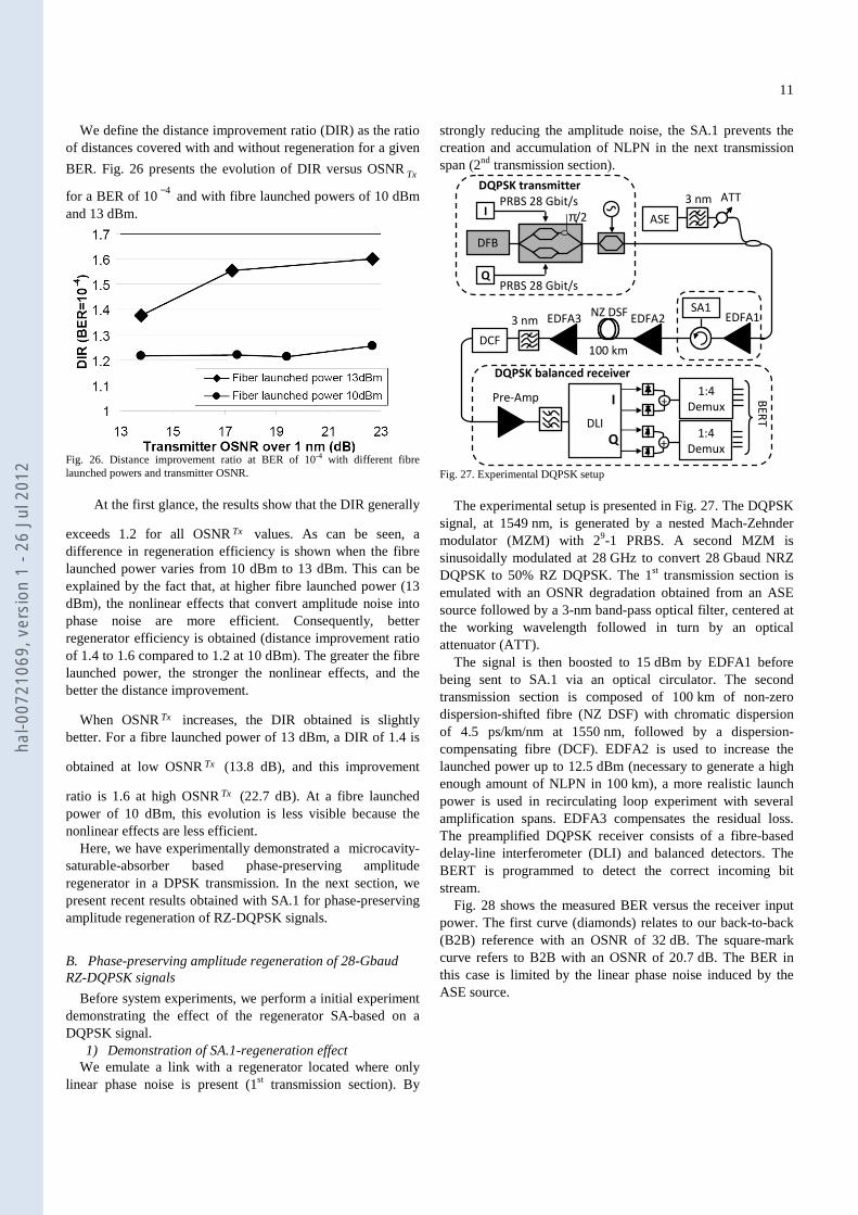
3) Experimental results for DPSK transmission
Fig. 25 shows the measured bit error rate (BER) versus transmission distance, with and without SA.1 based amplitude
regeneration. The OSNR at the transmitter (called OSNRTx ) is
22.7 dB (over 1 nm) and the fibre launched power is 13 dBm. This high value is unrealistic, but is required, in our experiment, to generate a high enough amount of NLPN in 100 km of transmission fibre. For longer distance between regenerators, the BER curves are shifted towards lower input power values since less launched power is needed for the same amount of total nonlinear phase noise in the system. In the case without SA.1, the BER grows rapidly due to linear and nonlinear phase noise accumulation. When the phase-preserving amplitude regenerator is introduced, the amplitude noise is reduced and the nonlinear phase noise is partly removed. As a consequence, the transmission distance is enhanced thanks to the regenerator. A transmission distance of
800 km is reached for a BER of 104− compared to 500 km in the case without regeneration, a distance improvement ratio of 1.6 is thus obtained.
Fig. 25. BER vs. transmission distance of the DPSK signal.
hal-0
0721
069,
ver
sion
1 -
26 J
ul 2
012
11
We define the distance improvement ratio (DIR) as the ratio of distances covered with and without regeneration for a given
BER. Fig. 26 presents the evolution of DIR versus OSNRTx
for a BER of 10 4− and with fibre launched powers of 10 dBm and 13 dBm.
Fig. 26. Distance improvement ratio at BER of 10-4 with different fibre launched powers and transmitter OSNR.
At the first glance, the results show that the DIR generally
exceeds 1.2 for all OSNRTx values. As can be seen, a difference in regeneration efficiency is shown when the fibre launched power varies from 10 dBm to 13 dBm. This can be explained by the fact that, at higher fibre launched power (13 dBm), the nonlinear effects that convert amplitude noise into phase noise are more efficient. Consequently, better regenerator efficiency is obtained (distance improvement ratio of 1.4 to 1.6 compared to 1.2 at 10 dBm). The greater the fibre launched power, the stronger the nonlinear effects, and the better the distance improvement.
When OSNRTx increases, the DIR obtained is slightly better. For a fibre launched power of 13 dBm, a DIR of 1.4 is
obtained at low OSNRTx (13.8 dB), and this improvement
ratio is 1.6 at high OSNRTx (22.7 dB). At a fibre launched power of 10 dBm, this evolution is less visible because the nonlinear effects are less efficient.
Here, we have experimentally demonstrated a microcavity-saturable-absorber based phase-preserving amplitude regenerator in a DPSK transmission. In the next section, we present recent results obtained with SA.1 for phase-preserving amplitude regeneration of RZ-DQPSK signals.
B. Phase-preserving amplitude regeneration of 28-Gbaud RZ-DQPSK signals
Before system experiments, we perform a initial experiment demonstrating the effect of the regenerator SA-based on a DQPSK signal.
1) Demonstration of SA.1-regeneration effect We emulate a link with a regenerator located where only
linear phase noise is present (1st transmission section). By
strongly reducing the amplitude noise, the SA.1 prevents the creation and accumulation of NLPN in the next transmission span (2nd transmission section).
DFB
100 kmDCF
NZ DSF3 nm EDFA3
I
Q
PRBS 28 Gbit/s
PRBS 28 Gbit/s
ATT
EDFA1SA1
DQPSK transmitter
π/2
DQPSK balanced receiver
Pre-Amp
+1:4
Demux
+1:4
Demux
BE
RT
DLI
Q
I
ASE
3 nm
EDFA2
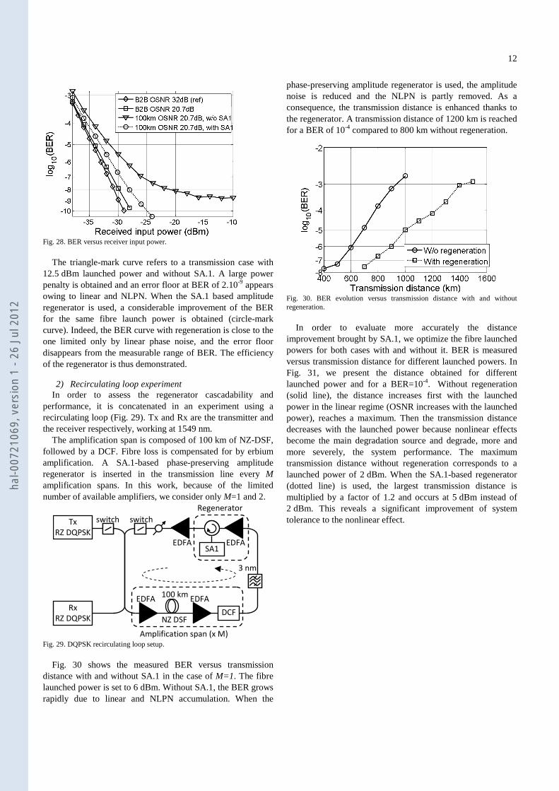
Fig. 27. Experimental DQPSK setup
The experimental setup is presented in Fig. 27. The DQPSK
signal, at 1549 nm, is generated by a nested Mach-Zehnder modulator (MZM) with 29-1 PRBS. A second MZM is sinusoidally modulated at 28 GHz to convert 28 Gbaud NRZ DQPSK to 50% RZ DQPSK. The 1st transmission section is emulated with an OSNR degradation obtained from an ASE source followed by a 3-nm band-pass optical filter, centered at the working wavelength followed in turn by an optical attenuator (ATT).
The signal is then boosted to 15 dBm by EDFA1 before being sent to SA.1 via an optical circulator. The second transmission section is composed of 100 km of non-zero dispersion-shifted fibre (NZ DSF) with chromatic dispersion of 4.5 ps/km/nm at 1550 nm, followed by a dispersion-compensating fibre (DCF). EDFA2 is used to increase the launched power up to 12.5 dBm (necessary to generate a high enough amount of NLPN in 100 km), a more realistic launch power is used in recirculating loop experiment with several amplification spans. EDFA3 compensates the residual loss. The preamplified DQPSK receiver consists of a fibre-based delay-line interferometer (DLI) and balanced detectors. The BERT is programmed to detect the correct incoming bit stream.
Fig. 28 shows the measured BER versus the receiver input power. The first curve (diamonds) relates to our back-to-back (B2B) reference with an OSNR of 32 dB. The square-mark curve refers to B2B with an OSNR of 20.7 dB. The BER in this case is limited by the linear phase noise induced by the ASE source.
hal-0
0721
069,
ver
sion
1 -
26 J
ul 2
012
12
Fig. 28. BER versus receiver input power.
The triangle-mark curve refers to a transmission case with
12.5 dBm launched power and without SA.1. A large power penalty is obtained and an error floor at BER of 2.10-9 appears owing to linear and NLPN. When the SA.1 based amplitude regenerator is used, a considerable improvement of the BER for the same fibre launch power is obtained (circle-mark curve). Indeed, the BER curve with regeneration is close to the one limited only by linear phase noise, and the error floor disappears from the measurable range of BER. The efficiency of the regenerator is thus demonstrated.
2) Recirculating loop experiment In order to assess the regenerator cascadability and
performance, it is concatenated in an experiment using a recirculating loop (Fig. 29). Tx and Rx are the transmitter and the receiver respectively, working at 1549 nm.
The amplification span is composed of 100 km of NZ-DSF, followed by a DCF. Fibre loss is compensated for by erbium amplification. A SA.1-based phase-preserving amplitude regenerator is inserted in the transmission line every M amplification spans. In this work, because of the limited number of available amplifiers, we consider only M=1 and 2.
100 km
NZ DSFDCF
EDFA
EDFA
EDFA
Tx
RZ DQPSK
switchswitch
EDFASA1
Rx
RZ DQPSK
Regenerator
Amplification span (x M)
3 nm
Fig. 29. DQPSK recirculating loop setup.
Fig. 30 shows the measured BER versus transmission
distance with and without SA.1 in the case of M=1. The fibre launched power is set to 6 dBm. Without SA.1, the BER grows rapidly due to linear and NLPN accumulation. When the
phase-preserving amplitude regenerator is used, the amplitude noise is reduced and the NLPN is partly removed. As a consequence, the transmission distance is enhanced thanks to the regenerator. A transmission distance of 1200 km is reached for a BER of 10-4 compared to 800 km without regeneration.
Fig. 30. BER evolution versus transmission distance with and without regeneration.
In order to evaluate more accurately the distance
improvement brought by SA.1, we optimize the fibre launched powers for both cases with and without it. BER is measured versus transmission distance for different launched powers. In Fig. 31, we present the distance obtained for different launched power and for a BER=10-4. Without regeneration (solid line), the distance increases first with the launched power in the linear regime (OSNR increases with the launched power), reaches a maximum. Then the transmission distance decreases with the launched power because nonlinear effects become the main degradation source and degrade, more and more severely, the system performance. The maximum transmission distance without regeneration corresponds to a launched power of 2 dBm. When the SA.1-based regenerator (dotted line) is used, the largest transmission distance is multiplied by a factor of 1.2 and occurs at 5 dBm instead of 2 dBm. This reveals a significant improvement of system tolerance to the nonlinear effect.
hal-0
0721
069,
ver
sion
1 -
26 J
ul 2
012
13
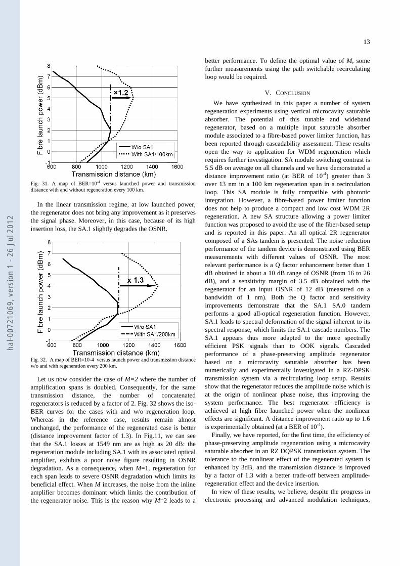
Fig. 31. A map of BER=10-4 versus launched power and transmission distance with and without regeneration every 100 km.
In the linear transmission regime, at low launched power,
the regenerator does not bring any improvement as it preserves the signal phase. Moreover, in this case, because of its high insertion loss, the SA.1 slightly degrades the OSNR.
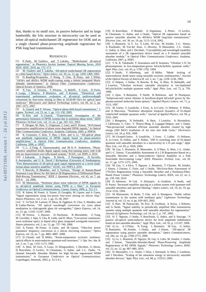
Fig. 32. A map of BER=10-4 versus launch power and transmission distance w/o and with regeneration every 200 km.
Let us now consider the case of M=2 where the number of amplification spans is doubled. Consequently, for the same transmission distance, the number of concatenated regenerators is reduced by a factor of 2. Fig. 32 shows the iso-BER curves for the cases with and w/o regeneration loop. Whereas in the reference case, results remain almost unchanged, the performance of the regenerated case is better (distance improvement factor of 1.3). In Fig.11, we can see that the SA.1 losses at 1549 nm are as high as 20 dB: the regeneration module including SA.1 with its associated optical amplifier, exhibits a poor noise figure resulting in OSNR degradation. As a consequence, when M=1, regeneration for each span leads to severe OSNR degradation which limits its beneficial effect. When M increases, the noise from the inline amplifier becomes dominant which limits the contribution of the regenerator noise. This is the reason why M=2 leads to a
better performance. To define the optimal value of M, some further measurements using the path switchable recirculating loop would be required.
V. CONCLUSION
We have synthesized in this paper a number of system regeneration experiments using vertical microcavity saturable absorber. The potential of this tunable and wideband regenerator, based on a multiple input saturable absorber module associated to a fibre-based power limiter function, has been reported through cascadability assessment. These results open the way to application for WDM regeneration which requires further investigation. SA module switching contrast is 5.5 dB on average on all channels and we have demonstrated a distance improvement ratio (at BER of 10-4) greater than 3 over 13 nm in a 100 km regeneration span in a recirculation loop. This SA module is fully compatible with photonic integration. However, a fibre-based power limiter function does not help to produce a compact and low cost WDM 2R regeneration. A new SA structure allowing a power limiter function was proposed to avoid the use of the fiber-based setup and is reported in this paper. An all optical 2R regenerator composed of a SAs tandem is presented. The noise reduction performance of the tandem device is demonstrated using BER measurements with different values of OSNR. The most relevant performance is a Q factor enhancement better than 1 dB obtained in about a 10 dB range of OSNR (from 16 to 26 dB), and a sensitivity margin of 3.5 dB obtained with the regenerator for an input OSNR of 12 dB (measured on a bandwidth of 1 nm). Both the Q factor and sensitivity improvements demonstrate that the SA.1 SA.0 tandem performs a good all-optical regeneration function. However, SA.1 leads to spectral deformation of the signal inherent to its spectral response, which limits the SA.1 cascade numbers. The SA.1 appears thus more adapted to the more spectrally efficient PSK signals than to OOK signals. Cascaded performance of a phase-preserving amplitude regenerator based on a microcavity saturable absorber has been numerically and experimentally investigated in a RZ-DPSK transmission system via a recirculating loop setup. Results show that the regenerator reduces the amplitude noise which is at the origin of nonlinear phase noise, thus improving the system performance. The best regenerator efficiency is achieved at high fibre launched power when the nonlinear effects are significant. A distance improvement ratio up to 1.6 is experimentally obtained (at a BER of 10-4).
Finally, we have reported, for the first time, the efficiency of phase-preserving amplitude regeneration using a microcavity saturable absorber in an RZ DQPSK transmission system. The tolerance to the nonlinear effect of the regenerated system is enhanced by 3dB, and the transmission distance is improved by a factor of 1.3 with a better trade-off between amplitude-regeneration effect and the device insertion.
In view of these results, we believe, despite the progress in electronic processing and advanced modulation techniques,
hal-0
0721
069,
ver
sion
1 -
26 J
ul 2
012
14
that, thanks to its small size, its passive behavior and its large bandwidth, the SAs structure in microcavity can be used as inline all-optical multichannel 2R regenerator for OOK and as a single channel phase-preserving amplitude regenerator for PSK long haul transmission.
REFERENCES
[1] P. Patki, M. Vasilyev, and T. Lakoba, “Multichannel all-optical regeneration,” in Photonics Society Summer Topical Meeting Series, 2010 IEEE. IEEE, 2010, pp. 172–173. [2] M. Vasilyev and T. Lakoba, “All-optical multichannel 2R regeneration in a fiber-based device,” Optics letters, vol. 30, no. 12, pp. 1458–1460, 2005. [3] D. Reading-Picopoulos, F. Wang, Y. Chai, R. Penty, and I. White, “10Gb/s and 40Gb/s WDM multi-casting using a hybrid integrated Mach-Zehnder interferometer,” in Optical Fiber Communication Conference. Optical Society of America, 2006. [4] N. Yan, A. Teixeira, T. Silveira, G. Beleffi, F. Curti, D. Forin, F. Longa, I. Monroy, P. Monteiro, and T. Koonen, “Theoretical and experimental performance evaluation of all-optical multiwavelength conversion by four-wave mixing in fiber at 10/20/40 Gb/s for optical layer multicast,” Microwave and Optical Technology Letters, vol. 49, no. 5, pp. 1067–1071, 2007. [5] A. Gnauck and P. Winzer, “Optical phase-shift-keyed transmission,” J. Lightw. Technol., vol. 23, no. 1, pp. 115–130, 2005. [6] H. Kim and A. Gnauck, “Experimental investigation of the performance limitation of DPSK systems due to nonlinear phase noise,” IEEE Photonics Technol. Lett., vol. 15, no. 2, pp. 320–322, 2003. [7] P. Devgan, M. Shin, V. Grigoryan, J. Lasri, and P. Kumar, “SOA-based regenerative amplification of phase noise degraded DPSK signals,” in Optical Fiber Communication Conference, Anaheim, California, 2005, p. PDP34. [8] K. Croussore, C. Kim, Y. Han, I. Kim, and G. Li, “All-optical phase and amplitude regeneration of DPSK signals based on phase-sensitive amplification,” in Optical Fiber Communication Conference, Anaheim, California, 2006, p. OFH7. [9] C. L. Z.Tong, E. Tipsuwannakul, and M. K. P. Andrekson, “Phase-sensitive amplified dwdm dqpsk signals using free-running lasers with 6-db link snr improvement over edfa-based systems,” ECOC, vol. PDP1.3, 2010. [10] J. Kakande, A. Bogris, R. Slavík, F. Parmigiani, D. Syvridis, P. Petropoulos, and U. K. David J Richardson (University of Southampton, “First demonstration of all-optical qpsk signal regeneration in a novel multi-format phase sensitive amplifier,” ECOC, vol. PDP3.3, 2010. [11] S. Boscolo, R. Bhamber, and S. Turitsyn, “Design of Raman-Based Nonlinear Loop Mirror for All-Optical 2R Regeneration of Differential Phase-Shift-Keying Transmission,” IEEE J. Quantum Electron., vol. 42, no. 7, pp. 619–6 24, 2006. [12] M. Matsumoto, “Nonlinear phase noise reduction of DPSK signals by an all-optical amplitude limiter using FWM in a fiber,” in European Conference on Optical Communications, Cannes, France, 2006, p. Tu1.3.5. [13] R. Salem, M. Foster, A. Turner, D. Geraghty, M. Lipson, and A. Gaeta, “Signal regeneration using low-power four-wave mixing on silicon chip,” Nature Photonics, vol. 2, no. 1, pp. 35–38, 2007. [14] V. Ta’Eed, M. Lamont, D. Moss, B. Eggleton, D. Choi, S. Madden, and B. Luther-Davies, “All optical wavelength conversion via cross phase modulation in chalcogenide glass rib waveguides,” Optics Express, vol. 14, no. 23, pp. 11242–11247, 2006. [15] M. Ferrera, L. Razzari, D. Duchesne, R. Morandotti, Z. Yang, M. Liscidini, J. Sipe, S. Chu, B. Little, and D. Moss, “Low-power continuous-wave nonlinear optics in doped silica glass integrated waveguide structures,” Nature photonics, vol. 2, no. 12, pp. 737–740, 2008. [16] A. Turner, M. Foster, A. Gaeta, and M. Lipson, “Ultra-low power parametric frequency conversion in a silicon microring resonator,” Optics Express, vol. 16, no. 7, pp. 4881–4887, 2008. [17] D. Chemla and D. Miller, “Room-temperature excitonic nonlinear-optical effects in semiconductor quantum-well structures,” J. Opt. Soc. Am. B, vol. 2, no. 7, pp. 1155–1173, 1985. [18] A. Shen, M. Goix, S. Louis, D. Delagrandiere, J. Decobert, G. Henin, D. Rouvillain, O. Leclerc, H. Choumane, G. Aubin, and J.-L. Oudar, “4-channel Saturable Absorber Module for high bit-rate regenerated WDM transmission,” in European Conference on Optical Communications, Copenhagen, Denmark, 2002, p. Tu 5.4.5.
[19] D. Rouvillain, P. Brindel, E. Seguineau, L. Pierre, O. Leclerc, H. Choumane, G. Aubin, and J. Oudar, “Optical 2R regenerator based on passive saturable absorber for 40Gbit/s WDM long-haul transmissions,” Electron. Lett., vol. 38, no. 19, pp. 1113–1114, 2002. [20] L. Bramerie, Q. T. Le, S. Lobo, M. Gay, M. Joindot, J.-C. Simon, A. Poudoulec, M. Van der Keur, C. Devemy, D. Massoubre, J.-L. Oudar, G. Aubin, A. Shen, and J. Decobert, “Cascadability and wavelength tunability assessment of a 2R regeneration device based on a 8 channel saturable absorber module,” in Optical Fiber Communication Conference, Anaheim, California, 2007, p. PDP1. [21] T. K. R. Takahashi, Y. Kawamura and H. Iwamura, “Ultrafast 1.55 ?m photoresponses in low-temperature-grown InGaAs/InAlAs quantum wells,” Appl. Phys. Lett., vol. 65, p. 1790–1792, 1994. [22] P. Smith, Y. Silberberg, and D. Miller, “Mode locking of semiconductor diode lasers using saturable excitonic nonlinearities,” Journal of the Optical Society of America B, vol. 2, no. 7, pp. 1228–1236, 1985. [23] E. Delpon, J. Oudar, N. Bouche, R. Raj, A. Shen, N. Stelmakh, and J. Lourtioz, “Ultrafast excitonic saturable absorption in ion-implanted InGaAs/InAlAs multiple quantum wells,” Appl. Phys. Lett., vol. 72, p. 759, 1998. [24] L. Qian, S. Benjamin, P. Smith, B. Robinson, and D. Thompson, “Subpicosecond carrier lifetime in beryllium-doped InGaAsP grown by He-plasma-assisted molecular beam epitaxy,” Applied Physics Letters, vol. 71, p. 1513, 1997. [25] M. Guézo, S. Loualiche, J. Even, A. Le Corre, O. Dehaese, Y. Pellan, and A. Marceaux, “Nonlinear absorption temporal dynamics of Fe-doped GaInAs/InP multiple quantum wells,” Journal of Applied Physics, vol. 94, p. 2355, 2003. [26] J. Mangeney, N. Stelmakh, A. Shen, J. Lourtioz, A. Alexandrou, J. Likforman, C. Clerc, V. Thierry-Mieg, E. Lugagne-Delpon, and J. Oudar, “Sub-picosecond wideband efficient saturable absorber created by high energy (200 MeV) irradiation of Au ions into bulk GaAs,” Electronics Letters, vol. 34, p. 818, 1998. [27] M. Gicquel-Guézo, S. Loualiche, J. Even, C. Labbé, O. Dehaese, A. Le Corre, H. Folliot, and Y. Pellan, “290 fs switching time of Fe-doped quantum well saturable absorbers in a microcavity in 1.55 µm range,” Appl. Phys. Lett., vol. 85, p. 5926, 2004. [28] M. Gay, L. Bramerie, D. Massoubre, A. O’Hare, A. Shen, J.-L. Oudar, and J.-C. Simon, “Cascadability Assessment of a 2 R Regenerator Based on a Saturable Absorber and a Semiconductor Optical Amplifier in a Path Switchable Recirculating Loop,” IEEE Photonics Technol. Lett., vol. 18, no. 11, pp. 1273–1275, 2006. [29] M. Gay, C. e Silva, T. Nguyen, L. Bramerie, T. Chartier, M. Joindot, J. Simon, J. Fatome, C. Finot, and J. Oudar, “Bit-Error-Rate Assessment of 170-Gb/s Regeneration Using a Saturable Absorber and a Nonlinear-Fiber-Based Power Limiter,” Photonics Technology Letters, IEEE, vol. 22, no. 3, pp. 158–160, 2010. [30] D. Atkinson, W. Loh, V. Afanasjev, A. Grudinin, A. Seeds, and D. Payne, “Increased amplifier spacing in a soliton system with quantum-well saturable absorbers and spectral filtering,” Optics Letters, vol. 19, no. 19, pp. 1514–1516, 1994. [31] M. Matsumoto, H. Ikeda, T. Uda, and A. Hasegawa, “Stable soliton transmission in the system with nonlinear gain,” Lightwave Technology, Journal of, vol. 13, no. 4, pp. 658–665, 2002. [32] E. Burr, M. Pantouvaki, M. Fice, R. Gwilliam, A. Krysa, J. Roberts, and A. Seeds, “Signal stability in periodically amplified fiber transmission systems using multiple quantum well saturable absorbers for regeneration,” Journal of Lightwave Technology, vol. 24, no. 2, p. 747, 2006. [33] H. T. Nguyen, J. Oudar, S. Bouchoule, G. Aubin, and S. Sauvage, “A passive all-optical semiconductor device for level amplitude stabilization based on fast saturable absorber,” Appl. Phys. Lett., vol. 92, p. 111107, 2008. [34] Q. Le, A. O’Hare, N. Trung, L. Bramerie, M. Gay, G. Aubin, H. Ramanitra, M. Joindot, J. Oudar, and J. Simon, “All-optical 2R regeneration using passive saturable absorption,” Optics Communications, vol. 282, no. 14, pp. 2768–2773, 2009. [35] Q. Le, L. Bramerie, H. Nguyen, M. Gay, S. Lobo, M. Joindot, J. Oudar, and J. Simon, “Saturable-Absorber-Based Phase-Preserving Amplitude Regeneration of RZ DPSK Signals,” Photonics Technology Letters, IEEE, vol. 22, no. 12, pp. 887–889, 2010. [36] D. Massoubre, J.-L. Oudar, J. Dion, J. Harmand, A. Shen, J. Landreau, and J. Decobert, “Scaling of the saturation energy in microcavity saturable absorber devices,” Appl. Phys. Lett., vol. 88, p. 153513, 2006.
hal-0
0721
069,
ver
sion
1 -
26 J
ul 2
012
15
[37] D. Massoubre, J.-L. Oudar, J. Fatome, S. Pitois, G. Millot, J. Decobert, and J. Landreau, “All-optical extinction-ratio enhancement of a 160 GHz pulse train by a saturable-absorber vertical microcavity,” Optics Letters, vol. 31, no. 4, pp. 537–539, 2006. [38] N. Bergano, F. Kerfoot, and C. Davidsion, “Margin measurements in optical amplifier system,” IEEE Photon. Technol. Lett., vol. 5, no. 3, p. 304, 1993. [39] M. Gay, L. Bramerie, J.-C. Simon, V. Roncin, G. Girault, M. Joindot, B. Clouet, S. Lobo, S. Feve, and T. Chartier, “2R and 3R optical regeneration: from device to system characterization,” in European Conference on Optical Communications, Cannes, France, 2006, p. Tu131. [40] A. Saleh, “Modeling of nonlinearity in semiconductor optical amplifiers,” in IEEE Global Communications Conference, 1989, pp. 665–670. Laurent Bramerie was born in France in 1974. He received the opto-electronic engineering degree and the Ph.D. degree from ENSSAT, University of Rennes I, France, in 1999 and 2004, respectively. He worked two years in Corvis, Lannion, France, a system vendor making ulra-long haul 10 Gb/s DWDM systems; in Corvis he was the technical expert on ultra-long haul 40 Gb/s DWDM systems. He was hired in 2003 at CNRS FOTON, ENSAT, Universisty of Rennes I, France, to work on the PERSYST platform which is a public research platform offering testbeds for 40 Gb/s and 10 Gb/s optical telecommunications systems open to private companies and academic laboratories. He is now research engineer at CNRS-FOTON, where he is the manager of the PERSYST platform. He has co-authored approximately 60 papers or communications, including 2 invited conferences and 3 post-deadline papers. Quang Trung Le received the joint research Master and Engineering Diploma in Photonics and Optical Communication, and the PhD in Physics at University of Rennes 1, France, in 2006 and 2010, respectively. His thesis research was carried out within Laboratoire CNRS-Foton (Fonctions optiques pour les technologies de l’information) and concerned the theoretical and experimental studies of all-optical and nonlinear signal processing for high-speed data communications. Since September 2010, he joint Orange Labs, Lannion, France as postdoctoral researcher. His research is mainly focus on the study and development of next generation of access networks. Mathilde Gay was born in 1978. She received her PhD in February 2006 from CNRS Foton-INSA, on the investigation of the impact of optical regeneration on high bit rate optical transmission systems at 10 and 40 Gbit/s. She works now as a research engineer at CNRS Foton on the PERSYST platform where she is in charge of international relations. She coordinates Foton activities in Copernicus EU project on OTDM / WDM optical receivers based on photonic crystal integrated circuits. She is the author or co-author of more than 60 international papers with a selection process of 2 invited papers and 3 postdeadline papers. Arthur O’Hare Received BSc. (Pure and Applied Physics) 1972, MSc (Opto-Electronics) 1973 from Queen’s University, Belfast. He is a Senior Lecturer in Physics at the Dublin Institute of Technology. He has carried out research in optical communications since 1984 in direct and coherent detection systems in cooperation with CNET, new Orange Labs, and with Enssat (University of Rennes1). Sébastien Lobo Michel Joindot (M84, SM93) graduated from Ecole Polytechnique Paris in 1967 and Ecole Nationale Supérieure des Télécommunications Paris in 1970. Since that time, he has been working in Cnet, now France Telecom R&D, successively on millimeter waveguide, radio systems and communications (modulation, equalization, synchronisation) and after 1990 on optical transmission and transport networks. He has been in position of member of the technical staff, in the fields of optical transmission and digital communications. Between 1984 and 1992, he has been in charge of the PhD level in signal processing and digital communications at the University of Rennes 1. Since December 2006, he has left France Telecom and is now with Enssat (University of Rennes 1), where he works about optical functions and
systems and especially digital communications aspects within the FOTON laboratory. Jean-Claude Simon received the Doctorat d’Etat degree from Université de Nice in 1983. From 1975 to 1998 he was with CNET, the research centre of the French PTT (now France Telecom R&D) as a researcher in the field of semiconductor optical amplifiers and non-linear optical signal processing, principally 2R and 3R all-optical regeneration. In 1999 he moved to ENSSAT, graduate school of University of Rennes 1, as a Full Professor in optoelectronics. He is presently director of FOTON, a research laboratory associated with CNRS. He has authored or co-authored approximately 200 journal and conference papers including some 25 invited presentations, 10 patents, and 3 book chapters. He has contributed to European research programs (RACE 1027, ESPRIT 3 MOSAIC, ACTS KEOPS, NoE ePIXnet and FP7 Copernicus). Dr. Simon is a member of the European Management Committee of the European Conference on Optical Communication (ECOC). He is a recipient of the Fabry-de Grammont award from the French Optical Society. Hoang-Trung Nguyen Jean-Louis Oudar, PhD in 1977, University of Paris. Performing research at CNET and later at France Telecom R&D, he has worked on nonlinear optical phenomena in condensed matter. Studying the enhanced optical nonlinearities of organic compounds, he developed the basis of a molecular engineering approach for nonlinear organic materials, an internationally recognised pioneering work. Since 2000, he works at the Laboratory for Photonics and Nanostructures of the Centre National de la Recherche Scientifique (CNRS-LPN). His present research interests include fast saturable absorber nanophotonic devices for all-optical regeneration, semiconductor light sources, short pulse generation and mode-locking phenomena in semiconductor lasers.
hal-0
0721
069,
ver
sion
1 -
26 J
ul 2
012


