Embed Size (px)
Citation preview

arX
iv:n
lin/0
4080
47v1
[nl
in.P
S] 2
6 A
ug 2
004
All-optical switching and amplification of discrete vector solitons
in nonlinear cubic birefringent waveguide arrays
Rodrigo A. Vicencio and Mario I. Molina
Departamento de Fısica, Facultad de Ciencias,
Universidad de Chile, Casilla 653, Santiago, Chile
Yuri S. Kivshar
Nonlinear Physics Centre, Research School of Physical Sciences and Engineering,
Australian National University, Canberra ACT 0200, Australia
Abstract
We study all-optical switching based on the dynamical properties of discrete
vector solitons in waveguide arrays. We employ the concept of the polarization
mode instability and demonstrate simultaneous switching and amplification of
a weak signal by a strong pump of the other polarization.
c© 2008 Optical Society of America
OCIS codes: 190.0190, 190.4370, 190.5530.
1

1. Introduction
Discrete spatial solitons are usually introduced as spatially localized nonlinear modes of
weakly coupled optical waveguides1, and they have recently been observed experimentally
in different nonlinear systems2. A standard theoretical approach in the study of discrete
spatial optical solitons is based on the derivation of an effective discrete nonlinear model
and the analysis of its stationary localized solutions—discrete localized modes3.
Many studies analyzed both propagation and steering of scalar discrete solitons in nonlin-
ear waveguide arrays, including trapping, reflection, and refraction of an incoming discrete
soliton in an array with defects4. For waveguide arrays with quadratic nonlinear response,
Pertsch et al.5 suggested an optical switching scheme where a low-power diffractionless beam
is coupled parametrically to a pump, resulting in generation of a strong idler beam. Re-
cently, we suggested6 to control multi-port switching of discrete solitons in waveguide arrays
by engineering the coupling between the neighboring waveguides: this induces a change
of the dynamic properties of the array through the modification of the effective Peierls-
Nabarro (PN) potential , a nonlinear discreteness-induced potential that is responsible for
the transverse dynamics of discrete solitons in a waveguide array.
In materials with a nonlinear cubic response, we expect a very rich nonlinear dynamics
and coupling between different modes. In particular, coupling between the waves of two
orthogonal polarizations can result in the formation of a vector soliton. Vector solitons can be
employed for different schemes of all-optical switching schemes, e.g. by employing collisions
between orthogonally polarized solitons without7 or with8 four-wave mixing (FWM) effects.
The FMW effect is responsible for the energy exchange between the two (TE and TM)
polarizations. In planar waveguides, the TE mode is known as ‘slow’, while the TM mode–
as ‘fast’, because the TE mode has larger propagation constant. Interaction between the
2
TE and TM modes is known to lead to polarization mode instability9, so that the TM mode
is always unstable with respect to the TE mode. This implies that the fast mode transfers
the energy to the slow mode.
The theory of discrete vector solitons developed so far does not include the analysis of
the FWM effects (as an example, see Ref. 10). However, the first experimental studies of
the vectorial interactions and discrete vector solitons in waveguide arrays11 due to coupling
between two orthogonally polarized modes, suggest the importance of the FWM effects
demonstrating that the initial phase between the TE and TM modes defines the energy
exchange between the modes.
In this Letter, we study numerically the dynamics and switching properties of discrete
vector solitons employing the concept of polarization mode instability. We demonstrate an
effective switching, control, and amplification of a weak signal by a strong pump of the
orthogonal polarization that can be useful for multi-port all-optical switching.
In order to analyze the polarization effects for discrete solitons, we consider a model of
birefringent cubic nonlinear waveguide arrays recently fabricated experimentally11, described
by the coupled-mode theory within the slowly varying envelope approximation:
− idan
dz= V +
n {an} + |an|2an + A|bn|2an + Bb2na∗
n
−idbn
dz= V −
n {bn} + |bn|2bn + A|an|2bn + Ba2nb∗n, (1)
where V ±
n {an} = ±an + V (an+1 + an−1), an and bn are the normalized envelopes of the TE-
and TM-polarized components of the electric field, respectively, z stands for the propagation
distance, V is the coupling parameter assumed to be the same for both polarizations (both
modes have the similar transverse extensions). Nonlinear coefficients A and B characterize
the cross-phase-modulation and the FWM effects (weighted with the self-focusing term),
3

respectively. In our study, we use the experimental parameters of this model as defined in
Ref. 11, i.e. A = 1, B = 0.5, and V = 0.92. The normalized power,
P = Pa + Pb =∑
n
(|an|2 + |bn|2), (2)
and Hamiltonian, H = −∑n(Ha
n + Hbn + Hab
n ), where
Ha,bn = ±|an|2 + V (a∗
nan+1 + ana∗
n+1) +1
2|an|4,
Habn = |an|2|bn|2 +
B
2(b2
na∗2n + a2
nb∗2n ) (3)
are conserved in the dynamics, and they both play an important role for checking numerical
accuracy and for estimation of the realistic power of the switching-amplification process
(e.g., Preal ≈ 56 × P [W ] in the AlGaAs waveguide array used in Ref. 11).
An important step of our analysis is a choice of the appropriate initial profiles for both
modes. Since the exact solution to Eq. (1) is not known, we select a truncated sech-like
profile6:
an(0) = a0 sech[a0(n − nca)/√
2] e−ika(n−nca) eiφa
bn(0) = b0 sech[b0(n − ncb)/√
2] e−ikb(n−ncb) eiφb , (4)
for n − nca = n − ncb = 0,±1, and an(0) = bn(0) = 0, otherwise. Parameters a0 and b0 are
the initial amplitudes, ka and kb are the initial kicks (transverse angles), nca and ncb are the
initial center positions, and φa and φb are the input phases, for both TE and TM modes,
respectively. As has been verified earlier6, this ansatz provides a very good agreement in the
scalar case, when just one mode propagates in the array. A specific choice of the initial input
is not a restriction to our analysis, because a discrete soliton is a self-adjusting mode, and
an energy excess is emitted in the form of radiation modes9. We have carried out numerical
simulations with other profiles, and the dynamic behavior was found to be similar.
4

In the polarization-induced dynamics, a fast mode is unstable with respect to its trans-
formation into a slow mode9,11 Numerically, we observe that we can invert this polariza-
tion instability with an appropriate use of the initial phase shift. When the initial phase
shift is 0 or π (linearly polarized), the TM mode always transfers a part of its energy to
the TE mode. On the other hand, if the initial phase shift is π/2 (elliptically polarized),
we observe a reversed effect. Thus, we can control the energy transfer by choosing the
initial phase shift between both modes at the input. In some cases, e.g. when we con-
sider large propagation distances, the energy exchange can be complete. In this paper, we
study the linearly polarized case only, because the maximum power gain for the TE mode,
(Pa(zmax) − Pa(0))/Pa(0), observed in this situation (∼ 6000%) is higher than for the ellip-
tically polarized case (∼ 100%). This asymmetry in the polarization instability is a very
interesting feature, but here we are interested only in an efficient all-optical switching scheme
based on this effect.
In our numerical simulations, we take zmax = 50 and an array of 110 waveguides. We
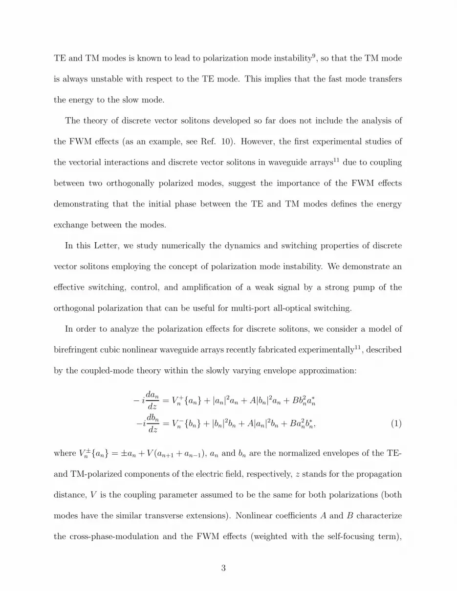
made sweeps of the system parameters and observe the TE gain. On a phase diagram in
Fig. 1, we show the TE (signal) power gain vs. the TM (pump) mode input angle kb – the
TM (pump) power content Pb(0) space, for a small TE initial power Pa(0) = 0.03 and zero
angle ka = 0, and for initial linear polarization. The whiter region marks a high gain limit
(up to 60 times), while the black region marks a low gain (0.7). As expected, the maximum
gain is achieved when the angle of the pump is near zero, and when the amplitude to the
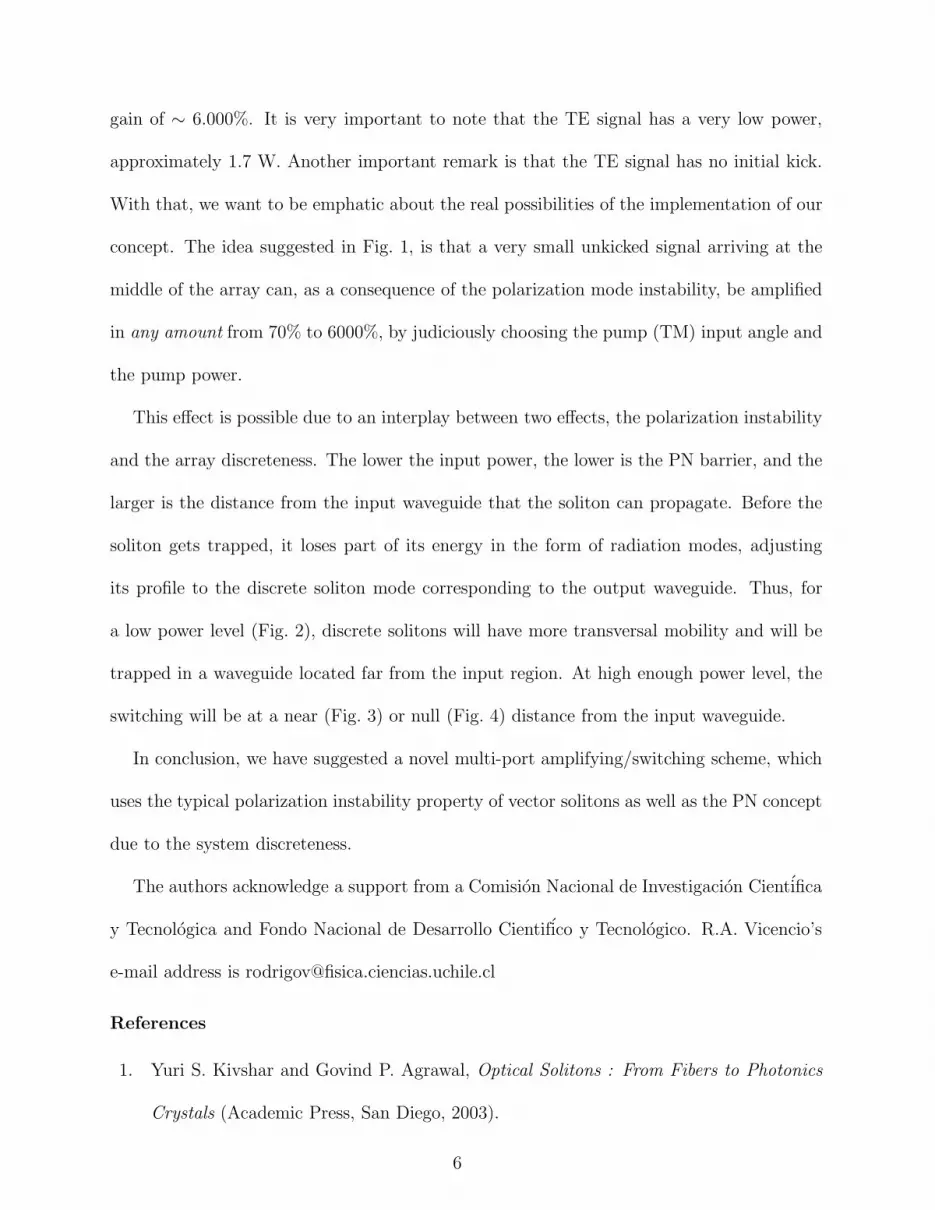
pump is the highest. In Fig. 2 (point “A” in Fig. 1), we show the longest switching case
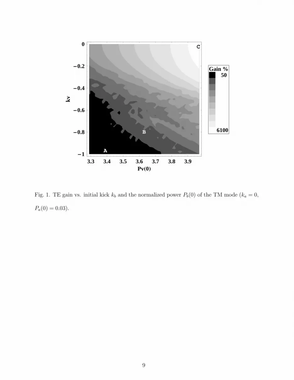
(13 sites) which is associated with a low power gain, ∼ 70%. In Fig. 3 (point “B” in Fig. 1),
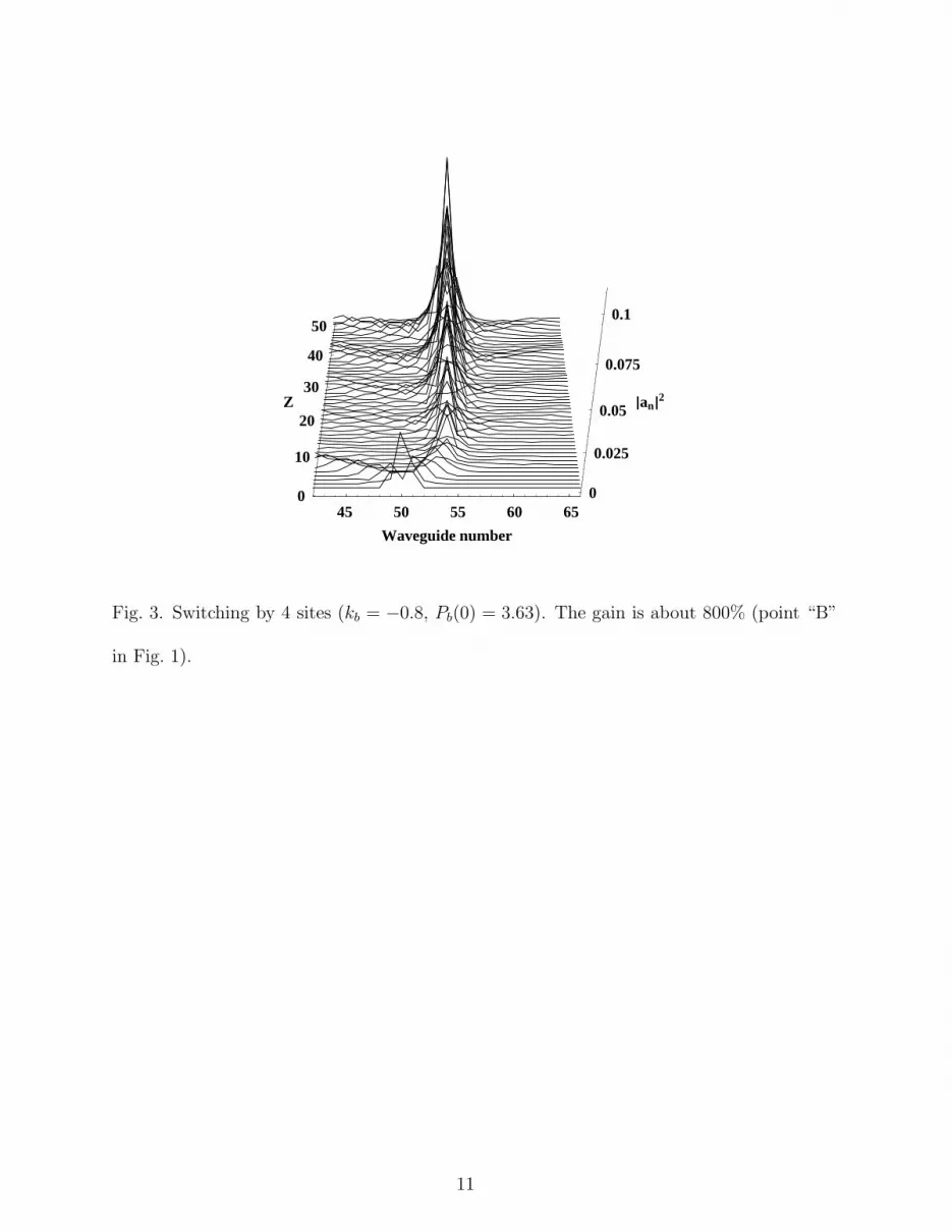
we show a switching for 4 sites with a medium range power gain of ∼ 800%. In Fig. 4 (point
“C” in Fig. 1), we show an example of strongly suppressed switching with a huge power
5
gain of ∼ 6.000%. It is very important to note that the TE signal has a very low power,
approximately 1.7 W. Another important remark is that the TE signal has no initial kick.
With that, we want to be emphatic about the real possibilities of the implementation of our
concept. The idea suggested in Fig. 1, is that a very small unkicked signal arriving at the
middle of the array can, as a consequence of the polarization mode instability, be amplified
in any amount from 70% to 6000%, by judiciously choosing the pump (TM) input angle and
the pump power.
This effect is possible due to an interplay between two effects, the polarization instability
and the array discreteness. The lower the input power, the lower is the PN barrier, and the
larger is the distance from the input waveguide that the soliton can propagate. Before the
soliton gets trapped, it loses part of its energy in the form of radiation modes, adjusting
its profile to the discrete soliton mode corresponding to the output waveguide. Thus, for
a low power level (Fig. 2), discrete solitons will have more transversal mobility and will be
trapped in a waveguide located far from the input region. At high enough power level, the
switching will be at a near (Fig. 3) or null (Fig. 4) distance from the input waveguide.
In conclusion, we have suggested a novel multi-port amplifying/switching scheme, which
uses the typical polarization instability property of vector solitons as well as the PN concept
due to the system discreteness.
The authors acknowledge a support from a Comision Nacional de Investigacion Cientifica
y Tecnologica and Fondo Nacional de Desarrollo Cientifico y Tecnologico. R.A. Vicencio’s
e-mail address is [email protected]
References
1. Yuri S. Kivshar and Govind P. Agrawal, Optical Solitons : From Fibers to Photonics
Crystals (Academic Press, San Diego, 2003).
6

2. D.N. Christodoulides, F. Lederer, and Y. Silberberg, Nature 424, 817 (2003).
3. D.K. Campbell, S. Flach, and Yu.S. Kivshar, Phys. Today 57, 43 (2004).
4. W. Krolikowski and Yu. S. Kivshar, J. Opt. Soc. Am. B 13, 876 (1996).
5. T. Pertsch, U. Peschel, and F. Lederer, Opt. Lett. 28, 102 (2003).
6. R.A. Vicencio, M.I. Molina, and Yu.S. Kivshar, Opt. Lett. 28, 1942 (2003).
7. X. D. Cao and D. D. Meyerhofer, Opt. Lett. 19, 1711 (1994).
8. A. Schauer, I.V. Melnikov, and J.S. Aitchison, J. Opt. Soc. Am. B 21, 57 (2004).
9. R. Malendevich, L. Friedrich, G. Stegeman, J. Soto-Crespo, N. Akhmediev, and J. S.
Aitchison, J. Opt. Soc. Am. B 19, 695 (2002), and reference therein.
10. S. Darmanyan, A. Kobyakov, E. Schmidt, and F. Lederer, Phys. Rev. E 57, 3520
(1998).
11. J. Meier, J. Hudock, D. Christodoulides, G. Stegeman, Y. Silberberg, R. Morandotti,
and J.S. Aitchison, Phys. Rev. Lett. 91, 143907 (2003).
7

List of Figure Captions
Fig. 1. TE gain vs. initial kick kb and the normalized power Pb(0) of the TM mode (ka = 0,
Pa(0) = 0.03).
Fig. 2. Switching by 13 sites (kb = −1, Pb(0) = 3.39). The gain is about 70% (point “A”
in Fig. 1).
Fig. 3. Switching by 4 sites (kb = −0.8, Pb(0) = 3.63). The gain is about 800% (point
“B” in Fig. 1).
Fig. 4. Trapping without switching (kb = 0, Pb(0) = 3.97). The gain is about 6.000%
(point “C” in Fig. 1).
8
3.3 3.4 3.5 3.6 3.7 3.8 3.9PvH0L
-1
-0.8
-0.6
-0.4
-0.2
0
kv
B
A
C
6100
50Gain %
Fig. 1. TE gain vs. initial kick kb and the normalized power Pb(0) of the TM mode (ka = 0,
Pa(0) = 0.03).
9

40 50 60 70
Waveguide number
0
10
20
30
40
50
Z
0
0.005
0.01
0.015
0.02
ÈanÈ2
Fig. 2. Switching by 13 sites (kb = −1, Pb(0) = 3.39). The gain is about 70% (point “A” in
Fig. 1).
10
45 50 55 60 65
Waveguide number
0
10
20
30
40
50
Z
0
0.025
0.05
0.075
0.1
ÈanÈ2
Fig. 3. Switching by 4 sites (kb = −0.8, Pb(0) = 3.63). The gain is about 800% (point “B”
in Fig. 1).
11

40 45 50 55 60
Waveguide number
0
10
20
30
40
50
Z
0
0.2
0.4
0.6
0.8
ÈanÈ2
Fig. 4. Trapping without switching (kb = 0, Pb(0) = 3.97). The gain is about 6.000% (point
“C” in Fig. 1).
12


