Embed Size (px)
Citation preview

Alpha ST 320 Instruction Manual
Bar Feeds & Accessories • Chip & Coolant Management • Work Support Systems
Member of the LNS Group
LNS America4621 East Tech Drive
Cincinnati, Ohio 45245Telephone: 513-528-5674
Fax: 513-528-5733http://www.LNSAmerica.com
Email: [email protected]


V1.203.02.09
TABLE OF CONTENTS
CHAPTER 1 BASIC NOTIONS
Structure 1-2 Rights 1-4 Declaration of compliance 1-5 Safety instructions 1-6 Safety devices 1-7
CHAPTER 2 TECHNICAL DATA
Characteristics 2-2 Floor plans 2-2
CHAPTER 3 SETTING INTO OPERATION
Transport 3-2 Overview 3-5 Installation 3-7
CHAPTER 4 ELECTRICS
Interface 4-2 Diagrams 4-3 Electrics 4-4
CHAPTER 5 PNEUMATICS
Pneumatic equipment 5-2
CHAPTER 6 HYDRAULICS
Hydraulic system 6-2 Hydraulic schematic 6-3
ALPHA ST 320

ALPHA ST 320
CHAPTER 7 GENERAL DESCRIPTION
Guiding channel and pusher 7-2 Loading rack 7-4
Vise 7-4 Drive 7-5 Length measurement device 7-5 Channel cover mechanism 7-6 Anti-vibration 7-6 Remnant drawer 7-7
CHAPTER 8 OPERATION
Remote control 8-2 Manual operation 8-3 Manual loading system 8-6 TD-200 display and settings 8-7
CHAPTER 9 MALFUNCTIONS
Alarm messages and troubleshooting 9-2
CHAPTER 10 SPARE PARTS
Spare parts 10-2
APPENDICES
Appendix A : Programming example A-2 Appendix B : Ordering form A-3 Appendix C : LNS agencies A-4

CHAPTER 1: BASIC NOTIONS
ALPHA ST 320
1-1
CHAPTER 1: BASIC NOTIONS
1. STRUCTURE 1-2
1.1 Cross-references 1-2 1.2 Captions 1-2 1.3 Symbols and terminology 1-3
2. RIGHTS 1-4
3. DECLARATION OF COMPLIANCE 1-5
4. SAFETY INSTRUCTIONS 1-6
5. SAFETY DEVICES 1-7
5.1 Description 1-7 5.2 Layout 1-7

CHAPTER 1: BASIC NOTIONS
ALPHA ST 320
1-2
1. STRUCTURE This manual consists of various chapters, each containing several points, paragraphs, etc. Lists may be contained in paragraphs.
• The page number is indicated in the top outside margin of the page. • The chapter number and title are indicated in the top inside margin of the page. • The model of the bar feed system is indicated in the bottom outside margin of the page.
1.1 Cross-references Each chapter generally contains all of the information related to the description and settings of the devices and elements represented therein. Therefore, if a setting must be made while you are handling the system, please refer to the chapter on the device to be set, for example: (see chapter *) or (see point *).
1.2 Captions Whenever possible, the reference numbers contained in the instruction manual are shown with the LNS ordering number of the indicated element. To make it easier to place an order of supplies, a form has been included in the annex at the end of this manual.

CHAPTER 1: BASIC NOTIONS
ALPHA ST 320
1-3
1.3 Symbols and terminology
This sign recommends following the directions very closely avoiding causing an incident that could result in injury, damage to the equipment, or data loss.
This sign indicates that safety measures must be taken to avoid possible electrical shocks or mishaps.
The notes stress interesting points or comments, and provide useful advice for optimal system operation.
This sign points out an advice about environmental protection.

CHAPTER 1: BASIC NOTIONS
ALPHA ST 320
1-4
2. RIGHTS All rights reserved. Reproduction, recording or transmission of all, or any portion, of this manual, in any form or through any means whatsoever, whether mechanical, photographic, and sound or other, without the express written authorization of LNS SA, is prohibited. LNS SA disclaims all responsibility for errors which may be contained in this manual and the problems which may result therefore. LNS SA and its subsidiaries cannot be made responsible for the debts, losses, expenses, or damage incurred, or suffered, by the buyer of this product, or a third party, following an accident, incorrect use, or misuse, or stemming from modifications, repairs, or transformations not authorized by LNS SA. LNS SA and its subsidiaries cannot be held responsible for damage and problems arising from the use of options and products other than LNS products, or products approved by LNS SA. The names of the products indicated in this manual are registered trademarks.

CHAPTER 1: BASIC NOTIONS
ALPHA ST 320
1-5
3. DECLARATION OF COMPLIANCE (Directive 89/392/EEC, Article 4.2 and Appendix 1, Chapter B)
PROHIBITION OF PUTTING INTO OPERATION Manufacturer : LNS SA. Address : Route de Frinvillier CH-2534 Orvin Declares that: The ALPHA ST 320 automatic bar feed system - Is designed to be incorporated into a machine, or to be assembled with other machines, to create a
machine covered by Directive 89/392/EEC amended, and that the following (parts/paragraphs) of the harmonized standards have been applied: EN 292, EN 60 204 1, EN 1088, EN 418, EN 60947, 89/336/EEC, 73/23/EEC.
- And furthermore declares that it is prohibited to put the machine into operation before the machine
into which it is to be inserted, or of which it will become a part, has been examined and declared in conformity with the provisions of Directive 89/392/EEC and the national laws transposing it, i.e. forming a whole including the machine to which reference is being made in the present declaration.
Orvin, 23.08.2005 LNS SA B. Brügger Sales manager

CHAPTER 1: BASIC NOTIONS
ALPHA ST 320
1-6
4. SAFETY INSTRUCTIONS • Do not handle the equipment without
having knowledge of the safety instructions and the instructions for use. Safety instructions for the bar feed system, as well as the CNC lathe, must be strictly observed.
• Non-qualified personnel, children, and
persons under the influence of alcohol or medication should not handle the equipment.
• Loose garments, long hair and jewelry
can be dangerous.
• Do not remove any covers while the bar feeder or the machine is under electrical power.
• Do not conduct any maintenance
operations during the automatic cycle.
• Do not grasp moving or rotating objects, or nearby elements.
• If certain safety shields or safety covers
are removed to conduct maintenance, they must be reinstalled as soon as the maintenance work is completed.
• No servicing should be carried out on
the interface or inside the electrical cabinet while the bar feeder or the lathe is under electrical power.
• It is strictly prohibited to jump wire or
remove circuit breakers, main switches, and especially safety switches.
• To avoid any harm to persons, or
damage to components, use only the indicated points for lifting and moving the bar feeder system. No one should be near the hanging load, or within the operating range of the overhead hoist/crane, forklift, or any other means used for lifting and transportation. Do not knock the bar feeder while moving it as this could damage it.
• Do not move the bar feeder while it is
electrically powered on.
• The work area surrounding the bar feed system should always be clear of objects and well lit. The presence of oil on the ground could cause falls; it is important to maintain the floor clean on a regular basis.
• Do not place the machine in a damp
area and make sure that water or oil does not come into contact with the electrical equipment.
• Do not open the clamping device (collet
or chuck) of the lathe manually when the bar feeder is in automatic mode (Interface).
• Each time the diameter is changed, also
adapt spindle reduction tube. The use of spindle reduction tubes is highly recommended for machining bars with diameters smaller than the maximum capacity of the spindle.
• Do not attempt to recharge the batteries
of the PLC.
• For the use and maintenance of the bar feeder, use only parts provided by or recommended by LNS.
• If it is necessary to move the bar feeder
once it has been originally installed, do not reinstall it before first contacting LNS or its local representative.
• The rotating bar should never protrude
the rear of the lathe spindle.
• The maximum length (max. L) the bar feeder system is allowed to load is given by the length of the lathe spindle. The bar should never extend more than 3 times its diameter beyond the lathe clamping device without support.
• LNS disclaim all responsibility for
possible accidents or property damage caused when safety instructions are not followed.

CHAPTER 1: BASIC NOTIONS
ALPHA ST 320
1-7
5. SAFETY DEVICES
5.1 Description The ALPHA ST 320 bar feed system has been designed with a focus on maximum safety during its handling and complies with all IEC requirements. Safety covers and devices make access to the moving parts of the bar feed system impossible. Safety switches keep the bar feed system from operating when these protections are open. The design of the switches, as well as their insertion into the bar feed system, makes it practically impossible to bypass them. By pressing the emergency stop button located on the remote control and the electrical box, the functions of the bar feed system and the lathe are immediately stopped.
The LNS company, or its local representative, may not be held responsible for possible accidents or property damage, whether caused directly or not, by any means whatsoever, if certain safety devices have not been included.
5.2 Layout
Designation Description
A Main access cover
B Emergency stop push button
C Remote station
QS1 Main disconnect switch
SQ11 Safety switch of the main access cover
B
SQ11 A
C
QS1

CHAPTER 1
ALPHA ST 320
1-8 : BASIC NOTIONS

CHAPTER 2: TECHNICAL DATA
ALPHA ST 320
2-1
CHAPTER 2: TECHNICAL DATA
1. CHARACTERISTICS (*) 2-2
2. FLOOR PLAN 2-2
2.1 Alpha ST 320 floor plan 2-3

CHAPTER 2: TECHNICAL DATA
ALPHA ST 320
2-2
1. CHARACTERISTICS (*)
12 ft
Bar diameter [mm] 3 to 20
Weight [lbs/kg] 3217 lbs / 1459 kg
Overall length [mm] 4539
Overall width [mm] 507
Max. bar length [in / mm] 147 in / 3734 mm
Min./Max. Remnant length [mm] 50 / 400
Main electrical power (Volt)* 230 + / - 10% Volts 50 / 60Hz
Maximum current rate (Amps) 4.0A
Loading cycle for bar stock 30-40 seconds
Centerline height [mm] 900 – 1200
Bar loading capacity 13 bars @ 20 mm diameter
Oil capacity 40 Liters (10.5 gallons) ISO 100
Air pressure 6 bar (90 psi) *) Depending on the options, these technical data may vary. Please refer to the technical data sheet
2. FLOOR PLAN The following floor space plans indicate the most frequently used dimensions for placing the bar feed system. Details on the dimensions of other parts or elements of the bar feed system will be furnished upon request. All dimensions on the following diagram are listed in millimeters.

CHAPTER 2: TECHNICAL DATA
ALPHA ST 320
2-3
2.1 Alpha ST 320 floor plan

CHAPTER 2
ALPHA ST 320
2-4 : TECHNICAL DATA

CHAPTER 3: SETTING INTO OPERATION 3-1
CHAPTER 3: SETTING INTO OPERATION
1. TRANSPORT 3-2
1.1 Crate dimension 3-2 1.2 Unpacking 3-3
2. OVERVIEW 3-4
3. INSTALLATION 3-6
ALPHA ST 320

CHAPTER 3: SETTING INTO OPERATION 3-2
1. TRANSPORT
To protect the bar feeder during transportation, the bar feeder is shipped in a wood crate. Please make sure it is not damaged before you open it.
1.1 Crate dimension
Type Total Weight
[kg / lbs] Length [mm]
Width [mm]
Height [mm]
3.7m (12ft) 1459 / 3217 4940 760 1410
ALPHA ST 320

CHAPTER 3: SETTING INTO OPERATION 3-3
1.2 Unpacking
Step 1: Open the crate. Remove the top panel first (Fig 3.1)
2
3
1
3
Fig 3.1
Step 2: To lift the whole machine, use two 30mm bars of 1m length each. Slide them into the stand and use a lifting strap (Fig 3.2 #5) to lift the machine.
Fig 3.2
5
ALPHA ST 320

CHAPTER 3: SETTING INTO OPERATION 3-4
2. OVERVIEW . OVERVIEW Fig 3.3 Fig 3.3
4
16
5
32
Before installing the bar feeder, be sure that all of the parts and tools are ready to connect to the lathe.
Step 1: Connect air pressure to the bar feeder. (Fig 3.3 #2) An 8 mm extension hose is provided, be
sure to check the fitting size. Step 2: There is a specific interface connection for each lathe. (Fig 3.3 #3) Make sure the one you
received corresponds to your lathe. Check the interface drawing located inside the electrical cabinet. (Fig 3.3 #1) For more information about the interface, refer to Chapter 4.
Step 3: The bar feeder can be equipped with a wide range of guiding channels (Fig 3.4),make sure the
one you received suits your needs. For more information about the guiding channel, refer to Chapter 7.
Step 4: Collets corresponding to the bar stock size are needed. Fig 3.4
1 2
3
Designation Description
1 Guiding channels
2 Pusher support
3 Feeding pusher
ALPHA ST 320

CHAPTER 3: SETTING INTO OPERATION 3-5
Step 5: The bar feeder is hydraulic; the oil tank capacity is about 40 liters. (Fig 3.3 #6) Only use ISO
100 quality oil. When filling the tank, check the level with the filling gauge. (Fig 3.5) For more information about the hydraulic system, refer to Chapter 6.
Fig 3.5
ALPHA ST 320

CHAPTER 3: SETTING INTO OPERATION 3-6
3. INSTALLATION . INSTALLATION
Before you start to install the bar feeder, make sure the lathe is already leveled. Before you start to install the bar feeder, make sure the lathe is already leveled.
Step 1: Install the front fixed tube or telescope tube on the bar feeder. Step 1: Install the front fixed tube or telescope tube on the bar feeder. Step 2: Align the bar feeder roughly with the lathe. Keep about 20 mm clearance between the front
tube and the spindle. On a sliding headstock lathe, make sure to move the headstock to maximum backward position before checking the position.
Step 2: Align the bar feeder roughly with the lathe. Keep about 20 mm clearance between the front tube and the spindle. On a sliding headstock lathe, make sure to move the headstock to maximum backward position before checking the position.
Step 3: Loosen the floor pads (Fig 3.6 #1) and adjust them to make the stands stable. Step 3: Loosen the floor pads (Fig 3.6 #1) and adjust them to make the stands stable. Step 4: Loosen all the locking screws on each stand (Fig 3.6 #2) and adjust the height of the bar
feeder using the main screw. (Fig 3.6 #3 ) Step 4: Loosen all the locking screws on each stand (Fig 3.6 #2) and adjust the height of the bar
feeder using the main screw. (Fig 3.6 #3 ) Fig 3.6 Fig 3.6
Step 5: Remove the front tube and replace it with the alignment bushing. (Fig 3.7 #1) Fig 3.7
ALPHA ST 320

CHAPTER 3: SETTING INTO OPERATION 3-7
Step 6: Remove the PE channel, and install the alignment bushing. (Fig 3.8 #2) Fig 3.8
Step 7: Clamp the bushing (Fig 3.9 #3) into the collet of the lathe. Fig 3.9
Step 8: Pull the string through all the bushings. Step 9: Finalize the alignment. The string must be center with the bushing and with the spindle. (back
side)
Check the position of the front stand looking at bushing. Check the position of the rear stand looking at the back of the spindle.
Step 10: Tighten all the locking screws (Fig 3.6 #1, 2, 3) and re-check the alignment. Step 11: Remove the string and bushing and reinstall the connecting parts. On swiss type lathes make
sure the headstock can move along the entire travel.
ALPHA ST 320
CHAPTER 3: SETTING INTO OPERATION
ALPHA ST 320
3-8
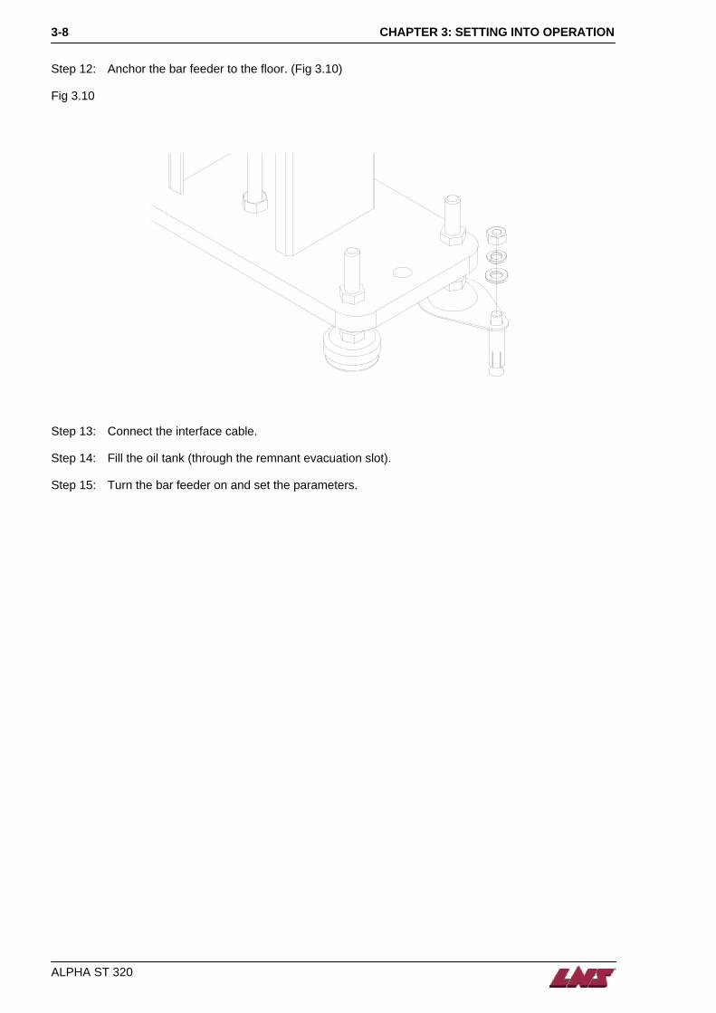
Step 12: Anchor the bar feeder to the floor. (Fig 3.10) Fig 3.10
Step 13: Connect the interface cable. Step 14: Fill the oil tank (through the remnant evacuation slot). Step 15: Turn the bar feeder on and set the parameters.

CHAPTER 4: ELECTRICS 4-1
CHAPTER 4: ELECTRICS
1. ELECTRICS 4-2
1.1 Layout of the electrical elements 4-2 1.2 Layout of the elements in the control cabinet 4-3 1.3 PCB Layout 4-11 1.4 Symbols 4-13 1.5 Electric diagrams 4-15
2. INTERFACE 4-27
2.1 Power 4-27 2.2 Signal 4-27
3. DIAGRAMS 4-28
ALPHA ST 320

CHAPTER 4: ELECTRICS 4-2
1. ELECTRICS
1.1 Layout of the electrical elements
B
QS1
M2
SQ6 SQ4
SQ5
SQ11
A
SQ7
SP1
SQ1
C SQ2
D
M1
Designation Part No Description
A - Control cabinet
B 9A05-000 Remote control station with E-Stop button
C 9E05-009 E-Stop push button
D 9E05-005 TD200 HMI
QS1 9A05-009 Main disconnect switch
M1 4.706 Servo motor
M2 9A50-000 Hydraulic pump motor
SP1 9E05-016 Air pressure switch
SQ1 4.474 Measuring device proximity switch
SQ2 9A30-001 Pusher home position switch (proximity switch)
SQ4 9A30-002 Guiding channel closed verification switch
SQ5 9A30-003 Remnant extraction verification switch
SQ6 9A30-004 Guiding channel open verification switch
SQ7 4.050 Oil pressure switch
SQ11 4.763 Main access cover switch
ALPHA ST 320

CHAPTER 4: ELECTRICS 4-3
1.2 Layout of the elements in the control cabinet
Designation Part No Description Designation Part No Description
PLC 9A05-001 Programmable controller (CPU 226)
KM1 / K1 705-025 Motor switches
QF2 9A05-008 Circuit breakers Servo Amp 9A05-002 Servo amplifier
QS1 9A05-009 Main disconnect switch Power Supply 9A05-005 Power supply
QM1 9A05-010 Hydraulic pump motor overload protection
PCB Board 9A05-003 Printed circuit board
QF1 9A05-007 Main power circuit breaker K1 705-025 Safety circuit contactor
EM223 9A05-011 I/O expansion module EM232 9A05-012 Analog output expansion module
ALPHA ST 320

CHAPTER 4: ELECTRICS 4-4
1.2.1 Circuit breakers and overload protection
(a) Hydraulic Pump Motor Starter Protector-QM1 QM1 protects the hydraulic pump motor. If the motor requires excessive power, overload trips and push-button (C)-STOP is released. For safety reasons, the power supply to the motor is immediately interrupted. After having located and repaired the problem causing this interruption, reset the circuit breaker by pressing the push-button (E) -START. The factory setting of the breaking current is 2.5 Amperes.
Designation Description
A Power in connector
B Setting of the breaking current
C Release button
D Power out connector
E Reset Button
F Test push-button
(b) Circuit breaker-QF1
Circuit breaker QF1 protects the servo amp/motor. If the electrical current to the servo is too high, the breaker activates and lever (B) flips down. The power supply to the servo amp is immediately interrupted to avoid damage. After having located and repaired the problem reset the lever (B) of the circuit breaker. The factory setting of the breaking current is 2.5 Amperes.
Designation Description
A Power in connecting terminal
B Lever off/on
C Power out connecting terminal
ALPHA ST 320

CHAPTER 4: ELECTRICS 4-5
(c) Circuit breaker-QF2 QF2 protects the two phases, which power the +24 VDC power supply and the magazine loading rack motor (M3). Should the latter require excessive power, the breaker activates and lever (B) flips down. The power supply to the transformer is immediately interrupted to avoid damage. After having located and repaired the problem, reset the lever (B) of the circuit breaker.
Designation Description
A Power in connecting terminal
B Lever off/on
C Power out connecting terminal
1.2.2 +24 VDC Power supply
The power supply module provides DC 24V voltage for various modules of the PLC, PCB switches, solenoid electrovalves, etc.
Designation Description
A Input AC200/220V
B Output DC 24V
ALPHA ST 320

CHAPTER 4: ELECTRICS 4-6
1.2.3 Servo Amplifier By means of the servo amplifier, the programmable controller controls the movements of the servo motor. The input values, as well as the position of the pusher carrier, are continuously registered.
AA
Designation Description
A 230 V + ground power supply
B Power output to SERVO motor
C Battery (not used)
D Battery plug
E Emergency stop contact
F Encoder connecting plug
G Programmable controller / SERVO amplifier communication connecting plug
H Alarm and codes display of amplifier
I Cover
AA 220 Vac Input
ALPHA ST 320
CHAPTER 4: ELECTRICS 4-7
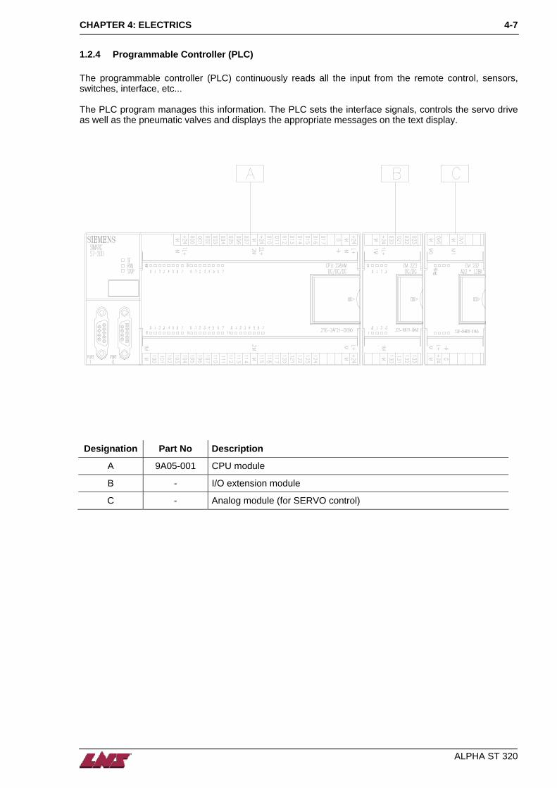
1.2.4 Programmable Controller (PLC) The programmable controller (PLC) continuously reads all the input from the remote control, sensors, switches, interface, etc... The PLC program manages this information. The PLC sets the interface signals, controls the servo drive as well as the pneumatic valves and displays the appropriate messages on the text display.
Designation Part No Description
A 9A05-001 CPU module
B - I/O extension module
C - Analog module (for SERVO control)
ALPHA ST 320

CHAPTER 4: ELECTRICS 4-8
(a) CPU Module The first module (CPU 226) contains the main processor for the PLC as well as the bar feeder software.
Designation Description
A No software or System Fault – LED
B Run Mode – LED
C Stop Mode - LED
D Battery or DROM insert
E Interface connecting to TD200
F Output terminal Q0.0~Q1.7
G Expansion module
H Input terminal I0.0~I2.7
I Port, Stop/Run, PR0/PR1 selectors provided inside expansion module
J PR0 for analog signal adjustment
K PR1 for analog signal adjustment
L Flexible ribbon cable connecting to expansion module
ALPHA ST 320
CHAPTER 4: ELECTRICS 4-9
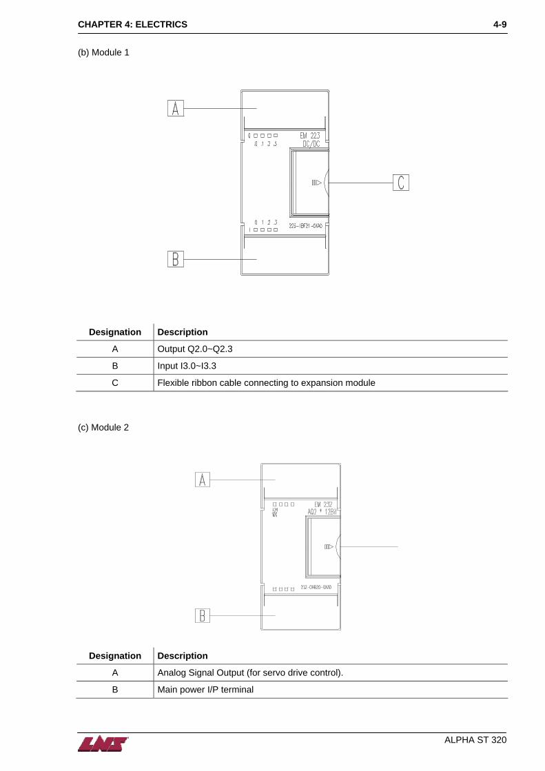
(b) Module 1
Designation Description
A Output Q2.0~Q2.3
B Input I3.0~I3.3
C Flexible ribbon cable connecting to expansion module (c) Module 2
Designation Description
A Analog Signal Output (for servo drive control).
B Main power I/P terminal
ALPHA ST 320

CHAPTER 4: ELECTRICS 4-10
1.2.5 Contactors (a) Hydraulic Pump Motor Contactor – KM1 Controls oil pump motor On/Off.
Designation Description
A Input (from QM1)
B Output (to M2 oil pump)
C Contactor control main power
D On/Off position (b) Safety Circuit Contactor -- KI Supplies power to the Servo Amp as long as all safety devices are in the correct operating state.
Designation Description
A Main power I/P(From QF1)
B Main power O/P(To servo amplifier)
C Motion help contact(To PLC)
D Contactor control main power
E Operating State (I = energized / O = De-energized)
ALPHA ST 320

CHAPTER 4: ELECTRICS 4-11
1.3 PCB Layout
A B
C
Designation Description
A PCB version (ESTM) and Date
B Interface terminal connector
C Operators Pendant Connector
R1 Interface relay – Barfeed Alarm
R2 Interface relay – Load Cycle Complete
R3 Interface relay – End of Bar
R4 Interface relay – Spindle Interlock
R5 Interface relay –
RSO Servo Amp “ON” relay
RSA Servo Amp Alarm relay
RA Not used
RB Not used
ALPHA ST 320

CHAPTER 4: ELECTRICS 4-12
(a) Interface signals from the CNC-lathe
(b) Interface signals from the bar feeder
ALPHA ST 320

CHAPTER 4: ELECTRICS 4-13
1.4 Symbols
Symbol Description Designation
Main disconnect switch
Main circuit
Circuit-breaker
Contactor mains
Transformer
Bridge rectifier
Fuse
Fuse
Servo motor
Hydraulic pump motor
ALPHA ST 320

CHAPTER 4: ELECTRICS 4-14
Symbol Description Designation
Emergency stop
Safety switch
Indicator lamp
Relay
Valve solenoid
Diode
LED
Select switch
Proximity switch
Limit switch
Air pressure switch
Momentary switch
Function switch
ALPHA ST 320

CHAPTER 4: ELECTRICS 4-15
1.5 Electric diagrams
ALPHA ST 320

CHAPTER 4: ELECTRICS 4-16
ALPHA ST 320

CHAPTER 4: ELECTRICS 4-17
ALPHA ST 320
CHAPTER 4: ELECTRICS 4-18
ALPHA ST 320

CHAPTER 4: ELECTRICS 4-19
ALPHA ST 320

CHAPTER 4: ELECTRICS 4-20
ALPHA ST 320

CHAPTER 4: ELECTRICS 4-21
ALPHA ST 320

CHAPTER 4: ELECTRICS 4-22
ALPHA ST 320

CHAPTER 4: ELECTRICS 4-23
ALPHA ST 320

CHAPTER 4: ELECTRICS 4-24
ALPHA ST 320

CHAPTER 4: ELECTRICS 4-25
ALPHA ST 320

CHAPTER 4: ELECTRICS 4-26
ALPHA ST 320

CHAPTER 4: ELECTRICS 4-27
2. INTERFACE There is a different interface connection for almost each lathe type. The interface diagram for the bar feeder can be found inside the electrical box. Each interface is identified by a number (and lathe type).
2.1 Power This bar feeder must be connected to: 3 X 200 / 220 / 240 Volts 50 or 60 Hz.
2.2 Signal There are two different signal types (standard interface): Lathe to bar feeder signal: (Inputs) A1:Collet open / close status
A2:Lathe alarm
A3:Start loading cycle command
A4:Push signal Bar feeder to lathe signal: (Outputs) R1:Bar feeder alarm
R2:Loading cycle completed signal
R3:End of bar
R4:Automatic mode
R5:Bar loader empty alarm There are several parameters to configure the interface (authorized personnel only). The recommended parameter settings are given on the interface diagram in the electrical cabinet.
ALPHA ST 320

CHAPTER 4: ELECTRICS
ALPHA ST 320
4-28
3. DIAGRAMS The interface diagram below is provided an example. The diagram corresponding to your bar feed system is located in the electric cabinet, with the electric diagram.
CHAPTER 5: PNEUMATICS
ALPHA ST 320
5-1
CHAPTER 5: PNEUMATICS
1. PNEUMATIC EQUIPMENT 5-2
1.1 Description 5-2 1.2 Weekly maintenance 5-2 1.3 Pneumatic System 5-3 1.4 Diagram 5-4

CHAPTER 5: PNEUMATICS
ALPHA ST 320
5-2
1. PNEUMATIC EQUIPMENT Please read the safety precautions described at the beginning of this manual before handling the following devices.
1.1 Description The following automatic movements of the Alpha ST 320 bar feeder system are done via pneumatic elements, namely: The locking of the feeding pusher The raising and lowering of the guiding channels The opening and closing of front rest and vise The loading of the bar stock The air blast unit
To guarantee optimal operation of the bar feed system, a minimum pressure of 5 bar (75psi), and a maximum pressure of 6 bar (90psi) is mandatory. It is required to supply dry and clean air to the bar feeder. We provide you an extension hose with standard fitting to connect the bar feeder to your equipment. (Fig 5.1 #1) Adjust the output pressure using the knob (Fig 5.1 #2), you can read the value on the gauge. (Fig 5.1 #3) Factory setting: 6 bar. Fig 5.1
1
2
5
3
4
1.2 Weekly maintenance Check and complete the oil level in the lubricant tank (Fig 5.1 #4). To add oil, disconnect the air; loosen the oil tank to take it out. Oil viscosity ISO 100. Check and drain the water in the filter unit (Fig 5.1 #5). To drain the water, loosen the screw under the tank.

CHAPTER 5: PNEUMATICS
ALPHA ST 320
5-3
1.3 Pneumatic System
Designation Description Designation Description
A Guiding channel open / close cylinder YV2A Guiding channel open solenoid
B Vise cylinder YV2B Guiding channel closed solenoid
C Measuring device cylinder YV3 Vise jaw closed solenoid
SP1 Air pressure switch YV4 Spare
YV0 Measuring device solenoid YV5 Air blast solenoid
YV1 Front Rest
AB
C

CHAPTER 5
ALPHA ST 320
5-4 : PNEUMATICS
1.4 Diagram

CHAPTER 6: HYDRAULICS
ALPHA ST 320
6-1
CHAPTER 6: HYDRAULICS
1. HYDRAULIC SYSTEM 6-2
2. HYDRAULIC SCHEMATIC 6-3

CHAPTER 6: HYDRAULICS
ALPHA ST 320
6-2
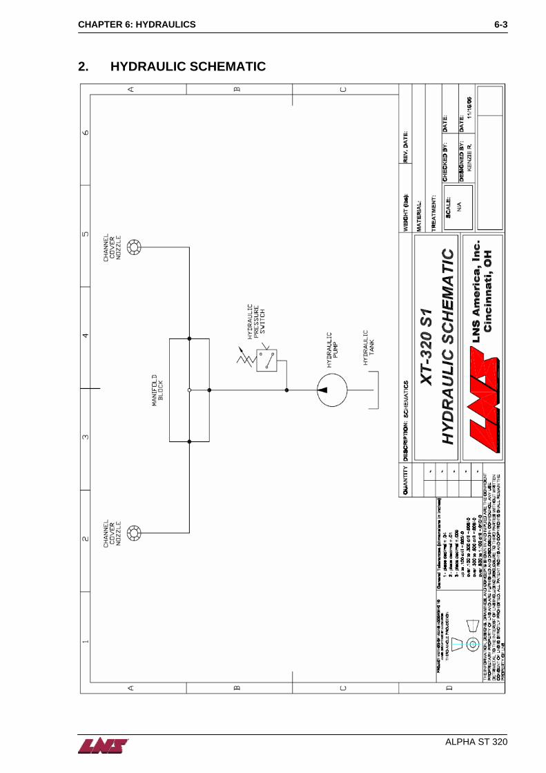
1. HYDRAULIC SYSTEM The guiding channel is filled with oil during operation to avoid vibrations and reduce noise (Fig 6.1). We recommend using hydraulic oil with viscosity ISO 100. The quantity of oil required to fill the tank is 40 liters. Remove the remnant drawer and fill the oil through the remnant evacuation slot into the oil tank. Do it slowly and make sure the oil level does not exceed 15mm. Check the oil level inside the tank using the gage on the front side. Fig 6.1
ATTENTION: Do not add oil when the bar feeder is running. Wait until the oil has completely returned to the tank.
The oil pump starts running when the bar feeder is in auto mode. It stops when the pusher reaches the anti-vibration or if the lathe is not running for more than 5 minutes. (Collet signal absent)
CHAPTER 6: HYDRAULICS
ALPHA ST 320
6-3
2. HYDRAULIC SCHEMATIC

CHAPTER 6
ALPHA ST 320
6-4 : HYDRAULICS

CHAPTER 7: GENERAL DESCRIPTION
ALPHA ST 320
7-1
CHAPTER 7: GENERAL DESCRIPTION
1. GUIDING CHANNEL & PUSHER 7-2
2. LOADING RACK 7-4
3. VISE 7-4
4. DRIVE 7-5
5. LENGTH MEASUREMENT DEVICE 7-5
6. CHANNEL COVER MECHANISM 7-6
7. ANTI-VIBRATION 7-6
7.1 Opened position 7-6 7.2 Closed position 7-6
8. REMNANT DRAWER 7-7

CHAPTER 7: GENERAL DESCRIPTION
ALPHA ST 320
7-2
1. GUIDING CHANNEL & PUSHER It is necessary to replace the pusher and guiding channels according to your bar stock diameter. The pusher size needs to correspond to the channel size (pusher diameter = channel diameter – 1 mm). Anti-vibration needs to be adjusted to pusher size. Fig 7.1
Designation Description
1 Feeding pusher
2 Loading flag
3 PU channel
4 PE channel
5 Support

CHAPTER 7: GENERAL DESCRIPTION
ALPHA ST 320
7-3
In manual mode, move the pusher back to its home position and open the channel. (Fig 7.2) Step 1: Take out the pusher (# 3). Step 2: Remove the screw (# 1) to release the flag (# 2). Step 3: Remove the screw (# 7) to release the pusher support (# 4). Step 4: Replace the channels (# 5 & # 6). Step 5: Lock in place the new support pusher (# 4) and the new flag (# 2). Step 6: Insert the new pusher (# 3).
Fig 7.2

CHAPTER 7: GENERAL DESCRIPTION
ALPHA ST 320
7-4
2. LOADING RACK The loading rack is actuated by a pneumatic cylinder. The loading finger (Fig 7.3 #1) is moving up to load a new bar. The position can be adjusted for different size materials by adjusting the screw (Fig 7.3 #2). Tighten wingnut (Fig 7.3 #3) to lock into position. To avoid bar stock (Fig 7.3 #4) overlap, the plate limit position (Fig 7.3 #5) can be adjusted. Loosen the knob (Fig 7.3 #6) to release the plate. Adjust about 2 mm from the material and tighten knob (Fig 7.3 #6). Repeat the operation for each plate. Fig. 7.3
3. VISE The vise is actuated by a pneumatic cylinder (Fig 7.4 #1). It does not need to be adjusted for each bar diameter. The sensor LED (Fig 7.4 #2) is only ‘ON’ when the vise is closed without bar between the jaws (Fig 7.4 #3). Fig. 7.4

CHAPTER 7: GENERAL DESCRIPTION
ALPHA ST 320
7-5
4. DRIVE The pusher is driven by a servo motor (Fig 7.5 #1). The transmission is built of drive gear (Fig 7.5 #2), pulley (Fig 7.5 #3) and chain (not shown). The chain tension can be adjusted with the front idler pulley according to (Fig 7.6). Fig 7.5 Fig 7.6
5. LENGTH MEASUREMENT DEVICE Each time a new bar is loaded, the plate (Fig 7.7 #1) is brought to the upright position and obstructs the guiding channel. When the bar hits the plate, the switch (Fig 7.7 #2) is activated and plate (Fig 7.7 #1) flips downward. Fig. 7.7
1
2
3

CHAPTER 7: GENERAL DESCRIPTION
ALPHA ST 320
7-6
6. CHANNEL COVER MECHANISM The guiding channel cover mechanism is activated by a cylinder (Fig 7.9 #1). When the cylinder extends the guiding channel is closed. When it retracts the channel is opened. Fig 7.8 2 3 1
7. ANTI-VIBRATION The anti-vibration is a roller guide type device. When the bar feeder is running, the anti-vibration is closed on the bar to avoid vibrations. It opens when the pusher reaches it. Both the opened and the closed positions have to be adjusted. Fig 7.9
7.1 Opened position In manual mode, move the pusher forward until it reaches the anti-vibration. Loosen the nut (Fig 7.10 #1) to release the screw (Fig 7.10 #2). Tighten the screw (Fig 7.10 #2) until you feel it grip the pusher. Then make about ½ turn backward to release. Lock into position with nut (Fig 7.10 #1).
7.2 Closed position Load a bar, feed it into the lathe and close the chuck. Auto Start the bar feeder to close the anti-vibration. Loosen the nuts (Fig 7.10 #3, #4). Tighten nut (Fig 7.10 #4) until it touches the main support (Fig 7.10 #5). From there, tighten 1 more turn to release the material and lock nuts (Fig 7.10 #4, #3) together.

CHAPTER 7: GENERAL DESCRIPTION
ALPHA ST 320
7-7
8. REMNANT DRAWER The bar feeder is equipped with a remnant drawer (Fig 7.11). It may be removed to empty it and slide it back into position when the bar feeder is in operation. Max remnant length: 400 mm / 15.748 in Min remnant length: 50 mm / 1.968 in Fig 7.10

CHAPTER 7
ALPHA ST 320
7-8 : GENERAL DESCRIPTION

CHAPTER 8: OPERATION
ALPHA ST 320
8-1
CHAPTER 8: OPERATION
1. REMOTE CONTROL 8-2
2. MANUAL OPERATION 8-3
2.1 Guiding Channel Closed 8-3 2.2 Guiding Channel Open 8-4 2.3 Automatic Operation 8-5
3. TD-200 DISPLAY AND SETTINGS 8-6
3.1 Parameter F1~F8 display and description 8-7 3.2 P0 & P1 Setting 8-9 3.3 Message Display 8-9 3.4 MANUAL mode display 8-9 3.5 AUTO mode display 8-10

CHAPTER 8: OPERATION
ALPHA ST 320
8-2
1. REMOTE CONTROL
Designation Description
A Emergency Stop push button
B Manual mode
C Pusher forward
D Guiding channels open
E Guiding channels closed
F Pusher reverse
G Auto mode
H Auto Start
J Alarm indicator
K Spindle inching
L End of bar
M Lathe push command
N Collet signal status
A
B
C
D
NM
L
K
J
H
G
F
E

CHAPTER 8: OPERATION
ALPHA ST 320
8-3
2. MANUAL OPERATION The function of the manual operation keys depends on the status of the guiding channel cover (open or close).
2.1 Guiding Channel Closed
Move pusher forward
+
Move pusher forward with reduced speed.
Move pusher backward
+
Move pusher backward with reduced speed
Open channel. Condition: Pusher in home position (SQ2 activated)
No Function

CHAPTER 8: OPERATION
ALPHA ST 320
8-4
2.2 Guiding Channel Open
Move loading flag forward
+
Move loading flag forward with reduced speed.
Move loading flag backward
+
Move loading flag backward with reduced speed
Length measurement device on (SQ1)
Close channel and insert bar into chuck

CHAPTER 8: OPERATION
ALPHA ST 320
8-5
2.3 Automatic Operation There are two conditions in which the automatic cycle can be started.
2.3.1 Automatic Cycle If the channel is open the automatic cycle starts with Step 1. If the channel is closed the sequence starts at Step 4. Step 1: The loading flag feeds bar forward to the vice and returns home. The vice clamps the bar.
Step 2: The guiding channel closes and the pusher moves forward to insert the bar into the collet.
Step 3: The bar is moved forward to the Top Cut position.
Step 4: The lathe makes the Top Cut and starts producing parts.
Step 5: When the ‘End of bar’ position is reached the clamping device opens and the pusher retracts
with the remnant.

CHAPTER 8: OPERATION
ALPHA ST 320
8-6
Step 6: The remnant is clamped with the vice and the pusher moves back to extract the remnant.
Step 7: The remnant drops into the remnant drawer and the channel is opened.
Step 8: The new bar is loaded into the guiding channel. The cycle is continued with the first step.
3. TD-200 DISPLAY AND SETTINGS TD-200 display is used to set the parameters. There are 8 main parameters that can be select by the 4 function keys.
F2F1F5 F6
F4F3
SHFT ESC
F7 F8
Ent er
To select Functions 1 – 4 (F1 – F4): Step 1: Press F1 , F2 , F3 or F4 Step 2: Enter Step 3: Press ▲ or ▼ to change parameter Step 4: Press Enter to confirm the change

CHAPTER 8: OPERATION
ALPHA ST 320
8-7
To select Functions 5 – 8 (F5 – F8): Step 1: Press Shift Step 2: Press F5 , F6 , F7 or F8 Step 3: Press Enter Step 4: Press ▲ or ▼ to change parameter Step 5: Press Enter to confirm the change
3.1 Parameter F1~F8 display and description
3.1.1 F1 : Bar Diameter F 1 : B A R D I A M E T E R
( 3 - 2 6 m m ) : The bar stock size, for example, 10mm in diameter is set and memorized in the PLC. The value of F1 ranges from 3 to 20mm and is always an integer number.
3.1.2 Clamp Openings / F2 : Part Length P A R T F O R C H U C K S =
F 2 : P A R T L E N G T H = Part for Chucks:This value indicates whether an additional chuck opening/closing is required to make one work piece. Only the values 0 (=no additional chuck opening/closing) or 1 (= one additional opening/closing) are allowed. (This parameter is only used when the lathe does not provide interface signal A3) F2:Set this value to the work piece length + tooling width. E.g. Work piece length is 20mm and the width of the cutting tool is 2mm part length = 22mm. With every work piece the remaining bar length is reduced by 22mm.
3.1.3 F3 : Guiding Channel Diameter G U I D I N G C H A N N E L D I A -
M E T E R : 8 - 2 9 m m F 3: Guiding channel size:This value affects the pushing force. It should correspond to the actual channel size (the channel size is marked on the channel).

CHAPTER 8: OPERATION
ALPHA ST 320
8-8
3.1.4 F4 : End of Bar Position E N D O F B A R P O S I T I O N :
# ( 0 ) F 4:
Set F4 to the end of bar position. The bottom middle value shows the current pusher position. The bottom left value shows the number of pieces that can be produced with the setting of the end of bar position. Usually, the end of bar position is adjusted as closely as possible behind the clamping system of the lathe (approx. 5mm behind the jaws or collet pads). This will provide minimum bar stock remnant.
3.1.5 F5 : Top-Cut Position : Now T O P - C U T P O S I T I O N :
N O W : F 5 F5: Set to the distance between the length measurement device (Fig. 17.1, SQ1) and the Top Cut position in the lathe. NOW (read only): Distance between the current bar end and the length measurement device. If the bar has not yet passed the length measurement device the value is 0. Setting Procedure: In manual mode load a new bar and feed it into the spindle. Manually position the bar to the top cut position. Then copy the value of NOW to F5.
3.1.6 F6 : Front Rest : Now F 6 : A N T I - V I B R R S T :
N O W : ( O P T I O N ) The antivibration device must be opened before the pusher reaches it. F6 Anti-Vibration Rest: Pusher position at which the antivibration device is opened. Region: Pusher position at which the optional second antivibration unit must be opened. Region (read only): Current pusher position.
3.1.7 Too Short / Too Long
T O O S H O R T
F 7 : T O O L O N G The bar feeder has the capability to check every part length and to signal an alarm message if the part is too short or too long. Too Short: “0”, no underfeeding (too short) alarm.
“1”, alarm will occur in case of underfeeding. F7: Too Long: “0”, no overfeeding (too long) alarm.
“1”, alarm will occur in case of overfeeding.

CHAPTER 8: OPERATION
ALPHA ST 320
8-9
3.1.8 Pusher Move Pos / First Feed
P U S H E R M O V E P O S =
F 8 : F I R S T F E E D = Pusher move position: Defines the distance that the pusher moves forward to insert the bar into the finger chuck. The value range is from 20 to 50mm. The default value is 25mm. F8: First Feed: First feed (short pusher stroke) length. Set to a position suitable for clamping the bar with the vice. The default value is 1470mm.
3.2 P0 & P1 Setting There are two analog settings that can be adjusted with a screwdriver on the PLC CPU226 (located in the el. cabinet). The current settings are displayed in manual mode.
P0 and P1 should only be set by experienced technicians or authorized personnel only!
P0: Pushing force override. The pushing force is automatically adjusted according to parameters F1 and F3. This value can be overridden by the analog setting of P0. The range is ± 30%. The P0 region (read only) displays the current override percentage (e.g. 23%). P1: This setting only applies for fixed headstock lathes. On fixed headstock type lathes the bar feeder feeds the bar against a turret stop. Before the bar hits the turret stop the speed is reduced. The speed is changed at distance ‘L’ from the turret stop. The value ‘L’ can be set by P1. The range is from 0 to 51mm. The current value is displayed in the P1 region.
P 0 = P0 Region P 1 = P1 Region
% S % t
3.3 Message Display Unless an alarm occurs the ‘Manual’ or ‘Auto’ screen is displayed. After pressing a function key (F1 – F8) the display will automatically return to the ‘Manual’ screen after 1min.
3.4 MANUAL mode display
P 0 = P0 Region P 1 = P1 Region Pusher Region
Seq. Region Speed Region % S Torque Region % t Seq. Region --- PLC software status (for technician only). – Sequence number Speed Region --- Motor speed percentage. Torque Region --- Motor torque percentage. Pusher Region --- Current pusher position P0 Region --- see chapter 8 4.2 P1 Region --- see chapter 8 4.2

CHAPTER 8
ALPHA ST 320
8-10 : OPERATION
3.5 AUTO mode display
Counter Region Chuck Region Pusher Region
Seq. Region Speed Region % S Torque Region % t Counter Region --- Cycle counter. Total number of bar loading cycles. Chuck Region --- # : indicates chuck opened.
* : indicates chuck closed. ON : indicates servo on. OFF indicates servo off. ie.. ‘*OFF’ Chuck closed and servo OFF.
Seq. Region --- PLC software status (for technician only). – Sequence number Speed Region --- Motor speed percentage. Torque Region --- Motor torque percentage. Pusher Region --- Current pusher position

CHAPTER 9: MALFUNCTIONS
ALPHA ST 320
9-1
CHAPTER 9: MALFUNCTIONS
1. ALARM MESSAGES AND TROUBLESHOOTING 9-2
1.1 Alarm 1 – Emergency Stop Line Open is Open 9-2 1.2 Alarm 2 – Main Access Cover Open 9-2 1.3 Alarm 3 – Servo Alarm 9-2 1.4 Alarm 4 – Check Switch SQ2 9-3 1.5 Alarm 5 – Air Pressure Failure 9-3 1.6 Alarm 6 – Bar Stock Insertion Malfunction 9-3 1.7 Alarm 7 – Bar Stock Cannot Extracted Collet 9-3 1.8 Alarm 8 – No Remnant 9-4 1.9 Alarm 9 – Bar Stock Loading Error 9-4 1.10 Alarm 11 – Overfeeding 9-4 1.11 Alarm 12 – Bar Stock Not Extracted Collet 9-5 1.12 Alarm 13 – Front Stopper Can’t Move Up 9-5 1.13 Alarm 14 – Lathe Collet Not Open in Feed Out 9-5 1.14 Alarm 15 – Bar Feeder is Not in Auto 9-5 1.15 Alarm 16 – Bar Stock Moving Forward 9-6 1.16 Alarm 17 – Pusher Moving Length Too Shorter 9-6 1.17 Alarm 18 – Guiding Channel Malfunction Closing 9-6 1.18 Alarm 19 – Guiding Channel Malfunction Closing 9-7 1.19 Alarm 21 – SQ3 is Malfunction 9-7 1.20 Alarm 22 – Guiding Channel Malfunction Opening 9-7 1.21 Alarm 23 – Default Prior to Open Guiding Channel 9-7 1.22 Alarm 27 – Pusher Can Not Push Bar 9-8 1.23 Alarm 31 – Position Error 9-8 1.24 Alarm 32 – Loading Safety Time Elapsed 9-8 1.25 Alarm 33 – Lathe Did Not Resume Start Cycle 9-9 1.26 Alarm 34 – Pusher Drive Error 9-9 1.27 Alarm 35 – Alarm Signal From the Lathe 9-9

CHAPTER 9: MALFUNCTIONS
ALPHA ST 320
9-2
1. ALARM MESSAGES AND TROUBLESHOOTING All alarms can be reset by pressing the ‘Manual’ key on the remote control. Please take note of the alarm before resetting (the alarm can not be recalled).
1.1 Alarm 1 – Emergency Stop Line Open is Open
e 1 : E M E R G E N C Y S T O P Alarm1:
L I N E I S O P E N !
Description :
Main emergency stop control unit open. Solution :
Check emergency stop switches on remote pendant and electrical cabinet door. Check lathe emergency stop (interface connectors 7&8). Check Motor protection switches QM1 (oil pump) and QF1 (servo drive). Check main access cover safety switch (terminal connectors No.10/12). Check relay K1 (servo drive power relay).
1.2 Alarm 2 – Main Access Cover Open
e 2 : M A I N A C C E S S C O V E R Alarm2:
O P E N ! : Description :
The main access cover is open. Solution :
Close the main access cover (check cover switch SQ11).
1.3 Alarm 3 – Servo Alarm
e 3 : S E R V O A L A R M ! Alarm3:
P O W E R O F F 2 S T H E N O N Description :
An obstacle has prevented the servo drive from moving. Solution :
Power down the bar feed for 2 sec. and power back on. Check for a mechanical obstruction. Check for burrs on bar stock.
CHAPTER 9: MALFUNCTIONS
ALPHA ST 320
9-3
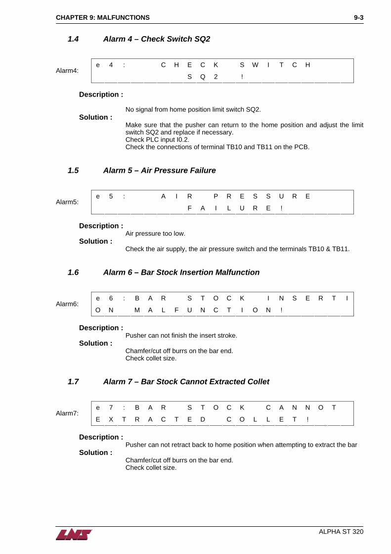
1.4 Alarm 4 – Check Switch SQ2
e 4 : C H E C K S W I T C H Alarm4:
S Q 2 ! Description :
No signal from home position limit switch SQ2. Solution :
Make sure that the pusher can return to the home position and adjust the limit switch SQ2 and replace if necessary. Check PLC input I0.2. Check the connections of terminal TB10 and TB11 on the PCB.
1.5 Alarm 5 – Air Pressure Failure
e 5 : A I R P R E S S U R E Alarm5:
F A I L U R E ! Description :
Air pressure too low. Solution :
Check the air supply, the air pressure switch and the terminals TB10 & TB11.
1.6 Alarm 6 – Bar Stock Insertion Malfunction
e 6 : B A R S T O C K I N S E R T I Alarm6:
O N M A L F U N C T I O N ! Description :
Pusher can not finish the insert stroke. Solution :
Chamfer/cut off burrs on the bar end. Check collet size.
1.7 Alarm 7 – Bar Stock Cannot Extracted Collet
e 7 : B A R S T O C K C A N N O T Alarm7:
E X T R A C T E D C O L L E T ! Description :
Pusher can not retract back to home position when attempting to extract the bar Solution :
Chamfer/cut off burrs on the bar end. Check collet size.

CHAPTER 9: MALFUNCTIONS
ALPHA ST 320
9-4
1.8 Alarm 8 – No Remnant
e 8 : N O R E M N A N T Alarm8:
Description :
No bar is present when attempting to extract the bar. Possibly the bar was lost when retracting from the lathe.
Solution : Check burrs on the bar end. Make sure that the lathe chuck opens completely. Make sure the collet is not too loose/broken. Check limit switch SQ4 (must turn on only when the vice is completely closed without bar)
1.9 Alarm 9 – Bar Stock Loading Error
e 9 : B A R S T O C K L O A D I N G Alarm9:
E R R O R ! Description :
No bar present when attempting to insert bar. Solution :
Check bar stock supply. Check limit switch SQ4 (must turn on only when the vice is completely closed without bar)
1.10 Alarm 11 – Overfeeding
e 1 1 : O V E R F E E D I N G ! Alarm11:
Description :
Only applies to fix type lathes. Occurs when the feeding distance is bigger than the defined part length (parameter F2).
Solution : Check parameter F2. Check the timing of the ‘chuck open’ interface signal (PLC input I3.1). Check that turret stop tool is not broken.

CHAPTER 9: MALFUNCTIONS
ALPHA ST 320
9-5
1.11 Alarm 12 – Bar Stock Not Extracted Collet
e 1 2 : B A R S T O C K N O T Alarm12:
E X T R A C T E D C O L L E T ! Description :
Bar still present after extraction. SQ4 switch still on after home position (SQ2) is reached.
Solution : Check clamping blades. Adjust SQ4. Check vice function.
1.12 Alarm 13 – Front Stopper Can’t Move Up
e 1 3 : F R O N T S T O P P E R Alarm13:
C A N N O T M O V E U P ! Description :
Top cut device fails to function. Solution :
Remove remaining bar stock from guiding channel. Check function of the cylinder (valve YV0). Check adjustment of switch SQ1.
1.13 Alarm 14 – Lathe Collet Not Open in Feed Out
e 1 4 : L A T H E C O L L E T N O T Alarm14:
O P E N I N F E E D O U T ! Description :
Chuck open signal of lathe is not present while changing material. Solution :
Check the interface signal (I 3.1). Check the ‘chuck open’ parameter setting (only authorized personnel).
1.14 Alarm 15 – Bar Feeder is Not in Auto
e 1 5 : B A R F E E D E R I S Alarm15:
N O T I N A U T O ! Description :
If the lathe chuck is opened and closed more than three times while the bar feeder is in manual mode this alarm will occur.
Solution : Select bar feeder Auto Mode.

CHAPTER 9: MALFUNCTIONS
ALPHA ST 320
9-6
1.15 Alarm 16 – Bar Stock Moving Forward
e 1 6 : B A R S T O C K M O V I N G Alarm16:
F O R W A R D ! This alarm only occurs on sliding headstock machines.
Description :
When the chuck is opened the bar is normally pushed against the stopper and can not move. If the bar moves more than 160mm while the chuck is open this alarm occurs. If the pusher loses the bar end during a production cycle the pusher can move past the bar end. If during a production cycle the pusher moves more than the part length (parameter F2) + 50mm this alarm occurs.
Solution : Check the turret stop on the lathe. Check that the bar end is in the collet.
1.16 Alarm 17 – Pusher Moving Length Too Shorter
e 1 7 : P U S H E R M O V I N G Alarm17:
L E N G T H T O O S H O R T E R Description :
Sliding headstock machines: The distance the pusher moves between each chuck opening is measured. If it is smaller than the part length (parameter F2) this alarm occurs. Fixed Type Lathe: Feed out distance must be equal to the part length (parameter F2).
Solution : Check parameter F2. Make sure that nothing is blocking the pusher and that there are no parts or dirt in the channel. Make sure there is no chips between the front of the bar and the turret stop.
1.17 Alarm 18 – Guiding Channel Malfunction Closing
e 1 8 : G U I D I N G C H A N N E L Alarm18:
M A L F U N C T I O N C L O S I N G ! Description :
Limit switches SQ5 (open position) and SQ3 (close position) are both activated at the same time.
Solution : Check the adjustment of the limit switches. Check that the switches function. Replace if necessary. Check wiring of limit switches to PLC.

CHAPTER 9: MALFUNCTIONS
ALPHA ST 320
9-7
1.18 Alarm 19 – Guiding Channel Malfunction Closing
e 1 9 : G U I D I N G C H A N N E L Alarm19:
M A L F U N C T I O N C L O S I N G ! Description :
Limit switches SQ5 (open position) and SQ3 (close position) are both activated at the same time.
Solution : Check the adjustment of the limit switches. Check that the switches function. Replace if necessary. Check wiring of limit switches to PLC.
1.19 Alarm 21 – SQ3 is Malfunction
e 2 1 : S Q 3 I S Alarm21:
M A L F U N C T I O N
Description :
This alarm automatic occurs when during the production cycle, the guiding channel closed switch (SQ3 – I 0.4) turns off.
Solution :
Check the adjustment of limit switch SQ3 and the wiring to the PLC.
1.20 Alarm 22 – Guiding Channel Malfunction Opening
e 2 2 : G U I D I N G C H A N N E L Alarm22:
M A L F U N C T I O N O P E N I N G ! Description :
Guiding channel could not open within the time limit. Solution :
Check limit switch SQ5. Check air pressure and valves of cylinder. Check for mechanical obstacle preventing the guiding channel from opening.
1.21 Alarm 23 – Default Prior to Open Guiding Channel
e 2 3 : D E F A U L T P R I O R T O Alarm23:
O P E N G U I D I N G C H A N N E L Description :
The open position limit switch gives a signal before the channel open. Solenoid (YV2A) is activated
Solution : Check position and function of limit switch SQ5.

CHAPTER 9: MALFUNCTIONS
ALPHA ST 320
9-8
1.22 Alarm 27 – Pusher Can Not Push Bar
e 2 7 : P U S H E R C A N N O T Alarm27:
P U S H B A R ! Description :
If the interface implements a start signal from the bar feeder to the lathe, then the part length is checked BEFORE the chuck on the lathe closes. If the length is too short then this alarm occurs (The difference to Alarm 17 is that Alarm 27 already occurs before the chuck is closed. This is only possible if the interface includes a start signal from the bar feeder to the lathe.).
Solution : Check the value of parameter F2. Make sure nothing is blocking the pusher.
1.23 Alarm 31 – Position Error
e 3 1 : P O S I T I O N E R R O R ! Alarm31:
S A F E T I M E R E L A P S E D ! Description :
This alarm occurs if the loading flag does not reach its forward position during loading within a predetermined time limit.
Solution : Check for a mechanical obstacle preventing the loading flag from traveling forward.
1.24 Alarm 32 – Loading Safety Time Elapsed
e 3 2 : L O A D I N G S A F E T Y Alarm32:
T I M E E L A P S E D ! Description :
This alarm occurs if the newly loaded bar does not reach the top-cut position within a predetermined time limit.
Solution : Clean burrs/chamfer bar end. Check for a mechanical obstacle preventing the loading flag from traveling forward. Check value of parameter F5.

CHAPTER 9: MALFUNCTIONS
ALPHA ST 320
9-9
1.25 Alarm 33 – Lathe Did Not Resume Start Cycle
e 3 3 : L A T H E D I D N O T Alarm33:
R E S U M E S T A R T C Y C L E ! Description :
After the bar is positioned in Top Cut position the lathe does not close the chuck within the time limit of 10sec.
Solution : Check interface start signal PLC output Q1.6 (interface relay R2) and check the lathe NC program.
1.26 Alarm 34 – Pusher Drive Error
e 3 4 : P U S H E R D R I V E Alarm34:
E R R O R ! C H A I N B R O K E N ? Description :
When the pusher is moved to the home position it is expected to hit the stopper at the home position. If the motor can keep turning after reaching the home position this alarm occurs.
Solution : Check the mechanical power transmission from motor to the pusher (chain broken? chain too loose?).
1.27 Alarm 35 – Alarm Signal From the Lathe
e 3 5 : A L A R M S I G N A L Alarm35:
F R O M T H E L A T H E ! Description :
Alarm signal from lathe. Solution :
Check the lathe.

CHAPTER 9
ALPHA ST 320
9-10 : MALFUNCTIONS

CHAPTER 10: SPARE PARTS
ALPHA ST 320
10-1
CHAPTER 10: SPARE PARTS
1. SPARE PARTS 10-2
1.1 Magazine Rack 10-2 1.2 Rack Cover 10-4 1.3 Extraction Device 10-5 1.4 Chassis Assembly 10-7 1.5 Cover 10-8 1.6 Hydraulic Tank 10-9 1.7 Chain Drive Assembly 10-10 1.8 Bar Measuring 10-11 1.9 Pusher Lifting System 10-12 1.10 Front Rest 10-13 1.11 Upper Channel 10-15 1.12 Guiding Elements 10-17

CHAPTER 10: SPARE PARTS
ALPHA ST 320
10-2
1. SPARE PARTS
1.1 Magazine Rack

CHAPTER 10: SPARE PARTS
ALPHA ST 320
10-3

CHAPTER 10: SPARE PARTS
ALPHA ST 320
10-4
1.2 Rack Cover

CHAPTER 10: SPARE PARTS
ALPHA ST 320
10-5
1.3 Extraction Device

CHAPTER 10: SPARE PARTS
ALPHA ST 320
10-6

CHAPTER 10: SPARE PARTS
ALPHA ST 320
10-7
1.4 Chassis Assembly

CHAPTER 10: SPARE PARTS
ALPHA ST 320
10-8
1.5 Cover

CHAPTER 10: SPARE PARTS
ALPHA ST 320
10-9
1.6 Hydraulic Tank

CHAPTER 10: SPARE PARTS
ALPHA ST 320
10-10
1.7 Chain Drive Assembly

CHAPTER 10: SPARE PARTS
ALPHA ST 320
10-11
1.8 Bar Measuring

CHAPTER 10: SPARE PARTS
ALPHA ST 320
10-12
1.9 Pusher Lifting System

CHAPTER 10: SPARE PARTS
ALPHA ST 320
10-13
1.10 Front Rest

CHAPTER 10: SPARE PARTS
ALPHA ST 320
10-14

CHAPTER 10: SPARE PARTS
ALPHA ST 320
10-15
1.11 Upper Channel

CHAPTER 10: SPARE PARTS
ALPHA ST 320
10-16

CHAPTER 10: SPARE PARTS
ALPHA ST 320
10-17
1.12 Guiding Elements

CHAPTER 10: SPARE PARTS
ALPHA ST 320
10-18

CHAPTER 10: SPARE PARTS
ALPHA ST 320
10-19

CHAPTER 10: SPARE PARTS
ALPHA ST 320
10-20

CHAPTER 10: SPARE PARTS
ALPHA ST 320
10-21

CHAPTER 10: SPARE PARTS
ALPHA ST 320
10-22

CHAPTER 10: SPARE PARTS
ALPHA ST 320
10-23

CHAPTER 1
ALPHA ST 320
10-24 0: SPARE PARTS

APPENDICES A-1
APPENDICES
APPENDIX A: PROGRAMMING EXAMPLE A-2
APPENDIX B: ORDERING FORM A-3
APPENDIX C: LNS AGENCIES A-4
ALPHA ST 320

A-2 APPENDICES
APPENDIX A: PROGRAMMING EXAMPLE
MAIN PROGRAM
N... ”M” CODE “LATHE IN AUTOMATIC CYCLE”
N... SPINDLE STOP
N... COOLANT OFF
N... TURRET TO FEED IN POSITION
N... COLLET OPEN
N... TURRET TO FEED OUT POSITION
N... END OF BAR CHECK (PROGRAM JUMP) >
> SUB-PROGRAM
N... CLOSE COLLET
N... TURRET HOME
N... CLEAR TURRET
... “M”CODE (DWELL/LOAD)
N...
N... CLOSE COLLET
N... START SPINDLE
PART PROGRAM N... COLLANT ON
N... X, Z, G, F, T, S, M, ...
N... TOP CUT MATERIAL
N... MACHINE PART
N...
N... PARTS CATCHER IN (IF AVAILABLE)
N...
N... CUT OFF
N... END OF SUB-PROGRAM
N... PARTS CATCHER OFF (IF AVAILABLE)
< (RETURN TO MAIN PROGRAM)
N...
N...
N... X, Z, G, F, T, S, M, ...
N...
N... END OF PROGRAM (LOOP)
Important : The above is an example only. Programming may change according to the interface between the lathe and the bar feed.
ALPHA ST 320
APPENDICES A-3
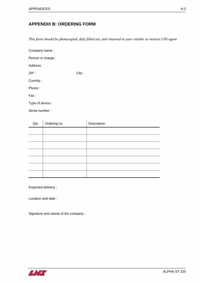
APPENDIX B: ORDERING FORM
This form should be photocopied, duly filled out, and returned to your retailer or nearest LNS agent Company name : Person in charge : Address : ZIP : City : Country : Phone : Fax : Type of device : Serial number :
Qty. Ordering no. Description
Expected delivery : Location and date : Signature and stamp of the company :
ALPHA ST 320

A-4 APPENDICES
ALPHA ST 320
APPENDIX C: LNS AGENCIES
BELGIQUE SL-TECH Industrial Automation & Services Avenue du Bois Jacquet 15 B - 7711 DOTTIGNIES
TEL. +32 56 845 699 FAX +32 56 845 609
DEUTSCHLAND MAW WERKZEUGMASCHINEN GMBH Industriestrasse 6 Postfach 60 01 64 D - 71050 SINDELFINGEN
TEL. +49 703 17 37 60 FAX +49 703 13 82 005
[email protected] www.maw-gmbh.de
DENMARK N.L. TOOLS Kuldyssen 13 I. Sal DK - 2630 TASTRUP
TEL. +45 43 71 17 29 FAX +45 43 71 23 59
ESPANA / PORTUGAL ITALMATIC S.A. Paseo Donostia 82 POL. 26 CP 4 E - 20115 ASTIGARRAGA GUIPUZCOA
TEL. +34 943 33 56 33 FAX +34 943 33 55 65
FINLAND GROENBLOM AB P.O. Box 81 Mekaanikonkatu 6 FI - 00811 Helsinki
TEL. +35 89 755 8240 FAX +35 89 780 715
[email protected] www.gronblom.fi
FRANCE LNS FRANCE Pae les Jourdies 160, rue des Champs Plans F - 74800 St-Pierre en Faucigny
TEL. +33 4 50 03 93 32 FAX +33 4 50 03 93 34
GREAT BRITAIN LNS TURBO UK Limited Waterside Park, Valley Way Wombell Barnsley S73 0BB GREAT BRITAIN
TEL. +44 1226 27 00 33 FAX +44 1226 27 00 44
[email protected] www.turbosystemsinc.com
HUNGARY Prevotex Hungary Kft. Lágymányosi út 6. 1111 BUDAPEST HUNGARY
TEL. +36 1 279 26 50 FAX +36 1 279 26 59
[email protected] www.prevotex.hu
INDIA TETRAMA CONSULT PVT LTD Flat 523, The Embassy 15, Ali Asker Road 560 052 BANGALORE INDIA
TEL. +91 80 220 48 87 FAX +91 80 220 23 37
[email protected] www.tetrama.com
ISRAEL M.T.M. Machine Tool Marketing Ltd. Habarzel Str. 31 P.O. Box 13334 61132 TEL AVIV / RAMAT-HACHAYAL ISRAEL
TEL. +97 23 647 9560 FAX +97 23 647 9578
[email protected] www.mtm.co.il

APPENDICES A-5
ALPHA ST 320
ITALIA LNS AUTOMAZIONE S.R.L. Via Mons. Colombo 34 I - 21053 CASTELLANZA - VA
TEL. +39 0 331 501 901 FAX +39 0 331 482 101
NORWAY VEMA BRYNILDSRUD Maskin As Postbox 114 Vestre Nes 2 1378 NESBRU NORWAY
TEL. +47 669 83 634 FAX +47 669 83 640
[email protected] www.vema.no
PHILIPPINES MESCO INC. P.O. Box 1688 MCPO 1256 MAKATI METRO MANILA PHILIPPINES
TEL. +632 631 17 75 FAX +632 631 40 28
POLAND Prevotex Service Sp. z.o.o. ul. Brukselska 44/21A PL - 09-973 Warsawa
TEL. +48 22 672 91 81 FAX +48 22 616 55 81
SCHWEIZ / SUISSE / SVIZZERA LNS S.A. Case postale 33 CH - 2534 ORVIN
TEL. +41 / 32 358 02 00 FAX +41 / 32 358 02 01
SOUTH AFRICA EDWIN ROTH & CO. LTD 6 Derrick Road Spartan 1620 KEMPTON PARK SOUTH AFRICA
TEL. +27 11 970 19 30 FAX +27 11 394 11 32
SWEDEN AB BONTHRON & EWING Box 18 Gymnasievägen 2 18 621 VALLENTUNA SWEDEN
TEL. +46 8 514 307 60 FAX +46 8 514 307 61
[email protected] www.bonthron-ewing.se
TAÏWAN FEDEK MACHINES Co. LTD. 13-10, Chi Nan Rd. Wujih Hsiang TAICHUNG SIEN
TEL. +88 642 335 49 20 FAX +88 642 335 49 29
www.fedek.com.tw
TCHECHISCHE REPUBLIK- SLOWAKEI MRG spol. sr.o. Jizni 57 37010 CESKE BUDEJOVICE TCHECHISCHE REPUBLIK
TEL. +420 386 321 829 FAX +420 386 222 702
USA / CANADA / MEXICO LNS AMERICA INC 4621 East Tech Drive CINCINNATI, OHIO 45245 USA
TEL. +1 513 528 56 74 FAX +1 513 528 57 33
[email protected] www.lnsamerica.com


