Embed Size (px)
Citation preview
AMERICAN DUCTILE IRON PIPE
3-8
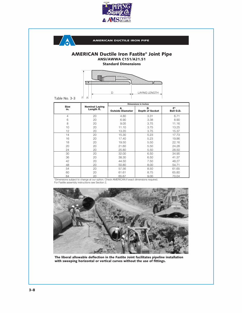
The liberal allowable deflection in the Fastite Joint facilitates pipeline installationwith sweeping horizontal or vertical curves without the use of fittings.
AMERICAN Ductile Iron Fastite® Joint PipeANSI/AWWA C151/A21.51
Standard Dimensions
*Dimensions subject to change at our option. Check AMERICAN if exact dimensions required.For Fastite assembly instructions see Section 2.
Table No. 3-3
LAYING LENGTHD
F A
Sizein.
Nominal LayingLength ft. A
Outside DiameterD
Depth of SocketF*
Bell O.D.
4 20 4.80 3.31 6.716 20 6.90 3.38 8.908 20 9.05 3.75 11.1610 20 11.10 3.75 13.2512 20 13.20 3.75 15.3714 20 15.30 5.23 17.7316 20 17.40 5.23 19.8618 20 19.50 5.50 22.1620 20 21.60 5.50 24.2824 20 25.80 5.50 28.5030 20 32.00 6.50 34.9536 20 38.30 6.50 41.3742 20 44.50 7.50 48.2748 20 50.80 8.00 54.7154 20 57.56 8.50 61.6560 20 61.61 8.75 65.8064 20 65.67 9.00 70.04
Dimensions in Inches
AMERICAN DUCTILE IRON PIPE
3-10
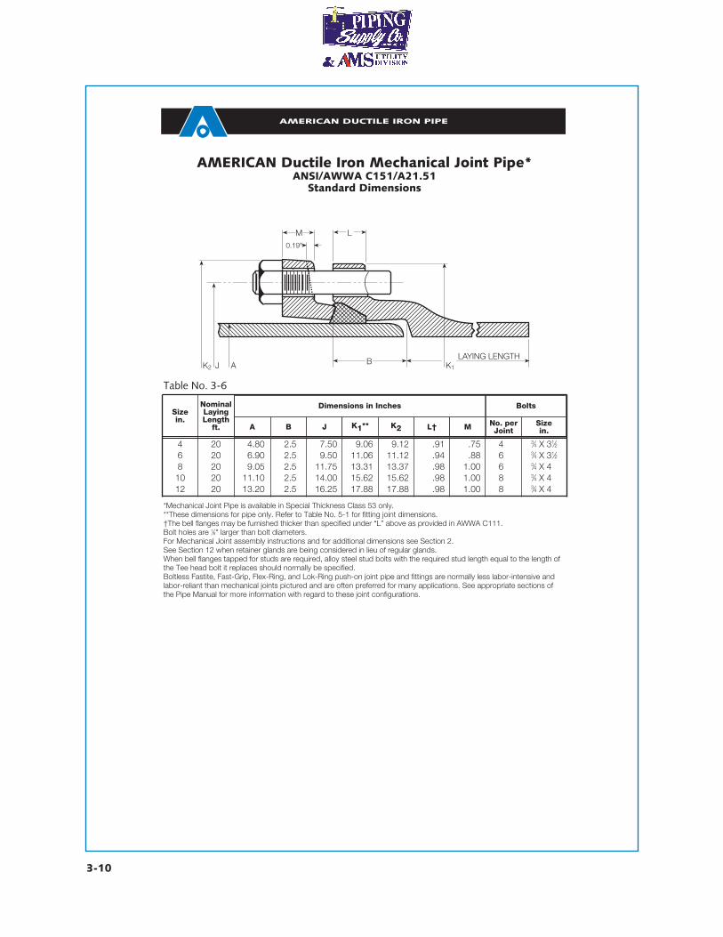
AMERICAN Ductile Iron Mechanical Joint Pipe*ANSI/AWWA C151/A21.51
Standard Dimensions
Table No. 3-6
*Mechanical Joint Pipe is available in Special Thickness Class 53 only.**These dimensions for pipe only. Refer to Table No. 5-1 for fitting joint dimensions.†The bell flanges may be furnished thicker than specified under “L” above as provided in AWWA C111.Bolt holes are 1⁄8" larger than bolt diameters.For Mechanical Joint assembly instructions and for additional dimensions see Section 2.See Section 12 when retainer glands are being considered in lieu of regular glands.When bell flanges tapped for studs are required, alloy steel stud bolts with the required stud length equal to the length ofthe Tee head bolt it replaces should normally be specified.Boltless Fastite, Fast-Grip, Flex-Ring, and Lok-Ring push-on joint pipe and fittings are normally less labor-intensive andlabor-reliant than mechanical joints pictured and are often preferred for many applications. See appropriate sections ofthe Pipe Manual for more information with regard to these joint configurations.
LM0.19"
J AK2 K1
LAYING LENGTHB
Sizein.
NominalLayingLength
ft. A B J K1** K2 L† M No. perJoint
Sizein.
4 20 4.80 2.5 7.50 9.06 9.12 .91 .75 4 3⁄4 X 31⁄26 20 6.90 2.5 9.50 11.06 11.12 .94 .88 6 3⁄4 X 31⁄28 20 9.05 2.5 11.75 13.31 13.37 .98 1.00 6 3⁄4 X 410 20 11.10 2.5 14.00 15.62 15.62 .98 1.00 8 3⁄4 X 412 20 13.20 2.5 16.25 17.88 17.88 .98 1.00 8 3⁄4 X 4
Dimensions in Inches Bolts

AMERICAN DUCTILE IRON PIPE
3-13
AMERICAN Ductile Iron PipeANSI/AWWA C150/A21.50
and ANSI/AWWA C151/A21.51
Standard Pressure Classes – Wall Thickness and Nominal Wall Thicknesses
Pressure classes are defined as the rated water working pressure of the pipe in psi. The thicknesses shown are ade-quate for the rated water working pressure plus a surge allowance of 100 psi. Calculations result in net thicknesses andare based on a minimum yield strength in tension of 42,000 psi and 2.0 safety factor times the sum of working pressureand 100 psi surge allowance.
Thickness can be calculated for rated water working pressure and surges other than the above by use of equation 1 inANSI/AWWA C150/A21.50.
AMERICAN Ductile Iron pipe is available for water working pressures greater than 350 psi. Check AMERICAN for details.These are standard pressure classes as given in AWWA C150 and C151. AMERICAN can furnish any thickness in
between these standard thicknesses if deemed economical for major projects.AMERICAN Ductile Iron pipe is also available with thicknesses greater than Pressure Class 350. For special applica-
tions, contact AMERICAN.
Sizein.
OutsideDiameter
in.150 200 250 300 350
4 4.80 - - - - 0.256 6.90 - - - - 0.258 9.05 - - - - 0.2510 11.10 - - - - 0.2612 13.20 - - - - 0.2814 15.30 - - 0.28 0.30 0.3116 17.40 - - 0.30 0.32 0.3418 19.50 - - 0.31 0.34 0.3620 21.60 - - 0.33 0.36 0.3824 25.80 - 0.33 0.37 0.40 0.4330 32.00 0.34 0.38 0.42 0.45 0.4936 38.30 0.38 0.42 0.47 0.51 0.5642 44.50 0.41 0.47 0.52 0.57 0.6348 50.80 0.46 0.52 0.58 0.64 0.7054 57.56 0.51 0.58 0.65 0.72 0.7960 61.61 0.54 0.61 0.68 0.76 0.8364 65.67 0.56 0.64 0.72 0.80 0.87
Pressure Class
Nominal Thickness in Inches
Table No. 3-8
AMERICAN DUCTILE IRON PIPE
3-14
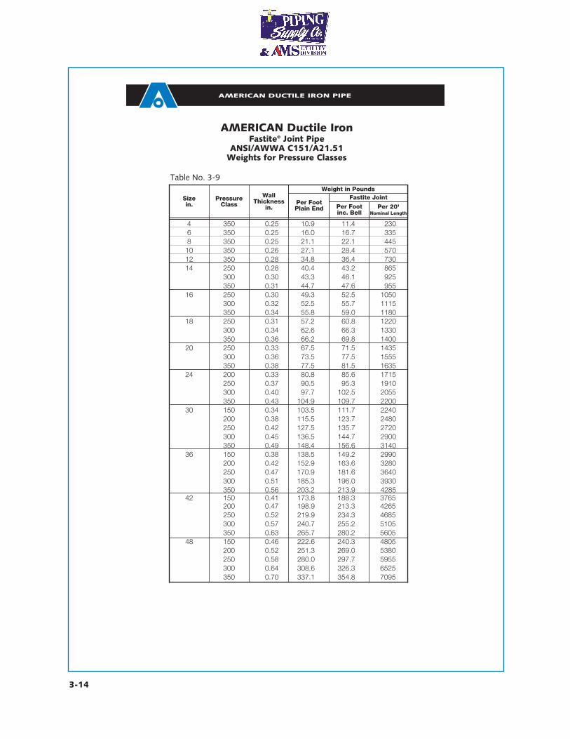
AMERICAN Ductile IronFastite® Joint Pipe
ANSI/AWWA C151/A21.51Weights for Pressure Classes
Sizein.
PressureClass
WallThickness
in.Per Foot Plain End Per Foot
inc. BellPer 20'
Nominal Length
4 350 0.25 10.9 11.4 2306 350 0.25 16.0 16.7 3358 350 0.25 21.1 22.1 44510 350 0.26 27.1 28.4 57012 350 0.28 34.8 36.4 73014 250 0.28 40.4 43.2 865
300 0.30 43.3 46.1 925350 0.31 44.7 47.6 955
16 250 0.30 49.3 52.5 1050300 0.32 52.5 55.7 1115350 0.34 55.8 59.0 1180
18 250 0.31 57.2 60.8 1220300 0.34 62.6 66.3 1330350 0.36 66.2 69.8 1400
20 250 0.33 67.5 71.5 1435300 0.36 73.5 77.5 1555350 0.38 77.5 81.5 1635
24 200 0.33 80.8 85.6 1715250 0.37 90.5 95.3 1910300 0.40 97.7 102.5 2055350 0.43 104.9 109.7 2200
30 150 0.34 103.5 111.7 2240200 0.38 115.5 123.7 2480250 0.42 127.5 135.7 2720300 0.45 136.5 144.7 2900350 0.49 148.4 156.6 3140
36 150 0.38 138.5 149.2 2990200 0.42 152.9 163.6 3280250 0.47 170.9 181.6 3640300 0.51 185.3 196.0 3930350 0.56 203.2 213.9 4285
Fastite JointWeight in Pounds
Table No. 3-9
42 150 0.41 173.8 188.3 3765200 0.47 198.9 213.3 4265250 0.52 219.9 234.3 4685300 0.57 240.7 255.2 5105350 0.63 265.7 280.2 5605
48 150 0.46 222.6 240.3 4805200 0.52 251.3 269.0 5380250 0.58 280.0 297.7 5955300 0.64 308.6 326.3 6525350 0.70 337.1 354.8 7095
AMERICAN DUCTILE IRON PIPE
3-15
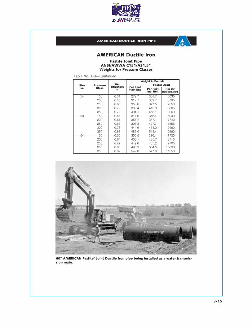
AMERICAN Ductile IronFastite Joint Pipe
ANSI/AWWA C151/A21.51Weights for Pressure Classes
Sizein.
PressureClass
WallThickness
in.Per FootPlain End Per Foot
inc. BellPer 20'
Nominal Length
54 150 0.51 279.7 301.7 6035200 0.58 317.7 339.7 6795250 0.65 355.6 377.5 7550300 0.72 393.4 415.3 8305350 0.79 431.1 453.1 9060
60 150 0.54 317.0 346.4 6930200 0.61 357.7 387.1 7740250 0.68 398.3 427.7 8555300 0.76 444.6 474.0 9480350 0.83 485.0 514.4 10290
64 150 0.56 350.5 386.1 7720200 0.64 400.1 435.7 8715250 0.72 449.6 485.2 9705300 0.80 498.9 534.5 10690
Fastite JointWeight in Pounds
Table No. 3-9—Continued
350 0.87 542.0 577.6 11550
60" AMERICAN Fastite® Joint Ductile Iron pipe being installed as a water transmis-sion main.
AMERICAN DUCTILE IRON PIPE
3-19
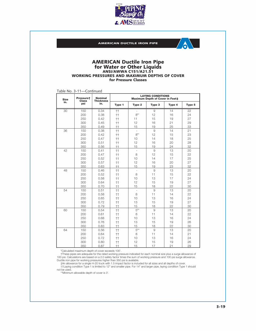
*Calculated maximum depth of cover exceeds 100’.†These pipes are adequate for the rated working pressure indicated for each nominal size plus a surge allowance of
100 psi. Calculations are based on a 2.0 safety factor times the sum of working pressure and 100 psi surge allowance.Ductile iron pipe for working pressures higher than 350 psi is available.
‡An allowance for a single H-20 truck with 1.5 impact factor is included for all sizes and all depths of cover.††Laying condition Type 1 is limited to 12" and smaller pipe. For 14" and larger pipe, laying condition Type 1 should
not be used.**Minimum allowable depth of cover is 3’.
Table No. 3-11—Continued
AMERICAN Ductile Iron Pipefor Water or Other Liquids
ANSI/AWWA C151/A21.51WORKING PRESSURES AND MAXIMUM DEPTHS OF COVER
for Pressure Classes
Sizein.
Pressure†Class
psi
NominalThickness
in. Type 1 Type 2 Type 3 Type 4 Type 5
30 150 0.34 †† - 9 14 22200 0.38 †† 8 12 16 24250 0.42 †† 11 15 19 27300 0.45 †† 12 16 21 29350 0.49 †† 15 19 25 33
36 150 0.38 †† - 9 14 21200 0.42 †† 8 12 15 23250 0.47 †† 10 14 18 25300 0.51 †† 12 16 20 28350 0.56 †† 15 19 24 32
42 150 0.41 †† - 9 13 20200 0.47 †† 8 12 15 22250 0.52 †† 10 14 17 25300 0.57 †† 12 16 20 27350 0.63 †† 15 19 23 32
48 150 0.46 †† - 9 13 20200 0.52 †† 8 11 15 22250 0.58 †† 10 13 17 24300 0.64 †† 12 15 19 27350 0.70 †† 15 18 22 30
54 150 0.51 †† - 9 13 20200 0.58 †† 8 11 14 22250 0.65 †† 10 13 16 24300 0.72 †† 13 15 19 27350 0.79 †† 15 18 22 30
60 150 0.54 †† 5 9 13 20200 0.61 †† 8 11 14 22250 0.68 †† 10 13 16 24300 0.76 †† 13 15 19 26350 0.83 †† 15 18 22 30
64 150 0.56 †† 5 9 13 20200 0.64 †† 8 11 14 21250 0.72 †† 10 13 16 24300 0.80 †† 12 15 19 26350 0.87 †† 15 17 21 29
LAYING CONDITIONSMaximum Depth of Cover in Feet‡
**
**
**
**
AMERICAN DUCTILE IRON PIPE
3-20
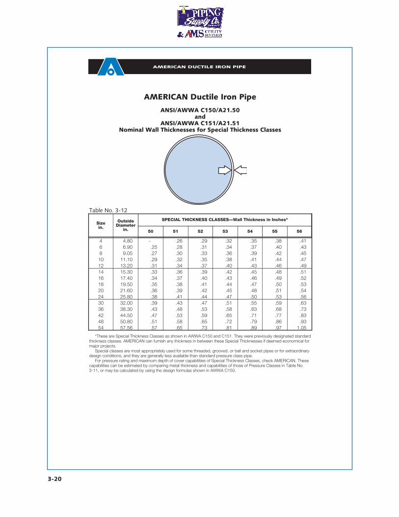
AMERICAN Ductile Iron Pipe
ANSI/AWWA C150/A21.50and
ANSI/AWWA C151/A21.51Nominal Wall Thicknesses for Special Thickness Classes
*These are Special Thickness Classes as shown in AWWA C150 and C151. They were previously designated standardthickness classes. AMERICAN can furnish any thickness in between these Special Thicknesses if deemed economical formajor projects.
Special classes are most appropriately used for some threaded, grooved, or ball and socket pipes or for extraordinarydesign conditions, and they are generally less available than standard pressure class pipe.
For pressure rating and maximum depth of cover capabilities of Special Thickness Classes, check AMERICAN. Thesecapabilities can be estimated by comparing metal thickness and capabilities of those of Pressure Classes in Table No. 3-11, or may be calculated by using the design formulas shown in AWWA C150.
Table No. 3-12
Sizein.
OutsideDiameter
in. 50 51 52 53 54 55 56
4 4.80 - .26 .29 .32 .35 .38 .416 6.90 .25 .28 .31 .34 .37 .40 .438 9.05 .27 .30 .33 .36 .39 .42 .4510 11.10 .29 .32 .35 .38 .41 .44 .4712 13.20 .31 .34 .37 .40 .43 .46 .4914 15.30 .33 .36 .39 .42 .45 .48 .5116 17.40 .34 .37 .40 .43 .46 .49 .5218 19.50 .35 .38 .41 .44 .47 .50 .5320 21.60 .36 .39 .42 .45 .48 .51 .5424 25.80 .38 .41 .44 .47 .50 .53 .5630 32.00 .39 .43 .47 .51 .55 .59 .6336 38.30 .43 .48 .53 .58 .63 .68 .7342 44.50 .47 .53 .59 .65 .71 .77 .8348 50.80 .51 .58 .65 .72 .79 .86 .9354 57.56 .57 .65 .73 .81 .89 .97 1.05
SPECIAL THICKNESS CLASSES—Wall Thickness in Inches*
AMERICAN DUCTILE IRON PIPE
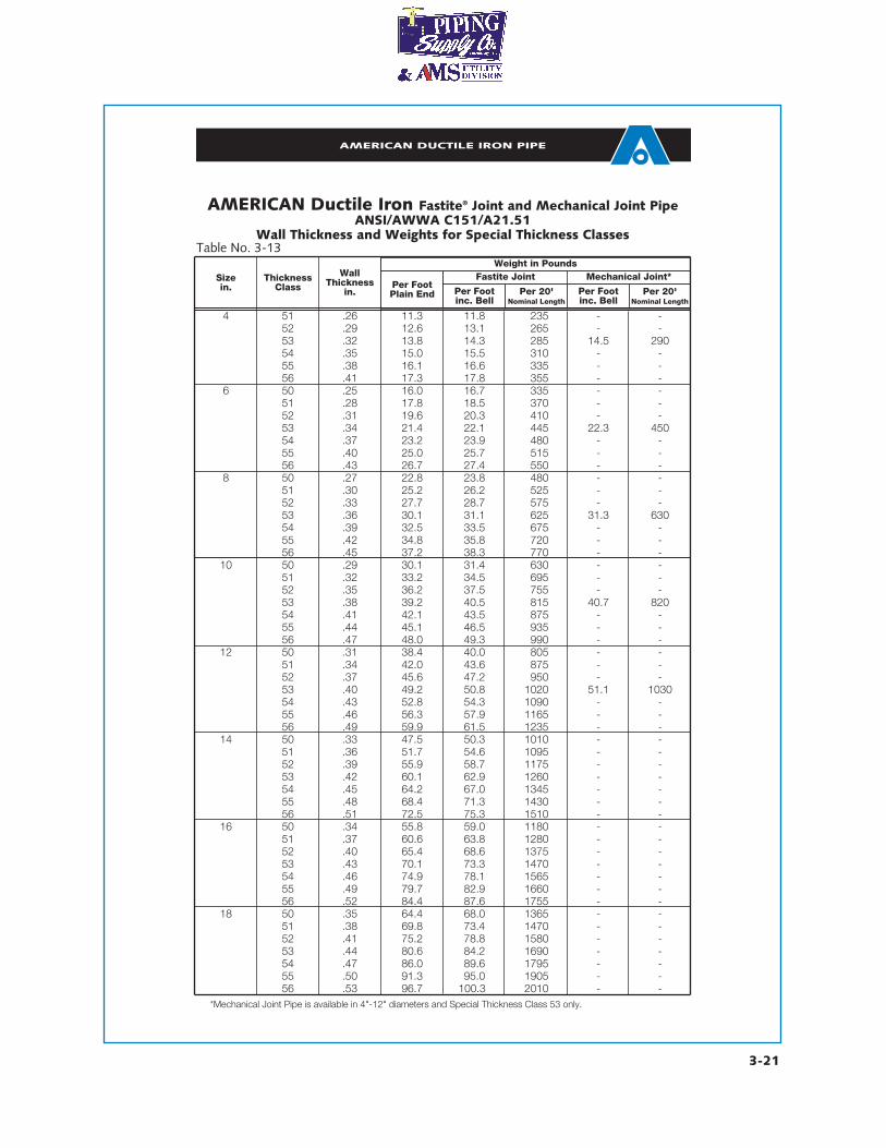
Sizein.
AMERICAN Ductile Iron Fastite® Joint and Mechanical Joint PipeANSI/AWWA C151/A21.51
Wall Thickness and Weights for Special Thickness Classes
ThicknessClass
Wall Thickness
in.Per FootPlain End Per Foot
inc. BellPer 20'
Nominal LengthPer Footinc. Bell
Per 20'Nominal Length
4 51 .26 11.3 11.8 235 - -52 .29 12.6 13.1 265 - -53 .32 13.8 14.3 285 14.5 29054 .35 15.0 15.5 310 - -55 .38 16.1 16.6 335 - -56 .41 17.3 17.8 355 - -
6 50 .25 16.0 16.7 335 - -51 .28 17.8 18.5 370 - -52 .31 19.6 20.3 410 - -53 .34 21.4 22.1 445 22.3 45054 .37 23.2 23.9 480 - -55 .40 25.0 25.7 515 - -56 .43 26.7 27.4 550 - -
8 50 .27 22.8 23.8 480 - -51 .30 25.2 26.2 525 - -52 .33 27.7 28.7 575 - -53 .36 30.1 31.1 625 31.3 63054 .39 32.5 33.5 675 - -55 .42 34.8 35.8 720 - -56 .45 37.2 38.3 770 - -
10 50 .29 30.1 31.4 630 - -51 .32 33.2 34.5 695 - -52 .35 36.2 37.5 755 - -53 .38 39.2 40.5 815 40.7 82054 .41 42.1 43.5 875 - -55 .44 45.1 46.5 935 - -56 .47 48.0 49.3 990 - -
12 50 .31 38.4 40.0 805 - -51 .34 42.0 43.6 875 - -52 .37 45.6 47.2 950 - -53 .40 49.2 50.8 1020 51.1 103054 .43 52.8 54.3 1090 - -55 .46 56.3 57.9 1165 - -56 .49 59.9 61.5 1235 - -
14 50 .33 47.5 50.3 1010 - -51 .36 51.7 54.6 1095 - -52 .39 55.9 58.7 1175 - -53 .42 60.1 62.9 1260 - -54 .45 64.2 67.0 1345 - -55 .48 68.4 71.3 1430 - -56 .51 72.5 75.3 1510 - -
16 50 .34 55.8 59.0 1180 - -51 .37 60.6 63.8 1280 - -52 .40 65.4 68.6 1375 - -53 .43 70.1 73.3 1470 - -54 .46 74.9 78.1 1565 - -55 .49 79.7 82.9 1660 - -56 .52 84.4 87.6 1755 - -
18 50 .35 64.4 68.0 1365 - -51 .38 69.8 73.4 1470 - -52 .41 75.2 78.8 1580 - -53 .44 80.6 84.2 1690 - -54 .47 86.0 89.6 1795 - -55 .50 91.3 95.0 1905 - -56 .53 96.7 100.3 2010 - -
Mechanical Joint*Fastite JointWeight in Pounds
Table No. 3-13
*Mechanical Joint Pipe is available in 4"-12" diameters and Special Thickness Class 53 only.
3-21
AMERICAN DUCTILE IRON PIPE
3-22
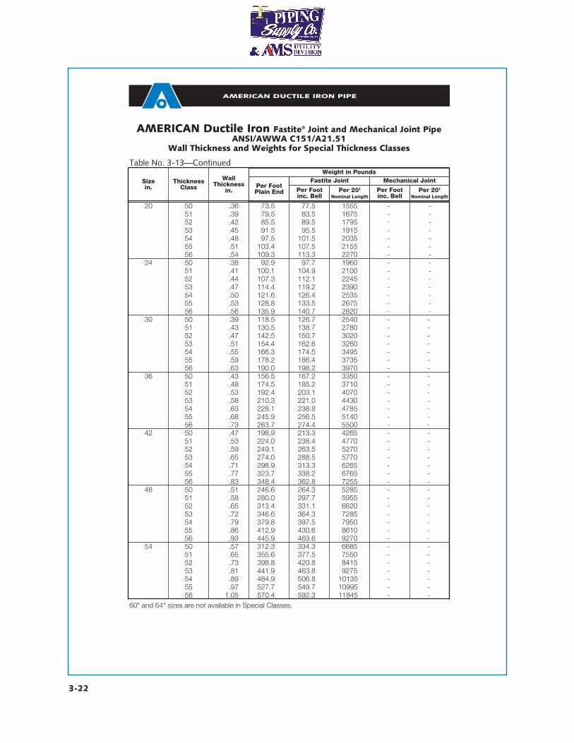
AMERICAN Ductile Iron Fastite® Joint and Mechanical Joint PipeANSI/AWWA C151/A21.51
Wall Thickness and Weights for Special Thickness Classes
60" and 64" sizes are not available in Special Classes.
Sizein.
ThicknessClass
WallThickness
in.Per FootPlain End Per Foot
inc. BellPer 20'
Nominal LengthPer Footinc. Bell
Per 20'Nominal Length
20 50 .36 73.5 77.5 1555 - -51 .39 79.5 83.5 1675 - -52 .42 85.5 89.5 1795 - -53 .45 91.5 95.5 1915 - -54 .48 97.5 101.5 2035 - -55 .51 103.4 107.5 2155 - -56 .54 109.3 113.3 2270 - -
24 50 .38 92.9 97.7 1960 - -51 .41 100.1 104.9 2100 - -52 .44 107.3 112.1 2245 - -53 .47 114.4 119.2 2390 - -54 .50 121.6 126.4 2535 - -55 .53 128.8 133.5 2675 - -56 .56 135.9 140.7 2820 - -
30 50 .39 118.5 126.7 2540 - -51 .43 130.5 138.7 2780 - -52 .47 142.5 150.7 3020 - -53 .51 154.4 162.6 3260 - -54 .55 166.3 174.5 3495 - -55 .59 178.2 186.4 3735 - -56 .63 190.0 198.2 3970 - -
36 50 .43 156.5 167.2 3350 - -51 .48 174.5 185.2 3710 - -52 .53 192.4 203.1 4070 - -53 .58 210.3 221.0 4430 - -54 .63 228.1 238.8 4785 - -55 .68 245.9 256.5 5140 - -56 .73 263.7 274.4 5500 - -
42 50 .47 198.9 213.3 4265 - -51 .53 224.0 238.4 4770 - -52 .59 249.1 263.5 5270 - -53 .65 274.0 288.5 5770 - -54 .71 298.9 313.3 6265 - -55 .77 323.7 338.2 6765 - -56 .83 348.4 362.8 7255 - -
48 50 .51 246.6 264.3 5285 - -51 .58 280.0 297.7 5955 - -52 .65 313.4 331.1 6620 - -53 .72 346.6 364.3 7285 - -54 .79 379.8 397.5 7950 - -55 .86 412.9 430.6 8610 - -56 .93 445.9 463.6 9270 - -
54 50 .57 312.3 334.3 6685 - -51 .65 355.6 377.5 7550 - -52 .73 398.8 420.8 8415 - -53 .81 441.9 463.8 9275 - -54 .89 484.9 506.8 10135 - -55 .97 527.7 549.7 10995 - -56 1.05 570.4 592.3 11845 - -
Mechanical JointFastite JointWeight in Pounds
Table No. 3-13—Continued
AMERICAN DUCTILE IRON PIPE
3-24
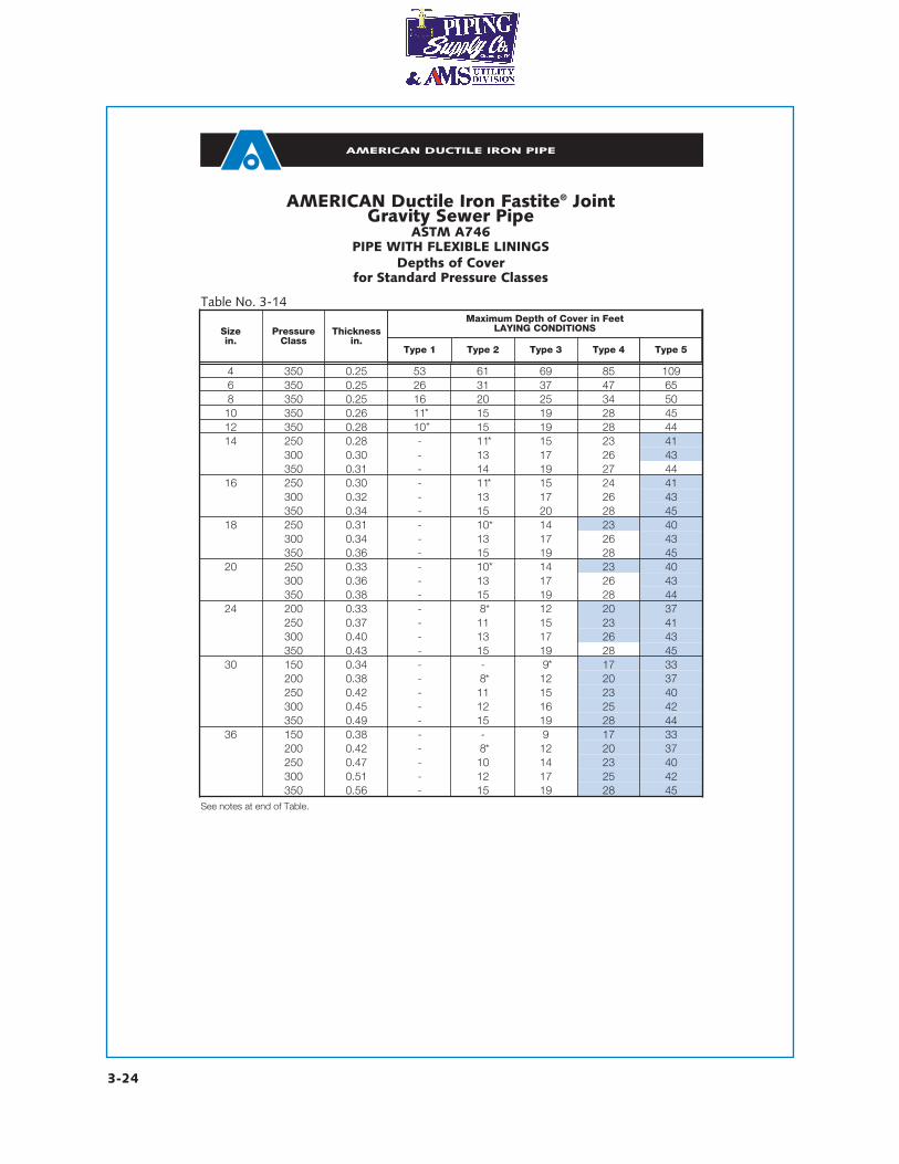
AMERICAN Ductile Iron Fastite® JointGravity Sewer Pipe
ASTM A746PIPE WITH FLEXIBLE LININGS
Depths of Coverfor Standard Pressure Classes
Table No. 3-14
Sizein.
PressureClass
Thicknessin.
Type 1 Type 2 Type 3 Type 4 Type 5
4 350 0.25 53 61 69 85 1096 350 0.25 26 31 37 47 658 350 0.25 16 20 25 34 5010 350 0.26 11 15 19 28 4512 350 0.28 10 15 19 28 4414 250 0.28 - 11 15 23 41
300 0.30 - 13 17 26 43350 0.31 - 14 19 27 44
16 250 0.30 - 11 15 24 41300 0.32 - 13 17 26 43350 0.34 - 15 20 28 45
18 250 0.31 - 10 14 23 40300 0.34 - 13 17 26 43350 0.36 - 15 19 28 45
20 250 0.33 - 10 14 23 40300 0.36 - 13 17 26 43350 0.38 - 15 19 28 44
24 200 0.33 - 8 12 20 37250 0.37 - 11 15 23 41300 0.40 - 13 17 26 43350 0.43 - 15 19 28 45
30 150 0.34 - - 9 17 33200 0.38 - 8 12 20 37250 0.42 - 11 15 23 40300 0.45 - 12 16 25 42350 0.49 - 15 19 28 44
36 150 0.38 - - 9 17 33200 0.42 - 8 12 20 37250 0.47 - 10 14 23 40300 0.51 - 12 17 25 42350 0.56 - 15 19 28 45
Maximum Depth of Cover in FeetLAYING CONDITIONS
**
*
*
*
*
*
*
*
See notes at end of Table.
*
AMERICAN DUCTILE IRON PIPE
3-25
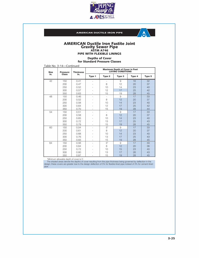
*Minimum allowable depth of cover is 3’.The shaded areas denote the depths of cover resulting from the pipe thickness being governed by deflection in the
design; these covers are greater due to the design deflection of 5% for flexible-lined pipe instead of 3% for cement-linedpipe.
AMERICAN Ductile Iron Fastite JointGravity Sewer Pipe
ASTM A746PIPE WITH FLEXIBLE LININGS
Depths of Coverfor Standard Pressure Classes
Table No. 3-14—Continued
Sizein.
PressureClass
Thicknessin.
Type 1 Type 2 Type 3 Type 4 Type 5
42 150 0.41 - - 9 16 32200 0.47 - 8 12 20 37250 0.52 - 10 14 23 40300 0.57 - 12 17 25 42350 0.63 - 15 19 28 45
48 150 0.46 - - 9 17 33200 0.52 - 8 12 20 37250 0.58 - 10 14 23 40300 0.64 - 12 17 25 42350 0.70 - 15 19 28 44
54 150 0.51 - - 9 17 33200 0.58 - 8 12 20 37250 0.65 - 10 14 23 40300 0.72 - 13 17 25 43350 0.79 - 15 19 28 45
60 150 0.54 - 5 9 17 33200 0.61 - 8 12 20 37250 0.68 - 10 14 23 40300 0.76 - 13 17 25 43350 0.83 - 15 19 28 45
64 150 0.56 - 5 9 17 33200 0.64 - 8 12 20 36250 0.72 - 10 15 23 40300 0.80 - 13 17 26 43350 0.87 - 15 19 28 45
Maximum Depth of Cover in FeetLAYING CONDITIONS
*
*
AMERICAN DUCTILE IRON PIPE
3-30
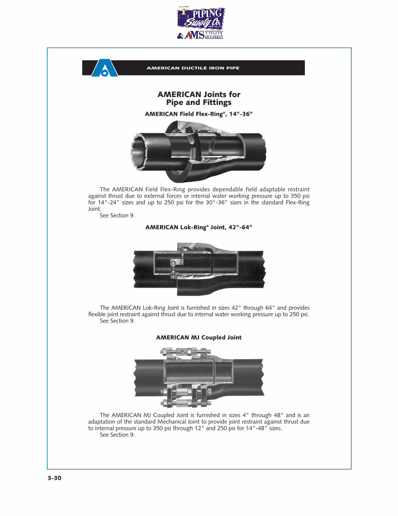
AMERICAN Joints forPipe and Fittings
AMERICAN Lok-Ring® Joint, 42"-64"
The AMERICAN Lok-Ring Joint is furnished in sizes 42" through 64" and providesflexible joint restraint against thrust due to internal water working pressure up to 250 psi.
See Section 9.
AMERICAN Field Flex-Ring®, 14"-36"
The AMERICAN Field Flex-Ring provides dependable field adaptable restraintagainst thrust due to external forces or internal water working pressure up to 350 psifor 14"-24" sizes and up to 250 psi for the 30"-36" sizes in the standard Flex-RingJoint.
See Section 9.
The AMERICAN MJ Coupled Joint is furnished in sizes 4" through 48" and is anadaptation of the standard Mechanical Joint to provide joint restraint against thrust dueto internal pressure up to 350 psi through 12" and 250 psi for 14"-48" sizes.
See Section 9.
AMERICAN MJ Coupled Joint
3-31
AMERICAN DUCTILE IRON PIPE
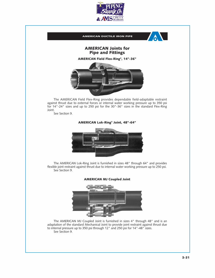
AMERICAN Joints forPipe and Fittings
AMERICAN Lok-Ring® Joint, 48"-64"
The AMERICAN Lok-Ring Joint is furnished in sizes 48" through 64" and providesflexible joint restraint against thrust due to internal water working pressure up to 250 psi.
See Section 9.
AMERICAN Field Flex-Ring®, 14"-36"
The AMERICAN Field Flex-Ring provides dependable field-adaptable restraintagainst thrust due to external forces or internal water working pressure up to 350 psifor 14"-24" sizes and up to 250 psi for the 30"-36" sizes in the standard Flex-RingJoint.
See Section 9.
The AMERICAN MJ Coupled Joint is furnished in sizes 4" through 48" and is anadaptation of the standard Mechanical Joint to provide joint restraint against thrust dueto internal pressure up to 350 psi through 12" and 250 psi for 14"-48" sizes.
See Section 9.
AMERICAN MJ Coupled Joint
AMERICAN DUCTILE IRON PIPE
3-32
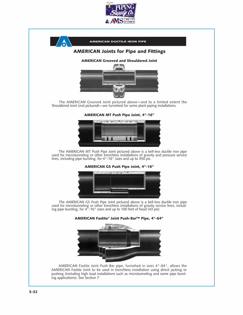
AMERICAN Joints for Pipe and Fittings
The AMERICAN Grooved Joint pictured above—and to a limited extent theShouldered Joint (not pictured)—are furnished for some plant piping installations.
AMERICAN Grooved and Shouldered Joint
AMERICAN MT Push Pipe Joint, 4"-16"
The AMERICAN MT Push Pipe Joint pictured above is a bell-less ductile iron pipeused for microtunneling or other trenchless installations of gravity and pressure servicelines, including pipe bursting, for 4"-16" sizes and up to 350 psi.
The AMERICAN GS Push Pipe Joint pictured above is a bell-less ductile iron pipeused for microtunneling or other trenchless installations of gravity service lines, includ-ing pipe bursting, for 4"-16" sizes and up to 100 feet of head (43 psi).
AMERICAN GS Push Pipe Joint, 4"-16"
AMERICAN Fastite Joint Push-Bar pipe, furnished in sizes 4"-64", allows theAMERICAN Fastite Joint to be used in trenchless installation using direct jacking orpushing (including high load installations such as microtunneling and some pipe burst-ing applications). See Section 7.
AMERICAN Fastite® Joint Push-Bar™ Pipe, 4"-64"
AMERICAN DUCTILE IRON PIPE
3-33
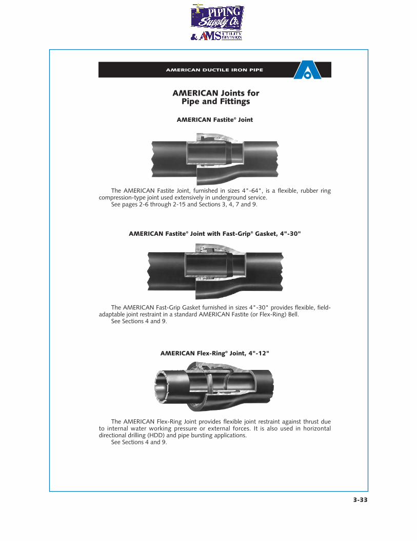
AMERICAN Joints forPipe and Fittings
AMERICAN Fastite® Joint
The AMERICAN Fastite Joint, furnished in sizes 4"-64", is a flexible, rubber ringcompression-type joint used extensively in underground service.
See pages 2-6 through 2-15 and Sections 3, 4, 7 and 9.
AMERICAN Flex-Ring® Joint, 4"-12"
AMERICAN Fastite® Joint with Fast-Grip® Gasket, 4"-30"
The AMERICAN Flex-Ring Joint provides flexible joint restraint against thrust dueto internal water working pressure or external forces. It is also used in horizontal directional drilling (HDD) and pipe bursting applications.
See Sections 4 and 9.
The AMERICAN Fast-Grip Gasket furnished in sizes 4"-30" provides flexible, field-adaptable joint restraint in a standard AMERICAN Fastite (or Flex-Ring) Bell.
See Sections 4 and 9.


