Embed Size (px)
Citation preview
IEEE TRANSACTIONS ON SYSTEMS, MAN, AND CYBERNETICS, VOL. SMC-l 1, NO. 2, FEBRUARY 1981
[7] L. Fisher and J. W. van Ness, "Distinguishability of probabilitymeasures," A iiii. Math. Stat., pp. 381-392, 1969.
[8] W. R. Gaffey, "Discriminatory analysis: Perfect discrimination asthe number of variables increases," USAF School of AviationMedicine, Randolf Field, TX, Rep. 5, Project 21-49-004, 1957.
[9] G. F. Hughes, "On the mean accuracy of statistical pattern recog-nizers," IEEE Trans. In5form. Theory, vol. IT-14, no. 1, pp. 55-63,1968.
[10] S. John, "On some classification problems," Sankhyac, vol. 22, pp.301-316, 1960.
[11] A. Kudo, "The classificatory problem viewed as a two-decisionproblem I," Memn., Fac. of Sci., Kyushu Univ., Ser. A 13, pp.96- 125, 1959.
[12] _ _, "The classificatory problem viewed as a two-decision prob-lem II," Meni., Fac. of Sci., Kyushu Univ., Ser. A 14, pp. 63-83,1960.
[13] L. LeCam, "Convergence of estimates under dimensionality restric-tions," A ntn. Math. Stat., pp. 38-53, 1973.
[14] E. L. Lehmann, Testinig Statistical Hypotheses. New York: Wiley,1959.
[15] A. Z. Memon and M. Okamoto, "Asymptotic expansion of thedistribution of the Z-statistic in discriminant analysis," J. Multi-variate Anialysis, vol. 1, pp. 294- 307, 1971.
[16] J. W. van Ness, "Dimensionality and classification performancewith independent coordinates," IEEE Trans. Syst., Man, Cybern.,
vol. SMC-7, no. 7, pp. 560- 564, 1977.[17] W. Schaafsma, "Classifying when populations are estimated," in
Discrimninant A nialysis and Applications, T. Cacoullos, Ed. NewYork: Academic, 1973.
[18] _ _, "Selecting variables in discriminant analysis for improvingupon classical procedures," in Kanal-Krishnaiah, Handbook of Sta-tistics, vol. 2. New York: North Holland, 1981.
[19] W. Schaafsma and A. G. M. Steerneman, "Discriminant analysiswhen the number of features is unbounded," Dept. Math., StateUniv., Groningen, The Netherlands, Internal Rep. 1981.
[20] W. Schaafsma and G. N. van Vark, "Classification and discrimina-tion problems with applications, part I," Stat. Neerlandica, vol. 31,pp. 25-45, 1977.
[21] _ _, "Classification and discrimination problems with appli-cations, part IIa," Stat. Neerlandica, vol. 33, pp. 91-126, 1979.
[22] M. Siotani and R. H. Wang, "Asymptotic expansions for error ratesand comparison of the W-procedure and the Z-procedure in dis-criminant analysis," in Krishnaiah, Multivariate Analysis IV. NewYork: North Holland, 1977.
[23] A. Wald, "Tests of statistical hypotheses concerning several parame-ters when the number of observations is large," Trans. Am. Math.Soc., vol. 54, pp. 426-482, 1943.
[24] _ _, "On a statistical problem arising in the classification of anindividual into one of two groups," Ann. Math. Stat., pp. 145-162,1944.
An Orienting Robot for Feeding WorkpiecesStored in Bins
JOHN R. BIRK, MEMBER, IEEE, ROBERT B. KELLEY, MEMBER, IEEE, AND HENRIQUE A. S. MARTINS
Abstract-A robot system has been tested which can acquire a class ofworkpieces that are unoriented in bins and transport them, one at a time, toa destination with the proper orientation. This kind of robot has numerousapplications in industries which manufacture discrete-part products inbatches. A variety of approaches to the design of an orienting robot havebeen identified. For acquisition, gripper design and vision algorithmsshould be considered together. A vacuum gripper which adapts to surfaceangle and an algorithm which finds the center of smooth regions in the binimage have been shown to form an effective combination. Knowledge of theposition and orientation of the workpieces near the top of the bin is notnecessary for acquisition. Collisions with workpieces in the bin whoseposes are not known can be avoided by having the gripper follow a line ofsight approach path. To simplify the computation of workpiece orientation,it was found to be useful to employ a gripper which locked a workpiece inone of a finite number of states and which did not obscure the workpiece.For an orienting robot which is designed to service a variety of differentworkpieces, using an arm with six degrees of freedom greatly facilitatesworkpiece transportation.
Manuscript received January 30, 1980; revised October 10, 1980. Thiswork was supported in part by the National Science Foundation underGrants APR74-13935 and DAR78-27337.The authors are with the Department of Electrical Engineering, Univer-
sity of Rhode Island, Kingston, RI 02881.
I. INTRODUCTION
T HE PROBLEM of feeding workpieces from bins intomachines is common in many manufacturing in-
dustries. Currently there are three primary solutions to thisproblem: human labor, mechanical feeders, and preservingorientation for blind robots. Before discussing the ap-proach of this paper, namely robots with sensors, thedisadvantages of these alternative approaches will be con-sidered briefly.
Feeding workpieces to machines is a monotonous jobwhich does not enrich human life. Young people todayhave increasingly higher aspirations for good jobs. Whilethe cost of labor is increasing, human performance remainsessentially constant. Furthermore the environment inmanufacturing areas is often unhealthy and, when work-pieces are inserted into machines, limbs are often in danger.One problem with vibratory feeders is that some
workpieces have shapes which make them difficult, if notimpossible, to orient. Some parts cause jamming, such asparts which are very thin, out of tolerance, or foreign.
0018-9472/81/0200-0151$00.75 ( 1981 IEEE
151
1 5 2T-i.RANSACTIONS ON SYSTEMS, MAN, AND CYBERNETICS, VOL. SMC-I 1, NO. 2, FEBRUARY 1981
Some parts tangle with one another. Some parts can bedamaged by scratching against each other or against theorienting device. Large workpieces require very large feedersand substantial energy. The cost and lead time of design,debugging, support, and changeover of mechanical devicesmay be excessive, especially for batch production. Feedrate changes with the number of parts in the feeder.Mechanical feeders often emit excessive noise, and vibra-tion may be conducted into other structures. Even if a
rejection mechanism is controlled by vision [24], most ofthe problems with mechanical feeders which have beencited, remaln.
Preserving the orientation of parts is often suggested as a
solution for avoiding the bins of parts problem. Thissolution is particularly attractive since commercially availa-ble industrial robots can load machines with workpiecesthat are supplied oriented in magazines or pallets. Howeverpreserving orientation is often impractical or uneconomi-cal. Since machines work at different cycle times, it maynot be possible to use all members of a set of linkedmachines at full capacity. If one machine fails, a whole lineof machines may have to be stopped. If a robot has to taketime to unload a workpiece from a machine, rather thanhaving the workpiece quickly blown out with a blast of air,machine throughput may be lowered. Mechanisms to un-
load workpieces while preserving orientation tend to beexpensive and space consuming. Machines are already setup to accommodate batch work with stacks of bins beingused for intermediate buffer storage. Pallets of orientedparts may be upset during transfer from workstation toworkstation. Parts of an assembly may come from manyvendors and the cost of shipping oriented parts is usuallyprohibitive due to low packing densities. Because of thedisadvantages of the three standard approaches, robotswith sensors have a future in workpiece feeding applica-tions.Various technical contributions have been made to the
bin of parts problem. A data base of images of castingshave been made available [3]. A number of studies havebeen made on estimating the position and orientation(pose) of workpieces which have a finite number of stateson a plane, i.e., orientations with equilibrium [2], [15], [21],[29]. The use of visual feedback while transporting objectshas been studied [27]. The acquisition of a part hangingwith an arbitrary orientation was investigated [28]. Dihe-drally tipped boxes which vibrate can be used to orientisolated parts [13]. Overlapping parts, which are nearlyhorizontal, have been analyzed for position and orientation[11], [23]. Regions which belong to the same object havebeen identified in an image of a stack of blocks [12], [14].For pose estimation with three continuous unknown
angles, the issues of sampling images and of choosing asecond view were investigated [9]. The issue of refiningpose estimates of a piece in the hand was studied in termsof certain reference poses about which linear interpolationof image features could be used [8], [19]. The tasks ofestimating the pose of pieces in the bin which were par-tially occluded and of only acquiring pieces which could be
transported directly to a goal with a prespecified pose wereexamined [20]. The automatic identification of the rota-tional axes of symmetry of a workpiece from multipleviews was investigated [18]. Matching local features toworkpiece models has been used for pose estimation [4],[5], [10].The location of large circular holes which are accessible
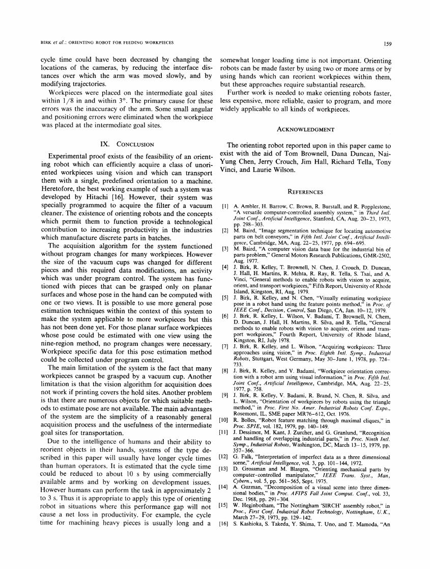
from the direction of the camera can be found fromcomplete ellipses [22], [31]. Intact ellipses have also beenused to locate the circular vacuum cleaner filter which is onthe "top" of a pile of similar parts [16]. The parts of anassembly have been separated by a robot from a heap bygrasping for protrusions which were located visually andby pushing with the hand at various levels [1].
This paper discusses the system aspects of the problemof designing robots which feed machines from bins. Afunctional experimental robot is described which appearsto be the first to efficiently acquire a class of workpiecesfrom a bin using vision. Efficient acquisition is accom-plished by a special vacuum cup hand and a simple visionalgorithm which finds central portions of smooth surfaces.This robot has an integrated architecture which permitspieces to be transported to a goal site with a single positionand orientation, regardless of the side on which theworkpiece was acquired [17]. Although the experimentalsystem did not handle a large variety of workpieces, thissystem represents a milestone in the development of orient-ing robots. Furthermore it can readily be improved tohandle a greater variety of workpieces.
II. OVERVIEW OF DESIGN PHILOSOPHY
The job of feeding workpieces from bins can be brokeninto three tasks: acquiring a workpiece from a bin, comput-ing its orientation in the hand, and transporting theworkpiece to its destination.
Sensors could be used for acquisition to answer some ofthe following questions. What is the pose of all pieces inthe bin? What piece is the least heavily loaded by otherpieces and which piece is uppermost? Using knowledge ofthe hand, sensory information about the bin of workpiecesmight be used to answer these other questions. Which pieceis the easiest to access? What pieces can be grasped andwhere can pieces be grasped? The last question wasemphasized in this work. By combining a gripper whichcould acquire parts on surfaces despite uncertainties inworkpiece pose and a vision algorithm which could locateunoccluded surfaces, a feasible means to answer this ques-tion was identified.
It is realistic to compute the pose of a piece in the handafter the workpiece is acquired because computing theposes of pieces in the bin is difficult, and sometimesimpossible. Furthermore, during acquisition the piece mayshift relative to the hand. The computation of workpiecepose in the hand is facilitated by a surface gripper since apiece can be presented to a camera without the gripperoccluding the piece.
152
BIRK et al.: ORIENTING ROBOT FOR FEEDING WORKPIECES
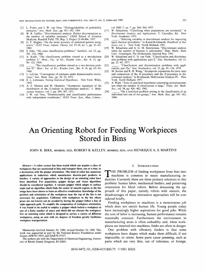
Fig. 1. Experimental orienting robot. A six-axis arm is holding conduitjunction box for viewing by workstation camera on right. The armcamera is on upper left. On lower left, from left to right, are bin,insertion tool, regrasping station, and chute for terminal goal site.
Initially the transportation problem was solved by man-ually placing a workpiece at its final destination, collectingdata on hand-workpiece relations at this site which avoidedcollisions, and then only acquiring workpieces with a hand-workpiece relation that would permit transportation [20].The problem with this solution is that it does not take longbefore the pieces at the top of the bin are facing the wrongway to permit transportation to a machine by a single arm.Therefore the emphasis was shifted from finding trans-portable pieces in the bin to designing a system architec-ture which made workpieces transportable for nearly allorientations in the bin. For this kind of architecture, aregrasping station, a reorienting station, an insertion tool,or another arm may be used. A regrasping station canaccept a piece from a robot arm and hold it while the armmoves to regrasp it with another pose. A reorienting sta-tion is like a regrasping station, but it also actively changesthe pose of a piece. Another arm can serve as a sophisti-cated reorienting station. An insertion tool may be used asa regrasping station but instead of the arm regrasping thepiece, the arm can hold the piece by holding the insertiontool. An insertion tool's geometry can assist in feedingpieces into narrow places.
III. ORIENTING ROBOT ARCHITECTURE
The system consisted of an arm, a vacuum gripper, avision subsystem, a minicomputer, a regrasping station, aninsertion tool, a bin of workpieces, and a terminal goal site.A view of the system is presented in Fig. 1.The robot arm had three linear displacement tables and
a cantilevered wrist with three intersecting rotary joints.This configuration resulted in a relatively simple calcula-tion to solve for the joint values of a computed hand pose.Axes had incremental motions to one thousandth of aninch and one thousandth of a revolution.The vacuum gripper had a number of features which
overcame several problems for an orienting robot. By
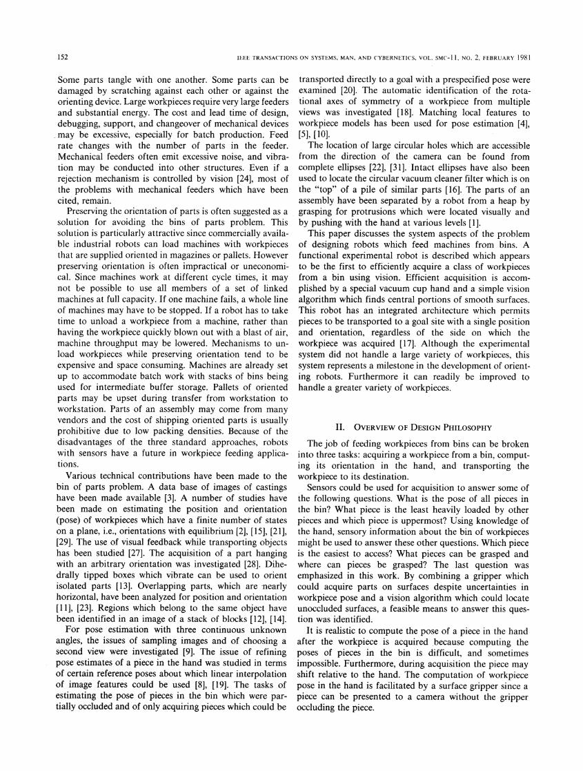
Fig. 2. Special vacuum gripper adapts to unknown surface angles to aidacquisition.
adapting to unknown surface angles, the difficult visualproblem of pose estimation in the bin was not necessary.By grasping a single surface, region analysis was obviatedand the sole requirement of vision was to locate a uniformregion. By having the unlocked cup approach the acquisi-tion surface along the line of sight, the problem of acollision between the hand and other pieces in the bin wasovercome. By sensing initial contact with a workpiece, adeep bin could be serviced. In this case collisions wereavoided by limiting additional downward motion into thebin to the amount required for surface adaption. By havingthe ability to lock the adapting cup, the workpiece could betransported while it was held rigidly. The locking featurealso made planar workpieces have one of a finite numberof stable states relative to the gripper, thus greatly simplify-ing the pose estimation problem. By holding a workpieceby a single surface, the problem of obscuring vision wasovercome. Various pieces could be acquired by usingvacuum cups with different sizes and shapes. Design detailsof the experimental surface adapting vacuum gripper havebeen documented elsewhere [6]. A view of this gripper isgiven in Fig. 2.The vision subsystem had two TV cameras and ap-
propriate lighting. One camera was mounted on the arm. Itwas used to view the bin. It was mounted on the arm toallow workpieces on the regrasping station, on the insertiontool, or in other parts of a large bin to be viewed if visualanalysis was required. However since this feature was not
153
IEEE TRANSACTIONS ON SYSTEMS, MAN, AND CYBERNETICS, VOL. SMC-I 1, NO. 2, FEBRUARY 1981
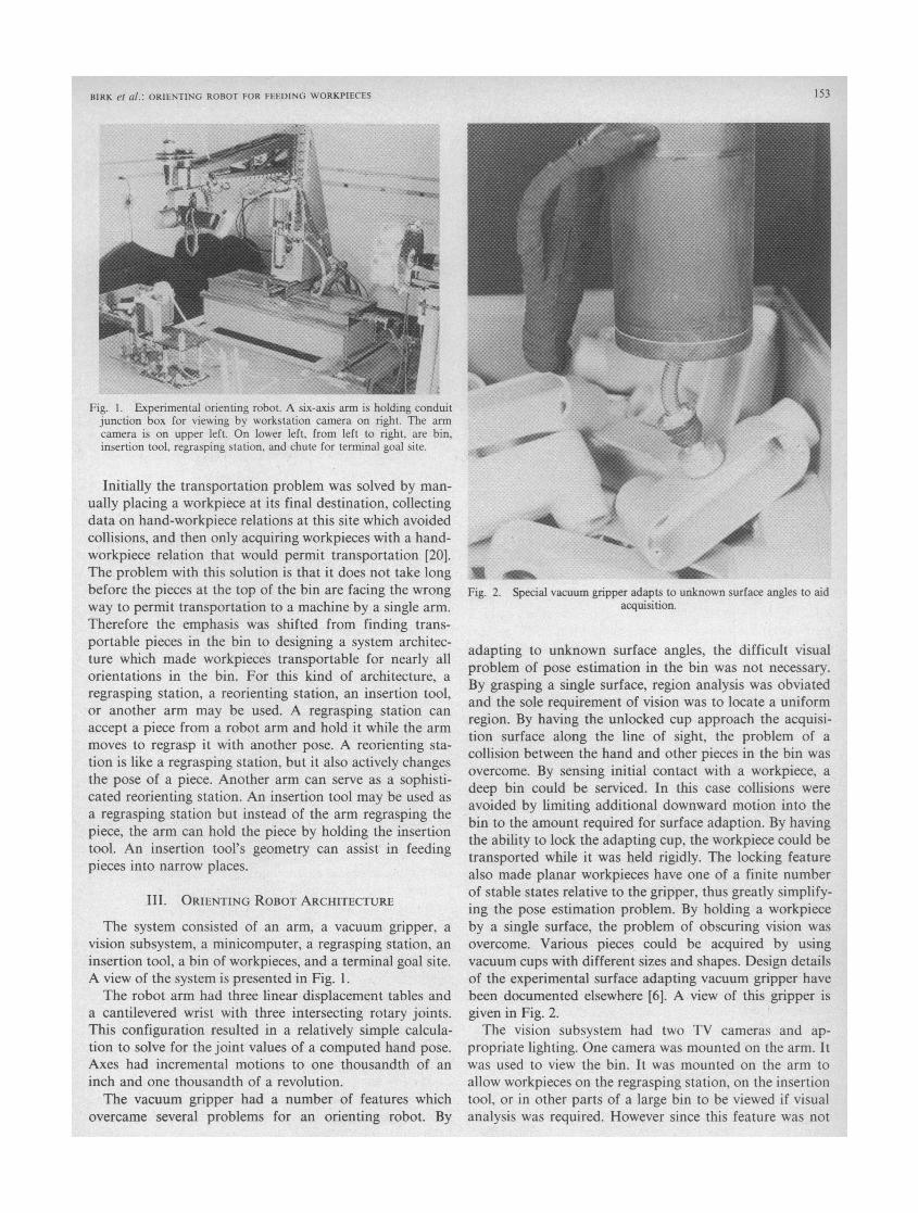
Fig. 3. Insertion tool, on left, holding conduit junction box, and re-grasping station, on lower right, which are used to transport piecesregardless of orientation with which they were acquired.
used, this camera could have been mounted separately, andseparate mounting would have eliminated the time neededfor the arm to move to the bin view pose. Reflected lightoff the ceiling was used to illuminate the bin. In this waycontrast was controlled so that workpiece surfaces whichwere nearly horizontal appeared brighter, yet other surfaceswere also visible. The other camera was mounted on theworkstation so that it could be used to estimate the pose ofpieces held in the hand. A ring of lights was placed aroundthe workstation camera to provide the symmetrical il-lumination which simplified the computation of workpieceorientation. By aligning the camera's axes with the arm'slinear axes, computations were further simplified.To achieve the objective of bringing a workpiece to the
terminal goal site while holding it in a predetermined way,
an insertion tool and a regrasping station were used. Theinsertion tool was designed to hold a workpiece with a
vacuum cup and to be picked up with the vacuum of thearm's gripper. The tool also had a breakaway system whichwould stop the arm if the tool collided into a workstationstructure. It had a slender structure to minirnize problemswith collisions during placement of the workpiece into a
machine. Whenever possible, after a piece was acquired, itwas handed off to the insertion tool. To permit this mo-
tion, the insertion tool was supported by a stand near thecenter of the arm's working volume. Sometimes a workpiecewas acquired with an orientation which did not permit it to
be transferred to the insertion tool with the proper orienta-tion. For this case, the piece was first transferred to theregrasping station, a rigidly mounted vacuum cup near thecenter of the arm's workspace. Then the arm would pick up
the insertion tool and use the tool to grab the piece fromthe regrasping station in a standard pose. The insertiontool and regrasping station with workpieces in their stan-dard poses are shown in Fig. 3.
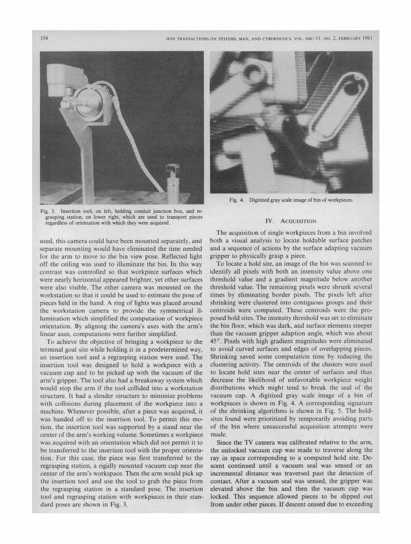
Fig. 4. Digitized gray scale image of bin of workpieces.
IV. AcQuISITION
The acquisition of single workpieces from a bin involvedboth a visual analysis to locate holdable surface patchesand a sequence of actions by the surface adapting vacuumgripper to physically grasp a piece.To locate a hold site, an image of the bin was scanned to
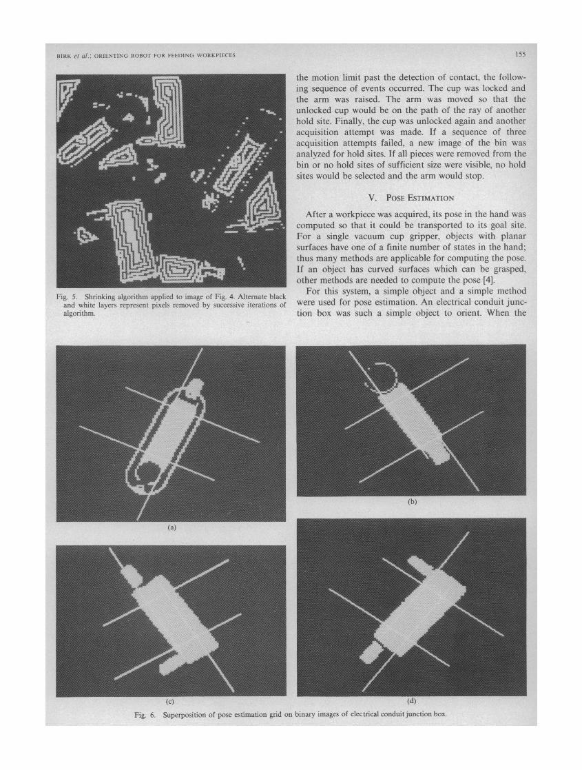
identify all pixels with both an intensity value above onethreshold value and a gradient magnitude below anotherthreshold value. The remaining pixels were shrunk severaltimes by eliminating border pixels. The pixels left aftershrinking were clustered into contiguous groups and theircentroids were computed. These centroids were the pro-posed hold sites. The intensity threshold was set to eliminatethe bin floor, which was dark, and surface elements steeperthan the vacuum gripper adaption angle, which was about450. Pixels with high gradient magnitudes were eliminatedto avoid curved surfaces and edges of overlapping pieces.Shrinking saved some computation time by reducing theclustering activity. The centroids of the clusters were usedto locate hold sites near the center of surfaces and thusdecrease the likelihood of unfavorable workpiece weightdistributions which might tend to break the seal of thevacuum cup. A digitized gray scale image of a bin ofworkpieces is shown in Fig. 4. A corresponding signatureof the shrinking algorithms is shown in Fig. 5. The hold-sites found were prioritized by temporarily avoiding partsof the bin where unsuccessful acquisition attempts weremade.
Since the TV camera was calibrated relative to the arm,the unlocked vacuum cup was made to traverse along theray in space corresponding to a computed hold site. De-scent continued until a vacuum seal was sensed or anincremental distance was traversed past the detection ofcontact. After a vacuum seal was sensed, the gripper waselevated above the bin and then the vacuum cup waslocked. This sequence allowed pieces to be slipped outfrom under other pieces. If descent ceased due to exceeding
154
BIRK et al.: ORIENTING ROBOr FOR FEEDING WORKPIECES
Fig. 5. Shrinking algorithm applied to image of Fig. 4. Alternate blackand white layers represent pixels removed by successive iterations ofalgorithm.
the motion limit past the detection of contact, the follow-ing sequence of events occurred. The cup was locked andthe arm was raised. The arm was moved so that theunlocked cup would be on the path of the ray of anotherhold site. Finally, the cup was unlocked again and anotheracquisition attempt was made. If a sequence of threeacquisition attempts failed, a new image of the bin wasanalyzed for hold sites. If all pieces were removed from thebin or no hold sites of sufficient size were visible, no holdsites would be selected and the arm would stop.
V. POSE ESTIMATION
After a workpiece was acquired, its pose in the hand wascomputed so that it could be transported to its goal site.For a single vacuum cup gripper, objects with planarsurfaces have one of a finite number of states in the hand;thus many methods are applicable for computing the pose.If an object has curved surfaces which can be grasped,other methods are needed to compute the pose [4].
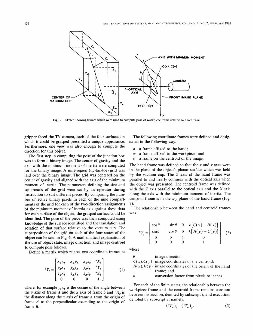
For this system, a simple object and a simple methodwere used for pose estimation. An electrical conduit junc-tion box was such a simple object to orient. When the
(b)
(a)
(C) kaJFig. 6. Superposition of pose estimation grid on binary images of electrical conduit junction box.
155
JElEl TRANSACTIONS ON SYSrEMS. MAN, AND CYBERNE'FCS, VOL. SMC-I 1, NO. 2, FEBRUARY 1981
AXIS WITH MIWUM MOMENT
CENTER OF \ -\FRONT IMAGE PLANEVACUUM CUP
\W H(x), H(y)
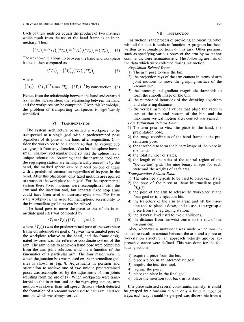
Fig. 7. Sketch showing frames which were used to compute pose of workpiece frame relative to hand frame.
gripper faced the TV camera, each of the four surfaces onwhich it could be grasped presented a unique appearance.Furthermore, one view was also enough to compute thedirection for this object.The first step in computing the pose of the junction box
was to form a binary image. The center of gravity and theaxis with the minimum moment of inertia were computedfor the binary image. A nine-region (tic-tac-toe) grid waslaid over the binary image. The grid was centered on thecenter of gravity and aligned with the axis of the minimummoment of inertia. The parameters defining the size andsquareness of the grid were set by an operator duringinstruction to suit different pieces. By comparing the num-ber of active binary pixels in each of the nine compart-ments of the grid for each of the two-direction assignmentsof the minimum moment of inertia axis against these datafor each surface of the object, the grasped surface could beidentified. The pose of the piece was then computed usingknowledge of the surface identified and the translation androtation of that surface relative to the vacuum cup. Thesuperposition of the grid on each of the four states of theobject can be seen in Fig. 6. A mathematical explanation ofthe use of object state, image direction, and image centroidto compute pose follows.
Define a matrix which relates two coordinate frames as
XaXb XaYb XaZb Xb
aT I YaXb YaYb YaZb Yb
Za)Ab ZaYb ZaZb zbO O 0 1
where, for example YaXb is the cosine of the angle betweenthe y axis of frame A and the x axis of frame b and bX isthe distance along the x axis of frame A from the origin offrame A to the perpendicular extending to the origin offrame B.
The following coordinate frames were defined and desig-nated in the following way.
h a frame affixed to the hand;w a frame affixed to the workpiece; andc a frame on the centroid of the image.
The hand frame was defined so that the x and y axes werein the plane of the object's planar surface which was heldby the vacuum cup. The- Z axis of the hand frame wasparallel to and nearly collinear with the optical axis whenthe object was presented. The centroid frame was definedwith the Z axis parallel to the optical axis and the X axisalong the axis with the minimum moment of inertia. Thecentroid frame is in the x-y plane of the hand frame (Fig.7).The relationship between the hand and centroid frames
was
cos6
hT - sinG
- w
where
6C(x), C(y)H(x),H(y)
k
sinG 0 k[C(x) -H(x)]cos6 0 k[H(y) -C(Y)]j (2)
0 1 0O 0 1
image directionimage coordinates of the centroid;image coordinates of the origin of the handframe; andconversion factor from pixels to inches.
For each of the finite states, the relationship between theworkpiece frame and the centroid frame remains constantbetween instruction, denoted by subscript i, and execution,denoted by subscript e, namely,
('T) (cTw)e. (3)
156
E
BIRK et al.: ORIENTING ROBOT FOR FEEDING WORKPIECES
Each of these matrices equals the product of two matriceswhich result from the use of the hand frame as an inter-mediary. Thus,
(CTw)= (CT)i(hT)=(CT)i(hT)= (cTw)e (4)The unknown relationship between the hand and workpieceframe is then computed as
(hTw)= (hTh)e(Th)I(hTw)i, (5)where
(hTc) = (CTh) since bT = (aTb) by construction. (6)Hence, from the relationship between the hand and centroidframes during execution, the relationship between the handand the workpiece can be computed. Given this knowledge,the problem of transporting workpieces is significantlysimplified.
VI. TRANSPORTATION
The system architecture permitted a workpiece to betransported to a single goal with a predetermined poseregardless of its pose in the hand after acquisition. Con-sider the workpiece to be a sphere so that the vacuum cupcan grasp it from any direction. Also let this sphere have asmall, shallow, rectangular hole so that the sphere has aunique orientation. Assuming that the insertion tool andthe regrasping station are hemispherically accessible by thehand, the marked sphere can be placed on one of thesewith a predefined orientation regardless of its pose in thehand. After this placement, only fixed motions are requiredto transport the workpiece to its goal. For the experimentalsystem these fixed motions were accomplished with thearm and the insertion tool, but separate fixed stop armscould have been used to decrease cycle time. For finitestate workpieces, the need for hemispheric accessibility tothe intermediate goal sites can be relaxed.The hand pose to move the piece to one of the inter-
mediate goal sites was computed by
0Th =Tw(i) Th, j=1,2
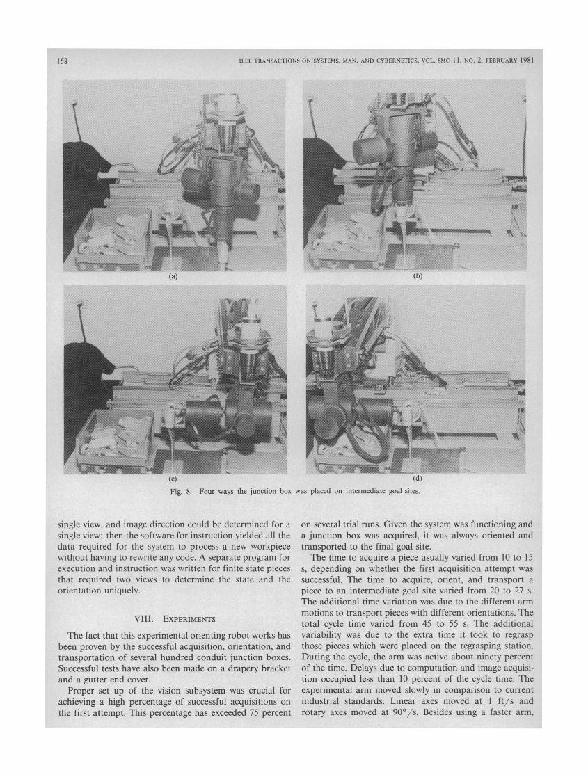
where, 0T,( j) was the predetermined pose of the workpieceframe on intermediate goalj, WTh was the estimated pose ofthe workpiece relative to the hand, and the frame desig-nated by zero was the reference coordinate system of thearm. The arm joints to achieve a hand pose were computedfrom the arm joint solution, which is a function of thekinematics of a particular arm. The four major ways inwhich the junction box was placed on the intermediate goalsites is shown in Fig. 8. Adjustments in position andorientation to achieve one of two unique predeterminedposes was accomplished by the adjustment of arm jointsresulting from the use of (7). When workpieces were trans-ferred to the insertion tool or the regrasping station, armmotion was slower than full speed. Sensors which detectedthe formation of a vacuum were used to halt arm interfacemotion, which was always vertical.
VII. INSTRUCTION
Instruction is the process of providing an orienting robotwith all the data it needs to function. A program has beenwritten to automate portions of this task. Other portions,such as specifying various poses of the arm by switchboxcommands, were semiautomatic. The following are lists ofthe data which were collected during instruction.
Acquisition Related Data:1) The arm pose to view the bin,2) the projection rays of the arm camera in terms of arm
joint motions to move the grasping surface of thevacuum cup,
3) the intensity and gradient magnitude thresholds toform the smooth image of the bin,
4) the number of iterations of the shrinking algorithmand clustering distance,
5) the vertical arm joint values that place the vacuumcup at the top and bottom of the bin, and themaximum vertical motion after contact was sensed.
Pose Estimation Related Data:1) The arm pose to view the piece in the hand, the
presentation pose,2) the image coordinates of the hand frame at the pre-
sentation pose,3) the threshold to form the binary image of the piece in
the hand,4) the total number of states,5) the length of the sides of the central region of the
"tic-tac-toe" grid. The nine binary images for eachstate and the weights of each area.
Transportation Related Data:1) The intermediate goals to be used to place each state,2) the pose of the piece at these intermediate goals
OTW( j)~3) the pose of the arm to release the workpiece at the
final goal or to a rejection bin,4) the trajectory of the arm to grasp and lift the inser-
tion tool to place it down, and to use it to regrasp apiece from the regrasping station;
5) the traverse level used to avoid collisions,6) the distance from the wrist center to the end of the
vacuum cup.Also, whenever a movement was made which was in-
tended to result in contact between the arm and a piece orworkstation structure, an approach velocity and/or ap-proach distance were defined. This was done for the fol-lowing actions:
1)2)3)4)5)6)
acquire a piece from the bin,place a piece in an intermediate goal,acquire the insertion tool,regrasp the piece,place the piece in the final goal,place the insertion tool back in its stand.
If a piece satisfied several constraints, namely: it couldbe grasped by a vacuum cup in only a finite number ofways, each way it could be grasped was discernible from a
157
IEEE TRANSACTIONS ON SYSTEMS, MAN, AND CYBERNETICS, VOL. SMC-I 1, NO. 2, FEBRUARY 1981
(b)'-I
Fig. 8. Four ways the junction box was placed on intermediate goal sites.
single view, and image direction could be determined for asingle view; then the software for instruction yielded all thedata required for the system to process a new workpiecewithout having to rewrite any code. A separate program forexecution and instruction was written for finite state piecesthat required two views to determine the state and theorientation uniquely.
VIII. EXPERIMENTS
The fact that this experimental orienting robot works hasbeen proven by the successful acquisition, orientation, andtransportation of several hundred conduit junction boxes.Successful tests have also been made on a drapery bracketand a gutter end cover.
Proper set up of the vision subsystem was crucial forachieving a high percentage of successful acquisitions onthe first attempt. This percentage has exceeded 75 percent
on several trial runs. Given the system was functioning anda junction box was acquired, it was always oriented andtransported to the final goal site.The time to acquire a piece usually varied from 10 to 15
s, depending on whether the first acquisition attempt wassuccessful. The time to acquire, orient, and transport apiece to an intermediate goal site varied from 20 to 27 s.The additional time variation was due to the different armmotions to transport pieces with different orientations. Thetotal cycle time varied from 45 to 55 s. The additionalvariability was due to the extra time it took to regraspthose pieces which were placed on the regrasping station.During the cycle, the arm was active about ninety percentof the time. Delays due to computation and image acquisi-tion occupied less than 10 percent of the cycle time. Theexperimental arm moved slowly in comparison to currentindustrial standards. Linear axes moved at I ft/s androtary axes moved at 90°/s. Besides using a faster arm,
158
BIRK et al.: ORIENTING ROBOT FOR FEEDING WORKPIECES
cycle time could have been decreased by changing thelocations of the cameras, by reducing the interface dis-tances over which the arm was moved slowly, and bymodifying trajectories.
Workpieces were placed on the intermediate goal siteswithin 1/8 in and within 3°. The primary cause for theseerrors was the inaccuracy of the arm. Some small angularand positioning errors were eliminated when the workpiecewas placed at the intermediate goal sites.
IX. CONCLUSION
Experimental proof exists of the feasibility of an orient-ing robot which can efficiently acquire a class of unori-ented workpieces using vision and which can transportthem with a single, predefined orientation to a machine.Heretofore, the best working example of such a system wasdeveloped by Hitachi [16]. However, their system wasspecially programmed to acquire the filter of a vacuumcleaner. The existence of orienting robots and the conceptswhich permit them to function provide a technologicalcontribution to increasing productivity in the industrieswhich manufacture discrete parts in batches.The acquisition algorithm for the system functioned
without program changes for many workpieces. Howeverthe size of the vacuum cups was changed for differentpieces and this required data modifications, an activitywhich was under program control. The system has func-tioned with pieces that can be grasped only on planarsurfaces and whose pose in the hand can be computed withone or two views. It is possible to use more general poseestimation techniques within the context of this system tomake the system applicable to more workpieces but thishas not been done yet. For those planar surface workpieceswhose pose could be estimated with one view using thenine-region method, no program changes were necessary.Workpiece specific data for this pose estimation methodcould be collected under program control.The main limitation of the system is the fact that many
workpieces cannot be grasped by a vacuum cup. Anotherlimitation is that the vision algorithm for acquisition doesnot work if printing covers the hold sites. Another problemis that there are numerous objects for which suitable meth-ods to estimate pose are not available. The main advantagesof the system are the simplicity of a reasonably generalacquisition process and the usefulness of the intermediategoal sites for transportation.Due to the intelligence of humans and their ability to
reorient objects in their hands, systems of the type de-scribed in this paper will usually have longer cycle timesthan human operators. It is estimated that the cycle timecould be reduced to about 10 s by using commerciallyavailable arms and by working on development issues.However humans can perform the task in approximately 2to 3 s. Thus it is appropriate to apply this type of orientingrobot in situations where this performance gap will notcause a net loss in productivity. For example, the cycletime for machining heavy pieces is usually long and a
159
somewhat longer loading time is not important. Orientingrobots can be made faster by using two or more arms or byusing hands which can reorient workpieces within them,but these approaches require substantial research.
Further work is needed to make orienting robots faster,less expensive, more reliable, easier to program, and morewidely applicable to all kinds of workpieces.
ACKNOWLEDGMENT
The orienting robot reported upon in this paper came toexist with the aid of Tom Brownell, Dana Duncan, Nai-Yung Chen, Jerry Crouch, Jim Hall, Richard Tella, TonyVinci, and Laurie Wilson.
REFERENCES
[I] A. Ambler, H. Barrow, C. Brown, R. Burstall, and R. Popplestone,"A versatile computer-controlled assembly system," in Third Intl.Joinlt Conf., Artificial Intelligence, Stanford, CA, Aug. 20-23, 1973,pp. 298- 303.
[21 M. Baird, "Image segmentation technique for locating automotiveparts on belt conveyors," in Fifth Intl. Joint Conf., Artificial Intelli-gence, Cambridge, MA, Aug. 22-25, 1977, pp. 694-695.
[3] M. Baird, "A computer vision data base for the industrial bin ofparts problem," General Motors Research Publications, GMR-2502,Aug. 1977.
[4] J. Birk, R. Kelley, T. Brownell, N. Chen, J. Crouch, D. Duncan,J. Hall, H. Martins, R. Mehta, R. Ray, R. Tella, S. Tsai, and A.Vinci, "General methods to enable robots with vision to acquire,orient, and transport workpieces," Fifth Report, University of RhodeIsland, Kingston, RI, Aug. 1979.
[5] J. Birk, R. Kelley, and N. Chen, "Visually estimating workpiecepose in a robot hand using the feature points method," in Proc. ofIEEE Conf., Decision, Control, San Diego, CA, Jan. 10-12, 1979.
[6] J. Birk, R. Kelley, L. Wilson, V. Badami, T. Brownell, N. Chem,D. Duncan, J. Hall, H. Martins, R. Silva, and R. Tella, "Generalmethods to enable robots with vision to acquire, orient and trans-port workpieces," Fourth Report, University of Rhode Island,Kingston, RI, July 1978.
[7] J. Birk, R. Kelley, and L. Wilson, "Acquiring workpieces: Threeapproaches using vision," in Proc. Eighth Intl. Symp., IndustrialRobots, Stuttgart, West Germany, May 30-June 1, 1978, pp. 724-733.
[81 J. Birk, R. Kelley, and V. Badami, "Workpiece orientation correc-tion with a robot arm using visual information," in Proc. Fifth Intl.Joint Conf., Artificial Intelligence, Cambridge, MA, Aug. 22-25,1977, p. 758.
[9] J. Birk, R. Kelley, V. Badami, R. Brand, N. Chen, R. Silva, andL. Wilson, "Orientation of workpieces by robots using the trianglemethod," in Proc. First No. Amer. Industrial Robots Conf. Expo.,Rosemont, IL, SME paper MR76-612, Oct. 1976.
[10] R. Bolles, "Robot feature matching through maximal cliques," inProc. SPIE, vol. 182, 1979, pp. 140- 149.
[11] J. Dessimoz, M. Kant, J. Zurcher, and G. Granlund, "Recognitionand handling of overlapping industrial parts," in Proc. Ninth Intl.Symp., Industrial Robots, Washington, DC, March 13-15, 1979, pp.357-366.
[12] G. Falk, "Interpretation of imperfect data as a three dimensionalscene," Artificial Intelligence, vol. 3, pp. 101- 144, 1972.
[131 D. Grossman and M. Blasgen, "Orienting mechanical parts bycomputer-controlled manipulator," IEEE Trans. Syst., Man,Cybern., vol. 5, pp. 561-565, Sept. 1975.
[14] A. Guzman, "Decomposition of a visual scene into three dimen-sional bodies," in Proc. AFIPS Fall Joint Comput. Conf., vol. 33,Dec. 1968, pp. 291-304.
[15] W. Heginbotham, "The Nottingham 'SIRCH' assembly robot," inProc., First Conf. Industrial Robot Technology, Nottingham, U.K.,March 27-29, 1973, pp. 129-142.
[16] S. Kashioka, S. Takeda, Y. Shima, T. Uno, and T. Mamoda, "An
IEEE TRANSACTIONS ON SYSTEMS, MAN, AND CYBERNETICS, VOL. SMC-l 1, NO. 2, FEBRUARY 1981
approach to the integrated intelligent robot with multiple sensoryfeedback: Visual recognition techniques," in Proc., 7th Intl. Symp.,Industrial Robots, Tokyo, Japan, Oct. 19-21, 1977, pp. 531-538.
[17] R. Kelley, J. Birk, D. Duncan, H. Martins, and R. Tella, "A robotsystem which feeds workpieces from bins into machines," in Proc.9th Intl. Symp., Industrial Robots, Washington, DC, March 13-15,1979, pp. 339-355.
[18] R. Kelley, J. Birk, and R. Silva, "Identification of object symmetryfrom multiple views," Proc., IEEE Computer Society Conf., PatternRecognition, Image Processing, Chicago, IL, May 31-June 2, 1978,pp. 327-330.
[19] R. Kelley, J. Birk, and V. Badami, "Workpiece transportation byrobots using vision," in Second No. American Industrial Robot Conf.Detroit, MI, Oct. 31-Nov. 3, 1977, SME Paper MS77-746. Re-printed in 1978 Manufacturing Engineering Transactions, SME,Dearborn, MI.
[20] R. Kelley, J. Birk, and L. Wilson, "Algorithms to visually acquireworkpieces," in Proc. Seventh Intl. Symp. Industrial Robots, Tokyo,Japan, Oct. 19-21, 1977, pp. 497-506.
[21] P. Martini and G. Nehr, "Recognition of angular orientation ofobjects with the help of optical sensors," Industrial Robot, vol. 6, pp.62-69, June 1979.
[22] Y. Nakagawa and A. Rosenfeld, "A note on polygonal and ellipticalapproximation of mechanical parts," Pattern Recognition, vol. 11,pp. 133-142, 1979.
[23] W. Perkins, "A model-based vision system for industrial parts,"IEEE Trans. Comput., vol. C-27, pp. 126-143, Feb. 1978.
[24] A. Pugh, K. Waddon, and W. Heginbotham, "Orientation andinspection of component parts," SPIE vol. 145, Industrial Applica-tions Solid-State Image Scanners, London, UK, pp. 66-76, March,1978.
[25] C. Rosen, N. Nitzan, G. Agin, G. Andeen, J. Berger, R. Blean, G.Gleason, J. Hill, W. Park, and R. Paul, "Machine intelligenceresearch applied to industrial automation," Sixth Report, StanfordResearch Institute, Menlo Park, CA, Nov. 1976.
[261 C. Rosen, D. Nitzan, G. Agin, R. Blean, R. Duda, G. Gleason, J.Kramers, W. Park, R. Paul, and A. Sword, "Exploratory research inadvanced automation," Fourth Report, Stanford Research Institute,Menlo Park, CA, June 1975.
[27] Y. Shirai and H. Inoue, "Guiding a robot by visual feedback inassembling tasks," Pattern Recognition, vol. 5, pp. 99-108, June1973.
[28] Y. Tsuboi and T. Inoue, "Robot assembly system using TV camera,"in Sixth Intl. Symp., Industrial Robots, Nottingham, UK, March24-26, 1976, pp. BB:21-32.
[29] Y. Tsuboi, T. Shiraishi, and N. Kosaka, "Positioning and shapedetection algorithms for an industrial robot," Systems, Computers,Cotntrols, vol. 4, pp. 8-16, 1973.
[30] S. Tsuji and F. Matsumoto, "Detection of ellipses by a modifiedHough transformation," IEEE Trans. Comput., vol. 27, pp. 777- 781,Aug. 1978.
[31] S. Tsuji and A. Nakamura, "Recognition of an object in a stack ofindustrial parts," in Fourth Intl. Joint Conf. on Artificial Intelligence,Tbilisi, U.S.S.R., Sept. 3-8, 1975, pp. 811-818.
Correspondence
A Model for Computing the Size of a Therapy GroupA. L. SWEET
Abstract-The U.S. Air Force, in the process of planning for theimplementation of a Health Maintenance Program for CardiovascularDisease, developed a concept of placing personnel in a therapy group,where they would be subjected to special medical treatment. Entry into thetherapy group is determined by an individual's risk, computed using theDuncan-Walker logistic model. The size of the therapy group is governedby policies relating to entry and length of stay. A queueing model ispresented by means of which the expected size of the therapy group can becomputed. Computation is accomplished by a combination of direct meth-ods and simulation, and the effect of policies on the size of the therapygroup can be studied.
I. INTRODUCTIONThe U.S. Air Force School of Aerospace Medicine, in the
process of initiating a service-wide Health Maintenance Programfor Cardiovascular Disease [1], chose to place personnel in "ther-apy groups," where they would be subjected to special treatmentin order to reduce the possibility of their having cardiovasculardisease in the future. It was suggested that entry into the therapygroup be based on the use of the Duncan-Walker logistic model[2], which allows computation of an individual's "risk" as afunction of various "risk factors." Those individuals above athreshold value of risk would be asked to enter the therapy group.After a random length of time, the individual could leave the
Manuscript received August 1, 1980; revised October 30, 1980. This workwas partially supported by the U.S. Air Force School of Aerospace Medicineunder Contracts F75CO082 and F77C336 15.The author is with the School of Industrial Engineering, Grissom Hall,
Purdue University, West Lafayette, IN 47907.
therapy group but would be allowed to reenter at a later time. Inaddition to these possible reentries, new personnel are constantlyentering the Air Force at various ages, some of which will beeligible for the therapy group. Personnel remain in the Air Forcefor a tour of duty of random length.The Air Force planned to begin the Health Maintenance
Program with pilot programs at a small number of bases duringwhich time data could be collected before implementing theprogram service-wide. As funds were available for treating only aportion of all Air Force personnel each year, it was necessary toestimate the size of the therapy group before beginning theprogram. The size of the therapy group could be controlled bythe values used for the risk threshold and also by the regulationsgoverning the ability of individuals to leave and reenter thetherapy group.
In order to enhance the usefulness of the data collected duringthe duration of the pilot program, it was desirable to find areasonable set of risk thresholds and regulations before startingthe program. To this end mathematical models for the size andcost of the therapy program were constructed [3], [4], and thepurpose of this paper is to present one of these models. One ofthe uses of these models was to perform sensitivity analyses ofthe effects of changes in the control variables on the size andcomposition of the therapy group.The model presented below is an infinite server queuing model
with complicated rules governing service times. The solution forthe expected size of the therapy group is obtained by a combina-tion of analysis and simulation. The simulation aspects are suchthat means had to be devised to sample only those individuals inthe Air Force population who would be in the therapy group inorder to keep the cost of the simulation runs reasonable. Finallyit is noted that the availability of certain data a priori and thepossibility of obtaining some needed data during the pilot pro-
0018-9472/81/0200-0160$00.75 ( 1981 IEEE
160


