Embed Size (px)
Citation preview

loournal of Structural Geology, Vol. 17, No. 9, pi. 1337 to 1346,1!XJ5 Copyright @ 1995 Elsevier Science Ltd
Printed in Great Britain. All rights reserved 0191-8141/95 s9.5o+o.oo
0191-8141(95)ooo12-7
Analogue models of laccolith formation
TERESA ROMAN-BERDIEL,* D. GAPAIS and J. P. BRUN
Geosciences Rennes (UPR 4661, CNRS), Universite de Rennes 1,35042 Rennes Cedex, France
(Received 13 May 1994; accepted in revised form 10 January 1995)
Abstract-This paper describes dynamically scaled analogue models of laccolithic intrusions. Experiments consisted of the injection of a Newtonian fluid (low-viscosity silicone putty) into a sandpack, with or without an interbedded ductile layer of silicone putty acting as a potential decollement level. Boundary conditions were chosen to analyze the influence of the thickness of the brittle cover and of the decollement layer on the pattern of intrusion. Further experiments were made to examine the effects of an extensional regime during intrusion. Experiments showed that: (1) laccolith formation requires the occurrence of a decollement layer between two competent units, (2) the critical thickness of the dtcollement layer necessary for laccolith formation decreases with increasing depth, (3) laccoliths change from lenses to bell-shaped with decreasing overburden, (4) for a constant thickness of the dtcollement layer, the largest diameter of laccoliths is proportional to the thickness of the overburden. and (5) a svn-iniection gravitational sliding regime results in an asymmetric laccohth, with amplification of the beh shape. . -
INTRODUCTION
Laccoliths are concordant, often lens-shaped, magmatic intrusions (Fig. 1). They are common features in various tectonic environments. Thus, Corry (1988) compiled a list of about 900 laccoliths, most of them in North America. In the Himalayas, the Manaslu pluton (Le Fort ef al. 1987, Guillot et al. 1993) and the Gandotri- Badrinath Massif (Scaillet 1990) also provide remark- able examples of laccolithic intrusions.
The laccolith concept was first defined by Gilbert (1877). He visualized magma rising up a pipe and spreading a lens along a subhorizontal disconformity and lifting a domed roof of overburden. Early works examined conditions for laccolith formation in terms of dynamic properties of the ascending magma (Paige 1913, Darton & Paige 1925, Barksdale 1937, Hurlburt & Griggs 1939). Subsequent studies have emphasized the roles of the overburden and of the physical properties of the country-rocks (Mudge 1968, Johnson 1970, Johnson & Pollard 1973, Pollard 1973, Pollard & Johnson 1973, Pollard et al. 1975, Pollard & Holzhausen 1979, Koch et al. 1981). In particular, Pollard & Johnson (1973) fo- cused on the stress distribution in the cover, and argued that the shape of a laccolith can be modelled by elastic bending of the overburden in response to the upward driving force of the magma.
Several experimental models of laccoliths have been made since the beginning of the century (Howe 1901, McCarthy 1925, Hurlburt & Griggs 1939, Pollard & Johnson 1973, Dixon & Simpson 1987, Merle & Vende- ville 1992). One geometrical characteristic of laccoliths is a rather flat and concordant basal surface (Fig. 1). This suggests that they are emplaced along discontinuities just above a relatively resistant crustal layer through
*Also at: Dpto. de Geologfa, Facuhad de Ciencias, 50009 Zaragoza, Spain.
(W
,,,,,,,,,1,1,,, ..\.
‘,‘,‘,‘,‘,‘,‘,‘,‘,‘,‘,‘,‘,‘,‘,’ ‘\‘\‘\‘\‘\‘\‘\‘\‘\‘\‘.‘\‘\‘.‘.’ . . \,\,. . . . \ . . ,. . .
~11,~1~~~1~~,,,
w .,.,. \ ,.,\,\.., ,,,,\ \,\, \,\
Fig. 1. Diagrammatic cross-sections illustrating some common shapes and emplacement sites of natural laccoliths (typically of some km in horizontal length), as reported in the literature. Laccoliths shown in black. (a) Flat laccohth emplaced above the basement (hached)-cover interface (e.g. Niger-Hill Laccolith, Darton 1909). (b) Bell-shaped laccolith within sedimentary cover (e.g. Alpine Laccolith, Weed & Pirsson 1895). (c) Laccolith emplaced within weak sediments, at the base of a competent layer (e.g. Ragged Top Laccolith, Irving 1899), (d) Asymmetric laccolith developed adjacent to a normal fault (e.g.
Barker Laccohth, Witkind 1973).
which the magma rises (Gilbert 1877). Natural laccoliths are generally emplaced at shallow depths, typically a few kilometers (Barksdale 1937, Mudge 1968, Johnson & Pollard 1973), and thus largely above the crustal brittle- ductile transition. Dixon & Simpson (1987) made scaled
1337
1338 T. ROMAN-BERDIEL. D. GAPAIS and J. P. BRUN
7.7 cm 8-10.5 cm
5.5 cm O-l cm
38 cm/h 38CfYl/h high viscosity 30-41 cm/h silicone putty (c)
O”- 3” [
sand - medium viscosity
i low viTity silicone putty .t t:y puW
10 cm
(d) II
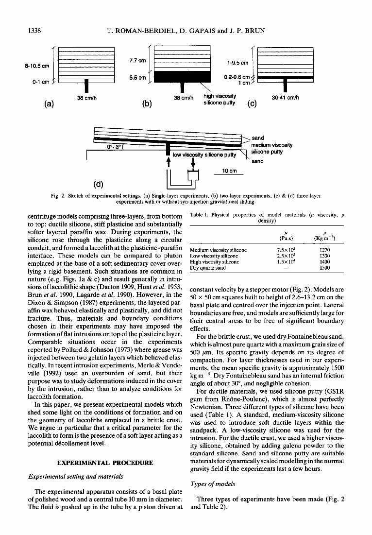
Fig. 2. Sketch of experimental settings. (a) Single-layer experiments, (b) two-layer experiments, (c) & (d) three-layer experiments with or without syn-injection gravitational sliding.
centrifuge models comprising three-layers, from bottom to top: ductile silicone, stiff plasticine and substantially softer layered paraffin wax. During experiments, the silicone rose through the plasticine along a circular conduit, and formed a laccolith at the plasticine-paraffin interface. These models can be compared to pluton emplaced at the base of a soft sedimentary cover over- lying a rigid basement. Such situations are common in nature (e.g. Figs. la & c) and result generally in intru- sions of laccolithic shape (Darton 1909, Hunt et al. 1953, Brun et al. 1990, Lagarde et al. 1990). However, in the Dixon & Simpson (1987) experiments, the layered par- affin wax behaved elastically and plastically, and did not fracture. Thus, materials and boundary conditions chosen in their experiments may have imposed the formation of flat intrusions on top of the plasticine layer. Comparable situations occur in the experiments reported by Pollard & Johnson (1973) where grease was injected between two gelatin layers which behaved elas- tically. In recent intrusion experiments, Merle & Vende- ville (1992) used an overburden of sand, but their purpose was to study deformations induced in the cover by the intrusion, rather than to analyze conditions for laccolith formation.
In this paper, we present experimental models which shed some light on the conditions of formation and on the geometry of laccoliths emplaced in a brittle crust. We argue in particular that a critical parameter for the laccolith to form is the presence of a soft layer acting as a potential decollement level.
EXPERIMENTAL PROCEDURE
Experimental setting and materials
The experimental apparatus consists of a basal plate of polished wood and a central tube 10 mm in diameter. The fluid is pushed up in the tube by a piston driven at
Table 1. Physical properties of model materials ($ viscosity, p density)
(PES, P
(Kg mm3)
Medium viscosity silicone Low viscosity silicone High viscosity silicone Dry quartz sand
7.5Xld 1270 2.5~1~ 1330 15x104 1400
- 1500
constant velocity by a stepper motor (Fig. 2). Models are 50 x 50 cm squares built to height of 2.6-13.2 cm on the basal plate and centred over the injection point. Lateral boundaries are free, and models are sufficiently large for their central areas to be free of significant boundary effects.
For the brittle crust, we used dry Fontainebleau sand, which is almost pure quartz with a maximum grain size of 500 ,um. Its specific gravity depends on its degree of compaction. For layer thicknesses used in our experi- ments, the mean specific gravity is approximately 1500 kg rne3. Dry Fontainebleau sand has an internal friction angle of about 30”, and negligible cohesion.
For ductile materials, we used silicone putty (GSlR gum from Rhone-Poulenc), which is almost perfectly Newtonian. Three different types of silicone have been used (Table 1). A standard, medium-viscosity silicone was used to introduce soft ductile layers within the sandpack. A low-viscosity silicone was used for the intrusion. For the ductile crust, we used a higher viscos- ity silicone, obtained by adding galena powder to the standard silicone. Sand and silicone putty are suitable materials for dynamically scaled modelling in the normal gravity field if the experiments last a few hours.
Types of models
Three types of experiments have been made (Fig. 2 and Table 2).

Analogue models of laccolith formation 1339
Table 2. Model characteristics and experimental conditions
Series
Single layer
Two layer Three layer-l
Three layer-II
Three layer-III
Thickness Thickness of sand
of high layer Thickness Thickness viscosity below of of sand Dip Injection Experimental silicone injection decollement overburden angle velocity temperature
Model layer (cm) point (cm) level (cm) (cm) (“) (“C) (cm h-i)
1 - 1 - 8 0 30 38 2 - - - 10.5 0 30 38 1 5.5 - 1.7 0 30 38 1 - 1 0.2 9.5 0 28 34.5 2 - 1 0.2 8 0 28 37.5 3 - 1 0.2 6 0 31 41.5 4 - 1 0.2 5 0 30 39.2 5 - 1 0.2 4 0 31 37.5
1 - 1 0.6 5.6 0 29 34 2 - 1 0.6 4.3 0 29 30 3 - 1 0.6 3 0 29 32.5 4 - 1 0.6 2 0 29 33.5 5 - 1 0.6 1 0 30 33.2
1 - 1 0.6 4 3 30 31.2 2 - 1 0.6 3 3 30 31.2 3 - 1 0.6 2 3 30 31.2 4 - 1 0.6 1 3 30 31.2
Single layer sand models were made to observe the geometry of magma intrusion in a homogeneous brittle crust. In these experiments, the injection was made either 1 cm above the base of the sandpack (Fig. 2a), or to the base of the sandpack. These latter experiments were made to check a possible influence of the basal discontinuity defined by the sand-wood interface on the geometry of intrusions.
In a second set of experiments, we used two-layer models made of a basal layer of high viscosity silicone putty overlain by a sandpack. In these models, the low- viscosity silicone putty was injected at the sand-silicone interface in order to examine intrusion kinematics at the crustal brittle-ductile transition (Fig. 2b).
The third set of experiments used three-layer models made of a sandpack containing a medium-viscosity layer of silicone putty. The purpose of these experiments was to study the effect of a soft layer acting as a potential dtcollement level within the cover above the brittle- ductile transition. The low viscosity intrusion was injected to the base of the soft layer (Fig. 2~). Two series of static three-layer experiments were made, with soft layers of 2 mm and 6 mm, respectively. In each series, several experiments with different thicknesses of sand overburden were made. In a third series of experiments, models were tilted a few degrees in order to examine the effects of syn-injection deformation by gravitational sliding (Fig. 2d).
In all models, the sandpack contained horizontal passive markers made of coloured sand, and the silicone layer contained vertical passive markers (Fig. 3). These were obtained by building the layer with vertical bands containing a slight amount of blue methylene powder mixed with the silicone, alternating with bands of methylene-free silicone. At the end of each experiment, these markers allowed us to observe the deformation on cross-sections made in the central part of the model. A
grid of square passive sand markers drawn on the upper surface of the models allowed examination of surface deformation during experiments (see Fig. 3~).
Scaling
Models have been dynamically scaled following prin- ciples discussed by Hubbert (1937) and Ramberg (1981). We chose a length ratio of 105, so that 1 cm in the models is equivalent to 1 km in nature. Gravity field, densities and viscosities are imposed in the models by the experi- mental conditions and materials used (see Table 1). Remaining dimensions (experiment duration, stress, and strain rate) are imposed by the scaling.
One series of three-layer experiments (series II) allowed a rough estimate of stress magnitudes on the top surface of the intrusion. In these models, with constant thickness of the soft layer and similar injection velocities (Table 2), the minimum thickness of sand overburden that resulted in failure above the intrusion was found to be of the order of 3 cm (see incipient faulting in model II- 3, Figs. 3c and 4~). For overburden thicknesses less than 3 cm, the injected silicone always reached the surface of the model (Figs. 4a & b). The stress field above the intrusion is generally complex, as revealed by changes in dips of individual faults with depth (see Fig. 4~). How- ever, overall fault dips do not differ significantly from values around 60”. We therefore considered that stress conditions for normal faulting provided sufficiently satisfactory minimum estimates for scaling purpose in dry sand.
A lithostatic pressure corresponding to a 3 cm thick sand overburden, with an internal friction coefficient of 0.6 and a specific gravity of 1500 kg rnw3, yields a differential stress for normal faulting of the order of 300 Pa. According to the chosen length ratio (Table 2), a 3 cm thick overburden scales to 3 km in nature. For a
1340 T. ROMAN-BERDIEL, D. GAPAIS and J. P. BRUN
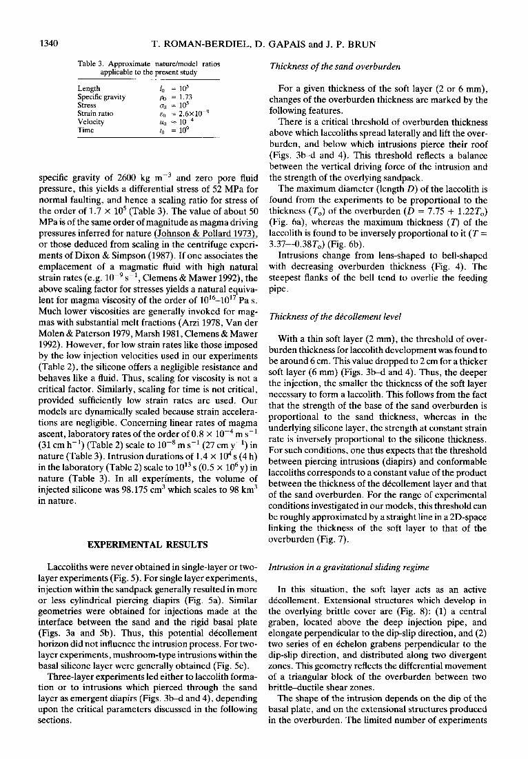
Table 3. Approximate nature/model ratios applicable to the present study
Length Specific gravity Stress Strain ratio Velocity Time
I,, = 10s po = 1.73 ff(J = 16 E,, = 2.6~10-~ lkJ = 10-4 fCJ = 109
specific gravity of 2600 kg me3 and zero pore fluid pressure, this yields a differential stress of 52 MPa for normal faulting, and hence a scaling ratio for stress of the order of 1.7 x lo5 (Table 3). The value of about 50 MPa is of the same order of magnitude as magma driving pressures inferred for nature (Johnson & Pollard 1973), or those deduced from scaling in the centrifuge experi- ments of Dixon & Simpson (1987). If one associates the emplacement of a magmatic fluid with high natural strain rates (e.g. lop9 s-l, Clemens & Mawer 1992), the above scaling factor for stresses yields a natural equiva- lent for magma viscosity of the order of 10’6-1017 Pa s. Much lower viscosities are generally invoked for mag- mas with substantial melt fractions (Arzi 1978, Van der Molen & Paterson 1979, Marsh 1981, Clemens & Mawer 1992). However, for low strain rates like those imposed by the low injection velocities used in our experiments (Table 2), the silicone offers a negligible resistance and behaves like a fluid. Thus, scaling for viscosity is not a critical factor. Similarly, scaling for time is not critical, provided sufficiently low strain rates are used. Our models are dynamically scaled because strain accelera- tions are negligible. Concerning linear rates of magma ascent, laboratory rates of the order of 0.8 x lop4 m s-l (31 cm h-i) (Table 2) scale to lo-’ m s-l (27 cm y-l) in nature (Table 3). Intrusion durations of 1.4 x lo4 s (4 h) in the laboratory (Table 2) scale to 1013 s (0.5 x lo6 y) in nature (Table 3). In all experiments, the volume of injected silicone was 98.175 cm3 which scales to 98 km3 in nature.
EXPERIMENTAL RESULTS
Laccoliths were never obtained in single-layer or two- layer experiments (Fig. 5). For single layer experiments, injection within the sandpack generally resulted in more or less cylindrical piercing diapirs (Fig. 5a). Similar geometries were obtained for injections made at the interface between the sand and the rigid basal plate (Figs. 3a and 5b). Thus, this potential decollement horizon did not influence the intrusion process. For two- layer experiments, mushroom-type intrusions within the basal silicone layer were generally obtained (Fig. 5~).
Three-layer experiments led either to laccolith forma- tion or to intrusions which pierced through the sand layer as emergent diapirs (Figs. 3b-d and 4), depending upon the critical parameters discussed in the following sections.
Thickness of the sand overburden
For a given thickness of the soft layer (2 or 6 mm), changes of the overburden thickness are marked by the following features.
There is a critical threshold of overburden thickness above which laccoliths spread laterally and lift the over- burden, and below which intrusions pierce their roof (Figs. 3b-d and 4). This threshold reflects a balance between the vertical driving force of the intrusion and the strength of the overlying sandpack.
The maximum diameter (length D) of the laccolith is found from the experiments to be proportional to the thickness (TO) of the overburden (D = 7.75 + 1.22T,,) (Fig. 6a), whereas the maximum thickness (7’) of the laccolith is found to be inversely proportional to it (T = 3.37--0.38T,) (Fig. 6b).
Intrusions change from lens-shaped to bell-shaped with decreasing overburden thickness (Fig. 4). The steepest flanks of the bell tend to overlie the feeding pipe.
Thickness of the d&ollement level
With a thin soft layer (2 mm), the threshold of over- burden thickness for laccolith development was found to be around 6 cm. This value dropped to 2 cm for a thicker soft layer (6 mm) (Figs. 3b-d and 4). Thus, the deeper the injection, the smaller the thickness of the soft layer necessary to form a laccolith. This follows from the fact that the strength of the base of the sand overburden is proportional to the sand thickness, whereas in the underlying silicone layer, the strength at constant strain rate is inversely proportional to the silicone thickness. For such conditions, one thus expects that the threshold between piercing intrusions (diapirs) and conformable laccoliths corresponds to a constant value of the product between the thickness of the decollement layer and that of the sand overburden. For the range of experimental conditions investigated in our models, this threshold can be roughly approximated by a straight line in a 2D-space linking the thickness of the soft layer to that of the overburden (Fig. 7).
Intrusion in a gravitational sliding regime
In this situation, the soft layer acts as an active decollement . Extensional structures which develop in the overlying brittle cover are (Fig. 8): (1) a central graben, located above the deep injection pipe, and elongate perpendicular to the dip-slip direction, and (2) two series of en echelon grabens perpendicular to the dip-slip direction, and distributed along two divergent zones. This geometry reflects the differential movement of a triangular block of the overburden between two brittleductile shear zones.
The shape of the intrusion depends on the dip of the basal plate, and on the extensional structures produced in the overburden. The limited number of experiments

Analogue models of laccolith formation
Fig. 3. Laser-prints of photographs of final stages of representative static experiments. (a) Central cross-section within single sand layer (model-2) where injection was made at the base of a 10.5 cm sandpack. (b) Central cross-section within three-layer model I-1 with 9.5 cm sand overburden. (c) Surface-view and central cross-section of three-layer model II-3 with
3 cm sand overburden. (d) Central cross-section within three-layer model I-5 with 4 cm sand overburden.
1341

T. ROMAN-BERDIEL, D. GAPAIS and J. P. BRUN
( a
Fig. 8. Laser-prints of photographs of final stages of three-layer experiments with syn-injection gravitational sliding. (a) Surface-view of model 111-4; arrow points towards the slip direction. (b) Central cross-section within model 111-l.
1342

Analogue models of laccolith formation 1343
(a)
(W
(c)
(a
(e)
Model H-5 1
1 Model II-4 1
1 Model II-2 1
1 Model II-1 1
u m ? sand medium injected
viscosity low viscosity silicone putty silicone putty
5cm
1 cm
I 2cm
3cm
4.3 cm
5.6 cm
Fig. 4. Central cross-sections of final stages of five different three-layer experiments with same thickness of d&ollement layer (6 mm) and increasing thickness (l-5.6 cm) of sand overburden (Series-II, Table 2).
did not allow detailed analysis of these effects. How- of the feeding conduit, as a result of bulk dip-slip motion ever, intrusions produced in gravitational sliding regime of the sandpack, (2) a tendency for the frontal boundary always showed rather flat roofs (Fig. 8b), in contrast to of the intrusion to dip more steeply than the rear static experiments (Figs. 3 and 4). In addition, a major boundary, and (3) a tendency for strongly asymmetric and systematic geometrical feature observed in all our spreading of the intrusion along the decollement. This extensional experiments is a strong asymmetry of the asymmetric spreading is expressed by the development intrusion. This asymmetry is always marked by (Fig. of a sheared basal tongue trailing behind the intrusion, Sb): (1) a substantial offset of the intrusion down-slope linking it to its feeder. 16 17:9-1

1344 T. ROMAN-BERDIEL, D. GAPAIS and J. P. BRUN
cm
cm
Model Single layer-l
10.5 cm
(b) Model Single layer-2
/
7.7 cm
5.5 cm
(cl Model Two layer-l 0 5cm 0 I
hF m Injected viscosity low viscosity silicone putty silicone putty
Fig. 5. Examples of central cross-sections of final stages of three different single-layer (a) & (b) and two-layer (c) experiments. (a) Injection 1 cm above the base of the sandpack. (b) Injection at the
sand-wood interface. (c) Injection at the sand-silicone interface.
COMPARISON WITH NATURE
Intrusion shapes
Our experimental conditions grossly oversimplify nature and limit comparisons between models and natu- ral laccoliths. In particular, we have not varied injection conditions, especially the size of the feeding pipe or the volume of the intrusion. Nor have we modelled changes of viscosity and strength which accompany syn- emplacement cooling of natural intrusions.
However, our model laccoliths have shapes similar to natural laccoliths (Gilbert 1877, Johnson & Pollard 1973) (Fig. 1). Bell-shaped intrusions produced in static experiments tend to be centred over the feeding pipe, a feature also assumed for natural laccoliths (Talbot 1993) (Fig. 1). The diameter of natural laccoliths tends to increase with increasing depth (e.g. Gilbert 1877, Hunt et al. 1953). Theoretical models further predict linear relationships between maximum length of laccolith and depth of emplacement (Gilbert 1877, Johnson 1970), a feature also clearly shown by our experiments (Fig. 6a).
(4
(b)
1 2 3 4 i
Thickness of brittle overburden (cm)
0
2.2 -
T = 3.37 - 0.38To R = 0.97 2 -
1.8 -
1.6 -
1.2 I 1 I I I I 2.5 3 3.5 4 4.5 5 5.5
, Thickness of brittle overburden (cm)
Fig. 6. Diameter (a) and thickness (b) of laccolith vs thickness of sand overburden for series-II experiments (shown in Fig. 4). Intrusion thicknesses are reported for non-piercing intrusions only (models II-l,
2,3, Fig. 4).
- n n \O 0 a \ \ conformable
\ laccolithic
- disconformable ’ intrusions
piercing ‘, - intrusions
\
n n ‘O a 0
0 2 4 6 8 10
Thickness of brittle overburden (cm)
Fig. 7. Fields of conformable laccoliths and of piercing intrusions according to thicknesses of soft layer and sand overburden (experi-
ment series I and II).
The diameter/thickness ratios of our model laccoliths range between about 0.1 to 0.3, values which are of the same order of magnitude as the mean aspect ratio of 0.14 reported by Gilbert (1877) for the Henry Mountains laccoliths. More detailed comparisons between the dimensions of model and natural laccoliths cannot be made because the volume of injected silicone was kept constant in all experiments. Nevertheless, our results emphasize that shapes of laccoliths can be diagnostic of their emplacement depths.

Analogue models of laccolith formation 1345
WNW
a Tethyan Sediments m Manaslu laccolith
Higher Himalaya Crystalline
Fig. 9. Schematic block diagram showing location and shape of the Manaslu granite in Central Himalaya (modified after Le Fort el al. 1987).
Laccoliths and crustal layering
In many natural situations, laccoliths appear to have spread along well expressed discontinuities, such as the basement-cover interface (Fig. la), sharp bedding sur- faces between strongly contrasted lithologies (Fig. lb), within incompetent strata like shales or clays (Hunt et al. 1953) (Fig. lc), or beneath strata which can form a barrier limiting the upward migration of the magma (Fig. lc) (see Hunt et al. 1953, Mudge, 1968, Johnson & Pollard 1973). In the Himalayas, Tertiary peraluminous granites are preferentially located at the base of the low- grade Tethyan sedimentary sequence which lies on top of the Higher-Himalaya crystalline rocks (Le Fort et al. 1987, Scaillet 1990, Guillot et al. 1993). This particular location is well illustrated by the Manaslu granite which has been recently described as a laccolith (Guillot et al. 1993) (Fig. 9). Several lines of evidence along the Himalayan Chain indicate that Higher-Himalaya crys- talline rocks and the Tethyan cover are separated by a major detachment zone (Herren 1987, P&her 1991, Gapais et al. 1992). Further examples of close relation- ship between laccolith emplacement and tectonic dis- continuities are found in the Variscan belt. Thus, most syntectonic peraluminous granites of South Brittany (western France) are tabular intrusions (Vigneresse 1983) located along crustal-scale extensional shear zones lifting deep crustal units into the upper crust (Gapais ef al. 1993).
Our experiments have clearly shown that the occur- rence of a weak layer is critical in permitting the forma- tion of a laccolithic intrusion. They thus emphasize that close relationships should be commonly observed be- tween laccolith locations and zones of crustal weakness. These zones may be ductile shear zones (Gapais et al. 1993), or weak sedimentary layers overlying a resistant basement (Darton 1909, Brun et al. 1990, Lagarde et al. 1990). We believe that the lithological setting of many natural laccoliths should be reexamined in the light of our experiments.
The use of sand in models allowed fracturing and
piercing in conditions unfavourable for laccolith forma- tion. According to our results, piercing intrusions are favoured both by a thin overburden and thinner soft layers (Fig. 7). Thus, strength discontinuities alone can be expected to be as efficient in laccolith localization where the weight of the overburden is high, i.e. that they are deep seated (Fig. 7). Single layer experiments further showed that a 10.5 cm thick overburden (10.5 km in nature) was not sufficient to impose the formation of a laccolith along a potential dCcollement horizon (Figs. 3a and 5b). These resvlts suggest that laccoliths may pro- vide information about the structure of the underlying crust. In particular, our experiments suggest that no significant weak level is likely beneath a laccolith.
Effect of syn-emplacement regional sliding
The flat attitude of the roof of intrusions produced during gravitational sliding (Fig. 8b) differs strongly from that of static experiments (Fig. 4). This difference is probably primary and due to the sliding of the over- burden, rather than to a change from a lens shape or bell shape to a plateau during progressive deformation (Dixon & Simpson 1987, Talbot 1993).
In our experiments, syn-emplacement sliding of the granular overburden over the ductile dCcollement yielded strongly asymmetric laccoliths, with unequivo- cal relationships between asymmetry and bulk shear sense. These laccoliths show strong analogies with the fault-bounded asymmetric laccoliths (the ‘sphenoliths’ described by Cross 1894) (Witkind 1965,1973) (Fig. Id). In the Himalayas, the Manaslu granite was emplaced during regional shearing (Le Fort et al. 1987, France- Lanord & Le Fort 1988, P&her 1991, Guillot et al. 1993). Sections across this laccolith (Le Fort et al. 1987, Guillot et al. 1993) (Fig. 9) are remarkably similar to those across our experimental laccoliths. In particular, the Manaslu laccolith is strongly asymmetric. Its western contact dips steeply in contrast to a thin and flat basal granitic tail on its eastern side. Unfortunately, available data are not sufficient to relate the poorly known shape

1346 T. ROMAN-BERDIEL, D. GAPAIS and J. P. BRUN
of this laccolith to its bulk shearing conditions which were complicated by both wrenching and normal fault- ing (P&her 1991). More detailed analyses of intrusions like this have the potential of deducing emplacement kinematics from their geometry.
CONCLUSIONS
(1) The formation of a laccolith requires the occur- rence of a soft layer or a potential dCcollement level, between two competent units.
(2) In our experiments, the critical thickness of the soft layer necessary for laccolith formation decreases with increasing depth (overburden thickness).
(3) Deep experimental laccoliths under thick over- burdens tend to have lens shapes. With decreasing overburden thickness, bell-shaped intrusions develop and the deformation of the overburden increases. The bell tends to be centred over the circular feeding pipe in static experiments.
(4) The diameter of experimental laccoliths is pro- portional to the thickness of the overburden.
(5) A syn-injection gravitational sliding regime pro- duces asymmetric laccoliths with a steeply dipping front boundary and a sheared basal tongue at the rear. Thus, the asymmetry of laccoliths could be diagnostic of syn- emplacement bulk kinematics.
Acknowledgements--We thank J. J. Kermarrec who made and main- tained the experimental apparatus, and helped with the experiments. C. Faccenna made useful suggestions on early drafts of the manuscript. C. Talbot and an anonymous reviewer are thanked for their construc- tive comments. This work was supported by the Spanish Ministry of Education and Science (research grant to T.R.B.).
REFERENCES
Arzi, A. A. 1978. Critical phenomena in the rheology of partially melted rocks. Tectonophysics 44, 173-184.
Barksdale, J. D. 1937. The Shonkin Sag Laccolith. Am. J. Sci. 33,321- 359.
Brun, J. P., Gapais, D., CognB, J. P., Ledru, P. & Vigneresse, J. L. 1990. The Flamanville Pluton (Northwest France): an unequivocal example of a syntectonically expanding pluton. J. Geol. 25, 271- 286.
Clemens, J. D. & Mawer, C. K. 1992. Granitic magma transport by fracture propagation. Tectonophysics 204,339-360.
Corry, C. E. 1988. Laccoliths; mechanics of emplacement and growth. Spec. Pap. geol. Sot. Am. 220, I-110.
Cross, C. W. 1894. The laccolithic mountain groups of Colorado, Utah and Arizona. 14th A. Rep. U.S. geol. Surv. 2,157-241.
Darton, N. H. 1909. Geology and water resources of the northern portion of the Black Hills and adjoining regions of South Dakota and Wyoming. Prof. Pap. U.S. geol. Surv. 65, l-105.
Darton, N. H. & Paige, S. 1925. Description of the central Black Hills U.S. geol. Surv. Geological Atlas, Central black-Hills folio 219, l- 34.
Dixon, J. M. & Simpson, D. G. 1987. Centrifuge modelling of laccolith intrusion. J. Struct. Geol. 9,87-103.
France-Lanord, C. & Le. Fort, P. 1988. Crustal melting and granite genesis. Trans. R. Sot. Edinburgh Earth Sci. 79,183-195.
Gapais, D., Lagarde, J. L., Le Corre, C., Audren, C., Jegouzo, P., Casas Sainz, A. & Van Den Driessche, J. 1993. La zone de cisaillement de Quiberon: t6moin d’extension de la chaine varisque en Bretagne m&idionale au Carbonifkre. C. r. Acad. Sci. Paris s&ie II, 316, 1123-1129.
Guillot, S., P&her, A., Rochette, P. & Le Fort, P. 1993. The emplacement of the Manaslu granite of Central Nepal: field and magnetic susceptibility constraints. In: Himalayan Tectonics (edited by Treolar, P. J. & Searle, M. P.). Spec. Publ. geol. Sot. Land. 74, 413-428.
Herren, E. 1987. Zanskar shear zone: NortheastSouthwest extension within the Higher Himalayas (Ladakh, India). Geology 15, w13.
Howe, E. 1901. Experiments illustrating intrusion and erosion. 21stA. Rep. U.S. geol. Surv. 291-303.
Hubbert, M. K. 1937. Theory of scale models as applied to the study of geologic structures. Bull. geol. Sot. Am. 48, 1459.
Hunt, C. B., Aver&t, P. &Miller, R. L. 1953. Geology and geography of the Henry Mountains region, Utah. Prof. Pap. U.S. geol. Suw. 228, l-234.
Hurlbut, C. S. & Griggs, D. T. 1939. Igneous rocks of the Highwood Mountains, Montana-I. The Laceoliths. Bull. geol. Sot. Am. 50, 1043-1112.
Irving, J. D. 1899. A contribution to the geology of the Northern Black Hills. Ann. New York Acad. Sci. 12, 187-340.
Johnson, A. M. 1970. Physical Processes in Geology. Freeman, Cooper & Company, San Francisco.
Johnson, A. M. & Pollard, D. D. 1973. Mechanics of growth of some laccolithic intrusions in the Hem-y Mountains, Utah, I. Field obser- vations, Gilbert’s model, physical properties and flow of the magma. Tectonophysics 18,261-309.
Koch, F. G., Johnson, A. M. & Pollard, D. D. 1981. Monoclinal bending of strata over laccolith intrusions. Tectonophysics 74, T21- T31.
Lagarde, J. L., Brun, J. P. & Gapais, D. 1990. Formation des plutons granitiques par injection et expansion la&ale dans leur site de mise en place: une alternative au diapirisme en domaine Bpizonal. C. r. Acad. Sci. Paris S6rie II, 310,1109-1114.
Le Fort, P., Cuney, M., Deniel, C., France-Lanord, C., Sheppard, S. M. F., Upreti, B. N. & Vidal, P. 1987. Crustal generation of the Himalayan leucogranites. Tectonophysics 134,39-57.
Marsh, B. D. 1981. On the crystallinity, probability of occurrence and rheology of lava and magma. Contr. Miner. Petrol. 78, 85-98.
Merle, 0. & Vendeville, B. 1992. Modelisation analogique de chevau- chements induits par des intrusions magmatiques. C. r. Acad. Sci. Paris SBrie II, 315, 1541-1547.
McCarthy, G. R. 1925. Some facts and theories concerning laccoliths. J. Geol. 33,1-18.
Mudge, M. R. 1968. Depth control of some concordant intrusions. Bull. geol. Sot. Am. 79,315-332.
Paige, S. 1913. The bearing of progressive increase of viscosity during intrusion on the form of laccoliths. J. Geol. 21,541-549.
P&her, A. 1991. The contact between the Higher-Himalaya crystal- line and the Tibetan sedimentary series: Miocene large-scale dextral shearing. Tectonics 10,587-598.
Pollard, D. D. 1973. Derivation and evaluation of the mechanical model for sheet intrusions. Tectonophysics 19,233-269.
Pollard, D. D. & Holzhausen, G. 1979. On the mechanical interaction between a fluid-filled fracture and the earth’s surface. Tectono- physics 53,27-57.
Pollard, D. D. &Johnson, A. M. 1973. Mechanics of growth of some laccolithic intrusions in the Henry Mountains, Utah, II. Bending and failure of overburden layers and sill formation. Tectonophysics 18,311-354.
Pollard, D. D., Muller, 0. H. & Dockstader, D. R. 1975. The form and growth of fingered sheet intrusions. Bull. geol. Sot. Am. 86, 351-363.
Ramberg, H. 1981. Gravity, Deformation and the Earth’s Crust in Theory, Experiments and Geological Applications. Academic Press, London.
Scaillet, B. 1990. Structure et GBochimie d’un leucogranite en rtgime de collision continentale: l’exemple du massif de Gangotri- Badrinath (Himalayan deu Garhwal). Thesis, Institut National Polytechnique de Lorraine.
Talbot, C. J. 1993. Spreading of salt structures in the Gulf of Mexico. Tectonophysics 228, 151-166.
Van der Molen, I. &Paterson, M. S. 1979. Experimental deformation of partially-melted granite. Contr. Miner. Petrol. 70,299-318.
Vigneresse, J. L. 1983. Enracinement des granites armoricains estimC d’apres la gravimdtrie. Bull. Sot. gbol. miner. Bretagne 15, 1-15.
Weed, W. H. & Pirsson, L. V. 1895. Highwood Mountains of Montana. Bull. geol. Sot. Am. 6,349-422.
Witkind, I. J. 1965. Relation of laccolithic intrusion to faulting in the Gapais, D., P&her, A., Gilbert, E. & Ballevre, M. 1992. Synconver- northern part of the Barker Quadrangle, Little Belt Mountains,
gence spreading of the Higher Himalayan crystalline in Ladakh. Montana. Prof. Pap. U.S. geol. Surv. 525-C, C20-C24. Tectonics 11, 1045-1056. Witkind, I. J. 1973. Igneous rocks and related mineral deposits of the
Gilbert, G. K. 1877. Report on the Geology of the Henry Mountains. Barker Quadrangle, Little Belt Mountains, Montana. Prof. Pap. U.S. geogr. geol. Surv. Rocky Mountains Region l-170. U.S. geol. Suw. 752, l-58.