Embed Size (px)
Citation preview
IOSR Journal of Mechanical and Civil Engineering (IOSR-JMCE)
e-ISSN: 2278-1684,p-ISSN: 2320-334X, Volume 11, Issue 4 Ver. VI (Jul- Aug. 2014), PP 35-45 www.iosrjournals.org
www.iosrjournals.org 35 | Page
Analysis of failure of Brakes due to leakages of cylinder through
CFD
Shivshankar S. Trivedi1
, Prashant N. Ulhe2
1
(Mechanical Engg. Department, SSBT’s COET, Bambhori, Jalgaon / North Maharashtra University, India) 2
(Mechanical Engg. Department, SSBT’s COET, Bambhori, Jalgaon / North Maharashtra University, India)
Abstract: Today’s world is very fast moving and in this world we all are well understand that the how
important brake is? Effectiveness of braking system are essentials part to avoid accidents and save life. Also
majority of accidents in vehicles are happen due to chassis failure and braking failure. Here I take the subject to
understand the causes of failure of hydraulic brake systems in SUV. The brakes are the most important active
safety of a car and one of its key pieces. However, many drivers do not seem to understand it well.
According to a statistics, about 40% of the defects detected by the ITV correspond to the brakes. It is not enough
to bring the car to the shop when something goes wrong. Leakage is major problem in TMC. In any case if tmc leak it may leads to accident. So leakage and
performance of tmc is most important. Various parts of tmc such as piston, spring does not leak. The body of
tmc may leak as well seals used in assembly of piston.
In this project the different reasons of leakages are finding and simulation with CFD are carried out.
Keywords: Leakage analysis of brake , Body leak analysis , CFD.
I. Introduction
1.1 Background:
In automotive engineering, Leakages in brake system cause major/ minor accident to the vehicle Hence it is important to develop the system while assembly to avoid the leakages in brakes accessories like Wheel
cylinder, TMC. The tandem master cylinder is a control device that converts non-hydraulic pressure (commonly
from a driver's foot) into hydraulic pressure. Leakages are occurs due to contamination of foreign particles in the
area of seal moving surface in TMC bore, scratch mark in TMC, Seal Cracks, Body leak due to blow holes or
inclusion. Due to this pressure development is minimise causes to distance require to stop the vehicle is
increased and failure of brakes may lead to customer complaint from where it is manufactured.
1.2 Objectives Of The Study:
1.2.1 General Objective: The objective of the Analysis is to produce results which may help to rectify problems associated
withthe Leakages of tendom master cylinder or wheel cylinder because of various reasons to avoid failure of
brake system and improve the productivity with minimizing the cycle time . This also help to improve the customer confidence. This analys is carried out on body leak testing unit in a company by changing
the testing parameters and analyse with software like CFD & validate on Test rid. Another objective of this
project is to increase the productivity during assembly of Component
.
1.2.2 Specific Objectives: I. To develop mathematical and Meshing model of the TMC used in brake assembly.
II. Based on the analysis, identify parameters and sections which are highly prone to leak
III.Reduce the cycle time to improve the output of line. Iv.Arrive at conclusions and propose recommendations.
1.3 METHODOLOGY: To fulfill the objectives of the study the following are used.
I. Literature Review: Survey of books, journal articles, proceedings of international Conferences, manufacturer catalogues, and other relevant literatures are done.
II. Data Collection: Data regarding the leakages parameters in and the SUV segment
III.Modeling and Analysis: The mathematical analysis of leakage of different pressure and time
Validation of found mathematical result on the test rig with the same pressure
IV. Conclusions and Recommendations.
1.4 Organization Of The Thesis: The body of this thesis is divided into eight main chapters. The first chapter discusses background and
Analysis of failure of Brakes due to leakages of cylinder through CFD
www.iosrjournals.org 36 | Page
objectives of the study.In addition to this basic introduction of brakes component is given . The second chapter
covers the review of some of the journal articles, proceedings and publications which were referred during the
course of the thesis. Also, as this is very special work there are very less work in this area of thesis will be stated. The mathematical and CFD element modeling is discussed in the sixth chapter. Also, covered in this
chapter is meshing of the solid model of the TMC used for the analysis and validation and the mathematical
formulation of these elements. The results obtained from the analytical formulation analysis of the TMC and
discussions based on these results are included in the eighth chapter. Finally, the eighth chapter covers
conclusions drawn based on the results of the analysis and recommendations for future work.
II. Literature Reveiw There are many reasons for the failure of brake system, Leakages are one of them. Although the brake
system are using the tendam master cylinder with dual chamber effectiveness of braking will affect due to leakages. A major problem to the brake system is a brake fluid leak, if there is a slow leak in the system it will
effect the brake master cylinder by allowing air into the system creating a low peddle and eventual brake
operation failure. If a large brake fluid leak is present, fluid escapes, leading to a major brake failure on one half
of the system (front or rear).
Running from the brake lines to the brake calipers as well as to the wheel cylinders are rubber brake
hoses. It is advised to avoid their exposure to dirt, road grime, salt and other elements. These can make the
rubber to become brittle and can produce crack. This will then lead to a failure in the brake system. As well, it is
worth noting that brake failure can be caused by water in the brake fluid. When the fluid gets hot, the water will
vaporize. This steam can be compressed unlike the water. However, instead of the braking effort being
transmitted to the wheels, it is dissipated and the car will fail to brake. So it is important not to forget changing
the brake fluid at given interval. (Failure of braking system) A leak in the brake system, which is a more critical issue than just low brake fluid levels or worn out
brake shoes. This article describes several tips in checking for brake fluid leaks. Although a low level of brake
fluid does not necessarily signal leakage (as in the case of worn brake shoes), the blinking red warning dash light
would probably be the first indicator of leakage. If you are sure that your brake shoes are still okay, but you keep
running low on brake fluid, it’s time to raise the warning flag. The first thing to do when checking for leaks in
the brake system is to locate the leaking point. You can do this by looking for wet spots on the wheels or tires, as
well as on the driveway or road where your car is parked. If you do find them, check your brake fluid levels
immediately. A puddle underneath the rear of the engine may often signal leakage in or near the master
cylinder.( www.brakeproducts.com)
These are the reasons why the leakages in fields and in company leakages are observed because of
contamination and casting defects or seal cut on these topics very less research are conducted Here I am working
to find out what happens on system if there is defect in TMC casting or what happens when there is contamination?. Why the defect escape from testing.
With help of this research I am simulating the leakage with the help of CFD software and the results are
compared with the air as fluid medium and also brake fluid as a medium.
III. Industrial Methodology There are major failures in any automobile, steering failure and brake failure. Before installation of tmc
to brake line it should be tasted for its performance and leakage.
Leakage is major problem in TMC. In any case if tmc leak it may leads to accident. So leakage and
performance of tmc is most important. Various parts of tmc such as piston, spring does not leak. The body of tmc may leak as well seals
used in assembly of piston.
In company ( In any TMC manufacturing industry) , the tmc leakage is find out in assembly section
where assembly and all quality test held simultaneously. To test the tmc, is done after every assembled part.
Initially empty body is tested by filling fluid with moderate pressure in it. After filling of air pressure it is
withhold for 6 seconds, if there will any leakage in body pressure of air will decrease and in case it follows
below pre set pressure the body will be rejected for leakage failure. The same test carried for every seal
assembly on each station. Small crack developed in seal may leak the tmc.
There are two ways of tasting of leakages,
Body Leak
Body leak is detected without assemble of any component. As body is made up of casting leak is detected due improper casting. Body leak is detected with charging of 5 bar pressure air inside cylinder bore and
leak is detected.
Seal Leak
Sometimes seal may be assembled reversed due to operator mistake, sometimes small crack in seal or due
Analysis of failure of Brakes due to leakages of cylinder through CFD
www.iosrjournals.org 37 | Page
to contamination of burr present in seal while manufacturing it. Seal leak is detected by vacuum pressure of 200
Pa. A vacuum is generated inside cylinder bore when it is assembled ( by piston and piston
seal)
IV. Computational Fluid Dynamics CFD provides numerical approximation to the equations that govern fluid motion. Application of the
CFD to analyze a fluid problem requires the following steps. First, the mathematical equations describing the
fluid flow are written. These are usually a set of partial differential equations. These equations are then
discretized to produce a numerical analogue of the equations. The domain is then divided into small grids or
elements. Finally, the initial conditions and the boundary conditions of the specific problem are used to solve
these equations. The solution method can be direct or iterative. In addition, certain control parameters are used
to control the convergence, stability, and accuracy of the method.
Mathematical Formulation
Governing equations
The equations governing the fluid motion are the three fundamental principles of mass, momentum, and energy
conservation.
Where as,
ρ is the fluid density, V is the fluid velocity vector, is the viscous stress tensor, p is pressure, F is the body forces, e is the internal energy, Q is the heat source term, t is time, Φ is the dissipation term,
q is the heat loss by conduction.
Fourier’s law for heat transfer by conduction can be used to describe q as: where k is the coefficient of thermal
conductivity, and T is the temperature. Depending on the nature of physics governing the fluid motion one or
more terms might be negligible.
For example, if the fluid is incompressible and the coefficient of viscosity of the fluid, µ, as well as, coefficient
of thermal conductivity is constant, the continuity, momentum, and energy equations reduced.
4.1 Software For Cfd GAMBIT and FLUENT are tools to analysis the fluid flow problems and the branch of science for this problem
is known as Computation Fluid Dynamics (CFD)
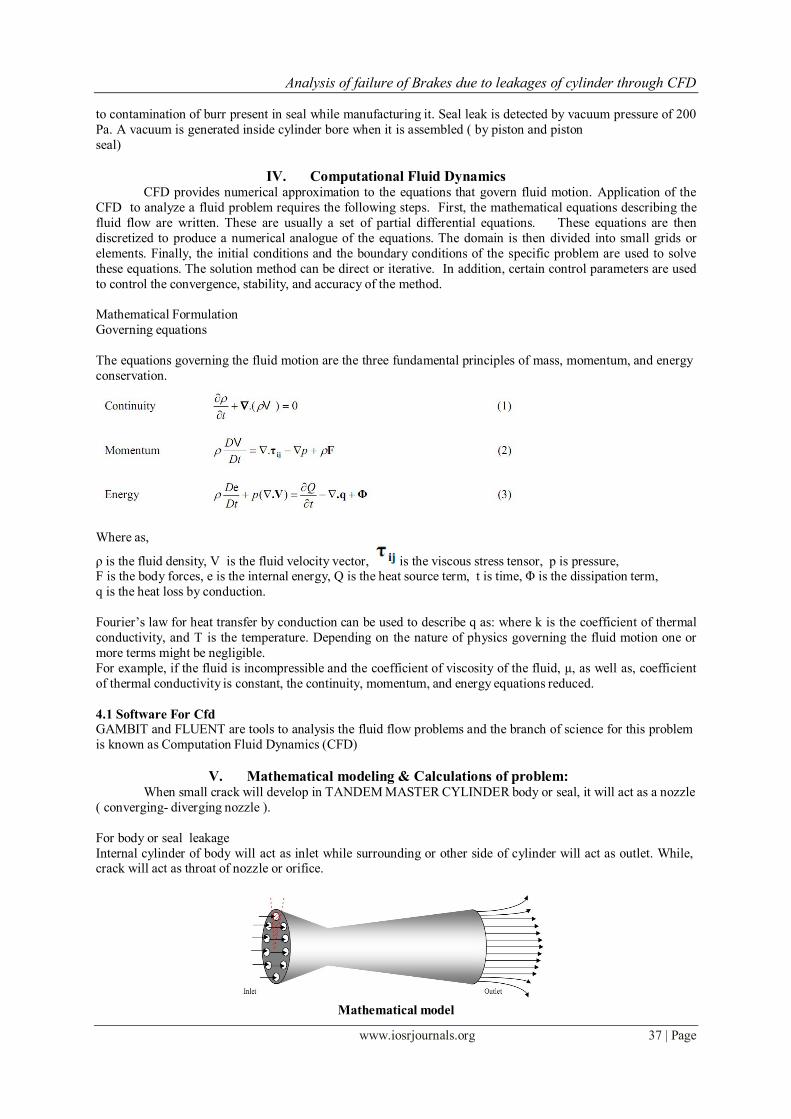
V. Mathematical modeling & Calculations of problem: When small crack will develop in TANDEM MASTER CYLINDER body or seal, it will act as a nozzle
( converging- diverging nozzle ).
For body or seal leakage
Internal cylinder of body will act as inlet while surrounding or other side of cylinder will act as outlet. While, crack will act as throat of nozzle or orifice.
Mathematical model
Analysis of failure of Brakes due to leakages of cylinder through CFD
www.iosrjournals.org 38 | Page
Mathematical model of crack consist of mass, momentum and energy conservation equations. When we assume
a fixed in space volume of cylinder bore Ω, bounded by close surface S, the mass conservation equation in
general form is as the following
The momentum conservation equation in general form is as follows:
where: τ-shear stress tensor, F-vector of external forces, p-pressure. The energy conservation equation in general
form is as follows:
ρ -the fluid density, V -the fluid velocity vector, τ -is the viscous stress tensor, p -pressure, F -the body forces,
e is the internal energy, Q -the heat source term, t - time, Φ -the dissipation term, q - the heat loss
Material
AC2A ( Aluminum alloy)
Tandem master cylinder used in Maruti WagonR, ( YR9) Dimension of TANDEM MASTER CYLINDER
Bore dia. = 19.06 mm
Depth of TANDEM MASTER CYLINDER= 162.06 mm
Temperature of assembly room 293 K
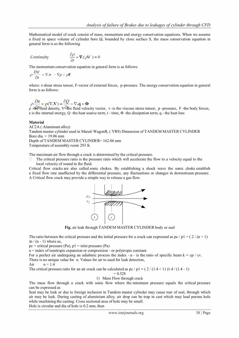
The maximum air flow through a crack is determined by the critical pressure.
The critical pressure ratio is the pressure ratio which will accelerate the flow to a velocity equal to the
local velocity of sound in the fluid.
Critical flow cracks are also called sonic chokes. By establishing a shock wave the sonic choke establish
a fixed flow rate unaffected by the differential pressure, any fluctuations or changes in downstream pressure.
A Critical flow crack may provide a simple way to release a gas flow.
Fig. air leak through TANDEM MASTER CYLINDER body or seal
The ratio between the critical pressure and the initial pressure for a crack can expressed as pc / p1 = ( 2 / (n + 1)
)n / (n - 1) where as, pc = critical pressure (Pa), p1 = inlet pressure (Pa)
n = index of isentropic expansion or compression - or polytropic constant
For a perfect air undergoing an adiabatic process the index - n - is the ratio of specific heats k = cp / cv.
There is no unique value for n. Values for air to used for leak detection,
Air n = 1.4
The critical pressure ratio for an air crack can be calculated as pc / p1 = ( 2 / (1.4 + 1) )1.4 / (1.4 - 1)
= 0.528
1) Mass Flow through crack
The mass flow through a crack with sonic flow where the minimum pressure equals the critical pressure
can be expressed as
Seal may be leak or due to foreign inclusion in Tandem master cylinder may cause tear of seal, through which air may be leak. During casting of aluminium alloy, air drop can be trap in cast which may lead porous hole
while machining the casting. Cross sectional area of hole may be small.
Hole is circular and dia of hole is 0.2 mm, then
Analysis of failure of Brakes due to leakages of cylinder through CFD
www.iosrjournals.org 39 | Page
Density of air, ρ = 1.225 kg/m3
A2 = π ((0.0002 m)/2)2 / 2
= 1.57 x 10⁻⁸(m2) A1 = π ((0.019 )/2)2 = 2.835 x 10⁻⁴ (m2)
Theoretical flow can be calculated
q = A2 [ 2(p1 - p2) / ρ(1 - (A2/A1)2) ]1/2 where as
A2 = crack cross sectional area (m2)
A1= cylinder cross sectional area (m2)
ρ = initial density (kg/m3) For 5 bar pressure testing,
q = (1.57 x 10⁻⁸ ) [ 2 (500000 -99860 ) / (1.225)(1 - ( (1.57 x 10⁻⁸ ) / (2.835x10⁻⁴ ) )2 ]1/2
= 808.32 x 1.57 x 10-8
=1.269 x 10⁻⁵ (m3/s)
The mass flow can be calculated as:
m = q ρ m = mass flow (kg/s)
= (1.269 x 10⁻⁵ ) (1.225)
= 1.55 x 10⁻⁵ (kg/s)
As testing time for detection of the leak is minimum 5 seconds, therefore calculating for different time, For 4 sec,
= 1.55 x 10-5 x 4
= 6.2 x 10⁻⁵ (kg) For 4.5 sec,
= 1.55 x 10-5 x 4.5
= 6.975 x 10⁻⁵ (kg) For 5 sec,
= 1.55 x 10-5 x 5
= 7.75 x 10⁻⁵ (kg)
Total mass of air in cylinder at 5 bar pressure,
= (ρ1 x v x 5) = 1.225 x 2.835 x 0.081 x 10-4 x 5
= 1.406 x 10⁻⁴(kg)
Total mass of air in cylinder at 4.5 bar pressure,
= (ρ1 x v x 4.5)
= 1.225 x 2.835 x 0.081 x 10-4 x 4.5
= 1.266x 10⁻⁴(kg)
Total mass of air in cylinder at 4 bar pressure,
= (ρ1 x v x 4)
= 1.225 x 2.835 x 0.081 x 10-4 x 4
= 1.125x 10⁻⁴(kg)
So remaining pressure in cylinder is approximately 3.25 bar to 3.5 bar.
Total fall of pressure is 1.5 bar and is not sufficient to detect leak in seal or body of TANDEM
MASTER CYLINDER when leak crack will be very small.
For detection of leak allowable pressure limit is 4.5 bar to 5.5 bar. If pressure falls below 4.5 bar then
testing machine rejects the component for leakage. And time of leak detection is 5 seconds. If leak is not
detected in 5 seconds then Tandem master cylinder is considered as ok. But it may lead serious problem in
future of Tandem master cylinder. During continue use of Tandem master cylinder, after some days size of
crack increases which causes leak and may lead accident of vehicle. And leak can be detected in minimum 2.5
seconds ( with one second of allowance as considering frictional loss and depth of length of hole).
Now, minimum leakage time is 3.5 seconds filled with 5 bar. For 10 bar pressure testing,
q = (1.57 x 10⁻⁸ ) [ 2 (1000000 -99860 ) / (1.225)(1 - ( (1.57 x 10⁻⁸ ) / (2.835x10⁻⁴ ) )2 ]1/2
= 1212.77 x 1.57 x 10-8 =1.904 x 10⁻⁵ (m3/s)
The mass flow can be calculated as:
m = q ρ
m = mass flow (kg/s)
= (1.904 x 10⁻⁵ ) (1.225)
= 2.332x 10⁻⁵ (kg/s)
As testing time for detection of the leak is minimum 5 seconds, therefore calculating for different time, For 2.5
sec,
= 2.332 x 10-5 x 2.5
= 5.83x 10⁻⁵ (kg) For 4.5 sec,
Analysis of failure of Brakes due to leakages of cylinder through CFD
www.iosrjournals.org 40 | Page
= 2.332 x 10-5 x 4.5
= 1.049x 10⁻⁴ (kg) For 5 sec,
= 2.332 x 10-5 x 5 = 1.166 x 10⁻⁴ (kg)
Total mass of air in cylinder at 10 bar pressure,
= (ρ1 x v x 10)
= 1.225 x 2.835 x 0.081 x 10-4 x 10
= 2.81 x 10⁻⁴(kg)
Total mass of air in cylinder at 9.5 bar pressure,
= (ρ1 x v x 9.5)
= 1.225 x 2.835 x 0.081 x 10-4 x 9.5
= 2.67 x 10⁻⁴(kg)
Total mass of air in cylinder at 9 bar pressure,
= (ρ1 x v x 9) = 1.225 x 2.835 x 0.081 x 10-4 x 9
= 2.53 x 10⁻⁴(kg)
At 2.5 seconds amount of mass leaked is approximately 5.83x 10⁻⁵ (kg). Hence remaining mass is calculated
as,
Total mass of cylinder at 5 bar – mass leak after 2.5 seconds
= 2.81 x 10⁻⁴- 5.83x 10-5 = 2.227 x 10⁻⁴
Remaining pressure in cylinder is now 8 bar after 2.5 seconds.
Total fall of pressure is 2 bar and sufficient to detect leak in seal or body of TANDEM MASTER
CYLINDER. Even though when crack will be very small, then also fall in pressure will still sufficient to find
out leak of TANDEM MASTER CYLINDER.
For detection of leak allowable pressure limit can be change as 9 bar to 11 bar. Time of leak detection is 4 seconds. If leak will not detected in 4 seconds then Tandem master cylinder is considered as ok. Due to
higher pressure, leak detection accuracy can increase more and within a short period of time. Due to high
pressure even very small leak can be detected easily an in less time. That will increase in production and even
that will assured safety of vehicles. Leak can be detected in minimum 2.5 seconds (with one second of
allowance as considering frictional loss and depth of length of hole).
Now, minimum leakage time is 3.5 seconds filled with 10 bar.
VI. Software Simulation For Cfd GAMBIT and FLUENT are tools for analysis the fluid flow problems and the branch of science of fluidbis known as Computation Fluid Dynamics (CFD)
GAMBIT: GAMBIT full form is Geometry And Mesh Building Intelligent Tool
GAMBIT is used for pre-processing operation (which is required before starting of solution) of fluid flow
problem which includes following operations:
Geometry creation (specifies the domain of fluid flow problem)
Mesh generation (discretization of domain to solve governing equations at each cell)
Specifying the boundary zones (name & type) to apply boundary conditions for problem.
GAMBIT export the file containing all the data related to pre-processing.
In this geometry bore diameter of cylinder 19.06 mm is drawn and 4 mm thick seal is placed at 81 mm distance
from inlet. And semicircular crack is provided on seal of diameter 0.2 mm on the corner of cylinder for leak.
Fig. Meshing of TANDEM MASTER CYLINDER along with seal and leak in GAMBIT
Analysis of failure of Brakes due to leakages of cylinder through CFD
www.iosrjournals.org 41 | Page
Meshing of cylinder is extremely fine of 0.01 mm size of element. And selection of element is tetrahedron. Then
boundary conditions given as,
1. Pressure inlet 2. Pressure outlet
3. Wall ( for seal and outer surface of body)\
4. Fluid zone
FLUENT: This software solve/iterate the problem by importing the file which was exported by GAMBIT to define the
problem in FLUENT.
Fluent will require following data to setup the solution for problem.
Solution method/model
Material properties
Boundary and operating conditions for given problem Initial conditions and no. of iterations required to converge the solution. After applying/specifying
above data, FLUENT is ready for solution process.
After solution is performed, post processing is done for reviewing the results of solutions to analyze the
given problem.
Fig. Grid of TANDEM MASTER CYLINDER along with seal and leak in TANDEM MASTER CYLINDER
For 5 bar
Fig. pressure lost after 2.5 seconds in TANDEM MASTER CYLINDER along with seal and leak in TANDEM
MASTER CYLINDER for 5 bar
Fig. Dynamic pressure in TANDEM MASTER CYLINDER along with seal and leak for 5 bar
For 10 bar
Analysis of failure of Brakes due to leakages of cylinder through CFD
www.iosrjournals.org 42 | Page
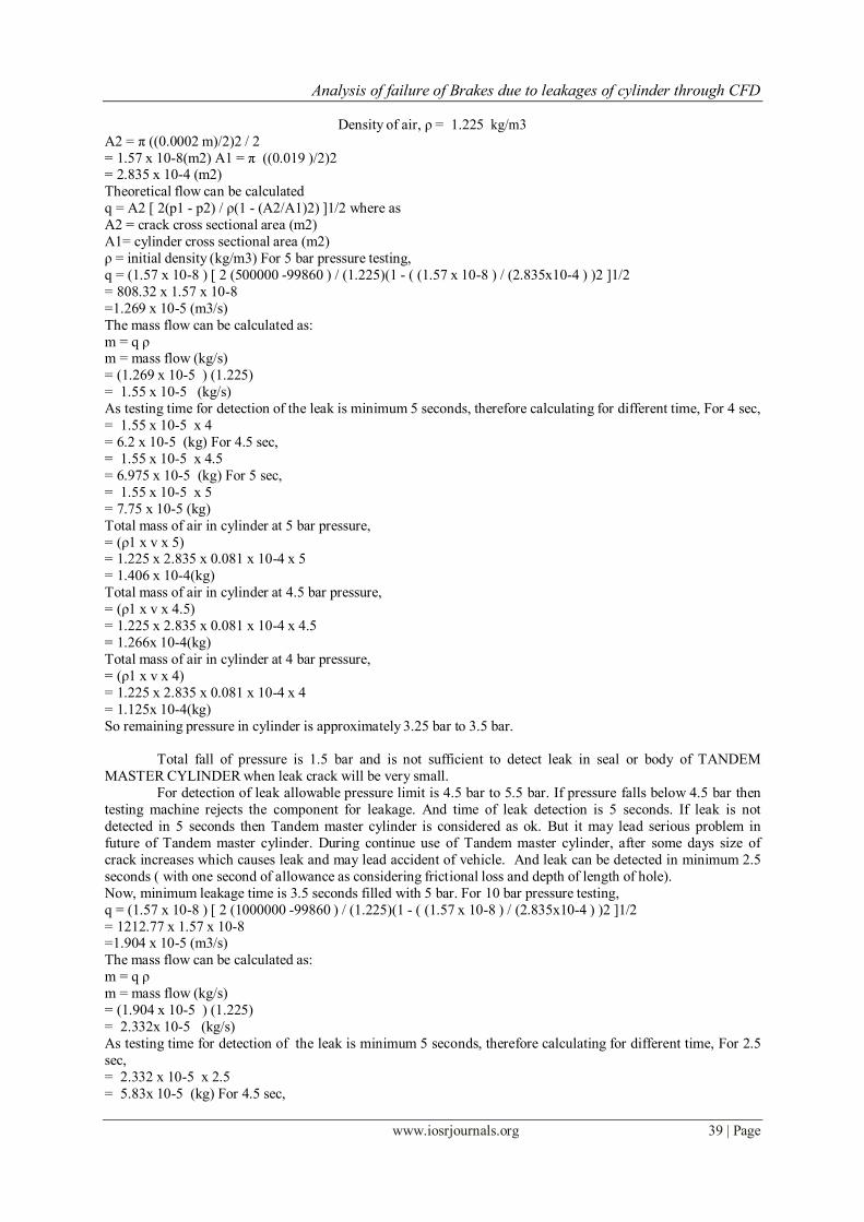
Fig. pressure lost after 2.5 seconds in TANDEM MASTER CYLINDER along with seal and leak in TANDEM
MASTER CYLINDER for 10 bar
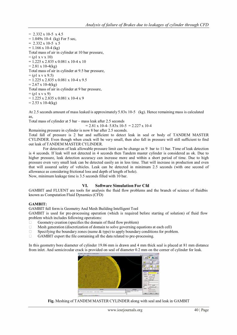
Fig. Distribution of turbulent kinetic energy in TANDEM MASTER CYLINDER along with seal and leak in
TANDEM MASTER CYLINDER for 10 bar
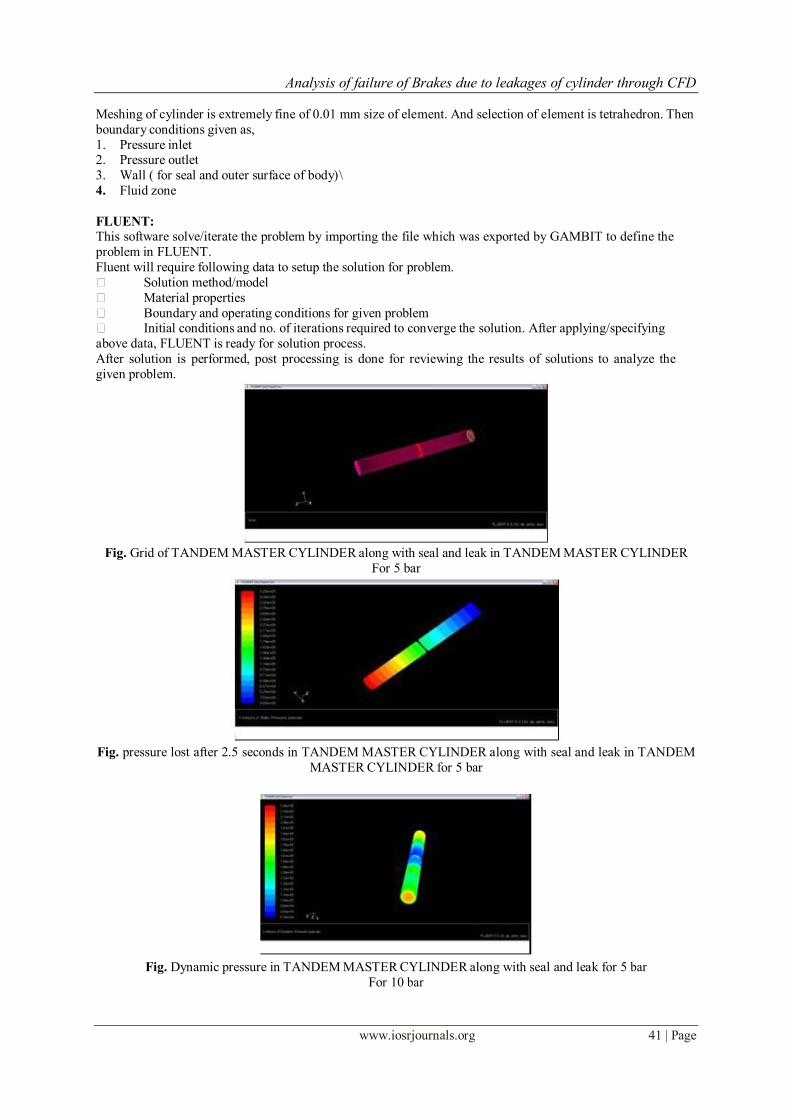
Fig. Max. development of shear stress on seal and leak area in TANDEM MASTER CYLINDER for 10 bar
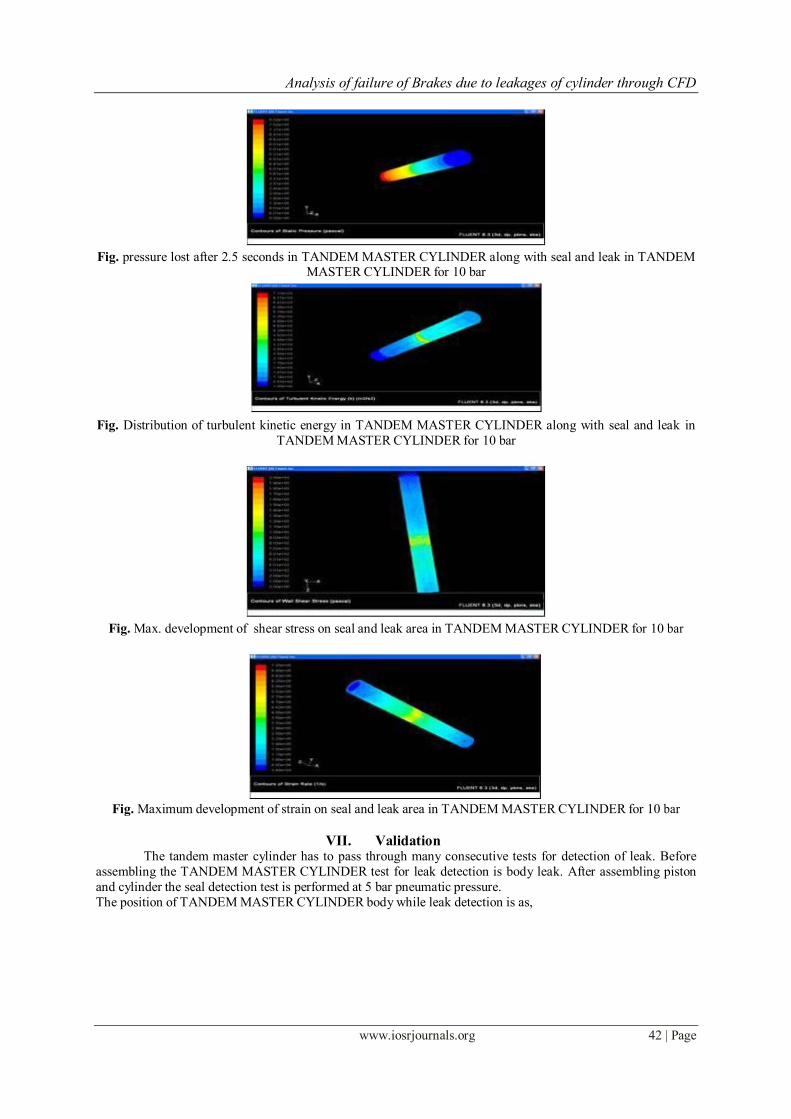
Fig. Maximum development of strain on seal and leak area in TANDEM MASTER CYLINDER for 10 bar
VII. Validation The tandem master cylinder has to pass through many consecutive tests for detection of leak. Before
assembling the TANDEM MASTER CYLINDER test for leak detection is body leak. After assembling piston
and cylinder the seal detection test is performed at 5 bar pneumatic pressure.
The position of TANDEM MASTER CYLINDER body while leak detection is as,
Analysis of failure of Brakes due to leakages of cylinder through CFD
www.iosrjournals.org 43 | Page
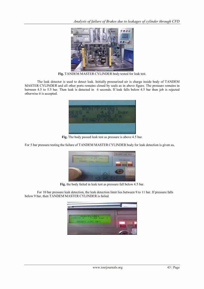
Fig. TANDEM MASTER CYLINDER body tested for leak test.
The leak detector is used to detect leak. Initially pressurized air is charge inside body of TANDEM
MASTER CYLINDER and all other ports remains closed by seals as in above figure. The pressure remains in
between 4.5 to 5.5 bar. Then leak is detected in 6 seconds. If leak falls below 4.5 bar then job is rejected
otherwise it is accepted.
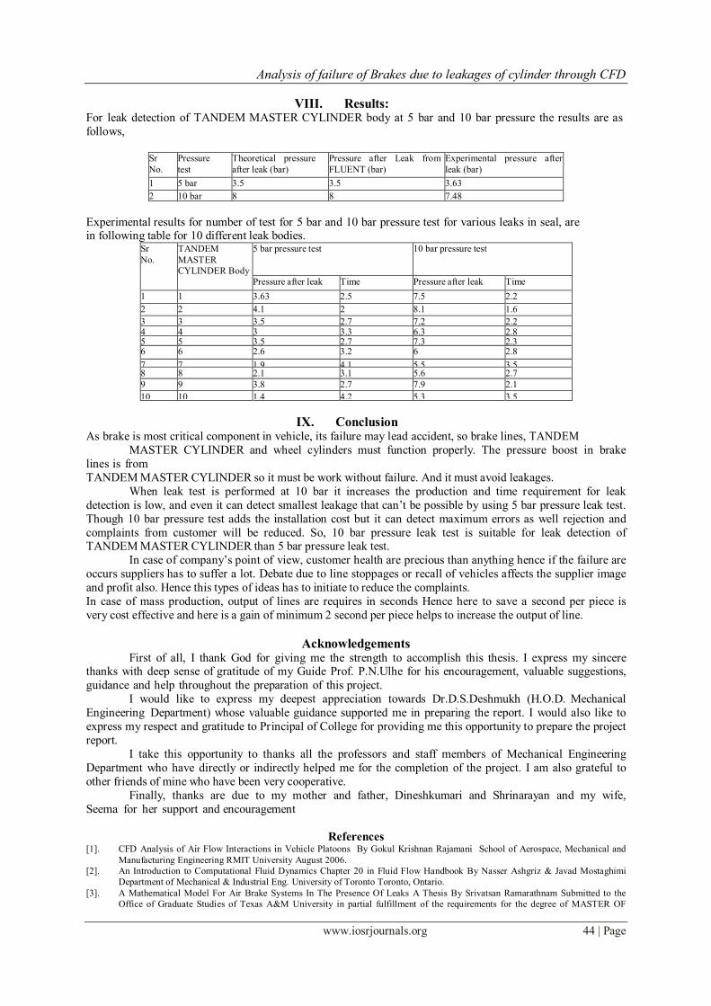
Fig. The body passed leak test as pressure is above 4.5 bar.
For 5 bar pressure testing the failure of TANDEM MASTER CYLINDER body for leak detection is given as,
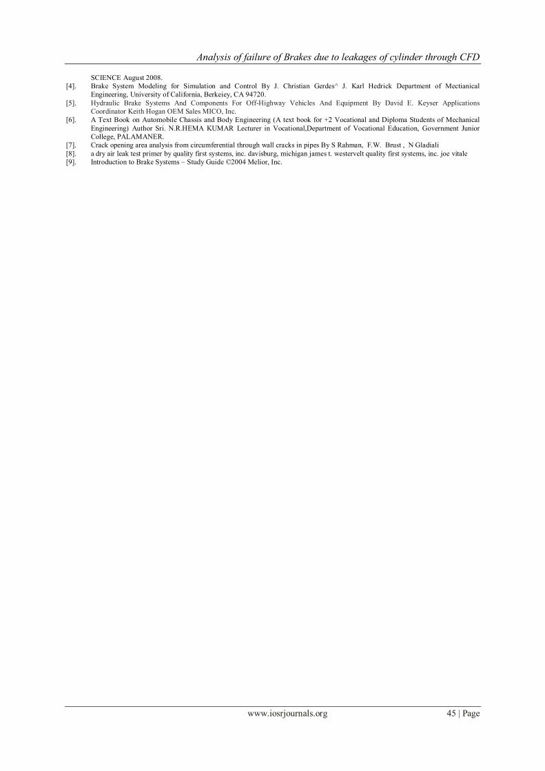
Fig. the body failed in leak test as pressure fall below 4.5 bar.
For 10 bar pressure leak detection, the leak detection limit lies between 9 to 11 bar. If pressure falls below 9 bar, then TANDEM MASTER CYLINDER is failed.
Analysis of failure of Brakes due to leakages of cylinder through CFD
www.iosrjournals.org 44 | Page
VIII. Results: For leak detection of TANDEM MASTER CYLINDER body at 5 bar and 10 bar pressure the results are as
follows,
Sr
No.
Pressure
test
Theoretical pressure
after leak (bar)
Pressure after Leak from
FLUENT (bar)
Experimental pressure after
leak (bar)
1 5 bar 3.5 3.5 3.63
2 10 bar 8 8 7.48
Experimental results for number of test for 5 bar and 10 bar pressure test for various leaks in seal, are in following table for 10 different leak bodies.
Sr
No.
TANDEM
MASTER
CYLINDER Body
5 bar pressure test 10 bar pressure test
Pressure after leak Time Pressure after leak Time
1 1 3.63 2.5 7.5 2.2
2 2 4.1 2 8.1 1.6
3 3 3.5 2.7 7.2 2.2 4 4 3 3.3 6.3 2.8 5 5 3.5 2.7 7.3 2.3 6 6 2.6 3.2 6 2.8
7 7 1.9 4.1 5.5 3.5 8 8 2.1 3.1 5.6 2.7
9 9 3.8 2.7 7.9 2.1
10 10 1.4 4.2 5.3 3.5
IX. Conclusion As brake is most critical component in vehicle, its failure may lead accident, so brake lines, TANDEM
MASTER CYLINDER and wheel cylinders must function properly. The pressure boost in brake
lines is from
TANDEM MASTER CYLINDER so it must be work without failure. And it must avoid leakages.
When leak test is performed at 10 bar it increases the production and time requirement for leak
detection is low, and even it can detect smallest leakage that can’t be possible by using 5 bar pressure leak test.
Though 10 bar pressure test adds the installation cost but it can detect maximum errors as well rejection and
complaints from customer will be reduced. So, 10 bar pressure leak test is suitable for leak detection of TANDEM MASTER CYLINDER than 5 bar pressure leak test.
In case of company’s point of view, customer health are precious than anything hence if the failure are
occurs suppliers has to suffer a lot. Debate due to line stoppages or recall of vehicles affects the supplier image
and profit also. Hence this types of ideas has to initiate to reduce the complaints.
In case of mass production, output of lines are requires in seconds Hence here to save a second per piece is
very cost effective and here is a gain of minimum 2 second per piece helps to increase the output of line.
Acknowledgements First of all, I thank God for giving me the strength to accomplish this thesis. I express my sincere
thanks with deep sense of gratitude of my Guide Prof. P.N.Ulhe for his encouragement, valuable suggestions,
guidance and help throughout the preparation of this project.
I would like to express my deepest appreciation towards Dr.D.S.Deshmukh (H.O.D. Mechanical
Engineering Department) whose valuable guidance supported me in preparing the report. I would also like to
express my respect and gratitude to Principal of College for providing me this opportunity to prepare the project
report.
I take this opportunity to thanks all the professors and staff members of Mechanical Engineering
Department who have directly or indirectly helped me for the completion of the project. I am also grateful to
other friends of mine who have been very cooperative.
Finally, thanks are due to my mother and father, Dineshkumari and Shrinarayan and my wife,
Seema for her support and encouragement
References [1]. CFD Analysis of Air Flow Interactions in Vehicle Platoons By Gokul Krishnan Rajamani School of Aerospace, Mechanical and
Manufacturing Engineering RMIT University August 2006.
[2]. An Introduction to Computational Fluid Dynamics Chapter 20 in Fluid Flow Handbook By Nasser Ashgriz & Javad Mostaghimi
Department of Mechanical & Industrial Eng. University of Toronto Toronto, Ontario.
[3]. A Mathematical Model For Air Brake Systems In The Presence Of Leaks A Thesis By Srivatsan Ramarathnam Submitted to the
Office of Graduate Studies of Texas A&M University in partial fulfillment of the requirements for the degree of MASTER OF
Analysis of failure of Brakes due to leakages of cylinder through CFD
www.iosrjournals.org 45 | Page
SCIENCE August 2008.
[4]. Brake System Modeling for Simulation and Control By J. Christian Gerdes^ J. Karl Hedrick Department of Mectianical
Engineering, University of California, Berkeiey, CA 94720.
[5]. Hydraulic Brake Systems And Components For Off-Highway Vehicles And Equipment By David E. Keyser Applications
Coordinator Keith Hogan OEM Sales MICO, Inc.
[6]. A Text Book on Automobile Chassis and Body Engineering (A text book for +2 Vocational and Diploma Students of Mechanical
Engineering) Author Sri. N.R.HEMA KUMAR Lecturer in Vocational,Department of Vocational Education, Government Junior
College, PALAMANER.
[7]. Crack opening area analysis from circumferential through wall cracks in pipes By S Rahman, F.W. Brust , N Gladiali
[8]. a dry air leak test primer by quality first systems, inc. davisburg, michigan james t. westervelt quality first systems, inc. joe vitale
[9]. Introduction to Brake Systems – Study Guide ©2004 Melior, Inc.


