Embed Size (px)
Citation preview
Angle Choke Valves
Table of ContentsPage
SchuF Choke Valve Design 3
Angle Choke Valve Models 6
70FK High Pressure Angle Choke Valves (HPAC) 6
70NV Needle Spline Choke Valves (NSC) 7
70KS Cage Choke Valves (CC) 8
70HS Anti-Cav Cage Choke Valves (ACC) 9
70MC Multi-Stage Cage Choke Valves (MCC) 10
70EC External Sleeve Choke Valves (ESC) 11
70DF Turn-Style Disc Choke Valves (TDC) 12
70MS Multi-Stage Disc Choke Valves (MDC) 13
70SC Stacker Choke Valves (SC) 14
70PC Positive Angle Choke Valves (PAC) 15
SchuF Choke Valve Construction 16
SchuF Angle Choke Valve Features 17
ASME Angle Choke Valve Dimensions 18
API Angle Choke Valve Dimensions 21
Inside SchuF Fetterolf Design 24
Choke Valve Standards 25
Choke Valve Inquiry Form 26
SchuF Product Portfolio 27
SchuF Site Contact Information 28
SchuF is fully registered, accredited and certified worldwide
©Te
bN
adI b
igst
ock
.co
m©
Pix
On
eI s
hu
tter
sto
ck©
TexP
ixP
ub
lish
ing
I big
sto
ck.c
om
©b
ud
abar
I big
sto
ck.c
om
©d
avis
pic
sI b
igst
ock
.co
m
2
SchuF Choke Valve Design
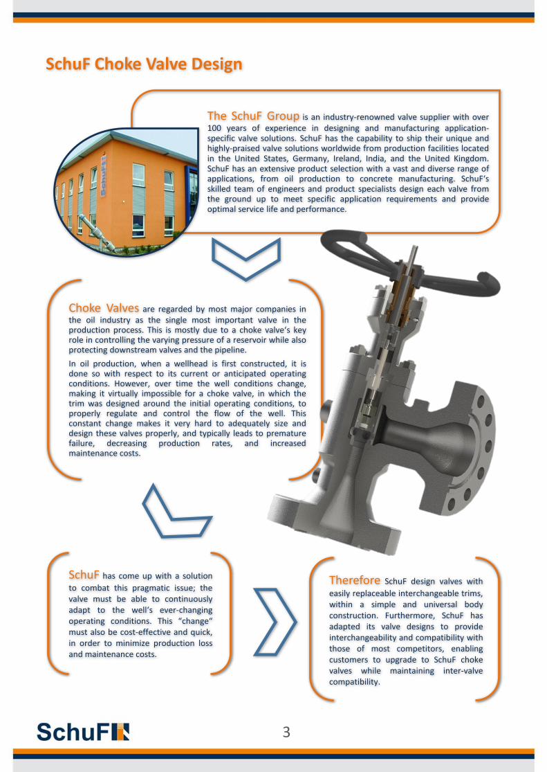
The SchuF Group is an industry-renowned valve supplier with over100 years of experience in designing and manufacturing application-specific valve solutions. SchuF has the capability to ship their unique andhighly-praised valve solutions worldwide from production facilities locatedin the United States, Germany, Ireland, India, and the United Kingdom.SchuF has an extensive product selection with a vast and diverse range ofapplications, from oil production to concrete manufacturing. SchuF‘sskilled team of engineers and product specialists design each valve fromthe ground up to meet specific application requirements and provideoptimal service life and performance.
Choke Valves are regarded by most major companies inthe oil industry as the single most important valve in theproduction process. This is mostly due to a choke valve‘s keyrole in controlling the varying pressure of a reservoir while alsoprotecting downstream valves and the pipeline.
In oil production, when a wellhead is first constructed, it isdone so with respect to its current or anticipated operatingconditions. However, over time the well conditions change,making it virtually impossible for a choke valve, in which thetrim was designed around the initial operating conditions, toproperly regulate and control the flow of the well. Thisconstant change makes it very hard to adequately size anddesign these valves properly, and typically leads to prematurefailure, decreasing production rates, and increasedmaintenance costs.
SchuF has come up with a solution
to combat this pragmatic issue; thevalve must be able to continuouslyadapt to the well‘s ever-changingoperating conditions. This “change“must also be cost-effective and quick,in order to minimize production lossand maintenance costs.
Therefore SchuF design valves with
easily replaceable interchangeable trims,within a simple and universal bodyconstruction. Furthermore, SchuF hasadapted its valve designs to provideinterchangeability and compatibility withthose of most competitors, enablingcustomers to upgrade to SchuF chokevalves while maintaining inter-valvecompatibility.
3
¹ Recommended Standard Construction, more options are available upon request² Material is NACE MR0175 Compliant
Type 70 Choke Valve Specifications & Recommended Material Applications¹
Pressure Rating ASME 600# - 4500# / API 2000 – 15000 PSI CWP
TemperatureRating
-59° to 177° C (-75° to 350° F) API Temperature Classifications K,L,N,P,R,S,T,U,V,X,Y
Flow Control Equal Percentage, Linear, Patented X³, Bell Curve, On-Off
Shut-Off Class ANSI/ FCI Class IV (ANSI/ FCI Class V is optional)
Trim Material API AA & BB API CC API DD² & EE² API FF² API HH²
RecommendedService
General OilCorrosive (CO2)
General OilCorrosive (CO2)
Sour (H2S)Low Corrosive (CO2)
Sour (H2S) Corrosive (CO2)
High Sour (H2S)High Corrosive (CO2)
1 BodyAPI 60K
Carbon SteelLow Alloy Steel
Duplex SSCarbon Steel
Stainless Steel
API 60KCarbon Steel
Low Alloy Steel
Duplex SSClad Low Alloy Steel
Stainless Steel
Clad Low Alloy SteelCorrosion Resistant Alloy
2 BonnetAPI 60K
Carbon SteelLow Alloy Steel
Duplex SSCarbon Steel
Stainless Steel
API 60KCarbon Steel
Low Alloy Steel
Duplex SSClad Low Alloy Steel
Stainless Steel
Clad Low Alloy SteelLow Alloy Steel
Corrosion Resistant alloy
3 Seat/ BeanLow Alloy SteelStainless Steel
Tungsten Carbide
AISI 17-4PHStainless Steel
Tungsten Carbide
AISI 17-4PHLow Alloy Steel
Tungsten Carbide
AISI 17-4PHStainless Steel
Tungsten Carbide
Corrosion Resistant alloyTungsten Carbide
4 SleeveLow Alloy SteelStainless Steel
Tungsten Carbide
AISI 17-4PHStainless Steel
Tungsten Carbide
AISI 17-4PHLow Alloy Steel
Tungsten Carbide
AISI 17-4PHStainless Steel
Tungsten Carbide
Corrosion Resistant alloyTungsten Carbide
5 PlugLow Alloy SteelStainless Steel
Tungsten Carbide
AISI 17-4PHStainless Steel
Tungsten Carbide
AISI 17-4PHLow Alloy Steel
Tungsten Carbide
AISI 17-4PHStainless Steel
Tungsten Carbide
Corrosion Resistant alloyTungsten Carbide
6 StemAISI 17-4PH
Low Alloy SteelAISI 17-4PH
Low Alloy SteelAISI 17-4PH
Low Alloy SteelAISI 17-4PHInconel 718
AISI 17-4PHInconel 718
7 Lower SealCarbon Steel
Stainless SteelSoft Seal
Low Alloy SteelStainless Steel
Soft Seal
Carbon Steel Inconel 625
Soft Seal
Low Alloy SteelInconel 625
Soft Seal
Ni-AlloyInconel 625
Soft Seal
8 Bonnet SealCarbon Steel
Stainless SteelSoft Seal
Low Alloy SteelStainless Steel
Soft Seal
Carbon Steel Inconel 625
Soft Seal
Inconel 625Stainless Steel
Soft Seal
Ni-AlloyInconel 625
Soft Seal
SchuF Choke Valve Design
Temperature Classification
Material Operating Temperature Range
Minimum °F (°C) Maximum °F (°C)
K -75°F (-60°C) 180°F (82°C)
L -50°F (-46°C) 180°F (82°C)
P -20°F (-29°C) 180°F (82°C)
R Room Temperature
S 0°F (-18°C) 150°F (66°C)
T 0°F (-18°C) 180°F (82°C)
U 0°F (-18°C) 250°F (121°C)
V 35°F (2°C) 250°F (121°C)
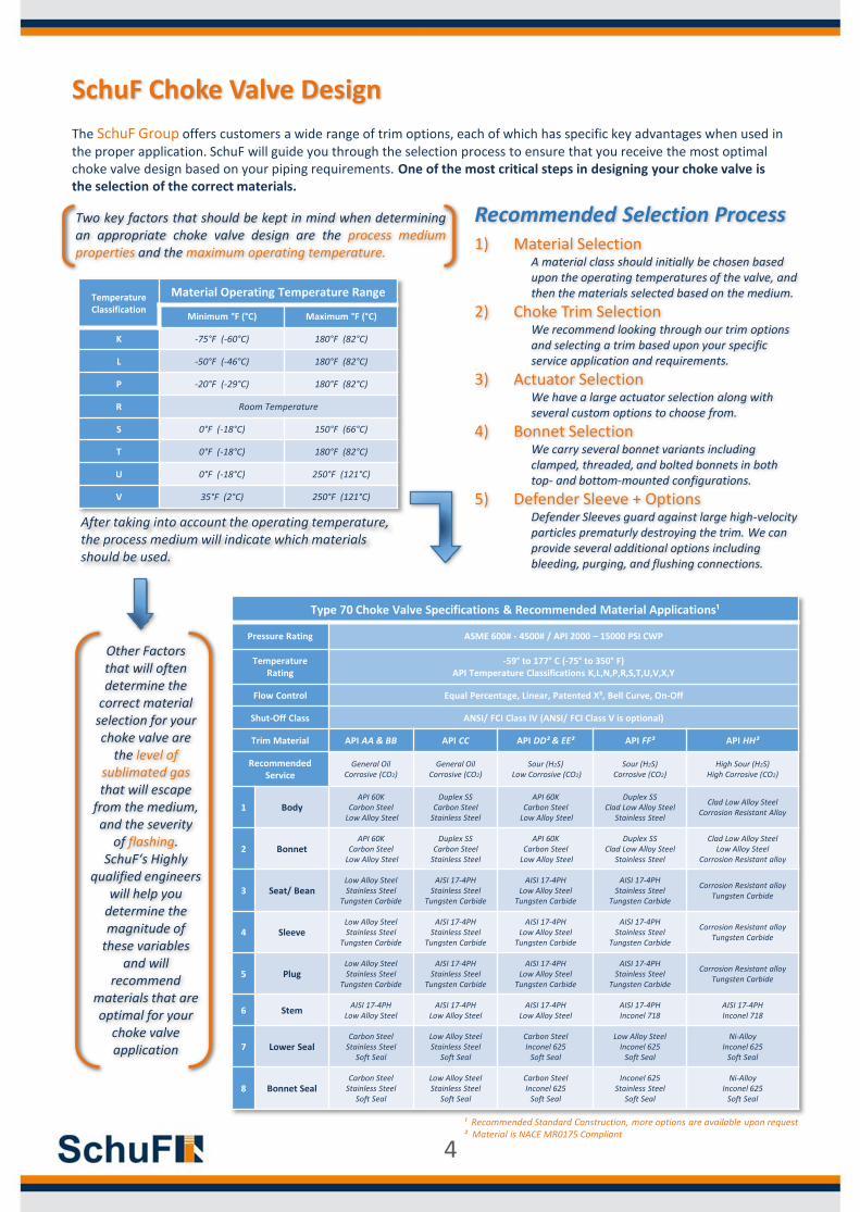
Two key factors that should be kept in mind when determiningan appropriate choke valve design are the process mediumproperties and the maximum operating temperature.
Other Factorsthat will often determine the
correct material selection for your choke valve are
the level of sublimated gasthat will escape
from the medium, and the severity
of flashing. SchuF‘s Highly
qualified engineers will help you
determine themagnitude of
these variables and will
recommend materials that are optimal for your
choke valve application
The SchuF Group offers customers a wide range of trim options, each of which has specific key advantages when used in the proper application. SchuF will guide you through the selection process to ensure that you receive the most optimal choke valve design based on your piping requirements. One of the most critical steps in designing your choke valve is the selection of the correct materials.
Recommended Selection Process1) Material Selection
A material class should initially be chosen based upon the operating temperatures of the valve, and then the materials selected based on the medium.
2) Choke Trim SelectionWe recommend looking through our trim options and selecting a trim based upon your specific service application and requirements.
3) Actuator SelectionWe have a large actuator selection along with several custom options to choose from.
4) Bonnet SelectionWe carry several bonnet variants including clamped, threaded, and bolted bonnets in both top- and bottom-mounted configurations.
5) Defender Sleeve + OptionsDefender Sleeves guard against large high-velocity particles prematurly destroying the trim. We can provide several additional options including bleeding, purging, and flushing connections.
After taking into account the operating temperature, the process medium will indicate which materials should be used.
4
SchuF Choke Valve Design
Actuator Options
Bonnet Cap Options
Trim Options
Adapter Options
Body Options
Pneumatic Hydraulic Electro-HydraulicElectric Stepping Manual
SchuF Angle Dynamic & Passive TrimsPlease see pages 6-15
Positive Bean Adapter
Angle Body Axial Body Globe Body
Defender Sleeve
Bonnet Options
Bolted Bonnet
Actuated Yoke Adjustable BonnetPositive Cap
Clamped Bonnet Threaded Bonnet
ASME FlangedAPI Flanged
ISO/ DIN FlangedClampedHubbed
ThreadedButt Weld
Union
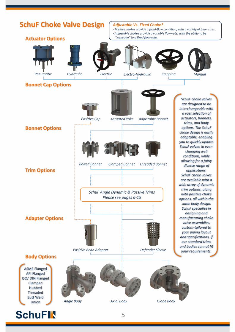
SchuF choke valves are designed to be
interchangeable with a vast selection of
actuators, bonnets, trims, and body
options. The SchuF choke design is easily adaptable, enabling
you to quickly update SchuF valves to ever-
changing well conditions, while
allowing for a fairly diverse range of
applications. SchuF choke valves are available with a
wide array of dynamic trim options, along with positive choke
options, all within the same body design. SchuF specialise in
designing and manufacturing choke
valve assemblies, custom-tailored to your piping layout
and specifications, if our standard trims
and bodies cannot fit your requirements.
Adjustable Vs. Fixed Choke?- Positive chokes provide a fixed-flow condition, with a variety of bean sizes. - Adjustable chokes provide a variable flow-rate, with the abilty to be
“locked-in“ to a fixed flow-rate.
5
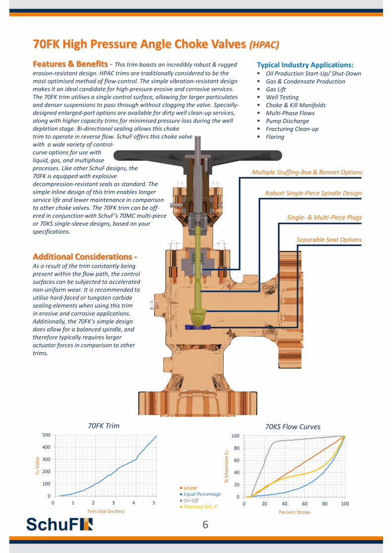
Features & Benefits - This trim boasts an incredibly robust & rugged
erosion-resistant design. HPAC trims are traditionally considered to be the most optimised method of flow-control. The simple vibration-resistant design makes it an ideal candidate for high-pressure erosive and corrosive services. The 70FK trim utilises a single control surface, allowing for larger particulates and denser suspensions to pass through without clogging the valve. Specially-designed enlarged-port options are available for dirty well clean-up services, along with higher capacity trims for minimised pressure loss during the well depletion stage. Bi-directional sealing allows this choke trim to operate in reverse flow. SchuF offers this choke valvewith a wide variety of control-curve options for use with liquid, gas, and multiphase processes. Like other SchuF designs, the 70FK is equipped with explosive decompression-resistant seals as standard. Thesimple inline design of this trim enables longerservice life and lower maintenance in comparisonto other choke valves. The 70FK trim can be off-ered in conjunction with SchuF’s 70MC multi-pieceor 70KS single-sleeve designs, based on yourspecifications.
70FK High Pressure Angle Choke Valves (HPAC)
Typical Industry Applications: Oil Production Start-Up/ Shut-Down Gas & Condensate Production Gas Lift Well Testing Choke & Kill Manifolds Multi-Phase Flows Pump Discharge Fracturing Clean-up Flaring
Additional Considerations -As a result of the trim constantly being present within the flow path, the control surfaces can be subjected to accelerated non-uniform wear. It is recommended to utilise hard-faced or tungsten carbide sealing elements when using this trim in erosive and corrosive applications. Additionally, the 70FK‘s simple design does allow for a balanced spindle, and therefore typically requires larger actuator forces in comparison to other trims.
0
100
200
300
400
500
0 1 2 3 4 5
Cv
Val
ue
Trim Size (Inches)
70FK Trim
0
20
40
60
80
100
0 20 40 60 80 100
% M
axim
um
Cv
Percent Stroke
70KS Flow Curves
● Linear● Equal Percentage● On-Off● Patented Bell X³
Multiple Stuffing-Box & Bonnet Options
Robust Single-Piece Spindle Design
Single- & Multi-Piece Plugs
Separable Seat Options
6
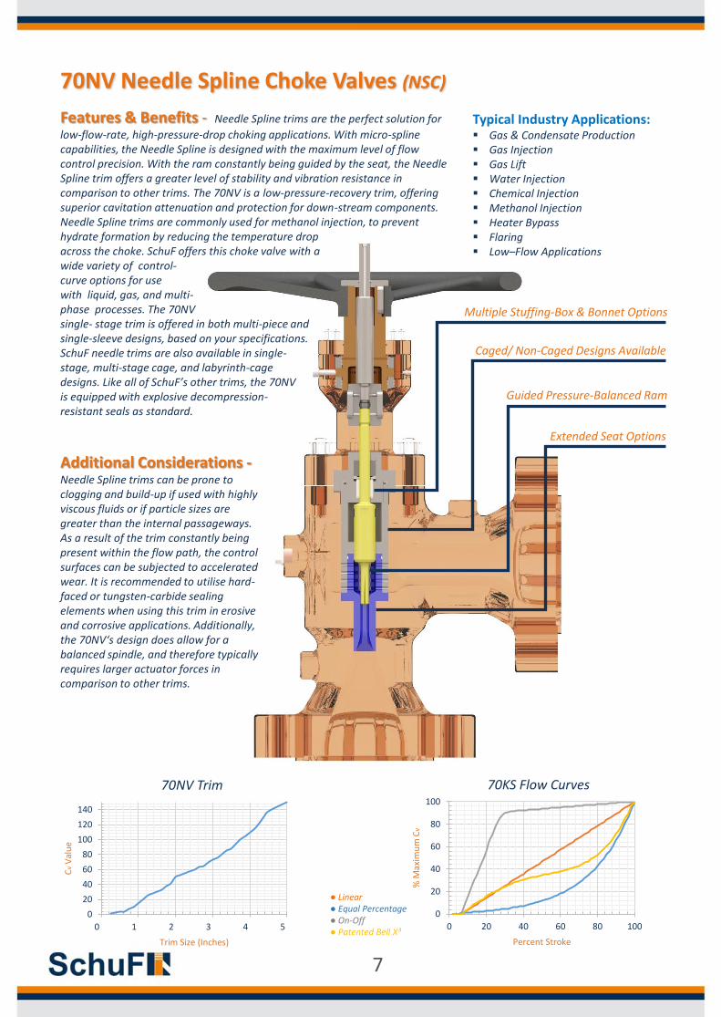
Features & Benefits - Needle Spline trims are the perfect solution for
low-flow-rate, high-pressure-drop choking applications. With micro-spline capabilities, the Needle Spline is designed with the maximum level of flow control precision. With the ram constantly being guided by the seat, the Needle Spline trim offers a greater level of stability and vibration resistance in comparison to other trims. The 70NV is a low-pressure-recovery trim, offering superior cavitation attenuation and protection for down-stream components. Needle Spline trims are commonly used for methanol injection, to prevent hydrate formation by reducing the temperature dropacross the choke. SchuF offers this choke valve with awide variety of control-curve options for usewith liquid, gas, and multi-phase processes. The 70NVsingle- stage trim is offered in both multi-piece and single-sleeve designs, based on your specifications. SchuF needle trims are also available in single-stage, multi-stage cage, and labyrinth-cage designs. Like all of SchuF’s other trims, the 70NVis equipped with explosive decompression-resistant seals as standard.
Additional Considerations -Needle Spline trims can be prone to clogging and build-up if used with highly viscous fluids or if particle sizes are greater than the internal passageways. As a result of the trim constantly being present within the flow path, the control surfaces can be subjected to accelerated wear. It is recommended to utilise hard-faced or tungsten-carbide sealing elements when using this trim in erosive and corrosive applications. Additionally, the 70NV‘s design does allow for a balanced spindle, and therefore typically requires larger actuator forces in comparison to other trims.
0
20
40
60
80
100
120
140
0 1 2 3 4 5
Cv
Val
ue
Trim Size (Inches)
70NV Trim
70NV Needle Spline Choke Valves (NSC)
Typical Industry Applications: Gas & Condensate Production Gas Injection Gas Lift Water Injection Chemical Injection Methanol Injection Heater Bypass Flaring Low–Flow Applications
0
20
40
60
80
100
0 20 40 60 80 100
% M
axim
um
Cv
Percent Stroke
70KS Flow Curves
● Linear● Equal Percentage● On-Off● Patented Bell X³
Multiple Stuffing-Box & Bonnet Options
Caged/ Non-Caged Designs Available
Guided Pressure-Balanced Ram
Extended Seat Options
7
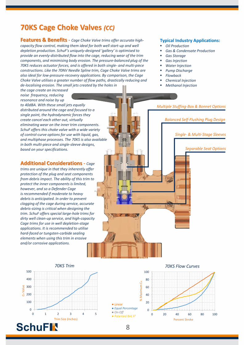
Features & Benefits - Cage Choke Valve trims offer accurate high-
capacity flow control, making them ideal for both well start-up and well depletion production. SchuF’s uniquely-designed ‘gallery’ is optimised to provide an evenly-distributed flow into the cage, reducing wear of the trim components, and minimising body erosion. The pressure-balanced plug of the 70KS reduces actuator forces, and is offered in both single- and multi-piece constructions. Like the 70NV Needle Spline trim, Cage Choke Valve trims are also ideal for low-pressure-recovery applications. By comparison, the Cage Choke Valve utilises a greater number of flow paths, drastically reducing and de-localising erosion. The small jets created by the holes inthe cage create an increasednoise frequency, reducing resonance and noise by up to 40dBA. With these small jets equally distributed around the cage and focused to a single point, the hydrodynamic forces they create cancel each other out, virtually eliminating wear on the inner trim components. SchuF offers this choke valve with a wide varietyof control-curve options for use with liquid, gas,and multiphase processes. The 70KS is also available in both multi-piece and single-sleeve designs, based on your specifications.
Additional Considerations - Cage
trims are unique in that they inherently offer protection of the plug and seat components from debris impact. The ability of this trim to protect the inner components is limited, however, and so a Defender Cage is recommended if moderate to heavy debris is anticipated. In order to prevent clogging of the cage during service, accurate debris-sizing is critical when designing the trim. SchuF offers special large-hole trims for dirty well clean-up service, and high-capacity Cage trims for use in well depletion-stage applications. It is recommended to utilise hard-faced or tungsten-carbide sealing elements when using this trim in erosiveand/or corrosive applications.
0
100
200
300
400
500
0 1 2 3 4 5
Cv
Val
ue
Trim Size (Inches)
70KS Trim
70KS Cage Choke Valves (CC)
Typical Industry Applications: Oil Production Gas & Condensate Production Gas Storage Gas Injection Water Injection Pump Discharge Flowback Chemical Injection Methanol Injection
0
20
40
60
80
100
0 20 40 60 80 100
% M
axim
um
Cv
Percent Stroke
70KS Flow Curves
● Linear● Equal Percentage● On-Off● Patented Bell X³
Multiple Stuffing-Box & Bonnet Options
Balanced Self-Flushing Plug Design
Single- & Multi-Stage Sleeves
Separable Seat Options
8
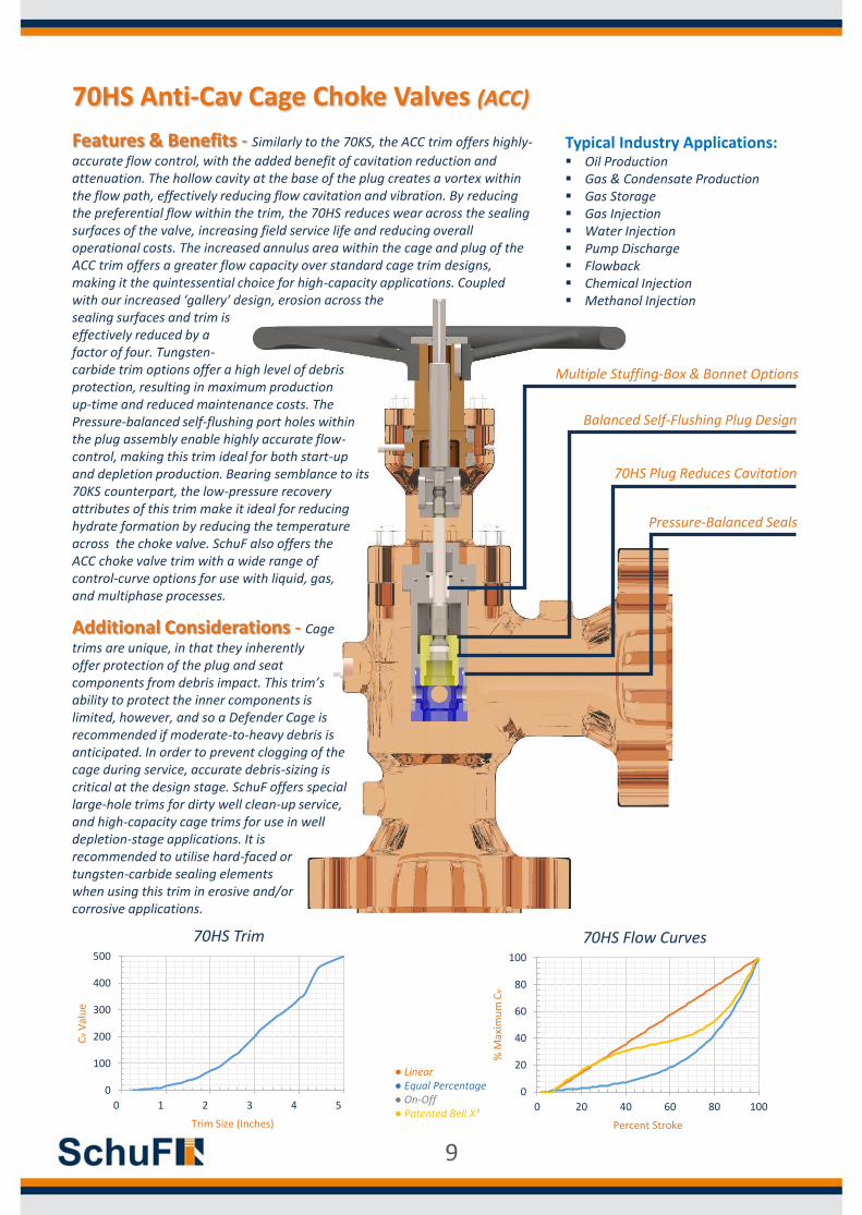
Features & Benefits - Similarly to the 70KS, the ACC trim offers highly-
accurate flow control, with the added benefit of cavitation reduction and attenuation. The hollow cavity at the base of the plug creates a vortex within the flow path, effectively reducing flow cavitation and vibration. By reducing the preferential flow within the trim, the 70HS reduces wear across the sealing surfaces of the valve, increasing field service life and reducing overall operational costs. The increased annulus area within the cage and plug of the ACC trim offers a greater flow capacity over standard cage trim designs, making it the quintessential choice for high-capacity applications. Coupledwith our increased ‘gallery’ design, erosion across thesealing surfaces and trim is effectively reduced by a factor of four. Tungsten-carbide trim options offer a high level of debris protection, resulting in maximum production up-time and reduced maintenance costs. The Pressure-balanced self-flushing port holes within the plug assembly enable highly accurate flow-control, making this trim ideal for both start-up and depletion production. Bearing semblance to its70KS counterpart, the low-pressure recoveryattributes of this trim make it ideal for reducinghydrate formation by reducing the temperatureacross the choke valve. SchuF also offers theACC choke valve trim with a wide range ofcontrol-curve options for use with liquid, gas,and multiphase processes.
70HS Anti-Cav Cage Choke Valves (ACC)
Typical Industry Applications: Oil Production Gas & Condensate Production Gas Storage Gas Injection Water Injection Pump Discharge Flowback Chemical Injection Methanol Injection
0
100
200
300
400
500
0 1 2 3 4 5
Cv
Val
ue
Trim Size (Inches)
70HS Trim
0
20
40
60
80
100
0 20 40 60 80 100
% M
axim
um
Cv
Percent Stroke
70HS Flow Curves
● Linear● Equal Percentage● On-Off● Patented Bell X³
Multiple Stuffing-Box & Bonnet Options
Balanced Self-Flushing Plug Design
70HS Plug Reduces Cavitation
Pressure-Balanced Seals
Additional Considerations - Cage
trims are unique, in that they inherentlyoffer protection of the plug and seat components from debris impact. This trim’s ability to protect the inner components is limited, however, and so a Defender Cage is recommended if moderate-to-heavy debris is anticipated. In order to prevent clogging of the cage during service, accurate debris-sizing is critical at the design stage. SchuF offers special large-hole trims for dirty well clean-up service, and high-capacity cage trims for use in well depletion-stage applications. It is recommended to utilise hard-faced or tungsten-carbide sealing elements when using this trim in erosive and/or corrosive applications.
9
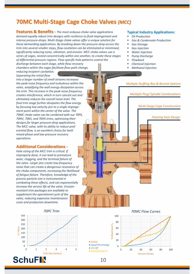
Additional Considerations -Hole-sizing of the MCC trim is critical. If improperly done, it can lead to premature wear, clogging, and the terminal failure of the valve. Larger jets create low-frequency noise that can create a dangerous resonance of the choke components, increasing the likelihood of fatigue failure. Therefore, knowledge of the process particle-size is instrumental in combating these effects, and can exponentially increase the service life of the valve. Erosion-resistant trim packages are available to supplement the operational cycle of the valve, reducing expensive maintenance costs and production downtime.
70MC Multi-Stage Cage Choke Valves (MCC)
Typical Industry Applications: Oil Production Gas & Condensate Production Gas Storage Gas Injection Water Injection Pump Discharge Flowback Chemical Injection Methanol Injection
Features & Benefits - The most arduous choke valve applications
demand equally robust trim designs with resilience to fluid-impingement and intense pressure-drops. Multi-Stage choke valves offer a unique solution for these demanding applications. By breaking down the pressure-drop across the trim into several smaller steps, flow cavitation can be eliminated or minimised, significantly reducing noise, vibration, and erosion. MCC choke valves use a series of cages, nested concentrically within one another, to create these stages of differential pressure regions. Flow-specific hole patterns control the discharge between each stage, while flow-recovery chambers within the cages facilitate flow-path change, reducing incipient cavitation. Separating the initial flow into a larger number of small streams increases the peak noise frequency and turbulence within the valve, amplifying the wall energy dissipation across the trim. This increase in the peak noise frequency creates interference, which in turn cancels out and ultimately reduces the overall noise level. The final trim stage further dissipates the flow energy by focusing low velocity jets to a single impinge-ment point within the center of the valve. The 70MC choke valve can be combined with our 70FK,70NV, 70KS, and 70HS trims, optimising theirdesigns for larger pressure-drop applications.The MCC valve, with its ability to reduce pref-erential flow, is an excellent choice for bothmixed-phase and low-pressure recoveryoperations.
0
20
40
60
80
100
0 20 40 60 80 100
% M
axim
um
Cv
Percent Stroke
70MC Flow Curves
● Linear● Equal Percentage● On-Off● Patented Bell X³
Multiple Stuffing-Box & Bonnet Options
Multiple Plug/ Spindle Combinations
Multi-Stage Cage Construction
Floating Seat Design
0
50
100
150
200
250
300
350
0 1 2 3 4 5
Cv
Val
ue
Trim Size (Inches)
70PC Trim
10
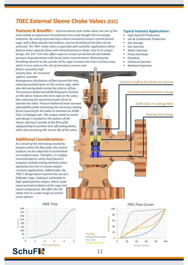
Additional Considerations -As a result of the trim being constantly present within the flow path, the control surfaces can be subjected to accelerated non-uniform wear. Therefore, it is highly recommended to utilise hard-faced or tungsten-carbide sealing elements when operating this trim in erosive and/or corrosive applications. Additionally, the 70EC‘s design doesn’t permit the use of a Defender Cage, making it vulnerable to high-speed particle impact, which could cause premature failure of the cage and sleeve components. We offer the ESC choke trim in a wide range of control-curve options.
70EC External Sleeve Choke Valves (ESC)
Typical Industry Applications: High-Sand Oil-Production Gas & Condensate Production Gas Storage Gas Injection Water Injection Pump Discharge Flowback Chemical Injection Methanol Injection
Features & Benefits – External-sleeve-style choke valves are one of the
most widely accepted and conventional trims used thought the oil and gas industries. By raising and lowering a sleeve mounted around a central ported cage, with a flow-specific hole pattern, precise throttling of the flow can be achieved. The 70EC choke valve is especially well-suited for applications which feature lower-capacity flows with elevated pressure-drops. Due to its unique design, the ‘ESC’ trim also offers superior erosion protection for formidable pressure drop operations with heavy sand concentrations. Relocating the throttling element to the outside of the cage increases the trim’s annulus area, which in turn reduces the risk of premature erosion andfailure caused by high-velocity flow. An increased ‘gallery’ provideshomogenous distribution of flow around the trim, reducing localised wear on the central cage, while also decreasing body erosion by a factor of four. The pressure-balanced self-flushing ports located on the sleeve reduces the stem load on the valve, thus reducing the required actuator force to operate the valve. Pressure-balanced seals increase adjustability while minimising the necessary sealing forces required for the valve to maintain an ASME Class IV leakage rate. The unique metal-to-metal seat design is located on the bottom of the sleeve, placing it outside of the flow path, safeguarding its positive shut-off sealing ability,while also increasing the service life of the valve.
0
20
40
60
80
100
0 20 40 60 80 100
% M
axim
um
Cv
Percent Stroke
70EC Flow Curves
● Linear● Equal Percentage● On-Off● Patented Bell X³
Multiple Stuffing-Box & Bonnet Options
Self-Cleaning Ported Sleeve Design
ASME Class IV Leakage Rate
Floating Seat Design
0
50
100
150
200
250
300
350
400
0 1 2 3 4 5
Cv
Val
ue
Trim Size (Inches)
70PC Trim
11
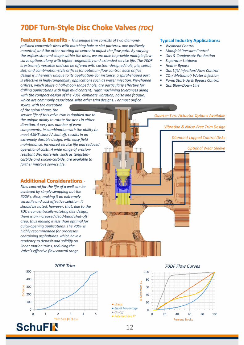
Additional Considerations -Flow control for the life of a well can be achieved by simply swapping out the 70DF´s discs, making it an extremely versatile and cost effective solution. It should be noted, however, that, due to the TDC´s concentrically-rotating disc design, there is an increased dead-band shut-off area, thus making it less than optimal for quick-opening applications. The 70DF is highly recommended for processes containing asphaltines, which have a tendency to deposit and solidify on linear motion trims, reducing the Valve’s effective flow control range.
70DF Turn-Style Disc Choke Valves (TDC)
Typical Industry Applications: Wellhead Control Manifold Pressure Control Gas & Condensate Production Separator Letdown Heater Bypass Gas Lift/ Injection/ Flow Control CO₂/ Methanol/ Water Injection Pump Start-Up & Bypass Control Gas Blow-Down Line
Features & Benefits - This unique trim consists of two diamond-
polished concentric discs with matching hole or slot patterns, one positively mounted, and the other rotating on center to adjust the flow path. By varying the orifices size and shape within the discs, we are able to provide multiple flow-curve options along with higher rangeability and extended service life. The 70DF is extremely versatile and can be offered with custom-designed hole, pie, spiral, slot, and combination-style orifices for optimum flow control. Each orifice design is inherently unique to its application- for instance, a spiral-shaped port is effective in high-rangeability applications such as water injection. Pie-shaped orifices, which utilise a half-moon shaped hole, are particularly effective for drilling applications with high mud content. Tight machining tolerances along with the compact design of the 70DF eliminate vibration, noise and fatigue, which are commonly associated with other trim designs. For most orificestyles, with the exceptionof the spiral shape, theservice life of this valve trim is doubled due to the unique ability to rotate the discs in either direction. A very low number of wear components, in combination with the ability tomeet ASME class IV shut off, results in an extremely durable design, with easy field maintenance, increased service life and reduced operational costs. A wide range of erosion-resistant disc materials, such as tungsten-carbide and silicon-carbide, are available to further improve service life.
0
100
200
300
400
500
0 1 2 3 4 5
Cv
Val
ue
Trim Size (Inches)
70DF Trim
● Linear● Equal Percentage● On-Off● Patented Bell X³
Quarter-Turn Actuator Options Available
Vibration & Noise-Free Trim Design
Diamond-Lapped Control Disks
Optional Wear Sleeve
0
20
40
60
80
100
0 20 40 60 80 100
% M
axim
um
Cv
Percent Stroke
70DF Flow Curves
12
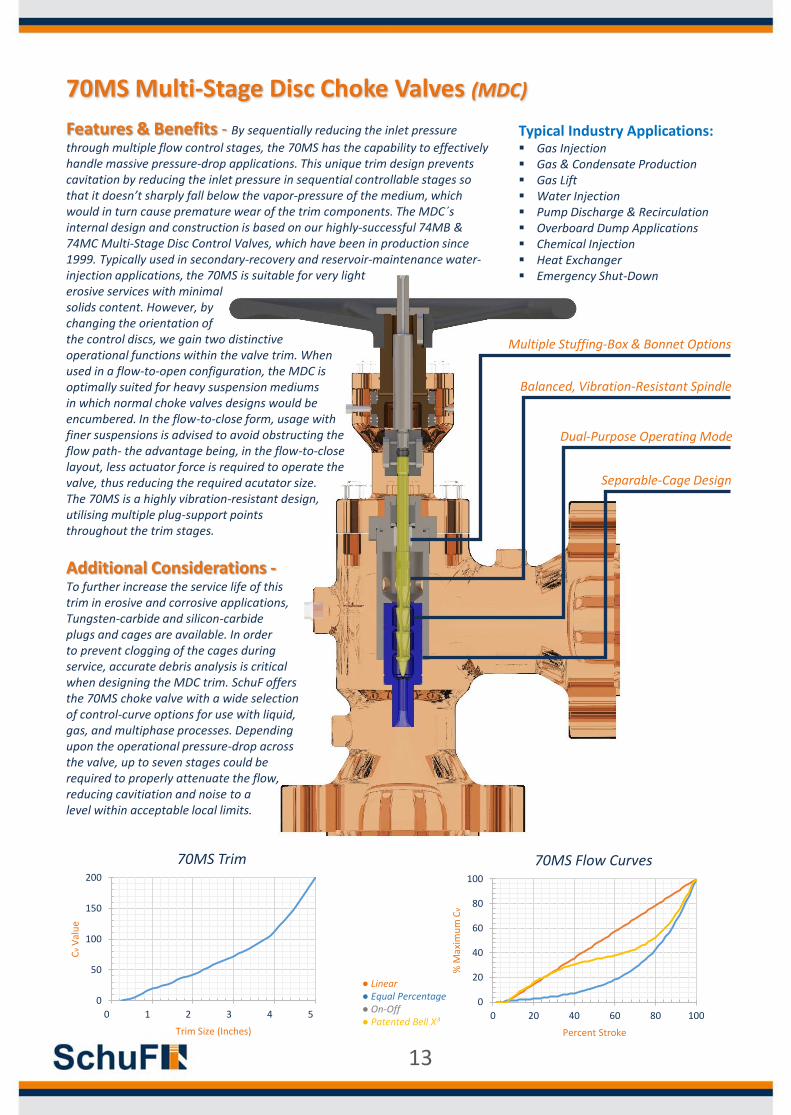
70MS Multi-Stage Disc Choke Valves (MDC)
Typical Industry Applications: Gas Injection Gas & Condensate Production Gas Lift Water Injection Pump Discharge & Recirculation Overboard Dump Applications Chemical Injection Heat Exchanger Emergency Shut-Down
Features & Benefits - By sequentially reducing the inlet pressure
through multiple flow control stages, the 70MS has the capability to effectively handle massive pressure-drop applications. This unique trim design prevents cavitation by reducing the inlet pressure in sequential controllable stages so that it doesn’t sharply fall below the vapor-pressure of the medium, which would in turn cause premature wear of the trim components. The MDC´s internal design and construction is based on our highly-successful 74MB & 74MC Multi-Stage Disc Control Valves, which have been in production since 1999. Typically used in secondary-recovery and reservoir-maintenance water-injection applications, the 70MS is suitable for very light erosive services with minimal solids content. However, by changing the orientation of the control discs, we gain two distinctive operational functions within the valve trim. When used in a flow-to-open configuration, the MDC is optimally suited for heavy suspension mediums in which normal choke valves designs would be encumbered. In the flow-to-close form, usage withfiner suspensions is advised to avoid obstructing the flow path- the advantage being, in the flow-to-close layout, less actuator force is required to operate the valve, thus reducing the required acutator size.The 70MS is a highly vibration-resistant design, utilising multiple plug-support pointsthroughout the trim stages.
0
50
100
150
200
0 1 2 3 4 5
Cv
Val
ue
Trim Size (Inches)
70MS Trim
0
20
40
60
80
100
0 20 40 60 80 100
% M
axim
um
Cv
Percent Stroke
70MS Flow Curves
● Linear● Equal Percentage● On-Off● Patented Bell X³
Multiple Stuffing-Box & Bonnet Options
Balanced, Vibration-Resistant Spindle
Dual-Purpose Operating Mode
Separable-Cage Design
Additional Considerations -To further increase the service life of this trim in erosive and corrosive applications, Tungsten-carbide and silicon-carbide plugs and cages are available. In order to prevent clogging of the cages during service, accurate debris analysis is critical when designing the MDC trim. SchuF offers the 70MS choke valve with a wide selection of control-curve options for use with liquid, gas, and multiphase processes. Depending upon the operational pressure-drop across the valve, up to seven stages could be required to properly attenuate the flow, reducing cavitiation and noise to alevel within acceptable local limits.
13

Features & Benefits - SchuF Stacker choke valves offer our customers
the ability to utilise higher differential operating pressures for extended periods of time during production. By forcing the process through a series of sharp turns and splitting channels, the 70SC Stacker valve is able to break the flow velocity down to manageable levels by de-localising the flow streams. The flow resistance created by these turns and channels limits the process fluid’s exit velocity to a less aggressive level, greatly reducing wear, noise, vibration, and erosion. Significant research has shown that the rate of erosion within the valve is directly proportional to the velocity of the medium through the trim. In fact, reducing the flow rate to approximately half of its initial value yields almost eight times less erosion across the trim control surfaces. To further prevent premature failure of the internal trim components, these bends and channels are designed with multiple-stage Pressure-drops, similar to our 70MS choke valves.By constantly expanding the bends and channels through the trim we are able to minimize the wear and erosion of these control surfaces, resulting in a much longer-lasting and reliablevalve design. Specially designed scrapers preventsolids building up and reduce the need for servicingand production downtime. By increasing the stroke, we offer a greater rangeability with our SC valves, reducing or eliminating the need for swapping of additional trim packages.
70SC Stacker Choke Valves (SC)
Typical Industry Applications: Oil Production Start-Up/ Shut-Down Gas & Condensate Production Gas & Methanol Injection Gas Lift Water Injection Pump Discharge Overboard Dump Applications Chemical Injection Fracturing Clean-Up
0
20
40
60
80
100
0 20 40 60 80 100
% M
axim
um
Cv
Percent Stroke
70SC Flow Curves
● Linear● Equal Percentage● On-Off● Patented Bell X³
Multiple Stuffing-Box & Bonnet Options
Multiple-Stage Let-Down Control
Solid Tungsten-Carbide Trim
Floating Trim Design
Additional Considerations –Specially-designed expanded-passage trim designs are available to accommodate processes with higher-than-normal solids content, while operating with the same unparalleled reliability as our standard models. With no internal components welded or screwed into the body, there is no need for special maintenance tools, reducing servicing time and overall operational of the valve. Up to six stages are available with this unique trim design, offering the maximum flow attenuation and protection possible. Solid tungsten-carbide plug & disc assemblies are standard on our SC model, withadditional erosion-resistantmaterial options also available.
0
20
40
60
80
100
120
0 1 2 3 4 5
Cv
Val
ue
Trim Size (Inches)
70SC Trim
14
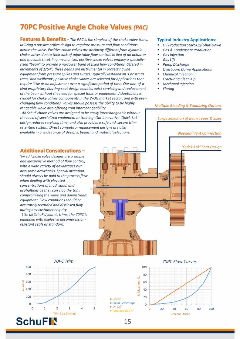
Features & Benefits - The PAC is the simplest of the choke valve trims,
utilizing a passive orifice design to regulate pressure and flow conditions across the valve. Positive choke valves are distinctly different from dynamic choke valves due to their lack of adjustable flow control. In lieu of an actuator and movable throttling mechanism, positive choke valves employ a specially-sized “bean” to provide a narrower band of fixed flow conditions. Offered in increments of 1/64”, these beans are instrumental in protecting line equipment from pressure spikes and surges. Typically installed on ‘Christmas trees’ and wellheads, positive choke valves are selected for applications that require little or no adjustment over a significant period of time. Our one-of-a-kind proprietary floating-seat design enables quick servicing and replacement of the bean without the need for special tools or equipment. Adaptability is crucial for choke valves components in the WOG market sector, and with ever-changing flow conditions, valves should possess the ability to be highly rangeable while also offering trim interchangeability. All SchuF choke valves are designed to be easily interchangeable without
the need of specialized equipment or training. Our innovative ‘Quick-Lok’ design reduces servicing time, and also provides a safe and secure trim-retention system. Direct competitor replacement designs are alsoavailable in a wide range of designs, beans, and material selections.
70PC Positive Angle Choke Valves (PAC)
Typical Industry Applications: Oil Production Start-Up/ Shut-Down Gas & Condensate Production Gas Injection Gas Lift Pump Discharge Overboard Dump Applications Chemical Injection Fracturing Clean-Up Methanol Injection Flaring
0
100
200
300
400
500
0 1 2 3 4 5
Cv
Val
ue
Trim Size (Inches)
70PC Trim
0
20
40
60
80
100
0 20 40 60 80 100
% M
axim
um
Cv
Percent Stroke
70PC Flow Curves
● Linear● Equal Percentage● On-Off● Patented Bell X³
Multiple Bleeding & Equalizing Options
Large Selection of Bean Types & Sizes
Bleeder/ Vent Connection
‘Quick-Lok‘ Seat DesignAdditional Considerations –’Fixed ‘choke valve designs are a simple and inexpensive method of flow control, with a wide variety of advantages but also some drawbacks. Special attention should always be paid to the process flow when dealing with elevated concentrations of mud, sand, and asphaltines as they can clog the trim, compromising the valve and downstream equipment. Flow conditions should be accurately recorded and disclosed fully during any customer enquiry. Like all SchuF dynamic trims, the 70PC is
equipped with explosive decompression-resistant seals as standard.
15
120
55
20
73
74
14
16
125
9070
6595
60
68
80
35
40
180
13
112
195
274230
277
210
190
240
235
121
12
116 115
10
185
220
17
18
72
260
250
210
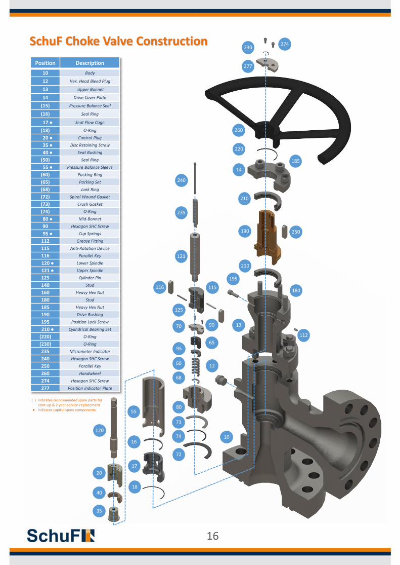
Position Description
10 Body
12 Hex. Head Bleed Plug
13 Upper Bonnet
14 Drive Cover Plate
(15) Pressure Balance Seal
(16) Seal Ring
17 ● Seat Flow Cage
(18) O-Ring
20 ● Control Plug
35 ● Disc Retaining Screw
40 ● Seat Bushing
(50) Seal Ring
55 ● Pressure Balance Sleeve
(60) Packing Ring
(65) Packing Set
(68) Junk Ring
(72) Spiral Wound Gasket
(73) Crush Gasket
(74) O-Ring
80 ● Mid-Bonnet
90 Hexagon SHC Screw
95 ● Cup Springs
112 Grease Fitting
115 Anti-Rotation Device
116 Parallel Key
120 ● Lower Spindle
121 ● Upper Spindle
125 Cylinder Pin
140 Stud
160 Heavy Hex Nut
180 Stud
185 Heavy Hex Nut
190 Drive Bushing
195 Position Lock Screw
210 ● Cylindrical Bearing Set
(220) O-Ring
(230) O-Ring
235 Micrometer Indicator
240 Hexagon SHC Screw
250 Parallel Key
260 Handwheel
274 Hexagon SHC Screw
277 Position indicator Plate
SchuF Choke Valve Construction
( ) Indicates recommended spare parts for start-up & 2 year service replacement
● Indicates capitol spare components
16
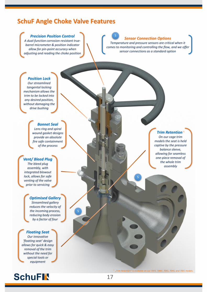
SchuF Angle Choke Valve Features
Optimised Gallery Streamlined gallery
reduces the velocity of the incoming process, reducing body erosion
by a factor of four
Vent/ Bleed Plug The bleed plug assembly, with
integrated blowout lock, allows for safe venting of the valve
prior to servicing
Floating Seat Our innovative
‘floating seat‘ design allows for quick & easy
removal of the trim without the need for
special tools or equipment
Bonnet SealLens ring and spiral
wound gasket designs provide an absolute
fire safe containment of the process
Trim Retention ¹
On our cage trim models the seat is held captive by the pressure
balance sleeve, allowing for seamless one-piece removal of
the whole trim assembly
¹ „Trim Retention“ is available on our 70FK, 70NV, 70KS, 70HS, and 70EC models.
Position Lock Our streamlined
tangental locking mechanism allows the trim to be locked into any desired position,
without damaging the drive bushing
Precision Position ControlA dual-function corrosion-resistant true-barrel micrometer & position indicator
allow for pin-point accuracy when adjusting and reading the choke position
S
S
Sensor Connection OptionsTemperature and pressure sensors are critical when it
comes to monitoring and controlling the flow, and we offer sensor connections as a standard option
S
17
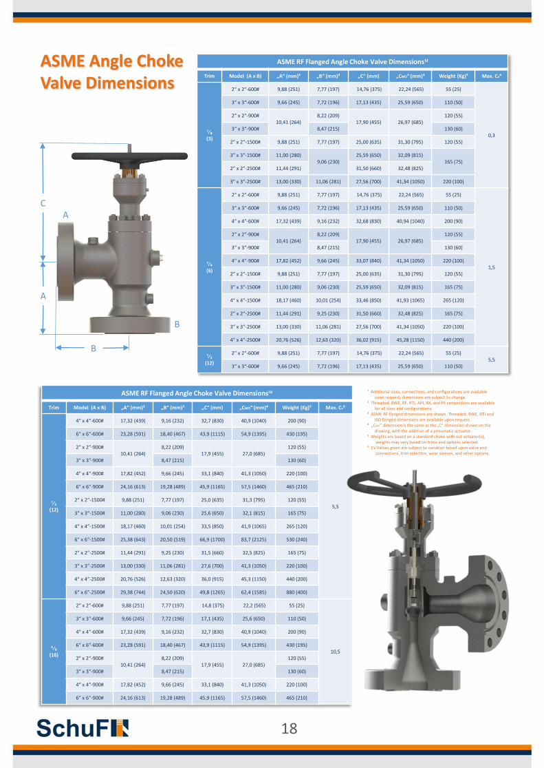
ASME Angle Choke Valve Dimensions
ASME RF Flanged Angle Choke Valve Dimensions¹²
Trim Model (A x B) „A“ (mm)³ „B“ (mm)³ „C“ (mm) „CMO“ (mm)⁴ Weight (Kg)⁵ Max. Cv⁶
¹⁄₈ (3)
2“ x 2“-600# 9,88 (251) 7,77 (197) 14,76 (375) 22,24 (565) 55 (25)
0,3
3“ x 3“-600# 9,66 (245) 7,72 (196) 17,13 (435) 25,59 (650) 110 (50)
2“ x 2“-900#10,41 (264)
8,22 (209)17,90 (455) 26,97 (685)
120 (55)
3“ x 3“-900# 8,47 (215) 130 (60)
2“ x 2“-1500# 9,88 (251) 7,77 (197) 25,00 (635) 31,30 (795) 120 (55)
3“ x 3“-1500# 11,00 (280)9,06 (230)
25,59 (650) 32,09 (815)165 (75)
2“ x 2“-2500# 11,44 (291) 31,50 (660) 32,48 (825)
3“ x 3“-2500# 13,00 (330) 11,06 (281) 27,56 (700) 41,34 (1050) 220 (100)
¹⁄₄ (6)
2“ x 2“-600# 9,88 (251) 7,77 (197) 14,76 (375) 22,24 (565) 55 (25)
1,5
3“ x 3“-600# 9,66 (245) 7,72 (196) 17,13 (435) 25,59 (650) 110 (50)
4“ x 4“-600# 17,32 (439) 9,16 (232) 32,68 (830) 40,94 (1040) 200 (90)
2“ x 2“-900#10,41 (264)
8,22 (209)17,90 (455) 26,97 (685)
120 (55)
3“ x 3“-900# 8,47 (215) 130 (60)
4“ x 4“-900# 17,82 (452) 9,66 (245) 33,07 (840) 41,34 (1050) 220 (100)
2“ x 2“-1500# 9,88 (251) 7,77 (197) 25,00 (635) 31,30 (795) 120 (55)
3“ x 3“-1500# 11,00 (280) 9,06 (230) 25,59 (650) 32,09 (815) 165 (75)
4“ x 4“-1500# 18,17 (460) 10,01 (254) 33,46 (850) 41,93 (1065) 265 (120)
2“ x 2“-2500# 11,44 (291) 9,25 (230) 31,50 (660) 32,48 (825) 165 (75)
3“ x 3“-2500# 13,00 (330) 11,06 (281) 27,56 (700) 41,34 (1050) 220 (100)
4“ x 4“-2500# 20,76 (526) 12,63 (320) 36,02 (915) 45,28 (1150) 440 (200)
¹⁄₂ (12)
2“ x 2“-600# 9,88 (251) 7,77 (197) 14,76 (375) 22,24 (565) 55 (25)5,5
3“ x 3“-600# 9,66 (245) 7,72 (196) 17,13 (435) 25,59 (650) 110 (50)
ASME RF Flanged Angle Choke Valve Dimensions¹²
Trim Model (A x B) „A“ (mm)³ „B“ (mm)³ „C“ (mm) „CMO“ (mm)⁴ Weight (Kg)⁵ Max. Cv⁶
¹⁄₂ (12)
4“ x 4“-600# 17,32 (439) 9,16 (232) 32,7 (830) 40,9 (1040) 200 (90)
5,5
6“ x 6“-600# 23,28 (591) 18,40 (467) 43,9 (1115) 54,9 (1395) 430 (195)
2“ x 2“-900#10,41 (264)
8,22 (209)17,9 (455) 27,0 (685)
120 (55)
3“ x 3“-900# 8,47 (215) 130 (60)
4“ x 4“-900# 17,82 (452) 9,66 (245) 33,1 (840) 41,3 (1050) 220 (100)
6“ x 6“-900# 24,16 (613) 19,28 (489) 45,9 (1165) 57,5 (1460) 465 (210)
2“ x 2“-1500# 9,88 (251) 7,77 (197) 25,0 (635) 31,3 (795) 120 (55)
3“ x 3“-1500# 11,00 (280) 9,06 (230) 25,6 (650) 32,1 (815) 165 (75)
4“ x 4“-1500# 18,17 (460) 10,01 (254) 33,5 (850) 41,9 (1065) 265 (120)
6“ x 6“-1500# 25,38 (643) 20,50 (519) 66,9 (1700) 83,7 (2125) 530 (240)
2“ x 2“-2500# 11,44 (291) 9,25 (230) 31,5 (660) 32,5 (825) 165 (75)
3“ x 3“-2500# 13,00 (330) 11,06 (281) 27,6 (700) 41,3 (1050) 220 (100)
4“ x 4“-2500# 20,76 (526) 12,63 (320) 36,0 (915) 45,3 (1150) 440 (200)
6“ x 6“-2500# 29,38 (744) 24,50 (620) 49,8 (1265) 62,4 (1585) 880 (400)
⁵⁄₈ (16)
2“ x 2“-600# 9,88 (251) 7,77 (197) 14,8 (375) 22,2 (565) 55 (25)
10,5
3“ x 3“-600# 9,66 (245) 7,72 (196) 17,1 (435) 25,6 (650) 110 (50)
4“ x 4“-600# 17,32 (439) 9,16 (232) 32,7 (830) 40,9 (1040) 200 (90)
6“ x 6“-600# 23,28 (591) 18,40 (467) 43,9 (1115) 54,9 (1395) 430 (195)
2“ x 2“-900#10,41 (264)
8,22 (209)17,9 (455) 27,0 (685)
120 (55)
3“ x 3“-900# 8,47 (215) 130 (60)
4“ x 4“-900# 17,82 (452) 9,66 (245) 33,1 (840) 41,3 (1050) 220 (100)
6“ x 6“-900# 24,16 (613) 19,28 (489) 45,9 (1165) 57,5 (1460) 465 (210)
A
B
B
A
C
¹ Additional sizes, connections, and configurations are available upon request; dimensions are subject to change.
² Threaded, BWE, RF, RTJ, API, BX, and PE connections are available for all sizes and configurations.
³ ASME RF flanged dimensions are shown. Threaded, BWE, RTJ and ISO flanged dimensions are available upon request.
⁴ „CMO“ dimension is the same as the„C“ dimension shown on the drawing, with the addition of a pneumatic actuator.
⁵ Weights are based on a standard choke with out actuator(s), weights may vary based on trims and options selected.
⁶ Cv Values given are subject to variation based upon valve end connections, trim selection, wear sleeves, and other options.
18
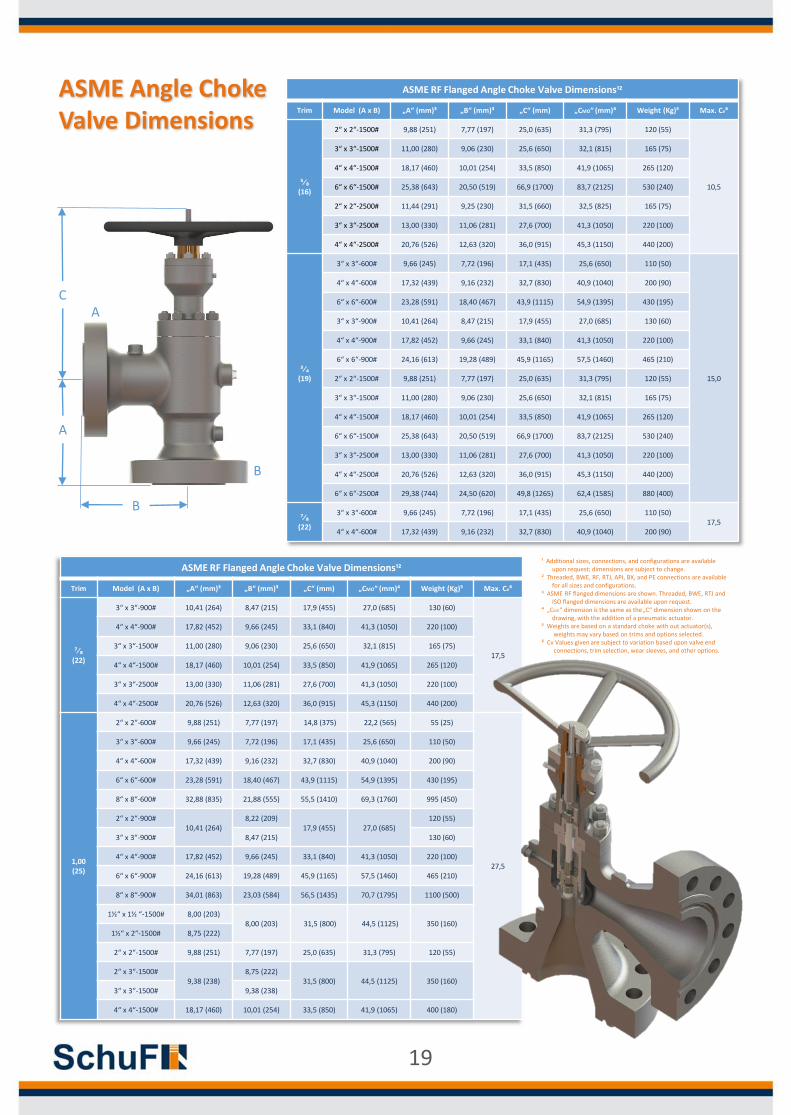
ASME RF Flanged Angle Choke Valve Dimensions¹²
Trim Model (A x B) „A“ (mm)³ „B“ (mm)³ „C“ (mm) „CMO“ (mm)⁴ Weight (Kg)⁵ Max. Cv⁶
⁵⁄₈ (16)
2“ x 2“-1500# 9,88 (251) 7,77 (197) 25,0 (635) 31,3 (795) 120 (55)
10,5
3“ x 3“-1500# 11,00 (280) 9,06 (230) 25,6 (650) 32,1 (815) 165 (75)
4“ x 4“-1500# 18,17 (460) 10,01 (254) 33,5 (850) 41,9 (1065) 265 (120)
6“ x 6“-1500# 25,38 (643) 20,50 (519) 66,9 (1700) 83,7 (2125) 530 (240)
2“ x 2“-2500# 11,44 (291) 9,25 (230) 31,5 (660) 32,5 (825) 165 (75)
3“ x 3“-2500# 13,00 (330) 11,06 (281) 27,6 (700) 41,3 (1050) 220 (100)
4“ x 4“-2500# 20,76 (526) 12,63 (320) 36,0 (915) 45,3 (1150) 440 (200)
³⁄₄ (19)
3“ x 3“-600# 9,66 (245) 7,72 (196) 17,1 (435) 25,6 (650) 110 (50)
15,0
4“ x 4“-600# 17,32 (439) 9,16 (232) 32,7 (830) 40,9 (1040) 200 (90)
6“ x 6“-600# 23,28 (591) 18,40 (467) 43,9 (1115) 54,9 (1395) 430 (195)
3“ x 3“-900# 10,41 (264) 8,47 (215) 17,9 (455) 27,0 (685) 130 (60)
4“ x 4“-900# 17,82 (452) 9,66 (245) 33,1 (840) 41,3 (1050) 220 (100)
6“ x 6“-900# 24,16 (613) 19,28 (489) 45,9 (1165) 57,5 (1460) 465 (210)
2“ x 2“-1500# 9,88 (251) 7,77 (197) 25,0 (635) 31,3 (795) 120 (55)
3“ x 3“-1500# 11,00 (280) 9,06 (230) 25,6 (650) 32,1 (815) 165 (75)
4“ x 4“-1500# 18,17 (460) 10,01 (254) 33,5 (850) 41,9 (1065) 265 (120)
6“ x 6“-1500# 25,38 (643) 20,50 (519) 66,9 (1700) 83,7 (2125) 530 (240)
3“ x 3“-2500# 13,00 (330) 11,06 (281) 27,6 (700) 41,3 (1050) 220 (100)
4“ x 4“-2500# 20,76 (526) 12,63 (320) 36,0 (915) 45,3 (1150) 440 (200)
6“ x 6“-2500# 29,38 (744) 24,50 (620) 49,8 (1265) 62,4 (1585) 880 (400)
⁷⁄₈ (22)
3“ x 3“-600# 9,66 (245) 7,72 (196) 17,1 (435) 25,6 (650) 110 (50)17,5
4“ x 4“-600# 17,32 (439) 9,16 (232) 32,7 (830) 40,9 (1040) 200 (90)
ASME RF Flanged Angle Choke Valve Dimensions¹²
Trim Model (A x B) „A“ (mm)³ „B“ (mm)³ „C“ (mm) „CMO“ (mm)⁴ Weight (Kg)⁵ Max. Cv⁶
⁷⁄₈ (22)
3“ x 3“-900# 10,41 (264) 8,47 (215) 17,9 (455) 27,0 (685) 130 (60)
17,5
4“ x 4“-900# 17,82 (452) 9,66 (245) 33,1 (840) 41,3 (1050) 220 (100)
3“ x 3“-1500# 11,00 (280) 9,06 (230) 25,6 (650) 32,1 (815) 165 (75)
4“ x 4“-1500# 18,17 (460) 10,01 (254) 33,5 (850) 41,9 (1065) 265 (120)
3“ x 3“-2500# 13,00 (330) 11,06 (281) 27,6 (700) 41,3 (1050) 220 (100)
4“ x 4“-2500# 20,76 (526) 12,63 (320) 36,0 (915) 45,3 (1150) 440 (200)
1,00 (25)
2“ x 2“-600# 9,88 (251) 7,77 (197) 14,8 (375) 22,2 (565) 55 (25)
27,5
3“ x 3“-600# 9,66 (245) 7,72 (196) 17,1 (435) 25,6 (650) 110 (50)
4“ x 4“-600# 17,32 (439) 9,16 (232) 32,7 (830) 40,9 (1040) 200 (90)
6“ x 6“-600# 23,28 (591) 18,40 (467) 43,9 (1115) 54,9 (1395) 430 (195)
8“ x 8“-600# 32,88 (835) 21,88 (555) 55,5 (1410) 69,3 (1760) 995 (450)
2“ x 2“-900#10,41 (264)
8,22 (209)17,9 (455) 27,0 (685)
120 (55)
3“ x 3“-900# 8,47 (215) 130 (60)
4“ x 4“-900# 17,82 (452) 9,66 (245) 33,1 (840) 41,3 (1050) 220 (100)
6“ x 6“-900# 24,16 (613) 19,28 (489) 45,9 (1165) 57,5 (1460) 465 (210)
8“ x 8“-900# 34,01 (863) 23,03 (584) 56,5 (1435) 70,7 (1795) 1100 (500)
1½“ x 1½ “-1500# 8,00 (203)8,00 (203) 31,5 (800) 44,5 (1125) 350 (160)
1½“ x 2“-1500# 8,75 (222)
2“ x 2“-1500# 9,88 (251) 7,77 (197) 25,0 (635) 31,3 (795) 120 (55)
2“ x 3“-1500#9,38 (238)
8,75 (222)31,5 (800) 44,5 (1125) 350 (160)
3“ x 3“-1500# 9,38 (238)
4“ x 4“-1500# 18,17 (460) 10,01 (254) 33,5 (850) 41,9 (1065) 400 (180)
ASME Angle Choke Valve Dimensions
A
B
B
A
C
¹ Additional sizes, connections, and configurations are available upon request; dimensions are subject to change.
² Threaded, BWE, RF, RTJ, API, BX, and PE connections are available for all sizes and configurations.
³ ASME RF flanged dimensions are shown. Threaded, BWE, RTJ and ISO flanged dimensions are available upon request.
⁴ „CMO“ dimension is the same as the„C“ dimension shown on the drawing, with the addition of a pneumatic actuator.
⁵ Weights are based on a standard choke with out actuator(s), weights may vary based on trims and options selected.
⁶ Cv Values given are subject to variation based upon valve end connections, trim selection, wear sleeves, and other options.
19
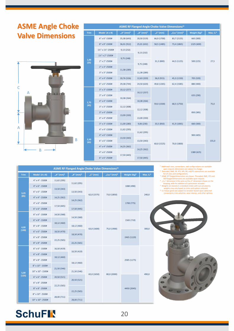
ASME RF Flanged Angle Choke Valve Dimensions¹²
Trim Model (A x B) „A“ (mm)³ „B“ (mm)³ „C“ (mm) „CMO“ (mm)⁴ Weight (Kg)⁵ Max. Cv⁶
1,00 (25)
6“ x 6“-1500# 25,38 (643) 20,50 (519) 66,9 (1700) 83,7 (2125) 665 (300)
27,5
8“ x 8“-1500# 36,01 (912) 25,01 (632) 58,5 (1485) 73,4 (1865) 1325 (600)
1½“ x 1½“-2500# 9,13 (232)9,13 (232)
31,5 (800) 44,5 (1125) 500 (225)
1½“ x 2“-2500#9,75 (248)
2“ x 2“-2500#9,75 (248)
2“ x 3“-2500#11,38 (289)
3“ x 3“-2500# 11,38 (289)
4“ x 4“-2500# 20,76 (526) 12,63 (320) 36,0 (915) 45,3 (1150) 705 (320)
6“ x 6“-2500# 29,38 (744) 24,50 (620) 49,8 (1265) 62,4 (1585) 880 (400)
1,75 (45)
3“ x 3“-1500# 10,12 (257)10,12 (257)
59,0 (1500) 68,5 (1750)
635 (290)
75,0
3“ x 4“-1500#10,38 (264)
4“ x 4“-1500# 10,38 (264)
3“ x 3“-2500# 12,12 (308)12,12 (308)
850 (385)3“ x 4“-2500#13,00 (330)
4“ x 4“-2500# 13,00 (330)
2,50 (65)
3“ x 3“-1500# 11,00 (280) 9,06 (230) 33,5 (850) 41,9 (1065) 660 (300)
155,0
4“ x 4“-1500# 11,62 (295)11,62 (295)
60,0 (1525) 70,0 (1800)
900 (405)4“ x 6“-1500#13,50 (343)
6“ x 6“-1500# 13,50 (343)
4“ x 4“-2500# 14,25 (362)14,25 (362)
1380 (625)4“ x 6“-2500#17,50 (445)
6“ x 6“-2500# 17,50 (445)
ASME RF Flanged Angle Choke Valve Dimensions¹²
Trim Model (A x B) „A“ (mm)³ „B“ (mm)³ „C“ (mm) „CMO“ (mm)⁴ Weight (Kg)⁵ Max. Cv⁶
3,25 (85)
4“ x 4“- 1500# 11,62 (295)11,62 (295)
62,0 (1575) 73,0 (1850)
1080 (490)
240,0
4“ x 6“- 1500#13,50 (343)
6“ x 6“- 1500# 13,50 (343)
4“ x 4“- 2500# 14,25 (362)14,25 (362)
1700 (775)4“ x 6“- 2500#17,50 (445)
6“ x 6“- 2500# 17,50 (445)
4,00 (100)
6“ x 6“- 1500# 14,50 (368)14,50 (368)
63,0 (1600) 75,0 (1900)
1565 (710)
300,0
6“ x 8“- 1500#18,12 (460)
8“ x 8“- 1500# 18,12 (460)
6“ x 6“- 2500# 18,50 (470)18,50 (470)
2465 (1120)6“ x 8“- 2500#22,25 (565)
8“ x 8“- 2500# 22,25 (565)
5,00 (125)
6“ x 6“- 1500# 16,50 (419)16,50 (419)
65,0 (1650) 80,0 (2000)
2585 (1175)
490,0
6“ x 8“- 1500#18,12 (460)
8“ x 8“- 1500#18,12 (460)
8“ x 10“- 1500#21,50 (546)
10“ x 10“- 1500# 21,50 (546)
6“ x 6“- 2500# 20,50 (521)20,50 (521)
4450 (2045)
6“ x 8“- 2500#22,25 (565)
8“ x 8“- 2500#22,25 (565)
8“ x 10“- 2500#28,00 (711)
10“ x 10“- 2500# 28,00 (711)
ASME Angle Choke Valve Dimensions
A
B
B
A
C
¹ Additional sizes, connections, and configurations are available upon request; dimensions are subject to change.
² Threaded, BWE, RF, RTJ, API, BX, and PE connections are available for all sizes and configurations.
³ ASME RF flanged dimensions are shown. Threaded, BWE, RTJ and ISO flanged dimensions are available upon request.
⁴ „CMO“ dimension is the same as the„C“ dimension shown on the drawing, with the addition of a pneumatic actuator.
⁵ Weights are based on a standard choke with out actuator(s), weights may vary based on trims and options selected.
⁶ Cv Values given are subject to variation based upon valve end connections, trim selection, wear sleeves, and other options.
20
A
B
B
A
C
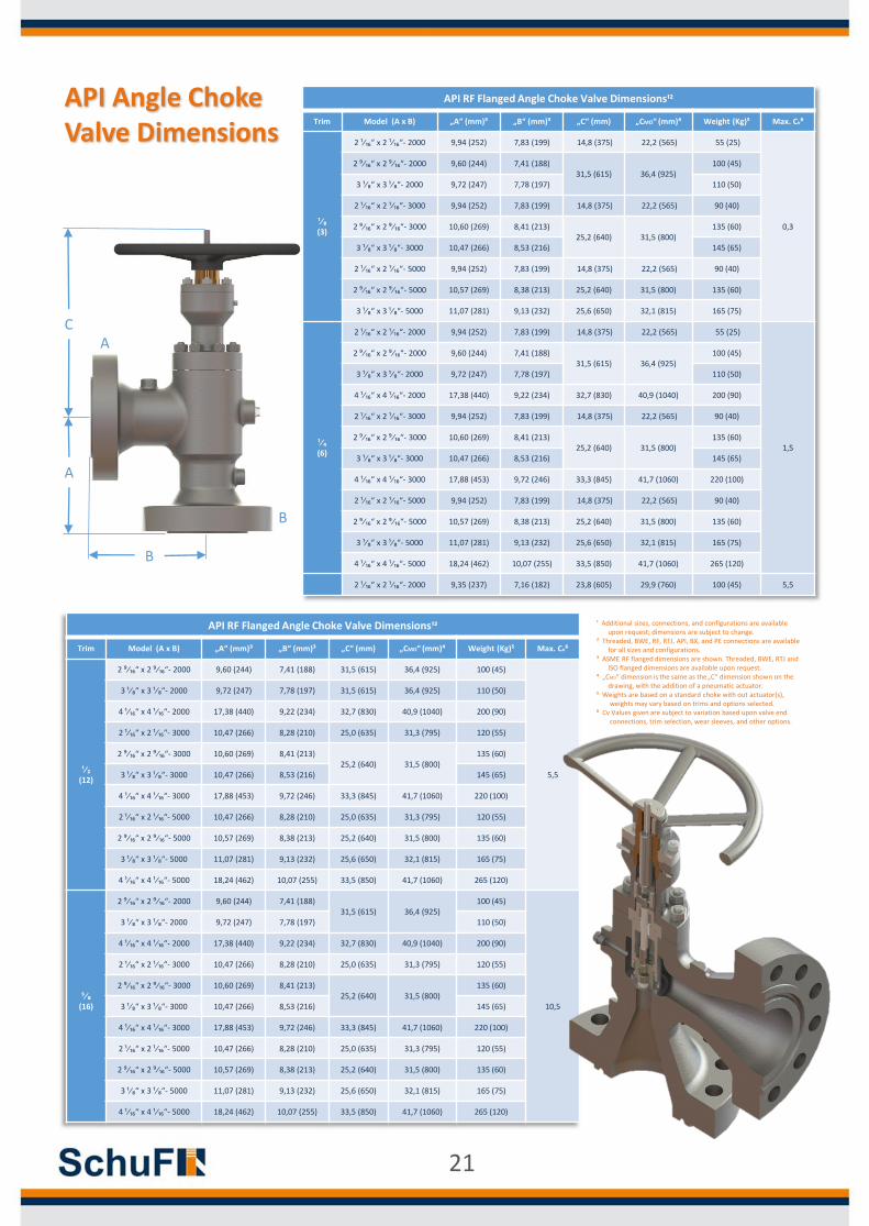
API RF Flanged Angle Choke Valve Dimensions¹²
Trim Model (A x B) „A“ (mm)³ „B“ (mm)³ „C“ (mm) „CMO“ (mm)⁴ Weight (Kg)⁵ Max. Cv⁶
¹⁄₈ (3)
2 ¹⁄₁₆“ x 2 ¹⁄₁₆“- 2000 9,94 (252) 7,83 (199) 14,8 (375) 22,2 (565) 55 (25)
0,3
2 ⁹⁄₁₆“ x 2 ⁹⁄₁₆“- 2000 9,60 (244) 7,41 (188)31,5 (615) 36,4 (925)
100 (45)
3 ¹⁄₈“ x 3 ¹⁄₈“- 2000 9,72 (247) 7,78 (197) 110 (50)
2 ¹⁄₁₆“ x 2 ¹⁄₁₆“- 3000 9,94 (252) 7,83 (199) 14,8 (375) 22,2 (565) 90 (40)
2 ⁹⁄₁₆“ x 2 ⁹⁄₁₆“- 3000 10,60 (269) 8,41 (213)25,2 (640) 31,5 (800)
135 (60)
3 ¹⁄₈“ x 3 ¹⁄₈“- 3000 10,47 (266) 8,53 (216) 145 (65)
2 ¹⁄₁₆“ x 2 ¹⁄₁₆“- 5000 9,94 (252) 7,83 (199) 14,8 (375) 22,2 (565) 90 (40)
2 ⁹⁄₁₆“ x 2 ⁹⁄₁₆“- 5000 10,57 (269) 8,38 (213) 25,2 (640) 31,5 (800) 135 (60)
3 ¹⁄₈“ x 3 ¹⁄₈“- 5000 11,07 (281) 9,13 (232) 25,6 (650) 32,1 (815) 165 (75)
¹⁄₄ (6)
2 ¹⁄₁₆“ x 2 ¹⁄₁₆“- 2000 9,94 (252) 7,83 (199) 14,8 (375) 22,2 (565) 55 (25)
1,5
2 ⁹⁄₁₆“ x 2 ⁹⁄₁₆“- 2000 9,60 (244) 7,41 (188)31,5 (615) 36,4 (925)
100 (45)
3 ¹⁄₈“ x 3 ¹⁄₈“- 2000 9,72 (247) 7,78 (197) 110 (50)
4 ¹⁄₁₆“ x 4 ¹⁄₁₆“- 2000 17,38 (440) 9,22 (234) 32,7 (830) 40,9 (1040) 200 (90)
2 ¹⁄₁₆“ x 2 ¹⁄₁₆“- 3000 9,94 (252) 7,83 (199) 14,8 (375) 22,2 (565) 90 (40)
2 ⁹⁄₁₆“ x 2 ⁹⁄₁₆“- 3000 10,60 (269) 8,41 (213)25,2 (640) 31,5 (800)
135 (60)
3 ¹⁄₈“ x 3 ¹⁄₈“- 3000 10,47 (266) 8,53 (216) 145 (65)
4 ¹⁄₁₆“ x 4 ¹⁄₁₆“- 3000 17,88 (453) 9,72 (246) 33,3 (845) 41,7 (1060) 220 (100)
2 ¹⁄₁₆“ x 2 ¹⁄₁₆“- 5000 9,94 (252) 7,83 (199) 14,8 (375) 22,2 (565) 90 (40)
2 ⁹⁄₁₆“ x 2 ⁹⁄₁₆“- 5000 10,57 (269) 8,38 (213) 25,2 (640) 31,5 (800) 135 (60)
3 ¹⁄₈“ x 3 ¹⁄₈“- 5000 11,07 (281) 9,13 (232) 25,6 (650) 32,1 (815) 165 (75)
4 ¹⁄₁₆“ x 4 ¹⁄₁₆“- 5000 18,24 (462) 10,07 (255) 33,5 (850) 41,7 (1060) 265 (120)
2 ¹⁄₁₆“ x 2 ¹⁄₁₆“- 2000 9,35 (237) 7,16 (182) 23,8 (605) 29,9 (760) 100 (45) 5,5
API RF Flanged Angle Choke Valve Dimensions¹²
Trim Model (A x B) „A“ (mm)³ „B“ (mm)³ „C“ (mm) „CMO“ (mm)⁴ Weight (Kg)⁵ Max. Cv⁶
¹⁄₂ (12)
2 ⁹⁄₁₆“ x 2 ⁹⁄₁₆“- 2000 9,60 (244) 7,41 (188) 31,5 (615) 36,4 (925) 100 (45)
5,5
3 ¹⁄₈“ x 3 ¹⁄₈“- 2000 9,72 (247) 7,78 (197) 31,5 (615) 36,4 (925) 110 (50)
4 ¹⁄₁₆“ x 4 ¹⁄₁₆“- 2000 17,38 (440) 9,22 (234) 32,7 (830) 40,9 (1040) 200 (90)
2 ¹⁄₁₆“ x 2 ¹⁄₁₆“- 3000 10,47 (266) 8,28 (210) 25,0 (635) 31,3 (795) 120 (55)
2 ⁹⁄₁₆“ x 2 ⁹⁄₁₆“- 3000 10,60 (269) 8,41 (213)25,2 (640) 31,5 (800)
135 (60)
3 ¹⁄₈“ x 3 ¹⁄₈“- 3000 10,47 (266) 8,53 (216) 145 (65)
4 ¹⁄₁₆“ x 4 ¹⁄₁₆“- 3000 17,88 (453) 9,72 (246) 33,3 (845) 41,7 (1060) 220 (100)
2 ¹⁄₁₆“ x 2 ¹⁄₁₆“- 5000 10,47 (266) 8,28 (210) 25,0 (635) 31,3 (795) 120 (55)
2 ⁹⁄₁₆“ x 2 ⁹⁄₁₆“- 5000 10,57 (269) 8,38 (213) 25,2 (640) 31,5 (800) 135 (60)
3 ¹⁄₈“ x 3 ¹⁄₈“- 5000 11,07 (281) 9,13 (232) 25,6 (650) 32,1 (815) 165 (75)
4 ¹⁄₁₆“ x 4 ¹⁄₁₆“- 5000 18,24 (462) 10,07 (255) 33,5 (850) 41,7 (1060) 265 (120)
⁵⁄₈ (16)
2 ⁹⁄₁₆“ x 2 ⁹⁄₁₆“- 2000 9,60 (244) 7,41 (188)31,5 (615) 36,4 (925)
100 (45)
10,5
3 ¹⁄₈“ x 3 ¹⁄₈“- 2000 9,72 (247) 7,78 (197) 110 (50)
4 ¹⁄₁₆“ x 4 ¹⁄₁₆“- 2000 17,38 (440) 9,22 (234) 32,7 (830) 40,9 (1040) 200 (90)
2 ¹⁄₁₆“ x 2 ¹⁄₁₆“- 3000 10,47 (266) 8,28 (210) 25,0 (635) 31,3 (795) 120 (55)
2 ⁹⁄₁₆“ x 2 ⁹⁄₁₆“- 3000 10,60 (269) 8,41 (213)25,2 (640) 31,5 (800)
135 (60)
3 ¹⁄₈“ x 3 ¹⁄₈“- 3000 10,47 (266) 8,53 (216) 145 (65)
4 ¹⁄₁₆“ x 4 ¹⁄₁₆“- 3000 17,88 (453) 9,72 (246) 33,3 (845) 41,7 (1060) 220 (100)
2 ¹⁄₁₆“ x 2 ¹⁄₁₆“- 5000 10,47 (266) 8,28 (210) 25,0 (635) 31,3 (795) 120 (55)
2 ⁹⁄₁₆“ x 2 ⁹⁄₁₆“- 5000 10,57 (269) 8,38 (213) 25,2 (640) 31,5 (800) 135 (60)
3 ¹⁄₈“ x 3 ¹⁄₈“- 5000 11,07 (281) 9,13 (232) 25,6 (650) 32,1 (815) 165 (75)
4 ¹⁄₁₆“ x 4 ¹⁄₁₆“- 5000 18,24 (462) 10,07 (255) 33,5 (850) 41,7 (1060) 265 (120)
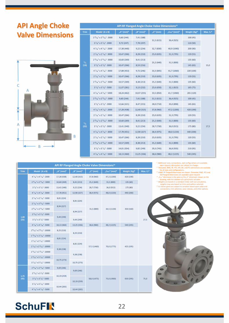
API Angle Choke Valve Dimensions
¹ Additional sizes, connections, and configurations are available upon request; dimensions are subject to change.
² Threaded, BWE, RF, RTJ, API, BX, and PE connections are available for all sizes and configurations.
³ ASME RF flanged dimensions are shown. Threaded, BWE, RTJ and ISO flanged dimensions are available upon request.
⁴ „CMO“ dimension is the same as the„C“ dimension shown on the drawing, with the addition of a pneumatic actuator.
⁵ Weights are based on a standard choke with out actuator(s), weights may vary based on trims and options selected.
⁶ Cv Values given are subject to variation based upon valve end connections, trim selection, wear sleeves, and other options.
21
A
B
B
A
C
API RF Flanged Angle Choke Valve Dimensions¹²
Trim Model (A x B) „A“ (mm)³ „B“ (mm)³ „C“ (mm) „CMO“ (mm)⁴ Weight (Kg)⁵ Max. Cv⁶
³⁄₄ (19)
2 ⁹⁄₁₆“ x 2 ⁹⁄₁₆“- 2000 9,60 (244) 7,41 (188)31,5 (615) 36,4 (925)
100 (45)
15,0
3 ¹⁄₈“ x 3 ¹⁄₈“- 2000 9,72 (247) 7,78 (197) 110 (50)
4 ¹⁄₁₆“ x 4 ¹⁄₁₆“- 2000 17,38 (440) 9,22 (234) 32,7 (830) 40,9 (1040) 200 (90)
2 ¹⁄₁₆“ x 2 ¹⁄₁₆“- 3000 10,47 (266) 8,28 (210) 25,0 (635) 31,3 (795) 120 (55)
2 ⁹⁄₁₆“ x 2 ⁹⁄₁₆“- 3000 10,60 (269) 8,41 (213)25,2 (640) 31,5 (800)
135 (60)
3 ¹⁄₈“ x 3 ¹⁄₈“- 3000 10,47 (266) 8,53 (216) 145 (65)
4 ¹⁄₁₆“ x 4 ¹⁄₁₆“- 3000 17,88 (453) 9,72 (246) 33,3 (845) 41,7 (1060) 220 (100)
2 ¹⁄₁₆“ x 2 ¹⁄₁₆“- 5000 10,47 (266) 8,28 (210) 25,0 (635) 31,3 (795) 120 (55)
2 ⁹⁄₁₆“ x 2 ⁹⁄₁₆“- 5000 10,57 (269) 8,38 (213) 25,2 (640) 31,5 (800) 135 (60)
3 ¹⁄₈“ x 3 ¹⁄₈“- 5000 11,07 (281) 9,13 (232) 25,6 (650) 32,1 (815) 165 (75)
4 ¹⁄₁₆“ x 4 ¹⁄₁₆“- 5000 18,24 (462) 10,07 (255) 33,5 (850) 41,7 (1060) 265 (120)
⁷⁄₈ (22)
2 ⁹⁄₁₆“ x 2 ⁹⁄₁₆“- 2000 9,60 (244) 7,41 (188) 31,5 (615) 36,4 (925) 100 (45)
17,5
3 ¹⁄₈“ x 3 ¹⁄₈“- 2000 12,66 (321) 8,47 (215) 28,0 (710) 35,0 (890) 145 (65)
4 ¹⁄₁₆“ x 4 ¹⁄₁₆“- 2000 17,28 (438) 12,40 (315) 37,8 (960) 47,2 (1200) 420 (190)
2 ¹⁄₁₆“ x 2 ¹⁄₁₆“- 3000 10,47 (266) 8,28 (210) 25,0 (635) 31,3 (795) 120 (55)
2 ⁹⁄₁₆“ x 2 ⁹⁄₁₆“- 3000 10,60 (269) 8,41 (213) 25,2 (640) 31,5 (800) 135 (60)
3 ¹⁄₈“ x 3 ¹⁄₈“- 3000 13,41 (340) 9,22 (234) 28,7 (730) 36,0 (915) 175 (80)
4 ¹⁄₁₆“ x 4 ¹⁄₁₆“- 3000 17,78 (451) 12,90 (327) 38,4 (975) 48,0 (1220) 440 (200)
2 ¹⁄₁₆“ x 2 ¹⁄₁₆“- 5000 10,47 (266) 8,28 (210) 25,0 (635) 31,3 (795) 120 (55)
2 ⁹⁄₁₆“ x 2 ⁹⁄₁₆“- 5000 10,57 (269) 8,38 (213) 25,2 (640) 31,5 (800) 135 (60)
3 ¹⁄₈“ x 3 ¹⁄₈“- 5000 14,01 (354) 9,82 (249) 29,3 (745) 36,8 (935) 210 (95)
4 ¹⁄₁₆“ x 4 ¹⁄₁₆“- 5000 18,13 (460) 13,25 (336) 38,6 (980) 48,2 (1225) 540 (245)
API RF Flanged Angle Choke Valve Dimensions¹²
Trim Model (A x B) „A“ (mm)³ „B“ (mm)³ „C“ (mm) „CMO“ (mm)⁴ Weight (Kg)⁵ Max. Cv⁶
1,00 (25)
4 ¹⁄₁₆“ x 4 ¹⁄₁₆“- 2000 17,28 (438) 12,40 (315) 37,8 (960) 47,2 (1200) 420 (190)
27,5
2 ⁹⁄₁₆“ x 2 ⁹⁄₁₆“- 3000 10,60 (269) 8,41 (213) 25,2 (640) 31,5 (800) 135 (60)
3 ¹⁄₈“ x 3 ¹⁄₈“- 3000 13,41 (340) 9,22 (234) 28,7 (730) 36,0 (915) 175 (80)
4 ¹⁄₁₆“ x 4 ¹⁄₁₆“- 3000 17,78 (451) 12,90 (327) 38,4 (975) 48,0 (1220) 440 (200)
2 ¹⁄₁₆“ x 2 ¹⁄₁₆“- 5000 8,81 (224)8,81 (224)
31,5 (800) 44,5 (1130) 350 (160)
2 ¹⁄₁₆“ x 2 ⁹⁄₁₆“- 50008,94 (227)
2 ⁹⁄₁₆“ x 2 ⁹⁄₁₆“- 50008,94 (227)
2 ⁹⁄₁₆“ x 3 ¹⁄₈“- 50009,44 (240)
3 ¹⁄₈“ x 3 ¹⁄₈“- 5000 9,44 (240)
4 ¹⁄₁₆“ x 4 ¹⁄₁₆“- 5000 18,13 (460) 13,25 (336) 38,6 (980) 48,2 (1225) 540 (245)
1¹³⁄₁₆“ x 1¹³⁄₁₆“- 10000 8,25 (210)8,25 (210)
57,5 (1460) 70,0 (1775) 425 (195)
1 ¹³⁄₁₆“ x 2 ¹⁄₁₆“- 100008,81 (224)
2 ¹⁄₁₆“ x 2 ¹⁄₁₆“- 100008,81 (224)
2 ¹⁄₁₆“ x 2 ⁹⁄₁₆“- 100009,38 (238)
2 ⁹⁄₁₆“ x 2 ⁹⁄₁₆“- 100009,38 (238)
2 ⁹⁄₁₆“ x 3 ¹⁄₁₆“- 1000010,75 (273)
3 ¹⁄₁₆“ x 3 ¹⁄₁₆“- 10000 10,75 (273)
1,75 (45)
2 ⁹⁄₁₆“ x 2 ⁹⁄₁₆“- 5000 9,69 (246)9,69 (246)
58,0 (1475) 75,0 (1900) 650 (295) 75,0
2 ⁹⁄₁₆“ x 3 ¹⁄₈“- 500010,19 (259)
3 ¹⁄₈“ x 3 ¹⁄₈“- 500010,19 (259)
3 ¹⁄₈“ x 4 ¹⁄₁₆“- 500010,44 (265)
4 ¹⁄₁₆“ x 4 ¹⁄₁₆“- 5000 10,44 (265)
API Angle Choke Valve Dimensions
¹ Additional sizes, connections, and configurations are available upon request; dimensions are subject to change.
² Threaded, BWE, RF, RTJ, API, BX, and PE connections are available for all sizes and configurations.
³ ASME RF flanged dimensions are shown. Threaded, BWE, RTJ and ISO flanged dimensions are available upon request.
⁴ „CMO“ dimension is the same as the„C“ dimension shown on the drawing, with the addition of a pneumatic actuator.
⁵ Weights are based on a standard choke with out actuator(s), weights may vary based on trims and options selected.
⁶ Cv Values given are subject to variation based upon valve end connections, trim selection, wear sleeves, and other options.
22
A
B
B
A
C
API RF Flanged Angle Choke Valve Dimensions¹²
Trim Model (A x B) „A“ (mm)³ „B“ (mm)³ „C“ (mm) „CMO“ (mm)⁴ Weight (Kg)⁵ Max. Cv⁶
1,75 (45)
4 ¹⁄₁₆“ x 4 ¹⁄₁₆“- 5000 10,44 (265) 58,0 (1475) 75,0 (1900) 650 (295)
75,0
2 ⁹⁄₁₆“ x 2 ⁹⁄₁₆“- 10000 11,38 (289)11,38 (289)
59,0 (1500) 80,0 (2030) 770 (350)
2 ⁹⁄₁₆“ x 3 ¹⁄₁₆“- 1000012,00 (305)
3 ¹⁄₁₆“ x 3 ¹⁄₁₆“- 1000012,00 (305)
3 ¹⁄₁₆“ x 4 ¹⁄₁₆“- 1000013,00 (330)
4 ¹⁄₁₆“ x 4 ¹⁄₁₆“- 10000 13,00 (330)
2,50 (65)
3 ¹⁄₈“ x 3 ¹⁄₈“- 5000 10,19 (259)10,19 (259)
60,0 (1525)
75,0 (1900) 850 (385)
155,0
3 ¹⁄₈“ x 4 ¹⁄₁₆“- 5000 11,69 (297)
3 ¹⁄₈“ x 3 ¹⁄₈“- 5000 10,19 (259)10,19 (259)
3 ¹⁄₈“ x 4 ¹⁄₁₆“- 500011,69 (297)
4 ¹⁄₁₆“ x 4 ¹⁄₁₆“- 500011,69 (297)
4 ¹⁄₁₆“ x 5 ¹⁄₈“- 500012,94 (329)
5 ¹⁄₈“ x 5 ¹⁄₈“- 5000 12,94 (329)
3 ¹⁄₁₆“ x 3 ¹⁄₁₆“- 10000 12,00 (305)12,00 (305)
80,0 (2030) 935 (425)
3 ¹⁄₁₆“ x 4 ¹⁄₁₆“- 1000013,00 (330)
4 ¹⁄₁₆“ x 4 ¹⁄₁₆“- 1000013,00 (330)
4 ¹⁄₁₆“ x 5 ¹⁄₈“- 1000014,81 (376)
5 ¹⁄₈“ x 5 ¹⁄₈“- 10000 14,81 (376)
3,25 (85)
4 ¹⁄₁₆“ x 4 ¹⁄₁₆“- 5000 11,69 (297)11,69 (297)
85,0 (2160) 1000 (455) 240,04 ¹⁄₁₆“ x 5 ¹⁄₈“- 5000
12,94 (329)62,0 (1575)5 ¹⁄₈“ x 5 ¹⁄₈“- 5000
12,94 (329)5 ¹⁄₈“ x 7 ¹⁄₁₆“- 5000 13,62 (346)
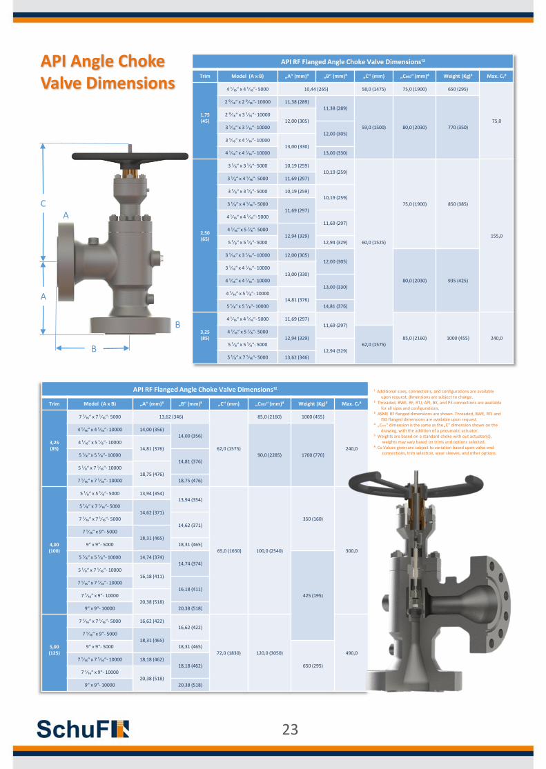
API Angle Choke Valve Dimensions
API RF Flanged Angle Choke Valve Dimensions¹²
Trim Model (A x B) „A“ (mm)³ „B“ (mm)³ „C“ (mm) „CMO“ (mm)⁴ Weight (Kg)⁵ Max. Cv⁶
3,25 (85)
7 ¹⁄₁₆“ x 7 ¹⁄₁₆“- 5000 13,62 (346)
62,0 (1575)
85,0 (2160) 1000 (455)
240,0
4 ¹⁄₁₆“ x 4 ¹⁄₁₆“- 10000 14,00 (356)14,00 (356)
90,0 (2285) 1700 (770)
4 ¹⁄₁₆“ x 5 ¹⁄₈“- 1000014,81 (376)
5 ¹⁄₈“ x 5 ¹⁄₈“- 1000014,81 (376)
5 ¹⁄₈“ x 7 ¹⁄₁₆“- 1000018,75 (476)
7 ¹⁄₁₆“ x 7 ¹⁄₁₆“- 10000 18,75 (476)
4,00 (100)
5 ¹⁄₈“ x 5 ¹⁄₈“- 5000 13,94 (354)13,94 (354)
65,0 (1650) 100,0 (2540)
350 (160)
300,0
5 ¹⁄₈“ x 7 ¹⁄₁₆“- 500014,62 (371)
7 ¹⁄₁₆“ x 7 ¹⁄₁₆“- 500014,62 (371)
7 ¹⁄₁₆“ x 9“- 500018,31 (465)
9“ x 9“- 5000 18,31 (465)
5 ¹⁄₈“ x 5 ¹⁄₈“- 10000 14,74 (374)14,74 (374)
425 (195)
5 ¹⁄₈“ x 7 ¹⁄₁₆“- 1000016,18 (411)
7 ¹⁄₁₆“ x 7 ¹⁄₁₆“- 1000016,18 (411)
7 ¹⁄₁₆“ x 9“- 1000020,38 (518)
9“ x 9“- 10000 20,38 (518)
5,00 (125)
7 ¹⁄₁₆“ x 7 ¹⁄₁₆“- 5000 16,62 (422)16,62 (422)
72,0 (1830) 120,0 (3050) 490,0
7 ¹⁄₁₆“ x 9“- 500018,31 (465)
9“ x 9“- 5000 18,31 (465)
650 (295)7 ¹⁄₁₆“ x 7 ¹⁄₁₆“- 10000 18,18 (462)
18,18 (462)7 ¹⁄₁₆“ x 9“- 10000
20,38 (518)9“ x 9“- 10000 20,38 (518)
¹ Additional sizes, connections, and configurations are available upon request; dimensions are subject to change.
² Threaded, BWE, RF, RTJ, API, BX, and PE connections are available for all sizes and configurations.
³ ASME RF flanged dimensions are shown. Threaded, BWE, RTJ and ISO flanged dimensions are available upon request.
⁴ „CMO“ dimension is the same as the„C“ dimension shown on the drawing, with the addition of a pneumatic actuator.
⁵ Weights are based on a standard choke with out actuator(s), weights may vary based on trims and options selected.
⁶ Cv Values given are subject to variation based upon valve end connections, trim selection, wear sleeves, and other options.
23
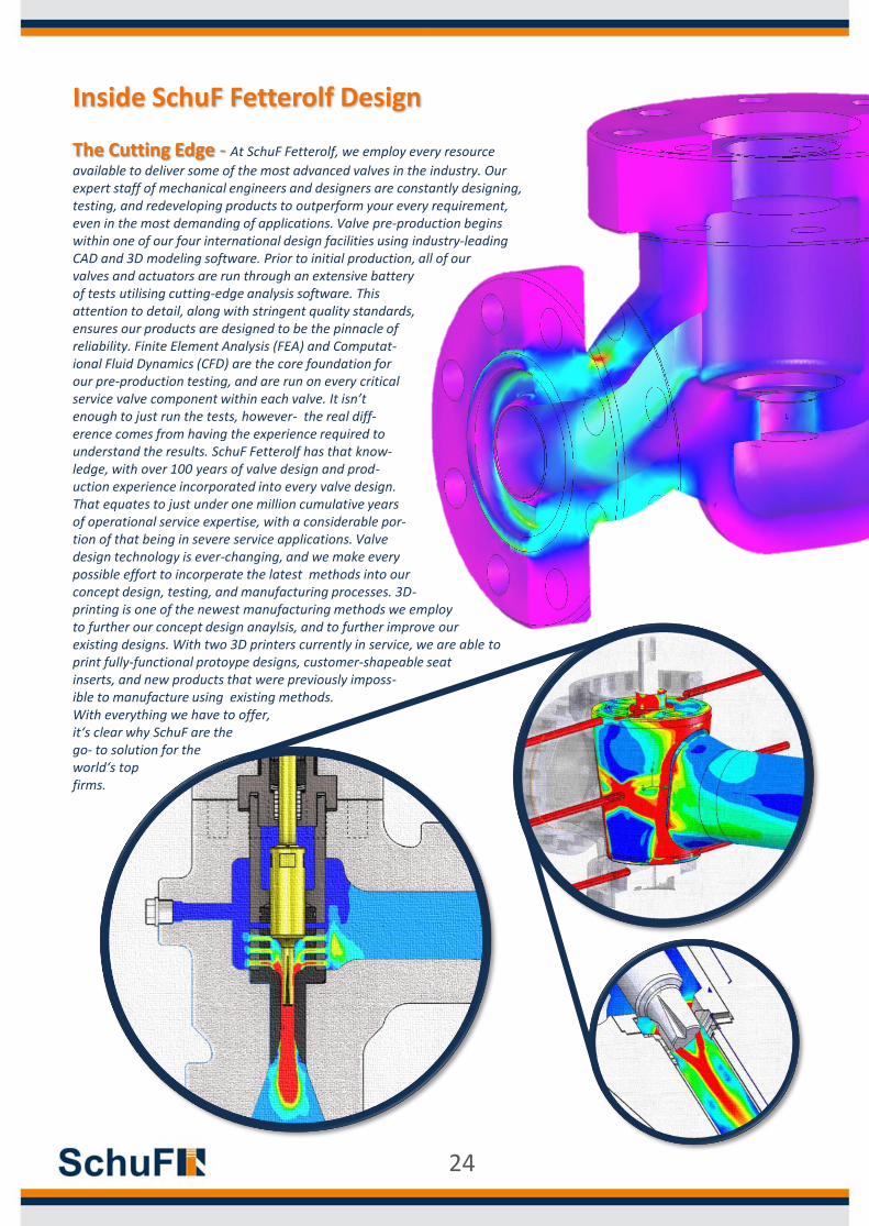
Inside SchuF Fetterolf Design
The Cutting Edge - At SchuF Fetterolf, we employ every resource
available to deliver some of the most advanced valves in the industry. Our expert staff of mechanical engineers and designers are constantly designing, testing, and redeveloping products to outperform your every requirement, even in the most demanding of applications. Valve pre-production begins within one of our four international design facilities using industry-leading CAD and 3D modeling software. Prior to initial production, all of our valves and actuators are run through an extensive battery of tests utilising cutting-edge analysis software. This attention to detail, along with stringent quality standards, ensures our products are designed to be the pinnacle of reliability. Finite Element Analysis (FEA) and Computat-ional Fluid Dynamics (CFD) are the core foundation forour pre-production testing, and are run on every criticalservice valve component within each valve. It isn’tenough to just run the tests, however- the real diff-erence comes from having the experience required tounderstand the results. SchuF Fetterolf has that know-ledge, with over 100 years of valve design and prod-uction experience incorporated into every valve design.That equates to just under one million cumulative yearsof operational service expertise, with a considerable por-tion of that being in severe service applications. Valvedesign technology is ever-changing, and we make everypossible effort to incorperate the latest methods into ourconcept design, testing, and manufacturing processes. 3D-printing is one of the newest manufacturing methods we employ to further our concept design anaylsis, and to further improve ourexisting designs. With two 3D printers currently in service, we are able toprint fully-functional protoype designs, customer-shapeable seatinserts, and new products that were previously imposs-ible to manufacture using existing methods.With everything we have to offer,it‘s clear why SchuF are thego- to solution for theworld‘s topfirms.
24
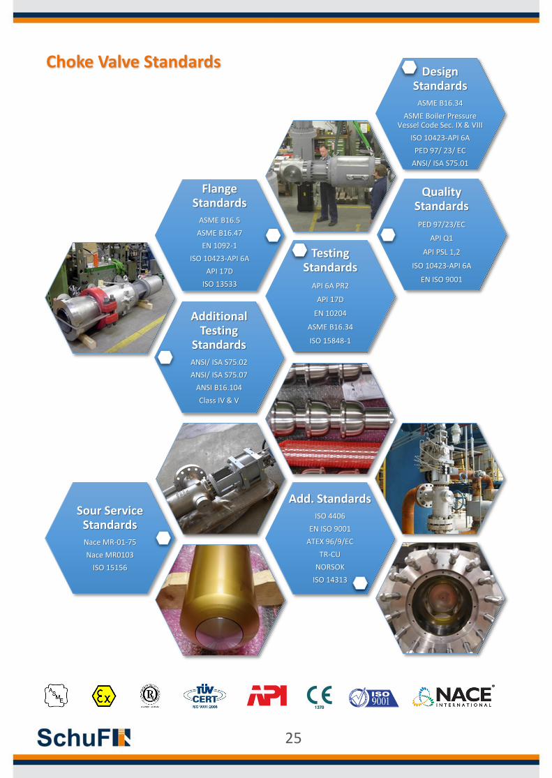
Choke Valve StandardsDesign
Standards ASME B16.34
ASME Boiler Pressure Vessel Code Sec. IX & VIII
ISO 10423-API 6A
PED 97/ 23/ EC
ANSI/ ISA S75.01
Testing Standards
API 6A PR2
API 17D
EN 10204
ASME B16.34
ISO 15848-1
Sour Service StandardsNace MR-01-75
Nace MR0103
ISO 15156
Quality Standards
PED 97/23/EC
API Q1
API PSL 1,2
ISO 10423-API 6A
EN ISO 9001
Add. StandardsISO 4406
EN ISO 9001
ATEX 96/9/EC
TR-CU
NORSOK
ISO 14313
Additional Testing
StandardsANSI/ ISA S75.02
ANSI/ ISA S75.07
ANSI B16.104
Class IV & V
Flange Standards
ASME B16.5
ASME B16.47
EN 1092-1
ISO 10423-API 6A
API 17D
ISO 13533
25
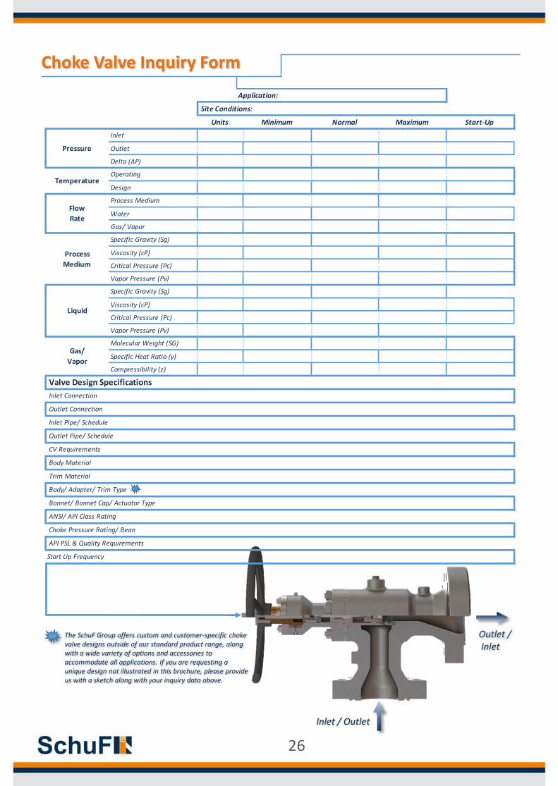
Choke Valve Inquiry Form
Outlet /Inlet
Inlet / Outlet
Maximum Start-Up
Start Up Frequency
Gas/
Vapor
Body Material
Trim Material
Body/ Adapter/ Trim Type
Bonnet/ Bonnet Cap/ Actuator Type
ANSI/ API Class Rating
Choke Pressure Rating/ Bean
Valve Design Specifications
Inlet Pipe/ Schedule
Outlet Pipe/ Schedule
CV Requirements
Specific Heat Ratio (γ)
Compressibility (z)
API PSL & Quality Requirements
Molecular Weight (SG)
Inlet Connection
Outlet Connection
Liquid
Specific Gravity (Sg)
Viscosity (cP)
Critical Pressure (Pc)
Vapor Pressure (Pv)
Process
Medium
Specific Gravity (Sg)
Viscosity (cP)
Critical Pressure (Pc)
Vapor Pressure (Pv)
Flow
RateWater
Gas/ Vapor
Process Medium
TemperatureOperating
Design
Pressure
Inlet
Outlet
Delta (ΔP)
Application:
Site Conditions:
Units Minimum Normal
The SchuF Group offers custom and customer-specific choke valve designs outside of our standard product range, along with a wide variety of options and accessories to accommodate all applications. If you are requesting a unique design not illustrated in this brochure, please provide us with a sketch along with your inquiry data above.
26
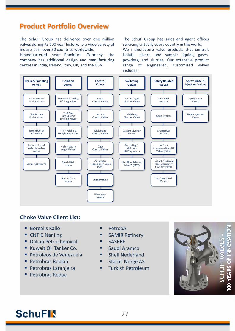
Product Portfolio Overview
Choke Valve Client List:
PetroSA SAMIR Refinery SASREF Saudi Aramco Shell Nederland Statoil Norge AS Turkish Petroleum
Borealis Kallo CNTIC Nanjing Dalian Petrochemical Kuwait Oil Tanker Co. Petroleos de Venezuela Petrobras Replan Petrobras Laranjeira Petrobras Reduc
27
Drain & Sampling Valves
Piston BottomOutlet Valves
Control Valves
Angle Control Valves
In-Line Control Valves
Multistage Control Valves
Cage Control Valves
AutomaticRecirculation Valve
(ARV)
Choke Valves
BlowdownValves
Isolation Valves
Standard & IsoPlugLift Plug Valves
TruEPlug Soft Sealing
Lift Plug Valves
Y- / P- Globe & Straightway Valves
High PressureAngle Valves
Special Ball Valves
Special Gate Valves
SwitchingValves
Y, R, & T type Diverter Valves
MultiwayDiverter Valves
SwitchPlug™ Multiway
Lift Plug Valves
ManiFlow Selector Valves™ (MSV)
Custom DiverterValves
Safety RelatedValves
Line Blind Systems
Goggle Valves
ChangeoverValves
In-Tank Emergency Shut-Off
Valves (TESO)
IsoTank® External Tank Emergency Shut-Off Valves
Non-Slam Check Valves
Spray Rinse & Injection Valves
Spray RinseValves
Steam InjectionValves
Disc BottomOutlet Valves
Sampling Systems
Bottom Outlet Ball Valves
Screw-in, Line & Wafer Sampling
Valves
The SchuF Group has delivered over one millionvalves during its 100 year history, to a wide variety ofindustries in over 50 countries worldwide.Headquartered near Frankfurt, Germany, thecompany has additional design and manufacturingcentres in India, Ireland, Italy, UK, and the USA.
The SchuF Group has sales and agent officesservicing virtually every country in the world.We manufacture valve products that control,isolate, divert, and sample liquids, gases,powders, and slurries. Our extensive productrange of engineered, customized valvesincludes:

28


