Embed Size (px)
Citation preview
Aerospace Science and Technology 12 (2008) 627–637
www.elsevier.com/locate/aescte
Anti-skid induced aircraft landing gear instability
Stefania Gualdi, Marco Morandini ∗, Gian Luca Ghiringhelli
Dipartimento di Ingegneria Aerospaziale, Politecnico di Milano, via La Masa 34, 20156 Milano, Italy
Received 14 May 2007; received in revised form 30 November 2007; accepted 26 February 2008
Available online 5 March 2008
Abstract
The paper deals with the application of multidisciplinary multibody modelling to the analysis of a particular aircraft landing gear-inducedinstability, known as “gear walk”. This low frequency fore-and-aft oscillation of the landing gear (LG) is primarily due to the coupling of the LGdeflection with the brake anti-skid control system characteristics. The objective is the development of a modelling approach that can be used asa design tool for the anti-skid controller in order to avoid malfunction during the braking manoeuvre. A comprehensive multibody model of anaircraft with a tripod main LG is developed and used, together with a simple anti-skid model, to predict the onset of the instability. The componentsused in the multibody model are thoroughly explained and the numerical results obtained are presented and discussed.© 2008 Elsevier Masson SAS. All rights reserved.
Keywords: Gear walk; Landing gear; Braking; Anti-skid; Multibody simulation
1. Introduction
This paper presents an approach to the modelling and sim-ulation of landing gear-induced unstable behaviour in a multi-body environment. In the field of aircraft engineering, the appli-cation of multidisciplinary simulation in the initial phases of aproject is beginning to gain momentum. In the last years, multi-body codes have been successfully employed for the predictionof landing gear (LG) dynamic behaviour and limit cycles [4,12,15,16,23,25,37,44]; in fact, the LG configuration, in termsof geometry, inertial characteristics and kinematics, howevercomplex, is fairly easily reproduced with appropriate parts andjoints, including flexible elements. Modelling the nonlinearitiesdue to tires and shock absorbers is not as straightforward: forthese functional components, special-purpose models must bedeveloped and implemented.
The case study presented in this paper deals with the insta-bility known as “gear walk”, a self-sustaining fore-and-aft lowfrequency vibration of the LG, primarily due to the coupling ofthe brake anti-skid system with the leg structural dynamics. Ba-
* Corresponding author. Tel.: +39 02 2399 8362; fax +39 02 2399 8334.E-mail addresses: [email protected] (S. Gualdi),
[email protected] (M. Morandini), [email protected](G.L. Ghiringhelli).
1270-9638/$ – see front matter © 2008 Elsevier Masson SAS. All rights reserved.doi:10.1016/j.ast.2008.02.002
sically, as the brakes are applied and the horizontal ground loaddevelops, the leg flexes rearwards; when an incipient skid is de-tected by the anti-lock system, the brakes are released and theleg springs forwards. This accelerates the wheel rapidly, trick-ing the anti-skid system into applying the brake pressure again,and the cycle repeats itself. The frequency range of the phe-nomenon depends on the type of LG: some authors place itin the 10–20 Hz range [8], some indicate ∼10 Hz [44], whileothers generally speak of a range between 10 and 50 Hz [18].The effects of this instability can be felt throughout the aircraftstructure as a low frequency shudder, for example 12 Hz on theMD80 [2], that can reach very high amplitudes. This instabilityis known to be affected by factors such as tire inflation pressureand the presence of air in the brake hydraulic system [2]. It ispotentially dangerous and can lead to complete LG structuralfailure [2,18]. While well-known instabilities, such as shimmy,have been extensively investigated through the years [34], thevibrational phenomena linked to the brakes, such as gear walk,chatter and squeal, are only recently being addressed [17,23,25–27,37].
The data used for the elaboration of the multibody modelpresented in this paper includes, among others, the assemblydrawings of the single components, FE models, the aircraftmass breakdown, the LG dynamic drop test results, the tireand shock absorber quasi-static force-deflection characteristics,
628 S. Gualdi et al. / Aerospace Science and Technology 12 (2008) 627–637
as well as field test data recorded during landing and brakingcampaigns. The major difficulties encountered during the de-velopment of the aircraft model are due to the fact that thedetail required for modelling the single components in orderto adequately reproduce the dynamic behaviour of the com-plete system is not known a priori. In this sense, the choiceof a multibody environment has the advantage of allowing theuser to build models step-by-step: the various components canbe modelled and tested separately, according to the availabledata, integrating them in the complete model and successivelyadding degrees of complexity without having to start all overagain each time.
The first objective of the paper is thus to show how a multi-body model can be progressively enhanced, studying the ef-fects of different model parameters, such as the landing gear–fuselage attachment deformability, or the gear deformability, inorder to adequately reproduce the dynamic behaviour of thecomplete system. Once the model has reached a satisfactorylevel of correlation with the available experimental data, the at-tention shifts to the origin of the “gear walk” instability and tohow it can be suppressed for the particular case study presented.The multibody model obtained can in fact be fitted with an anti-skid control system and the resulting system dynamic responseto different landing conditions can be investigated. It must benoted, however, that while for the aircraft and its LGs the avail-able data is sufficient to allow the development and tuning ofa realistic model, there is unfortunately no information regard-ing the anti-skid system designed for this aircraft. The controlsystem presented in this work is thus only a plausible surrogateof the real system and is developed with the scope of showinghow the tuning of the control parameters can affect the onset ofthe gear walk phenomenon.
If compared to the recent works regarding gear walk [23,26], this paper presents a comprehensive description of themultibody special modelling elements required to predict theinstability, including the tire and brake model, as well as fric-tion models (used both in the brake element and to introducejoint friction). The case study is affected by important geomet-ric nonlinearities, and the model is not built using linearisedequations around a reference configuration (such as a modalexpansion); rather, the deformability of the LG is reproducedusing beam elements and deformable joints. The LG model dy-namic response is validated using available drop test data. It isthen shown how the complete model can be successfully usedin order to design an anti-skid controller and to verify its be-haviour in different operational conditions.
2. Multibody model
The multibody model used in this work is implemented inthe MBDyn code, a freely available software [30]. Particularattention has been dedicated to the development of nonlinearmodels: tires, shock absorbers, brakes and the anti-skid con-trol system [4,11,15]. In the frame of virtual testing, specialelements simulating translational accelerometers have been in-troduced to monitor the accelerations without having to resortto a posteriori derivations.
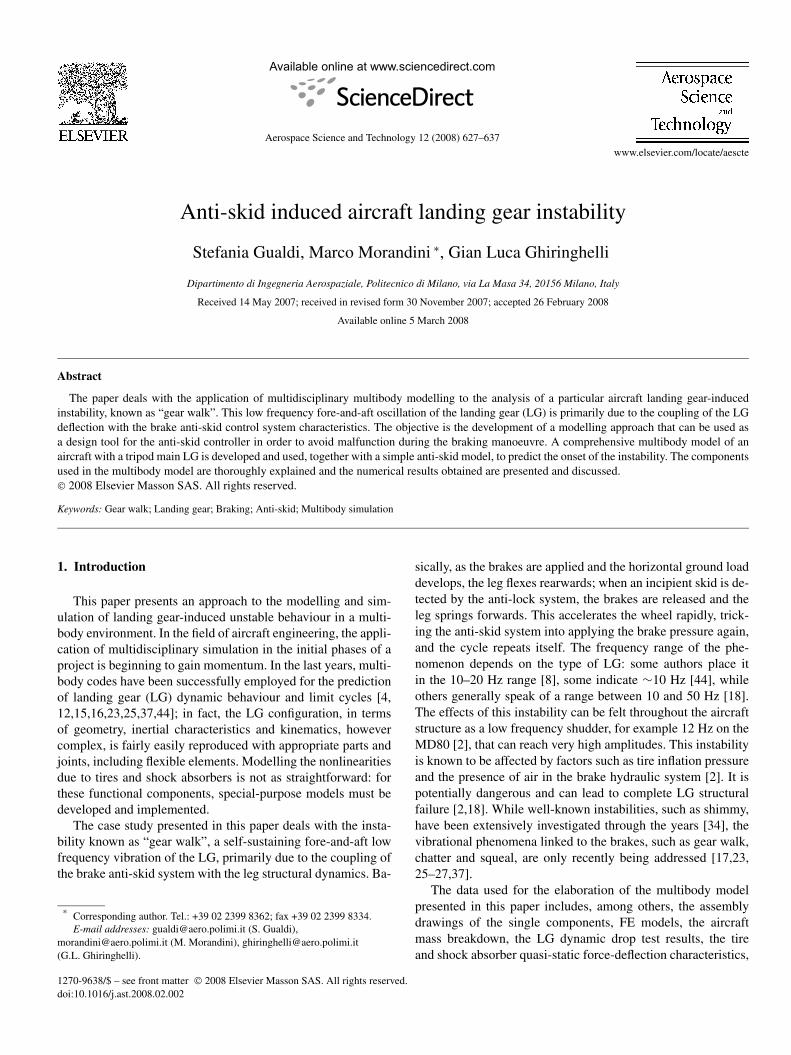
Fig. 1. Tripod MLG multibody model.
The case study presented regards an aircraft with a tripod-type main landing gear (MLG) which is known to suffer fromgear walk in normal braking conditions. A tripod LG is pecu-liar from a kinematic and dynamic standpoint, as it increasesthe gear track during compression (Fig. 1). A symmetrical ap-proach is adopted under the assumption that the time scale ofthe aircraft yaw dynamics radically differs from that of the de-formable LG longitudinal dynamics. A multibody semi-modelof the aircraft is fitted with a single tripod MLG and a telescopicnose landing gear (NLG). Although the gear walk phenomenonactually involves only the MLG, the NLG is needed to capturethe pitch oscillations that arise during braking due to the longi-tudinal aircraft dynamics and LG deflection. The decelerationapplied, in fact, induces a pitch in the aircraft attitude, causinga vertical load transfer between the MLG and the NLG. Al-though occurring at relatively low frequencies, the vertical loadvariation can influence the behaviour of the anti-skid controlsystem [19].
2.1. Gear structural model
Preliminary studies (see Section 3) lead to the conclusionthat the MLG model and its fuselage attachment need a cer-tain degree of detail to fulfil gear walk instability simulationrequirements. The NLG, on the other hand, is of interest only toguarantee the correct dynamic and static behaviour of the air-craft semi-model (see Section 2.2); it has thus been modelledwithout introducing structural flexibility.
The MLG multibody model includes leg deformability andfuselage attachment flexibility: the main strut, the drag braceand the retraction actuator are modelled using flexible beamand rod elements, reproducing the web-like structures (Fig. 1),whilst the connecting elements, the wheel axle and the wheelare rigid. The local MLG-fuselage attachment deformability,computed using an available FE model, has been introducedin the model using flexible joint elements. The mass and iner-tial characteristics, including those of the brakes mounted onthe MLG, have been lumped at the structural element nodesusing the available manufacturer mass breakdown data sheetsand assembly drawings. Internal friction has been added to allthe relevant joint elements, using a realistic friction model [9]
S. Gualdi et al. / Aerospace Science and Technology 12 (2008) 627–637 629
(see Section 2.4) combined with a Herzian contact force dis-tribution model [10] in order to estimate joint friction. Themetal-on-metal friction coefficient has been chosen referring tothe literature, as no experimental data was available. Free-playhas not been taken into account at this stage.
2.2. Shock absorber model
Both the NLG and the MLG are fitted with oleo-pneumaticshock absorbers with metering pins and direction-dependentfixed orifice areas. The nonlinear oleo-pneumatic shock ab-sorber model implemented in MBDyn uses a rod element witha viscoelastic constitutive law [15]: the nonlinear elastic andviscous forces are modelled using the classical polytropic com-pression and velocity-squared damping equations [31]; a cylin-der and piston assembly friction term is also considered [15].
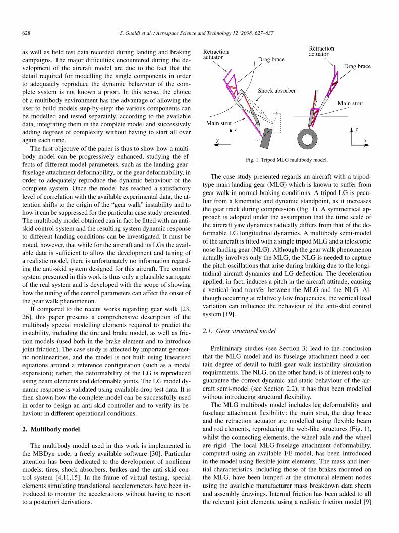
The geometrical parameters required for the definition of theshock absorber constitutive law are derived from the LG as-sembly drawings, while the functional parameters are tuned tomatch the experimental quasi-static compression and dynamicdrop test results (see Fig. 2). In the case of the NLG, due tothe fact that we are considering a semi-model of the aircraft,the functional parameters are tuned so that for any combinationof shock absorber stroke and stroke speed, the force transmit-ted by the equivalent NLG is exactly half of that which wouldhave been developed, in the same conditions, by the real NLG.
This guarantees the correct static and dynamic response of theaircraft semi-model, whose mass is, of course, half of the realaircraft mass.
2.3. Tire model
The tire model implemented in MBDyn for this applica-tion is an evolution of a model specifically developed, andsuccessfully used, for landing and impact analysis [14,15,17],integrated with an approach similar to that adopted by Van Zan-ten [42] to improve the dynamic behaviour of the tire, includingvisco-elastic effects.
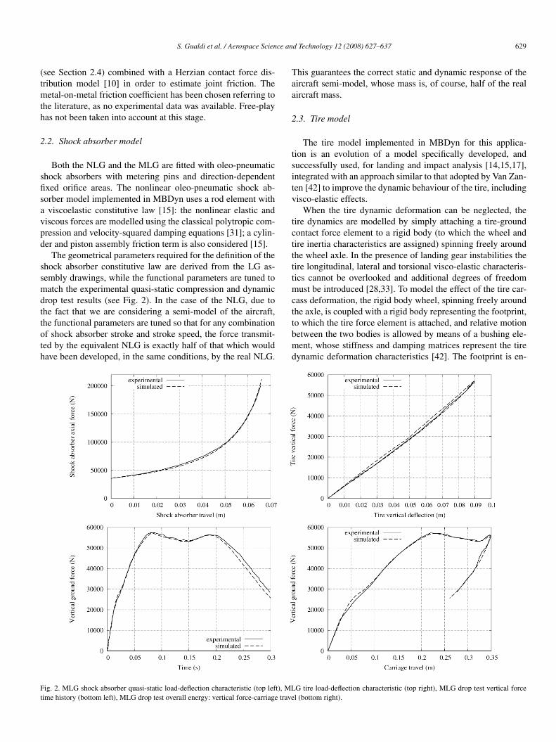
When the tire dynamic deformation can be neglected, thetire dynamics are modelled by simply attaching a tire-groundcontact force element to a rigid body (to which the wheel andtire inertia characteristics are assigned) spinning freely aroundthe wheel axle. In the presence of landing gear instabilities thetire longitudinal, lateral and torsional visco-elastic characteris-tics cannot be overlooked and additional degrees of freedommust be introduced [28,33]. To model the effect of the tire car-cass deformation, the rigid body wheel, spinning freely aroundthe axle, is coupled with a rigid body representing the footprint,to which the tire force element is attached, and relative motionbetween the two bodies is allowed by means of a bushing ele-ment, whose stiffness and damping matrices represent the tiredynamic deformation characteristics [42]. The footprint is en-
Fig. 2. MLG shock absorber quasi-static load-deflection characteristic (top left), MLG tire load-deflection characteristic (top right), MLG drop test vertical forcetime history (bottom left), MLG drop test overall energy: vertical force-carriage travel (bottom right).
630 S. Gualdi et al. / Aerospace Science and Technology 12 (2008) 627–637
Fig. 3. Multibody tire element; the linear spring represent the 6 DOF viscoelas-tic bushing connecting the footprint and the rigid wheel bodies (the torus andthe disk).
dowed with a mass, representing the portion of tread in contactwith the ground which does not participate in the tire dynamics.The remaining wheel and tire mass and inertia characteristicsare assigned to the rigid body wheel. In this way, the wheel isfree to follow the LG deflection, being loaded by the groundinteraction forces, correctly located at the footprint. A schemeof the resulting model is shown in Fig. 3. The friction charac-teristics considered are steady-state [13,38], thus no dynamicfriction effects [43] are accounted for in this model.
In the tire-ground contact force element, the nonlinear ver-tical force is modelled using an approach that reverses thephysics of the phenomenon: in a tire under loading, except forvery sharp impacts, the pressure and internal volume changevery little while the carcass deforms and the footprint areaincreases. In the present model, the carcass penetrates unde-formed into the ground: the footprint area A is equal to thegeometrical intersection (for the specific relative position) ofa torus, representing the tire, with the ground, while the inter-section volume V with the ground is subtracted from the initialvolume V0, determining a polytropic increase in the tire internalpressure p [36]. The resulting vertical force is computed as:
Fv(t) = Ap0
(V0
V0 − V
)γ (1 + tanh
(δ
δref
))(1)
where the hyperbolic tangent term, with a reference tire de-flection rate δref, is introduced in order to model the effectsof tire hysteresis [14]. The nonlinear longitudinal and lateralforce components are modelled using the vertical force compo-nent and the steady-state longitudinal and lateral friction coef-ficients, mapped as functions of the slip ratio (SR) and the slipangle (α). These tire-ground interaction parameters, commonlyused for vehicle dynamics analyses [13,38], are respectively de-fined as:
SR = |va long + ωtr||va long| (2)
and
α = atan
(va lat
va long
)(3)
where va long and va lat are the wheel axle speed components inthe wheel plane and parallel to the wheel axle, respectively, andωt and r are the instantaneous wheel angular velocity and tireradius. The forces are all applied at the contact point, at the cen-tre of the tire footprint area. This is of course a simplification, as
the actual pressure distribution on the contact patch varies [20,38,40]. A detailed overview of the tire force element equationscan be found in [14].
The bushing connecting the footprint to the rigid body wheelhas stiffness and damping matrices whose coefficients repre-sent the tire visco-elastic characteristics. In its present form, themodel implemented in MBDyn accounts for the tire longitu-dinal, lateral and vertical deformability and torsion around thewheel axis. Off-diagonal terms are not included. The dampingmatrix coefficients are considered proportional to the stiffnessesfor lack of available data.
The NLG and MLG tire force element geometrical param-eters have been deduced from manufacturer data, while thefunctional parameters have been tuned by virtual testing refer-ring to available experimental static load-deflection curves anddynamic drop test results (see Fig. 2). The tire-terrain longitu-dinal and lateral friction coefficients used are those found in theliterature for smooth asphalt [1].
Tire dynamic deformation is neglected in the case of theNLG: the tire force element is directly attached to the rigidwheel. The complete tire model is implemented only for theMLG and the stiffness matrix coefficients introduced in themodel are estimated using consolidated design procedures [40]and available manufacturer data. The proportional damping co-efficient has been chosen referring to information sparingly re-ported in the literature [6,24].
2.4. Brake and anti-skid control system models
The anti-skid system is modelled by integrating a closed-loop controller in the multibody simulation. The control forceis fed into the mechanical system by a brake element thatcomputes, accounting for the dynamics of a realistic frictionmodel [9], the braking torque, as a function of the applied brak-ing force. At present, no attempt is made to exactly modelthe hydraulic system dynamics, although the multidisciplinaryMBDyn code is capable of handling these aspects [29], norhave brake heating effects been considered, even though theymay prove to be relevant [32,35]; this will be the object of fu-ture research. However, the operational bandwidth limitationsintroduced by the presence of the anti-skid servovalve and thehydraulic system dynamics have been accounted for by filteringthe control system signal with an appropriate cut-off frequencybefore feeding it into the brake element.
The brake dynamic friction model is derived from the well-known LuGre friction law (see [3] for a detailed review offriction models). In this formulation [3,5,7,9] the friction co-efficient ff is computed as a function of the rigid body relativedisplacement x and its elastic component ξ :
ff = σ0ξ + σ1ξ + σ2x σ0, σ1, σ2 > 0, (4)
where σ0, the contact stiffness, accounts for the elastic pre-sliding relative displacement, σ1 is the damping for the tan-gential compliance and σ2 is the viscous friction parameter,accounting for rising static friction and for frictional memoryduring slip. This model is completed by the addition of a differ-
S. Gualdi et al. / Aerospace Science and Technology 12 (2008) 627–637 631
ential equation defining the elastic relative displacement com-ponent ξ :
ξ = x
(1 − σ0
|fss(x)| sign(x)ξ
)(5)
where the steady-state friction curve fss(x) (also known as theStribeck curve) defines the dependence of the friction coeffi-cient on the relative body velocity in steady-state conditions(ξ = 0 and x = const). MBDyn uses a slightly modified versionof the above formulæ, implementing those defined in [9], wherethe frictional behaviour in the presence of a mixed elastic-plastic displacement is suitably modelled. The complete formu-lation has not been transcribed for the sake of brevity.
The brake model works as follows: a force Fbrake is appliedto the brake pads, the brake element computes the friction coef-ficient ff between the pads and the disks, and the brake torqueapplied to the wheel-axle rotational joint is then simply givenby M = FbrakeffRdisk, where Rdisk is the equivalent mean ra-dius of the brake disk.
Braking is simulated in this work by applying a constantforce Fpilot, representing the pilot pedal force, and activating aconstant gain proportional-integral-derivative (PID) controllerto compute the control force FABS. The anti-skid model is sin-gle acting, i.e. the hydraulic pressure supplied to the brake canonly be reduced, never increased. FABS is thus applied onlywhen negative. The overall braking force fed into the brake el-ement is given by
Fbrake = min(0,FABS) + Fpilot (6)
The anti-skid controller braking strategy adopted in thiswork aims at achieving an optimal slip ratio SRtarget, chosen inorder to maximise the available tire-ground friction coefficient.In the study presented, a value of 0.3 for the SRtarget, whichcorresponds to the maximum friction coefficient for smooth dryasphalt [1,39], is considered. To avoid including an observer forthe SR (see Eq. (2)), since aboard the aircraft, ωt can be instan-taneously measured, while va long and r cannot, the controlleruses an estimated SR, based on the tire static radius R, obtainedwhen the aircraft is at rest and on the aircraft longitudinal speedvlong:
SR = 1 − ωtR
vlong, (7)
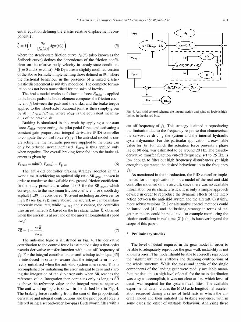
The anti-skid logic is illustrated in Fig. 4. The derivativecontribution to the control force is estimated using a first-orderpseudo-derivative transfer function with a cut-off frequency offd. For the integral contribution, an anti-windup technique [45]is introduced in order to assure that the integral term is cor-rectly initialised when the anti-skid system intervenes. This isaccomplished by initialising the error integral to zero and start-ing the integration of the slip error only when SR reaches thereference value. Integration then continues only as long as SRis above the reference value or the integral remains negative.The anti-wind up logic is shown in the dashed box in Fig. 4.The braking force resulting from the sum of the proportional,derivative and integral contributions and the pilot pedal force isfiltered using a second-order low-pass Butterworth filter with a
Fig. 4. Anti-skid control scheme; the integral action anti-wind up logic is high-lighted in the dashed box.
cut-off frequency of fB. This strategy is aimed at reproducingthe limitation due to the frequency response that characterisesthe servovalve driving the system and the internal hydraulicsystem dynamics. For this particular application, a reasonablevalue for fB, for which the actuation force presents a phaselag of 90 deg, was estimated to be around 20 Hz. The pseudo-derivative transfer function cut-off frequency, set to 25 Hz, islow enough to filter out high frequency disturbances yet highenough to guarantee the desired behaviour up to the frequencyfB.
As mentioned in the introduction, the PID controller imple-mented for this application is not a model of the real anti-skidcontroller mounted on the aircraft, since there was no availableinformation on its characteristics. It is only a simple approachdevised in order to reproduce the dynamic effects of the inter-action between the anti-skid system and the aircraft. Certainly,more robust versions [21] or alternative control methods couldbe introduced [41], and the braking strategy in terms of tar-get parameters could be redefined, for example monitoring thefriction coefficient in real time [21]; this is however beyond thescope of this paper.
3. Preliminary studies
The level of detail required in the gear model in order tobe able to adequately reproduce the gear walk instability is notknown a priori. The model should be able to correctly reproducethe “significant” mass, stiffness and damping contributions ofthe whole structure. While the mass and inertia of the singlecomponents of the landing gear were readily available manu-facturer data, thus a high level of detail for the mass distributionwas easy to accomplish, it was not clear at first which level ofdetail was required for the system flexibilities. The availableexperimental data includes the MLG axle longitudinal acceler-ation recorded during a series of field tests in which the air-craft landed and then initiated the braking sequence, with insome cases the onset of unstable behaviour. Analysing these
632 S. Gualdi et al. / Aerospace Science and Technology 12 (2008) 627–637
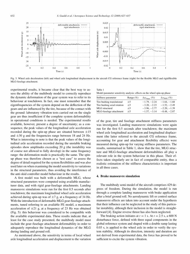
Fig. 5. Wheel axle deceleration (left) and wheel axle longitudinal displacement in the aircraft CG reference frame (right) for the flexible MLG and rigid/flexibleMLG-fuselage attachment.
experimental results, it became clear that the best way to as-sess the ability of the multibody model to correctly reproducethe dynamic deformation of the gear system was to refer to itsbehaviour at touchdown. In fact, one must remember that theeigenfrequencies of the system depend on the deflection of thegears and are influenced by the tire, because of the contact withthe ground: laboratory vibration tests carried out on the singlegear are thus insufficient if the complete system deformabilityin operational conditions is needed. The experimental resultsavailable, however, present a degree of uncertainty; as a con-sequence, the peak values of the longitudinal axle accelerationrecorded during the spin-up phase are situated between ±15and ±30 g and the frequencies range between 18 and 24 Hz.What is interesting to note is that the peak values of the longi-tudinal axle acceleration recorded during the unstable brakingepisodes show amplitudes exceeding 20 g (the instability wasof course not allowed to fully develop) in the same frequencyrange: the deformation mode is practically the same. The spin-up phase was therefore chosen as a “test case” to assess thedegree of detail required for the system flexibilities and was alsoused later on when examining the model sensitivity to variationsin the structural parameters, thus avoiding the interference ofthe anti-skid controller model behaviour in the results.
A first model was built with a deformable MLG, whosestructural parameters were computed using available manufac-turer data, and with rigid gear-fuselage attachments. Landingmanoeuvre simulations were run for the first 0.5 seconds aftertouchdown; the maximum longitudinal wheel axle accelerationachieved during spin-up was of ±7 g, at a frequency of 34 Hz.With the introduction of deformable MLG gear-fuselage attach-ments, tuned referring to an available FE model, a maximumacceleration of ±21 g, at a frequency of 23 Hz was obtained(Fig. 5): this behaviour was considered to be compatible withthe available experimental data. These results indicate that, atleast for the case study presented, the multibody model mustinclude the gear–fuselage attachment deformability in order toadequately reproduce the longitudinal dynamics of the MLGduring landing and ground roll.
As mentioned above, the sensitivity in terms of local wheelaxle longitudinal acceleration and displacement to the variation
Table 1Model parameter sensitivity analysis: effects on the wheel spin-up phase
Stiffness parameter Range (%) �axmax (%) �xmax (%)
Tire bushing translational ±5 −1.79, −2.24 −1.64, −1.68Tire bushing axial rotation ±5 −3.20, −2.23 −1.52, −2.49MLG structural ±5 −3.96, −2.77 −2.20, −1.39MLG-fuselage attachment ±5 −1.57, −3.14 −0.48, −2.87
of the gear, tire and fuselage attachment stiffness parameterswas investigated. Landing manoeuvre simulations were againrun for the first 0.5 seconds after touchdown; the maximumwheel axle longitudinal acceleration and longitudinal displace-ment (the latter referred to the aircraft CG reference frame,accounting for gear and attachment flexibility effects) weremeasured during spin-up for varying stiffness parameters. Theresults, summarised in Table 1, show that the tire, MLG struc-ture and MLG-fuselage attachment deformabilities all play arelevant role in the system behaviour in this phase. Their ef-fects taken singularly are in fact of comparable entity, thus arealistic estimation of the stiffness characteristics is importantin all three cases.
4. Brake manoeuvre simulation
The multibody semi-model of the aircraft comprises 429 de-grees of freedom. During the simulation, the model is runthrough a complete landing manoeuvre with brake applicationafter a brief ground roll. No aerodynamic lift or control surfacemanoeuvre effects are taken into account under the hypothesisthat their influence can be neglected in the study of this particu-lar instability, although their inclusion in the model is straight-forward [4]. Engine reverse thrust has also been neglected.
The braking action initiates at t = 1 s. At t = 2.5 s, a 600 Ndisturbance force, defined with three equal components in theglobal reference system and shaped with a double ramp lasting0.03 s, is applied to the wheel axle in order to verify the sys-tem stability. Although its direction, intensity and duration arenot derived from experimental data, the force has proved to besufficient to excite the system vibration.
S. Gualdi et al. / Aerospace Science and Technology 12 (2008) 627–637 633
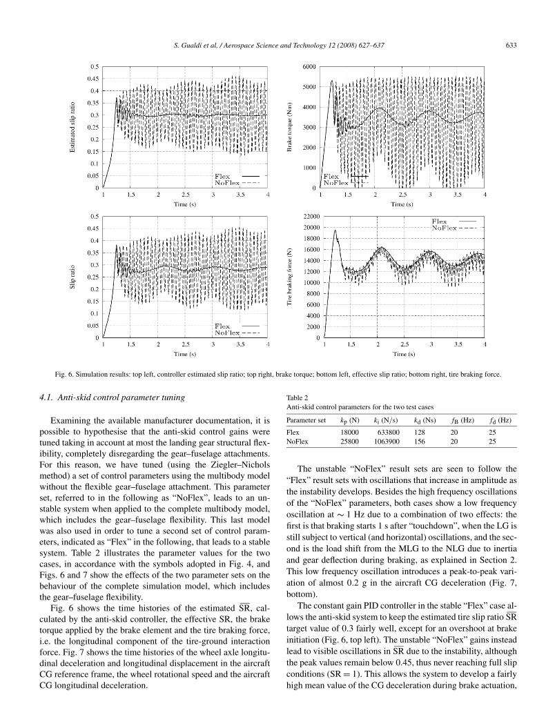
Fig. 6. Simulation results: top left, controller estimated slip ratio; top right, brake torque; bottom left, effective slip ratio; bottom right, tire braking force.
4.1. Anti-skid control parameter tuning
Examining the available manufacturer documentation, it ispossible to hypothesise that the anti-skid control gains weretuned taking in account at most the landing gear structural flex-ibility, completely disregarding the gear–fuselage attachments.For this reason, we have tuned (using the Ziegler–Nicholsmethod) a set of control parameters using the multibody modelwithout the flexible gear–fuselage attachment. This parameterset, referred to in the following as “NoFlex”, leads to an un-stable system when applied to the complete multibody model,which includes the gear–fuselage flexibility. This last modelwas also used in order to tune a second set of control param-eters, indicated as “Flex” in the following, that leads to a stablesystem. Table 2 illustrates the parameter values for the twocases, in accordance with the symbols adopted in Fig. 4, andFigs. 6 and 7 show the effects of the two parameter sets on thebehaviour of the complete simulation model, which includesthe gear–fuselage flexibility.
Fig. 6 shows the time histories of the estimated SR, cal-culated by the anti-skid controller, the effective SR, the braketorque applied by the brake element and the tire braking force,i.e. the longitudinal component of the tire-ground interactionforce. Fig. 7 shows the time histories of the wheel axle longitu-dinal deceleration and longitudinal displacement in the aircraftCG reference frame, the wheel rotational speed and the aircraftCG longitudinal deceleration.
Table 2Anti-skid control parameters for the two test cases
Parameter set kp (N) ki (N/s) kd (Ns) fB (Hz) fd (Hz)
Flex 18000 633800 128 20 25NoFlex 25800 1063900 156 20 25
The unstable “NoFlex” result sets are seen to follow the“Flex” result sets with oscillations that increase in amplitude asthe instability develops. Besides the high frequency oscillationsof the “NoFlex” parameters, both cases show a low frequencyoscillation at ∼ 1 Hz due to a combination of two effects: thefirst is that braking starts 1 s after “touchdown”, when the LG isstill subject to vertical (and horizontal) oscillations, and the sec-ond is the load shift from the MLG to the NLG due to inertiaand gear deflection during braking, as explained in Section 2.This low frequency oscillation introduces a peak-to-peak vari-ation of almost 0.2 g in the aircraft CG deceleration (Fig. 7,bottom).
The constant gain PID controller in the stable “Flex” case al-lows the anti-skid system to keep the estimated tire slip ratio SRtarget value of 0.3 fairly well, except for an overshoot at brakeinitiation (Fig. 6, top left). The unstable “NoFlex” gains insteadlead to visible oscillations in SR due to the instability, althoughthe peak values remain below 0.45, thus never reaching full slipconditions (SR = 1). This allows the system to develop a fairlyhigh mean value of the CG deceleration during brake actuation,
634 S. Gualdi et al. / Aerospace Science and Technology 12 (2008) 627–637
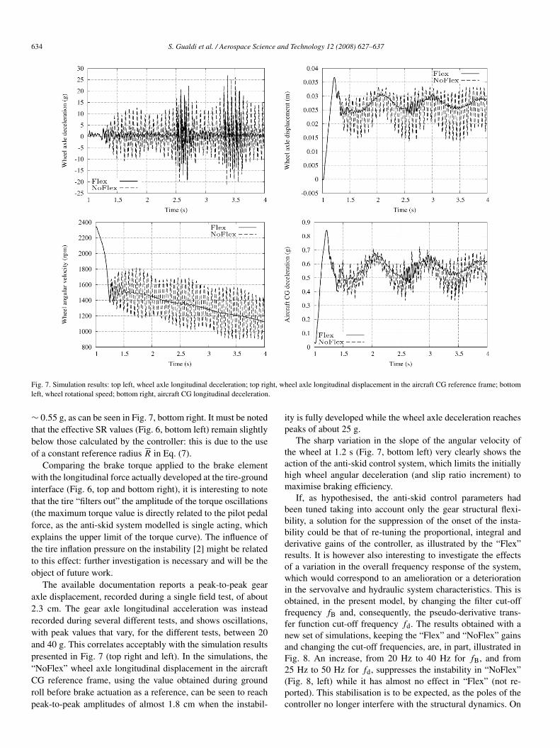
Fig. 7. Simulation results: top left, wheel axle longitudinal deceleration; top right, wheel axle longitudinal displacement in the aircraft CG reference frame; bottomleft, wheel rotational speed; bottom right, aircraft CG longitudinal deceleration.
∼ 0.55 g, as can be seen in Fig. 7, bottom right. It must be notedthat the effective SR values (Fig. 6, bottom left) remain slightlybelow those calculated by the controller: this is due to the useof a constant reference radius R in Eq. (7).
Comparing the brake torque applied to the brake elementwith the longitudinal force actually developed at the tire-groundinterface (Fig. 6, top and bottom right), it is interesting to notethat the tire “filters out” the amplitude of the torque oscillations(the maximum torque value is directly related to the pilot pedalforce, as the anti-skid system modelled is single acting, whichexplains the upper limit of the torque curve). The influence ofthe tire inflation pressure on the instability [2] might be relatedto this effect: further investigation is necessary and will be theobject of future work.
The available documentation reports a peak-to-peak gearaxle displacement, recorded during a single field test, of about2.3 cm. The gear axle longitudinal acceleration was insteadrecorded during several different tests, and shows oscillations,with peak values that vary, for the different tests, between 20and 40 g. This correlates acceptably with the simulation resultspresented in Fig. 7 (top right and left). In the simulations, the“NoFlex” wheel axle longitudinal displacement in the aircraftCG reference frame, using the value obtained during groundroll before brake actuation as a reference, can be seen to reachpeak-to-peak amplitudes of almost 1.8 cm when the instabil-
ity is fully developed while the wheel axle deceleration reachespeaks of about 25 g.
The sharp variation in the slope of the angular velocity ofthe wheel at 1.2 s (Fig. 7, bottom left) very clearly shows theaction of the anti-skid control system, which limits the initiallyhigh wheel angular deceleration (and slip ratio increment) tomaximise braking efficiency.
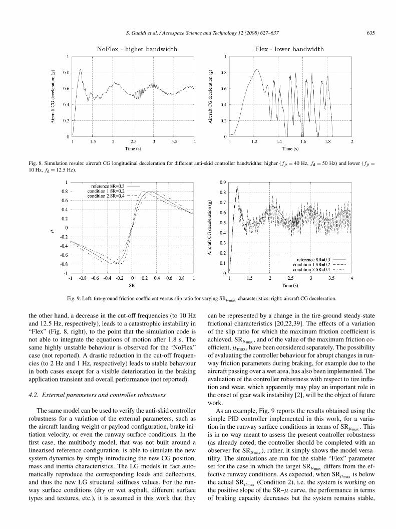
If, as hypothesised, the anti-skid control parameters hadbeen tuned taking into account only the gear structural flexi-bility, a solution for the suppression of the onset of the insta-bility could be that of re-tuning the proportional, integral andderivative gains of the controller, as illustrated by the “Flex”results. It is however also interesting to investigate the effectsof a variation in the overall frequency response of the system,which would correspond to an amelioration or a deteriorationin the servovalve and hydraulic system characteristics. This isobtained, in the present model, by changing the filter cut-offfrequency fB and, consequently, the pseudo-derivative trans-fer function cut-off frequency fd. The results obtained with anew set of simulations, keeping the “Flex” and “NoFlex” gainsand changing the cut-off frequencies, are, in part, illustrated inFig. 8. An increase, from 20 Hz to 40 Hz for fB, and from25 Hz to 50 Hz for fd, suppresses the instability in “NoFlex”(Fig. 8, left) while it has almost no effect in “Flex” (not re-ported). This stabilisation is to be expected, as the poles of thecontroller no longer interfere with the structural dynamics. On
S. Gualdi et al. / Aerospace Science and Technology 12 (2008) 627–637 635
Fig. 8. Simulation results: aircraft CG longitudinal deceleration for different anti-skid controller bandwidths; higher (fp = 40 Hz, fd = 50 Hz) and lower (fp =10 Hz, fd = 12.5 Hz).
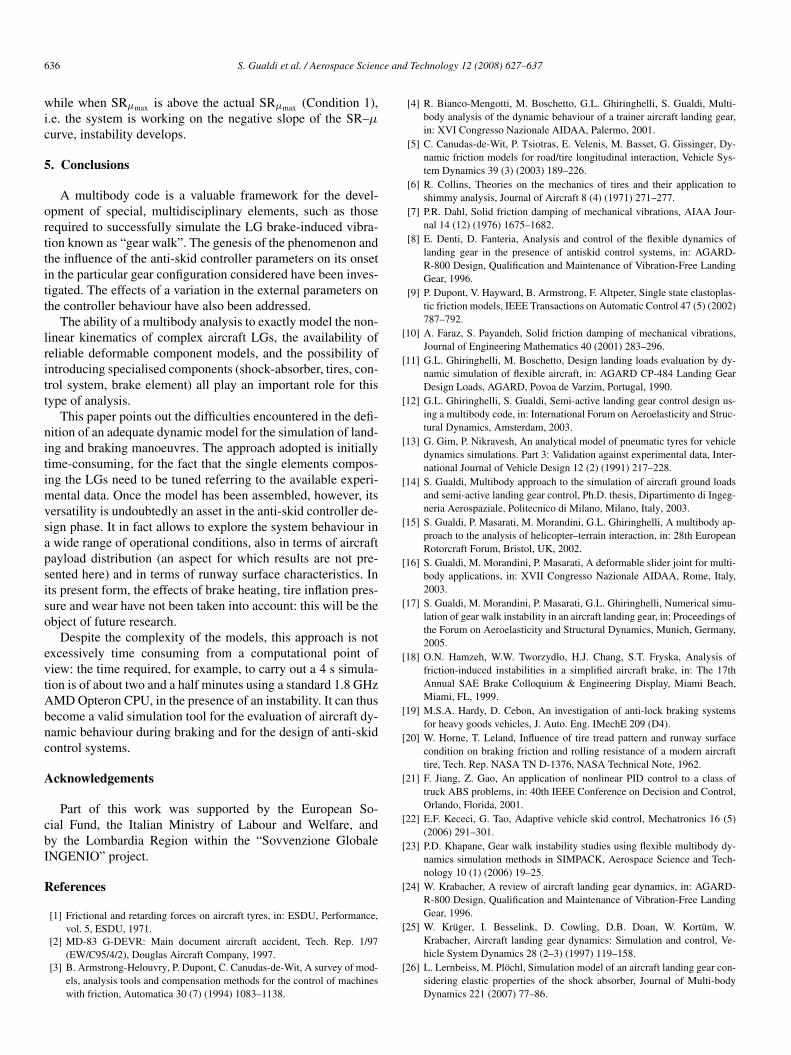
Fig. 9. Left: tire-ground friction coefficient versus slip ratio for varying SRμmax characteristics; right: aircraft CG deceleration.
the other hand, a decrease in the cut-off frequencies (to 10 Hzand 12.5 Hz, respectively), leads to a catastrophic instability in“Flex” (Fig. 8, right), to the point that the simulation code isnot able to integrate the equations of motion after 1.8 s. Thesame highly unstable behaviour is observed for the ‘NoFlex”case (not reported). A drastic reduction in the cut-off frequen-cies (to 2 Hz and 1 Hz, respectively) leads to stable behaviourin both cases except for a visible deterioration in the brakingapplication transient and overall performance (not reported).
4.2. External parameters and controller robustness
The same model can be used to verify the anti-skid controllerrobustness for a variation of the external parameters, such asthe aircraft landing weight or payload configuration, brake ini-tiation velocity, or even the runway surface conditions. In thefirst case, the multibody model, that was not built around alinearised reference configuration, is able to simulate the newsystem dynamics by simply introducing the new CG position,mass and inertia characteristics. The LG models in fact auto-matically reproduce the corresponding loads and deflections,and thus the new LG structural stiffness values. For the run-way surface conditions (dry or wet asphalt, different surfacetypes and textures, etc.), it is assumed in this work that they
can be represented by a change in the tire-ground steady-statefrictional characteristics [20,22,39]. The effects of a variationof the slip ratio for which the maximum friction coefficient isachieved, SRμmax , and of the value of the maximum friction co-efficient, μmax, have been considered separately. The possibilityof evaluating the controller behaviour for abrupt changes in run-way friction parameters during braking, for example due to theaircraft passing over a wet area, has also been implemented. Theevaluation of the controller robustness with respect to tire infla-tion and wear, which apparently may play an important role inthe onset of gear walk instability [2], will be the object of futurework.
As an example, Fig. 9 reports the results obtained using thesimple PID controller implemented in this work, for a varia-tion in the runway surface conditions in terms of SRμmax . Thisis in no way meant to assess the present controller robustness(as already noted, the controller should be completed with anobserver for SRμmax ), rather, it simply shows the model versa-tility. The simulations are run for the stable “Flex” parameterset for the case in which the target SRμmax differs from the ef-fective runway conditions. As expected, when SRμmax is belowthe actual SRμmax (Condition 2), i.e. the system is working onthe positive slope of the SR–μ curve, the performance in termsof braking capacity decreases but the system remains stable,
636 S. Gualdi et al. / Aerospace Science and Technology 12 (2008) 627–637
while when SRμmax is above the actual SRμmax (Condition 1),i.e. the system is working on the negative slope of the SR–μ
curve, instability develops.
5. Conclusions
A multibody code is a valuable framework for the devel-opment of special, multidisciplinary elements, such as thoserequired to successfully simulate the LG brake-induced vibra-tion known as “gear walk”. The genesis of the phenomenon andthe influence of the anti-skid controller parameters on its onsetin the particular gear configuration considered have been inves-tigated. The effects of a variation in the external parameters onthe controller behaviour have also been addressed.
The ability of a multibody analysis to exactly model the non-linear kinematics of complex aircraft LGs, the availability ofreliable deformable component models, and the possibility ofintroducing specialised components (shock-absorber, tires, con-trol system, brake element) all play an important role for thistype of analysis.
This paper points out the difficulties encountered in the defi-nition of an adequate dynamic model for the simulation of land-ing and braking manoeuvres. The approach adopted is initiallytime-consuming, for the fact that the single elements compos-ing the LGs need to be tuned referring to the available experi-mental data. Once the model has been assembled, however, itsversatility is undoubtedly an asset in the anti-skid controller de-sign phase. It in fact allows to explore the system behaviour ina wide range of operational conditions, also in terms of aircraftpayload distribution (an aspect for which results are not pre-sented here) and in terms of runway surface characteristics. Inits present form, the effects of brake heating, tire inflation pres-sure and wear have not been taken into account: this will be theobject of future research.
Despite the complexity of the models, this approach is notexcessively time consuming from a computational point ofview: the time required, for example, to carry out a 4 s simula-tion is of about two and a half minutes using a standard 1.8 GHzAMD Opteron CPU, in the presence of an instability. It can thusbecome a valid simulation tool for the evaluation of aircraft dy-namic behaviour during braking and for the design of anti-skidcontrol systems.
Acknowledgements
Part of this work was supported by the European So-cial Fund, the Italian Ministry of Labour and Welfare, andby the Lombardia Region within the “Sovvenzione GlobaleINGENIO” project.
References
[1] Frictional and retarding forces on aircraft tyres, in: ESDU, Performance,vol. 5, ESDU, 1971.
[2] MD-83 G-DEVR: Main document aircraft accident, Tech. Rep. 1/97(EW/C95/4/2), Douglas Aircraft Company, 1997.
[3] B. Armstrong-Helouvry, P. Dupont, C. Canudas-de-Wit, A survey of mod-els, analysis tools and compensation methods for the control of machineswith friction, Automatica 30 (7) (1994) 1083–1138.
[4] R. Bianco-Mengotti, M. Boschetto, G.L. Ghiringhelli, S. Gualdi, Multi-body analysis of the dynamic behaviour of a trainer aircraft landing gear,in: XVI Congresso Nazionale AIDAA, Palermo, 2001.
[5] C. Canudas-de-Wit, P. Tsiotras, E. Velenis, M. Basset, G. Gissinger, Dy-namic friction models for road/tire longitudinal interaction, Vehicle Sys-tem Dynamics 39 (3) (2003) 189–226.
[6] R. Collins, Theories on the mechanics of tires and their application toshimmy analysis, Journal of Aircraft 8 (4) (1971) 271–277.
[7] P.R. Dahl, Solid friction damping of mechanical vibrations, AIAA Jour-nal 14 (12) (1976) 1675–1682.
[8] E. Denti, D. Fanteria, Analysis and control of the flexible dynamics oflanding gear in the presence of antiskid control systems, in: AGARD-R-800 Design, Qualification and Maintenance of Vibration-Free LandingGear, 1996.
[9] P. Dupont, V. Hayward, B. Armstrong, F. Altpeter, Single state elastoplas-tic friction models, IEEE Transactions on Automatic Control 47 (5) (2002)787–792.
[10] A. Faraz, S. Payandeh, Solid friction damping of mechanical vibrations,Journal of Engineering Mathematics 40 (2001) 283–296.
[11] G.L. Ghiringhelli, M. Boschetto, Design landing loads evaluation by dy-namic simulation of flexible aircraft, in: AGARD CP-484 Landing GearDesign Loads, AGARD, Povoa de Varzim, Portugal, 1990.
[12] G.L. Ghiringhelli, S. Gualdi, Semi-active landing gear control design us-ing a multibody code, in: International Forum on Aeroelasticity and Struc-tural Dynamics, Amsterdam, 2003.
[13] G. Gim, P. Nikravesh, An analytical model of pneumatic tyres for vehicledynamics simulations. Part 3: Validation against experimental data, Inter-national Journal of Vehicle Design 12 (2) (1991) 217–228.
[14] S. Gualdi, Multibody approach to the simulation of aircraft ground loadsand semi-active landing gear control, Ph.D. thesis, Dipartimento di Ingeg-neria Aerospaziale, Politecnico di Milano, Milano, Italy, 2003.
[15] S. Gualdi, P. Masarati, M. Morandini, G.L. Ghiringhelli, A multibody ap-proach to the analysis of helicopter–terrain interaction, in: 28th EuropeanRotorcraft Forum, Bristol, UK, 2002.
[16] S. Gualdi, M. Morandini, P. Masarati, A deformable slider joint for multi-body applications, in: XVII Congresso Nazionale AIDAA, Rome, Italy,2003.
[17] S. Gualdi, M. Morandini, P. Masarati, G.L. Ghiringhelli, Numerical simu-lation of gear walk instability in an aircraft landing gear, in: Proceedings ofthe Forum on Aeroelasticity and Structural Dynamics, Munich, Germany,2005.
[18] O.N. Hamzeh, W.W. Tworzydlo, H.J. Chang, S.T. Fryska, Analysis offriction-induced instabilities in a simplified aircraft brake, in: The 17thAnnual SAE Brake Colloquium & Engineering Display, Miami Beach,Miami, FL, 1999.
[19] M.S.A. Hardy, D. Cebon, An investigation of anti-lock braking systemsfor heavy goods vehicles, J. Auto. Eng. IMechE 209 (D4).
[20] W. Horne, T. Leland, Influence of tire tread pattern and runway surfacecondition on braking friction and rolling resistance of a modern aircrafttire, Tech. Rep. NASA TN D-1376, NASA Technical Note, 1962.
[21] F. Jiang, Z. Gao, An application of nonlinear PID control to a class oftruck ABS problems, in: 40th IEEE Conference on Decision and Control,Orlando, Florida, 2001.
[22] E.F. Kececi, G. Tao, Adaptive vehicle skid control, Mechatronics 16 (5)(2006) 291–301.
[23] P.D. Khapane, Gear walk instability studies using flexible multibody dy-namics simulation methods in SIMPACK, Aerospace Science and Tech-nology 10 (1) (2006) 19–25.
[24] W. Krabacher, A review of aircraft landing gear dynamics, in: AGARD-R-800 Design, Qualification and Maintenance of Vibration-Free LandingGear, 1996.
[25] W. Krüger, I. Besselink, D. Cowling, D.B. Doan, W. Kortüm, W.Krabacher, Aircraft landing gear dynamics: Simulation and control, Ve-hicle System Dynamics 28 (2–3) (1997) 119–158.
[26] L. Lernbeiss, M. Plöchl, Simulation model of an aircraft landing gear con-sidering elastic properties of the shock absorber, Journal of Multi-bodyDynamics 221 (2007) 77–86.
S. Gualdi et al. / Aerospace Science and Technology 12 (2008) 627–637 637
[27] S.Y. Liu, J.T. Gordon, M.A. Oezbek, Nonlinear model for aircraft brakesqueal analysis: Model description and solution methodology, Journal ofAircraft 35 (4) (1998) 623–630.
[28] W. Luber, G. Kempf, A. Krauss, Self-induced oscillations of landing gearas an integral landing gear aircraft system problem, in: AGARD-R-800Design, Qualification and Maintenance of Vibration-Free Landing Gear,1996.
[29] P. Masarati, G.L. Ghiringhelli, M. Lanz, P. Mantegazza, Integration of hy-draulic components in a multibody framework for rotorcraft analysis, in:26th European Rotorcraft Forum, The Hague, The Netherlands, 2000.
[30] P. Masarati, M. Morandini, G. Quaranta, P. Mantegazza, Open-sourcemultibody analysis software, in: Multibody Dynamics 2003, InternationalConference on Advances in Computational Multibody Dynamics, Lisboa,Portugal, 2003.
[31] B. Milwitzky, F.E. Cook, Analysis of landing gear behavior, TR 1154,NACA, 1954.
[32] V.G. Oancea, T.A. Laursen, A finite element formulation of thermome-chanical rate-dependent frictional sliding, International Journal for Nu-merical Methods in Engineering 40 (1997) 4275–4311.
[33] J. Pauwelussena, L. Gootjesb, C. Schroederb, K.U. Kohneb, S. Jansenc,A. Schmeitzd, Full vehicle ABS braking using the SWIFT rigid ring tyremodel, Control Engineering Practice 11 (2003) 199–207.
[34] J. Pritchard, Overview of landing gear dynamics, Journal of Aircraft 38 (1)(2001) 130–137.
[35] J.G. Pruett, Modeling of friction performance in carbon/carbon brake ma-terials, in: Proceedings of the 23rd Biennial Conference on Carbon, Penn-sylvania State University, Pennsylvania, 1997.
[36] L. Puccinelli, Modelli di contatto nei programmi per la simulazione di
crash, in: Atti del X Congresso Nazione dell’Associazione Italiana diAeronautica e Astronautica, Pisa, Italy, 1989.
[37] T. Rook, S. Kumar, Dynamic aircraft landing gear simulation using flexi-ble multibody dynamics methods in ADAMS to guide component designand testing, in: Proceedings of the North American MDI User Conference2001, Novi, Michigan, 2001.
[38] H. Sakai, Theoretical and experimental studies on the dynamic propertiesof tyres. Part 2: Experimental investigation of rubber friction and defor-mation of a tyre, International Journal of Vehicle Design 2 (2) (1981)182–226.
[39] J.F. Sinnamon, Literature survey of tire-road experiments, Tech. Rep. UM-HSRI-PF-74-5, Highway Safety Research Institute, 1974.
[40] R.F. Smiley, W.B. Horne, Mechanical properties of pneumatic tires withspecial reference to modern aircraft tires, TR R-64, NASA, 1960.
[41] I. Tunay, E.Y. Rodin, A.A. Beck, Modeling and robust control design foraircraft brake hydraulics, IEEE Transactions on Control Systems Technol-ogy 9 (2) (2001) 319–329.
[42] A. Van Zanten, R. Erhardt, A. Lutz, Measurement and simulation of tran-sients in longitudinal and lateral tire forces, Tech. Rep. 900210, SAETechnical Papers, 1990.
[43] E. Velenis, P. Tsiotras, C. Canudas-de-Wit, M. Sorine, Dynamic tire fric-tion models for combined longitudinal and lateral vehicle motion, VehicleSystem Dynamics 43 (1) (2005) 3–29.
[44] H. Vinayak, Pitch plane simulation of aircraft landing gears usingADAMS, in: 1998 North American MDI User Conference, Ann Arbor,Michigan, 1998.
[45] A. Visioli, Modified anti-windup scheme for PID controllers, IEE Proc. –Control Theory Appl. 150 (1).


