Embed Size (px)
Citation preview

Applicability of silicon micro-finned heat sinks for 500× Concentrating Photovoltaics Systems
Leonardo Micheli1*, S. Senthilarasu1, K.S. Reddy2, Tapas K. Mallick1
1Environment and Sustainability Institute; University of Exeter, Penryn Campus, Penryn, Cornwall TR10 9EZ, UK
2Heat Transfer and Thermal Power Laboratory, Department of Mechanical Engineering, Indian Institute of Technology Madras, Chennai 600 036, India
*Corresponding Author: [email protected]
Abstract:
In Concentrating Photovoltaic (CPV) applications, the sunlight is focused onto solar cells up to thousands of times and, without an adequate cooling system, the cell’s temperature can dangerously raise over the operating temperature range in few seconds. In this study, an investigation on micro-finned heat sink for high concentrating photovoltaics has been conducted. The geometry of the system and the choice of the components play an important role in the thermal management of CPV. The size of cell, as well as the optics, can strongly affect the thermal behaviour of the CPV: the effects of the CPV geometry on the thermal performance of the heat sink are experimentally investigated and discussed in order to design an optimized system for passive cooling. A micro-fin array is developed to handle the heat generated by the cell and the system is studied in different conditions to prove the applicability of this passive solution to the harsh CPV conditions. It has been found that micro-fins are a suitable solution for passive cooling at concentrations up to 500×. Moreover, this kind of solutions shows the potential to achieve high mass specific power values, proving its competitiveness in mobile or tracked systems, such as CPV.
Keywords: cpv, cooling, micro heat sinks, fins.
1. Introduction
Standard photovoltaics (PV) is not yet a cost-competitive energy technology compared to other power generation sources, such as coal, natural gas, nuclear and wind [1]. Several solution have been proposed to reduce the cost of PV [2–4]. Among these, Concentrating Photovoltaics (CPV) has been firstly proposed in early ‘70s [5] and consists of the replacement of part of the expensive semiconductor area with cheaper concentrating materials [6].
The efficiency of any photovoltaic cell decreases when the solar cell temperature increases [7]. The temperature risings can cause mechanical failures, such as deformation on the cell surface, delamination of the transparent layer and development of micro-cracks on the cell. Moreover, the

different thermal expansions coefficients among the materials composing the cell and the cell’s assembly can lead to immediate or fatigue failures if exposed to extreme thermal cycles. For these reasons, a cooling system is generally introduced in CPV, where lenses or mirrors are used to concentrate sunlight onto the solar cells, achieving high power densities.
The performance of the CPV modules are particularly affected by the raise in the cell’s temperature [8]. For this reason, the temperature of the cell needs to be maintained within the range of CPV working temperatures (50 to 80°C, [9]). Aluminum flat plates and finned heat sinks are the most common passive cooling solution applied in CPV [10]. The number, the spacing and the length of the fins [11], as well as the inclination angle and the temperature difference [12] influence the thermal behavior of the heat sink. Aluminum is generally used to produce the supporting structure, the framings and the heat sink and, according to [13], contributes up to 67% of the module’s weight and is responsible for the 64% of the module’s greenhouse gas emissions. Reducing the weight of the heat sink would benefit in terms of system’s efficiency and emissions’ drop. In this light, micro and nano-technologies can offer an innovative solution for high performance CPV cooling. Any technology with at least one micro or nano-scaled dimension is defined micro or nano-technology, respectively [14]. The beneficial application of micro- and nano-technologies has already been recognized by previous researchers [15,16]. Among the emerging passive micro-technologies, micro-fins appear to be one of the most promising solutions [17].
There are many researches in literature focused on the application of micro-fins in active cooling systems, whereas micro-fins in natural convection haven’t been widely investigated. Moreover, it is known that the correlations used in macro-finned heat sinks cannot be employed at micro-scale [18]. It has been proved that the convective heat transfer coefficient increases when the fin spacing is increased or the fin height is decreased [19]. Along with that, the contribution of the radiative heat exchange cannot be neglected [20]. Natural convective micro-fins are still a wide, unexplored subject and further investigations are needed to understand the potential of this solution.
This paper investigates the employability of silicon micro-finned heat sinks in natural convection for passive cooling of 500× CPV systems. The effects of the CPV systems geometry and cell’s size on the thermal behaviour are firstly investigated. A simulation model is developed to find out the most suitable substrate material, in terms of heat dissipation and thermal stress. Some heated micro-fins arrays have been tested in natural convection to determine their performance and optimize their geometry: the results of the experimental investigation are reported and compared with the prediction of a thermal simulation. The application of micro-fins for passive cooling of CPV has been found able to enhance the power-to-weight ratio of CPV modules. Moreover, it has the potential to reduce the material usage, the installation costs and the tracker’s energy consumptions, contributing to increase the cost competitiveness of CPV in the renewable energy market.

2. System configuration
High CPV (HCPV) systems operate at concentrations between 300 and 2000 suns [21]. These systems generally exploit multijunction solar cells, which are designed to generate more current per unit of area than the conventional silicon cells [22]. The cells are allocated on an electrical substrate, usually called cell assembly. The bypass diodes, used to minimize electrical losses and damages when the cells are shadowed, and the current extraction mechanism are installed on the cell assembly too. According to the IEC 62108 [23], the cell assembly, the secondary optics and the heat dissipation system form the solar receiver. A complete system, able to convert the unconcentrated solar radiation into heat is called module [22] and is represented in Figure 1. The modules are usually mounted on a tracking system that continuously moves them, in order to optimize the incident angle of the sunlight.
Figure 1 – Structure of a CPV module, composed by primary and secondary concentrators, cells, diodes and heat sinks. Adapted from [22].
The thermal behaviour of a CPV system depends on different factors other than the concentration and outdoor conditions only. The distribution of the cells on the assembly limits the surface available for the heat exchange. The geometry of the concentrators influences the orientation of the heat sink. The size of the cell is proportional to the waste heat generated. Each kind of substrate has a different thermal behaviour, and this affects the temperature of the cells. In the next sections, an analysis of the thermal effects of each CPV component is reported and commented.
2.1. Geometry of the cell assembly
Royne et al. [10] grouped the CPV system’s geometries in three categories:

• Single cell geometry: the concentrators focus the sunlight onto an individual cell. This is the optimal configuration for cooling: ideally, an area equal to the surface of concentrators is available for cooling purposes.
• Linear geometry: two sides of each cell are in contact with the adjacent cells. The surface available for the heat exchange is reduced.
• Densely packed geometry: each cell is surrounded by cells on each side (excluding the cells placed on the edges of the assembly). The application of passive cooling systems is difficult, due to the reduced areas available for cooling and the high thermal power densities.
The single cell geometry is the most favourable for passive cooling and, for this reason, it is going to be used in this receiver.
The choice of the cooling fluid is usually based on its availability and accessibility. High thermally conductive fluids might too expensive or not easy to provide in remote locations, and water is not yet supplied in many locations worldwide. For these reasons, air is the most common cooling fluid to be exploited, both for active or passive systems. In this work, a single cell, air-cooled receiver has been considered.
2.2. Concentrating optics
The geometry of the concentrators has a high impact on the thermal management of CPV systems. The high concentrations are commonly achieved through reflection or refraction [24]: the most common geometries are shown in Figure 2. In reflecting systems without secondary, the receiver is usually located between the sun and the mirrors (Figure 2a). So, the receiver needs to be as much compact as possible, in order to minimize the shadowing. In these systems active coolers are usually preferred because of their higher heat removal capacity. If a secondary reflector is present instead (Figure 2b) or lenses are used as concentrators (Figure 2c), there won’t be risks of shadowing and then larger areas are usually available for cooling. Passive coolers can usually be exploited in these configurations, even if the orientation of the heat sink becomes an issue. CPV systems are usually tracked, and the inclination angle of the receiver continuously changes. Heat sinks in natural convection are especially affected by the inclination angle and, in particular, a downward facing heat sink is the worst orientation for a passive cooling [25].
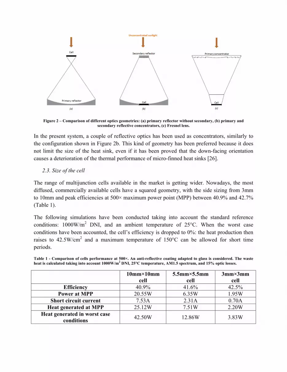
Figure 2 – Comparison of different optics geometries: (a) primary reflector without secondary, (b) primary and secondary reflective concentrators, (c) Fresnel lens.
In the present system, a couple of reflective optics has been used as concentrators, similarly to the configuration shown in Figure 2b. This kind of geometry has been preferred because it does not limit the size of the heat sink, even if it has been proved that the down-facing orientation causes a deterioration of the thermal performance of micro-finned heat sinks [26].
2.3. Size of the cell
The range of multijunction cells available in the market is getting wider. Nowadays, the most diffused, commercially available cells have a squared geometry, with the side sizing from 3mm to 10mm and peak efficiencies at 500× maximum power point (MPP) between 40.9% and 42.7% (Table 1).
The following simulations have been conducted taking into account the standard reference conditions: 1000W/m2 DNI, and an ambient temperature of 25°C. When the worst case conditions have been accounted, the cell’s efficiency is dropped to 0%: the heat production then raises to 42.5W/cm2 and a maximum temperature of 150°C can be allowed for short time periods.
Table 1 - Comparison of cells performance at 500×. An anti-reflective coating adapted to glass is considered. The waste heat is calculated taking into account 1000W/m2 DNI, 25°C temperature, AM1.5 spectrum, and 15% optic losses.
10mm×10mm cell
5.5mm×5.5mm cell
3mm×3mm cell
Efficiency 40.9% 41.6% 42.5% Power at MPP 20.55W 6.35W 1.95W
Short circuit current 7.53A 2.31A 0.70A Heat generated at MPP 25.12W 7.51W 2.20W
Heat generated in worst case conditions 42.50W 12.86W 3.83W

A 3mm×3mm multijunction cell has been chosen for the presented passively-cooled system. Along with the lowest amount of heat generated because of the limited size, this cell has the highest efficiency and, thus, the lowest rate of waste heat produced per unit of active area. Among the different geometries, the single cell configuration is the most favourable for passive cooling and, for this reason, is going to be used in this receiver.
2.4. Substrate
The waste heat produced by the cell is moved, by conduction, to the heat sink, where it has to be dissipated in an external system to limit the temperature of the heat sink. Any object placed in contact with a fluid exchanges heat with it through natural convection and radiation and this is the condition of a solar receiver mounted in an outdoor CPV system. The rate of natural convection (qc) is approximately proportional to the difference between the surface and the free stand fluid temperatures, respectively reported as Ts and Tamb:
𝑞! = 𝑆 ∙ ℎ! ∙ (𝑇! − 𝑇!"#)
where S stands for the area of the exchanging surface and hc represents the constant of proportionality, called convective heat transfer coefficient. It depends on the fluid, the state of the flow and the geometry of the system. The heat transfer coefficient for air in free convection usually ranges between 3 and 25 W/m2K [27]. On the other hand, radiation is a function of the difference between the temperature fourth powers.
𝑞! = 𝜎 ∙ 𝑆 ∙ 𝐹!!! ∙ 𝜀 ∙ 𝑇!! − 𝑇!"#!
where σ is the Stefan-Boltzmann constant (~5.67·10-8 W/m2K4), F1-2 the view factor, and ε the emissivity of the surface’s material.
The simplest solution to dissipate the waste heat generate by the cell is to use a large, flat heat sink, placed at the bottom of the heat spreader. Aluminium is the material generally chosen due to its good balance between thermal performances, weight and costs. Combining the two equations above and considering the only bottom surface, it is possible to calculate the minimum area (SHS) the heat sink requires to properly work:
𝑆!" =𝑞!"##
ℎ! ∙ 𝑇! − 𝑇!"# + 𝜎 ∙ 𝐹!!! ∙ 𝜀 ∙ 𝑇!! − 𝑇!"#!
Assuming that all the heat generated by a 3mm×3mm sized cell (2.20W) reaches the heat sink, and, similarly to the conditions in [28], an upper bound for emissivity of 0.09 and a view factor of 1, considering only the flat bottom surface of the receiver, and taking into account an optimistic value of 25 W/m2K for the air heat transfer coefficient, a heat sink surface temperature of 60°C, and an ambient temperature of 25°C, a dissipating area of 0.0025 m2 for the aluminium heat sink is required. It corresponds to an aluminium plate sizing 5.0 cm per side for cooling a 3mm×3mm sized cell. Assuming the same surface’s temperature, a silicon wafer would need a smaller surface because of the higher emissivity than aluminium, but, because of 5cm×5cm are

standard sizes for the three considered substrates and are similar to the dimensions of commercial receivers, they have been taken into account for the design of the single cell receiver.
Many commercial companies use direct bonded copper (DBC) as substrate for CPV installations. These substrates have excellent thermal and electrical properties and grant high mechanical strength. They need anyway an external heat sink and the unsolderability between Cu and Al is a factor that may enhance the thermal resistance of the contact interface. An alternative to DBC is represented by insulated metal substrates (IMS). These substrates are gaining attention in the CPV market because of their low cost, higher flexibility in design and good thermal performance. A third option is represented by a silicon wafer: silicon has a similar thermal expansion coefficient to III-V materials and it is easy to machine. On the other hand, silicon is more expensive than the other substrate and quite fragile. In order to predict the performance of the three substrates, three models have been developed in COMSOL Multiphysics 5.0. The materials and the related thicknesses have been chosen accordingly to the receivers presented in literature and are shown in Table 2.
Table 2 - Geometries and materials considered for the three substrates
DBC [29] IMS [30] Si wafer [31]
Layer Material Thermal
resistance [K/W]
Material Thermal
resistance [K/W]
Material Thermal
resistance [K/W]
Cell 0.190mm Ge 3.17·10-2 0.190mm
Ge 3.17·10-2 0.190mm Ge 3.17·10-2
Solder 0.125mm solder 1.56·10-2 0.125mm
solder 1.56·10-2 0.125mm solder 1.56·10-2
Conductive layer
0.25mm Cu 2.50·10-4 0.035mm
Cu 3.50·10-5 0.001mm Cu 1.27·10-6
Dielectric 0.32mm Al2O3
1.07·10-5 0.005mm epoxy 6.67·10-4 0.001mm
Si3N4 3.33·10-5
Heat spreader/heat sink
0.25mm Cu 2.50·10-4 2mm Al 5.00·10-3 0.55 mm
Si 1.87·10-3
The three 5cm×5cm squared receivers have been reproduced in COMSOL, using the “Heat Transfer in Solids” and the “Solid Mechanics” modules. The properties of the materials are reported in Table 3. The solder is reproduced as Thin Thermally Resistive Layer (0.004mm, 4.5W/mK). The cell is set as the heat source, with a power input of 2.20W. A convective heat flux of 10W/m2K and is modelled on all the external surfaces of the receivers. No radiative exchange is considered.

Table 3 - Properties of materials used in the COMSOL simulation
Material Alumina Aluminum Copper Germanium Silicon Coefficient of thermal expansion [1/K] 8.0·10-6 23·10-6 17·10-6 5.9·10-6 2.6·10-6
Density [kg/m3] 3900 2700 8700 5323 2329 Heat capacity [J/kgK] 900 900 385 320 700 Poisson’s ratio 0.222 0.33 0.35 0.26 0.28 Thermal conductivity [W/mK] 27 238 400 60 130
Young’s modulus [Pa] 300 ·109 70·109 110 ·109 10.3·1011 170 ·109
The results are sown in the figures below, where the front view of the receiver is reproduced. The thermal stresses are reported in MPa, and the temperatures in Celsius degrees. In order to make the comparison easier, the results are shown using the same scale: the thermal stress scale ranges from 0 Mpa (dark blue) to 300Mpa (dark red) and the temperature scale starts from 35°C (dark blue) to 75°C (dark red).
Figure 3 - The thermal stresses and the temperature distribution on the direct bonded copper. Max thermal stress: 195MPa. Max Temperature: 75.0°C.

Figure 4 – The thermal stresses and the temperature distribution on the insulated metal substrate. Max thermal stress: 298MPa. Max Temperature: 72.8°C.
Figure 5 - The thermal stresses and the temperature distribution on the silicon wafer. Max thermal stress: 70.6MPa. Max Temperature: 53.3°C.
All the receivers show maximum cell’s temperatures that fall between 50°C and 80°C, the operating range of CPV systems [9]. Direct bonded copper (Figure 3) and insulated metal substrate (Figure 4) show similar maximum temperatures: 75.0°C and 72.8°C respectively. Among the three receivers, the silicon wafer (Figure 5) shows the lower thermal stresses (70.6MPa) and the lowest temperature (53.3°C). For this reason, a silicon wafer appears to be the most suitable substrate for a passive cooled CPV application.
As further proof of reliability, the thermal performance of the three substrates in the worst case conditions has been investigated as well. The results are shown in Figure 6, Figure 7 and Figure 8, and similarly to the previous investigation, the scale is not varied among the studies: from 40°C (dark blue) to 120°C (dark red). The simulation confirmed the better thermal behaviour of the silicon wafer, which is expected to reach a temperature of 78°C, which is 30 to 40°C degrees below the other two substrates’ temperatures.

Figure 6 - The temperature distribution on the direct bonded copper in the worst case conditions. Max Temperature: 116°C.
Figure 7 – The temperature distribution on the insulated metal substrate in the worst case conditions. Max Temperature: 112°C.
Figure 8 - The temperature distribution on the silicon wafer in the worst case conditions. Max Temperature: 78°C.

The silicon wafer is showing the best performance in terms of heat removal ability for a single cell configuration in natural convective conditions. Moreover, the silicon wafer is preferable because of the highest emissivity of the material, if compared to aluminum and copper, and because silicon micro-machining has already been widely deployed [17]. Integrating the cooling system in the receiver would enhance the thermal behaviour of the system: an external heat would have required to be bonded by a thermal interface material, which is usually cause of an high thermal resistance [32]. Silicon receivers have already been successfully developed for CPV applications [33,34]: sputtering is generally used to deposit the different layers on the substrate. So, the silicon wafer has been chosen as substrate for the single cell receiver to be designed and will be further investigated in the following chapters.
3. Micro-heat sink
3.1. Fin geometry
It has already been demonstrated that the heat transfer coefficient is enhanced by the high values of spacing and the low height of the fins [19]. In this application, the fin geometry has been chosen in order to optimize the heat management of the CPV system: among the geometries tested in [35], the dimensions showed in Table 4 are those that maximize the fin effectiveness. The fins have been mechanically diced on a 1.4mm-thick, 5cm×5cm silicon wafer. The nomenclature used to describe the fins is explained in Figure 9.
Table 4 - Dimensions of the micro-finned heat sink
Dimension Heat sink
length, L
Heat sink width,
W
Fin thickness,
t
Fin spacing,
s
Fin height,
H
Base thickness,
tb
Number of fins
Value 50.0 mm 49.9 mm 0.2 mm 0.8 mm 0.6 mm 0.8 mm 50
Figure 9 – Symbols used for describing the micro-fins geometry [35]
3.2. Methodology

The experimental setup used for the experiment is the same reported in [35]. The fins have been heated using an electrical heater and then back-insulated in order to reduce the heat transfer from all the surfaces other than the fins. The temperatures have been recorded using the FLIR infrared camera: it has been considered constant across the volume of the fin array. In the real scenario, all the surfaces of the system will exchange heat with the ambient and the heat generator will coincide with the cell, so it will have a limited extension compared to the heat sink. For this reason, a COMSOL simulation has been conducted, using the heat transfer coefficients sorted out by the experimental investigation and a heat source sized as the solar cell (3mm×3mm). The thermal behaviour of the finned surface has been compared with those of the unfinned flat silicon wafer.
The fins have been modelled at 500× in two conditions: the maximum power point conditions (1000W/m2 DNI, 25°C ambient temperature, 42.5% cell efficiency) and in the worst case conditions (1000W/m2 DNI, 25°C ambient temperature, 0% cell efficiency). In the first case the cell is modelled as a heat source, with a power input of 2.20W, whereas in the second case the power input is increased to 3.83W. In all the simulations, the fins are modelled in facing downwards orientation: this is the most challenging condition a CPV cooling system has to face while in operation. The same assumptions made for the previous model have been considered: the fins have been added to the geometry and their heat transfer coefficients have been set accordingly to the results of the experimental investigation. Because of the experimental losses accounted for the 26% of the heat in input, DC power inputs of 2.6W and 5.1W have been supplied to the experimental setup to measure the heat transfer in the maximum power point and in the worst case conditions respectively. Natural convection from the upper surface has been considered as well: it is set accordingly to the experimental heat transfer of the horizontally facing upward flat plane. All the experimentally obtained heat transfer coefficients are resumed in Table 5.
Table 5 - Values of the heat transfer coefficients experimentally obtained and used in the thermal model
Surface\Qcell 2.20W 3.25W Upper flat surface (upwards) 3.72W/m2K 4.73W/m2K
Unfinned surface (downwards) 3.44W/m2K 3.80W/m2K Finned surface (downwards) 3.33 W/m2K 3.65W/m2K
The emissivity has been taken into account as well: a silicon emissivity of 0.78 has been introduced. The view factors of the fins have been calculated accordingly to the methodology reported in [36].
3.3. Thermal performance in standard operating conditions
The results of the simulation are shown in Figure 10 and Figure 11. A maximum cell’s temperature of 78.8°C is registered for the flat silicon wafer in CPV operating conditions (Figure 10). By introducing the fins, the cell’s temperature is found to drop to 70.4°C (Figure 11),

showing a non-negligible benefit in terms of thermal management. Taking into account the temperature coefficients of the cell (-0.106%(rel)/°C), reducing the cell’s temperature of 7.4°C is expected to lead to a relative improvement in electrical efficiency of 0.78%.
Figure 10 – Temperature distribution across the flat silicon wafer in CPV operating conditions (78.8°C).

Figure 11 – Temperature distribution in CPV operating conditions for the finned silicon wafer (70.4°C).
3.4. Thermal performance in worst case conditions
The worst case scenario for a CPV cooling system happens at high irradiance, when the cell is not able to generate any electrical power and, so, all the sunlight is converted into heat. These are not operating conditions: the system is not expected to work, and the tracking system is designed to move the system out of focus. In this scenario, higher temperatures are accepted, but they should not exceed 150°C anyway.
In these conditions, the flat and the finned silicon wafers are expected to achieve maximum cell’s temperatures of 111°C (Figure 12) and 99.9°C (Figure 13), which fall below the maximum limit. The fins further prove their ability of improving the thermal performance of a HCPV receiver.

Figure 12 - Temperature distribution across the flat silicon wafer in CPV worst case conditions (111°C).

Figure 13 – Temperature distribution in CPV worst case conditions (99.9°C).
3.5.Mass specific power
In tracked system, the weight of the heat sink is a factor that can sensibly affect the overall performances. The heavier the system, the more the energy consumed by the tracker and, thus, the lower the efficiencies. The mass specific power expresses the ratio between the electrical power output and the heat sink weight. The higher the mass specific power, the lower is the weight of the heat sink per unit of power output. Considering the same electrical output conditions, systems with a higher mass specific power would be lighter than those with a low mass specific power. Unfortunately, only a limited number of studies reported the dimensions of the heat sinks used in CPV applications, listed in Table 6.
Table 6 - Properties and mass specific power of passive cooled systems presented in literature. Whereas not reported, a density of 2700 kg/m3 for aluminum and a 1cm2 sized cell, with a power output of 20.71W at 500× maximum power point, have been considered.
Ref. Type of heat sink
Weight of the heat sink/receiver
Cell’s size
Max electrical power output (concentration)
Mass specific power
[37] Radial finned 0.600 kg 1cm×1cm 34.99We (1000×) 58.32 We/kg [38] Heat spreader 0.405 kg 1cm×1cm 20.71We (500×) 51.13 We/kg
By using a smaller cell, it is possible to increase the mass specific power: the flat silicon wafer used for a 3mm×3mm cell has a mass specific power about 5 times higher than the one of the heat sinks used for the 1cm×1cm cells. The introduction of the micro-fins, further enhance the mass specific power: this coefficient has been found to increases by the 75% after the fins have been diced (Table 7).
Table 7 - Properties and mass specific power of passive cooled systems studied in the present work.
Type of heat sink Weight of the heat sink Cell’s size Max electrical power output at 500× Mass specific power Unfinned surface 0.007798kg 0.3cm×0.3cm 1.96We 251.34We/kg
Finned surface 0.004498kg 0.3cm×0.3cm 1.96We 435.75We/kg
Taking into account the maximum temperatures of the cells, it is possible to refine the previous predictions, revising the expected maximum electrical power outputs according to the temperature’s coefficient reported in the cell’s datasheet (-1.8mW/°C).
Table 8 - Refined mass specific powers of passive cooled systems studied in the present work.
Type of heat sink Max predicted temperature
Refined max electrical power output at 500×
Weight of the heat sink
Mass specific power
Unfinned surface 78.8°C 1.86We 0.007798 kg 238.52We/kg Finned surface 70.4°C 1.88We 0.004498 kg 417.96We/kg
Despite the low number of heat sinks that have been compared, these results confirm that the micro-fins are able to introduce two benefits to an unfinned surface: a reduction in maximum
temperature and a stronger improvement in terms of mass specific power. Therefore, micro-finned heat sinks can find application in many fields, where the reduction of volumes, weight and costs is a priority, such as the mobile phones, the tablets or laptop markets.
4. Conclusions
The present study reports the design of a natural convective micro-finned heat sink for high concentrating photovoltaic applications. The effects of the temperature on the CPV cells have been briefly explained and the selection of the optics geometry and the components has been detailed and justified. The substrate, a 5cm×5cm-sized silicon wafer, has been selected on the basis of a thermal simulation: silicon wafers show minimized thermal stresses and maximized heat transfer compared to direct bonded copper boards and insulated metal substrates.
The most effective fin geometry has been selected according to the results an experimental investigation. The same results have then been used as input for a thermal model to prove the reliability of micro-fins for high CPV cooling both in standard operation and in worst case conditions. In the considered 500× CPV system, the introduction of micro-fins is found to enhance the thermal management of the receiver. In both conditions, the fins performed well, keeping the solar cell at a temperature lower than the maximum acceptable temperature for CPV systems and that of the unfinned flat silicon wafer. Along with the good thermal performances, the fins show an increased mass specific power compared to similar solution applied in CPV. The considered fins have been found to enhance the mass specific power from about 60We/kg to more than 400We/kg compared to the convectional CPV systems. Compared to an unfinned flat surface, the enhancement is found to be equal to 75%. Reducing the heat sink’s weight would reduce the load for the solar tracker and, then, improve the system’s efficiency. These thermal and weight benefits due to the micro-fins make them appealable for those mobile and tracked systems, such as CPV.
Acknowledgments
This work has been financially supported by the EPSRC-DST funded BioCPV project.
Reference
[1] US Energy Information Administration, Levelized Cost and Levelized Avoided Cost of New Generation Resources in the Annual Energy Outlook 2014, 2014.
[2] H.M. Tawancy, Enhancing the photovoltaic effect in the infrared region by germanium quantum dots inserted in the intrinsic region of a silicon p-i-n diode with nanostructure, J. Mater. Sci. 47 (2012) 93–99. doi:10.1007/s10853-011-5728-9.
[3] A. Goodrich, T. James, M. Woodhouse, Utility-Scale Photovoltaic (PV) System Prices in the United States: Current Drivers and Cost-Reduction Opportunities, 2012.

[4] K. Ardani, D. Seif, C. Davidson, J. Morris, S. Truitt, R. Torbert, et al., Preliminary non-hardware (’soft') cost-reduction Roadmap for residential and small commercial solar photovoltaics, 2013-2020, 2013. doi:10.1109/PVSC.2013.6745192.
[5] P. Verlinden, A. Lewandowski, C. Bingham, G. Kinsey, R. Sherif, J. Lasich, Performance and Reliability of Multijunction III-V Modules for Concentrator Dish and Central Receiver Applications, in: 2006 IEEE 4th World Conf. Photovolt. Energy Conf., IEEE, 2006: pp. 592–597. doi:10.1109/WCPEC.2006.279526.
[6] S. Kurtz, Opportunities and challenges for development of a mature concentrating photovoltaic power industry, 2009.
[7] A. Luque, S. Hegedus, Handbook of Photovoltaic Science and Engineering, John Wiley & Sons, Ltd, Chichester, UK, 2003. doi:10.1002/0470014008.
[8] A. Luque, V.M. Andreev, Concentrator Photovoltaics, Springer Berlin Heidelberg, Berlin, Heidelberg, 2007. doi:10.1007/978-3-540-68798-6.
[9] E.F. Fernández, F. Almonacid, P. Rodrigo, P. Pérez-Higueras, Calculation of the cell temperature of a high concentrator photovoltaic (HCPV) module: A study and comparison of different methods, Sol. Energy Mater. Sol. Cells. 121 (2014) 144–151. doi:10.1016/j.solmat.2013.11.009.
[10] A. Royne, C.J. Dey, D.R. Mills, Cooling of photovoltaic cells under concentrated illumination: a critical review, Sol. Energy Mater. Sol. Cells. 86 (2005) 451–483. doi:10.1016/j.solmat.2004.09.003.
[11] S.K. Natarajan, T.K. Mallick, M. Katz, S. Weingaertner, Numerical investigations of solar cell temperature for photovoltaic concentrator system with and without passive cooling arrangements, Int. J. Therm. Sci. 50 (2011) 2514–2521. doi:10.1016/j.ijthermalsci.2011.06.014.
[12] K.H. Do, T.H. Kim, Y.-S. Han, B.-I. Choi, M.-B. Kim, General correlation of a natural convective heat sink with plate-fins for high concentrating photovoltaic module cooling, Sol. Energy. 86 (2012) 2725–2734. doi:10.1016/j.solener.2012.06.010.
[13] G. Timò, Results of the APOLLON Project and Concentrating Photovoltaic Perspective, Milan (IT), 2014.
[14] B. Bhushan, 01 Introduction to Nanotechnology, Semin. Cell Dev. Biol. 714 (2010) 1–6. doi:10.1016/j.semcdb.2010.02.009.
[15] S. Chaturvedi, P.N. Dave, Design process for nanomaterials, J. Mater. Sci. 48 (2013) 3605–3622. doi:10.1007/s10853-013-7196-x.

[16] D. Qin, B.B.A. Riggs, Nanotechnology: A Top–Down Approach, Encycl. Supramol. Chem. (2012) 1–9. doi:10.1081/E-ESMC-120047104.
[17] L. Micheli, N. Sarmah, X. Luo, K.S. Reddy, T.K. Mallick, Opportunities and challenges in micro- and nano-technologies for concentrating photovoltaic cooling: A review, Renew. Sustain. Energy Rev. 20 (2013) 595–610. doi:10.1016/j.rser.2012.11.051.
[18] J.S. Kim, B.K. Park, J.S. Lee, Natural Convection Heat Transfer Around Microfin Arrays, Exp. Heat Transf. 21 (2008) 55–72. doi:10.1080/08916150701647835.
[19] S. Mahmoud, R. Al-Dadah, D.K. Aspinwall, S.L. Soo, H. Hemida, Effect of micro fin geometry on natural convection heat transfer of horizontal microstructures, Appl. Therm. Eng. 31 (2011) 627–633. doi:10.1016/j.applthermaleng.2010.09.017.
[20] H. Shokouhmand, A. Ahmadpour, Heat Transfer from a Micro Fin Array Heat Sink by Natural Convection and Radiation under Slip Flow Regime, in: Proc. World Congr. Eng., 2010.
[21] P. Pérez-Higueras, E. Muñoz, G. Almonacid, P.G. Vidal, High Concentrator PhotoVoltaics efficiencies: Present status and forecast, Renew. Sustain. Energy Rev. 15 (2011) 1810–1815. doi:10.1016/j.rser.2010.11.046.
[22] P. Rodrigo, E.F. Fernández, F. Almonacid, P.J. Pérez-Higueras, Review of methods for the calculation of cell temperature in high concentration photovoltaic modules for electrical characterization, Renew. Sustain. Energy Rev. 38 (2014) 478–488. doi:10.1016/j.rser.2014.06.008.
[23] International Electrotechnical Commission, Concentrator photovoltaic (CPV) modules and assemblies - Design qualification and type approval (IEC 62108 ed1.0), (2007).
[24] C. Sierra, A.J. Vázquez, High solar energy concentration with a Fresnel lens, J. Mater. Sci. 40 (2005) 1339–1343. doi:10.1007/s10853-005-0562-6.
[25] G. Mittelman, a. Dayan, K. Dado-Turjeman, a. Ullmann, Laminar free convection underneath a downward facing inclined hot fin array, Int. J. Heat Mass Transf. 50 (2007) 2582–2589. doi:10.1016/j.ijheatmasstransfer.2006.11.033.
[26] F.P. Incropera, D.P. DeWitt, T.L. Bergman, A.S. Lavine, Fundamentals of Heat and Mass Transfer, Wiley, 2007.
[27] A. Mills, Basic heat and mass transfer, 2nd ed., Prentice Hall, 1999.
[28] D.P. Kulkarni, D.K. Das, Analytical and numerical studies on microscale heat sinks for electronic applications, Appl. Therm. Eng. 25 (2005) 2432–2449. doi:10.1016/j.applthermaleng.2004.12.010.

[29] AZURSPACE Solar Power GmbH, Enhanced Fresnel Assembly - EFA, (2010).
[30] L. Micheli, N. Sarmah, X. Luo, K.S. Reddy, T.K. Mallick, Development of a novel 16-cell densely packed 500x CPV assembly on insulated metal substrate, in: P. Ghosh (Ed.), 4th Int. Conf. Adv. Energy Res., Bombay, 2013: pp. 948–956.
[31] W. Escher, R. Ghannam, A. Khalll, S. Paredes, B. Michel, Advanced liquid cooling for concentrated photovoltaic electro-thermal co-generation, in: Therm. Issues Emerg. Technol., IEEE, Cairo, 2010: pp. 9–17.
[32] G. Martinelli, M. Stefancich, 7 Solar Cell Cooling, in: Conc. Photovoltaics, Springer, 2007: pp. 133–149.
[33] W. Escher, S. Paredes, S. Zimmermann, C.L. Ong, P. Ruch, B. Michel, Thermal management and overall performance of a high concentration PV, 239 (2012) 239–243. doi:10.1063/1.4753877.
[34] S. Paredes, W. Escher, R. Ghannam, C.L. Ong, B. Michel, Low Thermal Resistance HCPV Multi Chip Receiver for Thermal Energy Reuse, in: 28th Eur. Photovolt. Sol. Energy Conf. Exhib., 2012.
[35] L. Micheli, K. Reddy, T.K. Mallick, Plate Micro-Fins in Natural Convection: Experimental Study on Thermal Effectiveness and Mass Usage, in: Int. Conf. Polygeneration Technol. Perspect. (ICP 2015), Chennai (India), 2015.
[36] N.V. Suryanarayana, Engineering Heat Transfer, West Publishing Company, 1995.
[37] P. Blumenfeld, J. Foresi, Y. Lang, J. Nagyvary, Thermal Management and Engineering Economics in CPV Design, Emcore Corp., Albuquerque, NM (USA), 2010.
[38] K. Araki, H. Uozumi, M. Yamaguchi, A simple passive cooling structure and its heat analysis for 500× concentrator PV module, Conf. Rec. Twenty-Ninth IEEE Photovolt. Spec. Conf. 2002. (n.d.) 1568–1571. doi:10.1109/PVSC.2002.1190913.


