Embed Size (px)
Citation preview
Chapter 1APPLICATION OF GRAPHTRANSFORMATION TO VISUALLANGUAGESR. BARDOHL, G. TAENTZERDepartment of Computer Science, Technical University BerlinD-10587 Berlin, GermanyE-mails: frosi,[email protected]. MINASDepartment of Computer Science, University of Erlangen-N�urnbergD-91058 Erlangen, GermanyE-mail: [email protected]. SCH�URRDepartment of Computer Science, University Bw M�unchenD-85577 Neubiberg, GermanyE-mail: [email protected] may be used to de�ne visual sentences consisting of a set of visual symbolssuch as graphic primitives, icons or pictures, and a set of relations in between.Graph grammars are thus a natural means for de�ning a visual language in termsof its graph language. Using graph grammars for visual language de�nition, typesof visual languages are tightly coupled with types of graph languages. Expressivepower of a visual language type has to be considered carefully against e�ciency oftools, e.g., when parsing visual languages. Context-free as well as di�erent kinds ofcontext-sensitive languages are considered in this chapter. Based on these concepts,two VL environment generating tools and languages|DiaGen and GenGEd|arepresented that comprise generators for visual editors and parsers.Graph transformation languages themselves form a kind of very high-level visualprogramming languages, where the underlying data model is a graph. These lan-guages use graph transformation rules for manipulating graph instances on anappropriate level of abstraction. General purpose graph transformation languagesPROGRES and Agg as well as special purpose languages DiaGen and GenGEdare discussed and compared with each other.1

21.1 IntroductionNowadays visual languages and visual environments emerge in an increasingfrequency. This development is driven by the hope to provide considerableproductivity improvement when using visual tools and languages. Visual lan-guages are developed for very di�erent tasks. Languages for visual modelingare accompanied by visual programming languages, visual database query lan-guages and so forth. To get an overview of the recent developments the readeris referred to [1,2,3].While visual languages are used for many di�erent tasks it is still not clearhow to de�ne the term \visual language". At least, visual languages have topossess a multi-dimensional representation of language elements. Similarly totextual languages, visual languages can be classi�ed wrt. to certain paradigmssuch as constraint-based, data ow or rule-based. Languages based on graphsand graph transformation, the main topic of this book, are considered to berule-based. Some of them are used as general purpose programming languages,others as special purpose languages for generating visual programming tools.Although visual languages are used wide-spread, there is still a standard visualformalismas the Backus-Naur-Forms missing to de�ne their syntax and seman-tics. All the currently used grammars for syntax de�nition of visual languages,such as picture layout grammars [4,5], or constraint multiset grammars [6], usetextual instead of visual notations, i.e., multi-dimensional representations haveto be coded into one-dimensional strings. Using graph grammars instead wehave a much more natural and itself visual formalism for this purpose. Visualsentences consisting of a set of visual symbols such as graphic primitives, iconsor pictures, and a set of relations such as \above" or \inside", are de�nedby a graph. Graph rules de�ne the language's grammar. Its graph languagedetermines then the whole visual language. There are several di�erent graphtransformation formalisms (compare [7]). A subset of them being applied tovisual language de�nition is discussed in this chapter.The theory of visual languages, e.g., a language hierarchy [8] and parsing algo-rithms [5,9,10,11] are very much oriented at the pendants for textual languages.Using graph grammars for visual language de�nition, the type of visual lan-guages is usually not restricted to be context-free, but more general types oflanguages are often used. Theoretical results concerning independency of graphrule application can pro�tably be applied to e�ciently parsing context-free aswell as less restricted languages.This chapter is organized as follows: Section 1.2 gives an overview of visual lan-guages and environments. It concentrates on visual programming languages,especially rule-based languages. The tasks of de�ning the syntax of visual lan-

1.2. VISUAL LANGUAGES AND ENVIRONMENTS 3guages by means of graph grammars and of generating syntax-directed editorsas well as parsers for certain classes of visual languages are the main subjects ofSection 1.3, 1.4, and 1.5, respectively. Whereas Section 1.3 introduces into thesyntax de�nition of context-free visual languages as well as less restricted onesby di�erent kinds of graph grammars, Section 1.4 and 1.5 concentrate on toolgeneration based on these graph grammar de�nitions. Section 1.4 presents sev-eral generators for visual language editors which support syntax-directed andfree-hand editing. In Section 1.5 several parsing algorithms are discussed.Graph transformation based visual languages and corresponding tools are con-sidered in Section 1.6 which completes the overview of visual languages givenin Section 1.2. Mainly, general purposes languages PROGRES and Agg as wellas VL environment generating languages DiaGen and GenGEd are discussedand compared with each other.1.2 Visual Languages and EnvironmentsThis section introduces the reader to the world of visual languages with a mainemphasis on visual programming languages. Its �rst Subsection 1.2.1 explainswhy it is so di�cult to �nd a precise distinction between visual and textualprogramming languages and environments. The following Subsection 1.2.2 andSubsection 1.2.3 are nevertheless an attempt to come up with working de�ni-tions for visual programming languages and environments. They contain a briefsurvey about the history of visual programming and review major classi�cationattempts. Subsection 1.2.4 presents afterwards that class of visual languagesin more detail, which contains all graph transformation languages as specialcases. This is the class of rule-based visual programming languages with itsmost important subclass of icon-rewriting languages. Finally, Subsection 1.2.5summarizes the state of the art of visual programming.1.2.1 Characterization of Visual LanguagesAny book or survey paper about visual programming languages starts with anattempt to distinguish between visual and textual programming languages andtheir environments. In the very �rst moment this seems to be no problem at all,based on the assumption that visual languages have a graphical representationand that textual languages use a stream of characters as their representation.But characterizing a visual programming language as a language with a graph-ical representation defers the problem to the de�nition of the term graphicalrepresentation. Therefore, Brad Myers came up with another de�nition of theterm visual programming (VP) in [12]:

4 \Visual Programming (VP) refers to any system that allows theuser to specify a program in a two (or more) dimensional fashion.Conventional textual languages are not considered two dimensionalsince the compiler or interpreter processes it as a long, one dimen-sional stream."At a �rst glance, this de�nition based on the number of meaningful dimen-sions of a program (representation) seems to solve all our problems. But soonit will be obvious that the new de�nition raises further questions: Are languageslike Cobol 73 [13], where the �rst 11 columns of a line are reserved for spe-ci�c purposes, really visual programming languages? Are Nassi-Shneidermandiagrams [14], which simply o�er another representation of a conventional pro-gram's ow of control, a visual programming language? And what about allthose commercial \visual" programming environments|like VisualBasic fromMicrosoft Corp. [15]|which are user interface programming extensions of tex-tual programming languages? In the following subsections we will answer thesequestions and come up with a slightly di�erent working de�nition of the term\visual programming language".1.2.2 Visual Programming LanguagesThe history of visual (programming) languages started about 30 years ago,when �rst prototypes of computers with graphics displays and gesture-basedinput devices (light pen) became available [16]. Usually mentioned ancestorsin survey papers like [17,18,19] are:� AMBIT/G [20] and PLAN2D [21], which are early examples of graphrewriting languages and which were developed to simplify pointer pro-gramming tasks.� Pygmalion [22,23], which is probably the �rst icon-based programming-by-example language.� GRAIN [24], a so-called Graphics-oriented Relational Algebraic INter-preter, which has a text-oriented user interface, but supports storage ofpictures in and retrieval of pictures from a relational data base system.� Grail [25] and PIGS [26] which are both imperative programming lan-guages with a graphical representation of the ow of control and a tex-tual representation for basic statements; Grail is based on owchartsand machine language statements, whereas PIGS combines Pascal withNassi-Shneiderman diagrams.

1.2. VISUAL LANGUAGES AND ENVIRONMENTS 5Hundreds of visual (programming) languages followed these trend-setting an-cestors. Almost all of them are not general purpose programming languages,but were developed for various kinds of system modeling purposes. The ar-ti�cial intelligence community invented for instance graphical notations likeSowa's Conceptual Graphs [27] for classi�cation and reasoning purposes. Andnowadays popular structured or object-oriented software engineering methodso�er their users an abundance of di�erent diagram types. Some well-knownexamples are data ow diagrams and class diagrams in OMT [28] as well asMessage Sequence Charts and Statecharts in UML [29].Reviewing the list of presented examples, we have di�culties to �nd one com-mon principle which distinguishes visual and non-visual (programming) lan-guages. This is due to the fact that some of them, like GRAIN, manipulatevisual objects, but have a textual representation. Others, like Entity Relation-ship diagrams, have a visual representation, but are not real programminglanguages. And again others, like PIGS, are de�nitely real programming lan-guages, but o�er just an additional graphical representation for a traditionaltextual programming language like Pascal.This observation caused Shu to introduce the following classi�cation for visuallanguages [19]:1. Visual information processing languages have a text representation, butare designed for the manipulation of inherently visual objects. One ex-ample of this category is the aforementioned image data base system(language) GRAIN [24].2. Visual interaction languages deal with objects which have an imposedgraphical representation. Examples of this kind are user interface pro-gramming languages like VisualBasic [15].3. Visual programming languages are �nally those languages which o�ergraphical constructs for programming purposes. One example of this cat-egory is Pygmalion [23].Having some problems with this attempt to classify and characterize visual(programming) languages, we return to a variant of Myers' de�nition of avisual programming language (VPL) [12]:\A visual programming language is a programming language withat least some constructs which have an either inherently or super-imposed multi-dimensional representation".This de�nition includes all languages mentioned above, except GRAIN withits purely text-oriented representation.

6Relying on such a broad de�nition of the term visual programming language,we are now ready to deal with the classi�cation system for VPLs developedby Burnett and Baker in [30]. It classi�es VPLs mainly with respect to theirunderlying programmingparadigm and the type of visual representation. Otheraspects, which are taken into account, are available language features, languageimplementation issues, language purpose, and theoretical background.Usually distinguished (2-dimensional) visual representation types are� diagrammatic representations with 2-dimensional shapes as object visu-alizations and polylines as (binary) relationship visualizations,� iconic representations, where spatial relationships like \above" or \adja-cent" between icons play the role of explicit connections between objectsof diagrammatic representations,� and form-based representations as they are used in spreadsheet applica-tions and spreadsheet-based general purpose programming languages.The classi�cation of VPLs with respect to their underlying programmingparadigm in [30] lists categories like concurrent language, constraint-based lan-guage, data ow language, form-based language, and rule-based language.Visual graph transformation languages such as Agg (cf. Chapter ?? and Sub-section 1.6.2), PAGG (cf. Chapter ??), or PROGRES (cf. Chapter ?? andSubsection 1.6.1) belong to the category of rule-based VPLs or, more precisely,to the subcategory of diagrammatic rule-based VPLs. As a consequence, wewill continue our survey with a brief discussion of rule-based VPLs in Sub-section 1.2.4. Section 1.6 contains a more detailed comparison of visual graphtransformation languages.For further details concerning other categories of visual languages the readeris referred to the IEEE series of Visual Language conference proceedings [31]as well as to paper collections like [32,33] or to the following two special issuesof IEEE Computer [34,35].1.2.3 Visual Programming EnvironmentsThe history of visual programming environments (VPEs) is tightly bound tothe history of visual programming languages covered by the previous subsec-tion. Repeating their development from a slightly di�erent point of view wouldbe rather boring. Therefore, we have adopted the approach of Allen Amblerand Margaret Burnett in their VPE survey paper [18] to broaden our viewand include all ancient software tools with visual/graphical user interfaces.Such a decision is justi�ed by the fact that many important concepts of VPEs

1.2. VISUAL LANGUAGES AND ENVIRONMENTS 7were �rst available in tools which are either not programming environments orcentered around textual programming languages.Such a history should probably start with the system SketchPad [16], whichwas built at the beginning of the 60ies on the experimental U.S. Army, Navy,and Air Force computer TX2. Being a constraint-based, extendible graphicseditor with a \What you see is what you get" user interface, it was decadesahead of its time. Push buttons, switches, and menus were already used forcommand activation purposes. A light pen together with drag, drop, and snapto grid functionality allowed its users to construct graphics interactively.NLS/Augment [36] is another mind-setting VPE ancestor. It is the �rst at-tempt to implement Vannevar Bush's vision of a \Mind Machine" [37,38], ahybrid of nowadays used hypermedia editors and the world wide web. Its fa-ther, Doug C. Engelbart, invented the (three button) mouse. NLS/Augmentwas probably the �rst implementation of a hypermedia tool with support formulti-user hypertext editing and video conferencing.Moving the focus from editing systems to programming environments, we haveto mention two environments as further milestones for the development ofmodern user interfaces. The Smalltalk environment [39] was the �rst one whichused overlapping windows, whereas the Cedar environment [40] introduced theless successful concept of tiling windows. These windows do not overlap, butrearrange themselves semiautomatically such that the available space is alwayscompletely covered.The program visualization system BALSA and the generic programming envi-ronments Pecan and Garden added then the important idea of multiple viewsfor the same logical data structure to the concept of window-based user in-terfaces. BALSA [41] gives its users extensive support for the construction ofrather di�erent types of graphical read-only views for monitoring the executionof programs. Pecan [42], on the other hand, was probably the �rst program-ming environment which supported visualization and editing of programs viamultiple textual and graphical views. Its textual views were generated fromprogramming language syntax de�nitions, whereas its graphical views werestill hardwired and handcoded. Soon afterwards its successor Garden [43] be-came famous for its ability to automate parts of the development process ofeditable graphical program views. Furthermore, both Pecan and Garden aswell as a many purely text-oriented programming environments, like the Cor-nell Program Synthesizer (CPS) [44], established the necessary technology forincremental analysis and compilation of manipulated programs. These werethe necessary prerequisites for building highly responsive VPEs, where editedprograms are continuously reevaluated.It is quite obvious that all above mentioned systems had an impact on the

8development of VPEs, as they are used nowadays. They made important con-tributions to the appearance of their user interfaces and their responsive styleof programming based on the tight integration of editing, analysis, and exe-cution functionalities. Nevertheless, most of these systems are not VPEs withrespect to the following de�nition:A visual programming environment is an integrated set of tools thatsupports editing, analysis, and execution of visual programs.SketchPad, NLS/Augment, and BALSA are not programming environments,whereas Pecan and CPS do not support visual programming languages. Theonly exception is the generic programming environment Garden, which wasused, for instance, to build Petri net tools.For further attempts to characterize VPEs and to clarify their relationshipsto software visualization systems like BALSA the reader is referred to thepaper [45]. It partitions the �eld of software visualization into algorithm andprogram visualization. It de�nes VPEs as a subclass of program visualizationtools with appropriate means for static code or data visualization.1.2.4 Rule-Based Visual Programming LanguagesThe idea of programming with rules (productions) was strongly in uenced bythe long mathematical tradition to use axioms and inference rules for reasoningpurposes. It is also closely related to the research area of formal language the-ory, where productions are used to describe, generate, and recognize languagesand their sentences.In order to be able to distinguish properly between (1) language modeling withrules (productions) and (2) programming with rules, we will use the followingterminology throughout this chapter:1. A grammar uses its productions to derive all sentences of a language froma given axiom. It distinguishes between intermediate derivation results inthe form of nonterminal sentences and terminal sentences which cannotbe rewritten. The \natural" semantics of a grammar is the set of itsgenerated terminal sentences.2. A rewriting or transformation system, on the other hand, takes a givenset of facts as input and uses its rules to answer questions about thesefacts or to transform them into a desired state. It has no axiom andmakes no distinction between nonterminal and terminal elements. The\natural" semantics of a rewriting system is a binary relation over a givendomain of sentential forms.

1.2. VISUAL LANGUAGES AND ENVIRONMENTS 9In this subsection we are only interested in the story of rule-based program-ming, i.e., point (2) above. The related aspect (1) of de�ning grammars forvisual languages will be postponed to Section 1.3. The development of rule-based programming language began about 25 years ago with the constructionof expert systems like the medical diagnosis system MYCIN [46]. EMYCIN,the development language of MYCIN, and OPS5 [47] are two early examplesof textual rule-based programming languages. Early examples of visual graphrewriting languages are AMBIT/G [20] and PLAN2D [21].Postponing the presentation of graph rewriting (transformation) languages toSection 1.6, our history of visual rule-based programming languages (VRPLs)starts some years later on with systems like BITPICT [48], ChemTrains [49],KidSim [50], Vampire [51], and PictorialJanus [52]. All of them, except Picto-rialJanus, belong to the category of icon rewriting languages. Their underlyingknowledge base is not a set of facts with a superimposed graphical representa-tion, but a two-dimensional picture, usually called workspace or grid, with orwithout an underlying logical interpretation.All these languages adhere to the simple recognize-select-execute model of rule-based languages:1. Recognize: all or some occurrences (matches) of left-hand sides of rules(LHS) are computed.2. Select : a prede�ned strategy is used to select one rule and one occurrenceof this rule if recognize returns more than one applicable rule or morethan one occurrence.3. Execute: the selected rule replaces the selected occurrence of its left-handside (LHS) by a copy of its right-hand side (RHS).The whole execution process stops as soon as no more rules are applicable.Despite their common execution model, VRPLs di�er from each other withrespect to many aspects like the structure of their workspace, the details ofthe pattern matching process, and so on:� In BITPICT [48] workspaces as well as LHS and RHS of rules are simplepixel grids; a rule matches an area of the workspace which is identical toits LHS after geometric re ection and rotation operations. The systemdoes not support modeling of higher-level entities.� KidSim [50] uses di�erent types of icons instead of a single type of pixelas grid entries. Its matching process does not involve geometric re ection

10 and rotation operations, but supports abstraction by means of subclass-ing. A more general icon in a rule's LHS matches any more speci�c iconon the workspace. Icons may possess properties (like size) and rules mayquery and manipulate these properties.� Vampire [51] is another step further on from the simple data model of bitmatrixes to logical graph structures. It adds the concept of abstract spa-tial relationships|like \above"|and logical connections between iconsto the pure icon rewriting concept of KidSim. It is, therefore, no longernecessary to write n di�erent rules for processing all pairs of icons whichare 1 to n grid units above each other.� ChemTrains [49], �nally, is a kind of missing link between pure iconrewriting languages and graph rewriting languages, which are no longersensitive to geometric relations of regarded objects. It manipulates graph-ical objects like boxes and lines and regards only two types of spatial re-lationships between them: connects and contains. It is therefore no longerwell-suited for manipulating object representations.At the current time visual rule-based languages are mainly used to prototypeinteractive simulation programs, computer games, and visual programmingenvironments with iconic user interfaces. Iconic VRPLs like KidSim are saidto be well-suited as a �rst programming language for school children [50].Simple KidSim rewrite rules are de�ned by �rst creating the expected initialsituation and then editing this situation until it becomes the desired result.The initial situation corresponds to the left-hand side, the desired situation tothe right-hand side of a new rewrite rule.This approach gradually breaks down when we have to deal with non-toyproblems. In this case means of abstraction are urgently needed such that theLHS of a rule does not only match exact copies on the workspace, but a wholefamily of similar situations. This was the main motivation for adding conceptslike class hierarchies or textually de�ned and constraint icon attributes to theVRPL Vampire [51].Other well-known shortcomings of pure rule-based languages are completely in-dependent from the fact whether they have a visual or a textual representation.It is often said that production systems are easier to maintain and to modifythan conventional programs [53]. In one case we de�ne a new rewrite rule in or-der to add a new feature. It is then up to the system's recognize-select-executecycle to call the new rewrite rule whenever possible. In the other case adding aprocedure declaration to a program has no e�ects until the program's ow ofcontrol has changed, too. But the lack of any user-de�ned control structures of-ten turns out to be a disadvantage, too. Without having any imperative means

1.2. VISUAL LANGUAGES AND ENVIRONMENTS 11to control the order of rule applications we have to resort to tricks like addingextra elements to LHS and RHS of rules. The resulting production system hasan implicitly de�ned ow of control and its rules may no longer be added orremoved independently from each other. Regulated grammars or programmedrewriting systems|such as the graph transformation languages PAGG (cf.Chapter ??) and PROGRES (cf. Chapter ?? and Subsection 1.6.1)|addressthis problem by combining a rule-based style of programming with additionalmeans to control the selection of applicable rules.Last but not least, all presented rule-based languages neglect the necessity tospecify the set of all meaningful workspace con�gurations separately from theset of rewrite rules that manipulate these con�gurations. A Vampire user maye.g. create any arrangement of connected icons on the workspace as the sys-tem's initial situation. But often a set of rewrite rules makes some assumptionsabout the (non)existence of certain icon con�gurations on the initial workspace.Therefore, a Vampire user will never know in advance whether a nontrivial setof rewrite rules is able to process a given input or not. This situation couldbe improved if icon hierarchies played a more important role. They can beextended to class diagrams with additional integrity constraints, as they areused in object-oriented modeling language like UML [29] as well as in the graphtransformation language PROGRES of Chapter ??.1.2.5 Summary of Visual Languages and EnvironmentsOn the previous pages we sketched the history of visual (programming) lan-guages and environments. It became clear that visual languages are nowadaysused by computer scientists for rather di�erent purposes like knowledge mod-eling, data base design, or object-oriented (structured) analysis and design ofsoftware systems. Outside the computer science community, the usage of vi-sual notations for developing architectural designs, circuit designs etc. has along ongoing tradition. Still used text-oriented languages for modeling chemi-cal processes or programming electronic components are currently replaced byvisual languages, too.It is safe to say that VPLs based on the concept of ow charts, the data owprogramming paradigm, or the �nite state automaton model are much morepopular than those VPLs which support a rule-based style of programming.As a consequence there is a certain lack of VPLs which may be used to pro-gram abstract data manipulations on a very high level. This point of view iscon�rmed by the existence of hundreds of visual data base design languages,the existence of dozens of visual data base query languages, but the existenceof only a handful of visual data base manipulation languages [54].

12Despite the wide-spread usage of visual modeling, if not visual programminglanguages, there is a considerable lack of formalisms for de�ning their syntaxand semantics. Until now, there exists no equivalent to Backus-Naur-Formsor attribute grammars, which would be the notation for de�ning the syntaxand semantics of a visual language or for generating visual language editors,interpreters, and compilers. Even worse, almost all currently used VPL syntaxde�nition formalisms|like picture layout grammars [5], or constraint multisetgrammars [6]|have a textual instead of a visual notation. They are processedusing standard text editors, parsers, and so on. As a consequence, most pub-lished visual languages come with informal and imprecise de�nitions, and thedevelopment of their tools often requires way far too many person years.Throughout the rest of this chapter we will demonstrate that the graph trans-formation paradigm is one promising approach to overcome the de�cienciesmentioned above: graph grammars are used in Section 1.3 as a powerful vi-sual syntax de�nition formalism, graph transformation based (meta) tools areused in Section 1.4 to generate VL programming environments (with a mainemphasis on VL editors), and they are used in Section 1.5 to generate VLparsers. Last but not least Section 1.6 shows that graph transformation basedlanguages are a special brand of (visual) rule-based programming languages,which have a precisely de�ned syntax and semantics, and which o�er therebyappropriate means for checking the correctness of constructed programs.1.3 De�ning the Syntax of Visual LanguagesThis section explains how graph grammars are used for visual language mod-eling purposes. Its �rst subsection explains the distinction between a visuallanguage's concrete and abstract syntax, whereas the following subsectionspresent di�erent classes of (hyper)graph grammars of increasing expressive-ness.1.3.1 Concrete and Abstract Syntax of Visual LanguagesSentences of visual languages may often be regarded as assemblies of pictorialobjects with spatial relationships like `above' or `contains' between them, i.e.,their representations are a kind of directed graphs. Such a spatial relationshipsgraph (SRG), which describes the structure of a visual sentence seen as apicture, is often complemented by a more abstract graph, the so-called abstractsyntax graph (ASG). An ASG provides the information about the syntax andsemantics of a visual sentence in a more succinct form. It is geared towardsthe interpretation or compilation of the regarded sentence.

1.3. DEFINING THE SYNTAX OF VISUAL LANGUAGES 13The distinction between ASGs and SRGs|as introduced in [55]|has been in-spired by the Model-View-Controller concept of Smalltalk and the traditionaldistinction between abstract and concrete syntax for textual languages. It isa prerequisite for modeling those visual languages, which o�er di�erent rep-resentations of the same concept simultaneously (e.g., a pure diagrammaticrepresentation, a textual representation, : : : ). As both SRGs and ASGs aregraphs, graph grammars are a natural means for de�ning the concrete and theabstract syntax of visual languages. An SRG graph grammar de�nes the lan-guage of all legal (spatial) combinations of regarded pictorial objects, whereasan ASG graph grammar de�nes the underlying (more abstract) language of allinterpretable object con�gurations.Other VL syntax de�nition approaches use relations or attributed multisetsas their underlying data models. The main (dis)advantage of graph grammarscompared with relational grammars [56] is that they enforce a strict distinc-tion between objects (nodes) and relations between objects (arcs, edges). Bothapproaches are, therefore, more or less equivalent to each other, especially inthe case of hypergraph grammars, which use hyperedges as n-ary relationshipobjects.The di�erences between graph grammars on one hand and picture layout gram-mars [5] or constraint multiset grammars on the other hand [8] are more im-portant. The latter two approaches enforce a language modeler to represent allneeded spatial or abstract relationships implicitly as constraints over attributevalues of objects. Therefore, attribute assignments within a production havethe implicit side e�ect of creating new (derived) relationships to unknown ob-jects (from the production's point of view). Graph grammars follow a quitedi�erent approach. They use explicitly manipulated edges for any kind of rela-tionships between objects. For further details concerning di�erences of variousVL syntax de�nition approaches and their accompanying parsing algorithmsthe reader is referred to Section 1.5.The following Figure 1.1 shows the relationships between SRGs and ASGsand their purposes in more detail. SRGs and ASGs of a VL sentence must bederivable from the axioms of their corresponding graph grammars and may bemanipulated using a syntax-directed editor. As already mentioned, once con-structed ASGs are used for interpretation and compilation purposes, whereasSRGs are used to layout and to display (render) visual language representa-tions. Please note that SRGs may also be produced as the output of a scanningand pattern recognition process as described in [57]. Furthermore, it is some-times desirable to manipulate SRGs using a low-level graphics editor. A graphgrammar parser is then responsible for recreating the new graph's derivationhistory.

14Abstract SyntaxGraph (ASG)
Derivation
Spatial RelationsGraph (SRG)
Derivation
translation
syntax-directed editorinterpreter/compiler
layout algorithmgraphics editor
scanning
rendering
parsingFigure 1.1: Three levels of visual sentence representation.Please note that the derivation histories of SRGs and ASGs have to be modeledas separate data structures. A usual syntax-directed editor for ASGs or SRGsmanipulates thereby the explicitly represented derivation history of a graphtogether with the graph itself. We will see later on in Section 1.4 that it is oftenpossible to replace the graph grammarde�nition of a visual language by a graphtransformation system, which de�nes all legal syntax-directed editor operationsfor a language of graphs without maintaining any derivation histories. It is thenno longer possible to manipulate SRGs using a low-level graphics editor andto use a parser for regenerating the corresponding derivation history as well asthe related ASG as shown in Figure 1.2.Abstract SyntaxGraph (ASG)
Spatial RelationsGraph (SRG)
translation
structure-oriented editorinterpreter
layout algorithmlayout editor
rendering
compilerFigure 1.2: A simpli�ed visual sentence representation approach.Until now, we did not explain how ASGs and SRGs are related to each other,i.e., how an update of one graph is translated into an update of the relatedgraph. In the most general case the relationships between ASGs and SRGsare modeled as coupled graph grammars as introduced in [58,59]. Assumingthat any ASG graph grammar production is related to a single SRG graphgrammar production and vice versa, it is a straightforward task to keep theASG and SRG derivation histories and thereby the underlying graphs in aconsistent state. In the absence of explicitly represented derivation histories amore primitive procedure has to be used to translate directly any ASG or SRGupdate into an update of the corresponding graph (as sketched in Figure 1.2.)

1.3. DEFINING THE SYNTAX OF VISUAL LANGUAGES 15The following subsections explain in more detail how graph grammars maybe used to de�ne the syntax of visual sentences in order to distinguish correctvisual sentences from incorrect ones and to de�ne their structure. Graph gram-mars are brie y introduced in the following Subsection 1.3.2. Subsections 1.3.3and 1.3.4 then present two di�erent approaches how to represent visual sen-tences by graphs. Subsection 1.3.3 uses hypergraphs, whereas Subsection 1.3.4uses graph structures. For each of these approaches, di�erent types of graphgrammars used for describing VL syntax are discussed, too. These subsectionsas well as the following Section 1.5 about graph grammar parsers disregard thedistinction between ASGs and SRGs to a certain extent. The discussion relatedto Figure 1.1 and Figure 1.2 will be resumed later on in Section 1.4. There wewill see that all presented graph-based VL environment (editor) generatorsrealize only subsets of the conceptual VL representation model of Figure 1.1.1.3.2 Graph GrammarsA visual language with a set of valid visual sentences that are represented bysome kind of graphs (hypergraphs in Subsection 1.3.3 and graph structuresin Subsection 1.3.4) corresponds with the language of the visual sentences'representations. Now we will brie y introduce general graph and hypergraphgrammars. In the following subsections, we will then de�ne several classes ofgrammars|context-free (CF) hypergraph grammars, context-free hypergraphgrammars with embeddings (CFe), and unrestricted graph grammars|whichare apt to de�ne such languages of graph representations. For these grammars,we will present parsing algorithms in Section 1.5. Such a parser is necessary fordistinguishing correct visual sentences from incorrect ones and for constructingthe logical structure of correct diagrams.A graph grammar is similar to a string grammar in the sense that the grammarconsists of �nite sets of labels for nodes and edges, an axiom, i.e., an initialgraph, and a �nite set of productions. Each node, respectively edge, can beequipped with an element of the label set. These elements can be used astypes or as terminal or nonterminal symbols. Each production consists of aleft-hand-side graph (LHS) and a right-hand-side graph (RHS). It describeshow an occurrence of the LHS in a graph can be replaced by the RHS; theresulting graph is said to be derived from the previous one by a rewrite step.The language of a graph grammar is the set of all graphs which can be derivedin a �nite sequence of rewrite steps from the initial graph.A hypergraph grammar is a graph grammarwith hypergraphs instead of graphsand hyperedges instead of edges. The axiom of a hypergraph grammar is agraph consisting of a single hyperedge that visits each of the axioms nodes and

16input x
while x>1
x := 3x-1x := x/2
y nx even ?
i1 i2
m0m1
msc simple
a
works_for
Job Tasks
Employee Company
(b) (c)(a)Figure 1.3: Instance of a Nassi-Shneiderman diagram (a), of a Message Sequence Chart (b),and of a UML class diagram (c).that has a nonterminal label (\axiom label").Similar to string grammars certain types of graph grammars with di�erentgenerative power are distinguished. Each type is de�ned by imposing certainrestrictions on their productions and permitted derivation sequences. In Sub-sections 1.3.3 and 1.3.4 we will discuss three grammar types. The reason forrestricting grammars is that the existence of parsers for a grammar and theire�ciency highly depend on these restrictions.To motivate and illustrate the need for di�erent graph grammar types we willuse Nassi-Shneiderman diagrams (NSDs), Message Sequence Charts (MSCs),and a speci�c kind of UML class diagrams as running examples. NSDs are a VLfor representing structured programs [14] by attaching boxes to obtain rectan-gular diagrams. MSC is a language for the description of interaction betweenentities [60]. A diagram in MSC describes which messages are interchangedbetween process instances, and what internal actions they perform. UML [29]o�ers a comprehensive VL for system modelling. It contains, e.g., class di-agrams for describing object-oriented classes and their relationships. In ourexample we restrict class diagrams to classes represented by boxes and associ-ations represented by arrows between classes. Associations may be augmentedby association classes; this is visualized by a box representing the associationclass connected to the association with a dashed line. Figure 1.3 shows samplediagrams for NSD, MSC, and UML class diagrams.Also similar to string grammars, graph grammars can make use of attributes.As described in the following, we extend nodes and edges by attributes whichmay be used to represent actual positions and sizes of pictorial objects. E.g., forthe NSD example, we will use two node attributes x and y for the coordinates ofthe box vertex represented by this node. Of course, other information like colorand texture can also be represented by attributes. Among other things, thenext subsection and Section 1.4 brie y discuss how attributed graph grammarsmay be used to de�ne the syntax of VL sentences. Attributed graph grammars

1.3. DEFINING THE SYNTAX OF VISUAL LANGUAGES 17may process attributes quite similar as attributed string grammars [61]: eachnode and each (hyper)edge with the same label has to carry attributes of thesame types. Each production describes relationships between attributes whichare used by the production. Whenever a production is going to be applied,i.e., when the LHS is matched with a host subgraph, matching attributes areidenti�ed. The relationships between the production's attributes either restrictapplication of the production (if the attributes of the matched subgraph donot satisfy required relations) or they contain information how to computeattribute values which were yet unknown.1.3.3 Hypergraph Representation of Visual SentencesThis subsection explains how hypergraphs and hypergraph grammars can beused to model visual sentences. Primarily, we will discuss graphs which areclosely related to the visual appearance of a VL sentence, i.e., the sentence'sSRG. Of course, the same graph concepts can be used for the ASG. However,the structure of ASGs is less determined by the sentence's visual appearance,but more by its logical structure and how the sentence is further processedwithin the VL environment. Since we focus on VLs as such but less on theiruse within VL environments, we emphasize SRGs.We will �rst describe how hypergraphs may be used as a representation ofvisual sentences. We will then discuss how the syntax of certain VLs can beexpressed by context-free hypergraph grammars. A more expressive grammarapproach that allows to describe a less restricted syntax is discussed afterwards.Even more general kinds of hypergraph grammars may be used in this context,but we restrict our discussion to these kinds of syntax since they allow for moreor less e�cient parsing which is described in Section 1.5. Subsection 1.3.4will continue with a di�erent approach for representing visual sentences. Sinceparsing is not an issue of this approach, a more general kind of syntax isdescribed there.Hypergraph Model There are two ways to use graphs for modeling visualsentences: Pictorial objects are either represented by nodes and relationshipsbetween them by edges, or pictorial objects are represented by edges and nodesare used for connections between related objects. A variant of this �rst ap-proach is discussed in detail in Subsection 1.3.4. This subsection explains thesecond approach in detail. It is an appropriate means for representing visualsentences in a uniformway. In particular, free-hand editing as used by DiaGen(cf. Subsection 1.4.3) bene�ts from this approach. However, it requires hyper-graphs instead of graphs as in the other approach.

18A hypergraph is a generalization of a directed graph with a �nite set of nodesand a �nite set of hyperedges. Each hyperedge is labeled and has a certainnumber of tentacles. The hyperedge label determines the number of tentacles.Each tentacle is connected to a node. Directed edges are hyperedges with asource and a target tentacle. This de�nition of hyperedge-labeled hypergraphsover a certain label set corresponds to 0-hypergraphs de�ned in [62].A visual sentence consists of a set of pictorial objects that are related in a wayspeci�c to the VL. Such objects are indivisible visual structures that are cre-ated, deleted, and related to other objects using editors in a VL environment.Hypergraphs o�er a natural representation of visual sentences: each pictorialobject is represented by a single hyperedge labeled by the object's type. Itstentacles model the object's attachment areas where it can be attached (i.e., re-lated) to other objects. Nodes are used as connecting entities: pictorial objectsrelated by their attachment areas are modeled by the corresponding tentaclesbeing connected to common nodes.aIn our NSD example (Figure 1.3a), pictorial object types and thus the labelingalphabet consist of text, cond, while, and until for simple statement boxes,condition boxes, while and until polygons. The attachment areas are the boxes'vertices. The hypergraph for the NSD of Figure 1.3a is shown in Figure 1.4a.Hyperedges are depicted similar to diagram components in order to visualizethe correspondence between tentacles and attachment areas.For MSC (Figure 1.3b), we have a labeling alphabet msc, start, end, line, mes-sage, action, and text representing surrounding boxes, start and end boxes,vertical lifelines, message arrows, action boxes, and labeling text. A surround-ing box has the borderline, an area for lifelines, and a subarea for labeling textas attachment areas. A message's attachment areas are head and tail of thearrow as well as an area for the labeling text. The other diagram componentshave similar attachment areas. Special consideration is needed for lifelines: Anatural representation would be a hyperedge representing the whole lifeline.This hyperedge would need as many tentacles as there are actions, incoming,and outgoing messages plus two additional ones for beginning and end of theline. However, dealing with hyperedges with variable number of tentacles makesproblems with syntax de�nition. Therefore, we represent lifeline segments be-tween each two events or actions instead of the whole lifeline. Figure 1.4b showsthe hypergraph representing the MSC shown in Figure 1.3b.Context-Free Syntax The syntax of a VL distinguishes between correctand incorrect sentences of the VL. When visual sentences are representedaThere are VLs using general spatial relationships between their components which haveto be represented by hyperedges, too. Such VLs are not considered here.

1.3. DEFINING THE SYNTAX OF VISUAL LANGUAGES 19p
texttext
cond
text
while
(a)
h
a
cd f g
n
j k l
m
i
o
q
p
b
e
nstart name
msc
line
tolifeline tolifeline
to
name
frommessage
text
text
i2
m0msc simple
m1a
i1text
from
name
name
msc line
to
line
line msc
msctofrom from to from to
name
env
contains
text
msc message
lifelinestart
text
lifeline lifeline end
end
text
end
name
startfromto actionlifeline fromfrom
(b)
Figure 1.4: Hypergraph representation of the NSD (a) and the MSC (b) in Figure 1.3.Nodes are depicted as black dots, hyperedges as boxes, and tentacles as lines connectinghyperedges with nodes. Tentacles of (b) are labeled where necessary. Node labels in (b) areused as references in Figure 1.7. Ovals represent text attributes of the associated hyperedges.by hypergraphs, hypergraph grammars can be used to de�ne the languageof hypergraphs representing correct visual sentences. The simplest hypergraphgrammar type is the class of context-free hypergraph grammars which are quitesimilar to context-free string grammars and which are discussed in detail in [62].A context-free hypergraph grammar has context-free productions only. TheLHS of each production consists of a single hyperedge labeled by a nontermi-nal symbol. The RHS consists of an arbitrary hypergraph over terminal andnonterminal symbols. Each node of the LHS has a corresponding node of theRHS. Informally spoken, a rewrite step using a context-free production consistsof removing the LHS hyperedge from the host hypergraph and pasting in theRHS instead. The correspondence between LHS and RHS nodes determines

20a
b
c
d
e
a
b
c
d
e
a
b
c
db d
a ca
b
c
d
a
b
c
d
a
b
c
d
b d
a c
e
NSDStmt
NSDStmt
Stmt text
NSD NSD
cond
NSD
while NSD
rect(a,b,c,d)c.x-a.x > until.we.y-b.y > until.he.x-a.x = k
rect(a,b,c,d)c.x-a.x > text.wa.y-b.y > text.h
rect(a,b,c,d)c.x-a.x > cond.wa.y-e.y > cond.h
rect(a,b,c,d)c.x-a.x > while.wa.y-e.y > while.he.x-a.x = k
untilFigure 1.5: Context-free hypergraph productions for NSDs with constraints on node andhyperedge attributes. rect(a; b; c; d) is an abbreviation for some equations requiring that a,b, c, and d represent vertices of a rectangle. k is some constant value.how the RHS has to �t into the remainder of the host hypergraph after remov-ing the LHS. Because of this behaviour, context-free hypergraph grammars arealso called hyperedge replacement grammars [62].The hypergraph representations for NSDs can be speci�ed using a context-freehypergraph grammar. Its terminal symbols are text, cond, while, and until,the types of NSD components. Nonterminal symbols are NSD and Stmt. NSDis also the grammar's axiom label. The context-free hypergraph productionsare shown in Figure 1.5, that also contains constraints on node and hyperedgeattributes which are explained later. Terminal and nonterminal hyperedges aredepicted as gray resp. oval white boxes. Productions are represented as L ::= Rwhere productions with the same LHS separate the di�erent right-hand sidesby j. Corresponding LHS and RHS nodes are equally labeled.The derivation sequence creating a hypergraph from the axiom indicates thatthe hypergraph is a member of the grammar's language. In general, this deriva-tion sequence is not unique; many permutations of a derivation sequence areequivalent derivation sequences. A derivation sequence is hence not an adequaterepresentation of the hypergraph's syntactic structure. However, a derivationsequence starting from a hypergraph with a single hyperedge in a context-freehypergraph grammar de�nes a derivation tree in almost the same way as aderivation sequence in a context-free string grammar does. Informally spoken,the derivation tree has hyperedges as its nodes. The root is the starting hy-peredge, and each node has those hyperedges as children which replace thenode's hyperedge in the derivation sequence. A formal de�nition of derivationtrees for context-free hypergraph grammars and a detailed discussion of their

1.3. DEFINING THE SYNTAX OF VISUAL LANGUAGES 21properties and relationships to derivation sequences can be found in [62,63].The derivation tree of a terminal hypergraph starting at the axiom representsthe set of all equivalent derivation sequences and thus the syntactic structureof the hypergraph. Therefore, this tree is the preferred representation of thederivation history as shown in Figure 1.1.If nodes and hyperedges have attributes, context-free hypergraph grammarscan be extended for attribute evaluation purposes similar to attributed context-free string grammars [61]: each production is extended by expressions that as-sign values to some node or hyperedge attributes of its LHS or RHS dependingon other node or hyperedge attributes of the LHS or RHS. Expressions getevaluated when a derivation tree of a hypergraph is completed: Some attributevalues are externally set, the others are calculated using the expressions. Theproblem of value assignment thus consists of evaluating all the expressions in asequence such that each required value has been either set externally or com-puted earlier. Inconsistent, circular, and undetermined evaluation sequencesmay occur if there are no restrictions on expressions attached to productions.For briefness we do not explain in detail how these problems are solved. Werather brie y explain a more general approach: each production is extendedby constraints on any node or hyperedge attributes of its LHS and RHS. Con-straints are more general than value assignments of regular attributed gram-mars since constraints do not impose a certain evaluation sequence. Figure 1.5shows the productions for the NSD example extended by constraints whichare linear inequalities here. Attributes are referenced as n:a where n is a nodeor hyperedge label and a one of n's attributes. Each node carries attributesx and y for the coordinates of the represented box vertex. Furthermore, text,cond, while, and until have attributes w and h representing width and heightof the contained text. Attribute values are again computed when a derivationtree is completed: The hyperedge attributes are externally de�ned by repre-sented typed text. However x and y values have to be determined such that allconstraints implicitly de�ned by the derivation tree are satis�ed. For our NSDexample each assignment of values to attributes represents a valid NSD layout.Computing such valid values assignments is in general NP-complete, howeverfor certain types of constraints e�cient evaluation algorithms are known, e.g.,for constraints based on linear inequalities as in our NSD example [64].Context-Free Syntax with Embeddings Context-free hypergraph gram-mars are very limited in their expressiveness. Each context-free production isonly permitted to refer to a single hyperedge which is replaced when the pro-duction is applied. It is not possible to refer to more than one hyperedge whichis frequently necessary, e.g., for our MSC example: Appropriate productions

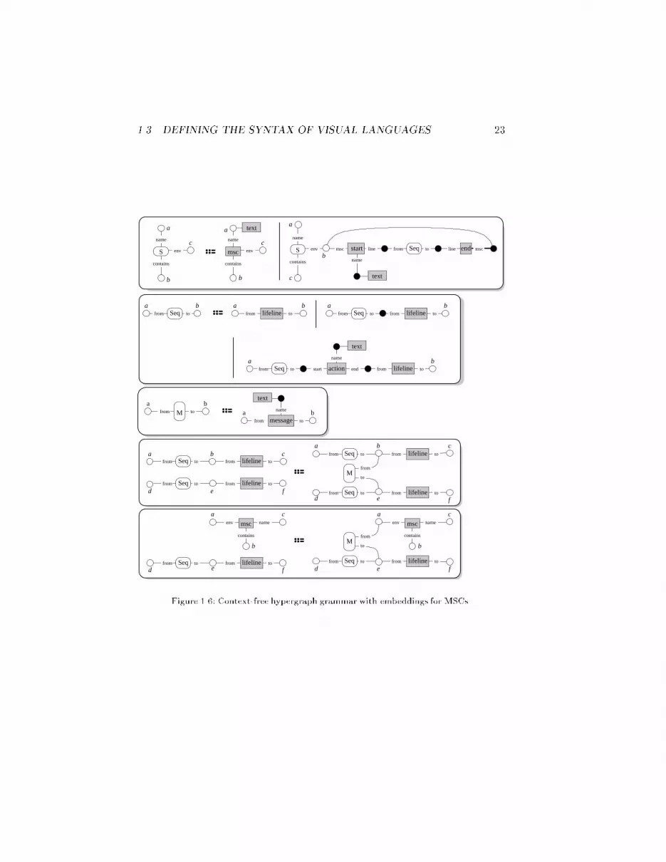
22have to create message hyperedges between any two nodes that are visited bylifeline hyperedges. Any production describing this situation has to refer tothese lifeline hyperedges. Hence, context-free grammars cannot be used for de-scribing MSC. Instead of context-free hypergraph grammars, we now considercontext-free ones with embeddings, a slightly extended but much more expres-sive grammar class, which can describe MSC hypergraph representations.A context-free hypergraph grammar with embeddings (CFeHG) is a context-freehypergraph grammar with additional embedding productions: the RHS of anembedding production is the same as its LHS with an additional hyperedge.The application of an embedding production thus simply adds a hyperedge toa given context. However, in order to make e�cient parsing possible (cf. Sec-tion 1.5), there is a restriction on permitted derivation sequences: embeddingproductions must not be applied to a context that contains hyperedges whichhave been created by any previous rewrite step using an embedding production.The hypergraph representations for MSCs can be speci�ed using a CFeHG.Its terminal symbols are the types of MSC diagram components. Nonterminalsymbols are S, M, and Seq. S is the axiom label. Figure 1.6 shows the pro-ductions. The last two productions are embedding productions which embeda message into an appropriate context, the others are context-free ones. Actu-ally, one production is missing which is the same as the last one except the Mhyperedge which has to be reversed.The derivation structure and history of a hypergraph (cf. Figure 1.1) is rep-resented quite similar to derivation trees for context-free grammars. Becauseof the embedding productions, we obtain a directed acyclic graph (DAG) in-stead of a tree: application of context-free productions extends the DAG in thesame way as for derivation trees, but each application of an embedding pro-duction inserts a new node for the embedded hyperedge with DAG edges fromall nodes representing the context to this new node. Derivation DAGs have acertain structure because of the restriction on derivation sequences: they con-sist of a \main" derivation tree and some additional derivation trees startingat embedded hyperedges which are pasted into the main derivation tree byDAG edges. Figure 1.7 shows the derivation DAG for the MSC hypergraph inFigure 1.4. DAG nodes are labeled with the label and the visited nodes of therepresented hyperedge.We can conclude from the structure of derivation DAGs that each hyper-graph of the language of a CFeHG can be separated into a collection of sub-hypergraphs which are derived by the grammar's context-free productions.One of the subgraphs is derived from the axiom, the others are derived fromhyperedges created by application of embedding productions.We will see in the following subsection that even CFeHGs do not have su�cient
1.3. DEFINING THE SYNTAX OF VISUAL LANGUAGES 23c c
b
a
b
a
c
bab a b
ba
a
a ba b
a b c
d e fd e
a cb
f
ac
b
a
d fe
c
b
e fd
a
b
S env
name
contains
msc env
name
contains
text
Seqfrom toS env
name
contains
end mscstart linemsc
name
text
line
Seqfrom to lifeline tofromSeqfrom to lifeline tofrom
action
name
start end
text
lifeline tofromSeqfrom to
tofrom
text
message
nameMfrom to
Seqfrom to
Seqfrom toto
fromM
Seqfrom to
Seqfrom to
lifeline tofrom
lifeline tofrom
lifeline tofrom
lifeline tofrom
Seqfrom to
to
fromM
Seqfrom to
msc
contains
env name
lifeline tofrom
msc
contains
env name
lifeline tofromFigure 1.6: Context-free hypergraph grammar with embeddings for MSCs.

24line(i,j)
Seq(d,f)
Seq(d,e)
line(d,e)
action(k,l,m) text(m) line(l,q)msc(a,b,c)line(e,f)
line(f,g) start(c,i,n) Seq(i,q) end(q,c) text(n)
Seq(i,k)text(a)
S(a,b,c)
end(g,c) text(h)Seq(d,g)start(c,d,h) S(a,b,c)
S(a,b,c)
Seq(i,j)line(j,k)
message(f,j,o) text(o)
M(f,j)M(e,b)
message(e,b,p) text(p)Figure 1.7: Derivation DAG of the MSC hypergraph in Figure 1.4.expressive power for some VLs. Therefore, the following subsection considersunrestricted grammars, however not for hypergraphs as in this subsection, butfor graph structures.1.3.4 Graph Structure Representation of Visual SentencesGeneral attributed and labeled graph structures as introduced in [65] can beused to model all graph classes, e.g, hypergraphs as presented in the previoussubsection as well as attributed graphs consisting of nodes, edges and (data) at-tributes. They are based on algebraic concepts as presented in [66], i.e., graphstructures are algebras wrt. an algebraic signature, which consists of unaryoperation symbols only. This general graph structure approach is adapted formodeling VLs. Since connections between visual symbols require graphical con-straints between them, these constraints are put into equations extending thesignature and yielding a visual (algebraic) speci�cation of a speci�c VL. Weconsider the visual speci�cation as the VL-alphabet: visual symbols de�ne thesort symbols with a certain layout, and connections de�ne the operation sym-bols. On the other hand, connections are relations between visual symbolsgiven by graphical constraints. These constraints de�ne the equations whichhave to be satis�ed by each visual sentence, i.e., by each algebra. As usual theVL-grammar consists of a start graph (axiom) and several productions. Thestart graph as well as each LHS and RHS of a production are algebras wrt. theVL-alphabet, i.e., the visual speci�cation of a speci�c VL. Such VL-grammarsare not restricted to be context-free nor context-free with embeddings.An algebraic speci�cation for hypergraphs modeling VLs can also be given ac-cording to the de�nition in [62] which is the basis for the hypergraph approach

1.3. DEFINING THE SYNTAX OF VISUAL LANGUAGES 25as presented in this chapter.b Although it is possible to model hypergraphs us-ing the graph structure approach, the VL-de�nition will be di�erent in this sub-section. We have seen that hyperedges are used to de�ne the pictorial objects,and nodes to de�ne the connections. In our approach we do not distinguishbetween nodes and edges. Graph items are used to hold the pictorial objects,and operations between graph items de�ne the connections. Additionally, wedo not distinguish between nonterminal and terminal symbols.In the previous subsections hypergraph grammars have been presented con-cerning the concrete syntax of NSDs and MSCs. Remember, that a SRG repre-sents the pictorial objects, i.e., it is a reduction of the spatial relations, whereasthe ASG represents the abstract syntax of a visual sentence. Within this sub-section we discuss the graph structure approach according to the concrete aswell as the abstract syntax. This is illustrated by a speci�c kind of UML classdiagrams (cf. Figure 1.3 (c)). It is neither possible to de�ne the abstract syntaxof class diagrams by a context-free hypergraph grammar nor by a context-free one with embeddings. Therefore, we switch now to the graph structureapproach to describe the syntax of this speci�c VL.A visual sentence is an attributed graph structure [68], i.e., an algebra wrt. avisual speci�cation (VL-alphabet) consisting of a logical part according to theabstract syntax, a graphical part according to the concrete syntax and suitablelayout operations coupling both parts. The latter one is due to the translationin Figure 1.2 (cf. Page 14). The logical part of a visual speci�cation is de�nedby a graph signature, a data signature and attribution operations. All sortsymbols (sorts) of the logical part de�ne the types occurring within a visuallanguage, whereas the operation symbols (opns) de�ne the connections betweenthese types. The logical part of the visual speci�cation for class diagrams isillustrated by Figure 1.8. It does not include the whole signature for the stringdata type which is built up over characters, because it is assumed to be wellknown.An attributed graph structure is an algebra wrt. a visual speci�cation, i.e.,for each sort symbol exists a carrier set and for each operation symbol existsan operation, and equations (not described until now) are satis�ed by eachalgebra. The graph part is given by total operations whereas the data and at-tribute parts are partial (cf. [69,70]). The graph-like logical part of the algebra,i.e., the visual sentence illustrated by Figure 1.3 (c), is presented in Figure 1.9.The carriers are visualized by rectangles with a leading number followed by itstype inside. Each operation is visualized by an arrow.The algebraic approach allows to de�ne a kind of hierarchy on the types (sorts)bAn algebraic graph structure signature for hypergraphs supposing a slight di�erent no-tation can be found by Def. 4.5.4 in [67].
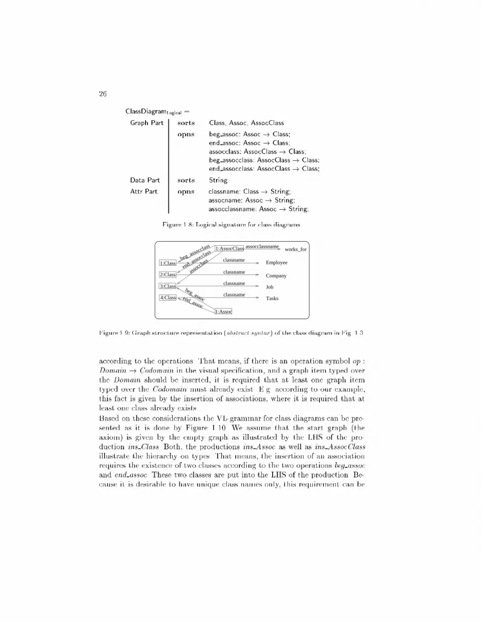
26 ClassDiagramLogical =Graph Part sorts Class, Assoc, AssocClassopns beg assoc: Assoc ! Class;end assoc: Assoc ! Class;assocclass: AssocClass! Class;beg assocclass: AssocClass! Class;end assocclass: AssocClass! Class;Data Part sorts StringAttr Part opns classname: Class! String;assocname: Assoc ! String;assocclassname: Assoc ! String;Figure 1.8: Logical signature for class diagrams.classname
classname
classname
classname
1:Class
2:Class
3:Class
4:Class
Company
Job
Tasks
Employee
assocc
lass
end_assoc
beg_assoc
end_assocclass
beg_assocclass assocclassname1:AssocClass
1:Assoc
works_forFigure 1.9: Graph structure representation (abstract syntax) of the class diagram in Fig. 1.3.according to the operations. That means, if there is an operation symbol op :Domain ! Codomain in the visual speci�cation, and a graph item typed overthe Domain should be inserted, it is required that at least one graph itemtyped over the Codomain must already exist. E.g. according to our example,this fact is given by the insertion of associations, where it is required that atleast one class already exists.Based on these considerations the VL-grammar for class diagrams can be pre-sented as it is done by Figure 1.10. We assume that the start graph (theaxiom) is given by the empty graph as illustrated by the LHS of the pro-duction ins Class. Both, the productions ins Assoc as well as ins AssocClassillustrate the hierarchy on types. That means, the insertion of an associationrequires the existence of two classes according to the two operations beg assocand end assoc. These two classes are put into the LHS of the production. Be-cause it is desirable to have unique class names only, this requirement can be

1.3. DEFINING THE SYNTAX OF VISUAL LANGUAGES 271:Class classnamecn
1:Class
2:Class
1:Class1:Assoc1:Class
3:Class
1:Class
2:Class
1:Class
1:Class classname cn
ins_AssocClass
ins_Assoc2:Class
1:Class
beg_assoc
end_assoc
2:Class 1:AssocClass
assocclass
end_assocclass
beg_assocclass
ins_ClassName (cn:String)
ins_Class Figure 1.10: Abstract syntax of VL-productions for class diagrams.expressed by the application condition as given by the canceled item of theins ClassName production's LHS. Such application conditions (cf. [71,70]) canbe used for the adequate de�nition of the abstract syntax. Notice, the produc-tions expressing the insertion of a binary association name as well as a namefor an association class are analogous to the ins ClassName production.The VL-grammar of Figure 1.10 is an unrestricted graph structure grammarwith empty start graph. The application of these productions yields the abstractsyntax of the class diagram presented in Figure 1.3, respectively Figure 1.9:ins Class inserts 1:Class,ins ClassName(cn=Employee) inserts the string Employee,ins Class inserts 2:Class,ins ClassName(cn=Company) inserts the string Company,ins AssocClass inserts 1:AssocClass, 3:Class,ins ClassName(cn=Job) inserts the string Job,ins AssocClassName(an=works for) inserts the string works for,ins Class inserts 4:Class,ins ClassName(cn=Tasks) inserts the string Tasks, andins Assoc inserts 1:Assoc.The abstract syntax of such class diagrams cannot be de�ned with a context-free hypergraph grammar with embeddings as presented in the previous sub-section. Remember please, that embedded productions must not be appliedto a context containing hyperedges which have been created by any previousrewrite step using an embedding production. This restriction is necessary fore�cient parsing which is discussed in Subsection 1.5.3. Although it is conceiv-able in the hypergraph approach to de�ne several association types as shownabove the corresponding productions would be embedded productions. I.e., theapplication of production ins Assoc (for 1:Assoc) is forbidden when the pro-duction inserting the association class (for 1:AssocClass) is already applied.The logical part of a VL will be now extended by graphical attributes. As

28already mentioned, a visual speci�cation consists of a logical part, a graphicalpart, suitable layout operations coupling both parts, and further equations.The concrete syntax of VLs is given by graphical expressions according tothe language Gvt [72]. Each visual means is de�ned by a box with variableparameters for its position and its size. These parameters are replaced by realvalues when instances are used, e.g., within a rewrite step. A possible algebraicsignature for graphics is sketched in Figure 1.11.graphic Sig =sorts Graphic, Point, Size, FillIntensity, FillColor, TextSize, TextFont, Bool, : : :opns /* Constructors */rect, roundrect: Point Size FillIntensity FillColor! Graphic;line, arrow: Point Size Point Point! Graphic;text: Point Size TextSize TextFont String ! Graphic;box: Point Size ListOfGraphic! Graphic;: : :/* Access Routines */refpoint: Graphic ! Point;width, height: Graphic ! Real; xpos, ypos: Point! Real;north, south, east, west, northwest, : : : : Graphic ! Point;: : :/* Constraints */overlapping: Point! Point; inside: Graphic ! Graphic;begin, end: Point! Point; equalPosition: Point ! Point;equalWidth, equalHeight: Graphic ! Graphic;�xedDistance: Graphic Graphic ! Graphic;: : : Figure 1.11: Signature for graphics.The concepts for graphical objects, i.e., graphical types, are now explained inmore detail: We assume to have an implementation of a �xed graphic algebraG, which is an algebra wrt. graphic Sig. In our model each graphical objectis de�ned by a surrounding imaginary box with a reference point (refpoint),de�ned by the upper left corner, and its size (Width and Heigth). The elementsof the graphic algebra G describe not only primitive graphical objects, as e.g.given by rect, line, etc. but also complex graphical objects which are de�nedby box-expressions. For illustration let us regard the graphical expression fora class presented by Figure 1.12. Such box-expressions describe the graphictypes according to the concrete syntax of a VL's visual means. They will betaken into account for further progress, i.e., they de�ne the default layout of

1.3. DEFINING THE SYNTAX OF VISUAL LANGUAGES 29each graph item. The o�sets of each including primitive is set relatively to thereference point refpoint of the surrounding box. This reference point is givenby a variable, i.e., it can be de�ned by any position. The sizes (Width, Height)are de�ned by variables, too. They are instantiated by concrete values whena production is applied. The size of the box depends on the size and relativepositions of its parameters.box([4,1], [2,3],(rect([0,0], [2,1], 0, white),rect([0,1], [2,1], 0, white),rect([0,2], [2,1], 0, white))
layout(Class) =
1 2 4 653
1
2
3
4
7
r1: rect([1,4], [2,1], 0, white),
r2: rect([1,3], [2,1], 0, white),
r3: rect([1,2], [2,1], 0, white))Figure 1.12: Graphical expression (type) for a class.On top of box-expressions graphical high-level constraints can be used to de-scribe relations between graphics. Such relations are necessary according tothe operations of the VL-alphabet's logical part including the attribution ofgraph items by data types. These constraint de�nitions establish equations, thesignature for the VL-alphabet is enriched by. The equations for the operationsassocclass, beg assocclass and end assocclass are presented in Figure 1.13.8 ac:AssocClass, class:Class;assocclass(ac) = class =) begin (layout(ac)) = layout(class).north;8 ac:AssocClass, class:Class;beg assocclass(ac) = class =) begin (layout(ac)) = layout(class).east;8 ac:AssocClass, class:Class;end assocclass(ac) = class =) end (layout(ac)) = layout(class).west;Figure 1.13: Equations for the operations assocclass, beg assocclass and end assocclass.According to the discussion about graph structures with unary operations only,the graphic algebra consists of n-ary operations. The same is true for the datatype attributes. This is the reason why we do not distinguish between SRG andASG. In our approach the SRG is the ASG with additional attributes, namelythe graphics and data types. Two graph structures (LHS, RHS) are illustratedby the production describing the insertion of an association in Figure 1.14.The upper part of this �gure presents the abstract syntax whereas the lower
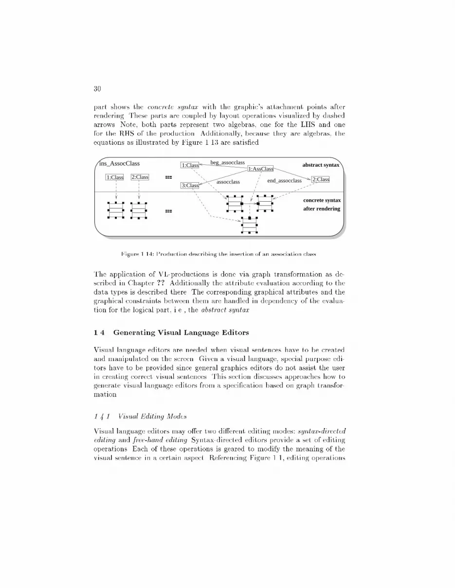
30part shows the concrete syntax with the graphic's attachment points afterrendering. These parts are coupled by layout operations visualized by dashedarrows. Note, both parts represent two algebras, one for the LHS and onefor the RHS of the production. Additionally, because they are algebras, theequations as illustrated by Figure 1.13 are satis�ed.concrete syntax
after rendering
2:Class3:Class
1:AssClass1:Class
2:Class1:Class
abstract syntaxins_AssocClass beg_assocclass
assocclass end_assocclassFigure 1.14: Production describing the insertion of an association class.The application of VL-productions is done via graph transformation as de-scribed in Chapter ??. Additionally the attribute evaluation according to thedata types is described there. The corresponding graphical attributes and thegraphical constraints between them are handled in dependency of the evalua-tion for the logical part, i.e., the abstract syntax.1.4 Generating Visual Language EditorsVisual language editors are needed when visual sentences have to be createdand manipulated on the screen. Given a visual language, special purpose edi-tors have to be provided since general graphics editors do not assist the userin creating correct visual sentences. This section discusses approaches how togenerate visual language editors from a speci�cation based on graph transfor-mation.1.4.1 Visual Editing ModesVisual language editors may o�er two di�erent editing modes: syntax-directedediting and free-hand editing. Syntax-directed editors provide a set of editingoperations. Each of these operations is geared to modify the meaning of thevisual sentence in a certain aspect. Referencing Figure 1.1, editing operations

1.4. GENERATING VISUAL LANGUAGE EDITORS 31modify the visual sentence's ASG; its SRG and thus its visual appearance areupdated accordingly.Syntax-directed editing is supported by two approaches: the grammar-basedone uses an explicit grammar for de�ning a visual language and its ASGs inde-pendent of any editor. Editor operations modify directly a sentence's derivationhistory and, thereby, indirectly the generated (hyper)graph. A typical exampleis LOGGIE which permits generation of graphical, language-speci�c program-ming environments [73]. It uses context-free attribute grammars as the keydata structure for specifying the language and derivation trees for representingthe derivation history. The transformation-based approach omits an explicitgrammar for specifying a visual language. Editing operations are de�ned bygraph transformations on the ASG which also de�ne the visual language at thesame time. The visual language is thus de�ned by its editor. As usual such ed-itors do not keep track of their visual sentences' derivation histories. G�ottler'sPAGG system (cf. Chapter ??) is a typical example of such a system whichrepresents visual sentences by attributed graphs and editing transformationsby productions of programmed attributed graph grammars. Other examples ofthe transformation-based approach are PROGRES (cf. Chapter ?? and Sub-section 1.6.1) and GenGEd (cf. Subsection 1.4.2).The advantage of the grammar-based approach is to be based on a grammaras a concise syntax de�nition. Basic editing operations (e.g., insertion anddeletion of simple objects) can be derived from this grammar; more complexediting operations may be de�ned by additional graph transformations whichcan be checked against this grammar in order not to change the language.On the other hand, the transformation-based approach has the advantage ofbeing able to easily model intermediate, temporally incorrect visual sentencesin terms of the syntax of the visual language, which is not directly repre-sented. Such intermediate, syntactically incorrect visual sentences, which theuser soon completes to syntactically correct ones, are often required for conve-nient editing. The transformation-based approach, moreover, even comprisesthe grammar-based one if we disregard the grammar-based approach's concisesyntax de�nition by a grammar since the grammar-based approach also needsadditional transformations to de�ne complex editing operations.Syntax-directed editors can also be distinguished by the way how the user in-teracts with the editor. The select&apply paradigm as used with most of theseeditors (e.g., PAGG and LOGGIE) requires the user to select an editing oper-ation and some pictorial objects. As an e�ect the editing operation is appliedto the visual sentence by using the selected objects as parameters. There is noneed to explicitly specify this interaction paradigm since it is inherent in thegraph transformation approach. However it forces the user to be completely

32aware of the underlying graph transformation system. If those details shouldbe hidden from the user, interactions have to be more elaborated. The edi-tor speci�cation has to describe interaction patterns to be translated to graphtransformations. This approach is discussed in more detail in Subsection 1.4.3.Visual language editors providing free-hand editing are low-level graphics ed-itors directly manipulating the visual sentence. Referencing Figure 1.1, theeditor modi�es a visual sentence's SRG. The graphics editor becomes a vi-sual language editor by manipulating only pictorial objects used by the visuallanguage and by o�ering a parser. A parser is necessary for checking the cor-rectness of visual sentences, for recreating the SRG's derivation history, andfor updating the ASG accordingly. The advantage of free-hand editing oversyntax-directed editing is to de�ne a visual language by a concise graph gram-mar only; editing operations can be omitted. The editor does not force theuser to edit visual sentences in a certain way since there is no restriction toprede�ned editing operations. However, this may turn out to be a disadvantagesince editors permit to create any visual sentence; editors do not o�er explicitguidance to the user. Furthermore, free-hand editing requires a parser and isthus restricted to visual languages and graph grammars which o�er e�cientparsers.This section discusses syntax-directed and free-hand editors based on graphtransformation only. Other visual language editors like the ones based on con-straint multiset grammars [74] or description logic [75] mainly o�er free-handediting, but lack syntax-directed editing. The latter requires an explicit rep-resentation of objects and their relations which is the strength of the graphbased approach.A typical example of systems generating visual language editors providing free-hand editing and being based on some kind of graph grammar is VLCC byCostagliola et al. [76]. VLCC uses positional grammars [8] as a grammar for-malism which is related to graph grammars in special cases and that providese�cient parsing. VLCC comes with a visual speci�cation tool which is usedto specify a set of pictorial objects that can be arbitrarily manipulated andconnected by the generated low-level graphics editor. Syntax rules, which arealso speci�ed using this tool, use a notation quite similar to the concrete rep-resentation of VL sentences.Similar to VLCC, GenGEd is a system for generating visual language editorswhich comes with a visual speci�cation tool that allows to specify the VL'spictorial objects as well as its syntax rules in the same notation as used inthe generated editor. Generated editors o�er syntax-directed editing using thetransformation-based approach and the select&apply-paradigm. GenGEd isdiscussed in more detail in the following Subsection 1.4.2. Subsection 1.4.3 then
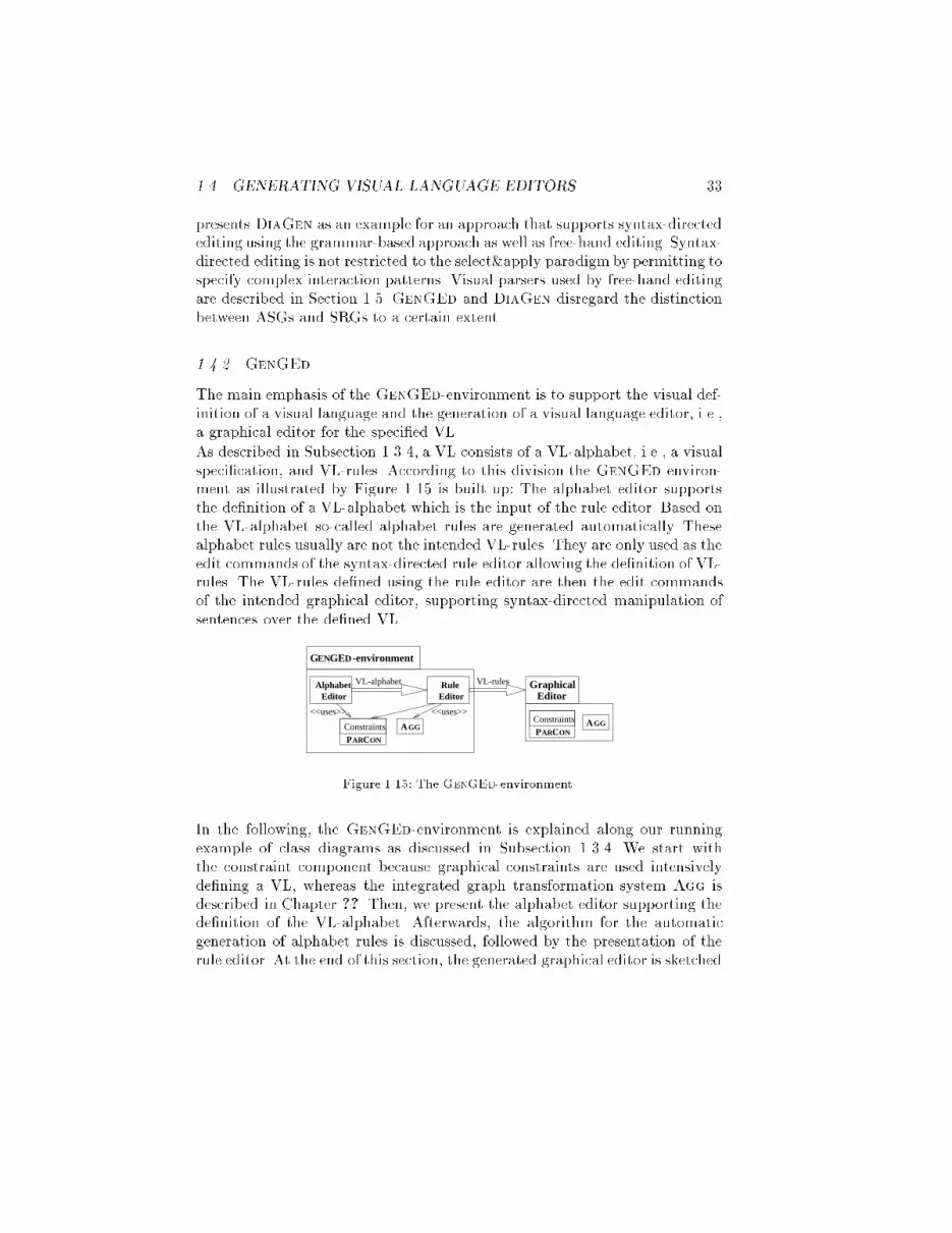
1.4. GENERATING VISUAL LANGUAGE EDITORS 33presents DiaGen as an example for an approach that supports syntax-directedediting using the grammar-based approach as well as free-hand editing. Syntax-directed editing is not restricted to the select&apply paradigm by permitting tospecify complex interaction patterns. Visual parsers used by free-hand editingare described in Section 1.5. GenGEd and DiaGen disregard the distinctionbetween ASGs and SRGs to a certain extent.1.4.2 GenGEdThe main emphasis of the GenGEd-environment is to support the visual def-inition of a visual language and the generation of a visual language editor, i.e.,a graphical editor for the speci�ed VL.As described in Subsection 1.3.4, a VL consists of a VL-alphabet, i.e., a visualspeci�cation, and VL-rules. According to this division the GenGEd environ-ment as illustrated by Figure 1.15 is built up: The alphabet editor supportsthe de�nition of a VL-alphabet which is the input of the rule editor. Based onthe VL-alphabet so-called alphabet rules are generated automatically. Thesealphabet rules usually are not the intended VL-rules. They are only used as theedit commands of the syntax-directed rule editor allowing the de�nition of VL-rules. The VL-rules de�ned using the rule editor are then the edit commandsof the intended graphical editor, supporting syntax-directed manipulation ofsentences over the de�ned VL.CONARP
Constraints AGG
CONARPConstraints AGG
GED-environmentGEN
Alphabet Graphical Editor
<<uses>> <<uses>>
VL-alphabet VL-rules
EditorRule
EditorFigure 1.15: The GenGEd-environment.In the following, the GenGEd-environment is explained along our runningexample of class diagrams as discussed in Subsection 1.3.4. We start withthe constraint component because graphical constraints are used intensivelyde�ning a VL, whereas the integrated graph transformation system Agg isdescribed in Chapter ??. Then, we present the alphabet editor supporting thede�nition of the VL-alphabet. Afterwards, the algorithm for the automaticgeneration of alphabet rules is discussed, followed by the presentation of therule editor. At the end of this section, the generated graphical editor is sketched

34allowing the syntax-directed manipulation of visual sentences which is done viathe select&apply-paradigm.Each editor consists of a frame with several top-down menus. Editor speci�cfunctions are put into the left side. The right area is used by each editor forits speci�c tasks. We have to mention, that for sake of space we cannot discussthe whole functionality of the environment, i.e., each editor.Constraints The constraint component available within GenGEd o�ers ahigh-level constraint language. Each high-level constraint (HLC) is de�nedby suitable low-level constraints (LLCs) of the integrated constraint solverParCon (cf. [77]).The solver is used as a server. It is implemented in Objective C in contrastto all other components discussed in this subsection which are implemented inJava. The prede�ned HLCs are collected within a library which can be seen asa superset of the used ParCon constraint language. These prede�ned HLCsmay not be su�cient enough to support the de�nition of all needed graphicalsymbols and their connections. Therefore, a user can extend the library by ownconstraints expressed in the HLC-language.Alphabet Editor For the visual de�nition of a VL-alphabet two compo-nents are available: the Graphical Symbol Editor (GSE) and the ConnectingEditor (CE). The GSE supports the drawing of graphical objects, i.e., thevisual means of a VL, and the determination of implemented data type at-tributes. For each graphical object the user is asked to insert a name for it.Each name establishes one of the visual speci�cation's sort symbols of thegraph part, resp. data part, whereas each graphical object de�nes a graphicof the graphical part. Furthermore, naming the graphics establishes implicitlythe layout operations. These layout operations couple the sort symbols with itsgraphical counterpart according to the translation in Figure 1.2 (cf. Page 14).The graphical objects connected with a name are further-on called graphicalsymbols. When the graphical symbols are determined, the CE can be usedto determine the operations for the visual speci�cation's logical part and thegraphical constraints which de�ne the equations.The GSE is similar to common graphical editors. The main di�erence is givenby graphical constraints, which are to be used for de�ning one graphical object:Each graphical object consists either of a primitive graphical object as givenby a rectangle, circle, arrow, etc. or of several primitive graphical objects whichare connected by graphical constraints yielding a box-expression as presentedin Figure 1.12. According to our example, the graphical objects are determined

1.4. GENERATING VISUAL LANGUAGE EDITORS 35for a class (Class), a binary association (Assoc) and the association class (As-socClass).The visual means for the String data type as used within our example for theclass name, the association name and the association class name is given byText. Note, the default properties of the graphical object Text can be changed.However, if di�erent properties for names are desired, it is necessary to de�neseveral String data types. E.g. if all class names should be written in italicsand all association names should be depicted in the normal style, then a userchooses Text twice and de�nes the desired properties.The graphical symbols de�ned using the GSE are available within the sequentlytoggled CE. Their images are put onto buttons with their type names (sortsymbols) below. They can be chosen and put onto the drawing area as il-lustrated in Figure 1.16, where the constraints according to the operationsbeg assocclass, end assocclass and assocclass are to be de�ned. Each operationde�nition is controlled by the CE, i.e., constraints can be de�ned and addition-ally the user has to de�ne Domain and Codomain of the operation accordingto the logical part of a visual speci�cation. The latter one is supported bya dialogue after pressing the New Operation button. If the operation and atleast one constraint is de�ned this is visible by a connecting line as illustratedin Figure 1.16. When all operations, respectively constraints, are de�ned thevisual speci�cation as discussed in Subsection 1.3.4 is established.Generated Alphabet Rules The VL-alphabet, i.e., the visual speci�ca-tion, is the basis for the automatical generation of alphabet rules. These al-phabet rules are used as the edit commands of the rule editor. Notice, that analphabet rule may be already a VL-rule. Nevertheless, for most VL-alphabetsnot all generated rules express the intended VL-rules.The alphabet rules are built up according to the graph part's sort symbolscoupled with its graphic, i.e., for each graphical symbol an insertion rule isgenerated c: The LHS of such a rule is initially empty and the RHS comprisesthe graphical symbol. This generated rule is modi�ed if an operation existswhose Domain is the sort of the symbol which should be inserted. Then, theLHS and the RHS comprise additionally the graphical symbol of the opera-tion's Codomain. Furthermore, the RHS includes the graphical symbol for theoperation's Domain. This handling is due to the hierarchy of operations and thealgebraic approach as discussed in Subsection 1.3.4. That means, each side of arule is a visual sentence and therefore an algebra wrt. the visual speci�cation.Because the graph part is total all operations must be de�ned.cNot only insertion rules are generated but also rules describing deletion, moving, etc.

36Figure 1.16: The GenGEd-connecting editor.The upper part of Figure 1.17 presents the generated alphabet rule for theinsertion of an AssocClass. Following the algorithm, �rst the LHS of thisrule is empty, whereas the RHS includes the graphical symbol for AssocClass.The second step is to examine the operations. Three operations (assocclass,beg assocclass, end assocclass) are de�ned in the visual speci�cation where As-socClass is the Domain of (cf. Figure 1.8). For each operation's Codomain agraphical symbol is generated, in this case three graphical symbols for Class.These three classes are now put into the LHS as well as into the RHS. TheRHS includes additionally the graphical symbol for AssocClass. Then, the op-erations are de�ned according to the logical part of a visual sentence, and thegraphical constraints, i.e., the equations, are satis�ed.Attribution rules are generated automatically, too. According to our exampleseveral attribution operations (and constraints) are de�ned, that are class-name, assocname, and assocclassname, all given by the String data type. Foreach attribution an insertion rule is generated d where the attribute's value isdenoted by the rule parameter. The algorithm for the generation of attributionrules is the same as described above. I.e., for each attribution a rule is gener-dNot only insertion rules are generated but also rules describing deletion, moving, etc.
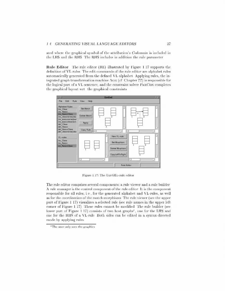
1.4. GENERATING VISUAL LANGUAGE EDITORS 37ated where the graphical symbol of the attribution's Codomain is included inthe LHS and the RHS. The RHS includes in addition the rule parameter.Rule Editor The rule editor (RE) illustrated by Figure 1.17 supports thede�nition of VL-rules. The edit commands of the rule editor are alphabet rulesautomatically generated from the de�ned VL-alphabet. Applying rules, the in-tegrated graph transformation machineAgg (cf. Chapter ??) is responsible forthe logical part of a VL-sentence, and the constraint solver ParCon completesthe graphical layout wrt. the graphical constraints.Figure 1.17: The GenGEd-rule editor.The rule editor comprises several components: a rule viewer and a rule builder.A rule manager is the control component of the rule editor. It is the componentresponsible for all rules, i.e., for the generated alphabet and VL-rules, as wellas for the coordination of the match morphisms. The rule viewer (see the upperpart of Figure 1.17) visualizes a selected rule (see rule names in the upper leftcorner of Figure 1.17). These rules cannot be modi�ed. The rule builder (seelower part of Figure 1.17) consists of two host graphse, one for the LHS andone for the RHS of a VL-rule. Both sides can be edited in a syntax-directedmode by applying rules.eThe user only sees the graphics.

38For rule application it is necessary to de�ne the match morphism. I.e., afterpressing the Set Match button, each graphical symbol of the rule viewer's LHSmust be mapped onto exactly one component of the rule builder's LHS orRHS. Then, the visualized rule can be applied by pressing the Apply button.Applying a rule means, that the rule's LHS will be deleted in the host graph(graphic) and substituted by the RHS. If a VL-rule is complete the componentsof both sides must be related by a mapping (morphism). Such a mapping willbe de�ned implicitely if a VL-rules RHS is constructed as a copy of its LHS: if�rst the VL-rule's LHS is edited, then, pressing the CopyLeftToRight buttonyields a copy of the LHS in the VL-rule's RHS including the mapping. Both,the VL-rule's LHS and RHS may be modi�ed afterwards.Let us illustrate the construction of the VL-rule presented by Figure 1.14in Subsection 1.3.4 which expresses the proper semantical e�ect of insertingan AssocClass in contrast to the generated alphabet rule visualized in theupper part of Figure 1.17. Starting with empty LHS and RHS of the VL-rule, the alphabet rule ins class is applied twice to the LHS. Pressing theCopyLeftToRight button yields both classes in the RHS and de�nes implicitlythe necessarily mapping. Thereafter, the rule ins class is applied again on theRHS yielding the third class in Figure 1.17. This RHS is the basis to apply thealphabet rule ins AssocClass as shown by the rule viewer in Figure 1.17. Thisleads to the desired VL-rule.Some automatically generated rules may already describe a VL-rule. In thiscase it is possible, to copy the generated rule into the list of VL-rules. For ourexample this was the case for the rule ins Class and ins Assoc.Generated Graphical Editor A syntax-directed graphical editor (GE) asillustrated in Figure 1.18 is generated from the VL-rules, and supports the edit-ing of visual sentences by application of these rules. The rule application of aGenGEd-generated graphical editor is performed by the graph transformationmachine Agg. Agg is working on the logical graph structure. The constraintserver ParCon solves the corresponding graphical constraints. In contrast tothe rule editor, a graphical editor o�ers only one host graph. This host graphis the visual sentence VL-rules can be applied to. Apart from that, a graphicaleditor has the same behaviour as the rule editor.VL-rules can be applied by mapping the graphical symbols of the VL-rule'sLHS (visualized by the RuleViewer) onto type consistent graphical symbolsof the working area. These objects are replaced by the corresponding objectsof the VL-rule's RHS. Automatic layout adjustment of the adjacent graphicalsymbols is enforced if one graphical symbol is moved.

1.4. GENERATING VISUAL LANGUAGE EDITORS 39Figure 1.18: The graphic editor for class diagrams.1.4.3 DiaGenDiaGen is a tool consisting of a framework together with a generator thatis used to create graphical editors from a formal speci�cation. Editors employhypergraphs as internal model of visual sentences and hypergraph grammarsto de�ne the VL's syntax. This subsection gives a brief survey of DiaGen andbegins with DiaGen's grammar-based syntax-directed editing mode. Context-free VLs are considered �rst. DiaGen's extension to syntax-directed editingof non-context-free VLs are brie y described next. Later on, this subsectioncontinues with DiaGen's free-hand editing mode which is made possible byvisual parsers that check the correctness of visual sentences. As a runningexample of this subsection, we will use Nassi-Shneiderman diagrams (NSDs)as described in Section 1.3.DiaGen uses the traditional compiler compiler approach to create visualeditors from a (textual) speci�cation. In the beginning, DiaGen was de-signed to generate syntax-directed editors for context-free VLs only. Editorsof this DiaGen version consist of generated C++ code together with a C++-framework based on X Windows and Motif.Figure 1.19 shows screenshots of a session with an NSD editor that has beengenerated by this DiaGen version. The left screenshot shows two NSDs on

40Figure 1.19: Syntax directed editing of Nassi-Shneiderman diagrams.the editor canvas where a sequence of statements of the lower NSD is selected(marked by the small gray handles at the corners of the selected statements).The right screenshot shows the editor state after the selected statement se-quence of the left screenshot has been moved into the upper NSD, which isagain depicted as a selected statement sequence. The user can carry out thisediting operation in a direct manipulation manner by clicking on the selectedstatement sequence in the left screenshot and dragging the sequence|an out-line follows the mouse movement|to the new position, which is the line belowthe while condition, where the mouse button is released. The editor then up-dates both diagrams, i.e., it carries out the structural modi�cation imposed bythe user and then updates the diagram layout automatically.This example illustrates the main features of syntax-directed editors generatedby DiaGen:� Editors allow to create syntactically correct diagrams only. Each editingoperation preserves this property of any diagram edited on the screen.� Editing operations are implicitly selected and carried out. Instead of thetraditional select&apply paradigm, the user can interact in a very naturalway with the editor by selecting diagram parts and dragging them to newpositions in a direct manipulation manner.� Editors are provided with a syntactic grouping mechanism, i.e., a collec-tion of selected diagram components are considered as one component if

1.4. GENERATING VISUAL LANGUAGE EDITORS 41they form a syntactic whole which, of course, depends on the VL. ForNSDs, statement sequences may be grouped.� Editors have an automatic layout mechanism which computes a valid di-agram layout after structural modi�cations, but also after explicit layoutmodi�cations by the user (e.g., when the user repositions some diagramcomponents).Each of these features have to be described in the editor speci�cation. Thefollowing presents a brief survey of their concepts.Diagrams are internally represented by hypergraphs as described in Section 1.3:each pictorial object is modeled by a hyperedge (for a hypergraph represen-tation of NSDs see Figure 1.4); nodes and hyperedges carry attributes whichde�ne the diagram layout. An attributed context-free hypergraph grammarde�nes the VL syntax in terms of its hypergraph models. Figure 1.5 shows thegrammar for NSDs which also contains constraints on attributes which de�nevalid layouts. The main data structure representing a diagram, however, is thederivation tree of its hypergraph representation. It is this data structure thatis primarilymodi�ed by editing operations; the visual appearance of a diagramis the image when mapping the hypergraph speci�ed by its derivation tree tothe screen. The mapping is de�ned by the editor speci�cation, which containsdescriptions how each hyperedge type has to be visualized on the screen, andby attribute values de�ning the layout, i.e, position, geometry etc., of eachhyperedge image. A constraint solver makes use of the derivation tree andcomputes and recomputes valid attribute values according to the constraintsof the attributed hypergraph grammar after each structural modi�cation tothe derivation tree and after each layout modi�cation by the user [64].Syntax-directed editing operations are internally transformations on thesederivation trees. They have to be de�ned in the speci�cation used by the gener-ator. However, they are not made visible to the editor user. Their application iscontrolled by interaction automata which are part of the speci�cation, too [78].Interaction automata have been motivated by Statecharts [79] and are special-ized for describing interactions. Each interaction automaton has an initial stateand a set of �nal states. An automaton recognizes an interaction pattern, i.e., asequence of external or internal events (e.g., mouse clicks or mouse movementsrespectively satisfaction of some predicates on the editor's state), if there is apath from the initial to a �nal state such that the transitions along the pathare subsequently carried out. Transitions are labeled by conditions and actions.Conditions may be references to external events, references to predicates writ-ten as (C++) procedures representing internal events, or references to otherinteraction automata. A transition is carried out when the state at the transi-

42mouse pos. withina selected group?
g := group thatcontains mouse
Move(g)
draw outlineof g
mouse moved
delete outline of g;determine target t
button released
delete old outline of g;draw new outline of gmouse moved
button released
otherwise
Layout()
CutOut(g)
Insert(g,t)
store mouseposition
mouse buttonpressed
position
MoveSelected() Move (group g)Figure 1.20: Two of the interaction automata describing the interaction depicted in Fig-ure 1.19. Actions (shown in italics) and conditions are presented using an informal syntax.Initial states are marked by gray �ll pattern, �nal states by double circles.tion source is active and the associated condition is satis�ed. This means thateither an appropriate external event has happened, or the predicate evaluatesto true, or the referenced automaton has recognized an interaction pattern. Byusing interaction automata as conditions within other interaction automata,one obtains a hierarchical description of interaction patterns which the editorreacts on. Additionally to conditions, transitions are labeled by actions, e.g.,transformations on derivation trees, which are carried out together with thetransitions. Figure 1.20 shows the a simpli�ed version of interaction automataresponsible for the editing operation depicted in Figure 1.19, i.e., detecting amouse click over the selected statement sequence in the left screenshot, drag-ging an outline of the sequence following the mouse movement, and insertingthe sequence at the new position.As the example also shows, editors employ a syntactic grouping mechanism.When diagram components get selected, the corresponding hyperedges arelabeled as selected. A transformation system which is described in the edi-tor speci�cation, too, then replaces appropriately labeled subtrees of deriva-tion trees by special hyperedges that represent the selected group. This wholeprocess is again controlled by interaction automata. For NSDs, subtrees thatrepresent sequences of selected statements are replaced by such group hyper-edges. Finally, editing operations are also speci�ed as transformation rules onderivation trees that may contain group hyperedges as replacement of a whole(selected) subtree. Interaction automata take care of selecting the right ruleswhich have to be applied. Figure 1.20 �rst applies a rule CutOut(g) which re-moves the selected group (g) from its original position. Insert(g,t) then insertsthis group at the target position (t).Since context-freeness turned out to be too restrictive, DiaGen has been ex-tended to non-context-free VLs in a limited way that preserves the mechanismsalready available for editing of context-free VLs: each non-context-free diagramhas to consist of a context-free skeleton, which is represented by a derivation

1.4. GENERATING VISUAL LANGUAGE EDITORS 43Figure 1.21: Free-hand editing of Nassi-Shneiderman diagrams.tree, and a layer of additional hyperedges. The editor speci�cation then has tocontain a context-free hypergraph grammar for the context-free skeletons, butalso additional transformation rules that add and remove these additional hy-peredges. Again, interaction automata control editing operations that modifyderivation trees or the additional hypergraph layer.However, syntax-directed editing as described so far turned out to be quite re-strictive for the editor user. The user had to use prede�ned editing operations.Furthermore, visual sentences have to be correct all the time. Intermediate syn-tactically incorrect editing states that are sometimes convenient are prohibitedby this approach. Therefore, the syntax-directed editing mode has been com-bined with a free-hand editing mode supported by visual parsers that checkwhether diagrams are syntactically correct and recreate their derivation DAG(c.f. Section 1.3). Actually, a new version of DiaGen (DiaGen II) for thiscombined approach has been implemented using Java instead of C++ sincethe previous DiaGen version happened to be less portable.Figure 1.21 shows two screenshots of a session of an NSD editor created byDiaGen II that also supports free-hand editing. The left screenshot shows asyntactically correct diagram which is now modi�ed by the user who movesthe top-most component representing the while condition to a new position.The visual parser recognizes that the resulting diagram is not syntacticallycorrect. It consists of a diagram component that does not belong to any correctsubdiagram (the while condition) and two correct subdiagramsf (the remainingtwo rectangular subdiagrams). The following Section 1.5 explains visual parsersthat are used by DiaGen for this task.fOn the computer screen, the color red is used to mark such incorrect diagram parts;bright colors like white and yellow characterize correct subdiagrams.

44For syntax-directed editing, editing operations are carried out on the hyper-graph model; the visual appearance of the diagram is an image when mappingthe hypergraph to the screen. For free-hand editing, however, the situation isdi�erent: a low-level graphic editor allows the user to modify pictorial objectsdirectly. The hypergraph has to be kept up-to-date accordingly. This task issimpli�ed by the use of the hypergraph model as described in Subsection 1.3.3:hyperedge tentacles represent attaching areas of the corresponding pictorial ob-ject. Pictorial objects that are related by their attachment areas are modeledby the corresponding hyperedge tentacles being connected to common nodes inthe hypergraph model. DiaGen creates a low-level graphic editor that allowsto manipulate pictorial objects of the speci�ed VL; the internal hypergraphmodel is modi�ed accordingly by watching the pictorial objects' attaching ar-eas [80].Free-hand editing with parser support relaxes the need to specify a full set oftransformations on diagrams for syntax-directed editing since free-hand editingcan be used for (yet) unspeci�ed diagram operations. Therefore, this editingmode enhances usability of editors and also makes rapid prototyping of dia-gram editors possible because|as an extreme case|speci�cation of diagramoperations can be omitted completely.1.5 Generating Visual Language ParsersThe previous section pointed out that visual editors which represent visualsentences by graphs and allow for free-hand editing have to make use of a graphparser. It is the parser's task to distinguish syntactically correct graphs|andtherefore visual sentences|from incorrect ones and to translate a graph intoits syntactic structure. The syntactic structure may then be used for furtherprocessing, e.g., to create an abstract syntax graph (cf. Figure 1.1). This sectiondiscusses how visual languages de�ned by graph grammars may be parsed andhow visual editors can make use of parsing information.1.5.1 The Visual Language Parsing ProblemA graph parser tries to decide the membership problem for graph grammars:for a given graph and a graph grammar, it tries to �nd a derivation sequencefrom the grammar's axiom to the given graph. This problem is undecidablefor general grammars [81]; hence, restricted classes of graph grammars areexamined for which this problem is more or less e�ciently decidable. In thefollowing we will consider context-free hypergraph grammars, context-free oneswith embeddings, as well as layered graph grammars, which are introduced in

1.5. GENERATING VISUAL LANGUAGE PARSERS 45Section 1.5.4. In general, the derivation sequence is the only way to representa graph's syntactic structure if it is a member of the grammar's language.For these (hyper)graph grammar classes, however, derivation trees resp. DAGs(cf. Section 1.3) can be used for a more structured syntax representation.Visual parsers, i.e., graph parsers used for parsing graph representations ofvisual sentences, have to provide additional features. A simple graph parserjust classifying an assembly of pictorial elements as correct or incorrect is un-satisfying for the user. Similar to programming language compilers, the visualparser has to identify the errors of the visual sentence, i.e, it has to �nd aminimal subset of pictorial objects that is responsible for being an incorrectvisual sentence and the maximal subsets being correct visual sentences. Low-level graphics editors may then give feedback and guide the user in correctingerrors. Furthermore, visual parsers should work incrementally in order to keepinformations gathered in earlier parser runs. This is especially important in thesituation described in Section 1.3 where the parser is used to keep an abstractrepresentation (ASG) of the visual sentence up-to-date with its concrete repre-sentation (SRG). Since it is this ASG that is used for further processing of thevisual sentence, it is necessary to maintain those parts of an ASG that havenot been modi�ed by editing operations. Parsers always starting from scratchwould rebuild the abstract representation anew after each editing operation.Parsers working incrementally, however, can meet this requirement.The next Subsections 1.5.2 and 1.5.3 outline visual parsers for context-free hy-pergraph grammars and context-free ones with embeddings which run o�ineas well as incrementally and which o�er error feedback. These hypergraphgrammar classes already cover a wide range of practical problems. Finally, inSubsection 1.5.4, a parser for layered graph grammars, an even more generalclass of graph grammars is described. However, graph and hypergraph gram-mars are not the only grammar type for which visual language parsers havebeen proposed. Table 1.1 summarizes parsing approaches for constraint mul-tiset grammars, relational grammars, picture grammars (consisting of picturelayout grammars and positional grammars), and graph as well as hypergraphgrammars including the ones discussed in more detail in the next subsections.The table answers the following questions for each of the parsing approaches:� How does a production's LHS and RHS look like?� Does the formalismallow references to additional context elements, whichhave to be present, but remain unmodi�ed when applying a production?� Does the grammar type of this parsing approach have more or less com-plex embedding rules, which establish connections between new elements(created by a production) and the surrounding structure?

46Context Embedding Add. parsing Space/TimeType Authors LHS RHS elements rules restrictions complexityKaul[82,83] one non-terminal directed nonemptygraph no yes implicitly def. vertexordering by edges linearRozenberg/Welzl [84] one non-terminal directed graph with-out nonterminal neigh-bours no yes (bounded degree,connected graph) exponential(polynomial)Graph Rekers/Sch�urr [85] directedgraph directed connected,nonempty graph directed graph extended con-text global layering con-dition for grammar exponentialZhang/Zhang [86] directedgraph directed connected,nonempty graph directed graph extended con-text con uent grammar polynomialBunke/Haller [87] one non-terminal nonempty plex struc-ture no �xed set of con-nection points no exponentialHyper-graph one non-terminal hypergraph no �xed set of con-nection points (k-separability [62]) exponential(polynomial)Minas [88] one non-terminal hypergraph hypergraph �xed set of con-nection points embedding restric-tions (k-sep. [62]) exponential(polynomial)Wittenburg[56] one non-terminal nonempty relationalstructure no yes explicitly def. vertexordering by relations exponentialrelational Ferrucci etal. [89] one non-terminal rel. structure withoutnonterminal neigh-bours no yes (bounded degree,connected structure) exponential(polynomial)Golin [4] one non-terminal one or two (non) termi-nals one nonterminal implicit �nite set of possibleattribute values polynomialPicture Costagliolaet al. [90] one non-terminal positional sententialform no implicit or�xed set ofconnectionpoints LR-condition linearMultiset Marriott[6] one non-terminal arbitrary nonemptymultiset (yes) implicit acyclic grammar, nocontext elements exponentialTable 1.1: Visual language parsing approaches.

1.5. GENERATING VISUAL LANGUAGE PARSERS 47� Are there additional restrictions for the set of productions or for the formof the parsed structures?� Is the time and space complexity of this parsing approach linear, polyno-mial, or even exponential with respect to the size of the input structure?The question of embedding rules deals with a speci�c aspect of graph gram-mars as opposed to string grammars since it is concerned with the problem ofhow new elements (created by a production) are connected to its surroundingstructure. Connections are either implicitly established as with picture lay-out or constraint multiset grammars since relations between objects are onlyimplicitly de�ned. Or the LHS and RHS of a productions are extended by acommon context, which is not modi�ed when applying the production. Or thereare complex embedding rules that describe the redirection of arbitrary sets ofrelationships from replaced objects to replacing objects.The precedence graph grammar parser of Kaul [82,83] is an attempt to gener-alize the idea of parsing based on operator precedence and has a linear timeand space complexity. The parsing process is a kind of handle rewriting, wheregraph handles (subgraphs of the input graph) are identi�ed by analysing ver-tex and edge labels of their direct context. Unfortunately, this approach worksonly for a very restricted class of graph languages.Other approaches use Earley-style parsers [91]: Bunke and Haller [87] use plexgrammars, which are essentially context-free hypergraph grammars with re-stricted forms of embedding rules. Any nonterminal has only a �xed numberof connection points to its context. Wittenburg's parser [56] uses dotted rulesto organize the parsing process for relational grammars, but without presentingany heuristics how to select \good" dotted rules. Furthermore, it is restrictedto the case of relational structures, where relationships of the same type de-�ne partial orders. Finally, the approach of Ferrucci et al. [89] with so-called1NS-RG grammars is a translation of the graph grammar approach of Rozen-berg/Welzl [84] into the terminology of relational languages. In this approachRHSs of productions may not contain nonterminals as neighbours, therebyguaranteeing local con uence of graph rewriting (parsing) steps. Furthermore,polynomial complexity is guaranteed as long as generated graphs are connectedand an upper boundary for the number of adjacent edges at a single vertex isknown.Golin's and Marriott's parsers are based on bottom-up parsing similar tothe parsers by Tomita [92] and Cocke-Younger-Kasami [93,94] for context-free string grammars. Marriott's constraint multiset grammars [6] furthermoreallow rather general forms of context elements (preserved common elementsof LHS and RHS). Golin's parsing algorithm for picture layout grammars [4]

48supports terminal context elements, too, but has a main focus on productionswith one nonterminal on the LHS and at most two nonterminals on the RHSwith prede�ned spatial relationships between them.Minas's parsers [88] for hypergraph grammars are also inspired by the Cocke-Younger-Kasami parser. The �rst one is restricted to purely context-free hy-pergraph grammars, the second allows to parse context-free grammars withembeddings. Rekers and Sch�urr's parser [85] for layered graph grammars isable to deal with nearly unrestricted graph grammars. The only restrictionis a layering restriction which ensures that parsing is alway terminating. Mi-nas's as well as Rekers and Sch�urr's parsers are discussed in more detail in thefollowing subsections.Zhang and Zhang [86] have recently proposed a simple parser for a furtherrestricted kind of layered graph grammars. They reverse each grammar pro-duction and thus obtain a new graph transformation system. As long as thereverse graph transformation system is con uent, a graph can be parsed byreducing it to an initial graph.Finally, Costagliola et al. have proposed a parser for positional grammars [90]which basically extends string grammars by 2D-relationships. Their parser isbased on LR-parsers used for context-free string grammars.However, with the exception of the two parsing algorithms for hypergraphgrammars which will be outlined in the next subsections, none of these parserssupports incremental parsing which is necessary for maintaining as much in-formation from earlier parser runs as possible. Parsing of partially correctstructures is only possible with the parsers outlined in the next subsections aswell as with Bunke/Haller's and Wittenburg's parser.1.5.2 Parsing for Context-Free Hypergraph GrammarsThe idea of a parser for context-free hypergraph grammars (cf. Section 1.3.1)has been inspired by the Cocke-Younger-Kasami parser (CYK) [93,94] forcontext-free string grammars. The original CYK parser can be used with anycontext-free grammar that has Chomsky normal-form (CNF), i.e., there areonly productions with the RHS consisting of either exactly one terminal or ex-actly two nonterminal symbols. This is no restriction since every context-freegrammar can be transformed into CNF.g The special case of the empty wordin the grammar's language is omitted here. CNF for context-free hypergraphgrammars is similarly de�ned: the RHS of each production consists of a hy-pergraph with either exactly one terminal hyperedge (terminal production) orgTable 1.1 does not mention the restriction to CNF grammars because every context-freegrammar can be transformed into CNF.

1.5. GENERATING VISUAL LANGUAGE PARSERS 49exactly two nonterminal hyperedges (nonterminal production).The hypergraph parser constructs syntactic information bottom-up similar tothe original CYK parser: it starts with the terminal hyperedges and creates allnonterminal hyperedges that can be derived using terminal productions. There-after, the parser creates additional hyperedges that are derivable to hyperedgescreated previously. Derivation trees for syntactically correct subgraphs are in-herently constructed when storing the directly derivable hyperedges for eachnonterminal hyperedge.An e�cient organization of the bottom-up construction of nonterminal hy-peredges is to successively create sets Si (i = 1; 2; : : : ; n with n the numberof terminal hyperedges) of nonterminal hyperedges that can be derived to aterminal subgraph with exactly i hyperedges.h Thus S1 has to be �lled withhyperedges derivable with terminal productions. Then the sets S2; S3; : : : ; Snare successively created. A new nonterminal hyperedge e together with refer-ences to its visited nodes is inserted into Sk if there exist an i (1 � i < k) andhyperedges e1 2 Si and e2 2 Sk�i such that� e can be derived to the hypergraph consisting of e1 and e2 (together withthe corresponding nodes) using a nonterminal production.� the terminal subgraphs of e1 and e2 have disjoint hyperedge sets.After termination, the sets Si of hyperedges together with references to theirderived child hyperedges contain the complete syntactic information of thehypergraph. The entire hypergraph is syntactically correct if Sn contains ahyperedge labeled with the grammar's axiom (axiom hyperedge). The grammaris ambiguous if more than one of such hyperedges is contained. In the following,we assume non-ambiguous grammars.The parsing algorithm outlined above is a re�nement of the parsing procedurepresented in [62]. The algorithm makes use of the grammar's CNF and anexplicit organization of parsing results in its structure of sets Si which makethe algorithmwell-suited for its application with low-level graphics editors. Theparsing algorithm has to have exponential complexity for general context-freegrammars, but it has polynomial complexity for certain grammars as pointedout in [62]. The NSD grammar is an example of such a grammar.The hypergraph parser furthermore meets the criteria for visual languageparsers: it can also be used for partially correct hypergraphs, and it may beused incrementally, i.e., subsequent runs of the parser can make use of theresults of previous runs. These features are considered next.hIn the following, we call the terminal subgraph that can be derived from a hyperedge esimply terminal subgraph of e.

50In general, the hypergraph as entirety is not syntactically correct, but containsa number of correct subgraphs. The sets Si make it easy to �nd a set of maximalcorrect subgraphs (i.e., consisting of as many hyperedges as possible and beingsyntactically correct): the sets Sn; Sn�1; Sn�2; : : : are searched for occurrencesof axiom hyperedges. Such a hyperedge is selected if there are no con icts withany previously selected one. Two hyperedges are said to have con icts if theirterminal subgraphs have common terminal hyperedges. After termination, theselected axiom hyperedges are the derivation tree roots of correct subgraphs,thus specifying correct (sub)sentences. Note that this classi�cation is in generalambiguous: if a set Si contains axiom hyperedges with overlapping terminalsubgraphs, at most one of them is selected; therefore, the sequence of checkingaxiom hyperedges in Si may in uence the selection.The parser algorithm described so far constructs a hypergraph's syntactic in-formation from scratch. When keeping the syntactic information, i.e., the setsSi, up-to-date even after hypergraph modi�cations, we obtain an incrementalparsing algorithm. Each hypergraph modi�cation can be divided into basicmodi�cations of three kinds:i� Splitting the hypergraph into two unconnected subgraphs: Nonterminalhyperedges become invalid if their terminal subgraphs are also split whensplitting the entire hypergraph. Therefore updating the sets Si meansto check each nonterminal hyperedge and to remove it if its terminalsubgraph is split.� Joining two previously unconnected subgraphs by merging nodes: The ex-isting nonterminal hyperedges remain valid, and the parser has to createadditional ones. This is done like parsing from scratch, but pairs of al-ready processed nonterminal hyperedges may remain unconsidered.� Adding an isolated hyperedge to the hypergraph: An additional, but emptyset Sn+1 has to be established, and S1 is extended by nonterminal hy-peredges that can be derived to the new terminal one.The remaining task of the compiler is to search for maximal correct subgraphsand to reconstruct derivation trees. Again, the parser can save work here bykeeping track of unchanged portions of the sets Si.iWe assume that syntactically correct subgraphs have to be connected like in the NSDexample. This corresponds with a grammar where each production has a connected RHS.Otherwise a similar argumentation applies.

1.5. GENERATING VISUAL LANGUAGE PARSERS 511.5.3 Parsing for Context-Free Hypergraph Grammars with EmbeddingsContext-free grammars have limited expressiveness. Therefore, Subsec-tion 1.3.3 has introduced context-free hypergraph grammars with embeddings(CFeHGs) which consist of context-free as well as embedding productions.Please remember, that embedding productions must not be applied to a con-text that contains hyperedges which have been created by any previous rewritestep using an embedding production. Their de�nition and the restriction ofpermitted derivation sequences has been motivated by the wish for more ex-pressiveness and yet e�cient parsing capabilities. The following shows thatonly a slight extension of the parser for context-free grammars is necessary inorder to obtain a parser for CFeHGs.Derivation structures for CFeHGs are DAGs as explained in Subsection 1.3.3.Each of these DAGs consists of a main (derivation) tree and some additional(derivation) trees that are pasted into the main tree by applying embeddingproductions. When used with an CFeHG's context-free productions only, theparser outlined for context-free grammars will just create these trees, however,without the DAG edges embedding the additional trees into the main tree.An extension of the parser is then responsible for selecting context hyperedgeswithin the main tree and appropriately pasting in these additional trees rootedat embedded nonterminal hyperedges. The overall procedure of parsing forCFeHGs is as follows:� Transformation step: The grammar is �rst transformed into a purelycontext-free one. Each embedding production is replaced by a context-free production with the same RHS, but with a hypergraph as LHS whichconsists of a single hyperedge with a new and unique nonterminal label,but without any tentacles. This new context-free hypergraph grammaris then transformed into CNF. Each of the original embedding produc-tions is thus transformed into a set of context-free productions whichderive the embedding context and the embedded hyperedge of the orig-inal embedding production from a new nonterminal. Whenever such anonterminal is created in the parsing step, a candidate for an applicationof an embedding production has been found.Figure 1.22a shows the new context-free production as a result of trans-forming the last (embedding) production of the CFeHG for MSC shownin Figure 1.6. E is the new and unique nonterminal label. The derivablecontext consists of the hyperedges labeled by msc, Seq, and lifeline, theembedded hyperedge is an M -hyperedge. Figure 1.22b shows the CNFof this new production.
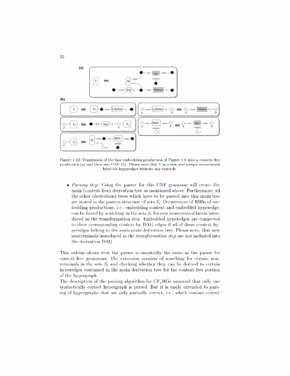
52a a
aa
a ab b
ba a b
cc
to
fromM
Seqfrom to
E
msc
contains
env name
lifeline tofrom
E E1 from Lifeline to
E2E1 Seqfrom to
E2
MSCfrom
to
env name
contains
M
Lifelinefrom to lifeline tofrom
MSCcontains
mscenv nameenv name
contains
(a)
(b)
Figure 1.22: Translation of the last embedding production of Figure 1.6 into a context-freeproduction (a) and then into CNF (b). Please note that E is a new and unique nonterminallabel for hyperedges without any tentacle.� Parsing step: Using the parser for this CNF grammar will create themain (context-free) derivation tree as mentioned above. Furthermore, allthe other (derivation) trees which have to be pasted into this main treeare stored in the parsers structure of sets Si. Occurrences of RHSs of em-bedding productions, i.e., embedding context and embedded hyperedge,can be found by searching in the sets Si for new nonterminal labels intro-duced in the transformation step. Embedded hyperedges are connectedto their corresponding context by DAG edges if all of these context hy-peredges belong to the same main derivation tree. Please note, that newnonterminals introduced in the transformation step are not included intothe derivation DAG.This outline shows that the parser is essentially the same as the parser forcontext-free grammars. The extension consists of searching for certain non-terminals in the sets Si and checking whether they can be derived to certainhyperedges contained in the main derivation tree for the context-free portionof the hypergraph.The description of the parsing algorithm for CFeHGs assumed that only onesyntactically correct hypergraph is parsed. But it is easily extended to pars-ing of hypergraphs that are only partially correct, i.e., which contain correct
1.5. GENERATING VISUAL LANGUAGE PARSERS 53subgraphs and some hyperedges not belonging to any correct subgraph. Theprocedure is also an extension of the parsing for context-free hypergraph gram-mars: The context-free parser searches for maximal main derivation trees inthe structure of sets Si as described before. In the following step, i.e., whensearching how to paste in embedded derivation trees, the parser has to verifyfor each embedding that its context's hyperedges belong to the same mainderivation tree.Incremental parsing is also a simple extension of the context-free parser. Sincethe CFeHG has been transformed into a context-free hypergraph grammar, thestructure of sets Si can be kept up-to-date as described before. Main derivationtrees are created incrementally by the context-free parser as described before.The parser can save work in the following step, i.e., when trying to paste inembedded derivation trees, by keeping track which derivation trees have notbeen changed.1.5.4 Parsing for Layered Graph GrammarsFollowing the structure of Section 1.3 we now have to explain how it is possibleto parse more general classes of (hyper)graph grammars than those discusseduntil now. Therefore, we will return to the language of class diagrams of Sub-section 1.3.4, which could not be characterized precisely by means of context-free hypergraph grammars with embeddings. Subsection 1.3.4 introduced forthat purpose unrestricted graph grammars for which the parsing problem be-comes undecidable in the general case. Furthermore, this subsection switchedfrom hypergraphs to graph structures which were depicted as simple directedgraphs. Here we will also exchange the employed graph data model and switchfrom hypergraphs to directed graphs, too. But we have to emphasize that theparsing algorithm presented on the following pages is more or less independentof the underlying graph model and works, therefore, also for hypergraphs. Itwas introduced in [95] and accepts a rather general subclass of unrestrictedgraph grammars as input, so-called layered graph grammars (LGGs). As aconsequence, it has an exponential worst-case runtime and space complexity.Talking about parsing algorithms one has to distinguish two tasks which haveto be performed:1. The searching in the host graph for matches of a production's RHS.This is an expensive process which works at the graph element level.One standard solution for improving the e�ciency of the needed graphpattern matching algorithm is based on so-called search plans. Thesesearch plans are lists of graph traversal instructions, which �nd as awhole all possible matches for a given rule's LHS or RHS in a graph.

54 For further details concerning the computation of almost optimal searchplans the reader is referred to [96].2. Each completed RHS match corresponds to one possible reduction step,i.e., to the reverse application of a production. These reverse applications,called production instances, have to be combined into a derivation. In thecase of ambiguities it might however happen that more than one deriva-tion exists, or it might happen that a recognized production instance isnot part of any derivation of the complete input graph.During the development of the LGG parsing algorithm it became evident thatdealing with these two tasks at the same time results in very complex algo-rithms. These algorithms would even perform a lot of work which often turnsout to be useless afterwards. Therefore, the LGG parsing algorithm consists oftwo phases, a bottom-up phase similar to the one of the presented hypergraphgrammar parsers which is followed by an additional top-down phase.The bottom-up phase searches the graph for matches of right-hand sides ofproductions. On the recognition of such a RHS, a production instance pi iscreated and copies of its LHS elements without corresponding RHS elementsare added to the graph. The additions might in turn lead to the recognition ofother right-hand sides and thereby to the creation of new production instancesthat create in turn : : : . The result of the bottom-up phase is the collection PIof all production instances discovered.The production instances created have dependency relations among each other,such as above(pi, pi'), which means that pi should occur before pi' in a deriva-tion of the regarded input graph. This happens whenever one production in-stance creates a graph element which is then matched by the RHS of an-other production instance. Another example of a dependency relation is ex-clude(pi,pi'), which states that pi and pi' may not occur in the same deriva-tion. Two productions exclude each other, whenever they reduce (with theirRHS) the same graph elements. These dependency relations can be computedduring the bottom-up phase.The dependency relations are used to direct the second phase of the parsingprocess, the top-down phase. It starts with the graph grammar's axiom graphand applies production instances of PI in such a way that the above and ex-clude relations are respected. By knowing all possible production instances andtheir dependencies in advance, the top-down phase is able to postpone explo-ration of alternative derivation branches as long as possible. When necessary,these alternative derivations are developed in a pseudo-parallel fashion, witha preference for depth-�rst development.

1.6. VISUAL GRAPH TRANSFORMATION LANGUAGES 55Please note that the bottom-up phase does not terminate in the general casefor a given unrestricted graph grammar. We, therefore, have to introduce thefollowing layering restriction on the grammar: every edge and node label isassigned a layer number, such that terminal labels belong to layer 0, and non-terminal labels belong to a layer greater than 0. This layer assignment has tobe such that every production respects the following order for its LHS andRHS: LHS < RHS () 9ijLHSji < jRHSji ^ 8j<ijLHSjj = jRHSjjwith jGjk the number of elements in G which have a label of layer k. Thelayering restriction guarantees that the reduction step of any production in-stance covers more graph elements of lower layers with its RHS than it addsto these layers as copies of its LHS. It enforces thereby the termination of thebottom-up phase by disallowing \cyclic" grammars.The class diagram graph grammar of Figure 1.10 ful�lls the layering restrictionin a trivial way. The LHS of each of its productions is a proper subgraph of itsRHS, i.e., each LHS contains simply less graph elements than the correspondingRHS. Even better, there is no LHS graph element which does not have acorresponding RHS graph element. As a consequence, the bottom-up phasedoes not add a single node or edge to the given input graph, but just computesall possible RHS matches and the dependency relationships between therebygenerated production instances.For further technical details concerning the presented parsing algorithm thereader is referred to [95]. A considerably simpli�ed parsing algorithm for con- uent layered graph grammars, sometimes called reserved graph grammars(RGG), may be found in [86]. The parsing algorithm for RGGs has a poly-nomial worst-case behavior but is restricted because of the requirement ofcon uence.1.6 Visual Graph Transformation LanguagesGraph transformation languages|as presented in the preceding sections as wellas in Chapters ??, ??, and ?? of this book|constitute a well-established branchof rule-based visual speci�cation or programming languages. They o�er solu-tions for a number of open problems mentioned at the end of Subsection 1.2.4about rule-based VLs:� a tighter integration of data modeling by means of class and object dia-grams and operation speci�cation by means of rules,

56 � a (more) precise de�nition of the semantics of rules, including non-obvious cases like \two left-hand side items match the same graph item",� and a controlled application of rules instead of the standard \recognize-select-execute" cycle of pure rule-based systems.It is not the purpose of this section to explain in detail how today availablegraph transformation languages and their programming environments look likeand how they solve the presented list of problems. On the contrary, this sectioncomplements in-depth presentations of the general purpose graph transforma-tion languages Agg and PROGRES in Chapters ?? and ??, respectively.This section starts with short subsections about the history and the mostimportant properties of these languages and then compares main features ofthem and of the VL environment generating graph transformation languagesGenGEd and DiaGen presented in the preceding sections.1.6.1 The Graph Transformation Language PROGRESOne of the biggest projects that uses graph transformation systems as an ex-ecutable speci�cation or visual programming language was launched about 18years ago [97]. Its central idea was to use graph transformation systems in-stead of attribute grammars for mechanizing the development of IntegratedProgramming Support (software engineering) ENvironments [98]. This lead tothe project's name IPSEN. Such an environment o�ers tools for all phases of thesoftware life cycle from analysis over design to programming, and it supportsaccompanying administration tasks like con�guration and project managementas well as reuse of software.In the beginning pure graph transformation systems with rather simple formsof rules were used in IPSEN [99]. But soon it became obvious that additionalconcepts were needed to make the description of complex software engineer-ing tools feasible. One of the most important extensions was the introductionof new means for controlling the application of graph transformation rules.This lead to the invention of PROgrammed Graph REwriting Systems, withPROGRES being one example of this kind (cf. Chapter ??). PROGRES is avisual programming language in the sense that it has a graph-oriented datamodel and a graphical syntax for its most important language constructs. Itwas developed having the following design goals in mind:� Use graphical syntax where appropriate, but do not exclude textual syn-tax when it is more natural and concise.

1.6. VISUAL GRAPH TRANSFORMATION LANGUAGES 57� Distinguish between data de�nition and data manipulation as databaselanguages do and use graph type de�nitions in the form of class diagrams(graph schemata) to typecheck graph manipulating operations.� O�er declarative language elements for the (visual) de�nition of graphviews, derived attributes, and integrity constraints (based on incremen-tal attribute evaluation algorithms and ECA-rules of active databasesystems).� Refrain users from the task to guarantee con uence of de�ned graphtransformation systems by keeping track of rewriting con icts and back-tracking out of dead-end derivations.� Complement the visual rule-oriented programming paradigm with theimperative programming paradigm of textual procedural programminglanguages.� Finally, do not incorporate elements into the language, which are eithernot (e�ciently) executable or come without a precisely de�ned syntaxand semantics de�nition.The development of PROGRES and its formal de�nition in [100,101] wouldnot have been possible without the existence of a number of predecessors. Wehave to mention its direct predecessors developed by Engels/Sch�afer [98] andLewerentz [102] as well as another language based on Programmed AttributedGraph Grammars (PAGG), developed by Herbert G�ottler [103,104]. All theselanguages use the same data model of directed, attributed, node- and edgelabeled graphs as PROGRES, o�er a mixed visual/textual notation for thede�nition of graph transformation rules, and regulate the application of theirrules by means of imperative control structures, too.Comparing PROGRES with those rule-based VLs introduced in Subsec-tion 1.2.4we have to state that languages like BITPICT [48] or ChemTrains [49]focus on manipulation of data only. Even Vampire [51] with its class hierarchiesand icon rewriting rules comes without a rigid type concept and without anytype checking tools. Therefore, all these systems postpone recognition of pro-gramming errors to runtime and su�er from the same disadvantages as any un-typed or weakly typed programming language. With respect to its graph typede�nition capabilities, PROGRES is more similar to visual database program-ming languages such as GOOD [105]. But these languages have less expressivepattern matching and replacing constructs; some of them are even not compu-tationally complete (no recursion). Furthermore, neither the above mentionedlanguages nor|to the best of our knowledge|any other visual rule-oriented

58language o�ers nondeterministically working control structures together withthe ability to backtrack out of dead-ends of locally failing graph transformationsteps.1.6.2 The Graph Transformation Language AggCompared to visual programming languages, Agg may be understood as ahybrid programming language which o�ers visually as well as textually rep-resented elements. Graph transformation on the visual side is combined withJavaj, the textual object-oriented programming language recently developedby SUN. Both concepts are tightly coupled, thus, the visual program part isscalable. The advantage of combining visual concepts with a common textualprogramming language lies in the broad availability of programming know-howconcerning concepts, libraries and tools for textual programming languages.Weuse Java for this purpose, because Java is a modern, interpreted language whichis platform independent. In Agg we also chose the interpretative approach forgraph transformation, which is very natural in this context. Since Agg it-self is written in Java we get platform independence for the whole applicationdeveloped with Agg for free.The development of the graph transformation systemAgg at TU Berlin startedwith the realization of a exible graph editor plus an accompanying smallgraph transformation component programmed in Ei�el [106].Agg has been re-implemented in Java to open it for exible attribute computations. In this way,Agg becomes a general purpose language where a new programming paradigm,i.e., graph transformation, is incorporated into the object-oriented paradigm.A further aim of Agg is to make graph transformation �t for distributedapplications. Especially distributed algorithms are well described by graphtransformation. Independent and concurrent actions within such systems arebetter formulated in a rule-based manner to avoid global control ow as far aspossible. The whole development of Agg is headed towards a visual design toolfor distributed systems. Such a tool should be able to at least prototypicallyrealize really distributed systems with graph transformation.As PROGRES, Agg is designed as a general purpose graph transformationbased language. But both languages di�er in various concepts, especially con-cerning the underlying graph model and the graph transformation concepts.These di�erences will be discussed in Subsection 1.6.3 in more detail. Concern-ing the graph transformation-based concepts, the comparison of PROGRES toother visual languages holds also for Agg. Concerning attribution and ruleapplication control, the way how graph transformation is embedded into otherj\Java" is a trademark of Sun Microsystems, Inc.

1.6. VISUAL GRAPH TRANSFORMATION LANGUAGES 59programming paradigms is similar to PROGRES. The main di�erences are:PROGRES has some basic built-in data types. All other types have to be de-�ned in a so-called host language, which may be Modula-2 or C, and which haveto be imported to PROGRES. In Agg no built-in types exist and Java is usedfor this purpose. In PROGRES, custom-de�ned imperative control constructsare used to formulate programmed graph rewriting, i.e., the control constructsare not taken from an established programming language. Programmed graphrewriting in PROGRES is based on transactions which are designed to havethe same characteristics as rules. Using Java to control rule application as itis planned for Agg such a transaction concept is not automatically provided,but may be programmed in Java.Agg has a formal foundation based on the single-pushout approach to graphtransformation [67]. Its underlying graph model is the graph structure of la-beled and attributed hierarchical graphs. This graph model is used inside tomanage and transform the graphs. For the user interface typed and attributeddirected graphs are chosen as graph data model. It is planned to make hierar-chical graphs also available at the user interface. The overview on abstractionlevels as well as their inspection will be supported by several views.Arbitrary graph rules are allowed to be formulated including insertion, deletionand gluing of graph parts as well as complex attribute computations formulatedin Java. Moreover, negative application conditions can be added to restrictthe applicability to certain situations. It is planned to further control ruleapplications by formulating an explicit control ow again in Java. A changeto hierarchical graphs would also allow these graphs in the rules to formulateactions on several abstraction levels.Since the theoretical concepts are implemented as directly as possible { notleaving out necessary e�ciency considerations { Agg o�ers clear concepts anda sound behavior concerning the graph transformation part. Furthermore, theformal foundation of Agg o�ers the possibility for software validation. Vali-dation features are not yet available, but will be one of the next extensions ofAgg.The Agg environment supports the visual administration of graphs and rules,structured into graph grammars. Visual editing, interpretation, and debuggingtools are integrated in the Agg environment. The visual layout of graphs isquite simple yet showing nodes by some closed form (rectangle, circle,etc.) andedges by two-colored lines. More sophisticated user-de�ned layouts of nodesand edges will be available by exchanging the graph and rule editors of Aggby new ones generated by GenGEd. Furthermore, layout constraints for prettyprinting transformed graphs are then supported.

601.6.3 Comparison of Graph Transformation LanguagesHaving presented the two general purpose graph transformation languagesAgg and PROGRES in the preceding sections and the special purpose lan-guages GenGEd and DiaGen,k in Subsections 1.4.2 and 1.4.3, it is now timeto present the promised comparison of these languages, their accompanying(meta) programming tools, and their generated VL tools (the output of theirmeta programming tools). The comparison is organized as two tables, wherethe �rst one deals with language issues and the second one with tool issues.Table 1.23 about graph transformation languages consists of four parts, wherethe �rst one deals with the language's data model, the second one with therelated topic of derived data elements, the third one with the central topic ofgraph transformation rules, and the last one with additional means to regulatethe application of graph transformation rules.The �rst nine rows about the data model of the presented graph transformationlanguages start with some overall properties of a graph data model and discussthen more speci�c properties of nodes, edges, and attributes, respectively. Asalready explained beforehand, the presented languages employ rather di�erentdata models, varying from directed graphs in the case of Agg and PROGRESto hypergraphs in the case of DiaGen (plus derivation DAGs generated by aparser) and to arbitrary graph structures in the case of GenGEd. All four lan-guages have a kind of type de�nition, which declares �rst the components of aregarded class of graphs, before instances of this class may be manipulated bymeans of graph transformations. These type de�nitions have rather di�erentforms, ranging from algebraic signatures in the case of GenGEd to extendedEntity Relationship diagrams (class diagrams) in the case of PROGRES. Itis worth-while to notice that not a single of the four languages o�ers propersupport for the de�nition of graph hierarchies, i.e., the well-known concept ofaggregation is missing. This is partly due to the fact that it is very di�cult tocome up with a precise de�nition of the di�erences between regular relation-ships (edges) and aggregations in the case of arbitrary graph structures. Agguses hierarchical graphs internally, but they are not yet available at the user'sinterface.Concerning the properties of the basic elements of the four language's datamodels the di�erences are less important. All languages know some kind ofattributed object. These objects, the nodes, play the central role in the caseof Agg, GenGEd, and PROGRES, but are of minor importance in the caseof DiaGen. Nodes of DiaGen are only used as connection points betweenk In the following, DiaGen actually refers to DiaGen II if DiaGen I is not explicitlyreferred to.

1.6. VISUAL GRAPH TRANSFORMATION LANGUAGES 61Language Props. AGG DiaGen GenGEd PROGRES
Gra
ph D
ata
Mod
el
grap
h
kind directed graph hypergraph, deriv. DAG graph structure directed graph
type definition node and edge types hyperedge types graph signature graph schema (diagram)
graph hierarchy (internal)
node
kind labeled, attributed object unlabeled attr. object labeled, attributed object labeled, attributed object
label form, color, text graphic node type of schema
edge
kind dir., labeled, attr. object labeled attributed object dir., labeled, attr. object directed, labeled tuple.
label color, text graphics graphics edge type of schema
attr.
value Java object/value Java {C++} object/value Java object/value C values, built-in values
language Java expressions Java expr.essions visual, constraints C or PROGRES expr.
Der
ived
Ele
ms graph views [planned] [planned] def. with ECA rules
derived edges grouping defined with path expr.
derived attributes defined with constraints defined with constraints def. with directed equ.
integrity constraints [visual definition] visual, 1st order logic exp
Rul
es (
Pro
duct
ions
)
notation visual textual, [ visual ] exchangeable visual visual & textual
mat
ches homo/isomorphic both both both both
multiple matches [subrules] set node, star rule
cond
ition
s attr. conditions [Java expression] Java expressions [graphical constraints] 1st order logic expr.
pos. LHS context LHS-subgraphs LHS-subgraphs LHS-subgraphs paths, LHS-subgraphs
neg. LHS context LHS-related graphs LHS-related graphs LHS-related graphs neg. LHS nodes, edges
confl
icts delete/preserve delete forbidden delete forbidden
dangling edges delete forbidden delete delete
graph gluing for graph objects graph objects graph objects
embe
d visual notation set nodes
text notation embedding rules
Con
trol programming language [Java methods] Java {C++} & automata transactions
programming style [object-oriented] object-oriented imperative & backtrackFigure 1.23: Comparison of four graph transformation languages (entries in square bracketsare not implemented, entries in curly braces were part of an earlier version).hyperedges and do not have any additional label as in all other cases. Edges,on the other hand, model� labeled, attributed binary relationships (directed edges) with identi�ersin Agg (parallel and m:n relationships are supported),

62 � labeled attributed n-ary relationships (hyperedges) with labeled tentaclesinDiaGen (which have about the same properties as edges inGenGEd)� labeled, attributed binary relationships with identi�ers inGenGEd (par-allel relationships as well as m:n or 1:n relationships are supported),� and labeled, attributed binary relationships without identi�ers in thecase of PROGRES (parallel relationships are not supported, but m:nrelationships are).All languages except GenGEd use a host language for the de�nition of at-tribute types and the manipulation of attribute values. This is Java in the caseof Agg and DiaGen II, it is C in the case of PROGRES, and C++ in the caseof Diagen I. Both GenGEd and PROGRES o�er (furthermore) a number ofbuilt-in data types which are part of the language itself and not imported froma host programming language.Until now we had our main focus on those data elements which are explicitlymanipulated by graph transformation rules. But there is another category of so-called derived data elements which are automatically updated whenever somerelated data elements are modi�ed. First of all PROGRES o�ers some helpfor the de�nition of graph views based on the concept of active integrity con-straints, which is closely related to the Event-Condition-Action (ECA) rules ofactive database systems. Furthermore, PROGRES allows one to de�ne derivededges and attributes as well as normal integrity constraints based on so-calledpath expressions, directed equations, and graphical patterns. DiaGen andGenGEd, on the other hand, use the more general concept of arbitrary con-straints (undirected equations, inequalities, : : : ) instead of directed equationsfor the de�nition of derived attributes. Finally DiaGen has some groupingmechanism for viewing and handling collections of hyperedges selected by theuser as composite derived hyperedges.Concerning the de�nition of graph transformation rules Table 1.23 distin-guishes four groups of properties plus two additional properties. They concernthe employed notation, some properties of LHS matches, additional possibil-ities for the de�nition of application conditions which prohibit certain LHSmatches, the properties of the rewriting mechanism itself, and the existence ofadditional means for the manipulation of embedding edges (those edges whichconnect the replaced/replacing subgraph with the rest graph).It is remarkable that all discussed languages have a switch which allows one tochoose between homomorphic and isomorphic matching (two LHS elements areallowed or disallowed to match the same host graph element) due to the factthat almost all earlier graph transformation approaches adhere either to the ho-momorphic or to the isomorphic graph transformation approach. Furthermore,

1.6. VISUAL GRAPH TRANSFORMATION LANGUAGES 63not a single of the presented languages supports parallel graph transformationin the general case, where several rules are applied in parallel to some or alloccurrences (matches) of their LHS. PROGRES o�ers some limited support formanipulating sets of nodes of arbitrary size in a single graph transformationstep as well as for rewriting all matches of a single rule in parallel (with cer-tain restrictions). The PROGRES language constructs for these purposes area special case of so-called subrules with multiple matches, as they are plannedfor Agg.Additional conditions, which prohibit rule applications to otherwise legal LHSmatches, are treated very similar in all four cases. There is some textual lan-guage for the de�nition of attribute conditions, it is possible to require theexistence of certain nodes and edges as part of the LHS, which are not a�ectedby the speci�ed graph transformation, as well as to prohibit the existence ofcertain nodes and edges. All languages, except PROGRES, support the de�-nition of negative graphs (which may not exist as extensions of a determinedLHS occurrence), whereas PROGRES relies on the simpler concept of singlenegative LHS nodes and edges.The graph transformation mechanisms of our four languages, which removeand add certain graph elements after a distinct LHS match has been �xed,are rather straightforward. There are only three speci�c points which have tobe taken into account. First of all we have to decide what happens if a graphelement, which is part of a rule's LHS and RHS, and another graph element,which is only part of the rule's LHS, match the same host graph element. Aggand GenGEd vote for deletion in the case of such a delete/preserve con ict,whereas DiaGen and PROGRES simply forbid such a graph transformationstep. Furthermore, we have to make the decision what happens to those edgesof deleted host graph nodes (tentacles of hyperedges) which are not part of theapplied rule's match. DiaGen favours again the conservative approach andforbids such a graph transformation step, whereas all other languages simplydelete the otherwise dangling edges, too.The following table row about graph gluing shows that all languages exceptPROGRES allow one to glue (merge) some distinct host graph elements inthe course of a graph transformation step. This concept is not supported byPROGRES, forcing its users to model gluing as the deletion of all graph ele-ments except of one. This is possible due to the fact that PROGRES supportsthe redirection of all incidents edges of deleted (or preserved) nodes to othernodes. First of all the visual notation of the above mentioned set nodes maybe used for this purpose. Furthermore, there are textually denoted embeddingrules, which follow the tradition of the expression-oriented algorithmic graphtransformation approach.

64Finally, the last rows of Table 1.23 sketch the availablemeans for controlling theapplication of rules. DiaGen uses the imperative programming means of Java(C++ in the case of DiaGen I) for this purpose as well as so-called interactionautomata. PROGRES, on the other hand, o�ers so-called transactions, whichcombine an imperative programming style with a more rule-oriented depth-�rst-search and backtracking programming style.Switching from languages to tools (systems) we have to regard Table 1.24. Thistable consists of two subtables, where the �rst one characterizes the tools forediting, analyzing, and executing graph transformations, whereas the secondone deals with generated visual (programming) tools only. Tools of the �rstcategory are, therefore, used to develop tools of the second category. Theyare sometimes called meta programming tools. The table shows that Agg isnot used for the development of visual tools, whereas the three remainingsystems are able to generate di�erent parts of VL programming environments.GenGEd is rather strong concerning the de�nition of graphical representationsand their layout (based on constraints); it generates syntax-directed graphicaleditors only. DiaGen, on the other hand, lies its main emphasis on free-handediting and parsing of diagrams. PROGRES, �nally, has its strong points whencomplex analysis operations or animations have to be speci�ed.Concerning the available tool support it is clearly visible that PROGRES isthe \eldest" system with the, therefore, most complete support for editing,analysing, and execution activities. It possesses a sophisticated type checkerand supports direct interpretative execution as well as compilation of speci-�cations. DiaGen follows the traditional compiler compiler approach, i.e., itprocesses a pure textual de�nition of a hypergraph grammar plus the associ-ated constraint de�nitions, Java methods, and interaction automata. It checksits input with respect to a given text grammar as well as some additional con-sistency conditions and produces a visual language editor as output. At thecurrent implementation state of DiaGen II, however, this compiler compileris not yet fully available for generating syntax-directed editors.The remaining two systems may be described as follows: Agg has the clos-est integration of a graph transformation machinery with the Java executionmachinery and follows the interpretative execution approach only. GenGEdis famous for its integration with the layout constraint solver ParCon and its exibility concerning the notation of LHS and RHS of its rules. It is the onlygraph transformation tool which allows one to adapt its rule editor such thatit uses directly the visual constructs of a studied application domain.

1.7. CONCLUSIONS 65Tools AGG DiaGen GenGEd PROGRES
(Met
a) P
rogr
amm
ing
Tool
s
syntax-dir. editor for visual elements visual/texual elements visual/textual elements
text editor for Java elements all language elements high-level constraints all language elements
text parser for Java elements all language elements high-level constraints all language elements
analyzer {consistency checker} type checker
interpreter Java Byte Code ParCon & AGG PROGRES Byte Code
debugger part of interpreter
code generator [Java] Java {C++} C, Modula-2, tcl/tk
graph display graph editor graphics editors browser, text file
graph layout manual constraint-based Sugiyama, …
Gen
erat
ed V
L T
ools
VL representation visual, API visual diagram & text [table]
syntax-dir. editor {+} graphical (rule) editors diagram editors
free-hand editor +
parser restr. context-sensitve
analyzer +
animation tools + [planned] +
layout algorithms constraints, plug-in constraint-based Sugiyama, …Figure 1.24: Comparison of four graph transformation programming tools (entries in squarebrackets are not implemented, entries in curly braces were part of an earlier version).1.7 ConclusionsGraph transformation approaches and visual languages are two research topicswhich are close to each and which may pro�t from each other considerably.As we have seen in this chapter, graph transformation languages are a specialbrand of rule-based visual languages. They have some properties which arerather unusual for rule-based visual languages in general, such as a very preciseformal de�nition of their rewriting semantics or the combination of rules withimperative control structures.Visual rule-based languages, on the other hand, o�er some concepts which areusually not present in graph transformation languages. Examples of this kindare a very tight integration of layout modi�cations and logical operations (inmost cases the layout of a visual programming language rules LHS and RHS ismeaningful and a�ects the layout of the manipulated workspace), the construc-tion of rules based on programming-by-example, the generation of families ofsimilar rules (based on some examples), and so forth.

66Furthermore, we have seen that graph grammars and graph transformationbased programming languages are very useful for constructing precise de�ni-tions of visual languages as well as for generating visual programming tools.Within this chapter we laid the main emphasis on syntax de�nition issues. Wepresented a number of graph grammar parsing algorithms of increasing com-plexity as well as some techniques and meta tools for generating syntax-directededitors and free-hand editors. Nevertheless, we have to point out that the graphtransformation approach is also well prepared for de�ning the static as well asthe dynamic semantics of a visual language. These topics are addressed bydi�erent chapters of this book, which discuss for instance the construction ofsoftware engineering tools (cf. Chapter ??), the realization of compiler-compilercomponents (cf. Chapter ??), or the development of process modeling tools (cf.Chapter ??). In all these cases graph transformation rules are used to analyzeand animate (the internal graph representations of) the sentences of a regardedlanguage.Being a survey about the relationships between visual languages and graphtransformation approaches, this chapter presented and compared four di�erentgraph transformation languages. Two of them, the visual programming toolgenerating languages DiaGen and GenGEd, were presented in more detail.The remaining two more general purpose graph transformation (programming)languages Agg and PROGRES, which are the main subjects of Chapter ??and Chapter ?? in this book, were only introduced for comparison purposes.Agg, DiaGen, GenGEd, and PROGRES are the results of a decade ofapplication-oriented graph transformation research activities. They were builtbased on the experiences of with a long list of predecessors, which starts withsome common ancestors of all visual and graph transformation languages: AM-BIT/G and PLAN2D.Nevertheless, our list of important future research topics is still rather long:First of all unnecessary di�erences of di�erent approaches should be eliminated.Furthermore, guidelines have to be developed which explain the remainingdi�erences between hypergraphs and directed graphs or graph structures, dis-tributed graph transformation and controlled sequential graph transformation,context-free hypergraph grammars with embeddings and layered graph gram-mars, and so forth from a users point of view. Last but not least we have toattack some common problems with the visual language community: we haveto solve the \scaling-up problem" by o�ering appropriate module concepts, the\frustrated user problem" by developing more e�cient tools which make betteruse of available screen space, produce less unacceptable diagram layouts, andso forth.

REFERENCES 67References1. Proc. IEEE Symposium on Visual Languages (VL'95), Los Alamitos, CA,1995. IEEE Computer Society Press.2. Proc. IEEE Symposium on Visual Languages (VL'96), Los Alamitos, CA,1996. IEEE Computer Society Press.3. Proc. IEEE Symposium on Visual Languages (VL'97), Los Alamitos, CA,1997. IEEE Computer Society Press.4. E. Golin. A method for the speci�cation and parsing of visual languages.PhD thesis, Brown University, 1991.5. E. Golin. Parsing visual languages with picture layout grammars. Journalof Visual Languages and Computing, 2(4):371{394, 1991.6. K. Marriott. Constraint multiset grammars. In [107], pages 118{125,1994.7. G. Rozenberg, editor. Handbook on Graph Grammars: Foundations, vol-ume 1. World Scienti�c, Singapore, 1997.8. K. Marriott and B. Meyer. On the classi�cation of visual languagesby grammar hierarchies. Journal of Visual Languages and Computing,8(4):375{402, 1997.9. K. Wittenburg and L. Weitzman. Visual grammars and incrementalparsing for interface languages. In [108], pages 111{118, 1990.10. G. Costagliola and S.-K. Chang. Parsing 2-D languages with positionalgrammars. In Proc. of 1991 International Workshop on Parsing Tech-nologies (IWPT'91), pages 218{224, Cancun, Mexico, 1991. Associationfor Computational Linguistics.11. S. Chok and K. Marriott. Parsing visual languages. In 18th AustralasianComputer Science Conference, Glenolg, South Australia, 1995.12. A. B. Myers. Visual programming, programming by example, and pro-gram visualization: A taxonomy. In [32], pages 33{40. 1990. Reprintfrom [109].13. V. Dock. Cobol: American National Standard. Reston Publ. Company,1973.14. I. Nassi and B. Shneiderman. Flowchart techniques for structured pro-gramming. SIGPLAN Notices, 8(8), 1973.15. M. Halverson. Microsoft visual basic 4 step by step. Microsoft Press,Redmond, WA, 1995.16. I. E. Sutherland. Sketchpad: A man-machine graphical communicationssystem. In Proc. 23rd AFIPS Spring Joint Computer Conference, 1963.17. S.-K. Chang. Visual languages: A tutorial and survey. In [32], pages7{18. 1990. Reprint from [110].

6818. A. L. Ambler and M. M. Burnett. In uence of visual technology on theevolution of language environments. In [32], pages 19{32. 1990. Reprintfrom [111].19. N. C. Shu. Visual programming languages: A perspective and a dimen-sional analysis. In [32]. 1990. Reprint from [112].20. C. Christensen. An example of the manipulation of directed graphs in theambit/g programming language. In Interactive Systems for Experimentaland Applied Mathematics, New York, 1968. Academic Press.21. E. Denert, R. Franck, and W. Streng. Plan2d - towards a two-dimensionalprogramming language. volume 26 of Lecture Notes in Computer Science,pages 202{213. Springer Verlag, 1974.22. D. C. Smith. Pygmalion - A Computer Program to Model and StimulateCreative Thought. PhD thesis, Stanford University, Stanford, CA, 1975.23. D. C. Smith. Pygmalion: A computer program to model and stimulatecreative thought. In [32], pages 216{251. 1990.24. S. K. Chang, J. Reuss, and B. H. McCormick. Design considerationsof a pictorial database system. Int. Journal of Policy Anal. Inf. Syst.,1(2):49{70, 1978.25. T. O. Ellis, J. F. Heafner, and W. L. Sibley. The grail project: Anexperiment in man-machine communication. Technical Report ReportRM-5999-Arpa, RAND, 1969.26. M. C. Pong and N. Ng. Pigs - a system for programming with interactivegraphical support. Software, Practice and Experience, 13(9):847{855,1983.27. J. F. Sowa. Conceptual Structures: Information Processing in Minds andMachines. Addison-Wesley, Reading, Mass., 1984.28. J. Rumbaugh, M. Blaha, W. P. F. Eddy, and W. Lorensen. Object-Oriented Modeling and Design. Prentice Hall, Englewood Cli�s, NJ,1991.29. Rational Software Corporation. UML semantics, version 1.1.http://www.rational.com, 1997.30. M. M. Burnett and M. J. Baker. A classi�cation system for visual pro-gramming. Journal of Visual Languages and Computing, 5(3):287{300,1994.31. Proc. IEEE Symposium/Workshop on Visual Languages (VL'XX), LosAlamitos, CA, 19XX. IEEE Computer Society Press.32. E. P. Glinert, editor. Visual Programming Environments: Paradigms andSystems. IEEE Computer Society Press, Los Alamitos, CA, 1990.33. M. M. Burnett, A. Goldberg, and T. G. Lewis, editors. Visual Object-Oriented Programming: Concepts and Environments. Manning Publica-

REFERENCES 69tions Co., Greenwich, 1995.34. R. B. Grafton and T. Ichikawa, editors. Computer: Special Issue onVisual Programming, volume 18 (8). IEEE Computer Society Press, LosAlamitos, CA, 1985.35. M. M. Burnet and D. W. McIntyre, editors. Computer: Special Issue onVisual Programming, volume 28 (3). IEEE Computer Society Press, LosAlamitos, CA, 1995.36. D. C. Engelbart and W. K. English. A research center for augmentinghuman intellect. In Proc. 1968 Fall Joint Computer Conf., volume 33-1,pages 395{410, Montvale, NJ, 1968. AFIPS Press.37. V. Bush. As we may think. Atlantic Monthly, pages 101{108, 1945.38. V. Bush. As we may think. In [113], pages 85{110. 1991. Reprint of [37].39. A. Goldberg. Smalltalk 80 - The Interactive Programming Environment.Addison Wesley, Reading, MA, 1984.40. D. C. Swinehart, P. T. Zellweger, and R. B. Hagmann. The structure ofcedar. In [114], pages 230{244. 1985.41. M. H. Brown and R. Sedgewick. Techniques for algorithm animation.IEEE Software, 2(1):28{39, 1985.42. S. P. Reiss. Pecan: Program development systems that support multipleviews. IEEE Transactions on Software Engineering, 11(3):276{285, 1985.43. S. P. Reiss. Garden tools: Support for graphical programming. In [115].1986.44. T. Teitelbaum and T. Reps. The cornell program synthesizer. Commu-nications of the ACM, 24(9):563{573, 1981.45. B. A. Price, R. M. Baecker, and I. S. Small. A principled taxonomyof software visualization. Journal of Visual Languages and Computing,4(3):211{266, 1993.46. E. H. Shortli�e. Computer Based Medical Consultations: MYCIN. Else-vier Science Publ., Amsterdam, 1976.47. C. L. Forgy. Ops5 user's manual. Technical Report CMU-CS-81-135,Department of Computer Science, Carnegie Mellon University, 1981.48. G. W. Furnas. New graphical reasoning models for understanding graph-ical interfaces. In Proc. of Conf. on Human Factors in Computer Systems- CHI'91, pages 71{78, New York, 1991. ACM Press.49. B. Bell and C. Lewis. ChemTrains: A language for creating behavingpictures. In [116], pages 188{195, 1993.50. D. C. Smith, A. Cypher, and J. Spohrer. KidSim: Programmingagents without a programming language. Communications of the ACM,37(7):54{67, 1994.51. D. M. McIntyre. Design and implementation with vampire. In [33], pages

70 129{160. 1995.52. K. M. Kahn and V. Saraswat. Complete visualizations of concurrentprograms and their executions. In [108], pages 7{15, 1990.53. L. Bronwston, R. Farell, E. Kant, and N. Martin. Programming ExpertSystems in OPS5 { An introduction to rule-based programming. Addison-Wesley, New York, 1986.54. M. Costabile and T. Catarci, editors. Special Issue on Visual QuerySystems, volume 6 (1). Academic Press, New York, 1995.55. J. Rekers and A. Sch�urr. A graph based framework for the implementa-tion of visual environments. In [2], pages 148{155, 1996.56. K. Wittenburg. Earley-style parsing for relational grammars. In [117],pages 192{199, 1992.57. A. Grbavec and D. Blostein. Mathematics recognition using graph rewrit-ing. In Third Int. Conf. on Document Image Analysis and Recognition,pages 417{421, Montreal, Canada, 1995.58. T. W. Pratt. Pair grammars, graph languages and string-to-graph trans-lations. Journal of Computer and System Sciences, 5:560{595, 1971.59. A. Sch�urr. Speci�cation of graph translators with triple graph gram-mars. In Proc. of the 20th International Workshop on Graph-TheoreticConcepts in Computer Science, number 904 in Lecture Notes in Com-puter Science, pages 151{163, Berlin, 1994. Springer Verlag.60. ITU-T, Geneva. Recommendation Z.120: Mes-sage Sequence Chart (MSC), 1993. See also:http://www.win.tue.nl/win/cs/fm/sjouke/msc.html.61. D. E. Knuth. Semantics of context-free languages. Mathematical SystemsTheory, 2(2):127{145, 1968. Errata 5:1 (1971) 95{96.62. F. Drewes, A. Habel, and H.-J. Kreowski. Hyperedge replacement graphgrammars. In [7].63. A. Habel. Hyperedge Replacement: Grammars and Languages, volume643 of Lecture Notes in Computer Science. Springer-Verlag, Berlin, 1992.64. M. Minas and G. Viehstaedt. Speci�cation of diagram editors providinglayout adjustments. In [116], pages 324{329, 1993.65. M. L�owe, M. Kor�, and A. Wagner. An algebraic framework for thetransformation of attributed graphs. In R. Sleep, R. Plasmeijer, andM. van Eekelen, editors, Term Graph Rewriting: Theory and Practice,pages 185{199. John Wiley, New York, 1993.66. H. Ehrig and B. Mahr. Fundamentals of algebraic speci�cations 1: Equa-tions and initial semantics, volume 6 of EACTS Monographs on Theo-retical Computer Science. Springer, Berlin, 1985.67. H. Ehrig, R. Heckel, M. Kor�, M. L�owe, L. Ribeiro, and A. Wagner.
REFERENCES 71Algebraic approaches to graph transformation { part ii: Single pushoutapproach and comparison with double pushout approach. In chapter 4in [7], pages 247{312. 1997.68. R. Bardohl and G. Taentzer. De�ning visual languages by algebraicspeci�cation techniques and graph grammars. In [118], pages 27{42.69. G. Taentzer, I. Fischer, M. Koch, and V. Volle. Distributed graph trans-formation with application to visual design of distributed systems. In[119].70. I. Fischer, M. Koch, and V. Volle. Conditinal attributed graph trans-formations as unifying formalism for neural networks. Technical report,Technical University Berlin, 1998.71. A. Habel, R. Heckel, and G. Taentzer. Graph grammars with negative ap-plication conditions. Special issue of Fundamenta Informaticae, 26(3,4),1996.72. R. Bardohl and I. Cla�en. Graphical support for prototyping of algebraicspeci�cations. In B. Wol�nger, editor, Innovationen bei Rechen- undKommunikationssystemen, pages 19{26. Informatik aktuell, 1994.73. B. Backlund, O. Hagsand, and B. Pehrson. Generation of visual language-oriented design environments. Journal of Visual Languages and Comput-ing, 1:333{354, 1990.74. S. S. Chok and K. Marriott. Automatic construction of user interfacesfrom constraint multiset grammars. In [1], pages 242{249, 1995.75. V. Haarslev and M. Wessel. GenEd { an editor with generic semanticsfor formal reasoning about visual notation. In [2], pages 204{211, 1996.76. G. Costagliola, S. Ore�ce, and A. De Lucia. Automatic generation ofvisual programming environments. IEEE computer, pages 56{66, 1995.77. P. Griebel. Parcon - Paralleles L�osen von gra�schen Constraints. PhDthesis, Paderborn University, February 1996.78. G. Viehstaedt and M. Minas. Interaction in really graphical user inter-faces. In [107], pages 270{277, 1994.79. D. Harel. Statecharts: A visual formalism for complex systems. Scienceof Computer Programming, 8:231{274, 1987.80. M. Minas. Hypergraphs as a uniform diagram representation model.In Prelim. Proc. 6th International Workshop on Theory and Applica-tion of Graph Transformations (TAGT'98), pages 24{31. Universit�at-Gesamthochschule Paderborn, Technical Report tr-ri-98-201, Reihe In-formatik, November 1998.81. A. Salomaa. Formal Languages. Academic Press, New York, 1973.82. M. Kaul. Parsing of graphs in linear time. In H. Ehrig, M. Nagl, andG. Rozenberg, editors, Graph Grammars and Their Application to Com-

72 puter Science, volume 153 of Lecture Notes in Computer Science, pages206{218, 1983.83. M. Kaul. Syntaxanalyse f�ur Pr�azedenzgraphgrammatiken. PhD thesis,Universit�at Passau, 1985.84. G. Rozenberg and E. Welzl. Boundary NLC graph grammars { Ba-sic de�nitions, normal forms, and complexity. Information and Control,69:136{167, 1986.85. J. Rekers and A. Sch�urr. A graph grammar approach to graphical pars-ing. In [1], pages 195{202, 1995. Available from ftp.wi.leidenuniv.nl, �le/pub/CS/TechnicalReports/1995/tr95-15.ps.gz.86. D.-Q. Zhang and K. Zhang. Reserved graph grammar: A speci�cationtool for diagrammatic VPLs. In [3], pages 288{295, 1997.87. H. Bunke and B. Haller. A parser for context-free plex grammars. InM. Nagl, editor, Proc. 15th Int. Workshop on Graph-Theoretic Conceptsin Computer Science (WG'89), LNCS 411, pages 136{150. Springer-Verlag, 1989.88. M. Minas. Diagram editing with hypergraph parser support. In [3], pages226{233, 1997.89. F. Ferrucci, G. Tortora, M. Tucci, and G. Vitellio. A predictive parser forvisual languages speci�ed by relation grammars. In [107], pages 245{252,1994.90. G. Costagliola, S. Ore�ce, G. Polese, G. Tortora, and M. Tucci. Auto-matic parser generation for pictorial languages. In [116], pages 306{313,1993.91. J. Earley. An e�cient context-free parsing algorithm. Communicationsof the Association for Computing Machinery, 13(2):94{102, 1970.92. M. Tomita. E�cient Parsing for Natural Languages. Kluwer AcademicPublishers, 1985.93. D. Younger. Recognition and parsing of context-free languages in timen3. Information and Control, 10(2):189{208, 1967.94. T. Kasami. An e�cient recognition and syntax analysis algorithm forcontext-free languages. Technical Report AFCRL-65-758,Air Force Cam-bridge Research Laboratory, Bedford Mass., 1965.95. J. Rekers and A. Sch�urr. De�ning and parsing visual languages withlayered graph grammars. Journal of Visual Languages and Computing,8(1):27{55, 1997.96. A. Z�undorf. Graph pattern matching in PROGRES. In J. Cuny, H. Ehrig,G. Engels, and G. Rozenberg, editors, Proc. Fifth Intl. Workshop onGraph Grammars and Their Application to Comp. Sci., volume 1073 ofLecture Notes in Computer Science, pages 454{468. Springer, 1996.

REFERENCES 7397. M. Nagl. An incremental compiler as component of a system for softwaredevelopment. In Informatik Fachberichte, Berlin, 1980. Springer Verlag.98. G. Engels and W. Sch�afer. Programmentwicklungsumgebungen: Konzepteund Realisierung. Teubner, Stuttgart, 1989.99. M. Nagl, G. Engels, R. Gall, and W. Sch�afer. Software speci�cation bygraph grammars. In H. Ehrig, M. Nagl, and G. Rozenberg, editors, GraphGrammars and Their Application to Computer Science, volume 153 ofLecture Notes in Computer Science, pages 267{287, 1983.100. A. Sch�urr. Operationales Spezi�zieren mit programmierten Graph-ersetzungssystemen: formale De�nitionen Anwendungsbeispiele undWerkzeugunterst�utzung. Deutscher Universit�ats-Verlag, Wiesbaden,1991.101. A. Sch�urr. Developing graphical (software engineering) tools withPROGRES. In Proc. 19th Int. Conf. on Software Engineering (ICSE'97),pages 618{619, Los Alamitos, CA, 1997. IEEE Computer Society Press.Formal Demonstration.102. C. Lewerentz. Interaktives Entwerfen gro�er Programmsysteme:Konzepte und Werkzeuge, volume 194 of Informatik-Fachberichte.Springer-Verlag, Berlin, 1988. Doctoral dissertation.103. H. G�ottler. Graph grammars and diagram editing. In H. Ehrig, M. Nagl,G. Rozenberg, and A. Rosenfeld, editors, Graph Grammars and TheirApplication to Computer Science, volume 291 of Lecture Notes in Com-puter Science, pages 216{231, 1987.104. H. G�ottler. Graphgrammatiken in der Softwaretechnik, volume 178 ofInformatik-Fachberichte. Springer-Verlag, Berlin, 1988.105. J. Paredaens, J. Bussche, M. Andries, M. Gemis, M. Gyssens, I. Thyssens,D. van Gucht, V. Sarathy, and L. Saxton. An overview of good. SIGMODRecord, 21(1):25{31, 1992.106. M. L�owe and M. Beyer. AGG | an implementation of algebraic graphrewriting. In Rewriting Techniques and Applications, volume 690 of Lec-ture Notes in Computer Science, pages 451{456. Springer-Verlag, 1993.107. Proc. IEEE Symposium on Visual Languages (VL'94), Los Alamitos, CA,1994. IEEE Computer Society Press.108. Proc. IEEE Workshop on Visual Languages (VL'90), Los Alamitos, CA,1990. IEEE Computer Society Press.109. B. A. Myers. Visual programming, programming by example, and pro-gram visualization: A taxonomy. In Proc. CHI'86: Human Factors inComputing Systems, pages 59{66, New York, 1986. ACM Press.110. S.-K. Chang. Visual languages: A tutorial and survey. IEEE Software,4(1):29{39, 1987.

74111. A. L. Ambler and M. M. Burnett. In uence of visual technology on theevolution of language environments. Computer, 22(10):9{22, 1989.112. N. C. Shu. Visual programming languages: A perspective and a dimen-sional analysis. In [120]. 1986.113. J. M. Nyce and P. Kahn, editors. From Memex to Hypertext: VannevarBush and the Mind's Machine. Academic Press, London, 1991.114. L. P. Deutsch, editor. ACM SIGPLAN '85 Symp. on Language Issues inProgramming Environments, ACM SIGPLAN Notices, volume 20. ACMPress, New York, 1985.115. R. Conradi, T. Didriksen, and D. Wanvik, editors. Advanced Program-ming Environments, volume 244 of Lecture Notes in Computer Science.Springer Verlag, Berlin, 1986.116. Proc. IEEE Symposium on Visual Languages (VL'93), Los Alamitos, CA,1993. IEEE Computer Society Press.117. Proc. IEEE Workshop on Visual Languages (VL'92), Los Alamitos, CA,1992. IEEE Computer Society Press.118. Proc. Workshop on Theory of Visual Languages (TVL'97), Capri, Italy,1997.119. G. Rozenberg, editor. The Handbook of Graph Grammars, volume 3.World Scienti�c, 1999.120. S.-K. Chang, T. Ichikawa, and P. Ligomenides, editors. Visual Languages.Management and Information Systems Series. Plenum Press, New York,1986.

IndexAbstract syntax graph, 13Agg, 58Alphabet Editor, 35Alphabet rules, 36AMBIT/G, 5Application conditionnegative, 60, 63ASG, 13Attributed context-free hypergraphgrammar, 42Attributed graph grammar, 17BALSA, 8BITPICT, 10Bottom-up phase, 55CE, 35Cedar, 7CFeHG, 22, 51ChemTrains, 10Chomsky normal-form, 49Class diagrams, 17CNF, 49Connecting Editor, 35Constraint multiset grammar, 14,48Constraint solver, 42Constraints, 22, 34Context elements, 46Context-free hypergraph grammar,20, 49
Context-free hypergraph grammarwith embeddings, 22, 51Coupled graph grammar, 15CYK, 49Derivation DAG, 23Derivation tree, 21DiaGen, 39DiaGen II, 44Diagrammatic representation, 6Direct manipulation, 41Embedding production, 22Embedding rules, 46Form-based representation, 6Free-hand editing, 32, 43Garden, 8GE, 39Generated Graphical Editor, 39GenGEd, 33GOOD, 58Grail, 5GRAIN, 5Grammar, 9Graphhierarchical, 60Graph grammar, 16Graph parser, 45Graph structure approach, 23abstract syntax, 2675

76 INDEXconcrete syntax, 28Graph transformationsingle-pushout approach, 59Graphical Symbol Editor, 35Graphical types, 29GSE, 35Hyperedge, 18Hyperedge replacement grammar,20Hypergraph, 18Iconic representation, 6Initial graph, 16Interaction automaton, 42IPSEN, 57Java, 35, 44, 58KidSim, 10Layered graph grammar, 48, 54Layering restriction, 55Layout operations, 26, 30Left-hand side, 10LGG, 54LHS, 10, 16LOGGIE, 31Message Sequence Charts, 16Meta programming tool, 65MSC, 16Nassi-Shneiderman diagram, 16NLS/Augment, 7Nonterminal symbol, 16NSD, 16PAGG, 32, 58Pecan, 8Picture layout grammar, 14, 48PIGS, 5
PLAN2D, 5Plex grammar, 48Positional grammar, 49Precedence graph grammar, 48Production, 16nonterminal, 49terminal, 49Programmed grammar, 11Programmed rewriting system, 11PROGRES, 57Pygmalion, 5RE, 37Regulated grammar, 11Relational grammar, 13, 48Rewriting system, 9RHS, 10, 16Right-hand side, 10Rule Editor, 37Si, 50SketchPad, 7Smalltalk, 7Spatial relationships graph, 13SRG, 13Statecharts, 42Syntax-directed editing, 31, 42Tentacle, 18Terminal symbol, 16Top-down phase, 55Transformation system, 9UML, 16Vampire, 10Visual de�nition of VLs, 33Visual editing mode, 31Visual information processing lan-guage, 6Visual interaction language, 6

INDEX 77Visual means, 28Visual parser, 45Visual programming, 4Visual programming environment,7Visual programming language, 6Visual rule-based language, 9Visual sentence, 26Visual speci�cation, 29VL-alphabet, 25, 29VL-grammar, 28, 30VLCC, 33VP, 4VPE, 7VPL, 6VRPL, 9


