Embed Size (px)
Citation preview
Adminsitrative Record Page 33733
State of California Department of Water Resources
CALIFORNIA WATER COMMISSION
SCOTT E. FRANKLIN, Chall'person, Newhall Thomas K. Beard, Vice Chall'person, Stockton
Roy E. Dodson. • • •
Daniel M. Dooley • •
Harrison C. Dunning •••
Merrill R. Goodall
Donald L. Hayashi. • •
Charlene H. Orszag •
Alexandra F. Stillman. •
Orville L. Abbott
• .San Diego
Hanford
Davis
• .Claremont
• .San Francisco
• Sherman Oaks
• • • • • Arcata
Executive Officer·and Chief Engineer
Tom Y. Fujimoto Assistant Executive Officer
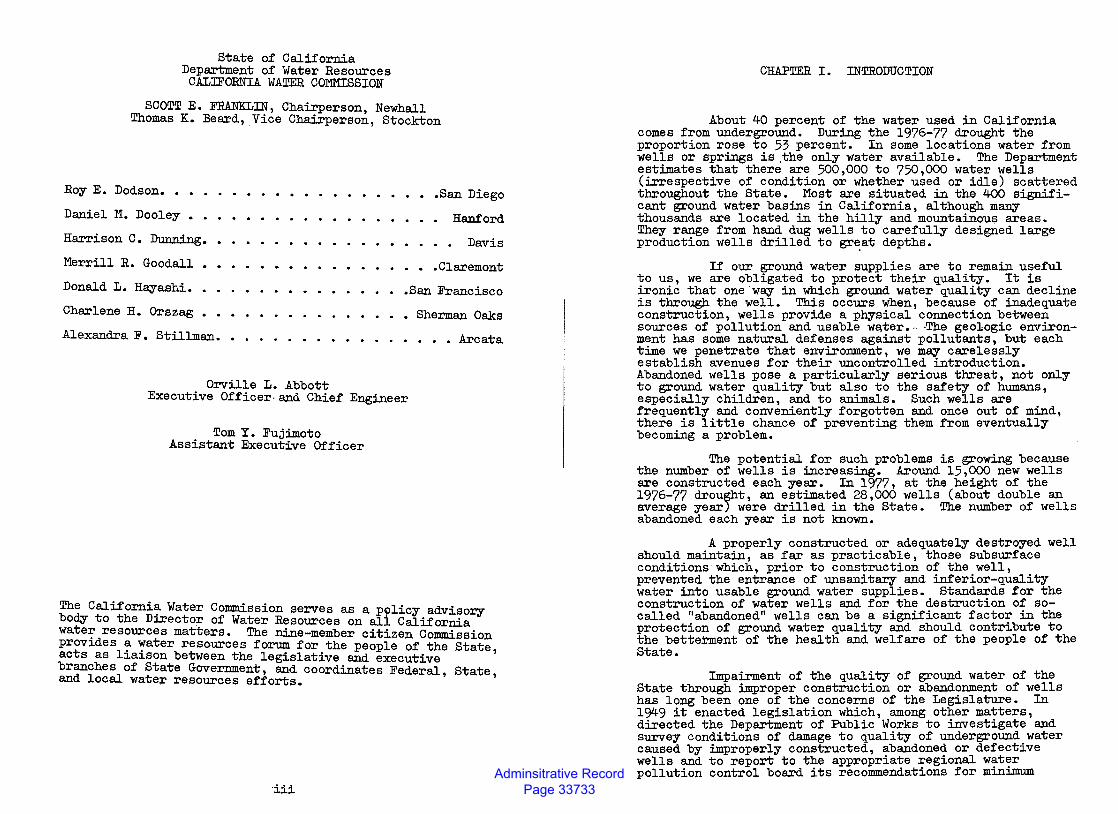
The California Water Commission serves as a p9licy advisory body to the Director of Water Resources on all California wate~ resources matters. The nine-member citizen Commission prov~des a water resources forum for the people of the State acts as liaison between the legislative and executive ' branches of State Government, and coordinates Federal, State, and local water resources efforts.
•iii
CHAPTER I. INTRODUCTION
About 40 percent of the water used in California comes from underground. During the 1976-77 drought the proportion rose to 53 percent. In some locations water from wells or springs is .the only water available. The Department estimates that there are 500,000 to 750,000 water wells (irrespective of condition or whether used or idle) scattered throughout the State. Most are situated in the 400 significant ground water basins in California, although many thousands are located in the hilly and mountainous areas. They range from hand dug wells to carefully designed large production wells drilled to gr~at depths.
If our ground water supplies are to remain useful to us, we are obligated to protect their quality. It is ironic that one way in which ground water quality can decline is through the well. This occurs when, because of inadequate construction, wells provide a physical connection between sources of pollution and usable wa,ter., ,The geologic environment has some natural defenses against pollutants, but each time we penetrate that environment, we may carelessly establish avenues for their uncontrolled introduction. Abandoned wells pose a particularly serious threat, not only to ground water quality but also to the safety of humans, especially children, and to animals. Such wells are frequently and conveniently forgotten and once out of mind, there is little chance of preventing them from eventually becoming a problem.
The potential for such problems is growing because the number of wells is increasing. Around 15,000 new wells are constructed each year. In 1977, at the height of the 1976-77 drought, an estimated 28,000 wells (about double an average year) were drilled in the State. The number of wells abandoned each year is not known.
A properly constructed or adequately destroyed well should maintain, as far as practicable, those subsurface conditions which, prior to construction of the well, prevented the entrance of unsanitary and inferior-quality water into usable ground water supplies. Standards for the construction of water wells and for the destruction of socalled "abandoned" wells can be a significant factor in the protection of ground water quality and should contribute to the betterment of the health and welfare of the people of the State.
Impairment of the quality of ground water of the State through improper construction or abandonment of wells has long been one of the concerns of the Legislature. In 1949 it enacted legislation which, among other matters, directed the Department of Public Works to investigate and survey conditions of damage to quality of underground water caused by improperly constructed, abandoned or defective wells and to report to the appropriate regional water pollution control board its recommendations for minimum
Adminsitrative Record Page 33734
standards of well construction (Chapter 1552, Statutes of 1949). These investigative and reporting responsibilities are now lodged in the Department of Water Resources by Water Code Section 231, which reads as follows:
231. The department, either independently or in cooperation with any person or any county, state, federal or other agency, shall investigate and survey conditions of damage to quality of underground waters, which conditions are or may be caused by improperly constructed, abandoned or defective wells through the interconnection of strata or the introduction of surface waters into underground waters. The department shall report to the appropriate California regional water quality control board its recommendations for minimum standards of well construction in any particular locality in which it deems regulation necessary to protection of quality of underground water, and shall report to the Legislature from time to time, its recommendations for proper sealing of abandoned wells.
During the 1965 and 1967 General Sessions, the Legislature again reviewed the matter of standards for water well construction. As a result, it established a procedure for implementing standards developed under Section 231 by enacting Chapter 323, Statutes of 1967, which added Sections 13800 through 13806 to the Water Code. The wording of these sections was amended in 1969 when the Legislature enacted the Porter-Cologne Water Qu&lity Control Act (Chapter 482, Statutes of 1969). In Section 13800, the Department of Water Resources' reporting responsibility is enlarged upon:
13800. The department, after such studies and investigation pursuant to Section 231 as it finds necessary, on determining that water well and cathodic protection well construction, maintenance, abandonment, and destruction standards are needed in an area to protect the quality of water used or which may be used for any beneficial use, shall so report to the appropriate regional water quality control board and to the State Department of Health Services. The report shall contain such recommended standards for water well and cathodic protection well construction, maintenance, abandonment, and destruction as, in the·department's opinion, are necessary to protect the quality of any affected water.
The State Department of Health Services also has a concurrent interest in problems caused by improperly constructed, defective, or "abandoned" wells. This interest is evidenced in the "California Safe Drinking Water Act" (Chapter 7 of Part 1 of Division 5 of the Health and Safety Code, State of California), which deals with the health aspects of public water supplies. Under this authorization, the Department of Health Services requires a water purveyor to apply for an amended water permit before a new well is constructed and connected to the water system. Before the
amended (or new) permit is issued a thorough review is.made of (a) the location of the wel~ with respect to.potent1al contamination hazards, (b) des1gn an~ construct1on of.the well necessary to prevent contaminat1on or the exclus1on of undesirable water, and (c) the bacterial an~ chemical q";lal~ty of the water produced. The Department m~ 1ssue ~ perm1t if it finds that the water "under all circumstances 1~ pure, wholesome· and potable and does not endanger the l1ves o~ health of 'human beings." Specific water quality and mon1toring standards have been adopted by regulation. If at any time water produced from an existing well fa~ls to comply with such standards, the Department m~ requ1re changes or modifications of the well, provisions of appropriate.water treatment, or cause the curtailed use, even destruct1o~ of the well, in order to assure a safe supply to the publ1c.
In summary, the responsibi~ity of the Departme~t of Water Resources is to advise the Leg1slature and appro~r1ate state agencies on the maintenance of ground water qual1ty, including protection against adverse effects caused by . improper well construction or the ab~donment ?f wells. T.h1s responsibility applies to all wells, 1rrespect1ve o~ p~ose. T.he responsibility of the Department of.Health Serv1c~s 1s to investigate evaluate and approve publ1c water suppl1es including the design ~d construction of water wells.
This report was prepared by t~e.D~p~tment of Water Resources in fulfillment of its respons1b1l1t1es ~der the provisions of Section 231 of the Water Code, ~d 1n cooperation with the State Department of-Health Serv1ces.
Statement of the Problem
Wells themselves do not cause ground water quality to deteriorate. Rather, it is inadequate construction, or, in the case of wells that no longer serve a ";lseful purpo~e, their improper destruction, that can ~esult 1n th~ deter1oration of ground water quality. Depend1ng on the c1rcum~tances, such quality deterioration may affect the wa~er supp~y1ng a single well or if the pollution is substant1al, a s1zable segment of ~ ground water basin.
The impairment of water quality in an individual well, or group of wells, is the most c?mmon. Gro~d water supplies have been responsible for a s1zable port1on of the water-borne disease outbreaks reported in the United States. Most of these outbreaks occurred where wells were so poorly constructed that they allowed contaminants to enter the well. Contaminants entering improperly constructed wells ~e not limited to disease organisms. The~e is also ~ grow1ng number of case histories concerning undes1rable chem1cals, both toxic and nontoxic, that have gained a~cess to ground water and adversely affected wells a short d1stance aw~.
The mechanism of water quality impairment caused ~y faulty wells affecting large segments of a ground water bas1n is not well defined. In most instances, a n~be~ of factors have been involved; the wells have served pr1mar1ly to . facilitate the impairment. The most· noteworthy examples 1n
Adminsitrative Record Page 33735
California of widespread water quality deterioration are in coastal ground water basins that have been subjected to seawater intrusion.
Inadequately constructed or improperly "abandoned" wells are .not the sole cauae of water quality degradation in a Ca.Iifornia ground water basin. A small quantity of contaminants enter;ng one well may not have far-reaching effect. However, (1) the construction of thousands of new wells in California each year, (2) the fact that many are becoming more closely spaced, and (3) the growing number of wells being neglected or indiscriminately abandoned indicate that the potential for impairing ground water quality is growing. Then, when pollutants move along the lines of natural water movement, the effects will be long-lasting and difficult, if not impossible, to correct.
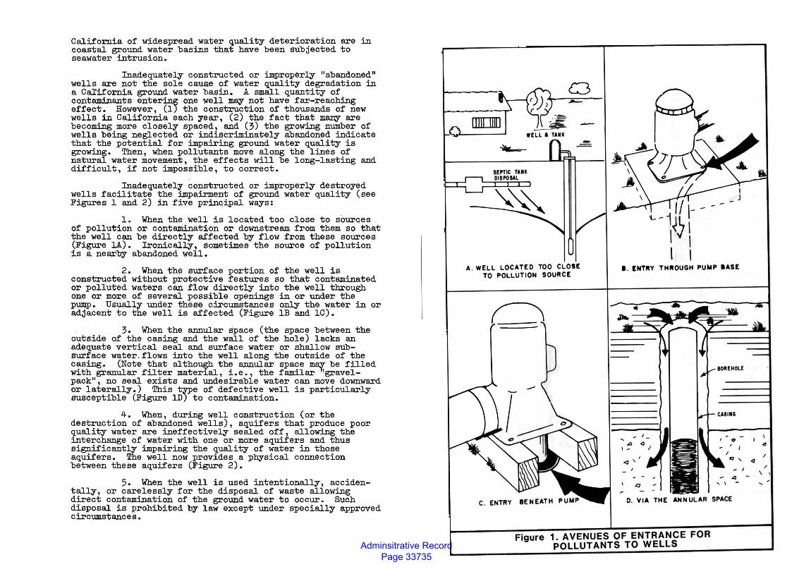
Inadequately constructed or improperly destroyed wells facilitate the impairment of ground water quality (see Figures 1 and 2) in five prinqipal ways:
1. When the well is located too close to sources of pollution or contamination or downstream from them so that the well can be directly affected by flow from these sources (Figure lA). Ironically, sometimes the source of pollution is a nearby abandoned well.
2. When the surface portion of the well is constructed without protective features so that contaminated or polluted waters can flow directly into the well through one or more of several possible openings in or under the pump. Usually under these circumstances only the water in or adjacent to the well is affected (Figure lB and lC).
3. When the annular space (the space between the outside of the casing and the wall of the hole) lacks an adequate vertical seal and surface water or shallow subsurface water.flows into the well along the outside of the casing. (Note that although the annular space may be filled with granular filter material, i.e., the familar "gravelpack", no seal exists and undesirable water can move downward or laterally.) This type of defective well is particularly susceptible (Figure lD) to contamination.
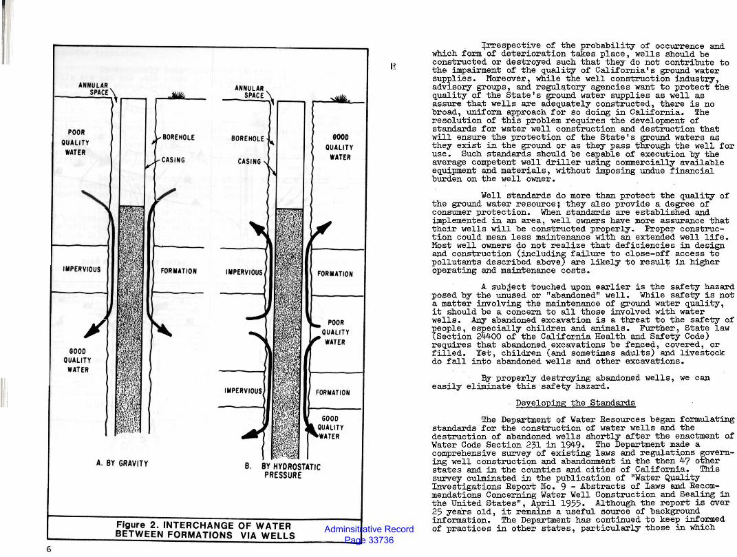
4. When, during well construction (or the destruction of abandoned wells), aquifers that produce poor quality water are ineffectively sealed off, allowing the interchange of water with one or more aquifers and thus significantly impairing the quality of water in those aquifers. The well now provides a physical connection between these aquifers (Figure 2).
5. When the well is used ~tentionally, accidentally, or carelessly for the disposal of waste allowing direct contamination of the ground water to occur. Such disposal is prohibited by law except under specially approved circumstances.
A. WELL LOCATED TOO CLOSE TO POLLUTION SOURCE
._ -i~J r- -1- I
I. INTRY THROUGH PUMP lASE
D. VIA THE ANNULAR SPACE
Figure 1. AVENUES OF ENTRANCE FOR POLLUTANTS TO WELLS .
Adminsitrative Record Page 33736
6
POOR QUALITY
WATER
IMPERVIOUS
GOOD QUALITY
WATER
FORMATION
ANNULAR SPACE
IMPERVIOUS
9000 QUALITY
WATER
FORMATION
POOR
FORMATION
A. BY GRAVITY 8. BY HYDROSTATIC PRESSURE
Figure 2. INTERCHANGE OF WATER BETWEEN FORMATIONS VIA WELLS
11!
+r.respective of the probability of occurrence and which form of deterioration takes place, wells should be constructed or destroyed such that they do not contribute to the impairment of the quality of California's ground water supplies. Moreover, while the well construction industry, advisory groups, and regulatory agencies want to protect the quality of the State's ground water supplies as well as assure. that wells are adequately constructed, there is no broad, uniform approach for so doing in California. The resolution of this problem requires the development of standards for water well construction and destruction that will ensure the protection of the State's ground waters as they exist in the ground or as they pass through the well for use. Such standards should be capable of execution by the average competent well driller using commercially available equipment and materials, without imposing undue financial burden on the well owner.
Well standards do more than protect the quality of the ground water resource; they also provide a degree of consumer protection. When standards are established and implemented in an area, well owners have more assurance that their wells will be constructed properly. Proper construction could mean less maintenance with an extended well life. Most well owners do not realize that deficiencies in design and construction (including failure to close-off. access to pollutants described above) are likely to result in higher operating and maintenance costs. ·
A subject touched upon earlier is the safety hazard posed by the unused or "abandoned" well. While safety is not a matter involving the maintenance of ground water quality, it should be a concern to all those involved with water wells. Any abandoned excavation is a threat to the safety of :people, especially children and animals. Further, State law (Section 24400 of the California Health and Safety Code) requires that abandoned excavations be fenced, covered, or filled. Yet, children (and sometimes adults) and livestock do fall into abandoned wells and other excavations.
By properly destroying abandoned wells, we can easily eliminate this safety hazard.
Developing the Standards
The Department of Water ~esources began formulating standards for the construction of water wells and the destruction of abandoned wells shortly after the enactment of Water Code Section 231 in 1949. The Department made a comprehensive survey of existing laws and regulations governing well construction and abandonment in the then 47 other states and in the counties and. cities of California. This survey culminated in the publication of "Water Quality Investigations Report No. 9 - Abstracts of Laws and Recommendations Concerning Water Well Construction and Sealing in the United States", April 1955. Although the report is over 25 years old, it remains a useful source of background information. The Department has continued to keep informed of practices in other states, particularly those in which
Adminsitrative Record Page 33737
standards have been established, and changes in the status of :::alifornia county well ordinances.
Concurrently the Department assembled and evaluated information on the development of well standards in California. The information was grouped illto three broad categories: (1) ground water geology and hydrology, (2) impairment of ground water quality, and (3) water well construction practioes. The latter included suggestions and recommendations on methods and materials from representatives of state and federal agencies, steel companies, casing fabricators, pump manufacturers, water well drilling contractors, and·other organizations and individuals concerned with the development and use of ground water.
This activity culminated in the publication of the standards in their initial draft form, "Recommended Minimum Well Construction and Sealing Standards for Protection of Ground Water Quality State of California", Bulletin 74, Preliminary Edition, July 1962. In March and April 1965, the Department conducted a series of public hearings in conjunction with the Department of Health Services at six cities in the State. Discussion and comments received centered on two areas: (1) the standards recommended, and (2) means of implementation. Most of those concerned felt that the standards, as written, were too general. Accordingly, the Department decided to redraft them.
Following a review of all prior material and comments rece.ived during the period 1963 through 1966, the Department published an interim,edition of the chapter containing the standards in February 1967. Two public hearings on the interim edition were held in M~ 1967, and written comments were received as part of the record. These were also joint hearings with the Department of Health Services.
The eight hearings produced correspondence and an extensive file of transcripts containing information, op~~ons, and suggestions, which would fill several volumes, if published.
In February 1968 current form.
standards .ed :in their
For the most part, the standards can be applied anywhere in the State under practically aQY conditions. The procedures for closing-off the avenues of access, properly locating a well, destroying an abandoned well, etc., in Del Norte County, at the northwest corner of California, are similar to those in western Fresno County. Similarly, sealing-off the water in one or more zones or aquifers, to prevent its migration to other zones or aquifers, ~be just as desirable for a well in western Merced County as it is at one on the Oxnard plain of Ventura County although, perhaps , for different reasons. However, in specific areas of the State it has been necessary to define the existing geologic and hydrologic conditions and the circumstances under which these standards should be applied. For example, it is
helpful to describe the areal and vertical extent of geologic materials where sealing is needed to prevent the migration of poor quality water.
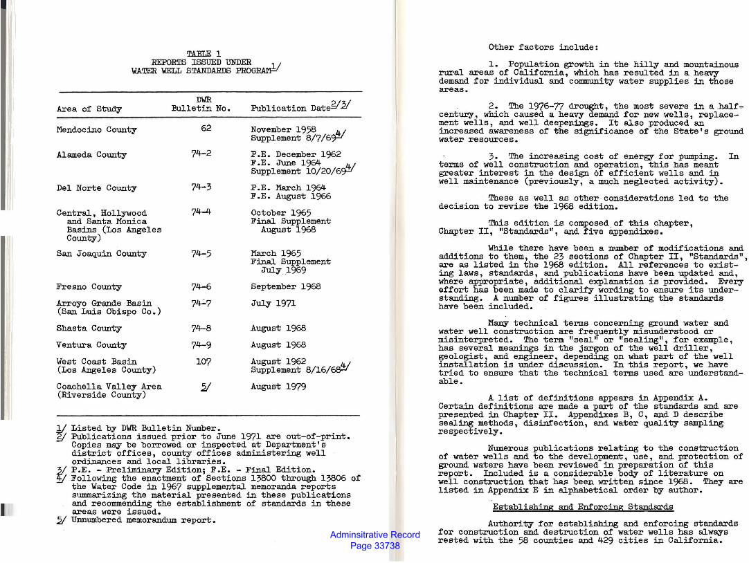
Thus , the Department maintained a concurrent and subsequent activity consisting of studies and reports describing the application of standards in designated areas of California. And, in addition to Bulletin 74, the Department issued a number of reports containing well standards for those areas (see Table 1).1/
The 1981 Edition
The foreword to the 1968 edition stated that:
"Whereas the standards in this report are as final as they can be at the present time, the Department will revise them from time to time. We recognize that, as with other published standards, to be effective and useful they must be revised and updated in light of both changes in practice and degree of success achieved in their application."
Sufficient changes in the field of water well construction and experience with applying the 1968 standards warrant revising them. Foremost among the changes in construction practices are:
1. The development and use of plastic·materials for casing in water wells. A subject only alluded to in the 1968 edition, the use of plastic well casing and screen has had phenomenal growth in the United States. So much has the usage increased that a national materials standard has been developed and a manual of installation practices has just been published.
.. 2. The use of the air rotary. drilling method for constructing wells in the hard rock areas of the State. Although this method of drilling was in use in 1968, its use has mushroomed since then. The equipment is very effective and very fast. Coupled with the use of plastic well casing, the method has made the construction of a well several hundred feet deep in one d~ a common event in hard rock areas.
3. Rapid growth in the use of well screens in place of perforated casing in the intake sections of wells.
4~ Increased use of the reverse-circulation method of well drilling for large diameter deep wells in unconsolidated formations. It too is an e~remely fast method.
One other report, Bulletin 74-1, "Cathodic Protection Well Standards: State of California", March 1973 deals with another kind of well. Cathodic protection wells house devices used to alleviate electrolytic corrosion of pipelines, tanks, and simil.ar installations. Such wells ~ also function as instruments for the deterioration of ground water quality. For that reason, standards for their con~truction and destruction have also been issued.
Adminsitrative Record Page 33738
II
TABLE 1 REPORTS ISSUED UNDER ____ l 1
WATER WELL STANDARDS FROG~
Area of Study
Mendocino County
Alameda County
Del Norte County
Central, Hollywood and Santa Monica Basins (Los Angeles County)
San Joaquin County
Fresno County
Arroyo Grande Basin (San Luis Obispo Co.)
Shasta County
Ventura County
West Coast Basin (Los Angeles County)
Coachella Valley Area (Riverside County)
DWR Bulletin No.
62
74-2
74-3
74-4
74-5
74-8
74-9
107
Publication Dat~21
November 1958 _41 Supplement 8/7/6~
P.E. December 1962 F .E. June 1964 _41 Supplement 10/20/6~
P.E. March 1964 F .E. August 1966
October 1965 Final Supplement
August 1968
March 1965 Final Supplement
July 1969
September 1968
July 1971
August 1968
August 1968
August 1962 __ 4 ; Supplement 8/16/~
August 1979
1/ Listed by DWR Bulletin Number. fl Publications issued prior to June 1971 are out-of-print.
Copies may be borrowed or inspected at Department's district offices, county offices administering well ordinances and local libraries.
3/ P.E. - Preliminary Edition; F.E. -Final Edition. ~ Following the enactment of Sections 13800 through 13806 of
the Water Code in 1967 supplemental memoranda reports s1xmmarizing the material presented in these publications and recommending the establishment of standards in these areas were issued.
2/ Unnumbered memorandum report.
Other factors include:
1. Population growth in the hilly and mountainous rural areas of California, which has resulted in a heavy demand for individual and community water supplies in those areas.
2. The 1976-77 drought, the most severe in a half ... century, which caused a heavy .demand for new wells, replacement wells, and well deepenings. It also produced an increased awareness of the significance of the State's ground water resources.
3. The increasing cost of energy for pumping. In terms of well construction and operation, this has meant greater interest in the design of efficient wells and in well maintenance (previously, a much neglected activity).
These as well as other considerations led to the decision to revise the 1968 edition.
This edition is composed_of this chapter, Chapter II, "Standards", and five appendixes.
While there have been a number of modifications and additions to them, the 23 sections of Chapter II, "Standards", are as listed in the 1968 edition. All references to existing laws, standards, and publications have been updated and, where appropriate, additional explanation is provided. Every effort has been made to clarify wording to ensure its understanding. A number of figures illustrating the standards have been included.
Many technical terms concerning ground water and water well construction are frequently misunderstood or misinterpreted. The term "seal" or "sealing", for example, has several meanings in the jargon of the well driller, geologist, and engineer, depending on what part of the well installation is under discussion. In this report, we have tried to ensure that the technical terms used are understandable.
A list of definitions appears in Appendix A. Certain definitions are made a part of the standards and are presented in Chapter II. Appendixes B, c, and D describe sealing methods, disinfection, and water quality sampling respectively.
Numerous publications relating to the construction of water wells and to the development, use, and protection of ground waters have been reviewed in preparation of this report. Included is a considerable body of literature on well construction that has been written since 1968. They are listed in Appendix E in alphabetical order by author.
Establishing and Enforcing Standards
Authority for establishing and enforcing standards for construction and destruction of water wells has always rested with the 58 counties and 429 cities in California.
Adminsitrative Record Page 33739
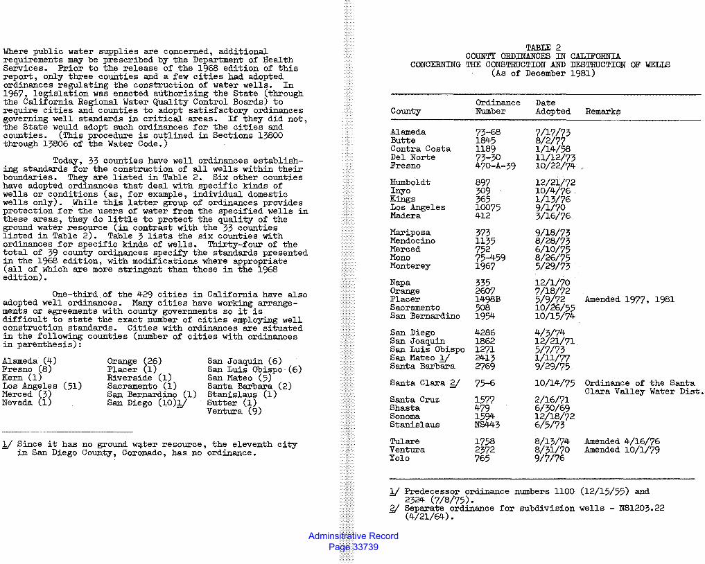
Where public water supplies are concerned, additional requirements may be prescribed by the Department of Health Services. Prior to the release of the 1968 edition of this report, only three counties and a few cities had adopted ordinances regulating the construction of water wells. In 1967, legislation was enacted authorizing the State (through the California Regional Water Quality Control Boards) to require cities and counties to adopt satisfactory ordinances governing well standards in critical areas. If they did not the State would adopt such ordinances for the cities and ' counties. (This procedure is outlined in Sections 13800 through 13806 of the Water Code.)
Today, 33 counties have well ordinances establishing standards for the construction of all wells within their boundaries. They are listed in Table 2. Six other counties have adopted ordinances that deal with specific kinds of wells or conditions (as, for example, individual domestic wells o~y). While this latter group of ordinances provides protect~on for the users of water from the specified wells in these areas, they do little to protect the quality of the ground water resource (in contrast with the 33 counties listed in Table 2). Table 3 lists the six counties with ordinances for specific kinds of wells. Thirty-four of the ~otal of 39 county ordinances specify the standards presented ~ the 1968 edition, with modifications where appropriate (all of which are more stringent than those in the 1968 edition).
One-third of the 429 cities in California have also adopted well ordinances. Many cities have working arrangem~nt~ or agreements with county governments so it is diff~cult.to state the exact number of cities employing well construct~on standards. Cities with ordinances are situated in the following counties (number of cities with ordinances in parenthesis):
Alameda (4) Fresno (8) Kern (1) Los Angeles (51) Merced (3) Nevada (1)
Orange (26) Placer (1) Riverside (1) Sacramento (1) San Bernardino (1) San Diego (10)11
San Joaquin (6) San Luis Obispo·(6) San l"'ateo (5) Santa Barbara (2) Stanislaus (1) Sutter (1) Ventura (9)
11 Since it has no ground w~ter resource, the eleventh city in San Diego County, Coronado, has no ordinance.
TABLE 2 COUNTY ORDINANCES IN CALIFORNIA
CONCERNING THE CONSTRUCTION AND DESTRUCTION OF WELLS (As of December 1981)
Ordinance Date County Number Adopted Remark~
Alameda 73-68 7/17/73 Butte 1845 8/2/77 Contra Costa 1189 1/14/58 Del Norte 73-30 11/12/73 Fresno 470-A-39 10/22/74
Humboldt 897 12/21/72 Inyo 309 10/4/76 Kings 365 1/13/76 Los Angeles 10075 9/1/70 Madera 412 3/16/76
Mariposa 373 9/18/73 Mendocino 1135 8/28/73 Merced 752 6/10/75 Mono 75-459 8/26/75 Monterey 1967 5/29/73
Napa 335 12/1/70 Orange 2607 7/18/72 Placer 1498B 5/9/72 Amended 1977, 1981 Sacramento 508 10/26/55 San Bernardino 1954 10/15/74
San Diego 4286 4/3/74 San Joaquin 1862 12/21/71 San Luis Obispo 1271 5/7/73 San l"'ateo 11 2413 1/11/77 Santa Barbara 2769 9/29/75
Santa Clara y 75-6 10/14/75 Ordinance of the Santa
Santa Cruz 1577 2/16/71 Clara Valley Water Dist.
Shasta 479 6/30/69 Sonoma 1594 12/18/72 Stanislaus NS443 6/5/73
Tulare 1758 8/13/74 Amended 4/16/76 Ventura 2372 8/31/70 Amended 10/1/79 Yolo 765 9/7/76
11 Predecessor ordinance numbers 1100 (12/15/55) and 2324 (7/8/75).
~ Separate ordinance for subdivision wells - NS1203.22 (4/21/64).
Adminsitrative Record Page 33740
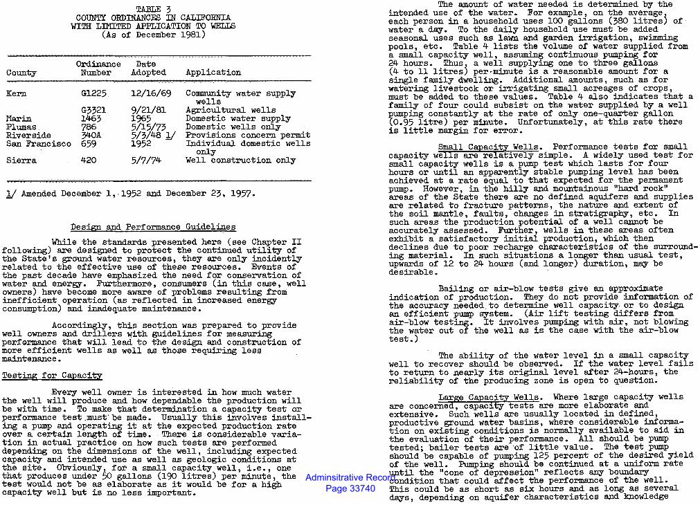
County
Kern
!'la.rin Plumas Riverside
TABLE 3 COUNTY ORDINANCES IN CALJFORNIA
WITH LIMITED APPLICATION TO WELLS (As of December 1981)
Ordinance Number
Date Adopted Application
Community water supply wells
San Francisco
Gl225
G3321 1463 786 340A 659
12/16/69
9/21/81 1965 5/15/73 5/3/48 Jj 1952
Agricultural wells Domestic water supply Domestic wells only Provisions concern permit Individual domestic wells
Sierra 420 5/7/74 only
Well construction only
Jj Amended December 1,·1952 and December 23, 1957.
Design and Performance Guidelines
While the standards presented here (see Chapter II following) are designed to protect the continued utility of the State's ground water resources, they are only incidently related to the effective use of these resources. Events of the past decade have emphasized the need for conservation of water and energy. Furthermore, consumers (in this case, well owners) have become more aware of problems resulting from inefficient operation (as reflected in increased energy consumption) and inadequate maintenance.
Accordingly, this section was prepared to provide well owners and drillers with guidelines for measuring perfGrmance that will lead to the design and construction of mo~e efficient wells as well as those requiring less ma~tenance.
Testing for Capacity
Every well owner is interested in how much water the well will produce and how dependable the production will be with time. To make that determination a capacity test or performance test_must'be made. Usually this involves installing a pump and operating it at the expected production rate over a certain length of time. - There is considerable variation in actual practice on how such tests are performed depending on the dimensions of the well, including expected capacity and intended use as well as geologic conditions at the site. Obviously, for a small capacity well, i.e. one that produces under 50 gallons (190 litres) per minut~ the test would not be as elaborate as it would be for a hi~ capacity well but is no less important.
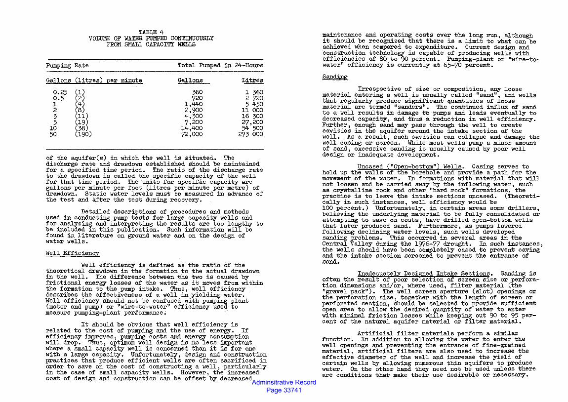
. The amount of water needed is determined by the ~tended use of the water. For example, on the average each person in a household uses 100 gallons (380 litresj of water a day. To the daily household use must be added seasonal uses such as lawn and garden irrigation, swimming pools, etc. Table 4 lists the volume of water supplied from a small capacity well, assuming continuous pumping for 24 hours. Thus a well supplying one to three gallons (4 to 11 litresj per-minute is a reasonable amount for a single family dwelling. Additional amounts, such as for watering livestock or irrigating small acreages of crops, must be added to these values. Table 4 also indicates that a fami~y of four qould subsist on the water supplied by a well ~ump~ constantly at the rate of only one-quarter gallon (0.95 litre) per minute. Unfortunately, at this rate there is little margin for error.
Small Capacity Wells. Performance tests for small capacity wells are relatively simple. A widely used test for small capacity wells is a pump test which lasts for four hours or until an apparently stable pumping level has been achieved at a rate equal to that expected for the permanent pump. However, in the hilly and mountainous "hard rock" areas of the State there are no defined aquifers and supplies are related to fracture patterns, the nature and extent of the soil mantle, faults, changes in stratigraphy, etc. In such areas the production potential of a well cannot be accurately assessed. Further, wells in these areas often exhibit a satisfactory initial production, which then declines due to poor recharge characteristics of the surrounding material. In such situations a longer than usual test, upwards of 12 to 24 hours (and longer) duration, may be desirable.
Bailing or air-blow tests give an approximate indication of production. They do not provide information of the accuracy needed to determine well capacity. or to design an efficient pump ff,YStem. (Air lift testing differs from air-blow testing. It involves pumping with air, not blowing the water out of the well as is the case with the air-blow test.)
The ability of the water level in a small capacity well to recover should be observed. If the water level fails to return to nearly its original level after 24-hours, the reliability of the producing zone is open to question.
Large Capacity Wells. Where large capacity wells are concerned, capacity tests are more elaborate and extensive. Such wells are usually located in defined, productive ground water basins, where considerable information on existing conditions is normally available to aid in the evaluation of their performance. All should be pump tested; bailer tests are ·of little value. The test pump should be capable of pumping 125 percent of the desired yield of the well. Pumping should be continued at a uniform rate until the "cone of depression" reflects any boundary condition that could affect the performance of the well. This could be as short as six hours and as long as several days, depending on aquifer characteristics and knowledge
Adminsitrative Record Page 33741
T.AELE 4 VOLUME OF WATER PUMPED CONTINUOUSLY
FROM SMALL CAPACITY WELLS
Pumping Rate Total Pumped
Gallons (litres2 :12er minute Gallons
0.25 (1) 360 0.5 (2) 720 1 ~~~ 1,440 2 2,900 3 (ll) 4,300 5 (19) 7,200
10 (38) 14,400 50 (190) 72,000
in 24-Hours
Litres
1 360 2 720 5 450
ll 000 16 300 27,200 54 500
273 000
of the aquifer(s) in which the well is situated.. The discharge rate and drawdown established should be maintained for a specified time period. The ratio of the discharge rate to the drawdown is called the specific capacity of the well for that time period. The units for specif-ic capacity are gallons per minute per foot (litres per minute per metre) of drawdown. Static water levels must be measured in advance of the test and after the test during recovery.
De.tailed descriptions of procedures and methods used in conducting pump tests for large capacity wells and for analyzing and interpreting the results are too lengthy to be included in this publication. Such information will be found in literature on ground water and on the design of water wells.
Well Efficiency
Well efficiency is defined as the ratio of the theoretical drawdown in the formation to the actual drawdown in the well. The difference between the two is caused by frictional energy losses of the water as it moves from within the formation to the pump intake. Thus, well efficiency describes the effectiveness of a well in yielding water. Well efficiency should not be confused with pumping-plant (motor and pump) or ''wire-to-water" efficiency used to measure pumping-plant per£ormance~
It should be obvious that well efficiency is related to the cost of pumping and the use of energy. If efficiency improves, pumping costs and energy consumption will drop. Thus, optimum well design is no less important where a small capacity well is concerned than it is for one with a large capacity. Unfortunately, design and constructi:m practices that produce efficient wells are often sacrificed ~ order to save on the cost of constructing a well, particularly in the case of small capacity wells. However, the increased cost of design and construction can be offset by decreased
maintenance and operating costs over the long run, although it should be recognized that there is a limit to what can be achieved when compared to expenditure. Current design and construction technology is capable of producing wells with efficiencies of 80 to 90 percent. Pumping-plant or "wire-towater" efficiency is currently at 65-70 percent.
Sand:i.ng
Irrespective of size or composition, any loose material entering a well is usually called "sand", and wells that regularly produce significant quantities of loose material are termed "sanders". The continued influx of sand to a well results in damage to pumps and leads eventually to decreased capacity, and thus a reduction in well efficiency. Further, enough sand may pass through the well to create cavities in the aquifer around the intake section of the well. As a result, such cavities can collapse and damage the well casing or screen. While most wells pump a minor amount of sand, excessive sanding is usually caused by poor well design or inadequate development.
Uncased ("Open-bottom"} Wells. Casing serves to hold up the walls of the borehole and provide a path for the movement of the water. In formations with material that will not loosen and be carried away by the inflowing water, such as crystalline rock and other "hard rock" formations, the . practice is to leave the intake sections uncased. (Theoret~cally in such instances, well efficiency would be 100 percent.) Unfortunately, in certain areas some drillers, believing the underlying material to be fully consolidated or attempting to save on costs, have drilled open-bottom w~lls that later produced sand. Furthermore, as pumps lowerea. following declining water levels, such wells developed sanding problems. This occurred in several areas in. the Central Valley during the 1976-77 drought. In such ~stan~es, the wells should have been completely cased to prevent cav~ and the intake section screened to prevent the entrance of sand..
Inadequately Designed Intake Sections. Sanding is often the result of poor selection of screen size or perforation dimensions and/or, where used, filter material (the "gravel pack"). The well screen aperture (slot) openings or the perforation size, together with the length.of scre~n.or perforated section, should be selected to prov~de suff~c~ent open area to allow the desired quantity of water to enter with minimal friction losses while keeping out 90 to 95 percent of the natural aquifer material or filter material.
Artificial filter materials perform a similar function. In addition to allowing the water to enter the well openings and preventing the entrance of fine-grained material artificial filters are also used to increase the effectiv~ diameter of the well and increase the yield of certain wells by allowing numerous thin aquifers to produce water. On the other hand they need not be used unless there are conditions that make their use desirable or necessary.
Adminsitrative Record Page 33742
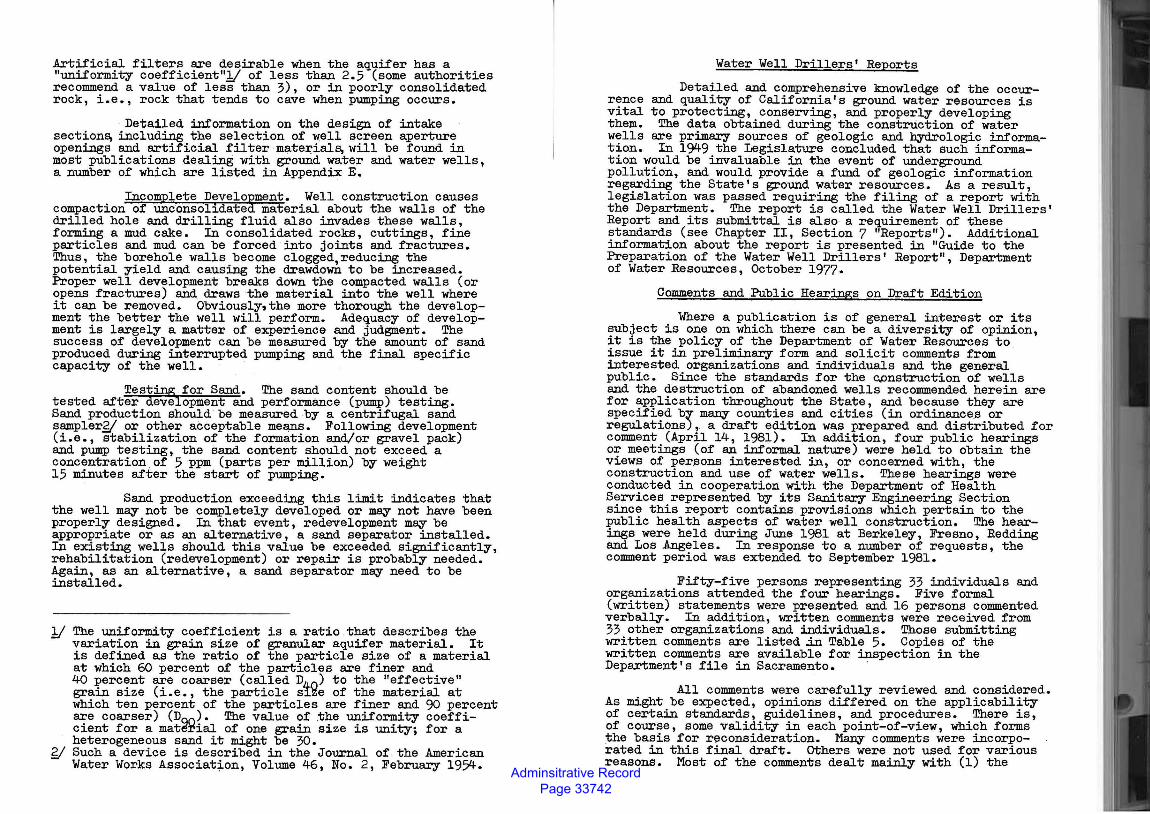
Artificial filters are desirable when the aquifer has a "uniformity coefficient"1/ of less than 2.5 (some authorities recommend a value of less than 3), or in poorly consolidated rock, i.e., rock that tends to cave when pumping occurs.
Detailed information on the design of intake section~ including the selection of well screen aperture openings and artificial filter materials, will be found in most publications dealing with ground water and water wells, a number of which are listed in Appendix E.
Incomplete Develo~ment. Well construction causes compaction of unconsolidate material about the walls of the drilled hole and drilling fluid also invades these walls, forming a mud cake. In consolidated rocks, cuttings, fine particles and mud can be forced into joints and fractures. Thus, the borehole walls become clogged,reducing the potential yield and causing the drawdown to be increased. Proper well development breaks down the compacted walls (or opens fractures) and draws the material into the well where it can be removed. Obviously,the more thorough the development the better the well will perform. Adequacy of development is largely a matter of experience and judgment. The success of development can be measured by the amount of sand produced during interrupted pumping and the final specific capacity of the well.
Testing . for Sand. The sand content should be tested after development and performance (pump) testing. Sand production should be measured by a centrifugal sand samplerS( or other acceptable means. Following development (i.e., stabilization of the formation and/or gravel pack) and pump testing, the sand content should not exceed a concentration of 5 ppm (parts per million) by weight 15 minutes after the start of pumping.
Sand production exceeding this limit indicates that the well may not be completely developed or m~ not have been properly designed. In that event, redevelopment m~ be appropriate or as an alternative, a sand separator installed. In existing wells should this value be exceeded significantly, rehabilitation (redevelopment) or repair is probably needed. Again, as an alternative, a sand separator m~ need to be installed.
1( The uniformity coefficient is a ratio that describes the variation in grain size of granular aquifer material. It is defined as the ratio of the particle size of a material at which 60 percent of the particles are finer and 40 percent are coarser (called D4-0 ) to the "effective" grain size (i.e., the particle s1ze of the material at which ten percent of the particles are finer and 90 percent are coarser) (DQO). The value of .the uniformity coefficient for a matE~rial of one grain size is unity; for a heterogeneous sand it might be 30.
gj Such a device is described in the Journal of the American Water Works Association, Volume 46, No. 2, February 1954.
Water Well Drillers' Reports
Detailed and comprehensive knowledge of the occurrence and quality of California's ground water resources is vital to protecting, conserving, and properly developing them. The data obtained during the construction of water wells are primary sources of geologic and hydrologic information. In 1949 the Legislature concluded that such information would be invaluable in the event of underground pollution, and would provide a fund of geologic information regarding the State's ground water resources. As a result, legislation was passed requiring the filing of a report with the Department. The report is called the Water Well Drillers' Report and its submittal is also· a requirement of these standards (see Chapter II, Section 7 "Reports"). Additional information about the report is presented in "Guide to the Preparation of the Water Well Drillers' Report", Department of Water Resources, October 1977.
Comments and Public Hearings on Draft Edition
Where a publication is of general interest or its subject is one on which .there can be a diversity of opinion, it is the policy of the Department of Water Resources to issue it in preliminary form and solicit comments from interested organizations and individuals and the general public. Since the standards for the ~nstruction of wells and the destruction of abandoned wells recommended herein are for application throughout the State, and because they are specified by many counties and cities (in ordinances or regulations),. a draft edition was prepared and distributed for comment (April 14, 1981). In addition, four public hearings or meetings (of an informal nature) were held to obtain the views of persons interested in, or concerned with, the construction and use of water wells. These hearings were conducted in cooperation with the Department of Health Services represented by its Sanitary Engineering Section since this report contains provisions which pertain to the public health aspects of water well construction. The hearings were held during June 1981 at Berkeley, Fresno, Redding and Los Angeles. In response to a number of requests, the comment period was extended to September 1981.
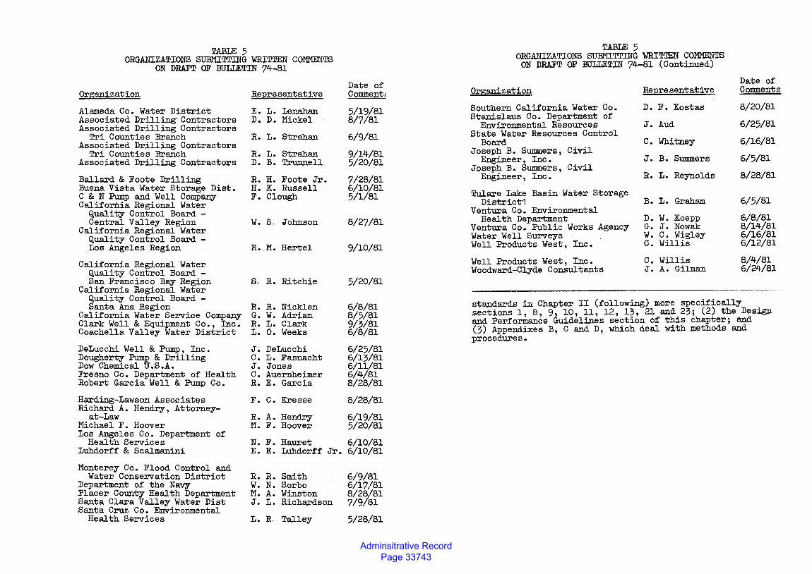
Fifty-five persons representing 33 individuals and organizations attended the four hearings. Five formal (written) statements were presented and 16 persons commented verbally. In addition, written comments were received from 33 other organizations and individuals. Those submitting written comments are listed jn Table 5. Copies of the written comments are available for inspection in the Department's file in Sacramento. ·
All comments were carefully reviewed and considered. As might be expected, opinions differed on the applicability of certain standards, guidelines, and procedures. There is, of course, some validity in each point-of-view, which forms the basis for r~consideration. Many comments were incorporated in this final draft. others were not used for various reasons. Most of the comments dealt mainly with (1) the
Adminsitrative Record Page 33743
TABLE 5 ORGANIZATIONS SUBMITTJNG WRITTEN COMMENTS
ON DRAFT OF BULLETJN 74-81
Organization
Alameda Co. Water District Associated Drilling· Contractors Associated Drilling Contractors
Tri Counties Branch Associated Drilling Contractors
Tri Counties Branch Associated Drilling Contractors
Ballard & Foote Drilling Buena Vista Water Storage Dist. C & N Pump and Well Company California Regional Water
Quality Control Board -Central Valley Region
California Regional Water Quality Control Board -Los Angeles Region
California Regional Water Quality Control Board -San Francisco Bay Region
California Regional Water Quality Control Board -Santa Ana Region
California Water Service Company Clark Well & Equipment Co., Inc. Coachella Valley Water District
DeLucchi Well & Pump, Inc. Dougherty Pump & Drilling Dow Chemical U.S.A. Fresno Co. Department of Health Robert Garcia Well & Pump Co.
Harding-Lawson Associates Richard A. Hendry, Attorney-
at-Law Michael F. Hoover Los Angeles Co. Department of
Health Services Luhdorff & Scalmanini
Monterey Co. Flood Control and Water Conservation District
Department of the Navy Placer County Health Department Santa Clara Valley Water Dist Santa Cruz Co. Environmental
Health Services
Re:Qresentative
E. L. Lenahan D. D. Mickel
R. L. Strahan
R. L. Strahan D. B. Trunnell
R. H. Foote Jr. H. K. Russell F. Clough
w. s. Johnson
R. M. Hertel
s. R. Ritchie
R. R. Nicklen G. w. Adrian R. L. Clark L. o. Weeks
J. DeLucchi C. L. Fasnacht J. Jones C. Auernheimer R. E. Garcia
F. c. Kresse
R. A. Hendry M. F. Hoover
N. F. Hauret E. E. Luhdorff Jr.
R. R. Smith W. N. Sorbo M. A. Winston J. L. Richardson
L. R. Talley
Date of Comm.ent1
5/19/81 8/7/81
6/9/81
9/14/81 5/20/81
7/28/81 6/10/81 5/1/81
8/27/81
9/10/81
5/20/81
6/8/81 8/5/81 9/3/81 6/8/81
6/25/81 6/13/81 6/ll/81 6/4/81 8/28/81
8/28/81
6/19/81 5/20/81
6/10/81 6/10/81
6/9/131 6/17/81 8/28/81 7/9/131
5/28/81
TABLE 5 ORGANIZATIONS SUBMITTJNG WRITTEN COMMENTS
ON DRAFT OF BULLETJN 74-81 (Continued)
Organization
Southern California Water Co. Stanislaus Co. Department of
Environmental Resources State Water Resources Control
Board Joseph B. Summers, Civil
Engineer, Inc • Joseph B. Summers, Civil
Engineer, Inc.
Tulare Lake Basin Water Storage District1
Ventura Co. Environmental Health Department
Ventura Co. Public Works Agency Water Well Surveys Well Products West, Inc.
Well Products West, Inc. Woodward-Clyde Consultants
Re:2resentative
D. F. Kostas
J. Aud
c. Whitney
J. B. Summers
R. L. Reynolds
B. L. Graham
D. W. Koepp G. J. Nowak W. C. Wigley C. Willis
c. Willis J. A. Gilman
Date of Comments
8/20/81
6/25/81
6/16/81
6/5/81
8/28/81
6/5/81
6/8/81 8/14/81 6/16/81 6/12/81
8/4/81 6/24/81
standards in Chapter II (following) more specifically sections 1, 8, 9, 10, 11, 12, 13, 21 and 23; (2) the Design and Performance Guidelines section of this chapter; and (3) Appendixes B, C and D, which deal with methods and procedures.
Adminsitrative Record Page 33744
iHAPTER II. STANDARDS
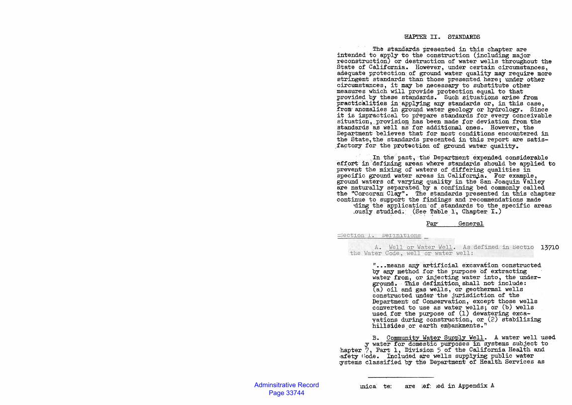
· The st~dards presented in this chapter are intended to apply to the .construction ()..ncluding major reconstruction) or destruction of water wells throughout the State of California. However, under certain circumstances, adequate p~otection of ground water quality may require more stringent standards than those presented here; under other circumstances, it may be necessary to substitute other measures which will provide protection equal to that provided by these standards. Such situations arise from practiciliities in applying a:JJY L;Jtandards or, in this case, from· anomalies in grotind water geology or hydrology. Since it is impractical to prepare standards for every conceivable situation 1 provisio:g., has been made tor deviation from the standards as welL as for additional ones. However, the Department believes that. for most conditions encoUntered in the State,the standards presented in this report are satisfa9tor,r for the probation of ground water quality.
· .. .. In the :past, ·the Department . expended considerable eff.ort in 'defining areas where standards should be applied to prevent the mixing of waters of differing qualities in specific ground . water areas in Californ,;i.a. For example, ground waters of_ varying quality in the San Joaquin Valley are naturally separated by a confining bed commonly called the "Corcoran Cla;y". The standards presented in this ·chapter continue to support the findings and recommendatic:ms made
·ding the application · of • standards . to the specific areas .ous,],y stUdied. (Se~ ~able . 1, Chapter I.)
Par· General
:::::.iect1.on ,L .
tlw 13710
II • o .meanS anY artificial eXCaVatiOn COnStructed by a:JJY method for the purpose ·of extracting water from, or injecting water into, the underjp:'Ound • . This definition, shall not include: (a) oil and gas wells, or geothermal wells constructed under the jurisdiction of the Department of Conservation, · except those wells converted to use as water wells; or (b) wells used .. for the pu;n>ose of (1) dewatering excayations during construction, or (2) stabilizing hillsides or earth embankments."
B. Community Water SupPly Well. A water well used ~ water for domestic purposes in systems subject to
ihapter 7, Part 1, Division 5 of the California Health and lafety 1 lode. Included are · wells supplying public water :ystem.s classified by t;tie Department of Health Services as
mica: te: are lef: Led in Appendix A
Adminsitrative Record Page 33745
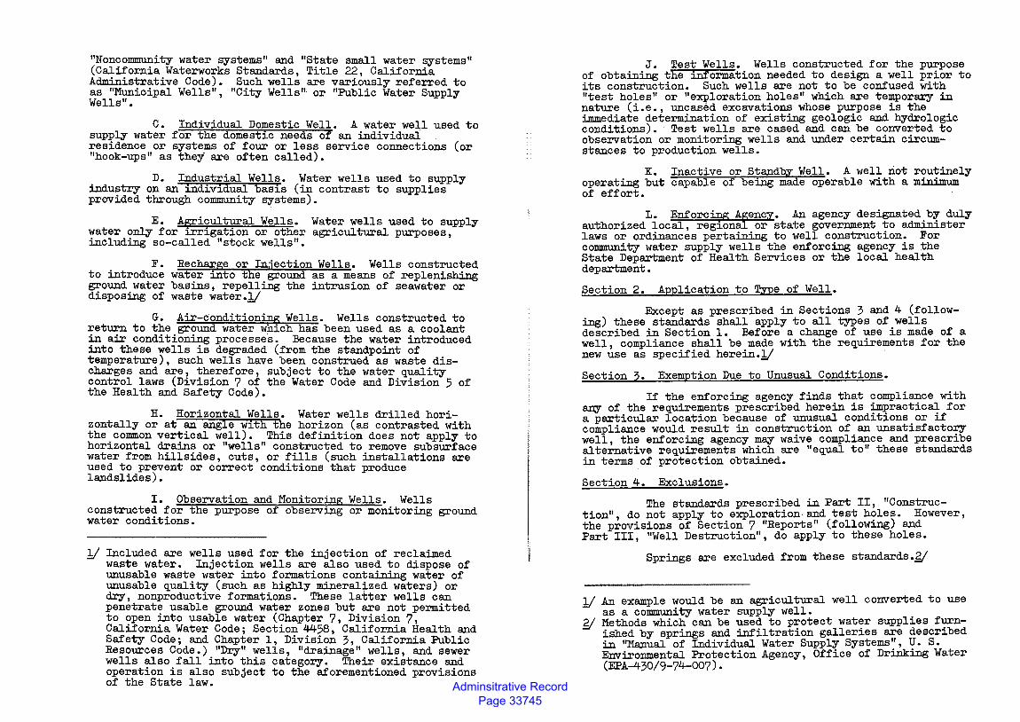
"Noncommunity water systems" and "State small water systems" (California Waterworks Standards, Title 22, California Administrative Code). Such wells are variously referred to as "Municipal Wells", "City Wells" or "Public Water Supply Wells".
C. Individual Domestic Well. A water well used to supply water for the domest~c needs of an individual residence or systems of four or less service connections (or "hook-ups" as they are often called).
D. Industrial Wells. Water wells used to supply industry on an ~dividual basis (in contrast to supplies provided through community systems).
E. Agricultural Wells. Water wells used to supply water only for irrigation or other agricultural purposes, including so-called "stock wells".
F. to introduce ground water disposing of
Recharge or Injection Wells. Wells constructed water into the ground as a means of replenishing basins, repelling the intrusion of seawater or waste water.Jj
G. Air-conditioning Wells. Wells constructed to return to the ground water which has been used as a coolant in air conditioning processes. Because the water introduced into these wells is degraded (from the standpoint of temperature), such wells have been construed as waste discharges and are, therefore, subject to the water quality control laws (Division 7 of the Water Code and Division 5 of the Health and Safety Code).
H. Horizontal Wells. Water wells drilled horizontally or at an angle w~th the horizon (as contrasted with the common vertical well). This definition does not apply to horizontal drains or "wells" constructed to remove subsurface water from hillsides, cuts, or fills (such installations are used to prevent or correct conditions that produce landslides).
I. Observation and Monitoring Wells. Wells constructed for the purpose of observing or monitoring ground water conditions.
Included are wells used for the injection of reclaimed waste water. Injection wells are also used to dispose of unusable waste water into formations containing water of unusable quality (such as highly mineralized waters) or dry, nonproductive formations. These latter wells can penetrate usable ground water zones but are not permitted to open into usable water (Chapter 7, Division 7, California Water Code; Section 4458, California Health and Safety Code; and Chapter 1, Division 3, California Public Resources Code.) "Dry" wells, "drainage" wells, and sewer wells also fall into this category. Their existance and operation is also subject to the aforementioned provisions of the State law.
J. Test Wells. Wells constructed for the purpose of obtaining the information needed to design a well p~ior to its construction. Such wells are not to be confused w~th "test holes" or "exploration holes" which are temporary in nature (i.e., uncased excavations whose purpose is the immediate determination of existing geologic and hydrologic conditions). Test wells are cased and can be converted to observation or monitoring wells and under certain circumstances to production wells.
K. Inactive or Standby Well. A well not routinely operating but capable of being made operable with a minimum of effort.
L. Enforcing Agency. An agency designated _b;y- duly authorized local, regional or state government to admin~ster laws or ordinances pertaining to well construction. For community water supply wells the enforcing agency is the State Department of Health Services or the local health department.
Section 2. Application to Type of Well.
Except as prescribed in Sections 3 and 4 (following) these standards shall apply to all types of.wells described in Section 1. Before a change of use ~s made of a well, compliance shall be made with the requirements for the new use as specified herein.Jj
Section 3. Exemption Due to Unusual Conditions.
If the enforcing agency finds that compliance with any of the requirements prescribed herein is ~~ractic~ for a particular location because of unusual cond~t~ons or if compliance would result in construction of an unsatisfactory well the enforcing agency m~ waive compliance and prescribe alte~ative requirements which are "equal to" these standards in terms of protection obtained.
Section 4. Exclusions.
The standards prescribed in Part II, "Construction", do not apply to exploration· and test h<;>les. However, the provisions of Section 7 "Reports" (follow~) and Part III, "Well Destruction", do apply to these holes.
Springs are excluded from these standards.g(
11 An example would be an agricultural well converted to use as a community water supply well. .
g; Methods which can be used to protect water suppl~es f~ished by springs and infiltration galleries are descr~bed in "Manual of Individual Water Supply Systems", U. S. Environmental Protection Agency, Office of Drinking Water (EPA-430/9-74-007).
Adminsitrative Record Page 33746
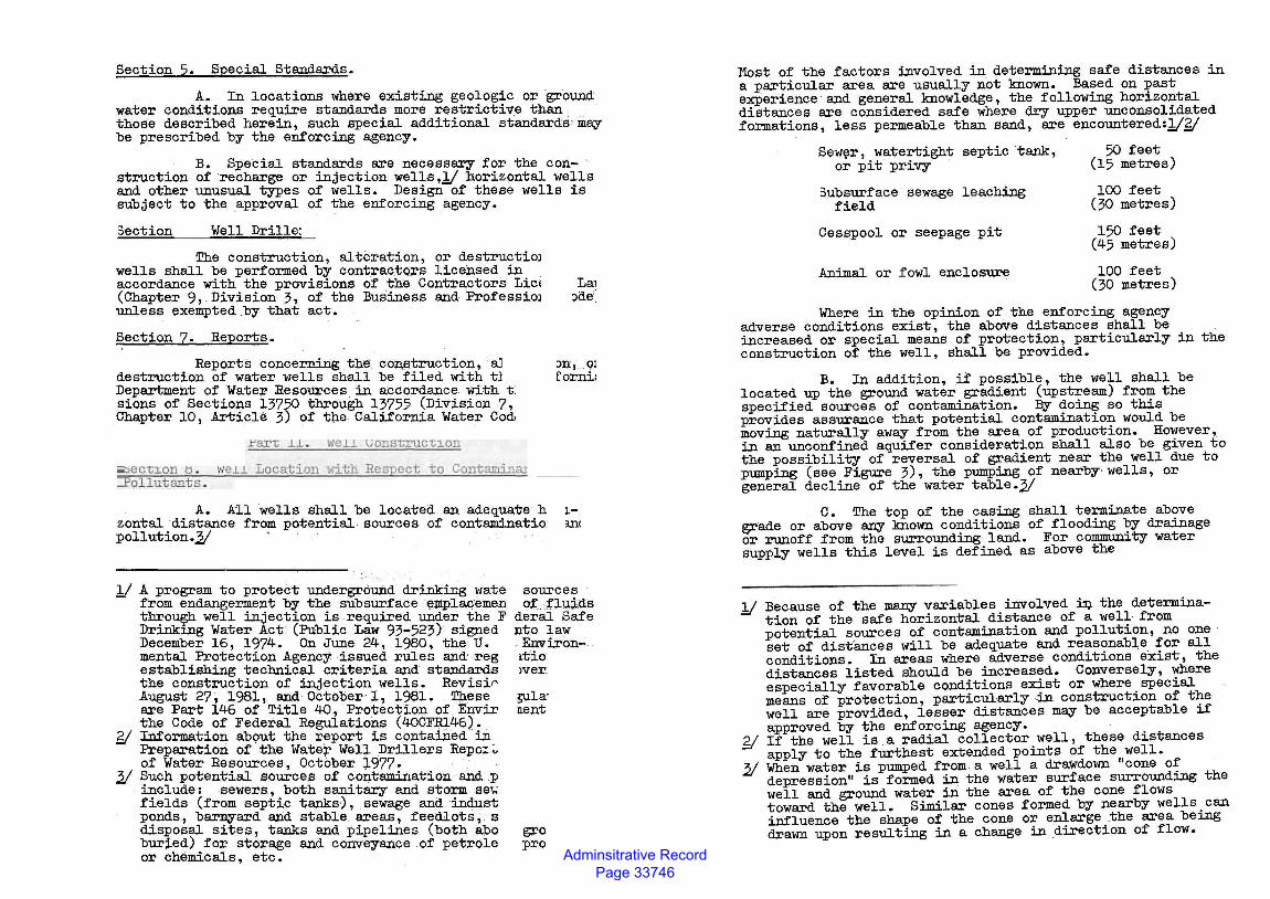
Section 5. Special Standards.
A. In locations where existing geologic or ground water conditions require standards more restrictive than those described herein, such special additional standards may be prescribed by the enforcing agency.
B. Special standards are necessary for the con- · struction of recharge or injection wells,,!/ horizontal wells and other unusual types of wells. Design of these wells is subject to the approval of the enforcing agency.
3ection Well Drille:
The construction, alteration, or destructioJ wells shall be performed by contractoJ:s licensed in accordance with the provisions of the Contractors LicE La1 (Chapter 9, Division 3, of the Business and ProfessioJ :>de unless exempted by that act.
Section 7. Reports.
Reports concerning t:O,e construction, aJ nx, Ql destruction of water wells shall be filed with tl rorni; Department of Water Resources in accordance With tl sions of Sections 13750 through 13755 (Division 7, Chapter 10, ArticlE! 3) of the California Water Cod•
;;o:;ec't:l.on tl . ~·eJ. .l Locat:i.on ~o."i.th llcSTJoct -to Cont~ :Pob.ut ants .
A. All wells shall be located an adequate h Lzontal distance from potential sources of contaminatio: m< pollution.2( ·
.!/ A program to protect underground drinking wate from endangerment by the subsurface ell1plac:;emen through well injection is required under the F Drinking Water Act. (Public Law 93-.523) signed December 16, 1974. On June 24, 1980, the U. mental Protection Agency issued rules and reg establishing technical criteria and standards the construction of injection wells. Revisi0 August 27, 1981, and October 1, 1981. These are Part 146 of Title 40, Protection of Envir the Code of Federal Regulations (40CFRJ.46).
Y Information ab0ut the report is contained in Preparation of the Wate~ Well Drillers Repo:.;, of Water Resources, October 1977-
2/ Such potential sources of contamination and p include: sewers, both sanitary and storm se>; fields (from septic tanks), sewage and indust ponds, barnyard and stable .. areas, feedlots., s disposal sites, tanks and pipelines (both abo buried) for storage and conveyance of petrole or chemicals, etc.
sources ot.:fluiQ.s
deral Safe nto law Environ-l.t'io >ver;
~la· nent
gro pro
Most of the factors involved in determining safe distances in a particular area are usually not known. Ba~ed on ~ast experience and general knowledge, the folloW2Dg hor1zo~tal distances are considered safe where dry upper unconsol1dated formations, less permeable than sand, are encountered:.!/Y
Sew~r, watertight septic tank, or pit privy
3ubsurface sewage leaching field
Cesspool or seepage pit
Animal or fowl enclosure
50 feet (15 metres)
100 feet (30 metres)
150 feet (45 metres)
100 feet (30 metres)
Where in the opinion of the enforcing agency adverse conditions exist, the above distances shall be increased or special means of protection, particularly in the construction of the well, shall be provided.
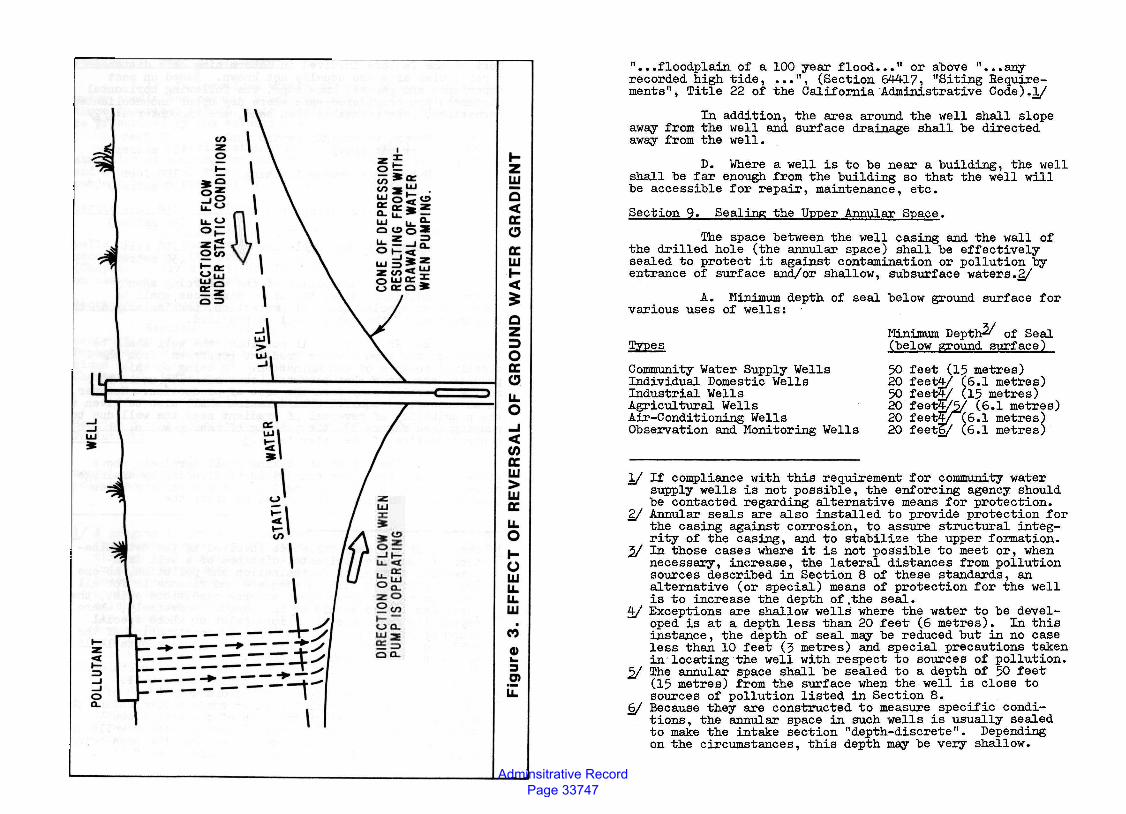
B. In addition, if' possible, the well shall be located up the ground water gradient (upstream) from the specified sources of contamina~ion. By ~o~ so this provides assurance that potent1al contam1nat1on would be moving naturally away from the area of production. Hm~·ever, in an unconfined aquifer consideration shall also be g1ven to the possibility of reversal of gradient near the well due to pumping (see Figure 3), the pumping of nearby·wells, or general decline of the water table.2(
c. The top of the casing shall terminate ab?ve &rade or above a:n:y known conditions of flooding by dra1nage or runoff from the surrounding land. For community water supply wells this level is defined as above the
y Because of the many variables involved ilJ. the determination of the safe horizontal distance of a well from potential sources of contamination and pollution, no one set of distances will be adequate and reasonable for all conditions. In areas where adverse conditions exist, the distances listed should be increased. Conversely, ~here especially favorable conditions ex~st or where_spec1al means of protection, partic~arly ·1n construct1on of t~e well are provided, lesser d~stances may be acceptable if approved by the enforcing agency. . y If the well is a radial collector well, these d1stances apply to the furthest extended points of the,well.
21 When water is pumped from a well a drawdown cone o~ depression" is formed in the water surface surround1ng the well and ground water in the area of the cone flows toward the well. Similar cones formed by nearby wells. can influence the shape of the cone o~ e~arge _the area be1ng drawn upon resulting in a change 1n d1rect1on of flow.
Adminsitrative Record Page 33747
__J __J L&J •
1-:z C[ I;::) __J __J
0 0..
(/)
z 0
' \ \
~\ > uJ ....J
a:
i\ ~J E\ (/)
\ \ \/
-------+/ _.--~--~+./ ------- / -------- ., ...... ---+--=-=-- - _, _
\
I :z:I: 0~ -:.o:: (/) L&J cn:::.t- . UJocct!) o::o:::.z a..~.~- -L&J ~.~-a.. ct!) 0 :::. I.L..~__J~ Ot-ct UJ5:.z :zcnccL&J oL&Jo:::I: uo::c:lt
~ z w -Q oct a: ~
a: w ~ oct
== Q z ::;)
0 a: ~-u. 0 _, oct (/) a: w > w a: u. 0 ~ 0 w u. u. w . (\')
Q) ... ::::J C)
u.
11 ••• floodplain of a 100 year flood ••• 11 or above 11
••• any recorded high tide, ••• ", (Section 64417, 11Siting Requirements", Title 22 of the California Administrative Code) .y
In addition, the area around the well shall slope awey from the well and surface drainage shall be directed awey from the well.
D. Where a well is to be near a building, the well shall be far enough from the building so that the well will be accessible for repair, maintenance, etc.
Section 9. Sealing the Upper Annular Space.
The space between the well casing and the wall of the drilled hole (the annular space) shall be effectively sealed to protect it against contamination or pollution by entrance of surface and/or shallow, subsurface waters.gj
A. Minimum depth of seal below ground surface for various uses of wells:
~
Community Water Supply Wells Individual Domestic Wells Industrial Wells Agricultural Wells Air-Conditioning Wells Observation and Monitoring Wells
Minimum Depth21 of Seal (below ground surface)
50 feet (15 metres) 20 feet4/ (6.1 met~es) 50 feet4/ (15 metres) 20 feet4i?1/ (6.1 metres) 20 feet4/ (6.1 metres) 20 feet£! (6.1 metres)
1/ If compliance with this requirement for community water supply wells is not possible, the enforcing agency should be contacted regarding alternative means for protection.
6/ Annular seals are also installed to provide protection for the casing against corrosion, to assure structural integrity of the casing, and to stabilize the upper formation.
2/ In those cases where it is not possible to meet or, when necessary, increase, the lateral distances from pollution sources described in Section 8 of these standards, an alternative (or special) means of protection for the well is to increase the depth of.the seal.
~ Exceptions are shallow wells where the water to be developed is at a depth less than 20 feet (6 metres). In this instance, the depth of seal mey be reduced but in no case less than 10 feet (3 metres) and special precautions taken in·locating the well with respect to sources of pollution.
2/ The annular space shall be sealed to a depth of 50 feet (15 metres) from the surface when the well is close to sources of pollution listed in Section 8.
§/ Because they are constructed to measure specific conditions, the annular space in such wells is usually sealed to make the intake section "depth-discrete 11
• Depending on the circumstances, this depth mey be very shallow.
Adminsitrative Record Page 33748
In areas£~ where freezing is a potential problem, the top of the seal may be below ground surface but in no case more than 4 feet (1.2 metres) below ground surface.
Sealing Conditions.g( Following are ·equirements to b1 observed in sealing the annular space:
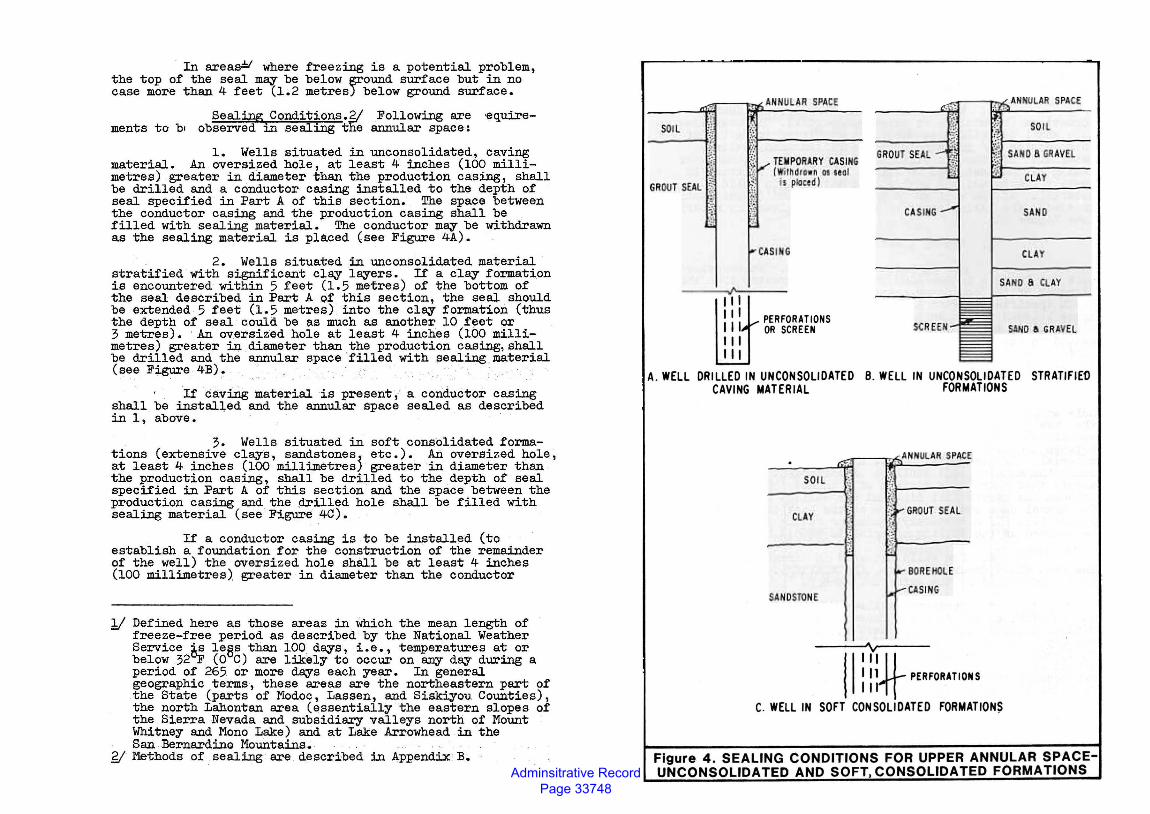
l. Wells situated in unconsolidated, caving material. An oversi.zed hole, at least 4 inches (100 millimetres) greater in diameter than the production casing, shall be drilled and a conductor casing installed to the depth of seal specified in Part A of this section. The space between the conductor casing and the production casing shall be filled with sealing material. The conductor may be withdrawn as the sealing material is placed (see Figure 4A).
2. Wells situated in unconsolidated material stratified with significant clay layers. If a clay formation is encountered within 5 feet (1.5 metres) of the bottom of the seal described in Part A of this section, the seal should be extended 5 feet (1.5 metres) into the clay formation (thus the depth of seal could be as much as another 10 feet or 3 metres). An oversized hole at least 4 inches (100 millimetres) greater in diameter than the production casing, shall be drilled and the annular space filled with sealing material (see Figure 4B). · .. . • . . , · . - . ,- ,·•· ' · -'
If cav:Ulg material is present, a conductor casing shall be instal~ed and the annular space sealed as described in 1, above.
3. Wells situated in soft consolidated formations (extensive clays, sandstones~ etc.). An oversized hole, at least 4 inches (100 millimetres) greater in diameter than the production casing, shall be drilled to the depth of seal specified in Part A of this section and the space between the production casing and the drilled hole shall be filled with sealing material (see Figure 4C).
If a conductor casing is .to be installed (to establish a foundation for the construction of the remainder of the well) the oversized hole shall be at least 4 inches (100 millimetres) greater in diameter than the conductor
1/ Defined here as those areas in which the mean length of freeze-free period as described by the National Weather Service is lees than 100 days, i.e., temperatures at or below 32"F ( 0 C) are likely to occur on arry day during a period of 265 or more days each year. In general geographic terms, these areas are the northeastern part of the State (parts of Modoc, Lassen, and Siskiyou Counties), the north Lahontan area (essentially the eastern slopes of the Sierra Nevada and subsidiary valleys north of Mount Whitney and Mono Lake) and at Lake Arrowhead in the San Bernardino Mountains. .
Y l"lethods of sealing are described in Appendix· B.
SOIL -------;!;~ .,
~·i }
GROLJ'I' SEAL ~~
n::MPORlR'I' CASING [ WH~drnn as uol h ~cell l
PERFORATIONS OR SCREEN
GROUT SEA!.
ClAY
A. WELL DRILLED IN UNCONSOLIDATED B. WELL IN UNCONSOLIDATED STRATIFIEn CAVING MATERIAL FORMATIONS
~--~~~AH~N:U~~:R~S~P~~~E ----~6c;q;lt1
SOil ;. ----'-'\'!-
Cl ,l,Y
------:~:;
SANDSTO E
, I
:~ I J'.l----?'i. ;1 ~ GAQUT SEAL. 1" .:~
~J-----,, _..BORE hOlE
1- ......-CASING
'''-H-I I 1 PERFORATIONS Ill
C. WELL IN SOFT CONSOLIDATED FORMATIONS
Figure 4. SEALING CONDITIONS FOR UPPER ANNULAR SPACEUNCONSOLIDATED AND SOFT, CONSOLIDATED FORMATIONS
Adminsitrative Record Page 33749
II.!
casing and the annular space between the conductor casing and the drilled hole filled with sealing material to the depth specified in Part A of this section.
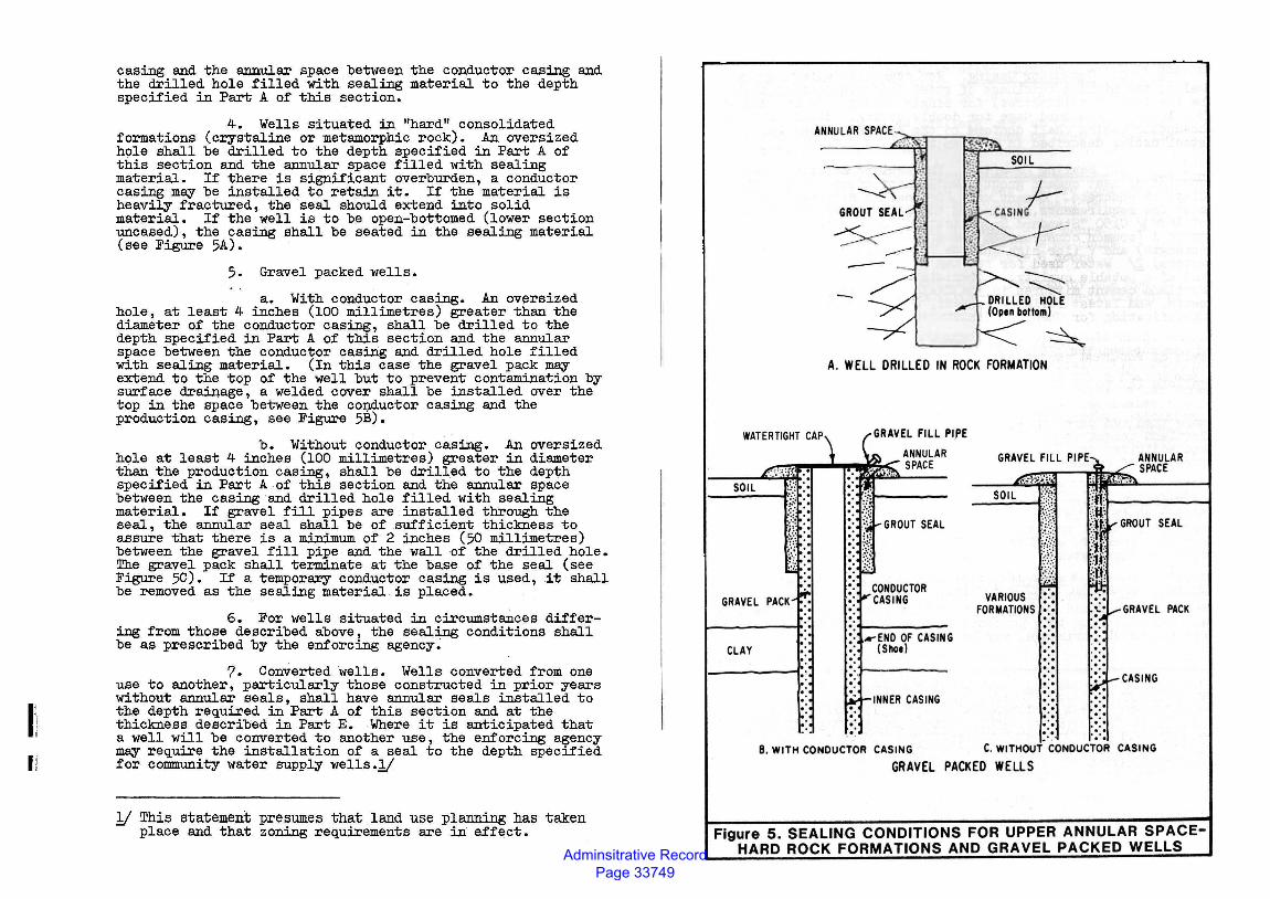
4. Wells situated in "hard" consolidated formations (crystaline or metamorphic rock). An oversized hole shall be drilled to the depth specified in Part A of this section and the annular space filled with sealing material. If there· is significant overburden, a conductor casing may be installed to retain it. If the material is heavily fractured, the seal should extend into solid material. If the well is to be open-bottomed (lower section uncased), the casing shall be seated in the sealing material (see Figure 5A).
5. Gravel packed wells.
a. With conductor casing. An oversized hole, at least 4 inches (100 millimetres) greater than the diameter of the conductor casing, shall be drilled to the depth specified in Part A of this section and the annular space between the conductor casing and drilled hole filled with sealing material. (In this case the gravel pack may extend to the top of the well but to prevent contamination by surface drainage, a welded cover shall be installed over the top in the space between the co~ductor casing and the production casing, see Figure 5B).
b. Without conductor casing. An oversized hole at least 4 inches (100 millimetres) greater in diameter than the production casing, shall be drilled to the depth specified in Part A of this section and the annular space between the casing and drilled hole filled with sealing material. If gravel fill pipes are installed through the seal, the annular seal shall be of sufficient thickness to assure that there is a minimum of 2 inches (50 millimetres) between the gravel fill pipe and the wall of the drilled hole. The gravel pack shall terminate at the base of the seal (see Figure 5C). If a temporary conductor casing is used, it shall be removed as the sealing material is placed.
6. For wells situated in circumstances differing from those described above, the sealing conditions shall be as prescribed by the enforcing agency.
?. ConVerted wells. Wells converted from one use to another, particularly those constructed in prior years without annular seals 1 shall have annular seals installed to the depth required in Part A of this section and at the thickness described in Part E. Where it is anticipated that a well will be converted to another use, the enforcing agency may require the installation of a seal to the depth specified for community water supply wells.l/
1( This statement presumes that land use planning has taken place and that_ zoning requirements are in effect.
SOIL
GRAVEL
CLAY
A. WELL DRILLED IN ROCK FORMATION
ANNULAR ~~r-!P""""""'PPW~C SPACE
..-END OF CASING (Shoe)
INNER CASING
ANNULAR .......-.~-~bb. SPACE
SOIL
VARIOUS : : FORMATIONS • • .. . . .. . . .. . . .. . . .. . . . . . . . .. . . ,. . . .
: : ~: : .. I· • • C. WITHOUT CONDUCTOR CASING 8. WITH CONDUCTOR CASING
GRAVEL PACKED WELLS
Figure 5. SEALING CONDITIONS FOR UPPER ANNULAR SPACEHARD ROCK FORMATIONS AND GRAVEL PACKED WELLS
Adminsitrative Record Page 33750
1111:1
C. Conductor Casing. For community water supply wells, the minimum thickness of steel conductor casing shall be 1/4 inch (6 millimetres) for single casing or a minimum of No. 10 U. S. Standard Gage for double casing. Steel used for conductor casing shall conform to the specifications for steel casing described in Section 12.
D. Sealing Material. The sealing material sl?-all consist of neat cement grout, sand-cement grout, bento~te cl~, or concrete. Cement used for sealing mixtures shall meet the requirements, including the latest revision thereof, of ASTMJ./ Cl50 "Standard Specification for Portland Cement" types· I-ccommon construction cement) III (high early strengj;h) and V (for high sulfate resistance, i.e., corrosive waters).g; Water used for sealing mixtures shall be clean and of a potable quality. Materials used as additives for Portland cement mixtures in the field shall meet the requirements, and latest revis.ion thereof, of ASTM 0494 "Standard Specification for Chemical Admixtures for Concrete".
1. Neat ceme~t grout shall be composed of one sack of Portland cement (94 pounds or 43 kilograms) to 4-1/2 to 6-1/2 (depending on cement type and additives used) gallon~ (17 to 25 litres) of clean water.
2. Sand-cement grout shall be composed of not more than two parts by weight of sand and one part of Portland cement to 4-1/2 to 6-1/2 (depending on cement type and additives used) gallons (17 to 25 litres) of clean water per sack of cement.
3. Concrete~ used shall be "Class A" (6 sacks of Portland cement per cub1c yard or 0.76 cubic metre) or "Class B" (5 sacks per cubic yard or 0.76 cubic metre).!!/ Aggregates shall meet the requirements, including the latest revision thereof, of ASTM C~3 "Standard Specification for Concrete Aggregates".
4. Special quick-setting cement, retardants to setting, and other additives, including hydrated lime to make the mix more fluid (up to 10 percent of the volume of cement), and bentonite (up to 5 percent) to make the mix more fluid and to reduce shrinkage, m~ be used.
1/ American Society for Testing and Materials. Y Corresponding API (American Petroleum Institute) cement
classes are: Type I - API Class A, Type III - API Class C. 2( Concrete is useful in sealing large-diameter wells where
the volume of annular seals required is likely to be substantial. However, unless care is exercised during placement, the coarse aggregate m~ become separated from the cement.
!!J A popular concrete mix among drillers consists of 8 sacks of Portland cement per cubic yard (0.76 cubic metre) and uniform aggregate of 3/8 inch (9.5 millimetres) diameter.
5. Bentonite c1~1/ mixtures shall be composed of bentonite clay and clean water thoroughly mixed before placement so that there are no balls, clods, etc.
6. Used drillers' mud or cuttings or chips from drilling the borehole shall not be used as sealing material.
7. The mini.mwn time that must be allow~d for materials containing cement to "set" before construct1on operations on the well may be resumed shall be:
a. Type I cement - 72 hours b. Type III cement - 48 hours c • Type V cement - 6 hours
When necessary these times m~ be reduced by the use of "accelerators", i.e., additives designed specifically to shorten setting time.
8. Where thermoplastic casing is used, caution should be exercised to control the heat generated during the curing of the cement (called "heat of. hydration") •. This is of special concern where casing of th1nner wall th1cknesses are to be installed. The addition of bentonite to the cement mixture (up to 8 percent) or circulating water inside the casing will lower the temperature of the cement. Additives which accelerate the curing process also tend to increase the heat generated and should not be used where thermoplastic casing is installed.
E. Thickness of Seal. The thickness of the seal shall be at least a nominal 2 inches,g( and not less tban . three times the size of t~e largest coarse aggregate used 1n the sealing material.
F. Placement of Seal.
1. Before placing the seal all loose cuttings, drilling mud, or other obstructions shall be removed from the annular space by flushing.
y Cl~ in the form of a mud-laden fluid is similar to and has the advantages of neat cement and sand-cement grout. There is a disadvantage in that cl~ in~ separate from the fluid. Cl~ should not be used where structural. strength or stability of the seal is required, where.flo~1ng or moving water might break it down, or where 1t m1ght dry out. Although there are other types o~ cl~ availabl7 , . none have the sealing properties (part1cular~y the ab1l1ty to expand dramatically) comparable to benton1te. Therefore only bentonite cl~s are recommended.
g; In other words the borehole shall be nominally 4 inches (100 millimetr~s) larger in diameter than the nomin~ casing diameter (thus creating a 2-inch, or~50 mill1metre annular space).
Adminsitrative Record Page 33751
2. Before sealing commences a packer or similar retaining device or a small quantity of sealant may be placed and permitted to set at the bottom of the interval to be sealed to form a foundation for the seal.
3. The sealing material shall be applied, when possible, in one continuous operation from the bottom of the interval to be sealed to the top. Where the seal is to be very deep (i.e., greater than 100 feet or 30 metres) a short segment at least 10 feet (3 metres) in length m~ be installed first, allowed to "set" or partially "set" and then the remainder of the seal placed in one continuous operation.
4.· Gravity installation of sealant without the aid of a tremie or grout pipe shall not be used unless the interval to be sealed is dry and in no case where the interval is over 30 feet (9 metres) in depth.
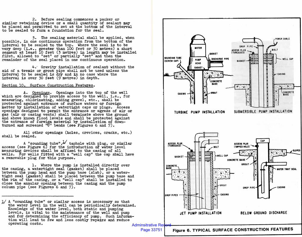
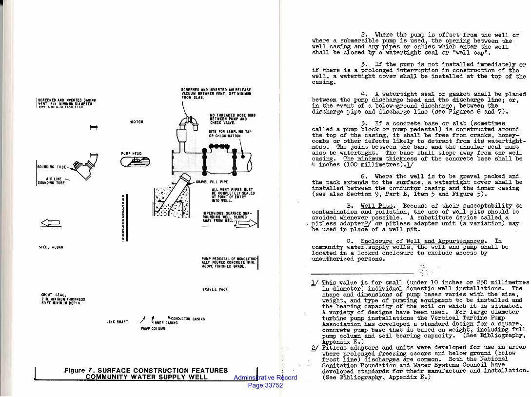
Section 10. Surface Construction Features.
A. Openings. Openings into the top of the well which are designed to provide access to the well, i.e., for measuring, chlorinating, adding gravel, etc. , shall be protected against entrance of surface waters or foreign matter by installation of watertight caps or plugs. Access openings designed to permit the entrance or egress of air or gas (air or casing vents) shall terminate above the ground and above known flood levels and shall be protected against the entrance of foreign material by installation of downturned and screened ''U" bends (see Figures 6 and 7).
All other openings (holes, cr evices, cracks, etc.) shall be sealed.
A "soundf.ne; tube" ,11 taphole with plug, or similar access (see Figure 6) for the introduction of water level measuring devices shall be affixed to the casing of all wells. For wells fitted with a "well cap" the cap shall have a removable · plug for this purpose.
1. Where the pump is installed directly over the casing, a watertight seal (gasket) shall be placed between the pump head and the pump base (slab), or a watertight seal (gasket) shall be placed between the pump base and the rim of the casing, or a "well cap" shall be installed to close the annular opening between the casing and the pump column pipe (see Figure.s 6 and 7).
11 A "sounding. tube" or similar access is necessary so that the water level in the well can be periodically determined. Knowledge of the water level, both static and pumping levels, is vital to the maintenance of the well and pump and for determining the efficiency of pump. Such information will lead to few and less costly repairs and reduce operating costs.
:.·
TURBINE PUMP INSTALLATION SUBMERSIBLE PUMP IN STALLATION
JET PUMP INSTALLATION BELOW GROUND DISCHARGE
Figure 6 . TYPICAL SURFACE CONSTRUCTION FEATURES
Adminsitrative Record Page 33752
I SCREENED AND INVERTED CASING VENT. 31N. IIINIIIUII DIAIIETER ':II I",. UIUIUIIU I"BAU e>l Aft
SOUNDING TUBE ~ AIRLINE .._V
SOUNDING TUBE
STEEL REBAR
GROUT SEAL, 21N. IIINIIIUII THICKNESS 50 FT. IIINIIIUII DEPTH.
IIOTOR
PUIIP HEAD
em •' ~ .
SCREENED AND INVERTED AIR RELEASE YACUUII BREAKER VENT, 3FT.IIINIIIUII FROII SLAB.
\ NO THREADED HOSE BIBB BETWEEN PUIIP AND CHECK VALVE .
SITE FOR SAMPLING TAP OR CHLORINATION
ALL YENT PIPES IIUST IE COMPLETELY SEALED AT POINT OF ENTRY INTO WELL .
IIIPERYIOUS SURFACE SUR- I ROUNDING WELL SLOPED AWAY FROII WELLJc:=:>
PUIIP PEDESTAL OF IIONOLITHIC1 ALLY POURED CONCRETE II IN. AIOYE FINISHED 6RADE .
GRAVEL PACK
LINE SHAFT I -II 'CONDUCTOR CASING l1NNER CASING
PUIIP COLUIIN
Figure 7. SURFACE CONSTRUCTION FEATURES COMMUNITY WATER SUPPLY WELL
2. Where the pump is offset from the well or where a submersible pump is used, the opening between the well casing and any pipes or cables which enter the well shall be closed by a watertight seal or "well cap".
3. If the pump is not installed immediately or if there is a prolonged interruption in construction of the well., a watertight cover shall be installed at the top o:f the casing.
4. A watertight seal or gasket shall be placed between the pump discharge head and the discharge line; or, in the event of a below-ground discharge, between the discharge pipe and discharge line (see Figures 6 and 7).
5. If a concrete base or slab (sometimes called a pump block or pump pedestal) is constructed around the top of the casing, it shall be free from cracks, honeycombs or other defects likely to detract from its watertightness. The joint between the base and the annular seal must also be watertight. The base shall slope aw~ from the well casing. The minimum thickness of the concrete base shall be 4 inches (100 millimetres).1(
6. Where the well is to be gravel packed and the pack extends to the surface, a watertight cover shall be installed between the conductQr casing and the inner casing (see also Section 9, Part B, Item 5 and Figure 5).
B. Well Pits. Because of their susceptability to contamination and pollution, the use of well pits should be avoided whenever possible. A substitute device called a pitless adaptergj or pitless adapter unit (a variation) m~ be used in place of a well pit.
c. Enclosure of Well and Appurtenances. In community water.supply wells, the well and pump shall be located in a locked enclosure to exclude access by unauthorized persons.
1f This value is for small (under 10 inches or 250 millimetres in diameter) individual domestic well installations. The shape and dimensions of pump bases varies with the size, weight, and type of pumping equipment to be installed and the bearing capacity of the soil on which it is situated. A variety of designs have been used. For large diameter turbine pump installations the Vertical Turbine Pump Association has developed a standard design for a square, concrete pump base that is based on weight, including full pump column and soil bearing capacity. (See Bibliography, Appendix E. )
g; Pitless adaptors and units.were developed for use in areas where prolonged freezing occurs and below ground (below frost line) discharges are common. Both the National Sanitation Foundation and Water Systems Council have developed standards for their manufacture and installation. (See Bibliography, Appendix E.)
Adminsitrative Record Page 33753
I~
D. Pump Blowoff. When there is a blowoff or drain line from the pump discharge, it shall be located above any known flood levels and protected against the possibility of backsiphonage or backpressure. The blowoff or drain line shall not be connected to any sewer or storm drain except when connected through an air gap.
E. Air Vents. In community water supply wells to minimize the possibil1ty of contamination caused by the creation of a partial vacuum during pumping, a casing vent shall be installed (Figure 7). In addition, to release air trapped in the pump column when the pump is not running, air release vents shall be installed (Figure 7). Air vents are also recommended for other types of wells except those having jet pump installations requiring positive pressure (which cannot have a vent).
F. Backflow Prevention)/ All pump discharge pipes not discharg1ng to the atmosphere shall be equipped with a check valve or similar device to prevent backflow and/ or backsiphonage into the well when the pump shuts doWn. The check valve shall be installed between the pump head and the connection to the distribution system or standpipe.
Section 11. Disinfection and Other Sanita;r Requirements.
A.- Disinfection.g; All wells produc~ water for domestic use (1.e., drink1ng or food processing) shall be disinfected following construction, repair, or when work is done on the pump, before the well is placed in service.
B. Gravel. Gravel used in gravel-packed wells shall come from clean sources and should be thoroughly washed before being placed in the well. Gravel purchased from a supplier should be washed at the pit or plant prior to delivery to the well site.
During placement of the gravel in the annular space disinfectants (usually calcium hypochlorite in tablet or granular form) shall be added to the gravel at a uniform rate (two tablets per cubic foot or one pound of the granular form per cubic yard).
C. Lubricants. Mud and water used as a drilling lubricant shall be free from sewage contamination. Oil and water used for lubrication of the pump and pump bearing shall also be free from contamination.
g;
The potential for the accidental contamination of wells through backflow or backsiphonage is high, particularly where there is the possibility of interconnection with other systems or in systems where agricultural chemicals (fertilizers, pesticides, etc.) are being injected. A procedure for disinfecting a well is described in Appendix C.
Section 12. Casing.
A. Casin~ Material.1/ Requirements pertaining to well casing are to 1nsure that the casing will perform the functions for which it is designed, i.e., to maintain the hole by preventing its walls from collapsing, to provide a channel for the conveyance of the water, and to provide a measure of protection for the quality of the water pumped.
l. enough to resist and those forces installation.
Well casing shall be strong and tough the forces imposed on it during installation which can normally be expected after
2. Steel is the material most frequently used for well casing, especially in drilled wells. The thickness of steel used ~or well casing shall be selected in accordance with good design practices applied with due consideration to conditions at the site of the well.g/ There are three principal classifications of steel materials used for water well casing, and all are acceptable for use so long as they meet the following conditions.
g;
Abbreviations used are: API-American Petroleum Institute; ASTM-American Society for Testing and Materials; AWWAAmerican Water Works Association. Selection of casing depends on its ability to resist external forces as well as factors affecting the casing serviceability. The maximum theoretical external pressure under which a particular well casing of a specific diameter and thickness will collapse can be calculated. However, other considerations such as the effect of driving the casing into place or other impact forces which may have an effect on the ability of a particular casing to resist external pressures, cannot be calculated with accuracy. Good design practices preclude the selection of a casing of a particular thickness for use where it will experience external pressures approaching the maximum or where unknown forces might magnify the effect of the external forces. Instead it is customary for designers to introduce factors of safety which tend to ensure that the casing selected will resist all probable forces imposed upon it. Consequently, experience and sound judgment, coupled with these factors or safety, have so far proved to be the best guide in sele,ct=ing the-proper casing. Suggested thicknesses for steel casing for various depths and diameters are to be found in material published by the various steel manufacturers and fabricators and in publications on the design ot water wells. The suggested thicknesses contained -in such publications are not to be considered a part of these standards.
l
Adminsitrative Record Page 33754
a. Standard and line pi~e. This material shall meet one of the following specificat~ons . including the latest revision thereof: '
(1)
(2)
API Std. 5L, "Specification for Line Pipe".
API Std. 5LX, "Specification for High-Test Line Pipe".
(3) ASTM A53, "Standard Specification for Pipe, Steel, Black and HotDipped, Zinc-Coated Welded and Seamless".
(4) ASTM Al20, "Standard Specification for Pipe, Steel, Black and HotDipped Zinc-Coated (Galvanized) Welded and Seamless, for Ordinar,y Uses".
(5) ASTM Al34, "Standard Specification for Electric-Fusion (Arc)-Welded Steel Pipe (sizes NPS 16 and over)".
(6) ASTM Al35, "Standard Specification for Electric-Resistance-Welded Steel Pipe".
(7) ASTM Al39, "Standard Specification for Electric-Fusion (Arc)-Welded Steel .Pipe (sizes 4 inches and over)".
(8) ASTM A2ll, "Standard Specification for Spiral-Welded Steel or Iron Pipe".
(9) AWWA C200, "AWWA Standard for Steel Water Pipe 6 Inches and Larger".
b. Structural Steel. This material shall meet one of the following specifications of the American Soc~e~ for Testing and Materials, including the latest rev~s~on thereof:
(1) ASTM A36, "Standard Specification for Structural Steel".
(2)
3)
ASTM A242, "Standard Specification for High Strength Low Alloy Structural Steel" •
ASTM A283, "Standard Specification for Low and Intermediate Tensile Strength Carbon Steel Plates of Structural Quality".
(4) ASTM A441, "Tentative Specification for High-Strength Low Alloy Structural Manganese Vanadium Steel".
(5) ASTM A570, "Standard Specification for Hot-Rolled Carbon Steel Sheet and Strip, Structural Quality".
c. High strength carbon steel sheets referred to by their manufacturers and fabricators as "well c~sing steel"~ At J?resent, there ar~ no standard specificat~ons concern~ th~s material. However, the major steel producers market products whose chemical and physical properties are quite similar. Each sheet of material shall contain mill markings which will identify the manufacturer and SJ?ecif~ that the m~terial is well casing steel which compl~es ~th the che~cal and physical properties published by the manufacturer.
d. Stainless steel casing shall meet the prov~s~ons of ASTM A409, "Standard Specification for Welded Large Diameter Austenitic Steel Pipe for Corrosive or High Temperat-ure Service".
3. Plastic is also used as casing for water wells in many locations under a variety of circumstances.lJ Because large-diameter (10 inches or 250 millimetres and larger) plastic casing has not been used extensively and especially at depths exceeding 300 feet (90 metres), special care must be exercised in the design and construction of wells that will employ these sizes. Particular attention should be given to the effect on thermoplastic casing of heat generated during cementing operations (see also Part B, "Installation of Casing" of this section, item 8, Part D, "Sealing Material" of Section 9, and discussion of plastic casing in Chapter I).
There are two groups of plastic materials available: thermoplastics and thermosets. Thermoplastics soften with the application of heat and reharden when cooled. Thus they can be repeatedly reformed. Thermosets cannot be reformed. During manufacture their molecules are permanently "set" by heat, chemical action or a combination of both. Thermoplastics used for plastic casing are ABS (acrylonitrile butadiene styrene), PVC (polyviriyl chloride) and SR (styrene rubber). The thermosetting plastic used for casing is fiberglass.
Information about the selection and installation of thermoplastic casing will be found in "Manual on the Selection and Installation of Thermoplastic Water Well Casing", a joint publication of the National Water Well Association and the Plastic Pipe Institut~.
Adminsitrative Record Page 33755
a. ThermoplaS'!;ics. This material shall meet the requirements of ASTM F480, "Standard Specification for Thermoplastic Water Well Casing Pipe and Couplings Made in Standard Dimension Ratios (SDR)" including the latest revision thereof.1( SDR is the ratio of pipe diameter to wall thickness.
b. Thermosets. This material shall meet the requirements of the following specifications including the. latest revisions thereof:
(l) ASTM D2996, "Standard Specification for Filament Wound Reinforced Thermoset:ting Resin Pipe".
(2) ASTM D2997, "Standard Specification for Centrifugally Cast Reinforced Thermosetting Resin Pipe".
(3) ,ABTM D3517, "Standard Specification for Reinforced Plastic Mortar Pressure Pipe".
(4) AWWA C950, "AWWA Standard for Glass-Fiber~Reinforced Thermosetting-Resin Pressure Pipe".
c. All plastic casing used for community water supply wells and individual wells shall meet the provisions of National Sanitation Foundation Standard No. 14 for Plastic Piping System Components and Related Materials.61
d. Plastic casing should not be stored in direct sunlight or subjected to freezing temperatures for extensive periods of time. Further, it should be stored so as to prevent sagging or bending.
4. Concrete pipe used for casing should conform to the following specifications, including the latest revision thereof:
(a) ASTM Cl4, "Standard Specifications for Concrete Sewer, Storm Drain, and Culvert Pipe" •
1/ Certain sizes of ABS and PVC plastic pipe products made in Schedule 40 and 80 (and others) wall thicknesses correspond to or overlap some of the sizes described in ASTM F480. However, this does not mean that they are equivalent products. They are classified in ASTM F480 as well casing specials referencing ASTM Specifications Dl527 (for ABS pipe) and ASTM Dl785 and D2241 (for PVC pipe).
61 NSF Standard No. 14 includes the requirements of ASTM F480 described in paragraph a, preceding.
(b) ASTM C76, "Standard Specification for Reinforced Concrete Culvert, Storm Drain, and Sewer Pipe".
(c) AWWA C300, "AWWA Standard for Reinforced Concrete FPeseure Pipe Steel Cylinder Type, for Water and Other Liquids".
(d) AWWA C30l, "AWWA Standard for Prestressed Concrete Pressure Pipe, Steel Cylinder Type, for Water and Other Liquids".
5. Other materials,1( except as listed in . No. 6 below, may be used as casing for water wells, subject to the approval of the enforcing agency.
6. Galvanized sheet metal pipe ("downspout"), or natural wood shall not be used as casing.
B. Installation of Cas~. All casing shall be placed with sufficient care to avo1d damage to casing sections and joints. All joints in the casing above the perforations or screens shall be watertight. The uppermost perforations shall be at least below the depth specified in Section 9, Part A, "Depth of Seal". Casing shall be equipped with centering guides to ensure even thickness of annular seal and/or gravel pack.
1. Metallic casing. Steel casing may be joined by either welding or by threading and coupling. Welding shall be accomplished in accordance with standards of American Welding Society or the most recent revision of the American Society of Mechanical Engineers Boiler Construction Code. Where casing is driven, (as is generally the case when the cable tool method of construction is used), the casing shall be equipped with a "drive shoe" at the lower end.
2. Plastic (non-metallic) casing.61 Depending on the type of material and its fabrication, plastic casing may be joined by solvent welding or mechanically joined (threaded or otherwise coupled). The solvent cement used for solvent welding shall meet the specifications for the type of plastic used and shall be applied in accordance with the manufacturer's instructions,particularly those pertaining to setting time required for the joint to develop handling strength. An adapter shall be used to join plastic casing to metallic casing or screen.
61
Such as wrought iron, asbestos cement pipe, and synthetic woods, all of which have been successfully employed as casing in California or elsewhere. Their present use is limited to special cases. Specifications for most of these materials are published.by either ASTM or AWWA. Information about the installation of thermoplastic casing will be found in "Manual on the Selection and Installation of Thermoplastic Water Well Casing", a joint publication of the National Water Well Association and the Plastic Pipe Institute.
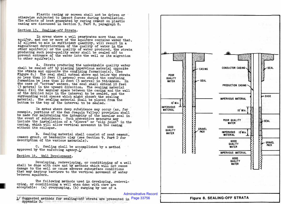
Adminsitrative Record Page 33756
I~ I
Plastic casing or screen shall not be driven or otherwise subjected to impact forces during installation. The effects of heat generated by curing cement on plastic casing are discussed in Section 9, Part B, paragraph 8.
Section 13. Sealing-off Strata.
In areas where a well penetrates more than one aquifer, and one ·or more of the aquifers contains water that, if allowed to mix in sufficient quantity, will result in a significant deterioration of the quality of water in the other aquifer(s) or the quality of water produced, the strata producing such poor-quality water shall be sealed off to prevent entrance of the water irito the well or its migration to other aquifer(s).
A. Strata producing the undesirable quality water shall be sealed off by placing impervious material opposite the strata and opposite the confining formation(s). (See Figure 8.) The seal shall extend above and below the strata no less than 10 feet (3 metres) even should the confining formation be less than 10 feet (3 metres) in thickness. In the case of. "bottom" waters, the seal shall eXtend 10 feet (3 metres) in the upward direction. The sealing material shall fill the annular space between the casing and the wall of the drilled hole in the interval to be sealed, and the surrounding void spaces which might absorb the sealing material. The sealing material shall be placed from the bottom to the top of the interval to be sealed.
In areas where deep subsidence m~ occur (as, for exa.:inple, portions of the San Joaquin Valley) provision shall be made for maintaining the integrity of the annular seal in the event of subsidence. Such preventive measures may include the installation of a "sleeve" or "slip joint" in the casing, which will allow vertical movement in the casing without its collapse.
B. Sealing material shall consist of neat cement, cement grout, or bentonite clay (see Section 9, Part D for description of the various materials).
C. Sealing shall be accomplished by a method approved by the enforcing agency.l(
Section 14. Well Development.
Developing, redeveloping, or conditioning of a well shall be done with care and by methods which will not cause damage to the well or cause adverse subsurface conditions that may destroy barriers to the vertical movement of water between aquifers.
The following methods used in developing, redeveloping, or conditioning a well when done with care are acceptable: (a) overpumping, (b) surging by use ~f a
.l/ Suggested methBcis f br sea1W1~.t.f- ~ str~ta are 'presented in • ·Appendix B. -- ·. ... .. •. · · ... . . --······~"·· ..
:t1Ji~t0~~~
POOR QUALITY WATER
~~~ -:i:: E~~ ,,
~ .,
1-----,.-t% IMPERVI~~SM i nl &
MATERIAL ·:
. GOOD . .
QUALITY . WATER
. . . . . . . . . . . -
l!iti~t ~1-- CASING .......
1!v SEAL ::::
~(; i:.~
/~;1-----
1 ~:·1----
• GRAVEL :~PACK
-·
CONDUCTOR CASING'- \
~
1 PRODUCTION CASING ........
"' IMPERVIOUS MATERIAL
, T -· 10 Min . ~_ ;t
POOR QUALITY WATER
GOOD QUALITY WATER ~: .
----------------~· IMPERVIOUS MATERIAL
GOOD QUALITY WATER .•
~~ :::· ...,..SEAL ...... . -~~
! !~-SHOE
~: it:;l ----'1 ~~ '~ ~~ f'SEAL
:::: ~)t-----1
!":: :t----;
: "ir"" GRAVEL :: PACK . .·t-----t . :.t-----t . .
_....._ .•
Figure 8. SEALING-OFF STRATA
Adminsitrative Record Page 33757
plunger, (c) surging with compressed air, (d) backwashing or surging by alternately starting and stopping the pump, (e) jetting with water, (f) introduction of chemicals desigqed for this purpose, and (g) a combination of the above.
The use of explosives for development should be done only by persons trained to handle them. Further, they should be used with special care where two or more distinct aquifers separated by a natural barrier have been penetrated.
Where chemicals or explosives have been used, the well shall be pumped until these agents have been removed.
Section 15. Water Quality Sampling.!/
The requirements to be followed with respect to water quality sampling are:
A. CoiDDi.unit:y Water Supply Wells and Certain Industrial Wells. The water from all community water supply wells and industrial wells which provide water fqr use in food processing shall be sampled immediately following development and disinfection, and appropriate analysis made.
Rules and regulati0ns governing the constituents to be tested, type of testing, etc., for community water supply systems are contained in Chapter 15, "Domestic Water Quality and Monitoring", of Title 22, California Adminis-' trative Code. Water analysis shall be performed by a laboratory certified by the California Department of Health Services. A copy of the laboratory analysis shall be forwarded to the California Department of Health Services or to the local health department. Approval of the enforcing agency must be ~btained before the well is put into use.
Except where there is free discharge from the pump (that is, there is no direct connection to the water delivery system such as to a sump), a sample tap (see Figure 7) shall be provided on the discharge line so that water representative of the water in the well may be drawn for laboratory analysis. The tap shall be located so as to prevent back siphonage to the pump discharge when the pump is shut off (e.g., on the system side of the check valve).
B. other Types of Wells. To determine the quality of water produced by a new well it should be sampled immediately following construction and development. Appropriate analyses shall be made based upon the intended uses of the water.
!/ The collection of water quality samples is described in Appendix D.
Section 16. Special Provisions ror Large Diameter Shallow ~-
A. Use as Community Water Supply Wells. Because shallow ground waters are often of poor quality and because they are easily contaminated, the use of bored or dug wells, or wells less than 50 feet (15 metres) dee~, to provide community water supplies shall be avoided (unless there is no other feasible means for obtaining water). When used for this purpose, these wells shall be located at least 250 feet (76 metres) from any underground sewage disposal facility.
B. Bored Wells. All bored wells shall be cased with concrete p~pe or steel casing whose joints are watertight from 6 inches (150 lllillimetres) above the ground surface to the depths specified in Section 9, Part A. Except where corrugated steel pipe is used as casing, the minimum thickness of the surrounding concrete seal shall be 3 inches (75 millimetres). Where corrugated -steel pipe is employed; the joints are not watertight and a thicker annular seal (no less than 6 inches or 150 millimetres) shall be installed.
c. ~Wells. All dug wells shall be "curbed" with a waterti~ curbing extending from above the ground surface to the depths specified in Section 9, Part A. The curbing shall be of -concrete poured-in-place or of casing (either precast concrete pipe or steel) surrounded on the outside by concrete.
If the curbing is to be _made of concrete, pouredin-place, it shall not be less than 6 inches (150 millimetres) thick. If precast concrete pipe or steel casing is used as part of the curbing, the space between the wall of the hole and the casing shall be filled with concrete to the depths specified in Section 9, Part A. The minimum thickness of the surrounding concrete shall be 3 inches (75 millimetres).
D. Casil;g Material. Either steel (including corrugated steel p~pe) or concrete may be used for casing bored or dug wells. Corrugated aluminum pipe is not recommended for use as casing.!/
!/ Aluminum placed in an aggressive soil is subject to electrolytic corrosion. When the soil pH is very high (over 8.0) or very low (under 6.0) this could present problems and, therefore, the soil pH ought to be checked. In addition, galvanic corrosion is likely to take place unless the pump is also made of aluminum. Accordingly, the use of most of the aluminum alloys currently available is not recommended.
Adminsitrative Record Page 33758
1. Steel used in the manufacture of casing for bored and dug wells should conform to the specifications for casing material described in Section 12. Minimum thickness of steel casing for bored and dug wells shall be:
Diameter Inches Millimetres
18 24 30 36 42 48
450 600 750 900
1050 1150
U. S. Standard Gage or Plate Thickness
8 gage 1/4 inch 1/4 inch 1/4 inch l/4 inch 1/4 inch
(4.18 millimetres) (6.35 millimetres) (6.35 millimetres) (6.35 millimetres~ (6.35 millimetres (6.35 millimetres
Corrugated steel pipe used as casing shall meet the specifications (including the latest.revision) of ASTMl_/ A444, "Standard Sl>ecificat:ion for Steel Sheet, Zinc Coated (Galvanized) by the HOT-DIP Process for Culverts and Underdrains". The minimum thickness of sheet used shall be 0.109 inches (2.8 millime~res).
2. Concrete casing can consist of either poured-in-place concrete or precast concrete pipe. Pouredin-place concrete should be sufficiently strong to withstand the earth and water pressures imposed on it during, as well as after, construction. It should be properly reinforced with steel to furnish tensile strength and to resist cracking, and it should be free from honeycombing or other defects likely to impair the ability of the concrete structure to remain watertight •. Aggregate small enough to place witho~t "bridging" should be used. Poured-in-place concrete shall be "Class A" (6 sacks of Portland cement per cubic yard or 0.76 cubic metre) or "Class B" (5 sacks per cubic yard or 0.76 cubic metre).
Precast concrete pipe is usually composed of concrete rings from 1 to 6 feet (0.3 to 1.8 metres) in diameter and approximately 3 to 8 feet (0.9 to 2.4 metres) long. To serve satisfactorily as casing, these rings should be free of blemishes that would impair their strength or serviceability. Concrete pipe shall conform to the specifications listeq in Section 12, Part A, item 4. .
E. Covers. All bored and dug wells shall be proyided with a structurally sound, watertight, cover made of concrete or steel.
1( American Society. for Testing and Materials.
Provisions for Driven Wells "Well
A. If the well is to be used as an individual domestic well, an oversize hole with a diameter at least 3 inches (75 millimetres) greater than the diameter of the pipe shall be constructed to a depth of 6 feet (1.8 meters) and the annular space around the pipe shall be filled with · neat cement, cement grout, or bentonite mud.
B. The minimum wall thickness of steel drive pipe shall be not less than 0.140 inches (3.5 millimetres).
C. Well points made of thermoplastic materials should not be driven but jetted or washed into place.
Section 18. Rehabilitation, Repair and Deepening of Wells.
A. Rehabilitation is the treatment of a well by chemical or mechanical means (or both) to recover lost production caused by incrustation or clogging of screens or the formation immediately adjacent to the well. The following methods used for rehabilitating a well when done with care are acceptable: (1) introduction of chemicals designed for this purpose, (2) surging by use of compressed air, (3) backwashing or surging by alternately starting or stopping the pump, (4) jetting with water, (5) sonic cleaning, (6) vibratory explosives, and (?) combinations of these. Methods which produce an explosion (in addition to the use of vibratory explosives mentioned above) are also acceptable provided, however, they are used with great care, particularly where aquifers are separated by distinct barriers to the movement of ground water.
In those cases where chemicals or explosives have been used, the well shall be pumped until all traces of them have been removed.
B. In the repair of wells, material used for casing shall meet the requirements of Se<?tion 12 "Casing" of these provisions. In addition, the requ1rements of Section 11, Part A "Disinfection" and, when applicable, Section 14 "Sealing-off Strata" shall be followed •
C •. Where wells are to be deepened, the requirements of Sections 11, 12, 13, 14, and 15 of these standards shall be followed.
Section 19. Temporary Cover.
Whenever there is an interruption in work on the well such as overnight shutdown, during inclement weather, or waiting periods required for the setting up of sealing materials for tests, for installation of the pump, etc., the well opening shall be closed with a cover to prevent the introduction of undesirable material into the well and to insure the public safety. The cover shall be held in place or "weighted-down" in such a manner that it cannot be removed except with the aid of equipment or through the use of tools.
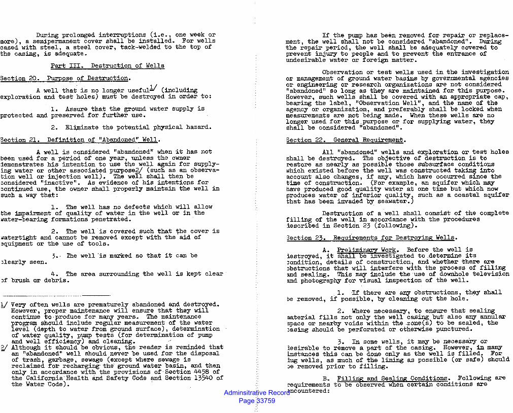
Adminsitrative Record Page 33759
During prolonged interruptions (i.e., one week or more), a semipermanent cover shall be installed. For wells cased with steel, a steel cover, tack-welded to the top of the casing, is adequate.
Part III. Destruction of Wells
Section 20. Purpose of Destruction.
A well that. is no longer useful1( (including exploration and test holes) must be destroyed in order to:
1. Assure that the ground water supply is protected and preserved for further use.
2. EH,minate the potential physical hazard.
Section 21. Definition of "Abandoned" Well.
A well is considered "abandoned" when it has not been used for a period of one year, unless the owner iemonstrates his intention to use the well again for supplying water or other associated purpose2/ (such as an observation well or· injection well). The werl shall then be considered "inactive". As evidence of his intentions for continued use, the owner shall properly maintain the well in such a way that:
1. The well has no defects which will allow the impairment of quality of water in the well or in the ~ater-bearing formations penetrated.
2. The well is covered such that the cover is ~atertight and cannot be removed except with the aid of 9quipment or the use of tools.
~-· rhe well "is marked so that it can be )!early seen.
4. The area surrounding the well is kept clear 'f brush or debris.
1( Ver,y often wells are prematurely abandoned and destroyed. However, proper maintenance will ensure that they will continue to· produce for ma:n:y years. The maintenance program should include regular measurement of the water level (depth to water from ground surface), determination of water quality, pump tests (for determination of pump and well efficiency) and cleaning. ··
g( Although it should be obvious, the reader is reminded that an "abandoned" well should never be used for the disposal of trash, garbage, sewage (except where sewage is reclaimed for recharging· the· ground water basin, and then only in accordance with the provisions of Section 4458 of the California·Health and Safety Code and Section 13540 of the Water Code).
If the pump has been removed for repair or replacement , the well shall not be considered "abandoned" • During the repair period, the well shall be adequately covered to prevent injury to people and to prevent the entrance of undesirable water or foreign matter.
Observation or test wells used in the investigation or management of ground water basins by governmental agencies or engineering or research organizations are not considered "abandoned" so long as they are maintained for this purpose. However, such wells shall be covered with an appropriate cap, bearing the label, "Observation Well", and the name qf the agency or organization, and preferably shall be locked when measurements are not being made. When these wells are no longer used for this.purpose or for supplying water, they shall be considered "abandoned".
Section 22. General Requirement.
All "abandoned". wells and exploration or test holes shall be destroyed. The objective of destruction is to restore as nearly as possible those subsurface conditions which existed before the well was constructed tak~ into account also changes, if a:n:y, which have occurred s1.nce the time of construction. (For example, an aquifer which may nave produced good quality water at one time but which now produces water of inferior quality~ such as a coastal aquifer that has been invaded by seawater.)
Destruction of a well shall consist of the complete filling of the well in accordance with the procedures iescribed in Section 23 (following).
3ection 23. Requirements for Destroying Wells.
A. Preliminro;r Work. Before the well is iestroyed, it shall be 1.nvestigated to .determine its ~ondition, details of construction, and whether there are ~bstructions that will interfere with the process of filling and sealing. This may include the·use of downhole television and photography for visual inspection of the well.
1. If there are a:n:y obstructions, they shall be removed, if possible, by cleaning out the hole.
2. Where necessary, to ensure that sealing naterial fills not only the well casing but also a:n:y annular space or nearby voids within the .zone(s) to be sealed, the )asing should be perforated or otherwise punctured.
3. In some wells, it may be necessary or lesirable to remove a part of the casing. However, in ma:n:y Lnstances this can be done only as the well is filled. For lug wells, as much of the lining as possible (or safe) should )e removed prior to filling.
B. Filling and Sealing Conditions. Following are ~equirements to be observed when certain conditions are mcountered:
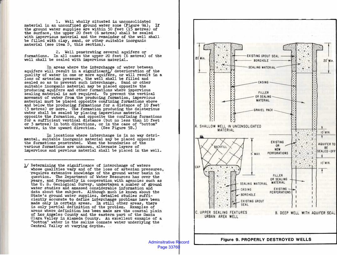
Adminsitrative Record Page 33760
1. Well wholly situated in unconsolidated material in an unconfined ground water zone (Figure 9A). If the ground water suppl~es are within 50 feet (15 metres) of the surface, the upper 20 feet (6 metres) shall be sealed with impervious material and the remainder of the well shall be filled with cl~, sand, or other suitable inorganic material (see item D, this section).
2. Well penetrating several a~uifers or formations. In all cases the upper 20 feet (6 metres) of the well shall be sealed with ~ervious material.
In areas where the interchange of water between aquifers will result in a significant1/ deterioration of the quality of water in one or more aquifers, or will result in a loss of artesian pressure, the well shall be filled and sealed so as to preyent such interchange. Sand or other suitable inorganic material ~ be placed opposite the producing aquifers and other formations where impervious sealing material is not required. To prevent the vertical movement of water from the producing formation, impervious material must be placed opposite confining formations above and below the producing formations for a distance of 10 feet (3 metres) or more~ The formation producing the deleterious water shall be seal.ed by placing impervious material opposite the formation, and opposite the confining formations for a sufficient vertical distance (but. no less than 10 feet or 3 metres) in both directions, or in the case of "bottom" waters, in the upward direction. (See Figure 9B.) .
In locations where interchange is in no way detrimental, suitable inorganic material m~ be placed opposite the formations penetrated. When the boundaries of the various formations are unknown, alternate l~ers of impervious and pervious material shall be placed in the well.
1/ Determining the significance of interchange of waters whose qualities vary and of the loss of artesian pressures, ·requires extensive knowledge of the ground water basin in question. The Department of Water Resources has over the years, and frequently in cooperation with agencies such as the U. S. Geological Survey, · undertaken a number of ground water studies and amassed considerable information and data about the subject. Although much is known about the State's ground water supplies, detailed studies sufficiently accurate to define interchange problems have been made only in certain areas. In still other areas, there is only partial definition of the problem. Examples of areas where definition has been made are the coastal plain of Los Angeles County and the eastern part of the Santa Clara Valley in Alameda County. An excellent example of a "bottom" water is the saline c.onnate water underlying the Central Valley at varying depths. ·
f'IL ER CI·R SE.A 14'fG -lt,UERI.IIl
20 i!ltn.
C. UPPER SEAUNG ff.A - URES OR·BAN AREA WH.L
B. DEEP WEL.L WliH AQU I' ER $E
Figure 9. PROPERLY DESTROYED WELLS
Adminsitrative Record Page 33761
3. Well penetrating creviced or fractured rock. If creviced or fractured rock formations are encountered just below the surface, the portions of the well oposite this formation shall be sealed with neat cement, sand-cement grout, or concrete. If these formations extend to considerable depth, alternate l~ers of coarse stonel/ and cement grout or concrete m~ be used to fill the well. Fine grained material shall not be used as fill material for creviced or fractured rock formations.
4. Well in noncreviced, consolidated formation. The upper 20 feet (6.1 metres) of a well in a noncreviced, consolidated formation shall be filled with impervious material. The remainder of the well m~ be filled with cl~ or other suitable inorganic material.
5. Well penetrating specific aquifers, local conditions. Under certain local conditions, the enforcing agency m~ require that specific aquifers o~ formations be sealed off during destruction of the well.
C. Placement of Material. The following requirements shall be observed in placing fill or sealing material in wells to be destroyed:
1. The well shall be filled with the appropriate material (as described in item D of this section) from the bottom of the well up.
2. Where neat cement grout, sand-cement grout, or concrete is used, it shall be poured in one continuous operation.
3. Sealing material shall be placed in the interval or intervals to be sealed by methods that prevent free fall, dilution, and/or separation of aggregates from cementing materials. ·
4. Where the head (pressure) producing flow is great, special care and methods must be used to restrict the flow while placing the sealing material. In such cases, the casing must be perforated opposite the area to be sealed and the sealing material forced out under pressure into the surrounding formation.
5. In destroying gravel-packed wells, the casing shall be perforated or otherwise punctured opposite the area to be sealed. The sealing material shall then be placed within the casing, completely filling the portion adjacent to the area to be sealed and then forced out under pressure into the gravel envelope.
6. When pressure is applied to force sealing material into the annular space, the pressure shall be maintained for a length of time sufficient for the cementing mixture to set.
Y The limiting dimensions of coarse stone are usually considered to range between l/4 and 4 inches (6.3 to 100 millimetres). ·
7. To assure that the well is filled and there has been no jamming or "bridging" of the material, verification shall be made that the volume of material placed in. the well installation at least equals ·the volume of the empty hole.
D. Materials. Requirements for sealing and fill materials are as follows:
l. Im-eervious Sealing Materials. No material is completely imperv~ous. However, sealing materials shall have such a low permeability that the volume of water passing through them is of small consequence.
Suitable impervious materials include neat cement, sand-cement grout, concrete, and bentonite cl~, all of which are described in Section 9, paragraph D, "Sealing Material" of these standards; and well-proportioned mixes of silts, sands, and clays (or cement), and native soils that have a coefficient of permeability of less than 10 feet (3 ·metres) per year.1f Used drilling muds are not acceptable.
2. Filler Material. Many materials are suitable for use as a filler in destroying wells. These include clay, silt, sand, gravel, crushed stone, native soils, mixtures of the aforementioned types, and those described in the preceding paragraph. Material containing organic matter shall not be used.
E. Additional Requirements for Wells in Urban Areas.
In incorporated areas or unincorporated areas developed for .multiple habitation, to make further use of the well site, the following additional requirements must be met (see Figure 90):
1. A hole shall be excavated around the well casing to a depth of 5 feet (1.5 metres) below the ground surface and the well casing removed to the bottom of the excavation.
2. The sealing material used for the upper portion of the well shall be allowed to spill over into the excavation to form a cap.
3. After the well has been properly filled, including sufficient time for sealing material in the excavation to set, the excavation shall be filled with native soil.
F. Temporary Cover. During periods when no work is being done on the~l, such as overnight or while waiting for sealing material to set, the well and surrounding excavation, if any, shall be covered. The cover shall be sufficiently strong and well enough anchored to prevent the introduction of foreign material into the well and to protect the public from a potentially hazardous situation.
!I Examples of materials of this type are: very fine sand with a large percentage of silt or cl~, inorganic silts, mixtures of silt and clay, and clay. Native materials should not be. used when the sealing operation involves the use of pressure.
Adminsitrative Record Page 33762
.. •···'
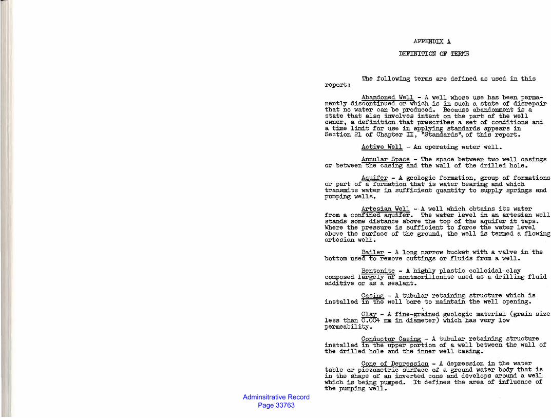
Adminsitrative Record Page 33763
report:
.APPENDIX A
m:FINITION OF TEru1S
The following terms are defined as used in this
Abandoned Well - A well whose use has been permanently discontinued or which is in such a state of disrepair that no water can be produced. Because abandonment is a state that also involves intent on the part of the well owner, a definition that prescribes a set of conditions and a time limit for use in applying standards appears in Section 21 of Chapter II, "Standards", of this report.
Active Well - An operating water well.
Annular Space - The space between two well casings or between the casing and the wall of the drilled hole.
Aquifer - A geologic formation, group of formations or part of a formation that is water bearing and which transmits water in sufficient quantity to supply SJ>rings and pumping wells.
Artesian Well -·A well which obtains its water from a corlfined aquifer. The water level in an artesian well stands some distance above the top of the aquifer it taps. Where the pressure is sufficient to force the water level above the surface of the ground, the well is termed a flowing artesian well.
Bailer - A long narrow bucket with a valve in "the bottom used to remove cuttings or fluids from a well.
Bentonite -A highly plastic colloidal· clay composed largely of montmorillonite used as a drilling fluid additive or as a sealant.
Cas~ - A tubular retaining structure which is installed in ~ well bore to maintain the well opening.
~- A fine-gr8..ined geologic material (grain size less than o.uo4 mm in diameter) which has vecy low permeability.
Conductor Casing - A tubular retaining structure installed in the upper portion of a well between the wall of the drilled hole and the inner well casing.
Cone of Depression - A depression in the water table or piezometric surface of a ground water body that is in the shape of an inverted cone and develops around a well which is being pumped. It defines the area of influence of the pumping well.
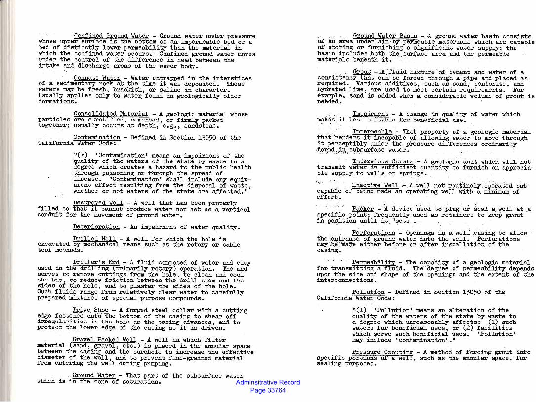
Adminsitrative Record Page 33764
Confined Ground Water - Ground water under pressure whose upper surface ~s the bottom of an impermeable bed or a bed of distinctly lower permeability than the material in which the confined water occurs. Confined ground water moves under the control of the difference in head between the intake and discharge areas of the water body.
Connate Water - Water entrapped in the interstices of a sedimentary rock at the time it was deposited. These waters m~ be fresh, brackish, or saline in character. Usually applies only to wate~ found in geologically older formations.
Consolidated Material - A geologic material whose particles are stratified, cemented, or fi.rmly packed together; usually occurs at depth, e.g., sandstone.
Contamination - Defined in Section 13050 of the California Water Code:
"(k) 'Contamination' means an impairment of the quality of the waters of the state by waste to a degree which creates a hazard to the public health through :po_isoning or through the spread of disease. 'Contamination' shall include any equivalent effect resulting from the disposal of waste, whether or not waters of the state are affected."
Destroyed Well - A well that has been properly filled so that it cannot produce water nor act as a vertical conduit for the movement of ground water.
Deterioration - An impairment of water quality.
Drilled Well - A well for which the hole is excavated by mechan~cal means such as the rotary or cable tool methods.
Driller's Mud - A fluid composed of water and cl~ used in the drilling (primarily rotary) operation. The mud serves to remove cuttings from the hole, to clean and cool the bit, to reduce friction between the drill stem and the sides of the hole, and to plaster the sides of the hole. Such fluids range from relatively clear water to carefully prepared mixtures of special p~ose compounds.
Drive Shoe - A forged steel collar with a cutting edge fastened onto the bottom of the casing to shear off irregularities in the hole as the casing advances, and to protect the lower edge of the casing as it is driven.
Gravel Packed Well - A well in which filter material (sand, gravel, etc.) is placed in the annular space between the casing and the borehole to increase the effective diameter of the well, and to prevent fine-grained material from entering the well during pumping.
Ground Water - That part of the subsurface water which is in the zone of saturation.
@round Water Basin - A ground water basin consists of an area underlain by permeable materials which are capable of storing or furnishing a significant water supply; the baf3in includes ,both thEl .surface area and the permeable materials beneath .it.
.·. . Grout - :A ·.fluid mixture of. cement and water of a consistency that cari be forced through a pipe and placed as required. Various additives, such as sand, bentonite, and bydrated .lime, are used to meet certain requirements. For example., .sand is added when a considerable volume of grout is needed.
Impairment - A chang .. e in quality of water which mak~~ it less suitable for beneficial use.
. . .•. . ... . . Impermeable - That property of a geologic mat.erial that ·renders it incapable o:t;. allowing water to move through it perceptibly under the pressure differences ordinarily f.ou,nO:: :.?ffi,p~psurface water.
Impervious Strata - A geologic unit which will not transmit water in sUfficient. quantity to furnish an appreciable s~ply to wells or spr~s.
Inactive Well - .A well not rou-einely. operated but capaBle of being m:a<le an operating well with a mi:n.imwJl of · effort.
' . Packer - A device used to plug or seal a. well at a
specific po~t; frequently used as retainers to keep grout in PO£\.ttion until it "sets".
Perforations - Openings in a well casing to allow the 'eJ:ltrance of ground water into the well. Perforations ~- b.e.:mad.e either before or after installation .of the casing.
Permeability - The capacity of a geologic material for transmitting a fluid. The degree of permeability depends upon the size and shape of the openings and the extent of the interconnections.
Pollution -·Defined in Section 13050 of the California Water Code:
"(1) 'Pollution' means an alteration of the quality of the waters of the state by waste to a degree which unreasonably affects: (1) such waters for beneficial uses, or (2) facilities which serve such beneficial uses. 'Pollution' m~ include 'contamination' • "
Pressure Grout~ - A method of forcing grout into specific portions of a w~, such as the annular space, for sealing p~oses.
Adminsitrative Record Page 33765
§uality of Water or Water Quality -· Defined in Section 13 50 of the California Water Code:
"(g) 'Quality of the water' or 'quality of the waters' refers to chemical, physical, biological, bacteriological, radiological, and other properties and characteristics of water which affect its use."
Screen or Well Screen - A factory-perforated casing used in a well that maximizes the entry of water from the producing zone and minimizes the entrance of sand.
Tremie - A·tubular device or pipe used to place grout in the annular space. Originally designed for placing concrete under water, the discharge end of the tube is kept submerged in the freshly deposited grout so as not to break the seal while filling the annular space.
that
Unconsolidated Material - 'A sediment that is loosely arranged or unstratified, or whose particles are not cemented together occurring either at the surface or at depth.
Waste - Defined in Section 13050 of the California Water Code_: __
"(d) 'Waste' includes sewage and aey/all other waste substances, liquid, solid, gaseous, or radioactive, associated with human habitation, or of human or animal origin, or from aey producing, manufacturing, or processing operation of whatever nature, including such waste placed within containers of whatever nature prior to, and for purposes of, disposal."
APPENDIX B
SUGGESTED METHODS FOR SEALING THE ANNULAR SPACE AND FOR SEALING-OFF STRATA
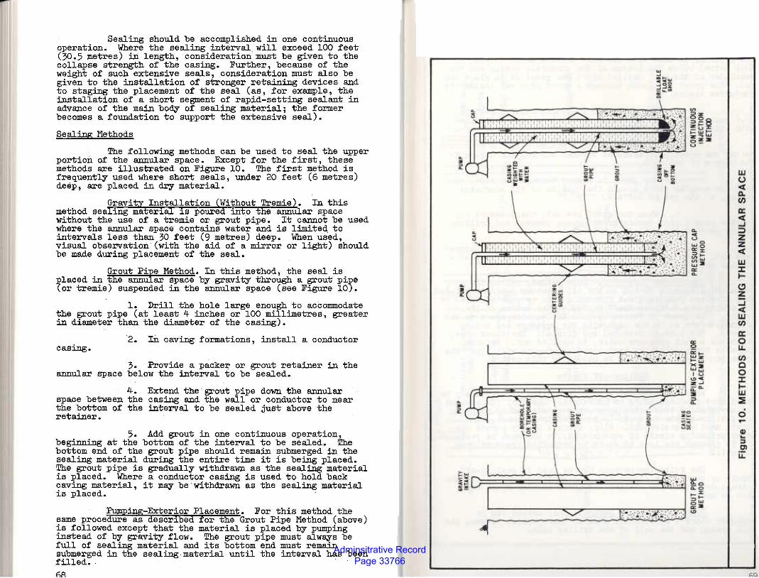
Adminsitrative Record Page 33766
Sealing should be accomplished in one continuous operation. Where the sealing interval. will exceed 100 teet (30.5 metres) in length, consideration must be given to the collapse strength of the casing. Further, because of the weight of such extensive seals, consideration must also be given to the installation of stronger retaining devices and to staging the placement of the seal (as, for example, the installation of a short segment of rapid-setting sealant in advance of the main boey of sealing material; the former becomes a foundation to support the extensive seal).
Sealing Methods
The following methods can be used to seal the upper portion of the annular space. Except for the first, these methods are illustrated on Figure 10. The first method is frequently used where short seals, under 20 feet (6 metres) deep, are placed in dry material.
Gravity Installation (Without Tremie). In this method sealing material is poured into the annular space without the use of a tremie or grout pipe. It cannot be used where the annular space contains water and is limited, to intervals less than 30 feet (9 ·metres) deep. When used, visual observation (with the aid of a mirror or light) should be made during placement of the seal.
Grout Pipe Method. In this method, the seal is ~laced·in the annular space by gravity through a grout pi~e (or tremie) suspended in the annular space (see Figure 10).
1. Drill the hole large enough to accommodate the grout pipe (at least 4 inches or 100 millimetres, greater in diameter than the diameter of the casing) •
2. In caving formations, install a conductor casing.
3. Provide a packer or grout retainer in the annular space below the interval to be sealed.
4. space between the the bottom of the retainer.
Extend the grout pipe down the annular casing and the wall or conductor to near interval to be sealed just above the
5. Add grout in one continuous operation, beginning at the bottom of the interval to be sealed. The bottom end of the grout pipe should remain submerged in the sealing material during the entire time it is being placed. The grout pipe is gradually withdrawn as the sealing material is placed. Where a conductor casing is used to hold back caving material, it m~ be withdrawn as the sealing material is placed.
Pumping-Exterior Placement. For this method the same procedure as described for the Grout Pipe Method (above) is followed except that the material is placed by pumping instead of by gravity flow. The grout pipe must alw~s be full of sealing material and its bottom end must remain submerged in the sealing material until the interval has been filled.. · 68
ci ..
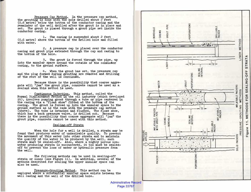
Adminsitrative Record Page 33767
Pressure Cap Method. In the pre.ssure cap method, the grouting is done with the hole drilled about 2 feet (0.6 metre) below the bottom of the. conductor casing and the remainder of the well drilled after the grout is in place and set. The grout is placed through a grout pipe set inside the conductor casing.
1. The casing is suspended about 2 feet (0.6 metre) above the bottom of the drilled hole and filled with water.
2. A pressure cap is placed over the conductor casing and grout pipe extended through the cap and casing to the bottom of the hole.
3. The grout is forced through the pipe, up into the annular space around the outside of the conductor casing, to the ground surface.
4. When the grout has set, the pressure cap and' the plug formed during grouting are removed and drilling of the rest of the well is continued.
Because there is the possibility that coarse aggregate will "jam" the . grout pipe, concrete cannot be used as a sealant when this method is used.
Continuous Injection. This method, called the Normal Displacement Method in the oil industry (which developed it), involves pumping grout through a tube or pipe centered in the casing via a "float shoe" fitted at the bottom of the casing. The grout is forced up into· the annular space to the ground surface as is the case with the pressure cap method (above). The tube is detached and flushed. The float shoe, which has a back pressure valve, is drilled out. Because there is the possibility that coarse aggregate will "jam" the grout pipe, concrete cannot be used with this method.
Sealing-off Strata
When the hole for a well is drilled, a s~ata may be found that produce~ water of undesirable quality. To prevent the movement of this water into other strata and to maintain the quality of the water to be produced by the well, such strata must be sealed-off. Also, where a highly porous nonwater producing strata is encountered, it too must be sealedoff to prevent the loss of water or hydraulic pressure from the well.
The following methods can be used in sealing-off strata or zones (see Figure 11). In addition, several of the methods described for sealing the upper annular space can also be used.
Pressure-Grout~ Method. Tb.:i,s method can be employed where a substantial annUlar space exists between the well casing and the wall of the drilled hole.
0 C)
~ w 2
I
:5 1 z <( _, 1-
!(( IX: 1-(1)
•
u. 11. 0
I
C!Ji i z ::i !(( Ll.l (fJ
a: 0 l.i. ti'J Q 0 J: l 1-IU
·~ I&J -~ : ..... ~ I 111
~I :i z: 01
--------~4r~--~~~~~r:;~~~~;-~~------------ffi 11. ~~~~~----------- ~ u
< •<1.
0
~~~~~----------~ ~ --~------~~~~~~------~
Adminsitrative Record Page 33768
-1. Perforate the casing opposite the interval
to be sealed.
2. Place a packer or other sealing device in the casing below the bottom of the perforated interval.
3. Use a dump bailer or grout pipe to place grout in the casing opposite the interval to be sealed. Sufficient grout shall be placed to fill the annular space and extend out into the strata to be sealed-off.
4. Place a packer or other sealing device in the casing above the perforations.
5. Apply pressure to the top packer to force the grout through the perforations into the interval to be sealed.
6. Maintain pressure until the material has set.
?. Drill out the packers and other material remaining in the well.
Frequently, an assembly consisting of inflatable (balloon) packers and grout pipe is used. The packers are placed to enclose the interval to be sealed, they are inflated and the grout pumped down the hose (which passes through the upper packer) into the interval to be sealed. Water is then pumped into the interval, squeezing the grout through the perforations. When the grout is sufficiently hardened, the packers are deflated and removed.
Liner Method. Where the annular space between the casing and the wall of the drilled hole is minimal, the liner method can be employed.
1. Perforate the casing opposite the interval to be sealed.
2. Place a smaller diameter metal liner, about 2 inches (50 millimetres) less in diameter, inside the casing opposite the perforated interval to be sealed, and extend it at least 10 feet (3 metres) above and below the perforated interval.
3. Provide a grout retaining seal at the bottom of the annular space between the liner and the well casing.
4. Extend the grout pipe into the opening between the liner and casing, and fill the annular space with grout in one continuous operation.
5. The botton end of the grout pipe should remain submerged in the sealing material during the entire time it is being placed. The grout pipe is gradually withdrawn as the sealing material is placed.
APPENDIX C
SUGGESTED PROCEDURES FOR DIS:rnFECTING WELLS
Adminsitrative Record Page 33769
APPENDIX C
SUGGESTED PROCEDURES FOR DISINFECTING WELLS
Disinfection of all wells is recommended to eliminate pathogenic organisms as well as organisms that can grow in wells and thereby cause clogging and effect the quality of water produced. Disinfection of the well is the final act of well construction or repair before it is placed in service. Wells should also be disinfected following repair or replacement of the pump and/or well maintenance. The procedures described in this appendix are recommended for disinfecting wells; however, other methods may be used provided it can be demonstrated that they will yield comparable results. For new wells, disinfection should take place following development (this will assure that the well is purged of drilling mud, dirt and other debris that reduces the effectiveness of the disinfection), testing for yield, and installation of the pump. When there is a delay in pump installation, interim ·or partial disinfection should be undertaken.
Disinfection involves seven steps:
1. A chlorine solution containing at least 50 mg/1 (or parts per million) available chlorine, is added to the well. Table 6 lists quantities of various chlorine compounds required to dose 100 feet (30 metres) of water- ·· filled casing at 50 mg/1 for diameters ranging from 2 to 24 inches (50 to 600 millimetres). For wells that have been repaired or when the pump has bee·n repaired or replaced and 1 bringing the well back into service quickly is desired, the solution should contain at least 100 mg/1 available chlorine. To obtain this concentration, double the amounts shown in Table 6.
2. The pump column or drop pipe shall be washed with the chlorine solution as it is lowered into the well.
3. After it has been placed into position, the pump shall be turned on and· off several times (i.e., "surged") so as to thoroughly mix the disinfectant with the water in the well. Pump until the water discharged has the odor of chlorine. Repeat this procedure several times at one-hour intervals. ·
4. The well shall be allowed to stand without pumping for 24 hours.
Adminsitrative Record Page 33770
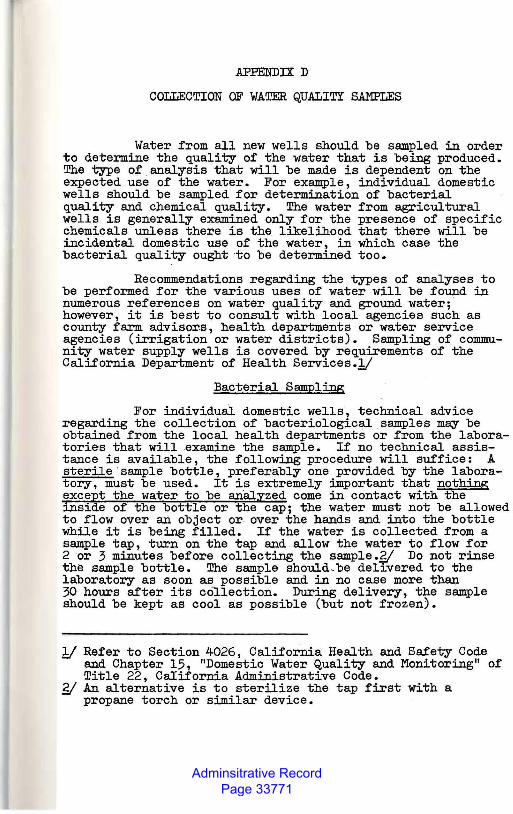
Adminsitrative Record Page 33771
APPENDIX D
COLLECTION OF WATER QUALITY SAMPLES
Water from all new wells should be sampled in order to determine the quality of the water that is being produced. The type of analysis that will be made is dependent on the expected use of the water. For example, individual domestic wells should be sampled for determination of bacterial quality and chemical quality. The water from agricultural wells is generally examined only for the presence of specific chemicals unless there is the likelihood that there will be incidental domestic use of the water, in which case the bacterial quality ought to be determined too.
Recommendations regarding the types of analyses to be performed for the various uses of water will be found in numerous references on water quality and ground water; · however, it is best to consult with local agencies such as county farm advisor.s, health departlllents or water service agencies (irrigation or water districts). Sampling of community water supply wells is covered by requirements of the California Department of Health Services.!/
Bacterial Sampling
For individual domestic wells, technical advice regarding the collection of bacteriological samples may be obtained from the local health departments or from the laboratories that will examine the sample. If no technical assistance is available, the following procedure will suffice: A sterile ·sample bottle, preferably one provided by the laboratory, must be used. It is extremely important that nothing exce~t the water to be analyzed come in contact with the insi e of the bottle or the cap; the water must not be allowed to flow over an object or over the hands and into the bottle while it is being filled. If the water is collected from a sample tap, turn on the tap and allow the water to flow for 2 or 3 minutes before collecting the sample.~ Do not rinse the sample bottle. The sample should be delJ.vered to the laboratory as soon as possible and in no case more than 30 hours after its collection. During delivery, the sample should be kept as cool as possible (but not frozen).
!/ Refer to Section 4026, California Health and Safety Code and Chapter 15, "Domestic Water Quality and Monitoring" of Title 22, California Administrative Code.
g( An alternative is to sterilize the tap first with a propane torch or similar device.
Adminsitrative Record Page 33772
Chemical Sampling
Generally, a routine mineral analyses (determination of the concentrations of the common minerals such as calcium, sodium, chlor1de, sulfate, etc.) plus analyses for selected minor elements will suffice, particularly where there is no prior knowledge of the chemical quality of the water in the area where the well is located. Where quality conditions in the surrounding area are known, a more selective analysis may be made. For specified uses it may also be desirable to make analysis for concentrations of certain constituents (such as iron and manganese in the case of domestic water or boron in irrigation water). Organic chemicals are not routinely determined. Information or advice on chemical quality conditions may be obtained from local agencies such as the county farm advisors, health departments, etc.
The sample should be collected after the well has been pumped long enough to remove standing water and development and disinfectant chemicals, and to ensure that water f .rom the producing formation(s) has entered the well. The water sample should be collected in a chemically clean container, preferably one obtained from the laboratory that will perform the analysis. The · container should be rinsed several times with the water to be sampled prior to collecting the sample. The laboratory performing the analysis should issue instructions regarding the quantity of sample required ' and whether or not preservatives are needed. However, one-half gallon (1.9 litres) is usually sufficient for a routine mineral analysis; one gallon (3.8 litres) w4en analysis for minor elements (i.e., iron, manganese, etc.) is also required. Sample quantities for organic chemicals vary according to the type of analysis, and range from very small amounts up to several gallons (litres). In addition, where organic chemicals are to be determined, special sampling procedures and equipment may be required. This is particularly true for volatile organic compounds.
In all cases the temperature of the water should be determined immediately upon collection of the sample.
APPENDIX E
BIBLIOGRAPHY
83
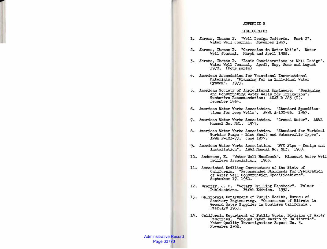
Adminsitrative Record Page 33773
APPENDIX E
BIBLIOGRAPHY
1. .Ahrens, Thomas P. "Well .Design Criteria. Part 2". Water Well JournaL November 1957.
2. .Ahrens, Thomas P. "Corrosion in Water Wells". Water Well Journal. Ma.rJll and April 1966.
3 • .Ahrens, Thomas P. "Basic Considerations of Well Design". Water Well Journal. April, May, June and August 1970. (Four parts)
4. American Association for Vocational Instructional Materials. "Planning for an Individual Water System". 1973.
5. American Society o:f Agricultural Engineers. "Designing and Constructing Water Wells for Irrigation". Tentative Recommendation: ASAE R 283 (T). December 1964.
6. American Water Works Association. "Standard Specifications for Deep Wells". AWA A-100-66. 1967.
7. American Water Works Association. "Ground Water". AWA Manual No. M21. 1973.
8. American Water Works Association. "Standard for Vertical Turbine Pumps - Line Shaft and Submersible Types". AWA E-101-77. June 1977.
9. American Water Works Association. "PVC Pipe -.Design and Installation". AWA Manual No. 1'123. 1980.
10. Anderson, K. "Water Well Handbook". Missouri Water Well Drillers Association. 1963.
11. Associated Drilling Contractors of the State of California. "Recommended Standards for Preparation of Water Well Construction Specifications". September 17, 1960.
12. Brantly, J. E. "Rotary Drilling Handbook". Palmer Publications. Fifth Edition. 1952.
13. California Department of Public Health, Bureau of Sanitary Engineering. "Occurrence of Nitrate in Ground Water Supplies in Southern California". February 1963.
14. California Department of Public Works, Division of Water Resources. "Ground Water Basins in California". Water Quality Investigations Report No. 3. November 1952.
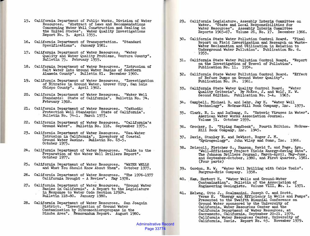
Adminsitrative Record Page 33774
15. California Department of Public Works, Division of Water Resources. "Abstract of Laws and Recommendations Concerning Water Well Construction and Sealing in the United States". Water Quality Investigations Report No. 9. April 1955.
16. California Department of Transportation. "Standard Specifications". January 1981.
17. California Department of Water Resources. "Water Quality and Water Quality Problems, Ventura County". Bulletin 75. February 1959.
18. California Department of Water Resources. "Intrusion of Salt Water Into Ground Water Basins of Southern Alameda County". Bulletin 81. December 1960.
19. California Department of Water Resources. "Investigation of Nitrates in Ground Water, Grover City, San Luis Obispo County" • April 1962.
20. California Department of Water Resources. "Water Well Standards:. State of California". Bulletin No. 74. February 1968.
21. California Department of Water Resources. "Cathodic Protection Well Standards: State of California".
' Bulletin No. 74-.1. March 1973.
22.
23.
24.
25.
26.
27.
28.
California Department of Water Resources. "California's Ground Water". Bulletin No. ll8. September 1975.
California Department of Water Resources. "Sea-Water Intrusion in California". Inventory of Coastal Ground Water Basins. Bulletin No. 63-5. October 1975.
California Department of Water Resources. "Guide to the Preparation of the Water Well Drillers Report". October 1977.
California Department of Water Resources. "WATER WELLS and What You Should Know About Them". October 1977.
California Department of Water Resources. "The 1976-1977 California Drought - A Review". May 1978.
California Department of Water Resources. "Ground Water Basins in California". A .Re.port to the Legislature in Response to Water Code Section 12924. Bulletin 118-80. January 1980.
California Department of Water Resources. San Joaquin District. "Investigation of Ground Water Contamination by Dibromochloropropane in the Dinuba Area". . Memorandum Report. August 1980.
29.
30.
31.
32.
33.
34.
35.
36.
37.
38.
39.
40.
41.
California Legislature, Assembly Interim Committee on Water. "State and Local Responsibilities for Water Resources". Assembly Interim Committee Reports 1965-67. Volume 26, No. 17. December 1966.
California State Water Pollution Control Board. "Final Report on Field Investigation and Research on WasteWater Reclamation and Utilization in Relation to Underground Water Pollution". Publication No. 6. 1953.
California State Water Pollution Control Board. "Report on the Investigation of Travel of Pollution". Publication No. ll. 1954. ·
California State Water Pollution Control Board. "Effect of Refuse Dumps on Ground Water Quality". Publication No. 24. 1961.
California State Water Quality Control Board. "Water Quality Criteria". By-McKee, J. andWolf, H. W. Second Edition. Publication No. 3-A. 1963.
Campbell, Michael D. and Lebr, Ja:y H. "Water Well Technology". McGraw-Hill Book Company, Inc. 1973.
Clark, N. L. and LuChang, s. "Enteric Viruses in Water". American Water Works Association Journal. Volume 51. October 1959.
Crocker, S. "Piping Handbook". Fourth Edition. McGrawHill Book Company, Inc. 1945.
Davis, Stanley N. and DeWiest, Roger J. M. "Hydrogeology". John Wiley and Sons, Inc. 1966.
Driscoll , Fletcher G. , Hanson, David T. and Page , Izyn. "Well-Efficiency Project Yields Energy-Saving Data". The Johnson Drillers Journal , March-April, May-June , and September-October, 1980, and First Quarter, 1981. (Four parts)
Gordon, R. W. "Water Well Drilling with Cable Tools". Bucyrus-Erie Company. 1958.
Ham, Herbert H. "Water Wells and Ground-Water Contamination". Bulletin of the Association of Engineering Geologists. Volume VIII, No. 1. 1971.
Helweg, Otto J., Scalrnanini, Joseph C. and Scott, Verne H. "Energy and Efficiency in Wells and Pumps". Presented to the Twelfth Biennial Conference on Ground Water sponsored by the University of California, Water Resources Center and the California Department of Water Resources, at Sacramento, California, September 20-21 , 1979. California Water Resources Center, University of California, Davis. Report No. 45. November 1979.
Adminsitrative Record Page 33775
42.
43.
44.
45.
46.
47.
48.
49.
50.
51.
I 52.
53.
Idaho Department of Water Resources. "Minimum Well Construction Standards". Rules and Regulations. June 1975. ·
International Association of Plumbing and Mechanical Officials. "Uniform Plumbing Code". 1976 Edition. 1976.
Jobnson Division, Universal Oil Products Company, lJ:;l.c. "Ground Water and Wells". 1966.
Kurt, Carl E. and Warman,. James G. "Engineer~ Performance of Thermoplastic Water Well Cas:u:~gs". WRRI Bulletin 44. Water Resources Research Institute, Auburn University. July 1980.
Lenain, A. F. "The Impact of Nitrates on Water Use". Presented to the California Section Meeting, American Water Works Association, Los Angeles, California. October 27, 1966.
Library of Congress, Congressional Research Service. "Resource Losses from Surface Water, Groundwater, and Atmospheric Contamination: A Catalog". A report prepared for the Committee on Environment and Public Works, U. S. Senate, 96th Congress, Serial No. 96-9. March 1980.
Lieber, M. , et al. "Cadmium and Hexavalent Chromium in Nassau County Ground Water". Journal of the American Water Works Association. Volume 56. June 1964.
Luhdorff, Jr., Eugene E. "Protecting Ground Water Quality - Some ;Problems and Solutions". Presented at the Ninth Biennial Conference on Ground Water sponsored by the University of California, Water Resources Center and the California Department of Water Resources at Goleta, California, September 13-14, 1973. ' 'Water Resources Center, University of California, Davis. Report No. 26. December 1973.
Minnesota Board of Health. "The Water Well Construction Code and Amendments to Regulations Relating to the Licensing of Water Well Contractors". Adopted April 11, 1974.
Moore,. Preston L. "Drilling Practices Manual". The Petroleum Publishing Company. 1974.
Moss, Jr., R. "Evaluation of Materials for Water Well Casings and Screens". Paper presented before the National Association of Corrosion Engineers, Western Region Meeting, San Francisco, California. October 1, 1966.
National Sanitation Foundation. "Standard No. 14 for Plastic Piping System Components and Related Materials". As revised November 1978.
54-
55-
56.
57-
58.
59.
60.
61.
62.
64.
65.
66.
67.
National Water Well Association. Beginning Training Manual".
"Water Well Drillers 1971.
National Water Well Association and The Plastic Pipe Institute "Manual on the Selection and Installation of Thermoplastic Water Well Casing11
• October 1, 1980.
Oregon Drilling Association, Incorporated. "Manual of Water Well Construction Practices for the State of Oregon". Second Edition. 1968.
Oregon Water Resources Department. "Rules and Regulations Prescribing General Standards for the Construction and Maintenance of Water Wells in Oregon". Effective January 1, 1979. Published jointly with Oregon Department of Human Resources, Health Division and Oregon Department of Commerce, Building Codes Division.
Rossum, John R. "Control of Sand in Water Systems". Journal American Water Works Association. Volume 46, No. 2. February 1954.
Schrock, B. J. "Thermosetting Resin Pipe". Presented at the American Society of Civil Engineers Fall Convention, San Francisco, California. October 17-21, 1977. Preprint No. 3088.
Schwalen, H. C. "The Stovepipe or California Method of Well, Drilling as Practised in Arizona". University of Arizona, College of Agriculture. Bulletin No. 112. November 1, 1925.
Speedstar Division, Koehring Company. "Well Drilling Manual" • (Undated)
Spiridonoff, S. V. "Design and Use of Radial Collector Wells". Journal American Water Works Association. Volume 56. June 1964.
State of Nevada, Department of Conservation and Natural Resources, Division of Water Resources. "Rules and Regulations for Drilling Wells and Other Related Material". Undated.
Stead, F. M. "A Discussion of Factors Limiting the Bacterial Pollution of Underground Waters by Sewage". Report of the California State Assembly Interim Fact-Finding Committee on Water Pollution. 194-9.
Todd, D. K. "Ground Water Hydrology". John Wiley and Sons, Inc. 1959.
Tolman, c. F. "Ground Water". McGraw-Hill Book Company, Inc. 1939.
U. · S. Bureau of Reclamation. "Groundwater Manual". First Edition. 1977.
Adminsitrative Record Page 33776
68.
69.
70.
71.
72.
73.
74.
75-
76.
77.
78.
79-
80.
81.
U. S. Department of Commerce, Environmental Science Services Administration. "CLIMATES OF THE STATES -Climate of California". Climatograpb;y of the United States No. 60-4. Revised June 1970.
U.s. Department of Housing·and Urban Development. "Minimum Property Standards for One and Two Family Dwellings". 1973 Edition with Revisions for 1974, 1975 and 1976.
U. S. Departments of the .Anrry and the Air Force. "Wells". Technical Manual TM5-297 and Air Force Manual 85-23. August 1, 1957.
U. S. Environmental Protection Agency, Office of Air and Water Programs. "Ground Water Pollution from Subsurface Excavations". 1973. EPA 430/9-73-012.
U. S. Environmental Protection Agency, Office of Research and Development. "Subsurface Biological Activity in Relation to Ground Water Pollution". September 1973. EPA 660/2-73-014.
U. s. Environmental Protection Agency, Office of Water Programs, Water Supply Division. "Manual of Individual Water Supply Systems". Revised 1974. EPA 430/9-74-007.
' U. S. Environmental Protection Agency, Office of Water Supply. . "Manual of Water Well Construction Practices". 1976. EPA 570/9-75-001.
U. s. Environmental Protection Agency, Office of Water Supply. "National Interim Primary Drinking Water Regulations". 1976. EPA 570/9-76-003.
U. S. Environmental Protection Agency, Office of Research and Development. "Impact of Abandoned Wells on Ground Water". August 1977. EPA 600/3-77-095.
U. S. Geological Survey. "Stud;y and Interpretation of the Chemical Characteristics of Natural Water". Water Supply Paper 1473. 1959.
U. S. Geological Survey. "A Primer on Ground Water". 1963.
U. S. Geological Survey. "Reverse Circulation Drilling, an Improved Tool for Production Wells and Exploratory Holes". Open File Report. May 1963.
U. S. Geological Survey. "A Primer on Water Quality". 1965.
U. S. Geological Survey. "Regional Trends in Water Well Drilling in the United States". Circular 533. 1966.
82.
83.
84.
85.
86.
87.
88.
89.
90.
91.
92.
93.
U. S. Geological Survey. "Evaluation and Control of Corrosion and Encrustation in Tube Wells of the Indus Plains, West Pakistan". Water Supply Paper 1608-L. 1969.
u. S. Public Health Service. "Ground Water Contamination". Proceedings of the 1961 Symposium. Technical Report W61-5. 1961.
U. S. Public Health Service. "Recommended State Legislation and Regulations - Urban Water Supply and Sewerage Systems Act and Regulations - Water Well Construction and Pump Installation Act and Regulations - Individual Sewerage Disposal Systems Act and Regulations. July 1965.
United States Senate, Eighty-ninth Congress, Committee on Interior and Insular Affairs. "Mineral and Water Resources of California - Part II, Water Resources; Section I; Water Resources Appraisal". Report of the U. S. Department of the Interior, Geological Survey, in collaboration with the California Department of Water Resources. 1966.
University of California •. "Irrigation Wells and Well Drilling". Agricultural Experiment Station, College of Agriculture • Circular 404. May 1.951.
University of California. "Proceedings -·Symposium on Agricultural Waste Waters, Davis, California, April 6-8, 1966". Water Resources Center Report No. 10.
University of California •. "Water Wells and Pumps: Their Design, Construction, Operation and Maintenance". Division of Agricultural Sciences. Bulletin 1889. May 1978.
Vertical Turbine Pump Association. "Turbine Pump Facts". 1962.
Walker, T. R. "Ground Water Contamination in the Rocky Mountain Arsenal Area, Denver, Colorado". The Geological Society of America. Bulletin 72, Volume 3. March 1961.
Washington Department of Ecology. "Minimum Standards for Construction and Maintenance of Water Wells". Chapter 173-160 Washington Administrative Code. January 10, 1979.
Water Systems Council. "Water Systems Handbook". Sixth Edition. 1977.
Water Systems Council. "'What you need to know about WELLS & WATER SYSTEMS". 1975.
91
Adminsitrative Record Page 33777
';;!"+ . Water Well Journal. "Water Well Drilling Methods". Reprint of seven papers presented at the 1957 National Water Well Exposition.
95 + Weibel, S. R. , et al. "Waterborne-Disease Outbreaks, 1946-60". Journal of the American Water Works Association. Volu.m.e 56. August 196LJ..