Embed Size (px)
Citation preview
EBLA AND ITS LANDSCAPEEarly State Formation in the Ancient Near East
Edited byPaolo Matthiae and Nicolò Marchetti
Walnut Creek, California
LEFT COAST PRESS, INC.1630 North Main Street, #400Walnut Creek, CA 94596http://www.LCoastPress.com
Copyright © 2013 by Left Coast Press, Inc.
Editorial Staff
Frances Pinnock (head), Marta D'Andrea, Maria Gabriella Micale, Sara Pizzimenti, Agnese Vacca
The research leading to these results has received funding from the European Union Seventh Framework Programme, Ideas, under grant agreement no. 249394, project "EBLA CHORA - The early state and its chora. Towns, villages and landscape at Ebla in Syria during the 3rd Millennium b.c."
All rights reserved. No part of this publication may be reproduced,stored in a retrieval system, or transmitted in any form or by anymeans, electronic, mechanical, photocopying, recording, or otherwise,without the prior permission of the publisher.Illustrations, if not otherwise credited, are copyrighted to the Ebla Chora Projectand require due credit as such if reproduced in any form.
ISBN 978-1-61132-228-6 hardcover
ISBN 978-1-61132-230-9 paperback
ISBN 978-1-61132-674-1 consumer eBook
Library of Congress Cataloging-in-Publication Data
Ebla and its landscape : early state formation in the ancient Near East / edited by Paolo Matthiae and Nicolò Marchetti.pages cm Includes bibliographical references and index.ISBN 978-1-61132-228-6 (hardcover : alk. paper) — ISBN 978-1-61132-230-9 (pbk. : alk. paper) — ISBN 978-1-61132-674-1 (consumer ebook)
1. Ebla (Extinct city)—Antiquities. 2. Ebla (Extinct city))—Politics and government. 3. Landscape archaeology)—Syria-Ebla (Extinct city) 4. Social archaeology)—Syria-Ebla (Extinct city) 5. City and town life)—Syria-Ebla (Extinct city) 6. Excavations (Archaeology))—Syria-Ebla (Extinct city) 7. Material culture )— Syria-Ebla (Extinct city) 8. Geomorphology)—Syria-Ebla (Extinct city) 9. Plant remains (Archaeology))—Syria-Ebla (Extinct city) 10. Animal remains (Archaeology)—Syria-Ebla (Extinct city) I. Matthiae, Paolo. II. Marchetti, Nicolò, 1968-
DS99.E25E27 2013
939.4'33—dc23
2013000596
Printed in the United States of America
The paper used in this publication meets the minimum requirements of AmericanNational Standard for Information Sciences-Permanence of Paper for Printed Library
Materials, ANSI/NISO Z39.48-1992.
Chapter 22
ArchAeometricAl AnAlysis of ArchitecturAl components of
royAl pAlAce G
M.L. Santarelli and G. Spreafico
1. the archaeological context1
The structures of ebla dating to the early bronze iVa (ca. 2400–2300 b.c.) show a particularly accurate building technique. This appears evident in the remains of Royal palace brought to light in a good state of preservation in area G, sealed under the thick destruction layers that are a consequence of the capture of the mature early syrian town. Most of the walls still stand to a height of 2.50–4.50 m, with a maximum preserved height of 7.10 m.
Royal palace G was built using the traditional mud-brick building techniques, well documented in the ancient near eastern architecture and still in use until modern times (Fathy 1970; 1986; sweet 1974; Facey 1997). Rectangular sun-dried mud bricks (ca. 60x40x12 cm), composed by earth, water, and chopped straw, were set with a clay mortar on a low stone foundation of local limestone, consisting of rough blocks laid in courses. The wall surfaces were then covered with a whitish lime plaster, used as a beautifying and protecting element for the brickwork. several stone staircases connecting the lower and the upper sectors of the palace and smooth hard lime floors carefully laid, approximately 5–7 cm thick, complete the picture of the architectural remains preserved in area G, since the upper portion of the walls and the wood used for inter-level ceilings and supporting or roofing elements were not preserved. These architectural parts are documented by the large amount of bricks and
charred wooden materials found collapsed in the destruction layers sealing the building complex. Their presence can be also inferred from indirect evidence. For example, the presence of wooden columns supporting the porches on the eastern and northern sides of the court of audience is indicated by the regular holes and the stone bases found embedded in the floor of the court (Matthiae 1976, 195, fig. 3; 1995a, 69–94; 2010b, 64–93).
in past as well as in present times, mud bricks were usually produced mixing earth with water and some tempering element, such as chopped straw (like in ebla), grain chaff, sand, gravel, or dung (aurenche 1977, 40–42; Wright 1985, 352–58; Reich 1992, 5–7; politis 1993; Moorey 1994, 304–9; sauvage 1998, 17–21; leriche 2000; cooke 2010, 8–15).2 The clay contained in the earth acts as a binding material thanks to its adhesiveness. The straw is useful for tempering the clay, reducing the shrinkage of the brick and preventing it from cracking and breaking up as it dries, but it also serves other functions. it improves the compressive and tensile strength of the brick, acting as a mechanical binding factor, and helps conducting the moisture to the brick surface during the drying process (Houben and Guillaud 1994, 82–83; Facey 1997, 84).
The stone foundation helps to prevent the moisture from rising from the soil into the wall and damaging the mud-brick structure. The rising damp is especially detrimental to thick
368 M.L. Santarelli and G. Spreafico
walls, as the faces dry more quickly than the core and this can cause a slow, gradual detachment of the outer surface. For this reason the ancient builders tended to adapt the stone size, the height of foundations, and the accuracy in masonry according to the mud-brick walls thickness and the expected soil damp, as we can notice also in Royal palace G of ebla, where the stone foundations were more or less solid depending on static questions, wall size and function, and ground conditions (the stone foundations are different for partition and main walls, for walls founded on the flat ground of the lower town and retaining walls built on the slopes of the acropolis, etc.). as a general rule the stone structure consisted of two faces of roughly hewn limestone blocks with few small stones filling gaps and a core of rubble stones and earth.
in many cases the stone foundations were not visible at the moment of the excavation, since they and the upstanding brick walls were equally covered by a whitish plaster. The wall rendering shows a very accurate surface finishing, suggesting a clear beautifying purpose and providing in some cases a contrasting background for the wonderful composite wall panels of wood decorated with gold leaf and shell, limestone, lapis lazuli, and steatite inlays, or with the addition of marble inlays, which adorned the walls of the most important quarters of the building complex (Matthiae 1995a, 85, 100–1, 112–13, plates 44, 51–52, 57–59; 2010b, 83, 152–67, figs. 70–71, 73, 75–79, plates X-Xi; Matthiae, pinnock, and scandone Matthiae 1995, 274–79, 301–14, 320–24). since the excavations did not bring to light the external walls of Royal palace G,3 we can infer that the lime plaster was used mainly for its aesthetic value in order to uniform the surface of the internal walls rather than to protect it from the effects of precipitations and wind erosion, as expected for the external façades.4
The use of lime plaster for wall and floor rendering is widely attested in the ancient near east since the pre-pottery neolithic period (Gourdin and Kingery 1975; Kingery, Vandiver, and prickett 1988). its presence has
been noticed throughout the history of anatolia and the levant, for example at aşikli Höyük, Çayönü, chatal Höyük, alalakh, Hama, Qatna, byblos, tell Ramad, Yiftael, Jericho, ain Ghazal, lachish, and tell Kabri. laboratory and technological analyses have been recently carried out on the neolithic wall and floor plasters of Hama (Thuesen and Gwozdz 1982), the plasters dating to the Middle bronze–iron age ii period of lachish (shimron 2004), and the late bronze age plasters of Qatna (brysbaert 2011).
The lime rendering was usually applied on the wall in several layers, generally laying on two or three coatings of progressively more refined plaster. The first layer had the purpose to make the surface even; the wall face was previously damped in order to prevent the underlying bricks from absorbing the water from the rendering and cracking up. On top of this layer a thinner, more refined lime plaster was applied. The last finishing layer was then laid on. a smooth dense surface could be obtained by polishing or burnishing the coating with some hard tool.5 When the rendering had been accomplished, the mud-brick wall appeared covered by a resistant, even whitish surface, while the minute pores in the plaster allowed the structure to continue “breathing,” absorbing and releasing small quantities of moisture during the day.
The technology, manufacture, and composition of Royal palace G floors testify to technical excellence and to the investment of resources, energies, and materials for both practical and aesthetic purposes.6 The floors appear to be constituted of at least two layers. a first layer of crushed limestone was laid on the ground surface previously leveled, forming a suitable bed for the following lime plaster layer that was spread over filling the interstices and providing an even surface. This surface was then strongly compacted, maybe using a stone roller, and probably polished with a stone tool, as we have already noticed for the wall plasters. a similar technique seems to have been observed at byblos on the neolithic floors dating to the fifth millennium b.c. (dunand 1973, 12, fig. 2, plate Vi), and at Megiddo on the ia plaster floors—
369Archaeometrical Analysis of Architectural Components
even though in this case the material employed in floor manufacture is considered to be not burnt lime, but crushed and powdered local limestone (lamon and shipton 1939, 17).7
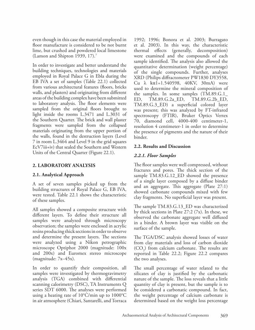
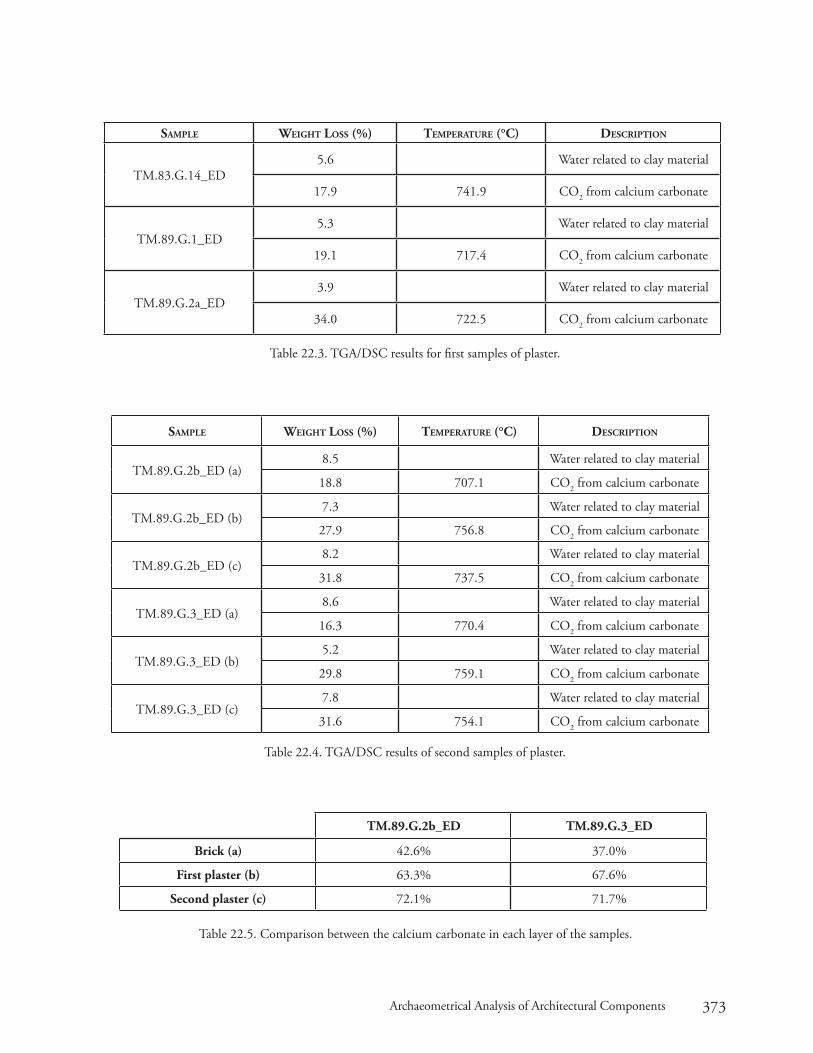
in order to investigate and better understand the building techniques, technologies and materials employed in Royal palace G in ebla during the eb iVa a set of samples (table 22.1) collected from various architectural features (floors, bricks walls, and plasters) and originating from different areas of the building complex have been submitted to laboratory analysis. The floor elements were sampled from the original floors brought to light inside the rooms l.3471 and l.3031 of the southern Quarter. The brick and wall plaster fragments were sampled from the collapsed materials originating from the upper portion of the walls, found in the destruction layers (level 7 in room l.3464 and level 9 in the grid squares ecV7iii+iv) that sealed the southern and Western Units of the central Quarter (Figure 22.1).
2. laboratory analysis
2.1. analytical approach
a set of seven samples picked up from the building structures of Royal palace G, eb iVa, were tested. table 22.1 shows the characteristic of these samples.
all samples showed a composite structure with different layers. to define their structure all samples were analyzed through microscopy observation; the samples were enclosed in acrylic resins producing thick sections in order to observe and determine the present layers. The sections were analyzed using a nikon petrographic microscope Optiphot 2000 (magnitude: 100x and 200x) and euromex stereo microscope (magnitude: 7x–45x).
in order to quantify their composition, all samples were investigated by thermogravimetry analysis (tGa) combined with differential scanning calorimetry (dsc), ta instruments Q series sdt 6000. The analyses were performed using a heating rate of 10°c/min up to 1000°c in air atmosphere (chiari, santarelli, and torraca
1992; 1996; bonora et al. 2003; burragato et al. 2003). in this way, the characteristic thermal effects (generally, decomposition) were examined and the compounds of each sample identified. The analysis also allowed the quantitative determination (weight percentage) of the single compounds. Further, analyses XRd (philips diffractometer pW1830 dY3558, cu λ kα1=1.540598, 40KV, 30ma) were used to determine the mineral composition of the samples. in some samples (tM.89.G.1_ed, tM.89.G.2a_ed, tM.89.G.2b_ed, tM.89.G.3_ed) a superficial colored layer was present; this was analyzed by Ft-infrared spectroscopy (FtiR), bruker Optics Vertex 70, diamond cell, 4000-400 centimeter-1, resolution 4 centimeter-1 in order to determine the presence of pigments and the nature of their binder.
2.2. results and discussion
2.2.1. Floor Samples
The floor samples were well compressed, without fractures and pores. The thick section of the sample tM.83.G.12_ed showed the presence of a single layer composed by a diffuse binder and an aggregate. This aggregate (plate 27:1) showed carbonate compounds mixed with few clay fragments. no superficial layer was present.
The sample tM.83.G.13_ed was characterized by thick sections in plate 27:2 (7x). in these, we observed the carbonate aggregate well diffused in a binder. a brown layer was visible on the surface of the sample.
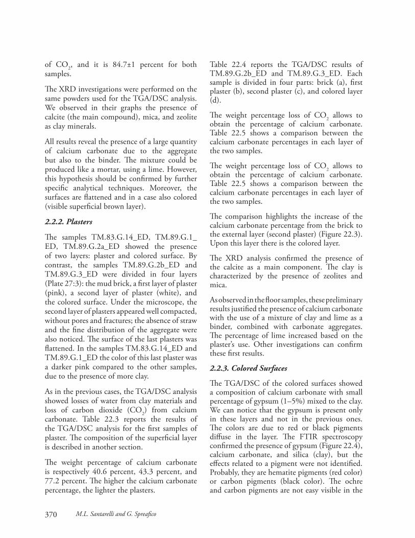
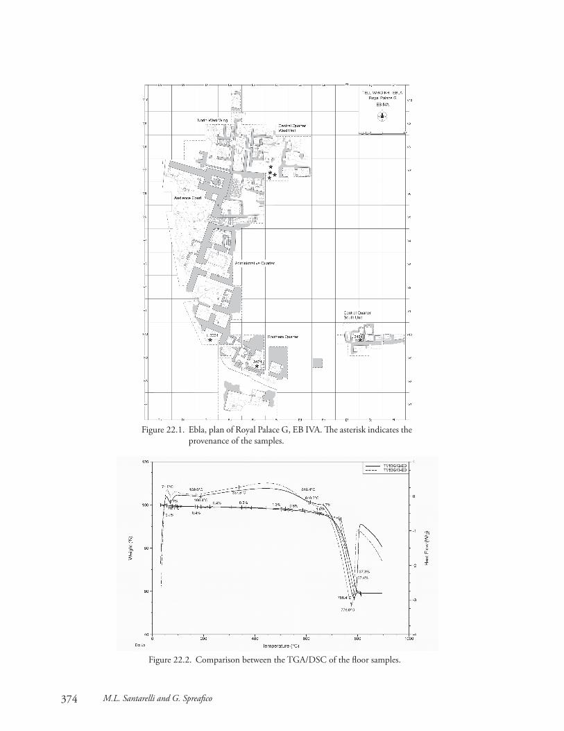
The tGa/dsc analysis showed losses of water from clay materials and loss of carbon dioxide (cO2) from calcium carbonate. The results are reported in table 22.2; Figure 22.2 compares the two analyses.
The small percentage of water related to the silicates of clay is justified by the carbonatic nature of the sample. The loss reveals that a little quantity of clay is present, but the sample is to be considered a carbonatic compound. in fact, the weight percentage of calcium carbonate is determined based on the weight loss percentage
370 M.L. Santarelli and G. Spreafico
of cO2, and it is 84.7±1 percent for both samples.
The XRd investigations were performed on the same powders used for the tGa/dsc analysis. We observed in their graphs the presence of calcite (the main compound), mica, and zeolite as clay minerals.
all results reveal the presence of a large quantity of calcium carbonate due to the aggregate but also to the binder. The mixture could be produced like a mortar, using a lime. However, this hypothesis should be confirmed by further specific analytical techniques. Moreover, the surfaces are flattened and in a case also colored (visible superficial brown layer).
2.2.2. Plasters
The samples tM.83.G.14_ed, tM.89.G.1_ed, tM.89.G.2a_ed showed the presence of two layers: plaster and colored surface. by contrast, the samples tM.89.G.2b_ed and tM.89.G.3_ed were divided in four layers (plate 27:3): the mud brick, a first layer of plaster (pink), a second layer of plaster (white), and the colored surface. Under the microscope, the second layer of plasters appeared well compacted, without pores and fractures; the absence of straw and the fine distribution of the aggregate were also noticed. The surface of the last plasters was flattened. in the samples tM.83.G.14_ed and tM.89.G.1_ed the color of this last plaster was a darker pink compared to the other samples, due to the presence of more clay.
as in the previous cases, the tGa/dsc analysis showed losses of water from clay materials and loss of carbon dioxide (cO2) from calcium carbonate. table 22.3 reports the results of the tGa/dsc analysis for the first samples of plaster. The composition of the superficial layer is described in another section.
The weight percentage of calcium carbonate is respectively 40.6 percent, 43.3 percent, and 77.2 percent. The higher the calcium carbonate percentage, the lighter the plasters.
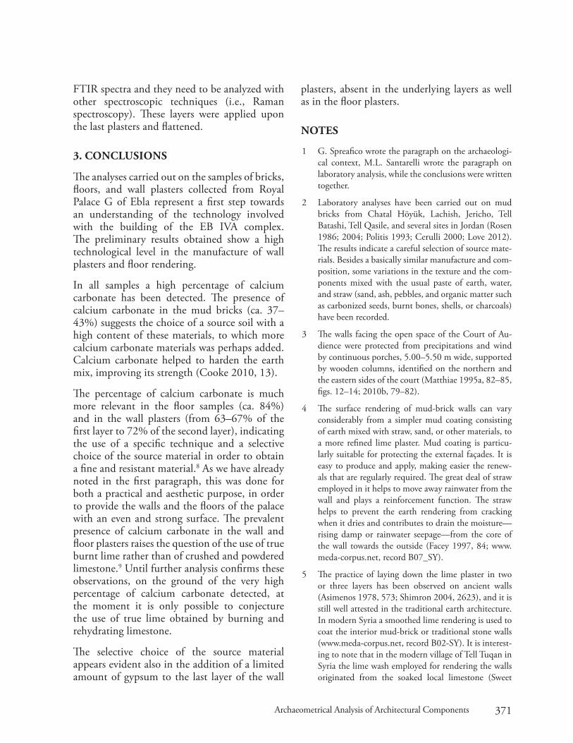
table 22.4 reports the tGa/dsc results of tM.89.G.2b_ed and tM.89.G.3_ed. each sample is divided in four parts: brick (a), first plaster (b), second plaster (c), and colored layer (d).
The weight percentage loss of cO2 allows to obtain the percentage of calcium carbonate. table 22.5 shows a comparison between the calcium carbonate percentages in each layer of the two samples.
The weight percentage loss of cO2 allows to obtain the percentage of calcium carbonate. table 22.5 shows a comparison between the calcium carbonate percentages in each layer of the two samples.
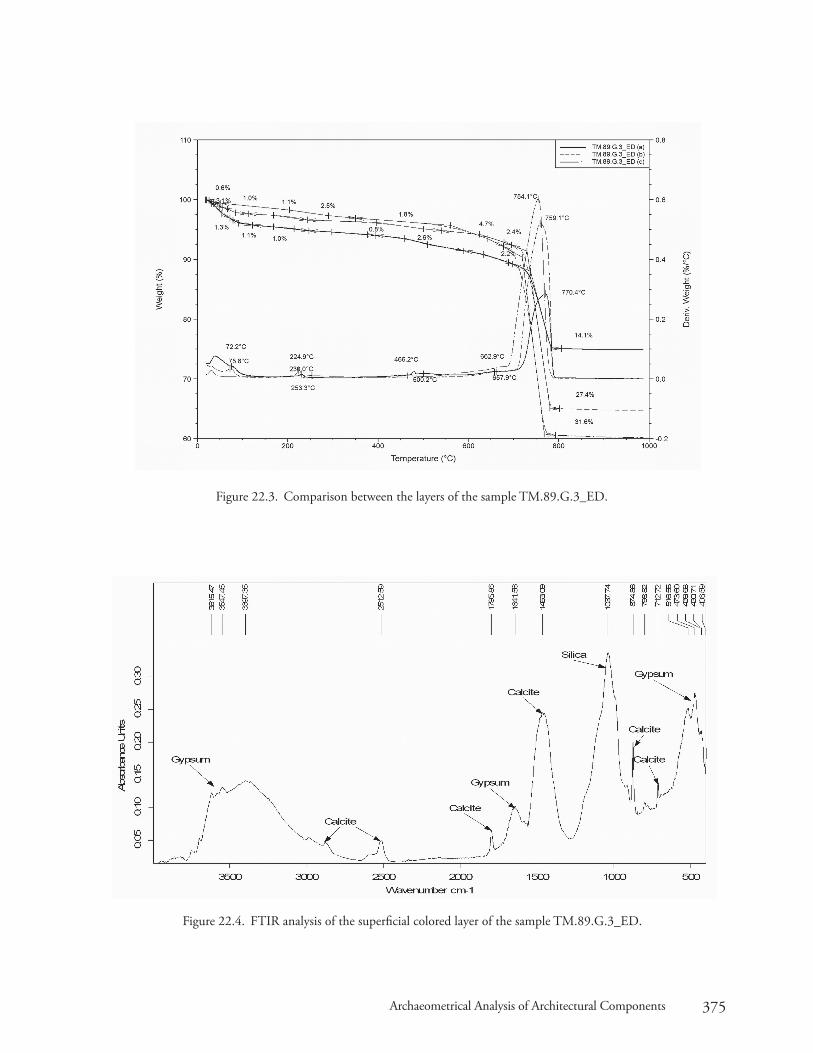
The comparison highlights the increase of the calcium carbonate percentage from the brick to the external layer (second plaster) (Figure 22.3). Upon this layer there is the colored layer.
The XRd analysis confirmed the presence of the calcite as a main component. The clay is characterized by the presence of zeolites and mica.
as observed in the floor samples, these preliminary results justified the presence of calcium carbonate with the use of a mixture of clay and lime as a binder, combined with carbonate aggregates. The percentage of lime increased based on the plaster’s use. Other investigations can confirm these first results.
2.2.3. Colored Surfaces
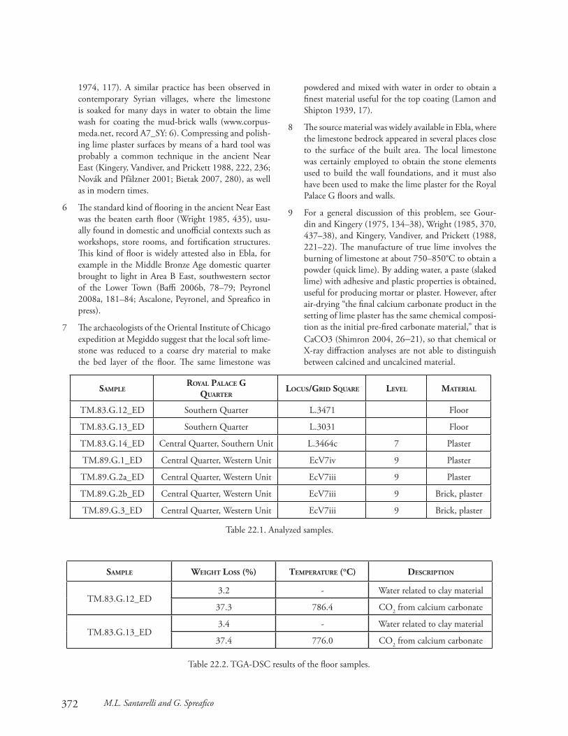
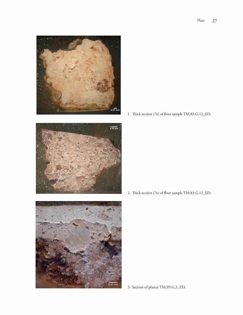
The tGa/dsc of the colored surfaces showed a composition of calcium carbonate with small percentage of gypsum (1–5%) mixed to the clay. We can notice that the gypsum is present only in these layers and not in the previous ones. The colors are due to red or black pigments diffuse in the layer. The FtiR spectroscopy confirmed the presence of gypsum (Figure 22.4), calcium carbonate, and silica (clay), but the effects related to a pigment were not identified. probably, they are hematite pigments (red color) or carbon pigments (black color). The ochre and carbon pigments are not easy visible in the
371Archaeometrical Analysis of Architectural Components
FtiR spectra and they need to be analyzed with other spectroscopic techniques (i.e., Raman spectroscopy). These layers were applied upon the last plasters and flattened.
3. conclusions
The analyses carried out on the samples of bricks, floors, and wall plasters collected from Royal palace G of ebla represent a first step towards an understanding of the technology involved with the building of the eb iVa complex. The preliminary results obtained show a high technological level in the manufacture of wall plasters and floor rendering.
in all samples a high percentage of calcium carbonate has been detected. The presence of calcium carbonate in the mud bricks (ca. 37–43%) suggests the choice of a source soil with a high content of these materials, to which more calcium carbonate materials was perhaps added. calcium carbonate helped to harden the earth mix, improving its strength (cooke 2010, 13).
The percentage of calcium carbonate is much more relevant in the floor samples (ca. 84%) and in the wall plasters (from 63–67% of the first layer to 72% of the second layer), indicating the use of a specific technique and a selective choice of the source material in order to obtain a fine and resistant material.8 as we have already noted in the first paragraph, this was done for both a practical and aesthetic purpose, in order to provide the walls and the floors of the palace with an even and strong surface. The prevalent presence of calcium carbonate in the wall and floor plasters raises the question of the use of true burnt lime rather than of crushed and powdered limestone.9 Until further analysis confirms these observations, on the ground of the very high percentage of calcium carbonate detected, at the moment it is only possible to conjecture the use of true lime obtained by burning and rehydrating limestone.
The selective choice of the source material appears evident also in the addition of a limited amount of gypsum to the last layer of the wall
plasters, absent in the underlying layers as well as in the floor plasters.
notes
1 G. spreafico wrote the paragraph on the archaeologi-cal context, M.l. santarelli wrote the paragraph on laboratory analysis, while the conclusions were written together.
2 laboratory analyses have been carried out on mud bricks from chatal Höyük, lachish, Jericho, tell batashi, tell Qasile, and several sites in Jordan (Rosen 1986; 2004; politis 1993; cerulli 2000; love 2012). The results indicate a careful selection of source mate-rials. besides a basically similar manufacture and com-position, some variations in the texture and the com-ponents mixed with the usual paste of earth, water, and straw (sand, ash, pebbles, and organic matter such as carbonized seeds, burnt bones, shells, or charcoals) have been recorded.
3 The walls facing the open space of the court of au-dience were protected from precipitations and wind by continuous porches, 5.00–5.50 m wide, supported by wooden columns, identified on the northern and the eastern sides of the court (Matthiae 1995a, 82–85, figs. 12–14; 2010b, 79–82).
4 The surface rendering of mud-brick walls can vary considerably from a simpler mud coating consisting of earth mixed with straw, sand, or other materials, to a more refined lime plaster. Mud coating is particu-larly suitable for protecting the external façades. it is easy to produce and apply, making easier the renew-als that are regularly required. The great deal of straw employed in it helps to move away rainwater from the wall and plays a reinforcement function. The straw helps to prevent the earth rendering from cracking when it dries and contributes to drain the moisture—rising damp or rainwater seepage—from the core of the wall towards the outside (Facey 1997, 84; www.meda-corpus.net, record b07_sY).
5 The practice of laying down the lime plaster in two or three layers has been observed on ancient walls (asimenos 1978, 573; shimron 2004, 2623), and it is still well attested in the traditional earth architecture. in modern syria a smoothed lime rendering is used to coat the interior mud-brick or traditional stone walls (www.meda-corpus.net, record b02-sY). it is interest-ing to note that in the modern village of tell tuqan in syria the lime wash employed for rendering the walls originated from the soaked local limestone (sweet
372 M.L. Santarelli and G. Spreafico
1974, 117). a similar practice has been observed in contemporary syrian villages, where the limestone is soaked for many days in water to obtain the lime wash for coating the mud-brick walls (www.corpus-meda.net, record a7_sY: 6). compressing and polish-ing lime plaster surfaces by means of a hard tool was probably a common technique in the ancient near east (Kingery, Vandiver, and prickett 1988, 222, 236; novák and pfälzner 2001; bietak 2007, 280), as well as in modern times.
6 The standard kind of flooring in the ancient near east was the beaten earth floor (Wright 1985, 435), usu-ally found in domestic and unofficial contexts such as workshops, store rooms, and fortification structures. This kind of floor is widely attested also in ebla, for example in the Middle bronze age domestic quarter brought to light in area b east, southwestern sector of the lower town (baffi 2006b, 78–79; peyronel 2008a, 181–84; ascalone, peyronel, and spreafico in press).
7 The archaeologists of the Oriental institute of chicago expedition at Megiddo suggest that the local soft lime-stone was reduced to a coarse dry material to make the bed layer of the floor. The same limestone was
powdered and mixed with water in order to obtain a finest material useful for the top coating (lamon and shipton 1939, 17).
8 The source material was widely available in ebla, where the limestone bedrock appeared in several places close to the surface of the built area. The local limestone was certainly employed to obtain the stone elements used to build the wall foundations, and it must also have been used to make the lime plaster for the Royal palace G floors and walls.
9 For a general discussion of this problem, see Gour-din and Kingery (1975, 134–38), Wright (1985, 370, 437–38), and Kingery, Vandiver, and prickett (1988, 221–22). The manufacture of true lime involves the burning of limestone at about 750–850°c to obtain a powder (quick lime). by adding water, a paste (slaked lime) with adhesive and plastic properties is obtained, useful for producing mortar or plaster. However, after air-drying “the final calcium carbonate product in the setting of lime plaster has the same chemical composi-tion as the initial pre-fired carbonate material,” that is cacO3 (shimron 2004, 26–21), so that chemical or X-ray diffraction analyses are not able to distinguish between calcined and uncalcined material.
SaMPleroyal Palace g
quarterlocuS/grid Square level Material
tM.83.G.12_ed southern Quarter l.3471 Floor
tM.83.G.13_ed southern Quarter l.3031 Floor
tM.83.G.14_ed central Quarter, southern Unit l.3464c 7 plaster
tM.89.G.1_ed central Quarter, Western Unit ecV7iv 9 plaster
tM.89.G.2a_ed central Quarter, Western Unit ecV7iii 9 plaster
tM.89.G.2b_ed central Quarter, Western Unit ecV7iii 9 brick, plaster
tM.89.G.3_ed central Quarter, Western Unit ecV7iii 9 brick, plaster
table 22.1. analyzed samples.
SaMPle weight loSS (%) teMPerature (°c) deScriPtion
tM.83.G.12_ed3.2 - Water related to clay material
37.3 786.4 cO2 from calcium carbonate
tM.83.G.13_ed3.4 - Water related to clay material
37.4 776.0 cO2 from calcium carbonate
table 22.2. tGa-dsc results of the floor samples.
373Archaeometrical Analysis of Architectural Components
SaMPle weight loSS (%) teMPerature (°c) deScriPtion
tM.83.G.14_ed5.6 Water related to clay material
17.9 741.9 cO2 from calcium carbonate
tM.89.G.1_ed5.3 Water related to clay material
19.1 717.4 cO2 from calcium carbonate
tM.89.G.2a_ed3.9 Water related to clay material
34.0 722.5 cO2 from calcium carbonate
table 22.3. tGa/dsc results for first samples of plaster.
SaMPle weight loSS (%) teMPerature (°c) deScriPtion
tM.89.G.2b_ed (a)8.5 Water related to clay material
18.8 707.1 cO2 from calcium carbonate
tM.89.G.2b_ed (b)7.3 Water related to clay material
27.9 756.8 cO2 from calcium carbonate
tM.89.G.2b_ed (c)8.2 Water related to clay material
31.8 737.5 cO2 from calcium carbonate
tM.89.G.3_ed (a)8.6 Water related to clay material
16.3 770.4 cO2 from calcium carbonate
tM.89.G.3_ed (b)5.2 Water related to clay material
29.8 759.1 cO2 from calcium carbonate
tM.89.G.3_ed (c)7.8 Water related to clay material
31.6 754.1 cO2 from calcium carbonate
table 22.4. tGa/dsc results of second samples of plaster.
table 22.5. comparison between the calcium carbonate in each layer of the samples.
tM.89.g.2b_ed tM.89.g.3_ed
brick (a) 42.6% 37.0%
first plaster (b) 63.3% 67.6%
second plaster (c) 72.1% 71.7%
374 M.L. Santarelli and G. Spreafico
Figure 22.2. comparison between the tGa/dsc of the floor samples.
Figure 22.1. ebla, plan of Royal palace G, eb iVa. The asterisk indicates the provenance of the samples.
375Archaeometrical Analysis of Architectural Components
Figure 22.4. FtiR analysis of the superficial colored layer of the sample tM.89.G.3_ed.
Figure 22.3. comparison between the layers of the sample tM.89.G.3_ed.
27Plate
1. Thick section (7x) of floor sample tM.83.G.12_ed.
2. Thick section (7x) of floor sample tM.83.G.13_ed.
3. section of plaster tM.89.G.3_ed.


