Embed Size (px)
Citation preview
ARCHITECTURAL EXPRESSION OF SEISMIC STRENGTHENING
(Published in Earthquake Spectra, Vol. 17, No. 3, 2002, pp. 417-426.)
Andrew Charleson, Julieanna Preston and Mark Taylor
Corresponding (first) author: Andrew Charleson
Mailing address: School of Architecture Victoria University of Wellington P O Box 600 Wellington New Zealand
Phone: +64 4 463 6222
Fax: +64 4 463 6204
E-mail address: [email protected]
Submission date for review copies:
Submission date for camera-ready copy:
Architectural Expression of Seismic Strengthening
Andrew Charleson1, Julieanna Preston2 and Mark Taylor1
Current seismic strengthening approaches to historic buildings place emphasis upon concealing engineering technologies. This study investigates, through a process of architectural and structural engineering design, the architectural possibilities inherent in a completely different approach. Recognising both conservation concerns and the architectural qualities of two existing earthquake prone buildings, the study explores seismic strengthening strategies that are exposed to view in order to contribute, in both a physical and aesthetic sense, a layer of architectural richness. A 1960s eight storey reinforced concrete office building and a three storey unreinforced masonry building are the subject of theoretical seismic strengthening schemes. The paper describes the buildings, the strengthening approaches from both architectural and structural engineering perspectives, and comments on the outcome with respect to conservation guidelines. Although the proposed schemes challenge some sections of the guidelines, the authors believe the exposed structure enhances the existing architecture, and in so doing suggests an alternative approach for seismic retrofitting.
INTRODUCTION
Both in New Zealand and internationally, the most common architectural approach to seismic retrofitting of historic buildings involves concealment of new structure. The underlying presumption is that the building appearance should not be changed. However, for less meritorious buildings, at least in New Zealand, the prevailing attitude is that strengthening should be done for the least possible cost. New structure is therefore often exposed without any refinement in detailing, or concerns about any other detrimental architectural impacts it might have. Often the aesthetic quality of engineering detailing can be improved considerably. The impression is of a functional, economical engineered approach, with little architectural input. This does not rule out the acceptability of a purely structural approach in the case of strengthening industrial structures or other buildings where work is concealed. In many situations however, although a building owner might benefit financially in the short term from the cheapest option, missed aesthetic opportunities may be regretted later.
This study challenges these contrasting approaches by investigating the possibility of deliberately expressing strengthening structure so as to make a new and positive architectural contribution to an existing building. A US National Park Publication (Look et al, 1999) suggests such a possibility in a discussion of the potential intrusiveness of seismic strengthening: “However, structural reinforcement can be introduced sensitively. In such
1 School of Architecture, Victoria University of Wellington 2 University of Arkansas, Arkansas
cases, its design, placement, patterning, and detailing should respect the historic character of the building, even when the reinforcement itself is visible.” Some designers might interpret “respect” as meaning to imitate or conform as closely as possible to historic character, but this research questions that approach. It proposes that exposed strengthening can offer a critical insight to the existing building in a way that contributes aesthetically.
The research-by-design methodology at the basis of this paper can be considered architecturally equivalent to research approaches common in the field of structural engineering. Some research papers, particularly in the field of earthquake engineering, describe a process where real or theoretical structural designs are mathematically modelled and subjected to various computer analyses, usually involving earthquake time histories. Analytical findings from such research have contributed enormously to earthquake engineering knowledge and are the basis of most code requirements. In this study, structural design is not followed by a numerical analysis, but by architectural critique and review undertaken after each design move. Review involves aesthetic and theoretical judgements made in relation to structural necessities and possibilities.
Structural strengthening may be expressed for a variety of reasons. Designers may wish to raise awareness of the structural limitations of existing construction in order to dispel the myth of ‘constructional survivability’ (Charleson and Taylor, 1997). They may wish to increase the possibility of interventions being reversed at a later date (Look et al, 1999), or to merely celebrate seismic strengthening technology.
A lack of awareness of these issues, at least in New Zealand, may be due to a lack of published discussion. The two primary engineering resource documents (New Zealand National Society for Earthquake Engineering, 1985 and 1996) focus entirely on technical requirements. The ICOMOS New Zealand Charter (1993) provides some guidelines, but these are quite general in nature. Fortunately, they have been recently supplemented by a New Zealand Historic Places Trust/Pouhere Taonga document (Robinson and Bowman, 2000) that emphasizes the importance of architectural conservation skills in treating historic buildings.
In order to test an approach to retrofitting where strengthening structure is expressed, the authors chose two Wellington buildings as case studies. A number of potentially earthquake-prone buildings were identified, ranging from between thirty-seven and ninety years old, each of varying degrees of cultural significance or location prominence. One building distinguished itself from the rest, not by its intrinsic value as a notable piece of city architecture, but by its building construction process and its apparent structural fragility. Although its lift-slab construction technique is most uncommon in New Zealand, this eight storey building is representative of many multistorey reinforced concrete buildings constructed prior to modern ductile design and detailing requirements. A second building, Turnbull House, of unreinforced masonry construction was chosen for its historical value, public appeal and prominent location.
PRE-1976 BUILDING
BUILDING DESCRIPTION
The building, named the Pre-1976 Building for the purposes of this paper, occupies a corner site in an area of the city where medium-rise office buildings of the Central Business District reduce in scale to two and three storey small office and retail buildings. Eight storeys
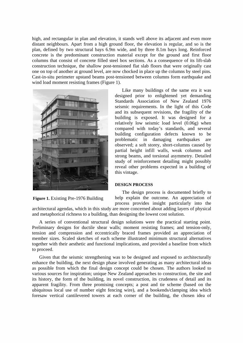
high, and rectangular in plan and elevation, it stands well above its adjacent and even more distant neighbours. Apart from a high ground floor, the elevation is regular, and so is the plan, defined by two structural bays 6.9m wide, and by three 8.1m bays long. Reinforced concrete is the predominant construction material except for the ground and first floor columns that consist of concrete filled steel box sections. As a consequence of its lift-slab construction technique, the shallow post-tensioned flat slab floors that were originally cast one on top of another at ground level, are now chocked in place up the columns by steel pins. Cast-in-situ perimeter upstand beams post-tensioned between columns form earthquake and wind load moment resisting frames (Figure 1).
Like many buildings of the same era it was designed prior to enlightened yet demanding Standards Association of New Zealand 1976 seismic requirements. In the light of this Code and its subsequent revisions, the fragility of the building is exposed. It was designed for a relatively low seismic load level (0.06g) when compared with today’s standards, and several building configuration defects known to be problematic in damaging earthquakes are observed; a soft storey, short-columns caused by partial height infill walls, weak columns and strong beams, and torsional asymmetry. Detailed study of reinforcement detailing might possibly reveal other problems expected in a building of this vintage.
DESIGN PROCESS
The design process is documented briefly to help explain the outcome. An appreciation of process provides insight particularly into the
architectural agendas, which in this study are more concerned about adding layers of physical and metaphorical richness to a building, than designing the lowest cost solution.
A series of conventional structural design solutions were the practical starting point. Preliminary designs for ductile shear walls; moment resisting frames; and tension-only, tension and compression and eccentrically braced frames provided an appreciation of member sizes. Scaled sketches of each scheme illustrated minimum structural alternatives together with their aesthetic and functional implications, and provided a baseline from which to proceed.
Given that the seismic strengthening was to be designed and exposed to architecturally enhance the building, the next design phase involved generating as many architectural ideas as possible from which the final design concept could be chosen. The authors looked to various sources for inspiration; unique New Zealand approaches to construction, the site and its history, the form of the building, its novel construction, its crudeness of detail and its apparent fragility. From three promising concepts; a post and tie scheme (based on the ubiquitous local use of number eight fencing wire), and a bookends/clamping idea which foresaw vertical cantilevered towers at each corner of the building, the chosen idea of
Figure 1. Existing Pre-1976 Building
propping and shoring emerged. This idea provided an opportunity to inject New Zealand character into the design and to transform existing fragility into resilience and strength.
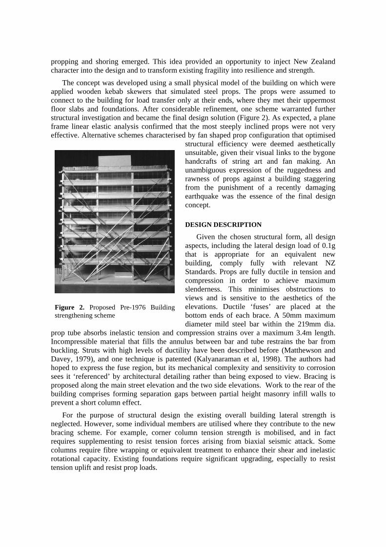
The concept was developed using a small physical model of the building on which were applied wooden kebab skewers that simulated steel props. The props were assumed to connect to the building for load transfer only at their ends, where they met their uppermost floor slabs and foundations. After considerable refinement, one scheme warranted further structural investigation and became the final design solution (Figure 2). As expected, a plane frame linear elastic analysis confirmed that the most steeply inclined props were not very effective. Alternative schemes characterised by fan shaped prop configuration that optimised
structural efficiency were deemed aesthetically unsuitable, given their visual links to the bygone handcrafts of string art and fan making. An unambiguous expression of the ruggedness and rawness of props against a building staggering from the punishment of a recently damaging earthquake was the essence of the final design concept.
DESIGN DESCRIPTION
Given the chosen structural form, all design aspects, including the lateral design load of 0.1g that is appropriate for an equivalent new building, comply fully with relevant NZ Standards. Props are fully ductile in tension and compression in order to achieve maximum slenderness. This minimises obstructions to views and is sensitive to the aesthetics of the elevations. Ductile ‘fuses’ are placed at the bottom ends of each brace. A 50mm maximum diameter mild steel bar within the 219mm dia.
prop tube absorbs inelastic tension and compression strains over a maximum 3.4m length. Incompressible material that fills the annulus between bar and tube restrains the bar from buckling. Struts with high levels of ductility have been described before (Matthewson and Davey, 1979), and one technique is patented (Kalyanaraman et al, 1998). The authors had hoped to express the fuse region, but its mechanical complexity and sensitivity to corrosion sees it ‘referenced’ by architectural detailing rather than being exposed to view. Bracing is proposed along the main street elevation and the two side elevations. Work to the rear of the building comprises forming separation gaps between partial height masonry infill walls to prevent a short column effect.
For the purpose of structural design the existing overall building lateral strength is neglected. However, some individual members are utilised where they contribute to the new bracing scheme. For example, corner column tension strength is mobilised, and in fact requires supplementing to resist tension forces arising from biaxial seismic attack. Some columns require fibre wrapping or equivalent treatment to enhance their shear and inelastic rotational capacity. Existing foundations require significant upgrading, especially to resist tension uplift and resist prop loads.
Figure 2. Proposed Pre-1976 Building strengthening scheme
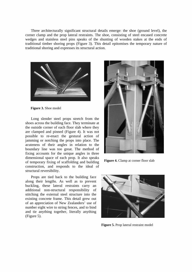
Three architecturally significant structural details emerge: the shoe (ground level), the corner clamp and the prop lateral restraints. The shoe, consisting of steel encased concrete wedges and stainless steel pins speaks of the shunting of wooden stakes at the ends of traditional timber shoring props (Figure 3). This detail epitomises the temporary nature of traditional shoring and expresses its structural action.
Long slender steel props stretch from the shoes across the building face. They terminate at the outside corner of each floor slab where they are clamped and pinned (Figure 4). It was not possible to re-enact the gestural action of jamming or notching the props into place. The acuteness of their angles in relation to the boundary line was too great. The method of fixing accounts for the unique angles in three dimensional space of each prop. It also speaks of temporary fixing of scaffolding and building construction, and responds to the ideal of structural reversibility.
Props are tied back to the building face along their lengths. As well as to prevent buckling, these lateral restraints carry an additional non-structural responsibility of stitching the external steel structure into the existing concrete frame. This detail grew out of an appreciation of New Zealanders’ use of number eight wire to string fences, and to bind and tie anything together, literally anything (Figure 5).
Figure 3. Shoe model
Figure 4. Clamp at corner floor slab
Figure 5. Prop lateral restraint model
TURNBULL HOUSE
BUILDING DESCRIPTION
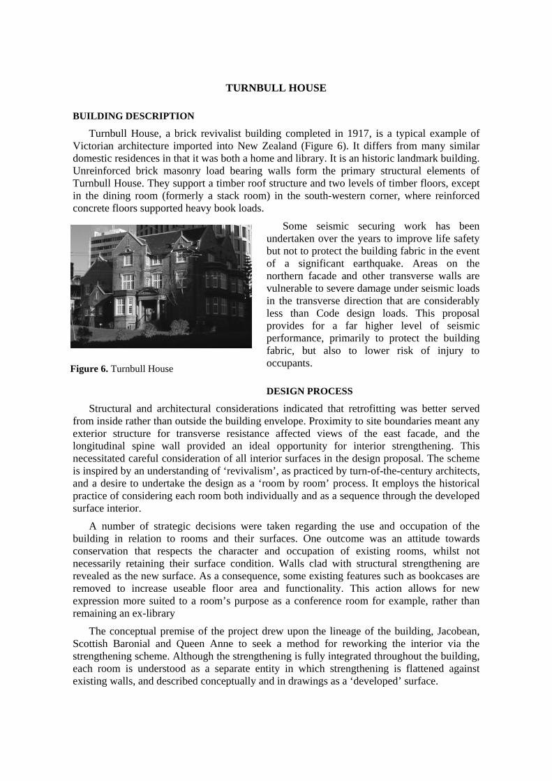
Turnbull House, a brick revivalist building completed in 1917, is a typical example of Victorian architecture imported into New Zealand (Figure 6). It differs from many similar domestic residences in that it was both a home and library. It is an historic landmark building. Unreinforced brick masonry load bearing walls form the primary structural elements of Turnbull House. They support a timber roof structure and two levels of timber floors, except in the dining room (formerly a stack room) in the south-western corner, where reinforced concrete floors supported heavy book loads.
Some seismic securing work has been undertaken over the years to improve life safety but not to protect the building fabric in the event of a significant earthquake. Areas on the northern facade and other transverse walls are vulnerable to severe damage under seismic loads in the transverse direction that are considerably less than Code design loads. This proposal provides for a far higher level of seismic performance, primarily to protect the building fabric, but also to lower risk of injury to occupants.
DESIGN PROCESS
Structural and architectural considerations indicated that retrofitting was better served from inside rather than outside the building envelope. Proximity to site boundaries meant any exterior structure for transverse resistance affected views of the east facade, and the longitudinal spine wall provided an ideal opportunity for interior strengthening. This necessitated careful consideration of all interior surfaces in the design proposal. The scheme is inspired by an understanding of ‘revivalism’, as practiced by turn-of-the-century architects, and a desire to undertake the design as a ‘room by room’ process. It employs the historical practice of considering each room both individually and as a sequence through the developed surface interior.
A number of strategic decisions were taken regarding the use and occupation of the building in relation to rooms and their surfaces. One outcome was an attitude towards conservation that respects the character and occupation of existing rooms, whilst not necessarily retaining their surface condition. Walls clad with structural strengthening are revealed as the new surface. As a consequence, some existing features such as bookcases are removed to increase useable floor area and functionality. This action allows for new expression more suited to a room’s purpose as a conference room for example, rather than remaining an ex-library
The conceptual premise of the project drew upon the lineage of the building, Jacobean, Scottish Baronial and Queen Anne to seek a method for reworking the interior via the strengthening scheme. Although the strengthening is fully integrated throughout the building, each room is understood as a separate entity in which strengthening is flattened against existing walls, and described conceptually and in drawings as a ‘developed’ surface.
Figure 6. Turnbull House
STRENGTHENING SCHEME
In accordance with the New Zealand National Society for Earthquake Engineering retrofitting guidelines, the scheme adopts a strengthening level (0.4g) that is equivalent to 67% of Code requirements for a new building. At this load level the new structure, designed to resist all seismic load elastically, restricts the horizontal deflection of the building to 30mm at eaves level, 10m above ground, to minimise brickwork damage.
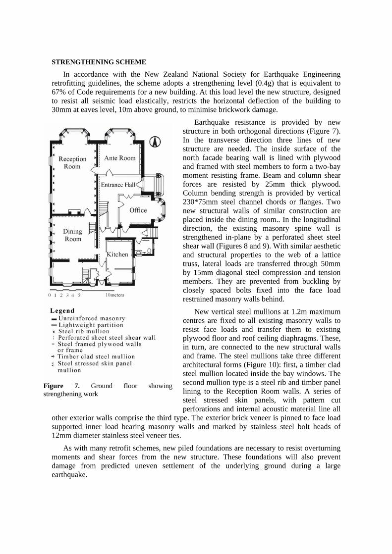
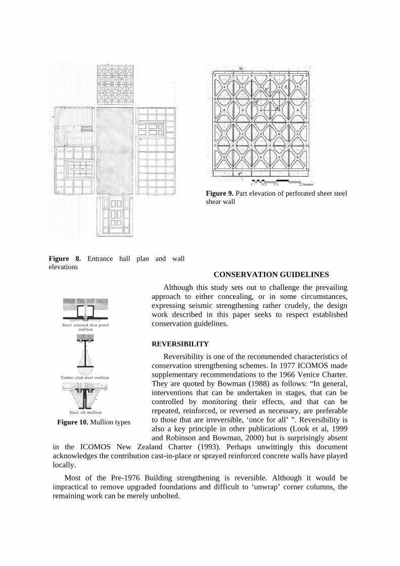
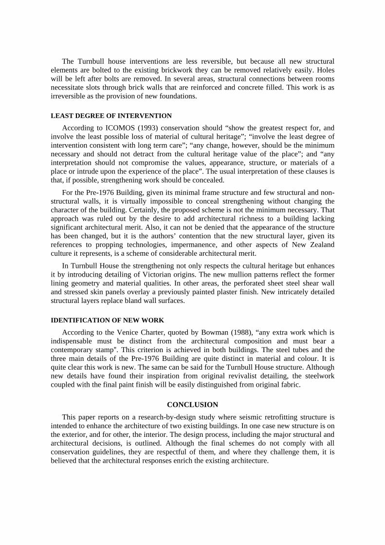
Earthquake resistance is provided by new structure in both orthogonal directions (Figure 7). In the transverse direction three lines of new structure are needed. The inside surface of the north facade bearing wall is lined with plywood and framed with steel members to form a two-bay moment resisting frame. Beam and column shear forces are resisted by 25mm thick plywood. Column bending strength is provided by vertical 230*75mm steel channel chords or flanges. Two new structural walls of similar construction are placed inside the dining room.. In the longitudinal direction, the existing masonry spine wall is strengthened in-plane by a perforated sheet steel shear wall (Figures 8 and 9). With similar aesthetic and structural properties to the web of a lattice truss, lateral loads are transferred through 50mm by 15mm diagonal steel compression and tension members. They are prevented from buckling by closely spaced bolts fixed into the face load restrained masonry walls behind.
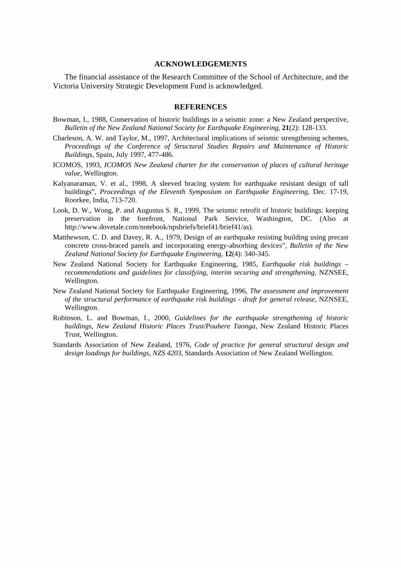
New vertical steel mullions at 1.2m maximum centres are fixed to all existing masonry walls to resist face loads and transfer them to existing plywood floor and roof ceiling diaphragms. These, in turn, are connected to the new structural walls and frame. The steel mullions take three different architectural forms (Figure 10): first, a timber clad steel mullion located inside the bay windows. The second mullion type is a steel rib and timber panel lining to the Reception Room walls. A series of steel stressed skin panels, with pattern cut perforations and internal acoustic material line all
other exterior walls comprise the third type. The exterior brick veneer is pinned to face load supported inner load bearing masonry walls and marked by stainless steel bolt heads of 12mm diameter stainless steel veneer ties.
As with many retrofit schemes, new piled foundations are necessary to resist overturning moments and shear forces from the new structure. These foundations will also prevent damage from predicted uneven settlement of the underlying ground during a large earthquake.
Figure 7. Ground floor showing strengthening work
CONSERVATION GUIDELINES
Although this study sets out to challenge the prevailing approach to either concealing, or in some circumstances, expressing seismic strengthening rather crudely, the design work described in this paper seeks to respect established conservation guidelines.
REVERSIBILITY
Reversibility is one of the recommended characteristics of conservation strengthening schemes. In 1977 ICOMOS made supplementary recommendations to the 1966 Venice Charter. They are quoted by Bowman (1988) as follows: “In general, interventions that can be undertaken in stages, that can be controlled by monitoring their effects, and that can be repeated, reinforced, or reversed as necessary, are preferable to those that are irreversible, ‘once for all’ ”. Reversibility is also a key principle in other publications (Look et al, 1999 and Robinson and Bowman, 2000) but is surprisingly absent
in the ICOMOS New Zealand Charter (1993). Perhaps unwittingly this document acknowledges the contribution cast-in-place or sprayed reinforced concrete walls have played locally.
Most of the Pre-1976 Building strengthening is reversible. Although it would be impractical to remove upgraded foundations and difficult to ‘unwrap’ corner columns, the remaining work can be merely unbolted.
Figure 8. Entrance hall plan and wall elevations
Figure 10. Mullion types
Figure 9. Part elevation of perforated sheet steel shear wall
The Turnbull house interventions are less reversible, but because all new structural elements are bolted to the existing brickwork they can be removed relatively easily. Holes will be left after bolts are removed. In several areas, structural connections between rooms necessitate slots through brick walls that are reinforced and concrete filled. This work is as irreversible as the provision of new foundations.
LEAST DEGREE OF INTERVENTION
According to ICOMOS (1993) conservation should “show the greatest respect for, and involve the least possible loss of material of cultural heritage”; “involve the least degree of intervention consistent with long term care”; “any change, however, should be the minimum necessary and should not detract from the cultural heritage value of the place”; and “any interpretation should not compromise the values, appearance, structure, or materials of a place or intrude upon the experience of the place”. The usual interpretation of these clauses is that, if possible, strengthening work should be concealed.
For the Pre-1976 Building, given its minimal frame structure and few structural and non-structural walls, it is virtually impossible to conceal strengthening without changing the character of the building. Certainly, the proposed scheme is not the minimum necessary. That approach was ruled out by the desire to add architectural richness to a building lacking significant architectural merit. Also, it can not be denied that the appearance of the structure has been changed, but it is the authors’ contention that the new structural layer, given its references to propping technologies, impermanence, and other aspects of New Zealand culture it represents, is a scheme of considerable architectural merit.
In Turnbull House the strengthening not only respects the cultural heritage but enhances it by introducing detailing of Victorian origins. The new mullion patterns reflect the former lining geometry and material qualities. In other areas, the perforated sheet steel shear wall and stressed skin panels overlay a previously painted plaster finish. New intricately detailed structural layers replace bland wall surfaces.
IDENTIFICATION OF NEW WORK
According to the Venice Charter, quoted by Bowman (1988), “any extra work which is indispensable must be distinct from the architectural composition and must bear a contemporary stamp@. This criterion is achieved in both buildings. The steel tubes and the three main details of the Pre-1976 Building are quite distinct in material and colour. It is quite clear this work is new. The same can be said for the Turnbull House structure. Although new details have found their inspiration from original revivalist detailing, the steelwork coupled with the final paint finish will be easily distinguished from original fabric.
CONCLUSION
This paper reports on a research-by-design study where seismic retrofitting structure is intended to enhance the architecture of two existing buildings. In one case new structure is on the exterior, and for other, the interior. The design process, including the major structural and architectural decisions, is outlined. Although the final schemes do not comply with all conservation guidelines, they are respectful of them, and where they challenge them, it is believed that the architectural responses enrich the existing architecture.
ACKNOWLEDGEMENTS
The financial assistance of the Research Committee of the School of Architecture, and the Victoria University Strategic Development Fund is acknowledged.
REFERENCES Bowman, I., 1988, Conservation of historic buildings in a seismic zone: a New Zealand perspective,
Bulletin of the New Zealand National Society for Earthquake Engineering, 21(2): 128-133. Charleson, A. W. and Taylor, M., 1997, Architectural implications of seismic strengthening schemes,
Proceedings of the Conference of Structural Studies Repairs and Maintenance of Historic Buildings, Spain, July 1997, 477-486.
ICOMOS, 1993, ICOMOS New Zealand charter for the conservation of places of cultural heritage value, Wellington.
Kalyanaraman, V. et al., 1998, A sleeved bracing system for earthquake resistant design of tall buildings”, Proceedings of the Eleventh Symposium on Earthquake Engineering, Dec. 17-19, Roorkee, India, 713-720.
Look, D. W., Wong, P. and Augustus S. R., 1999, The seismic retrofit of historic buildings: keeping preservation in the forefront, National Park Service, Washington, DC. (Also at http://www.dovetale.com/notebook/npsbriefs/brief41/brief41/as).
Matthewson, C. D. and Davey, R. A., 1979, Design of an earthquake resisting building using precast concrete cross-braced panels and incorporating energy-absorbing devices”, Bulletin of the New Zealand National Society for Earthquake Engineering, 12(4): 340-345.
New Zealand National Society for Earthquake Engineering, 1985, Earthquake risk buildings – recommendations and guidelines for classifying, interim securing and strengthening, NZNSEE, Wellington.
New Zealand National Society for Earthquake Engineering, 1996, The assessment and improvement of the structural performance of earthquake risk buildings - draft for general release, NZNSEE, Wellington.
Robinson, L. and Bowman, I., 2000, Guidelines for the earthquake strengthening of historic buildings, New Zealand Historic Places Trust/Pouhere Taonga, New Zealand Historic Places Trust, Wellington.
Standards Association of New Zealand, 1976, Code of practice for general structural design and design loadings for buildings, NZS 4203, Standards Association of New Zealand Wellington.


