Embed Size (px)
Citation preview
ARUBA VALIDATED DESIGN
ARUBA SD-BRANCH Design & Deployment Guide
August 2020
Aruba Design & Deployment Guide
Table of Contents
Document Conventions ............................................................................................................................1
Introduction ................................................................................................................................................2Purpose of This Guide ........................................................................................................................................................................................ 2
Customer Use Cases ........................................................................................................................................................................................... 4
SD-Branch Design ......................................................................................................................................5SD-Branch Architecture ..................................................................................................................................................................................... 9
Aruba SD-WAN .................................................................................................................................................................................................. 19
Aruba SD-LAN.................................................................................................................................................................................................... 34
SD-Branch Components .................................................................................................................................................................................. 38
Deploying the SD-Branch ........................................................................................................................47Aruba Central...................................................................................................................................................................................................... 48
SD-Branch Network Configuration Overview .............................................................................................................................................51
Preparing to Deploy the SD-Branch Network .............................................................................................................................................53
Configuring the VPNC Group ......................................................................................................................................................................... 59
Configuring the VPNC Devices ...................................................................................................................................................................... 78
Configuring the Branch Gateway Group—One Branch Gateway per Branch ......................................................................................92
Configuring a Branch Gateway Device—One Branch Gateway per Branch ...................................................................................... 116
Configuring the Branch Gateway Group for High Availability—Two Branch Gateways Per Branch ............................................. 123
Configuring a Branch Gateway Device—Two Branch Gateways per Branch ..................................................................................... 146
Configuring the Branch Switch UI Group .................................................................................................................................................. 164
Configuring the Device Switch UI Group .................................................................................................................................................. 171
Configuring the Branch Access Points Group ........................................................................................................................................... 174
Configuring the WLAN Access Points ........................................................................................................................................................ 184
Summary .................................................................................................................................................186
What’s New in This Version ..................................................................................................................187
Aruba Design & Deployment Guide 1
Document Conventions
Bold text indicates a command, navigational path, or a user interface element. Examples:
• the show stacking command
• Navigate to Configuration > System > General
• click Save
Italic text indicates the definition of important terminology. Example:
• Spatial streaming is a transmission technique in MIMO wireless communication
Blue text indicates a variable for which you should substitute a value appropriate for your environment. Example:
• stacking member 2 priority 250
Highlighting indicates emphasis. Example:
• ip address 10.4.20.2/22
Note Notes contain asides or tips.
Caution Cautions warn you about circumstances that could cause a failure.
Aruba Design & Deployment Guide 2
Introduction
Software-defined branch (SD-Branch) is a technology shift towards solutions that are agile, open, and cloud-in-tegrated. SD-Branch includes SD-WAN components that deliver a secure, service provider independent network with enterprise-level performance over disparate wide-area network (WAN) technologies. However, although SD-WAN solves a real IT problem, it only addresses part of the issue organizations face when dealing with distributed locations.
Organizations often roll out and operate distributed, heterogeneous networks with centralized teams. These distributed networks offer many services besides just WAN connectivity. Branch networks need wired and wireless LANs, security and policy enforcement, and of course, WAN interconnects. SD-Branch extends the concepts beyond SD-WAN to all elements in the branch, delivering a full-stack solution that includes SD-LAN and security that address all network connectivity needs.
When you are formulating the strategy for your SD-Branch rollout, Aruba recommends that you:
• Purchase as much WAN bandwidth as possible to alleviate potential bottlenecks during the busiest times of the day.
• Increase Internet bandwidth, instead of buying additional private bandwidth.
• Use cloud-based tools to simplify the configuration, operation, and management of the WAN.
PURPOSE OF THIS GUIDEThis guide covers the Aruba SD-Branch design, including reference architectures along with their associated hardware and software components. It contains an explanation of the requirements that shaped the design and the benefits it provides your organization. The guide describes a single unified infrastructure that integrates access points (APs), switches, gateways, and network management with access-control and traffic-control policies.
This guide assumes the reader has an equivalent knowledge of an Aruba Certified Mobility Associate or Aruba Certified Switching Associate.
Aruba Design & Deployment Guide 3
Design Goals
The overall goal is to create a simple, scalable design that is easy to replicate across all sites in your network. The solution components are limited to a specific set of products to help with operations and maintenance. The key features addressed by Aruba SD-Branch include:
• Simplicity with zero-touch provisioning—SD-Branch devices can be factory-shipped directly to a remote site by automatically matching orders to an Aruba customer account, and a mobile Installer app is available for third-party systems integrators to quickly install equipment. Combined with configura-tion hierarchy, which assigns APs, switches, and gateways to site-specific configurations, networks are brought up very quickly.
• Unified policy management—For Aruba and third-party network infrastructure, Aruba ClearPass de-livers a common policy framework for multivendor wired and wireless networks. This software-defined approach makes it easy for the network administrator to distribute changes quickly based on corporate risk and compliance requirements. ClearPass Device Insight (CPDI) adds AI-powered device profiling to help automate discovery of the latest mobile and IoT endpoints.
• Predictive analytics and assurance—Aruba Central’s artificial intelligence (AI), machine learning (ML), and automation capabilities identify issues and notify IT of problems while recommending changes. When you shift to a cloud-hosted model, data is collected and crowdsourced from Aruba’s large installed base while taking advantage of Aruba’s data science expertise.
• Secure WAN connectivity—Enable SD-WAN technology to support the use of the Internet to replace or augment private WAN services. Elements of the solution include path quality monitoring (PQM) to track the available paths, stateful firewall with application fingerprinting to identify traffic flows, dynamic path selection (DPS) to use the optimal path, and centralized routing to offload the branch gateways (BGWs) from participating in the routing decisions. You can also use end-user identity information when selecting the available WAN paths.
• LAN automation with dynamic segmentation—Most branch networks are needlessly complex because designs are based on a proliferation of VLANs, complex IP addressing schemes, access control lists (ACLs), and architectures that are tailored to the needs of automation software. The SD-Branch architecture seeks to flatten the branch into fewer subnets or even a single subnet, eliminating the dependence on static IP addressing schemes and hardwired ACLs across multiple devices. This is achieved by consolidating all policy enforcement into a single device in the branch.
You can use this guide to design new networks or to optimize and upgrade existing networks. It is not intended as an exhaustive discussion of all options but rather to present commonly recommended designs, features, and hardware.
Aruba Design & Deployment Guide 4
Audience
This guide is written for IT professionals who need to design an Aruba SD-Branch network. These IT profes-sionals can fill a variety of roles:
• Systems engineers who need a standard set of procedures for implementing solutions
• Project managers who create statements of work for Aruba implementations
• Aruba partners who sell technology or create implementation documentation
CUSTOMER USE CASESBranch networks are changing rapidly. The most pressing challenges include an increasing number of mobile and IoT devices, growing bandwidth requirements of the business, and modern users who expect connectivity for work and personal use from anywhere at any time. The teams that run these distributed networks are not getting any bigger and often, they are shrinking. Organizations expect new network rollouts to be complete in shorter timeframes, and IT organizations are asked to improve service levels, reduce costs, and shift spending from capital expense to operating expense.
This guide discusses the following use cases:
• Secure WAN communications using IPsec tunnels over an independent transport
• ZTP for all networking components in the branch
• Switch stacking for simplified management, high availability, and scalability
• Link aggregation for high bandwidth, redundancy, and resiliency between switches and gateways
• Wireless as the primary access method for branch employees
• Wireless and wired guest access for customers, partners, and vendors
• Consistent security for wired and wireless devices based on roles
Aruba Design & Deployment Guide 5
SD-Branch Design
This guide addresses the most common uses cases of an SD-Branch solution. If you are planning a more complex project that is not covered in this guide, contact an Aruba or partner SE/CSE for design verification. The Aruba SD-Branch design consists of the following elements:
• Aruba Central—Flexible policy, configuration, and monitoring capabilities allow an organization to sim-plify network operations by providing zero-touch provisioning and customizable templates in order to quickly deploy BGWs, switches, and APs. Aruba Central provides centralized management for historical data reports, monitoring for PCI compliance, and troubleshooting for regional and global locations. It also gives you key insights into WAN health and optimization to help IT determine the best link to send traffic to corporate data centers or to the Internet based on per-user, per-device, or per-application policies.
• Aruba ClearPass—Allows network security policies to be automatically assigned based on user or device role from a central location. This capability ensures that policies are consistent, eliminating the chance of devices having old configurations and minimizing human-introduced errors. The network identifies, authenticates, and grants trust based on the user or device role.
• Aruba headend gateways—The Aruba 7200 Series, virtual gateways, and certain Aruba 7000 Series platforms can act as headend gateways, or VPN concentrators (VPNCs), for SD-Branch designs. BGWs establish VPN tunnels to one or more VPNCs over multiple providers networks. High availability options support multiple VPNCs deployed at a single site or deployed in pairs at multiple sites for the highest availability. The VPNC supports active/standby or active/active uplinks from the branch locations.
• Aruba virtual gateways—The virtual gateway simplifies branch network deployments for organizations that are migrating to Infrastructure as a Service (IaaS) providers such as Amazon Web Services and Microsoft Azure. They provide the ability to directly connect a branch to cloud instances, improving access to the resources hosted in a public cloud. The virtual gateway supports resilient connectivity by using multiple transport links and delivers centralized policy management across the branch, data center, and cloud endpoints.
• Aruba branch gateways—The Aruba 9000 Series, 7200 Series, and 7000 Series can operate as BGWs to optimize and control WAN, LAN, and cloud security services. The BGW provides routing, firewall, security, URL filtering, and WAN optimization. With support for multiple WAN connection types, the BGW routes traffic over the most efficient link based on availability, application, user, and link health. This allows organizations to take advantage of high-speed, low-cost broadband links to supplement or replace traditional WAN links such as MPLS.
Aruba Design & Deployment Guide 6
• Aruba access switches—The Aruba 2930F, 2930M, 3810M, and 5400R family of switches connect wired devices to the branch network, such as APs, workstations, medical devices, multi-function printers, point-of-sale devices, and other devices that don’t support Wi-Fi or that do need higher performance than a wireless connection can provide. The access layer also provides PoE to devices such as APs, IP phones, and IP cameras. You can use the switches standalone or in a stacked configuration, depending on the number of ports needed at each location.
• Aruba access points—Aruba AP-5xx models are dual radio 802.11ax Wi-Fi 6 APs and the AP-3xx models are dual radio 802.11ac Wave 2 Wi-Fi 5 APs that support different throughput and client loads. With Aruba’s controllerless model called Instant, there is no central controller, and the controller functions are distributed among the APs. Instant is typically used in branch sites and scales up to 128 APs per cluster. In this type of design, you normally see less than 50 APs per cluster at each remote site.
• Aruba threat detection—Aruba’s role-based Intrusion Detection System and Intrusion Prevention System (IDPS) capabilities are available in the 9000 series gateways. Aruba IDPS allows an organization to set security policies on individual- or role-based access to branch endpoints. It analyzes data packets entering the network and acts quickly to prevent threats in real time. All identified threats are logged for correlation analysis.
You can find a complete list of Aruba Central-supported hardware in the components area at the end of this section.
Aruba Design & Deployment Guide 7
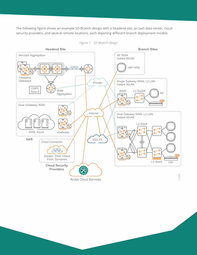
The following figure shows an example SD-Branch design with a headend site, an IaaS data center, cloud security providers, and several remote locations, each depicting different branch deployment models.
Figure 1 SD-Branch design
1129
A
Branch Sites
Aruba Cloud Services
Cloud SecurityProviders
Cloud Connector
Zscaler, PAN, CheckPoint, Symantec
AWS, Azure vGateway
IaaS
Dual vGateway WAN
AP WANInstant WLAN
IAP-VPN
Headend Site
Services Aggregation
HeadendGateways
WAN Aggregation
OSPFArea 0
Single Gateway WAN, L2 LANInstant WLAN
APL2 SwitchBGW
Dual Gateway WAN, L2 LANInstant WLAN
L2 Stack
L2 Stack UXI
Private
Internet
5G/LTE
Aruba Design & Deployment Guide 8
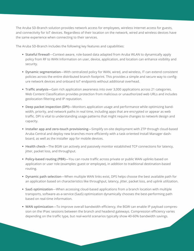
The Aruba SD-Branch solution provides network access for employees, wireless Internet access for guests, and connectivity for IoT devices. Regardless of their location on the network, wired and wireless devices have the same experience when connecting to their services.
The Aruba SD-Branch includes the following key features and capabilities:
• Stateful firewall—Context-aware, role-based data adapted from Aruba WLAN to dynamically apply policy from RF to WAN Information on user, device, application, and location can enhance visibility and security.
• Dynamic segmentation—With centralized policy for WAN, wired, and wireless, IT can extend consistent policies across the entire distributed branch footprint. This provides a simple and secure way to config-ure network devices and onboard IoT endpoints without additional overhead.
• Traffic analysis—Gain rich application awareness into over 3,000 applications across 21 categories. Web Content Classification provides protection from malicious or unauthorized web URLs and includes geolocation filtering and IP reputation.
• Deep packet inspection (DPI)—Monitors application usage and performance while optimizing band-width, priority, and network paths in real time, including apps that are encrypted or appear as web traffic. DPI is vital to understanding usage patterns that might require changes to network design and capacity.
• Installer app and zero-touch provisioning—Simplify on-site deployment with ZTP through cloud-based Aruba Central and deploy new branches more efficiently with a task-oriented Install Manager dash-board, as well as the installer app for mobile devices.
• Health check—The BGW can actively and passively monitor established TCP connections for latency, jitter, packet loss, and throughput.
• Policy-based routing (PBR)—You can route traffic across private or public WAN uplinks based on application or user role (examples: guest or employee), in addition to traditional destination-based routing.
• Dynamic path selection—When multiple WAN links exist, DPS helps choose the best available path for an application based on characteristics like throughput, latency, jitter, packet loss, and uplink utilization.
• SaaS optimization—When accessing cloud-based applications from a branch location with multiple transports, software-as-a-service (SaaS) optimization dynamically chooses the best-performing path based on real-time information.
• WAN optimization—To improve overall bandwidth efficiency, the BGW can enable IP payload compres-sion on the IPsec sessions between the branch and headend gateways. Compression efficiency varies depending on the traffic type, but real-world scenarios typically show 40-60% bandwidth savings.
Aruba Design & Deployment Guide 9
• Private or Internet WAN—The BGW can support multiple uplinks, such as Internet broadband, existing MPLS, metro Ethernet, and cellular connectivity, with multiple transport overlays across uplinks. You can route traffic destined for the Internet locally, and you can route traffic destined for the data center either over private WAN or any available Internet path.
• Third-party integration—To reduce local branch complexity, integration with cloud services provided by firewall vendors such as Zscaler, Palo Alto Networks, Check Point, and UCC applications such as Microsoft Skype for Business makes extending security easier and more reliable across the distributed enterprise.
SD-BRANCH ARCHITECTUREWANs are the key component for branch office employees to communicate with their co-workers and custom-ers. Applications have moved to centralized data centers and cloud-based providers. Businesses depend on their network to maintain a competitive edge and the WAN is one of the highest monthly costs of the network.
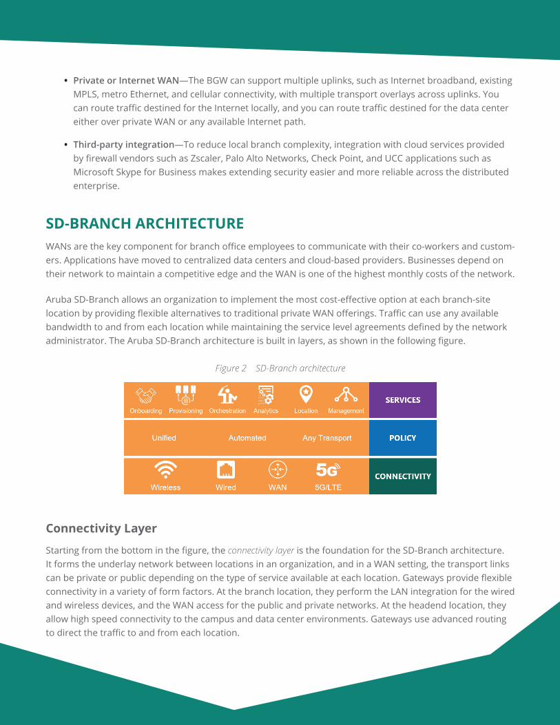
Aruba SD-Branch allows an organization to implement the most cost-effective option at each branch-site location by providing flexible alternatives to traditional private WAN offerings. Traffic can use any available bandwidth to and from each location while maintaining the service level agreements defined by the network administrator. The Aruba SD-Branch architecture is built in layers, as shown in the following figure.
Figure 2 SD-Branch architecture
Connectivity Layer
Starting from the bottom in the figure, the connectivity layer is the foundation for the SD-Branch architecture. It forms the underlay network between locations in an organization, and in a WAN setting, the transport links can be private or public depending on the type of service available at each location. Gateways provide flexible connectivity in a variety of form factors. At the branch location, they perform the LAN integration for the wired and wireless devices, and the WAN access for the public and private networks. At the headend location, they allow high speed connectivity to the campus and data center environments. Gateways use advanced routing to direct the traffic to and from each location.
Aruba Design & Deployment Guide 10
The switches and access points form the campus network at each location and connect to the gateway for the WAN services. There are several different branch sizes, and each of them has a recommended wired and wireless design based on their requirements.
Policy Layer
The policy layer runs over the top of the connectivity layer and allows organizations to securely transport traffic between sites. VPN tunnels are established between branch and headend gateways to create an SD-WAN overlay network. Headend sites are typically corporate headquarters, private data centers, or IaaS data centers hosted in the cloud, and they include one or more headend gateways. Branch sites are remote locations that include one or more branch gateways. Larger deployments might include additional headend sites, providing path diversity and application redundancy in the event of a primary site failure.
A flexible transport design uses secure policy overlay tunnels to simplify the WAN deployment. The tunnels for public and private WAN connections reduce complexity for your routing and security, regardless of the underlying networks. The tunnels also provide flexibility by allowing an organization to choose different service provider options based on availability and cost for each location, while maintaining a common overlay network.
Services Layer
The services layer is where the operations team interacts with the network. It provides significant capabilities leveraging AI, ML, and location-based services for network visibility and insights into how the network is performing. By leveraging a common data lake in the cloud, Aruba Central can correlate cross-domain events and display multiple dimensions of information in context, unlocking powerful capabilities around automated root cause analysis while providing robust analytics.
Headend Site Design
The recommended headend site design consists of a pair of redundant gateways to terminate the IPsec tunnels from the BGWs. Additional headend sites are supported, and you can deploy them by using the techniques described in this guide.
Physical Gateways
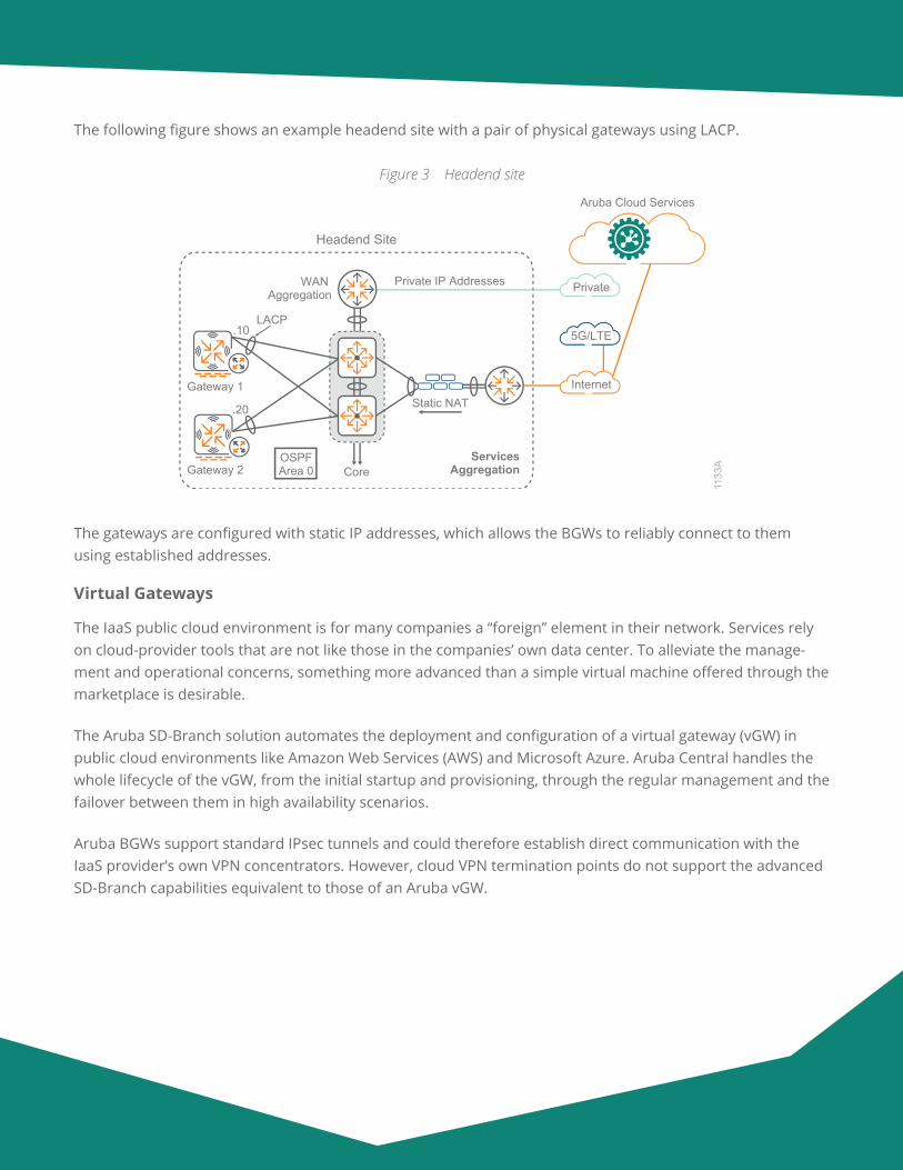
The physical gateways connect to the services aggregation layer, and we recommend LACP for uplink port redundancy or equal-cost multi-path routing for L3 redundancy. The gateways terminate the IPsec tunnels from the private WAN by using private IP addresses and from the Internet by using static NAT addresses on the firewall.
Aruba Design & Deployment Guide 11
The following figure shows an example headend site with a pair of physical gateways using LACP.
Figure 3 Headend site
1133
A
Gateway 1
LACP.10
.20
Core
WAN Aggregation
Static NAT
Private IP Addresses
Headend Site
Aruba Cloud Services
ServicesAggregationGateway 2
OSPFArea 0
Internet
5G/LTE
Private
The gateways are configured with static IP addresses, which allows the BGWs to reliably connect to them using established addresses.
Virtual Gateways
The IaaS public cloud environment is for many companies a “foreign” element in their network. Services rely on cloud-provider tools that are not like those in the companies’ own data center. To alleviate the manage-ment and operational concerns, something more advanced than a simple virtual machine offered through the marketplace is desirable.
The Aruba SD-Branch solution automates the deployment and configuration of a virtual gateway (vGW) in public cloud environments like Amazon Web Services (AWS) and Microsoft Azure. Aruba Central handles the whole lifecycle of the vGW, from the initial startup and provisioning, through the regular management and the failover between them in high availability scenarios.
Aruba BGWs support standard IPsec tunnels and could therefore establish direct communication with the IaaS provider’s own VPN concentrators. However, cloud VPN termination points do not support the advanced SD-Branch capabilities equivalent to those of an Aruba vGW.
Aruba Design & Deployment Guide 12
The most critical features are as follows:
• Orchestrated tunnels—Aruba Central automates the establishment of IPsec tunnels from all BGWs to all relevant VPNCs, including the vGW.
• Orchestrated routing—Aruba Central automates the exchange of routes across the SD-WAN, to and from the vGW location.
• Reverse path pinning—The vGW ensures the traffic always returns through the same WAN path, allowing BGWs to perform DPS, PBR, and uplink load-balancing as needed.
• End-to-end visibility—Allows you to manage all SD-Branch network devices under a single pane of glass in the cloud.
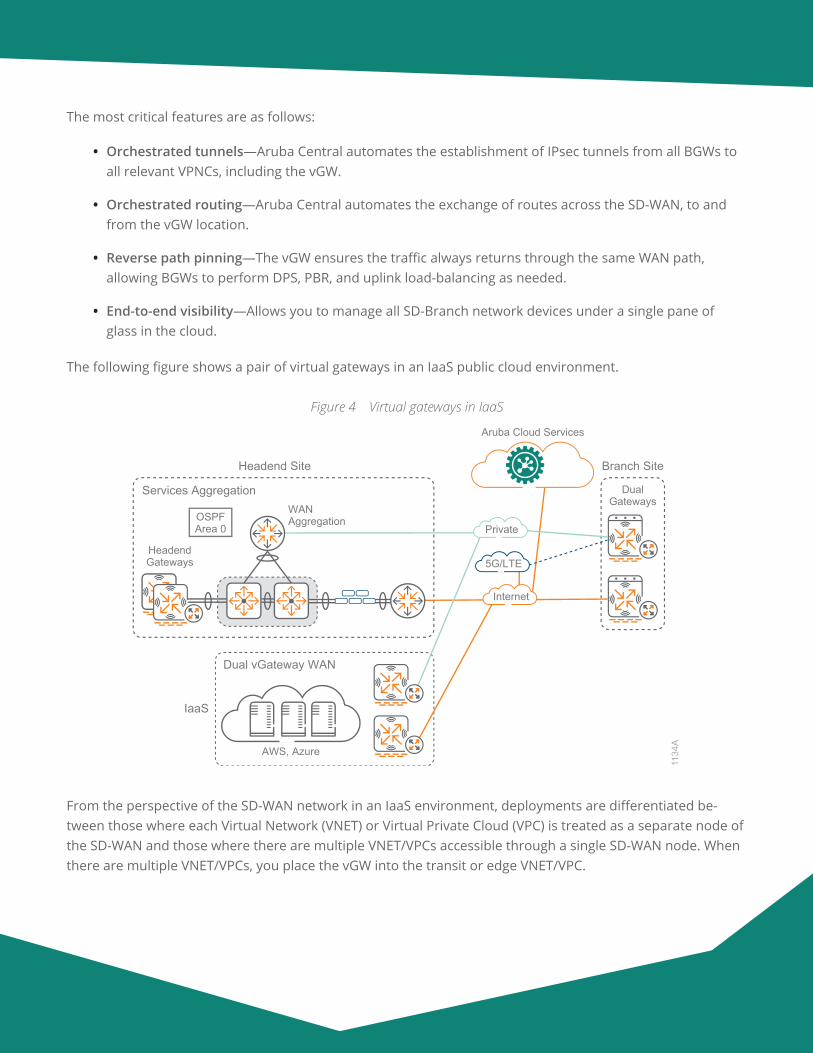
The following figure shows a pair of virtual gateways in an IaaS public cloud environment.
Figure 4 Virtual gateways in IaaS
1134
A
Headend Site
Aruba Cloud Services
DualGateways
Services Aggregation
Branch Site
5G/LTEHeadendGateways
WAN AggregationOSPF
Area 0
AWS, Azure
IaaS
Dual vGateway WAN
Internet
Private
From the perspective of the SD-WAN network in an IaaS environment, deployments are differentiated be-tween those where each Virtual Network (VNET) or Virtual Private Cloud (VPC) is treated as a separate node of the SD-WAN and those where there are multiple VNET/VPCs accessible through a single SD-WAN node. When there are multiple VNET/VPCs, you place the vGW into the transit or edge VNET/VPC.
Aruba Design & Deployment Guide 13
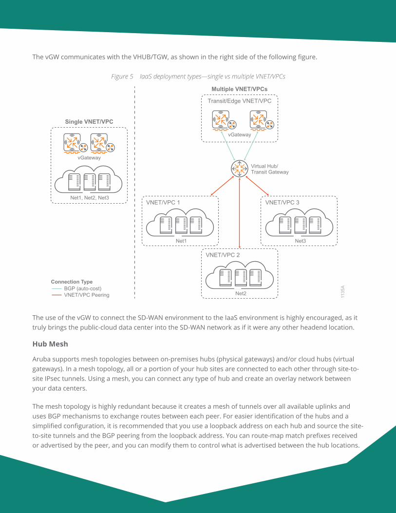
The vGW communicates with the VHUB/TGW, as shown in the right side of the following figure.
Figure 5 IaaS deployment types—single vs multiple VNET/VPCs
1135
A
Transit/Edge VNET/VPC
Multiple VNET/VPCs
vGateway
Single VNET/VPC
VNET/VPC 1
Net1
VNET/VPC 2
Net2
VNET/VPC 3
Net3
Virtual Hub/Transit Gateway
vGateway
Net1, Net2, Net3
Connection Type
VNET/VPC PeeringBGP (auto-cost)
The use of the vGW to connect the SD-WAN environment to the IaaS environment is highly encouraged, as it truly brings the public-cloud data center into the SD-WAN network as if it were any other headend location.
Hub Mesh
Aruba supports mesh topologies between on-premises hubs (physical gateways) and/or cloud hubs (virtual gateways). In a mesh topology, all or a portion of your hub sites are connected to each other through site-to-site IPsec tunnels. Using a mesh, you can connect any type of hub and create an overlay network between your data centers.
The mesh topology is highly redundant because it creates a mesh of tunnels over all available uplinks and uses BGP mechanisms to exchange routes between each peer. For easier identification of the hubs and a simplified configuration, it is recommended that you use a loopback address on each hub and source the site-to-site tunnels and the BGP peering from the loopback address. You can route-map match prefixes received or advertised by the peer, and you can modify them to control what is advertised between the hub locations.
Aruba Design & Deployment Guide 14
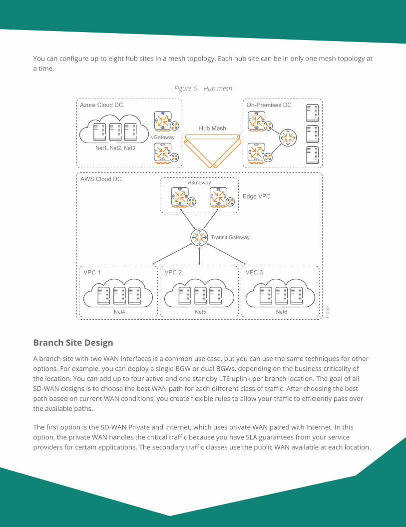
You can configure up to eight hub sites in a mesh topology. Each hub site can be in only one mesh topology at a time.
Figure 6 Hub mesh
1136
A
Edge VPC
vGatewayAWS Cloud DC
VPC 1
Net4
VPC 2
Net5
VPC 3
Net6
Transit Gateway
Azure Cloud DC
vGateway
Net1, Net2, Net3
On-Premises DC
Hub Mesh
Branch Site Design
A branch site with two WAN interfaces is a common use case, but you can use the same techniques for other options. For example, you can deploy a single BGW or dual BGWs, depending on the business criticality of the location. You can add up to four active and one standby LTE uplink per branch location. The goal of all SD-WAN designs is to choose the best WAN path for each different class of traffic. After choosing the best path based on current WAN conditions, you create flexible rules to allow your traffic to efficiently pass over the available paths.
The first option is the SD-WAN Private and Internet, which uses private WAN paired with Internet. In this option, the private WAN handles the critical traffic because you have SLA guarantees from your service providers for certain applications. The secondary traffic classes use the public WAN available at each location.
Aruba Design & Deployment Guide 15
The second option is the SD-WAN Dual Internet, which uses two Internet services. With this option, you select one of the Internet paths as the preferred path. You can select the provider that has more direct connections to each of your branch sites, or you can choose the one with the most bandwidth. The secondary traffic classes use the remaining Internet bandwidth available at each location.
Branch Gateway Options
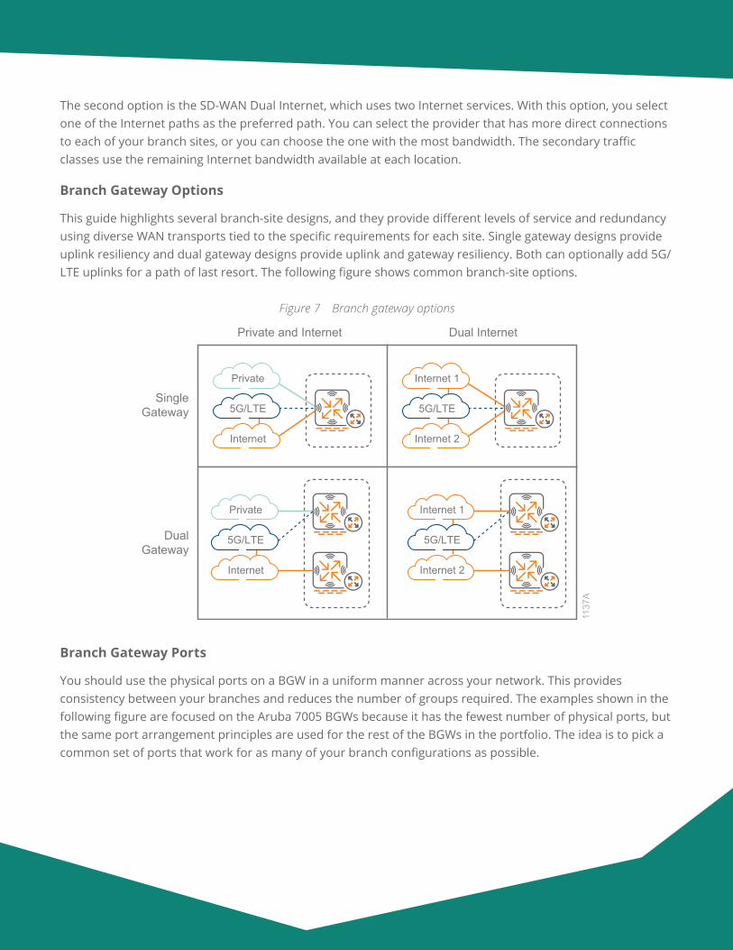
This guide highlights several branch-site designs, and they provide different levels of service and redundancy using diverse WAN transports tied to the specific requirements for each site. Single gateway designs provide uplink resiliency and dual gateway designs provide uplink and gateway resiliency. Both can optionally add 5G/LTE uplinks for a path of last resort. The following figure shows common branch-site options.
Figure 7 Branch gateway options
Internet
Private
5G/LTE
Internet 2
Internet 1
5G/LTE
Internet 2
Internet 1
5G/LTE
Internet
Private
5G/LTE
Private and Internet Dual Internet
SingleGateway
DualGateway
1137
A
Branch Gateway Ports
You should use the physical ports on a BGW in a uniform manner across your network. This provides consistency between your branches and reduces the number of groups required. The examples shown in the following figure are focused on the Aruba 7005 BGWs because it has the fewest number of physical ports, but the same port arrangement principles are used for the rest of the BGWs in the portfolio. The idea is to pick a common set of ports that work for as many of your branch configurations as possible.
Aruba Design & Deployment Guide 16
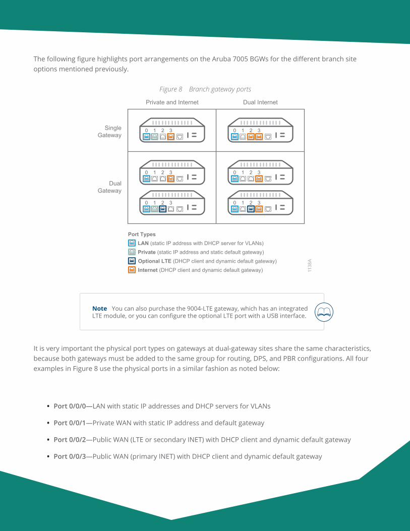
The following figure highlights port arrangements on the Aruba 7005 BGWs for the different branch site options mentioned previously.
Figure 8 Branch gateway ports
Private and Internet Dual Internet
SingleGateway
DualGateway
1138
A
0 1 2 3
0 1 2 3 0 1 2 3
0 1 2 3
0 1 2 30 1 2 3
Optional LTE (DHCP client and dynamic default gateway)
LAN (static IP address with DHCP server for VLANs)Private (static IP address and static default gateway)
Internet (DHCP client and dynamic default gateway)
Port Types
Note You can also purchase the 9004-LTE gateway, which has an integrated LTE module, or you can configure the optional LTE port with a USB interface.
It is very important the physical port types on gateways at dual-gateway sites share the same characteristics, because both gateways must be added to the same group for routing, DPS, and PBR configurations. All four examples in Figure 8 use the physical ports in a similar fashion as noted below:
• Port 0/0/0—LAN with static IP addresses and DHCP servers for VLANs
• Port 0/0/1—Private WAN with static IP address and default gateway
• Port 0/0/2—Public WAN (LTE or secondary INET) with DHCP client and dynamic default gateway
• Port 0/0/3—Public WAN (primary INET) with DHCP client and dynamic default gateway
Aruba Design & Deployment Guide 17
Because the port arrangements for each of the groups are aligned configuration-wise, you can configure an initial group and then copy it to the new groups to save time during the group configuration procedures. The port types you choose do not have to align with the choices above, but they should match the common port arrangements for your environment.
Trusted vs Untrusted
Unlike traditional perimeter firewalls, the trusted interface feature in an Aruba gateway’s role-based firewall refers to whether there is a user-session for all traffic coming through an interface with the potential for role assignment policies. The two options are as follows:
• The gateway does not keep user-sessions for traffic coming through trusted interfaces.
• The gateway maintains user-sessions for all devices coming from untrusted interfaces. This means you must assign a role assignment (AAA) profile to all VLANs attached to untrusted interfaces, regardless of whether you plan to enable role assignments.
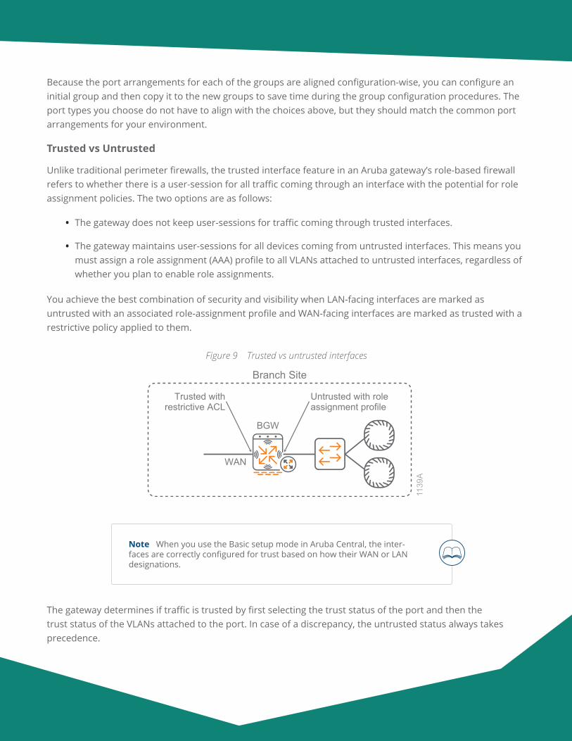
You achieve the best combination of security and visibility when LAN-facing interfaces are marked as untrusted with an associated role-assignment profile and WAN-facing interfaces are marked as trusted with a restrictive policy applied to them.
Figure 9 Trusted vs untrusted interfaces
Branch Site
1139
ABGW
WAN
Untrusted with roleassignment profile
Trusted withrestrictive ACL
Note When you use the Basic setup mode in Aruba Central, the inter-faces are correctly configured for trust based on how their WAN or LAN designations.
The gateway determines if traffic is trusted by first selecting the trust status of the port and then the trust status of the VLANs attached to the port. In case of a discrepancy, the untrusted status always takes precedence.
Aruba Design & Deployment Guide 18
Policy Layer
The Aruba SD-Branch solution implements standards-based VPN tunnels. To simplify the SD-WAN overlay tunnel establishment, the Aruba gateways leverage factory installed trusted platform module (TPM) certif-icates for mutual authentication. The TPM certificates are installed on each Aruba gateway at the factory; however, end-user certificates are also supported.
The SD-WAN overlay tunnel is initiated from the BGW and terminates on a gateway using network address translation-traversal for the Internet paths. The only firewall port that you need to open between a headend gateway and a BGW for a tunnel to establish is UDP destination port 4500. You can terminate the tunnels directly on the headend gateway or NAT them via an intermediate device, such as an edge firewall for the Internet WAN connection.
For private WANs, the tunnels are typically terminated on a headend gateway by using a VLAN interface as-signed with a private IPv4 address. You can either terminate Internet-based WAN services on a gateway using a public IPv4 address or a private IPv4 address. This depends on your organization’s data center architecture.
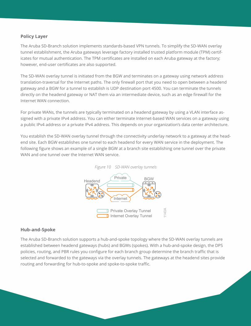
You establish the SD-WAN overlay tunnel through the connectivity underlay network to a gateway at the head-end site. Each BGW establishes one tunnel to each headend for every WAN service in the deployment. The following figure shows an example of a single BGW at a branch site establishing one tunnel over the private WAN and one tunnel over the Internet WAN service.
Figure 10 SD-WAN overlay tunnels11
40A
BGW
Private Overlay TunnelInternet Overlay Tunnel
Headend
Internet
Private
Hub-and-Spoke
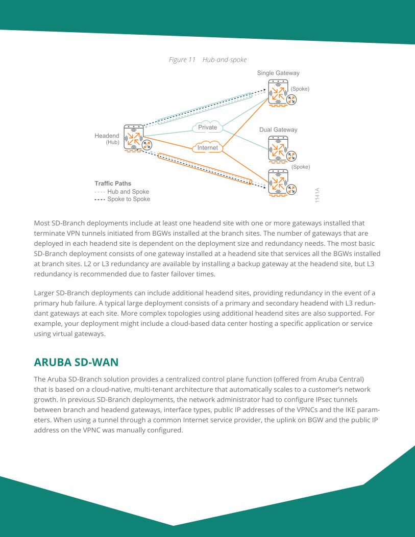
The Aruba SD-Branch solution supports a hub-and-spoke topology where the SD-WAN overlay tunnels are established between headend gateways (hubs) and BGWs (spokes). With a hub-and-spoke design, the DPS policies, routing, and PBR rules you configure for each branch group determine the branch traffic that is selected and forwarded to the gateways via the overlay tunnels. The gateways at the headend sites provide routing and forwarding for hub-to-spoke and spoke-to-spoke traffic.
Aruba Design & Deployment Guide 19
Figure 11 Hub-and-spoke
1141
A
(Spoke)
Dual Gateway
Single Gateway
Headend(Hub)
(Spoke)
Internet
Private
Hub and SpokeSpoke to Spoke
Traffic Paths
Most SD-Branch deployments include at least one headend site with one or more gateways installed that terminate VPN tunnels initiated from BGWs installed at the branch sites. The number of gateways that are deployed in each headend site is dependent on the deployment size and redundancy needs. The most basic SD-Branch deployment consists of one gateway installed at a headend site that services all the BGWs installed at branch sites. L2 or L3 redundancy are available by installing a backup gateway at the headend site, but L3 redundancy is recommended due to faster failover times.
Larger SD-Branch deployments can include additional headend sites, providing redundancy in the event of a primary hub failure. A typical large deployment consists of a primary and secondary headend with L3 redun-dant gateways at each site. More complex topologies using additional headend sites are also supported. For example, your deployment might include a cloud-based data center hosting a specific application or service using virtual gateways.
ARUBA SD-WANThe Aruba SD-Branch solution provides a centralized control plane function (offered from Aruba Central) that is based on a cloud-native, multi-tenant architecture that automatically scales to a customer’s network growth. In previous SD-Branch deployments, the network administrator had to configure IPsec tunnels between branch and headend gateways, interface types, public IP addresses of the VPNCs and the IKE param-eters. When using a tunnel through a common Internet service provider, the uplink on BGW and the public IP address on the VPNC was manually configured.
Aruba Design & Deployment Guide 20
The configuration workflows were cumbersome and prone to misconfigurations that often-delayed deploy-ments and led to unnecessary calls to TAC. There was no support for dynamic protocols or orchestrated routes through the overlay tunnels. Static routes pointing to each data center were configured with different costs in order to provide redundancy in case of a failure. For large deployments, which might have hundreds of locations, static routes were not scalable or easy to administer.
SD-WAN Orchestrator
To simplify the configuration, Aruba introduced SD-WAN Orchestrator to automatically setup IPsec tunnels and configure dynamic routing between the BGWs and headend VPNC. Overlay Tunnel and Route Orchestra-tor processes run in Central to automate the existing workflows.
The Aruba SD-WAN Orchestrator provides the following features:
• The IPSec overlay is automatically created through tunnel orchestration.
• Reachability information is propagated through route orchestration, and route redistribution is done through a single group configuration.
• Routing policies are set with a simple hub preference at the group level and route redistribution at the headend ensures symmetry.
• Individual devices do not need to be configured with the overlay topology and routing policy because they are done at group level for all devices.
• When a new BGW is added to a group, it dynamically learns the overlay topology and orchestration creates the tunnels and route policy.
• Changing the path preference is done by changing hub preference setting and routing costs are trans-lated into the data center routing process.
• Scalability is built into the orchestration, which helps an organization build a robust routing design.
Tunnel Orchestrator
In order to build an SD-WAN network, the first step is to bring up a policy overlay network that is independent of the underlying WAN circuits. In order to do this, the administrator identifies the uplink interfaces in all gateways with their corresponding service provider. After the information is entered, SD-WAN Orchestrator establishes the overlay tunnels according to the defined policy.
Aruba Design & Deployment Guide 21
The main functions of Aruba Overlay Tunnel Orchestrator include:
• Discovering the public/private IP addresses and uplinks attributes
• Exchanging keys and sending keys to devices
• Building IPsec tunnels
• Refreshing keying material before old keys expire
Aruba Overlay Tunnel Orchestrator removes the complexity and scalability issues associated with configuring IPsec tunnels. It also eliminates the need to specify Internet Key Exchange (IKE)-related information. With SD-WAN Orchestrator, Aruba simplifies the configuration of one of the most complex tasks when bringing up an SD-WAN service.
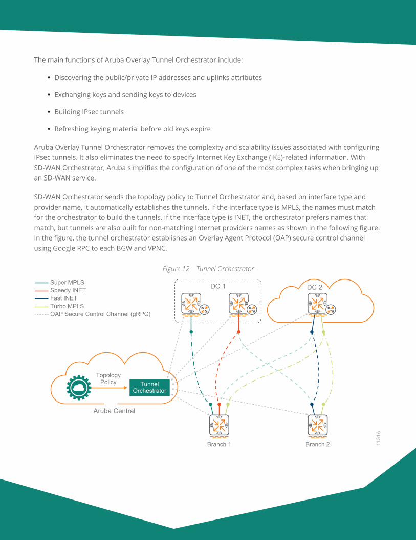
SD-WAN Orchestrator sends the topology policy to Tunnel Orchestrator and, based on interface type and provider name, it automatically establishes the tunnels. If the interface type is MPLS, the names must match for the orchestrator to build the tunnels. If the interface type is INET, the orchestrator prefers names that match, but tunnels are also built for non-matching Internet providers names as shown in the following figure. In the figure, the tunnel orchestrator establishes an Overlay Agent Protocol (OAP) secure control channel using Google RPC to each BGW and VPNC.
Figure 12 Tunnel Orchestrator
1131
A
DC 1 DC 2
Aruba Central
TunnelOrchestrator
TopologyPolicy
Branch 1 Branch 2
Speedy INET
Turbo MPLSOAP Secure Control Channel (gRPC)
Fast INET
Super MPLS
Aruba Design & Deployment Guide 22
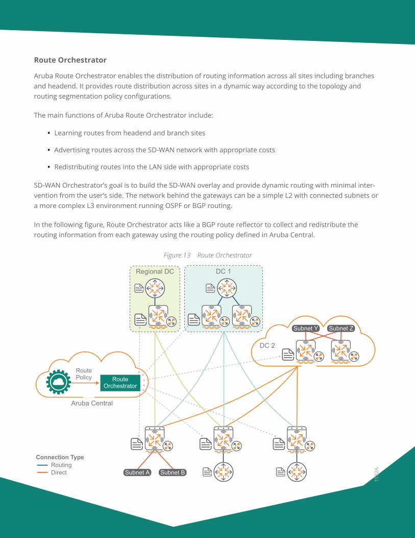
Route Orchestrator
Aruba Route Orchestrator enables the distribution of routing information across all sites including branches and headend. It provides route distribution across sites in a dynamic way according to the topology and routing segmentation policy configurations.
The main functions of Aruba Route Orchestrator include:
• Learning routes from headend and branch sites
• Advertising routes across the SD-WAN network with appropriate costs
• Redistributing routes into the LAN side with appropriate costs
SD-WAN Orchestrator’s goal is to build the SD-WAN overlay and provide dynamic routing with minimal inter-vention from the user’s side. The network behind the gateways can be a simple L2 with connected subnets or a more complex L3 environment running OSPF or BGP routing.
In the following figure, Route Orchestrator acts like a BGP route reflector to collect and redistribute the routing information from each gateway using the routing policy defined in Aruba Central.
Figure 13 Route Orchestrator
RouteOrchestrator
RoutePolicy
1132
A
Regional DC
Aruba Central
DC 1
DC 2
Subnet Y
Subnet A Subnet B
Connection Type
DirectRouting
Subnet Z
Aruba Design & Deployment Guide 23
Traditional Branch
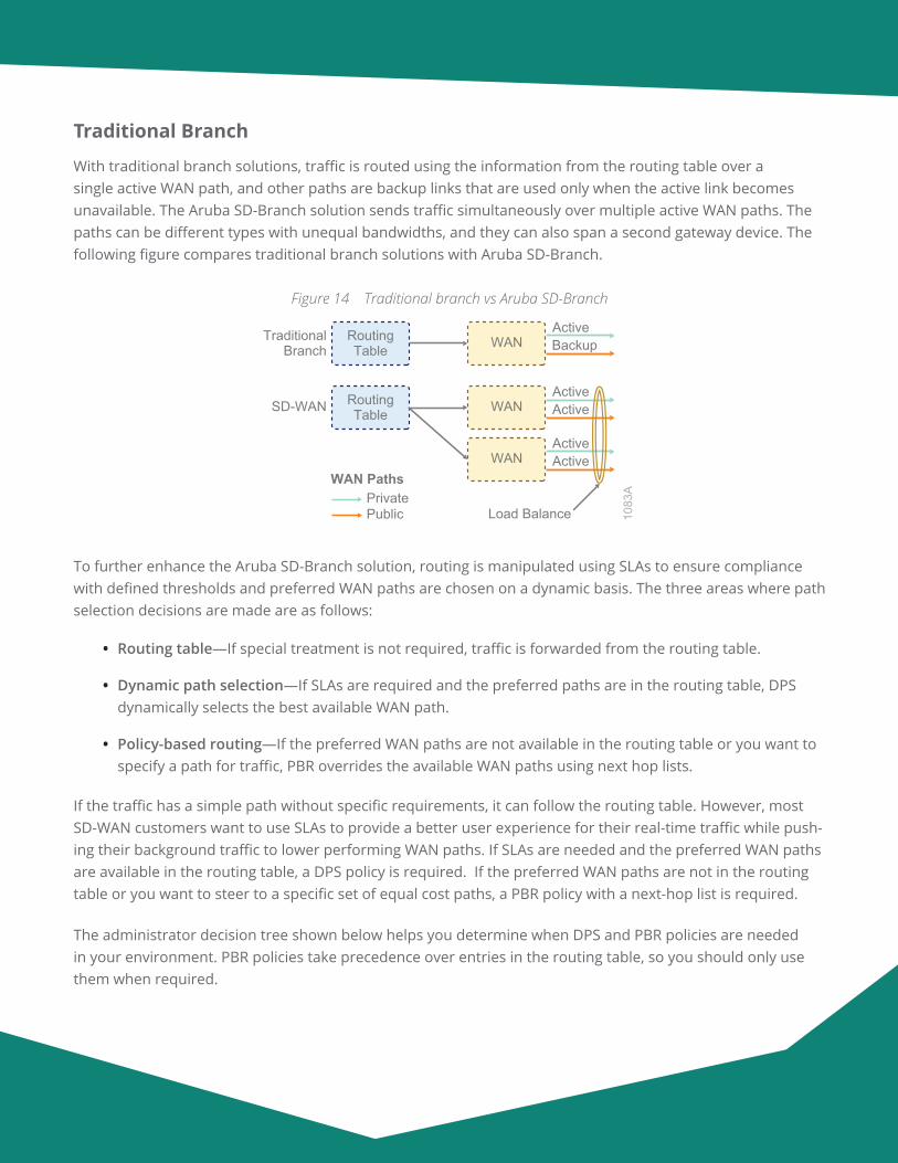
With traditional branch solutions, traffic is routed using the information from the routing table over a single active WAN path, and other paths are backup links that are used only when the active link becomes unavailable. The Aruba SD-Branch solution sends traffic simultaneously over multiple active WAN paths. The paths can be different types with unequal bandwidths, and they can also span a second gateway device. The following figure compares traditional branch solutions with Aruba SD-Branch.
Figure 14 Traditional branch vs Aruba SD-Branch
1083
A
TraditionalBranch Backup
RoutingTable
ActiveWAN
SD-WAN ActiveRoutingTable
ActiveWAN
ActiveActive
Load Balance
WANWAN Paths
PrivatePublic
To further enhance the Aruba SD-Branch solution, routing is manipulated using SLAs to ensure compliance with defined thresholds and preferred WAN paths are chosen on a dynamic basis. The three areas where path selection decisions are made are as follows:
• Routing table—If special treatment is not required, traffic is forwarded from the routing table.
• Dynamic path selection—If SLAs are required and the preferred paths are in the routing table, DPS dynamically selects the best available WAN path.
• Policy-based routing—If the preferred WAN paths are not available in the routing table or you want to specify a path for traffic, PBR overrides the available WAN paths using next hop lists.
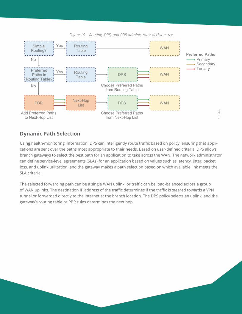
If the traffic has a simple path without specific requirements, it can follow the routing table. However, most SD-WAN customers want to use SLAs to provide a better user experience for their real-time traffic while push-ing their background traffic to lower performing WAN paths. If SLAs are needed and the preferred WAN paths are available in the routing table, a DPS policy is required. If the preferred WAN paths are not in the routing table or you want to steer to a specific set of equal cost paths, a PBR policy with a next-hop list is required.
The administrator decision tree shown below helps you determine when DPS and PBR policies are needed in your environment. PBR policies take precedence over entries in the routing table, so you should only use them when required.
Aruba Design & Deployment Guide 24
Figure 15 Routing, DPS, and PBR administrator decision tree
1084
A
RoutingTable
Choose Preferred Pathsfrom Routing Table
SimpleRouting?
Yes
No
WAN
RoutingTable DPS
PreferredPaths in
Routing Table?
Yes
No
WAN
Choose Preferred Pathsfrom Next-Hop List
Add Preferred Pathsto Next-Hop List
Next-HopList DPSPBR WAN
Preferred PathsPrimarySecondaryTertiary
Dynamic Path Selection
Using health-monitoring information, DPS can intelligently route traffic based on policy, ensuring that appli-cations are sent over the paths most appropriate to their needs. Based on user-defined criteria, DPS allows branch gateways to select the best path for an application to take across the WAN. The network administrator can define service-level agreements (SLAs) for an application based on values such as latency, jitter, packet loss, and uplink utilization, and the gateway makes a path selection based on which available link meets the SLA criteria.
The selected forwarding path can be a single WAN uplink, or traffic can be load-balanced across a group of WAN uplinks. The destination IP address of the traffic determines if the traffic is steered towards a VPN tunnel or forwarded directly to the Internet at the branch location. The DPS policy selects an uplink, and the gateway’s routing table or PBR rules determines the next hop.
Aruba Design & Deployment Guide 25
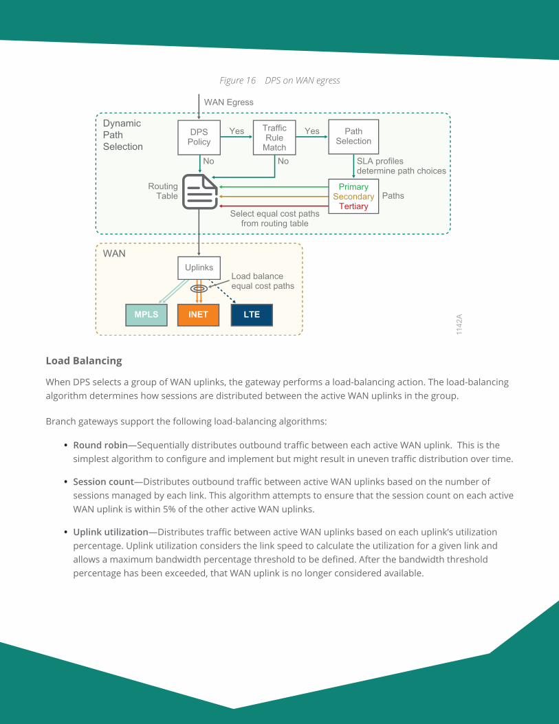
Figure 16 DPS on WAN egress
DynamicPathSelection
WAN
RoutingTable
WAN Egress
Yes Yes
MPLS INET LTE
1142
A
UplinksLoad balanceequal cost paths
Select equal cost pathsfrom routing table
SLA profilesdetermine path choices
No No
Paths
DPSPolicy
TrafficRule
Match
PathSelection
PrimarySecondary
Tertiary
Load Balancing
When DPS selects a group of WAN uplinks, the gateway performs a load-balancing action. The load-balancing algorithm determines how sessions are distributed between the active WAN uplinks in the group.
Branch gateways support the following load-balancing algorithms:
• Round robin—Sequentially distributes outbound traffic between each active WAN uplink. This is the simplest algorithm to configure and implement but might result in uneven traffic distribution over time.
• Session count—Distributes outbound traffic between active WAN uplinks based on the number of sessions managed by each link. This algorithm attempts to ensure that the session count on each active WAN uplink is within 5% of the other active WAN uplinks.
• Uplink utilization—Distributes traffic between active WAN uplinks based on each uplink’s utilization percentage. Uplink utilization considers the link speed to calculate the utilization for a given link and allows a maximum bandwidth percentage threshold to be defined. After the bandwidth threshold percentage has been exceeded, that WAN uplink is no longer considered available.
Aruba Design & Deployment Guide 26
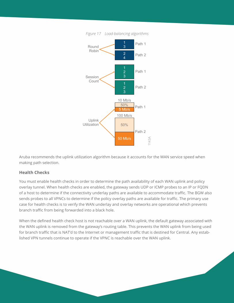
Figure 17 Load-balancing algorithms
1143
A50 Mb/s
50%
5 Mb/s
13
50%
100 Mb/s
Path 1
Path 1
123
Path 1
123
Path 2
24
Path 2
Path 2
10 Mb/s
UplinkUtilization
RoundRobin
SessionCount
Aruba recommends the uplink utilization algorithm because it accounts for the WAN service speed when making path selection.
Health Checks
You must enable health checks in order to determine the path availability of each WAN uplink and policy overlay tunnel. When health checks are enabled, the gateway sends UDP or ICMP probes to an IP or FQDN of a host to determine if the connectivity underlay paths are available to accommodate traffic. The BGW also sends probes to all VPNCs to determine if the policy overlay paths are available for traffic. The primary use case for health checks is to verify the WAN underlay and overlay networks are operational which prevents branch traffic from being forwarded into a black hole.
When the defined health check host is not reachable over a WAN uplink, the default gateway associated with the WAN uplink is removed from the gateway’s routing table. This prevents the WAN uplink from being used for branch traffic that is NAT’d to the Internet or management traffic that is destined for Central. Any estab-lished VPN tunnels continue to operate if the VPNC is reachable over the WAN uplink.
Aruba Design & Deployment Guide 27
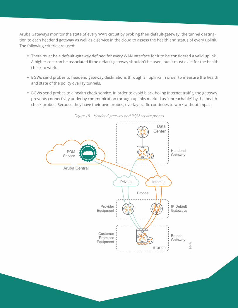
Aruba Gateways monitor the state of every WAN circuit by probing their default-gateway, the tunnel destina-tion to each headend gateway as well as a service in the cloud to assess the health and status of every uplink. The following criteria are used:
• There must be a default-gateway defined for every WAN interface for it to be considered a valid uplink. A higher cost can be associated if the default-gateway shouldn’t be used, but it must exist for the health check to work.
• BGWs send probes to headend gateway destinations through all uplinks in order to measure the health and state of the policy overlay tunnels.
• BGWs send probes to a health check service. In order to avoid black-holing Internet traffic, the gateway prevents connectivity underlay communication through uplinks marked as “unreachable” by the health check probes. Because they have their own probes, overlay traffic continues to work without impact
Figure 18 Headend gateway and PQM service probes
PQMService
ProviderEquipment
IP DefaultGateways
HeadendGateway
Probes
CustomerPremises
EquipmentBranchGateway
Branch
Aruba Central
DataCenter
InternetPrivate
1144
A
Aruba Design & Deployment Guide 28
Aruba PQM Service
As part of the SD-Branch solution, Aruba provides a global Path Quality Monitoring (PQM) service that gateways can probe to measure the quality of the uplinks. This global service consists on a set of nodes that respond to ICMP/UDP probes from gateways managed by Aruba Central. All other traffic is throttled to avoid DoS attacks.
This service is maintained by the Aruba Cloud Operations team. On top of the regular monitoring of all the PQM nodes and the authoritative DNS, Aruba has distributed probes all over the world probing pqm.arubanetworks.com every five minutes. These probes are constantly reporting latency, packet loss, and which PQM node is responding to the Aruba Cloud Operations dashboard. This provides not just monitoring of the instances but a true 24x7 monitoring of the PQM service.
The Aruba SD-Branch solution relies on control-plane communication between BGWs and VPNCs, which allows the SD-WAN orchestrator to negotiate tunnels and establish routes. At least two paths of communica-tion are recommended between the gateways and Aruba Central. This becomes even more important when dealing with Internet, LTE or VSAT circuits that are not be as reliable as an enterprise-grade MPLS network. You can achieve a second path to Aruba Central by configuring a static default route with a higher cost point-ing to the private WAN overlay tunnel, which is routed over the headend site’s DMZ out to the Internet.
Policy-Based Routing
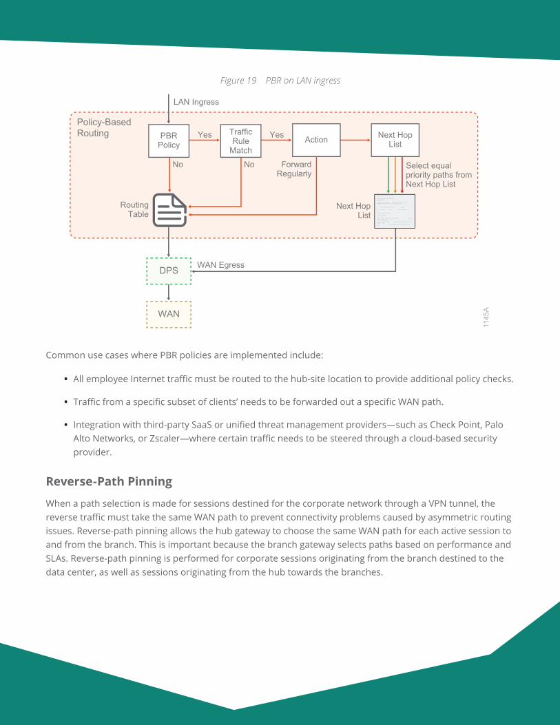
Some advanced deployments might require PBR to override destination-based routes when traffic must be forwarded over a specific WAN path. If needed, PBR policies override the routing table for both underlay and overlay traffic. For example, if you want all traffic from your corporate users to go through the hub-site location, you apply a PBR rule pointing to the overlay tunnels. The gateway can use multiple paths by setting the same priority in a next-hop list and applying the PBR policy to the relevant user roles. If more than one active path is available, the gateway selects them using a combination of DPS and load-balancing.
Aruba Design & Deployment Guide 29
Figure 19 PBR on LAN ingress
WAN
Policy-BasedRouting
DPS
RoutingTable
LAN Ingress
Yes Yes
1145
A
WAN Egress
Select equalpriority paths fromNext Hop List
No No ForwardRegularly
Next HopList
PBRPolicy
TrafficRule
MatchAction Next Hop
List
show ip access-list tunnel-employee
ip access-list route tunnel-employeetunnel-employee---------------Priority Source Destination Service Application DSCP Action NextHopList IpsecMap Tunnel TunnelGroup IPv4/6-------- ------ ----------- ------- ----------- ---- ------ ----------- -------- ------ ----------- ------1 any 10.0.0.0 255.0.0.0 any forward42 any any any route corp-inet 4
show ip nexthop-list corp-inet
Nexthop-List Entries--------------------Name Dest Preemptive Failover Nexthop NexthopDest Nexthop Priority---- ---- ------------------- ------- ------------ ----------------corp-inet 0x4402 Enabled *data-vpnc-00:0b:86:bb:bb:a7-isp1_inet0x4421 200 *data-vpnc-00:0b:86:bb:bb:a7-isp2_inet 0x4422 220
Common use cases where PBR policies are implemented include:
• All employee Internet traffic must be routed to the hub-site location to provide additional policy checks.
• Traffic from a specific subset of clients’ needs to be forwarded out a specific WAN path.
• Integration with third-party SaaS or unified threat management providers—such as Check Point, Palo Alto Networks, or Zscaler—where certain traffic needs to be steered through a cloud-based security provider.
Reverse-Path Pinning
When a path selection is made for sessions destined for the corporate network through a VPN tunnel, the reverse traffic must take the same WAN path to prevent connectivity problems caused by asymmetric routing issues. Reverse-path pinning allows the hub gateway to choose the same WAN path for each active session to and from the branch. This is important because the branch gateway selects paths based on performance and SLAs. Reverse-path pinning is performed for corporate sessions originating from the branch destined to the data center, as well as sessions originating from the hub towards the branches.
Aruba Design & Deployment Guide 30
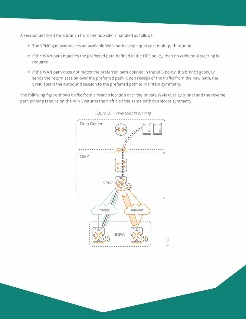
A session destined for a branch from the hub site is handled as follows:
• The VPNC gateway selects an available WAN path using equal-cost multi-path routing.
• If the WAN path matches the preferred path defined in the DPS policy, then no additional steering is required.
• If the WAN path does not match the preferred path defined in the DPS policy, the branch gateway sends the return session over the preferred path. Upon receipt of the traffic from the new path, the VPNC steers the outbound session to the preferred path to maintain symmetry.
The following figure shows traffic from a branch location over the private WAN overlay tunnel and the reverse path pinning feature on the VPNC returns the traffic on the same path to enforce symmetry.
Figure 20 Reverse-path pinning
VPNC
BGWs
Data Center
DMZ
1146
A
Private Internet
Aruba Design & Deployment Guide 31
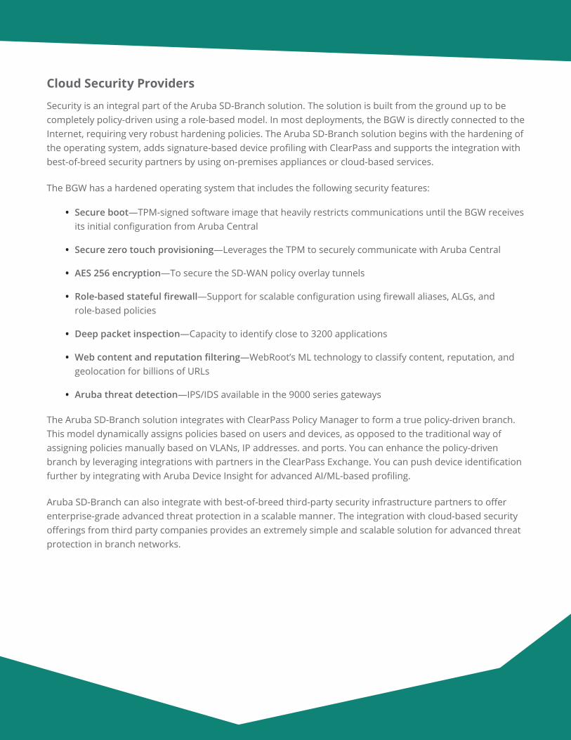
Cloud Security Providers
Security is an integral part of the Aruba SD-Branch solution. The solution is built from the ground up to be completely policy-driven using a role-based model. In most deployments, the BGW is directly connected to the Internet, requiring very robust hardening policies. The Aruba SD-Branch solution begins with the hardening of the operating system, adds signature-based device profiling with ClearPass and supports the integration with best-of-breed security partners by using on-premises appliances or cloud-based services.
The BGW has a hardened operating system that includes the following security features:
• Secure boot—TPM-signed software image that heavily restricts communications until the BGW receives its initial configuration from Aruba Central
• Secure zero touch provisioning—Leverages the TPM to securely communicate with Aruba Central
• AES 256 encryption—To secure the SD-WAN policy overlay tunnels
• Role-based stateful firewall—Support for scalable configuration using firewall aliases, ALGs, and role-based policies
• Deep packet inspection—Capacity to identify close to 3200 applications
• Web content and reputation filtering—WebRoot’s ML technology to classify content, reputation, and geolocation for billions of URLs
• Aruba threat detection—IPS/IDS available in the 9000 series gateways
The Aruba SD-Branch solution integrates with ClearPass Policy Manager to form a true policy-driven branch. This model dynamically assigns policies based on users and devices, as opposed to the traditional way of assigning policies manually based on VLANs, IP addresses. and ports. You can enhance the policy-driven branch by leveraging integrations with partners in the ClearPass Exchange. You can push device identification further by integrating with Aruba Device Insight for advanced AI/ML-based profiling.
Aruba SD-Branch can also integrate with best-of-breed third-party security infrastructure partners to offer enterprise-grade advanced threat protection in a scalable manner. The integration with cloud-based security offerings from third party companies provides an extremely simple and scalable solution for advanced threat protection in branch networks.
Aruba Design & Deployment Guide 32
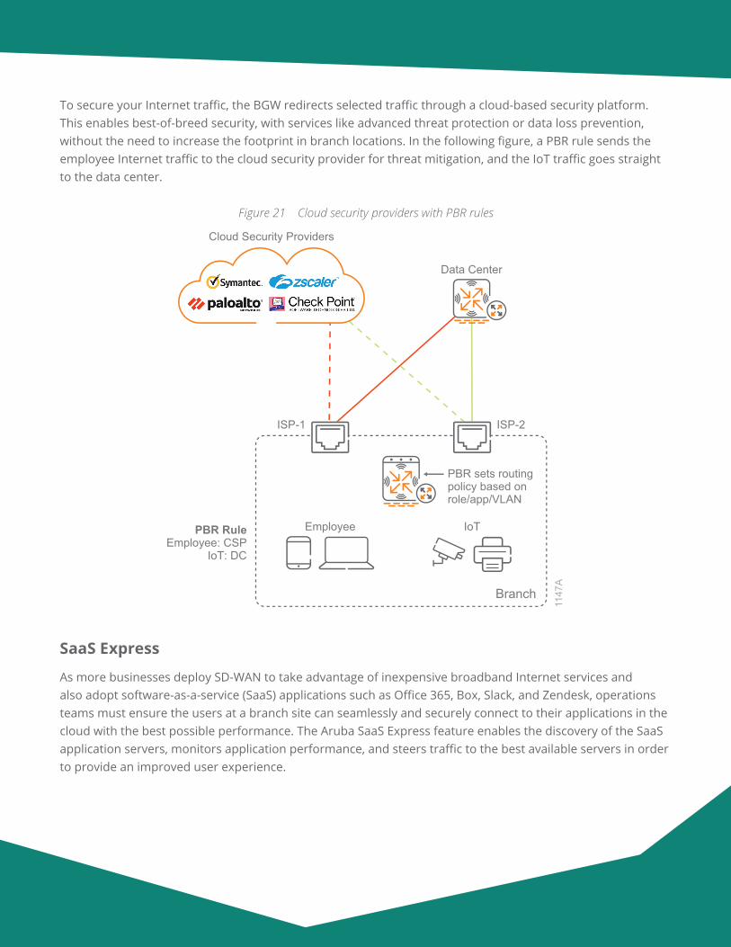
To secure your Internet traffic, the BGW redirects selected traffic through a cloud-based security platform. This enables best-of-breed security, with services like advanced threat protection or data loss prevention, without the need to increase the footprint in branch locations. In the following figure, a PBR rule sends the employee Internet traffic to the cloud security provider for threat mitigation, and the IoT traffic goes straight to the data center.
Figure 21 Cloud security providers with PBR rules
PBR RuleEmployee: CSP
IoT: DC
ISP-1 ISP-2
PBR sets routingpolicy based onrole/app/VLAN
Branch
Cloud Security Providers
1147
A
IoTEmployee
Data Center
SaaS Express
As more businesses deploy SD-WAN to take advantage of inexpensive broadband Internet services and also adopt software-as-a-service (SaaS) applications such as Office 365, Box, Slack, and Zendesk, operations teams must ensure the users at a branch site can seamlessly and securely connect to their applications in the cloud with the best possible performance. The Aruba SaaS Express feature enables the discovery of the SaaS application servers, monitors application performance, and steers traffic to the best available servers in order to provide an improved user experience.
Aruba Design & Deployment Guide 33
The SaaS Express feature offers the following benefits:
• Real-time probe measurement to determine the optimal ISP for user traffic
• Ability to choose the best network path for SaaS applications in order to optimize the user experience
• Improved service reliability with multiple network paths and dynamic traffic-steering
SaaS Application Profile Parameter
The BGW supports a set of applications and application categories in the DPI library. The built-in application profiles include a set of SaaS applications; for example, Adobe, Dropbox, Amazon, Google, Salesforce, Slack, Webex, etc. If a SaaS application is not available in the list, the network administrator can configure their own.
Each SaaS application profile includes the following elements:
• Name—Name of the SaaS application
• FQDN—A list of domain URLs bound to the SaaS application
• Exit profile—Traffic steering policy for determining an optimal path exit
• SLA—Threshold profile for measuring path quality and performance
• Health check probe URI—URI to use for probes to determine the best available path
HTTP and DNS Probes
Aruba BGWs send HTTP requests to each SaaS application over every available path. They calculate the average packet loss and latency for each path in order to determine the one with the best performance. When a user requests access to a SaaS application, the BGW dynamically steers the application traffic to the best available path.
When a client requests SaaS application access, the BGW intercepts the DNS query acting as a proxy and forwards the query to the DNS server to resolve into IP addresses. Using the type of SaaS application and the location of DNS caching servers for a given ISP, the BGW determines the best available uplink. This means traffic is automatically steered to the best performing SaaS servers, rather than statically defining them based on a best-guess geographic location.
Traffic Steering and Path Selection
Network administrators can use a WAN policy with path steering based on key performance indicators, such as jitter, latency, and packet loss, to attach the policy to each SaaS application profile. By default, the BGW includes a Best for SaaS SLA profile, which is used for SaaS application profiles. Network administrators can also use a custom SaaS policy for steering their SaaS application traffic.
Aruba Design & Deployment Guide 34
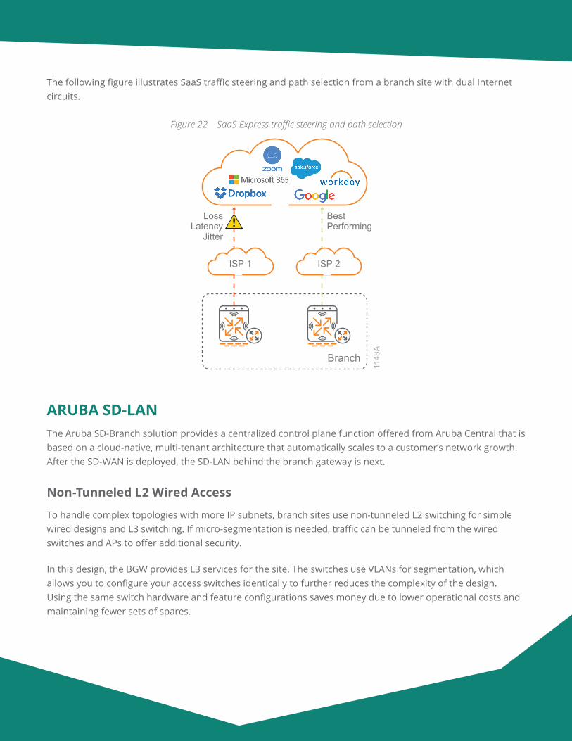
The following figure illustrates SaaS traffic steering and path selection from a branch site with dual Internet circuits.
Figure 22 SaaS Express traffic steering and path selection
Branch
1148
A
BestPerforming
LossLatency
Jitter
ISP 1 ISP 2
ARUBA SD-LANThe Aruba SD-Branch solution provides a centralized control plane function offered from Aruba Central that is based on a cloud-native, multi-tenant architecture that automatically scales to a customer’s network growth. After the SD-WAN is deployed, the SD-LAN behind the branch gateway is next.
Non-Tunneled L2 Wired Access
To handle complex topologies with more IP subnets, branch sites use non-tunneled L2 switching for simple wired designs and L3 switching. If micro-segmentation is needed, traffic can be tunneled from the wired switches and APs to offer additional security.
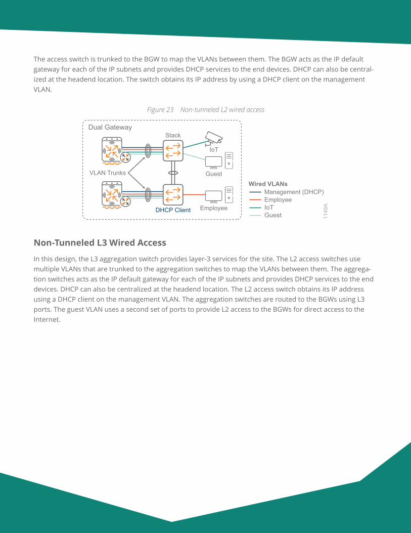
In this design, the BGW provides L3 services for the site. The switches use VLANs for segmentation, which allows you to configure your access switches identically to further reduces the complexity of the design. Using the same switch hardware and feature configurations saves money due to lower operational costs and maintaining fewer sets of spares.
Aruba Design & Deployment Guide 35
The access switch is trunked to the BGW to map the VLANs between them. The BGW acts as the IP default gateway for each of the IP subnets and provides DHCP services to the end devices. DHCP can also be central-ized at the headend location. The switch obtains its IP address by using a DHCP client on the management VLAN.
Figure 23 Non-tunneled L2 wired access
Dual Gateway
VLAN Trunks
Stack
DHCP Client
Guest
IoT
Employee
1149
A
Wired VLANs
GuestIoTEmployeeManagement (DHCP)
Non-Tunneled L3 Wired Access
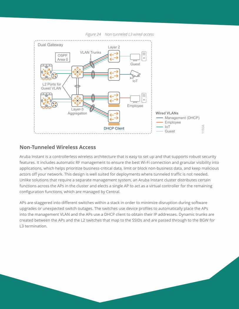
In this design, the L3 aggregation switch provides layer-3 services for the site. The L2 access switches use multiple VLANs that are trunked to the aggregation switches to map the VLANs between them. The aggrega-tion switches acts as the IP default gateway for each of the IP subnets and provides DHCP services to the end devices. DHCP can also be centralized at the headend location. The L2 access switch obtains its IP address using a DHCP client on the management VLAN. The aggregation switches are routed to the BGWs using L3 ports. The guest VLAN uses a second set of ports to provide L2 access to the BGWs for direct access to the Internet.
Aruba Design & Deployment Guide 36
Figure 24 Non-tunneled L3 wired access
Dual Gateway
L2 Ports forGuest VLAN
VLAN Trunks
Layer-3Aggregation
Layer 2
DHCP Client
Guest
IoT
Employee
1150
A
OSPFArea 0
Wired VLANs
GuestIoTEmployeeManagement (DHCP)
Non-Tunneled Wireless Access
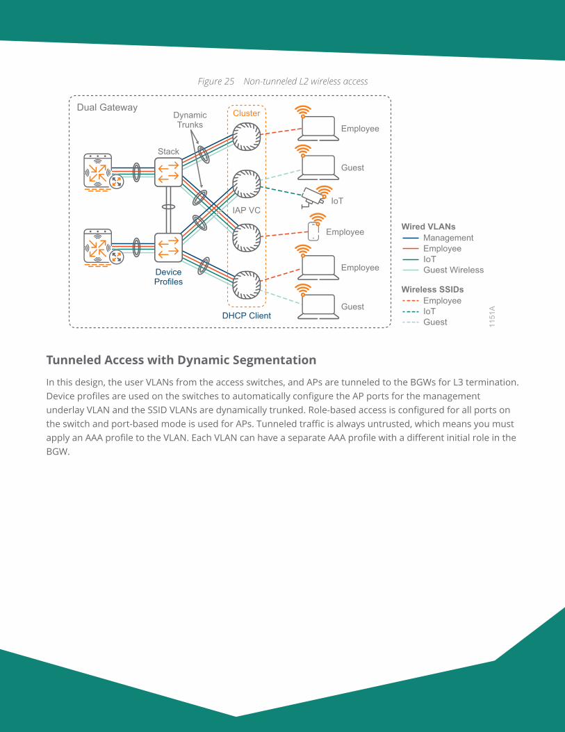
Aruba Instant is a controllerless wireless architecture that is easy to set up and that supports robust security features. It includes automatic RF management to ensure the best Wi-Fi connection and granular visibility into applications, which helps prioritize business-critical data, limit or block non-business data, and keep malicious actors off your network. This design is well suited for deployments where tunneled traffic is not needed. Unlike solutions that require a separate management system, an Aruba Instant cluster distributes certain functions across the APs in the cluster and elects a single AP to act as a virtual controller for the remaining configuration functions, which are managed by Central.
APs are staggered into different switches within a stack in order to minimize disruption during software upgrades or unexpected switch outages. The switches use device profiles to automatically place the APs into the management VLAN and the APs use a DHCP client to obtain their IP addresses. Dynamic trunks are created between the APs and the L2 switches that map to the SSIDs and are passed through to the BGW for L3 termination.
Aruba Design & Deployment Guide 37
Figure 25 Non-tunneled L2 wireless access
ClusterDual GatewayDynamicTrunks
Stack
DHCP Client
DeviceProfiles
Guest
Employee
IoT
Employee
Guest
Employee
IAP VC
1151
A
Wireless SSIDs
GuestIoTEmployee
Wired VLANs
Guest WirelessIoTEmployeeManagement
Tunneled Access with Dynamic Segmentation
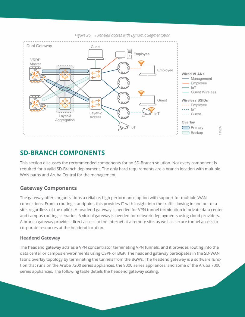
In this design, the user VLANs from the access switches, and APs are tunneled to the BGWs for L3 termination. Device profiles are used on the switches to automatically configure the AP ports for the management underlay VLAN and the SSID VLANs are dynamically trunked. Role-based access is configured for all ports on the switch and port-based mode is used for APs. Tunneled traffic is always untrusted, which means you must apply an AAA profile to the VLAN. Each VLAN can have a separate AAA profile with a different initial role in the BGW.
Aruba Design & Deployment Guide 38
Figure 26 Tunneled access with Dynamic Segmentation
Dual Gateway
Layer-3Aggregation
1152
A
Wireless SSIDs
GuestIoTEmployee
OverlayPrimaryBackup
Wired VLANs
Guest WirelessIoTEmployeeManagement
Layer-2Access
VRRPMaster
Guest
Employee
Guest
Employee
IoT
IoT
SD-BRANCH COMPONENTSThis section discusses the recommended components for an SD-Branch solution. Not every component is required for a valid SD-Branch deployment. The only hard requirements are a branch location with multiple WAN paths and Aruba Central for the management.
Gateway Components
The gateway offers organizations a reliable, high performance option with support for multiple WAN connections. From a routing standpoint, this provides IT with insight into the traffic flowing in and out of a site, regardless of the uplink. A headend gateway is needed for VPN tunnel termination in private data center and campus routing scenarios. A virtual gateway is needed for network deployments using cloud providers. A branch gateway provides direct access to the Internet at a remote site, as well as secure tunnel access to corporate resources at the headend location.
Headend Gateway
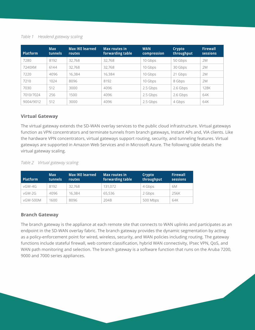
The headend gateway acts as a VPN concentrator terminating VPN tunnels, and it provides routing into the data center or campus environments using OSPF or BGP. The headend gateway participates in the SD-WAN fabric overlay topology by terminating the tunnels from the BGWs. The headend gateway is a software func-tion that runs on the Aruba 7200 series appliances, the 9000 series appliances, and some of the Aruba 7000 series appliances. The following table details the headend gateway scaling.
Aruba Design & Deployment Guide 39
Table 1 Headend gateway scaling
PlatformMax tunnels
Max IKE learned routes
Max routes in forwarding table
WAN compression
Crypto throughput
Firewall sessions
7280 8192 32,768 32,768 10 Gbps 50 Gbps 2M
7240XM 6144 32,768 32,768 10 Gbps 30 Gbps 2M
7220 4096 16,384 16,384 10 Gbps 21 Gbps 2M
7210 1024 8096 8192 10 Gbps 8 Gbps 2M
7030 512 3000 4096 2.5 Gbps 2.6 Gbps 128K
7010/7024 256 1500 4096 2.5 Gbps 2.6 Gbps 64K
9004/9012 512 3000 4096 2.5 Gbps 4 Gbps 64K
Virtual Gateway
The virtual gateway extends the SD-WAN overlay services to the public cloud infrastructure. Virtual gateways function as VPN concentrators and terminate tunnels from branch gateways, Instant APs and, VIA clients. Like the hardware VPN concentrators, virtual gateways support routing, security, and tunneling features. Virtual gateways are supported in Amazon Web Services and in Microsoft Azure. The following table details the virtual gateway scaling.
Table 2 Virtual gateway scaling
PlatformMax tunnels
Max IKE learned routes
Max routes in forwarding table
Crypto throughput
Firewall sessions
vGW-4G 8192 32,768 131,072 4 Gbps 6M
vGW-2G 4096 16,384 65,536 2 Gbps 256K
vGW-500M 1600 8096 2048 500 Mbps 64K
Branch Gateway
The branch gateway is the appliance at each remote site that connects to WAN uplinks and participates as an endpoint in the SD-WAN overlay fabric. The branch gateway provides the dynamic segmentation by acting as a policy-enforcement point for wired, wireless, security, and WAN policies including routing. The gateway functions include stateful firewall, web content classification, hybrid WAN connectivity, IPsec VPN, QoS, and WAN path monitoring and selection. The branch gateway is a software function that runs on the Aruba 7200, 9000 and 7000 series appliances.
Aruba Design & Deployment Guide 40
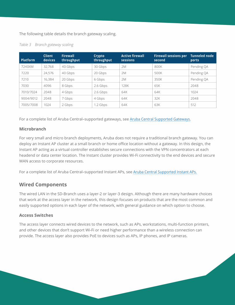
The following table details the branch gateway scaling.
Table 3 Branch gateway scaling
PlatformClient devices
Firewall throughput
Crypto throughput
Active firewall sessions
Firewall sessions per second
Tunneled node ports
7240XM 32,768 40 Gbps 30 Gbps 2M 800K Pending QA
7220 24,576 40 Gbps 20 Gbps 2M 500K Pending QA
7210 16,384 20 Gbps 6 Gbps 2M 350K Pending QA
7030 4096 8 Gbps 2.6 Gbps 128K 65K 2048
7010/7024 2048 4 Gbps 2.6 Gbps 64K 64K 1024
9004/9012 2048 7 Gbps 4 Gbps 64K 32K 2048
7005/7008 1024 2 Gbps 1.2 Gbps 64K 63K 512
For a complete list of Aruba Central–supported gateways, see Aruba Central Supported Gateways.
Microbranch
For very small and micro branch deployments, Aruba does not require a traditional branch gateway. You can deploy an Instant AP cluster at a small branch or home office location without a gateway. In this design, the Instant AP acting as a virtual controller establishes secure connections with the VPN concentrators at each headend or data center location. The Instant cluster provides Wi-Fi connectivity to the end devices and secure WAN access to corporate resources.
For a complete list of Aruba Central–supported Instant APs, see Aruba Central Supported Instant APs.
Wired Components
The wired LAN in the SD-Branch uses a layer-2 or layer-3 design. Although there are many hardware choices that work at the access layer in the network, this design focuses on products that are the most common and easily supported options in each layer of the network, with general guidance on which option to choose.
Access Switches
The access layer connects wired devices to the network, such as APs, workstations, multi-function printers, and other devices that don’t support Wi-Fi or need higher performance than a wireless connection can provide. The access layer also provides PoE to devices such as APs, IP phones, and IP cameras.
Aruba Design & Deployment Guide 41
The following features are common across the Aruba access switches:
• Support for security and network management with Aruba ClearPass and Aruba Central
• REST APIs for automation
• PoE for APs, IP phones, and IoT devices
The number of ports needed in an access closet and the performance required determine which access switch model is the best fit for your network.
Aruba 5400R—The Aruba 5400R chassis supports a variety of interface modules that provide copper and fiber interfaces in different speeds and densities. At the access layer, the switch supports up to 96 HP Smart Rate Multi-Gigabit or 288 1-GbE ports with PoE+. This switch is ideal for organizations that need large numbers of access ports in high-density areas of their network (majority of access closets with 96+ ports). Features:
• Layer-3 modular switch with VSF stacking, tunnel node, ACLs, robust QoS, low latency, and resiliency
• HPE Smart Rate for high-speed multi-gigabit bandwidth (IEEE 802.3bz) and PoE+
• Scalable line-rate 40 GbE for wireless traffic aggregation
Aruba 3810M—The Aruba 3810M is available with either 24 or 48 1-GbE access ports with PoE+ (30W) on each port and either 4 SPF+ ports or 2 40-GbE ports on an optional expansion module. The 3810M is also available in a model with 40 1-GbE ports and 8 HPE Smart Rate ports capable of 1, 2.5, 5, or 10 GbE. The 3810M supports backplane stacking with up to 10 switches in a single stack and advanced layer-3 services. It also supports meshed stacking. This switch is ideal for organizations that have larger access closets requiring larger switch stacks, are deploying or planning on deploying 802.11ac Wave 2 APs and want a switch with high performance and room for future growth. Features:
• Layer-3 switch with backplane stacking, tunnel node, ACLs, robust QoS, low latency, and resiliency
• HPE Smart Rate for high-speed multi-gigabit bandwidth (IEEE 802.3bz) and PoE+
• Modular line-rate 10-GbE and 40-GbE ports for wireless aggregation
Aruba Design & Deployment Guide 42
Aruba 2930M—The Aruba 2930M is available with either 24 or 48 1-GbE access ports with PoE+ (30W) on each port and either 4 SPF+ ports or 2 40-GbE ports on an optional expansion module. The 2930M is also available in a model with 40 1-GbE ports and 8 HPE Smart Rate ports capable of 1, 2.5, 5, or 10 GbE. The 2930M supports backplane stacking with up to 10 switches in a single stack and dynamic layer-3 services. This switch is designed for organizations wanting to create a digital workplace optimized for mobile users with an integrated wired and wireless access network. Features:
• Layer-3 switch with backplane stacking, tunnel node, ACLs, and robust QoS
• HPE Smart Rate for high-speed multi-gigabit bandwidth (IEEE 802.3bz) and up to 1440 W PoE+
• Modular 10-GbE or 40-GbE uplinks
• Models with 24 ports of HPE Smart Rate with IEEE 802.3bz
Aruba 2930F—The Aruba 2930F is available with either 24 or 48 1-GbE access ports and 370W PoE+. The switch supports Virtual Switching Framework (VSF), allowing you to stack up to 8 switches using available front ports. Although the 2930F supports basic layer-3 features, it is typically deployed as a layer-2 switch. This switch is ideal for organizations that have smaller access closets requiring only one or two switches, are looking for good performance, and who can accept a limited feature set in return for lower cost. Features:
• Layer-3 switch with VSF stacking, tunnel node, ACLs, and robust QoS
• Convenient built-in 1GbE or 10GbE uplinks and up to 740 W PoE+
Aggregation Switches
The aggregation layer provides connectivity for all access layer switches and connects to the branch gateways. The aggregation layer is responsible for layer-3 routing in this design, and it handles all traffic between net-works on the LAN and traffic leaving the LAN for the WAN or the Internet. For high availability, the aggregation layer consists of a pair of switches acting as a single switch. If a switch fails or needs to be taken out of service for maintenance, the other switch continues forwarding traffic without interruption to the LAN services.
The following features are common across the aggregation switches:
• HPE Smart Rate for high-speed multi-gigabit bandwidth (IEEE 802.3bz) and PoE+
• Support for security and network management with Aruba ClearPass and Aruba Central
• REST APIs for the software-defined network
Aruba Design & Deployment Guide 43
Aruba 5400R—The Aruba 5400R chassis supports a variety of interface modules that provide copper and fiber interfaces in different speeds and densities. The switch supports up to 96 10-GbE ports (SFP+ and 10GBASE-T), 96 HP Smart Rate Multi-Gigabit, or 288 1-GbE ports with PoE+. This switch is ideal for organizations that need to aggregate many access switches and might need to connect servers, firewalls, or other network appliances directly to the aggregation layer. The 5400R chassis includes the following features:
• Layer-3 modular switch with VSF stacking, static routing, RIP, OSPF, ACLs, robust QoS, policy-based routing, low latency, and resiliency
• Scalable line-rate 40GbE for wireless traffic aggregation
Aruba 3810M—The Aruba 3810M is available in a 16 port SFP+ and a two-module slot model. The module slots allow for an additional 8 SFP+ or 2 40-GbE ports. This switch is ideal for organizations with a small LAN who to aggregate 1 or 10-GbE connected access switches. The 3810 includes the following features:
• Layer-3 switch with backplane stacking, static routing, RIP, OSPF, ACLs, robust QoS, policy-based rout-ing, low latency, and resiliency
• Modular line-rate 10-GbE and 40-GbE ports for wireless aggregation
For a complete list of Aruba Central–supported switches, see Aruba Central Supported Switches.
Wireless Components
With Aruba’s controllerless model called Instant, there is no central controller and the controller functions are distributed among the APs. Instant is typically used in smaller networks or branch sites and scales up to 128 APs per cluster. In this design, we recommend deploying Aruba Instant with up to 50 APs. If you are planning to install more than 50 Instant APs, please contact an Aruba or partner SE/CSE for verification of your design.
Access Points
There are currently two series of Aruba access points: the latest generation 5xx series 802.11ax APs and the 3xx series 802.11ac Wave 2 APs. Details about currently available models are listed below; they support different throughput and client loads to meet different deployment needs.
The last digit in the model number denotes the antenna type. If the number is 4, then the AP has connectors for external antennas. If the number is 5, then the AP has internal antennas. For example, IAP-334 has external antennas and IAP-335 has internal antennas. In most office deployments, internal antenna models are preferred.
Aruba Design & Deployment Guide 44
The following features are common across the current Aruba 5xx and 3xx APs:
• Unified AP for either controller-based or controllerless deployment modes
• Hitless PoE failover between both Ethernet ports (dual Ethernet models only)
• Built-in Bluetooth Low-Energy radio
• Advanced Cellular Coexistence to minimize interference from cellular networks
• Support for security and network management with Aruba ClearPass and Aruba Central
• Application visibility for QoS and traffic control
• Enhanced security with WPA3 and Enhanced Open
Aruba 5xx Series Access Point Options
The Aruba 5xx Series of campus access points support 802.11ax to efficiently and simultaneously serve mul-tiple clients and traffic types in dense environments. These APs offer increased data rates for both individual device and overall system while delivering high performance and throughput in environments where mobile and IoT density is a growing concern.
Aruba 5xx common capabilities:
• Dual uplink ports with LACP support for redundancy and increased capacity
• Bluetooth 5 and Zigbee radios for location and IoT use-cases
• Green AP mode for energy savings up to 70%
Aruba 550 Series Access Points—The Aruba 550 Series APs are ideal for extreme high-density environments, such as public venues, higher education, hotels, and enterprise offices. The 550 series supports maximum data rates of 4.8Gbps in the 5GHz band and 1,150Mbps in the 2.4GHz band (for an aggregate peak rate of 5.95Gbps). The Aruba 550 series requires ArubaOS and Aruba InstantOS 8.5 software, and its features include:
• Dual-radio (8x8 + 4x4 MIMO)
• Optional tri-radio mode* with two 5GHz and one 2.4GHz radio (all 4x4 MIMO)
• Dual 5G HPE Smart Rate ports
• AI-powered features for wireless RF and client connectivity optimization
• Up to 1024 associated client devices per radio (recommended active 200) *
*Some 5xx features are not supported in the initial release but will be enabled in future software releases.
Aruba Design & Deployment Guide 45
Aruba 530 Series Access Points—The Aruba 530 Series APs are ideal for very high-density environments, such as higher education, K12, retail branches, hotels, and digital workplaces. The 530 series supports maximum data rates of 2.4Gbps in the 5GHz band and 1,150Mbps in the 2.4GHz band (for an aggregate peak rate of 3.55Gbps). The Aruba 530 series requires ArubaOS and Aruba InstantOS 8.5 software, and its features include:
• Dual-radio (dual 4x4 MIMO)
• Dual 5G HPE Smart Rate ports
• AI-powered features for wireless RF and client connectivity optimization
• Up to 1024 associated client devices per radio (recommended active 200)*
*Some 5xx features are not supported in the initial release but will be enabled in future software releases.
Aruba 510 Series Access Points—The Aruba 510 Series APs are ideal for high-density environments, such as schools, retail branches, hotels, and enterprise offices. The 510 series supports maximum data rates of 2.4Gbps in the 5GHz band and 575Mbps in the 2.4GHz band (for an aggregate peak data rate of 2.975Gbps). The Aruba 510 series requires ArubaOS and Aruba InstantOS 8.4 software, and its features include:
• Dual-radio (4x4 + 2x2 MIMO)
• Single 2.5G HPE Smart Rate and Gigabit Ethernet uplink ports
• Up to 256 associated client devices per radio
Aruba 3xx Series Access Point Options
Aruba 340 Series Access Points—The Aruba 340 Series is the highest performance AP and supports HPE Smart Rate uplink, so it can use the full performance of 3.5 Gbps on two 5-GHz bands or 1.7 Gbps in the 5-GHz band and 800Mbps in the 2.4-GHz band, for a combined bandwidth of 2.5 Gbps. This model is ideal for organizations that require very high density and next-generation performance for auditoriums, high-density office environments, or public venues. The Aruba 340 series requires ArubaOS and Aruba InstantOS 8.3 software.
• Dual radio 4x4 802.11ac AP with MU-MIMO
• Optional dual 5-GHz mode supported, where the 2.4-GHz radio is converted to a second 5-GHz radio
• Antenna polarization diversity for optimized RF performance
• HPE Smart Rate and Gigabit Ethernet uplink ports with Link Aggregation Control Protocol (LACP) support for increased capacity
• Hitless PoE failover between both Ethernet ports
Aruba Design & Deployment Guide 46
Aruba 330 Series Access Points—The Aruba 330 Series is a high-performance AP and supports HPE Smart Rate uplink, so it can use the full performance of 1.7 Gbps in 5-GHz band and 600Mbps in 2.4-GHz band for a combined bandwidth of 2.3 Gbps. This model is ideal for organizations that require high density and next-generation performance for auditoriums, high-density office environments, or public venues.
• Antenna polarization diversity for optimized RF performance
• HPE Smart Rate and Gigabit Ethernet uplink ports with LACP support for increased capacity
• Hitless PoE failover between both Ethernet ports
Aruba 310 Series Access Points—The Aruba 310 Series is a medium-performance AP that supports 1.7 Gbps in the 5GHz band and 300 Mbps in the 2.4-GHz band with a single Gigabit Ethernet uplink. This model is ideal for organizations that need to support medium-density environments, such as schools, retail branches, hotels, and enterprise offices that don’t require multi-gigabit performance.
Aruba 300 Series Access Points—The Aruba 300 Series is an entry-level AP that supports 1.3 Gbps in the 5-GHz band and 300 Mbps in the 2.4-GHz band with a single Gigabit Ethernet uplink. This model is ideal for organizations with medium-density environments, organizations that want the latest technology but don’t need the higher level of performance.
For a complete list of Aruba Central–supported Instant APs, see Aruba Central Supported Instant APs.
Aruba Design & Deployment Guide 47
Deploying the SD-Branch
The Aruba SD-Branch design provides SD-WAN, wired, and wireless connectivity for branch users. The SD-WAN interconnects the corporate site with the remote-site locations, making it a critical part of the network. Modern WAN networks require a flexible and scalable design to support mission-critical applications and real-time multimedia communications from any location on the corporate network. Access to cloud-based services from each branch location is also critical to the success of keeping the network running as efficiently as possible.
The SD-Branch design:
• Combines SD-WAN, wireless, and wired infrastructure with cloud-based orchestration
• Provides location-independent network access to improve employee and guest productivity
• Simplifies setup with zero-touch provisioning and plug-and-play branch deployment
• Provides wireless connectivity to hard-to-wire locations, eliminating the need for costly construction
• Simplifies configuring, managing, and operating, by using cloud-based controls
Simple, repeatable designs are easier to deploy, manage, and maintain. This design shows recommended deployment options and general guidance for which options to use.
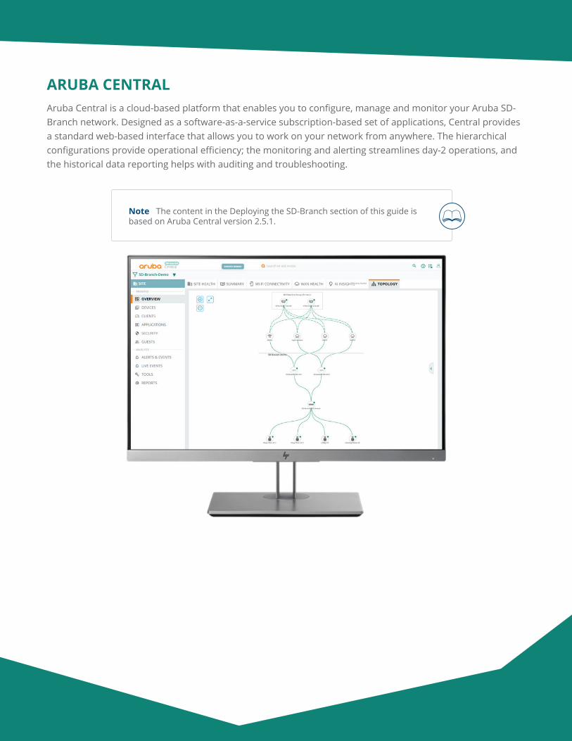
Aruba Design & Deployment Guide 48
ARUBA CENTRALAruba Central is a cloud-based platform that enables you to configure, manage and monitor your Aruba SD-Branch network. Designed as a software-as-a-service subscription-based set of applications, Central provides a standard web-based interface that allows you to work on your network from anywhere. The hierarchical configurations provide operational efficiency; the monitoring and alerting streamlines day-2 operations, and the historical data reporting helps with auditing and troubleshooting.
Note The content in the Deploying the SD-Branch section of this guide is based on Aruba Central version 2.5.1.
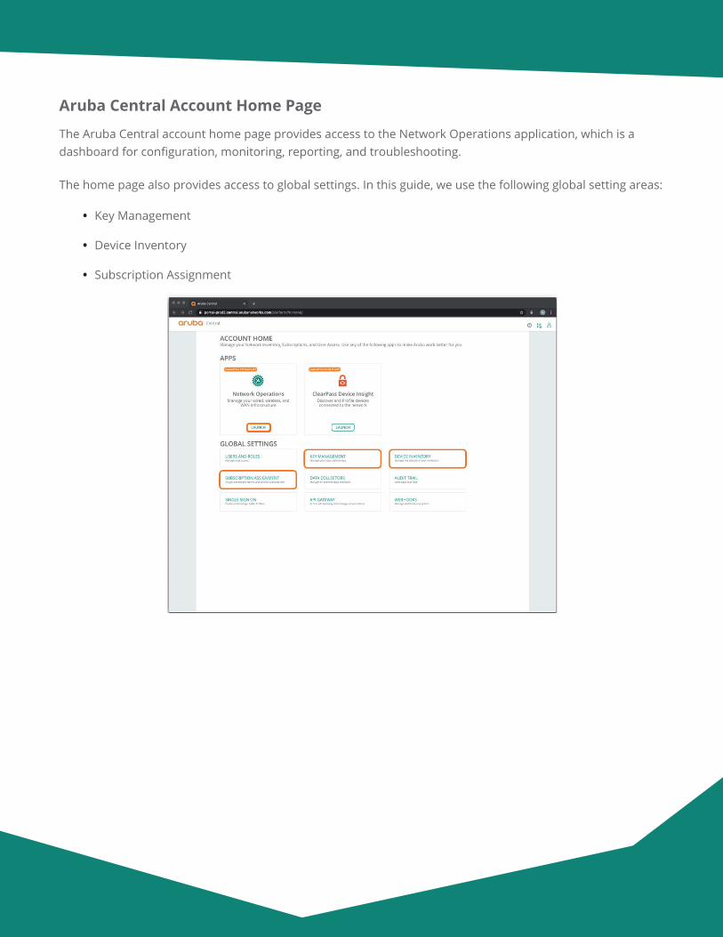
Aruba Design & Deployment Guide 49
Aruba Central Account Home Page
The Aruba Central account home page provides access to the Network Operations application, which is a dashboard for configuration, monitoring, reporting, and troubleshooting.
The home page also provides access to global settings. In this guide, we use the following global setting areas:
• Key Management
• Device Inventory
• Subscription Assignment
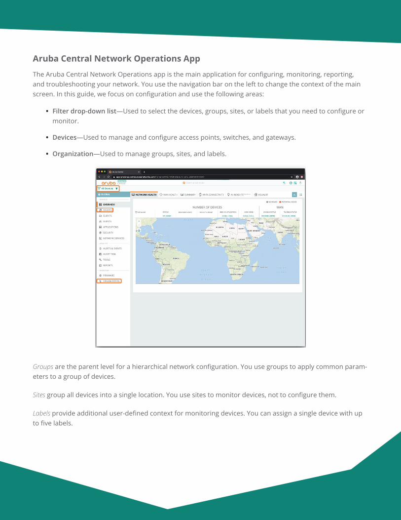
Aruba Design & Deployment Guide 50
Aruba Central Network Operations App
The Aruba Central Network Operations app is the main application for configuring, monitoring, reporting, and troubleshooting your network. You use the navigation bar on the left to change the context of the main screen. In this guide, we focus on configuration and use the following areas:
• Filter drop-down list—Used to select the devices, groups, sites, or labels that you need to configure or monitor.
• Devices—Used to manage and configure access points, switches, and gateways.
• Organization—Used to manage groups, sites, and labels.
Groups are the parent level for a hierarchical network configuration. You use groups to apply common param-eters to a group of devices.
Sites group all devices into a single location. You use sites to monitor devices, not to configure them.
Labels provide additional user-defined context for monitoring devices. You can assign a single device with up to five labels.
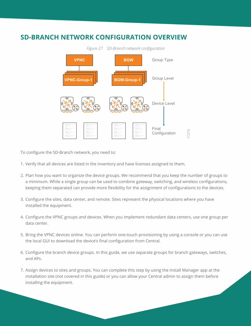
Aruba Design & Deployment Guide 51
SD-BRANCH NETWORK CONFIGURATION OVERVIEWFigure 27 SD-Branch network configuration
VPNC Group Type
VPNC-Group-1 Group Level
Device Level
FinalConfiguration
1127
A
BGW
BGW-Group-1
interface vlan 5 ip address 10.8.255.200 255.255.255.255 operstate up description "System IP"!
interface vlan 1 ip address 10.8.40.2 255.255.255.0 ip nat inside description "Management"!
interface vlan 20 ip address 10.8.41.2 255.255.255.0 ip nat inside description "Employee"!
interface vlan 999 ip address 192.168.99.2 255.255.255.0 ip nat inside description "Guest WiFi"!!
To configure the SD-Branch network, you need to:
1. Verify that all devices are listed in the inventory and have licenses assigned to them.
2. Plan how you want to organize the device groups. We recommend that you keep the number of groups to a minimum. While a single group can be used to combine gateway, switching, and wireless configurations, keeping them separated can provide more flexibility for the assignment of configurations to the devices.
3. Configure the sites, data center, and remote. Sites represent the physical locations where you have installed the equipment.
4. Configure the VPNC groups and devices. When you implement redundant data centers, use one group per data center.
5. Bring the VPNC devices online. You can perform one-touch provisioning by using a console or you can use the local GUI to download the device’s final configuration from Central.
6. Configure the branch device groups. In this guide, we use separate groups for branch gateways, switches, and APs.
7. Assign devices to sites and groups. You can complete this step by using the Install Manager app at the installation site (not covered in this guide) or you can allow your Central admin to assign them before installing the equipment.
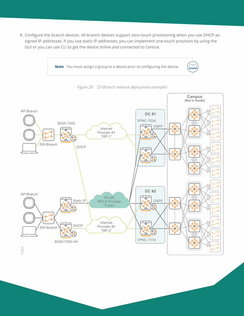
Aruba Design & Deployment Guide 52
8. Configure the branch devices. All branch devices support zero-touch provisioning when you use DHCP-as-signed IP addresses. If you use static IP addresses, you can implement one-touch provision by using the GUI or you can use CLI to get the device online and connected to Central.
Note You must assign a group to a device prior to configuring the device.
Figure 28 SD-Branch network deployment examples
AP-Branch
DC #2
DC #1
SW-Branch
BGW-7005
InternetProvider #2
“ISP-2”
InternetProvider #1
“ISP-1”
1128
A
AP-Branch
SW-Branch
BGW-7005-HA
DHCP
OSPFStatic IP
DHCP
VPNC-7210
VPNC-7024
WLANMPLS Provider
“Turbo”
OSPF
Campus(Not in Guide)
Aruba Design & Deployment Guide 53
Preparing to Deploy the SD-Branch Network
1.1 Add Your Devices to the Device Inventory Manually
1.2 Configure the Device Subscription Keys
1.3 Assign Subscriptions to the Devices Manually
1.4 Define the Device Sites
Procedures
We recommend that you complete the steps in this section prior to configuring the network devices.
1.1 Add Your Devices to the Device Inventory Manually
Aruba Central automatically adds each device you purchase to the device inventory in your Central account. You also have the option of manually adding a device by using the MAC address and serial number of the device.
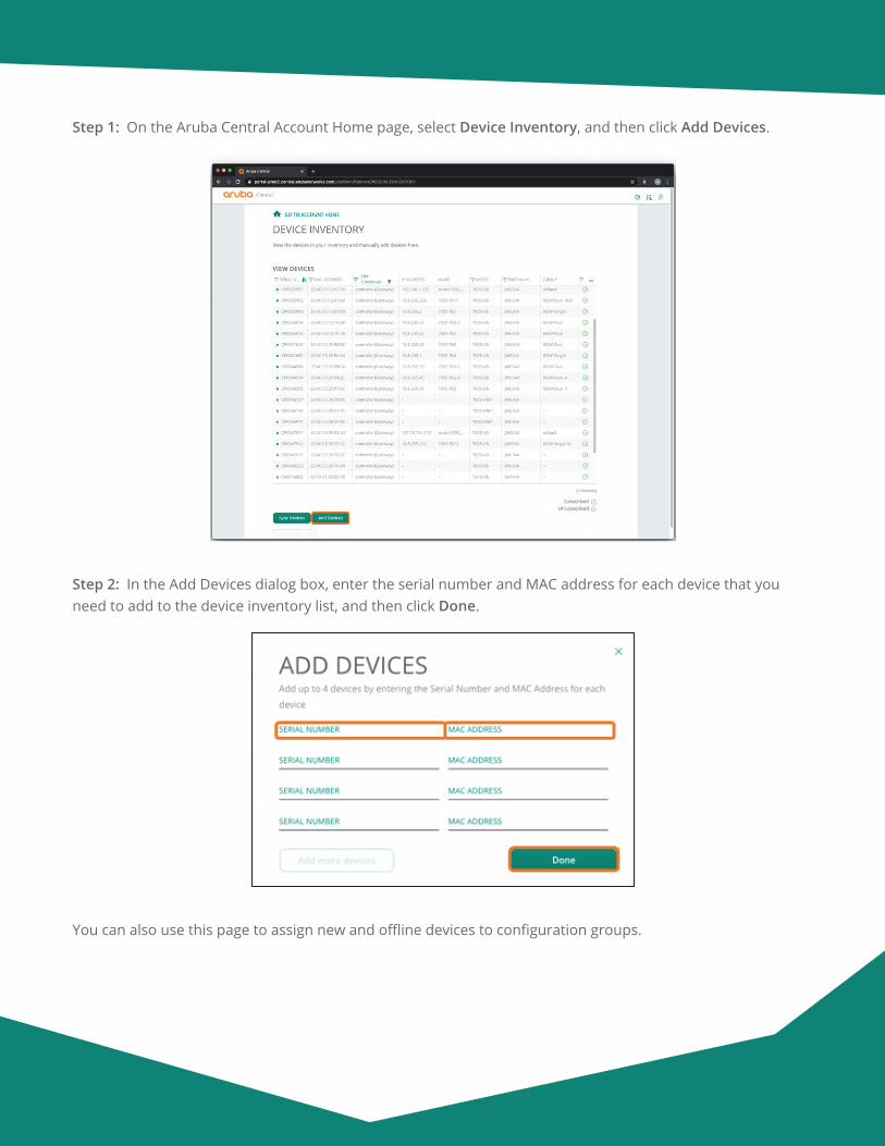
Aruba Design & Deployment Guide 54
Step 1: On the Aruba Central Account Home page, select Device Inventory, and then click Add Devices.
Step 2: In the Add Devices dialog box, enter the serial number and MAC address for each device that you need to add to the device inventory list, and then click Done.
You can also use this page to assign new and offline devices to configuration groups.
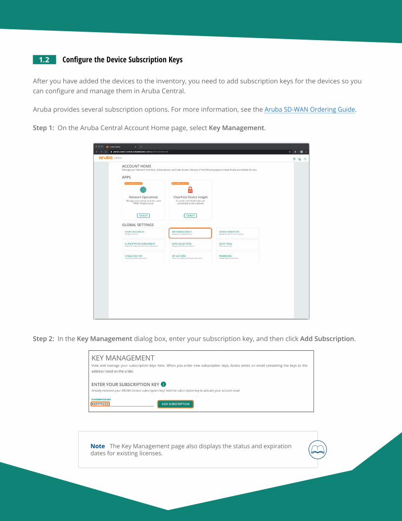
Aruba Design & Deployment Guide 55
1.2 Configure the Device Subscription Keys
After you have added the devices to the inventory, you need to add subscription keys for the devices so you can configure and manage them in Aruba Central.
Aruba provides several subscription options. For more information, see the Aruba SD-WAN Ordering Guide.
Step 1: On the Aruba Central Account Home page, select Key Management.
Step 2: In the Key Management dialog box, enter your subscription key, and then click Add Subscription.
Note The Key Management page also displays the status and expiration dates for existing licenses.
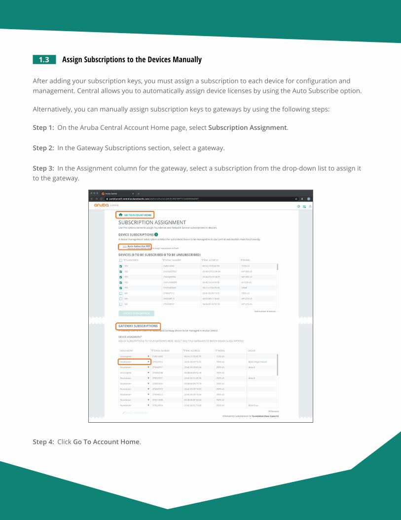
Aruba Design & Deployment Guide 56
1.3 Assign Subscriptions to the Devices Manually
After adding your subscription keys, you must assign a subscription to each device for configuration and management. Central allows you to automatically assign device licenses by using the Auto Subscribe option.
Alternatively, you can manually assign subscription keys to gateways by using the following steps:
Step 1: On the Aruba Central Account Home page, select Subscription Assignment.
Step 2: In the Gateway Subscriptions section, select a gateway.
Step 3: In the Assignment column for the gateway, select a subscription from the drop-down list to assign it to the gateway.
Step 4: Click Go To Account Home.
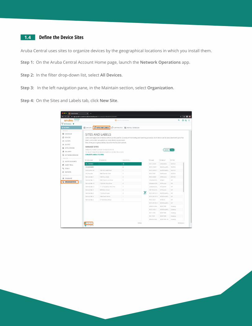
Aruba Design & Deployment Guide 57
1.4 Define the Device Sites
Aruba Central uses sites to organize devices by the geographical locations in which you install them.
Step 1: On the Aruba Central Account Home page, launch the Network Operations app.
Step 2: In the filter drop-down list, select All Devices.
Step 3: In the left navigation pane, in the Maintain section, select Organization.
Step 4: On the Sites and Labels tab, click New Site.
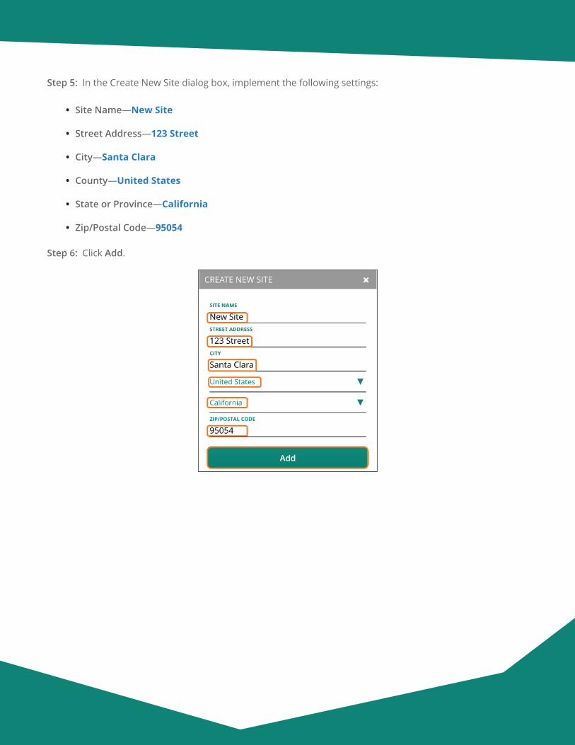
Aruba Design & Deployment Guide 58
Step 5: In the Create New Site dialog box, implement the following settings:
• Site Name—New Site
• Street Address—123 Street
• City—Santa Clara
• County—United States
• State or Province—California
• Zip/Postal Code—95054
Step 6: Click Add.

Aruba Design & Deployment Guide 59
Configuring the VPNC Group
2.1 Create a New VPNC Group
2.2 Select the Hardware Model of the VPNC Group
2.3 Set the VPNC Group System Time Parameters
2.4 Select a DNS Server for the VPNC Gateway
2.5 Create a Management User Account
2.6 Create VLANs for Each Ethernet Port
2.7 Assign the VLANs to the LAN Ports
2.8 Enable Tunnel Orchestrator Peering
2.9 Configure the Overlay Routing
Procedures
Aruba Central uses a two-level hierarchy for configuration tasks. A device’s final configuration is a combina-tion of the group configuration along with the device-specific configuration. Aruba recommends that you create groups for devices that have similar deployment parameters and that you use groups for most device configuration. You configure device-specific configurations, like IP addresses and routing, at the VPNC device level. Aruba recommends that you fully configure the gateways at the group and device level before connect-ing to the network to prevent partial configurations from creating connectivity issues .
2.1 Create a New VPNC Group
Use this procedure to create a group and assign it to the VPNC group type. Use one group per data center.
Step 1: On the Aruba Central Account Home page, launch the Network Operations app.
Step 2: In the filter drop-down list, select All Devices.
Step 3: In the left navigation pane, in the Maintain section, select Organization.
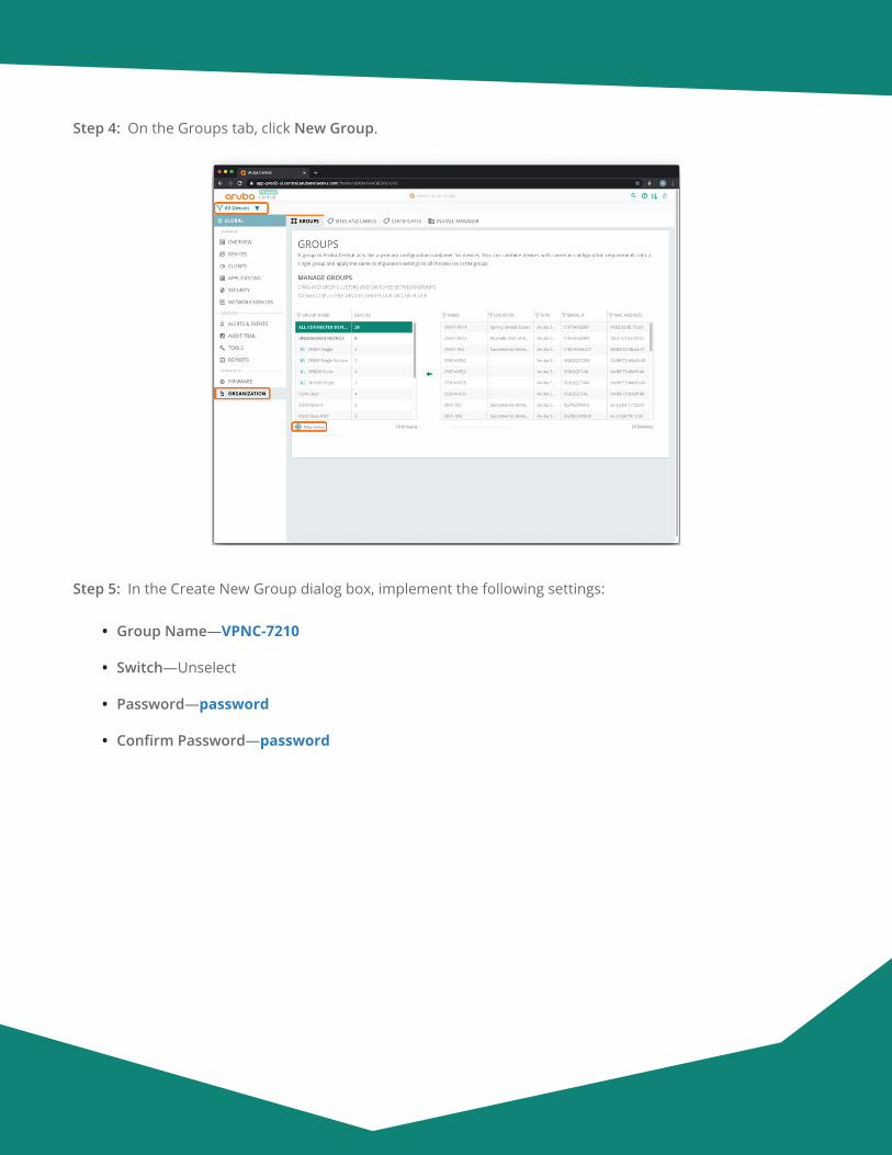
Aruba Design & Deployment Guide 60
Step 4: On the Groups tab, click New Group.
Step 5: In the Create New Group dialog box, implement the following settings:
• Group Name—VPNC-7210
• Switch—Unselect
• Password—password
• Confirm Password—password
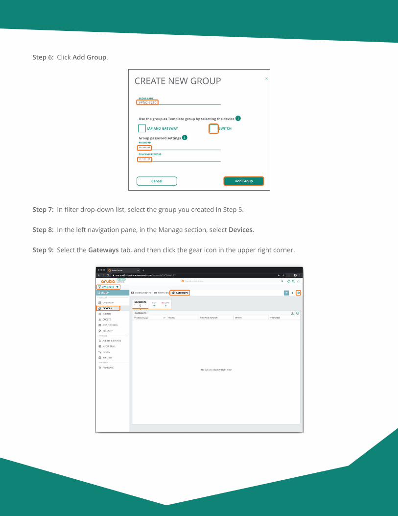
Aruba Design & Deployment Guide 61
Step 6: Click Add Group.
Step 7: In filter drop-down list, select the group you created in Step 5.
Step 8: In the left navigation pane, in the Manage section, select Devices.
Step 9: Select the Gateways tab, and then click the gear icon in the upper right corner.
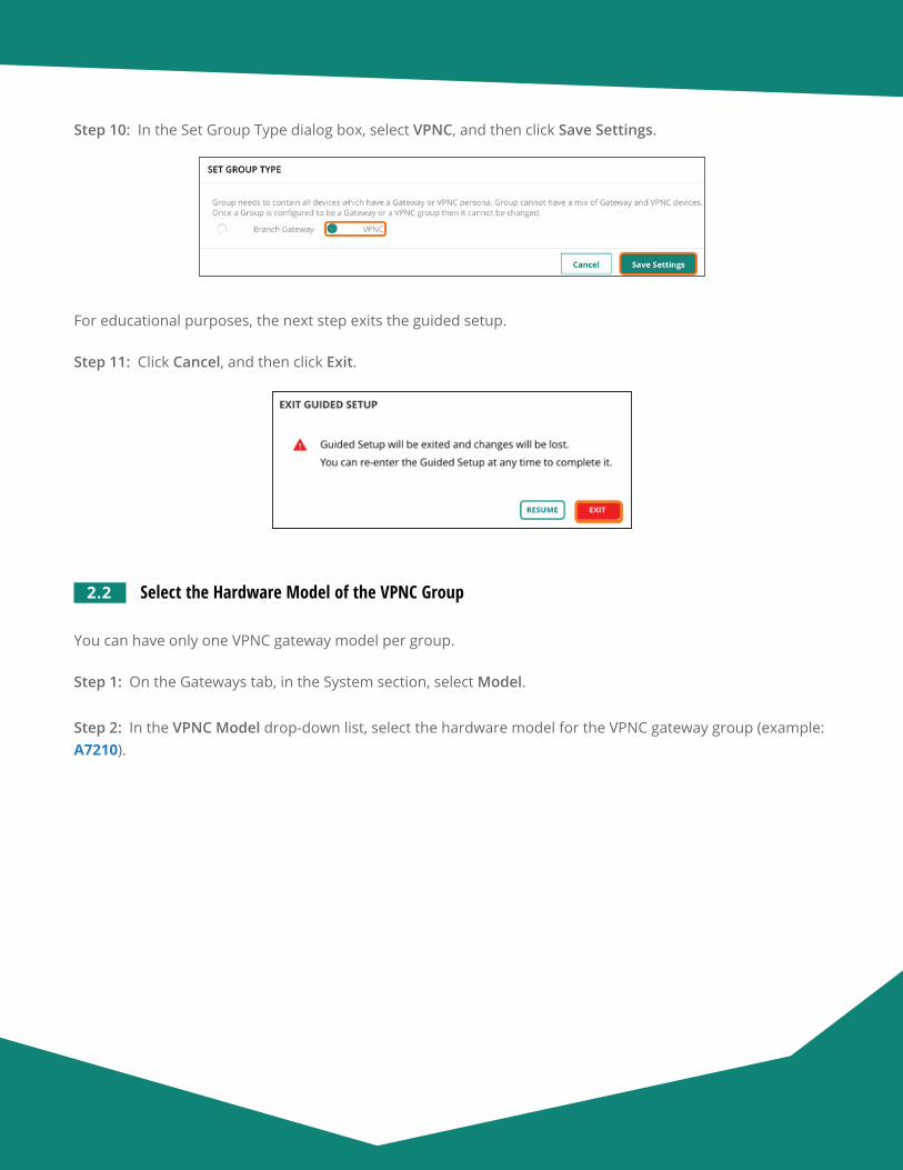
Aruba Design & Deployment Guide 62
Step 10: In the Set Group Type dialog box, select VPNC, and then click Save Settings.
For educational purposes, the next step exits the guided setup.
Step 11: Click Cancel, and then click Exit.
2.2 Select the Hardware Model of the VPNC Group
You can have only one VPNC gateway model per group.
Step 1: On the Gateways tab, in the System section, select Model.
Step 2: In the VPNC Model drop-down list, select the hardware model for the VPNC gateway group (example: A7210).
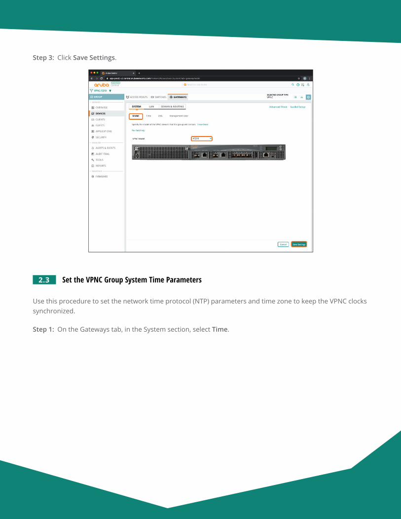
Aruba Design & Deployment Guide 63
Step 3: Click Save Settings.
2.3 Set the VPNC Group System Time Parameters
Use this procedure to set the network time protocol (NTP) parameters and time zone to keep the VPNC clocks synchronized.
Step 1: On the Gateways tab, in the System section, select Time.
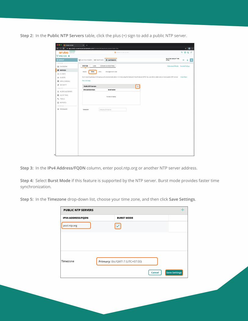
Aruba Design & Deployment Guide 64
Step 2: In the Public NTP Servers table, click the plus (+) sign to add a public NTP server.
-
Step 3: In the IPv4 Address/FQDN column, enter pool.ntp.org or another NTP server address.
Step 4: Select Burst Mode if this feature is supported by the NTP server. Burst mode provides faster time synchronization.
Step 5: In the Timezone drop-down list, choose your time zone, and then click Save Settings.
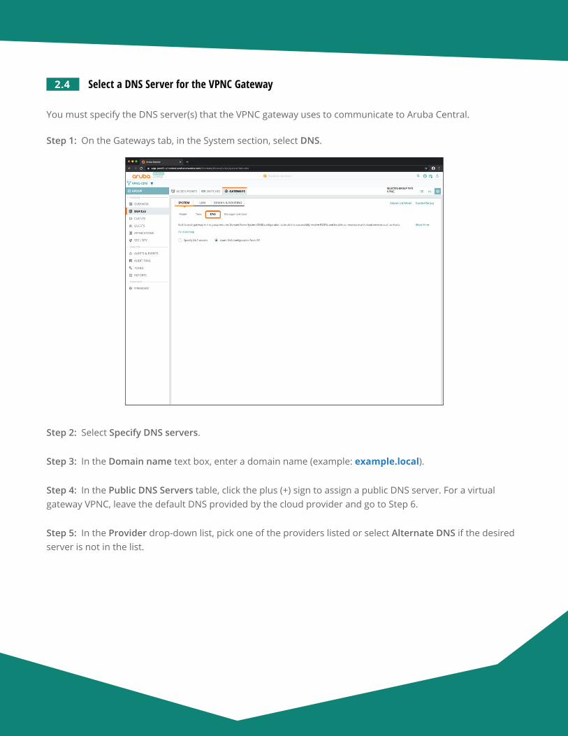
Aruba Design & Deployment Guide 65
2.4 Select a DNS Server for the VPNC Gateway
You must specify the DNS server(s) that the VPNC gateway uses to communicate to Aruba Central.
Step 1: On the Gateways tab, in the System section, select DNS.
Step 2: Select Specify DNS servers.
Step 3: In the Domain name text box, enter a domain name (example: example.local).
Step 4: In the Public DNS Servers table, click the plus (+) sign to assign a public DNS server. For a virtual gateway VPNC, leave the default DNS provided by the cloud provider and go to Step 6.
Step 5: In the Provider drop-down list, pick one of the providers listed or select Alternate DNS if the desired server is not in the list.
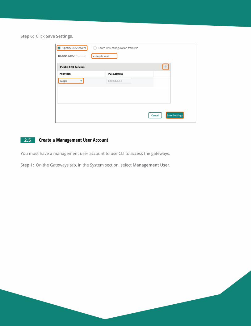
Aruba Design & Deployment Guide 66
Step 6: Click Save Settings.
2.5 Create a Management User Account
You must have a management user account to use CLI to access the gateways.
Step 1: On the Gateways tab, in the System section, select Management User.
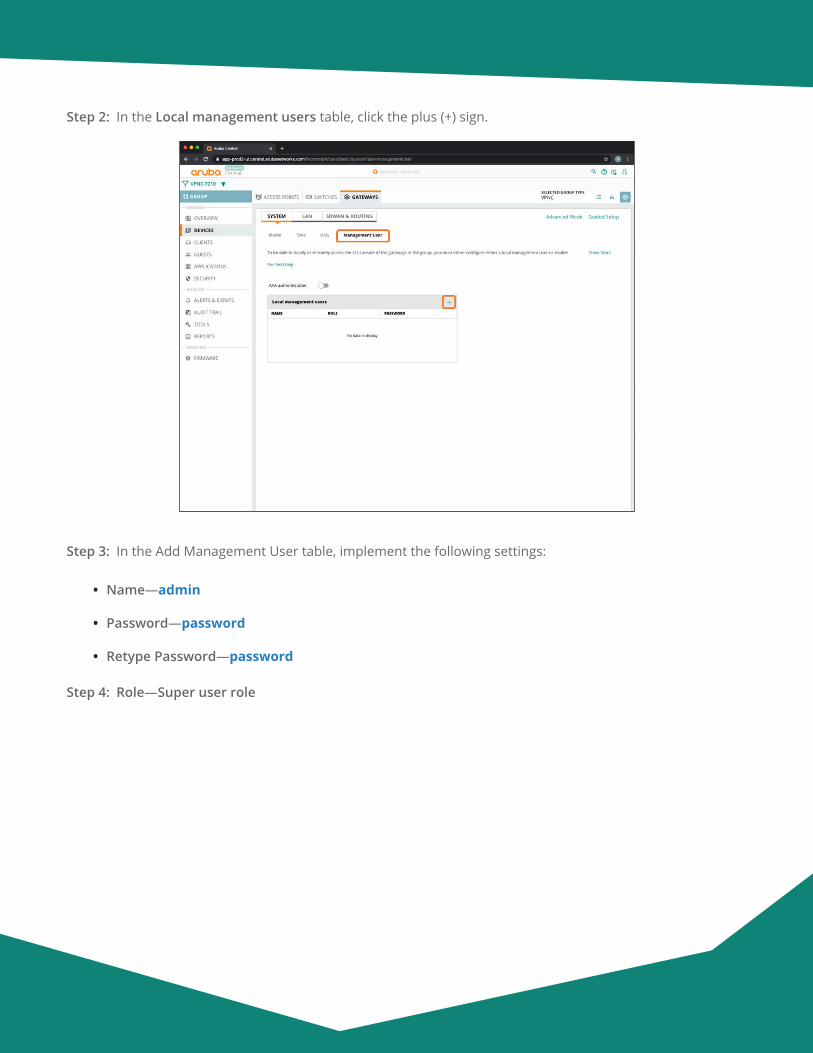
Aruba Design & Deployment Guide 67
Step 2: In the Local management users table, click the plus (+) sign.
Step 3: In the Add Management User table, implement the following settings:
• Name—admin
• Password—password
• Retype Password—password
Step 4: Role—Super user role
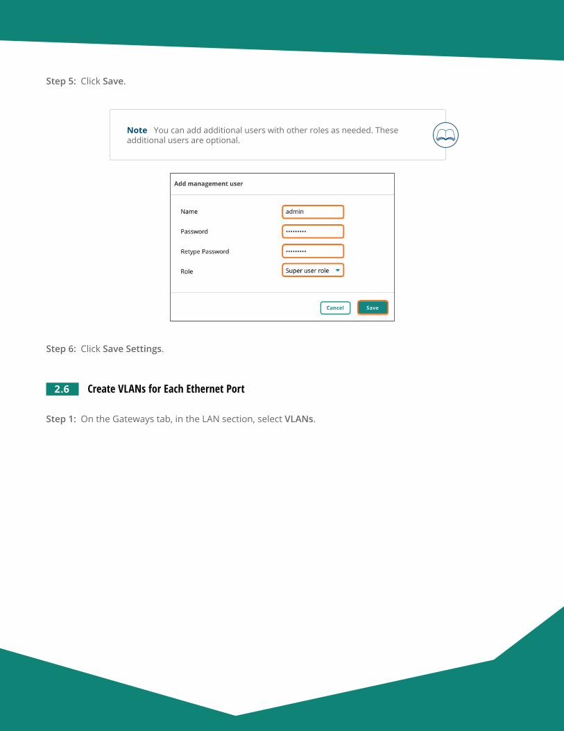
Aruba Design & Deployment Guide 68
Step 5: Click Save.
Note You can add additional users with other roles as needed. These additional users are optional.
Step 6: Click Save Settings.
2.6 Create VLANs for Each Ethernet Port
Step 1: On the Gateways tab, in the LAN section, select VLANs.
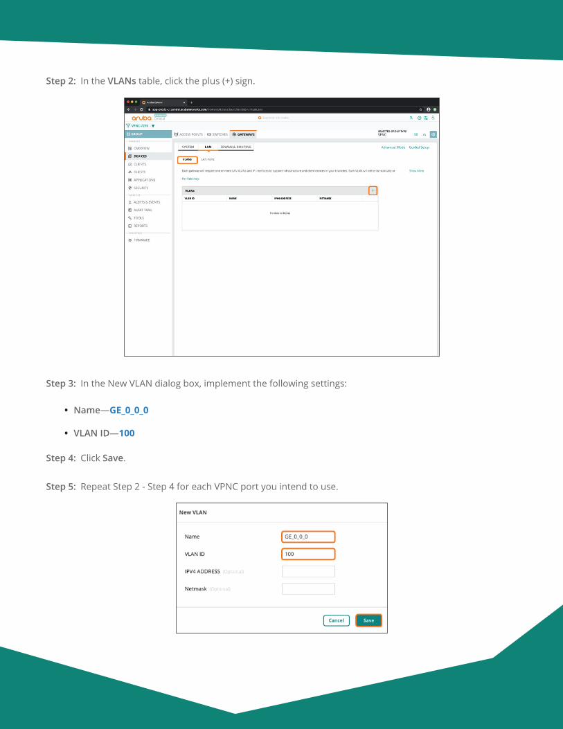
Aruba Design & Deployment Guide 69
Step 2: In the VLANs table, click the plus (+) sign.
Step 3: In the New VLAN dialog box, implement the following settings:
• Name—GE_0_0_0
• VLAN ID—100
Step 4: Click Save.
Step 5: Repeat Step 2 - Step 4 for each VPNC port you intend to use.

Aruba Design & Deployment Guide 70
Step 6: Verify the VLAN information in the summary table, and then click Save Settings.
2.7 Assign the VLANs to the LAN Ports
Step 1: On the Gateways tab, in the LAN section, select LAN Ports.
Step 2: In the LAN ports/port channel table, click the plus (+) sign.
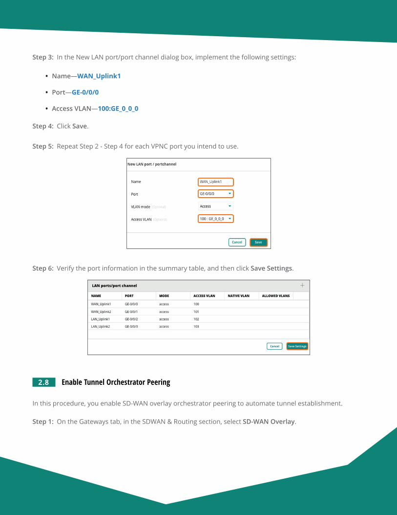
Aruba Design & Deployment Guide 71
Step 3: In the New LAN port/port channel dialog box, implement the following settings:
• Name—WAN_Uplink1
• Port—GE-0/0/0
• Access VLAN—100:GE_0_0_0
Step 4: Click Save.
Step 5: Repeat Step 2 - Step 4 for each VPNC port you intend to use.
Step 6: Verify the port information in the summary table, and then click Save Settings.
2.8 Enable Tunnel Orchestrator Peering
In this procedure, you enable SD-WAN overlay orchestrator peering to automate tunnel establishment.
Step 1: On the Gateways tab, in the SDWAN & Routing section, select SD-WAN Overlay.

Aruba Design & Deployment Guide 72
Step 2: Click Overlay Orchestrator Peering, and then click Save Settings.
2.9 Create a New Route Map
(Optional)
Use this procedure to create a route map. You can use this route map to control redistribution of specific overlay prefixes into OSPF.
Step 1: On the Gateways tab, in the SDWAN & Routing section, select Route Maps.
Step 2: On the Route Maps page, expand Route Maps to display the route maps table.
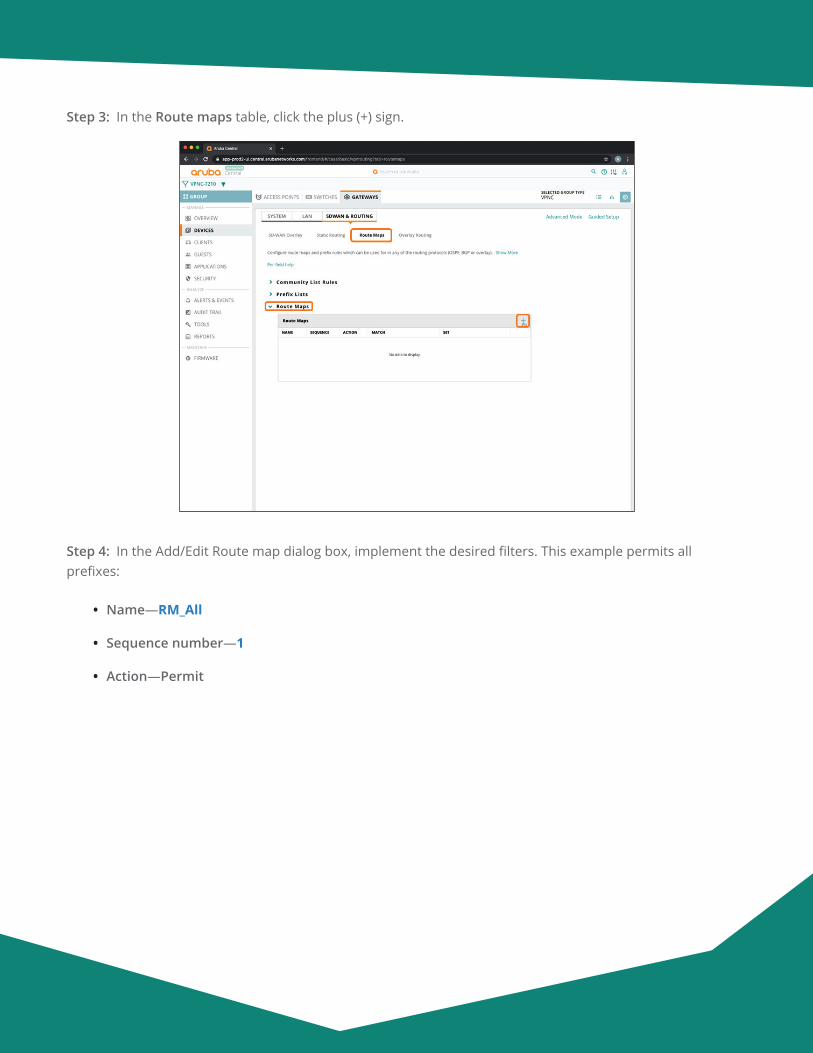
Aruba Design & Deployment Guide 73
Step 3: In the Route maps table, click the plus (+) sign.
Step 4: In the Add/Edit Route map dialog box, implement the desired filters. This example permits all prefixes:
• Name—RM_All
• Sequence number—1
• Action—Permit
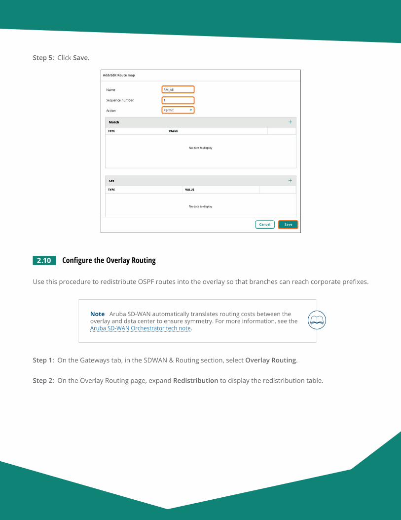
Aruba Design & Deployment Guide 74
Step 5: Click Save.
2.10 Configure the Overlay Routing
Use this procedure to redistribute OSPF routes into the overlay so that branches can reach corporate prefixes.
Note Aruba SD-WAN automatically translates routing costs between the overlay and data center to ensure symmetry. For more information, see the Aruba SD-WAN Orchestrator tech note.
Step 1: On the Gateways tab, in the SDWAN & Routing section, select Overlay Routing.
Step 2: On the Overlay Routing page, expand Redistribution to display the redistribution table.
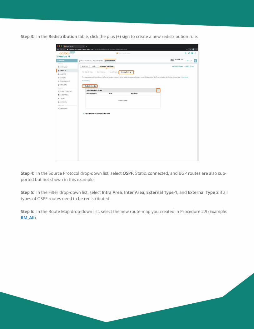
Aruba Design & Deployment Guide 75
Step 3: In the Redistribution table, click the plus (+) sign to create a new redistribution rule.
Step 4: In the Source Protocol drop-down list, select OSPF. Static, connected, and BGP routes are also sup-ported but not shown in this example.
Step 5: In the Filter drop-down list, select Intra Area, Inter Area, External Type-1, and External Type 2 if all types of OSPF routes need to be redistributed.
Step 6: In the Route Map drop-down list, select the new route-map you created in Procedure 2.9 (Example: RM_All).
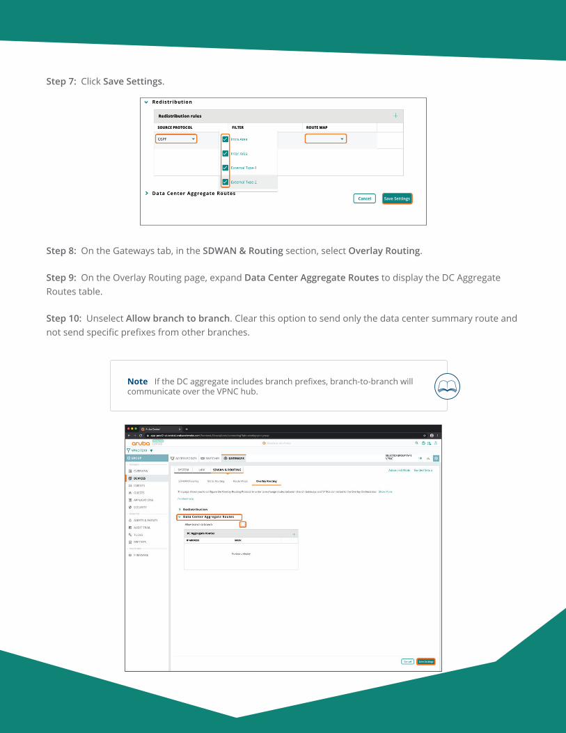
Aruba Design & Deployment Guide 76
Step 7: Click Save Settings.
Step 8: On the Gateways tab, in the SDWAN & Routing section, select Overlay Routing.
Step 9: On the Overlay Routing page, expand Data Center Aggregate Routes to display the DC Aggregate Routes table.
Step 10: Unselect Allow branch to branch. Clear this option to send only the data center summary route and not send specific prefixes from other branches.
Note If the DC aggregate includes branch prefixes, branch-to-branch will communicate over the VPNC hub.
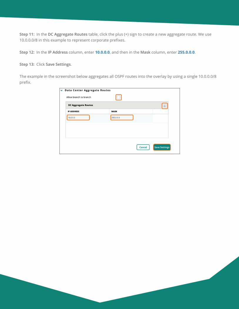
Aruba Design & Deployment Guide 77
Step 11: In the DC Aggregate Routes table, click the plus (+) sign to create a new aggregate route. We use 10.0.0.0/8 in this example to represent corporate prefixes.
Step 12: In the IP Address column, enter 10.0.0.0, and then in the Mask column, enter 255.0.0.0.
Step 13: Click Save Settings.
The example in the screenshot below aggregates all OSPF routes into the overlay by using a single 10.0.0.0/8 prefix.
Aruba Design & Deployment Guide 78
Configuring the VPNC Devices
3.1 Assign a VPNC Device to a Group
3.2 Initiate the VPNC Device Configuration
3.3 Configure the IP Address for the VPNC Device
3.4 Assign a Hostname to the VPNC Device
3.5 Assign IP Addresses to the VLANs
3.6 Configure the WAN Providers
3.7 Configure the Default Route to the Internet
3.8 Configure OSPF Routing to the LAN
3.9 Enable One-Touch Provisioning on the VPNC Device
Procedures
Repeat this set of procedures for each VPNC.
3.1 Assign a VPNC Device to a Group
In this procedure, you assign the VPNC device(s) to a group. Use one VPNC group per data center.
Step 1: On Aruba Central Account Home page, select Device Inventory.
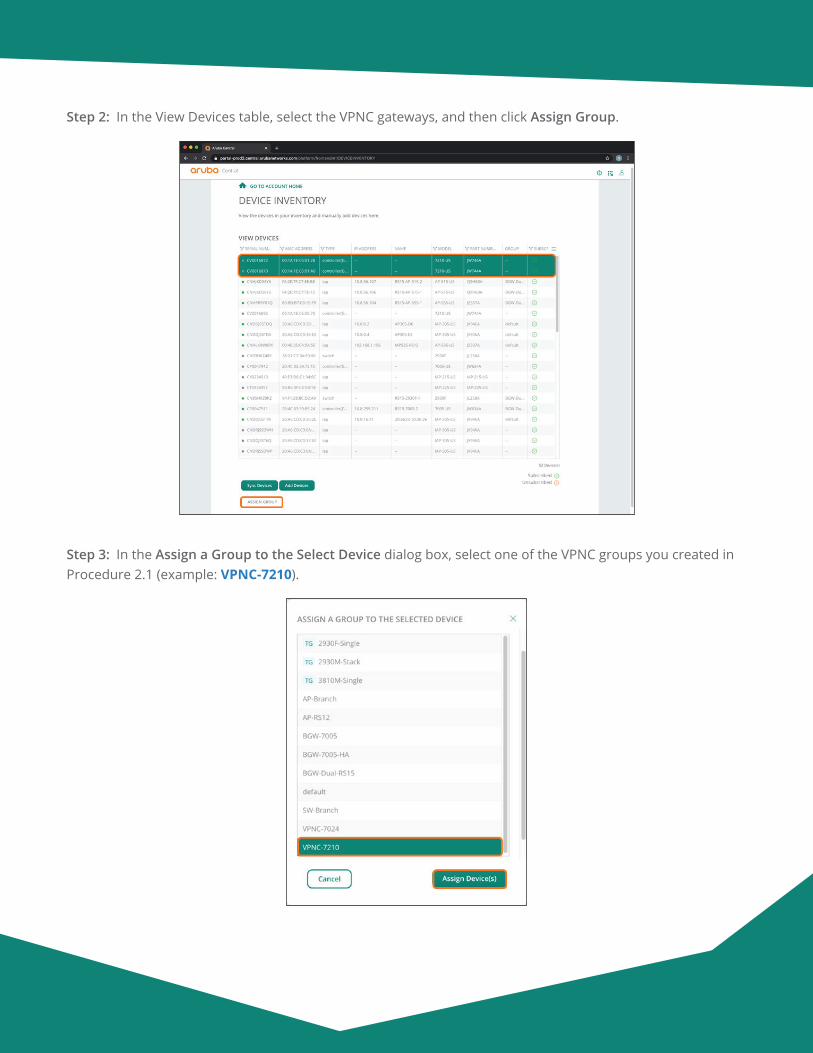
Aruba Design & Deployment Guide 79
Step 2: In the View Devices table, select the VPNC gateways, and then click Assign Group.
Step 3: In the Assign a Group to the Select Device dialog box, select one of the VPNC groups you created in Procedure 2.1 (example: VPNC-7210).
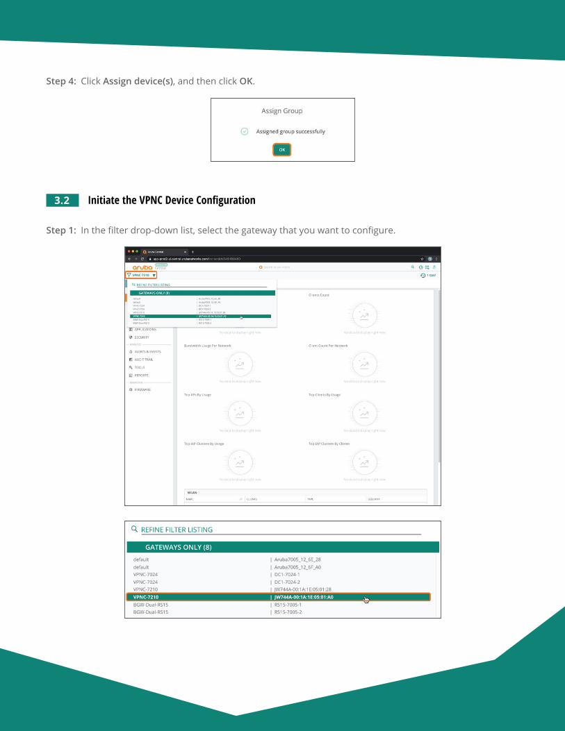
Aruba Design & Deployment Guide 80
Step 4: Click Assign device(s), and then click OK.
3.2 Initiate the VPNC Device Configuration
Step 1: In the filter drop-down list, select the gateway that you want to configure.
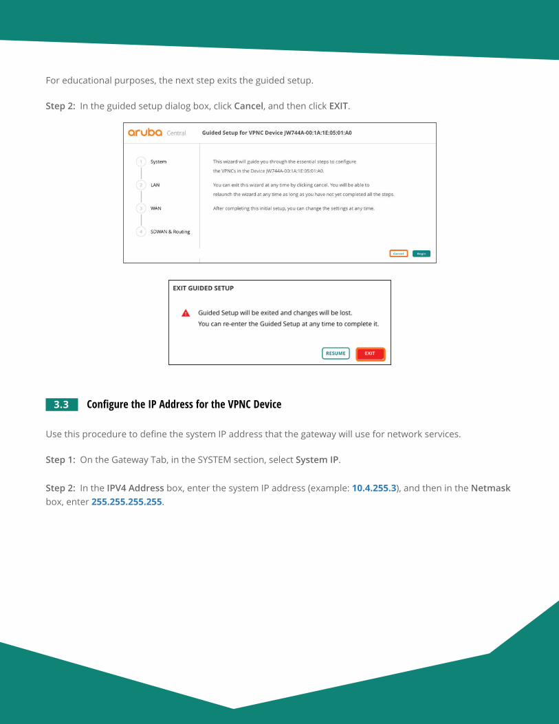
Aruba Design & Deployment Guide 81
For educational purposes, the next step exits the guided setup.
Step 2: In the guided setup dialog box, click Cancel, and then click EXIT.
3.3 Configure the IP Address for the VPNC Device
Use this procedure to define the system IP address that the gateway will use for network services.
Step 1: On the Gateway Tab, in the SYSTEM section, select System IP.
Step 2: In the IPV4 Address box, enter the system IP address (example: 10.4.255.3), and then in the Netmask box, enter 255.255.255.255.
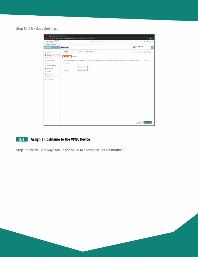
Aruba Design & Deployment Guide 82
Step 3: Click Save Settings.
3.4 Assign a Hostname to the VPNC Device
Step 1: On the Gateways tab, in the SYSTEM section, select Hostname.
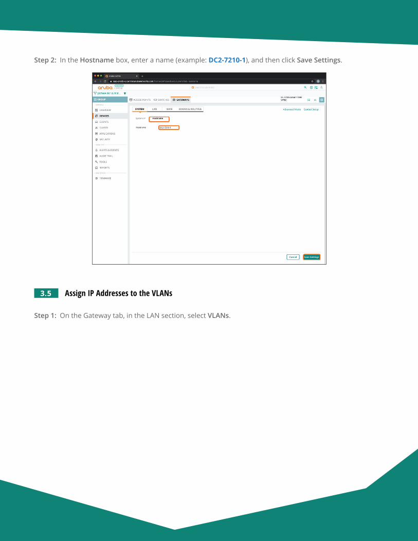
Aruba Design & Deployment Guide 83
Step 2: In the Hostname box, enter a name (example: DC2-7210-1), and then click Save Settings.
3.5 Assign IP Addresses to the VLANs
Step 1: On the Gateway tab, in the LAN section, select VLANs.
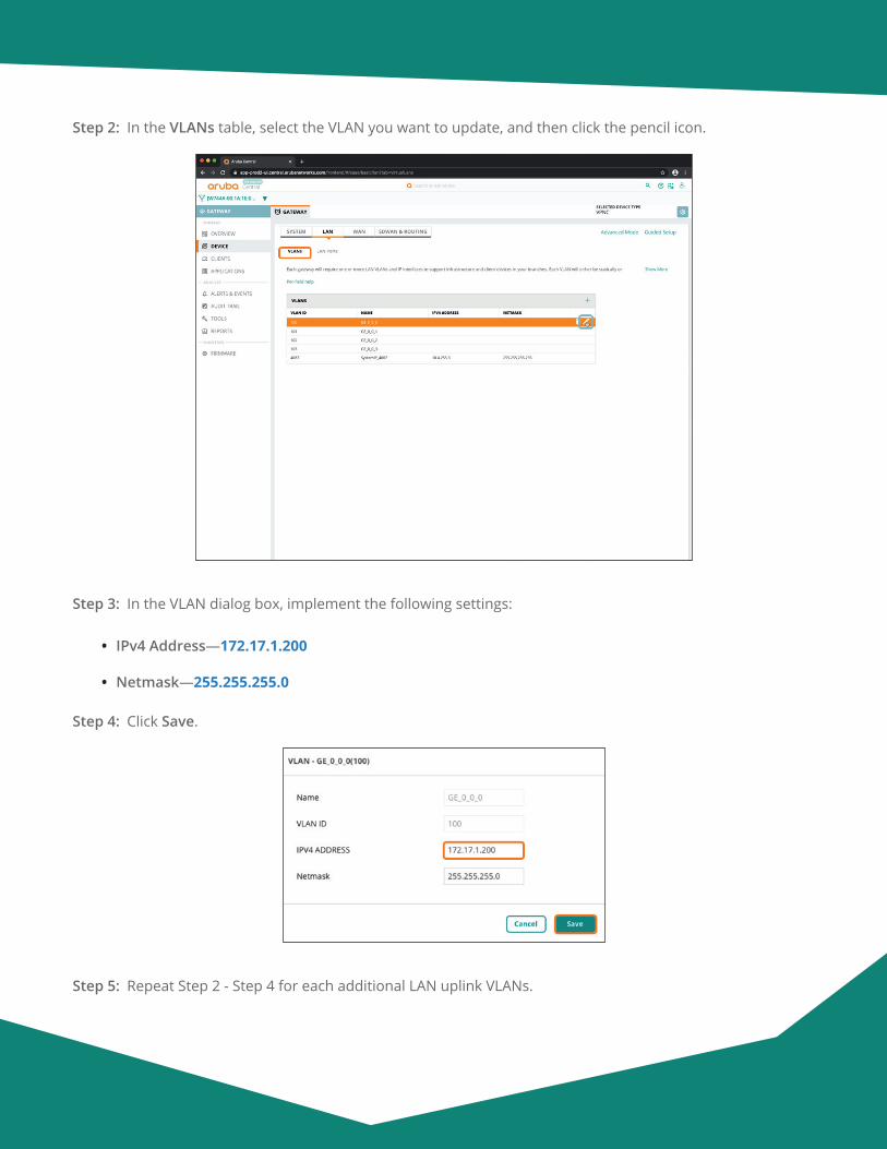
Aruba Design & Deployment Guide 84
Step 2: In the VLANs table, select the VLAN you want to update, and then click the pencil icon.
Step 3: In the VLAN dialog box, implement the following settings:
• IPv4 Address—172.17.1.200
• Netmask—255.255.255.0
Step 4: Click Save.
Step 5: Repeat Step 2 - Step 4 for each additional LAN uplink VLANs.
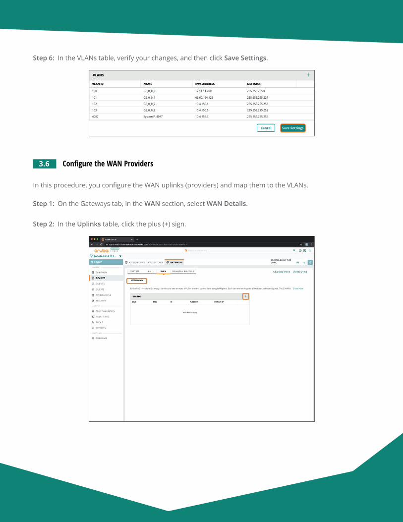
Aruba Design & Deployment Guide 85
Step 6: In the VLANs table, verify your changes, and then click Save Settings.
3.6 Configure the WAN Providers
In this procedure, you configure the WAN uplinks (providers) and map them to the VLANs.
Step 1: On the Gateways tab, in the WAN section, select WAN Details.
Step 2: In the Uplinks table, click the plus (+) sign.
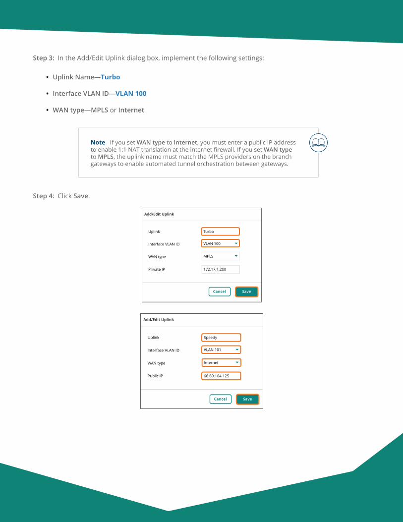
Aruba Design & Deployment Guide 86
Step 3: In the Add/Edit Uplink dialog box, implement the following settings:
• Uplink Name—Turbo
• Interface VLAN ID—VLAN 100
• WAN type—MPLS or Internet
Note If you set WAN type to Internet, you must enter a public IP address to enable 1:1 NAT translation at the internet firewall. If you set WAN type to MPLS, the uplink name must match the MPLS providers on the branch gateways to enable automated tunnel orchestration between gateways.
Step 4: Click Save.
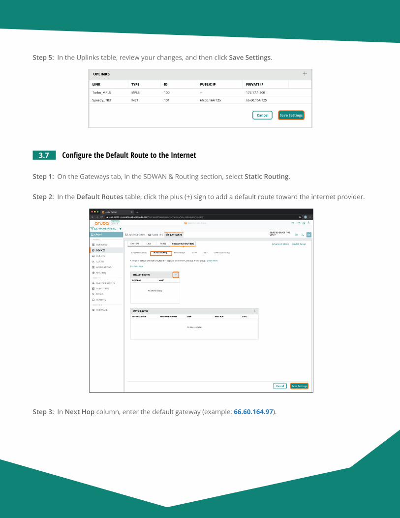
Aruba Design & Deployment Guide 87
Step 5: In the Uplinks table, review your changes, and then click Save Settings.
3.7 Configure the Default Route to the Internet
Step 1: On the Gateways tab, in the SDWAN & Routing section, select Static Routing.
Step 2: In the Default Routes table, click the plus (+) sign to add a default route toward the internet provider.
Step 3: In Next Hop column, enter the default gateway (example: 66.60.164.97).
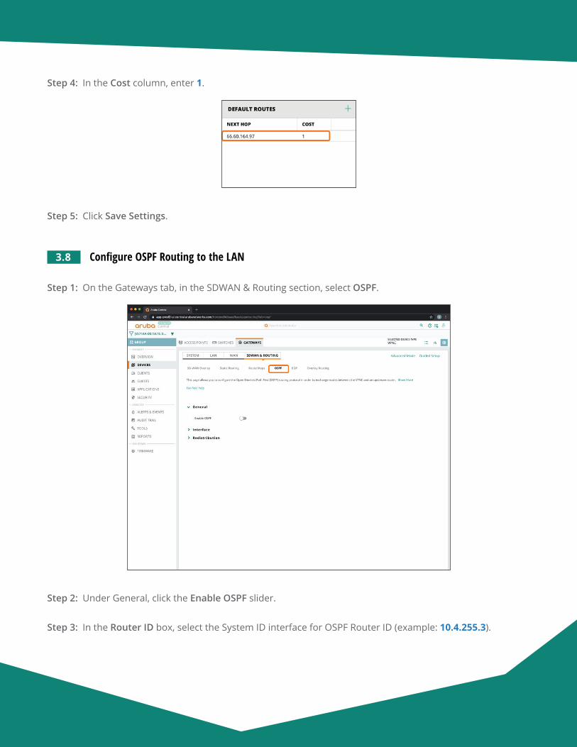
Aruba Design & Deployment Guide 88
Step 4: In the Cost column, enter 1.
Step 5: Click Save Settings.
3.8 Configure OSPF Routing to the LAN
Step 1: On the Gateways tab, in the SDWAN & Routing section, select OSPF.
Step 2: Under General, click the Enable OSPF slider.
Step 3: In the Router ID box, select the System ID interface for OSPF Router ID (example: 10.4.255.3).
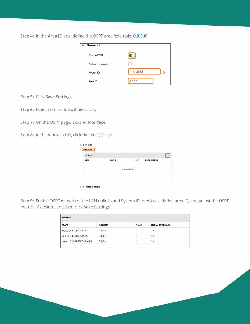
Aruba Design & Deployment Guide 89
Step 4: In the Area ID box, define the OSPF area (example: 0.0.0.0).
Step 5: Click Save Settings.
Step 6: Repeat these steps, if necessary.
Step 7: On the OSPF page, expand Interface.
Step 8: In the VLANs table, click the plus (+) sign.
Step 9: Enable OSPF on each of the LAN uplinks and System IP interfaces, define area ID, and adjust the OSPF metrics, if desired, and then click Save Settings.
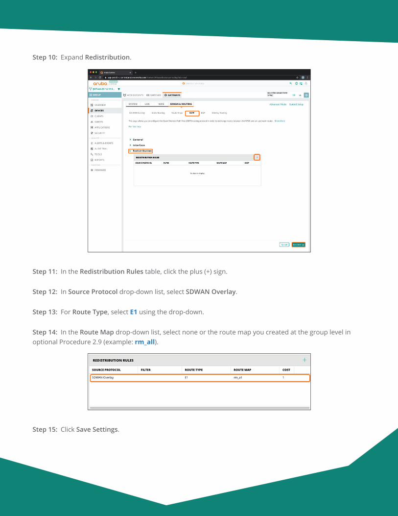
Aruba Design & Deployment Guide 90
Step 10: Expand Redistribution.
Step 11: In the Redistribution Rules table, click the plus (+) sign.
Step 12: In Source Protocol drop-down list, select SDWAN Overlay.
Step 13: For Route Type, select E1 using the drop-down.
Step 14: In the Route Map drop-down list, select none or the route map you created at the group level in optional Procedure 2.9 (example: rm_all).
Step 15: Click Save Settings.
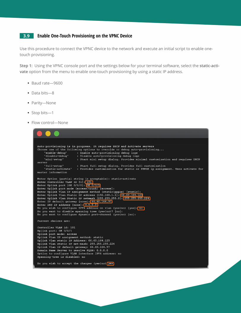
Aruba Design & Deployment Guide 91
3.9 Enable One-Touch Provisioning on the VPNC Device
Use this procedure to connect the VPNC device to the network and execute an initial script to enable one-touch provisioning.
Step 1: Using the VPNC console port and the settings below for your terminal software, select the static-acti-vate option from the menu to enable one-touch provisioning by using a static IP address.
• Baud rate—9600
• Data bits—8
• Parity—None
• Stop bits—1
• Flow control—None
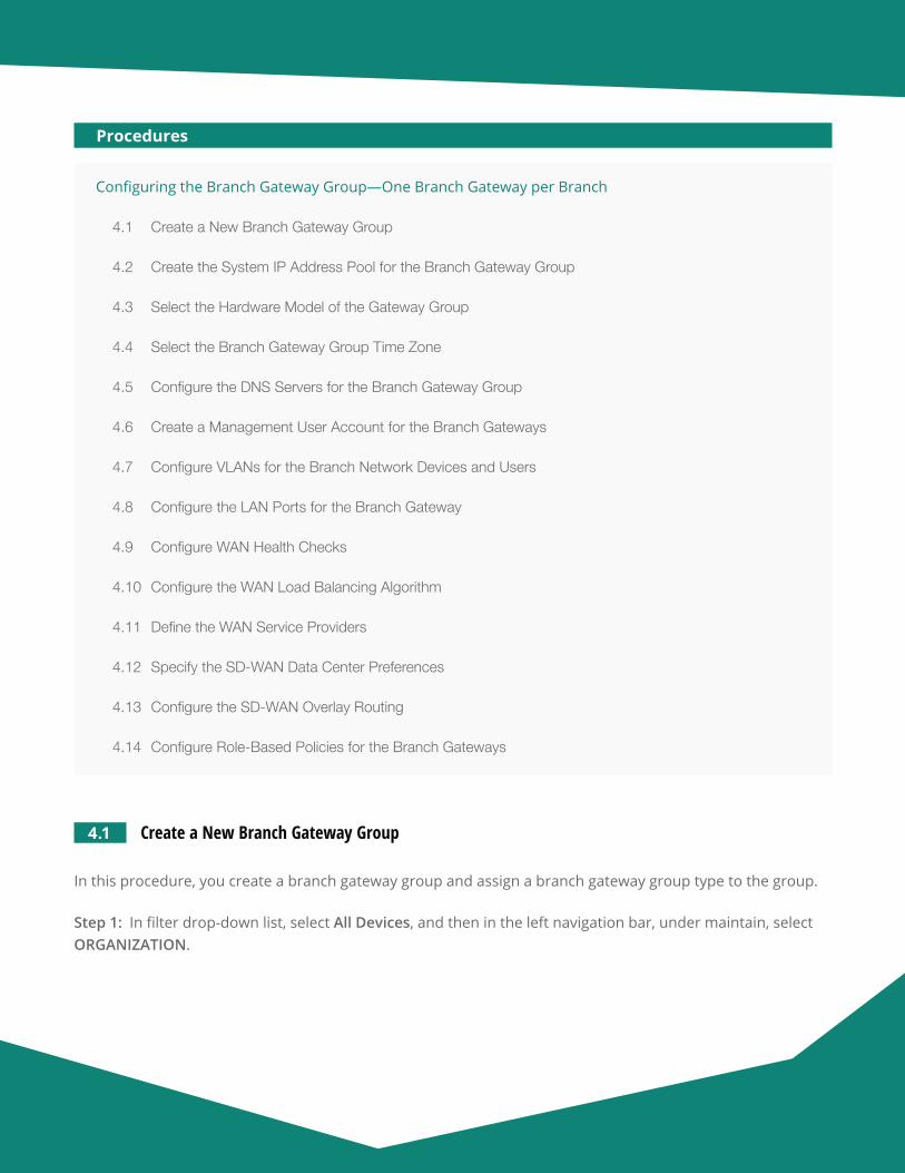
Aruba Design & Deployment Guide 92
Configuring the Branch Gateway Group—One Branch Gateway per Branch
4.1 Create a New Branch Gateway Group
4.2 Create the System IP Address Pool for the Branch Gateway Group
4.3 Select the Hardware Model of the Gateway Group
4.4 Select the Branch Gateway Group Time Zone
4.5 Configure the DNS Servers for the Branch Gateway Group
4.6 Create a Management User Account for the Branch Gateways
4.7 Configure VLANs for the Branch Network Devices and Users
4.8 Configure the LAN Ports for the Branch Gateway
4.9 Configure WAN Health Checks
4.10 Configure the WAN Load Balancing Algorithm
4.11 Define the WAN Service Providers
4.12 Specify the SD-WAN Data Center Preferences
4.13 Configure the SD-WAN Overlay Routing
4.14 Configure Role-Based Policies for the Branch Gateways
Procedures
4.1 Create a New Branch Gateway Group
In this procedure, you create a branch gateway group and assign a branch gateway group type to the group.
Step 1: In filter drop-down list, select All Devices, and then in the left navigation bar, under maintain, select ORGANIZATION.
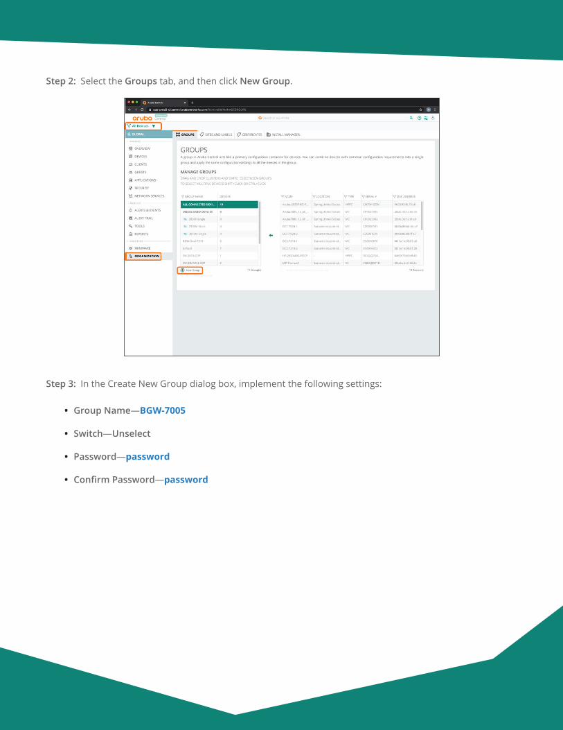
Aruba Design & Deployment Guide 93
Step 2: Select the Groups tab, and then click New Group.
Step 3: In the Create New Group dialog box, implement the following settings:
• Group Name—BGW-7005
• Switch—Unselect
• Password—password
• Confirm Password—password

Aruba Design & Deployment Guide 94
Step 4: Click Add Group.
Note If you intend to use the Install Manager App, assign the group to the sites at this point.
Step 5: In the filter drop-down list, select BGW-7005.
Step 6: In the left navigation pane, in the Manage section, click Devices.

Aruba Design & Deployment Guide 95
Step 7: Select the Gateways tab, and then click the gear icon in top right.
Step 8: In the Set Group Type dialog box, select Branch Gateway, and then click Save Settings.
For educational purposes, the next step exits the guided setup.
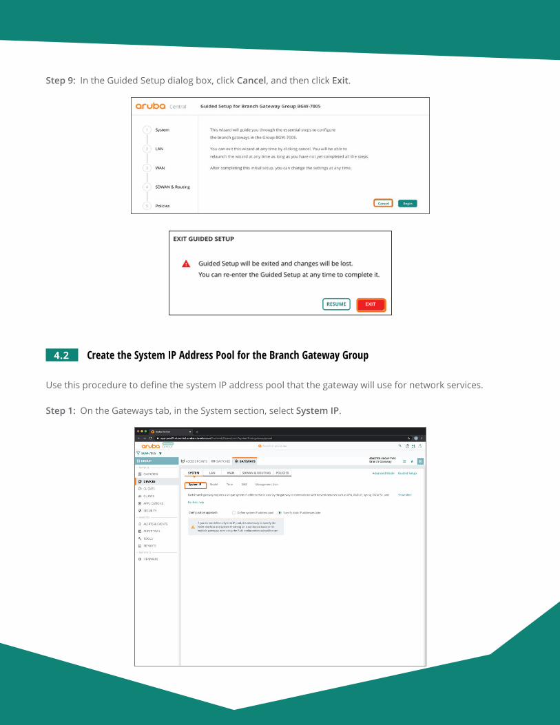
Aruba Design & Deployment Guide 96
Step 9: In the Guided Setup dialog box, click Cancel, and then click Exit.
4.2 Create the System IP Address Pool for the Branch Gateway Group
Use this procedure to define the system IP address pool that the gateway will use for network services.
Step 1: On the Gateways tab, in the System section, select System IP.
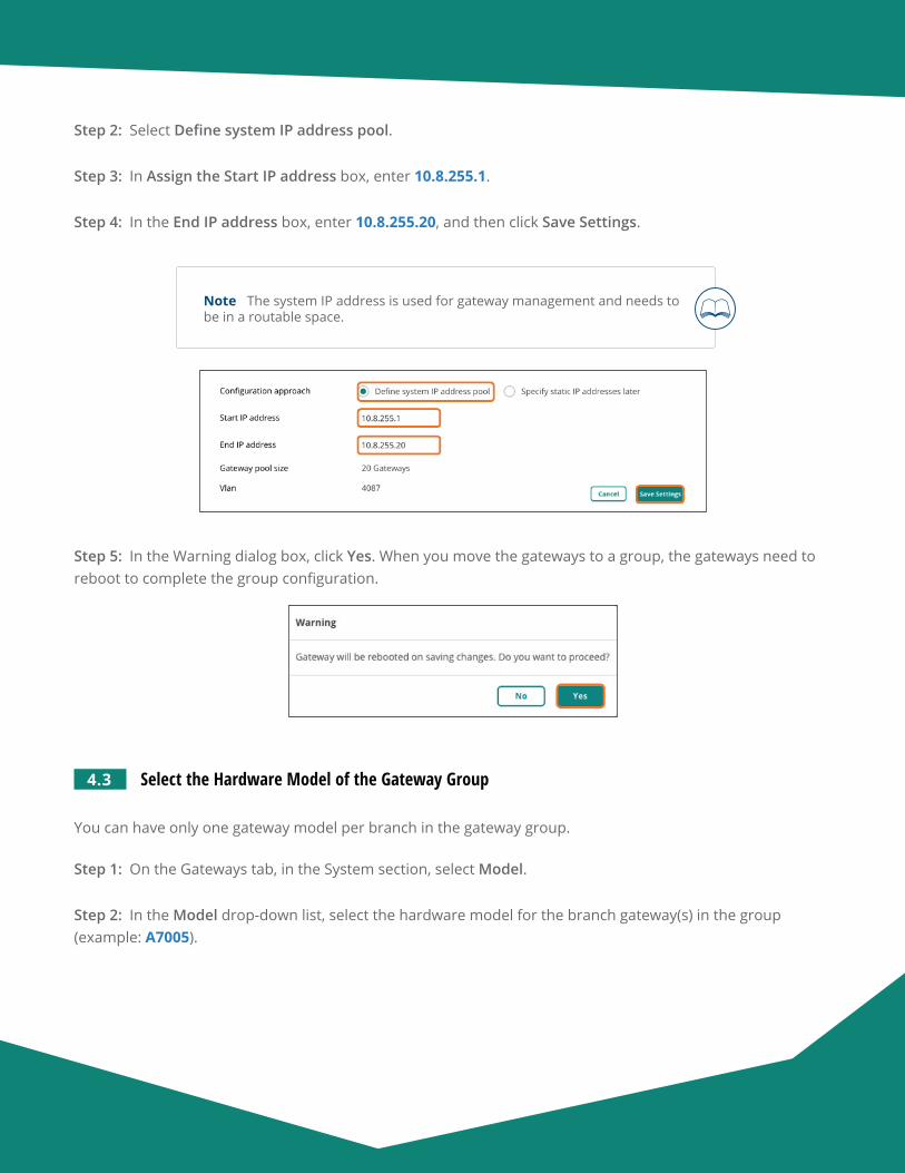
Aruba Design & Deployment Guide 97
Step 2: Select Define system IP address pool.
Step 3: In Assign the Start IP address box, enter 10.8.255.1.
Step 4: In the End IP address box, enter 10.8.255.20, and then click Save Settings.
Note The system IP address is used for gateway management and needs to be in a routable space.
Step 5: In the Warning dialog box, click Yes. When you move the gateways to a group, the gateways need to reboot to complete the group configuration.
4.3 Select the Hardware Model of the Gateway Group
You can have only one gateway model per branch in the gateway group.
Step 1: On the Gateways tab, in the System section, select Model.
Step 2: In the Model drop-down list, select the hardware model for the branch gateway(s) in the group (example: A7005).
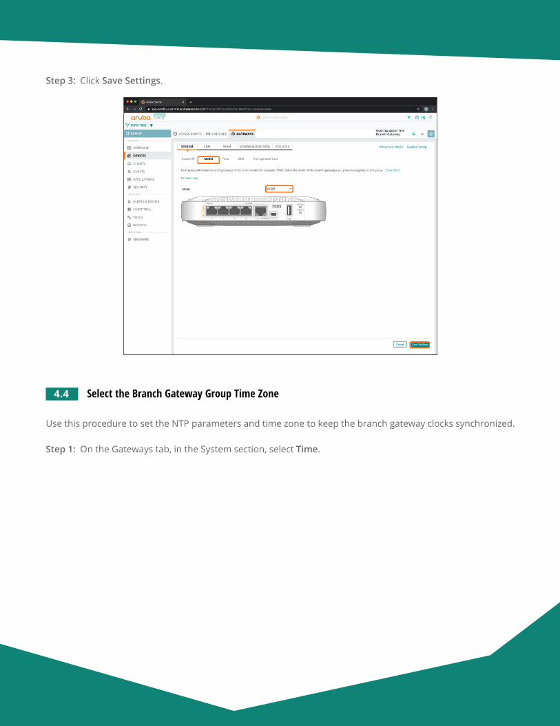
Aruba Design & Deployment Guide 98
Step 3: Click Save Settings.
4.4 Select the Branch Gateway Group Time Zone
Use this procedure to set the NTP parameters and time zone to keep the branch gateway clocks synchronized.
Step 1: On the Gateways tab, in the System section, select Time.
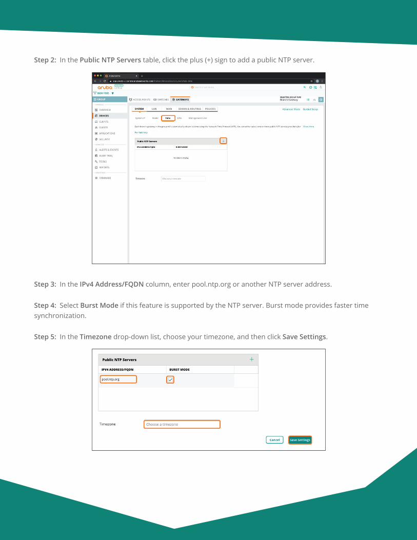
Aruba Design & Deployment Guide 99
Step 2: In the Public NTP Servers table, click the plus (+) sign to add a public NTP server.
Step 3: In the IPv4 Address/FQDN column, enter pool.ntp.org or another NTP server address.
Step 4: Select Burst Mode if this feature is supported by the NTP server. Burst mode provides faster time synchronization.
Step 5: In the Timezone drop-down list, choose your timezone, and then click Save Settings.

Aruba Design & Deployment Guide 100
4.5 Configure the DNS Servers for the Branch Gateway Group
You must specify the DNS server(s) that the gateway uses to communicate to Aruba Central.
Step 1: On the Gateways tab, in the System section, select DNS.
Step 2: Click Specify DNS servers.
Step 3: In the Domain name text box, enter a domain name (example: example.local).
Step 4: In the Public DNS Servers table, click the plus (+) sign.
Step 5: In the Provider drop-down list, select one of the providers listed or manually configure the desired DNS server(s). This server needs to be reachable when the device comes up for connectivity to Central.
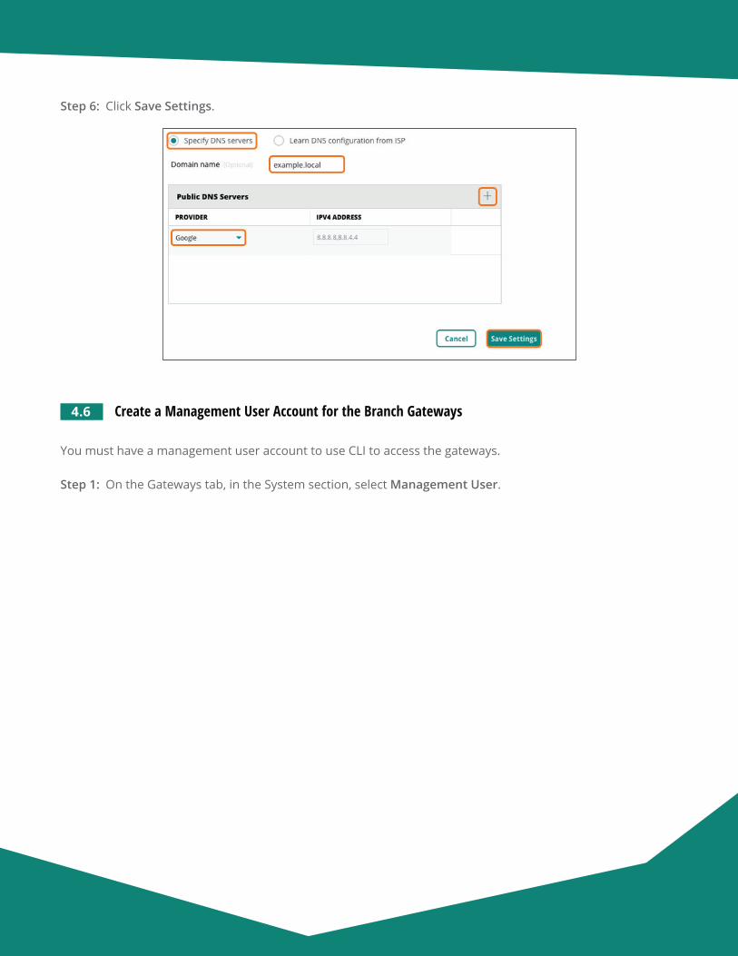
Aruba Design & Deployment Guide 101
Step 6: Click Save Settings.
4.6 Create a Management User Account for the Branch Gateways
You must have a management user account to use CLI to access the gateways.
Step 1: On the Gateways tab, in the System section, select Management User.
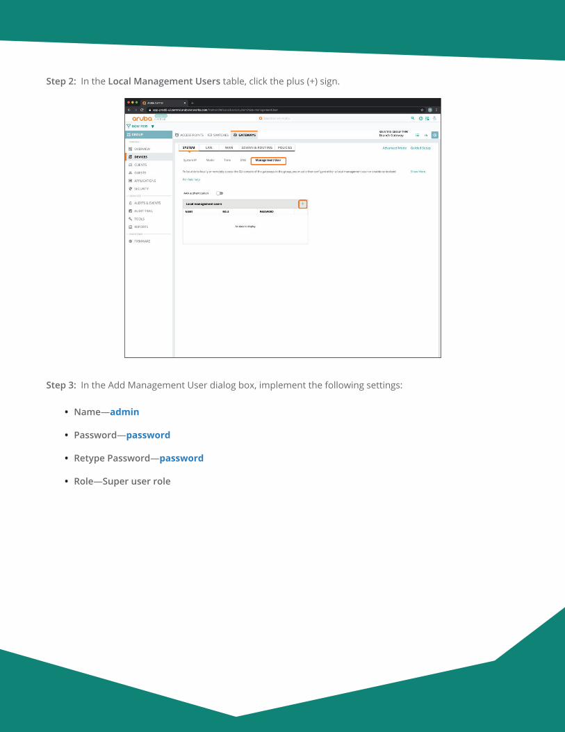
Aruba Design & Deployment Guide 102
Step 2: In the Local Management Users table, click the plus (+) sign.
Step 3: In the Add Management User dialog box, implement the following settings:
• Name—admin
• Password—password
• Retype Password—password
• Role—Super user role
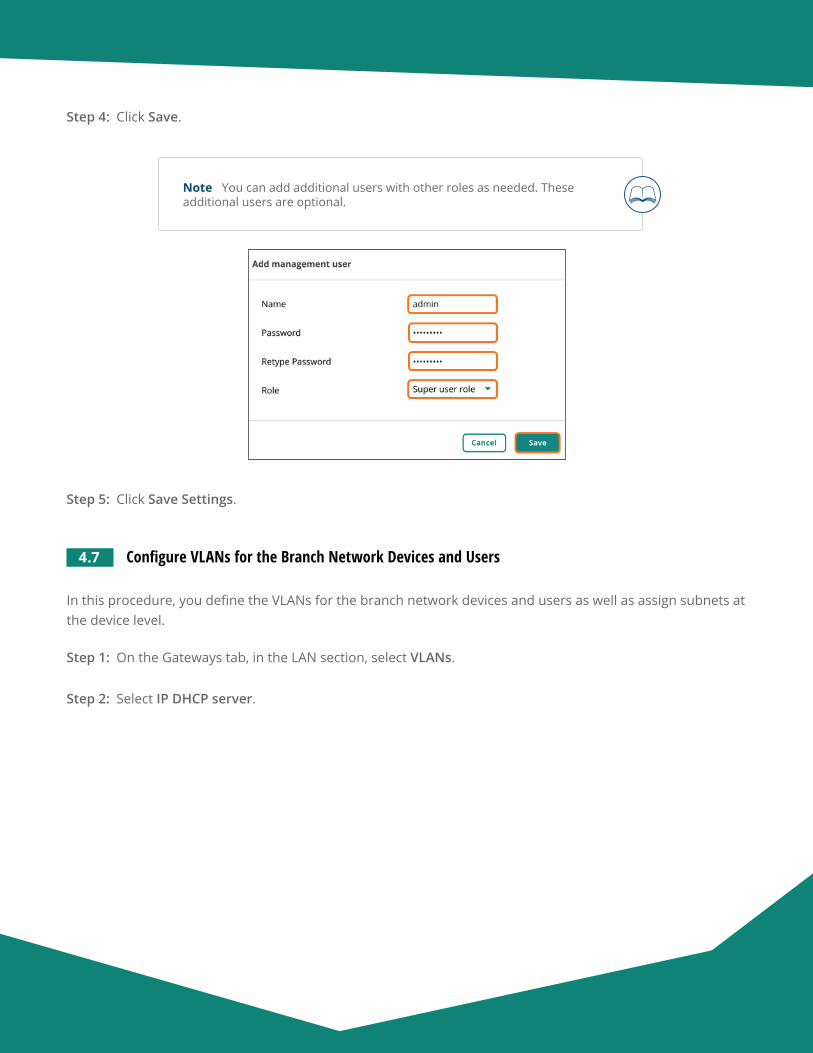
Aruba Design & Deployment Guide 103
Step 4: Click Save.
Note You can add additional users with other roles as needed. These additional users are optional.
Step 5: Click Save Settings.
4.7 Configure VLANs for the Branch Network Devices and Users
In this procedure, you define the VLANs for the branch network devices and users as well as assign subnets at the device level.
Step 1: On the Gateways tab, in the LAN section, select VLANs.
Step 2: Select IP DHCP server.
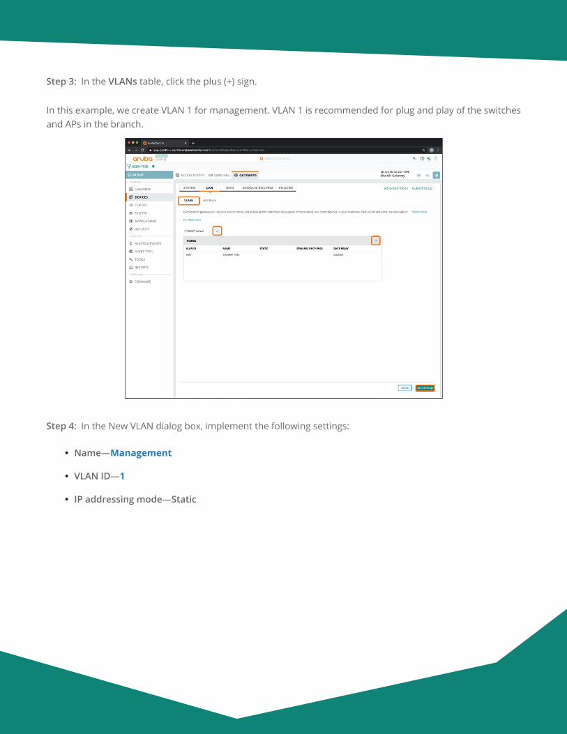
Aruba Design & Deployment Guide 104
Step 3: In the VLANs table, click the plus (+) sign.
In this example, we create VLAN 1 for management. VLAN 1 is recommended for plug and play of the switches and APs in the branch.
Step 4: In the New VLAN dialog box, implement the following settings:
• Name—Management
• VLAN ID—1
• IP addressing mode—Static
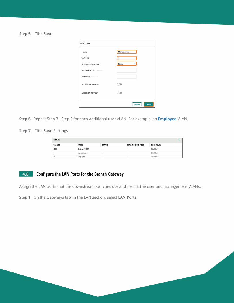
Aruba Design & Deployment Guide 105
Step 5: Click Save.
Step 6: Repeat Step 3 - Step 5 for each additional user VLAN. For example, an Employee VLAN.
Step 7: Click Save Settings.
4.8 Configure the LAN Ports for the Branch Gateway
Assign the LAN ports that the downstream switches use and permit the user and management VLANs.
Step 1: On the Gateways tab, in the LAN section, select LAN Ports.
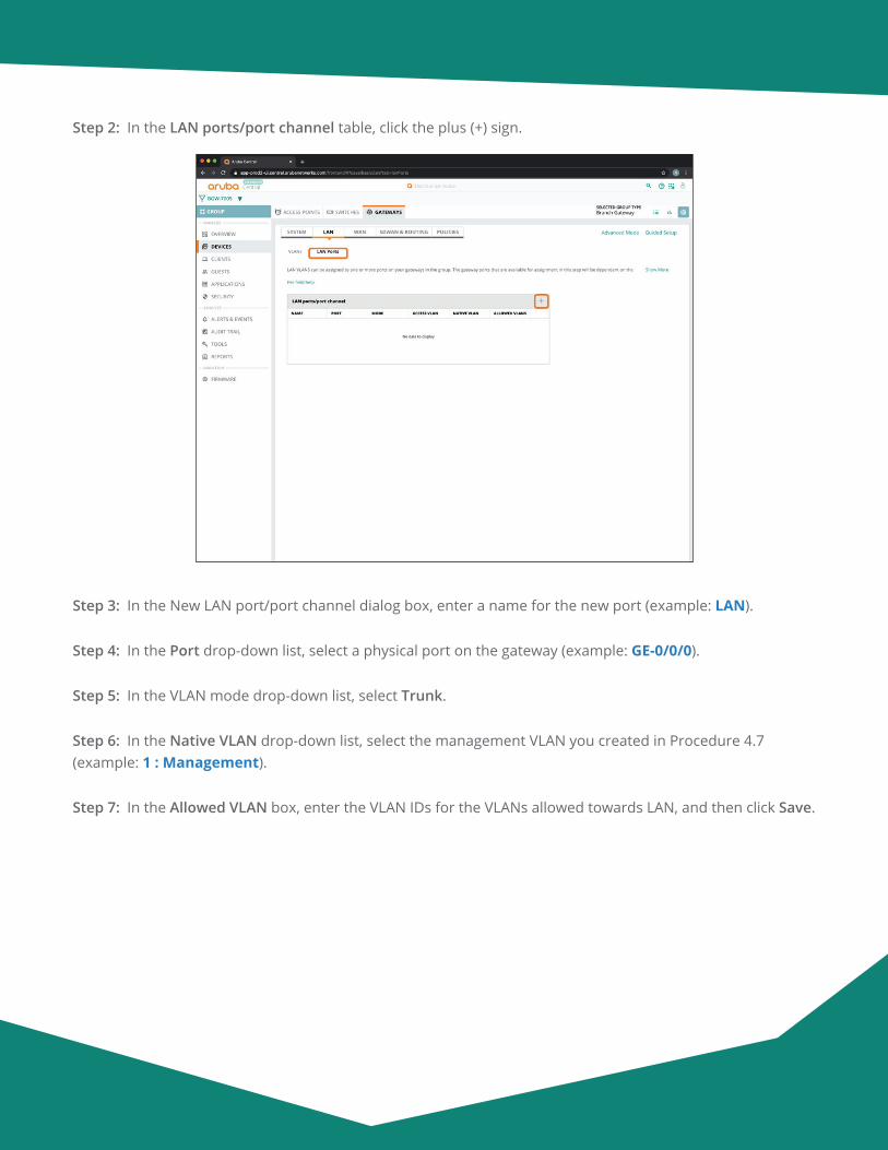
Aruba Design & Deployment Guide 106
Step 2: In the LAN ports/port channel table, click the plus (+) sign.
Step 3: In the New LAN port/port channel dialog box, enter a name for the new port (example: LAN).
Step 4: In the Port drop-down list, select a physical port on the gateway (example: GE-0/0/0).
Step 5: In the VLAN mode drop-down list, select Trunk.
Step 6: In the Native VLAN drop-down list, select the management VLAN you created in Procedure 4.7 (example: 1 : Management).
Step 7: In the Allowed VLAN box, enter the VLAN IDs for the VLANs allowed towards LAN, and then click Save.
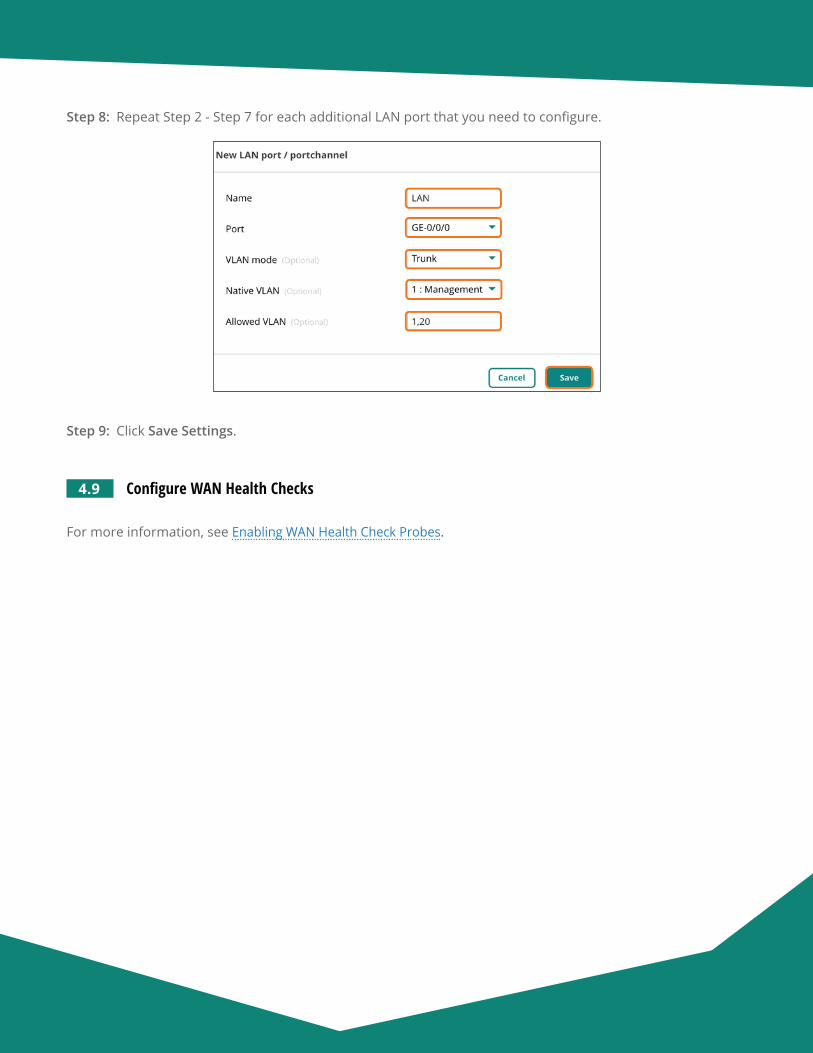
Aruba Design & Deployment Guide 107
Step 8: Repeat Step 2 - Step 7 for each additional LAN port that you need to configure.
Step 9: Click Save Settings.
4.9 Configure WAN Health Checks
For more information, see Enabling WAN Health Check Probes.
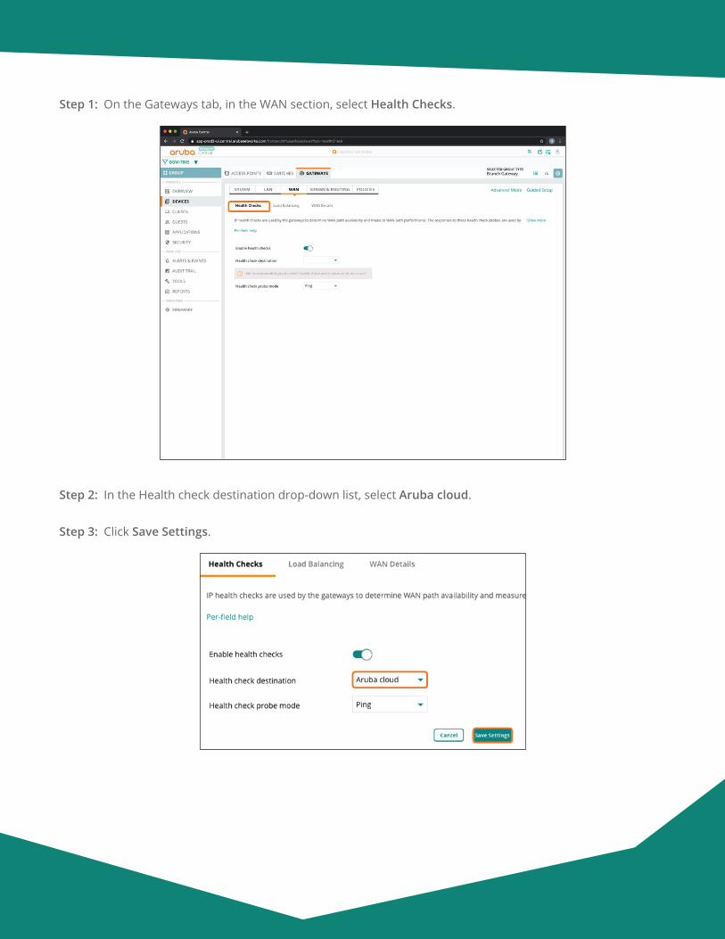
Aruba Design & Deployment Guide 108
Step 1: On the Gateways tab, in the WAN section, select Health Checks.
Step 2: In the Health check destination drop-down list, select Aruba cloud.
Step 3: Click Save Settings.
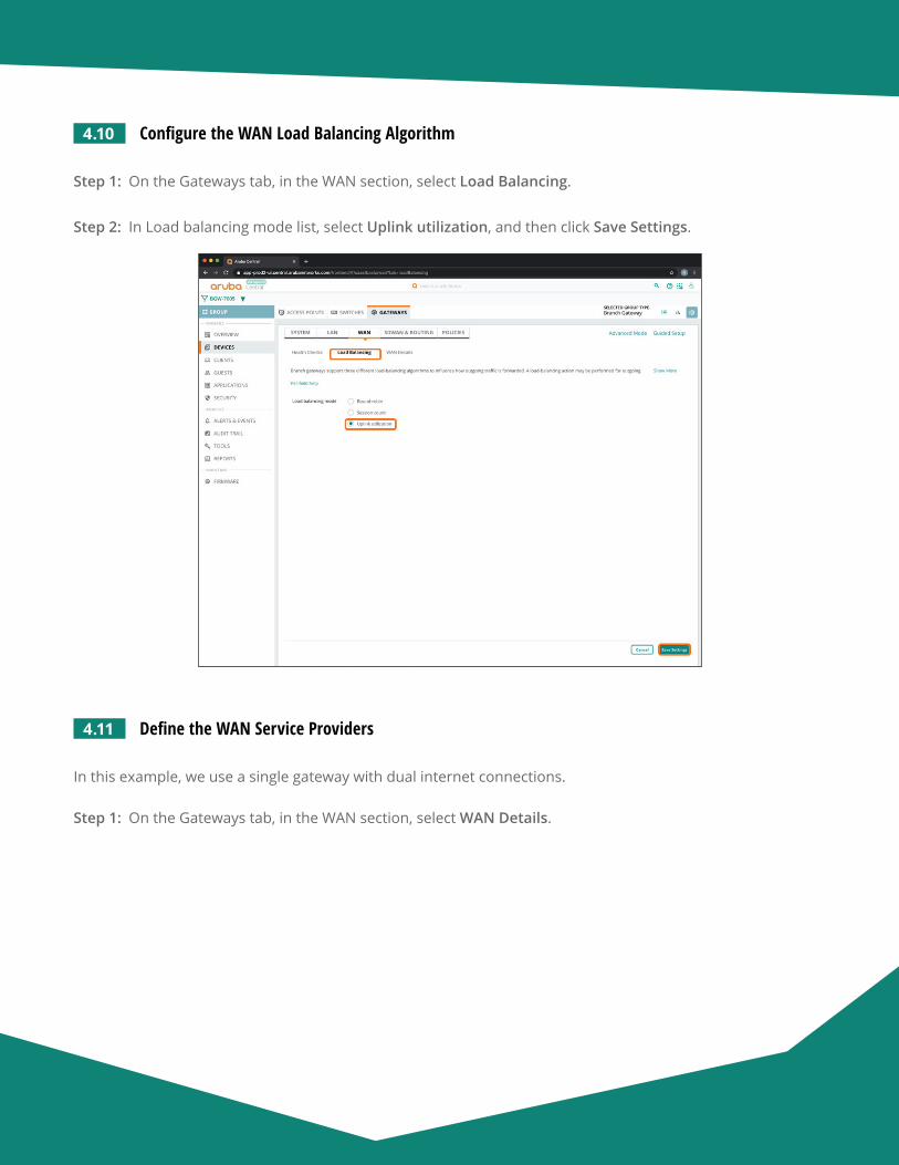
Aruba Design & Deployment Guide 109
4.10 Configure the WAN Load Balancing Algorithm
Step 1: On the Gateways tab, in the WAN section, select Load Balancing.
Step 2: In Load balancing mode list, select Uplink utilization, and then click Save Settings.
4.11 Define the WAN Service Providers
In this example, we use a single gateway with dual internet connections.
Step 1: On the Gateways tab, in the WAN section, select WAN Details.
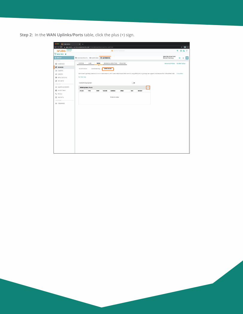
Aruba Design & Deployment Guide 110
Step 2: In the WAN Uplinks/Ports table, click the plus (+) sign.
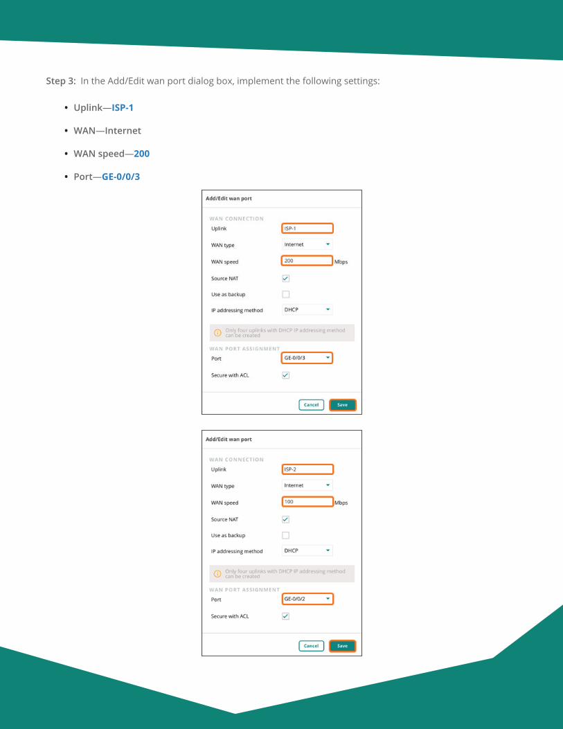
Aruba Design & Deployment Guide 111
Step 3: In the Add/Edit wan port dialog box, implement the following settings:
• Uplink—ISP-1
• WAN—Internet
• WAN speed—200
• Port—GE-0/0/3
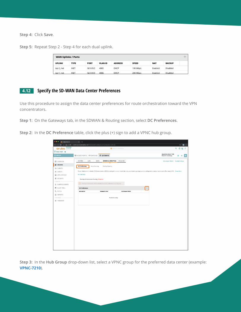
Aruba Design & Deployment Guide 112
Step 4: Click Save.
Step 5: Repeat Step 2 - Step 4 for each dual uplink.
4.12 Specify the SD-WAN Data Center Preferences
Use this procedure to assign the data center preferences for route orchestration toward the VPN concentrators.
Step 1: On the Gateways tab, in the SDWAN & Routing section, select DC Preferences.
Step 2: In the DC Preference table, click the plus (+) sign to add a VPNC hub group.
Step 3: In the Hub Group drop-down list, select a VPNC group for the preferred data center (example: VPNC-7210).
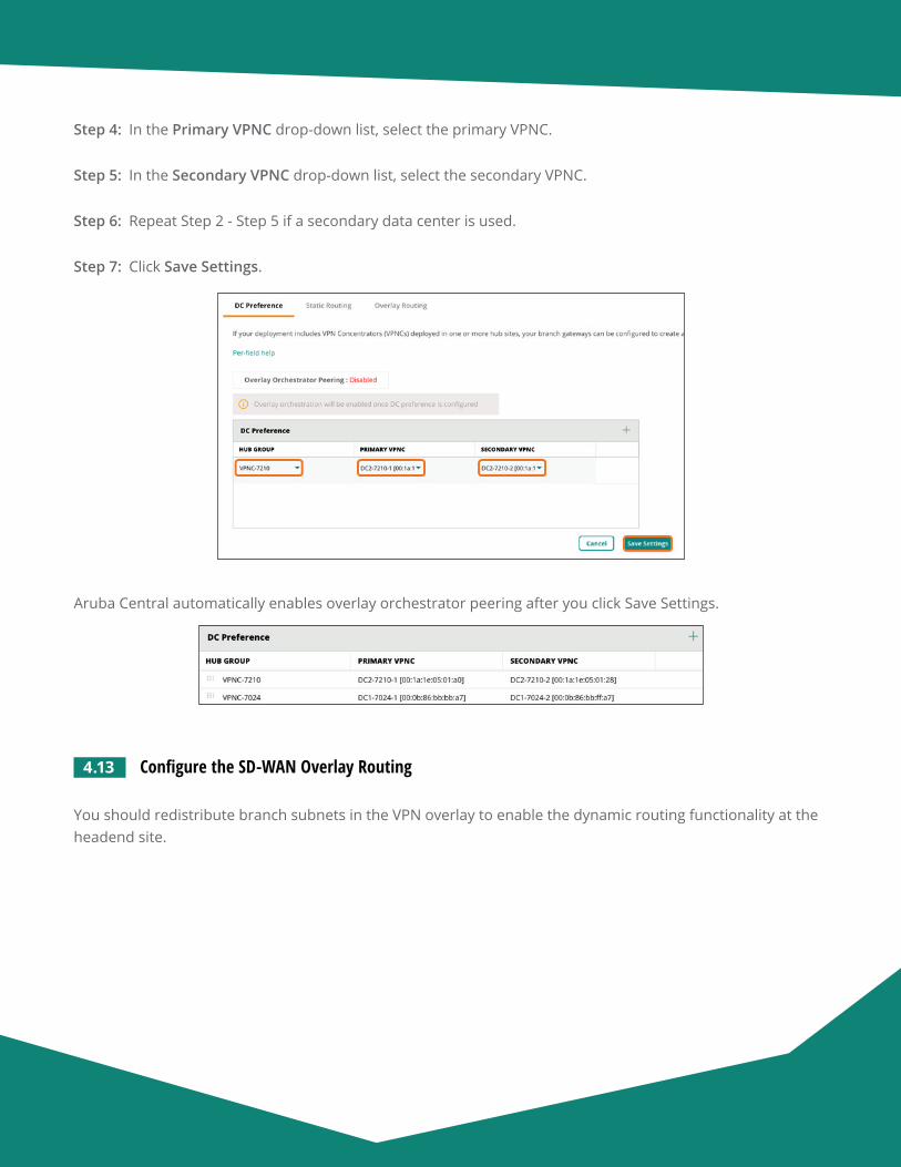
Aruba Design & Deployment Guide 113
Step 4: In the Primary VPNC drop-down list, select the primary VPNC.
Step 5: In the Secondary VPNC drop-down list, select the secondary VPNC.
Step 6: Repeat Step 2 - Step 5 if a secondary data center is used.
Step 7: Click Save Settings.
Aruba Central automatically enables overlay orchestrator peering after you click Save Settings.
4.13 Configure the SD-WAN Overlay Routing
You should redistribute branch subnets in the VPN overlay to enable the dynamic routing functionality at the headend site.
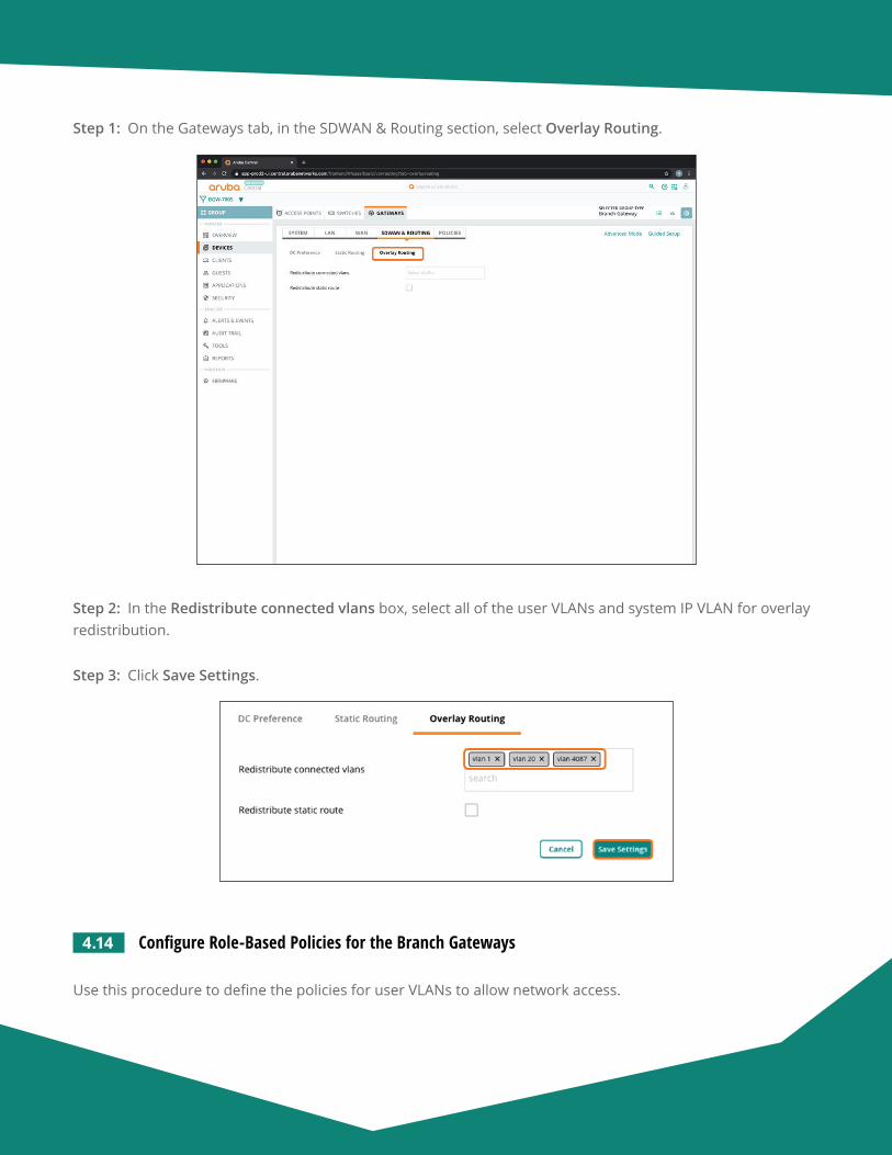
Aruba Design & Deployment Guide 114
Step 1: On the Gateways tab, in the SDWAN & Routing section, select Overlay Routing.
Step 2: In the Redistribute connected vlans box, select all of the user VLANs and system IP VLAN for overlay redistribution.
Step 3: Click Save Settings.
4.14 Configure Role-Based Policies for the Branch Gateways
Use this procedure to define the policies for user VLANs to allow network access.
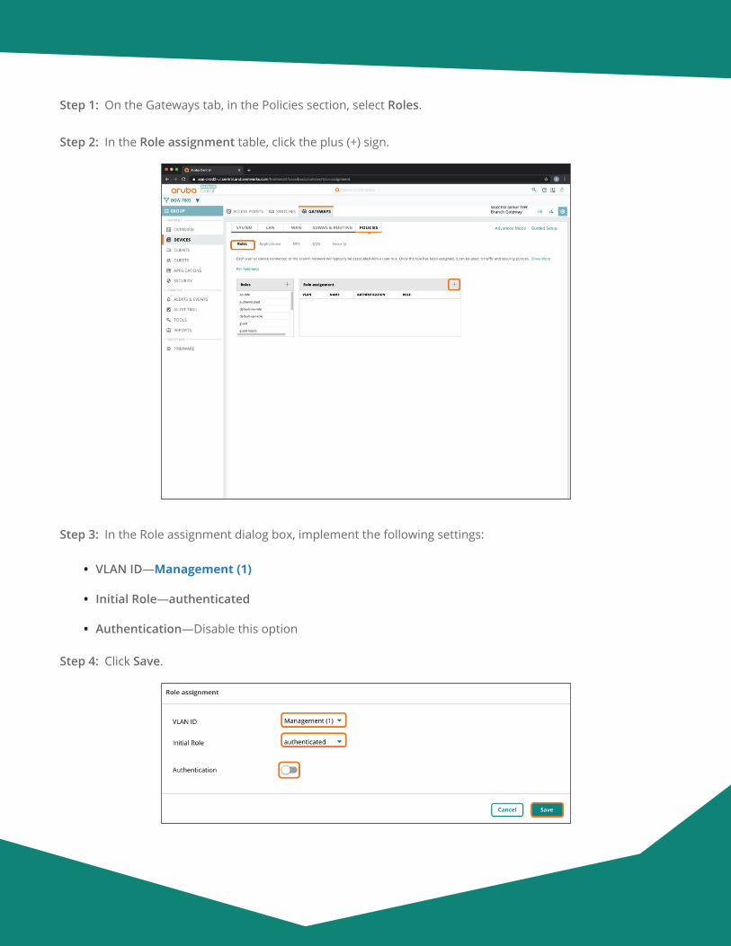
Aruba Design & Deployment Guide 115
Step 1: On the Gateways tab, in the Policies section, select Roles.
Step 2: In the Role assignment table, click the plus (+) sign.
Step 3: In the Role assignment dialog box, implement the following settings:
• VLAN ID—Management (1)
• Initial Role—authenticated
• Authentication—Disable this option
Step 4: Click Save.
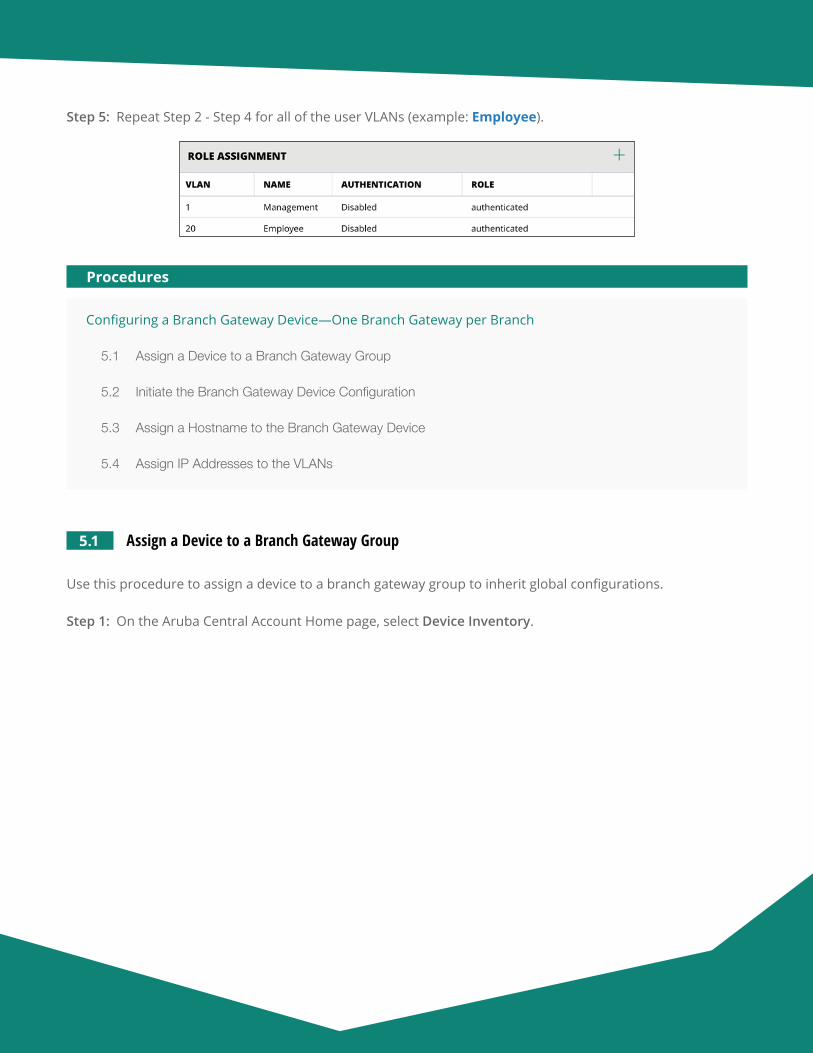
Aruba Design & Deployment Guide 116
Step 5: Repeat Step 2 - Step 4 for all of the user VLANs (example: Employee).
Configuring a Branch Gateway Device—One Branch Gateway per Branch
5.1 Assign a Device to a Branch Gateway Group
5.2 Initiate the Branch Gateway Device Configuration
5.3 Assign a Hostname to the Branch Gateway Device
5.4 Assign IP Addresses to the VLANs
Procedures
5.1 Assign a Device to a Branch Gateway Group
Use this procedure to assign a device to a branch gateway group to inherit global configurations.
Step 1: On the Aruba Central Account Home page, select Device Inventory.
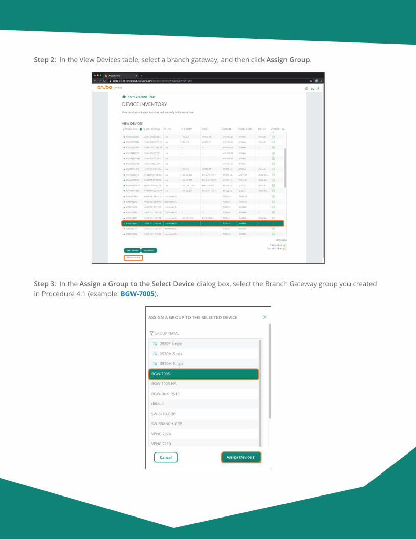
Aruba Design & Deployment Guide 117
Step 2: In the View Devices table, select a branch gateway, and then click Assign Group.
Step 3: In the Assign a Group to the Select Device dialog box, select the Branch Gateway group you created in Procedure 4.1 (example: BGW-7005).
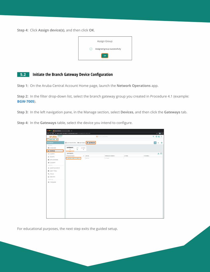
Aruba Design & Deployment Guide 118
Step 4: Click Assign device(s), and then click OK.
5.2 Initiate the Branch Gateway Device Configuration
Step 1: On the Aruba Central Account Home page, launch the Network Operations app.
Step 2: In the filter drop-down list, select the branch gateway group you created in Procedure 4.1 (example: BGW-7005).
Step 3: In the left navigation pane, in the Manage section, select Devices, and then click the Gateways tab.
Step 4: In the Gateways table, select the device you intend to configure.
For educational purposes, the next step exits the guided setup.
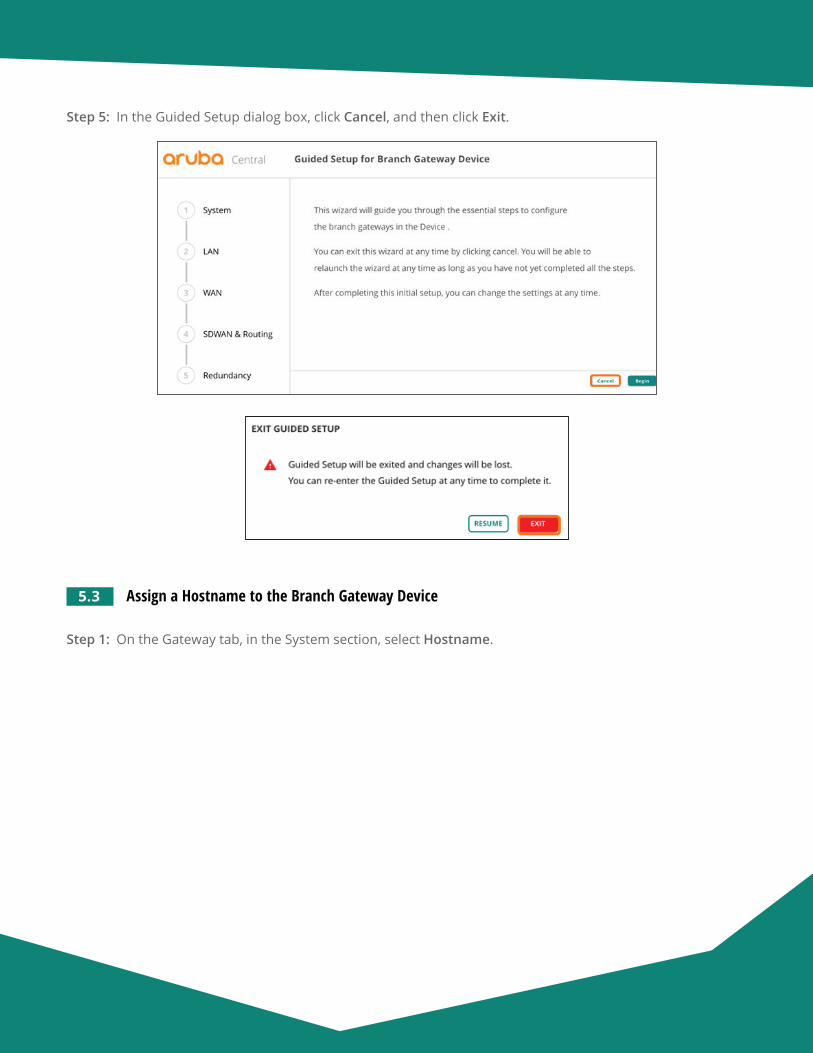
Aruba Design & Deployment Guide 119
Step 5: In the Guided Setup dialog box, click Cancel, and then click Exit.
5.3 Assign a Hostname to the Branch Gateway Device
Step 1: On the Gateway tab, in the System section, select Hostname.
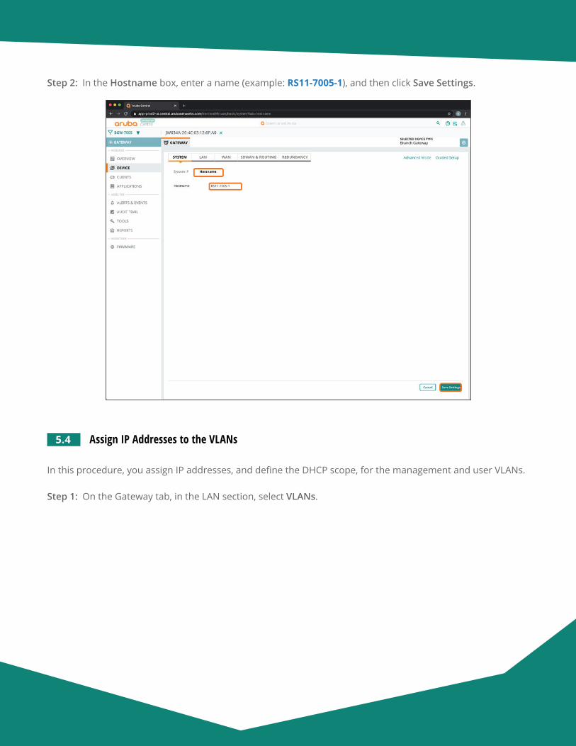
Aruba Design & Deployment Guide 120
Step 2: In the Hostname box, enter a name (example: RS11-7005-1), and then click Save Settings.
5.4 Assign IP Addresses to the VLANs
In this procedure, you assign IP addresses, and define the DHCP scope, for the management and user VLANs.
Step 1: On the Gateway tab, in the LAN section, select VLANs.
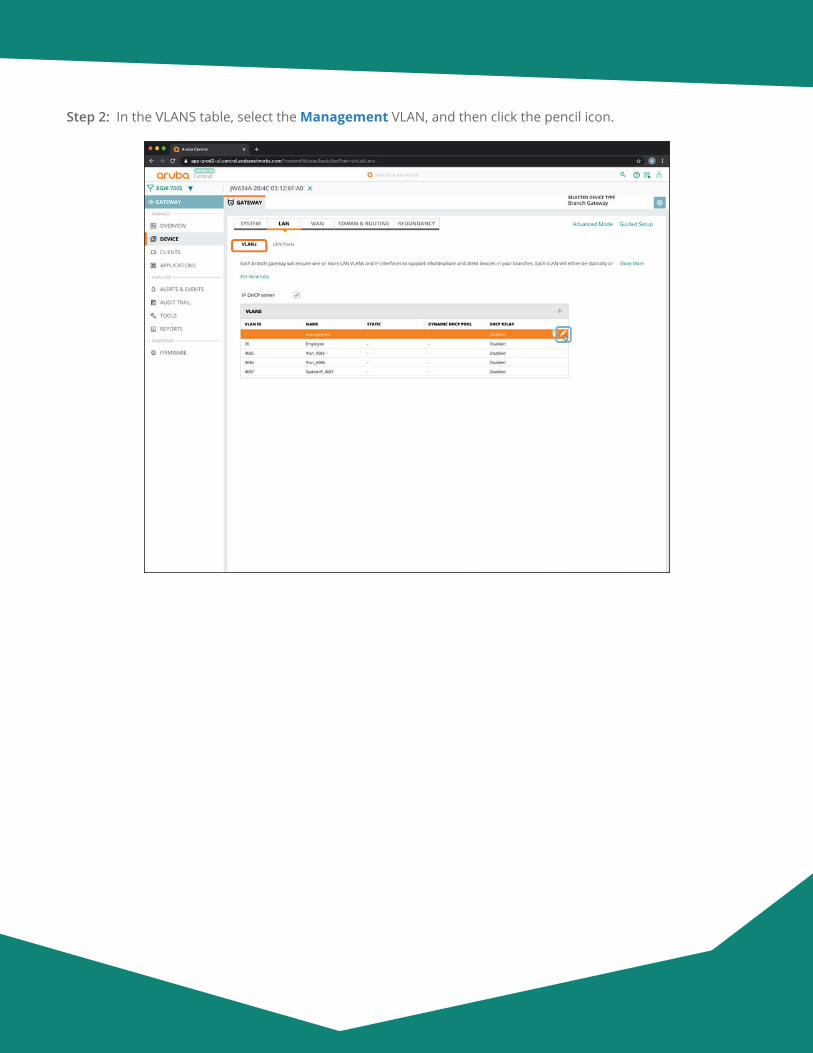
Aruba Design & Deployment Guide 121
Step 2: In the VLANS table, select the Management VLAN, and then click the pencil icon.
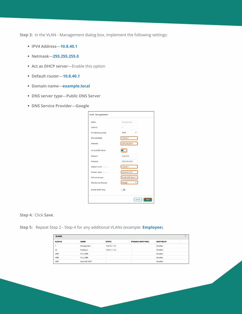
Aruba Design & Deployment Guide 122
Step 3: In the VLAN - Management dialog box, implement the following settings:
• IPV4 Address—10.8.40.1
• Netmask—255.255.255.0
• Act as DHCP server—Enable this option
• Default router—10.8.40.1
• Domain name—example.local
• DNS server type—Public DNS Server
• DNS Service Provider—Google
Step 4: Click Save.
Step 5: Repeat Step 2 - Step 4 for any additional VLANs (example: Employee).
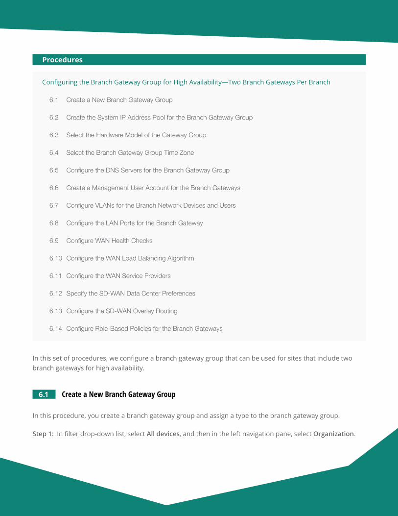
Aruba Design & Deployment Guide 123
Configuring the Branch Gateway Group for High Availability—Two Branch Gateways Per Branch
6.1 Create a New Branch Gateway Group
6.2 Create the System IP Address Pool for the Branch Gateway Group
6.3 Select the Hardware Model of the Gateway Group
6.4 Select the Branch Gateway Group Time Zone
6.5 Configure the DNS Servers for the Branch Gateway Group
6.6 Create a Management User Account for the Branch Gateways
6.7 Configure VLANs for the Branch Network Devices and Users
6.8 Configure the LAN Ports for the Branch Gateway
6.9 Configure WAN Health Checks
6.10 Configure the WAN Load Balancing Algorithm
6.11 Configure the WAN Service Providers
6.12 Specify the SD-WAN Data Center Preferences
6.13 Configure the SD-WAN Overlay Routing
6.14 Configure Role-Based Policies for the Branch Gateways
Procedures
In this set of procedures, we configure a branch gateway group that can be used for sites that include two branch gateways for high availability.
6.1 Create a New Branch Gateway Group
In this procedure, you create a branch gateway group and assign a type to the branch gateway group.
Step 1: In filter drop-down list, select All devices, and then in the left navigation pane, select Organization.

Aruba Design & Deployment Guide 124
Step 2: On the Groups tab, click New Group.
Step 3: In the Create New group dialog box, implement the following settings:
• Group Name—BGW-7005-HA
• Switch—Unselect this option
• Password—password
• Confirm Password—password
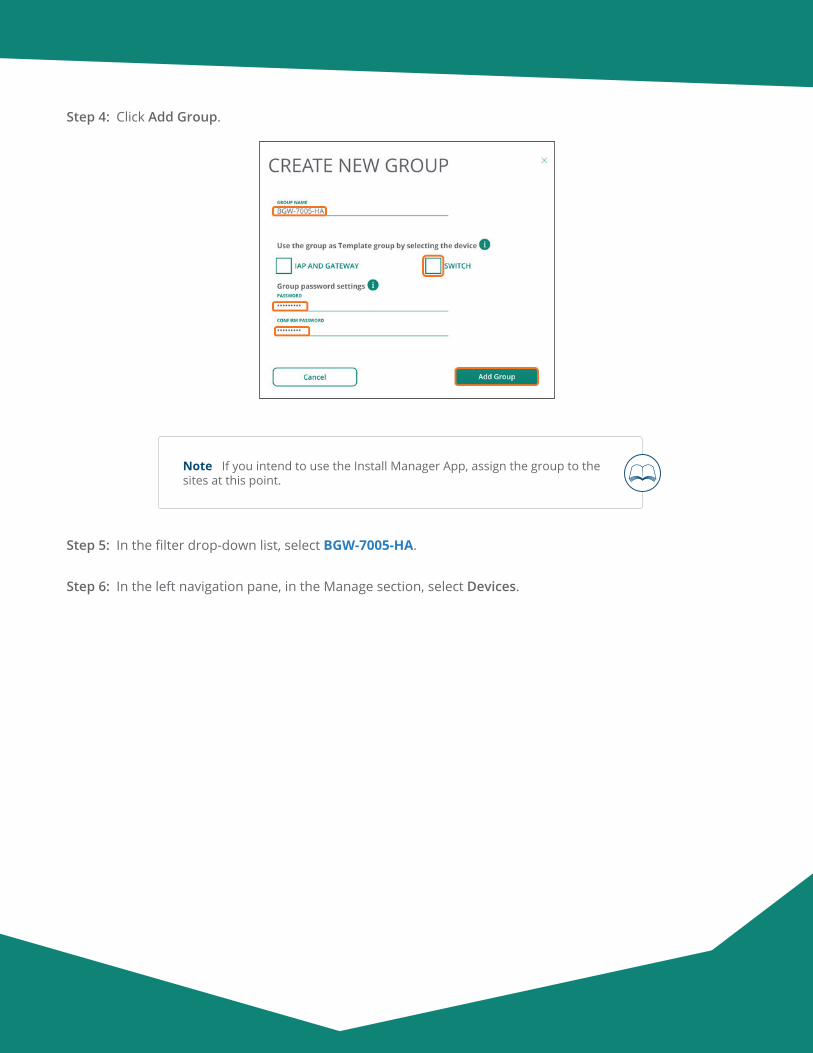
Aruba Design & Deployment Guide 125
Step 4: Click Add Group.
Note If you intend to use the Install Manager App, assign the group to the sites at this point.
Step 5: In the filter drop-down list, select BGW-7005-HA.
Step 6: In the left navigation pane, in the Manage section, select Devices.
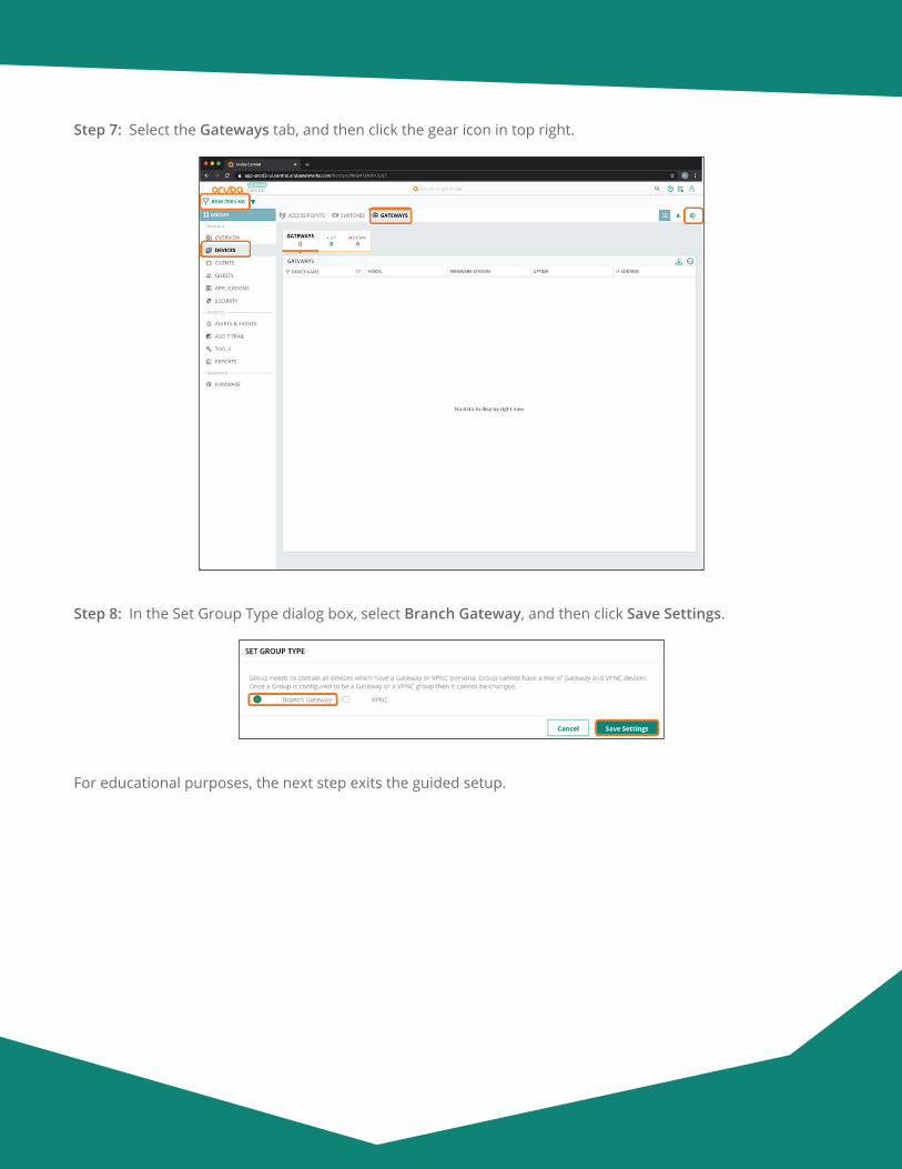
Aruba Design & Deployment Guide 126
Step 7: Select the Gateways tab, and then click the gear icon in top right.
Step 8: In the Set Group Type dialog box, select Branch Gateway, and then click Save Settings.
For educational purposes, the next step exits the guided setup.
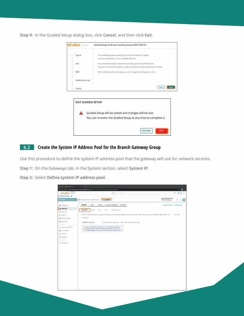
Aruba Design & Deployment Guide 127
Step 9: In the Guided Setup dialog box, click Cancel, and then click Exit.
6.2 Create the System IP Address Pool for the Branch Gateway Group
Use this procedure to define the system IP address pool that the gateway will use for network services.
Step 1: On the Gateways tab, in the System section, select System IP.
Step 2: Select Define system IP address pool.
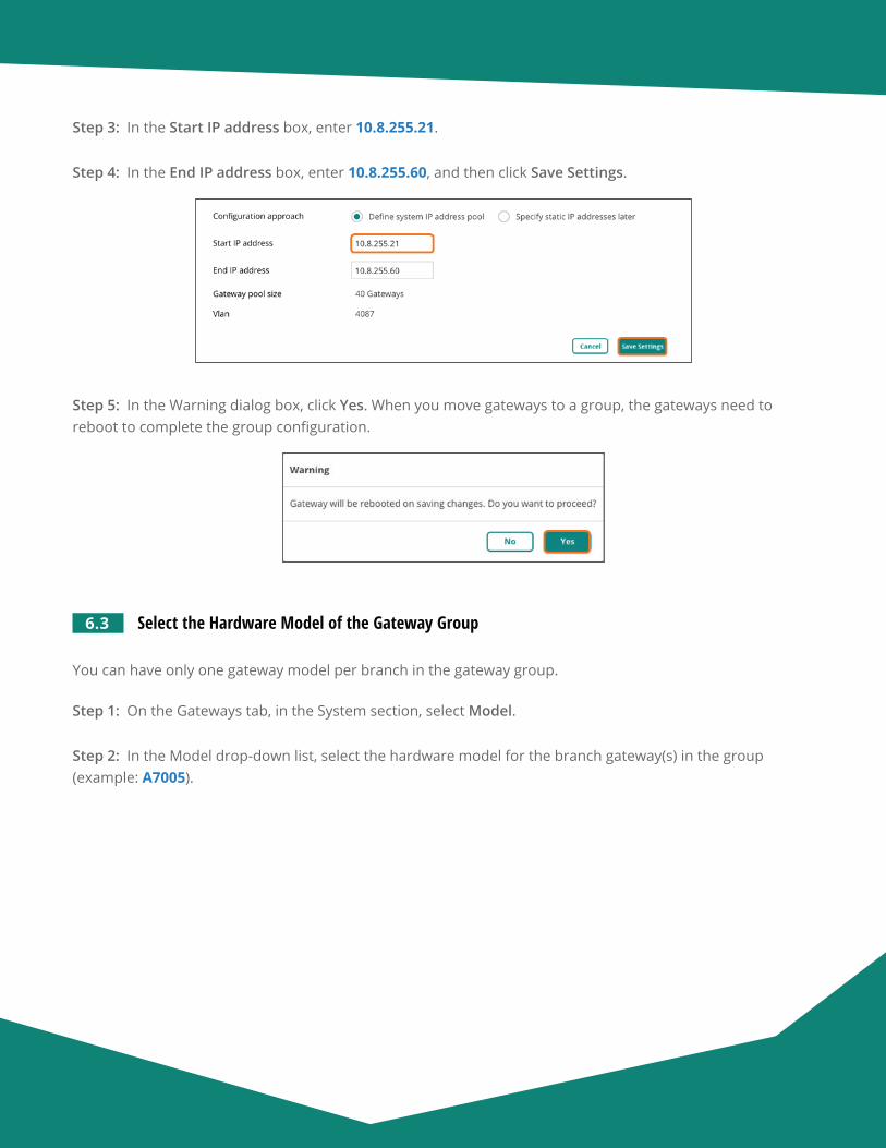
Aruba Design & Deployment Guide 128
Step 3: In the Start IP address box, enter 10.8.255.21.
Step 4: In the End IP address box, enter 10.8.255.60, and then click Save Settings.
Step 5: In the Warning dialog box, click Yes. When you move gateways to a group, the gateways need to reboot to complete the group configuration.
6.3 Select the Hardware Model of the Gateway Group
You can have only one gateway model per branch in the gateway group.
Step 1: On the Gateways tab, in the System section, select Model.
Step 2: In the Model drop-down list, select the hardware model for the branch gateway(s) in the group (example: A7005).
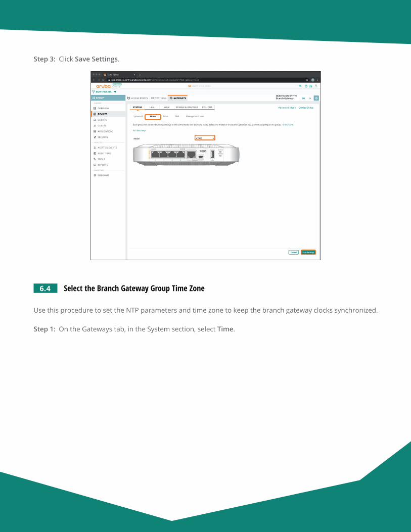
Aruba Design & Deployment Guide 129
Step 3: Click Save Settings.
6.4 Select the Branch Gateway Group Time Zone
Use this procedure to set the NTP parameters and time zone to keep the branch gateway clocks synchronized.
Step 1: On the Gateways tab, in the System section, select Time.

Aruba Design & Deployment Guide 130
Step 2: In the Public NTP Servers table, click the plus (+) sign to add a public NTP server.
Step 3: In the IPv4 Address/FQDN column, enter pool.ntp.org or another NTP server address.
Step 4: Select Burst Mode if this feature is supported by the NTP server. Burst Mode provides faster time synchronization.
Step 5: In the Timezone drop-down list, choose your timezone, and then click Save Settings.
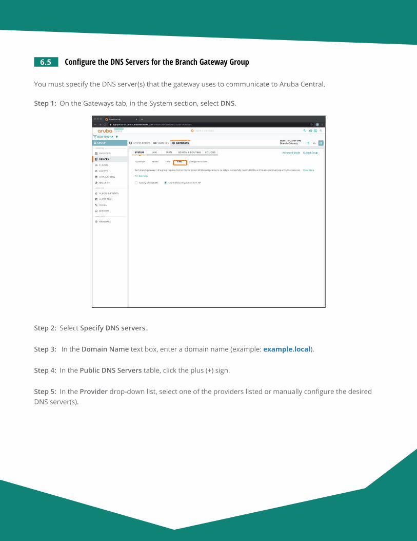
Aruba Design & Deployment Guide 131
6.5 Configure the DNS Servers for the Branch Gateway Group
You must specify the DNS server(s) that the gateway uses to communicate to Aruba Central.
Step 1: On the Gateways tab, in the System section, select DNS.
Step 2: Select Specify DNS servers.
Step 3: In the Domain Name text box, enter a domain name (example: example.local).
Step 4: In the Public DNS Servers table, click the plus (+) sign.
Step 5: In the Provider drop-down list, select one of the providers listed or manually configure the desired DNS server(s).
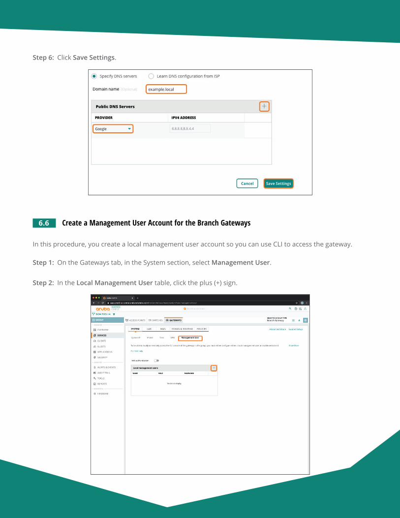
Aruba Design & Deployment Guide 132
Step 6: Click Save Settings.
6.6 Create a Management User Account for the Branch Gateways
In this procedure, you create a local management user account so you can use CLI to access the gateway.
Step 1: On the Gateways tab, in the System section, select Management User.
Step 2: In the Local Management User table, click the plus (+) sign.
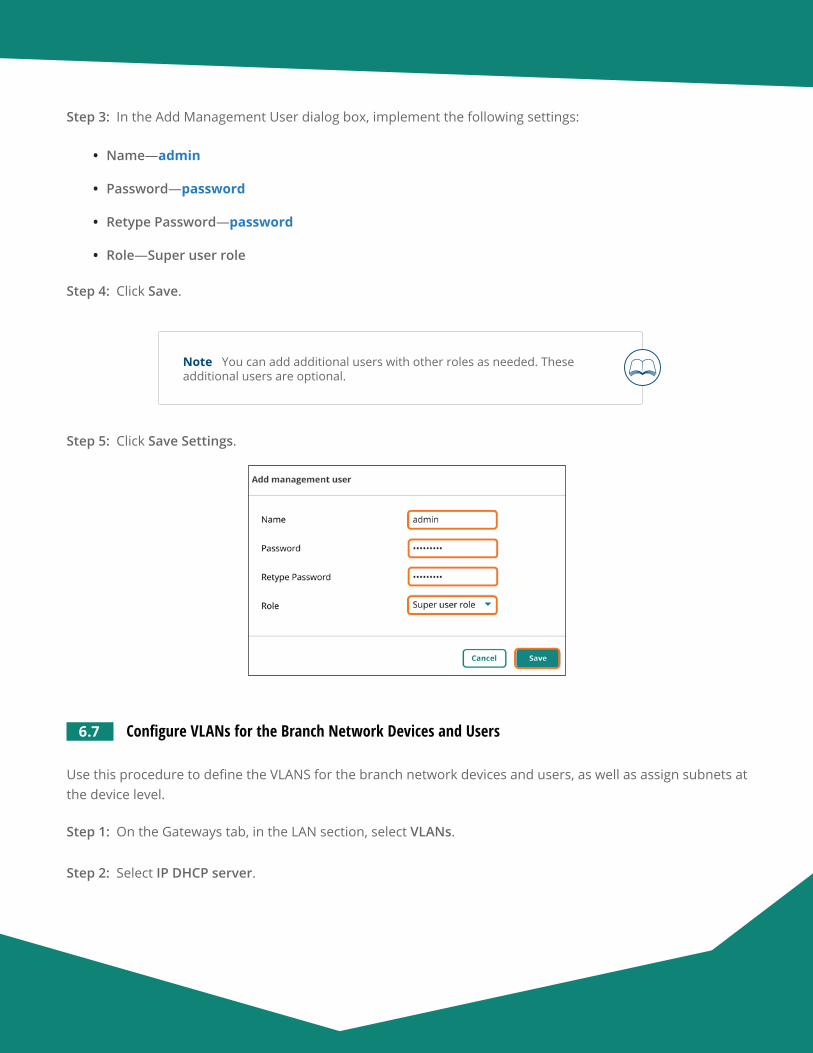
Aruba Design & Deployment Guide 133
Step 3: In the Add Management User dialog box, implement the following settings:
• Name—admin
• Password—password
• Retype Password—password
• Role—Super user role
Step 4: Click Save.
Note You can add additional users with other roles as needed. These additional users are optional.
Step 5: Click Save Settings.
6.7 Configure VLANs for the Branch Network Devices and Users
Use this procedure to define the VLANS for the branch network devices and users, as well as assign subnets at the device level.
Step 1: On the Gateways tab, in the LAN section, select VLANs.
Step 2: Select IP DHCP server.
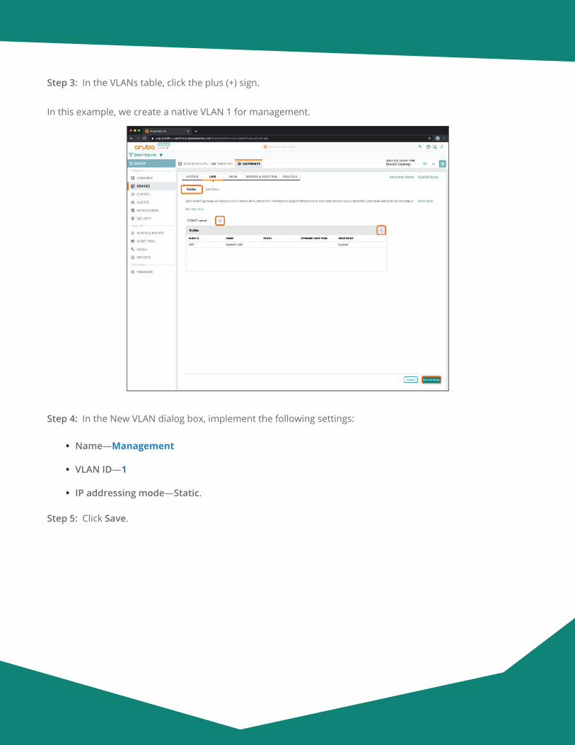
Aruba Design & Deployment Guide 134
Step 3: In the VLANs table, click the plus (+) sign.
In this example, we create a native VLAN 1 for management.
Step 4: In the New VLAN dialog box, implement the following settings:
• Name—Management
• VLAN ID—1
• IP addressing mode—Static.
Step 5: Click Save.
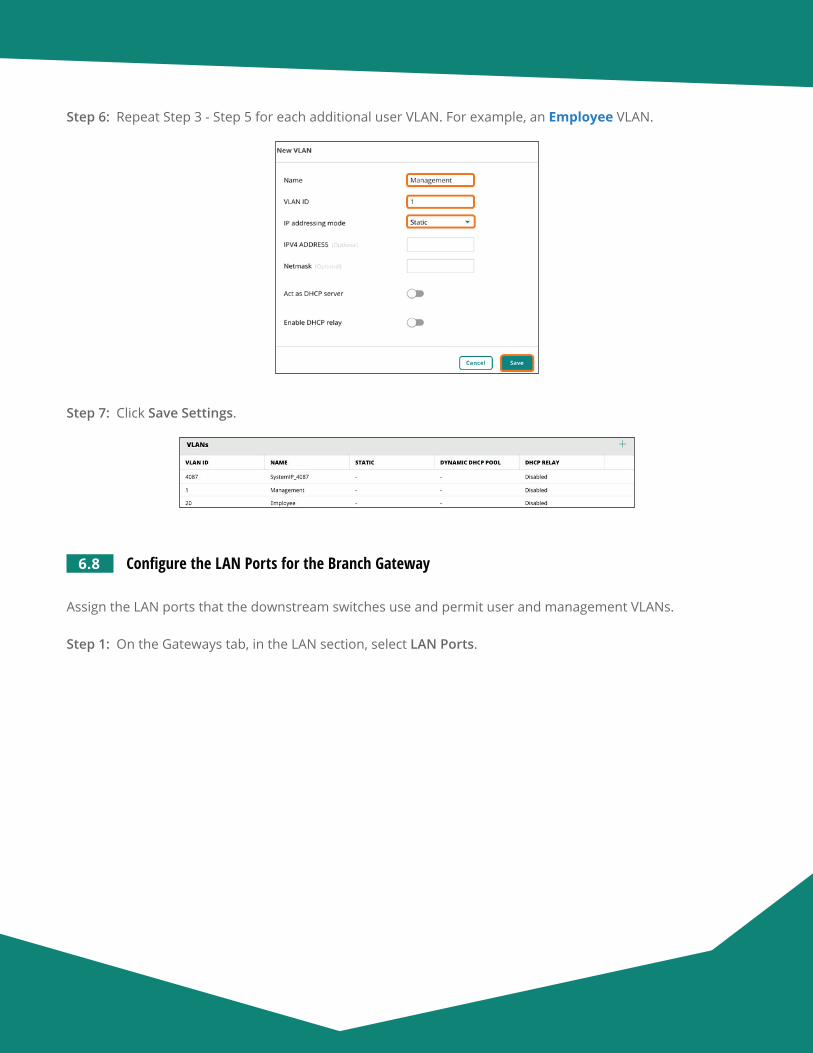
Aruba Design & Deployment Guide 135
Step 6: Repeat Step 3 - Step 5 for each additional user VLAN. For example, an Employee VLAN.
Step 7: Click Save Settings.
6.8 Configure the LAN Ports for the Branch Gateway
Assign the LAN ports that the downstream switches use and permit user and management VLANs.
Step 1: On the Gateways tab, in the LAN section, select LAN Ports.

Aruba Design & Deployment Guide 136
Step 2: In the LAN ports/port channel table, click the plus (+) sign.
Step 3: In the New LAN port/port channel dialog box, in the Name box, enter a name for the new port (exam-ple: LAN).
Step 4: In the Port drop-down list, select a physical port on the gateway (example: GE-0/0/0).
Step 5: In the VLAN mode drop-down list, select Trunk.
Step 6: In the Native VLAN drop-down box, select the management VLAN you created in Procedure 6.7 (example: 1 : Management).
Step 7: In the Allowed VLAN box, enter the VLAN IDs for the VLANs allowed towards the LAN.
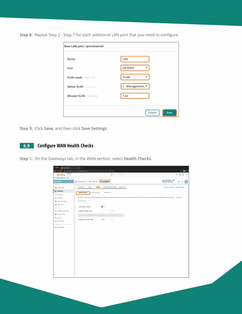
Aruba Design & Deployment Guide 137
Step 8: Repeat Step 2 - Step 7 for each additional LAN port that you need to configure.
Step 9: Click Save, and then click Save Settings.
6.9 Configure WAN Health Checks
Step 1: On the Gateways tab, in the WAN section, select Health Checks.
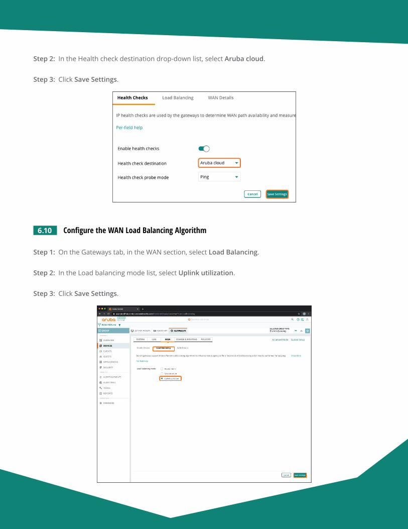
Aruba Design & Deployment Guide 138
Step 2: In the Health check destination drop-down list, select Aruba cloud.
Step 3: Click Save Settings.
6.10 Configure the WAN Load Balancing Algorithm
Step 1: On the Gateways tab, in the WAN section, select Load Balancing.
Step 2: In the Load balancing mode list, select Uplink utilization.
Step 3: Click Save Settings.
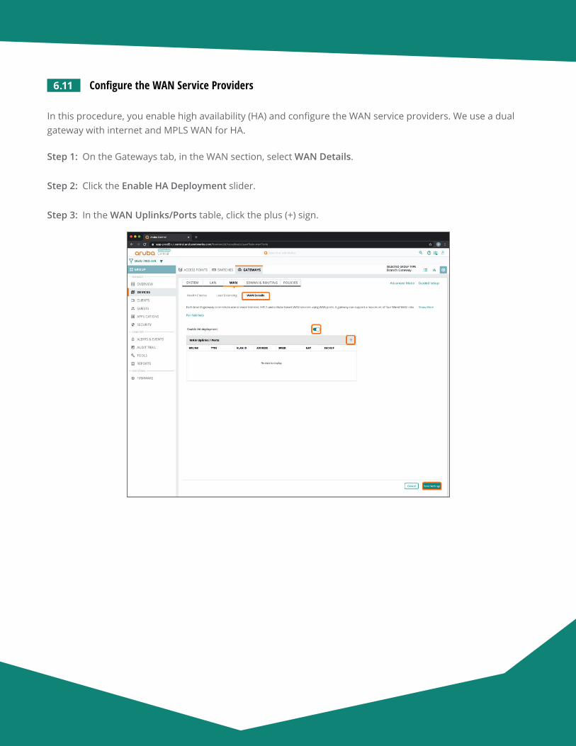
Aruba Design & Deployment Guide 139
6.11 Configure the WAN Service Providers
In this procedure, you enable high availability (HA) and configure the WAN service providers. We use a dual gateway with internet and MPLS WAN for HA.
Step 1: On the Gateways tab, in the WAN section, select WAN Details.
Step 2: Click the Enable HA Deployment slider.
Step 3: In the WAN Uplinks/Ports table, click the plus (+) sign.
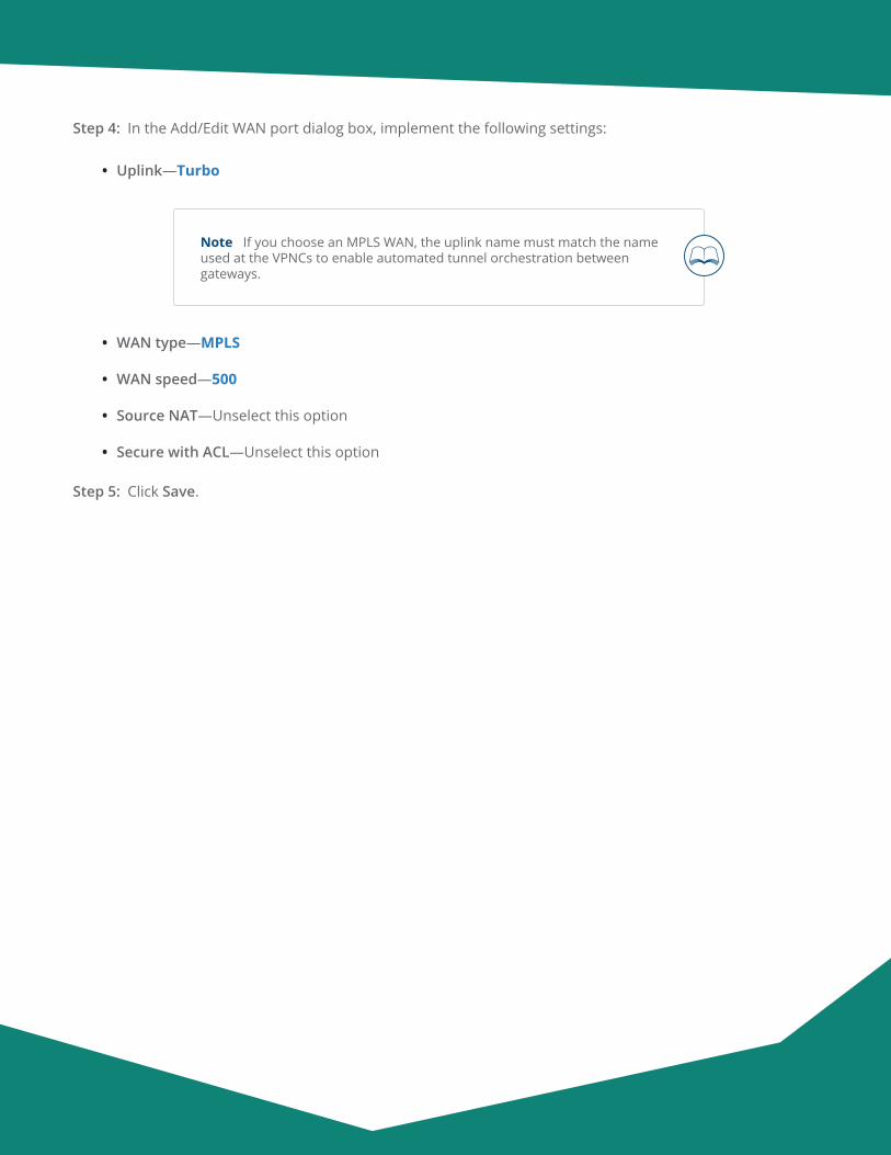
Aruba Design & Deployment Guide 140
Step 4: In the Add/Edit WAN port dialog box, implement the following settings:
• Uplink—Turbo
Note If you choose an MPLS WAN, the uplink name must match the name used at the VPNCs to enable automated tunnel orchestration between gateways.
• WAN type—MPLS
• WAN speed—500
• Source NAT—Unselect this option
• Secure with ACL—Unselect this option
Step 5: Click Save.
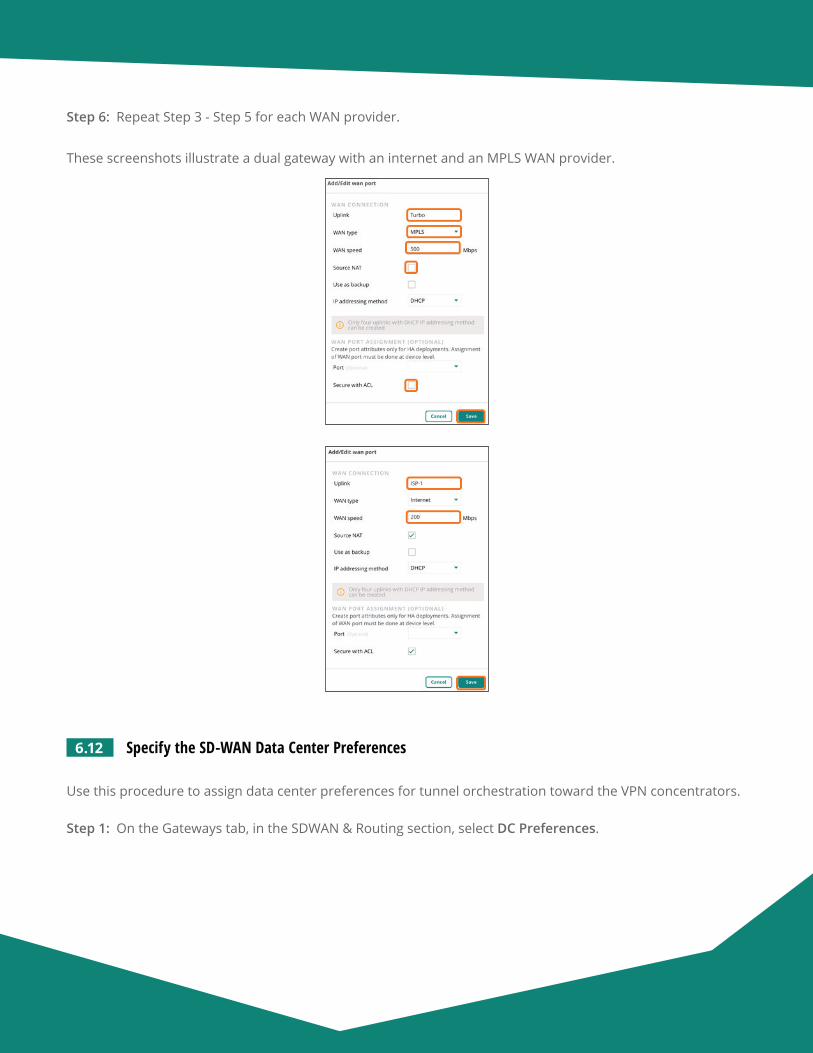
Aruba Design & Deployment Guide 141
Step 6: Repeat Step 3 - Step 5 for each WAN provider.
These screenshots illustrate a dual gateway with an internet and an MPLS WAN provider.
6.12 Specify the SD-WAN Data Center Preferences
Use this procedure to assign data center preferences for tunnel orchestration toward the VPN concentrators.
Step 1: On the Gateways tab, in the SDWAN & Routing section, select DC Preferences.
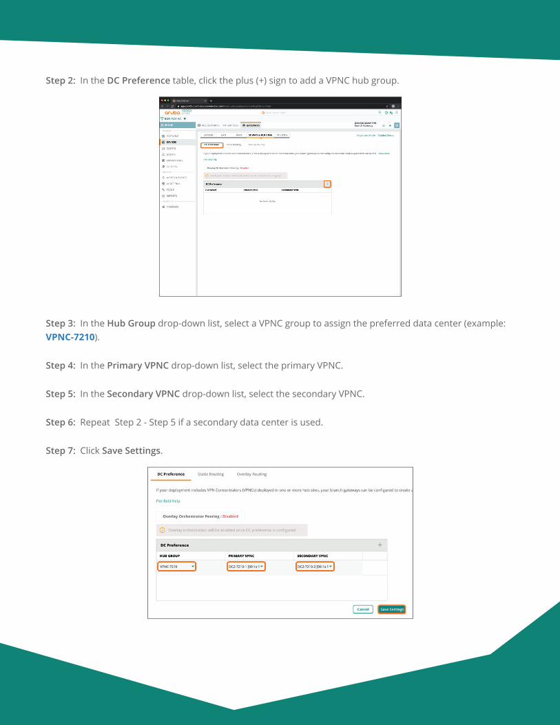
Aruba Design & Deployment Guide 142
Step 2: In the DC Preference table, click the plus (+) sign to add a VPNC hub group.
Step 3: In the Hub Group drop-down list, select a VPNC group to assign the preferred data center (example: VPNC-7210).
Step 4: In the Primary VPNC drop-down list, select the primary VPNC.
Step 5: In the Secondary VPNC drop-down list, select the secondary VPNC.
Step 6: Repeat Step 2 - Step 5 if a secondary data center is used.
Step 7: Click Save Settings.
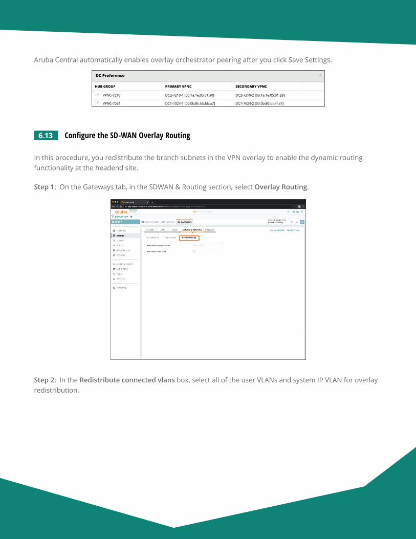
Aruba Design & Deployment Guide 143
Aruba Central automatically enables overlay orchestrator peering after you click Save Settings.
6.13 Configure the SD-WAN Overlay Routing
In this procedure, you redistribute the branch subnets in the VPN overlay to enable the dynamic routing functionality at the headend site.
Step 1: On the Gateways tab, in the SDWAN & Routing section, select Overlay Routing.
Step 2: In the Redistribute connected vlans box, select all of the user VLANs and system IP VLAN for overlay redistribution.
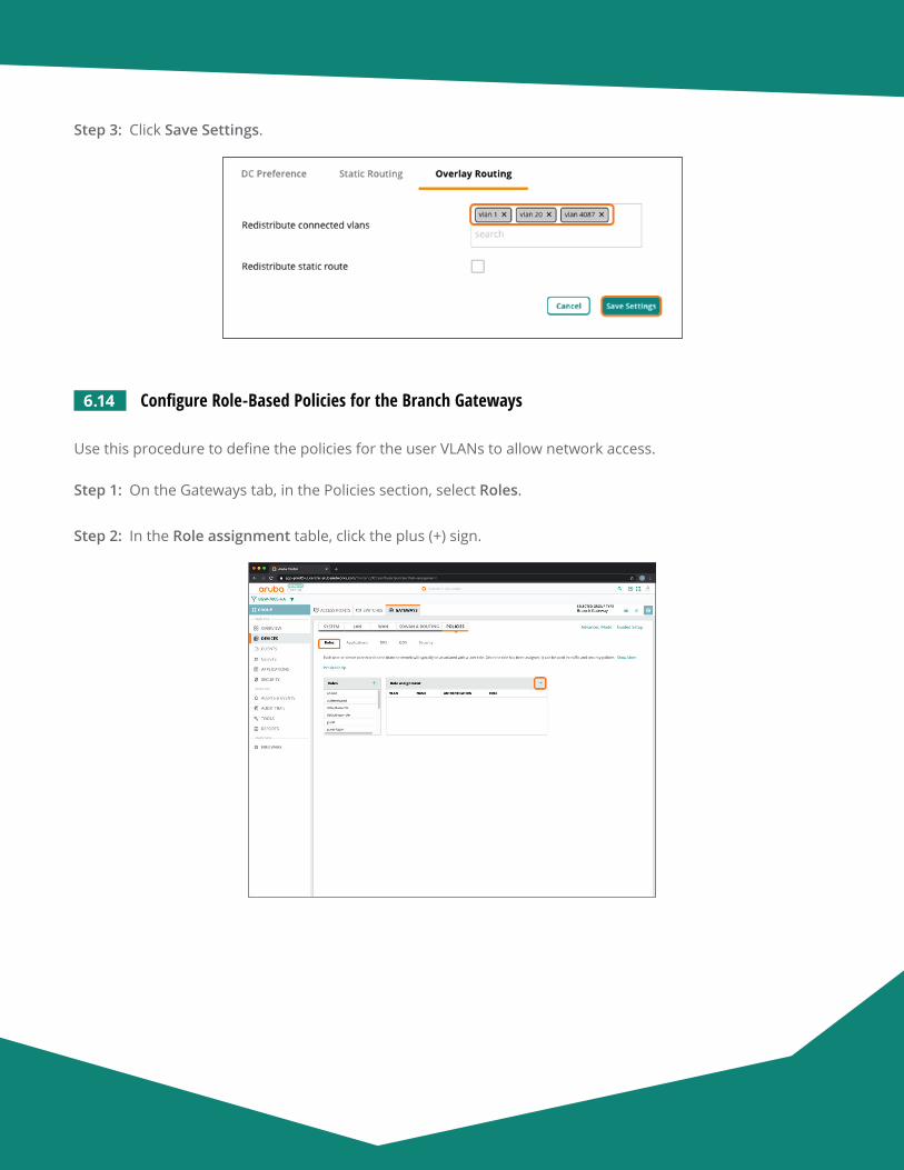
Aruba Design & Deployment Guide 144
Step 3: Click Save Settings.
6.14 Configure Role-Based Policies for the Branch Gateways
Use this procedure to define the policies for the user VLANs to allow network access.
Step 1: On the Gateways tab, in the Policies section, select Roles.
Step 2: In the Role assignment table, click the plus (+) sign.
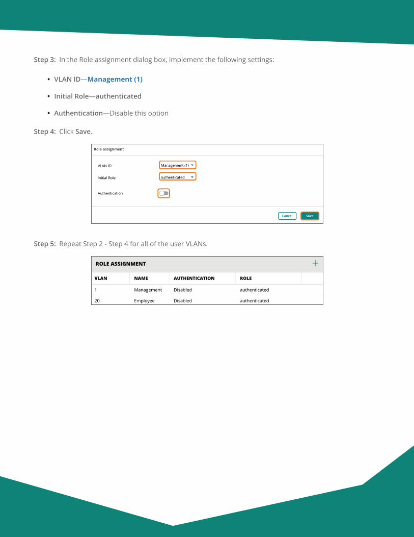
Aruba Design & Deployment Guide 145
Step 3: In the Role assignment dialog box, implement the following settings:
• VLAN ID—Management (1)
• Initial Role—authenticated
• Authentication—Disable this option
Step 4: Click Save.
Step 5: Repeat Step 2 - Step 4 for all of the user VLANs.
Aruba Design & Deployment Guide 146
Configuring a Branch Gateway Device—Two Branch Gateways per Branch
7.1 Assign the Branch Gateway Devices to a Group
7.2 Initiate the Primary Branch Gateway Configuration
7.3 Assign a Hostname to the Primary Branch Gateway Device
7.4 Assign IP Addresses to the VLAN
7.5 Set the DHCP Scope
7.6 Initiate the Secondary Branch Gateway Configuration
7.7 Assign a Hostname to the Secondary Branch Gateway
7.8 Assign IP Addresses to the VLANs
7.9 Set the DHCP Scope
7.10 Specify the WAN Ports
7.11 Assign a Default Route for MPLS
7.12 Configure the LAN Redundancy
Procedures
7.1 Assign the Branch Gateway Devices to a Group
Step 1: On the Aruba Central Account Home page, select Device Inventory.
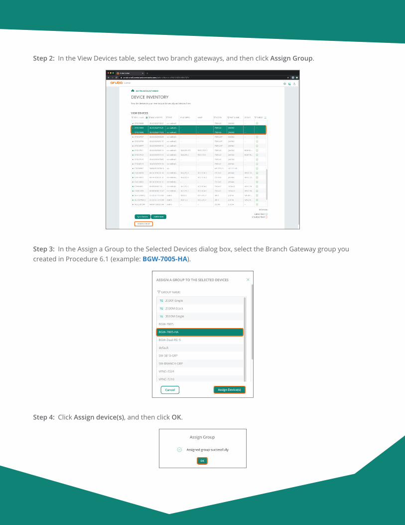
Aruba Design & Deployment Guide 147
Step 2: In the View Devices table, select two branch gateways, and then click Assign Group.
Step 3: In the Assign a Group to the Selected Devices dialog box, select the Branch Gateway group you created in Procedure 6.1 (example: BGW-7005-HA).
Step 4: Click Assign device(s), and then click OK.
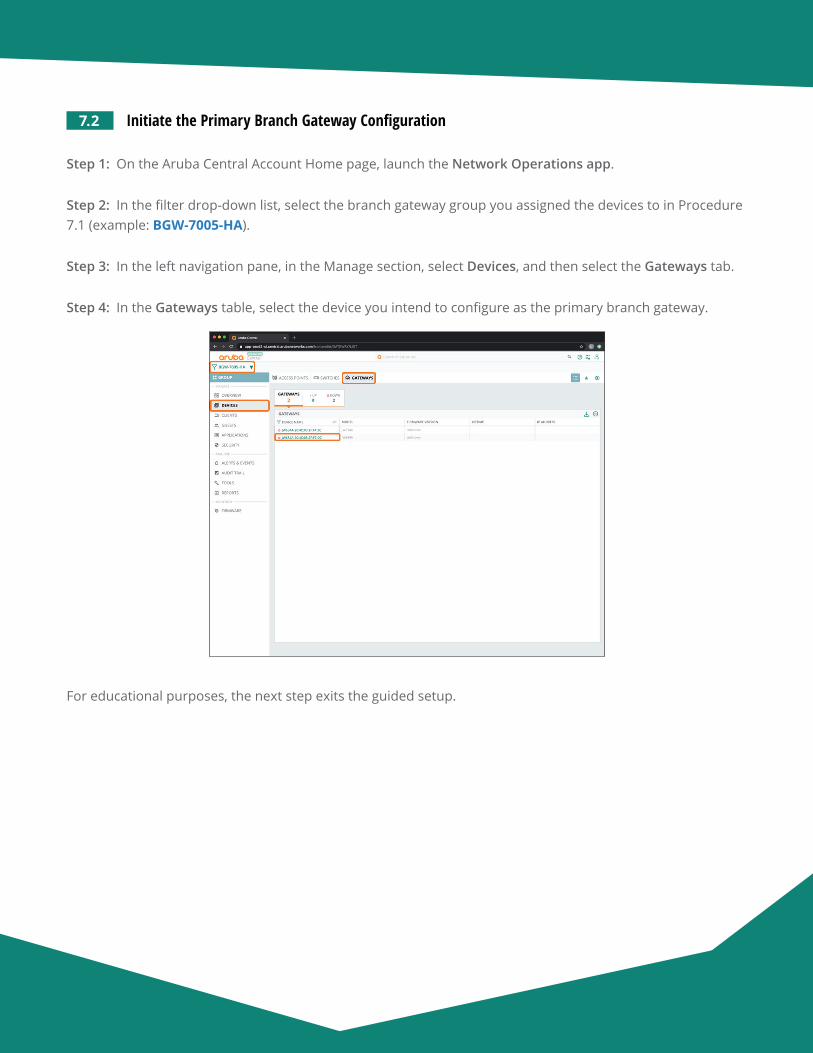
Aruba Design & Deployment Guide 148
7.2 Initiate the Primary Branch Gateway Configuration
Step 1: On the Aruba Central Account Home page, launch the Network Operations app.
Step 2: In the filter drop-down list, select the branch gateway group you assigned the devices to in Procedure 7.1 (example: BGW-7005-HA).
Step 3: In the left navigation pane, in the Manage section, select Devices, and then select the Gateways tab.
Step 4: In the Gateways table, select the device you intend to configure as the primary branch gateway.
For educational purposes, the next step exits the guided setup.
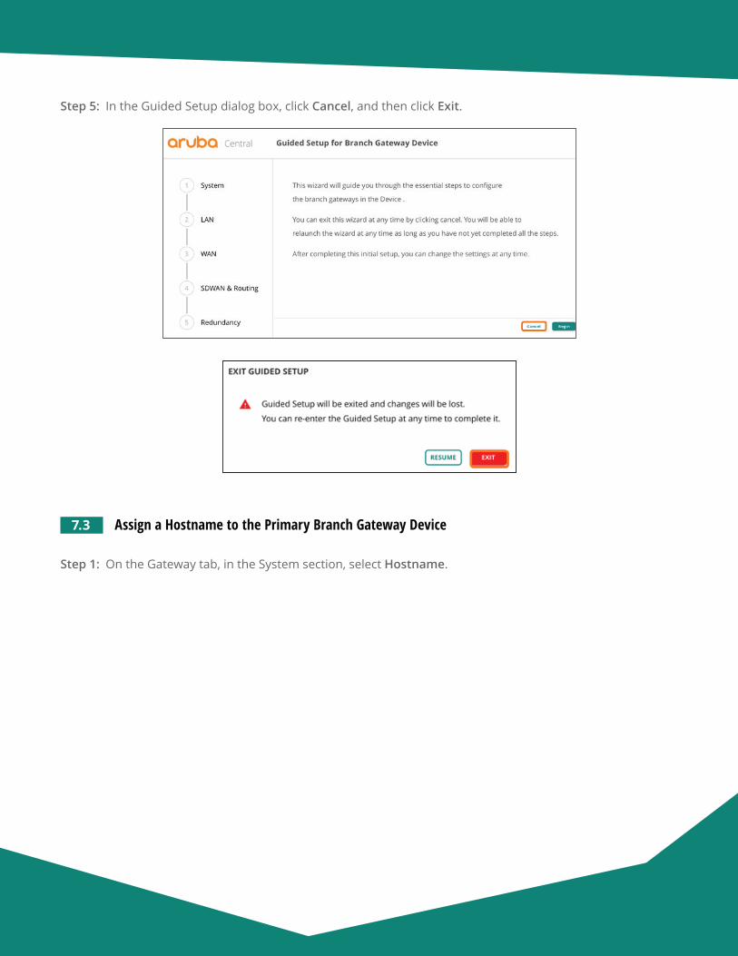
Aruba Design & Deployment Guide 149
Step 5: In the Guided Setup dialog box, click Cancel, and then click Exit.
7.3 Assign a Hostname to the Primary Branch Gateway Device
Step 1: On the Gateway tab, in the System section, select Hostname.
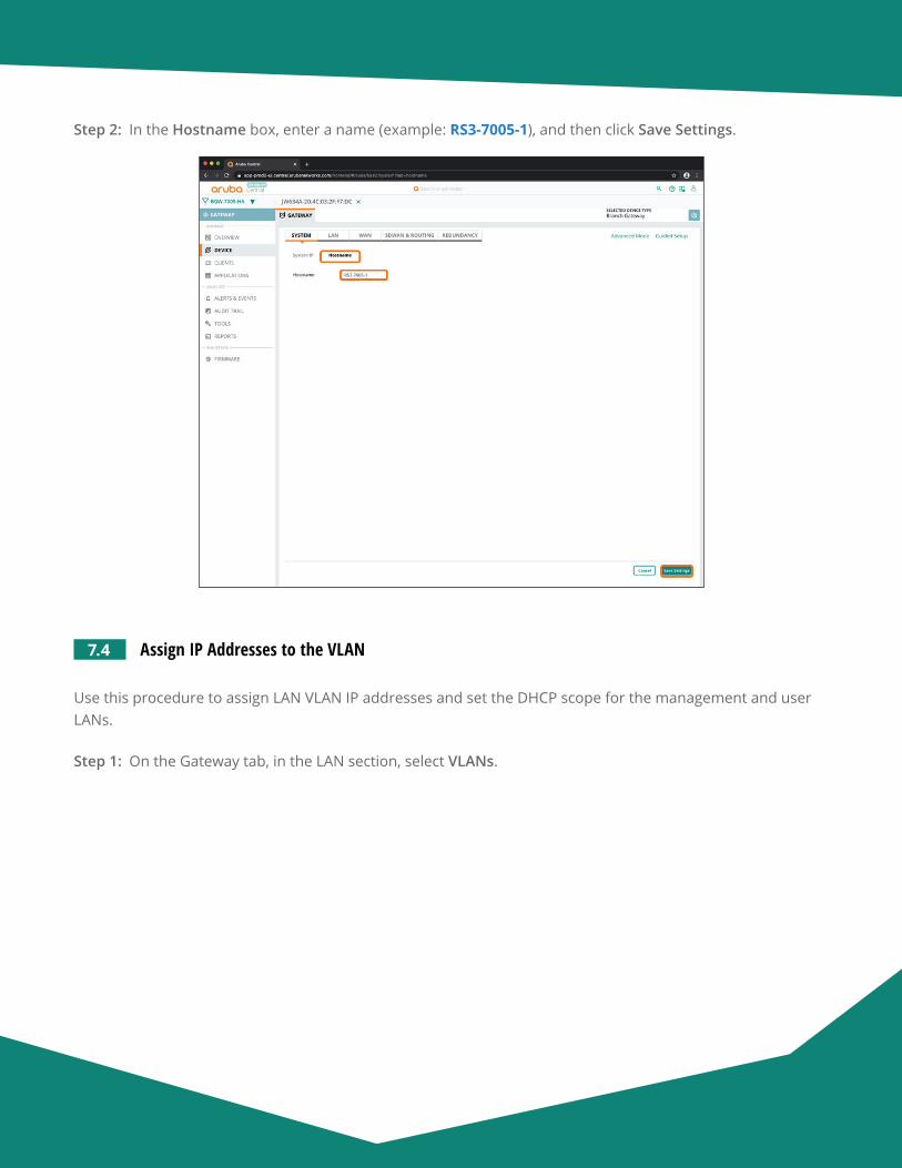
Aruba Design & Deployment Guide 150
Step 2: In the Hostname box, enter a name (example: RS3-7005-1), and then click Save Settings.
7.4 Assign IP Addresses to the VLAN
Use this procedure to assign LAN VLAN IP addresses and set the DHCP scope for the management and user LANs.
Step 1: On the Gateway tab, in the LAN section, select VLANs.
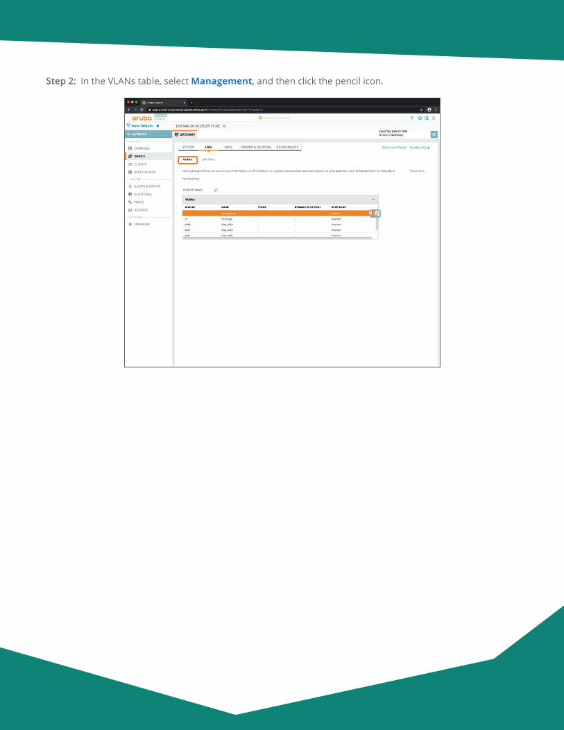
Aruba Design & Deployment Guide 151
Step 2: In the VLANs table, select Management, and then click the pencil icon.

Aruba Design & Deployment Guide 152
Step 3: In the VLAN - Management dialog box, implement the following settings:
• IPV4 Address—10.8.8.2
• Act as DHCP server—Enable this option
• DNS server type—Public DNS Server
• DNS Service Provider—Google
Step 4: Click Save.
Step 5: Repeat Step 2 - Step 4 for any additional VLANs (example: Employee).
Step 6: Click Save Settings.
7.5 Set the DHCP Scope
Step 1: On the Gateway tab, in the LAN section, select VLANs.
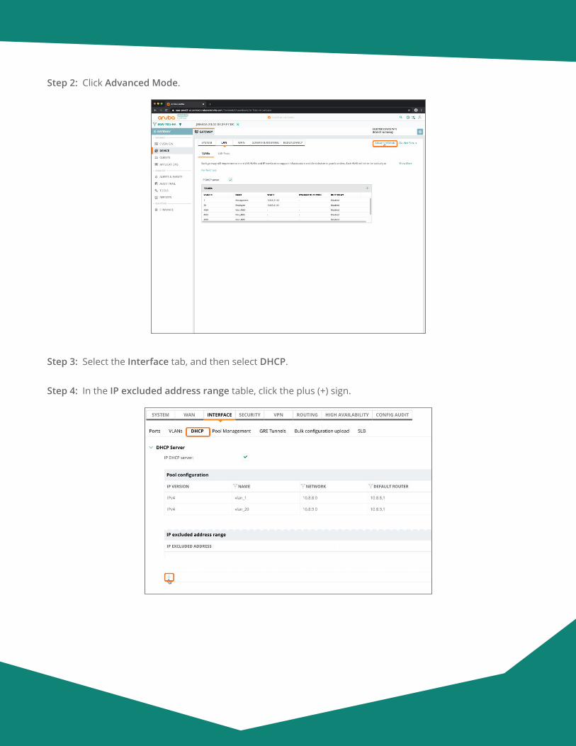
Aruba Design & Deployment Guide 153
Step 2: Click Advanced Mode.
Step 3: Select the Interface tab, and then select DHCP.
Step 4: In the IP excluded address range table, click the plus (+) sign.
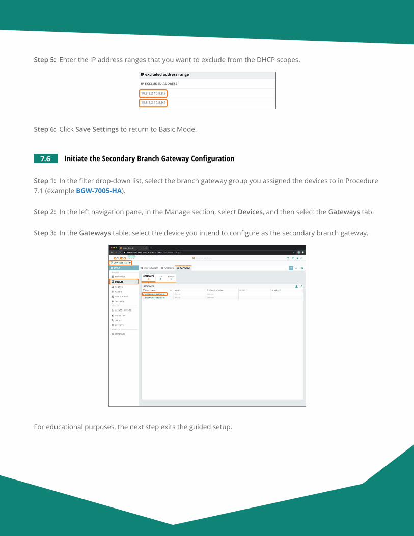
Aruba Design & Deployment Guide 154
Step 5: Enter the IP address ranges that you want to exclude from the DHCP scopes.
Step 6: Click Save Settings to return to Basic Mode.
7.6 Initiate the Secondary Branch Gateway Configuration
Step 1: In the filter drop-down list, select the branch gateway group you assigned the devices to in Procedure 7.1 (example BGW-7005-HA).
Step 2: In the left navigation pane, in the Manage section, select Devices, and then select the Gateways tab.
Step 3: In the Gateways table, select the device you intend to configure as the secondary branch gateway.
For educational purposes, the next step exits the guided setup.
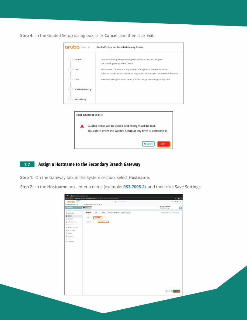
Aruba Design & Deployment Guide 155
Step 4: In the Guided Setup dialog box, click Cancel, and then click Exit.
7.7 Assign a Hostname to the Secondary Branch Gateway
Step 1: On the Gateway tab, in the System section, select Hostname.
Step 2: In the Hostname box, enter a name (example: RS3-7005-2), and then click Save Settings.
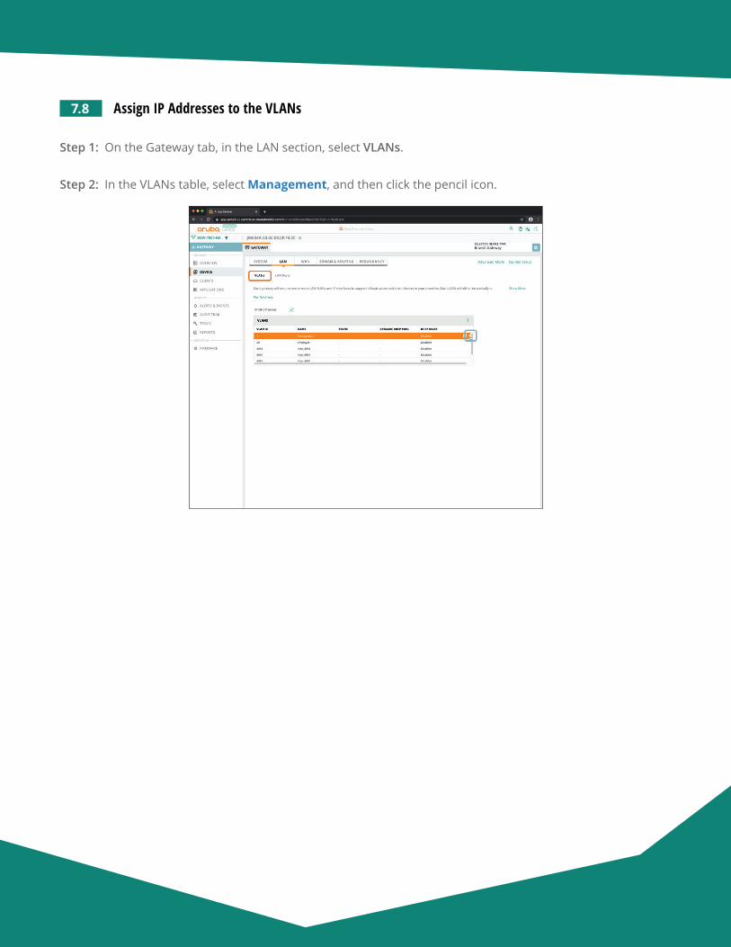
Aruba Design & Deployment Guide 156
7.8 Assign IP Addresses to the VLANs
Step 1: On the Gateway tab, in the LAN section, select VLANs.
Step 2: In the VLANs table, select Management, and then click the pencil icon.
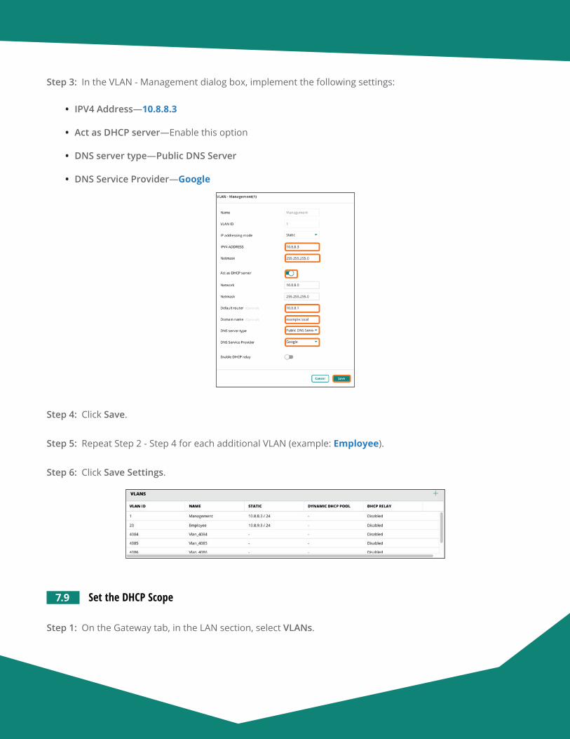
Aruba Design & Deployment Guide 157
Step 3: In the VLAN - Management dialog box, implement the following settings:
• IPV4 Address—10.8.8.3
• Act as DHCP server—Enable this option
• DNS server type—Public DNS Server
• DNS Service Provider—Google
Step 4: Click Save.
Step 5: Repeat Step 2 - Step 4 for each additional VLAN (example: Employee).
Step 6: Click Save Settings.
7.9 Set the DHCP Scope
Step 1: On the Gateway tab, in the LAN section, select VLANs.
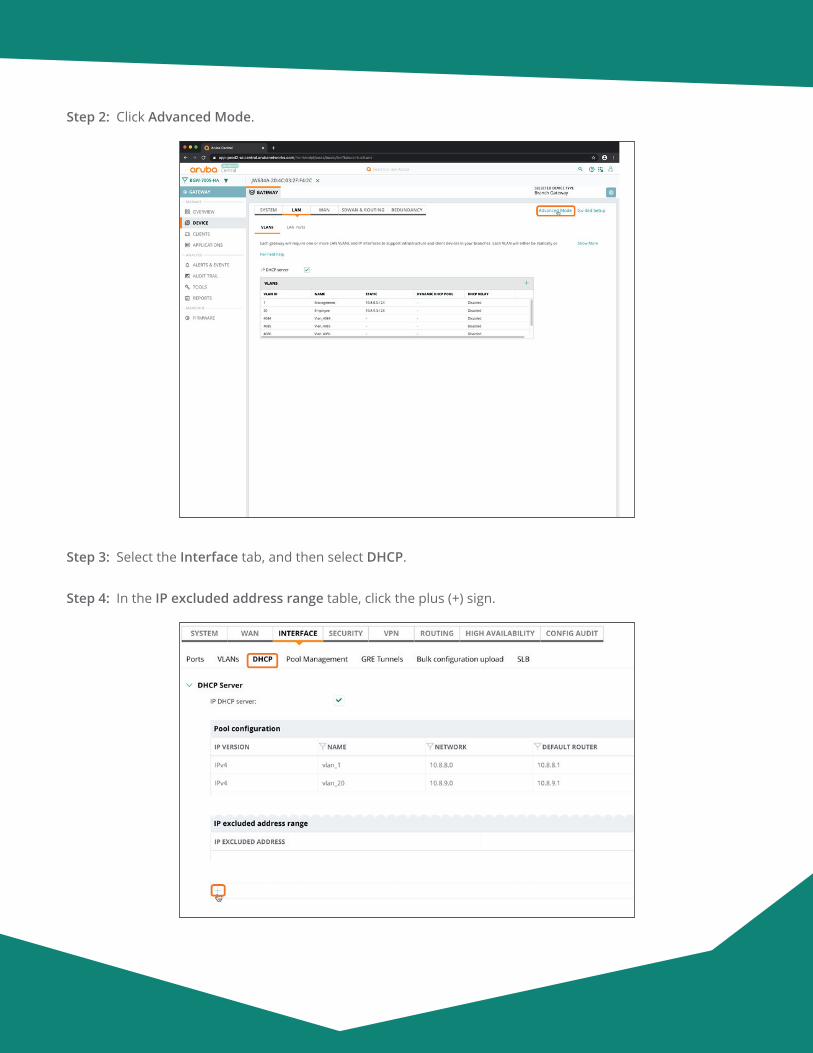
Aruba Design & Deployment Guide 158
Step 2: Click Advanced Mode.
Step 3: Select the Interface tab, and then select DHCP.
Step 4: In the IP excluded address range table, click the plus (+) sign.
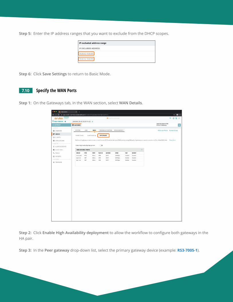
Aruba Design & Deployment Guide 159
Step 5: Enter the IP address ranges that you want to exclude from the DHCP scopes.
Step 6: Click Save Settings to return to Basic Mode.
7.10 Specify the WAN Ports
Step 1: On the Gateways tab, in the WAN section, select WAN Details.
Step 2: Click Enable High Availability deployment to allow the workflow to configure both gateways in the HA pair.
Step 3: In the Peer gateway drop-down list, select the primary gateway device (example: RS3-7005-1).
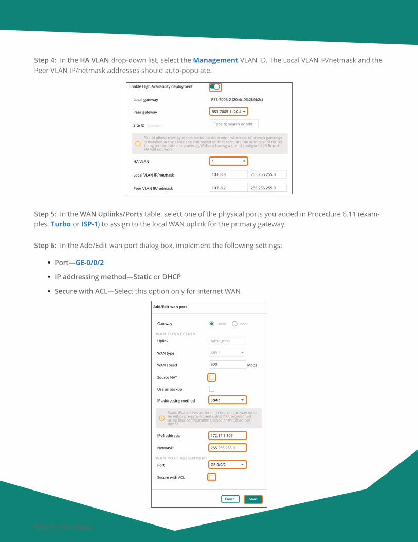
Aruba Design & Deployment Guide 160
Step 4: In the HA VLAN drop-down list, select the Management VLAN ID. The Local VLAN IP/netmask and the Peer VLAN IP/netmask addresses should auto-populate.
Step 5: In the WAN Uplinks/Ports table, select one of the physical ports you added in Procedure 6.11 (exam-ples: Turbo or ISP-1) to assign to the local WAN uplink for the primary gateway.
Step 6: In the Add/Edit wan port dialog box, implement the following settings:
• Port—GE-0/0/2
• IP addressing method—Static or DHCP
• Secure with ACL—Select this option only for Internet WAN
Step 7: Click Save.
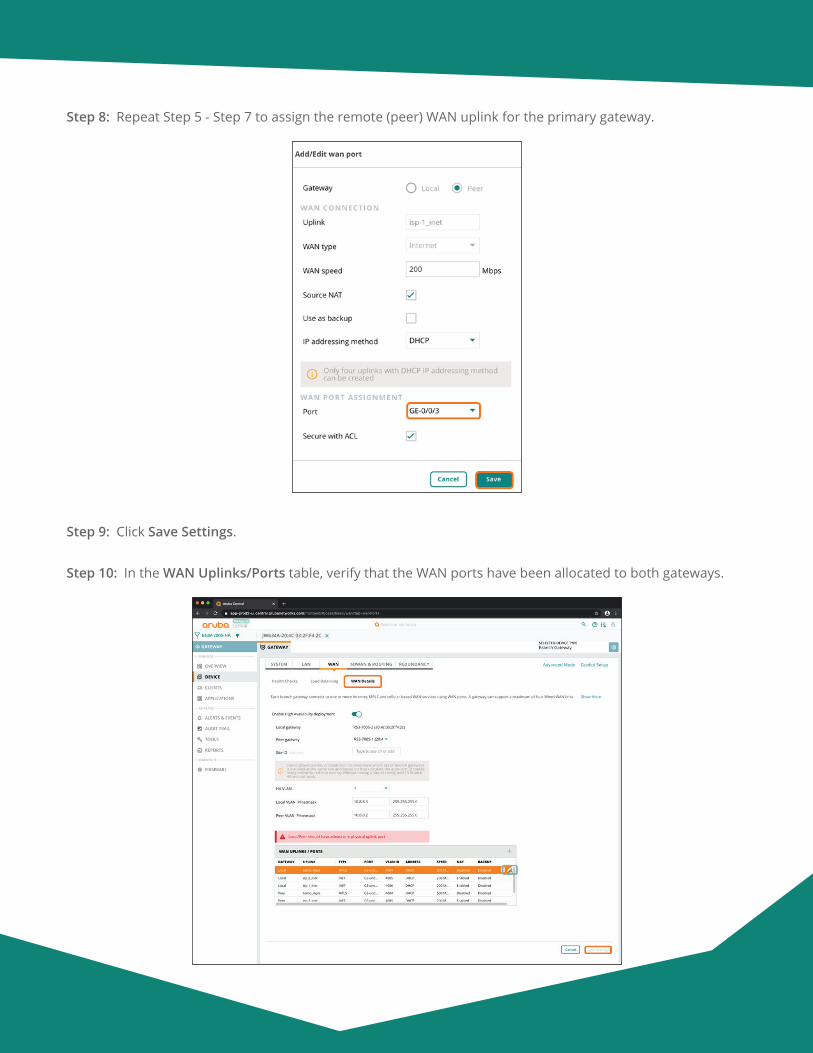
Aruba Design & Deployment Guide 161
Step 8: Repeat Step 5 - Step 7 to assign the remote (peer) WAN uplink for the primary gateway.
Step 9: Click Save Settings.
Step 10: In the WAN Uplinks/Ports table, verify that the WAN ports have been allocated to both gateways.
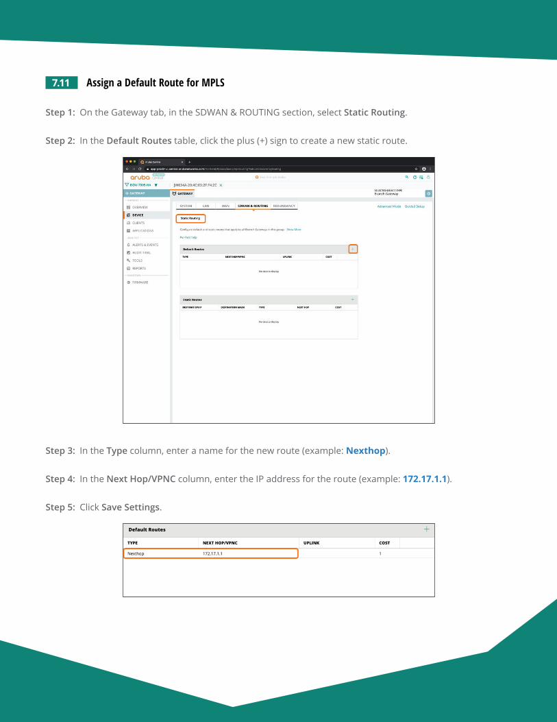
Aruba Design & Deployment Guide 162
7.11 Assign a Default Route for MPLS
Step 1: On the Gateway tab, in the SDWAN & ROUTING section, select Static Routing.
Step 2: In the Default Routes table, click the plus (+) sign to create a new static route.
Step 3: In the Type column, enter a name for the new route (example: Nexthop).
Step 4: In the Next Hop/VPNC column, enter the IP address for the route (example: 172.17.1.1).
Step 5: Click Save Settings.
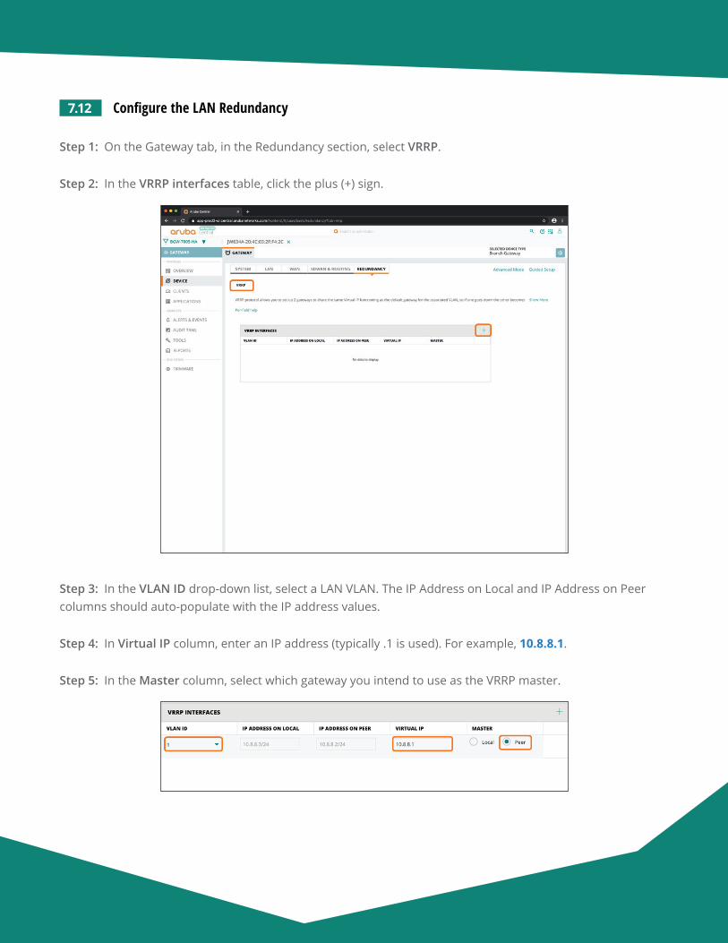
Aruba Design & Deployment Guide 163
7.12 Configure the LAN Redundancy
Step 1: On the Gateway tab, in the Redundancy section, select VRRP.
Step 2: In the VRRP interfaces table, click the plus (+) sign.
Step 3: In the VLAN ID drop-down list, select a LAN VLAN. The IP Address on Local and IP Address on Peer columns should auto-populate with the IP address values.
Step 4: In Virtual IP column, enter an IP address (typically .1 is used). For example, 10.8.8.1.
Step 5: In the Master column, select which gateway you intend to use as the VRRP master.
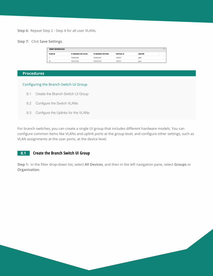
Aruba Design & Deployment Guide 164
Step 6: Repeat Step 2 - Step 4 for all user VLANs.
Step 7: Click Save Settings.
Configuring the Branch Switch UI Group
8.1 Create the Branch Switch UI Group
8.2 Configure the Switch VLANs
8.3 Configure the Uplinks for the VLANs
Procedures
For branch switches, you can create a single UI group that includes different hardware models. You can configure common items like VLANs and uplink ports at the group level, and configure other settings, such as VLAN assignments at the user ports, at the device level.
8.1 Create the Branch Switch UI Group
Step 1: In the filter drop-down list, select All Devices, and then in the left navigation pane, select Groups or Organization.
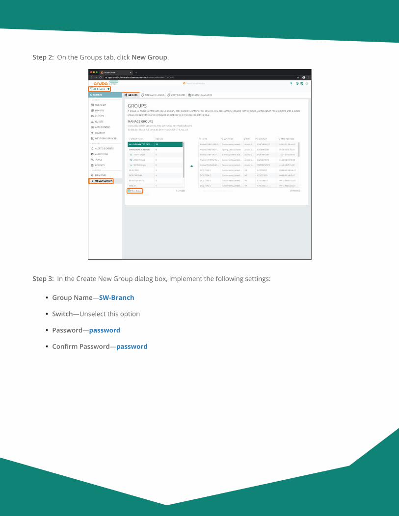
Aruba Design & Deployment Guide 165
Step 2: On the Groups tab, click New Group.
Step 3: In the Create New Group dialog box, implement the following settings:
• Group Name—SW-Branch
• Switch—Unselect this option
• Password—password
• Confirm Password—password
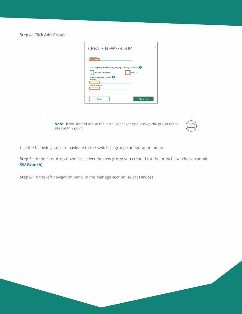
Aruba Design & Deployment Guide 166
Step 4: Click Add Group.
Note If you intend to use the Install Manager App, assign the group to the sites at this point.
Use the following steps to navigate to the switch UI group configuration menu.
Step 5: In the filter drop-down list, select the new group you created for the branch switches (example: SW-Branch).
Step 6: In the left navigation pane, in the Manage section, select Devices.
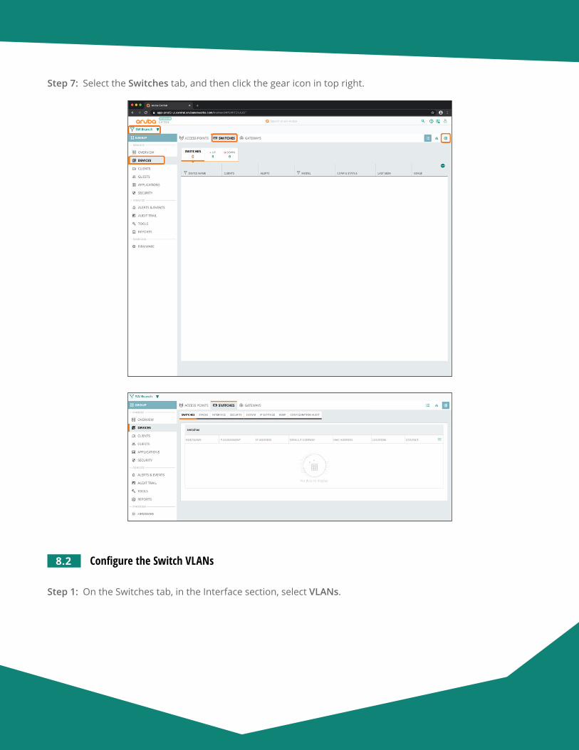
Aruba Design & Deployment Guide 167
Step 7: Select the Switches tab, and then click the gear icon in top right.
8.2 Configure the Switch VLANs
Step 1: On the Switches tab, in the Interface section, select VLANs.
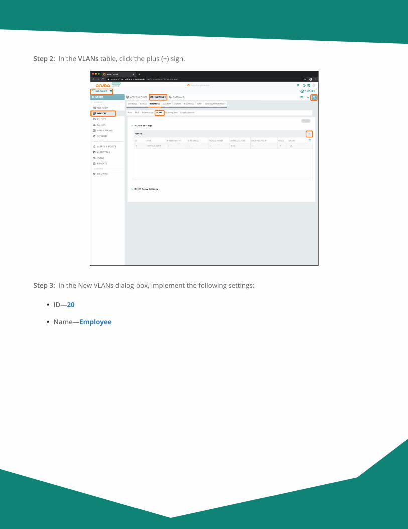
Aruba Design & Deployment Guide 168
Step 2: In the VLANs table, click the plus (+) sign.
Step 3: In the New VLANs dialog box, implement the following settings:
• ID—20
• Name—Employee
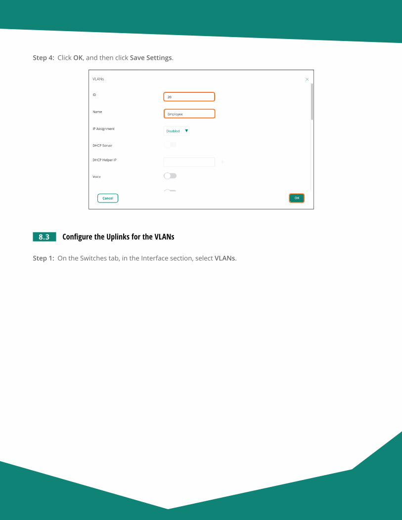
Aruba Design & Deployment Guide 169
Step 4: Click OK, and then click Save Settings.
8.3 Configure the Uplinks for the VLANs
Step 1: On the Switches tab, in the Interface section, select VLANs.
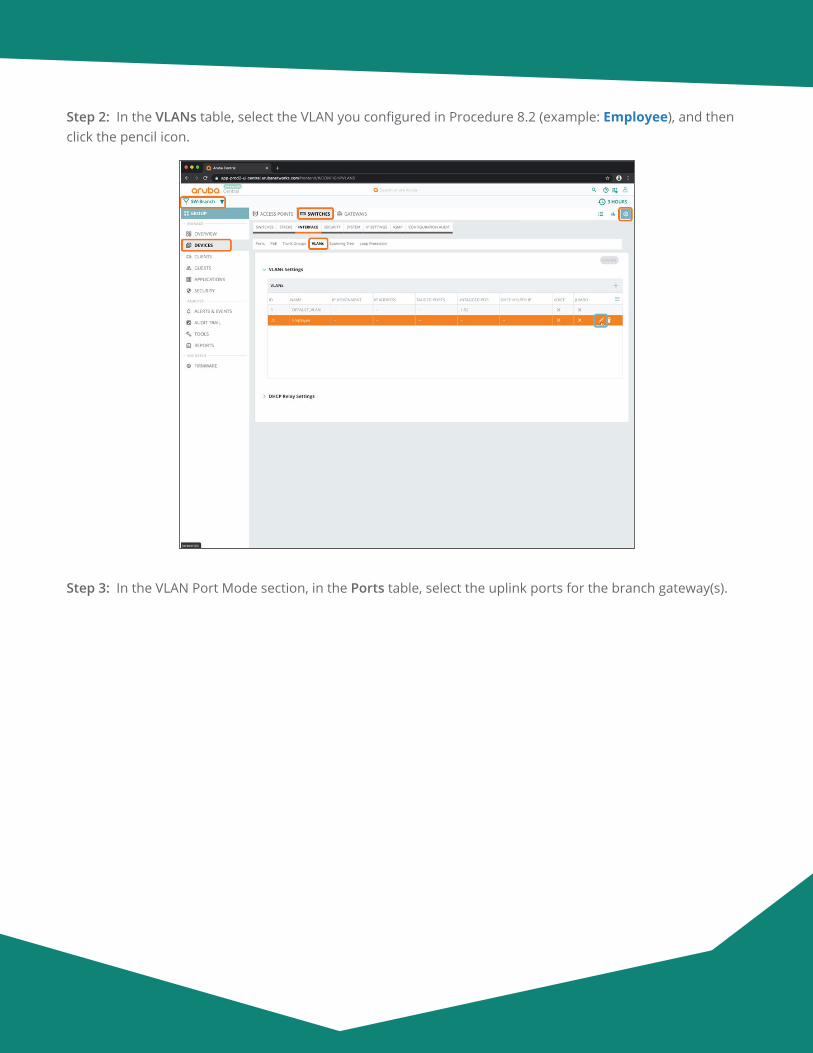
Aruba Design & Deployment Guide 170
Step 2: In the VLANs table, select the VLAN you configured in Procedure 8.2 (example: Employee), and then click the pencil icon.
Step 3: In the VLAN Port Mode section, in the Ports table, select the uplink ports for the branch gateway(s).
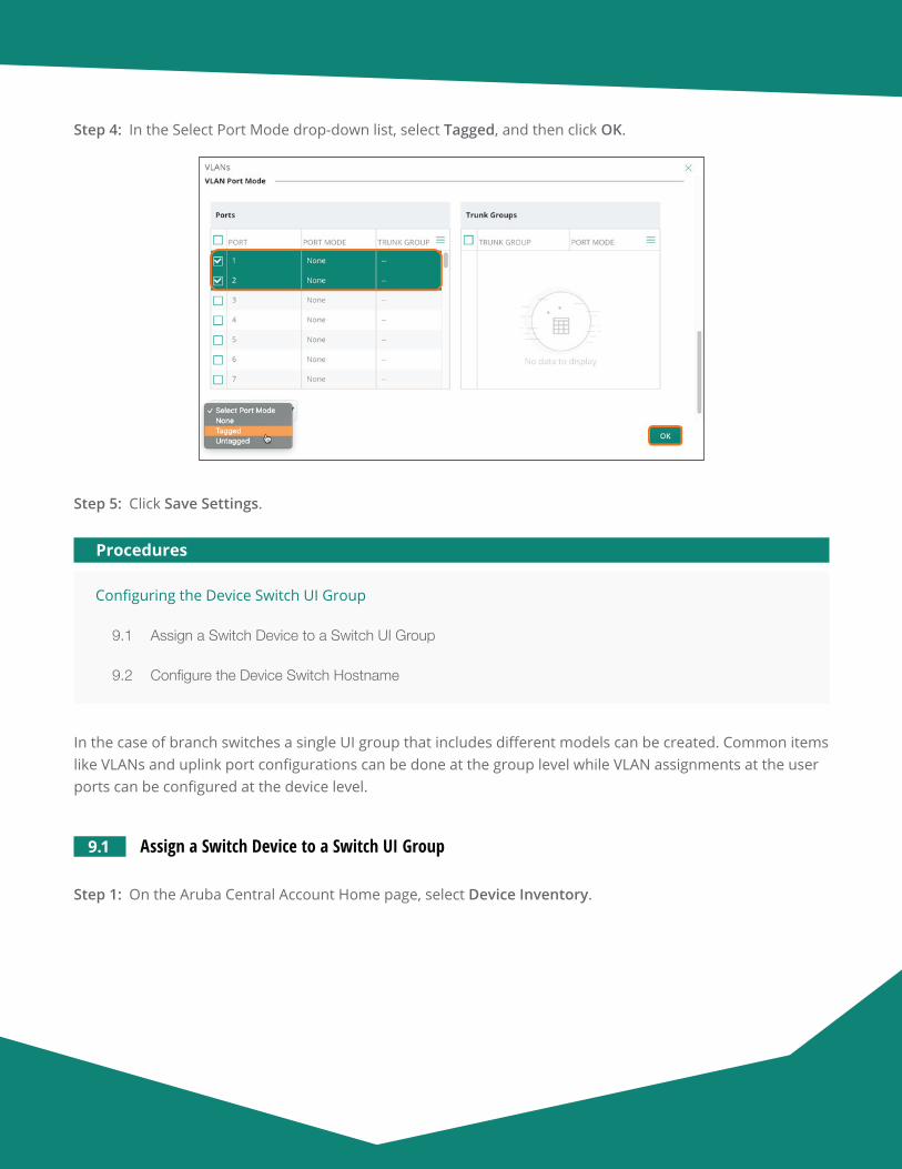
Aruba Design & Deployment Guide 171
Step 4: In the Select Port Mode drop-down list, select Tagged, and then click OK.
Step 5: Click Save Settings.
Configuring the Device Switch UI Group
9.1 Assign a Switch Device to a Switch UI Group
9.2 Configure the Device Switch Hostname
Procedures
In the case of branch switches a single UI group that includes different models can be created. Common items like VLANs and uplink port configurations can be done at the group level while VLAN assignments at the user ports can be configured at the device level.
9.1 Assign a Switch Device to a Switch UI Group
Step 1: On the Aruba Central Account Home page, select Device Inventory.
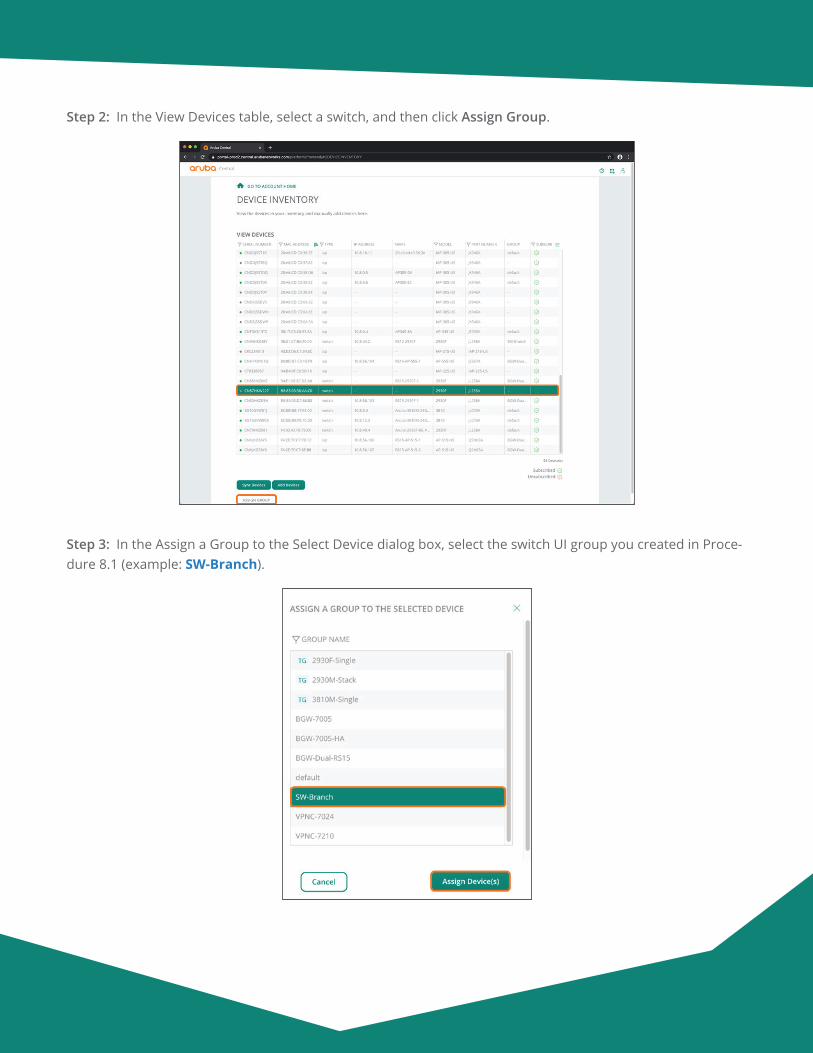
Aruba Design & Deployment Guide 172
Step 2: In the View Devices table, select a switch, and then click Assign Group.
Step 3: In the Assign a Group to the Select Device dialog box, select the switch UI group you created in Proce-dure 8.1 (example: SW-Branch).
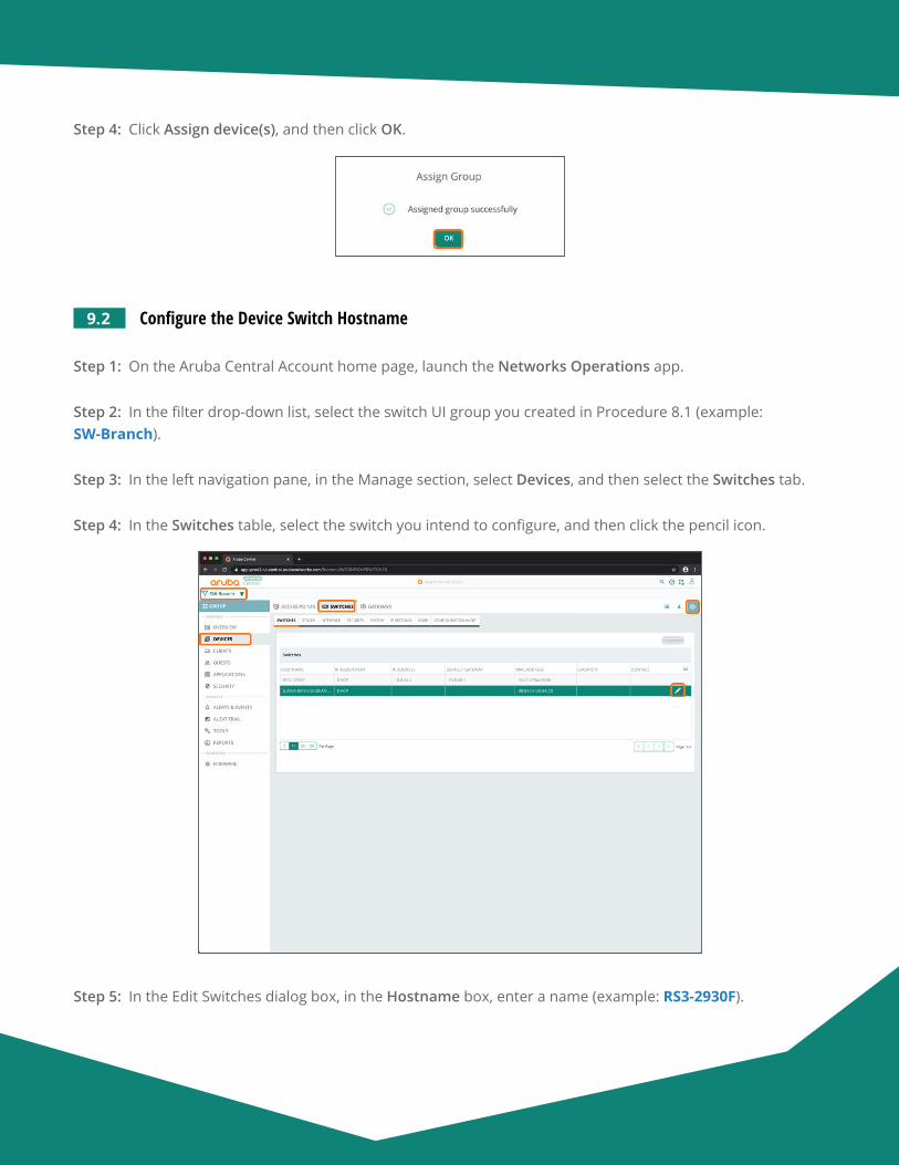
Aruba Design & Deployment Guide 173
Step 4: Click Assign device(s), and then click OK.
9.2 Configure the Device Switch Hostname
Step 1: On the Aruba Central Account home page, launch the Networks Operations app.
Step 2: In the filter drop-down list, select the switch UI group you created in Procedure 8.1 (example: SW-Branch).
Step 3: In the left navigation pane, in the Manage section, select Devices, and then select the Switches tab.
Step 4: In the Switches table, select the switch you intend to configure, and then click the pencil icon.
Step 5: In the Edit Switches dialog box, in the Hostname box, enter a name (example: RS3-2930F).
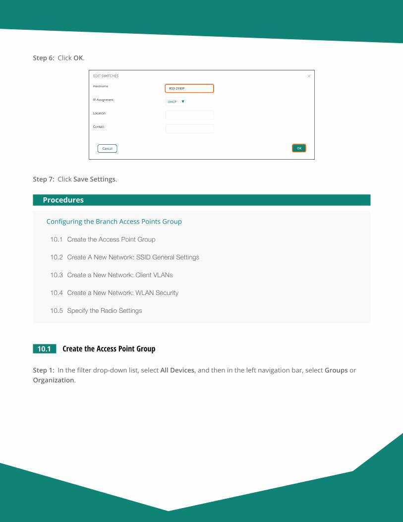
Aruba Design & Deployment Guide 174
Step 6: Click OK.
Step 7: Click Save Settings.
Configuring the Branch Access Points Group
10.1 Create the Access Point Group
10.2 Create A New Network: SSID General Settings
10.3 Create a New Network: Client VLANs
10.4 Create a New Network: WLAN Security
10.5 Specify the Radio Settings
Procedures
10.1 Create the Access Point Group
Step 1: In the filter drop-down list, select All Devices, and then in the left navigation bar, select Groups or Organization.

Aruba Design & Deployment Guide 175
Step 2: On the Groups tab, click New Group.
Step 3: In the Create New Group dialog box, implement the following settings:
• Group Name—AP-Branch
• Switch—Unselect this option
• Password—password
• Confirm Password—password
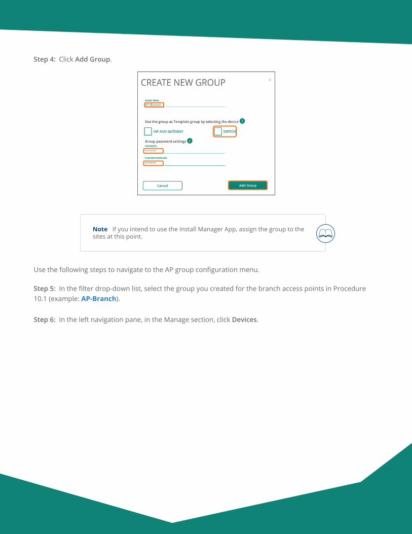
Aruba Design & Deployment Guide 176
Step 4: Click Add Group.
Note If you intend to use the Install Manager App, assign the group to the sites at this point.
Use the following steps to navigate to the AP group configuration menu.
Step 5: In the filter drop-down list, select the group you created for the branch access points in Procedure 10.1 (example: AP-Branch).
Step 6: In the left navigation pane, in the Manage section, click Devices.
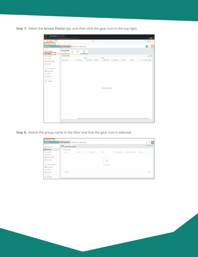
Aruba Design & Deployment Guide 177
Step 7: Select the Access Points tab, and then click the gear icon in the top right.
Step 8: Notice the group name in the filter and that the gear icon is selected.
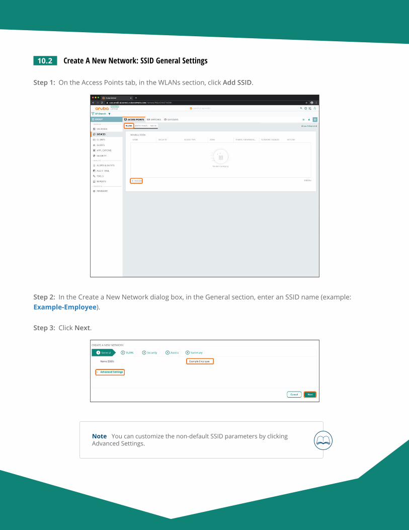
Aruba Design & Deployment Guide 178
10.2 Create A New Network: SSID General Settings
Step 1: On the Access Points tab, in the WLANs section, click Add SSID.
Step 2: In the Create a New Network dialog box, in the General section, enter an SSID name (example: Example-Employee).
Step 3: Click Next.
Note You can customize the non-default SSID parameters by clicking Advanced Settings.
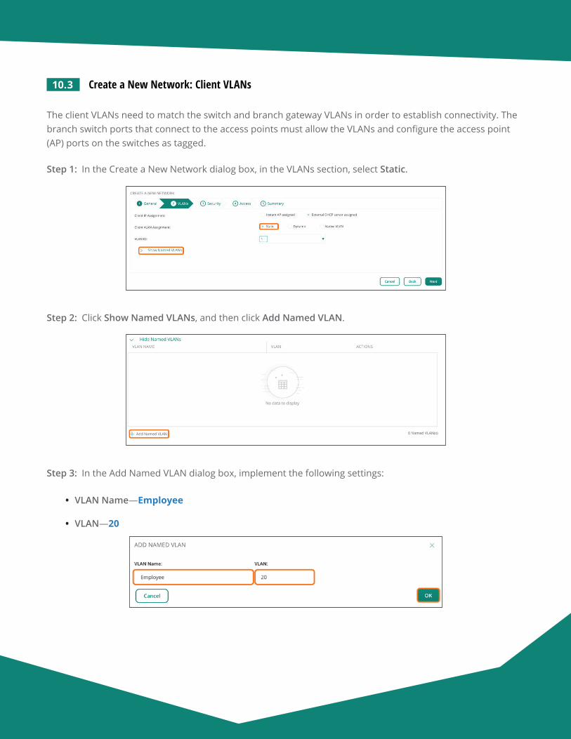
Aruba Design & Deployment Guide 179
10.3 Create a New Network: Client VLANs
The client VLANs need to match the switch and branch gateway VLANs in order to establish connectivity. The branch switch ports that connect to the access points must allow the VLANs and configure the access point (AP) ports on the switches as tagged.
Step 1: In the Create a New Network dialog box, in the VLANs section, select Static.
Step 2: Click Show Named VLANs, and then click Add Named VLAN.
Step 3: In the Add Named VLAN dialog box, implement the following settings:
• VLAN Name—Employee
• VLAN—20
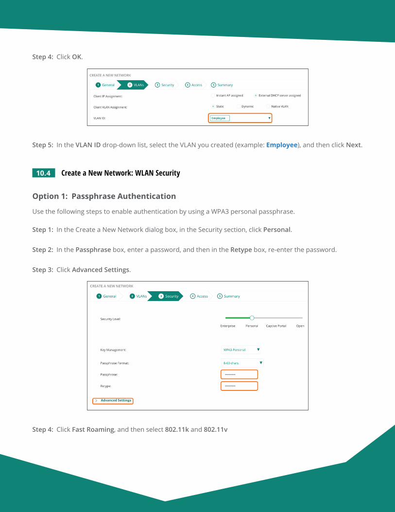
Aruba Design & Deployment Guide 180
Step 4: Click OK.
Step 5: In the VLAN ID drop-down list, select the VLAN you created (example: Employee), and then click Next.
10.4 Create a New Network: WLAN Security
Option 1: Passphrase Authentication
Use the following steps to enable authentication by using a WPA3 personal passphrase.
Step 1: In the Create a New Network dialog box, in the Security section, click Personal.
Step 2: In the Passphrase box, enter a password, and then in the Retype box, re-enter the password.
Step 3: Click Advanced Settings.
Step 4: Click Fast Roaming, and then select 802.11k and 802.11v
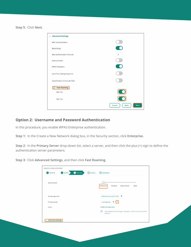
Aruba Design & Deployment Guide 181
Step 5: Click Next.
Option 2: Username and Password Authentication
In this procedure, you enable WPA3 Enterprise authentication.
Step 1: In the Create a New Network dialog box, in the Security section, click Enterprise.
Step 2: In the Primary Server drop-down list, select a server, and then click the plus (+) sign to define the authentication server parameters.
Step 3: Click Advanced Settings, and then click Fast Roaming.
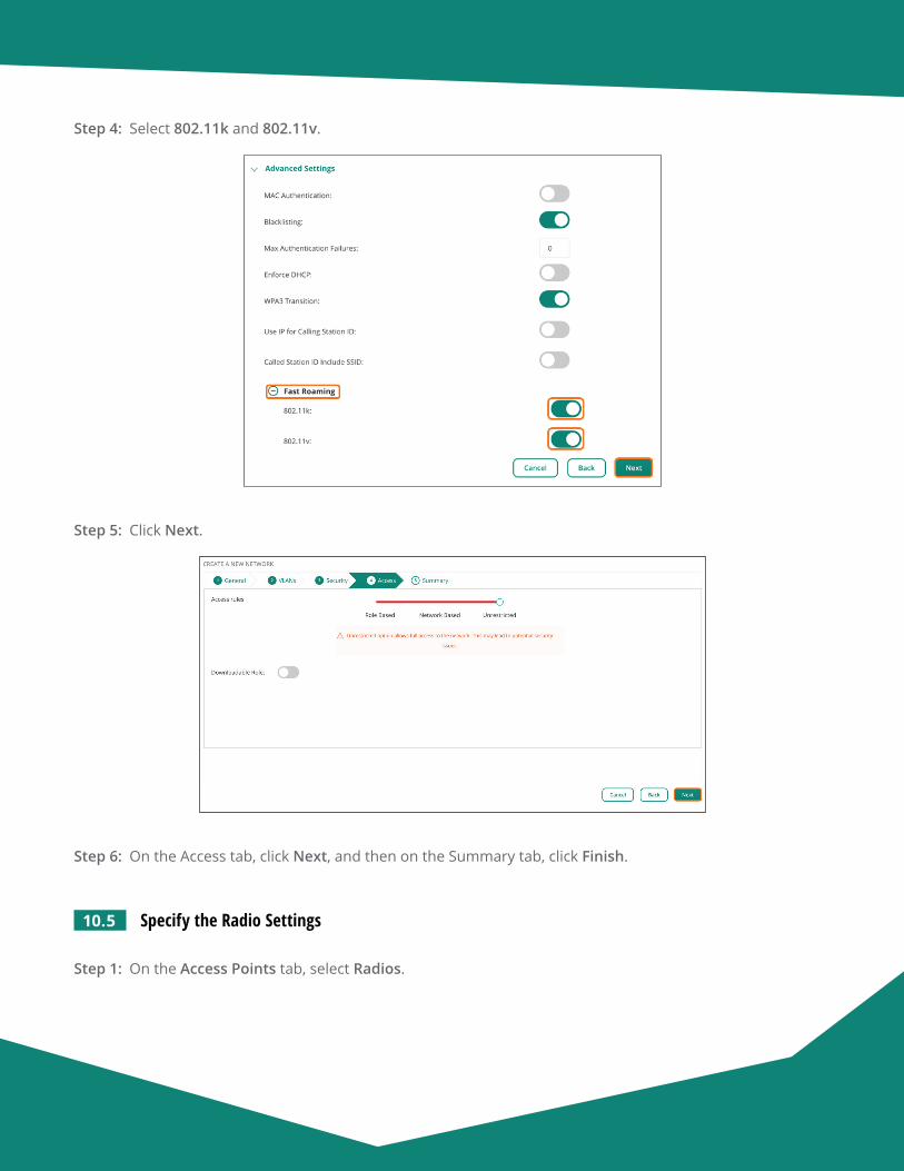
Aruba Design & Deployment Guide 182
Step 4: Select 802.11k and 802.11v.
Step 5: Click Next.
Step 6: On the Access tab, click Next, and then on the Summary tab, click Finish.
10.5 Specify the Radio Settings
Step 1: On the Access Points tab, select Radios.
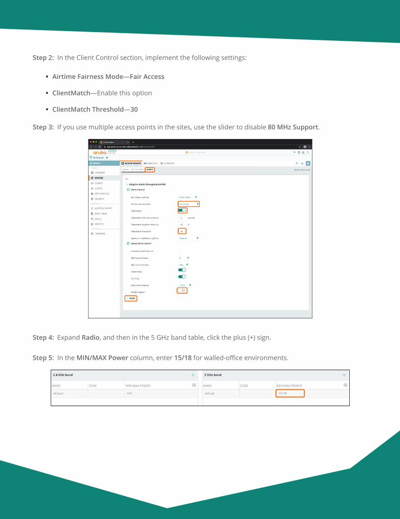
Aruba Design & Deployment Guide 183
Step 2: In the Client Control section, implement the following settings:
• Airtime Fairness Mode—Fair Access
• ClientMatch—Enable this option
• ClientMatch Threshold—30
Step 3: If you use multiple access points in the sites, use the slider to disable 80 MHz Support.
Step 4: Expand Radio, and then in the 5 GHz band table, click the plus (+) sign.
Step 5: In the MIN/MAX Power column, enter 15/18 for walled-office environments.
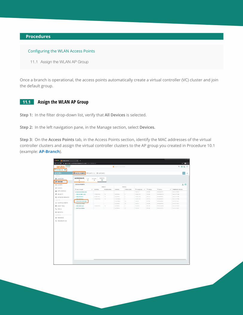
Aruba Design & Deployment Guide 184
Configuring the WLAN Access Points
11.1 Assign the WLAN AP Group
Procedures
Once a branch is operational, the access points automatically create a virtual controller (VC) cluster and join the default group.
11.1 Assign the WLAN AP Group
Step 1: In the filter drop-down list, verify that All Devices is selected.
Step 2: In the left navigation pane, in the Manage section, select Devices.
Step 3: On the Access Points tab, in the Access Points section, identify the MAC addresses of the virtual controller clusters and assign the virtual controller clusters to the AP group you created in Procedure 10.1 (example: AP-Branch).
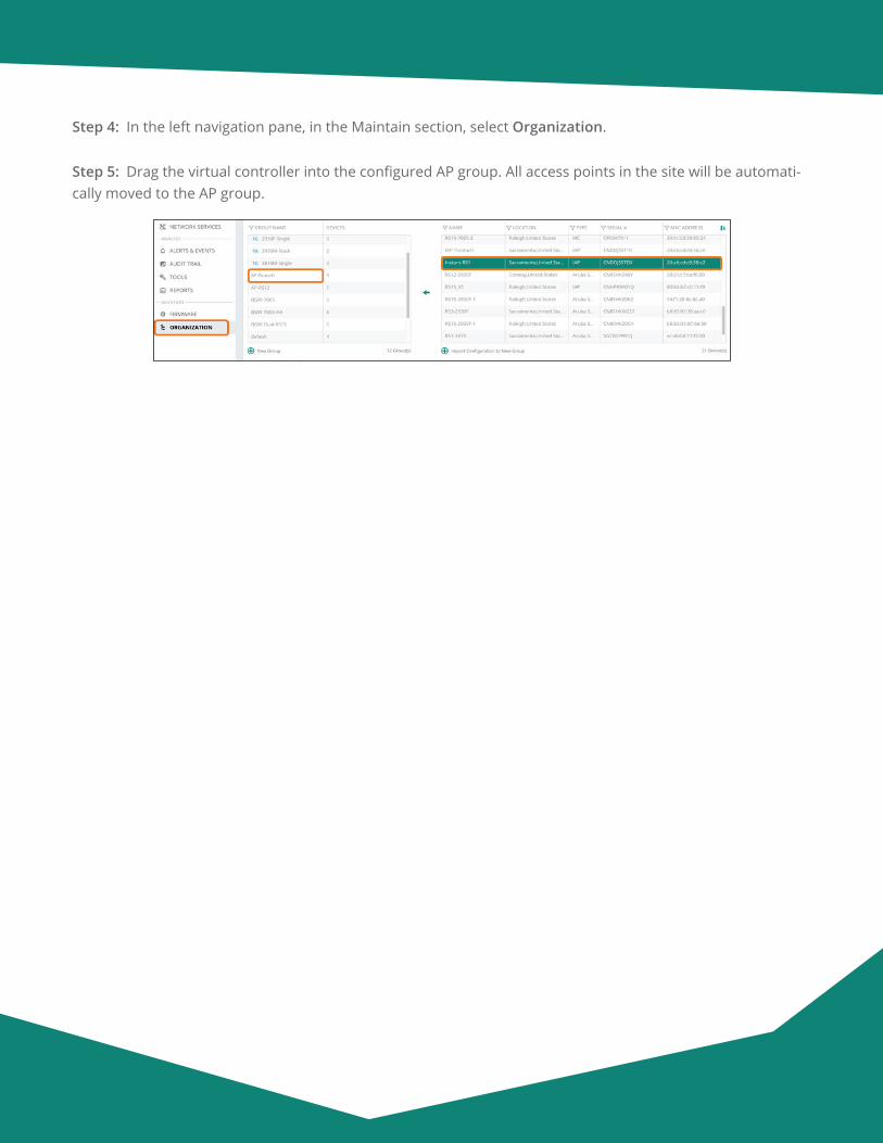
Aruba Design & Deployment Guide 185
Step 4: In the left navigation pane, in the Maintain section, select Organization.
Step 5: Drag the virtual controller into the configured AP group. All access points in the site will be automati-cally moved to the AP group.
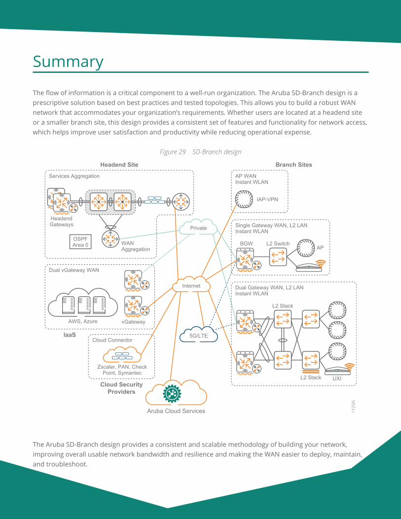
Aruba Design & Deployment Guide 186
Summary
The flow of information is a critical component to a well-run organization. The Aruba SD-Branch design is a prescriptive solution based on best practices and tested topologies. This allows you to build a robust WAN network that accommodates your organization’s requirements. Whether users are located at a headend site or a smaller branch site, this design provides a consistent set of features and functionality for network access, which helps improve user satisfaction and productivity while reducing operational expense.
Figure 29 SD-Branch design
1129
A
Branch Sites
Aruba Cloud Services
Cloud SecurityProviders
Cloud Connector
Zscaler, PAN, CheckPoint, Symantec
AWS, Azure vGateway
IaaS
Dual vGateway WAN
AP WANInstant WLAN
IAP-VPN
Headend Site
Services Aggregation
HeadendGateways
WAN Aggregation
OSPFArea 0
Single Gateway WAN, L2 LANInstant WLAN
APL2 SwitchBGW
Dual Gateway WAN, L2 LANInstant WLAN
L2 Stack
L2 Stack UXI
Private
Internet
5G/LTE
The Aruba SD-Branch design provides a consistent and scalable methodology of building your network, improving overall usable network bandwidth and resilience and making the WAN easier to deploy, maintain, and troubleshoot.
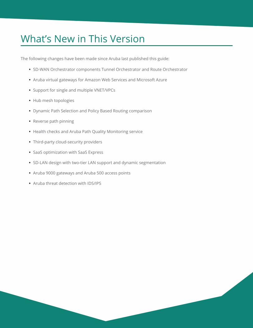
Aruba Design & Deployment Guide 187
What’s New in This Version
The following changes have been made since Aruba last published this guide:
• SD-WAN Orchestrator components Tunnel Orchestrator and Route Orchestrator
• Aruba virtual gateways for Amazon Web Services and Microsoft Azure
• Support for single and multiple VNET/VPCs
• Hub mesh topologies
• Dynamic Path Selection and Policy Based Routing comparison
• Reverse path pinning
• Health checks and Aruba Path Quality Monitoring service
• Third-party cloud-security providers
• SaaS optimization with SaaS Express
• SD-LAN design with two-tier LAN support and dynamic segmentation
• Aruba 9000 gateways and Aruba 500 access points
• Aruba threat detection with IDS/IPS
© Copyright 2020 Hewlett Packard Enterprise Development LP. The information contained herein is subject to change without notice. The only warranties for Hewlett Packard Enterprise products and services are set forth in the express warranty statements accompanying such products and services. Nothing herein should be construed as constituting an additional warranty. Hewlett Packard Enterprise shall not be liable for technical or editorial errors or omissions contained herein. Aruba Networks and the Aruba logo are registered trademarks of Aruba Networks, Inc. Third-party trademarks mentioned are the property of their respective owners. To view the end-user software agreement, go to www.arubanetworks.com/assets/legal/EULA.pdf
B-000601A-20A-1 04/21 a00103243enw
You can use the feedback form to send suggestions and comments about this guide.


