Embed Size (px)
Citation preview
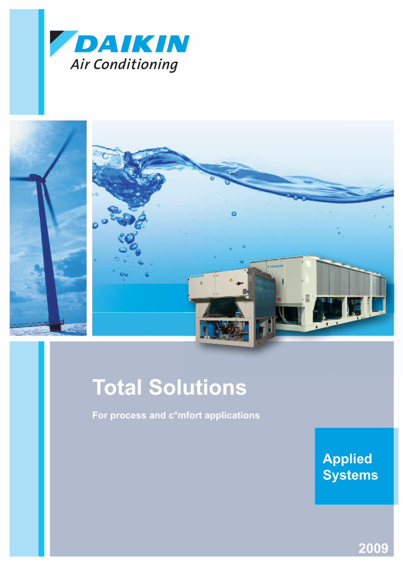
AppliedSystems
Total Solutions For process and c°mfort applications
2009

02
Great in cooling and heating
TABLE OF CONTENTS
PRODUCT PORTFOLIO 04
OPTIONS PORTFOLIO 08
ACCESSORIES PORTFOLIO 10
ENVIRONMENTAL AWARENESS 12
HEAT RECOVERY 14
RELIABLE & EFFICIENT 16
AIR-COOLED 18
CONDENSERLESS 62
WATER-COOLED 68
CONDENSING UNITS 92
CONDENSER DRYCOOLER 98
HYDRONIC KIT 99
VENTILATION 100
MEASURING CONDITIONS 116
03

PRODUCT PORTFOLIO
04
230
254
209
329
358
395
330
360
400
222
329
358
395
330
360
400
222
144
111
164
199
349
285
110
140
160
200
280
340
111111
150
114
171
110
150
170
111
148
116
176
208
377
301
138
107
158
191
335
274
379
110
140
160
200
280
340
400
1 1 1 1 1 1 2
111111
80 105
152
182
131
2 2 2 2 21 1 2
080
100
130
150
180
210
240
260
18,4
11,6
23,8
5 8 10
1 1 1
121
149
171
226
286
330
372
150
170
240
300
340
380
120
1 1 1 2 2 2 2
184
198
225
245
261
275
298
321
370
190
200
230
260
280
300
320
340
360
222222222
247
275
301
327
351
376
260
280
320
340
360
380
2 2 2 2 2 2
195
208
233
256
274
289
306
336
381
200
210
240
260
280
300
320
340
400
222222222
203
231
253
271
286
299
309
240
210
260
280
300
320
340
2 2 2 2 2 2 2
509,1 17,1
21 25 34 4037 46 5427241812
5 8 10 12 16
20
24
2221111
1 1 1 1 2 2 2
11,3
18 22,5
26,5
37 46,6
55,3
8 10 12 16 20 245
1 1 1 1 2 2 2
79
30 35
68
33
2 2 2 21 1 2 2
2 2 2 2 2 21 1
080
100
130
150
180
210
230
165
199
225
258
88 114
284
149
250
77 145 183
234
252
100
136 211
330
306
361274
341
260
280
300
320
340
360
380
2 2 2 2 2 2 2
2222 2
255
275
298
321
343
368
385
7,1 115,2 6
005
006
007
011
1 1 1
8,500
9
1
9,501
0
1 1
1301
3
1
900
9
1
1101
1
1
11
5,65
7,75
10 11,5
13
14
6,35
1
1
1
12,5
1
1 1 1 1 1
7,1 115,2 6
005
006
007
011
1 1 1
8,500
9
1
9,501
0
1 1
1301
3
1
900
9
1
1101
1
1
77 8 8 4 5 9
107
1100
1
148
176
1
1
274
280
2
349
340
1
199
200
1
777 88 88 444 5 99
150
150
171
170
SCREW EWAD650-C18BJYNN 48
EWAD650-C21BJYNN/A 50
EWAD550-C12BJYNN/Q 52
EWAD600-C10BJYNN/Z 54
R-407C
EWAP110-540MBYNN 55
EWTP110-540MBYNN 56
EWAP800-C18AJYNN 58
EWAP850-C18AJYNN/A 60
C/U SCREW R-407C ERAP110-170MBYNN 97
1111
000 33 444 22
85
1301
3
3716
2
993535
8008
0
230
2
240
209
20
333 555
274
27
230
63
2
3414
340
3
2
343
380
33
2
385
333 555 55 66 33
1111
34377
2
171
88
1
000000 3333 444444 2222
2
10221
1
231
240
271
280
2
233
240
2
274
280
2
306
320
381
400
2
55 5 8 1 33 8 555
85
635
63
1
775
7
1
10
12,5
1301
30
3
Type Compr. Refr. Modee Reference Packshot Page 0 17.5 200
SWING R-410A EWAQ005-007ACV3EWAQ009-011ACV3 20
SCROLL R-410AEWAQ009-013ACW1 21
SWING R-410A EWYQ005-007ACV3EWYQ009-011ACV3
20
SCROLL R-410AEWYQ009-013ACW1 21
SCROLL
R-407C
EUWAC5-10FZW 22
EUWA*5-24KAZWEUWA30-35HZW
24
EUWY*5-24KAZW 26
R-410A
EWAQ080-260DAYN 28
EWYQ080-250DAYN 30
EWAD120-600MBYNN 38
EWAD190-600AJYNN 40
EWAD260-650AJYNN/A 42
A/C EWAD210-500AJYNN/Q 44
EWAD200-600AJYNN/H 46
EWAD330-550AJYNN/S** 32
EWAD330-550AJYNN/X* 34
R-134a EWYD260-380AJYNN 36

AIR COOLED
05
423
515
459
488
420
460
490
520
2222
423
515
459
488
420
460
490
520
2222
395
468
541
400
460
540
222
538
604
667
893
725
805
780
944
1102
1056
1015
1197
550
600
650
700
750
800
850
900
950
C10
C11
C12
22222 3333333
569
631
668
1013
840
914
953
600
650
700
850
900
950
C10
2 2 2 3 3 3 3
875
790
944
1026
1092
1158
1284
1354
1426
1516
1583
1650
800
900
950
C10
C11
C12
C13
C14
C15
C16
C17
C18
2 2 2 2 2 3 3 3 3 3 3 3
954
854
1028
1124
1196
1253
1357
1427
1497
1595
1644
1729
850
900
950
C10
C11
C12
C13
C14
C15
C16
C17
C18
2 2222 3 3 3 3 3 3 3
640
700
761
1109
817
988
886
1322
1057
1166
1226
1520
1772
1641
650
700
750
850
900
950
C10
C11
C12
C13
C14
C15
C16
C18
2 2 2 2 2 3 3 3 3 3 3 4 4 4
667
723
800
974
855
926
903
1038
1222
1177
1094
1282
1430
1354
1557
1806
1710
1920
650
700
800
850
900
950
C10
C11
C12
C13
C14
C15
C16
C17
C18
C19
C20
C21
2 2 2 2 2 2 2 3 3 3 3 3 3 3 4 4 4 4
407
434
441
449
520
460
540
2 2
222
449
525
605
460
520
600
2 2 2
401
510
551
588
451
478
400
440
480
500
550
600
222222
401
501
531
582
627
420
500
550
600
650
2 2 2 2 2
502
426
468
529
600
561
420
460
480
500
550
600
222222
400
428
448
501
400
440
460
500
2 2 2 2
397
412
22
9 00
1354
C14
3
1092
805
800
3
1102
C11
3
1109
C11
3
1226
C13
3
800
800
2
926
950
2
1222
C14
3
1354
C16
3
988
950
3
974
C10
99 00
1357
C13
3
1497
C15
3
1595
C16
3
1729
C18
3
kW
459
460
2
459
460
2
412
4
488
490
2
488
490
2
605
600
551
550
2
448
460
2
500 1,000 2,000
A/C = Air CooledW/C = Water CooledC/U = Condensing UnitC/L = Condenserless Chiller
= Cooling Only
= Heating Only
= Heat Pump
= Heat Recovery
= Heating
= Cooling
Option Combination & Exceptions: /A High Efficiency Unit/Q Standard Efficiency Unit, Extra Low Noise/H High Ambient Unit/Z High Efficiency Unit, Extra Low Noise/S Inverter Unit/X High Efficiency Inverter Unit* Preliminary Info

PRODUCT PORTFOLIO
06
1
300
420
428
2
400
381
2
360
352
2
320
315
2
270
270
1
240
244
1
190
189
1
160
160
1
2712,1
20 5431 40 62
012
020
026
030
045
055
065
1 1 1 1 2 2 2
120
170
240
260
340
400
170
116
235
340
265
405
221111
433
440
362
360
1
369
380
1
333
394
340
400
1 1
388
400
1
431
440
1
15,4
35 41 52 71 8126 105
124
142
153
164
176
213
224
235
246195
014
022
028
035
045
055
065
090
110
120
130
145
155
165
175
185
195
100
8613 21 28 32 43 56 65 195
99 112
121
130
142
155
168
177
186
222222222222211 211
1 1 1 1 2 2 2 2 2 2 2 2 2 2 2 2 2 2
183
123
273
249
432
366
120
180
240
280
360
440
147
216
290
327
431
1 1 1 1 2 2
1 1 1 1 2
165
201
253
280
334
372
402
170
210
260
300
320
380
420
1 1 1 1 2 2 2
186
223
276
307
366
408
190
230
280
320
380
400
221111
226
1
271
1
336
1
378
1
208
252
318
356
418
1 1 1 1 2
Type Compr. Refr. Mode Reference Packshot Page 0 17.5 200
W/C
SCROLL R-407CEWWP014-065KAW1N
EWWP090-195KAW170
SCREW
R-134a
EWWD120-540MBYNN 72
EWWD170-600DJYNN 74
EWWD190-650DJYNN/A 76
EWWD340-C18EJYNN 80
EWWD360-C12EJYNN/A 82
EWWD380-C11BJYNN 84
R-410A
EWWQ400-C20AJYNN 86
EWWQ440-C22AJYNN/A 88
CENTRI-FUGAL R-134a
D-DWSC 90
D-DWDC 90
C/L
SCROLL R-407C EWLP012-65KAW1N 64
SCREW R-134a
EWLD120-540MBYNN 65
EWLD160-550DJYNN 66
EWLD320-C17EJYNN 67
6 3 6 6 8
2 00 2 55 8 7 557 6
40 626206
506
5
2
240
235
1
2002
0
270
270
1
400
381
2
273
280
2
1
3 0 4 2 2
418
2
154
1
035
035
32
065
0065
2
090
00
86
2
105
2
31303
130
155
15
155
2
1766
175
177
2
33 333 33999 33 66 22
2133
2
666 33 66 6 88
271
1
307
203230
378
1
300
300
420
428
1
400
391
1
320
328
1

WATER COOLED
07
1
4500
2 2
600
9000
550
525
2
480
475
2
480
500
540
500
470
530
222
1134
C12
2
1038
C11
2
933
950
2
976
C10
2
866
850
2
795
800
2
720
750
2
573
600
1
506
500
1
433
440
1
521
445
734
816
895
976
1050
460
550
750
850
900
C10
C11
1111111
460
705
640
538
782
460
550
650
700
800
1155
3
C12
1204
3
C13
1274
3
C14
1346
3
C15
1401
3
C16
1455
3
C17
1510
3
C18
1 1 2 2 2
844
850
2
910
900
2
1027
C10
2
986
950
2
474
742
651
574
880
813
1077
1028
891
980
1210
1488
1352
1281
1620
1783
1928
2093
2 2 2 2 1 2 2 2 2
480
600
650
750
800
850
900
C10
C11
C12
C13
C14
C15
C16
C17
C18
C19
C20
1 1 1 1 2 1 2 2 1
527
431
818
740
653
993
1139
1059
1182
1397
1297
1479
1605
1769
1901
2061
2196
1 2 2 2 2 1 2 2 2 2
440
550
650
750
800
950
C10
C11
C12
C13
C14
C15
C16
C18
C19
C20
C22
1 1 1 1 1 1 2
432
522
498
546
440
500
520
540
505
580
617
655
2 2 2 2
22 2 2
494
556
448
460
500
600
2 2 2
496
444
604
540
460
500
550
650
2222
741
2
446
2
495
2
539
2
601
2
655
2
465
504
563
623
705
22 2 2 2
kW 500 1,000 2,000 9,000
4 6 06 4
0050
0
2
9000
617
28 4844
846
0
2
66
880
850
1210
2
C13
1352
2
C15
498
500
50
2
494
5500
2
546
4 655
6660
0
2
980
C10
2
622 88 2288 66850
650
0
2093
2093
2
C20
C20
795
800
866
850
2
933
950
2
44 66 006 444
1204
3
C13
1346
C15
496
00500
2
4955
2
986
950
C12
2
600
993
950
1
2061
2
C20
9,00
C17
1422
3
C16
1370
3
C15
1319
3
C14
1267
3
C13
1188
3
C12
1125
3
800
788
2
850
850
2
900
919
2
950
966
2
C11
1078
3
C10
1003
3
750
730
2
650
657
2
600
596
2
500
504
1
A/C = Air CooledW/C = Water CooledC/U = Condensing UnitC/L = Condenserless Chiller
= Cooling Only
= Heating Only
= Heat Pump
= Heat Recovery
= Heating
= Cooling
Option Combination & Exceptions: /A High Efficiency Unit/Q Standard Efficiency Unit, Extra Low Noise/H High Ambient Unit/Z High Efficiency Unit, Extra Low Noise/S Inverter Unit/X High Efficiency Inverter Unit

PORTFOLIO
08
Type Compr. Refr. Mode Reference Products
A/C
SWING R-410AEWAQ-ACV3P 005-006-007EWYQ-ACV3P 005-006-007
SCROLL
R-410A
EWAQ-ACV3 (7) 009-010-011EWAQ-ACW1 (7) 009-011-013EWYQ-ACV3 (7) 009-010-011EWYQ-ACW1 (7) 009-011-013
R-407C
EUWAC-FZW 5-8-10EUWAN-KAZW 5-8-10-12-16-20-24EUWAP-KAZW 5-8-10-12-16-20-24EUWAB-KAZW 5-8-10-12-16-20-24EUWA-HZW 30-35
EUWYN-KAZW 5-8-10-12-16-20-24EUWYP-KAZW 5-8-10-12-16-20-24EUWYB-KAZW 5-8-10-12-16-20-24
R-410AEWAQ-DAYNN 080-100-130-150-180-210-240-260EWYQ-DAYNN 080-100-130-150-180-210-230-250
SCREW
R-134a
EWAD-MBYNN120-150-170-240-300-340380-460-520-600
EWAD-AJYNN
190-200230-260-280-300-320-340-360400440-480-500-550-600
EWAD-AJYNN / A260-280-320-340-360-380-420500-550-600-650
EWAD-AJYNN / Q210-240-260-280-300-320-340400-440-460-500
EWAD-AJYNN / H
200-210240-260-280-300-320-340-400420-460-480-500-550-600
EWAD-AJYNN/S * 330-360-400-420-460-490-520EWAD-AJYNN/X * 330-360-400-420-460-490-520
EWYD-AJYNN260-280-300320-340-360-380
EWAD-BJYNN650-700-750-850-900-950-C10-C11-C12-C13C14-C15-C16-C18
EWAD-BJYNN / A650-700-800-850-900-950-C10-C11-C12-C13C14-C15-C16-C17-C18-C19-C20-C21
EWAD-BJYNN / Q 550-600-650-700-750 800-850-900-950-C10-C11-C12EWAD-BJYNN / Z 600-650-700-850-900-950-C10
R-407C
EWAP-MBYNN 110-140-160-200-280-340-400-460-540EWTP-MBYNN 110-140-160-200-280-340-400-460-540
EWAP-AJYNN800-900-950-C10-C11-C12-C13-C14C15-C16-C17-C18
EWAP-AJYNN / A850-900-950-C10-C11-C12-C13-C14C15-C16-C17-C18
C/U SCREW R-407C ERAP-MBYNN 110-150-170
W/C
SCROLL R-407CEWWP-KAW1N 014-022-028-035-045-055-065EWWP-KAW1M 045-055-065
SCREW
R-134a
EWWD-MBYNN 120-180-240-280-360-440-500-520-540EWWD-DJYNN 170-210-260-300-320-380-420-460-500-600
EWWD-DJYNN / A190-230-280-320-380-400-460-500550-650
EWWD-EJYNN (6)340-400-460-550-650-700-800-850-900-950-C10-C12-C13-C14-C15-C16-C17-C18
EWWD-EJYNN/A (6) 360-440-500-600-750-800-850-950-C10-C11-C12
EWWD-BJYNN 380-460-550-750-850-900-C10-C11
R-410a
EWWQ-AJYNN400-480-600-650-750-800-850-900-C10-C11-C12-C13-C14-C15-C16-C17-C18-C19-C20
EWWQ-AJYNN / A440-550-650-750-800-950-C10-C11-C12-C13-C14-C15-C16-C18-C19-C20-C22
C/L
SCROLL R-407C EWLP-KAW1N 012-020-026-030-040-055-065
SCREW R-134a
EWLD-MBYNN 120-170-240-260-340-400-480-500-540EWLD-DJYNN (6) 160-190-240-280-320-360-380-420-480-550
EWLD-EJYNN (6)320-400-420-500-600-650-750-800-850-900-950-C10-C11-C12-C12-C14-C15-C16-C17
Integrated Hydronics Noise & Head Pressure Con
Singlepumpcontact
Twin pump contact
Singlepump
Twinpump
High ESP pump High ESP twin pump
Buffertank
Reduced Noise Lownoise
Inverter fans
FanSilent
OPSC OPTC OPSP OPTP OPHP OPHT OPBT OPRN OPLN OPIF OPFS
STD
STD
STD •
STD •
STD •
STD •
•
•
•
• • • • • • • •(3)
• • • • • • • •(3)
•
• •
•(1) •(2)(3) •(1) •(2)(3) • •
• • • • • •
• • • • •
• • • • •(3) • •
• • • • • •
• • • • • •
STD
STD
•(1) •(2)(3) •(1) •(2)(3) •
• • • • •
• • • • •
• • •
• • •
•(3) •(3) •(3) •(3) • •(3)
• • • • • •(3)
• • • • •
• • •
• • • • •
• • •
• • STD
• • STD
• •
•
• • • • •
• • •
• • • • •
• • •
• •
•
•
•
•
•
•
Cooling Only
Heating Only
Heat Pump
Heat Recovery
Option Combination & Exceptions: /A High Effi ciency Unit/Q Standard Effi ciency Unit, Extra Low Noise/H High Ambient Unit/Z High Effi ciency Unit, Extra Low Noise/S Inverter Unit/X High Effi ciency Inverter Unit
A/C Air CooledW/C Water CooledC/F Centrifugal FanC/U Condensing UnitC/L Condenserless Chiller
(1) Unit Length Increase By 230mm(2) Unit Length Increase By 310mm(3) Not Available With Option OPLN(4) High Pressure Side Gauge(5) Not Available With Option OPLN - OPRN
(6) OPLR Liquid Receiver option available(7) EKRP1HB option kit available* Preliminary info
(s) OP12 & OP03 needs to be added to meet Swedish national law 1992: 16

OPTIONS
09
ntrol Heat Recovery LWE Electrical Refrigerant Condenser Misc
Low Ambient
High ESP fans Total Heat Recovery
Partial Heat Recovery
High Glycol
Low Glycol
Evaporator heater tape
Mainswitch
Soft starter
Power factor 0,9
A / V meter
Address card
No switchbox
Electronic Expansion Valve
Pressure relief valve
Suction stop valve
Gauges Coil guards
Blank Cu / Alcoils
Cu /Sn coils
Cu /Cu coils
Cu / Ni heat exchanger
Spring Anti Vibration Mounts
OPLA OPHF OPTR OPPR OPZH OPZL OP10 OP52 OPSS OPPF OP57 OPAC OPNS OPEX OP03 OP12 OPGA OPCG OPAL OPSN OPCU OPNI OPSVM
•
•
•
•
•
•
• •
• • • •
• • • •
• • • •
• • • •
• • • •
• • • •
• • • •
• • STD • •(s) •(s) •
• • STD • •(s) •(s) •
• STD • • •(s) •(s) •
• STD • • •(s) •(s) •
• • • STD STD STD STD • • •(s) STD •(4) • • • • •
• • • STD STD STD STD • • •(s) STD •(4) • • • • •
• • • STD STD STD STD • • • •(s) STD •(4) • • • • •
• • • STD STD STD STD • • • •(s) STD •(4) • • • • •
• • • STD STD STD STD • • •(s) STD •(4) • • • • •
• • • STD STD STD STD • • • •(s) STD •(4) • • • • •
• • STD STD STD STD • • •(s) STD •(4) • • • • •
• • STD STD STD STD • • • •(s) STD •(4) • • • • •
• • • STD STD STD STD • • •(s) STD •(4) • • • • •
• • • STD STD STD STD • • •(s) STD •(4) • • • • •
• • • STD STD STD STD • • • •(s) STD •(4) • • • • •
• • • STD STD STD STD STD •(s) STD •(4) • • • • •
• • • STD STD STD STD STD •(s) STD •(4) • • • • •
• • STD STD STD STD •(s) STD •(4) • • • • •
• • STD STD STD STD •(s) STD •(4) • • • • •
• •(5) • • • STD STD STD • • • STD •(s) •(s) •(4) • • • • •
• •(5) • • • STD STD STD • • • STD •(s) •(s) •(4) • • • • •
• •(5) • • • STD STD STD • • • STD •(s) •(s) •(4) • • • • •
• •(5) • • STD STD STD STD • • • STD •(s) •(s) •(4) • • • • •
• • STD STD STD STD • • • STD •(s) •(s) •(4) • • • • •
• • STD STD STD STD • • • STD •(s) •(s) •(4) • • • • •
• STD • • •(s) •(s) •
STD • • •(s) •(s) •
• •(5) • • STD STD STD STD • • • STD •(s) •(s) •(4) • • • • •
• •(5) • • STD STD STD STD • • • STD •(s) •(s) •(4) • • • • •
• •(5) • • STD STD STD STD • • • STD •(s) •(s) •(4) • • • • •
• •(5) • • STD STD STD STD • • • STD •(s) •(s) •(4) • • • • •
• STD • • •(s) •
• •
• • STD
• • •(s) •(s)
• • STD STD STD • • • STD •(s) STD STD •
• • STD STD STD • • • STD •(s) STD STD •
• STD STD STD • • • STD •(s) STD STD •
• • STD STD STD • • • STD •(s) •(s) STD
• • STD STD STD • • • STD •(s) •(s) STD
STD STD STD • • • STD •(s) •(s) STD
STD STD STD • • • STD •(s) •(s) STD
• STD • • • STD •(s) •(s) STD •
• STD STD STD • • • STD •(s) •(s) STD •
• STD STD STD • • • STD •(s) •(s) STD •
• STD STD STD • • • STD •(s) •(s) STD •
• STD STD STD • • • STD •(s) •(s) STD •
• •
• • •(s) •(s)
• STD STD STD • • STD •(s) •(s) STD
• • STD STD STD • • STD •(s) •(s) STD
• • STD STD STD • • STD •(s) •(s) STD

10
Type: FWM, FWL, FWVDescriptionAdditional single row heat exchangerElectric heater2-pipe 3-way valve4-pipe 3-way valveFan stop thermostatAir intake & discharge grilleSupporting feetSupporting feet + grilleFresh air intakeRear panelController electronic - remoteController electronic - remoteController electronic - remoteController electronic - remotePipe temperature sensorPipe holderControl electromechanicalControl electronic - built-inControl electronic - remoteMaster slave optionVertical drainpanHorizontal drainpan
1 2 3 4 6 8 10 FWV FWL FWM
ESRH02A6 ESRH03A6 ESRH06A6 ESRH10A6 x x xEEH01A6 EEH02A6 EEH03A6 EEH06A6 EEH10A6 x x x
E2MV03A6 E2MV06A6 E2MV10A6 x x xE4MV03A6 E4MV06A6 E4MV10A6 x x x
YFSTA6 x x xEAIDF02A6 EAIDF03A6 EAIDF06A6 EAIDF10A6 - - x
ESFV06A6 ESFV10A6 x - xESFVG02A6 ESFVG03A6 ESFVG06A6 ESFVG10A6 x - -
EFA02A6 EFA03A6 EFA06A6 EFA10A6 x x xERPV02A6 ERPV03A6 ERPV06A6 ERPV10A6 x x -
CE.S_RAB10.1 x x xCE.S_RAB30.1 x x xCE.S_RDF10 x x xCE.S_RDF30 x x x
CE.S_QAH11.1 x x xCE.S_ARG86.2 x x x
ECFWMB6 x x -ECFWEB6 x x -ECFWER6 x x xEPIMSA6 x x xEDPVA6 x x xEDPHA6 - x x
Type Compr. Refr. Mode Reference
A/C
SWING R-410AEWAQ005-007ACV3PEWYQ005-007ACV3P
SCROLL
R-410A
EWAQ009-011ACV3EWAQ009-013ACW1EWYQ009-011ACV3EWYQ009-013ACW1
R-407C
EUWAC5-8-10FZWEUWAN5-8KAZW
EUWAN10-12KAZWEUWAN16KAZW
EUWAN20-24KAZWEUWAP5-8KAZW
EUWAP10-12KAZWEUWAP16KAZW
EUWAP20-24KAZWEUWAB5-8KAZW
EUWAB10-12KAZWEUWAB16KAZW
EUWAB20-24KAZWEUWA30-35HZWEUWYN5-8KAZW
EUWYN10-12KAZWEUWYN16KAZW
EUWYN20-24KAZWEUWYP5-8KAZW
EUWYP10-12KAZWEUWYP16KAZW
EUWYP20-24KAZWEUWYB5-8KAZW
EUWYB10-12KAZWEUWYB16KAZW
EUWYB20-24KAZW
R-410A
EWAQ080-210DAYNNEWAQ240-260DAYNNEWYQ080-210DAYNNEWYQ230-250DAYNN
SCREW
R-134a
EWAD120-600MBYNNEWAD190-600AJYNN
EWAD260-650AJYNN/AEWAD210-500AJYNN/QEWAD200-600AJYNN/H
EWAD330-520AJYNN/S *EWAD330-520AJYNN/X *
EWYD260-380AJYNNEWAD650-C18BJYNN
EWAD650-C21BJYNN/AEWAD550-C12BJYNN/QEWAD600-C10BJYNN/Z
R-407C
EWAP110-540MBYNNEWTP110-540MBYNNEWAP800-C18AJYNN
EWAP850-C18AJYNN/AC/U SCREW R-407C ERAP110-170MBYNN
W/C
SCROLL R-407C
EWWP014KAW1NEWWP022KAW1NEWWP028KAW1NEWWP035KAW1NEWWP045KAW1N
EWWP055-065KAW1NEWWP045-055-065KAW1M
SCREW R-134a
EWWD120-540MBYNNEWWD170-600DJYNN
EWWD190-650DJYNN/AEWWD340-C18EJYNN
EWWD360-C12EJYNN/AEWWD380-C11BJYNN
C/C
SCROLL R-407C
EWLP012KAW1NEWLP020KAW1NEWLP026KAW1NEWLP030KAW1NEWLP040KAW1N
EWLP055-065KAW1N
SCREW R-134aEWLD120-540MBYNNEWLD160-550DJYNNEWLD320-C17EJYNN
Gauges Soft starter Communication cards LON
gateway
EKGA
U5/8K
A
EKGA
U10/1
2KA
EKGA
U16K
A
EKGA
U20/2
4KA
EKGA
U25/3
0H
EKSS
EKAC
10B
EKAC
30A
EKAC
200A
EKAC
200J
EKAC
PG
EKAC
BAC
EKAC
LON
EKLO
NPG
•• • •
• • •• •
• •• • •
• • •• •
• •• • •
• • •• •
• •• • •
• • •• • •
• •• •
• • •• • •
• •• •
• • •• • •
• •• •
• •• •• •• •
•• • •• • •• • •• • •• • •• • •• • •• •• •• •• •
••
• •• •
•• •• •• •• •
••
•• •• •• •• •• •
• •• •• •• •
••
•• •• •
Modbus gatewayBacnet gateway
EKBM
SMBA
EKBM
SBNA
EKBN
PG
EKBM
SBNJ
EKRU
MC
•(1) •(1) •(1•(1) •(1) •(1•(1) •(1) •(1•(1) •(1) •(1•(1) •(1) •(1•(1) •(1) •(1•(1) •(1) •(1•(1) •(1) •(1•(1) •(1) •(1•(1) •(1) •(1•(1) •(1) •(1•(1) •(1) •(1•(1) •(1) •(1•(1) •(1)•(1) •(1) •(1•(1) •(1) •(1•(1) •(1) •(1•(1) •(1) •(1•(1) •(1) •(1•(1) •(1) •(1•(1) •(1) •(1•(1) •(1) •(1•(1) •(1) •(1•(1) •(1) •(1•(1) •(1) •(1•(1) •(1) •(1
••••
•(2) •(2)
••••
•(2) •(2)•(2) •(2)
••
•(2) •(2)•(1) •(1) •(1•(1) •(1) •(1•(1) •(1) •(1•(1) •(1) •(1•(1) •(1) •(1•(1) •(1) •(1
•(2) •(2)•••••
•(1) •(1) •(1•(1) •(1) •(1•(1) •(1) •(1•(1) •(1) •(1•(1) •(1) •(1•(1) •(1) •(1•(2) •(2)
••
(3) (2 pieces are needed)
Type: FWT, FWF and FWCFWT FWC F
DescriptionStandard wired remote control MERCASimplifi ed wired remote control SRC-COASimplifi ed wired remote control SRC-HPA2-pipe 3-way valve - - MCKC2-pipe 3-way valve - MCKAW2T3VN4-pipe 3-way valve - MCKAWH4T3VNWireless control for cooling only WRC-COBWireless control for heat pump WRC-HPBDecoration panel 900 x 900 2-pipe (4) - DCP900TBDecoration panel 900 x 900 4-pipe (4) - DCP900FBDecoration panel 600x600 - - DCP
(4) Including WRC-COA / WRC-HPA
CH
ILLE
RFA
N C
OIL
(1) To install EKBMSMBA, EKBMSBNA and EKRUMC, EKAC10B needs to be installed on the unit. (2) To install EKBMSMBA and EKBMSBNA, EKAC200A needs to be installed on the unit. * Preliminary info

ACCESSORIES
11
Type: FWDDescriptionElectric heater: smallElectric heater: big2-pipe 3-way valve4-pipe 3-way valveVertical DrainpanHorizontal DrainpanFan stop thermostatFresh air intakeController electronic - remoteController electronic - remoteController electronic - remoteController electronic - remotePipe temperature sensorPipe holderController electronic - remoteMaster slave Interface
4 6 8 10 12 16 18
EDEH04A6 EDEHS06A6 EDEHS10A6 EDEHS12A6 EDEHS18A6EDEH04A6 EDEHB06A6 EDEHB10A6 EDEHB12A6 EDEHB18A6ED2MV04A6 ED2MV10A6 ED2MV12A6 ED2MV18A6ED4MV04A6 ED4MV10A6 2xED2MV12A6 2 x ED2MV18A6
EDDPV10A6 EDDPV18A6EDDPH10A6 EDDPH18A6
YFSTA6EDMFA04A6 EDMFA06A6 EDMFA10A6 EDMFA12A6 EDMFA18A6
CE.S_RAB10.1 CE.S_RAB10.1 + EPIB6CE.S_RAB30.1 CE.S_RAB30.1 + EPIB6CE.S_RDF10 CE.S_RDF10 + EPIB6CE.S_RDF30 CE.S_RDF30 + EPIB6
CE.S_QAH11.1 CE.S_QAH11.1 + EPIB6CE.S_ARG86.2 CE.S_ARG86.2 + EPIB6
ECFWER6 ECFWER6 + EPIB6EPIMSA6 -
Type: FWB-A2-4 5-7 8-10
DescriptionAdditional heat exchanger EAH04A6 EAH07A6 EAH10A63-way valve add. h/e E2MV307A6 E2MV310A62-way valve add. h/e E2MV207A6 E2MV210A6Electric Heater Factory mountedFan stop thermostat YFSTA6Controller electronic - remote CE.S_RAB10.1Controller electronic - remote CE.S_RAB30.1Controller electronic - remote CE.S_RDF10Controller electronic - remote CE.S_RDF30Pipe temperature sensor CE.S_QAH11.1Pipe holder CE.S_ARG86.2Controller electronic - remote ECFWER6 ECFWER6 ECFWER6 + EPIB6Master slave Interface EPIMSA6
Type: FWB-JDescription2-pipe 3-way valve MCWCN4-pipe 3-way valve MCWHNController electronic - remote Simplifi ed version 2 pipe system (no change over possible)
CE.S_RAB10.1
Controller electronic - remote Simplifi ed version 4 pipe system
CE.S_RAB30.1
Controller electronic - remote Full version with display 2 pipe system
CE.S_RDF10
Controller electronic - remote Full version with display 4 pipe system
CE.S_RDF30
Pipe temperature sensor For change over
CE.S_QAH11.1
Pipe holder To mount CE.S_QAH11.1
CE.S_ARG86.2
Remote user interface Buffer tanks
EKRU
MC
EKRU
PC
EKRU
PG
EKRU
PCJ
EKRU
PCK
EKBT
EKBT
500N
EKBT
C10N
EKBT
500C
EKBT
C10C
1)1) •1) •1) •1) •1) •1) •1) •1) •1)1)1)1)
1) •1) •1) •1) •1) •1) •1) •1) •1)1)1)1)
••••
• • • • •• • • • •• • • • •• • • • •• • • • •• • • • •• • • • •• • • • •
• • • • •• • • • •• • • • •• • • • •
• • • • •• • • • •
• • • • •• • • • •
•1)1)1)1)1)1)
• • • • •• • • • •• • • • •• • • • •• • • • •• • • • •
1)1)1)1)1)1)
• • • • •• • • • •• • • • •
Hydraulic module Low noise kit Switch box
EHM
C10A
10
EHM
C10A
80
EHM
C15A
10
EHM
C15A
80
EHM
C30A
10
EHM
C30A
80
EKLS1
EKLS2
ECB1
MUW
ECB2
MUW
ECB3
MUW
• •
•
• • •• • •• • • • •
• • •• • • • • (3)
• • • (3)• • •
• • •• • •• • • • •
• • •• • • • • (3)
• • • (3)
Common leaving water sensor
Sequenc-ing
Panel
Plant Visor Modem
Converter RS485 to
RS232
Convert-er RS485 to USB
Waterpipe Kit
EKCL
WS
EKCS
CII
EKPV
2J
EKM
ODEM
EKGS
MOD
EKCO
N
EKCO
NUSB
EKGN
210
EKGN
260
••
••
•• • • • • •• • • • • •• • • • • •• • • • • •• • • • • •• • • • • •• • • • • •• • • • • •• • • • • •• • • • • •• • • • • •
••
• • • • • •• • • • • •
•• • • • • •• • • • • •• • • • • •• • • • • •• • • • • •
•• • • • • •• • • • • •
FWF
CW2T3VN--
--
P600TB

ENVIRONMENTALAWARENESS
AIR CONDITIONING AND THE ENVIRONMENT
Air conditioning systems provide a signifi cant
level of indoor comfort, making possible
optimum working and living conditions in the
most extreme climates.
In recent years, motivated by a global awareness
of the need to reduce the burdens on the en-
vironment, some manufacturers includingDaikin
have invested enormous efforts in limiting the
negative effects associated with the production
and the operation of air conditioners.
Hence, models with energy saving features and
improved eco-production techniques have seen
the light of day, making a signifi cant contribution
to limiting the impact on the environment.
SMART CONTROL BRINGS COMFORT AND REDUCES ENERGY CONSUMPTION
Inverter technology used in the mini-chiller
(EWAQ-AC and EWYQ-AC) and in the EWYD-
AJYNN allows more precise control of the
leaving water condition in function of the load.
This leads to energy savings and high comfort
levels, ensuring it is never too cool or too hot.
This is a major advantage over standard fi xed
speed models, which use on/off cycling of
the compressor, creating greater fl uctuations in
control conditions.
Inverter technology offers improved levels of comfort:
Energy effi cient: Continuous matching ›of load requirement
Start-up time is reduced by 1/3 ›Less frequent start/stop cycles ›Reduced sound pressure levels ›High EER /COP values ›
12

Temperature remains stable
Air conditioning without Inverter
Air conditioning with Inverter
Slow start
INVERTER TECHNOLOGY 13

In many applications there often exists a
simultaneous cooling and heating demand
requirement alongside one another. To benefi t
from this Daikin offers chillers with the option of
heat recovery. This option further increases the
application fl exibility and extends possibilities
in the hotel and leisure industry as well as the
industrial and process sectors.
By energetically recovering useful heat from the
cooling cycle that would otherwise be rejected to
the outside, extremely high COPs can be realised
in heat recovery mode. The heat recovery unit
aims to achieve an optimum balance between
cooling and heat recovery to maximize the
unit effi ciency and offer savings in hot water
production.
Depending on the temperature requirement
either partial heat recovery or full heat recovery
may be selected.
HEAT RECOVERY
14

OPPR – Partial recovery
A stainless steel brazed plate heat exchanger is
mounted in series between the compressor and
air-cooled condenser as a desuperheater. The
sensible heat from the hot discharge gas will
be recovered, while the latent heat exchange
will occur in the air-cooled condenser. The units
effi ciency is maintained as condensing pressure
can be reduced due to air-cooled condenser
becoming oversized.
OPTR – Total recovery
A Shell and Tube heat exchanger is mounted in
parallel with the air-cooled condenser for full
heat recovery of both sensible and latent heat.
Hot water temperatures up to 50°C can be
achieved.
Condenser
45°C
40°C
Comp
Partial Recovery
7°C 12°C
OPPR
Total Recovery
Comp
40°C 45°C
Condenser
15

THE SCROLL COMPRESSORFOR CONTROLLED CAPACITY:
Whatever the requirements of the customer, large
systems requiring constant capacity or smaller systems
for fl exibility, DAIKIN always provides a reliable and
effi cient solution.
RELIABLE AND EFFICIENT
3 COMPRESSOR TYPES FOR ALL APPLICATIONS:
Being compact, the DAIKIN scroll compressor is used with
R-407C and R-410A to provide constant reliability and
high efficiency right throughout its service life. Designed
for small and medium capacities, the scroll compressors are
used with air cooled and water cooled chillers within the
range of capacities between 9.1 and 281kW.
Characteristics :
Compact, simple yet robust design ›
Absence of valves and oscillating connecting ›
mechanisms providing maximum reliability
Constant compression guaranteeing low energy ›
consumption
Increased compression efficiency thanks to ›
the absence of volumetric re-expansion
Low sound level ›
Low starting current ›
SWING COMPRESSOR:
The mini-chiller range is equipped with a swing compressor.
This innovative design by Daikin with fewer moving parts
allows smoother more reliable operation with low vibration
and low noise levels. The high efficiency motor reduces
energy consumption resulting in energy cost savings.
swing scroll
The piston which the bladeand the roller unified
Swing bush16

Casing1.
Slide valve2.
Screw rotor3.
Bearing4.
Motor5.
Gate rotor6.
2nd stage oil separator7.
Demister (oil separator)8.
Refrigerant suction9.
Refrigerant discharge10.
Compressor terminal + CTP11.
Stepper Motor12.
THE SINGLE SCREW STEPLESS COMPRESSOR - FOR HIGH CAPACITY:
Characteristics :
Optimal performance through stepless capacity control ›
in function of the chilled water temperature. The unit
capacity is infinitely variable from 30 - 100% on single
circuit units and 15 - 100% on dual circuit units.
Compact, simple yet robust construction. ›
Using a main single screw and two gate rotors, axial ›
and radial forces are balanced thanks to the symmetrical
compression guaranteeing low bearing loads.
Renowned for its low noise levels and the double walled ›
casing design, add to the attenuation effect.
Gate rotors made of polymer material result in closer ›
tolerances with main screw and reduced friction greatly
improving compressor efficiency and lifetime.
No oil pump necessary – lubrication based on differential ›
pressure principle.
Easy access to both compressor and safety devices ›
Star delta starter with low starting current as standard ›
The heart of the larger Daikin chillers are semi hermetic single
screw compressors, designed, tested and manufactured
in Daikin’s own laboratories, in order to meet the highest
capacity, performance and maintenance specifications.
This compressor has been especially developed for
operation with R-134a or R-407C and R410A refrigerant,
guaranteeing unequalled reliability and many years of
efficient operation. The bearing life is 100000hrs with
inspection and maintenance intervals every 40000hrs.
screw17
1
2
38 4
6
910
7
12
11
5

EWYQ-ACV3 / EWAQ-ACV3 20
EWYQ-ACV3/W1 / EWAQ-ACV3/W1 21
EUWAC-FZW 22
EUWA*-KAZW 24
EUWY*-KAZW 26
EWAQ-DAYN 28
EWYQ-DAYN 30
EWAD-AJYNN/S 32
EWAD-AJYNN/X 34
EWYD-AJYNN 36
EWAD-MBYN 38
EWAD-AJYNN 40
EWAD-AJYNN/A 42
EWAD-AJYNN/Q 44
EWAD-AJYNN/H 46
EWAD-BJYNN 48
EWAD-BJYNN/A 50
EWAD-BJYNN/Q 52
EWAD-BJYNN/Z 54
EWAP-MBYN 55
EWTP-MBYN 56
EWAP-AJYNN 58
EWAP-AJYNN/A 60
TABLE OF CONTENTS
AIR
-CO
OLE
D
AIR-COOLEDAir cooled chillers are most
frequently used in the chilled
water market. Out of its wide
range of chillers in cooling only
or heat pump version, with or
without integrated hydronic
components, DAIKIN always
offers you a chiller fi tting your
application needs.
Daikin has taken great care to match major
chiller components and refrigerant combinations
to a point where high effi ciency ranges of
technically advanced and closely optimised
air and water cooled units are now widely
available for use with R-410A, R-407C and
R-134a refrigerants.
swing scroll screw
18

57 3 2 4 5
101198561
1
t
t
t
11
10
13
1
89
5
7 3 2 5 4
61
5
t
t
t
AIR COOLED CHILLER
HEAT RECOVERY CHILLER
Temperature sensor1. Filter2. Shut-off valve3. Pump4.
Pressure port5. Flow switch6. Air purge7. Pressure gauge8.
Balancing valve9. Drain valve10. Charging valve11. Safety valve12.
Temperature sensor1. Filter2. Shut-off valve3. Pump4.
Pressure port5. Flow switch6. Air purge7. Pressure gauge8.
Balancing valve9. Drain valve10. Charging valve11. Safety valve12.
Mixing valve13.
AIR
-CO
OLE
D
EVAP
ORA
TOR
To fan coil units
Buffer Tank
Expansionvessel
Chillers
To fan coil units
To sanitary use
EVAP
ORA
TOR
Chillers
Heat recovery exchanger
12
Expansionvessel
Buffer Tank
WaterTank
19

STRENGTHS
O › ptimised for use with R-410A.Inverter controlled swing compressor ›- Precise temperature control- No buffer tank required.PE treated condenser coil. ›Heating operation from -15°C to 43°C. › Integrated hydronics ›- valves, fi lter, fl ow switch- 3 speed pump- 6l expansion vessel.Adaptive control possibility. ›
OPTIONS (factory mounted)
Evaporator heater tape. ›
CONTROL
Leaving water control. ›Setpoint in heating & cooling. ›
AVAILABLE INPUTS
Voltage free contact: ›- ON/OFF.- Cooling/Heating changeover.Schedule timer: ›- ON/OFF.- Dual setpoint.- Silent operation.
s w i n g
ELECTRONIC CONTROL
swin
g
only applicable for EWYQ-ACV3
Capacity (Eurovent) Cooling kWHeating kW
Nominal input (Eurovent)
Cooling kWHeating kW
EERCOP (Eurovent)
Dimensions Height x Width x Depth mmWeight Machine weight kg
Operating Weight kgWater Heat Exchanger
Type Brased plateMinimum water volume in the system lWater fl ow rate Min l/minNominal Water Flow
Cooling l/minHeating l/min
Air heat exchanger Type Tube typeExternal static Pressure
Cooling kPaHeating kPa
Expansion vessel Volume lCompressor Type Hermetically sealed swing compressor
Model QuantitySound Power Cooling dBAOperation Range Water side Cooling °C
Heating °CAir side Cooling °CDB
Heating °CDBRefrigerant circuit Refrigerant type
Refrigerant charge kgNo of circuitsRefrigerant control Inverter
Power Supply 1~/230V/50HzPiping connections Water heat exchanger inlet / outlet 1'' mbsp
Water heat exchanger drain hose nipple 1/2'' fbsp
005 006 007
5.2 6.0 7.15.65 6.35 7.751.89 2.35 2.951.97 2.24 2.832.75 2.55 2.412.87 2.83 2.74
805x1,190x360100104
1012
14.9 17.2 20.417.5 19.5 23.5
49.4 45.1 38.344.5 40.3 30.7
6
162 63
5 ~ 2025 ~ 5010 ~ 43-15 ~ 25R-410A
1.71
COOLING ONLY / HEATING & COOLINGCOOLING ONLY / HEATING & COOLING
air-cooled20
EWAQ005AC
EWYQ-ACV3EWAQ-ACV3
EWAQ
-ACV
3EW
YQ-A
CV3

STRENGTHS
Optimised for use with R-410A. ›Inverter controlled scroll compressor ›ESEER up to 4.7 ›Sound operation down to 62dB(A) ›Built-in hydraulic module ›
- No buffer tank required - Standard pump included
Available in single phase and three phase ›
OPTIONS (factory mounted)
High ESP pump (up to 90kPa) › Evaporator heater tape ›
OPTION KIT
Digital I/O PCB ›
scro
ll
Note: only applicable for EWYQ-ACV3 and EWYQ-ACW1* grey cells contain preliminary data
COOLING ONLY/HEAT PUMP 009ACV3* 010ACV3* 011ACV3* 009ACW1* 011ACW1* 013ACW1*
Capacity (Eurovent) Cooling kW 8.5 9.5 11.0 9.0 11.0 13.0 Heating kW 10.0 11.5 13.0 11.0 12.5 14.0
Nominal input (Eurovent)
Cooling kW -Heating kW -
EER 2.84 2.82 2.66 2.94 2.91 2.37 COP 3.37 3.39 3.35 3.48 3.30 3.21
Dimensions Height x Width x Depth mm 1,420 x 1,420 x 320 (384 including feet)
Weight Machine weight kg 145 145 145 145 145 145 Operating weight kg -
Water Heat Exchanger
Type -Minimum water volume in the system l -Water fl ow rate Min Min -Nominal Water Flow
Cooling l/min -Heating l/min -
Air heat exchanger Type -External static Pressure
Cooling kPa -Heating kPa -
Expansion vessel Volume l -
Compressor Type Hermetically sealed scroll compressor Model Quantity -
Sound Power Cooling dBa 64 64 64 64 64 69 Heating dBa 64 64 64 64 64 66
Operation RangeWater side Cooling °C 5~22
Heating °C -15~35
Air side Cooling °CDB 10~46Heating °CDB 25~50
Refrigerant circuit
Refrigerant type R-410A Refrigerant charge kg < 3 No of circuits -Refrigerant control -
Power Supply 1N~/230V/50Hz 3N~/400V/50Hz
Piping connectionsWater heat exchanger inlet / outlet -Water heat exchanger drain -
air-cooled
s c ro l l
21
EWYQ005AC
EWYQ-ACV3/W1EWAQ-ACV3/W1
EWAQ
-ACV
3/W
1EW
YQ-A
CV3/
W1

EU
WA
C-F
ZW
EUWAC-FZW air-cooled
STRENGTHS
Daikin scroll compressor ›Standard reverse phase protection ›High fan static pressure (up to 150Pa) ›Operation down to -10°C ›ambient temperature
Pressure gauges ›
OPTIONS (factory mounted)
Chilled water temperature ›down to - 5°C (ZH) or -10°C (ZL)
ACCESSORIES (kit)
Filter ›BMS gateway ›(MODBUS / J-BUS / BACNET protocol)
Remote user interface ›Hydraulic module (see page 83) ›
CONTROL
Microprocessor control ›Water inlet temperature control ›
s c ro l l
scro
ll
22

EU
WA
C-F
ZW
EUWAC8FZWEUWAC8FZW
AVAILABLEINPUTS / OUTPUTS
Input
ON / OFF (per circuit) ›Pump / fl ow switch ›
Output
Compressor operation ›Summary alarm ›Pump relay contact › ELECTRONIC CONTROL
Cooling only 5 8 10Capacity Cooling kW 11.60 18.40 23.80
Nominal input Cooling kW 5.25 7.78 9.85
EER 2.21 2.37 2.42
Capacity Steps % 100-0
Dimensions (Height x Width x Depth) mm 1,345x856x630 1,290x1,180x630 1,395x1,330x630
Unit kg 164 224 261
Operating Weight kg 166 228 266
Water Heat Exchanger
Type Brased plate, one per circuit
Minimum water volume in the system l 101 153 212
Water fl ow rate
Min l/min 16 23 28
Nominal l/min 33 53 68
Max l/min 64 92 112
Air heat exchanger Type Cross fi n coil/Hi-X tubes and PE coated waffl e louvre fi ns
Sound Power Cooling dBA 63 66 69
CompressorType Hermetically sealed scroll compressor
Model Quantity 1
Refrigerant circuit
Refrigerant type R-407C
Refrigerant charge kg 2.1 3.9 4.7
No of circuits 1
Refrigerant control Thermostatic expansion valve
Power Supply 3N~/400V/50Hz
Piping connections Evaporator water inlet/outlet fbsp 1''fi eld installation
scro
ll
2323
ELECTRONIC CONTROL

EU
WA
*-K
AZW
air-cooled
STRENGTHS
Integrated hydraulic module ›
(models B and P).
Built-in buffer tank (model B). ›
Daikin scroll compressor. ›
Standard main isolator switch. ›
Standard water fl ow switch. ›
Standard fi lter ›
(delivered as a kit with the unit).
Operation down to -15°C ambient ›
temperature.
Standard reverse phase protection. ›
Standard condenser protection grille. ›
Freeze-up protection and prevention. ›
PE treated condenser coil. ›
OPTIONS (factory mounted)
Chilled water temperature down ›to - 5°C (OPZH) or -10°C (OPZL).
High ESP fans (50Pa) (OPHF). ›Pump size up (OPHP). ›
ACCESSORIES (kit)
Refrigerant pressure gauges. ›BMS gateway ›(MODBUS / J-BUS / BACNET protocol). ›Remote user interface. ›200l buffer tank. ›Soft starter (single circuit). ›
CONTROL
Microprocessor control. ›Water inlet temperature control. ›
AVAILABLE INPUTS / OUTPUTS
Input
Remote ON / OFF. ›Pump contact. ›
Output
Compressor operation. ›Summary alarm. ›Pump relay contact. ›
Air purge
Buffer tank
Water Pressure gauge
Expansion vessel
Drain
Pressure port
Safety valve
Flow switch
Pump
Water flow adjusting valve
HYDRAULIC AND REFRIGERANT DIAGRAM
s c ro l l
scro
ll
24 EUWA*-KAZW

EU
WA
*-K
AZW
EUWAN:
Standard equipment
Scroll compressor ›Main isolator switch ›Water fl ow switch ›Filter ›Condenser protection grille. ›All year operation ›
EUWAP = EUWAN +
Pump ›Expansion vessel ›Adjusting valve ›Drain ›Water pressure gauge ›Pressure relief valve. ›
EUWAB = EUWAP +
Buffer tank ›
ELECTRONIC CONTROL
Cooling only N5 P5 B5 N8 P8 B8 N10 P10 B10 N12 P12 B12 N16 P16 B16 N20 P20 B20 N24 P24 B24
Capacity Cooling kW 11.30 17.90 22.50 26.50 37.00 46.60 55.30
Nominal input Cooling kW 4.52 4.64 4.64 7.38 7.39 7.39 8.79 8.74 8.74 11.50 15.20 15.00 15.00 18.10 17.90 17.90 24.00
EER 2.5 2.44 2.44 2.43 2.42 2.42 2.56 2.57 2.57 2.3 2.43 2.47 2.47 2.57 2.6 2.6 2.3
Capacity Steps % 0-100 0-100 0-50-100 0-50-100
Dimensions (Height x Width x Depth) mm 1,230x1,290x734 1,450x1,290x734 1,321x2,580x734 1,541x2,580x734 1,541x2,580x734
Unit kg 150 168 180 215 229 241 245 259 271 248 262 274 430 448 460 490 508 520 496 514 526
Operating Weight kg 152 171 239 218 232 300 248 262 330 251 265 335 436 457 525 496 518 586 503 524 592
Water Heat Exchanger
Type Brased plate
Minimum water volume in the system l 54 85 108 126 88 111 132
Water fl ow rate
Min l/min 16 26 32 38 53 67 79
Nominal l/min 32 51 64 76 106 134 158
Max l/min 65 102 129 152 212 267 317
Air heat exchanger Type Cross fi n coil/Hi-X tubes and PE coated waffl e louvre fi ns
Buffer tank volume Volume l - 55 - 55 - 55 - 55 - 55 - 55 - 55
Sound Power Cooling dBA 67 76 78 79 81
CompressorType Cross fi n coil/Hi-X tubes and PE coated waffl e louvre fi ns
Model Quantity 1 2
Refrigerant circuit
Refrigerant type R-407C
Refrigerant charge kg 3.9 4.6 6.0 4.6 5.9 6.0
No of circuits 1 2
Refrigerant control Thermostatic expansion valve
Power Supply 3N~/400V/50Hz
Piping connections Evaporator water inlet/outlet 1-1/4''15 mm 2''15 mm
scro
ll
25
EUWAN16KAZW
ELECTRONIC CONTROL

EU
WY-
KA
ZW
air-cooled
STRENGTHS
Integrated hydraulic module ›
(models B and P)
Built-in buffer tank (model B) ›
Daikin scroll compressor ›
Standard main isolator switch ›
Standard water fl ow switch ›
Standard fi lter ›
(delivered as a kit with the unit)
Operation down to -15°C ›
ambient temperature
Standard reverse phase protection ›
Standard condenser protection grille ›
Freeze-up protection and prevention ›
PE treated condenser coil ›
OPTIONS (factory mounted)
Chilled water temperature down ›to - 5°C (OPZH) or -10°C (OPZL)
High ESP fans (50Pa) (OPHF) ›Pump size up (OPHP) ›
ACCESSORIES (kit)
Refrigerant pressure gauges. ›BMS gateway ›(MODBUS / J-BUS / BACNET protocol) ›Remote user interface ›200l buffer tank ›Soft starter (single circuit) ›
CONTROL
Microprocessor control ›Water inlet temperature control ›
AVAILABLE INPUTS / OUTPUTS
Input
Remote ON / OFF ›Pump contact ›Remote cool / heat selection ›
Output
Compressor operation ›Summary alarm ›Pump relay contact ›
s c ro l l
scro
ll
26 EUWY*-KAZW

EU
WY-
KA
ZW
EUWYN16KAZW
EUWYN:
Standard equipment
Scroll compressor ›Main isolator switch ›Water fl ow switch ›Filter ›Condenser protection grille. ›All year operation ›
EUWYP = EUWYN +
Pump ›Expansion vessel ›Adjusting valve ›Drain ›Water pressure gauge ›Pressure relief valve. ›
EUWYB = EUWYP +
Buffer tank ›
Heat Pump N5 P5 B5 N8 P8 B8 N10 P10 B10 N12 P12 B12 N16 P16 B16 N20 P20 B20 N24 P24 B24
CapacityCooling kW 9.10 17.10 21.00 25.00 34.20 40.00 50.00
Heating kW 11.90 18.50 24.00 27.00 37.00 46.00 54.00
Nominal input Cooling kW 3.78 7.45 7.46 8.57 11.40 14.90 16.30 22.80
Heating kW 4.59 7.10 9.10 10.80 14.20 17.40 21.60
EER 2.41 2.3 2.29 2.45 2.19 2.3 2.45 2.19
COP 2.59 2.61 2.64 2.5 2.61 2.64 2.5
Capacity Steps % 0-100 0-50-100
Dimensions (Height x Width x Depth) mm 1,230x1,290x734 1,450x1,290x734 1,321x2,580x734 1,541x2,580x734
Unit kg 163 181 193 227 241 253 258 272 284 258 272 284 455 473 485 516 534 546 516 534 546
Operating Weight kg 165 184 252 230 244 312 261 275 343 261 275 343 461 482 550 522 544 612 522 544 612
Water Heat Exchanger
Type Brased plate
Minimum water volume in the system l 43 82 100 119 82 96 119
Water fl ow rateMin l/min 21 31 38 45 61 72 89
Max l/min 68 106 137 155 212 263 309
Nominal Water pressure drop
Cooling kPa 10 25 24 33 12 19
Heating kPa 17 29 31 38 14 16 22
Air heat exchanger Type Cross fi n coil/Hi-X tubes and PE coated waffl e louvre fi ns
Buffer tank volume Volume l - 55 - 55 - 55 - 55 - 55 - 55 - 55
Sound Power Cooling dBA 67 76 78 79 81
CompressorType Hermetically sealed scroll compressor
Model Quantity 1 2
Refrigerant circuit
Refrigerant type R-407C
Refrigerant charge kg 4.6 4.7 5.4 10.2 10.8 11.2
No of circuits 1 2
Refrigerant control Thermostatic expansion valve
Power Supply 3N~/400V/50Hz
Piping connections Evaporator water inlet/outlet 1-1/4''15mm 2''15mm
ELECTRONIC CONTROL
scro
ll
27
ELECTRONIC CONTROL
EW
AQ
-DAY
N
air-cooled
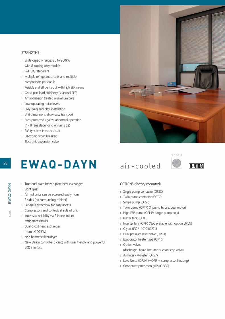
STRENGTHS
Wide capacity range: 80 to 260kW ›with 8 cooling only models
R-410A refrigerant ›Multiple refrigerant circuits and multiple ›compressors per circuit
Reliable and effi cient scroll with high EER values ›Good part load effi ciency (seasonal EER) ›Anti-corrosion treated aluminium coils ›Low operating noise levels ›Easy 'plug and play' installation ›Unit dimensions allow easy transport ›Fans protected against abnormal operation ›(4 - 8 fans depending on unit size)
Safety valves in each circuit ›Electronic circuit breakers ›Electronic expansion valve ›
True dual plate brazed plate heat exchanger ›Sight glass ›All hydronics can be accessed easily from ›3 sides (no surrounding cabinet)
Separate switchbox for easy access ›Compressors and controls at side of unit ›Increased reliability via 2 independent ›refrigerant circuits
Dual circuit heat exchanger ›(from >100 kW)
Non hermetic fi lter/dryer ›New Daikin controller (Pcaso) with user friendly and powerful ›LCD interface
OPTIONS (factory mounted)
Single pump contactor (OPSC) ›Twin pump contactor (OPTC) ›Single pump (OPSP) ›Twin pump (OPTP) (1 pump house, dual motor) ›High ESP pump (OPHP) (single pump only) ›Buffer tank (OPBT) ›Inverter fans (OPIF) (Not available with option OPLN) ›Glycol 0°C / -10°C (OPZL) ›Dual pressure relief valve (OP03) ›Evaporator heater tape (OP10) ›Option valves ›(discharge-, liquid line- and suction stop valve)
A-meter / V-meter (OP57) ›Low Noise (OPLN) (=OPIF + compressor housing) ›Condenser protection grills (OPCG) ›
s c ro l l
scro
ll
28 EWAQ-DAYN
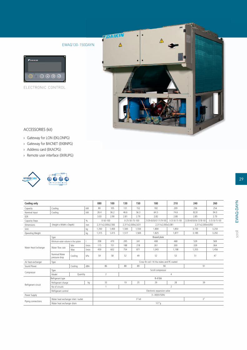
EW
AQ
-DAY
NCooling only 080 100 130 150 180 210 240 260
Capacity Cooling kW 80 105 131 152 182 209 236 254
Nominal input Cooling kW 26.4 36.2 46.6 56.3 64.5 74.6 82.8 94.0
EER 3.03 2.90 2.81 2.70 2.82 2.80 2.85 2.70
Capacity Steps % 0-50-100 0-25-50-75-100 21/29-43/50/57-71/79-100 0-25-50-75-100 22/28-40/50/56-72/78-100 0-25-50-75-100
Dimensions (Height x Width x Depth) mm 2,311x2,000x2,566 2,311x2,000x2,631 2,311x2,000x3,081 2,311x2,000x4,850
Unit kg 1,350 1,400 1,500 1,550 1,800 1,850 3,150 3,250
Operating Weight kg 1,315 1,415 1,517 1,569 1,825 1,877 3,189 3,292
Water Heat Exchanger
Type Brased plate
Minimum water volume in the system l 358 470 295 341 408 468 529 569
Water fl ow rateMin l/min 115 151 188 218 261 300 339 364
Max l/min 459 602 754 871 1,043 1,198 1,355 1,456
Nominal Water pressure drop
Cooling kPa 59 58 52 49 52 53 51 47
Air heat exchanger Type Cross fi n coil / Hi-Xss tubes and PE coated
Sound Power Cooling dBA 86 88 89 90 91
CompressorType Scroll compressor
Model Quantity 2 4
Refrigerant circuit
Refrigerant type R-410A
Refrigerant charge kg 33 19 25 29 28 39
No of circuits 1 2
Refrigerant control Electronic expansion valve
Power Supply 3~/400V/50Hz
Piping connectionsWater heat exchanger inlet / outlet 3"od 3"
Water heat exchanger drain 1/2"g
ELECTRONIC CONTROL
ACCESSORIES (kit)
Gateway for LON (EKLONPG) ›Gateway for BACNET (EKBNPG) ›Address card (EKACPG) ›Remote user interface (EKRUPG) ›
scro
ll
EWAQ130-150DAYN
29

EW
YQ
-DAY
N
air-cooled
STRENGTHS
Wide capacity range: 80 to 250kW with ›8 heat pump models
R-410A refrigerant ›Multiple refrigerant circuits and multiple compressors per ›circuit
Reliable and effi cient scroll with high EER values ›Good part load effi ciency (seasonal EER) ›Anti-corrosion treated aluminium coils ›Low operating noise levels ›Easy 'plug and play' installation ›Unit dimensions allow easy transport ›Fans protected against abnormal operation ›(4 - 8 fans depending on unit size)
Safety valves in each circuit ›Electronic circuit breakers ›Electronic expansion valve ›
True dual plate brazed plate heat exchanger ›Sight glass ›All hydronics can be accessed easily from ›3 sides (no surrounding cabinet)
Separate switchbox for easy access ›Compressors and controls at side of unit ›Increased reliability via 2 independent refrigerant circuits ›Dual circuit heat exchanger (from >100 kW) ›Non hermetic fi lter/dryer ›New Daikin controller (Pcaso) with user friendly and powerful ›LCD interface
OPTIONS (factory mounted)
Single pump contactor (OPSC) ›Twin pump contactor (OPTC) ›Single pump (OPSP) ›Twin pump (OPTP) (1 pump house, dual motor) ›High ESP pump (OPHP) (single pump only) ›Buffer tank (OPBT) ›Inverter fans (OPIF) (Not available with option OPLN) ›Glycol 0°C / -10°C (OPZL) ›Dual pressure relief valve (OP03) ›Evaporator heater tape (OP10) ›Option valves ›(discharge-, liquid line- and suction stop valve)
A-meter / V-meter (OP57) ›Low Noise (OPLN) (=OPIF + compressor housing) ›Condenser protection grills (OPCG) ›
s c ro l l
scro
ll
30 EWYQ-DAYN

EW
YQ
-DAY
NHeat Pump 080 100 130 150 180 210 230 250
CapacityCooling kW 77 100 136 145 183 211 231 252
Heating kW 87.7 114 149 165 199 225 258 281
Nominal inputCooling kW 26.5 36.2 47.6 55.7 63.8 75.3 82.2 93.5
Heating kW 30.0 38.1 49.6 58.8 68.0 77.0 84.2 96.6
EER 2.91 2.76 2.86 2.6 2.87 2.8 2.81 2.70
COP 2.92 2.99 3 2.81 2.93 2.92 3.06 2.91
Capacity Steps % 0-50-100 0-25-50-75-100 21/29-43/50/57-71/79-100 0-25-50-75-100 22/28-44/50/56-72/78-100 0-25-50-75-100
Dimensions (Height x Width x Depth) mm 2,311x2,000x2,566 2,311x2,000x2,631 2,311x2,000x3,081 2,311x2,000x4,850
Unit kg 1,400 1,450 1,550 1,600 1,850 1,900 3,200 3,300
Operating Weight kg 1,415 1,465 1,567 1,619 1,875 1,927 3,239 3,342
Water Heat Exchanger
Type Brased plate
Minimum water volume in the system l 393 511 334 370 446 504 578 629
Water fl ow rateMin l/min 110 143 195 208 262 302 331 361
Max l/min 503 654 854 946 1,141 1,290 1,479 1,611
Nominal Water pressure drop
Cooling /Heating
kPa 36 /47 36 /47 43 / 51 38 / 49 41 / 48 44 / 50 39 / 48 38 / 46
Air heat exchanger Type Cross fi n coil / Hi-Xss tubes and PE coated
Sound Power Cooling dBA 86 88 89 90 91
CompressorType Scroll compressor
Model Quantity 2 4
Refrigerant circuit
Refrigerant type R-410A
Refrigerant charge kg 33 37 22 32 39
No of circuits 1 2
Refrigerant control Electronic expansion valve
Power Supply 3~/400V/50Hz
Piping connectionsWater heat exchanger inlet / outlet 3"od 3"
Water heat exchanger drain 1/2"g
ELECTRONIC CONTROL
ACCESSORIES (kit)
Gateway for LON (EKLONPG) ›Gateway for BACNET (EKBNPG) ›Address card (EKACPG) ›Remote user interface (EKRUPG) ›
scro
ll
EWYQ130-150DAYN
31
DAYN

STRENGTHS
All models are PED pressure vessel approved ›
Inverter stepless single-screw compressor ›
Optimised for use with R-134a ›
Cooling range: 329–515kW ›
2 truly independent refrigerant circuits ›
DX shell and tube evaporator – one pass ›
refrigerant side to minimize pressure drops
Quick start-up ›
Standard electronic expansion valve ›ESEER up to 4.70 ›Good part load effi ciency ›Power factor > 0.95 cos › φ
OPTIONS (factory mounted)
Total heat recovery ›
Partial heat recovery ›
Reduced noise / Low noise ›
Current limit display ›
High pressure manometers ›
Coil guards ›
STANDARD AVAILABLE
Glycol application ›
Evaporator heater ›
Suction stop valve ›
Main switch ›
INVERTERair-cooled
s c re w
scre
w
32 EWAD-AJYNN/S
EWAD
-AJY
NN
/S

Capacity (Eurovent) Cooling kWCapacity Steps %EERESEERDimensions (Height x Width x Depth) mmWeight Machine weight kg
Operating Weight kgWater Heat Exchanger Evaporator
Type Shell and tubeMinimum water volume in the system lWater volume lWater fl ow rate
Min l/minNominal l/minMax l/min
Nominal water pressure drop Cooling kPaAir heat exchanger Type Louvered fi nsFan Nominal air fl ow m³/min
Speed rpmCompressor Type Single screw compressor
Model QuantitySound Power Cooling dBA
Water side Min~Max °CDBAir side Min~Max °CDB
Refrigerant circuit Refrigerant typeRefrigerant charge kgNo of circuitsRefrigerant control
Power Supply 3~/400V/50HzPiping connections Evaporator water inlet/outlet 168.30
330 360 400 420 460 490 520
329 358 395 423 459 488 51513.5 ÷ 100
2.74 2.63 2.68 2.66 2.74 2.71 2.674.59 4.60 4.55 4.59 4.57 4.70 4.60
2,355x2,224x4,352 2,355x2,224x5,252 2,355x2,224x6,1524,190 4,590 5,0704,440 4,840 5,320
1,277 1,389 1,533 1,641 1,781 1,893 1,998271 264 256 248515 565 622 673 727 768 814943 1,026 1,132 1,213 1,316 1,399 1,476
1,360 1,491 1,637 1,759 1,935 2,025 2,13960 61 72 67 78 69 76
1,960 2,450 2,940700
2102.8 103.2 103.6
-9.5 (OPZL)~15-10~32R-134a
80 100 1202
Electronic expansion valve
COOLING ONLYCOOLING ONLY
Operation Range
EWAD-AJYNN/S
ACCESSORIES
Communication cards ›
(EKAC200J – EKACBAC - EKACLON)
Remote user interface (EKRUPCJ) ›
Buffer tanks ›
(EKBT500N - EKBTC10N -
EKBT500C - EKBTC500C)
Sequencing panel (EKCSCII) ›
Plant visor (EKPV2J) ›
Modem (EKMODEM – EKGSMOD) ›
Converter RS485 to RS 232 ›
(EKCON) ELECTRONIC CONTROL
scre
w
ELECTRONIC CONTROL
33
EWAD
-AJY
NN
/S

STRENGTHS
High effi ciency inverter ›
ESEER up to 5.01 ›
Up to 48° ›
All models are PED pressure vessel approved ›
Inverter stepless single-screw compressor ›
Optimised for use with R-134a ›
Cooling range: 329-515kW ›
EER up to 3.03 ›
2 truly independent refrigerant circuits ›
DX shell and tube evaporator – one pass ›
refrigerant side to minimize pressure drops
Good part load effi ciency ›
Power factor > 0.95 cos › φQuick start-up ›
Standard electronic expansion valve ›
OPTIONS (factory mounted)
Total heat recovery ›
Partial heat recovery ›
20mm insulation on evaporator ›
Current limit display ›
High pressure manometers ›
Ambient outside temperature sensor and ›
set-point reset
Coil guards ›
Reduced noise/Low noise ›
STANDARD AVAILABLE
Glycol application ›
Evaporator heater ›
Suction stop valve ›
Main switch ›
air-cooled
scre
w
HIGH EFFICIENCY INVERTER
s c re w
34 EWAD-AJYNN/X
EWAD
-AJY
NN
/X

ACCESSORIES
Communication cards ›
(EKAC200J – EKACBAC - EKACLON)
Remote user interface (EKRUPCJ) ›
Buffer tanks ›
(EKBT500N - EKBTC10N -
EKBT500C - EKBTC500C)
Sequencing panel (EKCSCII) ›
Plant visor (EKPV2J) ›
Modem (EKMODEM – EKGSMOD) ›
Converter RS485 to RS 232 ›
(EKCON) ELECTRONIC CONTROL
scre
w
Capacity (Eurovent) Cooling kWCapacity Steps %EERESEERDimensions (Height x Width x Depth) mmWeight Machine weight kg
Operating Weight kgWater Heat Exchanger Evaporator
Type Shell and tubeMinimum water volume in the system lWater volume lWater fl ow rate
Min l/minNominal l/minMax l/min
Nominal water pressure drop Cooling kPaAir heat exchanger Type Louvered fi nsFan Nominal air fl ow m³/min
Speed rpmCompressor Type Single screw compressor
Model QuantitySound Power Cooling dBA
Water side Min~Max °CDBAir side Min~Max °CDB
Refrigerant circuit Refrigerant typeRefrigerant charge kgNo of circuitsRefrigerant control
Power Supply 3~/400V/50HzPiping connections Evaporator water inlet/outlet 168.30
330 360 400 420 460 490 520
329 358 395 423 459 488 51513.5 ÷ 100
2.78 2.66 2.73 2.70 2.79 2.75 2.714.79 4.82 4.78 4.84 4.81 5.01 4.84
2,355x2,224x4,352 2,355x2,224x5,252 2,355x2,224x6,1524,190 4,590 5,0704,440 4,840 5,320
1,277 1,389 1,533 1,641 1,781 1,893 1,998271 264 256 248515 565 622 673 727 768 814943 1,026 1,132 1,213 1,316 1,399 1,476
1,360 1,491 1,637 1,759 1,935 2,025 2,13960 61 72 67 78 69 76
1,960 2,450 2,940700
2102.8 103.2 103.6
-9.5 (OPZL)~15-10~32R-134a
80 100 1202
Electronic expansion valve
COOLING ONLYCOOLING ONLY
EWAD-AJYNN/X
ELECTRONIC CONTROL
35
EWAD
-AJY
NN
/X

EW
YD
-AJY
NN STRENGTHS
Cooling function available on demand ›
Doubling up of major components provides the equivalent of ›
two chiller units
in one base frame
Excellent EER and COP values ›
Extremely low operating noise ›
during part load cycles
No electric current surge ›
Inverter ›
Optimized defrost cycles ›
Optimum ESEER values ›
Partial heat recovery available ›
PID microprocessor control ›
Power factor up to 0.95 cos › φ
Rapid set-point achievement ›
Signifi cant savings in installation costs ›
Substantial cost savings compared to ›
a traditional gas boiler installation
Twin independent refrigerating ›
circuits ensure operational back up
and unit reliability
Wide operating range ›
STANDARD AVAILABLE
Glycol application ›
Evaporator heater ›
Suction stop valve ›
Main switch ›
Electronic expansion valve ›
OPTIONS (factory mounted)
Partial heat recovery ›
Fan silent ›
Gauges (High pressure side gauge) ›
Coil guards ›
Blank Cu/Al coils ›
air-cooled
s c re w
scre
w
36 EWYD-AJYNN

EW
YD
-AJY
NNHeat Pump 260 280 300 320 340 360 380
Capacity Cooling kW 255 275 298 321 343 368 385
Heating kW 274 306 330 341 361 397 412
Nominal inputCooling kW 89.8 99.3 108 116 123 132 142
Heating kW 89.5 99.1 108 117 123 131 139
EER 2.84 2.77 2.76 2.77 2.79 2.71
COP 3.06 3.09 3.06 2.91 2.93 3.03 2.96
Dimensions (Height x Width x Depth) mm 2,335x2,254x3,547 2,335x2,254x4,783
Unit kg 3,370 4,020
Operating Weight kg 3,500 4,150
Water Heat Exchanger
Type Shell and tube
Nominal Water pressure drop
Cooling kPa 60 65 74 50 53 60 65
Heating kPa 69 79 90 56 58 69 74
Air heat exchanger Type Grooved tubes and ALU coated louvred fi ns
Sound Power Cooling dBA 99.5 100.4
CompressorType Semi-hermetic single screw compressor
Model Quantity 2
Refrigerant circuit
Refrigerant type R-134a
Refrigerant charge kg 76 84 96 104
No of circuits 2
Power Supply 3~/400V/50Hz
Piping connections Evaporator water inlet/outlet 5"
ELECTRONIC CONTROL
ACCESSORIES
Communication cards ›(EKAC200J – EKACBAC - EKACLON)
Remote user interface (EKRUPCJ) ›Buffer tanks ›(EKBT500N - EKBTC10N -
EKBT500C - EKBTC500C)
Sequencing panel (EKCSCII) ›Plant visor (EKPV2J) ›Modem (EKMODEM – EKGSMOD) ›Converter RS485 to RS 232 ›(EKCON)
scre
w
37
EWYD-AJYNN
ELECTRONIC CONTROL
YNN

EW
AD
-MB
YN
air-cooled
STRENGTHS
DAIKIN stepless single screw compressor ›Operation down to -15°C ambient ›temperature
Standard reverse phase protection ›Freeze-up protection and prevention ›PE treated condenser coil ›VICTAULIC joints ›Standard discharge shut-off valve ›DICN operation as standard within same series ›Flow switch ›Modular design ›High energy effi ciency ratio ›
OPTIONS (factory mounted)
Main isolator switch ›Condenser protection grilles ›Low noise (-5 to -7dB(A)) › › Compressor suction stop valve
Ampere & Voltmeter ›(read-out on switchbox)
› Chilled water temperature down to
- 5°C (ZH) or -10°C (ZL)
Hi-ESP fans ›Dual pressure relief valve ›
ACCESSORIES (kit)
Leaving water control sensor for DICN › › BMS gateway.
(MODBUS/J-BUS/BACNET protocol)
Remote user interface (EKRUPC) ›
s c re w
scre
w
38 EWAD-MBYN

EW
AD
-MB
YN
CONTROL
Microprocessor control ›Water inlet or outlet ›temperature control
Leaving water control sensor for DICN ›
AVAILABLE INPUTS / OUTPUTS
Input
ON / OFF (per circuit) ›Dual setpoint ›Pump / fl ow switch ›
Output
Compressor operation ›Summary alarm (per circuit) ›Pump relay contact › ELECTRONIC CONTROL
Cooling only 120 150 170 240 300 340 380 460 520 600
Capacity kW 121 149 171 226 286 330 372 449 525 605
Nominal input Cooling kW 41.1 54.1 64.9 83.7 105 136 130 170 210 263
EER 2.94 2.75 2.63 2.7 2.72 2.43 2.86 2.64 2.5 2.3
Capacity Steps % 30-100 15-100
Dimensions (Height x Width x Depth) mm 2,221x3,973x1,109 2,250x4,280x2,238 2,250x5,901x2,238
Unit kg 1,391 1,600 1,705 2,710 3,210 3,260 5,335 5,595 5,775 5,855
Operating Weight kg 1,441 1,663 1,768 2,790 3,340 3,390 5,497 5,779 5,959 6,039
Water Heat Exchanger
Type Shell and tube
Minimum water volume in the system l 590 730 840 550 700 810 910 1,100 1,280 1,480
Water fl ow rateMin l/min 150 200 300 395 540 640 870
Max l/min 490 725 930 1,165 1,580 1,880
Nominal Water pressure drop
Cooling kPa 40.1 18.6 24.8 41 36.6 49.1 20.8 25.6 35.1 46.6
Air heat exchanger Type Cross fi n coil/Hi-X tubes and PE coated waffl e louvre fi ns
Sound Power Cooling dBA 87 94 92 90 97 95 97 98 100 101
CompressorType Semi-hermetic single screw compressor
Model Quantity 1 2
Refrigerant circuit
Refrigerant type R-134a
Refrigerant charge kg 26 37 42 30 41 44 65 70
No of circuits 1 2
Refrigerant control Thermostatic expansion valve Electronic expansion valve
Power Supply 3~/400V/50Hz
Piping connections Evaporator water inlet/outlet3'' vc 1/2'' g-f uni-iso 228/1
4'' victaulic coupling 1/2'' g-f uni-iso 228/1
5'' victaulic coupling 1/2'' g-f uni-iso 228/1
6'' victaulic coupling 1/2'' g-f uni-iso 228/1
scre
w
EWAD170MBYNN
ELECTRONIC CONTROL
39

EW
AD
-AJY
NN
air-cooled
STRENGTHS
All models are PED pressure ›vessel approved
Stepless single-screw compressor ›Optimised for use with R-134a ›Cooling range: 184–588kW ›Condenser protection grilles are available ›throughout the whole range
2 truly independent refrigerant circuits ›DX shell and tube evaporator – one pass ›refrigerant side to minimize pressure drops
Several operating sound levels down to 93dB ›
OPTIONS (factory mounted)
Single pump ›Twin pump ›High ESP pump ›High ESP twin pump ›Total heat recovery ›Partial heat recovery ›Reduced noise (440-480-500-550-600) / ›Low noise
Fan silent ›Low ambient ›Power factor 0.9 cos › φGauges ›Coil guards ›Soft starter (400-440-480-500-550 600) ›Blank Cu/Al coils ›Electronic expansion valve ›STANDARD AVAILABLE
Glycol application ›Evaporator heater ›Suction stop valve ›Main switch ›
s c re w
scre
w
40 EWAD-AJYNN

EW
AD
-AJY
NN
ACCESSORIES
Communication cards ›(EKAC200J – EKACBAC -
EKACLON)
Remote user interface (EKRUPCJ) ›Buffer tanks ›(EKBT500N - EKBTC10N - EKBT500C -
EKBTC500C)
Sequencing panel (EKCSCII) ›Plant visor (EKPV2J) ›Modem (EKMODEM – EKGSMOD) ›Converter RS485 to RS 232 (EKCON) ›
COOLING ONLYCOOLING ONLY 190 200 230 260 280 300 320 340 360 400 440 480 500 550 600
Capacity Cooling kW 184.0 197.8 225.0 245.0 261.0 275.0 298.4 321.0 370.0 401.3 451.0 478.7 510.1 551.0 588.0Nominal input Cooling kW 81.3 79.6 84.6 93.5 101.3 108.3 119.4 123.4 133.4 155.7 167.0 177.6 186.9 195.6 202.9EER 2.26 2.48 2.66 2.62 2.58 2.54 2.50 2.60 2.77 2.58 2.70 2.69 2.73 2.82 2.90Capacity Steps % 12.5 - 100
Dimensions (Height x Width x Depth) mm2,340 x
2,235 x 2,2402,340 x 2,235 x 3,140
2,340 x2,235 x 4,040
2,340 x2,235 x 3,140
2,340 x 2,235 x 4,040
Unit kg 2,380 2,466 2,766 2,806 2,846 3,166 3,186 3,552 3,932 3,997 4,052 4,092 4,122Operating Weight kg 2,405 2,497 2,859 2,896 2,936 3,279 3,299 3,680 4,102 4,161 4,216 4,252 4,282
Water Heat Exchanger
TypePlate to plate
heat exchangerShell and tube
water volume l 25 31 93 90 113 128 170 164 160
Water fl ow rate
Min l/min 311 374 327 333 361 368 503 512 920.32 1,240.87 1,317.08 1,403.20 1,516.00 1,617.81Nominal l/min 527 567 645 702 748 788 855 920 1,061 1,150.41 1,292.57 1,371.96 1,461.67 1,579.17 1,685.22Max l/min 985 1,182 1,033 1,053 1,141 1,162 1,164 1,590 1,618 1,380 1,551.09 1,646.35 1,754.00 1,895.01 2,022.26
Air heat exchanger Type Grooved tubes and ALU coated louvred fi nsSound Power Cooling dBA 93.7 94.3 94.7 97.2 95.8 96.7 98.2 98.7
CompressorType Semi-hermetic single screw compressorModel Quantity 2
Refrigerant circuitRefrigerant type R-134aRefrigerant charge kg 44 60 70 80 70 80 78 76No of circuits 2
Power Supply 3~/400V/50HzPiping connections Evaporator water inlet/outlet 3''1/2'' gas 4''1/2'' gas 1/2'' gas
ELECTRONIC CONTROL
scre
w
41
0C -
EWAD-AJYNN
ELECTRONIC CONTROL

EW
AD
-AJY
NN
/A
air-cooled
STRENGTHS
High Effi ciency ›Eurovent class A: EER up to 3.21 ›All models are PED pressure vessel approved ›Stepless single-screw compressor ›Optimised for use with R-134a ›Cooling range: 247-626.6kW ›2 truly independent refrigerant circuits ›DX shell and tube evaporator – one pass ›refrigerant side to minimize pressure drops
Several operating sound levels down to 96dB ›Condenser protection grilles are available ›throughout the whole range
STANDARD AVAILABLE
Glycol application ›Evaporator heater ›Suction stop valve ›Main switch ›
OPTIONS (factory mounted)
Single pump ›Twin pump ›High ESP pump ›High ESP twin pump ›Total heat recovery ›Partial heat recovery ›Fan silent ›Low ambient ›Power factor 0.9 cos › φGauges ›Coil guards ›Soft starter (500-550-600-650) ›Blank Cu/Al coils ›Electronic expansion valve ›
HIGH EFFICIENCY
s c re w
scre
w
42 EWAD-AJYNN/A

EW
AD
-AJY
NN
/A
ACCESSORIES
Communication cards ›(EKAC200J – EKACBAC - EKACLON)
Remote user interface (EKRUPCJ) ›Buffer tanks ›(EKBT500N - EKBTC10N -
EKBT500C - EKBTC500C)
Sequencing panel (EKCSCII) ›Plant visor (EKPV2J) ›Modem (EKMODEM – EKGSMOD) ›Converter RS485 to RS 232 ›(EKCON)
Cooling only 260 280 320 340 360 380 420 500 550 600 650
Capacity Cooling kW 247.0 275.0 301.5 327.0 351.0 376.0 401.0 501.4 531.5 582.2 626.6
Nominal input Cooling kW 79.2 87.3 94.2 103.8 112.8 120.2 127.5 160.6 170.9 183.5 195.4
EER 3.12 3.15 3.20 3.15 3.11 3.13 3.15 3.12 3.11 3.17 3.21
Capacity Steps % 12.5 - 100
Dimensions (Height x Width x Depth) mm 2,340x2,235x3,140 2,340x2,235x4,040 2,340x2,235x4,940
Unit kg 2,866 3,186 3,286 3,366 3,376 3,321 3,386 4,252 4,642 4,652
Operating Weight kg 2,959 3,299 3,399 3,530 3,535 3,480 3,545 4,515 4,905 4,908
Water Heat Exchanger
Type Shell and tube
Water volume l 93 113 164 159 263 256
Water fl ow rate
Min l/min 373 489 495 537 586 593 598 1,152.09 1,221.25 1,337.75 1,439.77
Nominal l/min 708 788 864 937 1,006 1,078 1,150 1,440.11 1,526.57 1,672.19 1,799.71
Max l/min 1,180 1,546 1,565 1,697 1,853 1,876 1,890 1,728.14 1,831.88 2,006.63 2,159.66
Air heat exchanger Type Grooved tubes and ALU coated louvred fi ns
Sound Power Cooling dBA 96.8 97.2 99.7 98.7 99.2
CompressorType Semi-hermetic single screw compressor
Model Quantity 2
Refrigerant circuit
Refrigerant type R-134a
Refrigerant charge kg 80 100 110 95 110 80 104
No of circuits 2
Power Supply 3~/400V/50Hz
Piping connections Evaporator water inlet/outlet 4''1/2'' gas 1/2'' gas
ELECTRONIC CONTROL
scre
w
43
EWAD-AJYNN/A
ELECTRONIC CONTROL
N)
AJYNN/A

air-cooled
STRENGTHS
Standard effi ciency extra low noise ›Several operating sound levels down to 84dB ›All models are PED pressure vessel approved ›Stepless single-screw compressor ›Optimised for use with R-134a ›Cooling range: 203–500.8kW ›2 truly independent refrigerant circuits ›DX shell and tube evaporator – one pass ›refrigerant side to minimize pressure drops
Condenser protection grilles are available ›throughout the whole range
OPTIONS (factory mounted)
Total heat recovery ›Partial heat recovery ›Fan silent ›Power factor 0.9 cos › φGauges ›Coil guards ›Soft starter (400-440-460-500) ›Blank Cu/Al coils ›Electronic expansion valve ›
STANDARD AVAILABLE
Glycol application ›Evaporator heater ›Suction stop valve ›Main switch ›
EXTRA LOW NOISE
s c re w
scre
w
44 EWAD-AJYNN/Q
EW
AD
-AJY
NN
/Q

ACCESSORIES
Communication cards ›(EKAC200J – EKACBAC - EKACLON)
Remote user interface (EKRUPCJ) ›Buffer tanks ›(EKBT500N - EKBTC10N -
EKBT500C - EKBTC500C)
Sequencing panel (EKCSCII) ›Plant visor (EKPV2J) ›Modem (EKMODEM – EKGSMOD) ›Converter RS485 to RS 232 ›(EKCON)
Cooling only 210 240 260 280 300 320 340 400 440 460 500
Capacity Cooling kW 203.0 231.1 252.7 270.8 286.1 299.4 308.8 400.5 428.5 458.4 500.8
Nominal input Cooling kW 79.8 85.2 93.7 104.5 114.5 126.1 136.3 156.0 173.8 182.4 189.9
EER 2.54 2.71 2.70 2.59 2.50 2.37 2.27 2.57 2.47 2.51 2.64
Capacity Steps % 12.5 - 100
Dimensions (Height x Width x Depth) mm 2,340x2,235x3,140 2,340x2,235x4,040 2,340x2,235x4,940
Unit kg 3,046 3,366 3,466 3,546 3,556 3,567 3,722 3,912 3,972
Operating Weight kg 3,136 3,479 3,579 3,710 3,715 3,737 3,892 4,076 4,136
Water Heat Exchanger
Type Shell and tube
Water volume l 90 113 164 159 170 164
Water fl ow rate
Min l/min 364 474 483 518 566 572 571 918.27 982.47 1,051.02 1,148.24
Nominal l/min 582 662 724 776 820 858 885 1,147.84 1,228.09 1,313.78 1,435.30
Max l/min 1,152 1,500 1,527 1,637 1,790 1,809 1,807 1,377.41 1,473.70 1,576.54 1,722.36
Air heat exchanger Type Grooved tubes and ALU coated louvred fi ns
Sound Power Cooling dBA 84.3 84.7 85.7 86.2
CompressorType Semi-hermetic single screw compressor
Model Quantity 2
Refrigerant circuit
Refrigerant type R-134a
Refrigerant charge kg 80 100 110 72 80 83 86
No of circuits 2
Power Supply 3~/400V/50Hz
Piping connections Evaporator water inlet/outlet 1/2'' gas
ELECTRONIC CONTROL
scre
w
45
EWAD-AJYNN/Q
ELECTRONIC CONTROL
N)
AJYNN/Q
EW
AD
-AJY
NN
/Q

EW
AD
-AJY
NN
/H STRENGTHS
High ambient ›Up to 48° ›All models are PED pressure vessel approved ›Stepless single-screw compressor ›Optimised for use with R-134a ›Cooling range: 194.6–600.4kW ›EER up to 3.03 ›2 truly independent refrigerant circuits ›DX shell and tube evaporator – one pass ›refrigerant side to minimize pressure drops
Several operating sound levels down to 96dB ›
OPTIONS (factory mounted)
Single pump ›Twin pump ›High ESP pump ›High ESP twin pump ›Total heat recovery ›Partial heat recovery ›Fan silent ›Power factor 0.9 cos › φGauges ›Coil guards ›Soft starter (420-460-480-500-550-600) ›Blank Cu/Al coils ›Electronic expansion valve ›
STANDARD AVAILABLE
Glycol application ›Evaporator heater ›Suction stop valve ›Main switch ›
HIGH AMBIENT
air-cooled
s c re w
scre
w
46 EWAD-AJYNN/H

EW
AD
-AJY
NN
/H
ACCESSORIES
Communication cards ›(EKAC200J – EKACBAC - EKACLON)
Remote user interface (EKRUPCJ) ›Buffer tanks ›(EKBT500N - EKBTC10N -
EKBT500C - EKBTC500C)
Sequencing panel (EKCSCII) ›Plant visor (EKPV2J) ›Modem (EKMODEM – EKGSMOD) ›Converter RS485 to RS 232 ›(EKCON)
EWAD-AJYNN/H
Cooling only 200 210 240 260 280 300 320 340 400 420 460 480 500 550 600
Capacity Cooling kW 194.6 208.3 233.5 256.1 273.7 289.3 306.4 335.6 381.2 426.0 468.1 502.1 529.5 561.0 600.4
Nominal input Cooling kW 77.2 75.6 83.0 91.0 97.8 103.9 112.1 120.3 127.4 146.5 160.3 170.8 180.1 192.2 198.4
EER 2.52 2.76 2.81 2.80 2.78 2.73 2.79 2.99 2.91 2.92 2.94 2.92 3.03
Capacity Steps % 12.5 - 100
Dimensions (Height x Width x Depth) mm 2,340x2,235x2,240 2,340x2,235x3,140 2,340x2,235x4,040 2,340x2,235x4,940
Unit kg 2,380 2,466 2,766 2,806 2,846 3,166 3,186 3,942 4,202 4,277 4,332 4,392 4,402
Operating Weight kg 2,405 2,497 2,859 2,896 2,936 3,279 3,299 4,112 4,372 4,441 4,496 4,552 4,562
Water Heat Exchanger
Type Plate to plate heat exchanger Shell and tube
Water volume l 25 31 93 90 113 170 164 160
Water fl ow rate
Min l/min 314 378 331 337 366 369 373 507 518 976.74 1,073.26 1,151.22 1,214.04 1,286.27 1,376.60
Nominal l/min 558 597 669 734 785 829 878 962 1,093 1,220.92 1,341.58 1,439.03 1,517.55 1,607.83 1,720.75
Max l/min 994 1,194 1,045 1,065 1,157 1,167 1,179 1,603 1,638 1,465.11 1,609.90 1,726.83 1,821.07 1,929.40 2,064.90
Air heat exchanger Type Grooved tubes and ALU coated louvred fi ns
Sound Power Cooling dBA 98.2 98.8 99.2 101 96.7 99.7 99.2 99.7
CompressorType Semi-hermetic single screw compressor
Model Quantity 2
Refrigerant circuit
Refrigerant type R-134a
Refrigerant charge kg 44 60 70 80 76 86 95 104
No of circuits 2
Power Supply 3~/400V/50Hz
Piping connections Evaporator water inlet/outlet 1/2'' gas
ELECTRONIC CONTROL
scre
w
47
ELECTRONIC CONTROL
N)
AJYNN/H
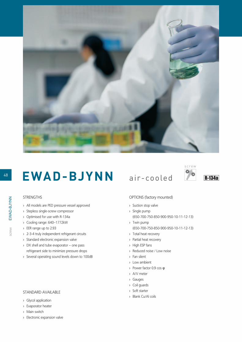
air-cooled
STRENGTHS
All models are PED pressure vessel approved ›Stepless single-screw compressor ›Optimised for use with R-134a ›Cooling range: 640–1772kW ›EER range up to 2.93 ›2-3-4 truly independent refrigerant circuits ›Standard electronic expansion valve ›DX shell and tube evaporator – one pass ›refrigerant side to minimize pressure drops
Several operating sound levels down to 100dB ›
OPTIONS (factory mounted)
Suction stop valve ›Single pump ›(650-700-750-850-900-950-10-11-12-13)
Twin pump ›(650-700-750-850-900-950-10-11-12-13)
Total heat recovery ›Partial heat recovery ›High ESP fans ›Reduced noise / Low noise ›Fan silent ›Low ambient ›Power factor 0.9 cos › φA/V meter ›Gauges ›Coil guards ›Soft starter ›Blank Cu/Al coils ›
STANDARD AVAILABLE
Glycol application ›Evaporator heater ›Main switch ›Electronic expansion valve ›
s c re w
scre
w
48 EWAD-BJYNN
EW
AD
-BJY
NN

ACCESSORIES
Communication cards ›(EKAC200J – EKACLON)
Bacnet gateway (EKBMSBNJ) ›Remote user interface (EKRUPCK) ›Buffer tanks (EKBT500N - EKBTC10N - ›EKBT500C - EKBTC500C)
Sequencing panel (EKCSCII) ›Plant visor (EKPV2J) ›Modem (EKMODEM – EKGSMOD) ›Converter RS485 to RS 232 (EKCON) ›
Cooling only 650 700 750 850 900 950 C10 C11 C12 C13 C14 C15 C16 C18
Capacity Cooling kW 640 700 761 817 886 988 1057 1109 1166 1226 1322 1520 1641 1772
Nominal input Cooling kW 233 250 271 290 302 358 372 396 417 435 452 540 580 604
EER 2.75 2.8 2.81 2.82 2.93 2.76 2.84 2.8 2.82 2.92 2.81 2.83 2.93
Capacity Steps % stepless 12.5 - 100 stepless 8.3 - 100 stepless 6,25 - 100
Dimensions (Height x Width x Depth) mm 2,520x2,230x5,310 2,520x2,230x6,210 2,520x2,230x7,400 2,520x2,230x8,270 2,520x2,230x9,200 2,520x2,230x11000 2,520x2,230x11,900
Unit kg 4,910 4,990 5,256 5,480 5,580 7,550 7,830 8,420 8,570 9,552 10,632 10,832
Operating Weight kg 5,130 5,200 5,520 5,734 5,834 7,970 8,250 8,830 8,980 10,024 11,140 11,340
Water Heat Exchanger
Type Shell and tube
Water volume l 254 246 415 402 254 + 246 246 + 246
Water fl ow rate
Min l/min 960 962 840 844 1,136 1,011 1,015 1,408 1,406 1,412 1,413 1,867 1,684 2,295
Nominal l/min 1,834 2,007 2,182 2,343 2,540 2,832 3,029 3,180 3,341 3,515 3,791 4,359 4,704 5,081
Max l/min 3,035 3,043 2,655 2,670 3,593 3,197 3,210 4,453 4,445 4,464 4,467 5,904 5,327 7,258
Air heat exchanger Type Grooved tubes and ALU coated louvred fi ns
Sound Power Cooling dBA 100 101 100 101 102 103
CompressorType Semi-hermetic single screw compressor
Model Quantity 2 3 4
Refrigerant circuit
Refrigerant type R-134a
Refrigerant charge kg 99 108 118 128 153 162 172 182 192 236 256
No of circuits 2 3 4
Refrigerant control Electronic expansion valve
Power Supply 3~/400V/50Hz
Piping connections Evaporator water inlet/outlet victaulic, diameter 168.3mm1/2'' gas victaulic, diameter 219.1mm1/2'' gas victaulic, diameter 168.3mm1/2'' gas
ELECTRONIC CONTROL
scre
w
49
EWAD-BJYNN
ELECTRONIC CONTROL
EW
AD
-BJY
NN

air-cooled
STRENGTHS
High effi ciency ›EER range up to 3.33 ›All models are PED pressure vessel approved ›Stepless single-screw compressor ›Optimised for use with R-134a ›Cooling range: 667–1920kW ›2-3-4 truly independent refrigerant circuits ›Standard electronic expansion valve ›DX shell and tube evaporator – one pass ›refrigerant side to minimize pressure drops
Several operating sound levels down to 100dB ›
OPTIONS (factory mounted)
Suction stop valve ›Single pump ›(650-700-750-800-850-900-950-10-11-12-13-
14-15)
Twin pump (650-700-800-850-900-950-10-11- ›12-13-14-15)
Total heat recovery ›Partial heat recovery ›High ESP fans ›Reduced noise / Low noise ›Fan silent ›Low ambient ›Power factor 0.9 cos › φA/V meter ›Gauges ›Coil guards ›Soft starter ›Blank Cu/Al coils ›
STANDARD AVAILABLE
Glycol application ›Evaporator heater ›Main switch ›Electronic expansion valve ›
HIGH EFFICIENCY
s c re w
scre
w
50 EWAD-BJYNN/A
EW
AD
-BJY
NN
/A

ACCESSORIES
Communication cards ›(EKAC200J – EKACLON)
Bacnet gateway (EKBMSBNJ) ›Remote user interface (EKRUPCK) ›Buffer tanks ›(EKBT500N - EKBTC10N -
EKBT500C - EKBTC500C)
Sequencing panel (EKCSCII) ›Plant visor (EKPV2J) ›Modem (EKMODEM – EKGSMOD) ›Converter RS485 to RS 232 ›(EKCON)
Cooling only 650 700 800 850 900 950 C10 C11 C12 C13 C14 C15 C16 C17 C18 C19 C20 C21
Capacity Cooling kW 667 723 800 855 903 926 974 1,038 1,094 1,177 1,222 1,282 1,354 1,430 1,557 1,710 1,806 1,920
Nominal input Cooling kW 223 237 259 278 292 287 294 343 355 377 399 415 433 430 520 558 584 603
EER 2.99 3.05 3.09 3.08 3.09 3.23 3.31 3.03 3.08 3.12 3.06 3.09 3.13 3.33 2.99 3.06 3.09 3.18
Capacity Steps % stepless 12.5 - 100 stepless 8.3 - 100 stepless 6.25 - 100
Dimensions (Height x Width x Depth) mm2,520x2,230
x6,2102,520x2,230
x7,1102,520x2,230
x 8,3002,520x2,230
x9,2002,520x2,230
x10,1002,520x2,230
x11,0002,520x2,230
x12,8002,520x2,230
x13,670
Unit kg 5,205 5,419 5,660 5,790 5,890 6,333 6,563 8,420 8,950 9,390 9,540 10,355 10,960 11,168 11,368 12,144
Operating Weight kg 5,410 5,624 5,910 6,040 6,140 6,589 6,967 8,830 9,360 9,800 9,950 10,931 11,420 11,678 11,878 13,036
Water Heat Exchanger
Type Shell and tube
Water volume l 254 246 244 392 415 402 533 254+246 246+246 392+392
Water fl ow rate
Min l/min 956 966 843 845 1,141 1,266 1,861 1,015 1,017 1,407 1,410 1,418 1,988 1,861 1,697 2,293 3,711
Nominal l/min 1,911 2,072 2,293 2,450 2,589 2,656 2,792 2,976 3,136 3,375 3,504 3,676 3,882 4,099 4,463 4,903 5,178 5,504
Max l/min 3,022 3,055 2,666 2,673 3,608 4,004 5,885 3,209 3,217 4,450 4,458 4,483 6,287 5,886 5,366 7,250 11,734
Air heat exchanger Type Grooved tubes and ALU coated louvred fi ns
Sound Power Cooling dBA 101 100 101 102 103 102 103
CompressorType Semi-hermetic single screw compressor
Model Quantity 2 3 4
Refrigerant circuit
Refrigerant type R-134a
Refrigerant charge kg 107 116 126 136 146 156 165 174 184 194 204 214 224 252 272 282
No of circuits 2 3 4
Power Supply 3~/400V/50Hz
Piping connections Evaporator water inlet/outlet victaulic, diameter 168.3mm1/2'' gas victaulic, diameter 219.1mm1/2'' gasvictaulic, diameter 168.3mm1/2'' gas
v Ø 219.1 mm1/2'' gas
ELECTRONIC CONTROL
scre
w
EWAD-BJYNN/A
51
ELECTRONIC CONTROL
EW
AD
-BJY
NN
/A

EWAD-BJYNN/Q air-cooled
STRENGTHS
Standard effi ciency extra low noise ›Several operating sound levels down to 86dB ›All models are PED pressure vessel approved ›Stepless single-screw compressor ›Optimised for use with R-134a ›Cooling range: 538–1197kW ›EER range up to 2.76 ›2-3-4 truly independent refrigerant circuits ›Standard electronic expansion valve ›DX shell and tube evaporator – one pass ›refrigerant side to minimize pressure drops
OPTIONS (factory mounted)
Suction stop valve ›Single pump ›Twin pump ›Total heat recovery ›Partial heat recovery ›High ESP fans (50-600-650-700-750-900-950- ›10-11-12)
Power factor 0.9 cos › φA/V meter ›Gauges ›Coil guards ›Soft starter ›Blank cu/al coils ›
STANDARD AVAILABLE
Glycol application ›Evaporator heater ›Main switch ›Electronic expansion valve ›
EXTRA LOW NOISE
s c re w
scre
w
52
EW
AD
-BJY
NN
/Q

ACCESSORIES
Communication cards ›(EKAC200J – EKACLON)
Bacnet gateway (EKBMSBNJ) ›Remote user interface (EKRUPCK) ›Buffer tanks (EKBT500N - EKBTC10N - ›EKBT500C - EKBTC500C)
Sequencing panel (EKCSCII) ›Plant visor (EKPV2J) ›Modem (EKMODEM – EKGSMOD) ›Converter RS485 to RS 232 (EKCON) ›
Cooling only 550 600 650 700 750 800 850 900 950 C10 C11 C12
Capacity Cooling kW 538 604 667 725 780 805 893 944 1,015 1,056 1,102 1,197
Nominal input Cooling kW 223 235 249 267 286 335 347 361 371 390 407 434
EER 2.41 2.57 2.68 2.72 2.73 2.4 2.57 2.61 2.74 2.71 2.76
Capacity Steps % stepless 12.5 - 100 stepless 8.3 - 100
Dimensions (Height x Width x Depth) mm 2,520x2,230x5,310 2,520x2,230x6,210 2,520x2,230x7,110 2,520x2,230x8,300 2,520x2,230x9,200 2,520x2,230x10,100 25,20x2,230x11,000
Unit kg 5,230 5,445 5,659 5,900 6,030 8,190 8,725 9,310 9,750
Operating Weight kg 5,440 5,650 5,864 6,150 6,280 8,610 9,150 9,720 10,160
Water Heat Exchanger
Type Shell and tube
Water volume l 261 254 246 424 415 402
Water fl ow rate
Min l/min 716 953 956 841 839 1,053 1,008 1,012 1,013 1,397 1,406 1,413
Nominal l/min 1,543 1,731 1,912 2,078 2,235 2,307 2,559 2,705 2,909 3,028 3,160 3,431
Max l/min 2,263 3,013 3,023 2,661 2,652 3,330 3,187 3,199 3,203 4,417 4,447 4,467
Air heat exchanger Type Grooved tubes and ALU coated louvred fi ns
Sound Power Cooling dBA 86 87 88 89
CompressorType Semi-hermetic single screw compressor
Model Quantity 2 3
Refrigerant circuit
Refrigerant type R-134a
Refrigerant charge kg 98 107 116 126 136 147 156 165 174 184 194 204
No of circuits 2 3
Refrigerant control Electronic expansion valve
Power Supply 3~/400V/50Hz
Piping connections Evaporator water inlet/outlet victaulic, diameter 168.3mm1/2'' gas victaulic, diameter 219.1mm1/2'' gas
ELECTRONIC CONTROL
scre
w
EWAD-BJYNN/Q
53
ELECTRONIC CONTROL
EW
AD
-BJY
NN
/Q

STRENGTHS
High effi ciency and extra low noise ›EER range up to 2.75 ›Several operating sound levels down to 86dB ›All models are PED pressure vessel approved ›Stepless single-screw compressor ›Optimised for use with R-134a ›Cooling range: 569–1013kW ›2-3-4 truly independent refrigerant circuits ›Standard electronic expansion valve ›DX shell and tube evaporator – one pass ›refrigerant side to minimize pressure drops
STANDARD AVAILABLE
Glycol application ›Evaporator heater ›Main switch ›Electronic expansion valve ›
OPTIONS (factory mounted)
Single pump ›Twin pump ›Total heat recovery ›Partial heat recovery ›High ESP fans ›(600-650-700-950-10)Fan silent ›Power factor 0.9 cos › φSuction stop valve ›A/V meter ›Gauges ›Coil guards ›Soft starter ›Blank Cu/Al coils ›
ACCESSORIES (kit)
Communication cards (EKAC200J – ›EKACLON)Bacnet gateway (EKBMSBNJ) ›Remote user interface ›(EKRUPCK) Buffer tanks (EKBT500N - ›EKBTC10N - EKBT500C - EKBTC500C)Sequencing panel (EKCSCII) ›Plant visor (EKPV2J) ›Modem (EKMODEM – ›EKGSMOD)Converter RS485 to RS 232 ›(EKCON)
HIGH EFFICIENCY - EXTRA LOW NOISE
air-cooled
ELECTRONIC CONTROL
Cooling only 600 650 700 850 900 950 C10
Capacity Cooling kW 569 631 668 840 914 953 1013
Nominal input Cooling kW 220 241 268 328 342 367 368
EER 2.59 2.62 2.49 2.56 2.67 2.6 2.75
Capacity Steps % stepless 12.5 - 100 stepless 8.3 - 100
Dimensions (Height x Width x Depth) mm 2520x2230x6210 2520x2230x7110 2520x2230x9200 2520x2230x10100 2520x2230x11000
Unit kg 5659 5900 6030 8725 9310 9750
Operating Weight kg 5864 6150 6280 9150 9720 10160
Water Heat Exchanger
Type Shell and tube
Water volume l 254 246 415 402
Water fl ow rate
Min l/min 958 843 1032 1318 1317 1325
Nominal l/min 1631 1808 1914 2409 2620 2731 2903
Max l/min 3028 2665 2666 3263 4169 4164 4189
Air heat exchanger Type Grooved tubes and ALU coated louvred fi ns
Sound Power Cooling dBA 86 87 88
CompressorType Semi-hermetic single screw compressor
Model Quantity 2 3
Refrigerant circuit
Refrigerant type R-134a
Refrigerant charge kg 106 115 124 159 168 177 186
No of circuits 2 3
Power Supply 3~/400V/50Hz
Piping connections Evaporator water inlet/outlet victaulic, diameter 168.3mm1/2'' gas victaulic, diameter 219.1mm1/2'' gas
s c re w
scre
wEWAD-BJYNN/Z
ELECTRONIC CONTROL
s c re w
54 EWAD-BJYNN/Z
EW
AD
-BJY
NN
/Z

STRENGTHS
DAIKIN stepless single screw compressor ›Operation down to -15°C ambient temperature ›Standard reverse phase protection ›Freeze-up protection and prevention ›PE treated condenser coil ›VICTAULIC joints and fi lter as standard ›DICN operation as standard within same series ›Chilled water temperature down to ›5°C(ZH) or -10°C(ZL) (user setting)Standard discharge shut-off valve ›Standard fl ow switch ›Modular design ›
OPTIONS(factory mounted)
dual pressure relief valve ›on the condenser.Main isolator switch. ›Condenser protection grilles. ›Low noise (-5 to -7dB(A)). ›Compressor suction stop valve ›Ampere & Voltmeter ›(read-out on switchbox).Hi-ESP fans. ›Inverter fans. ›Heat Recovery (see also p. 52) ›
ACCESSORIES (kit)
leaving water control ›sensor for DICN.BMS card. ›BMS gateway (MODBUS/J-BUS/ ›BACNET protocol).Remote user interface (EKPUPC). ›
CONTROL
Microprocessor control. ›Water inlet or outlet ›temperature controlWeekly operating schedule. ›
AVAILABLEINPUTS / OUTPUTS
InputON / OFF (per circuit). ›Dual setpoint through analog ›signal.Floating setpoint. ›Pump / fl ow switch. ›
OutputCompressor operation. ›Summary alarm (per circuit). ›Pump relay contact. ›
air-cooled
ELECTRONIC CONTROL
Cooling only 110 140 160 200 280 340 400 460 540Capacity Cooling kW 111.00 144.00 164.00 199.00 285.00 349.00 395.00 468.00 541.00
Nominal input Cooling kW 41.90 51.80 64.30 78.10 108.00 140.00 156.00 189.00 222.00
EER 2.65 2.78 2.55 2.64 2.49 2.53 2.48 2.44
Capacity Steps % 30-100 15-100
Dimensions (Height x Width x Depth) mm 2250x2346x2238 2250x4280x2238 2250x5901x2238
Unit kg 1417 1571 1660 2203 2583 2633 4865 4988 5111
Operating Weight kg 1425 1584 1676 2223 2610 2667 4939 5069 5199
Water Heat Exchanger
Type Brased plate, one per circuit
Water volume l 540 700 800 970 1390 1710 970 1140 1320
Water fl ow rateMin l/min 160 205 235 285 410 500 565 670 775
Max l/min 640 825 940 1140 1640 2000 2265 2680 3100
Nominal Water pressure drop
Cooling kPa 50.0 48.0 41.0 31.0 42.0 52.0 35.0 39.0 44.0
Air heat exchanger Type Cross fi n coil/Hi-X tubes and PE coated waffl e louvre fi ns
Sound Power Cooling dBA 91 96 97 99 100 101
CompressorType Semi-hermetic single screw compressor
Model Quantity 1
Refrigerant circuit
Refrigerant type R-407C
Refrigerant charge kg 27.0 39.0 42.0 58.0 84.0 128.0 129.0 130.0
No of circuits 1 2
Refrigerant control Thermostatic expansion valve
Power Supply 3~/400V/50Hz
Piping connections Evaporator water inlet/outletfl exible coupling + counterpipe for
welding 3''odfi eld installationfl exible coupling + counterpipe
for welding 3''od1/4''gfl exible coupling + counterpipe
for welding 3''1/4''gfl exible coupling + counterpipe
for welding 5''1/4''g
Relief device outlet compressor: 1''npt compressor: 2x1''nptcompressor: 2x(1''npt)
compressor: 1x(1''npt)+1x(2x1''npt)
compressor: 2x(2x1''npt)
s c re w
scre
w
EWAP200MBYN
ELECTRONIC CONTROL
55EWAP-MBYN
EW
AP
-MB
YN

EW
TP-M
BY
N In many applications there often exists a simultaneous
cooling and heating demand requirement alongside one
another. To benefit from this Daikin offer the full range of
R-407C EWTP110-540MBYN chillers with heat recovery.
This option further increases the application flexibility and
extends possibilities in the hotel and leisure industry as well
as the industrial and process sectors.
By energetically recovering useful heat from the cooling
cycle that would otherwise be rejected to outside COPs of
up to 5.62 can be realized in heat recovery mode. The heat
recovery unit aims to achieve an optimum balance between
cooling and heat recovery to maximize the unit efficiency
and offer savings in hot water production. For full heat
recovery both sensible and latent heat exchange will occur
in the recovery exchanger. Inverter fans will be used to
control the recovery outlet water temperature, by throttling
back the airflow and maintaining the required condensing
temperature.
BASED ON EWAP-MBYN
heat recovery
As a desuperheater the sensible heat from the hot discharge
gas will be recovered, while the latent heat exchange will
occur in the air-cooled condenser. The units efficiency is
maintained as condensing pressure can be reduced due
to air-cooled condenser becoming oversized. Hot water
temperatures up to 70°C can be achieved.
s c re w
scre
w
56 EWTP-MBYN

EW
TP-M
BY
N
7°C 12°C
Full Recovery
Condenser
45°C
40°C85% of CC + PI
Comp
7°C 12°C
Partial Recovery(Desuperheater)
Condenser
60°C
50°C
35% of CC + PI
Comp
Heat recovery 110 140 160 200 280 340 400 460 540
Capacity
Cooling kW 107.00 138.00 158.00 191.00 274.00 335.00 379.00 449.00 520.00
Cooling during heat recovery kW 97.70 126.00 144.00 171.00 251.00 311.00 337.00 401.00 465.00
Heat recovery kW 116.00 148.00 176.00 208.00 301.00 377.00 407.00 434.00 441.00
Nominal inputCooling kW 43.70 54.00 67.00 81.30 113.00 146.00 163.00 197.00 232.00
Heat recovery kW 39.40 47.80 62.40 73.20 103.00 132.00 142.00 177.00 214.00
EER 2.45 2.56 2.36 2.35 2.42 2.29 2.33 2.28 2.24
COP 5.44 5.73 5.13 5.17 5.36 5.21 5.24 4.71 4.24
Capacity Steps % 30-100 (stepless) 15-100 (stepless)
Dimensions (Height x Width x Depth) mm 2250x2346x2238 2250x4280x2238 2250x5901x2238
Unit kg 1465 1629 1723 2266 2646 2727 4990 5113 5236
Operating Weight kg 1483 1654 1752 2299 2692 2784 5090 5220 5350
Water Heat Exchanger
Type Brased plate, one per circuit
Minimum water volume in the system l 520 680 770 930 1340 1640 930 1100 1270
Water fl ow rateMin l/min 160 205 235 285 410 500 565 670 775
Max l/min 640 825 940 1140 1640 2000 2265 2680 3100
Air heat exchanger Type Cross fi n coil/Hi-X tubes and chromate coated waffl e louvre fi ns
Sound Power Cooling dBA 89 94 95 96 98 99
CompressorType Semi-hermetic single screw compressor
Model Quantity 1
Refrigerant circuit
Refrigerant type R-407C
Refrigerant charge kg 32.0 46.0 49.0 70.0 110.0 79.0 80.0
No of circuits 1 2
Refrigerant control Thermostatic expansion valve
Power Supply 3~/400V/50Hz
Piping connectionsEvaporator water inlet/outlet
fl exible coupling + counterpipe for welding 3'' od fi eld installation
fl exible coupling + counterpipe for welding 3''1/4''g
fl exible coupling 5''1/4''g
Heat recovery condenser inlet/outlet 2''g
ELECTRONIC CONTROL
scre
w
57
EWTP-MBYN
ELECTRONIC CONTROL

air-cooled
STRENGTHS
All models are PED pressure vessel approved ›Stepless single-screw compressor ›Optimised for use with R-407C ›Cooling range: 790–1650kW ›EER range up to 2.35 ›2 -3 truly independent refrigerant circuits ›Standard electronic expansion valve ›DX shell and tube evaporator – one pass ›refrigerant side for easy oil circulation and return
Several operating sound levels down to 101dB ›
OPTIONS (factory mounted)
Single pump (800-900-950-10-11-12-13-14) ›Twin pump (800-900-950-10-11-12-13-14) ›Total heat recovery ›Partial heat recovery ›High ESP fans ›Reduced noise / Low noise ›Fan silent ›Low ambient ›Power factor 0.9 cos › φSuction stop valve ›A/V meter ›Gauges ›Coil guards ›Soft starter ›Blank cu/al coils ›
STANDARD AVAILABLE
Glycol application ›Evaporator heater ›Main switch ›Electronic expansion valve ›
s c re w
scre
w
58 EWAP-AJYNN
EW
AP
-AJY
NN

ACCESSORIES
Communication cards ›(EKAC200J – EKACLON)
Bacnet gateway (EKBMSBNJ) ›Remote user interface (EKRUPCK) ›Buffer tanks (EKBT500N - EKBTC10N - ›EKBT500C - EKBTC500C)
Sequencing panel (EKCSCII) ›Plant visor (EKPV2J) ›Modem (EKMODEM – EKGSMOD) ›Converter RS485 to RS 232 (EKCON) ›
COOLING ONLY 800 900 950 C10 C11 C12 C13 C14 C15 C16 C17 C18
Capacity Cooling kW 790 875 944 1026 1092 1158 1284 1354 1426 1516 1583 1650
Nominal input Cooling kW 340 373 405 442 476 507 546 578 609 647 682 717
EER 2.32 2.35 2.33 2.32 2.29 2.28 2.35 2.34 2.32 2.3
Capacity Steps % stepless 12.5-100 stepless 8.3-100
Dimensions (Height x Width x Depth) mm 2520x6210x2230 2520x7110x2230 2520x8010x2230 2520x9170x2230 2520x10070x2230 2520x10970x2230 2520x11870x2230
Unit kg 5165 5425 5555 5795 5905 7990 8305 8435 8890 8905 9155 9265
Operating Weight kg 5430 5710 5840 6070 6180 8270 8775 8905 9360 9350 9600 9710
Water Heat Exchanger
Type Shell and tube
Water volume l 278 271 256 263 432 419
Water fl ow rate
Min l/min 882 1090 1096 1371 1373 1212 1614 1626 1642 2357 2359 2365
Nominal l/min 2265 2508 2706 2941 3130 3320 3681 3882 4088 4346 4538 4730
Max l/min 2788 3445 3465 4337 4341 3833 5104 5141 5192 7453 7460 7479
Air heat exchanger Type Grooved tubes and ALU coated louvred fi ns
Sound Power Cooling dBA 101 102 103 104
CompressorType Semi-hermetic single screw compressor
Model Quantity 2 3
Refrigerant circuit
Refrigerant type R-407C
Refrigerant charge kg 120 130 140 150 160 180 190 200 210 220 230 240
No of circuits 2 3
Refrigerant control Electronic expansion valve
Power Supply 3~/400V/50Hz
Piping connections Evaporator water inlet/outlet victaulic, diameter 219.1mm1/2'' gas victaulic, diameter 273mm1/2'' gas
ELECTRONIC CONTROL
scre
w
5959
EWAP-AJYNN
ELECTRONIC CONTROL
EW
AP
-AJY
NN

EW
AP
-AJY
NN
/A STRENGTHS
High effi ciency ›Several operating sound levels down to 102dB ›All models are PED pressure vessel approved ›Stepless single-screw compressor ›Optimised for use with R-407C ›Cooling range: 854–1729kW ›EER range up to 2.69 ›2 -3 truly independent refrigerant circuits ›Standard electronic expansion valve ›DX shell and tube evaporator – one pass ›refrigerant side for easy oil circulation and return
OPTIONS (factory mounted)
Suction stop valve ›Single pump (800-900-950-10-11-12-13-14) ›Twin pump (800-900-950-10-11-12-13-14) ›Total heat recovery ›Partial heat recovery ›High ESP fans ›Reduced noise / Low noise ›Fan silent ›Low ambient ›Power factor 0.9 cos › φA/V meter ›Guages ›Coil guards ›Soft starter ›Blank Cu / Al coils ›
STANDARD AVAILABLE
Glycol application ›Evaporator heater ›Main switch ›Electronic expansion valve ›
air-cooledHIGH EFFICIENCY
s c re w
scre
w
60 EWAP-AJYNN/A
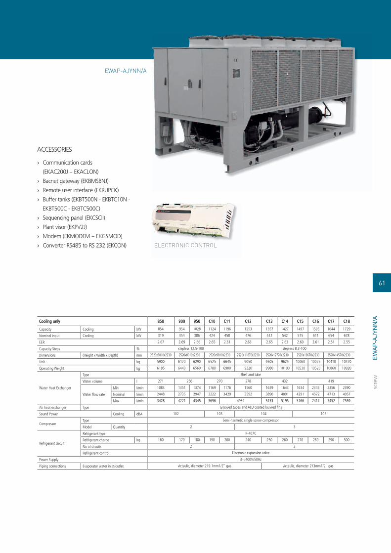
EW
AP
-AJY
NN
/A
ACCESSORIES
Communication cards ›(EKAC200J – EKACLON)
Bacnet gateway (EKBMSBNJ) ›Remote user interface (EKRUPCK) ›Buffer tanks (EKBT500N - EKBTC10N - ›EKBT500C - EKBTC500C)
Sequencing panel (EKCSCII) ›Plant visor (EKPV2J) ›Modem (EKMODEM – EKGSMOD) ›Converter RS485 to RS 232 (EKCON) ›
Cooling only 850 900 950 C10 C11 C12 C13 C14 C15 C16 C17 C18
Capacity Cooling kW 854 954 1028 1124 1196 1253 1357 1427 1497 1595 1644 1729
Nominal input Cooling kW 319 354 386 424 458 476 512 542 575 611 654 678
EER 2.67 2.69 2.66 2.65 2.61 2.63 2.65 2.63 2.60 2.61 2.51 2.55
Capacity Steps % stepless 12.5-100 stepless 8.3-100
Dimensions (Height x Width x Depth) mm 2520x8010x2230 2520x8910x2230 2520x9810x2230 2520x11870x2230 2520x12770x2230 2520x13670x2230 2520x14570x2230
Unit kg 5900 6170 6290 6525 6645 9050 9505 9625 10060 10075 10410 10470
Operating Weight kg 6185 6440 6560 6780 6900 9320 9980 10100 10530 10520 10860 10920
Water Heat Exchanger
Type Shell and tube
Water volume l 271 256 270 278 432 419
Water fl ow rate
Min l/min 1084 1351 1374 1169 1176 1560 1629 1643 1634 2346 2356 2390
Nominal l/min 2448 2735 2947 3222 3429 3592 3890 4091 4291 4572 4713 4957
Max l/min 3428 4271 4345 3696 4934 5153 5195 5166 7417 7452 7559
Air heat exchanger Type Grooved tubes and ALU coated louvred fi ns
Sound Power Cooling dBA 102 103 104 105
CompressorType Semi-hermetic single screw compressor
Model Quantity 2 3
Refrigerant circuit
Refrigerant type R-407C
Refrigerant charge kg 160 170 180 190 200 240 250 260 270 280 290 300
No of circuits 2 3
Refrigerant control Electronic expansion valve
Power Supply 3~/400V/50Hz
Piping connections Evaporator water inlet/outlet victaulic, diameter 219.1mm1/2'' gas victaulic, diameter 273mm1/2'' gas
ELECTRONIC CONTROL
scre
w
6161
EWAP-AJYNN/A
ELECTRONIC CONTROL

CONDENSERLESSDaikin offers you fl exible condenserless chillers
with remote condenser, which can be used to satisfy
applications with special requirements in the fi eld
of available space, sound level or extreme operating
conditions. In these exceptional cases, remote condenser
solutions can be preferred over standard air-cooled
or water-cooled solutions.
TABLE OF CONTENTS
EWLP-KAW1N 64
EWLD-MBYN 65
EWLD-DJYNN 66
EWLD-EJYNN 67
CO
ND
ENSE
RLE
SS
62

41 5 5
6
7
85
12
9 1011
23
1
Temperature sensor1.
Filter2.
Shut-off valve3.
Pump4.
Pressure port5.
Flow switch6.
Air purge7.
Pressure gauge8.
Balancing valve9.
Drain valve10.
Charging valve11.
Safety valve12.
ChillersGas
Liquid
Evap
ora
tor
Expan-sion
vessel
Buffer tank
To fan coilunits
To condenser
CONDENSERLESS
CO
ND
ENSE
RLE
SS
63
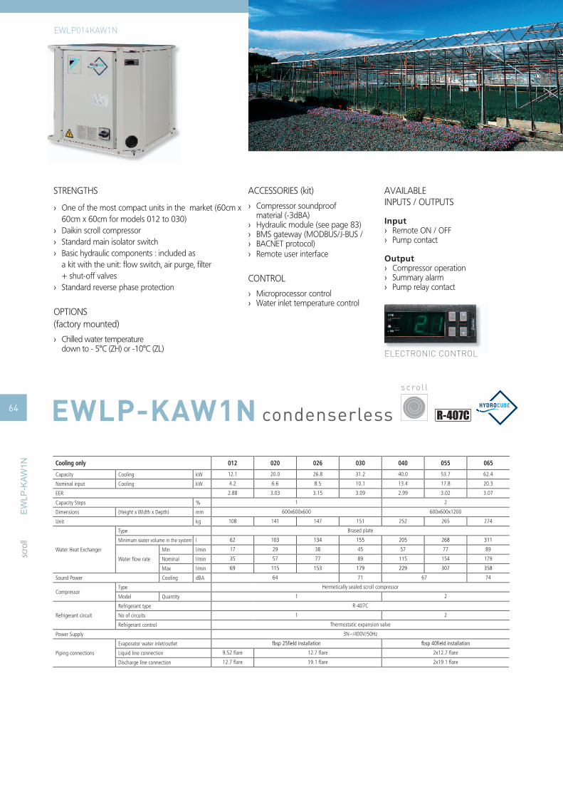
condenserless
STRENGTHS
One of the most compact units in the market (60cm x ›60cm x 60cm for models 012 to 030)Daikin scroll compressor ›Standard main isolator switch ›Basic hydraulic components : included as ›a kit with the unit: fl ow switch, air purge, fi lter + shut-off valvesStandard reverse phase protection ›
OPTIONS(factory mounted)
Chilled water temperature ›down to - 5°C (ZH) or -10°C (ZL)
ACCESSORIES (kit)
Compressor soundproof ›material (-3dBA)Hydraulic module (see page 83) ›BMS gateway (MODBUS/J-BUS / ›BACNET protocol) ›Remote user interface ›
CONTROL
Microprocessor control ›Water inlet temperature control ›
AVAILABLEINPUTS / OUTPUTS
InputRemote ON / OFF ›Pump contact ›
OutputCompressor operation ›Summary alarm ›Pump relay contact ›
ELECTRONIC CONTROL
Cooling only 012 020 026 030 040 055 065
Capacity Cooling kW 12.1 20.0 26.8 31.2 40.0 53.7 62.4
Nominal input Cooling kW 4.2 6.6 8.5 10.1 13.4 17.8 20.3
EER 2.88 3.03 3.15 3.09 2.99 3.02 3.07
Capacity Steps % 1 2
Dimensions (Height x Width x Depth) mm 600x600x600 600x600x1200
Unit kg 108 141 147 151 252 265 274
Water Heat Exchanger
Type Brased plate
Minimum water volume in the system l 62 103 134 155 205 268 311
Water fl ow rate
Min l/min 17 29 38 45 57 77 89
Nominal l/min 35 57 77 89 115 154 179
Max l/min 69 115 153 179 229 307 358
Sound Power Cooling dBA 64 71 67 74
CompressorType Hermetically sealed scroll compressor
Model Quantity 1 2
Refrigerant circuit
Refrigerant type R-407C
No of circuits 1 2
Refrigerant control Thermostatic expansion valve
Power Supply 3N~/400V/50Hz
Piping connections
Evaporator water inlet/outlet fbsp 25fi eld installation fbsp 40fi eld installation
Liquid line connection 9.52 fl are 12.7 fl are 2x12.7 fl are
Discharge line connection 12.7 fl are 19.1 fl are 2x19.1 fl are
s c ro l l
scro
ll
64
EWLP014KAW1N
EWLP-KAW1N
ELECTRONIC CONTROL
EW
LP-K
AW1N

STRENGTHS
DAIKIN stepless single screw compressor ›Compact and modular design ›Standard phase sequence controller ›VICTAULIC joints ›DICN operation as standard within ›same seriesStandard discharge shut-off valve ›Standard fl ow switch ›Standard fi lter ›
AVAILABLEINPUTS / OUTPUTS
InputON / OFF ›Pump contact ›Dual setpoint through analog signal ›Floating set point ›
OutputCompressor operation ›Summary alarm ›Fan-condenser relay contacts ›Pump relay contact ›OPTIONS (factory mounted)
Main isolator switch ›Low noise (-6dB(A)) ›Compressor suction stop valve ›
ELECTRONIC CONTROL
Ampere and Voltmeter ›(read-out on switchbox)Chilled water temperature down ›to - 5°C (ZH) or -10°C (ZL)Dual pressure relief valve ›
ACCESSORIES (kit)
BMS gateway (MODBUS / ›J-BUS / BACNET protocol)Remote user interface ›
CONTROL
Microprocessor control ›Water inlet temperature control ›Weekly operation schedule ›
Cooling only 120 170 240 260 340 400 480 500 540
Capacity Cooling kW 116.00 170.00 235.00 265.00 340.00 405.00 470.00 500.00 530.00
Nominal input Cooling kW 32.00 49.80 66.50 77.90 99.60 116.00 133.00 144.00 156.00
EER 3.63 3.41 3.53 3.4 3.41 3.49 3.53 3.47 3.4
Capacity Steps % 30-100 stepless 15-100 stepless
Dimensions (Height x Width x Depth) mm1018x2681 (3051)x930
1018x2681 (3254)x930 2000x2681 (3254)x930
Unit kg 891 1110 1342 1428 2220 2452 2684 2770 2856
Operating Weight kg 907 1130 1369 1462 2260 2497 2738 2831 2924
Water Heat Exchanger
Type Brased plate, one per circuit
Minimum water volume in the system l 570 830 1150 1300 830 990 1150 1220 1295
Water fl ow rate
Min l/min 175 265 350 400 525 625 700 750 800
Nominal l/min 333 487 674 760 975 1161 1347 1434 1520
Max l/min 700 1070 1400 1600 2100 2500 2800 3000 3200
Sound Power Cooling dBA 87 93 94 93 96
CompressorType Semi-hermetic single screw compressor
Model Quantity 1 2
Refrigerant circuit
Refrigerant type R-134a
No of circuits 1 2
Refrigerant control Thermostatic expansion valve Electronic expansion valveThermostatic
expansion valveElectronic expansion valve
Power Supply 3~/400V/50Hz
Piping connections
Evaporator water inlet/outlet3'' od vc fi eld installation
3'' victaulic coupling fi eld installation
Liquid line connection 7/8'' 1'' 1/8 1'' 3/8 2x1/8'' 1''1/8 + 1''3/8 2x1'' 3/8
Discharge line connection 2'' 1/8 2'' 5/8 2x(2''1/8) 2'' 1/8 + 2'' 5/8 2x(2''5/8)
s c re w
scre
w
6565EWLD-MBYN
EWLD120MBYN
EW
LD-M
BY
N

scre
w
condenserless
STRENGTHS
Cooling range: 161-526kW ›EER range: 3.48-3.70 ›Stepless single-screw compressor ›Optimised for use with R-134a ›1 or 3 truly independent refrigerant circuits ›Standard electronic expansion valve ›DX shell and tube evaporator – one pass refrigerant ›side for easy oil circulation and returnAll models are PED pressure vessel approved ›
Modem (EKMODEM – ›EKGSMOD)Bacnet gateway (EKBMSBNJ) › Remote user interface (EKRUPCK) ›Sequencing panel (EKCSCII) ›Buffer tanks ›(EKBT500N – EKBTC10N – EKBT500C – EKBTC10C)Plant visor (EKPV2J) ›
STANDARD AVAILABLE
Glycol application ›Main switch ›Suction stop valve ›
Gauges ›Electronic expansion valve ›
OPTIONS (factory mounted)
Partial heat recovery ›Power factor 0.9 cos › φA/V meter ›Low noise ›Soft starter ›Liquid receiver ›
ACCESSORIES
Communication cards (EKAC200J – ›EKACBAC –EKACLON)Converter RS485 to RS232 ›Converter RS485 to USB ›
66
EWLD
-DJY
NN
EWLD-DJYNN
EWLD-DJYNN
Cooling only 160 190 240 270 320 360 400 420 480 550
Capacity (Eurovent) Cooling kW 160.6 189 244 270.4 315.5 352.2 381.1 428.3 475.7 525.9
Nominal input (Eurovent) Cooling kW 45.4 54.3 65.9 74.6 90.6 99.7 108.6 120 131.5 148
Capacity Steps % 25-100 (stepless) 12.5-100 (stepless)
EER 3.54 3.48 3.7 3.62 3.48 3.53 3.51 3.57 3.62 3.55
Dimensions (Height x Width x Depth) mm 1,860x1,000x3,700 1,942x1,100x4,400
WeightMachine weight kg 1,280 1,398 2,442 2,446 2,501 2,506
Operating Weight kg 1,337 1,516 2,560 2,670
Water Heat Exchanger
Type Shell and tube - direct expansion
Water volume l 1,151 1,354 1,749 1,938 1,130 1,262 1,365 1,535 1,704 1,884
Water fl ow rate
Min l/min 230.20 270.90 349.74 387.58 452.22 504.83 546.25 613.90 681.84 753.80
Nominal l/min 460.39 541.81 699.47 775.16 904.44 1,009.65 1,092.50 1,227.81 1,363.69 1,507.60
Max l/min 649.15 763.95 986.26 1,092.97 1,275.27 1,423.61 1,540.42 1,731.21 1,922.80 2,125.71
Nominal water pressure drop Cooling kPa 48 69 43 53 64 63 72 54 68
CompressorType Semi-hermetic single screw compressor
Model Quantity 1 2
Sound Power Cooling dBA 88 90.5
Operating RangeEvaporator Min~Max °C -8 ~ 15
Condensing Temperature Min~Max °C 25 ~ 50
Refrigerant circuit
Refrigerant type R-134a
Refrigerant charge kg 5 10
No of circuits 1 2
Refrigerant control Electronic expansion valve
Power Supply 3~/400V/50Hz
Piping connections Evaporator water inlet/outlet 88.9 114.3 139.7
s c re w

scre
w
condenserless
s c re w
STRENGTHS
Cooling range: 328-1,422kW ›EER range: 3.51-3.91 ›Stepless single-screw compressor ›Optimised for use with R-134a ›1-2-3 truly independent refrigerant circuits ›Standard electronic expansion valve ›DX shell and tube evaporator – one pass refrigerant side ›for easy oil circulation and returnAll models are PED pressure vessel approved ›
STANDARD AVAILABLE
Main switch ›Gauges ›Electronic expansion valve ›
OPTIONS (factory mounted)
Total heat recovery ›Partial heat recovery ›Power factor 0.9 cos › φA/V meter ›Soft starter ›Liquid receiver ›
ACCESSORIES
Communication cards (EKAC200J – ›EKACBAC –EKACLON)Converter RS485 to RS232 ›Converter RS485 to USB ›Modem (EKMODEM – ›EKGSMOD)
Bacnet gateway (EKBMSBNJ) ›Remote user interface (EKRUPCK) ›Sequencing panel (EKCSCII) ›Buffer tanks (EKBT500N – EKBTC10N – ›EKBT500C – EKBTC10C)Plant visor (EKPV2J) ›
EWLD
-EJY
NN
67EWLD-EJYNN
EWLD-EJYNN
Cooling only 320 400 420 500 600 650 750 800 850 900 950 C10 C11 C12 C13 C14 C15 C16 C17
Capacity (Eurovent) Cooling kW 328 391 428 504 596 657 730 788 850 919 966 1,003 1,078 1,125 1,188 1,267 1,319 1,370 1,422
Nominal input (Eurovent) Cooling kW 83.8 100 116 137 165 181 198 214 231 252 271 279 296 312 329 347 366 386 405
EER 3.91 3.69 3.68 3.61 3.63 3.69 3.68 3.65 3.56 -
Dimensions (Height x Width x Depth) mm 1,921x1,461x3,338 2,113x1,350x4,332 2,398x2,153x4,470
WeightMachine weight kg 1,861 1,869 1,884 3,331 3,339 3,347 3,356 3,364 3,412 5,146 5,167 5,188 5,208
Operating Weight kg 2,054 2,052 2,056 3,602 3,603 3,604 3,605 3,645 5,667 5,671 5,677 5,680
Water Heat ExchangerEvaporator
Type Shell and tube
Water fl ow rate Nominal l/min 939 1,119.8 1,227.6 1,445.6 1,709.6 1,884.1 2,093 2,258.3 2,436.5 2,634 2,768.2 2,874.6 3,090.3 3,223.9 3,407 3,631.7 3,780.2 3,928.8 4,077.4
Nominal water pressure drop Cooling kPa 33.7 46.27 47.28 54.12 48.57 38.96 51.57 47.15 46.98 58.35 45.07 52.23 45.67 49.28 41.21 50.8 54.6 58.53 62.57
CompressorType Screw compressor
Model Quantity 1 2 3
Sound Power Cooling dBA 93.6 94.6 96.6 96.9 97.3 97.8 98.8 99.8 98.3 98.6 99.8 100.6 101.2 101.8
Operating Range
Evaporator Min~Max °CDB -8 (OPZL)~15
Condensor Min~Max °CDB -
Water side Min~Max °CDB -
Air side Min~Max °CDB -
Condensing temperature Min~Max °CDB -
Evaporating temperature Min~Max °CDB -
Refrigerant circuit
Refrigerant type R-134a
Refrigerant charge kg 5
No of circuits 1 2 3
Refrigerant control Electronic expansion valve
Power Supply 3~/400V/50Hz
Piping connections Evaporator water inlet/outlet 168.30 219.10

WATER-COOLEDDaikin offers you compact
water-cooled chiller units which
require only very limited space
in a machine room.
Used for commercial or industrial
applications, these chillers generate
cold and hot water, which can be used
for chilling, heating, or even both
at the same time.
TABLE OF CONTENTS
EWWP-KAW1N 70
EWWD-MBYN 72
EWWD-DJYNN 74
EWWD-DJYNN/A 76
EWWD-CJYNN 78
EWWD-EJYNN 80
EWWD-EJYNN/A 82
EWWD-BJYNN 84
EWWQ-AJYNN 86
EWWQ-AJYNN/A 88
D-DWSC/D-DWDC 90
WA
TER-
COO
LED
68

7 5
5
4
3
1
2
4
1 3
1210 9 8
5
6
2
58 9
11
10 12
6
3
3
11
75 5
3
13
WATER COOLED CHILLER
To fan coil units
or thermal
load
To fan coil units
or thermal
load
Buffer tank
Buffer tank
Expansion vessel
Expansion vesselChillers
Evap
ora
tor
Co
nd
ense
rBalancing valve1. Pressure gauge2. Temperature sensor3. Drain valve4. Shut-off valve5. Charging valve6. Filter7. Air purge8. Safety valve9. Pressure port10. Pump11. Flow switch12. Bypass valve13.
WA
TER-
COO
LED
69

water-cooled
STRENGTHS
One of the most compact units in the market ›(60cm x 60cm x 60cm for models 014 to 035)Daikin scroll compressor ›Standard reverse phase protection ›Extension possible up to 195kW ›
FOR SINGLE MODULE UNITS
Standard main isolator switch ›Basic hydraulic components for KA-series included ›with the unit as a kit: fl ow switch, air purge, fi lter +
shut-off valves for both condenser and evaporator
OPTIONS (factory mounted)
Chilled water temperature down to - 5°C (OPZH) or ›-10°C (OPZL)
ACCESSORIES (kit)
Compressor soundproof material ›(-3dBA)
Hydraulic module (see page 83) ›BMS gateway (MODBUS/J-BUS / ›BACNET protocol)
Remote user interface ›
CONTROL
Microprocessor control ›Water inlet ›temperature control
Cold water or ›hot water regulation
AVAILABLEINPUTS / OUTPUTS
Input
Remote ON / OFF ›Pump contact ›Cool/heat selection ›
Output
Compressor operation ›Summary alarm ›Pump relay contact ›
ELECTRONIC CONTROL
Cooling only/heating only 014 022 028 035 045 055 065 90 100 110 120 130 145 155 165 175 185 195
Capacity Cooling kW 13.0 21.5 28.0 32.5 43.0 56 65.0 86.0 99.0 112 121 130 142 155 168 177 186 195
Nominal input Cooling kW 3.61 5.79 7.48 8.75 12.1 16 18.3 23.6 27.3 31.0 33.1 35.2 39.1 42.8 46.5 48.6 50.7 52.8
EER 3.60 3.71 3.74 3.71 3.55 3.5 3.55 3.64 3.63 3.61 3.66 3.69 3.63 3.62 3.61 3.64 3.67 3.69
Capacity Steps % 1 2 4 6
Dimensions (Height x Width x Depth) mm 600x600x600 600x600x1200 1200x600x1200 1800x600x1200
Unit kg 118 155 165 172 300 320 334 600 620 640 654 668 920 940 960 974 988 1002
Water Heat Exchanger
Type Brased plate
Minimum water volume in the system l 62 103 134 155 205 268 311 205 268 311 205 268 311
Water fl ow rate
Min l/min 24 39 51 59 79 102 118 157 181 205 221 237 260 283 307 323 339 355
Nominal l/min 48 78 102 118 157 205 237 314 362 410 442 474 519 567 614 647 679 711
Max l/min 95 157 203 237 314 410 474 629 724 819 883 948 1038 1133 1229 1293 1357 1422
Sound Power Cooling dBA 64 71 67 74 71 75 77 73 76 78 79
CompressorType Hermetically sealed scroll compressor
Model Quantity 1 2 4 6 8 6
Refrigerant circuit
Refrigerant type R-407C
Refrigerant charge kg 1.2 2 2.5 3.1 4.6 5.6 9.2 10.2 11.2 13.8 14.8 15.8 16.8
No of circuits 1 2 4 6
Refrigerant control Thermostatic expansion valve
Power Supply 3N~/400V/50Hz
Piping connectionsEvaporator water inlet/outlet fbsp 25 fi eld installation fbsp 40 fi eld installation 2 x 2 x fbsp 38 fi eld installation 3 x 2 x fbsp 38 fi eld installation
Condenser water inlet/outlet fbsp 25 fi eld installation fbsp 40 fi eld installation 2 x 2 x fbsp 38 fi eld installation 3 x 2 x fbsp 38 fi eld installation
s c ro l l
scro
ll
70 EWWP-KAW1N
ELECTRONIC CONTROL
EW
WP
-KAW
1N

SELECTION TABLE 1 MODULE (KA-series) 2 MODULES (KA-series) 3 MODULES (KA-series)
Capacity index 014 022 028 035 045 055 065 090 100 110 120 130 145 155 165 175 185 195
Cooling capacity (kW) 13 21.5 28 32.5 43 56 65 86 99 112 121 130 142 155 168 177 186 195
Heating capacity (kW) 16 26.2 35.3 41 52.5 71 81 105 124 142 153 164 176 195 213 224 235 246
UNIT+CONTROL(factory mounted)
EWWP014KAW1N 1 - - - - - - - - - - - - - - - - -
EWWP022KAW1N - 1 - - - - - - - - - - - - - - - -
EWWP028KAW1N - - 1 - - - - - - - - - - - - - - -
EWWP035KAW1N - - - 1 - - - - - - - - - - - - - -
EWWP045KAW1N - - - - 1 - - - - - - - - - - - - -
EWWP055KAW1N - - - - - 1 - - - - - - - - - - - -
EWWP065KAW1N - - - - - - 1 - - - - - - - - - - -
UNIT ONLY(Without Control)
EWWP045KAW1M - - - - 1 - - 2 1 - - - 2 1 - - - -
EWWP055KAW1M - - - - - 1 - - 1 2 1 - 1 2 3 2 1 -
EWWP065KAW1M - - - - - - 1 - - - 1 2 - - - 1 2 3
CONTROL(Kit)
ECB 1 MUW - - - - 1 1 1 - - - - - - - - - -
ECB 2 MUW - - - - - - - 1 1 1 1 1 - - - - - -
ECB 3 MUW - - - - - - - - - - - - 1 1 1 1 1 1
For example: for a 121 kW -HP system, select : EWWP055KAW1 + EWWP065KAW1
scro
ll
7171
EWWP014-035KAW1N
EWWP090-130KAW1N
EWWP145-130KAW1N
EW
WP
-KAW
1N

EW
WD
-MB
YN
water-cooled
STRENGTHS
Compact and modular design. ›DAIKIN stepless single screw compressor. ›Standard reverse phase protection. ›VICTAULIC joints. ›DICN operation as standard within same series. ›Standard discharge shut-off valve. ›Standard fi lter, fl ow switch. ›
ACCESSORIES (kit)
BMS gateway (MODBUS/J-BUS / BACNET protocol). ›Remote user interface (EKRUPC). ›
CONTROL
Microprocessor control. ›Water inlet or outlet temperature control. ›Weekly operating schedule. ›
OPTION (factory mounted)
Main isolator switch. ›Low noise (-5 to -7dB(A)). ›Compressor suction stopvalve. ›Ampere & Voltmeter ›(read-out on switchbox).
Chilled water temperature down to - ›5°C (ZH) or -10°C (ZL).
Dual pressure relief valve. ›
s c re w
scre
w
72 EWWD-MBYN
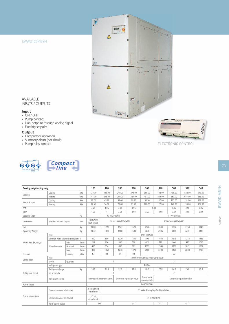
EW
WD
-MB
YN
AVAILABLEINPUTS / OUTPUTS
InputON / OFF. ›Pump contact. ›Dual setpoint through analog signal. ›Floating setpoint. ›
OutputCompressor operation. ›Summary alarm (per circuit). ›Pump relay contact. › ELECTRONIC CONTROL
Cooling only/heating only 120 180 240 280 360 440 500 520 540
CapacityCooling kW 123.00 183.00 249.00 273.00 366.00 432.00 498.00 522.00 546.00
Heating kW 147.00 216.00 290.00 327.00 431.00 505.00 580.00 617.00 655.00
Nominal inputCooling kW 28.70 45.20 61.60 69.20 90.50 107.00 123.00 131.00 138.00
Heating kW 34.50 54.00 72.80 83.40 108.00 127.00 146.00 156.00 167.00
EER 4.29 4.05 4.04 3.95 4.04 4.05 3.98 3.96
COP 4.26 4 3.98 3.92 3.99 3.98 3.97 3.96 3.92
Capacity Steps % 30-100 stepless 15-100 stepless
Dimensions (Height x Width x Depth) mm1018x2681 (3051)x930
1018x2681 (3254)x930 2000x2681 (3254)x930
Unit kg 1000 1273 1527 1623 2546 2800 3034 3150 3346
Operating Weight kg 1032 1318 1588 1693 2636 2906 3156 3281 3485
Water Heat Exchanger
Type Shell and tube
Minimum water volume in the system l 600 890 1220 1330 895 1055 1215 1275 1335
Water fl ow rate
Min l/min 217 336 450 520 670 790 900 970 1040
Nominal l/min 435 654 890 981 1309 1545 1781 1871 1962
Max l/min 800 1050 1230 1370 2100 2290 2470 2600 2730
Pressure Cooling dBA 87 93 94 93 96
CompressorType Semi-hermetic single screw compressor
Model Quantity 1 2
Refrigerant circuit
Refrigerant type R-134a
Refrigerant charge kg 18.0 35.0 37.0 38.0 70.0 72.0 74.0 75.0 76.0
No of circuits 1 2
Refrigerant control Thermostatic expansion valve Electronic expansion valveThermostatic
expansion valveElectronic expansion valve
Power Supply 3~/400V/50Hz
Piping connections
Evaporator water inlet/outlet3" od vc fi eld installation
3" victaulic coupling fi eld installation
Condensor water inlet/outlet2'' 1/2
victaulic m63'' victaulic m6
Relief device outlet 1x1'' 2x1'' 3x1'' 4x1''
scre
w
73
EWWD120MBYN

water-cooled
STRENGTHS
All models are PED pressure vessel approved ›Stepless single-screw compressor ›Optimised for use with R-134a ›Cooling range: 165.5–555.7kW ›EER range up to 4 ›1-2 truly independent refrigerant circuits ›Standard electronic expansion valve ›DX shell and tube evaporator – one pass ›refrigerant side for easy oil circulation and return
STANDARD AVAILABLE
Glycol application ›Suction stop valve ›Main switch ›Gauges ›
Electronic expansion valve
OPTIONS (factory mounted)
Total heat recovery ›Partial heat recovery ›Power factor 0.9 cos › φA/V meter ›Low noise ›Soft starter ›Cu/Ni heat exchanger ›
s c re w
scre
w
74 EWWD-DJYNN
EW
WD
-DJY
NN

ACCESSORIES
Communication cards ›(EKAC200J – EKACLON)
Bacnet gateway (EKBMSBNJ) ›Remote user interface (EKRUPCK) ›Buffer tanks (EKBT500N - EKBTC10N - ›EKBT500C - EKBTC500C)
Sequencing panel (EKCSCII) ›Plant visor (EKPV2J) ›Modem (EKMODEM – EKGSMOD) ›Converter RS485 to RS 232 (EKCON) › ELECTRONIC CONTROL
Cooling only 170 210 260 300 320 380 420 460 500 600
Capacity Cooling kW 165.5 201.2 252.8 280.4 333.9 372.2 402.5 448.3 493.7 555.7
Nominal input Cooling kW 42.1 50.7 64.9 75.4 84.3 93.1 101.4 115.1 129.0 150.2
EER 3.93 3.97 3.9 3.72 3.96 4 3.97 3.89 3.83 3.7
Capacity Steps % stepless 25-100 stepless 12.5-100
Dimensions (Height x Width x Depth) mm 1860x3435x920 1880x4305x860
Unit kg 1393 1410 1503 2687 2697 2702 2757 2762
Operating Weight kg 1470 1480 1650 2840 2850 2860 2970
Water Heat Exchanger
Type Shell and tube
Water volume l 13 15 26 28 30
Water fl ow rate
Min l/min 303 357 363 368 603 659 718 726 729 741
Nominal l/min 595 722 911 1020 1199 1334 1445 1615 1785 2024
Max l/min 959 1128 1147 1162 1908 2083 2270 2296 2305 2344
Sound pressure Cooling dBA 69.7 71.7
CompressorType Semi-hermetic single screw compressor
Model Quantity 1 2
Refrigerant circuit
Refrigerant type R-134a
Refrigerant charge kg 50 100
No of circuits 1 2
Refrigerant control Electronic expansion valve
Power Supply 3~/400V/50Hz
Piping connections Evaporator water inlet/outlet 1/2'' gas
scre
w
75
EWWD-DJYNN
EW
WD
-DJY
NN

water-cooled
STRENGTHS
High effi ciency ›EER range up to 4.7 ›All models are PED pressure vessel approved ›Stepless single-screw compressor ›Optimised for use with R-134a ›Cooling range: 186.4–603.9kW ›1-2 truly independent refrigerant circuits ›Standard electronic expansion valve ›DX shell and tube evaporator – one pass ›refrigerant side for easy oil circulation and return
STANDARD AVAILABLE
Glycol application ›Suction stop valve ›Main switch ›Gauges ›Electronic expansion valve ›
OPTIONS (factory mounted)
Total heat recovery (190-230-28-320-380-400-460-500) ›Partial heat recovery ›Power factor 0.9 cos › φA/V meter ›Low noise ›Soft starter ›Cu/Ni heat exchanger ›
HIGH EFFICIENCY
s c re w
scre
w
76 EWWD-DJYNN/A
EW
WD
-DJY
NN
/A

ACCESSORIES
Communication cards ›(EKAC200J – EKACLON)
Bacnet gateway (EKBMSBNJ) ›Remote user interface (EKRUPCK) ›Buffer tanks (EKBT500N - EKBTC10N - ›EKBT500C - EKBTC500C)
Sequencing panel (EKCSCII) ›Plant visor (EKPV2J) ›Modem (EKMODEM – EKGSMOD) ›Converter RS485 to RS 232 (EKCON) › ELECTRONIC CONTROL
Cooling only 190 230 280 320 380 400 460 500 550 650
Capacity Cooling kW 186.4 223.3 276.5 306.7 366.3 408.2 443.6 496 540.5 603.9
Nominal input Cooling kW 39.7 48.1 59.3 71.4 79.3 87.2 95 104.8 114.4 137.7
EER 4.7 4.64 4.66 4.3 4.62 4.68 4.67 4.73 4.72 4.39
Capacity Steps % stepless 25-100 stepless 12.5-100
Dimensions (Height x Width x Depth) mm 1860x3435x920 1880x4305x860
Unit kg 1650 1665 1680 2800 2945 2955 2975 2990
Operating Weight kg 1800 1810 1820 3020 3280 3290 3315 3340
Water Heat Exchanger
Type Shell and tube
Water volume l 22 25 44 47 50 59 68
Water fl ow rate
Min l/min 497 550 609 648 994 1089 1202 1362 1533 1542
Nominal l/min 648 778 963 1084 1277 1420 1544 1722 1877 2126
Max l/min 1572 1740 1925 2048 3145 3444 3801 4306 4847 4877
Sound Power Cooling dBA 69.7 71.7
CompressorType Semi-hermetic single screw compressor
Model Quantity 1 2
Refrigerant circuit
Refrigerant type R-134a
Refrigerant charge kg 50 100
No of circuits 1 2
Refrigerant control Electronic expansion valve
Power Supply 3~/400V/50Hz
scre
w
77
EWWD-DJYNN/A
EW
WD
-DJY
NN
/A

EW
WD
-CJY
NN
water-cooled
STRENGTHS
All models are PED pressure vessel approved ›Stepless single-screw compressor ›Optimised for use with R-134a ›Cooling range: 334–1893kW ›EER up to 4.68 ›1-2-3-4 truly independent refrigerant circuits ›Standard electronic expansion valve ›DX shell and tube evaporator – one pass ›refrigerant side to minimize pressure drops
STANDARD AVAILABLE
Glycol application ›Main switch ›Gauges ›Electronic expansion valve ›
OPTIONS (factory mounted)
Total heat recovery ›Partial heat recovery ›Power factor 0.9 cos › φSuction stop valve ›A/V meter ›Soft starter ›Cu / Ni heat exchanger ›
s c re w
scre
w
78 EWWD-CJYNN

EW
WD
-CJY
NN
ACCESSORIES
Communication cards ›(EKAC200J – EKACLON)
Bacnet gateway (EKBMSBNJ) ›Remote user interface (EKRUPCK) ›Buffer tanks (EKBT500N - EKBTC10N - ›EKBT500C - EKBTC500C)
Sequencing panel (EKCSCII) ›Plant visor (EKPV2J) ›Modem (EKMODEM – EKGSMOD) ›Converter RS485 to RS 232 (EKCON) › ELECTRONIC CONTROL
Cooling only 340 400 480 550 700 750 800 900 950 C10 C11 C12 C13 C14 C15 C16 C17 C18 C19
Capacity Cooling kW 334 399 462 510 666 735 792 871 934 1074 1139 1205 1268 1331 1394 1525 1629 1761 1893
Nominal input Cooling kW 81.1 90.1 102 109 160 170 180 194 207 250 261 273 284 297 309 344 366 391 416
EER 4.12 4.43 4.53 4.68 4.16 4.32 4.4 4.49 4.51 4.3 4.36 4.41 4.46 4.48 4.51 4.43 4.45 4.5 4.55
Capacity Steps % stepless 25-100 stepless 12.5-100 stepless 8.3-100 stepless 6.25-100
Dimensions (Height x Width x Depth) mm 1970x3310x900 2070x4300x1290 2320x3770x2160 2320x5151x2240
Unit kg 1830 1855 1886 1965 3395 3495 3515 3560 3590 4960 4980 5110 5135 5175 5205 6790 6830 6890 6940
Operating Weight kg 2000 2030 2050 2160 3640 3910 3940 3990 4020 5410 5430 5630 5660 5710 5740 7580 7630 7690 7730
Water Heat Exchanger
Type Shell and tube
Water volume l 30 35 34 36 60 63 70 75 80 95 100 105 110 115 120 135 140 150 160
Water fl ow rate
Min l/min 626 720 817 936 1232 1348 1447 1527 1635 1974 2059 2173 2284 2364 2473 2749 2895 3164 3268
Max l/min 1980 2278 2584 2960 3896 4261 4577 4829 5170 6244 6512 6872 7222 7475 7821 8692 9156 10006 10336
Nominal l/min 1188 1404 1614 1776 2370 2592 2784 3054 3270 3798 4014 4236 4452 4668 4884 5358 5718 6168 6618
Sound pressure Cooling dBA 75.2 76.2 78.2 77.8 78.2 78.7 79.8 80.7 79.2 79.5 79.8 80.6 81.2 81.8 80.3 81.9 82.8
CompressorType Semi-hermetic single screw compressor
Model Quantity 1 2 3 4
Refrigerant circuit
Refrigerant type R-134a
Refrigerant charge kg 53 63 73 77 106 116 126 136 146 169 179 189 199 209 219 232 252 272 292
No of circuits 1 2 3 4
Refrigerant control Electronic expansion valve
Power Supply 3~/400V/50Hz 3~/380-440V/50Hz
Piping connections Evaporator water inlet/outlet 1/2'' gas
scre
w
79
EWWD-CJYNN

STRENGTHS
All models are PED pressure vessel approved ›Stepless single-screw compressor ›Optimised for use with R-134a ›Cooling range: 333-1,510 kW ›EER range: 4.28-4.66 ›1-2-3 truly independent refrigerant circuits ›Standard electronic expansion valve ›DX shell and tube evaporator – one pass ›refrigerant side to minimize pressure dropsPartial and total heat recovery option available ›
STANDARD AVAILABLE
Glycol application ›
Main switch ›
Gauges ›
Electronic expansion valve ›
OPTIONS (factory mounted)
Total heat recovery ›
Partial heat recovery ›
Power factor 0.9 cos › φSuction stop valve ›
A/V meter ›
Soft starter ›
Cu / Ni heat exchanger ›
Dual pressure relief valve ›
scre
w
water-cooled
s c re w
80 EWWD-EJYNN
EWW
D-E
JYN
N
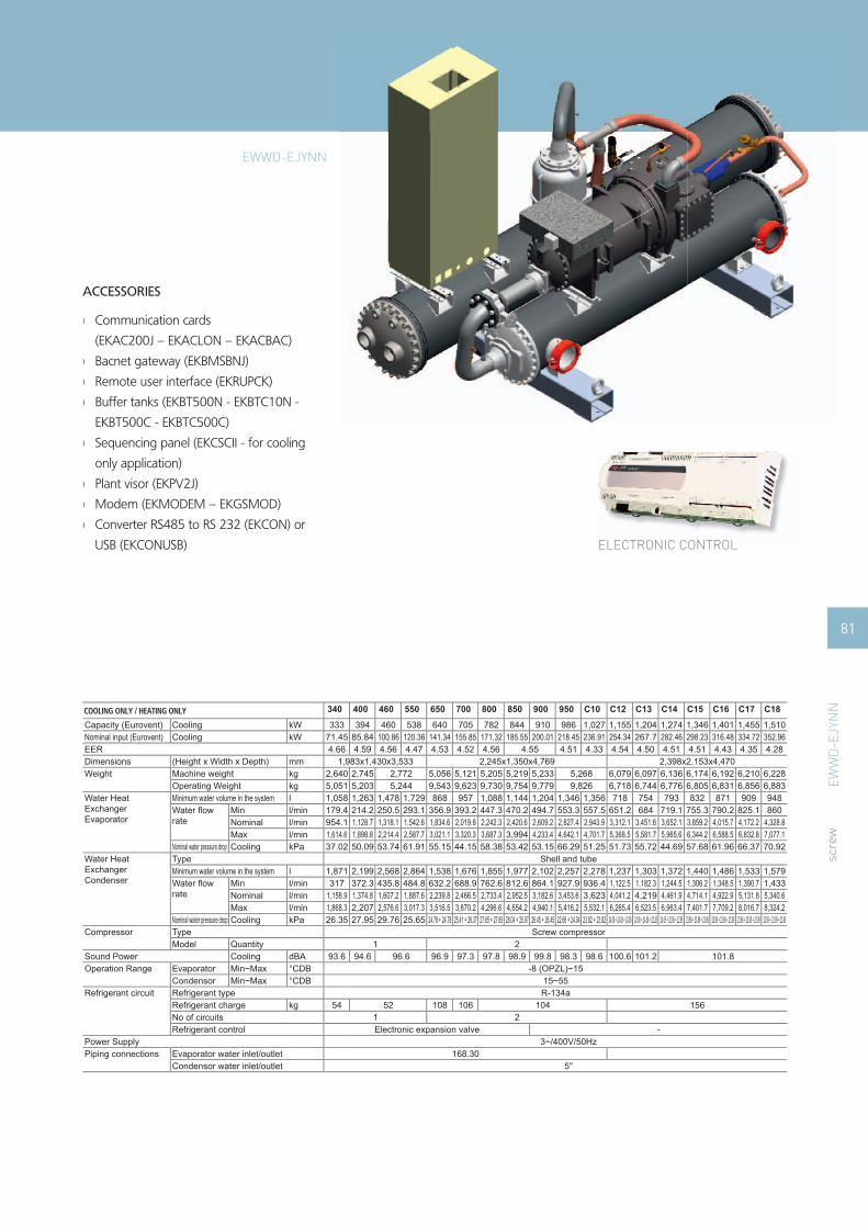
ACCESSORIES
Communication cards ›
(EKAC200J – EKACLON – EKACBAC)
Bacnet gateway (EKBMSBNJ) ›
Remote user interface (EKRUPCK) ›
Buffer tanks (EKBT500N - EKBTC10N - ›
EKBT500C - EKBTC500C)
Sequencing panel (EKCSCII - for cooling ›
only application)
Plant visor (EKPV2J) ›
Modem (EKMODEM – EKGSMOD) ›
Converter RS485 to RS 232 (EKCON) or ›
USB (EKCONUSB) ELECTRONIC CONTROL
scre
w
Capacity (Eurovent) Cooling kWNominal input (Eurovent) Cooling kWEERDimensions (Height x Width x Depth) mmWeight Machine weight kg
Operating Weight kgWater Heat Exchanger Evaporator
Minimum water volume in the system lWater fl ow rate
Min l/minNominal l/minMax l/min
Nominal water pressure drop Cooling kPaWater Heat Exchanger Condenser
Type Shell and tubeMinimum water volume in the system lWater fl ow rate
Min l/minNominal l/minMax l/min
Nominal water pressure drop Cooling kPaCompressor Type Screw compressor
Model QuantitySound Power Cooling dBAOperation Range Evaporator Min~Max °CDB
Condensor Min~Max °CDBRefrigerant circuit Refrigerant type
Refrigerant charge kgNo of circuitsRefrigerant control
Power Supply 3~/400V/50HzPiping connections Evaporator water inlet/outlet 168.30 219.10
Condensor water inlet/outlet 5''
340 400 460 550 650 700 800 850 900 950 C10 C12 C13 C14 C15 C16 C17 C18
333 394 460 538 640 705 782 844 910 986 1,027 1,155 1,204 1,274 1,346 1,401 1,455 1,51071.45 85.84 100.86 120.36 141.34 155.85 171.32 185.55 200.01 218.45 236.91 254.34 267.7 282.46 298.23 316.48 334.72 352.964.66 4.59 4.56 4.47 4.53 4.52 4.56 4.55 4.51 4.33 4.54 4.50 4.51 4.51 4.43 4.35 4.28
1,983x1,430x3,533 2,245x1,350x4,769 2,398x2,153x4,4702,640 2,745 2,772 5,056 5,121 5,205 5,219 5,233 5,268 6,079 6,097 6,136 6,174 6,192 6,210 6,2285,051 5,203 5,244 9,543 9,623 9,730 9,754 9,779 9,826 6,718 6,744 6,776 6,805 6,831 6,856 6,8831,058 1,263 1,478 1,729 868 957 1,088 1,144 1,204 1,346 1,356 718 754 793 832 871 909 948179.4 214.2 250.5 293.1 356.9 393.2 447.3 470.2 494.7 553.3 557.5 651.2 684 719.1 755.3 790.2 825.1 860954.1 1,128.7 1,318.1 1,542.6 1,834.6 2,019.8 2,242.3 2,420.6 2,609.2 2,827.4 2,943.9 3,312.1 3,451.6 3,652.1 3,859.2 4,015.7 4,172.2 4,328.81,614.6 1,898.8 2,214.4 2,587.7 3,021.1 3,320.3 3,687.3 3,994 4,233.4 4,642.1 4,701.7 5,368.5 5,581.7 5,965.6 6,344.2 6,588.5 6,832.8 7,077.137.02 50.09 53.74 61.91 55.15 44.15 58.38 53.42 53.15 66.29 51.25 51.73 55.72 44.69 57.68 61.96 66.37 70.92
1,871 2,199 2,568 2,864 1,538 1,676 1,855 1,977 2,102 2,257 2,278 1,237 1,303 1,372 1,440 1,486 1,533 1,579317 372.3 435.8 484.8 632.2 688.9 762.6 812.6 864.1 927.9 936.4 1,122.5 1,182.3 1,244.5 1,306.2 1,348.5 1,390.7 1,433
1,158.9 1,374.8 1,607.2 1,887.6 2,239.8 2,466.5 2,733.4 2,952.5 3,182.6 3,453.6 3,623 4,041.2 4,219 4,461.9 4,714.1 4,922.9 5,131.8 5,340.61,868.3 2,207 2,576.6 3,017.3 3,516.5 3,870.2 4,296.6 4,654.2 4,940.1 5,416.2 5,532.1 6,265.4 6,523.5 6,963.4 7,401.7 7,709.2 8,016.7 8,324.226.35 27.95 29.76 25.65 24.78 + 24.78 25.41 + 26.37 27.65 + 27.65 28.04 + 25.97 26.45 + 26.45 22.66 + 24.04 23.82 + 23.82 24.08 + 24.08 + 24.08 24.08 + 24.08 + 22.28 24.55 + 22.95 + 22.95 23.86 + 23.86 + 23.86 23.86 + 23.86 + 23.09 23.86 + 23.09 + 23.09 23.09 + 23.09 + 23.09
1 293.6 94.6 96.6 96.9 97.3 97.8 98.9 99.8 98.3 98.6 100.6 101.2 101.8
-8 (OPZL)~1515~55R-134a
54 52 108 106 104 1561 2Electronic expansion valve -
COOLING ONLY / HEATING ONLYCOOLING ONLY / HEATING ONLY
EWWD-EJYNN
EWW
D-E
JYN
N
81

STRENGTHS
High effi ciency ›All models are PED pressure vessel approved ›Stepless single-screw compressor ›Optimised for use with R-134a ›Cooling range: 362-1,134 kW ›EER range: 4.72-5.12 ›1 or 2 truly independent refrigerant circuits ›Standard electronic expansion valve ›DX shell and tube evaporator – one pass ›refrigerant side to minimize pressure drops
STANDARD AVAILABLE
Glycol application ›
Main switch ›
Gauges ›
Electronic expansion valve ›
OPTIONS (factory mounted)
Power factor 0.9 cos › φSuction stop valve ›
A/V meter ›
Soft starter ›
Cu / Ni heat exchanger ›
Dual pressure relief valve ›
scre
w
water-cooled
s c re w
HIGH EFFICIENCY
82 EWWD-EJYNN/A
EWW
D-E
JYN
N/A

ACCESSORIES
Communication cards ›
(EKAC200J – EKACLON – EKACBAC)
Bacnet gateway (EKBMSBNJ) ›
Remote user interface (EKRUPCK) ›
Buffer tanks (EKBT500N - EKBTC10N - ›
EKBT500C - EKBTC500C)
Sequencing panel (EKCSCII - for cooling ›
only application)
Plant visor (EKPV2J) ›
Modem (EKMODEM – EKGSMOD) ›
Converter RS485 to RS 232 (EKCON) or ›
USB (EKCONUSB) ELECTRONIC CONTROL
scre
w
Capacity (Eurovent) Cooling kWNominal input (Eurovent) Cooling kWEERDimensions (Height x Width x Depth) mmWeight Machine weight kg
Operating Weight kgWater Heat Exchanger Evaporator
Type Shell and tubeMinimum water volume in the system lWater fl ow rate
Min l/minNominal l/minMax l/min
Nominal water pressure drop Cooling kPaWater Heat Exchanger Condenser
Type Shell and tubeMinimum water volume in the system lWater fl ow rate
Min l/minNominal l/minMax l/min
Nominal water pressure drop Cooling kPaCompressor Type Screw compressor
Model QuantitySound Power Cooling dBAOperation Range Evaporator Min~Max °CDB
Condensor Min~Max °CDBWater side Min~Max °CDBAir side Min~Max °CDBCondensing temperature Min~Max °CDBEvaporating temperature Min~Max °CDB
Refrigerant circuit Refrigerant typeRefrigerant charge kgNo of circuitsRefrigerant control
Power Supply 3~/400V/50HzPiping connections Evaporator water inlet/outlet 168.30 219.10
Condensor water inlet/outlet 4''
360 440 500 600 750 800 850 950 C10 C11 C12
362 433 506 573 720 795 866 933 976 1,038 1,13470.68 85.32 100.09 120.35 141.56 155.84 170.45 184.75 199.04 219.92 239.925.12 5.08 5.06 4.76 5.09 5.1 5.08 5.05 4.9 4.72 4.73
1,983x1,430x3,533 2,245x1,350x4,7692,640 2,745 2,772 5,056 5,121 5,205 5,219 5,233 5,2685,051 5,203 5,244 9,543 9,623 9,730 9,754 9,779 9,826
1,127 1,350 1,582 1,801 948 1,052 1,146 1,240 1,301 1,382 1,515191.1 229 268.2 305.3 389.8 432.6 471 509.7 534.9 567.9 622.8
1,036.6 1,241.5 1,451.2 1,642.6 2,063.2 2,278.4 2,483.4 2,676 2,797.6 2,975.2 3,249.82,280.1 2,720.9 3,170.1 3,559.6 4,479.1 4,925.7 5,368.3 5,762.2 6,003.3 6,395.9 6,960.6
64 48 54 68 58 68 56 64 72 46 52
1,923 2,262 2,653 2,938 1,604 1,758 1,901 2,060 2,187 2,295 2,457326.1 384.2 450 497.7 659.3 722.5 781.4 846.9 898.8 943.5 1,010
1,239.2 1,486.1 1,738.1 1,987.6 1,234.8 1,498.8 1,485 1,708.8 1,684.2 1,987.2 1,969.22,034.8 2,432.7 2,836.1 3,206.3 3,996.8 4,396.3 4,797.9 5,150.9 5,384.9 5,766.7 6,270.747.67 47.19 51.37 66.03 48.07 46.92 49.83 64.97
1 293.6 94.6 96.6 96.9 97.3 97.8 98.9 99.8 98.3 98.6
-8 (OPZL)~1515~55
----
R-134a54 52 108 106 104
1 2Electronic expansion valve
COOLING ONLY / HEATING ONLYCOOLING ONLY / HEATING ONLY
EWWD-EJYNN/A
EWW
D-E
JYN
N/A
83

water-cooled
STRENGTHS
All models are PED pressure vessel approved ›1 and 2 stepless single-screw compressors ›Optimised for use with R-134a ›Cooling range: 369–1050kW ›Super high effi ciency: EER up to 5.83 ›Very high EER values at part loads condition ›Flooded evaporator ›Expansion valve with liquid level control ›
STANDARD AVAILABLE
Main switch ›Gauges ›Electronic expansion valve ›
OPTIONS (factory mounted)
Glycol application ›Suction stop valve ›A / V meter ›Soft starter ›Cu / Ni heat exchanger ›
s c re w
scre
w
84 EWWD-BJYNN
EW
WD
-BJY
NN

ACCESSORIES
Communication cards ›(EKAC200J – EKACLON)
Bacnet gateway (EKBMSBNJ) ›Remote user interface (EKRUPCK) ›Buffer tanks (EKBT500N - EKBTC10N - ›EKBT500C - EKBTC500C)
Sequencing panel (EKCSCII) ›Plant visor (EKPV2J) ›Modem (EKMODEM – EKGSMOD) ›Converter RS485 to RS 232 (EKCON) › ELECTRONIC CONTROL
Cooling only 380 460 550 750 850 900 C10 C11
Capacity Cooling kW 369 445 521 734 816 895 976 1050
Nominal input Cooling kW 65 77.9 90 129 142 155 167 180
EER 5.68 5.71 5.79 5.69 5.75 5.77 5.84 5.83
Capacity Steps % stepless 25-100 stepless 12.5-100
Dimensions (Height x Width x Depth) mm 2250x3625x1551 2250x3860x1551 2300x4145x1743 2300x4145x1808 2300x4145x1910
Unit kg 3089 3370 3603 5546 5636 6007 6448 6598
Operating Weight kg 3250 3588 3870 5911 6045 6460 6972 7163
Water Heat Exchanger
Type Flooded shell and tube
Water volume l 83 111 133 181 199 243 263
Water fl ow rate
Min l/min 665 948 1086 1478 1703 1904 1924 2146
Nominal l/min 1244 1499 1752 2474 2746 3010 3277 3526
Max l/min 2103 2998 3435 4675 5386 6020 6085 6786
Sound Power Cooling dBA 78 79 80 81 81.5 82 82.5 83
CompressorType Semi-hermetic single screw compressor
Model Quantity 1 2
Refrigerant circuit
Refrigerant type R-134a
Refrigerant charge kg 130 165 180 200 215 230 274 290
No of circuits 1
Refrigerant control Electronic expansion valve
Power Supply 3~/400V/50Hz
Piping connections Evaporator water inlet/outlet 1/2'' gas
scre
w
85
EWWD-BJYNN
EW
WD
-BJY
NN

water-cooled
s c re w
scre
w
STRENGTHS
Cooling range: 388-2,093kW ›
EER range up to 4.62 ›
ESEER up to 5.37 ›
1 or 2 stepless single-screw compressors ›
1 or 2 truly independent refrigerant circuits ›
Optimised for use with R-410A ›
Shell and tube heat exchanger ›
Standard electronic expansion valve ›
Compact design ›
Partial heat recovery available ›
All models are PED pressure vessel approved ›
STANDARD AVAILABLE
Glycol application ›
Main switch ›
Gauges ›
Electronic expansion valve ›
OPTIONS (factory mounted)
Partial heat recovery ›
Power factor 0.9 cos › φA/V meter ›
Soft starter ›
Pressure relief valve ›
Suction stop valve ›
86 EWWQ-AJYNN
EWW
Q-A
JYN
N

ELECTRONIC CONTROL
scre
w
Capacity (Eurovent) Cooling kWNominal input (Eurovent) Cooling kWCapacity Steps % 25-100 (stepless) 12.5-100 (stepless) 25-100 (stepless) 12.5-100 (stepless) 25-100 (stepless) 12.5-100 (stepless)EERESEERDimensions Height x Width x Depth mmWeight Machine weight kg
Operating Weight kgWater Heat Exchanger Evaporator
Type Shell and tubeWater volume lWater fl ow rate
Min l/minMax l/min
Nominal water pressure drop Cooling kPaWater Heat Exchanger Condenser
Type Shell and tubeWater volume lWater volume lWater fl ow rate
Min l/minMax l/min
Nominal water pressure drop Cooling kPaCompressor Type Semi hermetic single screw compressor
Model QuantitySound Power Cooling dBAOperation Range Evaporator Min~Max °C
Condenser Min~Max °CRefrigerant circuit Refrigerant type
Refrigerant charge kgNo of circuitsRefrigerant control
Power Supply 3~/400V/50HzPiping connections Evaporator water inlet/outlet 168.30 219.10 273.00
Condenser water inlet/outlet 5'' 5'' 6" 5'' 6" 5" 6" 5" 6"
400 480 600 650 750 800 850 900 C10 C11 C12 C13 C14 C15 C16 C17 C18 C19 C20
387.96 474.13 574.36 651.45 742.14 812.53 880.09 891.19 980.45 1,028.15 1,077.43 1,210.09 1,281.09 1,352.09 1,488.14 1,620.34 1,783.43 1,928.13 2,092.7387.37 106.27 130.44 147.86 169.73 175.22 206.4 194.02 212.97 245.47 236.90 261.72 279.05 296.39 339.95 375.37 408.72 441.58 475.47
4.44 4.46 4.4 4.41 4.37 4.64 4.26 4.59 4.6 4.19 4.55 4.62 4.59 4.56 4.38 4.32 4.36 4.37 4.404.95 4.98 4.97 4.72 5.37 4.60 5.36 5.34 4.53 5.33 5.36 5.35 5.29 4.93 4.82 4.89 4.871,846x1,065x3,431 2,000x1,226x3,440 1,846x1,266x3,561 2,170x1,350x4,902 1,846x1,266x3,561 2,170x1,350x4,902 1,846x1,266x3,561 2,379x1,350x4,912 2,455x1,350x4,835 2,547x1,350x4,844 2,547x1,350x4,8091,933 1,967 2,283 2,332 2,407 3,921 2,427 3,949 3,988 2,457 4,344 4,529 4,536 4,607 4,988 4,999 5,053 5,204 5,2892,135 2,169 2,543 2,628 2,777 4,422 2,795 4,463 4,496 2,812 4,780 5,186 5,200 5,280 5,602 5,615 5,670 5,881 5,970
124 118 176 170 274 344 266 344 325 251 325 538 505 495 539 527664 812 986 1,118 1,225 1,385 1,279 1,522 1,673 1,283 1,845 2,062 2,188 2,314 2,391 2,501 2,925 3,267 3,667
1,258 1,354 1,860 2,108 2,415 2,649 2,859 2,898 3,189 3,342 3,492 3,937 4,160 4,383 4,840 5,255 5,785 6,238 6,76849.43 64.65 45.04 47.92 54.74 53.80 50.22 63.54 59.07 57.23 70.01 45.37 50.28 55.40 59.86 69.74 89.42 98.78 122.57
79 92 84 162 97 79 102 79 92 104 52 60 60 68 54 54 61 61 77- 79 - 92 - 60 68 54 57 61 77
813 994 1,210 1,371 1,506 1,683 1,579 1,854 2,037 1,589 2,251 2,508 2,664 2,821 2,937 3,080 3,595 4,015 4,5001,541 1,878 2,282 2,587 2,968 3,220 3,530 3,882 4,139 4,260 4,789 5,066 5,345 5,945 6,472 7,112 7,666 8,30760.15 64.35 67.91 66.02 16.46 64.44 20.43 66.55 67.64 25.92 70.09 73.40 69.77 16.52 19.31 16.93 17.08 15.02
1 2 1 2 1 2100.2 101.2 102.3 101.5 104.7 102.3 104.7 105.1 103.2 104.7 105.2 106.5 105.8 106.2 106.6 107.1 107.5
-4~1025~45R-410A
80 90 100 85+85 100 85+85 100 95+95 100+100 130+1301 2 1 2 1 2
COOLING ONLYCOOLING ONLY
Electronic expansion valve
5"
EWW
Q-A
JYN
N
87
ACCESSORIES
Communication cards ›
(EKAC200J – EKACBAC –EKACLON)
Converter RS485 to RS232 ›
Converter RS485 to USB ›
Modem (EKMODEM – EKGSMOD) ›
Bacnet gateway (EKBMSBNJ) ›
Remote user interface (EKRUPCK) ›
Sequencing panel (EKCSCII) ›
Plant visor (EKPV2J) ›
EWWQ-AJYNN

water-cooled
s c re w
scre
w
STRENGTHS
Cooling range: 431-2,196kW ›
EER range up to 5.09 ›
ESEER up to 5.98 ›
1 or 2 stepless single-screw compressors ›
1 or 2 truly independent refrigerant circuits ›
Optimised for use with R-410A ›
Shell and tube heat exchanger ›
Standard electronic expansion valve ›
Compact design ›
Partial heat recovery available ›
All models are PED pressure vessel approved ›
STANDARD AVAILABLE
Glycol application ›
Main switch ›
Gauges ›
Electronic expansion valve ›
OPTIONS (factory mounted)
Partial heat recovery ›
Power factor 0.9 cos › φA/V meter ›
Soft starter ›
Pressure relief valve ›
Suction stop valve ›
88 EWWQ-AJYNN/A
EWW
Q-A
JYN
N/A

ELECTRONIC CONTROL
scre
w
ACCESSORIES
Communication cards (EKAC200J – EKAC- ›
BAC –EKACLON)
Converter RS485 to RS232 ›
Converter RS485 to USB ›
Modem (EKMODEM – EKGSMOD) ›
Bacnet gateway (EKBMSBNJ) ›
Remote user interface (EKRUPCK) ›
Sequencing panel (EKCSCII) ›
Plant visor (EKPV2J) ›
Capacity (Eurovent) Cooling kWNominal input (Eurovent) Cooling kWCapacity Steps % 25-100 (stepless) 12.5-100 (stepless) 25-100 (stepless) 12.5-100 (stepless)EERESEERDimensions Height x Width x Depth mmWeight Machine weight kg
Operating Weight kgWater Heat Exchanger Evaporator
Type Shell and tubeWater volume lWater fl ow rate
Min l/minMax l/min
Nominal water pressure drop Cooling kPaWater Heat Exchanger Condenser
Type Shell and tubeWater volume lWater volume lWater fl ow rate
Min l/minMax l/min
Nominal water pressure drop Cooling kPaCompressor Type Semi-hermetic single screw compressor
Model QuantitySound Power Cooling dBAOperation Range Evaporator Min~Max °C
Condenser Min~Max °CRefrigerant circuit Refrigerant type
Refrigerant charge kgNo of circuitsRefrigerant control Electronic expansion valve
Power Supply 3~/400V/50HzPiping connections Evaporator water inlet/outlet 219.10 273.00
Condenser water inlet/outlet 5'' 5"
440 550 650 750 800 950 C10 C11 C12 C13 C14 C15 C16 C18 C19 C20 C22
431 527 653 740 818 993 1,059 1,139 1,182 1,297 1,397 1,479 1,605 1,769 1,901 2,061 2,19686.67 104.72 128.28 145.95 162.04 196.57 209.49 232.06 233.11 257.54 274.77 291.86 321.48 356.36 390.31 425.94 460.72
4.97 5.03 5.09 5.07 5.05 5.06 4.91 5.07 5.04 5.08 5.07 4.99 4.96 4.87 4.84 4.775.58 5.61 5.69 5.67 5.64 5.39 5.89 5.28 5.87 5.88 5.98 5.93 5.67 5.71 5.48 5.50 5.382,000x1,211x3,987 2,001x1,218x3,855 2,000x1,266x3,854 2,001x1,448x3,891 2,453x1,350x4,985 2,001x1,448x3,891 2,453x1,350x4,985 2,547x1,350x4,844 2,547x1,350x4,809
2,322 2,403 2,738 2,407 2,427 4,775 2,457 4,831 4,873 4,919 4,969 5,117 5,388 5,408 5,4142,594 2,685 2,745 3,158 2,815 3,056 5,431 3,086 5,479 5,512 5,546 5,606 5,794 5,843 6,110 6,118 6,124
220 213 200 334 325 538 587 538 575 563 551 495 484 535 527733 898 1,114 1,262 1,438 1,733 1,805 1,994 2,016 2,213 2,383 2,523 2,811 3,097 3,334 3,617 3,862
1,407 1,718 2,133 2,419 2,651 3,234 3,462 3,695 3,862 4,237 4,563 4,823 5,219 5,749 6,158 6,671 7,09455.77 68.81 71.54 64.27 57.46 53.85 53.69 68.89 64.23 55.13 67.85 75.14 70.1 89.12 91.3 113.04 126.77
52 69 81 86 83 91 69 91 73 76 75 86 91 91 91 91 91- 70 - 76 86 91
881 1,076 1,332 1,511 1,723 2,076 2,162 2,400 2,414 2,652 2,852 3,021 3,374 3,721 4,019 4,365 4,6721,691 2,552 2,896 3,176 3,875 4,147 4,447 4,624 5,077 5,461 5,774 6,264 6,908 7,422 8,049 8,58150.16 39.75 42.38 46.94 59.79 64.73 40.10 83.56 47.93 48.17 49.20 46.82 44.26 61.21 60.50 79.00
1 2 1 2100.9 101.7 102.6 102.7 102.0 102.9 105.2 103.8 105.6 106.1 106.5 105.8 106.2 106.6 107.1 107.5
-4~1025~45R-410A
95 110 130 120+120 130 120+120 130+1301 2 1 2
COOLING ONLYCOOLING ONLY
EWW
Q-A
JYN
N/A
89
EWWQ-AJYNN/A
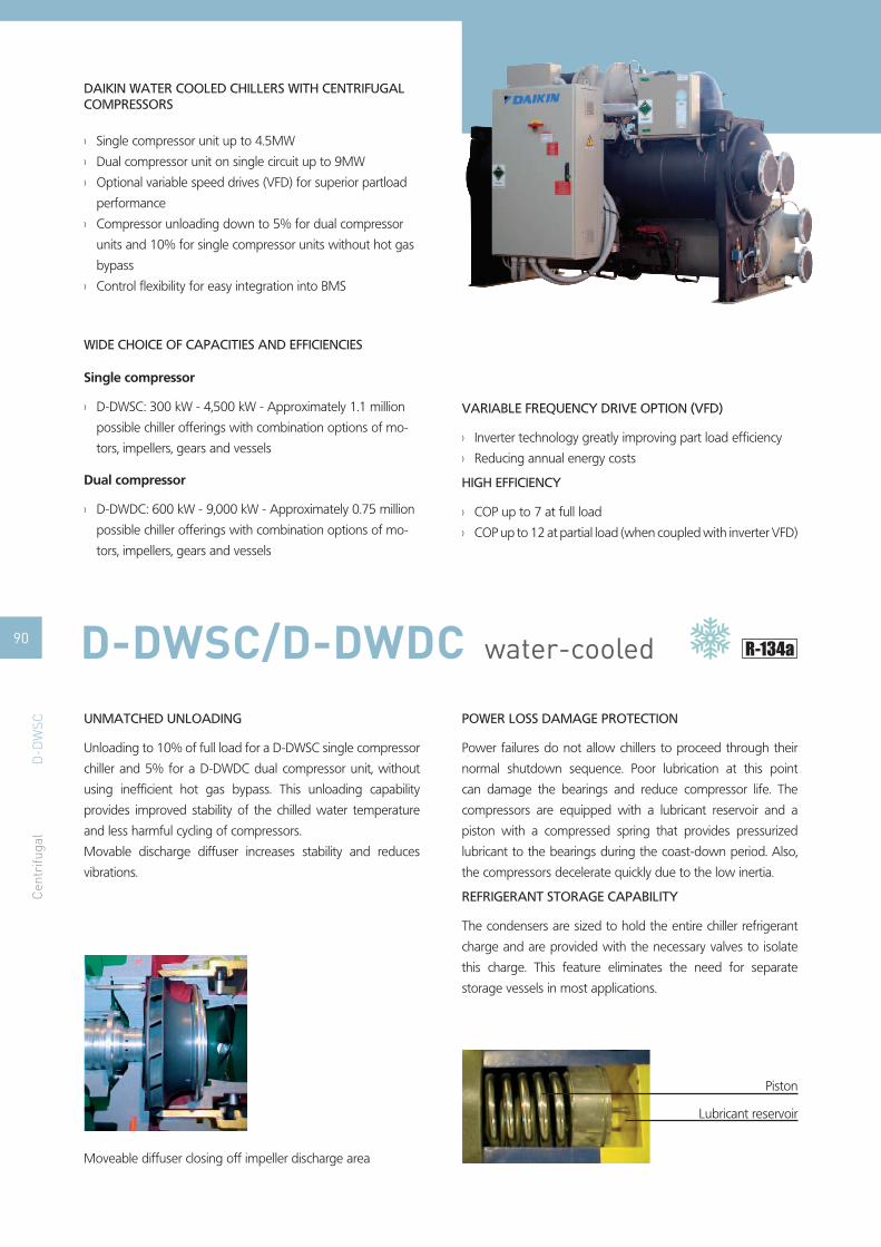
water-cooled
UNMATCHED UNLOADING
Unloading to 10% of full load for a D-DWSC single compressor
chiller and 5% for a D-DWDC dual compressor unit, without
using ineffi cient hot gas bypass. This unloading capability
provides improved stability of the chilled water temperature
and less harmful cycling of compressors.
Movable discharge diffuser increases stability and reduces
vibrations.
Moveable diffuser closing off impeller discharge area
D-D
WSC
90 D-DWSC/D-DWDC
Single compressor unit up to 4.5MW ›
Dual compressor unit on single circuit up to 9MW ›
Optional variable speed drives (VFD) for superior partload ›
performance
Compressor unloading down to 5% for dual compressor ›
units and 10% for single compressor units without hot gas
bypass
Control fl exibility for easy integration into BMS ›
WIDE CHOICE OF CAPACITIES AND EFFICIENCIES
Single compressor
D-DWSC: 300 kW - 4,500 kW - Approximately 1.1 million ›
possible chiller offerings with combination options of mo-
tors, impellers, gears and vessels
Dual compressor
D-DWDC: 600 kW - 9,000 kW - Approximately 0.75 million ›
possible chiller offerings with combination options of mo-
tors, impellers, gears and vessels
VARIABLE FREQUENCY DRIVE OPTION (VFD)
Inverter technology greatly improving part load effi ciency ›
Reducing annual energy costs ›
HIGH EFFICIENCY
COP up to 7 at full load ›
COP up to 12 at partial load (when coupled with inverter VFD) ›
POWER LOSS DAMAGE PROTECTION
Power failures do not allow chillers to proceed through their
normal shutdown sequence. Poor lubrication at this point
can damage the bearings and reduce compressor life. The
compressors are equipped with a lubricant reservoir and a
piston with a compressed spring that provides pressurized
lubricant to the bearings during the coast-down period. Also,
the compressors decelerate quickly due to the low inertia.
REFRIGERANT STORAGE CAPABILITY
The condensers are sized to hold the entire chiller refrigerant
charge and are provided with the necessary valves to isolate
this charge. This feature eliminates the need for separate
storage vessels in most applications.
Piston
Lubricant reservoir
DAIKIN WATER COOLED CHILLERS WITH CENTRIFUGAL COMPRESSORS
Cen
trifu
gal

water-cooled
LOW OPERATIONAL SOUND LEVEL
Liquid Injection
A small amount of liquid refrigerant is taken from the conden-
ser and injected into the compressor discharge area. The liquid
droplets absorb sound energy and reduce the compressor's
overall operational sound level. The droplets evaporate and re-
duce discharge superheat.
Quieter as chiller unloads
Daikin’s design results in a reduction in sound levels at lower
loads, where most chillers spend most of their operating
hours.
ONE D-DWDC DUAL COMPRESSOR CHILLER VERSUS
TWO SINGLE COMPRESSOR CHILLERS
Lower equipment costs than two separate chillers ›
Lower installation cost than two separate chillers ›
Lower annual operating cost than either one large or two ›
small chillers
Less equipment room space required than for two separate ›
chillers
(smaller footprint)
Capacity reduction to 5% of design value ›
Standby redundancy for most of the cooling season op- ›
tions of motors, impellers, gears and vessels
D- D-D D D-D D-D
D-DWSC: single compressorD-DWDC: double compressorVFD: compressor inverterSpecifi c selections can vary up or down from this example.
10.0
9.0
8.0
7.0
6.0
5.0
4.0
3.0
2.0
1.0
0.07.0 7.4 9.7 10.0
PARTIAL LOADS EFFICIENCY FOR 2,000 KW CENTRIFUGAL UNIT
D-D
WD
CEXCELLENT PART LOAD EFFICIENCY
When one compressor is running, it is able to utilize the heat
transfer area of the entire chiller, twice the amount found
on a single compressor chiller. This huge amount of surface
provides exceptional part load effi ciency. The addition of VFDs
to the dual compressor chiller produces a very high ARI certifi ed
Integrated Part Load Value (IPLV).
91D-DWSC/D-DWDC
Cen
trifu
gal

CONDENSING UNITSThe Daikin condensing units can
be used in a wide variety of air
conditioning, refrigeration and
ventilation applications.
TABLE OF CONTENTS
RP-EKRPER 93
ERX 94
ERAP-MBYNN 97
PIPING DIAGRAM FOR COMFORT COOLING APPLICATION
Switchbox1.
Thermistor line2.
Chiller Air handling unit
92

RP
-EK
RP
ER
s c ro l l
condensing units
on/off signal
Daikincommunication
RP200B or RP250B
RefrigerantpipingThermistor
Liquid pipeAir
handling unit
Operation signal Error signal
Communication Box EKRPER
dimensions unit
H mm 357
W mm 240
D mm 78
weight unit kg 2.5
material unit resin
colour unit Ivory white
Outdoor Unit RP200B7W1 RP250B7W1
Dimensions (Height x Width x Depth) mm 1220x1290x700 1440x1290x700
Weight kg 194 206
Operation Range Cooling Min~Max °CDB -5~46
Sound pressure level Cooling dBA 56 56
Sound power level Cooling dBA 77 77
Refrigerant Type R-407C
Power Supply 3N~/400V/50Hz
Piping connections Liquid (OD)/Gas/Drain mm 12.7 / 28.6 / 26 15.9 / 28.6 / 26
Piping Length (Maximum) m 50
Max. internunit level difference m 30
scro
ll
DDC kontroler
93RP-EKRPER

ERX
ERX
for air handling appl icat ions (pair)
for
air
hand
ling
appl
icat
ions
(pai
r)
A new range of R-410A inverter condensing units for pair application with air handling units.
Inverter controlled units ›Large capacity range (from 71 to 140 class) ›Cooling only ›R-410A ›Flexible control possibilities: ›
Control x: ›control of air temperature (discharge temperature, suction temperature, room temperature) via external device (DDC controller)Control y: ›control of evaporating temperature via Daikin control (no DDC controller needed)Control z: ›control of air temperature (suction temperature, room temperature) via Daikin control (no DDC controller needed)
Wide range of expansion valve kits available ›
Cooling onlyERX100A9V1 ERX125A9V1 ERX140A9V1
Outdoor units
Cooling capacity kW 11.8 14.2 15.8
Power input Cooling kW 3.52 4.33 4.98
EER Nominal 3.35 3.28 3.17
CasingColor Daikin White
Material Painted galvanized steel plate
Dimensions HxWxD mm 1,345x900x320
Weight kg 120
Sound pressure level Cooling Nominal dB(A) 50 51 53
Sound power level Cooling Nominal dB(A) 66 67 69
Operation range Cooling Min-Max °CDB -5 ~ 46
Refrigerant type R-410A
Piping connections
Liquid mm ø9.52
Gas mm ø15.9 ø19.1
Drain mm ø26x3
Piping length Max m 50
Power supply V3 1 ~, 220-240V, 50Hz
94

95
ERX
Combination table
Outdoor unit
Control box Expansion valve kit Optionscontrol z control x or y class 63 class 80 class 100 class 125 class 140 class 200 class 250 Central drain kit
EKEXDCBA EKEXFCBA EKEXV63 EKEXV80 EKEXv100 EKEXV125 EKEXV140 EKEXV200 EKEXV250 KKPJ5F180
1ph
ERX100A9V1 P P P P P P - - - X
ERX125A9V1 P P P P P P P - - X
ERX140A9V1 P P - P P P P - - X
3ph
ERX125A9V1 - - P P P P P - - -
ERX200A9V1 P P - - P P P P P -
ERX250A9V1 P P - - - P P P P -
P: Pair: Combination depending on air handling units coils volume.x: Possibility to connect.
Liquid pipe
DDC control (control x)
Gas pipe
Liquid pipe
Gas pipe
Expansion valve kit : EKEXV kit
Control box :EKEXDCB : control zEKEXFCB : control x,y
F1,F2 communication
Air handling unit
(Field Supply)
Cooling onlyERX125AW1 ERX200AW1 ERX250AW1
Outdoor units
Cooling capacity kW 14.0 22.4 28.0
Power input Cooling kW 3.52 5.56 7.42
EER Nominal 3.98 4.03 3.77
CasingColor Daikin White
Material Painted galvanized steel plate
Dimensions HxWxD mm 1680x930x765
Weight kg 157 185 238
Sound pressure level Cooling Nominal dB(A) 54 57 58
Sound power level Cooling Nominal dB(A) 72 78 78
Operation range Cooling Min-Max °CDB -5.0 ~ 43.0
Refrigerant type R-410A
Piping connectionsLiquid mm ø9.52
Gas mm ø15.9 ø19.1 ø22.2
Power supply V3 3N~, 400V, 50Hz
95
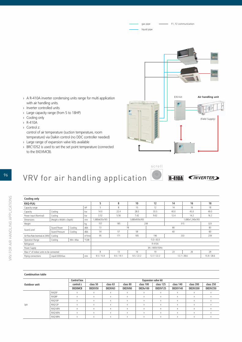
VRV
FOR
AIR
HAN
DLI
NG
APP
LICA
TIO
NS
VRV for air handling application
A R-410A inverter condensing units range for multi application ›with air handling units.Inverter controlled units ›Large capacity range (from 5 to 18HP) ›Cooling only ›R-410A ›Control z: ›control of air temperature (suction temperature, room temperature) via Daikin control (no DDC controller needed)Large range of expansion valve kits available ›BRC1D52 is used to set the set point temperature (connected ›to the EKEXMCB).
s c ro l l
gas pipe
liquid pipe
F1, F2 communication
EXV-kit Air handling unit
(Field Supply)
Combination table
Outdoor unit
Control box Expansion valve kitcontrol z class 50 class 63 class 80 class 100 class 125 class 140 class 200 class 250EKEXMCB EKEXV50 EKEXV63 EKEXV80 EKEXv100 EKEXV125 EKEXV140 EKEXV200 EKEXV250
3ph
RXQ5P x x x x x x x x x
RXQ8P x x x x x x x x x
RXQ10P x x x x x x x x x
RXQ12P x x x x x x x x x
RXQ14PA x x x x x x x x x
RXQ16PA x x x x x x x x x
RXQ18PA x x x x x x x x x
Cooling only
RXQ-P(A) 5 8 10 12 14 16 18Capacity range HP 5 8 10 12 14 16 18
Capacity Cooling kw 14.0 22.4 28.0 33.5 40.0 45.0 49.0
Power input (Nominal) Cooling kw 3.52 5.56 7.42 9.62 12.4 14.2 16.2
Dimensions (Height x Width x Depth) mm 1,680x635x765 1,680x930x765 1,680x1,240x765
Weight kg 157 185 238 315 323
Sound LevelSound Power Cooling dBA 72 78 80 83
Sound Pressure Cooling dBA 54 57 58 60 63
Air Flow Rate (nominal at 230V) Cooling m³/min 95 171 185 196 233 239
Operation Range Cooling Min~Max °CDB -5.0~43.0
Refrigerant R-410A
Power Supply 3N~/400V/50Hz
Max n° of indoor units to be connected 8 13 16 19 23 26 29
Piping connections Liquid (OD)/Gas mm 9.5 / 15.9 9.5 / 19.1 9.5 / 22.2 12.7 / 22.2 12.7 / 28.6 15.9 / 28.6
96

Cooling only 110 150 170
Capacity Cooling kW 114.00 150.00 171.00
Nominal input Cooling kW 42.10 52.40 65.20
EER 2.71 2.86 2.62
Capacity Steps % 30-100
Dimensions (Height x Width x Depth) mm 2250x2346x2238
Unit kg 1326 1440 1516
Air heat exchanger Type Cross fi n coil/Hi-X tubes and PE coated waffl e louvre fi ns
Sound Power Cooling dBA 91 96
CompressorType Semi-hermetic single screw compressor
Model Quantity 1
Refrigerant circuit
Refrigerant type R-407C
Refrigerant charge kg 5.5 7.5
No of circuits 1
Power Supply 3~/400V/50Hz
Piping connections
Suction line connection 2'' 1/8
Liquid line connection 7/8''
Relief device outlet compressor: 1''npt
STRENGTHS
DAIKIN stepless single screw compressor. ›Operation down to -15°C ambient temperature. ›Standard reverse phase protection. ›Freeze-up protection and prevention. ›PE treated condenser coil. ›Liquid stop valve. ›Discharge stop valve. ›Standard suction stop valve. ›
OPTIONS(factory mounted)
Main isolator switch. ›Condenser protection grilles. ›Low noise (down to -6dB(A)). ›Ampere & Voltmeter ›(read-out on switchbox).Hi-ESP fans. ›
ACCESSORIES (kit)
BMS gateway (MODBUS/J-BUS/ ›BACNET protocol).Remote user interface. ›
CONTROL
Return air or room ›temperature control.Weekly operating schedule. ›
AVAILABLEINPUTS / OUTPUTS
InputON / OFF. ›Dual setpoint through ›analog signal.Air fl ow switch. ›Capacity limit. ›
OutputCompressor operation. ›Summary alarm. ›
ELECTRONIC CONTROL
condensing units
s c re w
scre
w
ELECTRONIC CONTROL
97ERAP-MBYN
ERAP150MBYNN
ER
AP
-MB
YN

98
LU-V
E
CONDENSER
Single coil, both for vertical ›and horizontal installation, or double coil (V shape) ventilated condensers for air conditioning and for industrial process cooling. High effi ciency compact ›heat exchangers with inner grooved 3/8 copper tubes for a reduced refrigerant chargePatented “Safetubes ›system”Extreme low noise ›and energy saving models availableCapacities from 3 up to ›more than 2,400 kW
DRY COOLER
Single coil, both for ›vertical and horizontal installation, or double ›coil (V shape) dry coolers for air conditioning and for industrial process cooling ›High effi ciency compact ›heat exchangers with 3/8“ copper tubes ›Patented “Safetubes ›system”Low noise and energy ›saving models availableCapacities from 11 up ›to nearly 2,000 kW
MHVC / SHVCType: ductFan: centrifugalCapacity: 6 – 375 kW
SHV/EHV/SAV/EAVType: horizontal or verticalFan: axialCapacity: 3 – 1,236 kW
SDHV/SHVD/EHVDType: V-shapeFan: axialCapacity: 185 – 2,405 kW
SHV/EHV/SAV/EAVType: horizontal or verticalFan: axialCapacity: 11 – 996 kW
SDHV/SHVD/EHVDType: V-shapeFan: axialCapacity: 147 – 1,973 kW
CONDENSER DRY COOLER
cond
ense
r dry
coo
ler
KAPACITET
5 10 250 500 750 1000 1500 2000 2500
MHVC / SHVC
SHV / EHV / SAV / EAV
SDHV / SHVD / EHVD
KAPACITET
5 10 250 500 750 1000 1500 2000 2500
SHL / EHL
SDHL / SHLD / EHLD

EHMC-AV
EKBT
EHMC15AV1010
hydraulic module
mH2O
55
50
45
40
35
30
25
20
15
10
5
00 20 40 60 80 100 120 140 160 180 200 220 240 260 (l/min)
Water flow
PUMP CHARACTERISTICS
STRENGTHS
100l buffer tank. ›Freeze-up protection (heater tape). ›Single pump. ›12l expansion vessel. ›Standard dual pressure ports. ›
Type Content Description
EKBT 200l Buffer tank with casing
EKBT500N 500l Buffer tank
EKBTC10 1000l Buffer tank
EKBT500C 500l Buffer tank with casing
EKBTC10C 1000l Buffer tank with casing
LEGENDS
Pump characteristicsEHMC30AV10801. EHMC10AV1080 &2. EHMC15AV1080EHMC30AV10103. EHMC10AV1010 &4. EHMC15AV1010
Hydraulic module + filter pressures losses5. EHMC15/30AV1010 &
EHMC15/30AV10806. EHMC10AV1010 &
EHMC10AV1080
EHMC-AV10 15 30
1010 1080 1010 1080 1010 1080
Nominal fl ow l/min 62 88 187
External static pressure mH2O 17 34 15 27 10 27
Nominal input W 630 1,050 650 1,070 1,070 2,090
Dimensions (HxWxD) mm 1,284x635x688 1,284x635x688 1,284x635x688
Machine weight kg 99 101 102 104 105 111
Sound power dBA 63 63 63
Sond pressure dBA 52 52 52
Power supply V1 230V/1~/50Hz
Operation rangeWater side °CDB -10°C ~ 55°C
Air side °CDB -10°C ~ 43°C
Piping connectionsEvaporator water inlet/outlet 1” BSPF 2” BSPF 2-1/2” BSPF
Drain connection 1/2”
buffer tank
HYDRONIC KIT
hydr
onic
kit
99

Daikin ventilation products are a highly effi cient means of
turning a water chiller, heat pump or hot water boiler into
an effi cient, quiet air conditioning system. These units are
an effective solution to provide a comfortable environment
for both commercial and residential applications.
101 FWF
102 FWC
103 FWT
104 FWV
105 FWL
106 FWM
107 FWB
108 FWB-J
109 FWD
110 AIR COOLER
112 AIR HANDLING UNIT
114 ROOFTOP
TABLE OF CONTENTS
VENTILATIONV
EN
TILA
TIO
N
100
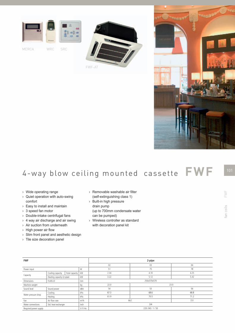
10FWF
fan
coils
4-way blow ceil ing mounted cassette
Wide operating range ›Quiet operation with auto-swing ›comfortEasy to install and maintain ›3 speed fan motor ›Double-intake centrifugal fans ›4 way air discharge and air swing ›Air suction from underneath ›High power air fl ow ›Slim front panel and aesthetic design ›Tile size decoration panel ›
FWF 2-pipe
02 03 04
Power input W 51 75 78
CapacityCooling capacity Total capacity kW 2.34 4.10 4.25
Heating capacity (2-pipe) kW 3.22 5.12 5.42
Dimensions H xW x D mm 250x570x570
Machine weight kg 22.0 23.0
Sound level Sound power dBA 54 53 56
Water pressure dropCooling kPa 67.3 68.6 68.8
Heating kPa 61.9 70.5 71.2
Fan Air fl ow rate m³/h 662 731
Water connections Std. heat exchanger inch 3/4
Required power supply V / f / Hz 220-240 / 1 / 50
Removable washable air fi lter ›(self-extinguishing class 1)Built-in high pressure ›drain pump (up to 700mm condensate water can be pumped)Wireless controller as standard ›with decoration panel kit
MERCA WRC SRC
FWF-AT
101
FWF

102 FWC
FWC08AAT
MERCA WRC SRC
fan
coils
4-way blow cei l ing mounted cassette
Wide operating range ›Quiet operation with auto-swing comfort ›Easy to install and maintain ›Flexibility (2-pipe or 4-pipe) ›3 speed fan motor ›Double-intake centrifugal fans ›4 way air discharge and air swing ›Air suction from underneath ›High power air fl ow ›Slim front panel and aesthetic design ›Removable washable air fi lter (self-extinguishing class 1) ›Built-in high pressure drain pump (up to 700mm ›condensate water can be pumped)Wireless controller as standard with decoration panel kit ›
FWC 2-pipe 4-pipe
07 08 10 11 12 02 03 04 05 06
Power input W 127 151 164 192 253 122 138 153 184 232
Capacity
Cooling capacity Total capacity kW 6.63 7.50 8.80 9.95 10.80 3.81 3.96 4.63 5.01 5.16
Heating capacity (2-pipe) kW 8.40 9.50 11.00 12.00 12.90 -
Heating capacity (4-pipe) kW - 10.55 10.99 12.51 13.48 13.77
Dimensions H xW x D mm 335x820x821
Machine weight kg 31.0 32.0 35.0 38.0 40.0 31.0 32.0 35.0 38.0 40.0
Sound level Sound power dBA 52 55 60 61 64 52 55 60 61 64
Water pressure dropCooling kPa 24.8 30.8 41.6 52.2 69.3 3.56 3.78 4.94 5.7 5.96
Heating kPa 21.4 26.8 35.3 45.2 64.1 -
Fan Air fl ow rate m³/h 1,310 1,380 1,560 1,740 1,840 1,310 1,380 1,560 1,740 1,840
Water connections Std. heat exchanger inch 3/4''
Required power supply V / f / Hz 220-240 / 1 / 50
FWC

10103103FWT
fan
coils
wall mounted unit
Wide operating range ›Quiet operation with auto-swing comfort ›Easy to install and maintain ›3 speed fan motor ›Double-intake centrifugal fans ›Excellent air fl ow and air distribution ›Flexibility via interchangeable water connection side ›High power air fl ow ›Insulated with self-extinguishing class 1 heat insulation ›Removable washable air fi lter ›(self-extinguishing class 1)Slim and compact aesthetic design ›Wireless remote control up to 9m distance, availability of a wired ›or simplifi ed controllerLED indicator gives an indication on the (normal or wrong) ›operation of the unit
FWT 2-pipe
02 03 04 05 06
Power input W 24 25 29 66 69
CapacityCooling capacity Total capacity kW 2.34 2.78 3.22 4.54 5.28
Heating capacity (2-pipe) kW 3.02 3.75 4.10 6.01 6.74
Dimensions H xW x D mm 260x799x198 260x899x198 304x1,062x222
Machine weight kg 10.0 12.0 16.0
Sound level Sound power dBA 53 55 61 64
Water pressure dropCooling kPa 48.3 64.7 69.3 50.3 69.3
Heating kPa 42 58.6 60.6 50.6 70.6
Fan Air fl ow rate m³/h 467 510 586 1,070 1,121
Water connections Std. heat exchanger inch 1/2''
Required power supply V / f / Hz 220-240 / 1 / 50
FWT05-06AT
FWT
MERCA WRC SRC

104104 FWV
fan
coils
f loor standing unit
Quick fi xing system for wall mounting ›Pre-assembled 3-way/4-port ON/OFF valves are available ›Valve packages are insulated, no extra drain pan required ›Valve packages contain balancing valves ›and sensor pocketFast-on connections for electrical options : ›no tools neededQuick removal of washable fi lter ›Electrical heater : no relay up to 2kW capacity ›Electrical heater : equipped with two overheat ›cut-out thermostats
FWV01-10C* 2-pipe (*=TN or TV) 4-pipe (*=FN or FV)
01 02 03 04 06 08 10 01 02 03 04 06 08 10
Power input W 37 53 56 98 182 244 37 53 56 98 182 244
Capacity
Cooling capacityTotal capacity kW 1.54 2.09 2.93 4.33 4.77 6.71 8.02 1.46 1.90 2.87 4.33 4.67 6.64 7.88
Sensible capacity kW 1.20 1.51 2.11 3.15 3.65 4.91 5.96 1.14 1.51 2.07 3.15 3.57 4.85 5.85
Heating capacity (2-pipe) kW 2.14 2.57 3.81 5.63 6.36 7.83 10.03 -
Heating capacity (4-pipe) kW - 1.90 2.10 3.08 5.05 5.30 7.91 9.30
Dimensions H xW x D mm 564x774x226564
x984x226564x1194x226 564x1404x251 564x774x226
564x984x226
564x1194x226 564x1404x251
Machine weight kg 19 20 25 30 31 41 20 21 26 32 33 44
Sound level Sound power dBA 45 50 47 52 56 61 66 45 50 47 52 56 61 66
Water pressure dropCooling kPa 13 11 12 14 12 19 13 11 12 14 12 19
Heating kPa 9 11 9 10 9 16 7 8 5 10 8 9
Fan Air fl ow rate m³/h 319 344 442 706 785 1011 1393 307 327 431 690 763 998 1362
Water connections Std. heat exchanger inch 1/2 3/4 1/2 3/4
Required power supply V / f / Hz 230/1/50
Water fl owCooling l/h 265 359 504 745 820 1,154 1,343 251 327 494 745 803 1,142 1,355
Heating l/h 265 359 504 745 820 1,154 1,343 196 182 286 396 465 694 816
Coil Water volume heating l - 0.5 0.7 1 1.4 2.1
Maximum absorbed current W 0.17 0.24 0.25 0.44 0.43 0.80 1.12 0.17 0.24 0.25 0.44 0.43 0.80 1.12
* : TN (2-pipe, without valves) - TV (2-pipe, with ON/OFF 3-way valves) - FN (4-pipe, without valves) - FV (4-pipe, with ON/OFF 3-way valves)
FWV02CAT
ECFWER6 RAB RDF
FWV

10105105FWL
fan
coils
f lexi type unit
Quick fi xing system for wall/ceiling mounting ›Pre-assembled 3-way/4-port ON/OFF valves are available ›Valve packages are insulated, no extra drain pan required ›Valve packages contain balancing valves and sensor pocket ›Fast-on connections for electrical options : no tools needed ›Quick removal of washable fi lter ›Electrical heater : no relay up to 2kW capacity ›Electrical heater : equipped with two overheat cut-out thermostats ›
FWL01-10C* 2-pipe (*=TN or TV) 4-pipe (*=FN or FV)
01 02 03 04 06 08 10 01 02 03 04 06 08 10
Power input W 37 53 56 98 182 244 37 53 56 98 182 244
Capacity
Cooling capacityTotal capacity kW 1.54 2.09 2.93 4.33 4.77 6.71 8.02 1.46 1.90 2.87 4.33 4.67 6.64 7.88
Sensible capacity kW 1.20 1.51 2.11 3.15 3.65 4.91 5.96 1.14 1.51 2.07 3.15 3.57 4.85 5.85
Heating capacity (2-pipe) kW 2.14 2.57 3.81 5.63 6.36 7.83 10.03 -
Heating capacity (4-pipe) kW - 1.90 2.10 3.08 5.05 5.30 7.91 9.30
Dimensions H xW x D mm 564x774x226564x984
x226564x1194x226 564x1404x251 564x774x226
564x984x226
564x1194x226 564x1404x251
Machine weight kg 20 21 27 32 33 44 21 22 28 34 35 46
Sound level Sound power dBA 45 50 47 52 56 61 66 45 50 47 52 56 61 66
Water pressure dropCooling kPa 13 11 12 14 12 19 13 11 12 14 12 19
Heating kPa 9 11 9 10 9 16 7 8 5 10 8 9
Fan Air fl ow rate m³/h 319 344 442 706 785 1011 1393 307 327 431 690 763 998 1362
Water connections Std. heat exchanger inch 1/2 3/4 1/2 3/4
Required power supply V / f / Hz 230/1/50
Water fl owCooling l/h 265 359 504 745 820 1,154 1,343 251 327 494 745 803 1,142 1,355
Heating l/h 265 359 504 745 820 1,154 1,343 196 182 286 396 465 694 816
Coil Water volume heating l - 0.5 0.7 1 1.4 2.1
Maximum absorbed current W 0.17 0.24 0.25 0.44 0.43 0.80 1.12 0.17 0.24 0.25 0.44 0.43 0.80 1.12
* : TN (2-pipe, without valves) - TV (2-pipe, with ON/OFF 3-way valves) - FN (4-pipe, without valves) - FV (4-pipe, with ON/OFF 3-way valves)
FWL03C
FWL03C
FWL
ECFWER6 RAB RDF
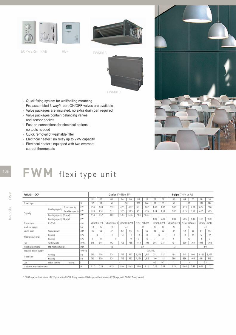
106 FWM
FWM01C
FWM01C
ECFWER6 RAB RDF
fan
coils
f lexi type unit
Quick fi xing system for wall/ceiling mounting ›Pre-assembled 3-way/4-port ON/OFF valves are available ›Valve packages are insulated, no extra drain pan required ›Valve packages contain balancing valves ›and sensor pocketFast-on connections for electrical options : ›no tools neededQuick removal of washable fi lter ›Electrical heater : no relay up to 2kW capacity ›Electrical heater : equipped with two overheat ›cut-out thermostats
FWM01-10C* 2-pipe (*=TN or TV) 4-pipe (*=FN or FV)
01 02 03 04 06 08 10 01 02 03 04 06 08 10
Power input W 37 53 56 98 182 244 37 53 56 98 182 244
Capacity
Cooling capacityTotal capacity kW 1.54 2.09 2.93 4.33 4.77 6.71 8.02 1.46 1.90 2.87 4.33 4.67 6.64 7.88
Sensible capacity kW 1.20 1.51 2.11 3.15 3.65 4.91 5.96 1.14 1.51 2.07 3.15 3.57 4.85 5.85
Heating capacity (2-pipe) kW 2.14 2.57 3.81 5.63 6.36 7.83 10.03 -
Heating capacity (4-pipe) kW - 1.90 2.10 3.08 5.05 5.30 7.91 9.30
Dimensions H xW x D mm 535x584x224 535x794x224 535x1004x224 535x1214x249 535x584x224 535x794x224 535x1004x224 535x1214x249
Machine weight kg 14 15 19 23 32 15 16 20 25 34
Sound level Sound power dBA 45 50 47 52 56 61 66 45 50 47 52 56 61 66
Water pressure dropCooling kPa 13 11 12 14 12 19 13 11 12 14 12 19
Heating kPa 9 11 9 10 9 16 7 8 5 10 8 9
Fan Air fl ow rate m³/h 319 344 442 706 785 1011 1393 307 327 431 690 763 998 1362
Water connections Std. heat exchanger inch 1/2 3/4 1/2 3/4
Required power supply V / f / Hz 230/1/50
Water fl owCooling l/h 265 359 504 745 820 1,154 1,343 251 327 494 745 803 1,142 1,355
Heating l/h 265 359 504 745 820 1,154 1,343 196 182 286 396 465 694 816
Coil Water volume heating l - 0.5 0.7 1 1.4 2.1
Maximum absorbed current W 0.17 0.24 0.25 0.44 0.43 0.80 1.12 0.17 0.24 0.25 0.44 0.43 0.80 1.12
* : TN (2-pipe, without valves) - TV (2-pipe, with ON/OFF 3-way valves) - FN (4-pipe, without valves) - FV (4-pipe, with ON/OFF 3-way valves)
FWM

10107107FWB
FWB04AAT
ECFWER6 RAB RDF
fan
coils
concealed cei l ing unit
Height of the units only 240mm for all the sizes ›3, 4 or 6 stage row cooling coil ›Drain pan to collect the condensate from: heat ›exchanger and regulating valves7-speed electrical motors (with thermal ›protection on windings)All 7 speeds pre-wired in the factory in the ›terminal block of the switch boxStandard air fi lter : removable from the bottom ›
FWB02-10AT 2-pipe
02 03 04 05 06 07 08 09 10
Power input W 106 192 294
Capacity
Cooling capacityTotal capacity kW 2.61 3.14 3.49 5.08 5.45 6.47 7.57 8.67 10.34
Sensible capacity kW 1.88 2.16 2.34 3.60 3.87 4.40 5.23 5.96 6.90
Heating capacity (2-pipe) kW 5.47 6.01 6.47 10.31 11.39 12.28 15.05 16.85 18.78
Heating capacity (4-pipe)* kW 3.14 5.99 12.80
Dimensions H xW x D mm 239x1039x609 239x1389x609 239x1739x609
Machine weight kg 23 24 26 31 33 35 43 45 48
Sound level Sound power dBA 58 60 69
Water pressure dropCooling kPa 8 14 11 15 8 14 21 26
Heating kPa 7 10 8 12 7 10 16 15 18
FanAir fl ow rate m³/h 400 800 1200
Available pressure Pa 71 65 59
Water connections Std. heat exchanger inch 3/4
Required power supply V / f / Hz 230/1/50
Water fl owCooling l/h 448 539 598 873 936 1,111 1,299 1,488 1,774
Heating l/h 275 526 1,123
Maximum absorbed current W 0.51 0.94 1.28
* : 4-pipe = 2-pipe + option Additional heat exchanger
FWB

108 FWB-J
FWB02JT
ECFWER6 RAB RDF
fan
coils
concealed cei l ing unit
Wide operating range ›Quiet operation via enlarged fan wheels ›Easy maintenance: fi lter can be removed from both sides ›and beneath (maximum fi lter size is 400mm)Flexibility (2-pipe or 4-pipe) ›4 speed fan motor (3 selectable) ›Direct driven centrifugal fans ›Flexibility via interchangeable water connection side ›High power air fl ow ›Slim and compact aesthetic design ›Available static pressure of 30 Pa ›Extended drain pan as standard ›Filter as standard ›Plenum as standard ›Insulated with self-extinguishing class 1 heat insulation ›Electronic room thermostat ›
FWB-J 2-pipe 4-pipe
02 03 04 05 06 07 08 09 10 11 02 03 04 06 07 08 10
Power input W 34 53 57 54 86 121 117 134 164 166 34 51 54 84 117 137 163
Capacity
Cooling capacity Total capacity kW 1.64 2.67 2.99 3.34 4.81 5.31 6.16 7.26 8.49 8.99 1.67 2.67 3.03 4.88 5.33 6.53 8.21
Heating capacity (2-pipe) kW 2.16 3.62 3.97 4.11 6.30 7.47 8.09 9.64 11.57 11.71 2.12 3.69 3.87 6.40 7.52 9.01 11.09
Heating capacity (4-pipe) kW - 2.49 3.92 4.43 6.70 8.16 9.56 11.68
Dimensions H xW x D mm251x814x590
251x984x590
251x1,114x590
251x1,314x590
251x1,564x590
251x1,664x590
251x1,924x590
251x814x590
251x984x590
251x1,114x590
251x1,314x590
251x1,564x590
251x1,664x590
251x1,924x590
Machine weight kg 20.0 23.0 28.0 31.0 33.0 44.0 48.0 52.0 50.0 56.0 22.0 27.0 31.0 36.0 48.0 52.0 56.0
Sound level Sound power dBA 47.5 52 49 50 52 55 55.5 56 47 52 50 52 55 56
Water pressure dropCooling kPa 10.91 8.34 15.64 11.22 31.31 12.56 7.62 9.83 21.71 16.81 10.95 8.24 15.67 29.95 9.24 12.49 19.38
Heating kPa 8.86 6.76 12.84 9.21 25.87 11.13 6.57 8.60 18.56 14.46 8.94 6.64 12.84 24.16 7.89 9.67 16.50
FanAir fl ow rate m³/h 262 428 431 428 757 945 950 1,066 1,463 1,341 220 424 437 747 898 1,112 1,385
Available pressure Pa 30
Water connections Std. heat exchanger inch 3/4
Required power supply V / f / Hz 220-240 / 1 / 50
FWB
-J

109109FWD
FWD04A
FWD04A
ECFWER6 RAB RDF
fan
coils
f lexi type unit
Quick fi xing system for wall/ceiling mounting ›Straight duct connector is mounted ›to discharge sideStandard air fi lter : removable from the bottom ›
FWD04-18A* 2-pipe (*=T) 4-pipe (*F)
04 06 08 10 012 016 018 04 06 08 10 012 016 018
Power input W 234 349 443 714 1197 234 349 443 714 1197
Capacity
Cooling capacityTotal capacity kW 3.90 6.20 7.80 8.82 11.90 16.40 18.30 3.90 6.20 7.80 8.82 11.90 16.40 18.30
Sensible capacity kW 3.08 4.65 6.52 7.16 9.36 12.80 14.10 3.08 4.65 6.52 7.16 9.36 12.80 14.10
Heating capacity (2-pipe) kW 4.49 6.62 9.21 15.86 21.15 -
Heating capacity (4-pipe) kW - 4.05 7.71 9.43 10.79 14.45 19.81 21.92
Dimensions H xW x D280x754x559
280x964x559
280x1174x559
280x1174x559
352x1384x718
280x754x559
280x964x559
280x1174x559
352x1174x718
352x1384x718
mm
Machine weight kg 35 43 50 52 71 83 86 33 41 47 49 65 77 80
Sound level Sound power dBA 66 69 72 74 78 66 69 72 74 78
Water pressure dropCooling kPa 17 24 16 26 34 45 17 24 16 26 34 45
Heating kPa 9 15 13 12 16 14 20 13 21 28 37
FanAir fl ow rate m³/h 800 1250 1600 2200 3000 800 1250 1600 2200 3000
Available pressure Pa 63 53 63 59 92 138 128 66 58 68 64 97 145 134
Water connections Std. heat exchanger inch 3/4 1 3/4 1
Required power supply V / f / Hz 230/1/50
Water fl owCooling l/h 674 1,064 1,339 1,514 2,056 2,833 3,14 674 1,064 1,339 1,514 2,056 2,833 3,140
Heating l/h 674 1,064 1,339 1,514 2,056 2,833 3,140 349 581 808 1,392 1,856
* : T(2-pipe) - F(4-pipe)
FWD

S2HCW S3HCW
SHDNW / SHDSW SHAW
110
LU-V
E
Air coolers for big storage,freezing and working cold
rooms with positive and negative temperature for
the industry. The heat exchanger of the air cooler is
made of high effi ciency copper tubes with internal
special helical profi le for the water/glycol solution.
Several models available with different fi n spacings
and for capacities from 1 up to more than 160 kW.
air
cool
er
Air cooler

LU-VENHIW / HILW HDIW
CHSW LHSW
111
air
cool
erLU
-VE

112
air
hand
ling
unit
Air handling units for fi ltering, heating, cooling, ›humidifying, and air drying Air handling units with heat recovery ›Air handling units for outdoor or roof top ›installationAir handling units for process industry ›Air handling units in hygienic execution for ›hospital and clean roomAir handling units with indirect gas fi red heating ›Air handling units for swimming pool applications ›
HEAT RECOVERY SYSTEMS
There are different types of heat recovery systems available:
Coil loop system › Plate heat exchanger ›Heat wheel ›Accublock ›Heat pipe › … ›
Air handling unit 1.000 m 3/h-124.000 m 3/h
WEG
ER

11113113
air
hand
ling
unit
Range selection diagramm for DW 64-3125
Air volume in m3/h
WEG
ER

114
UATP-A
‘Plug and Play’ installation: the single unit configuration ›requires no additional piping work as both the indoor and outdoor sides are pre-connected. Refrigerant is factory pre-charged to ensure clean and ›efficient operation. The air volume and static pressure required can be ›adjusted according to the requirement because of the use of a belt driven fan. The flat top design of the unit allows for maximum ›utilization of warehouse and container space. High efficiency and reliable scroll compressor. ›Convertible: fan can be mounted in two directions ›(Class 240-280-320-450-560).Coil with anti-corrosion treatment. ›
rooftop
Cooling only NON-INVERTER
Outdoor Units UATP180AMY1 UATP240AMY1 UATP280AMY1 UATP320AMY1 UATP450AMY1 UATP560AMY1 UATP700AMY1 UATP850AMY1 UATPC10AMY1 UATPC12AMY1
Capacity CoolingMinimum kW 17.291 21.101 27.842 32.238 41.030 55.684 67.406 82.939 97.007 121.624
Nominal kW 5.89 8.70 11.60 12.18 17.20 25.10 28.70 40.16 41.87 48.80
EER Cooling 2.94 2.43 2.40 2.65 2.39 2.22 2.35 2.07 2.32 2.49
Air Flow Rate evaporator Cooling m³/min 51 80 100 102 160 190 227 263 312 354
External Static Pressure Pa 98 196 294
Condensation Drain Size Diameter mm 25.4
CasingColour Light Grey
Material Electro galvanised mild steel
Dimensions HxWxD mm 1000x1100x1530
1000x1300x1530 1200x1990x1670 1735x2250x2800 1974x2252x3180
Weight Unit kg 295 370 400 425 665 765 1200 1350 1510 1600
Air Flow Rate condensor Cooling m³/min 127 160 227 320 566
Operation Range Cooling Min-Max °CDB 20°C - 46°C
Sound Level Sound Power dBA 63 65 66 68 70 70 74 74 80 80
Refrigerant Type R-407C
Power Supply 3~/50Hz/380-415V
roof
tops
UAT
P-A
UATP-A

115115
UATYP-A
rooftop
‘Plug and Play’ installation: the single unit configuration ›requires no additional piping work as both the indoor and outdoor sides are pre-connected. Refrigerant is factory pre-charged to ensure clean and ›efficient operation. The air volume and static pressure required can be ›adjusted according to the requirement because of the use of a belt driven fan. The flat top design of the unit allows for maximum ›utilization of warehouse and container space. High efficiency and reliable scroll compressor. ›Convertible: fan can be mounted in two directions ›(Class 240-280-320-450-560).Coil with anti-corrosion treatment. ›
Heat pump NON-INVERTER
Outdoor Units UATYP180AMY1 UATYP240AMY1 UATYP280AMY1 UATYP320AMY1 UATYP450AMY1 UATYP560AMY1 UATYP700AMY1 UATYP850AMY1 UATYPC10AMY1 UATYPC12AMY1
CapacityCooling Minimum kW 16.705 21.101 25.790 29.307 43.668 55.684 67.406 82.939 101.110 109.609
Heating Nominal kW 20.222 22.566 29.89 35.755 46.891 67.406 74.733 92.317 102.290 126.314
EER Cooling 2.44 2.51 2.38 2.28 2.64 2.63 2.31 2.17 2.34 2.27
COP Heating 3.06 2.99 3.05 3.11 2.98 3.32 2.85 2.65 2.45 2.70
Air Flow Rate evaporator Cooling m³/min 51 80 100 102 160 190 226 263 312 354
External Static Pressure Pa 98 196 294
Condensation Drain Size Diameter (OD) mm 25.4
CasingColour Light Grey
Material Electro galvanised mild steel
Dimensions Unit HxWxD mm 1000x1100x1530 1200x1990x1800 1735x2250x2800 1974x2252x3180
Weight Unit kg 320 385 415 440 700 800 12000 1350 1510 1600
Air Flow Rate condensor Cooling m³/min 127 160 283 320 566
Operation RangeCooling Min-Max °CDB 20°C – 46°C
Heating Min-Max °CWD -15°C – 20°C
Sound Level Sound Power dBA 63 65 66 68 70 70 74 74 80 80
Refrigerant Type R-407C
Power Supply 3~/50Hz/380-415V
roof
tops
UATYP-A
UAT
YP-A
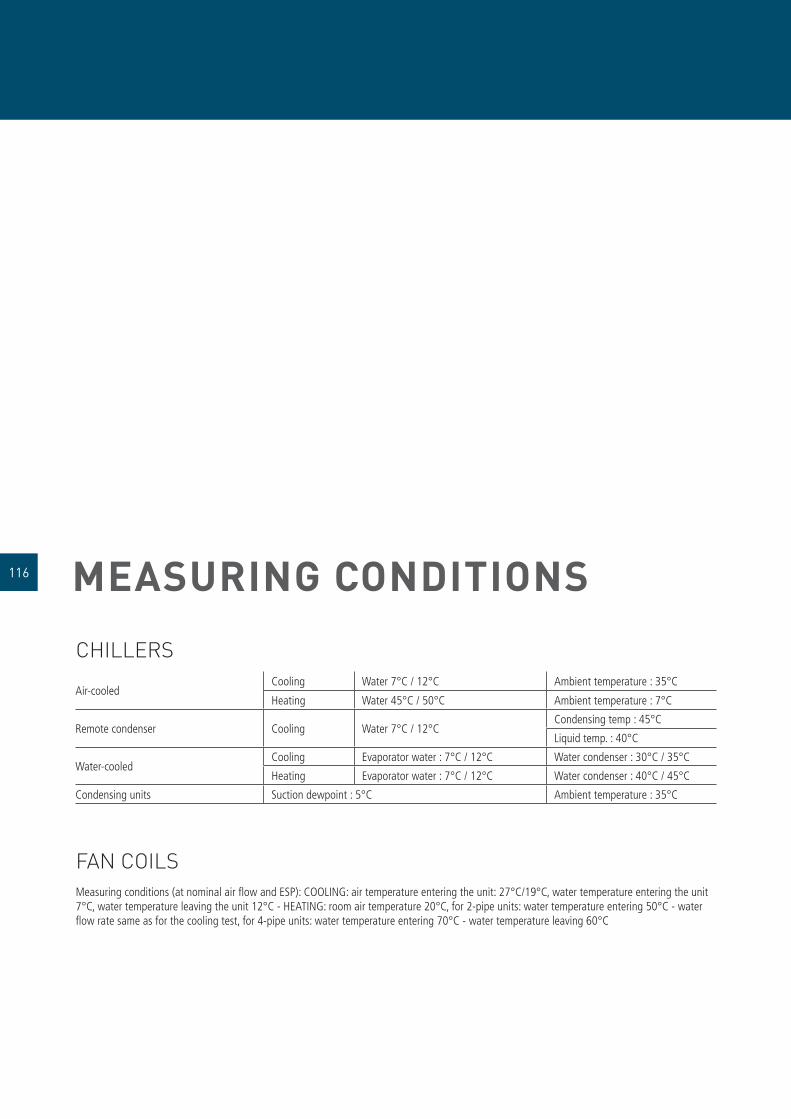
MEASURING CONDITIONS
CHILLERS
Air-cooledCooling Water 7°C / 12°C Ambient temperature : 35°C
Heating Water 45°C / 50°C Ambient temperature : 7°C
Remote condenser Cooling Water 7°C / 12°C Condensing temp : 45°C
Liquid temp. : 40°C
Water-cooledCooling Evaporator water : 7°C / 12°C Water condenser : 30°C / 35°C
Heating Evaporator water : 7°C / 12°C Water condenser : 40°C / 45°C
Condensing units Suction dewpoint : 5°C Ambient temperature : 35°C
FAN COILSMeasuring conditions (at nominal air fl ow and ESP): COOLING: air temperature entering the unit: 27°C/19°C, water temperature entering the unit 7°C, water temperature leaving the unit 12°C - HEATING: room air temperature 20°C, for 2-pipe units: water temperature entering 50°C - water fl ow rate same as for the cooling test, for 4-pipe units: water temperature entering 70°C - water temperature leaving 60°C
116

117

NOTES
118

119

Daikin products are available at:
Cop
yrig
ht ©
DAI
KIN
· Th
e sp
ecifi
catio
ns, d
esig
ns a
nd in
form
atio
n in
this
bro
chur
e ar
e su
bjec
t to
chan
ge w
ithou
t not
ice.
Your Daikin technical adviser will advise you professionally and
comprehensively and an on site, non binding consultation will enable
a tailor-made solution to be developed for you.
Daikin’s unique position as a manufacturer of air conditioning equipment, compressors and refrigerants has led to its close involvement in environmental issues. For several years Daikin has had the intention to become a leader in the provision of environmental friendly products. This challenge demands the eco design and development of a wide range of products and an energy management system; which involves energy conservation and reduction of waste.
All Daikin units comply with the European Union regulations concerning the safety of appliances.
Daikin Europe N.V. participates in the Eurovent Certifi cation Programme. The products comply with those listed in the Eurovent directory.
The ISO 14001 standard guarantees an effective environmental management system and contributes to the protection of human health and the environment against any possible repercussions of Daikin activities, products and services as well as the retention and enhancement of environmental quality.
The quality management system of Daikin Europe N.V. is recognised by the LRQA in conformity with the ISO 9001 standard. ISO 9001 relates to quality assurance pertaining to the planning, development and construction of products as well as the services offered in connection with these products.


