Embed Size (px)
Citation preview

Металлопрокат и трубы постандартам
DIN, EN, ANSI, ASME, ASTM, ISO
ОМ ГРУПП Поставляет в Россию металлопрокат по стандарту
ASME B18.31.2
Данная брошюра предоставлена для ознакомления!
www.fedclicom.ru [email protected]+7(495)139-61-88
A N A M E R I C A N N A T I O N A L S T A N D A R D
ASME B18.31.2-2014(Revision of ASME B18.31.2-2008)
Continuous Thread Stud, Double-End Stud, and Flange Bolting Stud (Stud Bolt) (Inch Series)
Copyright ASME International Provided by IHS under license with ASME Licensee=University of Alberta/5966844001, User=rezaei, reza
Not for Resale, 05/02/2015 10:51:20 MDTNo reproduction or networking permitted without license from IHS
--```,`,`,`,,,,,,`,,`,`,,`,,```,-`-`,,`,,`,`,,`---

Copyright ASME International Provided by IHS under license with ASME Licensee=University of Alberta/5966844001, User=rezaei, reza
Not for Resale, 05/02/2015 10:51:20 MDTNo reproduction or networking permitted without license from IHS
--```,`,`,`,,,,,,`,,`,`,,`,,```,-`-`,,`,,`,`,,`---

ASME B18.31.2-2014(Revision of ASME B18.31.2-2008)
Continuous ThreadStud, Double-EndStud, and FlangeBolting Stud (StudBolt) (Inch Series)
A N A M E R I C A N N A T I O N A L S T A N D A R D
Two Park Avenue • New York, NY • 10016 USA
Copyright ASME International Provided by IHS under license with ASME Licensee=University of Alberta/5966844001, User=rezaei, reza
Not for Resale, 05/02/2015 10:51:20 MDTNo reproduction or networking permitted without license from IHS
--```,`,`,`,,,,,,`,,`,`,,`,,```,-`-`,,`,,`,`,,`---

Date of Issuance: October 29, 2014
This Standard will be revised when the Society approves the issuance of a new edition.
ASME issues written replies to inquiries concerning interpretations of technical aspects of thisStandard. Interpretations are published on the Committee Web page and under go.asme.org/InterpsDatabase. Periodically certain actions of the ASME B18 Committee may be published asCases. Cases are published on the ASME Web site under the B18 Committee Page at go.asme.org/B18committee as they are issued.
Errata to codes and standards may be posted on the ASME Web site under the Committee Pages toprovide corrections to incorrectly published items, or to correct typographical or grammatical errorsin codes and standards. Such errata shall be used on the date posted.
The B18 Committee Page can be found at go.asme.org/B18committee. There is an option availableto automatically receive an e-mail notification when errata are posted to a particular code or standard.This option can be found on the appropriate Committee Page after selecting “Errata” in the “PublicationInformation” section.
ASME is the registered trademark of The American Society of Mechanical Engineers.
This code or standard was developed under procedures accredited as meeting the criteria for American NationalStandards. The Standards Committee that approved the code or standard was balanced to assure that individuals fromcompetent and concerned interests have had an opportunity to participate. The proposed code or standard was madeavailable for public review and comment that provides an opportunity for additional public input from industry, academia,regulatory agencies, and the public-at-large.
ASME does not “approve,” “rate,” or “endorse” any item, construction, proprietary device, or activity.ASME does not take any position with respect to the validity of any patent rights asserted in connection with any
items mentioned in this document, and does not undertake to insure anyone utilizing a standard against liability forinfringement of any applicable letters patent, nor assume any such liability. Users of a code or standard are expresslyadvised that determination of the validity of any such patent rights, and the risk of infringement of such rights, isentirely their own responsibility.
Participation by federal agency representative(s) or person(s) affiliated with industry is not to be interpreted asgovernment or industry endorsement of this code or standard.
ASME accepts responsibility for only those interpretations of this document issued in accordance with the establishedASME procedures and policies, which precludes the issuance of interpretations by individuals.
No part of this document may be reproduced in any form,in an electronic retrieval system or otherwise,
without the prior written permission of the publisher.
The American Society of Mechanical EngineersTwo Park Avenue, New York, NY 10016-5990
Copyright © 2014 byTHE AMERICAN SOCIETY OF MECHANICAL ENGINEERS
All rights reservedPrinted in U.S.A.
Copyright ASME International Provided by IHS under license with ASME Licensee=University of Alberta/5966844001, User=rezaei, reza
Not for Resale, 05/02/2015 10:51:20 MDTNo reproduction or networking permitted without license from IHS
--```,`,`,`,,,,,,`,,`,`,,`,,```,-`-`,,`,,`,`,,`---

CONTENTS
Foreword . . . . . . . . . . . . . . . . . . . . . . . . . . . . . . . . . . . . . . . . . . . . . . . . . . . . . . . . . . . . . . . . . . . . . . . . . . . . . . ivCommittee Roster . . . . . . . . . . . . . . . . . . . . . . . . . . . . . . . . . . . . . . . . . . . . . . . . . . . . . . . . . . . . . . . . . . . . . viCorrespondence With the B18 Committee . . . . . . . . . . . . . . . . . . . . . . . . . . . . . . . . . . . . . . . . . . . . . . vii
1 Introduction . . . . . . . . . . . . . . . . . . . . . . . . . . . . . . . . . . . . . . . . . . . . . . . . . . . . . . . . . . . . . . . . . . . . . . . . 1
2 Comparison With ISO Documents . . . . . . . . . . . . . . . . . . . . . . . . . . . . . . . . . . . . . . . . . . . . . . . . . . . . 1
3 Referenced Standards . . . . . . . . . . . . . . . . . . . . . . . . . . . . . . . . . . . . . . . . . . . . . . . . . . . . . . . . . . . . . . . 1
4 Terminology . . . . . . . . . . . . . . . . . . . . . . . . . . . . . . . . . . . . . . . . . . . . . . . . . . . . . . . . . . . . . . . . . . . . . . . . 2
5 Dimensions . . . . . . . . . . . . . . . . . . . . . . . . . . . . . . . . . . . . . . . . . . . . . . . . . . . . . . . . . . . . . . . . . . . . . . . . . 2
6 Body Diameter . . . . . . . . . . . . . . . . . . . . . . . . . . . . . . . . . . . . . . . . . . . . . . . . . . . . . . . . . . . . . . . . . . . . . . 2
7 Stud Length . . . . . . . . . . . . . . . . . . . . . . . . . . . . . . . . . . . . . . . . . . . . . . . . . . . . . . . . . . . . . . . . . . . . . . . . 2
8 Stud Ends . . . . . . . . . . . . . . . . . . . . . . . . . . . . . . . . . . . . . . . . . . . . . . . . . . . . . . . . . . . . . . . . . . . . . . . . . . 7
9 Thread Length . . . . . . . . . . . . . . . . . . . . . . . . . . . . . . . . . . . . . . . . . . . . . . . . . . . . . . . . . . . . . . . . . . . . . . 7
10 Screw Threads . . . . . . . . . . . . . . . . . . . . . . . . . . . . . . . . . . . . . . . . . . . . . . . . . . . . . . . . . . . . . . . . . . . . . . 7
11 Materials and Mechanical Properties . . . . . . . . . . . . . . . . . . . . . . . . . . . . . . . . . . . . . . . . . . . . . . . . . 7
12 Identification Symbols. . . . . . . . . . . . . . . . . . . . . . . . . . . . . . . . . . . . . . . . . . . . . . . . . . . . . . . . . . . . . . . 8
13 Finish . . . . . . . . . . . . . . . . . . . . . . . . . . . . . . . . . . . . . . . . . . . . . . . . . . . . . . . . . . . . . . . . . . . . . . . . . . . . . . 8
14 Workmanship . . . . . . . . . . . . . . . . . . . . . . . . . . . . . . . . . . . . . . . . . . . . . . . . . . . . . . . . . . . . . . . . . . . . . . . 8
15 Straightness . . . . . . . . . . . . . . . . . . . . . . . . . . . . . . . . . . . . . . . . . . . . . . . . . . . . . . . . . . . . . . . . . . . . . . . . 8
16 Inspection and Quality Assurance . . . . . . . . . . . . . . . . . . . . . . . . . . . . . . . . . . . . . . . . . . . . . . . . . . . . 8
17 Clearance Holes . . . . . . . . . . . . . . . . . . . . . . . . . . . . . . . . . . . . . . . . . . . . . . . . . . . . . . . . . . . . . . . . . . . . . 8
18 Stud Designation. . . . . . . . . . . . . . . . . . . . . . . . . . . . . . . . . . . . . . . . . . . . . . . . . . . . . . . . . . . . . . . . . . . . 8
Figure1 Relationship of Dimensions, L and U, on Flange Bolting Studs (Stud Bolts) . . . . . . . . . . 2
Tables1 Dimensions for Continuous Thread Studs . . . . . . . . . . . . . . . . . . . . . . . . . . . . . . . . . . . . . . . . . . 32 Dimensions for Clamping Type Studs . . . . . . . . . . . . . . . . . . . . . . . . . . . . . . . . . . . . . . . . . . . . . . 43 Dimensions for Tap-End Studs (1.5D Engagement) . . . . . . . . . . . . . . . . . . . . . . . . . . . . . . . . . . 54 Body Diameters for Double-End Studs . . . . . . . . . . . . . . . . . . . . . . . . . . . . . . . . . . . . . . . . . . . . . 65 Continuous Thread and Double-End Stud Length Tolerances . . . . . . . . . . . . . . . . . . . . . . . . 76 Flange Bolting Stud (Stud Bolt) Length Tolerances . . . . . . . . . . . . . . . . . . . . . . . . . . . . . . . . . . 7
iii
Copyright ASME International Provided by IHS under license with ASME Licensee=University of Alberta/5966844001, User=rezaei, reza
Not for Resale, 05/02/2015 10:51:20 MDTNo reproduction or networking permitted without license from IHS
--```,`,`,`,,,,,,`,,`,`,,`,,```,-`-`,,`,,`,`,,`---

FOREWORD
ASME Standards Committee B18 for the Standardization of Bolts, Nuts, Rivets, Screws, Washers,and Similar Fasteners (formerly American National Standards Committee B18) was organizedin March 1922 as Sectional Committee B18 under the aegis of the American Engineering StandardsCommittee (later the American Standards Association, then the United States of AmericaStandards Institute, and, as of October 6, 1969, the American National Standards Institute, Inc.[ANSI]) with the Society of Automotive Engineers (SAE) and the American Society of MechanicalEngineers (ASME) as joint sponsors.
In 1995, the SAE Ship Systems and Equipment Committee that was preparing fastener partstandards for the shipbuilding industry asked ASME Committee B18 if there was an interest indeveloping dimensional standards for studs. At the December 1995 meeting of B18 in Atlanta,it was reported that a survey by ASME showed considerable interest in establishing a subcommit-tee to develop stud standards, and 11 representatives indicated their willingness to serve on asubcommittee. Subcommittee 31 was established, and draft SAE inch and metric stud standardswere distributed for review.
The first meeting of Subcommittee 31 on studs was held in April 1996, in conjunction withthe ASME B18 meetings in Chicago. Existing stud standards (IFI 136, Studs and Bolts, and IFI 528,Metric Studs and Bolts) were compared with the draft SAE standards (J2271, Part Standard forStuds — Continuous and Double End [Inch Series], and J2271M, Part Standard for Studs —Continuous and Double End [Metric]). The Subcommittee then identified the configurations tobe developed along with thread sizes and diameters to be covered. It was determined to developboth inch and metric standards covering both continuously threaded and double-ended studs.A decision to develop the metric standard first was unanimously passed.
As the metric standard B18.31.1M was developed, little effort was devoted to the inch standarduntil 2005. In April 2005, the Subcommittee developed basic requirements for the inch studs thatwere similar to the metric studs, with the addition of interference-fit studs using ASME B1.12threads. A draft was reviewed at the November 2006 meeting with a number of format changessuggested. How to define the nominal length for tap-end studs was discussed, and a motionwas approved to identify the nominal length as the overall length rather than the protrusionlength when installed as used in ASME B18.31.1M per ISO 225 requirements.
In November 2006, the Subcommittee decided that diameters from 1⁄4 in. to 4 in. would becovered although at the previous meeting it had been agreed to cover diameters down to Size No. 0.The nominal length for tap-end studs was again revisited without a consensus being reached.At the April 2007 meeting, examples of both methods of identifying the nominal length of tapstuds were reviewed, and it was determined to use the overall length as the nominal length asthis had been the past convention for inch studs in the United States.
A draft was balloted prior to the November 2007 meeting and several disapprovals wereresolved at the meeting. It was agreed that the maximum nut-end thread length would be deletedin favor of a total thread length to the last scratch, which would be the minimum thread lengthplus five thread pitches. As a result, thread gaging is simplified without affecting the overallsuitability of the studs.
A reconsideration draft was balloted prior to the April 2008 meeting. The only disapprovalwas withdrawn prior to the meeting, and the Subcommittee approved several minor editorialcorrections at the meeting.
ASME B18.31.2-2008 was approved by the American National Standards Institute onAugust 4, 2008.
In the fall of 2013, the B18.31 Subcommittee decided it was time to make some minor revisionsto B18.31.2 to update its format and content to be consistent with recent revisions of other B18standards. The technical revisions are to change the pointed ends from optional to mandatory,
iv
Copyright ASME International Provided by IHS under license with ASME Licensee=University of Alberta/5966844001, User=rezaei, reza
Not for Resale, 05/02/2015 10:51:20 MDTNo reproduction or networking permitted without license from IHS
--```,`,`,`,,,,,,`,,`,`,,`,,```,-`-`,,`,,`,`,,`---

and to add a stud type referred to as “flange bolting stud (stud bolt).” This is a stud design thatoriginated in the 1960s by the publication of the ASME B16.5 flange standard wherein it describedthe continuous-thread stud having a length designation from the first full thread on one end tothe first full thread on the other end rather than the length being designated as being from endto end. This description was used for many years in general terms in ASTM A193 and A962, butnever thoroughly covered by the ASME B18 standards.
This revision was approved by ANSI on August 1, 2014.
v
Copyright ASME International Provided by IHS under license with ASME Licensee=University of Alberta/5966844001, User=rezaei, reza
Not for Resale, 05/02/2015 10:51:20 MDTNo reproduction or networking permitted without license from IHS
--```,`,`,`,,,,,,`,,`,`,,`,,```,-`-`,,`,,`,`,,`---

ASME B18 COMMITTEEStandardization of Bolts, Nuts, Rivets, Screws, Washers, and
Similar Fasteners(The following is the roster of the Committee at the time of approval of this Standard.)
STANDARDS COMMITTEE OFFICERS
J. Greenslade, ChairD. S. George, Vice Chair
W. H. King, Vice ChairC. J. Gomez, Secretary
STANDARDS COMMITTEE PERSONNEL
V. Cartina, Nylok, LLCD. A. Clever, Contributing Member, ConsultantA. P. Cockman, Ford Motor Co.C. D. de la Garza, TSP, Inc.D. S. George, Ramco SpecialtiesC. J. Gomez, The American Society of Mechanical EngineersJ. Greenslade, Industrial Fasteners InstituteJ. J. Grey, Contributing Member, Fastener Consulting Services, Inc.A. Herskovitz, Contributing Member, ConsultantJ. Hubbard, Leland-Powell Fasteners, Inc.J. C. Jennings, Contributing Member, Naval Surface Warfare CenterW. H. King, Fastenal Co.D. Korneffel, Contributing Member, Cadenas PARTsolutions
SUBCOMMITTEE 31 — STUDS, LIFTING EYES, AND BENT BOLTS
C. D. de la Garza, Chair, TSP, Inc.T. Anderson, Vice Chair, Bay BoltJ. F. Braden, Fasteners UnlimitedD. A. Clever, Contributing Member, ConsultantJ. Finnegan, Safety Socket, LLCD. S. George, Ramco SpecialtiesJ. Greenslade, Industrial Fasteners InstituteA. Herskovitz, ConsultantJ. Hubbard, Leland-Powell Fasteners, Inc.J. C. Jennings, Naval Surface Warfare CenterJ. W. Lewis, Newport News Shipbuilding
vi
M. D. Prasad, Contributing Member, Global M & F Solutions, Inc.J. F. McCarrick, Defense Supply Center PhiladelphiaJ. P. Nash, Caterpillar, Inc.S. Savoji, Contributing Member, ITW MedalistQ. M. Smith III, Oregon Department of TransportationD. J. Soscia, General Dynamics Electric Boat Corp.W. R. Stevens, RamcoR. D. Strong, Doerken Corp.W. K. Wilcox, ConsultantC. B. Williamson, Fastenal Co.C. J. Wilson, ConsultantJ. G. Zeratsky, Contributing Member, National Rivet and
Manufacturing Co.
J. F. McCarrick, Defense Supply Center PhiladelphiaR. B. Meade, Atrona Test Labs, Inc.W. R. Schevey, BGM-Fastener Co., Inc.G. M. Simpson, Semblex Corp.D. J. Soscia, General Dynamics Electric Boat Corp.W. R. Stevens, RamcoR. D. Strong, Doerken Corp.W. K. Wilcox, ConsultantC. B. Williamson, Fastenal Co.C. J. Wilson, ConsultantD. Winn, Kamax
Copyright ASME International Provided by IHS under license with ASME Licensee=University of Alberta/5966844001, User=rezaei, reza
Not for Resale, 05/02/2015 10:51:20 MDTNo reproduction or networking permitted without license from IHS
--```,`,`,`,,,,,,`,,`,`,,`,,```,-`-`,,`,,`,`,,`---

CORRESPONDENCE WITH THE B18 COMMITTEE
General. ASME Standards are developed and maintained with the intent to represent theconsensus of concerned interests. As such, users of this Standard may interact with the Committeeby requesting interpretations, proposing revisions, and attending Committee meetings. Corre-spondence should be addressed to:
Secretary, B18 Standards CommitteeThe American Society of Mechanical EngineersTwo Park AvenueNew York, NY 10016-5990http://go.asme.org/Inquiry
Proposing Revisions. Revisions are made periodically to the Standard to incorporate changesthat appear necessary or desirable, as demonstrated by the experience gained from the applicationof the Standard. Approved revisions will be published periodically.
The Committee welcomes proposals for revisions to this Standard. Such proposals should beas specific as possible, citing the paragraph number(s), the proposed wording, and a detaileddescription of the reasons for the proposal, including any pertinent documentation.
Proposing a Case. Cases may be issued for the purpose of providing alternative rules whenjustified, to permit early implementation of an approved revision when the need is urgent, or toprovide rules not covered by existing provisions. Cases are effective immediately upon ASMEapproval and shall be posted on the ASME Committee Web page.
Requests for Cases shall provide a Statement of Need and Background Information. The requestshould identify the Standard and the paragraph, figure, or table number(s), and be written as aQuestion and Reply in the same format as existing Cases. Requests for Cases should also indicatethe applicable edition(s) of the Standard to which the proposed Case applies.
Interpretations. Upon request, the B18 Committee will render an interpretation of any require-ment of the Standard. Interpretations can only be rendered in response to a written request sentto the Secretary of the B18 Standards Committee at go.asme.org/Inquiry.
The request for an interpretation should be clear and unambiguous. It is further recommendedthat the inquirer submit his/her request in the following format:
Subject: Cite the applicable paragraph number(s) and the topic of the inquiry.Edition: Cite the applicable edition of the Standard for which the interpretation is
being requested.Question: Phrase the question as a request for an interpretation of a specific requirement
suitable for general understanding and use, not as a request for an approvalof a proprietary design or situation. The inquirer may also include any plansor drawings that are necessary to explain the question; however, they shouldnot contain proprietary names or information.
Requests that are not in this format may be rewritten in the appropriate format by the Committeeprior to being answered, which may inadvertently change the intent of the original request.
ASME procedures provide for reconsideration of any interpretation when or if additionalinformation that might affect an interpretation is available. Further, persons aggrieved by aninterpretation may appeal to the cognizant ASME Committee or Subcommittee. ASME does not“approve,” “certify,” “rate,” or “endorse” any item, construction, proprietary device, or activity.
Attending Committee Meetings. The B18 Standards Committee regularly holds meetingsand/or telephone conferences that are open to the public. Persons wishing to attend any meetingand/or telephone conference should contact the Secretary of the B18 Standards Committee. FutureCommittee meeting dates and locations can be found on the Committee Page atgo.asme.org/B18Committee.
vii
Copyright ASME International Provided by IHS under license with ASME Licensee=University of Alberta/5966844001, User=rezaei, reza
Not for Resale, 05/02/2015 10:51:20 MDTNo reproduction or networking permitted without license from IHS
--```,`,`,`,,,,,,`,,`,`,,`,,```,-`-`,,`,,`,`,,`---

INTENTIONALLY LEFT BLANK
viii
Copyright ASME International Provided by IHS under license with ASME Licensee=University of Alberta/5966844001, User=rezaei, reza
Not for Resale, 05/02/2015 10:51:20 MDTNo reproduction or networking permitted without license from IHS
--```,`,`,`,,,,,,`,,`,`,,`,,```,-`-`,,`,,`,`,,`---

ASME B18.31.2-2014
CONTINUOUS THREAD STUD, DOUBLE-END STUD, AND FLANGEBOLTING STUD (STUD BOLT) (INCH SERIES)
1 INTRODUCTION1.1 Scope
1.1.1 This Standard covers the complete dimen-sional and general data for the following types of studsin inch dimensions:
(a) continuous thread studs(b) double-end studs(c) flange bolting studs (stud bolts)These studs are recognized as American National
Standard. The following configurations are covered:continuous thread stud: a stud that is threaded over itscomplete length.double-end (clamping type — identical ends) stud: a studwith screw threads of the same length and configurationon each end. This type of stud serves the function ofclamping two bodies together with a nut on each end.double-end (tap-end type) stud: a stud designed to beinstalled in a tapped hole and usually with differentthreaded lengths on each end. For the tap end of thestuds, both regular unified threads and interference-fitthreads are covered.
Double-end studs of the following body diametersare covered:
(a) reduced-diameter body (see para. 6.1 fordimensions)
(b) full body (see para. 6.2 for dimensions)flange bolting stud (stud bolt): a threaded stud used pri-marily in applications with flanges covered by ASMEB16.5, and made using ASTM A01 bolting materials.
1.1.2 The inclusion of dimensional data in thisStandard is not intended to imply that all productsdescribed are stock production items. Consumers shouldconsult with suppliers concerning availability ofproducts.
2 COMPARISON WITH ISO DOCUMENTSThere is no comparable ISO standard.
3 REFERENCED STANDARDSThe following is a list of publications referenced in
this Standard. Unless otherwise specified, the referenceshall be to the most recent issue at the time of orderplacement.
ASME B1.1, Unified Inch Screw Threads (UN and UNRThread Form)
1
ASME B1.3, Screw Thread Gaging Systems forAcceptability — Inch and Metric Screw Threads (UN,UNR, UNJ, M, and MJ)
ASME B1.12, Class 5 Interference-Fit ThreadASME B16.5, Pipe and Flange FittingsASME B18.2.8, Clearance Holes for Bolts, Screws, and
StudsASME B18.2.9, Straightness Gage and Gaging for Bolts
and ScrewsASME B18.12, Glossary of Terms for Mechanical
FastenersASME B18.18, Quality Assurance for FastenersASME Y14.5, Dimensioning and TolerancingPublisher: The American Society of Mechanical
Engineers (ASME), Two Park Avenue, New York, NY10016-5990; Order Department: 22 Law Drive,P.O. Box 2900, Fairfield, NJ 07007-2900(www.asme.org)
ASTM A193/A193M, Alloy-Steel and Stainless SteelBolting Materials for High-Temperature Service
ASTM A320/A320M, Alloy Steel Bolting Materials forLow-Temperature Service
ASTM A354, Quenched and Tempered Alloy Steel Bolts,Studs, and Other Externally Threaded Fasteners
ASTM A380, Standard Practice for Cleaning, Descaling,and Passivation of Stainless Steel Parts, Equipment,and Systems
ASTM A437/A437M, Alloy-Steel Turbine-Type BoltingMaterial Specially Heat Treated for High-TemperatureService
ASTM A449, Quenched and Tempered Steel Bolts andStuds
ASTM A453/A453M, High-Temperature BoltingMaterials With Expansion Coefficients Comparable toAustenitic Stainless Steels
ASTM A540/A540M, Alloy-Steel Bolting Materials forSpecial Applications
ASTM A1014/A1014M, Precipitation-HardeningBolting Material (UNS N07718) for High TemperatureService
ASTM F468, Nonferrous Bolts, Hex Cap Screws, andStuds for General Use
ASTM F593, Stainless Steel Bolts, Hex Cap Screws,and Studs
ASTM F788/F788M, Surface Discontinuities of Bolts,Screws, and Studs, Inch and Metric Series
Copyright ASME International Provided by IHS under license with ASME Licensee=University of Alberta/5966844001, User=rezaei, reza
Not for Resale, 05/02/2015 10:51:20 MDTNo reproduction or networking permitted without license from IHS
--```,`,`,`,,,,,,`,,`,`,,`,,```,-`-`,,`,,`,`,,`---

ASME B18.31.2-2014
ASTM F1941, Electrodeposited Coatings on ThreadedFasteners [Unified Inch Screw Threads (UN/UNR)]
Publisher: ASTM International (ASTM), 100 Barr HarborDrive, P.O. Box C700, West Conshohocken, PA19428-2959 (www.astm.org)
SAE J429, Mechanical and Material Requirements forExternally Threaded Fasteners
SAE J2271, Ship Systems and Equipment — PartStandard for Studs — Continuous and Double-End(Inch Series)
Publisher: SAE International, 400 Commonwealth Drive,Warrendale, PA 15096-0001 (www.sae.org)
4 TERMINOLOGY
For definitions of terms relating to fasteners or fea-tures thereof used in this Standard, refer to ASME B18.12.
5 DIMENSIONS
(a) All dimensions in this Standard are given ininches, and apply before coating, unless otherwise speci-fied. Table 1 contains the dimensions for continuousthread studs. Table 2 contains the thread length dimen-sions for double-end (clamping type) studs. Table 3 con-tains the thread length requirements for tap end studs.Table 4 contains the body diameters for double-end(clamping type) studs and tap-end studs.
(b) Symbols specifying geometric characteristics arein accordance with ASME Y14.5.
6 BODY DIAMETER
The diameter of the body on studs that are notthreaded the full length shall be within the limits for DSspecified for the applicable configuration. Unless other-wise specified by the purchaser, the reduced-diameterbody or full body may be supplied at the option of thesupplier.
Fig. 1 Relationship of Dimensions, L and U, on Flange Bolting Studs (Stud Bolts)
U U
L
D
The “first full thread” is the point at which the thread crest truncation becomes consistent with all other thread crests further from the point.
2
6.1 Reduced Diameter Body
The maximum body diameter is the minimum majordiameter of the thread as defined in ASME B1.1. Theminimum body diameter is the minimum pitch diameterof the thread as defined in ASME B1.1. Dimensions areprovided in Table 4.
6.2 Full Body
The maximum body diameter is the same as the nomi-nal diameter of the fastener. The minimum body diame-ter is the minimum major diameter for the applicablethreads as shown in ASME B1.1, Table 3A. These dimen-sions are provided in Table 4.
NOTE: If the two ends of a stud have different threads, the mini-mum body diameter will be based on the thread with smallerminimum major diameter.
7 STUD LENGTH
The difference between “continuous thread stud” and“flange bolting stud (stud bolt)” is that the length ofcontinuous thread stud is defined by the overall lengthfrom end to end while the flange bolting stud length isdefined from the first full thread on one end to the firstfull thread on the other end.
7.1 Overall Length of Continuous and Double-EndStuds
The overall length, LT, of the continuous and double-end type studs is the distance, parallel to the axis of thestud from one end to the other end, measured to theextreme condition on each end. The length tolerancesin Table 5 are applied to this dimension.
7.2 Nominal Length for Flange Bolting Studs (StudBolts)
The nominal length, L, on flange bolting studs (seeFig. 1) is the distance parallel to the axis of the studfrom the first full thread on one end to the first full
Copyright ASME International Provided by IHS under license with ASME Licensee=University of Alberta/5966844001, User=rezaei, reza
Not for Resale, 05/02/2015 10:51:20 MDTNo reproduction or networking permitted without license from IHS
--```,`,`,`,,,,,,`,,`,`,,`,,```,-`-`,,`,,`,`,,`---

ASME B18.31.2-2014
Table 1 Dimensions for Continuous Thread Studs
U U
LT
D
Note (1)
Chamfered Thread Distance, U
Threads Per Inch [Note (2)] UNC Threads UNF Threads 8UN ThreadsNominal Diameter,Size D UNC UNF 8UN Min. Max. Min. Max. Min. Max.
1⁄4 0.2500 20 28 . . . 0.050 0.100 0.036 0.071 . . . . . .5⁄16 0.3125 18 24 . . . 0.056 0.111 0.042 0.083 . . . . . .3⁄8 0.3750 16 24 . . . 0.063 0.125 0.042 0.083 . . . . . .
7⁄16 0.4375 14 20 . . . 0.072 0.143 0.050 0.100 . . . . . .1⁄2 0.5000 13 20 . . . 0.077 0.154 0.050 0.100 . . . . . .
9⁄16 [Note (3)] 0.5625 12 18 . . . 0.084 0.167 0.056 0.111 . . . . . .5⁄8 0.6250 11 18 . . . 0.091 0.182 0.056 0.111 . . . . . .3⁄4 0.7500 10 16 . . . 0.100 0.200 0.063 0.125 . . . . . .7⁄8 0.8750 9 14 . . . 0.111 0.222 0.072 0.143 . . . . . .1 1.0000 8 12 . . . 0.125 0.250 0.084 0.167 . . . . . .
11⁄8 1.1250 7 12 8 0.143 0.286 0.084 0.167 0.125 0.25011⁄4 1.2500 7 12 8 0.143 0.286 0.084 0.167 0.125 0.25013⁄8 1.3750 6 12 8 0.167 0.333 0.084 0.167 0.125 0.25011⁄2 1.5000 6 12 8 0.167 0.333 0.084 0.167 0.125 0.250
15⁄8 1.6250 . . . . . . 8 . . . . . . . . . . . . 0.125 0.25013⁄4 1.7500 5 . . . 8 0.200 0.400 . . . . . . 0.125 0.25017⁄8 1.8750 . . . . . . 8 . . . . . . . . . . . . 0.125 0.250
2 2.0000 41⁄2 . . . 8 0.222 0.444 . . . . . . 0.125 0.250
21⁄4 2.2500 41⁄2 . . . 8 0.222 0.444 . . . . . . 0.125 0.25021⁄2 2.5000 4 . . . 8 0.250 0.500 . . . . . . 0.125 0.25023⁄4 2.7500 4 . . . 8 0.250 0.500 . . . . . . 0.125 0.250
3 3.0000 4 . . . 8 0.250 0.500 . . . . . . 0.125 0.250
31⁄4 3.2500 4 . . . 8 0.250 0.500 . . . . . . 0.125 0.25031⁄2 3.5000 4 . . . 8 0.250 0.500 . . . . . . 0.125 0.25033⁄4 3.7500 4 . . . 8 0.250 0.500 . . . . . . 0.125 0.250
4 4.0000 4 . . . 8 0.250 0.500 . . . . . . 0.125 0.250
NOTES:(1) See section 8 for end requirements.(2) See section 7 for requirements on stud lengths.(3) Nonpreferred size; not recommended for new design due to limited availability.
3
Copyright ASME International Provided by IHS under license with ASME Licensee=University of Alberta/5966844001, User=rezaei, reza
Not for Resale, 05/02/2015 10:51:20 MDTNo reproduction or networking permitted without license from IHS
--```,`,`,`,,,,,,`,,`,`,,`,,```,-`-`,,`,,`,`,,`---
ASME B18.31.2-2014
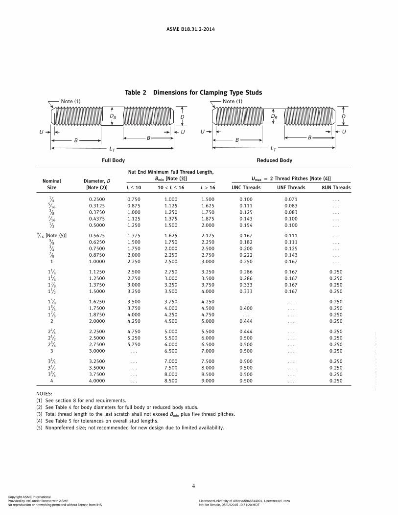
Table 2 Dimensions for Clamping Type Studs
Full Body Reduced Body
U U
LT
DDS
B BU U
LT
DDR
B B
Note (1) Note (1)
Nut End Minimum Full Thread Length,Bmin [Note (3)] Umax p 2 Thread Pitches [Note (4)]Nominal Diameter, D
Size [Note (2)] L ≤ 10 10 < L ≤ 16 L > 16 UNC Threads UNF Threads 8UN Threads
1⁄4 0.2500 0.750 1.000 1.500 0.100 0.071 . . .5⁄16 0.3125 0.875 1.125 1.625 0.111 0.083 . . .3⁄8 0.3750 1.000 1.250 1.750 0.125 0.083 . . .
7⁄16 0.4375 1.125 1.375 1.875 0.143 0.100 . . .1⁄2 0.5000 1.250 1.500 2.000 0.154 0.100 . . .
9⁄16 [Note (5)] 0.5625 1.375 1.625 2.125 0.167 0.111 . . .5⁄8 0.6250 1.500 1.750 2.250 0.182 0.111 . . .3⁄4 0.7500 1.750 2.000 2.500 0.200 0.125 . . .7⁄8 0.8750 2.000 2.250 2.750 0.222 0.143 . . .1 1.0000 2.250 2.500 3.000 0.250 0.167 . . .
11⁄8 1.1250 2.500 2.750 3.250 0.286 0.167 0.25011⁄4 1.2500 2.750 3.000 3.500 0.286 0.167 0.25013⁄8 1.3750 3.000 3.250 3.750 0.333 0.167 0.25011⁄2 1.5000 3.250 3.500 4.000 0.333 0.167 0.250
15⁄8 1.6250 3.500 3.750 4.250 . . . . . . 0.25013⁄4 1.7500 3.750 4.000 4.500 0.400 . . . 0.25017⁄8 1.8750 4.000 4.250 4.750 . . . . . . 0.250
2 2.0000 4.250 4.500 5.000 0.444 . . . 0.250
21⁄4 2.2500 4.750 5.000 5.500 0.444 . . . 0.25021⁄2 2.5000 5.250 5.500 6.000 0.500 . . . 0.25023⁄4 2.7500 5.750 6.000 6.500 0.500 . . . 0.250
3 3.0000 . . . 6.500 7.000 0.500 . . . 0.250
31⁄4 3.2500 . . . 7.000 7.500 0.500 . . . 0.25031⁄2 3.5000 . . . 7.500 8.000 0.500 . . . 0.25033⁄4 3.7500 . . . 8.000 8.500 0.500 . . . 0.250
4 4.0000 . . . 8.500 9.000 0.500 . . . 0.250
NOTES:(1) See section 8 for end requirements.(2) See Table 4 for body diameters for full body or reduced body studs.(3) Total thread length to the last scratch shall not exceed Bmin plus five thread pitches.(4) See Table 5 for tolerances on overall stud lengths.(5) Nonpreferred size; not recommended for new design due to limited availability.
4
Copyright ASME International Provided by IHS under license with ASME Licensee=University of Alberta/5966844001, User=rezaei, reza
Not for Resale, 05/02/2015 10:51:20 MDTNo reproduction or networking permitted without license from IHS
--```,`,`,`,,,,,,`,,`,`,,`,,```,-`-`,,`,,`,`,,`---

ASME B18.31.2-2014
Table 3 Dimensions for Tap-End Studs (1.5D Engagement)
Tap end Nut end Tap end Nut end
Full Body Reduced Body
U U
LT
DDS
BM B
DR
S (ref.)
U U
LT
D
BM BS (ref.)
Note (1)
NominalSize
Tap-End Full Thread Umax p 2P Minimum Nut-End Full Thread Length,Diameter,Length, BM Bmin [Note (3)]D UNC and
[Note (2)] Nominal Min. Max. NC-5 Thread UNF Thread 8UN Thread L ≤ 10 10 < L ≤ 16 L > 16
1⁄4 0.375 0.350 0.400 0.100 0.071 . . . 0.750 1.000 1.5005⁄16 0.469 0.440 0.498 0.111 0.083 . . . 0.875 1.125 1.6253⁄8 0.563 0.532 0.594 0.125 0.083 . . . 1.000 1.250 1.750
7⁄16 0.656 0.620 0.692 0.143 0.100 . . . 1.125 1.375 1.8751⁄2 0.750 0.708 0.792 0.154 0.100 . . . 1.250 1.500 2.000
9⁄16 [Note (4)] 0.844 0.802 0.896 0.167 0.111 . . . 1.375 1.625 2.1255⁄8 0.938 0.892 0.983 0.182 0.111 . . . 1.500 1.750 2.2503⁄4 1.125 1.075 1.175 0.200 0.125 . . . 1.750 2.000 2.5007⁄8 1.313 1.258 1.368 0.222 0.143 . . . 2.000 2.250 2.7501 1.500 1.438 1.562 0.250 0.167 . . . 2.250 2.500 3.000
11⁄8 1.688 1.625 1.750 0.286 0.167 0.250 2.500 2.750 3.25011⁄4 1.875 1.813 1.938 0.286 0.167 0.250 2.750 3.000 3.50013⁄8 2.063 2.000 2.125 0.333 0.167 0.250 3.000 3.250 3.75011⁄2 2.250 2.188 2.313 0.333 0.167 0.250 3.250 3.500 4.000
15⁄8 2.438 2.375 2.500 . . . . . . 0.250 3.500 3.750 4.25013⁄4 2.625 2.563 2.688 0.400 [Note (5)] . . . 0.250 3.750 4.000 4.50017⁄8 2.813 2.750 2.875 . . . . . . 0.250 4.000 4.250 4.750
2 3.000 2.925 3.075 0.444 [Note (5)] . . . 0.250 4.250 4.500 5.000
21⁄4 3.375 3.300 3.450 0.444 [Note (5)] . . . 0.250 4.750 5.000 5.50021⁄2 3.750 3.675 3.825 0.500 [Note (5)] . . . 0.250 5.250 5.500 6.00023⁄4 4.125 4.050 4.200 0.500 [Note (5)] . . . 0.250 5.750 6.000 6.500
3 4.500 4.425 4.575 0.500 [Note (5)] . . . 0.250 . . . 6.500 7.000
31⁄4 4.875 4.775 4.975 0.500 [Note (5)] . . . 0.250 . . . 7.000 7.50031⁄2 5.250 5.150 5.350 0.500 [Note (5)] . . . 0.250 . . . 7.500 8.00033⁄4 5.625 5.525 5.725 0.500 [Note (5)] . . . 0.250 . . . 8.000 8.500
4 6.000 5.900 6.100 0.500 [Note (5)] . . . 0.250 . . . 8.500 9.000
GENERAL NOTE:B p full nut-end thread length
BM p tap-end thread length (full threads)LT p overall length (nominal length). See para. 7.3 for length increments and Table 5 for tolerances on overall stud lengths.S p standoff (when installed) p LT − BMU p length to first full form thread
NOTES:(1) See section 8 for end requirements.(2) See Table 4 for body diameters for full body or reduced-body studs.(3) Total thread length to the last scratch shall not exceed Bmin plus five thread pitches.(4) Nonpreferred size; not recommended for new design due to limited availability.(5) UNC only.
5
Copyright ASME International Provided by IHS under license with ASME Licensee=University of Alberta/5966844001, User=rezaei, reza
Not for Resale, 05/02/2015 10:51:20 MDTNo reproduction or networking permitted without license from IHS
--```,`,`,`,,,,,,`,,`,`,,`,,```,-`-`,,`,,`,`,,`---
ASME B18.31.2-2014
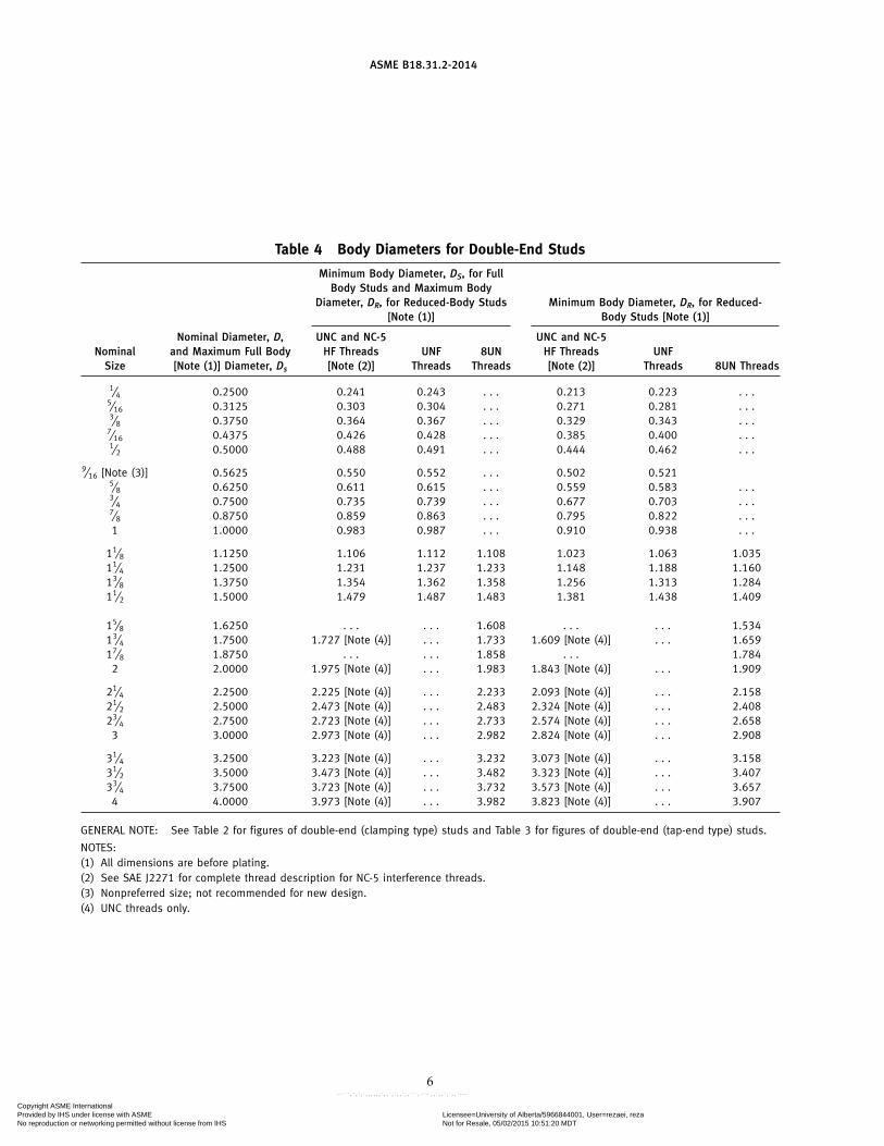
Table 4 Body Diameters for Double-End Studs
Minimum Body Diameter, DS, for FullBody Studs and Maximum Body
Diameter, DR, for Reduced-Body Studs Minimum Body Diameter, DR, for Reduced-[Note (1)] Body Studs [Note (1)]
Nominal Diameter, D, UNC and NC-5 UNC and NC-5Nominal and Maximum Full Body HF Threads UNF 8UN HF Threads UNF
Size [Note (1)] Diameter, Ds [Note (2)] Threads Threads [Note (2)] Threads 8UN Threads
1⁄4 0.2500 0.241 0.243 . . . 0.213 0.223 . . .5⁄16 0.3125 0.303 0.304 . . . 0.271 0.281 . . .3⁄8 0.3750 0.364 0.367 . . . 0.329 0.343 . . .
7⁄16 0.4375 0.426 0.428 . . . 0.385 0.400 . . .1⁄2 0.5000 0.488 0.491 . . . 0.444 0.462 . . .
9⁄16 [Note (3)] 0.5625 0.550 0.552 . . . 0.502 0.5215⁄8 0.6250 0.611 0.615 . . . 0.559 0.583 . . .3⁄4 0.7500 0.735 0.739 . . . 0.677 0.703 . . .7⁄8 0.8750 0.859 0.863 . . . 0.795 0.822 . . .1 1.0000 0.983 0.987 . . . 0.910 0.938 . . .
11⁄8 1.1250 1.106 1.112 1.108 1.023 1.063 1.03511⁄4 1.2500 1.231 1.237 1.233 1.148 1.188 1.16013⁄8 1.3750 1.354 1.362 1.358 1.256 1.313 1.28411⁄2 1.5000 1.479 1.487 1.483 1.381 1.438 1.409
15⁄8 1.6250 . . . . . . 1.608 . . . . . . 1.53413⁄4 1.7500 1.727 [Note (4)] . . . 1.733 1.609 [Note (4)] . . . 1.65917⁄8 1.8750 . . . . . . 1.858 . . . 1.784
2 2.0000 1.975 [Note (4)] . . . 1.983 1.843 [Note (4)] . . . 1.909
21⁄4 2.2500 2.225 [Note (4)] . . . 2.233 2.093 [Note (4)] . . . 2.15821⁄2 2.5000 2.473 [Note (4)] . . . 2.483 2.324 [Note (4)] . . . 2.40823⁄4 2.7500 2.723 [Note (4)] . . . 2.733 2.574 [Note (4)] . . . 2.658
3 3.0000 2.973 [Note (4)] . . . 2.982 2.824 [Note (4)] . . . 2.908
31⁄4 3.2500 3.223 [Note (4)] . . . 3.232 3.073 [Note (4)] . . . 3.15831⁄2 3.5000 3.473 [Note (4)] . . . 3.482 3.323 [Note (4)] . . . 3.40733⁄4 3.7500 3.723 [Note (4)] . . . 3.732 3.573 [Note (4)] . . . 3.657
4 4.0000 3.973 [Note (4)] . . . 3.982 3.823 [Note (4)] . . . 3.907
GENERAL NOTE: See Table 2 for figures of double-end (clamping type) studs and Table 3 for figures of double-end (tap-end type) studs.
NOTES:(1) All dimensions are before plating.(2) See SAE J2271 for complete thread description for NC-5 interference threads.(3) Nonpreferred size; not recommended for new design.(4) UNC threads only.
6
Copyright ASME International Provided by IHS under license with ASME Licensee=University of Alberta/5966844001, User=rezaei, reza
Not for Resale, 05/02/2015 10:51:20 MDTNo reproduction or networking permitted without license from IHS
--```,`,`,`,,,,,,`,,`,`,,`,,```,-`-`,,`,,`,`,,`---

ASME B18.31.2-2014
Table 5 Continuous Thread and Double-EndStud Length Tolerances
Clamping andDouble-End Continuous-Thread
Range, LT Studs Studs
From 3⁄4 through 21⁄2 ±0.03 ±0.04Over 21⁄2 through 4 ±0.05 ±0.08Over 4 through 8 ±0.08 ±0.10Over 8 through 16 ±0.10 ±0.12Over 16 ±0.12 ±0.18
Table 6 Flange Bolting Stud (Stud Bolt)Length Tolerances
Flange Bolting StudRange, L (Stud Bolt)
From 3⁄4 through 12 ±0.062Over 12 through 18 ±0.125Over 18 ±0.250
thread on the other end. Dimensions for U are the sameas those in Table 1. The length tolerances in Table 6 areapplied to the L dimension.
Flange bolting studs (stud bolts) can be made as con-tinuous thread (Table 1) or double-end (Table 2) withthe only difference being that nominal length, L, appliesto flange bolting studs and overall length, LT, applies toall other stud types.
7.3 Length Increments
The overall length of continuous thread and double-end studs and the nominal length of flange bolting studsshall be in one-quarter inch increments for lengthsthrough 10 in. For stud lengths greater than 10 in.,lengths shall be in whole inches and one-half inchincrements.
8 STUD ENDS
Stud ends shall be chamfered from the major diameterto a diameter equal to or less than the thread root diame-ter. The length of the chamfered end to the first fullformed thread at major diameter, as determined by thedistance the chamfered end enters into a cylindrical NOTGO major diameter ring gage, shall be one to two threadpitches on each end. The ends of the stud shall be reason-ably square with the axis of the stud, but the slight rim orcup resulting from manufacturing shall be permissible.
The ends shall be suitable for marking.
9 THREAD LENGTH
(a) For continuously threaded studs and flange bolt-ing studs, the entire length of the stud shall be threaded
7
except for the ends, as denoted by dimension, U, inTable 1.
(b) For double-end studs, full threads are required forthe lengths B and BM, except for the ends, as denotedby dimension, U, in Tables 2 and 3.
(c) The transition from full thread to incompletethread shall be smooth and uniform. The major diameterfor incomplete threads shall not exceed the actual diame-ter of the complete (full form) threads.
(d) For the nut ends of studs, the transition from fullthread to no thread shall be within five thread pitchesfrom the minimum full thread length, B.
10 SCREW THREADS
10.1 UNC, UNF, and 8UN Thread Series andTolerance Class
Threads shall be unified inch coarse, fine, or 8-threadseries Class 2A in accordance with ASME B1.1. Unlessotherwise specified by the purchaser, coated and platedthreads shall conform to the maximum limit ofClass 3A (GO) and the minimum limit of Class 2A(NOT GO).
10.2 Class 5 Interference-Fit Threads (for Tap-EndStuds)
In addition to the threads identified in para. 10.1,interference-fit threads may be ordered for the tap endof tap-end type studs. These threads shall be interferencefit (Class 5) of the modified National thread form inthe coarse thread series (NC) in sizes 0.250 in. through1.500 in. in accordance with ASME B1.12.
NOTE: To achieve the desired performance from an NC-5 thread,the indication of the proper suffix indicating the size of the majordiameter is critical. The designation of an NC-5 thread is not com-plete without the inclusion of the suffix. To select the appropriatesuffix for a specific application, the user should consultAppendices B and C in ASME B1.12. Additional information onNC-5 thread applications is available in SAE J2271.
10.3 Thread Gaging
Unless otherwise specified, dimensional acceptabilityof screw threads shall be determined based on System 21of ASME B1.3.
11 MATERIALS AND MECHANICAL PROPERTIES
11.1 Materials for Continuous Thread Studs,Double-End Studs, and Clamping Studs
Unless otherwise specified, steel studs shall conformto the requirements of ASTM A354, SAE J429, orASTM A449, as identified by the purchaser.
Unless otherwise specified, studs of corrosion resis-tant stainless steels shall conform to the requirementsof a specified group and condition designated inASTM F593.
Copyright ASME International Provided by IHS under license with ASME Licensee=University of Alberta/5966844001, User=rezaei, reza
Not for Resale, 05/02/2015 10:51:20 MDTNo reproduction or networking permitted without license from IHS
--```,`,`,`,,,,,,`,,`,`,,`,,```,-`-`,,`,,`,`,,`---

ASME B18.31.2-2014
Unless otherwise specified, nonferrous studs shallconform to the requirements of a designated alloy inASTM F468.
11.2 Materials for Flange Bolting Studs (Stud Bolts)
Flange bolting studs may be supplied to any gradecovered by the following ASTM material standards:A193/A193M, A320/A320M, A437/A437M, A453/A453M, A540/A540M, or A1014/A1014M.
12 IDENTIFICATION SYMBOLS
Markings shall be located on either the ends or thebodies of the studs unless otherwise specified.
12.1 Property Class Symbol
Each stud shall be marked in accordance with therequirements of the applicable specification (seesection 11) for its chemical and mechanical requirements.For tap-end studs, the material property class symbolshall be marked on the nut end or the body.
12.2 Source Symbols
Each stud of a size requiring marking, based on itsspecified material standard, shall be marked to identifyits source (manufacturer or private label distributor).
13 FINISH
Unless otherwise specified, studs other than corro-sion-resistant stainless steels shall be supplied with anatural (as-processed) finish, unplated or uncoated, ina clean condition, and lightly oiled. Studs produced fromcorrosion-resistant stainless steels shall be passivated inaccordance with ASTM A380.
Platings and coatings are not recommended for inter-ference-fit studs.
Requirements for zinc plating are contained in ASTMF1941.
14 WORKMANSHIP
Unless otherwise specified, studs shall be free fromsurface imperfections such as burrs, seams, laps, loosescale, or other irregularities that could affect serviceabil-ity. Surface discontinuities shall comply with the require-ments of ASTM F788/F788M.
15 STRAIGHTNESS
Straightness shall conform to the requirements ofASME B18.2.9.
8
16 INSPECTION AND QUALITY ASSURANCE
Studs shall be inspected to determine conformancewith this Standard. Inspection procedures may be speci-fied by the purchaser on the inquiry, purchase order, orthe engineering drawings, or shall be as agreed uponbetween the purchaser and supplier prior to acceptanceof the order. In the absence of a defined agreement, therequirements of ASME B18.18 shall apply.
17 CLEARANCE HOLES
The recommended sizes of clearance holes in materialto be assembled using inch studs are those listed inASME B18.2.8 for inch fasteners.
18 STUD DESIGNATION
(a) Description: Studs shall be designated by the fol-lowing data, preferably in the sequence shown:
(1) product name(2) product standard (ASME B18.31.2)(3) nominal diameter and thread pitch for Class 2A
screw threads(4) nominal diameter, thread pitch, and major
diameter thread suffix from ASME B1.12 (includingAppendices B and C) for NC-5 interference threads,when specified
(5) nominal length(6) material (applicable standard and grade or
alloy)(7) protective coating, if required
For tap-end studs, show tap-end thread type fromASME B1.12, length, and nut-end thread, as shown inExample (3) below.
EXAMPLES:(1) Continuous thread stud, ASME B18.31.2, 1⁄2-13 � 4, SAE J429
Grade 5, zinc plated per ASTM F1941 ClassificationCode Fe/Zn 5A
(2) Clamping type stud, reduced-diameter body, ASME B18.31.2,3⁄8-16 � 2, ASTM F468 nickel-copper alloy 400
(3) Tap-end stud, full body, ASME B18.31.2, 11⁄8 NC-5 HFS�61⁄2 � 11⁄8-8UN, ASTM F593 Alloy Group 2, Cold WorkedCondition
(4) Continuous thread flange bolting stud, ASME B18.31.2, 3⁄4-10UNC� 6, ASTM A193, Grade B7
(b) Part Identification Number (PIN): Refer toSAE J2271 PIN for all stud types covered in this Standardexcept flange bolting studs (stud bolts).
NOTE: SAE J2271 contains part identification numbers forinterference-fit tap-end studs with eight different suffixes fortap-end thread major diameters and guidance on selecting theappropriate thread configurations for both the tap-end and internalthread for the material into which the interference-fit stud isinstalled.
Copyright ASME International Provided by IHS under license with ASME Licensee=University of Alberta/5966844001, User=rezaei, reza
Not for Resale, 05/02/2015 10:51:20 MDTNo reproduction or networking permitted without license from IHS
--```,`,`,`,,,,,,`,,`,`,,`,,```,-`-`,,`,,`,`,,`---

Copyright ASME International Provided by IHS under license with ASME Licensee=University of Alberta/5966844001, User=rezaei, reza
Not for Resale, 05/02/2015 10:51:20 MDTNo reproduction or networking permitted without license from IHS
--```,`,`,`,,,,,,`,,`,`,,`,,```,-`-`,,`,,`,`,,`---

ASME B18.31.2-2014
M19514Copyright ASME International Provided by IHS under license with ASME Licensee=University of Alberta/5966844001, User=rezaei, reza
Not for Resale, 05/02/2015 10:51:20 MDTNo reproduction or networking permitted without license from IHS
--```,`,`,`,,,,,,`,,`,`,,`,,```,-`-`,,`,,`,`,,`---


