Embed Size (px)
Citation preview
7 --:. . . -. , i-, * .
*0 .
a . ', '*..
....%. se 01 5
;el fZ 0
1 ' /
t * z r
.., .. "1:000NEIPr. RESUME. .:,: k
0
Aww- , a. , -?.' a ' 4,
-.. tir,1183-'963 ...
.6: a 021e 1130..
, : . ,Iiiritary Curi'icula for Vocational 6 TeciinicalEduettion. Se1se-TA:1 PISTpose Vehtcle, (*clinic, Blozkts.
*, V-Vi; B11
$ astfrunaN 6 hi,o S,tse Univ. , Cól umbus. National 'Center for,.
.. -, es.earch in Voc/44onal tducation.; Techni:cal Training
Pt :: en t e, r Chanute APB, Ilt.',
SP.ONS A; BPNCY Bureau of Occupational and Adult EdlIcaion, (LHEW/Oir .
TITLE
, Washington; NCIPUB DATE 75 .
NOTE 563p.; For related documents see CE 0 24 329-931.
BUIS PRICE t1F0,2/P223 Plus Postage.DESCRITTOVS. .*Auto Necher.1.64:' Behavioral Obtectives; Course.% ."'"
Descriptions; Curticulum ,Guiles:..*Engines.; AgrquipmentIR? Mainteramte; *1..:zdustrio1 Arts: Inspecfionz Learning
Activ,itiew tessAly Plans; Jiotor Vehicles;Portiecondary Education; Procrramed Instructitinal
.
M.ELterl.als: *Pe-pa_r; Sezon-lary Education: Skilredbccupati!:.±1; Study Guides; *Vocationoi Education:'wotktiooks .
I.DENTIFIEFIS Nilitary Curriculum Proiect':, .yr
ABSTRACT - ,
This plan of instructio,n,- lesson 'plans, and stuile4t.materials,.(pi.oaramed texts, workhrokst-'and stddy guides) for asecondary-gostsecondary level course in .engine mechanics iq one of. a
'number militaty-develored curriculum packages s.elected eoradaptation to vocattiazal irstructiOn and curriculum development -in a.
setting.. It-i.s. the third ,of a four-part course (see Not? forother., sec.tions) covering ats.teral vehicle me.:h enics, incVldinginspe,otion main-tenance, recaff,r. The plan ,ot instrTction suggestsntter of hours Of class 't.ime devotel to e.ach lesson in two blozk s ofinstruction. (Blocks IV 'and V), tota,l of ,15q hours' of ,.in'strtictione(111 TunerUg and Troubleshootira lessions, 78.5 hours).", includingengiqe, mechanIcal, batterY, ianition, fuel, lubrication, cooling,cramczasEf.-- ventilating, anti-pollution, emission control,' lighting,warniagritand sig.nalr.sysemsy and (2) Poweet*aine. (9 lessons, 76.5'.h4ursl .iiicludirg.,maintenkrce, troubleshoofi'ng, and_ repair. It' alsodetails zr:iterioa objlctives' a'rd !?:.upport materials needed. Leor%.'plans oitline teavhin4 steps. Student materials in Block IV _incl.ide aworkbook, handout* anld thre'e prOgramed texts and in:Block It a stady-sluile wit.h objettiv-es, text., and -reJP.ew guestiors; studyguide/workbook wtth- shop prOcédures: ani saver. programed texts.
1 :I..e `
- . .* ReprodhctIons supplied by ED108 are the teSt that Car. b1.- wade* ,
I from the. °Ticino]. document.
PS
. *
i. **'*1-*,****'*1*********ip*****************44**t***************.**********.., --. ,'1
. 5.
5
* .
I.
Plm.
us_ _
W/SefT1111 WWI%1104IMMON & WILPARIISATIONM.
SOSCATNIS
otiCIJMENT .HAS OSIN ISPIO-OuCSO Ibtat tor ii Rietapliem
CIFFICI IIKTIONAL ISM TIA* *IAA T IOW SitiOfft00 POt. C'e
...411111r
44\ -'1#111r.
*
2,*-r.
a
a
. .41,1)1`,,-)
,) ,
t* t t",'-0
-PPPP,Prd
.11 oro
e. .! .to!,1. al.,1 I. :'.i;n1 ?
, .,40 % .4'403
';',:;41',':93.44°J-.;tiN 7
4 .
rn; k!.ib
.M% ,4
" Ni -.* ,. 419.47$ .( o :
o. o * r
tP.
,mna
4..1 1. '
,,. 4 tisk....7
.i47i4% 1.4 !-
"/tigir4;;
echnical Edüation
. j
t4.7.4
, . .L f .
Ganee.at Ourppos er13,6.19 Mechanicgo
Eilock,C. IV itL.
cuki
4 I I
9 .411
I aIrkat
,xter:77;"
o
oo
4
-
CENTER ,
FIA IIESUIRCJI 1WYOCAT1AI EDUCATIONTHE OHIO, SATE pravE
r .
;7
4 ' I
I I a
* P.
foo
,
i ,ei ,.. 4. .,
v,illiCI:,/i,.,... ftti1.1,,,,,4,1,1. 1 ; .1- ttl!I !i,....1 ...fil'?.4t11/4:
V'-..iI'' '.4...4:-/-14 1.: ; 4
1. !.1:44 14..,..:-. ... ::+ '491i
ok. tit,'-..!,,Utt"?' ..1.11- 4 1:** '''..44-,,1 , ;
. 14 . 4
...JP:7'. ."
114' ' .
-, k*- . ', , i ... t * '. s
. . ...7
4 .. .
i '
." ' .. : .:':: ,''' . i:i::::',4::'.1'..-il'::t.:1.11114:11,i:l',;..ic:11:!..11'i:'1';,1,'.1.:1..;"
4 .." .I. 14 .1 01 I ', -.
V .'-i L'IlC., 1* dial ''' .:4'"' ""...4..4'4
4444.;"*-1
f...4 4:11',''.4"/44;ta' 0 ,$-.4. : *.41 ,
4 4 4.y; / .. " . :. ''. 4 I: ' :,t.i.....:,,,...,,,' L4.4,....',...; A.:),"itit ''''.V11.'lliilf,... v .4!...4.;1141...,':;.4 ;.' `'..i: 1 1. . .. . , i.".111: V '4 ., .
t_r1;.4 *2-it. "'..e.1.9- -',.,-IL..1- i.11". f ..4.7."'2-f ' :. :!'i i. ::::f. ,* : .Ta. ..'',';''11'..L, tA4, ;,,i..4, ,1,..±':,.;:t:,,;1,, :?r,
.1.4..r
*'''
,.. . 0 ' ,' .44, .4 ! I Is # ,J, . I' *.
-4
'V'':14' \i ''., 4 41.- e-ev, : Ai ;'40,;"'11:!:::: s. .." ..: t. 11.1.:..,':1'..., :
:jt' ...::.'?.4....'!...4:1.,:* i't..::::1:i:;1',,,
: : -: 1,:::; ".:::1., : .,.,. 6.'.;:1-:'' ......1.1.i.:1:1,,,,:#1. 9.'..;..'s'S'e.,!:::1:::',
;[:':':.*:':1.1'4." *P.1.:1;.*.14;:''"1.:$
1'..;.:11:1:7;:i:1:.'::.:1'::;;;:,1
!,41,.,.ii4.,/i',1.,, I ..,), 4",:'...:Iii ,..,./1,41 .' ; 'i sr."'"
'''%. At ..8-1. ' --\1... li':, ....II'. 1. $4; f '
11% 'i , 1 1 '.' ' .4"':/ '''r?.' ....!;,... 1.'.' i ... ,"'
. -' i. ''''''
. 4t ''' , %.' ..:..;1!f.'itt.iltr... r.1..2'. 4',*sTiolfi.
'144'. Ij ki. ..!?* s'.. %'' :- ''' ;I.I,J- q . i . , ,I,. ,..1.:,.,-,i. IN.,.
-.1e.....f,r44f.,A 1 .0 4;.:'.'7 ..,,, ..1 ; . .. ,1 i14.,..:. 4., .),.itid i,.,..1'I' ' 'It , '1
-.' , .. : L' '.. '.":ii..1 ,.. r.: ; ...t it',1% 7 I .' ' ..
. f!1:1:,;,.1f %I.i#11,i,1.1 ... ri ., ., . r.,,,,,,,..,4. .
sy , ..,.,..,!:1',j1..), ,.If , . , . 1 ,
.},
*I.:4 ', ti,..:..:1;,t.4.4:1!.... '''; ' i 44$4,4'.4 '
tilt t,,.4 , '. 4.1 'L.'. ., i .1.41t11,.; ,
'-.1.- .'.. 4- '..1....' :. 11,1rt ',.:".'', !, .,,,k- .., $ I.
, . . , ,, .4 , ,.. . ,.. ' f' ,4. I. a '..,..:1.':.....i:.:1,(.....'.....1:44;.i.f:..1.4,:14....'
:5:::' 1 "::Ii ''''..;:::'I.
tt;111.1'11... 4i 1411.14i .14''''''idll.N..4)44S'i.
I 4 ' I P 14
".... I ... f
. IL I . ,..'i ..1. 4 :- 1",'
,, , , . ..
. .
'"
N,,
, ' , , i 44..4.14?1, 44 4 ri...y.,.... 4 ;4.! 4.,, ii,',..4;.,..;,,t . ..,-,;..4,,v1
e.,,. ...4 4, 4.71.-4 .444 1
!ti;',.tit..:441i-qt.Ii: .....,r'.i.1!Ili.,.:.,,C4;;;;%.4','?,-
i..')i.
,,..:: 'NO ;..4t,,', '(,', ,,..
, 'I .7.. ,, . . . 1
r ct 1. ''
' . .1 . .'!., . I W,
. %,.. ;:..,?;1 ..rIP, ' ' ; .., . :16'1. ,147(.1" . 't14.' fli, (.1',1e':11141t .41.1fil $11. 4!'*' '+01:14," '4f., . ' :,!.., ,{Wiorst tqf ": 4. /,'' -.14,4 t) ,rir. -''''.1','''.11;-. I'. ?,*1. V1*'': .' i..44,1:;' t--41: f414',' ' .?4144 c t .., I 't.t, .! ', 4. i% .4. 4/ I.., ; 4,4, 4.
.. , . a . ...! ,A, , ....,A,ty ,11',." .1,* l,04'. 't ,. a al j.., ,, ;a.' :,111'4.>./,..: t';',..:4,i'`14.14W./.4,.....",;14.,*7*.r0.!: 'A , , ..114'; 41%11;:.''.'1. .'I
4,4.1;',$*".. i':' 4' ,...;:, ilt...1,1.:.140 4`,..; .'4.' .,:',,I,4 t. l'oi 3., t , 44-9,.,1. . !.f.' r
j 4 . 41 .,4 ,..I ii r, ,,,. .. rl, . . I / - . f 4
' .49. ... ,T`'.: )4....... A 'a 'f ":* 1...4i..( .;"l'( ,; i ; .1'4: ) f*.°,1 '1.'liffj::*14'11:1.14j...i....'.''1:4';'' fl'iligiei:1_Ii...1.,.1. :
.. i ! , ; 1.,''/.4..41..St 4.,-f I '..1., i;4414',' dt '";,',4ti,I. :,:iVVitt ki?... ,. ,-,,, if ..I .'", 0 ., yl ail la 4 ':...;
'Ilk4719.".- !C. 11)1.4al. 4.4 ''' 4.1.'''.O. i 4:1'...' .. . a. :hi t , 1 '-,4 .. a ...., , *.,, 4. , t I a , /.1 'X,44" ' i , .. , ' .
' .?I iiri!4:1 . ...Ir .14..i
, ( ' ;-,.I '''' .:/.11qtrri';!'/ 4,-.4.1.:*.;41' '.-4':14 tit,', ,,,',1,4,14'.! ..' Y''',11.44.;.''., 40,3;;',... t.q. i-.4!i3rt. -.,,,4
,,,,ti
r . !T. .:,..1 p .', 41'. li', , itt "
-.A, Ali 1..!''. '. ", '', r%:.!P: ..1't (.1%,..: -40'44' 4,1':l, 1.'f4, 15,;.f;'' ;.:'.
...,.'. ; i.e, tr,'t eV I. .' f At i'l),'.1"..; : '
1,1 I.' . ". ',. ,.' ' 4.1",.... , L.,
.; 1.'.. 4-44 /°' l'''.4: ' r,..'4 4..% -4 '''' 1,11tii n.
1 ,, iA
'I%
1 ,,(.,1,.:.1:'..117-1;1
3 _ I It' : I ..,. '!
. '.11' I U. i n.14 , .
t
ft4
.1.6., 11 f ..-93 .I'}!' '°.'11;
,r, 1, 1,..,)
. . , ..:: ; III ,t : 11 F.::.r : :
4. .
' ! ii4 ..'1 441 L'-`4.:i. if ';'#,:441'.1:-.
' :,? ,,,.' .
., r ..."-..-,'.4....:i!.":;ti; 1*. _. 4 i 1
. 'IL-. 44
dr"
N ,.
'
,14.44 it....e)t:'ii, 4" 11.2 '",
IltS!.',4,1;,,- 3.1!.!44"e4,' .0,. ;
;,;.4.4,--
t1.
iA-,
,1,tfio,
.11111".;i,.
,,,,"'
1st
.,-14446'r,.,.
1 cs .;tt
,
,
PI
4'. '4
' 4.
,.34 '!.** . .1. .4,,1.1 ,44' : "
44
. ,4, .44 4 a r' -i a " 1.44
a ,g. *`t r
- -This military technical training course' has been selected and adapted by
Ate Cen:tee bor. Vocational Education for "Trial Implementation of a Mo4el SysteistolFrovide Alitary Curriculum Materials for Use in Vocational and TechnicalEducation," a dokojeci' sponisored by the Bureau of Occupational and Adult EduCation,.'
.bepartmint *of Health,' Edudation, and Welfare..f.
,
444
4.4%.14 41410.4 .
# ;
rot
.
..
4 'CO, 1- ;
y
e
011c /
MILT-TAW CURRIazum MNIERIALS
4.
The Militarbdeveloped curriculfam materials in this coursepackage %fere selected by 'the National Center felt' Research inVocational Education tit litarrewIrriculum Projett fort assern-
. ination to 'the ,six regional Curriculum Ccordinition Centers andother insEructional tnaterials agencies. The purpose ofdissend.nating these courSes was to make curricuhan teriald-eWveloped by- the .militazy nore accessible to vocatieducatprs in the civilian petting.
-The oourse materials'were aoguived, 6-Valuated by project
'staff and paactitioners in the fieldt'anXpreparedafordisseminattpn. Matefials whicliwere_specific to the nilitcarywere deleted4 o*yrighted materials were either cmitted or appro-val for their use was obtained. These qpurse packages contain.curriculum resource materials which can be adapted bo supi5ortvocational instruction and curriculum develwfient.
a."
411
4
Run
gh.
a. e
09
The National Centeriiiissioki Statement
rrarta,,....t,
The National Centei for Research inVocational Education's mission is to increasethe abilify af diverse Nensies, institutions,arfd organizations to sohie eilucational prob-lems relating to individual career planning,preparation, and -Progressio9. The NationalCenter fuyills, its mission by:
.
Generating knowledge through research
Develbping edueational programs andproducts *
,
Evaluating individual program needsand outcomes
Installing educational programs, products
r
Operating information systems toseryicei
pf Condukng leadership development. and. training programs
.FO FdFIT.HER INFORMATION ApOUTN.-Military Curriculum Materials .
vitRITE bR CALLProgrim Information OfficeThe Nptional Center for Research in Votational
Eclucation'the Ohm State University1060 Kenny Road, Columbus, Ohio 43210Telephone: 614/488-3865 br'Toil Free 800/
848-4815 within the continental U.S:ifixcept Ohio)
-
7_
'
-a
a.
V
Military.Ctirricutain,Materials for
( Vocational 'aridTechnical Ethication
Info-m-0.4:19 r?nd Field. Cm/ilian
Thr, i!'111 (1.,-,1.-! for ria..f;r,archi.thr.ntion
EL?
raa--17-M
MilitaryCurriculum MatdrialgDissemination Is . .
an activity to increase the accessibility ofmihtary-developed curriculum materials tovocational and technieal educators.
This project, funded by the U.S. Office ofEducation, includes the identification andacquisition of curriculum matcrials in printform ficim the Coast Guard, Air Force,
. Army, Marine Corps and Navy.
Access td .military curriculum materials isprovided through.a 4'sloint Memorandum of(Understanding" between the. U.S. Office ofEducation and the DePartment of Defense.
The acquired materials ere reviewed by.sancl subject matter specia/ists, and c rsesdeemed -applicable to vocational and tech-nieal edudattin are selected for dissemination.
*
The National C.9nter for ResearckjnVocationil Education is the U.S. Office ofeducation's tlesignated representative toacquire the materials'and conduct the prOjectactivities.
Project Stiff:
Wesley E. Buiike, Ph.D., DirectorN3tional CentIr Clearinghouse .
.ShiFley A. Chase, Ph.D.Prolect Director
What MaterialAre Available?
One hundred twenty courses on microfiche(thirteen in paper form) and descriptions of
,each have been provided to the vocational-Curriculum Coordination Centers and Otherinstructioi,al materials agencies for dissemi-nation.
-
Course materials include ctrogrammedinstruction, curriculum outlines, instructorguides, stUdent workbooks and technicalmanuals. .
The 120 courses represent' the followingsixteen vocational subject areas:
. N
AgricultU re Food Service,Aviation HealthBuilding & Heating & AirConsfruction' ConditioningTrader Machine Shop
Clerical 'Management &Occupations Supervision
Communications Meteorology &Drafting, NavigationElectronics . PhotographyEngine Mechanics Public Service
The number of couises and the subject areasrepresented will expffid as additional .rriate-rials with apphcation to vocational andtechnical education are identified .and selectedfor dissemination.4..=
r'
Hoiv Can TheseMaterials.Be Obtained?
Contact the Curriculum Coordination Centeryour region for information c-ri obtaining
materials (e.g.,- availebility_and cost). Theywill resPond to your request directly Dr refer-you to an -instructional, materials agencycloser to you.
CURRI.CULLIM COORDINATION CLINIEliS:
EASICENTRALRebecca S. Douglass
Director100 North First StreetSpringfield, IL 62777217/7820759
MkPWS7RoOert PattonDirac*1615 WiliSixth Ave.
.Stillwater, OK 7470440E/377-2000
r. .
NORTHEASTJoseph F. Kelly, Ph.D.Director -1
'225 WesiStatrStreet.:Trenton, NJ 08625609/292-6562 -
NORTHWESTWilliam DanielsDirectorBuilding 17Airdustrial ParkOlympia, WA 985042061753-0879
SOUTHEASTJacnis F. Shill,Director .
MississiPpi State,UniversityDrawer DX
Mississippi State:Mi. 39762601/325151b
-WESTERNLaWsierice F,H..Zane, Ph.D.
Directosi--1776 Univiitsity Ave.Horpfulu, HI 96822808/048-7834
7
iIILITART CURRICULA FoR VOCATIONAL & IECTIgICAL EDUCATION
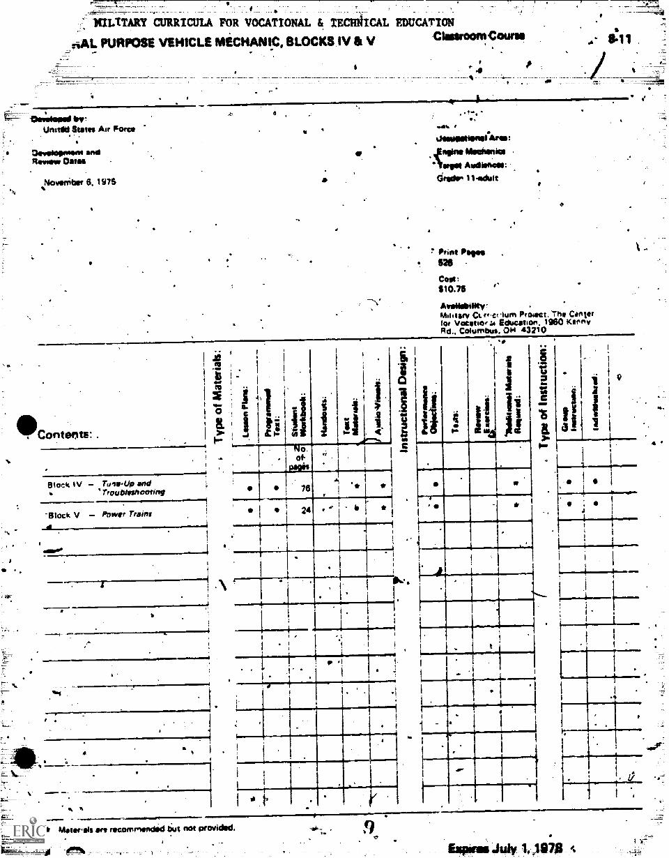
,riAL PURPOSE VEHICLE MICHANI.C, BLOCKS IV III V Classreorntoune
Develoassal bytUnitild States Air Force
'Oevehopnism andRomig* ONSII
November 6. 1975
4
7!
dm
Waseletiensases:poen Mechanics./forget Audiences:Citadir 11.edult
? Print Pages526
Cost:$10.75
Mth tie/ 04. rg+ct loon PrOoKt. Cyntertor vocatiorai Education. 1960 'CernyRd.. Columbus, 001 43210
Ha
1.1
"Contents:.
Block IV Turns-Up and"troubleshooting
'Block V Power trainsa
a
,-41141114
I
1 -
i
,
P.
a.
I
1
1
Ii 11.t o-
.
.
w
Ia. 1...i
..----,
4
I .
*1I
.
,
- No.of .i.
.
.---,----
.
76AI *
,
.
24 ö.
*
, ,
.1
g .
1 .
ig
..
..
4
. *4
4 1-
. ..
t.
.
i
.
,
0.
ii ii
I
1
TI
It
;
Maravals ere recommended tiut not provided.
Expires.htly 14,19a7S
..,=4.
1
-
4
7
Doscoolmat .
a
t t .
...0.1.0e
' a '
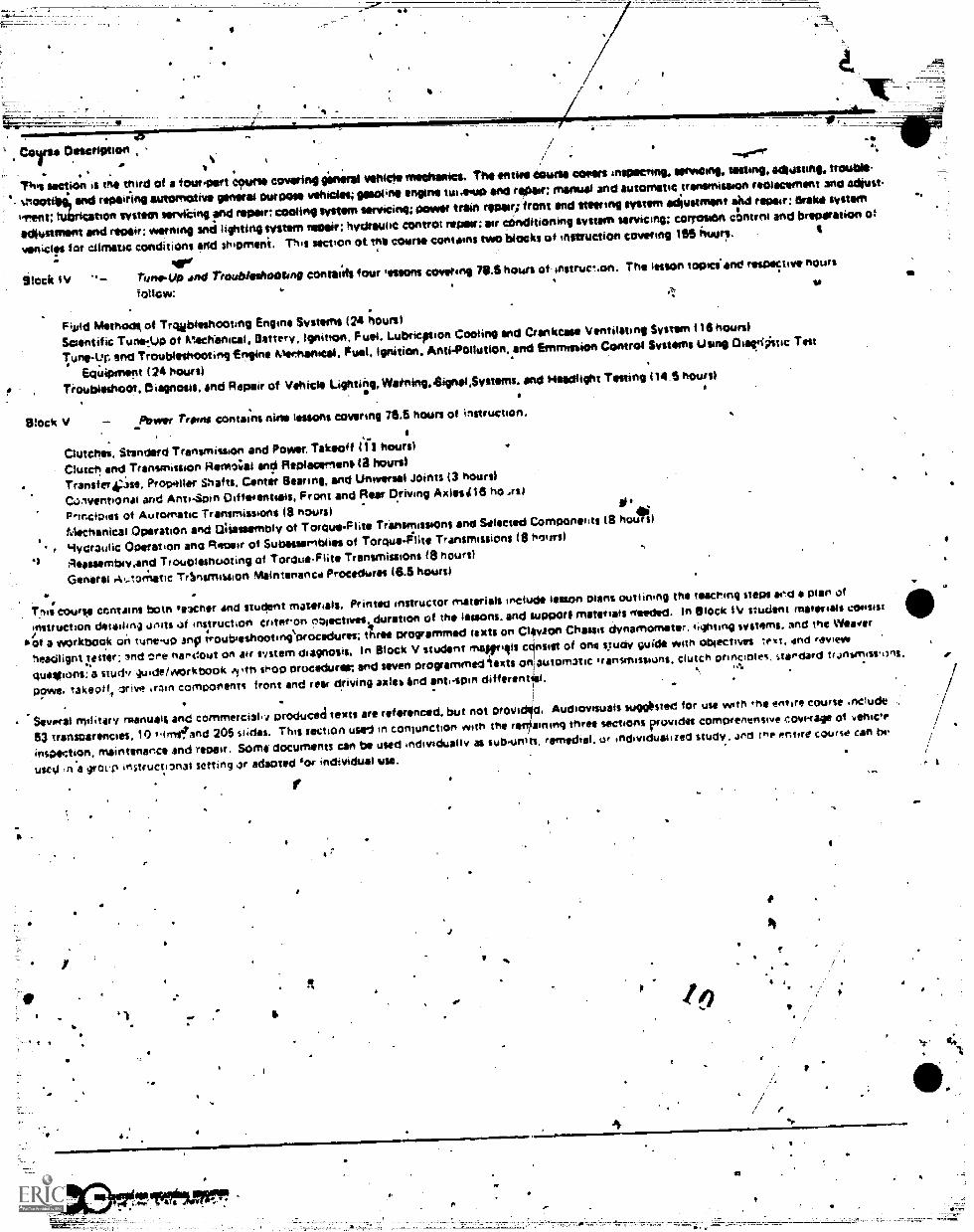
Toes Section is tne third of a fthatitart COsarle covering general vatic* methanol. The end** tootle Wean inspecting, servscing, tasting, &augurs., trouble,
'. s.rictotiksg, end repair-Mg eutomotive general OurooSe vehicles; gasoline engine tin.outo Ord repar; moue and automatic tranernilta00 reOlecomem 3h0 ldhltt
ent: tublicatiell svslterl wrirRing ri rePar: Roofing IV*44m Witting: Power train ropor;.front end lteering system adjustment ted repair: Enka Wean%
adiustment and repair; warning Ind lighting tystem ratan: hydraulic control repair; air conditioning system servicing; cOrrositin contrni and breparation of
%lenient for climetic conditions end shipmeni. This section ot Mi coarse contains two blocks of instruction covering 155 husirs. 4
Block lV runsi-Lip and Trouble:hearing cOntai.rfs four 'aeons covering 70.5 hours of. instrucr.on. The lesson toOlci and recopy, hours
follow:
Fijild Methods of Troubleshooting Engine Systems (24 hours)
Scientific Tune:Uo ot Mechanical, Battery, Ignition, Fuel, Lubricption Cooling and Crankcase Ventilating System (16 hours)
Tuft-L*0 end Troubleshooting Engine Mathanita. Fuel, Ignition, Anti-PollutiOn, and Emmosion Control Systems U tine OiatriOstic Tat
equipment (24 ('ours)Troubleshoot, Diagnosis, and Repair of Vehicle Lightitg, Watning.4ignal,Systems. Ond Headlight Testing (14.5 hours)
Block V Poe* Trona cOntans nine lessons covenng 76.5 hours of instruction.
Clutches. Standard Transmission and Pow. Takeoff I 'I I hours)
Clutch.and Tranvnission Hensos;al end Replacement ( a hours)
Transterj?fie, Propeller Shafts, Center Bearing, and Universal JOintS (3 hours)
C.mventionm and Anti-Spin Diffeientials, Front and Rear Driving Axles.116 ho
Principles ot Automatic Transmissions (8 noursiMechanical Operation and Uhassernbly of Torque-Flits Transmissions and Selected Compontrits (S noun)
ultioraulic Operation ano Recaur of Subsseembhea of Torqu.glite Transmissions (8 hours)
Reassembiy,and Trouolesnuoting of Toroue-Flite TransmissiOns 18 hours)
General .40..torriatic TrInsmisaion Staintenanca Procedures (6.5 hours)
Trite course contains bom 'owner and student materials. Printed instructor materials include lesson mans outlining the teaching steps aeb a plan of
instruction detailing units ot fnstrUcti011 criteron noiectnies4duration of the lessons, and tupport materials 'laded. In Block IV student materials consist
*of a workbook on tune-up Rifftroubseshootinidrocedures; three programmed texts on Clayton Chassis dynamometer. sighting systems, and trie Wearer
neacilignt !ester: lnd Cyre nahdout on air system diagnosis. In Block V student mae yogis cOnsist of one study guide who obieCtivet tri. and review
clulkilions: a Study 'guide/workbook shop orocedurar end seven programmed iesits Oni automatic transmissions, clutch prinvotes. stseciard trJrhmisivons,
pow,: raiseollf Ifive train coMponent% front and rear driving axles and anti-spin clifferennixi.
,I
Several military manuals and Cornmerci30 produced texts are referenced, but not Woe§ a. Audiovisuals suggbsted for use with ihe entire course .nclude
53 tranSOarenCieS, 10 fIrriftand 205 slides. This section used in COrriunCtiOrt eilth tht re inning three sections provides comorenensiye coverage ot yenicle
inspeotion. maintenance and repair. Some documents can be used individually as sub-units, remedial. 1 . individualized study. , and ine entire course can he
used na group instructipnal setting r adeoted 'or individual sise.
: 4
4
.
PissaroCcirs: 8-11
f
Gomm noon muctnizauNIC, awor.s.iivieuri
*Table of conients
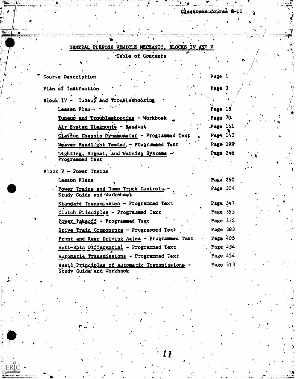
Course Description
Plan of Instruction
Block.IV Tune4 and Troublishoóting *
Lesson Page li
Tuneui and TroUbleshooting - Workbook' Page 70:
4,Andout .Page 141
C1a0on Chassis Drusimmeter - Programmed Text Pagg 142
,Weiver Headlight Tester.7 Programmed Text Page 194
Lighting, Signal, and %/Awning Systems Otge 246
Programmed Text
4.
Page 1
Page 3
4
Block V - Power Trains
Lesson Plans Page. 260
Power Trains and Dump Trpck Controls.- "age 324Study Guide andWorksheet
Stan4ard Transmission - PrOgrammed Text Page ?47
Clutch Plinciples Prograxned Text Page 355
Power Takeoff - Programmed Text Page 372
Drive Train Components - Programmed Text Page 383
Front and Rear Driving Axles -; rrogrammed Text Peg, 405
Anti-Spin Diffeiential - Programmed Text Page,434-
Automatic Transmissions - Programmed Text Page 454
Baste Principles of Automatic Transmissions. - Page 513Study Guide*and Workbook
Ol
a
g
a, 1
,
r-
is .
%
4
a
11.04.a.
.
-a
4
4 1
6
.
PIAMIDPINSTRUClY30 _
COURS* TITLE OK, .. ..
.
. Deneral Purpose Vehicle lepaitMen - Part I .
IlLOCK TITLE a
Tune-Up mid Troubleshooting.
.
.. -
N411....,;
UNITS Of toeST RUCTION AND CMTEMION ORACTIVESDURATKIN
ENOURSI2
.
,- .
,tSUPPORT MATERIALS A140 GUIDANCE
3o t -I
..
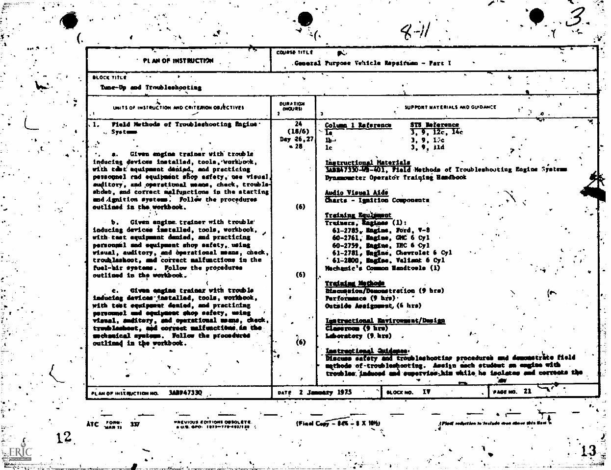
_._..,% , Field Methods of Troubleshonting,Engine
Systeme24
(18/6)Day 26,27
(6)
.
(6)
*
t
-,,elmbeatery(6)
. .
.
.
p
..Column 1 Reference 11118 Deference ,
..
.4
i
-AT" 3, f, ftc, lk .
lb,. 3, 9, Uc
lc . 3, 9, lid .
. .. . .
Iistruction41 Materials -i
. .
.. .
.
, .
.. a. Given engine trainer with troubleinducisg devices installed, toole,ovorlaook,with case equipment (Sealed, and practicingperionnel rad equipnint stop safety,- nee visual,eu4itori, and,operational seams, chuck, trouble.&Ass, sad Correct sigfunctione in the startingend.ignition systems. Fn1144 the proceduresoutlined In tluswerkbook.
.
: -''
.
b. Given engine trainer with troubleinducing cleric., installed, tools, workbook,with.teet oquipeaut &pied, mad practicingpersonnel mid equipment shop safety,, usingvisual, auditory, end operational means, checktroUhlesbont, mod'correct malfunctions la thetoel-tdr system,. P011ow the
3014133648-1031. Pield.Methode of Troublshooting Engine lystessDynamometer Operatdr Irelqing Ilamdbook
Audio Visual Aide --
&arts - Ignition Component& .\. .
,Traininnikulteat
..
Trainers; angi,es (1): .
61-2783,, memo, Porde V-8 . V.60-2761: melee, me 6 Cyl
,
60-2739, Sestee, INC 6 Cyl61-2781, iheitini, Chevrolet 6 Cyl
q.
614800, Seams, Valiant 6 Cyl ,
1
Mechanic's Common Bandtnele (1) -., ..
. .
Tratalse Methods .
propeauresoutlined in th? workbook.
(
c. elves eegime trainer with troubleiodUcleg dewicev,ostalled, tools, eurchbook,with tebt equipment denied, and practicingpereemnel mid equipmeut shop safety, usingvisual, meditery, and.operational means, Check,treobleebeet, lad cermet ealfuectilese, de .-tbemsUbmnical spasm. Follow the proceduralonal:led in tOe workbodk. .
. . .. .. %
N..
dl.
Diacuqmion/Demonstraiion (9 bra) \(eNPerfornence (9 his). "
Outilde deeienuesto(6 bre) t .
Iqustreetional Inviromeint/Deelan
thieeroos (9. bre) .
,.,
(9.bre). .t-
. . . ..tree' 4-=trig"safety
m eqpitede-of-trouble00ooting.
troubles:Wooed.
troubleebootine procedureh and demonstrate fieldAmain limb studest en =One with .
end eepervieAlminbile_he isolates end comets thesob
sum no. IV veer lei 21PLAN OF INiiiIKTION NM 3A1114733Q oArf 2 Jimmy 1973
IMIPO( 1/101.4 JOITIONI OOSOLIT a.
um. we: Iprt.I711H1011712"/
,1ro.Wiwi Goff - - 1 X 10S4
..ml=m.
SPAImi raresio. to forted. arra arse obis Must. ,
.
'
dit
r.
4
-$ 4TS pm-OP trom:om ;hove?Mae Of leCtIletri1-
;
-
-
c
.
-PLAN OF INSTRUCTION (C.:atTrame
DURAOR114 SI
2SUPPORT 64 A 1 III S ARO GyIDANCE
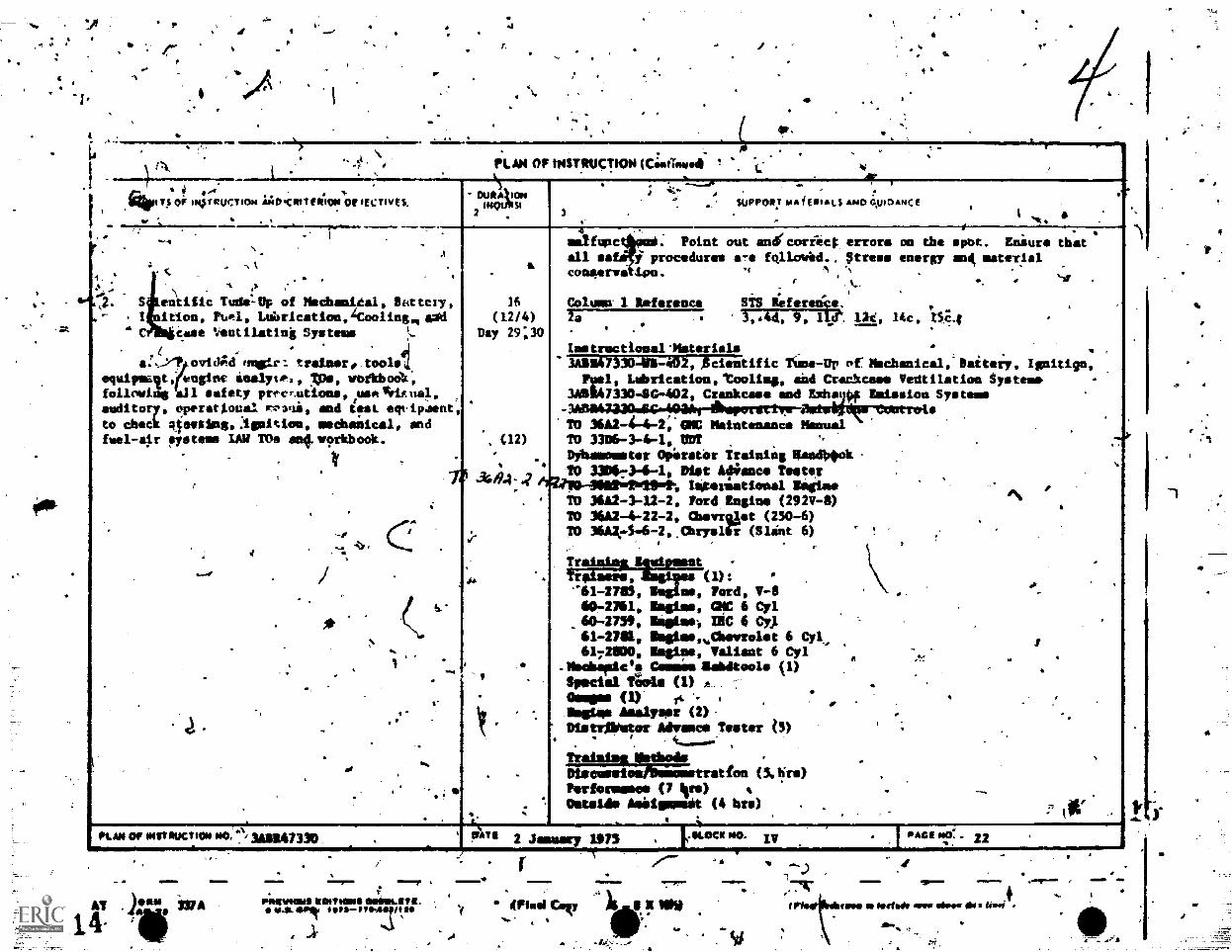
eniiiic Tude:Up of Mschanieal, Ilkittery,
ition, rUAI, LariCation,4COOlingimOdCMS! Ventil.ating Systems ',..
siltyr. x V. vbfkbool,a:../";a/ovitd finer. ... trainer, tool4
equipt; engine &sa
.4 .
follering all afety pr,scrutions, useliciEual.
auditory nperatiocal ri, and ieai etripaent,to check Rterraiing,:ignition, mechaiical, andfeel-air systems LAN TOe seq.morkbook.
PLAN OF IMITFUCTION MO. 3gligm330.
-
14AT . ).411. -MA
=11 T 10PRIIMIOUSIRCHT1011111esser.wra.
RA. Orli Be
16
(12/4)
Day 2930
arafunc . Point out andrcorrict errors on the apt. Eniure that.
fjrcillall sa i procedures a-e folic/Wed.. ;tress energy and, materialconeerwi Ion. .,( ., 'N
l%,...
s. %-lr
,-
Caulaw I Reference ST5 Reference.7i 3044, 0, lyt 11d.
-Itc , nc.lt
Iestrectionallbiterials3014)330-W8 -402,Acientific fees-Up pf Mochanical,-Beitery. Igniti9n,nal. Lubrication,'Cooling, aid Czar-kerma Ventilation System'
388947330 -8G-402, Crankcase and Exhatti# anterior& Systemes
TO 3682-4-4-2..01ID Maintenance Mensal. (12) TO 3386-3-4-1, UM
Dyhamomater OpirratOr Training Maed0Ook
344,41? 10 330473-4-1, Diet Atience Tester
FATI 2 January 1975
6fliv0-060220.214-, imeeristioual lguitueTO 3682-3-12-2. Ford famine (292V-8)TO 3682-4-22-2. Chavrast (250-6)TO 36A274-6-2,.Chryslii (Slint 6) !
, -(1)
Trainint assent -
-61-2785, me, Ford, V-860-2761, Oisime, CNC 6 Cyl
.60-2758, Oneimes, IRC 6 CO61-2701, lisime,v0evrolet 6 Cyl,6172800, Issime, Valiant 6 Cyl
.Neebamic'e Comes itabdtools (1)Special Tarts (1) A
06NOEN (1)'maims dialyser (2),Distr$Nitor Advance Tester (3)
irailde. indeed,Diecusstounelemstrstieu (3.1irs)Performance (7 4rs)Outside Asiiisneit (4 bre) .
9
AGEWC. 92
41Fhwei CIF IINO
A
.419."
04
%.
=1111.!....°NITS OF IisyouchON tmO.CIOTHOON OfuectIveS
OuRATICN(HMO%
OPINSTRUCTION (Caaweve4)
_
$uPPDXT AIA'REDALS AND GUIDANCE
4
4
A
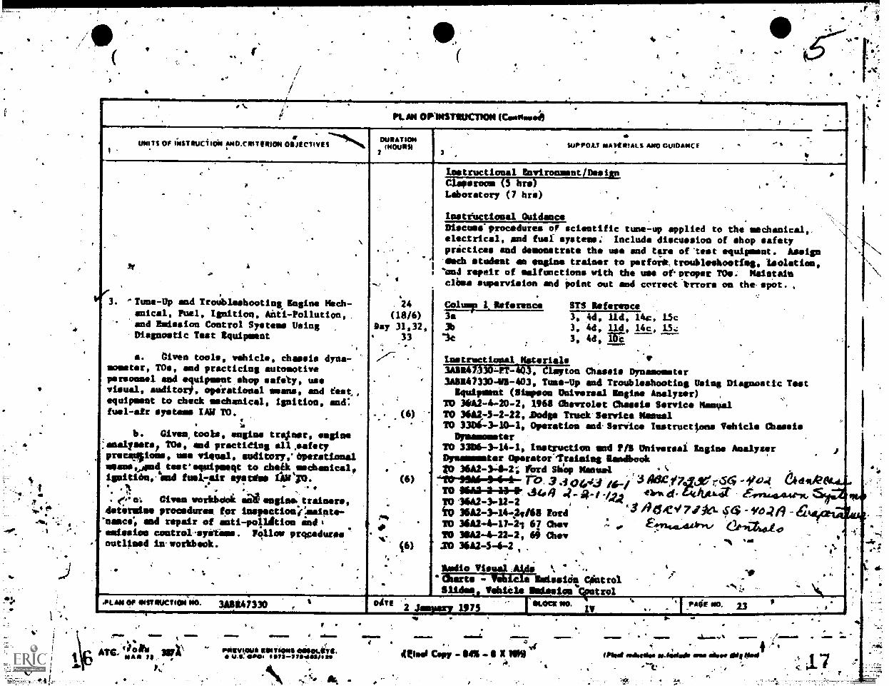
"Tune-Up and TroUbleshooting. Engine Mech-anical, Fuel, Ignition, Aiti -Pollution,
'and Emission Control Systeme Using'Diagnostic Test Equipment
a. given tools, vehicle, chassis dyna-mometer, TOs, and practicing automotivepersonnel and equipmeut shop safety, usevisual, anditor#, operational aeons, and fest,equipment to check aschanical, ignition, and:fusl -air ystem tAll TO.
. 1b. Given, tools, engine treiner, engine
-anal/sers, TO*, and practiting all.safetyprecelione, use visual, auditory,'Dperationalmeans,joind teareqmipmegt to cheek medhanicalf
fusilmir eyftdmi
0. given workbdok angina. trainers,&eternise procedures. for inspectionj
end repair of anti -po41dtion =dimissies° control-eyetams. Follow pmeduresoutlined in'workbeok.
41.IBLAN Of MST RUCTION NO. 3Aeg,47330
t.PM,
a
1
(I8/6)Day 31,32,
33
-
(6)
tmetructional Environaent/DesienClaparoom (5 hrs)Laboratory (7 hri)
Insteuctional Guidance
Discass'procedures of scientific tune-up applied to the mechanical,electrical, and fuel systems.: Include discussion of shop safetypractices and demonstrate the use and tfre of-test equipment. Assign'emch student an engine trainer to perforktroubleshootinge isolation.'ften.1 repair of malfunctions with the use otoroper TOe. Maintainclhas supervision and Point out and correct trrore on the-spot.
Colump /Deference3.3b
le
STS Deference
3, Ad, Ild, 14c, 15c3, 4d, Ild, 14c, 1543, 4d, Tri
Instructional...Materials
3ADD41)3041-443, Cleetoa Chassis Dynamometer3A14/330-V1-403, Tune-Up and Troubleshooting Using
Squirmiest (Simpson Universal Ingle. Analyser)TO 30A2-4-20-2, 1968 Chevrolet Chassis Service ManualTO 3611275-2-11,Bodge Treek.Service ManualTO 3306-3-10-1, Operation and-Seriice Instructions Vehicle
DynamommterTO 3306-3-14-1, Instruction mnd F/fi Universal. Engine AnalyserDynamemseer Operstor'qrainieg Eandbook
36A2-3-8-2; Perd Sh6p Manual A%
7610"910111,444.1r27.33044.344430441CA/grt4.56'f044 &tit*yo .3642-312-2 a
Diagnostic Test
42
Mamas
TO asaa-a-ao-g. -444 - I -42 'e"et 4." 6""414"%x'tu 36/42-3-1440611 lord "3 116,0,1741A1- IS-4TO 36A2-4-17-21 67 0ho, 044-277,14.4yTO 36/12-4-22-2, di them.,113 36A1-576-2
Audio Visual ;Ade&arta - %Alias IodootOn Ontrol.Slides uhia modision" trol
4.
4.
fa..
reevtous IONTSoNs osoot,M.s.p.s. moot ett-7/1410
*
Te
mosa.mor
,
4t1o.1 Cory 64% - S /I 1014
1975.Oelt NO.
#44.
VPAOE ND. 23
,
WSW ella&Aide* our Mr- Ill NM.
41
.......-...-.-----.-..----..._.................., ..................,, i
. FLAN OF 04STRUCT1ON (Ceutine.4
, UNITS Of INSTRUCtiON AND CRITERION ORMCPWES'i ! ..., _,.
DURATION- (HOURS) SUPPORT MATERIALS AND GUIDANCE
&
. .
b
:
,
.
.
. ,
.
. '..
.
. ,.,
., N...\
.
.
.
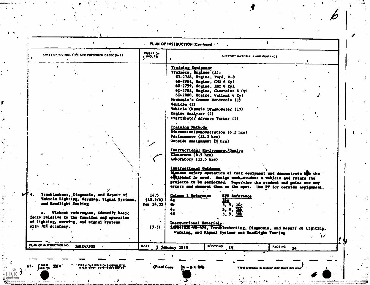
[ Y4. Trolibleshoot,,Diegnosis, and Impair of
Vehicle Lightingollerning, Signal Systems,end Deedlight.Testing
a. Mitheetreferegpes, idintify hastefacte'reletive to the functien mod operationof lighting, teeming, end signal 'systemswith 70,1 accuracy.
-,.
. .
,
.
.
.
14.1(10.5/4)
Day 34,35
'
(0.5)
Training Esulement . l .
.
,
>
.
.
.
.
demonstrate les theand rotate themad poiat est soy
for outside mellowest.
,
.
.
and Repati al Lighting,Tooting
. .it
Trainers, Engines (1):41-2785, Eugine, Ford, V-860-2161, Engine, GMC 6 Cyl .
60-275,, angina, !MC 6 Cyl41-2711, Engine, Chevrolet 6 Cyl .
61k-2800, Engine, Valiant 6 C71MSchenies Commoi Mandtools (1)Vehicle, (2)
"VehicleOessis Dynamometer (10).
Engine Ani1pier (2), Distributoi Advance Tester (5)
. . ,
Ualnina MethodsOfecueelon/Te;;;Stration (6.5 hrs)Parlament* (11.3 bre)Outside Assignment t6 bre)
\
1estructio41.00virosmint/Desiro '
CleeeroomA6.5 hr.)Labmitoty (11.5 bra)
Lest tional Guidance1
cuss s r;74-iiiams.of tet equipment andt is used. Assign eachostudest 4 :test*
projects to be performed. Supervirre the srrors and abstract them on the spot. One rr
, .
Calton I Reference !Ts Warsaw48 lie
.
4Ir 3-1-9 . lif.,
4c 3,,9, 16h44 3. 9. BC .
Iastuctiosa1 aterials-7330-16-40T, Troubleshooting, Dispeels,
naming, and Signal System and Headlight
.?""" illarUCTI°14 "°' 3S2147330 DATE1975
INNONME EMPEWD OMImpl FI- 7 rongurus acwritwoo ossoLets.
Amp. EMT 4111211WrInewil 111.
4 gml 1=1.
4Mitel Cep, ex.iew
=111M. !MX.
Imo redireeka so ireewly ems awe Os /NW
.1 .
er
74.1aio - ATC 'oirr;$ 337A
4
......--....--........................--.........-----...........--,...........- -......-....4.
PL MI OF INSTRUCTION (Comiessw. ,
Wats OP m(STIUCTION AMP CRIT MOM 011itCYtveSoUllAnOm
IMMO%2
e e . 1
. SUPPORT mATEMAL s me CLAOANCE3 4..----
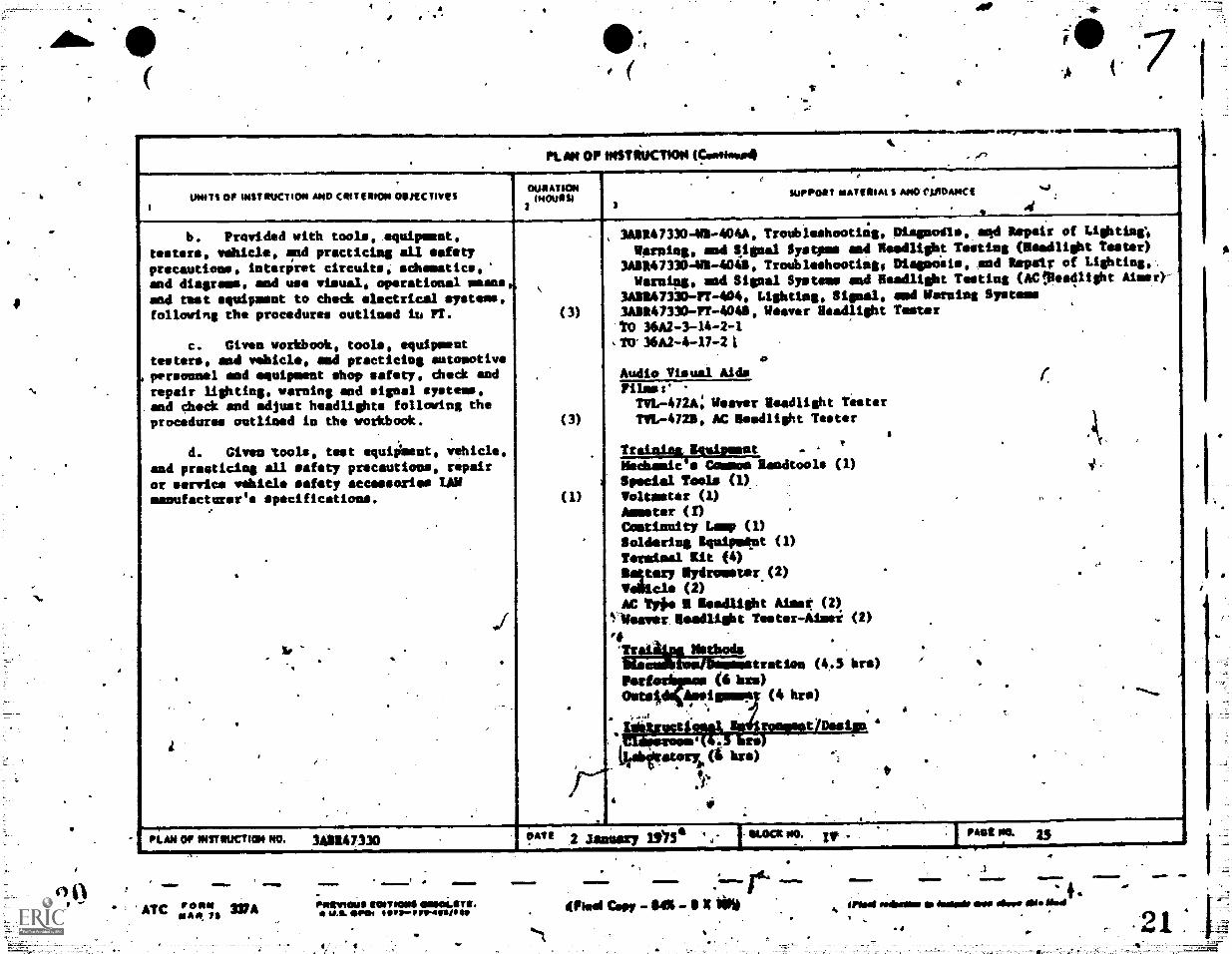
b. Provided with tools, equipment,testers, vehicl, Ind practicing all safetyprecautioes, interpret circuits, schematics,and diagram', and use visual, operational meansend test equipment to check electrical systems,following the procedures outlined iu Fr.
c. Given workbook, tools, equipmenttestrs, and vehicle, mad practicing Automotivepersonnel mod equipment shop safety, eheck andrepair lighting, warning and signal systems,and check and adjust headlights following theprocedures outlined in the workbook.
d. Given 'tools, test equiement, vehicle,and preaticins all safety precautions, repairor service vehicle safety accessories LAUmanufacturer's specifications.
e
.
la,
.
..
.
i,
.
(3)
.
(3)
(1)
.
,345H473,3 -WS-404A, Troubleshooting, Olessodis, aqd Repair of LiShting;
Harping, nod SiSmal Systpme end Rendlisht Meting (Readlight Tester)341147330 -VS -4014, Troubleshootimg, Diagonals, end Repair of Lighting,..
Harpies, mad $ ignal Systems and Readlight Testing (AC!Reedlisht Aimer)-3ASR47330-FT -404, Lighting, Signal, end Warning Systeme342147330-11-4041, Weever Headlight Tester
,
TO 36A2 -3-14 -2 -1
,TO 36A2 -4-17 -21 .
0Audio Visual AidsFilmes'TVL-4724; Weaver Osedlight TesterTVL-4722, AC diedlight Tester
s
Traimingvgleigueat .r .
Nechamic s Cammoe Randtoole (1) i.
Special Tools (1),Voltmeter (1) fs
Amstar (1).
Castlanity Limp (1) .
Soldering Squipmest (1).
Terminal Kit (4),.
. ,
nagtary Sydromster.(2) .
%ilia* (2)AC 11,641 I Modlisht AlmaT (2)
1.1Weaver. Beadlight Tester -Masi (2) ,
r,'TraLLnaNstbods
.
.
bia tratiou (4.3 hr.) 1
recto4wises (6 lurs) -
Outs; Amoismeml (4 hrs).........
.,..,,.
.
isemt Bs4irommestIDesise 44(g3 bre)
.11.abiltatory (1 bra). . i
t,.*
.1. ..
.
PLAN OP INSTILICINI. NO. 3AgE47330 !MI" 2 Jameary 103 *LOCK PO. iv . PAGE NO.
r r.irmovsaull MATIONS 0111101.11111.
U.S. *Me owsP75-4ost/f01.
p
KM OF imsnucros (Contieva.
ow Is oc ontouctICNI AND CRITCHO 00.1frt trims OuRATION040101111
2SuPPoeir osATEPIaLs AND Gwomoct
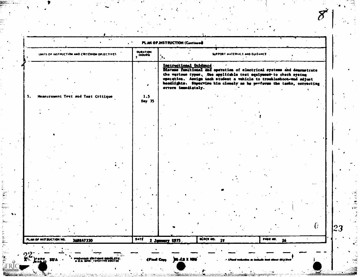
. Measurement Test mud Test Critique 1.5Day 35
Imstreotiemat Ouldammi.ETrilinnmat operettas of electrical 'Totems and desogistretethe VeTiOull types. Abe spendable test ageigneem-to check systenopetetion.. Assign Mach easiest a vehicle to troublesboot#end adjustheadlights. Sapervise bin clomar am be porfomno the tasks, correctingerrors innedistely.
4
tuvri 1975 ,IKOCE No IV
Pied an jus..ta NW
!Mt ND.
m
trimegalliele R Mts16116 ese Olswil WON'S
23
4.
4-Tx
4.
'S.
4 ta
a
ameIMINIIR.
.
PLAMIOPINSTSUCTOr...4 -
MUNI TITLE
General
: # 4.Purpose Vehicla Replirman - Part I .
..
.116........ .
GLOCE TITLE . ' ' t .
... ,
Power Trains .
..MI OF INSTRUCTION NOD COAT ff111011 OTUICTIEES
ATKININCURS,
SUPPORT NATIONALS AND GUIDANCE .. . .
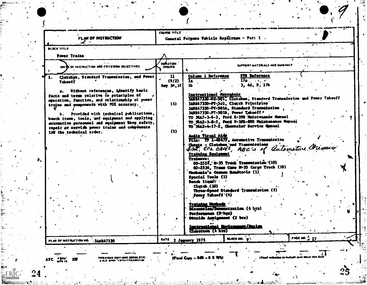
'. CluttNps, Standard Tramenisioe and Power
Takeoff
e. 01theut reteressee 14estify basicfacts and terms relative to principleo taf 0
operation, function, and relationship of parertrIns mnd romponenre with702 accuracy.
/.
.
*0. Provided with tochnical publicationsbench items, toolo,'end equipment sad applyingautomotive personnel sad equipsnt Shop safety,repair or morel* power train:: mad cohpanents
IAS the todhnical order...,. . A
., .
.
..
. s
.
,
.
4
,
.
. .
..
- . .,
.-, , .
.. ,
.
. .
..
.-.........11
(9/2)D5 36, 0
(4)
,
(5)
,
.
,
.
..
Column 1 Reference STS Deference .
la . TYW-7-777.77- , ,i
..
.
lb . 3, 44, 9,17b .
,
. ,. .
lostrutionelnategAaln . .
..30147 40..agf7 Clutches; Standard tranemiseton and'Power Takeoff3ASR47330-11141, Clutch Prleciples" ..
3A1R47330-P1401A, Standard Trassidssiem ..
3A1147330-,PT-9011, Power takeoff g .
TO 36A2 -3-6-2, Pord.S-100 Mriotenamie Manuel.
.,.
10,9SA2-34-2, Ford P-1004100 NWIntesamee klapoa4 .
TO31124-17 -2, Chorro1seSerwice'00nual .
. .Au#14k Visual A14 . .
A i711m: fit 1.-4o4irs, Automotive Transmissiou .
Ifillitaless,'Awl ..., ._,._. 424,4004:9e,ithiT c -A. 0 4f r, *age ta al.4.40.271..t 4 ,
TraiMins Iteionent..
. :Trainers:
40 -25211,4.7/45 Track Trasssissair/10) .
40-2334e Trams Vase 11-35 Cargo Truth (10) ,
(1) , .Nsheasie's O mar Ilamiltonla.
Special Tools (1) .1 .
knish Iteritr, . ., .... .
. Clittell ,( 10) .. , .Three4pee4.111ss4.rd tramemission (2) .
.,Powei Takeoff14) ' 'fi. -
.. .
.. , . ..
. Pertermieee.(5:440 . ,..- W
.
AMalik Aistipurst (2 birs) ..
e..
,
.- ,
PLA00101011fflIKTHINNO. \ 3A41.47330N
.rata NO A0 27 -
DA" 2 Jemmy 1975 MACK NO. lc . e.......Patvocou* R0ITI0N1 0411104ITIL
U.II Oval 'Iln*--rtesiOns Mod Cory 1 X NW
VfrIMIIP 1=10111M
Mod selbsteme Oirfaeloth ems *sow
==.=7.==-
c
a
.
*
A
ar;
.4.1I .. ...., ma.
.1 .-11MMINAMPAM. 1111. MiNi./MAN OF INSTRUCTION (CAtieved
A
kr
'WITS I;P INST tUt-T)ON AND CRIT ORION ORJECTIVES DURATIONtHOURNr
1
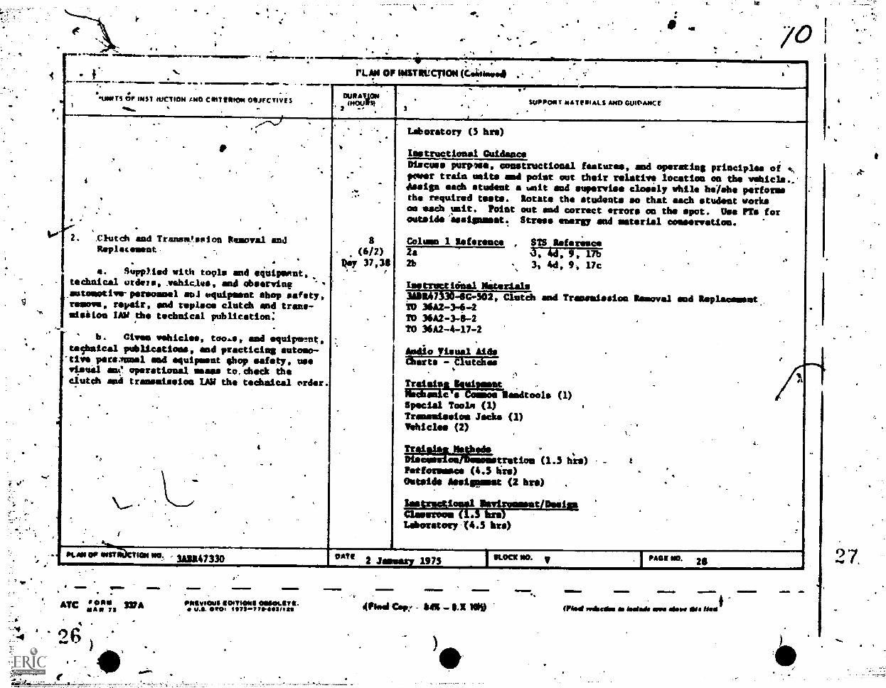
Chad% and Transe!svion Removal andReplecement
a. Supplied vith tools and equipment,technicel ordain, vehicles, and observing "'.autmestive-persomel soJ equipeest shop eafety,remove, repair, and replace clutch and trans-misiios LAU the technical publication:
-tive peremuma sod equipment ;hop safety, usevisual an0 operational mass to,check the
b. Claes vehicles, too.s, and equipstut,technical publications, mod practicing automo-
clutch and transmission LAW the technical order.
3
LAboratory (5 hre)
SUPPORT MATERIALS AND GUIDANCE
Instructional GMideace
Discuss purples, constructional features, and operatins principles of ANpower train units mod point out their relative location on the vehicle..Assiea each student a unit and supervise closely while heishe performsthe required tests. Rotate the tudents so that each student worksos sack unit. Point out and correct errors on the spot. Use PTs foroutside'issisnmast. Strese emergy and material conservation.
Column I Reference , SIB Referimuce2a 0, 4d, 9, 17b2b 3, Ad, 9, 17c
Isstroceloaal Niterials3111475304C-502, Cluteh and Transmission Removal smell soplaaamost.TO 36A2-3-6-4TO 36A2-3-6-2TO 36A2-4-17-2
Audio Visual AidsMarts - Clutches
Traisis ui etc Reedtoola (1)
Special Toole (1)Transmission Jacks (1)Vehicles (2)
Tidalei=us64scossl trstlom (1.3 hl-s)Potformmies (4.3 his)Outside Assiglomut (2 bre)
Sastractiosal Imviroamsat/DeilmaClassroom (1.3 brs)laboratory.(4.3 bre)
.
. .
ATC ilI.A" IS WA4
. 11,1
110111014 00110LeTt.maw 9710.7 71-1140*/ 1 all Mod Cop; 6411 -
)
11 41 1M 411
Mod voiscess Mama Nom aim Ws NANt
=1
.,
go.
9 84 ,
a
,, P1.410F imnitucrics (CaRtiaa.4/ .
UNITS OF INSTRUCTION 14404RITERION ONJECTIVESDURATION
(HOURS)
.
. SUPPORT MATERIALS AND GUIDANCE .. .
.
...
. ..
-,
.
..
--. -
.
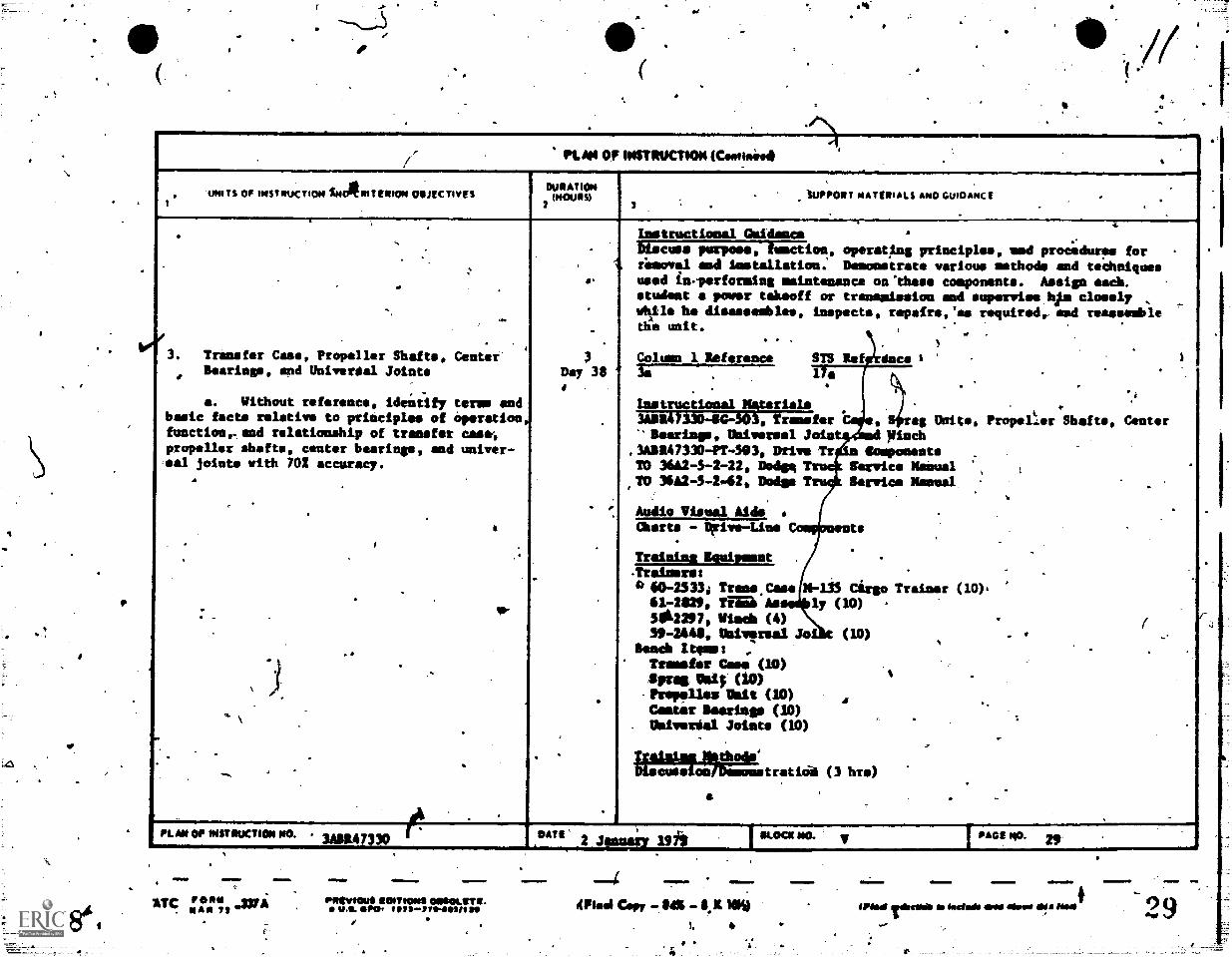
. Transfer Case, Propeller Shafts, CenterBearings, spd Univers:al Joints
-a. Without reference, identify ter= end
basic facts relative to principles of Operationfunctioneand relationship of transfer case,propeller shafts, center bearings, and univer-sal joints with 702 accuracy.
A
6
.I
.
. .
..
.
,
. \.
. -
,
..
.
A..
.
3Day 38
.
.
.
.
Instructional Geld:Ince .-
-.
_
.
.
Discus purpose, Unction, operating principles, ued procedures for .
rimoval and lestallation: Danonetrate various methods and tcheiquesused ineperforning maintenance on'tkese cosponenta. Assign each. .
student a power takeoff or transidesion and suPervims kfm cloudy .
while ha diem:gambles, inspects, repairs,'as required, and reasseablela
,di unit.
. .
.
Column I Reference STS Ref ince 13s 1 a .
.
.
.. .
. ..
Ins truçuonal Materials'k
IASS47 303, Wransfer eg Unite. Propel.er Shafts, Center" Searing., Universal Join 9inch,3ADS47330 -1T-303, DT/VO irr Somponents .
-
TO 36A2 -3 -2-22, Dodge 2 --, Service Melual ',..
TO 36A2 -3 -2 -62, Dodge 2 . Service Mama .
,
Audio Visual Aids . S
Charts - Dmive-Line - te.
Trainina Icuipeent.
-Trainers:.
4 60-2333i Trans Case 11-133 Cirgo Trainer (10).61-2,29, TEMI'lls ly (10)3612297, Winch (4) - (39-2445, VilvIraal Jo (10) . . ..
,
Bench Items: ,.
- .
Trarsfar Case (10)
Strai 1114 (10)1Prapolles Dalt (10).
Comer learisp (10)Orniveria1 Joists (10)
.
i
,
TWA'S*. .MiodilDisausalauTheamm trat ial (3 hr.)
.,a .
PLAst OP INSTRUCTION KO. 3ABR47330..r.... °ATI2 aarrY 19710 I
OLEIC* 1.° v PAGE NO. 29 ,
".7
=IMO
1TC "" .33A. Nan 79 r
=1..
Peeviews RDITIONS 011.0LETR.us aPor r1979-7te-1F141 Re
a
mbe
elitel Copy -. aI
Mmliwn II1
ried rob* me dodo* men clime ad NNW
f 4
4_
PL/11 OF KISTRUCTiON (Ceemeeat. ..
-
..
UN, TS OP INSTRUCTION AND CRITERION OSJECTIVESI t 1
DURATIONINOURSI
3
, .' '' SUPPOR T MATERIALS AND GUIDANCE .3 f .
.1---._.
.
. .
. 0
t,
-
.
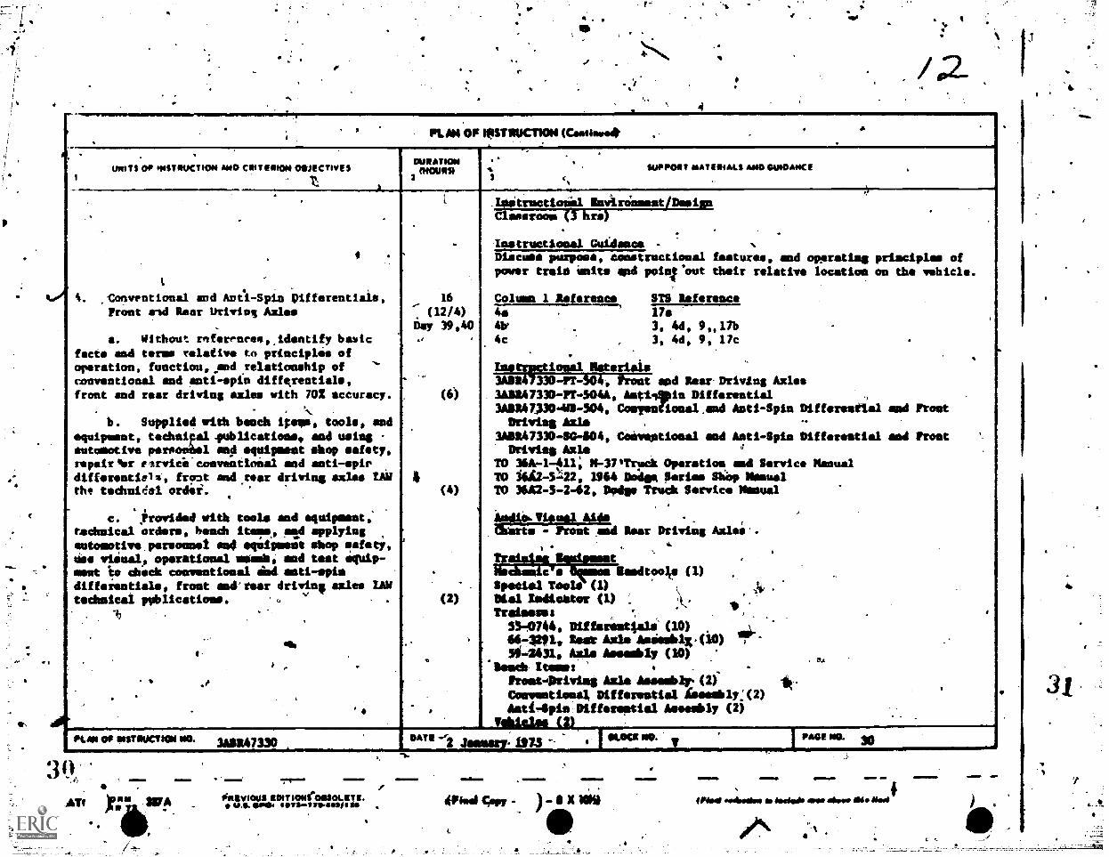
4. :Conventional and Ana-Spin pifferentials,Front and Rear Driving Axles
,
a. Without roferenree,Jdentify basicfacts and terms relativ to principles ofoperation, functiou, _end relationship of 'rsnventional and anti-spin differentials,front and rnar driving axles with 702 accuracy.
. . . \ .
b. Supplied with beach itens, tools, andequipment, technipel.publications, es4 using .
automotive nsrooAel sop iequipment shop safety,repairmnr elrvice'conventioial and anti-epirdifferentials', front and.rear driving axles TAWthe tedhnirlel ordei.
., .
t. powided olth tools mod squlposot.technical orders, beach none, fad applyingsotomotive.porsoosol so0 scapmest shop safety,ins vinual, operational anianle, red teat equip-smut io chck conventional iind anti-spindifferentials, front andirear driving axles UVtechnical pnblications. c.. .
11 .
,
qhe
!
..,
. . ,
.
16
(12/4)
6111 39 940., ,
4,
. (6)
4(4)
,
'
.
(2)
.
.
.
..
'.'
Ravironment/Denimn
.
'.
,
,
,gntructionil.
amorous (3 hrs). . .
IMOtreCtIOEIO1 GUidillkaa,'Discuss purpose, constructional features, and operating principles ofpower train Unit* nnd pOtO1.0Ut their relative location on the vehicle.
7
Column 1 Referents STS inference4. . 17.41). 3, 4d, 91.7b4c , 3, 4d, 9, lic .
..
Instrpctional Mieterials. .
3411247330-11404, Front apd Rear-Driving Axles3AMR47330-11-5044, Antilipin Differential3ASR41,30-10-304, ConyestionalAnd Anti-Spin Differential and FrostDriving Ails ,
P
1411147330-SC-604, Cannot/mai and Anti-Spin Differential and frostDriving Axle ,r
TO 36A-1-411; 11-37TrrPk Operation and Service ManualTO 3612-542, 1964 Oodso pities Sliop ManualTO 36A24-2-62, Dodge Mich Setrvice Noma
_
,
01114,Tiousl A446 .e
,
,M7G-=-ISITrinTel Rear Driving Axles..
, .., 4
t.
;::115:411;;::: Mamdtoolte (1)
Speels1 Tools (1) .
Inal Iodic/tor (1) :
\
A. -
T roilism: ',
53-0744, Ditfaxs' t4a1i (10)46-1201, lest Axle Asissb1x,(10) ..
50-4031, Ails Asombly (10)*Bawd' Wm: . -
.
Ftost-iptivist Aals Asssob1r.(2)
COoventlosal 0ifferestlal Aissob1y:(2)AstiApin.01ftereptlal Assembly (2)
Tablas, (2).
PUN OP INITINOCTION NO. 3Au47330.
I 'Lock NO. Tr PAGE NO. 30OATS ---2 "Rum 1973 -- 4
,
3
,Alff.
-
.M= .--olotavocius IIRITtomeossoLET a.
%Ls. eves os37148Pos
=1=1.
OMNI Copy - It MI
MIPIM 11.11. ..Irbil meadow in NdsI mom above e NoI
.. M11
3
mwPLAN Of IMINCT107.11kptif6.4
UNITS OF INSTRUCTION AND CRITERION OBJECTIVES DURATIONMOURN
2
-SuPPORS NATEMILS AND GUIDANCE
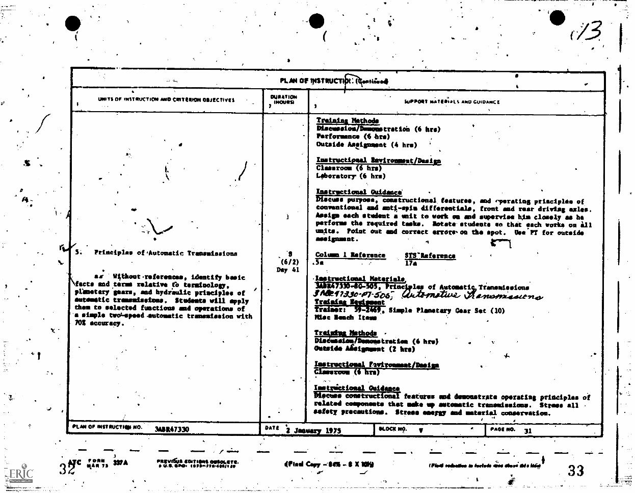
Principles of,Automatic Traninissions
114thout.references, identify basicfacts and.terms relative tb terminology,pranotary gears, and hydieulic prieciples ofautomatic-transmissions. Studemts will applythem to selected functions and operations of-a simple twouspeed.entomatic transmission withPOI ccuracy.
1(6/2)
Day 41
Trainina NOthods
Discession/Demenstratioi (6 bre)Performance (6 hrs)Outside Arlignment (4 hr.)
Instructional Invironment/DesignClassroom (6 brsiLehoratorr (6 hrs)
instructional guidance''Waco,. purpose, constructionel features, and eperating principles ofconventional and anti-spin diffrentials, front and rear driving axles.Assign each student a unit to work os end supervise him closely as heperforms th required tasks. notate students so that tech works on illunits. Point out and correct errors,ce the spot. WO PT for outsideassignment. A
COlUMM 1 Seferente STSIteference11.
.Instructiocal NicFials,.
IA1147330-60-505, Prim of AutanatisTransnissions1 Age1U14,-07-,5-As: X Att.420-4K:4.4.a-7.142,- .
tralaisikitstrestWalser: 59-2469, Simple Planetary Cear Set (10)Mac Beach Items
UAW's& IthodsSisdeseleR/Dmmeestratiee (6 bre)Outside Abotomment (2 bre)
gralEftritEEERESELftilt
Irstrictiesal O4idaimMeuse rosstructional features mad demonstrits °matins priaciplas ofrelated components that mik up automatic tranemissions. Stress allsafety precautions. Stress aseygy and material conservatism,
,
PLAN OP INSTRUCTOR.' NO. 3A1147330 DATE 42 jemmy MS I*Logi NO. v FACIE NO. 31
Iv FON" WAII.AR 72
V.
,
PRNINIfus MINAS oesoLITI.we. Sys, oPt1-fse-11011/12$
wirri mow .1 10..
Cry - I IO)0-
7-
WWI redleals Sib Meted@ dies Allsri id ihroil33
MIINNIONMEMIN1011=1ft.
PUN Of INSTRUCTION (CAN101110424
win OF pistIvOttO' SAO VINT MON ORJECTIVESDURATION
(MOURN SUPPORT MATERIALS AND OUIDANCE
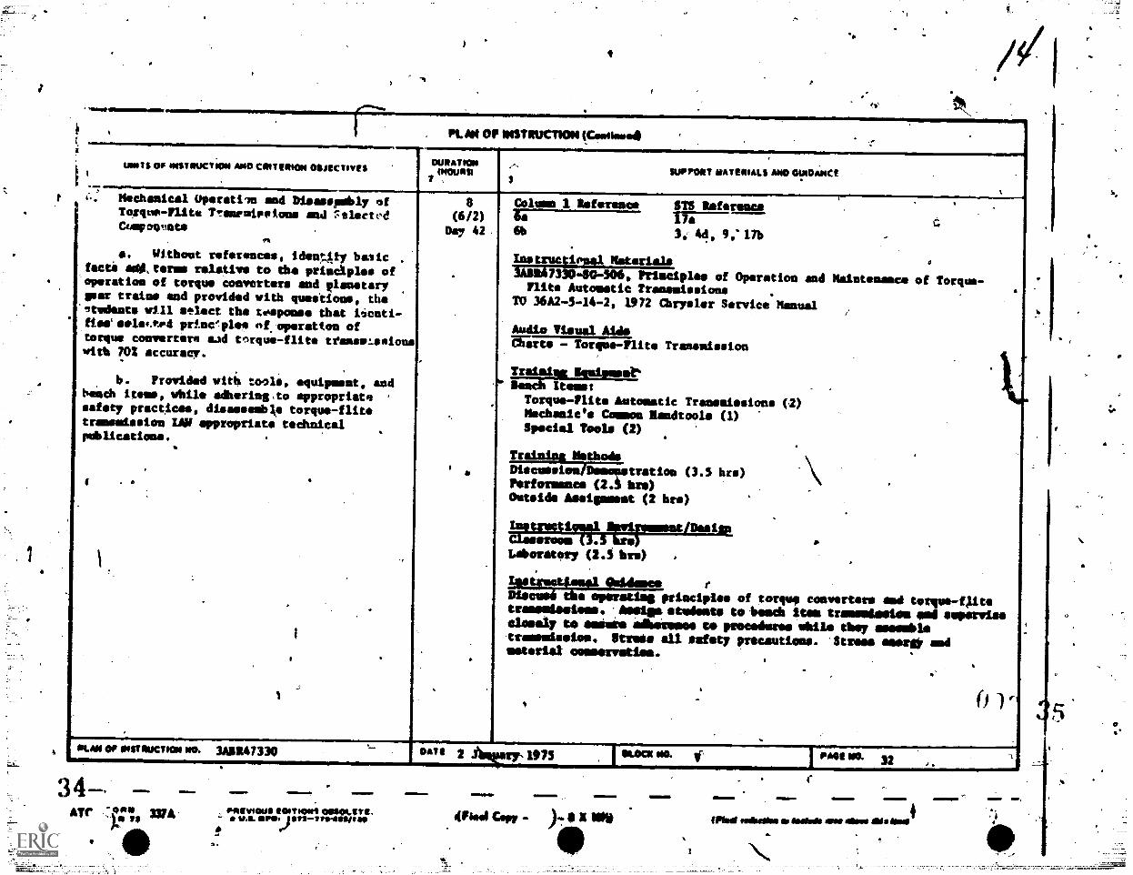
Michanicel Operatil. and Disasspmbly ofTorque-Rite Tranyudeeime and ::tlectvdComments
. Without references, ideu!...Aty baiic .
facti agi,terms relative to the principles ofoperation of torque converters and planetarypax trains and provided with questions, the'nedeate will @inset the regponse that iicatiflee' selef.rod prineplee of.operattou oftorque converter. sad tnrque -flit. treeselsaionswith 702 accuracy.
b. Provided wit tools, equipment, andbench items, while adhering.to appropriate .
safety practices, disassemble torque-flit.trammission LAW appropriate technical.publications.
8(6/2)
Day 42
C01090 1 Reference SIS Referme
6b 3, 44, 9; 17b
Inatructiousl Material.3422.47330-119-5a6, Prisciplos of-Operation and Maintenance of Torque -Flits Autometic Transmissions
TO 36A2 -5 -14 -2, 1972 Chrysler Service Manual
.
e
Audio Visual AL&Nitta - Torque-Flite Transmission
Treinialt ISN1womat"Month /toast
Torque-Plits Automatic Treosaissioms (2)Mechanic's Comma Ramdtoole (1)Special Tools (2)
Traimiee Methods
Dtscussion/Ommonstratiou (3.5 hr.)Performence (23 hge)Outside Assigmmemt (2 hr.)
assroom (3.ckivrimentiahiPCllottruct19491 4
mLaboratory (2.4 bra) .
.
lestruot2osol alidsoce r
Neene6 tie erstetift principles of torque converters god torquo,llitstraossiooloos. latsigs widgets totes* itos transmission osil sopossissclosely to solisis ilhoiromoo to prosodists Ails Choy ossooblstrassoisolos. Rages all safety precautions. 'Stress amere0 amdmotorist oommerostios.
1. vPLAN OP INSTRUCTION NO. 3App.47330 DAT!
34-ar -3;44 W A
1111
aMINI.10.
paiviOUS IttlytIouS osiokyrs.u.s. aP0tInti-1t*11011
2 Amp:2,1975
0441 Copy
IKOCK ANL
INIES IMNYM
}..xmow
40
PARE WO. 324
(Mid falbtate Isehlie Ewa wens Ads best4
`1110.1.
3*6'
INMIMMPWRIMIIIPMNOM11.1M0101101111011110Womisa
,PUN OF INSTRUCTION (Cowieved
-
um TS 00 last fluCTOos *ND CN1T ER.01 00/ECtive$OIMATION
MOMS) moppet Mat IRMA AND GUM ANC I ..1
,
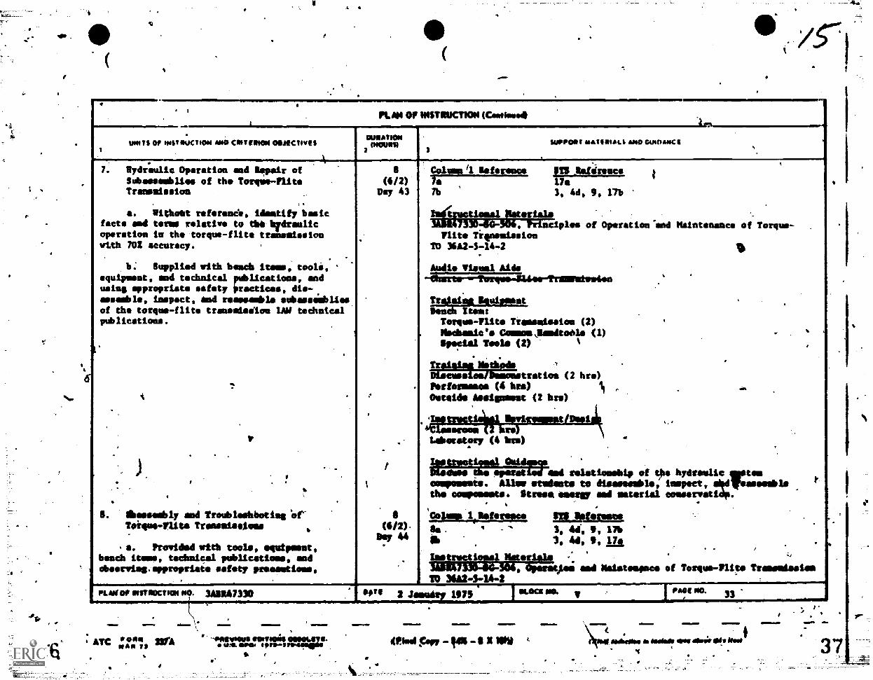
.. Hydraulic Operation mad lapair of
Subassemblies of the Torque -flit.Transmission
I. Withoet reference, Identify 6micfacts end term relative to WI-hydraulicoperation to the torque-flite transmissionwith 702 accuracy.
6; Supplied with bench items, tooli, .
equipment, and technical palications, andusing appropriate safety Orectices, die-assemble, inspect, and moveable sobmenabliesof the torque-flits transeislon LW tedhatcalpublications.
,
.
,
,
A
.
,
V
. . .
V. ).
..
,
...
. lbaesombly and Troublathboties 'of'?yip's-flits Tronseissioes
.
a. Provided with tools, equipment,bench items, technical
e
(6/2)Vey 43
?
,
.
t
8(4/2).
bey 44
.
caws il Saleroom 1......_11.61111Ce I._,$TSti Ile7b 3, 4d, 9, 176
timallIteriala7330410-506, Principles of Operation-end Maintenance of Torque-
nits TignamissionTO 36A2-3-14-2
111
Audio Visual Aids-.6iserte--fewqms.11ies-ftamemtweien
.
.
Troleiel SeniipmentSee& item:Torque-Flits Tramsmission (2) '
Neches/6' Cemoms Jlimdtoide (I)Ilpmial Peels (2) 1
V
,
.
Trciaieg Retied, *,'
.
Discussise/flemmnetretion (2 hr.)rettarmasea (4 bre)
it - .
.
Outeide Assignmet (2 bre)
.WOOS
Laboratory (4 imo).
.
,
roszamr!4::::Trolsard relationship of 9's hydraulic este'
conrommts. Allay students to disassemble, Inspect, 4101reassesble P
the couponents. disuse Seem sal aaterial consarratidp.,
colon iletereoco $TO leferosne,sa.
3, 44., 12, 17bii, 3, 4d, bong
.
.
.
pat HAW .. ..,
publications, nodcbaervisp:appropriaie safety pracoutioos, 9 Operation sod Maistonance of Torque-Flite Tramendasies
20 31h2 4-14-2
PLANO, INITMOCTION NO. 3geg47330 see 2 2 1975Piiet PIO. 3
ATC V 00111NAN 11 30,4 1NNIVICIPS OINVIEN6um. Gaol torasro4logge
r
IMMEM110.
41984 Pr, 'SI .11 X INV
..W11.
solottise Melba sop flair Si" NO0
.11M=1.#0
3
IMF
"kr
-
, # 11.41081110.1.11.# =01......i111111,1
PLAN OF stenuenosa mollommai
win eit NesTsucTIoN *240 CIIII MOM OOJECTIVIS OWIA'2104memo
1
..Nt SUPPORT marimaits AIM OutemOCI ,
2 ,t ,.......-..........---.....-----....;--..
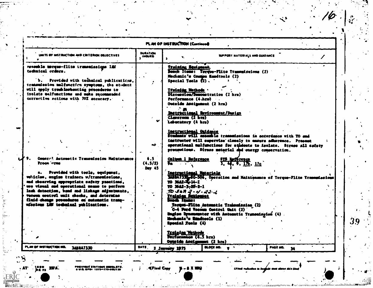
tnedile Siorsne-flite Lressniselips IN ,
teChnical orders.
At. Provided with teamical publicaticoe,transmission uslfunctics ymptoms. the videntwill upply trolbleobooting procedures toisolate malfunctions end mate tqconnesdadcorrective motions with 70! accuracy. .
.
.
.
. -
t.
. .,.
9. Gomm,. Automatic Transmission MaintenancePC04,-tiree
a. Providad with tools, squipmest,vehicles, engine trainers. iv/transmissions,and ohearviug approprist eatery restless,
'eso visual and sparatiomat moos to Preform ,
leak detectima, hand sad Wimp adjustmatits,'seem soutrdi unit checks, ad Asuman*fluid-dump pevesimee mi samstle tram,- ,
sabstoms IAN Mislaid pubilsatioss..i ' .
.
,,, . .
-
.
4
:
,
I°
.
6.3(4.3/2)
Day 43
.
. --
...
-,
,
_.
.- .
Tradaiss Skater* .limb Items larope-Plits Transmissions (2)
.,hischanie Comps Sandtool (2)
Special Tools (2). A .
....
. .
.
Thistle Nothode , ,
Discussiounamonetration (2-hre) .
Performance (4.hre) -
Outside Assignment (2 hrn)...
isstrilettagoklayironnsatpesimsClassroom (I ibli)laboratory (4 bre) .
.
.,
MMtWrMe transmissions li actardance with TO midLestrwtterelli superviseclosely to assure adbireace. Preeest 1
ellerstimml Iftlfelletifts for to toisolate. Strom all asfetyprecputions. Strese usttrial -anew cosmervation.
Wto 1 Pobreq2P T. 'Ai
va -. .1 171 c
,
i
, aT117 ii , iir T. raise and MaintSnence oi Torque-Flit. Transmissions
20 3GA2 14.4TO MA2-3746-2-1./b 440 4 7 9-_44-.4
Cselte="61144 .
y.opiii-nite Au4sest1e Trandesiot (2),04 Iremil Tasurs Costrol Aka (2) ..amiss Oprooster vith Aetematie Trasesiszio (4) .
lloamle Simitools (1) . .iimaissi Xamda (4) .
.
WWII% bre) a
Oftsidi Aestt (2 bra) ...KAM OP OISTOUCTION 010. mitx7330 .
. # ."Te 3 26111415 en FO2.091 NO. ir = I PAS'S ma 34
4Lo'+Irmo
AT 1,0*1 WA:re PS
.MM1 =MOEN. MM=.
pinvfauf tempo oosot.a2a.WA M! IIITIMMO4111111/1 as
IY 01.11# elm 1Afingl Copy yl.sx Nis
11110-_
:IM,NENm
UriodellidkOolbA14:41WdeletwAidaligrOT
1wirtworm,
39
.=01/ .1.W,
.. PL PI OF INSTRUCTION (Castinee4 ., ---.--
UNITS OP INST MX/00N AND CRIMSON 0111EeTIVESDURATION
INCURS) SUPPORT MAI ERMA MID GI/MAI< E p
.
-
\--,
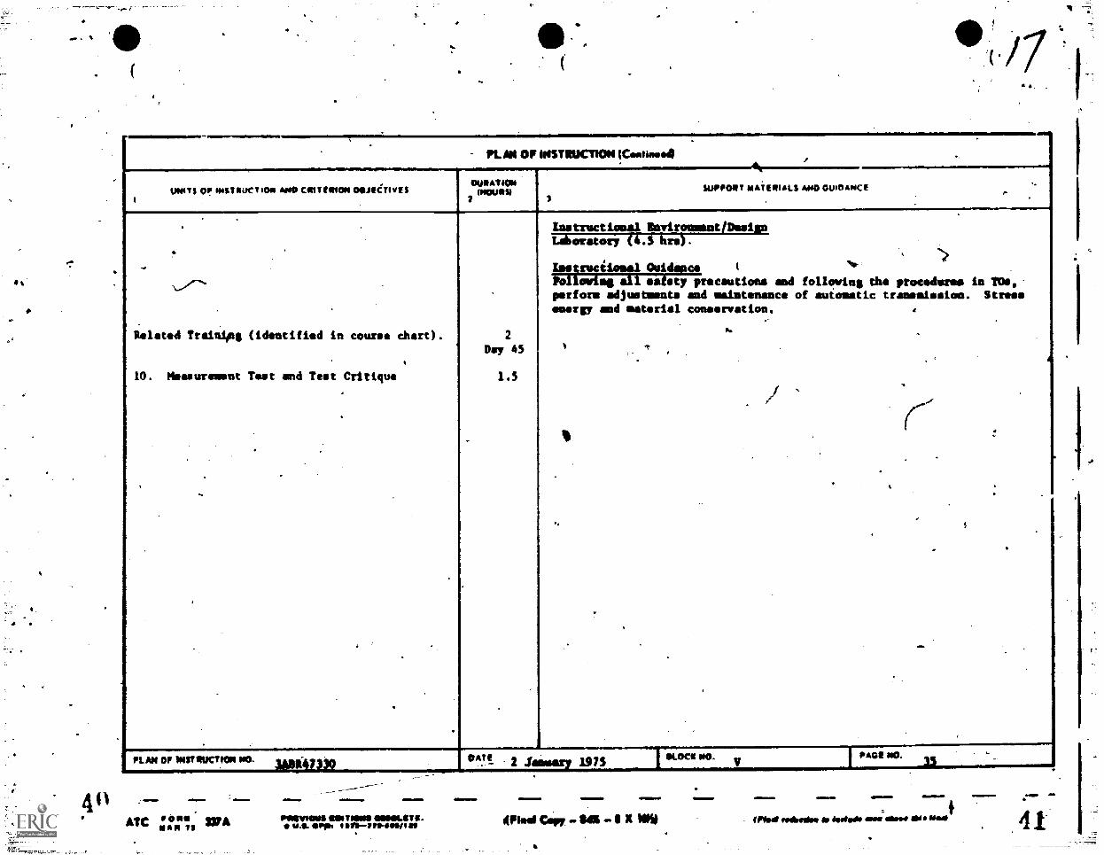
Related Trainipg (identified in course chart).
10 . Measurement Tes t and Tea t Critique.
. .
. -
,
,
.
2Day 45
1.5
.
.
Instructiosal Invitomment/Deeign
, )the procedures in TOs.
transmission. Stres,
-,
.
-.
...
,
Leboratory (i.S hre$ .
Istqrscilosal Ouidapce I
PollowImg air feisty precautions and followingperform adjustments and maintenance of automaticemery, aid material conservation.
...'
i T
,I
.
,
..
PL AN Of INSTRUCTION NO...4
PADS NO.
ATC '°°° WANAN TS
dOld MilNI1
Ilemose ROMONSOSINILSTE.U.S. Sop IIII/Srte-assit Mod 6.7 - s x woo
*M.N. . .Asalbsaloo Or Jule& ems Oars die s Had
041
- 4,41
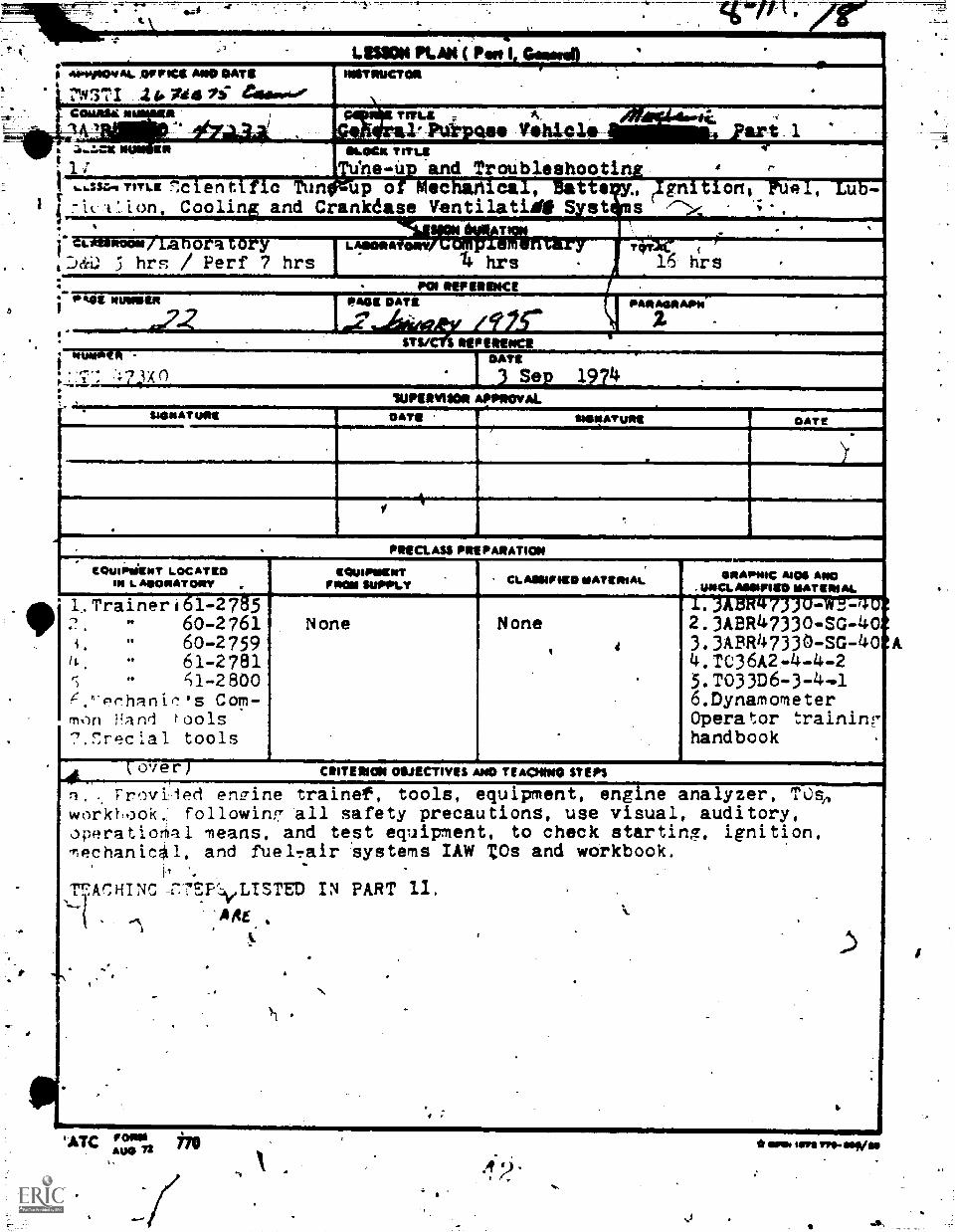
LIMN PLAI4 ( Pao; alooplOvAl. OFFICE AND DATE INSTNUCTON
N3171 Nd 73" e411000409COWRIE It TIELL
2OLIN* TITLE
ne-Up and TroubleshootingTITLE ti f ia tun up or mechartical, Batts
it t' ion, Coolin and Crankdase VentilatidE S st
AUhl 1. ari 1
umommw/Lanora toryJ&O 5 hrs / Perf 7 hrs
foakes mmis(t1
I
IMMO fri0. 4 xo
A2004061vRialift, At 'airyhrs
P01 REFERENCEImes DATE
Ignition, .1,-
Sys/ II REFERENCE
SNINAT USE
I DATE) Sep 1914
'SUPERVISOR APPROVAL
tusigATvit*
Lub-
DATE
PReCLASS PIE PARATION
EQUIFsIENT LOCATEDIN L. AISONATONT
1,Tralner161-27g'560-276160-2759
1,1 61-2781q.-2800
.'er..hanic's Com-frl.)n Hand tools7,F:recial tools
over )
EtlimPNENTFROM SEPOLY CLASSIFIED NATIRIAL
None None4
Ws.
ISIRAPNIC AIDS ANO. UNCLASSIFIED MATERIAL1.ABR47330-49-2-42.3ABR47330-SG-403.3ABR47330-SG-40 A4,TC36A2-4-4-25.T033D6-3-4.1&DynamometerOperator traininghandbook
CRITERION ORJECTIVES ANO TEACNINO STEPS
Troviled engine trainee, tools, equipment, engine analyzer, TOsoworl&ook followln7 All safety precautions, use visual, auditory,operatio6a1 /leans, and test equipment, to check starting, ignition,Techanical, and fuelTair iystems IAW TOs and workbook.
T7ACHINCEV:IeLTSTED IN PART 11.
-ARE1
'ATC "litAwl r *wet sm rro-asp/as
EQUIMENT LOCATED:N LeORATORY
.
GaugesEngine AnalyzerDi§tributor advance tester
Jo'
4 3
V
GRAPHIC AIDS ANDUNCLOSIFIED MATERIAL
7. .T613D6-3-1
A 1103042-2-1.3.29. T036A2 -3-12-2
10.. TO36A2 -442 -2
11. TO36A2 -54-2
V
a
7
'..,..,-.
4
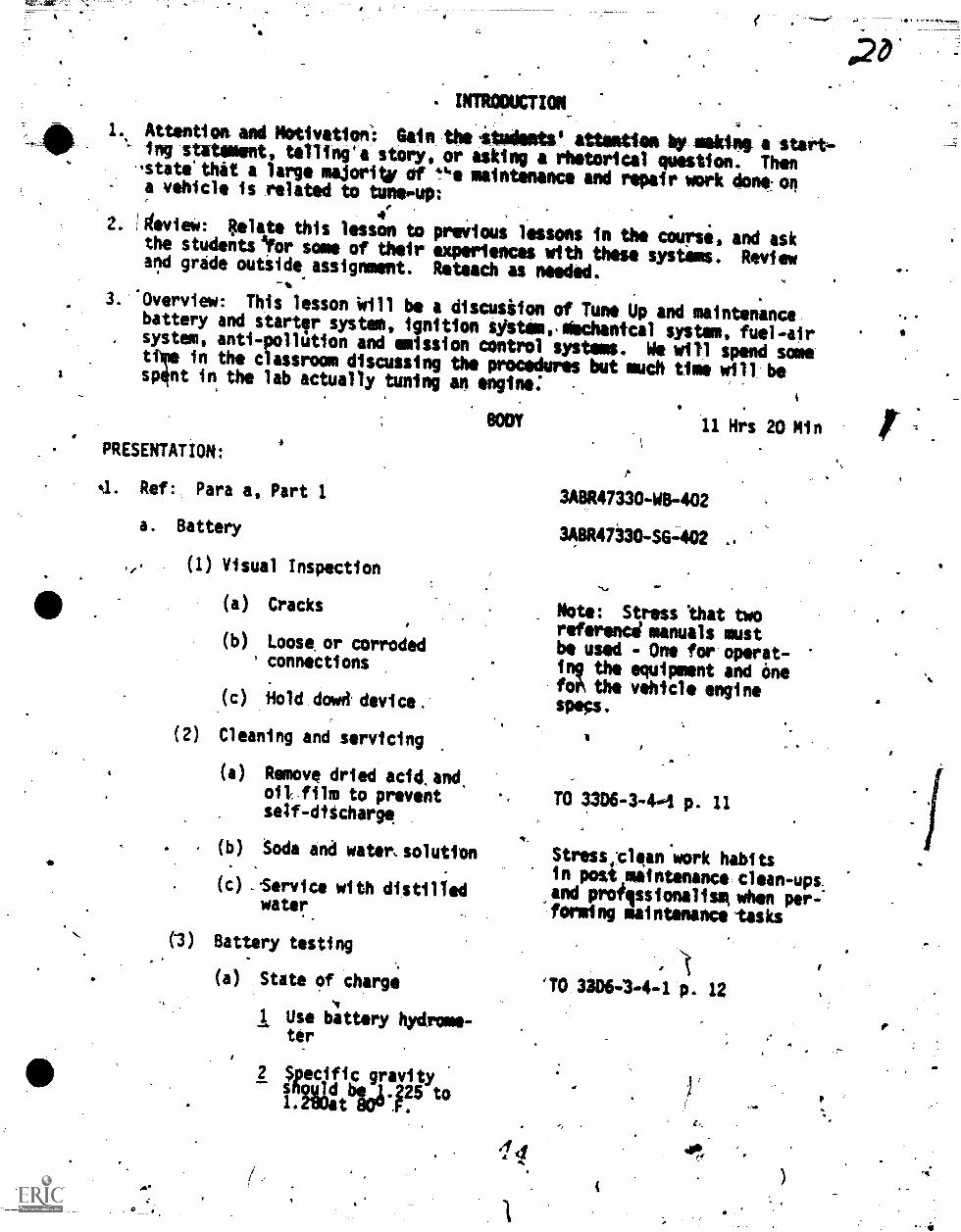
- INTRODUCTION_
Attnntiot and Motivation': Gain the irtudents1 attention by saes, a start-ing statment, telling*a story, or asking a rhetorical question. Then'state that a large majority of t maintenance and repair work done ona vehicle is related to tunes-up
42. AivieW: Relate this lesson to preVious lessons in the coursi, and askthe studentOor some of their experiences with these systems. Reviewand grade outside assignment. Reteach as needed.
'Overview: This lesson Will be a discusiion of Tune Up and maintenancebattery and starter system, ignition sistemcsiechantcal system, fuel-airsystem, anti-pollution and emission control systems. We will spend somettme in the classroom discussing the procedures but much time will besp4nt in the lab actually tuning an engine.
.
BODY
PRESENTATION:
4. Ref: Para a, Part 1
a. Battery
(1) Visual Inspection
(a) Cracks
(b) Loose or corroded° connections
(c) -Hold dowd. device.'
(2) Cleaning and servicing
(a) Remove dried acid.and.oil, film to prevent
self-discharge
(b.) .Soda and watemsolution
(c) iirvice with distilledwater
Battery testing
(a) State of charge
Use battery hydrome-ter
(3)
3- gegliE-grr25)ito. .
11 Hrs 20 Nin
3ABR47330-WB402
3ABR47330-SG-402
ow.
Note: Stress lhat tworeferenci manuals mustbe used - One fce operat-ing the equipment and Onefot, the vehicle enginespecs.
TO 3306-3-4-4 p. 11
Stressiclean work habitsin postemaintenance clean-ups.and professionalism, when per-''forming maintenance -tasks
'TO 3306-3-4-1 p. 12
6
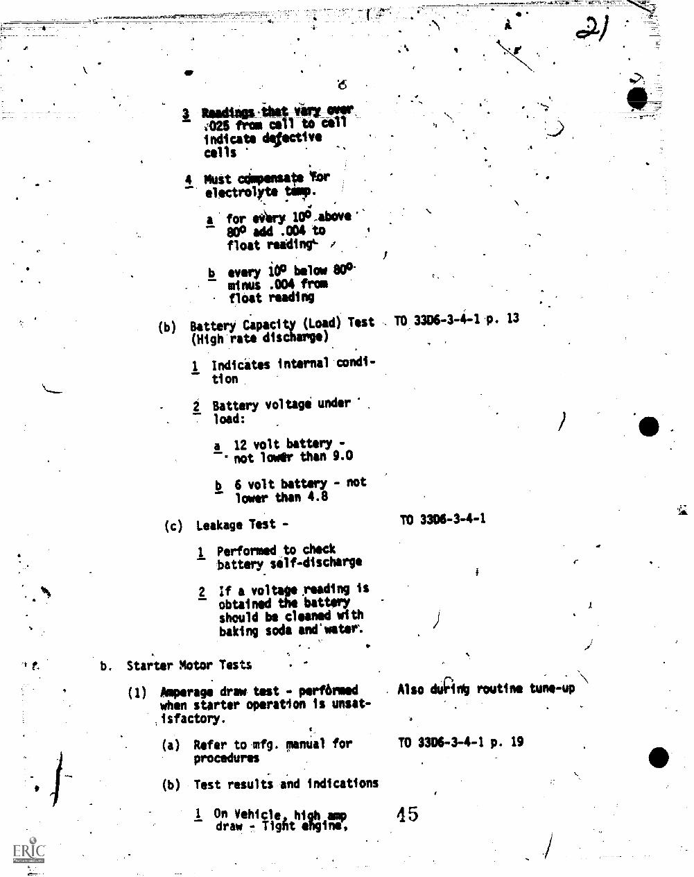
3 Reildiapilittlii I- Wilt425 from cell to cellindicate dftectivecells s
4 Must oilloensa Yarelectrolyte .!AmT.
a' for ei,ry 100,abovic'800 add .004 tofloat reading' s
b every 100 below 80°-minus .004 fromfloat reading
ss.
(b) Battery Ciipacity (Load) Test TO 3306-3-4-1,. 13
(High rate discharge)
1 Indicates internal condi-
tion
2 Battery voltagi under
load:
a 12 volt batterynot lower than 9.0
b 6 volt battery - notlower than 4.8
(c) Leakage Test -
1 Performed to check
battery self-discharge
2 If a voltage,reading is
obtained the batteryshould be cleaned with
baking soda andawater.
Starter Motor Tests
(1) Amperage draw test - performedwhen starter operation is unsat-zisfactory.
S.
(a) Refer to mfg. manual forprocedures
(b) Test results and indications
1 On Vehicle, high ampdraw - Tight elogino,
TO 3306-3-44
Also &Anti routine tune-Up \
TO 3306-3-4-1 p. 19
45
A
.
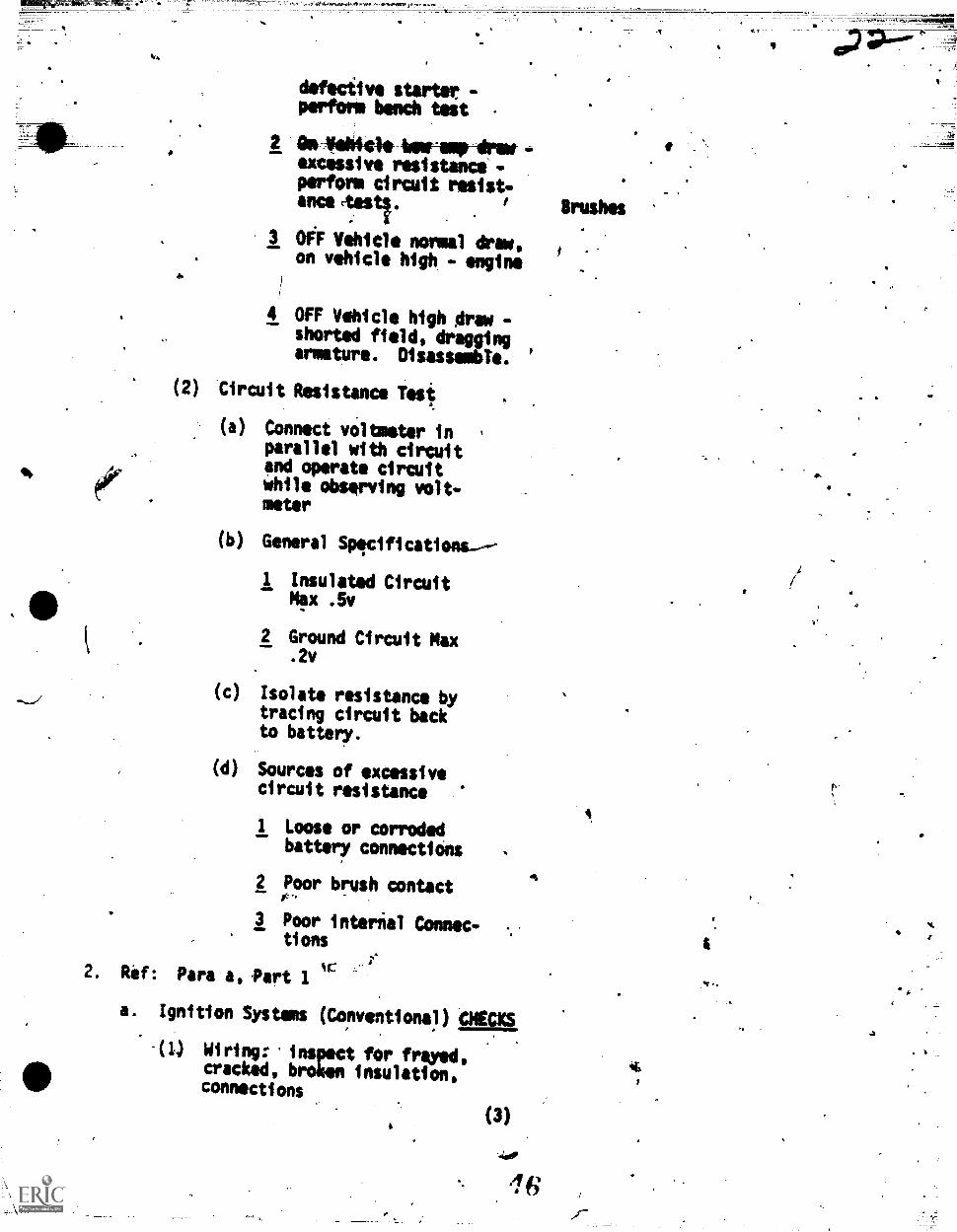
defective starter -perform bench test -
2 DalailittleimeraipArew-excissive resistance -perform circuit resist-ance ,tests. Brushes
3 oeF Vehicle normal drew,on vehicle high - engine
4 OFF Vehicle high Or* -shorted field, draggingarmature. Disassemble. '
(2) Circuit Resistance Test
(a) Connect voltmeter inparallel with circuitand operate circuitwhile observing volt-meter
(b) General Specifications---
1 Insulated CircuitMex .5v
2 Ground Circuit Max.2v
(c) Isolate resistance bytracing circuit backto battery.
(40 Sources of excessivecircuit resistance
1 Loose or corrodedbattery connectiOns
2 Poor brush contact
3 Poor internal Connec-tions
2. Rif: Para a,Part 1
a. Ignition Systems (Conventions?) CHECKS
(1) Wiring: inspect for freyed,cracked, broken insulation,connections
(3)
4
to
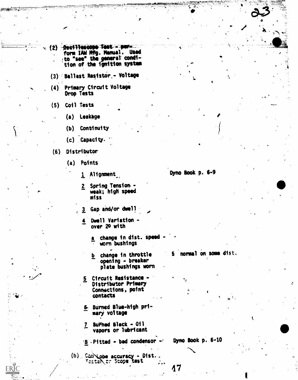
N- (2) *--OsenteteneWleet for*form 1AW Mfg. Manual . Used
to "see the general condi-
tion of .the ignition system
(3) Ballast Resistor,- Voltage
. (4) Primary Circuit VoltageDrop Tests
(5) Coil Tests
(a) Leakage
(b) Continuity
(c) 'Capacity.
(6) Distributor
(a) Points
1 Alignment
2 Spring Tension.-.. weak; high speed
miss
3 Gap and/or dwell
4 Dwell Variation -over 20 with
a change in dist. Speedworn bushings
I.
b change in throttleopening - breakerplate bushings worn
5 Circuit Resistance -Distributor PrimaryConnoictions, pointcontacts
6- Burned Blue-high pri-mari voltage
7 Bufhed Black - Oilvapors or lubricant
4.
A
'Dyno Book p. 6-9
5 normal im some dist.
4.
'8 -Pitted - bad condensor Dyno Book p. 640
(b)_ CuiNtie accuracy - Dist. ,
Tarte, cr Scope test . a
4 7
0
I.
it
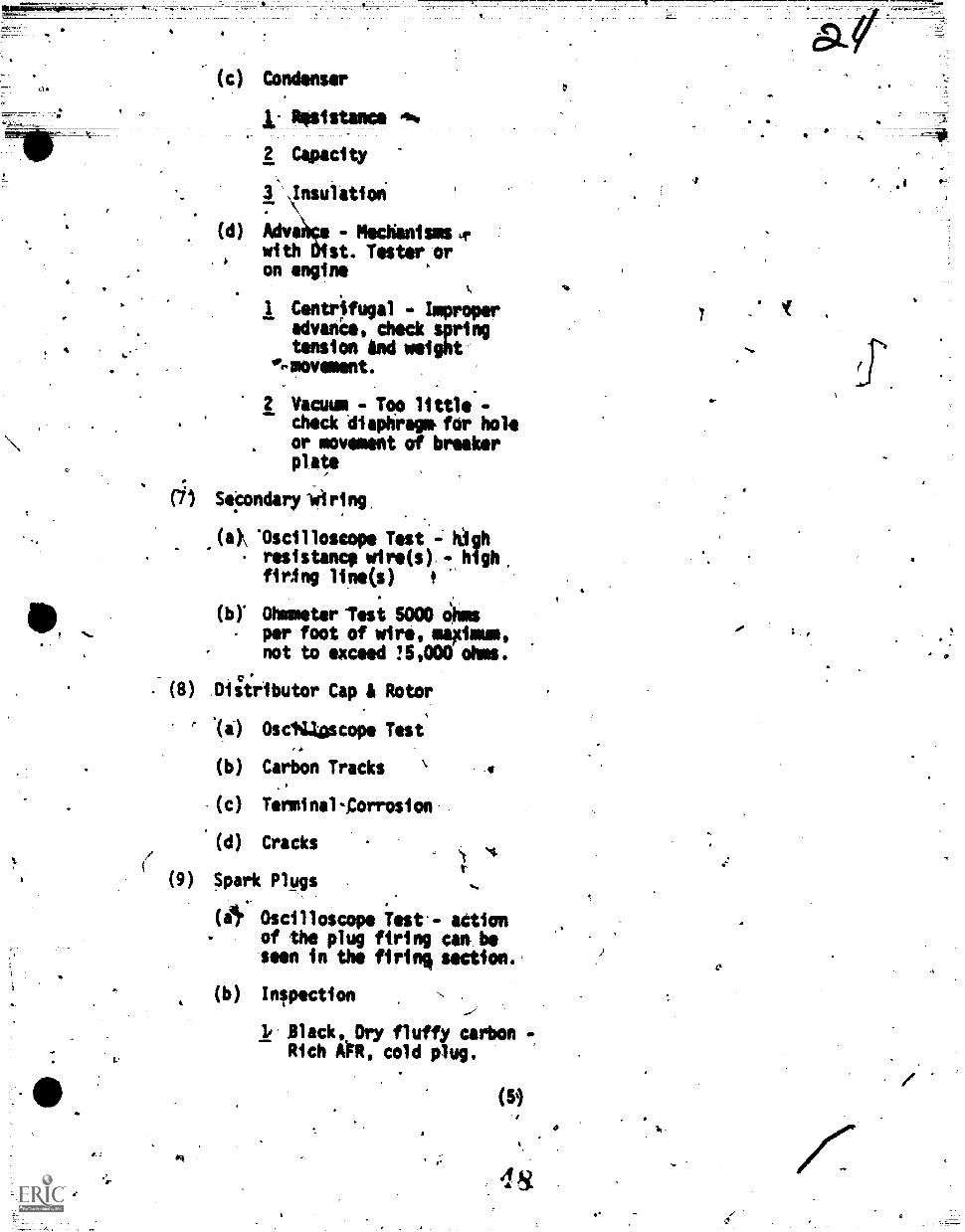
.(c) Condenser
1: Resistance 4%
2 Capacity
fAnsulation
(d) Adva: - Mechanisms urwith st. Tester oron engine
%
1 Centrifugal - Impropfradvanis, check springtension And weight
'...movement.
2 Vacuum - Too little -
check diaphragm, for holeor movement of breaker
plate
(;) Secondaryitiring,
(4 'Oscilloscope Test = kIghresistance wire(s).- high,firAng line(s) t
(b) Ohmmeter -Test 5000 Ohmsper foot of wire, maMmustnot to exceed ?5,000 ohms.
(8) DiStributor Cap & Rotor
F '(a) OsclUascope Test
(h) Carbon Tracks
(c) Terminal-,Corrosion
(d) Cracks
(9) Spark Plugs
(Or Oscilloscope Test-- action. of the plug firing can be
'seen in the firin% section.
(b) Inspection
1, Black, Dry fluffy carbon -
Rich OR, cold plug.
' r.
(5)
-
4
-
4.
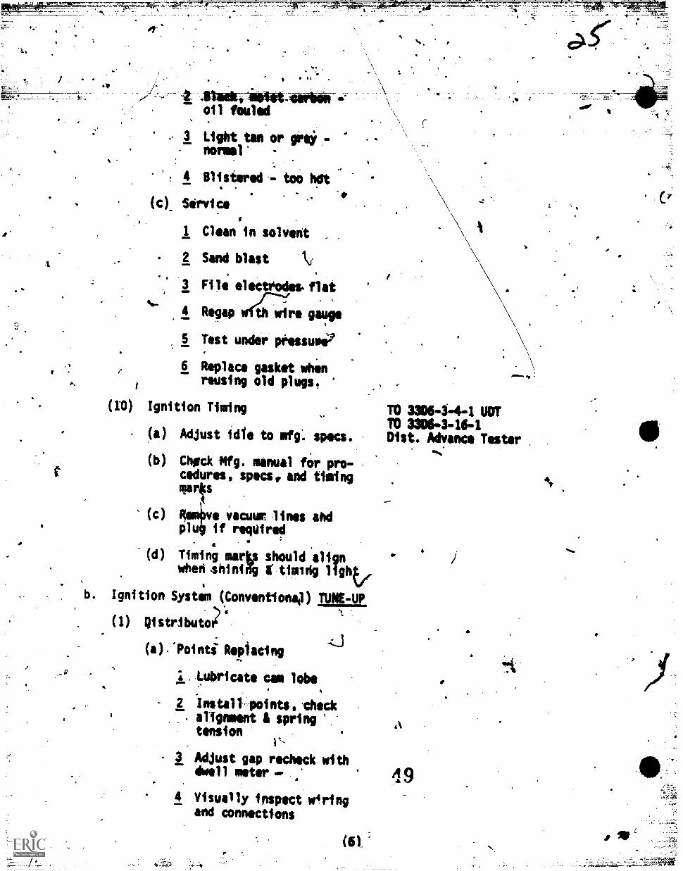
oil fouled
It
3 Light tan or go* -normal -
4 Blistered, - too hdt
(c), Service
1 Clean in solvent .
2 Sand blast kr.
3 FiI electrodes. flat
4 Regap wf47fte gauge
5 Test under pOessuse
6 Replace gasket whenreusing old plugs.
(ID) Ignition Timing
(a)
0
Adjust idle to mfg: specs.
(b) Chgck Mfg. manual for pro-cedures, specs, and timingmarts
(c) ve vacuur lines ahd:11:t if required
A
'4
(d) Timing mark should alignwheri .shiniWg timilig
b. Ignition Systm (Conventionaj) TUNE-UP'
(1) Di stributo4,3
(a)."Pointi Replacing
1, Lubricate cam lobe
2 Instill points, 'check. alignment springtension
3 Adjust gap recheck withdwell meter-.
4 Visually inspect wiringand connections
(6),
:'4*.gt,\
,13=ft 41
TO 33064-4-1 UOTTO 3306-3-16-1Dist. Advance Tester
49
a
APPLICATION:
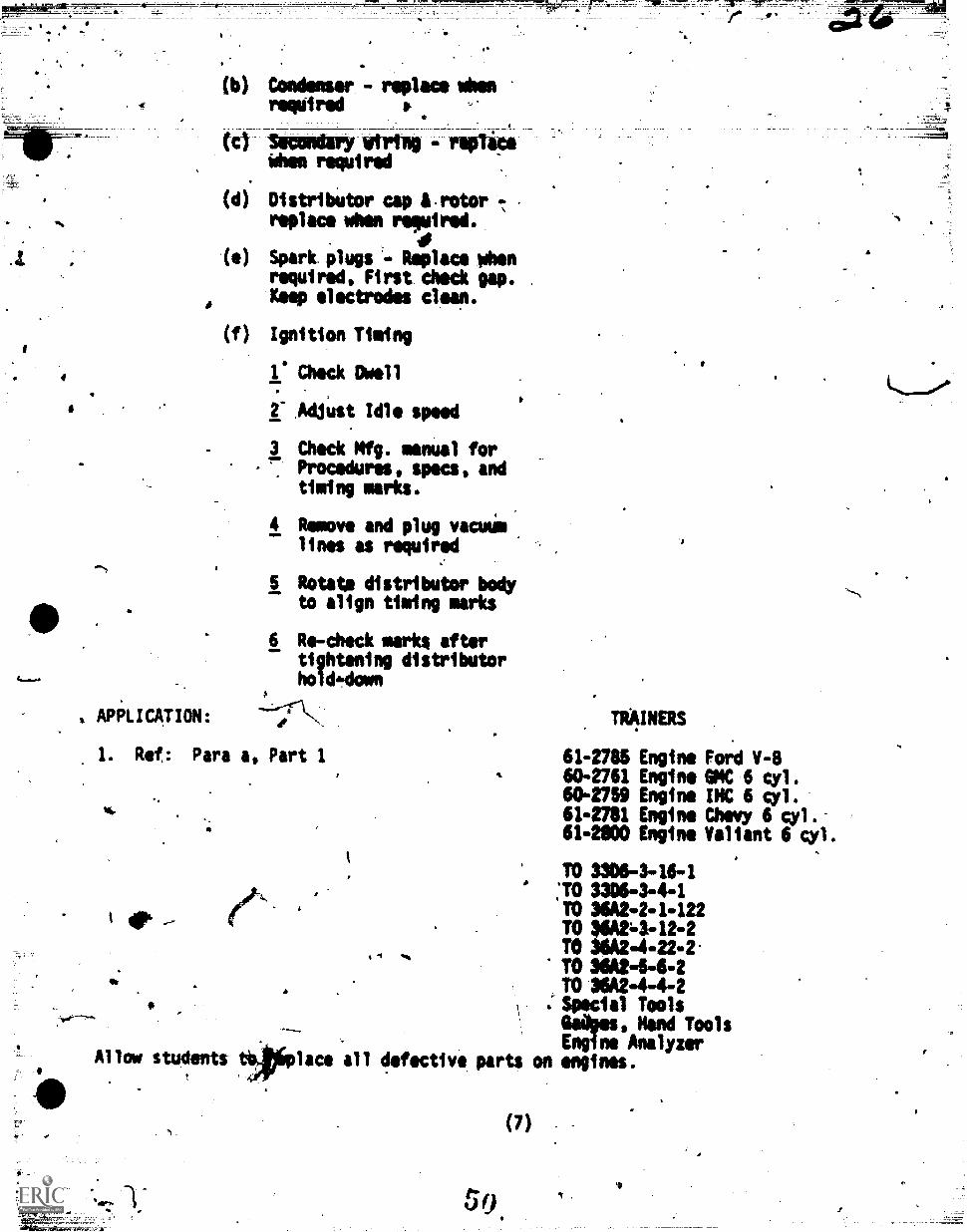
(b) Condenser. - replace whenrequired
341XedarYWhen required
(di Distributor cap 8-rotor 7
replace when reguired..
(e) Spark plugs - Replace Omrequired, First check gap.Keep electrodes clean.
(f) Ignition Timing
1. Check Dmell
2- Adjust Idle speed
3 Check Mfg. manual forrs
Procedures, specs, andtiming marks.
4 Remove and plug vacinim
lines as required
5 Rotate distributor bodyto align timing marks
6 Re-check marks aftertightening distributorhol&domn
I. Ref: Para a, Part 1
Os
Allow students
TRAINERS
61-2785 Engine Foti;c1 V-8
60-2761 Engine OMC 6 cyl.60-2759 Engine INC 6 cyl.61-2781 Engine Chevy 6 cyl.61-2800 Engine Valiant 6 gyl.
TO 3306-3-16-1'TO 3306-3-4-1'TO 36A2-2-1-122TO 36A263-12-2TO 36A2-4-22-2.TO 360244-2TO 36A2-4-4-2
:Special ToolsWO's. Nand ToolsEngine Analyzer
lace all defective parts on engines.
(7)
$
4
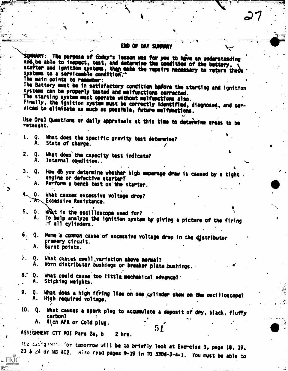
END OF DAY SWIM
The purpose of Wey's lesson wee for* tb hiie an understandingbe able to inspect, test, and deiermtne the coedition of the bettorY,
sta and ignition vetoes, tho,lrite the repairs necessary to reAturn thefesystems to & serviceabie condition.The main points to remember:The Battery must be in satisfactory condition Wore the starting Ind ignitionsystems can be properly tested and malfunctions corrected.The starting system must operate without malfunctions also.Finally, the ignition system must be correctly identified, diagnosed, and ser-viced to eliminate as much irs pOssible, future malfUnctions.
Use Oral Questions or daily appraisals at this time to detim)Mtne artals to beretaught.
a
What does the specificState of charge.
What doei.the capacityInternal condition..
gravity test determine?
t
test indicate?
Now 4 you.determine whether higb amperage draw is caused by a tight,
engine or defective startertPerform a bench test on the starter.
Wha.t causes excessive voltage drop?Excessive Resistance.
W t is the oscilloscope used for?To kelp analyze the ignition system by giving a picture of the firing.1 all cylinders.
6, Q. Name 'a common cause of excessive voltage drop in the dilstributorpramary circuit.Burnt points.A.
r. Q.
A.
8: Q.A.
9. Q.
A.
10. Q.
A.
What CaULOS dwellsvariation above normal?Worn distributor bushings or breaker platehushings.
What could cause too littlkmechanical advance?'Sticking weights.
What does a high f(ring line on one .cylinder shim on the oscilloscopeNfgh required voltage.
What causes a spark plug to &commutate a deposit of dry, black, fluffycarbon?Rch AFR or Cold plug.
4
ASSIGNMENT CTT POI Pars 2a, b 2 hrs.r 1
Me %,r tomorrow will be to briefly look at Exercise 3, page le. 19.23 & 44 of WB 402. Also rtsd pages S-19 in TO 3308-3-4-1. You must be able to
4

make a coeiression test to determine the internal condition of an engine: Thfsis what you will be doing in the lab Worm. Use the-method of study we havediscussed twftre. Neely: 3I Servehtmeitlestikee44 agate, Review.
INTRODUCTION TO NEW DAY'S WORK.. .
1. Thsnechan1cal system of the engine is a.
necessary part of thi ovetall.engine.Wlt t it we would not have an operational engiNe. 4nd it must work in harm-ony klth the rest of the engine° systems.
a. The mechanical system miOt be comptiwed with the workings of fine watch.As each tick of the watch meant every mechanical part must be in exactlythe right place to give the correct time; souk the mechanfical partsbe in,exactly the right place at the right time for a vehicle's engine 'toperform as it was built to.
'14
n
46 4., Yesterday we applied our knowledge of the electrical, starting, and batterysystems, and how to tune-up those systems.
3. Today'we will study mechanical and fuel/air systems. We will perform tests,and measure-compression and valve mechanisms, and measure and adjust fuel/airsystems, malfunctions and corrective action. We will also coVOrthe enginesupport systims.
PRESENTATION:
11. Ref: Para a, Part 1 3A8R47330-111-402-SG-402
a. Mechanical System -SG-402A
(1) Compression testing
(a) Normalize engine
(b) Clean area remove plugs
(c) Open chop and titrottleplates
(d) Insert.gauge and crankngine at least 4 time,
(e) Record readings reliat foraT1 cylinders - analyzelater
(2) Analyzing Compression TestRaadings
(a) One low cylinder
1 Burned Valve - Poppingat exhaust or carb
9 )
_
1.
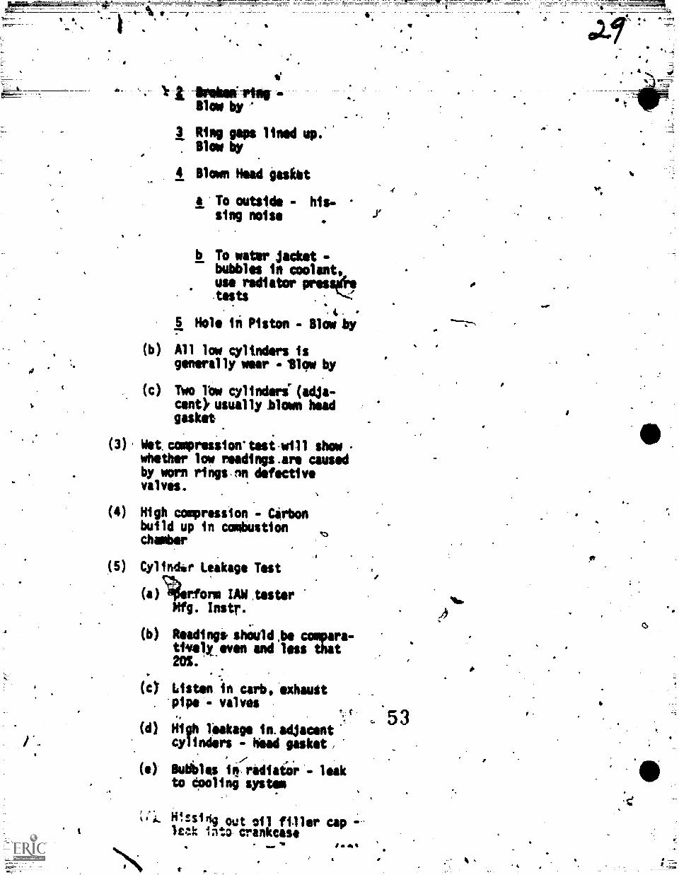
ihmimeiillirBlow by
3 Rimg gaps lined up.'Blow 0
4 Blown Head gasket
a To outside - his-sing noise
SI
b To water jacket -bubbles in coolant,use radiator presstitests S.
5 Hole in Piston - Blow by
(b) All low cylinders isgenerally weer - ilow by
(c) Two row cylinderi (adja-cent), usually blown headgasket
(3) Wet. compression'tesi-will show -
whether low readings.are causedby worn rings.9n defectivevalves.
(4) High compression Gerbonbuild up in combustionchamber
(5) Cylindlo Leakage Test
(a)70'rform IAWiesterMfg. Instr.
(b) Readingi shOuld,be -aware-tivekeven and less that
(*.c) Listen in cab, 'exhauttpipe - valves
(d) High leakage in.adjacentcylinders - head gasket/
(e)- Bubbls inrodiaiiir'- le'akto Opoling system
s. Hissidg out oil filler cap -leak into crankcase
ii
5 3
t.
.4,
p.
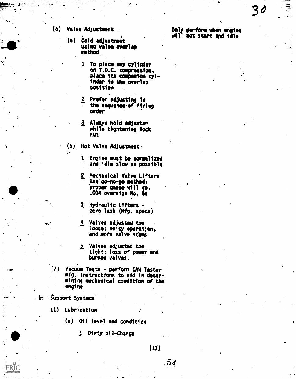
(6) Valve Adjustment .
(a) Cold adjustmekusing valve overlapmethod
1 To place allY alinderon T.D.C. compression,.place its companion cyl-inder in the overlapposition
,
2 Prefer adjusting inthe sequence.of flringorder
3 Always hold adjusterwhile tightenini locknut
(b) Hot Valve Adjustment-
1 Engine must be normalizedand idle slow as possible
2 Mechanical Valve LiftersDse'go-no -go method;proper gauge will go,.004 oversize No. Go
3 Hydraulic Lifters -
zero lash (Mfg. specs)
4 Valves adjusted tooloose; noisy operatlon,and oft valve stems,
5 Valies adjusted tootight; loss of power andburned valves.
(7) Vacuum Tests - perform LAW Testermfg. Instructions to aid in deter-mining mechanical condition of theengine
b. fupport Syltems
(1) Lubrication
(a) Oil level and condition
1 Dirty oil-Change
(U)
Only perform when enginewill not start and idle
.54
2 NOW Wand ail watikr
3 Clear bubbles in oi4 - Fuel
4 Foamy - Wrong.grado or over-filled
(b) Leaks - Tighten or replace gas-ket
(c) Filter
(d) Pressure0ook manual gaugeto output side of pump
(e) Low oil pressure - worn enginebearings, bad oil pump, pros-sure relief valve stuck open.
(f) High oil pressure, Pressurerelief valve stuck cicmed
(2) Cooling System
(a) For overheating or boilingcondition, check:
1 Coolant level and condi-tion
2 Fan belt
3 Leaks and clamps, checkhot and under pressure -use pressur tutor.
4 Pressure cap, raisesboiling point of coolant
5 Anti-freeze content Dyno book. p. 5-22. of coolant
Jr
6 Manifold heat control valve
(b) Slow warm.up - check thermcztat
(c) Vacuum Valve prevents vac-uum build up in radiatorwhin coolant contracts.
(3) Positive Crankcase Ventilating
xcl Removes blowbrlapors fromthe crankcase
5 5
.10
(b) Phevents condensationsludge formation
(c)
(d) P.C.V.Icalve controlsvapors into intakemanifold
_
e W
(e Test Valve IAW Mfg. specs
( ) Replac ialve henrecommended
2. -Ref: Para a, Part 1
a. Fuel System
(1) Fuel Pump
(a) Volume test - perform.,
if.high - speed perforianceis poor and lack of fuel atcarb. Best overall test
(b) Pressure test P- importantfOr*high Awed. Testsspring pressure
(c) Vacuum test - p4;rform
if volbme or presSureis low - Tests diaphragm
(2) Carburetor
(a) Float level - very import-ant to performance and fuel.economy
(b) Choke operation
(c). Idle A/F mixture - onlyIAW with Mfg. specs.
(3) rEvaporatiye Contrel System
(a) .Control fuel,vaporsfrom tank
(b) Carbon Canister
(c) Vacuum Lines,
(13)
4.
a
Check only if rich AFR at idle.
APPLUATION:
1. Ref: Para a, Part 1.
Allow students to replace all defective parts
EVALUATION:
1. The quizzes for the two days will begiven and reviewed for any weak areas.These quizzes will be in addition to-daily quizzes And questions as theneed arises.
SVMMARY AND REMOTIVATION:
TRAVERS:80-2761 fngine604759 Engine614781 Engine614800 Engine614786 Engine
f
PI 6 cyl.INC 6 cyl.
;bevy 6 cyl.ValiantFord V-8
TO 36A2-4 -4-2T0.3306-34-1TO 3306-3-16-1TO 36A2 -2-1 -122
TO 36A2 -4-22 -2
TO 36A2-66-2Gauges, Hand Tools,Special Hand Tools,Engihe Analyzers.Distrtbutor advanceTester
on engines.
CONCLUSION Hrs Min
Briefly cover the materiel of the last too deys, emphasizing the main pointsthat are as fIllows:
.3. The electrical system consists of many sub-assemblies that are tied=into each other. If one does not function properly, it wit] affect the'rest of the electrical system, as well as the other ongine,systems,example: if the battery is tot fully charged, an accurate compressiontest cannot be made. And I am certain that you could think of manymore examples if time permitted.
t. The fuel/air system is a, member of the triangle and its function.to-deliver fuel and air in the exact quantities to the combustionchamber.
c. The mechanical system is also needed to help .make the engine run andcoimpression within manufacturer's specifications is imperative for anefficient operating engine.
5 7
( 14 )
There 'ire ilso support systole that are 4est ai important as any of.-the aforomenttoned systems. Theee..ard as follow
(1) ',The imbrication system vied' tie Wow frichtt *sid the, mon-" _panyinq wear .to the *vier engin parts ant accessories..
(2) The cooling systole is also a very 1mportant4s4port.systee.Without it, themechanical.system could dot funptton very long. -
It takes the-heat aft from the combuitton chamber, as well astheother moving Omni Of.the engine. Remember th;t the temp-erature under the hood outside of the engine sometimes'reaches300-400 degrees F. so a hard working cooling systeli4s a:nec-essity. ,,
2. You now have used siientific methods of engini tune-Op.. Nouryou shouldbe able to apply your.abilities for the USAF as will as for personalgain. The sooneeyou are able to.demonstrate to your imMediate superiorshow well you perform your assigned duties-, the sooner you.will receivemonetary increases through promotions* This apOlies whether you stsy inthe Air Force or return to civilisn life. No one cap take iway your knowli-edge! It has been freely given,,so do not'''. afraid to pass it on totomeone less fortunate than you, someone noiattending a formal technicalschool.
USE ORAL QUESTIONS TO DETERMINE WEAK AREAS;
I. Q, What will you see at the oil fillei* cap-if the rings are excessivelyworn? Open System?
Blowby.
2. Q. Burned valves can be detected by listening in which area(s) whilethe engine is running?
A. Taii pipe & carburetor.4
Q:.*What will result when valves are left_ad4usted too tightly?
A. Loss of power, burned vanes.
Q. Whereldo you connect i gauge to check oil pressure?
A'. Main oil gallerY.
5. Q. .What would you check if the engine took too long to warm up?
A. Thermostat.
Q. What would you check if the crankciie wis developing excessivepressuriand'sludge?
o - A. PCV system.
low:ASSIGNMENT AND CLOSURE:
IP,1. Tne next lesson will cover tune-up and troubleshooting all systems of
(15)
dYnalometer. and SiiPsOlt-EnfineAmaty*': ThereTentyour usilmant
the entire engine4 using Diagnostic Test uiposint such as; The chassis
as follows:
CTT POI Para 3a, b, cs d.
: a. Read and study. PT 403, and WII-463. Be prepared to ansioer questionsconcerning the component; and operation of thcchassis.dynamometer andthe Simpson Engine AnaTyzer, its oampinents and operation. Also studyChapters 44-6, and the chart on the Mgt...page of DynamometeeOperatorTraining Handbook. DO NOT NAKE-ANY NMI IN THESE4BOOKS! I REPEAT--00 NOT MAKE ANY MARKS IN VVESE BOOKS! Answer the questiont at the endof eaWchapter on a separate sheet of paper and turn it in tomorrow.Please put your name, class number and tomorrow's date at the top ofthe first page. Read pages 64, 65 A 79494 of TO 3306-3-4-1.
(16)
6
Lanai PLAS4 ( Pen
* ov AL OFFICE ANC) DATE
1..1s1 A to tA 74.Ccuast NuNNRN
INBTRuCTOR
1
COURSE MLRGeneral Fur..si Vehicle
TIM2i1N4 t7L.1 V
U." TITLETine-up and Troub eshoo ng rig.
and EMission Control S
*you* MACK wits-Tune-u d Troubleshoot
ne .ec
stems UsiAb
/Laboratoryr Hr/Perf 11 5 hr
ca e gra on,Diagnostic. Test ETA
FlAsoRATORVicall LeMentalli6 lois
POIIEPERIN
4
C %UNSER
TOTALhrs
plumwmesitiroe4fg, Mzr.
STS/CTS 00PEREMCIOAT.3 Set) `1974.-
suPuttison APPOOVAL Apmm sessAtuots
3E P
'777; 7i.73X0,01.SIGN A T
PARAGRAIAN
ositg
PRECLASIMPARATION
EOUIPINSNT LOC Nk 0IN L ASCINAT Oft
.rrainefs60-4
61-2741-2800(4-2785
3.4.
5
6.VRri..)us','"echanic'n CommonHand 'tools (over)-
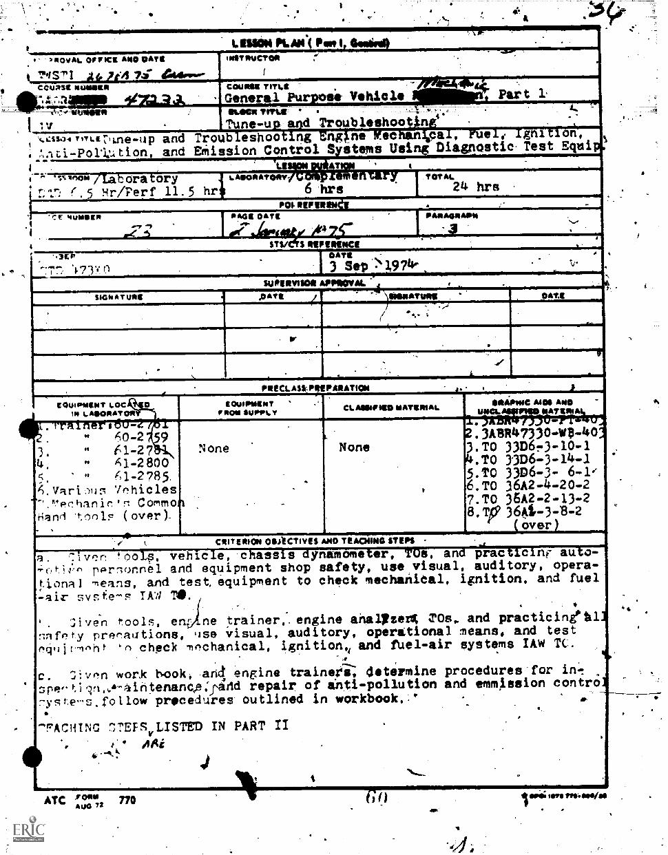
CRITERION OBJECTIVES A140 TEA00440 OEN'.1vr.,n ools, vehicle, chassis dynamometer, TOs, and practicint- auto-
-oti1n pprlonnel and equipment shop safety, use visual, auditory, opera-tional means, and test equipment to check mechanidal, ignition, and fuel
Ot
Pt
$t
tOuIPWRNTIr ROM 61.101,16T
1ohicles
None None
MOS Azo
3AZIMAAZ:11:1402,3ABR47330-WD-40,.TO 33136,3-10-14,TO 33D6-3-14-15.TO 3306-3- 6-1e6,TO )6A2-4-20-27.TO 36,42-2-13-28,T,364-3-B-2
over
-air sysf.e-s TAW V.
C;iven tools, en ne trainer,.engine anal/zerk TOs. and practicineilflifety prer!alltions, Ilse visual, auditory, operational means, and test
`n check mfIchanical, ignition,i and fuel-air systems IAW TC.
c. 74:von work book, and engine trainers, determine procedures for in.!5pe-tieri.,&-41ntenancp:pidd repair of inti-pollution and emmission contro-ygt,e-s.rollow pricethares outlined in workbook.,'
-4FACHTNC 7,TEFSVLISTED IN PART II
AAi
ATC 770A 1,00
G(.1 011; Mg% VP*: Mais/1
4
6.*"
A
a.
(
2
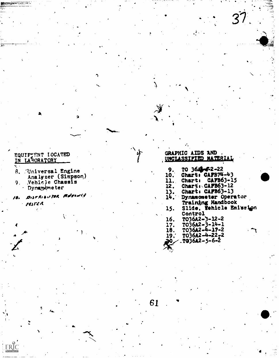
EQUIF;FNT LOCATED;N LATIORATORY
B. Ainiversal EngineAnalyzer (Simpson)
9. ArehiOe ChassisDynambneter
IL .04 silt, Toot Aseeihorce
0.04 reit
t.
Ara.
S.
f
e
I A.
s.
4
GRAPHIC AIDS 1ND .
(UNCLASSIF;ED MATERIA;
9. TO 364144-2210: Charts CAPT74 -4311. Chart, CAFB63 -1512. Chartst.CAP163 -1213. Charts CA1,863-1314.* Dynamonstor Operator
Trainkng Handbook15. Slide, Vehicle Emitelim
Control16. TO36A2.)-12.217. TO36A2 -3-14-118. T036A2 -4 -17 -2
19; TO36A2 -4 -22r2.1036A2 -5-6 -2
61 .
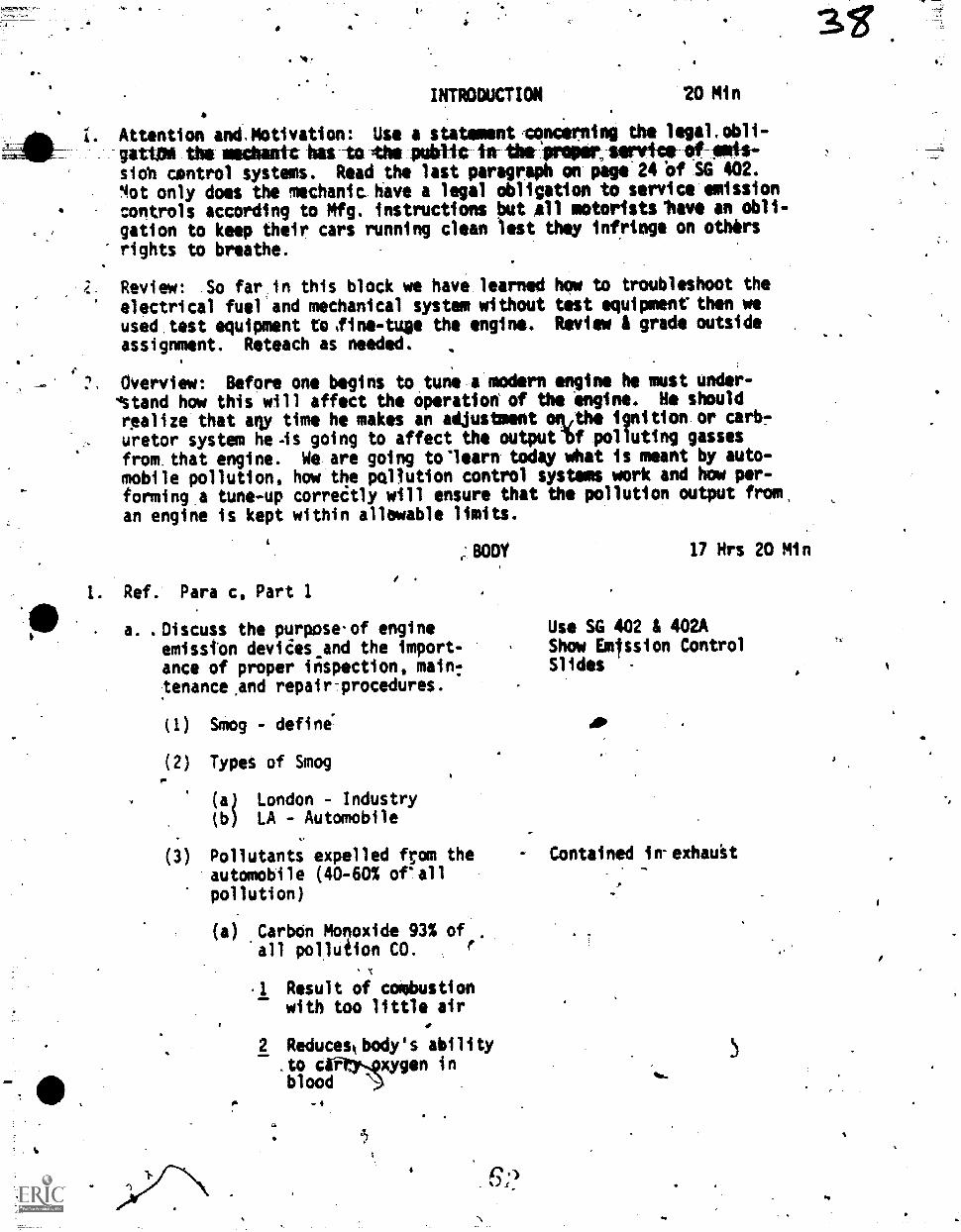
INTRODUCTION 20 Min
1. Attention and.Motivation: Use a statement4oncerning the legalwobli-gatilid the machank has to the public in thefpriver, writs of ads-slob control systems. Read the last paragraph on page 24 blf SG 402.
4ot only does the mechanic have a legal obligation to service emissioncontrols according to Mfg. instructions but all motoristsshave an obli-
gation to keep their cars running clean lest they infringe on others
rights to breathe.
Review: So far in this block we have learned how to troubleshoot theelectrical fuel and mechanical system without test equipment' then weused test equipment to,fine-tuge the engine. Review & grade outside
assignment. Reteach as needed.;
. Overview: Before one begins to tune-a modern engine he must under-.,
wastand how this will affect the Operation' of the engine. He should
realize that arty time he makes an adjustment °RAM ignition.or tali)?uretor system he.is going to affect the outputlf polluting gasses
from,that engine. We. are going tolearn todey what is meant by auto-mobile pollution, how the pollution control systems work and how per-
forminga tune-up correitly will ensure that the pollution output from,an engine is kept within allewable limits.
c' BODY 17 Hrs 20 Min
Ref. Para c, Part 1
a. .Discuss the purpose.of engineemisston devides.and the import-ance of proper inspection, main:tenance,and repair-procedures.
(1) Smog - define"
(2) Types of Smog
(a) London - Industry(b) LA - Automobile
(3) Pollutants expelled from theautomobile (40-60% orallpollution)
(a) Carbon Monoxide 93% of'all pollution CO. f
.1
.1 Result of combustionwith too little air
2 Reduceskbody's ability.to
oodcOry.pxygen in
bl \.)
Use SG 402 & 402AShow Emfssion ControlSlides
Contained in-exhauit
1
1
5
-lasivallipestiachamber gets cooler
4 Reduteeby leaner APR'(more air) and longerburni ng .4ime ( ng
5. Eng i ne Modificatloit
(b) Nydrocarbons.63% of allpollutionAC
Nareful whengtrnppedunder "inversion layer"and reacted.on up in bythe sun: "Photo chemical
- smog." Aided by moist-" air or high humidity
"LA'type" smog. ,
2. Unburned gasoltne
3 Exhault Ilych)Nocarbons.
Result from incompletecombustiokin engine 55%of hydro carbons
, ,N4
IL Ingition miss
Compression loss
c Low operiting temp.
4 25% of hydrocirbons areemitted from crankcaseblowby.
5 20% of hydrocarbons areemitted from fuel (tankA carb.)
(c) Nitrogen oxide - 50% ofpollution NOi
I Increase as engine temp.increases
2 .Combines with NC to pro-duce Photochemical Smog
3 Controlled by modified. engine and ignition
Emphasize importance oftune-vpi.
11,
"quench areef Fig. 5inversion layer - coldair .held under worm air.Ozone is also photo-chemi-cal smog.
. .
Emphesize'importence of' tune-ups. Unturned engine
increases hydro;carbon 5X
or more.
Fig 6 SG 402
When .00 and NC go down, NOxgoes up $ vice versa
Retarded Timing
(2)63
(d) Particulates 9% of allpOlution
1 Lead is considered possiblydangerous to human life
2 Lead coats the internalparts of any system thatcatalytically reducesexhaust pollution.
(e) Sulphur Dioxide - very smallamount, 5% of total emitted.Nixes with moisture to pro-duce sulphuric-acid. Damagingto plants., humans property.
(f) Asbestos fibers in brakelinings and clutch discs.Not proven but under study.
b. Diicuss the operation of Vehicle EmissionControl Devices
(1) Positive Crankcase Ventilationw f,
(a) Purpose - To removecrankcase blowby vaporsfrom the engine therebypreventing condensation toform sludge, and route thevapors to the intake mani-fold and engine to,beburned thereby preventinghydrocarbon contaminationof the atmosphere.
(b) Operation -
1 Fresh air is drawn intoair cleanter and routedto valve cover.
2 Fresh air mixes withcrankcase vapor andleaves by the hoseconnected betweenthe rocker arm \.cover andlintakemanifold.
Fig. 8 SG 402closed system
3 FCV valve controls flowpf vapors fromcrankcase to intakemanifold.
(3)d
N1-gh- menifeld-viatat 1-etid1e) draws the vilve tothe manifold end of thehousing restrictingflow of crankcas vapors.
5 When vacuum is decrease0as the throttle is openedthe spring overcomesvacuum and mover the valvetoward the crankcase endof the housing, allowingmore vapors to flow.
6 If the valve is stuckopen excessive vapors willbe allowed to enter the .
intake manifold at idlecausing poor idle. No
effectton high speedoperation.
7 If the valve is stuckclosed or plugged therewill be a-lack of crank-case ventilation causingexcessive crankcase pres-sure aqd oil contamination.
(c) Testing
I Test in accordance withmanufacturer's instruc-tions
2 Use comMerciaily soldPCV system tester.
3 Alternate test - PlugPCV hose. A reductionin engine RPM should .
occur.
(d) Servicing
I Clear Valve and filtersor replace as requiredby marufacturer
2 Inspect, clean andreplace if requiredhoses, tubes, andfittings.
(4)
55
I.
(2) EXHAUST EMISSION CONTROL
ta) Air Injection
1 Purpose - directs astream of fresh airinto the exhaustmanifold. This stimu-lates further liurningof (hydrogen) thusreducing HC and CO.
2 Components
a Air Pump - beltdriven
b Air manifold foreach head
c Check valve
d Diverter Valve -
e Connecting hoses.
3 Operation
a The pump dellverscompressed air throughthe air manifold to theexhaust)manifold whereit mixes with the exhaust.
b This mixture ignites andburns here rather thanpassing out the exhau%tpipe.
c The chock valve prevents.exhaust gasses from enter.ing the pump.
d The diverter valVe is con-nected to intake manifoldvacuum and controls thedirpciion of air flowfrom the pump. Duringdecelleration thevalve prevents freshair from entering theexhaust manifold, thuspreventing backfire.
*bog
"Gulp,by pass" or "Dump"valve,
4 titegesii
a If backfirina occurs, .
check the diverter valve,leaking air manifold;ignition timing, orai r/fuel rati o
b If-emissions are abovestandards check mg -ine'tune-up before theAIR syttem. .Then per-form detailed Check ofentire.AIR ststem lAWMfg. recommendations.
5 Names uted by Manufacturwes
a GM -.AIR - Air InjectorReactor
b Ford - Thermiictor
c Am. Mtrs. -.Air Guard
d Chrysler - limited use
until 1975
(b) Engine Modification (CombustionContml)
1 Ignition Timing
4
p.
a Generally more retarded at - Wider throttle Fig. 29
idle and stays retardod SG 402
until higher speeds.
b Commcnly used controls
(1) Thermostatic VacuumSwitch (GM) -Adt:arces timing' at
idle when enginebecomes, hot from 1
retarded timing.Lucated in enginecoolant Jacket nearnetr front of en-gine.
(2). Vacuum advanceValVe provides ,
vacuum to distri-butor during de-cillei-ation formdre.compiete comb
67
. 4
41.0
(3). Transmission Con-trolled Spark
kW* timingretarded untiltransmission isplaced in high gear(TRS FORD)
(4) Temperatur Switch -allows timing to ad-vance when engineis cold
(5) Vacuum Advancesolenoid - Valvewhich controlsvacuum to theadvance uniton the distribu-tor and is-con-trolled electric-ally by temperatureand the transmis-sion.
(6) Speed ControlledSpark - (GM) Aspeed sensor con-trols a vacuumvalve which pre-vents timing adv-
* ance until approx35 mph. and re-tards timing ondecellerationbelow approx.25 mph. (ESCFORD)
(7) Dual ControlledVacuum Advance(GM FORD) Allowsvacuum to retardtimtng at idleand advance tim-ing above idleand during over-heat conditions
(8) Distributor Retardsolenoid - Retards
410
Timing *Ong idleand decelleration.Solenoid on distri-,
4 butor is groundedwhen throttlt -
tacts stop. (C 9S) ii
Reduces NOx
(NDx Control System Chrys)
All work together
CR
(9) Distributor Advance Solenoid -
. (Chrys) Provides7-8 degrees ofspark advanceduring starting.Activated bystarter relay.
(10) Mechanical Adv-ance (A11) occursat higher speed
(11) Orifice SparkAdvance Control -
OSAC (Chrys)Delays vacuumto advance for 17seconds when goingfrom idle to partthrottle above.600F.
For control of Nox
2 Distributors - electronicignition is being used to
. prevent deterioratingbreaker points and chang-ing timing.
3 Carburetion
a Carburetors designedand calibrated toprovide a leaner Air/'Fuel rItil
b Idle mixture lim'itercaps
c -Strict adjustment pro-cedures
d %.Internal idle fuel limit-ing orifice
e Idle stop solenoid - pre-vents dieseling
(1) Ecergized when igni- 69.tion switch turned "on"
(2) idle spaad adjusted byturning pl...mgr in orout .
lot
(3) With ignitionswitch off,plump Cantractsand throttlelever strikesthrottle stopscrew
(4) Perform two ad-justments - onewith solenoidenergized, onewith solenoidIAW Mfg. specs.
f Soma 'throttle sole-
noids slow the clos-ing of the throttleon dercelleration
preventing an exces-sively rich mixture.
11. Carburetor Air Temp-erature Control -provides warm intakeair to carburetorwhen under lkood airtemOerature ts--lowerthin 100i.to providebetter vaporizationand leaner mixtures.
(1) Usually vacuumoperited
(2) Air valve shouldbe closed whencold
(3) Warm air passingexhaust manifoldenters the air'cleaner to sig-nal the tempera-ture sensor toopen the air doorin the snorkel tounder h9od air.
4 Hotter thermostats.areused to.Oroyide mphcomplete combustion.In addition/bighe radi-ator.pressure caps arsuseeto prevent oyerboiling .
( 9 )
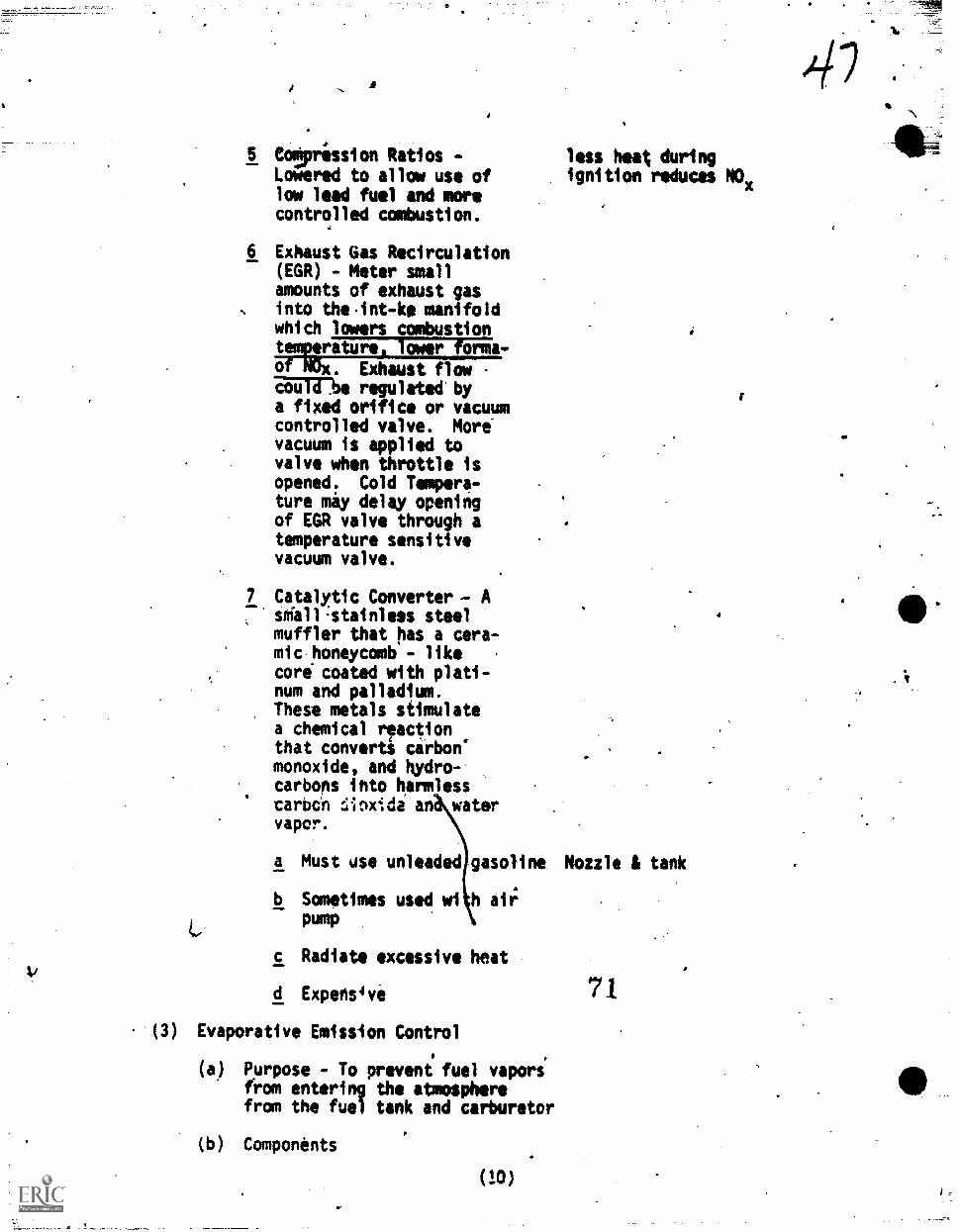
5 eotpression Ratios -
Lowered to allow use oflow lead fuel and morecontrolled combustion.
6 Exhaust Gas Recirculation(EGR) - Meter smallamounts of exhaust gasinto theint-ke manifoldwhich lowers combustiontemperature) lower forma -of NOx. Exhaust flowZBUT3713e regulated bya fixed orifice or vacuumcontrolled valve. Morevacuum is applied tovalve when throttle isopened. Cold Tempera-ture may delay openingof EGR valve through atemperature sensitivevacuum valve.
7 Catalytic Converter -- A
sdall.stainless steelmuffler that has a cera-mic honeycomb - like .
core coated with plati-num and palladium.These metals stimulatea chemical r!actionthat converts carbon'monoxide, and hydro-carbons into harmlesscarmn :;inxida an watervapor.
less heat duringignition reduces NOx
must use unleaded gasoline Nozzle 1 tank
b Sometimes used wl h aiipump
c Radiate excessive heat
d Expens4ve
(3) Evaporative Emission Control
(a) purpose - To prevent fuel vaporsfrom entering the atmospherefrom the fuel tank and carburetor
(b) Components
(10)
71
I.
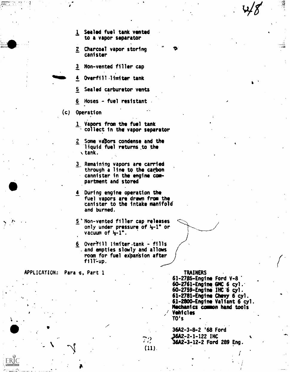
1 Sealed fuel tank ventedto a vapor separator
2 Charcoal vapor storingcanister
3 Non-vented filler cap
Almimw 4 Overfill-limiter tank
5 Sealed carburetor vents
6 Hoses - fuel resistant
(c) Operation
1. Vapors from the fuel tankcollect in the vapor separator
2 Some vdflors condense and theliquid fuel returns,to the
k tank.
3, Remaining vapors are carriedthrough a line to the carboncannister in the engine tom-partment and stored
4 During engine operation thefuel vapors art drawn from thetanister to the intake manifoldand burned.
5 'Non-vented filler cap releasesonly under pressure of 1/2-1" orvacuum of 11-1".
6 Overlfill limfter.tank - fills. and empties slowly and allowsroom for fuel eipan"sion afterfill=up.
APPLICATION.: Para ts, Part 1
a
4
6
TRAINERS .
61-2785-Engine Ford V-860-2761-Eng1ne GMC 6 cyl.-60-2759-Engine INC '6 cll.61-2781-Engine Chevy 6 cyl.614800-Engine Valiant 6 cyl.Mechanics common hand tools
/ VehiclesTO's -
36A2 -3 -8-2 ;68 Ford.
2-1-122 INC-3-12-2 Ford 289 Eng.
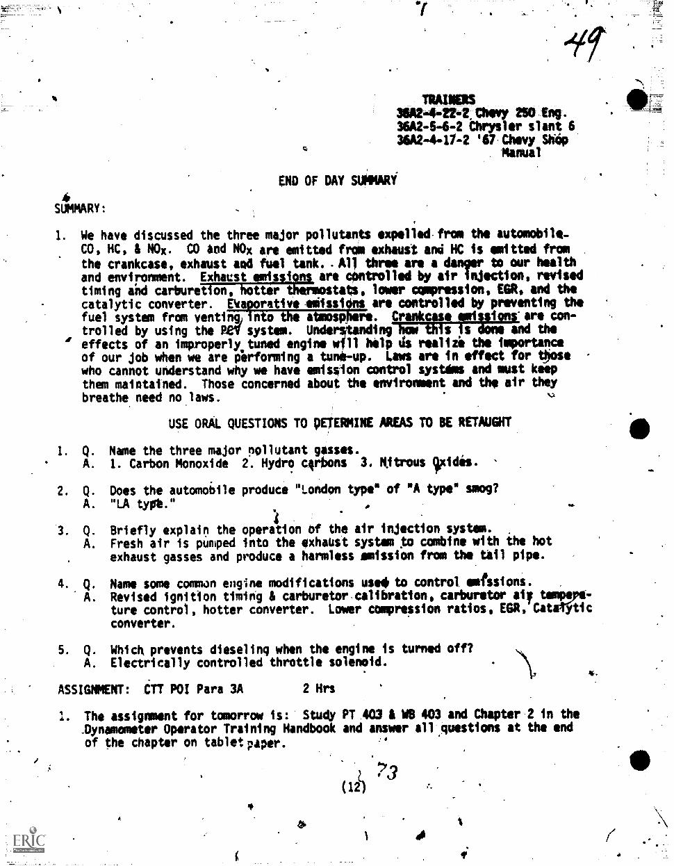
TRAINERS36A2-4-214Chovy250 1ng.36A2-64-2 Chrysler slant 636A2-4-17-2 '67.Chevy Shop
Manual
END OF DAY SUNNARI
SUMMARY:
1. We have discussed the three major pollutants expelled from the automobile-CO, HC, & NOR. CO and NOx are emitted frOm exhaust and HC is emitted frca
the crankcase, exhaust and fuel tank. 401 three are a danger to our healthand environment. Exhaust emissions are cOntrolled by air injection, revisedtiming ahd carburetion, hotter thermostats, lower compression, EGR, and thecatalytic converter. Eaporetive.elissilins are controlled by preventing thefuel system from venting) into the abmosOhere. Crankcese smissions'are con-trolled by using the Bev system. Unde tending how this is done and the
r!' effects of an improperly.tuned engine w 11 help ds realizi the importance
of our job when we are performing a tu n -up. Laws are in effect for thosewho cannot understand why we have emission control ystdms and must keepthem maintained. Those concerned about the environment and the air theybreathe need no.laws.
USE ORAL QUESTIONS TO pETERMINE AREAS TO BE RETAUGHT
1. Q. Name the three major pollutant gasses.A. 1. Carbon Monoxide 2. Hydro crilons 3. Nitrous Wcides. ,
2. Q. Does the automoidle produce "London type" of "A type" smog?A. "LA typt." A
1Q. Briefly explain the operation of the air injection system.
A. Fresh air is pumped into the exhaist system to combine with the hotexhaust gasses and produce a harmless emission from the tail pipe. ,
Q. Name some common engine modifications use4 to control emfisions.
A. Revised ignition timing & carburetor calibration, carburetor aiy tempve-ture control, hotter converter. Lower compression ratios, EGR, CateYticconverter.
5. Q. Which prevents dieseling when the engine is turned off?A. Electrically controlled throttle solenoid.
ASSIGNMENT: eTT POI Para 3A 2 Hrs
1. The assignment for tomorrow is: Study PT 403 & MB 403 and Chapter 2 in the_Dynamometer Operator Training Handbook and answer allluestions at the endof the chapter on tablet paper.
L(12)
I.
1 401 (
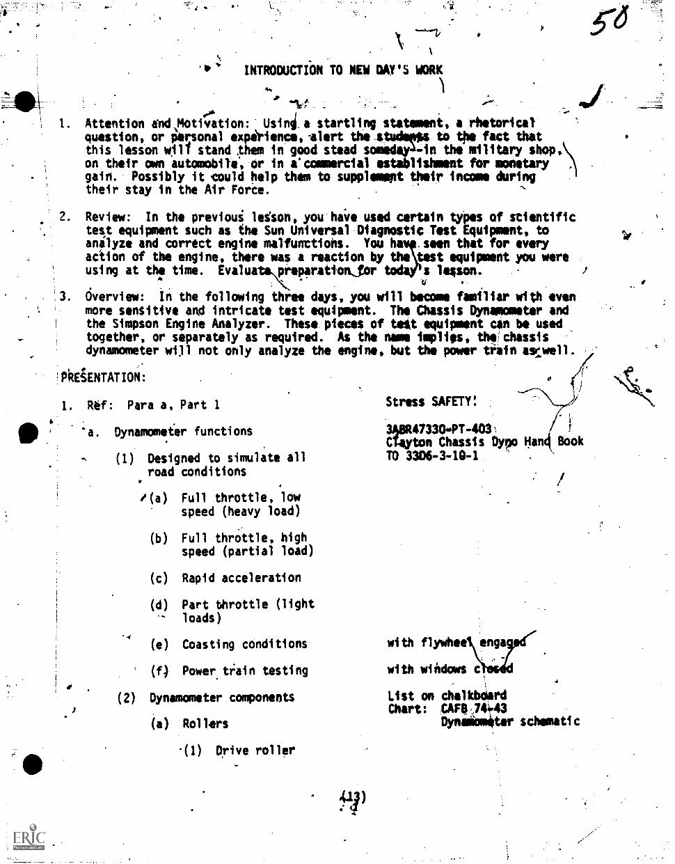
INTRODUCTION TO NEW DAY'S WORK
-41-t
00.
1. Attention ind.Motivation: Usinia startling statements a rhetoricalquestions or personal experiences-alert the studeptps to the fact thatthis lesson 011 stand plem in good stead somedaya-in thimilitary shop,on their own automobile, or in a'commercial establishment for monetary ,
gain. Possibly it could help them to supplement their income duringtheir stay in the Air Forie.
Review: In the previoui lesom, you'hAfe used certain types of stientifictest equipment such as the Sun Universal Diagnostic Test Equipments toanalyze and correct engine malfunttions. You hav seen that for everyaction of the engine, there was a reaction by the test equipment you wereusing at thf time. Evalu preparationjor s lesson.
Overview: in the following three days, you will become familiar with evenmore sensitive and intricate test equipment. The Chassis Dynamometer andthe Simpson Engine Analyzer. These pieces of teat equipment can be usedtogether, or separately as required. As the name implies, the'chassisdynamometer will not only analyze the engines but the power train asi:well.
'PhEiENTATION:
1.
6
110 .
"a. Dynamometer functions
Rtf: Para a, Part I
I
(1) Designed to simulate allroad conditions
C
"(a) Full throttle, lowspeed (heavy load)
(b) Full throttle, highspeed (partial load)
(c) Rapid acceleration
(d) Part throttle (lightloads)
'4
(e) Coasting conditions
(f) Power tl:ain testing
(2) Dynamometer components
(a) Rollers
-(1) Drive roller
Stress SAFETY:
3A8R473304T-4031CTayton Chassis Dypo Han4 BookTO 33D6-3-10-1 .
with flywhee enga
with windows
List on chalkboardChart: CAFIV744.43
Dynalomiter schematic
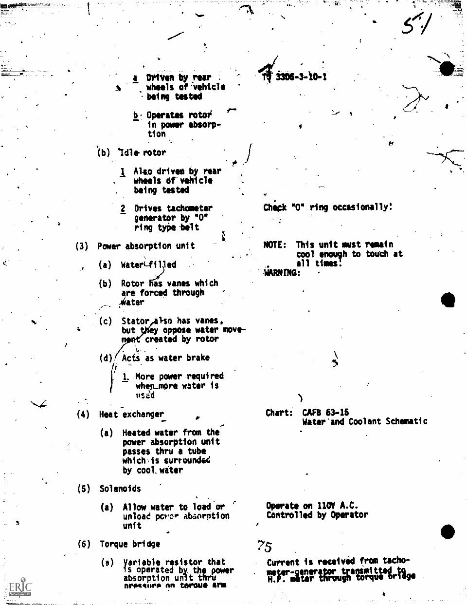
4(b)
a
a Dri'ven by yiear .
wheels of-vehicle '
.being tested
b. Operates rotoOin power absorp-tion
'Idle rotor
I Also driven by rearwheels Of-vehiclebeing tested
2. Drives tachometergenerator by NO"ring tyne.belt
(3) Pmer absorption unit
(a) WaterLfilled
(b) Rotor fii(s)vanes whichere forced throughAliater
a
(c) Stator,also has vanes,but tWey oppose water move-
created by rotor,
-
) Acts as water brake
1. More power requiredwherumore water isusal
(4) Heat exchanger
(a) Heated water from thepower absorption unitpasses thru a tubewhich\is surroundedby cool witer
(5) Solenoids
(a) Allow water to load orunload po.nr absorptionunit
41.
(6) Torque bridge
(a) Variable resistor thatis operated by the powerabsorption unit thrunrovtnro nn terms arm
*
41(1305-3-10-;
f4
4*.
Chick "0" ring occasionally!
NOTE: This unit must remaincool enough to touch atall times!
WARNTNG:
Chart: CAFB 63-15Water'and Coolant Schematic
Operate on 110V A.C.Controlled by Operator
Current is received from tacho-
TtriltUrtAutPtAtlirtige
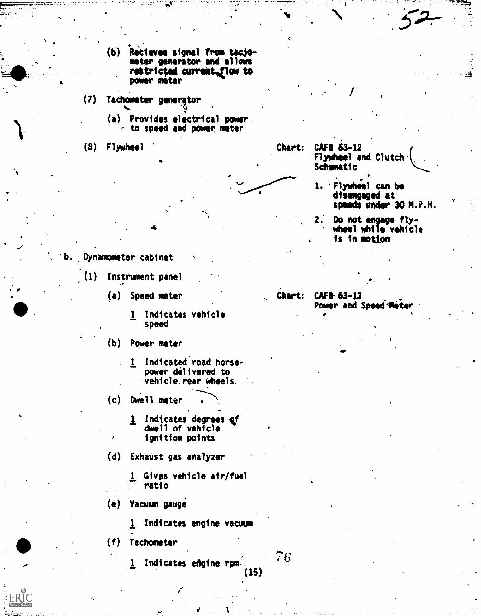
(b) Ihkieves signal from tacjo-meter generator and allowsriktrigtol-awreitAlow- topower meter
(7) TaCho6eter generator%.
(a) Provides electrical powerto speed and poor meter
(8) Flywheel
4,
*b. Dynamometer cabinet
(1) Instrument panel
(a) Speed meter
1 Indicates vehiclespeed
(b) Power meter
Chart: CAF8 63-12Flywheel and Clutdr(......Schematic
1. 'Flywhool can bedisengaged atspeeds under 30
2. Do not engage fly-wheel while vehicleis in motion*
1 Indicated road horse-power delivered tovehicle,rear wheels
(c) Dwell meter 4
1 Indicates degrees -Vdwell of vehicleignition points
(d) Exhaust gas analyzer
1 Gives vehicle aiP/fuelratio
(e) Vacuum gauge
1 Indicates engine vacuum
(f) Tachometer
1 Indicates edgine rpm-(15).
Chart: CAF8-63-13Power and SpeeePeter
,
76
410
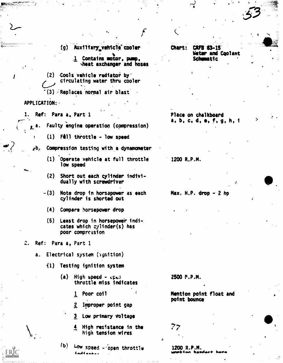
(g) Aoxiliarywvehtc*cooler. %
.1 Contains motor, pump,Nheat exchanger and hoses
(2) ,C4als vehicle radiator by'circulating water thru cooler
'(3) -Replaces-normal air blast
APPLICATION:. .
1. Ref: Para a, Part 1r--
4
"*.e.
0. Faulty engine operation (compression)
1 (1) Fill throttle - low speed
/be Compression testing with,a dynamometer
(I) 1:)perate vehicle at full throttle 1200 R.P.M.low speed
(2) Short out each cylinder indivi-dually with screwdriver
-(3) Note drop in horsapower as each Max. H.P. drop - 2 hpcylinder is shorted out
(4) Compare horsepower drop
(5) Least drop in horsepower indi-cates which cylinder(s) haspoor compression
Chart: CAM 6345Water and CeolantSchematic
Place on chalkboarda, b, c, de f, g, h, i
2. Ref: Para a, Part 1
a. Electrical system (loition)
'(1) Testing ignition system
(a) High speed - 44..1 2500 P.P.M.throttle miss indicates
I Poor coil
2 Improper point gap
3 Lom primary voltage
4 High resistance in thehigh tension wires
(b) Low speed --Open throttle
Mention point float andpoint bounce
1200 R.P.M.womplpion hawlake. harm
4
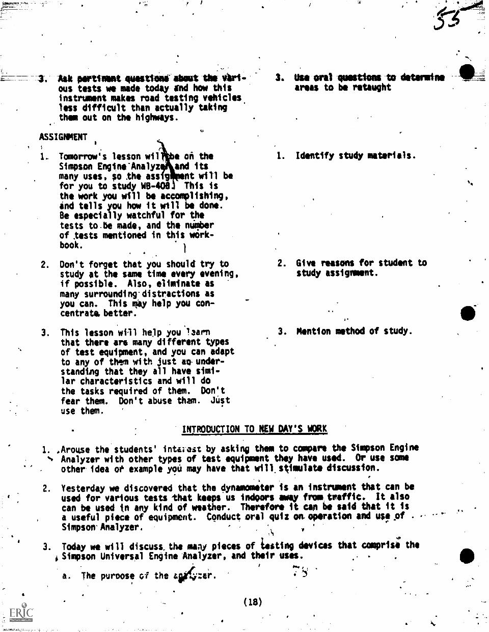
Ask pertinimit quettionighout the etri
ous tests we made today gnd how thisinstrument makes road testing vehiclesless difficult than actually takingthem out on the highways.
ASSIGNMENT
1. Tomorrow's lesson wil e on theSimpson Engine'Analyz and itsmany uses, so the ass g nt will befor you to study WB-408 This isthe work you will be accomplishing,ind tells you how it will be dont.Be especially watchful for thetests to.be made, and the numberof tests mentioned in this work-book.
1
2. Don't forget that you should try tostudy at the same time every evening,if possible. Also, eliminate asmany surrounding.distractions asyou can. This mgy help you con-centratabetter.
3. This lesson will help you 'earnthat there aro many different typesof test equipment, and you can adaptto any of them with just so, under-standing that they all have simi-lar characteristics and will dothe tasks required of them. Don'tfear them. Don't abuse tham. thqt
use them.
Use oral questions to detsminsareas to be retaught
1. Identify study materials.
2. Give reasons for student tostudy assignment.
cl
3. Mention method of study.
INTRODUCTION TO NEW DAY'S WORK
1. .Arouse the students' intcast by asking them to compare the Simpson Engine
s Analyzer with other types of test equipment they have used. Or use some
other idea ot example yoit may have that will.stimulate discussion.
2. Yesterday we discovered that the dynamometer is an instrument that can beused for various tests that keeps us indoors away from traffic. It also
can be used in any kind of weather. Therefore it can be said that it is
a useful piece of equipment. Conduct oral quiz on,operation and usfof .Simpson.Analyzer.
\4
3. Today we will discuss.the maly pieces of Luting devices that comprise theSimpson Universal Engine Analyzer, and their uses.
a. The puroose of the 414:er. .
4
(18)
4.-
41"
1 Poor, spark. plugs
2 Nigk tension-ableshorted out
3 Cracked distributorcap
3. Ref: Para a, Part 1
a. Fuel System
(1) ,Proper-iarburetor operation'
is determined by connectingthe exhaust gas analyse0 tothe tail'Ope an.1 the vacuumhose to the intake, manifnld
(2) Air/fuel ratios shouldconform to specificationsat all test points
APPLICATION:
1. eRef: Pars a, Part 1
.SUMMARY
1
p.
t
ENO OF DAY'S SUMMARY'
Today's lesso'n has shown you that thereIs much more to the 4ynamometer-thanjust setting up the vehicle. Thevarious test settings'will tell youthe condition of igiven vehicleunder road conditions.
2. The load settings that.you testedthe vehicle under were as fAillows:
a. Full throttle and 1200 R.P.M.
b. Full throttle and ?SOO
c. Rapid icceleration..'
Test at all settingrandat idle '
Vehicle Chassis DynamometerDistributor Advance TesterTO 3306-3-16-1TO- 36A2 -3-14-2-1 '68 Ford
1. Restate objectives of thelesson.covered in this day.
2. Emphasize the area ofmajor importance.
.
d. Part throttle and 2600 R.P.M.
Ae. 'Parethrottle and 1200 R.P.M.
(17)
b. A brieflescription of it.
c. Performing various tasks with it.
PRESENTATION:
1. Ref: Para b Part 1
a. Purpose of the analyzer
(1) The universal engine analyzeris used to test; troubleshoot,and tune-up 4, 6 and 8 cylinderinternarcombustion engineswith 6, 12, 24 or 32 voltelectrical systims
b. Description of equipment
(1)
ATTN: All Simpson electricalservices are transistorized!,Don't hook them up backwards
61-2785 Eng., Ford V-8
The universal engine analyzerconsists of 7 testing or All of these components areanalyzing components and 3 described in TO 3306-3-14-1accessory.or adapting com-ponents which are self-con-tained ahd independently,
operated. All cogpohentsare mounted or containedwithin a portable cabinet
(2). The components and adaptorsart as follows, with a briefdescription of each
(a) Adaptor iet, 24 voltwaterproof systems.
. Used for checkingall types of sealed,watertight electricalsystems
(b) Battery loader, test Do not multiply the A.H.R. withbatteries under operat- this battery loader:ing conditions
.
\lc) Analyzer, cylinder, deter-mines the internal conditionof the engine'
(d) Tester, charging batterystarter is used for trouble-shooting the various systems .
as the name implies; namely.the charging, starting and
rfri.battery,systlms
OM
( Analyzer& condemor amensto:is used to test and troubTeshoot those systole
(f) Tester, fuel pump', this unitis used to perform the.pres -sures volume andvacuumtests on the vehicle todetermine the service-ability-of the fuel andvacuum booster pumps
Connector set, spark plug,this set is used to connectthe clips of the tachometeradvance tester to the sparkpltig in order to checkspark-timing and advance
(h) Tester, tech dwell ignitionused to troubleshoot the
ignition system, and isolatethe cause of the malfunction.It is also used to set the.rpm and dwell when malfunc-tion is corrected
(i) Tester, tachometer advancecan be used to check andset ignition timing andcheck spark advance undervarious conditions .
(j) Analiar, condensor magneto.This unit is used to conductthe various,tests on the coiland the condenser in ignitionsystems
(9)
iPPLICATION6 .
1. Ref: Para 1i, Part 1'
bALUATION:
1. The quizzes for the three days will begiven at this point. This wtll be inaddition to the 4aily quizzes. Reteach
where needed.%
(20'
Same is item (4)
Vehicle should be runningand hose placed in bottleto-catch 'fuel
Also used'for secondary volt- )4age tests & resistance
Use aifg specs.as a reference ,
Vartous VehiclesAind Tools
UniversalIngine Analyzer(Stmpson)
Distributor Advance TesterTO 3306-3-16-1.TO 36A2-6-2-22TO 36*2-31-14-2-1 '68 Ford
Si
-
CONCLUSION 20 Min
SUMMARY AND REMOTIVATION:
1. Briefly cdver the material of the last three days, emphasizing the main pointsthat are as follows:
a. The chassis dynamometer, its components and its versatility.
(1) The console with.its six meters and gages.
(2) The rollers, tachometerigenerator, power absorption unit and howit operates, the flywheel and air clutch that engages iti
0) How to prepare the vehicle and the chassis dynamometer.
(4) The five test settings.
b. The use and servicing of the Simpson Engine Analyzer.
(1) How'each component part of'the analyzer is self-contained and multi-( Pt purposed.
(2) Name them and give a brief description of each.
2. These initruments that you have been using these last three days are not asdiffitult as they may have seemed at first, and as you progressed, you dis-cOvered that they could be adapted to your own Vehicle. You now have onlya working knowledge of the Dynamometer and the Simpson equipment, but withtime, patience, and practice, you can become very proficient with them.
ASSFGNMENT ANO-CLOSURi:4
1. The final lesson in Block 4 will cover Lights, Warning, and Signal SystemeThereforelour assignemnt is to study the material In Workbooks 404, 404A,and 4048. This lesson will also cover headlight aiming and testing. This
' is also cbvered in the aforementioned workbooks.
2. An appraisal will be givenAn the assignment mpterial. So be prepared on Monday.
A
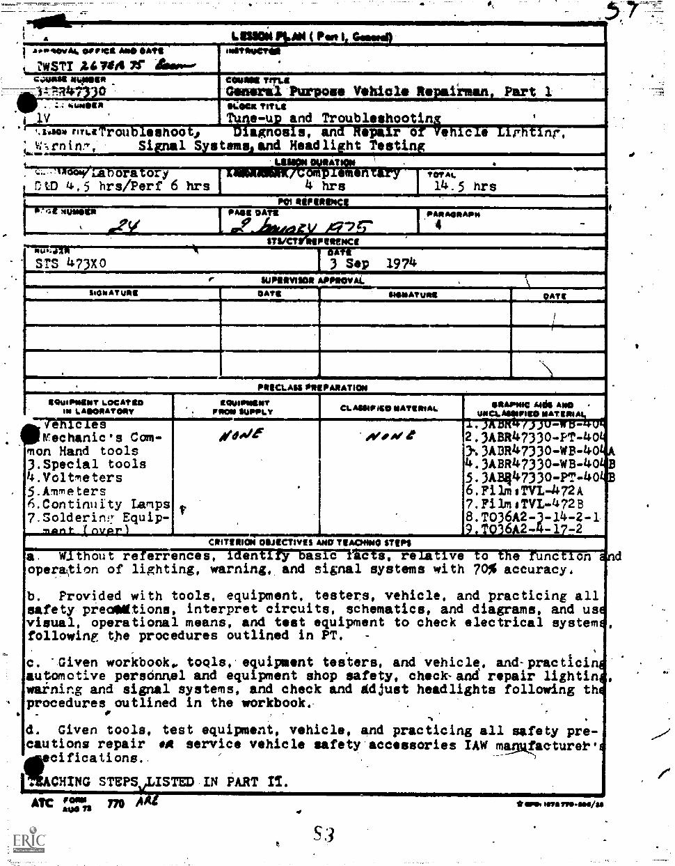
LIS1014 PM4 ( Pert 11 ao*lovAL Dome Aso OATS
USTI Ulffil ififtresuCTOI .
CAMAS MOWN COMM TrMILGeneral Purpose Vehicle Repaiimanl Part 1SI.DGM TITut
Tune-u and Troubleshootin I
iirlialF473(1. ; . .4411411110 1
i Iv%114011"11.4 rOu OO j agnos s, an eparo ece r nr,
' w--,rninry, Si 1 S stems and Headli ht Testin!....LS AT
LA ora oryOtD 4.5 hrs/Perf 6 hrs
, upolisOmTOT ati.
14.5 hrsPOI INFO
1 NUNS N
%
PASS OATS PARAONAPIO
4
STS/CT PeteNCENut 0 Ttsrs 473x0 3 Sep 1974
II"MililsIIIIIIIIIIIIIIIIMIMIIIIIWS:t:=iailMMMIEMoGlsAYURIIMICEMIIM
1111111E111111. PIECLAss ORIPASATION
ItOUIPIMINT LOCATtON LAIIONATORY
EQUIPININTFRO. SUPPLY CLASSIPiED MATERIAL osAymo Auk Also .
UNCLASSIFIED MATRON
orTiCITF-Kechanic's Com-
mon Hand tools3.Special tools4.Voltleters5.Ammeters6.Continuity Lamps7 . So1deriru! Equip-
//dole ovoive, ; ,.
2.3ABR4733o.pp.4o3' 3ABR47330-WB-404.3ABR47330-WB-405.3AB447330-PT-406.Filmern-472A7 . !Pi bn ITVL-47288. TO36A2-3-14-2-19 . TO36A2-4-17-2
Correll's; Ot/iCTIYIS ANO TEACHING STSPS
MFTWIiirelacte, relative to the runction -
warning, and signal systems with 70% accuracy,
tools, equipment, testers, vehicle, and practicing allinterpret circuits, schematics, and diagrams, and us,means, and test equipment to check electrical system:
outlined in PT.
s
toq1s, equipment testers, and vehicle, and-practicin-and equipment shop safety, check-and repair lightin
systems, and check and Adjust headlights following thin the workbook. . .
,
.
, .
equipment, vehicle, and practicing all safety pre-service vehicle safety accessories IAW mamfactureti
PART IT.
a. Wlthout referrences,operaion of lighting,
b. Provided withsafety preaNitions,visual, operationalfollowing the procedures
c. 'Given workbook,automotive perscinnelwaining and signalprocedures outlined
d. Given tools, testcautions repair mAsecifications..
rEACHING STMEISTED.INATC', rn A
ADO
S3
*am toss vre.m./as
EQUIPPENT LOCATED114 LABORATORY
8. Terminal Kits9. Battery hydrometers
10. ,AC type H headlight aimer11. Weaver headlight tester-aimer
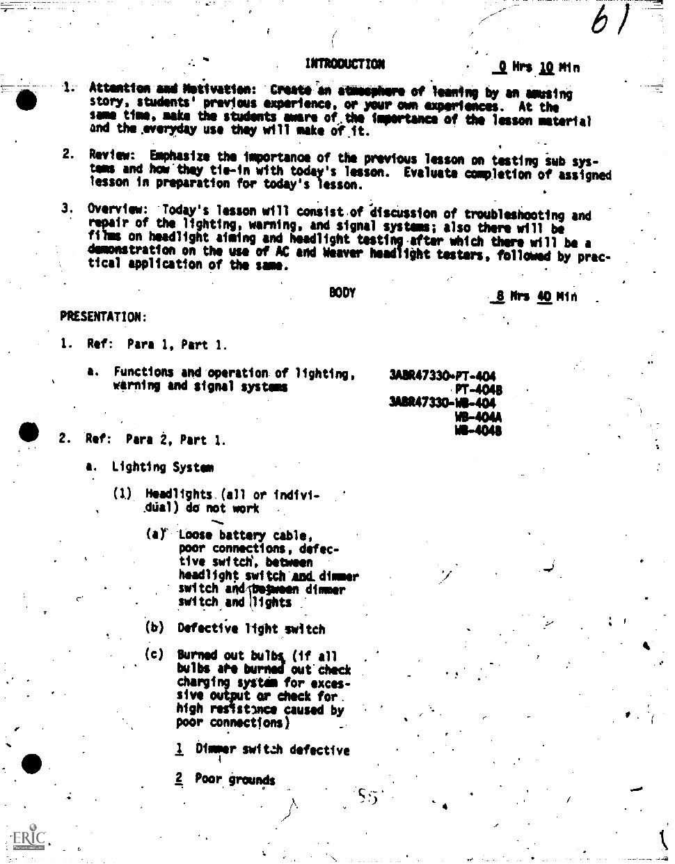
INTRODUCTION jHrsl9MlnAtteatten amaiNsiivallee: IrAmmft an atessehere-of leaning by an amusingstory, students' previous experience, or your own experiences. At thesame time, make the students aware of.the importance of the lesson materialand the Averyday use they will make Olt.
2. Review: Emphasize the %porton°, of the previous lesson on testing iub sys-tems and how"they tie-in with today's lesson. Evaluate completion of assignedlesson in preparation for today's lesson.
3. Overview: Today's lesson will consist.of discussion of troubleshooting andrepair of the lighting, warning, and signal systems; also there will befilms on headlight aiming and headlight testing-after which there will be ademonstration on the use of AC and Weaver headlight testers, followed by prac-tical pplication of tho same.
BODY
PRESENTATION:
8 Mrs 40 Min .
I. Ref: Para 1, Part 1.
a. Functions and operation of lighting, 3A8R473304T-404warning and signal systems PT-4048
34114733048-404WO-404A
2. Ref:
a.
Para 2, Part 1.
Lighting System
WO-4048
c-'
".
(1) Headlights (all orAllial) do not work
(a) Loose battery cable,poor connections, defec-tive swita, betweenheadlig14 switch-eold.dimmerswitch andqbeiween dimmerswitch andilights
Defecti;le light switch
(c) Burned out bulb% (if allbulbs te burniK outcheckcharging system for exces-sive output or check for.high resistuce caused bypoor connections)
1 Dimmer switzh defective
2 Poor. grouncls
/-
4
or.
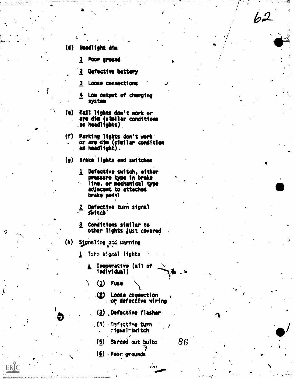
I.
(d) Headlight dim
Poor ground
4 Defective battery
3 Loose connections
4 Low output of chargingsystem
to) Tail lights don't work orareAtm (similar conditions,as headlights).
(f) parking lights don't work'or are dim (similar conditionatheadlight)0
(g) Brake lights and switches
1 Defective switch, itherpressure type in brakeline, or mechanical typeadjatent to attachedbrake pedal
1 Defective turn signalgltch
,1
3 Conditions similar toother lights Just covered
(h) Spinalingin4 warning
1 Tri sIgnl lights
IL 1=7111 (all of(;) Fuse \4L,
.(1) Loose coqnictlonor defective 41ring
(1) ,Defectivi flasher-
1(4) .12gictive turn /
r gibe tch
(6) Burnei out bulbs
(6) Poor grounds
4.
k Lights born butN.,I1 do sot flash or
flash- too rapidly
(1) Poor ground
(a) Difective or
vbfrasileP"
(1) Some flasheriare designedtO,flash adesignatedsize ind num-ber of bulbs,and othersare designedto flash any.numborbetween1 to 6
c Cancels improperly
(1) Cam improperlypositioned on
6 hub of steering\wheel
() Defective orimpropirly adjustedturn signal switch
d Oil pressure and charg-. Mg system indicator
lights
(1) Lights won't burnwhen ignition switchis turned on
Burnol/out tulbs
(.) Loose connec-tions or brokenOre from 1egt6tion 'witch orsending unit
Dehttive send-, ing unit (oil)
Light remains on when engineis running
)
IL Grounded wire fromsending unit
). Defective sending unit(oil)
c No oil iressure
d Defe5tive voltageregq13tor (chargingsystole)
I Malfunctions in charg-ing system
3 Horn
a- Horn(s) inoperativo
(1) Loose connectionsor broken wirefrom horn buttonrelay to horn, hornto horn
(/) Deflective relay
(1):'Defective hornbutton contacts
(I) Horn defectiveor out of adjust-ment
b NornAce4tes continu-IIy
(1) Vlerted mire
(g) Defictive hornbutton contacts
(1) Defective relay
Rof: Para 3, Part 1..
. Fuel, temperature, oil gauges'erraticor iaoperative
(1) Loose connections or brokenwires
,
(2)' Defediive sending Unit
(3) Osfsctivè Voltage01,03aler \\ -
(4) Peer ground
(5) To help isolate difficultiesas being sending unit orgauge, disconnect wire atsanding unit and ground it.If gauge registers, sendingunit is defective; if gaugedoesn't register, wiring orgauge is defective/
4. Ref: Para 3,, Part 1.
a. Windshield washers and wipers
(1) Wiper inoperative
(a) Fuse
(b) Defective dash switch
(c) Wiper unit latchingmechanism binding
(d) Defective relay control
(e) Defective wiper motor
(2) Wiper motor will, not shut-off
(a) Wiper unit latching mech-anism binding
(b) Relay control switchdefective
(3) C:cessive speed in Ili
(a) -Loose connection
(b) Resistpr open
(c) Motor,defeCtive
(4) Wiper operates in Hi or LOspeed only
(a) Dash switch
(b) Grounded wire
(c) Open wire 9(5)'
b: Heaters A beftosters
(1)* Heater and defroster inopera-tive
(a) Fuse
(b) Dash switch
(c) Reilistor
(d) Loose connections orbroken wire
(2) Heater and defroster don'tgive off sufficient heat
(a) Water valve on blockturned off
(b) Defective toperaturecontrol_ valve
(c) Broken control cable totemperature controlvalve
(d) Fresh air doors inopera-tive
(*) Inoperative ot no enginethermostat
5. Ref: Para 4, Part 1.
a. Purpose of tester (Weaver) (AC)
(I) Test canOlepower, beamdirecticn of: H;adlights,fog lights, and otheradverse weather lielts
(2) Also, furnish a positiveMOUS of correcting beamdirection
b. Units
° (I) Tester (Weaver)
(a) Photo-electric cell connectedto a calitrated meter whichmeasures taht intrilisa inthousandt MOW
Films; TVL-472 AABAC Headlight Meer, Model HWeever Headlight Tester Model Wx45
90
las%
e
(b) The calibrating stand is
/ designed to hold a flash-141* at t fixed height
11/ (2) Meer (AC)
(a) Transit and target isdesigned to compensatefor the floor slope
(b) Niers and adapters, leftand right, flied to aim theheadlight only
:,PPLICATION:
.1.. Ref: Para 2, 3 & 4, Part 1.
SUMMARY
Weaver Headlight MeerAC Type Headlight AtmersVarious VehiclesVoltmeters, Ammeters, Continuity
i:N, Soldering Eqmipment, Tenn-its and Hydrometers
gra OF OAY $UMMARy,
You have been given a series of problemsconcerning lights, warning and signalsystems, and quizzes covering thesame. You have also tested lights,warning and signal systems on vehicles.In addition you have seen films onhow to use the headlight tester andOmer to adjust headlights and dis-cussed various difficulties encountiredwith mis -aimed headlights.
v
1. Restate objeativee of the lesson(covered in this day).
2. You have also discussed and checked 2. Emphasize the area of majorheaters, defrosters, windshield importance.washers and wipers, and how the ,
horns are adjusted for tone andvoltme.
3. Pass out quizzes at this time and discuss 3. Use oral "questions to determtneany weak areas that show up. areas to be retemght.
ASSIGHHENT
1. Restudy Workbooks.404A and 40411, toprepare yourselfts for the lab workthe first thing in the morning.
2.This Additional study wit] assist you
imerstaneing me headlight tester god
1. Identify study meteriels.
2.
lioviaannitgielede"
.--the,headtfgAA Omer. INeolitil *givenquiz on this material before we parti-
cipate in therlabwork.
Continue to let a time aside every 3. Mention method'of study.evening for your studeng, and don't.forget-Please try to have as few dis-tractions as possible! Then concefttrateon the material oply. Try the SW methodof study as suggested before. Pleasegive it a fair try.
ICROCitTION to NEW CAY'SyoRk
1. Today you Will be able to put to use, the material discussed andtestedl yesterday. In your endeavor you my encounter difficulties withthe vehicle's and this is to be expected. These vehicles.are purposelyinduced with various malfunctions for yolir benefit. Aspire replace,and adjust according'to nenufacturer's spitifications. Conduct ques-tion/answer period to determine class preparation of assigned materials.
2. Remember the difference between the Headlight Tester (Weever Model WX-45)and the Headlight Aimer (A.C. MOW "H").
a. The Weaver Headlight Tester measures the intensity of the headlight,beam 1000 candlepower increments as wall as locating the beam direc-tion.
--br. The A.C. Weadlight Aimer does not measure beam intensity, only dir-ection.
_ _ .You must be able to differentiate between the-taro types of doers,their limitatiqns as well'as their capabilities. This yea will accost&plish today. Mb will now go to the lab area and conduct our'experissnts.
ApPL1CATION:
1! Ref: Pim 3, Part 1
2. Ref: Vera 4,'Part 1.
EVALUATION:
1. The quizzes fora-yesterday and today'sactiVitiet will be given at this time.These quizzes are in addition to thedaily quizzes and questions that areiisued and interspersed throughoutthe lesson.
SUNKIRIPMD REMOTIVATION:
CONCLUSION Mrs .1.0 Min
Briefly cover the material presented yeste0dAy and tot:141,1mi the experlence
t
gained-by applying the*r krorledge to the actual vehiclep. Stress the import-
ance of cr'py1na with tha state laws governing the headight Settings, as-wellumnitart Apecificationts Natten theetisivaresteovered inthis lesson, such as lights. warning, signal systems, heaters, defrosters,W/S washors and wipers, and gages.
SSIGNMENT ANO CLOSURE:
1. Reviftall the daily appraisalwand notes peitaining to the block in prepara-tion fbr final block measurement.
2. This. completes the activities Of-Block Four and si the end of block testsw411 be administered at this time.
study end respond to PT's 501, BOLA A 5016 dealing midi Clutch Operation,Transmission Construction and Operation and Power Take-off Units.
te
At. '
J'
WORKBOOK 3A1R47390.41-400
ow-
Technical.Training
Ale dko.stGeneral Purpose Vehicle AspaUsian
BLOCK IV'TUNER AND TRDUBLESHOOTING
3 June 1970
4CHANtiTE TECHNICAL TRAINIRG-4&NTER (ATC)
This supersedes rT 3A3R47330 -403 Through,404A, Student Workbook3A3R47330 -401A -1r Through404C-II, 25 April 1969.OPR: TSDTDISTRIBUTION:, X
TSDT - 200; 1500 n 2
----Designed For ATC Course Use
rA
I.
Training Publication are designedfor ATC courstuseenlys They are updated aa neoniaryfor tnining purposeit hot are not to bd paid on the job us authoritative relerencea in prat-
,-..-..ersaceitt-liechotea&Ordeko-or -other altkilai, pelaidiatiosa,t
c'eNIT
CONTENiS.
TITLE
401 Ileld Meehods of-Troubleshooting Engine Systems
402 Scientific Tuneup of-,MschaniCal, Battery, Ignition, Fuel *
Lubrication, Cooling, and CrankeaseVentilation Systems
403 Tuneup and Troubleshooting Using Diagnostic Test
Equipment (Simpson Universal Engine Analyser)
404 Troubleshooting, Diagnosis, and Repair,ot Lighting, Warning
and Signal Systems and Headlight Testiilg
404A Troubleshooting, Diagnosis, and Repair of Lighting, Waming
and Signal Systems and-Headlight Testing (Headlight Teiter)
4043 TroubleshOtoting, Diagnosis, and Repair of Lighting, Warning
and Signal Systems and Headlight Testing (AC Headlight Aimer) :
I.
1 Thru 14
. 15 Thru 29
31 Thru 47
49 Thru 63
65 Thru 61
71 Thru 74
.August 1969 .
't 4..
Or'
pp
L
4
L
rn
4.t
11.
70-s I.
+
Vehicle Maintenance Branch:Chanute AFB,
OBJECTIVES v.
.N".
\ .FIELD METHODS OF TROUBLESHOOTING ENGINE SYSTSMS
""'
SA3R47,330-WS4Ol
,
When you have'completed the exercises in this wqrksiteet you wilr be able tb:. . . . ,.._
.. ,
Ise visual:, auditory, and operational means to perform field methods of
troubleshooting engine component malfunctions in the electrical system, fuelV
.
system, lubrication syitem, 'cooling sysrtm, and Mechanical system. ..
Use operational *and-field methods to.inspeht, 'clean, test, ipfvite, and,
adjust the units ehae mitke up the vehicle components listed abov
Use handtools and publications properly 4nd observe all safety precautions.
or.QUIPMEN'T
Live EngineMecha9ics Tool Se-"t\
PROCEDURE t'
Using the worksheet ab a guide for gtep-by-step procedures and importantinformation, perform eich task listed and read the infoTmation about it whereapplicable-in the following exercises and as directed by,the instruttor,.,
./
Exercise
Locate and Correct Starting-SystemEqt.ippent: s
.
' Observe all Ipplicablesafety precautions.
4 .
Malfunctions
1.
01;tain the necessary 2."
handtools.
3. Obtain the applicablepublication.
Pt .
4. Attempt to stait thed'esignated engine andobserve the cranking
'speed.
eFe
Wfthout Special Test
4 3. Reference used:I' II . 6
4. If,when attemp;ingLtoit will not turn over,steps'should be takenOle trouble.
stait rengine
the.following,to isolate
Note:. Makft sure battery.good condition and fully
. .
I.
is incharged.
a.
A
I.
. -
r
5. Isolate the trouble *evelopedin-the starting motor circAlitwhen starting motOF.fails to\turn engine over4or it turns\sloUlye
4.
a. ,.-Observe light(s) while(.
attempting cra ,
and iso e t uble ifthe ligh s -stay.brightanerhere it no crankingaction,
5. If che&iitg with the engine in thethe headlights ,or ,dotte
is turned _se-while atileapting
t4 Erank the engine. If using anengine trainer, use a continuitylight hooked across the battery.
31;\
a. This condition fndicates.anopen circuit at some pop= inthe starting system (startingmotor, switch, or Oantrolcircuit).
(1) Tarn on,ignitionswitch; close.thecontrol witch.
(1)
.J(2) -Determine if the
magnetic switch
(2)
or solenoidoperates.
I .
*0'
(3) Isolate malfunctionin the cohtrol circuit.
(3)
b. Isolate troublyif light(s)goes out as the starterswitch is closed.
c. Isolate trouble if lightsdim considerably es,the.starter switch is closedand the starting motonoperatea.slowly or not atall.
6. Have the instru ctor check thejob.
44.
2
Most magnetic switchesortsolenoids may be. i
operated by hand. If
starting motor operateswhen snitch is closed,the-t6uble is in thecontrol, circuit.
Use jumper lead'and.connect around the con-trol devices End switches.
tiNote:-;If the trouble isin the starting motor,it muist be removed andcheaed.
yr
b. This condition tndicates thatthere is a poot oDnnectionbetween the battery andstarting motor.
Note: -.chgck L battery
1
If battity is ,ilagood 9ndi-tion, there'ally $e sowmechilnireal condit4t.
ehgine or startiAg tor
whi8h Fautes the trouble.
6. Instnictbros.in
4
dr h'-
4
r
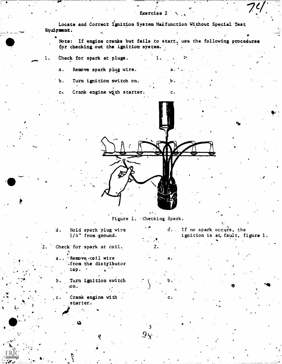
.
"tr
Exercise 2
4
Locate and Correct ignition System Malfunction Without Special TestEquipment.
Note: If engine cranks but fails to start, use the following proceduresfor checking out the ignition system.
1. neck for spark at plugs. 1.
a. Remove spark plug wire.
b. Turn ignition switch on.
c. Crank engine 4rth starter.
r--
II
4
1
Figure 1. Checking Spark.
d. Hold spark plug wire1/4" from-ground.
. Check for spark at coil.
6
a., TRemove/Coil wire'.from the distributorcip.
b. Turn ignition switch4on.
Lc. Crank engine with -
starter.
#4.3
.a
A
d. If no spark occurs, theignition is at? fault, figure 1.
Z .
a.
b.'
A
r
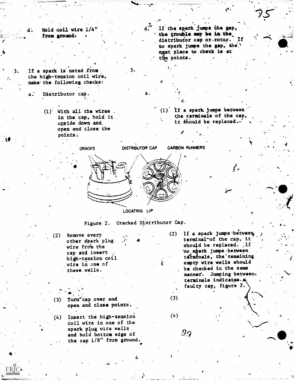
d. Hold coil. wire 1/4"from groondi a
If a spark is noted from,the high-tension cOil wire,make.the following checks:
a: Distributor cap.
ay With all the wires .
in the cap, hold itupside down and.open and close thepoints:
"CRACKS
A
d:. If the sp.ark jumps ehe gap, ,
the ;rouble may kadistribuior cap or.rotar. /f
to spark jumps the gap,- she`
nixt place Go check is att! points.
a.
DISTRIBUTOR CAP
(1). tf a spark. jumps between'.the terminals of the cap,it should be replaced,: %
,
CARBON RUNNERS
/
LOCATING LIP
Figure 2. Cracked Distributor
(2) Remove everyother sprk plug.wire from thecap and insert :
high-tension coilwire in one ofthese wells.
,
Turecap over andopen ana close points.
Insert the high-tensioneoil wire in one of thespark pitug wire wellsand hold bottom edge ofthe cap 1/8" from ground.
4
44.
?
Cap .
(2) If a spark jumps ;betweerk )
terminal-of the cap, itsho d be replaced. .If
r:ino s ark jumpsbetween
..3to nals, tbe'remainingescly wire wells shouldbe checked in the samemannee. Jumping betweenterminals Indicates, a 4
faulty cap, figure 2.
a
9,9
I.
*
A.;
r
la
.
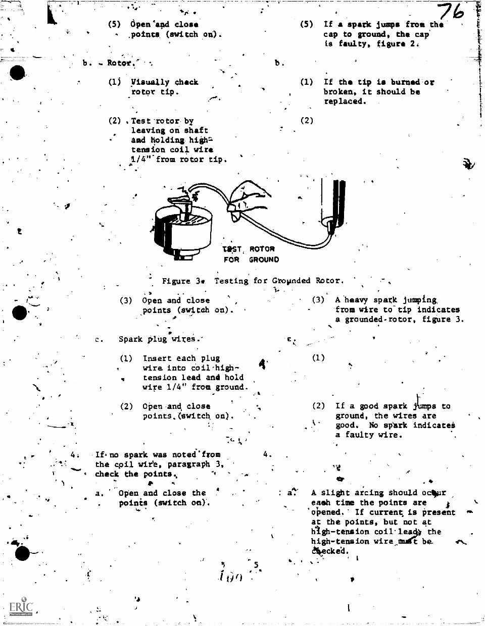
p.
-4!
44r;
(5) cipeniapd close.points (switch oti).
Rotor."
(lj Visually checkrotor tip.
(2) Test -rotor byleaving on shaftarid fielding highz-tension coil vire1./4"-from rotor tip.
b.
(5) If a spa* lumps from the'cap to ground, the cap'
is faulty, figure 2.
(1) If the tip is burned orbroken, it should bereplaced.
(2)
T.S.ST, ROTORFOR GROUND
Figure 3* Testing for
(3) Open and closepoints (switah on).
,
C Spark plug wires..
Insert each plugwire, into Coil-high-tension lead and holdwire 1/4" from ground.
OPen.and, closepoints. (switch. on).
If. no spark was noteefromthe cpil wiie, paragraph 3,check the points%
,a. Open and close the
poinis (switch oe)'.
.4
e
4.
4.
Gropnded Rotor.
A: a.
(3) A 'heavy spark jumping,from wire to-tip indicatesa grounded-rotor, figure 3.
(1)
If a good spark iCmps toground, the wires aregood. No sp`ark indicateiia faulty wire.
A slight arcing should ocily.ireast' time the points areopened. If current. is Presentat the points, but not athigh-tension coi1lea4 thehigh-tension wire_maCt be.8kecke'd.
4
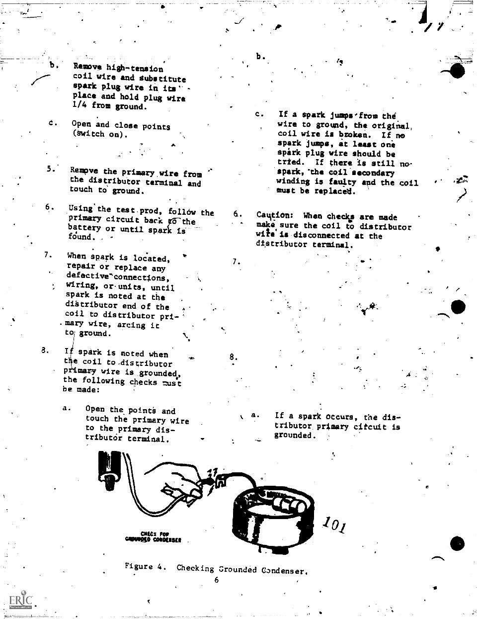
;FP..
Remove high-tensioncoil wire and dubstitutespark plug wire in its"- -
place and hold plug wire114 from ground.
c. Open and close points(Witch on).
5 Rempve ehe primary,wire fromthe distributor terminal andtouch to' ground.
6. Using'the test.prod, follOw theprimary circuit back FES-thebattery or until spark iifOund.
7. When spark is located,repair or replace anydefectiveconnections,wiring, or.units, untilspark is noted at thediStributor end of thecoil to distributor pri-
.mary wire, arcing ittoil ground.
8. I spark is noted whent e coil to,distributorp mazy wire is grounded.,the following checks mustbe made:
a. Open the,pointi andtouch the primary wireto the primary dis-tributdr terminal.
c. If a spark jumps'from thdwire to ground, the original,coil wire is broken. If nospark jumps, at least onispark plug wire should betrted. If there is still no-spark,"the coil secondarywinding is faulty and the coilmust be replaceli.
6. Camtion: When checko are mademake sure the coil to distributorwitelis disconnected at thedtstributor terminal.
7.
8.
a.
Op
If a spark occurs, the dis-tributor primary citcuit isgrounded. :
CNC: FOP001111,10 CONOUSUI
river'Figure 4. Checking Grounded Condenser.
6
.4,`"
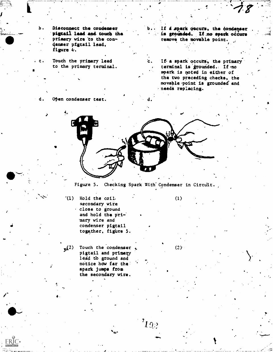
b. Disconnsct the condenser'pigtail lead and condi theprimary wire to the con-4enser pigtail lead,figure 4..
?,
c. Touch the primary leadto the primary terminal.
d. Ofen condenser test.
'b.. If A .apark twecurs, the eondltreris grsiciuted. /Lao *perk ocdureremove the movable point. ,
c. If a spark occurs, the primary'terminal is 'Aroutided.:, If.no
spark is noted in either ofthe two preceding checks, themovable.pOint ii grounded and
-needi replacing.
d.
Figure 5. Checking Spark with-.Condenser in Circat.
"(1) Hold the coil.secondary ,wire
, close to groundand hold the pri-mazy wire andcondenser pigtailtogether, fiture 5.
42) Touch the condenserpigtail and primaulead tb ground andno.tice hOw far thespark jumps fromthe secondary wire.
7
9:?
4
(1)
(2)-
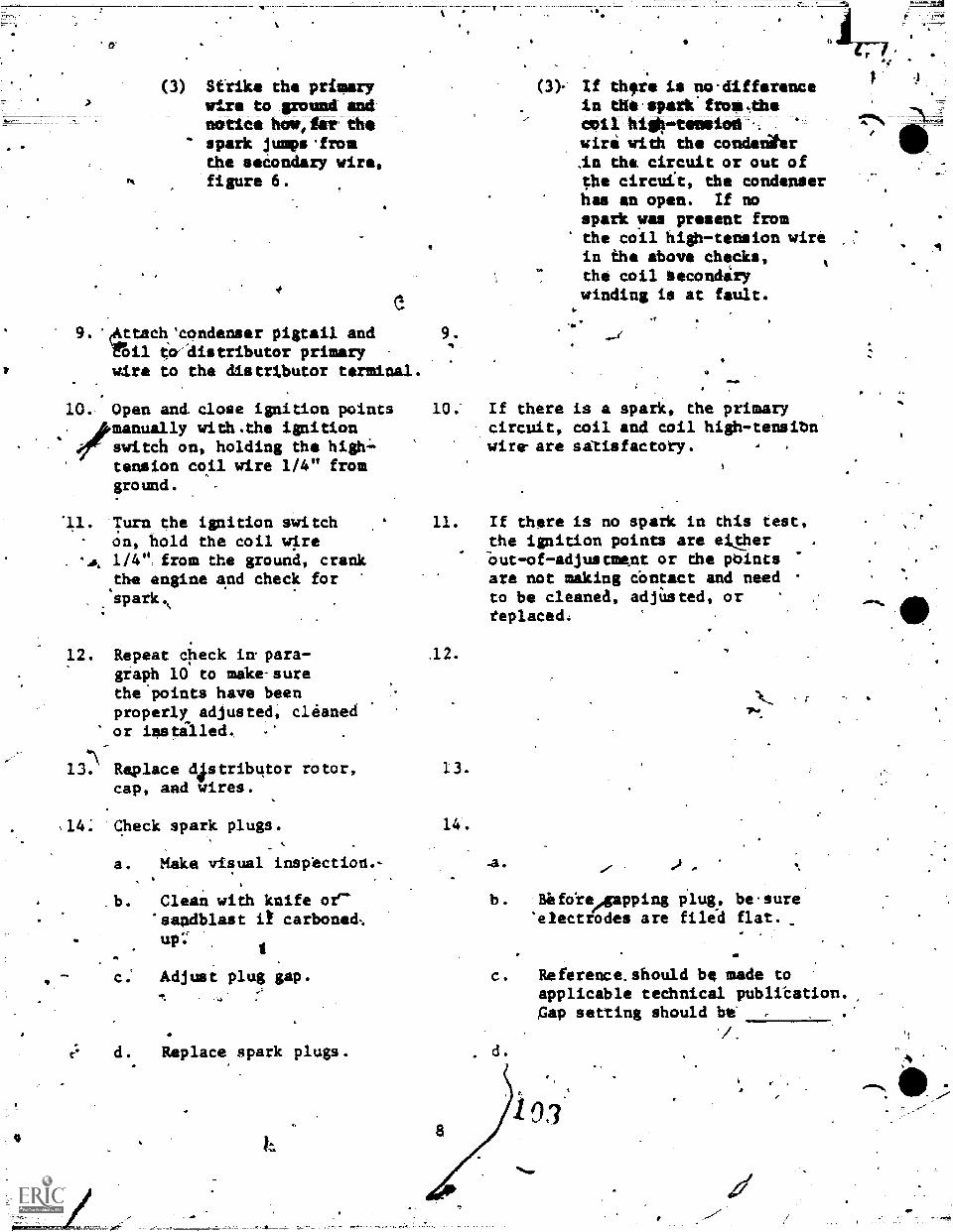
(3) Strike the primarywire to 'gonad amimatte* howsier thespark pimps 'fromthe secondary wire,figure 6.
9. 'eatach'condenser pigtail andfOil to-distributor primarywire to the distrtbutor terminal.
10, Open and close ignition points/manually with.tha ignitionswitch on, holding the hightension coil wire 1/4" fromground. -
11. Turn the ignition switchon, hold the coil wire1/4' , from the ground, crankthe engine and check forspark.,
9.
(3) If thfre is no-differencein the-spark from,thecviI hig44-temeiod'.,
wiri with the condenihr.in the. circuit or out ofthe circuft, the condenserhas an open. If nospark was present fromthe coil high-tension wirein the above checks,
-
the coil becondirywinding is at fault.
f
10; If there is a spark, the primarycircuit, coil and coil high-tensibnwire-are satisfactory.
11.
12. Repeat check in- para- .12.
graph 10 to make-surethe points have beenproperly adjusted, cleanedor iastalled.
6\13. Replace distributor rotor, 13.
cap, and wires.
14: Check spark plugs. 14.
t.
Make visual inspection.-
Clean with knife or''sandblast it carboned;up
c. Adjust plug gap.
d. Replace,spark plugs.
If there is no spark in this test,the ignition points are etther-out -of -adjustment or dhe points
are not making COntact and needto be cleaned, adjUsted, orteplaced.
.a.
b. Before/gapping plug, be.sure'electrodes are filed flat.
c. Reference.should be made toapplicable technical publi'cation.,Gap setting should bt'
'/.
. d.
487)10)7(
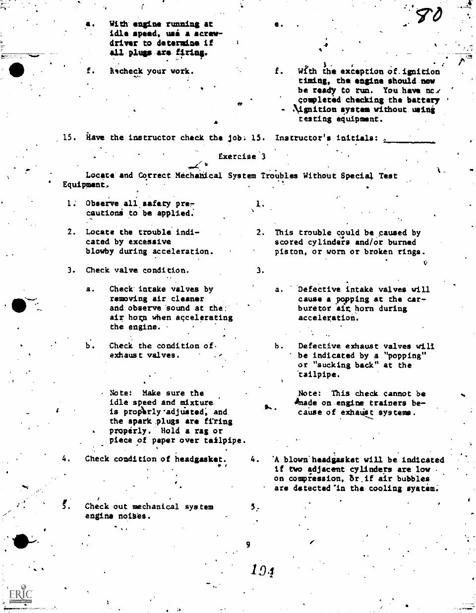
e. With engine running atidle speed, usi a screw-driver to determine ifall pluss ere firing.
f. Recheck your work.
I
1A
S d
With the exception Of.ignitiontiming, the engine should nowbe read7 to run. You have nci '
completed checking the batteryNignition aystem without usingtesting equipment.
,
15. kave the instructor check the job; 15. Instructor's initials: ,
Exercise 3
Locate and Correct Mechanical System TrO'ubles Without Special Test' Equipment,
1.; Observe all.safety prercautioni to be applied.
2. Locate the trouble indi-cated by excessiveblowby during acceleration.
3. Check valve condition,,
a. Check intake valves byremoving air cleanerand observe "sound at the:air hogn when acceleratingthe engine.
b.. Check the condition of,exhaust valves.
Note: Make sure theidle speed and mixtureis proArly'adjUsted; andthe spark plugs are firing
. properly. Hold a rag orpiece of paper over tailpipe.
4. Check condition of headgasket.
2. This trouble could be_caused byscored cylinders and/or burnedpiston, or worn or broken rings.
3.
a.V
Defective intake valves willcause a popping at the car-buretor ait horn duringacceleration.
-
b. Defective exhaust valves willbe indicated by a "popping"or "sucking back" at the
Note: This check cannot beAnade on engine trainers be-caUse of exhaust systems.
4. 'A blown'headgasket will be indicatedif two adjacent cylinders are lowon compression, br.if air bubblesare detected'in the cooling syatem;
Check out mechanical system 5;
engine noibes.
1D.1
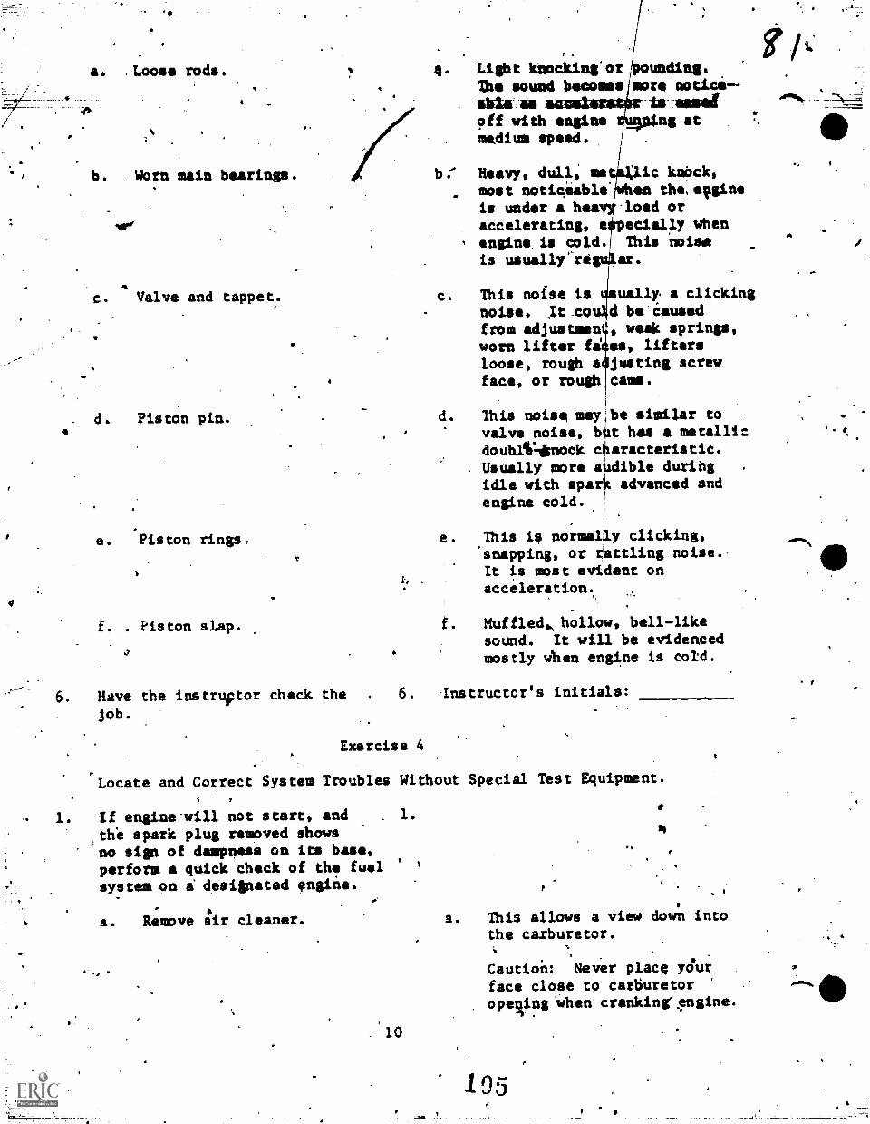
'
a. .Loose rods.
4
b. Worn main bearings.
sir
C. Valve and tappet.
d. Piston pin.
e. Piston rings.
f. . piston slap.
,r
6. Have the instrvtor check thejob.
Light Itnocking*or iounding.ft
The sound becomes more notion--abla as is Assafoff with engine _00.ng atmedium speed.
b. Heavy, dull; memost notigiableis under a hoeaccelerating, e
, engine, is cold.
is usually°-re
c. This noise isnoise. 1t Cofrom adjustmenworn lifter fdloose, rough aface, or rough
lic knOck,en the,euine
.load orecially whenThis noisear.
ually a clickingd be iaused9 weak springs,es, liftersJustin& screwcams.
d. This noise may be similar tovalve noise, b t has a metallicdoublIklisnock c aracteristic.
. Usually more audible duribg .
idle with apex+ advanced andengine cold.
e. This ia normally clicking,'snapping, or rattling noise.-It is most evident onacceleration.
Muffled., hollow, bell-likesound. It will be evidencedmostly When engine is cold.
6. Instructor's initials:
Exercise 4
rLocate and Correct System Troubles Without Special Test Equipment.
1. if engine.will not start, and . 1.
,thi spark plug removed showsno sign of dampness on its base,
perform a quick check of the fuel '
system-on i desilnated engine.
a. Remove air cleaner.
. 10
dl
a. This allows a view down intothe caxburetot.
Caution: Never place yOurface close to carburetoropeqing when crahkingr$ngine.
105
rim\
,
4*
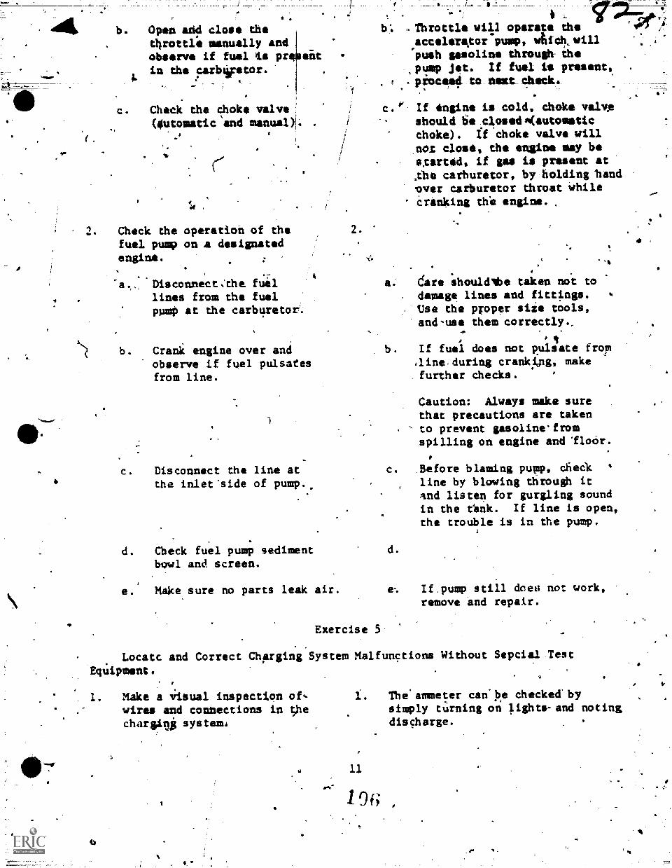
t'"t.
.b. Open add close the
throttle manually andobserve if fuel gis prin the parbOator.
sit
c. Check the choke valve(4utomatic and manual). .
,
Check dhe operation of thefuel pump on a designatedengine.
b.
C.
Disconnect:the fuellines from the fuelpump at the carburetor
Crani engine over andobserve if fuel pulsatesfrom line.
Disconnect the line atthe inlet'side of pump..
d. Check fuel punp sedimentbowl and screen,
e.' Make sure no parts leak air.
2.
b. -Throttle will operate the,acceleripor pump, whicb,willpush gasoline through thepump jet. If fuel is present,.peocaect to flairt check.
c.°' If engine is cold, choke valveshould Se.closedA(autometicchoke). If choke valve will.nOt close, the engine may bectsrvid, if gas is present atAbe carburetor, by holding hand.over carburetor throat while
' &ranking dhe engine.
4
a. dare shouldlbe taken not todamage lines and fittings.Use the proper siie tools,and-use them correctly.,
b. If fuel does not pulsate fropaine during crankApg, makefurther checks.
Caution: Always make surethat precautions are takento prevent gasoline'fromspilling on engine and Iloor.
c. Before blaming pump, dfieCkline by blowing through itand listen for gurgling soundin the tink. If line is open,the trouble is in the pump.
e-.
Exercise 5
z
If pump still dceo not work,remove and repair.
.
Locatc and Correct ChArging System Malfunctions WithoutEquipment,
1. Make a Visual inspection of-. wires and connections in ;he
chargilg systems
Sepcial Test
1. The' ammeter can' be checked bysimply tUrning on lights.and notingdischarge.
11
1 of;
tje
*
I
.%
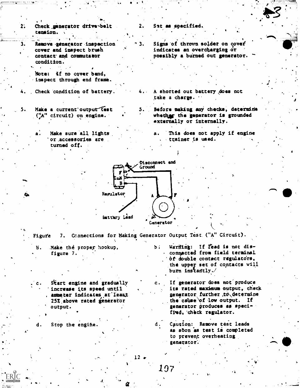
r
_
f
Check.gifteratOr drive,beltcaution.
I 'Remove lenerator inspectioncover and inapect brushcontact.' and commutator
condition., ,
0
'Note: if no cover band,-inspect through end frame.
4. Check condition of battery.
Make a current'outpurlist("A" circuit) on engine.
9
a: Make sure all lights,or ,accessories areturned off. ,
Figufe 7.
2. Sit an speafied..,
, .
n 3. Signstif thrown solder on covei.., indicates an overcharginuor
posSibly a burned out generator.
4. A shorted out battery.does nottake a charge.
5. Before making am', checks, datermidewhet* the generator is groundedexternally or internally.
a. 'This does not apply if enginetrainer is used.
-Disconnect endGround
Remistor
battery Lieed
Generator
Ccnnections for Making Generator Output Test. ("A" Circuic).
Make the propey hookup,figure 7.
Sleart engine and graduallyincrease tts speed untilammeter indicates.at-latAX25I,abolie rated generatoroutput.
1
d. Stop the engihe.
12*
b; Warfflitg: If read is not dis-conlected from field terminal
'6f double contact regulatdrs,the uppey set of contacts willburn instadtly./
c. If generator does noeproduceits rated maximum output, checkgenerator further .td\determinethe cabse\of low output. If
generator produces as speci-fked, 'check regulator.
.
Caution: Remove test leadsas sbon 'as test ii completedto prevenx overheatinggenerator:
197
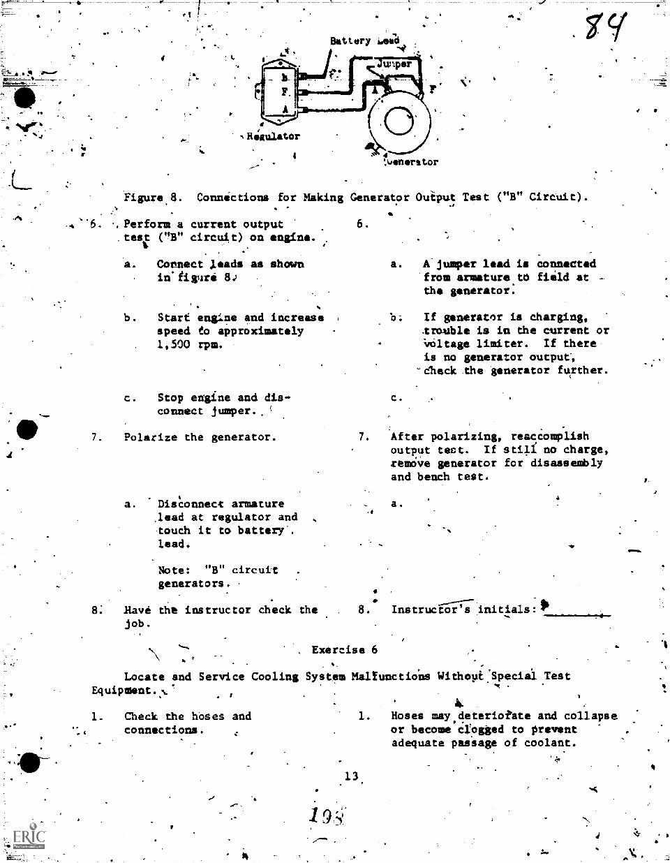
-
Battery Adeali-4) .
,Rezulator
4 4',(Jenerst.or
Figure 8. Connections for Making Generator Ouiput Test ("B" Circuit).
,4 Perform atest ("B"
current outputcircuit) on engine.
Cornect leads as shownin.iigure 8.)
b. Start engine and increasespeed to approximately1,500 rpm.
c. Stop ehgine and dis-connect jumper.. (
7. Polarize the generator.
a. Disconnect armaturelead at regulator andtouch it to battery .lead.
Note: "B" circuitgenerators.
8: Have the instructor check thejob.
6.
a. A jumper lead is connectedfrom armature.t0 field at -
the generator.
b. If generator is charging,lrouble is in dhe current orimltage limiter. If thereis no generator output',
-Check the generator further.
c.
7. After polarizing, reaccomplishoutput tect. If stig no charge,remove generator for disassemblyand bench test.
a.
#
8. Instructor s initia1s:114
4
. Exercise 6
Locate and Service Cooling System Mallunctio'ns Withept.Special TestEquipment.:6:
. I
1. Check the hoses andconnections.
1. Hoses may,deterioiete and collapseor become crogged to preventadequate passage of coolant.
13.
Is
0'
Check by squeezing-the.hqiies bl hand.
2. Check operatinn ofdiermos tat (s
.0 .
'Ar 3. -CheAgc, condition of coolant.
4. utsually.chek radiator°ores.
5.
r
Not&cbe radiator pressure
6. Hayejot.:
instructor check the
. .9
, 4
Run engine and observe temperaturegauge. Ingkne should reAch'operating,telperatuee within a Short time.It should not overheat durifig
operation.. 14.
3. appearance of coolant may indicaterust and scale:
4.
5. Always be sure the correct cap isused.
6: Instructor's initials:
Exercise 7
\Locate and Service LubricatingE4uipment.
1.1. Check the.appearance of
the oil on dipstick.te-
N
2. 'Note oil pressure when,engine i4 started.
3. Note oil pressure afterengine is normalized.
4. Have the Instructor checkthe projects.
4
t
It
444.,_
System MalfUnctions Without Special Test
14
1. Note latether)it is thin, dirty,thick, or has sufficiemt body.
2.
3.
.
4. Instiuctor's initialsA/ .
.4
ra
v
.1F-------%.
7 . . :, I ..-., a.3
"Nr....,.....
,Vehicle. Maintenance Branch 31BR47330-WS-402-": '4
Chanute'A, Illinois , . . 4,,
..--. I \ ,
.-- SCIENTIFIC TUNEUP OF:MECHANICAL, ,BAXIBEY, -IGNITIOI: FUEL
-LuzicAnoN, =xi*, ANS CRANKCASE, ANTILATION sysiims...,.
-) 'OBJECTIVES
\ .
,t. .
fr,
.ir "Vhen. you havi completed the exerCise4 in this worksheei you will be able to:.
-
Recognize, isolate, and idjust engine gerfor*fice of the engIntMechanical- ystems,,fuel air systems, starting systems, chatging systema and igatton
,
.., systems, by using*the required iest equipment,'commin handtools, and speepal
.- ., tbols. '' .
.-.-
.,
. .....-, .
1
. Observe 'safety preca4ions and use applicable technical ptiblicat.ions.,
,:iy..,..
a -
E0IPMENT ..
,4
t, - r : iit
10.
e-
tv, Enginegine Analyzer
MechaniFs 6netoolsSpectaL Tools
PROCEDURE
--, . .
Using the workshiee a a-guide for step -tep'procedures and importantinfumation, perforM each task listed and read ehe informatibn about it whereapplicable in the following exereises arta asvdirected by the instructor: .
Exercise 1
inspect the Satteryland Starting.System.
1. Observe all safety pre-, 1.6tautions applying to-the
project.
2. Obtain the nec4ssaryhandtools and testequipment.
3. ,Cttain the necessarytechnical:publications.
4. Visually inspect diesdesignated ,battery-..
'
...
$
a. .Check battery topfor sOrt or-r-acid.
ChCk cell yents.
,
e
4
C.
-
2. List equipment 'required.
a 4.
I.
4.
r3.- List rqgrence used.
.
. ,,
.44
3,
.. ,A.
.4.
4
15
( 1
a.
b. Make sure vent:ere open.
4
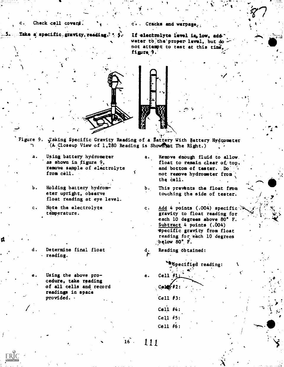
a.
s
c. Check 'cell cover".%
th,
Tako specific, gravityi.raiding., t
NO.
c's , Cricks and warpage.
If-electrolyte fevel ii tow, add-%water tb:theproper level, but do --'not attempt to test at this tima,fistro,".
117..:
-tr
Figure 9. gaking Specific Gravity Medi-L.1g of a Battery With Battery Hydvometer--1 (A- Closeup View of 1,280 Reading is Showftit The Right.)
a. Using battery hydrometeras shown in figure 9,remove sample of electrolytefrom cell.
b. Holding battery hydrom-eter upright, observefloat reading at eye level.
c. Note the electrolytetemperature.
d. Determine final float- reading.
e. Using the above pro-cedure, take readingof all cells and recordreadings in spaceprovided. -
a.
a.. Remave dnough fluid to allow.float to remain clear ottop.and bottom of tester. Do'
not remove hydrometer fromthe &Ill.
b. This prevhnts the float fill=touching the side of tester.
c. Add 4 points (.004) specific',gravity to float reading foreach 10 degrees above 80° F.Subtract 4 points (.604)itpecific gravity from floatreading for ditch 10 degreesbglow 810°. F.
Reading Obtained:d.
e.
*111Specifild reading: X,
. .
Cell #3:
Cell #4:
Cell #5:
Cell #6:
"draftstr
fY
0
6. Service the battery.
lv
8.
a. Neutralize acid.
ids
b. Flush lath war4r andthoroughly dry's.k
c. Paint' bittery holddownand case. ...
d. Coat ouside of batteryterminul oibles.
'Visually inspect the startingsystem.of theoiesignatedstarting system.
a. Check cables..
b. Check all'connections.
c. Check the starting molar.
Have,the instr.utor dheck thejob.
6.
a. Use a salution of baking soda .
and water.
b. Make 'sure thaE n6ne of thesolution enters the hattery.
c. Use acidresistant iaint whichprevents corrosion.
d. Use a thin coat of petrolatumjelly or vaseline. Thisretards corrosion.
a. Look for frayed insulation orbroken strands.
b. Check far:looseness andcorrosion.
c. This is a visual check of thebrushes, commutator, and'mountingst
Instkuctor's initials:
Exerise 2' %
Inspect-and Si'llvice the Charging System.,,
1. Observe the appltcablesafety precautions.
, 2. 'Ot)tain,the necessary tools.'
3. Check the generator Mountings.
4... Check the belt(s).
a *
5. Check the gt.Titrcondltion.
6. Check regulator mounting
AgL%
3. 'Sat*
4. Thoroughly check the condition,Make sure belt(s) has the correct
, 'te'nsion. (Alwatjs refer to
vehicle mantal.)', Recor0 beltdeflection:
Record specified deflection:
5.-7.Visua11y"check brushes, cogmlitatorcondition, and internal-cleanliness.
k
4
.11
;.
. ,
Cheat all wiririetndco,n!teptfis ,r;
.8.- sSeryite the dipignated
charging system. .
9., Have the instructor check thejob.
7. Check for loose or corroded con-nection' and conditioi of wires,
8. This donsists of correcting an .
troubles found.duting t4e *ape tionof thesystei.
9. Instructor's-initials:
txercise 3'
.
Determine Condition of Engine Mechanical Systems: .
Note: The basis of good performance depends on the.conditi;The follawing tests tell the experienced mechanic very mubh
condition of the enema.
Determine all applicable 1.
safety precautions.
, 2. Obtain the necesaarytools and eqUipment.
3. To insure safe damage-freeoperation, prior to. startingengine and performing tuneupof the engine', check thefollowing items.
*4.
a. Engine oil level.
b. Coolant'livel.
the;
Fuel ortil leak. :
4. ..Lines, fittings and filters.
e. Manifold heat control.
f. Crankcase vent system.
Operate engine until normaloperating temperature is
reached.
Test compression ondesignated engine.
9.
n of the engine,concifning the
2. List tools and equipment.
3.
a.
b.
C. .
d.
e.
f.
4.
..
5. No hookup.or specific prqceduies
will be ,given at,ihis timp.
.Always use the Otocedures asiven in the commercial manualapplying to the test equipmentbeing used. The student should
-use the note column for recordingany notes'pertOning to thetests that are,actually 'made.
18
"
L.
.6. - Frowthe followingcomptession test indicationdetermine the possible trouble.
a. Low compression on firststroke, builds up onfollowing strokes, butnever to specified amount.ImproVes when oil is added.
b. Low compression on ./first stroke does notbuild up on followingstrokes even with oiladded.
C. Sane indication asabove on two adjacentcylinders.
d. Compression pressure .higher than specified.
7. Pcrfcrm cylinder leakage test.
8. Have the instructor check thejob.
Type of equiiment used:
RefirenCe used:
Specified compmession.pressures:
Readings obtained:
In the spaces provided below,give, the possible trouble.
a. Possible trouble:
b. Possible trouble:
c. Possible trouble:.
d. Possible trouble:
If certain test equipment is avail-_able, .this test may be accomplished.However, if it is not availabre,disregard this project. This testis becoming very important and ismade to determine the percentageof leekage in individual cylinders.Also, the leakage can be pinpointedto a certain, location. Referto test equipment.manual for hook-.up and-testing procedures.
8. Instructor's initials:
V
qk ? ExerCise 4
Perform 4 Visual Inspection, _Service, and:Install Spark Plugs.'
1. Observe applicable safety 1.
precautions,.
2. Obtain the necessary toolsand equipment.
19
ti
2. List equipment required.
4
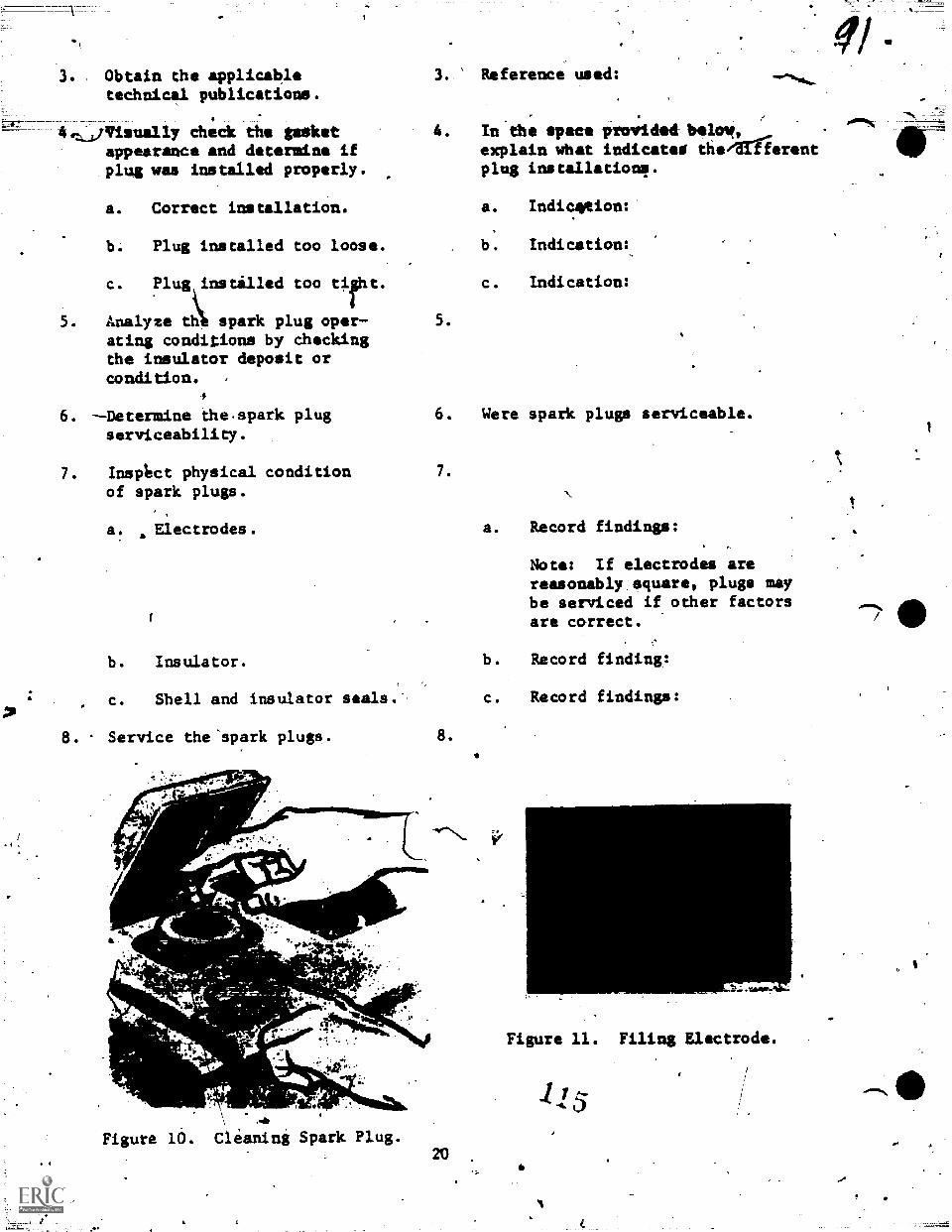
Obtain the applicabletechnical publications.
chedk the gasketappearance and determine ifplug was installed properly.
a. Correct installation.
b. Plug installed too loose.
c. Plug,instilled too tight.
5. Analyze th spark plug operating conditions by checkingthe insulator deposit orcondition. ,
4
6. --Determine the.spark plugserviceability.
7. InsOct physical conditionof spark plugs.
a. Electrodes.
b. Insulator.
c. Shell and insulator seals.
8. . Service the'spark plugs.
3. Reference used:
In the space provided-balm?,explain what indicates the/differentplug installations.
a. Indication:
b. Indication:
c. Indication:
5.
6. Were spark plugs serviceable.
7.
8.
Figure 10. Clianing Spark Plug.20
a. Record findings:
Note: If electrodes arereasonably,square, plugs maybe serviced if other factorsare correct.
b. Record finding:
c. Record findings:
Figure 11. Filing Electrode.
-115
a.' Sandblast firsing end
of plug, figure 10.
b. Clean upper insalatorand thresds.
c. File electrodes,figure 11.
-..
, ,
a. Do not overclean.ibstructed.
Clean as
b. Never use wire brush tO cleaninsulator. Rand *dr* -briallmay b. used to Alain threads. ".
Wipe upper'insulator withc/othand solvent. .
t. Use a point file. Fileilectrodes until the gap areais flat.
..
ta
A
Figure 12. Resetting Spark dap, Using Spark Cappirm Tool.
%d. Set according to specifications.
Note: Cbse suitable adjustingtool. Bend ground electrod
ct".. .
9. Install spark plugs in engine. 9. Clean seats, aAd on plugs whichrequii.e gaskets1 use new ones.Normally plug shouid be startedinto .cylinder by fingers unledsotherwise specifiedvip.Tighten plugsspecified amount: Re'cord specifiedtorque.
.d. Set the spark gap,figure 12.
10. Have the linstructos check thejob.
10..' Instructor's iditials:
Exercise 5
Visually Inspect and Service the Primary Ignition Circuit.
1. Observe applicable safetyprecautions.
21
1.
f.;
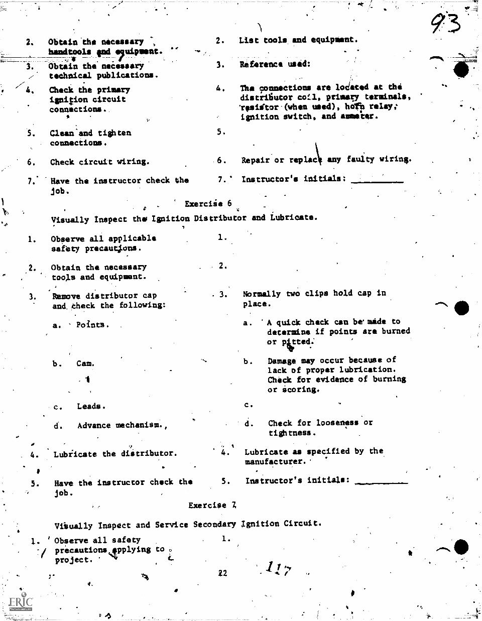
2. Obtain'the necessaryhandtools Ind equipmsnt.
fObtain the necessarytechnical publications.
/ 4. Check the primaryigni$ion circuitconnections.
Clean and tightenconnections.
6. Check circuit wiring.
7: Have the instructor check thejob.
Aar2. List tools.and equipment.
3. Reference used:
4. The 9onnections are Iodated at thedistriliutor cotl, primary terminals,vesidtor(gihen used), hdfp relay:ignition switch, and ammeter.
5.
\fRepair or replac any faulty wiring.
7. ' Instructor's initials:
Exerciie 6
Visually Inspect the Ignition Distributor
1. Observe all applicablesafety precautpns.
Obtain the necessarytools and equipment.
Remove distributor capand_theck the following:
a. Points.
b. Cam.
-
C. Leads.
d. Advance mechanism.,
4. Lubiicate the distributor.
to
Have the instructor check thejob.
1.
2.
and Lubricate.
3. Normally two clips hold cap in
place.
a . 'A quick dheck can be made todetermine if points are burned
Or lived.'
b. Damage may occur because oflack of proper lubrication.Check for evidence of burningor Scoring.
C.
d. Check for looseness ortightness.
4. Lubricate as specified by themanufacturer.'
Exercise Z
Instructor's initials:
Viivally Inspect and Service Secondary Ignition Circuit.
Observe all safety-/ precautions,epplying to .
project. 4.
9.
1.
22 j
ft
410
2. Obtain the necessary toolsr.
9.
c.
and equipment.
3. Obtain the applicable,technical, publications.
4. Nisually inspect thefollowing:
a. Rotor:
b. Cap.
C. Cables.
d. Coil.
5. Clean coil tower, high-tension wires, and insideof distributor cap.
6. Service or replaee any. defective parts. c
4
7. Have the instructor check thejob.
List tooli and equipAent.
3. Reference usfd:
4. A close examination of this secondary- circuit may uncover defects reopens-
ible for poor engine perfoimance.
a. Check for cracki, carbon tracks,and contact condition.
b. Same as for paragraph a.
c. Check condition - deterioratedinsulatioa and corrodedterminali.
d. Check for cracked or corrodedtower terminal.
5. Use lint free cloth.
6. If item is found unsatisfactory,service as required-.
7. Instructor's initials:
Exercise 8
Make a Visual Check and Service the Cooling System.
1. Observe all applicablesafety precautions.
2. Obtain the necessary toblsand equipment.
3. 91btain the applicablepuklicationsi. .
4. Visually inspect thefollowing cooling system.
. components.
a'. Radiator.
1.
2. List equipment required.
. 3. Reference used:
k
23
119
4. A thorough inspection may showtroubles repponsible for engine,trouble.
a. Check'for leaks, clogged Sirand water passages, andcle nlineis.
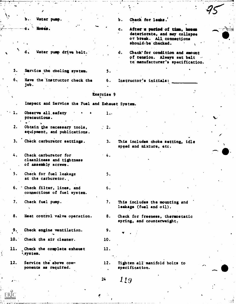
4.1
b., Watr pump.
Hoses.
Water pump drive belt.'
5. Service the cboling system.
6.. Have the.instructor check thejob.
Inspect and Service the Fuel
1. Observe all,safetyprecautions.
2. Obtain the'necessary tools,equipment, and publications.
. ,
3. Check carburetor ettings.
4. Check carburetor forcleanliness and ttghtnassof assembly screws.
5. Check for fuel leakageat the carburetor.
6. Check filter, lines, andconnections of fuel system.
7. Check fuel pump.
8. Heat control valve operation.
9. Check. engine ventilation..10. Check the air cleaner.
11. tCheck the complete exhaust
12. Service thiabove com-ponents as required.
..
b. Check for leaky.'
c. After a pettod Um, hemsdeteriorate, and may collapseor break All connegttonsshouldtbe checked.
d. Chsck'for condition and amountof tension. Always set belt -
to:manufacturer's specification.
5. 4
6. Instructor's initials:.
Exercise 9
and Exhaust System.
1..
3. This includes choke setting, idlespeed and mixture, etc.
4.
5.
6.
7. This includes the mounting andleakage (fuel.and oil).
8. Check for freeness, thermostaticspring, and counterweight.
9.
10.
11.
If
12. Tighten all'manifold bolts tospecification.
24 119
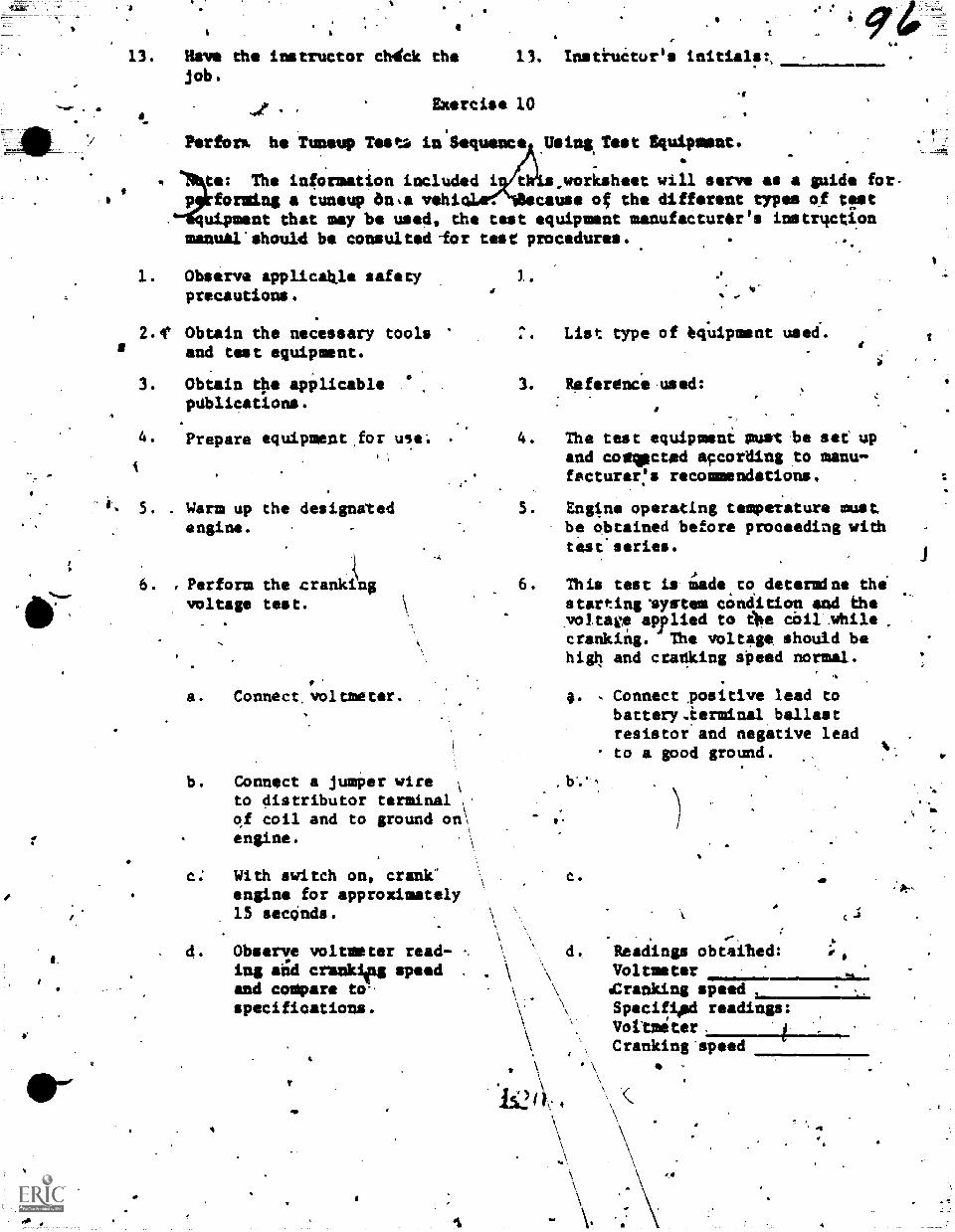
4
13. Have the instructor chirck the 13. /nstiuitur'sjob.
1
I. Exorcise 10Ir
Perfors. he *Tuneup Test:. in 'Sequence Using. Test Equipment._
4
te: The information included i tWis,workaheet will serve as a guide for-p forming a tuneup ?In.& vehi cause of the different types of ttst
uipment that may be used, the test equipment manufacturer's instrqctionmanual should be consulted -for test procedures.
Observe applicable safetyprecautions.
2.4( Obtain the necessary toolsand test equipment.
3. Obtain the applicablepublications.
4. Prepare equipment for use.
5. . Warm up the designatedengine.
6. , Perform the crankingvoltage test.
a. Connect, voltmeter. .
b. Connect a jumper wire ;
to distributor terminal cof coil and to ground on;engine.
With switch on, crank'engine for approximately15 sectinds.
4. Obser/e voltmeter read- ..
in; aild crunkieg speed .
and cosipare to-\ .
specifications. ,\\
\
3...11
e
List type of befuipment used..
3. Referenie used:
4. The test equiptesni suet .be set upand comocted according to manu-facturer:a recommendations. .
5. Engine operating temperature mustbe obtained before proceeding withteseseries.
6. This test is timule,to determine thestarting 'system condition and thevoltage applied to ellie coil whilecranking. The voltage should behigh and cranking speed normal.
V
.5
g. Connect positive lead tobattery.ierminal ballastresistor and negative leadto a good ground.
. b'.*
c..5
.-. .
d. Readings obtaihed:Voltmeter%Cranking speed ,
Specifiled readings:Voltmeter.Cranking'speed
4
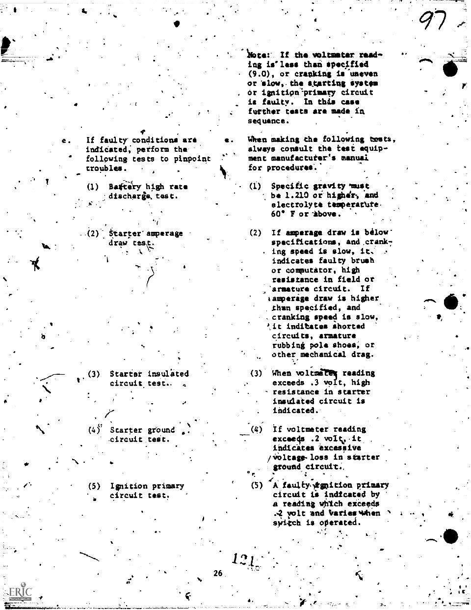
I.
e. If faultr conditions artindidated; petform thefollowing tests to pinpointtroubles. .
&Wiry high ratedischarge,test.
I.- .(2Y Starter amperage
ciraw
+4,
4.41,
(3) Starter insulatedcircuit.test-
Il(4r Starter ground
(5) Ignition primarycircuit teat.4 . .
I.
A
26
'
..loter If the voltmeter reed-ing ieless than specgied(9.0), or cranking is unevenor elow,.the outing system
. or ignitiontprimery circuitis faulty. In this casefurther tests are made insequence.
e. When making the following testa,always consult the test equip-ment manufactuter's manualfor procedures.'
(1) Specific gravity usts.tbe 1.210 or highdr, andelectrolyte temperat4e.60. F or *boy.. .
,
(2) If amperage draw is bilow"specifications, and:crank7
. ing speed is slow, it,indicates faulry brushor commutator, highresistance in field orarmature circuit. If&erage draw is higher
.than specified, and
,cranking speed is slow,it inditates ahortedcircuits, armaturerubbing pole shoes; orother mechanical drag.
(3) When voltmil readingexceeds .3 vo,t, high
- resistance in starterinsulated circuit isindicated.-
r(4) If voltmeter..reading
exceela .2 voltio-it. ,
indicates excessiVeiinitago-loss in starter
. ground circutt..,.t
(5) faulkylOpition primarycircuit ii Indicated bya reading whIch eiceeds
rolt and trariesmohen
sVilmh is operetea.
4.
a
t.
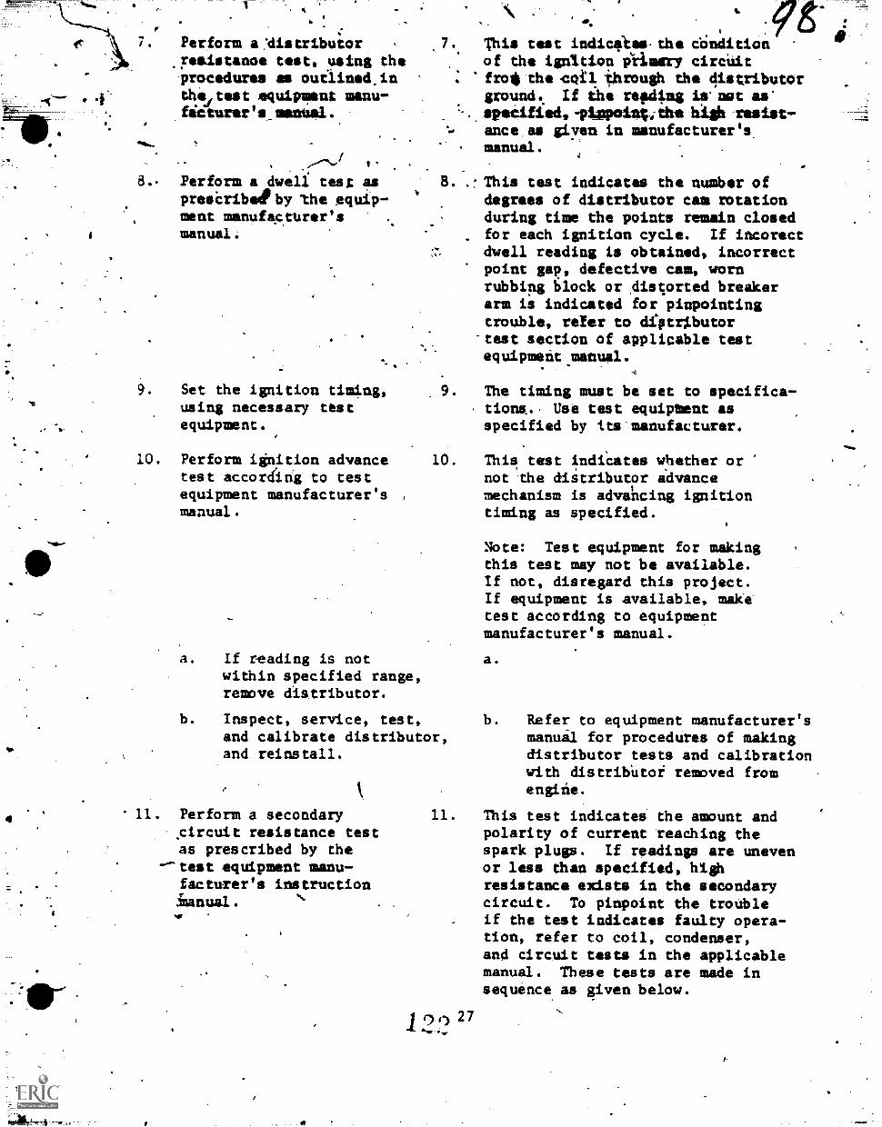
7. Perform a 'distributor,reeistanoe test, using theprocedures as outlined,in
. 4 thsitest equipment menu-futurity's menual.
4
8.. Perform a dwell test aspresiribelby the equip-ment manufaturer'smanual.
9. Set the ignition timing,using necessary testequipment.
10. Perform ignition advancetest according to testequipment manufacturer's ,
manual.
,7. This test indiefkes.the conditionof the ignition iiimary circUitfro* the Coil *hrough the distributorground. If ihe refdimg is nut as'
. specified, -ptspeinc, the lash resist-ance as given in manufacturer's
. manual.
..This test indicates the number ofdegrees of distributor cam rotationduring time the points remain closedfor each ignition cycle. If incorectdwell reading is obtained, incorrectpoint gap, defective cam, wornrubbing block or Aiscorted breakerarm is indicated for pinpointingtrouble, refer to diptilbutor-test section of applicable testequipment manual.
-6
9. The timing must be set to specifica-tiona. Use test equipbent asspecified by its manufacturer.
10. This, test indiCates whether ornot the diitributor advancemechanism is advancing ignitiontiming as specified.
a. If reading is notwithin specified range,remove distributor.
b. Inspect, service, test,and calibrate distributor,and reinstall.
k
11. Perform a secondary.circuit resistance testas prescribed by the
--test equipment manu-facturer's instructiontanual.
11.
1227
Note: Test equipment for makingthis test may not be available.If not, disregard this project.If equipment is available, maketest according to equipmentmanufacturer's manual.
a.
b. Refer to equipment manufacturer'smanuil for procedures of makingdistributor tests and calibrationwith distribUtor removed fromengitie.
This test indicates dhe amount andpolarity of current reaching thespark plugs. If readings are unevenor less dhan specified, highresistance exists in the secondarycircuit. To pinpoint the troubleif the test indicates faulty opera-tion, refer to coil, condenser,and circuit tests in the applicablemanual. These tests are made insequence as given below.
p.
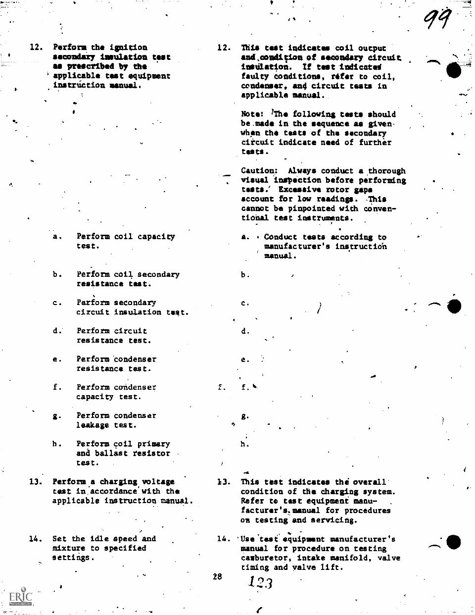
12. Perform the ignitionsecondary insulation tpstas prescribed by the
' applicable test equipmentinstriction manual.
a. Perform coil capacitytest.
b. Perform coil secondaryresistance test.
c. Perform secondarycircuit insulation test.
d. Perform circuitresistance test.
e. Perform 'condenserresistance test.
f. Perform condensercapacity test.
g. Perform condenserleakage test.
h. Perform coil primaryana ballast resistor -
test.
13. Perform.a charging.voltagetest in.accordance with theapplicable instruction manual.
14. Set the idle speed andmixture to specifiedsettings.
12. This teat indicates coil outputand.condition of secondary circuitinsdlatiwn. If test indicatedfaulty conditions, rdfer to coil,condenser, and circuit tests inapplicable manual.
Note: brhe following tests shouldbe.made in the sequence as given-whpn the tests of the secondarycircuit indicate need of furtherteats .
Caution,: Alwyn conduct a ,thoroughvisual inspection before performingtests.' Excessive rotor gapsaccount for low readings. .This
cannot be pinpointed with conven-tiohal test instruments.
a. Conduct tests according tomanufacturer's insitructiohmanual.
b.
C.
d.
e.
13. This test indicates the overallcondition of the Charging system.Refer to test equipment manu-facturer's,.menual for procedureson testing and servicing.
14. *Use test equipment manufacturer'smanual tor procedure on testingcanburetor, intake manifold, valvetiming and valve lift.
28 123
A
1115. Disconnect test leads from 15.
vehicle.
16. Have the instructor check. 16. Instructor's initials:.
the project.
You have now completed the Eield and Scientific Methods of Engiie Trouble-shooting and Tuneup, now ydu will further diagnose engine and power train per-formance by the use.ot the Chassis Dynamometer and the Universal Engine-
' Analyzer.
4
29
4
0
4
7,
60
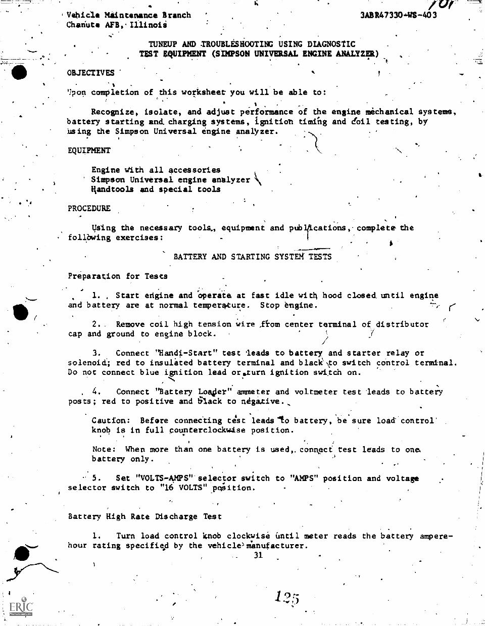
'Vehicle Maintenance BranchChariute
OBJECTIVES
fur-3ABR47330,-WS-403
TUNEUP AND TROUBLESHOOTING USING DIAGNOSTICTEST EQUIPMENT (SIMPSON UNIVERSAL ENGINE ANALYZER)
'jpon completion of this worksheet you will be able to:
% .
Recognize, isolate, and adjust performance of the engine mechanical systems,battery starting and, charging systems, ignitioh timihg and dal testing, byusing the Simpson Universal engine analyzer.
EQUIPMENT
Engine With all accessoriesSimpson Universal engine analyzerHandtools and special tools
PROCEDURE
Using the necessary tools, equipment and pubtcations, complete thefollWing exercises:
.
BATTERY AND STARTING SYSTEg TESTS
Preparation for Tests
1. , Start erigine and o perate at fast idle with hood closed until enginean d battery are at normal temperature. Stop engine.
2. Remove coil high tension wire ,q.om center terminal of distributorcap and ground to engine block.
3. Connect "Handi-Start" test leads to battery and starter relay orsolenoict; red to insulated battery terminal and blackto switch control terminal.Do not connect blue ignition lead orsturn ignition swttch on.
4. Connect "Battery LoakJer" ammeter and voltmeter test leads to batteryposts; red to positive and 61ack to negative.,
i
Caution: Before connecting test leadsdto battery, be sure load control'knob is in full coupterclockwIse position.
Note: When more than one battery is used,.connact test leads to one.battery only.
5. Set "VOLTS-AMPS" selector switch to "AMPS" position and voltageselector switch to "16 VOLTS" po:sition.
Battery High Rate Discharge Test
1. Turn load control knob clockwise Until meter reads the battery ampere-hour rating specifisd by the vehiclemanufacturer.
. 31
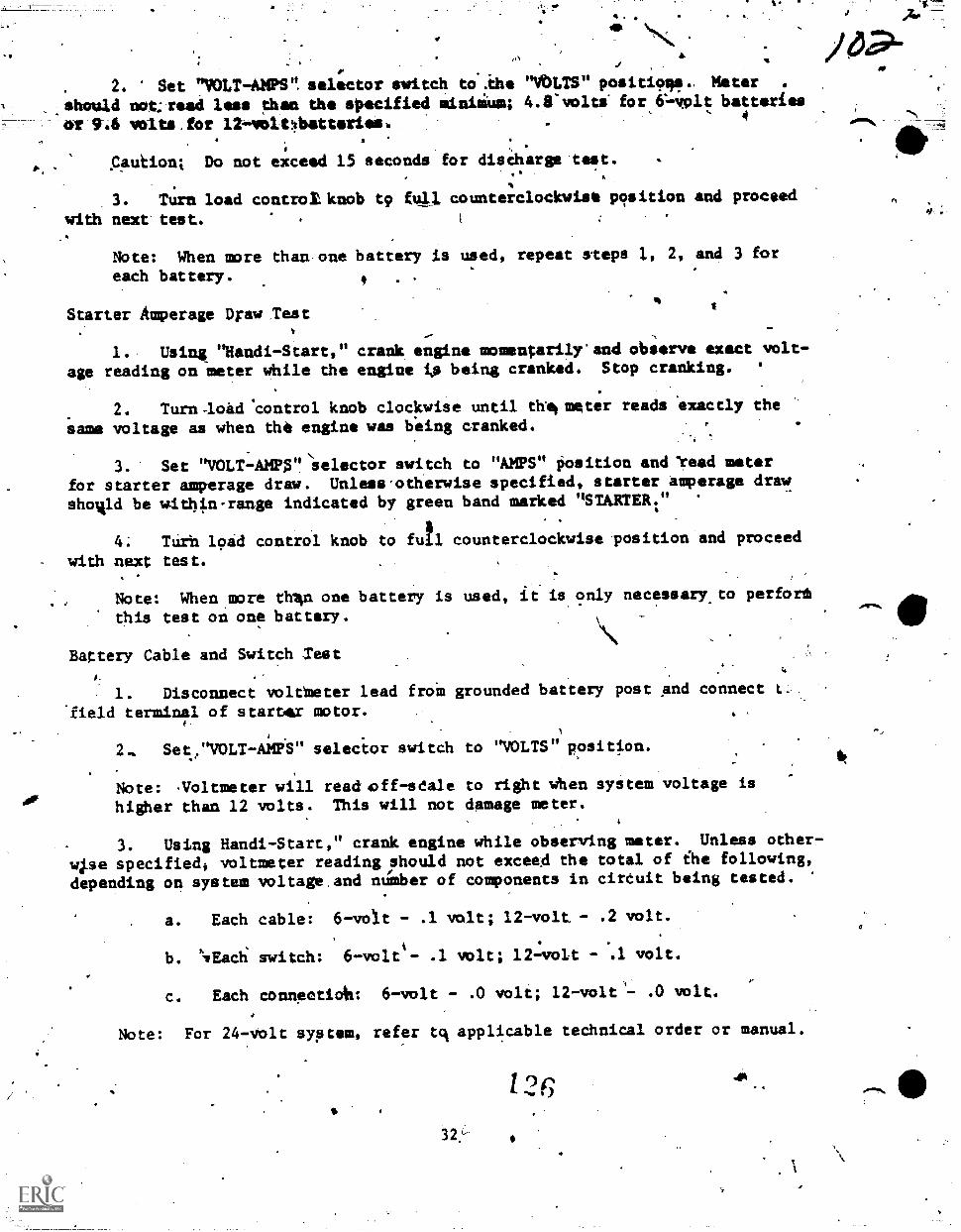
. 2. Set "VOLT-AMPS". selector switch to..ihe "VOLTS" positio sle. Meter .
.,shnuld notreeil less then the specified miniikus; 4.8'voltS for C-volt batteries
or 916 volts,for 12-volObatteries., 4
s Caution; Do not exceed 15 seconds for disCharge'tost..
3. Turn load control knob tp full counterclockwise position and proceed
with next'test.
Note: When more than-one battery is used, repeat vteps 1, 2, and 3 for
each battery. .
Starter Amperage Draw Test
1. Using "Handi -Start," crank engine momentarily'and observe exact volt-
age reading on meter while the engine is being cranked. Stop cranking. '
2. Turn-load control knob clockwise until thilmeter reads exactly the
same voltage as when the engine was being cranked. I.
3. Set "VOLT-AMPAelector switch to "AMPS" Position and 'teed meter
for starter amperage draw. Unless'otherwise specified, starter amperage draw
shomld be within-range indicated by green band marked "STARTER:"
4: TUrh load control knob to fill counterclockwise pvsition and proceed
with next test.
Note: When more thlin one battery is used, it is only necessary.to perforth
this test on one battery.
Battery Cable and Switch Test
1. Disconnect voltMeter lead froM grounded battery post and connect t.
field terminal
2.. Set.
of staroax motor.1
"VOLT-AMPS" selector switch to "VOLTS" position.
Note: Noltmeter will readoff-sdale to right when system voltage is
higher than 12 volts. This will not damage meter.
3. Using Handi-Start," crank engine while observing meter. Unless other-,
wpe specified* voltmeter reading,Should not exceed the total of ihe following,
depending on system voltage.and number of components in circuit being tested.
a. Each cable: 6-volt - .1 volt; 12-volt -
b. klyEacti switch: 6-volt- .1 volt; 12volt
C.
.2 volt.
- .1 volt.
Each conneotiA: 6-volt - .0 volt; 12-volt .0 volt.
Note: For 24-volt system, refer tck applicable technical order or manual.
1 orI )
32,-
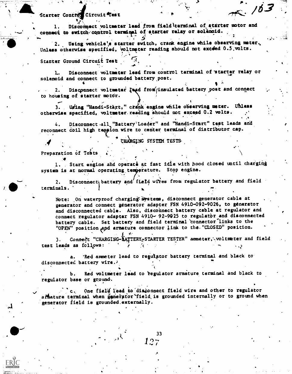
I.
Starter Conttdl Circuittest.00
.r1. Discontfect voltmeter lead from fieldAterminal of.starter motor and
connect to smitclvcqntrol termiT1 bf starter relay or solenoid.
.2. Using vehiclets starter witch, crank engine while observing meter%
Unless otherwise specified, "voltmeter reading should not excded 0.5.volts.
Starter Ground Circuit Test,
L. Disconnect voltmeter lead from control terminal of'starter relay or
solenoid and connect to grounded battery.post..
4 .
2. Discloonnect voltmeter sd fromirinsulated battery yost and connect
to hoUsing of starter motdr. I
w-- --
3. Uding "Nandi-Sart," cr nk'engine while observing meter. Messotherwise specified. voltmeter.reading Should not exceed 0.2 volts. ..
4.
reconnect
if
Disconnect-all "Battery'Loader" and "Randi-Srart" teet leads arid
Coil high telrlon wire to cedter terminal of distributor cap.
*6GING SYSTEM TESTS-
FrPreparation Of Tests 4'
,
,\
4 I.
1. , Start engine ahd operate it fast idle with bood closed until charging
system is at normal operating t rature. Stop engine.
2. Disconnect ryibattery and field wries from regulator batte and field
terminals. 14
Note: ,On waterproof chargingstems, disconnect generator cable atgenerator and connect generator adapter ESN 4910-092-9026, to generator
and disconnected cable. Also, disconnect battery cable at regulator andConnect regulator adapter FSN 4910-, 92-9025 to regulatOr.and disconnected
battery cable. Set battery and field terminal "connector links to the"OPEN" positionepd armature connector link to the-"CLOSED" position.
3. Conne8t "CHARGINGITTERY.TSTARTER TESTER" ammeter; voltmeter and field
test leads as follows: .(
a. 'Red ammeter lead to regullitor battery terminal and black to
disconnected battery wire.?
b. Red voltmeter lied to 1,egulator armiture terminal and black toregulator base or grown&
,
c. One field'read to'disonnect field wire and other to regulatoraAlature terminal when ieneksior`field.is grounded internally or to ground whengenerator field is grounded.externally.
4.
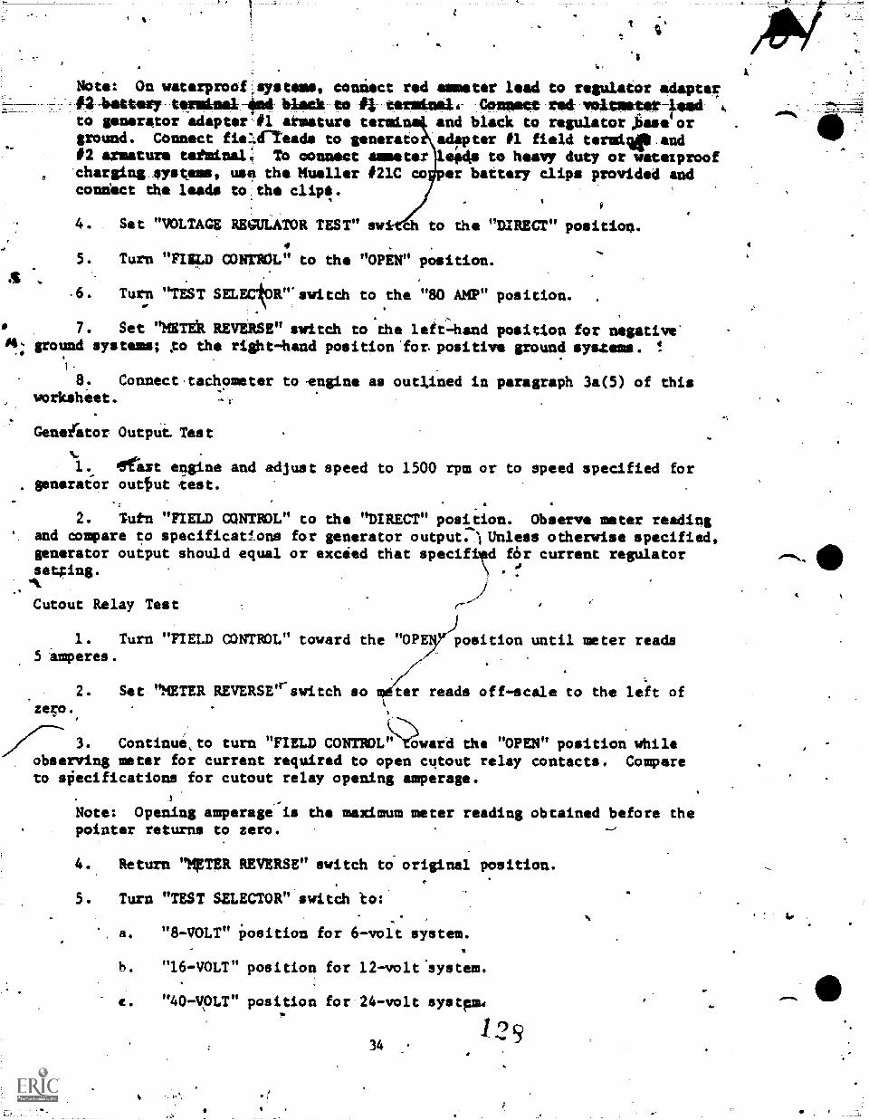
14
Note: On waterproof,systems, connect rod ammeter lead to regulator adapter#21Wittery tertlime1 4m4 black to #1 terminal. Connect red voltmeter-leadto generetor adapter #1 armature tend. n$ and black to regulatorsbase orground. Connect fie:Vreads to generato adepter 01 field termage.and#2 armature tatminal; To connect ammeter legs to heavy duty or watezproof'charging, systems, use tha Mueller #21C co er battery clips provided andconnect the leads to the clip.
4. Set "VOLTAGE REGULATOR TEST" swfrtt to the "DIRECT" position.
5. Turn "FIELD CONTROL" to the "OPEN" position.
.6. Turn "TEST SELECtOR". switch to the "80 AMP" position.
7. Set "MIT& REVERSE" switch to'the left:hand position for negative'ground systems; go the right-hand position 'for positive ground systems.
8. Connect,tachoseter to -engine as outlined in paragraph 3a(5) of thisworksheet. -T
Genezrator Output Test
1. agfaxt engine and adjust speed to 1500 rpm or to speed specified for. generaior outfut test.
2. Tutn "FIELD CONTR)L" to the "DIRECT" position. Observe meter readingand ampere co specifications for generator output.-) Unless otherwise specified,generator output should equal or exceed that specififd f6r current regulatorsetOng. \ .
Cutout Relay Test (
1. Turn "FIELD CONTROL" toward the "OPE position until meter reads5 amperes.
2. Set 'NETER REVERSE"-switch so witer reads off-scale to the left ofzeco., -
///--- 3. Continue,to turn "FIELD CONTROLward the "OPEN" position whileobserving meter for current required to open cutout relay contacts. Compareto sOecifications for cutout relay opening amperage.
Note: Opening amperage is the maximum meter reading obtained before thepointer returns to zero.
4. Return "MgTER REVERSE" switch to-original position.
5. Turn "TEST mecum' switch to:
a "8-VOLT" Position for 6-voit system.
b. "16-VOLT" position for 12-volt system.
e. "40-you" position for 24-volt system,
1:2 934
4
4.
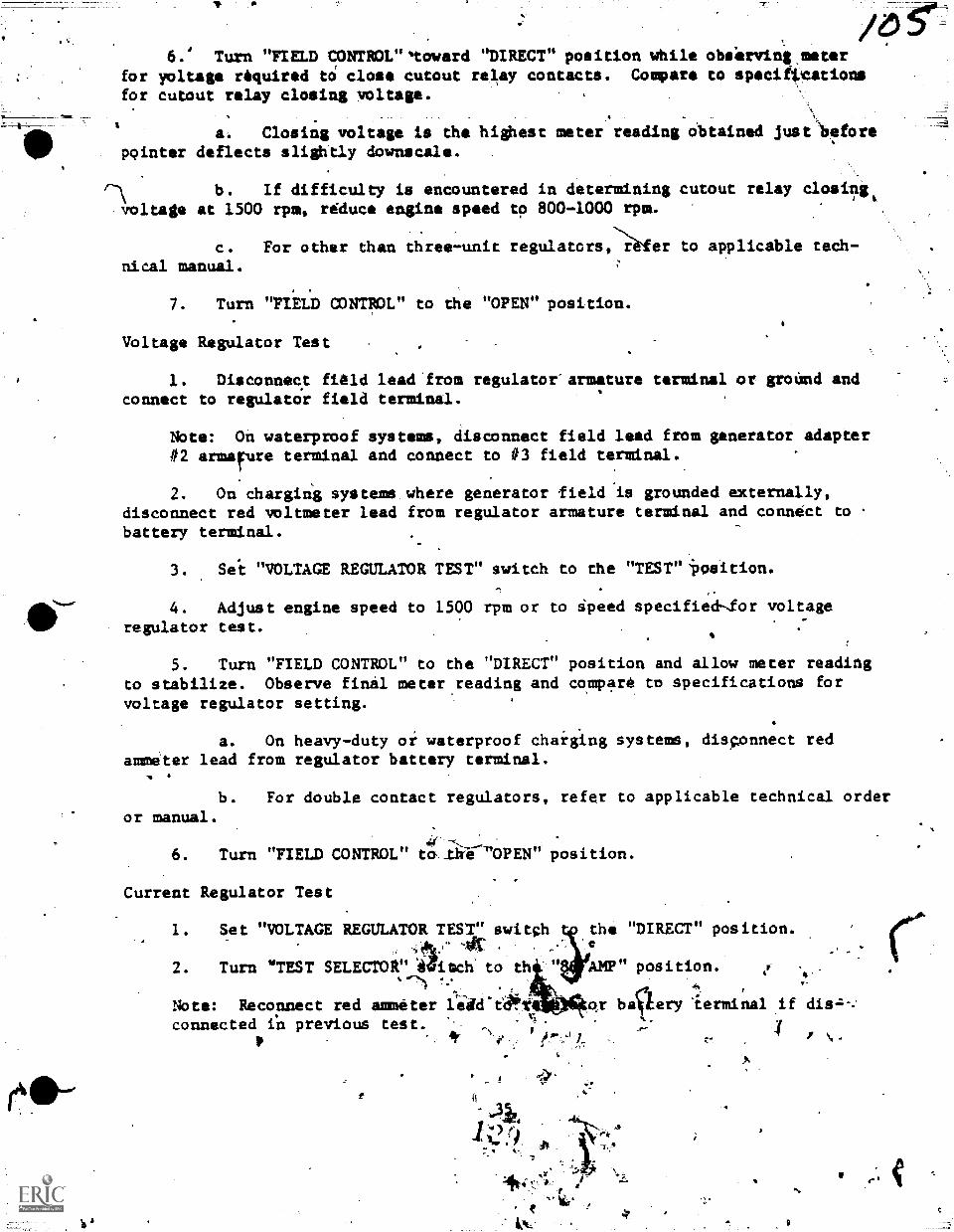
6.' Turn "FIELD CONTROL"toward "DIRECT" position while obs'erving,meterfor yoltage required tO close cutout relay contacts. Compare to specifpcationsfor cutout relay closing voltage.
a. Closing voltage is the highest meter reading obtained just 'beforepointer deflects slightly dowuscale.
b. If difficulty is encountered in determining cutout relay closihgtvoltage at 1500 rpm, reduce engine speed to 800-1000 rpm.
c. For other than three-unit regulators,fer to applicable tech-.
nical manual.
7. Turn "FIELD CONTROL" to the "OPEN" position.
Voltage Regulator Test
1. Disconnect field lead'from regulatoearmature terminal or groUnd andconnect to regulator field terminal.
Note: On waterproof systems, disconnect field lead from generator adapter#2 armafure terminal and connect to #3 field terminal.
2. On Charging systene where generator field is grounded externally,disconnect red voltmeter lead from regulator armature terminal and connect to .
battery terminal.
3. Sei "VOLTAGE REGULATOR TEST" switch to the "TEST"ilosition.
4. Adjust engine speed to 1500 rpm or to Speed specified-lor voltageregulator test.
5. Turn "FIELD CONTROL" to the "DIRECT" position and allow meter reading
to stabilize. Observe final meter.reading and compare to specifications forvoltage regulator setting.
. .
a. On heavy-duty oi waterproof charging systems, disconnect redammeter lead from regulator battery terminal.
b. For double contact regulators, refer to applicable technical orderor manual.
44(
6. Turn "FIELD CONTROL" t a Ike 'OPEN' position.
Current Regulator Test
1. Set "VOLTAGE REGULATOR TEST" switch4k." lk
2. Turn "TEST SELECTOR" 44isch to th
the "DIRECT" position.
AMP" position..Th d..
*
Note: Reconnect red ammeter lcatet 4 b4lery lermilnal if dis-7,-;
_
connected fil previous test. 1P
/ ..et
f.,i
;
1
-c-
,
,
10111t,v77,-.
,e
9
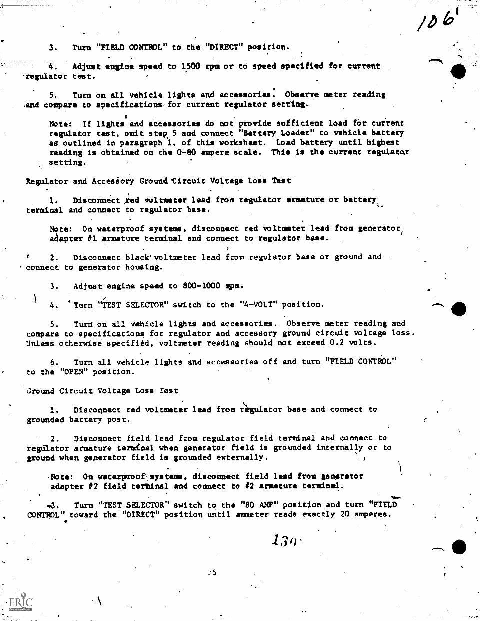
3. Turn "FIELD CONTROL" to the "DIRECT" position.
4. Adjust engine speed to 1500 rpm or to speed specified for currentreguiator test.
5. Turn on all vehicle lights and accessories. Observe meter readingsand compare to specificationsfor current regulator setting.
Note: If lights and accessories do not provide sufficient load for cuirentregulator test, omit step. 5 and connect "Battery Loader" to vehicle batteryas outlined in paragraph 1, of this worksheet. Load battery until highestreading is obtained on the 0-80 ampere scale. This is the current regulatcar
setting.
Regulator and Accesiory Ground*Circuit Voltage Loss Test
1. Disconnect ,red voltmeter lead from regulator armature or batteryterminal and connect to regulator base.
Note: On waterproof systems, disconnect red voltmeter lead from generatoriackapter #1 armature terminal and connect to regulator base.
2. Disconnect black'voltmeter lead from regulator base or ground andconnect to generator housing.
3. Adjust engine speed to 800-1000 Apm.
4. Turn "TEST SELECTOR" switch to the "4-VOLT" position.
5. Turn on all vehicle lights and accessories. Observe meter reading andcompare to specifications for regulator and accessory ground circuit voltage loss.
Unless otherwise specifiid, voltmeter reading should mot exceed 0.2 volts.
6. Turn all vehicle lights and accessories off and turn "FIELD CONTROL"to the "OPEN" position.
around Circuit Voltage Loss Test
1. Disconnect red voltmeter lead from iègulator base and connect togrounded battery post.
2. Disconnect field lead from regulator field terminal and connect toregulator armature termlnal when generator field is grounded internally or toground when generator field is grounded externally.
,Note: On waterpcoof systems, disconnect field lead from generatoradapter #2 field tertinal and connect to #2 armature terminal.
'3. Turn "TEST SMECTOR' switch to the "80 AMP" position and turn "FIELDCONTROL" toward the "DIRECT" position until ammeter reads exactly 20 amperes.
#
130
41110,4
a
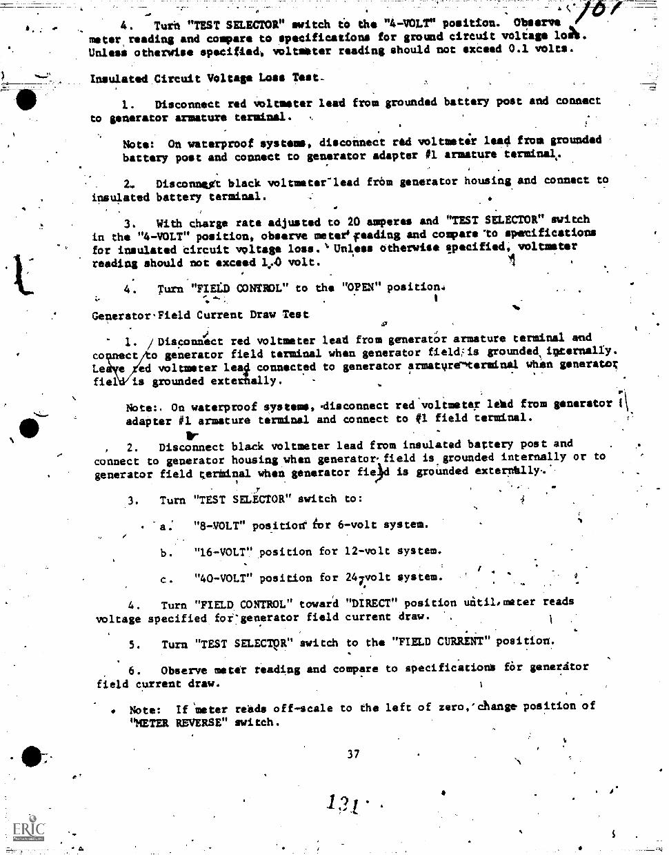
Affr
4. Turh "TEST SELECTOR" switch to the "4-VOLT" position. Observe
meter_reading and compare to specifications for ground circuit voltage lat.
Unlesi otherwise specified, voltmeter reading should not exceed 0.1 volts.
Insulated Circuit Voltase Loss Test-.
1. Disconnect red voltmeter lead from grounded battery post and connect
to generator armature terminal.
Note: On waterproof systems, disconnect red voltmeter load from grounded
battery post and connect to generator adapter #1 armature terminal,.
2. Disconnegt black voltmeter-lead fram generator housing and connect to
insulated battery terminal.
3. With charge rate adjusted to 20 amperes and "'TEST SELECTOR" switch
in the "4-VOLT" position, observe meter'feading and compare'to specifications
for insulated Circuit voltage loss.'* Unless otherwise pacified, voltmeter
reading should not exceed 1,00 volt. 1
4. Turn "FIELD CONTROL" to the "OPEN" position.:1
GeneratorField Current Draw Testa
1. /Disponnect red voltmeter lead frnm generator armature terminal end
co ct/to generator field terminal when generator fieldi-is grounded,ipternally.
ed voltmeter connected to generator armatvrelterminal when generatot4.Lefiel is grounded exte ally.
Note:. On waterproof systems,disconnect red voltmetex lekd from generator
adapter #1 armature terminal and connect to #1 field terminal.
Ir2. Disconnect black voltmeter lead from insulated battery post and
oannect to generator housing when generatorfield is.grounded internally or to
generator field terbinal when generator fiee)d is grounded exterrilaly-.'
I.
3. Turn "TEST SELECTOR" switch to:
a. "8-VOLT" position' 6or 6-volt system.
b. "16-VOLT" position for 12-volt system.
c. "40-VOLT" position for 247volt system.
4. Turn "FIELD. CONTROL" toward "DIRECT" position uitilemeter reads
voltage specified for:generator field current draw. ',1
5. Turn "TEST SELECTOR" switch to the "FIELD CURRENT" position.
6. Observe meter reading and compare to specifications fOr generitor
field current draw.
Note: If 'meter reads off-scale to the left of zero,'change position of
NETER REVERSE" switch.
371,
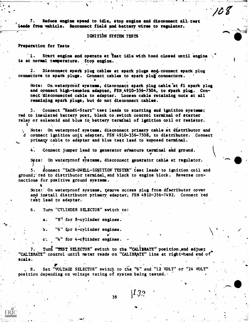
7. Reduce engine speed to idle, stop engine and disconnect all.test'leads from vehicle. Reconnect field and battery wires to regulator.
IGNITIbN SYSTEM TESTS'
Preparation for Tests
1. Start engine and operate at iast idle' with hood closed until 'engine %.is at normal temperature. ,Stop engine.
F. Disconnect spark plug cables at spark plugs an*connect spark plugconnectors to spark plugs. Connect cables to spark plug connectors.
Note: On.waterproOf systems, disconnect spark plug cable'at #1 spark plugand connect high7tension adaptei, FSN.4910-356-7504, to dpark plug. Con-negtfdisconnected cable to adapter. Loosen cable retaining nuts at allremaining spark plugs, but do not disconnect cables.
3. Connect "Nandi -Start"'test leads to starting and ignition systems;red to insulated battery post, black to.switch control terminal of starterrelay or solenoid and blue to battory.termenal of ignition coil or resistor.
\ Note: On waterproof systems, disconnect primary cable at distributor and4 connect ignition unit adapter, FSN 4910-356-7508, to distributor. Connect
primag cable to adapter and blue teat lead to axposed terminal.
4. Connect jumper lead to generator aimature terminal aild ground.
Nite: On waterproof slYstems, disconnect generator cable at regulator.
5. aonnect "TACH -DWELL -IGNITION TESTER" test leads-to ignition coil andground;'red to distributor termihal,and black to engine block. Reverse con-nections for positive ground systems. .
Note:' On waterproof systems, ;emove access plug from dfstributor coverand imstall distributor primary adapter, FSN 4910-356-7492. Connect 'red
test lead to adaptor.
6. Turn "CYLINDER SELECTOR" switch to:
a. "8" for 8-cylindar engines.
b. "6' Apr 6-cylinder engines.
e. "4" for 4-c,lih4er engines.
67. Turn n?EST SELECTOR" switch to the 'CALIBRATE" positionNend adjust
"CALIBRAtE" control untii meter reads on "CALIBRATE" line at right-hand end oescale.
r, 8. Set "VOLTAGE SELECTOR" switch to ti;e "6" and "12 VOLT" or "24 VOLT"
position depending on voltage rating ok systeM being tested.-
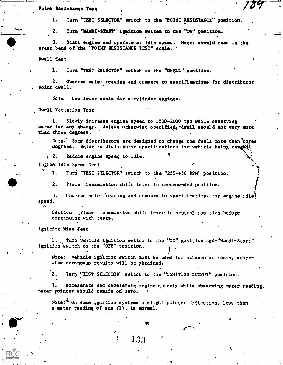
Point Resistance Test
1. Turn "TEST SELECTOR" switch to the "POINT RESISTANCE" el:nation.
2. Turn NAMDI.START" ignition witch to,the tvoiri position.a
3., Start engine.and operate at idle opted. Meter should read in thegreen band Of the "POINT RESISTANCE TEST" scele.
Dwell Test
1. Turn "TEST SELECTOR" switch to the "DWELL" position.
2. Observe meter reading and compare to specifioatiorm for distributor. point dwell.
Note: Use lower scale for 4-cylinder engines.
Dwell Variation Test
1. Slowly increase engine speed to 1500-2000 rpm while observingmeter for any change. Unless othirwise specifiefr-dwell should not vary morethan three degrees.
Note:' Some distributors are designed to 'change the dwell more thaOth eedegrees.,'Retfer to distributor specifications for vehicle being tes
2. Reduce engine speeO to ,Idle.
Engine Idle Speed Test
1. Turn "TEST SELECTOR" switch to the "250-650 RPM" position.
2. Place transmission shift lever in recommended position.
3. Observe meter 'reading and compare to specifications for engine idlespeed.
Caution: _Place transmission shift lever-in neutral position befosecontinuing with tests.
Ignition Miss Test
1. Turn vehicle ignition switch to the "ON" Rpsition and-"Handi-Start"ignition 'switch td the "OFF" position.
Note: Vehicle igriition witch must be used for balance of tests, other-wrse erroneous results will be obtained.
2. Turn "TEST SELECTOR" switch to the "IGNITION OUTPUT"- pcisition.
3. Accelerate and decelerate engine quickly while'observing meier reading.Meter potnter should remain od zero
-Note: it-On some tinition systems a slight pointer deflection, less thanmeter'reading of one (1), is normal.
39
3 3

Ignition Output Test
1. rur:a "UST SILECTOr svitch to the0
2: Adiust engin* speed to 1500 rps.
3# Turn "TEST SELECTOR" switch to the
'4. Using insutated pliers, disconnectspark plug andpbserve meter reading. Heteêband of the "IGNITION OUTPUT TEST" scale.
tmo-spoetror posit
"IGNITION OUTPUT" paniaon.
any one spark\p1ug cattle fromshould read stead/ in\th4 green
5. Reconnect spark plug cable to spark plug.
6.. Repeat steps 4 and 5 on all,remaining sparktlug cables.-
Secondary Current Test
k
1. Disconnect test leads from ignition coil.and vound and connect red.lead to grnund. C
Note: Always ground red lead for this test regardless of electrical sys-tem ground polarity.
2. Turn "TEST SELECTOR" switch to the "SECONDARY CURRENT -VOLTMEposition. 4
3. Connect black lead to any one spark plug and observe meter reading.Meter should read in the green band of the secondary current test scale.
4. Repeat step 3 on all remaining spark plugs.
5. Disconnect.test leads from spark plug and ground.
6. Reduce engine speed to idle and turn mehicle'ignition switch to n'FF"position.
7. Disconnect jumper lead from generator armature terminal and ground.
Note: On waterproof systems, reconnecegenerator cable to regulator.
Cranking if,oltage Test
1. "-Connect test leads to ignition coil and ground; red to batteryterminal and black to engine blotk. Reverse connections for positive ground
sys tems .
Note: On6waterproof systems, connimt red lead to exposed terminal onignition unit adapter.
S.
2. Connect jumper lead to distributor terminal of ignition coil and
ground.
Note: On waterproof systems, connect jumper lead to distributor primaryadapter and ground.
40I 3i
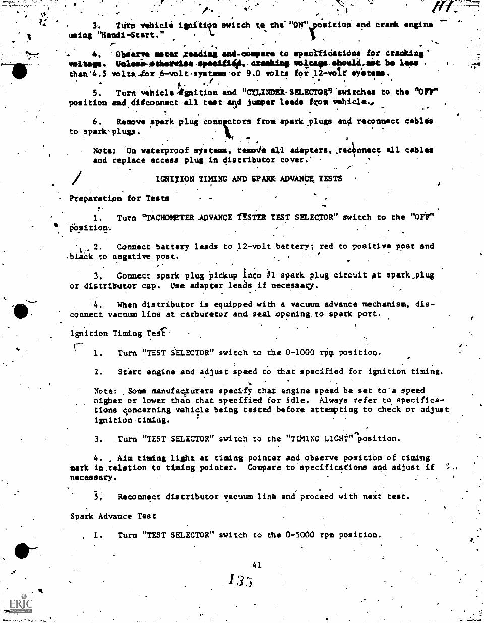
- ., ..
. . - /°- a,.,.- . .
V,.. r t .
4:.. , . ........, ,
.3. Tdrn vehicle ignitiv.3 wiitch to the- "Otruposition and crank engine
1 using liandi-Start." .. V ._... .. .. . I .
-, 4. Oblierve meter reading and.compare to specifidatidns for Cranking '. .
voltage. Ueleii--£therwite Sp/icing* cranking *strap should,nit In lona
than 4.5 voltalor 6-volt 'systems 'or 9.0 volts for 12-vol.r syitems., .
.40
a, f . ..f .
,
5. Turn vehicle 4gnition and "Cr,INDElt. mammal 'mite-has to the '10FF"position and digconnect all test and jumper leads fxon vehicle.4. C.,
1 .
6. Rem kove ipar, plug lors from spark plugs and reconnect cabesto spark- plug..
A
Alta; On waterproof syetems, revolt* a3,1 adapters, .reckinnect all cablesand replace access plug in distributor cover.' .
.
IGNITION TIMING AND SPARK ADVANtE TESTS
. Preparation for Testsr-
1. Turn "TACHOMETER -.ADVANCE fESTER TEST SELECTOR" switch to the "OW06.0tion,.
2. Connect battery leads to 12-volt battery; red to positive post and1.-
.black to negative post. e
3, Connect spark plug Pickup inio .#1 spark plug circuit at spark:plug
or distributor cap. Use adapter leaas if necessary.
. '4. When distributor is equipped with a vacuum advance meChanism, dis-connect vacuum line at carburetor and seal .opening,to spark port.
Ignition Timing -reit"r-' 1. Turn "TEST iELECTOR" switch to the 0-1000 rPqr position.
2. Start engine and adjust speed to that specified for ignition timing.
Note: ,Some manufa4urers specify.thaZ engine speed be set io'a speedhigher or lower than that specified for idle. Always refer to specifica-tions concerning vehicle being tested before attempting to check or adjustignition-timing.
3. .Turn "TEST SELECTOR" switch to the "TIMING LIGHt"ft
position.
4. , Aim timing light,at timing pointer and observe podition of timingmark in.relation to timing pointer. Compare to specificafions and adjust ifnecessary.
5, Reconnect distributor vacuum line and proceed with next test.
Spark Advance Test
. 1. Turn "TEST SELECTOR" switch to dhe 0-5000 rpm position.
2. Refer to distributor specifications.for vehicle being tested.
3. 'Select a speed specified for centrifugal or lovernor advance which,*hen multiplied by two, will be as high aepossible but not exceed 2500 enginerpm; ie, if distributor specifications Itate that spark should avance 11 - 13'degrees at 1100 rpm, multiply by rwo; or 2200 engine rpm.
'Note: Specifications for centrifugal or goxernor advance are usuallystated as distributor speed and degrees. If specification is statedas engine speed and degrees, select speed as instructed, but do mot matiply.
4. AJjust engine gpeed to specification selected.
i. Turn "TEST SELECTOR" gwitch to the "ADVANCE" position.
6._ Aim timing light at timing pointer and adjust advanci control untiltiming mark is aligned with pointer. .
Note: Advance control is located In timing light housing.
7. Observe meter reading and compare to specifications.
Note: If distributor has both cnetrifugal and vacuusitadvance mechanisms,meter should read specifiel centrifugal advance, plus specified maximumvacuum advance.
8. Adjust engine speed to that specified for idle. Stop engine.
9. Turn test selector to the "OFF" position and disconnect all leads.
COIL TESTS
Preparation for Tests
1. Turn.,"CONDENSER-MAGNETO ANALYZER TEST" selector switch to the "OFF"position.
2. Connect battery leads to 12-volt battery; red to positive post-and black to negative post.
Note: Battery leads have plier-type clips.
3. For on-the-vehicle tests, disconnect all wires from the coil.
Note: When bench testing coils having nonmetallic cases, the coil mustbe at least four inches away from any metal object, including metal benchtop. Magneto coils must be mounted on their iron.cores but removed fromthe stator unless otherwise specified.
Coil.SeCondary Resistance Test
1. Turn "TEST ::ELECTOR" switch,to the "FIL RESISTANCE" position.
2. Connect test leads to coil; red to either primary terminal and blackto secondary terminal.
42 I 31o;
4_ -
,
,
.
' -
.
.** Not.: Usi test clip or prod as recfuired.i.3.* Obtierve me'ter reading andlicompare to specifications for coil secondary,
winding resistance.' Unless otherwise specified, meter reading should be in the
../green band of the "COIL RESISTANCE TEST" stall, and not exceed 20,000 ohms.
,0-77111
^Note: To obtain resistance valye, multiply Wer reading by 1000.
Coil Insulation Test
1. Turn "TEST SELECTOR" switch to ehe "COIL SET" position. ,
2. Disconnect black lead from secondpory terminal and connect to otherprimary terminal. Use test.clip, not prodY
3. Turn "COIL INDEX" control to specified position and adjust set controluntil meter indicates value specified for coil set. Refer to specification chart.
101.,
Note: If no meter reading is obiained or s'ecified setting cannot bereathed, coil primary windinicis faulty.
4. Turn "TEST SELECTOR" SWitch.to the "COIL.TESTr position. Meter shouldread steady and in the green band of die "COIL. TEST" 41,..9,1e. (Meter stould'notvary more than one major division.) N
S. During coil insulation test and ustng black test prod, probe theareas between the primary and secondary terminals for leakage. Meter readingshould remain in green band of "COIL TEST" scale.
Note: When bench testing metal cased coils, also touch prod to case.Meter reading should remain in green band of "ODIL TEST" scale.
6. Turn "TEST SELECTOR" switch to the "OFF", position and disconnectbattery and test leads.
CONDENSER TESTS
Preparation of Tests
1. Turn "ODNDENSER-MAGNOTO ANALYZER TESt" selector switch to the 1DFF"position.
2. Connect battery leads to 12-volt hattery; red to positive post andblack to negative post.
Note: Battery leads have plier-typeclips.
3. For on-the-vehicle tests, disponnect primary wire at coil or distributorand install fiber block between breaker lever and cam.
Note: On waterproof systems, remove distributor cover and disconnectdistributor lead from coil.
4 3
3 7
A
fr
4. Turn "TEST SELECTOR" switch to the "CONDENSER RESISTANCE" position.
Connect red,and bt4ck Destlefda together and adjast set control.until meter reads on set line at righ-hand end of "'CONDENSER RESIS1ANGE TEST"scale.
teNote: Allow approximately 30 seconds for tester to iliarm,;.e befmre.attempt-ing to calibrate.
Condenser Resistance Test
41
1. Separate test leads and connect to distrib or housing and primaryterminals or lead. Meter should read in tee green b d of the "CONDENSERRESISTANCE TEST" scale.
Note: When bench testing condenser, connect test leads to condensercase and pigtail lead.
2. During condenser resistance teat, move condenser pigtail lead back .
and forth while observing meter for any change. Meter reading should remain \.steady in green band of "CONDENSER RESISTANCE TEST" scale.
Condenser Leakage Test
1. Turn "TEST SELECTOR" switch to "CONDENSER LEAKAGE" position.
2. Observe meter reading. Meter should read in the green band of the"CONDENSER LEAKAGE TEST" scale.
Condenser Capacity Test
4
1. Turn "TEST SELECTOR" switch to "CAPACITY" position.
2. Observe meter reading and compare to specifications. Condensercapacity should be within range specified by manufacturer.
Note: Meter reading indicates condenser capacity in microfarads (mfd).
3. Turn "TEST SELECTOR" switch to the "OFF" position and disconnectbattery and test leads.
.FUEL AND VACUUM BOaTER PUMP TESTS
Preparation for Tests1
1. Star4xengine and operate at fast idle with hood closed until engine.)...and fuel system are at normal temperature. Stop engine.
-2. R'emove carbul7etor air cleaner and disconnect fuel line at carburetor
inlet.
Note: When more thaG one cal-buretor is used, disconnect fuel line attee connection or junction.
I 344 -1001110%,
a.3.* Connect fuel pump tester inlet to disconnected fuel line.
CaUtion: pe aure inlet hose is securely'connected to fuel line. If
necessary, move retaining nut away from end of fuel line to prevent .
interference yith inlet hose.
4. Connect tachometer to engine as outlined in paragraph 3a(5)-of this:worksheet.
Fuel Pump Pressure Test
1. Start engine and operate at idle speed gr.speed specified tax fuelpump pressure tett.
2. Observe pressure gauge reading and compare to specifications foi 'fuel
pump pressure.,
Fuel Pump Volume Test
1. With engine operating at idle speed or speed specified fdr fuel pumpvolome test, direct tester discharge hose into a suitable fuel container.
2. Press "CAPACITY TEST" bution down and observe fuel gauge reading.Compare to specifications for fuel pump capacity or volume.
3. Release "CAPACITY TEST" buttOn.
4. Stop engine and disconnect tester inlet hose from fuel line.- Reconnect fuel line to carburetor in_et or tee connection and replace air cleaner.
:Fuel Pump Vacuum Test
1. Disconnect fuel inlet and outlet lines frot fuel pump.
2. Connect fuel pump tester inlet hose to pump inlet.
Now If necessary, remove fitting or flexible hose from 'fuel pump and
use 1/8" pipe adapter furnished.
3. Start engine.and operate at idle speed or speed specified for fuelpump vacuum test until highest vacuum gauge reading is obtained.
4. Obserlie final gauge reading and compare to specifications for fuelpump vacuum. Unless otherwise specified, fdel Pump vacpum should not be lessthan 10.0 inches.
5. Stop engine and observe vacuum gauge for about 15 seconds. Vacuumreading should remain constant and not. decrease after ehgine is stopped.
6. Disconnect tester inlet hose from fuel pump and reconnnect fuel linesto fuel pump.
J
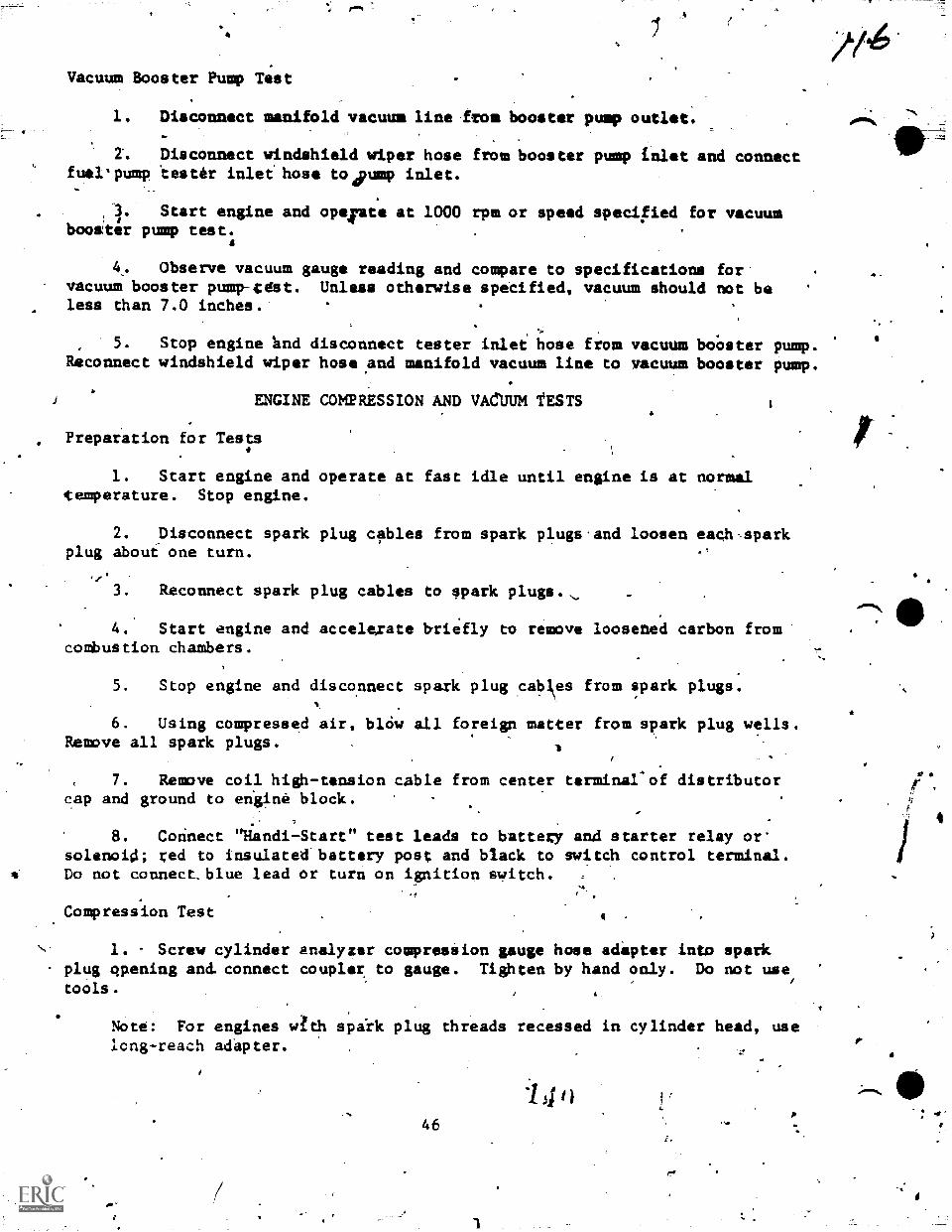
4
Vacuum Booster Pump Test
1. Disconnect manifold vacuum line from booster pump outlet.
Z. Disconnect windshield wiper hose from booster pump inlet and connectfuelpump tester inlet hose to4pump inlet.
Start engine and opeiate at 1000 rpm or speed specified for vacuum#
booster pump test.A
4. Observe vacuum gauge reading and compare to specifications forvacuum booster pump-tett. Unless otherwise specified, vacuum should not beless than 7.0 inches.
5 . Stop engine nd disconnect tester inlet hose from vacuum boo ster pump.Reconnect windshield wiper hose ,and manifold vacuum line to vacuum booster pump.
ENGINE COMPRESSION AND VACUUM TESTS
Preparation for Tests#
1. Start engine and operate at fast idle until engine is at normaltemperature. Stop engine.
2. Disconnect spark plug cables from spark plugs.and loosen eachsparkplug about one turn.
fir3: Reconnect spark plug cables to spark plugs.
4. Start engine and accelerate briefly to remove loosened carbon fromcombustion chambers.
5. Stop engine and disconnect spark plug cabes from spark plugs.
6. Using compressed air, blOw all foreign matter from spark plug wells.Remove all spark plugs.
7. Remove coil high-tension cable from center terminal'of distributorcap and ground to engine block.
8. Corinect 'Iiandi-Start" test leads to battery and starter relay or-solenoid; red to insulatelfbattery post and black to gwitch control terminal.Do not connect_blue lead or turn on ignition switch. ,
Compression Test 4
1. Screw cylinder analyzer compression gauge hose adapter into sparkplug opening and. connect coupler to gauge. Tighten by hand only. Do not usetools.
Note: For engines s./th spirk plug threads recessed in cylinder head, uselong-reach adapter.
46
"-'
1
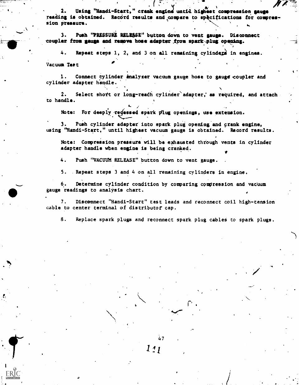
4411
1
( y2. Using "Randi-Start, " crank *mind untill highest compression gauge
mating is obtained. Record results and.coapare to spkciications fo'r compres-sion pressure.
.
3. Push "PRESSUii MAW" button down to vent gauge. Disconnectcoupler from mugs and remove boss adapter Iron spazir.-4Aus opening.
4. Repeat steps 1, 2, and 3 on all remaining cylindez in engines.
Vacuum Test.
1. Connect tylinder enalyzer vacuum gauge hose to gauge-coupler andcylinder adapter hitndle.
2. Select shott or long-readi cylinder adapter; as required, and attachto handle. 1
/ -
Note: For deeply.retsed spark Aug openings, use extension.
3. Push cylinder adapter into spark plug opening and crank engine,using "Handi-Start," until highest vacuum gauge is obtained. Record results.
Note: Compression pressure will be exhausted through vents in cylinderadapter handle wben engine is being cranked.
4. Push "VACUUM RELEASE" button down to vent gauge.
5. . Repeat steps 3 and 4 on all remaining cylinders in engine.
6. Determine cylinder condition by comparing compression and vacnumgauge readings to analysis chart.
7. Disconnect "Handi-Start" test leads and reconnect coil high-tensioncable to center terminal of distributor cap.
8. Replace spark plugs and reconnect spark plug cables to spark plugs.
47
11/
ro 4
,
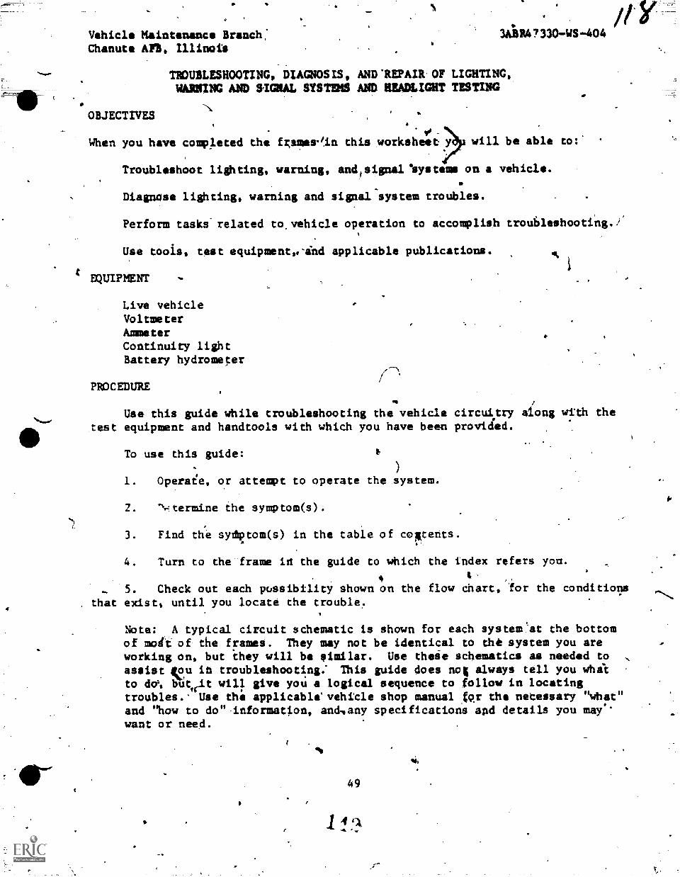
Vehicle Maintenance Branch:Chanute AFB, Illinoit
OBJECTIVES
/1.3A8 RA ? 33041S 410 4
TROUBLESHOOTING, DIAGNOSIS, AND.REPAIR.OF LIGHTING,WANING AND SIGNAL SYS-11M5 AND HEADLIGHT TESTING
VWhen you have completed the 4mm/in this worksheet y will be able to:
Troubleshoot lighting, warning, andtsignallaystems on a vehicle.
DiagnOse lighting, warning and signal-system troubles.
Perform tasks'related to.vehicle operation to accomplish trou6leshooting./
Use tools, test equipmentolind applicable publications.
EQUIPMENT
Live vehicleVoltmeterAmmeterContinuity lightBattery hydrometer
PROCEDURE
Use this guide while troubleshooting the vehicle circuitry ali.ong with thetest equipment and handtools with which you have been provided.
To use this guide:
1. Operaie, or attempt to operate the system.
Z. "vi-termine the symptom(s).
3. Find the sydptom(s) in the table of coptents.
4. Turn to the frame in the guide to which the index refers yom.t
A
- 5. Check out each possibility shown on the flow dhart, for the conditions
. that exist, until you locate the trouble.
Note: A typical circuit schematic is shown for each system'at the bottomof merit of the frames. They may not be identical to the system you areworking on, but ihey will be eimilar. Use theie schematics as needed toassist feu ta troubleshooting: This guide does not always tell you whalto alW, btitwit will give yoU a logical sequence to follow in locatingtroubles.. Use the applicablevehitle shop manual fpr the necessary "what"
and "how to do",information, andvany specifications and details you may.'want or need.
11,
49
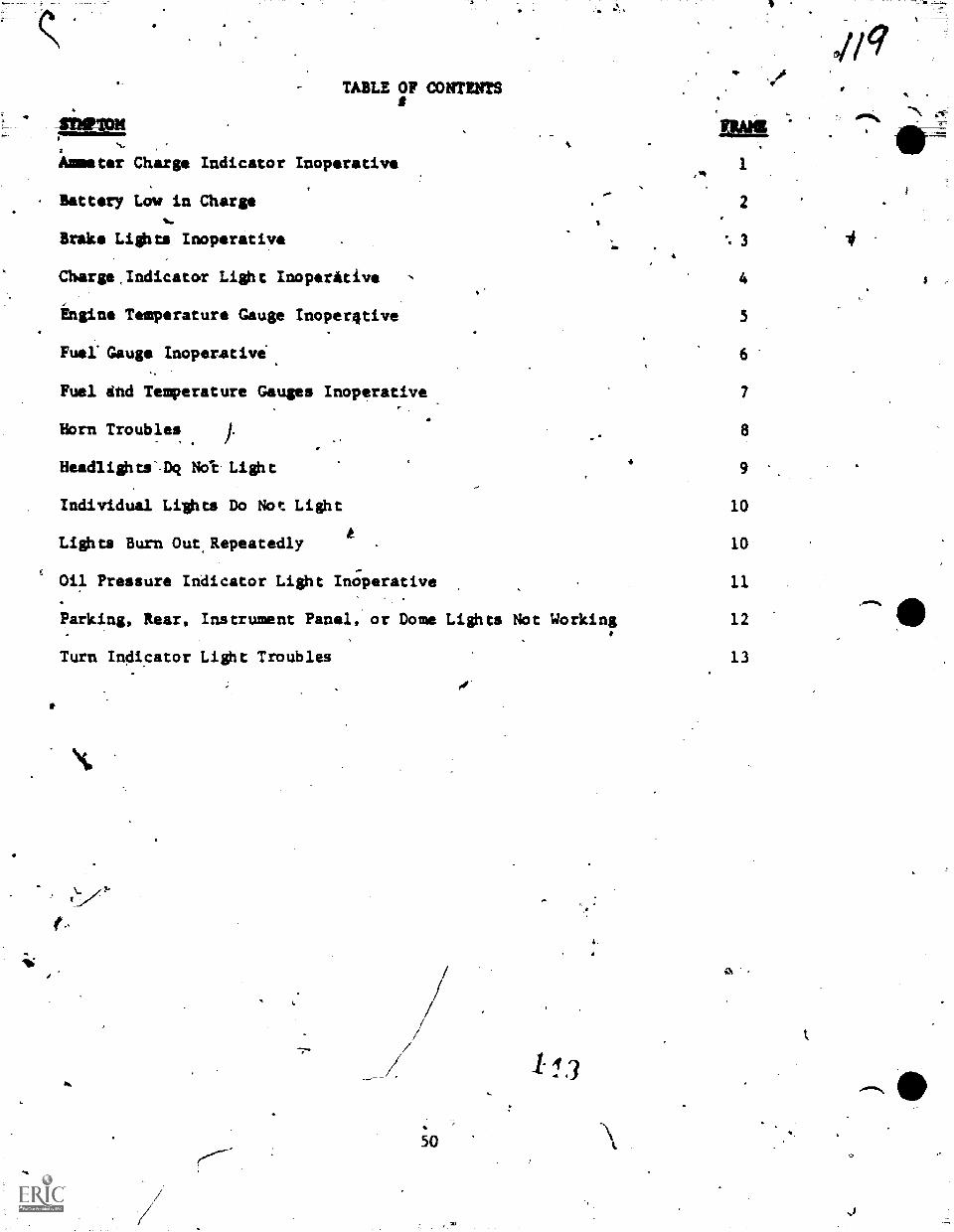
TABLE OF CONTENTSq.
Ammeter Charge Indicator Inoperative
Battery Low in Charge
Brake Lights Inoperative
Charge,Indicator Light InoperAtive
1
2
3
4
Engine Temperature Gauge Inoperative 5
Fuel:Gauge Inoperative 6
Fuel And Temperature Gauges Inoperative 7
Horn Troubles 8
Headlights'.Dq Not. Light 9
Individual Lights Do Not Light 10
Lights Burn Out.Repeatedly 10
Oil Pressure Indicator Light InOperative 11
Parking, Rear, Instrument Panel, or Dome Lights Not Working 12
Turn Indicator Light Troubles 13
50
113
011 -"N
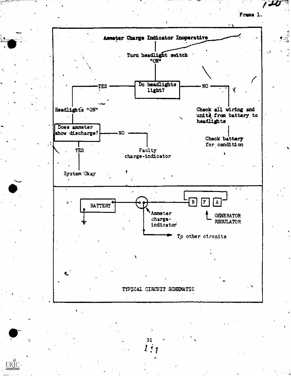
t,
Frame 1.
Headlights "ON"
Does ammetershow discharge?
Ansikter'DCharge Indicator Inoperative
Turn headlight switch"ON" \
Do Nolight?
1
.
$ystern 'Okay
Faultycharge-indicator
Check ail wiring andunitkfrds battery toheadlights
Check batter,'for,condition
liAmmetercharge-indicatoi
t_ GENERATORREGULATOR
To other circuits
TYPICAL CIRCUIT SCHMATIC
51
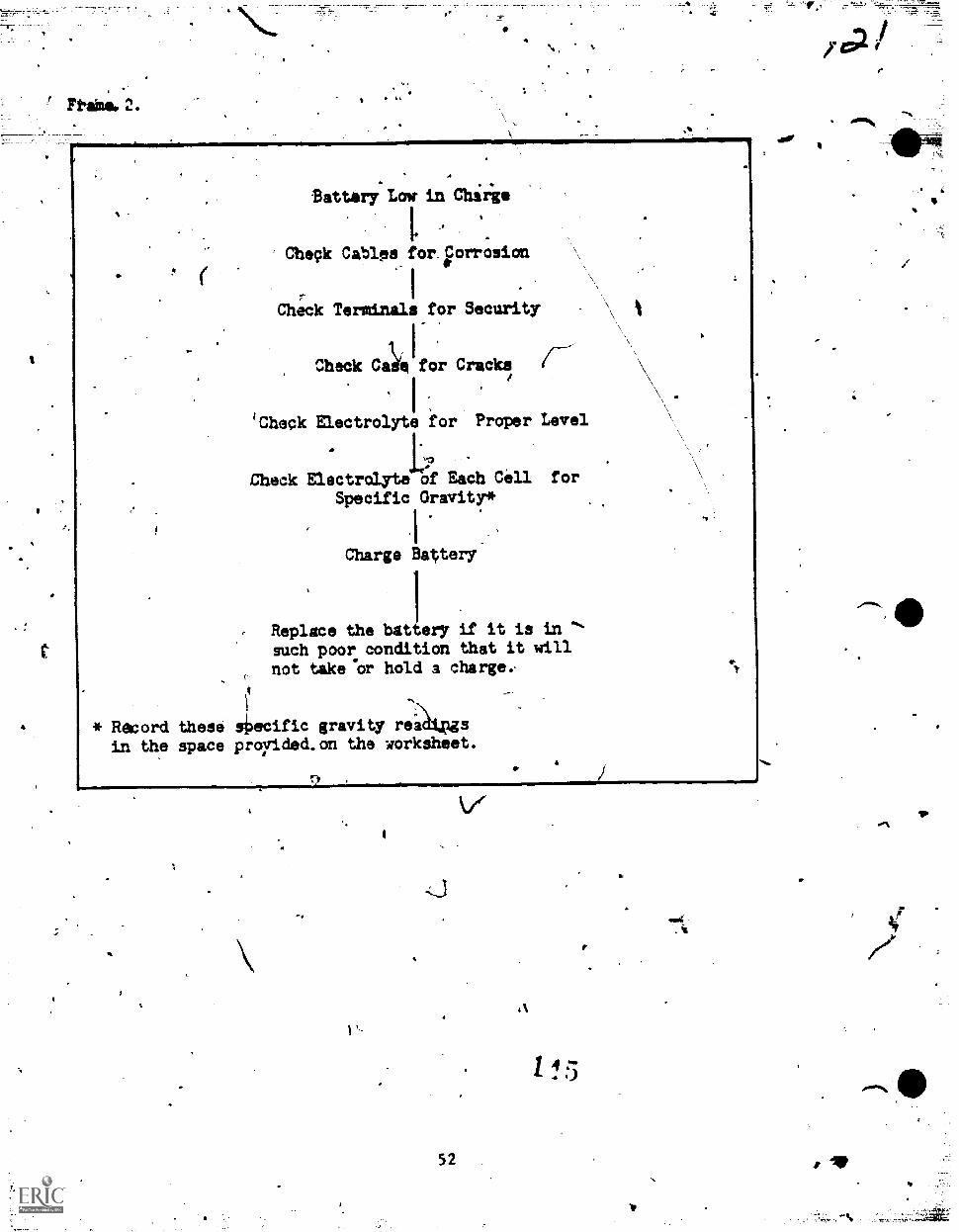
4
Ftaime..2.fa
A44
Battery Low. in Chirie
Check Cables for iorrosion
Check Terminals for Security
Check CLeifor Cracks
I .
'Check Electrolyte for Proper Level
Cbeck Electrdlyte of Each Cell for
Specific Gravity*
Charge Batery
IReplace the battery if it is insuch poor condition that it willnot teat:Or hold 3 chargee
* Record these sioecific gravity reidtpgs
in the space provided.on the worksheet.
fl
52
V
1 4
*
1
I.
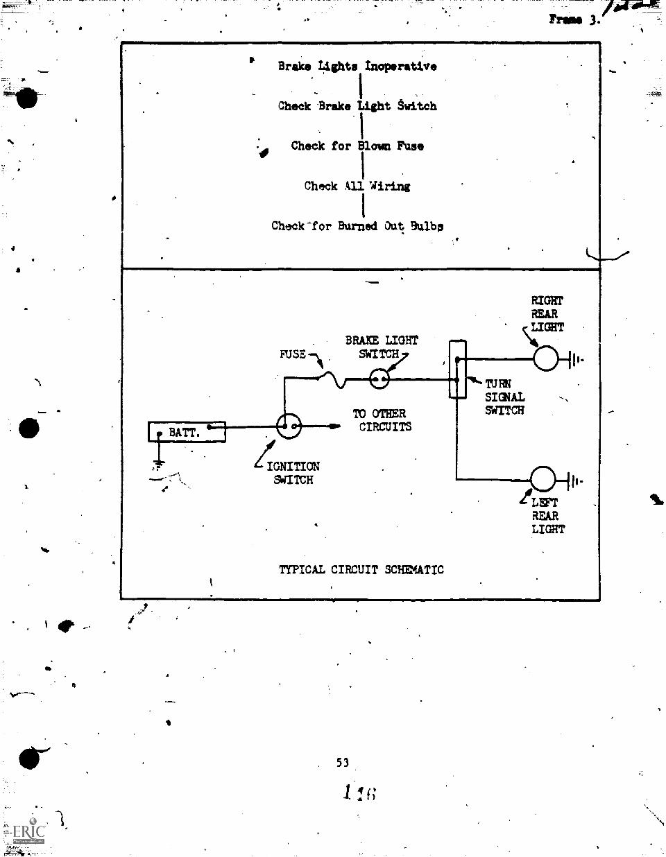
4
'\
milw
ot
4
fBrake Lights Inoperative
I
Check Brake Light switch
Cheek for Blown Fuse
Check All 'Wiring
Check-for Burned Out Bulbs
..10
, BRAKE LIGHTFUSE SWITCH
BATT.
Z IGNITIONSWITCH
TO OTHERCIRCUITS
TYPICAL CIRCUIT SCHMATIC
RIGHTREAR
\14,ICHT
IURNSIGIALWITCH
oII.LFFTREARLIGHT
53
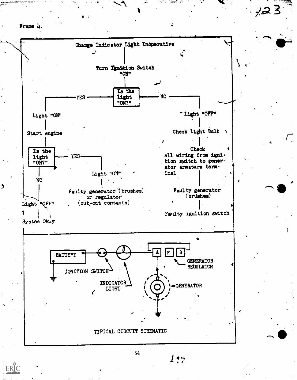
Prams 14.
Charge Indicator Light Inoperative
Turn ignition Switch"ON"
I Itght"ON?"
1
Light "ON" "OFF"
Start engine Cheek Light iulb
1
I
lightIs the YES-"ON?"
ILight "ON"
NO1 ,
Faulty generator `(bruahes).or regulator
. (cut7out contacta)Light NFF"
1 I
System Okay
ICheck
all wiring from igni-tion switch to gener-ator armature term-inal
Faulty generator(brdshee)
Fati.lty ignition switch
IGNITION SWITCH
INDICATORLIGHT
(
TYPICAL CIRCUIT SCHEMATIC
14L....GENERATOR
REMIATOR
LGENERATOR
54
iga
4
g
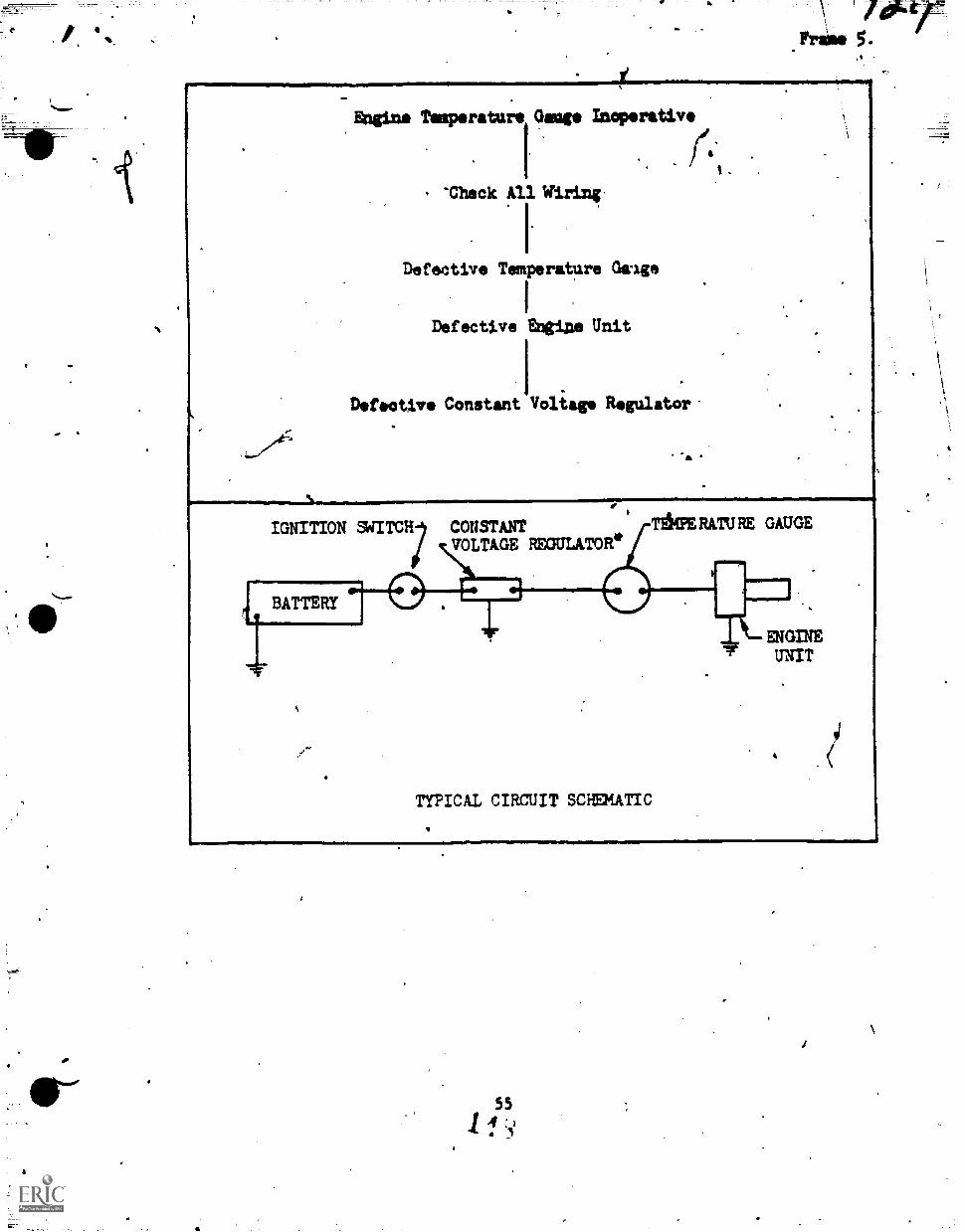
Engine Nimperature Gauge Maoporativo
ef.
s
Theck All Wiring,
I
Defective Temperatare Osage
I
Defective Enttne Unit
I
Defective Constant Voltage Regulator
-
IGNITION CONSTANT TAM RATU RE GAUGE
acliTAGE REGULATOR.
BATTERY
TYPICAL CIRCUIT SCHEMATIC
1--k ENGINEI" UNIT
554 : )
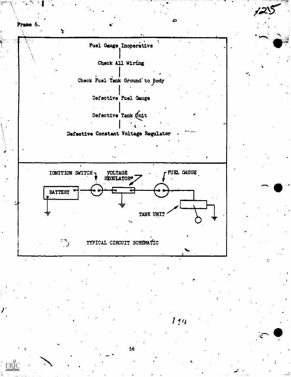
v
-
Fuel Gauge Inoperative
Check All Wiring
Check Fuel Tank Grouncrtoyody
Defective Fuel Gauge
Defective Tank kit
I *
Defective Constant Voltage Regulator
1,1
IGNITION WITCH, ;VOLTAGEREGULATOR4:7
BATTERY 111
FUEL GAUGE
TANK Tni rr
TYPICAL CIRCUIT SCHEMdIC
56
Sr
a11141/4.
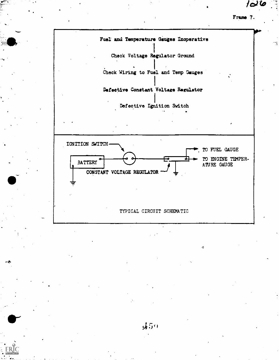
Fuel and Temperature Giuges Inoperative
Check Voltage Regulator Ground
Check Wiring to ruel and Temp Gauges
Defective Constant Voltage Regulator
Defective Ignition Switch
IGNITION SdITCH----\PO FUEL GAUGE
E0,_______÷.- TO ENGINE TEMPER-BATTERyl
'--
ATURE GAUGE
iCONSTANT VOLTAGE REGULATOR .7 .
TYPICAL CIRCUIT SCHEMATIC
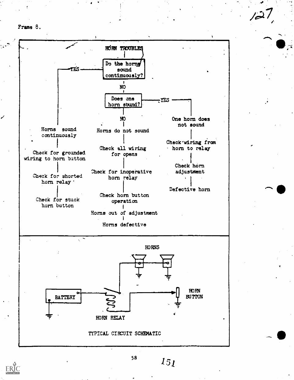
Frame 8.
Horns soundcontinuously
Check for groundedwiring to horn button
Chqck for shortedhorn relay'
Check for stuckhorn button
Do the hosound
ocontinuously?
NO
Does onehorn sbund?
NO
Horns do not sound
One horn doesnot sound
Check'wiring fromCheck all wiring horn to relay
for opens
Check hornCheck for inoperative adjustment
horn relay
Defective hornCheck horn button
operation
Horns out of adjustment
Horns defective
HOMS
9,1 HO EN
BU TTON
HORN RELAY
TYPICAL CIRCUIT SCHEMATIC
58 151
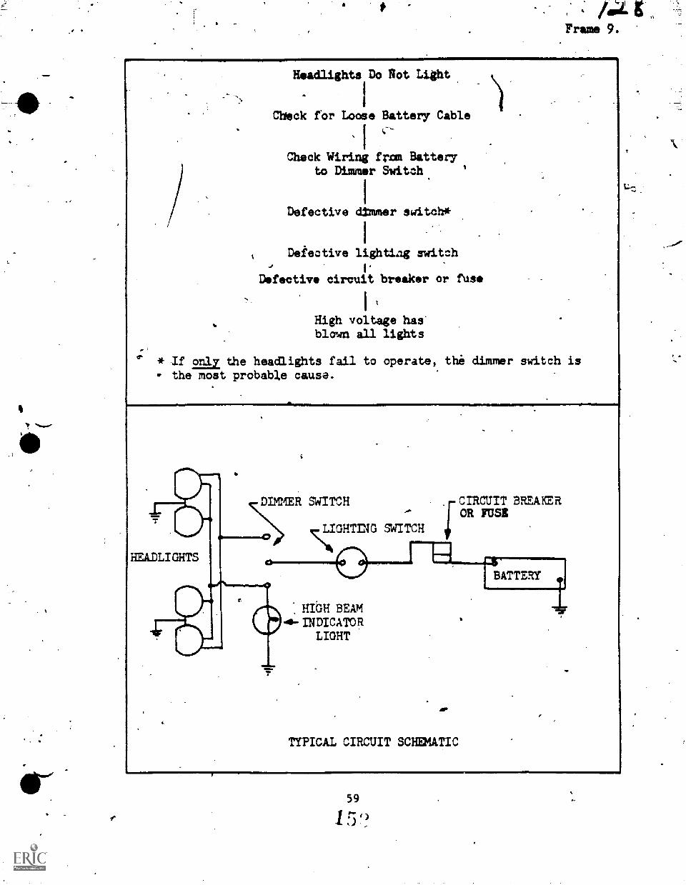
Frame 9.
Headlights Do Rot Light
Check for Loose Battery Cable
, I
Check Wiring frau Batteryto Dimmer Switch
Defective dimmer switch*
Deiective lightiag switch
I.Defective circuit breaker or fuse
High voltage has'blown all lights
* If ma the headlights fail to operate, the dimmer switch isthe most probable cause.
DIMER SWITCH
HEADLIGHTS
SWITCH
-..
HIGH BEAMde-INDICATOR
LIGHT
CIRCUIT BREAEROR FUSE
TYPICAL CIRCUIT SCHEMATIC
BATTERY
59
`)
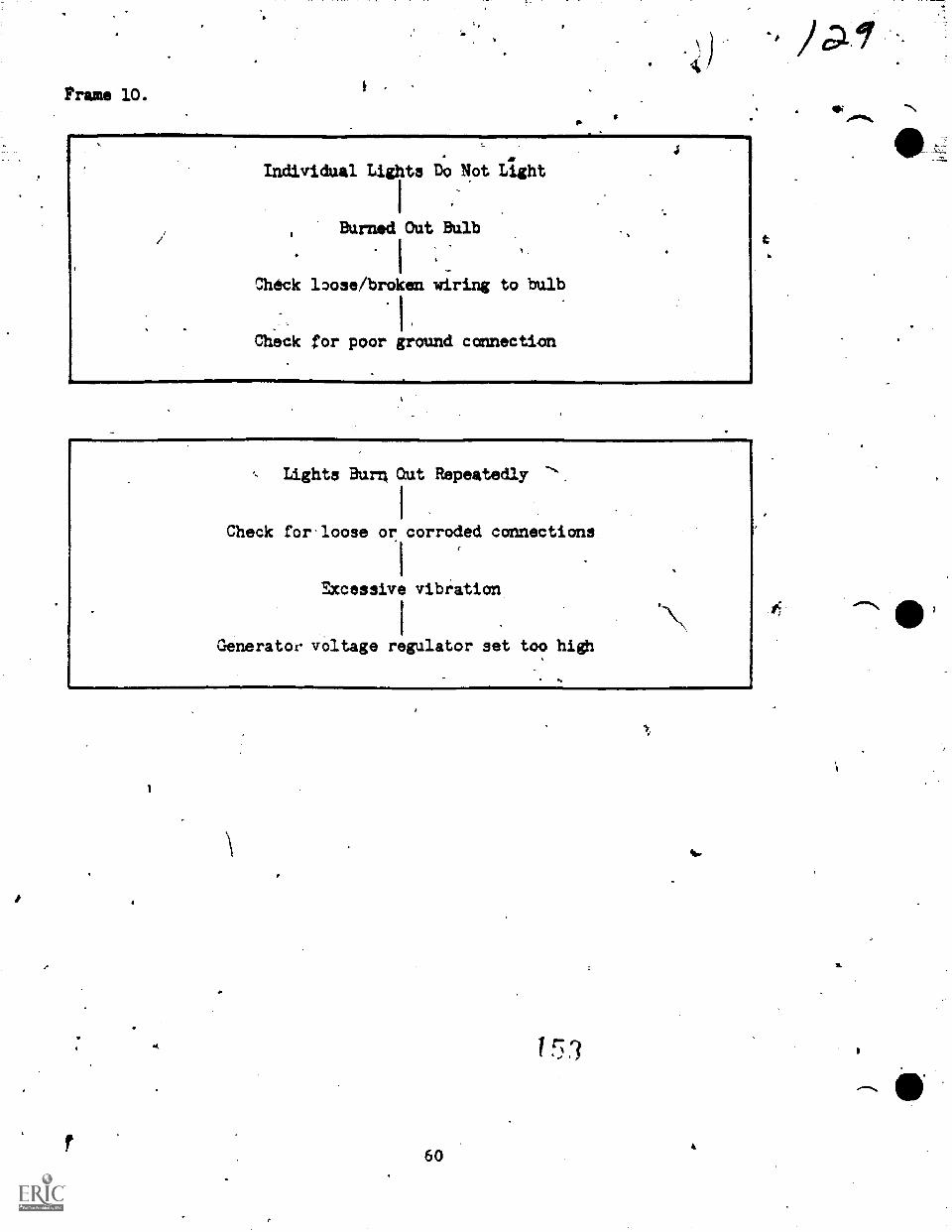
Prams 10.f
Individual Lights Do Not Light
Burned Out Bulb
Check 13ose/broken wiring to bulb
1.Check for poor ground connection
, Lights Burn Qut Repeatedly
Check for-loose or corroded cannections
Excessive vibration
Generatoe voltage regulator set too high
.
60
1 r7
j
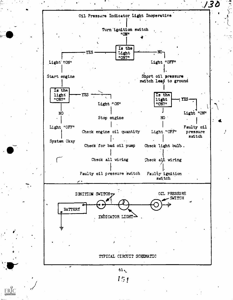
rI
S.
Oil Pressare Indicator Light Inoperative
I.Turn 'ignition switch
"ON"
Is theLight"ON?"
Light-ISON"
I
gtart engine
Is thelight"ON?"
NO
I
Light "OFF"
1
System Okay
-7-74-71
Light -"ON"
Stop engine
4
Light "OFF"
/36
Short oil pressureswftch leaii to ground
Is thelight 1---IYES--71"ON?ft
1 Lighi "ON"NO
I I Faulty oilCheck engine oil quantity Light "OFF" pressure
l' - I
switch
Check'for bad oil pump Check light bulb..
I
Check all wiring Check 0 wiring
[ I'
Faulty oil pressure 'switch Feralty'ignitionswitch
.0°1..IGNITION SWITCH
IBATTERY
INbICATOR LIGHT
TYPICAL CIRCUIT SCHEMATIC
on PaEssuREo.,.swiTCH
IP
61,
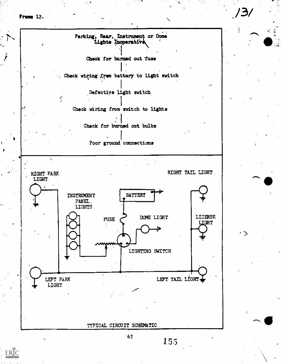
Frame 12.
.,
Parking, Rear, Doing,
tights *perativ
1
,
Cheek for burnad out 'fuse
1
Check viTing -gram battery to light switch
,I
...
.Defectiye light switdh
Check wiring from.switch to lights
r I
Check for bu'rned out bulbs
Poor ground connections
RIGHT PARKLIGHT
fl
INSTRUMENTPANEL.LIGHTS
FUSE
RIGHT TAIL LIGHT
BATTERY 1°4"
DOME LIGHT
LIGHTING SWITCH
LEFT PARKLIGHT
TYPICAL CIRCUIT SCHEMATIC
LICENSEGHT
LEFT TAIL LIGHTi?
62
/ 3/
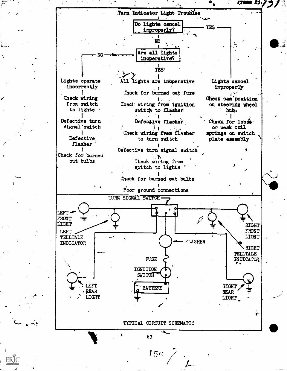
Lights operateincorrectly
I -
Check wiringfrom switchto lights
I
Defective turnsignal'switch
Defective.
flasher
Check for burnedbut bulbs
.Turn Indicator Light Troutiaemw-----IP-177--711
1Do lights cancelimproperly?
NO
'Are all lightsinoperative
TES'
IMiiNE/1===, ThS =1.MINEP,
'Tall lights are inbperative
Check for burned out fuse
Check wiring from ignitionswitch to flasher
Defective flash&
Check wiri2 IgfIreM:fiasherto turn aid tab
1
Defective turn signal switch
.:N-Check wiring from !switch to lights
Check for burned out bulbs
Poor ground connections
Lights cancel.:impropeay
Check cam'positionon steeridg yheel
-- huh,.
I 1
Check for looslor wedk coil
rprings on switchplata assembly
LEFT -air
FRONT'
LIGHT
LEFTTELLTALEINDICATOR
TURN SIGNAL staTCH
4
MASHER
91\ LEFTnutLIGHT
FUSE
IGNITICNSWITC
BATTERY
TYPICAL CIRCUIT SCHEMATIC
RIGHTFRONTLIGHT
RIGHTTEILTALEINDICATOR
RIGHT)?REARLIGHT
63
S.
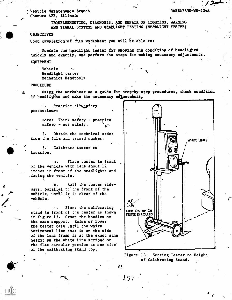
I Vehicle Maintenance Br.anchChanute AFB, Minnie
3ABR47330 -WS -404A
TigUBLESHOOTING, DIAGNOSIS, AND REPAIR OF LIGpTING, WARNINGAND SIGNAL SYSTEMS AND HEADLIGHT TESTING (HEAMLI-GHT TESTER)
OBJECTIVES
Upon completion'of this worksheet you will 6 able to:
Operate the headlight tester for showing the condition of headlightequickly and exactly, and Oerform the steps for making necessary adjustments.
EQUIPMENT
VehicleHeadlight tester_Mechanics Handtools
PROCEDURE
AL Using..the worksheet as a guide for step-by-Atep procedures, check condition6f headlights and make the necessary adlustmients. .
1. Practice allNufetyprecautions:
Note: Think safety - prasiicesafety - act safely.
2. Obtain the technical orderfrom the file and record number.
3. Calibrate tester tolocation.
a. Place tester in frontof the vehicle with lens ahout 12inches in front of ehe headlights andfacing the vehicle.
b. Roll the tester side-ways, parallel to'the front of thevehicle, until it is clear of the
c. Place the'calibratingstand in front of the tester as shownin figure 13. Grasp the handles onthe case suppprt. Raise or lowerthe tester case until the whitehorizontal line that is on the sideof the lens frame is at the exact sameheight as the white line scribed onthe flat circular portion at one side'of the calibrating stand top.
WHIR LINES
LINE ON WHICHTUTU IS ROLLED .0°
+6,
Figure 13. Setting Tester to Heightof Calibrating Stand.
.c 65
157
a
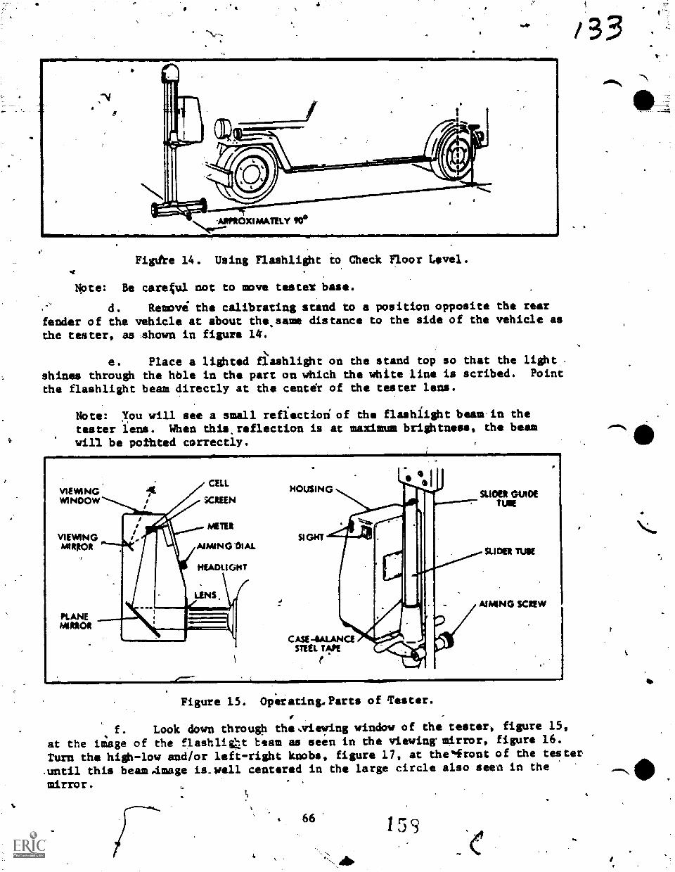
4
ARPROXIMATELY PO°
Figthe 14. Using Flashlight to Check Floor Level.
Note: Be caretul not to move testeX bass.
d. Remove the calibrating stand to a position opposite the rearfender of the vehicle at about tho.same distance to the side of the vehicle asthe tester, as shown in figure 14.
e. Place a lighted fkashlight on the stand top so that the lightshines through the hble in the part on which the white line is scribed. Point
the flashlight beam directly at the center of the tester lens.
Note: you will see a small reflectiod of the flashlight beam in the
tester lens. When this,roflection is at maximum brightness, the beamwill be pothted correctly.
VIEWINGWINDOW
VIEWINGMIRKA
PLANEMIRROR
CELL
SCREEN
MEIER
AIMING DIAL
HEADLIGHT
LENS
HOUSING
SIGHT
cAst-ammaSTEEL T4PE
SLIDER GUIDETUIE
SLIDER TUVE
AIMING SCREW
Figure 15. Operating.Parts of Tester.
/ 3
f. Look down through the,viewing window of the tester, figure 15,
at the image of the flashliCt team as seen in the viewing mirror, figure 16.
Turn the high-low and/or left-right knobs, figure 17, at thelfront of the tester
.until this beam.image is.well centered in the large circle also seen in the
mirror.
66.1 5 s
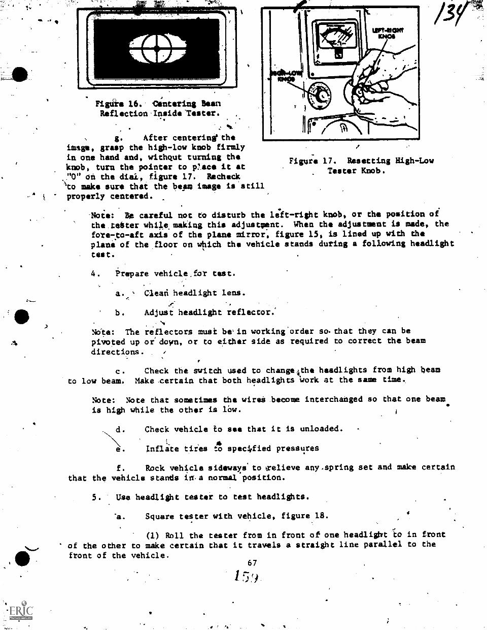
I.
/
Figure 16. Centering BeenReflection'Inside"Tester.
' w
, 41IL
g. After centerinetheimage, grasp the high-low knob firmlyin one hand and, withqut turning theknob, turn the pointer to p'acs it at"0" on the dial, figure 17. RecheckIto make sure that the beam image is stillproperly centered.
Figure 17. Resetting High-LowTester Knob.
3V
Note: Be careful not to disturb the leift-right knob, or the position oi
the teeter while making this adjustment. When the adjustment is made, thefore-.to-aft axis of the plane mirror, figure 15, is lined up with theplane of the floor on which the vehicle stands during a following headlighttest.
4: Prepare vehicle,for teat.
a. Cleari headlight lens.
b.
NOte: Thepivoted updirections
Adjust headlight reflector.
reflectors musk be,in working'order so.that they can beor' down, or to either side as required to correct the beam
c. Check the switch used to change4the headlights from high beamto low beam. Hake certain that both headlights Work at the seam time.
Note: Note that sometimes the wires become interchanged so that one beamis high while the other is lbw.
e.
Check vehicle to see that it is unloaded.
Tnflate tires to specirfied pressures
f. Rock vehicle sidewaxs to trelieve any.spring set and make certainthat the vehicle stands ima normal position.
5. Use headlight tester to test headlights.
*a. Square tester with vehicle, figure 18.4
(1) Roll the tester from in front of one headlight to in frontof the other to make certain that it travels a straight line parallel to thefront of the vehicle.
67
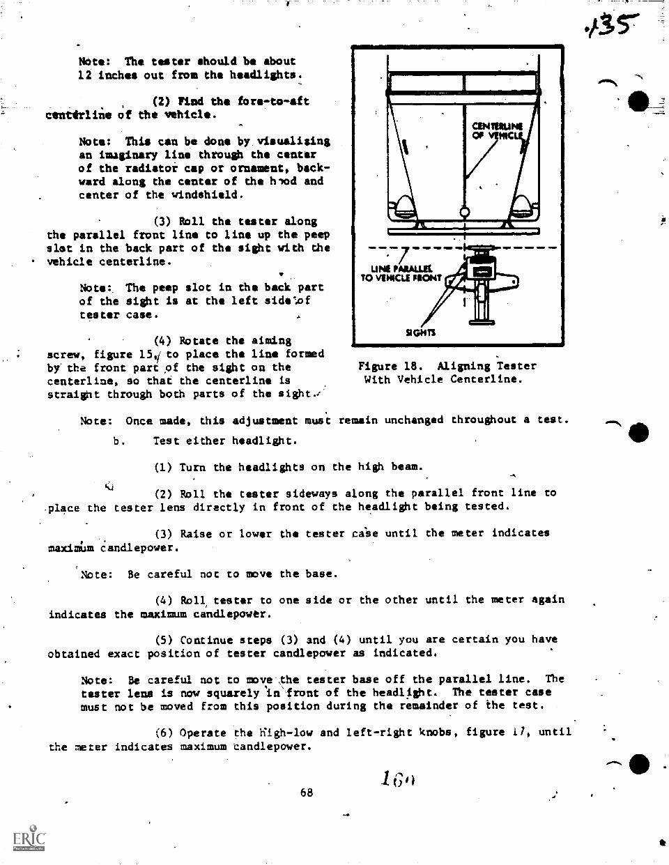
NOte: The tester should be about12 inches out from the headlights.
(2) Find the fore-to-aftcenarline of the vehicle.
Note: This can be done by:visualisingan imaginary line through the centerof the radiator cap or ornament, back-ward along the center of the hlod andcenter of the windshield.
(3) Roll the tester alongthe parallel front line to line up the peepslot in the back part of the sight with dhevehicle centerline.
Note: The peep slot in the back partof the sight is at the left side-poftester case.
(4) Rotate the aimingscrew, figure 151 to place the line formedby'the front part of the sight on thecenterline, so that the centerline isstraight through both parts of the sight,-
ON MUNEOVEP4C
L
COM
Figure 18. Aligning TesterWith Vehicle Centerline.
Note: Once made, this adjustment must remain unchanged throughout a test.
b. Test either headlight.
(1) Turn the headlights on the high beam.
<4(2) Roll the tester sideways along the parallel front line to
.place the tester lens directly in front of the headlight being tested.
(3) Raise or lower the tester ca'se until the meter indicates
maximilm candlepower.
Note: Be careful not to move the base.
(4) Roll tester to one side or the other until the meter againindicates the maximum candlepowtr.
(5) Continue steps (3) and (4) until you are certain you haveobtained exact position of tester candlepower as indicated.
Note: Be careful not to move Ihe tester base off the parallel line. The
taster lens is now squarely in'front of the headl.ight. The tester casemust not be moved from this position during the remainder of the test.
(6) Operate the iiigh-low and left-right knobs, figure 0, untilthe meter indicates maximum candlepower.
68
415-
amIN,
VIP dik Note: The plane mirror, figure 15, is now in perfect slimmest with theheadlight beam. Test results may be read on the meter and calibrated
dials at the front of the tester case.
c. Interpret results of test.
Note: The maximum brightness of the headlight can be read on the meterwith the tester in the final position. Reading is in thousands of candle-
mar. Divisions marked on the dial show "POOR," "GOOD," mnd "WilLENT"rangte At the end of test, the calibrated dials of the high-low and left..
right knobs will show tha beam direction. Ihese are graduated to show thenumber of inches that the beam will drop, raise, or turm to one side at adistance of 25 feet in front of the vehicle.
d. Correct misdirected beam, if required.
NOM The usual drop is three inches in 25 feet (shown by the array onthe high-low knob dial between the "2" and "4" at the right of the "0").Soma operators prefer no side angle (left-right knob set at "0"). Othersprefer to have the right headlight set in this manner, but to have the leftheadlight slightly toed in (knob set at "2" to "4" to the right of ID" on
the dial).
(1) Set the high-low and left-right knobs, figure 17, to showthe amount of drop and side angle desired.
(2) Adjust the headlight reflector until a maximum candlepowerreading is shown on the tester meter, if required.
Note: The tester must not be moved from its last position in the testwhen making this adjustment.
7
AO/a
Vehicle Maintenance BrapchChanute APB, Illinois.
3OR47330-WS-4041
TROUBLESHOOTING, DIAGNOSIS, AND.REPAIRP4F LIGHTING, WARNING ANDSIGNAL SYSTEMS AND HEADLIGHT TESTING (AC HEADLIGHT AMER)
OBJECTIVES
Upon completion of this worksheet.you will be able to:
.Operate the headlight aimer for.showing the conditionlof headlights quicklyand exactly, and perform tho steps _for making the necessary adjustments.
EQUIPMENT
VehicleHeadlightMechanics handtool
PROCEDURE
Using the worksheet as alguide for step-byrstep procedures, check conditionof headlights and make the necessary adjustments.
AIMING THE HEADLIGHTS
Preaiming Instruction.
1. Check dimmer switch for faulty operation.
2. Check high beam inaicator-indicates the HIGH beam is in operationwhen lighted.
3. Check for badly rusted or faulty heaalamp assemblies. These must becorrected before a satisfactory adjustment can be made.
4. Place vehicle on a level floor.
5. ClieCk front suspension height. Adjust to specifications as necessary.
6. Check tire inflation.
7. Rock vehicle sideways to allow vehicle to assume its normal position.
8. If gasoline tank is not full, place a weight in the trunk of vehicleto simulate the weight of a full tank (6-1/4 pounds per gallon).
9. There should be no other load in the vehicle other than the driver ora substituted weight of approximately 150 pounds placed in the driver's position.
10. Remove heaalamp front trim panel.. Do not remolre the seal beam
retainer rims.
71
C )o
Checking Aimer for Calibration.
1. Using a carpenteror stone meson level of known accurady, locate atrue vertical plate glass window or'ssooth surface.,
2. Set DOWN-UP pointer on DOWN 2.
'3'. Set RIGHT-UP pointer and floor level coavensator at "O."
4. .Secure aimers to glass or smooth surface three to five feet apart scisplit image targets can be located in the viewing port.
5. If bubble is centered in glass vial, vertical celibration is correct.If bubble is not centered, make the. DOWN-UP adjustment by rotating the leveladjusting Screw until the bubble is centered in the spirit level.
6. The horizontal aim is correct if the targets on opposite simians arealigned in viewing ports. If targets are not aligned in viewing ports, rotatemirror adjusting screw until target split image becomes aligned.
CoMpensating and Mounting the Aimer.
1. For mechanical aim, the_slope of the floor should be known..7
2. Place transit on floor id line with vertical centerline of the rightfront wheel. Place split image target in like position at right rear wheel.
3. Adjust range screw on transit until targetsplit image coincides crmerges into one unbroken line.
Note: Make sure that line of sight is perpendicular from the eye to theviewing port of the transit image centered.in viewing port of transit.
4. Turn dial on side of transit until bubble in spirit level is centered.
5. When bubble is centered, note "plus" or "mi.nus" reading on compensatorscale. This figure indicates the degree of slope of the floor and must be trans-ferred to elFh aimer.
1
6. With a screwdriver, turn adjusting slot of floor level compensatorin each aimer, until the correct plus or minus figure (or fractional part
, appears in the proper window).
Mounting and Adjusting the Aimers
1. While holding an aimer in alignment with the lens of one OUTBOARD,headlamp,,bring aimer up to and against headlamp lens.
Note: Make certain that the headlamp lens pads are making full contactwith the aimer mounting flange and that the aimer target is facing inboard.
72
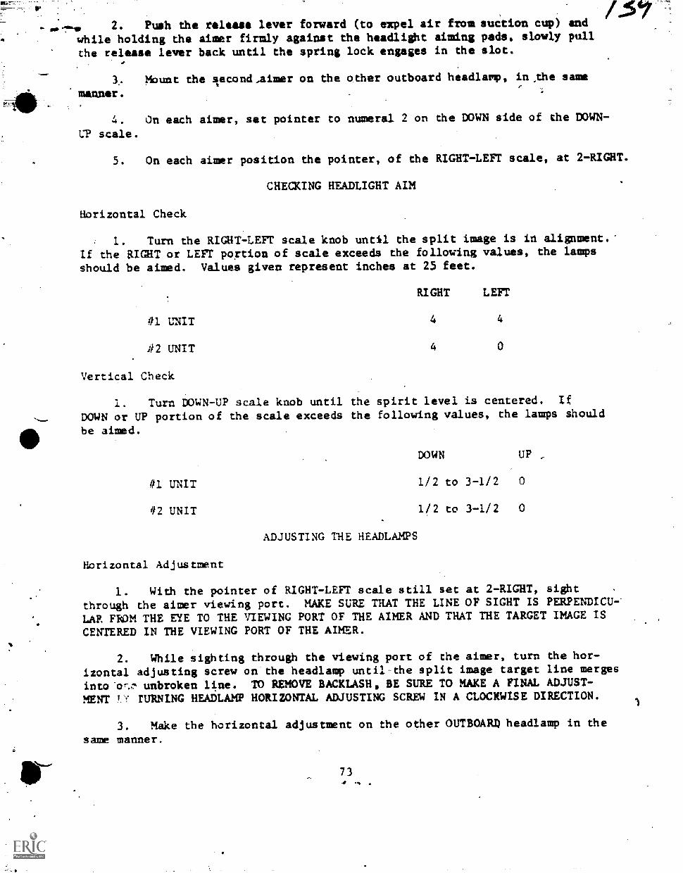
1-40 2. Push the release lever forward (to expel air fromsuction cup) andwhile holding the aimer firmly against the headlight aiming pads, slowly pull
the release lever back until the spring lock engages in the slot.
3. Mount the Iecond,aimer on the other outboard headlarp, in ,the same
manner.
4. On each aimer, set pointer to numeral 2 on the DOWN side of the DOWN -
CP scale.
5. On each aimer position the pointer, of the RIGHT-LEFT scale, at 2-RIGHT.
CHECKING HEADLIGHT AIM
Horizontal Check
1. Turn the RIGHT-LEFT scale knob until the split image is in alignment.'
If the RIGHT or LEFT po;tion of scale exceeds the following values, the lamps
should be aimed. Values given represent inches at 25 feet.
RIGHT LEFT
#1 UNIT 4 4
.#2 UNIT 4 0
Vertical Check
1. Turn DOWN-UP scale knob until the spirit level is centered. If
DOWN or UP portion of the scale exceeds the following values, the lamps should
be aimed.
DDWN UP ,
#1 UNIT 1/2 to 3-1/2 0
112 UNIT 1/2 to 3-1/2 0
ADJUSTING THE HEADLAMPS
Horizontal Adjustment
1. With the pointer of RIGHT -LEFT scale still set at 2-RIGHT, sight
through the aimer viewing port. MAKE SURE THAT THE LINE OF SIGHT IS PERPENDICU-
LAR FROM THE EYE TO THE VIEWING PORT OF THE AIMER AND THAT THE TARGET IMAGE IS
CENTERED IN THE VIEWING PORT OF THE AIMER.
2. While sighting through the viewing port of the aimer, turn the hor-izontal adjusting screw on the headlamp until the split image target line merges
into'cr-a, unbroken line. TO REMOVE BACKLASH, BE SURE TO MAKE A FINAL ADJUST-MENT !!' TURNING HEADLAMP HORIZONTAL ADJUSTING SCREW IN A CLOCKWISE DIRECTION.
3. Make the horizontal adjustment on the other OUTBOARD headlamp in the
same manner.
734
1
17aVertical Adjustment
1. Turn vertical adjusting screw on headlamp in a counterclockwisedirection to bring the bubble of tho spirit level on the aimer to car side ofcenter. Use care to avoid disturbing the installed position of the aimars.Then turn the screw clockwise until the bubble is centered 63r correct aim andelimination of backlash.
2. Make the vertical adjustment on the other OUTBOARD unit in the samemanner.
3. Recheck the target alignment on each side and readjust the horizontalaim, if necessary. Proceed to adjust the inboard units by following the instruc-tions as outlined for the outboard headlamps. Install headlamp trim panels.
Note: Remove the aimars by releasing the spring lock at the rear (bottom)of the aimer and pushing the release lever forward. Do not attempt toremove the aimers by pulling them away from the headlamp lens. Slide thesuction cup downward and away from the lens.
74
S.
ATC-3 AP'S W 114-1100-4
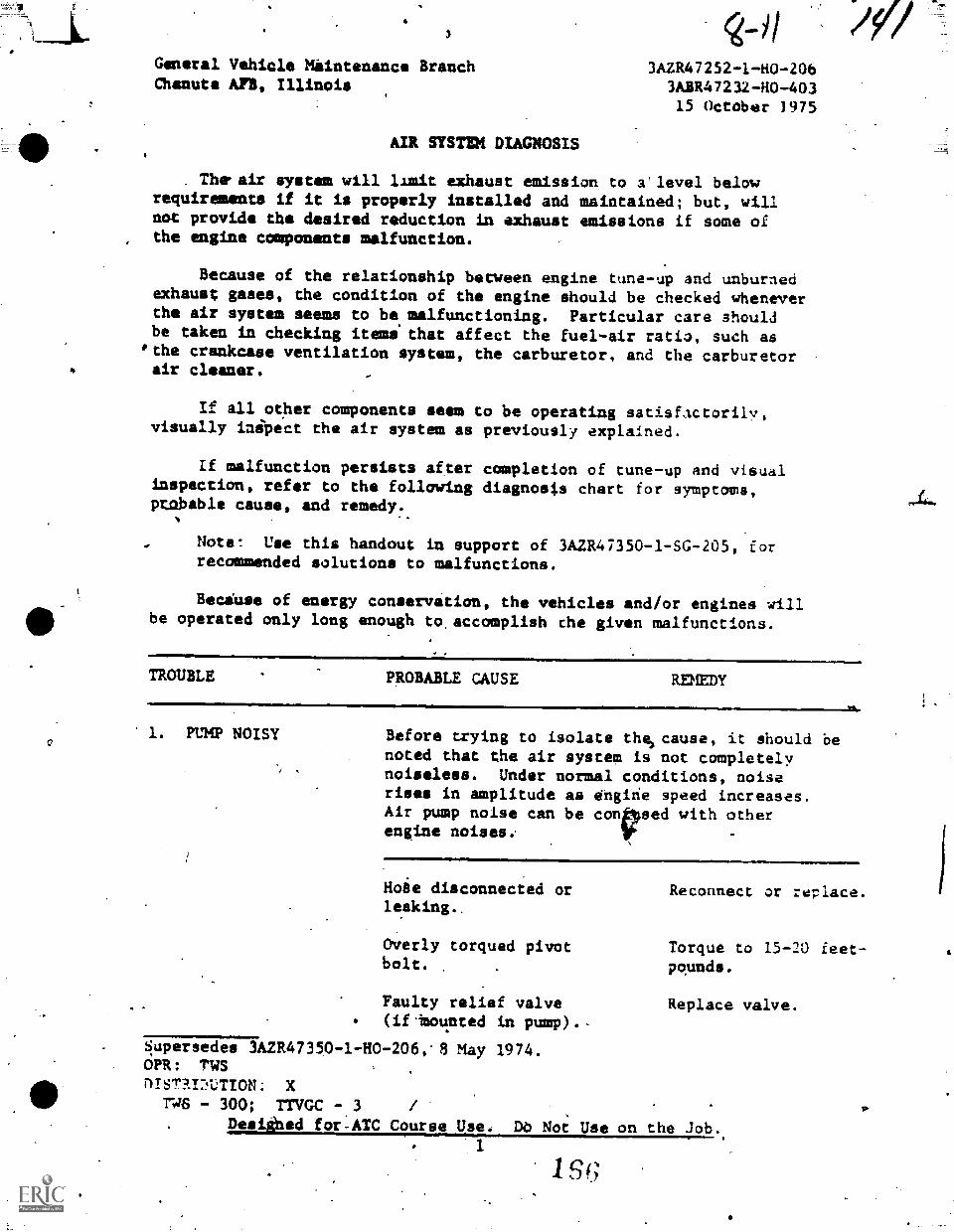
General Vehicle Maintenance BranchChanute All, Illinois
AIR SYSTEM DIAGNOSIS
g--1/3AZR47252-1-H0-206
3ABR47232-110-40315 October 1975
. The. air system will limit exhaust emission to a'level belowrequirements if it is properly installed and maintained; but, willnot provide the desired reduction in exhaust emissions if some ofthe engine components malfunction.
Because of the relationship between engine tune-up and unburnedexhaust gases, the condition of the engine should be checked wheneverthe air system seems to be. malfunctioning. Particular care shouldbe taken in checking items that affect the fuel-air ratio, such as
'the crankcase ventilation system, the carburetor, and the carburetorair cleaner.
If all other components seem to be operating satisfactorily,visually inipect the air system as previously explained.
If malfunction persists after completion of tune-up and visualinspection, refer to the following diagnosis chart for symptoms,prabable cause, and remedy.
Notet Use this handout in support of 3A2R47350-1-SG-205, forrecommended solutions to malfunctions.
Becduse of energy conservation, the vehicles and/or engines willbe operated only long enough to,accomplish the given malfunctions.
TROUBLE PROBABLE CAUSE REMEDY
1. PUMP NOISY Before trying to isolate thelcause, it should benoted that the air system is not completelynoiseless. Under normal conditions, noiserises in amplitude as Ongihe speed increases.Air pump noise can be cored with otherengine noises..
Hoie disconnected or Reconnect or replace.leaking..
Overly torqued pivotbolt.
.
Faulty relief valve(if-Mounted in pump).-
Supersedes IA2R47359-1-H0-206,'8 May 1974.OPR: TMSDISTAIDLTION: X
TW6 - 300; TTVGC - 3 I
Desitked for.ATC Course Ilse, DO Not' Use on the Job..1
Torque to 15-20 feet-pounds.
Replace valve.
1st;
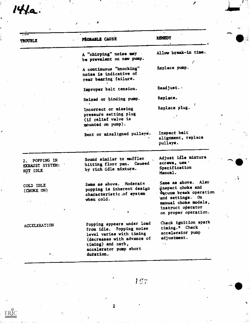
TV.
TROUBLE MIME CALISi
1=orammimwommrommNmof
MUM!
A "chirping" noise maybe prevalent on new pump.
A continuous "knocking"noise is indicative ofrear bearing failure.
Improper belt tension.
Seized or binding pump.
Incorrect or missingpressufe setting plug(if relief valve ismounted an pump).
Bent or misaligned pulleye.
Allmo break-in time.
Replace pump.
Readjust.,
Replace.
Replace plug.
Inspect beltalignment, replacepulleys.
2. POPPING INECdAUST SYSTEM:H97 IDLE
COLD IDLE(CHOKE ON)
ACCELERATION
Sound similar to muffler Adjust idle mixture
hitting floor pan. Caused screws, use'
by rich .idle mixture. SpecificationManual.
Same as above. Moderatepopping is inherent designcharacteristic.of systemwhen cold.
Popping appears under load
from idle. Popping noiselevel varies with timing(decreases.with advance of
timing) and carb,accelerator pump short
duration.
Same as abave. Also
4xspect choke and34cuum break operationAnd settings. On
manual choke models,instruct ofierator
on proper operation.
Check ignition sparktiming.* Check .
accelerator pumpadjustment.
2
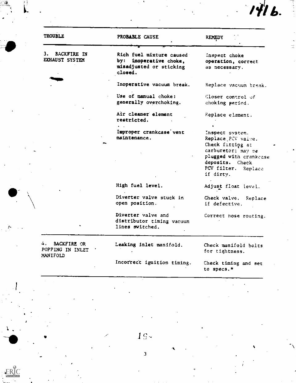
TROUBLE PROBABLE CAUSE REMEDY
3. BACKFIRE INEXHAUST SYSTEM
Rich fuel mixture causedby: inoperative choke,misadjusted or stickingclosed.
Inoperative vacuum break.
Use of manual choke:generally overchoking.
Air cleaner elementrestricted.
Improper crankcase'ventmaintenance.
High fuel level.
Diverter valve stuck inopen position.
Diverter valve anddistributor timing vacuumlines switched.
Inspect chokeoperation, correctas necessary.
Replace vacuum brak.
Closer control ofchoking period.
Replace element.
Inspect system.Replace.PCVCheck fIttipg a:carburetor; may oeplug.ged witn crankcasedeposits. CheckPCV filter. Replaceif dirty.
Adjust float 1evE.1.
Check valve. Replaceif defective.
Correct hose routing.
4. BACKFIRE ORPOPPING IN INLETMANIFOLD
Leaking inlet manifold.
Incorrecl ignition timing.
Check manifold boltsfor tightness.
Check timing and setto specs.*
3
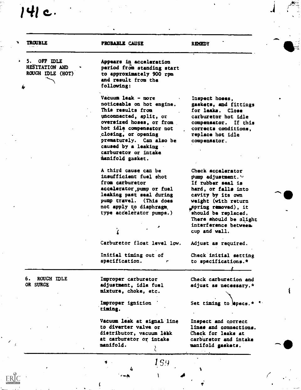
TROUBLE PROBABLE CAUSE RDIEDY
. 5. OFF IDLEHalTATION AND -
ROUGH IDLE (HOT)
.1111Imr6. ROUGH IDLEOR SURGE
Appears la accelerationperiod from standing startto approximately 900 rpmand result from thefollowing:
Vaeuum leak - morenoticeable on hot engine.This results fromoconnected, split, oroversized hoses, or fromhot idle compensator not.closing, or -openingprematurely. Can also becaused by a leakingcarburetor or intakeianifold gasket.
A third cause can beinsufficient fuel shotfrom carburetoraccelerator,pump or fuelleaking past seal duringpump travel. (This doesnot apply to diaphragm.type acdelerator pumps.)
Carburetor float level 19w.
Initial timing out ofspecification.
Inspect hoses,gaskets, and fittingsfor leaks. Closecarburetor hot idlecompensator. If thiscorrects conditions,replace hot idlecompensator.
Check acceleratorOump adjustment.AIf rubber seal ishard, or falls intocavity by its awnweight (with returnoppring removed), itshould be replaced.There should be slightinterference between,cup and wall.
Adjust as required.
Check initial settingto specifications.*
Improper carburetoradjustment, idle fuelmixture, choke, etc.
Lmproper ignition'timing.
Vacuum leak at signal lineto diverter valve ordistributor, vacuum ltlakat carburetor or intakemanifold.
Check carburetion andadjust as necessary.*
Set timing \t:)lapecs.*
Inspect and correctlines and connections.Check for leaks atcarbUretor and intakemanifold gaskets.
4S!)
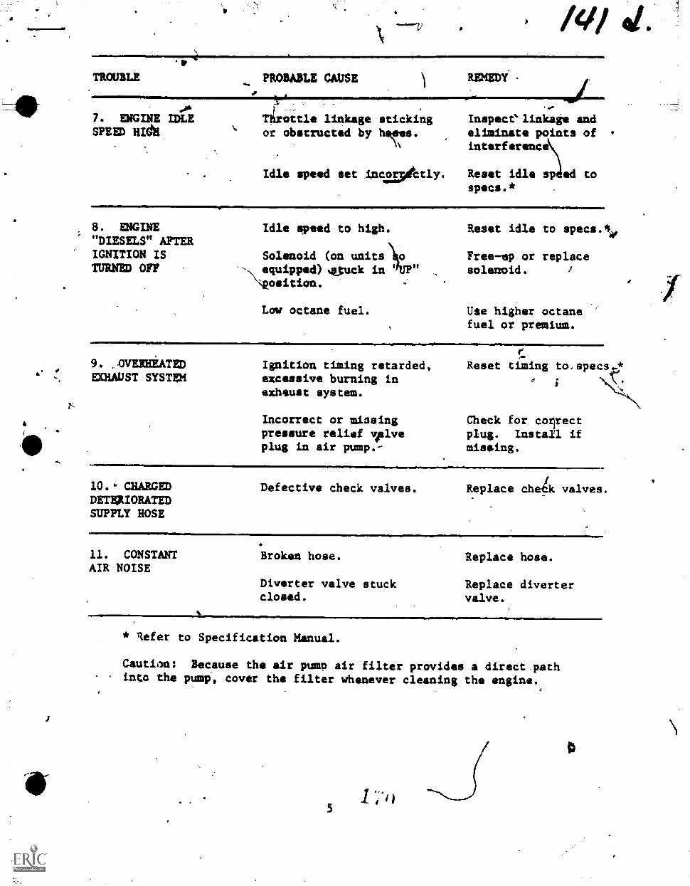
6
1
EXHAUST SYSTEM
a
a /4/TROUBLE PROBABLE CAUSE RINEDY
no&
7. ENGINE IDLESPEED HIG11
Tirottle linkage stickingor obstructed by heft's.
NN
Idle speed set incapktly.
we
Inspecelinkage andeliminate points ofinterference
Reset idle sp ed tospecs.*
8. ENGINE"DIESELS" AFTERIGNITION ISTURNED OFF
Idle speed to high.
UPSolenoid (on units 1 o
-,, equipped) 4.,tuck in\position.
Low octane fuel.
Reset idle to specs.%,
Free-ep or replacesolenoid.
Use higher octanefuel or premium.
9. ,411ERHEATED Ignition timing retarded,excessive burning inexhaust system.
Incorrect or miosingpressure relief valveplug in air pump.-
Reset timing to.specye
Check for corlrectplug. Install ifmiseing.
W.& CHARGEDDETFAIORATEDSUPPLY HOSE
Defective check valves. Replace chek valves.
11. CONSTANTAIR NOISE
Broken hose.
Diverter valve stuckclosed.
Replace hose.
Replace divertervalve.
* lefer to Specification Manual.
Caution: Because the air pump air filter provides a direct pathinto the pump', cover the filter whenever cleaning the engine.
51 ;I)
%do /fore06---Li Z.
PROGRAMMED TLX 3ABR47939,-PT -403
,Tednical Training
Plec.41.4.411.I
Automotive Repaigmme-
CLRITON CHASSIS ErINAMCIIETER
1 June 1970
CHANUTE TECHNICAL TRAINING CENTER (ATC)
OPR: TSDTDISTRIBUTION: XTSDT - 500; TSOC - 2
Designed For ATC Course Use
0
FOREWORD
This programmed text was prepared by personnel of the LSD teem for uselaths 3A1147330 Automotive Repairmen Course. It was validated with targetpopulation studeuts in 1964. The text has been successfully'use, by 1040'students in the cOurse.
OBJECTIVES
1. Upon completion of part one of this programmed text, you will be able toselect statementwthat identify the purpose, component loCations and-component functions of the Clayton chassis dynamometer.
2. Given the necessary handtools, a Oynamometer and part II of thie programmedtext, you will be able to:
a. Start and operate the Clayton Chassis Dynamometer.
b. Record readings taken iiiom the dynamomitei indicators.rub
c. Adjust the engine performance according to text informatiow,
'3. Using the information gained in parts one and two and- given hypotheticaldynamometer test results you will be able to analyze and select theprdhable cause of engine malfunctions.
90% accuracy is required for this program.
INSTRUCTIONS
This.programmed !..ext is written in segments calledcontains a bit of information and is followed by one oreach frame and respond to the question for that frame.next frame check your answer with the ones in frame 50,tion frame.
.frames Each. frame
more questictus. 'ReadBeforegoing to thewhich is your confirms-
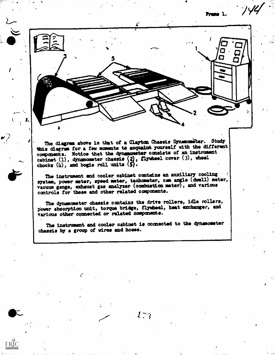
4v-
Pm, 1.
z The diagram above ix that of a Tartan dhassis DynamdmIlor. Study
this diagrma for a few moments to acquaint yourself with the different
components. Notice that the dynamometer consists of an instrument
cabinet (1), dynamometer chassis (;)s flywheel cover (3), wheel
chocks (4), and bogie rdll unite (5).
The instrument end cooler cabinet contains an auxiliary cooling
system, power sister, speed Meter, tachometer, cam angle (dwell) meter,
vacuum gauge, exhaust gas analyzer (ccabustion meter) , and various
controls for these and other related components.
The dynamometer chassis contains the drive rollers, idle rollers,
Over aboorption unit, torque bridge, flywheel, heat exchanger, and
various other connected or related components.
The instrument and cooler cabinet is connected to the dynamometer
Chassis by a group of wires and hoses.
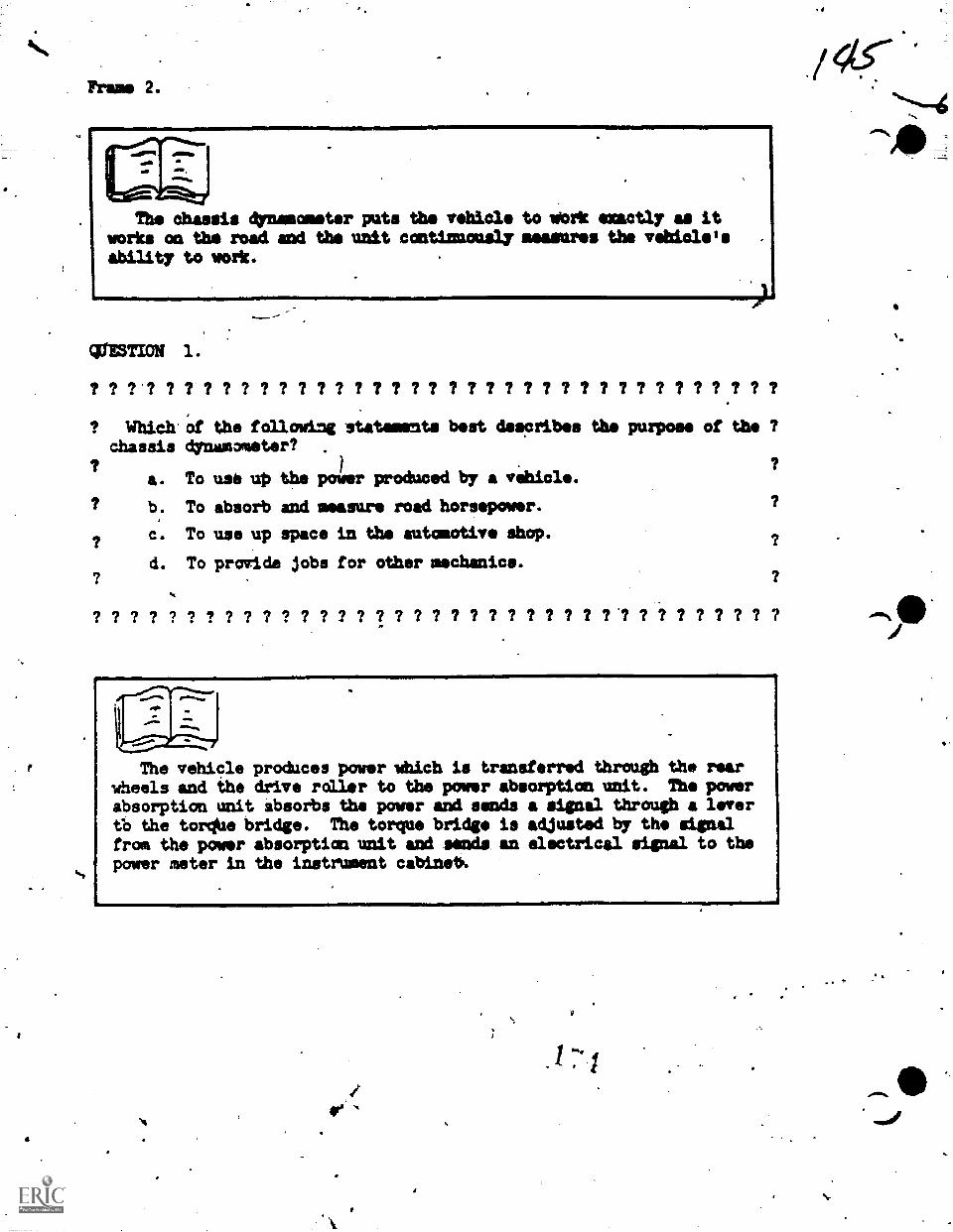
The chassis dynamometer puts the vehicle to Work exactly as itworks an the road and the unit contimusual4mmaanres the vehicle'sability to work.
cursTION 1.
7
? ? '? ? ? ? ? ? ? ? ? ? ? ? ? ? ? ? ? ? ? ? ? 1 1 ? 1 ? ? ? ? 7 ? ?
"a the following statements best describes the purpose of thechassis dynamometer?
a. To usb up the power produced by a vehicle.
b: To absorb and measure road horsepower.
C. To use up space in the automotive shop.
d. To proide jobs for other mechanics.
? ? ? 7 ? ? ? ? ? ? ? 7 ? ? ? ? ? 7 ? ? ? ? ? ? 7 ? ? 1 7 ? ? ? 7 ? ?
The vehicle produces power which is transferred through the rearwheels and the drive roller to the power absorption unit. The powerabsorption unit absoebs the power and sends a signal through a levertb the tor** bridge. The torque bridge is adjusted by the signalfrom the power absorption unit and semis an electrical signal to thepower meter in the instrument cabinet4
M..=..11111...11,11111MOIONNImpaloimb
a.
4
QUESTION 2.
? 7 ? ? ? ? ? ? ? ? ? 7 7 7 ? ? '7 7 ? 7.1? 7 7 7 7. ? 7 7 7 7 7 ? 7 ? ?
? Mbidh of these statements is'filse?
a. The drive roller produces the power indicated an the powermeter.
b. The torque bridge sends a signal to the power meter.
c. .The power met, indicates the 'wrapover being produced by? . the vehicle.
d. .The power absorption unit uses uto the power being,prodnced bithe vehicle.
? e. The drive roller is not connected directly to the torque 7
bridge.
? ?
7
? ? ? ?
QUESTION
? ? ?
?
?
? ?
3;
? ? 7
?
7
?
2
?
?
?
?
?
7
?
?
?
?
?
?
?
7
? 7 7 ? ?
? ? t ? ?
7
?
?
?
?
7
?
?
?
7
?
?
?
?
?
7
?
?
?
?
?
?
?
?
?
?
According to the information in Frame 2, wpich of the followingstatements is false?
a. The drive roller transfers power from the rear wheels to thepoVer absorption unit.
b. The power absorption unit absorbs the power being producedby the torque bridge.
c. The amount of power being absorbed is not adjusted by thetorya bridge.
d. Th power absorption unit sends a signal to the torquebridge.
? ? ? ? ? ? ? ? ? ? ? ? ? S'? ? ? ? 2 ? ? 7 ? 7 ? ? ? ? ? ? ? ? ? ? ?
-Sews a little confusing doesn't it? Really, it isn't. Just think'
about it for a momedt. The dynamometer is reproducing only actualvehicle actions. goy many tines have yon thought, "If I could onlydiagnose this vehicle's trouble while it is traveling-60 miles per hourI could deteimins thip,exact prcklem"? )So, just think of the dynamo-meter as the highways you normally drive on and perhaps this will maksthe lesson a little clearer to you.
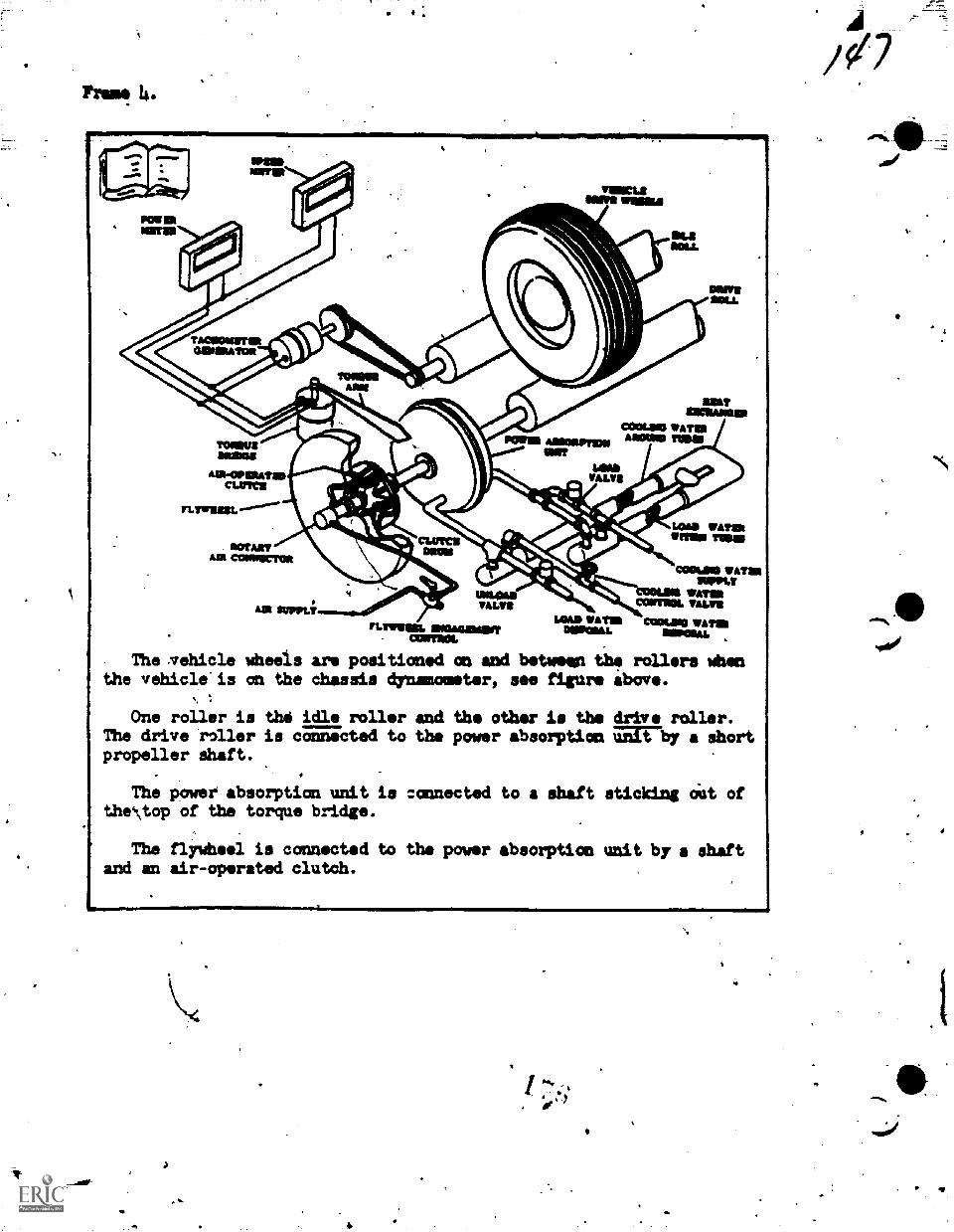
dr
NNWmine
IMM mossPow IlltNMI
MOMNUM
MOM° WATIIIMillUNIT
Ain-c0111%4TIMCUltat
normefAnt CammICTIM
1mime
14Wm, WATIst.1711111
OMAN IrmaAM
COMM. MVOComm WATER
11111101,u,
Ain SUPPLYWIL41111VASA*
Einagipsort0011,11011.
wall 'ALM
The ,vehicle wheeis are positioned on and between the rollers Whenthe vehicle'is on the dhassis dynamometer, see figure above.
One roller is the idle roller and the other is the drive roller.The drive roller is connected to the power absorption alrby a shortpropeller shaft.
The power absorption unit is connected to a shaft sticking ciut ofthe\top of the torque bridge.
The flywheel is connected t.03 the power absorption unit by a shaftand an air-operated clutch.
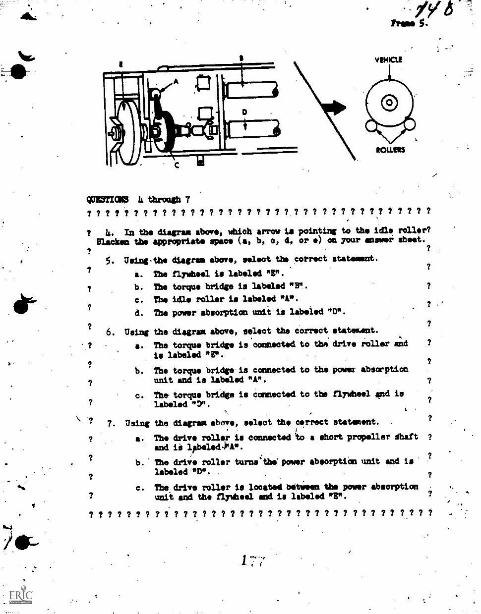
WWI= 4 through 7
VEHICLE
ROLLERS
? ? ? ? ? ? 7 7 ? ? ? ? ? ? 7 ? ? ? ? ? 7 ? ? 7 7 ? ? ? ? ? ? ? ? ? ? ?
4. In the diagram above, which arrow is pointing to the idle miller?
Blacken the appropriate space (a, b, 0, d, or ri) an your answer aheet.
Using-the diagram above, select the correct
a. The flywheel is labeled "3".
b. The torque bridge is labeled "BP.
c. The idle roller is labeled *A".
d. The power absorption unit 10 labeled "
6. Using the diagram above, select the Correct
a. The torque bridge is connected to the
is labeled "Er.
b. The torque bridge.is connected to theunit and is labeled "A".
c. The,torque bridge is Connected to thelabeled "7.
statement.
D.
stateaent .
drive roller and
powez absorption
flywheel end is
7. Using the diagram above, select the cerrect statement.
a. The drive roller is conneat44 Ito a ehort propeller dhaft
and ii lpbeled400.
b. The driv roller turns*:.the power absorptiOn unit and is
labeled "D".
c. The drive roller is located Wittig= the power absorptionunit and the flyWheel and is labeled "P.
? ? ? ? ? ? ? ? ? ? 7 ? ? ? ? ? ? ? ? ? ? ? 7 7 ? 7 ? ? ? ? ? ? ? ?
1 7'7
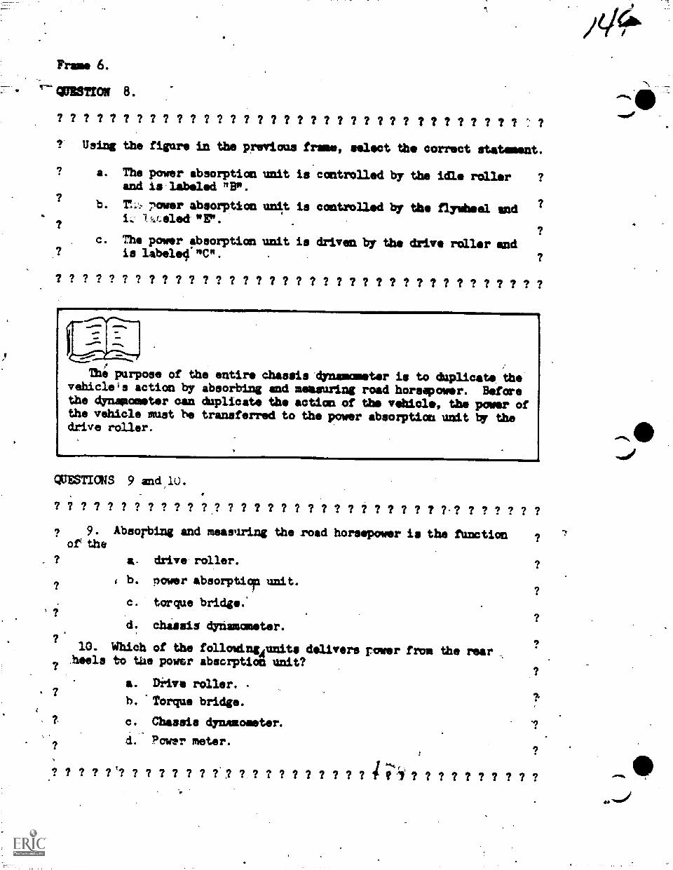
Frame 6.
alliSTION 8.
? ? ? ? ? ? ? ? ? ? ? ? ? ? ? ? ? ? 7 7 7 ? 7 ? 7 ? ? ? ? 1 ? ? ? ? ? ?
? Using the figure in the previous frame, select tho correct statament.
a. The power absorptionand is labeled "B".
b. Th: 7icarer absorption
"E".
c. The power absorptionis labeled "C".
unit is controlled by
unit is controlled by
unit is driven by the
the idle roller
the flywheel end
drive roller and
? ? ? ? ? ? ? ? ? ? ? ? ? ? ? ? ? ? ? ? ? ? ? ? ? ? ? ? ? ? ? ? ? ? ? ? ?
The purpose of the entire chassis dynamometer is to duplicate thevehiclels action by absorbing and measuring road horsepower. Beforethe dynamometer can duplicate the actioa of the vehicle, the power ofthe vehiele must be transferred to the power absorption unit by thedrive roller.
QUESTICKS 9 and,10.
? ? ? ? ? ? ? ? ? ? ? ? ? ? ? ? 7 ? ? ? 7 ? ? ? ? ? ? ? ? ? ? ? ?
a. drive roller.
i b. nower absorpti9p unit.
c. torque bridge.'
d. chassis dynamometer.
.7.
? 9.or the
Absorbing and measuring the road horsepower is the function
10. Which of the followingonits delivers rowerheels to tile power absorption unit?
?
a. Drive roller. -
b. Torque laridge.
c. Chassis dynamometer.
d. Power meter.
from the rear
? ? ? 7 ? '? ? 7 7 ? ? 7 ? ,? ? ? I ? ? ? ? 2 2 ? t 1 ? ? 7 7 7 7 2 ? ? ?
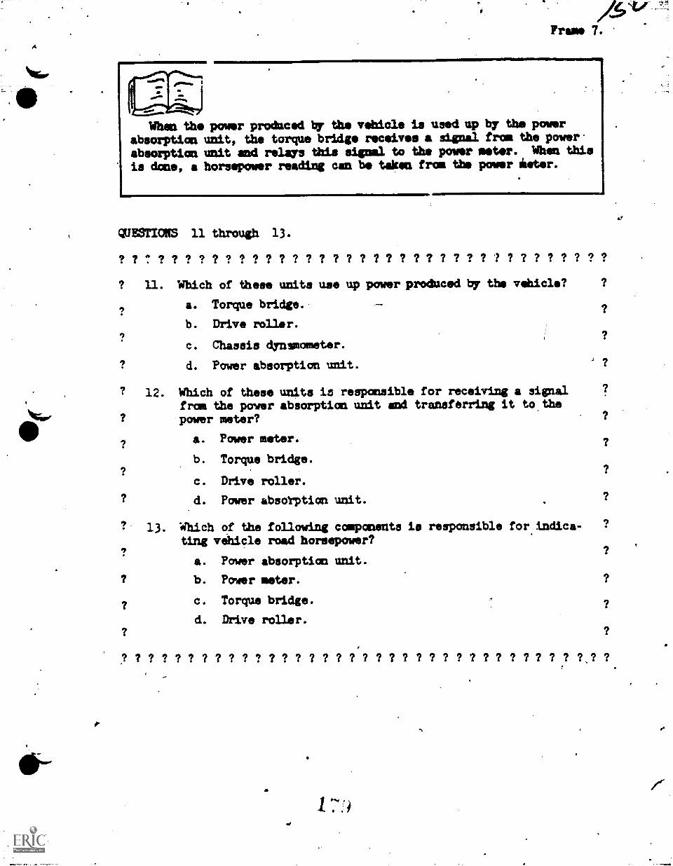
Frame 7.
When the power produced ty the vehicle is used up by the powerabsorption unit, the torque bridge receives a signal from the power
absorption unit and relays this signml to the power meter. When thisis done, a horsepower reading can be taken from the plover inter.
QUESTIONS 11 through 13.
? ? ? ? ? ? ? ? ? ? ? ? ? ? ? ? ? ? ? ? ? ? ? ? ? ? ? ? ? ? ? ? ? ? ? ?
? U. Which of these units use up power produced by the vehicle?
a. Torque bridge.
b. Drive roller.
c. Chassis dynsmometor.
d. Power absorption unit.
12. Which of these units ia responsible for receiving a signalfrom the power absorption unit and transferring it to thepower meter?
a. Power meter.
b. Torque bridge.
c. Drive roller.
d. Power absotption unit.
13. Which of the following components is responsible for indica-ting vehicle road horsepower?
a. Power absorption unit.
b. Power meter.
c. Torque bridge.
d. Drive roller.
? ? ? ? ? ? ? ? ? ? ? ? 7 ? ? ? ? ? 7 ? ? ? ? ? ? ? ? ? ? ? ? ? ? ?,? 7
1 74.
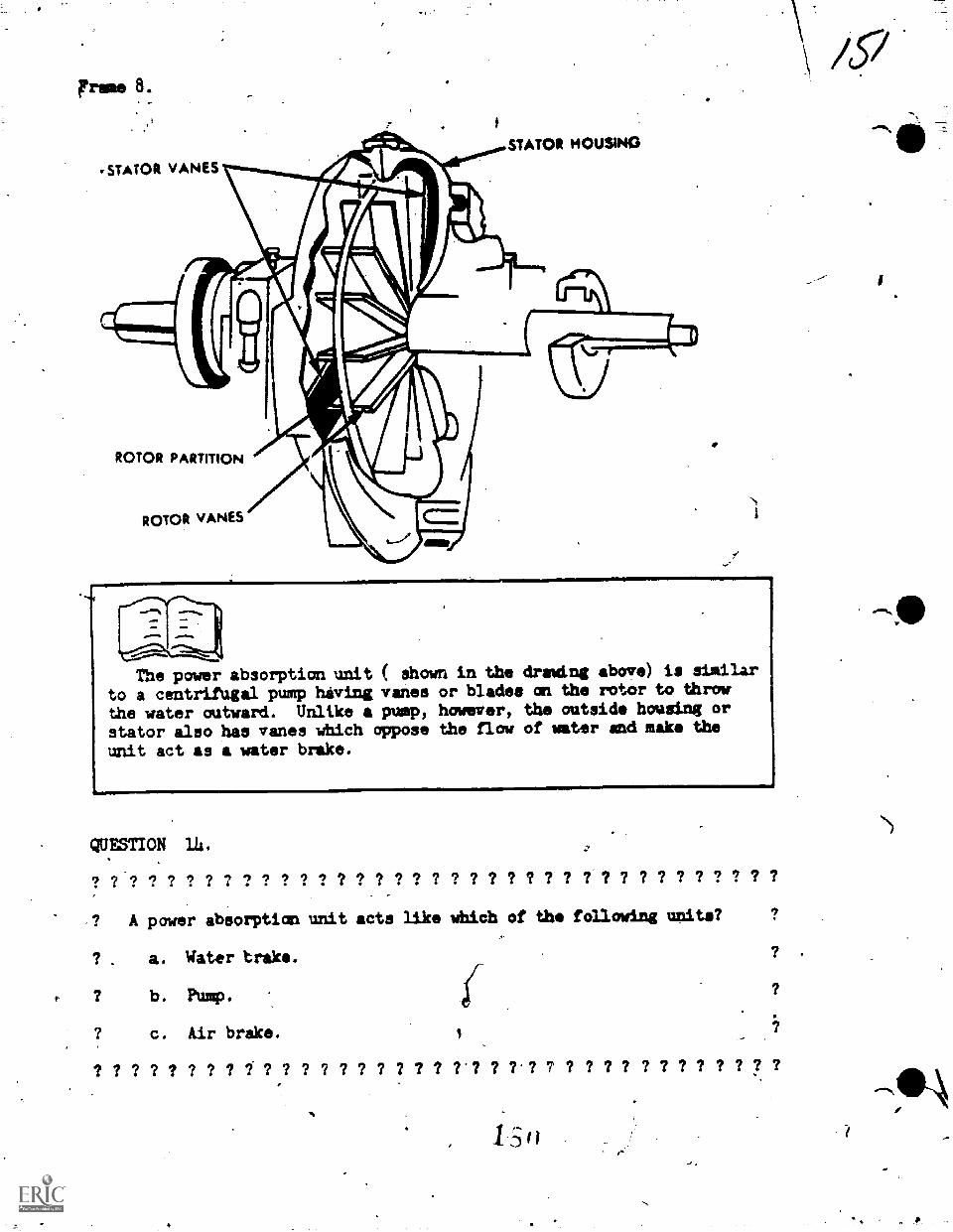
,STATOR VANES
STATOR MOUSING
ROTOR PARTITION
ROTOR VANES
The power absorption unit ( showto a centrifugal pump having vanesthe water outward. Unlike a pump,stator also has vanes which opposeunit act as a water brake.
A in the draming above) is similaror blades an the rotor to throwhowever, the outside housing orthe flow of water and make the
QUESTION 14.
? 7 ? ? ? ? ? ? ? ? ? ? ? ? ? ? ? ? ? ? ? ? ? ? ? ? ? ? ? ? ? ? ? ? ? ? ?
A power absorption unit acts like which of the following units?
? . a. Water brake.
? b. Pump.
? c. Air brake. 1
? ? ? ? ? ? ? ? ? ? ? ? ? ? ? ? ? ? ?'? ? ? ? 7 ? ? ? ? ? ? ? ? ? ? I ?
'*)
Frame 9.
By maintaining a constant aaount of water in the power absorption
unit the load can be held indefinitely. Ay adding or releasing water
the load can be ahansod. Water is added or released fAmi the power
absorption unit through the Use of a remote load cantrol switch-which
is controlled by the vehicle operator. To keep the water temperature
low (friction in the power absorption unit will heat the water) a heat
exchanger is built in the chassis of the dynamometer. That is, the
water is circulated from the poiver absorption unit to the heat ex-,
...);)ling
er and back to the power absorption,unit where it is used again.
The valve that operates the flYwhee1 engagement unit'is controlled
by air preasure. Although the flywheel will not be used during this
lesson, it is wiA for you to know how it is operated.
QUESTICN 15.
? ? ? ? ? ? ? ? ? ? ? ? ? ? ? ? ? ? ? ? ? ? ? ? ? ? ? ? 7 ? ? ? ? ? ?
How is the flywheel engaged?
a. By a water-operated control valve.
b. By an air-operated control valve.
c. By a manually-operated control valve.
? ? ? ? ? ? ? ? ? ? ? ? ? 7 ? ? ? ? ? ? ? ? ? ? ? ? 7 ? ? ? ? ? ?
On the end.of the drive roller, opposite the power absorption unit
is located a drive roller brake pawl. When this pawl is engaged, the
operator is free to drive the vehicle on or off the rollers.
.o.100
Frame 16.
QUESTION 16.
"I 9 9 9 7 7 ? 7 ? 7 7 7 7.7.7 7 7 7 ? 7 7 7 7 7 7 2 7 7 7 7
What is the purpose Of the drive roller brake pawl?
a. To keep the drive roller fram ever turming.
b. To keep the drive roller from turning only while abeing driven an the drive roller.
c. To keep the drive roller fram turvdmg oalTwhile abeing driven off the dynaaometer. ,
vehicle is
vehicle is'?
d. Tq keep the drive roller from turning when a vehicle is beingodriven onto or off of the dynamometer.
?i? 7-1? ? 9 9 9 *7 7 7 7 ? 7 9 7 ? ? 7 9 9 '7 9 9 9 9 9 ? 9 9
As wate is being used ii the power absorption unit, friction is
heating it. To prerent the water from overheating, it is forcedthrough a pipe, which is surrounded by another pipe containing cold
yaw, and then transferred back to the power absorption unit. This
heat exchanger is located on the dynamometer chaaeis along the frame
that supports the rollers.
QUESTION 17.0
? ? ? ? ? ? ? ?'? ? ? ? ? ? ? ? ? ? ? ? ?
What unit of the chassis dynamometer iswater used in the power absorption unit?
a. Power absorption unit.
, b. Two pipea of cold water.
c. Heat exchanger.
d. Tha dynimometer chassis.
7,7 ? ? ? ? ? ? ? ? ? ? ? ?
responsible for cooling the
7 7 7 7 7 7 7 7 7 7 7 7 7 7 7 7 7 7 7 7
/
1
1 cr)
dr'
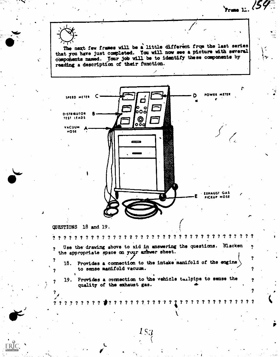
4
II
The next few frames will be a little differint frce the last series
that you have just complted. You mill now see a picture with several
components nammd. Your job will be to identify these components by
reading a descriptiOn of their function.
01511400KTEST LEADS
VACUUM AHost .
POWER METER
EXHAUST GASPICKUP HOSE
QUESTIONS 18 and 19.
? ? ? ? 7 ? ? ? ? ? ? ? ? 7 ? ? ? ? ? 7 ? ? ? ? 7 ? ? ? 7 7 ? 7 ? ?
? Use the drawing above to 'aid in answering the questions. *Blacken
the apprppriate spsce on aAwer sheet.
18. Provides a connection to the intake manifold of the engine
to sense manifold vacuum.I.
? 19. Provides a connection to the vehicle taalpipe to sense thequality of the exhaust gas.
7 7 7 7 7 7 *7 7 7 7 7 7 7 ; 7 7 7 7 7 7 7 7 7 7 7 7
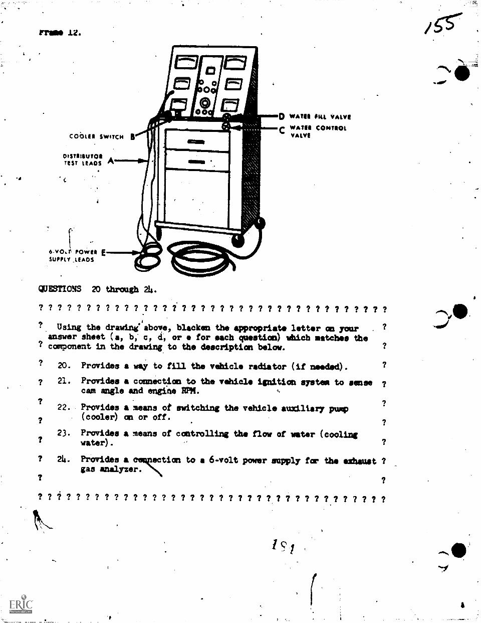
Frig& 1Z.
DISTRIEUTOR ATUT LEADS Pr
6.v0a. POWER ESUPPLY _LEADS
QUESTIONS 20 through 24.
o WATER ILL WAIVEr WATER CONTROL
VALVE
? ? ? ? ? ? ? ? ? ? ? ? ? ? ? ? ? ? ? ? ? ? ? ? ? ? ? ? ? ? ? ? ? ? ? ?A
? Using the drawini above, blacken the appropriate letter an your ?
answer sheet (a, b, c, d, or e for each question) which matches the? component in the drawing to the description below. ?
Provides a way to fill the vehicle radiator (if needed). ?
Provides a connection to the vehicle ignition system to sense ?cam angle and engine RPR.
?Provides a means of switching the vehicle auxiliary pump(cooler) an or off.
?
Provides a means of controlling the flow of water (cooling?
? 20.
? 21.
?22.
?
723.
? 24.
? ? ? ?
water).
Provides a to a 6-volt power supply far the elhaust ?gas analyzer.
?
? ? ? ? ? 7 ? 7 ? ? 7 ? ? ? 7 ? 7 ? ? ? ? ? ? ? ? ?. ? 7 7 ? ? ?
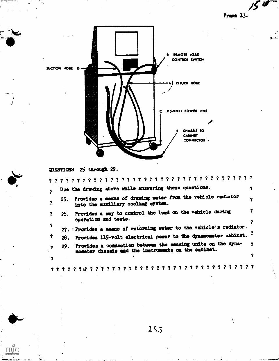
5UCT1ON NOSE D
WW1 LOADCONTROt SWITCH
C 113-11431.T POWER LINII
4ISSTICHS 25 through 29.
.0"
CHASM TOCANNOTCONNECTOR ,
? ? ? ? ? 7 ? ? ? ? ? ? ? 7 ? ? 7 ? ? ? ? ? ? ? ? ? ? ? ? 7 ? ? ? ? ? 7 ?
Doe the drawing above Whil answering these questions.
25. Provides a means of drawing water from the vehicle radiator
into the auxiliary cooling system.
? 26. Provides way to control the load ma the vehicle during
operatics and torts.
27. Alrovides a means of returning water to the vehicle's radiator.
28. Provides 115-volt electrical power to the dynamometer cabinet. a?
? 29. Provides a connection between the sensing units on the dyna-
sweeter Chassis mnd the instrumsts an the cabinet.
155
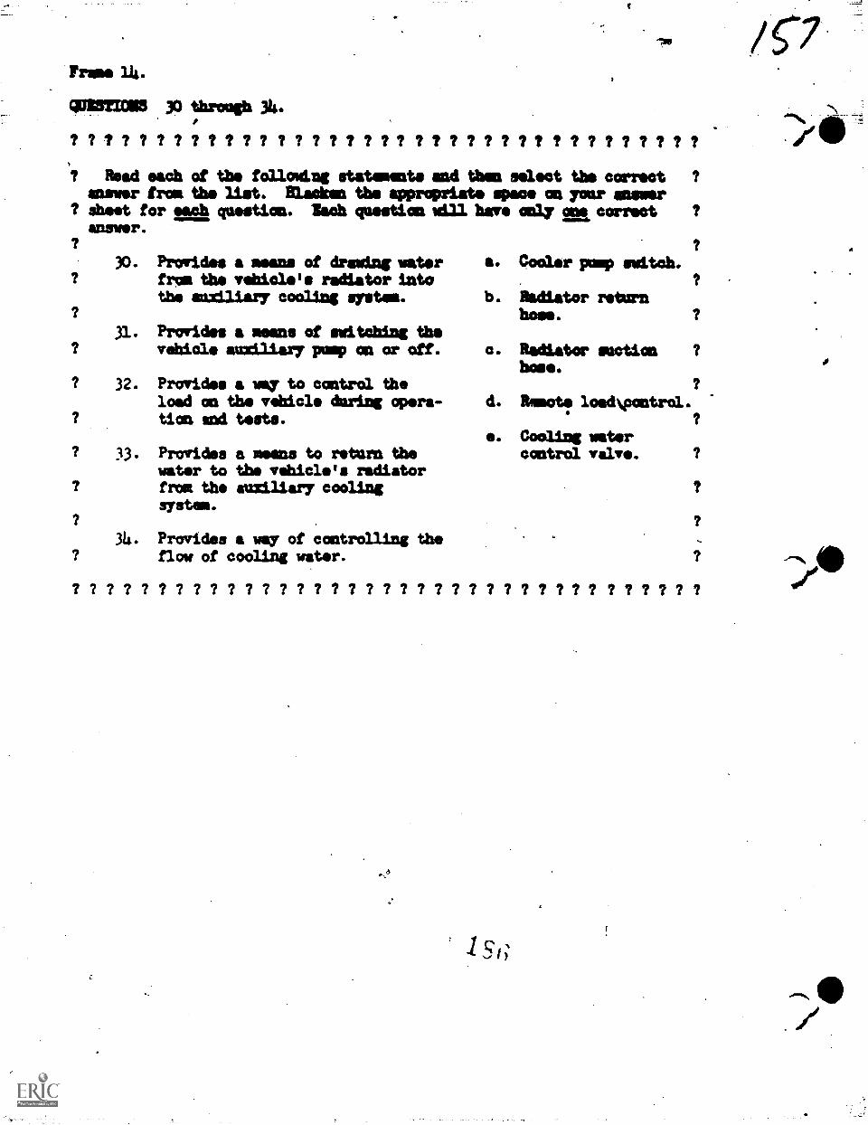
Trams lk.
0113=3115 30 'rough A.
? ? ? ? ? ? ? ? ? ? ? ? ? ? ? ? ? ? ? ? I I ? ? ? ? ? ? ? ? ? ? ? ?
? Read each of the followl.ng statements and then select the correctanswer from the list. Blacken the appropriate spece on your answer
? &set for each question. Inch questions= have clay one correctanswer.
30. Provides a means of drawing waterfrom the vehicle's radiator intothe auxiliary cooling gystem.
Provides a means of switching thevehicle ausatary pump on or off.
? 32. Provides a way to control theload on the vehicle during opera-
? tion sold tests.
33. Provides a means to return thewater to the vehicle's radiatorfraa the auxiliary coolingsystem.
34. Provides a 'my of controlling theflow of cooling water.
? ? ? ? ? ? ? ? ? ? ? ? ? ? ? ? ? ? ? ? ? ?
Cooler pump switch.
Radiator returnhose.
Radiator suction ?
hose.
&mote loadvontrol.
Cooling watercontrol valve.
? ? ? ? ? ? ? ? ? ? ? ? ? ?
1 s
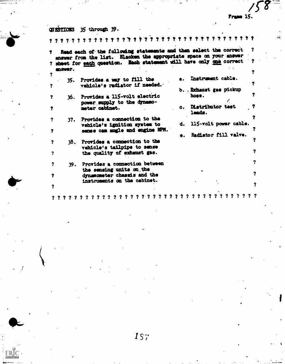
amor
/
'WliTIONS 35 through 39.
/S7?rams 15.
ttttttttlttaftt/tt -1 'i ttttttt ttttttttttt
Read each of-the following statements and then select the correa ?
answer !math. list. Blacken the appropriate space an your answer
? *set for es question. ladh statemestwal have on.ly col correct ?
35. Provides a way to fill thevehicle's radiator if needed.-
? 36. Provides a 115-volt electricpower.empay to the dynamo-
? meter cabinet.
7 37. Provides a connection to thevehicle's ignition system tosense cam mai and engine RPM.
38. Provides a connection to thevehicle's tailpipe to sent*the quality of exhaust gas.
39. Provides a connection betweentho sensing units m.0*dynamometer chassis and theinstruments on the cabinet.
a. Instrument cable.
b. tit:0:1unit gas pickup
hose.
c. Distributor testleads.
d. 115-volt power cable.
. Radiator fill valve.
? ? ? ? ? ? ? ? 7 ? ? ? ? ? ? ? ? ? 7 ? ? ? ? ? ? ? ? ? ? ? ? ? ? ? ?
p.
157
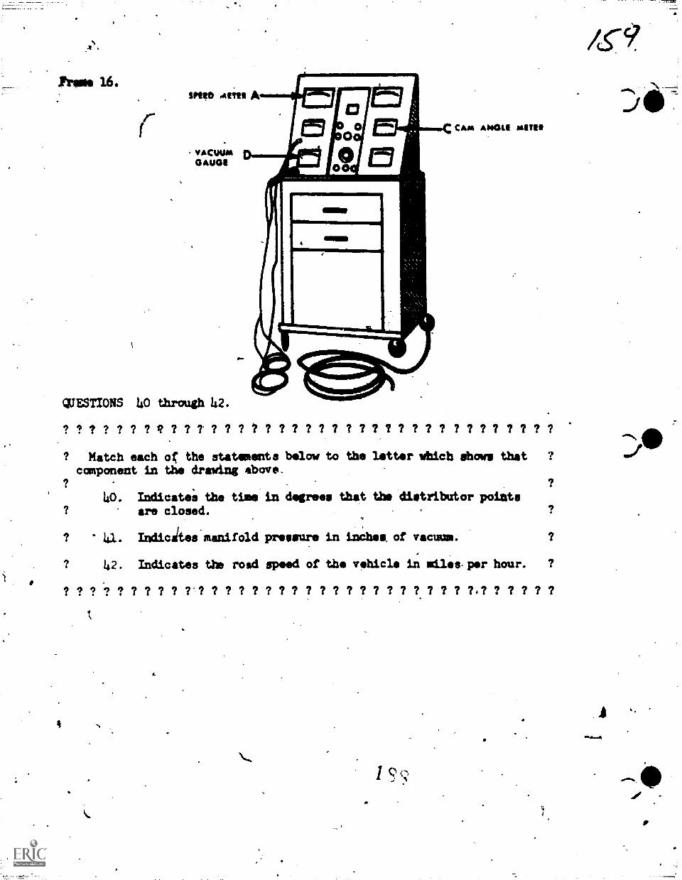
1Prio 16.SKID t4111 A
.VACOOM DGAUGE
QUESTIONS 40 through 42.
CAM ANGLI MITU
? ? ? ? ? ? ? ? ? ?' ? ? ? ? ? ? ? ? ? ? 7 ? ? ? 7 ? ? ? ? ? 7 ? 7 ? 7 ?
? Match each oC the statements below to the letter wbich dhows that ?
component in the drawing above.
40. Indicatea the time in degrees that the distributor pointsare closed.
I 41. Indicates manifold pressure in inches. of vacuum.
42. Indicates the road speed of the vehicle in miles-per hour. ?
? ? '6? ? ? ? ? ? Er? ? ? ? 7 ? 7 ? ? ? 7 7 ? ? ? ? ? ? ? ? 7.? ? 7 ? ? ?
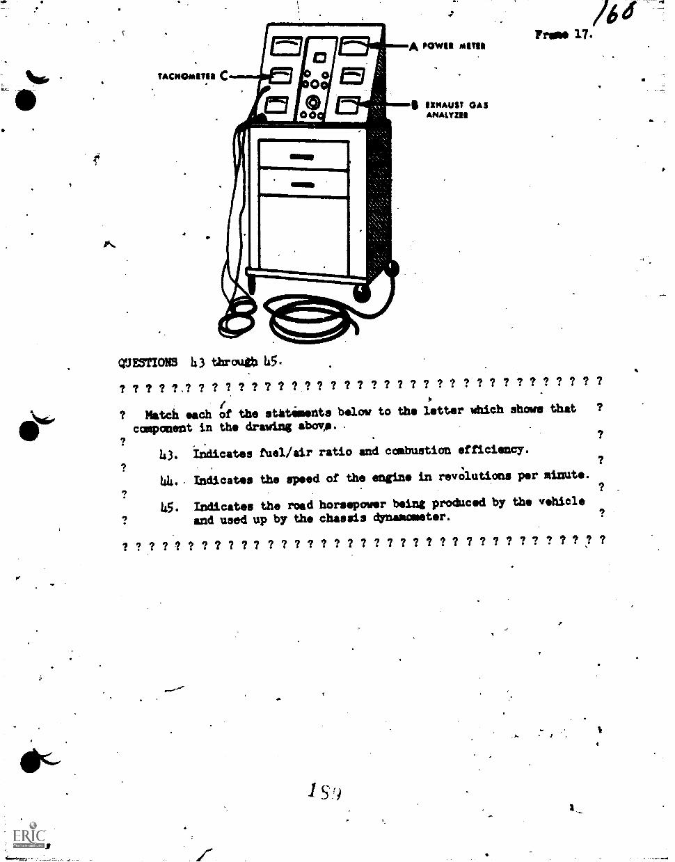
SO, ?ACM/AMA C
A POWIR AMA
QUESTIONS 43 through 45.
comusT GASANAISZER
Trues 17./6
? ? ? ? ?.? ? ? ? ? ? 7 ? ? ? ? ? ? ? ? ? ? ? ? ? ? ? ? ? ? ? ? ? ? ? ? ?
/ *
A114611? Match each of the statements below to the letter which shows that ?
11/component in the drawing &bolt,. .
? , .
?
43. Indicates fuel/air ratio end combustion efficiency.
44. Indicates the speed of the engine in revolutions per minute.
45. Indicates the road horsepower being produced by the vehicle
and used up by the chassis Onamometer.
? ? ? ? ? ? ? ? ? ? 7 ? ? ? 1 7 ? ? ? ? ? 7 ? ? ? ? ? ? ? 7 7 7 ? ? 7 7
"'".
15')
.
a.
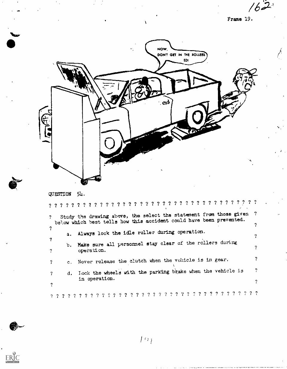
ol/6 4i12,4
Frame 19.
QUESTION 54 .
? ? ? ? ? '? ? ? ? ? ? ? ? ? ? ? ? ? ? ? ? ? ? ? ? ? ? ? ? ? ? ? ? ? ? ?
Study the drawing abeve, the select the statement from those given9
below which best tells how this accident could have been prevented.
a. Always lock the idle roller during operatiom
b. Make uure all personnel stay clear of the rollers during
operatton.
c. Never release the clutch when the vehicle io in gear.
9d. Lock the wheels with the parking brAke when the vehicle is
in operation.
? ? ? ? ? ? ? ? ? ? 7 ? ? ? ? ? ? ? ? ? ? ? ? ? ? ? ? ? ? ? ? ? ? 7 ?
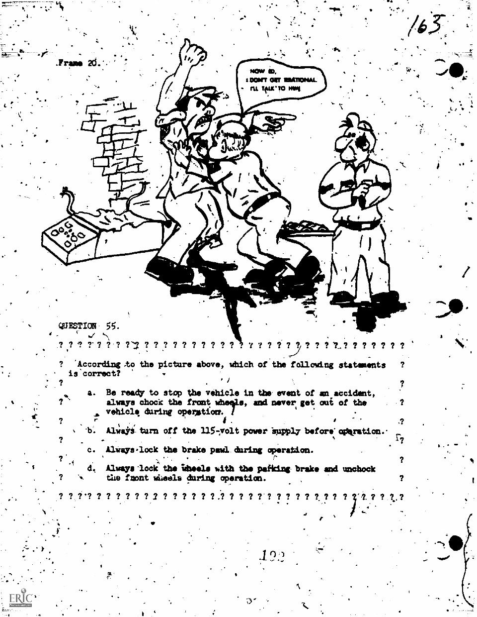
9
QUWTION 55.
? ? 9-1 .;? 97 ? ? ? 7 7 7 ? ? . r ? ? 73 ? ? ? t? ? ? ? ? 7 ?
a
'According-to the picture above, which of the following statementsis'correct? .
? 7a. Be ready to stop the vehicle in the event of an accident,
..
? always chock the front s, and n geever t oui of the . ?
vehicle during operjetiZet-1 .
? r i . I 1, t,. b. Alwaki-turn off the 1157volt power appply before'agAratian.-
? . , 1-7
c. ,Always.lock the brake pawl daring operation. .
?* ?.1
d. AlwAyslockthe iduels with the paiking brake and unchock
,
? '... the fsont wileels luring operation. , ?
,? ? ?'? ? ? ? ? ? ? 2 ? ? ? ? ? ?.? ? ? ? 7'? ? ? ? ? t ? ? ? A ? ? t.?. .
-- '
10
'r
re
I'
DPANDERTIR OPERATION AND TESTS
I r
You hav now`completed PaA I of the Chassis dynamometeeiesson.'
kart II of this lesson will .., the actual operation of a vehidle on
thaOlnamometem.mithADU at the contras. .
.
.
.. ,
.,
If you have been assigned the necessary toOlet: equipment and-
have been directed to use a specific dynamometer. vehicle, you
may prfoceed to the nait frame.-t
,
If you have not been given specific.lnstructions as to what
vehicle and dynamometer to uat, pONSULT TOUR IrTRUCTOR NOW.
. ,
0
4.
f
.
. I.4
4
t
64
-441a;;".-
0
L.
mow
t'
a.
C.
Frame. 21.
INSTRUCTIONS
4
U.
Part r/ ofthis lesson is designed to direct you tlirough_saah andevery phase of the chassis dynamometer oPeration'except,thi.opeiation,of the flyWheel. You will be required to.perform certain tasks endrecord several readings as taken frog the dynamometer indicators.
LOne very important thing to remekber in this part of the lesson ipto read EACH WORD VERY CAREFULLY. Each frame hgs been designedlin'such a woas to let you proceed systesmildcally-thrdugh each task.andtest. DO-NOT accomplish FT/ task that is not specifically called forin the Mae. To do so would only jepordise your own safety 'and the'safety of others in the shop atpa.
4There will be two students assigneCto this project. It. ip 841
gested that one-student-operate the vehicle'while the.other assistsand observes.. A. soon'as all tests hve been,completed -by the first-student then you may switch positions.
There is not a full-time instructor stUnding by your side duringthese tests. However, in instructor who is a technical expert.isavailable for your. use. A good polictto establish for yourself is"IF YOU ARE NOT SURE, CONSULT AN INSTRUCTORte
-
',Complete ONE stpp at a time. Read each word carefulIy. Take yourtime.
You may now proceed to Frame 22, Step 1.
- 4
1
..$
,
.=,=.....
a.
- 4
2
5
et
,IPtmme
No
Before;Litempting to cpst the dynamaneto'r oi the vehicle, there
are a few.things that,sust b. takei
DO THE ITILLINING THINGS.. A
let - Check the 'crankcase oil level ititherveihicle. If the qil
wleTel ii oksy, go on with the other tiski listed in this
stOp.. If the oil level is LW, consult an instructor.
2nd - Check the'coolant level in the *Ohicle,s-rsdistde. Fill it
if necessary.
3rd - Check and regulate the tire pressures.att .
NOTE: Make sure ill of the-above teaks have been completed Woregoing an to the next step.
ADVISORY: Road this satire step before attempting the task.
3!:
You are-nOW ready io place the vehicle an theNdynamometer. 'Inthis
course ofinstruction, the vehicle is always backed onto the dyne-
mometer. "
"Now, á-tart the vehl.cle4and back it onto the dynamometer rollers.
Use =tiros caution. Back the vehicle onto the rollers as straight,
as possible. .*
I 9:5
ft.
Ib
. .1.
%lime
A
its
IMMWMIlimMolMMNMMOIMM1=1/1IMIrOlIMMIMMIMMMMIL 1=11111
1tep 3.
Now, the vehicle must be 'center:8d! on the roller:. That la, tie
rear wheels of the vehicle. muat be tithe awaximato oenter.of the
roller* and at thrksame time, in line with the front wheels.
DO THIS MO: _Place the vehicle in *highs gear and oarefely and
*oar startlha rear wheels to timing. Vhan the M64418 etart to
Inm.theyeill.aline" up iithlthe front wheels. "Drivemrthe vehicle
for a few seconds.. .
. /#.
NCW n. Mame the tranamilhion in *neutral" and4Seve the sign: rmn-O. ----.ning. aet out of the vehicle amd Check the_position at the rear
wheelsa.thsn answer the following qmettion.
QUESTIONL
. ? 7 ? 7 ? ? t? ? ?-?.7 ? ? 7 ? ? ? ? ? dr?.? ?,? 7 ? ? ? ? ? ? ? 1 f-4,? 1.
? Do not record i'our answer. There are no in this part of ?. . .
the lesson which require Iou to write an answer or blacken a space:,
? Just answer the questioh iniour own mind awl do whet the answer says.?..,
? Are the rear wheels in.the approximate center of the dynamovter ?
rollers? .
TES - Good! go on to the next step.
NO 7 Bad! Consult your instructor. Be ;111 assist yap in re-
mgrinethe vehicle from thOrolleis and repoeitioning it. ?
? 7 ?",? ? I ? ? ? 77 V? ? ? ? ? I f ? ? ? ? ? 71:? ? ? ? ? ? I ? ?
*If
7- -
:r
0
. . ., .:\ )' a4p.,
.4. , .. I 1...Connect the lollop 44.11kust vent"t6 the vehicle's tailpipe. :his-
. . ..... , ,. ,
.....will alliiir the snaps exhaust*Pbe vintidpitiside instead of tato
the s#cp,area. , , i .1
...
.. 4.. , 4 '
.MEMmr
Stop
. 411
I.rlb
.4
1.
.4
(44/Trim 'St. -
Stv
Chock the fioni Mheels of the vehicle using the metal 'chocks.
4
Step 6 .
The vehicle is still widline and the transmission is in *neutral."
This means, that the rear mheels mayAole turned.by
:mait Wrn the rear wheels slow4.by MOD and remove all torsi:tin
objects Eros the tire treads. This 0 a safety factor.
4
st:ep
0
Movd the dynamometer cabinet close to the.left frontfender of the
vehicle aid at an angle that mill be easy to nos fram the driver's
spat of the vehicle. -
MOW - Turn the COOLER NTT= to the orr poeitkon. This mit& islocated an the cabin* base.under the meter panels.
197-
r
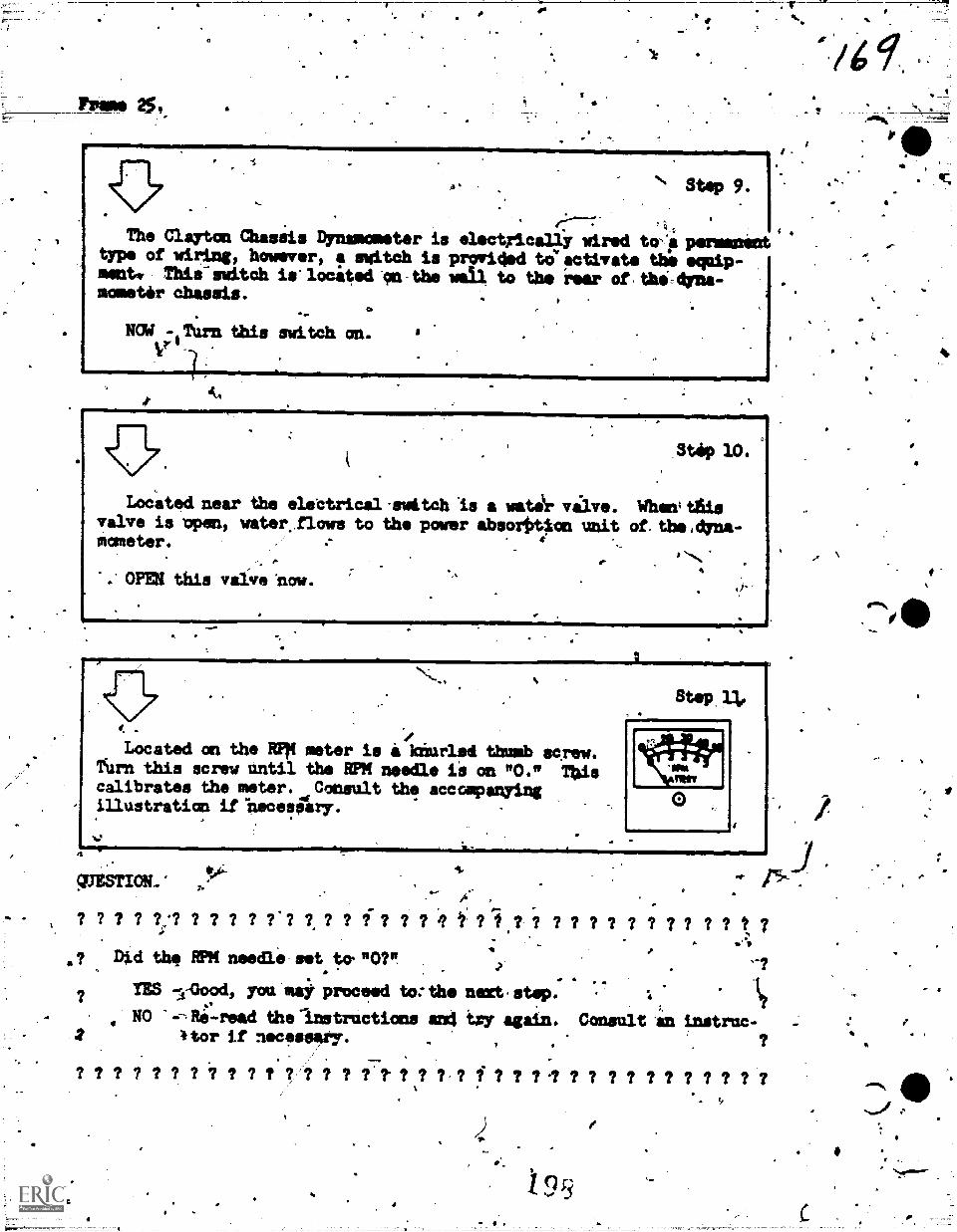
FPO* 259,
1.
7 49t
The Clayton Chasais Dynamometer is electrically wired to4 permanenttype of wiring, however, f switch is prori4ed teactivste the equip-ment' This-switch is'located on-ths wall to the rear ofthecdyna-mometir chassis.
NO4 Turn this switdh on.
a411,MM=mm1111
Located near the elsCtrical'switch is a watagr valve.valve is open, water.flows to the power absorOtpcon unitmameter.
OPEll this valve 'now.
Stip 10.
When; this
of. the ,dyna-
Located on the MI meter is a knurlsd thumb screw.furn this screw Until the RPM needle Li an 1'0." Thiscalibrates the meter. Consult the accompanyingillustratian if itecesAry.
4
WESTION.*.
? ? ? ? ?;? ? ? ? ? ? ? ? ? ? ? t ? ? ? ? ? ? ? 7 7 I t 7
VA-
T.
1.
Step 13e
.? Did the RPM needle set to."07".r 4
YES li-Oood, you may proceed to:the next.step. 1,
NO -,-,Rilread the-Instructions and try again. Consult an instrac-4tor if necessary.
1
? 7 7 7 7 7 7 7 7 7 7 7 ? ? 7. 7 7 7 f .7 7 7 7 7 7 7 7 7 7 7
4?.
fa
a
,
.
sup 12. ..---
The II= MISR must also be set am,ND." /t °zeroed" ip the
sane Mann** as the RPM meter.
Tara the knurred tha0 screw an the'dwell miter,until the needle,
is resting an ND." Do this now.
#
CIONSTION.
? ? ? ? ? ? ? ? ? ? ? ? ? ? ? ? ? ?I? ? ? ?.? ? ? ? ? ? ? ? ?-? ? ?.?,
? Ts the oviklipmotm;*edle on NO?"
?, TES - Jolly good! Tan know what to do so go on.
? NO limmmost - you goofed. Read Step 12 again. You can do it. ? .
? ? ? ? ? ? ? ? ? ??.? ? ? ? ? ? ?? ? ? ? ?,?..? ? ? ? 2 ? 7 ?
St4 13.
Located between the RPM meter and the dwell meter is a toggle
switdh marked "642" and "24" volt. Determine the battery voltcage
of the vehicle you Are working with and set.the toggle rwUch tio the
position that corresponds with that voltage. .
SZAMPLZ: If your vehicle_has a 12-volt battery, then si!plyyset
the toggle &witch in the "6-12" position.
J
.11
I
Ng.
\..
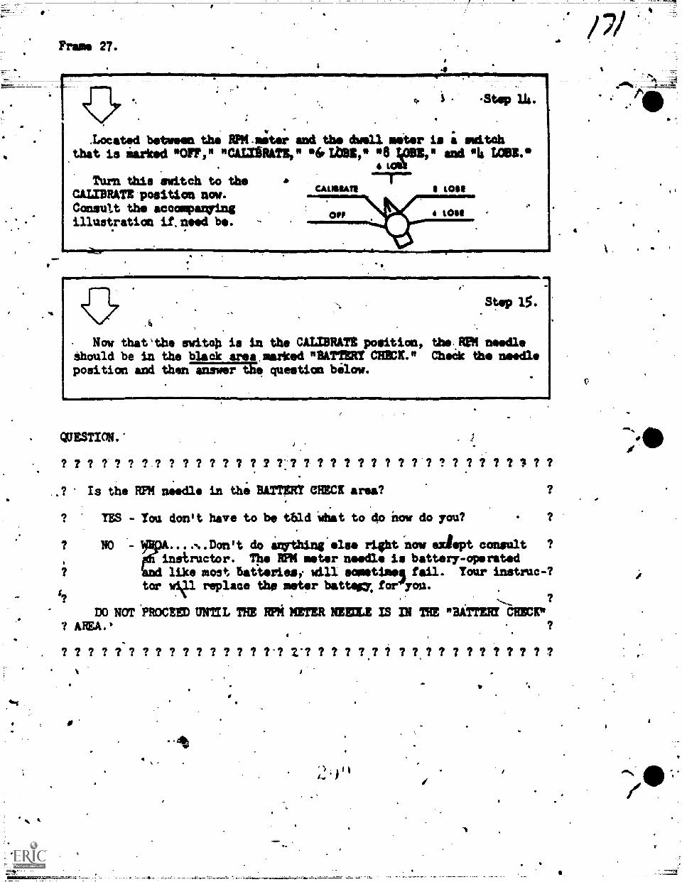
Frame 27.
4a11..mmormarrommareprmisimorpropmaiwomer.~
er.
;
;
-
.Located between tho RPM.meter awl the dwell meter is i switchthat is Marked *omit "CALIBRATE," 04Lbsii,* *8 ;pm* sod 111/ LOBE.°
LOU
.St4p lh.
Turn this switch to theLODI
CALIBRATE position now.Consult the accompanyingillustration if.need be.
S.
_
NOME. =P.
Step 15.
A
Now that'the switoh is in the CALIBRATE position, the EUR needleShould be in the black area,marked "BATTERY CEMCK." Cheek the needleposition and answer question below.
=1.1016
QUESTION.
? ? ? ? ? ? ? ? ? ? ? ? ? 7 ? ? ?: ? ? ? ? ? ? ? ? ? ? ? ? ? ? ? ? 7 7 ? ?
? Is the RPM needle in the BATTERY CHECK area?
YES - You don't have to be tbld What to do now do you?
? NO - Don't do imrthing else right now adept consult ?
instructor. The RPM meter needle is battery-operatedlike most 6a4eriesi will sometimes' fail. Your instruc-?
tor wi4F replace the meter battegy, forgyou.?
no Noi *PROCEED, UNTIL THE RPM METER NEEDLE IS IN THE "BATT= CHECK"
? ? 7 ? ? ? ? ? ? ? ? ? ? ? ?-? V? ? ? ? ? ? ? ? ? ? ? ? ? ? ? ? ? ?
'
V
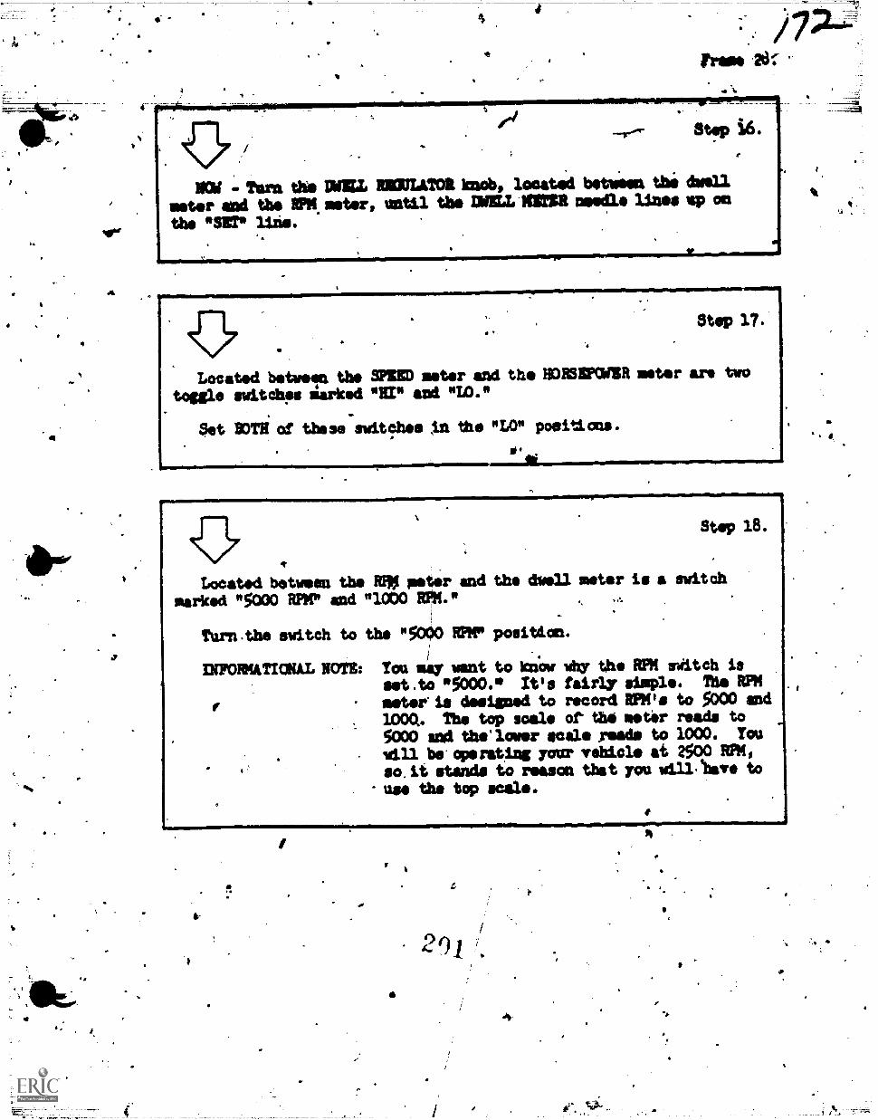
MOW '.-TOrn tits DOLL =WOE knob, lonatd beti 60. the dwell
meter and the IPM.seter, until the INELL MOE needle lines up on
the "SEP line.
..missogiOfisallifilIMORMENNENIUMIII:1111
Step 17.
Located between the SPIED meter and the HORSEPOWER meter are two
toggle switdh's iarked "RI" and "W."
Set Byrn of these switches IA the "LO" poeiticns.
Stop 18.
Located between the mo peter and the (hell meter is a switCh
marked "5000 RPM" and "3.0b0 ROL "
Turn.the switch to the "5000 mir position.
INFORMATIONAL NOTE: You savont to know why the RPM riitch isset ,to 5000.° It's fairly simple. The RPM
f mete/via designed to record RPM's to 5000 andDM. The top scale of the meter reads to5000 and the'lower seal. Toads to 1000. You
.will be' venting your vehicle at 2500 RPM,
. so.it stands to reason that you will.shave to
'use the top scale.
4
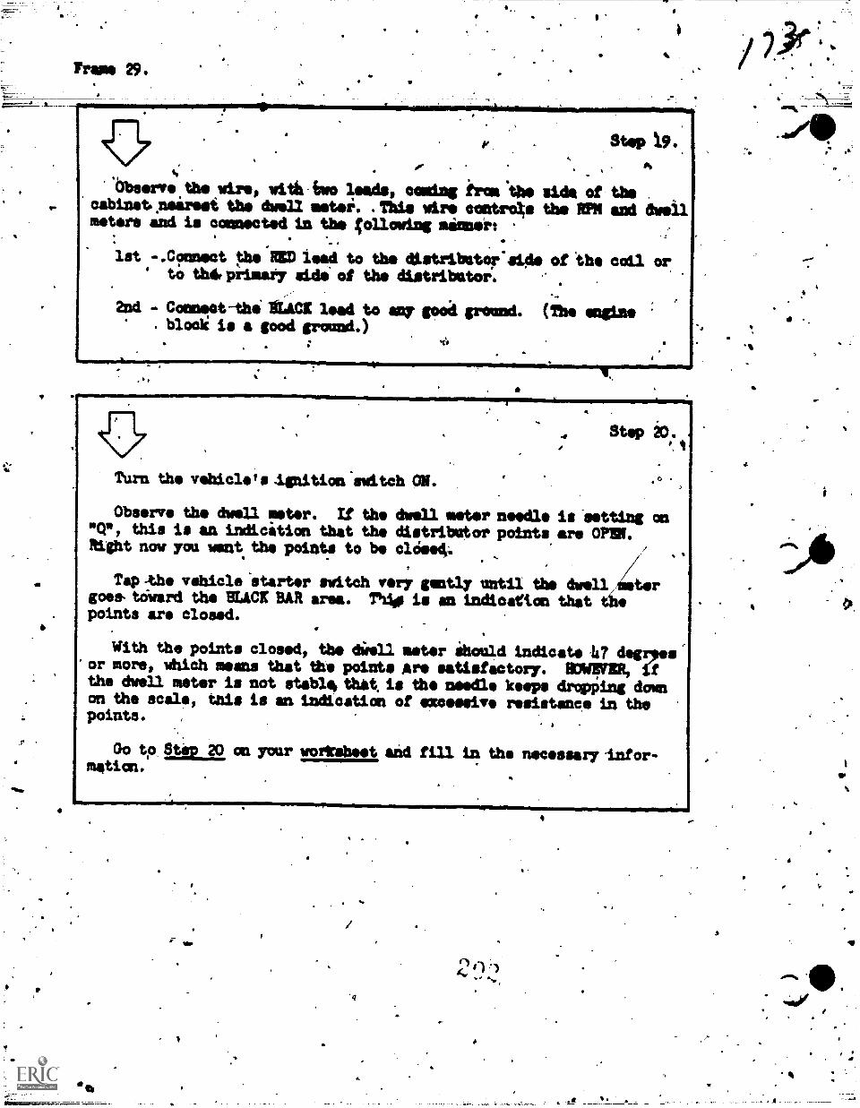
Aar mimmirmilmnimieminsismoimilmimosnr
Prams 29.
Stop i9.
ob.erv e the wire, with two leads, Gaming iron "the side of thecabinetneirest the duel/ metei. .This WOO cantro4s the RPM and awellmeters and is connected in the ;011owing minter:
lst -.C?nnect t.he RID lead to the distribator'side of 'the coil orto that primary side of the distributor:
Ccaneat-thi lien lead to way good ground. (The engineblock is a good ground.)
. ..mem41111111MY
; 4
44..i.ml=0/
Turn the vehicle's Ignition switch ON.
Step
Observe the dwell !meter. If the dwell meter needle is -setting on"Cr, this is an indication that the distribator points are OM.Right now you want. the points to be clOse4;
Tap -the vehicle 'starter switch very gently until the dwell,tergoes, to-ward the BUCK BAR area. Thile is an indication that thepoints are closed.
With the points closed, the 4:iron meter ihould indicate .147 degeor more, which means that the points Are satisfactory. 117.11FER,the dwell meter is not stable, that is the needle keeps &typing doleon the scale, this is an indication of excessive resistance in thepoints. ,
Go to atop 20, on your worksheet and fill in the necessary -infor-msticn.
4114
4
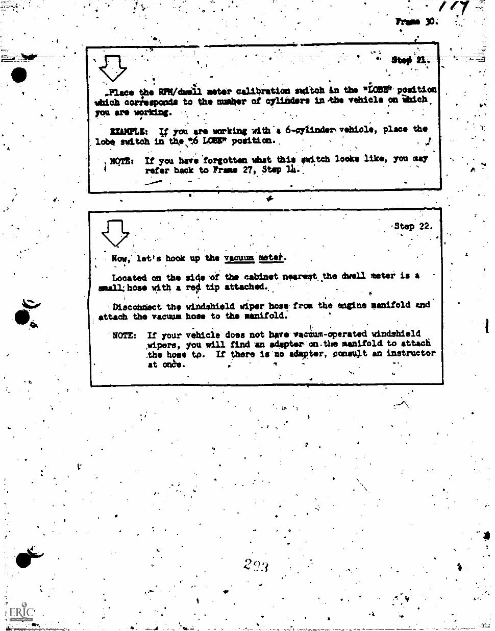
4
.Place the WPM/dwill meter calibration switch in the Wiper position
which corilesponde to the number of cylinders UV), vehicle on %lob
you are wrking. C, .
EINKPLI4 you are working with^a 6-cylinderivehicle, place the
lobe switch tn the,t6 LOOP position. .
.
llem: If you have forgotten what this switch looks like, you ear
refer badk to Frame 27, Step 14-. A
f-Step 22.
,
Now,' let's hook up the vacuum motet..
Located on the sicie.of the cabinet nearest,the dwell meter is a
snail ; hose with a re$1 tip attached..
f
AM.scanUect the windshield wiper betatron the engine aanifold andattadh the vacuum hose to the manifold:
,
NOTE: If your vehicle does not bave.vacuum-operated windshieldApers, you will find .an adgptsr eft-the manifold to attach
the hose to. If there is'uo adapter, consult an instructorat ones. *a
tol
V
I
lIP
1.7.1 ,
.11
0
11
4
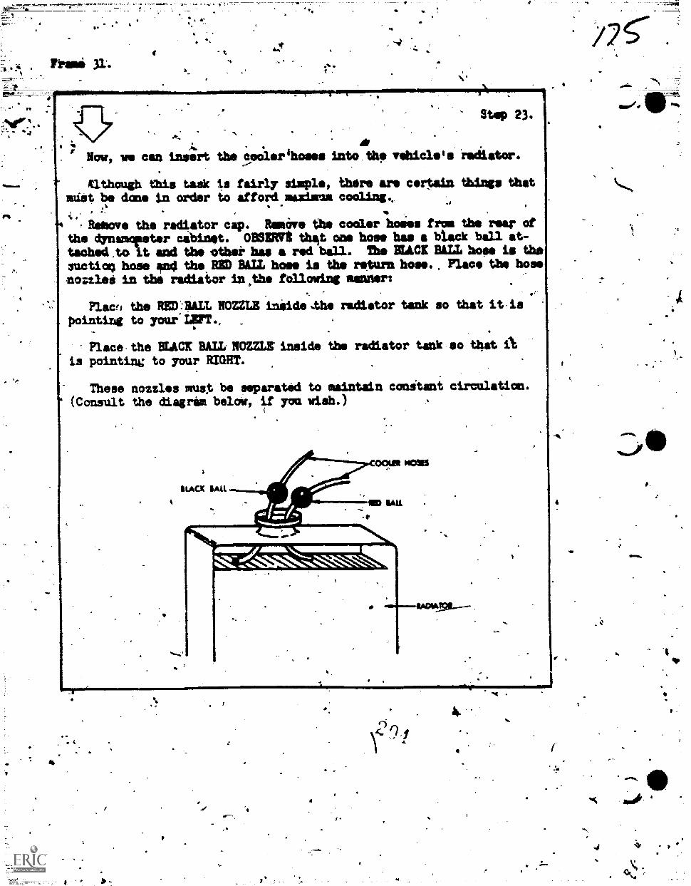
nazi 31-
Step 23.
Mow, we can inser t the ..4,14.erlsoses into the riadidoor.
Xlthough tilts tot* is fairly staple, there are certain tnings thatmilt be done tn order to afford maxima caviling,
,Relmove the radiator cap. RomOve the cooler holies from the roar of
tached.to t sad the *that. has a red baIl. The BLACK BILL hos* is thesuctiog hose an4 the RSD BALL hose is the return hose. Place the hose
moztled in the radiator in.thi following wiremort
the dynamciteter cabinet. Man tht one hose has a black ball at-
Flaws the RED:BALL BOMB Iniide.the radiator tank so that it,is
,
pointing to yourIFT, ,
Place,the BLACK BALL 1F3Mtinside the radiator tank so that Ais pointing to your MGM.
These nozzles alue, be separated to maintain conitant circulation.(Consult the diagram below, if you wish.)
ti.Acx 'ALL
if00124 MOUS
voinMW laralMOVI .141m1W.
4
r
4v
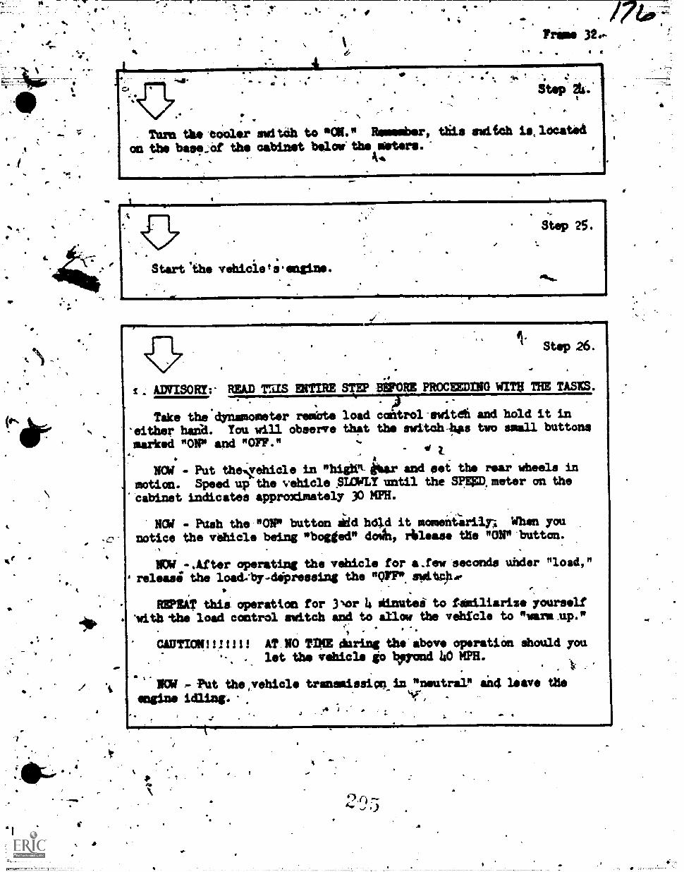
r
4.
re
4.A
Tram 320-
4111m1MEMMIMI1111.
Turn the eooler suit& to *ON." Remember, this switch is,located
an the base_Of the cabinet bolos' the rooters.'. 10.
111411rsmm...ImarrrprEr7rIr=malmOmmEP
.t
. ANISORY:- READ Tras EtiTIRE STEP
Take the dynamometer rembte load'either hada. You will observe thatmarked "ONP and "OFF."
Step 26.
BEFORE PROCEEDING WITH THE TASKS:,;,)
catitrol-ewitefi and hold it in
the switchs two small buttons
EM - Put thelehicle in "high" ibex and psi the rear wheels in
motion. Speedup the vehicle AMU' until the SpEED.meter an the
'cabinet indicates approximately NICER.
NOd - Push the "ONP button akd hold it momentiriln When younotice the vehicle being "bogged" dowlt, Alias. the "ON"'button.
NOW -.After operating the vehicle for a.few seconds under "load,"releaai the loadAvAigreesing the "OFF*.switc)he
REPEAT this operation for 3Nor 4 siinutei to familiarize yourself'with 'the load control switch and to slim the vehicle to "warm.up."
1
CAUTION:WI!! AT.NO TIME during the'above operatiOn should you. let the vehicle go Wand 40 MPH.
.. .
NUd , 'rut the,vehicle tranamissicakin "neutral" and leave the
*wine .
I.
'10.1M1
1.4
-a
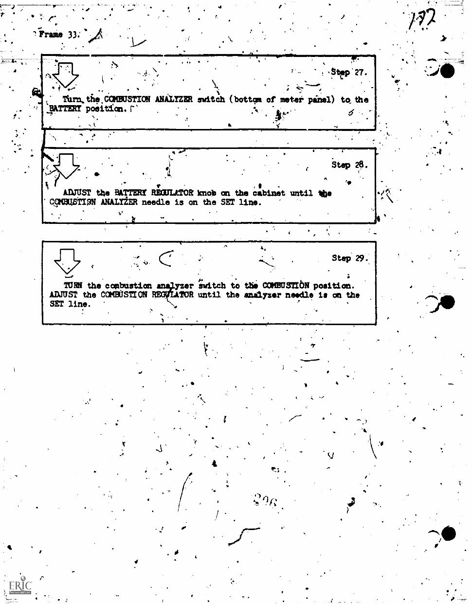
= e-
"!irrarae 33
I .f
:\>
. .. \.
i
..-..... s =ts 1.s
, ..
'rum the CCKBUSTION ANALYZER switch (bottom of meter pinel) to_ theUTTERS position. r% .
.4.
... .
511'.,, d
27.
=mrkTURN the ccebustion
ADJUST the COMBUSTIONSET line.
Step 29.
yzer 4;witch to the COPIBUSTI6N position.TOR until the analyzer needle is an the"{)t'
44.
14-
".;
)4
.
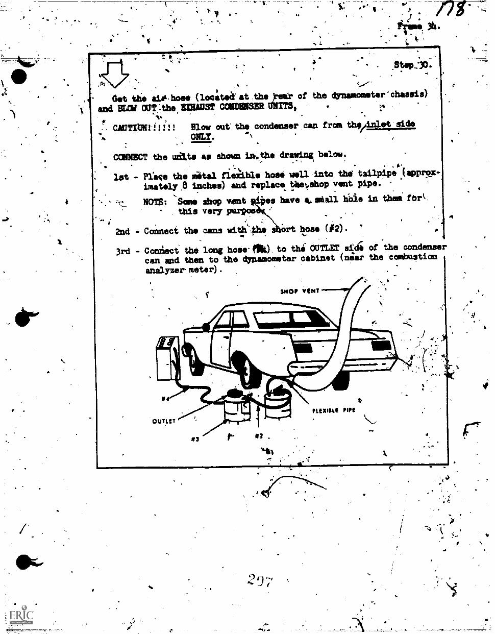
a
0 1
e
immosSImmamprisprioill.smnimmumwssmossmosins+:
4
Nit the at0-hose (locateaat.thel!!!! of the dynamometer'
and BLOW OTT4,he BISON COMM= uwiTst.
- CAUTIOVil", Blow out the condenser.can from thvinlet'side
. ONLY. '°,
chassis)
'
CCM= the udtts as shown in.the drawing below.
lst Plice the mital flexible hose well-into the tailpipe (approx..
imattly,8 inches) and replace, thon..shop vent pipe.'
5 .7%. NOM Some shop vent pes have &alien h'bie in them fbr
this very purpos
2nd - Connect the cans wity.phe
,
Ort hose (#2).
3rd - Coniect the long hose.elk) to thi OUTLET sidi of the condenser
can and then to the dynamometer cabinet (near the combustion
analyzer meter).
stoop VINT
Or
4
PLEXIIILE PIPE
OUTLET
9
't
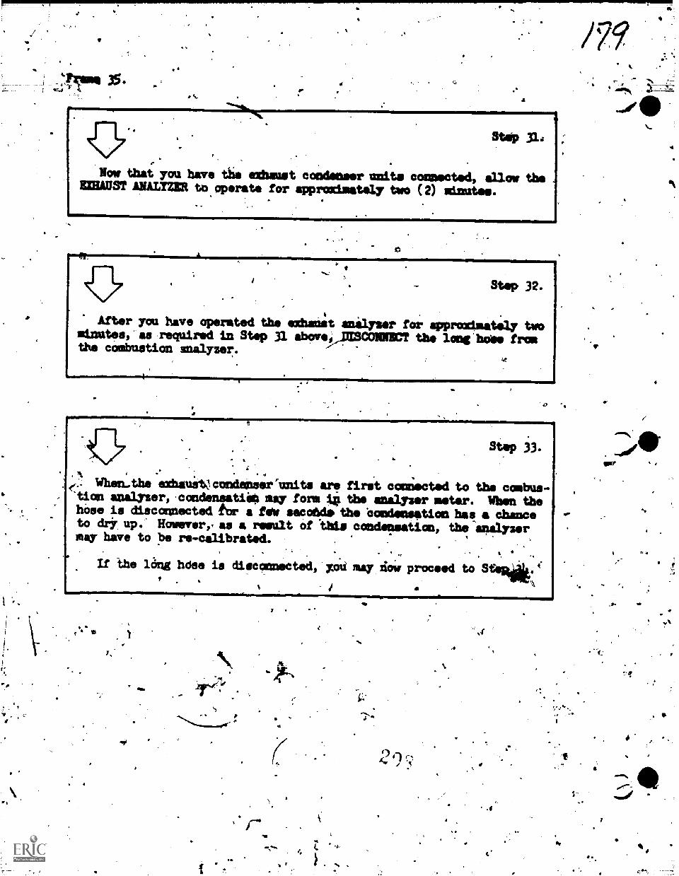
1
'Prase 35.S.
.4
/79
Now thai you have tiie etbaust condenser tmi.ts connected, allow theEXHAUST ANALYZER to operate for approximatAy two (2) minutes.
# *
Step 32.
After you have operated the exhaul4 anilyser for approximately twosinutes,'as required in Step 31 abov,,,pM3CONNECT the loag he'. fromthe combustion analyzer.
tStep 33.
) 4. When...the exhauiVcondenser'nnits are first connected to the conbus-eiion ana1yzer,.condensatii0 say form 4 the anilyzer meter. When thehose is disconnected for a few secoNde the Condensation has a chanceto (14 up.' However,, as a resdlt of "thls condensation, the-apilyzermay have to pe re-c;librated.
%
If the lang hose is disconnected, xOti may 164 proceed to Stla4ilk.(
S.
'ire/1
...'.%'die
N..
4 "
.3
114
WI"
1*
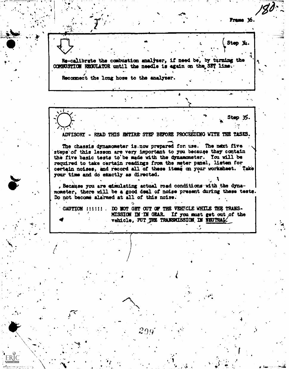
re
I
r
. Frame 36.
sEl"*
4. ytep 314.
-. .. .,
.V 4
V
4 iRe-calibrate the combUstion analtser, if need bi, by tigining the
COMBUSTION REOULATOR until the needle is again on the,SET line:..
Reconne4 tle long hose to the =Armor.
, '1 5
\ s
ev. stsp
ADVISORY - READ THIS ENTIRE-STEP won raomirao win THE TASKS:
The chassis dynamometer ia.now prepaied for: use. The next ftve.'stepi\of this lesson are very important to you because they contain `
the five basic tests to'be made with the dynamometer. You will berequired to take certal.n readings from the meter panel, listen forcertain noises, and record all of these itemi on your worksheet. 'Takeyour time and do eiractly as directed.
4
Eleca,\Ise you are eiMulating actuel road conditions-with the dyne--mometer, there will be a'good deal of nois present daring these testaDo nOt become alirmed at all of this noise;
CAUTION HIM . DO WIT GET cm or THE VER7CLE WHILE Tq TRANS-,
4MISSION IN IN GEAR. If you must get out f thevehicle, PUT3HE TRANSMISSIONIN NEU
4
Sb
.
4
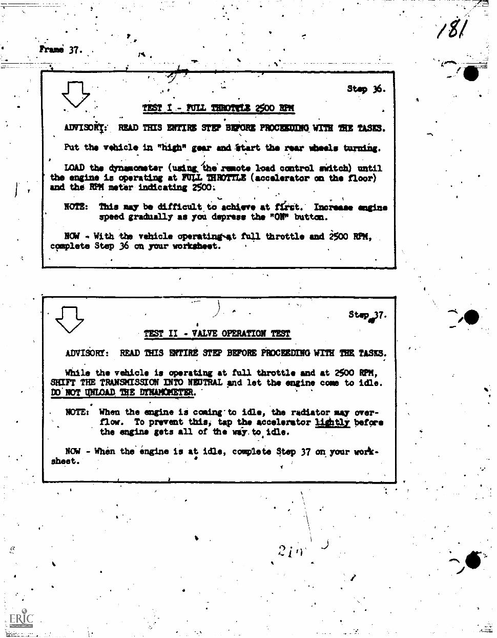
Frani 37. .
I
. . TEST I - rum =mks *Do RPM
ADVISORTe READ THIS ENTIRE sminion PAXECZNOW"Tra TRE TASKS.,
Put the vehicle in "high" gear and irt:.art the rear limas turn:Lag.
Step 36.
LOAD the dynamometer (using, the remote load control hitch) untilthe engine ia operating at FULL THROTTLE (accelerator on the floor)and the RPM meter indicating 2500:
NOTE: This may be difficult.to achieve at ffetit.- lacrosse enginespeed gradually as you depress the "ON" button.
NOd . With the vehicle operatingsaat full throttle and 2500 RPM,complete Step 36 on your worksheet. .
111t
miorummirmmmorawritommimtatimmumonowlmalmmmmI*
,)4
TEST II -VALVE OPMATION TEST
ADVIgORY: READ THIS ENTIRE STEP BEFORE PRXEEDING lent THE TASKS.
Step.37.
While the vehicle is operating at full throttle and at 2500 RPM,SHIFT THE TRANSMISSION INTO NEUTRAL and let the engine come to idle.DO'NOTOLOADIREMNAMern-
NOTE: When the engine 16 comincto idle, the radiator mmy over-flow. To prevent this, tap the accelerator 1igt1y beforethe engine gets all of the wii.toiidle.
EN -When the-ingine is at idle, complete §tep 37 cork your work-..
sheet.
z
L
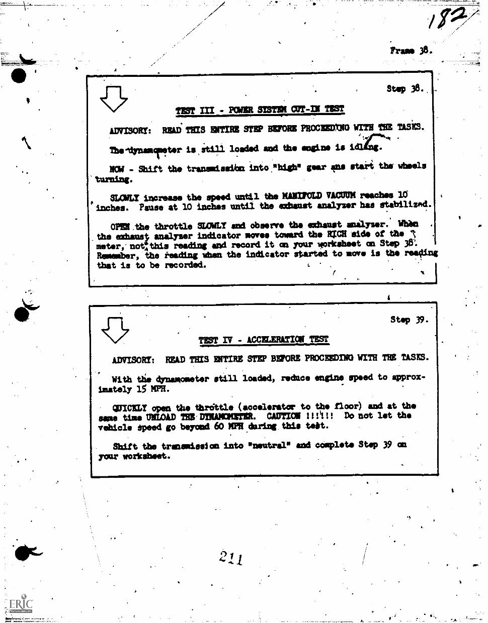
_A
40-
Frees 38.
TEST III - POWER SISTER CUT-IN TEST
ArmisoRr: Rini TEES ENTIRE STEP BEFORE PROCEEDXN0 WITH THE USES.
Thellimmurter is stifl loaded and the engine is
NOW - Shift the transmissibn into."high" gear 4ns staii the wheels
'turning.
stow increase the speed until the MANIFOLD VACUUM reaches 10
'inches. Pause at 10 indhes until the (*Must analyzer has stibilizad.
OPEN Abe throttle SLOWLY and Observe the exhaust anilyser: Whin
_the exhau0 analyser indicator *CVOS toward the RrCR side of the .
meter.not:this reading and record it an your worksheet an Step 36:
Remember, the reading When the indicator started to move is the reacting
that is to be recorded.
Step 38..
TEST IV - ACCELERATION TEST
ADVISOR!: READ THIS ENTIRE STEP BEFORE PROCEEDING WITH TRE TASKS.
With the dynamometer still loaded, reduce engine speed to approx-
imately 15 NPR.
QUICKLY open the thratle (accelerator to the floor) and at the
same time MOLD TRE'DTRAMCKETER. CAUTION Milt Do not let the
vehicle speed go beyond 60 MPH .during tbie tebt.
Shift the transmission into "neutral" and complete Step 39 an
your workaheet.
Step 39.
I
a
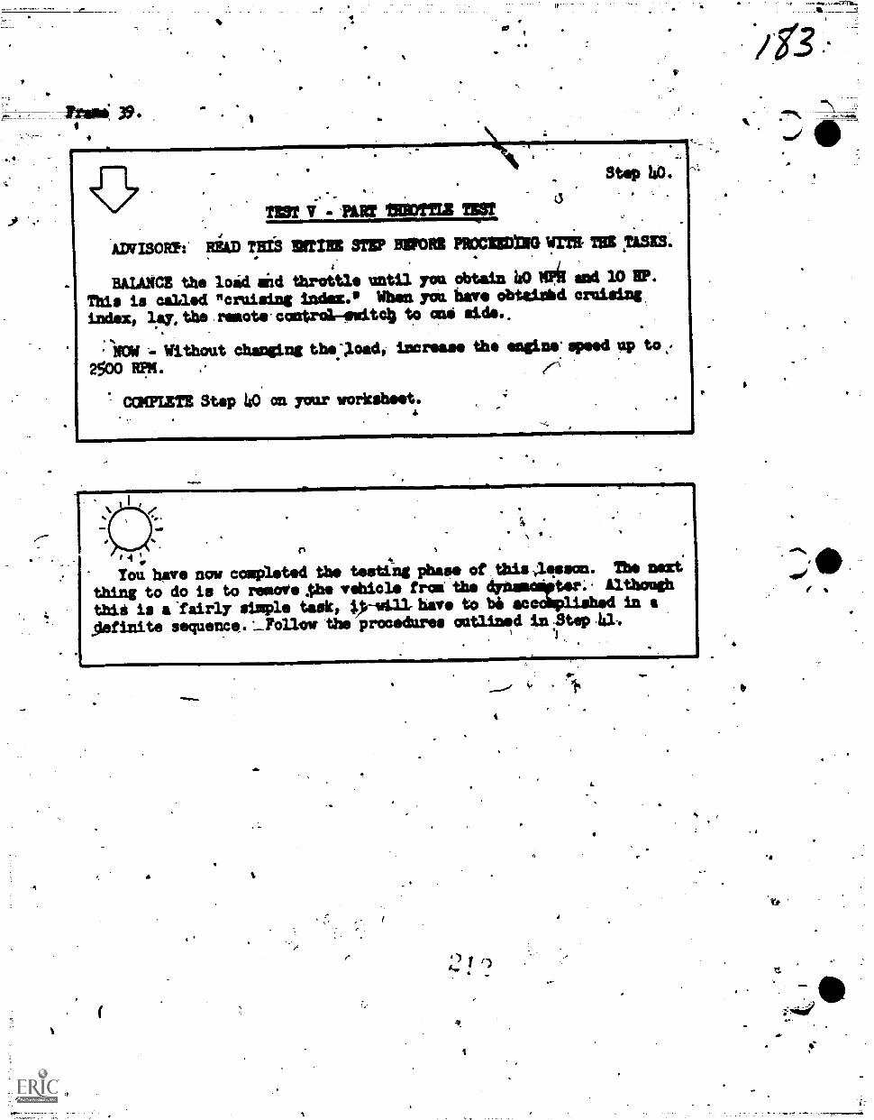
3g.
Step 40.
TEM 9.- PART TiOTTIZ nor,
Ammar,: READ ?ma NV MORI PROCIEDM TB *SKS.0,
HALA.NCE the load aid throttle until you obtain 40 11P,111 and 10 HP.This is called "cruising indes. When yot have obtaishd cruising,index, lay, the remote- control-ewitc4 to and side..
NCM -- Without changing the."Xoad, increase the engine speed up tot.2500 RM.
7 cam= Step 40 on your worksheet.
41-$
4_
5
Tou have now completed the testing phase of this -.;11sson. The nexthing to do is to remove As vehicle !rat the ter; Althoughthid is a 'fairly simple task, 1.)-i41.1 have to be au in aslefinite sequence. ____Follow the procedures outlined in Step 41,
' .
_
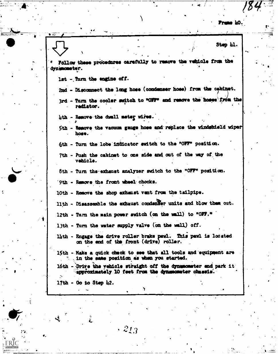
,
Frame 1$0._
r"
stop 41.
Mow these priicednres oarerally to remove the Tibiae from the
'Onamosestr.
1st -.Urn the engine off.
2md - Disconnect the lomg hos (condenser hose) from the cabiTt.
3rd - Tarn the cooler switch to "IOFFP and remove thelmwmpelmme the
radiator.
4th - Remove the dwell meter Akio.'
5th - Remove the vacuum page hose amoireOlace the wimdsbield wipe?
, hose.
6th - Turn the lobe'indicator switch to the "OPT" position.
7th - Push the cabinet to one side and, oat of the way of.thevehicl.
8th - Turn th.exhanst analyzer switch to the "OFF" position.
'9th Remove.the front Wheal chodke.
10th - Remove the Shop etheast vent from the tailpipe.
llth - Diaasesible the ',Mame, conderter units and blow them out.
12th - Tarn the main power switch (on the well) to "OFF.'
13th - Tarn the water sapply valve (on the well) off.
14th - Engage the drive roller brake peal. Thii pawl is locatedaft the end of thk front (drive) roller.
15th - Make a quick Check to eee that all tools amd'eqpipment are. in the same position is when you started.
16th -.:Drive 'the yehicle stiaight off the dimmemswrber mad park it--eppiOaimetoly 10 feet from the dynamotor !hassle:
1
17th - Oo to Stop 42.
E.
2.1.
.
None.
SUP la.
-
Au Oaring this lesson you hada been leading up to a. point limeyou can analyse, vehicle performance end make oertain decisions. Mal-functions, as you learned from the testing phase, &ow up in may'differeht taws in a vehicle.. %cause of this, reason rathe7 than ruleplays the most importint role in the detection of yaw.. maltunc-time. It wad be impossible to Make a rule wording each red everytrouble that could exist in a vehicle. So now it becomes necessary toanalyse a problem and use common sum, accompanied by manufacturertsspecifications, to determbao these areas Of malfunction. -
-
In the.next few from you will be given narratives depictingtroubles .you would.most likely .find in operating a vehicle on thechassis dynamometer. You will be asked questions about the narrative.Analyze the questions carettlly, then, select a correct answer foreach questicn from a gtven group of possible solutions.
Mark your answeve on the same answer sheet as you used with Part Iof this lesson. Begi with answer 56 on the answer sheet.
*
'Eh
1
446-
tr
r
PL1IXX
HOLTSI3 or isc cassia =mem
I.
I
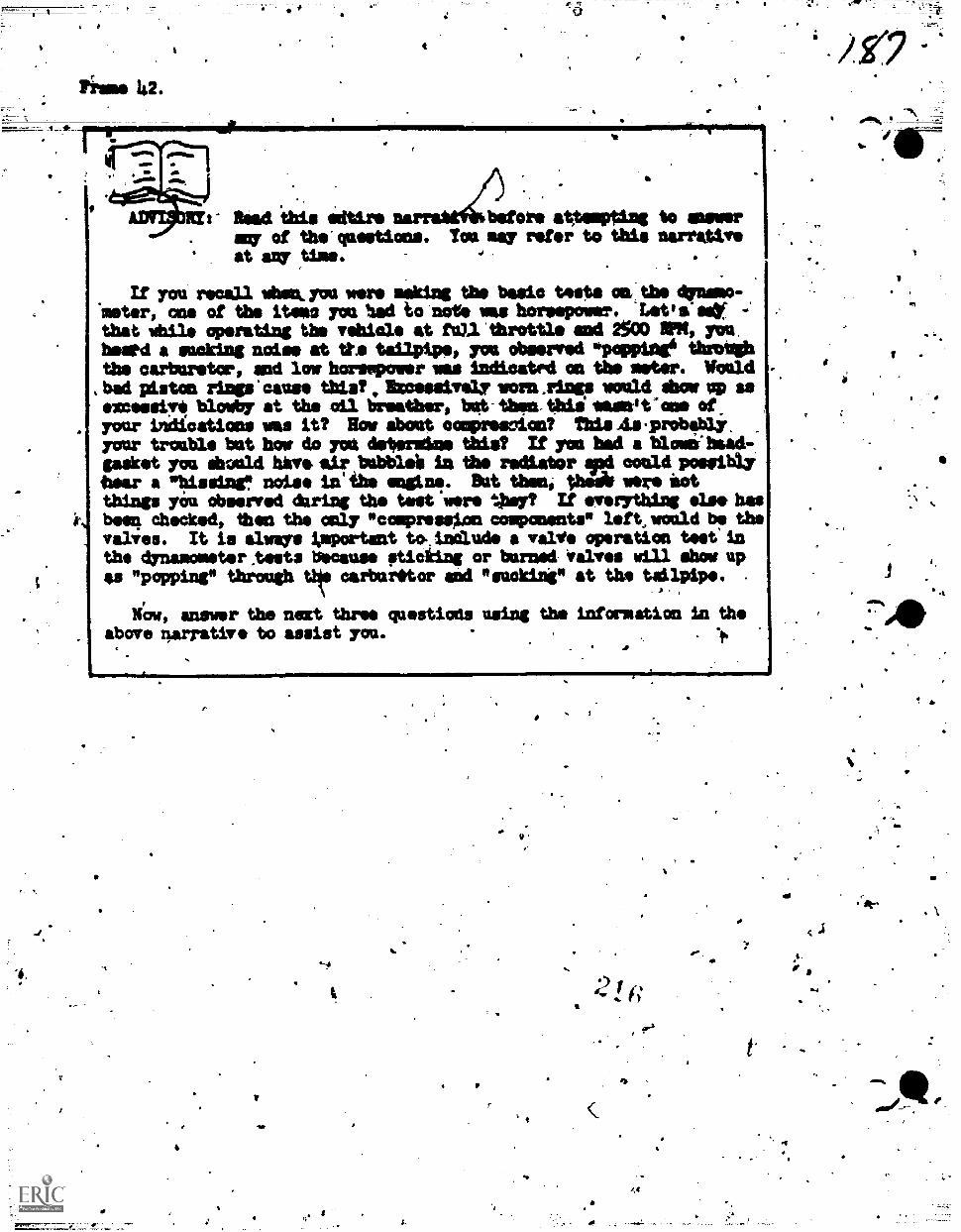
4
Fistae la.
a Riad 'this edtirs before atyosapting to gamersay of the' questions. You nay refer to this narrativeat any 'due.
If you recall, whelk you wars Baking the basic tests onr. the drum-'meter, cue of the items you had to note was horsepower. 'Letta'seYthat while operating the vehicle at full 'throttle and 2500 RPM, you.heatd a sucking noise at tta tailpipe, you observed *poppies, throb*the carburetor, end low horsepower was indicated on the aster. Would
, bad plbston rings'oause this? , Ihcoessively worn.rings would dacar op ssexcessive blowby at the oil breather, bat- than. Wig wasnit'ane of,your indications was it? Row about comprescion? This As.probably.your troable tut how do yol detendine ,WAI? If yen had a hloosi'braad-.gasket you &clad have sir bobblei in the radiator ajod could possiblytear a *hissing" noise in' the man.. But then, the* were lotthings you observed &ring the test were ttary? If everything else hasboort chocked, then the may "conpressXon components" left, would be thevalves. It is allows Josportant to.,inaudo a valV operat.ion test' inthe dynamometer .tests *cause sticking or burned Valves will show upas "popping" through thke carter.tor aid "waking" at the tailpipe. -
. ,
Now, answer the next three westiods using the information la theabove narrative to assist yam.
6
a
9
(
>
S.
O.
I.
4.
-
=WENS 56 *moll 58.. .
4 taiiit? if?..??1?,f1ciiti?.???1?? ? ? ? ??????
.1
? 56. Equal,17 low horsepower an adjacent cylifiders, air bubbles,in , ?
. the -radiator, end an audible hissing' mound' at tlas.amgine would
? 'indicate a *alfunatian in which of ,the following comments? ?
4 a. Intako' valves.
? ). bibmuat valves.
c« Beadeaske.
l ? .
4. Piatot rings. .1r' I sr 14
operating a v al. at the "dynamometer at fU thzottl 7 ,
and 2500 ffig, you had."baakfiring" in tlie ',arbitrator and theAR. 'road horsepower logan't up to spetificatims., What is the most.?.
/
?
7
, ?:
7
?
7
t .
?
s ?
?
probable cause of this?
A . Broke; piston rings. i?
.tr: Blown headgaaket. .a. ?
-, c- r Valves. ..
.
.. ?.k. Carboited rings. ?
58. During,vehicle oporation you' obsrve a good deal of blowby.(Blowby is amoke,aming from the oil breather.) What *had 7
aorpalli.cause 'this?. A 6,1,
. ?
a. Rings. .
N.
-.?
'b. Valives.-,
c. .11eadgaeket.. a,
I. d. NO120 of the abo*C,
0. . ?
?
. f t .
, ti 7* ? 7 ? ? 7 ? 7 ?%?e?.? 7 ? 7 7 ?,? .7 ? 7 ? ? 7 7 ? 7 ? ? ? 7 7 ? ? 7 ?
a
0
41
"'S'
s
a
I
r,
Prime
sP
.4o
-
The ignition' System of. a iehicle ig a very important and criticalsystem. All of the components of:7the ignition system must functionproperly in order to achieve max:imam horsepower. For ample, a mal-function lathe primary ignition systemwouldp4Obably "how up as ahigh speed mis-fire; and a secOndary ignitiodmalfunction would "showup as. a low speed mis-fire. This wOuld be true only if all otherWetassimbd-beenchofted,andltndd satisfactory. Aux, thAnge couldcause a vehicle to be extreeemle*slaggiah." Among these things are_carburetion and-basic tbildnii:.tet!s go back to hbrsepower again. Inthe narrative just prior to this'one, we said that a lack of horn-power conld be cmsed,by-sticking or barned,valves. That is,-if thevohicle is operatint at full throttle amd at 2500 RPM. -But, what ifyol,had a lack of borsepowardRring,auceleretion? This could hi causedby either catturetion or the advance system. So you /tee, a lot ofthings must bs tonsidered before. you commit yourself to an ahalysis oftile problem:
Aniwer the four questions in the next frome using the informationin the above narrative to assist you.
a
7
. Frame 45.
59. The vehicle is extremely sloggish. Carbnretion is satisfac-tory.' What is the problem?
a. .Prisbary ignition.-b. Secondary ignition.
c. Basic' Wain.'
d. Advance system.
O. Whenobservedfactory v
61.
.
fr
orating on the 47namomster -under load, youow horsepower. & compressiad check revealed satis-ves. What is the problem?.
a. Basic ilming.b. Advance system.
c. Primary ignition.I
d. Secandazy ignition.
2
A high speed nis-fire is not Probably caused by a maLfunctian,in which. of these comments?
a. SecandaiT ignition.
b. Primary ignition.c. Basic timing.d. Advance syistem.
62. .A low speed mis-fire indicatles problems in which of-thesecomponents?
a. Secondary ignition.b. Primary igniiimrc. Basic timing.d. Advance spit*.
? ? ? 7 ? ? 1 ? 1 ? ? ? ? 7 ? ? ? ? ? ? 7 ? 1 ? ? ? ? ? ? 7 ? ? ? ? 1 ?
t4
4
Frame 146.
Carbaretimis prdbably.ons orthe worst enemies of vahicleoperators. Operators complain of poor gas mileage, poor ameleration,roagh idle and slaw othmorc.things bat they do notlave a pracedpre tofollow in isolating these problem arena. Nos don't nieuncierstiad.The problems listed abaft are carbaretion malfunctions bat by no mesasare they restricted tw.earbaretion. Let's Consider same prablams.The akhaust gas analyser Shows that you have a-fidh 'datum Tbat is,yoa have too much fuel for the a:omit of eir Yon havkantering thespngine. Maw things oliuss ridh mixtares among them being a cloggedair cleaner. Perhaps @VW & closed or piertli atoned choke could at&cause richness. Always check the,air clamor end °bake, if the 10-tare is ridh, and if you find problems, correct them. If the mixtureleans out after Cleaning the air cleaner Or apeqing the choke, yuahaver found the problem. Bat suppose that your problas is a leen mix-ture. The engine is starring for fool. Could be.that a fdel pumpvolume test is in order or maybe a check for ZUel line restrictions.ait let's look at the vacaam meter for a second or two. ,Sapposi thatyou are operating intall throttle at 2500 N. The.vacaum readingshould be approximately 1 inch but the meter indicates 3 inches ofvacuum. The throttle must be fully open and thiddffloke Pally openif you'ever expect.to attain propei Tacna.
4
So, carbaretion is not eo Ample after all; is it? Ismer thenext three questions. Try not to use the,nerrative again gam youhave to. Think of the question as a test ad the dynamometer and makesone Moral deductions in your mind.
14,
4
4114
I.
-44
4
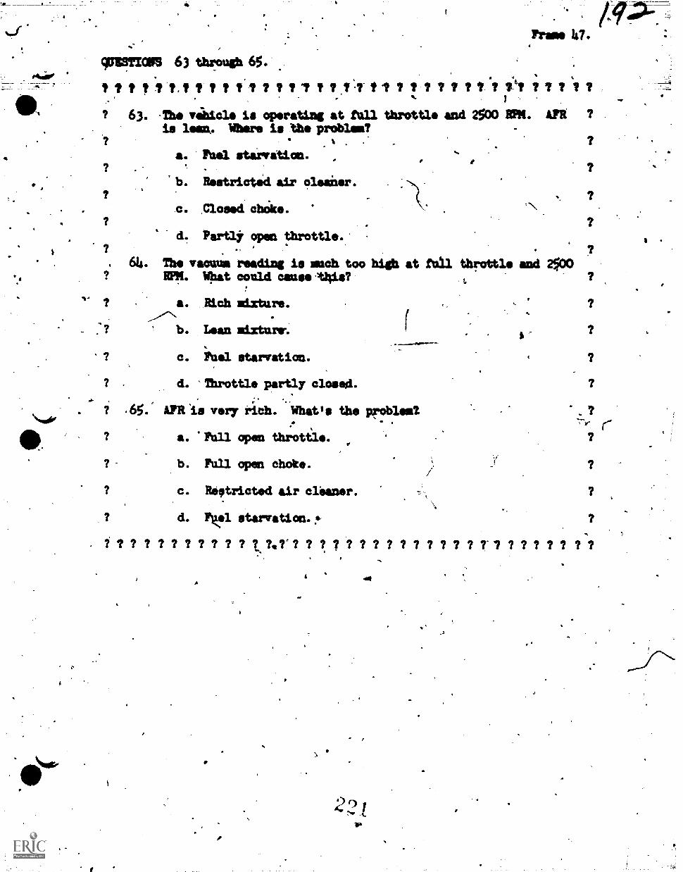
QUESTION 63 through 65.
? t ?.? 1 1 ? ? ? 1 ? / 1 7 tIll ? ? ? 1 ? ? ? 1 ? ? 1 ? ? ?
? 63. -The viiitcle is operating at full throttle and 2500 RPM. AIR ?is I. Where is the problem?
is9?-Frame Ia.
a. 1nel starvation.
b. Restrictik air olesiter.
C. .Closed chitke.
d. Partly open throttle..- ?
. 614. The vacuum reading is mach too high at full throttle and? M. illsat could cause.t4is? ?
a. Rich mixture.
b. Lean mixture-.
? c. Fuel starvation.
d. Throttle partly closed.;
? .65. APR is very rich. What's the problemt , ?-,
? a. Full open throttle. , ?
? b. Pull open choke. ?
? c. Restricted air cleaner. ?
d. Fl Btu-welt:a. !". 7 7 7 7 7 7 7 7 7 7 4(7.7.7 7 7 ? 7 7 7 7 7 7 7 7 7 7 7-7 7 7 7 7 7 7 7
o
2.2
r
.
,
0 r
Frame. 48..Sr.
T.k
Now-are'you'at identifying drivi line noises? Itid *ad knot thatcertain noises,mey travel to other parts of the-drive line and soundlike they are cowing from a certain component whiin actual,' thry.arenit. For example .a soisvtrmisiission may actually souid like agrowling.differentiai. So, it is tmportant that we ,estehlildh-dertaingivund rules to follow while determining drive line noises. Althoughwe do not use thd flyWheel in this lesson Wwould be necessary tohave it_engaged in order to detect certairi. drive' line 'noises. So., we
will build.typical problems and,lust assume that the flytheel isengaged.
While Mng the vehicle-through its gears, you notice, Arsaddiabuildup o NFIK but,you detect'only a alight change in.speed: AI the
dame time, you hear and feel a,"chatter." It is obvious ihat theclutch is faulty. But suppnse the vehicle has 41 howling'or hmmmIngnoise opming.from the Chassis. Naturally, this'noise can DO isolated-
to the transmission or to the Apar axle components. -The easiest and
quickest wit to determine where the noise is-coming fr o. is to have
. another person listen forth* noise while you operate the vehicle.Other than these few. problems.and the distanat popping and snappingsomad of a fruiltf,universa 3oint, not luny other noises lbould beaudible. Again, reason rather than rule will diete.
Let's answer these last three question. nov.
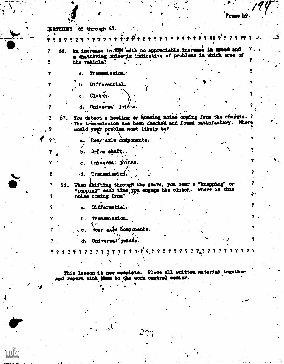
I.
.
_...
=TICE Sigt through 68.,
%-. . . .7 ? it ? ? V? 7 ? ? 7 ? 7 741 ft? ? ? 7 1-1, ? t I tst t t tt,ft 7 7 7? 7
1 66. An inn'rease in4A1601.1Wh no appreciahle=incr'leas in speed and ?. .
a dhattering noiselds lidicativ of problems in whi0b arek of
? ths vel,iicle? - _.,,.?
a. Transmission.'
4b. Differential.
c.
d. Un.tv.ral joizha.
, ?
I.A
?
I r
67. You detect a howling or bunting noise coping from the cbaisis. ?
-The,transmission has been chscked.and found satisfactory. 'Where
would yoe problem most likely be?
? a.,'Rearaxls coapanents.41` A.
b. Drive .shift.,
? ,
c. Universal foints.
0/,d. Tramp:L.1,i
68. When IhiftiOg thro.ug; the gears, you hear a."bnapping" or"popping" each timavyqu engage ths clutch: Where is this
noise coming from? '-
.? a. Differential.a
b. Transmission.
c. Rear alcke tomponsits.
th.
? 4 Universal!joinie.
? 1 ? ? 1 ? ? ? ? 7 I 7 7 ? ? ? ? ? ? 1 7 7 ? ? 1 1 1 ? 7 ? 7 ? ?
Tbis lesson'il now complete. Place all written material togetherrePort with thri to the work °patrol seater.
.al
v,
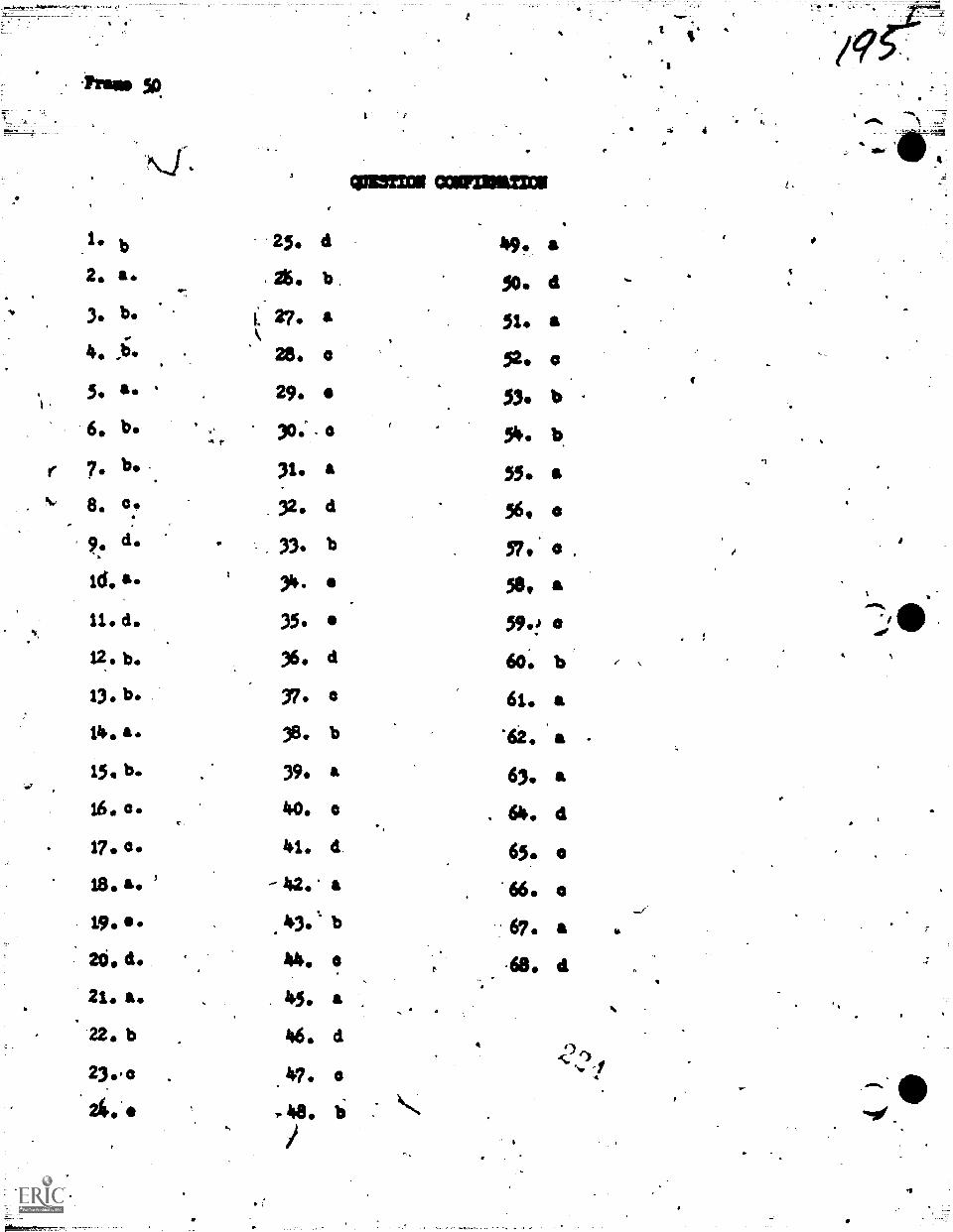
6, b
30.
.
. 26.
1 ..2?\
,28,
29.
,,A r 30;
cowman:a
b , 50. 4a 51. a0 52. a
53. b
r 7. be ,.
N. a 55 a8. 0.. 32. d 56. es,
- 57. .
6.1 4, I
33. b
31+. 3e. a11. cl. 35. 59.!
12. b. 36. d 60. b13. b. 37. a 61. a14. a. 38. b '62. a .
15, b. . 39. a O. a16 . 0 40. a 64. d
c
17. 04. 41. d 65. a
18. a ' - 42. a 66 . 0
19. El 43." b 67. a 4.
a -68. at26, d 44.
21. a. 45.
22. b 46.
23. 47.
24.6
a
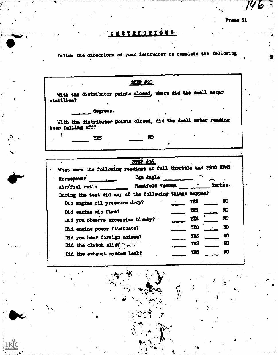
Trams 51
,IILINUALLAILL
Follow the directions of your instructor to complete the following.
=ALWith the distributor points clo.L. Jed idlers did the dwell motor
stabilise?
degrees.
With the.distributor points closed, did the dwell meter reading
keep falling en'
113
alma.What were the following readings at ful/ throttle and 2500
HorsePowi Cal Angle
Air/fuel ratio Manifold irecums Judaic
During the test did agy of the following things happen?
Did engine oil preemie drop?
Did engine mis-fire?
Did you observe excssive bloOby?
Did engine Rower fluctuate?
Did you hear foreiga noises?
Did the clutch
Did the eathaust system leak?.
4ic .-t*
07.),
s
" .
lfr y
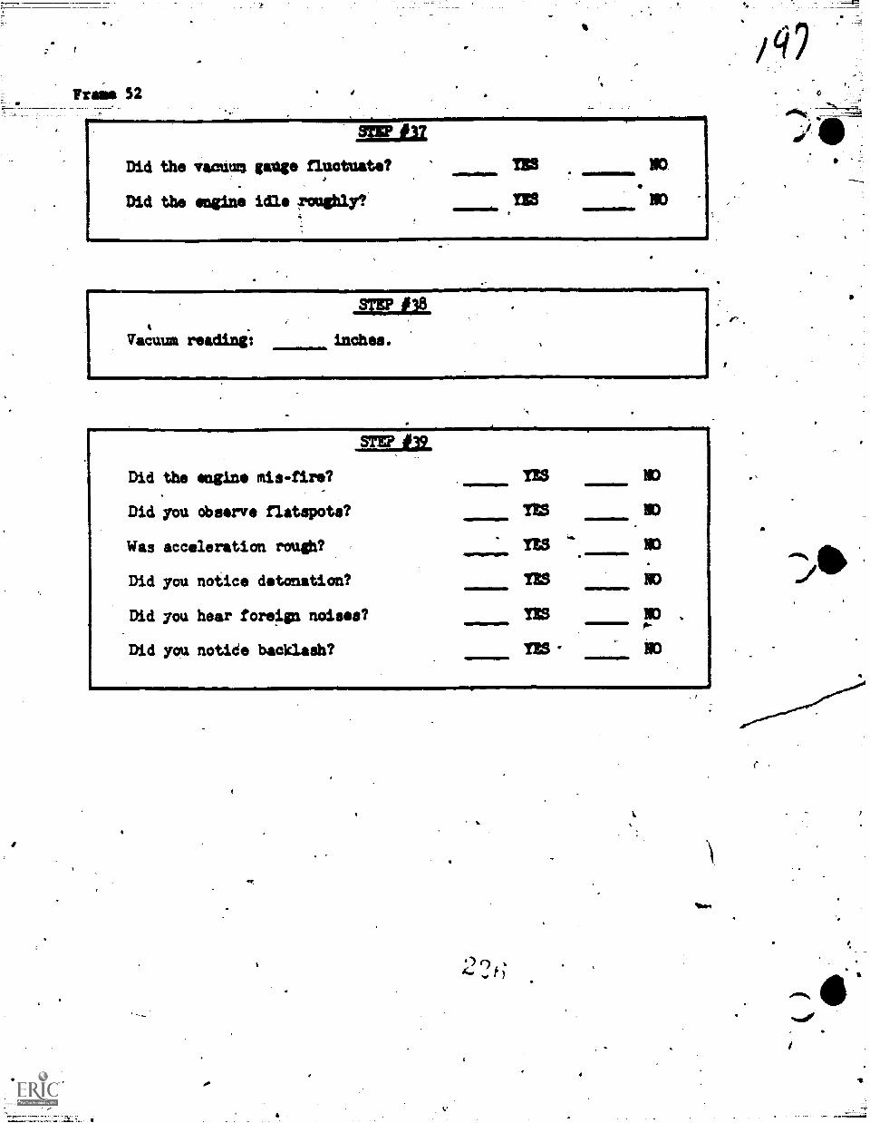
Did the vacumm gauge fluctuate?
Did the engine idle Teue3
Vacuum reading%
.E.PJAST
inches.
Did the engine mis-fire?
Did you observe flatspots?
Was acceleration rough?
Did you notice detonation? NO
Did ym hear foreign noises? IES N3
Did you notide backlash?
Imo*
f
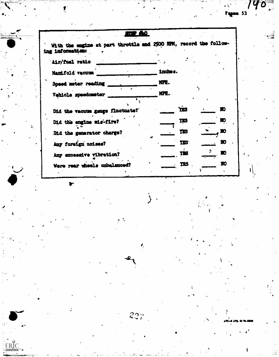
a-
4=OFMon=1=m0=IIWith the =gine at part threttle and. ZOO MI, record the follow-
ing infesmations
Air/fael ratio
tiansiold- no:Ma 1.1101.11.
Speed meter S
XPR..
Vhials, speedometer
Did the vacuom..gange fluctuate?'
DO the engine
Did the generator charge?
Any foreign: coisea?
excessive vibration?4
Wars rear *eels =balanced?
4.1
411p0.
rEdiplin
tam.wms
TRS IMEN
No .
NO
01
imp
a.
,
Technical Training
mea440 .
&General Purpose Vehicle Repaisamon.
WdEAVE RHEADLIGHT TESTER
28 Aigult 1970
NI
CHANUTE TECHNICAL TRAINING CENTER (ATC\
.This supersede* CISDT PT 47-53, 13 February 1967.OPR.: TSDTDIST RV3UTION: X
TSUJI' - 500; TSOC - 2
Designed For ATC Gourse Use
FOREWORD
This Programmed Text was developed for Isit in the 3A3R47330, AutomotiviiRepaiiman Course in 4965. It was validated with students from the course,90% of whom achieved the objectives as s.tated. T hs. text his been used forover four years, with approximately 3,000 students, and is considered valid.
OBJECTIVES
When you have completed.this programmed text, you will be able to1. List the two-fold purpose of the weaver headlight tester.
2. List the major components of the weave.r headlight tester.
T. Match a list of the major components with their location on the weaverheadlight tester.
4. Determine the candlepower of headlights using the tester meter on theweaver headlight tester.
Properly aimed the headlights of a vehicle using the weaver headlighttc6ter.
1.$
INSTRUCTIONS
Record all of your answers to questions on the standard answer sheet'supplied you along with this package.
Notify your instructor when you have completed Part I of this program. Hewill assign':you to a vehicle and provide the necessary equipment requiredso that you rnay 'complete the operation as called for in Part.II.
August 1969'
k
4
0.
SAD STORY DEPARTMENT
Frame 1
Airmiii Harry Hirsute was coming bacleto ',Ise late -one night fiomleave when an onconcing 'vehicle blinded him with it, headlighis. Harrydimmed his lights and the driver of the oncoming vehicle dimmed hi.
also but Harry was still blinded. Harry drove off the6 shoulder of.theroad ant blew a tire. By the time that Harry got the spare on, he waslate in repor.ting back in from leave.
It is reasonable ,to assume that the oncoming yehicle had its head-lights aimed iniploperly.
QUESTION 1. as
The headlights in the aliove story wer'e airsied
a. too high.
b. too low,,
C. too wide.
,04#
1
I I
I.
IN
Ar
AMP
;
There att.:many factors whiah ?sr* cause headligtts to bMnd *mimingtraffic., One bf thele factors is exceisive weight inthe truhic.. s'Another ,
factor is .too matii passenagersip the rear. seat. EitIrsr of tbese actosswill cause the front of thiivehiCle tO ride higher than Aim*.
4
QUESTION 2.
If the front end of a vehicle is ilkiiding high, how-will the headlights be.aimed? .
I
a. Too; low.
b. Too far to the 4014
c.\ 17o° far to the left.
/f
.. 4. Too high.
isfOw that you have an idea of how this prograam operates, no doubtyou would like to know a litt le mbre- abot4 wiat you will be doing.
1. ..After cornpletirig the Programmed Package; you will know: - 0a. The purpose of the Weaver Headlight Tester.
b. All the Oftajor,components orthe Weimer Headlidht Tester.
After completing the Programmed Task List yoiu will have:
a. betermined the candle power of headlights.
b. Properly ainied the headlighteof a vehicle.,
4
4
2
.2 A
t
4` S.
F rame . 3.
All vehicles, regardless of age or style, need to have their headlights4, adjusted at one time or ,another. Headlights become too high, too low,
too far to,the left or to the right.
QUESTIONS 3 and 4.
3. What is the best way t3 determine if the headlights need adjusting?
a. Through the use of a headlight tester.
b. With a screwdriver.
c. By a road test.
d. By the "guessA method.
4. The Weavei. Headlight Tester used in this training program is anexcellent Way of determining if the
.
a. headlights are burning.
b. headlights are aimed properly.
c. n the vehicle has excessive weight in the rear.
3
0 9 ,
44W 4.1A.,
I.
Frame *4.
The Weaver Headlight Tester is usecyto both aim the headlights andWimp* the tandlepower of the heed4ghts. That is. determine hesbright thi headlights are, and whether or not they come withinspecifications.
QUESTION 5.
What is the two-fold ppose Qf the Weaver Headlight Tester?
a. The Weaver Headlight Tester measures headlight candlepower.
b. The Weaver Headlight Tester determines if the headlights'ireaimed incorrectly.
4
c. The Weaver Headlight_Tester measures headlight candkepower an'ddetermines if headlight adjuitment is necessairy. \
4SP.
The next few frames of this program will teach you the compoilentsof the Weaver Headlight Tester: Study these components carefully.You will be required to know all of them when you have completed theprograni.
9
a
23,1
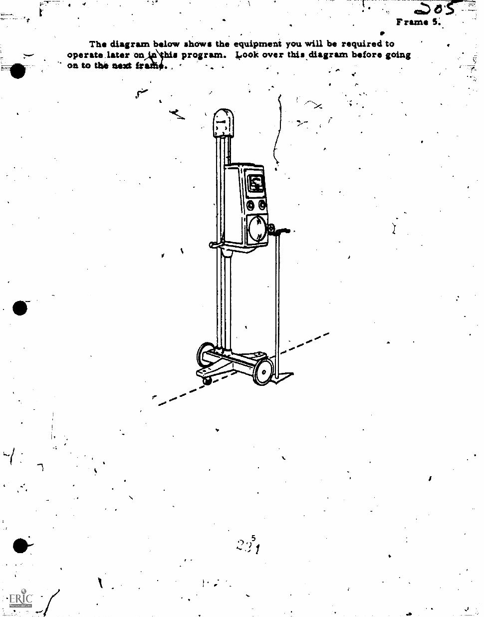
k a.Frame S..
The diagram below shows the equipment you will be required tooperate,later on his program. leook over this.diagram before goingon to We next ir
so 0..00
Lj
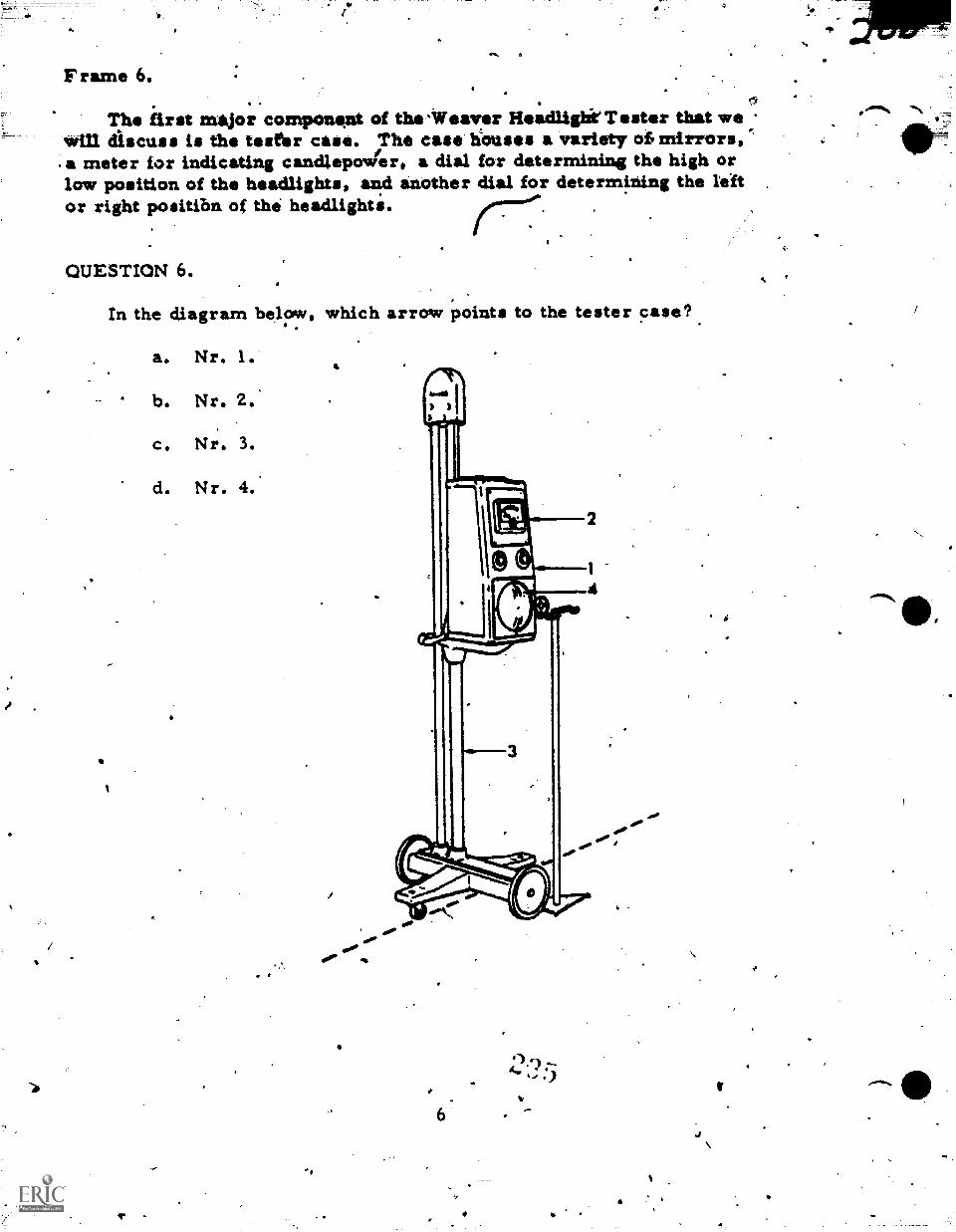
Frame 6.0
T hip first major componeat of the Veaver ileadlighiTester that wewill discuss is the tesfir case. The case hOuses a variety oh mirrors,a meter for indicating candlepovier, a dial for determining the high orlow position of the headlights, and another dial for determining the leftor right positibn of the headlighti.
QUESTION 6.
In the diagram below, which arrow points to the tester case?
a. Nr. 1
4 b. Nr. 2.'
c. Nr. 3.
d. Nr. 4.
4
4.0416
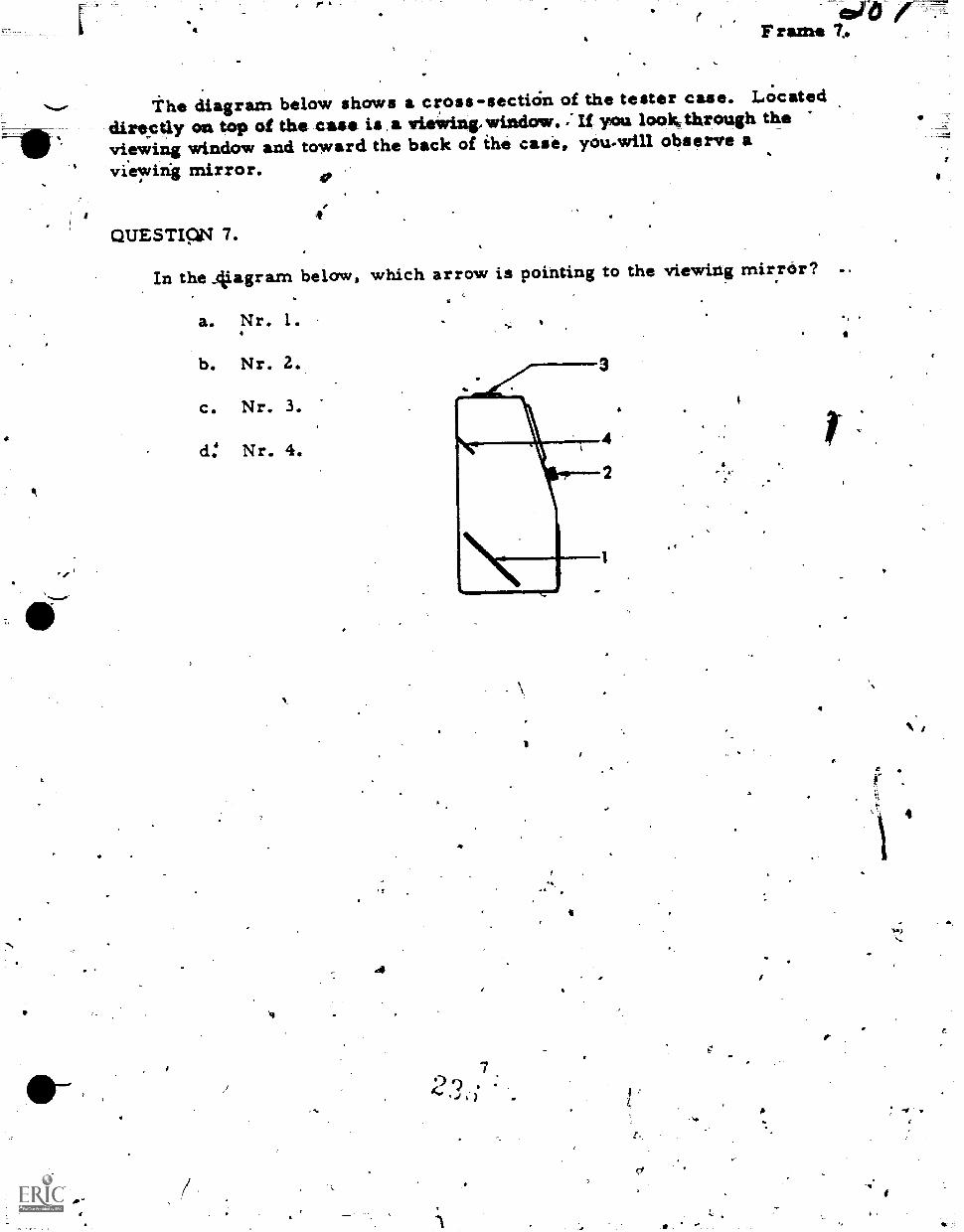
at
6 gare'Frame T.
the diagram below shows a cross-secticin of the tester case. Locateddire-ctly on top of the case is a viewing, window. ; If you lookthrough theviewing window and toward the back of the case, you.wilI observe aviewing mirror.
4.QUESTICV 7.
In the Aiagram below, which arrow is pointing to the viewing mirror?
a. Nr. 1.
b. Nr. 2.
C. Nr. 3.
d: Nr. 4.
.4
7)4 -1J )
1
4
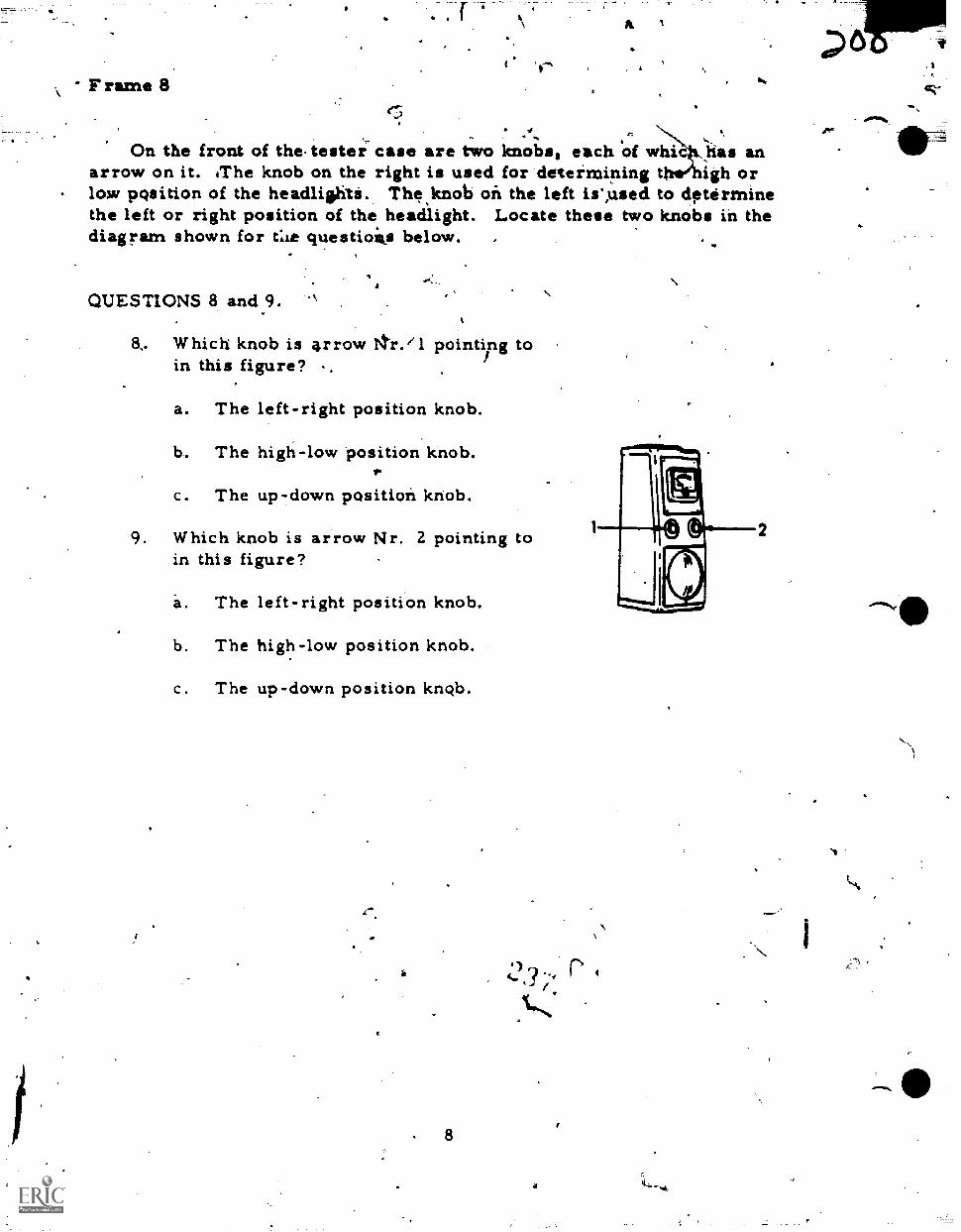
Frame 8(.3
On the front of the-tester case are two knobss each of whi has anarrow on it. iThe knob on the right is used for determining t igh orlow position of the headliehts. Thesknob on the left isused to determinethe left or right position of the headlight. Locate these two knobs in thediagram shown for tlie questioiis below. .
QUESTIONS 8 and 9. `
8. Which knob is arrow gr.'1 pointing toin this figure?
a. The left-right position knob.
b. The high-low position knob.
c. The up-down position knob.
9. Which knob is arrow Nr. 2 pointing toin this figure?
a. The left-right positiron knob.
b. The high-low position knob.
c. The up-down position knob.
ir
8
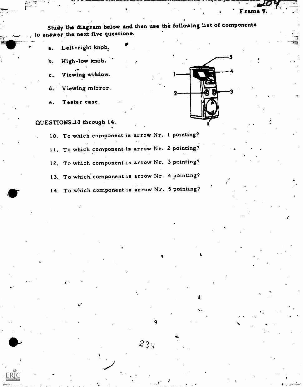
Study ihe diagram below and then use the following list of componentsto answer,the next five questions-.
a. Left-right knob.
b. High-low knob.
c. Viewing window.
d. viewing mirror.
e. Tester case.
QUESTIONSUO through 14.
2
10. To which component is arrow Nr. 1 pointing?
11. To which component is arrow Nr. 2 pointing?
12. To which component is arrow Nr. 3 pointing?
13. To which.component is arrow Nr. 4 pointing?
14. To which component_is arrow Nr. 5 pointing?
'v.
9
4
it.
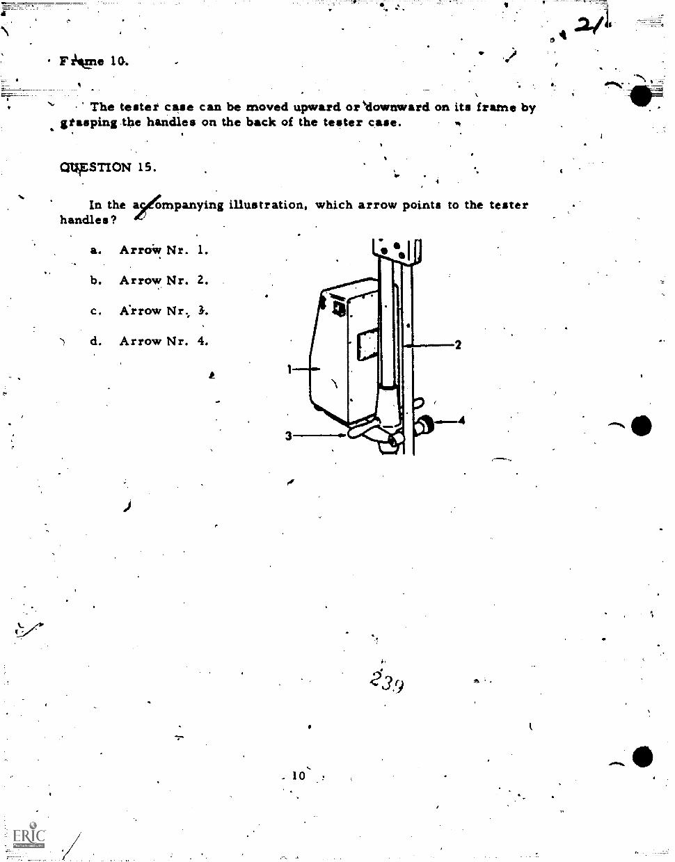
Fl Lvne 10.
The tester case can be moved upward oreklownward on its frame bygtasping the handles on the back of the tester case.
CRIAESTION 15.
In the a/gmpanying illustration, which arrow points to the testerhandles?
a. ArroW Nr. 1.
b. Arrow Nr. 2.
c. Krrow Nr., 3.
d. Arrow Nr. 4.
.. 10'
9
!MD,
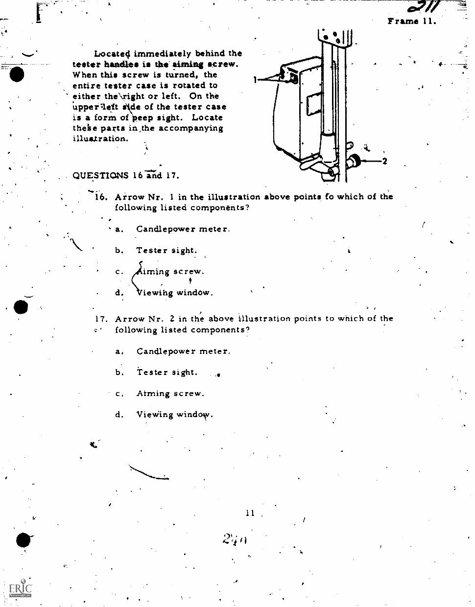
Sum,
Locate4 immediately behind thetester handles is the !timing sgrew.When this screw is turned, theentire tester case is rotated toeither the\right or left. On theupperaeft sde of the tester caseis a form ofipeep sight. Locatethehe parts in,the accompanyingillusktration.
QUESTIONS 16174 17.
Frame 11.
16. Arrow Nr. 1 in the illustration above points fb which of thefollowing listed components?
a. Candlepower meter.
b. Tester sight..
c. irning screw.
d. iewihg window.
17. Arrow Nr. 2 in the above illustration points to which of theq' following listed components?
a. Candlepower meter.
b. Tester sight.
c. Aiming screw.
d. Vie Wing windo\v.
11
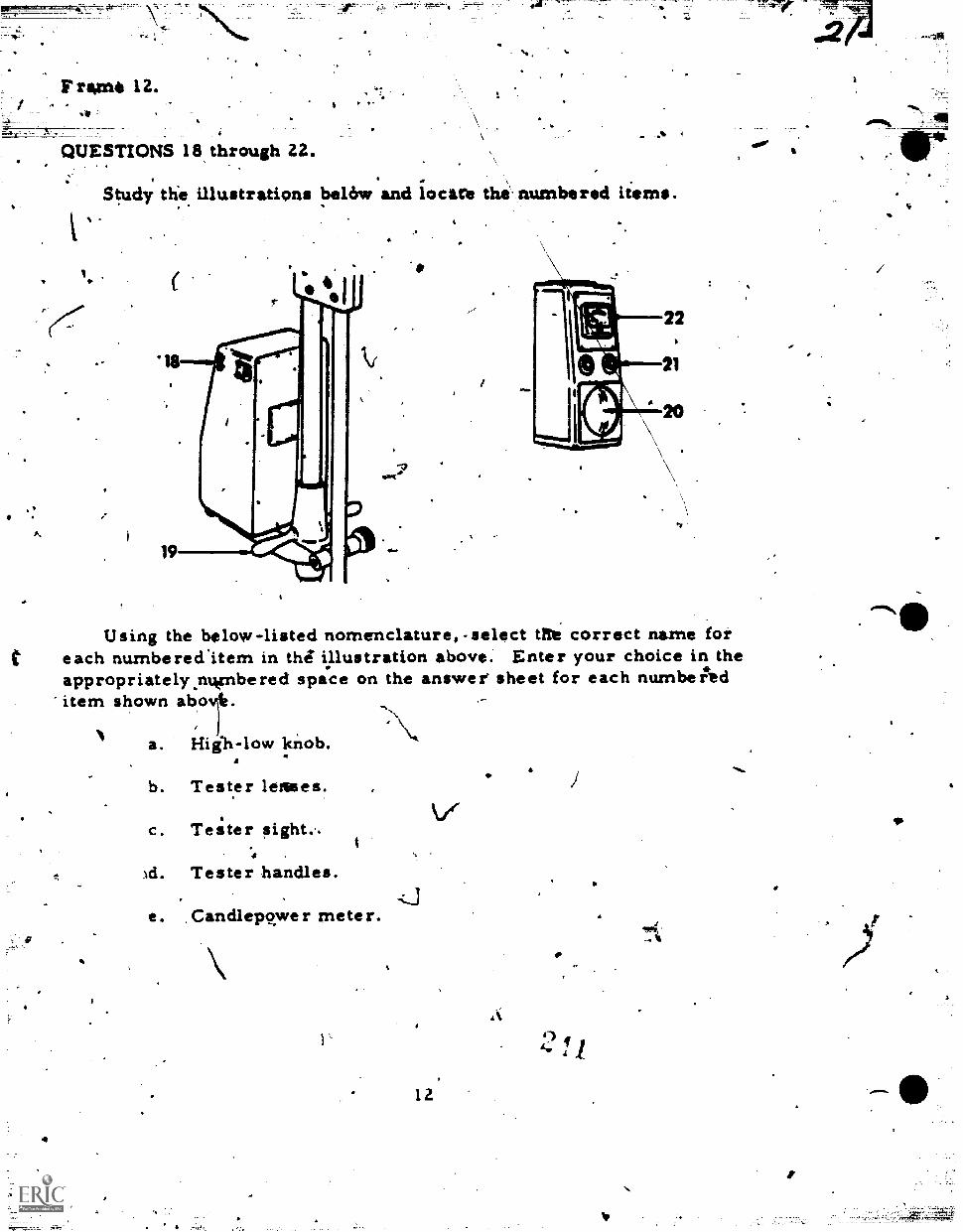
F ram* 12.Ip
QUESTIONS 18 through 22.
Study tlie illustrations belch,: and locate the numbered items.-
Nr#
MY!
Using the below-listed nomenclature, -select Me correct name foreach numbereditem in thi illustration above. Enter your choice in theappropriately.nwnbered space on the answer sheet for each numbeitd
'item shown abo
a. Hiih-low knob.
b. Tester lenses.
c. Tester sight..
d. Tester handles.
e. Candlepower meter.
12
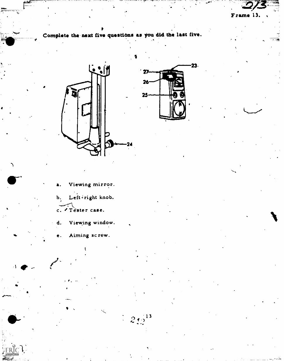
Complete thiT next five questions as toil did the last five.
a. Viewing mirror.
b. Leftzright knob.
c. 1Téster case.
d. Viewing window.
4h. e. Aiming screw.
.13/
Frame 13.
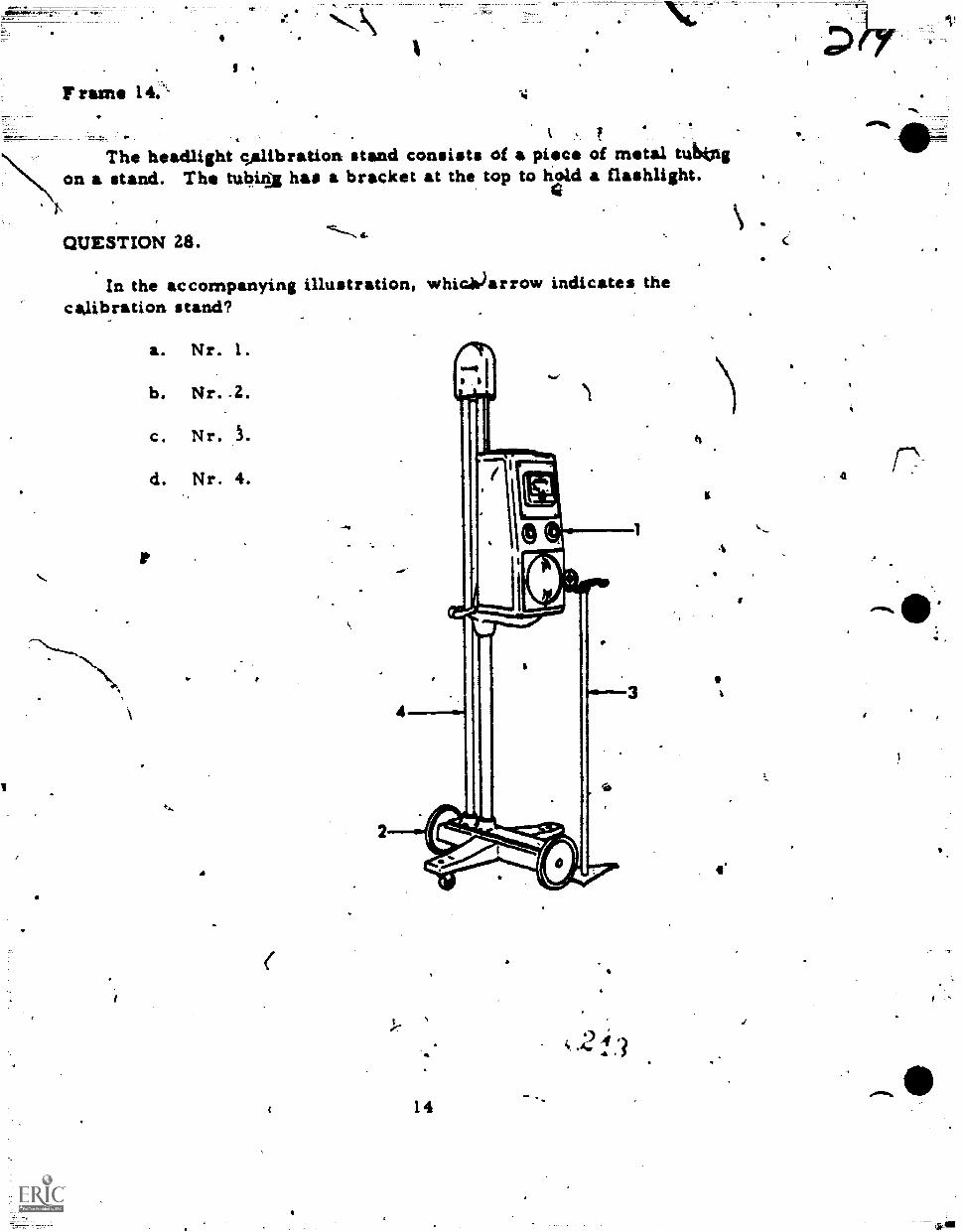
Triun 1 4.
"
54
fThe headlight calibration stand consists of a piece of metal tubtitg\ on a stand. The tubia has a bracket at the top to hold a flashlight.
QUESTION 28.
In the accompanying illustration, whiGitiarrow indicates thecalibration stand?
a. Nr. 1.
b. Nr..2.
c. Nr. L
d. Nr. 4.
14
0 4 ,
4
4.
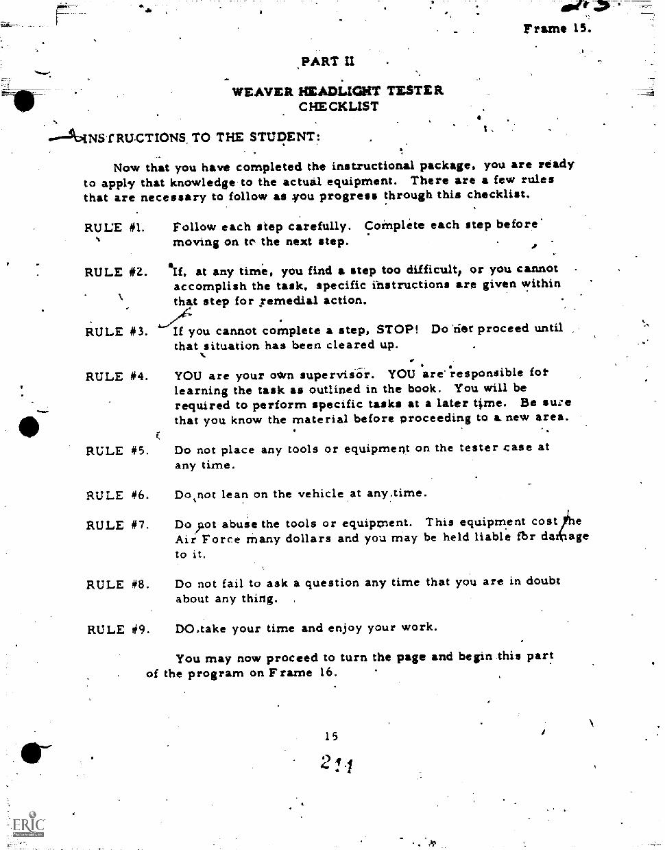
'ftnoe.
Frame 15.
PART U
WEAVER HEADLIGHT TESTE RC HE CKLIST
fRUCTIONS TO THE STUDENT:
Now that you have completed the instructional package, you are readyto apply that knowledge to the actual equipment. There are a few rulesthat are necessary to follow as you progress through this checklist.
RULE #1.
RULE #2.
RULE 03.
RULE #4.
Follow each step carefully. CoMplete each step before'moving on to the next step.
AIIf, at any time, you find a step too difficult, or you cannotaccomplish the task, specific ihstructions are given withinthat step for yemedial action.
If you cannot complete a step, STOP! Do 'tier proceed untilthat situation has been cleared up.
#P
YOU are your own supervido-i. YOU are responsible fotlearning the task as outlined in the book. You will berequired to perform specific tasks at a later ttme. Be sueethat you know the material before proceeding to &new area.
RULE #5. Do not place any tools or equipment on the tester case atany time.
RULE #6. Do not lean on the vehicle at any.time.
RULE #7. Do);tot abuSe the tools or equipment. This equipment cost e
Air Force many dollars and you may be held liable fbr da ageto it.
RULE #8. Do not fail to ask a question any time that you are in doubtabout any thing. ,
RULE #9. DO.take your time and enjoy your work.
You may now proceed to turn the page and begin this partof the program on Frame 16.
15
F roma 16.
4
1. Make sure that the vehicle is unit:jaded excePt for the normalcargo. Normal cargo includes such items as tire tools, jacks,spare tires, etc.
Z. - Check the tires for specified pres_aures and inflate as necessary,
.4)
I; 4 0 I
4
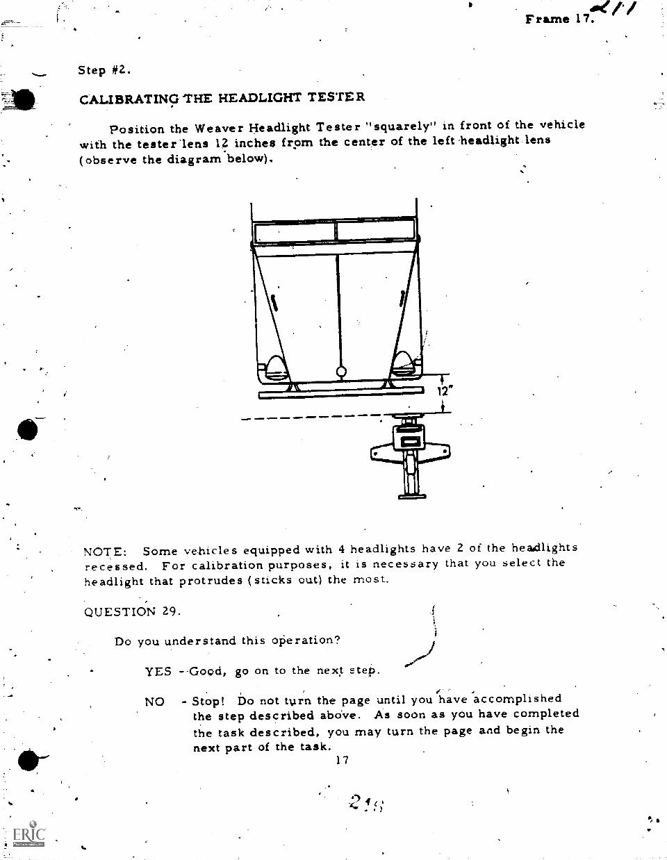
Step #2.
CALIBRATING THE HEADLIGHT TESTER
Ake,/Frame 17.
Position the Weaver Headlight Tester "squarely" in front of the vehiclewith the tester'lens 14 inches from the center of the left 'headlight lens(observe the diagram below).
NOTE: Some vehicles equipped with 4 headlights have 2 of the headdlightsreCessed. For calibration purposes, it is necessary that you select theheadlight that protrudes (sticks out) the most.
QUESTION 29.
Do you understand this oPeration?
YES --Good, go on to the next step.
NO - Stop! Do not tlirn the page until you have accomplishedthe step described abo've. As soon as you have completedthe task described, you may turn the page and begin thenext part of the task.
17
azQtFrame 18.
Step it1(
Now. - Rolls the tester slowly, straight across to the right headlight..STOP - Do nia push the tester in toward the right heidlig,ht.
When you complete the task outlined above go on to Frame 19.
18
a
o--
CAuTION: DO NOT ATTEMPT TO MOVE THE
-
Frame 19.
STER AT THIS TIME.
Now,' rneasure the distance between the tester1ens and the rightheadlight. Reco'rd this measurementQin the back side of your answersheet after item 30.
QUEST NS-31 and 32.
31. Did you measure from the center of the tester lens to theof the right headlight lens?
enter
a. YES - Good, record your measurement as item
,b. NO - Do so now and then record that measurement asitem 31.
2. Was your measurement at the right headlight 12 inches?
a. YES Proceed to Frame 22.
b. NO - Turn the page and continue 'with Frame 20.4
1 9
0
qr.
a
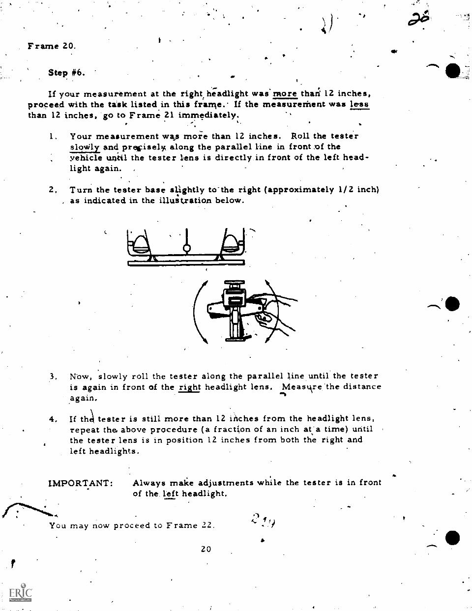
Frame 20.
Step #6.
0747
If your measurement at the right, headlight was more thari 12 inches,proceed with the task listed in this frame.- If the measurethent was lessthan 12 inches, go to Frame 21 immediately.
Your measurement wks moi:e than 12 inches. Roll the testersloWly, and precisely, along the parallel ine in front sof theyehicle until the tester lens is directly in front of the left head-light again.
2. Turn the tester base slightly to"the right (approximately 1/2 inch)as indicated in the illustration below.
3. Now, slowly roll the tester along the parallel line until the testeris again in front of the right headlight lens. Meastkre the distance
-11again.
4. If tht tester is still more than 12 inches from the headlight lens,repeat the4 above procedure (a fraction of an inch at'a time) untilthe tester lens is in position 12 inches from both the right andleft headlights.
IMPORTANT: Always make adjustments while the tester is in frontof the left headlight.
/10.6",011444<eib,
You may now proceed to Frame 22.
20
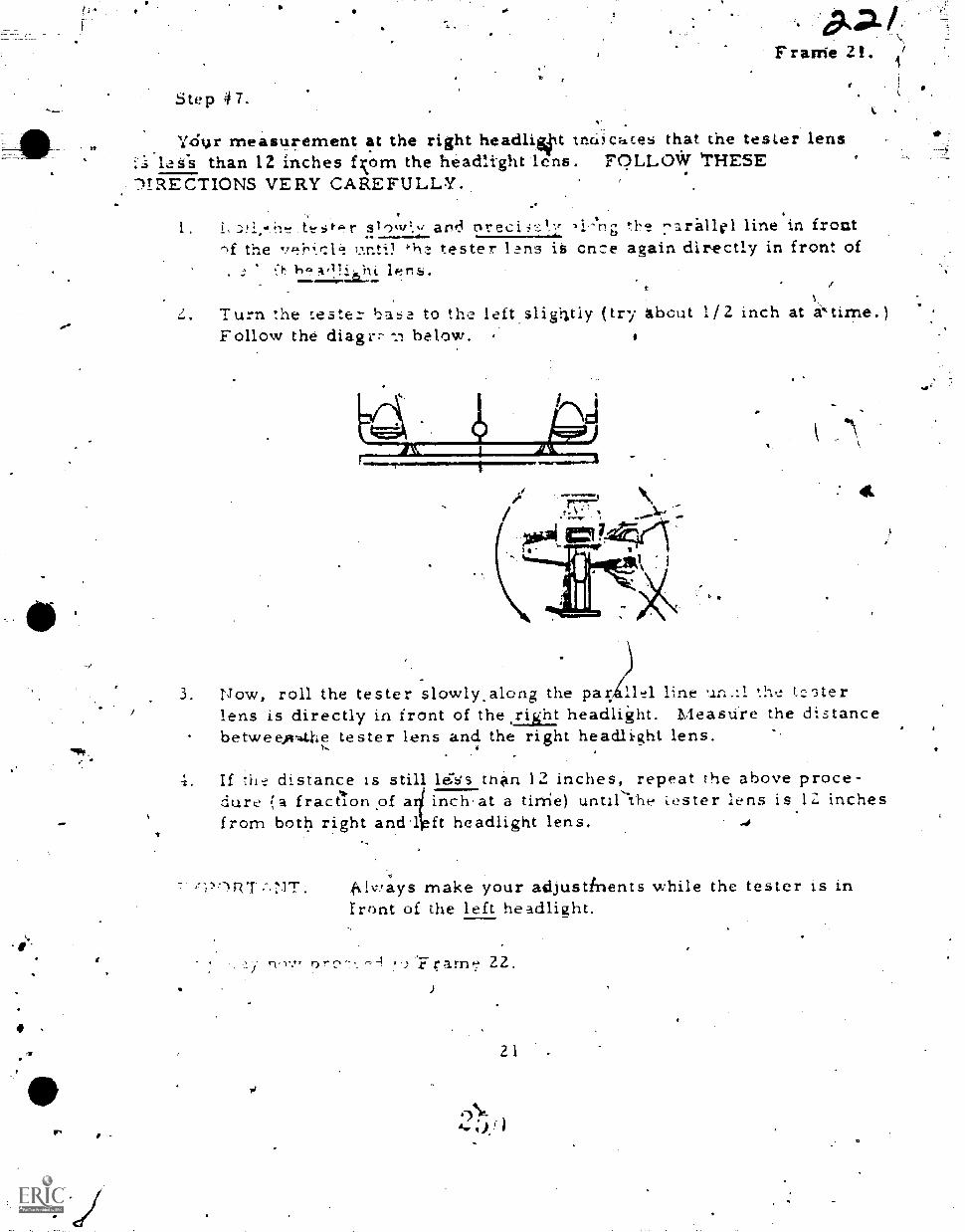
-
Frame 2 .
Step 4 7 .
Ydur measurement at the right headliot trici)caces that the tester lens. leis than 12 inches fom the headlight lens. FPLLOAr 'THESE'DIRECTIONS VERY CAREFULLY.
slo,v', and 4,7+.1, -, - "arallel line'in front-)f the 'Anti) 4-1. tester 1?ns iS once again dizkectly in front of
a
Turn the teste:- base to the left,sligiltly (try About 1/2 inch at gktinie.)Follow the diagrr below.
1
ci
3. Now, roll the tester slowly,along the par 1.1e1 line the 1c5terlens is directly in front of the fright headlight. Measure the distancebetwee,v4tie tester lens and the right headlight lens.
4. If the distance is still le:s's than 12 inches, repeat the above proce-dure a fract1,ion of a inch,at a tirrie) untilihe Lester lens is 1Z inchesfrom both right andl ft headlight lens.
41vYays make your adjustinents while the tester is infront of the left headlight.
,)"Frarrp: 22.
21 .
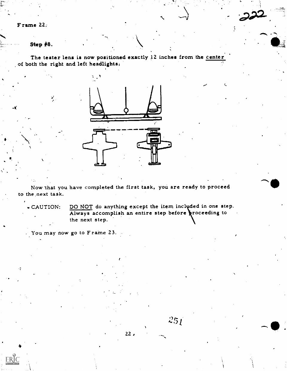
F rame 22:
Step #8.
Lir
The tester lens is now positioned exactly .12 inches from the centerof both the right and left headlights;
Now 'that you have completed the first task, you are ready to proceedto the next task.
.. CAUTION: DO NOT do anything except the item incl ded in one step.Always aecomplish an entire step before roceeding tothe next step.
You may now go to Frame 23.
22
one.,
Ilk_.,-7:
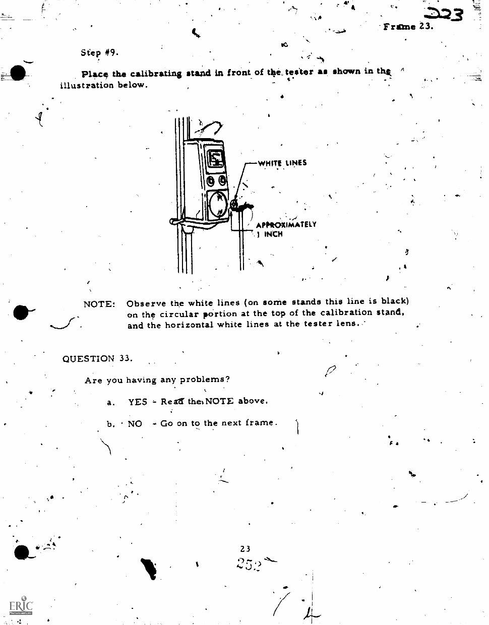
.......
_....-..,.__
0/1
Ica
Seep #9.
Frame 23.
place the calibrating stand in frant of tkte. tester as shown in th,tillustration below.
4
WHITE LINES
APPROXIMATELYINtH
A
,
A
NOTE: Observe the white lines (on some stands this line is black)on the circular portion at the top of the calibration stand,and the horizontal white lines at the tester lens.
QUESTION 33.
Are you having any problems?
a. YES - Rest' theINOTE above.
b. NO - Go on to the next frame.
23
-4
Jr,
4
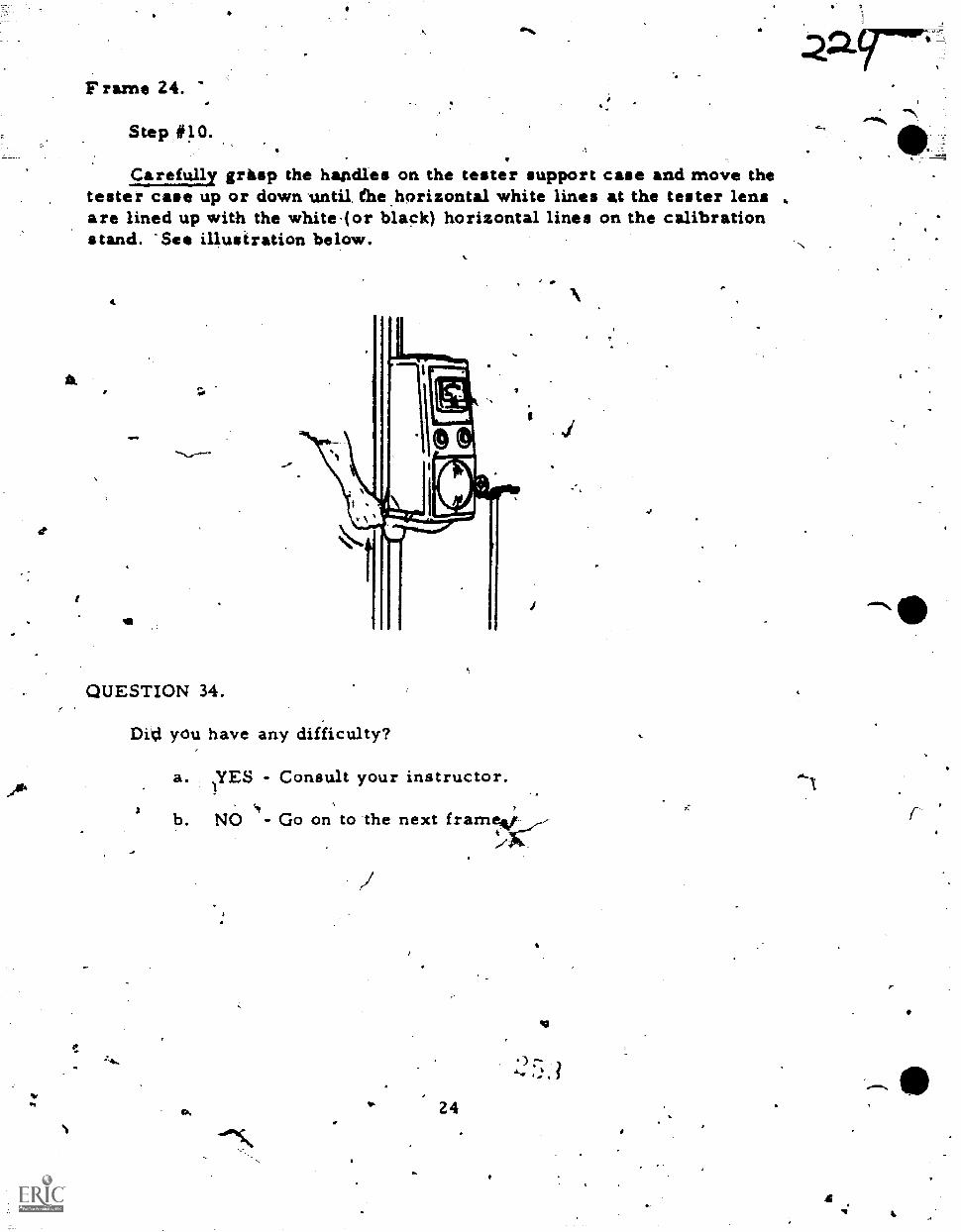
Frame 24.
Step #10.
Carefully grasp the handles on the tester support case and move thetester case up or down until, the horizontal white lines at the tester lensare lined up with the white(or black) horizontal lines on the calibrationstand. -See illustration below.
QUESTION 34.
Ditt you have any difficulty?
a.1YES - Consult your instructor.
1
b. NO - Go on to the next frame*/
24
1
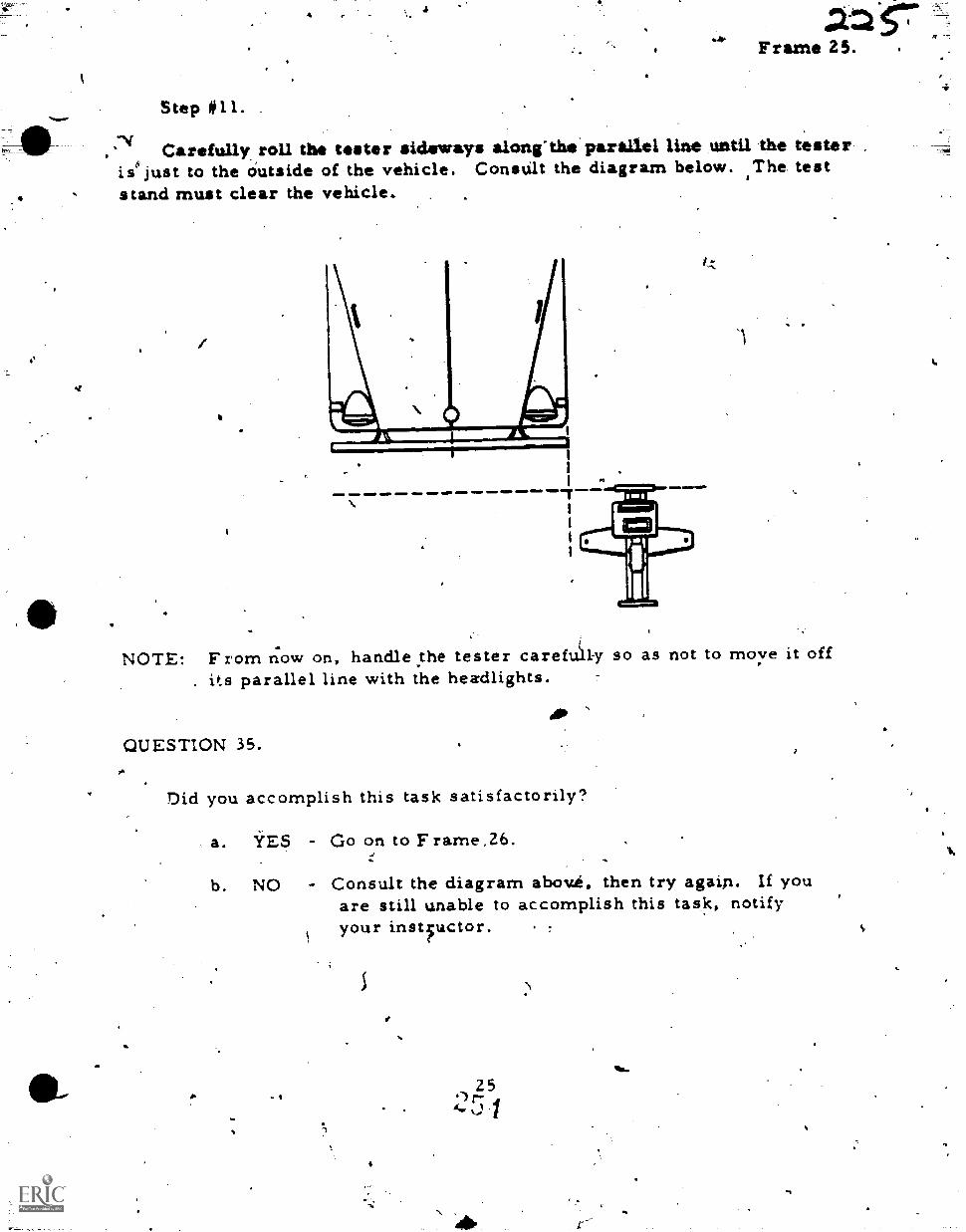
k
t-77.7111111F1
42-ZFrame 25.
Step #11.
s-4 Carefully roll the tester sideways alon(the paraltel line until the testerie just to the Outside of the vehicle. Constilt the diagram below. The teststand must clear the vehicle.
1
NOTE: From now on, handle.the tester caref l-y so as not to move it off. its parallel line with the headlights.
QUESTION 35.
Did you accomplish this task satisfactorily?
a. YES - Go on to Frame,26.
b. NO - Consult the diagram abov.h, then try again. If youare still unable to accomplish this task, notifyyour instfuctor.
4
)
25.)t-fa.
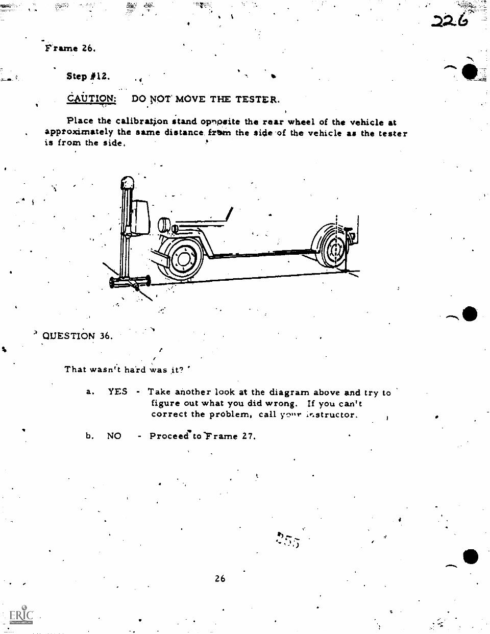
Frame 26.
Step P12.4"
DO.NOT MOVE THE TESTER.
Place the calibration stand opnpsite the rear wheel of the vehicle atapproximately the same distance frtorn the side-of the vehicle as the testeris from the side.
QUESTIaN 36.
,
That wasn't hard was .it?
a. YES - Take another look at the diagram above and try tofigure out what you did wrong. If you can'tcorrect the problem, call y.:±,%r ir,structor.
b. NO Proceedito-Frame 27.
26
:)
4
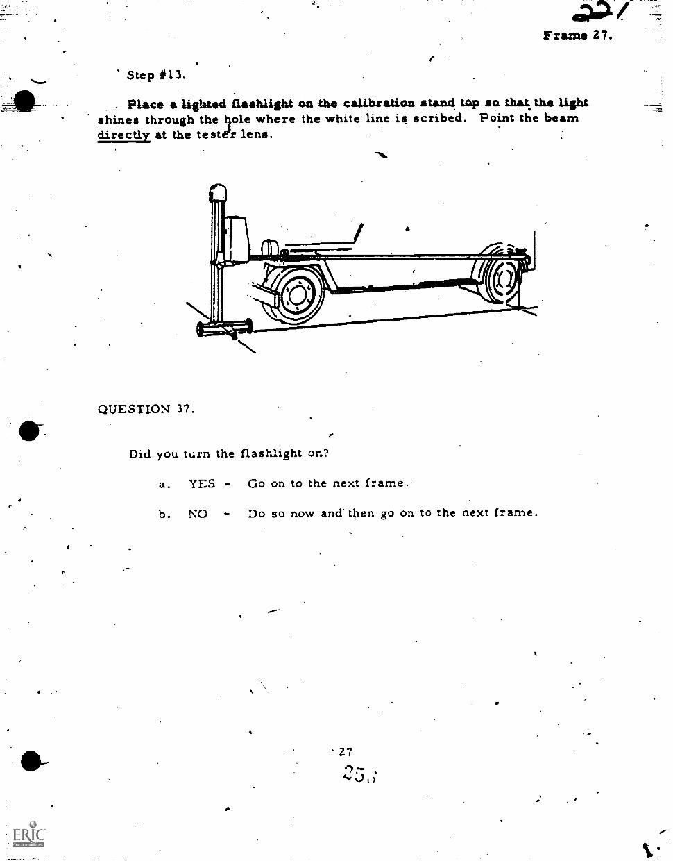
Frame 27.
Step #13.
Place a lighted flashlight on the calibration stand top so that the lightshines through the hole where the whitei line is scribed. Point the beamdirectly at the testekr lens.
QUESTION 37.
Did you turn the flashlight on?
a. YES - Go on to the next frame.-
b. NO - Do so now and then go on to the next frame.
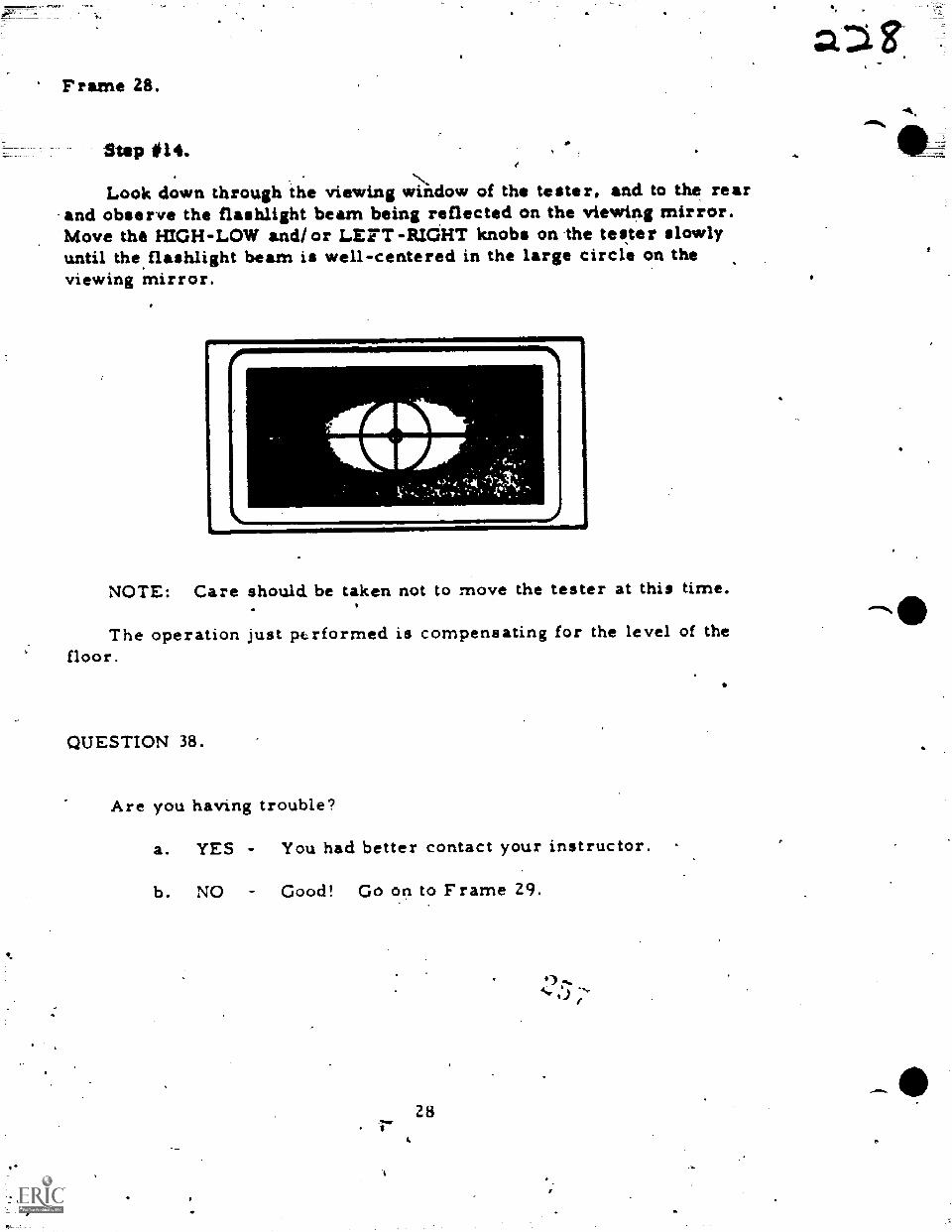
Frame 28.
Step #14.
Look down through the viewing wtndow of the tester, and to the rearand observe the flashlight beam being reflected on the viewing mirror.Move the HIGH-LOW and/or LEFT-RIGHT knobs on the tester slowlyuntil the flashlight beam is well-centered in the large circle on theviewing mirror.
I.441, f
NOTE: Care should, be taken not to move the tester at this time.
The operation just performed is compensating for the level of thefloor.
QUESTION 38.
Are you having trouble?
a. YES - You had better contact your instructor.
b. NO - Good! Go on to Frame 29.
28
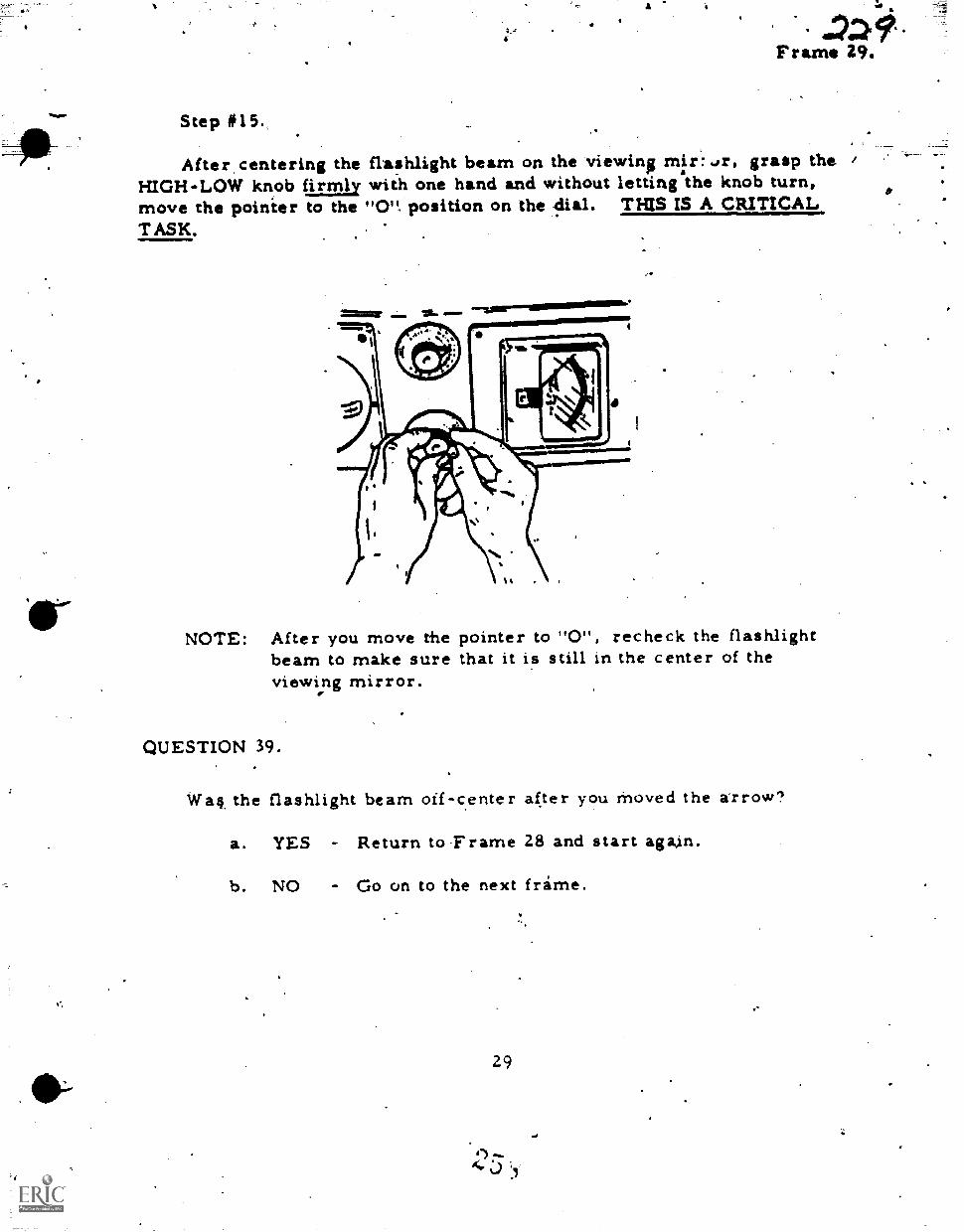
N
41w7Z9Frame Z.
Step #15.
After.centering the flashlight beam on the viewing mix:4r, grasp theHIGH-LOW knob firmly with one hand and without letting the knob turn,move the poinier to the "0". position on the 4ial. THIS IS A CRITICALTASK.
''"1.111111.111=00111M106
NOTE: After you move the pointer to "0", recheck the flashlightbeam to make sure that it is still in the center of theviewing mirror.
QUESTION 39.
Waft the flashlight beam off-center after you moved the arrow?
a. YES Return to Frame 28 and start again.
b. NO - Go on to the next frame.
29
en)joaf
Frame 30.
10.
Let'sdoing just
1st
7nd -
3rd -
make a quick revisw of what you,have done so far. You:axegreat. Here is a list of the tasks you have completed.
',You positioned the tester lens 12 inches in front Of both"high beam" headlights: /
You mitched the line on the calibration stand with the lineon the tester cage (at the lens).'
You denteKed the flashlight beam in the tester lens afteryou had set the calibration stand near the rear wheel ofthe vehicle.
4th - You set the HIGH-LOW arrow to "0" without moving theHIGH-LOW knob.
After you have read the.above review, you may go on to Frame 31.
You're doing real well, take your time and complete the tasks.4
30
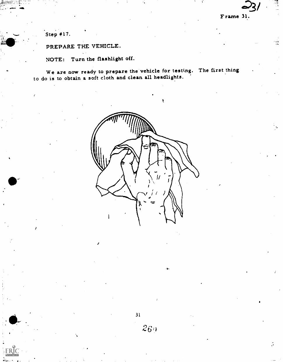
Frame 31.
Step *17.
PREPARE THE VEHICLE.
NOTE: Turn the flashlight off.
We are now ready to prepare the vehicle for testing. The first thingto do is to obtain a soft cloth and clean all headlights.
31
26)
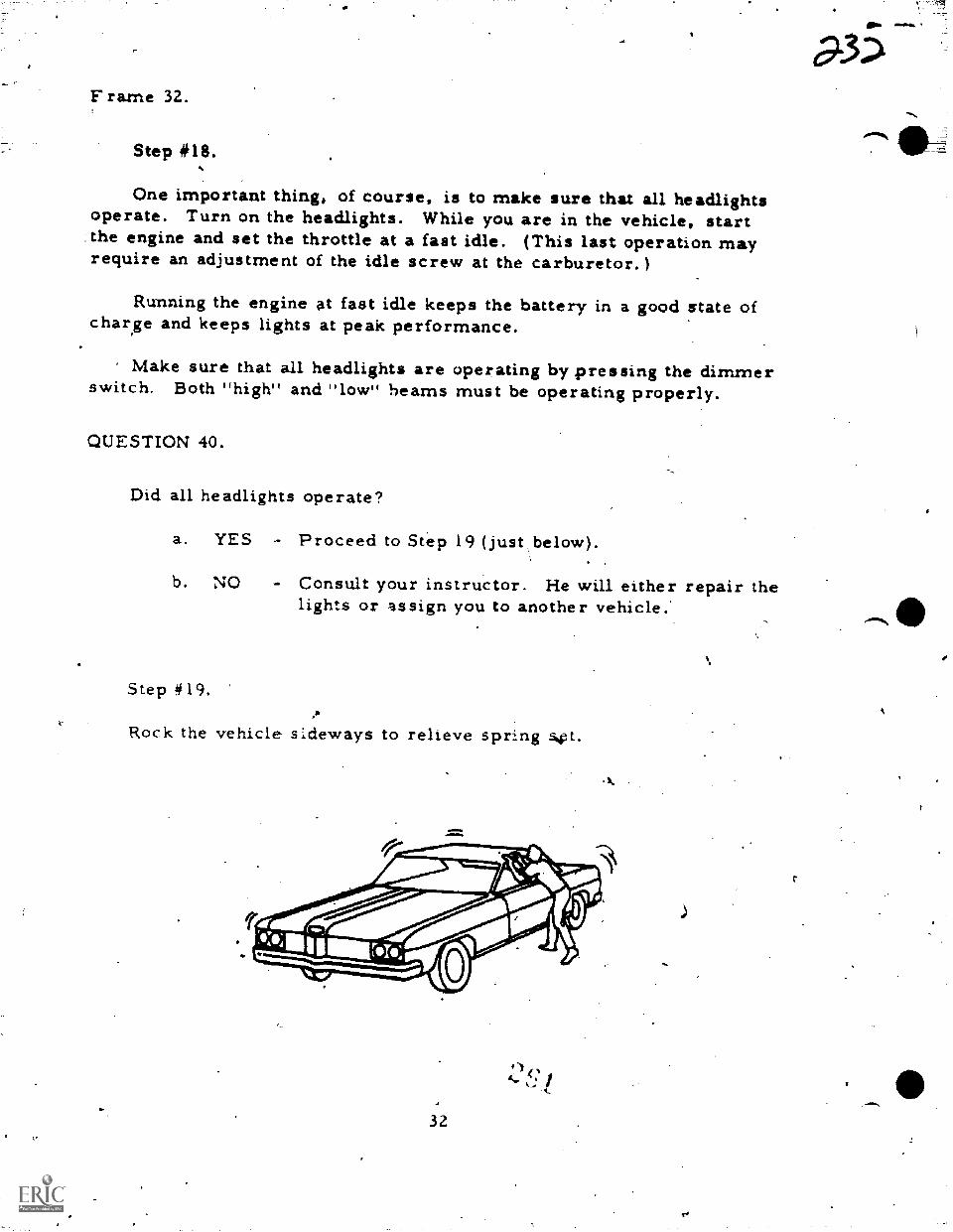
F rame 32.
Step #18.
One important thing, of course, is to make sure that all headlightsoperate. Turn on the headlights. While you are in the vehicle, startthe engine and set the throttle at a fast idle. (This last operation mayrequire an adjustment of the idle screw at the carburetor. )
Running the engine at fast idle keeps the battery in a good state ofcharse and keeps lights at peak performance.
Make sure that all headlights are operating by pressing the dimmerswitch. Both "high" and "low" beams must be operating properly.
QUESTION 40.
Did all headlights operate?
a. YES Proceed to Step 19 (just below).
b. NO Consult your instructor. He will either repair thelights or assign you to another vehicle.'
Step #19.,11
Rock the vehicle sideways to relieve spring s.pt.
32
a-35
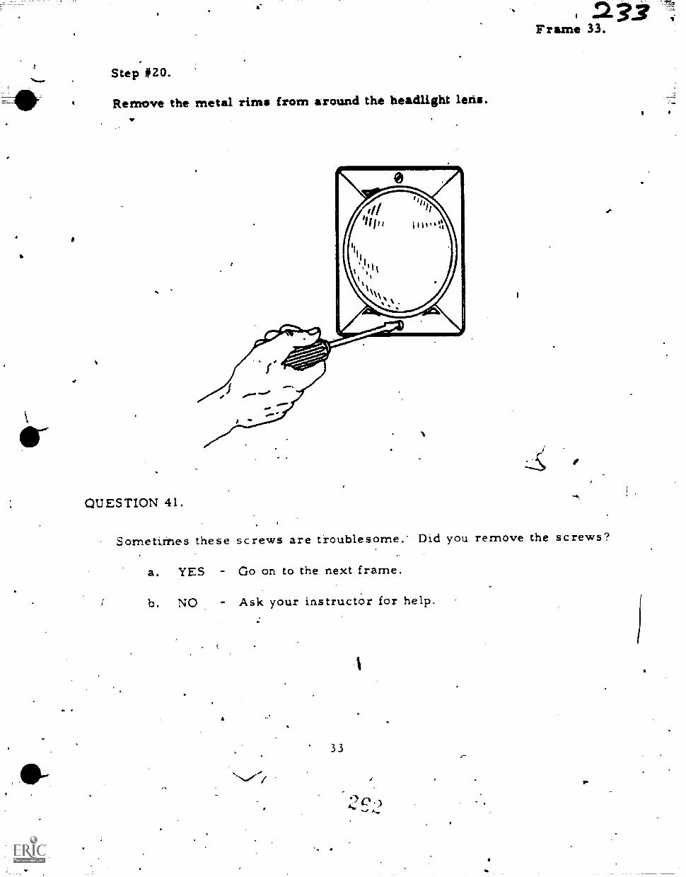
'..6
Step #20.
Remove the metal rims from around the headlight leris.
QUESTION 41. "61
Sornetithes these screws are troublesome. Did you remove the screws?
a. YES - Go on to the next frame.
b. NO - Ask your instructor for help.
33
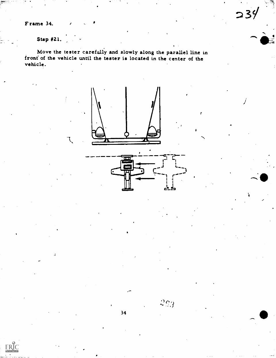
Frame 34.
Step #21.
Move the tester carefully and slowly along the parallel line infront of the vehicle until the tester is located in the center of thevehicle.
1. 61INNOMINPIN1
a.
34
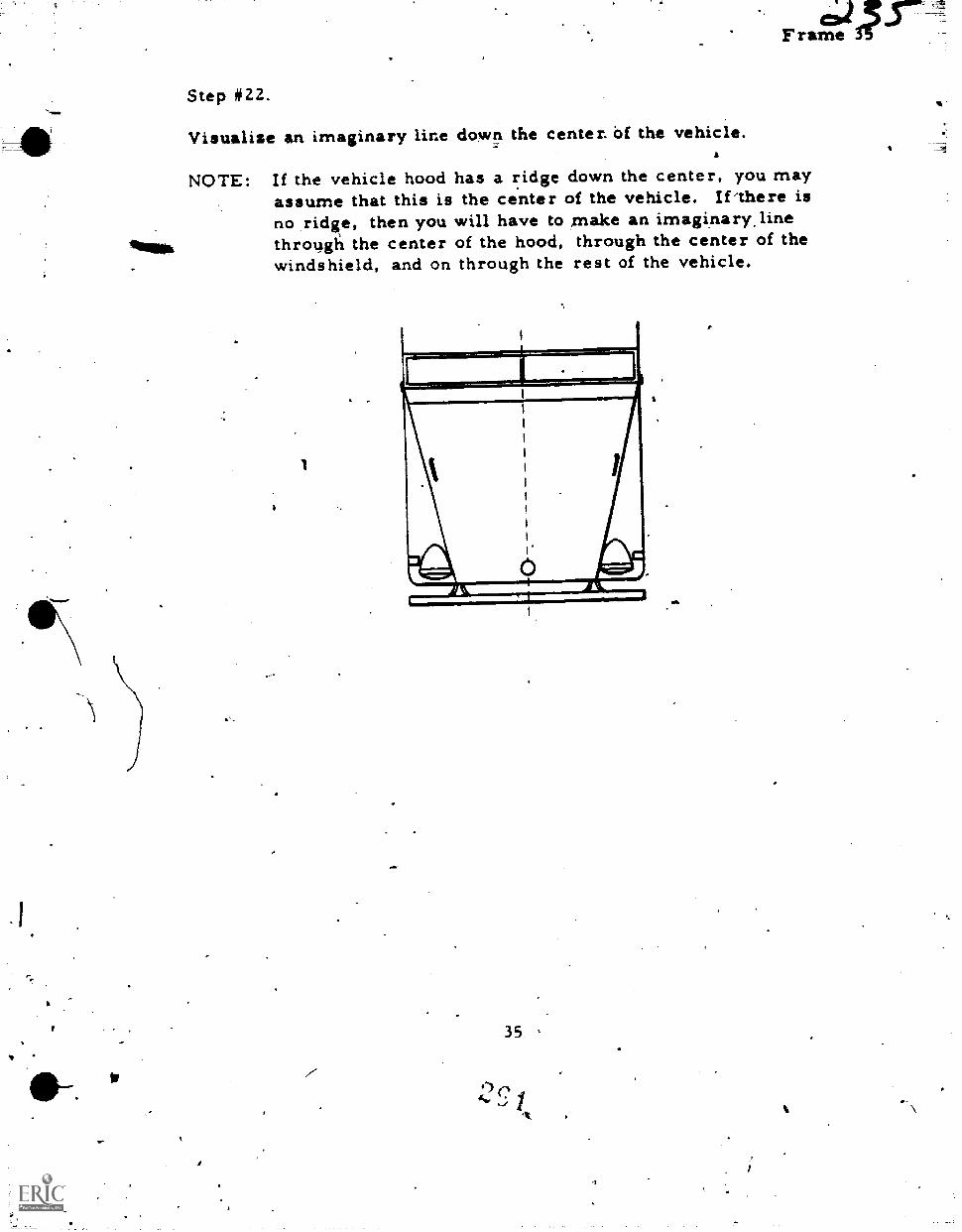
owl1 , .±7,
F rame
Step #22.
Visualize an imaginary line down the center. Of the vehicle.a
NOTE: If the vehicle hood has a ridge down the center, you mayassume that this is the center of the vehicle. If'there isno ridge, then you will have to make an imaginary.linethroggii the center of the hood, through the center of thewindshield, and on through the rest of the vehicle.
1
Ado,
35
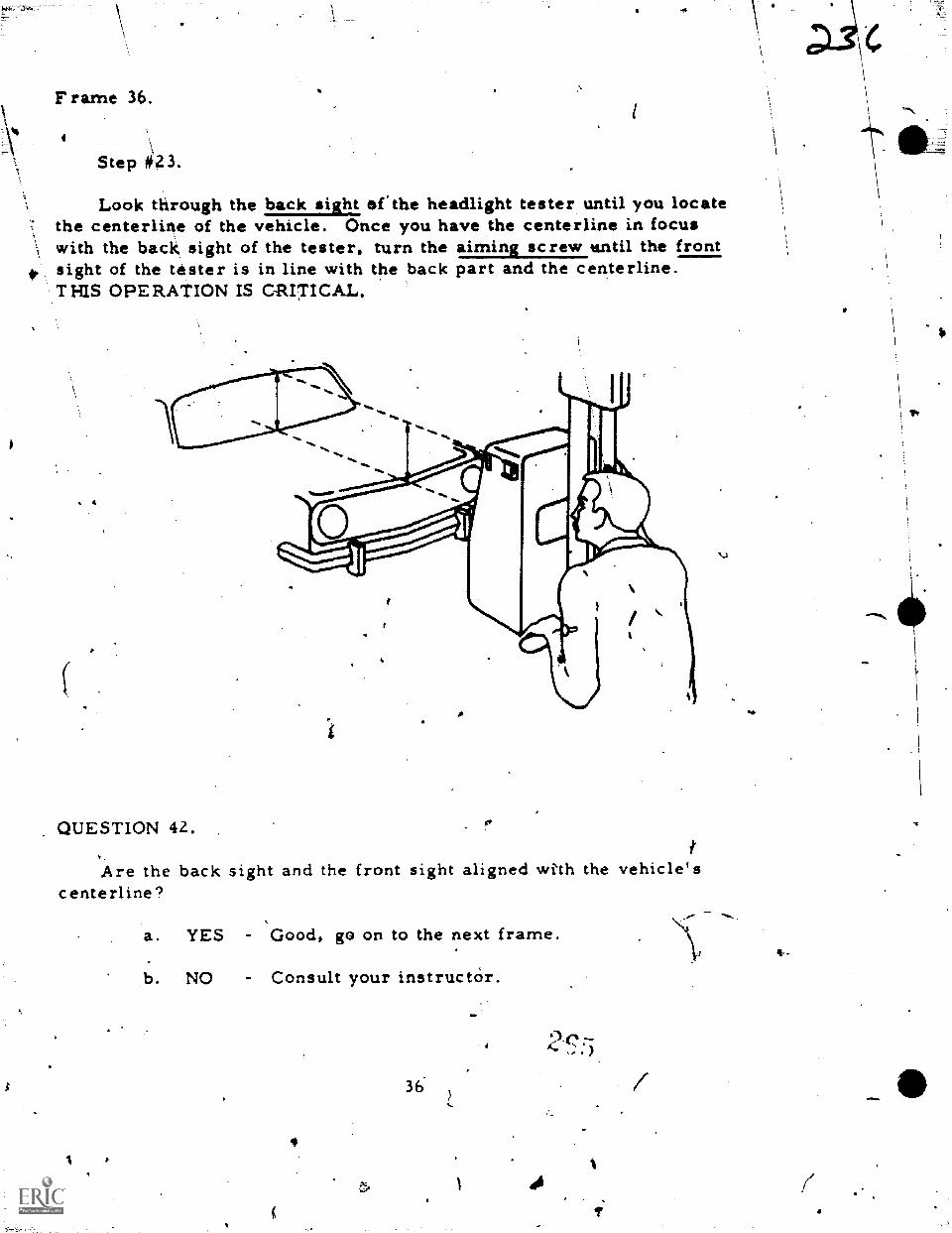
F rame 36.
Step 423.
Look through the back sight erthe headlight tester until you locatethe centerline of the vehicle. Once you have the centerline in focuswith the back sight of the tester, turn the aiming screw tintil the front
41. sight of the tester is in line with the back part and the centerline.THIS OPERATION IS CRITICAL.
QUESTION 42.
Are the back sight and the front sight aligned with the vehicle'scenterline?
a. YES - Good, go on to the next frame.
b. NO - Consult your instructOr.
36-
4
4
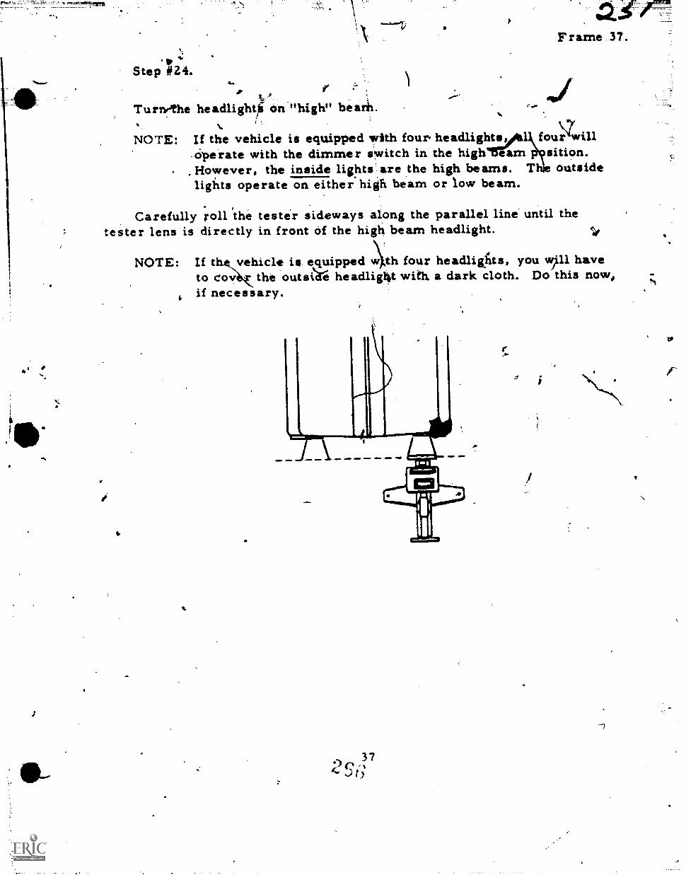
0
1
r
*Step #24.
Frame 37.
.. ' tr. %-- . .
Turnethe headlightfi on high" bearh. ......
(..,
,7%.
NOTE: If the vehicle is equipped with four. headlights,Al four will.ciperate with the dimmer switch in the highTrarn çsition.However, the inside lightsare the high beams. The outsideligitts operate on either high beam or low beam.
Carefully roll the tester sideways along the parallel line until thetester lens is directly in front of the high beam headlight.
NOTE: If thevehicle is equipped w th four headligtus, you wp1 haveto cov the outsilre head1ig4t with a dark cloth. Do this now,,if necessary.
372°,,)t)
it
'VD
CP
Nor
F rame 38.
go
Step #25%
Now that you have the testerilengjocated directly in front of thehigh beam headlight, you are ready for a critical task. Cafiftellyraise or lower the tester, case until the maxcrrium catidlep-74.7717-indicated on the tester meter.
4
NOTE: Perform this operation soiowly. When the headlight beamis directly in the center of the testeclens the needle onthe tester meter will be at its highesoini.. That's whereyou want it right now.
QUESTION 43.
Are you doing everything as directed?
e a. YiS
b. NO
Go to the next frame ,irAmediately.
You had better ask the instructor for assistance.
38
<q-
11 1- step n6.
f
da..5 7Frame 39.
Nowt roll the tester sideways along the parallel line (hack and forth)until maximurn candlepower is again located On the testep meter.
NOTE: Roll thetester slowly. You may not have to moye the testermore than an inch or so in either direction in order to obtainthe highest candlepower indication.
You think that you have the maximum candlepower now don't you?Let's check and see if you do. Carefully and slowly repeat Steps.25 ind 26to see ,if you can get a higher Candlepower indication..
Etr.
Now that you have maximum candlepower you may proceed lo the nextframe.
39
4
F rame 40.c.
Remember,theTreview 'you had a short while ago?.1
That review covered the calibration sequence, because you: A
a. Positioned the tester lens 12 inches in front of both highbeam headlights.
b. Matched the line on the calibration stand with the line onthe tester case (at the lens).
C. Centered ihe flashlight beam in the tester lens after youhad located,the calibration stand near the rear wheel ofthe vehicle.
4
Set the HIGH-LOW arrow to "0" without moving the HIGH-LOWknob.
Now,, take a look at the things you have completed since the calibra-tion sequence:
a. You cleaned the headlights.
b. You turned on the headlights, checked them, and starteil theengine and set it for fast idle.
c. You checked for excessive cargo and proper tire inflation.
d. You rocked the vehicle sideways to relieve spring set.
e. You removed the metal rims from the headlights.
f. You squared the tester case by lining it up with the centerof the vehicle by turning the aiming screws.
g. You covered the low beam (oil a four-headlight vehicle) andset the tester case in front of the high beam headlight. Youobtained the maximum candlepower on the meter by movingthe tester up, down, right, and left.
After reading the above review, proceed to Frame 41.
40
Frame 41.
Step #27.
Now, turn the HIGH-LOW knob on the testir until the highest candle-power reading is indicated on the tester meter.
CAUTION: Do not put your hand or allow:your sleeve to come betweenthe tester lens and the headlight. This action could lowerthe candlepower indication.
Turn the LEFT-RIGHT knob slowly until the maximum candlepoweris indicated on the tester meter.
You should just about have maximum candlepower indicated on the meter.Just 'to be sure, and this is imRortante turn both the HIGH-LOW and LEFT-RIGHT knobs, one at a time, slowly until you are sure of having maximunicandlepower indication.
CAUTION: DO NOT LEAN ON THE VEHICLE.
QUESTION 44.
Are you having a)-iy.problems?
a. YES You had better go back and re-execute Frames 37through 41 again. If this doesn't clear up yourproblems, check with your instructor.
b. NO Proceed to the next frame.
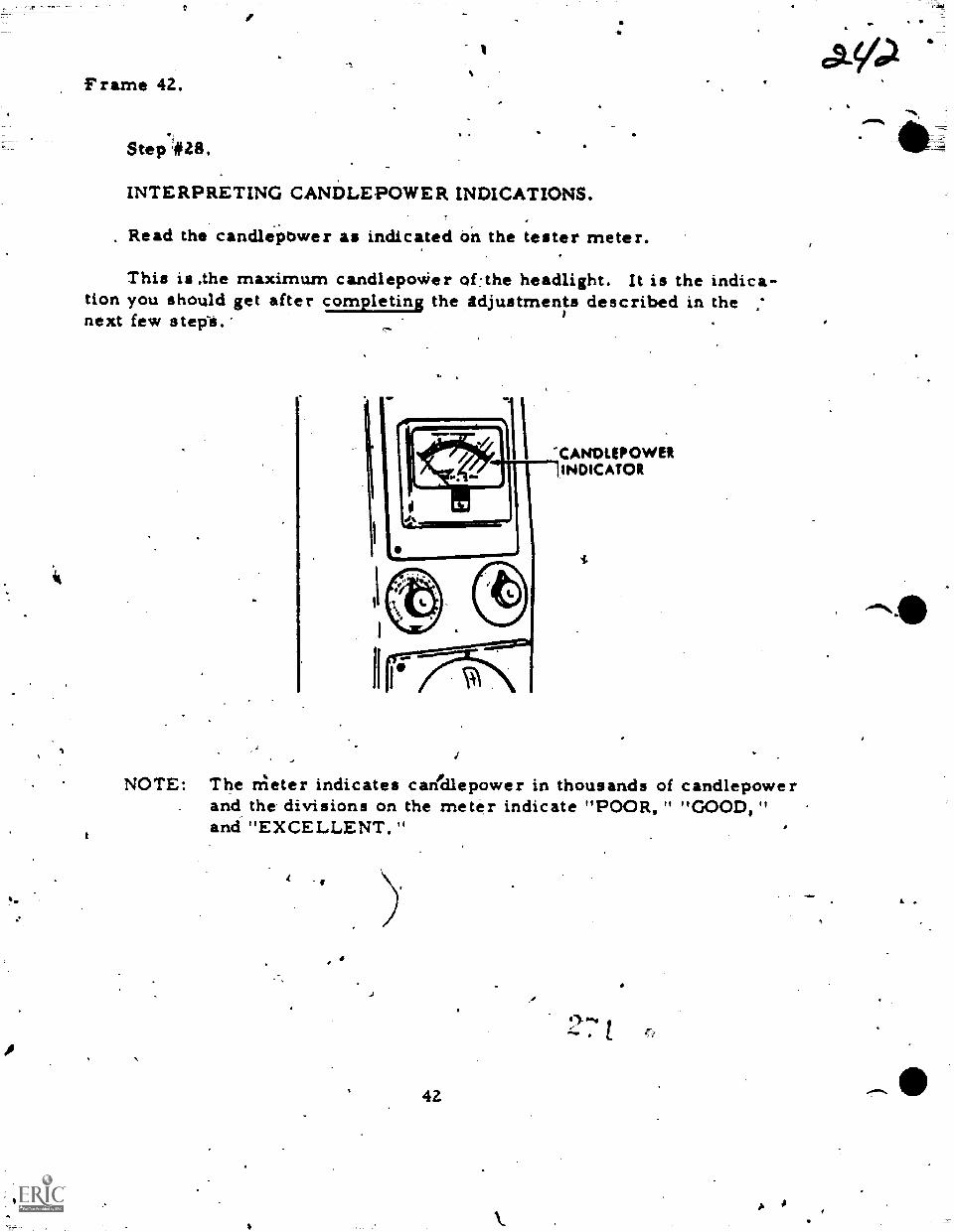
Frame 42.
Step #28.
INTERPRETING CANDLEPOWER INDICATIONS.
. Read the candlepOwer as indicated Oil the tester meter.
This is .the maximum candlepoWer ofthe headlight. It is the indica-tion you should get alter completing the idjustmen described in thenext few stepii.'
,
'
-CANDLEPOWER1INDICATOR
NOTE: The rrieter indicates caridlepower in thousands of candlepowerand the divisions on the meter indicate "POOR," "GOOD,"and "EXCELLENT."
7
42
A
a 41,
OM%
--7-
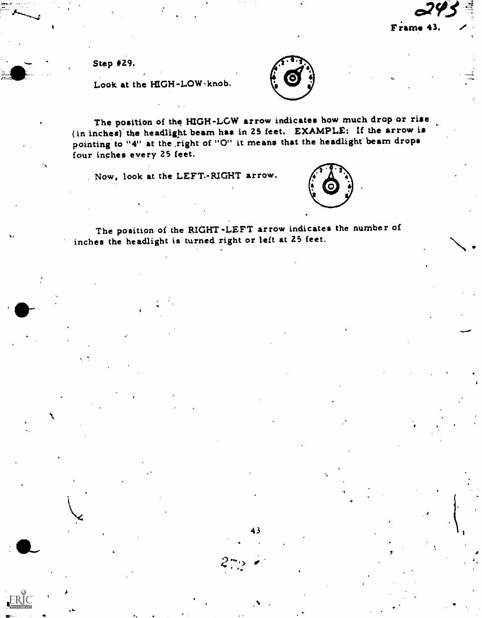
Step #29.
Look at the H1GH-LOW,knob.
The position.of the H1GH-LOW arrow indicates how much drop-or rise(in inches). the headlight beam has in 25 feet. EXAMPLE: If the arrow ispointing to "V at the ,right of "0" it means that the headlight beam dropsfour inches every 25 feet.
Now, look at the LEFT-RIGHT arrow.
The position of the R1GHT-LEFT arrow indicates the number ofinches the headlight is turned right or left at 25 feet.
I.
43
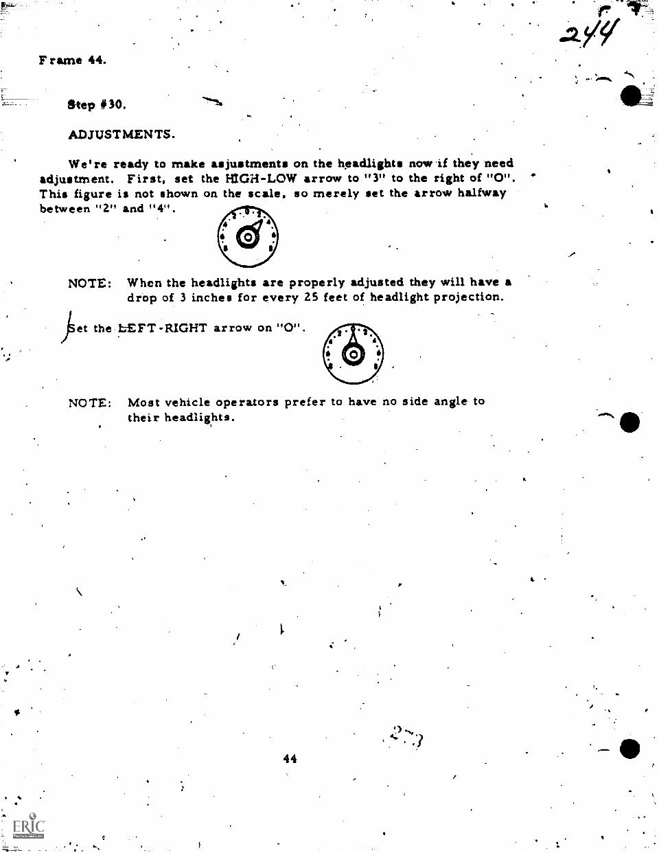
Frame 44.
Step #30.
ADJUSTMENTS.
We're ready to make asjustments on the headlights nowif they needadjustment. First, set the HIGH-LOW arrow to "3" to the right of "0".This figure is not shown on the scale, so merely set the arrow halfwaybetween "2" and "4".
NOTE: When the headlights are properly adjusted they will have adrop of 3 inches for every 25 feet of headlight projection.
.fiet the bEFT-RIGHT arrow on "0".
NOTE: Most vehicle operators prefer to have no side angle totheir headlights.
44
4
k
PS
Oa
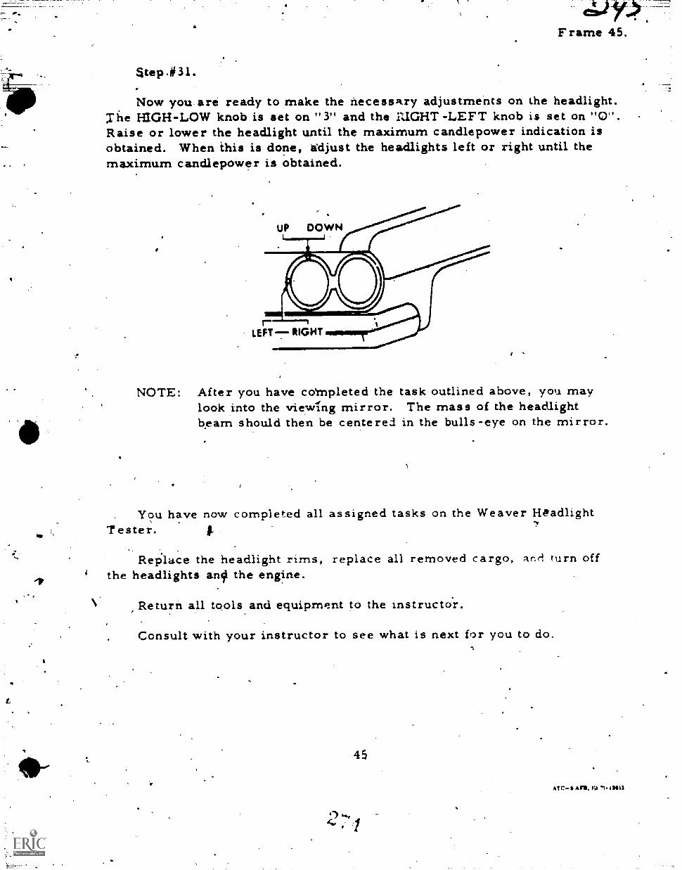
Frame 45.
atepn#3l.
Now you are ready to make the necessIkry adjustments on the headlight.Tile HIGH-LOW knob is set on "3" and the RIGHT -LEFT knob is set on "O''.Raise or lower the headlight until the maximum candlepower indication isobtained. When ihis is done, adjust the headlights left or right until themaximum candlepower is obtained.
NOTE: After you have coMpleted the task outlined above, you maylook into the viewIng mirror. The mass of the headlightbeam should then be centered in the bulls-eye on the mirror.
You have now completed all assigned tasks on the Weaver HeadlightTester.
RePlace the headlight rims, replace all removed cargo, and turn offthe headlights anil the engine.
Return all tools and equipment to the instructor.
Consult with your instructor to see what is next for you to do.
45
ATC$ Ars, rs4 T1. 131113
.1

A
NmIP
\ :Pe
PODIUM E,,,1111111 MAN
a
4 4
Technical Training
General rurpose Vehicle Mechanic
LIGHTING, SIGNAL, AND WARNING SYSTEMS
31 December 1975
USAF SCHOOL OF APPLIED AEROSPACE SCIENCES3340th Technical Training GroupChanute Air Foree Base, Ilinois
Designsrd FOt ATC. Course Use
00 NOT OSUON THEME
2 4PROGRAMKED TEXTJABR47232-PT-464
p.
4,
FOREWORD
This programmed text was designed fOr students enrolled in the GeneralPurpose.Vehicle Repairman Gourse,AABR47330. It was validsted by studentsenrolled,in that course in 1964 and has proved satisfactory iince:that time:
OBJECTIVES
Upon completion,of this programmed text you will be able to accomplish thefollowing objectives with 90% accuracy.
1. . Given three circuits and a list of circuit conditions, match eachcircuit with the correct condition.
2. Given a diagram shading different pieces of test equipment and alist of test equipment names, match each piece of test equipment with thecorrect name.
3. Given electrical circuits with a continuity light connected atdifferent points, indicate by each circuit whether the light should be ONor OFF.
4. . Given electrical circuits with a voltmeter connected at differentpoints and a list of voltage readings, match the voltage reading to thecorrect circuit.
Supersedes 3A1R47330-PT1-404, 13 May 1970.OPR: TWSDISTRIBUTION: X
174: - 730; TTI,GC - 1
St
9 7'
Assoft,
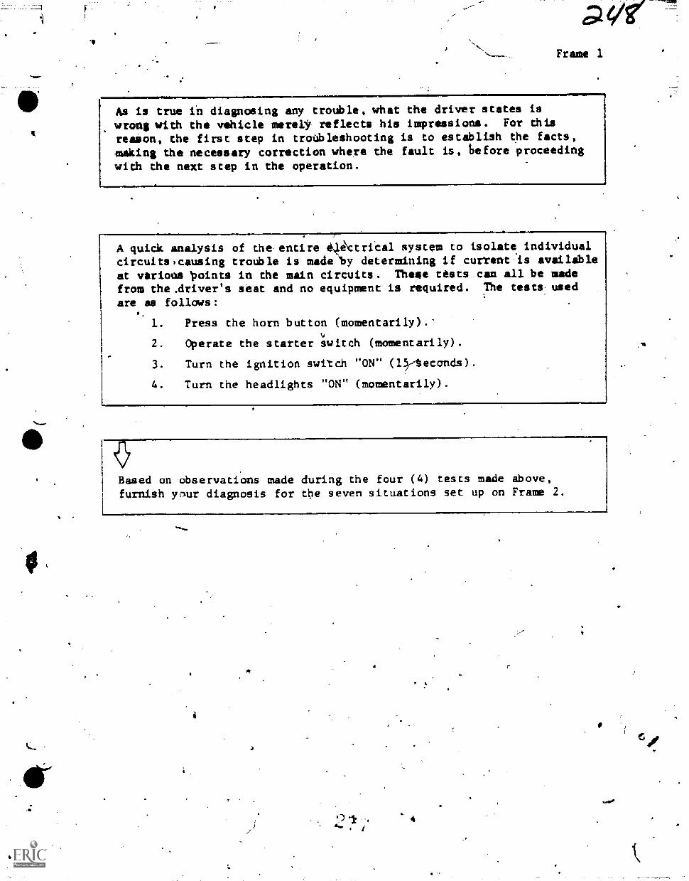
0.veFrame 1
As is true in diagnosing any trouble, what the driver states is
wrong with the vehicle merelY reflects his impressions. For this
reason, the first step in troubleshooting is to establish the facts,
making the necessary correction where the fault is, before proceeding
with the next step in the operation.
A quick analysis of the entire i*trical system to isolate individualcircuits,causing trouble is made "by determining if current is availebleat various 'points in the main circuits. Theee tests can all be madefrom the.driver's seat and no equipment is required. The tests used
are as follows:
1. Press the horn button (momentarily).-
2. Operate the starter switch (momentarily).
3. Turn the ignition switch "ON" (l;teconds).
4. Turn the headlights "ON" (momentarily).
Based on observations made during the four (4) tests made ibove,furnish yriur diagnosis for the seven situations set up on Frame 2.
4
ni
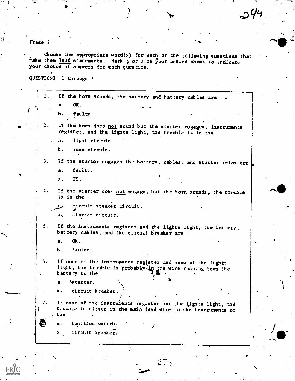
Frame 2
tzD
(loose the appropriate word(s) for each of the following questions thatinake them TRUE statements. Mark a or b on ;our answer sheet to indicateyour choice of answers for each question.
QUESTIONS 1 through 7
eh
p.
1. If the horn sounds, the battery and battery cables area. OK.
b. faulty.
2. If the horn does.not sound but the starter engages, instrumentsregister, and the lights light, the trouble is in thea. light circuit.b. horn ci rcuf t .
3. If the starter engages the battery, cables, and starter relay area. faulty.b. OK.
p.
4. If the starter doe- not engage, but the horn sounds, the troubleis in the
circuit breaker circuit .
104 starter circuit .
5. If the instruments register and the lights light, the battery,battery cables, and the circuit Sreaker area. OK.
b. faulty.
If none of the instruments regke_ster and none of the lightslight-, the trouble is probably4 3 the wire running from thebattery to thea. \starter.b. circuit breaker.
7. If none of the instruments register b_ut the liights light, thetrouble is either in the main feed wire to the instruments or
, the
a. igri-tion switch.b. circuit breakei:.
;dor'
ea)
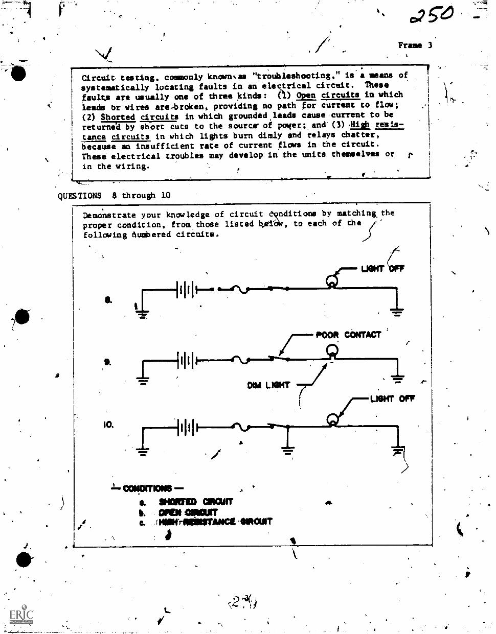
4
Frame 3
Circuit testing, commonly knornas "troubleshooting," is a means of
systematically locating faults in an electrical circuit. These
faults are usually one of three kinds: (I) Open circuits in which
leads Or wires are,broken, providing no path for current to flow;
(2) Shorted circuits in which grounded,leads cause current to be
returned by short cuts to the source" of power;, and (3) III& resis-
tance circuits in which lights burn dimly and relays chatter,
because an insufficient rate of current flaws in the circuit.
These electrical troubles may develop in the units themselves or
in the wiring.
QUESTIONS 8 through 10
Is
A
Demonstrate your knailedge of circuit do,nditions by matchingthe
proper condition, from.those listed bAlat, to each of
font:ming dumbered circuits.
huh
IO.
POOR, CONTACT
4r\jo...aramm..1.
DIM L WIT 71
.111IND.slat
(
LIGHT OFT
MI 1-:"\,"--41,
1..tx*gxnorasS. *MED CIRCUITb. CM GNI=a HilltraillITANCE .0114011T
s2t
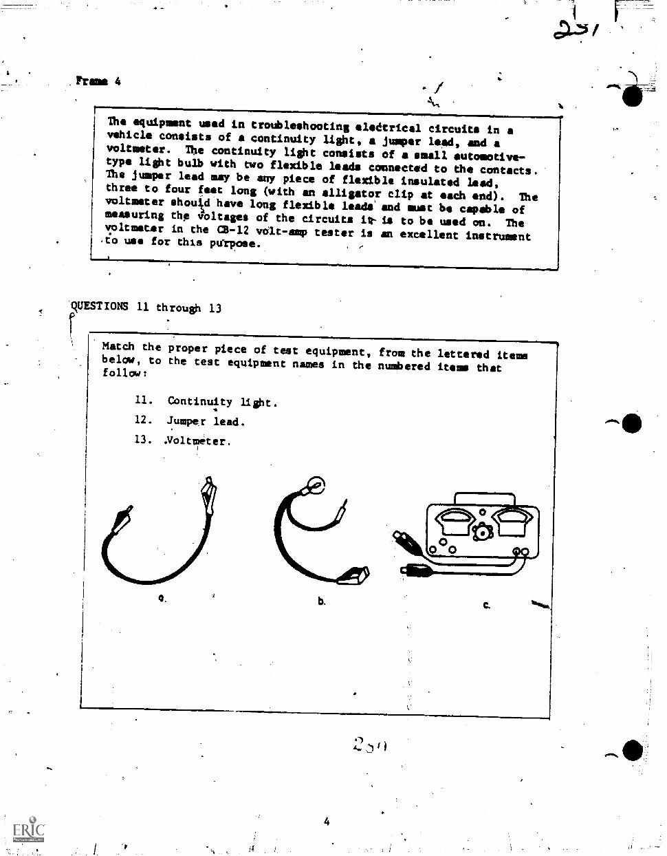
The equipment used in troubleshooting olidtrical circuits in avehicle consists of a continuity light, jumper Leeds and avoltmeter. The continuity light consists of a small automotive-type light bulb with two flexible leads connected to the contacts.The jumper lead may be any piece of flexible insulated lead,three to four feet long (with an alligator clip at each end). Thevoltmeter shouJtd have long flexible leadiand must be capable ofmeasuring the 4Oltages of the circuits itt- is to be used on. Thevoltmeter in the (2-12 vcilt-amp tester is an excellent instrumentto use for this pu'rpose.
IvEsrums 11 througb 13
rMatch the proper piece of test equipment, from the lettered itemsbelow, to the test equipment names in the numbered items thatfollow:
11. Continuity light.
12. Jumper lead.
13. Noltmeter.
G. b.
4
4.
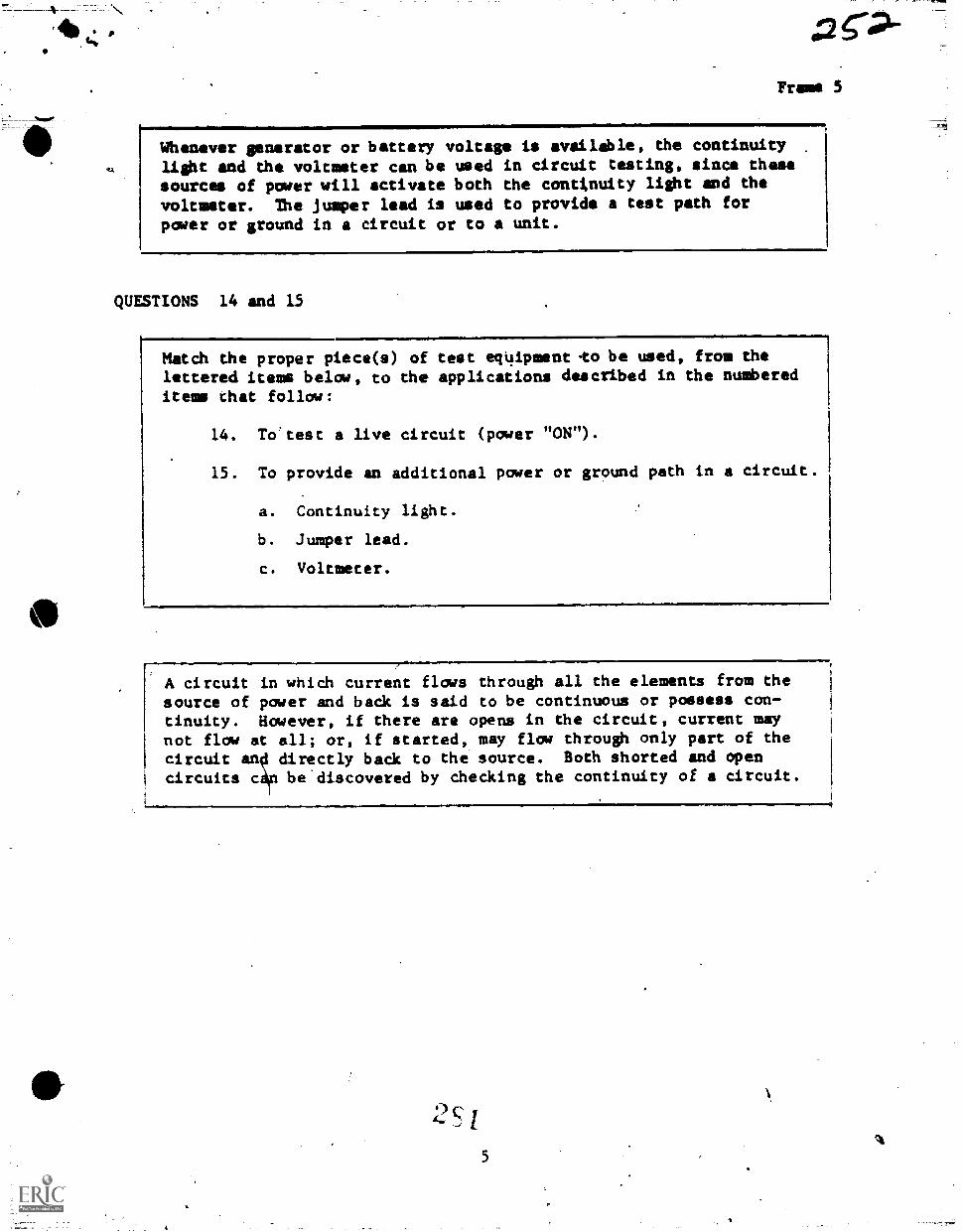
Frazee 3
Whenever generator or battery voltage is available, the continuitylight and the voltmeter can be used in circuit testing, since thesesources of power will activate both the cantimuity light and the
voltmeter. The jumper lead is used to provide a test path forpater or ground in a circuit or to a unit.
QUESTIONS 14 and 15
Match the proper piece(s) of test eqUipment-to be used, from thelettered items below, to the applications described in the numbereditems chat follow:
14. To'test a live circuit (power "ON").
15. To provide an additional power or ground path in a circuit.
a. Continuity light.
b. Jumper lead.
c. Voltmeter.
-
A circuit in which current flows through all the elements from thesource of power and back is said to be continuous or possess con-tinuity. However, if there are opens in the circuit, current maynot flow at all; or, if started, may flow through only part of the
1
circuit an thdirectly back to e source. Both shorted and opencircuits c r be'discovered by checking the continuity of a circuit.
S
5A
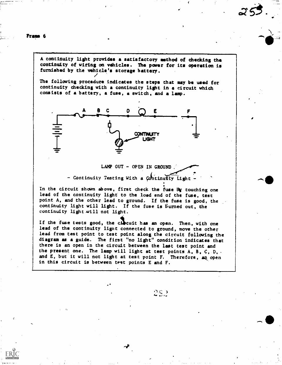
Fre,' 6
A continuity light provides a satisfactory method of checking thecontinuity of wiring on vehicles. The power for its operation isfurnished by the vehicle's storage battery.
The following procedure indicates the steps that may be used forcontinuity checking with a continuity light in a circuit whichconsists of a battery, a fuse, a switch, and a lamp.
am111110el1001 CONTNUITY4106°.1.' LIGHT
LAMP OUT - OPEN IN GROUND .
- Continuity Testing With a Atinutty Light -
AIME,4=111
In the circuit shown above, first check the fuse air touching onelead of the continuity light to the load end of the fuse, testpoint A, and the other lead to ground. If the fuse is good, thecontinuity light will light. If the fuse is Surned out, thecontinuity light mill not light.
If dhe fuse tests good, the cicuit has an open. Then, with onelead of the continuity lignt connected to ground, move the otherlead from test point to test point along the circuit following thediagram as a guide. The first "no light" condition indicates thatthere is an open in the circuit between the last test point andthe present one. The lamp will light at test points A, 8, C, D, s
and E, but it will not light at test point F. Therefore, ak openin this circuit is between test points E and F.
4
-dt
)411,
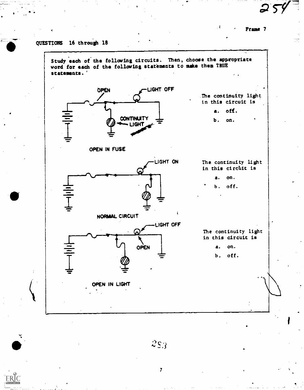
QUESTIONS 16 through 18,IMMmlMNI..01,MMOlimMS,
Frame 7
Study each of the follcming circuits. Then, choose the appropriateword for each of the following statements to make them TRUEstatements.
MMM.
aMM.11116
aimmMIMIMMIS
OPEN LIGHT OFF
CONTINUITY""'"fti
OPEN IN FUSE
LIGHT ON
NORMAL CIRCUIT
"---LIGHT OFF
The continuity lightin this circuit is
a. ofi.
b. on.
The continuity lightin this ciratit is
a. on.
b. off.
The continuity lightin this circuit is
OPEN a. on,
b. off.
momml
OPEN IN LIGHT
4)
7

Trams 8.
A voltmeter with long flexible leads provides a satisfactory methodof checking the continuity'of the wiring and equipment on vehicles.The voltage to be dhecked by the voltmeter is furnished by thestorage battery of ehe vehicle.
The procedure for using the voltmeter in troubleshooting is similarto that of using the coninuity light. The advantage of using thevoltmeter that losses in voltage because of high resistance inthe circuit (drop in voltage)can also be detected.
The following procedure indicates the steps that may be used forcircuit testing with a voltmeter.
C 8 .
DIM LAW
use PP - HIGH RESEITANCI W4 swim
..- Circuit Testing With i Voltmeter -
With the negat ve (-) clip of the volt1Meter connected to ground,move the .positive (+) clip from point to point along the circuit,with thl.power "ON."
Note: Keep in mind that this procedure is for a negative groundcircuit. If you work on a positive ground circuit, you mustreverse the leads.
Test each unit and length of wire. The first below normal voltageeading 9n ehe voltmeter indicates that there is a high resistanceondition between the last point at which the voltage was normal ande point of the below normal indication. In the circuit above, the
voltage is low at.the light socket, test point A, ind at the loadside'of the switch, test point B. At the power side of the switchtest point C, the voltage is normal. Therefore, the high resistanceis in the switch contacts.
2 S I
1,asarli
.01.
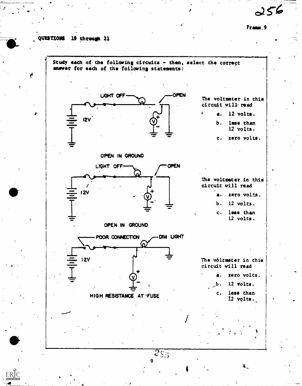
401147I014 19 5hrough 21
Study each of the following circuits - then, select the correctanswer for eaCh of the following statements:
I2V
OPEN IN GROUNO
LIGHT OFF
I2V
OPEN IN .GROUNO'
\--POOR CONNECTION DIM UGHT
HIGH RESISTANCE AT ,FU.SE
Frasis .9
The voltmeter in thiscircuit will. read
a. 12 volts.
b, less than12 volts.
c. zero volts.
The voltmeter in thiscircuit will read
a. zero volts.
b. 12 volts.
c. less dhan12 volts.
The vóltmeter in thiscircuit will read
a. zero volts.
b. 12 volts.
c. less than12 volts..
I.
'
9
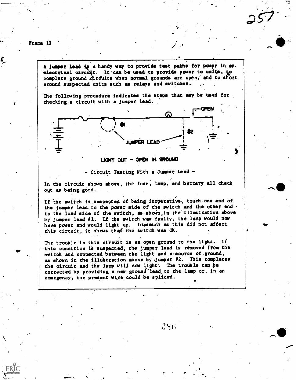
.0
Frame 10
A jumper lead i a handy way to provide test paths for powei in in,
electrical circu t. It'can be used to provide parer to units, cip
complete ground r&its when normal grounds are open, and to shortaround suspected units such as relays and switches.
The following procedure indicates the steps that may he used forchecking,a circuit with a jumper lead.
.. ,
0..0.......p....+.-- ..a.--r.
1
N\#2
1 71.,
JUMP6R LEAD ""...4...."'"...411
...
Lair our - WA IN. IMO- Circuit Tasting With ajumper Lead -
In the circuit,shown above, the fuse, lamp, and battery all checkout as being good.
If 'the switch Ls,suspected of being inoperative., touth.one and of
the jumper lead.to the power side of the switch and the other end ,to the load side of the switch, SS shownlin the'illustration Above
by jumper lead #1. If the switch was- faulty, the lamp would now
have power and would light up. Iffasmodh as this did not affect
this circuit, it shows thei'the switch.Was aK.
The troUble in this ctrcuit is as open ground to the lighx. If
.this condition ii suspected, the jumper lead is removed from the
switch and connected betieen the light and avsource of%ground,
as shown-in the illuitration above by jumper"02. This completes
the, circuit and the lamp will now light'. The trotible can ,be
corrected by providing a new groune'leakto the lamp or, in anemergency, the preeent wise,could be spliced.
:2 (.1 h
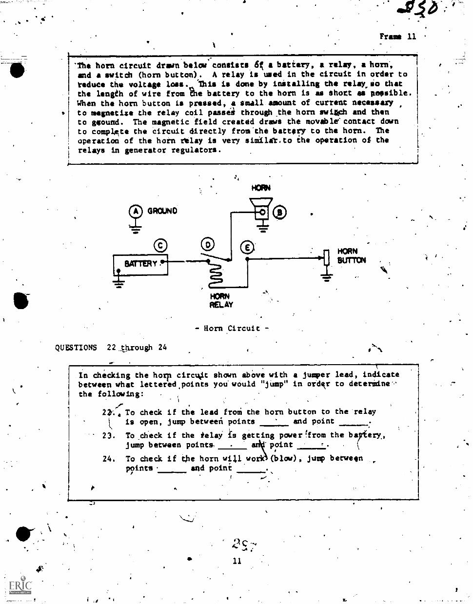
moVFrame 11
'The horn circuit drawn below consists 45 a battery, a relay, a horn-,
and a switch (horn button). A relay is used in the circuit in order to
reduce the voltage loas. 'This is done by initalling the relay,io thatthe length of wire from battery to the horn is as shott as poesible.When the horn button is pressed, a small amount of current necessaryto magnetize the relay coil passei through_the horn swiach and thento gqound. The magnetic field created draws the movable'contact downto complgte the circuit directly from the battery to the horn. The
operation of the hotn relay is very similet.to ihe operation of therelays in generator regulators.
HORN
- Horn ,Circuit
QUESTIONS 22 Orough 24
HORNBUTTON
Aka
In checking the horp circlkit sham abOve with a jumper lead, indicatebetween what lettered.points you would "jump" in oid,kr to determine
the following:
de22r... To check if the lead froi the horn button to the relay
1 is open, jump betweeit points and point
23. To check if the telay is getting poderqrom the bairterx,jump between point& . ad point f.
24. To check if the horn will work (blow), jump betweenpoints. and poini
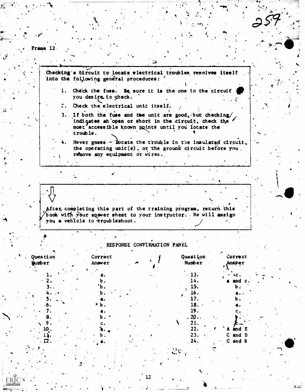
"11
Frame 12,
44141
"Pit
.4.411MMM
4
Is
Checking'a tircuit to locate electrical troubles resolves itselfinto the fol,lowing general procedures:
1
1. thick the fuse. Ht sure it is the one in the circuit fityou des ire.. to .,heck.
, theck the electrical unit itself.
3. ..If both the fuse and die unit are good.,but checking./,,indirtes ah'open or short in the tircuit, dheck tke fmost accessible known pq.liti until yoi locate thetrouble. *
4. Never gness.:11ocate the ticitile in Oe insulated circuit..
the operating unit(s) , or -the grounfi circuit -before you .
rd6ove any equipment Or wires.
ftet, comPleting this part of dhe training program,book witfi !,71sur agewer sheet to your instructor. . He
you a' veh1c1e to -troubleshoot .
returft 'this
will assign
9.
. questionkiumber
RESPONSE CONFIRMATION PANEL
CorrectAnswer
Questi,on
NumberCorrect'duperN
1.s_
2.
3.,
a.b.
.b.
13.
14.
15.
-
a and c.b:
A
4. . 16. a..
5.
.b
a. 17. b.
,6. b. 18. a.
7. a. 19.
8. b. , 20.-
N 9. C. 21.
.1(). 22. % A and E
b . 23. C and D. 24. C and B
,
er S.
A
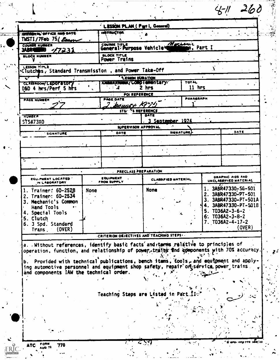
KAN ( P 1 Comm)
TWSTI/7feb 75
=wan: o Vehicle
.4
DLO= TITLEPower. Trains
` Part
LESSON T11`1,14ClUIC Standard Transmission , and Power Take-Off
ROOM
DID 4 hrs/Perf 5 h
'Lessors Maimen ry
2 hrs
P GE NUMBERPOI REPERIINCE
PAGE DATE '
mumevi
StS473X0
TOTAL
11 hrs
PARAGAAPP .4 i
STU REFIRENCE "ISIMIMENEW.M....M..I. 3 S112140er 1974
suPsItVISOR APP*OVAL
SIGNATURg DATE SIGNATOPIE OATIE
r7Ou.PIMINT !-OCATICOIN LAOAATORY
1!..,............'".1..=071/MP11
PRECLASS 'PREPARATION
1. Trainerf 60-2541 None
2. Trainer.: 60-25343. Mechanic's Common
Hand Tools4. Special Tools
S. Clutch6. 3 Spd. Standard' Trans. (OVER)
ICOWPGINTFAGG SUPPLY
CLANAPIE0 IIATEPIAL
None
-CRITERION OMECTIVES ANO. TEACHING STEPS. -
GRAPPIC MOS ANDwect.AssuriliO MAT CAI At.
1. 3A8R47330rSG-5012. 3ABR4733041-5013. 3A8R47330-PT-501A4. 3A8R47330-PT-501B5. T036A2-3-6-26: T036A2-3-8-27.J036A2-4-17-2
(OVER)
a. . Without references, identify basit factsiandrterms /114t1je to principles of ,.
. operation, function, and relationship of powere.trii*Ind ,.SOmponents yith 70% accuracy..
1
., vg 1: .
b. Provided with technical publications, benchitemitIoolsealTpi equtpmept and apply-
ing automotive personnel and equipment shop safity, repair'otsórvica.power,trains 4, -,
ind components IAW the technical order. c P :.:4,Lt00-4*.
,
I.
±4.2
\;,
( r
Teaching Steps are Osted in Patt_11-
.,
'N-
ATC 770mai) 72
1.
1.-"V
4.
Ps.
4
'EQUIPMENT EOCATEDIN LABORATORY
71'Power Take-Off
4
7 r
41
4.
GRAPHIC AIDS AND, UNCLASSIFIED MAT.
8. Film: TFI-4047F9. Chart: CAF8 67-106.
10. " V
'.1 74-2011.
a" 67-264
12V
r 67-265. 413.
ill
" 67-266.14.
os
? ". 67-267. ,15. u ,.,
. " 6726816.
," u67-269
,-
a
A
0t
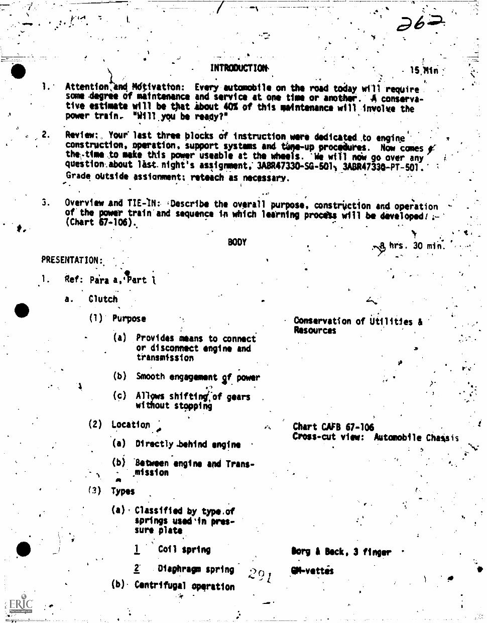
44411 *
a
0
I.
VON.
a
INTROOUCTVW., 15.14
Attention,and *nitration: Every automobile on the road today will requiresome -degree of maintenance and service at one time or another. -A conserva-tive estimate will be Oat About 0% of this maintenance will involve thepower trafn.. "1011.you be meter
Review; Youelast three blocks Of instruction were dedicated .to engineconstruction, operation, support systems and time-up procedures. Now colonythe,..time.to make this power useable at the wheels. 'We will noW go over anyquestionAbout list night's aslignment, 3A8R47330-SG-601% 3A0R47310-PT-501.'Grade outside ssignment; reteach as necessary.
3. Overview and TIE-1N: .0escribe the overalofthe power train and sequence 141 which(Chart 67-106).
BODY
PRESENTATION:. .
1. Ref: Pira aAart
a. Clutch
(1) Purpose
(a) Provides means to connecior disconnect engine andtransmission
oP
I purpose, constrUction and operationlearning procas will be developed,
(b) Smooth engagement if power'3
(c) Al19ws shiftimtof gearswithout stopping
(2) Location.;
.00 Directly *behind engine
(b) Ilebeeen'engine and Trans-. 1 mission
°I(1) Types
.
(0' Classified by type.Ofsprings usedin pres-sure plate
1 Coil spring
2" Diaphragm spring 420
(b). Centrifugal opgration
4,444
,INA hrs. 30 m n.
1.
Conservation of utilities &Resources
Chart COB 67-106Cross-cut view: Automobile Chatisis
Borg & Beck, 3 finger
AN-vettis
:
t.
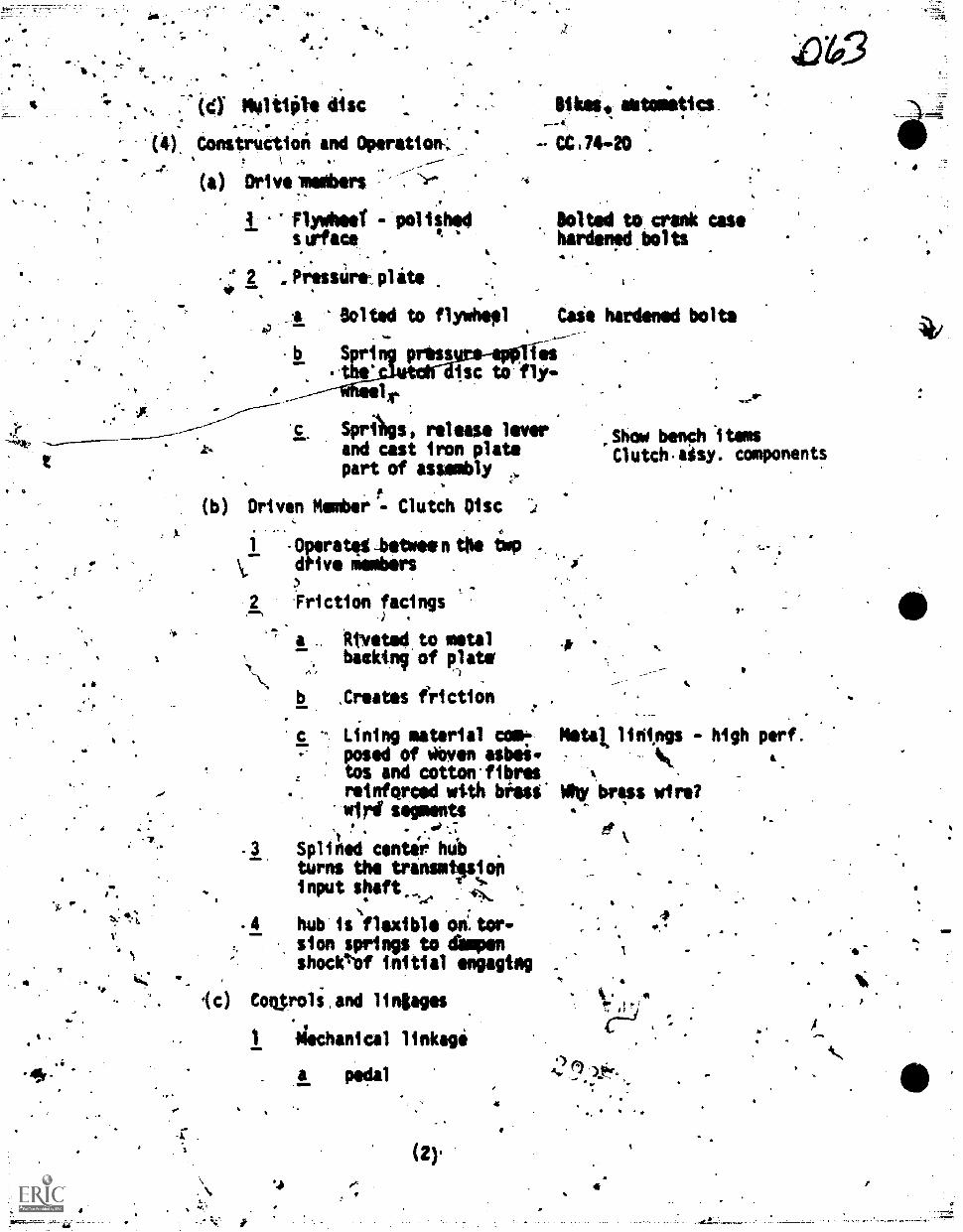
'4**,
I
N
444
t
164inits disc .
(4), Construction and Operation-;,
(a) Drivelembers-
Flydheel - eoliths('skrface
.. .
2 Prustire. plate
Bolted to flywheel
b St: press
1
SprAgs, release leverand cast iron platepart of assembly
(b) Driven Member"- Clutch Disc
'C
4
astometto
CC.74-20 .
Bolted to crank casehardened bolts
Caie hardened bolts
esisc to 'fly-
1 - Operateg ,betwee n the imP. .
\t. dive ambers
2 Friction faci ngs
a . Otveted to metalbackinv of plate
p.,
b ,Creates friction
c - Lining material com-posed of 'Wen asbeitos and cotton-fibresreinforced wi.th bOass'wird' segments .
010 -.7
centiri hubturns the transmissioninput shaft
es.
. 4 hub isflexibl on:tor-sion springs to amenshoclel-of initial engaging
(c) CoOrols,and lingages
Archanical linkage
. a pedal
.4
(2).
.44
400
,shew bench 'itemsCl utch asy. components
S.
S.
Metal lintngs
WIrl! lulu wire?
k.4". :,'
I)r,N
high perf.4.
0,
4-
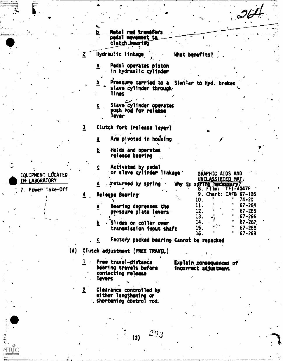
, EQUIPMENT OCATEDLAPORATORY
7. Power Take-Off
-140101-414-104NNON"pedal motitian-clut
Hydraulic linkage.
a Pedal operates pistonin hydraulic cylinder
What bmnefite. .
b Pressure carried to a Similar to Hyd. brakes% Aslave Cylinder through.'lines
c Slave *linder operatespush rod for release,1 ever
,
3 Clutch'fork (release lever)
Atinpivoted in hodsing
4
Holds and operatesrelease bearing
Activated by pedalor slave cylinder linkage'
9
GiAPHIC AIDS ANDUNCLVFIED MAT.
Teturnedfby spring . Why is sOrinfl issIlry?
Relegle Bearing
a Bearing depresses thepressure plate levers
b .Slldes on collar overtransmission itput shaft
B. lm: T -4047F9. Chart: CAFB 67-10610.
11.
12.
13.
14.
15.
16.
"
1.1
v
-11
".
"
"
"11
11
11
0
11
74-20
67-26467-26567-266t7-W.67-26867-269
Factory packed beartng Cannot be repacked
(d) Clutch adjustment (FRES TRAVEL)
1 Free travel-distancebearing travels beforecontacting releaselevers-
Clearance controlled byeither lengthening orshortening control rod
2 0(3)
Explain zonsequences ofincorrect adjustment
.r
-
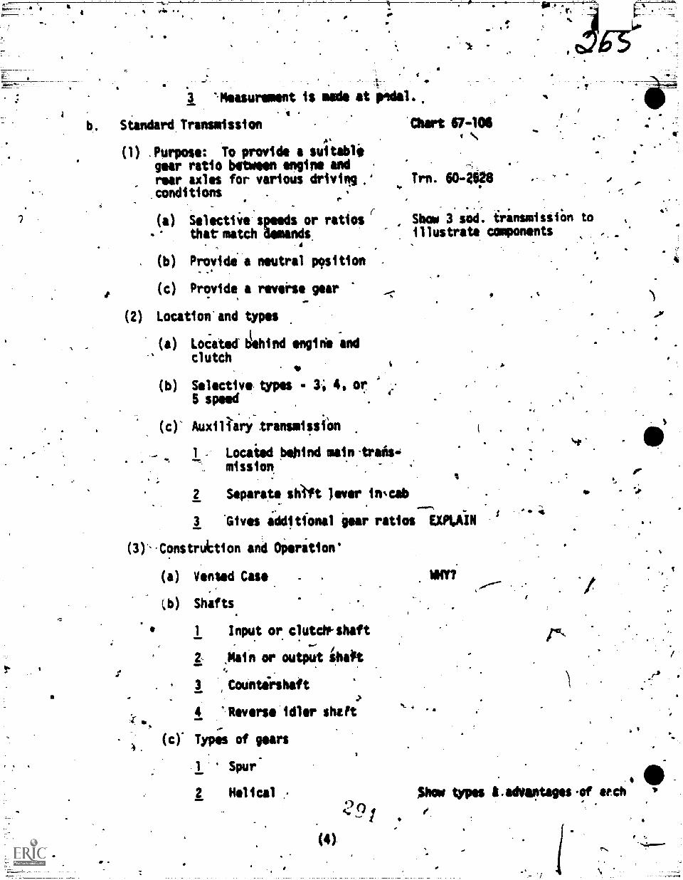
3 '-Measurement is mate at pedal.tb. Siandard Transmission .
(1) Purpose: To provide a suitablegear ratio between engine andrear axles for various drivilg.'conditions
Char t 67 10 6
Trn. 60 -2q8
(a) Selectiie'speeds or ratios r Show 3 sod. irinsmissiOn to
that-match Ulm* illustrate components
(b)
(c)
Provide a neutral p9sition
Provide a revolts, gear
(2) Location'and types
I
(a) locatod behind origin's and
clutch
(b) Stlictiv types 3, 4. or5 $peed
(c). Auxiliary transmissiOn
1 Locaied poind main-trans-mission.
2 Separate shlft Jiver iwcab
3 'Gtves idditional 'gear ratios EXPLAIN
(3)-Construttion and Oierition'
(a)
cb)
Vented Case
Shafts.
1 Input or clutcWshaft
2 ,Main or output iha#t
3 ,Countirshaft
4 "'Reverse idler shaft
(c) Types of gears4,
Spur-
2 Helical
1
(4)
MY?
00
,
1
;,
Pc
$how types Cadoamtages.of.etch
f
t.
\
.
11
( Yr Bearings: toisuPport indalit* shafts fin case, end gearson shafts' .
( ) Bushings: can be used inNMI areas ih lieu of bearing
5
(t) Thrust plates: used to separate WHTL.gears and gears.from case.
Synchronizer unit:. deviceussd to equalize speed oftwo moving gears orshaftsto facilitate smooth engage-ment
'(10 Control.Cover
1 Located on top or side. of transmission case
P Show & explain. .
2 Houses shaft and shifting Also detintsforks
41
3 Connected to shift lver
54,
Operatfon TFI 4047-F
1 Input and counter shafts Charts 67-106 '
in constant mesh 264
2662 Mainshaft is output 266
. 267Reverse idler in constant 268mesh with countershaft. 26.
Power takez.off (PTO)
:(1). Pu;pose: Attachment to trans-mission which provides rotatingfbrce to power auxillary equip-ment
(2) Construction ar;1 Operation
-(a) Sliding gear which will mesh-with countershaft
(b) PTO output shaft connectsto auxiliary component, I.E.winches, pumps
)4,
Trainer:60-2534
Trucks & Triciors.
Show power take-off
4
'5
,
455..
(c) Gear is-00gal or disnengaged from counter-shaft by linkage fromcab of vehicl
(3) TYP4s
(a) Single Gear
(b)' Reproduction
(c) Double drive#
APPLICATION:
1. Ref.cpara b, part,1
Common handtoolsBench...items
EVALUATION:
1. Why do we need a transmission?
t; Define the term gear.
,3. What drives the transmission input shaft?
4. What are the.maJor clutch_compoOnis?
5. How is the'pressure plate Machette flywheel?
6. What are the main purposes of the-clutCh?
. 7. How is clutch free travel adJuitment side?
8. What are the most common tyOks of. clutchoi?
-. 9. $ What holds and op)irates tie release beirinitC
* 10. What keeps the'bearing away fromthe pres,ure plate whoa clutch IS released?
111 Name' the 4 shafts in a transmission.
12. iihat is a synchronizer?;
13.. What drives the countershaft?
14. What is'the PTO.'used for?fa
16. '11here.1s the PTO mounted?
16. Where would you ftnd an auxiliary trinsmimie
4
Usually Mole,
"Specie Tools" -
Dial indicator STRESS SAFETYTO 3GA2-34-2TOTO ifit=2
alt4
e
S.
s
What type' gun. ire watt coolant
-18. Wbattwo types of linkages are usedin clutch control's?
CONCLUSION
SUM4A8* AND REMOTIVATION:
I. In order to transmit power smoothly from tho engine tq the transmission we
use the clutch. The alutch disc then drives the transmission input shaft
,witickidrives other gears to eventually give desire4 gear ratio to the rear
axies. An attachment to tha transmission, called a PTO will allaus to
15 Min.,
./ use the gears to drive auxiliary equipment..
..
. .
A4SIGNMENT AND CIZURE: eCTT POI Para 2a 2 Hrs. . PT 50IA WIZ
A. Review today's lessow.and' principles in preparation for removal, inspection,
repair and adjustments to bezovered in tomorrow's lesson, and read 3A8R47330-
SG-502, and answer review questions at,the end. Conservation of utilities and
resources. #1,
,
IP
a
am,
4
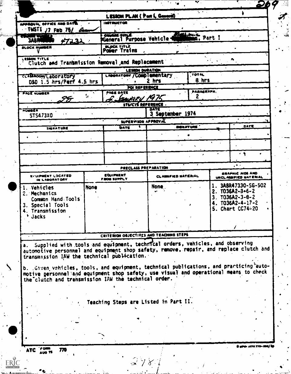
*
Lissom mass ( Om )
INSTRUCTOR
,
APPOIRMAL cornea AND DA
'-TWSTI 7 Feb 75 Assoftor.
--111111111MillLOCA sormagn
V
%
I . ...-.
ner e Vehiclea
PM; TA/ns .
, Part, .
t..ESSOIS TITLII .
Clutch and Trantmission
N
Rimovel,and
,
Replacement.
. .
LIMON MIRA iz_I. -.----7 a ra ryDSO 1.5 Ars/Perf 4.A hrs
AOORATORN emen2 hrs
TOT At
8 hrs
- RIPFAG MUMMER puss own ,PARAOINAPIC
e . .
Tv POMO!1.1r4WW"-----7
ST5473x0 3 timber 1974 .
.. SUPERMOR APPROV
. . .
, ....1...-.sseleATuRt ATE SIONNTIONt DATE
---.6.,. .
,
4.
,
.
. r
PRICLAU PREPARATION. .
EvuIPOIENT LOCATEDIN i ARNO At MY
1. Vehicles2..Mechanics
Common Hand.Tools3. Special Tools4. Transmission'Jacks
FIS0111........None
.
gownworrSUPPLY
CLASSIFIED MATERIALGRAPNIC AIDS AIN)
UNCL AMIPRO NAT (MAL
)
, .
.
None, . ,
..., - ,
,
,
.
1. 3A8R47330-5G-5022. T036A2-346 -23. T036A2-3 -8 -2
4. T036A2-4-17 -25. Chart CC74:-20 .
. ,. awremou otiectilics AND TIACION0 STEPS------:.a. Sueptied with tools and equipment, tech cal orders, vehicles, and observing
automotive personnel and equipment shop safety, remove, repair, and replace clutch and
transmission IAW the technical pub14cation.-.
,
b. ,Glven vehicles, tools, and equipment, technical publications, and prarticingteuto-
motive girsonnel %and equipment shop safety, use visual and operational means to check
the'clutch and transmission IAW the technical order. -
, .
,.
..
. . .
Teaching Steps are Listed tn Part II..
.
, ..
.
)
.
,.* .
, .
.
.. .
-.,
. ,
ATC 1'3" TNMPS TS
4
*Wee 7/79.114114
es.
mnicamoN4
S 8ftI. Attention ana Motivation: Knowing how a certaioLcomponent is constructed,s: .
Now it operator anewhete:it is heated, is really only part of the program.
' We must also be-aware qf how to determine malfunctions, procedures to remove,
and replace these. components and'how to make,necessary repairs..
. .,
.
".
.
-2. Review: Weilave studiid the components of the clutch-assembly ahd opera-
tion of clutch and transmission to transmit engine torque to rear wheels.
4Aow comes the time to performmeintenance, keep in mind-Safety iS our first
concern. At thi's time I will answer any questions about last night's
aisignment-MR47330-SG-502, 3ABR4733041'-501A and 3ABR473,0-PT-5018.
Grade outside assignment: Reteach as necessary.
.5
4
IS Mitt.
PRESENTATIN:
1. Ref: Para a, Part j
a. Shop safety
(1) SecOre taised vehicle
.
BOW 5 Hrs. 30 st4tn.
I.
Assign students to.their respective
vehicles4
.., (a) Place standi under framerails or Axle'housing .
(b) If raising only front ofvehicle block rear wheels
f,
(2) Wear goggles under xehicie Strest safety with use of gogglesN
(3) Keep doors closed
(40 Always stand creepers upwhen not-in use
.; ,
(5) Disconnect Ibitteiy cable
(6) Keep,fingerlaway from mov-ing parts of jack
.(7)VDo not leave toolg under.-foot (especially roundtools)
(i) Wipe up.oil or greasespills immediately
,
Troubleshooting clutch operation
."
11
4
.4
gf.4t:",:.! ^4,
.011,
4
(1) Slippage
(a) ;011 on disc
1 ,Rear Engine oil real
2 Front.transiission
3 Cracked chse
(b) Worn friction Ilning
(c) Improper'free travel
(d)* Defective pressure plate
(2) Clutch chatters
(a) Weak springs in pressure plate
(b) *kit cracked plate of flywheel
(c) Loose facing:on disc
(d) Worn facing on discr,
(3) Clutch Grabs
(a) Defective linkage
(b) Defective preisure plate
(c) Broken torque springs in disc
00 Oil pr grease Spots:on facing,
e Clach*and.transmission removal'andreplacement _
(1)* Raisq & Secure vehicles
(2) Drain transmissiod lubricant
(3) Disconnect shifting linkages
(4). Disconnect dutch' linkage.
W Remove propeller (Drive)shaft
a.
a
a.
Very annoying
Oangerous-Veh Can jumpforward suddenly
Explain RrocoduresTO 36A2-34-2
TO 36A248m2
TO 3024474
.
(a) *tape Unjoi-ni..cups Ar
(it) Instant- Ytor:twAti & WAS.
(6) disconnect spledometer cable.
(7) reigiovetcrOss member or mount
. k..
be necessary-to support engine_ .
(b) May require removal of hand. brace cables
c
(8) .*Remrte attaching.bolts
441e (9) 'Remove.transaissiod.assembly
.(4) use a jack for larger
4. trantitssions
. (10) RemOve clutch inspection 'cover from clutch (bell)housing .
7427-
. 0.
4.
a
A
(a) SoMe.vehiclis requireremoval .of entire clutch `housing
(11) Remove clutchl-ele:ie bearing ,
.(12) RemOve pressurp plate andclutch disc `
1
P.
(a) Mark P. Plate flywheel forproper reassembly
(b). Keep case hardened belts
kemove"flywheel only ifinspectionywarrants refacingor replacement
(a) Check starter ring gear', -
.o
L.
Use transmission jackwhere requ1red-144.
(NOTE)4 sods. cars trucks automatics
ow.
Why?
r
Explain why?
f I_ 0
(b) Cisock.pilot bearing (mitothness).
LocatAid in end of crankshpft
2 Supports and, al *is. trans.-
:mission input shaft
4
AO%
. .
A
,awe
4.44. 4
'04). Torquiflyopqma to crank-shaft-bolts --:*.' .
Cot "4 .-1- .. . ...
\
7 00. Replace in reverse procedure
, . '2.-' r,
m Wore tightening pres-. - sure plate bolts-per-. . a
, Aroma clutch alignment
a.
' 1
(b) Aligning clitte
Clutch irlient is, aliglpg ciutch
splines, transmissionshaft and pilot bearing
1! eerformed with
a Clutch alignment,tool
toolsali
Students 4111 9s. argue
WrencirlAWTO-precidures
;
Cot shift (oldnsmission shaft)
c . Du shtft, shift -'-is machined to
t nsmission input -
, sha t measurements
Insert tool thOough hubon.disc and inr pilotbeartng "..
4 flave tool in place and
begiw,to torque-pressureplate bolts° -
e
5 When tool is knovedClutch dfsc will bqrstationary '
d. Inspection of partsi.
(1) Clutch disc
(a) Worn faciiig
(b) T Loose or m1ss114g rivets
(c) ,Broken torque springs)
-(d) Chipped or twisted splinein hub "392
Wh:
=4.
Warped plate
(2) Pressure Iflate
(4)
.6
2
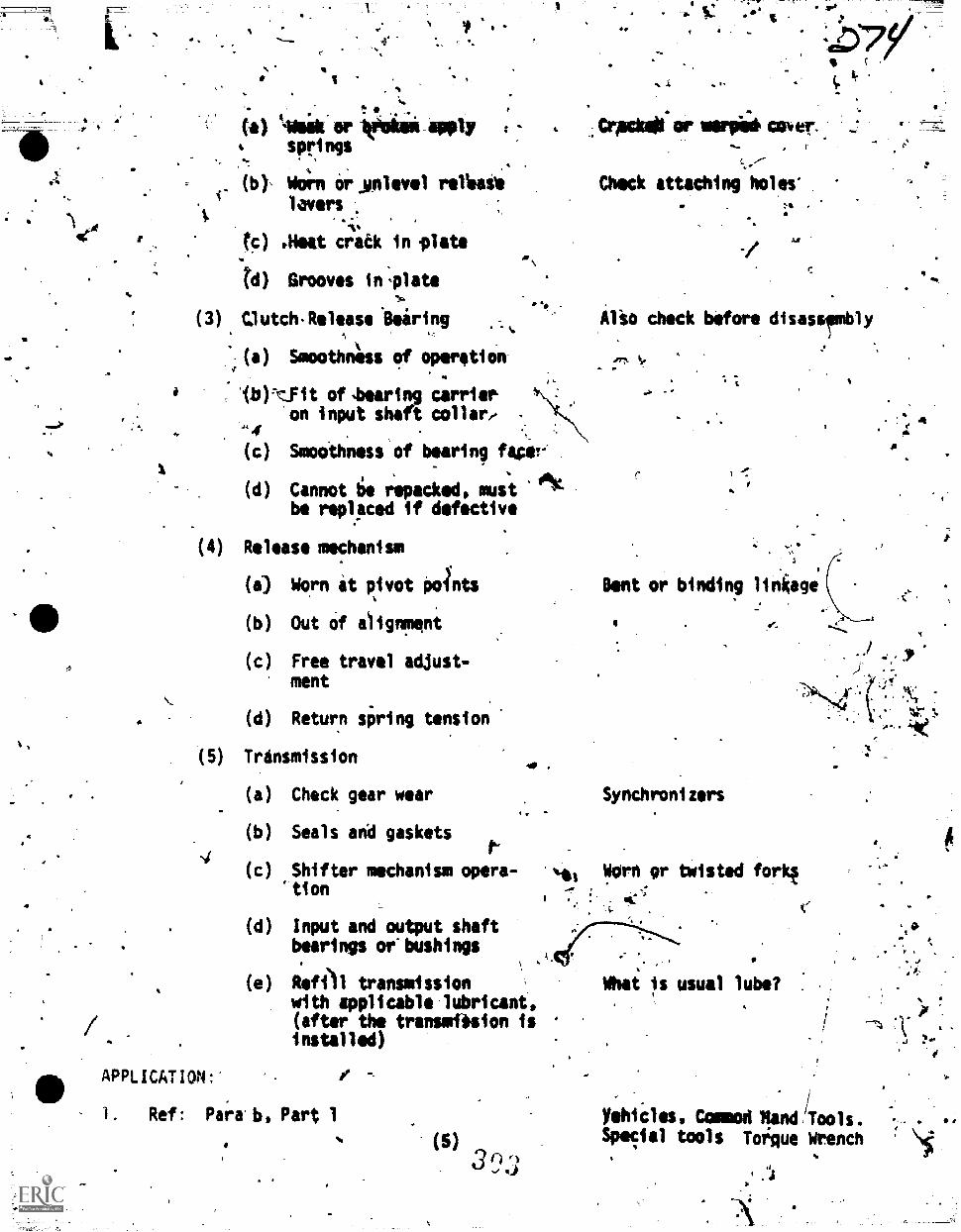
F!
4
4
A
,t
(a) Ii4ailt-ar leggin apply ;
springs
(b), Wci'rn Or ynlevallavers
: .(c) pHeat c;iiek in 'late
N) Grooves in'llata
(3) (3utch-Release *Bearing
(a) Smoothn6s of operatienet
'fb):Yit of .bearing carrier.on input shaft collar/
Smooihness'of bearing facer'
(d) Cannot 16 repacked, mustbe replaced if defective
(4) Release mechanism
(a) Worn at pivot poInts
(b) Out of alignmeni
(c) Free travel adjust-ment
(d) Return spring tension
(5) Transmission
(a) Check gear wear
(b) Seals and gaskets
(c) Shifter mechanism opera-"tion
4.
ott.
(d) Input and output shaftbearings oebushings
(e) Refi)1 transmissionwith applicable lubricant,(after the transmasion isinstalled)
APPLICATION:"
I. Ref: Para' b, Part 1
(5)
,Crpcloai
Chock attaching holes-
-/
Z.0
Also check before disassembly
fr:Lv.
Gent or binding linliage
4
Synchronizers
Werh 9r twisted forkt
4
,
What is usual lube?
Yahi cl as Conon land /Tools .Special tools Torque Wrench
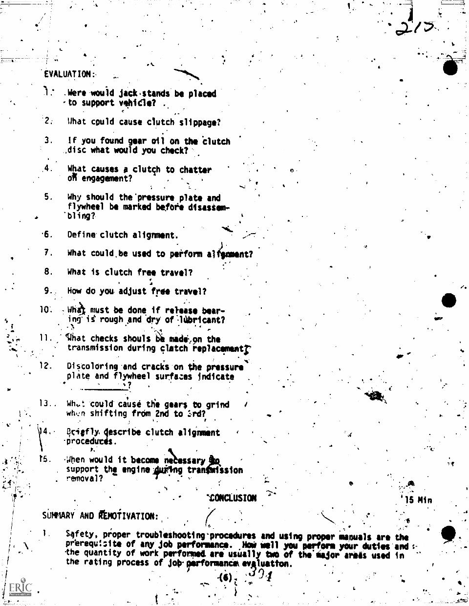
.IVALUATIOM:
1.' .Were would jack.stands be placed,to support vehicle?
What could cause clutch slippage?
If you found gear oil on the Clutch,disc what would you check?
'fz./.1'S.
.4. What causes 0 clutch to chatteroft engagement?
5. Why should the'pressure plate andflywheel be marked befOre disastem-bling?
.6. Define clutch alignment.
7. What could.be used to perform a fIgnment?
8. What is clutch free travel?
f.9.. How do you adjust free travel?
10: must be done if release bear-ing'ii rough And-dry of=14bricant?
11. '14hat checks shouls I modCon thetransmission during cliatch replacfmentr
12. Discoloring and cracis on the pressureplate and flywheel surfam indicate .
-.?
t
13.. WK.': could cause the gears to grindwh,:n shifting from 2nd to .1rd?
r_
14.. 440 *1y. cribe clutch alignment
o.,.
,
-proceducds.
1'5. Alen would it become n:b.essary ,
support the engine9uAng tran4%sion. removal?
,
. .
SUMMARi AND ffEM0fIVATION:,
`TOKLUSION
6.
6
6
Ok
'15 Min
S4fet.Y9 ot4oper troubleshooting'procedures and using proper manuals are theprerequIzite of any job performance. Hei well you perform your duties and s-
the quantity of work perfomet are usially two of th&Major areis used inthe rating process of joirrrformanclkevAluatton.
46). '491
*-
S.
Oa
. 41.!41,:i
.
.- ,..r.x
$4.." .
, 0- -: ..crlisin 2 iss ,
i
.ComOlete 3A8R41330-SG-503, 3ABR473304T-503 for tnmorropiss lessón. livvisat-. on today's matir'sls an4 jobs tell be given before class tomorrow. '.
r I,COnservation of 4t1lit1es & resources.
4
.
b
994
3" 4
St
4
t'
r7,)
11,
1
p.
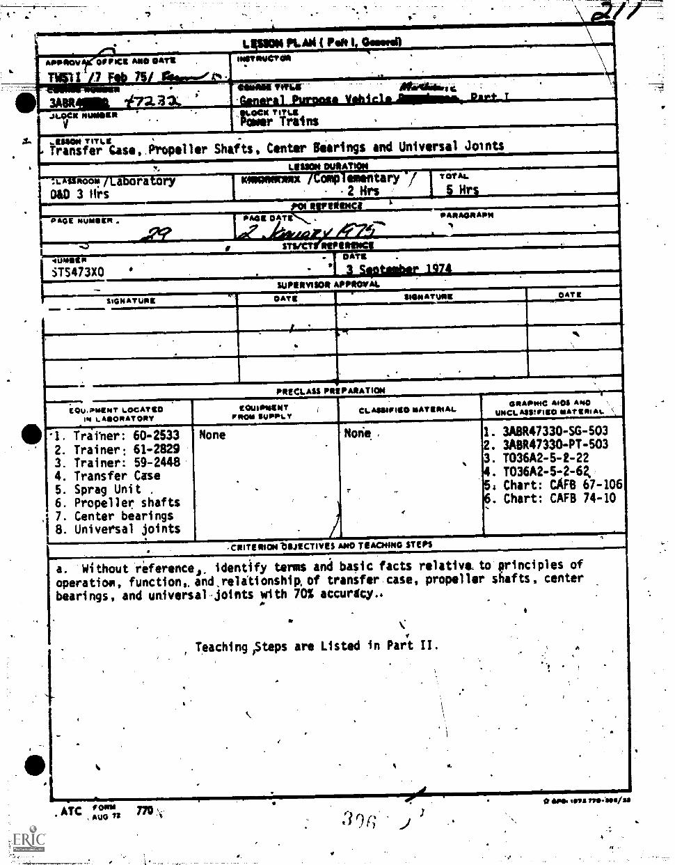
81,11140V *PPM* ANO OAT*
7
3A811411111 47aa.....vot mom'
KAM (raft
INETRIACTOR
A.
.1011111Minriii. mInie
AMMANEVNIA7:- 41064hdii .
1111P111 Pinata Vahiei. Arnimmek Okist, TMeV TintPaaer Trains
rain-
1.,assaw TITLETransfer Case, Propeller Shafts, Center Bier ngs and Universal Joints
ROOM
OAD 3 firs
I ra ryLESSON MEAT 'A,
STS473X0
"Pt
mamATURK
OATS
3 Setober 1974SUPIRVISOR APPROVAL
SIDNATURE°Avg
PRECLASS PREPARATION
ECiu. ?MEN T LOCAT IDL MOOR AT ORY
0 1. Trai'ner: 60-25332. Trainer: 61-28293. Trainer: 59-24484. Transfer Case5. Sprag Unit .
6. Propeller shafts7. Center bearings
1 8. Universal joints
None
101.1111111DITormouSuPPLY CI-AS*411HW MAMMAL
GRAPMIC AI 0$ AIM)%MCI. ASSIFII0 MAT CRI At.
1. 3A6147330-SG-5032. 3A8R47330-PT-6033. T036A2-5-2-224. T036A2-5-2-62,S: Chart: CAF6 67-1066. Chart: CAFB 74-10
Ia. Without reference, identify terms anti basic facts relative_to principles of
operatiom, function,. and,relationshiR of transfer case, propeller shafts, center
bearings, and universal.joints with 70% accuracy..
CRITERION blIJECTIVES AND TEACNING STEPS
Teaching,Steps are Listed in Part II.
.
4.
**POI seta rpe-losiss
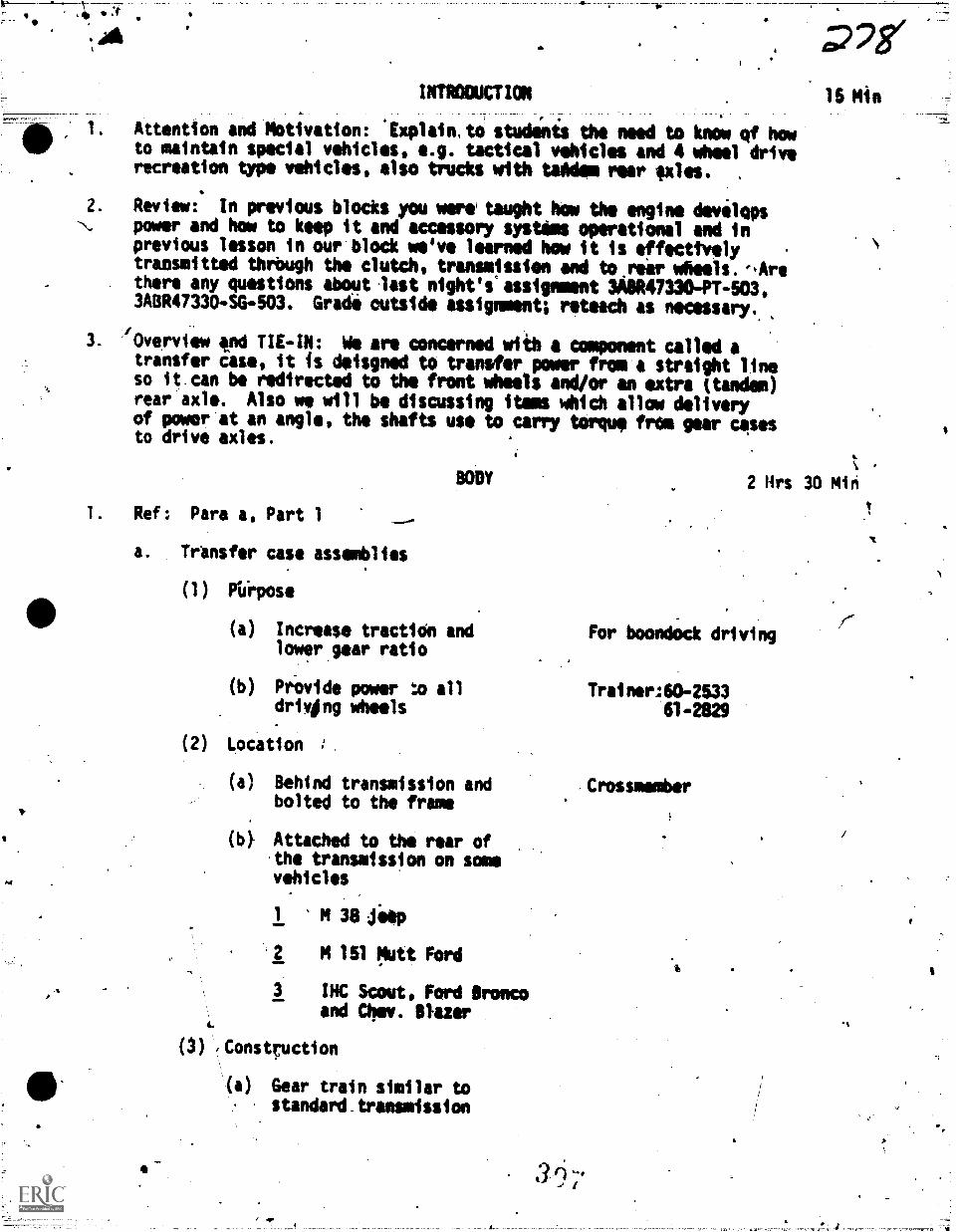
a , SIINTRODUCTION
Attention and Motivation: 'Explain,to studinis the need to know of howto maintain special vehicles, e.g. tactical vehicles and 4 wheel driverecreation type vehicles, also trucks with tandem rear axles. ,
2. Review: In previous blocks you were taught how the engine developsN. power and how to keep it and accessory systems operational and in
previous lesson in our block we've learned how it is effecttvelytransmitted thrbugh the clutch, transmission and to.rear wheels.eArethere any questions about last night's assignment 3A8R47330-PT403,3A8R47330-SG-503. Grade outside assignment; reteach as necessary.,
3. 'Overview and TIE-IN: We are concerned with a component called atransfer case, it is deisgned to transfer power from a straight lineso it.can be redirected to the front wheels and/or an extra (tandem)rear axle. Also we will be discussing items which allow deliveryof power at an angle, the shafts use to carry torque frte gear casesto drive axles.
1. Ref: Para a, Part 1
a. Transfer case assemblies
(1) Piirpose
(a)
15 Min
k
BODY 2 Hrs 30 Min
Increase traction andlower gear ratio
(b) Piovide power :JD alldriving wheels
(2) Location
(a) Behind transmission andbolted to the frame
(b} Attached to the rear ofthe transmission on somevehicles
1 M 381 jeep
2 M 151 Mutt Ford
3 INC Scout, Ford Broncoand Om. Paler
e.
(3) ,Construction
(a) Gear train similar tostandard.transmission
For boondOck driving
Trainer:60-253361-2829
Crosswember
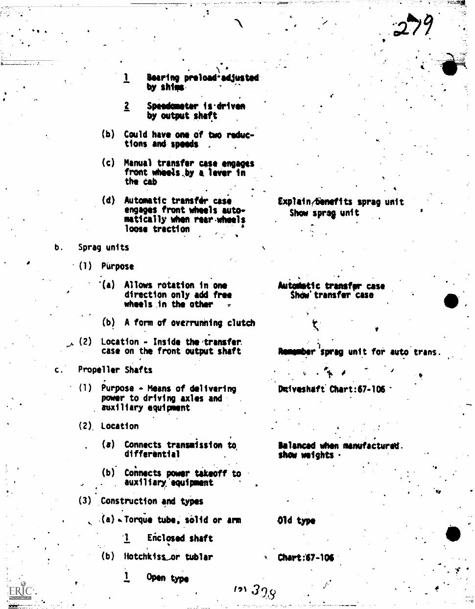
.a
Bearing preload-adjustedby shills,
2 Speedometer is.drivenby output shaft
(b) Could have one of two reduc-tions and speeds . .
(c) Manual transfer case engagesfront wheels,by a lever inthe Cab
( ) Automatic transfer caseengages front wheels auto-matically when rearvhselsloose traction
b. Sprag units
(1) Purpose
(a) Allows roiation in onedirection only add freewheels in the other
(b) A form of overrunning clutch
,x (2) Location - Inside theitransfer:case on the front output shaft
c. Propeller Shafts
(1) Purpose - Means of deliveringpower to driving axles andauxiliary equipment
(2), Location
(a) Connects transmission to.differential
(b) Connects power takeoff toauxiliary, equipment
(3) .Construction and types
.(a) %Torii(' tube, solid or arm
-1 Eiclosed shaft
(b) Hotchkisssor tublar
1 Open type
191
4
Explainebinefits sprag unit
Show spree unit
Autodatic transfpr casethow'transfer case
Nemember sprig unit for auto trans.
11.
Delveshaft. Chart:67-106
Balanced when manufactured,show weights
Old type
Chart:67-106
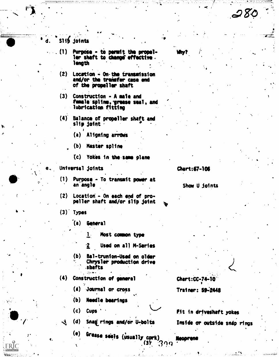
Slit joints4t
"la
(1) Purpose tO permit the propel-ler shaft to chant effedtive.-length
(2) Location - On-the transmissionand/or the transfer case endof the 'propeller shaft
(3) Construction - A sal andfemale spUneorease seaT, andlubrication fitting
(4) Balance of propeller sheet andslip joint
(a) Aligning airdws
(b) Master spline
(c) Yokes in thessane plane
e. Universal joints Chart:67-106
(1) Purpose - To transmit power atan angle Show U Joints
(2) Location - On each end of pro-peller shaft and/or slip joint
(3) Types
'(a) General
1 Most canon type
.2 Used on all MI-Series
Bal-trunion-Used on olderChrysler production drive,sbafts
(4) Conitruction of general Chart:CC-744i-
(4) Journal or cross Trainer: 594448
(b) Needle bearings
(c) Cups Fit in drivethaft yokes
4 (d) Stoat rings and/or U.-.bolts Inside or outside snip rings
(1) Grease sells (Usually cork) ,I0Prens.(3):. 199
/.
<0
q.
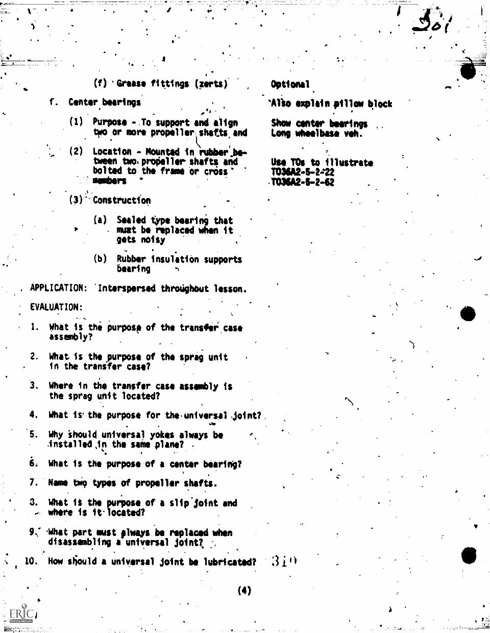
(f) Grease fittings (zerts)
Center bearings094'
(1) Purpose -Jo support and aligntwo or more propellerlshaUkand
(2) Location - Mounted in rubbei.be-tween twos primieller shafts andbolted to the frame or crass%members
(3)- Constructfon
(a) Sealed type bearing thatmutt be replaced when itgets noisy
(b) Rubber insulation supportsbearing -1
APPLICATION: 'Interspersed throdghbut lesson.
EVALUATION:S.
I. What is the purpose of theassembly?
2. What is thepurpose of thein the transfer case?
Wheee in the transfer casethe sprag unit located?
transfii case
sprag unit
assembly is
4. What iv the purpose for the-universal Joint?
5. Why Should universai yokes always beinstalleCir the smile plane? .
6. What is the purpose of a center bearing?
7. Name tWo types of propeller shafts.
3. What it the purpose of a slip joint andwhere is it-located?
9.: 'What pert must flways -be replaced whendisassembling a universal joint?,
10. Now stiould a universal joint be lubricated?
(4)
Optional
'Alio explain pillow 4lock
Show center bearingsLog wheelbase veh.
Use TOs to illustrateTO3M2-5-2=22,T036A24442
:310
-
(\\
.5
a
41, SUMMARY AND MOTIVATION :
COKLUSIO*
. .
1. Transfer cant allows power tp he transmitted to all driving axles% Sprag
units allow power to flow in one direction, free wheels in the othir dtr-
Nection. Propeller shaftsdeliver-power to differentials and auxiliaryequipment. Center bearings support two or more drive shafts. Univirsal
joints allow power to be transmitted at an angle. .
ASSIGNMENT AND CLOSURE: CTT POI Para 4. 2 hrs.
1. Read study pi0 3A8R47330 -PT-504A, 3ABR47330-SG-504.. and be prepared for a daily appraisal. Conservationvesources.
Ma,
s.
(S) -
Revird today's notesof utilities and
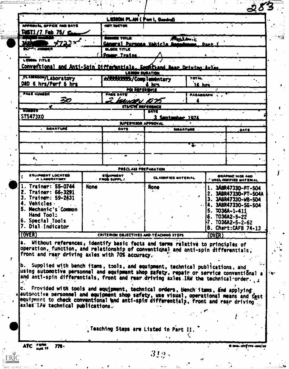
4
.,
LIMON !LAS ( en I GesdrelL, ,
flot ifiSiliiiiiall..._
'111.0"N 4$1161[*
onMOM . s
FrjosjllpppffllriXMAMIIIIIIIIIIIIIIIs i 4,16.. .
*LOCK TM.*'... "
L MOO* ?Ms
CrOinf 1 *, i )i i 4 a , i ,IPIIIOIPIIPIIIPMUIIIIIIII., i . .. . 1 ,,
IMIMMI61111.1111.111111.11111111111Mtii&r:1. aboratory
DSO 6 hrs P 1 it.
'..- .--4,,4 Complemintary
i 6.
TOTAL.
.
I
A An
OMBIA Ohne OAT* . 4 PA*AORAP21 ..- .
...,
WI,,. .. .
STS473X0,
summon APPROVAL. ttlik-I. aciosl... DATE
.:, .
,i linPRECLASS PRIPANATION
; "It, " T 141f-A T II.MINT
- WIN. t CL MVP ISO siATERIAl. ORAMICAIOS A*0UNCLASSMEO NATIMAL
/ I. Trainer: 55-07442. Trainer: 66,32913. Trainer.: 59-24314. Vehicles. .
5. Mechank's*ConnonHand Tool: -
6. Special Tools7. DialAnjicator
None
.
,
.,
.
.
None
A
.
.,
,
I. 3A8R47330-PI-5042. 3A8R47330-PT-504A3. 3A8R47330 -W8 -504
A. 3A8R47330-SG -5045. VO36A -1-444. T036A2-5 -22q. TO36A2-5 -2-628. Chart:CAFB 74-13
(ÔVER) CRITERION 011./ECTIVES ANOTtACIONO STEPS (021.....__,............a. Without referencesi identify basic facts and terms rilativö to princtples ofoperation, funCtion, and relationship of conventiohaj and anti-spin differentials;front and 'rear driving axles with 70% accuracye v;
,
-
b. Supplied with bench items, tools, and equipment, technical publications, endusing automotive personnel and equipment shop safety, repair or service conventiOnal aand ant1-spin differentials, front and rear.driving axles.IAW the technical-order. 44
)c. Provided with tools and equApment, technital orders, bench'itsms, ihd applyint
# automotive personnel and equipment shop safety, use visual, operational means and iistequipmert to check conventional ilnd anti-spin' diffemitialp, front and re4r driving _
xles-TAW technical publications.,. .4°,
i -
. a .
,Teaching Steps are Listed in Part II. .
.
I, (
A 'POW nO $Au* 72
3 1 .)-4 .0
*am m- as
to
,EQUIPMENT LOCATEDIN LABORATORY
O. Front-Driving#00 Assy.
1.,Conventional DM.Assy.
AO. Anti-spin Off.
r
r'
. t
e..
-1°
.!
1
GRAPHIC AIDS ANDUNCIASSIFIED.MT,.
9. Chart:CAFB 67-27410.
11.
12.-
y 13.
1415.
17.
18..
I.
u 67-272" 74L14" 74-15
74-47u 74-125as 74-18
744674-1967-106
.
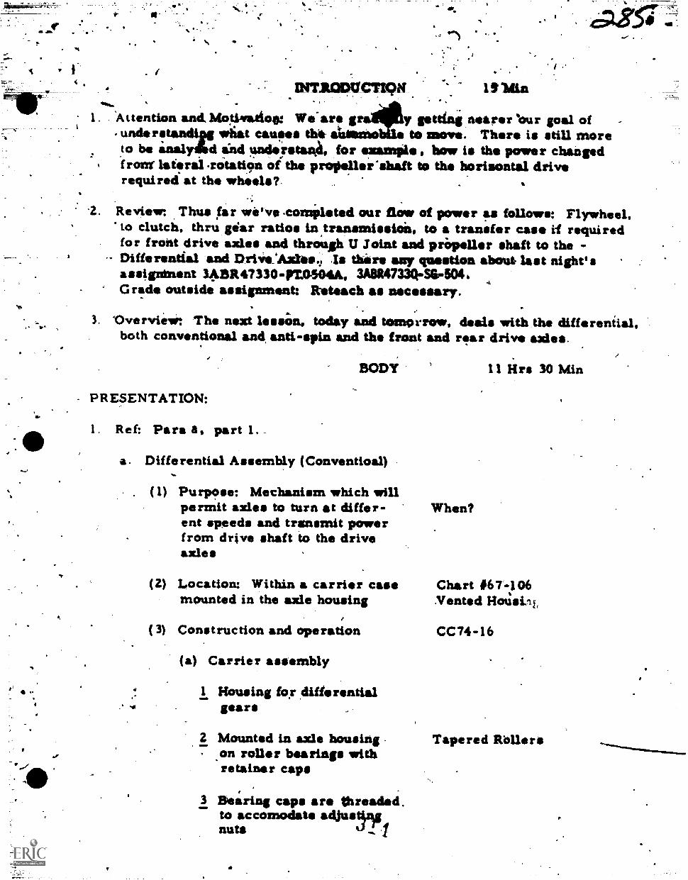
Attention and, Motiva.tioa: We-are g y getting nearer 'our goal ofund.rstsndtN wliat causes thit &Worn* to move. There is still moreto be analy6d a"nd understanA, for examPle, how is the power changed*front laterairOtation oft the propaler'shaft to the horisontal driverequired' at the wheels?,
.2. Review: Thus far we've .comileted our flow of power tys follows: Flywheel.to clutch, thru gear ratios in,transmissia, to a transfer case if requiredfor front drive axles and through U Joint and pripeller shaft to the -
- Differential and DrIvsAxte. Is thire any question about last night'sassigninent 3411R47330-rm504A, 3A8R47330-Ser 504 4
Grade outside assignment: Reteach as necessary.
3. 'Overview: The next lessOn, today and tomorrow, deals with the differential,both conventional and anti-spin and the front and rear drive axles.
INT.P.OPUCTIPM 131tan
BODY 11 ilrs 30 Min
- PRESENTATION:
I. Ref: Para a, part 1. _
a Differential Assembly (Conventioal)
(1) Purpose: Mechanism which willpermit axles to turn at differ- When?ent speeds and transmit powerfrom drive shaft to the driveaxles
Location: Within a carrier casemounted in the axle housing
Construction and operation
(a) Carrier assembly
1 Housing for differentialgears
2 Mounted in axle housingon roller bearings withretainer caps
3 Bearing caps are threaded.to accomodate adjustiAgnuts /
Chart 1067106Vented HousiAL
CC74-16
Tapered Rollers
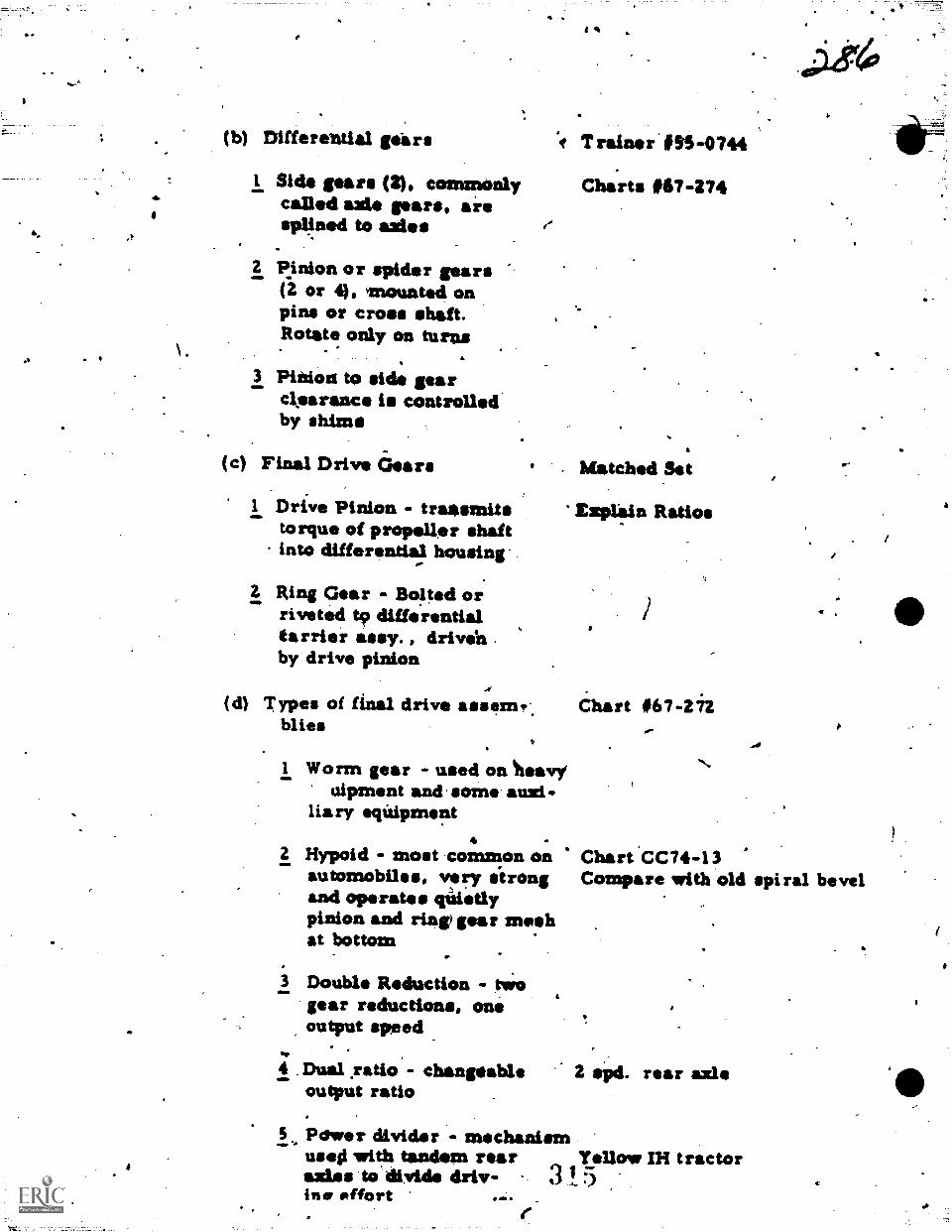
(b) Differential gears
$ide gears (2), commonlycalled axle gears, aiesplined to axles
11.
2 Pinion or spider gears(Z or 4), mounted onpins or cross shaft.Rotate only on turns
3 Pinion to side gearckearance is controlledby shims
(c) Final Drive Gears
I Drive Pinion transmitstorque of propeller shaftinto differential housing
2 Ring Gear - Bolted orriveted to differentialCarrier army. , drivel%by drive pinion
Trainor #55-0744
Charts t67-274
Matched Set
Explain Ratios
(d) Types of final drive :seem... Chart #67-272blies
1 Worm gear - used on Iteavyuipment and some auxi-
liary equipment
aw.
2 Hypoid - most common on Chart *CC74-13automobiles, very itrong Compare with old spiral beveland operates qUiedypinion and ring) par meshat bottom
3 Double Rduction - twogear reductions, oneoutput speed
4 _Dual yatio - changeable Z old. rear axleoutgaut ratio
5 Pchver divider - mechanismuses1 with tandem rear Yellow IH tractoraxles to divide driv- 3 I 5ins offort
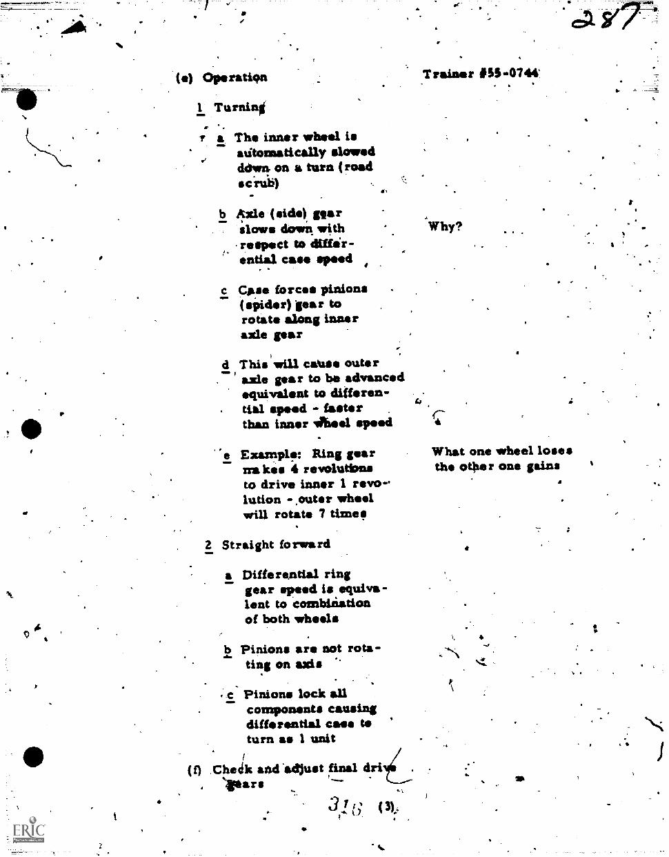
() OPeratiqin
1 Turning
r a The inner wheel I.adtomatically slowedddwn on a turn (roadsc rub)
Is
b Axle (side) parslows down withrespect to diffir-ential case speed
c Case forcs pinions(spider) par torotate along inneraxle par
d This will catuse outeraxle gear to be advancedequivalent to differen-tial speed - fasterthan inner Inwel speed
-
Examplf: Ring gear What one wheel losesnukes 4 revolutbns the other one gainsto drive inner 1 revo-lution -,outer wheelwill rotate 7 times
T raiser #55-0744
4Why?
2 Straight forward
a Differential ringgear speed I. equiva-lent to combinationof both wheels
b Pinions are not rota-ting on axis
.
e Pinions lock allcomponents causingdifferential case teturn as 1 unit
4 I I
(f) Checik and Odlust final dri1
, ..
. ..I 7
.
t31.(1
: ) (3); ..' . .
4
I
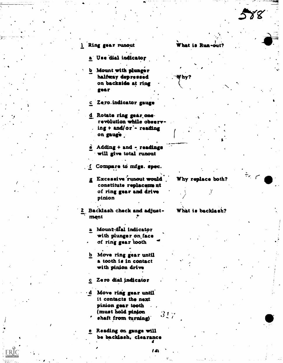
1 'Ring gear rignoat
a' Use dial indicator
What is Run-out?
b Mount with plungs rhalite/Sy depressedon backside at ringgear
Ze.ro.indicator gauge
d Rotate ring gear,one-revolution while observ-
, ing + andior.- readingOft gaug
Adding + and readingswill give total runout
a .f Conyare tO mfgs. spec.
Excessive 'runout wouldconstitute replacens ntof ring gear and drivepinion
2 BacIlash check and adjust-IVIt
a Mount-dral indicatorwith plunger an faceof ring gear "tooth
b Move ring gear untila tooth is in contactwith pinion drive
c Ze ro dial *dicator
d Move ring gear untilit contacts the nextpinion gear tooth .
(must hold pini.on 3 Ishaft from tvning) ... I
e Reading or& gauge willbe backlash, clearance
a
if
Why replace both?
Witit I. backlash?
a
I.
0
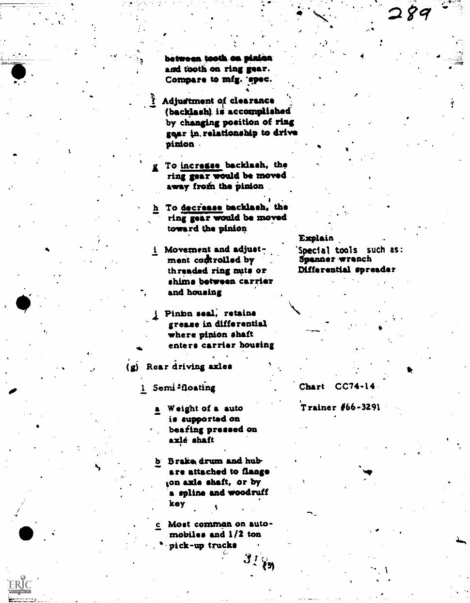
41.
t.
OMP
r-
betfrosa*aeth-elvilinienand tooth on ring gear.Compare to mfg. 'pec.
A
AdjUftnent 1 clearance (%
(backlash). is accomplished*by cl;anging position of ringgcor tn, relationship to drivepinion
To incretse backlash, thering gear would be movedaway fro& the Pinion
I -
To deciease backlash, thering gear would be movedtoward the pinion
i Movement and adjust7ment coil/trolled by ,threaded ring m#s orshims between carrierand housing
Pinbn seal; retainsgrease in differentialwhere pinion shaft
II# enters carrier housing
(g) Rear driving axles
1 Semilfloating Chart CC74-14
4
Explain'Special tools such as:Spanner wrenchDiffe rential spread* r
ID
a Weight of a autois supported onbeating pressed onaxle shaft
b Brake% drum and hub-are attached to flange
on axle shaft, or bya spline and woodruffkey
c Most common on auto--mobiles and 1/2 tonpick-up trucks
51
Trainer #66-3291
Nip
,
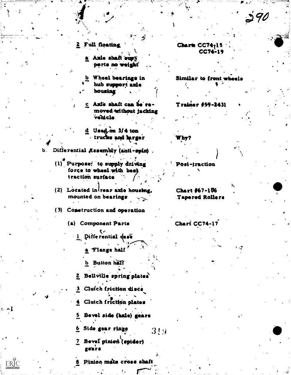
7
MI..
!
a
2 Fun floating '4
1.1
a Axle shatit:siinports.= weight
b Wheel bearings in4' hub suppore axle
c Azt. shaft canmoved Astithout jnelting
Charts CC74T13 .
CC74119
Similar to front.wheels
Traialer 41594431
d Use:4on 3/ 4 tontruass ,aad itrpi .W]ly?
..
b. Differential Assembly tantisp(n) ., .
r.
( 1 ) Purpose:* to-supply aziAling PoSi -tractionforço to wheelWithtraction surfaCe
(2) LOtated inirear axle housing. Chart .67406mounted on bearings Tapered Rollers
(3) Construction and operation
(a) Component Partse
1 pifferential cfasti
4 a %Flange half r
b Button h.411't(
2 Bellifille spring plates
3 Clutch friCtion disCs-
4 Clutch firctiOn plates
5 Bevel side (lurle) Plans
6 Side gear rind!
7 13.71 pinioilk(spidr)got r s
9
8 Pinion mita crOss shaft4
Cheri CC74-11
.11.
:,
-
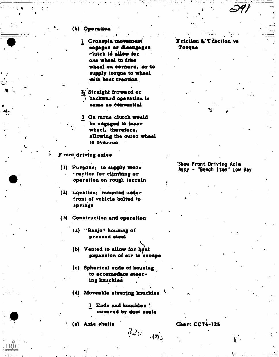
(b) Operation
T
1 Crosspin movement"engaps orclutch to allow forone wheel to friewheel on corners, or tosupply torque to wheelwith best tracdon
II: Straight forward'or\ backward operation is
same as cobvential
3 On turns clutch wouldbe engaged to innerwheel, therefore,allowing the outer wheelto overrun
e. F rant driving axles
(1) Purpose: to supply moretraction for climbing oroperation on roUgt. terrain
5
(2) Location: mounted underfront of vehicle bolted tosprinis
(3) Construction and operation
(a) "Banjo" housing ofpressed steel
(b) Vented to allow for h atexpansion of Mr to escape
(c) Spherical ends ofhousingto accomodate steer-ing knucklei
(cl) Moveable steerfaig knuckles
1 Ends and knuckles 1.coyereci by dust seals
(e) Axle shafts34)0
47)::
I. ct29)
F riction T hiction vsTorque
*Show Front Driving AxleAssy - "Bench Item" Low Bay
e
Chart CC74-125
4te,
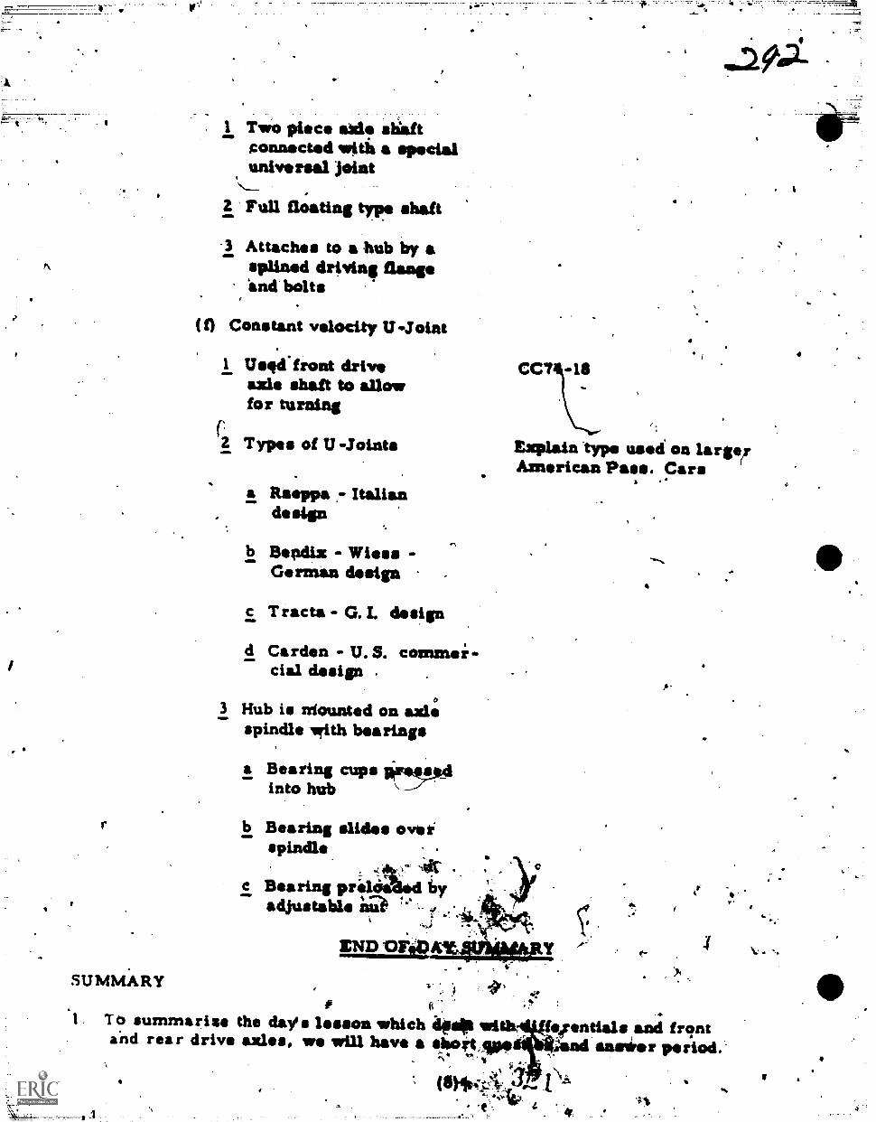
Pt
4
SUMMARY
l Two piece txlit sliaftgonnected with a specialUMVII rsal
Full floating type shaft
-3 Attaches to a hub by asplined driving flange'and bolts
(f) Constant velocity U.Joint
I Usgd.front driveaxle shaft to allowfor turning
z Types of U -Joints
a Rsoppa ,- Italiandesign
b Bepdix - Wiese -German design
c Tracts- G. I. design
d Carden - U.S. commei-cial design .
,
Explain typo used on large!American Pass. Cars
A-
3 Hub is utounted on axlespindle with bearings
a Bearing cups arsruiinto hub
b Bearing slides oveispindle
Bearing prid 6yadjustable ia
ICND OF&MIENWEI
, -.# iigv
i1. To summarise the day's lesson which ilts011 with, etrentials and frgnta.nd rea r drive axles, we will have a sloottAp. ;and Inns r period.-
,, .
'1}
(11)**1.1.'."..
-e:
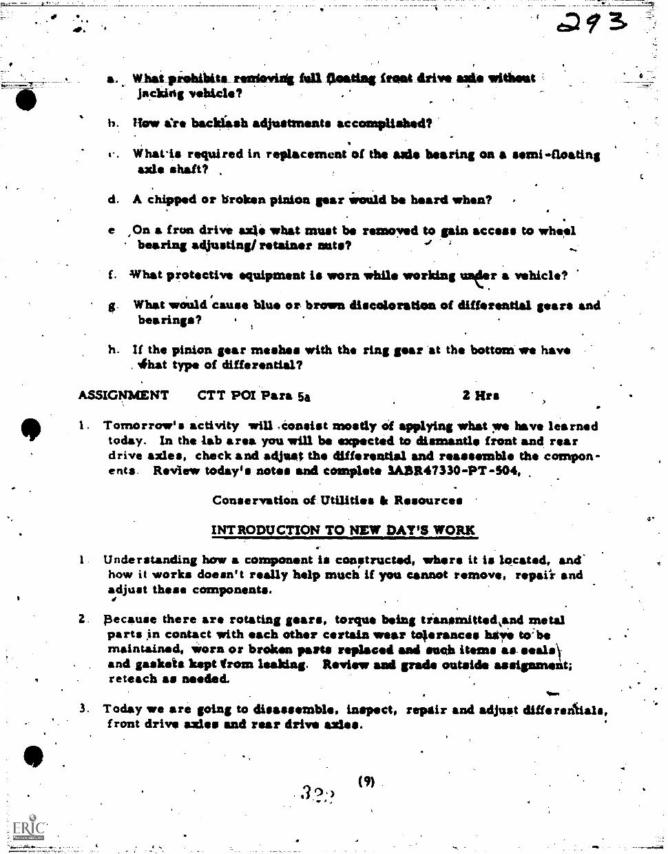
dD 9
What prohibits_ restiovidg full 4limating front drive ells withoutjacking vehicle?
h. How ere backlash adjustments accomplished?
. What.is required in replacement of the axle bearing on a semi-floatingaxle shaft?
d. A chipped or broken pinion gear Would be heard when?
On a fron drive axle what must be removed to gain access to wheelbearing adjusting/retainer nuts?
What protective equipment is worn while working un(ler a vehicle?,
What would cause blue or. brown discoloration of differential gears andbearings?
h. If the pinion gear meshes with the ring gear *at the bottom we have. rihat type of differential?
ASSIGNMENT CTT POI Para 5a 2 Hrs
I . Tomorrow's activity vrill ,Consist mostly Of applying what re have learnedtoday. In the lab area you will be expected to dismantle front and reardrive axles, check and adjuit the differential and reassemble the compon-ents. Review today's notes and complete 3MIR47330-PT-504.
Conservation of Utilities & Resources
INTRODUCTION TO NEW DAY'S WORK
1 Understanding how a component is conrructed, where it is located, and'how it works doesn't really help much if you cannot remove. repaer andadjust these components.
2. pecause there are rotating gears, torque being trinemitted,and metalparts in contact with each other certain wear tol.erances halis to'bemaintained, worn or broken pasts replaced and such items as- sealsand gaskets kept from leaking. Review and grade outside assignment;reteach as needed.
tow
3. Today we are going to disassemble, inspect, repair and adjust differeeeials,front drive axles and rear drive axles.
3 0 )(9)
'APPLICATION:
7
1. Ref: Para b, c, part 1.4
Removal proceckares.-
(1) Raise and secu4\!ehicle',
(a). Jackstand under axle, housing or frame
(b) Do not get underunsecured vehicle
. (c) Wear wiggls under vehicle
(2)% Main Lubricant
. I(a) Observe for metal
. filings
Remove proPeller shaft'
.Remove wheels and brakedrums
arRemove brake backing plate
(3)
(4)
(5)
(a) Rear ail* (semi-floating)this'is else axle shaft
retainer
(b) Some rear axles hive.- retaining clips within'
differential housing
(c) Front 'gills - this alsoconstitutes removingspindle
, (6) Carefully remoie-axle shafts
(a) Front axle - also C. V.U-Joint
(7) Remove nuts from carrierattaChing boTts
(10)
cc
TO 36A-17411
'TO 35A24-22.
TO 316,144-62.
ENFORCE SAFETY!!!Vehicles
Complete 3A8R47339-WB-604
V
Use mechanic's commori
handitoois
O Use "Bench Items" 1.1. Frets% Driving Axle Assy.2. Comintional Differential
43. Amti-spin Differential Assy.
To 1llustrte the ,
requirements for meinten-ance on these units.
Remov rear-cover
6
P
(11) Rovove cassias frosolkossiag
(9) Visually inspect componentsfor:
(a) Worn or tvrislInd splineson axle ahafta
(b) Axle boarings
(c) Discolored carrier bear-ings and cup!'
(d) ,Vorn or chipped spider andaxle gears*
Worn final drive gears
Worn pinion shaft splinesand yoke
(g) Front drive axle - deter-mine serviAeabilitir ofC. V. U-Joint
(h) , Piftiorl and axls.shaftseals
b Repair and adjustment procedures
a
(1) Differential (front or rear)
(a) Chick pinion depth andtooth contact
c\ (b) Check ring gear runout
(c) Check hacklsish
(;) Rear axle shaftsf.
.(a) Pressed bearings
(b) Retains: plate ,gaskei
(c) A3de.shaft seal (in hoein0
olb
Sp.c1a I:001s°=Mrsetlal woad's,
1
s
Whit,. causes discoloration?
.Use white or redLead Paint IAW TO
Dial indicator
ussytig,:l
" 1
04,
.14
s..
a
(3) Front drive ante
(a) 'Bushing in housing.
(b) C. V. U -Joint
1 Handpack with greaseupon.assembly
2 Check 1,140bit foksmoothness of opera.-tion
(c) Spindle housing gasket
Refnstall in reverse procedure ofremoving
E V UA TI N
1 How would.you secure a raised vehicle?
2. What would be the course of action Uthe ring gear runout proved to be inexcess Of mfgs. spec.?
3. .-,What would à the most obvioU dia.erence between a front and rearaxle .ithaft? '-
What transmits tUrning force o( thef runt' axle shaft to the hub?
What is the diffeience between a full-floating *axle and .iemi-floating axle?
How would you classify a frant -drive axle?
7. Where does the front driveaxlederive its power from?
8. Ho* do yOu .change tha amount of backlash?
4. What lubrication is required wheninstalling C. V. U -Joint!?
(l2)1,
,
at
cow:um:at 1 min
SUMMARY AND REMOTIVATION:\.1
S.
1 A differential is used to drive the rear wheels at different speeds asrequired during turning operations. Aattspia difkrentials use a series fofclutches to direct 92e pewel; 14) the wheel with theibeet traction surface.Vehicles *designed for off highwsty use, usually ate equippdd irith a drivins.axle in front for added traction.
Referring back ta the power plant, clutch, tranenitsaion and transfer casewe now see a complete picture by lammingAbout the differentials, axlesand drive wheels, our power trains aie now complete.
ASSIGNMENT AND CLOSURE: crr pa pars 54 2 hrs
Ss'
1. Starting with tomorrow's lesson, SG & WB SOS, we start studying an itme whichis,incressingly becoming more Ovular on sedans.and pick 'up, the automatictransmission; Conservation of utilities & resources.
2. Now is the time to begin considering the faci, you'll soon b expected to beable to assist in repairs of any auto.. Principle remains the same.
MPH,
4.
M. *FP= Apo amt.TWST1i7 Feb 75/
PostitucTopr -
x ,
,imatat laimake . .1.
V .
_
-MACK TITLa r&
Power, Trains *-- 4 w,
LIMN ToTLEPrinciples of Automatic Trani
4 f . ,I
p ioni.
.
MOON AT ... )
I. - i .. ..re ryDV 6 hrs
_4.1 . elentary2 h
TOTAL
1 - -
ap, .
*Mit ow - . PIANAGNARN
-., , l,STSICT P -
.
suisibt .STS473XV 3
suporvisol APPROVAL; .
DAT& ENDNAing DATE
... .
.
,
. ... . .
,.
1..- .. .
. .
.
. PRECIASS lief P ARA TION . I
EQUIPNENT LOCATEDHs LAGONATOOY
1. Trainer: 59424692. Bench-Ites,
Misc.
.
. .
eauslINENTPINGS SUPPLY
None
.
. 4 CLASS/PIED RATtina.t.
None
. ,,
,
.
011.ANINc AIDS kW)UNICLNISIPIID NATVIIIAL
1. 3A8R47336 -SG -50S
2. 3ABR47330-PT -SOS
,
; CRITERION 011JECTIVES AIM TEAONNO STEPS
,
a. Without references, identifY4basic facts and terms relative to termit:olOgy,
planetary-gears and hydraulic principles of 'automatic transmissions. Students will
apply them to selected functions and operations of a simple two speed autcaatic trans-
missions with 70%-accdracy.
. ..,
, "Teaching Steps are listed 'in Part'll..
.
.
_
.,. #
.
. -... I ., ,
ATC 'el" 770AUG 73
* aim orram-assiss
a,.
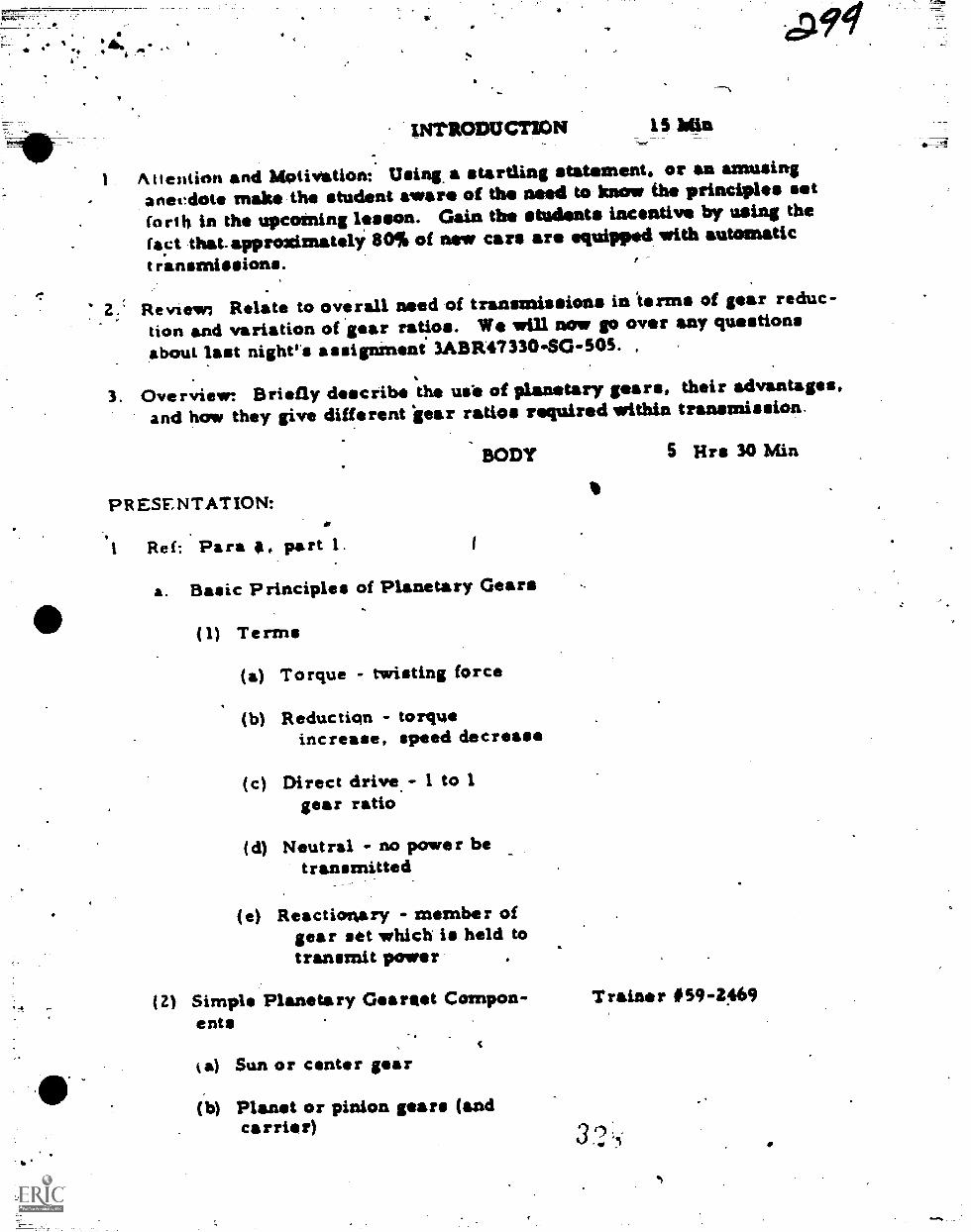
dies 94
INTRODUCTION IS Min
Attention and Motivation: Using a startling statement, or an amusinganecdote make the student aware of the mod to know the principles let(art,' in the upcoming lesson. Gain the students incentive by using thefact thatapproxiznately 80% of new cars are equipped with automatict ransmissions.
Review Relate to overall need of transmissions in terms of gear reduc-tion and variation of gear ratios. We will now go over any questionsabout last night.* assignMent 3ABR47330-SG-505. ,
3. Overview Briefly describe the use of planetary gears, their advantages,and how they give different 'gear ratios required within transmission.
BODY 5 lirs 30 Min
PRESENTATION:
I Ref: Para , part 1. 1
a. Basic Principles of Planetary Gears
(1) Terms
(a) Torque - twisting force
(b) Reduction - torqueincrease, speed decrease
(c) Direct drive.- I to 1gear ratio
(d) Neutral no power betransmitted
(e) Reactionary - member ofgear set which is held totransmit power
(2) Simple Planetary Gearaet Compon- T raine r #59 4469ents
a) Sun or center gear
(b) Planet or pinion gears (andcarrier)
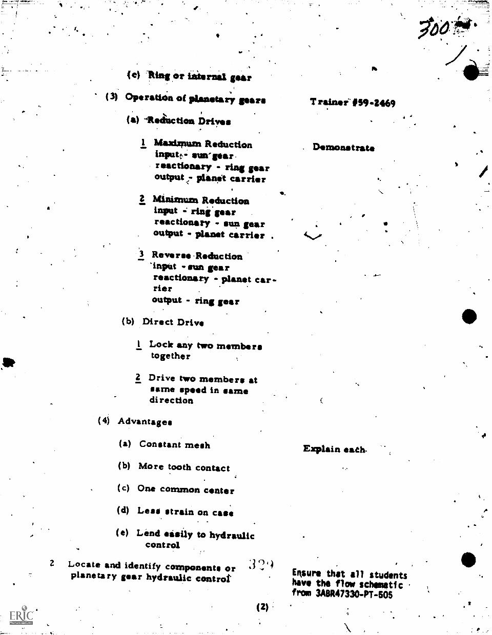
(e) this ,or internal gear
(3) Operatian of planetary pars T rainef' O594469
(a) -ilteauction Drives
1 MOAdgtIAM Reduction . Demonstrateinputc-- emvparreactionary - ring gearoutput <- plan:t carrier
2 Minimum Reductioninput rine.gearreactionary - sun gearoutput - planet carrier 4s.of
3 Reverse-Reduction*inpUt sun gearreactionary - planet car-rier ,
output - hng gear
(b) Direct Drive
I Lock any two memberstogether
2 Drive two members atsame speed in samedirection
4--
(4) Advantages
(a) Constant mesh Explain ends-
(b) More tooth contact
(c) One common center
(d) Less strain on case
(e) Lend easily to hydrauliccontrol
2 Locate and identify components orplanets ry gear hydraulic control'
3'1'4Ensure that all studentshave the flow schematicfrom 3A8R47330-PT-605
(2)
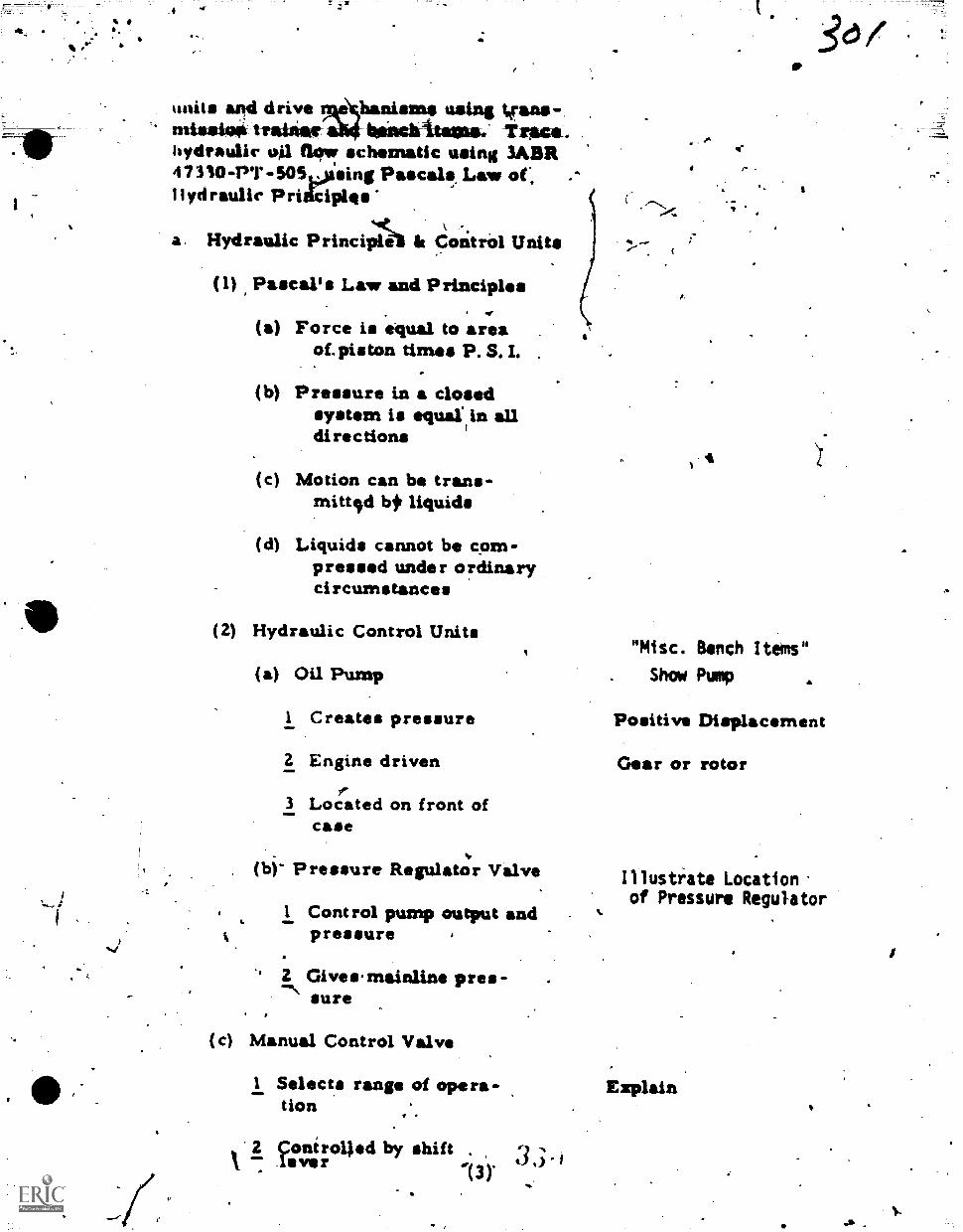
'mils and drive eb&aisms using VSA1bgliacititseas.: -Toare .
hydraulic 401 flqer schematic lacing MBA4 7 310-PT -503oasing Pascal', Law of,II yd raulie P ri4ciples
a. Hydraulic Principlei It Control Units
(1) Pascal's Law and Principles
(a) Force is equal to areaof, piston times P. S. I. .
-
(b) Pressure in a closedsystem is equalin alldirections
(c) Motion can be trans-rnittfol bir liquids
(d) Liquids cannot be com-pressed under ordinarycircumstances
(2) Hydraulic Control Units
4 r -
4
"Misc. Bench Items"
(a) Oil Pump . Show Pump a
1 Creates pressure Positive Displacement
Z Engine driven Gear or rotorf
3 Located on front ofcase
(b)- Pressure Regulator Valve
1 Control pump output andpressure
Gives'mainline pres-sure
(c) Manual Control Valve
Illustrate Locationof Pressure Regulator
1 Selects range of opera- Explaintion
gonerolled by shiftlever 0.)13)
Lin Tlisrottle Valve
I Delay/ upshift
2 dpntrolled by accelera-tqr linkage or vacimmrliodulator
3 Maiters pressure accord-ing to engine speed
(e) Automatic Shifter Valve
Controls, application ofbands and clutches (auto-
. matic upshift)
2 Is opened and closed bypressure from governoror throttle valve andspring
(1) Gove rnor
1 Causes upshift
2 Driven by outputshaft
3 Meters pressure accord-ing to road speed
"Misc. Bench Item"
Shp?, throttle valve
4.
(g) Valve ,Control Body Bench Item"Shaw valve body
1 Houses hydraulic con-trol valves - i.e. pres-sure regulator valve,manual valve, "automatic
. stifter valve
2 Usually located -iissidethe tranismission case
.(h) SeXwo0
i Hydraulic cylinder usedto apply bands
Sat
v
4
4!
ao.
2 Hydraulic applied springrelefteed
3 Conweits hydraulic pres-Burp to mechanical force
4
(i) Bands
I Friction lined band usedio hold one memlber reac-
. tio.nary for recbiction
2 Applied by servo .
(j) F riction Clutaes
1 Multiple disc
2 Applied by hydraulicpiston released by spring'pressure
3 Used tol lock two memberstogether for direct drive
(3) Actuating and Shifting Controls
(a) Neutral (engine running'not =lying)
1
1 Pressure to regulator
2 Regulator to munual valve
3 Regulator to governor
(b) Low range,- (moving slowly)
1 Servo applying band
2 ThrOttie valve delayingupshift
3' Slight governor pressureto shifter valve
(c) High Range (Direct Dri4e) .
3 3
Simple two speed
SOF
fog
4
61 Governor r 0,
Increase to overcamethrteile pressure
2 Shifter valve opens torelea"band and apilyclutch ,
(d) Closed throttle downshift/
1 GOvernor pressure /deireases IAW roadspeed
2 ,Throttle pretioure anding close shifter
3 Clutch is released andband reapplied
(e) Forced downshift (passinggear)
1 Movement of accileratorcauses throttle valveto open fully
2 Throttle valve pressureovrcomes governor pre.-sure causes shift valveto. close
3 Clutch is released andband appliod
Pass out copies of3ABR47330
coNtLIATONStiNCVAWY AtiP MOTIVATION r IkMin
Simple planetary gear sets, copiloting Ore., An; gear, sun par, and plane-tary carrier, are used tp obtain various gear ratios.. Reduction or torqueincrease is obtained by holding one member reactionary and driving another,while direct drive is obtained by locidng two members together. To holdone member, we spply a band with a servo, to lock two member* we applya clutch with a hydraulic piston. Servos and hydraulic pistons are actuat idby hydraulic pressure created by the oil paw. The pressure is regulated
(Alr14;i
a
(by the pressure regulator valtie and dist:Minded to various con-
.. T:711"-srati-gv.aurondeutIT'strt res-grin period).1.
ASSIGNMENT AND CLOiURE crr POI Para 6. 3A8R4731)-SO-506) 2 hrs
1
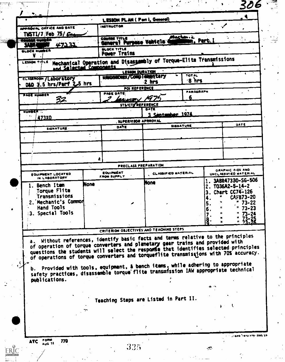
,
.
,LISSOM FLAX ( Pot I Gowen
APP1116WAU 0 :MR AMO OATE -
TWSTI/7!Feb 75/eda.,.1.e.
,
ImSTOWCTON., (
. .,
4000amult k,. . . ,:.
Genre *Ithielli : .
Iiiiiiiii11111111111iiiiiLE Mechanical Operation
!LOCK TITIAPower Trains ....6.....-2.......
and Ditpeaubly of Torque-Elite Transmissions
. ui . 1..AT .... . . .
L T a - a '17D&D .5 hrs/Perf hrs
,
ry a. TOTALI
.2 hrs II ihrs
MEd 'ff721111111111a041/40e4Salliiiiii' RIPER
....
""44111/1111111111111111111111111iiiiiilliiiiii111111111011111111111111111111111111, SIII0ERVIIOR RPRROVAL
.
SIGNATUREEIGNATunit Om
.7
.
A
PRECLAss PREPAIATION
EQUIPINDET LOCATEDIN LAEOPIATODY'
GRAPPHC AKA AND
1112!!!!!!!!!!!UNCLAssietED wit eilti at.
!IIII
1. Bench ItemTorque FliteTransmissions
2:Mechanic's CommoHand Tools
!3. Special Tools
,
I i
.
one
.
,
I. 3A8R47330-SG-5062. T036A2 -6 -14 -2
3. Chart CC74-1264. " CAF873 -20
5. 91 " 73-226. " " 73-237. II " 73-24
, CRITERION 011JECTIVESAND TEACHINO STEPS,
to the principlesprovided with
selectild.-principleswith 70% accuracy.
to appropriatetechnical
.
c
....._.,--1.-.....----,------
['
a, Without references, identify basic factt and terns relative
of operation of torque converters and planetary gear trains and
questions the students will select the respode that identifies
of operations of torque converters andtorqueflite transmislons
b. Provided with tools, equipment, A bench items, while adhering
safety practtces, disassemble torque'flite transmfssion IAW appropriate
publications. ,
. .
Teaching Steps are Listed in Part II.
....
.
.. .,
Aronr.ATC F°14" 770AuG ia/
a GPO .11112 779-3111411j83
z
C.
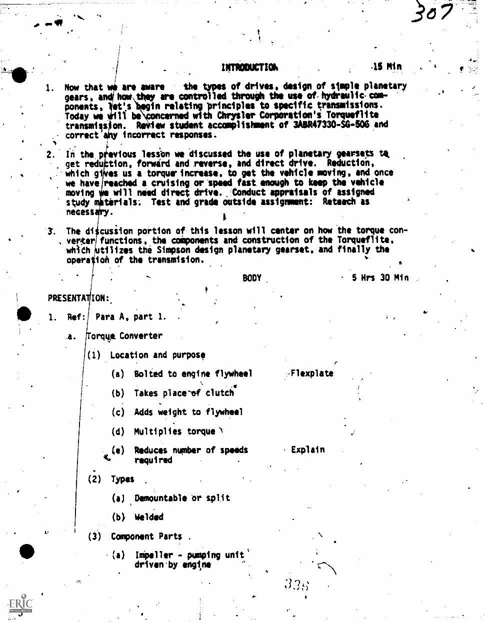
04.11,
INTRODUCTIOK 45 sin
Now that we are aware the types of drives, design of simple planetary
gears, andihow they are controlled through the use of,hydraulic.com-
ponents, et's eg1n relating principles to specific transmissions.Today we ièlfl bioncerned with Chrysler Corporetion's Torqueflittransmiis on. ReView student accomplishment of .3A8R47330-SG-506 and
, correct y incorrect responses.
In the,p evious lesion we discussed the use of planetary gearsets ta.get redu tion, forwird and reverse, and direct drive. Reductidn,
which gi es us a torquarincrease, to get the vehicle moving, and oncewe .have jreached a cruising oripeed fast enough to keep the vehiclemoving will need direct drive. tonduct appraisals of assignedstudy tirials: Test and grade outside assignment:. Reteach as
necess tThe di cusiion portion of this lesson will center on how the torque con-
, vertteri functions, the coiponents and construction of the Torqueflite,whieh utilizes the Simpson design planetary gearset, and finally theopera ioh of the transmision,
PRESENTA ION:.
411 I. Ref: Para A, part 1. .
4. orq4e. Converter
(1) Location and purpose
t..
BODY 5 Hrs 30 Min
(a) Bolted to engine flywheel ,Flexplate
(b) Takes place-of clutch
(c) Adds weight to flywheel
(d) Multiplies torque
(e) Reduces number of speeds Explaintt. required
(i) Types
(a) ,Demountable or split
(b) Welded
(3) Component Parts .
(a) Impeller - pumping unit'driven'by engtne
of
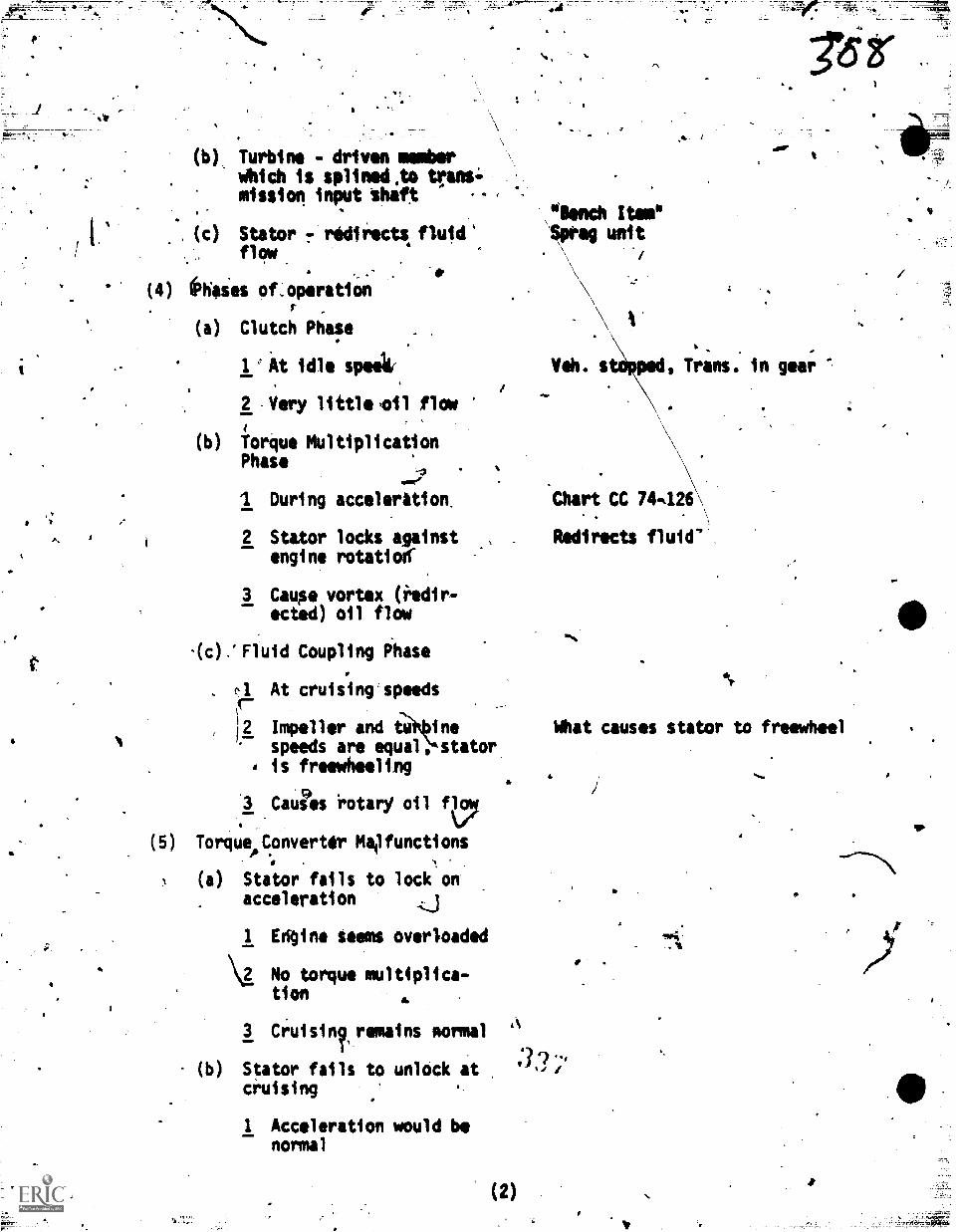
(b) Turbine - driven numberWhich is splined,t0 trans.;mission input theft
(c) Stator r redirects fluid'flow
(4) keies of,operat i.on
(a) Clutch Phase
1 At idle speak
2 Very little ,oil flow
(b) forque MultiplicationPhase
owe'
I During accelerition.
2 Stator locks against .,
engine rotation'
3 Cause vortex (redir-ected) oil flow
-(c),'Fluid Coupling Phase
f-1 At cruising speedsr-12 Impeller and ine
speeds are equal, stator. is freewheeling
3 Caues rotarY oil qa,
(5) Torqueo_Converter Mailfunctions
(a) Stator fails to lock onacceleration
1 Edgine seems overloaded
\I No torque multiplica-, tion
3 Cruisil, remains normal
(b) Stator fails to unlock atcruising
I Acceleration would benormal
\IWO Itnnulipreg unit
Moo
Veh. s
.*drz,
Trans. in gear
Chart CC 74426
Redirects fluid'.
What causes stator to freewheel
(2)
4.
I.
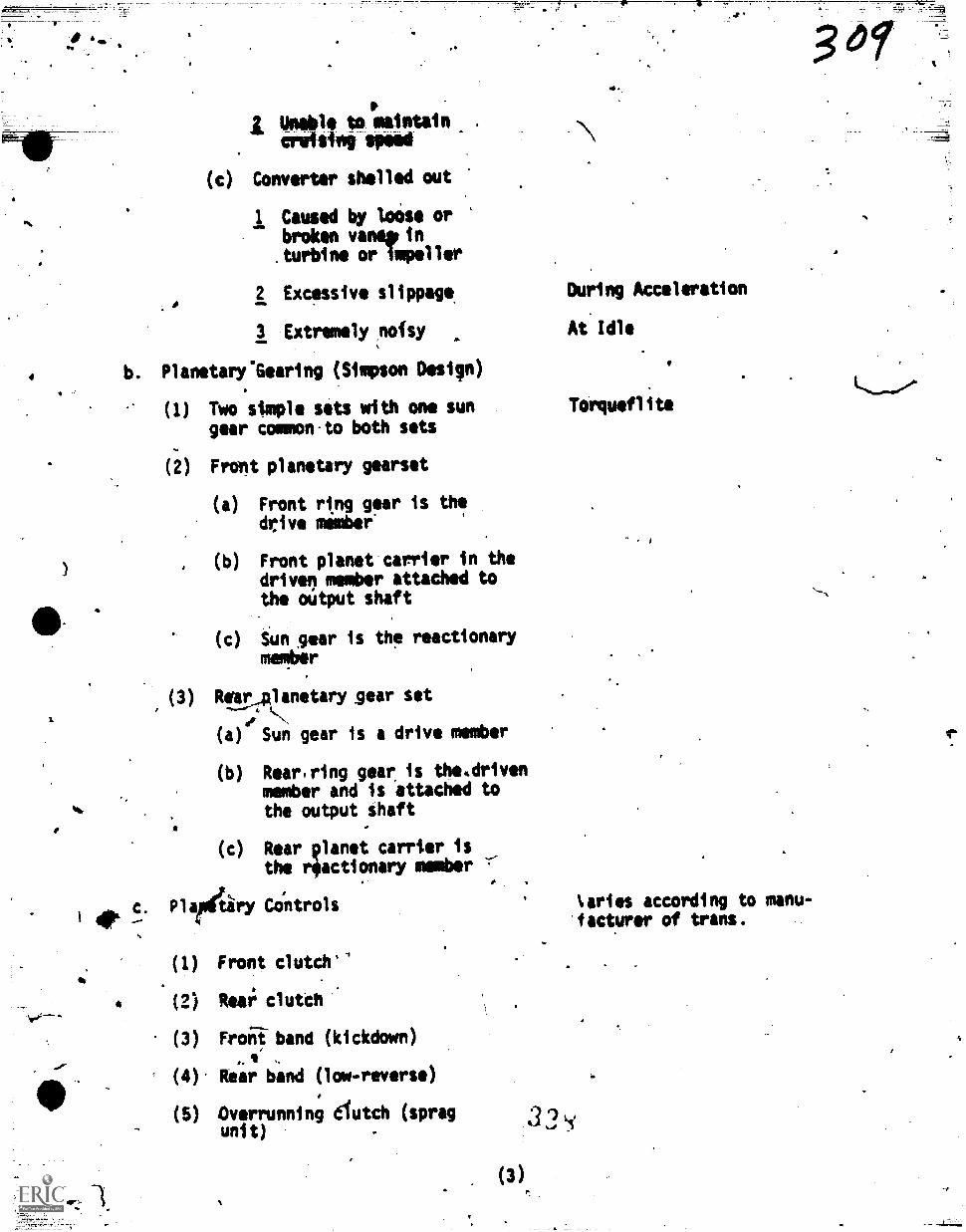
(amble to maintain
mien 'Peed
(c) Converter shelled out
1 Caused by loose orbroken vanespin.turbine or impeller
2 Excessive slippage, Durtng Acceleration
3 Extremely(nofsy At'Idle
b. PlanetarysGearing (Simpson Design)
Two stmple sets with one sungear common.to both sets
Front planetarY gearset
(a) Front ring gear is thedrive member'
(b) Front planet carrier in thedriven member attached tothe mitput shaft
Sun ,gear is the reactionarymember
(3) Rellr,planetary gear set
(a) Sun gear is a drive member
(b) Rear,ring gear is thcdrivenmember and is attached tothe output Shaft
(c)
(c) Rear planet carrier isthe rOctionary member
Torqueflite
c. Plardtiry Co'ntrols %Aries according to manu-facturer of trans.
.(1) Front clutch'"
(2) Real; clutch
(3) Froii band (kickdown)
(4) Rear band (low-reverse)
(5) Overrunning dutch (sprigunit)
Ope ration
(1) Neutral
(a) Input shaft turns thefront clutcPhull & rearclutch drum
Air)( ) No clutches applied, no
drive toplanetary gearsets
(2) Park
(a) Output shaft is locked to)case by the parking pawl
(b) With engine running, opera-tion is same as neutral
(3) 1st speed (Drive Rtnge)
(a) Reir clutch ii aOplied,which connects inputshaft to the, front ringgear
(b) Front planet carrier isheldtby output shaft
(c) Front planet pinions turnon the:. axis and drive thesun gait:- opposite of input
(d) Sun gear drives the rearplanetary pinions in thesame direction as inpit
(e) Rear planet carrier is held' by the overrunning clutch
(f) _Rear planetarypinions mustdrive rear ring gear andoutpuA shaft in same dir-ectioh as input
Chrt #73-20
Chart #73-22
i(4) 1st Speed (manual low) Chart 473-23
(a) Rear band is applied agdholds rear planet carrier
;5) Power flow same as 1stspeed drive range
(4)
33 '4
(0) Planet terrier cantretakavoliberwwiskidtprovides for engine.breking
(5) 2 nd Speed .Chert #73-24
(a) Roar clutch and frontband are applied
(b) Rear clutch locks iriputto front ring gear
(c) Front band holds frontclutch housing, drivingshoal, and front sungear
'(d) Front planet carrier isforced to walk aroundthe stationary sun gearand drive the oulputshaft
(e) Rear planet carrier idlesin direction of enginerotation (allowed byoverrunning clutth).
(6) 3rd Speed (Dtrect Drive)
(a) Rear clutch and frontclutch art applied atthe same Mae frontband
/is reletsed-
(b) Rear clutch locks inputto front ring. gear andfront clutch lOcksinput to the front sungear
(c) Sinc . two members of thefront gearset are beingdriven in the same dir-ection at the same speed,the entire gear trein isin direct drive
Chart 0.73 -2S
(7) Reverse chart #73-26
(a) ,Front clutch and marband are applied 3.11,
(5)
(b) Pront clutch locks input'to.the rear sun gear -
(c) Rear band holds rearplanet carrier
(d) Front carrier idles in reverse,
e. Removal and reinstallation
Safetv precautions
(a) Personal safety - removerings, watches and an,Z:.other jewelry
(b) Disconnect battery giOunacable
(c) Properly jack and supportthe vehicle
(d) Use transmission jack
(e) Wipe-up spilled fluid
(2) Removal Procedures
(a) Remove flywheel inspectioncover and flywheel,and con-verter for balance
Drain converter usiwga six point socket,ondrain plugs
Loosen oil pan or removedrain plug to drain trans-mission
(d) manufacturer'smanual for disconnectpoints NOTE: converterand transmission mustbe removed and replacedas an assembly
b)
(3) Installation Procidures
(a) 1tsiCaqy reversal ofremoval procedures
(b) Follog applicablemenus 1
ENFORCE! t's.
APPLICATION:
I. Ref: Para 8, part I.
SUMMARY AND REMOTIVATION
Use TO 36A2=544-2 andfollowtng tech data,using spechl and handtools disassemble trans-missions (Torqueflite) ,7
CONCLUSION 15 Min
3/3
1. The main purpose of the torque'converter is to multiply torque ind actai a clutch. The impeller (drive member) is dtiven by the engine andtransmits the torque to the turbine (driven member) through fluid whichturnt the trahsmission input shaft. The stator ridirects the oil flow'to cause torque multiplication. In the torqueflite, we hest two simpleplanetary gear sets with a sun gear common to each set. (Simpson Design).The Simpson planetary arrangement is controlted by two clutches, too bands,and an overrunning clutch (Sprig Unit). The rear clutch is applied in allforward speeds. In 1st speed (drive range) the overrunhing clutch holdsthe rear planetary carrier which transmits power through both gear sets.In manual low the only .differenue is the rear band holds the rear planetcarrier which altows.for engine braking. In 2nd speed the front band isapplied and holds the sun gear which transmits the torque through thefront planetary gear set. In 3rd speed (direct drive) the front and rear
110clutches are applied and locks the front ring gear and sun geai' to theinput shaft. In reversec the rear clutch and rear band are applied andtorque is reversed in the rear planetary gear set. During removal of anautomatic transmission, we must follow the applicable manual and all safetyprecautions.
(Conduct short question and answer period):
ASSIGNMENT AND CLOSURE CCT POI Para 7a
Conservation of Utilities.and Resources
2 Hrs
Continue assigned areas of3ABR47330-SG-506
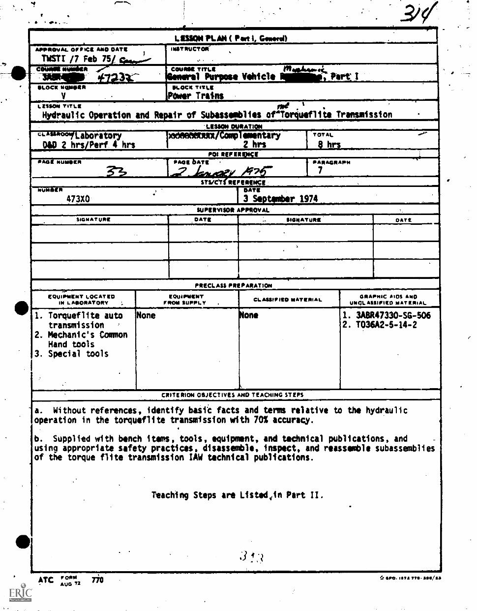
11 40 , -
L SUCH PLAN ( Pat I, Gomel)APPROVAL OFFICE AND DATE
TWIT /7 Feb 75
INSTRUCTOR'.
.
T'll--- 4
Iffig/80,: #7231.--CONNOR TITUlt 046441111.41.,
Purpose %Mei* 11.111.101 art ISLOCK NERSSIER
V
ELOCK TITLE
',ewer TrainsLESSON TITLE
Hydraulic Operation and Repair of Subassepblies of4Torquelite Transmission
'LESSON MOAT).(a. - a ratory Weenemx . . ementaryDAD 2 hrs/Perf 4 hrs 2 hrs
TOTAL
8 hrsPOI REP ERIOSSE
0,4111 NursOER MIII ban ,
33 A7rPARAGRAPH
sysier REPEuNceNURSER I
473X0 1
DATE
3 September 1974
SUPERVISOR APPROVAL
SIGNATURE DATE SIGNATURE OATE1.......,
1
PRECLASS PREPARATION-.0-'
EQUIPMENT LOCATED IIN LAISORATORY ',.
EQUIPMENTFROM SUPPLY .
CLASSIFIED MATERIA L GRAPHIC AIDS NDUNCILASSIFIE0 MATERIAL
I. Torqueflite autotransmission
2. Mechanic's CommonHand tools
3. Special tools
None hon.
f.
1. 3RBR47330 -SG -506
2. T036A2 -5 -14 -2
CRITERION OBJECTIVES AND TEACHING STEPS
a. Without references, identify basfc facts and term relative to the hydraulicoperation in the torqueflite transmission with 70% accuracy.
b. Supplied with bench items, tools, equipment, and technical publications, and -
using appropriate safety practices, disassemble, inspect, and reassemble subassembliesof the torque flite transmission IAW technical publications.
Teaching Steps are L1sted41n Part II.
-
770ATC FORMAUG 72
*Gm". less 71S- ar/aa
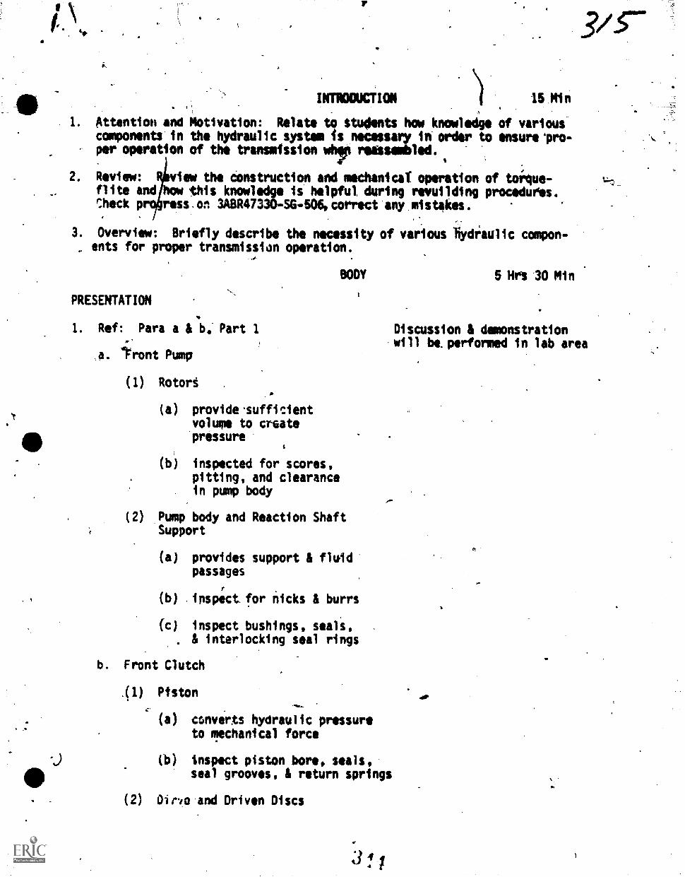
41P
10,
INTRODUCTION 15 Min
Attention and Motivation: Relate to Students how knowledge of variouscomponents'in the hydraulic system is necessary in order to ensureapro-per operation of the transmfssion wfir reesembled.
2. Review: R,view the Construction and mechanical operation of toilue-flite and how this knowledge is helpful dUring rewuilding procedufes.Theck prqress .on3ABR47330-SG-506,correct-any.mistakes.
3. Overview: Briefly describe the necessity of various tiydraulic compon-, ents for proper transmission operation.
BODY 5 Hrs 30 Min
PRESENTATION
1. Ref: Para a & be Part 1 Discussion & demonstrationwill be.performed in lab area
,a. tit-Int Pump
(1) Rotort .
(a) provide.sufficientvolume to crGatepressure
(b) inspected for scores,pitting, and clearance,in pump body
(2) Pump body and Reaction ShaftSupport
(a) provides support & fluidpassages
(b) inspect_for nicks & burrs
(c) inspect bushings, seals,& interlocking seal rings
b. Front Clutch
( 1)Piston
(a) converts hydraulic pressureto mechanical force
(b) inspect piston bore, seals,seal grooves, & return springs
(2) Oird.o and Driven Discs
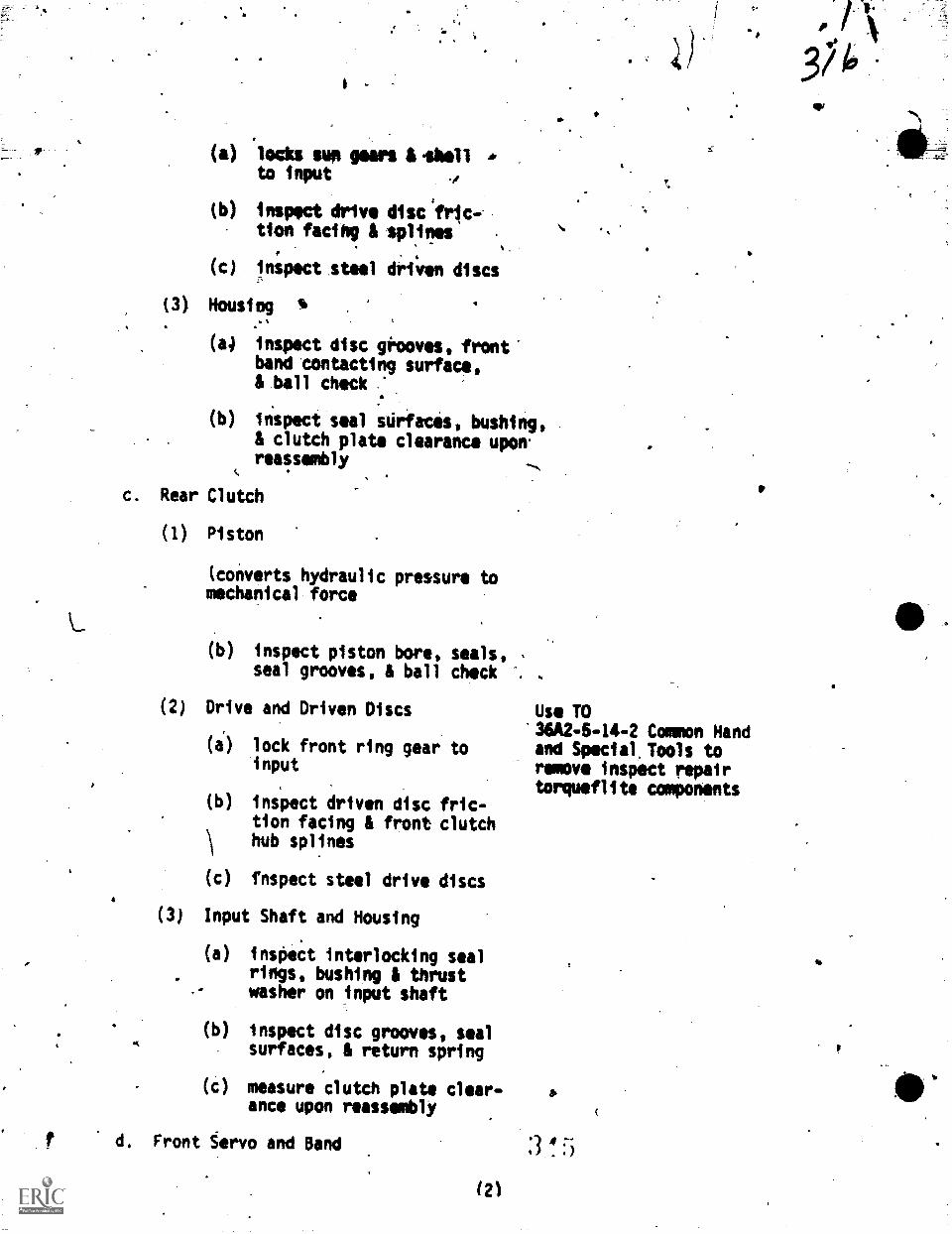
(3)
'
(a) locks sup gears &Abell *to input
(b) inspect drive disc fric-tion facing & splines
(c) inspect steel driven discs
Housiog s .
N
(a4
(b)
inspect disc grooves, front"band contacting surface,& ball check
inspect seal surfaces, bushing,& clutch plate clearance uponreassembty
c. Rear Clutch
(1) Piston
(converts hydraulic pressure tomechanical force
(b) inspect piston bore, seals,seal grooves, & ball check
(2) Drive and Driven Discs
(i) lock front ring gear toinput
inspect driven disc fric-tion facing & front clutchhub splines
fnspect steel drive discs
(3) Input Shaft and Housing
(a) inspect interlocking sealrings, bushing & thrustwasher on input shaft
(b) inspect disc grooves, sealsurfaces, & return spring
(c) measure clutch plate clear-ance upon reassembly
d. Front tervo and Band
(21
es.
Use TO36A2-5-14-2 Common Handand Special, Tools toremove inspect repairtorqueflita components
&
! 5
374
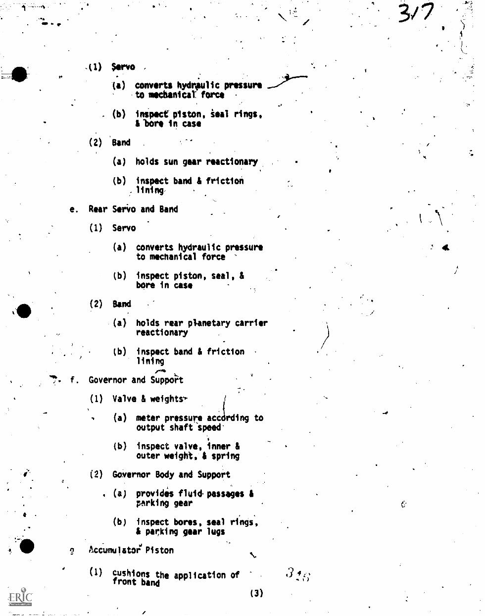
.(1) $ervo.
(a) converts hydnpulic pressure. .
to mecbanicaT force
(b) inspect piston, ieal rings,.
,
&lore in case
(2) Band
(a) holds sun gear reactionary
(b) inspect band & friction. lining
e. Rear &trim and Band
(1) Servo
(a) converts hydraulic pressureto mechanical force
(b) inspect piston, seal, &bore in case
(2) Band
(a) holds rear planetary carrierreactionary
(b) inspect band & frictionlining
f. Governor and Support
(1) Valve & weightr-
(a) meter pressure acc rding tooutput shaft speed'
(b) inspect valve, inner &outer weight, & spring
(2) Governor Body and Support
. (a) provides fluid-passages &parking gear
(b) inspect bores, seal rings,& parking gear lugs
Accumulatoi'Piston
(1) cushions the application offront band
(3)
3 4 4.1
.40
C.
4
*"1
(2) inspect Sian, seel, Koss, \piston bore in case;.& spring
h. Valve Body Assembly
(1) flow control valves
(a) provide Manual & automaticcontrol of transmission
(b) inspect all valves & valvesprings
(2) Housing, Transfer Plate, & Sep-,
arator Plate
(I) houses valves 11 providesfluid passageways
(b) inspect all mating sur-faces, valve bores, passage-
\
ways, & metering holes
i. Planetary Gear Train
(I) hydraulically controlled to providegear reduction 0 direct drive
(2) inspect bearing surfaces, oilpassages, & splines on outputshaft
(3)- inspect bushings & thrust washers
(4) inspect sun 1 ring gears, & planetarycarriers & gears
J. Overrunning Clutct
(1) inspect rollers, roller races, &roller springs-
.
(2) inspect cam set screw
APPLICATION:
I. Insterspersod throughout presentipon.
EVALUATION:
I. Question students on pertinent informa-tion.
(4)
CONCLUSION
-1111k StalPlARY AND RDWITIATION:
15 Min
A
1. .Today's lesson has shown & ixplained the fInctien, construction. &.. inspections of neerly all components in the torqueflite: In order
for any transmission to-finctior as dasignedi the components must bein the proper condition.
ASSIGNMENT AND CLOSURE!, 4-rr 411. pqrf 8a 3A8R47339-SG-506 2 hrs
1. Review the material 'covered today A tomorrow reassemble thetransmission & discuss tra-toashooting.
1'4
3 4 I.'(5)
;
Oa
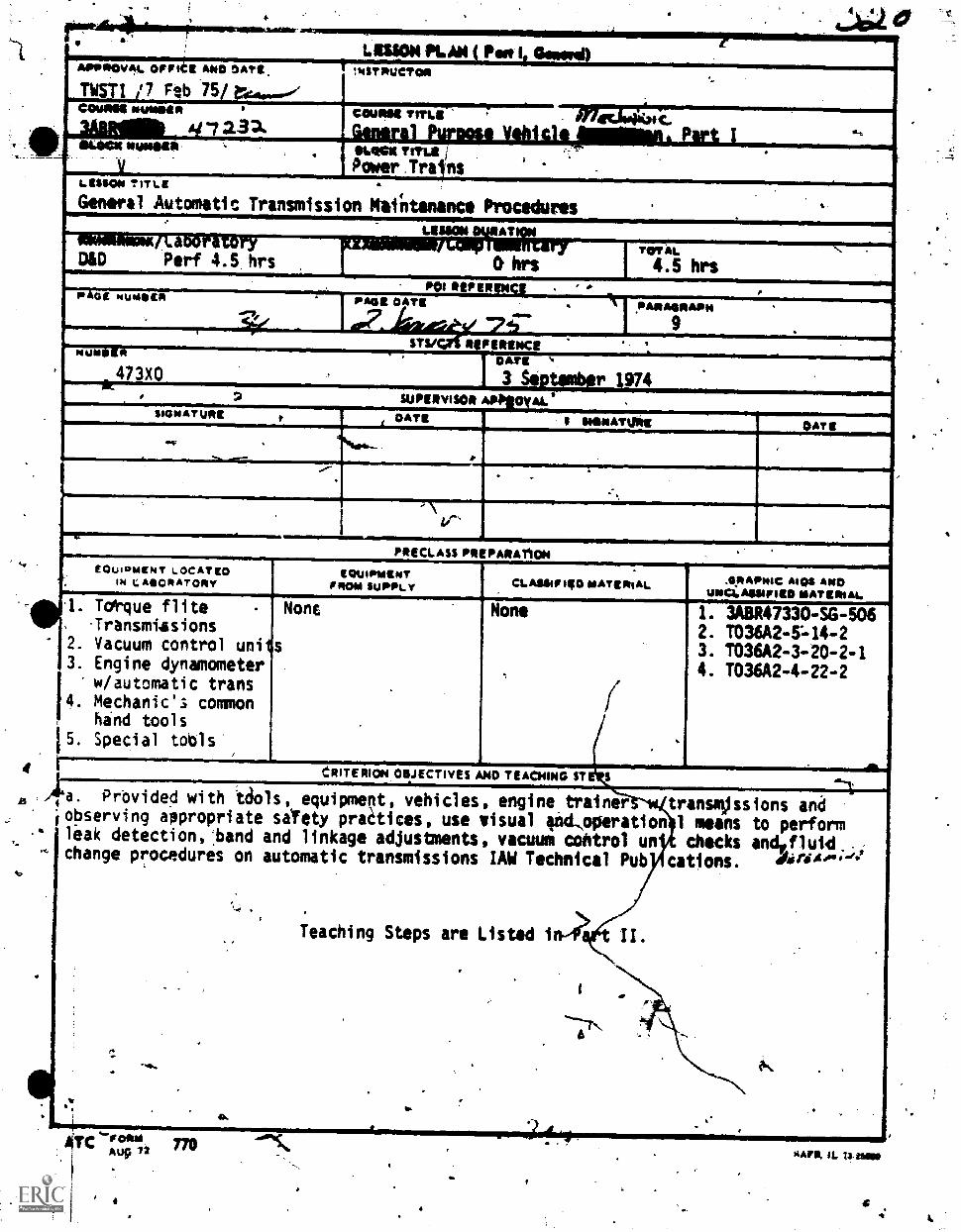
4
43
-i I
LIMON PLAN ( Peet it Gabor*lloSTPUCT011
..
,...........,....COMM TITLE , .m771/=C..
APTPOIONIAL.7171=NO *Att.TWSTI /7 Feb 75/roil...."COVION Nuesito ..- /13a.AMCW MMUS , MAME Tint i
'Power.Trains _
Malintenance Procedures .
LIMON TITLE
General Automatic Transmission
LISMIN . AT,.. - ..D&D Perf 4.5 hrs 0 hrs
TOTAL.
4.5 hrsPOI II PIREN p ...
pP GE NUMER
. 7s-Plf,PAGE DAyg .
aiT7.klOCtt* 74--'.PARA4IMIAPI4
9sty 1 Fametioemum
.
473X0. 2 SUPERVISOR APPloy ,
SIGNATURE p DATI II SIIIINATIMI OATS..%, .
'
.
..
PI/ICI-ASS PREPARATIONEQUIPMENT LOCATED
IN LABORATORYEQUIPMENT
PROM SUPPLY CLAMP mg oiATERIAL
1. Totque flite-Transmtasions
2. Vacuum control uniis3. Engine dynamometer
w/automatic trans4. Mechanic's common
. hind toolsIS Special tools'
NonE
.
None
.
1. 3AAR47334 -SG -546
2. T036A2 -5"1114 -2
3. T036A2 -3 -20 -2 -1
4. T036A2 -4 -22 -2
i dRITE RION OBJECTIVES AND TEACHINO $T S41
4a. Provide0 with tdols, equipment, vehicles, enginetrainer transmjssions anafobserving appropriate sifety praitices, use visual ind,operation 1 means to perform*leak detectionstand and linkage adjustments, vacuum control un checks andvflutd..,change procedures on automatic transmissions IAW Technical Pub cations. dari44-'s*
.
.
Teaching Steps are Listed 1n4 t II.
.1 .
.
k. .
..
..
. ..
.
0..
e.4-PORISAu9 72 770
SAFE. IL 11-43440
"Y
*.illoate to studeAts tile importance of regularmaintenance of transmissions=per operation,,dspendability, and good driveability. Also
).-vntstive maintenance can preventclater malfunctions and labor.
14view construction and operation of automatic transmissions. ConductCni appraisals on assignment. Test and grade outsido assignment:"tle.:r1 as needed. Check on completion of assignment in3A8R47330-S6-505.
ImmaxmaloN 15 Min
3. ilrialy describe the basic maintenance A adjustments common to automatics,NOP
BODY 4 Mrs
PRE774TATION:
1. Ref: Para sat-Part 1
a. aintenance Use Torqueflite transmissions
Preventative Maintenance
(a)
(t)
Fluid Level
1 Engine & transmission HOT!:normalized
2 selector Lever To fill pasiagesmust be moved .
through all ranges
3 Place transmission %PIOT OVERFILLin neutral, checklevel on dipstick
Fluid changes and filterreplacement
1 Follow manyfacturer's On samk vehicles, it is notmanual neceSsary
2 Usually done moreoften under seveve.operating conditions
visual Inspections
1 Linkage '
2 External leakage
3 -Vacuum connection & hoseon vafuum modulator
Ford - Type F
Show vacuum control units
350
b. Adjustments
)-
'ti) Band adjustments
(a) Correct .servo pisttn
(b) Adjusted at specifiedintervals.
travel
Dammistrate operation ofthe engine transmissionOnemdmeter trainers
(c) Adjusaid when needed
(d) Adjusted.acCirdiny.to mfg specs.
'(2) Throttle Valve.Adjustment -. Use common and special,tools as required to
(a) Adjusted to obtatn make adjustmentsproper shift points
(b) Adjusted to' mfg specs
(3) kanual,Vaive Linkage
(a) Check trans. and engine ihy?mounts
(b) To obtain proper rangeof operat4on
.
(c) According to mfg spec
(4) Pointer Alignment
(a) Adjusted after manuallinkage
(b) Usually on steering column
(c) According to mfg specs .
(5) Safety Starter Neutill Switch
(a) On transmitsion
-.(torqueflites)
(b) In linkage (C4)
(c) According to mfg specs
5
wot14,ATIoN: Interimarsed throughout body. TO 36/424444TO NA24-204-1
1 ,lef Para a, Part 1. TO, 311A24-22-2 .
Sand Adjusting Tools .
Hand Tools -
Bench Items
k
t,11-,_ would cause aeration of trans-
,441ion fluid?
1t preliminary checks are made:tfore fnitiating troubleshooting
:rocedures?
3. When performing band adjustment,4011t fs actually,being corrected?
'Oat is the purpose of the safetystarter neutral switch?
5. :What is controlled by the throttlevalve linkage adjustment?
What could cause an automatictransmission to overheat during operation?
7. when should bands be adjusted?
CONCLUSION 15 Min
SUMMARY AND REMOTIVATION:
1. preventive maintenance is necessary to ensdre Ihe proper operation & long-life of ah automatic transmission. Maintaining transmissions adjustments
ewill extend the life of transmission components and improve vehicle performance.
ASSIGNMENT AND CLOSURE:
1. Review today's lesson and 'accomplish new dey's assignment 31411R47330-SG-701 in. preparation for Block 7 - Conseniation of utilities and resources -
(3)
I.
amSTUDY
i
GU/DE 341R47S90-40-400
Technical Training
WORKSIMIT 3aa147330.418404
I. 11tecAftrc.Ueneral Purpose %idols Widow
BLOCK VPOWER TRAINS ,AND DUMP TRUCK CONTROLS
41'
13 April 1970
CHANUTE.TECHNICAL TRAINING CENTER (ATC)
./Designed FOr A.. Caws. Use
353
:1111in1 ng Publications ars designed tor ATC opnni use only. Thoy are updated as necessarykar Valais( purposast but are pet to be used on the lob at authoritative references in'prido'armee to Technital Orders or other offIcial publications.
August 1949 .,
3 1--
#00IN
I
Vehicle Maintenance BranChChanuti An, Illinois
OBJECTIVES
#.
13013ASR47300-SC-SOl
CLUTCHES, STANDARD TRANSMISSIONS, AND POWER TAMP?
Af,ter completing this unit of instruction, you will understand the
'impose, operating principles, and types of automotive clutches, standard
,:zanamissions aod power taksoffa. You will also be able to disassemble,
lispect, repair and reassemble these units
1-171`,ODUCTION
In prvious lessons you learned of the power plant and ite accessOries:
f)u ere now ready to learn how the paver developed by tbs vehicle engine
reaches the vehicle wheeli so that the wheels will rotate and cause the
vehicle to move. This iM done through I aeries of gears end shafts, commonly
called the power train, which mechanically connect the engine shaft elth
the vehicle wheels. The purpose of the power train is to carry'the power
of the engine to the wheels and accessory equipment. :11 a simple situation,
a let of gears or a dhain could perform this task. However, automotive
vehicles are not usually madelor such simple operating-conditions. They'
%Irue great pulling power, move at high speeds, travel in reverse as well
as forward and operate-over rough ground as well as on smooth roads. To
meat these varying demands, a number of units have been added. Includrd
iu these units are the clutch, transmission and power takeoff.
IMFOAATION
Information relative to the purpose, operating principles, and instruc-
tions for the disassembly, inspection, repair and reaseembly of automotive,
(AL:rchest standard transmissions and power takeoffs is Contained in Pro -
grnTmed Text 3ABR47330 -PT -501. Read-this information carefully end then .
....ibrer the questions contained therein.
II
Vehicle Maintenance BranchChanute APB, Illinois
NJECTIVES
3A5R47330 -SG -502.
CLUTCH AND TRANSMISSION REMOVAL AND REPLACEMENT
Upon completion of this unit of instruction, you will be able to remove,
inspect, install, and adjust clutch and transmission by using special tools
znd equipment and applying all safety precautions.
..NTRODUCTION
Because of the Variations in constrAction of transmissions on different
typa vehicles, different procedures must be iollowed when removing and
iastailing the tranimission. Basically the procedures are similiar. By
..-Aing the proper equipment it can be lowered to the floor or raised through
tne body, as specified. As with transmissions, the clutch, due to thedifferences in construction and design, make it necessary to use somewhat
different procedures and tools when removing it from the vehicle. The
first step in clutch removal is to remove the transmission.
!YrCRMATION
As previously stated, the removal and installation procedures for
clutches and transmissions may vary on certain vehicles. It would be
imtlossible to give a step-by-step procedure for these jobs at this time.
DTior to performing these tasks you will participate in a discussion relative
to the procedures for removing the clutch and transmission. You will
perform these jobs by using applicable vehicle publications and following
a task list and procedures as outlined by the inseructor. Speciil emphasis
be stressed on all safety precautions pertaining to these projects.
3
3
C.
::41:-..:Lcanct Branch
Ail, Illinois
..nIFCT.TNES
1P-313A3R47330 -SG-503
TRANSFER CASE, SPRAG UNITS, PROPELLER SHAFTS,CUTER SNARING, UNIVERSAL JOINTS, AND WINCE
After completing this unit of instruction, you will understand the:.1rnlse, constructional features, and operating principles of the transfer..4e, sprag unit, propeller shafts, center bokring, universal joints and--ch. You will also be able to disassemble, inspect, repair and reassemble
unitS,
,rraeDUCTION
Aa stated in a previous lesson, the purpose of the power train isuTry the power of the engine to the wheels and accessory equipment
wah as winches) of the vehicle. This is accomplished by a number ofunits. These include transmiseions, clutches, auxiliary transmissions,transfer cases, universal joints, slip joints, differentials, and finale71.725. It is the responsibility of the general purpose vehicle repairman
-24intain and keep these units in a fully operational coaition at allTo accomplish this, the mechanic must be able to perform any needed
!..;:arational testing, service and repair of these units.
InFnaMATION
?rogrammed Text 3A3R47330-PT -503, contains information,on the construction,operating principles, servicing and repair of these units. Also inclpded isproctdures for the removal and installation.of power train units. Riadtnis information carefully and answer the questions contained ttaerein.
ggafV.Allele Maintenance Branch 3A1R47330-SG-504
Chenute AFB, Illinois
CONVENTIONAL AdD ANTI..BFIN DIFFERENTIAL AND FRDNT DRIVING AXLE
OBJECTIVr3
After completing this unit of instruction, you will understand the;urpose, construction, and operating principles of differentials and front-
driving axles. You will also learn the procedures for removing, disassembling,tlzpecting and repairing these units.
-11720DUCTION
0 S7112 heavy -duxy vehicles have driving axles in the front as wellA.71 che rear. The primary differences between front and rear driving Axlesis mat front driving axles must have a maps of steering. All driving
1.xles contain a differential. The purpose of the differential ii to providefor differendes in speed of rotation of whe:10eas a vehicle rounds a corneror travels over uneven ground. Basically t re are two types of differentials,
conventional and non-slip,
LNECT.MaTION
To learn the purpose, construction, and operating principles of thedri7e axles and their components carefully read the information contained
?:ogrammed Text 3ABR47330-PT-504, and study its illustrations. Youwill learn the procedures for servicing, repairing, and troubleshootingthese units by completing the tasks as outlined in Worksheet 3A3R47330-WS-5N, and as directed.by your instructor.
Maintenance Bratich IA3R47330-W-504
':Nute AFE, tAlnola
CONVENTIONAL AND ANTI-SPIN DiFFEAKRTIAL ANIt FRONT-DRIVING ARL
"LIZG:IVES
yo,.1 have completed this Worksheet you will be able to:
Diaassemble and reassemble the drive axle.
Inspect the axle and its components.
Repair and adjust the.axle and components..
Driving AxleAxle StandMechanics Tool Set'
Exercise 1
Using the worksheet as a guide for step-by-step procedures and important
OLT a.ation, perform each task as outlined and as directed by the instructor.
PROCEDURE
1. Practice all safety precautionsapplying to the project.
2. Obtain applicable pl:blicationsfrom the file.
3. Prepare to disassemble andreassemble a front driving axle:
4. Drain lubricant from the front
axle housing.
5. Place front axle in a safe position.
Make preinspeotion of front axle.
IMPORTANT INFORMATION '04
1. Think Safety-Practice Safety-Act Safely.
2. Publications title ortechnical order No.
Y. Check for special tools,parts containers, drain pans,rags, etc.
4. Inspect drained lubricantfor broken parts or metalchips.
5. Be sure front axle will not, fall from work bench orstand.
6. Inspect front axle forcracks, leaks, gaskets,seals or other damage.
1
Remove 4ifferential cover, andinspect drive sears for damage
,iind adjustments.
temetw
Inspect differential gears(pinions) for free turning.
9. Remove the- wheel hubs.
1
10.. Remove steering knuale (spindlearm)-includtng.seals and retainers.
11. Remove axle shaft and universaljoint.
-1'2. Remove differential bearing caps,and differential case with gears.
13. Remove drive pinion'and bearings-
14. Clean and inspect the axlehousing including the steeringknuckles.
15. Clean and inspect all bearingsused in the driving.axle.
16. Clean and inspect all gears,replace worn gears.
r.TA.
7. .Check the pinion and drivegear adjustment for loose-ness,-tightnese, aid play,side play, heel wear, toewear, drive pinion too farahead or back, rough or worngear teeth.
8. Inspect the differential byturning o e hub or wheel,holding t i e other one still.
Th e diffe en tial pinipnsshould rotate inside thedifferential case betweenthe axle shaft side gears.
9. Place parts in a parts pancontaining cleaning solvent.Parts must be cleaned beforethey can be used again.
10. The retainers and seals mustbe removed first, the bearingcat's and shims next, then the
steering knuckle (spindle
, arm) can be removed. .
11. The axle shaft and U-jointcan be pulled out,by hand.
12. It may be necessary to usea special tool for spreadingthe housing, if the dif-ferential case is tight inthe housing.
13. A special tool, or a softmallet can be used toremove this pinion and
bearings.
14. Clean the axle housing andsteering knuckles. Inspeet
for grindings or chips.
15. All bearings must be washedclean inspected for roughspots on the rollers or
races.
16. Wash all gears in cleaningsolvent, inspect for wornor rough spots, replace all&ars' if they are worn orrough.
10 36 1 '1'
.. Clem and inspec,t axle shafts,Iplines, sad universal joints.
Check and order the oil sealsand gaskets needed.
.?. Check and prepare all partsand equipment for reassembly.
20. Replace the drive pinion in the
axle.housing:
21. Replace the drive gear anddifferential in axle housing.
22. Adjuic drive gear and pinionoacklah'(free play).
23. Replace axle shafts and univerdal
joints.
24. Place knuckle oil seals over axle
houAing ends.
. Zeplace steering knuckles (spindle
arms) and adjust bearings.
.4 4
317. Clean axle shafts, universal
joints and splines on theaxle shafts. Inspect for
wear. Be sure to inspecttho splines on end of tha.axle shafts, ififlorn'thikaxle shaft must be replaced.,
18. Oil seals and gaskets areueually replaced afterremoval.
19. Are you prepared to assemble
the driving axle? Have you
the proper parts; tools,gaskets, seals, gages, oil
end greases?
20. 4e sure good bearing areused, lubricated andadjusted. Special-gages
are used foi\making adjust-
ments. Ask your instructorabout adjustment* or referto the proper publicition.
21. Replace differential gears
ir differential case withdrive goer, and plike theassembly in the axle housing.
dr-
22. This backlash adjustment isthe amount of free play(movetent) you can turn the
drive gear without turningthe driviipinion. It canbe measured with a dial gage.
23. Push and turn on the 'axle
shaft until the splines .
slideinto the differentialside gear.
24. New oil seals should be used /r
to keep grease in and dirt
out.
25. These bearings ould be
,adjusted with a %reload.Refer to the applicablepublicatiqa for epecifi-
pations.
a.
,1.
2.6.* Bolt oil seals in place' cal the, steering knuckles Cepindleparel.
.
S. 1%.
edi
4 .
27. Replace wheel'hubs,. and brake'carrier-plates.
.28. Replace differential cover.
29. Make final check for missingparts, loose bolts, nuts, washers,seals, gaskets, keys, locks or
. plugs.
30. Lubricate.'
Participate in a critique of thecompleted project (job).
PROCEDURE
3Referring to items 1 th\ugh 8, complete the stateeents by. listing theapplicable units and components in spaces provided.
Exercise 2
26. After Fhe oil seals have_been belted 41n place. the qpi0(
turaing-(preload) load itilincrease but this ddhs not. t /
count with the specifics lons:4
27. Wheel hubs use ball orrolls; bearings. Thesebeirings must be wellpacked with wheel bearinggrease, aid proper adjusments made. Refer to theproper publication forwheel bearing adjustment.
When rePlacing the dif.ferential cover7a nemgasket umst be.used. B.sure t doss not grease:
29. "Th4k. 2 If you we goingto plac. this axle uJ.r a ,
vehicle, would you be willingto iide down the high,' in'it at 60 miles per hour
\28.
30. iAsk your instractor if you\should fill thiseaxle;housing to proper level withlubricant. If so refer tothe applicable pdblicatiimfor proper lubrication Sadlevel.
31. Your instructor will conductthe critique. Be preparedto ask and answer questions.
Referring to figuros.1 through 4, listin the spaces provided.
1. Power from the propellor shaft isudtted to the driving axle by the
ehe units and components as shown
changed 90 degreei and trans-
2. A flexible connection is providedby the
in the front driving axle housingand
3 S
I.
.
eme
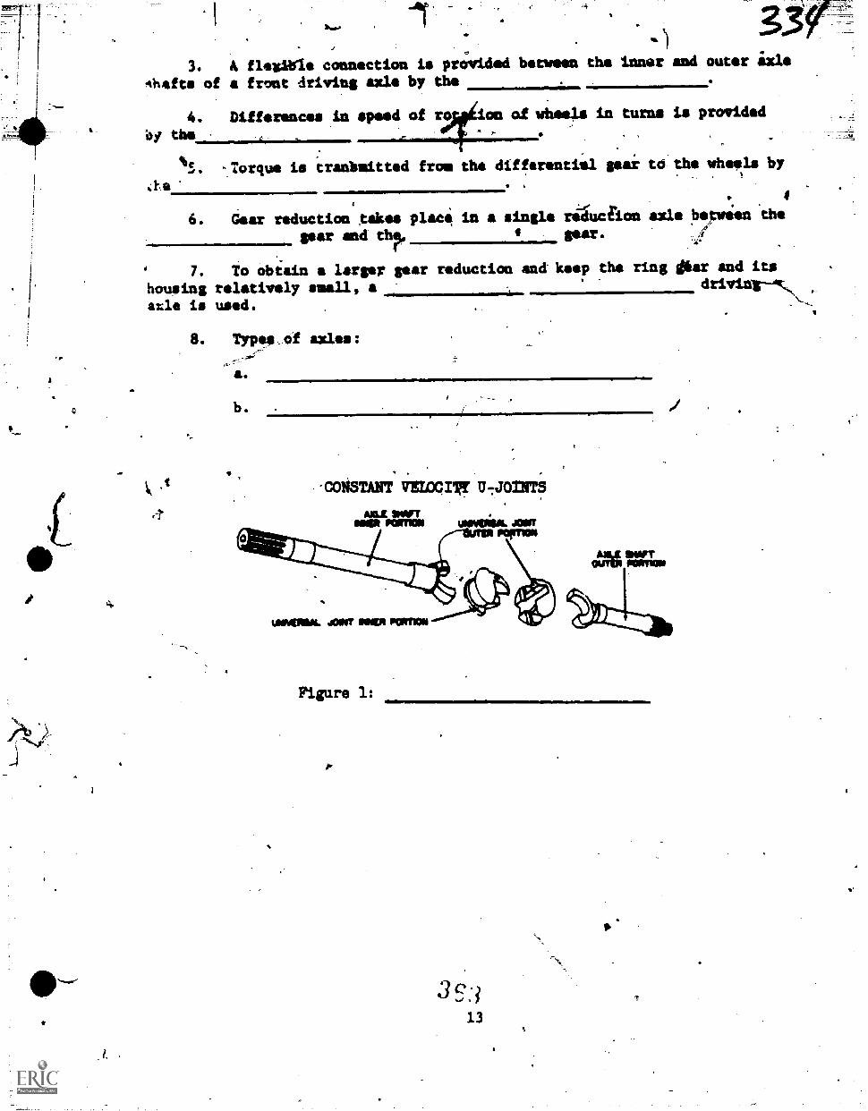
1
IP
t
3. A flosibis connection is provided between the innar and outer ixle
Ahefts of front driving axle by the
4. Differences in speed of ro on of wheels in turns is provided
bi this
s. -Torque is tradbmitted from the differentiill gear to tbs wheels by,
6. Gear reduction takes plac in a single tiduclion asle between thegear and thp, t Sur :g!
,7. To obiain a larger gear reduction end keep the ring dear and its
housing relatively uall, a driving-4c,
axle is used.
8. Types of axles:
a
b.
,
CONSTANT VI= rgr U-JOINTS
AXLE WITeaes Ken= uremia. Asa
WOMINLJOINTIONERPOMM
Figure 1: 11. Mmilm
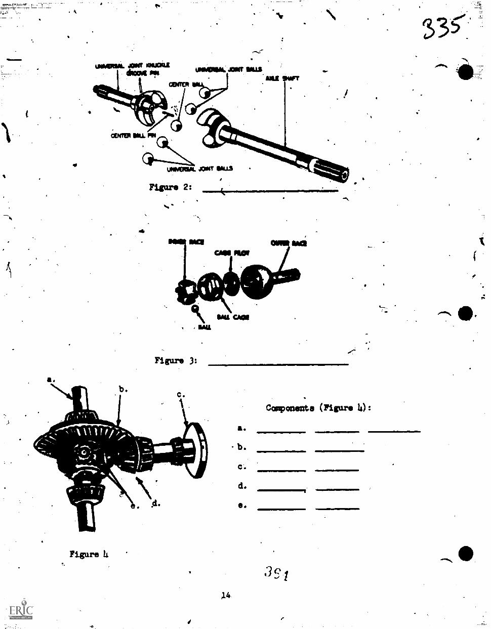
UMMERIAL JOINr ~FaAiwa "It
r-sr-
UNPAPION. AVIV NILS
Figure 2:
CMS PROW
1MM.
SAICAIIIIMAIL
Figure 3:
Figure 4
a.
- b.
C.
d.
C.
Components (Figure 4) :
I.
3
Vehicle Maintenance Branch 3ABR47330-SG-505
,:hanute AFB, Illinois
f.
OBJICTIVES
AUTOMATIC TRANSMISIONSr
fa
tftftr completing this unit of instructio4, you will understand the.lonstructiOnal features, operating principles, and troubleshooting proideurts
fluid couplers, torque comerters and automaticitransiissions. You4ill also gain a general knoiledge of adjustments required on automatic
C...yansmidsions.
INTRODUCTION
4
A transmission is.a variable fulcrum that gives the ,internal coibustion
engine graater flexibility of performance and application. The transmission
tan multiply the engineroutput torgiss many tilos. Without artransmissionthe internal combustion engine vould stall out unless, of,course, the-
engine sire is out of proportion to the work it is doing. .Frou a previous
lesspn you learned that the purpose of tny transmission was to providecliffitrent star ratios and a reversing capability through the use of different
gear arrangemtnts. As you know, a standard transmission requires manualshifting of the gears to provide the different forward speeds and reverse
capability. In the automatic transmission, the gears are never shifted,and yet the automatic transmission will provide these sips things.
INFORMATION
For more information of automatic transmissions, carefully read theinformation in Programmed Text 3ABR47330 -PT -505, and study its diagrams
and illustrations. This instructional material is relevant to the construc-
tion, operating principles, service, maintenance, adjustment, and troubleshoot-
ing of automatic transmissions, torque convertors and fluid couplings.
4E5
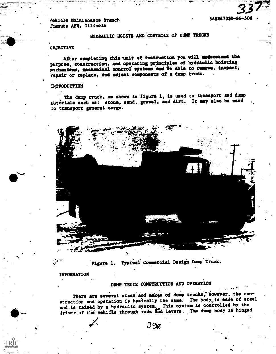
!'ehicle Saintanancs BranchZhanute APB, Illinois
'HYDRAULIC HOISTS AND:CONTIOLS OF DUMP TRUCICS
CBJECTIVE
3ABR47330-SG-504
After completing this unit of instruction you will understand ths
purpose, construction, and operating principles of hydraulic hoisting
mischaniams, mechanical control wystems'andl I. able to remove, inspect,
repair or replace, Ind adjust components of a dump truck. ,
INTRODUCTION
The dump truck, as shown in figure 1, is used to transport and dump
r;aterials such as: stone, sand, gravel, and dirt. It may also be used
to transport general cargo.
.41100r1 44r r,f1
10. .. ,
ifP..*
4"*.iima.
'A 7
rd.
=mmmmit._
alto .
UP ---1110+0 11° 4) "
'111114-
16,
4116 it*
'Figure 1. Typical C&rcial Design Dump Truck.
INFORMATION
4
, WI
"44.
DUMP TRUCK CONSTRUCTION AND OPERATION.
There are several sizes and mak,. .of dump trucks;fiowever, the con-
struction end operation is bpacally the same. The body_is made of steel
and is raised by a hydraulic system. This system.is codirolled by the
driver of the' vehiale through rods, fgd levers. ..The dump body is hinged
39g
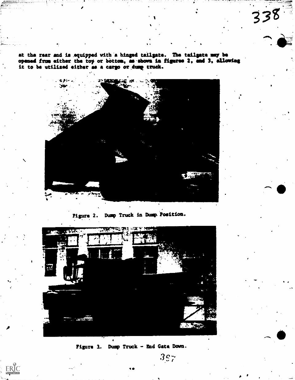
A
a
at the rear and is squipped with'a hinged tailgate. The tailgate mry beopened fro, either the top or bottom, as.thown la figures 2, sod 3, allowingit to be utilized either as a cargo or.dump truck.
w..
,
.374
Fiero 2. Dump Truck in Dump:Position.
lt
..*
00 t I 1, 11`
1 1-1---.1. i..111
« 41.7
` 4
Figure 1. Dump Truck - End Gate Down.
3671 0
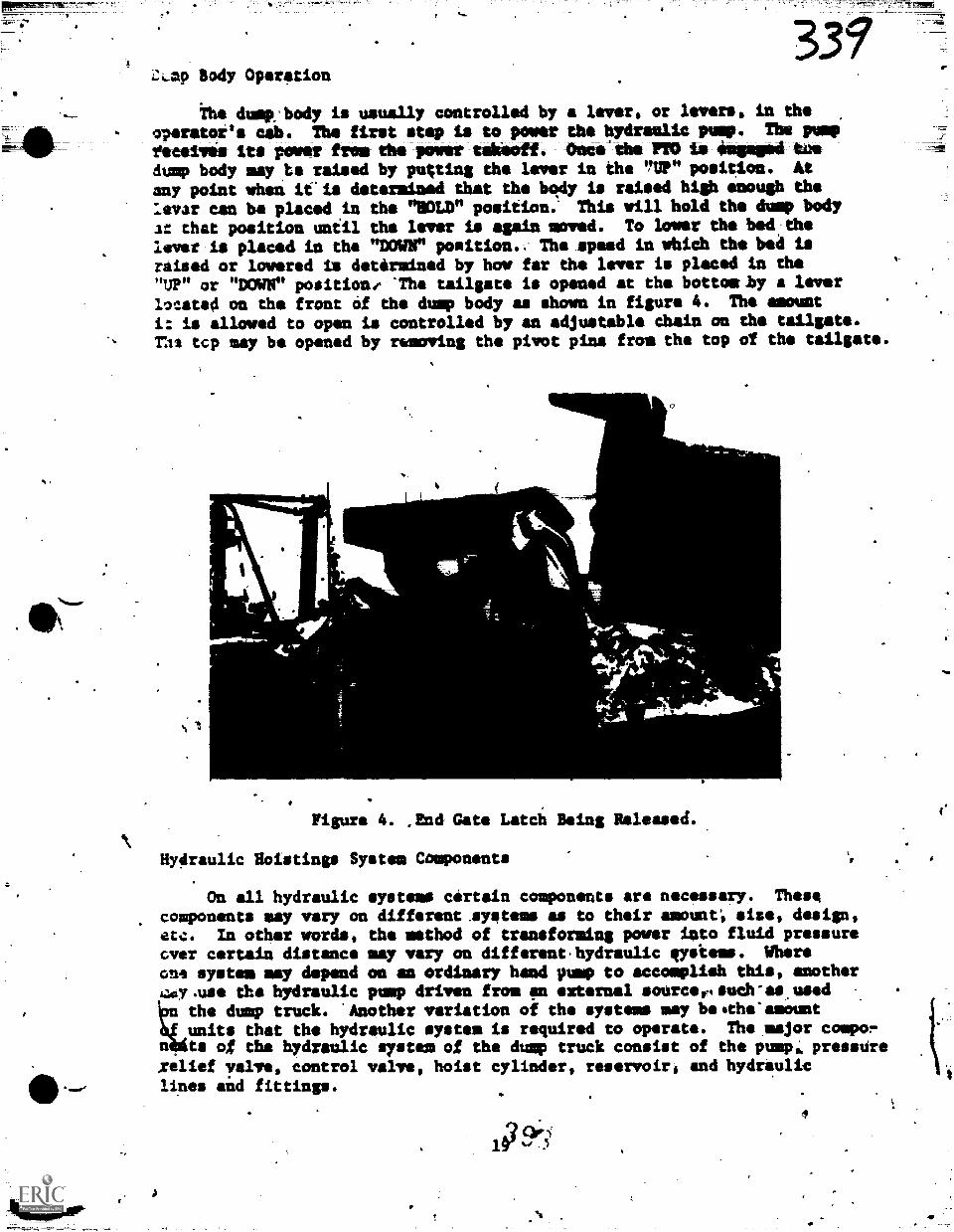
LLap Body Operation
the duit'body is usually controlled by a lever, or levers, in the
o7erater's cab. The first step is to power the hydraulic pump. The pump
toadies its power from the power takeoff. (Nwe'tbs PTO is engaged toedump body may ,te raised by putting the lever in the "UP" position. At
any point when it'is determined that the body is raised high enough the
:Altar can be placed in the "HOLD" position; This will hold the dump body
at that position until the lever is again moved. To lower the bed:thelever is placed in the "DOWN" position.. The speed in which the bed israised or lowered is determined by how far the lever is placed in the"UP" or "MAW positiane 'The tailgate is opened at the bottosby a leverlocated on the front Of the dump body as shown in figure 4. The amount
i: is allowed to open is controlled by an adjustable chain on the tailgate.
Thi tcp may be opened by removing the pivot pins from the top of the tailgate.
1
L1116...
Figure 4. ,End Gate Latch Being Released.
Hydraulic Hoisting. System Components
On all hydraulic systems certain components are necessary. These
components may vary on different.systeme as to their amount: else, design,etc. In other words, the method of transforming power into fluid pressureover certain distance may vary on different.hydraulic often.. Whereone system may depend on an ordinary hand pump to accomplish this, anothery.use the hydraulic pump driven from pp external sourcertsuch-as.usedthe dump truck. 'Another variation of the systems may beothe'ameunt
ntunits that the hydraulic system is required to operate. The major casco-ts of tha hydraulic system of the dump truck consist of the pump,;, presstire
Avlief valve, control valve, hoist cylinder, reservoir, and hydrauliclines aid fittings.
107.9v.
4
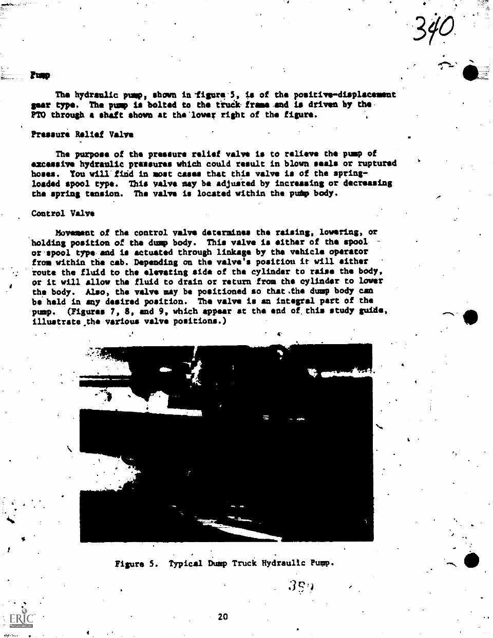
rump
The hydraulic pump, shown infigure.5, is of the positive-displacementgees type. The pump is bolted to the till& framerand is driven by the-PTO through shaft shown at the'lower right of the figura.
Pressure Relief Valve
The purpose of the pressure relief valve is to relieve the pump ofexcessive hydraulic prassures which could result in blown seals or rupturedhoses. You wilIfidd in most cases that this valve is of the spring-loaded spool type. This valve may be adjusted by increasing or decreasingthe spring tension. The valve is located within the puip body.
Control Valve
Movement of the control valve determines the raising, lowering, orholding position of the dump body. This valve is either of the spoolor'spool type.and is actuated through linkage by the vehicle operatorfrom within the cab. Depending on the valve's positiou it will eitherroute the fluid to the elevating side of the cylinder to raise the body,or it will allow the fluid to drain or return from the cylinder to lower
the body. Also, the valve may be positioned so that.the dump body canbe held in any desired position. The valve is an integral part of the
'pump. (Figures 7, 8, and 9, which-appear at the end of,this study guide,illustrate.the various valve positions.)
Figure 5. Typical Dump Truck Hydraulic Pump.
3Q:J
20
kt
s.
...0
. Cylinde:3 41f
me hoist cylinder is used to raise and lower the dump body efficiently
snd smoothly.
SINGLEvACTION CYLINDE1S. Fluid under pressure enters the cylinder
ana forces the push rod up. The pmsh rod is lowered by gravity and the
f:uid is bled off back into _the reservoir.
DOUBLE-ACTION. Fluid under pressure forces the push rod up and down.
This type cylinder allows the dump body to reach a near vertical position.
In this case pressure may be required to start the dump body.down, however,
gravity should be allowed to finish the lowering of the dump body.
TEL4SCOPIC CYLINDER. This cylinder is used to extend the push rod
%are than twice the length of the cylinder. It works on the principle
of a telescope. This type has a push rod within a push rod and will raise
nearly three times the length of the cylinder.
Hydraulic Lines and Fittings
These lines (hoses), shown in figure 5, are used to deliver fluid
from the confrol valve to the cylinder and back again. They msy both
be high pressure lines or one may be a law pressure line. If botn are
used they can be identified by a difference in diameter. The high pressure
is normally smaller than the low pressure.
Reservoir
The reservOir is normally located inside the cylinder. The fluid
is pumped from the top of the cylinder, and delivered under pressure to
the bottom of the.cylinder. In some applications the reservoir may be
a separate'tank.
Inspection and Repair of Dump Truck Units7
One of the most common failures of the hydraulic system used an the
dump trvek is Ole complete loss of pressure or low pressure.- Any signs
iof leakage should be, corrected immediately. This includes the installation
of new gaskets; adjusting packing, or tightening of nuts and bol.:s. All
linkage should be inpected for tightness and any points of wear, such
as clevises acd pins should be replaced. The control valve should be
checked for operation. It should work freely in all positions. The'valve
(provided it is 'the spring-loaded type) should snap back to neutral as
it is released. The hoist cylinder ram should be sulooQI and free from
rust.. A fine film of hydraulic fluid on the ram indicates a pruperly
adjusted packing.gland.
removal of Units From Dump Truck
When it is necessary to remove components of the hydraulic system
of the dump truck, the dump body should be raised and properly blocked
to prevent it from falling and injuring personnel working oh the vehicle.
I
21
A
DISCONNECTING LINES. Keep suitable containers handy Os catch'thehydraulic fluid when lines are disconnected. Use the proper tools fordisconnecting lines so that fittings will not be damaged.
Note; The fittings and end of lines should be taped to protect fittingsand prevent dirt from entering lines. Any dirt or foreign materialmay be very damaging to any hydraulic system.
REMOVING THE LIFT CYLINDER. Whenever it is necessary to remove thelift cylinder, an overhead crane or other suitable lifting device mustbe used to ease the task of handling the cylinder.
REMOVING THE HYDRAULIC PUMP. The punp is generally bolted to theframe. Mounting bolts, propeller shaft, linkage and lines must be removedin order to remove the pump from the truck.
REMOVAL OF THE CONTROL VALVE. This requires only the remoVal oflinkage, lines, and mounting bolts to remove it from the vehicle.
Replacement of Units
Replacing the units of the hydraulic system is simply a reversalof procedures used when removing them.
Tests of Units
When units have been replaced it will be necessary to refill thereservoir or cylinder with the specified type of fluid. Make sure that
no lines are left loose that will develop leaks under pressure. When
units have been replaced and all necessary items checked, start the vehicleand check the operation. Adjust the linkage on the power takeoff andthe control valve.
Servicing Hydraulic System Components
The hydraulic system of the dump truck is subject to leaking after"an extended period of vse. It is necessary that all lines, fittings,and gaskets be kept tightened or replaced (they cannot be repaired). Also,
other servicing is required from time to time to keep the system in topoperating condition.
LIFT CYLINDER. The lift cylinder is equipped with an adjustablepacking gland that may require tightening. A'properly tightened packinggland will not leak but does leave a film of fluid on the piston rod.Periodically,'en-inspection should be made to determinsthe specifiedfluid level of the reservoir or cylinde-. necessarl to add clean
hydraulic fluid as required. Ths type qf hydraulic fluid to be used isin the publication applicable to equipment in use.
Caution: Overtightening of the packing will score the rod and leaveit dry and subject to rusting '
LINKAGE. The mechanical cpntrol linkage may require servicing oradjusting after an extended period of use. The adles;ment may be required
%/,
S.
22
3
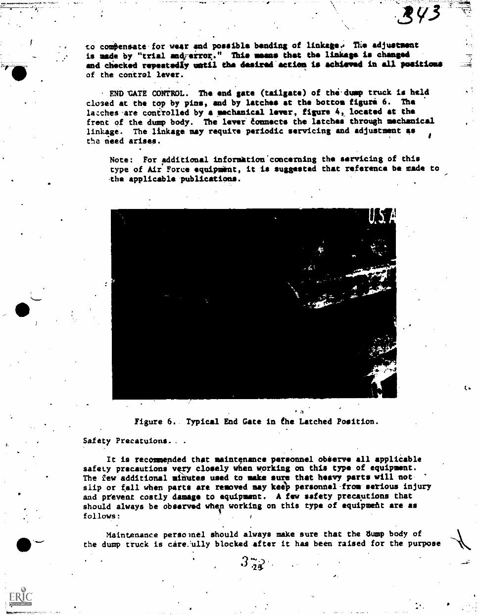
f.
- to comOensate for wear and possible bending of linkage:* Tlie adjustment
is made by "trial andreiror." This moans that the linkage is changedand ctiecked repeatedly until the desired-accien is achieved in all positionsof the control lever.
END 'GATE CONTROL. The end gate (tailgate) of the.dump truck is heldclo3ed at the top by pins, and by latches at the bottom figure 6. Thelacches-are conerolled by a aechanical lever, figure 4, located at thefront of the dump body. The lever' donnects the latches through mechanicallinkage. The linkage may require periodic servicing and adjustment asthe need arises.
Note: For additional informktion'concerning the servicing of thistype of Air Force equipment, it is suggested that referents be cede to
the applicable publications.
Figure 6. Typical End Gate in ehe Latched Position.
Safety Frecatuions.
It is recommepded that maintenance personnel obierve all appliCablesafety precautions very closely when working an this type of equipment.The few additional minutes used to make sure that heavy parts will notslip or fall when parts are removed may keeP personnel-from serious injuryand prevent costly damage to quipment. A few safety precautions thatshould always be observed whee working on this type of equipmeht are as
follows:
Maintenance persolnel should always make sure that the dump body ofthe dump truck is cire:ully blocked after it has been raised for the purpose
3
of Joking rtpairs to any unit attachtd on this undorsids of tht vehicleNEVER WORK UNDER A RAISED DUMP BED UNLESS IT IS PROPERLY BLOCKLD.
Care should be exercised not to get tiydraulic fluid or oil in theeyes.
Always wipe up any spilled hydraulic fluid from the floor or vehicleto prevent slipping.end falling. This should be done immediately afterit has been spilled.
It is often necessary to use a hoist or other suitable lifitng devicewhen removing or handling heavy components on this type of equipment.The components should be carefully supported,before being disconnected.
Exercise care when working with another mechanic. Always check tosee what vehicle units have been loosened by other maintenance persopnelbefore any attempt is made to remove such units as mounting bolts, etc.
Note: Remember! No attempt should be made to get under any unit that
is ready for removal.
QUESTIONS
1. Where is the hydraulic fluid stored?
2. What indicates a properly adjusted packing gland?
3. How does the control valve regulate the motion of the dump bed?
.4. Why does the end gate of a dump truck dpen at the bottom as-well as
the top?
4k.15. How is the hzIraulic pump on the dump tru driven?
;.
6. How would hydraulic pressure be increased if more'pressure were
needed?
.
T. What could happen if the packing gland 'WAS adjusted too tightly?*
8. How can the speed at which the cylinder operates be regulated?
9. What determines how wide the tailgate opens?
A10. What type of cylindersaare used on dump ttucks?
Note: If you have dilficulty answerinethese questions then by all
means go back and iqview the material that you are weak on.
24
))
4
,...
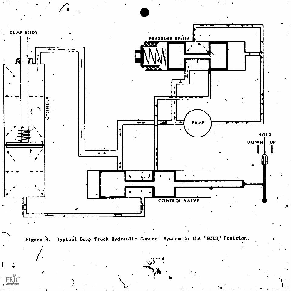
DUMP BODY
I.
PRESSURE RECIEF
11
CONTROL ,VALVE
HOLD
DOWN UPI
Figure II. TypicS1 Dump Truck Hydraulic Control System in the "HOLD,7 Posirion.
ft. -(7;41..
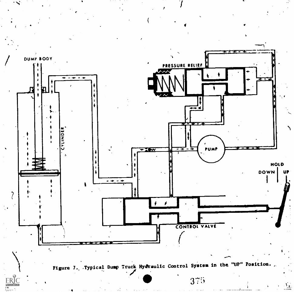
4
DUMP BODY
A
r444110)]
4
4
PRESSURE RELIEF
41P. 40.
PUMP
10
Er rar 3 'Mr
HOLD
DOWN I UP
CONTROL VALVE
r..%
Figure 7.. Typical Dump Truck Hyditaulic Control System in the "UP" Position.
'/
4
X:45
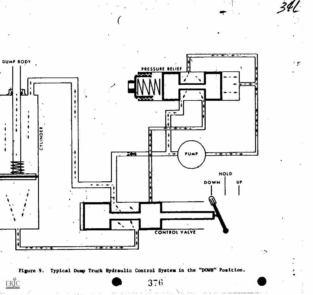
DUMP BODY
Ls
lb4,
PRESSURE RELIEF I~gni
4
4
p.
10. .41..
HOLD
1DOWN UP
I I
CONTROL VALVE
Figure.9. Typical Dump Truck Hydraulic Control System in the "DOWN" Position.
3676
r
k..31.-PVGRAMMED TEXT 3ABR473.3GPT-501A
A
Technical Training
fgeclumptc_.General Purpose Vehicle Repairman
c+ANDARD TRANSMISSION
4 March 1970*
CHANUTE TECHNICAL TRAINTNG CENTER (ATC),
This supersedes PT 3A8R47131-50113-11, 15 February 1968.
Designed For ATC Course Use
377
cd--//
37'r
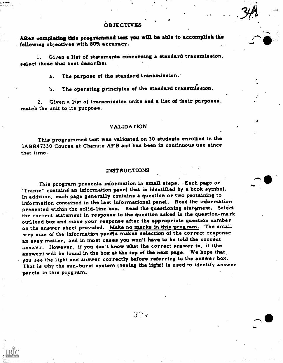
OBJECTIVES
Alit or completing this programmed text you will be able to accomplish thefollowing objectives with 801 acciiracy.
1. Given a list of statements concerning a standard transmission,select those that best describe:
a. The purpose of the standard transmission.
b. The operating principles of the standard transmrssion.
2. Given a list of transmission units and a list of their purposes,match the unit to its purpose.
VALIDATION
This programmed text was validated on 30 students enrolled in the3ABR47330 Course at Chanute AFB and has been in continuous use sincethat time.
INSTRUCTIONS
This program presents information in small steps. Each page or"frame" containi an information panel that is identified by a book symbol.In addition, each-page generally contains a question or two pertaining toinformation contained in the last informational panel. Read the informationpresented within the slid-line box. Read the questioning statement. Selectthe correct statement in response to the question asked in the question-markoutlined box and make your response after the appropriate question numberon the answer sheet provided. Make no marks in this program. The smallstep size of the information panels makes selection of the correct responsean easy matter, and in most cases you won't have to be told the correctanswer. However, if you don't know what the correct answer is, it (theanswer) will be found in the box at the top of the next page. We hope thatyou see the light and answer correctly before referring to the answer box.That is why the sun-burst system (leeing the light) is used to identify answerpanels in this program.
Mak
,""\
Frino 1.
vehicle redlged to operate under Sony different tyies of road
conditions, such as rough hilly ground, Asa, or smooth surfaces. It
will rewire sore power to go up a hill *it te rma em a lswel road,
therefore, a transmission is used to yaw the ascent of power deliver-
ed at erent times.
inoreaes.of torque maybe neceseery for a vehicle to pun up a
hill. It maybe that When the transmission to la LW gear there is agear redaction of 1211 from th engine to the prepsillor shaft. This
means that the crankshaft of the engine mast tarn over 12 tiseet_to_.
turn the propeller shaft once. If the same vehicle was on a smoothroad, the gear reduction is not needed and the transmission may be in
direct driv with a la gear ratio. This means that the crankshaftof the engine must turn over only oge time in order to turn the pro-
peller shaft once. The transmissiok aleo proVides anew= for backing
the vehicle. There is a need for many gear ratios in a vehicletandthe transmission is the unit that provides the operator with a selec-
tion of gear ratios and reverse direction between the engine and the
rear wheels.
MILSTEIN 1.
? ? ? ? ? ? ? ? ? ? ? ? ? ? ? ? ? ? ? ? ? ? ? ? ? ? ? ? ? ? ? ? ? ? ? ?
? Wbat is the purpose of the standard transmission?
? a. To engage and disengage the engine from the.rear wheels.'
b. Tn permit the engine to develop full torque.
? c. To provide the operator with a solectioi of gear ratios.
? de To provide equal torque distribution to both driving wheels. .?
? ? ? ? ? ? ? ? 7 ? ? ? ? ? ? ? ? ? ? ? ? ? 7 ? ? ? ? ? ? ? ? 7 ? ? ?
Frames 2.* ,
standard transmission operates on the principle of gear ratio,
which is usually defined is lie collative speed of rotation between
two meshing gears: The ratio is &itemized by the number of teeth an
the gears. ;kir ample, two soden gears having the ems nnlber ofteeth will both tura at the same speed. The transmission provides
emenna-of Changing the gear ratio.
ism=...=ma=saolWml.ErbalQUESTIONS 2 and 3.
? ? ? ? ? ? ? ? ? ? ? ? ? ? ? ? ? ? ? ? ? ? ? ? ? ? ? ? ? ? ? ? ? ? ? ? ?,
? 2. What is the operating principle of a stradard.transmission? ?
? a. rtictian. \.._.
i .
b. Gear ratio.?
?
c. Trsnsfer of motion by liquidi.?
3.
d. Centrtfugai force.
What unit on the vehicle provides the operator with selection
of gear ro!tios and reverse direction:between the engine anid the
rear Whedls?
a. Propeller shaft.
b. Engine.
?.c, Roar aile.
d. Tramemissian.
? ? ? ? ? 74? ? ? ? ? ? ? ? ? ? ? ? 7 7 7 7 ? ? ? ? ? ? ? ? ? ? 7 ? 7 ?
Jr
.1
Tram 3.
Answers to previous questions:
Most Standard transmissions have am engine-to-drive daft ratioof about 3 ti? 1 term gear. That is to soy, the engine crankshaftwill turn three times While the drive Shaft turns only once.. Thisengine-to-drive Shaft ratio id13. prodme high engine torque and lowvehicle speed.
Shifting the transmission'into SECOND gear generally results in a2 to 1 engine-to-dmpre shaft ratio. A smaller gear is used toin-crease the speed ot the drive abaft but this also &weasel thetorque deliverid.
THIRD gear is essontiaI/y a 1 to 1 engine-to-drive Shaft gear ratioThat is to say that for sedh engine revolution the drive ahaft willalso turn onsirevolution..
In make the Changes in gear ratio, speed is increased as thedrive Shaft revOlutions approadhed that of the engine crankshaft.These chsagesfin gear ratio are desirable once the vehicle is inmotion. The ability of the'engine to proem, the necessary torqueto mows a vehicle from rest is &creased as the engine-to-drive shaftratio if, decreased.
Torque is a twisting effort or "that force which produces or tendsto produce rotation." If geari are arranged to increase torque, gpeeais decreased but if they are arranged to increase speed, torque is de-creased.
clUlEITION 14.
S.
1 ? ? ? ? ? ? ? ? ? ? ? ? ? ? ? ? ? ? ? ? ? ? ? ? ? ? ? ? ? ? ? ? ? ? ?,?' Mbat is tile result in transmissicnwben a small gear an Ole input&aft drives a large gear an the output shaft?
a. Speed is increased and toinui is decreased.
b. Speed is decreased and torque is increasad.
c. Speed and torque'are decreased. \.
?
d. Spoma and torque are increased.b ?
? ? ? ? 1 ? ? ? 1 ? ? ? ? ? ?'? ? ? I ? ? ? ? / ? I ? ? ? ? ? ? ? ? ?
-
"bil vas the correct answer to the previous question
1,1
f' Thetranamissionprovides 4 means of varying gear ratios through
the use of gears mounted on 'hefts. The seers and.shats are housed
in the transmission case* la input abaft or antWh *eft is used to
transmit torque from the engine into the tramsniesing, While sn out-
put or meinibift is used totransmit the torque fron the trensmissian
to the prope4er Shaft.
=Mats 5 (through 7
? ? 7 ? 7 ? ? ? ? ? ? ? ? ? ? ? ? ? ? ? 7 7 ? ? ? ? ? ? ? 47 1 ? ? ? 1 ?
7
- S. What is the purpose of the transmission case
a. Provide the selection of diffrent gear ratios.
b. Prcmridifsmpport between the engine and the transmission*
c. House the differential gears.
d. House the traniiiission gears and Shafts.
6. What unit is used to transmit torque fr*.the engine to the'
transmission?
a. Input Shaft.
b. Output abaft.
1,10 c. Intermediate prcp.U.r shaft.
d. P.T.O. drtve Shaft%
7. What unit is used to transmit torque frokt.he transmission to .the
propellersibaft?
a. Input ahaft.
b. .Output Shaft.
c. Intermediate propeller Shaft.
d. P.T.O.' drive Shaft.
? 47 47 ? ? ? ? ? ? ? ? ? 7 1 1 ? ? ?.? ? 1 ? ? 2 ? ? 47 7 ? 7. ? ? ? 7 ?
3S.2
Ok.
a.
%MI
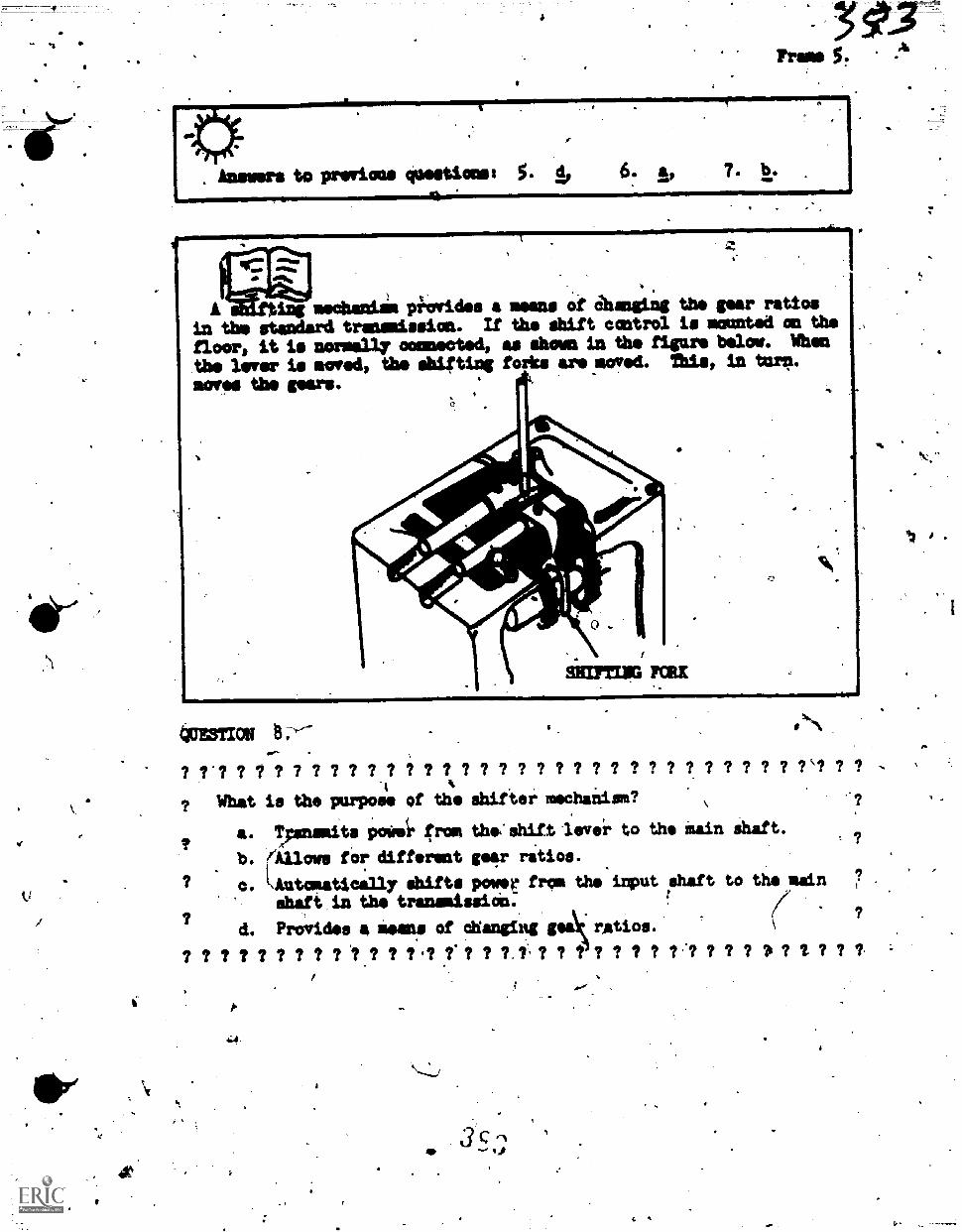
4.
ing mechanim piovides a moons of Shaming the gear ratios
in the standard transmission. If tho shift control is mounted on the
floor, it is normally ootmiectod, as shown in the figaro below. Whet
tbe limer is mowed, tbo shifting forks are moved. this, in tam.
4cE3TION 8:--
7.7 9 7 7 7 9 9 9 9 7k7
? What is the purpot4 of th shiftei mechaimiam? ?
16,
a.' Tymnsmits poesi. from tho'shift lever to the Main Shaft., ? ?
b. (Allows for different ger ratios.
? c. iqtatcaatiomilly shifts power from the'input shaft to the main ?
vt
shaft,in the transmission., /
? ( ?
d. Pro;rides a lima of changing gas\ ratios. \
? ? ? ? ? ? ? ? ? '? ? ? ? .? ?. ? ? 7.1 ? ? t ? ? ? ? 7.1 ? ? ? ?i ? 11- ? ? 7,
c- if
41;
-
r to prep.ous queitioeuAnra 8.
4
7- 4VESTIONS 9 through 12..
? ? 7 ? 7 7,7 .7 7 7.2-? 7c7 ? 7 7 7 7 7 7 1 ? ? ? ? ? ?.? ? ?%? 7 1 ?
Match the unitsright.
9. Transmission Case.
A10. Input Shaft.
?
U. ;output' shet. .
12. Shiiter Mechanism.
an tb. lieft with thfiir purposes as given an the
r? 9 ? 7 7 7 7' 7 7 7 7 7
d
r
a. Transait power from ths,Ingineto the transmission:
. .
Moms. the transmission gears ,
and.shafts.p/
c. Provide a'msans of changing. tear ratio.
Transmit.power from the trans-9.1,mission to the propeller shaft.
i? 9 7 7 9 7 f ? 9 ? 9 ? ? ?
NOTE: If, you have-any difficulty in matching the above items to theirpurposes you shaald to back through the material again.
m_
4
4 a
4itik
fr
ADIMPAIM E Tin rut
a
, Technical Training
General Purpose Vehicle MechanicBase Vehicielguipment Mechanic
"-facial Vehicle Mechanic
. ,^rash/Firs Vehielea)
(Refueling Vehicles)(Materials Handling Vehicles).
(Towing aid Servicing.Vehicles)'
CLUTCH PRINCIPLES
17 February 1976
41ki..)japt'.
.
%LIMA sal
Malt4723.1;A-11-40-dec3A1111,47233.11-PT-404C3ABR47231C-PT-404C3Avilt47231D-Pt-4W
8: 3 P 1.4 let
USAF SCHOOL OF AFPLIED:AEROSPACESOLEMCES3340th Technicalnieg CrapChanute Air Foice.`lisse:Illinois,"4:1 -=-'
a.
,
. ,
Dosignict For ATC Coves* Use-
DO NOT USE ON-rmiropi
k.
z
,to
.11
<.
4
4
,
'OBJECTIVES
When you have completed this text, you will be able t4 accomplish the followingobjectives to Sn, accuracy:
1
1. Given a list of statements concerning slutches, select those that: best describe its, purpose.
2. Given a list of statements concerning'clutch elements, select thestatements that list the princiPle parts of a clutch.
3. Given a list of statements concerning the typek of clutches, selectthose thai describe the single-plate clutch, the double-plate clutch, andthe MultiPle-disc clutch.
\J.
s
4. Given a Iist Of clutch elements and a list of clutch element'functions match the gorrect functioroto each clutch element.
INSTRUCTIONS .
44
A
This lesson presents information in small,s'teps. Each.page or Cfrant"contains an information panel and/cr questions pertaining to informationcontained in the panel. Read the information,presented,'then select thejcorrect statement In response to the queStion asked. -
After you.have selected an answer co a question and you have recorded thatanswer in the booklet, you may check the accuracy of your selection by turningto tphe last frame of this. program.(Confirmation Frame).
11;ere is no timt limit on this lesson. TAKE YOUR TIME. You may now proceedto Frame 1 and besin.
4
V-
. .1
11
1-.--""---------,1.
Supersedes 20R4733Q-Ptr50l, 25.February'1972.. 111FR: TiS .4'r
, ! ,
DISTRIBUTION:l'TWS - 400;
A
3
'"
.1
CLUTCH PRINCIPLES,
41
,,
:The Purpose of a clutch ia an automotive vehicle,is to provide 14 omens ;
of'conmecting and disconnecting th e! engine and ctransmi inn, ,The engine. and <.,
itranslission.umst be connecied=to tromiuit poaer from =.itingine to the trinoe.'aission. ;be mechanisms of the Clutch allows.this con cO.on to be m444grgdually flir suooth.starts. The enginerand transiissiciumst b4 disconnectedfrom each other in order to shift the transmission to variousteara ailoatstopiing the vehicle.
QUESTION 1.,
What fs the purpose df an automotive clutch?
-a. To connect and disconnectdifferential.
b. To connect and disconnect
c. To connect and discorrectdriving axle.
the tramemission from the
the engine from the diffetentiAl-:'a
the transmiss4n from the reit
To connect and disconnect the engine from the transmission.
Minn. A
To put a vehicle in motion from a aead stop, engine torque-4(twisting.
forde) must be developed (by "reving" up the engine) with the engine.and tranv-mission disconnected from each other. Without the use of the clutih this couldnot be done. The mechanisms of the clutch ,allow the connection to.pe madegradually and smoothly to avoid excessive shock loads to the_vehicZedrive tiain.
s.
4
CI
..
a
0.
a
4
QUESTION 2.
r
A. ,
Besides proviaing a means o&connecting &gift disconnecting the'enginefrom the transmission, the clutch must also provide a means of
developing engine.torque with tha vehicle standing still Ind r-the transmission in gear.
smoothly apiSlying engirie torque to the rest of'the drive'train.'
. bwothla. and b. above.
nerther- a, nor*b.
Sià -
- An automotive clutch h usually,located directly jbehind the engine. Itwill iblways be locited at some point in the power train betieen the engineand trinsmission.
/
QUESTION.3.
.k
\\,Fill In...the blank space with the correct aosi4r.
'The-automotive clutch is always located blipween.the,(a)
ank the (b)
A
a. Ail automotive-clutches depend on frictionsolid friction as in the conventional-clutch, orclutching mechanksis of automatic transmissions.will be concerned With'convfttional.clutches.
1/4
for" their operation, titherfluid friction as used in theThe remainder of this lesson
4.
a.S.
%-.
;a'
'44
4
S.
0.
:
2
111
b,
. 'WESTION*4
.
S.
.%11111.
* '
-.On wilat _doss a cOnven4onal clutch depsnd for operation?,. /
a. Solti,frictiO6. . .
b. Fluid friction. .
k
. Inertia.
1 a,
a.a
-Conventional Clutcfies ae devidid.into too different types of componentsor members - Drive Members a#d Driven Members'. ev
Drive lumbers are those' which ire connected io the engine. Drivenmembers.are those which are connected to the transmission. The majority of generalpurpose vothicle clutches utilize two dri46 members,and oft. driven member.
C" *s.
Poweris transferred -frock the engiss-to the transmissiOn through theclutch by bringing the drivinumembers limo gradual contact with the driveri'member. r.
16QUESTION 5 through 8.
Fill in the blanklapaces with the coriect answer.
ofe (a) r7-- and the (b) rare the two types ofmectibe%
Thused in Conventfmnal clutches. ,k i
6. Drive members lie those whieh are connected to the. I7
'transmission.members are those which are connecte.d to the'
Power &transferred -from the engine to the transmission' throughthe use of's
a.
a.
f
t'
a.
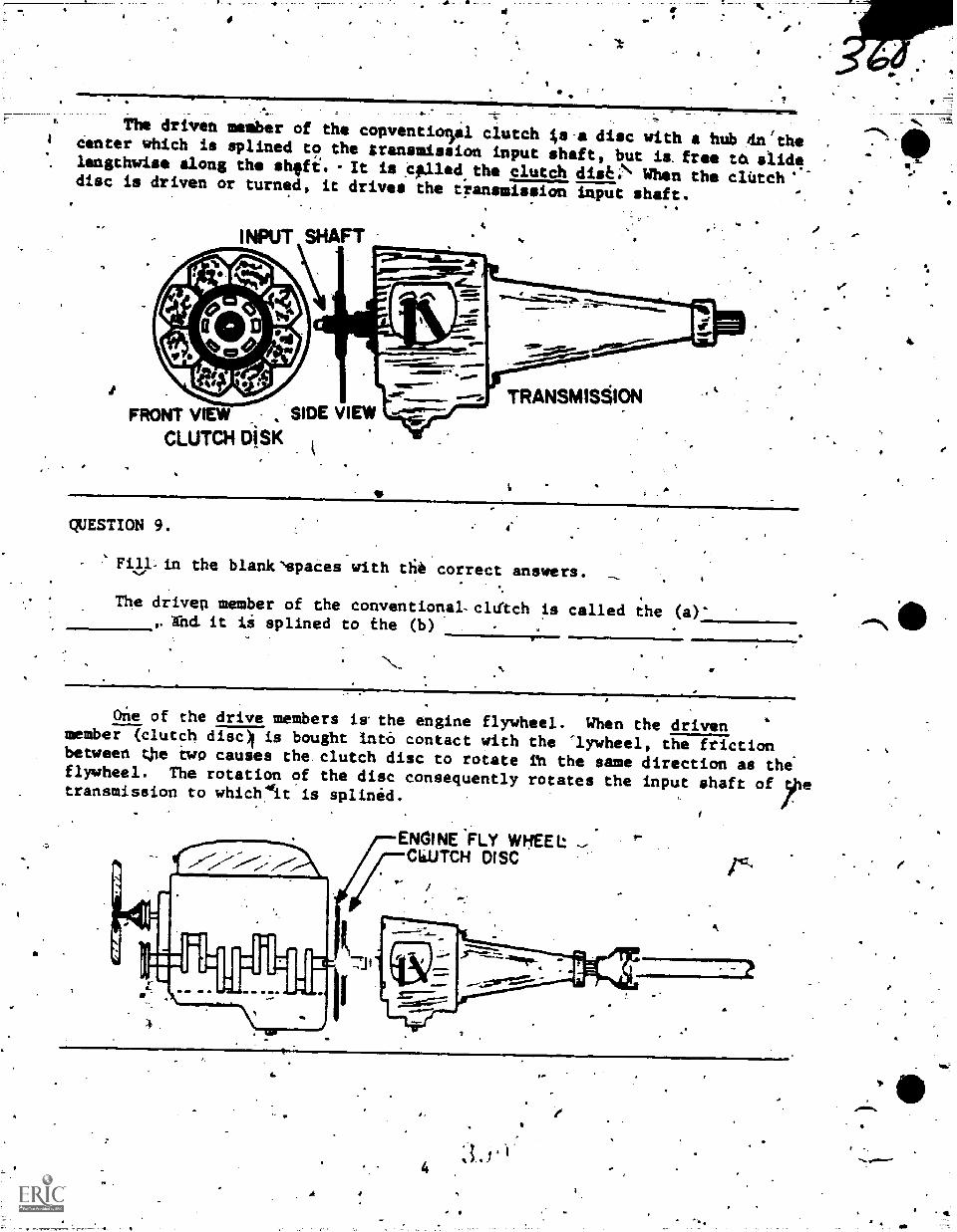
r
?
The driven member of the conventio5sl clutch 4s.a disc with a hub din'the4 Center which is splined to the transmission input shaft, but is.froe ta slidelengthwise along the shefi. -It is :gilled the clutCh dise:\ When the clutch'disc is driven or turned, it drives the tiansmission input shaft.
INPUT SHAFT
_
FRONT VIEW , SIDE VIEW
CLUTCH DISK
TRANSMISION
QUESTION 9. 4'
Filkin the blankspaces-with ttit correct answers.
The driven member of the conventional-cldlch is called the (a)-, hd. it is splined to the (b)
irr
One of the drive members iwthe engine flywheel. When the drivenmember (clutch disc), is bought int6 contact with the lywheel, the frictionbetween tjle bwo causes the clutch disc to rotate ih the same direction as the*flywheel. The rotation of the disc consequently rotates the input shaft of yletransmission to which'It is splinid.
ENGINE FLY WHEELCli.UTCH DISC
S..
3.5'14
#
.
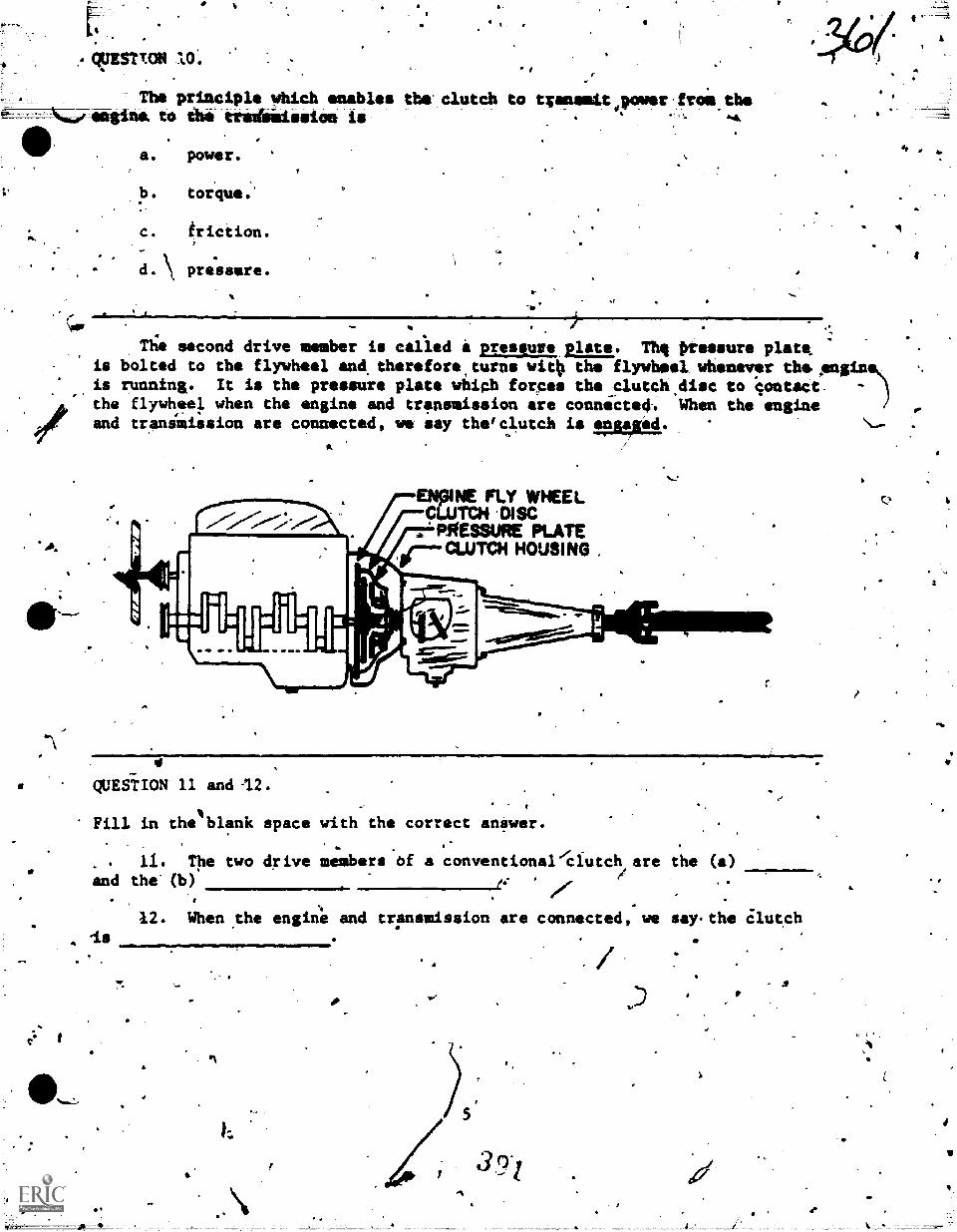
,
Q3IST1.014 O.-
Tbe primciple which enables the' clutch to tzensmit power.from the_ensina. to tits trs4s':ission is
6N\ mrrommmnirmri,..lonm=w1
a. power.
b. torque.
c. triction.
d.\ pressure.
- ...,
Ttie eecond drive member is called i preseure_plate,. Th, pressure plateis bolted to the flywheel and, therefore turns witp the flywheel whenever the Anginis running. It is the pressure plata which forces the Clutch,disc to contaCt. -
the flywheel when the engine and transmission are conniited. When the engineand transmission are connected, we say thefclutch is gasid.. \.....
.
.
-ENIMPE FLY WHEEL
CLUTCH .DISCPRESSURE PLATECLUTCH HOUSING
e QUESTION 11 and 12.
Cet-
Fill in the blank space with the correct anSwer.
, . 11. The two drive members Of a conventionaldautch are the (a)and the' (b)
/4'
U. When _the engine and transmission are connected, we
N./
say.the Clutch
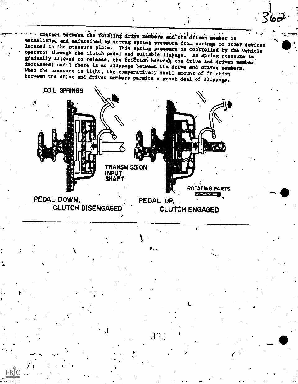
16.
A
do
.
.3427..ANEMM=111111111114
,EMPS
14*. contact hatosen the rotating drive goobers and-the driven memb
rer isestablished and maintained;by strong spring pressure from springs or other devices
411located in the pressure plate. This spring pressure is coitrolledly the vehicleoperator through the clutch pedal and suitable. linkage. As spring pressure isstadualli allowed to release, the friZtion betwe44 the drive and driven member'increases; until there is no slippage between the drive and &riven members.When the pressure is light, the comparatively small amount of frictionbetween the drive and driven members permits a great deal of slippage.
.COIL SPRINGS
TRANSMISSIONINPUTSHAFT
PEDAL DOWN,CLUTCH DISENGAGED
ROTATING PARTS1111=,
PEDAL UP, .
CLUTCH ENGAGED
%
4i.
,=14.=mb
Row ii the friction between the drive and driven members of tIlle4clutch
. vAttcontrolled?
, 11-111.11:41
411,
t.
0.
au. Through automaile V spring praisers in the elutalembers.
b. By the vehicle operator through the use of a c/utch pedal and.and suitable linkage.
c. By usiqg a glutch spring regulator and linkage adjuAtei.
4tarc cr. By shifting thetransmission into :lower ratio gear.
4." We stated in the list information Oanel that friction .between the membersincreases with,spring pressure and decreases with less mpring pressure.There is g reason for this. You will recall.from previous Informationthat the clutch must be 'engaged smoothly and gradually to prevent excessiveshock in the power train components. When friction is first obtained betweenthe.drive and driven ;members of the clutch, the vehicle will start to "creep"even though theri.is a great deal of slippage. The engine cannot transmitits-maximum power.to the -transmission until maximum friction is obtainedbetween the 'clutch members., That is, when all slipping has *copped and therisis a direct contiection between the driving stuileirven parts.
QUESTIONS 14 through 16.
.14. Under what condition will all power produced by the engine be applied
to the transmiision?T
a. When the driviwand driven clutch members have minimum friction.
b. When maximum siring pressure is applied to the clutch members.
e. When the clutch is islipping at its minimuM.
d. When the vehicle is beginning to "creep."
4 15. fUten'will a vehicle*begin to creep?
a. When the clutch is first disengaged.
b.' When the clutch is,fulky disengaged.
c. When the clutch is fully engaged.a'
d. When the clutch is partially'engaged.
A16.. Why.is it necessary to gradually and slowly engage the clutch of
a vehicle?
ft
a. To'creato less friction.
b. To create maximum friction.
c. To minimize power train shock.
d.. To start a vehicle moving suddenly.
,
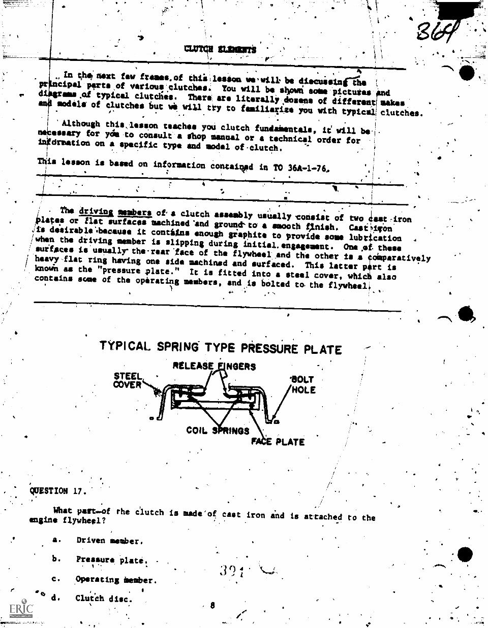
CLUTCH MOWS '
4
GP
a
In thinext flaw frames.of th*leston weiwilk be discuisincilepr cipal-perts,of varioul',clutChes You will be shpwri softe-pictutes'Oddibsrsms _of typical clutches. Thera:, are literalli.dosens of different! makes.al models of clutches tout we will try to familiaTi4e you with typicalIclutches.
'Although this,leseon teaches yoU clutch fundaisettals, Le will be.no6seary for Or to consult'a ihop manual or a technical order forinOrmation on a specific type and modal of.clutch.
This lesson is based on information contained in TO 36A-l-76,
The driving members of a clutch assembly usUally consist of two 4ast-ironplates or flat surfaces machined 'and grounAkto a smooth tInish. Casvticon.
is de'sirablebecause it coutitns enough graphite to provide some lubrication ,/when the driving member is slipping during initial.engagsment. One,ot thesesuiteces is usually-the-rearlece of the flywheel and the other ts a co:paratively/ heavy flat ring haring one side machined and surfaced. This latter part is/ knoWn as the "pressure plate." It is fitted into a steel cover, whiO alsocontains some of the operating members, and is bolted to the firth:04)
QUESTION 17.
TYPICAL SPRING' TYPE PRESSURE PLATERELEASE NOERS
STEELCOVER
SOLTHOLE
What palt.of rhe clutchengine flywheel?
a. Driven member.
b. Pressure plate.
c. Operating bomber.
ClutCh disc.
COIL S MOSPLATE
is made'of cast iron ind is attached ro the
8
qr.
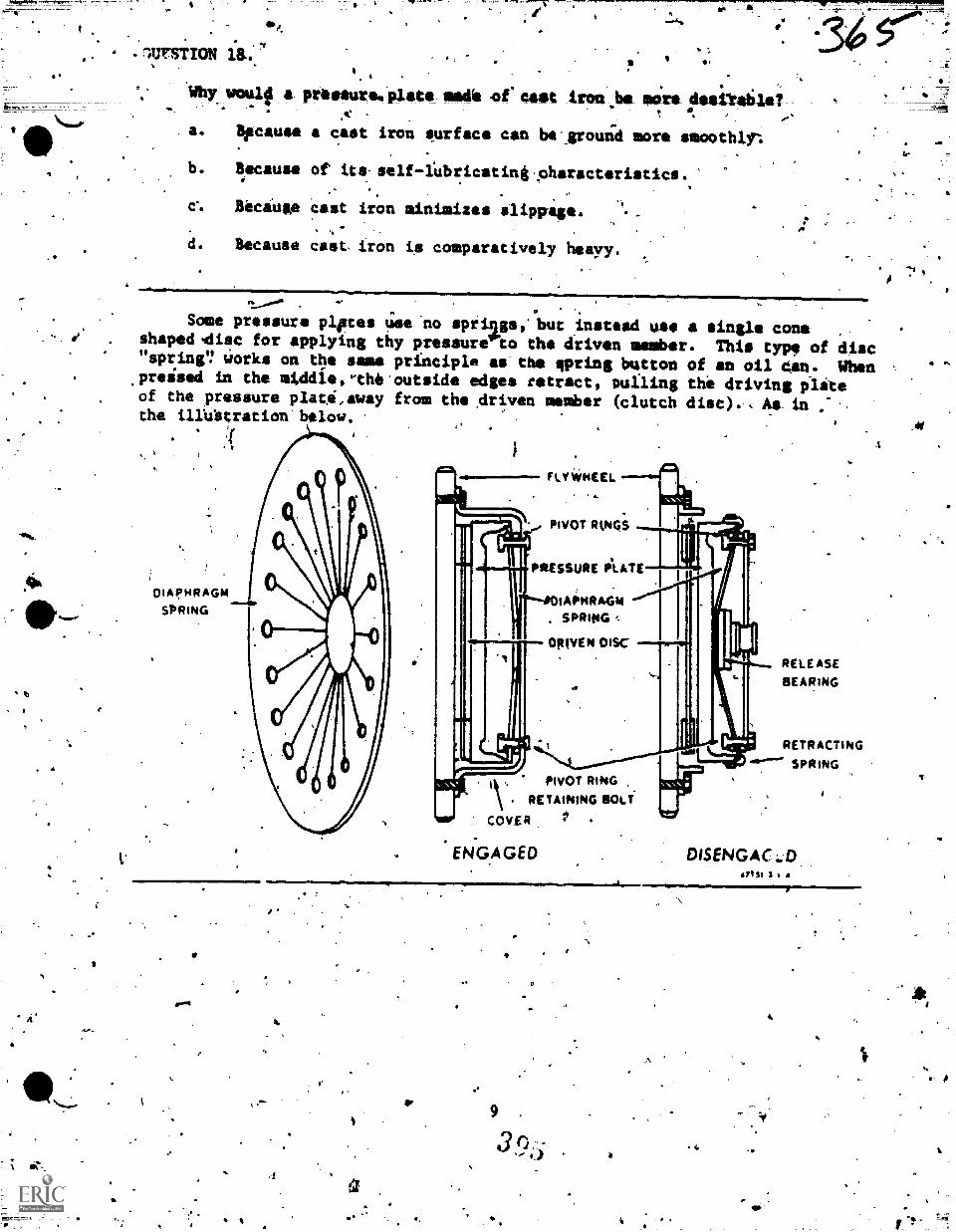
t.
.".lursnoti a.-
Whysoulf a praseure%plate meal ofcailt iron bow movedesitable,
a. Because a cast iron surface can ba vould more smoothly:
b. Because or its.self-foricatingaharactoristics.
c% Because cast iron minimizes slippage.
d. Because cast iron is comparatively heayy.
.
Some pressure Ares use no spriggs, but instead use a single coneshapedmdisc for applying thy pressureto ths driven member. This type of disc"spring'? 4orke on the same principle as the spring button of an oil Oen. When.preised in the middle,Pthecoutside edges retract, pulling the driving pliteof the pressure plat,away from the driven member (clutch disc). , As tm :the illUttration'below.
5m..1
PIVOT RIAGS
PR-ESSURE iLATE
DIAPHRAGMSPRING +-
DRIVEN DISC
TO
PIVOT RING ,
RETAINING BOLT
COVER
ENGAGED
RELEASE
BEARING
RETRACTING
DISENGAC:.D4171$1 3 i
4
3_,, 4,
,,
, j
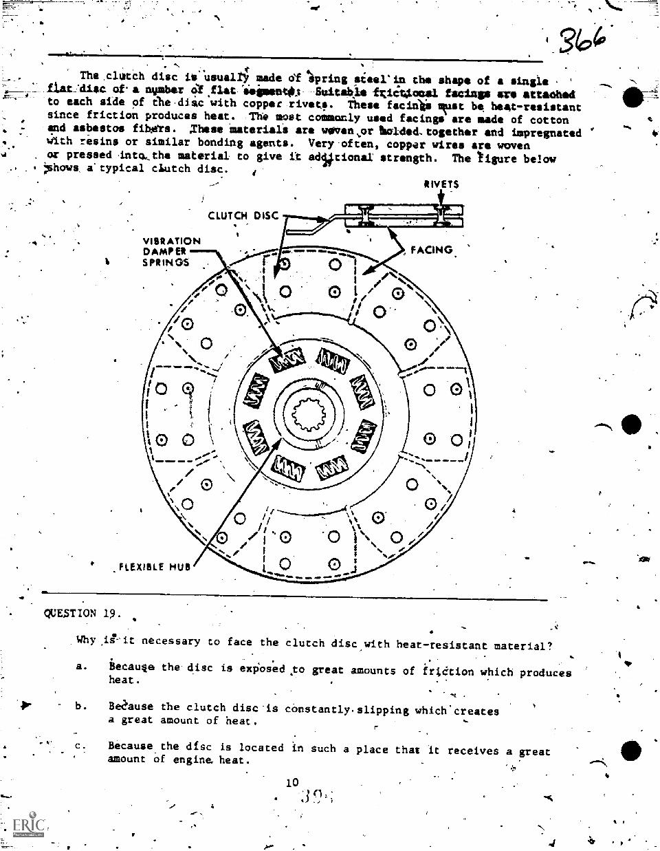
f.The clutch disc iS usually made df 4spring sieerin the shape of a single '
flat:diec of a mother ra.flat 4eiment0 Suitakie ftiiV.omal facing* at attaehed4.to each side of ihe,disc with copper rivet,. These facirilis lest be heat-resistantsince friction produces heat. The most commonly used facings are made of cottonand asbestos fibAits. .These materials are weIven..or bolded,together and impregnated
. 4ith resins or similar bonding agents. Very often, copper wires are woven...
. or pressed 4ntakthe material to give it adiitionaI strength. The tigure below,
*haws a'typical clutch disc. 4
3to
.
CLUTCH DISC
VIBRATIONDAMPERSPRINGS
.FLExiBLE HUB
QUUTION 19.
11111MIIIMENO,
imlIM WW1 41Iw
RIVETS
i----------ar.-vesmixIssisr-.
FACING.
0 /0 0 I / 0 \
' 0 o\
r0 I/ .
/1/i 01
j
0 /A
Why necessary to face the clutch disc with heat-resistant material?
a. iecauqe the disc is exposed ,to greatheat.
I.
amounts of irt8tion which produces
b. 3e2'ause the clutch disc'is constantly.a great amount of heat.
-
c. Because.the disc is located in such aamount of engine, heat.
10
slipping which'creates
place that it receives a great
4
O.
1,
e
4.
-mid. 'MIER, IMF
.1*4.
rhe clutch disc is provided wilh a flexible center mhich-absorbs the .
torsignal vibrat.ion pt the craMkshafe,li The flexible coiner usually takes,the,fors, or steel ccepraaaion.-spring, 'placed- between ;he hub atd- the steil disc.The springs lenait the'disc to iotate slightly backward ay ,the;ispringe. decompress.This slig&t backward and-fofward rotation permitted by the iprings allows iheciutifi shaft to rotate at-a mdre uniform--rate than die crankshaft,therebypieventing soMe of the.torsional vibration Of the crankshafi from beidgtransmitted to the'drive.
QUESTION 20:
;What is
a.. To
-
the ,purpose cf the flexible center on a clutch disc?
absorb
b.. To absorb
c. To absorb torsional
d. To absorb torsional
excessi,re vehicle !lied shock.
torsional vibration,of ohe crankshaft.
vibration of Lne transmission .
vibration of the pressure:plate.
.40.
In order to make clutCh engagement as smooth as possible and' to eliminate"chatter," several' methods have been used sp provide a 4ittle flexibility tothe clutch disc. -One type of disc is "dished," so that the inner and outer surfacesof the'friction facing ,make contacx gAduall) as spring pressure is increasedand Xhe disc flattens out. m'
.
,
QUESTION
AM'
What is.the purpOse of "dishing" a clutch disc?
a. To eliminate chatter and mike engagement Sudden.4
b. f T9 make the entite surface of the disc contact the driving membersimmediately upon engagement.
e
c. To elimiaate chatter and make clutch,engagement smooth-by allowing
.the'inner and outer edges .0 the'disc to make contact withthe driving members graduatly.
4
*
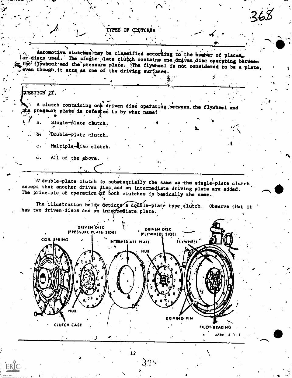
4.
7
TYPES OF gurrass.-\. ,
. .
. .,. Automogve.clutcl\iSsiaay be clipoified =gorillas io the htlik4r of platek.
)for-discs used.' The,sinile-;)late cli4gh dontaine one;d4.3-renidisc operettas blittieeniktlie4fyiwheel.and thepressure plaie.:iThe flywheel is ncit ocinsidered to be a -plate,
c4en thoush.it,acts AA one of the drivipg surlaces... t*
Ae-
1. ,*
"
le%
a
STION' gt. ' I
A clutch containing ona driven disci opotatiin.between.the flywheel andthe preesure plate' is refelked to by wtat name?
t a. Singlellate diutch.
louble-plate clutch.
c. MultipleAisc clutch.
d. All of .the Above.
_
as.
.4
ledouble-plate clutch is subetaitially the same as the single- plate clutchexcept that another driven Ois.and an interme4iate driving plate are added.The principle,of operation both clutches is basically the same,
r'y
The-illustration beldw depict a dim le-plate type.illitch. Observe that itiate.plite.has two driven:discs and an in.t
.-DRIVEN `6Isc i PRIVEN DISC
.
. (PRESSURE. PL ATE. SIDE) (FLYWHEEL SICE) ,
... ,COIL SPRING .INTSRPAIDIATE PLATE FLYWHEEL
kis
DRIVING PIN
CLUTCH CASE PROT)BPARING
472st--3)-1
4.12
0 11.,
...
4Wit capments-iesha ape the double-plate clutch?
.
'Co 4 TW6 drin:discs and nO driving plated',. 7
,13. One Antetmediate driving.plate and one driven 43e.
r r
a
'1.
.,.
c. To inbermediate driving-plates and two drive" discs.
Two diiven discs'and an ihtermediate driving ilate.
.A clutch having 'tour or more dtiven disAs is referred to as tmultiple-disc elutcH. Again, the principle of operation is essentialki awe same asthe.single plapeiand thy double-plate clutch.
o'rz-
4
-\QUESTION 24.
Haw many dri4/en discs does a milniple-disc clutch have?
a
"N,
a. One.
b. Two.
c. Three.a.
d. More than three.4
lb
A 611(:
ENSTRUCTIOASZ
, Amatch the numbered statement or-phrase'on
*statememt oe phrisegon the,right.
,
QUESTIONS 25 through 28.
25. Maximum -spring pressure is.ap-' plied-to the clutch members..
26.- Connects and disconnects the engineand transmisaion of a-vehicle:
27. A clutch depends on this for itsoperation.
.11
28. Drive members, driven members,,,:springs, and linkage.
the left with dam lettered
,a. Solid friciion..
b. Minimizeshock.
111,
c. Clutch.
tratn
I. Maximum engine power isapplied to thetransmissirl.
. 29. Gradually and smoothly ingagyheclutch of a vehicle.
QUESTIONS 25 through 33.
30k Twd driven discs and an-inter -mediate driving plate.
31. One'driveredisc opfrating between the flywheel aria thepressure gate.
i
32. Spring steel in the-shapeof a single-Ilat discor a number of
/flatsegments.
33. Two cast iram plates machinedand ground to a smooth finish.
%
34. Eliminatei clutch chatter andmakes engagement Smooth byallowing-member& to contactgradually.
-
4. Principal parts of theclutch. 0-
a. Clutch disc.
b. Pressure plates.
c. Double-plate clutch.
"Dishing" a Clutch-plate.
e. Single-plate clutch. ,
V
or
p.
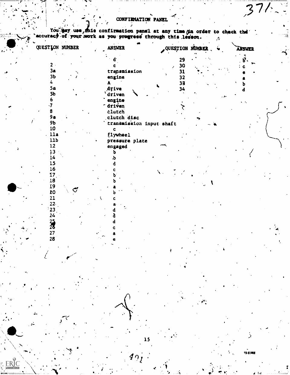
'
.
.... ,eI' 6. CONFIRMATION PANEL
You-Jaey usef2is confirmation pert' at any damp order to chock thd'
, rT 1.
-4,,Z1
,Ja
accuract: of yor work as you miress through this leiion..QUEST loN NUMBER ANSWER
292 303a trapsmission 313b engine 324 A 335a drive 345b tdriven6 engiole
-7 dtkien8 tlutch98 clutch disc9b tranaudision input- shaft10lla flywheelllb pressure plate12 engaged
14 ,b151617 b1819 a20 b21 c22. a23.24 a211
27 a1 p 28
40'
4.7/
,
=1
15
c
a
734102
,
1
4, ,)
1/4
a
PROGRAM= TUT 3ABR47$004T-S011stramminctol-.3ABI47231A-PT-4043A1147231B-PT-4043ABR47231C-PT-4043AHR47230-PT-502A
Technical Training
Nix ac4u4.0.,
General Purpose Vel 1.etreped/sIten
Special Vehicle saboairman(Towing A Servicing VehVi)
(Crash/7ire Vehicle(Refueling Vehicles)
(Materials Handling Vehicles')Base Maintenance Equipment Repairman
POWER TAKEOFF
30 May 1974IV
.
41 ,
k4.4
Ise
CHANUTE TECHNICAL TRAINING CENTER (ATC)1
This supersedes 3ABR47110-PT-501B, 3ABR47231-14T-603, 3A3R47231A-PT-603,3ABR47231B-PT-603, 3ABR47231C-PT-603, 17 August 1972.OPR: TWe \
DISTRIBUTION: XTWS.- 200; TTOC - 7
Di:keeled For ATC Cowl. Use
oo Nor oss ox mg 4914 n
OBJECT/VES
Upon completion of this programmed text you will be able to accOmplish theLollowing objectives with 85% accuracy.
. k
/
1. Given statements about powef takeoff units, select those thatbest describe their purpose and location.
<-
2. Given a diagram.of a pater takeoff unit, and a list of componentnames, match the component with its proper name.
3. Gkven a power takeoff unit, proper tooli and task list, disassemble,inspect and%reassemble the power takeoff unit.
VALIDATION
This programmed text was validated by students enrolled-in the 3ABR47330Course in 1964 and has proved successful'since that time.
INSTRUCTIONS
This lesson presents information in Small iteps. Eadh page or "frame"contains an information panel arid/or questions pertaining to informationcbntained in the last panel. Read the information presented within thesolid-lined box, identified by a closed or open book, then select thecorrect statement in response to the question /diked in the question-markoutlined box. DO NOT WRITE IN THIS BOOKLET. Mark all answers on theanswer sheet you have been. provided with (ATC Form 26A). After you haveselected an answer to a question, you may dheck the accuracy of yourselection by turning to Frame 9. Do not look at the confirmation frame(Frame 9) until you have made your selection of the lanswei:"----k-'
You may consult your instructor at any time.
You may now proceed to Frame 1 and begin. There is no timd limif on thislesson.
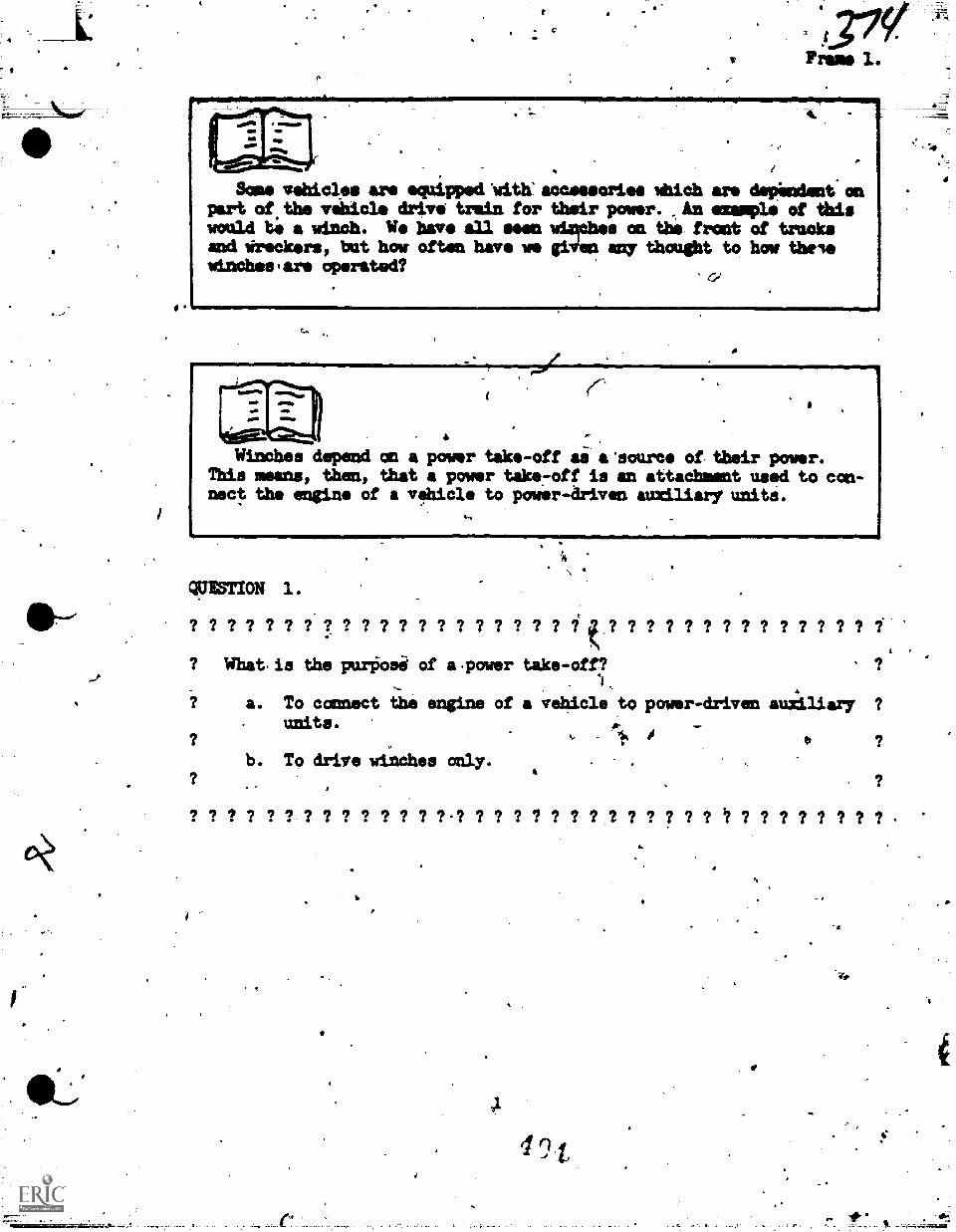
Some vehicles are equipped 'with:accessories mbich are depilndent enpart of the vehicle drive train for their power. ,Anonnmple of thismould te a minch. U. have all eeen winches on the front of trucksand *bookers, but hoy often have me giVen any thought to how theleminchesiare operated?
Winches depend an a power tike-off ai a'source of, their power.This means, then, that a power take7off is an attachment used to con-nect the engine of a vehicle to power-driven atudliaryumits.
WWII= 1.
? ? ? ? ? ? ? ? ? ? ? ? ? ? ? ? ? ? ? ? ? ? ? ? ? ? ? ? ? ? ? ? ?,
? What.is the purOosi of a.power take-off?1
a. To connect the engine of a vehicle to power-driven auxiliary ?
units.
b. To drive winches only.4
?
? ? ? ? ? ? ? ? ? ? ? ? ? ?-? ? ? ? ? ? ? ? ? ? ? ? ? ? ? ? ? ? ? ? ?
ft
e
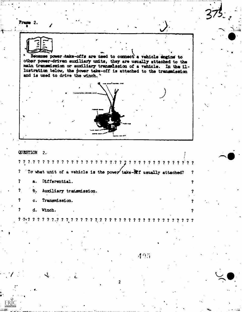
4
w-
* Bacons powerttake-offs are need to connect a vehicle ingine toother power-driven auziliaeY units, they are usually attached to themain transmission or auxiliary transmission of a vehicle. Ln the il-lustration below, the ilower take-off is attached to the transmissionand is used to drive the winch.*
QUESTION 2,
? ? ? ,? ? ? ? ? ? '? ? ? ? ? ? ? ? ? '? ? .'? '? ? '? '? ? ? ? ? ? ? ? ? 999'Ta what unit of a vehicle is the power4:ke-arf usually attached? ?
7 a. Differential.
? b. Auxiliary tratzmission.
? c. Transmission.
? d. Winch.
? ? 7 ? ? ? ? .? 7 7 ? ? 7 ? ? t ? 7 ? ? ? ? 7 7 ? ? ? ? ? ? 7 ? ? ? 7 ?
. 4.
2
4
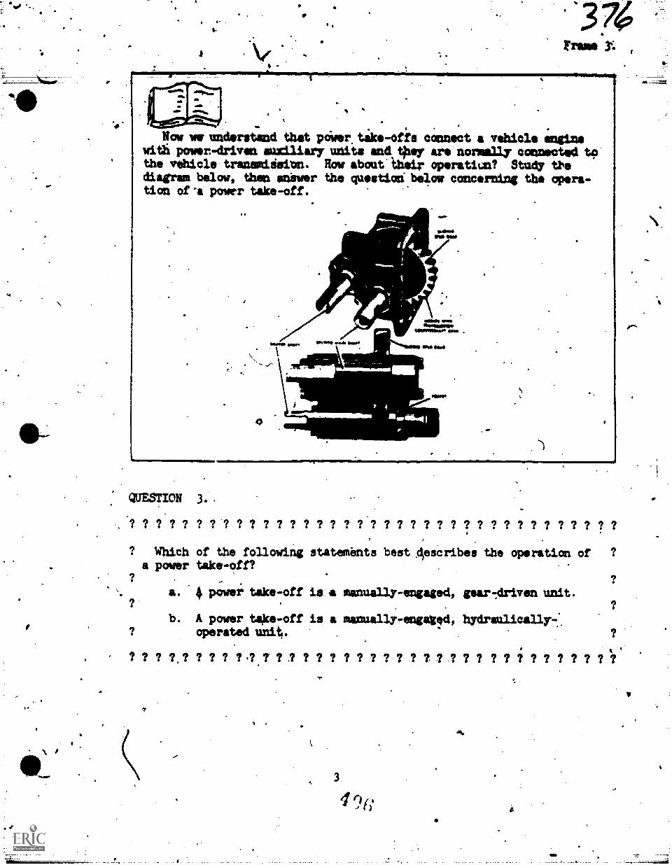
3 74Irma
Now we understand that piwer tilts-offs connect vehicle enginewitli power-driven auxiliary units and taltri are normally connected tothe vehicle tranunitisinn. Row about their operatiun? Study tbediagram below, then salver the qustiod below concerning the opera-tion of 'a pow.r take-off.
*
-\ .:::1 . ENOS w".111=11Nnis
UNOMIIII0
"011eue Ovail
POI
1=1111rWIMINI1=MMrIMM.IMMI01m1.
QUESTION 3. .
? 9.7 ? ? ? ? ? ? ? ? ? ? ? ? ? ? ? ? ? ? ? ? ? ? ? ? ? ? ? ? ? ? ? ? ?? Which of the following statements best Aescribes the operation of ?a power take-off?
a. 4 power take-off is a mancsally-engaledt Par-Ariven unit.
b. A power take-off is a manually-engaged, hydraulicall3r-:operated unit/.
? ? ? 7, ? ? ? ? ? ,? 7 ? ? ? ? ? ? ? ? ? ? ? ? ? ? ? ? ? ? I ? ? ? ? ? ? ?
It
43
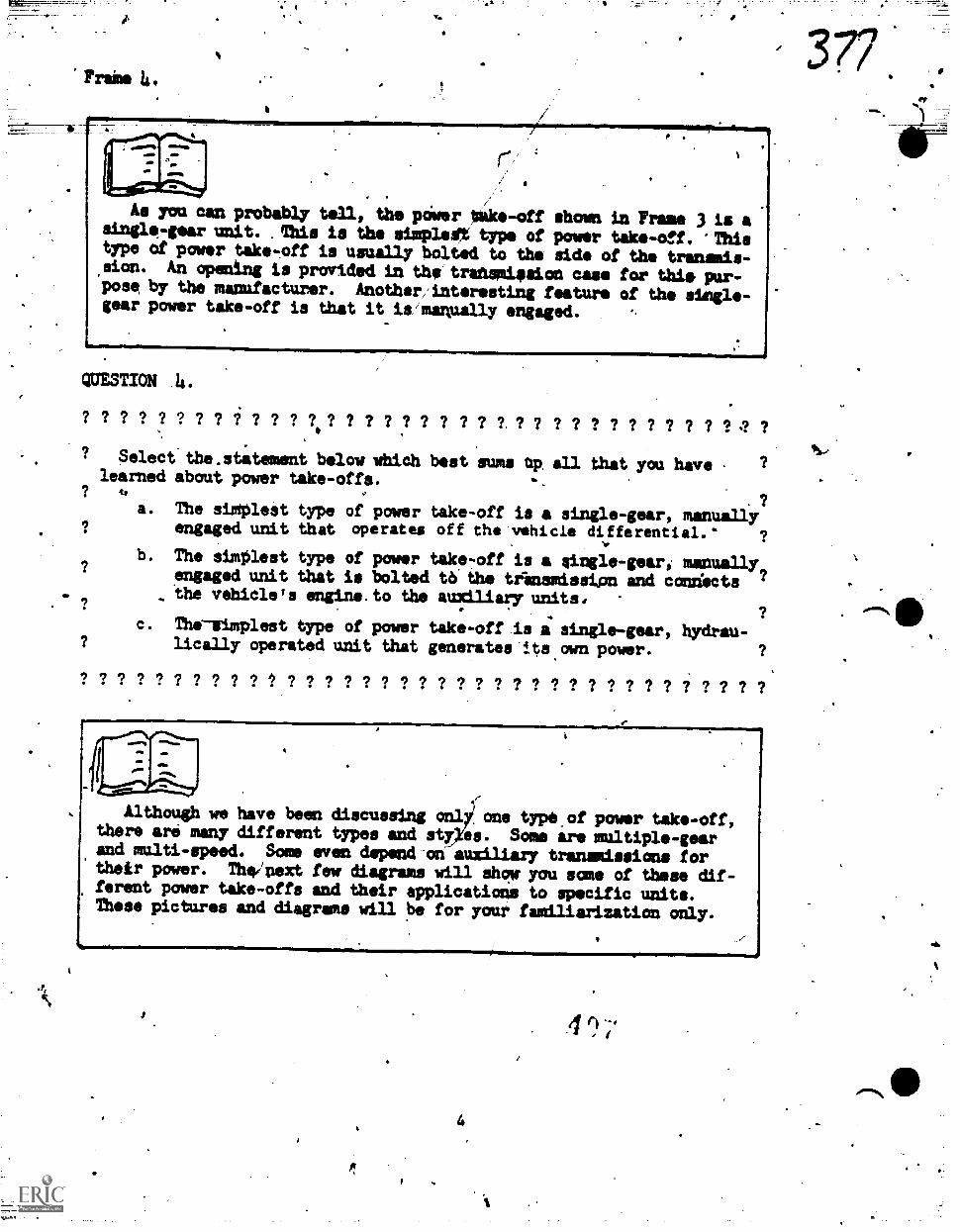
Trains 4.
j'4.
.
As you can probably teal, the power Im/tke-off shown in Frame 3 is asingle-gear unit. Ahis is the simplest% type of power take-ef. 'Thistype of power take-off is usually bolted to the side of the transmis-sion. An opening is provided in the transmission case for thie pur-pose by the manufacturer. Another'interesting feature of the simgle-gear power take-off is that it is manually engaged.
QUESTION 4.
? ? ? ? ? ? ? ? i ? ? ? ? ? ? 7 ? ? ? ? T ? ? 7 7 ? ? 7 7 7 7 ? 4
Select the.stitement below which best sums op all that you havelearned about power take-offs.
.rowirm
a. The sioplest type of power take-off is a single-gear, manuallyengaged unit that operates off the vehicle differential."
b. The simPlest type of power tak-off is a gingle-geari manuallyengaged unit that is bolted tb the trinsmission and condectsthe vehicle's engine.to the auxiliary units,
C. The-slopleet type of power take-off is a single-gear, hydrau-lically operated unit that generates its own power.
/ ? ? ? ? ? ? ? 9 / ? 9 ? ? ? ? 9 ? ? ? ? ? ? ? ?
Although we have been discussing an7x.i one typeof power take-off,there are many different trpes and sty es. Some are multiple-gearand multi-speed. Some even depend-on-auxiliary transmissions fortheir power. The/next few diagrams will show you some of these dif-ferent power take-offs and their applications to specific units.These pictures and diagrams will be for your familiarization only.
4
4 r4
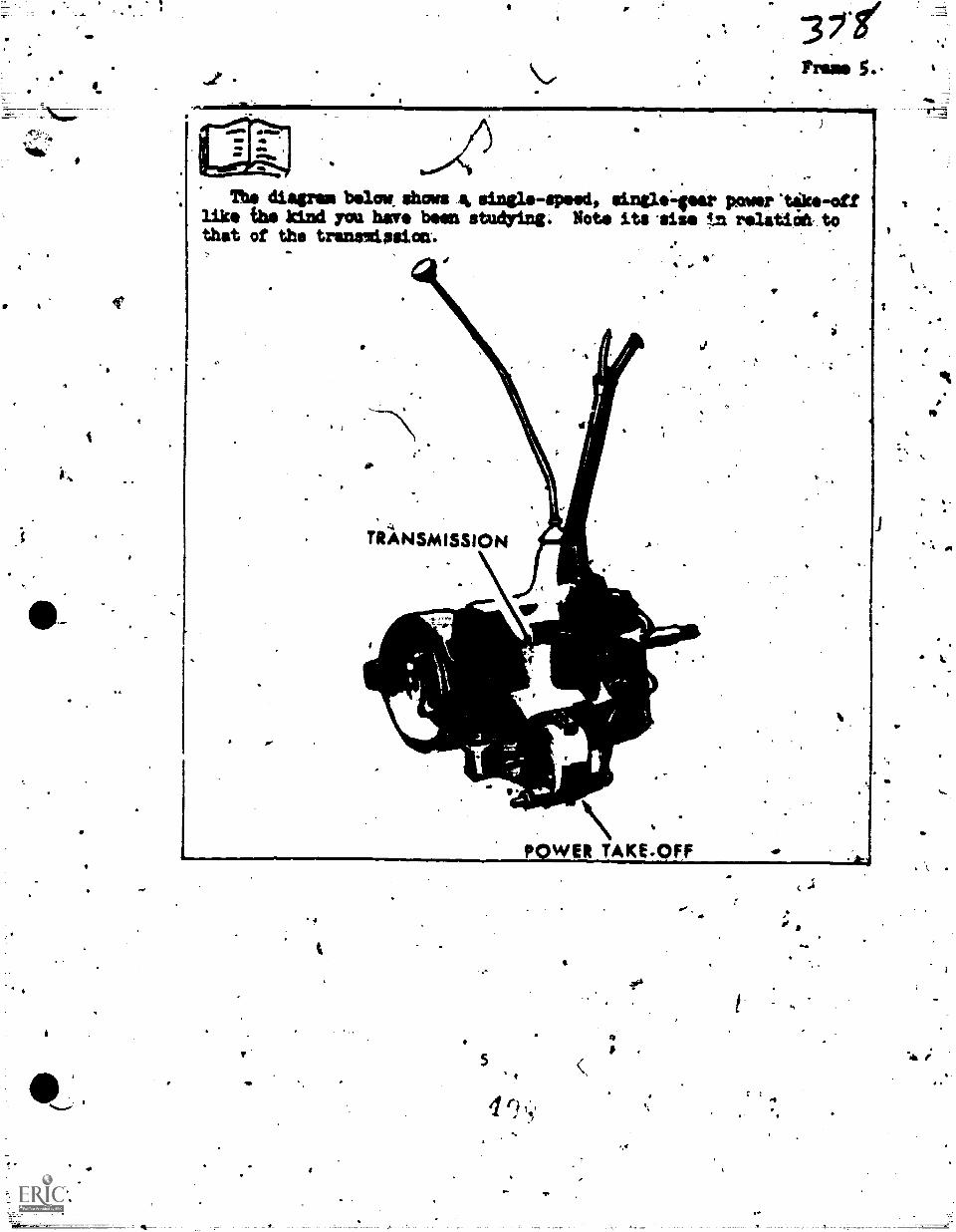
*h.
4
This diagram below, shows 44 single-speed, single-geer power 'tike-off ilike the kind yea have been studying. Note its site tn rslatiatt to ,that of the transmission-,
.. I
4
6
TRANSMISSION
p.WER TAKE-OFF
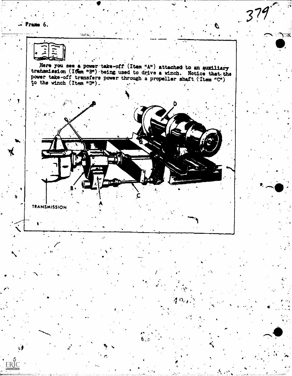
a
Frame
5-
.
a
V.
t,
Nero you see a power.take-pft (Item "A") attached to an auxiliary.trahsmission (Ifem "B").beingused to driire a winch.. Notice that:thepower take-off transfers power through a propeller shaft.(Item "C")to the winch (Item "D")..
Ae,
TRANSMISSION
41M11!
4111106
..3
ego
4 A
4
(),
6
l
4
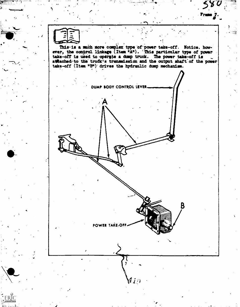
P1
This-is a maah more complex type Oftpower take-off. Notice. how-ever, the confrol linkage (Item "A"). 'This particular type of powertake-off is used to cpergte a dump truck. The power take-off is ,ainached.to the' trudies transmission and the output shaft' of the powertake-off (tt em ail"). drives the hydraulic dump mechanism.
DUMP BODY CONTROL LEVER
POWER TARE-OFF...0-.15°66°4r
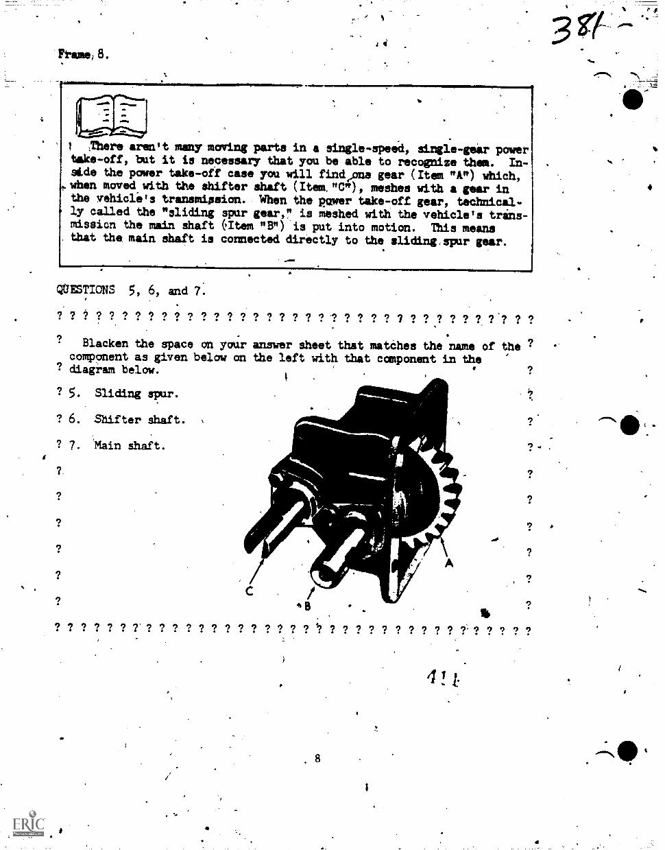
Pram) 8.
I.
:There aren't many moving parts in a single-speed, single-geir powertake-off, but it is necessary that you be able to recognize them. In-Ade the power take-off case you will findeans gear (Item "A") whiCh,
e.when maved with the shifter shaft (Itown"), meshes with a gear inthe vehicle's transmiseion. When the Rawer take-off gear, technical-ly called the "sliding spur gear," is meshed with the vehicle's trans-missicn the main shaft (Item "Br) is put into motion. This meansthat the main shaft is connected directly to the sliding,spur gear.
QUESTIONS 5, 6, and 7.
'7 '7 7 '7 '? '7 '7 9 9 '7 '7 9 9 9 '7 7 ? 7 .9 ? 9 1 '7 '1 9 '7 ? ? ? ? ? ?
Blacken the space an your answer sheet that matches the name of thecomponent as given below an the left with that component in the
? diagram below.
? 5. Sliding spur.
? 6. Shifter ihaft.
? 7. Main shaft.
16'7 '7 '7 9 9 '7 9 9 9 9 '7 9 .9 '7 '7 7 9 9 9 9 9 9. 9 9 9 9 9
.40
4 !
8
#rimele410.144.41r
CONFIRMATION PANEL
Ydu-mAy use these answers to check the;accuracy of.your responseso the questions asked in the lesson.
Anawer #1 is a.
Answer #2 is c.a
Answer #3 is a.
Answer #4 is b.
Answer #5Ts a.
Answer #6 is c.
Answer #7 is b.
Mee
4
WM.
*
a
-4
174
70- 11003
z 32 ,
/PROGRAMED TELT 3A31:47)96-PT-503
34314431442401A,
"Tethnigal Training
General Purpose VehicleSpecial Vehicle Repel
(Towing and Servicing Vehicle's)Spatial Vehicli Repairman
(Crash/Fire Vehicles)Special VehicleeRepairman
(Refueling .Vehicles)Special Vehicle Repairman
(tarerials Rapdliag Vehicles)Base MAintenance Equipment(Repairman.
.....--mr411111.--
DRIVE'TRAIN COMPONENTS
2 January 19-74
uctr
CHANUTE TECVNICAL TRAINING CENTik (ATC)
3AB14723IAPT-603L341472313-11-603A311314723WPT-603A
34.3,R4 7230-1T-502
This supersedes 3ABR47330-PT-503, 3ABR47231-PT -603A, 3A3R47231A-PT
3ABR47231B -PT-601A, 3ABR42731C-P1 -603A, 15 August 1972,
OFR: 1WSDISTRIBUTION: X -
TWS - 575; TTOC - 7
Dosigeod Foi ATC Gum Use
DO NOT USE ON TNII JOS'
41,7
ammisWhile most vehicle's are designed to operetv over relatively smooth herd-surfaced roads, dome vehicles must be abli tkoperate efficiintly over all'types Of terrain. These vehicles are equipped to 'transmit power to ali---wheel's.. This power ts transmitted through the use,of: transfer cases,Sprap units, propeller shafs and umiversal joints, center bearings, andpillow blocks. In addition,,same vehicles are equipped with a cable winchwhich is powered by a power take-off. These are the units that this lessonis all about. When you hive.finished with this program, you.will be ableto:
%
4
1. Siledt the correet answers to multiple-choice type questionsabout the purpose and operating principles of universal joints, propellershafts, center bearings, transfer erne, Spies units, winches, and pillowblocks.
2. Locate and identify these units on an illustration..
. 3. Locate information on the construction features af thesecomponents and their removal, disassembly, inspection, repair,reassembly, and installation.
4.. Disassemble, inspect, Ind reassembleuniversal joints, centerbearings, hnd transfer cases.
5. Operate and adjust a winch..1 1
I.
6.. Inspect a propeller shaft for serviceabNty.
These must be accaMPlished with 80% accuracy.
VALIDATION014
This programmed1text was validated by students enrolled in the 3ABR47330Cburse-in 1964 and has proved to be successful since.that tine. -
INSTRUCTIONS
The material to be presented in this program is broken up into small unitscalled "frames." Each framelcontains an information section' and/or anillustration panel msenting information that is to be learned. Follawing
' each inforaa;ion panel there will generally be presented a question or two.IndiCate your dhoice,of the correct answer by BLACKING OUT the letter onthe Standard Anstier Sheet that corresponds to your,choice. of the correctchoice f9r each questiOn. For confirmation of your'response, refer to thetop of tNE next frame where the correct answer(s) will be given.
Proceed to the ne xt pagetand start with Frame 1. Study the illustration
carefully befare turning to the information presented in Frame 2.
_
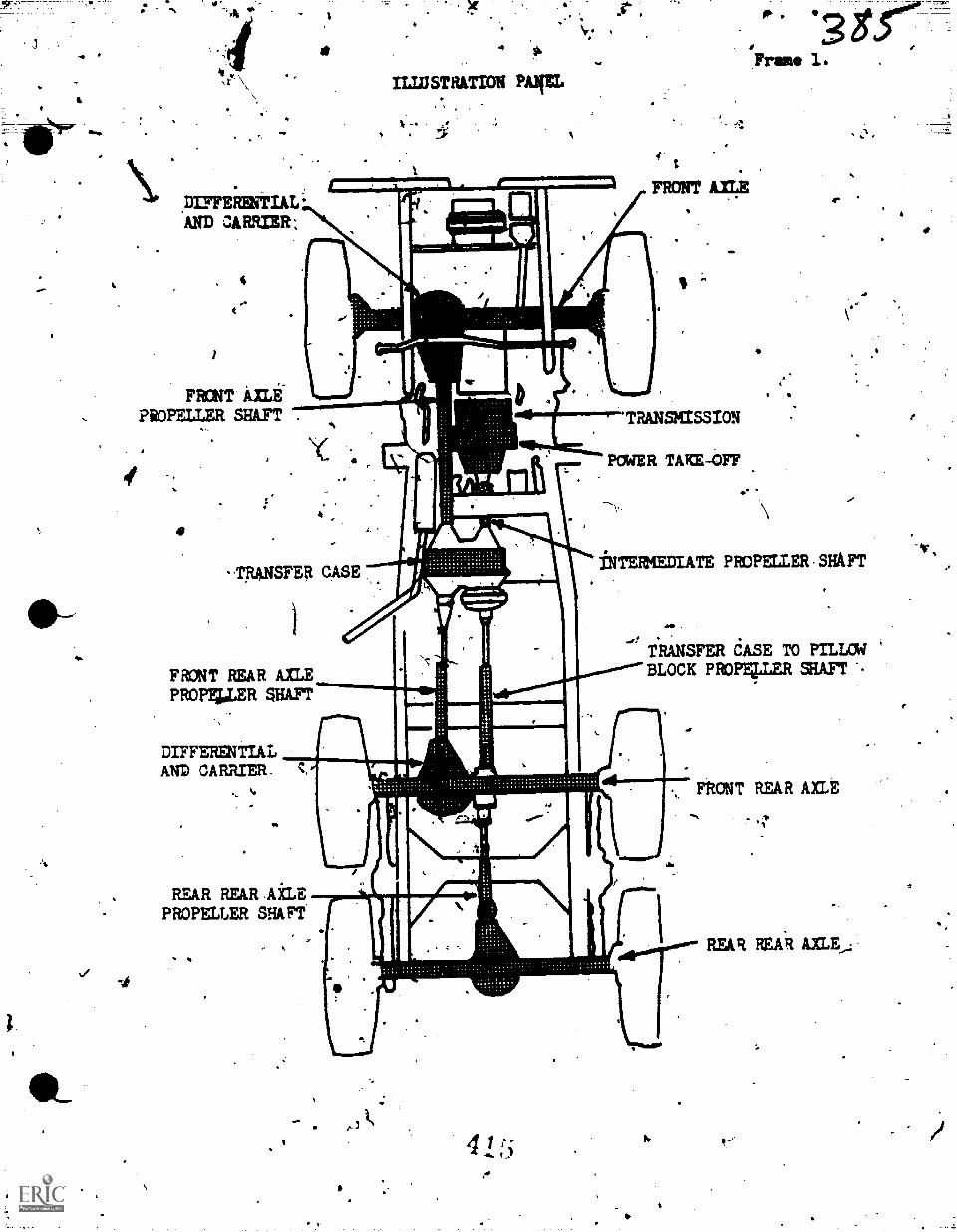
DUFEFOINTIAL'AND cARR33R;
4
FRONT AXLE*PROPMER SHAFT
t
.
Frame 1.
s.
?TRANSHISSION
POWER TAKE-017
-TRANSFER CASE
FRONT REAR AXLEPROPISILER SHAFT
DIFFERENTIALAND CARRIER-
._
a'
iNTERMEDIATE PROPELLER SHAFT
TitiNSFER dASE TO PILLOWBLOCK PROMLLER SUIT
REAR REAR AiLEPROPELLER SHAFT
,
415
FRONT REAR AXLE
REAR REAR AXLE,,
40"
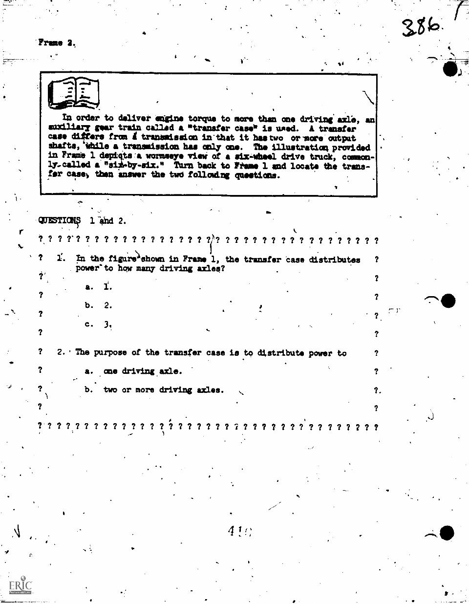
'Frame 2.
14
In order to deliver -engine torque to more than one driving axle, anauxiliary gear train called a *transfer Case* is wed. transferease difters from tranamission in'that it hastwo orlmore'outixtshafts,44hile a transmission, has only MO. The illustration, providedin Frate 1 depiqs:a wormesye via of a six4hee1 drive truck, common-lywcalled a *siOr.by-six." Tarn back to Fftme 2. and locate the trans-fr cas% then answer the twd following questions.
QUESTICIN 1 *Id 2.
' I 1% pi the fivre\4shown in Frame 1, the transfer Case distributes ?
poweeto hqw many driving axlee?
a.
b. 2.
ci 3,
? 2. . The purpose of the transfer case is to distribute power to
a. ane driving,axle. ?
b. two or more driving axles. I.?
? ? ? ? ? ? ? ? ? ? ? ? ? ? ? I ? ? ? ? ? ? ? ? ? ? ? ? ? ? ? ? I ? ?
4 1.
I
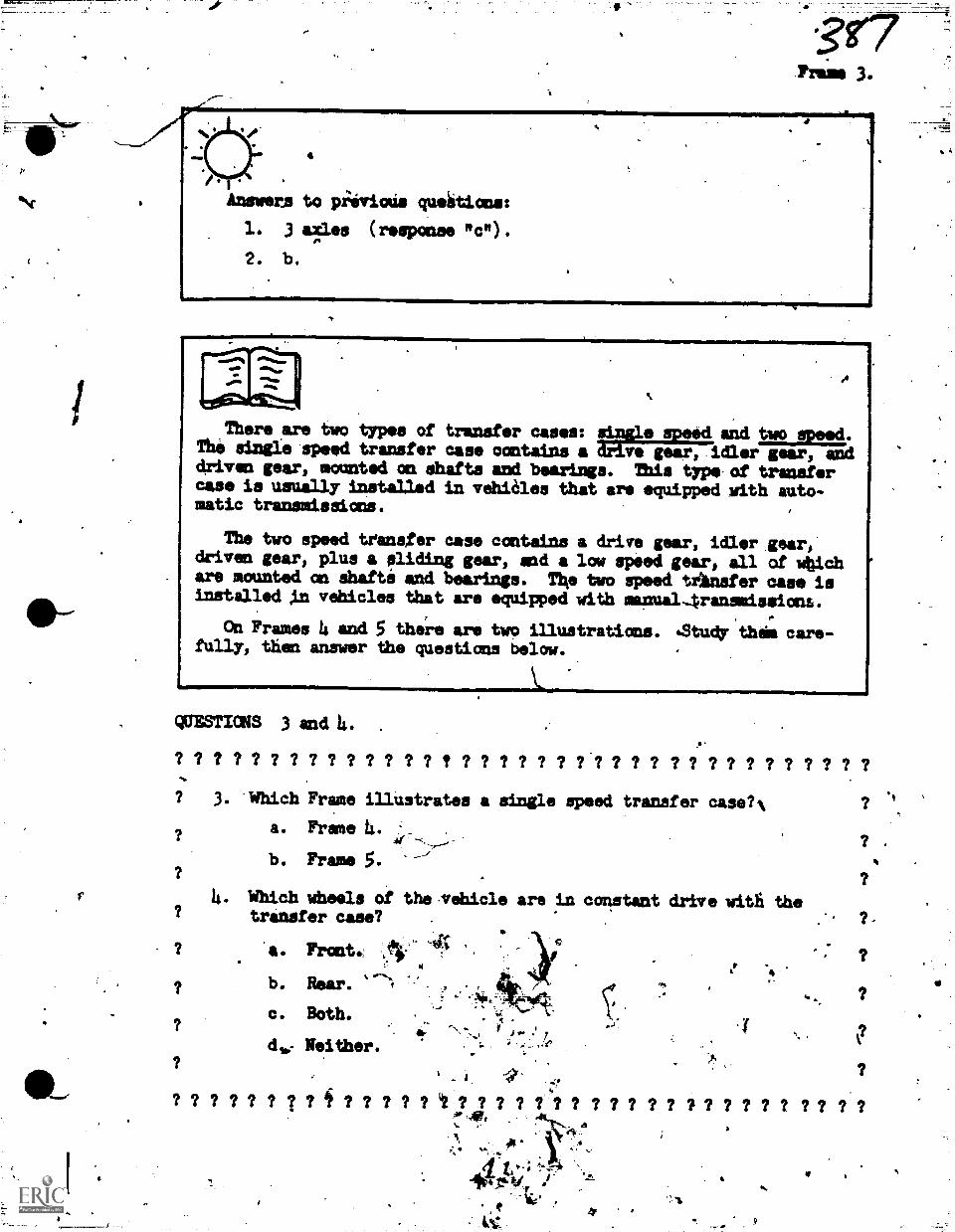
4
Answers to piiviods queiitions:
1. 3 axles (response mc").
2. b.
dAlummoM=IMMEIMMI111MMmMM1=oIlMIMmmomplIM111111M1=11111111Ib
There are two types of transfer cases: ANVAimIAand two speed.The single speed transfer case contains a iriar,idler gear, anddriven gear, mounted an dhafts and bearings. This typeof transtercase is usually installed in vehiâles that are equipped with auto-matic transmissions.
411.
The two speed transfer case contains a drive gear, idler,gear,driven gear, plus a sliding gear, awl a low speed gear, all of wbichare mounted oft shafte and bearinis. The two speed trInefer case isinstalled Al vehicles that are equipped with manual4ransmissions.
to
On Frames 4 and 5 there are two illustrations. %Study this care-fully, then answer the questions below.
AMI=,QUIOTICNS 3and14.
.
? ? ? ? ? ? ? ? ? ? ? ? ? ? ? ? ? ? ? ? ? .? ? ? ? ? ? ? ? ? ? ? ? ? ? ?? 3. Which Frame illustrates a single speed transfer case?%
a. Frage I.
b. Frame 5.
4. Which wheels of the ,vehicle ars in constant drive witfi thetransfer case? .
a. Front.
si,
b. Rear.,,,,,
.
. ..,s.,
c. Both. c-\
du,- Neither...
? .
?
.s
7 ? 7 ? ? ? ? 7 i ? ? ? 7 ? t ? 7 ? 7 7' ? 7 7 ? 7 7 ? ? ? 7 7 7 2 7 ? 7 ?:4LVt.
4r
3-
.k4v.;
4004.1v.,. i.. .
Iil,t
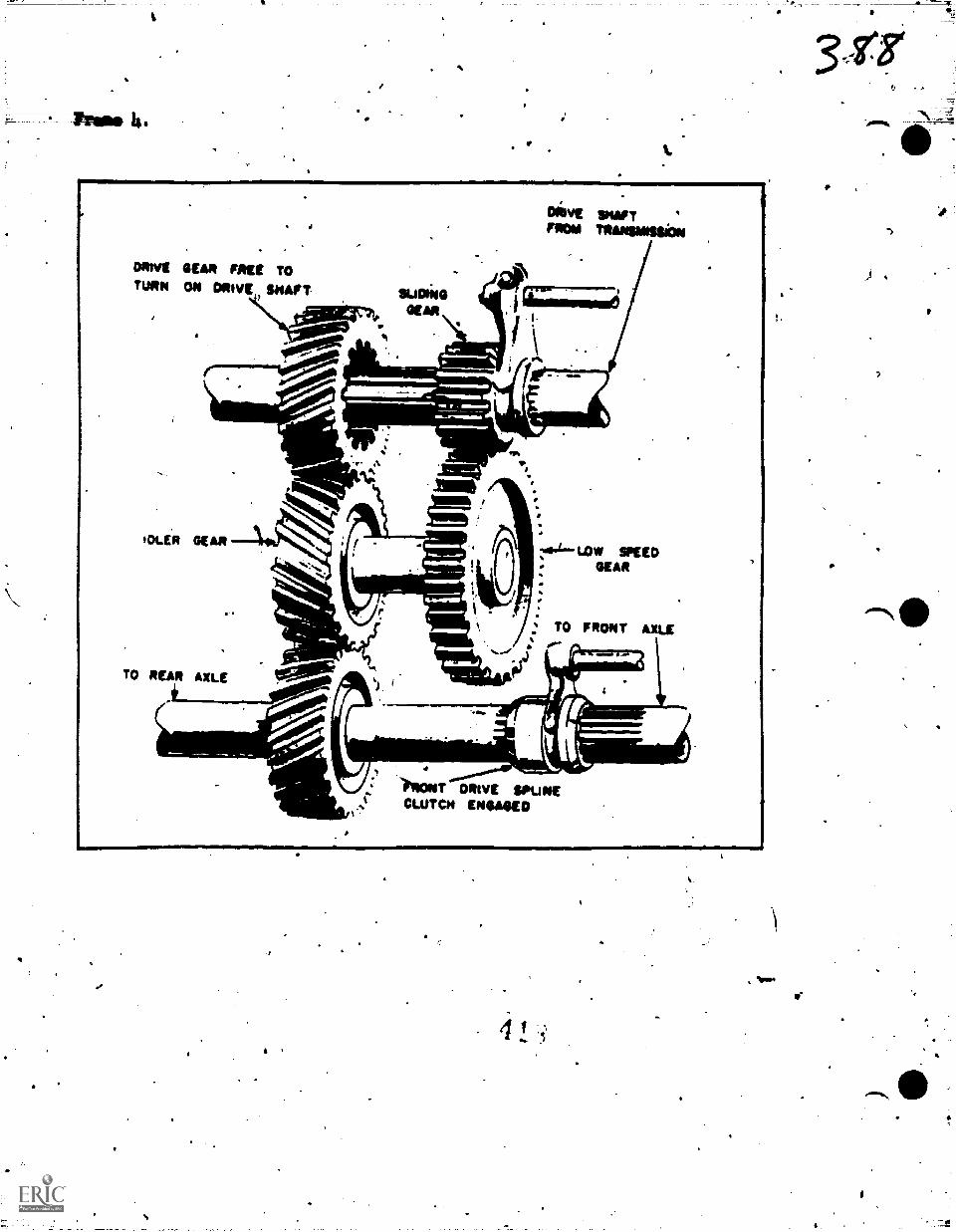
Was ts.
MW.IMsii=1MIMDiVE SHAFTPROM TRANSMISSION
IDLER GEARzas4 LOV/ SPEED
GEAR
'
TO FRONT Axi..1
TO REAR AXLE !108111*
AO(4) 1
T DRIVE SPUMECLUTCH ENGAGED
11
f
o-
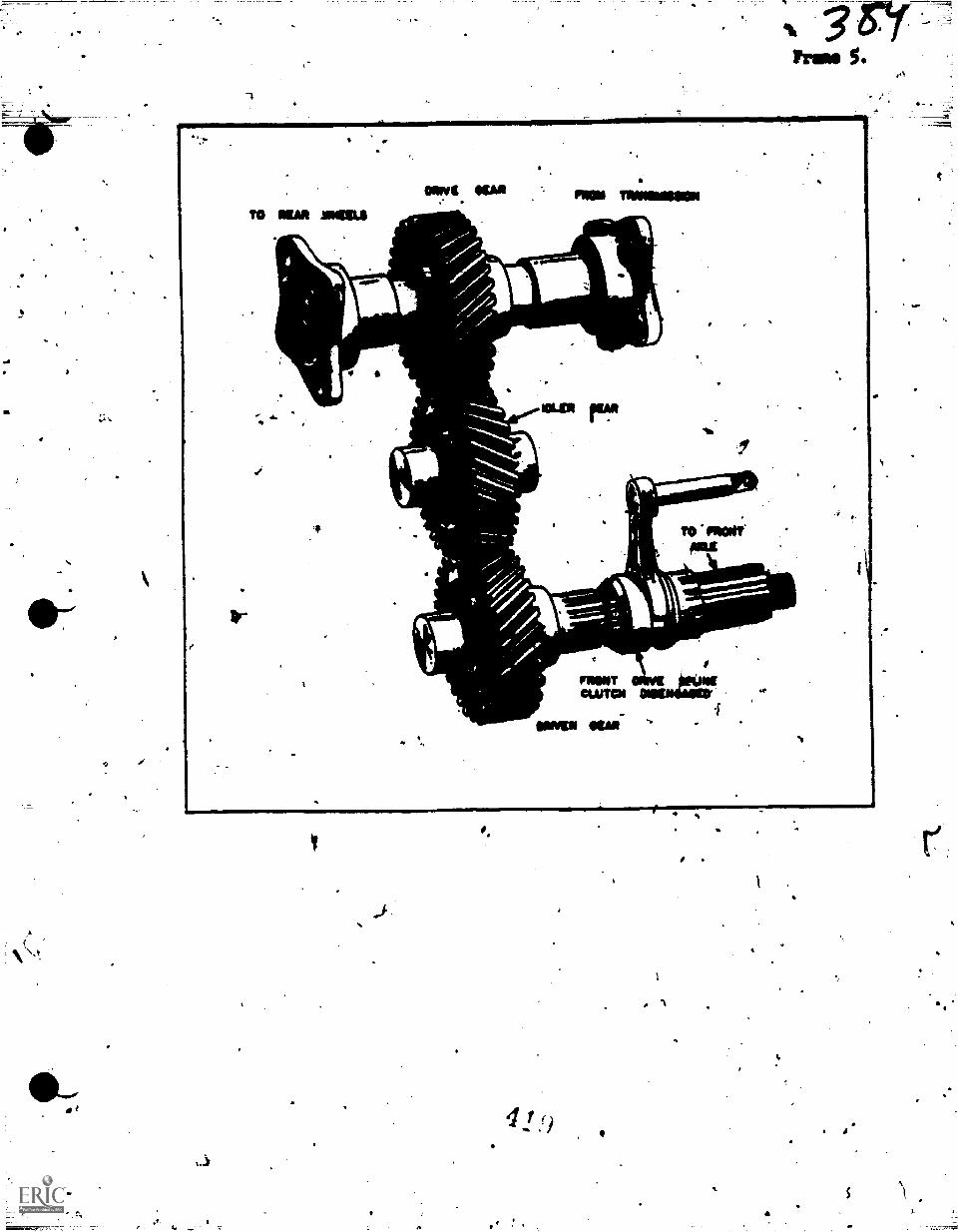
TO MAO MORS
fier41rl=10.
ROE INNO1118011
11.
MOIST'
_Arab.
MOTCLUTCH -iiiinamor
IMP 1M "
Prow 5.
4
.1
Answers to previous questions:
3. Prase S.
4. b. If the rear *eels wore PaT in constmt drive with theitransfer case there would be'no driving action at all.If the front :theels wok* in constant drive, there wouldbe no need for the transfer case.
Some transfer cases incorporate'a mechmtLametich automatically.diaengages thelront wheel driving action during tunis)since the!rant wheels are rotating at a different spoedethanbtho rear Wheelsat that time. SuCh disengagement helps Oinimize wear an the tiresand strain= the gears. In this type of transfer case, the frontax4 sliding gear which engages and disengages the, front wheel' driveA3 replaced by an automatic deautcher. Wbile there are many typesof automatic declutchers, the only ome we will discuss is the Sprag'Useably.
The Sprag Asiembly is essentially a mechanism 1sedsitar.declutch7Aig the front wheel drive. With this unit, power is automaticallyapplied to the front wheels when'the rear wheels lose traction.When the rear wheels regain traction, the ;iower is automaticallydisconnected from the front wheels.
quEsTiok 5.
? ? ? 2 ? ? ? ? ? ? ?.? ? ? ? ? ? ? ? ?,? ? ? ? ? ? ? ? ? ? 7 ? ? 7 ?*-
Thebpurpose of the $prag Assembly ueed on; vehicles with front'wheel drive is Ulf P
?.
?a. allow powerto be applied to the front wheels when tbe rear, 'wheels lose,traction. , ....
-
., ?
b. automatically disengage power from the rear Wheels whwn the? front wheels lose traction., ?
C. apply power to the' front wheels when the rear Wheeli losetraction, and disengage it the rear wheels regain.tracton.
? ,?
prevent the front wheels from spinning.? C:1)
fl
p.? 7 7 7 ? 7 7 7 ? ? P 9 9 9 9 ? ? ? 9 9 9 9 9 9 9 9 9 9 9 9 9 9 9 9 si 9
341
I.
do
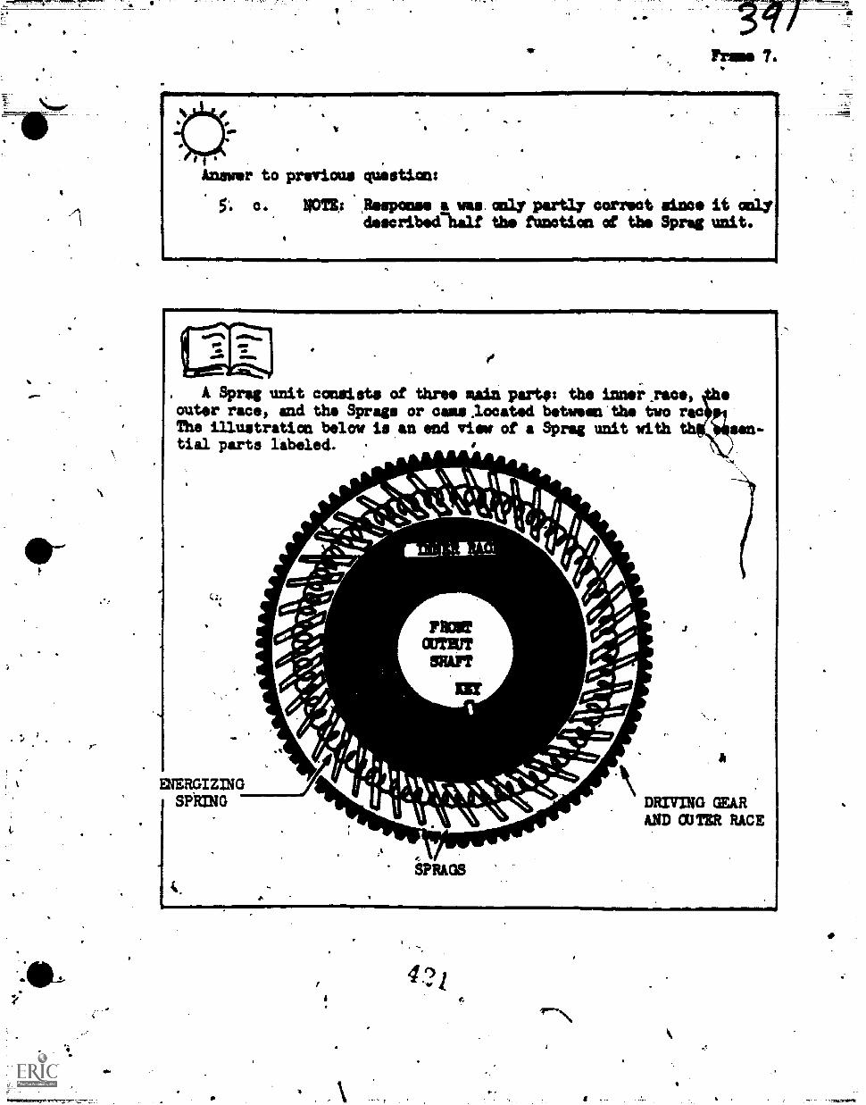
-
1P7in T.
VIIIMINNII..01wM11100111.011411MOMMMIF
koswor to previous question:
5. c. $0124 fitampcome a vu. only partly corTeot since it onlydescribedlulf tbs function of the Sprag unit.
, A Sprag unit consists of three Main party: the inns:0.race,=tar race, and ths Sprags or caas.located botween'the two rotThe illustration below is an end view of a Sprig unit withtial parts labeled. .
.A.A.1111411.A.
. 1*
.
ENERGIZINGSPRING
t.
=LITSHAFT
MI
Novr,SPRAGS
vr
DRIVING GEARAND CUTER RACE0ImM=b
42i
1
ba
The action of the SPragidiOends am the variable rotatim -of thetapes. Assume that the outer race of the Sprat unit is oanneaped tothe power output of the transfer case and that the inner rac is con-nected to the fiont driving's:de: When the.outer rece'attempts totutu faster than the inner me, the Sprags.pivot and look the racestogether. This causes the races to rotate itithe sale speed and de-liver power to the front driiing axle. Conversely, When the outerrace "arns slower than 'the inner ricli; is.it will when tbe.rear Whealsregatm traarairthe SO* pivot and disengage. This allows theinner ramp to "free wbeel" and power is n4 delivered to the frontdriving axle.. There are tiio Sprain in a.Sprag Assembly, a forwardsmd a reverse Sprat unit. ,The forward unit is emgaged-when ingear. The reverse only when the transmisaion is ehifted into reverse gear.
111M,
QUESTIONS 6 and 7.
? ? ? ? ? ? ? ? ? ? ? ? ? ? ? ? ? ? ? ? ? ? ? ? ? ? ? ? ? ? ? ? ?? 6. On what does the action ofthe Sprigs depend?
a. The direction of rotation of the Sprags.
7b. The variable rotation of the races:
c. The amount of power delivered to the front'.wheols.A
d. The amount of power'delivered to the rear wheals.
7, 7. What are the three main iarts 6f the Sprag umit?
? a. Inner race, outer.racej and clutch fingers. ? /. /
? b. Inner race, Sprigs, and oring Clips.?
c. Input shaft,-output shaft, end Sprigs.? -.
?d. Inner taco, Sprags, sm4 outer race..
? ,a?'
7 7 7 ? ? 7 7 ? ? ? 7 7 7 ? 7 7 ? ? ? 7 7 7 7 ? 7 7 7 7 ? ? 7 7 7 ? 7 7MIY
if .
a.
,11
t%
to previmis.questionS:
b.
d.
0
a
QUESTION B.
? ? ? ? ? ? ? ? ? ? ? ? 7 7 ?.? ? ? ? ? ? ? ? ? ? ? ? ? ? ? ? ?t?
What action will cause the Sprags to pivot and lodk the inner race'and outer race toieiher?
Y.
a.' The front-Wheels must.turn faster than the rear-wheels.
b. The ioner race mit tarn faster %maths outer race:
I - c. The' rear wheels must lose traction," -
d. The constant speed drive must be engaged:
-
? 7 ? ? ? 7 ? ? 7 ? 7 7 7 7 7 7 7 7 7 7 7 7 7 7. 7 7 7 7 7 ,7 7 7 7 7
The transfer case is mounted La the vehicle frame-between thetransmission and the rear axle. It remeivetil power from the outputdhaft of the tranAmission and transfers power to the frOnt drivingaxis and one or more rear,driving axles. On any vehicles equippedwith a transfer case, at least one'rear eagle in constant drivewith the transcer case. If the asehicle has two rear.axles, both,are usually in constant drive-with the transfer case. The frontdilving axle is not in constant drive, however, because it can be'disengaged or engaged either manually or autoftatically:
QUESTION 9.c 1
F
'7 I ?4;
? Because a transmission has only one outpa shaft, a vehille not ?
equipped with a transfer case co4ld hive
a. 'only one driving axle.?
b. more than one driving-Ole.
? ? ? ? ? ? ? ? ? ? ? 7-? ? ? ? ? ? ? ? ? ? ? ? ? ?.? ? ? I ? 7 ? ? ? ?
4
3...
4
*QUESTIONS 10 and 11.
7 ? ? ? ? ? ? ? ? ? ? ? ? ? ? ? ? ? ? ? ? ? ? ? ? ? ? ? ? ? ? ? ? ? ? ?
? 10. What automatically engages and disengages the frmnt wheel ?.
drive?
7
a. Front driving ails.
11
b. Sprag unit.
c. Transfer case. 1
d. Rear driving axle.
? 11. Haw does a Sprag unit operate?
a. Outer race turns faster than inner, Sprags pivot, raceslock together.
b. "'Inner race turns faster, Sprags pivot, racis locktogether.
? ? ? ? ? ? ? ? ? ? ? ? ? ? 7 ? ? ? ? ? ? ? ? ? ? ?-?'? ? ? ? ? ? ? ? ?
4
4
. _..-.-111r
The prindipal.meane of delivering torque produced by the tothe driving axiös ii by use of a propeller shaft., pm* vehi Los usedrive chains while-others uses direet drkov frau the Unmet' an tothe axle. However, most bf the vehicle y viii be' working th,will use a propeller Shaft to deliver th engine torque to the,driv.ing axles. Propeller shafts may be either sOlid_or tubular, and'areusually equipped with a universal joint on eaoh end.
asaasig.
7,0
Answers to previous Imestions:
10. b".
a
.
QUESTIONS 12.and 13.
? ? ? ? ? ? ? ? ? ? ? ? ? ? ? ? ? ? ? ? ? ? ? ? ? ? ? ? ? ? ? ? ? ? ? ? ?
12. Power is transferral from the tbanamissian to the drivingaxles by the
a. transfer case.
b. Sprag assembly.
c. propeller shaft.
d. crankshaft.
7
13. What is the least number of-propeller shafts a vehicle mayhave?
a. 1.
b. 2.
3.
d. L.
?
6?
7 7 7 7 7 ? ? 7 ? 7 7 7 ? 7 7 ? ? ? 7 ?. ? ? ? ? 7 ? '? 7 7 ? 7 7 ? ?
f
V025
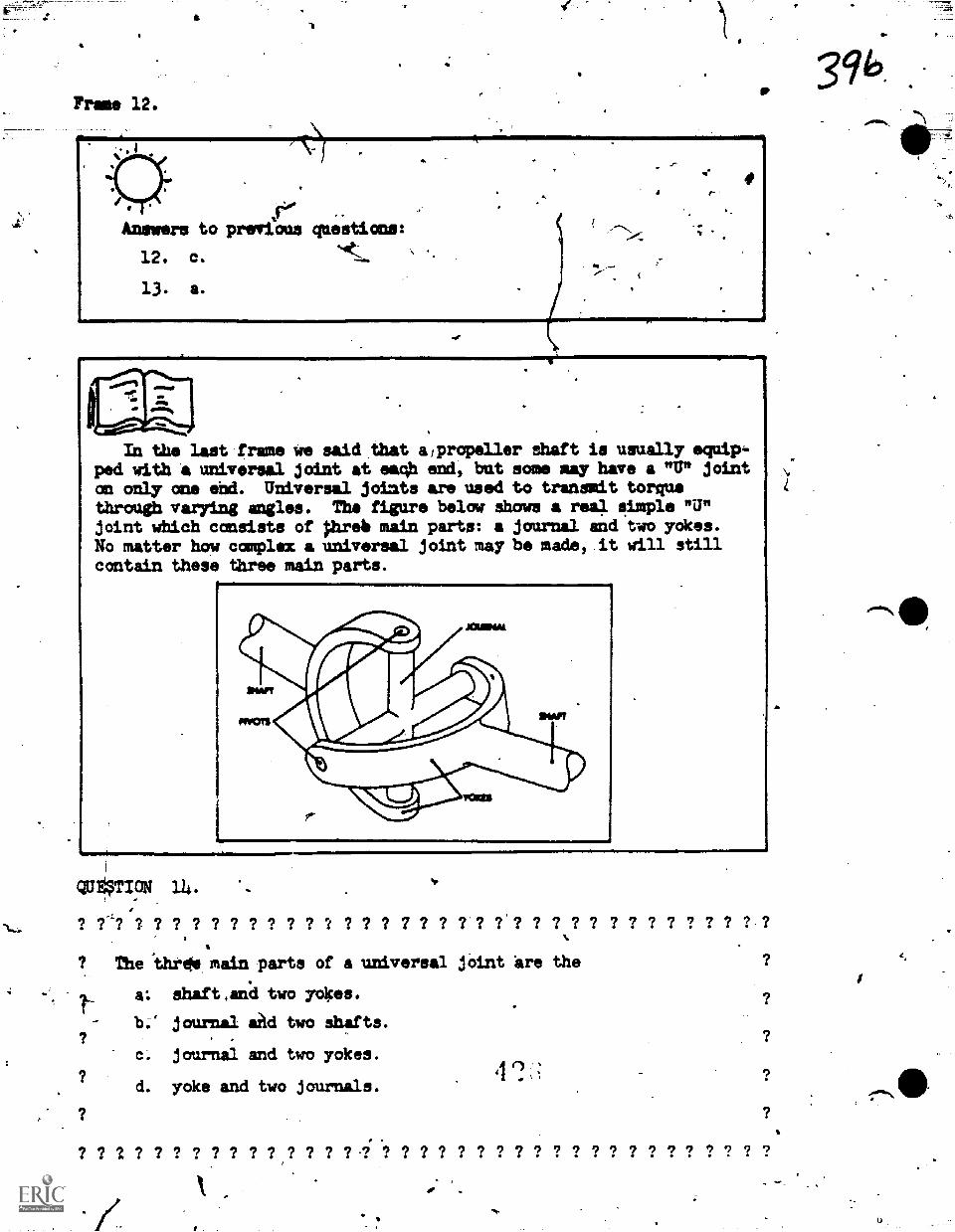
Frame 12.
Mb
r.Answers to previous questions:
12. c.
13. a.
d. .
r-
In the last frame we said that a/propeller shaft is usually equip-ped with a universal joint at eaqh end, bat some may have a "U" jointon only one end. Universal joiats are used to transmit torquethrough varying angles. Ths figure below shows a real simple "U"joint which consists of pirsio main parts: a journal and two yokes.No matter how complex a universal joint may be made, it will stillcontain these three main parts.
QU ICN 114 .
? ?-1? ? ? ? ? ? ? ? ? ? ? ? ? ? ? 7 ? ? ? ? ?'? ? 7 ? ? ? ? ? ? ? ? ? ? ?
? The 'threta main parts of a universal joint 'are the
a: shaf t and two yokes.
b;" journal aM two Shafts.
c, journal and two yokes.
d. yoke and two journals.
?
7 7 7 7 ? ? ? 7 ? ? 7 ? 7 7 ? 7 ? ? ? ? ? ? ? ? ? ? ? ? ? ? ? ? ?
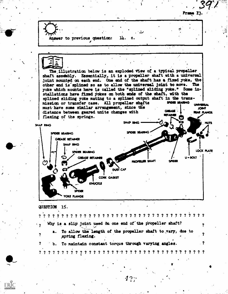
Answer to previous qaestion: 14. C.
The illustration below is. an exploded view of a typical propellerdhaft aiselmbly. Essentially, it is a propeller dhaft With a universaljoint mauntpd an each end. One end of the shaft has/a ft:mi.:rake, theother end is OLined-so as to allow the univrsal JOint tamove. The
yoke WhiCh mounts here is celled the "eplined Sliding yoke." Same in-stallations have fixed YOkes an both ends of the:Shaft, with thesplined sliding yoke mating to a gplined output shaft in the trans-miasion or transfer case. All propeller ahtfte VIM MANG
UPKYIRSAL
distance between geared units changes with,
MAI RANG!m hiust ve same similar arrsogement, since the .- MINT
flexing of the springs..WAINER
NitaSNAP ENG L-449kirt
SNAP RING
\
We RARINGmom SEAPANG
RETAINER
SNAP RING
I. SPIDER. MAW;IV GREASE WARM
"41101t.
0.....#.-
CAAWiet
Sprsor-- ....11111. DUST CAP
ICORK GASKET
KNUOCLE
SPIDER
YOKE FLANGE
ILOOC KATE
U SOLT
QUESTI0k, 15.
? 7 7 7 7 7 7 7 7 7 7 7 7 7 7 7 7 7 7 7 7 7 7 7 7 7 7 7 7 7 7 7 7 7 7
why is a slipAoint used on one end of-the Oopellsr ghaft?
a. To allow thiTlangth of the propeller Shaft to,vary, due tofirpting flexing. ,
b. To maintain constant torque through varying angles.
? ? 7 ? ? ? ? ? ? ? ? ? ? ? ? ? 7 71 ? ? ? ? ? ? ? ? ? ? ? ? 7 ? ? ? ? ?
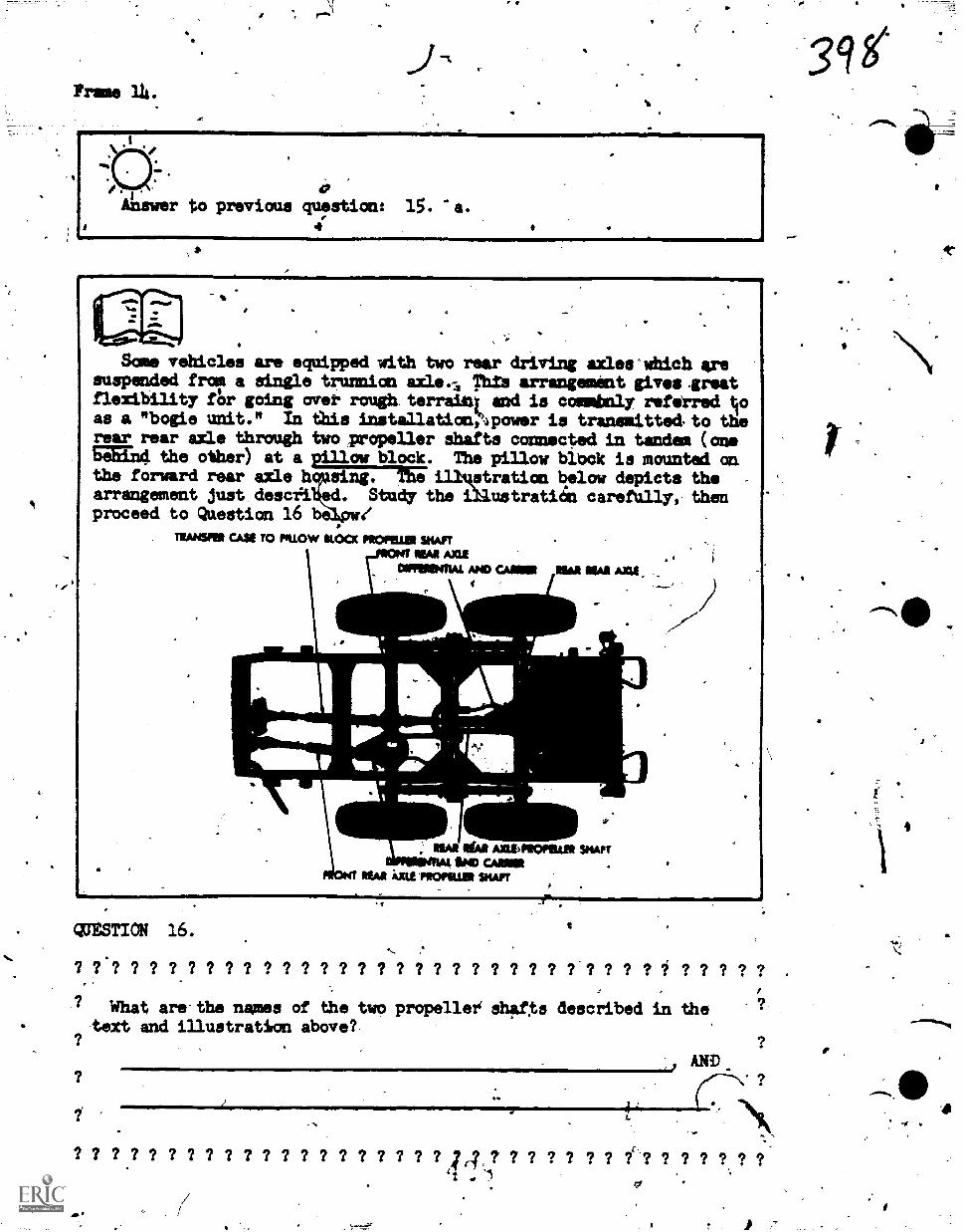
a
Frame
.0.41 t
Same vehicles are equipped with two rear driving axleCwhich aresuspended from a single trunnion axle..5 Thlve arrangement gives.greatflexibility Ar going over rough. terrain; and is commbnly referredas a "bogie unit." In this installationZipower is tranemitted,to therear rear mall through two iropeller !hafts connected in tandem (oneFa164 the other) at a piilow block. The pillow blbck is mounted amthe forward rear axle sing. The illuatration below depicts the -
arrangement just descii.ed. Study the illustrati6n carefully, thenproceed to Question 16 be 41
TEANSFEE CASE TO rouchv ILOCIC mom= SHAFTWAR AXLE
ONIFEEPOLAI ANO CANOE
NEAR Ida AXILFEOFILLER SHAFT00 CAME
;41 at moms SHAFT
WESTIN 16.
? ? ? ? ? ? ? ? ? ? ? ? ? ? ? ? ? 7 ? ? ? ? ? ? ? ? ? ? ? ? / ? ? ? ? ?
? What are the wee of the two propeller, shafs described in the ?
text and illustration abovel-
AND
0
? ? ? ? ? ? ? ? ? ? ? 7 7 ? ? 7 ? 7 ? ? 4, ? 7 ? ? ? ? ? ? ? .? ? ? ? ?
,0
39
0
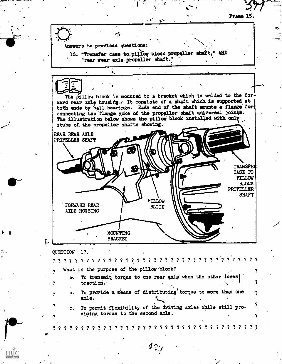
tie
'Frame 15.
Answers to previous questiona:.
16. "Transfer case to,pillow, block propeller &flit,
"rearrear.axle.propeller Shaft." ,
AND
.\
The pillow block is mounted to a bracket which is welded to the for-
ward rear axle housihg./ It conaists of a Shaft Which. is supportedAt
both ends by ball bearings. Eaeh end of.the shaft mounts a amp' forconnecting the Ilange yOke-of the propeller Shaft universal join*The illustration below shows the pilloi block installed with
stubs of.the propeller shafts Showing.
REAR REAR AXLEPROPELLER-SHAFT
FORARD REARAZLE HOUSING
11111111=am....
MOUNTINGBRACKET
TRANSFERCASE TOPILLUdBLOCK
PROPELLERSHAFT
QUESTION 17.
?What is the purpose of the pillow-block?
...._, ?
a-. To transmit torque to one rear axlsiNwhen the other loseel
1. tractiod.-
1
?b. To provide a Alans of distributing torque to more than one ?
axle. 1,,,, .
? ?c. To permit 4exibility of the driving axles while still pro-
viding torque to the second axle.,? ?
q? ? ? ? ? ? ? 7 7 ? 7 ? 7 7 ? 7 ? ? ? ? ? ? ? ? ? 7 7 ? ? ? ? ? ? 7 ? ? ?
rm. 16..1111iir '4111'0
fffiN1
,Answer to previous question(
17. c. Respcmses "a" and "b" are partially coirect, but theyare not the true purpose of.the pillow block.
On some vehicles the distance bptween the output shaft and theransmission or transfer cas and/the rear driving =leis so greatthat one long propeller shaft would tend'to "whir or vibgate. Also.such a abaft would contact the ground...when passing over sharp risessuch as curbings, driveways, etc. To prevent theee occmrrences, tvoshort propeller shafts with a center bearins betreen them, are used.A center bearing is similar to a pillow block in coeigiturst.icn, butthe center bearing is installed in a bracket which is bolted or weld-ed to d frame cross-member. Ambulances, airport limousinesand otherlong wheelbase vehicles,'as well as tracks, use a center bearing.
QUESTION 18.
? ? ? ? ? ? ? ? ? ? ? ? ? ? ? ? ? ? ? ? ? ?g ? ? ? ? ? ? ? ? ? ? ? ? ? ?
? What is the purpose of the center bearing? ?
-
? a. Supportd the center portion of the drive line when two pro-ieller shafts are used in tandem. *
b. Eliminates whipping and vpration that would occur if onlyone long propeller shaft was installed.
c. P.revents the e4aft from contacting the ground when thevehicles pass Over sharp rises.
4d. All of the above aro correct.
? ? ? ? ? ? ? 7 ? ? 7 7 ? 7 ? 7 7 7 ? ? 7 ? ? ? ? ? ?,? ? ? ? ? ?
4
41/
e
II
Answei to previous question:
18. d. The (=tar bearing,(sometimes called i."qarrier bearing"
does all those things. 1-
All of tie equipment discussed so far in this lesson is involvedin transmitting pawn' to the 'wheels. While- this enables *the vehicleto operate 'CU most types of terrain, certain weather conditimui Mayrender the Arabi= immobile regardless of the number of wheels it sayhave turning. This is where the winch comes into its own: By secur-ing the winch cable to a solid obNaahead of the vehicl, such as atree post, another vehicle etc., the vehicle can pill itselfthroUgh almotit anything. The winch may also be used to pull pthervehicles or pieces of equipment.
QUESTION 19.
? ? ? ? ? ? ? ? ? ? ? ? ? ? ? ? ? ? ? ? ? ? ? ? ? ? ? ? ? ? ? ? ? ? ?
What is the purpole of the yinch on a vehicle?a. To enable the vehicle to pull itself out of anT immobilizing
situation, as long as the engine is still operating.
b. To provide 13seans of extracting other vphicles or equipmert.
? c. Both "a" and "b" above.
d. Neither "a" por "b".
? ? 7 ? ? 7 ? ? ? ? ? ? ? ? ? 7 ? ? 7' 7 7 7 7 ? 7 ? 7 7 ? 7 7 ? ? ? 7 ?
Frame 18' 414 4
Answer to'pre oua question:
19. C.
r.
The winches installed an most vehicles are mounted behind thevp -front bumper of the vehicle. The winch is driven by a solid, pro-'peller dhaft frok i.power take-off. This Ower take-off (PTO) anybe mounted an either the transfer case or the transmission, and itis-controlled by a lever in the vehicle's cab.
QUESTION 20.
? ? 91. ? ? ?- ? ? ? ? ? ? ? ? ? ? ? ? ? ? ? ? ? ? ? ? ? ? ? ? ? ? ? ?
/ How is,the winpawered?
? a. By a lever in the driver's cab. ?
'7? b. By a propellsr shaft from the power take-or. ?
/ c. Both "a" and "b" above. , ?.
d. Neither "a""nor "s"
? ? ? ? ./.1 ? ? ? ? ? ? ? ? ? ? ? ? ? ? ? ? ? ? ? ? ? ? ? ? ? ? ? ?
a
9
.
Answer to previous qmstitzi:4
20. b.- If %you selectedasked-onlx how theConttputta.
fro:
"c", consider that the questionwas.powered, not how it was
The propeller shaft from the PTO to the winoh\has a universaljoint at each end. _Dm front,universil joint inc rporates a shearpin wbicb prevents dimage to the dAvingamkbanism ift the event thatthe is overloaded. There is a Wet/ brika the drms of thewinch tØ hold the load in any desired position or to hold the loadif the snow pin breaks.
0
,QUESTION 21.
? ? ? ? ? ? ? ?"? ? ? ? ? ? ? 1 ? .? ? ? 7 ? 7 ? ? ? 7 mr? 7 7 ? 7 1 7 7.
? lighat is the -safety brake an the drum of the winch?
S. It'prevents
7
e to the driving mechnism in the.event the? ?A Winch is overloaded.
-..
? 1 ?. it hAds the loa4 the desired position, or in the event
? that the shear phebreaks. ?
6 Both "a"4
and "b".above.
d. Neither "a"
? 7 7 7 ? ? 7 7 7 7 7 7 7 7 ? 7 7 ? ? ? ? ? ? ? ? ? ? 7 7 7 7 7 t/-*
4
41110
Prams 20.
Animpr to previous question:
21. b. .
rime"
This portion of the lesson, coveringnow completed. You should be able to:
1.- &pleat the correct answerslorwhich describe the purpose and
Universal joints.Propeller shafts.Center bearings.Pillow blocks.Transfer cases.aprag units.Windham. '
the first two objectives, is
aultiplo-choice quectioneoperating principles of:
2. Identi.0- mid locate the abovi listed unitstion.
on an illustra-
trAsk The 041.ningPortions of this lesson will be apcomplished in theLiboratdry, since it is all performance on actual vehicle components.
'Adore going to the laboratory, however, cheCk with your instructorfor he Noy want to qministor a test on this Progrimmed InstructionPackage.
ATCAI fit WINN
777.7_
N.,
NtOdAMMED TUT4
Techaisal Training
74aPT-504
ACackokalt.
General Purpose Vehicl Wee's=
FRONT AND REAR DRIVING AXLES
12 Hay 1971
*
frZ!'J;L 4.
CHANUTE TECHNICAL TRAINING CENTER (ATC)
This supersedes PT 3ABR47330-PT-5d4, 4 March 19/13.OPR: TDWSDISTRIBUTION: XTDWS - 50; TTOC - 2
Designed For ATC Course Use
OBSICTIVIS ,
-gpos-cospistiois of this last, you'irill.b. ibis up isampliS4 th6 toliondas.:Apiectives with 852 accuracy.
t, .
1. Given a list of drive train functiond, Oak out those Which applyto the driving axle assembly only.
2.
4.
assembly.
Name the four major components of the driving axle assembly.
State two possible fUnctions of the axle housing.
Name the unit which gives a fixed gear reduction in a driving axle
. 5. Name the two gears of a final drive.
6. Given the nuaber of teeth on a ring gear and the number of teeth ona pinion gear, compute the gear ratio.
7. State the Mot commonly used final drive. ,
8, State the advantage of using a double reduction driving axle.
9.
a final
10.
Given a list of troubles, pick out the rwo most oftenloccurr1ng indrive.
State the purpose of a conventional differential.
Name the three major parts of a differential assembly.
12. State the+difference between adrive axle.
/-
13. Name the mechanism which makesto steer while driving the wheels.
full-floating and semifloating
it possible for front driving axle
ItisTRUctIors
In thip.programmed text you will be given information in small sectionscalled frames. After most frames you will be asked a question or given aproblem to solve, wing the information acquired in the frame you just reador previous frames.
The correct answer for the question will be at the top of the top of thepage following the question, for maximum learning. $olve the probiem andCheck it over before looking at the "school solution." If you elected the
. correct answer,,procede with the'text. If you selected the wrong answer, goback over your work until you find Whore you were wrong before proceeding to
. the next frame.,
If you cannot determine where or why you made a mistake, ask yourinstructor to explaid it to you.
1
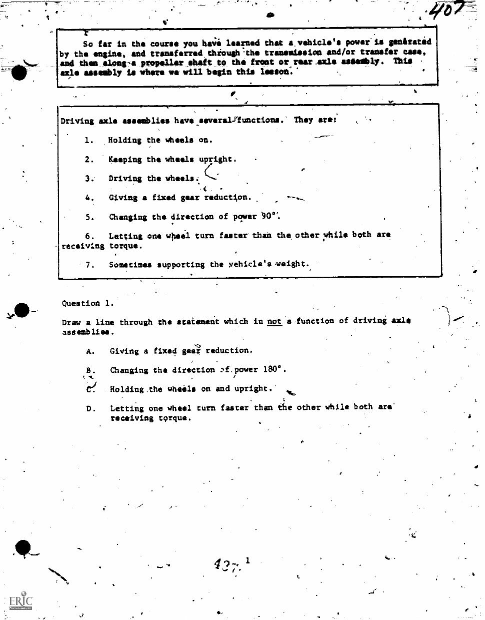
*07-So far in the course you ha4i learned that &vehicle's power'is gendratid
by the engine and transferred thiough.the transmission and/or transfer case,
and then aloni-a propelleroheit to the front or rear,axle aseembly. This
axle assembly is where we will begin this lesson:'
4
Driving axle assemblies have severakilunctions. They arel:
1. ,Holding the wheels on.
2. Keeping the wheels upright.
3. Driving the wheels%t4.. Giving a fixed gear reduction.
5. Changing the direction of power IN:0".
6. Letting one wheel turn faster than the other;d1hile both are
receiving torque.
7. Sometimes supporting the yehicle's.weight%
Question 1.
Draw a line through the staiement which in not a function of driving axle
assemblies.
A. Giving a fixed geiil reduction.
B. Changing the direction :.,f.power 1800.'IL
C? Holding.the wheels on and upright.'41..
D. Letting one wheel turn faster than the other while both are'
receiving torque.
4..
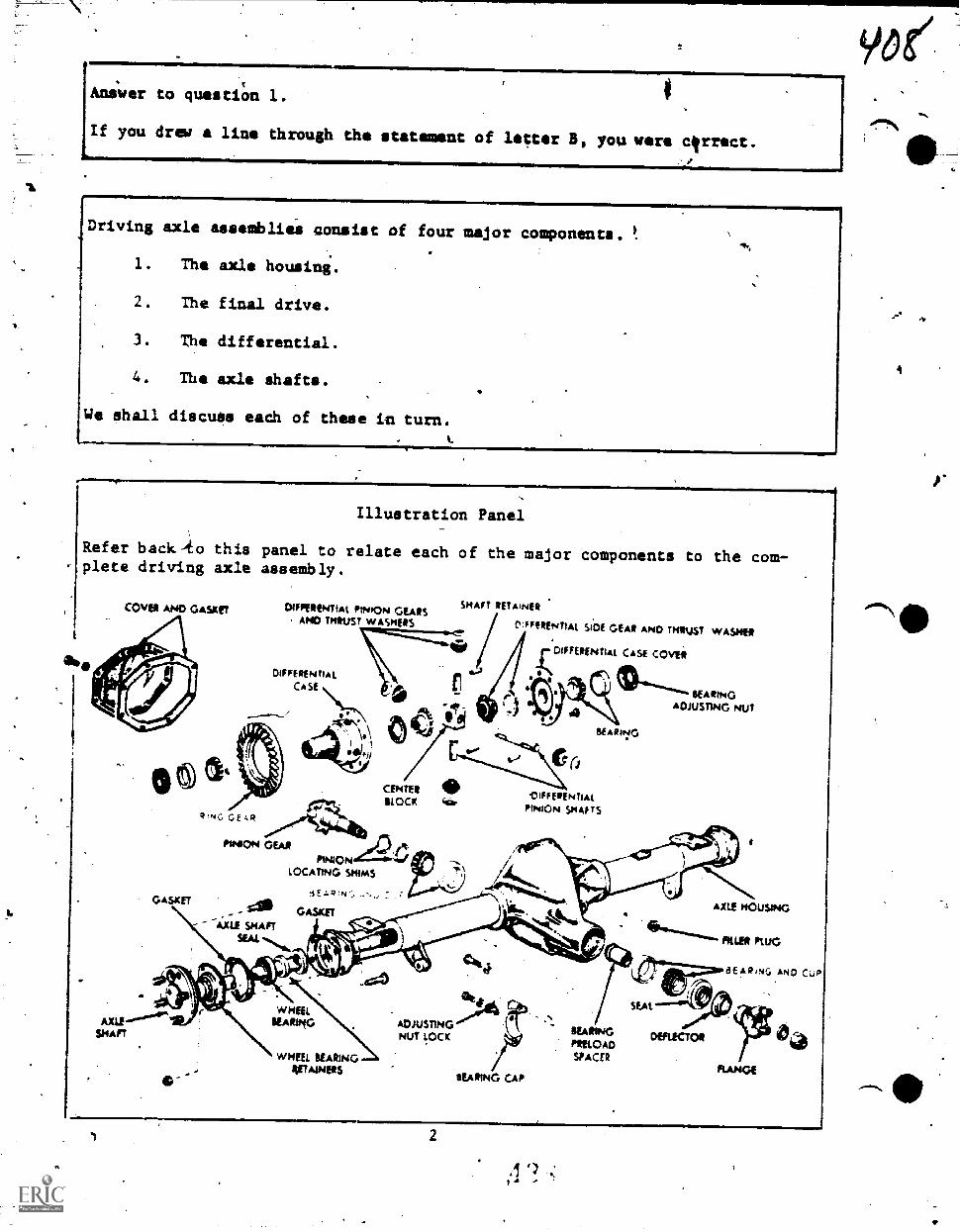
1
Aniwer to questiOn 1.
If you drew a line through the statement of letter B, you were c rrect.
Driving axle assembliee consist of four major components.
1. The axle housini.
2. The final drive.
3. The differential.
4. The axle shafts.
We shall discuss each of these in turn.
411.
Illustration Panel
Refer back-io this panel to relate each of the major components to the com-plete driving axle assembly.
COVER AND GASKET DIFFERENTIAL PINION GEARSAND THRUST WASHERS
SHAFT itETAir4R
C:FFERENTIAL SIDE GEAR AND TmRU.ST WASHER
'DIFFERENTIAL CASE COVER
DIFFERENTIALCA SE
SHAFT
\*\I '1
oil
RING GEAR
GASAET
PIRAON GEAR
PINUDNLOCATING SHIMS
lEz.o;Nr,
GASKET-AXLE SHAFT
SEAL
CENTER 411)BLOCK cll.
SEARING
OIFFERENTIAL
PINION SmAFTS
REARINGADJUSTING NUT
AXLE MOUSING
FILLER PLUG
aEAR,Nc, AND Cults
WHEELREARING
4111%16
NUT LOCK
S
to"
WHEEL SEARINGRATAINERS
SEA PING CAP
-
REARINGPRELOAD
SPACER
DEFLECTOR
'7 t'
t - '
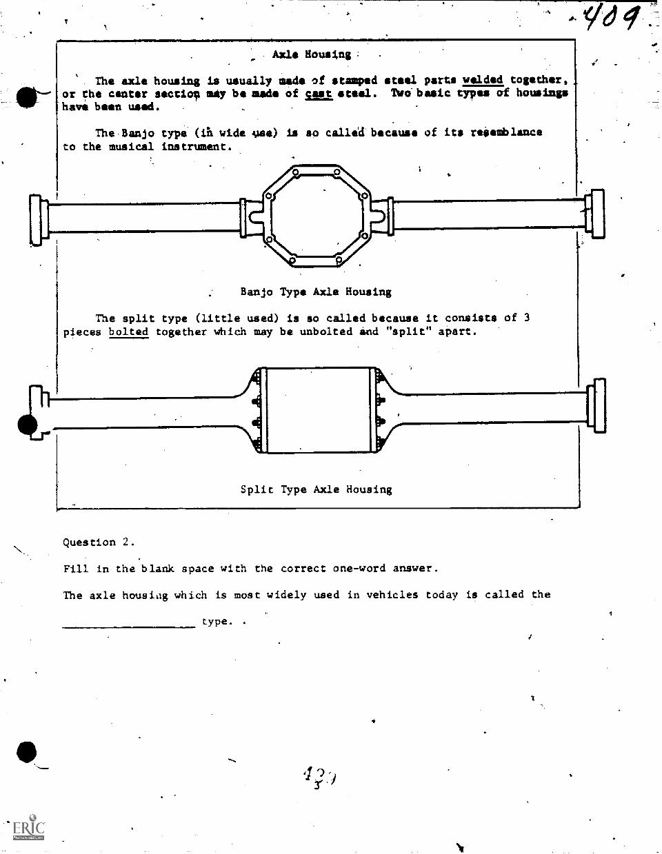
Axle Housing: .
The axle housing is usually made of stamped steel parts welded together,or the center sectio, mAy be made of soasteel. Two' basic types of housingshavi been used. ,
The.Banjo type (in wide ilse) is so calleU because of its reSemblanceto the musical instrument.
Banjo Type Axle Housing
The split type (little used) is so called because it consists of 3pieces bolted together which may be unbolted ind "split" apart.
Anni
Split Type Axle Housing
Question 2.
Fill in the blank space with the correct one-word answer.
The axle housiag which is most widely used in vehicles today is called the
type.
Answer to question 2. Banjo
,The purpose of thi axle housing is.to hiliWie the axle shafts and diferen-tial components and provide a lubrication bath for them. SOmetimes they arecilled on to s1pport same of the vehicle's weight.
Question 3.
True or False
The axle housing supports the vehicle's weight and drives the Wheels.
The only maintenance that is normally required for axle housings is toperiodically inspect.its fluid level and to insure that its vent is dotstopped yp.
Question 4. I.
What could happen to an axle housing as the result of a stopped up vent?
Select the best answer.
A. .The lubricant would not recebve proper cooling.
B. The.housing seals would start to leak:
, C. The wheels would become
Axles would not receive
hard to turn.4
proper lubrication.
4
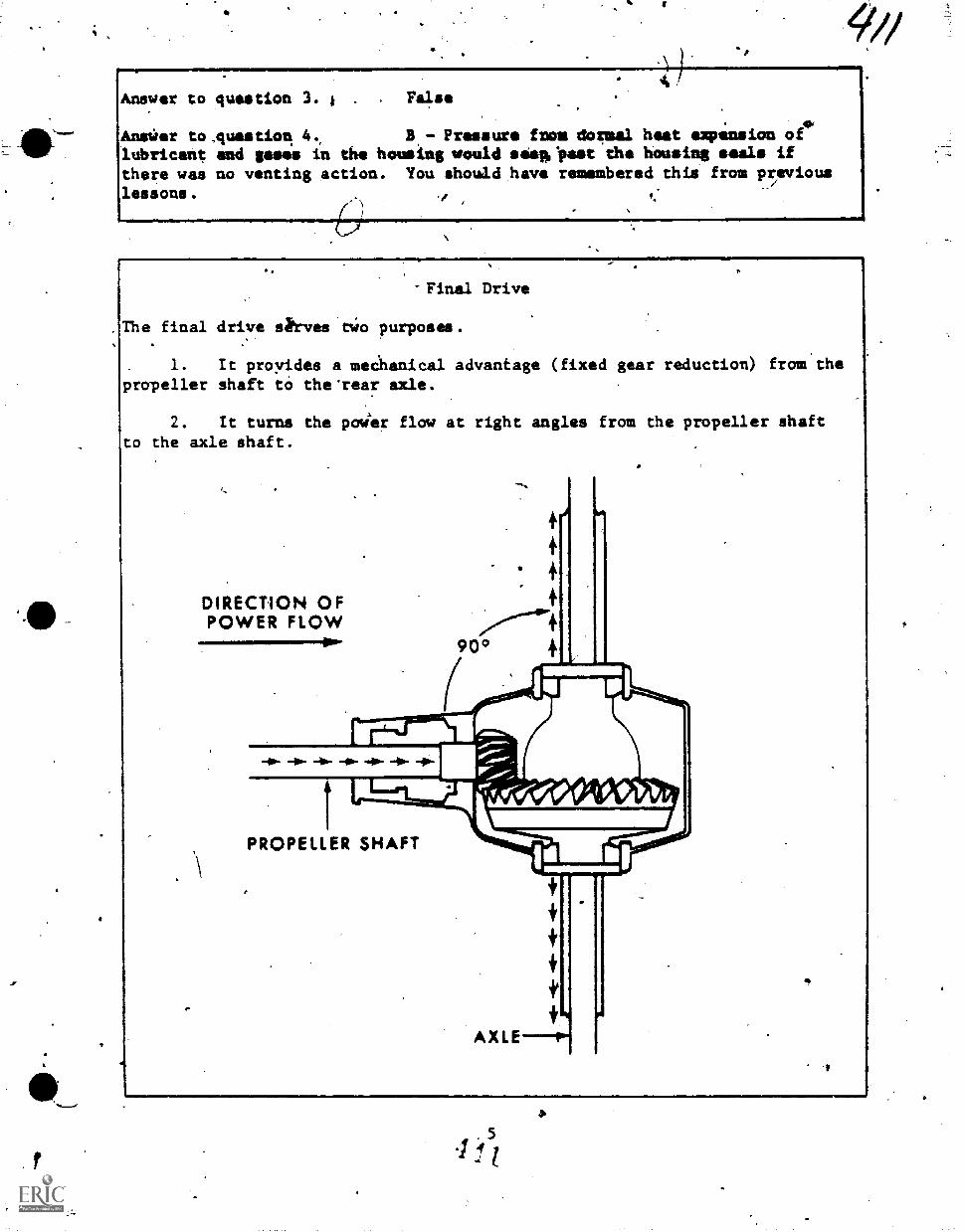
Answer to
Ana:Ter to
lubricantthere waslessons.
question 3. i False
Auestion 4. B - Pressure from dormal heat explosion ofand games in the housing would seapCpast the housing seals ifno venting action. You showld,have remembered this from previous
Final Drive
The final drive sh-ves tWo purposes.
1. It proyides a meChanical advantage (fixed gear reduction) from thepropeller shaft to the'rear axle.
2. It turns the poaer flow at right angles from the propeller shaftto the axle shaft.
DIRECTION OFPOWER FLOW
90°
iirm.110111
Al yr. Ireie, //I,/ Vet-0- -40- -412- -02- 401- A1111- -0-
PROPELLER SHAFT
. 5
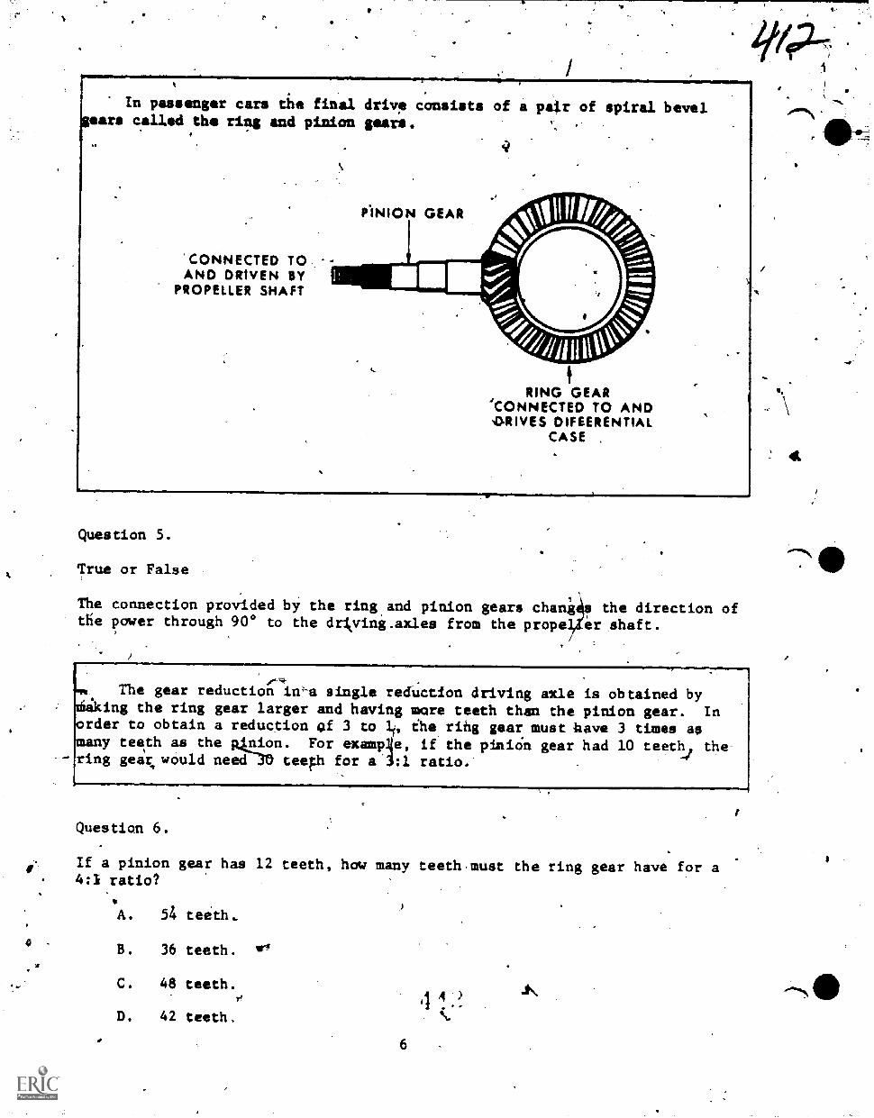
A
In passenger cars tile final driv, consists of a pair of spiral bevelgears called the ring and pinion gears.
'CONNECTED TOAND DRIVEN BY
PROPELLER SHAFT
ONION GEAR
RING GEAR'CONNECTED TO ANDORIVES DIFEERENTIAL
CASE ,
Question 5.
True or False,
The connection provided by the ring.and pinion gears chani a the direction ofthe power through 900 to the drkving.axles from the propel,Zer shaft.
r
-
The gear reduction in-a single reduction driving axle is obtained byAtiking the ring gear larger and having more teeth than the pinion gear. Inorder to obtain a reduction of 3 to 10 ihe ring gear must have 3 times asmany teeth as the p4ion. For examp4e, if the pinicin gear had 10 teeth, thering gear, would need teeth for a 3:1 ratio.
Question 6.
If a pinion gear has 12 teeth, how many teeth.must the ring gear have for a4:I ratio?
A. 54 teeth..
B. 36 teeth. 211
C. 48 teeth.
D. 42 teeth.
6
,1 A
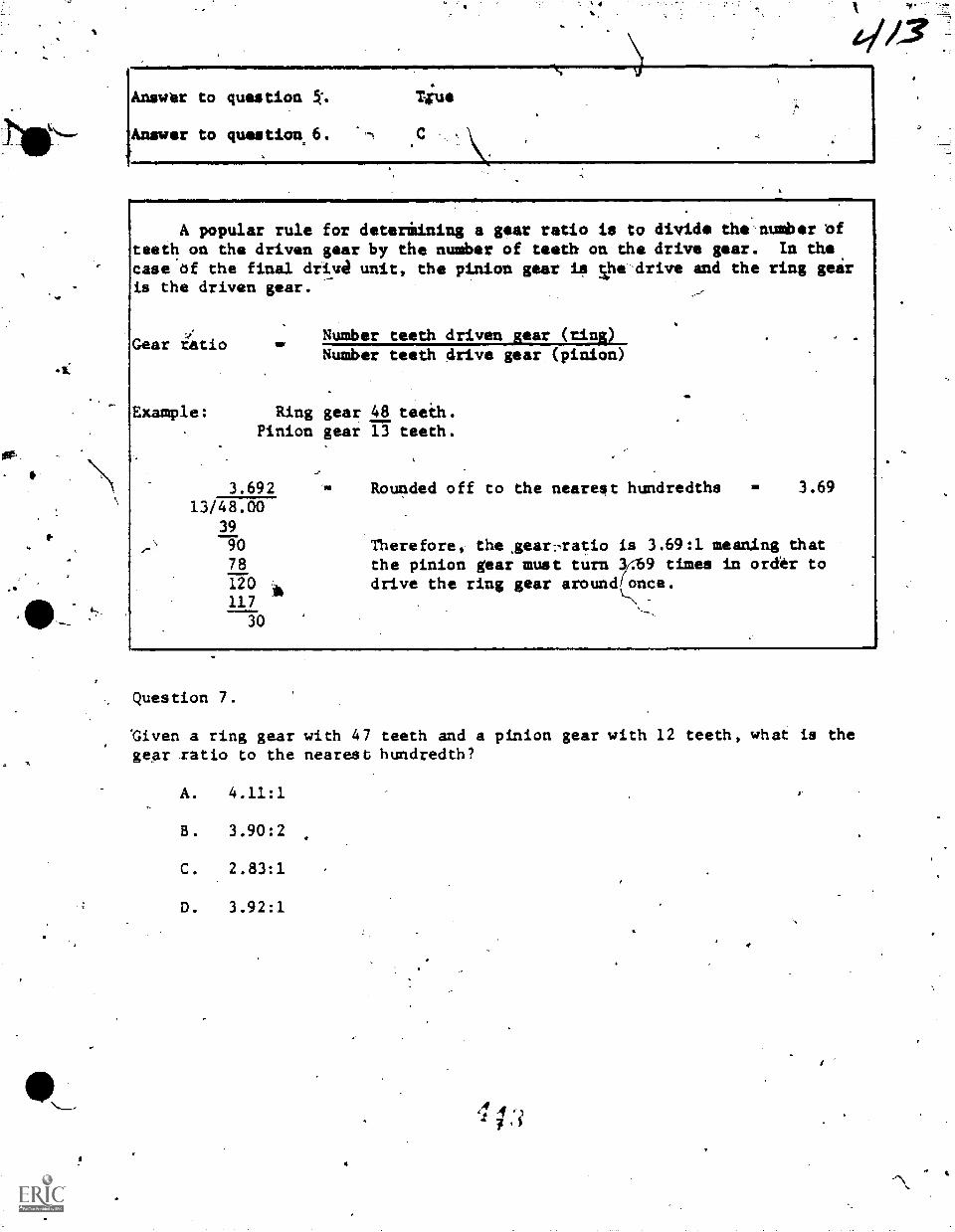
Answer to question A% %rue
Answer to question. 6. ,C
A popular rule for deteriining a gear ratio is,to divide the'nulberteeth on the driven gear by the number of teeth on the drive gear. In the
case of the final driva unit, the pinion gear is Vle-drive and the ring gearis the driven gear.
Gear riatioNumber teeth driven gear (ting)Number teeth drive gear (pinion)
Example: Ring gear 48 teeth.Pinion gear 13 teeth.
3.692 Rounded off to the nearest hundredths 3.69
13/48.0039
90 Therefore, the sear7ratio is 3.69:1 meaning that78 the pinion gear must turn 3469 times in order to120 I, drive the ring gear around(once.117
30
Question 7.
'Given a ring gear with 47 teeth and a pinion gear with 12 teeth, what is thegear ratio to the nearest hundredth?
A. 4.11:1
B. 3.90:2
C. 2.83:1
D. 3.92:1
7'
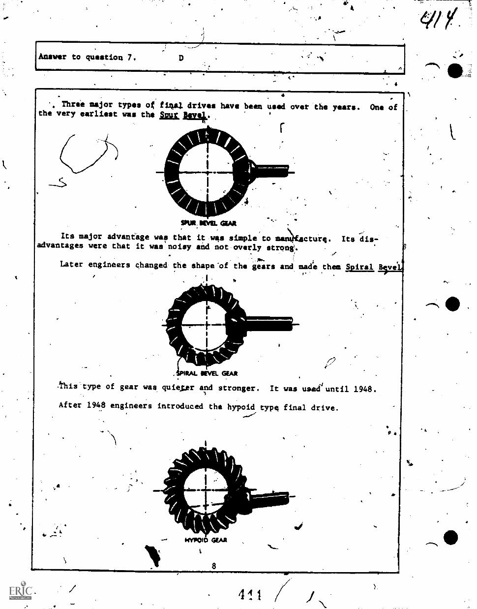
47.
-,*
1.
V
Answer to question 7.
Three major types ot f14al drives have been used over the years. One othe very earliest was the Ant jai* 4
SM. MEWL GEAR
Its major advantage was that it wee simple toadvantages were that it was noisy and not overly strong'.
cture. Its dis-
rP
Later engineers changed the shape'of the gears and made them Spiral,Bve
MAL REVEL GEAR
-this type of gear was quieter and stronger. It was used'until 1948.
After 1948 engineers introduced the hypoid type final drive.
41110110,7KYPOIO GEAR
_fr.MP.
. 41.1
Pi
AP
,
a_
V/rIt wds quiet, smooth, and strOmg. :Also by obseiving the illustration,
you can see that the mashing point of the ring and pinion gear is below the.
centerline of the,ring gear. This allows the_whole driveline to be loweredand the vehicle.may..set lower-to the stoned without an ueusually large tunnelor "hump" in the floorboar4 to accommodate the propeller shaft. Also thepinion could now be setting in lubricant al all times in the hypoid typedfive, while the spur bevel and:spiral bevel were lubricated SY the splashsystem. The hypoid type final drive is the ona most vehicles use today..,
*A4.
Question 8.
Why is the hypoid tipe final drive used, today?
A. It is strong.
fikB. It is quiskr..
C. It is better lubricated.
D. All of.rhe above. '\
-.04.S6
4
Ob.
9
7I
,
1
,
4:
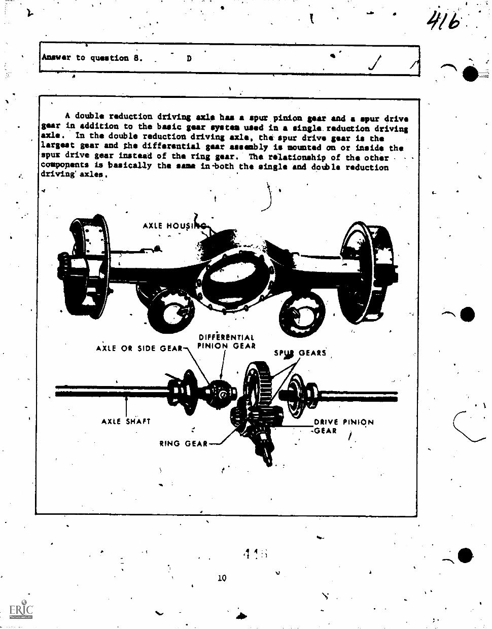
4/6*:
Answer to question 8.
A double reduction driving axle has a spur pinion gear and a spur drivegear in addition to the basic gear system used in a single. reduction drivingaxle. In the double reduction driving axle, the spur drive gear is thelargest gear and the differential gear assmably is mounted on or inside thespur drive gear instead of the ring gear. The relationship of the othercomponents is basically the same in-both the single and dotble reductiondriving axles.
rink
41\ AXLE HOUSS411t%,1.
AXLE OR SIDE GEARDIFF.ERENTIALPINION GEAR
SPIS GEARS
4011111.___
AXLE SH'AFT
RING GEAR
f
DRIVE PINION-GEAR
so"
I.
\
The gear reduction in a single reduction driving,axle is obtained by makithe.ring gear larger than the pinion gear and having more gear teeth than thepinion gear. In order to obtain a redtiction'qi 6 to 1, the ring gear.must besix times', as large 'as tho pinion gear. If the pinion gear were four inchesin diaMeter, Me ring geazwould have to be tventy-four inches,in diameter.A,differential housing under a vehicle that was more than twenty-four inchesin diameter wnuld cause a gmod deal of trouble,.so a doUble reduction drivingpxle would be better.. To obtain the.same gear reduction the pinion gear couldto the same 'four inches in diampetsr%,'the ring gear could be eight inches indiam4er, the pinion spur gear could be three inches in diameter and the spurdrive.gear could be nine inches in diameter. This arrangement would give agear ratio of 6 to 1 and the largest gear only nineee inches in diameter.
Question 9.
What is the adyantage of using a double reduction driving axle?
A. It provides six times the amount of gear reduction.
B. It eliminates the need for a ring gear..
C. It provides &large-gear reduction with smaller diameter gears.
D. It pliaces.th stresse4 icaused by turning, skidding, wheel wobble,and'the weig4 of the vehlcle on the axle housing.
V.
4
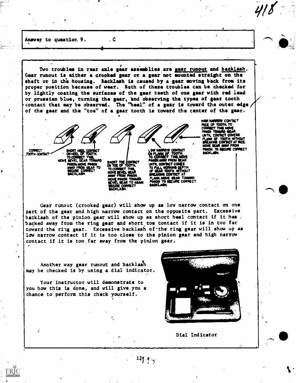
woi
Answer to question 9.
Two troubles in rear axle gear asiemblies are sear runout and badklash.Gear runout is either a crooked gear or a gear not mounted straight on theshaft or in thli housing. Backlash is caused by a gear moving beck from itsproper position because of wear. Both of these troubles can bo checked forby lightly coating the surfaces of the gear teeth of ono gear with red leador prussian blue, turning the gear, lind observing the types of gear toothcontact that may be observed. The "heel" of a gear is toward the outer edgeof the gear and the "toe" of a gear tooth is toward ehe center of the gear.
COMM,rooTw 0:$131CT MERL OF MT
WAITAITATram$011.801AKFAL ANIONAINAT FOKAI_ALAR TO
oHHACT
11HOHT TelON 100 OFTO CORIRCT 1110i.MOW KM sumavillw Rom mommpvi Ammo tcmemb
IKAR TO Atm
IANVELAgriga
LOW NOW! CONW
ON
3318fTO MalMIL COMO COMTO AAA. UMW olIPTHOF WM TOOTH ATTHouTMIMI COMM ATFLAW MOW OW TownIHNHUOKSECUHt COMOMIA
mei NSMOM COM,FACt Cr Room Tomaw me mmitMINN mum ow.UNTIL COWOCT 004R0FLANK OF TOOTH %6001TilliAMN0 ;cow AT ma.MOW NAN MAT FHOIF1,40,1 10 NOM =MKTSACHL.H.
Gear runout (crooked gear) will show up as low narrow contact on onepart of the gear and high narrow contact on the opposite part. Excessivebacklash of the pinion gear will show up as short heal contact if it hasbacked away from the ring gear and short.toe tontact if it is in too fartoward the riag gear. Excessive backlash ofthe ring gear will show up aslow narrow .contact if it is too close to the pinion gear and high narrowcontact if it is too far sway from the pinion gear.
Another way gear runout and backlaAmay be checked is by using a dial indicator.
Your instructor will demonstrate toyou how this is done, and will give you achance to perform this check yourself.
.0411M11MP
Dial Indicator
WQuestion 10.
What is the purpose of a SOL: tooth contact chIck?
A. To determine if the proper gears ara Installed.
B. To detect gear runout or backlash.
C. To dstermine if the rear axle is noisy.
D. To determine if a single or double reduction axle is being used.
Question 11.
When a gear is too close to or too far xway from the gear it should meshwith, what is the trouble?
A. Gear runout.
B. Gear tooth contact.
C. Rill gear meshing with pinion gear.
D. Gear backlash.
Question 12.
What can be done to detect gear runout or backlash?
. Drive the vehicle and measure the type of vibration.
B. Perform a gear tooth contact check.
C. Drive the vehicle and measure the amount of noise.
D. Drive the vehicle wheels on a lift.and observe the operation of therear axle from underneath.
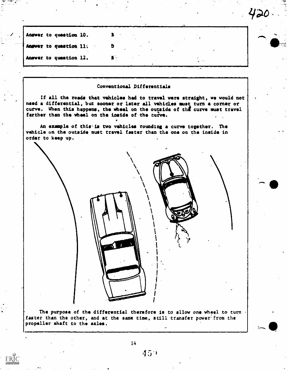
Answer to question 10.
-Answer to question 11:
Answer to question 12. 11
Conventional Differentials
If all the roads that vehicles had to travel were straight, we would notneed a differential, but sooner or later all vehiaes must turn a corner orcurve. When this happens, the Wheel on the outside of the curve must travelfarther than the Wheel on the inside of-the auilve.
An example of this-is two vehicles rounding a curve together. Thevehicle on the outside must travel faster than the one on the inside inorder to keep up.
\
1
1
, I
,
The purpose.of the differential therefore is to allow one whfel to turn ,
faster than the other, and at the same time, still transfer powerfrom thepropeller shaft to the axles.
14
ZPO
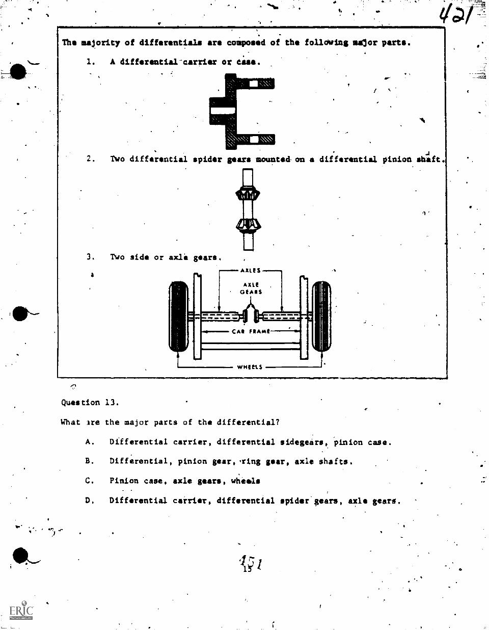
The majority of differentials are composed of the following salor parts.
1. A differential-carrier or Case.
2. Two differential spider gears mounted on a differential pinion shaft.
3. Two side or axle gears.
a
Question 13.
What ire the major parts of the differential?
A. Differential carrier, differential sidegears, pinion case.
B. Differential, pinion gear,,ring gear, axle shafts.
C. Pinion case, axle gears, wheels
D. Differential carrier, differential spider gears, axle gears.
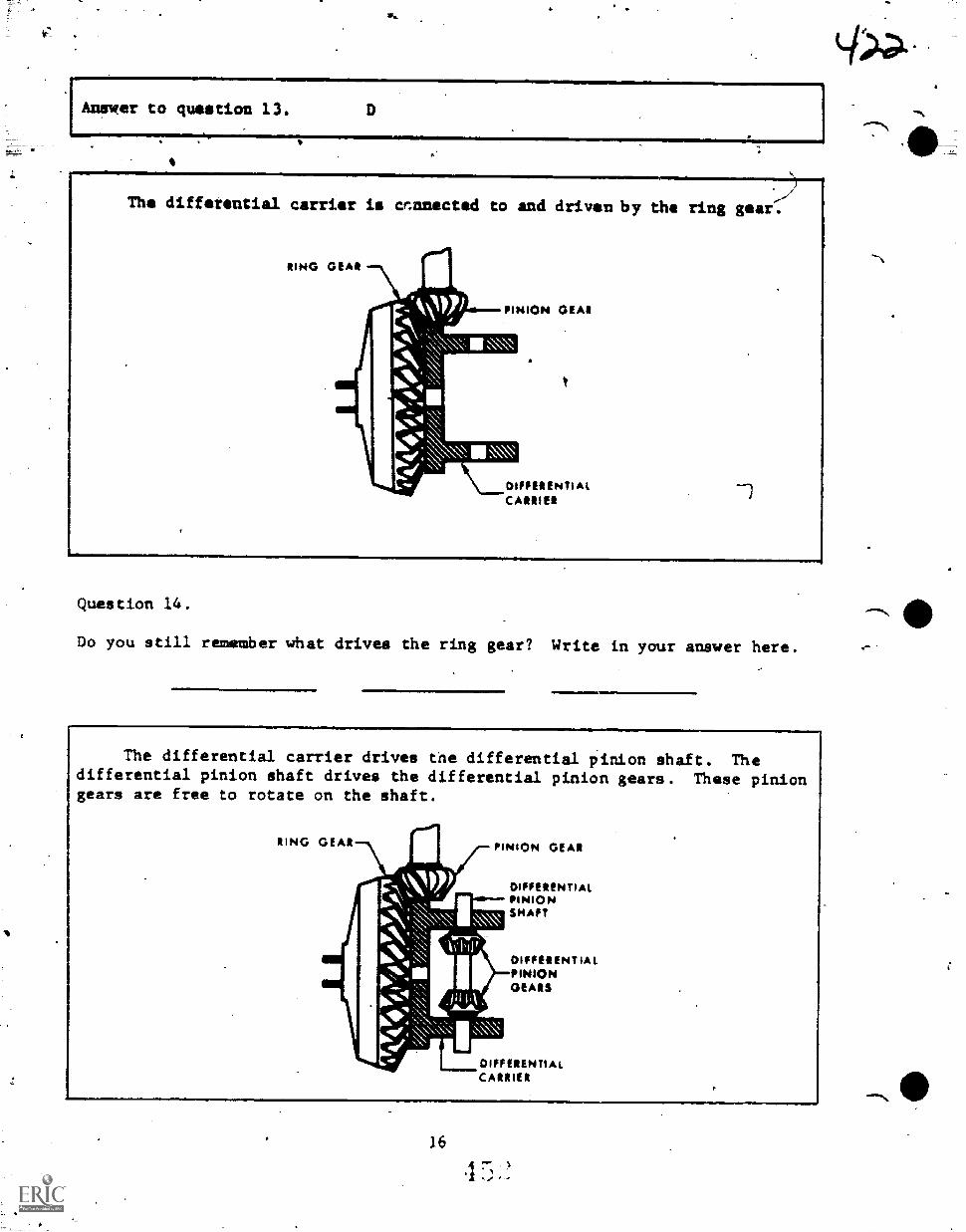
Answer to question 13.
The differential carrier is cfmnected to and driven by the ring gear.
DIFFERENTIALCARRIER
Question 14.
Do you still remember what drives the ring gear? Write in your answer here.
.11.1===M110111
The differential carrier drives the differential pinion shaft. Thedifferential pinion shaft drives the differential pinion gears. These piniongears are free to rotate on the shaft.
DIFFERENTIALPINIONSHAFT
DIFFERENTIALPINIONORARS
DIFFERENTIALCARRIER
16
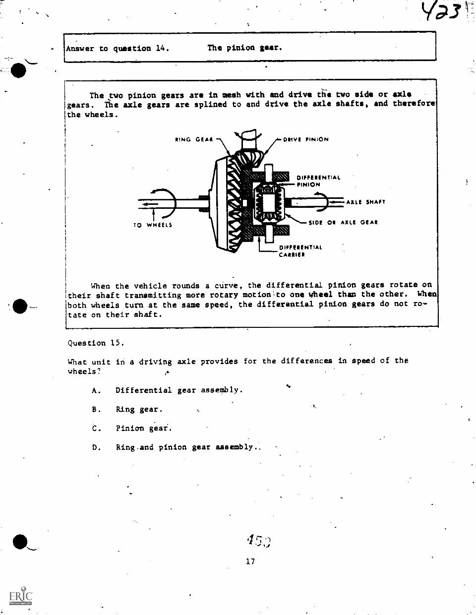
Answer to question 14. The pinion gear.
The two pinion gears are in mesh with and drive die two side or axlegears. The axle gears are splined to and drive the axle shafts, and therefore
the wheels.
RING GEAR DRIVE PINION
DIFFERENTIALPINION
TO WHEELS
-40.--.AXLE SHAFT
SIDE OR AXLE GEAR
DIFFERENTIALCARRIER
When the vehicle rounds a curve, the differential pinion gears rotate ontheir shaft transmitting more rotary motion\to one wheel than the other. When
both wheels turn at the same speed, the differential pinion gears do not ro-tate on their shaft.
Question 15.
What unit in a driving axle provides for the differences in speed of thewheels?
A. Differential gear assembly.
B. Ring gear.
C. Pinian gear.
D. Ring and pinion gear assembly.,
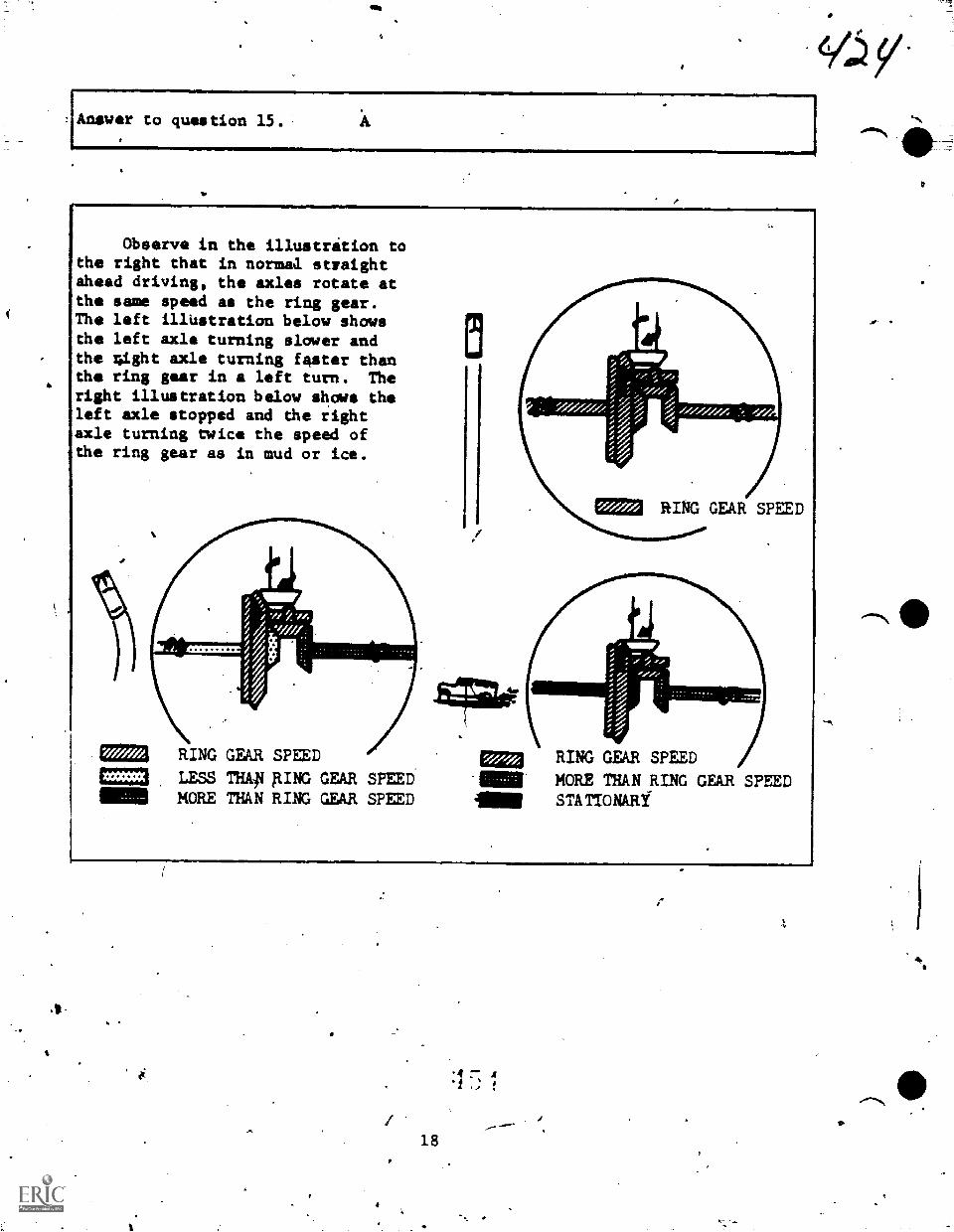
Answer to question 15. A
,t-
Observe in the illustrition tothe right that in normaa straightihead driving, the axles rotate atthe sane speed as the ring gear.The left i1l4stration below showsthe left axle turning slower andthe 4ight axle turning faster thanthe ring gear in a left turn. Theright illustration below shows theleft axle stopped and the rightaxle turning twice the speed ofthe ring gear as in mud or ice.
0223 RING GEAR SPEED
RING GEAR SPEED OEM= LESS THAp AING GEAR SPEED -1111111111 MORE THAN RING GEAR SPEED AIM
RING GEAR SPEED )/I
MORE THAN RING GEAR SPEEDSTATIONARY'
18
1 7
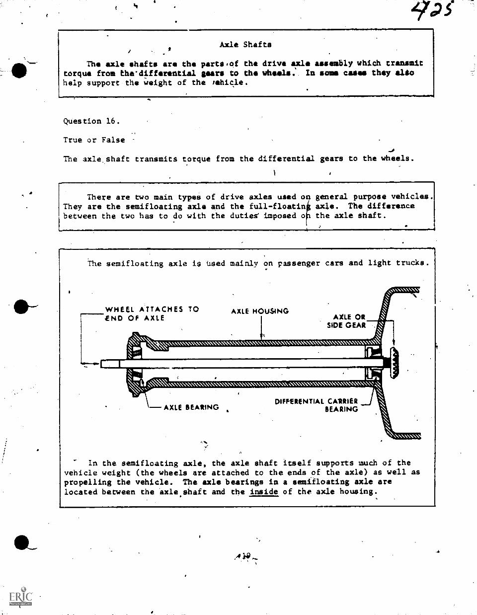
a
sala
Axle Shafts
The axle shafts are the parts,of the drive axle assembly which transmittorque from the-differential gears to the wheels. In some cases they aliohelp support the weight of the tehicle.
Question 16.
True or False
The axle.shaft transmits torque from the differential gears to the wheels.
There are rwo main types of drive axles used onThey are the semifloating axle and the full-floatinbetween the two has to do with the dutiee imposed o
general purpose vehicles.axle. The differencethe axle shaft.
The semifloating axle is -Used mainly on passenger cars and light trucks.
WHEEL ATTACHES TO-END OF AXLE
AXLE HOUSINGAXLE OR
SIDE GEAR
\\\\\\\\\NN\ \\\\\\N \\\\\\\\\\X\\\\\\\\\\\\\\\\\\\\\\W\\ IP I I I is
I rNMI% 1-1,111
\\.\\X' NX"..\\*\ -\\\\\\\\\' ...\\.\\"\\N XN* XN \\'` %NA *XS IS X \\N \\\\\\\\\\'
DIFFERENTIAL CA1RIERAXLE BEARING BEARING
In the semifloating axle, the axle shaft itself supports much of thevehicle weight (the wheels are attached to the ends of the axle) as well aspropelling the vehicle. The axle bearings in a semifloating axle arelocated between the -axle.shaft and the inside of the axle housing.
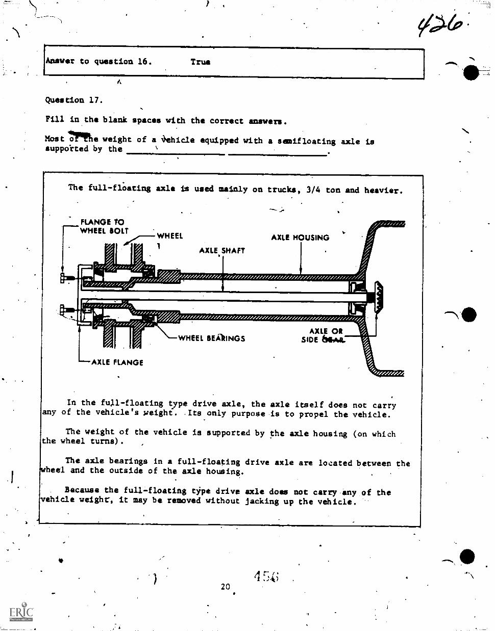
Answer to question 16. True
Question 17.
Fill in,the blank spaces with the correct answers.
Most 4:rine weight of a 4ehicle equipped with a semifloating axle issupplirted by the
mlil.=101=111.The full-floating axle is used mainly on trucks, 3/4 ton and heavier.
FLANGE /0WHEEL BOLT
WHEEL
; 11111111P/7/./
AXLE HOUSING1
AXLE SHAFT
,,; ik;LANs
AXLE ORYeHEEL BEAIINGS SIDE 64644./
---AXLE FLANGE
In the full-floating type drive axle, the axle itself does not carryany of the vehicle's Reight. .Its only purpose is to propel the vehicle.
The weight of the vehicle is supported by the axle housing (on whichthe wheel turns).
The axle bearings in a full-floating drive axle are located between thewheel and the outside of the axle housing.
Because the full-floating tipe drive axle does not carry,any of thevehicle weight, it may be removed without jacking up the vehicle.
2 0
lAno wer to question 17.. .axle shafts
Question 18.
What type r r driving axle bma all of the weight of the-yehicle and the
stresses caused by turning, skidding, and wheel wobble on the axle shaft?
A. Plain.
B. Semiflosting.
C. Full floating.
D. Three-quaiter floating-.
Question 19.
What type rear driviing axle has all of the weight of the vehicle and thestresses caused by turning, skidding, and wheel wobble on the axle housing?
A. Three-quarter floating.
B. Full-floating.
C. Semifloating.
D. Plain.
1
ND
'
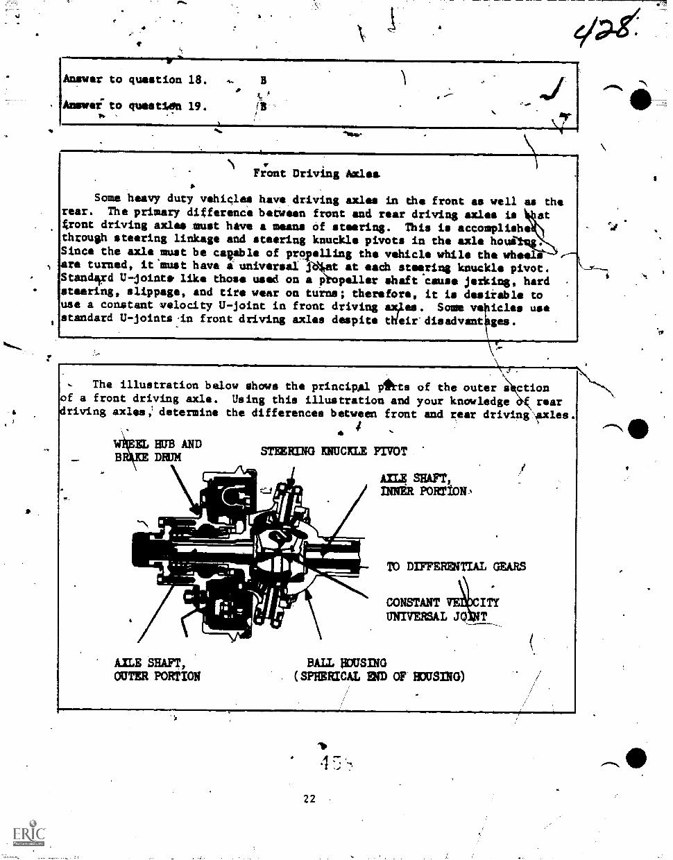
ep-g/41.
Answer to question 18.
Answer" to gm's tiIn 19 fBp.
Front Driving AxlesIt.
Some heavy duty vehicles have.driving axles in the front as well as therear. The primary difference between front and rear driving axles is at4ront driving axles must have a means of steering. This is accomplish*through steering linkage and steering knuckle pivots in the axle housSince the axle must be callable of pro
f
ailing the vehicle while the wheels
toeeare turned, it'must have a universal j t at each string knuckle pivot.
Standsird U-jointe like those used on a p pallor shaft cause jerking, hardsteering, slippage, and tire wear on turns; therefor*, it is dosiiable touse a constant velocity U -joint in front driving exiles. Some ve icles usestandard U-joints,in front driving axles despite tWeir'disadvant gee.
, The illustration below shows the principal Atts of the outer s ctionof a front driving axle. Using this illustration and your knowledge è reardriving axles; determine the differences between front and rear driving Axles.
IL HUB ANDSTEERING KNUCKLE PIVOT
DRUM
C.!
je"I
M.M
AXLE SHAFT,OUTER PORTION
licm.E.-11
AILE sain,INNER PORTION
TO DIFFERINTIAL GEAR.S
CONSTANT ITYUNIVERSAL JO, T
BALL pousirm. (SPHERICAL END OF HOUSING)
22
.10
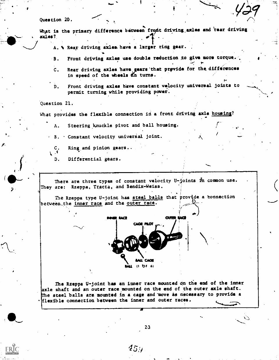
Question 20.
Whpt is the primary difference between frTit driving.axles and 'rear driving
axles?,
A. Rear driving axles have a larger ring gear.
B. Front driving axles use double reduction ,to give more torque.I.
C. Rear driving axles have,gears 'that prfpvide for the differences
in speed of the wheels dn turns.
D. Front driving axles have constant velocity universal joints topermit turning while providing power:
Question 21.
What provides the flexible connection i4 a front driving axle housing?
A. Steering,kauckle pivot and ball housing. /-
B. Constant velocity universal joint.
C. Ring and pinion gears.-
D. Differential gears.
There are three types of constant velocity U-ioints in common use.
They are: Rzeppa, Tracta, and'Bendix-Weiss..;
The Rzeppa type U-joint has steel balls Chat prov e a tonnection
between_the inner race and the outer race.
MIR RAOCA04 PIOT .
Ihe Rzeppa U-joint has an inner race mounted 4n die end of the inneraxle shaft and an outer race,mounted on the end of the outer axle shaft.
The steel balls are mounted in a cage and 'move As necessary to provide aflexible connection between the inner and outer races.
41
45,ti
23
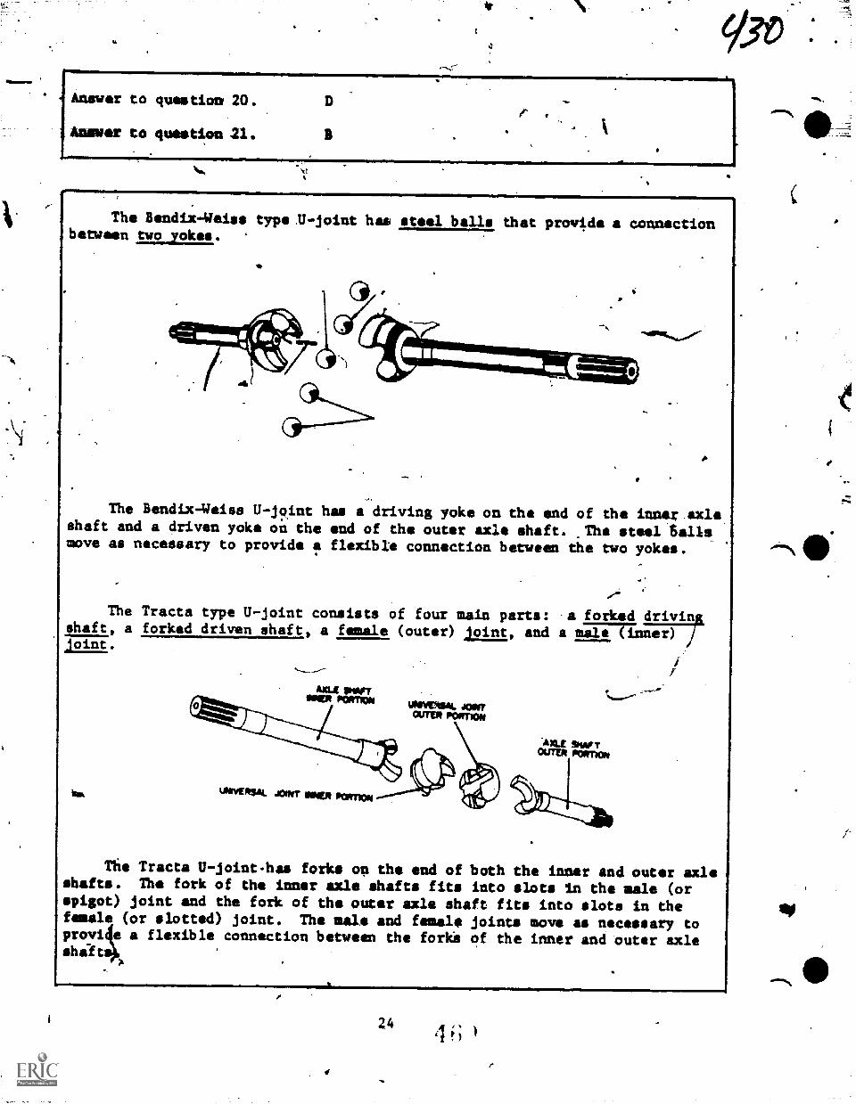
Answer to question 20.
Ammer to question 21.
=0IMIMIlalMENNIMIM
The Bendix-4eise type .U-joint has steel balls Chat provide a connectionbetween two yokes.
The Bendix-Weiss U-joint has a driving yoke on the end of the inner axleshaft and a driven yoke on the and of the outer axle shaft. .The tel Sellsmove as necessary to provide a flexible connection between the two yokes.
.4
The Tracts type U-joint consists of four main parts: a forkedftsha, a forked driven shaft, a female (outer) joint, and a male (inner)
joint.
law
nig Tracts U-joint-has forks on the end of both the inner and outer axleshafts. The fork of the inner axle ehafts fits into slots in the male (orspigot) joint and the fork of the outer axle shaft fits into slots in thefemale (or slotted) joint. The male and female joints move as necessary toprovi e a flexible connection between the forke of the inner and outer axleshilt
24
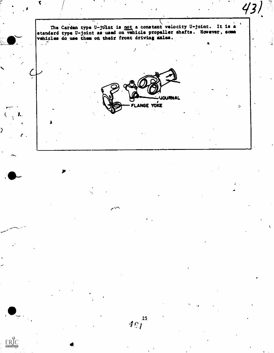
The Carden type U-16int is not a constant velocity U-joint. It is a
standard type U-joint as-used on vehicle propeller shafts. Hwever, somevehicles do use them 04 their front driving azles.
/
4
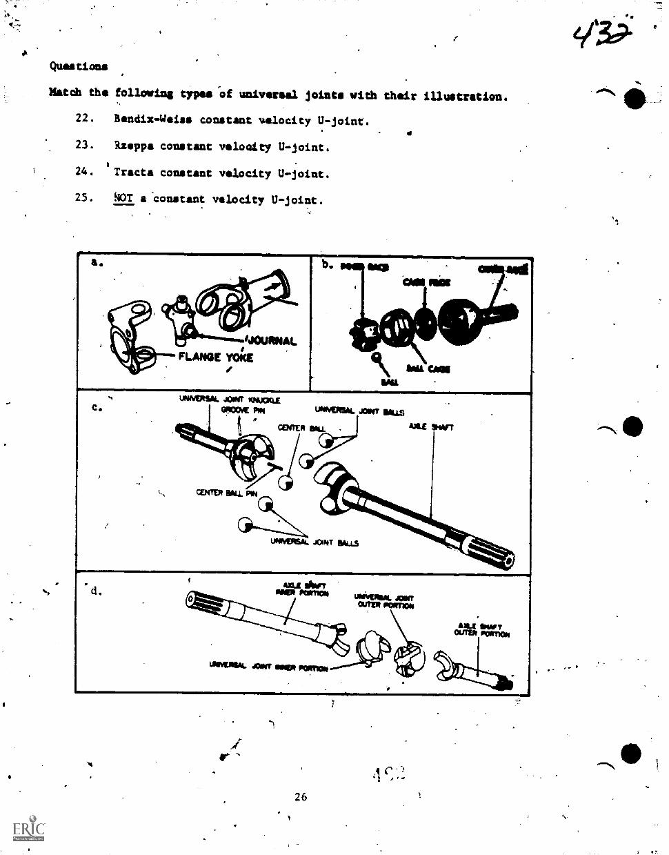
Questions
Match the following types -of universal joints with their illustration.
22. Bendix -Weiss constant velocity U-joint.
23. Rzeppa constant voloaity U -joint.
24. Tracts constant velocity U-joint.
25. NOT a constant velocity U-joint.
emBalS=MasrIia.
aas
CAlleMIL
d.
UNNERSAL JOINT 03,1UCKLE
'ONE PP. UNN10154. JOINT SUS
CENTER 130u. PIN
CENTER WILL SWT
uNIVERSQ. JCAT BALLS
AILE *OFTOUTV1 IPO1lT1ON4.=.11
26
VA3?
Answer to quastion 22.
4umrser to question 23.
Answer to question.24.
Answer to question 25. A
1
2 7101-111211
PilIP111111 NAN
.
7.4
PROGRAMMED TEXT 3A3147119-PT-504A
Technical Training
ACe4eltic.General Purpose Vehicle Repetrman
Special Vehicle Repairman(Towing and Servicing Vehicles)
(Crash/Fire VehiCles)(Refusling.Vehicles)
(Materials Handling Vehicles)
ANTI-SPIN DIFFERENTIAL
29 November 1971
21..***-
CHANUTE TECHNICAL TRAINING CENTER (ATC)
This supe sedes 3A3R47330-PT-504A, 29 December 1970.OPR: TDWSDISTRIBUTION: X .
TDWS - 800; TTOC - 6
.
Designed For ATC Course Use
DO MOT ,USE ON THE JOS
4
3A3R472314-PT-604A3A31.47231A-PT-604A3A31472313'4T-604A3ABR47231C -PT-604A
V
FOREWORD
This programmed'text was prepared for use in Course 3A3R47131 (now
47330) Automotive Repairman, in. 1965. The materials contained herein were
validated with 30 students from the subject course. All students used in
the validation exercise achieved the objectives as stated. The text has
been in continuous use-for the past five years and has trained about 3500
students. The text is.considered to be still valid.
OBJECTIVES
Upon completion of this programmed text you will be able to accomplish the
following objectives with 80% accuracy.
1. Given a diagram of the anti-stin unit components, write the name
of each component in the space provided by it.
2. State in your own words the main purpose of the anti-spin
differential.
3. Describe the operation of an anti-spin differential.
INSTRUCTIONS
This programmed text was designed to be uied in the Automotive Repairman.
course. It is written im small segments called frames. After each frame, you
will be required to respond in some way to the information given. Follow ehe
instructions, after each frami and always check your answers.which are located
at tfie top of the next page. If you need assistance, your instructor will be
neart;y to help you.
4 e)
Frame 1
In the conventional differential, the torque to the two axles is
evenly divided at All times. A fault of the conventional differential is
that if-one driving wheei loses traction and spins, the other wheel which
has more traction remains stationary and does not drive the- vehicle.
QUESTIONS
indicate whether the following statements are true or false.
1. Equal traction is supplied to both rear wheels.
2. The wheel with the greatest traction will spin when power is
applied.
3. Power to a conventional differential is always the same to bOth
axles.
AAnswers to Frame 1.
1. F 2. F 3. T
Frame 2
The main purpose of the anti-spin differential is to supply a greaterpercentage of the driving torque to the wheel with the best traction andstill furnish the wheel with poorer traction as much torque as it Ls ableto absorb.
QUESTIONS
Indicate whether each of the following statements are true or fa1s4./
4. Both wheels receive the same torque regardless of traction.
5. The greatest power goes to the wheel that can use it best.
6. The wheel with the poorer traction is provided some power.
2
.41
Answers to Frame 2.4
4. F 5. T 6. T
r-Frame 3
The anti-spin differential prevents "shock loads" or full engine torque,
from being transmitted to only one axle shaft. It provides power'to both
rear wheels and also maintains the differential action that is needed when
the vehicle is turning a corner, that is, it permits the outer wheel to
turn faster than the inner wheel.
440XESTIONS
Indicate whether each of the following itatements are true or false.
The anti-f.,pin differential
7. has the same ability, in turns, as a conventiongl differential.
8. provides power to both axle shafts at the same time.
9. only provides power to the axle shaft with the greatest traction.
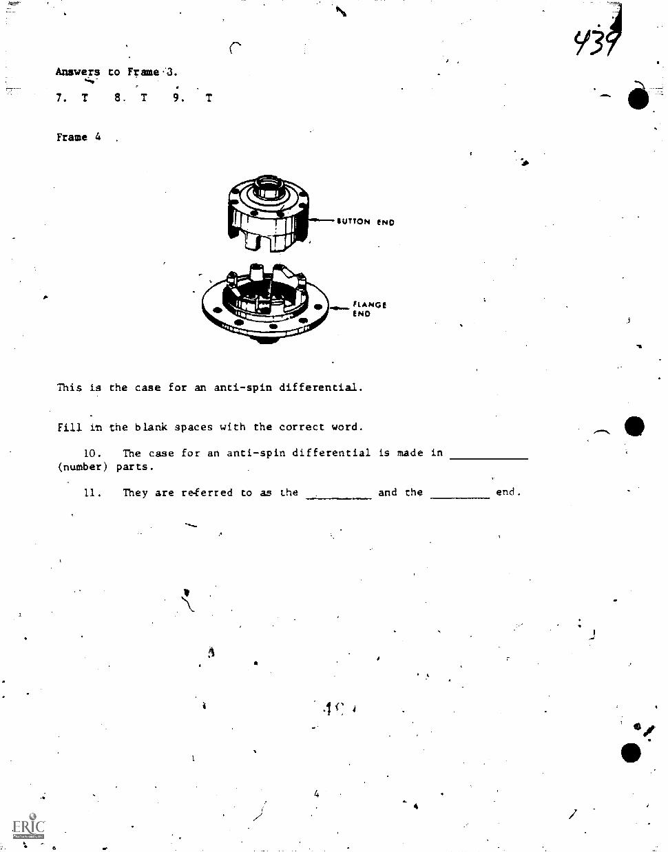
p.
Answers to Frame,3.
7. T 8 T 9. T
Frame 4
SUTTON ENG
RANGEEND
This is the case for an anti-spin differential.
Fill rn the blank spaces with the correct word.
10. The case for an anti-spin differential is made in(number) parts.
11. They are reterred to as the
a
4
and the end.
4
9'3
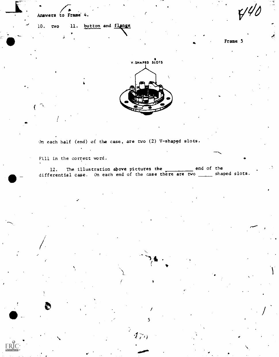
Answers to Frami 4.
10. two 11. button and f nge
V.SMAPED SLOTS
On each half (end) of the case, are two (2) V-shaped slots.
Fill in the correct word.
12. The illustration above pictures the end of the
v*o
Frame 5
differential case. On each end of the case there are two shaped slots.
1
5
tNo°*
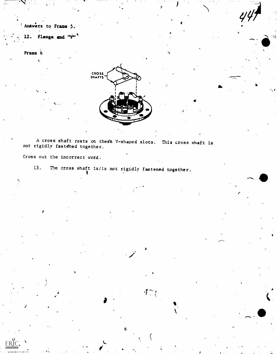
Ants:ere to Frame S.
12. flans. and "V"
Frame 6
A cross shaft rests on the1'e V-shaped slots. This cross shaft isnot rigidly fastehed together.
Cross out the incorrect word.
13. The cross shaft is/is not rigidly fastened together.
6
10,
-t
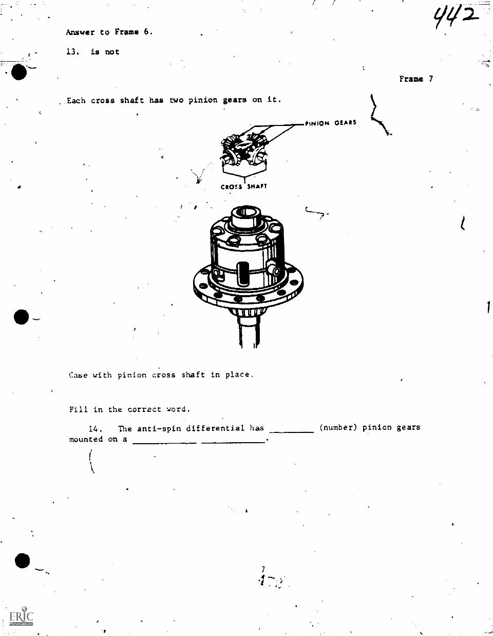
Answer to Frame 6.
13. is not
, Each cross shaft has two pinion gears on it.
Case with pinion cross shaft in place.
Fill in the correct word.
PINION GEARS
Frame 7
14. The anti-spin differential has (number) pinion gears
mounted on a
921-
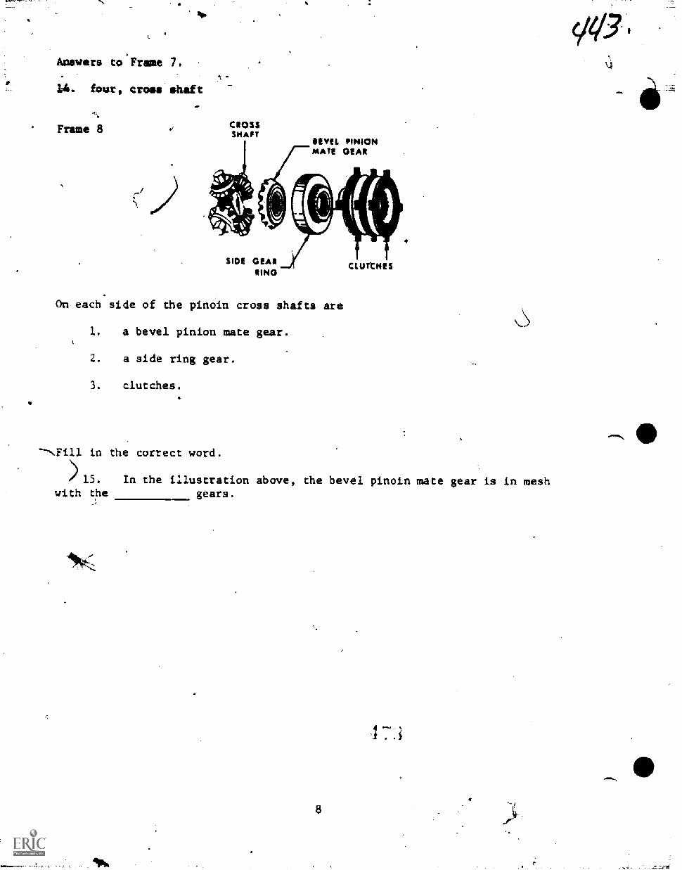
1 I II 1
VI/3Answers to'Frame 7.
14. four, cross ehaf
Frame 8 CROSSSHAFT
SEVEL PINIONMATE GEAR
SIOE GEARMN()
On each side of the pinoin cross shafts are
1. a bevel pinion mate gear.
2. a side ring gear.
3. clutches.
CLUTCHES
4
ft
in the correct word.
)15. In the illustration above, the bevel pinoin mate gear is in meshwith the gears.
8
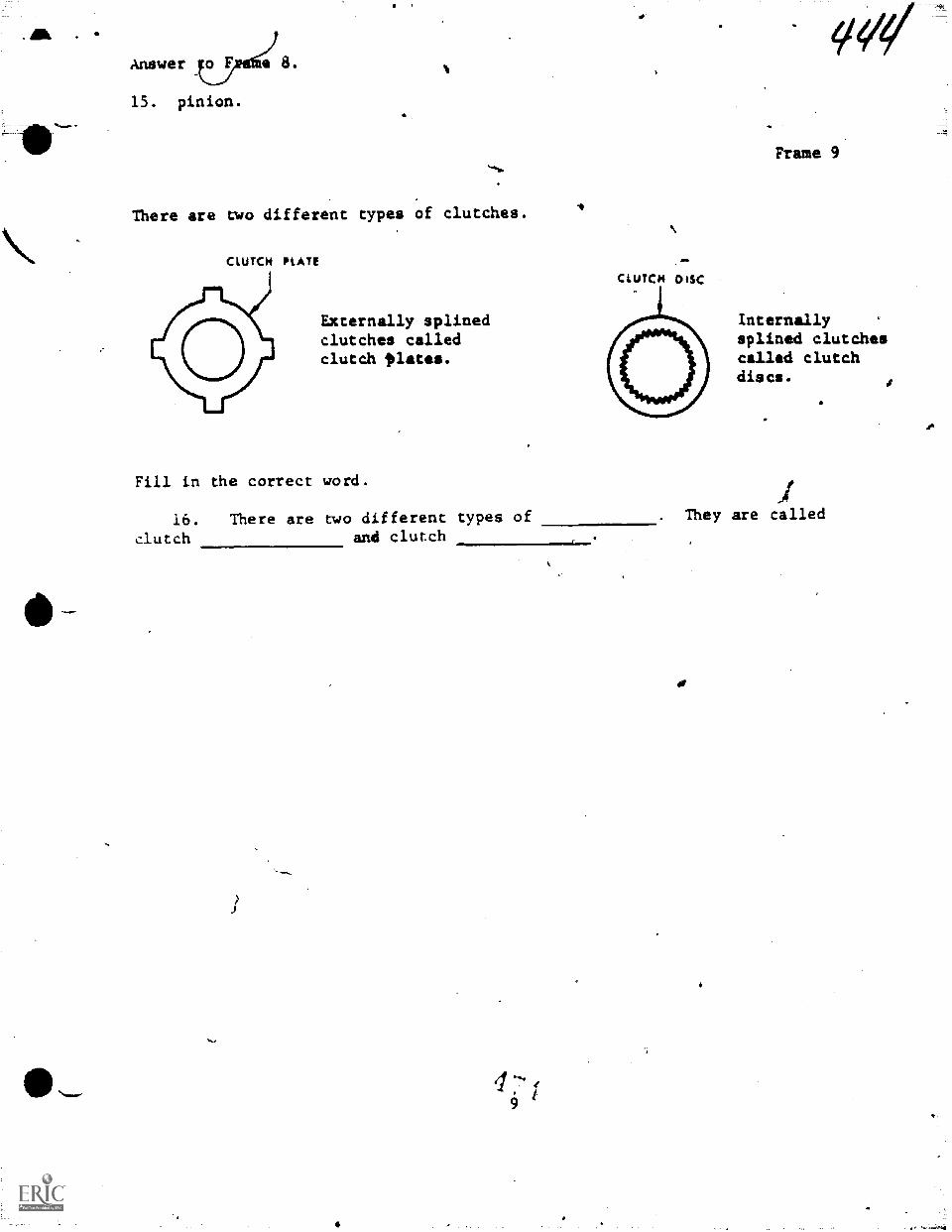
O
a
Answer
15. pinion.
There are two different types of clutches.
CLUTCH PLATE
Externally splinedclutches calledclutch *plates.
Fill in the correct word.
16. There are two different types ofclutch and clutch
CLUTCH DISC
vW
Frame 9
Internallysplined clutchescalled clutchdiscs.
. They are called
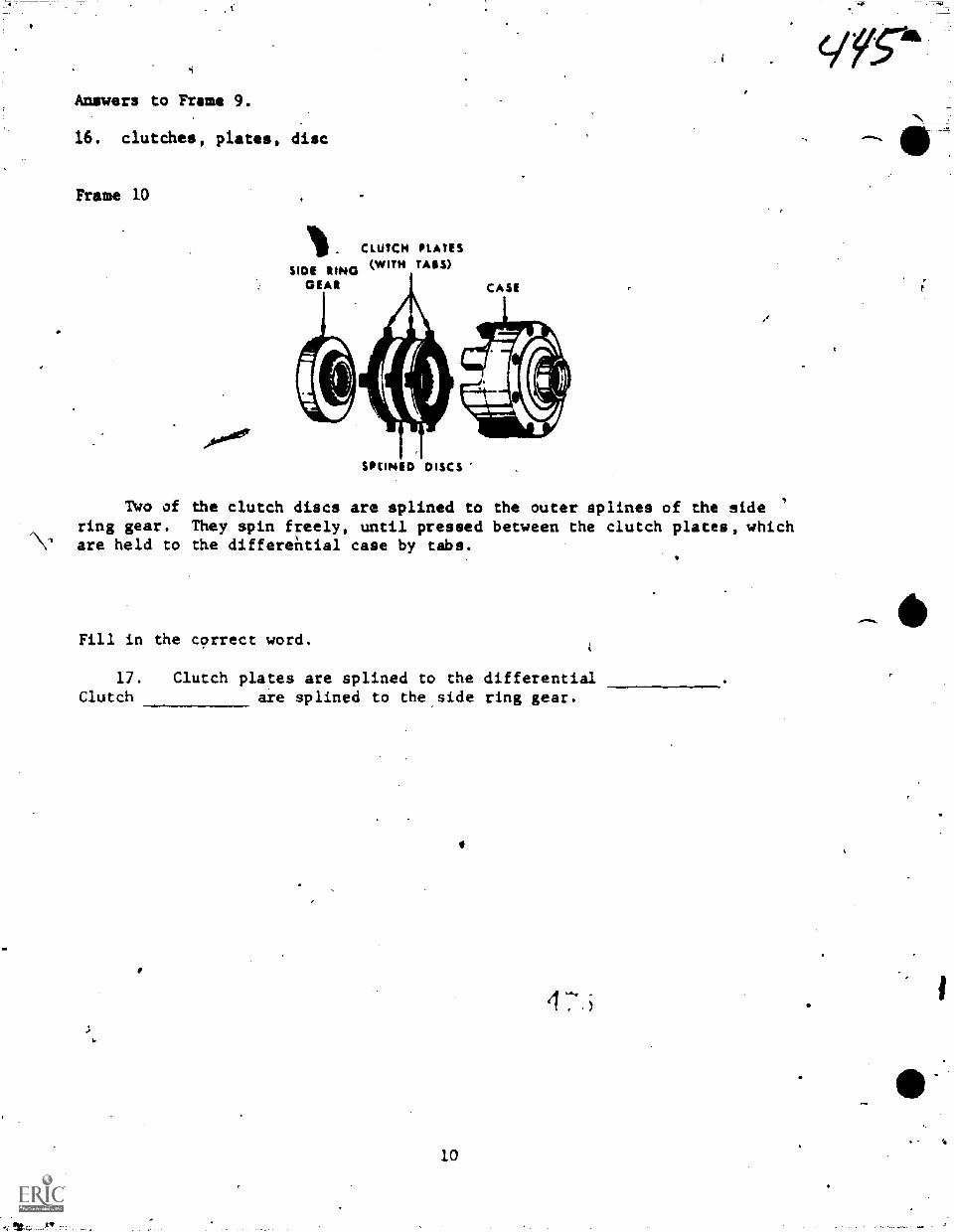
Answers to Fume 9.
16, clutches, plates, disc
Frame 10
CLUTCH PLATES(WITH TAGS)SIDE RIND
DEAN CASE
SPCINED DISCS
Two of the clutch discs are splined to the outer splines of the side '
ring gear. They spin freely, until pressed between the clutch plates, whichare held to the differential case by tabs.
Fill in the correct word.
17. Clutch plates are splined to the differentialClutch are splined to the.side ring gear.
10
VS-"A
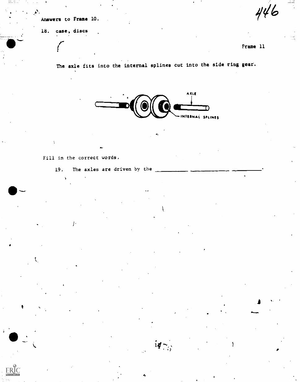
Answers to Frame 10.
18. case, discs
14Frame 11
The axle fits into the internal splines cut into the side ring gear.
4
AXLE
Fill in the correct words.
19. The axles are driven by the
INTERNAi SPLIN(S
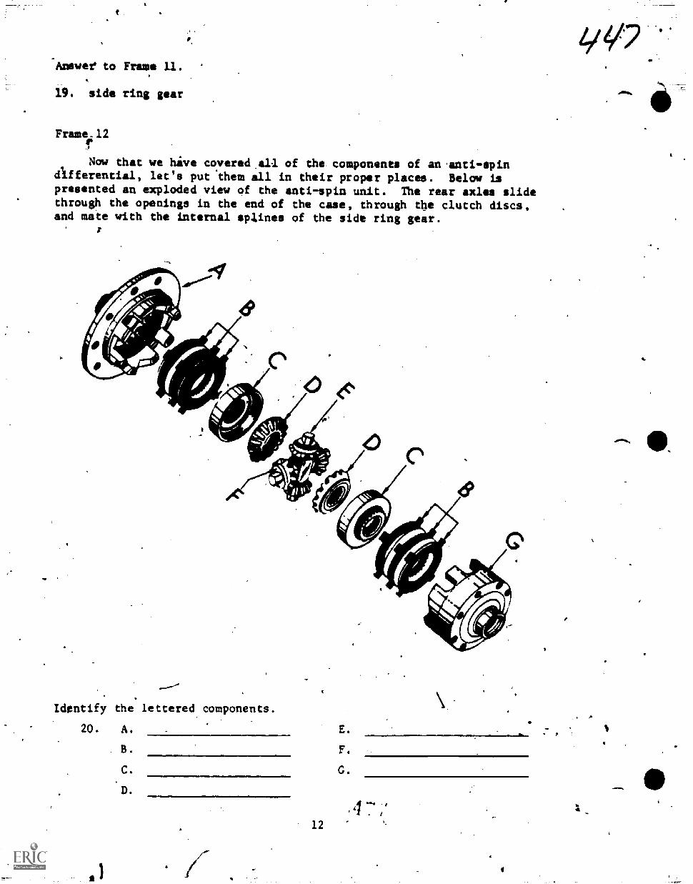
Anewef to Frame 11.
19. side ring gear
Frwne.12
Now that we hive covered.all of the components of an 'anti-spindifferential, let's put 'them all in their proper places. Below ispresented an exploded view of the anti-spin unit. The rear axles slidethrough the openings in the end of the case, through the clutch discs,and mate with the internal splines of the side ring gear.
Identify the lettered components.
20. A.
B.
C.
D.
=mlymmill1.0..
12
E.
F.
G.
a- p
1,a/7
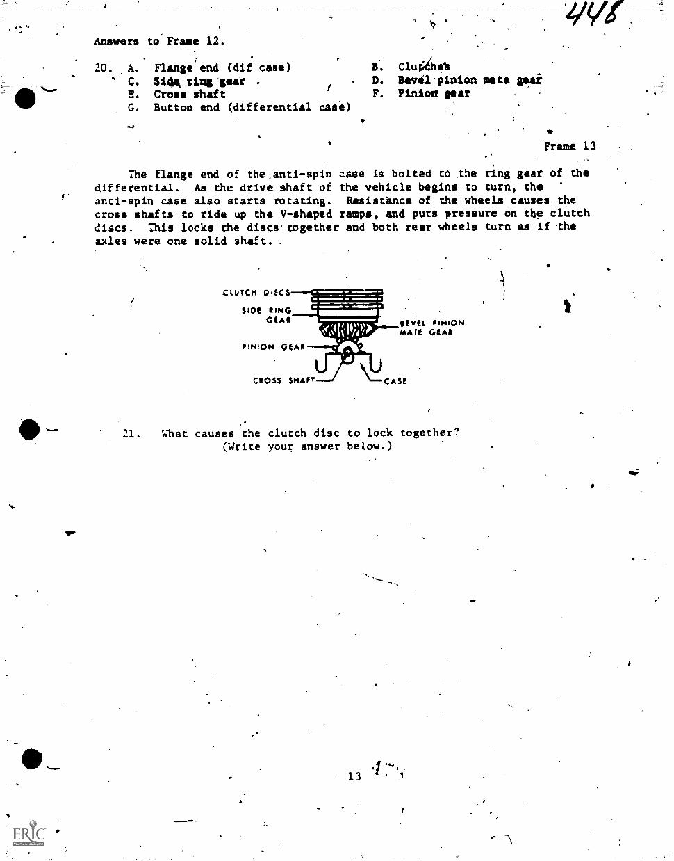
.:''Answers to' Frame 12.
20. A. Flange end (dif case) B. Cluahe%' C. Side. ring gear -
i. D. Bevil pinion mats teai
2. Cross shaft F. Pinion' tear
G. Button end (differential ease)
Frame 13 ,
The flange end of the,anti-spin case is bolted to the ring gear of thedifferential. As the drive shaft of the vehicle begins to turn, theanti-spin case also starts rotating. Resist'ance of the wheels causes thecross shafts to ride up the V-shaped ramps, and puts pressure on the clutchdiscs. This locks the discs.together and both rear wheels turn as if.theaxles were one solid shaft.
CLUTCH DISCS
SIDE ;ImoCeske
PINION GEAR
_
Nf,[(111);))>REVEL PINIONMATE GEAR
CROSS SHAFT CASE
21. What causes the clutch disc to lock together?(Write your answer below.)
II Answer to Frame 13.
. . . .
21. 4esistanie of tha wheels causes tks.cross shafts to ride up the V-shapedramps and Squeeze the Iclutches together. .
Frame 14 411
When the vehicle is turning,'therear wheel on the outside of the turnmust travel further than the inside wheel. In order to do this, it musttravel faster. As the vehicle starts around the turn, and the outside wheelspeeds up, the torque created by this increase in speed allows the crossshaft (acting on the outside wheel) to rldesbacitdown the V-shaped ramp andrelease the pressure on the clutch discs'. 'This allows the outside wheel toride free in a turn.
SI
Fill in the correct word.
22. The anti-spin differertial must act as a conventional differentialwhen the vehicle is
.0'
qa
a
14
1
p.
ty.
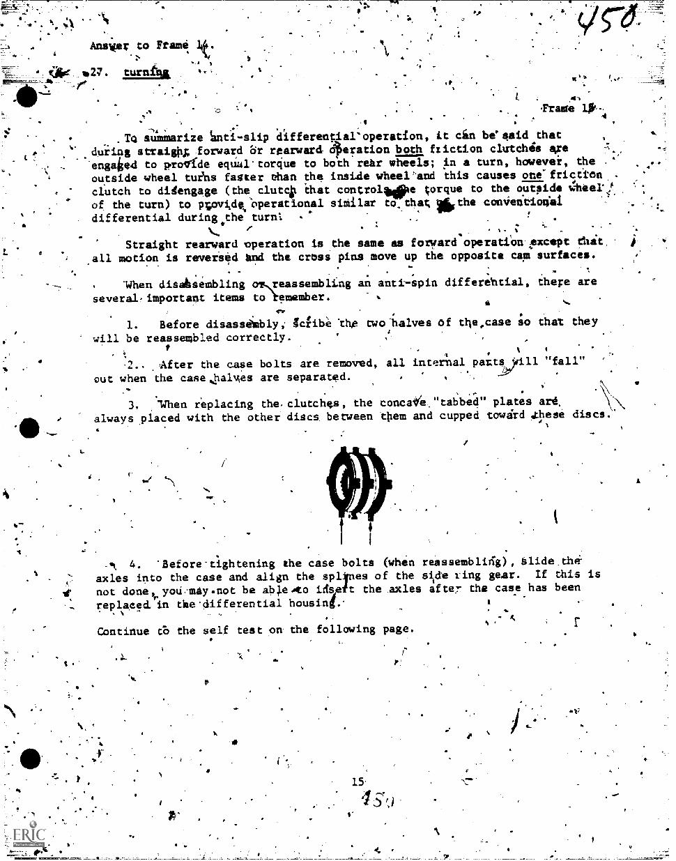
&%1-
Ansier to Frame It
,
(Are._ *27. turnihz141 .
9
4
.
iS 41
rade iv4
,To sumnarize aifferential'operation, it cin be'eaid that
during straighg forward 8r rearward 6)eration both friction clutches axe ...
engaiod to prolfde equul'torque to both rehr wheels; in a turn, howevei, the ..'
outside wheel tuins faster ehan the inside wheelhand this causes ote'frictiOn -
.clutch to disengage (the clutcit that controltopte torque to the outpide t!;heeki
.
, .
of the turn) to novisle:operational similar to.that, *the con4eneioria1,
.differential during.the turn:
,
'
:
_, ' 8
,. :.
Straight rearward operation is the same as forward operatiOn4except that
all motion is reversed Sind the cross pins move up the opposite cam surfaces.
S.
. .. .
.,
. .
. *When disahsembling olveassemblLng an antispin differehtial, there are
several.important items to emember. , .
a ....
1. Before disassimbly, Icfibe 'thg mo'halves of ttle,case so that they4
will be reassembled correctly. . ,
t. t
.
1 I % 1
.2.. _After the case bolts are removed, all internal patts 9111 "fall".-'
out when the case,lialmes are separated.
3. 'When replacing the.clutchgs, the concatee,"tabbed" plates are,
always .placed with the other discs between ttlem and cupped tawdrd 'these discs.
01 'Ls\
*e.
- 4. 'Before-tightening the case bolts (when reassemblieig), Slide th14-
axles into the case and align the sp4nes of the sitde ving gear. If this is
not done yoU..may.not be able.to idspit the axles afte7 the case has been
replaeed in the'differential housinf..,Continue 65 the self test pa the following page,
*
"
Nn
S.
9
A
S.
t
.7
p.A
-Circle your amegeis to fhe following questions and/or problems.#, .
*
,1. A scribb ma-sksboui be'placed on $he case of the anti-spli -
differential prior to -,
.'
Om/
ie.
b.
C.
removal.disassembly.reassembly.
\
2. A friction clutch.disengages
a. driving in reverse. t'acFeleraking rapidly on a slick'surface.
c. orib wheel turns-fasiker than the other.
when
*f'
3. Thy purpose of the anti-Opin differential is.to
.a., . cause both *heels to turn'at the same speed when turninl..
.b. provide the most Jrque to the wheel wtth the least resistanceand differential, action,in turns.
C. Provide the most torqsug to ehe wheellofferinetV beAt tractionand differential 'action in turns. .
,
4.
4. Full torque is transmitted,to both wheels when
clutches
a.
b.
C.
both clutches are engaged.both clutches are'disengaged.either clut0 is engaged'.
When both cross pins move "up" the ramp on the cam surfaces, both
a. engage to restrict differential action.b. disengage.to allow differential action:c. engage fo allow differential action, .
6.' When one cross pin moves "up" the rampsof ehe cacit suffaces
a. one clutch engages and the other disengagis.
b. both'clutches engage to restrict differential-action.
c. both clutches d sengage to restrict differential'action.
d. both elutches isengage to allow differential action.-
Indicate whether eaeh Of th'e followirig sfatemenp,,,are, true ot false.. .
. , 7. Rearaard operation of anti-spirydffTeiSsi4els dbei hol,reoluces g
effectiveness.-z
,
---- 8. During rearward'operation, both. clutehes disengaAt6.res ict0\-differeptial action. r :/$ .
.A ,
. ,. -a .
, 9. During rearward operation, both clUtches engage to pe(strict
differential action.
7
4.
---g
0
16'
4 a. p,../
A "
r .
:N
theif
'
I.
4
V t
I.
"
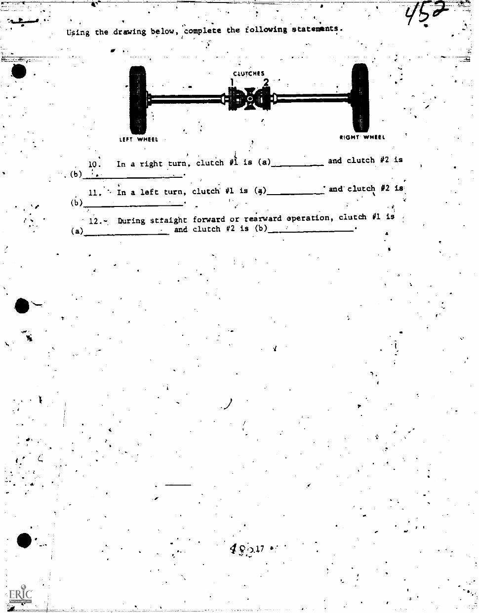
Using the drawing belaw,,complete the following statements.
't1
at-
CLUTCHES
2
LEFT WHEEL .RIGHT WHEEL
4
10. In a right turn, clutch 01 is (a) and clutch 02 is
( )
11.
,
in a left turn, clutch 01 is (4) . and'clutch #2 is'
(b) .-,
(a)
12.-,
.
During sttaight forward or rearward operation, clutch 01 is
and clutch 02 is (b)
4 9,3.17I
al
4
Answers to self test.
1
1:
2.. .0
3. C
4.
5. 'A
6. A
7. True
8. False
9.. False
10.(a) Disengaged
10.(b) Engagid
il.(a) Engaged
11.(b) Disengaged
12.(a) Engaged
12.(b) Engiged
a
ts
s-
-
4
4 Si
18
.,
4r.or
se.
v
4
S.
4. 4
Tichnical Trainingr
`0,.
4s.
sr
General Purpose Vehicle RepairmanSpecial Vehible Repairman
(Towing and Servicing.Vehicles)- (Crash/Fire Vehicles)
(Refueling Vehictek):Adatiterials Handling Vehicles)
% k .
AUTOMATIC TRANSMISSIONS
.00.>A.
ii March 1974
1
CHANUTE TECHNICAL
4r:".*
NIN6.-CENTER (411C0)\
This clperiedes 3ABR47330-PT-505r.22 February 1971 .
CPR: !VS01.DISTRIBUTION: X 7
TWS 500; TTOC, 6
.
sr,
ired Opt ATC Copra User
4 S
SI
""-
r
:or
1/4
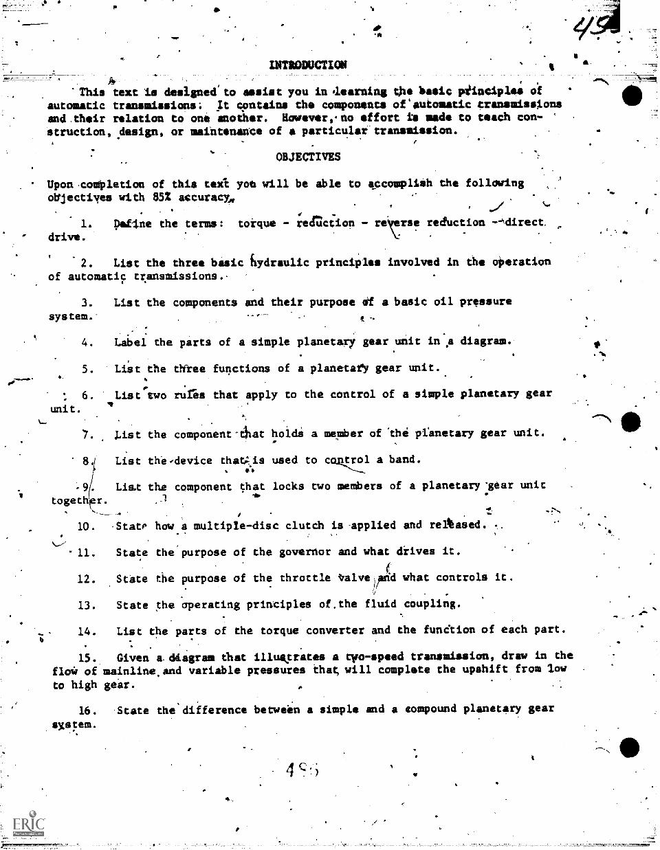
'MP
Ci
a.
INTRODUCTIM
.4 . .
.
'This text Is designed'to assist you in aoarning the basic piinciplos ofautomatic transmissions; It contains the components of'automatic transmissionsamd.their relation to ono another. Howavereno effort to made to teach con-struction, design, or maintenance of a particular transmission.
OBJECTIVES
Upon .coMpletion of this teXi you will be able to accompliih the followingoblectiyes with 852 accuracy,
1. !Wine the terms:drive.
or..
torque - redction - rer_rse reduction --44irect
2. List the three basic hydraulic principles involved in the alteration
of automatic transmissions..
3. List the components and their purpose elf a basic oil pressure
system.-'
4. Label the parts of a simple planetary gear unit in's diagram.
5. Liat the three functions of a planetarY gear unit.
6.
unit.
List two rures that apply to the control of a simple planetary gear
7. list the
8.1 List th.e
-9/ List thetogethrr.
10. StatP
11. State
component-4:at
-device thatAis.".
component that
hoidi a member of .the pranetary gear unit.
used to con..t7.1 a band.
locks two members of a planetary'gear unit
how a multip/e-disc clutch is-applied and reikased.
the'purpose of the governor and what drives it.
12. .State the purpose of the throttle tra1velprid what controls it.
13. State the 'operating principles of.the fluid coupling.
14. List the parts of the torque converter and the funCtion of each part.
15.
flo4 ofto high
Given a.dtagram that illustrates a tyo-speed transmission, draw in the
mainline,and variable pressures that will complete the upshift from low
gear.
16. State the difference between a simple and a compound planetary gear
sxstem.
4 c.
`14
."\
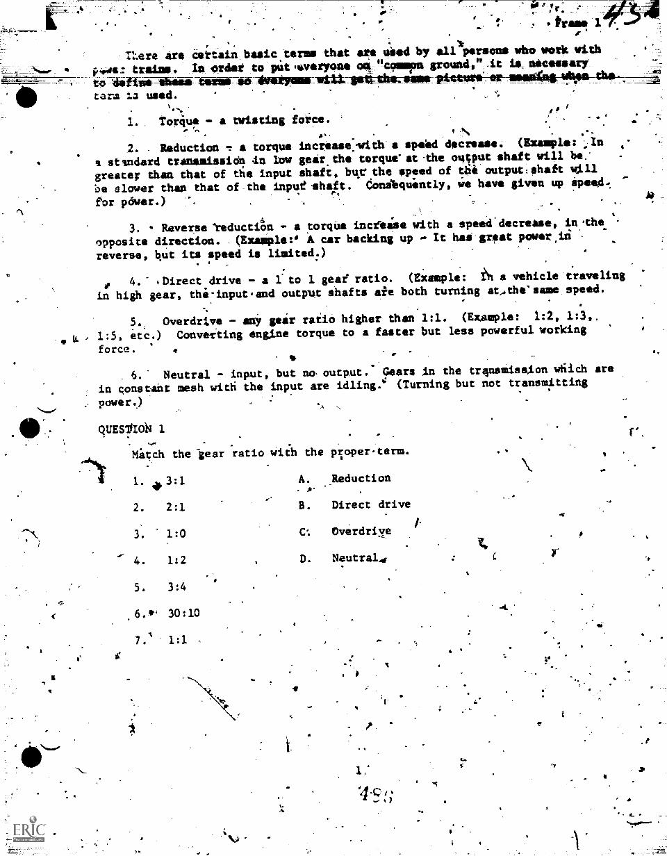
?-%
Oil r, - -
tram 3.
Mere are certain basic terms that are uied by all persons who work with
trains. In order to pit woirpone cmv"49mmima ground," .it is_ necessary.to Airtime tmeit 4M, iiiiMMOIMMIld41-104AAMLAHMit 1010011*-ar-2140611-4119P6-0411-% -=etara ia used.
1. Toriu, - a twisting force.is" e.'
2. -Reduction T a torque increase:with a spekd decrease. (Example: ...In
a standard tranamission tn byw geir.the terque"at-the output shaft will be:
greater than that of die input shaft, bur the speed of 6i-output:shaft w111
be slower than that of the input shaft. donikquintly, we have given up 111).0.
for power.)
I
4
3. Reverse teductiOn - a torque increise with a speed'decrease, in.the
opposite direction. (Example:' A ear backing up - It has great powersiri
reverse, kut its speed is limited:)
0 4." =Direct drive - a lto 1 geae ratio. (Example: ih a vehicle traveling
in high gear, the:input.and outgut shafts aie both turning at.the'same speed.
5., Overdrive - ani gear ratio higher than 1:1. (Example: 1:2, 1:3,
1:5, etc.) Conveiting engine torque to a faster but less powerful working
force. .
6.- Neutral - input, but no-output. Gears in the trirsmission wfiich are
in constant mesh witti the input are id1ing.4 (Turning but not transmitting
. power.)
quEs11lot4 1
-4Nif
".
Mitch the -gear ratio wiih the proper-term.
1. 3:1 A. Reduction
2. 2:1 B. Direct drive
3. 1:0 Cd. Overdriye
4. 1:2
5. 3:4
.6.** 30:10
7.1 1:1
D. Neutral4
4
ft
4.
1
I
Lb.
OE
4
r .
.r
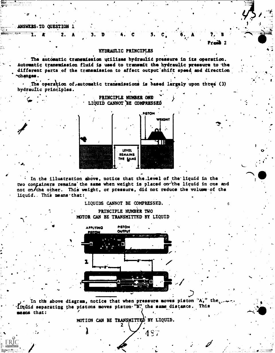
ff
a
. .
ANSWERS-TO QUESTION 1
1. AV 2. A
I.
HYDRAULIC PRINCIPLES
Frei& 2 .
The automatic transmission utilises hydraujid pressure in its operation.. Automatic transmission fluid ie used to transmit the hydraulAc pressure to the
different parts of the transmission to affect output'shift speed and direction. , .
ftchanges. t.,The operaNion offautosatic tranisissions is based largely upon thrti (3)
.-
hydrautic principles...
.
. -1.-
PRINCIPLE NUMBER ONE }
LIi/UID CANNOT 73E COMPRESSE6
,
LEVILRIMAINSMI WW1
,PISTON
YMIONT
La
,,
4 ;
In.the illustration. above, notice that the,level of thelliquid in thetwo conFainers remaina'the same when weight is placed on)the liquid in one andnot on/the other. Thii- !eight, or pressure, did not reduce the volume.of theliquid.. Thii means-that:.
LIQUIDS CANNOT BE COMPRESSED. 4,
17"
4.1
PRINCIPLE NUMBER TWOMOTOR CAN BE TRANSMITTED NY Lump
APPLYING PISTONOUTPUT
41411*
.0 in tht above diagram, notice that when pressure moves piston 'A.," the
'Tigilid separating ;he pistons moves piston."Br.the ame distance. This ,
means that:
MOTION CAN BE TRANS TT BY LIQUID.2
s:;
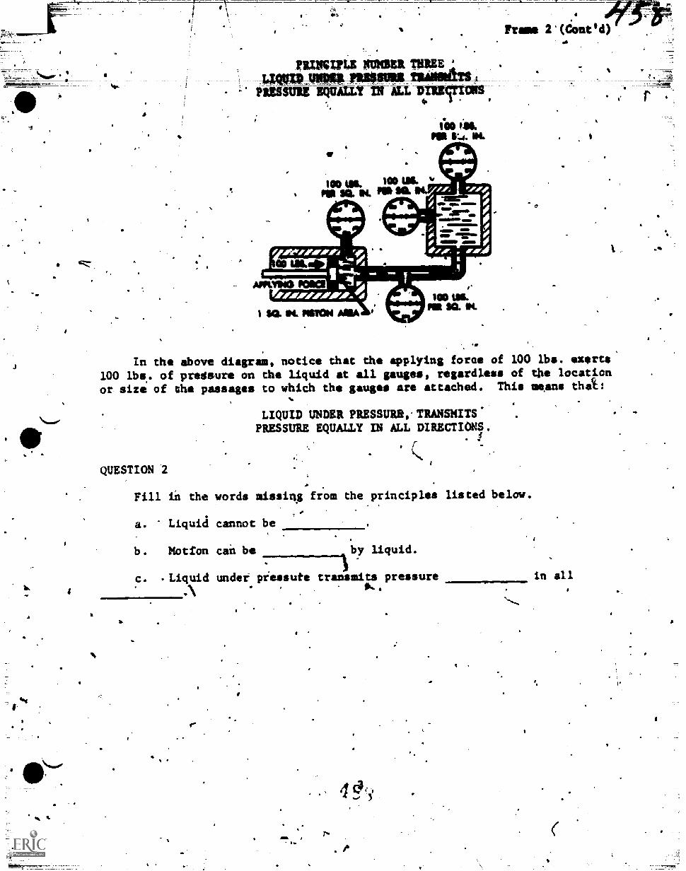
111.1MPLE NUMBER THREE-1,014=WAIPPUMPS MUM` IN ALL
Frame 2'(Cont d)
l'aor..4. Ol.
In the above diagram, notice that the applying force of 100 lbs. exerts100 lbs.. of predsure on ehe liquid at all gauges, regardless of the location
or size of the passages to which the gauges are attached. This means thai:
LIQUID UNDER PRESSUR84TRANSMITS.PRESSURE EQUALLY IN ALL DIRECTIONS.
QUESTION
Fill ih the words missing fr.= the principles listed below.
a. Liquid cannot be
b. Motion cah be %by liquid.
c. .Liquid undef piessute transmits pressure in all,
r-
S
7*.
e
.4
AMAMI TO QUESTION 2:
a. 420:416d4
b. ttensmitted
C.% equally in.all directipms
name 3
From previous learning experiences you found that the puepose of anytradthission was to provide different gear ratios end a revereing4capabilitythrough the use:of different geararrangemsdtt. As you kw*, a standard'transmission requires manual shifting of the gears to provide.the differentforward speeds and reverse capability. In the Automatic transmission, thegears ail never shifted, and yet the automatic transmission will ilovide these'same things.. This is accomplished thrOOgh the use of .a gear unit that isgreatly different tam the gears used in standaid transmissions and the mannerin whiCh the gear unit Cs controlled.
. This next part of the lbsson will explain the gear unit, its controls,and how it-transmits tqrciue from,the drive unit to the rear wheels.
The gears of.the scandard transiassion, as yoVicram Chem from past learningexperiences, cannot be used in the automatic transmit/lion. All automatictransmieslons must utilize &sear uait which is capable of providing forwardspeeds as well as a reverse feature without the shifting ,of gears. The type'of gear unit used is called a planetartam unit.
I.
S
a
NO RESPONSE REQUIRED
4
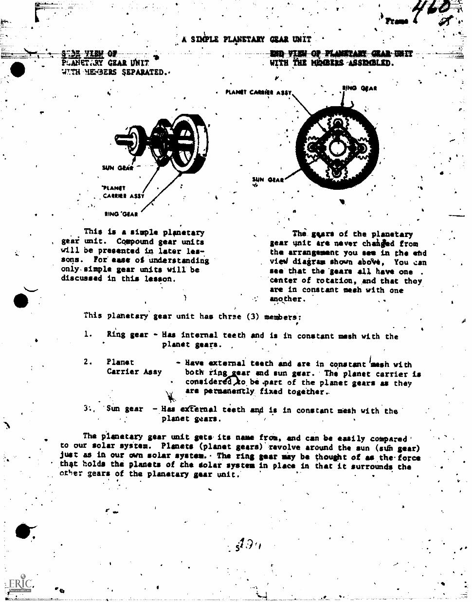
4
PLANETilY GEAR OUT 9.-nrcans SEPARATED.
sum Gila
'PLANETCARSISI ASSY
,
SING 'WAR
A S
This is a simple planetary.
gear unit. Cqmpound gear unitswill be presented in later les-.sons. For sass of understandingonly-simple gear units will bediscussed in this lesson.
PLANET/XI CZAR UN/T '
.11114-111111-0!
. WLTh :ha mote ..ASSDIBLIED.
M.
MAW ASSY
SUN 44A4o/
MSG IWO.1
.
v.
a
The gyms of the planetarygear gait are never chaheed fromthe arrangement you see in the whdviei diairas shown abdimt, You cansee that the'sears all have one .
center of rotation, and that theyare in constant mesh with oneanother.
This planetary' gear unit has thrse (3) members:
1. Ring gear - Has internal teeth and is ih constant mesh with theplanet gears.
2. PlanetCarrier Assy
- Have external teeth and are in constant mesh withboth iing_gpar and sun gear. The planet carrier isconsideraoto. be .part of the planet gears as theyare permanently fixed together,
'Sun gear -.Has egiernal teeth ang is in constant mesh with the"planet gears.
The planetary gear unit getwits name froi, and can be easily compared'to our solar syitem. Planets (planet gears) revolve around the sun (urn gear)just as in our own solar system.- The ring gear lay be thought of as.the-forceth4t holds the planets of the solar system in place in Chat it surrounds theotiler gears of the planetary gear unit.
el
' e
.
-
'
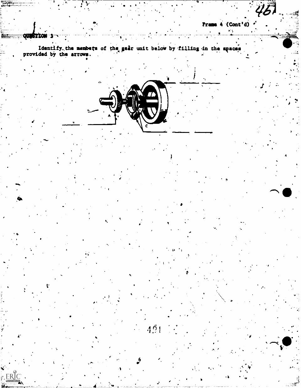
4
0
I
Ideatify,the sashimi of thIcseir unit belois by fiUing in th.e sioacepprovided bir the arrows.
.4
4"
. 414.12
.e
A
I.
i
A
0
=1.M1m1M
461
WI
a
4
0
4
dig
4
AWSWARS,TC WEST;OU 3 .
floiGaar B., Liiyi Giar C Planet Cairier Assy%
1. It was sta.ted prylviously Chat the planetary sear unit is capable Of pro-
., Vidink foiwardspeeds and reverse just as the different 'gear arrangements ofzhe standard qansuission will provide. Before going'intc,how.thdi is accam-plished, let's And out just what the-plaAktary gear unit will do.
The planetary gear unit when propeily controlled will produce
4
1. GEAR REDUCTION. - low or second geur same alp in a standard transmission.
4..4 :* 2, REVERSE kEDUCTION reverse gear same as 1.n a standard transmiision.
I.
.3 DIRECT DRIVE - high-gear pane as in a standard transmission.
There are die two rules which apply to the control of the planetary gearuni t
1. Anytimq we,Apply power to one member, hold one member, and takepower from the third member, the geak unit will produce a gear reduction and/orh reverse of direction.
2. Anytimi we lock two members together the gear unit will produCedirect), drive.
QUESTION 4
Fill in the blank spaces with the ,correct terms.
a. To obtain gear reduction and/or reVerse from a planetary gear*unit,
it is necessary to . to one Member, one_
member, and froia the third.
A
b. To obtain direct drive from a planetary gear unit', it is necessary
to members
4. Q
.4
S.
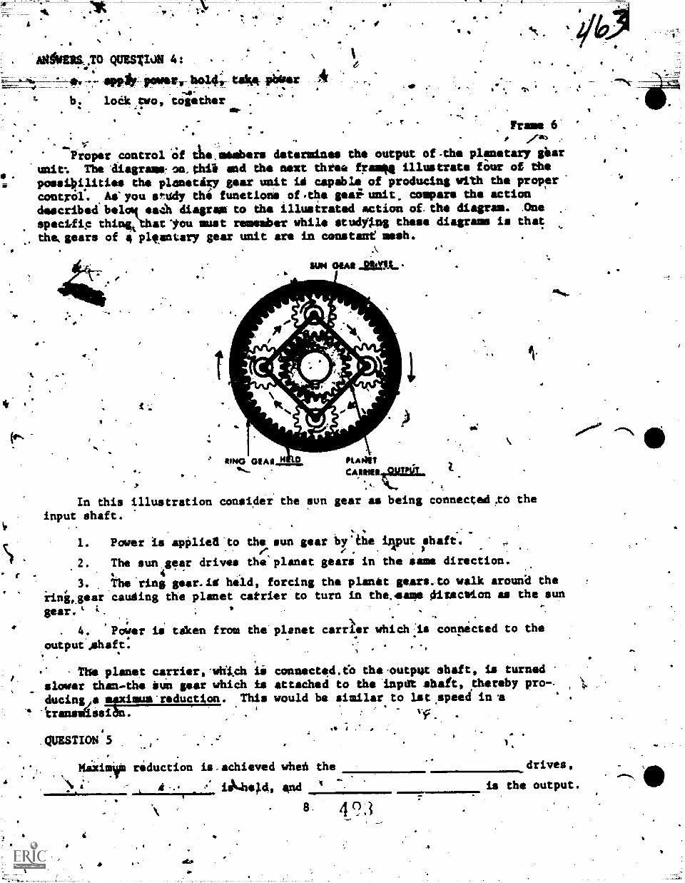
AHMILS,TO QUESZION 4:
*. *Pp* Powers 11014; WA- Patsr
b. lodk two, together
r_
Frame 6'. I
1
Proper control 'Of thessembors determines the output of-the planetary gear
'unit: The Aiagrams:on.thib and the next three fra u'''. illustrate faur of the* .* possi4ilities the pinnetiFy gear unit id capable of producing with the proper
control% .As'you sr.udy the function* of.the gealtunit. compare the actiondescribed Waal sa.-1 diagram to the illustrated action of the diagram. .0ne
specifie thinOhatIou must remember while studying these diagram, is that
the,gears of a pleantary gear unit are in constant mesh.. .\
t-
SUN MAI Jaen_
I.Nlilliammi4".=
RING WAN HMVcAlain .9PMIT
a;
In this illustration consider the sun gear as being connected,tO the
input shaft..
1. Power is apOlied'to the sun gear by.the input shaft.4
.2. The sun gear drives the planet gears in the same direction.. 4
3. The ring gear.id held, forcing the planet gears.to walk arouna theiing,gear cauding the planet catritr to turn in the.,4ame Oitectrion as the sun
gear.
4. Poyer is taken from the planet carrier which:.is connected to the
outpue.shaft.
s' The planet carrier,*which Lislower than..the tun gear which isducingie ms:imue-reduction. This
' Aransmassi .
QUESTION 5
connected.6 the.output shaft, is turnedattached to the impat shaft, thereby pro-.would be similar to 1st ,speetf in a
Vf.
,
Maxi* reduction is-achieved wheh the .drives,
....._LAL isli4he14, and ' is the output.7 .
.0
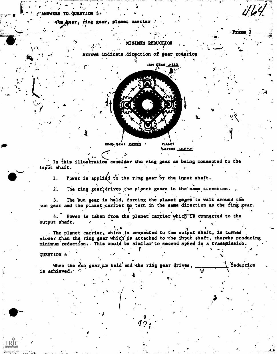
a
PPP'
e
S.
.* t e-ANSWEIS TO-QUESTION-5-
S.
1:2.*
;I
r
r.
4 '
41.1n14ear, iing gear, planet carrier 7
1 .\
411.
VOL
8
, A MININUM REDU9ION
Arrowg indicate.ditection of gear Totetio9, .;
i.. --%
In 6is illustration consider the ring gear as being connected to theInv* shaft. .4. .
.
.. -
1. f!ower is-appli d tO the ring gear ly the imput shaft..4
2-. The ring gearldrives ,the planet gears in the:same direction.
3. The buil gear is held, forcing the planet-gep;'to walk around die. . .
sun gear and the.planet:cariier rturn in the same direction 0 the fing gear.,.
- .
4. ftwer is taken from the planet carrier yhicrri connected to the
output shaft. 0 .
..,
.0 ..
1
;4. v..
The planet cariisr, Which.ps compeCted to the output shaft, is turnedslower%Oan the ring gear which'48 attached to the ihput shaft, thereby producingminimum reductIonk."Tbis would be similar-to second speed in a transmission:,
.t
aiMa.
:i0P4 Iw ' 4
as.
IIUNt;k OEN! DIME§ PLANITc
*tGAIIIIIER OUTPUT
f
tft. *01.M#
Tram, ;
0
a
fQUESTION 6.
When the tuo gearjs heldtand-the riig gear drives,ris achieved.' '
4^".;
4
9
:14
'Vfeduction
SI
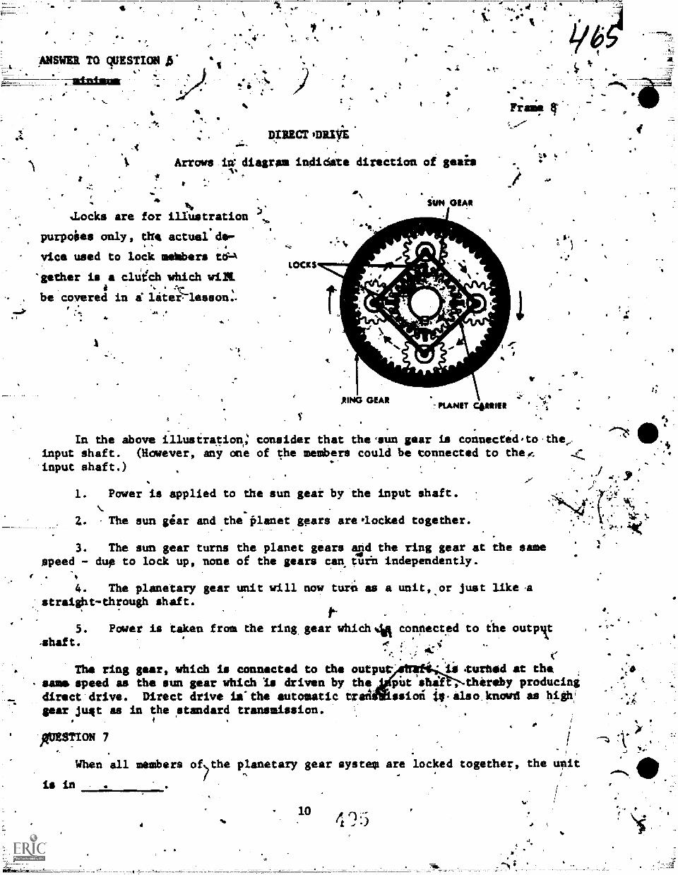
ANSWER TO QUESTIONA.
-4P4'
4 to
.
*11'
'
744 4
.P4 .1 It " or
:
puma at*:
Arrows ire diagram indidete direction of geais
1.
a
%Locks are for illustration
purpoies only, the actual de-.
vice used to lock metibers ti-A
"zither is a clach which wi2t
be covered in a' liter. lesson..
LOCKS
VI)
o
-PLANET Com
In the Above illustration,: consider that the.sun gear is connectedato,the,input shaft. (However, any one of the members could be connected to theieinput shaft.)
-/ ,.":...,
1. Power is applied to the sun gear by the input shaft..
2. The sun giar and the Olanet gears are.locked together.
3. The sun gear turns the planet gears Igd the ring gear at the samespeed - dup to lock up, none of the gears can turh independently.
f
4. The planetary gear unit will now turil as a unit,,or just like A,
straiOht-through shaft.. .
5. Power is taken from the ring, gear whiCh4R connected to ale outp1.1.
, ,, --
4thaft. Ac : i ..
.47'
...-
(.". .
,.
The ring gear, which is connected to the output' ii tufted at the .,40
same speed as the sun gear whiCh Is driven by the pilt shelf thereby producing ..
direct'drive. Direct drive is"the automatic matt ssioti ilt.also.knowd as high/
gear jusit as in the standard transmission.-.
, ,, i
I.
QUESTION 7.
When all members o5the planetary gear system are locked together, the wtit
is in
104.
,..
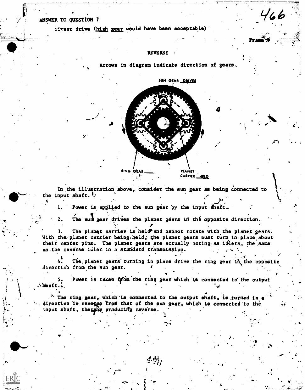
ANSWER TC QUESTION 7
oireat drive (high BEE would have been acceptable)
11;
e."
REVERSE
Arrows in diagram indicate direction of gears.
V
SUN CitAlt pivai
.0
AkA/1
11P40 WAS!
I S.
PLANET'
_KM
4
Frales-.4
Imthe illustration above; consider the sun gear as being Connected tothe input-shaft.I»
I.
1. Powet is ap011ed to the sun gear by the input afi'.. :
= 2. The sul gear.drives the planet gears id th6 opposite direction.
. .
3. The planet carrier ii heldPand cannot rotate with the planet sears.With the 'planet catrier beingrheld; 4he planet gears must tit= in place.aboultheir center pins. The planet gears are actually acting,as idkers, the,sameas.the reverse itilet in a stsddard transmission. _ . . i
. ,..
,,-. .
iI e
4. The,planet gears-turning in place drive the ring gear ih the oppositedirection from.the sun gear. t
.
%,
...
.. ._
Power is taken filfam 'the ring gear which is connected td the output.
,
. c
P' The ring gear, which'is connected, to the output shaft, is ,turned in a.
-direction in revew froth that of the sun gear, which is connected 'to the ,..
input shaft, therfbx produciag reveise.,
-,. :,...0.
. - ..
I
I.
-
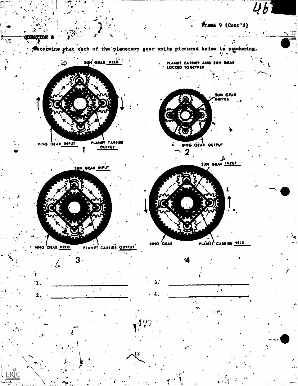
-1 .1: .--t- eN 8
, 'a C
.P
4
41-
Mihteistme "hat each of the *planetary gear unite _pictured below is peucing., .
.
, :
. peA1 HILO
reftI
'RING GEAR INPUT
*
%. *MG GEAR Nelb
PLANO* fAlltlf*
1OUTPUT
\\SUN 01A1 INPUT
AIL
11.
am.
PLANET CAINIIEI' OUTPUT
at
PLANET CAME* AP*0' SUN SIARMCKIM TOGITNIII
C.
SUN 01,41
RING dlAl OUTPUT
2sum 01A1.2=1,...
f/ Ababx
Ilk
RING 02A* PlAWIT CAUIU MILD
4.
Ir
#1,# -
".7 p
"
IP
ANSWER TQ QbESTION 8
1. Maim= Reduction.2. Direct Drivei3. lisztomia4iduction.4. Reverse Reduction.
Frame 10
As'you know, the planetary gear unitis vastly different in constructianamt operition from the gears laid in standard transmissions. Due to thisdifferenhp, the planetary gear unit has many advantages over the gears usedin standard transmissions. These advantages are listed below with a compuritonisde to the gear arrangement of the standard transmislion. Read one advantageat a time - read the corresponding comparison - then through the use of theillustration on the next page, compare the ; Netary gear unit to the standardtransmission gear arrangement.
ADVANTAGES
Advantages of planetary gears aver standardksliding gears.
1. Constant mesh. They never have to be shifted.
2. Stronger. More tooth contact.
3. One common center of rotation. Mounted on one Shaft.
4. Control. Easy to control hydraulically.
Note: Refer to the illustration on the next page While making thosecomparisons.
r
13 t
10c)-
A
I
a
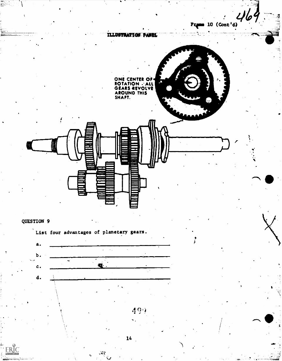
k
.
ILLUSTRATION Mtn
ONE CENTER OFROTATION - ALLGEARS IIEVOLVEAROUND THISSHAFT.
QUESTION 9
List four advantages of planetary gears.
a.
b .
C.
d.S.
14
z19'
4
SP
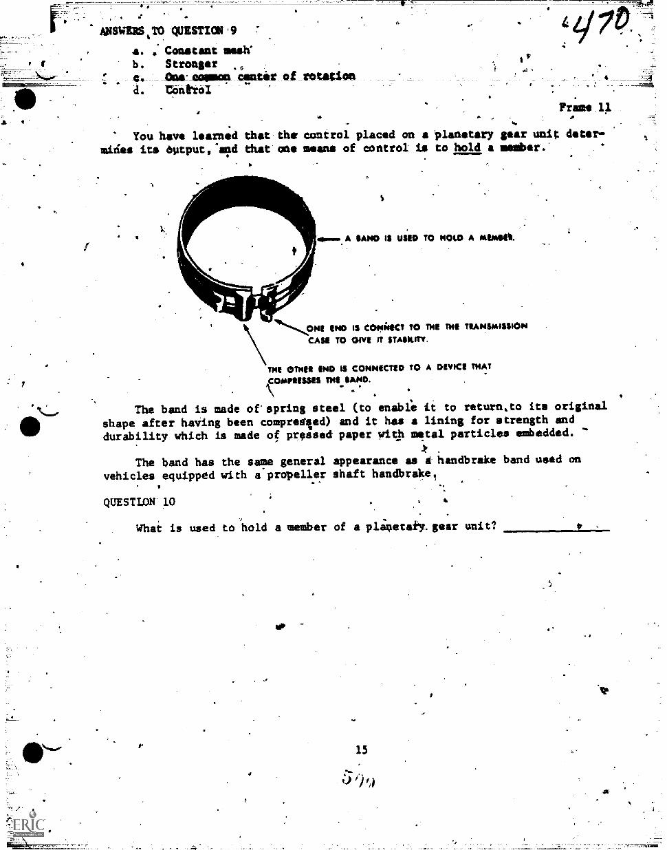
ANSWERS,TO QUESTICM '9
a. Constant mash'
b. Strongerg CUOILCOMMOR ortir of rotationd. tbniVol
.
,Frame 1.
. ,
...
You have learned that the control placed on a planetary gear unit deter,-
mirles its output:1"d that one means of control is to hold a member.
.
V. a. A SAND IS USED TO NOW A MINIIES.
1%,,,ONE END IS CON4ICT TO NE THE TRANUAISSION
CASE TO OWE TT STASkiTv.
THE OMER END IS CONNICTED TO A DEVICE THAT
4COMPRISSIS TNE SAND.
The band is made of'spring steel (to enable Li to return.to its original
shape after haVing been compregied) and it has a lining for strength and
durability which is made of pressed paper with metal particles embedded. '
The band has the same general appearance as a handbrake band used on
vehicles equipped with a propeller shaft handbrake.
QUESTLON-10 %
What is used to hold a member of a plinetail.gear unit?
,
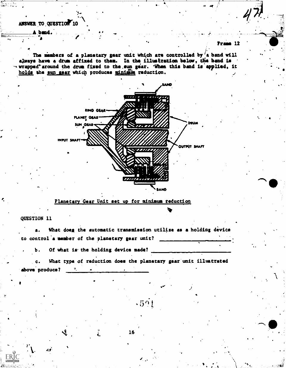
Anon ,TO .QUESTI0,10\
A band..
"tr
?rasa 12
The limbers of a planetary gear unit Whilch are controlled by a band willaXways have a drum affixed to them. In the illustration below, Oe band is
wrappeearound the drum fixed to the_sun giar. iftma this band is applied, itholds rho sun liar, whic# produces mina.= reduction.
Planetary Gear Unit set up for minimum reduction
QUESTION 11
a. What doe& the automatic transmission utilize as a holding device
to control'a member of the planetary gear unit?
b. Of what is.the holding device made?
c. What type of reduction does the planetary gear'unit illustrated
above-produce?
414
16
0"
4
4.
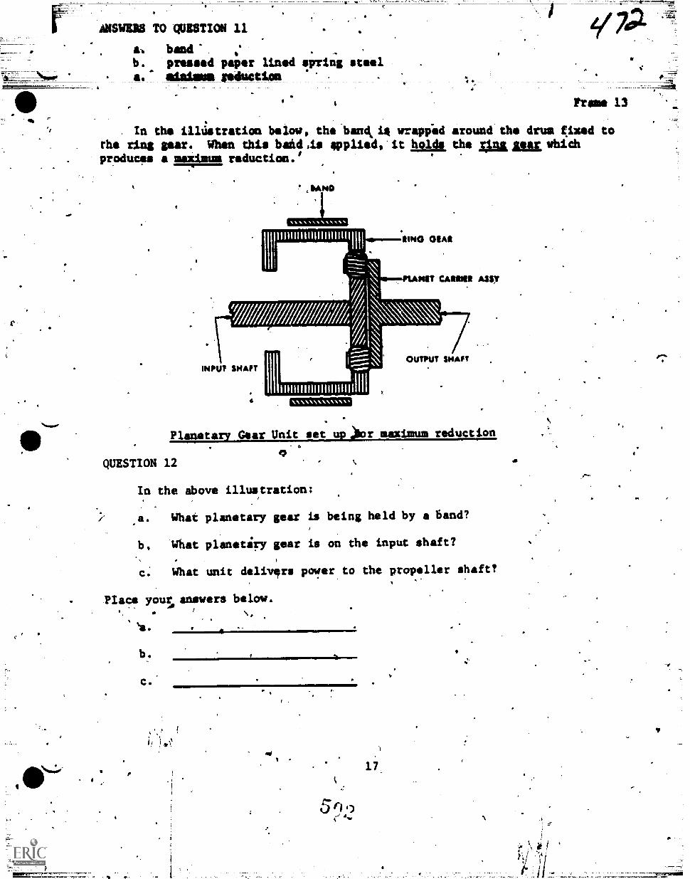
%mum,
or
rm.
ANNUS TO QUESTION 11
a-. bendb. pressed paper lined wring steela. alaiss ;eduction
=7,
Frame 13
In the illustration below, the band.is vrapiod around tho drua f.ixed torho ring gear. When this band,is applied,'it holds the slums: vhichproducss a maximum reduction.'
1
'AND
III Il I GIAR
PLANIT CARMEN Any
INPUT SHAFT
ll
/..-7.--_-___---
1
1...--:;\..
IIIIIIIIIIIIIIIIIIIIII1111
OUTPUT SHAFT
Planetary Gear Unit set up;Oor maximum reduction
QUESTION 12
In the above illustration:
.a. What planetary gear is being held by a band?
1), Wtrat planetiry gear is on the input shaft?
c. What unit delivIrs power to the propeller shaft?
Place yousanswers below.
`a.
b.
11_
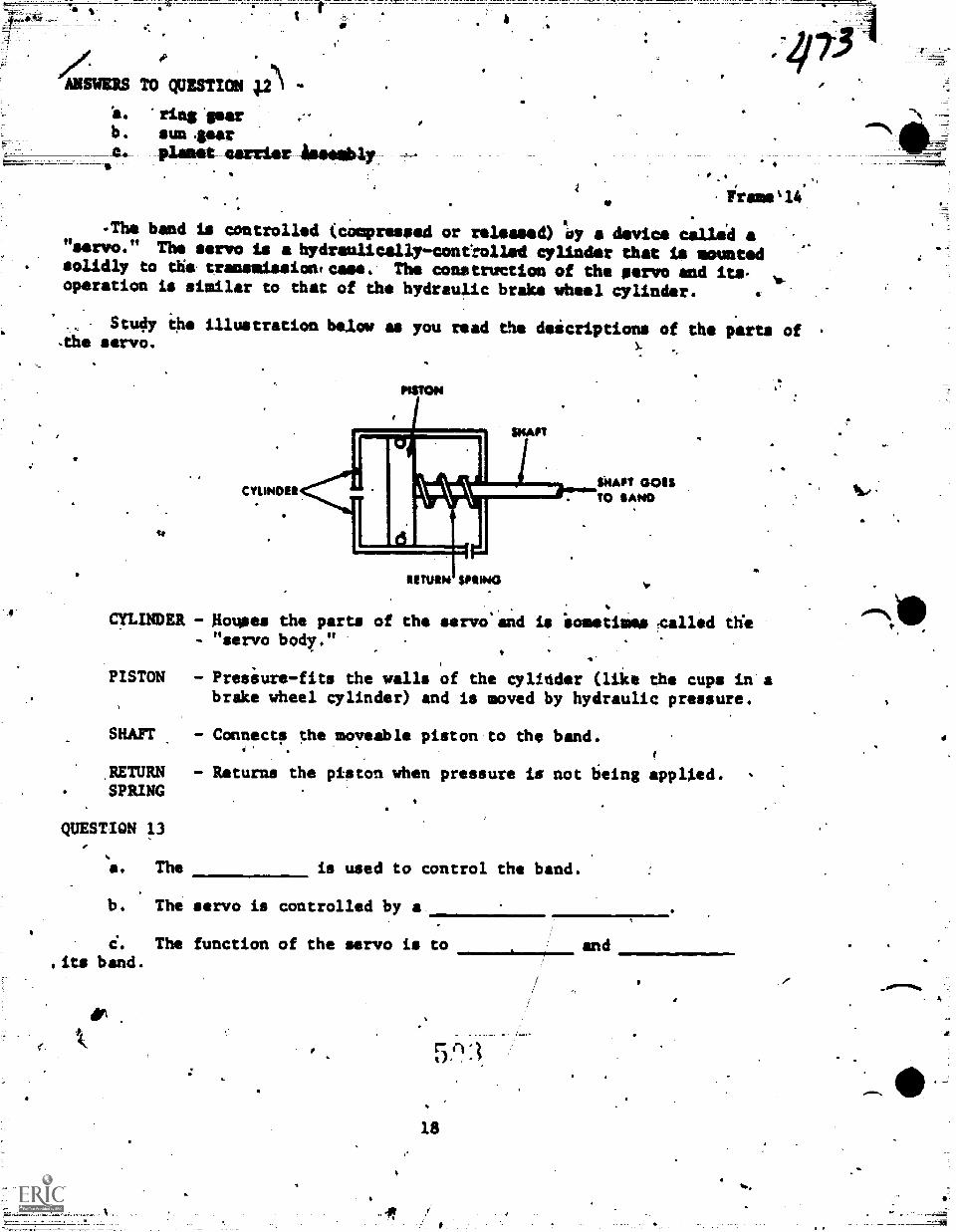
ANSWERS
a.
b.
TO QUESTION pi\
rinS 'Sear
a.
11.
un averplaint carrier issathly
irsms'14
The band is controlled (compressed or released) 'Sy a device called a"servo." The servo la a hydranlicallr-contiolled cylinder that is mountedsolidly to the transmissiontcaee. The construntion of the eery° and its,operation is similar to that of the hydraulic brake wheel cylinder. 4 4"
Study ihe illustration below as you read the doicriptions of the parts of.the servo.
CYUNDUSeAllf GOESTO SAND
CYLINDER - Rouses the parts of the servo and is iometimes leaned dieServo body ""- .
PISTON - Presiure-fits the walls of the cylicider (like the cups in abrake wheel cylinder) and is moved by hydraulic pressure.
MUT - Connects the moveable piston to the
RETURN - Returns the piston when pressure isSPRING
QUESTION 13
a. The
b.
.its band.
band.
not being applied.
is used to control the band.
The servo is controlled by a,
The function of the servo is to
5 fl
18
4
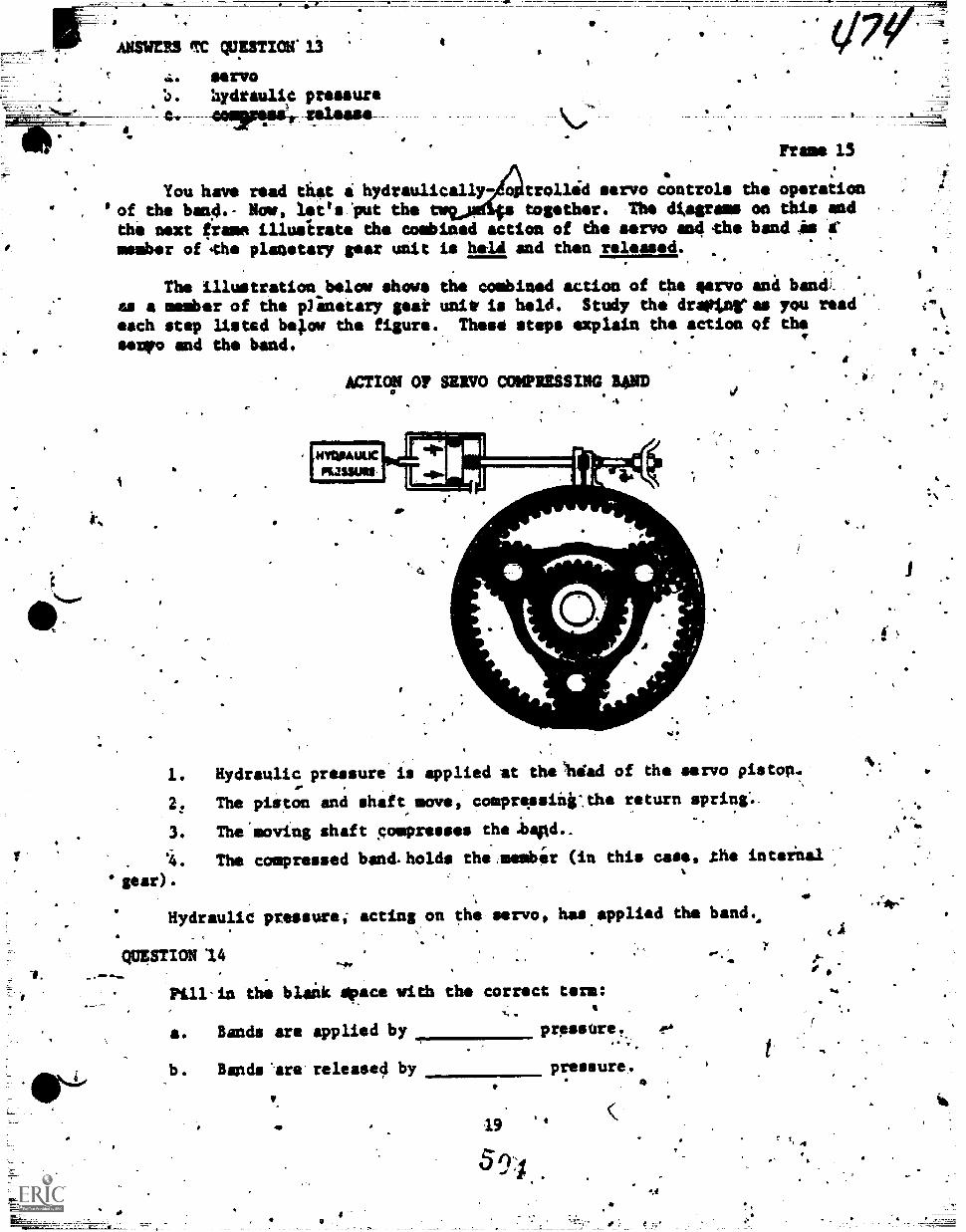
AMOS M wicrruxr 13
Ile L'VO
hydraulic pressurecowassi, release
t
Frame 15
You have read that a hydraulically trollid servo controls the operation
'of the band.- Now, let's 'put the together. The dtagroms on this andthe next grams illustrate the combined action of eh. servo and-the band is Armember of .the planetary gear unit is held and then released.
The illustration_below shows the combined action of the servoas a member of the Nattatary goat unit is held. Study the drotimreach step listed bepow the figure. These steps explain the actionservo end the band.
wimp or SERVO COMPRESSING B4ND
trfaMUUCmama
alk
.1
ana banCas you readof the
1. Hydraulic pressure is applied at the ritirad of the servo pistop.
2. The piston and shaft move, compressinicthe return spring:.
3. The moving shaft ;ompresses the.basd... .
. 4. The compressed band.holds the ,member (in this case, the inteiaal
gear).
Hydraulic pressure; acting on the servo, has.applied the band.
QUESTION 14
Pill-in thM blaik space with the correct term:,.
a. Hands are applied by prplisSre.. e.
b . Bands '-are. released by pressure.
410 19
5 94
.4%
1.4
4tr.
I.
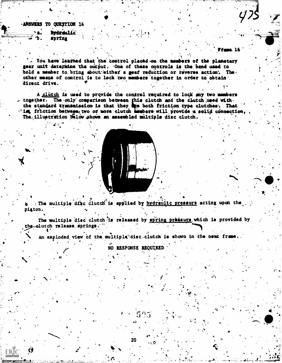
A*SWERS TO QUE4TICO 14
. spring
or .:Pfaff*. 16
,
I; Tim hay.- leained that the' coàtrol placed .on the remb-ers of the planetarygear unit deterilne the otitiut. .0nie of this* cqntrols is the fiend undid tohold a member to. bring abipitt.nithei 4 vat reduCtion or inverse action'. The-other means of control is to lock two members 'together in order to obtain .direct drive. 4' .
Aplatch is used 2o prqvide'the conUol required to loqk any two mmmbers
iremb
... together. The.only'ammparison between Ids clutdh and the clutch.AsSed Wilh- .8the standard gansaissiont is that they both friction typo clutches°. That
-'is fiiction betwepairwo or more clutch ers.will.prowidellsollA connection,The..illuatiStion lfilow oh* an assembled miltiple disc clutch
.1
. . 1I
6 A., 6.4
-Ab .The multiple diec lutcn is mined bx hydriulic pressure acting upon the
. . -
pigton. ..
4 ' %
.
*5
I.
Thetwaltiple aisi clutch is released by spring pre4sure:which is provided by,52.ye-,-clutch release.lprings_.: " ! ..1Th
-
k'. . .\ An exploded view of the:natiplediscclutch $s shown in ihe next frame...
NO RESPONSE REQURED
. -
s
0 (".1.)
4) 5
20
r.
4
I.
I.
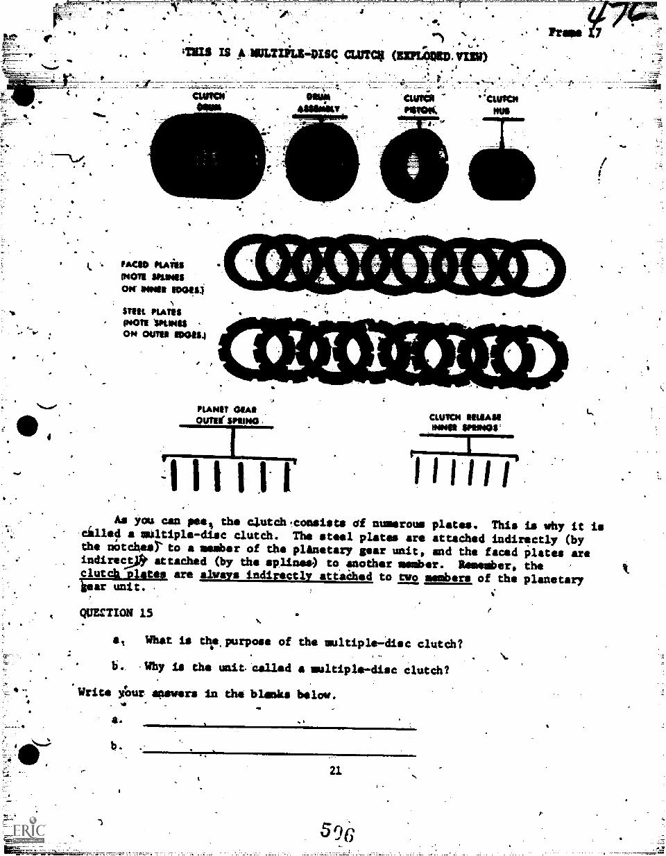
....) ..,-
IMIS LS A )ULTiOLS-DISC. mum ocaptimminimo.
. .,.
I e . r.
,w
r
44.4.
moo ruin(NOTE SPLINES
Ott Mai 11001111
STEIL PLATES(NOM 'SPLINES -
OH OUTS' MOM
4WISMO41`
or.
41.....4
PLANET MAROUTWIT SPOONS
1
_.,rw.-411111111M12.-
-monk
...- ramimm...
-.4111.-144.-_1104.
S.
CLUTCH MIAS!IWO ~OS'
Lomm%I .1 1 I
As you cap pees the clutchiconsista of numerous plates. This is why it iscilled a multiple-disc clutch. The steel plates are attached indirmctly (bythe ninches) to a member of the plAnetary gear unit, and the faced plates areindirecs* attached (by the splines) to another member. Remember, theclutch_plates are always indirectly attaihed to two members of the planetary'ear unit. ,
QUECTION 15
at What is dr, purpose of the multiple-disc clutch?
b. -Why is the unit called a multiple-disc clutch?
* Write Amr answers in the blinks below.
a.
b.. -
21
p.
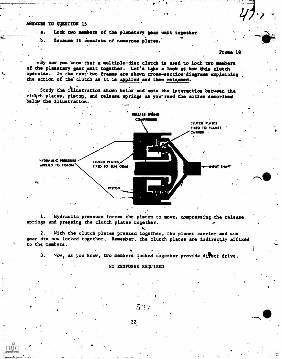
.-
ANNUS TO gpsTIom 15
. a. Lock two members of the planetary gear unit together
b. Because it iopsists of numerous plates.*
Prams 18-,
valy now you know-that a multiple-disc clutch is used to lock two members.,
of dhe planetary gear unit together. Let's tsks a look at how this clutchoperates. In.the nexttwo frames are shorn cross -section.diagrams explainingthe action of the'clutch as it is appliadand then ireleased.
L - .
, Study the illustration shown below and note the interaction between theclu ch plates, piston, and release springs you-read the action described
;ii
asbra the illustration.
HYDRA UM PRESSUREAPPLIED TO PISTON
MEAN aimCO/AMMO
CWTCH PLATES."'FIXED TO SUN OEM
CLUTCH PLATESFIXED TO PLANETCA12111
13.-INPUT SHAFT
1. Hydraulic pressure forces the pision to move, compressing the releasespTings and pressing the clutch plates together.
2. With the clutch plates pressed together, the (planet carrier and sungear are now locked together.. Remember, the clutch plates are indirectly affixedto the members,
3. Now, as you know, two members locked together provide dilNct drive.
1N*
NO RESPONSE REQUIRED
22
" 4
2D,
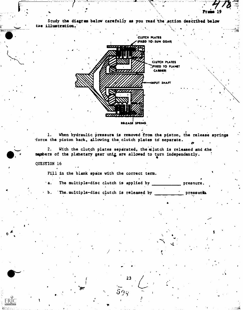
Study the diagram below carfully as you mad 'the ,action desCribed belowtae illustration.'
CWTCH MATES(NM TO =SUN GLIM
CLUTCH PLATES
.(PIXED TO PLANETCARMEN)
MIAMI SPRING,
1. When hydraulic pressure is removed .fram the piston, the release springslorce the piston back, allawing the clutch plates td separate.
2. With the clut.ch plates seParated, thesclutch is released and xhemmmbers of the planetary gear uni4. are allowed to ten independently.
QUESTION 16
Fill in the blank spice with the correct term.
'a. The multiple-disc clutch is applied by pressure.
- b. 'The.multiple-disc 4utch is released by pressurix
tAwc.
23
9.
. N
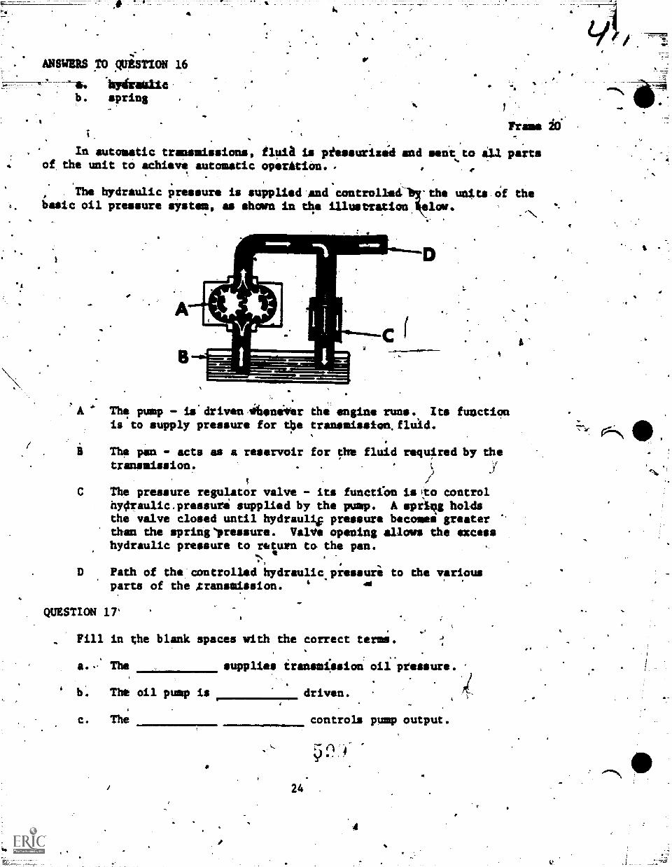
ANSWERS o puES TION 16
.140timmitatc
b. spring
Frame 10
In automatic transmissions, fluia is piessurizi4 and sent to ill partsof the unit to achieve automatic operAtion.
. .
The hydraulic pressure is supplied.and controlled' -the units.Of thebasic oil pressure sYstem, as shown in tko illustration *low.
I.
I.
The pump - is"driven efieneier the engine runs. Its functionis to supply pressure for tbe transaission.fluid.
The pan - acts as a reservoir for the fluid required by thetransmission.
/J
The pressure regulator valve - its function is Ito controlhy4raulic.pressuri supplied by the pump. A spriqg holdsthe valve closed until hydrauliF pressure becomes greater '
than the springlressure. ValVe opening allows the excesshydraulic pressure to rtiturn to- the pan.
e a '
Path of the controlled hydraulic.pressure to the variousparts of the Aransmission. 4
di
QUESTION 17'
, Fill in the blank spaces with the correct terms.
a.- The supplies iransmission oil pressure.)
b: The oil pump is driven.
c. The controls pump output.
24
. 7
ANSWERS TO QUOTION 17
:a. pow.b. engine-c. promuiuri regulator
.
4
4-Frame 21
A
Automatic transmissions shift eulogistically but Ilium they ihift ispartially detsrmAped by the operator bf the vekticle and the manner in which
he drives. .
,
When the gear selector (gear shift Lever), of a vehicle equipped with anautomatic two-speed transmission is placed in DRIVE.positioh and the acbelerator
is depressed, the vehtcliveioves forward. As it gains speed tha transmissionwill automatically shift td HIGH gear. When the icceleratqr Is let up snd- the
vehicle is all:pwed to slow down to a 16w speed, the transmission will auto-
matically shift down to LOW gear.
The automatic shifting of the'transmiersion is controlled by veriablehydraulicpressures (throttle pressure and governor pressure) which,are deter-mined bY the position of the accelerator And'the speed ofrthe
These two variable pressures (throttle and governor) act upon a valve(shifter valvO within the transmission that controls pressure to the serfoand aotch. The throttle pressure delays the upshift whtle the governoriiiessuie causes the upshift.
4
The following frames wiil show you how these pressures cause an automatictransmission to shift. A
411.
,
.NO RESPONSE REQUIRED
25
a
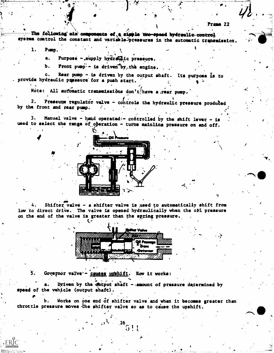
'sr=
\t;
The faticaring six\caispacivata Opikla tito-apaad hydrautio-contni;system cOmtrol the constant and variableLOressures in the automatic trensuission.
1. Pump. \
a. Purpose -.siipply hyditgkic pressure.
b. Front pumi'.- is driverAy,thl engit:4e.
c. Rear wmp - is driven by the output shaft. Its purpose is to. provide hydraulic pliessure.for a push start.
.
Nate: All aueOMatic trattemissians don'tihave a.rear pump.'
4
2. Pressume regulaar valve - controls the hydraultc pressure produtedby the front and rear pump. .
. P
3. Manual valve - hand operatedi- coatrollediy the shift lever - iswed to select the' range of
e_
ration - tuins mainline pressure on and off.
al4. Shifter valve - a shifter valve is msed 5o automatically shift from
low to direct driire. The valve is opened hydraulically when the okl pressureon the end of the valve is greater than the spring pressure.
ty-
speed of
throttle
Vakezjr 7/luridMM.=
'zTVII0M f ,.//; ,
am.
Goyernor varvC- causes ,t0Whift. Row it works;
4a
a. Driven by the 4Rttput shaft -.amount of pressure dexermined bythe veh*cle (output shaft).
b. Works on One end Of shifter valve and when it becomes greater thanpressure moves-the shifter valve so as to ciuse the upshift.
,41, 26 r, 1L
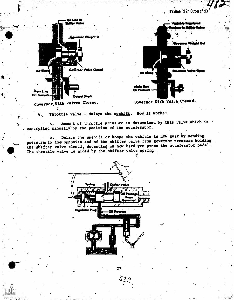
ON Woo togShiNot Volvo
Aromer %WO* IR
Air Nod
Melo UmON Proneso
, Trims 22'(Coned)
4.
liewsNesr Weigi* Owl
levemeWiviapse
GovernorsWith Valves Closed. Governor With ValveOpened.
.t
6., Throttle valve - delays the upshift. HoW it works;
N., a,. Amount of throttle pressure is determined by this valve which is '
,controlle4 manually'by the position of the accelerator.
-,". b. Delays the upshift or keeps the vehicle in LOW gearj*, sending
.
"pressureoto thelopposite end of the.shiftor valve from governor pressure_ holding
......
411
the shifter valve closed, depending,on how hard you press the accelerator pedal.
The throttle valve is aided by the shifter valve spring.
.r..1
2 7
APESTIOR 1.8
a. supplies pressure to operate transmission.'
b. 'control. hydraulic prassure.
Frame)22 (Coned)
c. is used to select tiZe range.
d. automatically shifts from loW to direct drive.
e. causes upshift.
f. delaym upshift.
5
416
67firi,le - irt
P
4
4
,"..
_
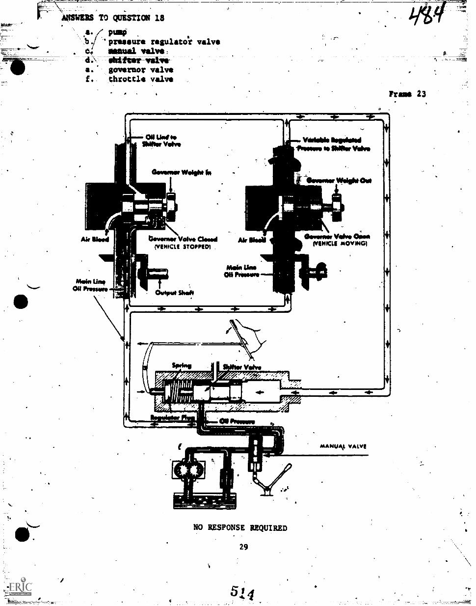
ANSWEES TO QUESTION 18
a./' pum0`13/ 'pressure regulatoli valvech mama/ valve:41:\ ebt140m1wAvvra. governor valvef. throttle valve
Trans 23i ON Unite*UN* Vein*
Gerwear Weight to
Ak Mood
Violable limpolsiedfreiseve lawVolvo
ilevenur ,Weight Out
A
Onvennor Valve Owed Air ilssirilENICLE STOP11151
Mein Line00 Pressure
/Asia LimON Prawn,
Oftemer Valve 43;noMINIM MOVINGI
PRIMPINO 9)
NO RESPONSE REQUIRED
29
514
" 5
ir
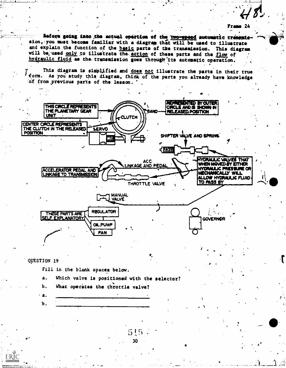
4M.
Frans 24
Wogs going LAS* Abo aqua *partition oftlaolmomopood aatooitit tremolo-sion,.you must become familiar with a diagrmm thli will be used to illustrateand explain the function of the basic parts f tise transmission. This diagramwill be;used xo illultrate the,,actir of these parts and the floe ofhydraulic fluid as the-transmission goes througtt'its autosatic operation.
.?
This diagram is sitpLified and does not illustrate the parts in their truerform. As you study this diagram, fhirik of the parts you already have knowledge
fromyrevious parts of the lesson.
sHIFTER AND SPOONS;
a
ACC.LiNKAGE AND PEDAL
-01YDRAULIC VAIlyEi THATWHEN PAWED EITHERIftfORAUUC PRESSURE OR
ALLOW HYDRAIJUC FLUID 4 1 \MEOINICALLY WLL
TO PASS SY ...NT.0THROTTLE VALVE
MANUAL[3=0 VALVE
ROGULATDR-
0 S.,
QUESTION 19
Fill in the blank spaces below.
a. Which valve is positioned with the selector?
b. What operates the throttle valve?
a.
b.
5 !. 530
1
4.
,--
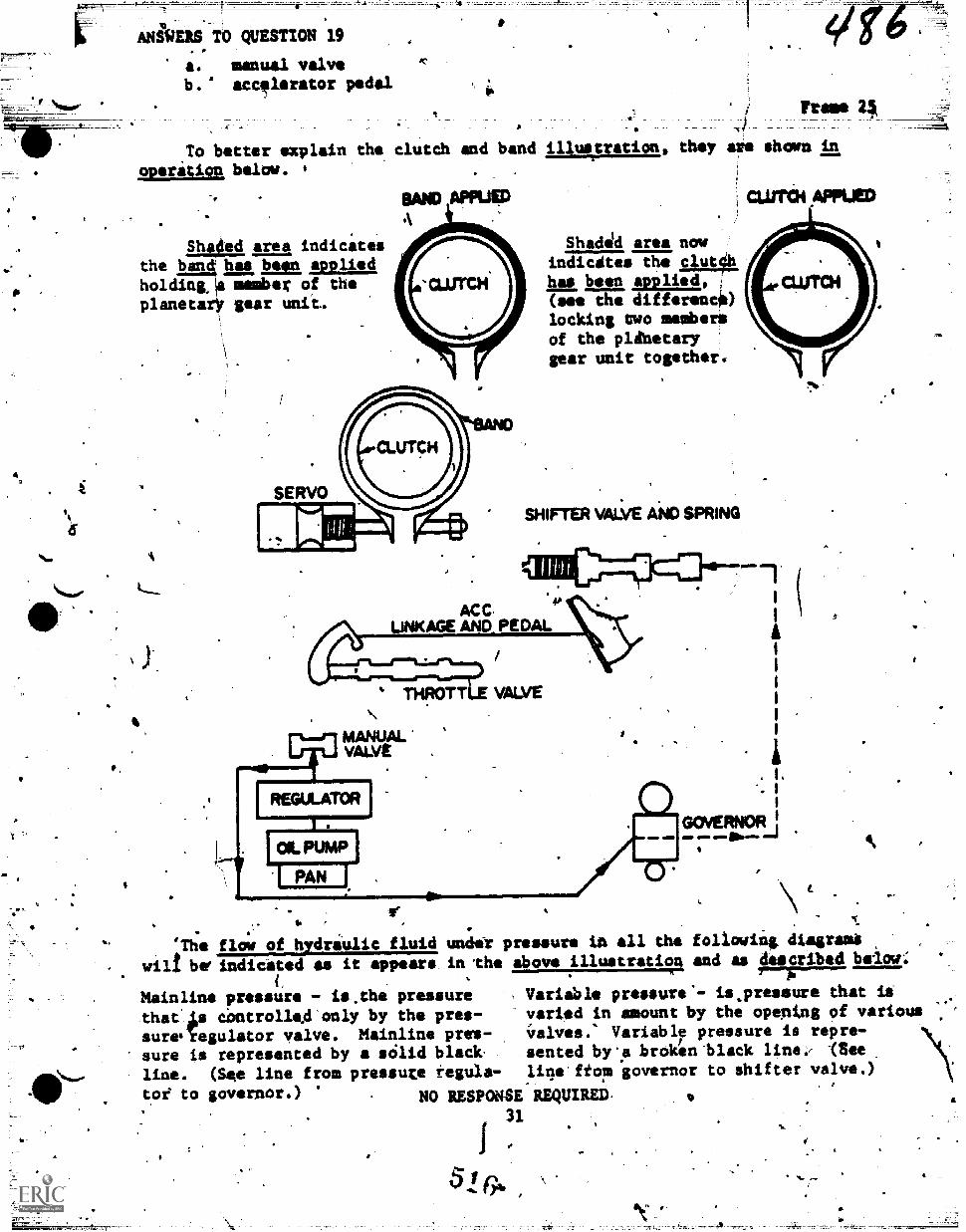
ANi0EIS TO QUESTION 19
a. manual valve sc.
b. acc!lerator pedal
To better explain the clutch and band illustration, they are shown in
operation below. i
Sha4ed area indicatesthe Imdi has been appliedholding:# member of theplanetarY gear
BAND APPUED
SERVO
Shadsld area now
indicates the 1.1a,thas been applied,(see the differenc0)locking uwo melba=of the plinetarygear unit together.
CUMIN APPIJED
SHIFTER VALVE AND SPRING
ACC.UNKAGE AND PEDAL
.
THROTT VALVE
. L*. I
GOVERNOR I
'The flow of hydraulic fluid under pressure in all the following digram/
wilt be' indicated as it appears in the above illustration and as described belov:
Variable pressure'- is.pressure ehat itvaried in amount by the opentng of various
Variabl7 pressure is repre-
sented by.a broken'black (See
line ftoni governor to shifter valve.)
Mainline pressure - is.the pressurethat'As dontrolled only by the pres-sureIegulator valve. Mainline pres-
sure is represented by a sOlid blackline. (See line from pressure regula-toe to governor.) NO RESPONSE REQUIRED.
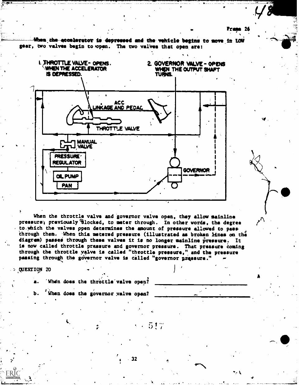
Frafaa 26
dmv-110011ierliter te depressed and the veldele begins to ism -in Lasear, two valves begin to Kopen. The two valifes that open are:
I. ;IHROTTLE VALVE- OPENS .
VallEN THE ACCELERATORIS DEPRESSED. ,
e
2. GOVERNOR VALVE- OPENSWHIIN THE OUTPUT SHAFTTIMMS.
. so.ACC.
THROTTLE VALVE
MANUAL -
1VALVE
PRESSURE-REGULATOR
AMA, AMID
II
I
, 1
1
U.1
When the throttle valve and governor valve open, they allow mainlinepressure-I previously %locked, to meter through. In other words, the degreeto.which the valves ppen determines the mount of pressure allowed to pas*through them. -When this metered pressure (illustrated as broken lines on thediagram) passeti through these valves it is no longer mainline fressure. Itis now called throttle pressure and governor pressure. That pressure comingthrough the throttle yalve is called "throttle pressures", and the pressurepassing throuk: the gdvernor valve is Called "governor pressure."
:..4yESTIO104 20
a. "Whdn does the thrOttle'valve opepi
.f_b. w4en does the giovernor :valve-open?
Afk
32 f-,\ee..
A
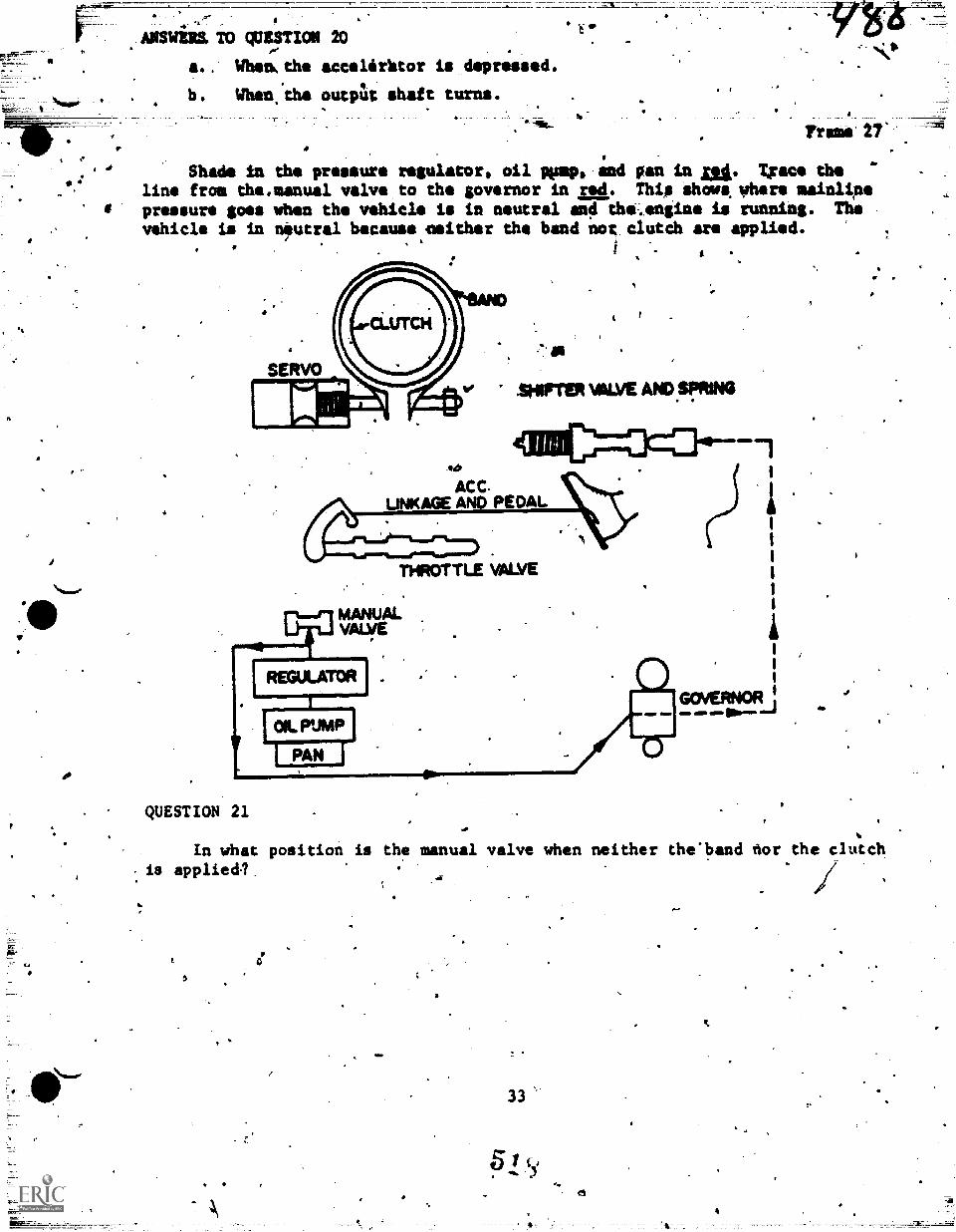
0
.00
a.. When, the accelirktor is depressed.When the output shaft turns.
4
Shade in the pressure regulator, oil pimp, and pan in ni. Um. theline from ths.nanual valve to the governor in 4. This shove where mainlinepressure goes when the vehicle is in neutral and the..engine is running. Thevehicle is in neutral because asither the band nor, clutch are applied.
,
-`
SHIFTER 1441.,VE AND SPRING
ACC.LINKAGE AND PEDAL
THROTTLE VAWE
QUESTION 21
I,GOVERNOR:
.1MP W' all"M
In what position is the manual valve when neither the'band nor the clutch- is appliedl.
01/
IN
33
e
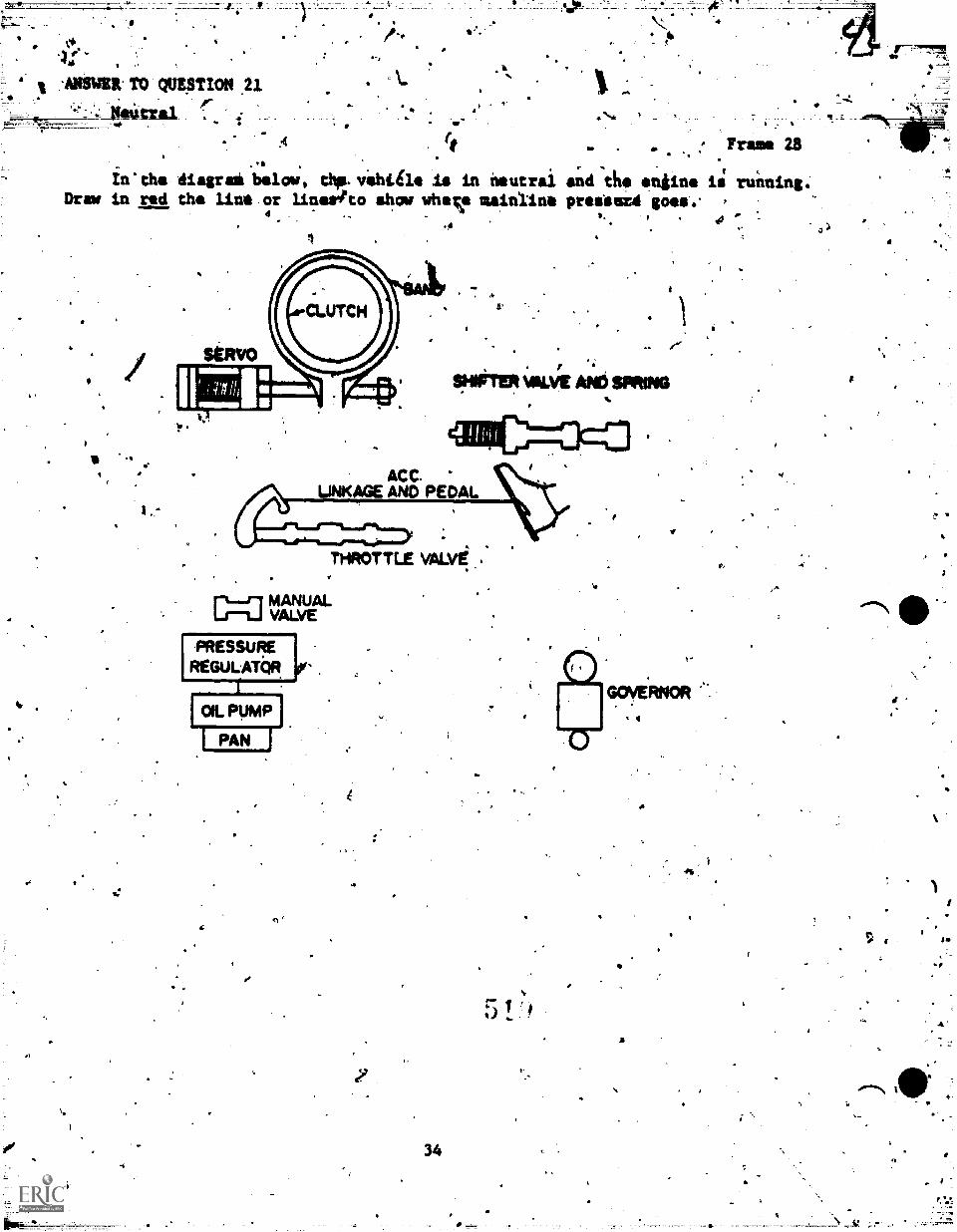
V
-AMER- TO QUEST1ON 21
,
a
rt
In' the diagral below, thp. iehtile Is in neutralDraw in red the line or linertto show uhev mainline
4 .
.4
u Frame 28r I t
and ths sngins is running .prssiecd goes.. =
4
SHIFTER VIIILVE AND SPRING
ACC.LINKAGE AND PEDAL
THROTTLE VALVE....
c=0 MANUALVALVE
PRESSUREREGULATOR
fI OIL PUMP
1 PAN j
G
Vs
34
-
t:
,
4*
0
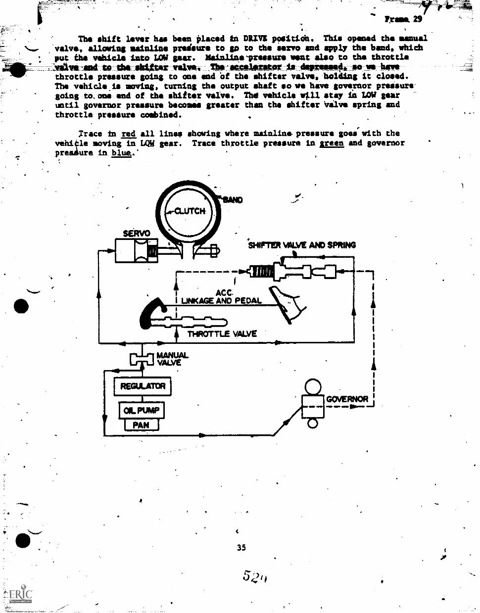
110.
. Yrame.29
. 1 ,
The shift lever has been placed in DRIVR poiitioh. This opened the manualvalve, allowing mainline preisure to go to the servo and apply the band, which
. put the vehicle into LOW sear. Maialthevressurs mat also to the throttle
IV. Wilmvismiteldmilid4*24wwlyse Thfraccelarator la-dePresewhilto vs lumthrottle pressure going to one end Of the shifter valve, holding it closed.The vehicle.is moving, turning the output shaft so we have governor pressure-going to,one end of the shifter valve. Thd vehicle will stay in LOW gearuntil governor pressure becomes greater than the shifter Vilve spring andthrottle pressure combined.
Trace in red all lines showing where mainline-pressure goes with theveh4le moving in LQW gear. Trace throttle pressure in green and governorpreadure in blue.'
35
521,
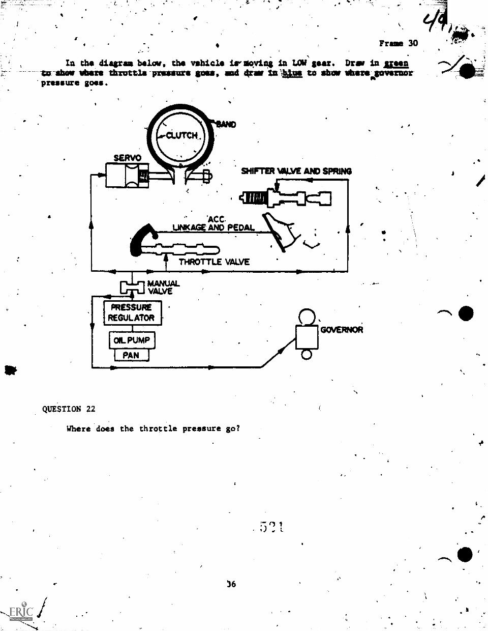
In the diagram below, the vehicle ireqving in LOW gear. Draw In momto show where throttle pressure goes, and *war inigia to show vitareapavernor'pressure goes.
a
QUESTION 22
Where does the throttle pressure go?
41
ft
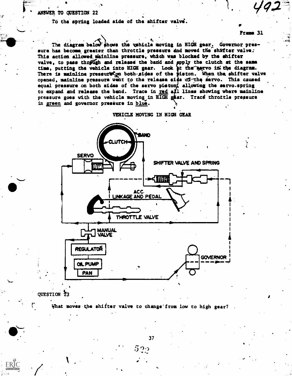
a
ANSWER TO QUESTION 22
TO the spring loaded side Of th; shifter valvi.
,
The diagram bidoll- hows the itshicle moving in HIGH gear,. Governor pres-sure has become greater than throttle pressure dnd moved the shifter valve;Th.is action allowed,dainline pressure, which wee blocked by the shiftervalve, to pass thriTgh and release the badd and pppl,y the clutch at the sametime, putting the vehicle into HIGH gear. Look t ih.rvo 1.15the diagram.There is mainline pressurVce both-sides of the $i.ton. Whsn tha shifter valveopened, mainline pressure went to the release si e ol-th, derv*. This causedequal pressure on both sides of the servo pistonJ alkowing the servo.springto expand and release the band. Trace in red al lines showing where mainlinepressure goes with the vehicle movinkin HIGH gear. Traci throttle pressurein green and governor presiure in blue.
Frame 31
VEHICLE MOVING IN HIGH GEAR
atmSERVO
afirrER whi.vg AND SPRING
ACC.I LINKAGE AND PEDAL
VALVE
QUESTION lb
GOVERNORow
What moves-the shifter valve to changefrom low to high gear?
37
5 0 g)
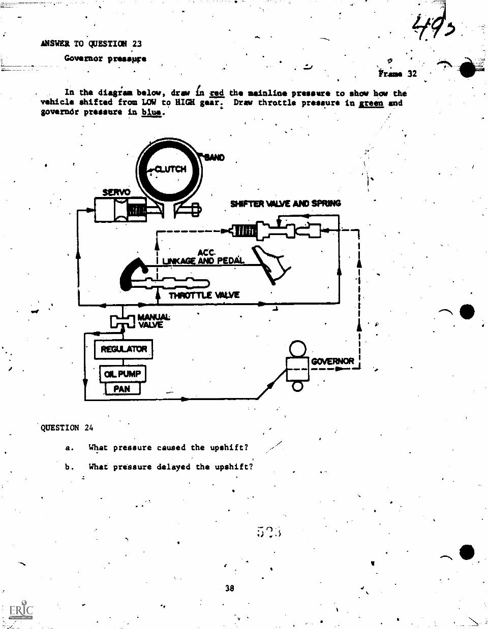
I.
ANSWER TO QUESTION 23
Governor presswe,
tram 32
In the diagism below, draw In red the mainline pressure to show how thevehicle shifted from LOW to RICH gear: Draw throttle pressure in Jarmn andgoverndr pressure in blue.
QUESTION 24
a. What pressure caused the upshift?
b. What pressure delayed the upshift?
38
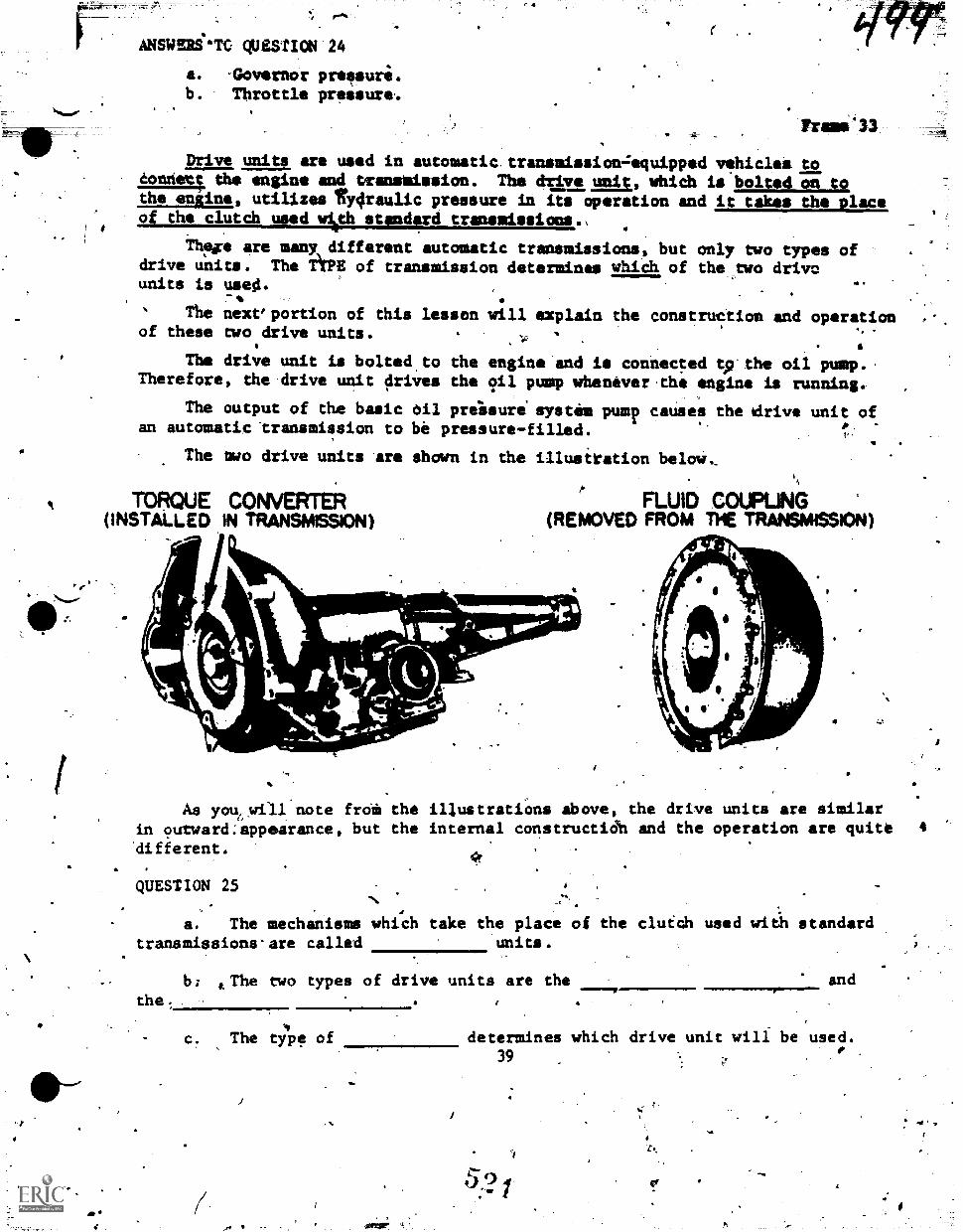
a
44.
7
ANSWSRSe*TC QUESTIO4 '24
a. -Governor preesure.b. Throttle pressure..
Drive units are used in automatic.transmissionzequipped vehiclet to.Connett, the engine and transiission. The drive unit, which is bolted on tothe eniine, utilizes ty4raulic pressure in its operation and it takes the placeof the clutch used Welt standard transmissions.,
Thefre are many different automatic transmissions, but only two types ofdrive units. The TiPE of transmission determines which of the two driveunits is usesi.
The nextportion of this lessonof these two drive units.
a .
will explain the construction and operation.
.
The drive unit is bolted to the engine and is connecced tp'the oil pump..Therefore, the drive unit drives the oil pump whenever the engine is running.
The output of the basic oil prelsuri system pump causes the idrive unit ofan automatic transmission to be pressure-filled. , -
The mwo drive units are shown in the illustration below,
TORQUE CONVERTER(INSTALLED IN TRANSMISSION)
1.1111..___-4=11=1Wir.
APIA_
FLUID COUPUNG(REMOVED FROM TPIE TRANSMISSION)
a
As you6will note froia the illustrations Above, the drive units are similarin outward:appearance, but the internal constructidh and the operation are quite 4
Aifferent.
QUESTION 25
a. The mechanisms which take the place of the clutch used witil standardtransmissions-are called units.
the. .
13: aThe two types of drive units are the and
1c. The type of determines which drive unit will be used.
,
39 . -..,
.
;
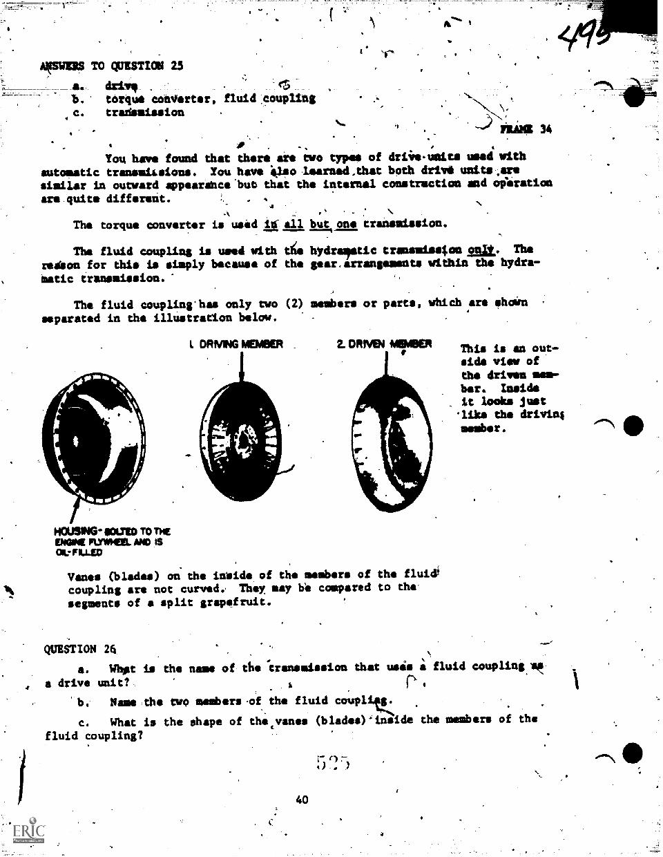
Armas To QuEsTIom 25
a. driv, et5
b. torque converter, fluid .couplingc. tradsaission \"
I;LiMi 34
You have found that there are two types of driire.ueits mei with
autoaatic transmitsious. You have 6elso learned,that both drivd units..aresimilar in outward appearshce'but that the intermal construction and oferation
are quite different.
The torque converter is used It au but one traismission.
The fluid coupling is used with die hydra:optic transmission Elt. Thereibon for this is simply because of the gear.arrangements within the hydra-
matic transaission.
The fluid coupling'has only two (2) members or parts, which are ehoin
separated in the illustrarion below. -
HOUSING soap To THEMGM FLYWHEEL MD IS011.-FILLW
I. DRMNG MEMBER 2. DRIVel "ABER
Vanes (blades) on the inside of the members of the fluii
coupling are not curved. They may be compared to the'
segments of split grapefruit.
This is an out-side view ofthe driven mem-ber. Insideit looks just'like the drivinimember.
QUESTION 26
a. Whet is the name of the 'transmission Chat usis a fluid coupling:,
a drive unit?
b. Name the two members of the fluid coupl
c. What is the shape of that's/an.. (blades)-inside the members of the
fluid coupling?
40
5 (25
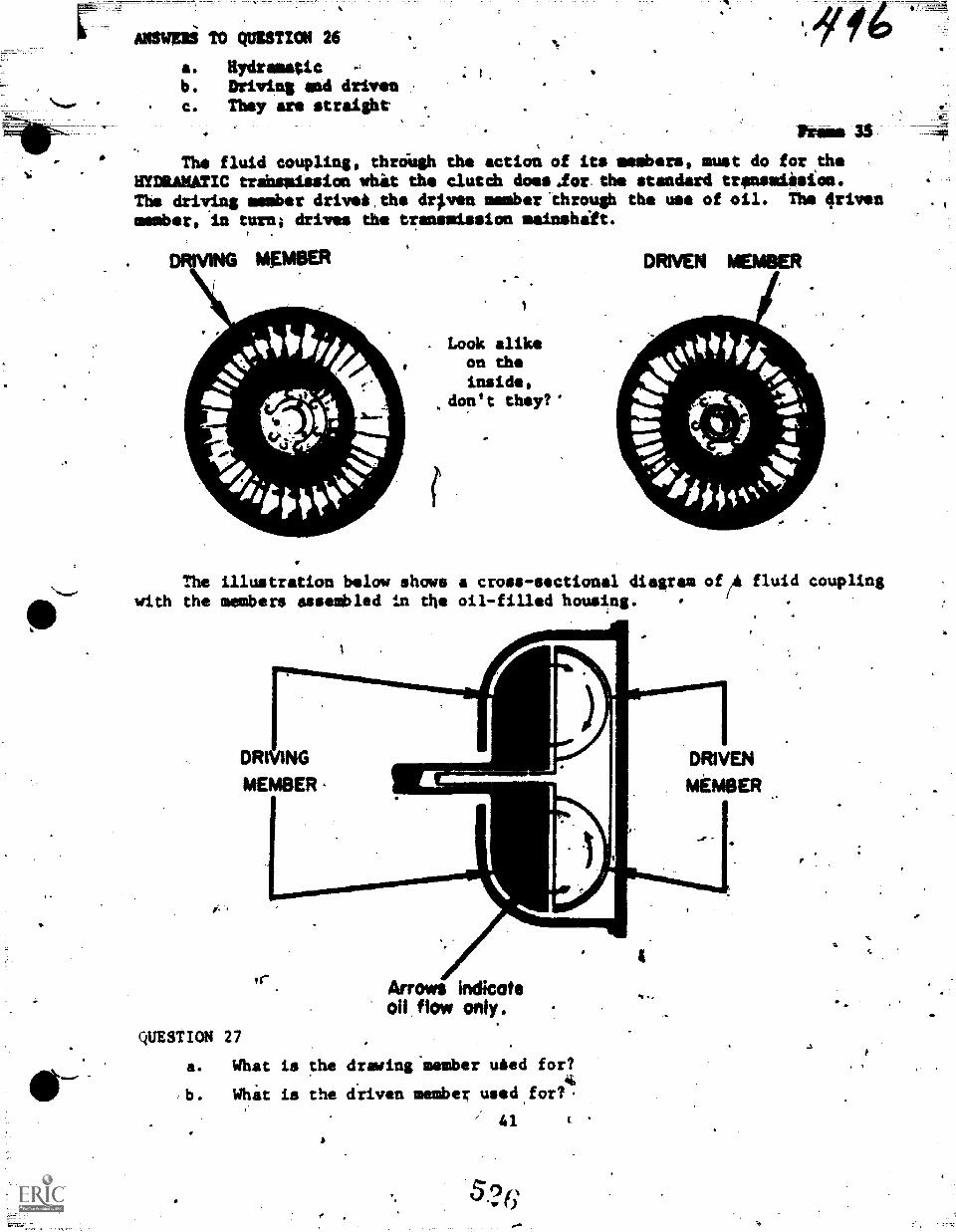
11.
s-
ANSWERi TO QUESTION 26
a. Rydramaticb. Driving and drivenc. They are straight
The fluid coupling, thro-ugh the action of its members, must do for theHYDRANATIC trabspission whit the clutch does .for the standard transsdision.The driving member drivel the drpen member 'through the use of oil. The drivenmember, in turn; drives the transmission mainshift.
DRIVING MEMBER
Look alikeon theinside,
.don't they?'
DRIVEN MEMIMER
The illustration below shows a cross-sectional diagram of/A fluid couplingwith the members assembled in the oil-filled housing.
"Paimumw,mummunimirmininam
DRIVING
MEMBER
111_
r Arrows Indicateoll flow only..
QUESTION 27.
a. What is the drawing-member 'Abed for?
b. Whit is the driven member used.for?.
x 41 (
V .
I.
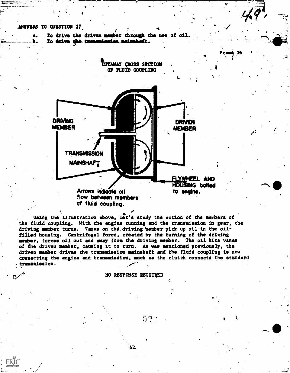
AMISS TO qUESTION 27_ 4a. _To drive the driven member through the use of Oil.-b. To drive gioAmmmemlimmUmismdasimmitt.
DRIVINGMEMBER
16TAWAr gloss SECTION .
'OF PLUM COUPLING
I.
TRANstassfoti
MAINSHAFT IL
,7==
v
Fraen 36 .
AIMS killcoto onfkm between numbersof fluid, coupling.
4 fOr
. Using the illustration above, let's study the action of the menfbers ofthe fluid coupling. With the engine running and the transmission in gear, thedriving member turtle; Vanes on the. driving 'Member pick up oil.in the oil-
filled housing. Centrifugal force, created by the turning of the drivingmilker, forces oil out and away from the driving millibar. The oil hits vanesof the driven member, causing it to turn: As was mentionad previously, thedriven member drives the transmission mainshaft and the fluid coupling Is now'connecting the angine,and transmission, much as the clutch connects the standard.pranSmission.
.
ANDING bolted
to engine.
NO RESPONSE REOUDIED
?
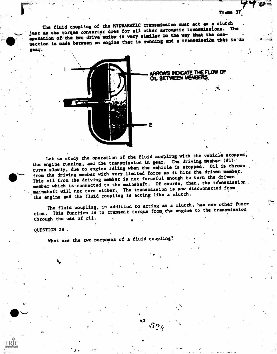
Frame 37'
The fluid coupling of the =MAMA= transmission must act as a clutch
iust is the torque converter does for all other automatic transmissions. The
--Aperatue of the ewe Arive(Aseite IA wry siaLlar ta the way that the con- ,
.nection is made between an engine that is running and a trenesisethe thht ts-tn
gear.
...,Alkiews.im.ARROWS INDICATE THE FLOW OFOIL BETWEEN MEMBEFO,
1
Let us study the operation of the fluid coupling with pie vehicle stopped,
the engine running, and the transmission in gear. The driving clamber (#l)---
turns slowly, due to engine idling when the,irehicle is stopped. Oil is thrown
from the driving member with very limited force as it hits the driven member.
This oil from the driving member is not forceful enough to turn ehe driven
member which is,connected to the mainshaft. Of course, then, the tikdsmission.
mainshaft will not turn either. The transmission is now disconnected from
the engine and the fluid coupling is acting like a clutch.
The-fluid coupling, in addition to acting as a clutch, has one other func-
tion. This function is to transmit torque from,the engine to the transmission
through the use of oil.
QUESTION 28 ,
What are the two purposes of a fluid coupling?
#
e
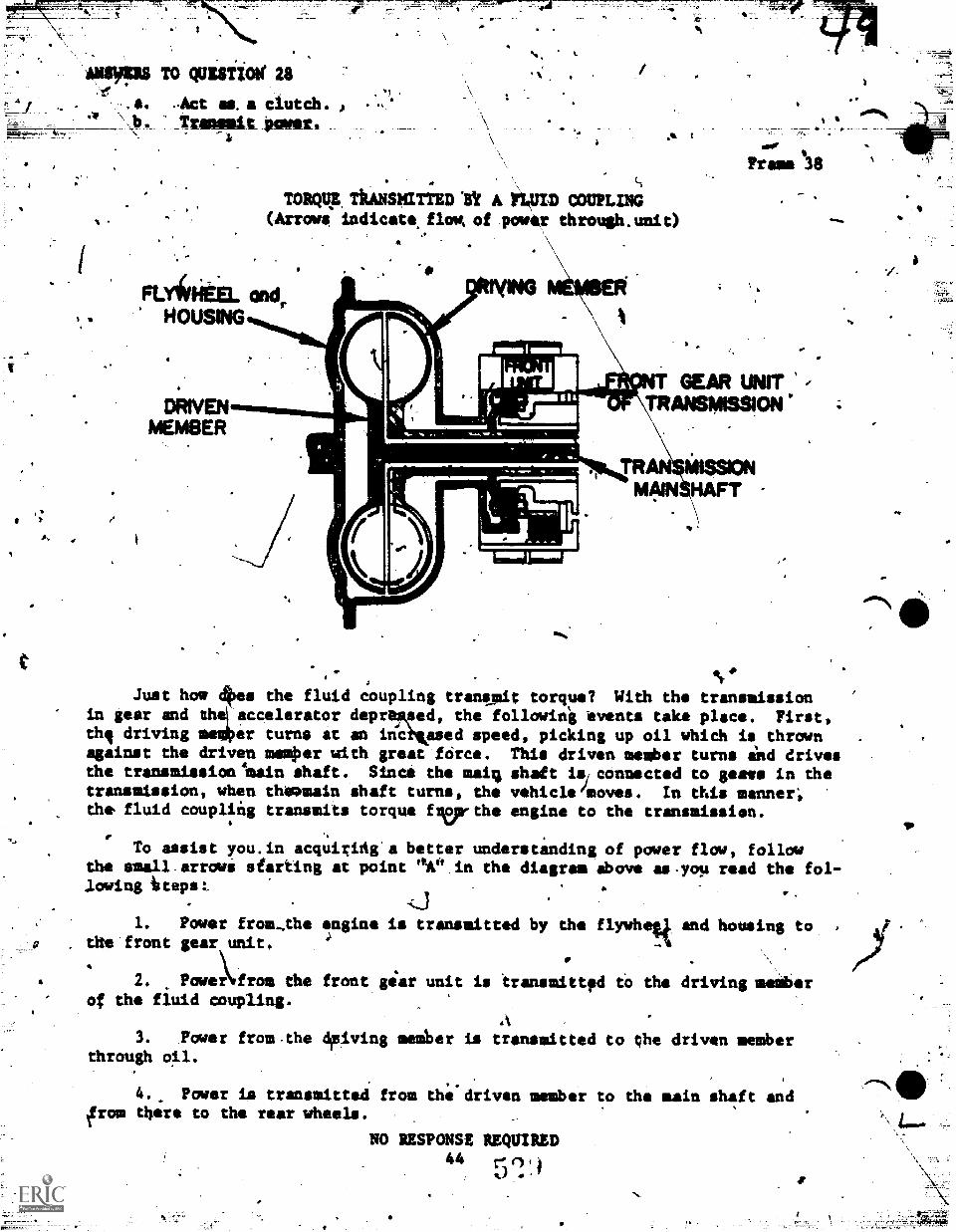
MOMS TO QUE8TiON' 28
.s. Act as.a clutch. A
,b. Trammit pow.-$ .16
TORQUE ThANSMMTTED V A Ii4tD COUPLING(Arrows, 'indicats flow, of lower throuth.unit)
\
Frame 138
aft%
Just how 4es the fluid coupling trantmit torque? With the transmissionin gear and itil:taccelerator depritmlz1, the following 'events take place. First,thi driving er turns at an ifiC ased speed, picking up oil which is thrownagainst the driven memper with great force. This driven member turns ind drivesthe transmission 'main shaft. Since the mai; shaft isiconnected to geese in thetransmission, when thomain shaft turns, the vehiclelmoves. In this manner;the fluid coupling transmits torque flerthe engine to the transmission.
.To assist you.in acquiriAg a better understanding of power flow, follow
the smell arrows siarting at point °A° in the diagram above as-you read the fol-lowing iteps:_ . .
-LI
1. Power from,the ngine is transmitted by the flywhotl and housing to ,
;the front gear unit. :J..
2. Powe)from the front gear unit is transmittpd to the driving member
.
of the fjuid coupling.
3. Power from,the driving member is transmitted to the driven memberthrough oil.
4.. Power is transmitted from the driven member to the main shaft andfrom tbere to the rear wheels.
NO RESPONSE REQUIRED44 r ,
.., 7
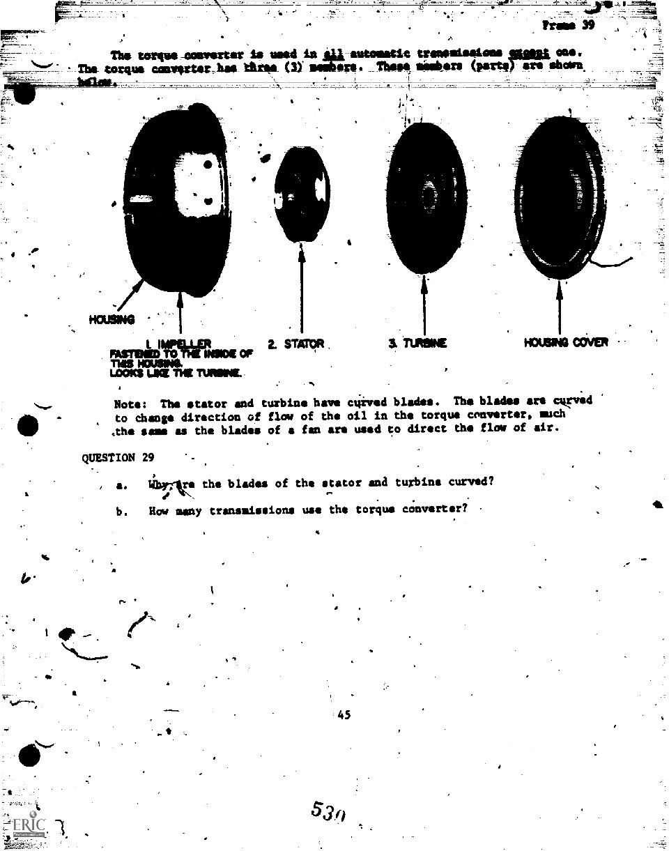
-
The torque-ommerter Is used IsAiLkentsmelle treassiassisss- The 4orque csmiqxter,hes amt. (I) sembere Thee* sinkers (pert!) taxi shown
S.
a
I L STATORFASTINE~41011 OFWS MUMS.LOOKS UNE THE MENNE.
a- A
TURBINE MUSING COVER
Note: The stator and turbine have cliived blades. The blades are cmTved
to change direction of flow of the oil in the torque converter, much
alne same as the blades of a fan are used to direct the flow of air.
QUESTION 29
a. Why-axe the blades of the stator and turbine curved?
0b. How many transmissions use the torque converter? .
p..
iat
a
45
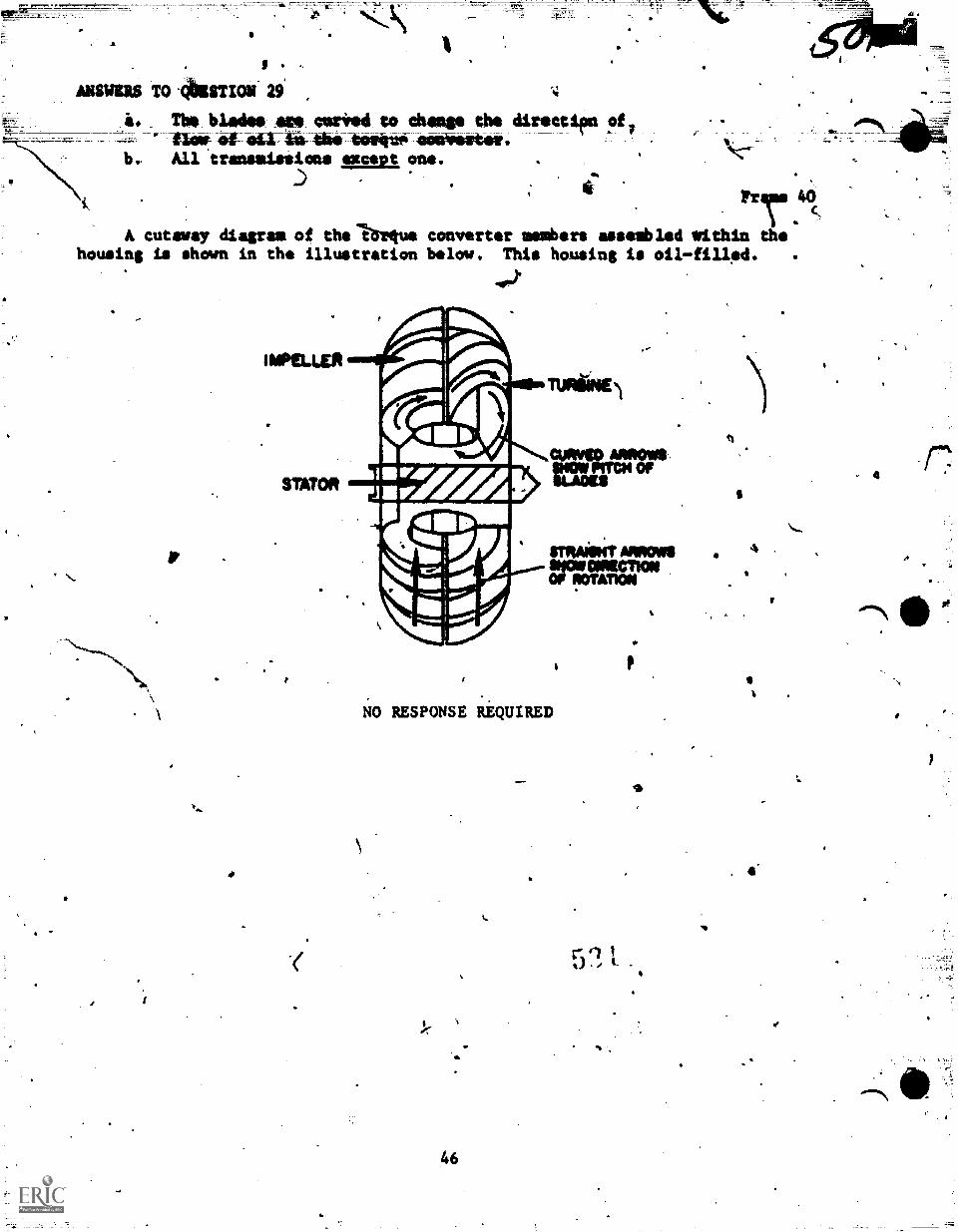
ANSWERS TO iiibESTIOS 29
The blades 'wearied to chimp the directien oft
All transmissions except one.
A cutaway diagram of thallreetus converter msmbers assembled within thehousing is shown in ths illustration below. This housing is oil-fillad.)
NO RESPONSE REQUIRED
46
k.
111
a
. 4"
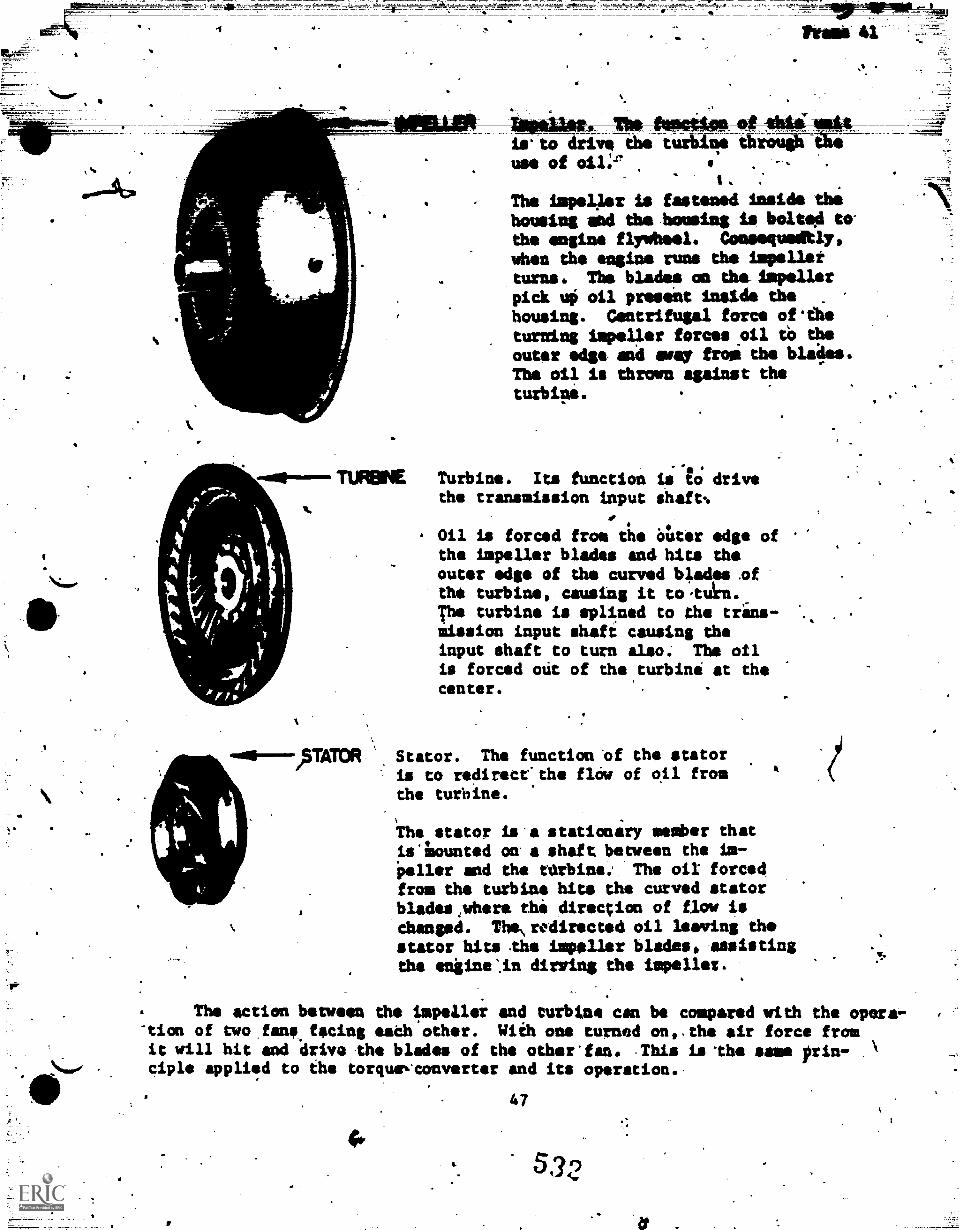
sAs.
6
70140ripW-is' to drive the turbile ea Imsuse of .
The impeller is fastened inside thit
housing and the housing is bolted tothe engine flywheel. Consequedtly,when the engine runs the impellerturns. The blades on the. Impellerpick uo oil present inside thehousing. Centrifugal force oftheturning impeller forces .oil to quit
outer edgs and Nosy from the blades.The oil is thrown against theturbipi.
-40-TUREINE Turbine. Its function is to drivethe transmission input shaft%
0
. Oil is forced from the alter edge ofthe impeller blades and hits theouter edge of the curved blades.ofthe turbine, causing it to 'ten.The turbine is splined to the trans-mission input shaft causing theinput shaft to turn also. The oilis forced mit of the turbine at thecenter.
-0111----)5WOR Stator. The function Of the statoris to redirscethe flow of oil fromthe turbine.
The stator is a stationary member thatis lounted ow a shaft between the im-peller and the terbine: The oil forcedfrom the turbine hits the curved statorblades,where the direction of flow ischanged. The\redirected oil leaving thestator hits the impeller blades, assistingthe entine.in dirring the impeller.
The action between the impeller and turbine can be compared with the opera,--tion of two,Cmis. facing math other. With one turned on,,the air force fromit will hit and drive the blades of the other'fan. .This islhe same prin- .ciple applied to the torquevconvertor and its operation..
47
532
.,=4Metteti 30
4A,
s
trams 41 (Cont'd)
a. What is the impeller of the torque'converter connected to?
b. Uhat member of the torque convetter drives the turbine by,oil force?
c. Wfiai is the function of the impellet of Ots torque-convertor?
d. What is the function of the.turbinerof the toique converter? ,
t. Ohat is the function of the stator of the torque con4iiiir?
41.1m.
48
LI
ask
;
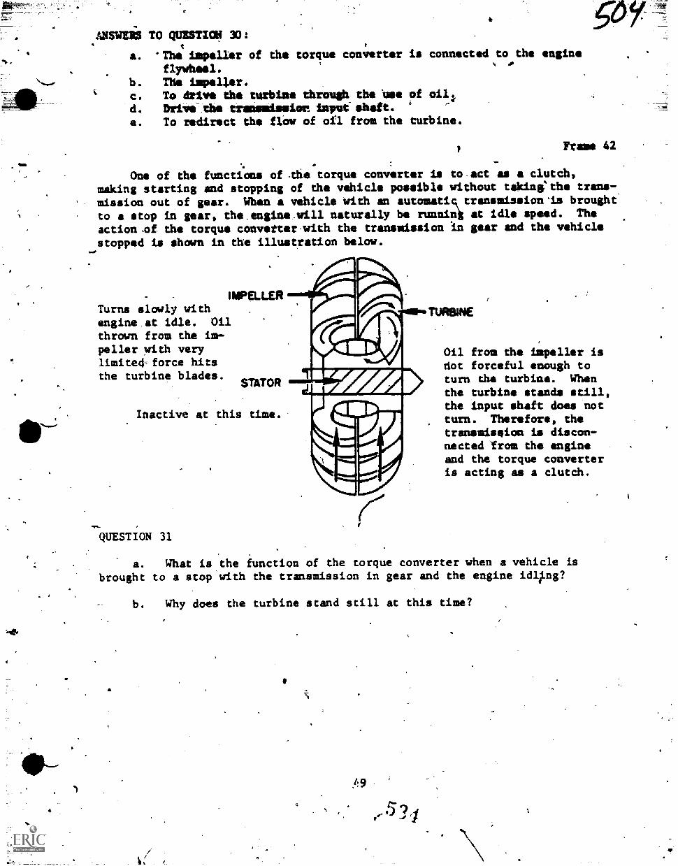
Ina
-414
a. Thsi impeller of the torque converter is connected to the engine
flywheel.b. The impeller.C. To drive the turbine through the bee of &lg.(d. Drive the trameniesier lava-shaft. -
a. To redirect the flow of otl from the turbine.
Frame 42
One of the functions of the torque converter is to.act as a clutch,making sterting and stopping of the vehicle possible without takinethe trans-,
mission out ,of gear. When a vehicle With an automatic transmission'is brought
to a stop in gear, the.engin4vwill naturally be runnink at idle speed. The
action .of the torque convetter,with the transmission in gear and the vehicle
stopped is shown in the illustration below.
IMPO-LERTurns slowly withengine at idle. Oilthrown from the int-peller with verylimited-force hitsthe turbine blades.
STATOR
Inactive at this time.
QUESTION 31
TURBINE
Oil from the impeller isdot forceful enough toturn the turbine. Whenthe turbine stands still,the input shaft does notturn. Therefore, thetransmiseion is discon-nected 'from the engineand the torque converteris acting as a clutch.
a. What is the function of the torque converter when a vehicle isbrought to a stop with the transmission in gear and the engine icIll.ng?
b. Why does the turbine stand still at this time?
r.-5?/
-0
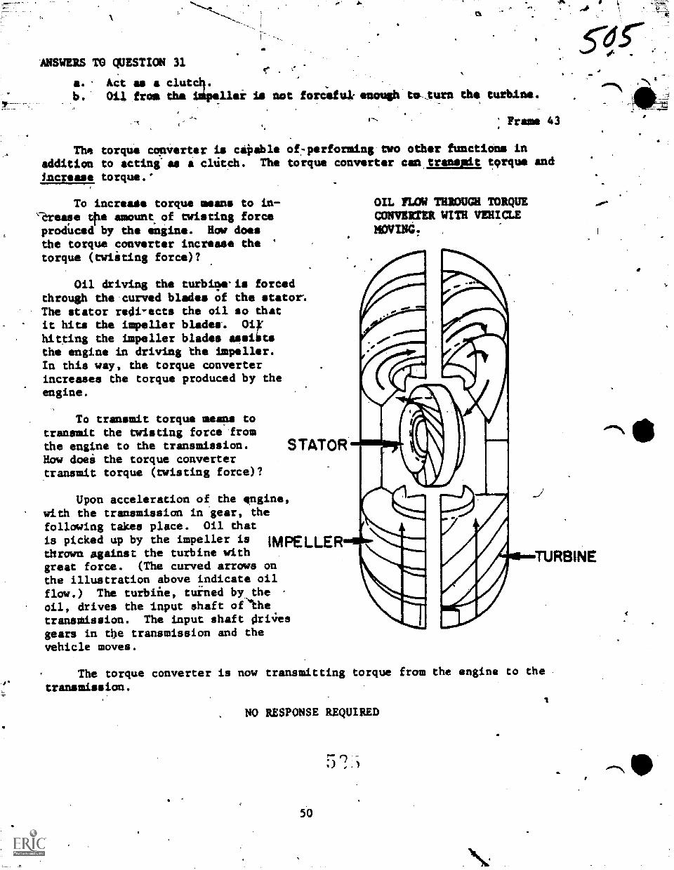
ANSWERS TO QUESTION 31C. . t.
a. Act as a clutch.b.' Oil from tha isipeller is not forefulenough toturn the turbine.
Frame 43
The torque converter is ca0able of-performing two other functions inaddition to acting'as a cltitch. The torque converter can_tranemit torque and
increase torque.'
To increats torque means to in-'trease tlhe amount of twisting forceproduced by the engine. How doesthe torque converter increase the '
torque (twiiting force)?
Oil driving the turbilwis fortedthrough the curved blades of the stator%The stator redi-ects the oil so thatit hits the impeller blades. oiyhitting the impeller blades assiitsthe engine in driving the impeller.In this way, the torque converterincreases the torque produced by theengine.
To transmit torque means totransmit the twisting force fromthe engine to the transmission.How doei the torque convertertransmit torque (twisting force)?
OIL FLOW THROUGH TORQUECONVERTER WITH VEHICLEMOVING.
Upon acceleration of the engine,with the transmission in gear, thefollowing takes place. Oil thatis picked up by the impeller is IMPELLERthrown against the turbine withgreat force. (The curved arrows onthe illustration above indicate oilflow.) The turbifie, tuined by theoil, drives the input shaft of`the
transnission. The input shaft 4ri4esgears in the transmission and thevehicle moves.
The torque converter is now transmitting torque from the engine to the .
transmission.
NO RESPONSE REQUIRED
5 '"?
50
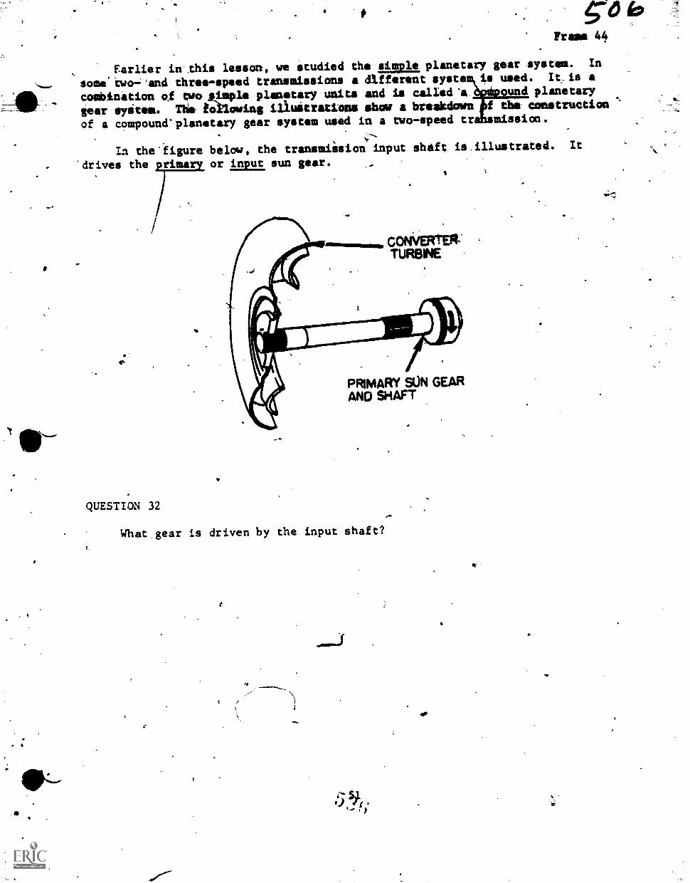
bFrame 44
Earlier in this lesson, we studied the simple planetary gear system. In
soma two'and three-speed transmissions a different systa is used. It. is a
combination of two simple planetary units and is called-a ----ound planetary
gear apices. The following illuitrations shoe a breakdown f the construction
of a compouncrplanetary gear system used in a two-speed tr .-missice.
In the*'figure below, the transmiision input shaft is.illustrated. It
'drives the rims or input sun gear.
QUESTION 32
*i PRIMARY SUN GEAR
,44 AND SHAFT
CONVERTER.TURBINE
What.gear is driven by the input shaft?
/
'.
'74
W,
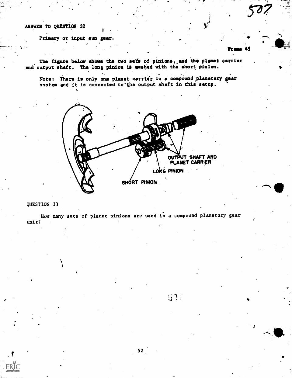
ANSWER TO QUESTiON 32
Primary or input sun gear.
IPFramed
The figura Wilow shows the two sies of pinions,,and the planat carrier
and output shaft. The long pinion Us meshed with the short pinion.
Note: There is only one planet carriir,in a compOund,planatary gearsystem and it is connected to'the output shaft in this setup.
QUESTION 33
SHAFT AHOPLANET CARRIER
LONG PINION
SHORT PINION
How many sets of planet pinions are used in a compound planetary gear
unit?
.4
52
:71)41 ,
.0
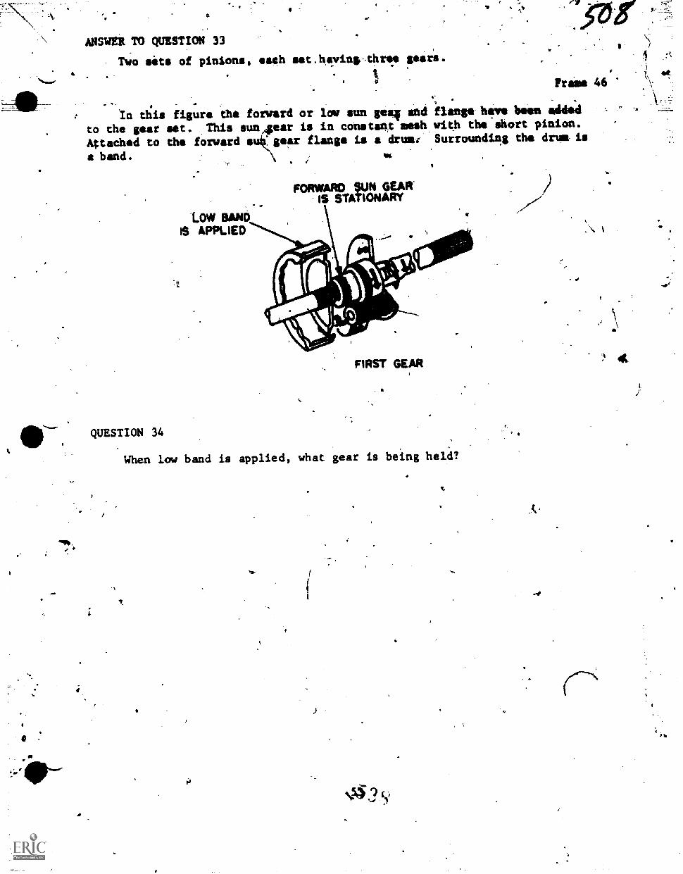
V
ANSWER TO QUESTION 33
, Two sits of pinions, ach set,hiwing,thre gears.
I.
Frame 46,
..
In this figure the forward or low sun gulag and flange hre bees added
to the gear set. .Tbis sun4ear is in constant mesh with the short pinion.
Attached to the forward sukgear flange is a drum: Surrounding the drum is
a band.
'LOW BANDAPPLIED
FORWARD SUN GEAR'IS STATIONARY
gr
FIRS1' GEAR
411r.QUESTION 34
When low band is applied, what gear is being held?
Vf-
a
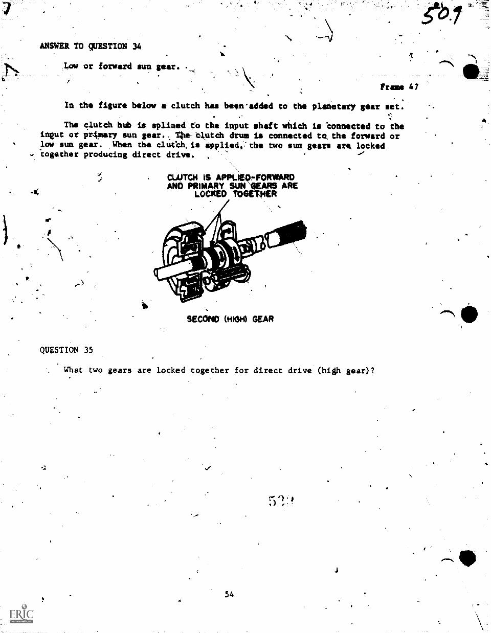
ANSWER TO QUESTION 34
-1(
.1.0ow or forward sun gear.
Frame 47,
In the figure below a clutch has biewadded to the planetary par set.
The clutch hub is splined to the input shaft which is Connected to theineut or pr4mary sun gear... T4le. Clutch drum is connected to, the forward orlow sun gear. When the cluech. is applied,: the two sun gears are, locked'together producing direct drive. ,
QUESTION 35
CLOTCH IS APPLIWFORWARDAND PRIMARY SUN1VEARS ARE
LOCKED TOGEMER
SECOND (HIGH) GEAR
What tlwo gears are locked together for direct drive (high gear)?
_or
54
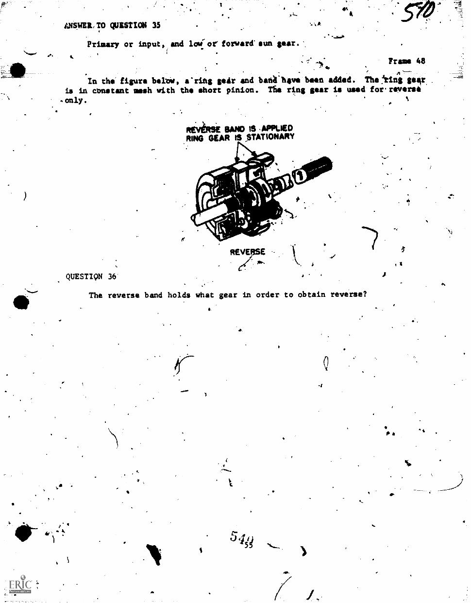
a
LNSWEIL TO QUESTICM 35
Primary or input and loci: or forward sun gear.
. fi Or
dirs
Frame 48
In the figure belrae, ering geAr and banil hgve been added. The !ring gear. .
is in cunstant mesh with the short pinion. The ring gear is used' for. reverse
QUESTIQN 36
REVIRSE BAND IS .APPLIEDRING GEAR IS STATIONARY
The reverse band holds what gear in order to obtain reverse?
(
4545ig
4.
4
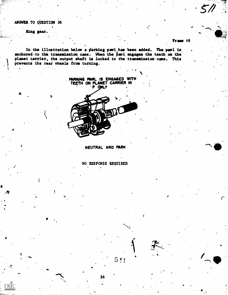
4.
ANSWER TO QbESTION 36
Ring sear.
frame 49
In the illustration below a farking perl has been added. The pawl isanchored-to the, transmission case. Whin the isawl engages the teeth on theplanet terrier, the output shaft is locked to the transmission ease. Thisprevents the rear wheels from turning.
AL
ems
0.
2
PARxwat wt. IS ENGAGED WITHTET114 ON PLANET CARRIER IN
NEUTRAL AND PARK
NO RESPONSE REQUIRED
56
A
9.
4
4
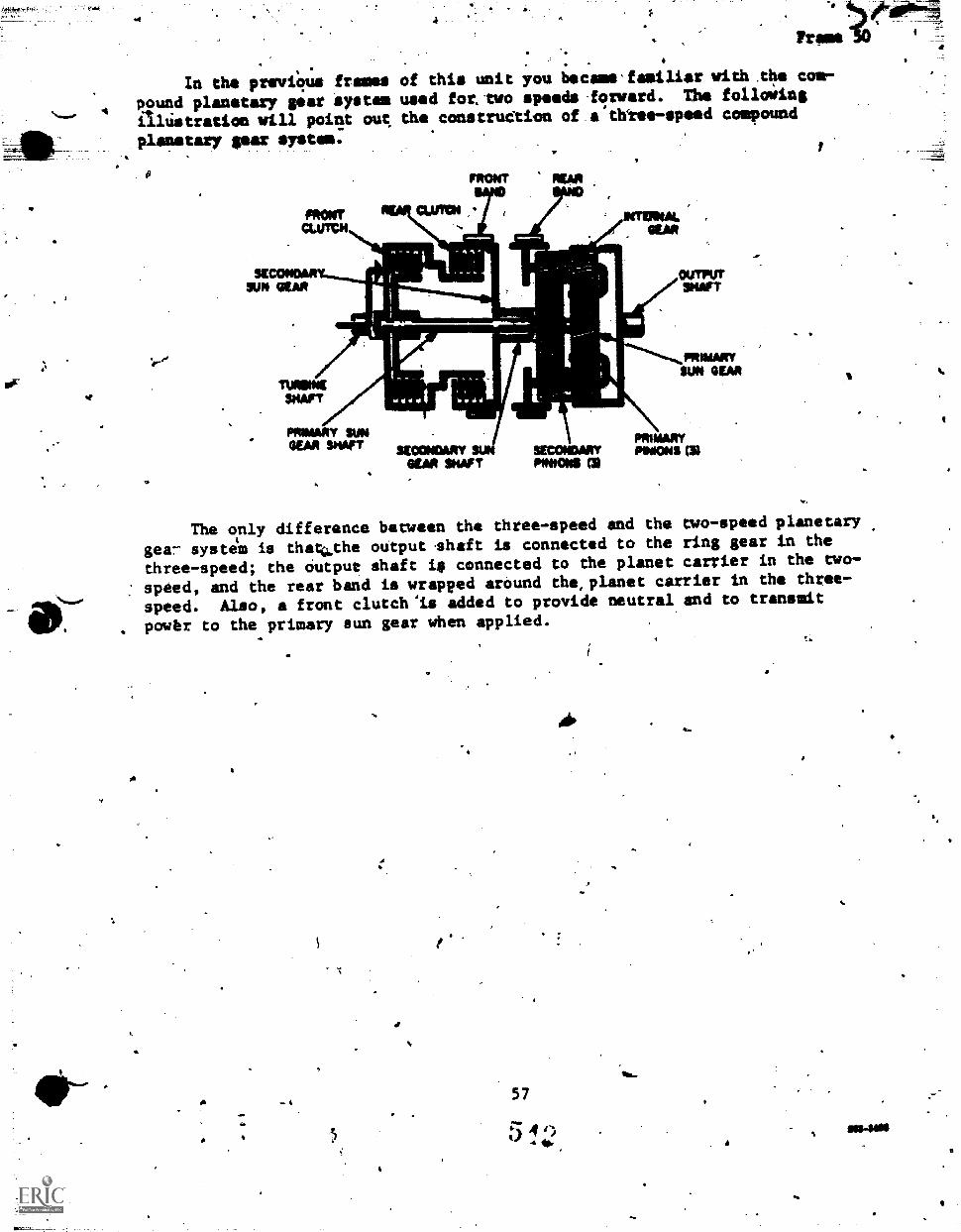
In the previOua framespound planetary sear system
Aalistration will poi* ouc
4
of this unit you became.familier with.the com-
used for..two speeds.frward. The followingthe construdtion of a thtee-speed compound
planetary sear system.
vir.of
SUN StM -
=1Wm
TURMASSNAPT
PPRIMARY SUNGEM SHOT
OUTPUTySHAFT
*ECONOMY SUNGEAR SNAP I`
SECONDARYPINIONS CD
PRIMMYSUN GEM
PRIMARYMOONS CR
The only difference between the three-speed and the two-speed planetary
ger- system is thaci.the oUtput .shaft is connected to the ring gear in the
three-speed; the Output shaft ig connected to the planet carrier in the two-
: speed, and the rear band is wrapped around the,planet carrier in the three-
speed. Also, a front clutch "is added to provide neutral and to transmit
. powbr to the primary sun gear when applied.
Ai.
"A
t', ti`',..! 7e;.21 r In DWI
. .i.-..
-?;
A
'''411kkr'
r
11.
'Tlehnicai. Training
General Purpose Vahiclegazific
'BASIC PRINCIPLESOf,
AUTOMATIC TRANSMISSIONS
4
16 Decether 1975
STUDY GUIDENORK8001:
-3AAR474-SW-34:15
USAF SCHOOL OF APpLIED AEROSPACE SCiENCES)340th Techpicalyrraining Group
Chanute Air Force Base, Illinois
Designati FOr ATC 'COWS* US*
DO NOT USE OM TNE JOS
5 13
rorr
Vehicle MAntenancs Branch-Chanute APB. Illinois
3M11147330-5W-505
BASIC PRWCIPLES OF AUTOMATIC TRANSMISSIONS
(;4citir%
vompletton or ON text., youw111 be.ahle to accomplish thefollowi g with 85% accuracy.
1. \Define the terms: torque, reduction, reverse reduction, anddirect dri
2. Li t the three basic hydraulic principles involved in the,operation.of automatic transmissions..
3. List the coMponents awl their purposes of a basic oil pressuresystem..
4. In a diagram, label the parts. of a,simOle planetary gear unit.
5.. List the h,t-ela functions-4'a a,planetary gear unit.
6. List two rules that apply to the control of a simple planetarygear unit.
unit.7. List the component that holds a member of the planetaiy gear
8. List the device that is used.to control a band.
9. List the component ehat locks two membIrs of a planetary gearunit together.
10. State how a multiple-disc clutch is applied and released.
II. State the purpose of the governor and what drives it.
12. State the purpose of the throttle valve and what controls it.
13. State the operating principles of the fluid coupling.
# la. List the parts of the torque convecter and the function ofeach part.
15. Given a diagram illustrating a two-speed transmission, drew inthe flow of main line and variable pressures that will cdmplete theupshift from low to high gear.
16. State the difference between a simple and a compound planetarygear'system.
Supersedes 3A3R47330-PT-505, 3ABR47231-1-PT-404B, 3A3R47231A-PT-40411,3ABR47231B-PT-4048, 3ABR47231C-PT-404B, 18 March 1974.OPR: TWSDISTRIBUTION: XTWS-300;TTVGC-1 4-
1) ?
1,0
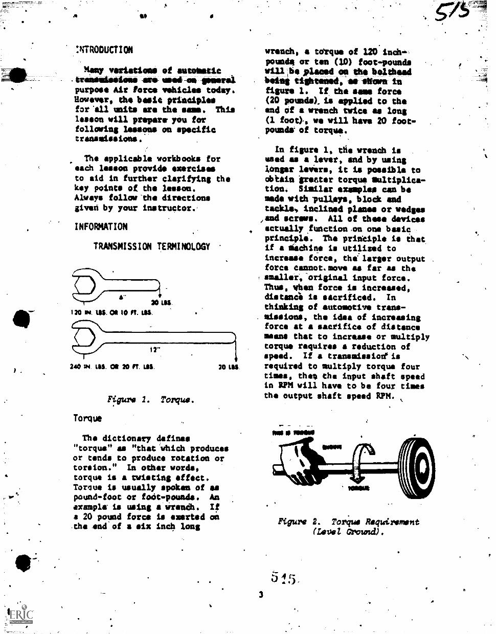
:NTRODUCTION
Many variations of autolaticATImimmigmbidoes ars imartAms timers'purpose Air Force vehicles today.However, the basic principlesfor 'all units are the same. Thislesson will prepare. you forfollowing lessons on specifictransmissions.
The applicable workbooks foreach lesson provide exercisesto aid in further clarifying thekey points of the lesson.Always follow 'the directionsgived by your instructor.'
INFORMATION
TRANSMISSION TERMINOLOGY
6"20 as
120 W4. 1.110. 01 10 Ft. MS,
12"
240 114 1.116. CO 20 FT. UIS.
Figure 1. Torque.
Torque
20 1St
The dictionary defines"torque" as "that 'which producesor tends to produce rotation ortorsion." In other words,torque is a twisting affect.Torque is usually spoken of aspound-foot or fait -pounds. Anexample is using a wrens*. Ifa 20 pound force is exerted od.tho snd of a six inch long
wrench, torque of 120 inch...pounde or ten (10) foot-poundsvill.bisplacedoethoboltheadbidet tightesed-aa -Worn infigure 1. If, the same force(20 pounds). is applied to theend of a wrench twice as long(1 foot),, we will have 20 foot-pounds- of torque.
In figure 1, tfie wrench is .
used as a lever, and by usinglonger levirs, it is possible toobiein greeter torque multiplica-tion. Similar examples can bemade wit:him:Wm, block andtackle', inclined planes or wedges
/and screws. All of these devices
4 actually,functionon one basicprinciple. The principle is thatif a Machine is utilised toincrease force, the' larger outputforce cannot.move as far as thesmaller,-original input force.Thus, when force is increased,distanc4 is sacrificed. Inthinking of automotive trans-missions, the idea of increasingforce at a sacrifice of distancemeans that to increase or multiplytorque requires a reduction ofspeed. If a transmission'isrequired to multiply torque fourtimes, then ths input shaft speedin RPM will have to be four timesthe output shaft speed RPM.
3
Figure 2. Torque Requirement(Level 0roundr).
5 1 5
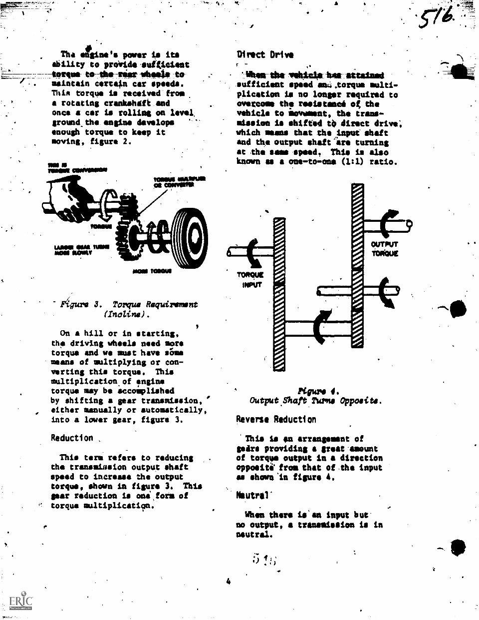
Tha etgins's power is itsAbility to prOride suf*iciont-torque to--tius sax mbisato tomaintain certain car speeds.Thin torque is received from.
rotatins crankshaft andonce a car is rolling on level,ground..the engine developsenough torque to keep itmoving, figure 2.
MNMOM OINOMOON
MOW
WOE OM NOGMON MOW
KAMM MULOMONOs COMM
Figure 3. Torque Requirement(Incline).
.
On hill or in starting,th, driving wheels need moretorque and we must have sOmismeans of multiplying or con-verting this torque. Thismultiplication.of !enginetorque may be accomplishedby shifting a gear transmission, "either manually or automatically,into a lmier gear, figure 3.
Reduction
This term refers to reducingthe trenamiasion output shaftspeed to increase the outputtorque, shown in figure 3. Thissear reduction is one,form oftorque multiplicati9n.
Direct Driver
Whet the vokLeilos Ms attained.sufficient speed an4.torque multi-plication is no longer required toovercome the resistanci og thevehicle to iovement, the trans-mission is shifted to direct drive;which means that therinput shaftand the output shaft ire turningat the sees.speed. This is alsoknown as a one-to-one (1:1) ratio.
4
Figure 4.Output.Shaft name Opposite.
Reverse Reduction
'This Is sn arrangement ofpiths providing a great-amountof torque output in a directionoppoeiti from that of.the inputas shan't:I figure 4.
Neutral"
When there is an Input butno output, a tranalisaion is inneutral.
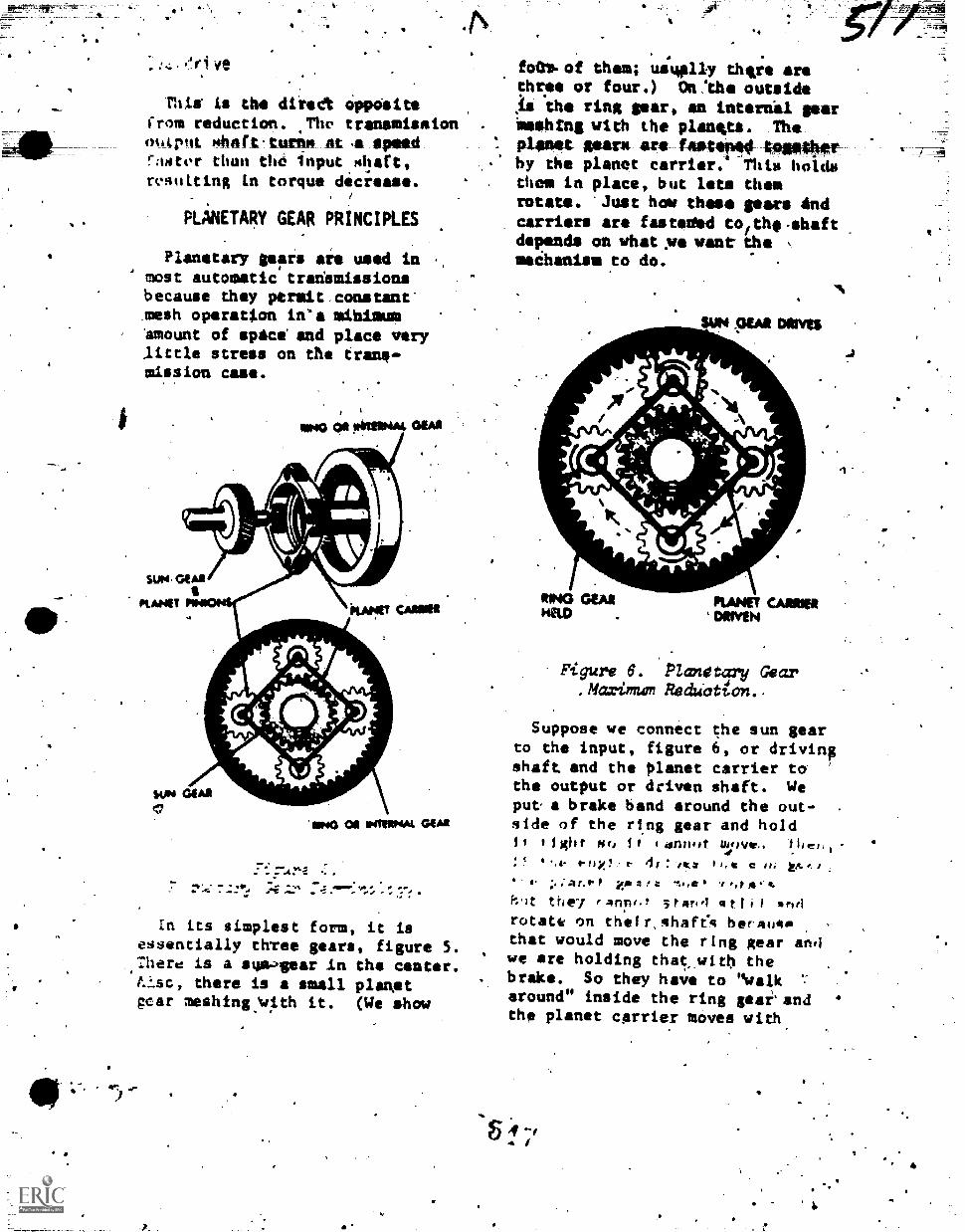
-411-
This is the diiedt OppOsitefrom reduction. .The transmissionoartit mhaft-turms at .11, speedraNter than the input shaft,resulting in torque decrease.
PLANETARY GEAR PRINCIPLES
Planetary gemrs are used inmost automatic transmissionsbecause dhey permit constant"mesh operation in'a mihimum
, amount of evict! and place verylittle stress on the tran,mission case.
WO Os 01111,4m.
$UM. GEAR
PLANET pimItT CANNER
1414 GOA.
ImP40 OS INTERNAl GOAN
7 ,, -. AQ ..Ir% m .0
In its simplest form, it isessentially thTee gears, figure 5.:here is a sua.)gear in the cantert.Isc, there is a small planetgear meshincwith it. (We show
5.
foft.of them; usually thve arethFee or four.) On!th outside1111 the ring gear, an internkl gearimehtng with the planepts. Th
Alma Writ aft bowteM4-1010*erby the planet carrier. This holdsthem in place, but lts themrotate. 'Just how these gears Andcarriers are fasteftd tofthe-shaftdepends on what:we want-the ,
machaniselto do.
.. .%
.Ar Nil/ Anrv,
S. r
awn
RING CAM PLANET UntoHELD . DoweN
Figure 6. Planetary Gear. Maximum Reduction.
Suppose we connect the sun gearto the input, figure 6, or drivingshaft and the planet carrier tathe output or driven shaft. Weput a brake band around the out-side of the ring gear and hold
I fight sr, I I drInIt 1.voeic. ia es,
4%P 41:,42 kx,,,;.;,41.,P10 itsingt *?0,04
the7 fanne.t 5tan4 qtfii itnel
rotate on their,shafect berilowthat would move the ring gear andwe are holding that_witb thebrake. So they have to "walkaround" inside the ring gearandthe planet carrier moves with.
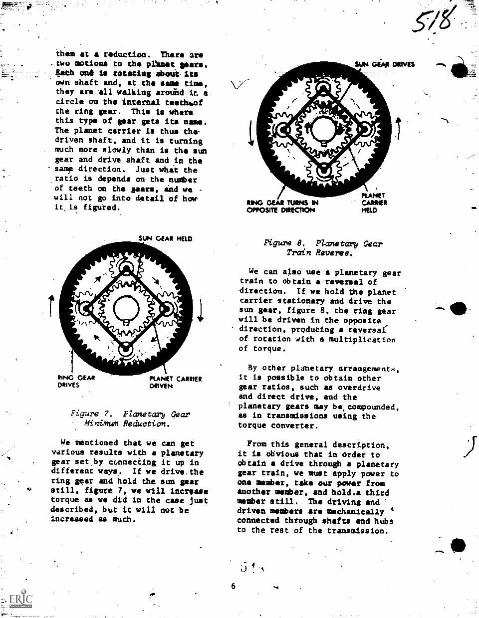
them at a reduction. There are-two motions-to the plknet.g0ars.4ath on& is rotating about itsown shaft and, at the sane time,they are all walking arodeld it. acircle an the.internal teethilathe ring gear. This is wherethis type of gear gats its name.The planet carrier is thus the-driven shaft, and it is turningmuch more slowly than is the sungear and drive shaft and in thesame direction. Just what the.ratio is depends on the numberof teeth on the gears, ind we -
will not go into detail of howit is figuted.
SUN GEAR HELD
1RING GEAR PtANET CARRIERDRIVES DRIVEN
Figure 7. Planetary GearMinimum Reduction.
We mentioned that we can getvarious results with a planetarygear set,by connecting it up indifferent ways,. If we drive,thering gear and hold the sun gear
0 still, figure 7, we will increasetorque as we did in the case justdescribed, but it will not beincreased as much.
sum Giv cows
RING GEAR TURNS INOPPOSITE DIRECTION
PLANETCARRIERHELD
Figure 8. Planetary GearTrain Reverse.
We can also use a planetary geartrain to obtain a reversal ofdirection. If we hold the planetcarrier stationary and drive thesun gear, figure 8, the ring gearwill be driven In the opposite,direction, praducing a reversalof rotation with a multiplicationof torque.
6
By other planetary arrangements,it is possible to obtain othergear ratios, such as overdriveand direct drive, and theplanetary gears gay be,compounded,as in transmissions using thetorque converter.
Fram this general description,it is abivious that in order toobtain drive through a planetarygear train, we must apply power toone member, take our power fromanother member, and hold.a thirdmember still. The driving anddriven members are mechanically 4connected through shafts and hubsto the rest of the transmission.
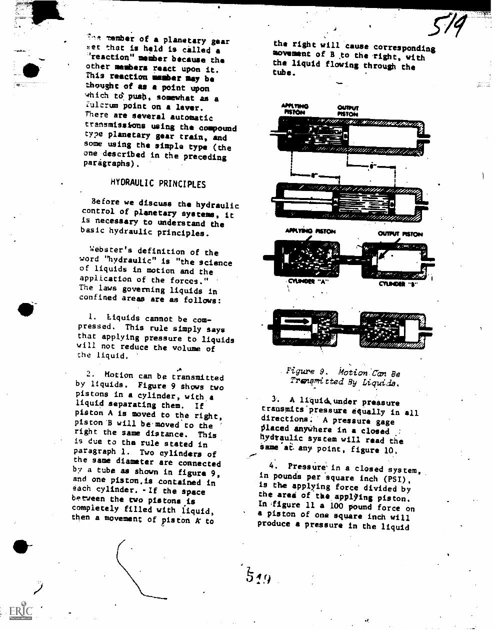
e
tember of a planetary geartet that is held is cilled'reaction" member because theother metbers react upon it.This reaction member say bethought of as a point uponwhich tds push, somewhat as aZulcrum point on a lever.-There are several automatictransmiss*ons using the compoundtype planetary gear train, andsome using the simple type (theone described in the precedingparagraphs).
HYDRAULIC PRINCIPLES
Before we discuss the hydrauliccontrol of planetary systems, itis necessary to understand thebasic hydraulic principles.
Webster's definition of theword "hydraulic" is "the scienceof liquids in motion and theapplication of the forces."The laws governing liquids inconfined areas are as follows:
1. Liquids cannot be com-pressed. This rule simply saysthat applying pressure to liquidswill not reduce the volune ofthe liquid.
A2. Motion can be transmitted
by liquids. Figure 9 shows twopistons in a cylinder, with,aliquid separating them. Ifpiston A is moved to the right,piston"B will be-moved to theright the sane distance. Thisis due to the rule stated inparagraph 1. Two cylinders ofthe same diameter are connectedby a tube as shown in figure 9,and one piston.is contained ineach cylinder. -If the spacebetween the two pistons ,iscompletely filled with liquid,then a movement of piston k to
1.
P9the right will cause correspondingmovement of 3 .to the right, withthe liquid flowing through thetube.
AMMOPISTON
OUTPUTPISTON
s.,ji .
11101M=1111.11MMMMI.
Ing.ftlown Algolmordi
MUSS PISTON OUTPUT PISTON
MOON -A". .
MOON '1"
Figure 9. Motion Can BeTransmitted By Liquids.
1. A liquidkunder pressuretransmits'pressure 04ually in alldirections; A pressure gagegamed anyWhere in a closedhydraulic system will read thesaaeat any point, figure 10.
4. PressUre'in a closed system,in pounds per'square inch (PSI),is the applying force divided bythe area of tit appl'ing piston.Inligure 11 a 103 pound force on
. a piston of one square inch willproduce a pressure in the liquid
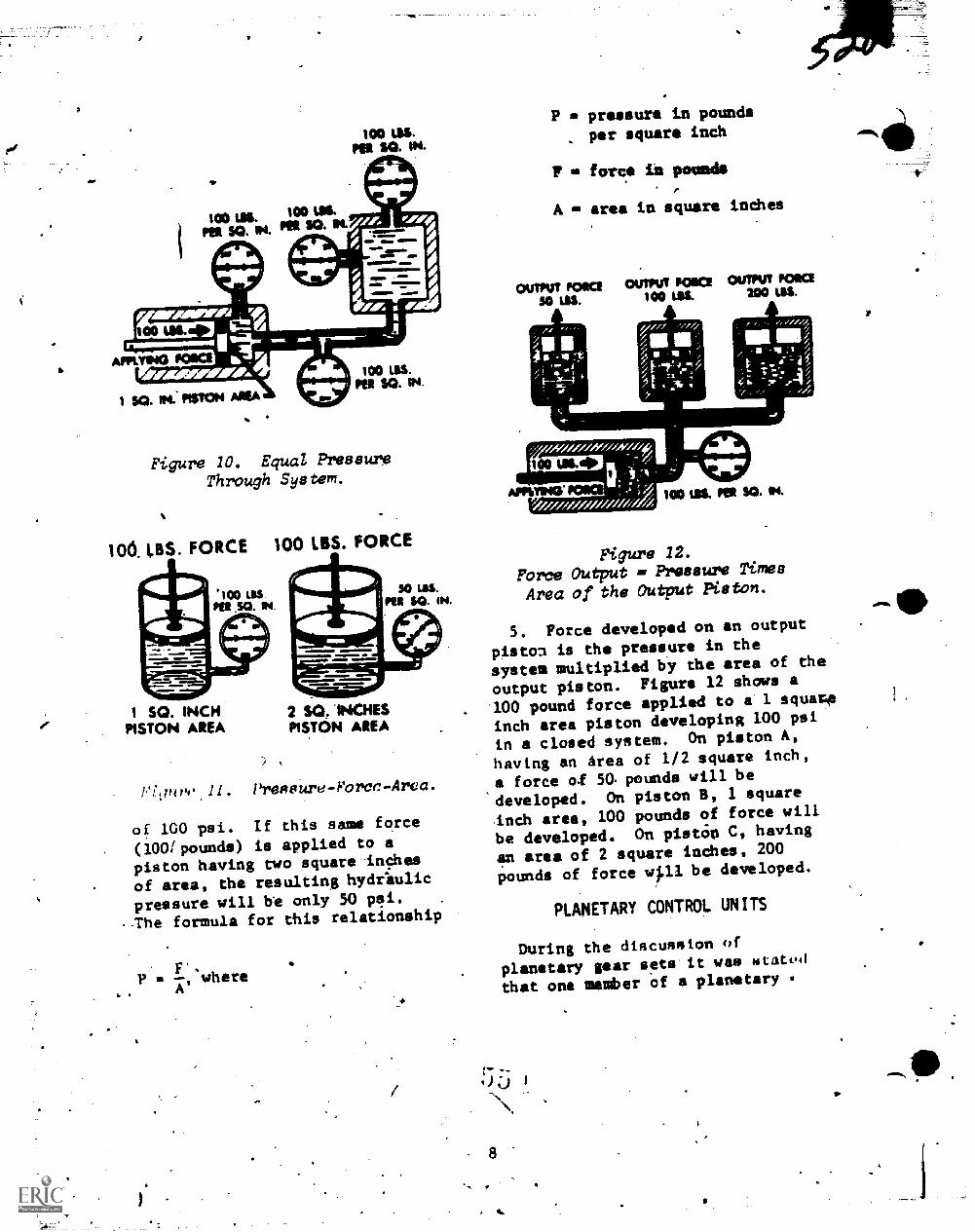
a
100 L$S.Pee SO. IN.
Figure 10. Equal PressureThrough System.
10 1,85. FORCE 100 LBS FORCE
SO LBS.PER $CE IN.
1 SQ. INCHPISTON AREA
1IMM MEMMIMIMM. MA-
2 SQ. INCHESPISTON AREA
PI,Iuro 11. Preoeure-Force-Area.
af 100 psi. If this same farce
(1001pounds) is applied to a
piston having two square inches
of area, the resulting hydrlulic
pressure will be only 50 pai. .
. The formula for this relationship
I'sP
'
whereA
P pressure in pounds
per square inch
w force in pagoda
A area in square indhes
OUTPUT POIKSJO LSS.
OUTPUT Pala100 LU.
OUTPUT POIKI200 LIS.
Figure 12.
Force Output m Pressure Times
Area of the Output P1ston.
5. Force developed on an output
pisto3 is the pressure in the
system multiplied by ehe area of the
output piston. Figure 12 shows a
100 pound force applied to a 1 squaro
inch area piston developing 100 psi
in a closed system. On piston A,
having an Area of 1/2 square inch,
a force of 50. pounds will be
developed. On piston B, 1 square
.inch area, 100 pounds of force will
be developed. On pistion C, having
an area of 2 square inches, 200
pounds of force w1.11 be developed.
PLANETARY CONTROL UNITS
During the discussion of
planetary par seta it W88 mtated
that one member of a planetary
AM%
41,
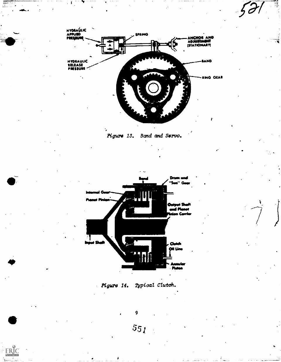
ts9
6 I
tiz4n10 vdP pr funBid
0.111W 1111.
41016 011010
meD ..u.S.. pup WWI
11V30 OMR
Ims Pdtv
--"loggsaM SNOW
4 Pal
forums paw pupg *Er way
411VNOUVI$1 40111MMICOV
014, 11000V ONIIMS
On, nod Mans 3nAveciAm
ionstesa 2turvirvokw
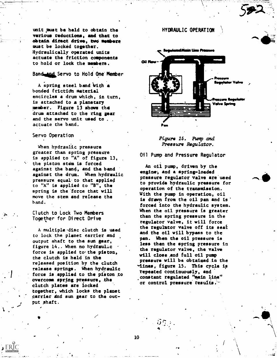
unit pmat be held to obtain thevarious reductions, and that toObtain direct drive, WO mesibersmust be locked together.Hydraulically operated unitsactuate the friction componentsto hold or lock the members.
BandmiliServo to Hold One Member
A spring steel band krith abonded frictidh materialencircles a drum which, in turn,is attached to a planetarymember. Figure 13 shows thedrum attached to the ring gearand the servo unit used to . .
actuate the band.
Servo Operation
When hydraulic pressuregteater than spring pressureis applied to "A" of figure 13,the piston stem is forcedagainst the band, and the bandagainst the drum. When hydraulicpressure equal.to that appliedto "A" is applied to "B", thespring is the lorce that willmove the stem and release theband.
Clutch to Lock Two MembersTogether for Direct Drive
A multiple.disc clutch is usedto lock the planet carrier andoutput shaft to the sun gear,figure 14., When no hydrauld.cforce is applied to,that piston,the clutch is held in therej.eased position by the clutchrelease springs. When hydraulicforce is applied to the piiton xoovercome sming pressure, theclutch plates are iockedtogether, which locks the planetcarrier dnd sun gear to the out-put shaft.
um.
HYDRAULIC OPERATION
Use Pressen
01114ovv-
.111.111
Pan
PriPlaweItegvinter Valve
:7...umplbegvioNwVohs* Spring
Figurw 15. PUmp andFreasurw Regulator.
Oil Pump and Pressure Regulator
An oil pump, driven by theengine-, and a spring-loaded
pressure regulator valve are'usedto provide hydraulic pressure foroperation of the transmission.With the pump in operation, oilis drown from the oil pan and is'forced into the hydraulic system.When the oil pressUre is greaterthan the spring pressure in theregulator valve, it will forcethe regukator valve off its seaEand the oil will bypass to thepan. When the oil pressure isless than the spring pressure inthe regulator valve, the valvewill close and full oil pumppressure will ba obtained in the',lines,- figure 15. This cycle iprepeated continuously, andconstant regulated line"or control pressure resuits.'-
10
;A
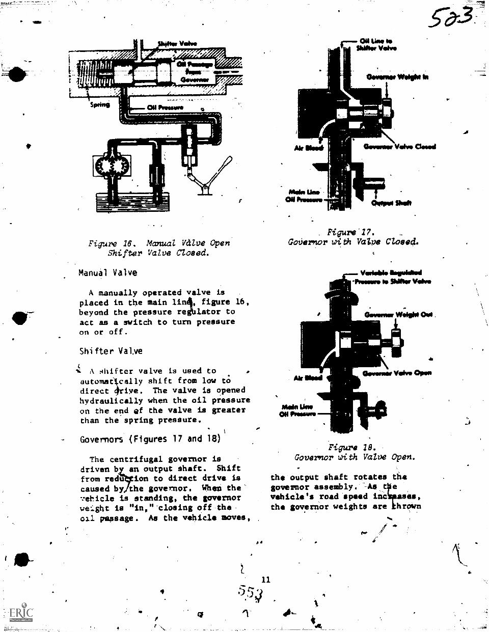
Figure 16. Manual Valve OpenShifter Valve Closed.
Manual Valve
A manually operated valve isplaced in the main lin4, figure 16,beyond the pressure redblator toact as a switch to turn pressureon or off.
Shifter Valye
% A shifter valve is used toautomatIcally shift from low tOdirect 4rive. The valve is openedhydraulically when the oil pressureon the end ef the valve is greaterthan the spring pressure.
Governors (Figures 17 and 18)
The centrifugal governor isdriven bZ
an output shaft. Shift
from redu ion to direct drive iscaused by the governor. Whei the'vehicle is standing, the governorwef.ght is "in,"-closing off the-oil passage. As the vehicle moves,
Melina
MoietiesONPreeeere
Oil Line reIShifter Valve
Geventer Weighs In
Geverner Valve Creed
Oetpoot Shaft
Figure 17.GoVernor with V2i08 Closed.
Ihorliened-Preseere le Shifter %dee
0 OIVOIMMIW
Me Illerd
nterinikreOil Promme
fieverner Valve Open
Figure 18.Governor with Valve Open.-
the output shaft rotates thegovernor assembly. As t evehicle's road speed incaaes,the governor weights are hrown
p.
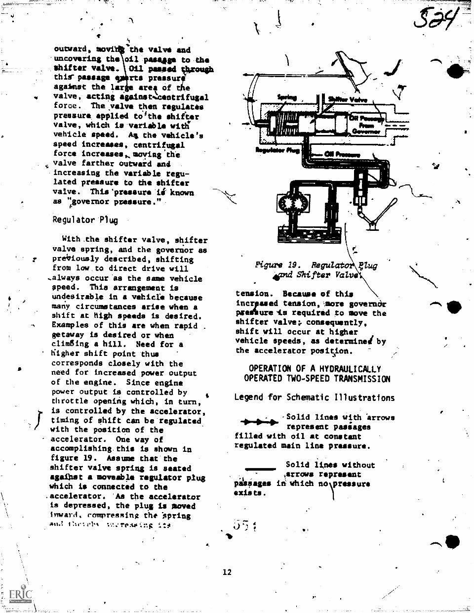
.*t
outward, movi %the valve anduncovering the oil passim" to theShifter valve. IOi1 pitied tkrouShthis' passage qs4rts pressurfevilest the laré. area of thevalve, acting igainstq:centrifugalforce. Theyalve then regulatespressure applied tolthe shiftervalve, which ill variable with'
vehicle speed. M the vehicle'sspeed increases, centrifugalforce increases,moving thevalve farther ourward andincreasing the variable regu-lated pressure to the shiftervalve. This'pressure ii knownas "governor pvessure."
Regulator Plug
With.the shifter valve, shiftervalve spring, and the governor asprelialously described, shiftingfrom low to direct drive will
,always occuras the same vehicleppeed. This arrangement isundesirable in a vehicle becausemany circumetances arise when ashift at high speeds Ls desired.Examples of this are when rapid .
getaway is desired or whenenraging a hill. Need for aKigher shift point thuscorresponds closely with theneed for increased power outputof the engine. Since enginepower output is controlled bythrottle opening which, in turn,is controlled by the accelerator,timing of shift can be regulatedwith the position of theaccelerator. One way ofaccomplishing this Ls shown infigure 19. Assume that theshifter valve spring is seatedaga0.st a moveable regulator plugwhich is connected to the.accelerator. 'Aa the acceleratoris depressed, the plug is movedInwarA, compressing rhe 'springAti.! Ctele1.% :.tag
Figure 19. Regulato4hand Shi fter Valve
tension. Because of thisincrpased tension,more governorpsenurets required ;o move theshifter valve; consequently,shift will occur at highervehicle speeds, as determined bythe accelerator position.
?lug
OPERATION OF A HYDRAULICALLYOPERATED TWO-SPEED TRANSMISSION
Legend for Schematic Illustrations
.-Solid lines with 'arrmdsrepresent pasiages
filled with oil at constantregulated main line pressure.
Solid ltnes withoutarrows represent
peerages in whichexists.
Ii tic
z
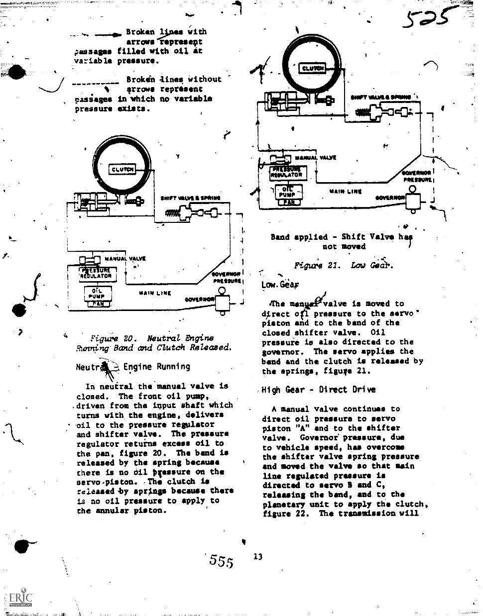
?manesvariable
pasiagespressure
Brokon24nes witharrows represect
filled with oil itpressure.
Brokin aines Without:Frogs represent
in 'which ao variableexists.
SWIFT VALK SIMMS
1
00VV1NOPINIIISUM,
4101011,11110e211
4 Figure 20. Neutral EngineRunning Band and Clutch Released.
Neutra. Engine Running
In neuiral the manual valve is
closed. The front oil pump,.driven from the input shaft whichturns with the engine, deliversoil to the pressure regulatorand shifter valve. The pressureregulator retuins excess oil tothe pan, figure 20. The band isreleased by the spring becausethere is no dil Otessure on theservorpiston. -The clutch is:die/wed by sprl.nge because there
is no oil pressure to apply tothe annular piston.
MORT MUM, IMMO
WAMIAL VALYS /01/111111011
PRIMPURIL
111.121:sovis81011
.
Band app/ied Shift'Valve halnot moved
Figure 21. Low Gea),.
Low. Gia,
Jrhe manJ&eV valve is moved togrect oçi pressure to the servo'piston and to the band of theclosed,shifter valve. Oilpressure is also directed to thegovernor. The servo applies thebend end the clutch is released bythe springs, figuva 21.
,High Gear - Direct Drive
55,5 13
A manual valve continues todirect oil pressure to servopiston "A" and to the shiftervalve. Governof pressure, dueto vehicle speed, has overcomethe shifter valve spring pressureand moved the valve so that mainline regulated pressure isdirected to servo B and C,releasing the band, and to theplanetary unit to apply the clutch,figure 22. The transmission will
p.
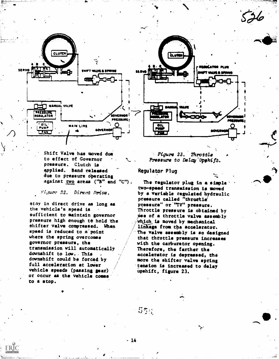
Shift Valve has moved dueto effect of Governorpressure. Clutch isepplied. Band releaseddue to pressure Operatingagainst two areas ("B" and
Yi.jure 22. Direct nrive.
stay in direct drive as long asthe vehicle's speed issufficient to maintain governorpressure high enough te hold theshifter valve compressed. Whenspeed is reduced to a'pointwhere the spring overcomesgovernor pressure, thetransndssion will automaticellydownshift to low.. This ,
downshift could be forced byfull acceleration at loWervehicle speeds (passing gear)or occur as the vehicle comes'to a stop.
%ft)
Figur, 23. ThrottlePressure to Delay'Upphift.
Regulator Plug
The regulator plug in a simple'two-speed transmission is movedby a variable regulated hydraulicpressure called "throttleptessure" or "TV" pressure.Throttle pressure is obtained by,iise of a throttle valve assembly
i410._ctis moved by mechanical/ liikige from the accelerator.
.
The valve assembly is so designedthat throttle pressure increaseswith the carburetor opening.Therefore, the farther theaccelerator is depressed, themore the shifter valve spring'tension is increased to delayiapshift, figure 23.
14
itt
:WLZTiCINS
1. Define "torque."
2. How is torque muliiplied bythe transmission?
3. What gears are included intne planetary gear system?
(...,1 4. Expltin the operatingprinciples of the planetary gears.
5. Explain the basic principlesof hydraUlics.
AWhat is the purpose of the
ft servo" as pertains to automatic-transsissions?
7
7. Explain the operation of theclutch.
8. Explain the operation of thetranisission governor.
55
15
4
Kaintsnancs nranch:nuke 011, Illinois
.
."TIVES
?
3ABR47330-6111 -505
BASIC PRINCIPLES OF AUTOMATIC TRMSNISSICtIS
Upon completion of dais wokkbook, you will be able to explainplanetary sear .operation4and the applicatton o: hydraulic principlesto a simple two-speed automatic transmission.
PROCEDURE
- Complete the following exercises by following the instructionsgiven for each exercise and as directed by your instructor.
10 5
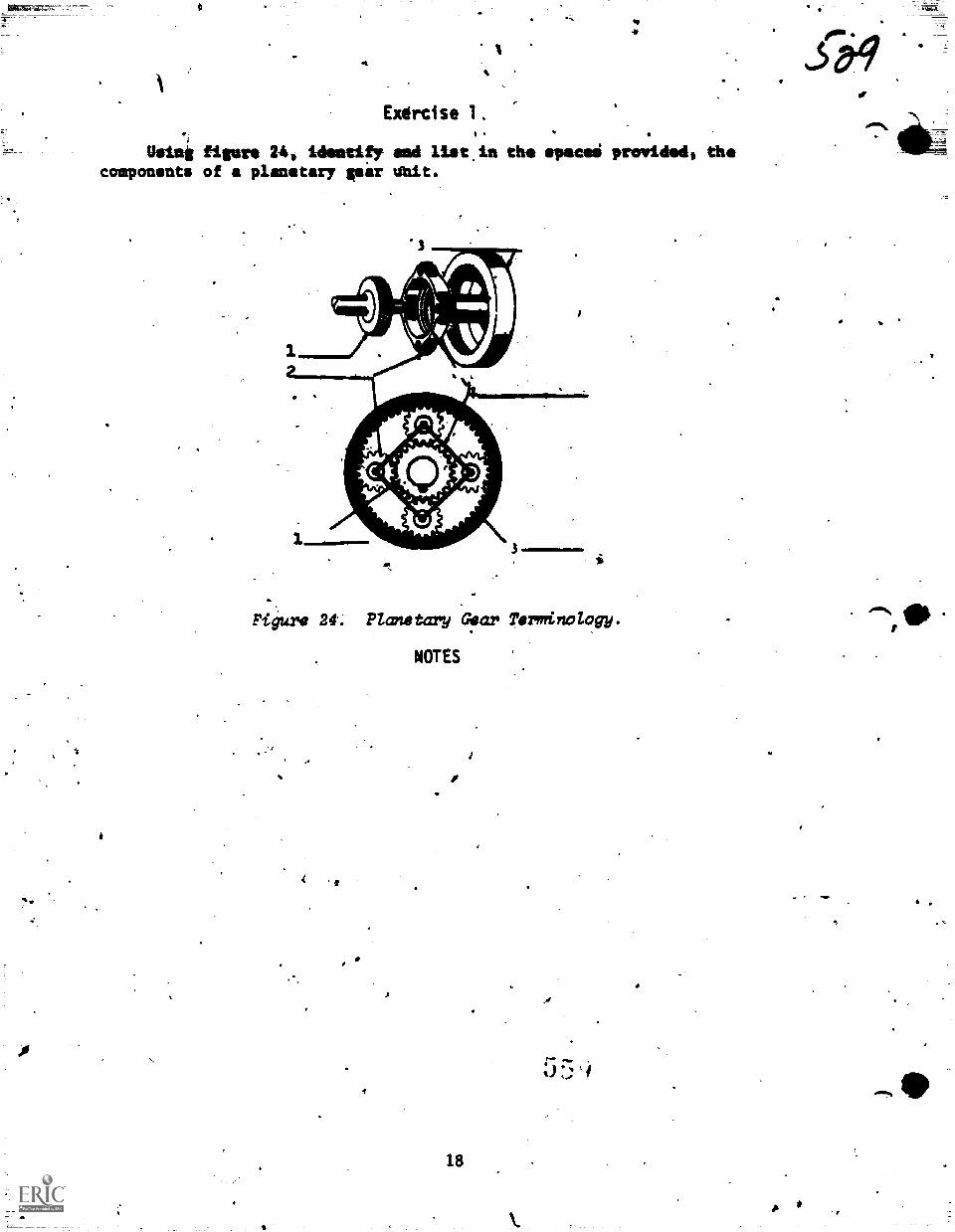
Exercise 1,
tieing figure 24, identift end liat.in the apnoea provided, thecomponents of a planetary gear Unit.
*3 --7"'W7
Figure 24. Planetary Gear Terminology. 410
1
NOTES
18
r--
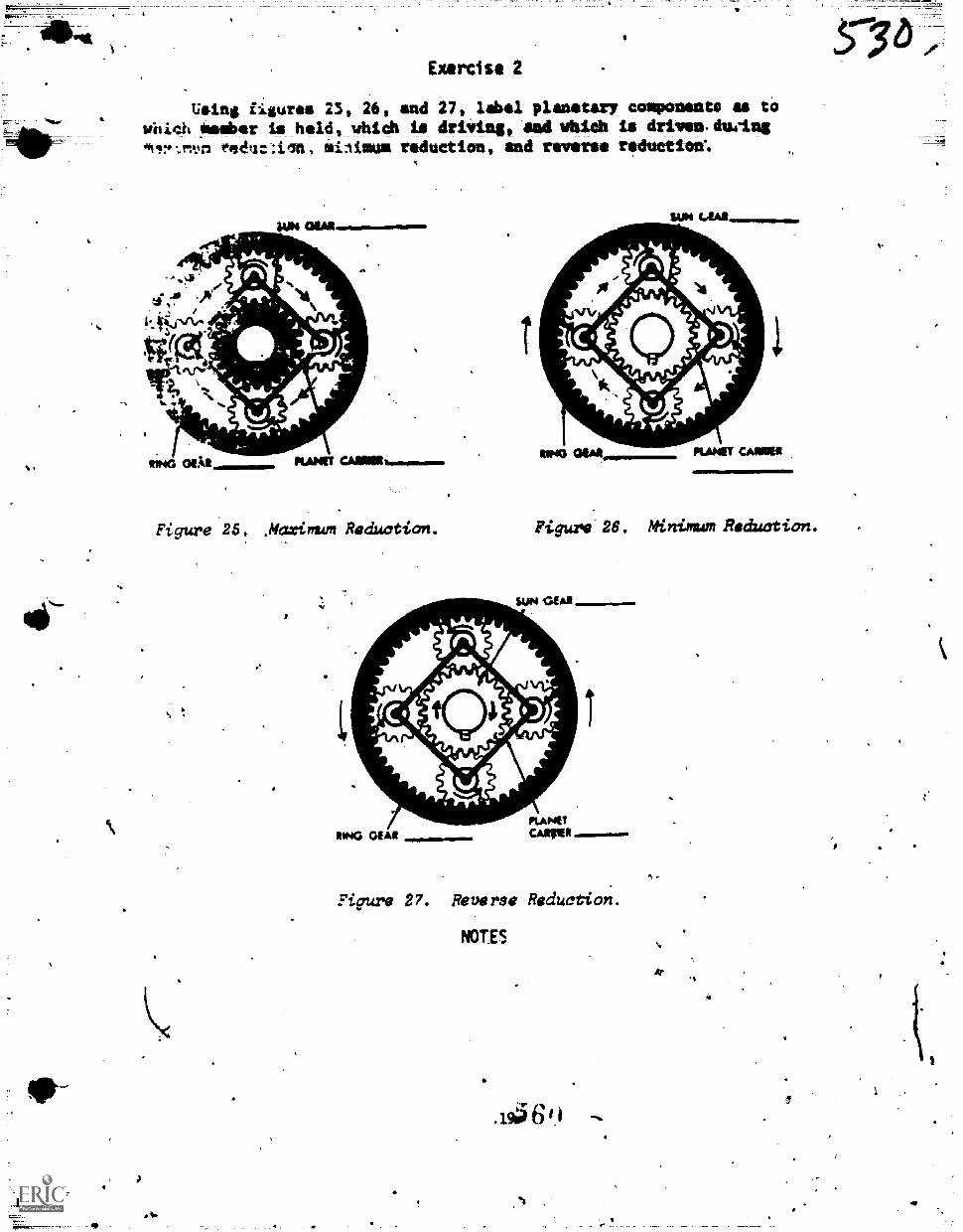
Exercise 2
Usins figures 23, 26, and 27, label planetary conponents as toWii't nember is held, which ia driving, and vbich is drivenduein$
iininun reduction, and reveres r'iluctiolf.
SUN OIAIR.o..p..op
to' ogAit RAM
SUN LAAR
RIP413 OEM PLANET CAMP
Figure 2 . .Maxinum Reduction. Figure 26. Minimum Reduction.
7
MANP
Figure 27. Reverse Reduction.
NOTES
.1915611
Pillii.111 1
57 6 ,
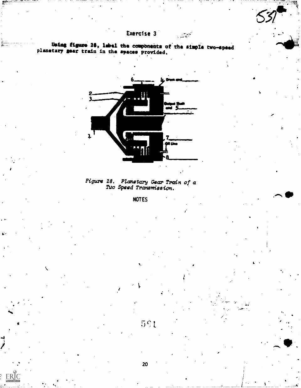
V.
Exercise 3 :
Voles figure 21, label the towboats of' the simple tivo-epeedplanetary gear train in the spaces provided.
&IOW Orillt
Figure 28. Planetary Gear Train of aTUo Speed Tranamieeion.
NOTES
5 c,
A
4
I.
4
--all
Exercise 4
List the purposes of the following components of a simpletranemiesion hydraulic systiva.
oil ptaap
2. Pressure regulators valve
Manual valve
4. Shifter valye
5. Governor valve
6. Throttle Valve
21
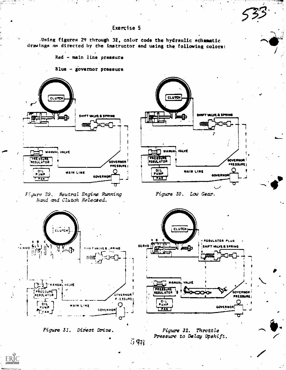
A
.Exercise 5
_Using figurem 29 through 32, color code the hydraulic aChematicdrawings no directed by the instructor and using the following colors:
Red - main line pressure
Blue - gOvernor pressure
1MANUAL VALVE
I wIrr vALV1. 6 $PIVINI
frWSSU'REGULATOR
7017"'"1P'JMPI 044 7
MAIN LtNtGOVINN0111
Ffgure 29. Neutral Engine RUnningRand and Clubch Released.
1pli...i.I V ANUAL vALVE
r--1.0441,,supf-]
RIGVLATcR
1
(._
1.0.umpr cm
L.1- P A 04
.:110. I' vat vE a .1aRtibia
ovi1477L;c1.
a0AII4 UWE
GOVERNOR 1
P ASSURE,
j_ jcovi.010001
Figure 31. Direct Drive.
Pressure to Delay Upshift.
tPi
WIRT WWI a SMUG
PRREGULATOR
OILPUMP'L...1.,
MAIN LINE
533
f
,
sovilINOR ;
PRESSURE,
GOVINNOPIr21_ .J
Figure 30. Low Gear.
RUVUMA PLUG -
t SHIFT vALVE & SPRING
4A
L16111111111MANUAL VALVE
rWUSUAI 1 &
:REGULATOR It6C3101.0.4
. -\.,4;;C WVERWM1 r
a PRESSURif
GeVERNOIr2L 4J'171
Figurw 32. Throttle


