Embed Size (px)
Citation preview

IEEE TRANSACTIONS ON WIRELESS COMMUNICATIONS (SUBMITTED) i
Asynchronous Multiuser Reception for OFDM
in Underwater Acoustic Communications
Zhaohui Wang,Student Member, IEEE,Shengli Zhou,Senior Member, IEEE,
Josko Catipovic,Member, IEEE,and Peter Willett,Fellow, IEEE
Suggested Editorial Areas: • Multicarrier communications
• Multiuser detection
• Multiple access techniques
Manuscript submitted January 12, 2012. Z.-H. Wang, and S. Zhou are supported by the ONR grant N00014-09-1-0704
(PECASE) and the NSF grant ECCS-1128581.
Z.-H. Wang, S. Zhou, and P. Willett are with the Department ofElectrical and Computer Engineering, University of Connecticut,
371 Fairfield Way U-2157, Storrs, CT 06269, USA (email:{zhwang, shengli, willett}@engr.uconn.edu).
J. Catipovic is with the Naval Undersea Warfare Center, Newport, RI 02841, USA (email: [email protected]).
Contact author: S. Zhou, Tel.: (860) 486-4593, email: [email protected]
January 12, 2012 DRAFT

IEEE TRANSACTIONS ON WIRELESS COMMUNICATIONS (SUBMITTED) 1
Abstract
Recently significant progress has been made on point-to-point underwater acoustic communica-
tions, and the interest has grown on the application of thosetechniques in multiuser communication
settings, where the asynchronous nature of multiuser communication poses a grand challenge. This
paper develops a time-asynchronous multiuser reception approach for orthogonal frequency division
multiplexing (OFDM) transmissions in underwater acousticchannels. The received data burst is seg-
mented and apportioned to multiple processing units in an overlapped fashion, where the length of
the processing unit depends on the maximum asynchronism among users on the OFDM block level.
Interference cancellation is adopted to reduce the interblock interference between overlapped processing
units. Within each processing unit, the residual inter-block interference from multiple users is aggregated
as one external interference which can be parameterized. Multiuser channel estimation, data detection,
and interference mitigation are then carried out in an iterative fashion. With asynchronous multiuser
transmissions, simulation and experimental results clearly demonstrate the impact of the maximum
relative delay among users on the receiver performance.
Index Terms
Asynchronous multiuser communication, OFDM, underwater acoustic channels, overlapped trunca-
tion, interference aggregation
I. INTRODUCTION
Underwater acoustic (UWA) communications and networking have been under extensive in-
vestigation in recent years. On the physical layer, significant advances have been witnessed for
both single-carrier and multicarrier transmissions; see,e.g. [1], [2], [3], [4], [5], [6], [7], [8],
[9], [10], [11], [12], [13], [14], [15], [16], and references therein. Interest is rapidly growing on
the integration of those latest point-to-point communication techniques to practical underwater
networked systems with multiple users.
This paper considers the application of OFDM modulation to multiuser underwater acoustic
communications. Should the signals from multiple users be synchronized at the receiver on the
OFDM block level, multiuser reception can be viewed as a distributed multi-input multi-output
(MIMO) problem, as considered in [17]. Synchronization, however, is an extremely challenging
task in distributed underwater acoustic systems, due to large propagation delays and lack of a
well-defined network infrastructure.
January 12, 2012 DRAFT

IEEE TRANSACTIONS ON WIRELESS COMMUNICATIONS (SUBMITTED) 2
A. Asynchronous OFDM Research in Radio Channels
Asynchronous multiuser reception has been extensively investigated with code-division multi-
ple access (CDMA) transmissions; see e.g., [18], [19], [20]and references therein. The impact of
the asynchronism of users on orthogonal frequency-division multiple access (OFDMA) uplink
transmission has been investigated in [21], [22]. Related work on the asynchronous OFDM
receiver is limited [23], [24], [25], [26], [27], [21], [22], and can be broadly grouped into two
main categories.
The works in the first category focus on the demodulation and decoding modules of the
receiver, assuming that perfect channel knowledge is available. In [23], a maximuma posteri-
ori (MAP) receiver over a three-dimensional trellis was developed for asynchronous multiuser
OFDMA transmissions, where the trellis is expanded by the user index, time index and subcarrier
index. This method has very high computational complexity when the number of subcarriers is
large. With the same truncation method in the synchronous multiuser reception to divide the
received signal into individual processing units, Ref. [24] pointed out that the conventional
frequency-domain approaches for decoding and interference suppression are not effective, as
the orthogonality of subcarriers of the misaligned users islost due to the misalignment of the
otherwise-orthogonal users’ signals. Hence, the spatial-time filtering techniques were employed
in [24], [25], [26] to exploit the spatial diversity of multiple receivers. In [28], a general message-
passing based equalization method was proposed in the presence of interference.
The works in the second category focus on channel estimationin asynchronous OFDM
systems. A subspace based semi-blind channel estimator wasproposed in [27] to separate the
desired user’s channel vector from channel vectors of otherusers. The method, although often
very useful, can be expected to suffer when the channels havefast time-variation.
Apparently, a complete receiver design for asynchronous OFDM with both channel estimation
and equalization is not available even for radio channels. In addition, methods developed for
radio channels may not be not directly applicable for fast-varying underwater acoustic channels.
B. This Work
Most works for underwater acoustic OFDM are on point-to-point communications, e.g., [1],
[2], [5]. The extension to cooperative OFDM assumes block level synchronism among users [17].
January 12, 2012 DRAFT
IEEE TRANSACTIONS ON WIRELESS COMMUNICATIONS (SUBMITTED) 3
This paper proposes a multiuser receiver for asynchronous OFDM transmissions in underwater
acoustic channels. The main contributions are the following.
• We develop a burst-by-burst asynchronous OFDM receiver, which partitions the received
signal corresponding to one data burst into multiple overlapping processing units, whose
length depends on the maximum asynchronism on the OFDM blocklevel among the users.
The interference from the neighboring processing units on the current processing unit is
reduced through interference subtraction. Within each processing unit, we adopt aninter-
ference aggregationconcept, treating the residual interferences arising fromthe misaligned
blocks from all users as one external interference. The interference is parameterized by
a number of parameters depending on the maximum relative delay among users. Then
multiuser channel estimation, data detection, and interference mitigation are carried out in
an iterative fashion.
• We provide a concrete example to investigate the distribution of the maximum block-level
relative delay among multiple asynchronous users.
• Extensive simulation and experimental results are used to validate the performance of the
proposed receiver in both time-invariant and time-varyingscenarios. These results highlight
the dependence of the decoding performance on the maximum relative delay among users.
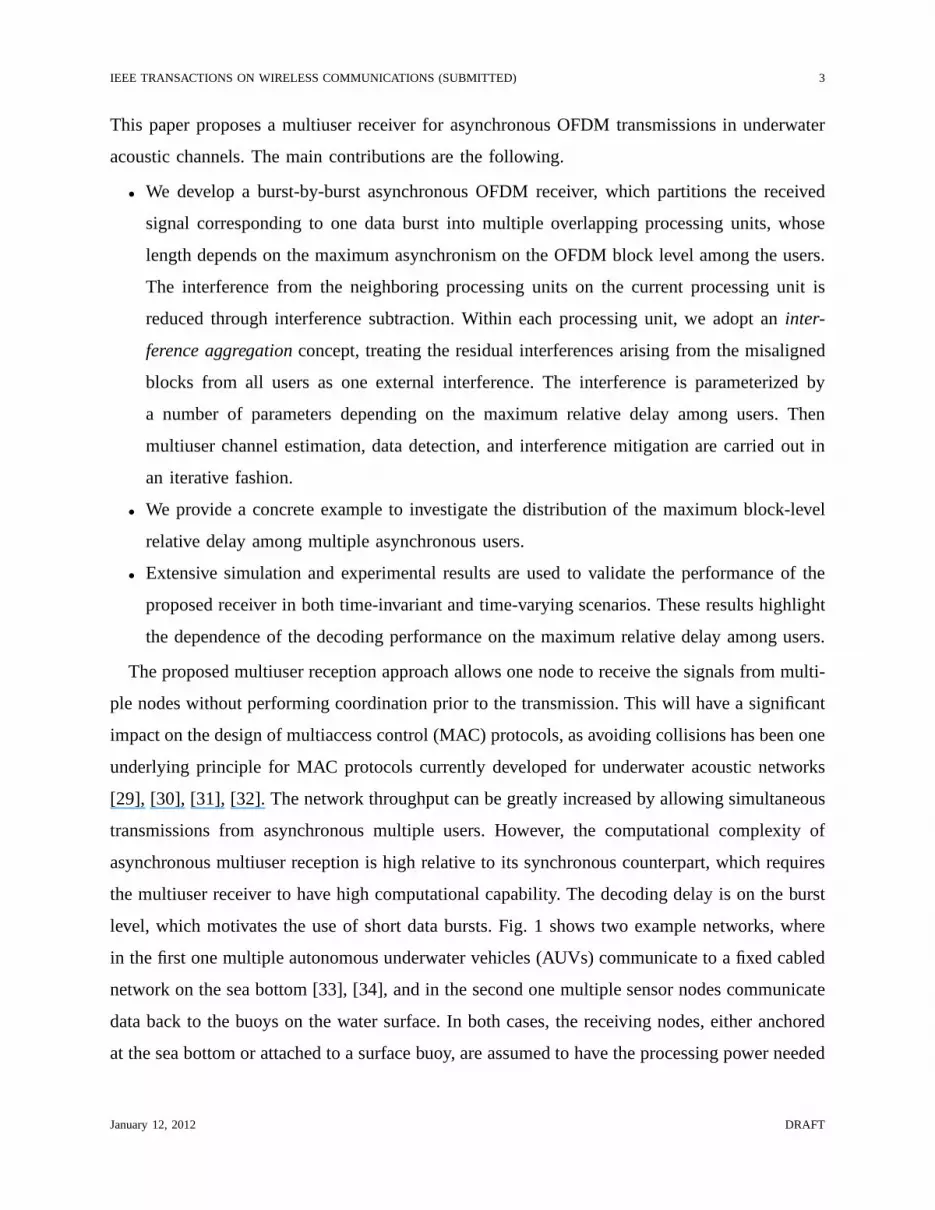
The proposed multiuser reception approach allows one node to receive the signals from multi-
ple nodes without performing coordination prior to the transmission. This will have a significant
impact on the design of multiaccess control (MAC) protocols, as avoiding collisions has been one
underlying principle for MAC protocols currently developed for underwater acoustic networks
[29], [30], [31], [32]. The network throughput can be greatly increased by allowing simultaneous
transmissions from asynchronous multiple users. However,the computational complexity of
asynchronous multiuser reception is high relative to its synchronous counterpart, which requires
the multiuser receiver to have high computational capability. The decoding delay is on the burst
level, which motivates the use of short data bursts. Fig. 1 shows two example networks, where
in the first one multiple autonomous underwater vehicles (AUVs) communicate to a fixed cabled
network on the sea bottom [33], [34], and in the second one multiple sensor nodes communicate
data back to the buoys on the water surface. In both cases, thereceiving nodes, either anchored
at the sea bottom or attached to a surface buoy, are assumed tohave the processing power needed
January 12, 2012 DRAFT

IEEE TRANSACTIONS ON WIRELESS COMMUNICATIONS (SUBMITTED) 4
to decode simultaneous transmissions from multiple users.
The rest of the paper is organized as follows. A burst-by-burst asynchronous multiuser OFDM
reception approach is developed in Section II, with severalkey modules detailed in Section
III. Investigation on the time-duration of the aggregated interference in an example network is
provided in Section IV. Simulations and experimental results are presented in Sections V and
VI, respectively. Conclusions are contained in Section VII.
Notation: Bold upper case letters and lower case letters are used to denote matrices and column
vectors, respectively.(·)T and (·)H denote transpose and Hermitian transpose, respectively.∝
denotes equality of functions up to a scaling factor.[a]m denotes themth element of vectora,
and [A]m,k denotes the(m, k)th element of matrixA.
II. THE PROPOSEDRECEIVER FORASYNCHRONOUSOFDM TRANSMISSIONS
Consider an underwater system consisting ofNu asynchronous users using block transmissions,
and a receiver equipped withNr receiving hydrophones. Assume that all users are using OFDM
transmissions with an identical parameter set1, which consists of the center frequencyfc, band-
width B, number of subcarriersK, symbol durationT and guard intervalTg with Tbl = T +Tg.
Let εµ denote the time-of-arrival theµth user, which can be obtained at the receiver by detecting
the preamble of this user. On the block level, we can assume that εµ ≤ Tbl/2; integer block
delays can be incorporated by reindexing the blocks. Without loss of generality, we assume that
0 = ε1 ≤ ε2 ≤ · · · εNu≤ Tbl/2, and defineεmax := εNu
.
The passband signal at theνth receiving element is the superposition ofNu waveforms,
yν(t) =Nu∑
µ=1
yν,µ(t − εµ) + wν(t), (1)
whereyν,µ(t) is the signal at theνth receiving element from theµth user, andwν(t) denotes the
ambient noise.
A. Overlapped Truncation
To facilitate the decoding operation at the receiver, the received signal is usually truncated into
individual processing units. For synchronous multiuser transmissions, the truncation can be easily
1The proposed scheme can be extended to single-carrier blocktransmissions if the OFDM multiuser decoding module is
replaced by a similar module tailored for single-carrier transmissions.
January 12, 2012 DRAFT

IEEE TRANSACTIONS ON WIRELESS COMMUNICATIONS (SUBMITTED) 5
carried out according to the block structure of the transmitted signal. However, for asynchronous
transmissions, the block structure of the transmitted signal at the receiver is destroyed. As shown
in Fig. 2, a block from one user can collide with multiple blocks from other users. Different
truncation methods could lead to different decoding schemes [22]. One existing method is to
synchronize the truncation to the time-of-arrival of one desired user [24], [27], [25], [26], with
each truncation having a block lengthTbl, including the complete information of one block from
the desired user and partial block information from others.However, this method is not effective
when the overlap length of the desired user and others is large.
In this work, we consider an overlapped truncation method asshown in Fig. 2, where each
truncated block length isTbl := Tbl + εmax. Thenth truncated block consists of the information
from (3Nu − 2) transmitted blocks, including i) part of the(n− 1)st blocks from users2 ∼ Nu
at the beginning of this truncation, ii) complete information of thenth blocks from theNu users,
and iii) part of the(n + 1)st blocks from users1 ∼ (Nu − 1) at the end of this truncation,
yν(t; n) =
Nu∑
µ=1
yν,µ(t − εµ; n)
︸ ︷︷ ︸
desired OFDM signal
+wν(t; n) t ∈ [0, Tbl]
+Nu∑
µ=2
yν,µ(t − εµ + Tbl; n − 1) +Nu−1∑
µ=1
yν,µ(t − εµ − Tbl; n + 1)
︸ ︷︷ ︸
interference from the preceding and succeeding processingunits
. (2)
With (2), an optimal receiver can be designed by treating theasynchronousNu-user problem
as a synchronous(3Nu − 2)-user problem [18]. However, solving the problem therein usually
requires more efforts than solving a typical synchronous(3Nu − 2)-user problem, since the
orthogonality of subcarriers of the(2Nu − 2) misaligned users in (2) is destroyed.
B. Interference Aggregation
In this paper, rather than modeling the partial block interferences from(2Nu − 2) users
individually with the transmitted signal, we use aninterference aggregationconcept to treat
the aggregated IBI as one interfering waveform as shown in Fig. 2, which is formulated as
Iν(t; n) =
∑Nu
µ=2 yν,µ(t − εµ + Tbl; n − 1), t ∈ [0, εmax]
0, t ∈ [εmax, Tbl]
∑Nu−1µ=1 yν,µ(t − εµ − Tbl; n + 1), t ∈ [Tbl, Tbl]
(3)
January 12, 2012 DRAFT

IEEE TRANSACTIONS ON WIRELESS COMMUNICATIONS (SUBMITTED) 6
which has a bandwidth identical to that of the useful signal denoted byB. Given the maximum
delay εmax, one can see that the number of the degrees-of-freedom (DoF)of the interfering
waveform, i.e., the time-bandwidth product of the aggregated interferenced2Bεmaxe, does not
change as the number of asynchronous users increases.
We have (2) reformulated as
yν(t; n) =
Nu∑
µ=1
yν,µ(t − εµ; n) + Iν(t; n) + wν(t; n), t ∈ [0, Tbl]. (4)
Hence, the asynchronousNu-user problem can be regarded as a synchronousNu-user problem
in the presence of an external interference.
C. The Overall Structure of the Proposed Receiver
As shown in [23], the IBI arising from the asynchronism of users can be optimally mitigated by
performing a joint decoding of blocks in one transmission from all users. However, this is usually
computationally prohibitive. Leveraging the overlapped truncation method and the interference
aggregation concept, we next propose a multiuser receptionapproach by performing a burst-by-
burst decoding with interference cancellation.
Different from the external interference considered in [35], the time-domain input-output
relationship in (2) shows the interference term in (4) actually consists of part of useful signals
corresponding to the(n − 1)st and the(n + 1)st transmitted blocks from theNu users. If these
blocks have been successfully decoded or estimates of transmitted symbols within these blocks
are available, one can get initial estimates of the interferences that spill over from these blocks to
the nth block, and thus take the estimates as thea priori knowledge of the interferences. After
subtracting initial estimates of the interferences from the received signal, the joint multiuser
decoding and cancellation of the aggregated residual interference can be performed in thenth
block.
The proposed asynchronous multiuser receiver for each block consists of the following three
steps.
• Interference subtraction:With the estimated interference passed from the preceding and
the succeeding processing units, interference subtraction can be carried out prior to the
multiuser decoding;
January 12, 2012 DRAFT

IEEE TRANSACTIONS ON WIRELESS COMMUNICATIONS (SUBMITTED) 7
• Joint multiuser processing with residual interference cancellation: Techniques for syn-
chronous multiuser decoding and approaches for external interference cancellation can be
used;
• Interference reconstruction:Based on the multiuser decoding results, the interference of the
current block to the preceding and the succeeding blocks will be reconstructed.
To improve the interference cancellation performance, an iterative forward/backward process-
ing of blocks within one burst can be performed, as shown in Fig. 3. As the iteration goes on,
the accuracy of interference estimation improves gradually, thus leading to a better multiuser
decoding performance, which in turn boosts the performanceof interference estimation.
A detailed description of three modules in the proposed receiver will be provided in Section III.
D. Discussions of the Proposed Receiver
Compared with a synchronous multiuser receiver, the proposed asynchronous multiuser re-
ceiver can only perform multiuser decoding after receivingthe whole burst from all users, hence
suffering a processing latency. Similar to the Viterbi algorithm for channel equalization, the
latency can be reduced by using thesliding blocktechniques proposed in, e.g. [36], [37], which
leads to a batch-by-batch processing, with the batch size depending on the maximum tolerant
latency and the storage capability of the receiver.
When the batch size is one, the proposed receiver degrades toa block-by-blockreceiver.
Relative to the block-by-block decoding, burst-by-burst decoding leverages the decoding results
of preceding and succeeding blocks for interference cancellation, hence enjoys a better decoding
performance; however, it suffers a processing latency of the batch size.
Hereafter, we mainly focus on the receiver design for burst-by-burst processing, and the block-
by-block receiver can be obtained as a special case whose performance will also be tested in
Sections V and VI.
III. D ESCRIPTIONS OFTHE RECEIVER MODULES
This section provides detailed descriptions on different modules of the proposed receiver for
asynchronous OFDM transmissions. The modules are presented according to their order in the
receiver processing.
January 12, 2012 DRAFT

IEEE TRANSACTIONS ON WIRELESS COMMUNICATIONS (SUBMITTED) 8
Prior to the interference subtraction, the passband-to-baseband downshifting and baseband
lowpass filtering are performed. Defineyν(t; n) as the baseband waveform corresponding to
the passband signalyν(t; n). In the sequel, we focus on the receiver modules operating inthe
baseband.
A. Interference Subtraction
Assume thea priori knowledge of the time-domain interference waveform in baseband which
is denoted byIν(t; n) (its availability will be discussed in Section III-D). Prior to the receiver
processing, subtraction of the initial interference estimate fromyν(t; n) in (4) leads to2
yν(t; n) =Nu∑
µ=1
yν,µ(t − εµ; n) + ην(t; n) + wν(t; n), t ∈ [0, Tbl] (5)
where ην(t; n) denotes the residual interference. As the residual interference has an identical
time-duration and bandwidth as the interferenceIν(t; n), the number of DoF ofην(t; n) is also
d2Bεmaxe.
In the initial forwardblock-to-blockdecoding of the proposed receiver, thea priori knowledge
of the interference from the subsequent block is not available. Hence, we set it as zero at the
beginning. Once all the blocks have been processed, the initial estimates of the interference
spilled over from both neighboring blocks are available. During the following processing, the
latest estimates of the decoded blocks are used for interference cancellation.
B. Frequency-Domain Oversampling
Defineα as the frequency-domain oversampling factor. Themth frequency component of the
time-domain signalyν(t; n) can be obtained via
zν [m; n] =1
T
∫ Tbl
0
yν(t; n)e−j2π m
αTtdt, (6)
for m = −αK/2, · · · , αK/2−1. Similarly, themth frequency componentην [m; n] of the residual
interferenceην(t; n) can be obtained.
2For receiver implementation, the interference subtraction can be performed with the baseband discrete samples.
January 12, 2012 DRAFT

IEEE TRANSACTIONS ON WIRELESS COMMUNICATIONS (SUBMITTED) 9
Stack the frequency componentszν [m; n] and ην [m; n] into vectorszν [n] and ην [n] of size
αK × 1, respectively. The input-output relationship in the frequency domain corresponding to
(5) can be compactly expressed as
zν [n] =Nu∑
µ=1
Λ(εµ)Hν,µ[n]sµ[n] + ην [n] + wν [n] (7)
wherewν [n] is the ambient noise vector, and the first summation term denotes the desired OFDM
signal, with sµ[n] being aK × 1 vector formed by the transmitted symbols at all subcarriers
from theµth user,Hν,µ[n] denoting anαK × K channel matrix between theµth user and the
νth receiving element, andΛ(εµ) instantiating a generic diagonal matrix defined as
[Λ(τ)]m,m = e−j2π(fc+m/(αT ))τ . (8)
Remark 1:Using the baseband sampling rateB = K/T , there aredTblBe = dTblK/T e
samples in each processing unit. To avoid information loss during the Fourier transform, the
frequency-domain oversampling factorα should satisfyαK ≥ TblK/T , i.e., αT ≥ Tbl. Based
on εmax < Tbl/2, we requireα ≥ 3(1 + Tg/T )/2. Takingα = 2 for example, the guard interval
should satisfyTg ≤ T/3.
C. Multiuser Channel Estimation and Data Decoding with Interference Cancellation
Based on the frequency-domain input-output relationship in (7), there are several unknowns
to estimate, including: i) the channel matrices{Hν,µ[n]}, ii) the information symbols in{sµ[n]},
and the interference{ην [n]}. To this end, we propose a receiver structure for iterative multiuser
channel estimation and data decoding and residual interference estimation within each block, as
shown in Fig. 3.
During the iterative processing, the multiuser decoding step takes the residual interference
estimate in the last iteration as the input, and based on the estimated desired OFDM component
after subtracting residual interference fromzν [n], it outputs the estimated channel matrices and
information symbols. Taking the output of multiuser decoding step as input, the residual inter-
ference step will subtract the reconstructed OFDM component from the frequency measurement
zν [n], so as to update the residual interference estimate which isthen fed back for the next
iteration. Once the parity check conditions of the channel decoders of all users are satisfied, or
the number of iterations reaches a predetermined thresholdImax, the iteration stops.
January 12, 2012 DRAFT
IEEE TRANSACTIONS ON WIRELESS COMMUNICATIONS (SUBMITTED) 10
For the initialization of the iterative receiver, we first treat the residual interference as the
ambient noise to get the initial estimates of channel matrices and information symbols, which
are then used to initialize the iterative operation.
The two critical components of the receiver are described next.
1) Parameterized Residual Interference Estimation and Subtraction: With the estimated chan-
nel matrices{Hν,µ[n]} and transmitted symbols{sµ[n]} from initialization or from the last
iteration, the frequency-domain measurements after subtracting the OFDM components are
ξν [n] = zν [n] −
Nu∑
µ=1
Λ(εµ)Hν,µ[n]sµ[n] (9)
which includes both the residual interference, and the the equivalent ambient noise consisting
of both ambient noise, and the channel and information symbol estimation errors.
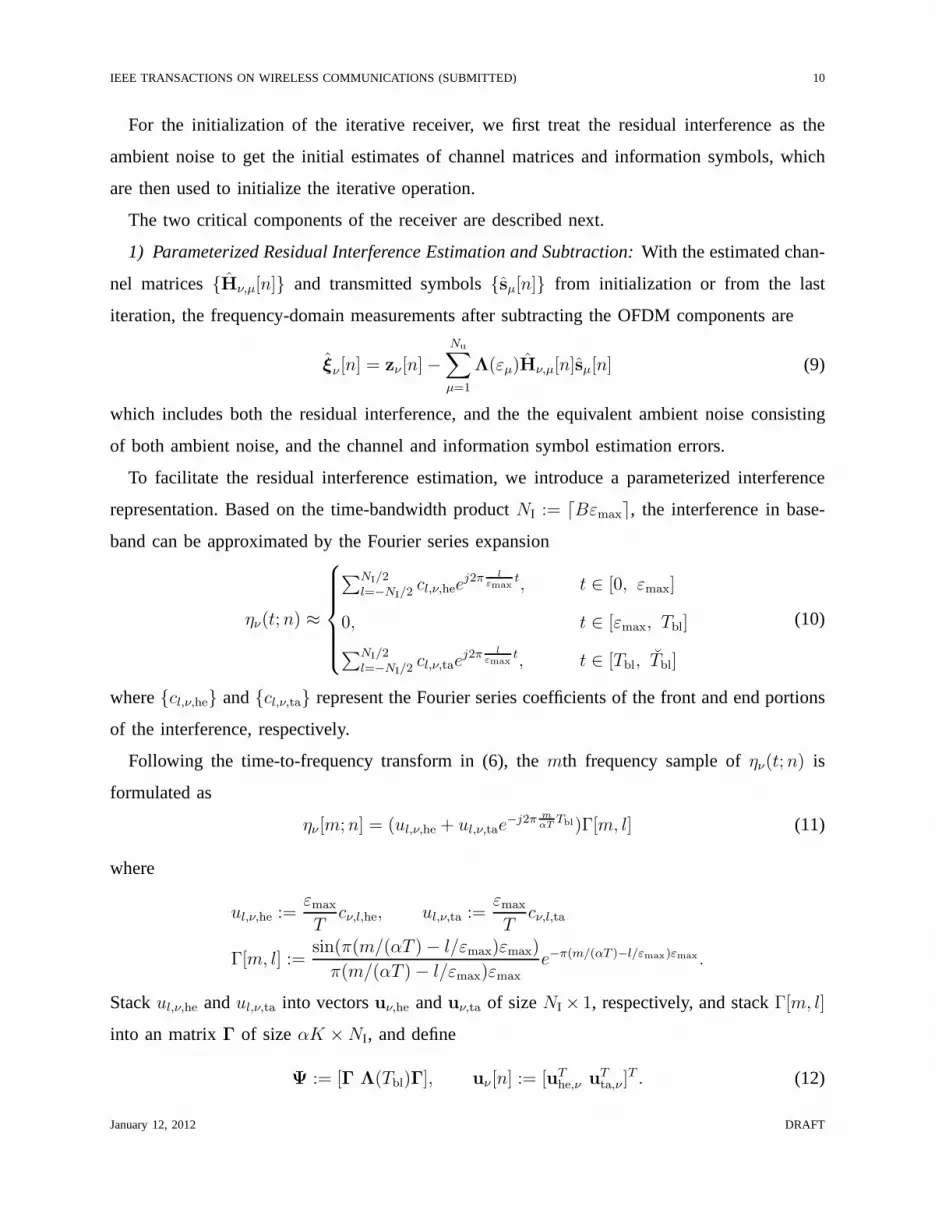
To facilitate the residual interference estimation, we introduce a parameterized interference
representation. Based on the time-bandwidth productNI := dBεmaxe, the interference in base-
band can be approximated by the Fourier series expansion
ην(t; n) ≈
∑NI/2l=−NI/2 cl,ν,hee
j2π l
εmaxt, t ∈ [0, εmax]
0, t ∈ [εmax, Tbl]
∑NI/2l=−NI/2 cl,ν,tae
j2π l
εmaxt, t ∈ [Tbl, Tbl]
(10)
where{cl,ν,he} and{cl,ν,ta} represent the Fourier series coefficients of the front and end portions
of the interference, respectively.
Following the time-to-frequency transform in (6), themth frequency sample ofην(t; n) is
formulated as
ην [m; n] = (ul,ν,he + ul,ν,tae−j2π m
αTTbl)Γ[m, l] (11)
where
ul,ν,he :=εmax
Tcν,l,he, ul,ν,ta :=
εmax
Tcν,l,ta
Γ[m, l] :=sin(π(m/(αT ) − l/εmax)εmax)
π(m/(αT ) − l/εmax)εmaxe−π(m/(αT )−l/εmax)εmax .
Stackul,ν,he andul,ν,ta into vectorsuν,he anduν,ta of sizeNI × 1, respectively, and stackΓ[m, l]
into an matrixΓ of sizeαK × NI, and define
Ψ := [Γ Λ(Tbl)Γ], uν [n] := [uThe,ν u
Tta,ν ]
T . (12)
January 12, 2012 DRAFT

IEEE TRANSACTIONS ON WIRELESS COMMUNICATIONS (SUBMITTED) 11
Eq. (11) can be compactly expressed as
ην [n] = Ψuν [n]. (13)
Based on the measurements in (9), the least-squares estimate of the interference vector is
uν [n] = (ΨHΨ)−1
Ψξν [n]. (14)
Note that(ΨHΨ)−1
Ψ only depends onεmax, hence can be pre-computed before receiver pro-
cessing.
2) Multiuser Channel Estimation and Data Detection:The desired OFDM component is
obtained by subtracting residual interference from the frequency measurements,
zν [n] = zν [n] − Ψuν [n]
=
Nu∑
µ=1
Λ(εµ)Hν,µ[n]sµ[n] + wν [n], (15)
where the equivalent noise term consists of both the ambientnoise and the interference estimation
error,
wν [n] = Ψ(uν [n] − uν [n]) + wν [n], (16)
which is treated as white Gaussian noise in the multiuser processing.
With {zν [n]}Nr
ν=1, whereNr > Nu is assumed, the conventional multi-input multi-output (MIMO)
OFDM receiver processing is then carried out. In this work, asparse channel estimator [9], a
linear MMSE equalizer [8], and a nonbinary low density parity-check (LDPC) decoder [38] are
used. After inputting the LMMSE estimate of information symbols into the nonbinary LDPC
decoder, both hard and soft decisions on the information symbols can be obtained, these being
fed back for the residual interference estimation, channelestimation and symbol detection in the
next iteration. For detailed description on the MIMO-OFDM receiver design, please refer [8]
and references therein.
D. Interference Reconstruction
Once the processing of thenth block stops, with the estimated channel matrices and the
information symbols the time-domain OFDM waveform in baseband can be reconstructed via
January 12, 2012 DRAFT

IEEE TRANSACTIONS ON WIRELESS COMMUNICATIONS (SUBMITTED) 12
the inverse discrete-time Fourier transform,
yν,µ(t; n) =
αK/2−1∑
m=−αK/2
K/2−1∑
k=−K/2
Hν,µ[m, k; n]sµ[k]ej2π m
αTt, (17)
for t ∈ [0, Tbl]. Based on the aggregated interference representation in (3), estimates of the
interference components inIν(t; n − 1) and Iν(t; n + 1), which are spilled over from thenth
block to the(n−1)st and the(n+1)st blocks, respectively, can be obtained by replacingyν,µ(t; n)
by yν,µ(t; n) in (3). They are then passed to the preceding and the succeeding processing units.
IV. I NVESTIGATION ON THE TIME DURATION OF THE AGGREGATED INTERFERENCE
As shown in (3) and (10), the number of degrees of freedom of the interference are decided
by its time-bandwidth productd2Bεmaxe. In this section, we investigate on the time duration of
the interference in an example network.
We consider a network with one data collection unit and multiple sensors, which operates
in a collision-tolerant fashion by allowing simultaneous transmissions fromNu sensors. For
simplicity, we assume that the receiver and sensors are at the same depth in water, the sensors
are uniformly distributed within a circle of diameterDN, and the receiver is located at the origin.
Suppose the network operating according to a MAC protocol with handshaking. The data
collection unit first broadcasts theclear-to-send(CTS) frame to allow simultaneous transmissions
of Nu active sensors which requested to send packets. Once receiving the CTS frame, each sensor
starts the data transmission.
Let di denote the distance between theith active sensor and the receiver. Based on the uniform
distribution of theith sensor within the circle, the probability density function (pdf) of di will
satisfy
f(di) ∝ 2πdi, (18)
which leads to the formulation,
f(di) =8di
D2N
, for di ∈ [0, DN/2]. (19)
Assuming that the acoustic waveform propagates along a straight line, the time-of-arrival of
packets from theith sensor is thusεi = 2di/c, with the pdf,
g(εi) =2c2εi
D2N
, for εi ∈ [0, DN/c] (20)
January 12, 2012 DRAFT

IEEE TRANSACTIONS ON WIRELESS COMMUNICATIONS (SUBMITTED) 13
wherec is the sound speed in water.
Notice that for the block transmissions, the time-of-arrival of the packageεi and the time-of-
arrival of each block within the packageεi is related via
εi = [εi] mod Tbl/2 = [2di/c] mod Tbl/2 . (21)
TakeTbl = 200 ms andc = 1500 m/s as an example. Fordi = 15 m, we haveεi = 20 ms; for
di = 45 m, we haveεi = 60 ms and fordi = 75 m, we haveεi = 0 ms.
Hence, the pdf ofεi is the folded summation ofg(εi), with
f(εi) =L∑
l=0
g
(
εi +lTbl
2
)
=L∑
l=0
8(εi + lTbl/2)
D2N
, for εi ∈ [0, Tbl/2] (22)
whereL = d2DN
Tblce, and the cumulative distribution function (cdf) ofεi follows as
F (εi) =
L∑
l=0
4(ε2i + lTbl)
D2N
, for εi ∈ [0, Tbl/2]. (23)
Substituting (22) and (23) into (25), the distribution of the interference time-durationεmax can
be obtained.
Assume that the arrival times ofNu users follow an independent and identical distribution with
the pdff(ε) and cdfF (ε). The maximum delayεmax is the rangeof the arrival-time sequence
[39],
εmax = max{ε1, ε2, · · · , εNu} − min{ε1, ε2, · · · , εNu
}. (24)
which has the pdf expressed as [39]
fNu(εmax) = Nu(Nu − 1)
∫∞
−∞
f(ε)[F (ε + εmax) − F (ε)]Nu−2f(ε + εmax)dε. (25)
Using the numerical integration, the pdf ofεmax corresponding to different number of users
is shown in Fig. 4, whereDN takes integer multiples ofTblc. One can see that as the number
of users increases, the pdf shifts to the large value region of εmax gradually. A similar trend
happens as the diameterDN increases, but the pdf shifts quite slowly.
January 12, 2012 DRAFT

IEEE TRANSACTIONS ON WIRELESS COMMUNICATIONS (SUBMITTED) 14
V. SIMULATION RESULTS
In simulation, the underwater acoustic channel between each user and each receiving hy-
drophone consists of10 discrete paths. The inter-arrival-time of paths follows anexponential
distribution with a mean of 1 ms. The amplitudes of paths are Rayleigh distributed with the
average power decreasing exponentially with the delay, where the difference between the be-
ginning and the end of the guard time is20 dB. The times-of-arrival of users follow a uniform
distribution within a certain interval. We assumeNbl = 10 blocks in each data burst.
The ZP-OFDM parameters are the following: center frequencyfc = 13 kHz, bandwidth
B = 9.77 kHz, OFDM symbol durationT = 104.86 ms, guard intervalTg = 24.6 ms, and number
of subcarriersK = 1024. Out of 1024 subcarriers, there are|SN| = 96 null subcarriers with 24
on each edge of the signal band for band protection and 48 evenly distributed in the middle for
the carrier frequency offset estimation;|SP| = 256 are pilot subcarriers uniformly distributed
among the 1024 subcarriers, and the remaining are|SD| = 672 data subcarriers for delivering
information symbols. The pilot symbols are drawn randomly from a QPSK constellation, and
different users have different pilot symbol sets. The data symbols are encoded with a rate-1/2
nonbinary LDPC code [38] and modulated by a QPSK constellation, which leads to a data rate
of each user
R =1
2
|SD|
T + Tglog24 = 5.2 kb/user/s. (26)
Throughout this paper, we adopt the block-error-rate (BLER) averaged over all users as the
performance metric. A frequency-domain oversampling factor α = 2 is used.
The decoding performance of four receiver processing configurations will be compared,
• Configuration 1: A block-by-block multiuser reception: By treating the interference as
ambient noise, the conventional iterative multiuser decoding techniques in Section III-C2
are used;
• Configuration 2:A block-by-block multiuser reception with interference cancellation: By
treating the interference as an external interference, theiterative joint multiuser processing
and interference cancellation in Section III-C is performed;
• Configuration 3:A block-to-block receiver with forward interference cancellation: After
the interference subtraction based on the interference estimate from the preceding block,
iterative joint multiuser decoding and residual interference cancellation are performed, as
January 12, 2012 DRAFT

IEEE TRANSACTIONS ON WIRELESS COMMUNICATIONS (SUBMITTED) 15
in Section III;
• Configuration 4:The proposed burst-by-burst receiver with multiple roundsof forward and
backward processing.
For fairness of comparison, the frequency-domain oversampling is used for all the configura-
tions, and we set an identical iteration number threshold (Imax = 4) in each block processing. Four
rounds of forward/backwardblock-to-blockprocessing in configuration 4 is used. In configuration
4, we take 10 blocks within one burst as one batch, while for configurations1 ∼ 3, the batch
size can be regarded as one.
In terms of the decoding complexity, one can see that configuration 1 has the lowest complex-
ity, the complexities of configurations 2 and 3 are similar, and configuration 4 has about eight
times of the complexity of configuration 3 due to the iterative forward and backward processing.
Meanwhile, configurations1 ∼ 3 are capable of on-line processing without decoding latency,
while configuration 4 suffers a decoding latency of the burstlength.
A. Two-User System with Time-Varying Channels
To explore the receiver performance in the time-varying UWAchannels, we draw the Doppler
rate of each path independently from a zero-mean uniform distribution with standard deviation
σv m/s. To achieve a good decoding performance, the ICI incurred by the channel variation is
considered explicitly. For the sake of receiver complexity, a band-limitednessassumption of the
channel matrix is adopted by assuming that only the elementsin the main diagonal and one
off-diagonal on each side are nonzero in this setting.
For ICI estimation with regularly distributed pilots, a progressive decoding procedure in [40]
is employed. During the iterative processing, the receiverassumes the absence of ICI to get
an initial estimate of the transmitted information symbols. Coupled with pilots, the information
symbol estimates are then used in the following iterations for channel estimation.
We assume that the relative delay of the second user is uniformly distributed within the interval
[0, Tbl/2]. With the Doppler rateσv = 0.1 m/s and assuming three receiving hydrophones,
Fig. 5 shows the BLER performance of the four receiving configurations with different signal-to-
noise (SNR) levels. One can see that the conventional receiver without interference cancellation
almost cannot work, that the block-by-block interference cancellation brings some performance
improvement, and that the burst-by-burst receiver has the best performance. Relative to the
January 12, 2012 DRAFT

IEEE TRANSACTIONS ON WIRELESS COMMUNICATIONS (SUBMITTED) 16
one-way message passing in the block-to-block receiver, the two-way message passing in the
proposed burst-by-burst receiver improves the decoding performance considerably.
Fig. 6 shows the BLER performance of the burst-by-burst receiver when the relative delay of
the second user is uniformly distributed within five consecutive intervals:[0, 0.1]Tbl, [0.1, 0.2]Tbl,
[0.2, 0.3]Tbl, [0.3, 0.4]Tbl and [0.4, 0.5]Tbl. One can see that as the relative delay of the
second user, i.e., the time-duration of the interference increases, the required SNR for successful
decoding of the two data streams also increases.
B. Multi-User System with Time-Invariant Channels
To examine the performance of the proposed burst-by-burst receiver as a function of number of
users, we setε1 = 0, and assume that the relative delay of the second user is uniformly distributed
within a certain interval, and that the delays of users3 ∼ Nu are uniformly distributed between
zero and the upper bound of this interval. By dividing half ofthe OFDM block duration[0, Tbl/2]
into five intervals:[0, 0.1]Tbl, [0.1, 0.2]Tbl, [0.2, 0.3]Tbl, [0.3, 0.4]Tbl and [0.4, 0.5]Tbl, Figs. 7
and 8 show the BLER performance of the proposed receiver withfour asynchronous users and
six hydrophones at the receiver. Relative to the BLER performance in the two-user scenario in
Fig. 6, one can see that as the number of users increases, the maximum delay of the users, i.e.,
the time-duration of the interference has more impact on thedecoding performance. Meanwhile,
one can also observe a considerable performance improvement brought by the iterative forward
and backward message passing.
VI. EXPERIMENTAL RESULTS
This mobile acoustic communication experiment(MACE10) was carried out off the coast
of Martha’s Vineyard, Massachusetts, June, 2010. The waterdepth was about 80 meters. The
receiving array was stationary, while the source was towed slowly away from the receiver and
then towed back, at a speed around 1 m/s. The relative distance of the transmitter and the receiver
changed from 500 m to 4.5 km [40]. Out of the two tows in this experiment, we only consider
the data collected in the first tow. There are 31 transmissions in total, with 20 blocks in each
transmission. We exclude one transmission file recorded during the turn of the source, where the
SNR of the received signal is quite low. The average SNR of considered files is around 20 dB.
January 12, 2012 DRAFT

IEEE TRANSACTIONS ON WIRELESS COMMUNICATIONS (SUBMITTED) 17
The ZP-OFDM parameters are the following: center frequencyfc = 13 kHz, bandwidth
B = 4.883 kHz, OFDM symbol durationT = 209.7 ms, guard intervalTg = 40.3 ms, and
number of subcarriersK = 1024. The subcarrier distribution is identical to that in the simulation
setting. Different blocks have different pilot symbol sets. With a rate-1/2 nonbinary LDPC code
and a QPSK constellation for information bit encoding and mapping, the data rate of each user
is
R =1
2
|SD|
T + Tglog24 = 2.7 kb/user/s. (27)
To test the proposed receiver for asynchronousNu-user transmissions, we generate asemi-
experimentaldata set by consecutively dividing received data blocks within each transmission
into Nu groups and regarding the blocks within each group as the signal from each user. After
a resampling operation to remove the main Doppler effect dueto the mobility of the source,
the received semi-experimental waveform is formed by adding the Nu groups together. Note
that due to the existence of ambient noise in the received data blocks, the SNR per user in
the semi-experimental data set decreases according to10 log(Nu) dB as the number of users
increases.
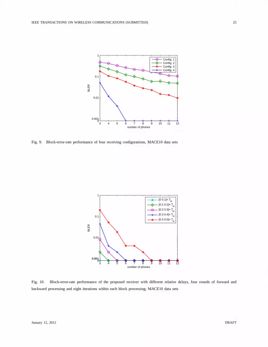
Similar to the simulation setup, the relative delay of each user is uniformly distributed within a
certain interval. By setting the distribution interval corresponding to the second user as[0, Tbl/2],
Fig. 9 shows the decoding performance of the four configurations in the simulation. Again, one
can see that the conventional multiuser reception approachwithout interference cancellation
almost cannot work, the block-by-block interference cancellation method improves the perfor-
mance a bit, and the proposed burst-by-burst receiver with the forward and backward message
passing is the best.
With different distribution intervals of the relative delay, the BLER performance of the pro-
posed burst-by-burst receiver with two asynchronous usersis shown in Fig. 10. One can see
that as the relative delay increases, i.e., the time-duration of the interference increases, more
receiving hydrophones are required for successful decoding.
Assuming that the relative delays of users are uniformly distributed within [0 Tbl/2], Fig. 11
shows the packet-success-rate of the proposed receiver with different number of users. One can
see that as the number of users increases, the decoding performance gets worse gradually. The
degradation can be attributed to the increased multiuser interference and the increased ambient
January 12, 2012 DRAFT
IEEE TRANSACTIONS ON WIRELESS COMMUNICATIONS (SUBMITTED) 18
noise power due to the generation of the semi-experimental data sets.
To achieve a robust decoding performance of the proposed receiver, a block-level erasure-
correction code over Galois field can be used [41]. With a rate-8/10 block-levelshortenedReed-
Solomon (RS) codeword3 applied for each data subcarrier across a packet consistingof 10
blocks, any two blocks can be received in error (hence erased), while the whole data burst can
be recovered. Fig. 11 shows the packet-success-rate (PSR) of the proposed receiver with different
number of users. Compared with the packet-success-rate without using erasure-correction coding,
introducing two redundant blocks leads to a considerable performance improvement. This option
is appealing for practical systems with asynchronous users.
VII. CONCLUSIONS
In this paper, we proposed an asynchronous multiuser reception method for OFDM in under-
water acoustic communications. With an overlapped truncation of the received signal and using
the interference aggregationconcept, the asynchronous multiuser problem was convertedto a
synchronous multiuser problem with interference, where interference mitigation and multiuser
decoding are carried out in an iterative fashion. Extensivesimulation and experimental results
demonstrated that the proposed receiver can effectively recover the transmitted symbols from
multiple asynchronous users. The decoding performance canbe further improved by using a
block-level RS erasure-correction code.
ACKNOWLEDGEMENT
We would like to thank Mr. L. Freitag and his team for conducting the MACE10 experiment.
REFERENCES
[1] M. Stojanovic, “Low complexity OFDM detector for underwater channels,” inProc. of MTS/IEEE OCEANS Conf., Boston,
MA, Sep. 18-21, 2006.
[2] B. Li, S. Zhou, M. Stojanovic, L. Freitag, and P. Willett,“Multicarrier communication over underwater acoustic channels
with nonuniform Doppler shifts,”IEEE J. Ocean. Eng., vol. 33, no. 2, Apr. 2008.
[3] F. Qu and L. Yang, “Basis expansion model for underwater acoustic channels?” inProc. of MTS/IEEE OCEANS Conf.,
Quebec City, Quebec, Sep. 2008.
3A shortened RS code can be obtained by setting some information symbols as zeros from a RS code of longer length [41].
January 12, 2012 DRAFT

IEEE TRANSACTIONS ON WIRELESS COMMUNICATIONS (SUBMITTED) 19
[4] T. Kang and R. A. Iltis, “Iterative carrier frequency offset and channel estimation for underwater acoustic OFDM systems,”
IEEE J. Select. Areas Commun., vol. 26, no. 9, pp. 1650–1661, Dec. 2008.
[5] G. Leus and P. A. V. Walree, “Multiband OFDM for covert acoustic communications,”IEEE J. Select. Areas Commun.,
vol. 26, no. 9, pp. 1662–1673, Dec. 2008.
[6] P. A. V. Walree and G. Leus, “Robust underwater telemetrywith adaptive turbo multiband equalization,”IEEE J. Ocean.
Eng., vol. 34, no. 4, p. 645655, Oct. 2009.
[7] A. Abdi and H. Guo, “A new compact multichannel receiver for underwater wireless communication networks,”IEEE
Trans. Wireless Commun., vol. 8, no. 7, pp. 3326–3329, Jul. 2009.
[8] B. Li, J. Huang, S. Zhou, K. Ball, M. Stojanovic, L. Freitag, and P. Willett, “MIMO-OFDM for high rate underwater
acoustic communications,”IEEE J. Ocean. Eng., vol. 34, no. 4, Oct. 2009.
[9] C. R. Berger, S. Zhou, J. Preisig, and P. Willett, “Sparsechannel estimation for multicarrier underwater acoustic
communication: From subspace methods to compressed sensing,” IEEE Trans. Signal Processing, vol. 58, no. 3, pp.
1708–1721, Mar. 2010.
[10] P. Ceballos and M. Stojanovic, “Adaptive channel estimation and data detection for underwater acoustic MIMO OFDM
systems,”IEEE J. Ocean. Eng., vol. 35, no. 3, pp. 635–646, Jul. 2010.
[11] T. Kang, H. C. Song, W. S. Hodgkiss, and J. S. Kim, “Long-range multi-carrier acoustic communications in shallow water
based on iterative sparse channel estimation,”J. Acoust. Soc. Am., vol. 128, no. 6, Dec. 2010.
[12] J. Tao, Y. R. Zheng, C. Xiao, and T. C. Yang, “Robust MIMO underwater acoustic communications using turbo block
decision-feedback equalization,”IEEE J. Ocean. Eng., vol. 35, no. 4, pp. 948–960, Oct. 2010.
[13] J. Tao, J. Wu, Y. R. Zheng, and C. Xiao, “Enhanced MIMO LMMSE turbo equalization: Algorithm, simulations and
undersea experimental results,”IEEE Trans. Signal Processing, vol. 59, no. 8, pp. 3813–3823, Aug. 2011.
[14] K. Tu, D. Fertonani, T. M. Duman, M. Stojanovic, J. Proakis, and P. Hursky, “Mitigation of intercarrier interference for
OFDM over time-varying underwater acoustic channels,”IEEE J. Ocean. Eng., vol. 36, no. 2, pp. 156 –171, Apr. 2011.
[15] H. Wan, R.-R. Chen, J. W. Choi, A. Singer, J. Preisig, andB. Farhang-Boroujeny, “Markov Chain Monte Carlo detection
for frequency-selective channels using list channel estimates,”IEEE J. Select. Topics Signal Proc., vol. 5, no. 8, pp. 1537
–1547, Dec. 2011.
[16] A. Song, M. Badiey, V. McDonald, and T. Yang, “Time reversal receivers for high rate multiple-input/multiple-output
communication,”IEEE J. Ocean. Eng., vol. 34, no. 4, pp. 525–538, Oct. 2011.
[17] K. Tu, T. Duman, J. Proakis, and M. Stojanovic, “Cooperative MIMO-OFDM communications: Receiver design for Doppler-
distorted underwater acoustic channels,” inProc. of Asilomar Conf. on Signals, Systems, and Computers, Pacific Grove,
CA, Nov. 2010, pp. 1335 –1339.
[18] S. Verdu,Multiuser Detection. New York: Cambridge University Press, 1998.
[19] A. Hui and K. Letaief, “Successive interference cancellation for multiuser asynchronous DS/CDMA detectors in multipath
fading links,” IEEE Trans. Commun., vol. 46, no. 3, pp. 384–391, Mar. 1998.
[20] J. Luo, K. Pattipati, and P. Willett, “A sliding window PDA for asynchronous CDMA, and a proposal for deliberate
asynchronicity,”IEEE Trans. Commun., vol. 57, no. 12, pp. 1970 – 1974, Dec. 2003.
[21] M. Park, K. Ko, H. Yoo, and D. Hong, “Performance analysis of OFDMA uplink systems with symbol timing misalignment,”
IEEE Commun. Lett., vol. 7, no. 8, pp. 376–378, Aug. 2003.
[22] K. Hamdi, “Precise interference analysis of OFDMA time-asynchronous wireless ad-hoc networks,”IEEE Trans. Wireless
Commun., vol. 9, no. 1, pp. 134 –144, Jan. 2010.
January 12, 2012 DRAFT

IEEE TRANSACTIONS ON WIRELESS COMMUNICATIONS (SUBMITTED) 20
[23] A. M. Tonello, “Asynchronous multicarrier multiple access: Optimal and sub-optimal detection and decoding,”Bell Labs
Tech. J., vol. 7, no. 3, pp. 191–217, 2003.
[24] T. Thomas and F. Vook, “Asynchronous interference suppression in broadband cyclic-prefix communications,”IEEE
Wireless Communication and Networking, vol. 1, pp. 568 –572, Mar. 2003.
[25] H. Jung and M. Zoltowski, “On the equalization of asynchronous multiuser OFDM signals in fading channels,” inProc.
of Intl. Conf. on Acoustics, Speech and Signal Proc., vol. 4, May 2004, pp. 765–768.
[26] Q. Li, J. Zhu, X. Guo, and C. Georghiades, “Asynchronousco-channel interference suppression in MIMO OFDM systems,”
in Proc. of Intl. Conf. on Commun., Jun. 2007, pp. 5744 –5750.
[27] H. Jung and M. Zoltowski, “Semiblind multichannel identification in asynchronous multiuser OFDM systems,” inProc.
of Asilomar Conf. on Signals, Systems, and Computers, Pacific Grove, CA, Oct. 2004.
[28] Y. Zhu, D. Guo, and M. L. Honig, “A message-passing approach for joint channel estimation, interference mitigation, and
decoding,”IEEE Trans. Wireless Commun., vol. 8, no. 12, pp. 6008–6018, Dec. 2009.
[29] I. F. Akyildiz, D. Pompili, and T. Melodia, “Challengesfor efficient communication in underwater acoustic sensor networks,”
ACM Sigbed Review, vol. 1, no. 1, pp. 3–8, Jul. 2004.
[30] J.-H. Cui, J. Kong, M. Gerla, and S. Zhou, “The challenges of building mobile underwater wireless networks for aquatic
applications,”IEEE Network, Special Issue on Wireless Sensor Networking, vol. 20, no. 3, pp. 12–18, May 2006.
[31] M. Chitre, S. Shahabudeen, and M. Stojanovic, “Underwater acoustic communications and networking: Recent advances
and future challenges,”Marine Technology Society Journal, vol. 42, no. 1, pp. 103–116, 2008.
[32] P. Casari and M. Zorzi, “Protocol design issues in underwater acoustic networks,”Elsevier Computer Communications,
vol. 34, pp. 2013–2025, Nov. 2011.
[33] R. Hayford, D. Nagle, and J. Catipovic, “AUTEC underseacellular network,” inProc. of the ACM Intl. Workshop on
Underwater Networks (WUWNet), Berkeley, California, Nov. 2009.
[34] Z.-H. Wang, S. Zhou, J. Catipovic, and J. Huang, “OFDM indeep water acoustic channels with extremely long delay
spread,” inProc. of the ACM Intl. Workshop on Underwater Networks (WUWNet), Massachusetts, USA, Sep. 2010.
[35] Z.-H. Wang, S. Zhou, J. Catipovic, and P. Willett, “Parameterized cancellation of partial-band partial-block-duration
interference for underwater acoustic OFDM,” inProc. of the ACM Intl. Workshop on Underwater Networks (WUWNet),
Seattle, USA, Dec. 2011.
[36] A. Viterbi, “An intuitive justification and a simplifiedimplementation of the MAP decoder for convolutional codes,” IEEE
J. Select. Areas Commun., vol. 16, no. 2, pp. 260–264, Feb. 1998.
[37] R. Liu and K. Parhi, “Low-latency low-complexity architectures for viterbi decoders,”IEEE Trans. Circuits and Systems,
vol. 56, no. 10, pp. 2315 –2324, Oct. 2009.
[38] J. Huang, S. Zhou, and P. Willett, “Nonbinary LDPC coding for multicarrier underwater acoustic communication,”IEEE
J. Select. Areas Commun., vol. 26, no. 9, pp. 1684–1696, Dec. 2008.
[39] H. A. David and H. N. Nagaraja,Order Statistics, 3rd ed. John Wiley and Sons, 2003, ch. 2, pp. 11–30.
[40] J.-Z. Huang, S. Zhou, J. Huang, J. Preisig, L. Freitag, and P. Willett, “Progressive MIMO-OFDM reception over time-
varying underwater acoustic channels,” inProc. of Asilomar Conf. on Signals, Systems, and Computers, Pacific Grove,
CA, Nov. 2010.
[41] S. Lin and D. J. Costello,Error Control Coding, 2nd ed. Prentice Hall, 2004.
January 12, 2012 DRAFT

IEEE TRANSACTIONS ON WIRELESS COMMUNICATIONS (SUBMITTED) 21
A network anchored at sea bottom A data collection network
surfaceAUV
bottom
gateway
sensors
Fig. 1. Two example underwater networks. The nodes anchoredat sea bottom in the first network are connected to a control
center via cables. The gateways in the second network can communicate with satellites or ships using radio waves.
user 1
user Nu
n-1 n n+1
n-1 n
TgT
(t;n)
!Nu n+1
(t) n-1 n n+1 t
user n-1 n n+1
n-1 n n+1n-1 n n+1
!!(t;n-1) !!(t;n+1)
);(~
for ]0[ max ntIt
!" );(~
for ][ blbl ntITTt
!
blT
Tbl
Fig. 2. Illustration of the overlapped partition of the received signal and the aggregated interference in an asynchronousNu-user
system
January 12, 2012 DRAFT

IEEE TRANSACTIONS ON WIRELESS COMMUNICATIONS (SUBMITTED) 22
1st block(n-1)st
blocknth block
(n+1)st
block
Nblth
block
forward processing
backward processing
);(for
]0[ max
ntI
t
!"
No
Decisions
Yes
OFDM Multiuser
Receiver Processing
Interference Subtraction
I = I + 1
the nth Truncation
Success or I = Imax?
Interference
Reconstruction
Residual Interference
Estimation/Subtraction
);(for
][ blbl
ntI
TTt
!
)1;(for
]0[ max
ntI
t
!
"
)1;(for
][ blbl
!
ntI
TTt
Fig. 3. Illustration of the proposed burst-by-burst asynchronous multiuser receiver with iterative forward/backward processing,
with Nbl blocks in each burst.
0 20 40 60 80 1000
0.005
0.01
0.015
0.02
0.025
Time duration of interference [ms]
Pro
babi
lity
dens
ity
2 users
3 users4 users
5 users
(a) with different number of users,DN = 300 m
0 20 40 60 80 1000
0.005
0.01
0.015
0.02
0.025
0.03
Time duration of interference [ms]
Pro
babi
lity
dens
ity
D
N = 150 m
DN = 300 m
DN = 1500 m
2 users4 users
(b) with differentDNs
Fig. 4. Probability density function of the maximum asynchronism on the OFDM block level in an asynchronous multiuser
system, where the users are uniformly distributed within a circle of diameterDN.
January 12, 2012 DRAFT

IEEE TRANSACTIONS ON WIRELESS COMMUNICATIONS (SUBMITTED) 23
0 1 2 3 4 510
−3
10−2
10−1
100
SNR per Symbol per User per Antenna [dB]
BLE
R
Config. 1Config. 2Config. 3Config. 4
Fig. 5. Block-error-rate performance of four receiving configurations,σv = 0.1 m/s
0 1 2 3 4 510
−3
10−2
10−1
100
SNR per Symbol per User per Antenna [dB]
BLE
R
[0 0.1]*T
bl
[0.1 0.2]*Tbl
[0.2 0.3]*Tbl
[0.3 0.4]*Tbl
[0.4 0.5]*Tbl
Fig. 6. Block-error-rate performance of the proposed receiver in a two-user system with different relative delays,σv = 0.1
m/s; three receiving hydrophones
January 12, 2012 DRAFT

IEEE TRANSACTIONS ON WIRELESS COMMUNICATIONS (SUBMITTED) 24
−4 −2 0 2 4 610
−3
10−2
10−1
100
SNR per Symbol per User per Antenna [dB]
BLE
R
[0 0.1]*T
bl
[0.1 0.2]*Tbl
[0.2 0.3]*Tbl
[0.3 0.4]*Tbl
[0.4 0.5]*Tbl
Fig. 7. Block-error-rate performance of the proposed receiver in a four-user system with different relative delays, six receiving
hydrophones
−1 0 1 2 3 410
−3
10−2
10−1
100
SNR per Symbol per User [dB]
BLE
R
round 1round 2round 3round 4
Fig. 8. Block-error-rate performance of the proposed receiver with four rounds of forward/backward processing,εmax ∼
U [0.3, 0.4] × Tbl, four users, six receiving hydrophones
January 12, 2012 DRAFT
IEEE TRANSACTIONS ON WIRELESS COMMUNICATIONS (SUBMITTED) 25
3 4 5 6 7 8 9 10 11 12
1
0.1
0.01
0.0010
number of phones
BLE
R
Config. 1Config. 2Config. 3Config. 4
Fig. 9. Block-error-rate performance of four receiving configurations, MACE10 data sets
3 4 5 6 7 8 9 10 11 12
1
0.1
0.01
0.0010.0010
number of phones
BLE
R
[0 0.1]× T
bl
[0.1 0.2]× Tbl
[0.2 0.3]× Tbl
[0.3 0.4]× Tbl
[0.4 0.5]× Tbl
Fig. 10. Block-error-rate performance of the proposed receiver with different relative delays, four rounds of forwardand
backward processing and eight iterations within each blockprocessing; MACE10 data sets
January 12, 2012 DRAFT

IEEE TRANSACTIONS ON WIRELESS COMMUNICATIONS (SUBMITTED) 26
2 3 40
0.2
0.4
0.6
0.8
1
1.2
1.4
1.6
1.8
number of users
pack
et s
ucce
ss r
ate
without RSrate−8/10 RS
Fig. 11. Packet-success-rate of the proposed receiver withdifferent number of users with and without a rate-8/10 Reed-
Solomon erasure-correction code across 10 blocks, four rounds of forward/backward processing, eight iterations within each
block processing
January 12, 2012 DRAFT


