Embed Size (px)
Citation preview
zenon manual Automatic Line Coloring (ALC) - Topology
v.7.11

©2014 Ing. Punzenberger COPA-DATA GmbH
All rights reserved.
Distribution and/or reproduction of this document or parts thereof in any form are permitted solely
with the written permission of the company COPA-DATA. The technical data contained herein has been
provided solely for informational purposes and is not legally binding. Subject to change, technical or
otherwise.
3
Contents
1. Welcome to COPA-DATA help ...................................................................................................... 5
2. Automatic Line Coloring (ALC) - Topology ..................................................................................... 5
3. ALC elements............................................................................................................................... 7
3.1 Procedural elements ................................................................................................................................... 8
3.1.1 Switch example - colors from ALC .............................................................................................. 11
3.1.2 Connection points of procedural elements ................................................................................ 15
3.1.3 Switch input/output ................................................................................................................... 17
3.2 Lines .......................................................................................................................................................... 18
3.2.1 Example ...................................................................................................................................... 22
3.2.2 Connection points of lines .......................................................................................................... 23
3.3 Checking the engineering .......................................................................................................................... 24
4. Configuration ............................................................................................................................ 25
4.1 Configuration of the sources ..................................................................................................................... 26
4.1.1 Coloring mode for UNDEFINED .................................................................................................. 28
4.2 Configuration of topological interlockings ................................................................................................ 30
4.2.1 Disconnector under load - interlocking conditions .................................................................... 32
4.3 Configuration of the screen marker .......................................................................................................... 33
5. Change ALC source color ............................................................................................................ 35
6. Detail screens ............................................................................................................................ 37
7. Error detection in electric grids .................................................................................................. 40
7.1 Search for ground fault ............................................................................................................................. 42
7.1.1 Mode of the search for ground faults ........................................................................................ 43
7.1.2 Earth Fault Identification Type ................................................................................................... 43
7.1.3 Ground fault display ................................................................................................................... 44
7.1.4 Earth fault triggering .................................................................................................................. 45
7.1.5 Start ground fault search ............................................................................................................ 46
7.1.6 Acknowledge ground fault message .......................................................................................... 47
7.1.7 End ground fault search ............................................................................................................. 48

4
7.2 Short circuit search ................................................................................................................................... 49
7.2.1 Short circuit identification type .................................................................................................. 50
7.2.2 Short circuit display .................................................................................................................... 51
7.2.3 Short circuit identification triggering ......................................................................................... 51
7.2.4 Acknowledge short circuit message ........................................................................................... 52
8. Impedance-based error detection and calculation of load distribution ........................................ 53

Welcome to COPA-DATA help
5
1. Welcome to COPA-DATA help
GENERAL HELP
If you cannot find any information you require in this help chapter or can think of anything that you
would like added, please send an email to [email protected]
(mailto:[email protected]).
PROJECT SUPPORT
You can receive support for any real project you may have from our Support Team, who you can contact
via email at [email protected] (mailto:[email protected]).
LICENSES AND MODULES
If you find that you need other modules or licenses, our staff will be happy to help you. Email
[email protected] (mailto:[email protected]).
2. Automatic Line Coloring (ALC) - Topology
The topological coloring of lines allows easy automatic dynamizing of tubes in technology (for media) as
well as in the energy distribution (for electricity). So process controlled coloring of topological nets can
easily be realized.
Because the tube structure is designed in the screen with all its technological elements (e.g. tanks and
valves, or generators, switches and consumers), it is internally emulated as a model and the media flow
is displayed in the Runtime.

Automatic Line Coloring (ALC) - Topology
6
In order to allow screen-overlapping models the entire design and configuration is always project-wide.
You therefore have one entire topological model per project, which is used for the calculation of the
tube statuses and ultimately for the coloring of the tubes.
The whole topology is created automatically from the graphic design. No other engineering actions are
necessary.
Information
The ALC algorithm only runs through once from a source starting from each switch.
DETAIL SCREENS
To display individual screens, a partial area can be taken from the topological network and displayed
individually by means of alias. A detail screen (on page 37) can be displayed with the data from
different equipment parts, for instance outputs or partial networks.
License information
Must be licensed for Editor and Runtime (single-user, server, standby).
No need to be licensed for Runtime client.
Licensing is carried out using the zenon Energy Edition.
ALC: Included in the license for Energy Edition; provides basic properties for
line coloring.
Topology package: Requires additional licensing on the server (not on the
client) and expands ALC by:
Multiple supplies
Secured supply
Topological interlockings
Transformer and separator topological elements
Error detection (version 6.50 and above)
ALC elements
7
3. ALC elements
Automatic Line Coloring (ALC) makes it possible to color lines regardless of the process status. The
combined element is used as the process element. Automatic line coloring allows easy automatic
dynamizing of tubes in technology (for media) as well as in the topological networks (for electricity).
ENGINEERING
For the design two types of screen elements with different functions are distinguished. On the one hand
these are procedural elements (on page 8) (source, switch/disconnector, drain, transformer or link) and
on the other hand lines (on page 18).
In doing so, the technical elements have a function and a color (source and transformer). If the
procedural elements are active, the connected lines take on the color of these elements at the source
and transformer or they take on the color of the element's input line for the switch and the link. If the
procedural elements are inactive, the color of the lines is taken from the definition in the editor.
The different functions of the elements are assigned in the properties of the combined element.
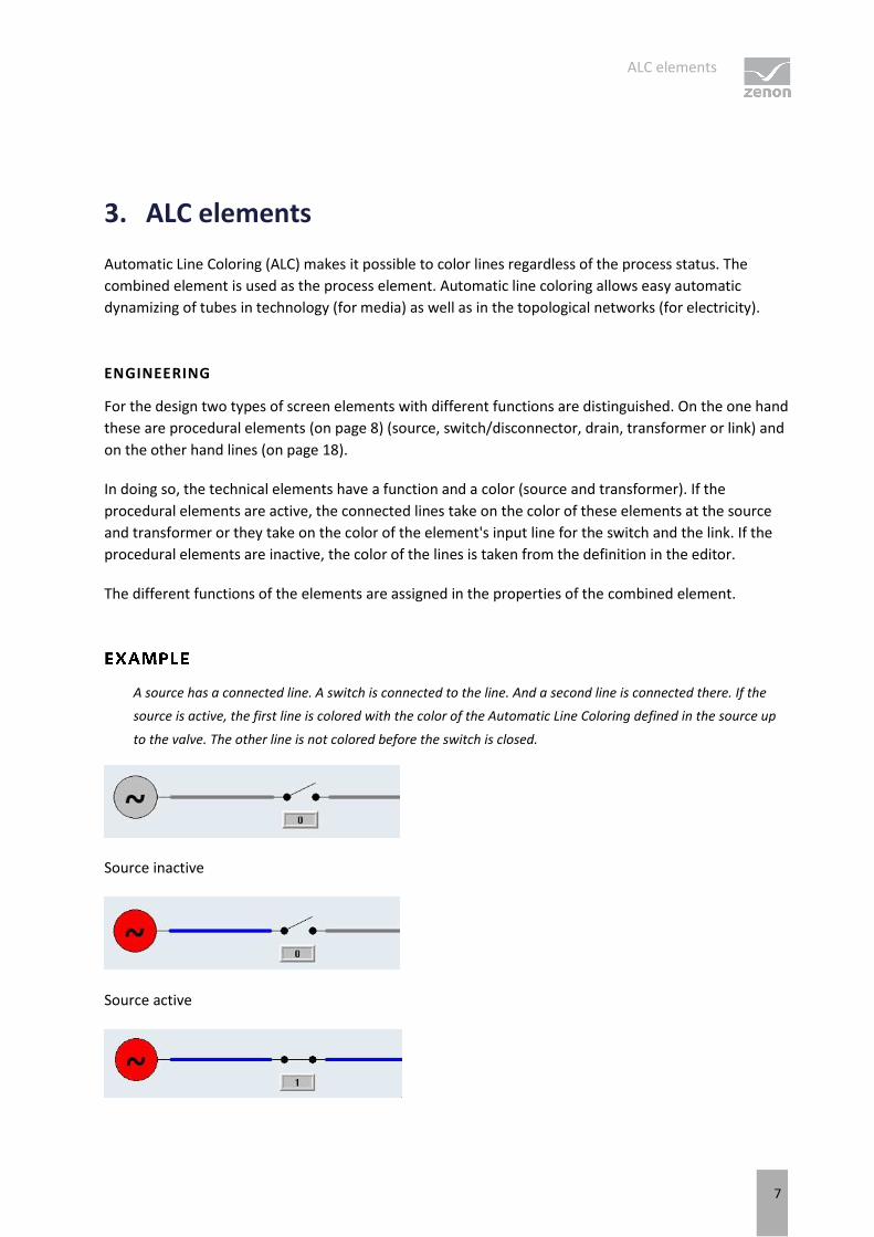
A source has a connected line. A switch is connected to the line. And a second line is connected there. If the
source is active, the first line is colored with the color of the Automatic Line Coloring defined in the source up
to the valve. The other line is not colored before the switch is closed.
Source inactive
Source active
ALC elements
8
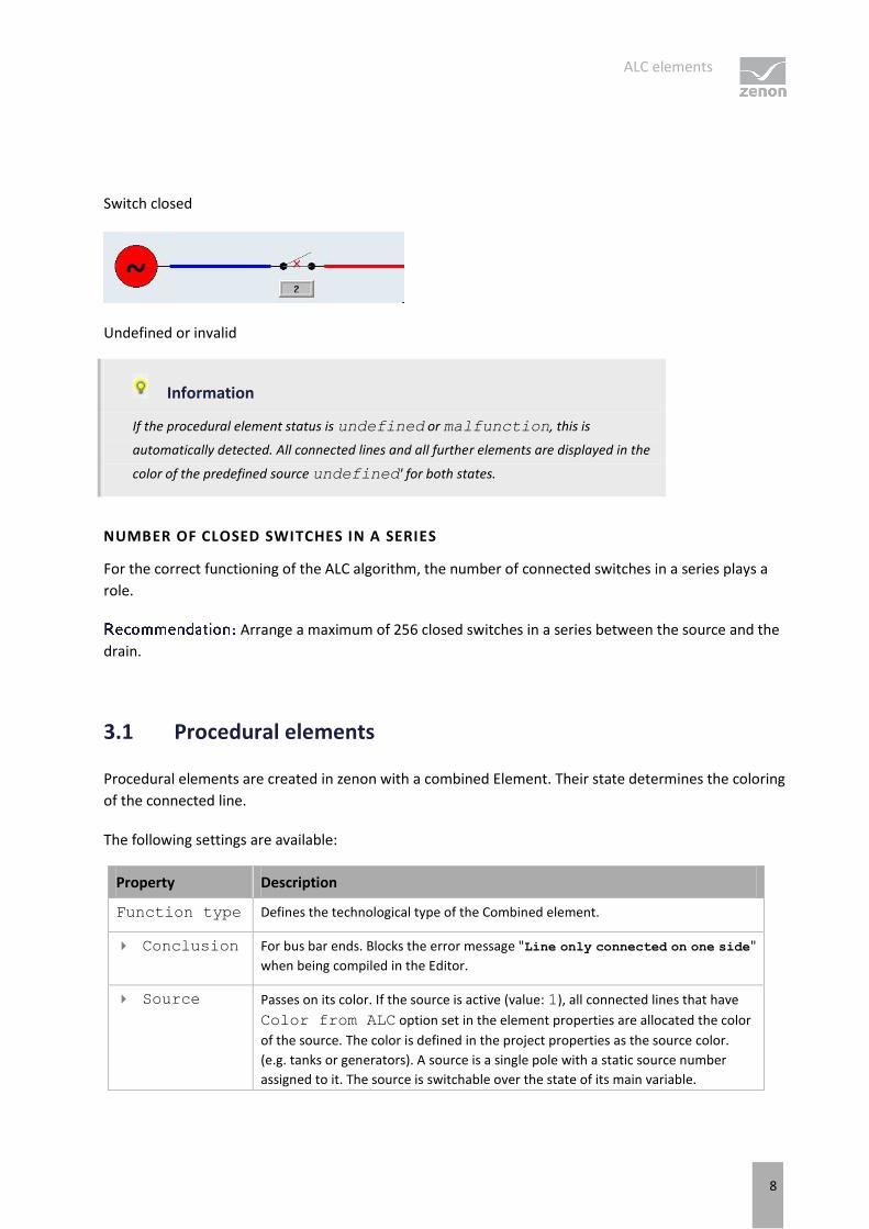
Switch closed
Undefined or invalid
Information
If the procedural element status is undefined or malfunction, this is
automatically detected. All connected lines and all further elements are displayed in the
color of the predefined source undefined' for both states.
NUMBER OF CLOSED SWITCHES IN A SERIES
For the correct functioning of the ALC algorithm, the number of connected switches in a series plays a
role.
Arrange a maximum of 256 closed switches in a series between the source and the
drain.
3.1 Procedural elements
Procedural elements are created in zenon with a combined Element. Their state determines the coloring
of the connected line.
The following settings are available:
Property Description
Function type Defines the technological type of the Combined element.
Conclusion For bus bar ends. Blocks the error message "Line only connected on one side"
when being compiled in the Editor.
Source Passes on its color. If the source is active (value: 1), all connected lines that have
Color from ALC option set in the element properties are allocated the color
of the source. The color is defined in the project properties as the source color.
(e.g. tanks or generators). A source is a single pole with a static source number
assigned to it. The source is switchable over the state of its main variable.
ALC elements
9
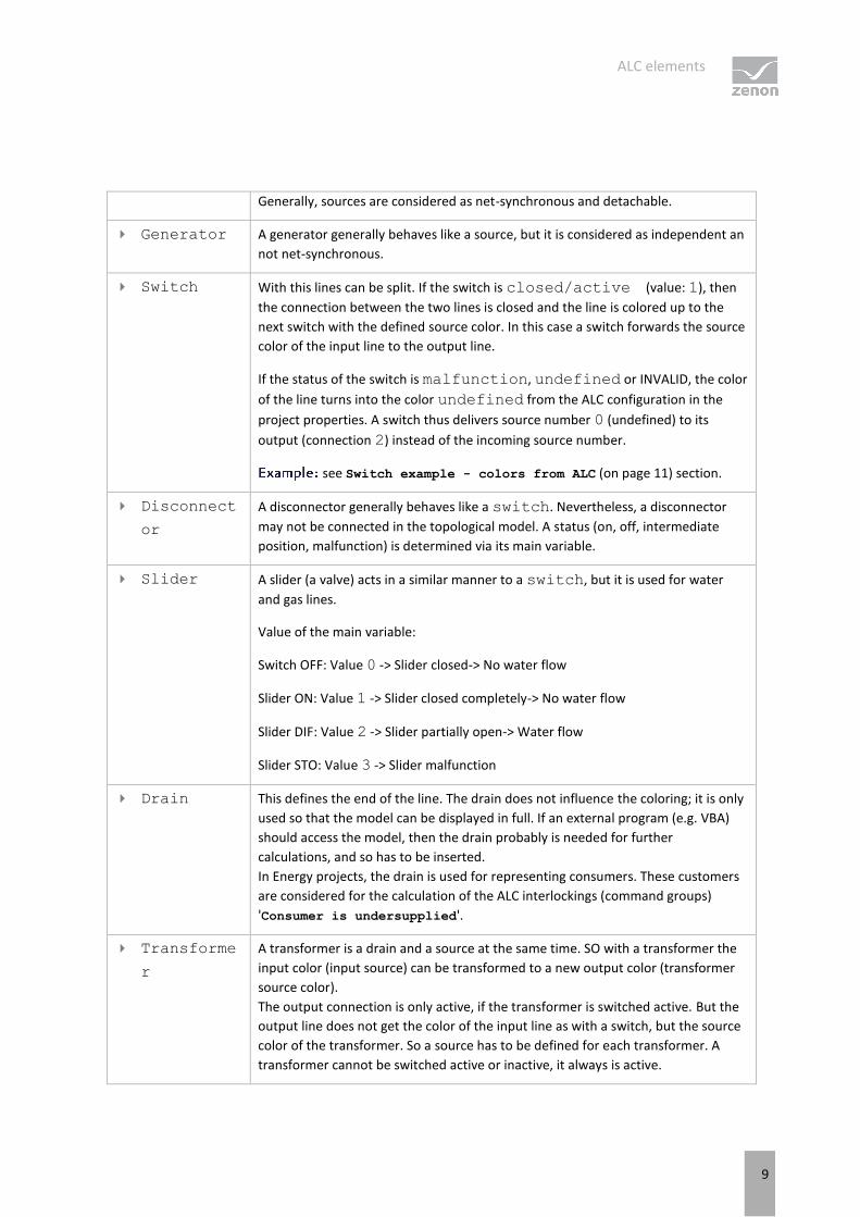
Generally, sources are considered as net-synchronous and detachable.
Generator A generator generally behaves like a source, but it is considered as independent an
not net-synchronous.
Switch With this lines can be split. If the switch is closed/active (value: 1), then
the connection between the two lines is closed and the line is colored up to the
next switch with the defined source color. In this case a switch forwards the source
color of the input line to the output line.
If the status of the switch is malfunction, undefined or INVALID, the color
of the line turns into the color undefined from the ALC configuration in the
project properties. A switch thus delivers source number 0 (undefined) to its
output (connection 2) instead of the incoming source number.
see Switch example - colors from ALC (on page 11) section.
Disconnect
or
A disconnector generally behaves like a switch. Nevertheless, a disconnector
may not be connected in the topological model. A status (on, off, intermediate
position, malfunction) is determined via its main variable.
Slider A slider (a valve) acts in a similar manner to a switch, but it is used for water
and gas lines.
Value of the main variable:
Switch OFF: Value 0 -> Slider closed-> No water flow
Slider ON: Value 1 -> Slider closed completely-> No water flow
Slider DIF: Value 2 -> Slider partially open-> Water flow
Slider STO: Value 3 -> Slider malfunction
Drain This defines the end of the line. The drain does not influence the coloring; it is only
used so that the model can be displayed in full. If an external program (e.g. VBA)
should access the model, then the drain probably is needed for further
calculations, and so has to be inserted.
In Energy projects, the drain is used for representing consumers. These customers
are considered for the calculation of the ALC interlockings (command groups)
'Consumer is undersupplied'.
Transforme
r
A transformer is a drain and a source at the same time. SO with a transformer the
input color (input source) can be transformed to a new output color (transformer
source color).
The output connection is only active, if the transformer is switched active. But the
output line does not get the color of the input line as with a switch, but the source
color of the transformer. So a source has to be defined for each transformer. A
transformer cannot be switched active or inactive, it always is active.
ALC elements
10
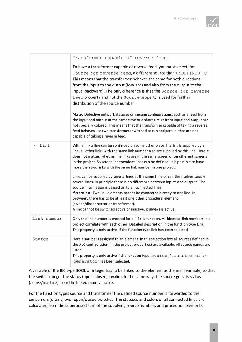
Transformer capable of reverse feed:
To have a transformer capable of reverse feed, you must select, for
Source for reverse feed, a different source than UNDEFINED [0].
This means that the transformer behaves the same for both directions -
from the input to the output (forward) and also from the output to the
input (backward). The only difference is that the Source for reverse
feed property and not the Source property is used for further
distribution of the source number .
Defective network statuses or missing configurations, such as a feed from
the input and output at the same time or a short circuit from input and output are
not specially colored. This means that the transformer capable of taking a reverse
feed behaves like two transformers switched to run antiparallel that are not
capable of taking a reverse feed.
Link With a link a line can be continued on some other place. If a link is supplied by a
line, all other links with the same link number also are supplied by this line. Here it
does not matter, whether the links are in the same screen or on different screens
in the project. So screen independent lines can be defined. It is possible to have
more than two links with the same link number in one project.
Links can be supplied by several lines at the same time or can themselves supply
several lines. In principle there is no difference between inputs and outputs. The
source information is passed on to all connected lines.
Two link elements cannot be connected directly to one line. In
between, there has to be at least one other procedural element
(switch/disconnector or transformer).
A link cannot be switched active or inactive, it always is active.
Link number Only the link number is entered for a link function. All identical link numbers in a
project correlate with each other. Detailed description in the function type Link.
This property is only active, if the function type link has been selected.
Source Here a source is assigned to an element. In this selection box all sources defined in
the ALC configuration (in the project properties) are available. All source names are
listed.
This property is only active if the function type 'source', 'transformer' or
'generator' has been selected.
A variable of the IEC type BOOL or integer has to be linked to the element as the main variable, so that
the switch can get the status (open, closed, invalid). In the same way, the source gets its status
(active/inactive) from the linked main variable.
For the function types source and transformer the defined source number is forwarded to the
consumers (drains) over open/closed switches. The statuses and colors of all connected lines are
calculated from the superposed sum of the supplying source numbers and procedural elements.
ALC elements
11
Information
Only the first two bits are considered for the switching. The first bit stands for the actual
switching. 0 equals off and 1 equals 1.
The second bit is the error bit. There is no error only if it is 0.
STATES
A switch and a source are switched on if the value of the linked variable is 1.
A switch is invalid if the value of the linked variable is >1 or has an INVALID status.
An invalid switch provides the source number 0 (undefined) at its exit (connection 2) instead of
the source number entering. In the direction towards the input the switch behaves as normal.
if the (acknowledgment) variable has the status INVALID, the whole subsequent
network is INVALID, because the status of the network is not known. The status INVALID
is forwarded (routed) using subsequent closed switches.
Attention
If in the single status the color and the fill color from the ALC is activated, also the
procedural elements are colored by the status of the connected lines in the Runtime.
3.1.1 Switch example - colors from ALC
EXAMPLE 1
Combined element with value status 00 and line color from ALC:
1. Configuration in the Editor:
Combined element with value status 00
ALC elements
12
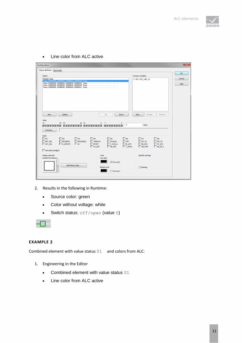
Line color from ALC active
2. Results in the following in Runtime:
Source color: green
Color without voltage: white
Switch status: off/open (value 0)
EXAMPLE 2
Combined element with value status 01 and colors from ALC:
1. Engineering in the Editor
Combined element with value status 01
Line color from ALC active
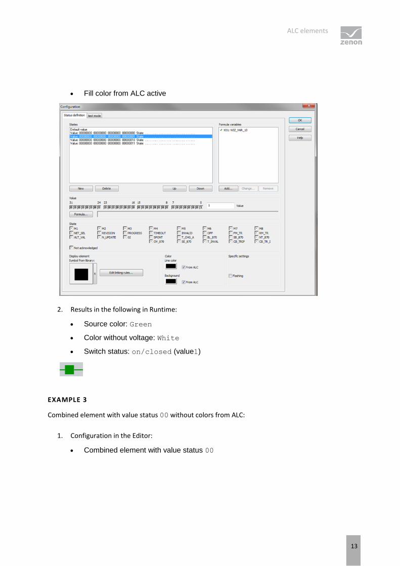
ALC elements
13
Fill color from ALC active
2. Results in the following in Runtime:
Source color: Green
Color without voltage: White
Switch status: on/closed (value1)
EXAMPLE 3
Combined element with value status 00 without colors from ALC:
1. Configuration in the Editor:
Combined element with value status 00
ALC elements
14
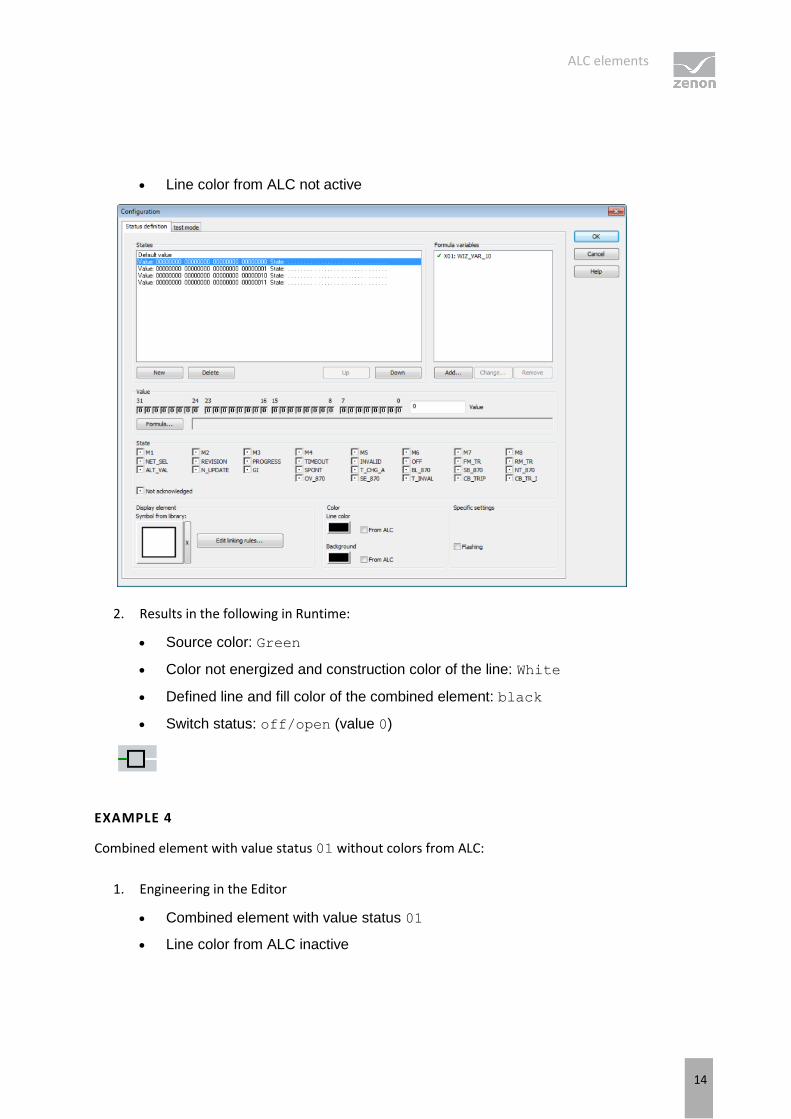
Line color from ALC not active
2. Results in the following in Runtime:
Source color: Green
Color not energized and construction color of the line: White
Defined line and fill color of the combined element: black
Switch status: off/open (value 0)
EXAMPLE 4
Combined element with value status 01 without colors from ALC:
1. Engineering in the Editor
Combined element with value status 01
Line color from ALC inactive
ALC elements
15
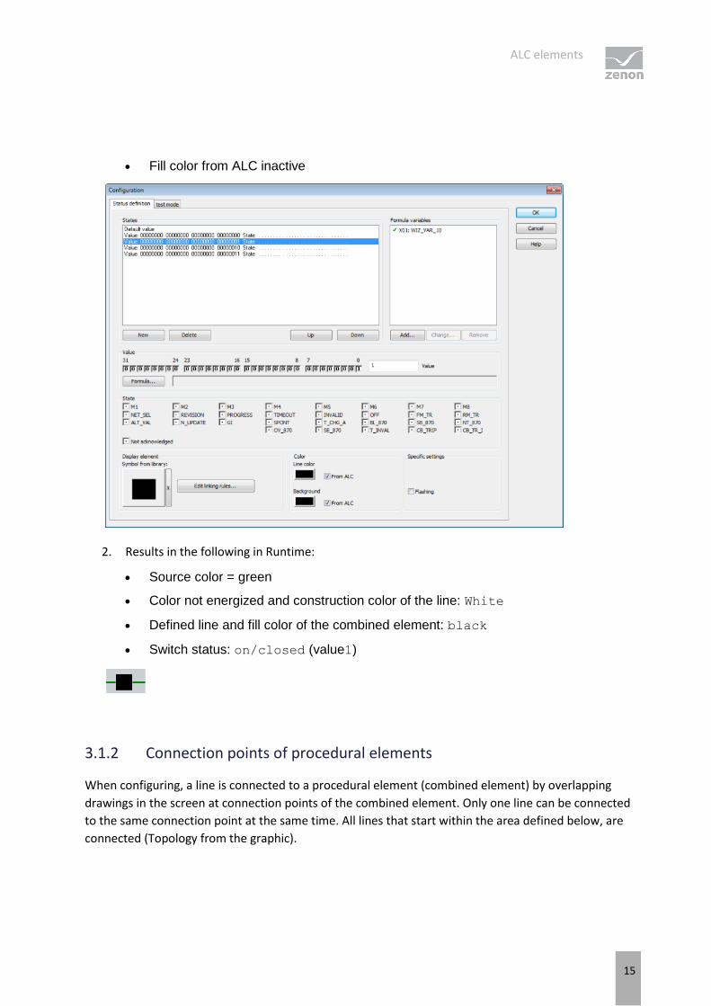
Fill color from ALC inactive
2. Results in the following in Runtime:
Source color = green
Color not energized and construction color of the line: White
Defined line and fill color of the combined element: black
Switch status: on/closed (value1)
3.1.2 Connection points of procedural elements
When configuring, a line is connected to a procedural element (combined element) by overlapping
drawings in the screen at connection points of the combined element. Only one line can be connected
to the same connection point at the same time. All lines that start within the area defined below, are
connected (Topology from the graphic).
ALC elements
16
Attention
Use ALC elements only in un-rotated state because:
The calculation for the topological model for the ALC in the Editor is based on the
position of the elements in un-rotated state and without considering any dynamics.
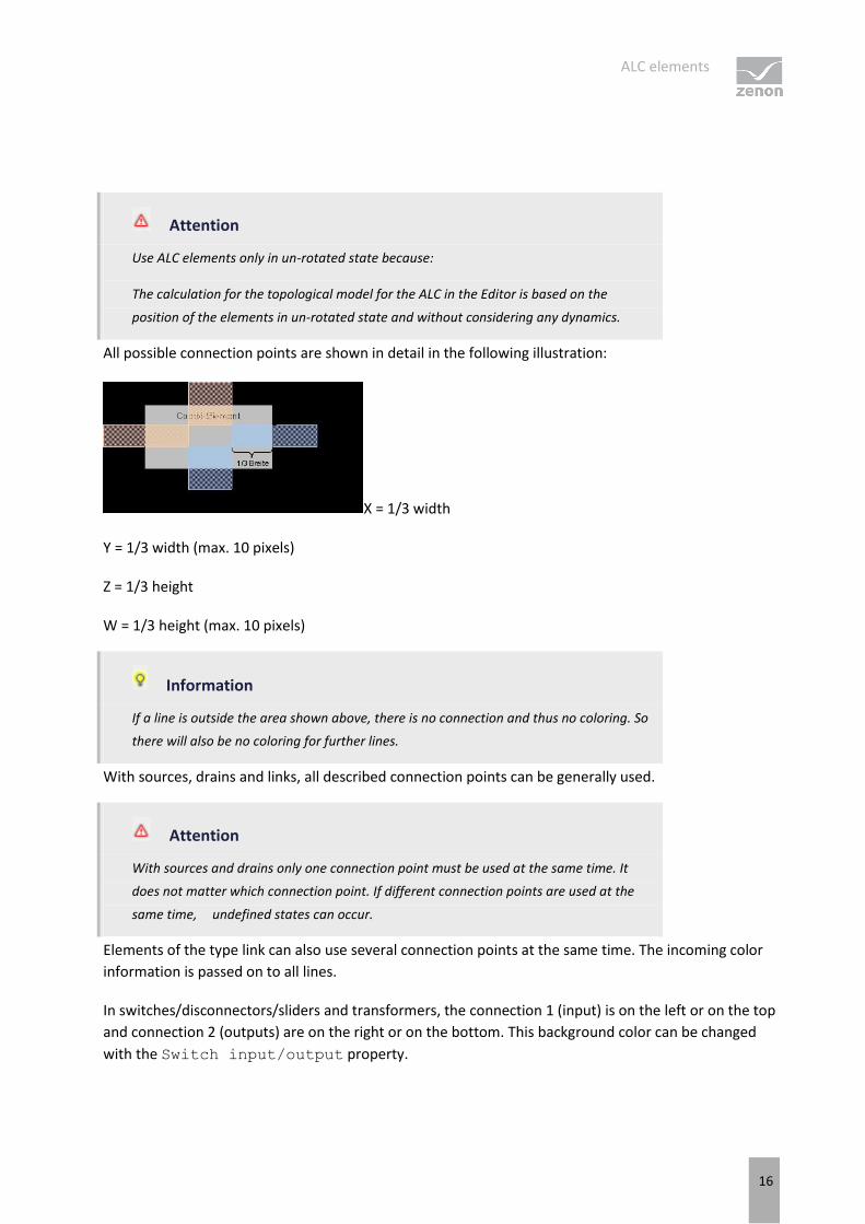
All possible connection points are shown in detail in the following illustration:
X = 1/3 width
Y = 1/3 width (max. 10 pixels)
Z = 1/3 height
W = 1/3 height (max. 10 pixels)
Information
If a line is outside the area shown above, there is no connection and thus no coloring. So
there will also be no coloring for further lines.
With sources, drains and links, all described connection points can be generally used.
Attention
With sources and drains only one connection point must be used at the same time. It
does not matter which connection point. If different connection points are used at the
same time, undefined states can occur.
Elements of the type link can also use several connection points at the same time. The incoming color
information is passed on to all lines.
In switches/disconnectors/sliders and transformers, the connection 1 (input) is on the left or on the top
and connection 2 (outputs) are on the right or on the bottom. This background color can be changed
with the Switch input/output property.
ALC elements
17
Information
At switches and transformers it has to be cared, that only one input connection and one
output connection is used. The simultaneous use of several input or output connection
points results in inconsistencies and is therefore not reliable.
Information
For all procedural elements the following is true: Only one line can be connected to a
connection point. Junctions cannot be realized directly on an element but must be drawn
with lines.
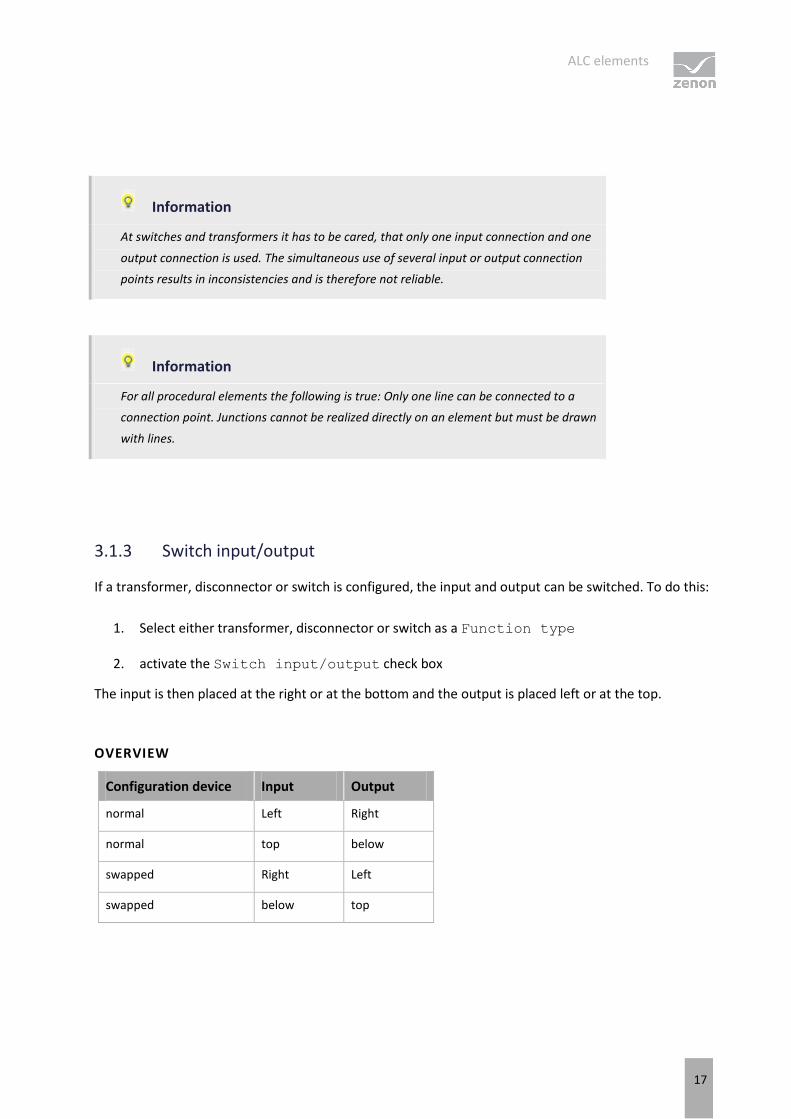
3.1.3 Switch input/output
If a transformer, disconnector or switch is configured, the input and output can be switched. To do this:
1. Select either transformer, disconnector or switch as a Function type
2. activate the Switch input/output check box
The input is then placed at the right or at the bottom and the output is placed left or at the top.
OVERVIEW
Configuration device Input Output
normal Left Right
normal top below
swapped Right Left
swapped below top
ALC elements
18
3.2 Lines
Lines are represented by vector elements Line, Polylines and Tube.
If the option Color from ALC is activated for a line, the coloring is defined by the ALC configuration.
Lines are automatically colored by the system depending on the status of the procedural elements and
the ALC settings.
Here the color usually comes from the highest priority source number of the media flowing through the
line, or stays "empty/not energized" just as defined in the screen with static or dynamic colors.
You define the display type by means of drop-down lists:
Priority for display
Display multiple supply
Display secured supply
The following options are available in the properties of the lines:
ALC elements
19
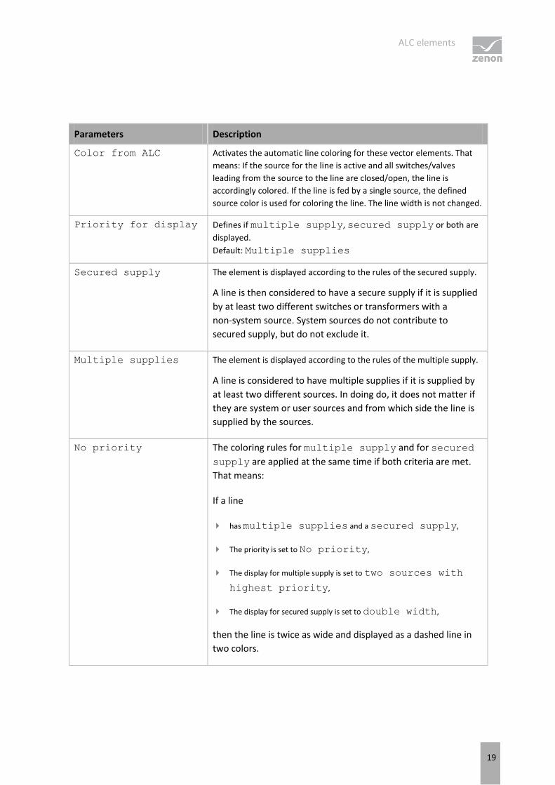
Parameters Description
Color from ALC Activates the automatic line coloring for these vector elements. That
means: If the source for the line is active and all switches/valves
leading from the source to the line are closed/open, the line is
accordingly colored. If the line is fed by a single source, the defined
source color is used for coloring the line. The line width is not changed.
Priority for display Defines if multiple supply, secured supply or both are
displayed.
Default: Multiple supplies
Secured supply The element is displayed according to the rules of the secured supply.
A line is then considered to have a secure supply if it is supplied
by at least two different switches or transformers with a
non-system source. System sources do not contribute to
secured supply, but do not exclude it.
Multiple supplies The element is displayed according to the rules of the multiple supply.
A line is considered to have multiple supplies if it is supplied by
at least two different sources. In doing do, it does not matter if
they are system or user sources and from which side the line is
supplied by the sources.
No priority The coloring rules for multiple supply and for secured
supply are applied at the same time if both criteria are met.
That means:
If a line
has multiple supplies and a secured supply,
The priority is set to No priority,
The display for multiple supply is set to two sources with
highest priority,
The display for secured supply is set to double width,
then the line is twice as wide and displayed as a dashed line in
two colors.
ALC elements
20
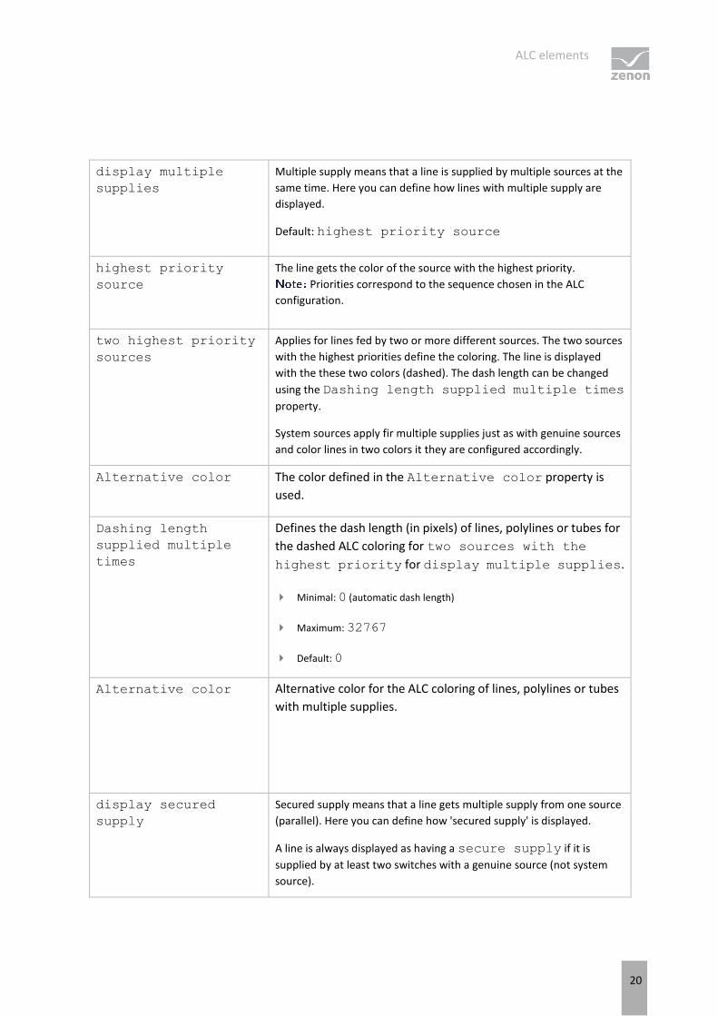
display multiple
supplies
Multiple supply means that a line is supplied by multiple sources at the
same time. Here you can define how lines with multiple supply are
displayed.
Default: highest priority source
highest priority
source
The line gets the color of the source with the highest priority.
Priorities correspond to the sequence chosen in the ALC
configuration.
two highest priority
sources
Applies for lines fed by two or more different sources. The two sources
with the highest priorities define the coloring. The line is displayed
with the these two colors (dashed). The dash length can be changed
using the Dashing length supplied multiple times
property.
System sources apply fir multiple supplies just as with genuine sources
and color lines in two colors it they are configured accordingly.
Alternative color The color defined in the Alternative color property is
used.
Dashing length
supplied multiple
times
Defines the dash length (in pixels) of lines, polylines or tubes for
the dashed ALC coloring for two sources with the
highest priority for display multiple supplies.
Minimal: 0 (automatic dash length)
Maximum: 32767
Default: 0
Alternative color Alternative color for the ALC coloring of lines, polylines or tubes
with multiple supplies.
display secured
supply
Secured supply means that a line gets multiple supply from one source
(parallel). Here you can define how 'secured supply' is displayed.
A line is always displayed as having a secure supply if it is
supplied by at least two switches with a genuine source (not system
source).
ALC elements
21
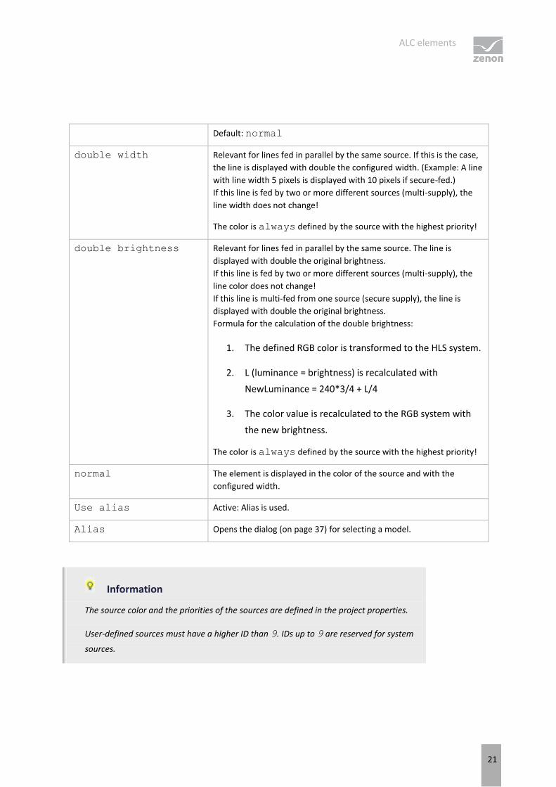
Default: normal
double width Relevant for lines fed in parallel by the same source. If this is the case,
the line is displayed with double the configured width. (Example: A line
with line width 5 pixels is displayed with 10 pixels if secure-fed.)
If this line is fed by two or more different sources (multi-supply), the
line width does not change!
The color is always defined by the source with the highest priority!
double brightness Relevant for lines fed in parallel by the same source. The line is
displayed with double the original brightness.
If this line is fed by two or more different sources (multi-supply), the
line color does not change!
If this line is multi-fed from one source (secure supply), the line is
displayed with double the original brightness.
Formula for the calculation of the double brightness:
1. The defined RGB color is transformed to the HLS system.
2. L (luminance = brightness) is recalculated with
NewLuminance = 240*3/4 + L/4
3. The color value is recalculated to the RGB system with
the new brightness.
The color is always defined by the source with the highest priority!
normal The element is displayed in the color of the source and with the
configured width.
Use alias Active: Alias is used.
Alias Opens the dialog (on page 37) for selecting a model.
Information
The source color and the priorities of the sources are defined in the project properties.
User-defined sources must have a higher ID than 9. IDs up to 9 are reserved for system
sources.
ALC elements
22
Information
The calculation of the color of a line in the Runtime is done with the following
priority list:
1. Automatic Line Coloring (highest priority, overrules all other settings)
2. Dynamic colors
3. Static colors
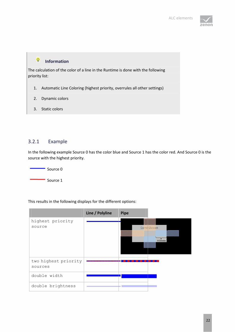
3.2.1 Example
In the following example Source 0 has the color blue and Source 1 has the color red. And Source 0 is the
source with the highest priority.
Source 0
Source 1
This results in the following displays for the different options:
Line / Polyline Pipe
highest priority
source
two highest priority
sources
double width
double brightness
ALC elements
23
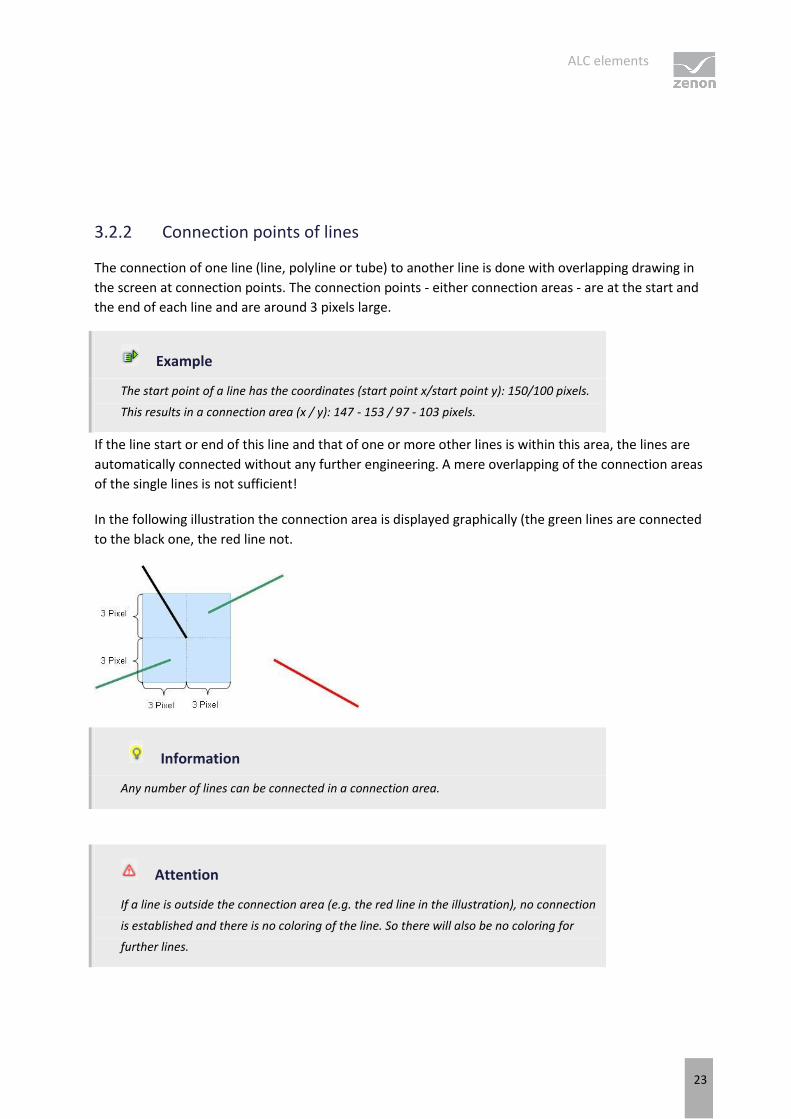
3.2.2 Connection points of lines
The connection of one line (line, polyline or tube) to another line is done with overlapping drawing in
the screen at connection points. The connection points - either connection areas - are at the start and
the end of each line and are around 3 pixels large.
Example
The start point of a line has the coordinates (start point x/start point y): 150/100 pixels.
This results in a connection area (x / y): 147 - 153 / 97 - 103 pixels.
If the line start or end of this line and that of one or more other lines is within this area, the lines are
automatically connected without any further engineering. A mere overlapping of the connection areas
of the single lines is not sufficient!
In the following illustration the connection area is displayed graphically (the green lines are connected
to the black one, the red line not.
Information
Any number of lines can be connected in a connection area.
Attention
If a line is outside the connection area (e.g. the red line in the illustration), no connection
is established and there is no coloring of the line. So there will also be no coloring for
further lines.
ALC elements
24
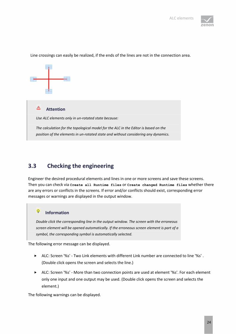
Line crossings can easily be realized, if the ends of the lines are not in the connection area.
Attention
Use ALC elements only in un-rotated state because:
The calculation for the topological model for the ALC in the Editor is based on the
position of the elements in un-rotated state and without considering any dynamics.
3.3 Checking the engineering
Engineer the desired procedural elements and lines in one or more screens and save these screens.
Then you can check via Create all Runtime files or Create changed Runtime files whether there
are any errors or conflicts in the screens. If error and/or conflicts should exist, corresponding error
messages or warnings are displayed in the output window.
Information
Double click the corresponding line in the output window. The screen with the erroneous
screen element will be opened automatically. If the erroneous screen element is part of a
symbol, the corresponding symbol is automatically selected.
The following error message can be displayed.
ALC: Screen '%s' - Two Link elements with different Link number are connected to line '%s' .
(Double click opens the screen and selects the line.)
ALC: Screen '%s' - More than two connection points are used at element '%s'. For each element
only one input and one output may be used. (Double click opens the screen and selects the
element.)
The following warnings can be displayed.
Configuration
25
ALC: Screen '%s' - Alias line '%s' is connected to a no-alias line. (Double click opens the screen
and selects the line.)
ALC: Screen '%s' - Alias element '%s' is connected to a no-alias line. (Double click opens the
screen and selects the element)
ALC: Screen '%s' - No-alias element '%s' is connected to an alias line. (Double click opens the
screen and selects the element)
ALC: Screen '%s' - Line '%s' is only connected on one side. (Double click opens the screen and
selects the line.)
ALC: Screen '%s' - Element '%s' is not connected. (Double click opens the screen and selects the
element)
ALC: Screen '%s' - Element '%s' is only connected on one side. (Double click opens the screen and
selects the element)
In the error messages or warnings the corresponding elements are identified using the element
reference. This reference also serves as the link key for ALC aliases.
4. Configuration
To configure ALC:
1. In project properties, select ALC configuration the property in the Automatic Line
Coloring group
2. Click on the ... button
3. The dialog for configuration is opened
4. Configure the desired properties for:
Sources (on page 26)
(note also the principles for Coloring for UNDEFINED (on page 28).)
Interlockings (on page 30)
Screen marker (on page 33)
Configuration
26
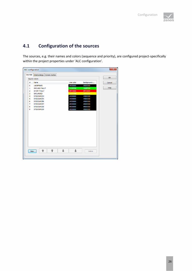
4.1 Configuration of the sources
The sources, e.g. their names and colors (sequence and priority), are configured project-specifically
within the project properties under 'ALC configuration'.
Configuration
27
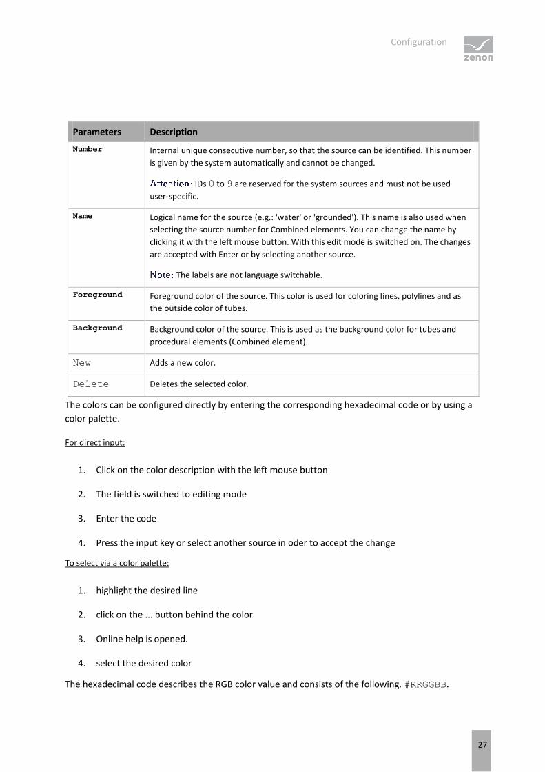
Parameters Description
Number Internal unique consecutive number, so that the source can be identified. This number
is given by the system automatically and cannot be changed.
IDs 0 to 9 are reserved for the system sources and must not be used
user-specific.
Name Logical name for the source (e.g.: 'water' or 'grounded'). This name is also used when
selecting the source number for Combined elements. You can change the name by
clicking it with the left mouse button. With this edit mode is switched on. The changes
are accepted with Enter or by selecting another source.
The labels are not language switchable.
Foreground Foreground color of the source. This color is used for coloring lines, polylines and as
the outside color of tubes.
Background Background color of the source. This is used as the background color for tubes and
procedural elements (Combined element).
New Adds a new color.
Delete Deletes the selected color.
The colors can be configured directly by entering the corresponding hexadecimal code or by using a
color palette.
For direct input:
1. Click on the color description with the left mouse button
2. The field is switched to editing mode
3. Enter the code
4. Press the input key or select another source in oder to accept the change
To select via a color palette:
1. highlight the desired line
2. click on the ... button behind the color
3. Online help is opened.
4. select the desired color
The hexadecimal code describes the RGB color value and consists of the following. #RRGGBB.
Configuration
28
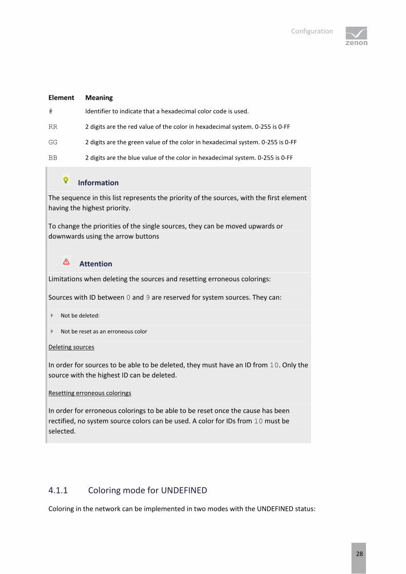
Element Meaning
# Identifier to indicate that a hexadecimal color code is used.
RR 2 digits are the red value of the color in hexadecimal system. 0-255 is 0-FF
GG 2 digits are the green value of the color in hexadecimal system. 0-255 is 0-FF
BB 2 digits are the blue value of the color in hexadecimal system. 0-255 is 0-FF
Information
The sequence in this list represents the priority of the sources, with the first element
having the highest priority.
To change the priorities of the single sources, they can be moved upwards or
downwards using the arrow buttons
Attention
Limitations when deleting the sources and resetting erroneous colorings:
Sources with ID between 0 and 9 are reserved for system sources. They can:
Not be deleted:
Not be reset as an erroneous color
Deleting sources
In order for sources to be able to be deleted, they must have an ID from 10. Only the
source with the highest ID can be deleted.
Resetting erroneous colorings
In order for erroneous colorings to be able to be reset once the cause has been
rectified, no system source colors can be used. A color for IDs from 10 must be
selected.
4.1.1 Coloring mode for UNDEFINED
Coloring in the network can be implemented in two modes with the UNDEFINED status:
Configuration
29
Standard
Input takes priority
This setting is made using the Automatic Line Coloring/Mode for coloring project
property.
The graph search starts with a source and goes through the whole network, so that each closed switch
(switch variable has the value 1) per direction is only gone through once, so no cycles occur. In doing so,
each node visited (=line segment) is colored with the source color. The directly-related lines are marked
as a node.
If the search finds a switch that has a switch variable with the following status, the UNDEFINED color is
used for coloring from this point onwards:
INVALID [values: any desired],
is invalid [value: 3]
is in intermediate position [value: 2])
The graph search is now continued in the same form. Each switch is gone through just once per
direction with the UNDEFINED color. Therefore each switch can be gone through a maximum of four
times per source:
1. with source number in forwards direction,
2. with source number in backwards direction,
3. with UNDEFINED in forwards direction,
4. with UNDEFINED in backwards direction,
With the Supply takes priority setting, only lines that have a supply from at least one source but
not clearly from any one source are colored as UNDEFINED. If a line is supplied with at least one source,
it can no longer receive an UNDEFINED color from another source.
This search is a two-stage search:
Configuration
30
In the first stage, as with Standard, the source color is distributed in the network from each
switched source, as long as the next switch is closed. The search is ended if the switch is open or
invalid/undefined.
In the second stage, the search is started at each invalid/undefined switch that receives a supply
from one side and the UNDEFINED color is distributed to the unsupplied side. This search also
considers the switches that are invalid/undefined as closed and thus distributes the UNDEFINED
color in the network until it meets a clearly open switch. In addition, a search is ended if a line
element is reached that is already supplied.
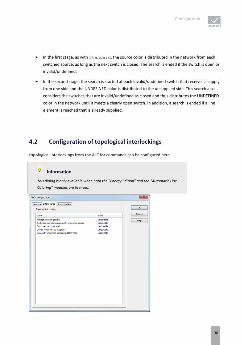
4.2 Configuration of topological interlockings
topological interlockings from the ALC for commands can be configured here.
Information
This dialog is only available when both the "Energy Edition" and the "Automatic Line
Coloring" modules are licensed.
Configuration
31
The following conditions are available: The settings made here apply globally, for the whole Topological
Model:
Parameters Description
Voltage towards
ground Interlocking is active if a switch/disconnector is to be closed and a grounded
potential is connected to its first connector and its other connector is connected
or undefined.
Switching action in
an area with an
undefined status
Interlocking is active if a switch disconnector is to be closed and both of its
connectors are 'undefined' or 'disturbed'.
Disconnector under
load Interlocking is active if certain conditions have been met for switching on or off.
Conditions: See "Disconnector under load - interlocking conditions (on page
32)" section.
Device would no
longer be supplied Interlocking is active, when a consumer, which was supplied before, would be
unsupplied after the switching action (by switch or disconnector).
Area with undefined
status would
increase
Interlocking is active if a switch disconnector is to be closed and one connector
is 'undefined' or 'disturbed' and the other not.
If you click in the Status column in one of these interlockings, a drop-down list opens with three
choices:
Parameters Description
do not check The selected condition is not considered in this project (topological model).
unlockable The selected condition is considered in this project. If the condition applies, the
user can unlock it with a command (Command screen). This unlocking action is
logged in the Chronological Event List.
not unlockable The selected condition is considered in this project. The user cannot unlock it.
EXCEPTION TOPOLOGICAL INTERLOCKING
The topological interlocking is not carried out if:
the variable of a switch has the status Revision
or
the variable is manually corrects or set to Alternate value and with this is set to the same
variable value as the initial value; in other words if the switch:
is set to OFF and then it is manually corrected to OFF or replaced.
Configuration
32
is set to ON and then it is manually corrected to ON or replaced.
4.2.1 Disconnector under load - interlocking conditions
For the disconnector under load topological interlocking, a disconnector can be switched if one of the
following conditions is met:
Before being switched:
The left and the right line segment receive energy from the same source
If the left line segment does not receive any voltage, the right line segment is grounded
If the left line segment is grounded, the right line segment does not receive any voltage
If the left line segment is not under load
If the right line segment is not under load
After being switched:
The left and the right line segment would receive energy from the same source
If the left line segment does not receive any voltage and the right line segment is grounded
If the left line segment were grounded, the right line segment would not receive any voltage
If the left line segment were not under load
If the right line segment were not under load
Configuration
33
Information
Meaning of "not under load"
All of the following conditions must be met for the status of not under load:
All switches and disconnectors connected to the line segment are open.
All sources and consuming devices connected to the line segment are switched off.
No transformer may be connected to the line segment.
It must not be a line that is only connected to this disconnector (open line).
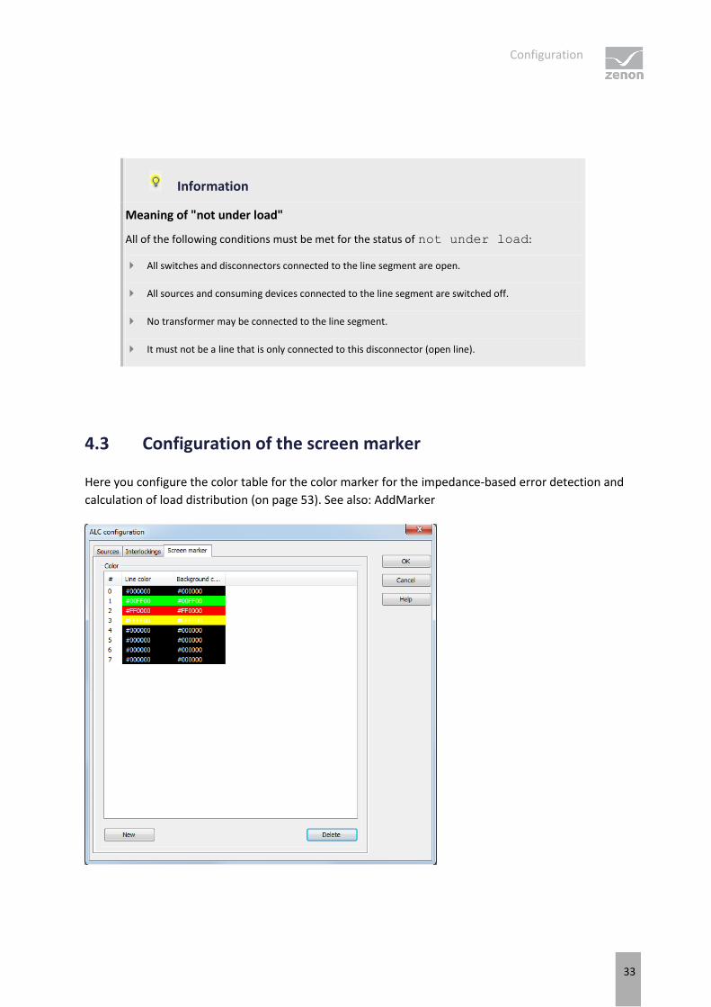
4.3 Configuration of the screen marker
Here you configure the color table for the color marker for the impedance-based error detection and
calculation of load distribution (on page 53). See also: AddMarker
Configuration
34
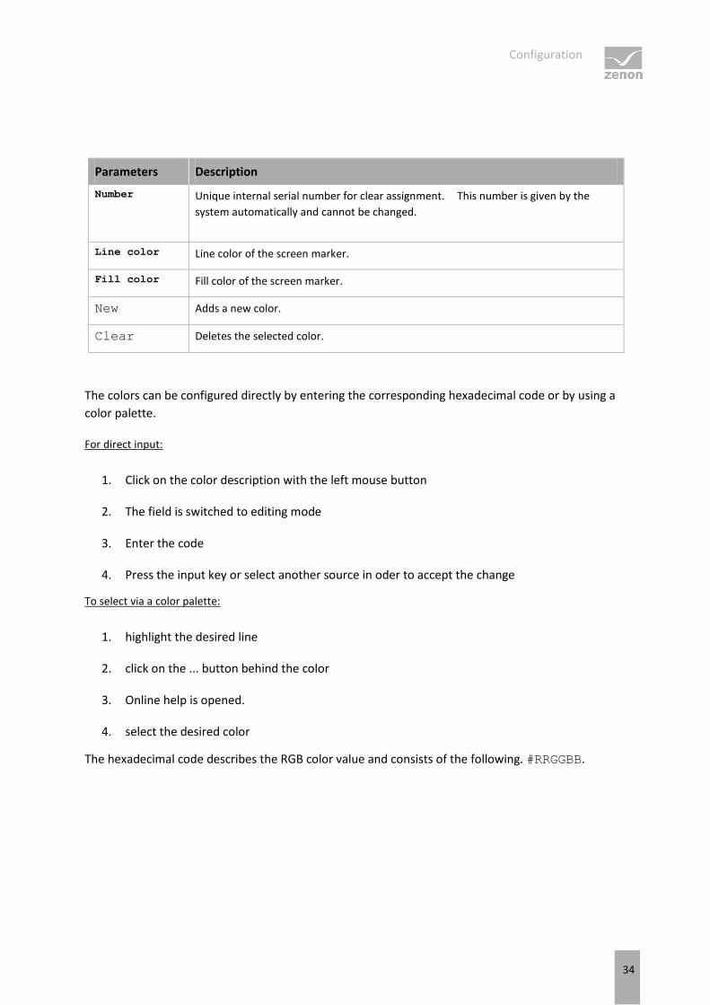
Parameters Description
Number Unique internal serial number for clear assignment. This number is given by the
system automatically and cannot be changed.
Line color Line color of the screen marker.
Fill color Fill color of the screen marker.
New Adds a new color.
Clear Deletes the selected color.
The colors can be configured directly by entering the corresponding hexadecimal code or by using a
color palette.
For direct input:
1. Click on the color description with the left mouse button
2. The field is switched to editing mode
3. Enter the code
4. Press the input key or select another source in oder to accept the change
To select via a color palette:
1. highlight the desired line
2. click on the ... button behind the color
3. Online help is opened.
4. select the desired color
The hexadecimal code describes the RGB color value and consists of the following. #RRGGBB.
Change ALC source color
35
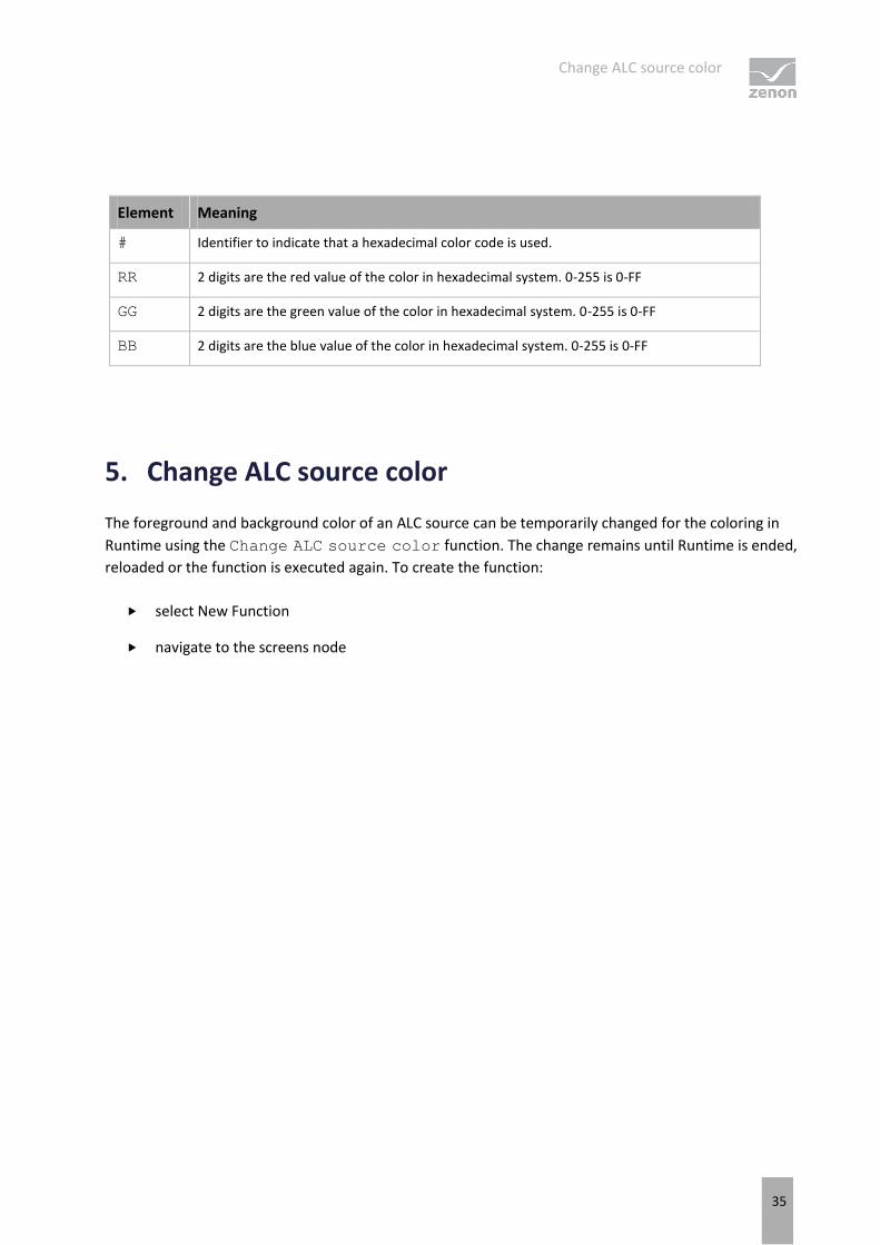
Element Meaning
# Identifier to indicate that a hexadecimal color code is used.
RR 2 digits are the red value of the color in hexadecimal system. 0-255 is 0-FF
GG 2 digits are the green value of the color in hexadecimal system. 0-255 is 0-FF
BB 2 digits are the blue value of the color in hexadecimal system. 0-255 is 0-FF
5. Change ALC source color
The foreground and background color of an ALC source can be temporarily changed for the coloring in
Runtime using the Change ALC source color function. The change remains until Runtime is ended,
reloaded or the function is executed again. To create the function:
select New Function
navigate to the screens node
Change ALC source color
36
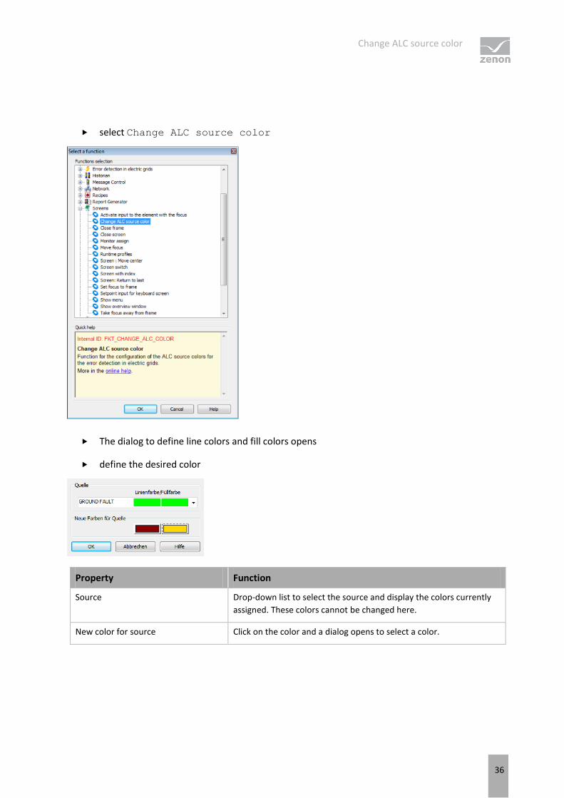
select Change ALC source color
The dialog to define line colors and fill colors opens
define the desired color
Property Function
Source Drop-down list to select the source and display the colors currently
assigned. These colors cannot be changed here.
New color for source Click on the color and a dialog opens to select a color.
Detail screens
37
6. Detail screens
To display individual screens, a partial area can be taken from the topological network and displayed
individually by means of alias. The screen elements in the detail screen are not included in the
topological model, but do however get their ALC colors from the model. They relate to an alias of the
screen elements in the overall screen.
CREATE ALIAS
Aliases can be created for the elements:
Line
Polyline
Tube
Combined element
To create a source element as an alias:
Activate it in the element's properties Use alias
(to do this, ALC must be licensed and the Color from ALC property active)
Click on the ... button in the Alias property
Detail screens
38
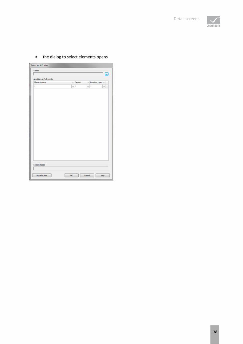
the dialog to select elements opens
Detail screens
39
Parameters Description
Screen Click the ... button and a dialog opens to select a screen.
Available ALC elements Shows the elements that belong to a screen with the element name, type
of element and function type. Clicking on an element selects an alias.
Filter
The elements can be sorted according to all columns. When setting a filter,
the options offered from all other filters are reduced to values that can be
sensibly combined.
Name: Input of a standard search term with wild cards (*). The last 12 search
terms are offered in the list until the Editor is ended.
Element: Select from drop-down list.
Function type: Select from drop-down list.
Clicking on ... opens saved search or drop-down list.
If a filter is active, clicking on the X deletes the filter.
Selected alias Shows the selected element in the field of Available ALC elements.
No selection Removes selected element.
OK Saves selection and closes dialog.
Cancel Discards changes and closes the dialog.
Help Opens online help.
Information
When selecting an element for a new alias, only elements and screens from the same
project that the alias was defined in can be selected. Elements from subprojects or
parallel projects are not available.
REPLACING ALIAS NAMES
Aliases can be be changed when switching screens with Replace link. A detail screen can therefore be
displayed with the data from different equipment parts, for instance lines or partial networks. Alias
names are replaced along the lines of variables and functions. It is also possible to replace in elements
that are used in symbols. The same dialog as is opened for the target as the Alias property.
Error detection in electric grids
40
Substitution using index variables is not possible.
7. Error detection in electric grids
Error detection marks grid parts that are subject to ground faults or short circuits by means of special
colors in ALC. Sources for error detection are what are called ground fault or short circuit reporters that
are assigned to a circuit breaker. Ground fault and short circuit reporters are always at the output of a
circuit breaker element. Error messages are fixed in the screen and must be reset manually.
Information
This function is only available when both the "Energy Edition" and the "Automatic Line
Coloring" modules are licensed.
ERROR DETECTION
Error detection runs locally. Each client in the network has its own independent model and can
therefore search for ground faults and short circuits in different parts of the network.
Error detection in the electrical network is divided into:
Ground fault search (on page 42)
Short circuit search (on page 49)
To configure error detection
You require a license for ALC and zenon Energy Edition
configure the appropriate screens
Configure (on page 8) ALC to the corresponding combined elements (switch, transformer,
disconnector, slider)
configure (on page 18) the lines so that they are colored by ALC
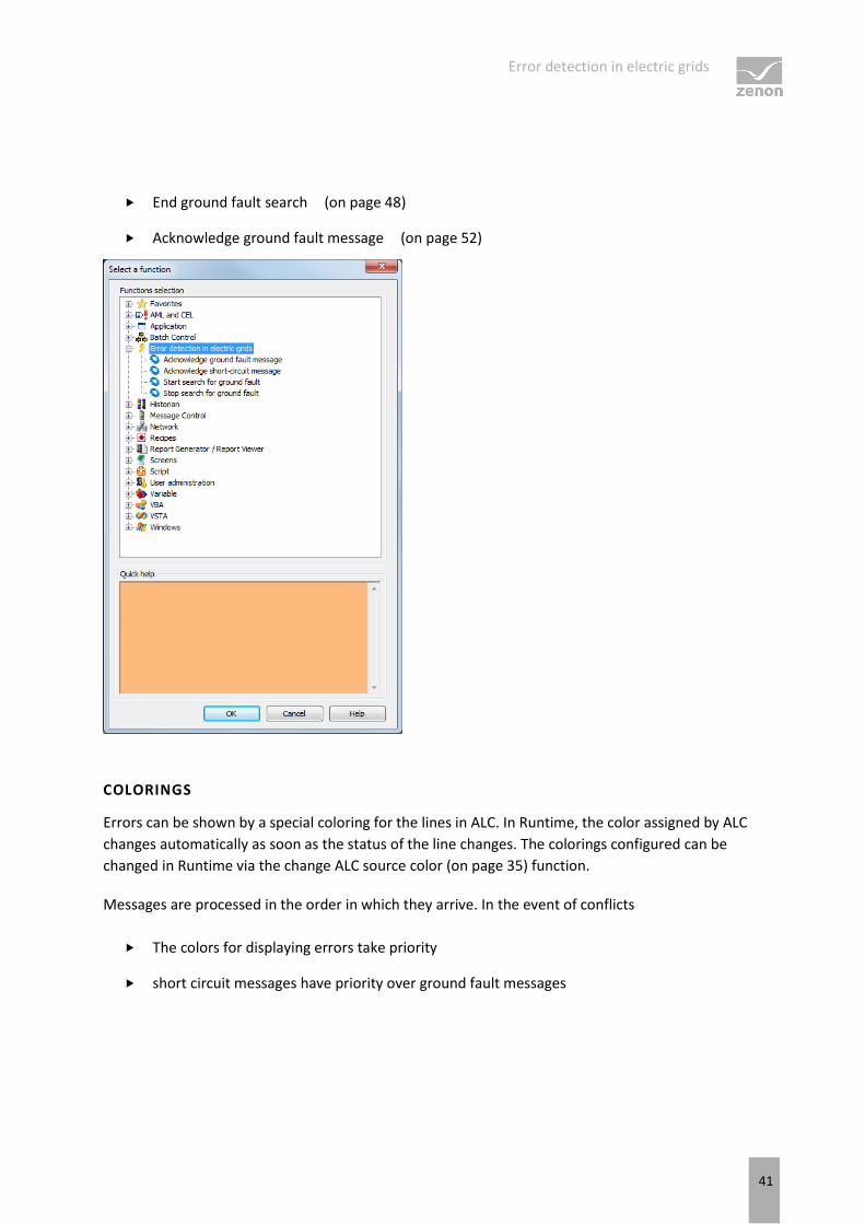
Special functions are available in Runtime for error detection:
Start search for ground fault (on page 46)
Acknowledge (on page 47) ground fault message (on page 47)
Error detection in electric grids
41
End ground fault search (on page 48)
Acknowledge ground fault message (on page 52)
COLORINGS
Errors can be shown by a special coloring for the lines in ALC. In Runtime, the color assigned by ALC
changes automatically as soon as the status of the line changes. The colorings configured can be
changed in Runtime via the change ALC source color (on page 35) function.
Messages are processed in the order in which they arrive. In the event of conflicts
The colors for displaying errors take priority
short circuit messages have priority over ground fault messages
Error detection in electric grids
42
7.1 Search for ground fault
The ground fault search serves to highlight the network parts hat potentially have a ground fault by
coloring these. The color is taken from the configuration of ALC source colors (on page 25) for the
GROUND FAULT source.
Which network parts potentially have a ground fault can be deduced from the ground fault messages
from ground fault identification devices (ground fault indicators, protective device with ground fault
recording). The following applies for ground faults:
Each device can have one to three ground fault messages.
Ground faults are either dealt with by permanent message processing or by transient message
processing.
For directional ground fault devices, the direction can be lagging or leading in relation to
triggering.
leading: First the message, then the transient bit.
lagging: First the transient bit, then the message.
Information
A network component that potentially has a ground fault is then no longer considered to
have a ground fault if this has been successfully connected.
To configure the ground fault search:
1. assign the combined element that represents the switching element to the Function type
switch (on page 43)
2. define the ground fault search mode (on page 43), fault display (on page 44) and ground fault
indication triggering (on page 45)
3. set up the functions for start ground fault search (on page 46), acknowledge ground fault search
(on page 47) and end ground fault search (on page 48)
Error detection in electric grids
43
Information
In order to also be able to set limits in intermeshed networks, only one area subject to a
ground fault per path is searched for a fault.
7.1.1 Mode of the search for ground faults
The short circuit search can either:
color the network part potentially subject to a short circuit
or
the whole network where the short circuit is located
The coloring mode is defined via the Mode of the search for ground faults property.
To configure the property:
navigate to the Automatic Line Coloring node in properties
select the desired mode in the Mode of the search for ground faults property
drop-down list
Color grid part: colors only the grid parts that are potentially subject to a short circuit
Color whole grid: colors in the whole linked grid where the short circuit is located
This setting can be changed in Runtime via the zenon API object model. In doing so, the short circuit
search is recalculated once again.
7.1.2 Earth Fault Identification Type
The direction and type of information processing for the switch type combined element are determined
by the Type setting. to configure:
1. navigate to the Automatic Line Coloring node in the combined element properties
2. open the Ground fault recognition node
Error detection in electric grids
44
3. select the desired type with the direction and type of alarm processing in the Type property
Direction:
indicates if the raising edge of trip alarm or if the raising edge of a direction comes
before
leading: The current direction status is used for the raising edge of the trip alarm
lagging: after a raising edge of the trip alarm, the first raising edge of a direction is
waited on; if this does not occur within 2 seconds, the earth fault device is
considered non-directional
Information processing:
states which information can be processed
none: normal switch; information is not processed
Permanent message processing: Newly received messages are considered a new
ground fault trip
Transient message processing: Messages that are received during a current Search
(on page 46) are suppressed
Note: The distinction between permanent message processing and transient message processing only
relates to processing the message, not to the type. Transient bit message processing need not therefore
relate to a transient bit.
Attention
To suppress intermittent ground faults, ground fault messages that are received in
intervals shorter than 2 seconds are ignored.
7.1.3 Ground fault display
The variable linked at Display is an output variable for error detection and displays the recorded
status of the ground fault identification device. This is necessary because all messages remain saved
internally until they are acknowledged, i.e. they do not necessarily conform to the current status of the
message variables.
Each time a recording is made, a set value is sent to this variable. In doing so, the values are as follows:
Error detection in electric grids
45
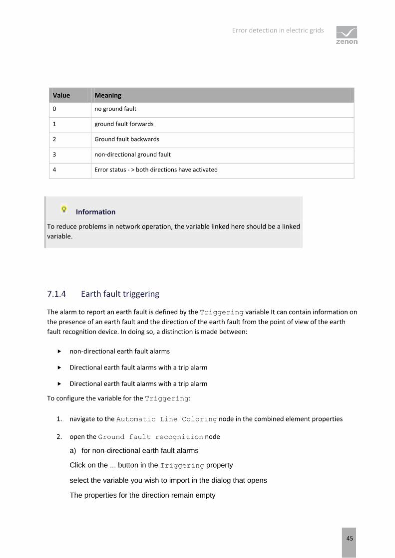
Value Meaning
0 no ground fault
1 ground fault forwards
2 Ground fault backwards
3 non-directional ground fault
4 Error status - > both directions have activated
Information
To reduce problems in network operation, the variable linked here should be a linked
variable.
7.1.4 Earth fault triggering
The alarm to report an earth fault is defined by the Triggering variable It can contain information on
the presence of an earth fault and the direction of the earth fault from the point of view of the earth
fault recognition device. In doing so, a distinction is made between:
non-directional earth fault alarms
Directional earth fault alarms with a trip alarm
Directional earth fault alarms with a trip alarm
To configure the variable for the Triggering:
1. navigate to the Automatic Line Coloring node in the combined element properties
2. open the Ground fault recognition node
a) for non-directional earth fault alarms
Click on the ... button in the Triggering property
select the variable you wish to import in the dialog that opens
The properties for the direction remain empty
Error detection in electric grids
46
b) for directional earth fault alarms with a trip alarm
link the variable with Triggering and add the appropriate direction:
Forwards: link a variable to the Forwards property
Backwards: link a variable to the Backwards property
c) for directional earth fault alarms without a trip alarm
Link the variable with the corresponding direction:
Forwards: link a variable to the Forwards property
Backwards: link a variable to the Backwards property
The Triggering property remains empty
Note: If you address a directional identification device with Forwards in both directions, this is then
considered erroneous and ignored.
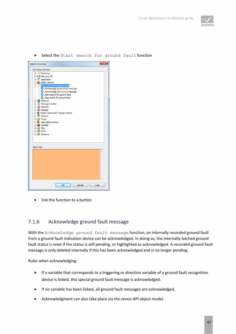
7.1.5 Start ground fault search
The function Start search for ground fault serves to localize a ground fault and has two
effects in Runtime:
1. Fault reports from all ground fault identification devices that were configured with wiper
message processing are ignored.
2. The search algorithm is changed: Switch actions can only reduce the area subject to a ground
fault further. Newly received messages do not therefore increase the area potentially subject to
a ground fault.
To configure the Start search for ground fault function:
create a new function
navigate to the error detection node in the electrical network
Error detection in electric grids
47
Select the Start search for ground fault function
link the function to a button
7.1.6 Acknowledge ground fault message
With the Acknowledge ground fault message function, an internally recorded ground fault
from a ground fault indication device can be acknowledged. In doing so, the internally-latched ground
fault status is reset if the status is still pending, or highlighted as acknowledged. A recorded ground fault
message is only deleted internally if this has been acknowledged and is no longer pending.
Rules when acknowledging:
If a variable that corresponds to a triggering or direction variable of a ground fault recognition
device is linked, this special ground fault message is acknowledged.
If no variable has been linked, all ground fault messages are acknowledged.
Acknowledgment can also take place via the zenon API object model.
Error detection in electric grids
48
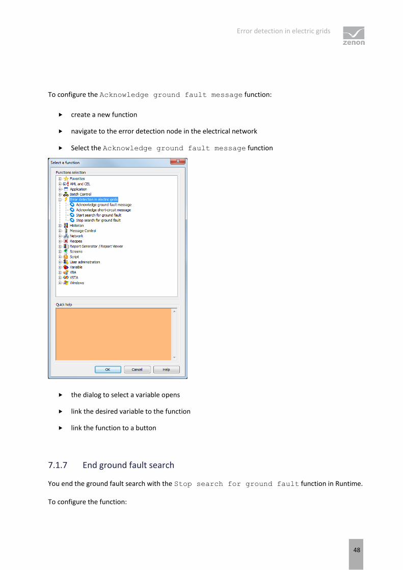
To configure the Acknowledge ground fault message function:
create a new function
navigate to the error detection node in the electrical network
Select the Acknowledge ground fault message function
the dialog to select a variable opens
link the desired variable to the function
link the function to a button
7.1.7 End ground fault search
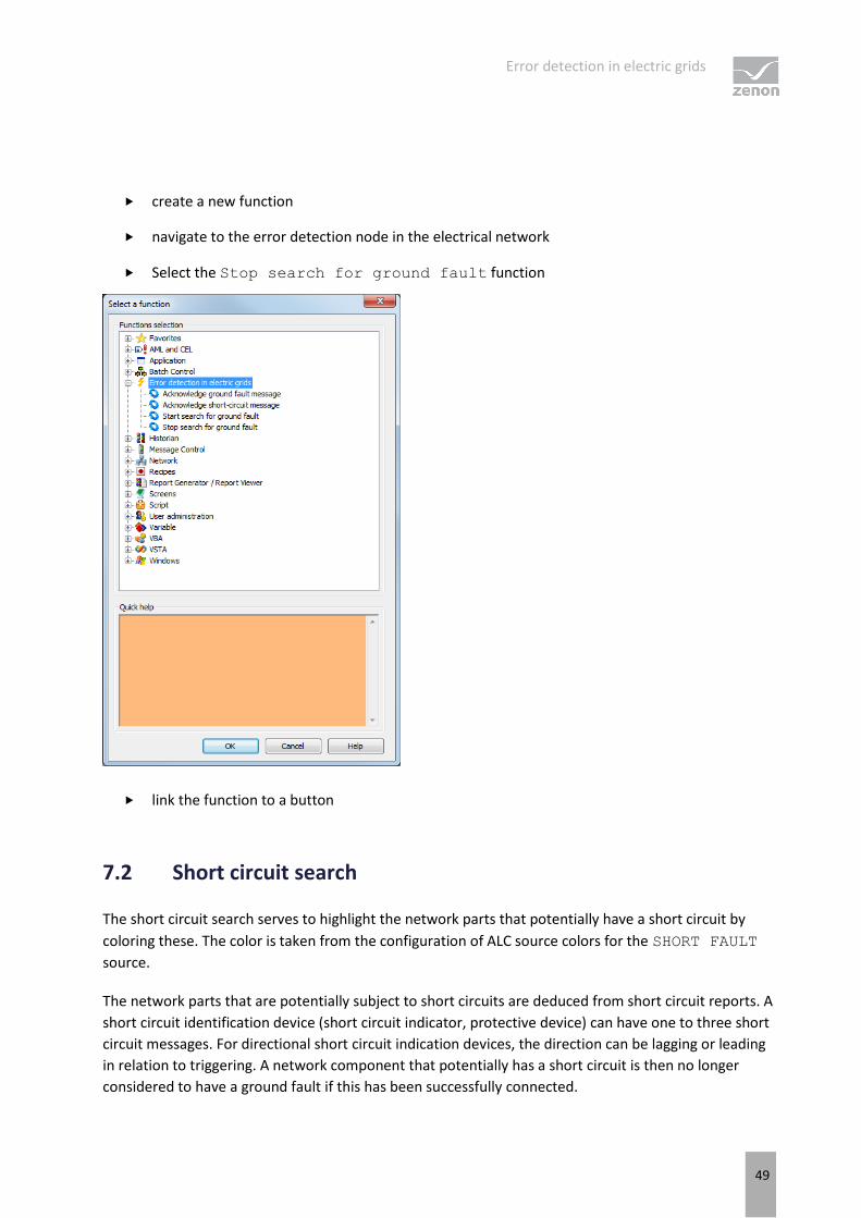
You end the ground fault search with the Stop search for ground fault function in Runtime.
To configure the function:
Error detection in electric grids
49
create a new function
navigate to the error detection node in the electrical network
Select the Stop search for ground fault function
link the function to a button
7.2 Short circuit search
The short circuit search serves to highlight the network parts that potentially have a short circuit by
coloring these. The color is taken from the configuration of ALC source colors for the SHORT FAULT
source.
The network parts that are potentially subject to short circuits are deduced from short circuit reports. A
short circuit identification device (short circuit indicator, protective device) can have one to three short
circuit messages. For directional short circuit indication devices, the direction can be lagging or leading
in relation to triggering. A network component that potentially has a short circuit is then no longer
considered to have a ground fault if this has been successfully connected.
Error detection in electric grids
50
ENGINEERING
To configure the short circuit search:
1. assign the combined element that represents the switching element to the Function type
switch (on page 50)
2. define Short circuit display (on page 51) andShort circuit identification triggering (on page 51)
3. Set up the Acknowledge short circuit message (on page 52) function
7.2.1 Short circuit identification type
The direction and type of information processing for the switch type combined element are determined
by the Type setting. to configure:
1. navigate to the Automatic Line Coloring node in the combined element properties
2. open the Short-circuit detection node
3. select the desired type at the Type property
Direction:
indicates if the raising edge of trip alarm or if the raising edge of a direction comes
before
leading:
The current direction status is used for the raising edge of the trip alarm
lagging:
after a raising edge of the trip alarm, the first raising edge of a direction is waited on;
if this does not occur within 2 seconds, the short circuit device is considered
non-directional
Information processing:
states which information can be processed
none:
normal switch; information is not processed
Permanent message processing:
Newly received messages are considered a new ground fault trip
Error detection in electric grids
51
7.2.2 Short circuit display
The variable linked at Display is an output variable for error detection and displays the recorded
status of the short circuit identification device. This is necessary because all messages remain saved
internally until they are acknowledged, i.e. they do not necessarily conform to the current status of the
message variables.
Each time a recording is made, a set value is sent to this variable. In doing so, the values are as follows:
Value Meaning
0 no short circuit
1 Short circuit forwards
2 Short circuit backwards
3 Non-directional short circuit
7.2.3 Short circuit identification triggering
The variable for the message from the short circuit identification device is defined by the Triggering
variable You can receive information about the presence of a short circuit and the direction of the short
circuit from the point of view of the short circuit identification device.In doing so, a distinction is made
between:
non-directional short circuit reporters
directional short circuit reporters with a trip alarm
directional short circuit alarms with a trip alarm
To configure the variables for:
1. navigate to the Automatic Line Coloring node in the combined element properties
2. open the Short-circuit detection node
a) for non-directional short circuit detection devices
Click on the ... button in the Triggering property
select the variable you wish to import in the dialog that opens
Error detection in electric grids
52
The properties for the direction remain empty
b) for directional short circuit detection devices with a trip alarm
link the variable with Triggering and add the appropriate direction:
Forwards: link a variable to the Forwards property
Backwards: link a variable to the Backwards property
c) for directional short circuit detection devices without a trip alarm
Link the variable with the corresponding direction:
Forwards: link a variable to the Forwards property
Backwards: link a variable to the Backwards property
The Triggering property remains empty
7.2.4 Acknowledge short circuit message
With the Acknowledge short-circuit message function, an internally recorded short circuit
from a short circuit indication device can be acknowledged. In doing so, the internally-latched ground
fault status is reset if the status is still pending, or highlighted as acknowledged. A recorded short circuit
message is only deleted internally if this has been acknowledged and is no longer pending.
Rules when acknowledging:
If a variable that corresponds to a triggering or direction variable of a short circuit recognition
device is linked, this special short circuit message is acknowledged.
If no variable has been linked, all short circuit messages are acknowledged.
Acknowledgment can also take place via the zenon API object model.
ACKNOWLEDGE SHORT-CIRCUIT MESSAGE
create a new function
navigate to the error detection node in the electrical network
Impedance-based error detection and calculation of load distribution
53
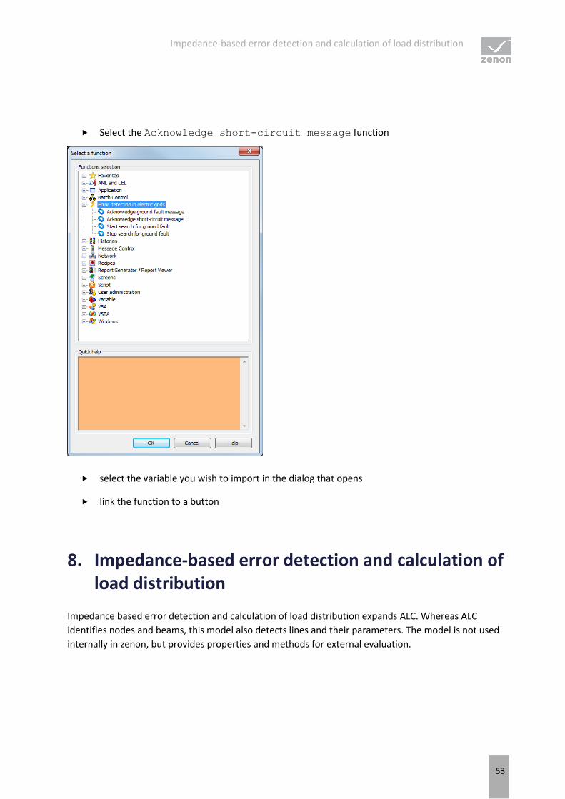
Select the Acknowledge short-circuit message function
select the variable you wish to import in the dialog that opens
link the function to a button
8. Impedance-based error detection and calculation of load distribution
Impedance based error detection and calculation of load distribution expands ALC. Whereas ALC
identifies nodes and beams, this model also detects lines and their parameters. The model is not used
internally in zenon, but provides properties and methods for external evaluation.

Impedance-based error detection and calculation of load distribution
54
PROPERTIES FOR ALC AND THE EXTENDED TOPOLOGICAL MODEL
The ALC elements combined element and line (line, polyline, tube) have special properties for error
detection for protection and to calculate the load distribution. These properties are not evaluated in
zenon, but are available via the zenon API algorithms to be created by users.
The simple topological model for the coloring was supplements by an expanded topological model that
includes all lines as separate beams. The extended topological model is stored as ALC.xml and can be
read by external applications this way. ALC.xml contains two sections:
GraphElements: contains the extended topological model without aliases
GraphAliases: contains only the aliases
Each object has a unique ID, via which it is referenced in the file. The attributes correspond to a subset
of the zenon screen elements that have created the elements.
Impedance-based error detection and calculation of load distribution
55
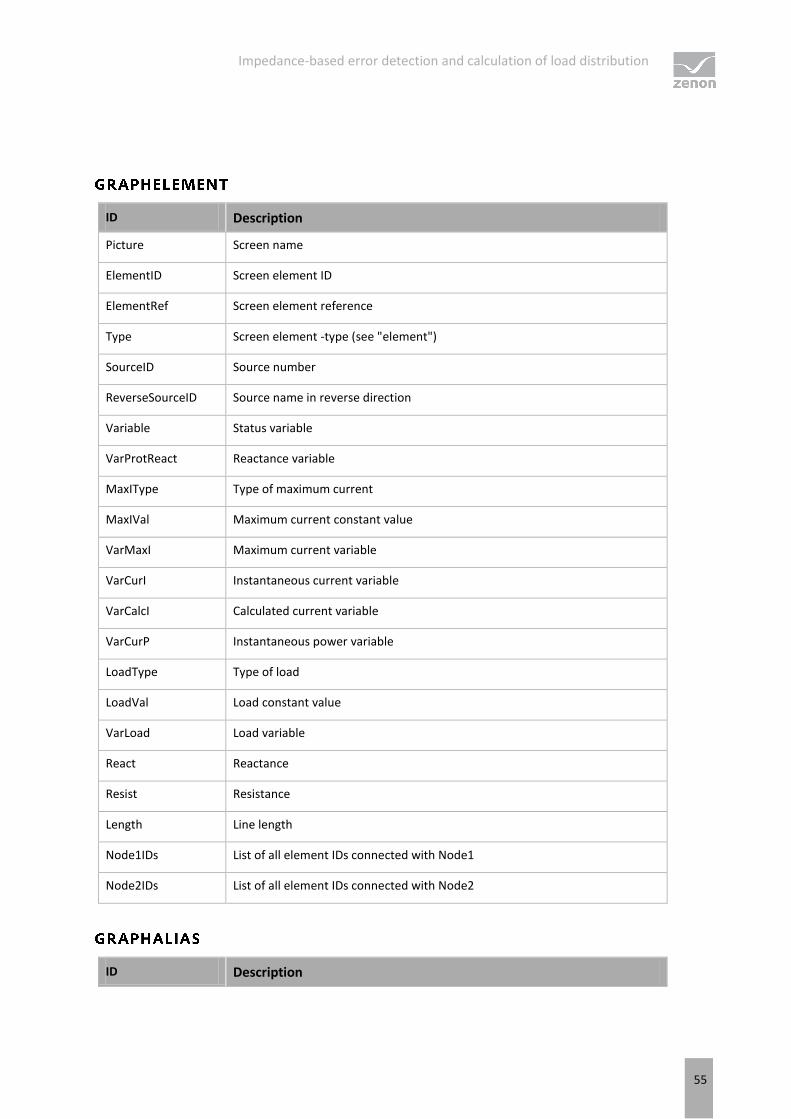
ID Description
Picture Screen name
ElementID Screen element ID
ElementRef Screen element reference
Type Screen element -type (see "element")
SourceID Source number
ReverseSourceID Source name in reverse direction
Variable Status variable
VarProtReact Reactance variable
MaxIType Type of maximum current
MaxIVal Maximum current constant value
VarMaxI Maximum current variable
VarCurI Instantaneous current variable
VarCalcI Calculated current variable
VarCurP Instantaneous power variable
LoadType Type of load
LoadVal Load constant value
VarLoad Load variable
React Reactance
Resist Resistance
Length Line length
Node1IDs List of all element IDs connected with Node1
Node2IDs List of all element IDs connected with Node2
ID Description
Impedance-based error detection and calculation of load distribution
56
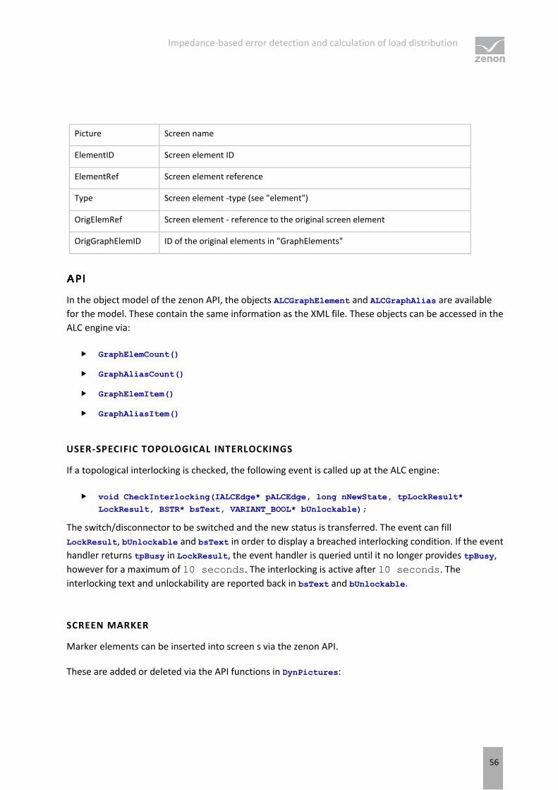
Picture Screen name
ElementID Screen element ID
ElementRef Screen element reference
Type Screen element -type (see "element")
OrigElemRef Screen element - reference to the original screen element
OrigGraphElemID ID of the original elements in "GraphElements"
In the object model of the zenon API, the objects ALCGraphElement and ALCGraphAlias are available
for the model. These contain the same information as the XML file. These objects can be accessed in the
ALC engine via:
GraphElemCount()
GraphAliasCount()
GraphElemItem()
GraphAliasItem()
USER-SPECIFIC TOPOLOGICAL INTERLOCKINGS
If a topological interlocking is checked, the following event is called up at the ALC engine:
void CheckInterlocking(IALCEdge* pALCEdge, long nNewState, tpLockResult*
LockResult, BSTR* bsText, VARIANT_BOOL* bUnlockable);
The switch/disconnector to be switched and the new status is transferred. The event can fill
LockResult, bUnlockable and bsText in order to display a breached interlocking condition. If the event
handler returns tpBusy in LockResult, the event handler is queried until it no longer provides tpBusy,
however for a maximum of 10 seconds. The interlocking is active after 10 seconds. The
interlocking text and unlockability are reported back in bsText and bUnlockable.
SCREEN MARKER
Marker elements can be inserted into screen s via the zenon API.
These are added or deleted via the API functions in DynPictures:
Impedance-based error detection and calculation of load distribution
57
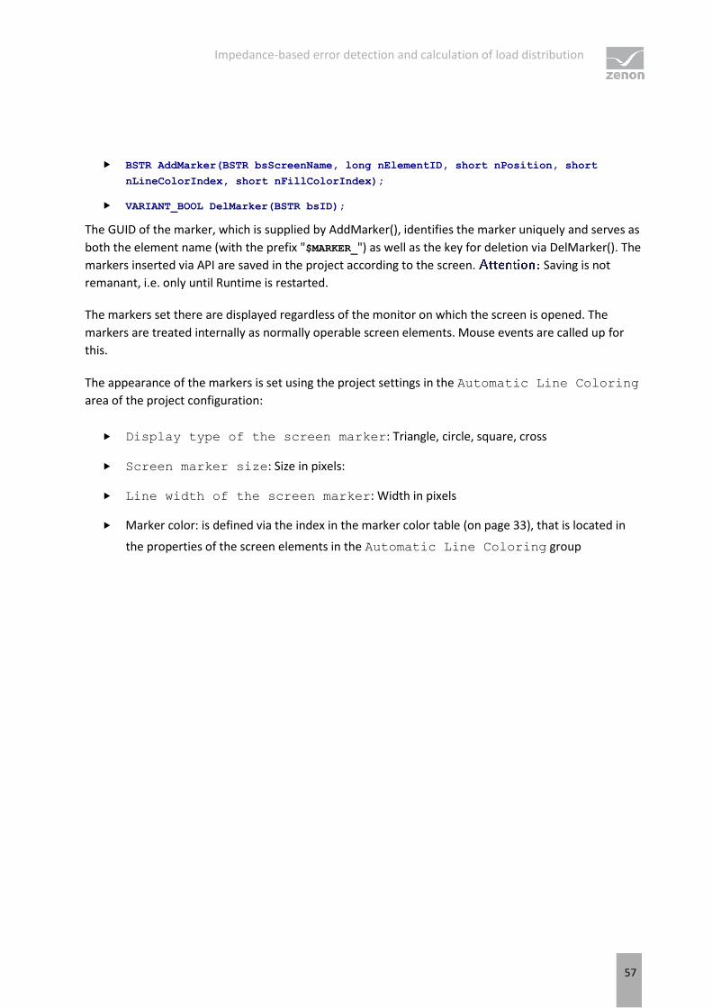
BSTR AddMarker(BSTR bsScreenName, long nElementID, short nPosition, short
nLineColorIndex, short nFillColorIndex);
VARIANT_BOOL DelMarker(BSTR bsID);
The GUID of the marker, which is supplied by AddMarker(), identifies the marker uniquely and serves as
both the element name (with the prefix "$MARKER_") as well as the key for deletion via DelMarker(). The
markers inserted via API are saved in the project according to the screen. Saving is not
remanant, i.e. only until Runtime is restarted.
The markers set there are displayed regardless of the monitor on which the screen is opened. The
markers are treated internally as normally operable screen elements. Mouse events are called up for
this.
The appearance of the markers is set using the project settings in the Automatic Line Coloring
area of the project configuration:
Display type of the screen marker: Triangle, circle, square, cross
Screen marker size: Size in pixels:
Line width of the screen marker: Width in pixels
Marker color: is defined via the index in the marker color table (on page 33), that is located in
the properties of the screen elements in the Automatic Line Coloring group


