Embed Size (px)
Citation preview

MALLA REDDY COLLEGE OF ENGINEERING & TECHNOLOGY
DEPARTMENT OF MECHANICAL ENGINEERING (Autonomous Institution-UGC, Govt. of India) Secunderabad-500100,Telangana State, India.
www.mrcet.ac.in
COURSE MATERIAL
III Year B. Tech II- Semester
MECHANICAL ENGINEERING
AUTOMOBILE ENGINEERING
R17A0323

www.mrcet.ac.in
MALLA REDDY COLLEGE OF ENGINEERING & TECHNOLOGY
(Autonomous Institution – UGC, Govt. of India)
DEPARTMENT OF MECHANICAL ENGINEERING
CONTENTS
1. Vision, Mission & Quality Policy
2. Pos, PSOs & PEOs
3. Blooms Taxonomy
4. Course Syllabus
5. Lecture Notes (Unit wise)
a. Objectives and outcomes
b. Notes
c. Presentation Material (PPT Slides/ Videos)
d. Industry applications relevant to the concepts covered
e. Question Bank for Assignments
f. Tutorial Questions
6. Previous Question Papers
MALLA REDDY COLLEGE OF ENGINEERING & TECHNOLOGY
(Autonomous Institution – UGC, Govt. of India)
VISION
❖ To establish a pedestal for the integral innovation, team spirit, originality and
competence in the students, expose them to face the global challenges and become
technology leaders of Indian vision of modern society.
MISSION
❖ To become a model institution in the fields of Engineering, Technology and
Management.
❖ To impart holistic education to the students to render them as industry ready
engineers.
❖ To ensure synchronization of MRCET ideologies with challenging demands of
International Pioneering Organizations.
QUALITY POLICY
❖ To implement best practices in Teaching and Learning process for both UG and PG
courses meticulously.
❖ To provide state of art infrastructure and expertise to impart quality education.
❖ To groom the students to become intellectually creative and professionally
competitive.
❖ To channelize the activities and tune them in heights of commitment and sincerity,
the requisites to claim the never - ending ladder of SUCCESS year after year.
For more information: www.mrcet.ac.in

MALLA REDDY COLLEGE OF ENGINEERING & TECHNOLOGY
(Autonomous Institution – UGC, Govt. of India)
www.mrcet.ac.in Department of Mechanical Engineering
VISION
To become an innovative knowledge center in mechanical engineering through state-of-
the-art teaching-learning and research practices, promoting creative thinking
professionals.
MISSION
The Department of Mechanical Engineering is dedicated for transforming the students
into highly competent Mechanical engineers to meet the needs of the industry, in a
changing and challenging technical environment, by strongly focusing in the
fundamentals of engineering sciences for achieving excellent results in their professional
pursuits.
Quality Policy
To pursuit global Standards of excellence in all our endeavors namely teaching,
research and continuing education and to remain accountable in our core and
support functions, through processes of self-evaluation and continuous
improvement.
To create a midst of excellence for imparting state of art education, industry-
oriented training research in the field of technical education.

MALLA REDDY COLLEGE OF ENGINEERING & TECHNOLOGY
(Autonomous Institution – UGC, Govt. of India)
www.mrcet.ac.in Department of Mechanical Engineering
PROGRAM OUTCOMES
Engineering Graduates will be able to:
1. Engineering knowledge: Apply the knowledge of mathematics, science, engineering
fundamentals, and an engineering specialization to the solution of complex engineering
problems.
2. Problem analysis: Identify, formulate, review research literature, and analyze complex
engineering problems reaching substantiated conclusions using first principles of
mathematics, natural sciences, and engineering sciences.
3. Design/development of solutions: Design solutions for complex engineering problems
and design system components or processes that meet the specified needs with
appropriate consideration for the public health and safety, and the cultural, societal, and
environmental considerations.
4. Conduct investigations of complex problems: Use research-based knowledge and
research methods including design of experiments, analysis and interpretation of data,
and synthesis of the information to provide valid conclusions.
5. Modern tool usage: Create, select, and apply appropriate techniques, resources, and
modern engineering and IT tools including prediction and modeling to complex
engineering activities with an understanding of the limitations.
6. The engineer and society: Apply reasoning informed by the contextual knowledge to
assess societal, health, safety, legal and cultural issues and the consequent
responsibilities relevant to the professional engineering practice.
7. Environment and sustainability: Understand the impact of the professional engineering
solutions in societal and environmental contexts, and demonstrate the knowledge of, and
need for sustainable development.
8. Ethics: Apply ethical principles and commit to professional ethics and responsibilities and
norms of the engineering practice.
9. Individual and teamwork: Function effectively as an individual, and as a member or
leader in diverse teams, and in multidisciplinary settings.
10. Communication: Communicate effectively on complex engineering activities with the
engineering community and with society at large, such as, being able to comprehend and
write effective reports and design documentation, make effective presentations, and give
and receive clear instructions.
11. Project management and finance: Demonstrate knowledge and understanding of the
engineering and management principles and apply these to one’s own work, as a member
and leader in a team, to manage projects and in multidisciplinary environments.

MALLA REDDY COLLEGE OF ENGINEERING & TECHNOLOGY
(Autonomous Institution – UGC, Govt. of India)
www.mrcet.ac.in Department of Mechanical Engineering
12. Life-long learning: Recognize the need for and have the preparation and ability to
engage in independent and life-long learning in the broadest context of technological
change.
PROGRAM SPECIFIC OUTCOMES (PSOs)
PSO1 Ability to analyze, design and develop Mechanical systems to solve the
Engineering problems by integrating thermal, design and manufacturing Domains.
PSO2 Ability to succeed in competitive examinations or to pursue higher studies or
research.
PSO3 Ability to apply the learned Mechanical Engineering knowledge for the
Development of society and self.
Program Educational Objectives (PEOs)
The Program Educational Objectives of the program offered by the department are broadly
listed below:
PEO1: PREPARATION
To provide sound foundation in mathematical, scientific and engineering fundamentals
necessary to analyze, formulate and solve engineering problems.
PEO2: CORE COMPETANCE
To provide thorough knowledge in Mechanical Engineering subjects including theoretical
knowledge and practical training for preparing physical models pertaining to Thermodynamics,
Hydraulics, Heat and Mass Transfer, Dynamics of Machinery, Jet Propulsion, Automobile
Engineering, Element Analysis, Production Technology, Mechatronics etc.
PEO3: INVENTION, INNOVATION AND CREATIVITY
To make the students to design, experiment, analyze, interpret in the core field with the help of
other inter disciplinary concepts wherever applicable.
PEO4: CAREER DEVELOPMENT
To inculcate the habit of lifelong learning for career development through successful completion
of advanced degrees, professional development courses, industrial training etc.

MALLA REDDY COLLEGE OF ENGINEERING & TECHNOLOGY
(Autonomous Institution – UGC, Govt. of India)
www.mrcet.ac.in Department of Mechanical Engineering
PEO5: PROFESSIONALISM
To impart technical knowledge, ethical values for professional development of the student to
solve complex problems and to work in multi-disciplinary ambience, whose solutions lead to
significant societal benefits.

MALLA REDDY COLLEGE OF ENGINEERING & TECHNOLOGY (Autonomous Institution – UGC, Govt. of India)
www.mrcet.ac.in Department of Mechanical Engineering
Blooms Taxonomy
Bloom’s Taxonomy is a classification of the different objectives and skills that educators set for
their students (learning objectives). The terminology has been updated to include the following
six levels of learning. These 6 levels can be used to structure the learning objectives, lessons,
and assessments of a course.
1. Remembering: Retrieving, recognizing, and recalling relevant knowledge from long‐ term
memory.
2. Understanding: Constructing meaning from oral, written, and graphic messages through
interpreting, exemplifying, classifying, summarizing, inferring, comparing, and explaining.
3. Applying: Carrying out or using a procedure for executing or implementing.
4. Analyzing: Breaking material into constituent parts, determining how the parts relate to
one another and to an overall structure or purpose through differentiating, organizing, and
attributing.
5. Evaluating: Making judgments based on criteria and standard through checking and
critiquing.
6. Creating: Putting elements together to form a coherent or functional whole; reorganizing
elements into a new pattern or structure through generating, planning, or producing.

MALLA REDDY COLLEGE OF ENGINEERING & TECHNOLOGY (Autonomous Institution – UGC, Govt. of India)
www.mrcet.ac.in Department of Mechanical Engineering

MALLA REDDY COLLEGE OF ENGINEERING & TECHNOLOGY III Year B. Tech, ME-II Sem
(R17A0323) AUTOMOBILE ENGINEERING
(CORE ELECTIVE – II) Objectives:
The objective of this subject is to provide knowledge about various systems involved in automobile engine.
Able to learn about different components of IC Engines.
Different automobile engine systems line diagrams.
UNIT –I VEHICLE STRUCTURE AND ENGINES
Types of automobiles vehicle construction and different layouts, chassis, frame and body,
Vehicle aerodynamics (various resistances and moments involved), IC engines components-
functions and materials, variable valve timing (VVT).
UNIT –II ENGINE AUXILIARY SYSTEMS
Electronically controlled gasoline injection system for SI engines, Electronically controlled diesel injection system (Unit injector system, Rotary distributor type and common rail direct injection system), Electronic ignition system (Transistorized coil ignition system, capacitive discharge ignition system), Turbo chargers (WGT, VGT), Engine emission control by three way catalytic converter system, Emission norms (Euro and BS).
UNIT –III TRANSMISSION SYSTEMS
Clutch-types and construction, gear boxes- manual and automatic, gear shift mechanisms, Over
drive, transfer box, fluid flywheel, torque converter, propeller shaft, slip joints, universal
joints, Differential and rear axle, Hotchkiss Drive and Torque Tube Drive.
UNIT –IV STEERING, BRAKES AND SUSPENSION SYSTEMS
Steering geometry and types of steering gear box-Power Steering, Types of Front Axle, Types
of Suspension Systems, Pneumatic and Hydraulic Braking Systems, Antilock Braking System
(ABS), electronic brake force distribution (EBD) and Traction Control.
UNIT –V ALTERNATIVE ENERGY SOURCES
Use of Natural Gas, Liquefied Petroleum Gas, Bio-diesel, Bio-ethanol, Gasohol
and Hydrogen in Automobiles- Engine modifications required Performance, Combustion
and Emission Characteristics of SI and CI engines with these alternate fuels - Electric and
Hybrid Vehicles, Fuel Cells.
L T/P/D C 3 0 3

TEXT BOOKS:
1. Jain K.K. and Asthana .R.B, Automobile Engineeri Tata McGraw Hill Publishers, New
Delhi, 2002.
2. Kirpal Singh, Automobile Engineering, Vol 1 & 2, Seventh Edition, Standard Publishers, New
Delhi, 13th Edition 2014.
REFERENCE BOOKS:
1. Ganesan V. Internal Combustion Engines, Third Edition, Tata McGraw-Hill, 2012.
2. Heinz Heisler, Advanced Engine Technology, SAE International Publications USA, 1998.
3. Joseph Heitner, Automotive Mechanics, Second Edition, East-West Press, 1999.
4. Martin W, Stockel and Martin T Stockle , Automotive Mechanics Fundamentals, The Good
heart - Will Cox Company Inc, USA ,1978.
5. Newton ,Steeds and Garet, Motor Vehicles, Butterworth Publishers,1989.
OUTCOMES:
The Automotive Engineering program aims to provide practice-oriented education based on the latest scientific results and methods.
Which enable students to work independently as automotive engineers.
Enables to face increasing challenges and standards of global markets.
DEPARTMENT OF MECHANICAL ENGINEERING
UNIT I
VEHICLE STRUCTURE AND ENGINES

DEPARTMENT OF MECHANICAL ENGINEERING
COURSE OBJECTIVES:
Student should able to understand the basic components of Automobile Engineering
COURSE OUTCOMES:
Student should able to List different types of Engines and their classifications

DEPARTMENT OF MECHANICAL ENGINEERING
1.1. Introduction of Automobile or Vehicle:
An Automobile is a self propelled vehicle which contains the power source for its
propulsion and is used for carrying passengers and goods on the ground, such as
car, bus, trucks, etc.,,
Types of Automobile:
The automobiles are classified by the following ways,
1. On the Basis of Load:
Heavy transport vehicle (HTV) or heavy motor vehicle (HMV),
Light transport vehicle (LTV), Light motor vehicle (LMV),
2. On the Basis of Wheels :
Two wheeler vehicle, for example : Scooter, motorcycle, scooty, etc.
Three wheeler vehicle, for example : Autorickshaw,
Three wheeler scooter for handicaps and tempo, etc.
Four wheeler vehicle, for example : Car, jeep, trucks, buses, etc.
Six wheeler vehicle, for example : Big trucks with two gear axles.
3. On the basis of Fuel Used:
Petrol vehicle, e.g. motorcycle, scooter, cars, etc.
Diesel vehicle, e.g. trucks, buses, etc.
Electric vehicle which use battery to drive.
Steam vehicle, e.g. an engine which uses steam engine.
Gas vehicle, e.g. LPG and CNG vehicles, where LPG is liquefied
4. On the basis of body style:
Sedan Hatchback car.
Coupe car Station wagon Convertible.
Van Special purpose vehicle, e.g. ambulance, milk van, etc.

DEPARTMENT OF MECHANICAL ENGINEERING
5. On the basis of Transmission:
Conventional vehicles with manual transmission, e.g. car with 5 gears.
Semi-automatic
Automatic : In automatic transmission, gears are not
required to be changed manually.
6. On the basis of Drive:
Left hand drive
Right hand drive
7. On the basis of Driving Axle
Front wheel drive
Rear wheel drive
All wheel drive
8. Position of Engine:
Engine in Front - Most of the vehicles have engine in the front.
Example : most of the cars,
Engine in the Rear Side Very few vehicles have engine located in
the rear. Example : Nano car.
Vehicle construction and Components;
The main components of an automobile refer to the following components;
Frame,
Chassis,
Body,
Power unit,
Transmission system.

DEPARTMENT OF MECHANICAL ENGINEERING
An automobile is made up of mainly two units, these are Chassis and Body.
“Frame” + “Base components” = “Chassis”
“Chassis” + “Body” = “Vehicle”
Frame :
The frame is the skeleton of the vehicle. It servers as a main foundation
and base for alignment for the chassis.
Types;
Conventional frame,
Semi integral frame;

DEPARTMENT OF MECHANICAL ENGINEERING
Integral or untidiest frame.
Chassis;
If the frame contains the base components its called as chassis. The
components are like Engine, radiator, clutch, gearbox, silencer, road wheels,
fuel tank, wirings, differential units, etc..,
Body:
Body is the superstructure of the vehicle and it is bolted to the chasis.
Types;
Car,
Truck,
Tractor,
Delivery van,
Jeep,
Bus, etc..,

DEPARTMENT OF MECHANICAL ENGINEERING
Components of an Engine;
Even though reciprocating internal combustion engines look quite simple, they
are highly complex machines. There are hundreds of components that have to
perform their functions satisfactorily to produce output power. There are two
types of engines, viz., spark ignition (S1) and compression-ignition (CI) engine.
Let us now go through the important engine components and the nomenclature
associated with an engine.
Terms connected with i.c. engines;
Bore: The inside diameter of the cylinder is called bore
Stroke: The linear distance along the cylinder axis between two limiting position
s is called stroke.
Top Dead Center ( T.D.C.) : the top most position of the piston towards cover
end side of the cylinder is called T.D.C.
Bottom dead Center (B.D.C.) : The lowest position of the piston towards the
crank end side of the cylinder is called B.D.C.
Clearance Volume: The volume contained in the cylinder above the top of the
piston , when the piston is at top dead center , is called the clearance volume.
Swept Volume: The volume swept through by the piston in moving between T.D.C. and B.D.C,
is called swept volume or piston displacement.
Compression Ratio: It is the ratio of Total cylinder volume to clearance volume.
Definition of ‘Engine’
An engine is a device, which transforms one form of energy into another form.
Normally, most of the engines convert thermal energy into mechanical work and

DEPARTMENT OF MECHANICAL ENGINEERING
therefore they are called ‘heat engines’.
Engine Components
The major components of the engine and their functions are briefly described below.
Cylinder Block:
The cylinder block is the main supporting structure for the various components. The
cylinder of a multicylinder engine is cast as a single unit, called cylinder block. The
cylinder head is mounted on the cylinder block.
The cylinder head and cylinder block are provided with water jackets in the case of
water- cooling with cooling fins in the case of air-cooling. Cylinder head gasket is
incorporated between the cylinder block and cylinder head. The cylinder head is held
tight to the cylinder block by number of bolts or studs. The bottom portion of the
cylinder block is called crankcase. A cover called crankcase, which becomes a sump
for lubricating oil is fastened to the bottom of the crankcase. The inner surface of the
cylinder block, which is machined and finished accurately to cylindrical shape, is
called bore or face.

DEPARTMENT OF MECHANICAL ENGINEERING
Cylinder
As the name implies it is a cylindrical vessel or space in which the piston makes a
reciprocating motion. The varying volume created in the cylinder during the operation
of the engine is filled with the working fluid and subjected to different thermodynamic
processes. The cylinder is supported in the cylinder block.
Piston
It is a cylindrical component fitted into the cylinder forming the moving boundary of
the combustion system. It fits perfectly (snugly) into the cylinder providing a gas-tight
space with the piston rings and the lubricant. It forms the first link in transmitting the
gas forces to the output shaft.
Combustion Chamber
The space enclosed in the upper part of the cylinder, by the cylinder head and the
piston top during the combustion process, is called the combustion chamber. The
combustion of fuel and the consequent release of thermal energy results in the building
up of pressure in this part of the cylinder.
Inlet Manifold
The pipe which connects the intake system to the inlet valve of the engine and through
which air or air-fuel mixture is drawn into the cylinder is called the inlet manifold.
Gudgeon Pin
It forms the link between the small end of the connecting rod and the piston.
Exhaust Manifold
The pipe that connects the exhaust system to the exhaust valve of the engine and
through which the products of combustion escape into the atmosphere is called the
exhaust manifold.

DEPARTMENT OF MECHANICAL ENGINEERING
Inlet and Exhaust Valves
Valves are commonly mushroom shaped poppet type. They are provided either on the
cylinder head or on the side of the cylinder for regulating the charge coming into the
cylinder (inlet valve) and for discharging the products of combustion (exhaust valve)
from the cylinder.
Connecting Rod
It interconnects the piston and the crankshaft and transmits the gas forces from the
piston to the crankshaft. The two ends of the connecting rod are called as small end and
the big end. Small end is connected to the piston by gudgeon pin and the big end is
connected to the crankshaft by crankpin.
Crankshaft
It converts the reciprocating motion of the piston into useful rotary motion of the
output shaft. In the crankshaft of a single cylinder engine there is pair of crank arms
and balance weights. The balance weights are provided for static and dynamic
balancing of the rotating system. The crankshaft is enclosed in a crankcase.
Piston Rings
Piston rings, fitted into the slots around the piston, provide a tight seal between the
piston and the cylinder wall thus preventing leakage of combustion gases
Camshaft
The camshaft and its associated parts control the opening and closing of the two
valves. The associated parts are push rods, rocker arms, valve springs and tappets. This
shaft also provides the drive to the ignition system. The camshaft is driven by the
crankshaft through timing gears.
Cams
These are made as integral parts of the camshaft and are designed in such a way to open the
valves at the correct timing and to keep them open for the necessary duration.

DEPARTMENT OF MECHANICAL ENGINEERING
Fly Wheel
The net torque imparted to the crankshaft during one complete cycle of operation of
the engine fluctuates causing a change in the angular velocity of the shaft. In order to
achieve a uniform torque an inertia mass in the form of a wheel is attached to the
output shaft and this wheel is called the flywheel.
Basic Parts of the Gasoline Engine:
Basic Parts of the Gasoline Engine are listed below;
Cylinder block
Piston
Piston rings
Piston pin
Connecting rod
Crankshaft
Cylinder head
Intake valve
Exhaust valve
Camshaft
Timing gears
Spark plug
Cylinder Block:
Cylinder Block Basic frame of gasoline engine. Contains the cylinder.
Piston:

DEPARTMENT OF MECHANICAL ENGINEERING
Piston A sliding plug that harnesses the force of the burning gases in the cylinder.
Piston Rings:
Piston rings seal the compression gases above the piston keep the oil below the piston rings.
Piston Pins:
Piston Pins Also known as the wrist pin, it connects the piston to the small end of the
connecting rod. It transfers the force and allows the rod to swing back and forth.
Connecting Rod:
Connecting Rod Connects the piston and piston pin to the crankshaft.
Crankshaft:
Crankshaft Along the the piston pin and connecting rod it converts the up and down motion
(reciprocating) of the engine to spinning (rotary) motion.
Flywheel:
Flywheel Carries the inertia when there is no power stroke.
Cylinder Head:
Cylinder Head Forms the top of the combustion chamber. Contains the valves, the
passageways for the fuel mixture to move in and out of the engine.
Intake and Exhaust Valves:
Intake and Exhaust Valves Doorway that lets the gases in and out of the engine.
Camshaft:
Camshaft Through the use of an eccentric the cam lobes push the valves open. The
valve springs close them.
Timing Gears:
Timing Gears These gears drive the camshaft from the crankshaft.
Variable Valve Timing

DEPARTMENT OF MECHANICAL ENGINEERING
It is inherent to the operation of internal combustion engines to possess inlet and
exhaust valves (4-stroke) or ports (2-stroke) for proper functioning. The idea here is
to entrap the incoming fresh charge in a well-designed combustion chamber and
then initiate ignition in order to release and convert the stored fuel chemical energy
into the thermal energy. Subsequent to this release of energy, a mechanical system,
such as piston-connecting-rod-crankshaft, is needed for conversion of the thermal
energy into the mechanical energy of the crankshaft. The incoming fresh charge
usually consists of fuel, air, and possibly exhaust gas recalculated (EGR) chemical
species. EGR is used for nitric oxide (NOX) emission control purposes. In this
scenario, the roles that valves, particularly the intake valves, play are critical for the
engine’s efficient operation, optimum performance, and minimization of pollutants
emission. In this tutorial, these aspects are addressed in a concise manner.
Historically speaking, many different types of valves and valve actuation
mechanisms have been tried in the past. Most have disappeared to the point that at
present time nearly all 4-stroke engines use poppet valves opened by a cam and
closed by a spring. A typical valve timing for a 4-stroke engine is shown in Fig. 1.
At wide open throttle operation of an SI engine, the exhaust gases rushing out of the
exhaust valve can assist pulling fresh charge into the cylinder (moving the intake
manifold fresh charge even before the piston has moved appreciably), therefore
justifying opening of the intake valve (IVO) even before TDC, see Fig. 1. At part
load operation, however, situation is a bit more complex and the below-atmospheric
pressure created by the partially open throttle valve can become less than the
chamber pressure at the time when intake valve is opened. This causes backflow of
burned gases from the cylinder into the intake system during the valve overlap
period. The overlap period is the time during which both intake and exhaust valves
are open (intake is being opened and exhaust being closed). Too early IVO will also
cause fresh charge to be lost out of the exhaust, for example, NASCAR engines.
At the closing, it is customary to delay the IVC beyond the BDC to take advantage
of the inertia of the fresh charge rushing into the engine, see Fig. 1. This will
increase what is referred to as the “volumetric efficiency” of the engine. The
volumetric efficiency indicates the breathing ability of the engine and is defined as
the actual mass of the fresh air trapped in the cylinder (after valves are closed)
divided by the theoretical mass of air calculated based on the piston displacement
volume. The higher the volumetric efficiency, the higher the engine ability to trap
DEPARTMENT OF MECHANICAL ENGINEERING
fresh air, providing opportunity for combustion of a more mass of fuel on account
of a more entrapped oxygen, thereby producing higher power for the same piston
displacement. Furthermore, the engine brake power rises and then falls off with
speed for a number of reasons: mainly the fall in volumetric efficiency, and the fall
in mechanical efficiency. The delayed closure of the intake valve for achieving
higher volumetric efficiency usually works best at higher engine speeds due to
sufficiently high inertia of the incoming fresh charge. Note that the IVO does also
affect the volumetric efficiency through the magnitude of the backflow into the
intake system mentioned earlier.
In engines, even though attempts are made to thoroughly scavenge the chamber
from burned gases, there is always a certain amount of burned gases left to be
mixed with the incoming fresh charge. As far as the combustion (really, flame
burning rate) is concerned, the amount of this residual burned gases left from the
previous cycle combustion is not desirable. The higher the quantity of residual
burned gases, the slower the flame mass burning rate. It is known that increases in
the valve overlap period will elevate the fraction of the residual gases in the
entrapped charge. Also, past research indicates that the amount of the residual gases
correlates inversely with the engine load (i.e. throttle valve position in SI engines),
being maximum at idle condition. This is the primary reason for engine stability
problems at idle condition. It should therefore be clear that the valve overlap period
can affect engine stability and hence efficiency. On the positive side, this residual
gases is useful to lower the burned gases temperature after combustion is complete,
reducing the NOX emissions. Figure 2 shows effects of the valve overlap period on
emissions of NOX and hydrocarbon (HC) at two different engine loads.
In summary, adjustments in valve timing (usually achieved by camshaft phasing)
affect the raw emissions, engine torque/power, and idle stability. However,
researchers have shown benefits in tailoring valve lift profile, primarily to achieve
higher efficiency and power, although emission benefits were also seen.
Combination of adjustments in valve timing and changes in valve lift are being
used to influence both emission levels and engine efficiency and, hence, fuel
economy. Finally, potential of SI engine load control is being considered through
variable lift designs. Research has shown that improvements in fuel economy and
emission can be achieved through an optimized combination of variable valve
timing and lift, see Fig. 3. To conclude, the adjustment of the valve timing in spark-
ignited (SI) engines is dictated by a set of conflicting targets and goals. These goals

DEPARTMENT OF MECHANICAL ENGINEERING
cannot be achieved with fixed valve timing. Systems that provide variable timing
and lift have recently found widespread use in engine design.
Figure 1. Indicates positions of intake and exhaust valves openings
and closures with respect to the top-dead and bottom-dead centers,
TDC and BDC respectively. TDC and BDC indicate the uppermost
and lowermost positions of the piston top on the diagram. The angles
shown are crankshaft angles. EVO and EVC are exhaust valve
opening and closures angles.

DEPARTMENT OF MECHANICAL ENGINEERING
Figure 2. Effects of valve overlap on emission of pollutants at
2000 rpm and two different engine loads. HC and NOX are
hydrocarbon and nitric oxides emissions.

Presentation Material

DEPARTMENT OF MECHANICAL ENGINEERING
V E H I C L E S T R U C T U R E A N D E N G I N E S
UNIT-I

D E P A R T M E N T O F M E C H A N I C A L E N G I N E E R I N G
OBJECTIVES
• Describe the differences between the unibody design and frame
and body design
• Tell how the four-stroke cycle engine operates
• Understand the purposes of the major engine support systems
• Describe the parts of front- and rear-wheel drive powertrains
• Explain major events in the history of the automobile

D E P A R T M E N T O F M E C H A N I C A L E N G I N E E R I N G
INTRODUCTION
• Automobiles have around more than 100 years
– Originally called horseless carriages
• Today more than 130 million cars in the U.S.
– One-third of cars in the world
• Source of employment for one in nine workers
• Americans drive 7,767 miles per year
• Automobiles include several systems
– Body and suspension, engine, electrical, etc.

D E P A R T M E N T O F M E C H A N I C A L E N G I N E E R I N G
BODY AND CHASSIS
• Chassis supports the engine and body
– Suspension
– Frame
– Brakes
– Steering
• Unibody design

D E P A R T M E N T O F M E C H A N I C A L E N G I N E E R I N G
INTRODUCTION
• Automobiles have around more than 100 years
– Originally called horseless carriages
• Today more than 130 million cars in the U.S.
– One-third of cars in the world
• Source of employment for one in nine workers
• Americans drive 7,767 miles per year
• Automobiles include several systems
– Body and suspension, engine, electrical, etc.

D E P A R T M E N T O F M E C H A N I C A L E N G I N E E R I N G
ENGINE PARTS AND OPERATION
• Most autos use a spark-ignited four-stroke reciprocating gasoline
engine
– Piston compresses air and fuel
– Air-fuel mixture is ignited
– Piston pushes rod and forces crankshaft to rotate
– Rotating crankshaft turns the wheels
– Burning mixture is sealed into cylinder by cylinder head and head
gasket
– Piston is sealed into cylinder by piston rings
D E P A R T M E N T O F M E C H A N I C A L E N G I N E E R I N G
ENGINE PARTS AND OPERATION (CONT'D.)
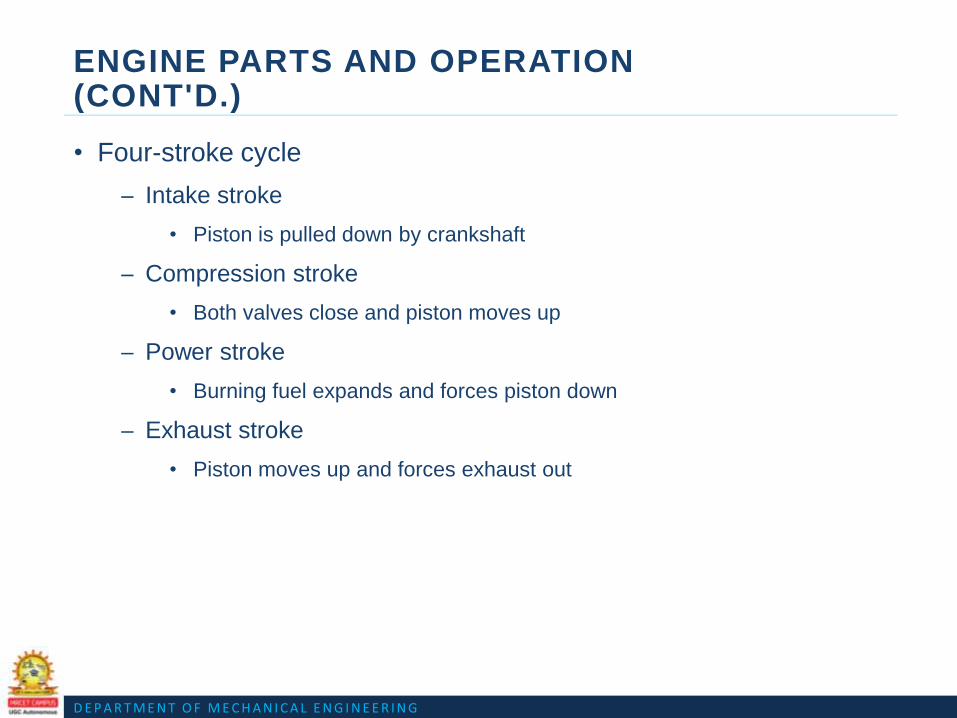
• Four-stroke cycle
– Intake stroke
• Piston is pulled down by crankshaft
– Compression stroke
• Both valves close and piston moves up
– Power stroke
• Burning fuel expands and forces piston down
– Exhaust stroke
• Piston moves up and forces exhaust out

D E P A R T M E N T O F M E C H A N I C A L E N G I N E E R I N G

D E P A R T M E N T O F M E C H A N I C A L E N G I N E E R I N G

D E P A R T M E N T O F M E C H A N I C A L E N G I N E E R I N G
ENGINE SUPPORT SYSTEMS
• Cooling system
– Cools the engine to prevent overheating
• Fuel system
– Carburetor
– Gasoline fuel injection
– Diesel fuel injection
• Lubrication system
– Moves pressurized oil to all engine areas

D E P A R T M E N T O F M E C H A N I C A L E N G I N E E R I N G

D E P A R T M E N T O F M E C H A N I C A L E N G I N E E R I N G
THE POWERTRAIN
• Transmits engine power to wheels
– Transmission (transaxle)
– Clutch
– Torque converter
– Differential
– Axles or half-shafts
• Front-wheel drive, rear-wheel drive, or all-wheel drive
• Manual or automatic

D E P A R T M E N T O F M E C H A N I C A L E N G I N E E R I N G

D E P A R T M E N T O F M E C H A N I C A L E N G I N E E R I N G
THE POWERTRAIN (CONT'D.)
• Manual transmission
– Gears change leverage or torque
– Clutch uncouples powertrain from engine
• Automatic transmission
– Gears shifted based on speed and engine load
• Drive shaft
– Used on rear-wheel drive cars to transfer power to the rear axle
– Hollow metal tube with universal joint at each end
• \

D E P A R T M E N T O F M E C H A N I C A L E N G I N E E R I N G
THE POWERTRAIN (CONT'D.)
• Rear axle assembly
– Drive axles power each rear wheel and a differential assembly
• Transaxle
– Used on front-wheel drive vehicles
– Transmission and differential in one housing

D E P A R T M E N T O F M E C H A N I C A L E N G I N E E R I N G
ACCESSORY SYSTEMS
• Also called comfort systems
– Air conditioning
– Heating
– Power seats
– Power windows
– Cruise control
– Navigation, sound systems, etc.
D E P A R T M E N T O F M E C H A N I C A L E N G I N E E R I N G
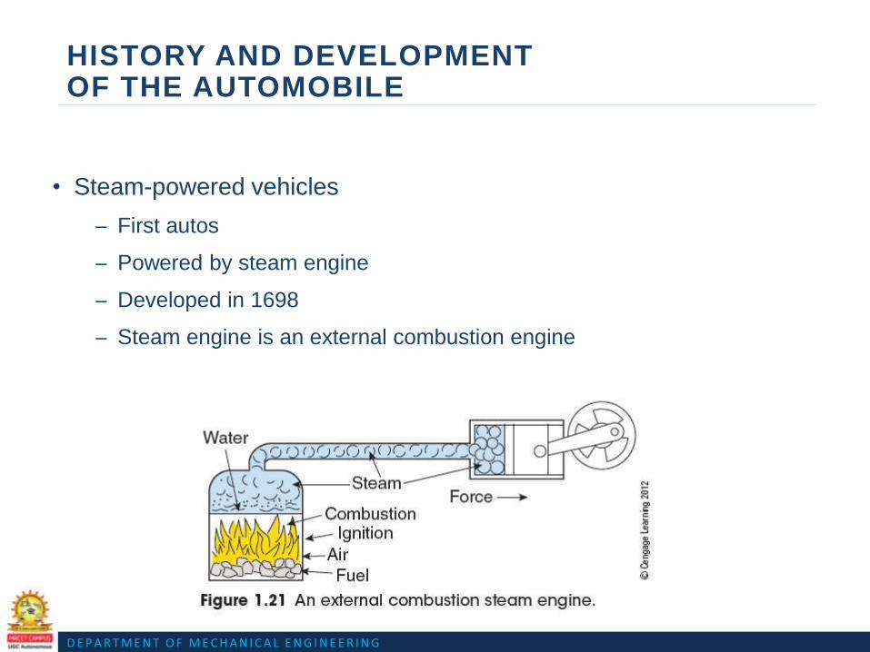
HISTORY AND DEVELOPMENT OF THE AUTOMOBILE
• Steam-powered vehicles
– First autos
– Powered by steam engine
– Developed in 1698
– Steam engine is an external combustion engine

D E P A R T M E N T O F M E C H A N I C A L E N G I N E E R I N G
D E P A R T M E N T O F M E C H A N I C A L E N G I N E E R I N G
HISTORY AND DEVELOPMENT OF THE AUTOMOBILE (CONT'D.)
• Early gasoline engines
– 1876: Dr. Nicolas Otto patented the slow-speed, four-stroke, internal
combustion engine
– 1885: Gottlieb Daimler patented high-speed, petroleum engine
– 1893: Benz shown at the World’s Fair in Chicago
– 1920: 90% of cars looked like carriages
– 3.8 million miles of road in the U.S. has been developed in less than
100 years

D E P A R T M E N T O F M E C H A N I C A L E N G I N E E R I N G
HISTORY AND DEVELOPMENT OF THE AUTOMOBILE (CONT'D.)
• Early automobile racing
– 1895: First auto race in Chicago
– 1913: Indianapolis 500 started
• Early transmissions
– Early cars had transmission on rear axle
• Later attached to rear of engine
• Carburetors
– Early carburetors had a wick saturated with gasoline
• Later had a bowl full of gasoline

D E P A R T M E N T O F M E C H A N I C A L E N G I N E E R I N G
HISTORY AND DEVELOPMENT OF THE AUTOMOBILE (CONT'D.)
• Fuel pumps
– 1915: Stewart Warner vacuum tank
– 1928: Electric and mechanical fuel pumps
• Lubrication systems
– Early engines used a drip oiler
• Later cars had mechanical oiling
• Tires
– 1900: Michelin’s first pneumatic tires
– 1919: All cars are equipped with cord tires

D E P A R T M E N T O F M E C H A N I C A L E N G I N E E R I N G
HISTORY AND DEVELOPMENT OF THE AUTOMOBILE (CONT'D.)
• Electrical systems
– Early cars had 8-, 12-, or 24-volt systems
– 1915: 6-volt battery became standard
– 1950s: 12-volt batteries became standard
• Starter system
– Early engines hand cranked to start
– 1912: Kettering electric starter motor

D E P A R T M E N T O F M E C H A N I C A L E N G I N E E R I N G

D E P A R T M E N T O F M E C H A N I C A L E N G I N E E R I N G
HISTORY AND DEVELOPMENT OF THE AUTOMOBILE (CONT'D.)
• Early American automobiles
– 1892: Charles and Frank Duryea build first operational car
– 1908-1926: Henry Ford produced the Model T
• Assembly line produced 1000 per day
– General Motors: Durant wanted to produce a variety of cars
• Good promoter, but poor business man
• Removed from GM
– 1919: Walter Chrysler starts Chrysler Corporation

D E P A R T M E N T O F M E C H A N I C A L E N G I N E E R I N G
HISTORY AND DEVELOPMENT OF THE AUTOMOBILE (CONT'D.)
• Later developments
– 1950s: American cars became large and powerful
• Poor fuel economy and high pollution
• Fuel economy standards
– 1973: Gas prices quadrupled
– 1975: U.S. Congress passed CAFE
• Modern developments
– Today’s cars benefit from military and space program innovations
– Advancements have improved safety and reliability

Question Bank for Assignment

Question Bank for Assignment
UNIT-I
1. Explain how a four wheel drive mechanism offers better power transmission in a
Automobile.
2. Discuss about the chassis and body components in automobile.
3. Explain with neat sketches the various types of chassis & discuss their advantages and disadvantages
4. What are the different methods of repairing an engine which has worn out cylinder walls?

UNIT II
ENGINE AUXILIARY SYSTEMS

Course Objective:
Student should understand the working of different types of fuel injection and fuel ignition systems for
modern gasoline and diesel engine.
Course outcome:
Student should able to describe working of different types of fuel injection and fuel ignition systems for
modern gasoline and diesel engine.
ENGINE AUXILIARY SYSTEMS
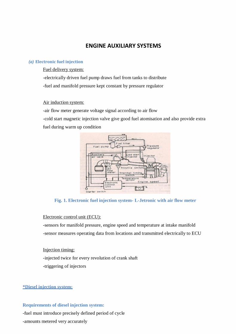
(a) Electronic fuel injection
Fuel delivery system:
-electrically driven fuel pump draws fuel from tanks to distribute
-fuel and manifold pressure kept constant by pressure regulator
Air induction system:
-air flow meter generate voltage signal according to air flow
-cold start magnetic injection valve give good fuel atomisation and also provide extra
fuel during warm up condition
Fig. 1. Electronic fuel injection system- L-Jetronic with air flow meter
Electronic control unit (ECU):
-sensors for manifold pressure, engine speed and temperature at intake manifold
-sensor measures operating data from locations and transmitted electrically to ECU
Injection timing:
-injected twice for every revolution of crank shaft
-triggering of injectors
*Diesel injection system:
Requirements of diesel injection system:
-fuel must introduce precisely defined period of cycle
-amounts metered very accurately

-rate of injection meet desired heat release pattern
-quantities of fuel meet changing speed and load condition
-good atomisation of fuel
-good spray pattern for rapid mixing of fuel and air
-no dribbling and after injection of fuel i.e. sharp injection
-injection timing suits the speed and load requirements
-distribution of fuel in multi-cylinder should uniform
-weight, size and cost of fuel injection system should be less
Types of diesel injection system:
(a) Air injection system:
-fuel supplied through camshaft driven fuel pump
-fuel valve is also connected with high pressure airline to inject into cylinder
-multi-stage compressor which supply air at a pressure of about 60 to 70 bar
Fig. 2. Air injection system

-blast air sweeps the fuel along with it
-good atomisation results in good mixture formation and hence high mean effective pressure
-heavy and viscous fuels are used
-fuel pump require small pressure
-but it is complicated due to compressor arrangement and expensive
-bulky engine and low bhp
-overheating and burning of valve seat
(b) Solid injection system:
-Fuel directly injected to combustion chamber without primary atomisation termed as solid
injection.
-Also known as airless mechanical injection
-2 units-pressurise and atomising unit
3 different types which are described below,
(i) Individual pump and injector or jerk pump system:
-separate metering and compression pump is used for each cylinder
-reciprocating fuel pump is used to meter and set the injection pressure of the fuel
-heavy gear arrangements which gives jerking noise, hence name is given is jerk pump
-jerk pump is used for medium and high speed diesel engines
Fig. 3. Individual pump and injector or jerk pump system

Fig. 4. Unit injector
(ii) Common rail system:
-high pressure fuel pump delivers fuel to an accumulator whose pressure is constant
-plunger type of pump is used
-driving mechanism is not stressed with high pressure hence noise is reduced
-common rail or pipe is connected in between accumulator and distributing elements
-separate metering and timing elements connected to automatic injector
-self-governing type
Fig. 5. Common rail system
(iii) Distributor system:
-fuel pump pressurises, meters and times the fuel supply to rotating distributor
-number of injection strokes per cycle for the pump equals to the number of cylinder
-One metering element which ensure uniform distribution
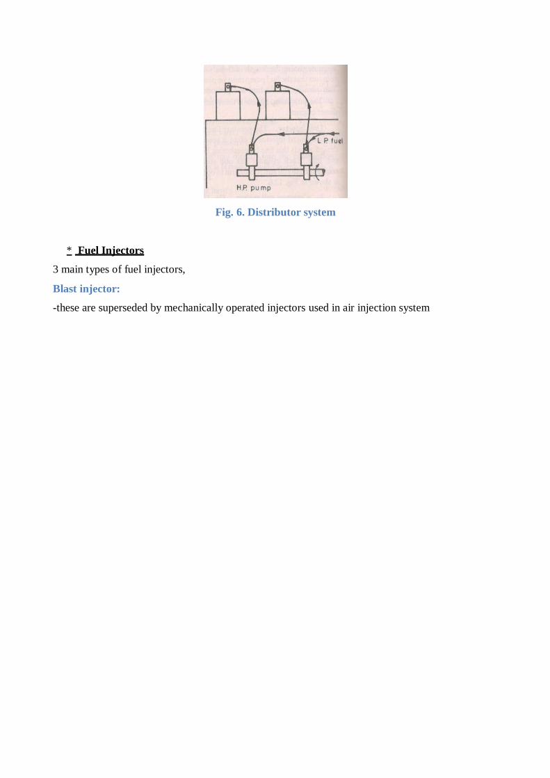
Fig. 6. Distributor system
* Fuel Injectors
3 main types of fuel injectors,
Blast injector:
-these are superseded by mechanically operated injectors used in air injection system

DEPARTMENT OF MECHANICAL ENGINEERING
Mechanically operated injector:
-consist of a set of camshaft, cams and rocker gear and other cams for controlling
the timing of the fuel injection
Automatic injector:
-consists of spring loaded needle valve and operated hydraulically by the pressure of fuel
-quanity of fuel is metered by the fuel pump
Types of nozzles:
(a) Depends on the type of combustion chamber,
Open combustion chamber:
-fuel seeks air
-air swirl is created due to inclined induction port
-multi-hole nozzle injects fuel at a pressure of about 200 to 300 bar to slow moving air
-provide good cold starting performance and improved thermal efficiency
Pre-combustion chamber:
-air velocity is very much high
-single hole nozzle with 65 to 100 bar injection pressure is used
-used in high speed engine due to rapid combustion
-external heating device for easy starting of the engine
(b) Open and closed
type of nozzle, Open
type:
-consists of fuel orifices and open to burner
-cheap and less efficient
ex- opposed piston two-stroke Junkers diesel engine
Closed type: pressure drop is minimised compared to open type
(c) Different types of nozzle for different combustion chamber
(i) Single hole nozzle:
-used in open combustion chamber
-size of hole larger than 0.2 mm
-very high injection pressure required

DEPARTMENT OF MECHANICAL ENGINEERING
(ii) Multi-hole nozzle:
-no. of hole varies from 4 to 18 and the size from 1.5 to 0.35 mm
-injection rate is not uniform
(iii) Pintle nozzle:
-a projection or pintle is provided in the nozzle to avoid weak injection and dribbling
-pintle may be cylindrical or conical shape
-cone angle varied from 0 to 60ᵒ
-provide good atomisation and reduced penetration
-fuel pressures are lower than single and multi-hole nozzle
(iv) Pintaux nozzle:
-injected fuel in upstream of air
-development of pintle nozzle with auxiliary hole drilled in the nozzle body
-reduced delay period and increased thermal efficiency
Turbocharger:
The turbo charger utilizes the wasted heat energy in the exhaust system, to run a
compressor which compresses the intake air. Compressed intake air has more density
and hence more fuel can be injected increasing the power of the engine. Turbo
charging is an ideal way to increase the engine power without increasing the engine
size.
A turbocharger, or turbo (colloquialism), from Greek "τύρβη" ("wake"), (also from
Latin "turbo" ("spinning top"), is a turbine-driven forced induction device that
increases an engine's efficiency and power by forcing extra air into the combustion
chamber. This improvement over a naturally aspirated engine's output results
because the turbine can force more air, and proportionately more fuel, into the
combustion chamber than atmospheric pressure alone.
Turbochargers were originally known as turbo superchargers when all forced induction
devices were classified as superchargers. Nowadays the term “supercharger” is
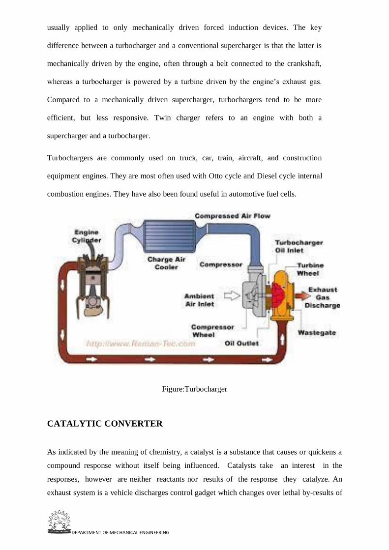
DEPARTMENT OF MECHANICAL ENGINEERING
usually applied to only mechanically driven forced induction devices. The key
difference between a turbocharger and a conventional supercharger is that the latter is
mechanically driven by the engine, often through a belt connected to the crankshaft,
whereas a turbocharger is powered by a turbine driven by the engine’s exhaust gas.
Compared to a mechanically driven supercharger, turbochargers tend to be more
efficient, but less responsive. Twin charger refers to an engine with both a
supercharger and a turbocharger.
Turbochargers are commonly used on truck, car, train, aircraft, and construction
equipment engines. They are most often used with Otto cycle and Diesel cycle internal
combustion engines. They have also been found useful in automotive fuel cells.
Figure:Turbocharger
CATALYTIC CONVERTER
As indicated by the meaning of chemistry, a catalyst is a substance that causes or quickens a
compound response without itself being influenced. Catalysts take an interest in the
responses, however are neither reactants nor results of the response they catalyze. An
exhaust system is a vehicle discharges control gadget which changes over lethal by-results of

DEPARTMENT OF MECHANICAL ENGINEERING
burning in the fumes of an interior ignition motor to less poisonous substances by
method for catalyzed compound responses . It lessens temperature at which CO and
HC change over into CO2 and H2O. Big and large exhaust systems utilize platinum
gathering of respectable metals.
The contaminations have negative effect on air quality, environment and human wellbeing
that leads in stringent standards of poison outflow. Quantities of option innovations like
change in motor plan, fuel pretreatment, utilization of option energizes, fuel added
substances, fumes treatment or better tuning of the ignition procedure and so forth, are
being considered to lower the release levels of the engine. Out of various progressions
available for auto vapor radiation control a fumes framework is found to best choice to
control CO, HC and NOx discharges from petrol driven vehicles while diesel particulate
channel and oxidation forces converter or diesel oxidation impulse have so far been the most
potential other option to control particulates outpourings from diesel driven vehicle [5]. An
exhaust system (CC) is put inside the tailpipe through which destructive fumes gasses
containing unburnt fuel, CO, NOx are transmitted .
Three-way Catalytic Converter
Similar to the oxidation converter, the reduction catalytic converter helps to eliminate
hydrocarbons and carbon-monoxide emanations, in addition to oxides of nitrogen
discharges, or NOx. NOx outflows are created in the motor burning chamber when it
reaches extremely high temperatures more than 2,500 degrees Fahrenheit, approximately. In
this type of converter, a reduction reaction also occurs in addition to two oxidation reactions
same as two-way converter. The reduction reaction occurs during the conversion of oxides
of nitrogen to nitrogen and oxygen. So this type of converter is also known as reduction
type catalytic converter.
Conversion Reactions in Three Way Catalytic Converter
CxH4x + 2xO2 → xCO2 + 2xH2O (conversion of hydrocarbons)
2xCO + O2 → 2xCO2 (conversion of carbon mono-oxides)
2NOx → N2 + xO2 [O2 + 2H2 → 2H2O] (Decomposition of oxides of nitrogen
DEPARTMENT OF MECHANICAL ENGINEERING
QUESTION BANK
UNIT-II
1. What are catalytic convertors and explain how they help in containing emissions from
a automobile.
2. Explain briefly the methods available to control emissions from a automobile.
3. Write about thermal and catalytic converters?
4. Explain common rail diesel injection system with necessary diagram.

Presentation Material

DEPARTMENT OF MECHANICAL ENGINEERING
E N G I N E A U X I L L A R Y S Y S T E M S
UNIT-II

D E P A R T M E N T O F M E C H A N I C A L E N G I N E E R I N G
OBJECTIVES
After studying Chapter 4, the reader should be able to:
1. Prepare for ASE Engine Performance (A8) certification test content area “C” (Fuel, Air Induction, and Exhaust Systems Diagnosis and Repair).
2. Explain how a diesel engine works.
3. Describe the difference between direct injection (DI) and indirect injection (IDI) diesel engines.
4. List the parts of the typical diesel engine fuel system.
5. Explain how glow plugs work.
6. List the advantages and disadvantages of a diesel engine.
7. Describe how diesel fuel is rated and tested. Hydraulic Electronic
D E P A R T M E N T O F M E C H A N I C A L E N G I N E E R I N G
DIESEL ENGINES
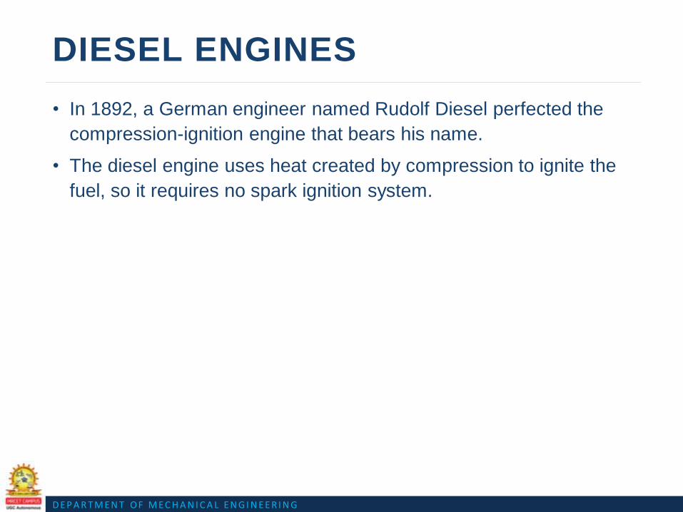
• In 1892, a German engineer named Rudolf Diesel perfected the
compression-ignition engine that bears his name.
• The diesel engine uses heat created by compression to ignite the
fuel, so it requires no spark ignition system.

D E P A R T M E N T O F M E C H A N I C A L E N G I N E E R I N G
DIESEL ENGINES
• The diesel engine requires compression ratios of 16:1 and higher.
• Incoming air is compressed until its temperature reaches about 1,000°F (540°C).
• This is called heat of compression.
• As the piston reaches the top of its compression stroke, fuel is injected into the cylinder, where it is ignited by the hot air
FIGURE :Diesel combustion occurs
when fuel is injected into the hot, highly
compressed air in the cylinder.

D E P A R T M E N T O F M E C H A N I C A L E N G I N E E R I N G
DIESEL ENGINES
FIGURE : A typical injector-pump-type automotive diesel fuel injection system.

D E P A R T M E N T O F M E C H A N I C A L E N G I N E E R I N G
DIESEL ENGINESINDIRECT AND DIRECT INJECTION
• In an indirect injection (abbreviated
IDI) diesel engine, fuel is injected into
a small prechamber, which is
connected to the cylinder by a narrow
opening.
• The initial combustion takes place in
this prechamber.
• This has the effect of slowing the rate
of combustion, which tends to reduce
noise.
FIGURE : An indirect injection diesel
engine uses a prechamber and a glow
plug.

D E P A R T M E N T O F M E C H A N I C A L E N G I N E E R I N G
DIESEL ENGINESINDIRECT AND DIRECT INJECTION
FIGURE :A direct injection diesel
engine injects the fuel directly into
the combustion chamber. Many
designs do not use a glow plug.

D E P A R T M E N T O F M E C H A N I C A L E N G I N E E R I N G
DIESEL ENGINESDIESEL FUEL IGNITION
• Ignition occurs in a diesel engine by injecting fuel into the air charge,
which has been heated by compression to a temperature greater than the
ignition point of the fuel or about 1,000°F (538°C).

D E P A R T M E N T O F M E C H A N I C A L E N G I N E E R I N G
THREE PHASES OF COMBUSTION
• There are three distinct phases or parts to the combustion in a
diesel engine.
– Ignition delay.
– Rapid combustion.
– Controlled combustion.

D E P A R T M E N T O F M E C H A N I C A L E N G I N E E R I N G
DIESEL ENGINE CONSTRUCTION
• Diesel engines must be constructed heavier than gasoline engines
because of the tremendous pressures that are created in the
cylinders during operation.
• The torque output of a diesel engine is often double or more than
the same size gasoline powered engines.

D E P A R T M E N T O F M E C H A N I C A L E N G I N E E R I N G
DIESEL ENGINE CONSTRUCTION
FIGURE :The common rail on a
Cummins diesel engine. A
highpressure pump (up to 30,000
PSI) is used to supply diesel fuel to
this common rail, which has cubes
running to each injector. Note the
thick cylinder walls and heavy-duty
construction.

D E P A R T M E N T O F M E C H A N I C A L E N G I N E E R I N G
DIESEL ENGINE CONSTRUCTION
FIGURE : A rod/piston assembly from a 5.9-liter Cummins diesel engine used in a
Dodge pickup truck.

D E P A R T M E N T O F M E C H A N I C A L E N G I N E E R I N G
FUEL TANK AND LIFT PUMP
• A fuel tank used on a vehicle equipped with a diesel engine differs from the one used with a gasoline engine in several ways, including:
– A larger filler neck for diesel fuel.
– No evaporative emission control devices or charcoal (carbon) canister.
• The diesel fuel is drawn from the fuel tank by a lift pump and delivers the fuel to the injection pump.
• Between the fuel tank and the lift pump is a water-fuel separator.
– Water is heavier than diesel fuel and sinks to the bottom of the separator.

D E P A R T M E N T O F M E C H A N I C A L E N G I N E E R I N G
FUEL TANK AND LIFT PUMP
FIGURE : Using an ice bath to test the fuel temperature sensor.

D E P A R T M E N T O F M E C H A N I C A L E N G I N E E R I N G
DIESEL ENGINE FUEL SYSTEMINJECTION PUMP
• A diesel engine injection
pump is used to increase
the pressure of the diesel
fuel from very low values
from the lift pump to the
extremely high pressures
needed for injection.
FIGURE : A typical distributor-type
diesel injection pump showing the
pump, lines, and fuel filter.

D E P A R T M E N T O F M E C H A N I C A L E N G I N E E R I N G
DIESEL ENGINE FUEL SYSTEMDISTRIBUTOR INJECTION PUMP
• A distributor diesel injection
pump is a high-pressure
pump assembly with lines
leading to each individual
injector.
• The high-pressure lines
between the distributor and
the injectors must be the
exact same length to ensure
proper injection timing.
FIGURE 4-9 A schematic of a Stanadyne diesel
fuel injection pump assembly showing all of the
related components.

D E P A R T M E N T O F M E C H A N I C A L E N G I N E E R I N G
DIESEL ENGINE FUEL SYSTEMHIGH-PRESSURE COMMON RAIL
• Newer diesel engines use a fuel delivery system referred to as a
high-pressure common rail (HPCR) design.
– Diesel fuel under high pressure, over 20,000 PSI (138,000 kPa), is
applied to the injectors, which are opened by a solenoid controlled by
the computer.

D E P A R T M E N T O F M E C H A N I C A L E N G I N E E R I N G
DIESEL ENGINE FUEL SYSTEMHIGH-PRESSURE COMMON RAIL
FIGURE 4-10 Overview of a computer-controlled high-pressure common rail V-8 diesel engine.

D E P A R T M E N T O F M E C H A N I C A L E N G I N E E R I N G
DIESEL ENGINE FUEL SYSTEMHEUI SYSTEM
• Ford 7.3- and 6.0-liter
diesels use a system Ford
calls a Hydraulic
Electronic Unit Injection
system, or HEUI system.
– The components that replace
the traditional mechanical
injection pump include a high-
pressure oil pump and
reservoir, pressure regulator
for the oil, and passages in
the cylinder head for flow of
fuel to the injectors.
FIGURE 4-11 A HEUI injector from a Ford
PowerStroke diesel engine. The grooves
indicate the location of the O-rings.

D E P A R T M E N T O F M E C H A N I C A L E N G I N E E R I N G
DIESEL INJECTOR NOZZLES
• Diesel injector nozzles are spring-loaded closed valves that
spray fuel directly into the combustion chamber or
precombustion chamber.
• Injector nozzles are threaded into the cylinder head, one for
each cylinder, and are replaceable as an assembly.
• The top of the injector nozzle has many holes to deliver an
atomized spray of diesel fuel into the cylinder.
• Parts of a diesel injector nozzle include:
– Heat shield.
– Injector body.
– Diesel injector needle valve.
– Injector pressure chamber.

D E P A R T M E N T O F M E C H A N I C A L E N G I N E E R I N G
DIESEL INJECTOR NOZZLE OPERATION• The electric solenoid
attached to the injector
nozzle is computer
controlled and opens to
allow fuel to flow into the
injector pressure chamber.
FIGURE 4-12 Typical computer-controlled
diesel engine fuel injectors.

D E P A R T M E N T O F M E C H A N I C A L E N G I N E E R I N G
GLOW PLUGS
• Glow plugs are always used in diesel engines equipped with a
precombustion chamber and may be used in direct injection diesel
engines to aid starting.
• A glow plug is a heating element that uses 12 volts from the
battery and aids in the starting of a cold engine.
• As the temperature of the glow plug increases, the resistance of
the heating element inside increases, thereby reducing the current
in amperes needed by the glow plugs.

D E P A R T M E N T O F M E C H A N I C A L E N G I N E E R I N G
GLOW PLUGS
FIGURE 4-13 A schematic of a
typical glow plug circuit. Notice that
the relay for the glow plug and intake
air heater are both computer
controlled.

D E P A R T M E N T O F M E C H A N I C A L E N G I N E E R I N G
ENGINE-DRIVEN VACUUM PUMP
• Because a diesel engine is unthrottled, it creates very little vacuum
in the intake manifold.
• Several engine and vehicle components operate using vacuum,
such as the exhaust gas recirculation (EGR) valve and the heating
and ventilation blend and air doors.
• Most diesels used in cars and light trucks are equipped with an
engine-driven vacuum pump to supply the vacuum for these
components.

D E P A R T M E N T O F M E C H A N I C A L E N G I N E E R I N G
WHAT ARE DIESEL ENGINE ADVANTAGES AND DISADVANTAGES?
FIGURE 4-14 Roller lifter
from a GM Duramax 6.6-liter
V-8 diesel engine. Notice the
size of this lifter compared to
a roller lifter used in a
gasoline engine.

D E P A R T M E N T O F M E C H A N I C A L E N G I N E E R I N G
DIESEL FUEL
• Diesel fuel must meet an entirely different set of standards than
gasoline.
• The fuel in a diesel engine is not ignited with a spark, but is ignited
by the heat generated by high compression.
• All diesel fuel must be clean, be able to flow at low temperatures,
and be of the proper cetane rating.
– Cleanliness.
– Low-temperature fluidity.
– Cetane number.

D E P A R T M E N T O F M E C H A N I C A L E N G I N E E R I N G
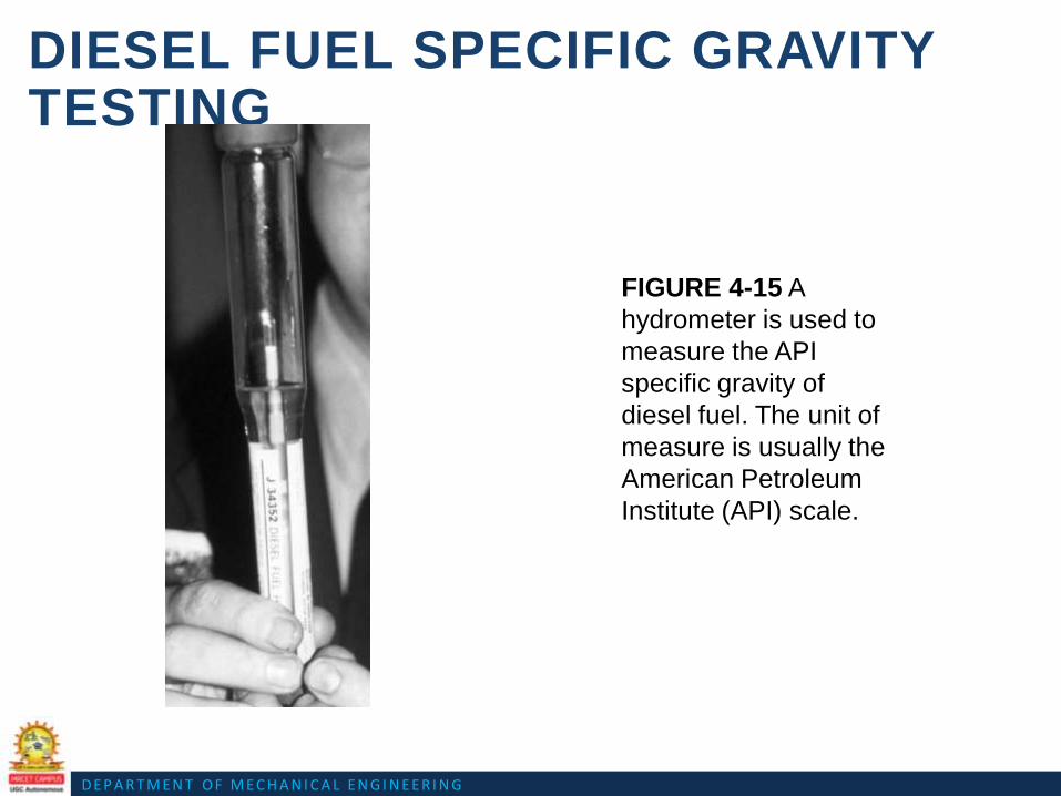
DIESEL FUEL SPECIFIC GRAVITY TESTING
• The density of diesel fuel should be tested whenever there is a
driveability concern.
• The density or specific gravity of diesel fuel is measured in units of
API gravity.
• API gravity is an arbitrary scale expressing the gravity or density of
liquid petroleum products devised jointly by the American
Petroleum Institute and the National Bureau of Standards.
D E P A R T M E N T O F M E C H A N I C A L E N G I N E E R I N G
DIESEL FUEL SPECIFIC GRAVITY TESTING
FIGURE 4-15 A
hydrometer is used to
measure the API
specific gravity of
diesel fuel. The unit of
measure is usually the
American Petroleum
Institute (API) scale.
D E P A R T M E N T O F M E C H A N I C A L E N G I N E E R I N G
DIESEL FUEL HEATERS
• Diesel fuel heaters help prevent power loss and stalling in cold
weather.
• The heater is placed in the fuel line between the tank and the
primary filter.
• Some coolant heaters are thermostatically controlled, which allows
fuel to bypass the heater once it has reached operating
temperature.

D E P A R T M E N T O F M E C H A N I C A L E N G I N E E R I N G
HEATED INTAKE AIR
• Some diesels, such as the
General Motors 6.6-liter
Duramax V-8, use an
electrical heater wire to
warm the intake air to help
in cold weather starting and
running.
FIGURE 4-16 A wire wound electrical
heater is used to warm the intake air on
some diesel engines.

D E P A R T M E N T O F M E C H A N I C A L E N G I N E E R I N G
ACCELERATOR PEDAL POSITION SENSOR
• Some light truck diesel engines are equipped with an
electronic throttle to control the amount of fuel injected into
the engine.
• Because a diesel engine does not use a throttle in the air
intake, the only way to control engine speed is by controlling
the amount of fuel being injected into the cylinders.
• Instead of a mechanical link from the accelerator pedal to
the diesel injection pump, a throttle-by-wire system uses an
accelerator pedal position sensor.
• To ensure safety, it consists of three separate sensors that
change in voltage as the accelerator pedal is depressed.

D E P A R T M E N T O F M E C H A N I C A L E N G I N E E R I N G
ACCELERATOR PEDAL POSITION SENSOR
FIGURE : A typical accelerator pedal position (APP) sensor uses three different
sensors in one package with each creating a different voltage as the accelerator is
moved.

D E P A R T M E N T O F M E C H A N I C A L E N G I N E E R I N G
SOOT OR PARTICULATE MATTER
• Soot particles may come directly from the exhaust tailpipe or they
can also form when emissions of nitrogen oxide and various sulfur
oxides chemically react with other pollutants suspended in the
atmosphere.
• Particulates are generally categorized as follows:
– TSP, Total Suspended Particulate.
– PM10.
– PM2.5.

D E P A R T M E N T O F M E C H A N I C A L E N G I N E E R I N G
DIESEL OXIDATION CATALYST (DOC)
• Diesel oxidation catalyst (DOC) consists of a flow-through
honeycomb-style substrate structure that is washcoated with a
layer of catalyst materials, similar to those used in a gasoline
engine catalytic converter.

Question Bank for Assignment

Question Bank for Assignment
UNIT-II
1. What are catalytic convertors and explain how they help in containing emissions from a
automobile.
2. Explain briefly the methods available to control emissions from a automobile.
3. Write about thermal and catalytic converters?
4. Explain common rail diesel injection system with necessary diagram.
5. Explain the operation of the typical turbocharger with sketch and write the advantages over
super charger

DEPARTMENT OF MECHANICAL ENGINEERING
UNIT III
TRANSMISSION SYSTEMS

DEPARTMENT OF MECHANICAL ENGINEERING
Course objectives:
Student should Understand the basic Principles of Transmission system of an Automobile Engineering
Course Outcomes:
Student should able to describe functioning of Transmission systems, Clutches, Gear boxes,
Synchromesh device, Propeller shaft, Differential axle.

DEPARTMENT OF MECHANICAL ENGINEERING

DEPARTMENT OF MECHANICAL ENGINEERING
TRANSMISSION SYSYTEMS
Introduction to the Transmission Systems in Automobile:
It is a system by means of which power developed by the engine is transmitted to the road
wheels to propel the vehicle.
Chief function of the device is to receive power at one torque and angular velocity and to
deliver it at another torque and the corresponding angular velocity.
REQUIREMENTS OF TRANSMISSION SYSTEM
1. To provide for disconnecting the engine from the driving wheels.
2. When the engine is running, to enable the connection to the driving wheels to be made
smoothly and without shock.
3. To enable the leverage between the engine and driving wheels to be varied.
4. It must reduce the drive-line speed from that of the engine to that of the driving wheels in
a ratio of somewhere between about 3:1 and 10:1 or more, according to the relative size of
engine and weight of vehicle.
5. Turn the drive, if necessary, through 90° or perhaps otherwise re-align it.
6. Enable the driving wheels to rotate at different speeds.
7. Provide for relative movement between the engine and driving wheels.
The most common transmission systems that have been used for the automotive
industry are:
Manual transmission,
Automatic transmission,
Semi-automatic transmission,

DEPARTMENT OF MECHANICAL ENGINEERING
Continuously-variable transmission (C.V.T.).
Manual Transmission:
The first transmission invented was the manual transmission system. The driver needs
to disengage the clutch to disconnect the power from the engine first, select the target
gear, and engage the clutch again to perform the gear change. This will challenge a
new driver. It always takes time for a new driver to get used to this skill.
Automatic Transmission:
An automatic transmission uses a fluid-coupling torque converter to replace the clutch
to avoid engaging/disengaging clutch during gear change. A completed gear set, called
planetary gears, is used to perform gear ratio change instead of selecting gear
manually. A driver no longer needs to worry about gear selection during driving. It
makes driving a car much easier, especially for a disabled or new driver. However, the
indirect gear contact of the torque converter causes power loss during power
transmission, and the complicated planetary gear structure makes the transmission
heavy and easily broken.
Semi-Automatic Transmission:
A semi-automatic transmission tries to combine the advantages of the manual and
automatic transmission systems, but avoid their disadvantages. However, the
complicated design of the semi- automatic transmission is still under development, and
the price is not cheap. It is only used for some luxury or sports cars currently.
Continuously Variable Transmission (C.V.T.):-
The Continuously Variable Transmission (C.V.T.) is a transmission in which the ratio
of the rotational speeds of two shafts, as the input shaft and output shaft of a vehicle or
other machine, can be varied continuously within a given range, providing an infinite

DEPARTMENT OF MECHANICAL ENGINEERING
number of possible ratios. The other mechanical transmissions described above only
allow a few different gear ratios to be selected, but this type of transmission essentially
has an infinite number of ratios available within a finite range.
It provides even better fuel economy if the engine is constantly made run at a single
speed. This transmission is capable of a better user experience, without the rise and fall
in speed of an engine, and the jerk felt when changing gears.
MANUAL TRANSMISSION SYSTEM
Manual transmissions also referred as stick shift transmission or just ‘stick', 'straight
drive', or standard transmission because you need to use the transmission stick every
time you change the gears. To perform the gear shift, the transmission system must
first be disengaged from the engine. After the target gear is selected, the transmission
and engine are engaged with each other again to perform the power transmission.
Manual transmissions are characterized by gear ratios that are selectable by locking
selected gear pairs to the output shaft inside the transmission.
Fig:The transmission system delivers the engine power to wheels.

DEPARTMENT OF MECHANICAL ENGINEERING
Fig: Layout of Automobile Power Transmission System
Components of manual transmission
The main components of manual transmission are:
• Clutch
• Gear box
• Slip joint
• Universal joint
• Propeller shaft
• Final drive
• Differential unit
• Rear axle
Clutch:
Clutch is a device which is used in the transmission system of automobile to engage
and disengage the engine to the transmission or gear box. It is located between the
transmission and the engine. When the clutch is engaged, the power flows from the
engine to the rear wheels in a rear- wheel-drive transmission and the vehicle moves.
When the clutch is disengaged, the power is not transmitted from the engine to the rear
wheels and vehicle stops even if engine is running.

DEPARTMENT OF MECHANICAL ENGINEERING
It works on the principle of friction. When two friction surfaces are brought in contact
with each other and they are united due to the friction between them. If one is revolved
the other will also revolve.
The friction depends upon the surface area contact. The friction surfaces are so
designed that the driven member initially slips on driving member when initially
pressure is applied. As pressure increases the driven member is brought gradually to
speed the driving member.
The three main parts of clutch are:
Driving member
Driven member
Operating member
The driving member consists of a flywheel mounted on the engine crank shaft. The flywheel
is bolted to cover which carries a pressure plate or driving disc, pressure springs and releasing
levers. Thus the entire assembly of flywheel and cover rotates all the times. The clutch

DEPARTMENT OF MECHANICAL ENGINEERING
housing and the cover provided with openings dissipate the heat generated by friction during
the clutch operation.
The driving member consists of a disc or plate called clutch plate. It is free to slide
length wise on the splines of the clutch shaft. It carries friction materials on both of its
surfaces when it is gripped between the flywheel and the pressure plate; it rotates the
clutch shaft through splines.
The operating members consists of a foot pedal, linkage, release or throw-out bearing,
release levers and springs necessary to ensure the proper operation of the clutch.
Now the driving member in an automobile is flywheel mounted on crank shaft, the
driven member is the pressure plate mounted on transmission or gear box input shaft.
Friction surfaces or clutch plates is placed between two members.
Types of Friction Materials:

DEPARTMENT OF MECHANICAL ENGINEERING
The friction materials of the clutch plate are generally of 3 types:
Mill Board Type
Molded type
Woven type
Mill Board type friction materials mainly include asbestos material with different types
of impregnates.
Molded type friction materials are made from a matrix of asbestos fiber and starch or
any other suitable binding materials. They are then heated to a certain temperature for
moulding in dies under pressure. They are also made into sheets by rolling, pressing
and backs till they are extremely hard and dense. Metallic wires are used sometimes to
increase wear properties.
Woven types facing materials are made by impregnating a cloth with certain binders or
by weaving threads of copper or brass wires covered with long fiber asbestos and
cotton. The woven sheets treated with binding solution are baked and rolled.
Table: Coefficients of Riction for Clutch Facing Materials
Sl. No. Material Coeffieicent Of Material(µ)
1. Leather 0.27
2. Cork 0.37
3. Cotton fabric 0.4-0.5
4. Asbestos Base
Materials
0.35-0.4

DEPARTMENT OF MECHANICAL ENGINEERING
Properties of Good Clutching:
Good Wearing Properties
High Resistance to heat
High coefficient of friction
Good Binders in it
Operation of Clutch:
When the clutch pedal is pressed through pedal movement, the clutch release bearing
presses on the clutch release lever plate which being connected to clutch release levers,
forces these levers forward. This causes the pressure plate to compress pressure
springs, thus allowing it to move away from the clutch driven plate. This action
releases the pressure on the driven plate and flywheel, the flywheel is now free to turn
independently, without turning the transmission.
When the clutch pedal is released, reverse action takes place i.e. the driven plate is
again forced against the flywheel by the pressure plate- because of the force exerted by
pressure springs. The pressure plate will keep on pressing the facings of driven plate
until friction created becomes equal to the resistance of the vehicle. Any further
increase in pressure will cause the clutch plate and the transmission shaft to turn along
with flywheel, thus achieving vehicle movement.
Single Clutch Plate:

DEPARTMENT OF MECHANICAL ENGINEERING
It is the most common type of clutch plate used in motor vehicles. Basically it consists
of only one clutch plate, mounted on the splines of the clutch plate. The flywheel is
mounted on engine crankshaft and rotates with it. The pressure plate is bolted to the
flywheel through clutch springs, and is free to slide on the clutch shaft when the clutch
pedal is operated. When the clutch is engaged the clutch plate is gripped between the
flywheel and pressure plate. The friction linings are on both the sides of the clutch
plate. Due to the friction between the flywheel, clutch plate and the pressure plate the
clutch plate revolves the flywheel. As the clutch plate revolves the clutch shaft also
revolves. Clutch shaft is connected to the transmission gear box. Thus the engine
power is transmitted to the crankshaft and then to the clutch shaft.
When the clutch pedal is pressed, the pressure plate moves back against the force of
the springs, and the clutch plate becomes free between the flywheel and the pressure
plate. Thus the flywheel remains rotating as long as the engine is running and the
clutch shaft speed reduces slowly and finally it stops rotating. As soon as the clutch
pedal is pressed, the clutch is said to be engaged, otherwise it remains engaged due to
the spring forces.

DEPARTMENT OF MECHANICAL ENGINEERING

DEPARTMENT OF MECHANICAL ENGINEERING
Multi-plate Clutch:
Multi-plate clutch consists of a number of clutch plates instead of only one clutch plate
as in case of single plate clutch. As The number of clutch plates are increased, the
friction surfaces also increases. The increased number of friction surfaces obliviously
increases the capacity of the clutch to transmit torque.
The plates are alternately fitted to engine and gear box shaft. They are firmly pressed
by strong coil springs and assembled in a drum. Each of the alternate plate slides on the
grooves on the flywheel and the other slides on splines on the pressure plate. Thus,
each alternate plate has inner and outer splines.
The multi-plate clutch works in the same way as a single plate clutch by operating the
clutch pedal. The multi-plate clutches are used in heavy commercial vehicles, racing
cars and motor cycles for transmitting high torque. The multi-plate clutch may be dry
or wet. When the clutch is operated in an oil bath, it is called a wet clutch. When the
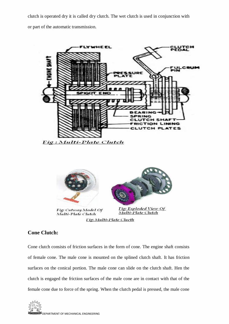
DEPARTMENT OF MECHANICAL ENGINEERING
clutch is operated dry it is called dry clutch. The wet clutch is used in conjunction with
or part of the automatic transmission.
Cone Clutch:
Cone clutch consists of friction surfaces in the form of cone. The engine shaft consists
of female cone. The male cone is mounted on the splined clutch shaft. It has friction
surfaces on the conical portion. The male cone can slide on the clutch shaft. Hen the
clutch is engaged the friction surfaces of the male cone are in contact with that of the
female cone due to force of the spring. When the clutch pedal is pressed, the male cone

DEPARTMENT OF MECHANICAL ENGINEERING
slides against the spring force and the clutch is disengaged.
The only advantage of the cone clutch is that the normal force acting on the friction
surfaces is greater than the axial force, as compare to the single plate clutch in which
the normal force acting on the friction surfaces is equal to the axial force. The
disadvantage in cone clutch is that if the angle of the cone is made smaller than 200 the
male cone tends to bind in the female cone and it becomes difficult to disengage the
clutch. Cone clutches are generally now only used in low peripheral speed applications
although they were once common in automobiles and other combustion engine
transmissions. They are usually now confined to very specialist transmissions in
racing, rallying, or in extreme off-road vehicles, although they are common in power
boats. Small cone clutches are used in synchronizer mechanisms in manual
transmissions.
Dog & Spline Clutch:
This type of clutch is used to lock two shafts together or to lock a gear to shaft. It
consists of a sleeve having two sets of internal splines. It slides on a splined shaft with
smallest diameter splines. The bigger diameter splines match with the external dog
clutch teeth on driving shaft. When the sleeve is made to slide on the splined shaft, its
teeth match with the dog clutch teeth of the driving shaft. Thus the sleeve turns the
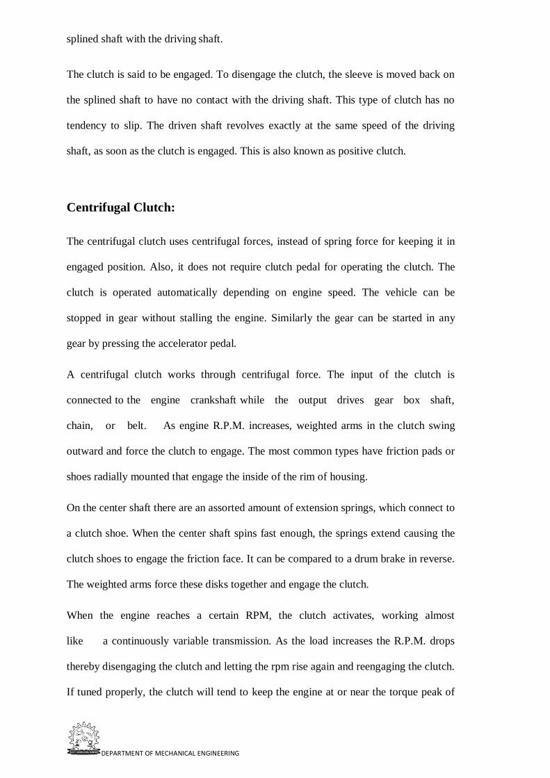
DEPARTMENT OF MECHANICAL ENGINEERING
splined shaft with the driving shaft.
The clutch is said to be engaged. To disengage the clutch, the sleeve is moved back on
the splined shaft to have no contact with the driving shaft. This type of clutch has no
tendency to slip. The driven shaft revolves exactly at the same speed of the driving
shaft, as soon as the clutch is engaged. This is also known as positive clutch.
Centrifugal Clutch:
The centrifugal clutch uses centrifugal forces, instead of spring force for keeping it in
engaged position. Also, it does not require clutch pedal for operating the clutch. The
clutch is operated automatically depending on engine speed. The vehicle can be
stopped in gear without stalling the engine. Similarly the gear can be started in any
gear by pressing the accelerator pedal.
A centrifugal clutch works through centrifugal force. The input of the clutch is
connected to the engine crankshaft while the output drives gear box shaft,
chain, or belt. As engine R.P.M. increases, weighted arms in the clutch swing
outward and force the clutch to engage. The most common types have friction pads or
shoes radially mounted that engage the inside of the rim of housing.
On the center shaft there are an assorted amount of extension springs, which connect to
a clutch shoe. When the center shaft spins fast enough, the springs extend causing the
clutch shoes to engage the friction face. It can be compared to a drum brake in reverse.
The weighted arms force these disks together and engage the clutch.
When the engine reaches a certain RPM, the clutch activates, working almost
like a continuously variable transmission. As the load increases the R.P.M. drops
thereby disengaging the clutch and letting the rpm rise again and reengaging the clutch.
If tuned properly, the clutch will tend to keep the engine at or near the torque peak of

DEPARTMENT OF MECHANICAL ENGINEERING
the engine.
These results in a fair bit of waste heat, but over a broad range of speeds it is much
more useful then a direct drive in many applications. Weaker spring/heavier shoes will
cause the clutch to engage at a lower R.P.M. while a stronger spring/lighter shoes will
cause the clutch to engage at a higher R.P.M.
Semi-centrifugal Clutch:-
A semi centrifugal clutch is used to transmit power from high powered engines and
racing car engines where clutch disengagements requires appreciable and tiresome
drivers effort. The transmission of power in such clutches is partly by clutch springs
and rest by centrifugal action of an extra weight provided in system. The clutch springs
serve to transmit the torque up to normal speeds, while the centrifugal force assists at
speeds higher than normal.
Besides clutch, pressure plate and splines shaft it mainly consists
of: Compression spring (3 numbers)
Weighted levers (3 numbers)
At normal speeds when the power transmission is low the spring keeps the clutch
engaged, the weighted levers do not have any pressure on the pressure plate. At high
speed, when the power transmission is high the weights fly off and levers exert
pressure on the plate which keeps the clutch firmly engaged. Thus instead of having
more stiff springs for keeping the clutch engaged firmly at high speeds, they are less
stiff, so that the driver may not get any strain in operating the clutch.
when the speed decreases, the weights fall and the levers do not exert any pressure on
the pressure plate. Only the spring pressure is exerted on the pressure plate which is
sufficient to keep the clutch engaged.
DEPARTMENT OF MECHANICAL ENGINEERING
Electromagnetic Clutch:
An electromagnetic clutch is a clutch (a mechanism for transmitting rotation) that is
engaged and disengaged by an electromagnetic actuator. In this type of clutch, the
flywheel consists of winding. The current is supplied to the winding from battery or
dynamo.
When the current passes through the winding it produces an electromagnetic field
which attracts the pressure plate, thereby engaging the clutch. When supply is cutoff,
the clutch is disengaged. The gear lever consists of a clutch release switch. When then
the driver holds the gear lever to change the gear the witch is operated cutting off the
current to the winding which causes the clutch disengaged. At low speeds when the
dynamo output is low, the clutch is not firmly engaged.
Therefore three springs are also provided on the pressure plate which helps the clutch
engaged firmly at low speed also. Cycling is achieved by turning the voltage/current to the

DEPARTMENT OF MECHANICAL ENGINEERING
electromagnet on and off. Slippage normally occurs only during acceleration. When the
clutch is fully engaged, there is no relative slip, assuming the clutch is sized properly, and
thus torque transfer is 100% efficient.
The electromagnetic clutch is most suitable for remote operation since no linkages are
required to control its engagement. It has fast, smooth operation. However, because
energy dissipates as heat in the electromagnetic actuator every time the clutch is
engaged, there is a risk of overheating. Consequently the maximum operating
temperature of the clutch is limited by the temperature rating of the insulation of the
electromagnet. This is a major limitation. Another disadvantage is higher initial cost.
Gear Box;
A gearbox is a mechanical method of transferring energy from one device to another
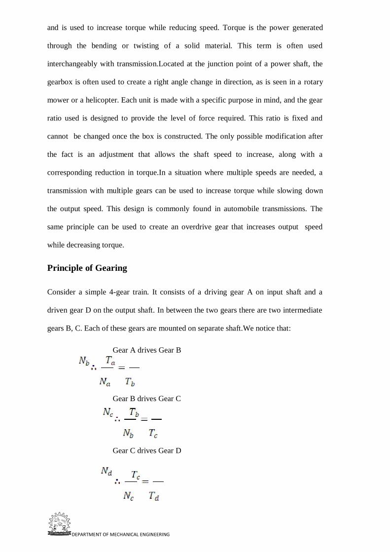
DEPARTMENT OF MECHANICAL ENGINEERING
and is used to increase torque while reducing speed. Torque is the power generated
through the bending or twisting of a solid material. This term is often used
interchangeably with transmission.Located at the junction point of a power shaft, the
gearbox is often used to create a right angle change in direction, as is seen in a rotary
mower or a helicopter. Each unit is made with a specific purpose in mind, and the gear
ratio used is designed to provide the level of force required. This ratio is fixed and
cannot be changed once the box is constructed. The only possible modification after
the fact is an adjustment that allows the shaft speed to increase, along with a
corresponding reduction in torque.In a situation where multiple speeds are needed, a
transmission with multiple gears can be used to increase torque while slowing down
the output speed. This design is commonly found in automobile transmissions. The
same principle can be used to create an overdrive gear that increases output speed
while decreasing torque.
Principle of Gearing
Consider a simple 4-gear train. It consists of a driving gear A on input shaft and a
driven gear D on the output shaft. In between the two gears there are two intermediate
gears B, C. Each of these gears are mounted on separate shaft.We notice that:
Gear A drives Gear B
Gear B drives Gear C
Gear C drives Gear D

DEPARTMENT OF MECHANICAL ENGINEERING
Therefore, the over all speed ratios are:
Types of Gear Boxes: The following types of gear box are used in automobiles:
Sliding Mesh
Constant Mesh
Synchromesh
Sliding Mesh Gear Box
It is the simplest gear box. The following figure shows 4-speed gear box in neutral
position. 4 gears are connected to the lay shaft/counter shaft. A reverse idler gear is
mounted on another shaft and always remains connected to the reverse gear of
countershaft. This “H” shift pattern enables the driver to select four different gear
ratios and a reverse gear.
Gears in Neutral:
When the engine is running and clutch is engaged the clutch shaft gear drives the
countershaft gear. The countershaft rotates opposite in direction of the clutch shaft. In
neutral position only the clutch shaft gear is connected to the countershaft gear. Other
gears are free and hence the transmission main shaft is not turning. The vehicle is
stationary.

DEPARTMENT OF MECHANICAL ENGINEERING
First or low shaft gear:

DEPARTMENT OF MECHANICAL ENGINEERING
By operating the gear shift lever the larger gear on the main shaft is moved along the
shaft to mesh with the first gear of the counter shaft. The main shaft turns in the same
direction as that of the clutch shaft. Since the smaller countershaft is engaged with
larger shaft gear a gear reduction of approximately 4:1 is obtained i.e. the clutch shaft
turns 4 times for each revolution of main shaft.

DEPARTMENT OF MECHANICAL ENGINEERING
Second speed gear:
By operating the gear shift lever the third gear on the main shaft is moved along the
shaft to mesh with the third gear of the counter shaft. The main shaft turns in same
direction as clutch shaft. A gear reduction of approximately 3:1is obtained.

DEPARTMENT OF MECHANICAL ENGINEERING
Third speed gear:
By operating the gear shift lever, the second gear of the main shaft and countershaft are
demeshed and then the third gear of the main shaft are forced axially against the clutch
shaft gear. External Teeth on the clutch shaft gear mesh with the internal teeth in the
third and top gear. The main shaft turns in same direction as clutch shaft. A gear
reduction of approximately 2:1is obtained i.e. the clutch shaft turns 2 times for each
revolution of main shaft.

DEPARTMENT OF MECHANICAL ENGINEERING
Fourth speed gear/ Top or High-Speed Gear:
By operating the gear shaft lever the third gears of the main and countershaft is demeshed and the
gears present on the main shaft along with the shaft is forced axially against the clutch shaft gear.
External teeth present on the main shaft engage with the internal teeth present on the main shaft. The
main shaft turns along with the clutch shaft and a gear ratio of approximately 1:1 is obtained.

DEPARTMENT OF MECHANICAL ENGINEERING
Reverse gear:
By operating the gear shift lever, the last gear present on the main shaft is engaged
with the reverse idler gear. The reverse idler gear is always in mesh with the counters
haft gear. Interposing the idler gear between the counter-shaft reverse gear and main
shaft gear, the main shaft turns in the direction opposite to the clutch shaft. This
reverses the rotation of the wheels so that the wheel backs.
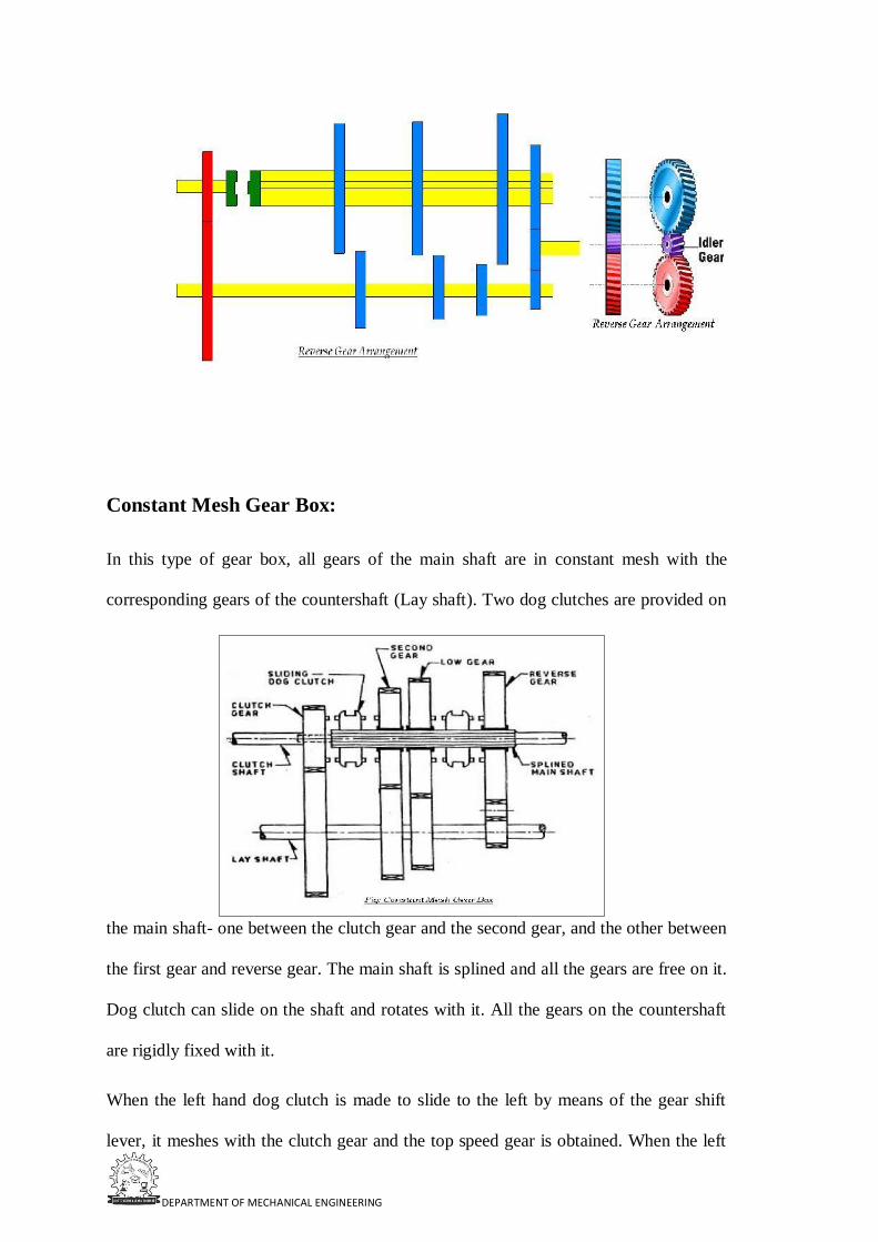
DEPARTMENT OF MECHANICAL ENGINEERING
Constant Mesh Gear Box:
In this type of gear box, all gears of the main shaft are in constant mesh with the
corresponding gears of the countershaft (Lay shaft). Two dog clutches are provided on
the main shaft- one between the clutch gear and the second gear, and the other between
the first gear and reverse gear. The main shaft is splined and all the gears are free on it.
Dog clutch can slide on the shaft and rotates with it. All the gears on the countershaft
are rigidly fixed with it.
When the left hand dog clutch is made to slide to the left by means of the gear shift
lever, it meshes with the clutch gear and the top speed gear is obtained. When the left

DEPARTMENT OF MECHANICAL ENGINEERING
hand dog clutch meshes with the second gear, the second speed gear is obtained.
Similarly by sliding the right hand dog clutch to the left and right, the first speed gear
and reverse gear are obtained respectively. In this gear box because all the gears are in
constant mesh they are safe from being damaged and an unpleasant grinding sound
does not occur while engaging and disengaging them.
Syncromesh Gear Box:
In sliding Mesh Gear box the two meshing gears need to be revolve at equal peripheral
speeds to achieve a jerk less engagement and it is true for constant mesh gear box in
which the peripheral speeds of sliding dog and the corresponding gear on the output
shaft must be equal. The peripheral speed is given byWhere d1 and N1 are pitch circle
diameter and r.p.m. of gear and d2 andN2 diameter and r.p.m. of attached dog
respectively. Now N1 ≠ N2 since d1 ≠ d2 . Thus there is a difference in gear and dog
which necessitates double declutching. The driver has to disengage the clutch twice in
quick succession therefore it is referred as double declutching. There are two steps
involved in this process:
The clutch is disengaged i.e. first declutching and the gear system is placed in its
neutral position. Now the clutch is reengaged and acceleration pedal is pressed to
adjust the engine speed according to driver’s judgment.The clutch is disengaged(i.e.
second declutching) again the appropriate gear is engaged and then the clutch is
reengaged
It is that gear box in which sliding synchronizing units are provided in place of sliding
dog clutches as in case of constant mesh gear box. With the help of synchronizing unit,
the speed of both the driving and driven shafts is synchronized before they are clutched
together through train of gears. The arrangement of power flow for the various gears
remains the same as in constant mesh gear box. The synchronizer is made of frictional
materials. When the collar tries to mesh with the gear, the synchronizer will touch the

DEPARTMENT OF MECHANICAL ENGINEERING
gear first and use friction force to drive the gear to spin at the same speed as the collar.
This will ensure that the collar is meshed into the gear very smoothly without
grinding.Synchromesh gear devices work on the principle that two gears to be engaged
are first bought into frictional contact which equalizes their speed after which they are
engaged readily and smoothly.
The following types of devices are mostly used in vehicles:
Pin Type
Synchronizer ring type
A synchronizing system is used for smooth meshing. Synchromesh works like a
friction clutch. In the following figure two conical surfaces cone-1 is the part of the
collar and the cone-2 is the part of the gear wheel. Cone1, 2 are revolving at different
speeds. While cone-2 is revolving, cone-1 gradually slides into it. Friction slows or
speeds up the gear wheel. Finally both the cones revolve at same speed.
In the following Fig collar and gear wheel are separate and they are revolving at different
speeds. The internal cone comes in contact with the outer cone of the gear wheel. Friction
slows or speeds up the gear wheel.
And when the collar and gear wheel rotate at same speed the spring loaded outer ring
of the collar is pushed forward. The dog slide smoothly into mesh without clashing.
The collar and gear wheel lock and revolve at same speed. This the principle of

DEPARTMENT OF MECHANICAL ENGINEERING
synchromesh.
U- Joint:
A universal joint, U-joint, Cardan joint, Hardy-Spicer joint, or Hooke's joint is a
linkage that transmits rotation between two non parallel shafts whose axes are coplanar
but not coinciding., and is commonly used in shafts that transmit rotary motion. It is
used in automobiles where it is used to transmit power from the gear box of the engine
to the rear axle. The driving shaft rotates at a uniform angular speed, where as the
driven shaft rotates at a continuously varying angular speed.
A complete revolution of either shaft will cause the other to rotate through a complete
revolution at the same time. Each shaft has fork at its end. The four ends of the two
fork are connected by a centre piece, the arms of which rest in bearings, provided in
fork ends. The centre piece can be of any shape of a cross, square or sphere having
four pins or arms. The four arms are at right angle to each other.
When the two shafts are at an angle other than 180° (straight), the driven shaft does not
rotate with constant angular speed in relation to the drive shaft; the more the angle
goes toward 90° the jerkier the movement gets (clearly, when the angle β = 90° the
shafts would even lock). However, the overall average speed of the driven shaft
remains the same as that of driving shaft, and so speed ratio of the driven to the driving
shaft on average is 1:1 over multiple rotations.
The angular speed ω2 of the driven shaft, as a function of the angular speed of the driving

DEPARTMENT OF MECHANICAL ENGINEERING
shaft ω1 and the angle of the driving shaft φ1, is found using:
ω2 = ω1 cosα / (1-sin2α.cos2θ)
For a given and set angle between the two shafts it can be seen that there is a cyclical
variation in the input to output velocity ratio. Maximum values occur when sin θ = 1, i.e.
when θ = 900 and 2700. The denominator is greatest when θ = 0or 1800 and this condition
gives the minimum ratio of the velocities
Components of Hooke’s Joint
Slip Joint in the Propeller Shaft;

DEPARTMENT OF MECHANICAL ENGINEERING
Hook Joint in the Propeller Shaft;
The Drive Shaft
The drive shaft, or propeller shaft, connects the transmission output shaft to the
differential pinion shaft. Since all roads are not perfectly smooth, and the transmission
is fixed, the drive shaft has to be flexible to absorb the shock of bumps in the road.
Universal, or "U-joints" allow the drive shaft to flex (and stop it from breaking) when
the drive angle changes.
Drive shafts are usually hollow in order to weigh less, but of a large diameter so that
they are strong. High quality steel, and sometimes aluminum are used in the
manufacture of the drive shaft. The shaft must be quite straight and balanced to avoid

DEPARTMENT OF MECHANICAL ENGINEERING
vibrating. Since it usually turns at engine speeds, a lot of damage can be caused if the
shaft is unbalanced, or bent. Damage can also be caused if the U-joints are worn out.
There are two types of drive shafts, the Hotchkiss drive and the Torque Tube Drive.
The Hotchkiss drive is made up of a drive shaft connected to the transmission output
shaft and the differential pinion gear shaft. U-joints are used in the front and rear. The
Hotchkiss drive transfers the torque of the output shaft to the differential. No wheel
drive thrust is sent to the drive shaft. Sometimes this drive comes in two pieces to
reduce vibration and make it easier to install (in this case, three U-joints are
needed).The two-piece types need ball bearings in a dustproof housing as center
support for the shafts. Rubber is added into this arrangement for noise and vibration
reduction.
The torque tube drive shaft is used if the drive shaft has to carry the wheel drive thrust.
It is a hollow steel tube that extends from the transmission to the rear axle housing.
One end is fastened to the axle housing by bolts. The transmission end is fastened with
a torque ball. The drive shaft fits into the torque tube. A U-joint is located in the torque
ball, and the axle housing end is splined to the pinion gear shaft. Drive thrust is sent
through the torque tube to the torque ball, to transmission, to engine and finally, to the
frame through the engine mounts. That is, the car is pushed forward by the torque tube
pressing on the engine.
Differential Unit:

DEPARTMENT OF MECHANICAL ENGINEERING
Differentials are a variety of gearbox, almost always used in one of two ways. In one
of these, it receives one input and provides two outputs; this is found in every
automobile. In automobile and other wheeled vehicles, the differential allows each of
the driving wheels to rotate at different speeds, while supplying equal torque to each of
them. In the other, less commonly encountered, it combines two inputs to create an
output that is the sum (or difference) of the inputs. In automotive applications, the
differential and its housing are sometimes collectively called a "pumpkin" (because the
housing resembles a pumpkin).
Purpose:-
The differential gear box has following functions:
Avoid skidding of the rear wheels on a road turning.
Reduces the speed of inner wheels and increases the speed of outer wheels,
while drawing a curve.
Keeps equal speeds of all the wheels while moving on a straight road.
Eliminates a single rigid rear axle, and provides a coupling between two rear axles.
The following description of a differential applies to a "traditional" rear- or front-
wheel-drive car or truck:

DEPARTMENT OF MECHANICAL ENGINEERING
Power is supplied from the engine, via the transmission or gearbox, to a drive shaft
termed as propeller shaft, which runs to the differential. A spiral bevel pinion gear at
the end of the propeller shaft is encased within the differential itself, and it meshes
with the large spiral bevel ring gear termed as crown wheel. The ring and pinion may
mesh in hypoid orientation.
The ring gear is attached to a carrier, which holds what is sometimes called a spider, a
cluster of four bevel gears in a rectangle, so each bevel gear meshes with two
neighbors and rotates counter to the third that it faces and does not mesh with. Two of
these spider gears are aligned on the same axis as the ring gear and drive the half shafts
connected to the vehicle's driven wheels.
These are called the side gears. The other two spider gears are aligned on a
perpendicular axis which changes orientation with the ring gear's rotation. These two
gears are just called pinion gears, not to be confused with the main pinion gear. (Other
spider designs employ different numbers of pinion gears depending on durability
requirements.)
As the carrier rotates, the changing axis orientation of the pinion gears imparts the
motion of the ring gear to the motion of the side gears by pushing on them rather than
turning against them (that is, the same teeth stay in contact), but because the spider
gears are not restricted from turning against each other, within that motion the side
gears can counter-rotate relative to the ring gear and to each other under the same force
(in which case the same teeth do not stay in contact).
Thus, for example, if the car is making a turn to the right, the main ring gear may make
10 full rotations. During that time, the left wheel will make more rotations because it
has further to travel, and the right wheel will make fewer rotations as it has less
distance to travel. The side gears will rotate in opposite directions relative to the ring
gear by, say, 2 full turns each (4 full turns relative to each other), resulting in the left

DEPARTMENT OF MECHANICAL ENGINEERING
wheel making 12 rotations, and the right wheel making 8 rotations.
The rotation of the ring gear is always the average of the rotations of the side gears.
This is why if the wheels are lifted off the ground with the engine off, and the drive
shaft is held (preventing the ring gear from turning inside the differential), manually
rotating one wheel causes the other to rotate in the opposite direction by the same
amount.
When the vehicle is traveling in a straight line, there will be no differential movement of the
planetary system of gears other than the minute movements necessary to compensate for
slight
differences in wheel diameter, undulations in the road (which make for a longer or
shorter wheel path), etc.
Automatic Transmission:
An automatic transmission (commonly "AT" or "Auto") is an automobile gearbox that
can change gear ratios automatically as the vehicle moves, freeing the driver from
DEPARTMENT OF MECHANICAL ENGINEERING
having to shift gears manually.
Automatic Transmission Modes:
In order to select the mode, the driver would have to move a gear shift lever located on
the steering column or on the floor next to him/her. In order to select gears/modes the
driver must push a button in (called the shift lock button) or pull the handle (only on
column mounted shifters) out. In some vehicles position selector buttons for each mode
on the cockpit instead, freeing up space on the central console. Vehicles conforming to
U.S. Government standards must have the modes ordered P- R-N-D-L (left to right, top
to bottom, or clockwise). Prior to this, quadrant-selected automatic transmissions often
utilized a P-N-D-L-R layout, or similar. Such a pattern led to a number of deaths and
injuries owing to un-intentional gear miss-selection, as well the danger of having a
selector (when worn) jump into Reverse from Low gear during engine braking
maneuvers.
Automatic Transmissions have various modes depending on the model and make of
the transmission. Some of the common modes are:
Park Mode (P):-
This selection mechanically locks the transmission, restricting the car from moving in
any direction. A parking pawl prevents the transmission—and therefore the vehicle—
from moving, although the vehicle's non-drive wheels may still spin freely. For this
reason, it is recommended to use the hand brake (or parking brake) because this
actually locks the (in most cases, rear) wheels and prevents them from moving. This
also increases the life of the transmission and the park pin mechanism, because parking
on an incline with the transmission in park without the parking brake engaged will
cause undue stress on the parking pin. An efficiently-adjusted hand brake should also
prevent the car from moving if a worn selector accidentally drops into reverse gear
DEPARTMENT OF MECHANICAL ENGINEERING
during early morning fast-idle engine warm ups.
Reverse (R):-
This puts the car into the reverse gear, giving the ability for the car to drive backwards.
In order for the driver to select reverse they must come to a complete stop, push the
shift lock button in (or pull the shift lever forward in the case of a column shifter) and
select reverse. Not coming to a complete stop can cause severe damage to the
transmission. Many modern automatic gearboxes have a safety mechanism in place,
which does to some extent prevent (but doesn't completely avoid) inadvertently putting
the car in reverse when the vehicle is moving.
This mechanism usually consists of a solenoid-controlled physical barrier on either
side of the Reverse position, which is electronically engaged by a switch on the brake
pedal. Therefore, the brake pedal needs to be depressed in order to allow the selection
of reverse. Some electronic transmissions prevent or delay engagement of reverse gear
altogether while the car is moving.
Neutral/No gear (N):-
This disconnects the transmission from the wheels so the car can move freely under its
own weight. This is the only other selection in which the car can be started.
Drive (D):-
This allows the car to move forward and accelerate through its range of gears. The
number of gears a transmission has depends on the model, but they can commonly
range from 3, 4 (the most common), 5, 6 (found in VW/Audi Direct Shift Gearbox), 7
(found in Mercedes 7G gearboxes, BMW M5 and VW/Audi Direct Shift Gearbox) and
8 in the newer models of Lexus cars. Some cars when put into D will automatically
lock the doors or turn on the Daytime Running Lamps.
Overdrive ([D], Od, Or A Boxed D):-

DEPARTMENT OF MECHANICAL ENGINEERING
This mode is used in some transmissions to allow early Computer Controlled
Transmissions to engage the Automatic Overdrive. In these transmissions, Drive (D)
locks the Automatic Overdrive off, but is identical otherwise. OD (Overdrive) in these
cars is engaged under steady speeds or low acceleration at approximately 35-45 mph
(approx. 72 km/h). Under hard acceleration or below 35-45 mph, the transmission will
automatically downshift. Vehicles with this option should be driven in this mode
unless circumstances require a lower gear.
Second (2 or S):-
This mode limits the transmission to the first two gears, or more commonly locks the
transmission in second gear. This can be used to drive in adverse conditions such as
snow and ice, as well as climbing or going down hills in the winter time. Some
vehicles will automatically up-shift out of second gear in this mode if a certain rpm
range is reached, to prevent engine damage.
First (1 or L):-
This mode locks the transmission in first gear only. It will not accelerate through any
gear range. This, like second, can be used during the winter season, or for towing.
As well as the above modes there are also other modes, dependent on the manufacturer
and model. Some examples include:
D5:- In Hondas and Acuras equipped with 5-speed automatic transmissions, this mode
is used commonly for highway use (as stated in the manual), and uses all five forward
gears.
D4:- This mode is also found in Honda and Acura 4 or 5-speed automatics and only
uses the first 4 gears. According to the manual, it is used for "stop and go traffic", such
as city driving.
D3:- This mode is found in Honda and Acura 4-speed automatics and only uses the

DEPARTMENT OF MECHANICAL ENGINEERING
first 3 gears. According to the manual, it is used for stop & go traffic, such as city
driving. This mode is also found in Honda and Acura 5-speed automatics.
This is the manual selection of gears for automatics, such as Porsche's Tiptronic. This
feature can also be found in Chrysler and General Motors products such as the Dodge
Magnum and Pontiac G6. The driver can shift up and down at will, by toggling the
shift lever (console mounted) like a semi-automatic transmission. This mode may be
engaged either through a selector/position or by actually changing gear (e.g. tipping the
gear-down paddles mounted near the driver's fingers on the steering wheel).
The predominant form of automatic transmission is hydraulically operated, using a
fluid coupling/ torque converter and a set of planetary gear-sets to provide a range of
torque multiplication.
Parts and Operation:-
A hydraulic automatic transmission consists of the following parts:
Torque Converter/Fluid Coupling
Planetary Gear Set
Clutch packs & Bands
Valve Body
Hydraulic or Lubricating Oil

DEPARTMENT OF MECHANICAL ENGINEERING
Torque Converter/Fluid Coupling: -Unlike a manual transmission system, automatic
transmission does not use a clutch to disconnect power from the engine temporarily
when shifting gears. Instead, a device called a torque converter was invented to prevent
power from being temporarily disconnected from the engine and also to pre-vent the
vehicle from stalling when the transmission is in gear.
A fluid coupling/torque converter consists of a sealed chamber containing two toroidal-
shaped, vaned components, the pump and turbine, immersed in fluid (usually oil). The
pump or driving torus (the latter a General Motors automotive term) is rotated by the
prime mover, which is typically an internal combustion engine or electric motor. The
pump's motion imparts a relatively complex centripetal motion to the fluid. Simplified,
this is a centrifugal force that throws the oil outwards against the coupling's housing,
whose shape forces the flow in the direction of the turbine or driven torus (the latter
also a General Motors term).
Here, Corolis force reaction transfers the angular fluid momentum outward and across,
applying torque to the turbine, thus causing it to rotate in the same direction as the
pump. The fluid leaving the center of the turbine returns to the pump, where the cycle

DEPARTMENT OF MECHANICAL ENGINEERING
endlessly repeats. The pump typically is connected to the flywheel of the engine—in
fact, the coupling's enclosure may be part of the flywheel proper, and thus is turned by
the engine's crankshaft. The turbine is connected to the input shaft of the transmission.
As engine speed increases while the transmission is in gear, torque is transferred from
the engine to the input shaft by the motion of the fluid, propelling the vehicle. In this
regard, the behavior of the fluid coupling strongly resembles that of a mechanical
clutch driving a manual transmission.
A torque converter differs from a fluid coupling in that it provides a variable amount of
torque multiplication at low engine speeds, increasing "breakaway" acceleration. This
is accomplished with a third member in the "coupling assembly" known as the stator,
and by altering the shapes of the vanes inside the coupling in such a way as to curve
the fluid's path into the stator. The stator captures the kinetic energy of the
transmission fluid in effect using the left-over force of it to enhance torque
multiplication.
Tiptronic transmission is a special type of automatic transmission with a computer
controlled automatic shift. The driver can switch the transmission to manual mode,
which lets her shift the gear at her wish sequentially up (+) or down (-) without
disengaging the clutch. This works just like a manual transmission; however, it still
uses a torque converter to transfer power from the engine. Unfortunately, this is less

DEPARTMENT OF MECHANICAL ENGINEERING
efficient than a manual transmission.
Planetary Gear-Set: - The automatic system for current automobiles uses a planetary
gear set instead of the traditional manual transmission gear set. The planetary gear set
contains four parts: sun gear, planet gears, planet carrier, and ring gear. Based on this
planetary set design, sun gear, planet carrier, and ring gear spin centrifugally. By
locking one of them, the planetary set can generate three different gear ratios,
including one reverse gear, without engaging and disengaging the gear set. The gear
set is actuated by hydraulic servos controlled by the valve body, providing two or more
gear ratios.
Clutch Packs And Bands: - A clutch pack consists of alternating disks that fit inside a
clutch drum. Half of the disks are steel and have splines that fit into groves on the
inside of the drum.
`The other half have a friction material bonded to their surface and have splines on the
inside edge that fit groves on the outer surface of the adjoining hub. There is a piston
inside the drum that is activated by oil pressure at the appropriate time to squeeze the
clutch pack together so that the two components become locked and turn as one.
A band is a steel strap with friction material bonded to the inside surface. One end of
the band is anchored against the transmission case while the other end is connected to a

DEPARTMENT OF MECHANICAL ENGINEERING
servo. At the appropriate time hydraulic oil is sent to the servo under pressure to
tighten the band around the drum to stop the drum from turning.
The bands come into play for manually selected gears, such as low range or reverse,
and operate on the planetary drum's circumference. Bands are not applied when
drive/overdrive range is selected, the torque being transmitted by the sprag clutches
instead.
The sun gear is connected to a drum, which can be locked by a band. The ring gear is
directly connected to the input shaft, which transfers power from the engine. The
planet carrier is connected to the output shaft, which transfers power into the wheels.
Based on this design, when in neutral, both band and clutch sets are released. Turning
the ring gear can only drive planet gears but not the planet carrier, which stays static if
the car is not moving. The planet gears drive the sun gear to spin freely. In this
situation, the input shaft is not able to transfer power to the output shaft. When shifting
to 1st gear, the band locks the sun gear by locking the drum. The ring gear drives the
planet carrier to spin. In this situation, the ring gear (input shaft) spins faster than the
planet carrier (output shaft).
To shift to higher gear, the band is released and the clutch is engaged to force the sun
gear and planet carrier (output shaft) to spin at the same speed. The input shaft will
also spin at the same speed as the output shaft, which makes the car run faster than in
1st gear. Using a compound planetary gear set generates more gear ratios with a special
gear ratio, over-drive gear whose gear ratio is small than 1.
This will make the gear shift smoother. Both the band and clutch piston are pressurized
by the hydraulic system. The part connecting the band or clutches to the hydraulic
system is called the shift valve, while the one connecting the hydraulic system to the
output shaft is called the governor.
The governor is a centrifugal sensor with a spring loaded valve. The faster the

DEPARTMENT OF MECHANICAL ENGINEERING
governor spins, the more the valve opens. The more the valve opens, the more the fluid
goes through and the higher the pressure applied on the shift valve. Therefore, each
band and clutch can be pushed to lock the gear based on a specific spin speed detected
by the governor from the output shaft. To make the hydraulic system work efficiently,
a complex maze of passages was designed to replace a large number of tubes. For
modern cars, an electronic con-trolled (computer controlled) solenoid pack is used to
detect throttle position, vehicle speed, engine speed, engine load, brake pedal position,
etc., and to automatically choose the best gear for a moving vehicle.
Principally, a type of device known as a sprag or roller clutch is used for routine
upshifts/downshifts. Operating much as a ratchet, it transmits torque only in one
direction, freewheeling or "overrunning" in the other. The advantage of this type of
clutch is that it eliminates the sensitivity of timing a simultaneous clutch release/apply
on two planetaries, simply "taking up" the drivetrain load when actuated,and releasing
automatically when the next gear's sprag clutch assumes the torque transfer.

DEPARTMENT OF MECHANICAL ENGINEERING
Valve Body: - Hydraulic control center that receives pressurized fluid from a main
pump operated by the fluid coupling/torque converter. The pressure coming from this
pump is regulated and used to run a network of spring-loaded valves, check balls and
servo pistons.
The valves use the pump pressure and the pressure from a centrifugal governor on the
output side (as well as hydraulic signals from the range selector valves and the throttle
valve or modulator) to control which ratio is selected on the gearset; as the car and
engine change speed, the difference between the pressures changes, causing different
sets of valves to open and close.
Each of the many valves in the valve body has a specific purpose and is named for that
function. For example the 2-3 shift valves activate the 2nd gear to 3rd gear up-shift or
the 3-2 shift timing valve which determines when a downshift should occur.
The hydraulic pressure controlled by these valves drives the various clutch and brake
band actuators, thereby controlling the operation of the planetary gearset to select the
optimum gear ratio for the current operating conditions. However, in many modern
automatic transmissions, the valves are controlled by electro-mechanical servos which
are controlled by the Engine Management System or a separate transmission controller.
The most important valve and the one that you have direct control over is the manual
valve. The manual valve is directly connected to the gear shift handle and covers and

DEPARTMENT OF MECHANICAL ENGINEERING
uncovers various passages depending on what position the gear shift is placed in.
When you place the gear shift in Drive, for instance, the manual valve directs fluid to
the clutch pack(s) that activates 1st gear.
It also sets up to monitor vehicle speed and throttle position so that it can determine the
optimal time and the force for the 1 - 2 shifts. On computer controlled transmissions,
you will also have electrical solenoids that are mounted in the valve body to direct
fluid to the appropriate clutch packs or bands under computer control to more precisely
control shift points.
Hydraulic & Lubricating Oil: - A component called Automatic Transmission Fluid
(ATF) which is part of the transmission mechanism provides lubrication, corrosion
prevention, and a hydraulic medium to convey mechanical power.
Primarily it is made of refined petroleum and processed to provide properties that
promote smooth power transmission and increase service life. ATF is one of the parts
of the automatic transmission that needs routine service as the vehicle ages.
Semi Automatic Transmission
A semi-automatic transmission (also known as clutch less manual transmission,
automated manual transmission, e-gear, shift-tronic, flappy paddle gearbox, or paddle
shift gearbox) is a system which uses electronic sensors, processors and actuators to do
gear shifts on the command of the driver. This removes the need for a clutch pedal
which the driver otherwise needs to depress before making a gear change, since the
clutch itself is actuated by electronic equipment which can synchronize the timing and
torque required to make gear shifts quick and smooth.
The system was designed by European automobile manufacturers to provide a better
driving experience, especially in cities where congestion frequently causes stop-and-go
traffic patterns. Like a tiptronic transmission, a semi-automatic transmission can also
be switched to manual mode to perform gear shifting at the drivers wish.

DEPARTMENT OF MECHANICAL ENGINEERING
The two most common semi-automatic transmissions
Direct shift transmission (or dual-clutch transmission)
Electro-hydraulic manual transmission (or sequential transmission)
Direct shift transmission: In direct shift transmission direct shift gear box is used. The
Direct-Shift Gearbox or D.S.G. is an electronically controlled, twin-shaft dual-clutch
manual gearbox, without a conventional clutch pedal, with full automatic or semi-
manual control.
Unlike the conventional manual transmission system, there are two different
gear/collar sets, with each connected to two different input/output shafts. The outer
clutch pack drives gears 1, 3, 5 and reverse. It is just like two conventional manual
transmission gear boxes in one. The inner clutch pack drives gears 2, 4, and 6. Instead
of a standard large dry single-plate clutch, each clutch pack is a collection of four small
wet interleaved clutch plates.
Due to space constraints, the two clutch assemblies are concentric. To automatically
shift from 1st gear to 2nd gear, first the computer detects that the spinning speed of the
input shaft is too high, and engages the 2nd gear’s collar to the 2nd gear. The clutch
then disengages from 1st gear’s input shaft, and engages the 2nd gear’s input shaft.
Controlled by computer, the gear shift becomes extremely fast compared with a
conventional manual transmission.
Using direct contact of the clutch instead of fluid coupling also improves power
transmission efficiency. Another advanced technology used for direct shift trans-
mission allows it to perform “double clutching” by shifting the gear to neutral first,
adjusting the spinning speed of the input shaft, and then shifting to the next gear. This

DEPARTMENT OF MECHANICAL ENGINEERING
makes gear shifting very smooth.
Operation Modes Of D.S.G.:-"D" mode:
When the motor vehicle is stationary, in neutral, both clutch packs are fully
disengaged. When the driver has selected D for drive (after pressing the foot brake
pedal), the transmission's first gear is selected on the first shaft, and the clutch prepares
to engage. At the same time, the second gear is also selected, but the clutch pack for
second gear remains fully disengaged. When the driver releases the brake pedal, the
clutch pack for the first gear takes up the drive, and the vehicle moves forward.
Pressing the accelerator pedal increases forward speed. As the car accelerates, the
transmission's computer determines when the second gear (which is connected to the
second clutch) should be fully utilized.
Depending on the vehicle speed and amount of power being requested by the driver
(full throttle or part-throttle normal driving), the D.S.G. then up-shifts. During this
sequence, the DSG disengages the first clutch while engaging the second clutch (all
power from the engine is now going through the second shaft), thus completing the
shift sequence. This sequence happens in 8 ms, and there is practically no power loss.
Once the vehicle has shifted up to second gear, the first gear is immediately de-
selected, and third gear (being on the same shaft as 1st and 5th) is pre-selected, and is
pending. Once the time comes to shift, the second clutch disengages and the first clutch
re-engages. This method of operation continues in the same manner up to 6th
gear.Downshifting is similar to up-shifting but in reverse order. The car's computer
senses the car slowing down or more power required, and thus lines up a lower gear on
one of the shafts not in use, and then completes the downshift.
The actual shift timings are determined by the D.S.G.'s Electronic Control Unit, or
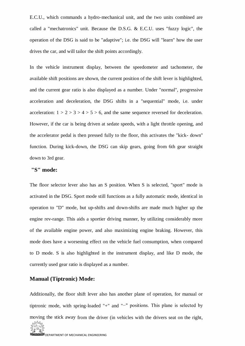
DEPARTMENT OF MECHANICAL ENGINEERING
E.C.U., which commands a hydro-mechanical unit, and the two units combined are
called a "mechatronics" unit. Because the D.S.G. & E.C.U. uses "fuzzy logic", the
operation of the DSG is said to be "adaptive"; i.e. the DSG will "learn" how the user
drives the car, and will tailor the shift points accordingly.
In the vehicle instrument display, between the speedometer and tachometer, the
available shift positions are shown, the current position of the shift lever is highlighted,
and the current gear ratio is also displayed as a number. Under "normal", progressive
acceleration and deceleration, the DSG shifts in a "sequential" mode, i.e. under
acceleration: 1 > 2 > 3 > 4 > 5 > 6, and the same sequence reversed for deceleration.
However, if the car is being driven at sedate speeds, with a light throttle opening, and
the accelerator pedal is then pressed fully to the floor, this activates the "kick- down"
function. During kick-down, the DSG can skip gears, going from 6th gear straight
down to 3rd gear.
"S" mode:
The floor selector lever also has an S position. When S is selected, "sport" mode is
activated in the DSG. Sport mode still functions as a fully automatic mode, identical in
operation to "D" mode, but up-shifts and down-shifts are made much higher up the
engine rev-range. This aids a sportier driving manner, by utilizing considerably more
of the available engine power, and also maximizing engine braking. However, this
mode does have a worsening effect on the vehicle fuel consumption, when compared
to D mode. S is also highlighted in the instrument display, and like D mode, the
currently used gear ratio is displayed as a number.
Manual (Tiptronic) Mode:
Additionally, the floor shift lever also has another plane of operation, for manual or
tiptronic mode, with spring-loaded "+" and "−" positions. This plane is selected by
moving the stick away from the driver (in vehicles with the drivers seat on the right,

DEPARTMENT OF MECHANICAL ENGINEERING
the lever is pushed to the left, and in left-hand drive cars, the stick is pushed to the
right) when in "D" mode only. When this plane is selected, the D.S.G. can now be
controlled like a manual gearbox, even though under a sequential shift pattern.
The readout in the instrument display changes to 6 -5- 4- 3- 2- 1, and just like the
automatic modes, the currently used gear ratio is highlighted. To change up a gear, the
lever is pushed forwards (against a spring pressure) towards the "+", and to change
down, the lever is pulled rearwards towards the "−".
The DSG box can now be operated with the gear changes being (primarily) determined by the driver.
This method of operation is commonly called "tiptronic". When accelerating in Manual/tiptronic
mode, the D.S.G. will still automatically change up just before the red-line and when decelerating, it
will change down automatically at very low revs, just before the engine idle speed (tick over).
Furthermore, if the driver calls for a gear when it is not appropriate (i.e., engine speed near the red-
line, and a down change is requested) the D.S.G. will delay the change until the engine revs are at an
appropriate level to cope with the requested gear.
Paddle Shifters:
On certain "sporty” or high-powered cars paddle shifters are available. The paddle
shifters have two distinct advantages: the driver can safely keep both hands on the
steering wheel when using the Manual/tiptronic mode; and the driver can immediately
manually override either of the automatic programs (D or S) on a temporary basis, and
gain instant manual control of the D.S.G. box.
If the manual override of one of the automatic programs (D or S) is utilized
intermittently, the gearbox will "default" back to the previously selected automatic
mode after a predetermined duration of inactivity of the paddles, or when the car
becomes stationary. Alternatively, should the driver wish to revert immediately to
automatic control, this can be done by holding the "+" paddle for at least two seconds.
Electro Hydraulic Manual Transmission:

DEPARTMENT OF MECHANICAL ENGINEERING
In electro-hydraulic manual transmission (also known as sequential transmission) the
gear set is almost the same as the conventional transmission system, except that the
shifting of the se-lector is not an “H” pattern. Instead, all selector forks are connected
to a drum. The drum has several grooves, and each has a ball sliding in it. Each fork
hooks up to a ball and can be moved forward and backward when the drum is turning.
Based on the pattern of the grooves on the drum, by turning the drum, each fork can
move forward and backward in turn, which makes gear selection sequential. Therefore,
it is impossible for an electro-hydraulic manual transmission to perform a gear shift
from 1st to 3rd or 4th to 2nd. The shifting must be sequential, like 1st ▬► 2nd ▬►
3rd ▬►4th, or 4th▬►3rd▬►2nd▬►1st.
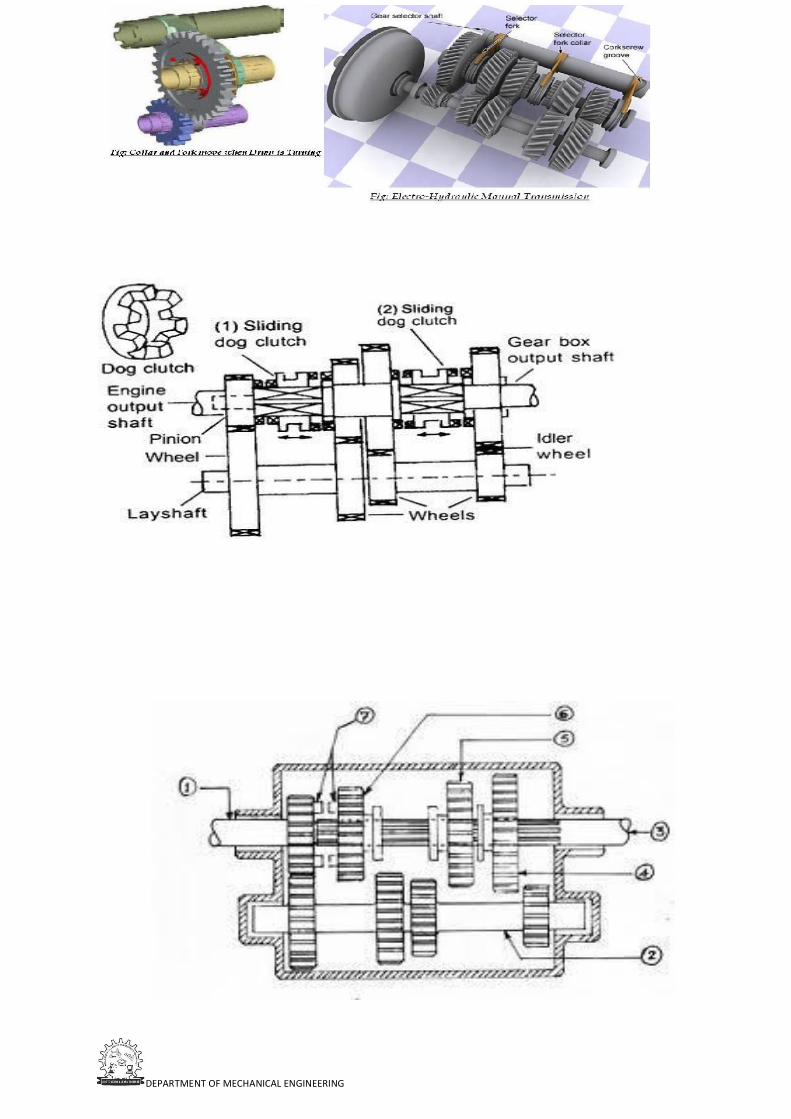
DEPARTMENT OF MECHANICAL ENGINEERING

DEPARTMENT OF MECHANICAL ENGINEERING
Hotchkiss drive;
The Hotchkiss drive is a system of power transmission. It was the dominant form of
power transmission for front-engine, rear-wheel drive layout cars in the 20th century.
The name comes from the French automobile firm of Hotchkiss, although it is
clear that other makers (such as Peerless) used similar systems before Hotchkiss.
During the early part of the 20th century the two major competing systems of power
transmission were the shaft-drive and chain-drive configurations. The Hotchkiss drive
is a shaft- drive system (another type of direct-drive transmission system is the torque
tube, which was also popular until the 1950s).
All shaft-drive systems consist of a driveshaft (also called a "propeller
shaft" or Cardan shaft) extending from the transmission in front to the differential in
the rear. The differentiating characteristic of the Hotchkiss drive is the fact
that it uses universal joints at both ends of the driveshaft, which is not enclosed.
The use of two universal joints, properly phased and with parallel alignment of the
drive and driven shafts, allows the use of simple cross- type universals. (In a torque-
tube arrangement only a single universal is used at the end of the transmission tail
shaft, and this universal should be a constant velocity joint.)
In the Hotchkiss drive, slip-splines or a plunge-type (ball and trunnion u-joint)
eliminate thrust transmitted back up the driveshaft from the axle, allowing simple rear-
axle positioning using parallel leaf springs. (In the torque-tube type this thrust is taken
by the torque tube to the transmission and thence to the transmission and motor mounts
to the frame. While the torque-tube type requires additional locating elements, such as
a Panhard rod, this allows the use of coil springs.)
Some Hotchkiss drive shafts are made in two pieces with another universal joint in the
center for greater flexibility, typically in trucks and specialty vehicles built on truck

DEPARTMENT OF MECHANICAL ENGINEERING
frames. Some installations use rubber mounts to isolate noise and vibration. The 1984–
1987 RWD Toyota Corolla (i.e., Corolla SR5 and GT-S) coupe is another example of a
car that uses a 2-part Hotchkiss driveshaft with a rubber-mounted center bearing.
This design was the main form of power transmission for most cars from the 1920s through
the 1970s. Presently (circa 2012), it remains common in pick-up trucks, and sport utility
vehicles
Torque tube Drive
A torque tube system is a driveshaft technology, often used in automobiles with a front
engine and rear drive. It is not as widespread as the Hotchkiss drive, but is still
occasionally used to this day. Drive shafts are sometimes also used for other vehicles
and machinery.
The "torque" that is referred to in the name is not that of the driveshaft, along the axis
of the car, but that applied by the wheels. The design problem that the torque tube
solves is how to get the traction forces generated by the wheels to the car frame. The

DEPARTMENT OF MECHANICAL ENGINEERING
"torque tube" transmits this force by directly coupling the axle differential to the
transmission and therefore propels the car forward by pushing on the
engine/transmission and then through the engine mounts to the car frame[citation needed].
In contrast, the Hotchkiss drive has the traction forces transmitted to the car frame by
using other suspension components such as leaf springs or trailing arms. A ball and
socket type of joint called a "torque ball" is used at one end of the torque tube to allow
relative motion between the axle and transmission due to suspension travel. Since the
torque tube does not constrain the axle in the lateral (side-to-side) direction a pan hard
rod is often used for this purpose. The combination of the pan hard rod and the torque
tube allows the easy implementation of soft coil springs in the rear to give good ride
quality.
In addition to transmitting the traction forces, the torque tube is hollow and contains
the rotating driveshaft. Inside the hollow torque ball is the universal joint of the
driveshaft that allows relative motion between the two ends of the driveshaft. In most
applications the drive shaft uses a single universal joint which has the disadvantage
that it causes speed fluctuations in the driveshaft when the shaft is not straight. The
Hotchkiss drive uses two universal joints which has the effect of canceling the speed

DEPARTMENT OF MECHANICAL ENGINEERING
fluctuations and gives a constant speed even when the shaft is no longer straight .

Presentation Material

DEPARTMENT OF MECHANICAL ENGINEERING
T R A N S M I S S I O N S Y S T E M S
UNIT-III

D E P A R T M E N T O F M E C H A N I C A L E N G I N E E R I N G
TRANSMISSION SYSTEM IN AN
AUTOMOBILE

D E P A R T M E N T O F M E C H A N I C A L E N G I N E E R I N G
WHAT IS A TRANSMISSION?
The word ‘Transmission’ means the whole of the mechanism that transmits the power from the engine crankshaft to the rear wheels, providing the suitable variations of the engine torque at the road wheels, whenever required.

D E P A R T M E N T O F M E C H A N I C A L E N G I N E E R I N G
TYPES OF TRANSMISSION
Manual transmission
Fully automatic Transmission
Semi-Automatic Transmission
Continuously Variable Transmission

D E P A R T M E N T O F M E C H A N I C A L E N G I N E E R I N G
MANUAL TRANSMISSION
Components of Manual Transmission:
Clutch
Gearbox
Differential

D E P A R T M E N T O F M E C H A N I C A L E N G I N E E R I N G
WHAT IS CLUTCH
It is a device which carries a power form engine to
drive wheel through shafts.
It is located between flywheel and gearbox

D E P A R T M E N T O F M E C H A N I C A L E N G I N E E R I N G
CONSTRUCTION OF CLUTCH

D E P A R T M E N T O F M E C H A N I C A L E N G I N E E R I N G
How it Works

D E P A R T M E N T O F M E C H A N I C A L E N G I N E E R I N G

D E P A R T M E N T O F M E C H A N I C A L E N G I N E E R I N G

D E P A R T M E N T O F M E C H A N I C A L E N G I N E E R I N G
Types of Clutches

D E P A R T M E N T O F M E C H A N I C A L E N G I N E E R I N G
SINGLE PLATE CLUTCH

D E P A R T M E N T O F M E C H A N I C A L E N G I N E E R I N G
MULTI-PLATE CLUTCH

D E P A R T M E N T O F M E C H A N I C A L E N G I N E E R I N G
CONE CLUTCH

D E P A R T M E N T O F M E C H A N I C A L E N G I N E E R I N G
ELECTROMAGNETIC CLUTCH

D E P A R T M E N T O F M E C H A N I C A L E N G I N E E R I N G
CENTRIFUGAL CLUTCH

D E P A R T M E N T O F M E C H A N I C A L E N G I N E E R I N G
GEARBOX

D E P A R T M E N T O F M E C H A N I C A L E N G I N E E R I N G
GEAR RATIO
It is the ratio of the no. of teeth on the driven
wheel to no. of teeth on the driver wheel or the
speed of rotation of the driver to the driven .
For example:
Gear ratio,
G=(20/10)=2:1
(smaller gear is the driver) 20
Teeth10
Teeth
D E P A R T M E N T O F M E C H A N I C A L E N G I N E E R I N G
TYPES OF GEARBOX
Constant mesh type
Synchromesh type
Sliding mesh type

D E P A R T M E N T O F M E C H A N I C A L E N G I N E E R I N G

D E P A R T M E N T O F M E C H A N I C A L E N G I N E E R I N G
CONSTANT MESH TYPE

D E P A R T M E N T O F M E C H A N I C A L E N G I N E E R I N G
DOG GEAR

D E P A R T M E N T O F M E C H A N I C A L E N G I N E E R I N G
GEARBOX
SYNCHROMESH TYPE

D E P A R T M E N T O F M E C H A N I C A L E N G I N E E R I N G
SLIDING MESH TYPE
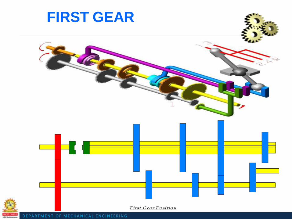
D E P A R T M E N T O F M E C H A N I C A L E N G I N E E R I N G
FIRST GEAR
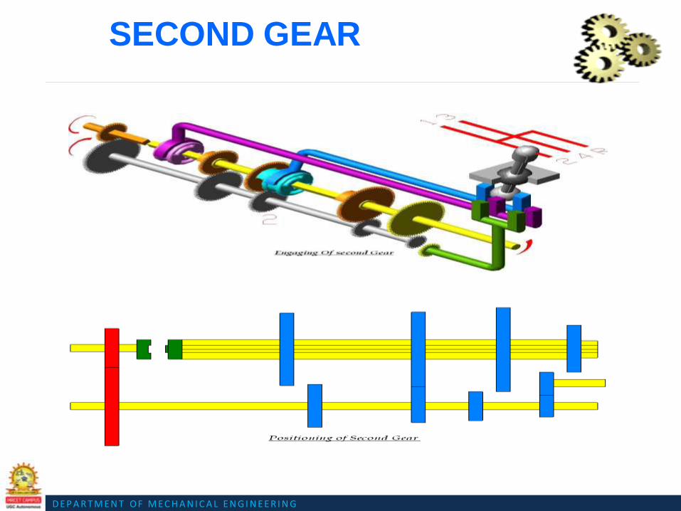
D E P A R T M E N T O F M E C H A N I C A L E N G I N E E R I N G
SECOND GEAR
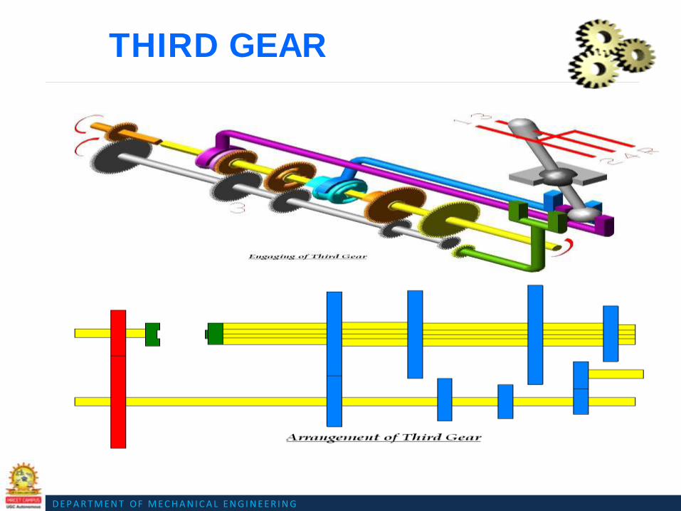
D E P A R T M E N T O F M E C H A N I C A L E N G I N E E R I N G
THIRD GEAR

D E P A R T M E N T O F M E C H A N I C A L E N G I N E E R I N G
FOURTH GEAR

D E P A R T M E N T O F M E C H A N I C A L E N G I N E E R I N G
REVERSE GEAR

D E P A R T M E N T O F M E C H A N I C A L E N G I N E E R I N G
SLIDING MESH
Oldest and the simplest type of transmission
Spur gears were used
Main shaft gears splined to the main shaft
Gear shift is achieved by sliding the gears on main
shaft
Low mechanical efficiency
Noisy operation

D E P A R T M E N T O F M E C H A N I C A L E N G I N E E R I N G
CONSTANT MESH
•
•
•
•
The gears on the main shaft and lay shaft are
in constant mesh
Main shaft gears are free to rotate
Gear engagement is achieved by dog clutches
splined to the main shaft
Helical gears are used

D E P A R T M E N T O F M E C H A N I C A L E N G I N E E R I N G
SYNCHRO MESH
• Gears are in constant mesh
• Instead of dog clutch synchroniser unit is used Each pair
of gear has one synchroniser unit
• Gears are first brought into frictional contact which equalizes
their speed after which the actual engagement takes place

D E P A R T M E N T O F M E C H A N I C A L E N G I N E E R I N G
DIFFERENTIAL

D E P A R T M E N T O F M E C H A N I C A L E N G I N E E R I N G
DIFFERENTIAL
Differential is a mechanism which
provide different speed to tyres at
cornering.
It provides equal torque on both tyre not
power.
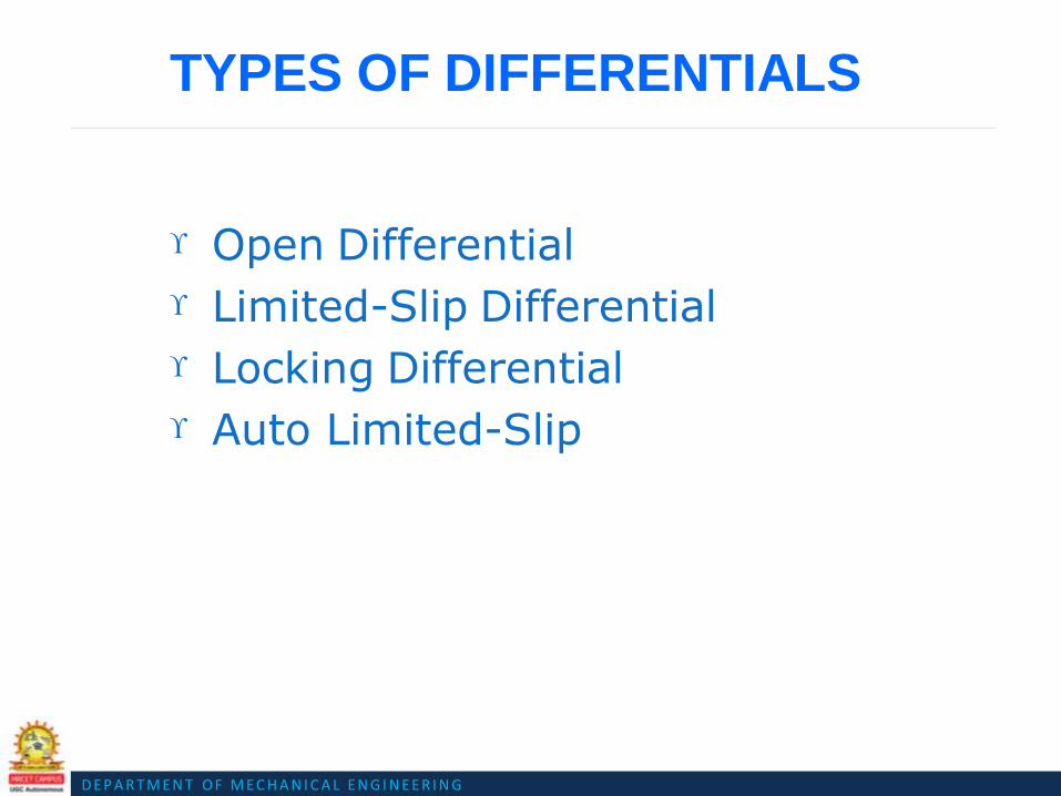
D E P A R T M E N T O F M E C H A N I C A L E N G I N E E R I N G
TYPES OF DIFFERENTIALS
Open Differential
Limited-Slip Differential
Locking Differential
Auto Limited-Slip Differential

Question Bank for Assignment
Question bank for Assignment
UNIT-III
1. Explain with a simple sketch, working of differential in a automobile
2. Explain the construction working and performance of a fluid flywheel. Enumerate the advantages of
fluid flywheel over the other types of clutches
3. Draw and explain with a simple sketch, working of a constant mesh gear box.
4. Draw a schematic diagram and explain the working of a torque convertor.
5. Explain with a simple sketch, construction and working of differential in a automobile
6. Explain with a simple sketch, construction and working of epicyclic gear box in an automobile
DEPARTMENT OF MECHANICAL ENGINEERING
UNIT IV
STEERING, BRAKES AND SUSPENSION SYSTEMS

DEPARTMENT OF MECHANICAL ENGINEERING
Course Objectives:
Understand the Principles of Suspension, steering and braking systems of an
Automobile
Course Outcomes:
Student should able to describe functioning of steering system, braking system
and Suspension systems for modern Automobile.

DEPARTMENT OF MECHANICAL ENGINEERING
Suspension system;
Suspension system is the term given to the system of springs, shock absorbers and
linkages that connects a vehicle to its wheels . It is basically cushion for passengers
protects the luggage or any cargo and also itself from damage and wear.
Sir William Brush is the father of suspension system in automobiles.
The main role of suspension system are as follows:
It supports the weight of vehicle .
Provides smoother ride for the driver and passengers i.e. acts as cushion.
Protects your vehicle from damage and wear .
It also plays a critical role in maintaining self driving conditions.
It also keeps the wheels pressed firmly to the ground for traction .
It isolates the body from road shocks and vibrations which would otherwise be
transferred to the passengers and load.
Principle :
When a tire hits an obstruction, there is a reaction force. The size of this reaction force
depends on the unsprung mass at each wheel assembly.
In general, the larger the ratio of sprung weight to unsprung weight, the less the body
and vehicle occupants are affected by bumps, dips, and other surface imperfections
such as small bridges. A large sprung weight to unsprung weight ratio can also impact
vehicle control.
No road is perfectly flat i.e. without irregularities. Even a freshly paved highways have
subtle imperfections that can be interact with vehicle’s wheels. These are the
imperfections that apply forces on wheels.
According to Newton ‘s law of motion all forces have both magnitude and direction.
A bump in the road causes the wheel to move up and down perpendicular to the road

DEPARTMENT OF MECHANICAL ENGINEERING
surface. The magnitude of course ,depends on whether the wheel is striking a giant
bump or a tiny speck. Thus, either the wheel experiences a vertical acceleration as it
passes over an imperfection.
The suspension of a car is actually part of the chassis, which comprises all of the
important systems located beneath the car's body. These system include :
Frame
Suspension system
Steering system
Tires or Wheels
Components of Suspension system;
There are three fundamental components of any suspension system.
Springs
Coil spring
Leaf springs
Air springs
Dampers
Shock Absorbers

DEPARTMENT OF MECHANICAL ENGINEERING
Struts:-
Anti-sway Bars
Anti sway bars.
Types of Suspension system;
Advantages;
Comfort to passengers
Good handling
Shields the vehicle from damage
Increases life of vehicle
Keeps the tires pressed firmly to ground.
Braking System;
A brake is a mechanical device which inhibits motion, slowing or stopping a moving
object or preventing its motion. The rest of this article is dedicated to various types of
vehicular brakes.
Most commonly brakes use friction between two surfaces pressed together to
convert the kinetic energy of the moving object into heat, though other methods of
energy conversion may be employed. For example regenerative braking converts much
of the energy to electrical energy, which may be stored for later use. Other methods
convert kinetic energy into potential energy in such stored forms as pressurized air or
pressurized oil. Eddy current brakes use magnetic fields to convert kinetic energy into

DEPARTMENT OF MECHANICAL ENGINEERING
electric current in the brake disc, fin, or rail, which is converted into heat. Still other
braking methods even transform kinetic energy into different forms, for example by
transferring the energy to a rotating flywheel.
Brakes are generally applied to rotating axles or wheels, but may also take other forms
such as the surface of a moving fluid (flaps deployed into water or air). Some vehicles
use a combination of braking mechanisms, such as drag racing cars with both wheel
brakes and a parachute, or airplanes with both wheel brakes and drag flaps raised into
the air during landing.
Since kinetic energy increases quadratically with velocity (k=mv2/2) an object
moving at 10 m/s has 100 times as much energy as one of the same mass moving at 1
m/s, and consequently the theoretical braking distance, when braking at the traction
limit, is 100 times as long. In practice, fast vehicles usually have significant air drag,
and energy lost to air drag rises quickly with speed. Almost all wheeled vehicles
have a brake of some sort. Even baggage carts and shopping carts may have them
for use on a moving ramp. Most fixed-wing aircraft are fitted with wheel brakes on the
undercarriage. Some aircraft also feature air brakes designed to reduce their speed in
flight.
Notable examples include gliders and some World War II-era aircraft, primarily some
fighter aircraft and many dive bombers of the era. These allow the aircraft to maintain
a safe speed in a steep descent. The Saab B 17 dive bomber and Vought F4U Corsair
fighter used the deployed undercarriage as an air brake. Friction brakes on automobiles
store braking heat in the drum brake or disc brake while braking then conduct it to
the air gradually. When traveling downhill some vehicles can use their engines to
brake.
When the brake pedal of a modern vehicle with hydraulic brakes is pushed,
ultimately a piston pushes the brake pad against the brake disc which slows the wheel
down. On the brake drum it is similar as the cylinder pushes the brake shoes against the

DEPARTMENT OF MECHANICAL ENGINEERING
drum which also slows the wheel down. Brakes may be broadly described as using
friction, pumping, or electromagnetic. One brake may use several principles: for
example, a pump may pass fluid through an orifice to create friction: Frictional brakes
are most common and can be divided broadly into "shoe" or "pad" brakes, using an
explicit wear surface, and hydrodynamic brakes, such as parachutes, which use friction
in a working fluid and do not explicitly wear. Typically the term "friction brake" is
used to mean pad/shoe brakes and excludes hydrodynamic brakes, even though
hydrodynamic brakes usefriction.
Friction (pad/shoe) brakes are often rotating devices with a stationary pad and a
rotating wear surface. Common configurations include shoes that contract to rub on
the outside of a rotating drum, such as a band brake; a rotating drum with shoes that
expand to rub the inside of a drum, commonly called a "drum brake", although other
drum configurations are possible; and pads that pinch a rotating disc, commonly called
a "disc brake".
Other brake configurations are used, but less often. For example, PCC trolley brakes
include a flat shoe which is clamped to the rail with an electromagnet; the Murphy
brake pinches a rotating drum, and the Ausco Lambert disc brake uses a hollow disc
(two parallel discs with a structural bridge) with shoes that sit between the disc
surfaces and expand laterally. Pumping brakes are often used where a pump is already
part of the machinery. For example, an internal-combustion piston motor can have the
fuel supply stopped, and then internal pumping losses of the engine create some
braking. Some engines use a valve override called a Jake brake to greatly increase
pumping losses. Pumping brakes can dump energy as heat, or can be regenerative
brakes that recharge a pressure reservoir called a hydraulic accumulator.
Electromagnetic brakes are likewise often used where an electric motor is already part
of the machinery. For example, many hybrid gasoline/electric vehicles use the electric
motor as a generator to charge electric batteries and also as a regenerative brake. Some

DEPARTMENT OF MECHANICAL ENGINEERING
diesel/electric railroad locomotives use the electric motors to generate electricity which
is then sent to a resistor bank and dumped as heat.
Types of Braking system in Automobile;
By applications –
1. Foot Brake,
2. Hand brake.
By Method of power –
1. Mechanical brake,
2. Hydraulic brake.
3. Vacuum brake,
4. Electrical brake and
5. Air brake.
By method of operations –
1. Manual brake,
2. Servo brake.
3. Power operation.
By construction –
1. Drum type brake,
2. Disc type brake
Anti-lock braking system (ABS)
Anti-lock braking system (ABS) is an automobile safety system that allows the wheels
on a motor vehicle to maintain tractive contact with the road surface according to
driver inputs while braking, preventing the wheels from locking up (ceasing rotation)

DEPARTMENT OF MECHANICAL ENGINEERING
and avoiding uncontrolled skidding. It is an automated system that uses the principles
of threshold braking and cadence braking which were practiced by skillful drivers with
previous generation braking systems. It does this at a much faster rate and with better
control than a driver could manage.
ABS generally offers improved vehicle control and decreases stopping distances on dry
and slippery surfaces for many drivers; however, on loose surfaces like gravel or snow-
covered pavement, ABS can significantly increase braking distance, although still
improving vehicle control.
Since initial widespread use in production cars, anti-lock braking systems have evolved
considerably. Recent versions not only prevent wheel lock under braking, but also
electronically control the front-to-rear brake bias. This function, depending on its
specific capabilities and implementation, is known as electronic brake force
distribution(EBD), traction control system, emergency brake assist, or electronic
stability control(ESC).
Operation
The anti-lock brake controller is also known as the CAB (Controller Anti-lock Brake).
Typically ABS includes a central electronic control unit (ECU), four wheel speed
sensors,
and at least two hydraulic valves within the brake hydraulics. The ECU constantly
monitors
the rotational speed of each wheel; if it detects a wheel rotating significantly slower
than the others, a condition indicative of impending wheel lock, it actuates the valves
to reduce hydraulic pressure to the brake at the affected wheel, thus reducing the
braking force on that wheel; the wheel then turns faster.
Conversely, if the ECU detects a wheel turning significantly faster than the others,
brake hydraulic pressure to the wheel is increased so the braking force is reapplied,
DEPARTMENT OF MECHANICAL ENGINEERING
slowing down the wheel. This process is repeated continuously and can be detected by
the driver via brake pedal pulsation. Some anti-lock systems can apply or release
braking pressure 15 times per second.[17] Because of this, the wheels of cars
equipped with ABS are practically impossible to lock even during panic braking in
extreme conditions.
The ECU is programmed to disregard differences in wheel rotative speed below a
critical threshold, because when the car is turning, the two wheels towards the center of
the curve turn slower than the outer two. For this same reason, a differential is used in
virtually all roadgoing vehicles. If a fault develops in any part of the ABS, a warning
light will usually be illuminated on the vehicle instrument panel, and the ABS will be
disabled until the fault is rectified.
Modern ABS applies individual brake pressure to all four wheels through a control
system of hub-mounted sensors and a dedicated micro-controller. ABS is offered or
comes standard on most road vehicles produced today and is the foundation for
electronic stability control systems, which are rapidly increasing in popularity due to
the vast reduction in price of vehicle electronics over the years.
Modern electronic stability control systems are an evolution of the ABS concept. Here,
a minimum of two additional sensors are added to help the system work: these are a
steering wheel angle sensor, and a gyroscopic sensor. The theory of operation is
simple: when the gyroscopic sensor detects that the direction taken by the car does not
coincide with what the steering wheel sensor reports, the ESC software will brake the
necessary individual wheel(s) (up to three with the most sophisticated systems), so that
the vehicle goes the way the driver intends. The steering wheel sensor also helps in the
operation of Cornering Brake Control (CBC), since this will tell the ABS that wheels
on the inside of the curve should brake more than wheels on the outside, and by how
much.

DEPARTMENT OF MECHANICAL ENGINEERING
ABS equipment may also be used to implement a traction control system (TCS) on
acceleration of the vehicle. If, when accelerating, the tire loses traction, the ABS
controller can detect the situation and take suitable action so that traction is regained.
More sophisticated versions of this can also control throttle levels and brakes
simultaneously.
Components of ABS
There are four main components of ABS:
Speed sensors,
Valves,
Pump, and
Controller.
Speed sensors
A speed sensor is used to determine the acceleration or deceleration of the wheel.
These sensors use a magnet and a coil of wire to generate a signal. The rotation of the
wheel or differential induces a magnetic field around the sensor. The fluctuations of
this magnetic field generate a voltage in the sensor. Since the voltage induced in the
sensor is a result of the rotating wheel, this sensor can become inaccurate at slow
speeds. The slower rotation of the wheel can cause inaccurate fluctuations in the
magnetic field and thus cause inaccurate readings to the controller.
Valves
There is a valve in the brake line of each brake controlled by the ABS. On some
systems, the valve has three positions:

DEPARTMENT OF MECHANICAL ENGINEERING
In position one, the valve is open; pressure from the master cylinder is passed right
through to the brake.
In position two, the valve blocks the line, isolating that brake from the master cylinder. This
prevents the pressure from rising further should the driver push the brake pedal harder.
In position three, the valve releases some of the pressure from the brake.
The majority of problems with the valve system occur due to clogged valves. When a
valve is clogged it is unable to open, close, or change position. An inoperable valve
will prevent the system from modulating the valves and controlling pressure supplied
to the brakes.
Pump
The pump in the ABS is used to restore the pressure to the hydraulic brakes after the valves
have released it. A signal from the controller will release the valve at the detection of wheel
slip. After a valve release the pressure supplied from the user, the pump is used to restore a
desired amount of pressure to the braking system. The controller will modulate the pumps
status in order to provide the desired amount of pressure and reduce slipping.
Controller
The controller is an ECU type unit in the car which receives information from each
individual wheel speed sensor, in turn if a wheel loses traction the signal is sent to the
controller, the controller will then limit the brake force (EBD) and activate the ABS
modulator which actuates the braking valves on and off.
Use
There are many different variations and control algorithms for use in ABS. One of the
simpler systems works as follows,
The controller monitors the speed sensors at all times. It is looking for decelerations in

DEPARTMENT OF MECHANICAL ENGINEERING
the wheel that are out of the ordinary. Right before wheel locks up, it will experience a
rapid deceleration.
If left unchecked, the wheel would stop much more quickly than any car could. It
might take a car five seconds to stop from 60 mph (96.6 km/h) under ideal conditions,
but a wheel that locks up could stop spinning in less than a second.
The ABS controller knows that such a rapid deceleration is impossible, so it reduces
the pressure to that brake until it sees an acceleration, then it increases the pressure
until it sees the deceleration again. It can do this very quickly, before the tire can
actually significantly change speed. The result is that the tire slows down at the same
rate as the car, with the brakes keeping the tires very near the point at which they will
start to lock up. This gives the system maximum braking power.
This replaces the need to manually pump the brakes while driving on a slippery or a
low traction surface, allowing steering even in the most emergency braking conditions.
When the ABS is in operation the driver will feel a pulsing in the brake pedal; this
comes from the rapid opening and closing of the valves. This pulsing also tells the
driver that the ABS has been triggered. Some ABS systems can cycle up to 16 times
per second.
Hydraulic braking system
The disc brake or disk brake is a device for slowing or stopping the rotation of a wheel
while it is in motion. A brake disc (or rotor in U.S. English) is usually made of cast
iron, but may in some cases be made of composites such as reinforced carbon-carbon
or ceramic-matrix composites.
This is connected to the wheel and/or the axle. To stop the wheel, friction material in
the form of brake pads (mounted on a device called a brake caliper) is forced
mechanically, hydraulically, pneumatically or electromagnetically against both sides of
the disc. Friction causes the disc and attached wheel to slow or stop. Brakes (both disc

DEPARTMENT OF MECHANICAL ENGINEERING
and drum) convert motion to heat, but if the brakes get too hot, they will become less
effective because they cannot dissipate enough heat. This condition of failure is known
as brake fade.
Construction of Braking system;
The most common arrangement of hydraulic brakes for passenger vehicles,
motorcycles, scooters, and mopeds, consists of the following:
Brake pedal or lever
A pushrod (also called an actuating rod)
A master cylinder assembly containing a piston assembly
Reinforced hydraulic lines
Brake caliper assembly usually consisting of one or two hollow aluminum or chrome-
plated steel pistons (called caliper pistons), a set of thermally conductive brake pads
and a rotor (also called a brake disc) or drum attached to an axle.The system is usually
filled with a glycol-ether based brake fluid (other fluids may also be used).
At one time, passenger vehicles commonly employed drum brakes on all four wheels.
Later, disc brakes were used for the front and drum brakes for the rear. However disc
brakes have shown better heat dissipation and greater resistance to 'fading' and are
therefore generally safer than drum brakes. So four-wheel disc brakes have become
increasingly popular, replacing drums on all but the most basic vehicles. Many two-
wheel vehicle designs, however, continue to employ a drum brake for the rear
wheel.The following description uses the terminology for and configuration of a simple
In a hydraulic brake system, when the brake pedal is pressed, a pushrod exerts force on
the piston(s) in the master cylinder, causing fluid from the brake fluid reservoir to flow
into a pressure chamber through a compensating port. This results in an increase in the
pressure of the entire hydraulic system, forcing fluid through the hydraulic lines toward

DEPARTMENT OF MECHANICAL ENGINEERING
one or more calipers where it acts upon one or two caliper pistons sealed by one or
more seated O-rings (which prevent leakage of the fluid).
The brake caliper pistons then apply force to the brake pads, pushing them against the
spinning rotor, and the friction between the pads and the rotor causes a brakingtorque
to be generated, slowing the vehicle. Heat generated by this friction is either dissipated
through vents and channels in the rotor or is conducted through the pads, which are
made of specialized heat-tolerant materials such as kevlar orsintered glass.
Subsequent release of the brake pedal/lever allows the spring(s) in my master cylinder
assembly to return the master piston(s) back into position. This action first relieves the
hydraulic pressure on the caliper, then applies suction to the brake piston in the caliper
assembly, moving it back into its housing and allowing the brake pads to release the
rotor.
The hydraulic braking system is designed as a closed system: unless there is a leak in
the system, none of the brake fluid enters or leaves it, nor does the fluid get consumed
through use.
Pneumatic braking system

DEPARTMENT OF MECHANICAL ENGINEERING
An air brake or, more formally, a compressed air brake system, is a type of friction
brake for vehicles in which compressed air pressing on a piston is used to apply the
pressure to the brake pad needed to stop the vehicle.
Air brakes are used in large heavy vehicles, particularly those having multiple trailers
which must be linked into the brake system, such as trucks, buses, trailers, and semi-
trailers in addition to their use in railroad trains.
George Westinghouse first developed air brakes for use in railway service. He patented a safer air
brake on March 5, 1872. Westinghouse made numerous alterations to improve his air pressured brake
invention, which led to various forms of the automatic brake. In the early 20th century, after its
advantages were proven in railway use, it was adopted by manufacturers of trucks and heavy road
vehicles
Construction of Braking system;
Air brake systems are typically used on heavy trucks and buses. The system consists of
service brakes, parking brakes, a control pedal, and an air storage tank. For the parking
brake, there is a disc or drum brake arrangement which is designed to be held in the
'applied' position by spring pressure.
Air pressure must be produced to release these "spring brake" parking brakes. For the
service brakes (the ones used while driving for slowing or stopping) to be applied, the
brake pedal is pushed, routing the air under pressure (approx 100–120 psi or 690–830
kPa) to the brake chamber, causing the brake to be engaged. Most types of truck air
brakes are drum brakes, though there is an increasing trend towards the use of disc
brakes in this application. The air compressor draws filtered air from the atmosphere
and forces it into high-pressure reservoirs at around 120 psi (830 kPa).
Most heavy vehicles have a gauge within the driver's view, indicating the availability
of air pressure for safe vehicle operation, often including warning tones or lights.
Setting of the parking/emergency brake releases the pressurized air in the lines

DEPARTMENT OF MECHANICAL ENGINEERING
between the compressed air storage tank and the brakes, thus allowing the spring
actuated parking brake to engage. A sudden loss of air pressure would result in full
spring brake pressure immediately.
A compressed air brake system is divided into a supply system and a control system.
The supply system compresses, stores and supplies high-pressure air to the control
system as well as to additional air operated auxiliary truck systems (gearbox shift
control, clutch pedal air assistance servo, etc.).
Highly simplified air brake diagram on a commercial road vehicle (does not show all
air reservoirs and all applicable air valves). The air compressor is driven by
the engine either by crankshaft pulley via a beltor directly from the engine timing
gears. It is lubricated and cooled by the engine lubrication and cooling systems.
Compressed air is first routed through a cooling coil and into an air dryer which
removes moisture and oil impurities and also may include a pressure regulator, safety
valve and smaller purge reservoir. As an alternative to the air dryer, the supply system
can be equipped with an anti-freeze device and oil separator. The compressed air is
then stored in a reservoir (also called a wet tank) from which it is then distributed via a
four way protection valve into the front and rear brake circuit air reservoir, a parking
brake reservoir and an auxiliary air supply distribution point. The system also includes

DEPARTMENT OF MECHANICAL ENGINEERING
various check, pressure limiting, drain and safety valves.Air brake systems may
include a wig wag device which deploys to warn the driver if the system air pressure
drops too low.
Control system
The control system is further divided into two service brake circuits: the parking brake
circuit and the trailer brake circuit. This dual brake circuit is further split into front and
rear wheel circuits which receive compressed air from their individual reservoirs for
added safety in case of an air leak. The service brakes are applied by means of a brake
pedal air valve which regulates both circuits.
The parking brake is the air operated spring brake type where its applied by spring
force in the spring brake cylinder and released by compressed air via hand control
valve. The trailer brake consists of a direct two line system: the supply line (marked
red) and the separate control or service line (marked blue). The supply line receives air
from the prime mover park brake air tank via a park brake relay valve and the control
line is regulated via the trailer brake relay valve. The operating signals for the relay are
provided by the prime mover brake pedal air valve, trailer service brake hand control
(subject to a country's relevant heavy vehicle legislation) and the prime mover park
brake hand control.
Advantages of Air Brakes;
Air brakes are used as an alternative to hydraulic brakes which are used on lighter
vehicles such as automobiles. Hydraulic brakes use a liquid (hydraulic fluid) to transfer
pressure from the brake pedal to the brake shoe to stop the vehicle. Air brakes have
several advantages for large multitrailer vehicles:
The supply of air is unlimited, so the brake system can never run out of its
operating fluid, as hydraulic brakes can. Minor leaks do not result in brake

DEPARTMENT OF MECHANICAL ENGINEERING
failures.
Air line couplings are easier to attach and detach than hydraulic lines; there is
no danger of letting air into hydraulic fluid. So air brake circuits of trailers can
be attached and removed easily by operators with little training.
Air not only serves as a fluid for transmission of force, but also stores potential
energy. So it can serve to control the force applied. Air brake systems include
an air tank that stores sufficient energy to stop the vehicle if the compressor
fails.
Air brakes are effective even with considerable leakage, so an air brake system
can be designed with sufficient "fail-safe" capacity to stop the vehicle safely
even when leaking.
Introduction of Steering system
Steering is the collection of components, linkages, etc. which allow a vessel
(ship,boat) or vehicle (car, motorcycle, bicycle) to follow the desired course. An
exception is the case of rail transport by which rail tracks combined together with
railroad switches (and also known as 'points' in British English) provide the steering
function.
The most conventional steering arrangement is to turn the front wheels using a hand–
operated steering wheel which is positioned in front of the driver, via the steering
column, which may contain universal joints (which may also be part of the collapsible
steering column design), to allow it to deviate somewhat from a straight line. Other
arrangements are sometimes found on different types of vehicles, for example, a
tiller or rear–wheel steering. Tracked vehicles such as bulldozers andtanks usually
employ differential steering — that is, the tracks are made to move at different speeds
or even in opposite directions, using clutches and brakes, to bring about a change of

DEPARTMENT OF MECHANICAL ENGINEERING
course or direction.
Wheeled vehicle steering - Basic geometry
Ackermann steering geometry
Caster angle θ indicates kingpinpivot line and gray area indicates vehicle's tire with the
wheel moving from right to left. A positive caster angle aids in directional stability, as
the wheel tends to trail, but a large angle makes steering more difficult.
Curves described by the rear wheels of a conventional automobile. While the vehicle
moves with a constant speed its inner and outer rear wheels do not.
The basic aim of steering is to ensure that the wheels are pointing in the desired
directions. This is typically achieved by a series of linkages, rods, pivots and gears.

DEPARTMENT OF MECHANICAL ENGINEERING
One of the fundamental concepts is that of caster angle – each wheel is steered with a
pivot point ahead of the wheel; this makes the steering tend to be self-centering
towards the direction of travel.
The steering linkages connecting the steering box and the wheels usually conforms to a
variation of Ackermann steering geometry, to account for the fact that in a turn, the
inner wheel is actually travelling a path of smaller radius than the outer wheel, so that
the degree of toe suitable for driving in a straight path is not suitable for turns. The
angle the wheels make with the vertical plane also influences steering dynamics (see
camber angle) as do the tires.
Rack and pinion, recirculating ball, worm and sector
Rack and pinion steering mechanism:
1. Steering wheel;
2. Steering column;
3. Rack and pinion;
4. Tie rod;
5. Kingpin

DEPARTMENT OF MECHANICAL ENGINEERING
Rack and pinion unit mounted in the cockpit of an Ariel Atom sports car chassis. For
most high volume production, this is usually mounted on the other side of this panel
Steering box of a motor vehicle, the traditional (non-assisted), you may notice that the
system allows you to adjust the braking and steering systems, you can also see the
attachment system to the frame.
Many modern cars use rack and pinion steering mechanisms, where the steering wheel
turns the pinion gear; the pinion moves the rack, which is a linear gear that meshes
with the pinion, converting circular motion into linear motion along the transverse axis
of the car (side to side motion). This motion applies steering torque to the swivel pin
ball joints that replaced previously used kingpins of the stub axle of the steered wheels
via tie rods and a short lever arm called the steering arm.
The rack and pinion design has the advantages of a large degree of feedback and direct
steering "feel". A disadvantage is that it is not adjustable, so that when it does
wear and develop lash, the only cure is replacement.
Older designs often use the recalculating ball mechanism, which is still found on trucks
and utility vehicles. This is a variation on the older sector design; the steering column
turns a large screw (the "worm gear") which meshes with a sector of a gear, causing it
to rotate about its axis as the worm gear is turned; an arm attached to the axis of the
sector moves the Pitman arm, which is connected to the steering linkage and thus steers
the wheels. The recalculating ball version of this apparatus reduces the considerable
friction by placing large ball bearings between the teeth of the worm and those of the
screw; at either end of the apparatus the balls exit from between the two pieces into a
channel internal to the box which connects them with the other end of the apparatus,
thus they are "recalculated".
The recirculating ball mechanism has the advantage of a much greater mechanical

DEPARTMENT OF MECHANICAL ENGINEERING
advantage, so that it was found on larger, heavier vehicles while the rack and pinion
was originally limited to smaller and lighter ones; due to the almost universal adoption
of power steering, however, this is no longer an important advantage, leading to the
increasing use of rack and pinion on newer cars.
The recirculating ball design also has a perceptible lash, or "dead spot" on center,
where a minute turn of the steering wheel in either direction does not move the steering
apparatus; this is easily adjustable via a screw on the end of the steering box to account
for wear, but it cannot be entirely eliminated because it will create excessive internal
forces at other positions and the mechanism will wear very rapidly. This design is still
in use in trucks and other large vehicles, where rapidity of steering and direct feel are
less important than robustness, maintainability, and mechanical advantage.
The worm and sector was an older design, used for example in Willys and Chrysler
vehicles, and the Ford Falcon (1960s).
Other systems for steering exist, but are uncommon on road vehicles. Children's toys
and go- karts often use a very direct linkage in the form of abellcrank (also commonly
known as a Pitman arm) attached directly between the steering column and the steering
arms, and the use of cable- operated steering linkages (e.g. the Capstan and Bowstring
mechanism) is also found on some home-built vehicles such as soapbox cars and
recumbent tricycles.
Steering Gear Boxes;
The steering gears converts the rotary motion of the steering wheel into the to-and-fro
motion of the link rod of the steering linkages. Moreover it also provides necessary
leverage so that the driver is able to steer the vehicle without fatigue.
There are various types of steering gear boxes are available in automobile.
Worm and Wheel steering gear box,
Cam and double roller steering gear box,
Worm and nut steering gear box,
DEPARTMENT OF MECHANICAL ENGINEERING
Recalculating ball type steering gear box,
Rack and pinion steering gear box,
Power steering
In automobiles, power steering (also known as power assisted steering (PAS) or
steering assist system) helps drivers steer by augmenting steering effort of the steering
wheel.
Hydraulic or electric actuators add controlled energy to the steering mechanism, so the
driver needs to provide only modest effort regardless of conditions. Power steering
helps considerably when a vehicle is stopped or moving slowly. Also, power steering
provides some feedback of forces acting on the front wheels to give an ongoing sense
of how the wheels are interacting with the road; this is typically called "rοad feel".
Representative power steering systems for cars augment steering effort via an actuator,
a hydraulic cylinder, which is part of a servo system. These systems have a direct
mechanical connection between the steering wheel and the linkage that steers the
wheels.
This means that power-steering system failure (to augment effort) still permits the
vehicle to be steered using manual effort alone.
Other power steering systems (such as those in the largest off-road construction
vehicles) have no direct mechanical connection to the steering linkage; they require
power. Systems of this kind, with no mechanical connection, are sometimes called
"drive by wire" or "steer by wire", by analogy with aviation's "fly-by-wire". In this
context, "wire" refers to electrical cables that carry power and data, not thin-wire-rope
mechanical control cables.
In other power steering systems, electric motors provide the assistance instead of
hydraulic systems. As with hydraulic types, power to the actuator (motor, in this case)
is controlled by the rest of the power-steering system.

DEPARTMENT OF MECHANICAL ENGINEERING
Some construction vehicles have a two-part frame with a rugged hinge in the middle;
this hinge allows the front and rear axles to become non-parallel to steer the vehicle.
Opposing hydraulic cylinders move the halves of the frame relative to each other to
steer.
Power steering helps the driver of a vehicle to steer by directing some of the power to
assist in swiveling the steered road wheels about their steering axes. As vehicles have
become heavier and switched to front wheel drive, particularly using negative offset
geometry, along with increases in tire width and diameter, the effort needed to turn the
wheels about their steering axis has increased, often to the point where major physical
exertion would be needed were it not for power assistance.
To alleviate this auto makers have developed power steering systems: or more
correctly power-assisted steering—on road going vehicles there has to be a mechanical
linkage as a failsafe. There are two types of power steering systems; hydraulic and
electric/electronic. A hydraulic- electric hybrid system is also possible.A hydraulic
power steering (HPS) uses hydraulic pressure supplied by an engine-driven pump to
assist the motion of turning the steering wheel. Electric power steering (EPS) is more
efficient than the hydraulic power steering, since the electric power steering motor only
needs to provide assistance when the steering wheel is turned, whereas the hydraulic
pump must run constantly.
In EPS, the amount of assistance is easily tunable to the vehicle type, road speed, and
even driver preference. An added benefit is the elimination of environmental hazard
posed by leakage and disposal of hydraulic power steering fluid. In addition, electrical
assistance is not lost when the engine fails or stalls, whereas hydraulic assistance stops
working if the engine stops, making the steering doubly heavy as the driver must now
turn not only the very heavy steering—without any help—but also the power-

DEPARTMENT OF MECHANICAL ENGINEERING
assistance system itself.
Speed Sensitive Steering
An outgrowth of power steering is speed sensitive steering, where the steering is
heavily assisted at low speed and lightly assisted at high speed. The auto makers
perceive that motorists might need to make large steering inputs while manoeuvering
for parking, but not while traveling at high speed. The first vehicle with this feature
was the Citroën SM with itsDiravi layout[citation needed], although rather than
altering the amount of assistance as in modern power steering systems, it altered the
pressure on a centring cam which made the steering wheel try to "spring" back to the
straight-ahead position. Modern speed-sensitive power steering systems reduce the
mechanical or electrical assistance as the vehicle speed increases, giving a more direct
feel. This feature is gradually becoming more common.

DEPARTMENT OF MECHANICAL ENGINEERING

Presentation Material

DEPARTMENT OF MECHANICAL ENGINEERING
S T E E R I N G , B R A K E S A N D S U S P E N S I O N S Y S T E M S
UNIT-IV

D E P A R T M E N T O F M E C H A N I C A L E N G I N E E R I N G
Suspension is the term given to the system
of springs, shock absorbers and linkages
that connects a vehicle to its wheels
Serve a dual purpose – contributing to the
car's handling and braking.
Protects the vehicle itself and any cargo or
luggage from damage and wear

D E P A R T M E N T O F M E C H A N I C A L E N G I N E E R I N G
•Supports the weight.
•Provides a smooth ride.
•Allows rapid cornering
without extreme body roll.
•Keeps tires in firm contact
with the road.
•Allows front wheels to turn
side-to-side for steering.
•Works with the steering system to keep the wheels in
correct alignment.
•Isolate passenger and cargo from vibration and shock

D E P A R T M E N T O F M E C H A N I C A L E N G I N E E R I N G
BASIC PARTS:
Control Arm:- movable lever
that fastens
the steering knuckle to the
vehicle’s
body or frame.
Steering Knuckle:– provides a
spindle or bearing support for the
wheel hub, bearings
and wheel assembly.

D E P A R T M E N T O F M E C H A N I C A L E N G I N E E R I N G
Ball Joints:– swivel joints that
allow control arm and steering
knuckle to move up and down
and side to side.
Springs:– supports the weight
of the vehicle; permits the
control arm and Wheel to move
up and down.
BASIC
PARTS:

D E P A R T M E N T O F M E C H A N I C A L E N G I N E E R I N G
Control arm bushing :–sleeves that allows the control
arm to swing
up and down on the frame.
BASIC PARTS: SHOCK ABSORBERS OR
DAMPENERS:- KEEPS THE
SUSPENSION FROM CONTINUING TO
BOUNCE AFTER SPRING
COMPRESSION AND EXTENSION.

D E P A R T M E N T O F M E C H A N I C A L E N G I N E E R I N G
NON-INDEPENDENT SUSPENSION:- It Has Both Right And Left Wheel
Attached To The Same Solid Axle. When One Wheel Hits A Bump In The
Road, Its Upward Movement Causes A Slight Tilt Of The Other Wheel.
Independent suspension:- Independent
suspension is a broad term for any automobile suspension
system that allows each wheel on the same axle to move
vertically independently of each other

D E P A R T M E N T O F M E C H A N I C A L E N G I N E E R I N G
NON-
INDEPEND
ENT
SUSPENSI
ON
Independent
Suspension

D E P A R T M E N T O F M E C H A N I C A L E N G I N E E R I N G
COIL SPRING AND LEAF SPRING

D E P A R T M E N T O F M E C H A N I C A L E N G I N E E R I N G
LEAF SPRING
Used in many early
applications
Internal friction
provides damping
Provide Lateral
location for the axle
Heavy
Prone to weaken
over time
Leaf springsare
now limited to the
rear of some cars

D E P A R T M E N T O F M E C H A N I C A L E N G I N E E R I N G
Litt le to no internal
damping
L o w cost
Compact Size
Used in many
Suspension types
Coi l spring is the
most common type
of spring found on
modern vehicles
COIL SPRING

D E P A R T M E N T O F M E C H A N I C A L E N G I N E E R I N G
TORSION BAR
•One end is attached to the frame and the other to the
lower control arm.
•Up and down of the suspension system twists the
torsion bar
•.It will then try to return to its original shape, moving the
control arm to its original place.
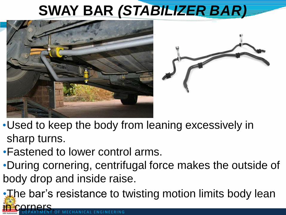
D E P A R T M E N T O F M E C H A N I C A L E N G I N E E R I N G
SWAY BAR (STABILIZER BAR)
•Used to keep the body from leaning excessively in
sharp turns.
•Fastened to lower control arms.
•During cornering, centrifugal force makes the outside of
body drop and inside raise.
•The bar’s resistance to twisting motion limits body lean
in corners.
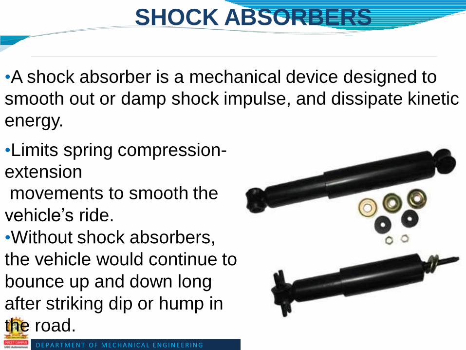
D E P A R T M E N T O F M E C H A N I C A L E N G I N E E R I N G
SHOCK ABSORBERS
•A shock absorber is a mechanical device designed to
smooth out or damp shock impulse, and dissipate kinetic
energy.
•Limits spring compression-
extensionmovements to smooth the
vehicle’s ride.
•Without shock absorbers,
the vehicle would continue to
bounce up and down long
after striking dip or hump in
the road.

D E P A R T M E N T O F M E C H A N I C A L E N G I N E E R I N G
STRUT ASSEMBLY (MACPHERSON STRUTS)

D E P A R T M E N T O F M E C H A N I C A L E N G I N E E R I N G
•Its is a independent suspension system
•Consists of a shock absorber, a coil spring, and an
upper damper unit.
•Strut assembly often replaces the upper control arm.
•The steering gear is either connected directly to the
lower shock absorber housing, or to an arm from the
front or back of the spindle.
•When you steer, it physically twists the strut and shock
absorber housing (and consequently the spring) to turn
the wheel.

D E P A R T M E N T O F M E C H A N I C A L E N G I N E E R I N G
Advantages:-
L o w productioncosts
Stamped construction
Preassembled
Strut body carries spring assembly
Compact
Simple mounting and no need for an upper
control arm
Simplicity
Reduction in fasteners and alignment of
vehicle suspension components.

D E P A R T M E N T O F M E C H A N I C A L E N G I N E E R I N G
• Suspension is a type of vehicle suspension powered by an
electric or engine driven air pump
• or compressor. This compressor pumps the air into a flexible
bellows, usually made from textile-reinforced rubber. This in turn
inflates
the bellows, and raises the
chassis from the axle.
Pneumatic Spring On
Semitrailer
AIR SUSPENSION

D E P A R T M E N T O F M E C H A N I C A L E N G I N E E R I N G
•These maintain a constant frequency of vibration
whether the vehicle is laden or unladen.
•Constant frame height is maintained.•It helps to reduce the load while the vehicle in motion
i.e. the dynamic loading as the spring rate variation
between laden and unladen weight is much less.
•It gives smooth and comfort ride of the vehicle.
•The stiffness of the system increases with the increase
of the deflection.
ADVANTAGES

D E P A R T M E N T O F M E C H A N I C A L E N G I N E E R I N G
• Air bag or air strut failure
-due to old age, or moisture within the air system that
damages them from the inside.
• Compressor failure
- Primarily due to leaking air springs or air struts
•
- Compressor burnout may also be caused by
moisture from within the air system coming into contact
with its electronic parts.
Dryer failure
- which functions to remove moisture from the air
system eventually becomes saturated and unable to
COMMON AIR SUSPENSION PROBLEMS

D E P A R T M E N T O F M E C H A N I C A L E N G I N E E R I N G
TRAVERSE SUSPENSION
SYSTEM

D E P A R T M E N T O F M E C H A N I C A L E N G I N E E R I N G
Normally find on the rear suspension
Combines independent double wishbone suspension with a leaf spring.
It involves one leaf spring mounted across the vehicle, connected at each end to the lower wishbone.
T h e centre of the spring is connected tothe front subframe in the middle of the car.
There are still two shock absorbers, mounted one to each side on the lower wishbones.

D E P A R T M E N T O F M E C H A N I C A L E N G I N E E R I N G
CHECKING SHOCK ABSORBER
CONDITION
Bounce test:-
•Push down on one corner of
vehicle’s body.
•Release the body and count
the number of
times the vehicle rebounds.
•Good – no more then two
rebounds.
Leaking Shocks:-
•Check for signs of leakage.
•If oily and wet, replace it.

D E P A R T M E N T O F M E C H A N I C A L E N G I N E E R I N G
CHECKING BALL JOINTS
•If spring on lower control arm, jack stand goes
under the control arm.
•If spring on upper control arm, jack stand goes
under frame.
If any play found,
replace it.

D E P A R T M E N T O F M E C H A N I C A L E N G I N E E R I N G
TIE ROD INSPECTION
Move the wheel side-to-side, should be no play.

D E P A R T M E N T O F M E C H A N I C A L E N G I N E E R I N G
STEERING SYSTEM
• A vehicle is not much use if it cannot be steered or guided. The act of guiding the vehicle is called steering
• Wheeled vehicles are steered by aiming or pointing the wheels in the direction we want the vehicle to go.The driver of a car or truck guides it by turning the steering wheel.

D E P A R T M E N T O F M E C H A N I C A L E N G I N E E R I N G
STEERING SYSTEM
•The function of a steering system is to convert the rotary movement of the steering wheel in driver's hand into the angular turn of the front wheels on road.•Additionally, the steering system should provide mechanical advantage over front wheel steering knuckles, offering driver an easy turning of front wheels with minimum effort in any desired direction.

D E P A R T M E N T O F M E C H A N I C A L E N G I N E E R I N G
•
•
The steering system of cars and trucks consists of levers, links, rods, and a gearbox and sometimes a hydraulic system that assists the driver's steering
effort.
The steering system is of critical importance in the safe operation of the vehicle. There must be no looseness between the steering wheel and the front wheels if the driver is to keep control over the direction the wheels point. The tires must meet the road at the correct angle to get good traction and to prevent unnecessary tire wear. Also, the driver should be able to hold the wheels in the straight ahead position and change them to the right or left with very little effort.

D E P A R T M E N T O F M E C H A N I C A L E N G I N E E R I N G
STEERING LAYOUT
• The following are commonly used layouts
• Swinging beam steering
• Fixed beam steering
• Ackermann steering principle

D E P A R T M E N T O F M E C H A N I C A L E N G I N E E R I N G
SWINGING BEAM STEERING
• In this layout the front axle is mounted onto the vehicle by means of a central turntable which allows the whole axle to pivot
• As each of the steered wheels is at right angles to the centre of the turn, the vehicle can follow a curved pathway. This gives true rolling motion in which the wheels has minimal resistance.

D E P A R T M E N T O F M E C H A N I C A L E N G I N E E R I N G
SWINGING BEAM STEERING
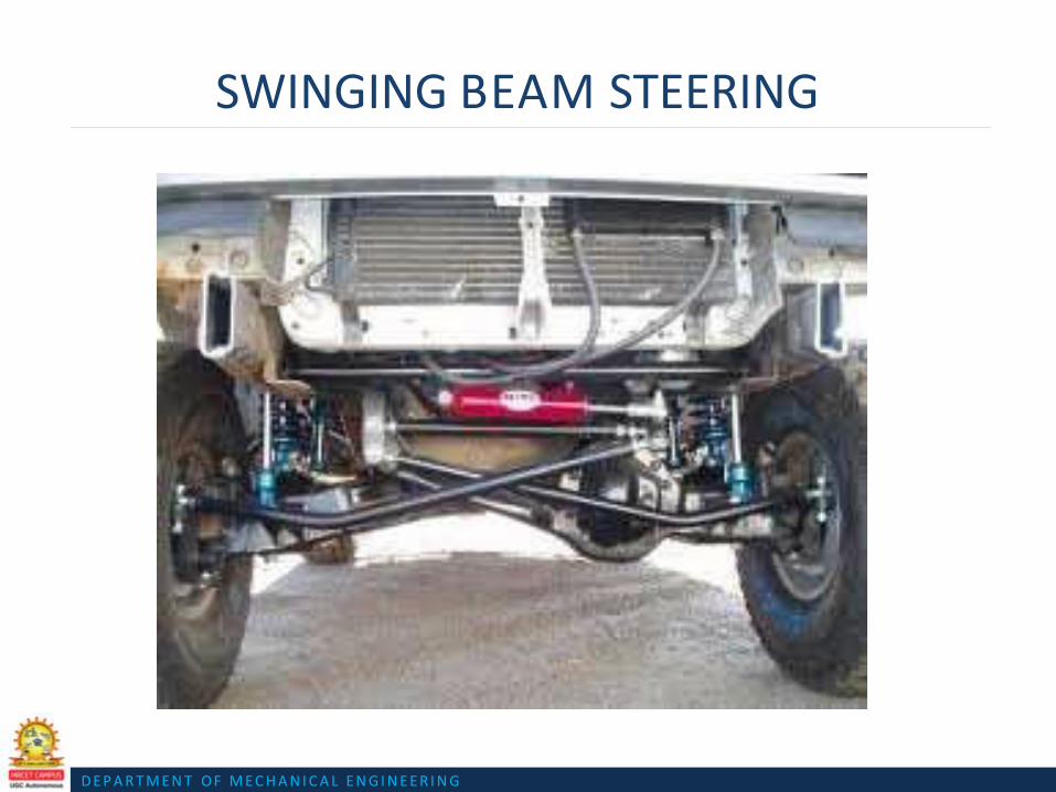
D E P A R T M E N T O F M E C H A N I C A L E N G I N E E R I N G
SWINGING BEAM STEERING

D E P A R T M E N T O F M E C H A N I C A L E N G I N E E R I N G
FIXED BEAM STEERING
• In fixed beam steering the front axle is unable to turn. Instead the wheels are mounted on pivoting sub axles, mounted on each end of the axle beam.
• This method is the basis of all steering systems. Vehicles with independent suspension have their stub axles mounted in the same relative positions.

D E P A R T M E N T O F M E C H A N I C A L E N G I N E E R I N G
FIXED BEAM STEERING

D E P A R T M E N T O F M E C H A N I C A L E N G I N E E R I N G
ACKERMAN STEERING PRINCIPLE
• To ensure that the front steered wheels rotate around a common centre the inner and outer roadwheels must be moved by differnt amounts. This achieved by setting the steering arms at an angle so that their projected centrelines meet on or near the centre of the rear axle.

D E P A R T M E N T O F M E C H A N I C A L E N G I N E E R I N G
ACKERMAN STEERING PRINCIPLE

D E P A R T M E N T O F M E C H A N I C A L E N G I N E E R I N G
ACKERMAN STEERING PRINCIPLE

D E P A R T M E N T O F M E C H A N I C A L E N G I N E E R I N G
ACKERMAN STEERING PRINCIPLE
• The intention of Ackermann geometry is to avoid the need for tyres to slip sideways when following the path around a curve.[2] The geometrical solution to this is for all wheels to have their axles arranged as radii of a circle with a common centre point. As the rear wheels are fixed, this centre point must be on a line extended from the rear axle. Intersecting the axes of the front wheels on this line as well requires that the inside front wheel is turned, when steering, through a greater angle than the outside wheel

D E P A R T M E N T O F M E C H A N I C A L E N G I N E E R I N G
ACKERMAN STEERING PRINCIPLE
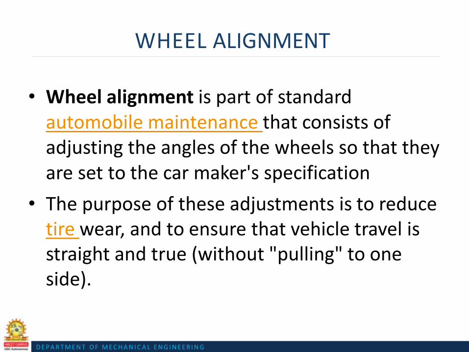
D E P A R T M E N T O F M E C H A N I C A L E N G I N E E R I N G
WHEEL ALIGNMENT
• Wheel alignment is part of standard automobile maintenance that consists of adjusting the angles of the wheels so that they are set to the car maker's specification
• The purpose of these adjustments is to reduce tire wear, and to ensure that vehicle travel is straight and true (without "pulling" to one side).

D E P A R T M E N T O F M E C H A N I C A L E N G I N E E R I N G
WHEEL ALIGNMENT
• Alignment angles can also be altered beyond the maker's specifications to obtain a specific handling characteristic. Motorsport and off-road applications may call for angles to be adjusted well beyond "normal" for a variety of reasons

D E P A R T M E N T O F M E C H A N I C A L E N G I N E E R I N G
WHEEL ALIGNMENT

D E P A R T M E N T O F M E C H A N I C A L E N G I N E E R I N G
WHEEL ALIGNMENT

D E P A R T M E N T O F M E C H A N I C A L E N G I N E E R I N G
WHEEL ALIGNMENT

D E P A R T M E N T O F M E C H A N I C A L E N G I N E E R I N G
STEERING ANGLES
• The steering geometry of a vehicle is purposely designed with certain steering angles these have an important effect on how the vehicle steers and handles
1.Caster angle
2.Camber angle
3.Kingpin inclination(KPI)

D E P A R T M E N T O F M E C H A N I C A L E N G I N E E R I N G
CASTER ANGLE
• Caster angle or castor angleis the angular displacement from the vertical axis of the suspension of a steered wheel in a car, bicycle or other vehicle, measured in the longitudinal direction. It is the angle between the pivot line (in a car - an imaginary line that runs through the center of the upper ball joint to the center of the lower ball joint) and vertical. Car racers sometimes adjust caster angle to optimize their car's handling characteristics in particular driving situations

D E P A R T M E N T O F M E C H A N I C A L E N G I N E E R I N G
CASTER ANGLE

D E P A R T M E N T O F M E C H A N I C A L E N G I N E E R I N G
CASTER ANGLE
• When an automotive vehicle's front suspension is aligned, caster is adjusted to achieve the self-centering action of steering, which affects the vehicle's straight-line stability. Improper caster settings will cause the driver to move the steering wheel both into and out of each turn, making it difficult to maintain a straight line.
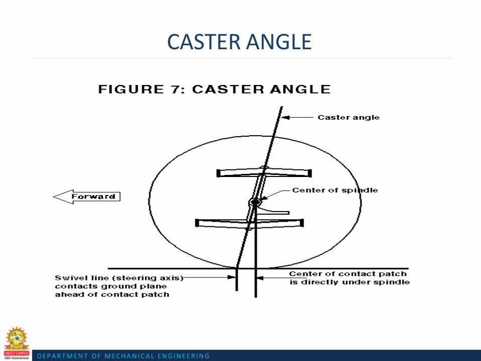
D E P A R T M E N T O F M E C H A N I C A L E N G I N E E R I N G
CASTER ANGLE

D E P A R T M E N T O F M E C H A N I C A L E N G I N E E R I N G
CAMBER ANGLE
•
•
• Camber angle is the angle made by the wheels of
a vehicle; specifically, it is the angle between
the vertical axis of the wheels used for steering
and the vertical axis of the vehicle when viewed from the front or rear.
• It is used in the design of steering and
suspension. If the top of the wheel is farther out
than the bottom (that is, away from the axle), it is called positive camber; if the bottom of the
wheel is farther out than the top, it is called negative camber
D E P A R T M E N T O F M E C H A N I C A L E N G I N E E R I N G
CAMBER ANGLE

D E P A R T M E N T O F M E C H A N I C A L E N G I N E E R I N G
CAMBER ANGLE
• Camber angle alters the handling qualities of a particular suspension design; in particular, negative camber improves grip when cornering. This is because it places the tire at a more optimal angle to the road, transmitting the forces through the vertical plane of the tire, rather than through a shear force across it. Another reason for negative camber is that a rubber tire tends to roll on itself while cornering. If the tire had zero camber, the inside edge of the contact patch would begin to lift off of the ground, thereby reducing the area of the contact patch. By applying negative camber, this effect is reduced, thereby maximizing the contact patch area. Note that this is only true for the outside tire during the turn; the inside tire would benefit most from positive camber.

D E P A R T M E N T O F M E C H A N I C A L E N G I N E E R I N G
CAMBER ANGLE

D E P A R T M E N T O F M E C H A N I C A L E N G I N E E R I N G
CAMBER ANGLE

D E P A R T M E N T O F M E C H A N I C A L E N G I N E E R I N G
CAMBER ANGLE

D E P A R T M E N T O F M E C H A N I C A L E N G I N E E R I N G
KINGPIN INCLINATION
•
•
• The kingpin, also king-pin and king pin,[ is the
main pivot in the steering mechanism of a car or
other vehicle. Originally this was literally a steel
pin on which the moveable, steerable wheel was
mounted to the suspension.
• On most modern designs, the kingpin is set at
an angle relative to the true vertical line, as
viewed from the front or back of the vehicle.
This is the kingpin inclination or KPI (also
called steering axis inclination, or SAI).

D E P A R T M E N T O F M E C H A N I C A L E N G I N E E R I N G
KINGPIN INCLINATION
• KPI is the angle at which the centrline of the kingpin or the axis of the steering swivels leans inwards from the vertical.

D E P A R T M E N T O F M E C H A N I C A L E N G I N E E R I N G
KINGPIN INCLINATION

D E P A R T M E N T O F M E C H A N I C A L E N G I N E E R I N G
KINGPIN INCLINATION

D E P A R T M E N T O F M E C H A N I C A L E N G I N E E R I N G
KINGPIN INCLINATION
D E P A R T M E N T O F M E C H A N I C A L E N G I N E E R I N G
STEERING GEAR
• The purpose of steering gear is to enable the driver to alter the vehicles steered direction with a minimum of effort. Three of the most common types in use are
1.Worm and peg
2.Recirculating ball
3.Rack and pinion

D E P A R T M E N T O F M E C H A N I C A L E N G I N E E R I N G
STEERING GEAR
• Worm and peg steering
• A worm drive is a gear arrangement in which a worm (which is a gear in the form of a screw
) meshes with a worm gear (which is similar in appearance to a spur gear, and is also called a worm wheel). The terminology is often confused by imprecise use of the term worm gear to refer to the worm, the worm gear, or the worm drive as a unit.

D E P A R T M E N T O F M E C H A N I C A L E N G I N E E R I N G
WORM AND PEG STEERING

D E P A R T M E N T O F M E C H A N I C A L E N G I N E E R I N G
WORM AND PEG
STEERING• With with this type of steering mechanism the
lower part of the steering column shaft is machined with a worm-type screw thread, which meshes with a peg protuding from the arm of the cross-shaft
• When the steering wheel is rotated, worm moves the peg along , and the arm transfered to a steering drop arm and linkage to move the roadwheels.

D E P A R T M E N T O F M E C H A N I C A L E N G I N E E R I N G
STEERING GEAR

D E P A R T M E N T O F M E C H A N I C A L E N G I N E E R I N G
RECIRCULATING BALL STEERING
• The recirculating ball steering mechanism contains a worm gear inside a block with a threaded hole in it; this block has gear teeth cut into the outside to engage the sector shaft (also called a sector gear) which moves the Pitman arm. The steering wheel connects to a shaft, which rotates the worm gear inside of the block. Instead of twisting further into the block, the worm gear is fixed so that when it spins, it moves the block, which transmits the motion through the gear to the pitman arm, causing the roadwheels to turn.

D E P A R T M E N T O F M E C H A N I C A L E N G I N E E R I N G
RECIRCULATING BALL STEERING

D E P A R T M E N T O F M E C H A N I C A L E N G I N E E R I N G
RECIRCULATING BALL STEERING

D E P A R T M E N T O F M E C H A N I C A L E N G I N E E R I N G
RECIRCULATING BALL STEERING
• The recirculating-ball steering gear contains aworm gear. You can image the gear in two parts. Thefirst part is a block of metal with a threaded hole in it. This block has gear teeth cut into the outside of it, which engage a gear that moves the pitman arm (see diagram above). The steering wheel connects to a threaded rod, similar to a bolt, that sticks into the hole in the block. When the steering wheel turns, it turns the bolt. Instead of twisting further into the block the way a regular bolt would, this bolt is held fixed so that when it spins, it moves the block, which moves the gear that turns the wheels.

D E P A R T M E N T O F M E C H A N I C A L E N G I N E E R I N G
RECIRCULATING BALL STEERING
D E P A R T M E N T O F M E C H A N I C A L E N G I N E E R I N G
STEERING GEAR

D E P A R T M E N T O F M E C H A N I C A L E N G I N E E R I N G
POWER STEERING
• Power steering, assists the driver of an automobile in steering by directing a portion of the vehicle's power to traverse the axis of one or more of the roadwheels. As vehicles have become heavier and switched tofront wheel drive, particularly using negativeoffset geometry, along with increases in tire width and diameter, the effort needed to turn the steering wheel manually has increased —often to the point where major physical exertion is required.

D E P A R T M E N T O F M E C H A N I C A L E N G I N E E R I N G
POWER STEERING
• To alleviate this, auto makers have developed power steering systems: or more correctly power-assisted steering — on road going vehicles there has to be a mechanical linkage as a fail safe. There are two types of power steering systems—hydraulic and electric/electronic. A hydraulic-electric hybrid system is also possible.

D E P A R T M E N T O F M E C H A N I C A L E N G I N E E R I N G
POWER STEERING
• A hydraulic power steering (HPS) uses hydraulic pressure supplied by an engine-driven pump to assist the motion of turning the steering wheel.Electric power steering (EPS) is more efficient thanthe hydraulic power steering, since the electric power steering motor only needs to provide assistance when the steering wheel is turned, whereas the hydraulic pump must run constantly. In EPS, the assist level is easily tunable to the vehicle type, road speed, and even driver preference.

D E P A R T M E N T O F M E C H A N I C A L E N G I N E E R I N G
POWER STEERING
• There are a couple of key components in power steering in addition to the rack-and-pinion or recirculating-ball mechanism
• PumpThe hydraulic power for the steering is provided by a rotary-vane pump (see diagram below). This pump is driven by the car's engine via a belt and pulley. It contains a set of retractable vanes that spin inside an oval chamber.

D E P A R T M E N T O F M E C H A N I C A L E N G I N E E R I N G
POWER STEERING

D E P A R T M E N T O F M E C H A N I C A L E N G I N E E R I N G
POWER STEERING
• Rotary ValveA power-steering system should assist the driver only when he is exerting force on the steering wheel (such as when starting a turn). When the driver is not exerting force (such as when driving in a straight line), the system shouldn't provide any assist. The device that senses the force on the steering wheel is called the rotary valve.

D E P A R T M E N T O F M E C H A N I C A L E N G I N E E R I N G
POWER STEERING
• The key to the rotary valve is a torsion bar. The torsion bar is a thin rod of metal that twists when torque is applied to it. The top of the bar is connected to the steering wheel, and the bottom of the bar is connected to the pinion or worm gear (which turns the wheels), so the amount of torque in the torsion bar is equal to the amount of torque the driver is using to turn the wheels. The more torque the driver uses to turn the wheels, the more the bar twists.

D E P A R T M E N T O F M E C H A N I C A L E N G I N E E R I N G
POWER STEERING

D E P A R T M E N T O F M E C H A N I C A L E N G I N E E R I N G
POWER STEERING

D E P A R T M E N T O F M E C H A N I C A L E N G I N E E R I N G
STEERING LINKAGE
•
•
•
The steering linkage is a combination of rods, andarms, that transmit the movement of the steeringgear to the front wheels.
It must transmit this movement to the front wheels, while still allowing for any up-and down movement they may make, while the vehicle is in motion.
The type of steering mechanism, and the number of linkages, depends on the type of steering box, its location, and the type of suspension on the vehicle.

D E P A R T M E N T O F M E C H A N I C A L E N G I N E E R I N G
STEERING LINKAGE

D E P A R T M E N T O F M E C H A N I C A L E N G I N E E R I N G
STEERING LINKAGE

D E P A R T M E N T O F M E C H A N I C A L E N G I N E E R I N G
BRAKE
• A brake is a
mechanical device
which inhibits motion.

D E P A R T M E N T O F M E C H A N I C A L E N G I N E E R I N G
WORKING OF BRAKES
• A COMMON MISCONCEPTION ABOUT BRAKES IS THAT BRAKES
SQUEEZE AGAINST A DRUM OR DISC, AND THE PRESSURE OF THE
SQUEEZING ACTION SLOWS THE VEHICLE DOWN. THIS IS IN FACT A
PART OF THE REASON FOR SLOWING DOWN A VEHICLE.
• ACTUALLY BRAKES USE FRICTION OF BRAKE SHOES AND DRUMS TO
CONVERT KINETIC ENERGY DEVELOPED BY THE VEHICLE INTO HEAT
ENERGY.
• WHEN WE APPLY BRAKES, THE PADS OR SHOES THAT PRESS AGAINST
THE BRAKE DRUMS OR ROTOR CONVERT KINETIC ENERGY INTO
THERMAL ENERGY VIA FRICTION.
THTHUS BRAKES ARE
ESSENTIALLY A MECHANISM
TO CHANGE ENERGY TYPES
D E P A R T M E N T O F M E C H A N I C A L E N G I N E E R I N G
TYPES OF BRAKES
1. MECHANICAL BRAKES• DRUM BRAKES
• DISC BRAKES
2. HYDRAULIC BRAKES
3. POWER BRAKES• AIR BRAKES
• AIR HYDRAULIC BRAKES
• VACCUM BRAKES
• ELECTRIC BRAKES

D E P A R T M E N T O F M E C H A N I C A L E N G I N E E R I N G
BRAKE SYSTEM COMPONENTS

D E P A R T M E N T O F M E C H A N I C A L E N G I N E E R I N G
HYDRAULIC BRAKES
• Hydraulics is the use of a liquid
under pressure to transfer force or
motion, or to increase an applied
force.
• The pressure on a liquid is
called HYRAULIC PRESSURE.
• And the brakes which are
operated by means of hydraulic
pressure are called HYDRAULIC
BRAKES.
• These brakes are based on
the principle of Pascal’s law.

D E P A R T M E N T O F M E C H A N I C A L E N G I N E E R I N G
PASCAL’S LAW
• The pressure exerted
anywhere in a mass of
confined liquid is
transmitted
undiminished in all
directions throughout
the liquid.
• Applied in
hydraulic lifts,
hydraulic brakes
etc.

D E P A R T M E N T O F M E C H A N I C A L E N G I N E E R I N G
MASTER CYLINDER IN ACTION
When we press the brake pedal, it pushes on primary
piston through a linkage.
Pressure is built in the cylinder and the lines as the brake pedal is depressedfurther.
The pressure between the primary and secondary piston forces the secondary piston to compress the fluid in its circuit.
If the brakes are operating properly, the pressure wll be same in both the circuits.
If there is a leak in one of the circuits, that circuit will not be able to maintainpressure.

D E P A R T M E N T O F M E C H A N I C A L E N G I N E E R I N G
MASTER CYLINDER

D E P A R T M E N T O F M E C H A N I C A L E N G I N E E R I N G
USE OF LIQUIDS INSTEAD OF
GASES
Liquids are used in hydraulic systems because liquids are incompressible.
If we use a gas, on increasing the pressure, the gas will be compressed into a smaller volume due to which there will be no transmission of force ormotion.

D E P A R T M E N T O F M E C H A N I C A L E N G I N E E R I N G
ADVANTAGES OF HYDRAULIC BRAKES
Equal braking effort to all the fourwheels
Less rate of wear (due to absence of joints compared to mechanical brakes)
Force multiplication (or divisions) very easily just by changing the size of one piston and cylinder relative to other.
D E P A R T M E N T O F M E C H A N I C A L E N G I N E E R I N G
DISADVANTAGES OF HYDRAULIC
BRAKES
Even slight leakage of air into the
breaking system makes it useless.
The brake shoes are liable to get
ruined if the brake fluid leaks out.

D E P A R T M E N T O F M E C H A N I C A L E N G I N E E R I N G
DISC BRAKES In a disc brake, the
fluid from the master
cylinder is forced into a
caliper where it presses
against a piston.
The piston in turn
squeezes two brake
pads against the disc
(rotor), which is attached
to wheel, forcing it to
slow down or stop.

D E P A R T M E N T O F M E C H A N I C A L E N G I N E E R I N G
DISC BRAKE AND BRAKE OF A
BICYCLE
Similar to a bicycle brake where two rubber pads run against the wheel rim creatingfriction.
But in a disc brake, the brake pads squeeze the rotor instead of the wheel, and the force
is transmitted hydraulically instead of through a cable.

D E P A R T M E N T O F M E C H A N I C A L E N G I N E E R I N G
DRUM BRAKES
The drum brake has a metal brake drum that encloses the brake assembly at each wheel.
Two curved brake shoes expand outward to slow or stop the drum which rotates with the wheel.

D E P A R T M E N T O F M E C H A N I C A L E N G I N E E R I N G
WORKING OF DRUM BRAKES
Drum brakes work on the same principle as the disc brakes.
Shoes press against a rotatingsurface.
In this system that surface is called a
drum.
Drum brake also has an adjuster mechanism, an
emergency brake mechanism and lots of springs.
The shoes are pulled away from the drum by the springs when the brakes are released.

D E P A R T M E N T O F M E C H A N I C A L E N G I N E E R I N G
DRUM BRAKE ADJUSTER
For the drum brakes to function
correctly, the brake shoes must
remain close to drum without
touching it.
If they get too far away from the
drum (as the shoes wear down),
the piston will require more fluid to
travel that distance and the brake
pedal will sink closer to the floor
when we apply brakes.
That is why most drum brakes have
an automatic adjuster.

D E P A R T M E N T O F M E C H A N I C A L E N G I N E E R I N G
DISK BRAKE AND DRUM BRAKE
D E P A R T M E N T O F M E C H A N I C A L E N G I N E E R I N G
SOME MORE POINTS
• Most modern cars have disc brakes on front wheels and drum brakes
on rear wheels and some wheels have disc brakes on all four wheels.
• To increase safety, most modern car brake systems are broken into
two circuits, with two wheels on each circuit.
• If a fluid leak occurs in one circuit, only two of the wheels will loose their
brakes and the car will still be able to stop when we press the break pedal.

D E P A R T M E N T O F M E C H A N I C A L E N G I N E E R I N G
EMERGENCY BRAKES
• In cars with disc brakes on all four wheels, an emergency brake has to be actuated by a separate mechanism than the primary brakes in case of a total primary break failure.
• Most cars use a cable to actuate the emergency brake.
• Some cars with four wheel disc breaks have a separate drum brake integrated into the hub of the rear wheels.
• This drum brake is only for emergency break system, an is actuated only by the cable. It has no hydraulics.

D E P A R T M E N T O F M E C H A N I C A L E N G I N E E R I N G
BRAKE FLUIDS
• One of the important characteristics of brake fluid is its BOILING POINT. Hydraulic systems rely on incompressible fluid to transmit force.
• Liquids are generally incompressible while
gases are compressible.
• If the break fluid boils (becomes a gas), it will loose most of its ability to transmit force.
• This may partially or completely disable he brakes.

Question Bank for Assignment

Question bank for Assignment
UNIT-IV
1. Define camber, castor, king pin rake angles and their significance in steering geometry.
2. With the help of a schematic diagram, explain Ackerman steering mechanism.
3. Explain the functioning of independent front wheel suspension system with torsion bar in a
automobile.
4. Explain with a suitable schematic diagram, working of hydraulic braking system in a vehicle.
5. What is ABS and how does ABS helps in improving uncontrolled skidding?
6. Explain the functioning of rigid axle suspension system with a neat sketch.
7. Briefly discuss the functional requirements of braking fluids.

DEPARTMENT OF MECHANICAL ENGINEERING
UNIT V
ALTERNATIVE ENERGY SOURCES

DEPARTMENT OF MECHANICAL ENGINEERING
Course Objectives:
Student should able to understand the basic operations of different vehicles
Course Outcomes:
Student should able to apply the knowledge of Electric vehicles, Hybrid vehicles
and solar vehicles.

DEPARTMENT OF MECHANICAL ENGINEERING
5.1.Natural Gas as a Fuel in Automobile;
A natural gas vehicle (NGV) is an alternative fuel vehicle that uses compressed
natural gas (CNG) or liquefied natural gas (LNG) as a cleaner alternative to other
fossil fuels. Natural gas vehicles should not be confused with vehicles powered
by propane(LPG), which is a fuel with a fundamentally different composition.
Worldwide, there were 14.8 million natural gas vehicles by 2011, led by Iran
with 2.86 million, Pakistan (2.85 million), Argentina (2.07 million), Brazil (1.70
million), and India (1.10 million).
The Asia-Pacific region leads the world with 6.8 million NGVs, followed by
Latin America with 4.2 million vehicles. In the Latin American region almost
90% of NGVs have bi-fuel engines, allowing these vehicles to run on either
gasoline or CNG. In Pakistan, almost every vehicle converted to (or
manufactured for) alternative fuel use typically retains the capability to run on
ordinary gasoline.
As of 2009, the U.S. had a fleet of 114,270 compressed natural gas (CNG)
vehicles, mostly buses; 147,030 vehicles running on liquefied petroleum gas
(LPG); and 3,176 vehicles liquefied natural gas (LNG). Other countries where
natural gas-powered buses are popular include India, Australia, Argentina, and
Germany. In OECD countries there are around 500,000 CNG vehicles. Pakistan's
market share of NGVs was 61.1% in 2010, follow by Armenia with 32%, and
Bolivia with 20%.The number of NGV refueling stations has also increased, to
18,202 worldwide as of 2010, up 10.2% from the previous year.
Existing gasoline-powered vehicles may be converted to run on CNG or LNG,
and can be dedicated (running only on natural gas) or bi-fuel (running on either
gasoline or natural gas. Diesel engines for heavy trucks and busses can also be
converted and can be dedicated with the addition of new heads containing spark

DEPARTMENT OF MECHANICAL ENGINEERING
ignition systems, or can be run on a blend of diesel and natural gas, with the
primary fuel being natural gas and a small amount of diesel fuel being used as an
ignition source.
An increasing number of vehicles worldwide are being manufactured to run on
CNG. Until recently, theHonda Civic GX was the only NGV commercially
available in the US market., however now Ford, GM and Ram have bi-fuel
offerings in their vehicle lineup. Fords approach is to offer a bi-fuel prep kit as a
factory option, and then have the customer choose an authorized partner to install
the natural gas equipment.
In 2006 the Brazilian subsidiary of FIAT introduced the Fiat Siena Tetra fuel, a
four-fuel car developed under Magneti Marelli of Fiat Brazil. This automobile
can run on natural gas (CNG); 100% ethanol (E100); E20 to E25 gasoline blend,
Brazil's mandatory gasoline; and pure gasoline, though no longer available in
Brazil it is used in neighboring countries.
NGV filling stations can be located anywhere that natural gas lines exist.
Compressors (CNG) or liquifaction plants (LNG) are usually built on large scale
but with CNG small home refueling stations are possible. A company called
FuelMaker pioneered such a system called Phill Home Refueling Appliance
(known as "Phill"), which they developed in partnership with Honda for the
American GX model. Phill is now manufactured and sold by BRC FuelMaker, a
division of Fuel Systems Solutions, Inc.
CNG may also be mixed with biogas, produced from landfills or wastewater,
which doesn't increase the concentration of carbon in the atmosphere. Despite its
advantages, the use of natural gas vehicles faces several limitations, including
fuel storage and infrastructure available for delivery and distribution at fueling
stations. CNG must be stored in high pressure cylinders (3000psi to 3600psi
operation pressure), and LNG must be stored in cryogenic cylinders (-260F to -

DEPARTMENT OF MECHANICAL ENGINEERING
200F).
These cylinders take up more space than gasoline or diesel tanks that can be
molded in intricate shapes to store more fuel and use less on-vehicle space. CNG
tanks are usually located in the vehicle's trunk or pickup bed, reducing the space
available for other cargo. This problem can be solved by installing the tanks
under the body of the vehicle, or on the roof (typical for busses), leaving cargo
areas free.
As with other alternative fuels, other barriers for widespread use of NGVs are
natural gas distribution to and at fueling stations as well as the low number of
CNG and LNG stations. CNG- powered vehicles are considered to be safer than
gasoline-powered vehicles
5.2.Liquefied petroleum gas as a Fuel in Automobile;
Liquefied petroleum gas or liquid petroleum gas (LPG or LP gas), also referred
to as simply propane or butane, is a flammable mixture of hydrocarbon gases
used as a fuel in heating appliances, cooking equipment, and vehicles. It is
increasingly used as an aerosol propellant and a refrigerant, replacing
chlorofluorocarbons in an effort to reduce damage to the ozone layer. When
specifically used as a vehicle fuel it is often referred to as auto gas.
Varieties of LPG bought and sold include mixes that are primarily propane (C
3H8),primarily butane (C4H10) and, most commonly, mixes including both
propane andbutane. In winter, the mixes contain more propane, while in summer,
they contain more butane. In the United States, primarily two grades of LPG are
sold: commercial propane and HD-5. These specifications are published by the
Gas Processors Association (GPA) and the American Society of Testing and
Materials (ASTM). Propane/butane blends are also listed in these specifications.
Propylene, butylenes and various other hydrocarbons are usually also present in
small concentrations. HD-5 limits the amount of propylene that can be placed in

DEPARTMENT OF MECHANICAL ENGINEERING
LPG to 5%, and is utilized as an autogas specification. A powerful odorant,
ethanethiol, is added so that leaks can be detected easily. The international
standard is EN 589. In the United States, tetrahydrothiophene (thiophane) or
amyl mercaptan are also approved odorants,[5] although neither is currently
being utilized.
LPG is prepared by refining petroleum or "wet" natural gas, and is almost
entirely derived from fossil fuel sources, being manufactured during the refining
of petroleum (crude oil), or extracted from petroleum or natural gas streams as
they emerge from the ground. It was first produced in 1910 by Dr. Walter
Snelling, and the first commercial products appeared in 1912. It currently
provides about 3% of all energy consumed, and burns relatively cleanly with no
soot and very few sulfur emissions.
As it is a gas, it does not pose ground or water pollution hazards, but it can cause
air pollution. LPG has a typical specific calorific value of 46.1 MJ/kg compared
with 42.5 MJ/kg for fuel oil and 43.5 MJ/kg for premium grade petrol
(gasoline).[6] However, its energy density per volume unit of 26 MJ/L is lower
than either that of petrol or fuel oil, as its relative density is lower (about 0.5–
0.58, compared to 0.71–0.77 for gasoline).
As its boiling point is below room temperature, LPG will evaporate quickly at
normal temperatures and pressures and is usually supplied in pressurised steel
vessels. They are typically filled to 80–85% of their capacity to allow for thermal
expansion of the contained liquid. The ratio between the volumes of the
vaporized gas and the liquefied gas varies depending on composition, pressure,
and temperature, but is typically around 250:1.
The pressure at which LPG becomes liquid, called its vapour pressure, likewise
varies depending on composition and temperature; for example, it is
approximately 220 kilopascals (32 psi) for pure butane at 20 °C (68 °F), and

DEPARTMENT OF MECHANICAL ENGINEERING
approximately 2,200 kilopascals (320 psi) for pure propane at 55 °C (131 °F).
LPG is heavier than air, unlike natural gas, and thus will flow along floors and
tend to settle in low spots, such as basements. There are two main dangers from
this. The first is a possible explosion if the mixture of LPG and air is within the
explosive limits and there is an ignition source. The second is suffocation due to
LPG displacing air, causing a decrease in oxygen concentration.
Large amounts of LPG can be stored in bulk cylinders and can be buried
underground.
5.3.Bio diesel as a Fuel in Automobile;
Biodiesel and conventional diesel vehicles are one in the same. Although light-,
medium-, and heavy-duty diesel vehicles are not technically "alternative fuel"
vehicles, many are capable of running on biodiesel. Biodiesel, which is most
often used as a blend with regular diesel fuel, can be used in many diesel vehicles
without any engine modification. The most common biodiesel blend is B20,
which is 20% biodiesel and 80% conventional diesel. B5 (5% biodiesel, 95%
diesel) is also commonly used in fleets.
Before using biodiesel, be sure to check your engine warranty to ensure that
higher-level blends (all OEMs accept the use of B5 and many accept the use of
B20) of this alternative fuel don't void or affect it. High-level biodiesel blends
(blends over B20) can have a solvency effect in engines and fuel systems that
previously used petroleum diesel which may result in degraded seals and clogged
fuel filters.
Biodiesel improves fuel lubricity and raises the cetane number of the fuel. Diesel
engines depend on the lubricity of the fuel to keep moving parts from wearing
prematurely. Federal regulations have gradually reduced allowable fuel sulfur to
only 15 parts per million, which has often resulted in lowered aromatics content
in diesel fuel. One advantage of biodiesel is that it can impart adequate lubricity

DEPARTMENT OF MECHANICAL ENGINEERING
to diesel fuels at blend levels as low as 1%.
5.4.Hybrid electric vehicle ;
A hybrid electric vehicle (HEV) is a type of hybrid vehicle and electric
vehiclewhich combines a conventional internal combustion engine (ICE)
propulsion system with an electric propulsion system. The presence of the
electric powertrain is intended to achieve either better fuel economy than a
conventional vehicle or better performance. There are a variety of HEV types,
and the degree to which they function as EVs varies as well. The most common
form of HEV is the hybrid electric car, although hybrid electric trucks (pickups
and tractors) and buses also exist.
Modern HEVs make use of efficiency-improving technologies such as
regenerative braking, which converts the vehicle's kinetic energy into electric
energy to charge the battery, rather than wasting it as heat energy as conventional
brakes do. Some varieties of HEVs use their internal combustion engine to
generate electricity by spinning an electrical generator (this combination is
known as a motor-generator), to either recharge their batteries or to directly
power the electric drive motors
Many HEVs reduce idle emissions by shutting down the ICE at idle and
restarting it when needed; this is known as a start-stop system. A hybrid-electric
produces less emissions from its ICE than a comparably sized gasoline car, since
an HEV's gasoline engine is usually smaller than a comparably sized pure
gasoline-burning vehicle (natural gas and propane fuels produce lower emissions)
and if not used to directly drive the car, can be geared to run at maximum
efficiency, further improving fuel economy.
In 1901 Ferdinand Porsche developed the Lohner-Porsche Mixte Hybrid, the first
gasoline- electric hybrid automobile in the world. The hybrid-electric vehicle did
not become widely available until the release of the Toyota Prius in Japan in

DEPARTMENT OF MECHANICAL ENGINEERING
1997, followed by the Honda Insight in 1999. While initially perceived as
unnecessary due to the low cost of gasoline, worldwide increases in the price of
petroleum caused many automakers to release hybrids in the late 2000s; they are
now perceived as a core segment of the automotive market of the future.
About 9 million hybrid electric vehicles have been sold worldwide by October
2014, led by Toyota Motor Company (TMC) with more than 7 million Lexus and
Toyota hybrids sold as of September 2014, followed by Honda Motor Co., Ltd.
with cumulative global sales of more than 1.35 million hybrids as of June 2014,
Ford Motor Corporation with over 375 thousand hybrids sold in the United States
through September 2014, and the Hyundai Group with cumulative global sales of
200 thousand hybrids as of March 2014, including both Hyundai Motors and Kia
Motors hybrid models.
Worldwide sales of hybrid vehicles produced by TMC reached 1 million units in
May 2007; 2 million in August 2009; and passed the 5 million mark in March
2013. As of December 2013, worldwide hybrid sales are led by the Toyota Prius
lift back, with cumulative sales of 3.17 million units, and available in almost 80
countries and regions.
The Prius nameplate has sold 4.2 million hybrids and plug-in hybrids up to
December 2013. The United States is the world's largest hybrid market with over
3 million hybrid automobiles and SUVs sold through October 2013, followed by
Japan with more than 2.6 million hybrids sold through September 2013. The
Prius is the top selling hybrid car in the U.S. market, passing the 1 million
milestones in April 2011. Cumulative sales of the Prius in Japan reached the 1
million mark in August 2011.
5.5.Fuel Cell;
A Fuel Cell is an electrochemical device that combines hydrogen and oxygen to
produce electricity, with water and heat as its by-product. Since conversion of the

DEPARTMENT OF MECHANICAL ENGINEERING
fuel to energy takes place via an electrochemical process, not combustion. It is a
clean, quiet and highly efficient process- two to three times more efficient than
fuel burning.
It operates similarly to a battery, but it does not run down nor does it require
recharging As long as fuel is supplied, a Fuel Cell will produce both energy and
heat A Fuel Cell consists of two catalyst coated electrodes surrounding an
electrolyte. One electrode is an anode and the other is a cathode The process
begins when Hydrogen molecules enter the anode The catalyst coating separates
hydrogen’s negatively charged electrons from the positively charged protons The
electrolyte allows the protons to pass through to the cathode, but not the
electrons.
Instead the electrons are directed through an external circuit which creates
electrical current. While the electrons pass through the external circuit, oxygen
molecules pass through the cathode. There the oxygen and the protons combine
with the electrons after they have passed through the external circuit. When the
oxygen and the protons combine with the electrons it produces water and heat.
Individual fuel cells can then be placed in a series to form a fuel cell stack. The
stack can be used in a system to power a vehicle or to provide stationary power to
a building

Presentation Material

DEPARTMENT OF MECHANICAL ENGINEERING
A LT E R N AT I V E E N E R G Y S O U R C E S
UNIT-V
D E P A R T M E N T O F M E C H A N I C A L E N G I N E E R I N G
ALTERNATIVE ENERGY SOURCES
UNIT-V

D E P A R T M E N T O F M E C H A N I C A L E N G I N E E R I N G
The U.S. Department of Energy (DOE) defines an alternative fuel as a product that is substantially nonpetroleum which yields energy security and environmental benefits.

D E P A R T M E N T O F M E C H A N I C A L E N G I N E E R I N G
• The Energy Policy Act of 1993 (EPAct) DOE currently recognizes the following as alternative fuels:
• Mixtures containing 85% or more by volume of alcohol fuel, including methanol and denatured ethanol

D E P A R T M E N T O F M E C H A N I C A L E N G I N E E R I N G
•Natural gas (compressed or liquefied)
•Liquefied petroleum gas (propane)
•Hydrogen
•Coal-derived liquid fuels

D E P A R T M E N T O F M E C H A N I C A L E N G I N E E R I N G
•Fuels derived from biological
materials
•Electricity (including
electricity from solar energy)
•100% Biodiesel (B100)

D E P A R T M E N T O F M E C H A N I C A L E N G I N E E R I N G
Pure biodiesel (B100) is
considered an alternative fuel
under EPAct. Butlower-level
biodiesel blends are not
considered alternative fuels

D E P A R T M E N T O F M E C H A N I C A L E N G I N E E R I N G
WHAT ARE THE CHARACTERISTICS OF ALTERNATIVE FUELS?
Primary Main Liquid
Components Fuel or
Source Gas
Biodiesel Vegetable oil, Soybean oil Liquid
animal fats, or
recycled restaurant grease
Compressed Methane Under- Gas
Natural Gas ground
(CNG) reserves
Ethanol (E85) Denatured Corn, grains, or Liquid
ethanol and agricultural
gasoline waste
Liquefied Methane that Underground Liquid
Natural Gas is cooled reserves
(LNG) cryogenically
Liquefied Propane A by-product of Liquid
Petroleum petroleum
Gas (LPG) refining or
natural gas
processing
Methanol Methanol and Natural gas, Liquid
(M85) gasoline coal, or woody
biomass

D E P A R T M E N T O F M E C H A N I C A L E N G I N E E R I N G
ALTERNATIVE FUEL VEHICLES
Biodiesel(B20)
Compressed
Natural
Gas(CNG) Electricity Ethanol(E85)
Any vehicle that
runs on diesel today-
no modifications are
needed for up to 5%
blends. Many
engines also
compatible with up
to 20% blends.
Many types of
vehicle classes.
Neighborhood
electric vehicles,
bicycles, light-duty
vehicles, medium
and heavy-duty
trucks and buses.
Light-duty vehicles,
medium and heavy-
duty trucks and
buses - these vehicles
are flexible fuel
vehicles that can be
fueled with E85
(ethanol), gasoline,
or any combination
of the two fuels.

D E P A R T M E N T O F M E C H A N I C A L E N G I N E E R I N G
ALTERNATIVE FUEL VEHICLES
Hydrogen
Liquified Natural Gas
(LNG)
Liquified Petroleum
Gas (LPG)Methanol (M85)
No vehicles are
available for
commercial sale
yet, but some
vehicles are being
leased for
demonstration
purposes.
Medium and heavy-duty
trucks and buses.
Light-duty vehicles,
which can be fueled
with propane or
gasoline, medium and
heavy-duty trucks and
buses that run on
propane.
Mostly Heavy-
duty buses are
available.

D E P A R T M E N T O F M E C H A N I C A L E N G I N E E R I N G
Ethanol
Ethanol is an alcohol-based alternative
fuel produced by fermenting and
distilling starch crops that have been
converted into simple sugars.
Feedstocks for this fuel include corn,
barley, and wheat.

D E P A R T M E N T O F M E C H A N I C A L E N G I N E E R I N G
Ethanol can also be produced
from "cellulosic biomass"
such as trees and grasses
and is called bioethanol.
Ethanol is most commonly
used to increase octane and
improve the emissions quality
of gasoline.

D E P A R T M E N T O F M E C H A N I C A L E N G I N E E R I N G
Natural Gas
Natural gas is a mixture of hydrocarbons,
mainly methane, and is produced either from
gas wells or in conjunction with crude oil
production. Natural gas is consumed in the
residential, commercial, industrial, and utility
markets.
Natural gas can either be stored onboard a
vehicle as compressed natural gas (CNG) or as
liquefied natural gas (LNG). Natural gas can
also be blended with hydrogen.

D E P A R T M E N T O F M E C H A N I C A L E N G I N E E R I N G
Natural Gas
The future holds great potential for natural gas because it can
potentially be used in fuel cell vehicles to make hydrogen.
Researchers found that fuel cell vehicles using hydrogen
produced from natural gas could present an attractive solution for
cutting greenhouse gas emissions.
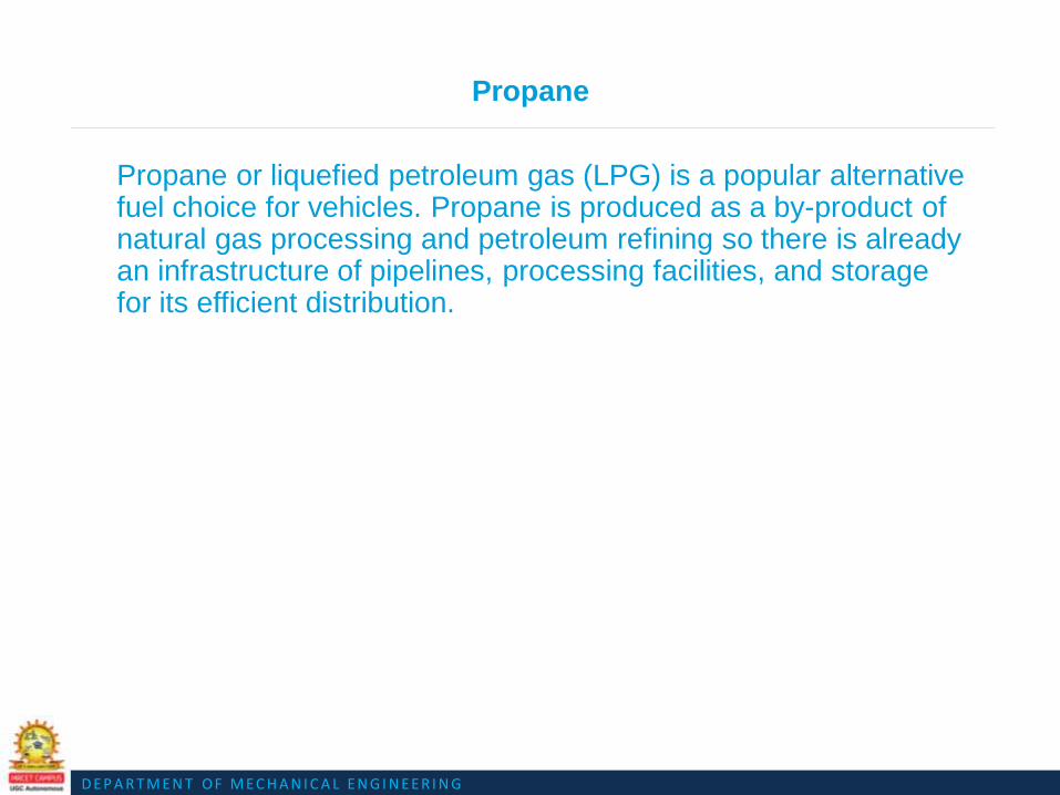
D E P A R T M E N T O F M E C H A N I C A L E N G I N E E R I N G
Propane
Propane or liquefied petroleum gas (LPG) is a popular alternative fuel choice for vehicles. Propane is produced as a by-product of natural gas processing and petroleum refining so there is already an infrastructure of pipelines, processing facilities, and storage for its efficient distribution.

D E P A R T M E N T O F M E C H A N I C A L E N G I N E E R I N G
HYDROGEN
The simplest and lightest fuel is hydrogen gas. Hydrogen may contain low levels of carbon monoxide and carbon dioxide, depending on the source.

D E P A R T M E N T O F M E C H A N I C A L E N G I N E E R I N G
Hydrogen
Hydrogen can be produced using diverse, domestic resources
including fossil fuels, such as natural gas and coal, nuclear; and
biomass and other renewable energy technologies, such as wind,
solar, geothermal, and hydro-electric power.

D E P A R T M E N T O F M E C H A N I C A L E N G I N E E R I N G
HYDROGEN
Hydrogen will play an important role in developing sustainable
transportation in the United States, because in the future it may be
produced in virtually unlimited quantities using renewable
resources.

D E P A R T M E N T O F M E C H A N I C A L E N G I N E E R I N G
HYDROGEN
Hydrogen is being explored for use in combustion engines and fuel cell electric vehicles. The energy density of hydrogen is very low under ambient conditions which presents greater transportation and storage hurdles than for liquid fuels. Storage systems are being developed to address these problems.
D E P A R T M E N T O F M E C H A N I C A L E N G I N E E R I N G
HCNG
DOE's Natural Gas Vehicle Technology is supporting a project to develop heavy-duty HCNG engines and transit buses. The HCNG (20% hydrogen / 80% CNG) engines demonstrated lower emissions than similar engines fueled by CNG alone. This blend provided no significant change in fuel efficiency.

D E P A R T M E N T O F M E C H A N I C A L E N G I N E E R I N G

D E P A R T M E N T O F M E C H A N I C A L E N G I N E E R I N G
ELECTRICITY
Trucks with a hybrid-
electric power train
combine a diesel engine
and electric motor to drive
the vehicle.

D E P A R T M E N T O F M E C H A N I C A L E N G I N E E R I N G
ELECTRICITY
Batteries capture and
store energy providing a
source of stored electric
power for the motor
during future
acceleration.

D E P A R T M E N T O F M E C H A N I C A L E N G I N E E R I N G
ELECTRICITY
All electrical charging of
the battery is provided by
the hybrid electric power
train, and no external
electrical infrastructure,
such as a power cord or
electrical outlet, is
needed.

D E P A R T M E N T O F M E C H A N I C A L E N G I N E E R I N G
ELECTRICITY
The balance between conventional and electric technology is an innovative method to improve environmental performance and decrease fuel use while eliminating the need for high electrical-demand infrastructure costs.

D E P A R T M E N T O F M E C H A N I C A L E N G I N E E R I N G
METHANOL
Methanol is produced from natural gas in production plants with 60% total energy efficiency. Methanol can be made with any renewable resource containing carbon such as seaweed, waste wood and garbage.

D E P A R T M E N T O F M E C H A N I C A L E N G I N E E R I N G
METHANOL
Methanol offers the greatest hope for early and broad introduction of fuel cells that will make Electric Vehicles practical within the next few years.

D E P A R T M E N T O F M E C H A N I C A L E N G I N E E R I N G
METHANOL
Whether reformed to provide hydrogen for conventional fuel cells or used directly in the latest liquid fed cells, methanol will overcome the greatest remaining obstacle to commercialization, by offering the only economical way to transport and store the hydrogen needed for fuel cells.

D E P A R T M E N T O F M E C H A N I C A L E N G I N E E R I N G
METHANOL
Methanol fuel cells
will greatly reduce
carbon dioxide
emissions for
vehicles and
virtually eliminate
smog and
particulate pollution.

D E P A R T M E N T O F M E C H A N I C A L E N G I N E E R I N G
BIODIESEL
Biodiesel contains no petroleum, but it can be blended at any level with petroleum diesel to create a biodiesel blend. It can be used in compression-ignition (diesel) engines with little or no modifications.

D E P A R T M E N T O F M E C H A N I C A L E N G I N E E R I N G
BIODIESEL
Biodiesel can be used as a pure fuel
or blended with petroleum in any
percentage. B20 (a blend of 20
percent by volume biodiesel with 80
percent by volume petroleum diesel)
has demonstrated significant
environmental benefits.

D E P A R T M E N T O F M E C H A N I C A L E N G I N E E R I N G
BIODIESEL
Biodiesel is registered as a fuel and fuel
additive with the EPA and meets clean
diesel standards established by the
California Air Resources Board (CARB).
Neat (100 percent) biodiesel has been
designated as an alternative fuel by the
Department of Energy (DOE) and the US
Department of Transportation (DOT).

D E P A R T M E N T O F M E C H A N I C A L E N G I N E E R I N G
BIODIESEL
The National Biodiesel Board has released the following sales volume estimates for the US:
2005 -- 75 million gallons2004 -- 25 million gallons2003 -- 20 million gallons2002 -- 15 million gallons2001 -- 5 million gallons2000 -- 2 million gallons1999 -- 500,000 gallons

D E P A R T M E N T O F M E C H A N I C A L E N G I N E E R I N G
PROBLEMS ASSOCIATED WITH
ALTERNATIVE FUELS

D E P A R T M E N T O F M E C H A N I C A L E N G I N E E R I N G
How to
convert
gases to
gallons for
tax
calculations?

D E P A R T M E N T O F M E C H A N I C A L E N G I N E E R I N G
Will taxing
model have
to be
modified in
the future?

D E P A R T M E N T O F M E C H A N I C A L E N G I N E E R I N G
Difference in definitions?
For example, EPA says B100 is alternative fuel, but a blend is not.
D E P A R T M E N T O F M E C H A N I C A L E N G I N E E R I N G
How to measure electricity, solar power, and wind power?

D E P A R T M E N T O F M E C H A N I C A L E N G I N E E R I N G
OPTIONS
Use Department
of Energy’s
Gasoline Gallon
Equivalent.

D E P A R T M E N T O F M E C H A N I C A L E N G I N E E R I N G
A gasoline gallon equivalent (GGE) is the amount of fuel
required to equal the energy content of one liquid gallon of
gasoline. A GGE is a way of comparing equivalent volumes of
fuel based on the energy content in British thermal units (Btu).

Question Bank for Assignment

Question Bank for Assignment
UNIT-V
1. Explain the electric and hybrid vehicle with neat sketch?
2. Explain different fuel cells with a neat sketch .Give their advantages and disadvantages?
3. Explain the operation of liquefied petroleum gas system with a neat sketch?
4. Explain engine modification required to use the alternate fuel in automobiles?

PREVIOUS YEAR QUESTION PAPERS

Code No: 126EH JAWAHARLAL NEHRU TECHNOLOGICAL UNIVERSITY HYDERABAD
B. Tech III Year II Semester Examinations, May - 2016
AUTOMOBILE ENGINEERING (Common to ME, MCT)
Time: 3 hours Max. Marks: 75
Note: This question paper contains two parts A and B.
Part A is compulsory which carries 25 marks. Answer all questions in Part A. Part B
consists of 5 units. Answer any one full question from each unit. Each question carries
10 marks and may have a, b, c as sub questions.
PART - A
(25 Marks)
1.a) What is the use of carburetor in S.I. engine? [2]
b) Explain about the requirements of diesel injection system. [3]
c) What is the spark advance and retard mechanism? [2]
d) Explain about the starting system of automobile. [3]
e) What are the functions of clutch? [2]
f) Why the shock absorbers are used in automobile. [3]
g) What do you mean by master cyclinder? [2]
h) Explain about the king pin rake. [3]
i) What are the advantages of using hydrogen as fuel? [2]
j) What are the merits and demerits of biomass? [3]
PART - B
(50 Marks)
2.a) Discuss about the fuel supply system in S.I. engine.
b) Explain about the different types of air filters. [5+5]
OR
3.a) Explain about the formation of spray in C.I. engine. b) Discuss about the chassis and body components in automobile. [5+5]
4.a) What do you mean by the term “Ignition”? How is it related with “combustion”?
b) Sketch and explain different types of Ignition systems used in automotive engines.[5+5]
OR 5.a)
b) Explain in detail about the liquid cooling system with a diagram.
Discuss about the bendix drive mechanism.
[5+5]
6.a)
b)
Discuss the working principles of
i) Torque tube drive.
ii) Hotchkiss drive. What are the functions of universal joint and Propeller shaft?
[5+5]
OR 7.a) Describe in detail about single plate clutch with a neat diagram.
b) Explain about the differential rear axle with neat sketch. [5+5]
R13

8.a) Explain the working principles of Hydraulic braking system with neat sketches.
b) Sketch and explain various steering geometries. [5+5]
OR
9.a) Discuss about the Davis steering mechanism in the automobiles. b) Describe about the mechanical brake system. [5+5]
10. Describe in detail about the multipoint fuel injection for S.I. engines. [10]
OR
11.a) What are the pollution standards for automobile. b) Discuss different energy alternatives with their merits and demerits. [5+5]

Page 1 of 1
Code No: R15A0333
MALLA REDDY COLLEGE OF ENGINEERING & TECHNOLOGY (Autonomous Institution – UGC, Govt. of India)
IV B. Tech I Semester Supplementary Examinations, May 2019
Automobile Engineering
(ME)
Roll No
Time: 3 hours Max. Marks: 75
Note: This question paper contains two parts A and B
Part A is compulsory which carriers 25 marks and Answer all questions.
Part B Consists of 5 SECTIONS (One SECTION for each UNIT). Answer FIVE Questions,
Choosing ONE Question from each SECTION and each Question carries 10 marks.
****
PART-A (25 Marks)
1). a Explain the need of crank case ventilation [2M]
b Compare rear wheel drive and front wheel drive [3M]
c Define evaporating cooling [2M]
d Explain the necessity of spark advance in ignition system [3M]
e Explain the working of wiper [2M]
f Give merits and demerits of Electrical energy for automobile as alternative
source [3M]
g What are the functions of a clutch [2M]
h Why slip joint is important? Explain [3M]
i Define camber and toe – out [2M]
j Compare Pneumatic and vacuum brakes [3M]
PART-B (50 MARKS)
SECTION-I
2 Explain the operation of the typical turbocharger with sketch and write the
advantages over super charger [10M]
OR
3 Sketch and explain dry sump lubrication systems and write the advantages over
wet sump lubricating system
[10M]
SECTION-II
4 Explain the construction and working of pressure sealed cooling [10M]
OR
5 Explain the construction and working of electronic ignition system [10M]
SECTION-III
6 Briefly discuss the working of bendix drive starting system [10M]
OR
7 Analyse how Multipoint fuel injection system for SI Engines control
emissions [10M]
SECTION-IV
8 Explain the construction and working of a differential with a neat sketch [10M]
OR
9 Explain in detail the automatic transmission system [10M]
SECTION-V
10 Explain the working of tandem master cylinder [10M]
OR
11 Briefly discuss the importance of Independent suspension system with the help of
a sketch [10M]
******
R15

Page 2 of 1

Code No: RT41031 R13 IV B.Tech I Semester Supplementary Examinations, February/March - 2018
AUTOMOBILE ENGINEERING
(Mechanical Engineering)
Time: 3 hours Max. Marks: 70
Question paper consists of Part-A and Part-B
Answer ALL sub questions from Part-A
Answer any THREE questions from Part-B
*****
PART–A (22 Marks)
1. a) How can turbo-charging improve performance of an engine? [4]
b) Why it is important to maintain tyre pressure? [4]
c) What is centre point steering? [3]
d) What are basic requirements of braking fluid? [4]
e) Explain why engines should not be sub-cooled. [3]
f) Explain why pollution standards have to be maintained. [4]
PART–B (3x16 = 48 Marks)
2. a) Explain how a four wheel drive mechanism offers better power transmission in a
automobile.
[8]
b) Draw and explain with a simple sketch, pressurized lubrication system with its
relative advantages.
[8]
3. a) What is the necessity for clutch assembly in transmission system and explain the
construction and working of a single plate clutch.
[8]
b) Explain with a simple sketch, working of differential in a automobile. [8]
4. a) Define camber, castor, king pin rake angles and their significance in steering
geometry.
[8]
b) With the help of a schematic diagram, explain Ackerman steering mechanism. [8]
5. a) Explain the functioning of independent front wheel suspension system with
torsion bar in a automobile.
[8]
b) Explain with a suitable schematic diagram, working of hydraulic braking system
in a vehicle.
[8]
6. a) What is ABS and how does ABS helps in improving uncontrolled skidding? [8]
b) Why bull bars are being discouraged legally by Indian government – comment? [8]
7. a) Briefly discuss the mechanism of formation of pollutants in engine exhaust. [8]
b) Discuss the tests that a crank shaft should be subjected to before re-installation in
a engine.
[8]
Set No. 1

Code No: RT41031 R13
IV B.Tech I Semester Supplementary Examinations, March - 2017
AUTOMOBILE ENGINEERING
(Mechanical Engineering)
Time: 3 hours Max. Marks: 70
Question paper consists of Part-A and Part-B
Answer ALL sub questions from Part-A
Answer any THREE questions from Part-B
*****
PART–A
1. a) What is crank case ventilation? [3]
b) Explain the important functions of centrifugal clutch. [4]
c) Enumerate the differences between Davis and Ackermann steering gears. [4]
d) Write about bendix drive mechanism solenoid switch. [4]
e) What is meant by traction control? [3]
f) State the precautions to be considered in engine reassembly. [4]
2. a)
b)
PART–B
With the help of a neat sketch explain Splash Lubrication system? Also discuss
its advantages and disadvantages?
Explain how the power can be transmitted in front wheel drive by using a neat
diagram.
[8]
[8]
3. a) Explain the construction working and performance of a fluid flywheel.
Enumerate the advantages of fluid flywheel over the other types of clutches.
[8]
b) Write about functions of a propeller shaft and Torque tube drive? [8]
4. a)
b)
Explain the term "Backlash" in Steering Gear. Write the common procedure
adopted to adjust the backlash in steering gear.
Explain why the front wheels have to toe-out in turns. Explain what is meant by
center point steering.
[8]
[8]
5. a) Explain the functioning of rigid axle suspension system with a neat sketch. [6]
b) Explain the requirements of braking fluids. [5]
c) Explain Compensated voltage control with the help of a diagram. [5]
6. a) With the help of a neat diagram explain the construction and working of
telescopic type of shock absorber? [8]
b) What are various safety systems adopted for automobiles? Explain wind shield
and speed control in detail. [8]
7. a) Explain about service details of valves and valve mechanism. [8]
b) Explain the use of alternative fuels for emission control? [8]
Set No. 1

Code No: RT41031 R13 Set No. 1 IV B.Tech I Semester Regular/Supplementary Examinations, October/November - 2017
AUTOMOBILE ENGINEERING (Mechanical Engineering)
Time: 3 hours Max. Marks: 70
Question paper consists of Part-A and Part-B
Answer ALL sub questions from Part-A
Answer any THREE questions from Part-B
*****
PART–A (22 Marks)
1. a) Why does the lower end of the connecting rod have to be spilt? [3] b) What are the advantages of synchromesh transmission? [4]
c) Define camber angle and its function in modern cars. [3]
d) How does torsion type spring shackle differ from compression type? [4]
e) Uses of engine specifications. [4]
f) How catalytic convertors help in controlling pollution? [4]
PART–B (3x16 = 48 Marks)
2. a) Explain with a simple schematic diagram, working of a four wheel drive
automobile. [8]
b) Why lubrication system is essential in a automobile, explain working of
pressurized lubrication system. [8]
3. a) Explain with a simple sketch, working of centrifugal type of clutch and why free
play should be provided for clutch.
[8]
b) Draw and explain with a simple sketch, working of a constant mesh gear box. [8]
4. a)
b)
Explain with a simple sketch, working of worm and ball bearing nut steering
mechanism.
What are the functions of steering system, explain with relevant sketch
Ackerman steering mechanism.
[8]
[8]
5. a) Explain with a schematic diagram, working of rigid axle front wheel suspension
system.
[8]
b) Briefly discuss the functional requirements of braking fluids. [8]
6. a) How effective are seat belts and explain why is it safer to wear seat belts. [8]
b) What is cruise control, explain briefly its working. [8]
7. a) Briefly explain the mechanism of formation of pollutants in automobile exhaust. [8] b) Explain briefly the procedure for service of valve mechanism in a automobile. [8]
1 of 1

R13 Set No. 4 Code No: RT41031
IV B.Tech I Semester Regular/Supplementary Examinations, October/November - 2017
AUTOMOBILE ENGINEERING (Mechanical Engineering)
Time: 3 hours Max. Marks: 70
Question paper consists of Part-A and Part-B
Answer ALL sub questions from Part-A
Answer any THREE questions from Part-B
*****
PART–A (22 Marks)
1. a) List all functions performed by lubricating oil in automobile engine. [4] b) Why are overdrives designed to be used above a set car speed? [3]
c) Why do the front wheels have to toe-out during turns? [3]
d) Differentiate between dead axle and live axle. [4]
e) Why seat belts are essential in modern cars? [4]
f) Why stringent norms are emphasized by pollution control boards? [4]
PART–B (3x16 = 48 Marks)
2. a) Give the comparison between front wheel drive and rear wheel drive. Also
mention advantages of four wheel drive. [8]
b) What is a super charger and explain how it can improve performance of an
engine. [8]
3. a) Explain with relevant schematic diagram, working of a multi plate clutch
b) assembly in a automobile. Why synchromesh gear box are more advantageous than constant mesh gear box,
[8]
Comment. [8]
4. a)
b)
What are camber and castor angles, what are its significance in steering
geometry.
Explain with a simple sketch, conventional type of linkage used in commercial
cars.
[8]
[8]
5. a)
b)
What are the advantages of independent suspension system, explain independent
front wheel suspension using torsion bars.
Draw and explain with simple layout hydraulic braking system in a commercial
automobile.
[8]
[8]
6. a)
b)
Explain how air bags work and why it is essential in a automobile.
What are suspension sensors and explain how these improve comfort levels in a
automobile.
[8]
[8]
7. a)
b)
Explain briefly the methods available to control emissions from a automobile.
Discuss various methods by which amount of wear can be estimated in big end
bearing of connecting rod.
[8]
[8]

1 of 1
Code No: RT41031 R13 Set No. 3 IV B.Tech I Semester Regular/Supplementary Examinations, October/November - 2017
AUTOMOBILE ENGINEERING (Mechanical Engineering)
Time: 3 hours Max. Marks: 70
Question paper consists of Part-A and Part-B
Answer ALL sub questions from Part-A
Answer any THREE questions from Part-B
*****
PART–A (22 Marks)
1. a) Why mineral oils used almost exclusively for engine lubrication? [4] b) What is the function of torsion spring in clutch assembly? [4]
c) What are the functions of steering gears in steering mechanism? [4]
d) Explain how hydraulic brakes are naturally self equalizing. [3]
e) What are functional requirements of wind screen? [3]
f) List all indications for cylinder wall wear. [4]
PART–B (3x16 = 48 Marks)
2. a) Explain the working of a turbocharger in a automobile and comment on how it
improves engine performance. [8]
b) What are the different methods of repairing an engine which has worn out
cylinder walls? [8]
3. a) Explain with a simple sketch, construction and working of differential in a automobile. [8]
b) Draw a schematic diagram and explain the working of a torque convertor. [8]
4. a)
b)
Why steering system is essential in a automobile, explain with relevant sketch
Davis steering mechanism?
Define directional stability and explain the factors which factors influence
directional stability in a automobile.
[8]
[8]
5. a) Draw and explain in detail with a simple sketch, working of master cylinder in
braking system.
[8]
b) Explain with a simple sketch, working of Bendix mechanism in a automobile. [8]
6. a)
b)
Explain the working of ABS in a automobile with simple sketch with its uses.
Briefly explain how engine specifications logically guide a customer while
purchasing a new vehicle.
[8]
[8]
7. a)
b)
What are catalytic convertors and explain how they help in containing emissions
from a automobile.
Discuss briefly inspection and repair procedures for engine crank shafts in
automobiles.
[8]
[8]

R13 Set No. 4 Code No: RT41031
IV B.Tech I Semester Regular/Supplementary Examinations, October/November - 2017
AUTOMOBILE ENGINEERING (Mechanical Engineering)
Time: 3 hours Max. Marks: 70
Question paper consists of Part-A and Part-B
Answer ALL sub questions from Part-A
Answer any THREE questions from Part-B
*****
PART–A (22 Marks)
1. a) List all functions of a piston rings in an engine. [3] b) Why is clutch pedal free play important? [3]
c) How does castor angle help in directional stability in automobiles? [4]
d) Explain why a high pedal produces better braking action than a low one? [4]
e) Is speed control essential in modern cars if so why? [4]
f) Why should aluminum heads be tightened only when cold? [4]
PART–B (3x16 = 48 Marks)
2. a)
b)
Draw a simple sketch of a supercharger and explain how its presence can
improve performance of an engine.
Why crankcase ventilation essential in a engine, explain with a simple sketch
working of it.
[8]
[8]
3. a)
b)
Explain with a simple sketch, construction and working of epicyclic gear box in a
automobile.
What are the different types of wheels used in passenger cars and what are the
advantages of tubeless tires.
[8]
[8]
4. a) What are the different types of steering gears used in commercial automobiles,
explain working of it.
[8]
b) What is steering geometry and explain it briefly. [8]
5. a)
b)
Explain with a simple sketch, working of power brakes in a commercial
automobile.
Draw and explain with relevant circuit diagram, working of a windscreen wiper
in a automobile.
[8]
[8]
6. a) What are the advantages and disadvantages of central locking system in a
automobile.
[8]
b) Explain with relevant sketches, working of electric windows in a automobile. [8]
7. a) What are the advantages and disadvantages of use of alternate fuels in
automobiles?
[8]
b) Discuss briefly the procedure for repair of cylinder wear in a automobile engine. [8]
1 of 1

Code No: RT41031 R13 Set No. 1 IV B.Tech I Semester Regular Examinations, November - 2016
AUTOMOBILE ENGINEERING
(Mechanical Engineering)
Time: 3 hours Max. Marks: 70
Question paper consists of Part-A and Part-B
Answer ALL sub questions from Part-A
Answer any THREE questions from Part-B
*****
PART–A (22 Marks)
1. a) Write the components of four wheeler automobile. [4]
b) Explain the importance and functions of transmission system. [4]
c) Explain the integral power steering? [3]
d) Write about requirements of brake fluid? [4]
e) Explain the importance of airbags? [3]
f) Explain why engine service is required? [4]
PART–B (3x16 = 48 Marks)
2. a) Explain about turbo charging and super charging. [8]
b) Write about oil pumps and engine service? [8]
3. a) Explain about centrifugal clutch with neat diagram? [8]
b) Explain about sliding mesh and synchro mesh gear boxes with neat diagrams? [8]
4. a) Explain the Davis Steering Mechanism? Write its relative merits? [8]
b) Explain about steering geometry in detail? [8]
5. a) Sketch the arrangement of pneumatic braking system used in automobiles and
explain?
[8]
b) Name the various electrical components used in an automobile & give their
functions?
[8]
6. a) Write about engine specification with regard to number of cylinders and
arrangement?
[8]
b) Explain about central locking and electric windows? [8]
7. a) Write about thermal and catalytic converters? [8]
b) Explain service details of engine cylinder head? [8]

Code No: RT41031 R13 Set No. 2 IV B.Tech I Semester Regular Examinations, November - 2016
AUTOMOBILE ENGINEERING
(Mechanical Engineering)
Time: 3 hours Max. Marks: 70
Question paper consists of Part-A and Part-B
Answer ALL sub questions from Part-A
Answer any THREE questions from Part-B
*****
PART–A (22 Marks)
1. a) Write about the types of automobile engines? [4]
b) What is the purpose of the pressure plate in a clutch? Explain? [4]
c) Explain about linkage power steering? [3]
d) Write about the current – voltage regulator? [4]
e) Explain the importance of seat belt regarding safety system? [3]
f) Write about International pollution standards? [4]
PART–B (3x16 = 48 Marks)
2. a) Explain how the power can be transmitted in front wheel drive by using a neat
diagram? [8]
b) Write about splash and pressure lubrication systems? [8]
3. a) Explain about magnetic clutch and fluid fly wheel in detail? [8]
b) Write about functions of a propeller shaft and Hotch – Kiss drive? [8]
4. a) Explain about the types of steering gears? [8]
b) Explain clearly how the King-Pin inclination produces directional stability? [8]
5. a) Write about rigid axle suspension system and shock absorber? [8]
b) Explain about Mechanical braking system? [8]
6. a) Write about engine specification with regard to torque? [8]
b) Explain about anti lock brake system (ABS) in detail? [8]
7. a) Explain the use of alternative fuels for emission control? [8]
b) Write about service details of valves and valve mechanism? [8]

Code No: RT41031 R13 Set No. 3 IV B.Tech I Semester Regular Examinations, November - 2016
AUTOMOBILE ENGINEERING
(Mechanical Engineering)
Time: 3 hours Max. Marks: 70
Question paper consists of Part-A and Part-B
Answer ALL sub questions from Part-A
Answer any THREE questions from Part-B
*****
PART–A (22 Marks)
1. a) Explain about oil filters? [4]
b) Write about types of gear boxes? [4]
c) Explain why do the front wheels have to toe-out in turns? [3]
d) Explain about vacuum brakes? [4]
e) Write about importance of the wind shied? [3]
f) Write about the National pollution standards? [4]
PART–B (3x16 = 48 Marks)
2. a) Explain how the power can be transmitted in rear wheel drive by using a neat
diagram? [8]
b) What is crankcase ventilation? Explain positive crankcase ventilation system
with a neat sketch. [8]
3. a) Write about single plate clutch and multi plate clutch in detail? [8]
b) Explain about torque tube drive and universal joint with neat diagram? [8]
4. a) Explain the Ackermann Steering Mechanism? Write its relative merits? [8]
b) Describe the cam and roller type of Steering Gear with neat diagram? [8]
5. a) Explain about independent suspension system? [8]
b) Explain about bendix drive mechanism and solenoid switch? [8]
6. a) Write about engine specification with regard to speed? [8]
b) Explain about suspension sensors in detail? [8]
7. a) Explain the procedure for concentration measurement of pollutants? [8]
b) Write about service details of piston-connecting rod assembly? [8]

Code No: RT41031 R13
IV B.Tech I Semester Regular Examinations, November - 2016
AUTOMOBILE ENGINEERING
(Mechanical Engineering)
Time: 3 hours Max. Marks: 70
Question paper consists of Part-A and Part-B
Answer ALL sub questions from Part-A
Answer any THREE questions from Part-B
*****
PART–A (22 Marks)
1. a) Explain about nitriding of crank shaft? [4]
b) Write about types of wheels and tyres? [4]
c) Explain what is meant by center point steering? [3]
d) Write the objects of suspension systems? [4]
e) Explain about bumper in safety system? [3]
f) Explain the types of pollutants? [4]
PART–B (3x16 = 48 Marks)
2. Sketch a chassis of any four wheelers and mark various parts on it. Explain the
functions of various components of automobile.
[16]
3. a) Explain about cone clutch with neat diagram? [8]
b) Write about differential rear axles in detail? [8]
4. a) Sketch and explain the construction and working principle of the recirculating
Ball type steering gear?
[10]
b) What requirements are expected in a good steering system? [6]
5. a) Explain about hydraulic brake system in detail? [8]
b) Explain about horn, wiper, fuel gauge and engine temperature indicator? [8]
6. a) Write about engine specification with regard to power? [8]
b) Explain about traction control and speed control? [8]
7. a) Explain the mechanism of pollutants formation? [8]
b) Explain about engine reassembly and its precautions? [8]
Set No. 4


