Embed Size (px)
Citation preview

Available online www.jsaer.com
Journal of Scientific and Engineering Research
214
Journal of Scientific and Engineering Research, 2016, 3(2):214-234
Research Article
ISSN: 2394-2630
CODEN(USA): JSERBR
A simple design of a laboratory testing rig for the experimental demonstration and
analysis of elastic deflections of beams with different end conditions
Kudzai Wadotiona1, Takunda Goredema
2, Tawanda Mushiri
3, Stephen Mutuli
4
1Graduate B.Sc. (Honours) Mechanical Engineering Student, Department of Mechanical Engineering,
University of Zimbabwe, 2Graduate B.Sc. (Honours) Mechanical Engineering Student, Department of Mechanical Engineering,
University of Zimbabwe, 3Lecturer Department of Mechanical Engineering, University of Zimbabwe,
4Visiting Professor on sabbatical leave, Department of Mechanical Engineering, University of
Zimbabwe, P.O Box MP167, Mt Pleasant, Harare, Zimbabwe (2014/2015)
Abstract Elastic deflection of beams is one of the major topics in the subject of Solid And Structural Mechanics
or Strength of Materials, studied by students pursuing a number of programs in engineering such as Mechanical
Engineering, Civil Engineering, Agricultural Engineering, Electrical Engineering, Metallurgical Engineering
etc. and the appreciation of the topic by the students is certainly enhanced by doing a number of appropriate and
relevant laboratory experiments. A simple design of an affordable beam deflection laboratory testing rig is
presented here and an experimental demonstration is carried out on a beam loaded by a combination of loadings
comprising point loads, distributed loads and couples under different end conditions, namely, simple end
supports; fixed end supports; one end fixed- and one end free ( cantilever); and one end fixed- and one end
propped, and corresponding deflections are recorded at specific designated points along the length of the beam.
A comparison of the experimental results of the deflections and the theoretical results obtained from the elastic
beam deflection theory is made.
KeywordsLaboratory, Rig, Experiment, Elastic deflection, Beams
Introduction
A number of new universities offering engineering programs have been established in many developing
countries in Africa such as in Kenya, Uganda, Tanzania, Zimbabwe etc., in the last fifteen years and it has been
observed that these universities face a big challenge due to lack of appropriate laboratory equipment for the
smooth running of the programs. As a result, almost all these new institutions are forced to rely on the older
ones for conducting many of the laboratory experiments and workshop practices. Worse still, in a number of
cases, even the older institutions have many of the equipment not working due to the constant unavailability of
sufficient funds to maintain those that are broken down as well as replace the ones that are obsolete. There is
therefore an urgent need for universities in the developing countries to focus on the development of locally
designed and fabricated laboratory equipment to help mitigate this problem [1]. The locally designed equipment
will certainly be cheaper and easily available and the corresponding maintenance costs will be affordable. In this
paper, a simple design of a laboratory testing rig for experimental demonstration and analysis of elastic
deflection of beams is presented. This testing rig is able to perform deflection tests on beams with different end
supports and carrying a combination of loadings comprising of point loads, distributed loads and couples. It is
important to note here that the commonly available testing rig for beam deflection tests (in these mentioned
universities) is designed to perform experiments on simply supported beams carrying point loads only.

Wadotiona K et al Journal of Scientific and Engineering Research, 2016, 3(2):214-234
Journal of Scientific and Engineering Research
215
Theory The topic of elastic deflections of beams is extensively covered in a number of undergraduate text-books of
Solid and Structural Mechanics or Strength of Materials, frequently available in university libraries or
bookshops and the used ones have been highlighted under references. The basic differential equation for the
deflection of beams is given by:
……………………………………………… (1)
Where is the Bending Moment, the Modulus of Elasticity of the beam, , the Second Moment of Area
of the beam cross-section about its neutral axis and ‘ ’ the deflection of the beam at a point distance ‘ ’ from
the left-end of the beam. If the Bending Moment ‘ ’ is expressed as a function of ‘ ’, then successive
integrations will first give expressions for and secondly expressions for , with a constant of
integration introduced after each integration. ‘ ’ is the expression for the slope of the beam and ‘ ’ is the
deflection. The two resulting constants of integration are determined from the boundary conditions and the final
expressions for the slope ‘ ’and the deflection ‘ ’ are established as functions of ‘ ’. Finally expressions
for the slope and deflection of the beam at any point (distance ‘ ’) along the length of the beam can be derived
[2-11].
A summary of some expressions for the deflections of beams (at specified points) with different loadings and
different end supports are hereby given as functions of the loading, the length of the beam, and .
Simply supported beams
(a) Simply supported beam of length ‘ ’ carrying a center point load ‘ ’, and the deflection calculated at
the center (See Fig 1) [5, 9].
(b) Simply supported beam of length ‘ ’ supporting two equal point loads, each, of magnitude and
applied at distance from each end with the deflection calculated at the centre. (See Fig 2) [5, 9].
2
2
dx
ydEI M
M E Iy x
M x
dx
dyEI EIy
dx
dyy
dx
dyy x
x
E I
l P
l P
4
l
2
l
2
l
Figure 1
EI
Ply l
x 48
3
2
P
(2)
P P
4
l
2
l
4
l
Figure 2
EI
Ply l
x 384
11 3
2
(3)

Wadotiona K et al Journal of Scientific and Engineering Research, 2016, 3(2):214-234
Journal of Scientific and Engineering Research
216
4
l
4
3l
mwN /
Figure 4
EI
wly l
x 12288
23 4
2
(5)
2
l 2
l Pe
Figure 3
EI
Ply l
x 48
3
2
(4)
P
(c) Simply supported beam of length ‘ ’ supporting a point load ‘ ’and a clockwise couple ‘ ’ applied
at the center with the deflection calculated at the centre ( See Fig 3 ) [2, 9].
(d) Simply supported beam of length ‘ ’ and carrying a uniformly distributed load of magnitude ‘ ’
over a distance with the deflection calculated at the centre ( See Fig 4 ) [5].
(c) Simply supported beam of length ‘ ’ and carrying a uniformly distributed load of magnitude ‘ ’
over a distance with the deflection calculated at the centre ( see Fig 5 )
l P Pe
l w
mN /4
l
l w mN /
2
l
mwN /
2
l
2
l
Figure 5
EI
wly l
x 768
5 4
2
(6)

Wadotiona K et al Journal of Scientific and Engineering Research, 2016, 3(2):214-234
Journal of Scientific and Engineering Research
217
mwN / P
Pe
2
l
4
l
4
l
Figure 8
64
3
768
11
768
51 234
2
PelPlwl
EIy l
x(9)
(e) Simply supported beam of length ‘ ’ carrying a uniformly distributed load of magnitude ‘ ’
over a distance with the deflection calculated at the centre ( See Fig 6 )[5]
(f) Simply supported beam of length ‘ ’ carrying a uniformly distributed load of magnitude ‘ ’
over the length ‘ ’ with the deflection calculated at the centre ( See Fig 7)[5]
(g) Simply supported beam of length ‘ ’ carrying a uniformly distributed load of magnitude ‘ ’
over a length , together with a point load ‘ ’ and a couple ‘ ’ applied at a point
distance from the right-hand support. The deflection is calculated at the centre of the beam (See
Fig 8) [2, 4, 9]
l w
mN /4
3l
l wmN / l
l w
mN /2
l P Pe
4
l
l
mwN /
Figure 7
EI
wly l
x 384
5 4
2
(8)
4
3l 4
l
mwN /
Figure 6
EI
wly l
x 12288
137 4
2
(7)

Wadotiona K et al Journal of Scientific and Engineering Research, 2016, 3(2):214-234
Journal of Scientific and Engineering Research
218
mwN / P
Pe 2
l
2
l
Figure 11
EI
Pl
EI
wly l
x 192384
34
2
(12)
Beams with Fixed Ends
(h) Beam of length ‘l’ with fixed ends carrying a point load ‘ ’ applied at the centre with the deflection
calculated at the centre ( See Fig 9) [2-4, 9]
Beam of length ‘ ’ , fixed at the ends and supporting a point load ‘ ’ and a clockwise couple ‘ ’ applied at
the centre with the deflection calculated at the centre ( See Fig 10)
(i) Beam of length ‘ ’ fixed at the ends and supporting a uniformly distributed load of magnitude ‘ ’
over the entire length as well as a point load ‘ ’ and a clockwise couple ‘ ’ applied at the
centre. The deflection is calculated at the centre ( See Fig 12 ) [2, 9].
P
l P Pe
l wmN / P Pe
(11)
P
Pe
2
l 2
l
EI
Ply l
x 192
3
2
Figure 10
P
2
l
2
l
Figure 9
EI
Ply l
x 192
3
2
(10)

Wadotiona K et al Journal of Scientific and Engineering Research, 2016, 3(2):214-234
Journal of Scientific and Engineering Research
219
P
2
l
2
l
Figure 12
EI
Ply l
x 768
7 3
2
(13)
Beams with one end fixed and one end propped
(j) Beam of length ‘ ’ fixed at the left-end, propped at the right end and supporting a load ‘ ’ applied
at the centre with the deflection calculated at the centre. ( See Fig 12 ) [2, 9].
(k) Beam of length ‘ ’ fixed at the left-end, propped at the right end and supporting a point load ‘ ’
acting at a point distance from the left end and a point load ‘ ’ together with a clockwise couple
of magnitude ‘ ’ applied at the centre. The deflection is calculated at the centre ( See Fig 13)[2]
l P
l W
4
lP
Pe
2
l
4
l
4
l
W P
Pe
Figure 13
128768
7
6144
251 233
2
PelPlWl
EIy l
x
(14)

Wadotiona K et al Journal of Scientific and Engineering Research, 2016, 3(2):214-234
Journal of Scientific and Engineering Research
220
(l) Beam of length ‘ ’ fixed at the left-end, propped at the right –end and supporting a uniformly
distributed load of magnitude ‘ ’ over a distance as well as a point load ‘ ’ and a
clockwise couple of magnitude ‘ ’ applied at a point distance from the right-hand end. The
deflection is calculated at the center (See Fig 14) [2, 5].
Beams one end fixed and the other end free
(Cantilever beams)
(m) Cantilever beam of length ‘ ’ fixed at the left end and supporting a point load ‘ ’ and a clockwise
couple ‘ ’ applied at the centre with the deflection calculated at the centre (See Fig 15) [2, 5].
(n) Cantilever beam of length ‘ ’ fixed at the left end and supporting a uniformly distributed load of
magnitude ‘ ’ over its entire length as well as a point load ‘ ’ together with a clockwise
l
w mN /2
lP
Pe4
l
l P
Pe
l
w mN / P
P
Pe
2
l
2
l
Figure 15
EI
Pel
EI
Ply l
x 824
23
2
(16)
mwN / P
Pe
2
l
4
l
4
l
Figure 14
6144
13
512
11
6144
431 423
2
wlPelPl
EIy l
x
(15)

Wadotiona K et al Journal of Scientific and Engineering Research, 2016, 3(2):214-234
Journal of Scientific and Engineering Research
221
couple of magnitude ‘ ’ applied at the right end. The deflection is measured at the centre ( See
Fig 16) [2, 5].
3.0:
Design, Materials And Methods
Design of rig framework
Figure 17
Fig 17 shows an isometric view of the designed rig frame. The frame has been assembled by welding together
pieces of 25mm × 25mm × 1.6mm steel square tubes. The attachment for simple supports are indicated on the
diagram and the beam simply rests on the indicated knife edges. On the right-hand side of the simple supports
points A₁ and A₂ are indicated on one side of the frame while points B₁ and B₂ are on the other side. The points
indicated are positions where accessories to facilitate fixed end conditions; one end fixed and one end propped;
and finally one end fixed and one end free (cantilever) are placed as indicated below.
Pe
mwN / P
Pe l
Figure 16
848
5
384
171 234
2
PelPlwl
EIy l
x
(17)

Wadotiona K et al Journal of Scientific and Engineering Research, 2016, 3(2):214-234
Journal of Scientific and Engineering Research
222
(a) Fixed – End position
Figure: 18
Fig 18(i) shows a diagram indicating fixed end condition. Four G-clamps are used to firmly grip the beam at
points A₁ , A₂ , B₁ and B₂ finally resulting in a beam of length ‘l’ with both ends fixed (see Fig 18(ii)).
(b) One end fixed, one end propped
Figure: 19
Fig 19(i) shows a diagram indicating a propped cantilever beam. Two G-clamps are used to firmly grip the
beam at points A₁ and A₂. At point B₂ an attachment for propping the beam is added as shown in the figure. Fig
19(ii) is a schematic representation of Fig 19(i).
(c) One end fixed, one end free
Figure 20
Fig 20(i) shows a diagram indicating a beam fixed at one end and free at the other end (cantilever). Two G-
clamps are used to firmly grip the beam at points A₁ and A₂ the other end being left free. Fig 20(ii) is a
schematic representation of Fig 20(i).

Wadotiona K et al Journal of Scientific and Engineering Research, 2016, 3(2):214-234
Journal of Scientific and Engineering Research
223
Simply supported
Figure 21
The simple supports are indicated on the frame shown in (Fig 17). A beam that is simply supported on the two
knife edges is shown above in Fig 21(i) and a schematic representation is shown in Fig 21 (ii).
Design of the accessory for application of point load and couple
Figure 22
Fig.22 above and Fig 23(i) below show diagrams of an attachment that is fixed at any preferred point on the
beam. A point load P applied with an eccentricity ‘e’ finally produces a point load ‘P’ together with a resulting
couple ‘Pe’ (see Fig 23(ii)).

Wadotiona K et al Journal of Scientific and Engineering Research, 2016, 3(2):214-234
Journal of Scientific and Engineering Research
224
Figure 23
Design of uniformly distributed loads
The concept of representing a uniformly distributed load can easily be understood by considering the sequence
of diagrams indicated in Fig 24. Fig 24(i) shows a block of weight W and length l to be placed on top of a beam
to produce a distributed load of magnitude 𝜔 = 𝑊
𝑙 𝑁 𝑚
This load W is applied on the beam as shown in Fig 24(ii) and as the beam deflects, the load touches the beam at
points X and Y. The load is unable to embrace the profile of the deflecting beam. The resulting loading is
simply two point loads each of magnitude 𝑊 2 acting at points X and Y instead of the expected uniformly
distributed load𝜔 = 𝑊
𝑙 𝑁 𝑚 .
On the other hand, if this load is imagined split into smaller segments as show in Fig 24(iv), the small segments
of this load end up embracing the profile of the beam thereby producing the expected uniformly distributed load.
Figure 24

Wadotiona K et al Journal of Scientific and Engineering Research, 2016, 3(2):214-234
Journal of Scientific and Engineering Research
225
Figure 25
Fabrication of uniformly distributed load
Fig 25 shows the steps taken in the fabrication of a uniformly distributed load. A metal sheet of thickness
1.2mm is marked as shown in Fig 25(i) and cut using guillotine to produce three identical strips. The three strips
are marked and split into smaller identical pieces as shown in Fig 25(ii).
Three identical pieces are joined together to form a small block using foam plastic and adhesive (See Fig 25
(iii)) and a number of identical blocks are produced in this way. The blocks are weighed and placed on the beam
one next to the each other and the final representation of a uniformly distributed load is obtained by dividing the
total weight by the length covered.
Properties of Beam Specimen
The beam specimen had a length of 1.5m with a rectangular cross section of 30mm by 5mm.The value of the
Modulus of Elasticity of the beam was 201𝐺𝑁 𝑚2 and this value was also confirmed by tests conducted at
Standards Association of Zimbabwe (SAZ).
Experimental procedure A series of experiments on beam deflection was conducted as described below.
a) Simply supported beam carrying a centre point load.
The cross-section of the beam was measured using Vernier calipers and the beam was placed on two
knife edges 1000 millimetres apart for simple supports. A dial gauge on magnetic stand was positioned
to measure the deflection at the centre.
A series of increasing loads, P was applied through an attachment at the centre (see Fig.1) and
corresponding deflections were recorded. A comparison of the experimental results was made with the
theoretical results predicted using Equation 2.
b) Simply supported beam of length ‘l’ carrying two equal loads each of magnitude P and applied at
a distance 𝒍 𝟒 from each end.
The beam was placed on two knife edges 1000 millimetres apart for simple supports and attachments
for application of two equal point loads were placed at points 250 millimetres from each end. A dial
gauge on magnetic stand was positioned to measure the deflection at the centre of the beam. A series of
increasing equal loads, P was applied at two points and the corresponding deflections were recorded at
the centre of the beam. A comparison of the experimental results was made with the theoretical results
predicted using Equation 3.

Wadotiona K et al Journal of Scientific and Engineering Research, 2016, 3(2):214-234
Journal of Scientific and Engineering Research
226
c) Simply supported beam of length ‘l’ supporting a point load P and a clockwise couple ‘Pe’ at the
centre.
The beam was placed on two knife edges 1000 millimetres apart for simple supports and the
attachment for the application of point load and couple (see Fig 22) was attached on the beam at the
centre. A dial gauge on magnetic stand was positioned to measure the deflection at the centre of the
beam. Increasing values of point loads ‘P’ were applied and the corresponding deflection at the centre
of the beam recorded. A comparison of the experimental results was made with the theoretical results
predicted using Equation 4.
d) Simply supported beam of length ‘l’ carrying a uniformly distributed load of magnitude ω N/m
and deflection measured at the centre.
The beam was placed on two knife edges 1000 millimetres apart for simple supports and a dial gauge
on magnetic stand was positioned to measure the deflection at the centre of the beam. Identical blocks
were weighed and placed on the beam progressively to cover quarter length, half length, three-quarters
length and full length. (See figures Fig 4, Fig 5, Fig 6, and Fig 7) For each of these loadings, the
corresponding deflections were recorded at the centre. A comparison of the experimental results was
made with the theoretical results from Equation 5 for quarter-length coverage, Equation 6 for half-
length coverage, Equation 7 three-quarters length coverage and Equation 8 for full length coverage.
e) Simply supported beam of length ‘l’ carrying a uniformly distributed load of magnitude ω N/m
over a length of 𝒍 𝟐 together with a point load P and a couple ‘Pe’ applied at a distance 𝒍 𝟒 from
the right hand support.
The beam was placed on knife edges 1000 millimetres apart for simple supports and the fixture for
point load and couple attached at a point 250 millimetres from the right hand end. A dial gauge on
magnetic stand was positioned to measure the deflection at the centre of the beam. Identical blocks to
produce a uniformly distributed load were placed to cover half the length of the beam. A series of
increasing point loads P was then applied on the fixture producing a point load P and couple ‘Pe’ (See
Fig 26), and the corresponding deflections were recorded at the centre of the beam. A comparison of
the recorded experimental results and the theoretical results from Equation 9 was made
Figure 26: A simply supported beam supporting a uniformly distributed load and a point load and a
couple
f) A beam of length l with fixed ends carrying a point load P applied at the centre
The beam of length 1000 millimetres is held fixed at both ends using four G-clamps (See Fig 18(i)) and
a fixture for application of point loads is attached at the centre of the beam. A dial gauge on magnetic
stand is positioned to measure the deflection at the centre. A series of increasing point loads P is
applied and the corresponding deflections are recorded. A comparison of experimental results is made
with the theoretical results from Equation 10.
g) A beam of length ‘l’ fixed at both ends and supporting a point load P and a couple ‘Pe’ at the
centre.

Wadotiona K et al Journal of Scientific and Engineering Research, 2016, 3(2):214-234
Journal of Scientific and Engineering Research
227
The beam of length 1000 millimetres is held fixed at both ends by G-Clamps and a fixture for the
application of point load and couple is fixed at the centre of the beam. A dial gauge on magnetic stand
is positioned to measure the deflection at the centre of the beam. A series of increasing loads P is
applied on the fixture and the corresponding deflections are recorded. A comparison of the results is
made with the theoretical results from Equation 11.
h) A beam of length ‘l’ fixed at both ends and supporting a uniformly distributed load of magnitude
ω N/m over the entire length as well as a point load P and a clockwise couple ‘Pe’ at the centre.
The beam of length 1000 millimetres is held fixed at both ends using four G-Clamps and the fixture for
application of point load and couple attached at the centre. A dial gauge on magnetic stand is
positioned to measure deflection at the centre.
Identical blocks to produce a uniformly distributed load are first placed along the length of the beam
and the corresponding deflection was recorded at the centre of the beam. A series of increasing loads P
is then applied on the fixture and the corresponding deflections are recorded at the centre of the beam
(See Fig.27). A comparison of the experimental results is made with the theoretical results obtained
from equation 12.
Figure 27: A beam fixed on both ends supporting a uniformly distributed load and a point load and a couple
i) A beam of length ‘l’ fixed at the left end and propped at the right end, supporting a centre point
load P
The beam of length 1000 millimetres is held fixed on one end using two G-Clamps and propped at the
right hand end (see Fig.19). A dial gauge on magnetic stand is positioned to measure deflections at the
centre of the beam. A series of increasing point loads P is applied at the centre and the corresponding
deflections at the centre of the beam are recorded. A comparison of the experimental results is made
with the theoretical results obtained from Equation 13.
j) A beam of length ‘l’ fixed at the left end and propped at the right end, supporting a point load W
acting at distance 𝒍 𝟒 from the end together with a point load P and a couple ‘Pe’ applied at the
centre.
The beam of length 1000 millimetres is held fixed on one end using two G-Clamps and propped on the
other end. A fixture for application of point load is placed at a point 250 millimetres from the left end,
and the fixture for the application of point load and couple is attached at the centre of the beam. A dial
gauge on magnetic stand is positioned to measure deflections at the centre of the beam. A load W (=
5.886 N) is first applied and the deflection at the centre is recorded, then a series of increasing loads P
are applied and the corresponding deflections at the centre are recorded. A comparison of the
experimental results is made with the theoretical results obtained from Equation 14.
k) A beam of length ‘l’ fixed at the left end and propped at the right hand end, supporting a
uniformly distributed load of magnitude ω N/m over a distance 𝒍 𝟐 as well as a point load P and
a clockwise couple ‘Pe’ applied at a distance 𝒍 𝟒 from the right hand end.

Wadotiona K et al Journal of Scientific and Engineering Research, 2016, 3(2):214-234
Journal of Scientific and Engineering Research
228
The beam of length 1000 millimetres is held fixed on one end using two G-Clamps and propped on the
right hand end. A fixture for application of point load and couple is attached at a point 250 millimetres
from the propped end and a dial gauge on magnetic stand is positioned to measure deflections at the
centre of the beam. Identical blocks to produce uniformly distributed load are first placed along the
length of the beam together. A series of increasing point loads P are applied on the fixture and the
corresponding deflections at the centre of the beam are recorded (See Fig.28). A comparison of the
experimental results is made with the theoretical results obtained from Equation 15.
Figure 28: A beam fixed on one end and propped at the other end supporting a uniformly distributed load and
a point load and a couple.
l) A cantilever beam of length ‘l’ supporting a point load P and a clockwise couple ‘Pe’ applied at
the centre of the beam.
The beam of length 550 millimetres is held fixed on one end using two G-Clamps and a fixture for
application of point load and couple fixed at the centre. A series of increasing point loads P are applied
on the fixture and the corresponding deflections at the centre of the beam are recorded. A comparison
of the experimental results is made with the theoretical results obtained from Equation 16.
m) A cantilever beam of length ‘l’ supporting a uniformly distributed load of magnitude ω N/m over
its entire length as well as appoint load P and a clockwise couple ‘Pe’ applied at the free end.
The beam of length 550 millimetres is held fixed on one end using two G-Clamps and the fixture for
application of point load and couple is attached at the free end. Identical blocks to produce a uniformly
distributed load are first placed along the entire length of the beam. A dial gauge on magnetic stand is
positioned to measure deflections at the centre of the beam. A series of increasing point loads P are
applied on the fixture and the corresponding deflections at the centre of the beam are recorded. A
comparison of the experimental results is made with the theoretical results obtained from Equation 17.
Figure 29: A cantilever beam supporting a uniformly distributed load and a couple and point load
Wadotiona K et al Journal of Scientific and Engineering Research, 2016, 3(2):214-234
Journal of Scientific and Engineering Research
229
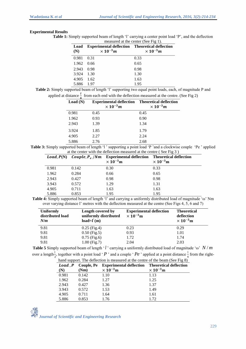
Experimental Results Table 1: Simply supported beam of length ‘l’ carrying a center point load ‘P’, and the deflection
measured at the center (See Fig 1).
Load
(N)
Experimental deflection
× 𝟏𝟎−𝟑𝒎
Theoretical deflection
× 𝟏𝟎−𝟑𝒎
0.981 0.31 0.33
1.962 0.66 0.65
2.943 0.98 0.98
3.924 1.30 1.30
4.905 1.62 1.63
5.886 1.97 1.95
Table 2: Simply supported beam of length ‘l’ supporting two equal point loads, each, of magnitude P and
applied at distance 𝒍
𝟒 from each end with the deflection measured at the centre. (See Fig 2)
Load (N) Experimental deflection
× 𝟏𝟎−𝟑𝒎
Theoretical deflection
× 𝟏𝟎−𝟑𝒎
0.981 0.45 0.45
1.962 0.93 0.90
2.943 1.39 1.34
3.924 1.85 1.79
4.905 2.27 2.24
5.886 2.76 2.68
Table 3: Simply supported beam of length ‘l ’ supporting a point load ‘P ’and a clockwise couple ‘Pe ’ applied
at the center with the deflection measured at the centre ( See Fig 3 )
𝑳𝒐𝒂𝒅,𝑷(N) 𝑪𝒐𝒖𝒑𝒍𝒆,𝑷𝒆 /𝑵𝒎 Experimental deflection
× 𝟏𝟎−𝟑m
Theoretical deflection
× 𝟏𝟎−𝟑m
0.981 0.142 0.30 0.33
1.962 0.284 0.66 0.65
2.943 0.427 0.98 0.98
3.943 0.572 1.29 1.31
4.905 0.711 1.63 1.63
5.886 0.853 1.95 1.95
Table 4: Simply supported beam of length ‘l’ and carrying a uniformly distributed load of magnitude ‘ω’ Nm
over varying distance l’ metres with the deflection measured at the centre (See Figs 4, 5, 6 and 7)
Table 5 Simply supported beam of length ‘ ’ carrying a uniformly distributed load of magnitude ‘ω’
over a lengthl
2, together with a point load ‘ ’ and a couple ‘ ’ applied at a point distance
l
4 from the right-
hand support. The deflection is measured at the centre of the beam (See Fig 8)
𝑳𝒐𝒂𝒅 ,𝑷
(N)
Couple, Pe
(Nm)
Experimental deflection
× 𝟏𝟎−𝟑m
Theoretical deflection
× 𝟏𝟎−𝟑m
0.981 0.142 1.10 1.13
1.962 0.284 1.27 1.25
2.943 0.427 1.36 1.37
3.943 0.572 1.53 1.49
4.905 0.711 1.64 1.61
5.886 0.853 1.76 1.72
l mN /
P Pe
Uniformly
distributed load
N/m
Length covered by
uniformly distributed
load=𝒍′ (m)
Experimental deflection
× 𝟏𝟎−𝟑m
Theoretical
deflection
× 𝟏𝟎−𝟑m
9.81 0.25 (Fig.4) 0.23 0.29
9.81 0.50 (Fig.5) 0.93 1.01
9.81 0.75 (Fig.6) 1.72 1.74
9.81 1.00 (Fig.7) 2.04 2.03

Wadotiona K et al Journal of Scientific and Engineering Research, 2016, 3(2):214-234
Journal of Scientific and Engineering Research
230
Figure 30
Table 6: Beam with fixed ends carrying a point load ‘P’ applied at the centre with the deflection measured at
the centre (See Fig 9).
𝐋𝐨𝐚𝐝 (N)
Experimental deflection
× 𝟏𝟎−𝟑m
Theoretical deflection
× 𝟏𝟎−𝟑m
0.981 0.07 0.09
1.962 0.15 0.18
2.943 0.26 0.27
3.924 0.35 0.37
4.905 0.44 0.47
5.886 0.53 0.55
Table 7: Beam of length ‘ ’, fixed at the ends and supporting a point load ‘ ’ and a clockwise couple ‘ ’
applied at the centre with the deflection measured at the centre (See Fig 10)
𝐋𝐨𝐚𝐝 (N)
Couple, Pe
(Nm)
Experimental deflection
× 𝟏𝟎−𝟑m
Theoretical deflection
× 𝟏𝟎−𝟑m
0.981 0.142 0.10 0.08
1.962 0.285 0.19 0.16
2.943 0.427 0.23 0.24
3.942 0.572 0.36 0.33
4.905 0.711 0.44 0.41
5.886 0.853 0.53 0.49
Table 8 Beam of length ‘ ’ fixed at the ends and supporting a uniformly distributed load of magnitude ‘ ’
over the entire length as well as a point load ‘ ’ and a clockwise couple ‘ ’ applied at the centre.
The deflection is measured at the centre (See Fig 11)
Load
(N)
Couple, Pe
(Nm)
Experimental
Deflection × 𝟏𝟎−𝟑m
Theoretical
Deflection × 𝟏𝟎−𝟑m
0.981 0.142 0.09 0.12
1.962 0.285 0.17 0.20
2.943 0.427 0.26 0.28
3.924 0.572 0.35 0.37
4.905 0.711 0.45 0.45
5.886 0.853 0.54 0.53
0
0.2
0.4
0.6
0.8
1
1.2
1.4
1.6
1.8
2
0 1 2 3 4 5 6 7
Def
lect
ion
/mm
Load/N
Simply supported beam with distributed load up to mid
span and a point load and couple at 3⁄4 span
Experimental Theoretical
l P Pe
l wmN / P Pe
Wadotiona K et al Journal of Scientific and Engineering Research, 2016, 3(2):214-234
Journal of Scientific and Engineering Research
231
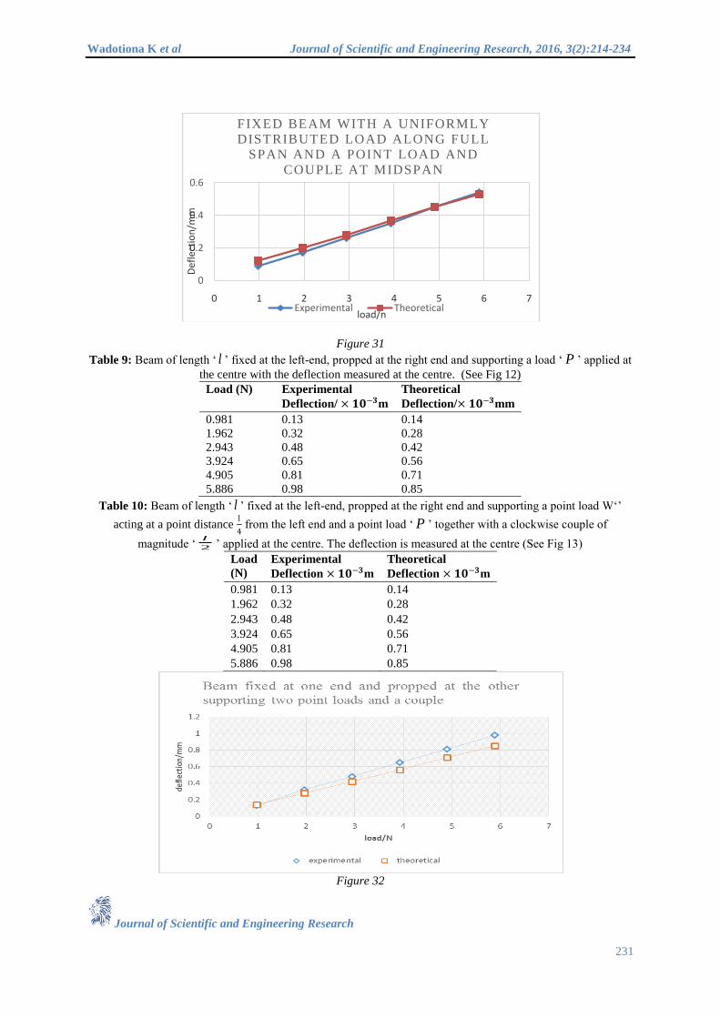
Figure 31
Table 9: Beam of length ‘ ’ fixed at the left-end, propped at the right end and supporting a load ‘ ’ applied at
the centre with the deflection measured at the centre. (See Fig 12)
Load (N) Experimental
Deflection/ × 𝟏𝟎−𝟑m
Theoretical
Deflection/× 𝟏𝟎−𝟑mm
0.981 0.13 0.14
1.962 0.32 0.28
2.943 0.48 0.42
3.924 0.65 0.56
4.905 0.81 0.71
5.886 0.98 0.85
Table 10: Beam of length ‘ ’ fixed at the left-end, propped at the right end and supporting a point load W‘’
acting at a point distance l
4 from the left end and a point load ‘ ’ together with a clockwise couple of
magnitude ‘ ’ applied at the centre. The deflection is measured at the centre (See Fig 13)
Load
(N)
Experimental
Deflection × 𝟏𝟎−𝟑m
Theoretical
Deflection × 𝟏𝟎−𝟑m
0.981 0.13 0.14
1.962 0.32 0.28
2.943 0.48 0.42
3.924 0.65 0.56
4.905 0.81 0.71
5.886 0.98 0.85
Figure 32
0
0.2
0.4
0.6
0 1 2 3 4 5 6 7
Def
lect
ion
/mm
load/n
FIXED BEAM WITH A UNIFORMLY
DISTRIBUTED LOAD ALONG FULL
SPAN AND A POINT LOAD AND
COUPLE AT MIDSPAN
Experimental Theoretical
l P
l
P
2
l

Wadotiona K et al Journal of Scientific and Engineering Research, 2016, 3(2):214-234
Journal of Scientific and Engineering Research
232
Table 11: Beam of length ‘ ’ fixed at the left-end, propped at the right –end and supporting a uniformly
distributed load of magnitude ‘ω’ over a distance l
2 as well as a point load ‘ ’ and a clockwise couple of
magnitude ‘ ’ applied at a point distance l
4 from the right-hand end. The deflection is measured at the center
(See Fig 14)
Load (N) Experimental
Deflection × 𝟏𝟎−𝟑m
Theoretical
Deflection × 𝟏𝟎−𝟑m
0.981 0.068 0.07
1.962 0.11 0.15
2.943 0.15 0.21
3.924 0.20 0.29
4.905 0.24 0.36
5.886 0.28 0.43
Figure 33
Table 12: Cantilever beam of length ‘ ’ fixed at the left end and supporting a point load ‘ ’ and a clockwise
couple ‘ ’ applied at the centre with the deflection measured at the centre (See Fig 15)
Load (N) Experimental Deflection
× 𝟏𝟎−𝟑m
Theoretical Deflection
× 𝟏𝟎−𝟑m
0.981 0.52 0.63
1.962 1.10 1.32
2.943 1.83 2.03
3.924 2.50 2.71
4.905 3.26 3.48
5.886 4.09 4.45
Figure 34
l mN / P
Pe
0
0.1
0.2
0.3
0.4
0.5
0 1 2 3 4 5 6 7
DEF
LEC
TIO
N/M
M
LOAD/N
Beam f ixed a t one end and propped a t the
o ther end suppor t ing a uni formly d i s t r ibuted
load and a poin t load and a couple
Experimental Theoretical
l P
Pe

Wadotiona K et al Journal of Scientific and Engineering Research, 2016, 3(2):214-234
Journal of Scientific and Engineering Research
233
(Uniformly distributed load = 9.81 N/m)
Table 13: Cantilever beam of length ‘ ’ fixed at the left end and supporting a uniformly distributed load of
magnitude ‘ ’ over its entire length as well as a point load ‘ ’ together with a clockwise couple of
magnitude ‘ ’ applied at the right end. The deflection is measured at the centre (See Fig 16)
Figure 35
The experimental results are indicated in Tables 1 to 13 and the corresponding results from theoretical
calculations are also indicated. In general it can be said that that there was a good correlation between the
experimental and the theoretical results. Table 4 shows results for a simply supported beam carrying a uniformly
distributed load over quarter length, half length, three-quarter length and full length. The results for the
deflection at the centre correlate well between the experimental and theoretical results.
Table 5 shows results for a simply supported beam carrying a uniformly distributed load over half the length, a
point load and a couple applied at quarter length from the right hand end support. The deflection was measured
at the centre and again a good correlation of experimental and theoretical results was observed. Fig. 30 shows a
graph plotted for the results.
Table 8 shows results for a beam fixed at both ends and supporting a uniformly distributed load of magnitude w,
over a length entire length of the beam together with a point load and couple applied at the centre with the
deflection measured at the centre as well. Fig 31 is a graph showing these results and again a good correlation is
observed.
Table 11 shows results for a beam fixed at one end and propped at the other end carrying uniformly distributed
load of magnitude w N/m over half the length of the beam as well as a point load and couple a quarter length
from the propped end. Fig 33 shows a graph indicating the experimental results and theoretical results with
deflection measured at the centre. In this case there was a small variation between the experimental and the
theoretical results.
Table 13 shows results for a cantilever beam fixed at the left end and supporting a uniformly distributed load of
magnitude w over the entire length of the beam together with a point load and couple applied at the free end and
deflection measured at the centre. Again here a small discrepancy is shown between the experimental and the
l
w mN / P
Pe
0
0.5
1
1.5
2
2.5
3
0 1 2 3 4 5 6 7
DEF
LEC
TIO
N/M
M
LOAD/N
Cantilever beam with uniformly distributed
load along full span and a point load and a
couple at the free end
Experimental Theoretical
Load
(N)
𝑪𝒐𝒖𝒑𝒍𝒆,𝑷𝒆
(Nm)
Experimental Deflection
× 𝟏𝟎−𝟑m
Theoretical Deflection
× 𝟏𝟎−𝟑m
0.981 0.142 0.48 0.99
1.962 0.284 0.94 1.34
2.943 0.427 1.40 1.70
3.943 0.572 1.86 2.06
4.905 0.711 2.34 2.41
5.886 0.853 2.83 2.77

Wadotiona K et al Journal of Scientific and Engineering Research, 2016, 3(2):214-234
Journal of Scientific and Engineering Research
234
theoretical results for smaller loads. The results tend to become closer as the load increases. Fig. 35 is a graph
showing these results.
Discussion In general there was good correlation between the experimental and the theoretical results for most of the
experiments carried out. In a few cases mentioned, a variation of results was noticed. There are a number of
sources of error that would have contributed to the variations observed which include the inhomogeneity of the
beam material and the beam not being perfectly straight initially. Efforts were made to achieve the expected
uniformly distributed load by splitting the load into smaller sections, this could have also contributed to some of
the errors noticed. The theoretical equations assumes that the point load and a couple are acting at a point.
However in these experiments, the attachment used covered a small contact area and this could have caused
some errors. The dial gauges used had not been recently serviced and calibrated. The human limitations in
reading accurately could have contributed to the errors as well.
Conclusion The laboratory testing rig designed has been able to demonstrate the elastic deflection of beams with different
end conditions and a combination of different loadings. The design of the uniformly distributed load presented
here has been shown to work and the concept of the design of the attachment of a point load and a couple has
worked very well. In general, the design of the testing rig has been made simple and easy to use. Simple
concepts have been used for the application of a couple as well as the uniformly distributed load. The testing rig
and its accessories were easy to manufacture and the overall cost was significantly low in comparison to the
importation of similar equipment. The success of this project should inspire the design and manufacture of other
laboratory equipment locally.
Acknowledgements We would like to thank Professor Mutuli for allowing us to do this research at University of Zimbabwe. It was a
success and the rig will be used in our laboratory as an asset.
References
[1] B. Kareem, "Development of a Beam Deflection Apparatus from Locally Sourced Material," Development
of a Beam Deflection Apparatus from Locally Sourced Material, vol. 2, no. 6, pp. 342-348, 2012.
[2] P. P. Benham, R. J. Crawford and C. G. Armstrong, Mechanics of Engineering Materials, Low Priced ed.,
Addison Wesley Longman Limited, 1997.
[3] Gere and Timoshenko, Mechanics of Materials, 2nd ed., PWS Publishers, A division of Wadsworth, Inc
USA (1984), 1984.
[4] E. Hearn, Mechanics of Materials : An introduction to the mechanics of elastic and plastic deformation of
solids and structural components, 3rd ed., Butterworth-Heinemann, 1997.
[5] W. A. Nash, Strength of Materials, 4th ed., New Dehli: Tata McGraw-Hill Publishing Company Limited,
2007.
[6] E. P. Popov, Engineering Mechanics of Solids, 2nd ed., Upper Sadle River, New Jersey: Prentice - Hall
Inc, 1998.
[7] S. Rattan, Strength of Materials, New Dehli: Tata McGraw-Hill, 2008.
[8] I. H. Shames and J. M. Pitarresi, Introduction to Solid Mechanics, 3rd ed., New Dehli: Prentice-Hall of
India Private Ltd, 2003.
[9] R. C. Stephens, Strength of Materials Theory and Examples, London: Edward Arnold Publishers Ltd, 1971.
[10] S. A. Urry and P. J. Turner, Solving Problems in Solid Mechanics, vol. I, Longman Group UK Ltd, 1986.
[11] B. Young, Essential Solid Mechanics Theory, Worked Examples and Problems, London: The MacMillan
Press Ltd, 1982.


