Embed Size (px)
Citation preview
Backscatter suppression for underwater modulatingretroreflector links using polarization
discrimination
Linda Mullen,1,* Brandon Cochenour,1 William Rabinovich,2
Rita Mahon,2 and John Muth3
1Naval Air Systems Command, NAVAIR, Electro-Optics and Special Mission Sensors Division,22347 Cedar Point Road, Patuxent River, Maryland 20670, USA
2Optical Sciences Division, Naval Research Laboratory, 4555 Overlook Avenue, SW, Washington DC 20375, USA3Electrical and Computer Engineering Department, North Carolina State University,
Box 7911, Raleigh, North Carolina 27606, USA
*Corresponding author: [email protected]
Received 19 September 2008; accepted 7 November 2008;posted 21 November 2008 (Doc. ID 101769); published 7 January 2009
Free space optical links underwater have the potential to enable short range (<100m) high-bandwidth(megabits per second) data links that have a low probability of detection and interception. The use of aretroreflecting free space optical link in water has the added advantage of allowing much of the weightand power burden of the link to remain at one end. While modulating retroreflectors have been success-fully implemented in above-water links, the underwater environment introduces new challenges. Thefocus of this paper is to address these challenges and to investigate techniques for minimizing their effecton the link performance. © 2009 Optical Society of America
OCIS codes: 010.4450, 010.4455, 290.5855, 060.2605.
1. Introduction
The future tactical ocean environment will be in-creasingly complicated. In addition to traditionalcommunication links, there will be increased relianceon underwater networks and a proliferation of un-manned vehicles in space, in the air, on the surface,and underwater. Above the air/water interface, wire-less radio frequency communications will continue toprovide the majority of communication channels.Underwater, where radio waves do not propagate,acoustic methods will continue to be used. However,while there have been substantial advances in acous-tic underwater communications, acoustics will behard pressed to provide sufficient bandwidth to mul-tiple platforms at the same time. This suggests that
high-bandwidth, short range underwater opticalcommunications have high potential to augmentacoustic communication methods. These types oflinks are distinctly different than the satellite to sub-marine operating at depth systems that were consid-ered in the 1980s and 1990s, where 100% reliabilitywas required regardless of cloud-cover conditions.
Underwater optical links using fiber optic cablescan provide gigabits per second of bandwidth but re-quire a physical connection between the two ends ofthe link, which is often undesirable. Tethered sys-tems to submarines impose speed and depth restric-tions that limit maneuverability. Free space opticallinks can allow high bandwidths without the needfor physical connections, but both the range andthe bandwidth of the link become limited by the prop-erties of underwater optical propagation. In addition,conventional free space systems require an opticalsource (laser or LED), a collimating telescope, a
0003-6935/09/020328-10$15.00/0© 2009 Optical Society of America
328 APPLIED OPTICS / Vol. 48, No. 2 / 10 January 2009
pointing system, and perhaps a separate receivingtelescope. For small platforms such as unmanned un-dersea vehicles or unattended sensors the size,weight, and power (SWAP) of such systems may beunacceptable. A similar problem faces atmosphericfree space optical links and has been successfullyhandled using modulating retroreflectors [1]. In aretroreflecting link, a conventional optical terminal,the interrogator sits at one end, where there is suffi-cient power and payload capacity to accommodate it.At the remote end sits a small passive optical retro-reflector utilizing either a corner cube or a cat’s eye.The retroreflector is coupled to some form of opticalmodulator. In operation, the interrogator paints theretroreflecting end of the link with a continuous-wave beam. The retroreflector passively reflects thisbeam back to the interrogator after the optical mod-ulator has imposed a signal on it. In this way, the ret-roreflecting end of the link can return data with noneed for a laser or pointing system and hence withlow SWAP. Data can be sent to the remote end ofthe link by incorporating a wide field of view photo-detector with the retroreflector and by modulatingthe interrogating beam.The challenge in implementing a retroreflecting
link in water is that optical propagation underwateris far more complex than for atmospheric links.Multiple small-angle forward scattering of the beamby suspended particles produces extended beam pro-files that are not the simple Gaussian shapes foundfor short atmospheric propagation. Depending on thedegree of spatial broadening of the laser beam under-water, there may be no advantage for the diffraction-limited optics that are used in above-water links. Atvery close ranges, scatter may actually helpmaintainthe link by mitigating the pointing requirementwhile operating as a nonline of sight communicationsystem. However, this scattering may also ultimatelylimit the link performance in terms of bandwidth ca-pacity. Scattering of the interrogating beam in thebackward direction must also be addressed. In thiscase, the backscattered light increases the back-ground signal level above which the modulated beamfrom the retroreflector must be discerned. This de-tected background signal also raises the noise levelat the receiver that can also limit link performance.While absorption of the optical signal will also add tothe overall loss of the link, the optical wavelengthcan be selected to minimize the loss particularly incleaner ocean waters. However, in more turbidwaters, absorption can actually help by reducingthe contribution of light that has scattered multipletimes on its path to and from the retroreflector.Fortunately, these challenges of the underwater
environment are not unique to modulating retrore-flector communication links. Decades of researchin underwater optical imaging have been spent de-veloping techniques for minimizing the detrimentaleffects of optical scattering in water. In Section 2, wereview the pros and cons of these methods as theyrelate to a modulating retroreflector link.
2. Lessons Learned from Underwater Imaging
Two different operating regimes can be defined forunderwater optical imaging systems: photon- (orsignal) limited detection and contrast-limited detec-tion. In the photon-limited case, absorption typicallydominates optical attenuation, and increasing thetransmitted optical power or the photodetector sen-sitivity will increase the detection range. For the ret-roreflector link, using a high-power laser and a largearea and wide field of view receiver on the interrogat-ing side along with an efficient modulating retrore-flector would optimize the link performance. Thecontrast-limited scenario is more complex since in-creasing the transmitted laser power or receiver sen-sitivity does not directly lead to increased range. Thisis due to the fact that while there may be sufficientlight reflected from the object of interest, it is buriedin the signal backscattered from the environment.Increasing the source power only alters the two sig-nal components proportionally, which does nothingfor improving the apparent contrast of the object. In-creasing the field of view of the receiver has a similareffect. While opening up the receiver acceptance an-gle increases the amount of object-reflected light thatis collected, it also substantially increases the back-ground signal level. In the retroreflector link, thelarge background signal masks the information-bearing signal emanating from the modulating retro-reflector. The only way to improve link performanceis to implement a technique that discriminatesagainst multiply scattered background photonswhile minimizing the loss of retroreflected returnsignal. In this paper, we concentrate on the con-trast-limited scenario and identify which approachdeveloped for enhancing image contrast is the mostappropriate for applying to the modulating retrore-flector scenario.
Perhaps the simplest approach for reducing thecontribution from backscattered light is to separatethe source and receiver in a bistatic geometry. This,in addition to reducing the transmitter beam diver-gence and the receiver field of view, limits the com-mon volume created by the source and receiver fieldof view overlap where backscattered photons origi-nate [2]. The main problem with implementing thisspatial filtering approach in the modulating retrore-flector geometry is that the retroreflector must bepurposely spoiled so that the retroreflected beamis not coincident with the interrogating signal. Whilethis has been done in the past for satellite-based ret-roreflector links, it makes the pointing and trackingof the link more challenging. More importantly,spoiling the retroreflector takes away one of themainadvantages of the retrolink in that the pointing andtracking requirements are minimized.
Another effective technique for improving detec-tion in contrast-limited environments is using timeto discriminate against multiply scattered light. Inthis case, a pulsed source is used in conjunction witha receiver that can be gated or turned on for veryshort time periods [3]. In the operation of a typical
10 January 2009 / Vol. 48, No. 2 / APPLIED OPTICS 329
range-gated imaging system, a short (10–20ns) pulseis transmitted to a distant object, and the receiver istimed to open only when the reflected light returnsfrom the object. Thus the backscattered signal thatreaches the receiver prior to the object-reflected lightis “gated out” of the return signal. The disadvantageof this approach is that it requires a priori knowledgeof the location (depth) of the underwater object.While this range-gated technique could be imple-mented in the modulating retroreflector link, it in-creases system complexity and limits the type ofinformation encoding that can be used.A third approach that has been used to enhance
optical imaging in contrast-limited scenarios takesadvantage of the differences in polarization betweenthe object-reflected and backscattered light [4–6].The basis for this method is that linearly polarizedlight that is diffusely scattered by an underwater ob-ject becomes depolarized while the light scattered inthe backward direction from the environment retainsthe original polarization state of the transmittedlight. A receiver with a polarizer oriented perpendi-cular to the transmitted light will reject the back-scatter signal while still recovering a portion of theobject-reflected light. The effectiveness of this ap-proach decreases when there is enough small-anglescattering that depolarizes the light on its way to andfrom the object and the light that is backscatteredfrom the medium. The success of the polarization-discrimination technique also relies on the polariza-tion properties of the target itself: the more specularthe target reflectivity, the less it will depolarize thelight. A distinct advantage of the modulating retro-reflector link is that the retroreflector itself can beviewed as a cooperative target since the polarizationproperties of the retroreflected light can be preciselycontrolled. In the scenario described previously, theretroreflector could rotate the polarization state ofthe information-bearing signal so that a properlyoriented polarizer at the receiver would only extin-guish the unwanted backscattered light. The effec-tiveness of this approach still relies on the effect ofthe environment on the polarization states of theinterrogating and retroreflected signals and thebackscattered light.Despite the drawbacks of the polarization-
discrimination approach, the simplicity of the techni-que warrants further investigation to understand itsbenefits and limitations relative to the modulatingretroreflector link geometry. In Section 3, the polar-ization properties of light in water are discussed inmore detail. In Section 4, measurements of opticalpolarization in tank water are presented and ana-lyzed in terms of their implications for an under-water modulating retroreflector link.
3. Light Polarization in Ocean Water
It was pointed out in Section 2 that the effectivenessof the polarization-discrimination approach relieson
1. the polarization properties of the medium, and2. the polarization properties of the target.
In the modulating retroreflector link, the polariza-tion properties of the target, the retroreflector, canbe precisely controlled in order to maximize the levelof the information-bearing, retroreflected signal atthe receiver. However, the polarization propertiesof the underwater environment cannot be controlledand must be examined in order to understand theireffect on the link performance. Specifically, we are in-terested as to what degree the polarization of the in-terrogating optical signal is altered on its path to andfrom the retroreflector and how the polarization ofthe light scattered back into the receiver is affectedby the scattering process. Fortunately there has beena significant amount of research that has focused oncharacterizing the optical scattering properties ofwater and on understanding the physics of polarizedlight propagation in water.
Optical scattering in natural waters is predomi-nantly due to particles that are large relative tothe blue-green wavelengths used in underwater sen-sing. This results in a very forward-peaked scatter-ing phase function that translates into a higherprobability for light to scatter at small angles. Thepolarization characteristics of the propagating lightfield depend on howmany times the light is scatteredin small angles on its path to the receiver and on theacceptance angle of the receiver. The vector radiativetransfer equation that describes polarized lightpropagation can be solved analytically using thesmall-angle approximation, which assumes highlyanisotropic scattering (photons do not deviate muchfrom their path due to peaked scattering phase func-tion) and significant absorption (to limit the contri-bution from light scattered at large angles andtraveling long distances) [7]. For a linearly polarizedlaser beam propagating through a homogeneouswater column, the degree of polarization of the laserbeam after propagating z meters, DOPFSðzÞ, can beapproximated by [7]
DOPFSðzÞ ≈ DOP0 expð−ϕbzÞ; ð1Þ
where DOP0 is the degree of polarization of the trans-mitted light, b is the scattering coefficient, and ϕ isthe depolarization factor of forward-scattered light.Under the small-angle approximation, the depolari-zation factor is defined by the following equation:
ϕ ¼ 12
Z∞
0ðM11 −M22Þθdθ; ð2Þ
where M11 and M22 are the diagonal elements of theMueller matrix that have been normalized to thescattering coefficient (i.e.,M11 is the scattering phasefunction), and θ is the scattering angle such thatM11and M22 are zero for θ > θ0, where θ0 is a sufficientlysmall angle, such that
330 APPLIED OPTICS / Vol. 48, No. 2 / 10 January 2009
θ0 ≪π2;
12
Z π
θ0M11ðθÞ sin θdθ ≪ 1: ð3Þ
According to Eq. (1), the degree of polarization de-creases exponentially with depth according to theproduct of the depolarization factor and the scatter-ing coefficient. The depolarization factor depends onthe particle shape, size, and index of refraction [7,8].For example, ϕ ¼ 0 (since M11 ¼ M22) for sphericalparticles. Since real sea particles are not perfectspheres, the depolarization factor is nonzero.Although published measurements of the polariza-tion properties of light in water are limited, onestudy of M11 and M22 at angles as small as 10°showed that M22=M11 ¼ 0:98 for actual ocean watersamples [9], indicating that the depolarization factoris minimal for small scattering angles. However, thedegree of polarization is also affected by the value ofthe scattering coefficient in the exponential term inEq. (1). The larger the scattering coefficient, themoredepolarized the light will be after propagating z me-ters. This makes physical sense since the higher thescattering coefficient, the stronger the probabilitythat light will scatter enough times that the polari-zation state will be rotated.The polarization properties of the backscattered
light are also important when evaluating the polar-ization-discrimination approach for the modulatingretroreflector link. The backscattering process inwater is typically considered to be a single-scatteringevent in the backscatter (π) direction, followed by aseries of small-angle forward-scattering events[10]. The degree of polarization for a linearly polar-ized beam that is backscattered from a homogeneouswater column, DOPBSðzÞ, can be expressed as [7]
DOPBSðzÞ ¼M22ðπÞM11ðπÞ
expð−2ϕbzÞ; ð4Þ
where M22ðπÞ and M11ðπÞ are the values of the firstand second diagonal elements of the Mueller matrixat an angle of π with respect to the transmitted laserbeam. In Eq. (4), the first term, M22ðπÞ=M11ðπÞ, de-scribes the degree of polarization of the single-scatterbackscatter event, while the exponential term char-acterizes the degree of polarization of the light that isscattered at small angles to and from the backscatterevent. Published measurements of M22=M11 ¼ 0:78at 160° [9] indicate that a single-scattering eventclose to the backscatter direction does not signifi-cantly alter the polarization state of light in naturalwaters. However, multiple-scattering events at smallangles can eventually cause the backscatter signal tobecome depolarized. Fortunately, polarized lidarsystems have been developed that can measurethe degree of polarization of backscattered light[7,8,11,12]. This is done by measuring the power ofthe copolarized component, PCOðzÞ, and the cross-polarized component, PCROSSðzÞ and computing theratio of the difference to the sum of these two terms,i.e.,
DOPðzÞ ¼ PcoðzÞ − PCROSSðzÞPcoðzÞ þ PCROSSðzÞ
: ð5Þ
Results show that the degree of polarization is higherin clear waters (85–90% to depths of 28–33m) than inturbid waters (70–80%) [7]. The difference is likelydue to the increased scattering coefficient in the tur-bid water scenario. Nevertheless, it is evident thatthe backscatter signal is still predominately polar-ized in the same state as the transmitted light upto significant underwater depths.
It is also important to point out that in addition tothe polarization properties of the medium and thetarget, the characteristics of the system itself canalso affect the degree of polarization of the detectedoptical signal. For example, opening up the receiverfield of view increases the probability that multiplyscattered light will be collected by the detector. Sincemultiple-scattering events are required to rotate thepolarization of the propagating light field, increasingthe receiver acceptance angle is expected to reducethe degree of polarization of the detected opticalsignal [5,11]. Opening up the receiver field of viewwill also allow more backscattered photons to be col-lected, which leads to a reduction in contrast and anincreased noise level at the receiver. A system trade-off must be made between making the field of viewlarge to collect more target-reflected (or retrore-flected) photons and increasing the probability thatthese photons will have a lower degree of polariza-tion and/or that more backscattered light will bedetected.
In summary, there is evidence that both the lightforward scattered on its path to and from an under-water object and the light that is scattered back tothe detector without reaching the object have a highdegree of polarization when linearly polarized lightis transmitted. Therefore, in the modulating retrore-flector link, it would be advantageous to rotate thepolarization of the light reaching the retroreflectorend of the link and place a polarizer in the receiverthat is oriented perpendicular to the polarizationstate of the transmitted light. This configurationwould block the copolarized component of the back-scatter while still transmitting the cross-polarizedretroreflected signal. To evaluate the effectivenessof this technique, a modulating retroreflector linkwas assembled and tested in a laboratory water tank.In Sections 4 and 5, the polarization characteristicsof the forward-scattered and backscattered lightfrom the tank water are studied as a function ofwater optical properties and receiver field of view.The results are then assessed in terms of their im-pact on the modulating retroreflector link perfor-mance. Finally, experiments conducted with anunderwater modulating retroreflector link that im-plements the polarization-discrimination techniqueare described, and the results are discussed.
10 January 2009 / Vol. 48, No. 2 / APPLIED OPTICS 331
4. Polarization Measurements in Maalox-EnhancedTank Water
To evaluate the effectiveness of implementing the po-larization-discrimination technique in the modulat-ing retroreflector link, it is useful to first conductexperiments in a controlled laboratory water tankenvironment. However, it is important to understandhow the scattering and absorption properties of thetank water compare with those seen in natural oceanwater. Pharmaceutical antacids have been used inthe past to simulate the scattering properties of sea-water. This is due to the fact that such substanceshave particle size distributions that produce a highlyforward-peaked scattering phase function when illu-minated with blue-green light [13,14]. As discussedpreviously, this is an important characteristic of nat-ural ocean water, especially when considering thepropagation of linearly polarized light. Despite thisshared attribute between seawater and Maalox-enhanced tank water, it is essential to measure thepolarization characteristics of light in tank waterand not rely on the published results for ocean water.This is due to the fact that, although the particle sizedistribution of Maalox may mimic that which isfound in seawater, the composition and shape ofthe particles may differ significantly from naturallyoccurring water particles. Furthermore the absorp-tion properties of Maalox are very different fromnaturally occurring water. In typical ocean water, ab-sorption makes up somewhere between 20–30% ofthe total attenuation, depending on whether it isdeep, open ocean water or coastal water. However,in Maalox, the absorption is lower—somewherebetween 5–15% of the total attenuation. These differ-ences are important since the higher the absorption,the higher the probability that photons scattered atlarge angles will be absorbed. Since these photonsare those that have a significant effect on the degreeof polarization of the light field [7], this must be ta-ken into account when using laboratory experimen-
tal results to predict system performance in thein situ environment.
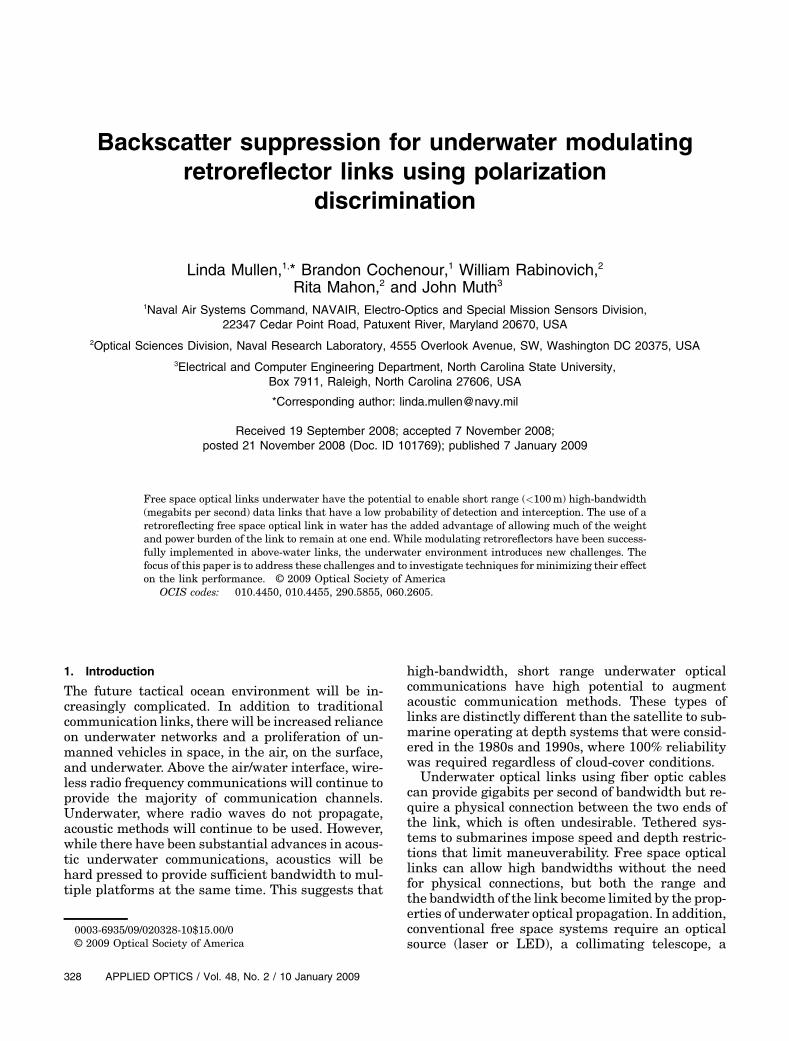
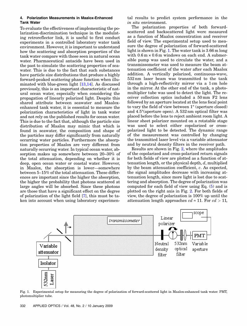
The polarization properties of both forward-scattered and backscattered light were measuredas a function of Maalox concentration and receiverfield of view. The experimental setup used to mea-sure the degree of polarization of forward-scatteredlight is shown in Fig. 1. The water tank is 3:66m longwith 0:6m× 0:6m windows on each end. A submer-sible pump was used to circulate the water, and atransmissometer was used to measure the beam at-tenuation coefficient of the water after each Maaloxaddition. A vertically polarized, continuous-wave,532nm laser beam was transmitted to the tankthrough a high-reflectivity mirror via a 1 cm holein the mirror. At the other end of the tank, a photo-multiplier tube was used to detect the light. The re-ceiver collection optics included a 50mm F2 lensfollowed by an aperture located at the lens focal pointto vary the field of view between 1° (aperture closed)and 4:5°(aperture open). A 532nm optical filter wasplaced before the lens to reject ambient room light. Alinear sheet polarizer mounted on a rotatable stagewas used to select either copolarized or cross-polarized light to be detected. The dynamic rangeof the measurement was controlled by changingthe transmitted laser level via a variable attenuatorand by neutral density filters in the receiver path.
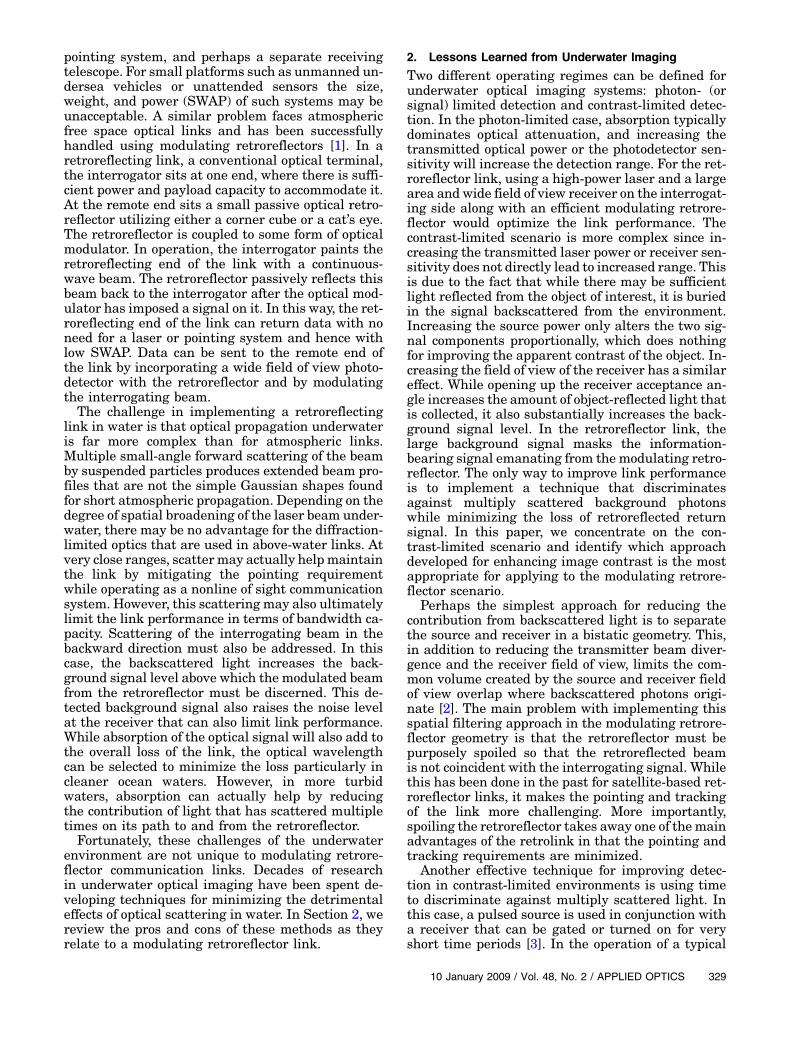
Results are shown in Fig. 2, where the amplitudesof the copolarized and cross-polarized return signalsfor both fields of view are plotted as a function of at-tenuation length, or the physical depth, d, multipliedby the beam attenuation coefficient, c. As expected,the signal amplitudes decrease with increasing at-tenuation length, since more light is lost due to scat-tering and absorption. The degree of polarization wascomputed for each field of view using Eq. (5) and isplotted on the right axis in Fig. 2. For both fields ofview, the degree of polarization is 100% up until theattenuation length approaches cd ≈ 11. For cd > 11,
Fig. 1. Experimental setup for measuring the degree of polarization of forward-scattered light in Maalox-enhanced tank water. PMT,photomultiplier tube.
332 APPLIED OPTICS / Vol. 48, No. 2 / 10 January 2009
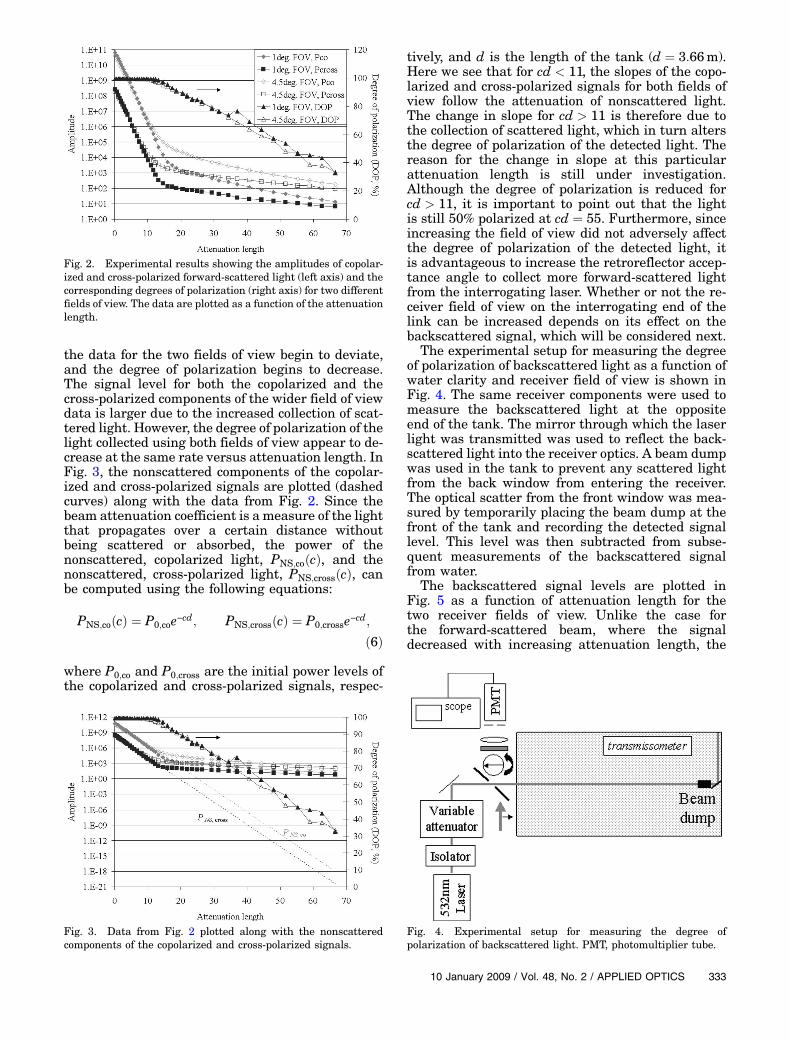
the data for the two fields of view begin to deviate,and the degree of polarization begins to decrease.The signal level for both the copolarized and thecross-polarized components of the wider field of viewdata is larger due to the increased collection of scat-tered light. However, the degree of polarization of thelight collected using both fields of view appear to de-crease at the same rate versus attenuation length. InFig. 3, the nonscattered components of the copolar-ized and cross-polarized signals are plotted (dashedcurves) along with the data from Fig. 2. Since thebeam attenuation coefficient is a measure of the lightthat propagates over a certain distance withoutbeing scattered or absorbed, the power of thenonscattered, copolarized light, PNS;coðcÞ, and thenonscattered, cross-polarized light, PNS;crossðcÞ, canbe computed using the following equations:
PNS;coðcÞ ¼ P0;coe−cd; PNS;crossðcÞ ¼ P0;crosse−cd;
ð6Þ
where P0;co and P0;cross are the initial power levels ofthe copolarized and cross-polarized signals, respec-
tively, and d is the length of the tank (d ¼ 3:66m).Here we see that for cd < 11, the slopes of the copo-larized and cross-polarized signals for both fields ofview follow the attenuation of nonscattered light.The change in slope for cd > 11 is therefore due tothe collection of scattered light, which in turn altersthe degree of polarization of the detected light. Thereason for the change in slope at this particularattenuation length is still under investigation.Although the degree of polarization is reduced forcd > 11, it is important to point out that the lightis still 50% polarized at cd ¼ 55. Furthermore, sinceincreasing the field of view did not adversely affectthe degree of polarization of the detected light, itis advantageous to increase the retroreflector accep-tance angle to collect more forward-scattered lightfrom the interrogating laser. Whether or not the re-ceiver field of view on the interrogating end of thelink can be increased depends on its effect on thebackscattered signal, which will be considered next.
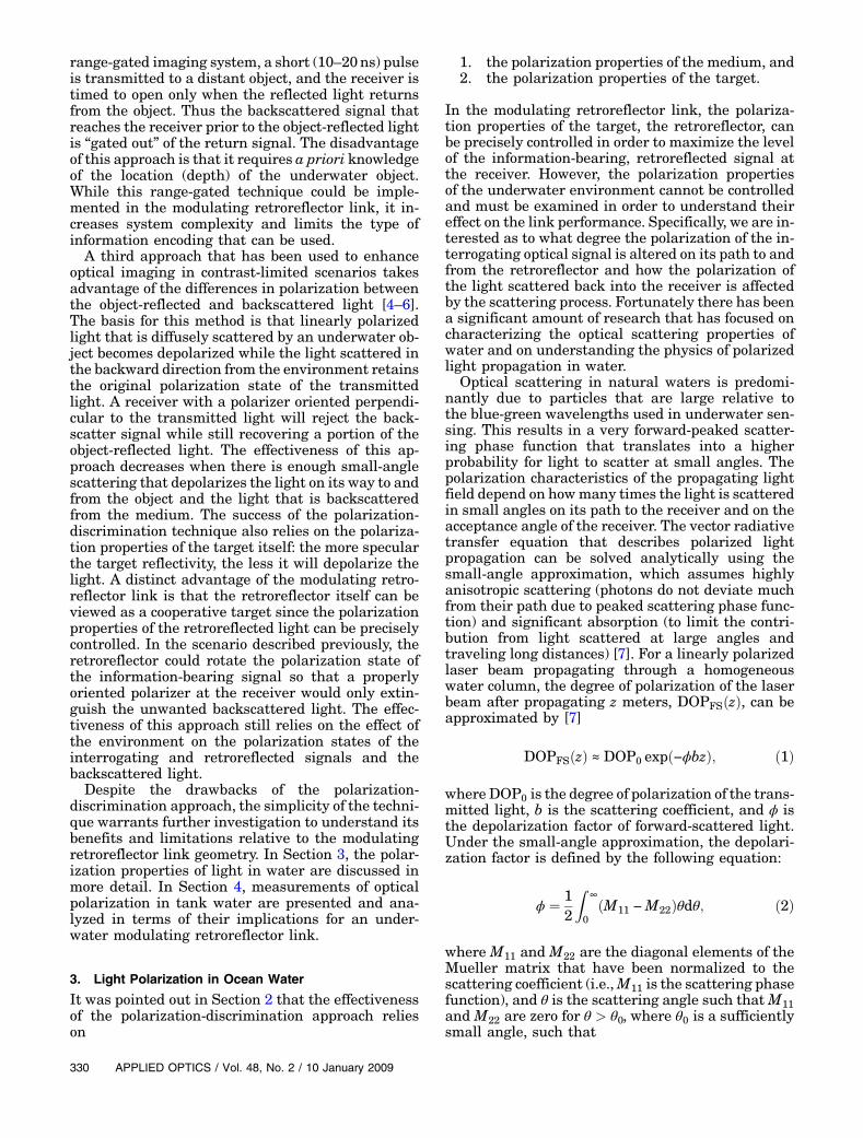
The experimental setup for measuring the degreeof polarization of backscattered light as a function ofwater clarity and receiver field of view is shown inFig. 4. The same receiver components were used tomeasure the backscattered light at the oppositeend of the tank. The mirror through which the laserlight was transmitted was used to reflect the back-scattered light into the receiver optics. A beam dumpwas used in the tank to prevent any scattered lightfrom the back window from entering the receiver.The optical scatter from the front window was mea-sured by temporarily placing the beam dump at thefront of the tank and recording the detected signallevel. This level was then subtracted from subse-quent measurements of the backscattered signalfrom water.
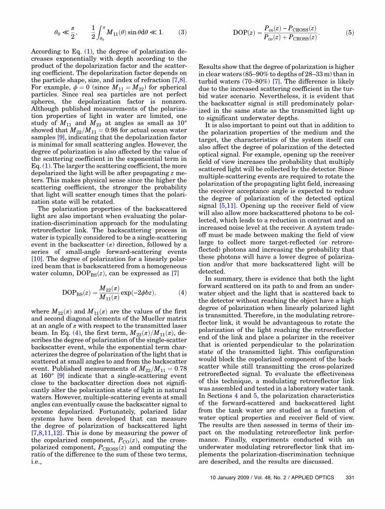
The backscattered signal levels are plotted inFig. 5 as a function of attenuation length for thetwo receiver fields of view. Unlike the case forthe forward-scattered beam, where the signaldecreased with increasing attenuation length, the
Fig. 2. Experimental results showing the amplitudes of copolar-ized and cross-polarized forward-scattered light (left axis) and thecorresponding degrees of polarization (right axis) for two differentfields of view. The data are plotted as a function of the attenuationlength.
Fig. 3. Data from Fig. 2 plotted along with the nonscatteredcomponents of the copolarized and cross-polarized signals.
Fig. 4. Experimental setup for measuring the degree ofpolarization of backscattered light. PMT, photomultiplier tube.
10 January 2009 / Vol. 48, No. 2 / APPLIED OPTICS 333
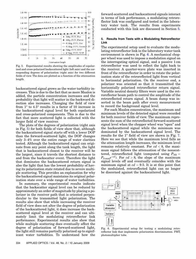
backscattered signal grows as the water turbidity in-creases. This is due to the fact that as more Maalox isadded, the particle concentration increases and theprobability that light will scatter in the backward di-rection also increases. Changing the field of viewfrom 1° to 4:5° results in a factor of 10 increase inthe backscattered signal level for both copolarizedand cross-polarized components. This is due to thefact that more scattered light is collected with thelarger field of view receiver.The plots of the degrees of polarization (right axis
in Fig. 5) for both fields of view show that, althoughthe backscattered signal starts off with a lower DOPthan the forward-scattered light, the DOP changesonly 3–4% over the entire range of water claritiestested. Although the backscattered signal can origi-nate from any point along the tank length, the lightthat is backscattered closest to the receiver will bethe largest, since it travels the shortest distance toand from the backscatter event. Therefore the lightthat dominates the backscattered return signal isalso the light that has the lowest probability of hav-ing its polarization state rotated due to severe multi-ple scattering. This provides an explanation for whythe backscattered signal maintains its original polar-ization state over a wide range of water turbidities.In summary, the experimental results indicate
that the backscatter signal level can be reduced byapproximately an order of magnitude by placing a po-larizer in the receiver path that is oriented perpen-dicular to the transmitted light polarization. Theresults also show that while increasing the receiverfield of view does not alter the degree of polarizationof the backscattered light, it does increase the back-scattered signal level at the receiver and can ulti-mately limit the modulating retroreflector linkperformance. Experimental results also show thatwhile multiple scattering does eventually affect thedegree of polarization of forward-scattered light,the light still remains partially polarized up to signif-icant water turbidities. To understand how the
forward-scattered and backscattered signals interactin terms of link performance, a modulating retrore-flector link was configured and tested in the labora-tory water tank. The results from experimentsconducted with this link are discussed in Section 5.
5. Results from Tests with a Modulating RetroreflectorLink
The experimental setup used to evaluate the modu-lating retroreflector link in the laboratory water tankenvironment is shown in Fig. 6. A mechanical chop-per wheel was used to impose a modulation signal onthe interrogating optical signal, and a passive 1 cmretroreflector was used to reflect the light back tothe receiver. A quarter-wave plate was inserted infront of the retroreflector in order to rotate the polar-ization state of the retroreflected light from verticalto horizontal polarization. On the receiver end, apolarizer was oriented so that it transmitted thehorizontally polarized retroreflector return signal.Variable neutral density filters were used in the ret-roreflector beam path to control the amplitude of theretroreflected return signal. A beam dump was in-serted in the beam path after every measurementto record the background signal level.
For each Maalox concentration, the maximum andminimum levels of the detected signal were recordedfor both receiver fields of view. The maximum repre-sents the sum of the retroreflected forward-scatteredsignal level when the chopper wheel was “open” andthe backscattered signal while the minimum wasdominated by the backscattered signal level. Theresults for the 1° field of view are shown in Fig. 7.Here we see that while the maximum level falls asthe attenuation length increases, the minimum levelremains relatively constant. For cd < 8, the maxi-mum signal follows the attenuation of the nonscat-tered, retroreflected light (computed using PNS ¼P0;maxe−cd). For cd > 8, the slope of the maximumsignal levels off and eventually coincides with theminimum signal at cd ¼ 9:5. It is at this point thatthe modulated, retroreflected light can no longerbe discerned against the backscattered light.
Fig. 5. Experimental results showing the amplitudes of copolar-ized and cross-polarized backscattered light (left axis) and the cor-responding degrees of polarization (right axis) for two differentfields of view. The data are plotted as a function of the attenuationlength.
Fig. 6. Experimental setup for testing a modulating retro-reflector link that implements polarization discrimination. PMT,photomultiplier tube.
334 APPLIED OPTICS / Vol. 48, No. 2 / 10 January 2009
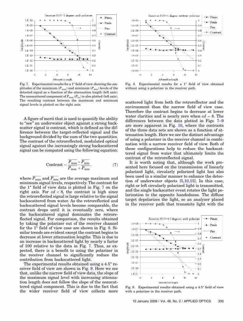
A figure of merit that is used to quantify the abilityto “see” an underwater object against a strong back-scatter signal is contrast, which is defined as the dif-ference between the target-reflected signal and thebackground divided by the sum of the two quantities.The contrast of the retroreflected, modulated opticalsignal against the increasingly strong backscatteredsignal can be computed using the following equation:
Contrast ¼ Pmax − Pmin
Pmax þ Pmin; ð7Þ
where Pmax and Pmin are the average maximum andminimum signal levels, respectively. The contrast forthe 1° field of view data is plotted in Fig. 7 on theright axis. For cd < 8, the contrast is high sincethe retroreflected signal is large relative to the signalbackscattered from water. As the retroreflected andbackscattered signal levels become comparable, thecontrast drops until it is eventually zero, wherethe backscattered signal dominates the retrore-flected signal. For comparison, the results obtainedby taking the polarizer out of the receiver channelfor the 1° field of view case are shown in Fig. 8. Si-milar trends are evident except the contrast begins todecrease at lower attenuation lengths. This is due toan increase in backscattered light by nearly a factorof 100 relative to the data in Fig. 7. Thus, as ex-pected, there is a benefit to using the polarizer inthe receiver channel to significantly reduce thecontribution from backscattered light.The experimental results obtained using a 4:5° re-
ceiver field of view are shown in Fig. 9. Here we seethat, unlike the narrow field of view data, the slope ofthe maximum signal level with increasing attenua-tion length does not follow the slope of the nonscat-tered signal component. This is due to the fact thatthe wider receiver field of view collects more
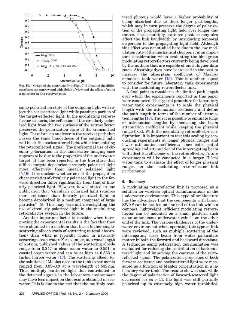
scattered light from both the retroreflector and theenvironment than the narrow field of view case.Therefore the contrast begins to decrease at lowerwater clarities and is nearly zero when cd ¼ 8. Thedifferences between the data plotted in Figs. 7–9are more apparent in Fig. 10, where the contrastsof the three data sets are shown as a function of at-tenuation length. Here we see the distinct advantageof using a polarizer in the receiver channel in combi-nation with a narrow receiver field of view. Both ofthese configurations help to reduce the backscat-tered signal from water that ultimately limits thecontrast of the retroreflected signal.
It is worth noting that, although the work pre-sented here focused on the transmission of linearlypolarized light, circularly polarized light has alsobeen used in a similar manner to enhance the detec-tion of underwater objects [5,10,15]. In this case,right or left circularly polarized light is transmitted,and the single backscatter event rotates the light po-larization to the opposite handedness. The diffusetarget depolarizes the light, so an analyzer placedin the receiver path that transmits light with the
Fig. 7. Experimental results for a 1° field of view showing the am-plitudes of the maximum (Pmax) and minimum (Pmin) levels of thedetected signal as a function of the attenuation length (left axis).The nonscattered component of Pmax (Pns) is also plotted (left axis).The resulting contrast between the maximum and minimumsignal levels is plotted on the right axis.
Fig. 8. Experimental results for a 1° field of view obtainedwithout using a polarizer in the receiver path.
Fig. 9. Experimental results obtained using a 4:5° field of viewwith a polarizer in the receiver path.
10 January 2009 / Vol. 48, No. 2 / APPLIED OPTICS 335
same polarization state of the outgoing light will re-ject the backscattered light while passing a portion ofthe target-reflected light. In the modulating retrore-flector scenario, the reflection of the circularly polar-ized light from the two surfaces of the retroreflectorpreserves the polarization state of the transmittedlight. Therefore, an analyzer in the receiver path thatpasses the same handedness of the outgoing lightwill block the backscattered light while transmittingthe retroreflected signal. The preferential use of cir-cular polarization in the underwater imaging caseappears to be due to the properties of the underwatertarget. It has been reported in the literature thatdiffuse targets depolarize circularly polarized lightmore effectively than linearly polarized light[5,16]. It is unclear whether or not the propagationcharacteristics of circularly polarized light in the for-ward direction differ significantly from that of line-arly polarized light. However, it was stated in onepublication that “circularly polarized light requiresmore collisions than linearly polarized light tobecome depolarized in a medium composed of largeparticles” [5]. This may warrant investigating theuse of circularly polarized light in the modulatingretroreflector system in the future.Another important factor to consider when inter-
preting the experimental results is the fact that theywere obtained in a medium that has a higher single-scattering albedo (ratio of scattering to total absorp-tion) than what is typically found in naturallyoccurring ocean water. For example, at a wavelengthof 514nm, published values of the scattering albedorange from 0.247 in clear ocean water to 0.551 incoastal ocean water and can be as high as 0.833 inturbid harbor water [17]. The scattering albedo forthe solutions of Maalox used in the tank experimentsranged from 0.85–0.9 at a wavelength of 532nm.Thus multiply scattered light that contributed tothe detected signals in the laboratory environmentmay have less impact on the results obtained in sea-water. This is due to the fact that the multiply scat-
tered photons would have a higher probability ofbeing absorbed due to their longer pathlengths,which may in turn preserve the degree of polariza-tion of the propagating light field over longer dis-tances. These multiply scattered photons may alsoaffect the link bandwidth by introducing temporaldispersion to the propagating light field. Althoughthis effect was not studied here due to the low mod-ulation rate of the mechanical chopper, it is an impor-tant consideration when evaluating the blue-greenmodulating retroreflectors currently being developedby the authors that are capable of much higher datarates. Absorbing dyes have been used in the past toincrease the absorption coefficient of Maalox-enhanced tank water [13]. This is another aspectto consider for future laboratory tank experimentswith the modulating retroreflector link.
A final point to consider is the limited path lengthover which the experiments reported in this paperwere conducted. The typical procedure for laboratorywater tank experiments is to scale the physicallength with the attenuation coefficient and definethe path length in terms of the number of attenua-tion lengths [13]. Thus it is possible to simulate long-er attenuation lengths by increasing the beamattenuation coefficient while keeping the physicalrange fixed. With the modulating retroreflector con-figuration, it is important to test this scaling by con-ducting experiments at longer physical ranges andlower attenuation coefficients since both spatialspreading and attenuation of the interrogating beamwill affect the efficiency of the retroreflector. Futureexperiments will be conducted in a larger (7:2m)water tank to evaluate the effect of longer physicalranges on the modulating retroreflector linkperformance.
6. Summary
A modulating retroreflector link is proposed as asolution for wireless optical communications in theunderwater environment. This type of architecturehas the advantage that the components with largerSWAP can be located on one end of the link while acompact, lightweight, efficient modulating retrore-flector can be mounted on a small platform suchas an autonomous underwater vehicle on the otherend of the link. The various challenges of the under-water environment when operating this type of linkwere reviewed, such as multiple scattering of theinterrogating laser beam from water particulatematter in both the forward and backward directions.A technique using polarization discrimination wasevaluated for reducing the contribution of backscat-tered light and improving the contrast of the retro-reflected signal. The polarization properties of bothforward-scattered and backscattered light were mea-sured as a function of Maalox concentration in a la-boratory water tank. The results showed that whilethe degree of polarization of forward-scattered lightdecreased for cd > 11, the light was still partiallypolarized up to extremely high water turbidities.
Fig. 10. Graph of the contrasts from Figs. 7–9 showing the differ-ence between narrow and wide fields of view and the effect of usinga polarizer in the receiver path.
336 APPLIED OPTICS / Vol. 48, No. 2 / 10 January 2009
Furthermore the degree of polarization of back-scattered light was relatively constant over theentire range of water clarities tested. Therefore itwas postulated that by rotating the polarizationstate of the interrogating laser beam at the retrore-flector and inserting a polarizer in the receiver paththat was oriented perpendicular with respect to theoutgoing laser beam polarization, the backscatteredsignal would be significantly reduced, and the con-trast of the retroreflected signal would be enhanced.This configuration was tested in the laboratory tankenvironment as a function of water clarity and recei-ver field of view. The results confirmed the fact thatthe polarization-discrimination technique combinedwith a narrow receiver field of view produced thehighest contrast of the modulated retroreflectedsignal. Future experiments include evaluating theuse of circular polarization on the retroreflector linkperformance, testing the effect of increased absorp-tion on the polarization measurements, and perform-ing measurements at longer physical ranges.
This work was funded by the Office of NavalResearch (ONR).
References1. W. S. Rabinovich, R. Mahon, H. R. Burris, G. C. Gilbreath, P. G.
Goetz, C. I. Moore, M. F. Stell, M. J. Vilcheck, J. L. Witkowsky,L. Swingen, M. R. Suite, E. Oh, and J. Koplow, “Free spaceoptical communications link at 1550nm using multiple-quantum-well modulating retroreflectors in a marineenvironment,” Opt. Eng. 44, 56001–56012 (2005).
2. M. P. Strand, “Underwater electro-optical system for mineidentification,” Proc. SPIE 2496, 487–497 (1995).
3. A. Weidemann, G. R. Fournier, L. Forand, and P. Mathieu,“In harbor underwater threat detection/identification usingactive imaging,” Proc. SPIE 5780, 59–70 (2005).
4. E. V. Miasinikov and T. V. Kondranin, “Effectiveness of thepolarization discrimination technique for underwater viewingsystems,” Proc. SPIE 1750, 433–442 (1992).
5. G. D. Lewis, D. L. Jordan, and P. J. Roberts, “Backscatteringtarget detection in a turbid medium by polarization discrimi-nation,” Appl. Opt. 38, 3937–3944 (1999).
6. J. G. Walker, P. Chang, and K. I. Hopcraft, “Visibility depthimprovement in active polarization imaging in scatteringmedia,” Appl. Opt. 39, 4933–4941 (2000).
7. A. P. Vasilkov, Y. A. Goldin, B. A. Gureev, F. E. Hoge, R. N.Swift, and C. W. Wright, “Aiborne polarized lidar detectionof scattering layers in the ocean,” Appl. Opt. 40, 4353–4364(2001).
8. A. Kouzoubov, M. J. Brennan, and J. C. Thomas, “Treatment ofpolarization in laser remote sensing of ocean water,” Appl.Opt. 37, 3873–3885 (1998).
9. K. J. Voss and E. S. Fry, “Measurement of the Mueller matrixfor ocean water,” Appl. Opt. 23, 4427–4439 (1984).
10. G. D. Gilbert and J. C. Pernicka, “Improvement of underwatervisibility by reduction of backscatter with a circular polariza-tion technique,” Appl. Opt. 6, 741–746 (1967).
11. G. M. Krekov, M. M. Krekova, and V. S. Sarmanaev, “Lasersensing of a subsurface oceanic layer. II. Polarization charac-teristics of signals,” Appl. Opt. 37, 1596–1601 (1998).
12. J. H. Churnside, V. V. Tatarskii, and J. J. Wilson, “Oceano-graphic lidar attenuation coefficients and signal fluctuationsmeasured on a ship in the Southern California Bight,” Appl.Opt. 37, 3105–3112 (1998).
13. S. Q. Duntley, “Underwater lighting by submerged lasers andincandescent sources,” SIO Ref. 71-1 (Scripps Insitution ofOceanography Visibility Laboratory, University of California,San Diego, 1971).
14. A. Laux, R. Billmers, L. Mullen, B. Concannon, J. Davis, J.Prentice, and V. Contarino, “The a, b, cs of oceanographiclidar predictions: a significant step toward closing the loop be-tween theory and experiment,” J. Mod. Opt. 49, 439–451(2002).
15. G. D. Gilbert, “The effects of particle size on contrast improve-ment by polarization discrimination for underwater targets,”Appl. Opt. 9, 421–428 (1970).
16. C. J. Funk, S. B. Bryant, and P. J. Heckman, Jr., Handbookof Underwater Imaging System Design (Naval UnderseaCenter, 1972).
17. C. D. Mobley, Light and Water: Radiative Transfer in NaturalWaters (Academic, 1994).
10 January 2009 / Vol. 48, No. 2 / APPLIED OPTICS 337


