Embed Size (px)
Citation preview
Mechanism
Mechanism and Machine Theory 42 (2007) 1141–1152
www.elsevier.com/locate/mechmt
andMachine Theory
Balancing conditions of spatial mechanisms
Nguyen Van Khang *, Nguyen Phong Dien
Department of Applied Mechanics, Hanoi University of Technology, 1 Dai Co Viet, Hanoi, Viet Nam
Received 6 April 2006; received in revised form 11 July 2006; accepted 31 August 2006Available online 12 October 2006
Abstract
The article proposes a method to algebraically derive the balancing conditions for shaking force and shaking moment ofspatial one-degree-of freedom mechanisms. These include formulae for complete elimination of the shaking force and theshaking moment caused by all moving links. The method has advantage of being suitable for the application of the widelyaccessible computer algebra systems such as MAPLE�. In the example, the algebraic balancing conditions for shakingforce and shaking moment of a spatial slider crank mechanism are given.� 2006 Elsevier Ltd. All rights reserved.
Keywords: Mechanism; Dynamic balancing; Dynamics of machines; Multibody dynamics
1. Introduction
The balancing of mechanisms is a classic problem in the field of the machine dynamics. The objective ofbalancing a mechanism is to eliminate the shaking force and shaking moment transmitted to the base and sur-rounding, in order that the mechanism attains dynamic efficiency and extended fatigue life.
Methods of complete shaking force and shaking moment balancing of planar mechanisms have been devel-oped in recent years [1–8]. It is well known that the shaking force and the shaking moment caused by all mov-ing links can be reduced by either internal mass redistribution, using counterweights or adding supplementarylinks such as cams or gears to the initial mechanism.
In contrast to the rapid progress in balancing theory of planar mechanisms, the development on the bal-ancing theory of spatial mechanisms is still limited. Balancing methods of planar mechanisms cannot bedirectly applicable to spatial mechanisms since kinematic and dynamic properties of spatial mechanisms aremuch more complex. The literature on this respect therefore is not extensive [8–18].
One of the problems of the complete shaking force and shaking moment balancing of the mechanism con-sists of deriving the so-called balancing conditions. These balancing conditions can be used to determine thesize and location of counterweights or supplementary links which must be added to the initial mechanism, inorder to eliminate the shaking force and the shaking moment.
0094-114X/$ - see front matter � 2006 Elsevier Ltd. All rights reserved.
doi:10.1016/j.mechmachtheory.2006.08.007
* Corresponding author. Tel.: +84 4 8680469; fax: +84 4 8683280.E-mail addresses: [email protected] (N. Van Khang), [email protected] (N. Phong Dien).
1142 N. Van Khang, N. Phong Dien / Mechanism and Machine Theory 42 (2007) 1141–1152
This article presents the complete shaking force and shaking moment balancing of space mechanisms usingthe methods of multibody dynamics [19–22] leading to algebraic balancing equations. The developed methodis suitable for the application of the widely accessible computer algebra systems such as MAPLE�. In theexample, the conditions for complete shaking force and shaking moment balancing of a spatial slider crankmechanism are given.
2. Balancing theory of spatial mechanism
2.1. General balancing conditions
We consider a spatial mechanism with holonomic and rheonomic constraints as a set of linked rigid bodiesin a closed loop structure. The shaking force F* and the shaking moment M�
O referred to a fixed point O, whichare caused by all moving links, can be expressed in the compact matrix form [14,19–22]
F� ¼ � d
dtp ¼ � d
dt
Xn
i¼1
mivSi ð1Þ
M�O ¼ �
d
dtlO ¼ �
d
dt
Xn
i¼1
ðIixi þ ~rSi mivSiÞ ð2Þ
wheremi mass of the ith link,n number of the moving links,vSi
velocity of the center of mass Si,xi angular velocity of the ith link,Ii inertia matrix of the ith link referred to Si,p linear momentum of the mechanism,lO angular momentum of the mechanism taken about fixed point O.
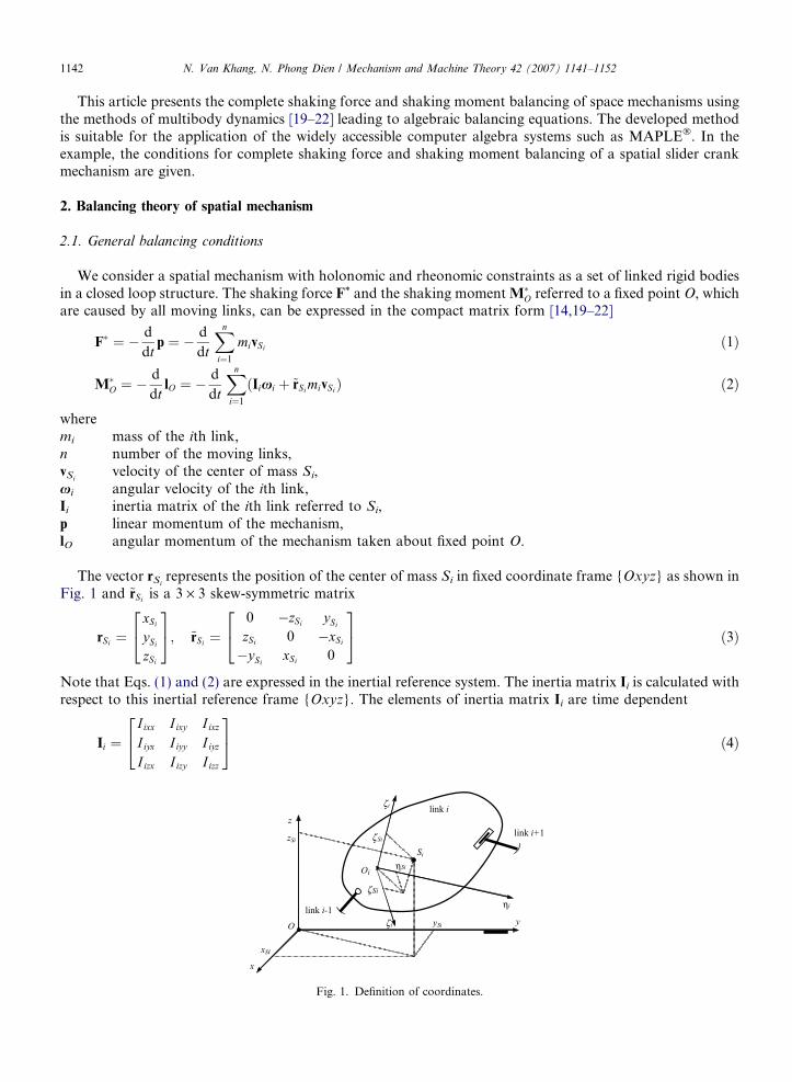
The vector rSirepresents the position of the center of mass Si in fixed coordinate frame {Oxyz} as shown in
Fig. 1 and ~rSi is a 3 · 3 skew-symmetric matrix
rSi ¼xSi
ySi
zSi
24
35; ~rSi ¼
0 �zSi ySi
zSi 0 �xSi
�ySixSi 0
24
35 ð3Þ
Note that Eqs. (1) and (2) are expressed in the inertial reference system. The inertia matrix Ii is calculated withrespect to this inertial reference frame {Oxyz}. The elements of inertia matrix Ii are time dependent
Ii ¼I ixx I ixy I ixz
I iyx I iyy I iyz
I izx I izy I izz
24
35 ð4Þ
link i+1
y
z
ηi
Si
ηSi
Si
Oi
O
link i
link i-1
zSi
xSi
i
Si
x
ySi
ζ
ζ
iζ
ζ
Fig. 1. Definition of coordinates.
N. Van Khang, N. Phong Dien / Mechanism and Machine Theory 42 (2007) 1141–1152 1143
For the following calculation we use often the inertia matrix IðiÞi relative to the axes of the link-fixed coordinate
frame {Oinigifi}:
IðiÞi ¼
I inn I ing I inf
I ign I igg I igf
I ifn I ifg I iff
264
375 ð5Þ
The elements of inertia matrix IðiÞi are constant in this case. According to [19–21] the matrix Ii can be written in
term of the matrix IðiÞi using the formula
Ii ¼ AiIðiÞi AT
i ð6Þ
where Ai denotes the matrix of the direction cosines of the ith link referred to the fixed coordinate frame.Let q be the independent generalized coordinate which describes the position of the mechanism. The veloc-
ity vSiand the angular velocity xi are given by [19]
vSi ¼ JT iðqÞ _qðtÞ ð7Þxi ¼ JRiðqÞ _qðtÞ ð8Þ
where JTi(q) and JRi
(q) denote the 3 · 1 Jacobian matrices that relate velocity vSiand angular velocity xi to the
generalized velocities _q. The matrices JTi(q) and JRi
(q) can be written in the form
JT i ¼ x0Siy0Si
z0Si
� �T; JRi ¼ s0ix s0iy s0iz
� �T ð9Þ
where the prime represents the derivative with respect to the generalized coordinate q and six, siy, siz are threecomponents of the rotational vector si (see also [19]). Substituting (7) and (8) into Eqs. (1) and (2), the shakingforce F* and the shaking moment M�
O take the form
F� ¼ � d
dt
Xn
i¼1
miJT iðqÞ" #
_q
( )ð10Þ
M�O ¼ �
d
dt
Xn
i¼1
IiJRiðqÞ þ mi~rSi JT iðqÞ" #
_q
( )ð11Þ
Using Eqs. (3), (4) and (9), the components of the shaking force F* and the shaking moment M�O in Cartesian
coordinates are given by
F �x ¼ � €qþ _q2 d
dq
� �Xn
i¼1
mix0Sið12Þ
F �y ¼ � €qþ _q2 d
dq
� �Xn
i¼1
miy0Sið13Þ
F �z ¼ � €qþ _q2 d
dq
� �Xn
i¼1
miz0Sið14Þ
M�Ox ¼ � €qþ _q2 d
dq
� �Xn
i¼1
mi ySiz0Si� zSi y
0Si
� �þ I ixxs0ix þ I ixys0iy þ I ixzs0iz
h ið15Þ
M�Oy ¼ � €qþ _q2 d
dq
� �Xn
i¼1
mi zSi x0Si� xSi z
0Si
� �þ I iyxs0ix þ I iyys0iy þ I iyzs0iz
h ið16Þ
M�Oz ¼ � €qþ _q2 d
dq
� �Xn
i¼1
mi xSi y0Si� ySi
x0Si
� �þ I izxs0ix þ I izys0iy þ I izzs0iz
h ið17Þ
So, the mechanism can be completely balanced if the shaking force and the shaking moment vanish at everyposition, this yields the general conditions for complete balancing of spatial mechanisms
1144 N. Van Khang, N. Phong Dien / Mechanism and Machine Theory 42 (2007) 1141–1152
Xn
i¼1
mix0Si¼ 0;
Xn
i¼1
miy 0Si¼ 0;
Xn
i¼1
miz0Si¼ 0 ð18Þ
Xn
i¼1
mi ySiz0Si� zSi y
0Si
� �þ I ixxs0ix þ I ixys0iy þ I ixzs0iz
h i¼ 0 ð19aÞ
Xn
i¼1
mi zSi x0Si� xSi z
0Si
� �þ I iyxs0ix þ I iyys0iy þ I iyzs0iz
h i¼ 0 ð19bÞ
Xn
i¼1
mi xSi y0Si� ySi
x0Si
� �þ I izxs0ix þ I izys0iy þ I izzs0iz
h i¼ 0 ð19cÞ
2.2. Algebraic balancing conditions of the shaking force
The position vector rSiwith respect to the fixed coordinate frame is given by
rSi ¼ rOi þ AirðiÞSi
ð20Þ
where rOiis position vector of origin Oi in the fixed coordinate frame {Oxyz} and r
ðiÞi is position vector of Si in
the moving coordinate frame {Oinigifi} shown in Fig. 1
rðiÞSi¼ nSi
gSifSi
� �T ð21Þ
From (20) and (21) the coordinates of the center of mass Si, rSi ¼ xSi ySizSi
� �T, can be rewritten as
[1,2]
xSi ¼ e�xi þ aTi z; ySi
¼ e�yi þ bTi z; zSi ¼ e�zi þ cT
i z; i ¼ 1; 2; . . . ; n ð22Þ
where the vectors ai, bi and ci consist of components which are independent of q, the elements of vector z arefunctions of the generalized coordinates which describe the motion of the links, e�xi, e�yi and e�zi are constantvalues.
Analogous to Eq. (22), the loop equations of the mechanism may be written in the matrix form
Dz ¼ f; D ¼ DI;DII½ � ð23Þ
Here the matrix D and the vector f include the components which are geometrical parameters and independentof q. A partitioning of vector z from Eq. (23)
z ¼v
w
� ð24Þ
leads to the following relation:
DIvþDIIw ¼ f ð25Þ
The matrix DII is chosen so that it must be a square matrix and nonsingular. The dimension of vector w andthe number of the loop equations are equal. By solving (25) with the vector of variables w, we have
w ¼ D�1II ðf �DIvÞ ð26Þ
By using Eqs. (24) and (26), the coordinates of the center of mass Si and their derivatives can be expressed interms of the reduced vector of variables v as
xSi ¼ exi þ gTi v; ySi
¼ eyi þ hTi v; zSi ¼ eyi þ kT
i v ð27Þ
x0Si¼ gT
i
dv
dq; y 0Si
¼ hTi
dv
dq; z0Si
¼ kTi
dv
dqð28Þ
N. Van Khang, N. Phong Dien / Mechanism and Machine Theory 42 (2007) 1141–1152 1145
where
gTi ¼ aT
iI � aTiIID
�1II DI; hT
i ¼ bTiI � bT
iIID�1II DI; kT
i ¼ cTiI � cT
iIID�1II DI
exi ¼ e�xi þ aTiIID
�1II f; eyi ¼ e�yi þ bT
iIID�1II f; ezi ¼ e�zi þ cT
iIID�1II f
ð29Þ
where vectors aiI, aiII, biI, biII, ciI, ciII include elements which are independent of q. Substituting Eq. (28) intobalancing conditions (18), we obtain
Xn
i¼1
migTi
!dv
dq¼ 0;
Xn
i¼1
mihTi
!dv
dq¼ 0;
Xn
i¼1
mikTi
!dv
dq¼ 0 ð30Þ
Finally, the algebraic balancing conditions for shaking force take the compact matrix form
Xn
i¼1
migTi ¼ 0;
Xn
i¼1
mihTi ¼ 0;
Xn
i¼1
mikTi ¼ 0 ð31Þ
2.3. Algebraic balancing conditions of the shaking moment
In order to extract the conditions for the shaking moment balancing, some additional transformations arerequired. Substituting (27) and (28) into Eq. (19), we have
uT1
dv
dqþ vTS1
dv
dqþXn
i¼1
I ixxs0ix þ I ixys0iy þ I ixzs0iz �
¼ 0 ð32aÞ
uT2
dv
dqþ vTS2
dv
dqþXn
i¼1
I iyxs0ix þ I iyys0iy þ I iyzs0iz �
¼ 0 ð32bÞ
uT3
dv
dqþ vTS3
dv
dqþXn
i¼1
I izxs0ix þ I izys0iy þ I izzs0iz �
¼ 0 ð32cÞ
where
uT1 ¼
Xn
i¼1
mi eyikTi � ezih
Ti
� �; uT
2 ¼Xn
i¼1
mi ezigTi � exik
Ti
� �; uT
3 ¼Xn
i¼1
mi exihTi � eyig
Ti
� �ð33Þ
and skew-symmetric matrices
S1 ¼Xn
i¼1
mi hikTi � kih
Ti
� �; S2 ¼
Xn
i¼1
mi kigTi � gik
Ti
� �; S3 ¼
Xn
i¼1
mi gihTi � hig
Ti
� �ð34Þ
Analog to Eqs. (22), the elements of the rotational vector si can be rewritten as [1]
six ¼ s�ix þ rT1iz; siy ¼ s�iy þ rT
2iz; siz ¼ s�iz þ rT3iz ð35Þ
where the vectors r1i, r2i and r3i include components which are independent of q, the values s�ix, s�iy and s�iz areconstant. The corresponding derivatives are given by
s0ix ¼ rT1i
dz
dq; s0iy ¼ rT
2i
dz
dq; s0iz ¼ rT
3i
dz
dqð36Þ
With the vector of variables z, the elements of the inertia matrix Ii may be rewritten in the matrix form as
I ixx ¼ zTdixx; I ixy ¼ zTdixy ; I ixz ¼ zTdixz
I iyx ¼ zTdiyx; I iyy ¼ zTdiyy ; I iyz ¼ zTdiyz
I izx ¼ zTdizx; I izy ¼ zTdizy ; I izz ¼ zTdizz
ð37Þ
1146 N. Van Khang, N. Phong Dien / Mechanism and Machine Theory 42 (2007) 1141–1152
where all elements in the vectors dixx, dixy, dixz, diyx, diyy, diyz, dizx, dizy, dizz are independent of the generalizedcoordinate q. By using Eqs. (36) and (37) and introducing the new matrices
H1 ¼ dixxrT1i þ dixyrT
2i þ dixzrT3i
H2 ¼ diyxrT1i þ diyyrT
2i þ diyzrT3i
H3 ¼ dizxrT1i þ dizyrT
2i þ dizzrT3i
ð38Þ
the third term in Eqs. (32a)–(32c) may be expressed in the matrix form as
Xni¼1
I ixxs0ix þ I ixys0iy þ I ixzs0iz �
¼ zTH1
dz
dqð39aÞ
Xn
i¼1
I iyxs0ix þ I iyys0iy þ I iyzs0iz �
¼ zTH2
dz
dqð39bÞ
Xn
i¼1
I izxs0ix þ I izys0iy þ I izzs0iz �
¼ zTH3
dz
dqð39cÞ
The matrix Hj can be partitioned in four sub-matrices corresponding to the vector of variables v and w in Eq.(24) as follows:
Hj ¼Hj1 Hj2
Hj3 Hj4
� ; j ¼ 1; 2; 3 ð40Þ
By using (26) and (40), the following relation is found from Eq. (39):
zTHjdz
dq¼ v
w
� THj1 Hj2
Hj3 Hj4
� dvdqdwdq
" #¼ vT Hj1 þ ðD�1
II DIÞTðHj4D�1II DI �Hj3Þ �Hj2D�1
II DI
h i dv
dq
þ ðD�1II fÞTðHj3 �Hj4D�1
II DIÞdv
dqð41Þ
By introducing the vector u�j
u�j
�T
¼ ðD�1II fÞTðHj3 �Hj4D�1
II DIÞ; j ¼ 1; 2; 3 ð42Þ
and the matrices S�j (j = 1,2,3)
S�j ¼ Hj1 þ ðD�1II DIÞTðHj4D�1
II DI �Hj3Þ �Hj2D�1II DI ð43Þ
Eq. (32) takes the form
uj þ u�j
�T dv
dqþ vT Sj þ S�j
� dv
dq¼ 0; j ¼ 1; 2; 3 ð44Þ
Finally, the following algebraic balancing conditions for shaking moment are found from Eq. (44):
uj þ u�j ¼ 0; Sj þ S�j ¼ 0; j ¼ 1; 2; 3 ð45Þ
The described algorithm allows us to derive the balancing conditions (31) and (45) for spatial one-degree-offreedom linkages.3. Example
In the following example we introduce the application of the balancing theory described above to a spatialslider crank mechanism shown in Fig. 2.
The configuration of the mechanism is also prescribed by rotation angles u, b and c. The angle u is chosenas the independent generalized coordinates q = u. The loop equations of the mechanism can be expressed inthe form
hþ l1 cos u� l2 cos c ¼ 0
� l1 sin u cos aþ l2 sin c sin b� d ¼ 0ð46Þ
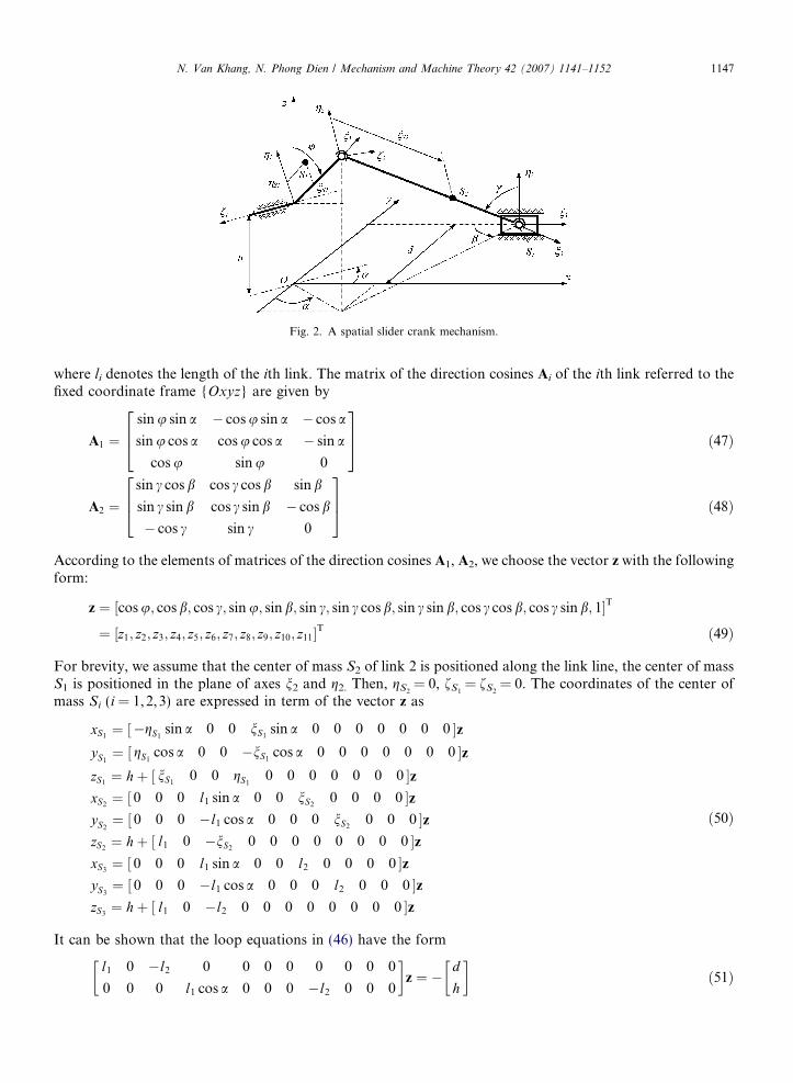
Fig. 2. A spatial slider crank mechanism.
N. Van Khang, N. Phong Dien / Mechanism and Machine Theory 42 (2007) 1141–1152 1147
where li denotes the length of the ith link. The matrix of the direction cosines Ai of the ith link referred to thefixed coordinate frame {Oxyz} are given by
A1 ¼sin u sin a � cos u sin a � cos a
sin u cos a cos u cos a � sin a
cos u sin u 0
264
375 ð47Þ
A2 ¼sin c cos b cos c cos b sin b
sin c sin b cos c sin b � cos b
� cos c sin c 0
264
375 ð48Þ
According to the elements of matrices of the direction cosines A1, A2, we choose the vector z with the followingform:
z ¼ cos u; cos b; cos c; sin u; sin b; sin c;½ sin c cos b; sin c sin b; cos c cos b; cos c sin b; 1�T
¼ z1; z2; z3; z4; z5; z6; z7; z8; z9; z10; z11½ �T ð49Þ
For brevity, we assume that the center of mass S2 of link 2 is positioned along the link line, the center of massS1 is positioned in the plane of axes n2 and g2. Then, gS2
= 0, fS1= fS2
= 0. The coordinates of the center ofmass Si (i = 1,2,3) are expressed in term of the vector z as
xS1¼ ½�gS1
sin a 0 0 nS1sin a 0 0 0 0 0 0 0 �z
yS1¼ ½ gS1
cos a 0 0 �nS1cos a 0 0 0 0 0 0 0 �z
zS1¼ hþ ½ nS1
0 0 gS10 0 0 0 0 0 0 �z
xS2¼ ½ 0 0 0 l1 sin a 0 0 nS2
0 0 0 0 �zyS2¼ ½ 0 0 0 �l1 cos a 0 0 0 nS2
0 0 0 �zzS2¼ hþ ½ l1 0 �nS2
0 0 0 0 0 0 0 0 �zxS3¼ ½ 0 0 0 l1 sin a 0 0 l2 0 0 0 0 �z
yS3¼ ½ 0 0 0 �l1 cos a 0 0 0 l2 0 0 0 �z
zS3¼ hþ ½ l1 0 �l2 0 0 0 0 0 0 0 0 �z
ð50Þ
It can be shown that the loop equations in (46) have the form
l1 0 �l2 0 0 0 0 0 0 0 0
0 0 0 l1 cos a 0 0 0 �l2 0 0 0
� z ¼ �
d
h
� ð51Þ
1148 N. Van Khang, N. Phong Dien / Mechanism and Machine Theory 42 (2007) 1141–1152
The reduced vector of variables v and the vector of eliminated variables w are selected from the original vectorz as follows
v ¼ cos u; cos b; sin u; sin b; sin c;½ sin c cos b; cos c cos b; cos c sin b; 1�T ð52Þw ¼ cos c; sin c sin b½ �T ð53Þ
The matrices DI, DII and DII�1 in Eq. (25) are given by
DI ¼l1 0 0 0 0 0 0 0 0
0 0 l1 cos a 0 0 0 0 0 0
� ; DII ¼
�l2 0
0 �l2
� ; D�1
II ¼ �1
l2
1 0
0 1
� ð54Þ
3.1. Conditions of the shaking force balancing
With the known coordinates of the center of masses from Eq. (50) and the matrix DI, DII�1 from Eq. (54),
the vectors gi, hi and ki can be determined according to Eq. (29) without any difficulty. Then, by substitutingall these results into Eq. (31), we get the following conditions for the complete shaking force balancing:
� m1gS1sin a ¼ 0
ðm1nS1þ m2l1 þ m3l1Þ sin a ¼ 0
m2nS2þ m3l2 ¼ 0
m1gS1cos a ¼ 0
m1nS1þ m2l1 1� nS2
l2
� �¼ 0
m1nS1cos aþ m2l1 1� nS2
l2
� �cos a ¼ 0
m1gS1¼ 0
ð55Þ
By simplifying the expressions in (55), the balancing conditions for shaking force of the mechanism arereduced into three equations f1 = 0, f2 = 0, f3 = 0, in which
f1 ¼ gS1
f2 ¼ m1nS1þ m2l1 þ m3l1
f3 ¼ m2nS2þ m3l2
ð56Þ
These conditions may be satisfied by internal mass redistribution or adding counterweights mounted on thelinks [11,12,16].
A simple numerical simulation is implemented in order to verify the correctness of these conditions for thestatic balancing. Parameters of the initial mechanism are given as follows: m1 = 7.0 (kg), m2 = 12.5 (kg),m3 = 10.5 (kg), l1 = 0.1 (m), l2 = 0.3 (m), h = 0.1 (m), d = 0.15 (m), nS1
= 0.01 (m), gS1= 0.02 (m),
nS2= 0.05 (m), gS2
= 0 (m).By using the conditions (56), we can determine the size and the location of the counterweights (see also
Fig. 3): m�1n�S1¼ 4:77 (kg m), m�2n
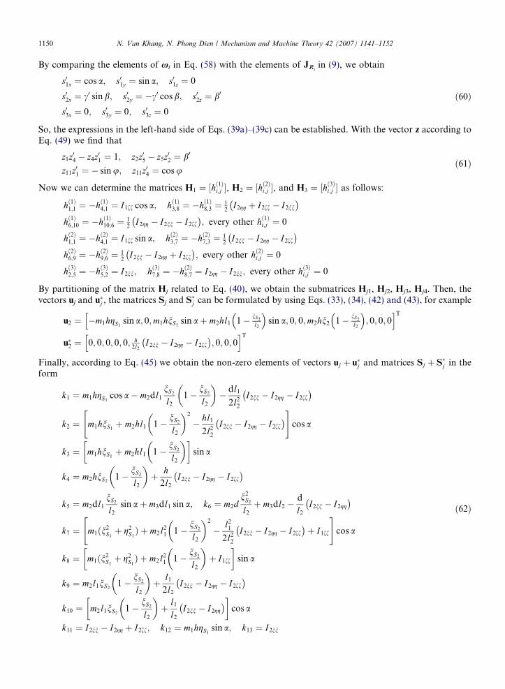
�S2¼ 3:78 (kg m). Fig. 4 simultaneously shows three components of the shak-
ing force produced by the unbalanced mechanism and the full force balanced mechanism. The results verifythat the shaking force of the force balanced mechanism is completely eliminated and there is no forces trans-mitted to the base during the motion of the mechanism.
3.2. Conditions of the shaking moment balancing
In order to derive the conditions for the shaking moment balancing, the angular velocities of the links withrespect to the fixed coordinate frame must be determined. Based on theory of multibody kinematics, theseangular velocities can be calculated from the known matrices of the direction cosines Ai as follows [19]:
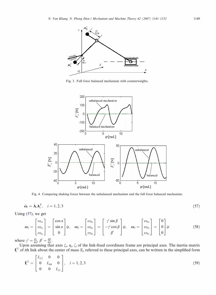
Fig. 3. Full force balanced mechanism with counterweights.
Fig. 4. Comparing shaking forces between the unbalanced mechanism and the full force balanced mechanism.
N. Van Khang, N. Phong Dien / Mechanism and Machine Theory 42 (2007) 1141–1152 1149
~xi ¼ _AiATi ; i ¼ 1; 2; 3 ð57Þ
Using (57), we get
x1 ¼x1x
x1y
x1z
264
375 ¼
cos a
sin a
0
264
375 _u; x2 ¼
x2x
x2y
x2z
264
375 ¼
c0 sin b
�c0 cos b
b0
264
375 _u; x3 ¼
x3x
x3y
x3z
264
375 ¼
0
0
0
264375 _u ð58Þ
where c0 ¼ dcdu, b0 ¼ db
du :Upon assuming that axes ni, gi, fi of the link-fixed coordinate frame are principal axes. The inertia matrix
IðiÞi of ith link about the center of mass Si, referred to these principal axes, can be written in the simplified form
IðiÞi ¼
I inn 0 0
0 I igg 0
0 0 I iff
264
375; i ¼ 1; 2; 3 ð59Þ
1150 N. Van Khang, N. Phong Dien / Mechanism and Machine Theory 42 (2007) 1141–1152
By comparing the elements of xi in Eq. (58) with the elements of JRiin (9), we obtain
s01x ¼ cos a; s01y ¼ sin a; s01z ¼ 0
s02x ¼ c0 sin b; s02y ¼ �c0 cos b; s02z ¼ b0
s03x ¼ 0; s03y ¼ 0; s03z ¼ 0
ð60Þ
So, the expressions in the left-hand side of Eqs. (39a)–(39c) can be established. With the vector z according toEq. (49) we find that
z1z04 � z4z01 ¼ 1; z2z05 � z5z02 ¼ b0
z11z01 ¼ � sin u; z11z04 ¼ cos uð61Þ
Now we can determine the matrices H1 ¼ ½hð1Þi;j �, H2 ¼ ½hð2Þi;j �, and H3 ¼ ½hð3Þi;j � as follows:
hð1Þ1;1 ¼ �hð1Þ4;1 ¼ I1ff cos a; hð1Þ3;8 ¼ �hð1Þ8;3 ¼ 12
I2gg þ I2ff � I2nn
� �hð1Þ6;10 ¼ �hð1Þ10;6 ¼ 1
2I2gg � I2nn � I2ff
� �; every other hð1Þi;j ¼ 0
hð2Þ1;1 ¼ �hð2Þ4;1 ¼ I1ff sin a; hð2Þ3;7 ¼ �hð2Þ7;3 ¼ 12
I2nn � I2gg � I2ff
� �hð2Þ6;9 ¼ �hð2Þ9;6 ¼ 1
2I2nn � I2gg þ I2ff
� �; every other hð2Þi;j ¼ 0
hð3Þ2;5 ¼ �hð3Þ5;2 ¼ I2nn; hð3Þ7;8 ¼ �hð2Þ8;7 ¼ I2gg � I2nn; every other hð3Þi;j ¼ 0
By partitioning of the matrix Hj related to Eq. (40), we obtain the submatrices Hj1, Hj2, Hj3, Hj4. Then, thevectors uj and u�j , the matrices Sj and S�j can be formulated by using Eqs. (33), (34), (42) and (43), for example
u2 ¼ �m1hgS1sin a; 0;m1hnS1
sin aþ m2hl1 1� nS2
l2
�sin a; 0; 0;m2hn2 1� nS2
l2
�; 0; 0; 0
h iT
u�2 ¼ 0; 0; 0; 0; 0; h2l2
I2nn � I2gg � I2ff
� �; 0; 0; 0
h iT
Finally, according to Eq. (45) we obtain the non-zero elements of vectors uj þ u�j and matrices Sj þ S�j in theform
k1 ¼ m1hgS1cos a� m2dl1
nS2
l2
1� nS2
l2
� �� dl1
2l22
I2nn � I2gg � I2ff
� �
k2 ¼ m1hnS1þ m2hl1 1� nS2
l2
� �2
� hl1
2l22
I2nn � I2gg � I2ff
� �" #cos a
k3 ¼ m1hnS1þ m2hl1 1� nS2
l2
� �� sin a
k4 ¼ m2hnS21� nS2
l2
� �þ h
2l2
I2nn � I2gg � I2ff
� �
k5 ¼ m2dl1
nS2
l2
sin aþ m3dl1 sin a; k6 ¼ m2dn2
S2
l2
þ m3dl2 �d
l2
I2nn � I2gg
� �k7 ¼ m1ðn2
S1þ g2
S1Þ þ m2l2
1 1� nS2
l2
� �2
� l21
2l22
I2nn � I2gg � I2ff
� �þ I1ff
" #cos a
k8 ¼ m1ðn2S1þ g2
S1Þ þ m2l2
1 1� nS2
l2
� �þ I1ff
� sin a
k9 ¼ m2l1nS21� nS2
l2
� �þ l1
2l2
I2nn � I2gg � I2ff
� �k10 ¼ m2l1nS2
1� nS2
l2
� �þ l1
l2
I2nn � I2gg
� �� cos a
k11 ¼ I2nn � I2gg þ I2ff; k12 ¼ m1hgS1sin a; k13 ¼ I2nn
ð62Þ
N. Van Khang, N. Phong Dien / Mechanism and Machine Theory 42 (2007) 1141–1152 1151
Note that the above obtained expressions are original. They can be further simplified. When we choose a =p/2, gS1
= 0 and let I2gg = I211, the expressions ki in (62) are reduced as follows:
f4 ¼ m2l2nS2� m2n
2S2� I211
f5 ¼ m1nS1þ m2l1 1� nS2
l2
� �
f6 ¼m2nS2
l1
l2
þ m3l1
f7 ¼ m1n2S1þ m2l2
1 1� nS2
l2
� �þ I111
f8 ¼ I2nn
ð63Þ
The shaking moment is completely balanced if the values of expressions fi (i = 4,5, . . . , 8) in Eq. (63) vanishsimultaneously. It is clearly shown that these conditions cannot be completely satisfied by adding counter-weights, since the values of f8 are not equal to zero in any case. These conditions are mainly of theoreticalinterest. However, Eq. (63) provide the necessary tool for the minimization of the shaking moment. Anotherapproach for solving the problem is the simultaneous minimization of the shaking force and shaking momentbased on conditions (56) and (63). From the conditions
fi ! min ði ¼ 1; 2; . . . ; 8Þ
one can choose a set of optimizing values for geometrical and inertia parameters of the links:m1, m2, m3, nS1, nS2, I111, I2nn, I2gg, I211. This problem will be considered in the future investigation.
4. Conclusions
In this article, a new method has been developed for deriving the general balancing conditions of spatialone-degree-of freedom mechanisms. The following conclusions have been reached:
• Based on theory of multibody dynamics, the algebraic balancing conditions for the shaking force and shak-ing moment of one DOF spatial mechanism have been established.
• The proposed method is illustrated by using a spatial slider crank mechanism. The balancing conditions forthe shaking force determined by this method accord with the results of other authors, for example Bagci[10]. The numerical simulations have been confirmed the feasibility of the proposed method.
• A specialized code has been developed on the MAPLE� environment for this study. It can be concludedthat the proposed method is suitable for the application of the widely accessible computer algebra systemssuch as MAPLE�. The algorithm for deriving the balancing conditions of spatial mechanisms will be pre-sented in the next paper.
• In the application of balancing techniques using counterweights and supplementary links [10–12] for spatialmechanisms, the proposed method may provide a helpful tool to obtain the exact balancing conditions and,therefore, we can get a better balancing results. This will be the subject of future work.
Acknowledgements
This paper was completed with the financial support of the Vietnam Basic Research Program in NaturalScience. An additional support was given by the Deutscher Akademischer Austauschdienst (the German Aca-demic Exchange Service). The authors gratefully acknowledge the generous support of these sponsors.
References
[1] H. Dresig, L. Rockhausen, S. Naake, Balancing Conditions for planar Mechanism, Flexible Mechanism, Dynamics, and Analysis,DE-vol. 47, ASME, 1992.
1152 N. Van Khang, N. Phong Dien / Mechanism and Machine Theory 42 (2007) 1141–1152
[2] H. Dresig, L. Rockhausen, S. Naake, Vollstandiger und harmonischer Ausgleich ebener Mechanismen, Fortschritt-Berichte VDI,Reihe 18, Nr. 155,VDI Verlag, Dusseldorf, 1994.
[3] H. Dresig, J.I. Vulfson, Dynamik der Mechanismen, Deutscher Verlag der Wissenschaften, Berlin, 1989.[4] I.S. Kochev, General method for active balancing of combined shaking moment and torque fluctuations in planar linkages,
Mechanism and Machine Theory 25 (1990) 679–687.[5] W.L. Cleghorn, Mechanics of Machines, Oxford University Press, 2005.[6] Nguyen Van Khang, Nguyen Phong Dien, Pham Van Son, Balancing conditions of planar mechanisms with multi-degree of freedom,
Vietnam Journal of Mechanics 27 (2005) 204–212.[7] Th. Thummel, Literaturbericht zum dynamischen Ausgleich schnellaufender Mechanismen, Wiss. Schriftenreihe der TH Karl-Marx-
Stadt, Mechanismendynamik, Heft 7 (1983) 57–92.[8] G.G. Lowen, F.R. Tepper, R.S. Berkorf, Balancing of linkages – an update, Mechanism and Machine Theory 18 (1983) 213–220.[9] R.E. Kaufman, G.N. Sandor, Complete force balancing of spatial linkages, Transactions of ASME, Journal of Engineering for
Industry 93 (1971) 620–626.[10] C. Bagci, Complete balancing of space mechanisms – shaking force balancing, Transactions of ASME, Journal of Mechanisms,
Transmissions, and Automation in Design 105 (1983) 609–616.[11] Ning-Xin Chen, The complete shaking force balancing of a spatial linkage, Mechanism and Machine Theory 19 (1984) 243–255.[12] Yue-Qing Yu, Complete shaking force and moment balancing of spatial irregular force transmission mechanisms using additional
link, Mechanism and Machine Theory 23 (1988) 279–285.[13] T.M. Abdel-Rahman, M.A. Elbestawi, Synthesis and dynamics of statically balanced direct-drive manipulators with decoupled inertia
tensors, Mechanism and Machine Theory 26 (1991) 389–402.[14] Nguyen Van Khang, Uber den Massenausgleich in Mehrkorpersystemen, Technische Mechanik, Band 14 Heft 3–4 (1994) 231–238.[15] J. Wang, C.M. Gosselin, Static balancing of spatial four-degree-of freedom parallel mechanisms, Mechanism and Machine Theory 35
(2000) 563–592.[16] V. Arakelian, M.R. Smith, Shaking moment minimization of fully force-balanced linkages, in: Proceedings of the 11th World
Congress in Mechanism and Machine Science, Tianjin, China, 2004.[17] J. Park, Principle of dynamical balance for multibody systems, Multibody System Dynamics 14 (2005) 269–299.[18] A. Russo, R. Sinatra, F. Xi, Static balancing of parallel robots, Mechanism and Machine Theory 40 (2005) 191–202.[19] W. Schiehlen, P. Eberhard, Technische Dynamik (2. Auflage), B.G. Teubner, Stuttgart, 2004.[20] M. Hiller, A. Kecskemethy, Ch. Woernle, Computergeschutzte Kinematik und Dynamik fur Fahrzeuge, Roboter und Mechanismen,
Institut A fur Mechanik, Universitat Stuttgart, 1987.[21] R.L. Huston, Multibody Dynamics, Butterworth–Heinemann, Boston, 1990.[22] H. Josephs, R.L. Huston, Dynamics of Mechanical Systems, CRC Press, Boca Raton, 2002.


