Embed Size (px)
Citation preview
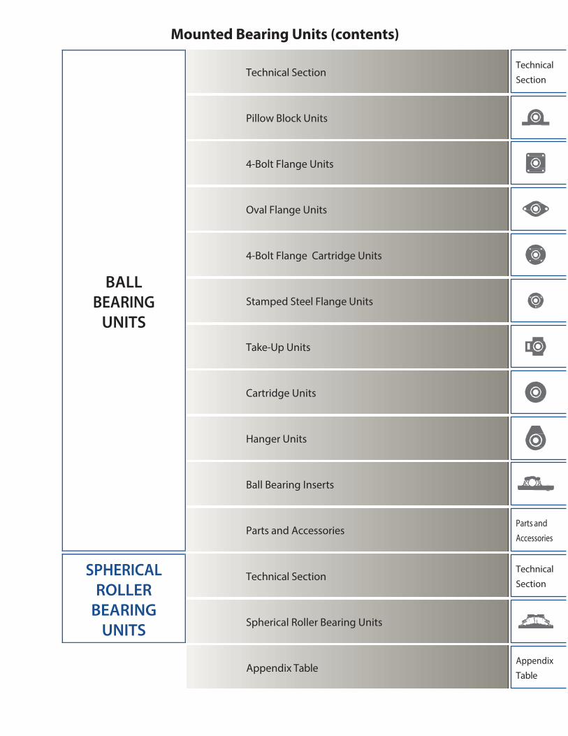
Mounted Bearing Units (contents)
Technical Section
Pillow Block Units
4-Bolt Flange Units
Oval Flange Units
4-Bolt Flange Cartridge Units
Stamped Steel Flange Units
Take-Up Units
Cartridge Units
Hanger Units
Ball Bearing Inserts
Parts and Accessories
Technical
Section
Parts and
Accessories
Technical Section
Spherical Roller Bearing Units
Technical
Section
Appendix Table Appendix
Table
BALL BEARING
UNITS
SPHERICAL ROLLER
BEARING UNITS
Contents
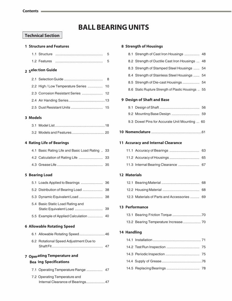
BALL BEARING UNITS
1 Structure and Features 8 Strength of Housings
2 S
2.4 Air Handing Series ..................................... 13 9 Design of Shaft and Base
3 Models
3.1 Model List ................................................... 18
3.2 Models and Features .................................. 20
4 Rating Life of Bearings
9.3 Dowel Pins for Accurate Unit Mounting ... 60
10 Nomenclature ...................................................... 61
11 Accuracy and Internal Clearance
5 Bearing Load
12 Materials
5.1 Loads Applied to Bearings ...................... 36 12.1 Bearing Material ...................................... 68
5.2 Distribution of Bearing Load .................... 38 12.2 Housing Material ..................................... 68
5.3 Dynamic Equivalent Load ........................ 38 12.3 Materials of Parts and Accessories ......... 69
5.4 Basic Static Load Rating and
Static Equivalent Load ............................ 39 13 Performance
5.5 Example of Applied Calculation ............... 40 13.1 Bearing Friction Torque ................................. 70
6 Allowable Rotating Speed
6.1 Allowable Rotating Speed .......................... 46
6.2 Rotational Speed Adjustment Due to
13.2 Bearing Temperature Increase .................. 70
14 Handling
14.1 Installation ................................................. 71
7 Oper
Bea
7.1
7.2 Operating Temperature and
Internal Clearance of Bearings ................... 47
Technical Section
1.1 Structure .................................................. 5 8.1 Strength of Cast Iron Housings ............... 48
1.2 Features .................................................. 5 8.2 Strength of Ductile Cast Iron Housings ... 48
elec
tion Guide
8.3 Strength of Stamped Steel Housings ...... 54
8.4 Strength of Stainless Steel Housings ...... 54 2.1 Selection Guide ....................................... 8
8.5 Strength of Die-cast Housings .................
54
2.2 High / Low Temperature Series ............... 10 8.6
Static Rupture Strength of Plastic Housings ..
55
2.3 Corrosion Resistant Series ..................... 12
2.5 Dust Resistant Units ................................ 15 9.1 Design of Shaft ........................................ 56
9.2 Mounting Base Design ............................ 59
4.1 Basic Rating Life and Basic Load Rating .. 33 11.1 Accuracy of Bearings .............................. 63
4.2 Calculation of Rating Life ........................ 33 11.2 Accuracy of Housings .............................. 65
4.3 Grease Life .............................................. 35 11.3 Internal Bearing Clearance ..................... 67
Shaft Fit ................................................... 47 14.2 Test Run Inspection ................................. 75
ating Temperature and 14.3 Periodic Inspection .................................. 75
ring Specifications 14.4 Supply of Grease .......................................... 76
Operating Temperature Range ................ 47 14.5 Replacing Bearings ................................. 78
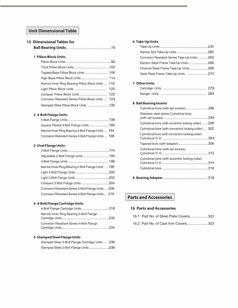
15 Dimensional Tables for Ball Bearing Units ............................................. 79
1 Pillow Block Units Pillow Block Units .............................................. 82
Thick Pillow Block Units .................................... 102
Tapped-Base Pillow Block Units ........................ 106
High-Base Pillow Block Units ............................ 114
Narrow Inner Ring Bearing Pillow Block Units ... 116
6 Take-Up Units Take-Up Units ................................................. 240
Narrow Slot Take-Up Units ................................ 260
Corrosion Resistant Series Take-Up Units ........... 262
Section Steel Frame Take-Up Units .................... 266
Channel Steel Frame Take-Up Units ................... 268
Steel Plate Frame Take-Up Units ....................... 274
7 Other Units
Stamped Steel Pillow Block Units ...................... 136
2 4-Bolt Flange Units
4-Bolt Flange Units .......................................... 138
Square Piloted 4-Bolt Flange Units .................... 160
Narrow Inner Ring Bearing 4-Bolt Flange Units ... 164
Corrosion Resistant Series 4-Bolt Flange Units ... 166
3 Oval Flange Units
2- Bolt Flange Units .......................................... 174
Adjustable 2-Bolt Flange Units .......................... 194
3- Bolt Flange Units .......................................... 196
Narrow Inner Ring Bearing 2-Bolt Flange Units ... 198
Light 3-Bolt Flange Units .................................. 200
Light 2-Bolt Flange Units .................................. 202
Compact 2-Bolt Flange Units ............................ 204
Corrosion Resistant Series 2-Bolt Flange Units ... 206
Corrosion Resistant Series 3-Bolt Flange Units ... 216
4 4-Bolt Flange Cartridge Units
4- Bolt Flange Cartridge Units ............................ 218
Narrow Inner Ring Bearing 4-Bolt Flange Cartridge Units ................................................ 232
Corrosion Resistant Series 4-Bolt Flange Cartridge Units ................................................ 234
5 Stamped Steel Flange Units
Stamped Steel 3-Bolt Flange Cartridge Units ... 236
Stamped Steel 2-Bolt Flange Units .................... 238
8 Ball Bearing Inserts Cylindrical bore (with set screws) ....................... 286
Stainless steel series Cylindrical bore (with set screws) .............................................. 294
Cylindrical bore (with eccentric locking collar) ...... 296
Cylindrical bore (with concentric locking collar) ... 302
Cylindrical bore (with concentric locking collar) Cylindrical O. D ............................................... 304
Tapered bore (with adapter) .............................. 306
Cylindrical bore (with set screws) Cylindrical O. D ............................................... 312
Cylindrical bore (with eccentric locking collar) Cylindrical O. D ............................................... 314
Cylindrical bore ............................................... 316
9 Bearing Adapter ................................................ 318
16 Parts and Accessories
16.1 Part No. of Steel Plate Covers ................... 322
16.2 Part No. of Cast Iron Covers ...................... 323
Parts and Accessories
Unit Dimensional Table
Light Pillow Block Units ................................ 120 Cartridge Units ........................................... 278
Compact Pillow Block Units ........................... 122 Hanger Units .............................................. 284
Corrosion Resistant Series Pillow Block Units ... 124
Contents
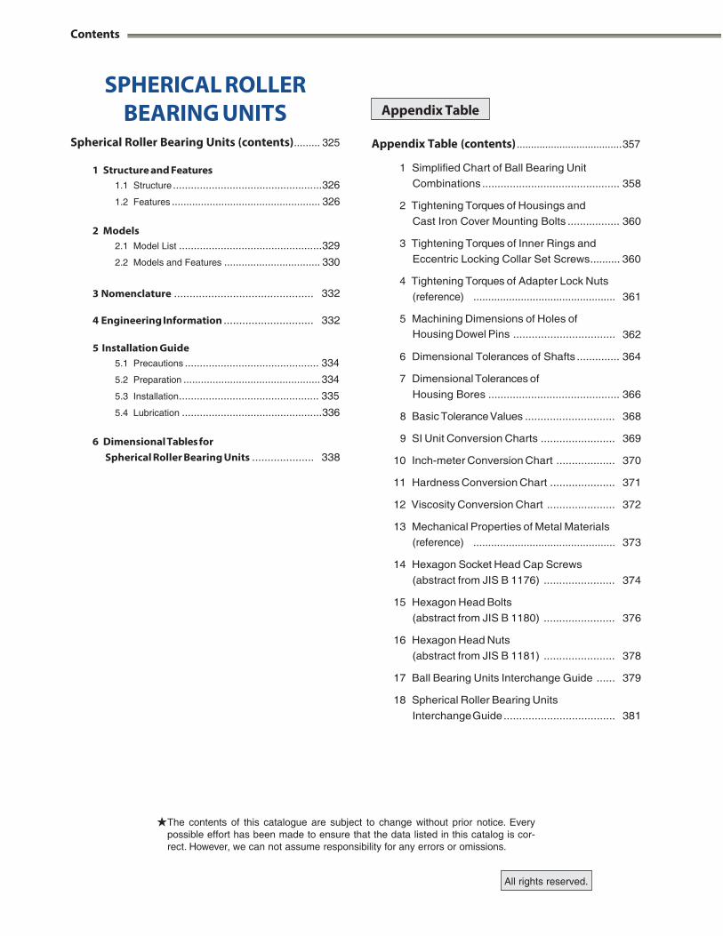
SPHERICAL ROLLER BEARING UNITS
Spherical Roller Bearing Units (contents) ......... 325
1 Structure and Features 1.1 Structure .................................................. 326
1.2 Features ................................................... 326
2 Models 2.1 Model List ................................................ 329
2.2 Models and Features ................................. 330
Appendix Table (contents) ..................................... 357
1 Simplified Chart of Ball Bearing Unit
Combinations ............................................. 358
2 Tightening Torques of Housings and
Cast Iron Cover Mounting Bolts ................. 360
3 Tightening Torques of Inner Rings and
Eccentric Locking Collar Set Screws .......... 360
4 Tightening Torques of Adapter Lock Nuts
5.1 Precautions ............................................. 334
5.2 Preparation ............................................... 334
5.3 Installation ............................................... 335
(reference) ................................................ 361
5 Machining Dimensions of Holes of Housing Dowel Pins .................................
362
6 Dimensional Tolerances of Shafts .............. 364
7 Dimensional Tolerances of
Housing Bores ........................................... 366
6
The contents of this catalogue are subject to change without prior notice. Every possible effort has been made to ensure that the data listed in this catalog is cor- rect. However, we can not assume responsibility for any errors or omissions.
All rights reserved.
Appendix Table
3 Nomenclature ............................................. 332
4 Engineering Information ............................. 5 Installation Guide
332
5.4 Lubrication ............................................... 336
Dimensional Tables for
8 Basic Tolerance Values ............................. 368
9 SI Unit Conversion Charts ........................ 369
Spherical Roller Bearing Units .................... 338 10 Inch-meter Conversion Chart ................... 370
11 Hardness Conversion Chart ..................... 371
12 Viscosity Conversion Chart ...................... 372
13 Mechanical Properties of Metal Materials
(reference) ................................................
373
14 Hexagon Socket Head Cap Screws
(abstract from JIS B 1176) .......................
374
15 Hexagon Head Bolts
(abstract from JIS B 1180) .......................
376
16 Hexagon Head Nuts
(abstract from JIS B 1181) .......................
378
17 Ball Bearing Units Interchange Guide ...... 379
18 Spherical Roller Bearing Units
Interchange Guide ....................................
381
1 Structure and Features
FYH Ball Bearing Units are manufactured to exacting stan- dards comprising of grease sealed deep groove ball bearings and housings in various forms.
Self-aligning units allow for easy installation and are sup- plied with grease fittings in order to facilitate quick and conve- nient re-lubrication.
1.1 Structure
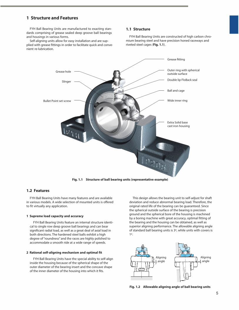
FYH Ball Bearing Units are constructed of high carbon chro- mium bearing steel and have precision honed raceways and riveted steel cages (Fig. 1.1).
1.2 Features
FYH Ball Bearing Units have many features and are available in various models. A wide selection of mounted units is offered to fit virtually any application.
1 Supreme load capacity and accuracy
FYH Ball Bearing Units feature an internal structure identi- cal to single row deep groove ball bearings and can bear significant radial load, as well as a great deal of axial load in both directions. The hardened steel balls exhibit a high degree of “roundness” and the races are highly polished to accommodate a smooth ride at a wide range of speeds.
This design allows the bearing unit to self-adjust for shaft deviation and reduce abnormal bearing load. Therefore, the original rated life of the bearing can be guaranteed. Since the spherical outside surface of the bearing is precision ground and the spherical bore of the housing is machined by a boring machine with great accuracy, optimal fitting of the bearing and the housing can be obtained, as well as superior aligning performance. The allowable aligning angle of standard ball bearing units is 3º, while units with covers is 1º.
2 Rational self-aligning mechanism and optimal fit
FYH Ball Bearing Units have the special ability to self-align inside the housing because of the spherical shape of the outer diameter of the bearing insert and the concave shape of the inner diameter of the housing into which it fits.
Aligning angle
Aligning angle
Fig. 1.2 Allowable aligning angle of ball bearing units
5
Grease fitting
Grease hole
Slinger
Outer ring with sphericaloutside surface
Double lip FloBack seal
Ball and cage
Bullet Point set screw Wide inner ring
Extra Solid base cast iron housing
Fig. 1.1 Structure of ball bearing units (representative example)
1 Structure and Features
3 Superior sealing performance
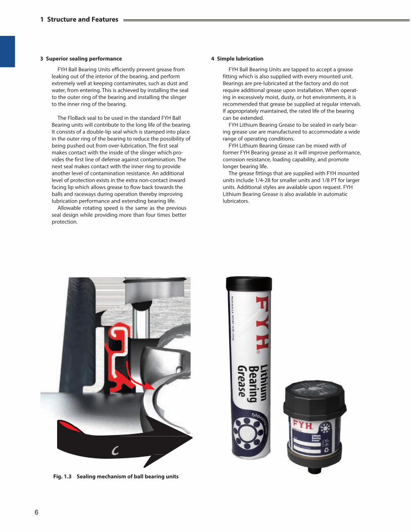
FYH Ball Bearing Units efficiently prevent grease from leaking out of the interior of the bearing, and perform extremely well at keeping contaminates, such as dust and water, from entering. This is achieved by installing the seal to the outer ring of the bearing and installing the slinger to the inner ring of the bearing.
The FloBack seal to be used in the standard FYH Ball
Bearing units will contribute to the long life of the bearing. It consists of a double-lip seal which is stamped into place in the outer ring of the bearing to reduce the possibility of being pushed out from over-lubrication. The first seal makes contact with the inside of the slinger which pro- vides the first line of defense against contamination. The next seal makes contact with the inner ring to provide another level of contamination resistance. An additional level of protection exists in the extra non-contact inward facing lip which allows grease to flow back towards the balls and raceways during operation thereby improving lubrication performance and extending bearing life.
Allowable rotating speed is the same as the previous seal design while providing more than four times better protection.
4 Simple lubrication
FYH Ball Bearing Units are tapped to accept a grease fitting which is also supplied with every mounted unit. Bearings are pre-lubricated at the factory and do not require additional grease upon installation. When operat- ing in excessively moist, dusty, or hot environments, it is recommended that grease be supplied at regular intervals. If appropriately maintained, the rated life of the bearing can be extended.
FYH Lithium Bearing Grease to be sealed in early bear- ing grease use are manufactured to accommodate a wide range of operating conditions.
FYH Lithium Bearing Grease can be mixed with of former FYH Bearing grease as it will improve performance, corrosion resistance, loading capability, and promote longer bearing life.
The grease fittings that are supplied with FYH mounted units include 1/4-28 for smaller units and 1/8 PT for larger units. Additional styles are available upon request. FYH Lithium Bearing Grease is also available in automatic lubricators.
Fig. 1.3 Sealing mechanism of ball bearing units
6
c

5 Highly rigid and rugged cast iron housings
FYH Ball Bearing Unit housings are designed so that they are optimized for reduction of deformation due to centralization of stress and load. Only the best material is selected to be cast by a highly advanced technique or press working technique, depending on the housing. Since any abnormal load on the bearing is eliminated by the housing, the life of the bearing can be extended. A Granular material baking finish coating (powder coating) helps resist corrosion and protect the surface of the housing for an extended period of time.
FYH original solid base pillow block housings seat better and produce a more stable mounting configuration that significantly reduces vibration.
The support ribs have been eliminated to make more room for mounting bolts and washers, yet these housings are more than 30% stronger than before while also reduc- ing housing weight. The new housing downward destruc- tion strength means that the inserts break before the housings.
7 Series and models
FYH Ball Bearing Units are available in various series and models. Reliability of machinery or equipment, used together with these units, can be improved by selecting and using units optimal for the application and operating conditions.
$High / Low Temperature Series
$Corrosion Resistant Series
Stainless Units Plastic Units Nickel plated Units
$Air Handling Series
S3 & S5 Bearing Units NU-LOC Units
$Dust Resistant Units
Triple lip seal inserts Felt seal inserts
$Dirt Resistant Units
6 Simple installation and handling
FYH Ball Bearing Units interchange with many different models and can be bolted to machinery without any modification. The exact amount of clearance is allowed between the bore and the shaft to allow a perfect fit. Therefore, FYH Ball Bearing Units do not require any additional lubrication or seal installation. As a result, handling and downtime can be drastically reduced. Four different locking mechanisms are available:
(1) Set Screw (2) Eccentric Locking Collar (3) Tapered Adapter (4) Concentric Collar
Mounting the bearing to the shaft can be executed
easily and securely by adopting any of these methods.
Tight Triple lip seal inserts Units with Covers
$Tougher casting Series Ductile iron housing
$Compact and lightweight Series Small die cast Units Lightweight casting Units Stamped Units
7
2 Selection Guide
2 Selection Guide
2.1 Selection Guide
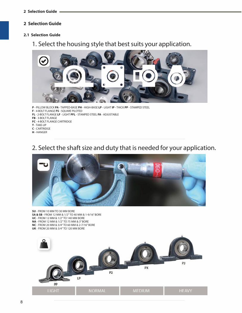
1. Select the housing style that best suits your application.
P - PILLOW BLOCK PA - TAPPED-BASE PH - HIGH-BASE LP - LIGHT IP - THICK PP - STAMPED STEEL F - 4-BOLT FLANGE FS - SQUARE PILOTED FL - 2-BOLT FLANGE LF - LIGHT PFL - STAMPED STEEL FA - ADJUSTABLE FB - 3-BOLT FLANGE FC - 4-BOLT FLANGE CARTRIDGE T - TAKE-UP C - CARTRIDGE H - HANGER
2. Select the shaft size and duty that is needed for your application.
SU - FROM 10 MM TO 30 MM BORE SA & SB - FROM 12 MM & 1/2” TO 40 MM & 1-9/16” BORE UC - FROM 12 MM & 1/2” TO 140 MM BORE NA - FROM 12 MM & 1/2” TO 75 MM & 3” BORE NC - FROM 20 MM & 3/4” TO 60 MM & 2-7/16” BORE UK - FROM 20 MM & 3/4” TO 120 MM BORE
8
2 Selection Guide

3. Do you need to customize the bearing for your application? Select STANDARD as the default.
TEMP - D2K2 -58°F TO 248°F (-50°C TO 120°C), D1K2 -40°F TO 356°F (-40°C TO 180°C), D9K2 -4°F TO 446°F (-20°C TO 230°C) WASH DOWN - STAINLESS STEEL UNITS, PLASTIC HOUSING UNITS, AIR HANDLING - S3 AIR HANDLING FIT UNITS, S5 NON CONTACT SEAL DUST - L3 TRIPLE LIP SEAL, COVERS DIRT - LT3 TIGHT TRIPLE LIP SEAL, COVERS
4. Select the locking style type for your insert.
UC - SETSCREW LOCK NA - ECCENTRIC COLLAR LOCK NC - CONCENTRIC COLLAR LOCK UK - ADAPTER SLEEVE LOCK
5. YOUR UNIT
Selection application is available
for download in the mobile device.
9 https://itunes.apple.com/us/app/fyh/id807018499?mt=8
TEMP
2 Selection Guide
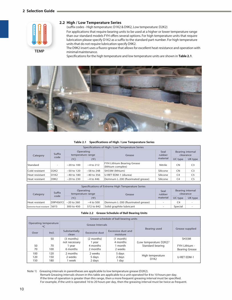
2.2 High / Low Temperature Series (suffix codes - High temperature: D1K2 & D9K2, Low temperature: D2K2) For applications that require bearing units to be used at a higher or lower temperature range than our standard models FYH offers several options. For high temperature units that require lubrication please specify D1K2 as a suffix to the standard part number. For high temperature units that do not require lubrication specify D9K2. The D9K2 insert uses a fluoro-grease that allows for excellent heat resistance and operation with minimal maintenance. Specifications for the high temperature and low temperature units are shown in Table 2.1.
Table 2.1 Specifications of High / Low Temperature Series
Specifications of High / Low Temperature Series
Category
Suffix code
Operating temperature range
Grease
Seal rubber
material
Bearing internal clearance
(ºC) (ºF) UC type UK type
Standard - −20 to 100 −4 to 212 FYH Lithium Bearing Grease (lithium complex)
Nitrile CN C3
Cold resistant D2K2 −50 to 120 −58 to 248 SH33M (lithium) Silicone CN C3
Heat resistant D1K2 −40 to 180 −40 to 356 U-RET EDM-1 (diurea) Silicone C4 C5
Heat resistant D9K2 −20 to 230 −4 to 446 Demnum L-200 (fluorinated grease) Silicone C4 C5
Specifications of Extreme High Temperature Series
Category
Suffix code
Operating temperature range
Grease
Seal rubber
material
Bearing internal clearance
(ºC) (ºF) UC type UK type
Heat resistant D9P4S6Y2 −20 to 260 −4 to 500 Demnum L-200 (fluorinated grease) - C4 -
Extreme heat resistant S6Y3 300 to 450 572 to 842 Solid graphite lubricant - Special -
Table 2.2 Grease Schedule of Ball Bearing Units
Grease schedule of ball bearing units
Operating temperature ºC
Grease Intervals
Bearing used
Grease supplied
Over Incl. Substantially
clean Excessive dust
Excessive dust and moisture
50
50 (3 months) (2 months) (1 month) (Low temperature D2K2)1)
SH33Mnot necessary 1 year 4 months
70 1 year 4 months 1 month Standard bearing FYH Lithium -70 100 6 months 2 months 2 weeks Bearing Grease
100 120 150
120 150 180
2 months 2 weeks 1 week
2 weeks 5 days 2 days
5 days 2 days 1 day
High temperature D1K2
U-RET EDM-1
Note 1) Greasing intervals in parentheses are applicable to low temperature grease (D2K2).
Remark Greasing intervals shown in this table are applicable to a unit operated for 8 to 10 hours per day. If the time of operation is greater than this range, then a more frequent greasing interval must be specified. For example, if the unit is operated 16 to 20 hours per day, then the greasing interval must be twice as frequent.
10
TEMP
2.2.1 Rotational speed adjustment due to shaft fit
A marginal degree of clearance is typically used to facilitate easy installation of a bearing to a shaft.
The amount of clearance between the bearing and shaft must be factored in to determine the maximum allowable rotational speed, and as rotational speed is increased, the amount of clearance must be decreased.
Table 2.3 shows the factor that must be used to correct the
allowable rotational speed. The maximum rotational speed is determined by multiplying the speed found in Table 6.1 by the factors below.
Table 2.3 Fitting factor of ball bearing units f c
(recommended)
Type of ball
bearing units
Fitting factor f c
Shaft tolerance range class
h5, j5 j6 h6 h7 h8 h9
Heat resistant type (Suffix code: D1K2) 1 1 0.7
Cold resistant type (Suffix code: D2K2) 1 1 0.7
2.2.2 Correction of basic load rating due to
temperature
If a ball bearing unit is used at a relatively high temperature the physical composition of the bearing material is changed leading to decreased hardness. This decreased hardness leads to the basic dynamic load rating being reduced. Once the structure of the bearing material has been changed, it will remain this way for the life of the unit, even when it returns to room temperature.
When using a ball bearing unit at 150 ºC or more, the basic load rating must be corrected by multiplying the basic dynamic load rating shown in the dimensional table by the temperature factor shown in Table 2.4.
Table 2.4 Temperature factor
2.2.3 Operating temperature range
The operating temperature of a ball bearing unit depends on the type of grease, the material of the seal, and the internal clearance of the bearing. FYH Ball Bearing Units are available in high temperature (D1K2, D9K2) and low temperature (D2K2) series, in addition to the standard models, to allow selection of the correct bearing for your operational temperature (see Table 2.1). The correct unit must be chosen for the desired temperature range, and it is equally important to use the appropriate grease according to the specified schedule.
2.2.4 Operating temperature and internal clearance
of bearings
When bearings are operated in a high ambient temperature environment, or when the operating temperature is high because of rotational speed, differential expansion rates occur within the bearing components. This causes higher friction, grease breakdown, and eventual seizure.
If the temperature difference between the inner and outer ring is known, or can be approximated, then the following Formula (2.1) may be applied.
Under these conditions, decrease in the internal clearance must be calculated, and the internal clearance of bearing needs to be selected properly.
St1 · De · 3t (2.1)
Whereas, St1: Decrease in the internal clearance of bearings
depending on the difference in the temperatures of the bearing inner ring and the bearing outer ring can be found by formula, mm
: Line expansion factor of bearing steel, 12.5 106
De: Raceway dia. of bearing outer ring, mm Diameter series 2, X De 0.92 D Diameter series 3De 0.9 D
D: Nominal bearing outer dia., mm 3t: Difference in temperatures of bearing inner ring
and outer ring, ºC
If a ball bearing unit is used in a high temperature environ- ment, an abnormal load will result due to thermal expansion of the shaft. This must be compensated for by allowing free movement of one side of the shaft. (See “9 Design of shaft and base”)
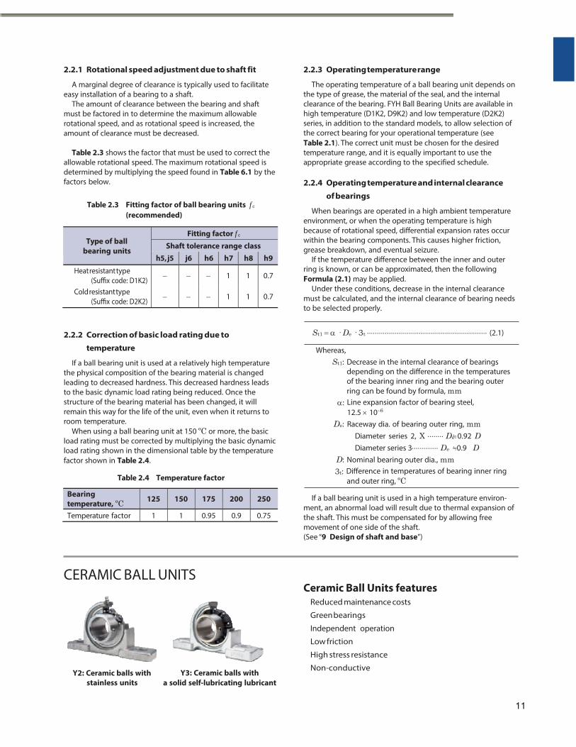
CERAMIC BALL UNITS Ceramic Ball Units features
Reduced maintenance costs
Green bearings
Independent operation
Low friction
High stress resistance
Y2: Ceramic balls with stainless units
Y3: Ceramic balls with
a solid self-lubricating lubricant
Non-conductive
11
Bearing temperature, ºC 125 150 175 200 250
Temperature factor 1 1 0.95 0.9 0.75
WASH DOWN
2 Selection Guide
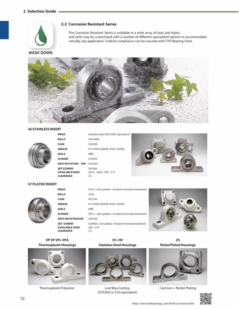
2.3 Corrosion Resistant Series
The Corrosion Resistant Series is available in a wide array of sizes and styles, and units may be customized with a number of different specialized options to accommodate virtually any application. Federal compliance can be assured with FYH Bearing Units.
S6 STAINLESS INSERT RINGS Stainless steel (SUS 440C equivalent)
BALLS SUS 440C
CAGE SUS304
GREASE H1 FOOD GRADE (FDA /USDA)
SEALS NBR
SLINGER SUS304
ANTI-ROTATION PIN SUS304
SET SCREWS SUS304 AVAILABLE SIZES 201X - 203X , 204 - 212 CLEARANCE C3
S7 PLATED INSERT RINGS SUJ2 + (zinc plated + trivalent chromate treatment)
BALLS SUJ2
CAGE NYLON
GREASE H1 FOOD GRADE (FDA /USDA)
SEALS NBR
SLINGER SPCC + (zinc plated + trivalent chromate treatment)
ANTI-ROTATION PIN SUS304
SET SCREWS SCM435 + (zinc plated + trivalent chromate treatment) AVAILABLE SIZES 204 - 210 CLEARANCE C3
Thermoplastic Polyester Lost Wax Casting
(SUS304 or 316 equivalent)
12
Cast Iron + Nickel Plating
http://www.fyhbearings.com/html/corrosion.html
WASH DOWN
VP VF VFL VPA H1, H9 Z5 Thermoplastic Housings Stainless Steel Housings Nickel Plated Housings
AIR HANDLING
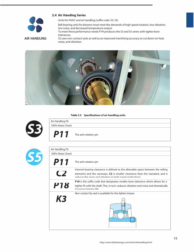
2.4 Air Handing Series Units for HVAC and air handling (suffix code: S3, S5)
Ball bearing units for blowers must meet the demands of high speed rotation, low vibration, low noise, and decreased temperature output. To meet these performance needs FYH produces the S3 and S5 series with tighter bore tolerances. S5 uses non-contact seals as well as an improved machining accuracy to cut down on heat, noise, and vibration.
Table 2.5 Specifications of air handling units
Air Handling Fit
100% Noise Check
P11 The anti-rotation pin
Air Handling Fit
100% Noise Check
P11
The anti-rotation pin
Internal bearing clearance is defined as the allowable space between the rollingC2 elements and the raceways. C2 is smaller clearance than the standard, and it reduces the noise and vibration in high speed applications
P18 is the suffix code that designates smaller bore tolerance which allows for aP18 tighter fit with the shaft. This, in turn, reduces vibration and noise and dramatically increases bearing life
Non contact lip seal is available for the lighter torque.
K3
13
http://www.fyhbearings.com/html/airhandling.html
AIR HANDLING
S3
S5
2 Selection Guide
2.4.1 Features of the air handring units
The air handling unit is manufactured with original fitting called the air handling fit which exists in the middle with fitting ”H” which can be assembled more easily than a standard fit “J.” In addition, “J” fit the standard is fit that there is not the need for the anti-rotation pin, but can be very secure in high speed applications by adding the anti-rotation pin.
S3 and S5 bearings are sound tested in order to make sure the noise level is low enough to be suitable for high speed applications such as blowers.
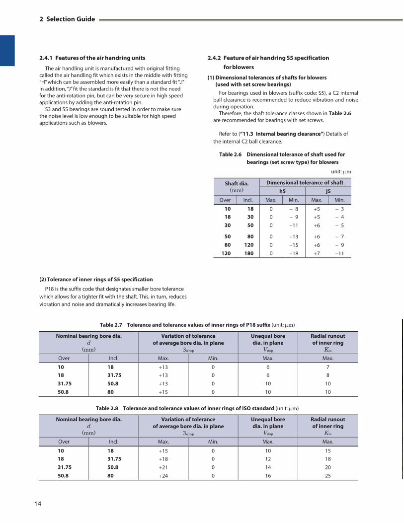
2.4.2 Feature of air handring S5 specification
for blowers
(1) Dimensional tolerances of shafts for blowers (used with set screw bearings)
For bearings used in blowers (suffix code: S5), a C2 internal ball clearance is recommended to reduce vibration and noise during operation.
Therefore, the shaft tolerance classes shown in Table 2.6 are recommended for bearings with set screws.
Refer to (“11.3 Internal bearing clearance”) Details of
the internal C2 ball clearance.
Table 2.6 Dimensional tolerance of shaft used for bearings (set screw type) for blowers
unit: m
Shaft dia. (mm)
Dimensional tolerance of shaft
h5 j5
Over Incl. Max. Min. Max. Min.
10 18 0 8 5 3 18 30 0 9 5 4 30 50 0 11 6 5
50 80 0 13 6 7 80 120 0 15 6 9
120 180 0 18 7 11
(2) Tolerance of inner rings of S5 specification
P18 is the suffix code that designates smaller bore tolerance which allows for a tighter fit with the shaft. This, in turn, reduces vibration and noise and dramatically increases bearing life.
Table 2.7 Tolerance and tolerance values of inner rings of P18 suffix (unit: m)
Nominal bearing bore dia. d
(mm)
Variation of tolerance of average bore dia. in plane
3dmp
Unequal bore dia. in plane
Vdsp
Radial runout of inner ring
Kia
Over Incl. Max. Min. Max. Max.
10 18 13 0 6 7 18 31.75 13 0 6 8 31.75 50.8 13 0 10 10 50.8 80 15 0 10 10
Table 2.8 Tolerance and tolerance values of inner rings of ISO standard (unit: m)
Nominal bearing bore dia. d
(mm)
Variation of tolerance of average bore dia. in plane
3dmp
Unequal bore dia. in plane
Vdsp
Radial runout of inner ring
Kia
Over Incl. Max. Min. Max. Max.
10 18 15 0 10 15 18 31.75 18 0 12 18 31.75 50.8 21 0 14 20 50.8 80 24 0 16 25
14
DUST
DIRT
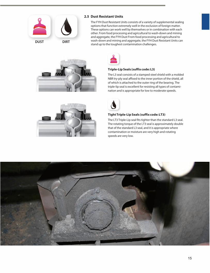
2.5 Dust Resistant Units
The FYH Dust Resistant Units consists of a variety of supplemental sealing options that function extremely well in the exclusion of foreign matter. These options can work well by themselves or in combination with each other. From food processing and agricultural to wash-down and mining and aggregate, the FYH Dust From food processing and agricultural to wash-down and mining and aggregate, the FYH Dust Resistant Units can stand up to the toughest contamination challenges.
Triple-Lip Seals (suffix code: L3)
The L3 seal consists of a stamped steel shield with a molded NBR try-ply seal affixed to the inner portion of the shield, all of which is attached to the outer ring of the bearing. The triple-lip seal is excellent for resisting all types of contami- nation and is appropriate for low to moderate speeds.
Tight Triple-Lip Seals (suffix code: LT3)
The LT3 Triple-Lip seal fits tighter than the standard L3 seal. The rotating torque of the LT3 seal is approximately double that of the standard L3 seal, and it is appropriate where contamination or moisture are very high and rotating speeds are very low.
15
DUST DIRT
2 Selection Guide
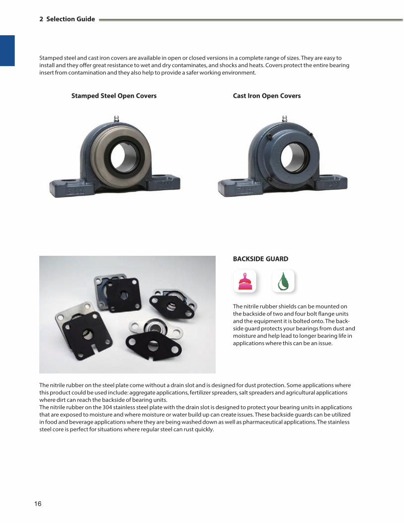
Stamped steel and cast iron covers are available in open or closed versions in a complete range of sizes. They are easy to install and they offer great resistance to wet and dry contaminates, and shocks and heats. Covers protect the entire bearing insert from contamination and they also help to provide a safer working environment.
Stamped Steel Open Covers Cast Iron Open Covers
BACKSIDE GUARD
The nitrile rubber shields can be mounted on the backside of two and four bolt flange units and the equipment it is bolted onto. The back- side guard protects your bearings from dust and moisture and help lead to longer bearing life in applications where this can be an issue.
The nitrile rubber on the steel plate come without a drain slot and is designed for dust protection. Some applications where this product could be used include: aggregate applications, fertilizer spreaders, salt spreaders and agricultural applications where dirt can reach the backside of bearing units. The nitrile rubber on the 304 stainless steel plate with the drain slot is designed to protect your bearing units in applications that are exposed to moisture and where moisture or water build up can create issues. These backside guards can be utilized in food and beverage applications where they are being washed down as well as pharmaceutical applications. The stainless steel core is perfect for situations where regular steel can rust quickly.
16
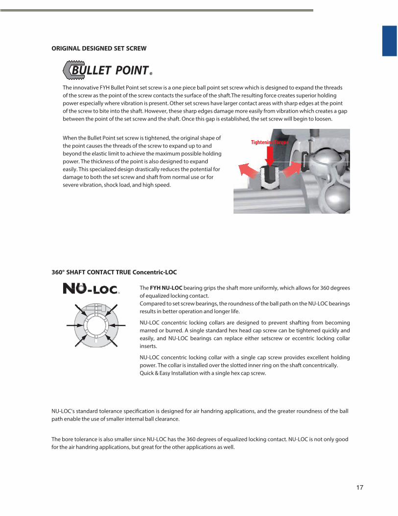
ORIGINAL DESIGNED SET SCREW
BULLET POINT
The innovative FYH Bullet Point set screw is a one piece ball point set screw which is designed to expand the threads of the screw as the point of the screw contacts the surface of the shaft.The resulting force creates superior holding power especially where vibration is present. Other set screws have larger contact areas with sharp edges at the point of the screw to bite into the shaft. However, these sharp edges damage more easily from vibration which creates a gap between the point of the set screw and the shaft. Once this gap is established, the set screw will begin to loosen.
When the Bullet Point set screw is tightened, the original shape of the point causes the threads of the screw to expand up to and beyond the elastic limit to achieve the maximum possible holding power. The thickness of the point is also designed to expand easily. This specialized design drastically reduces the potential for damage to both the set screw and shaft from normal use or for severe vibration, shock load, and high speed.
360° SHAFT CONTACT TRUE Concentric-LOC
The FYH NU-LOC bearing grips the shaft more uniformly, which allows for 360 degrees of equalized locking contact. Compared to set screw bearings, the roundness of the ball path on the NU-LOC bearings results in better operation and longer life.
NU-LOC concentric locking collars are designed to prevent shafting from becoming marred or burred. A single standard hex head cap screw can be tightened quickly and easily, and NU-LOC bearings can replace either setscrew or eccentric locking collar inserts.
NU-LOC concentric locking collar with a single cap screw provides excellent holding power. The collar is installed over the slotted inner ring on the shaft concentrically. Quick & Easy Installation with a single hex cap screw.
NU-LOC’s standard tolerance specification is designed for air handring applications, and the greater roundness of the ball path enable the use of smaller internal ball clearance.
The bore tolerance is also smaller since NU-LOC has the 360 degrees of equalized locking contact. NU-LOC is not only good for the air handring applications, but great for the other applications as well.
17
Tightening Torque
3 Models
3 Models
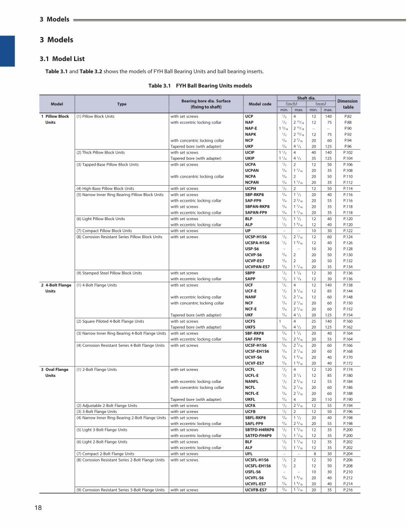
3.1 Model List
Table 3.1 and Table 3.2 shows the models of FYH Ball Bearing Units and ball bearing inserts.
Table 3.1 FYH Ball Bearing Units models
Model
Type
Bearing bore dia. Surface (fixing to shaft)
Model code
Shaft dia. Dimension
table (inch) (mm)
min. max. min. max.
1 Pillow Block Units
(1) Pillow Block Units with set screws with eccentric locking collar
with concentric locking collar Tapered bore (with adapter)
UCP NAP NAP-E NAPK NCP UKP
1/2
1/2
1 3/16
1/2
3/4
3/4
4 2 15/16
2 15/16
2 15/16
2 7/16
4 1/2
12 12 12 20 20
140 75 75 60
125
P.82 P.88 P.90 P.92 P.94 P.96
(2) Thick Pillow Block Units with set screws Tapered bore (with adapter)
UCIP UKIP
1 1/2
1 1/4
4 4 1/2
40 35
140 125
P.102 P.104
(3) Tapped-Base Pillow Block Units with set screws
with concentric locking collar
UCPA UCPAN NCPA NCPAN
1/2
3/4
3/4
3/4
2 1 7/16
2 1 7/16
12 20 20 20
50 35 50 35
P.106 P.108 P.110 P.112
(4) High-Base Pillow Block Units with set screws UCPH 1/2 2 12 50 P.114 (5) Narrow Inner Ring Bearing Pillow Block Units with set screws
with eccentric locking collar with set screws with eccentric locking collar
SBP-RKP8 SAP-FP9 SBPAN-RKP8 SAPAN-FP9
3/4
3/4
3/4
3/4
1 1/2
2 3/16
1 7/16
1 7/16
20 20 20 20
40 55 35 35
P.116 P.116 P.118 P.118
(6) Light Pillow Block Units with set screws with eccentric locking collar
BLP ALP
1/2
1/2
1 1/2
1 9/16
12 12
40 40
P.120 P.120
(7) Compact Pillow Block Units with set screws UP 10 30 P.122 (8) Corrosion Resistant Series Pillow Block Units with set screws UCSP-H1S6
UCSPA-H1S6 USP-S6 UCVP-S6 UCVP-ES7 UCVPAN-ES7
1/2
1/2
3/4
3/4
3/4
2 7/16
1 9/16
2 2 1 7/16
12 12 10 20 20 20
60 40 30 50 50 35
P.124 P.126 P.128 P.130 P.132 P.134
(9) Stamped Steel Pillow Block Units with set screws with eccentric locking collar
SBPP SAPP
1/2
1/2
1 1/4
1 1/4
12 12
30 30
P.136 P.136
2 4-Bolt Flange Units
(1) 4-Bolt Flange Units with set screws
with eccentric locking collar with concentric locking collar
Tapered bore (with adapter)
UCF UCF-E NANF NCF NCF-E UKF
1/2
1/2
1/2
3/4
3/4
3/4
4 3 7/16
2 7/16
2 7/16
2 7/16
4 1/2
12 12 12 20 20 20
140 85 60 60 60
125
P.138 P.144 P.148 P.150 P.152 P.154
(2) Square Piloted 4-Bolt Flange Units with set screws Tapered bore (with adapter)
UCFS UKFS
1 3/4
4 4 1/2
25 20
140 125
P.160 P.162
(3) Narrow Inner Ring Bearing 4-Bolt Flange Units with set screws with eccentric locking collar
SBF-RKP8 SAF-FP9
3/4
3/4
1 1/2
2 3/16
20 20
40 55
P.164 P.164
(4) Corrosion Resistant Series 4-Bolt Flange Units with set screws UCSF-H1S6 UCSF-EH1S6 UCVF-S6 UCVF-ES7
3/4
3/4
3/4
3/4
2 7/16
2 7/16
1 9/16
1 9/16
20 20 20 20
60 60 40 40
P.166 P.168 P.170 P.172
3 Oval Flange Units
(1) 2-Bolt Flange Units with set screws
with eccentric locking collar with concentric locking collar
Tapered bore (with adapter)
UCFL UCFL-E NANFL NCFL NCFL-E UKFL
1/2
1/2
1/2
3/4
3/4
3/4
4 3 1/4
2 3/16
2 7/16
2 7/16
4
12 12 12 20 20 20
120 85 55 60 60
110
P.174 P.180 P.184 P.186 P.188 P.190
(2) Adjustable 2-Bolt Flange Units with set screws UCFA 1/2 2 3/16 12 55 P.194 (3) 3-Bolt Flange Units with set screws UCFB 1/2 2 12 50 P.196 (4) Narrow Inner Ring Bearing 2-Bolt Flange Units with set screws
with eccentric locking collar SBFL-RKP8 SAFL-FP9
3/4
3/4
1 1/2
2 3/16
20 20
40 55
P.198 P.198
(5) Light 3-Bolt Flange Units with set screws with eccentric locking collar
SBTFD-H4RKP8 SATFD-FH4P9
1/2
1/2
1 7/16
1 7/16
12 12
35 35
P.200 P.200
(6) Light 2-Bolt Flange Units with set screws with eccentric locking collar
BLF ALF
1/2
1/2
1 7/16
1 7/16
12 12
35 35
P.202 P.202
(7) Compact 2-Bolt Flange Units with set screws UFL 8 30 P.204 (8) Corrosion Resistant Series 2-Bolt Flange Units with set screws UCSFL-H1S6
UCSFL-EH1S6 USFL-S6 UCVFL-S6 UCVFL-ES7
1/2
1/2
3/4
3/4
2 2
1 9/16
1 9/16
12 12 10 20 20
50 50 30 40 40
P.206 P.208 P.210 P.212 P.214
(9) Corrosion Resistant Series 3-Bolt Flange Units with set screws UCVFB-ES7 3/4 1 7/16 20 35 P.216
18
3 Models
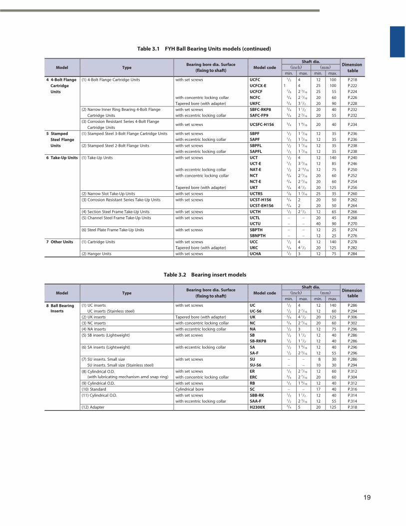
Table 3.1 FYH Ball Bearing Units models (continued)
Model
Type
Bearing bore dia. Surface (fixing to shaft)
Model code
Shaft dia. Dimension
table (inch) (mm)
min. max. min. max. 4 4-Bolt Flange
Cartridge Units
(1) 4-Bolt Flange Cartridge Units with set screws
with concentric locking collar Tapered bore (with adapter)
UCFC UCFCX-E UCFCF NCFC UKFC
1/2
1 7/8
3/4
3/4
4 4 2 3/16
2 7/16
3 1/2
12 25 25 20 20
100 100
55 60 90
P.218 P.222 P.224 P.226 P.228
(2) Narrow Inner Ring Bearing 4-Bolt Flange Cartridge Units
with set screws with eccentric locking collar
SBFC-RKP8 SAFC-FP9
3/4
3/4
1 1/2
2 3/16
20 20
40 55
P.232 P.232
(3) Corrosion Resistant Series 4-Bolt Flange Cartridge Units
with set screws UCSFC-H1S6 3/4 1 9/16 20 40 P.234
5 Stamped Steel Flange Units
(1) Stamped Steel 3-Bolt Flange Cartridge Units with set screws with eccentric locking collar
SBPF SAPF
1/2
1/2
1 7/16
1 7/16
12 12
35 35
P.236 P.236
(2) Stamped Steel 2-Bolt Flange Units with set screws with eccentric locking collar
SBPFL SAPFL
1/2
1/2
1 7/16
1 7/16
12 12
35 35
P.238 P.238
6 Take-Up Units (1) Take-Up Units with set screws
with eccentric locking collar with concentric locking collar
Tapered bore (with adapter)
UCT UCT-E NAT-E NCT NCT-E UKT
1/2
1/2
1/2
3/4
3/4
3/4
4 3 7/16
2 15/16
2 7/16
2 7/16
4 1/2
12 12 12 20 20 20
140 85 75 60 60
125
P.240 P.246 P.250 P.252 P.254 P.256
(2) Narrow Slot Take-Up Units with set screws UCTRS 7/8 1 7/16 25 35 P.260 (3) Corrosion Resistant Series Take-Up Units with set screws UCST-H1S6
UCST-EH1S6
3/4
3/4
2 2
20 20
50 50
P.262 P.264
(4) Section Steel Frame Take-Up Units with set screws UCTH 1/2 2 1/2 12 65 P.266 (5) Channel Steel Frame Take-Up Units with set screws UCTL
UCTU
20 40
45 90
P.268 P.270
(6) Steel Plate Frame Take-Up Units with set screws SBPTH SBNPTH
12 12
25 25
P.274 P.276
7 Other Units (1) Cartridge Units with set screws Tapered bore (with adapter)
UCC UKC
1/2
3/4
4 4 1/2
12 20
140 125
P.278 P.282
(2) Hanger Units with set screws UCHA 1/2 3 12 75 P.284
Table 3.2 Bearing insert models
Model
Type Bearing bore dia. Surface
(fixing to shaft)
Model code
Shaft dia. Dimension
table (inch) (mm)
min. max. min. max.
8 Ball Bearing Inserts
(1) UC inserts UC inserts (Stainless steel)
with set screws UC UC-S6
1/2
1/2
4 2 7/16
12 12
140 60
P.286 P.294
(2) UK inserts Tapered bore (with adapter) UK 3/4 4 1/2 20 125 P.306 (3) NC inserts with concentric locking collar NC 3/4 2 7/16 20 60 P.302 (4) NA inserts with eccentric locking collar NA 1/2 3 12 75 P.296 (5) SB inserts (Lightweight) with set screws SB
SB-RKP8
1/2
1/2
1 1/2
1 1/2
12 12
40 40
P.286 P.286
(6) SA inserts (Lightweight) with eccentric locking collar SA SA-F
1/2
1/2
1 9/16
2 3/16
12 12
40 55
P.296 P.296
(7) SU inserts. Small size SU inserts. Small size (Stainless steel)
with set screws SU SU-S6
8 10
30 30
P.286 P.294
(8) Cylindrical O.D. (with lubricating mechanism amd snap ring)
with set screws with concentric locking collar
ER ERC
1/2
3/4
2 7/16
2 7/16
12 20
60 60
P.312 P.304
(9) Cylindrical O.D. with set screws RB 1/2 1 9/16 12 40 P.312 (10) Standard Cylindrical bore SC 17 40 P.316 (11) Cylindrical O.D. with set screws
with eccentric locking collar SBB-RK SAA-F
1/2
1/2
1 1/2
2 3/16
12 12
40 55
P.314 P.314
(12) Adapter H2300X 3/4 5 20 125 P.318
19
STANDARD
3 Models
STANDARD
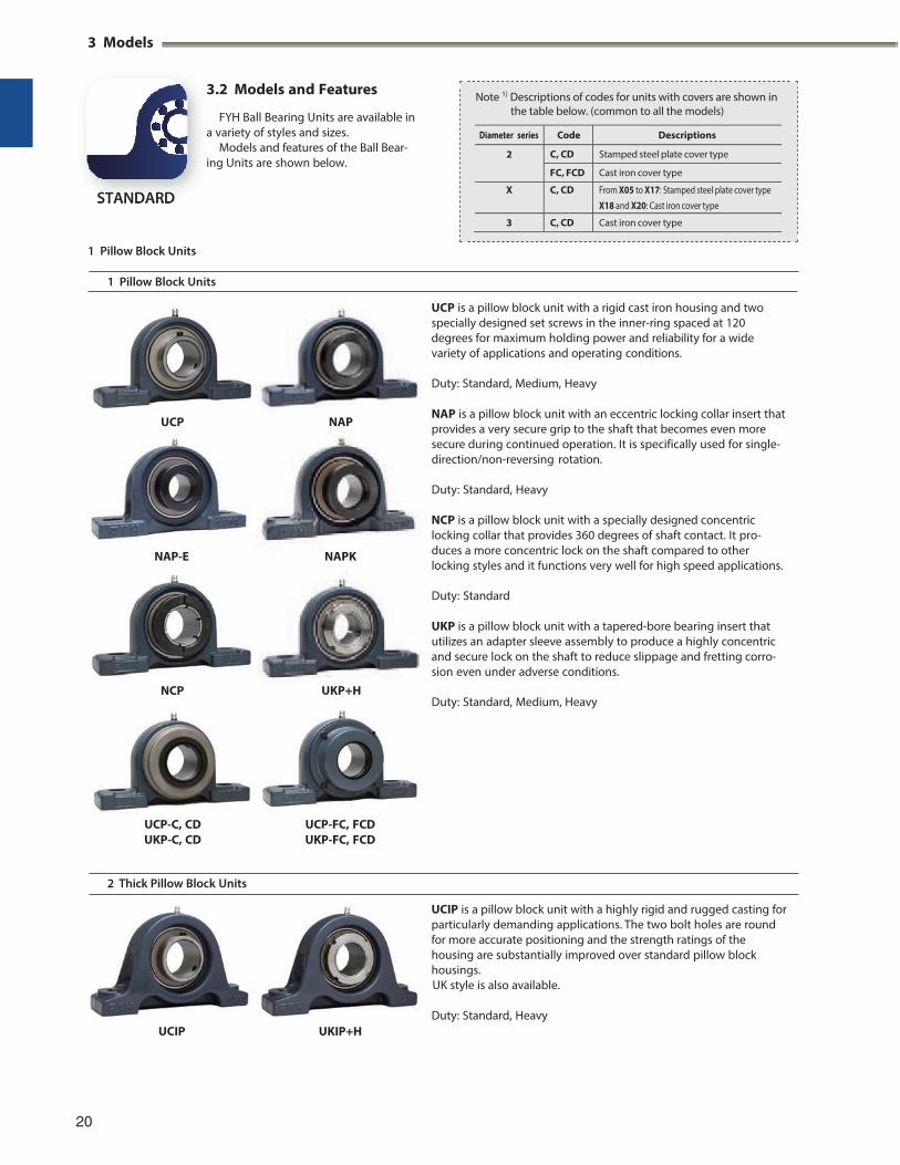
3.2 Models and Features
FYH Ball Bearing Units are available in a variety of styles and sizes.
Models and features of the Ball Bear- ing Units are shown below.
1 Pillow Block Units
1 Pillow Block Units
UCP is a pillow block unit with a rigid cast iron housing and two specially designed set screws in the inner-ring spaced at 120 degrees for maximum holding power and reliability for a wide variety of applications and operating conditions.
UCP
NCP
NAP
UKP+H
Duty: Standard, Medium, Heavy
NAP is a pillow block unit with an eccentric locking collar insert that provides a very secure grip to the shaft that becomes even more secure during continued operation. It is specifically used for single- direction/non-reversing rotation.
Duty: Standard, Heavy
NCP is a pillow block unit with a specially designed concentric locking collar that provides 360 degrees of shaft contact. It pro- duces a more concentric lock on the shaft compared to other locking styles and it functions very well for high speed applications.
Duty: Standard
UKP is a pillow block unit with a tapered-bore bearing insert that utilizes an adapter sleeve assembly to produce a highly concentric and secure lock on the shaft to reduce slippage and fretting corro- sion even under adverse conditions.
Duty: Standard, Medium, Heavy
UCP-C, CD UKP-C, CD
UCP-FC, FCD UKP-FC, FCD
2 Thick Pillow Block Units
UCIP is a pillow block unit with a highly rigid and rugged casting for particularly demanding applications. The two bolt holes are round for more accurate positioning and the strength ratings of the housing are substantially improved over standard pillow block housings. UK style is also available.
UCIP UKIP+H
Duty: Standard, Heavy
20
NAP-E NAPK
Note 1) Descriptions of codes for units with covers are shown in the table below. (common to all the models)
Diameter series Code Descriptions
2 C, CD Stamped steel plate cover type
FC, FCD Cast iron cover type
X C, CD From X05 to X17: Stamped steel plate cover type
X18 and X20: Cast iron cover type
3 C, CD Cast iron cover type
3 Tapped-Base Pillow Block Units
4 High-Base Pillow Block Units
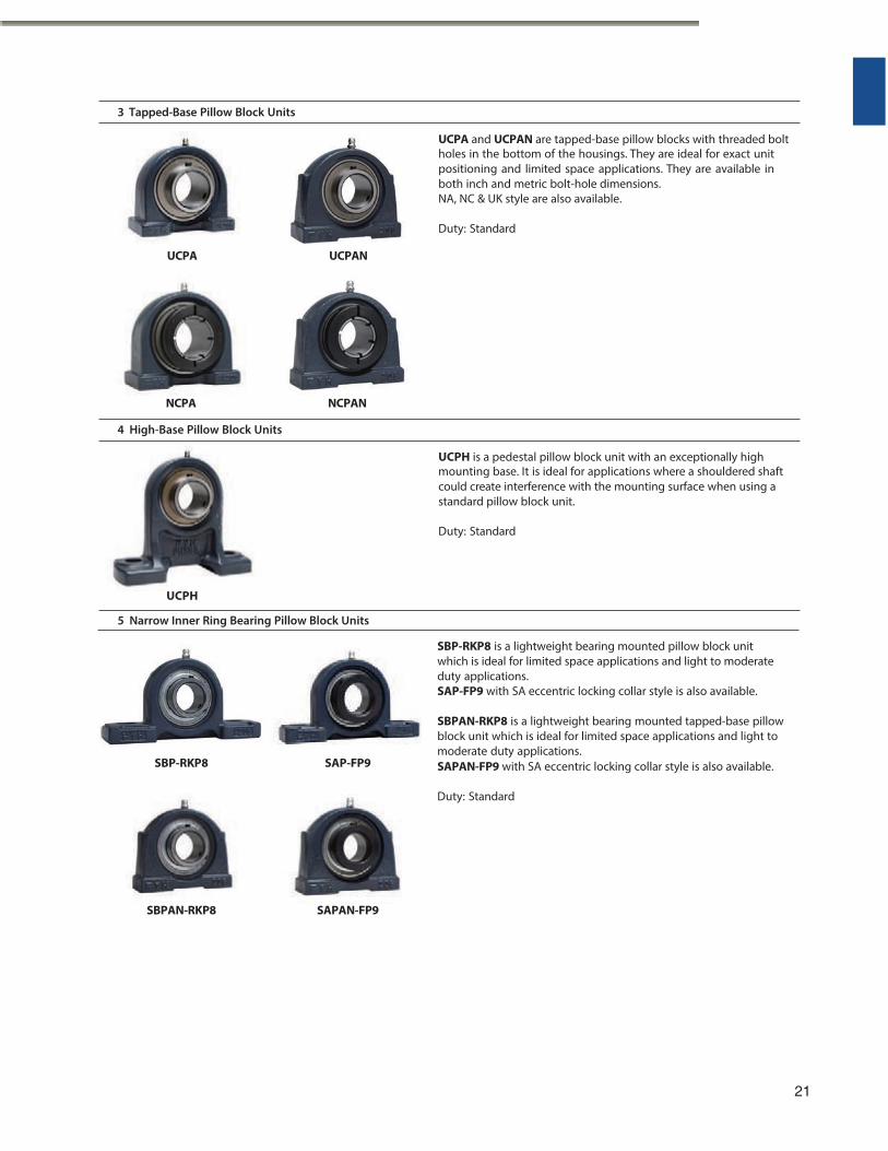
5 Narrow Inner Ring Bearing Pillow Block Units SBP-RKP8 is a lightweight bearing mounted pillow block unit which is ideal for limited space applications and light to moderate duty applications. SAP-FP9 with SA eccentric locking collar style is also available.
SBP-RKP8
SBPAN-RKP8
SAP-FP9
SAPAN-FP9
SBPAN-RKP8 is a lightweight bearing mounted tapped-base pillow block unit which is ideal for limited space applications and light to moderate duty applications. SAPAN-FP9 with SA eccentric locking collar style is also available.
Duty: Standard
21
UCPH is a pedestal pillow block unit with an exceptionally highmounting base. It is ideal for applications where a shouldered shaftcould create interference with the mounting surface when using a standard pillow block unit. Duty: Standard
UCPH
NCPANNCPA
UCPA and UCPAN are tapped-base pillow blocks with threaded boltholes in the bottom of the housings. They are ideal for exact unit positioning and limited space applications. They are available in both inch and metric bolt-hole dimensions. NA, NC & UK style are also available. Duty: Standard
UCPA UCPAN
3 Models
(1 Pillow Block Units)
6 Light Pillow Block Units
7 Compact Pillow Block Units
8 Corrosion Resistant Series Pillow Block Units
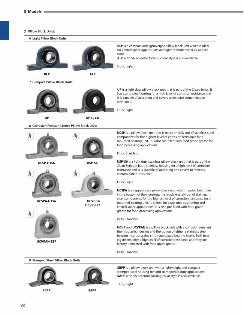
UCSP is a pillow block unit that is made entirely out of stainless steel components for the highest level of corrosion resistance for a mounted bearing unit. It is also pre-filled with food grade grease for food processing applications.
Duty: Standard
USP-S6 is a light duty stainless pillow block unit that is part of the Clean Series. It has a stainless housing for a high level of corrosion resistance and it is capable of accepting end covers to increase contamination resistance.
Duty: Light
UCVP-S6 UCVP-ES7
UCSPA is a tapped-base pillow block unit with threaded bolt holes in the bottom of the housings. It is made entirely out of stainless steel components for the highest level of corrosion resistance for a mounted bearing unit. It is ideal for exact unit positioning and limited space applications. It is also pre-filled with food grade grease for food processing applications.
Duty: Standard
UCVP and UCVPAN is a pillow block unit with a corrosion resistant thermoplastic housing and the option of either a stainless steel bearing insert or a zinc chromate plated bearing insert. Both bear- ing inserts offer a high level of corrosion resistance and they are factory lubricated with food grade grease.
Duty: Standard
9 Stamped Steel Pillow Block Units
SBPP SAPP
22
SBPP is a pillow block unit with a lightweight and compact stamped steel housing for light to moderate duty applications. SAPP with SA eccentric locking collar style is also available.
Duty: Light
UP is a light duty pillow block unit that is part of the Clean Series. Ithas a zinc-alloy housing for a high level of corrosion resistance and it is capable of accepting end covers to increase contamination resistance. Duty: Light
UP UP-C, CD
BLP is a compact and lightweight pillow block unit which is idealfor limited space applications and light to moderate duty applica- tions. ALP with SA eccentric locking collar style is also available. Duty: Light
BLP ALP
UCSP-H1S6 USP-S6
UCSPA-H1S6
UCVPAN-ES7
2 4-Bolt Flange Units
1 4-Bolt Flange Units
UCF
UCF-E
NCF
NCF-E
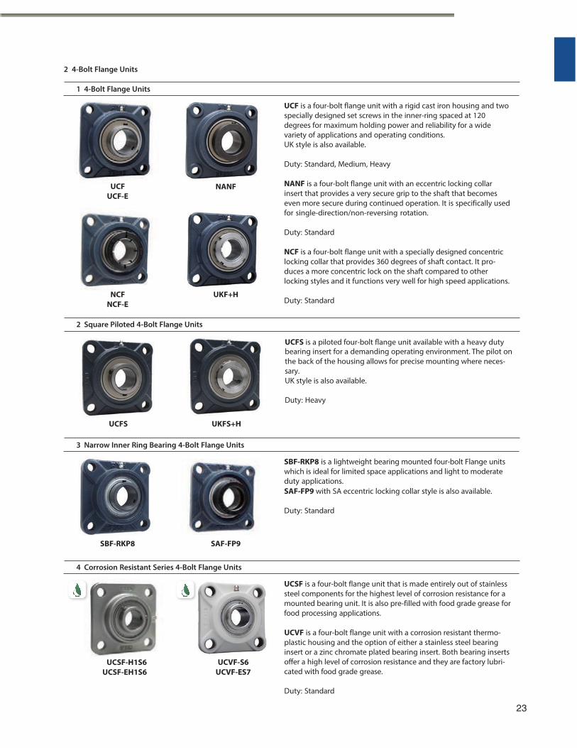
UCF is a four-bolt flange unit with a rigid cast iron housing and two specially designed set screws in the inner-ring spaced at 120 degrees for maximum holding power and reliability for a wide variety of applications and operating conditions. UK style is also available.
Duty: Standard, Medium, Heavy
NANF is a four-bolt flange unit with an eccentric locking collar insert that provides a very secure grip to the shaft that becomes even more secure during continued operation. It is specifically used for single-direction/non-reversing rotation.
Duty: Standard
NCF is a four-bolt flange unit with a specially designed concentric locking collar that provides 360 degrees of shaft contact. It pro- duces a more concentric lock on the shaft compared to other locking styles and it functions very well for high speed applications.
Duty: Standard
2 Square Piloted 4-Bolt Flange Units
3 Narrow Inner Ring Bearing 4-Bolt Flange Units
SBF-RKP8 SAF-FP9
SBF-RKP8 is a lightweight bearing mounted four-bolt Flange units which is ideal for limited space applications and light to moderate duty applications. SAF-FP9 with SA eccentric locking collar style is also available.
Duty: Standard
4 Corrosion Resistant Series 4-Bolt Flange Units
UCSF is a four-bolt flange unit that is made entirely out of stainless steel components for the highest level of corrosion resistance for a mounted bearing unit. It is also pre-filled with food grade grease for food processing applications.
UCSF-H1S6 UCSF-EH1S6
UCVF-S6 UCVF-ES7
UCVF is a four-bolt flange unit with a corrosion resistant thermo- plastic housing and the option of either a stainless steel bearing insert or a zinc chromate plated bearing insert. Both bearing inserts offer a high level of corrosion resistance and they are factory lubri- cated with food grade grease.
Duty: Standard
23
UCFS is a piloted four-bolt flange unit available with a heavy dutybearing insert for a demanding operating environment. The pilot onthe back of the housing allows for precise mounting where neces- sary. UK style is also available. Duty: Heavy
UCFS UKFS+H
NANF
UKF+H
3 Models
3 Oval Flange Units
1 2-Bolt Flange Units
UCFL-E
NCFL
NCFL-E
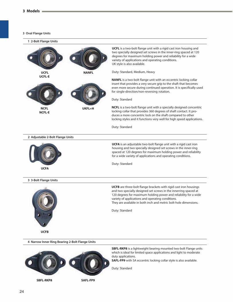
NANFL is a two-bolt flange unit with an eccentric locking collar insert that provides a very secure grip to the shaft that becomes even more secure during continued operation. It is specifically used for single-direction/non-reversing rotation.
Duty: Standard
NCFL is a two-bolt flange unit with a specially designed concentric locking collar that provides 360 degrees of shaft contact. It pro- duces a more concentric lock on the shaft compared to other locking styles and it functions very well for high speed applications.
Duty: Standard
2 Adjustable 2-Bolt Flange Units
3 3-Bolt Flange Units
UCFB
UCFB are three-bolt flange brackets with rigid cast iron housings and two specially designed set screws in the innerring spaced at 120 degrees for maximum holding power and reliability for a wide variety of applications and operating conditions. They are available in both inch and metric bolt-hole dimensions.
Duty: Standard
4 Narrow Inner Ring Bearing 2-Bolt Flange Units
SBFL-RKP8 is a lightweight bearing mounted two-bolt Flange units which is ideal for limited space applications and light to moderate duty applications. SAFL-FP9 with SA eccentric locking collar style is also available.
Duty: Standard
24
UCFA is an adjustable two-bolt flange unit with a rigid cast ironhousing and two specially designed set screws in the inner-ring spaced at 120 degrees for maximum holding power and reliabilityfor a wide variety of applications and operating conditions. Duty: Standard
UCFA
UCFL is a two-bolt flange unit with a rigid cast iron housing andtwo specially designed set screws in the inner-ring spaced at 120degrees for maximum holding power and reliability for a wide variety of applications and operating conditions. UK style is also available.
UCFL NANFL Duty: Standard, Medium, Heavy
UKFL+H
SBFL-RKP8 SAFL-FP9
5 Light 3-Bolt Flange Units
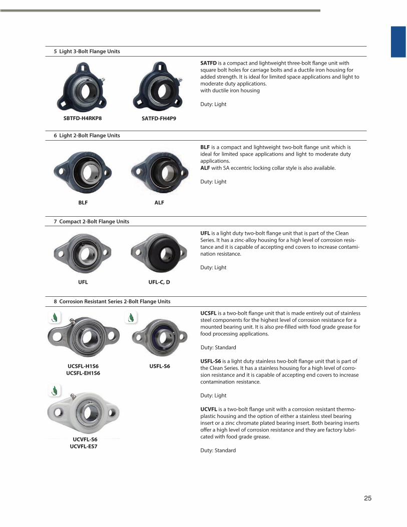
SATFD is a compact and lightweight three-bolt flange unit with square bolt holes for carriage bolts and a ductile iron housing for added strength. It is ideal for limited space applications and light to moderate duty applications. with ductile iron housing
Duty: Light
6 Light 2-Bolt Flange Units
BLF is a compact and lightweight two-bolt flange unit which is ideal for limited space applications and light to moderate duty applications. ALF with SA eccentric locking collar style is also available.
Duty: Light
BLF ALF
7 Compact 2-Bolt Flange Units
UFL UFL-C, D
UFL is a light duty two-bolt flange unit that is part of the Clean Series. It has a zinc-alloy housing for a high level of corrosion resis- tance and it is capable of accepting end covers to increase contami- nation resistance.
Duty: Light
8 Corrosion Resistant Series 2-Bolt Flange Units
UCSFL is a two-bolt flange unit that is made entirely out of stainless steel components for the highest level of corrosion resistance for a mounted bearing unit. It is also pre-filled with food grade grease for food processing applications.
Duty: Standard
UCSFL-H1S6
UCSFL-EH1S6
UCVFL-S6 UCVFL-ES7
USFL-S6
USFL-S6 is a light duty stainless two-bolt flange unit that is part of the Clean Series. It has a stainless housing for a high level of corro- sion resistance and it is capable of accepting end covers to increase contamination resistance.
Duty: Light
UCVFL is a two-bolt flange unit with a corrosion resistant thermo- plastic housing and the option of either a stainless steel bearing insert or a zinc chromate plated bearing insert. Both bearing inserts offer a high level of corrosion resistance and they are factory lubri- cated with food grade grease.
Duty: Standard
25
SBTFD-H4RKP8 SATFD-FH4P9
3 Models
(3 Oval Flange Units)
9 Corrosion Resistant Series 3-Bolt Flange Units
4 4-Bolt Flange Cartridge Units
1 4-Bolt Flange Cartridge Units
UCFC
UCFCX-E UCFCF
UKFC+H
NCFC
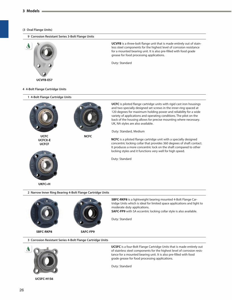
NCFC is a piloted flange cartridge unit with a specially designed concentric locking collar that provides 360 degrees of shaft contact. It produces a more concentric lock on the shaft compared to other locking styles and it functions very well for high speed.
Duty: Standard
2 Narrow Inner Ring Bearing 4-Bolt Flange Cartridge Units
SBFC-RKP8 SAFC-FP9
3 Corrosion Resistant Series 4-Bolt Flange Cartridge Units
UCSFC is a four-Bolt Flange Cartridge Units that is made entirely out of stainless steel components for the highest level of corrosion resis- tance for a mounted bearing unit. It is also pre-filled with food grade grease for food processing applications.
Duty: Standard
UCSFC-H1S6
26
SBFC-RKP8 is a lightweight bearing mounted 4-Bolt Flange Car- tridge Units which is ideal for limited space applications and light to moderate duty applications. SAFC-FP9 with SA eccentric locking collar style is also available.
Duty: Standard
UCFC is piloted flange cartridge units with rigid cast iron housings and two specially designed set screws in the inner-ring spaced at 120 degrees for maximum holding power and reliability for a wide variety of applications and operating conditions. The pilot on the back of the housing allows for precise mounting where necessary. UK, NA styles are also available.
Duty: Standard, Medium
UCVFB is a three-bolt flange unit that is made entirely out of stain-less steel components for the highest level of corrosion resistance for a mounted bearing unit. It is also pre-filled with food grade grease for food processing applications. Duty: Standard
UCVFB-ES7
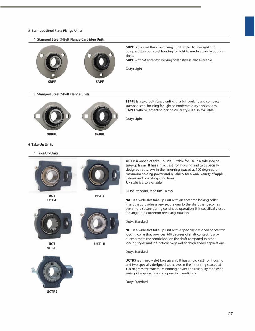
5 Stamped Steel Plate Flange Units
1 Stamped Steel 3-Bolt Flange Cartridge Units
SBPF SAPF
2 Stamped Steel 2-Bolt Flange Units
SBPFL is a two-bolt flange unit with a lightweight and compact stamped steel housing for light to moderate duty applications. SAPFL with SA eccentric locking collar style is also available.
Duty: Light
6 Take-Up Units
1 Take-Up Units
UCT
UCT-E
NCT
NCT-E
UCTRS
NAT-E NAT is a wide-slot take-up unit with an eccentric locking collar insert that provides a very secure grip to the shaft that becomes even more secure during continued operation. It is specifically used for single-direction/non-reversing rotation.
Duty: Standard
NCT is a wide-slot take-up unit with a specially designed concentric locking collar that provides 360 degrees of shaft contact. It pro- duces a more concentric lock on the shaft compared to other locking styles and it functions very well for high speed applications.
Duty: Standard
UCTRS is a narrow slot take up unit. It has a rigid cast iron housing and two specially designed set screws in the inner-ring spaced at 120 degrees for maximum holding power and reliability for a wide variety of applications and operating conditions.
Duty: Standard
27
UCT is a wide-slot take-up unit suitable for use in a side-mount take-up frame. It has a rigid cast iron housing and two specially designed set screws in the inner-ring spaced at 120 degrees for maximum holding power and reliability for a wide variety of appli- cations and operating conditions. UK style is also available.
Duty: Standard, Medium, Heavy
SBPF is a round three-bolt flange unit with a lightweight and compact stamped steel housing for light to moderate duty applica- tions. SAPF with SA eccentric locking collar style is also available.
Duty: Light
SBPFL SAPFL
UKT+H
3 Models
(6 Take-Up Units)
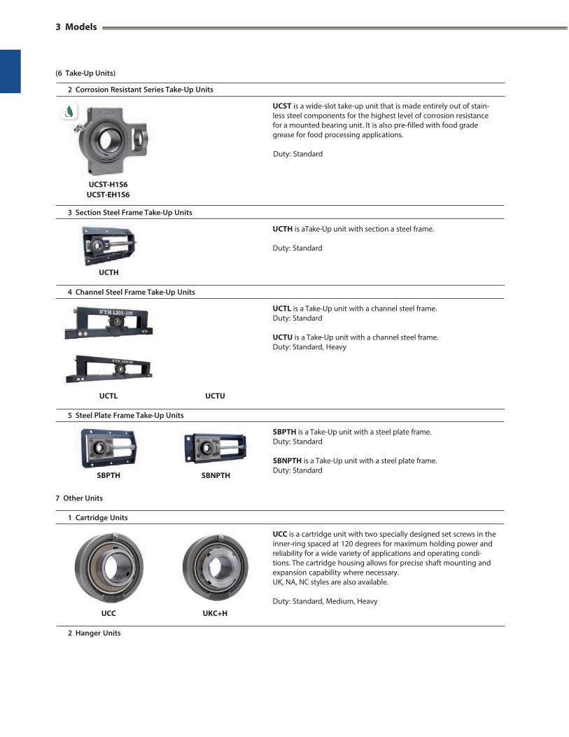
2 Corrosion Resistant Series Take-Up Units
UCST is a wide-slot take-up unit that is made entirely out of stain- less steel components for the highest level of corrosion resistance for a mounted bearing unit. It is also pre-filled with food grade grease for food processing applications.
Duty: Standard
UCST-H1S6 UCST-EH1S6
3 Section Steel Frame Take-Up Units
UCTH
UCTH is aTake-Up unit with section a steel frame.
Duty: Standard
4 Channel Steel Frame Take-Up Units
UCTL UCTU
UCTL is a Take-Up unit with a channel steel frame. Duty: Standard
UCTU is a Take-Up unit with a channel steel frame. Duty: Standard, Heavy
5 Steel Plate Frame Take-Up Units
SBNPTH
SBPTH is a Take-Up unit with a steel plate frame. Duty: Standard
SBNPTH is a Take-Up unit with a steel plate frame. Duty: Standard
7 Other Units
1 Cartridge Units
UCC UKC+H
UCC is a cartridge unit with two specially designed set screws in the inner-ring spaced at 120 degrees for maximum holding power and reliability for a wide variety of applications and operating condi- tions. The cartridge housing allows for precise shaft mounting and expansion capability where necessary. UK, NA, NC styles are also available.
Duty: Standard, Medium, Heavy
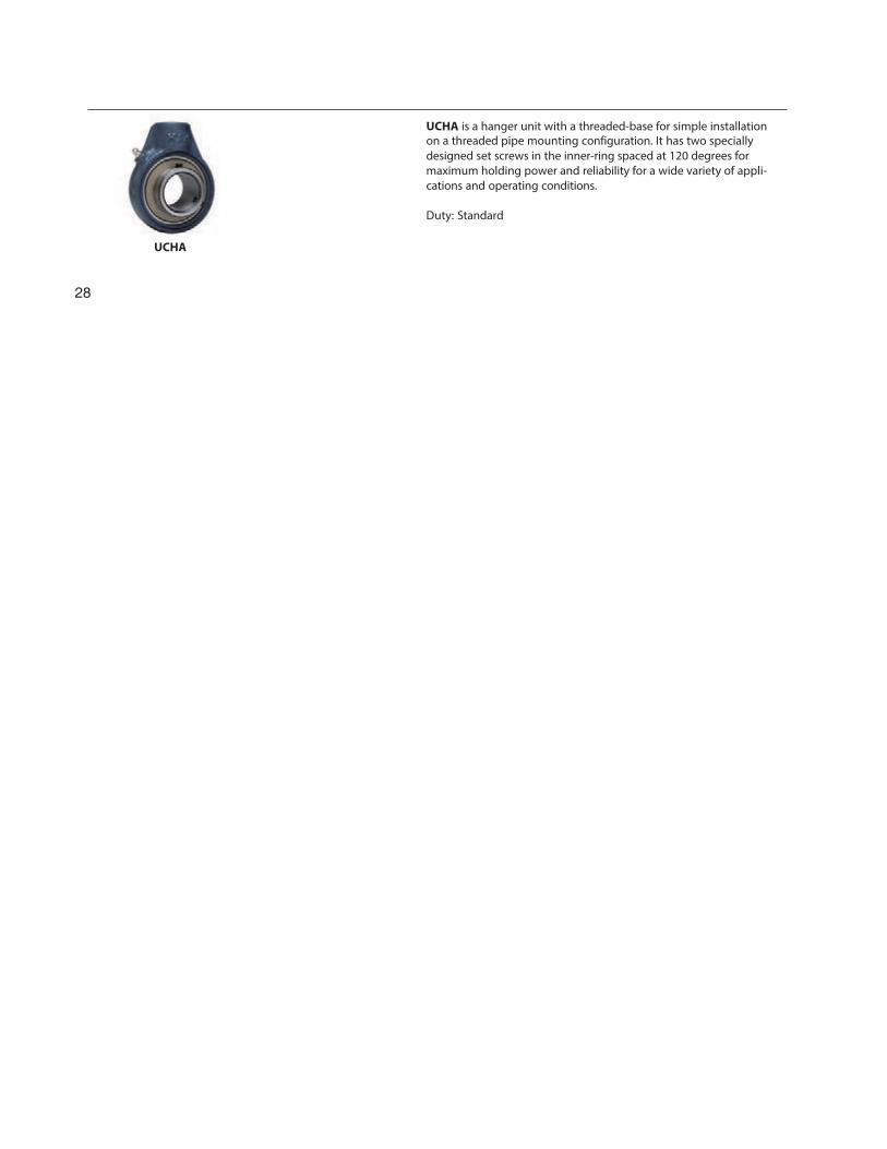
2 Hanger Units
SBPTH
28
UCHA is a hanger unit with a threaded-base for simple installationon a threaded pipe mounting configuration. It has two specially designed set screws in the inner-ring spaced at 120 degrees for maximum holding power and reliability for a wide variety of appli-cations and operating conditions. Duty: Standard
UCHA
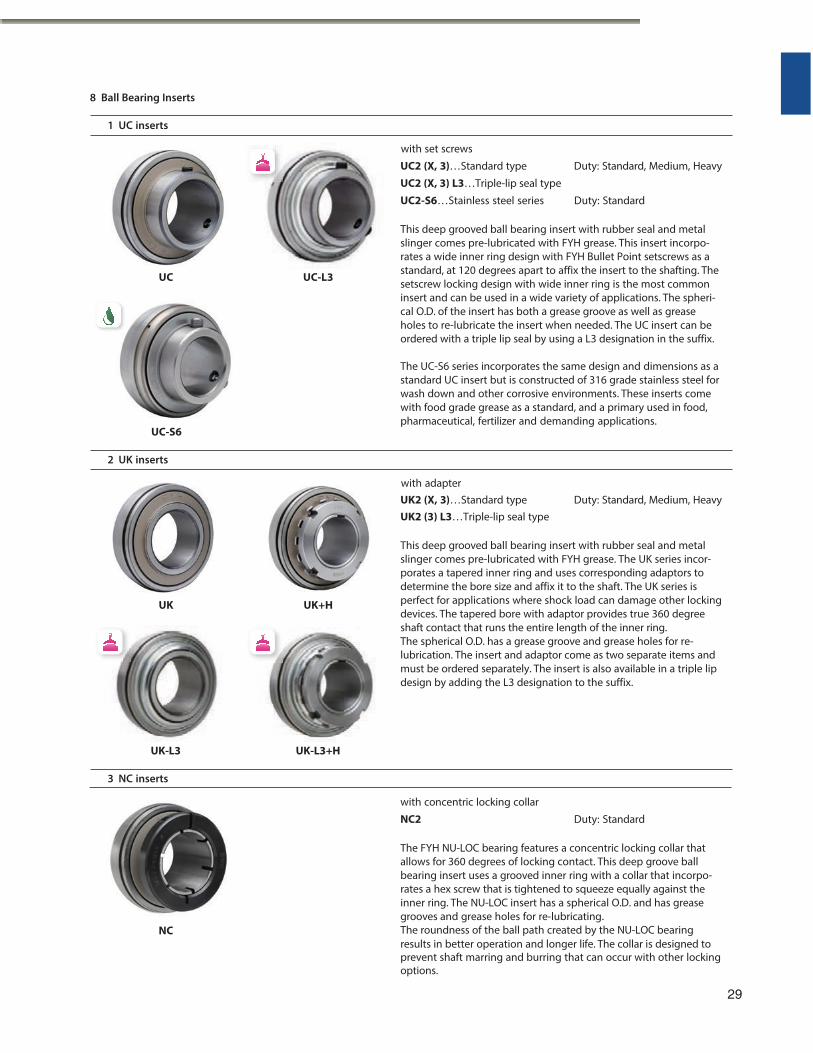
8 Ball Bearing Inserts
1 UC inserts
with set screws
UC2 (X, 3)…Standard type Duty: Standard, Medium, Heavy
UC2 (X, 3) L3…Triple-lip seal type
UC2-S6…Stainless steel series Duty: Standard
This deep grooved ball bearing insert with rubber seal and metal slinger comes pre-lubricated with FYH grease. This insert incorpo- rates a wide inner ring design with FYH Bullet Point setscrews as a standard, at 120 degrees apart to affix the insert to the shafting. The setscrew locking design with wide inner ring is the most common insert and can be used in a wide variety of applications. The spheri- cal O.D. of the insert has both a grease groove as well as grease holes to re-lubricate the insert when needed. The UC insert can be ordered with a triple lip seal by using a L3 designation in the suffix.
UC-S6
The UC-S6 series incorporates the same design and dimensions as a standard UC insert but is constructed of 316 grade stainless steel for wash down and other corrosive environments. These inserts come with food grade grease as a standard, and a primary used in food, pharmaceutical, fertilizer and demanding applications.
2 UK inserts
with adapter UK2 (X, 3)…Standard type Duty: Standard, Medium, Heavy UK2 (3) L3…Triple-lip seal type
This deep grooved ball bearing insert with rubber seal and metal slinger comes pre-lubricated with FYH grease. The UK series incor- porates a tapered inner ring and uses corresponding adaptors to determine the bore size and affix it to the shaft. The UK series is perfect for applications where shock load can damage other locking devices. The tapered bore with adaptor provides true 360 degree shaft contact that runs the entire length of the inner ring. The spherical O.D. has a grease groove and grease holes for re- lubrication. The insert and adaptor come as two separate items and must be ordered separately. The insert is also available in a triple lip design by adding the L3 designation to the suffix.
UK-L3 UK-L3+H
3 NC inserts
with concentric locking collar
NC2 Duty: Standard
The FYH NU-LOC bearing features a concentric locking collar that allows for 360 degrees of locking contact. This deep groove ball bearing insert uses a grooved inner ring with a collar that incorpo- rates a hex screw that is tightened to squeeze equally against the inner ring. The NU-LOC insert has a spherical O.D. and has grease grooves and grease holes for re-lubricating.
NC The roundness of the ball path created by the NU-LOC bearing results in better operation and longer life. The collar is designed to prevent shaft marring and burring that can occur with other locking options.
29
UC UC-L3
UK UK+H
3 Models
(8 Ball Bearing Inserts)
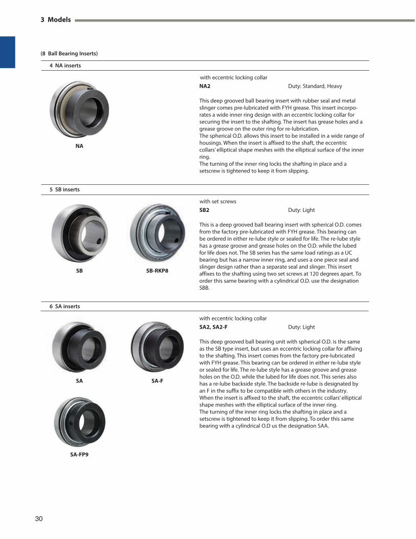
4 NA inserts
with eccentric locking collar NA2 Duty: Standard, Heavy
This deep grooved ball bearing insert with rubber seal and metal slinger comes pre-lubricated with FYH grease. This insert incorpo- rates a wide inner ring design with an eccentric locking collar for securing the insert to the shafting. The insert has grease holes and a grease groove on the outer ring for re-lubrication. The spherical O.D. allows this insert to be installed in a wide range of housings. When the insert is affixed to the shaft, the eccentric collars’ elliptical shape meshes with the elliptical surface of the inner ring. The turning of the inner ring locks the shafting in place and a setscrew is tightened to keep it from slipping.
5 SB inserts
with set screws SB2 Duty: Light
This is a deep grooved ball bearing insert with spherical O.D. comes from the factory pre-lubricated with FYH grease. This bearing can be ordered in either re-lube style or sealed for life. The re-lube style has a grease groove and grease holes on the O.D. while the lubed for life does not. The SB series has the same load ratings as a UC bearing but has a narrow inner ring, and uses a one piece seal and slinger design rather than a separate seal and slinger. This insert affixes to the shafting using two set screws at 120 degrees apart. To order this same bearing with a cylindrical O.D. use the designation SBB.
6 SA inserts
SA SA-F
with eccentric locking collar SA2, SA2-F Duty: Light
This deep grooved ball bearing unit with spherical O.D. is the same as the SB type insert, but uses an eccentric locking collar for affixing to the shafting. This insert comes from the factory pre-lubricated with FYH grease. This bearing can be ordered in either re-lube style or sealed for life. The re-lube style has a grease groove and grease holes on the O.D. while the lubed for life does not. This series also has a re-lube backside style. The backside re-lube is designated by an F in the suffix to be compatible with others in the industry. When the insert is affixed to the shaft, the eccentric collars’ elliptical shape meshes with the elliptical surface of the inner ring. The turning of the inner ring locks the shafting in place and a setscrew is tightened to keep it from slipping. To order this same bearing with a cylindrical O.D us the designation SAA.
30
NA
SB SB-RKP8
SA-FP9
ERC
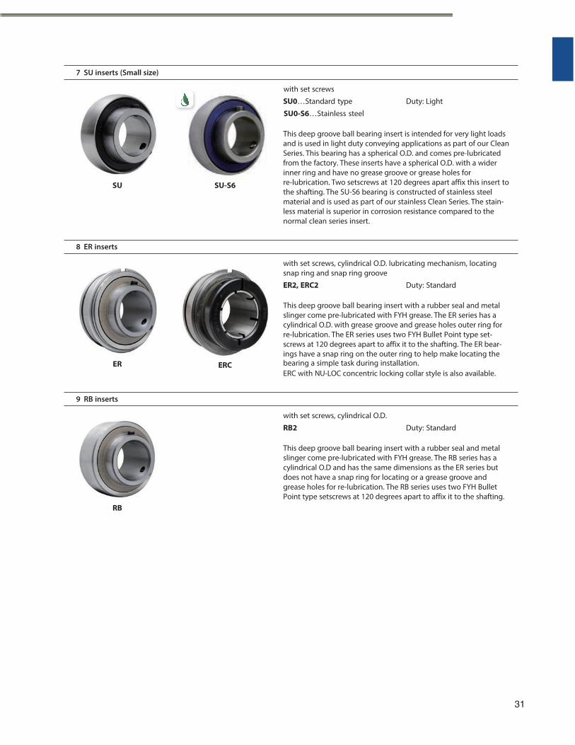
7 SU inserts (Small size)
with set screws
SU0…Standard type Duty: Light
SU0-S6…Stainless steel
This deep groove ball bearing insert is intended for very light loads and is used in light duty conveying applications as part of our Clean Series. This bearing has a spherical O.D. and comes pre-lubricated from the factory. These inserts have a spherical O.D. with a wider inner ring and have no grease groove or grease holes for re-lubrication. Two setscrews at 120 degrees apart affix this insert to the shafting. The SU-S6 bearing is constructed of stainless steel material and is used as part of our stainless Clean Series. The stain- less material is superior in corrosion resistance compared to the normal clean series insert.
8 ER inserts
with set screws, cylindrical O.D. lubricating mechanism, locating snap ring and snap ring groove
ER2, ERC2 Duty: Standard
This deep groove ball bearing insert with a rubber seal and metal slinger come pre-lubricated with FYH grease. The ER series has a cylindrical O.D. with grease groove and grease holes outer ring for re-lubrication. The ER series uses two FYH Bullet Point type set- screws at 120 degrees apart to affix it to the shafting. The ER bear- ings have a snap ring on the outer ring to help make locating the
ER bearing a simple task during installation. ERC with NU-LOC concentric locking collar style is also available.
9 RB inserts
with set screws, cylindrical O.D.
RB2 Duty: Standard
This deep groove ball bearing insert with a rubber seal and metal slinger come pre-lubricated with FYH grease. The RB series has a cylindrical O.D and has the same dimensions as the ER series but does not have a snap ring for locating or a grease groove and grease holes for re-lubrication. The RB series uses two FYH Bullet Point type setscrews at 120 degrees apart to affix it to the shafting.
RB
31
SU SU-S6
3 Models
(8 Ball Bearing Inserts)
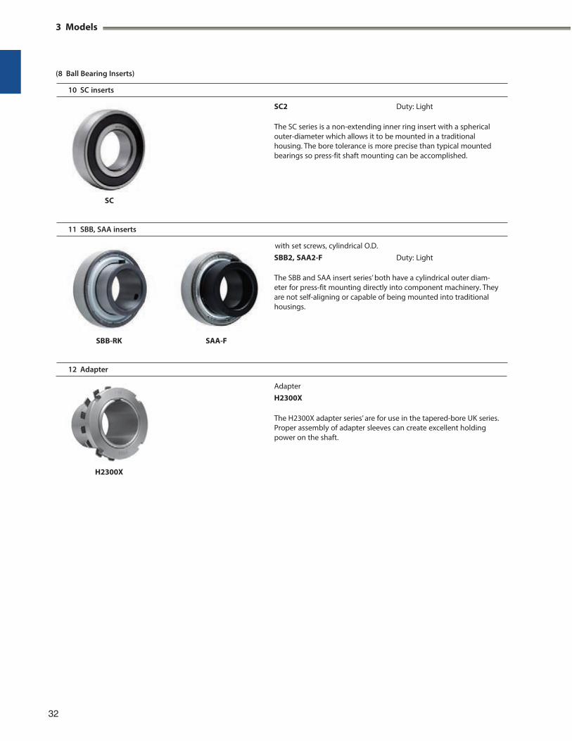
10 SC inserts
SC2 Duty: Light
The SC series is a non-extending inner ring insert with a spherical outer-diameter which allows it to be mounted in a traditional housing. The bore tolerance is more precise than typical mounted bearings so press-fit shaft mounting can be accomplished.
SC
11 SBB, SAA inserts
with set screws, cylindrical O.D. SBB2, SAA2-F Duty: Light
The SBB and SAA insert series’ both have a cylindrical outer diam- eter for press-fit mounting directly into component machinery. They are not self-aligning or capable of being mounted into traditional housings.
SBB-RK SAA-F
12 Adapter
H2300X
Adapter H2300X
The H2300X adapter series’ are for use in the tapered-bore UK series. Proper assembly of adapter sleeves can create excellent holding power on the shaft.
32
3
4 Rating Life of Bearings
When ball bearing units are installed and operated on a piece of machinery eventually a failure will occur. The period of operation until the unit cannot be used due to failure is called the bearing life.
Bearing failure is caused by two main reasons. The first is fatigue of bearing material, and the second is lubricant degradation. The life is figured on whichever fails first.
4.2 Calculation of Rating Life
The relationship between the basic rating life, the basic dynamic load rating, and the dynamic equivalent load of the ball bearing is indicated in Formula (4.1). If the ball bearing unit is being used at a fixed rotating speed, the life is indi- cated as time. This is shown in Formula (4.2).
Proper bearing lubrication will eliminate grease degrada- tion and allow full bearing life to be achieved. If the bearing units are run without replenishment of the grease the bearing life will have to be factored by either the grease life
(Total rotating frequency)
L10
Cr 3
Pr 6
(4.1)
3
or the bearing life. During installation, care must be taken not to damage the bearing. Proper bearing maintenance and lubrication will ensure long bearing life.
(Time)
Whereas,
L10h 10 Cr
60n Pr (4.2)
4.1 Basic Rating Life and Basic Load Rating
4.1.1 Basic rating life
When a bearing is rotated under load the raceways and the rolling elements are continuously exposed to load. Damage, such as scaling (flaking or peeling), eventually appears on the material, and the total rotating frequency until the damage appears is called the “fatigue limit of the bearing”. Fatigue limit of the bearing can vary greatly even
L10: Basic rating life, 106 rotations L10h: Basic rating life, hr
Cr: Basic dynamic load rating, N Pr: Dynamic equivalent load, N
(see “5 Bearing load”)
n: Rotating speed, min1
Calculation of the basic rating life using the life factor ( f h) and the speed factor ( f n) in Formula (4.2) are shown below.
if the bearings have the same structure, dimensions, mate- rials, machining methods, and are operated under the same conditions.
To account for this variation, a group of the same bear- L10h 500 f h (4.3)
Cr
ings operating under the same conditions are tested, and the total rotating frequency of 90% of the bearings operat- ing with no damage due to rotating fatigue (90% reliability)
Life factor f h f n ∙
Speed factor f n
Pr
106
1/3
(4.4)
is called the basic load rating.
4.1.2 Basic load rating
500 60n 1/3
(0.03n) (4.5)
Dynamic ratings are determined by placing a pure radial load on a radial bearing or by placing a central axial load on a thrust bearing. The dynamic rating is the load that the bearing will withstand for one million cycles before failure of the bearing.
These ratings are referred to as the basic dynamic radial load rating (Cr) or the basic dynamic axial load rating (Ca). These values are indicated in the catalog as the basic dynamic radial load rating (Cr), and the value is shown in the dimensional table.
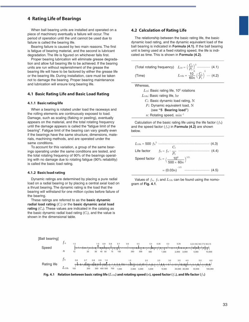
Values of f n, f h and L10h can be found using the nomo- gram of Fig. 4.1.
[Ball bearing]
Speed
Rating life
f n
n
f h
L10h
1.5 1.0 0.9 0.8 0.7 0.6 0.5 0.4 0.35 0.3 0.25 0.2 0.19 0.18 0.17 0.16 0.15
10 20 30 40 50 70 100 200 300 500 1,000 2,000 3,000 5,000 10,000
0.6 0.7 0.8 0.9 1.0 1.5 2.0 2.5 3.0 3.5 4.0 5.0 6.0
100 200 300 400 500 700 1,000 2,000 3,000 5,000 10,000 20,000 30,000 50,000 100,000
Fig. 4.1 Relation between basic rating life (L10h) and rotating speed (n), speed factor ( f n), and life factor ( f h)
33
4 Rating Life of Bearings
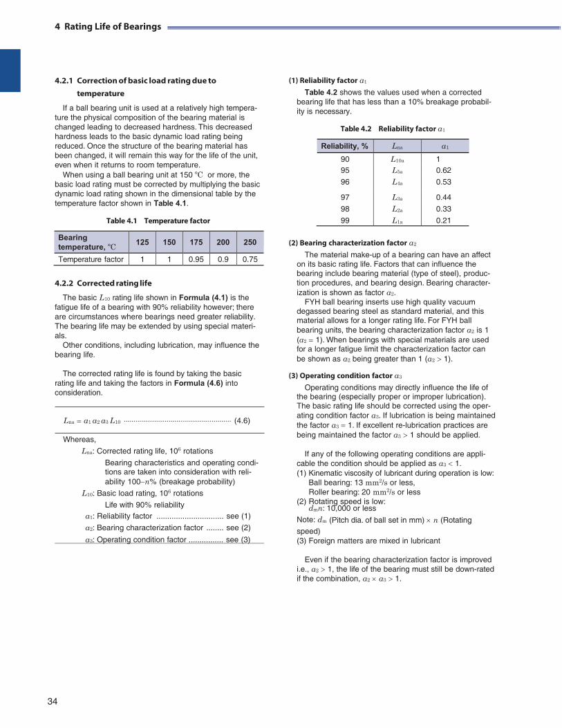
4.2.1 Correction of basic load rating due to
temperature
If a ball bearing unit is used at a relatively high tempera- ture the physical composition of the bearing material is changed leading to decreased hardness. This decreased hardness leads to the basic dynamic load rating being reduced. Once the structure of the bearing material has been changed, it will remain this way for the life of the unit, even when it returns to room temperature.
When using a ball bearing unit at 150 ºC or more, the basic load rating must be corrected by multiplying the basic dynamic load rating shown in the dimensional table by the temperature factor shown in Table 4.1.
Table 4.1 Temperature factor
(1) Reliability factor a1
Table 4.2 shows the values used when a corrected bearing life that has less than a 10% breakage probabil- ity is necessary.
Table 4.2 Reliability factor a1
4.2.2 Corrected rating life
The basic L10 rating life shown in Formula (4.1) is the fatigue life of a bearing with 90% reliability however; there are circumstances where bearings need greater reliability. The bearing life may be extended by using special materi- als.
Other conditions, including lubrication, may influence the bearing life.
The corrected rating life is found by taking the basic
rating life and taking the factors in Formula (4.6) into consideration.
Lna a1 a2 a3 L10 (4.6)
Whereas,
Lna: Corrected rating life, 106 rotations Bearing characteristics and operating condi- tions are taken into consideration with reli- ability 100n% (breakage probability)
L10: Basic load rating, 106 rotations
Life with 90% reliability
(2) Bearing characterization factor a2
The material make-up of a bearing can have an affect on its basic rating life. Factors that can influence the bearing include bearing material (type of steel), produc- tion procedures, and bearing design. Bearing character- ization is shown as factor a2.
FYH ball bearing inserts use high quality vacuum degassed bearing steel as standard material, and this material allows for a longer rating life. For FYH ball bearing units, the bearing characterization factor a2 is 1 (a2 1). When bearings with special materials are used for a longer fatigue limit the characterization factor can be shown as a2 being greater than 1 (a2 1).
(3) Operating condition factor a3
Operating conditions may directly influence the life of the bearing (especially proper or improper lubrication). The basic rating life should be corrected using the oper- ating condition factor a3. If lubrication is being maintained the factor a3 1. If excellent re-lubrication practices are being maintained the factor a3 1 should be applied.
If any of the following operating conditions are appli-
cable the condition should be applied as a3 1. (1) Kinematic viscosity of lubricant during operation is low:
Ball bearing: 13 mm2/s or less, Roller bearing: 20 mm2/s or less
(2) Rotating speed is low: dmn: 10,000 or less
a1: Reliability factor ............................... see (1) Note: dm (Pitch dia. of ball set in mm) n (Rotating a2: Bearing characterization factor ........ see (2)
a3: Operating condition factor ................ see (3) speed) (3) Foreign matters are mixed in lubricant
Even if the bearing characterization factor is improved
i.e., a2 1, the life of the bearing must still be down-rated if the combination, a2 a3 1.
34
Reliability, % Lna a1
90 L10a 1 95 L5a 0.62
96 L4a 0.53
97 L3a 0.44
98 L2a 0.33
99 L1a 0.21
Bearing temperature, ºC
125 150 175 200 250
Temperature factor 1 1 0.95 0.9 0.75
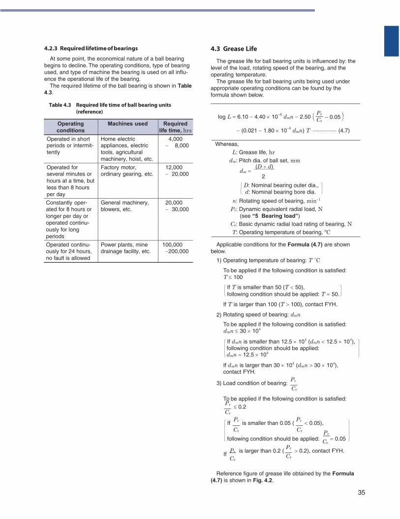
4.2.3 Required lifetime of bearings
At some point, the economical nature of a ball bearing begins to decline. The operating conditions, type of bearing used, and type of machine the bearing is used on all influ- ence the operational life of the bearing.
The required lifetime of the ball bearing is shown in Table 4.3.
Table 4.3 Required life time of ball bearing units
(reference)
4.3 Grease Life
The grease life for ball bearing units is influenced by: the level of the load, rotating speed of the bearing, and the operating temperature.
The grease life for ball bearing units being used under appropriate operating conditions can be found by the formula shown below.
log L 6.10 4.40 106 dmn 2.50 0.05
(0.021 1.80 108 dmn) T (4.7)
Whereas,
L: Grease life, hr dm: Pitch dia. of ball set, mm
(D d) dm
2
D: Nominal bearing outer dia., d: Nominal bearing bore dia.
n: Rotating speed of bearing, min1
Pr: Dynamic equivalent radial load, N (see “5 Bearing load”)
Cr: Basic dynamic radial load rating of bearing, N T: Operating temperature of bearing, ºC
Applicable conditions for the Formula (4.7) are shown below.
1) Operating temperature of bearing: T ˚C
To be applied if the following condition is satisfied: T 100
If T is smaller than 50 (T 50), following condition should be applied: T 50.
If T is larger than 100 (T 100), contact FYH.
2) Rotating speed of bearing: dmn
To be applied if the following condition is satisfied: dmn 30 104
If dmn is smaller than 12.5 104 (dmn 12.5 104), following condition should be applied: dmn 12.5 104
If dmn is larger than 30 104 (dmn 30 104), contact FYH.
3) Load condition of bearing: Pr
Cr
To be applied if the following condition is satisfied: Pr 0.2 Cr
If Pr
is smaller than 0.05 ( Pr 0.05),
Cr Cr Pr
following condition should be applied: Cr 0.05
If Pr
Cr
is larger than 0.2 ( Pr 0.2), contact FYH. Cr
Reference figure of grease life obtained by the Formula (4.7) is shown in Fig. 4.2.
35
Pr
CrOperating conditions
Machines used Required life time, hrs
Operated in short Home electric 4,000 periods or intermit- appliances, electric 8,000 tently tools, agricultural
machinery, hoist, etc.
Operated for Factory motor, 12,000 several minutes or ordinary gearing, etc. 20,000 hours at a time, but less than 8 hours per day
Constantly oper- General machinery, 20,000 ated for 8 hours or blowers, etc. 30,000 longer per day or operated continu- ously for long periods
Operated continu- Power plants, mine 100,000 ously for 24 hours, drainage facility, etc. 200,000 no fault is allowed
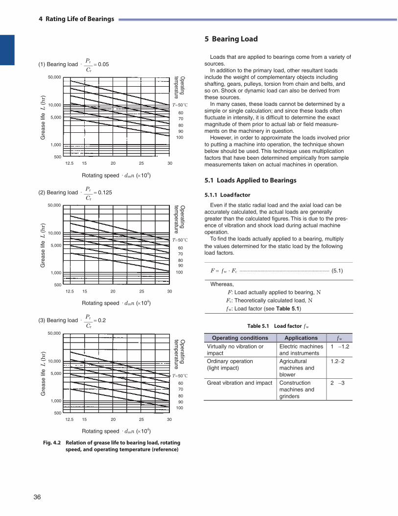
4 Rating Life of Bearings
5 Bearing Load
(1) Bearing load · Pr 0.05 Cr
50,000
10,000
5,000
1,000
500
T 50 ̊ C
60 70
80 90
100
Loads that are applied to bearings come from a variety of sources.
In addition to the primary load, other resultant loads include the weight of complementary objects including shafting, gears, pulleys, torsion from chain and belts, and so on. Shock or dynamic load can also be derived from these sources.
In many cases, these loads cannot be determined by a simple or single calculation; and since these loads often fluctuate in intensity, it is difficult to determine the exact magnitude of them prior to actual lab or field measure- ments on the machinery in question.
However, in order to approximate the loads involved prior to putting a machine into operation, the technique shown below should be used. This technique uses multiplication factors that have been determined empirically from sample
12.5 15 20 25 30
Rotating speed · dmn (104)
(2) Bearing load · Pr 0.125 Cr
50,000
10,000
T 50 ̊ C
measurements taken on actual machines in operation.
5.1 Loads Applied to Bearings
5.1.1 Load factor
Even if the static radial load and the axial load can be accurately calculated, the actual loads are generally greater than the calculated figures. This is due to the pres- ence of vibration and shock load during actual machine operation.
To find the loads actually applied to a bearing, multiply 5,000
60 the values determined for the static load by the following 70 load factors. 80 90
1,000
500
12.5 15 20 25 30
Rotating speed · dmn (104)
100 F f w ∙ Fc (5.1)
Whereas,
F: Load actually applied to bearing, N Fc: Theoretically calculated load, N f w: Load factor (see Table 5.1)
(3) Bearing load · Pr 0.2 Cr
Table 5.1 Load factor f w
50,000
10,000
5,000
1,000
500
12.5 15 20 25 30
Rotating speed · dmn (104)
T 50 ̊ C
60 70
80 90
100
Fig. 4.2 Relation of grease life to bearing load, rotating speed, and operating temperature (reference)
36
4 Rating Life of Bearings
Operating
temperature
Operating
temperature
Operating
temperature
Gre
ase
life
L (
hr)
G
reas
e lif
e L
(h
r)
Gre
ase
life
L (
hr)
Operating conditions Applications f w
Virtually no vibration or impact
Electric machines and instruments
1 1.2
Ordinary operation (light impact)
Agricultural machines and blower
1.22
Great vibration and impact Construction machines and grinders
2 3
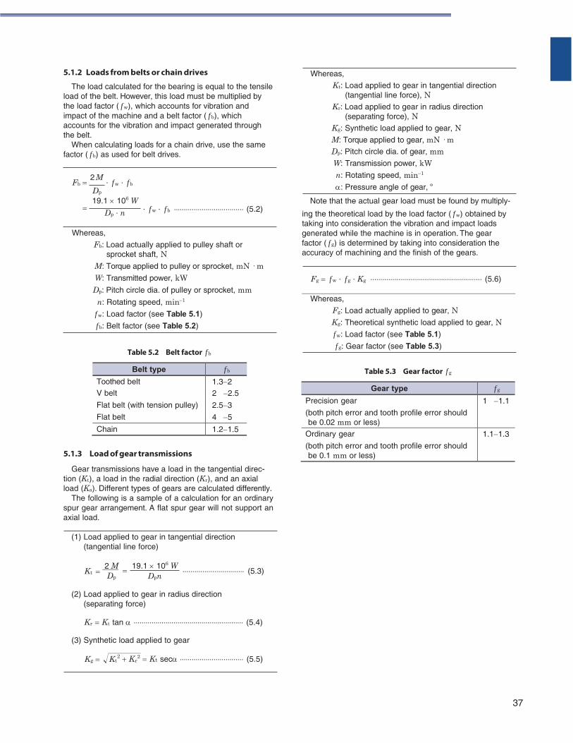
t r
5.1.2 Loads from belts or chain drives
The load calculated for the bearing is equal to the tensile load of the belt. However, this load must be multiplied by the load factor ( f w), which accounts for vibration and impact of the machine and a belt factor ( f b), which accounts for the vibration and impact generated through the belt.
When calculating loads for a chain drive, use the same factor ( f b) as used for belt drives.
Fb 2 M
∙ f w ∙ f b Dp
19.1 106 W
Whereas,
Kt: Load applied to gear in tangential direction (tangential line force), N
Kr: Load applied to gear in radius direction (separating force), N
Kg: Synthetic load applied to gear, N M: Torque applied to gear, mN · m Dp: Pitch circle dia. of gear, mm W: Transmission power, kW n: Rotating speed, min1
: Pressure angle of gear, º
Note that the actual gear load must be found by multiply-
Dp ∙ n ∙ f w ∙ f b (5.2) ing the theoretical load by the load factor ( f w) obtained by taking into consideration the vibration and impact loads
Whereas,
Fb: Load actually applied to pulley shaft or sprocket shaft, N
M: Torque applied to pulley or sprocket, mN · m W: Transmitted power, kW
generated while the machine is in operation. The gear factor ( f g) is determined by taking into consideration the accuracy of machining and the finish of the gears.
Fg f w ∙ f g ∙ Kg (5.6) Dp: Pitch circle dia. of pulley or sprocket, mm
n: Rotating speed, min1
f w: Load factor (see Table 5.1) f b: Belt factor (see Table 5.2)
Table 5.2 Belt factor f b
Whereas,
Fg: Load actually applied to gear, N Kg: Theoretical synthetic load applied to gear, N f w: Load factor (see Table 5.1) f g: Gear factor (see Table 5.3)
Table 5.3 Gear factor f g
5.1.3 Load of gear transmissions
Gear transmissions have a load in the tangential direc- tion (Kt), a load in the radial direction (Kr), and an axial load (Ka). Different types of gears are calculated differently.
The following is a sample of a calculation for an ordinary spur gear arrangement. A flat spur gear will not support an axial load.
(1) Load applied to gear in tangential direction (tangential line force)
Kt
2 M Dp
19.1 106 W Dpn
(5.3)
(2) Load applied to gear in radius direction (separating force)
Kr Kt tan (5.4)
(3) Synthetic load applied to gear
Kg K 2 K 2 Kt sec (5.5)
37
Belt type f b
Toothed belt 1.32 V belt 2 2.5
Flat belt (with tension pulley) 2.53
Flat belt 4 5
Chain 1.21.5
Gear type f g
Precision gear
(both pitch error and tooth profile error should be 0.02 mm or less)
1 1.1
Ordinary gear
(both pitch error and tooth profile error should be 0.1 mm or less)
1.11.3
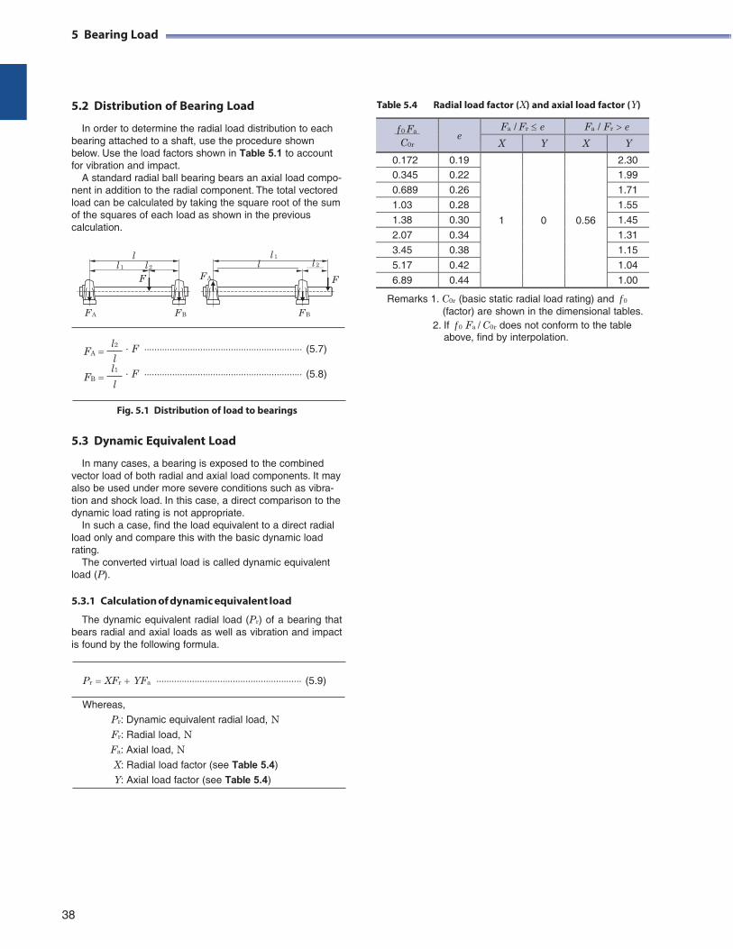
5 Bearing Load
5.2 Distribution of Bearing Load
In order to determine the radial load distribution to each bearing attached to a shaft, use the procedure shown below. Use the load factors shown in Table 5.1 to account for vibration and impact.
A standard radial ball bearing bears an axial load compo- nent in addition to the radial component. The total vectored load can be calculated by taking the square root of the sum of the squares of each load as shown in the previous calculation.
Table 5.4 Radial load factor (X) and axial load factor (Y)
l 1
l
l 2
F A F B
F A F
F B
Remarks 1. C0r (basic static radial load rating) and f 0
(factor) are shown in the dimensional tables. 2. If f 0 Fa / C0r does not conform to the table
above, find by interpolation. FA
FB
l2 ∙ F (5.7)
l l1 ∙ F (5.8)
l
Fig. 5.1 Distribution of load to bearings
5.3 Dynamic Equivalent Load
In many cases, a bearing is exposed to the combined vector load of both radial and axial load components. It may also be used under more severe conditions such as vibra- tion and shock load. In this case, a direct comparison to the dynamic load rating is not appropriate.
In such a case, find the load equivalent to a direct radial load only and compare this with the basic dynamic load rating.
The converted virtual load is called dynamic equivalent load (P).
5.3.1 Calculation of dynamic equivalent load
The dynamic equivalent radial load (Pr) of a bearing that bears radial and axial loads as well as vibration and impact is found by the following formula.
Pr XFr YFa (5.9)
Whereas,
Pr: Dynamic equivalent radial load, N Fr: Radial load, N Fa: Axial load, N X: Radial load factor (see Table 5.4)
Y: Axial load factor (see Table 5.4)
38
l l 1 l 2
F
f 0 Fa
C0r
e
Fa / Fr e Fa / Fr e
X Y X Y
0.172 0.19
1
0
0.56
2.30 0.345 0.22 1.99
0.689 0.26 1.71
1.03 0.28 1.55
1.38 0.30 1.45
2.07 0.34 1.31
3.45 0.38 1.15
5.17 0.42 1.04
6.89 0.44 1.00
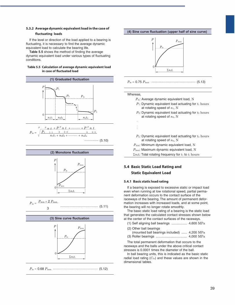
5.3.2 Average dynamic equivalent load in the case of
fluctuating loads
If the level or direction of the load applied to a bearing is P fluctuating, it is necessary to find the average dynamic equivalent load to calculate the bearing life.
Table 5.5 shows the method of finding the average dynamic equivalent load under various types of fluctuating conditions.
Table 5.5 Calculation of average dynamic equivalent load 0 in case of fluctuated load
P
0
p p n t
P p n t
Pn
P p n t
Pm 0.75 Pmax (5.13)
Whereas, Pm: Average dynamic equivalent load, N P1: Dynamic equivalent load actuating for t1 hours
at rotating speed of n1, N P2: Dynamic equivalent load actuating for t2 hours
at rotating speed of n2, N · · ·
Pm P1 1 1 2 2 2 n n n
n1t1 n2t2 nntn
(5.10)
P Pmax
Pm
Pn: Dynamic equivalent load actuating for tn hours at rotating speed of nn, N
Pmin: Minimum dynamic equivalent load, N Pmax: Maximum dynamic equivalent load, N niti: Total rotating frequency for t1 to ti hours
5.4 Basic Static Load Rating and Static Equivalent Load
0
Pm Pmin 2 Pmax
Pmin
niti
5.4.1 Basic static load rating
If a bearing is exposed to excessive static or impact load even when running at low rotational speed, partial perma- nent deformation occurs to the contact surface of the raceways of the bearing. The amount of permanent defor- mation increases with increased loads, and at some point,
3 (5.11) the bearing will no longer rotate smoothly.
The basic static load rating of a bearing is the static load that generates the calculated contact stresses shown below at the center of the contact surfaces of the raceways.
(1) Self aligning ball bearings ................. 4,600 MPa P
Pm
0 niti
Pmax (2) Other ball bearings (mounted ball bearings included) ...... 4,200 MPa
(3) Roller bearings .................................. 4,000 MPa
The total permanent deformation that occurs to the raceways and the balls under the above critical contact stresses is 0.0001 times the diameter of the ball.
In ball bearing units, this is indicated as the basic static radial load rating (C0r) and these values are shown in the dimensional tables.
Pm 0.68 Pmax (5.12)
39
(1) Graduated fluctuation
P1
P2 Pm
n1t1 n2t2 nntn
(2) Monotone fluctuation
(3) Sine curve fluctuation
(4) Sine curve fluctuation (upper half of sine curve)
Pmax
Pm
niti
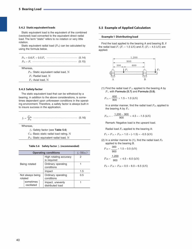
5 Bearing Load
5.4.2 Static equivalent loads
5.5 Example of Applied Calculation Static equivalent load is the equivalent of the combined
(vectored) load converted to the equivalent direct radial load. The term “static” refers to no rotation or very little rotation.
Static equivalent radial load (P0r) can be calculated by using the formula below.
Example 1 Distributing load
Find the load applied to the bearing A and bearing B, if the radial load F1 (F1 1.5 kN) and F2 (F2 4.5 kN) are applied.
P0r 0.6 Fr 0.5 Fa (5.14) 1,200
P0r Fr (5.15)
300
900
600 Whereas,
P0r: Static equivalent radial load, N Fr: Radial load, N Fa: Axial load, N
5.4.3 Safety factor
The static equivalent load that can be withstood by a
F 1 F 2
A B
(1) Find the radial load F1A applied to the bearing A by F1, with Formula (5.7) and Formula (5.8).
bearing, in addition to the above considerations, is some- times dependent upon unforeseen conditions in the operat-
F1A 600 900
1.5 1.0 (kN)
ing environment. Therefore, a safety factor is always built in to insure success in the application.
In a similar manner, find the radial load F2A applied to the bearing A by F2.
f s C0r P0r
(5.16)
F2A
1,200 900 900
4.5 1.5 (kN)
Whereas,
f s: Safety factor (see Table 5.6)
C0r: Basic static radial load rating, N P0r: Static equivalent radial load, N
Table 5.6 Safety factor f s (recommended)
Remark: Negative load is the upward load.
Radial load FA applied to the bearing A:
FA F1A F2A 1.0 (1.5) 0.5 (kN)
(2) In a similar manner to (1), find the radial load FB
applied to the bearing B.
F1B 300
1.5 0.5 (kN) 900
1,200
F2B 900
4.5 6.0 (kN)
FB F1B F2B 0.5 6.0 6.5 (kN)
40
Operating conditions f s (Min.)
Being rotated
High rotating accuracy is required
2
Ordinary operating conditions
1
Impact 1.5
Not always being rotated
sometimes oscillated
Ordinary operating conditions
0.5
Impact, unevenly distributed load
1
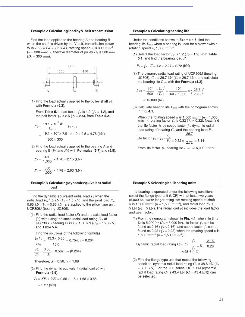
Example 2 Calculating load by V-belt transmission
Find the load applied to the bearing A and bearing B when the shaft is driven by the V-belt, transmission power W is 7.5 kw (W 7.5 kW), rotating speed n is 300 min1
(n 300 min1), effective diameter of pulley Dp is 300 mm (Dp 300 mm).
Example 4 Calculating bearing life
Under the conditions shown in Example 3, find the bearing life L10h when a bearing is used for a blower with a rotating speed n, 1,000 min1.
(1) Select the load factor f w is 1.2 ( f w 1.2) from Table 5.1, and find the bearing load Pr.
Pr f w ∙ F 1.2 2.27 2.72 (kN)
(2) The dynamic radial load rating of UCP306J (bearing UC306), Cr, is 26.7 kN (Cr 26.7 kN), and calculate the bearing life L10h with the Formula (4.2).
L10h 106
∙
Cr 3 106
26.7 3
60n Pr 60 1,000 2.72
(1) Find the load actually applied to the pulley shaft Fb
with Formula (5.2).
From Table 5.1, load factor f w is 1.2 ( f w 1.2), and the belt factor f b is 2.5 ( f b 2.5), from Table 5.2.
15,800 (hr)
(3) Calculate bearing life L10h with the nomogram shown in Fig. 4.1.
When the rotating speed n is 1,000 min1 (n 1,000 1 6 min ), rotating factor f n is 0.32 ( f n 0.32). Next, find
Fb 19.1 10 W
Dp ∙ n 6
∙ f w ∙ f b the life factor f h by speed factor f n, dynamic radial load rating of bearing Cr, and the bearing load Pr.
19.1 10 7.5 1.2 2.5 4.78 (kN) r
26.7
300 300 Life factor f h f n ∙ C
Pr 0.32 2.72 3.14
(2) Find the load actually applied to the bearing A and bearing B (FA and FB) with Formulas (5.7) and (5.8).
From life factor f h, bearing life L10h 16,000 hours.
FA
FB
450 1,000
550
1,000
4.78 2.15 (kN)
4.78 2.63 (kN)
Example 3 Calculating dynamic equivalent radial load
Find the dynamic equivalent radial load Pr when the
radial load Fr, 1.5 kN (Fr 1.5 kN), and the axial load Fa, 0.85 kN, (Fa 0.85 kN) are applied to the pillow type unit UCP306J (bearing UC306).
(1) Find the radial load factor (X) and the axial load factor (Y) with using the static radial load rating C0r of UCP306J (bearing UC306), 15.0 kN (C0r 15.0 kN), and Table 5.4.
Find the solutions of the following formulas:
Example 5 Selecting ball bearing units
If a bearing is operated under the following conditions, select the flange type unit (UCF) with at least two years (5,000 hours) or longer rating life: rotating speed of shaft n is 1,500 min1 (n 1,500 min1), and radial load Fr is 5 kN (Fr 5 kN). The radial load Fr includes the load factor and gear factor.
(1) From the nomogram shown in Fig. 4.1, when life time Lh is 5,000 hr (Lh 5,000 hr), life factor f h can be found as 2.16 ( f h 2.16), and speed factor f n can be found as 0.28 ( f n 0.28) when the rotating speed n is 1,500 min1 (n 1,500 min1).
f 0 Fa 13.3 0.85 0.754, e 0.264 f h
2.16 C0r 15.0 Dynamic radial load rating Cr Fr ∙
f n 5 0.28
Fa 0.85 0.567 e (0.264) 38.6 (kN) Fr 1.5
Therefore, X 0.56, Y 1.68
(2) Find the dynamic equivalent radial load Pr with Formula (5.9).
Pr XFr YFa 0.56 1.5 1.68 0.85
2.27 (kN)
(2) Find the flange type unit that meets the following condition: dynamic radial load rating Cr is 38.6 kN (Cr
38.6 kN). For the 200 series. UCF211J (dynamic radial load rating Cr is 43.4 kN (Cr 43.4 kN)) can be selected.
41
1,000
550 450
A B
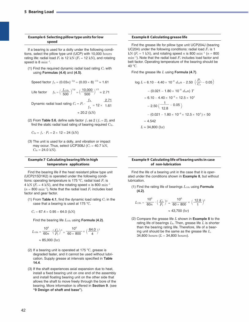
Pr
Cr
5 Bearing Load
Example 6 Selecting pillow type units for low speed
If a bearing is used for a dolly under the following condi-
tions, select the pillow type unit (UCP) with 10,000 hours rating life: radial load Fr is 12 kN (Fr 12 kN), and rotating speed is 8 min1.
(1) Find the required dynamic radial load rating Cr with using Formulas (4.4) and (4.5).
Speed factor f n (0.03n)1/p (0.03 8)1/3 1.61
Example 8 Calculating grease life
Find the grease life for pillow type unit UCP204J (bearing UC204) under the following conditions: radial load Fr is 1 kN (Fr 1 kN), and rotating speed n is 800 min1 (n 800 min1). Note that the radial load Fr includes load factor and belt factor. Operating temperature of the bearing should be 40 ºC.
Find the grease life L using Formula (4.7).
log L 6.10 4.40 106 dmn 2.50 0.05
Life factor
f h
L10h
500
1/p
10,000
500
f h
1/3 2.71
2.71
(0.021 1.80 108 dmn) T
6.10 4.40 106 12.5 104
Dynamic radial load rating Cr Pr ∙ f n
12 1.61 2.50 1 0.05 12.8
20.2 (kN)
(2) From Table 5.6, define safe factor f s as 2 ( f s 2), and find the static radial load rating of bearing required C0r.
C0r f s ∙ Pr 2 12 24 (kN)
(0.021 1.80 108 12.5 104 ) 50
4.542
L 34,800 (hr)
(3) The unit is used for a dolly, and vibration or impact may occur. Thus, select UCP308J (Cr 40.7 kN, C0r 24.0 kN).
Example 7 Calculating bearing life in high temperature applications
Find the bearing life if the heat resistant pillow type unit
(UCP215D1K2) is operated under the following condi- tions: operating temperature is 175 ºC, radial load Fr is 4 kN (Fr 4 kN), and the rotating speed n is 800 min1
(n 800 min1). Note that the radial load Fr includes load factor and gear factor.
Example 9 Calculating life of bearing units in case of non-lubrication
Find the life of a bearing unit in the case that it is oper- ated under the conditions shown in Example 8, but without lubrication.
(1) Find the rating life of bearings L10h using Formula (4.2).
(1) From Table 4.1, find the dynamic load rating Cr in the case that a bearing is used at 175 ºC.
L10h
106
60n ∙
Cr 3 Pr
106
60 800
12.8 3
1
Cr 67.4 0.95 64.0 (kN)
Find the bearing life L10h using Formula (4.2).
43,700 (hr)
(2) Compare the grease life L shown in Example 8 to the rating life of bearings Lh. Then, grease life L is shorter
L10h
106
60n ∙
Cr 3 Pr
106
60 800
64.0 3
4
than the bearing rating life. Therefore, life of a bear- ing unit should be the same as the grease life L, 34,800 hours (L 34,800 hours).
85,000 (hr)
(2) If a bearing unit is operated at 175 ºC, grease is degraded faster, and it cannot be used without lubri- cation. Supply grease at intervals specified in Table 14.4.
(3) If the shaft experiences axial expansion due to heat, install a fixed bearing unit on one end of the assembly and install floating bearing unit on the other side that allows the shaft to move freely through the bore of the bearing. More information is offered in Section 9. (see “9 Design of shaft and base”).
42
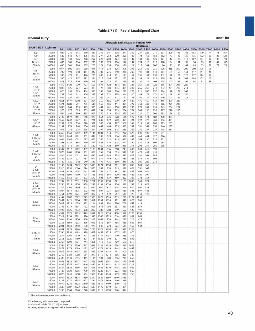
Table 5.7 (1) Radial Load/Speed Chart
Normal Duty Unit : lbf
Allowable Radial Load at Various RPM
SHAFT SIZE L10 hours RPM (min-1)
50 100 150 300 500 750 1000 1500 2000 2500 3000 3500 4000 4500 5000 5500 6000 6500 7000 7500 8000 85001/2” 10000 927 736 643 510 430 376 341 298 271 252 237 225 215 207 200 193 188 183 179 174 171 1675/8” 25000 683 542 474 376 317 277 252 220 200 185 174 166 158 152 147 143 138 135 132 129 126 1233/4” 50000 542 430 376 298 252 220 200 174 158 147 138 132 126 121 117 113 110 107 104 102 100 98
12 mm - 70000 485 385 336 267 225 196 179 156 142 132 124 118 112 108 104 101 98 96 93 91 89 87 20 mm 100000 430 341 298 237 200 174 158 138 126 117 110 104 100 96 93 90 87 85 83 81 79 78
7/8” 15/16”
1” 25 mm
10000 25000 50000 70000
100000
1014 747 593 530 471
805 593 471 421 373
703 518 411 367 326
558 411 326 292 259
471 347 275 246 218
411303240215191
373275218195173
326240191171151
296218173155138
275203161144128
259191151135120
246181 144 129 114
235173 138 123 109
226167 132 118 105
218161 128 114 101
212 156 124 111
98
206 151 120 107
95
200 147 117 105
93
195 144 114 102
91
191141 112 100
89
1-1/8” 1-3/16” 1-1/4”
30 mm
10000 25000 50000 70000
100000
1412 1040
826 738 655
1121 826 655 586 520
979 721 573 512 454
777 573 454 406 361
655 483 383 343 304
573422335299266
520383304272241
454335266238211
413304241216192
383282224200178
361266211189167
343252 200 179 159
328241 192 171 152
315232 184 165 146
304224 178 159 141
295 217 172 154 137
286 211 167 150 133
1-1/4” 10000 1861 1477 1290 1024 864 755 686 599 544 505 475 452 432 415 401 388 1-5/16” 25000 1371 1088 951 755 636 556 505 441 401 372 350 333 318 306 295 286 1-3/8” 50000 1088 864 755 599 505 441 401 350 318 295 278 264 253 243 234 227
1-7/16” 70000 973 772 675 535 452 394 358 313 284 264 248 236 226 217 210 203 35 mm 100000 864 686 599 475 401 350 318 278 253 234 221 210 200 193 186 180
1-1/2”
10000 2107 1672 1461 1160 978 854 776 678 616 572 538 511 489 470 454 25000 1553 1232 1077 854 721 630 572 500 454 421 397 377 360 346 3341-9/16” 50000 1232 978 854 678 572 500 454 397 360 334 315 299 286 275 26540 mm 70000 1102 874 764 606 511 447 406 355 322 299 281 267 256 246 237
100000 978 776 678 538 454 397 360 315 286 265 250 237 227 218 211
1-5/8” 1-11/16”
1-3/4” 45 mm
10000 25000 50000 70000
100000
2469 1819 1444 1291 1146
1960 1444 1146 1025
910
1712 1261 1001
895 795
1359 1001
795 710 631
1146 844 670 599 532
1001738586523465
910670532476422
795586465415369
722532422377335
670494392350311
631465369330293
599441 350 313 278
573422 335 300 266
551406 322 288 256
1-7/8” 1-15/16”
2” 50 mm
10000 25000 50000 70000
100000
2542 1873 1486 1329 1180
2017 1486 1180 1055
936
1762 1298 1031
921 818
1399 1031
818 731 649
1180 869 690 617 548
1031759603539478
936690548489435
818603478428380
743548435389345
690508403361320
649478380339301
617454 361 322 286
590435 345 308 274
2” 2-1/8”
2-3/16” 55 mm
10000 25000 50000 70000
100000
3143 2316 1838 1643 1459
2494 1838 1459 1304 1158
2179 1606 1274 1139 1011
1729 1274 1011
904 803
1459 1075
853 763 677
1274939745666591
1158853677605537
1011745591529469
919677537480427
853629499446396
803591469420373
763562 446 399 354
2-1/4” 2-3/8”
2-7/16” 60 mm
10000 25000 50000 70000
100000
3794 2796 2219 1984 1761
3012 2219 1761 1574 1398
2631 1938 1539 1375 1221
2088 1539 1221 1092
969
1761 1298 1030
921 817
15391134
900804714
13981030
817731649
1221900714638567
1109817649580515
1030759602538478
969714567507450
921678 538 481 427
2-1/2” 65 mm
10000 4142 3287 2872 2279 1923 1679 1526 1333 1211 1124 1058 25000 50000 70000
3052 2422 2165
2422 1923 1719
2116 1679 1501
1679 1333 1192
1417 1124 1005
1237982878
1124892798
982780697
892708633
828657588
780619553
100000 1923 1526 1333 1058 892 780 708 619 562 522 491
2-3/4” 70 mm
10000 4504 3575 3123 2479 2091 1826 1659 1450 1317 1223 1150 25000 50000 70000
3319 2634 2355
2634 2091 1869
2301 1826 1633
1826 1450 1296
1540 1223 1093
13461068
955
1223970867
1068848758
970770688
901715639
848673601
100000 2091 1659 1450 1150 970 848 770 673 611 567 534
2-15/16” 10000 4881 3874 3384 2686 2265 1979 1798 1571 1427 1325 25000 3596 2854 2493 1979 1669 1458 1325 1157 1051 976
3” 50000 2854 2265 1979 1571 1325 1157 1051 919 835 77575 mm 70000 2551 2025 1769 1404 1184 1035 940 821 746 693
100000 2265 1798 1571 1247 1051 919 835 729 662 615
3-1/8” 80 mm
10000 5264 4178 3650 2897 2443 2135 1939 1694 1539 1429 25000 50000 70000
3879 3079 2752
3079 2443 2184
2689 2135 1908
2135 1694 1514
1800 1429 1277
157312481116
142911341014
1248991886
1134900805
1053836747
100000 2443 1939 1694 1345 1134 991 900 786 714 663
3-1/4” 85 mm
10000 6083 4828 4217 3347 2823 2466 2241 1958 1779 1651 25000 50000 70000
4482 3557 3180
3557 2823 2524
3107 2466 2205
2466 1958 1750
2080 1651 1476
181714421289
165113101171
144211451023
13101040
930
1217966863
100000 2823 2241 1958 1554 1310 1145 1040 909 826 766
3-1/2” 90 mm
10000 6959 5523 4825 3830 3230 2822 2564 2240 2035 25000 50000 70000
5127 4070 3638
4070 3230 2887
3555 2822 2522
2822 2240 2002
2380 1889 1688
207916501475
188914991340
165013101171
149911901064
100000 3230 2564 2240 1778 1499 1310 1190 1040 944
1 . Shaded area A non-contact seal is used.
If the bearing with set screws is exposed to a heavy load (Pr / Cr > 0.12), vibration, or heavy inpact, use a tighter shaft tolerance than normal.
43
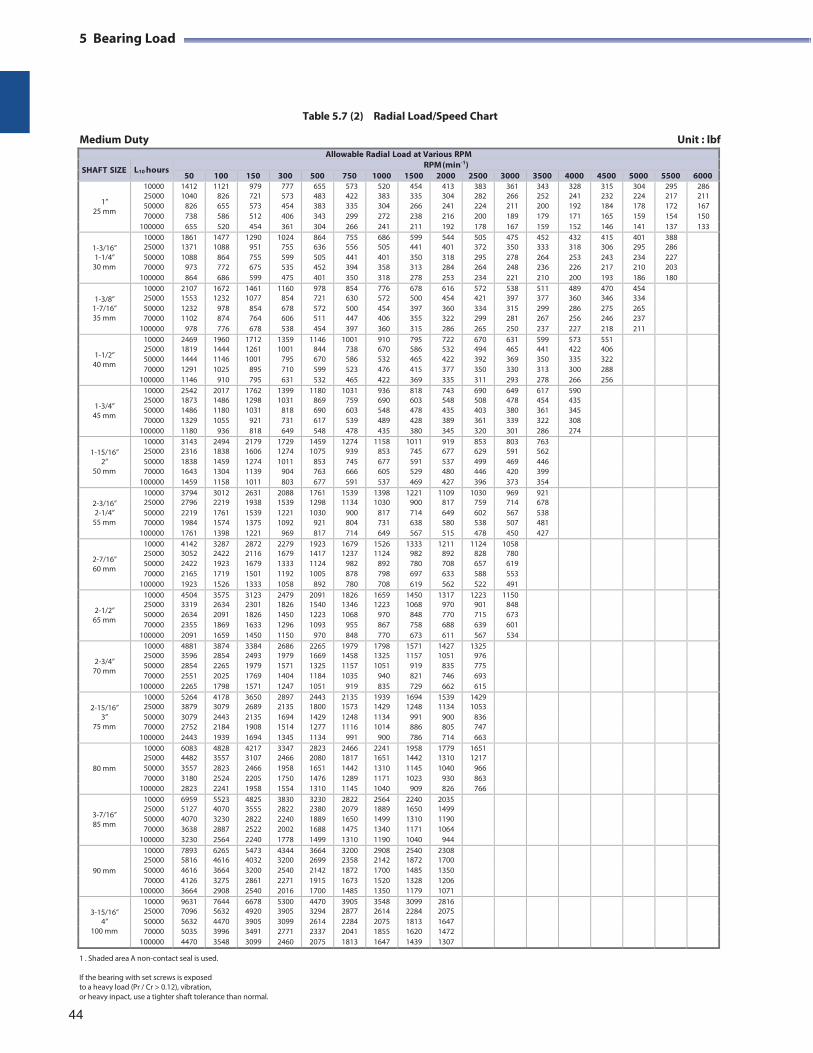
5 Bearing Load
Table 5.7 (2) Radial Load/Speed Chart
Medium Duty Unit : lbf
Allowable Radial Load at Various RPM
SHAFT SIZE L10 hours RPM(min-1)
50 100 150 300 500 750 1000 1500 2000 2500 3000 3500 4000 4500 5000 5500 6000
1” 25 mm
10000 1412 1121 979 777 655 573 520 454 413 383 361 343 328 315 304 295 28625000 50000 70000
1040 826 738
826 655 586
721 573 512
573 454 406
483 383 343
422335 299
383304 272
335266 238
304241 216
282224 200
266211 189
252200 179
241 192 171
232 184 165
224 178 159
217172 154
211167 150
100000 655 520 454 361 304 266 241 211 192 178 167 159 152 146 141 137 133
1-3/16” 10000 1861 1477 1290 1024 864 755 686 599 544 505 475 452 432 415 401 388 25000 1371 1088 951 755 636 556 505 441 401 372 350 333 318 306 295 286
1-1/4” 50000 1088 864 755 599 505 441 401 350 318 295 278 264 253 243 234 22730 mm 70000 973 772 675 535 452 394 358 313 284 264 248 236 226 217 210 203
100000 864 686 599 475 401 350 318 278 253 234 221 210 200 193 186 180
1-3/8” 10000 2107 1672 1461 1160 978 854 776 678 616 572 538 511 489 470 454 25000 1553 1232 1077 854 721 630 572 500 454 421 397 377 360 346 334
1-7/16” 50000 1232 978 854 678 572 500 454 397 360 334 315 299 286 275 265 35 mm 70000 1102 874 764 606 511 447 406 355 322 299 281 267 256 246 237
100000 978 776 678 538 454 397 360 315 286 265 250 237 227 218 211
1-1/2” 40 mm
10000 2469 1960 1712 1359 1146 1001 910 795 722 670 631 599 573 551 25000 50000 70000
1819 1444 1291
1444 1146 1025
1261 1001
895
1001 795 710
844 670 599
738586 523
670532 476
586465 415
532422 377
494392 350
465369 330
441350 313
422 335 300
406 322 288
100000 1146 910 795 631 532 465 422 369 335 311 293 278 266 256
1-3/4” 45 mm
10000 2542 2017 1762 1399 1180 1031 936 818 743 690 649 617 590 25000 50000 70000
1873 1486 1329
1486 1180 1055
1298 1031
921
1031 818 731
869 690 617
759603 539
690548 489
603478 428
548435 389
508403 361
478380 339
454361 322
435 345 308
100000 1180 936 818 649 548 478 435 380 345 320 301 286 274
1-15/16” 10000 3143 2494 2179 1729 1459 1274 1158 1011 919 853 803 763 25000 2316 1838 1606 1274 1075 939 853 745 677 629 591 562
2” 50000 1838 1459 1274 1011 853 745 677 591 537 499 469 44650 mm 70000 1643 1304 1139 904 763 666 605 529 480 446 420 399
100000 1459 1158 1011 803 677 591 537 469 427 396 373 354
2-3/16” 10000 3794 3012 2631 2088 1761 1539 1398 1221 1109 1030 969 921 25000 2796 2219 1938 1539 1298 1134 1030 900 817 759 714 678
2-1/4” 50000 2219 1761 1539 1221 1030 900 817 714 649 602 567 53855 mm 70000 1984 1574 1375 1092 921 804 731 638 580 538 507 481
100000 1761 1398 1221 969 817 714 649 567 515 478 450 427
2-7/16” 60 mm
10000 4142 3287 2872 2279 1923 1679 1526 1333 1211 1124 1058 25000 50000 70000
3052 2422 2165
2422 1923 1719
2116 1679 1501
1679 1333 1192
1417 1124 1005
1237982 878
1124892 798
982780 697
892708 633
828657 588
780619 553
100000 1923 1526 1333 1058 892 780 708 619 562 522 491
2-1/2” 65 mm
10000 4504 3575 3123 2479 2091 1826 1659 1450 1317 1223 1150 25000 50000 70000
3319 2634 2355
2634 2091 1869
2301 1826 1633
1826 1450 1296
1540 1223 1093
13461068
955
1223970 867
1068848 758
970770 688
901715 639
848673 601
100000 2091 1659 1450 1150 970 848 770 673 611 567 534
2-3/4” 70 mm
10000 4881 3874 3384 2686 2265 1979 1798 1571 1427 1325 25000 50000 70000
3596 2854 2551
2854 2265 2025
2493 1979 1769
1979 1571 1404
1669 1325 1184
14581157 1035
13251051
940
1157919 821
1051835 746
976775 693
100000 2265 1798 1571 1247 1051 919 835 729 662 615
2-15/16” 10000 5264 4178 3650 2897 2443 2135 1939 1694 1539 1429 25000 3879 3079 2689 2135 1800 1573 1429 1248 1134 1053
3” 50000 3079 2443 2135 1694 1429 1248 1134 991 900 83675 mm 70000 2752 2184 1908 1514 1277 1116 1014 886 805 747
100000 2443 1939 1694 1345 1134 991 900 786 714 663
80 mm
10000 6083 4828 4217 3347 2823 2466 2241 1958 1779 1651 25000 4482 3557 3107 2466 2080 1817 1651 1442 1310 121750000 3557 2823 2466 1958 1651 1442 1310 1145 1040 96670000 3180 2524 2205 1750 1476 1289 1171 1023 930 863
100000 2823 2241 1958 1554 1310 1145 1040 909 826 766
3-7/16” 85 mm
10000 6959 5523 4825 3830 3230 2822 2564 2240 2035 25000 50000 70000
5127 4070 3638
4070 3230 2887
3555 2822 2522
2822 2240 2002
2380 1889 1688
20791650 1475
18891499 1340
16501310 1171
14991190 1064
100000 3230 2564 2240 1778 1499 1310 1190 1040 944
90 mm
10000 7893 6265 5473 4344 3664 3200 2908 2540 2308 25000 5816 4616 4032 3200 2699 2358 2142 1872 170050000 4616 3664 3200 2540 2142 1872 1700 1485 135070000 4126 3275 2861 2271 1915 1673 1520 1328 1206
100000 3664 2908 2540 2016 1700 1485 1350 1179 1071
3-15/16” 10000 9631 7644 6678 5300 4470 3905 3548 3099 2816 25000 7096 5632 4920 3905 3294 2877 2614 2284 2075
4” 50000 5632 4470 3905 3099 2614 2284 2075 1813 1647100 mm 70000 5035 3996 3491 2771 2337 2041 1855 1620 1472
100000 4470 3548 3099 2460 2075 1813 1647 1439 1307
1 . Shaded area A non-contact seal is used.
If the bearing with set screws is exposed to a heavy load (Pr / Cr > 0.12), vibration, or heavy inpact, use a tighter shaft tolerance than normal.
44
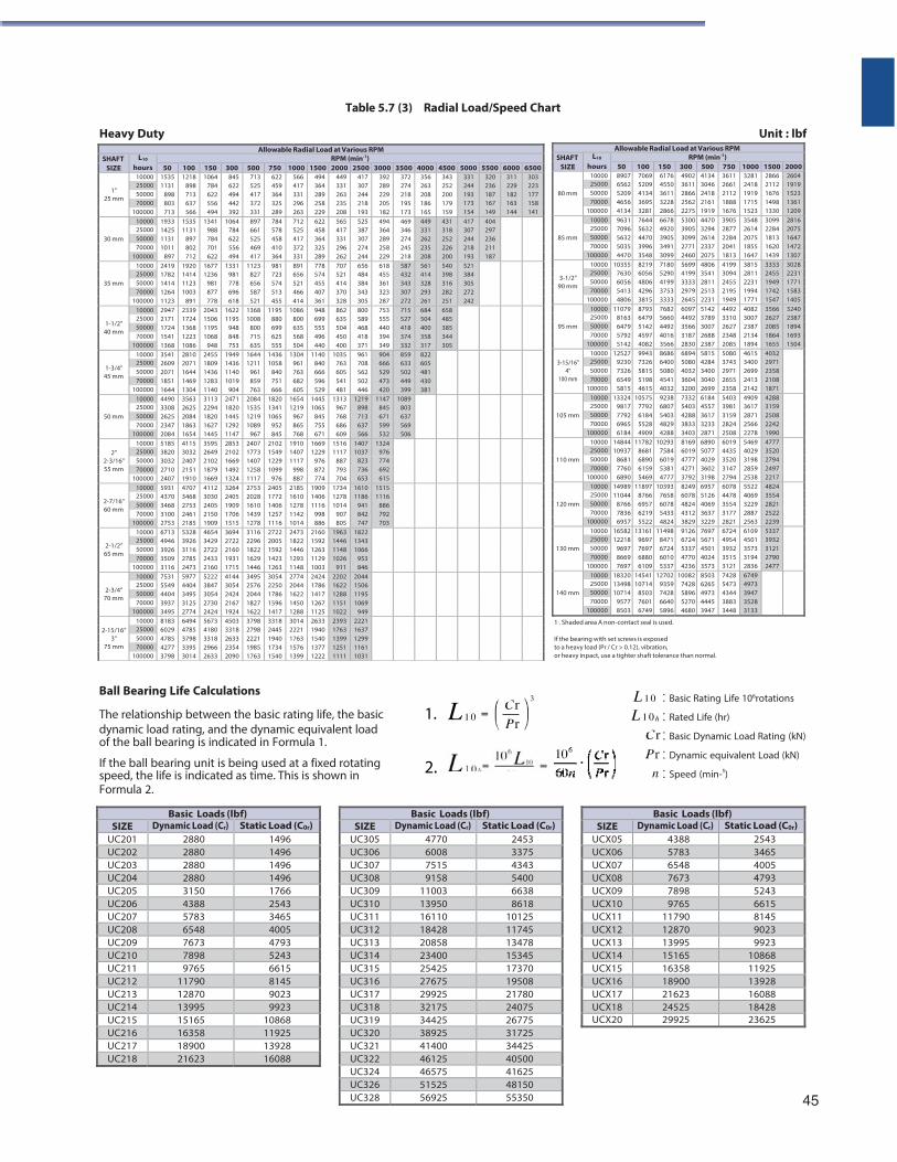
Table 5.7 (3) Radial Load/Speed Chart
Heavy Duty Unit : lbf
Allowable Radial Load at Various RPMSHAFT
SIZEL10
hoursRPM (min-1)
50 100 150 300 500 750 1000 1500 2000
80 mm
10000 8907 6562 5209 4656 4134
7069 5209 4134 3695 3281
6176 4550 3611 3228 2866
4902 3611 2866 2562 2275
4134 3046 2418 2161 1919
36112661211218881676
32812418191917151523
28662112167614981330
26041919152313611209
250005000070000
100000
85 mm
10000 9631 7096 5632 5035 4470
7644 5632 4470 3996 3548
6678 4920 3905 3491 3099
5300 3905 3099 2771 2460
4470 3294 2614 2337 2075
39052877228420411813
35482614207518551647
30992284181316201439
28162075164714721307
250005000070000
100000
3-1/2” 90 mm
10000 10355 7630 6056 5413 4806
8219 6056 4806 4296 3815
7180 5290 4199 3753 3333
5699 4199 3333 2979 2645
4806 3541 2811 2513 2231
41993094245521951949
38152811223119941771
33332455194917421547
30282231177115831405
250005000070000
100000
95 mm
10000 11079 8163 6479 5792 5142
8793 6479 5142 4597 4082
7682 5660 4492 4016 3566
6097 4492 3566 3187 2830
5142 3789 3007 2688 2387
44923310262723482085
40823007238721341894
35662627208518641655
32402387189416931504
250005000070000
100000
3-15/16”
4” 100 mm
10000 12527 9230 7326 6549 5815
9943 7326 5815 5198 4615
8686 6400 5080 4541 4032
6894 5080 4032 3604 3200
5815 4284 3400 3040 2699
50803743297126552358
46153400269924132142
40322971235821081871
250005000070000
100000
105 mm
10000 13324 9817 7792 6965 6184
10575 7792 6184 5528 4909
9238 6807 5403 4829 4288
7332 5403 4288 3833 3403
6184 4557 3617 3233 2871
54033981315928242508
49093617287125662278
42883159250822421990
250005000070000
100000
110 mm
10000 14844 10937
8681 7760 6890
11782 8681 6890 6159 5469
10293 7584 6019 5381 4777
8169 6019 4777 4271 3792
6890 5077 4029 3602 3198
60194435352031472794
54694029319828592538
47773520279424972217
250005000070000
100000
120 mm
10000 14989 11044
8766 7836 6957
11897 8766 6957 6219 5522
10393 7658 6078 5433 4824
8249 6078 4824 4312 3829
6957 5126 4069 3637 3229
60784478355431772821
55224069322928872563
48243554282125222239
250005000070000
100000
130 mm
10000 16582 12218
9697 8669 7697
13161 9697 7697 6880 6109
11498 8471 6724 6010 5337
9126 6724 5337 4770 4236
7697 5671 4501 4024 3573
67244954393235153121
61094501357331942836
53373932312127902477
250005000070000
100000
140 mm
10000 18320 13498 10714
9577 8503
14541 10714
8503 7601 6749
12702 9359 7428 6640 5896
10082 7428 5896 5270 4680
8503 6265 4973 4445 3947
74285473434438833448
67494973394735283133
250005000070000
100000
1 . Shaded area A non-contact seal is used.
If the bearing with set screws is exposed to a heavy load (Pr / Cr > 0.12), vibration, or heavy inpact, use a tighter shaft tolerance than normal.
Ball Bearing Life Calculations
The relationship between the basic rating life, the basic 1. dynamic load rating, and the dynamic equivalent load of the ball bearing is indicated in Formula 1.
If the ball bearing unit is being used at a fixed rotating 2. speed, the life is indicated as time. This is shown in Formula 2.
Basic Rating Life 106rotations
Rated Life (hr)
Basic Dynamic Load Rating (kN)
Dynamic equivalent Load (kN)
Speed (min-¹)
45
Basic Loads (lbf)SIZE Dynamic Load (Cr) Static Load (C0r)
UCX05 4388 2543UCX06 5783 3465UCX07 6548 4005UCX08 7673 4793UCX09 7898 5243UCX10 9765 6615UCX11 11790 8145UCX12 12870 9023UCX13 13995 9923UCX14 15165 10868UCX15 16358 11925UCX16 18900 13928UCX17 21623 16088UCX18 24525 18428UCX20 29925 23625
Basic Loads (lbf) SIZE Dynamic Load (Cr) Static Load (C0r)
UC201 2880 1496 UC202 2880 1496 UC203 2880 1496 UC204 2880 1496 UC205 3150 1766 UC206 4388 2543 UC207 5783 3465 UC208 6548 4005 UC209 7673 4793 UC210 7898 5243 UC211 9765 6615 UC212 11790 8145 UC213 12870 9023 UC214 13995 9923 UC215 15165 10868 UC216 16358 11925 UC217 18900 13928 UC218 21623 16088
Allowable Radial Load at Various RPMSHAFT
SIZE L10
hours RPM (min-1)
50 100 150 300 500 750 1000 1500 2000 2500 3000 3500 4000 4500 5000 5500 6000 6500
1” 25 mm
10000 1535 1131
898 803 713
1218 898 713 637 566
1064 784 622 556 494
845 622 494 442 392
713 525 417 372 331
622 459 364 325 289
566 417 331 296 263
494 364 289 258 229
449 331 263 235 208
417307244218193
392289229205182
372274218195173
356 263 208 186 165
343 252 200 179 159
331 244 193
320 236 187
311 229 182
303 223 177
25000 50000 70000 173
154 167 149
163 144
158 141 100000
30 mm
10000 1933 1425 1131 1011
897
1535 1131
897 802 712
1341 988 784 701 622
1064 784 622 556 494
897 661 525 469 417
784 578 458 410 364
712 525 417 372 331
622 458 364 325 289
565 417 331 296 262
525387307274244
494364289258229
469346274245218
449 331 262 235 208
431 318 252 226 200
417 307 244 218 193
404 297 236 211 187
25000 50000 70000
100000
35 mm
10000 2419 1782 1414 1264 1123
1920 1414 1123 1003
891
1677 1236
981 877 778
1331 981 778 696 618
1123 827 656 587 521
981 723 574 513 455
891 656 521 466 414
778 574 455 407 361
707 521 414 370 328
656484384343305
618455361323287
587432343307272
561 414 328 293 261
540 398 316 282 251
521 384 305 272 242
25000 50000 70000
100000
1-1/2” 40 mm
10000 2947 2171 1724 1541 1368
2339 1724 1368 1223 1086
2043 1506 1195 1068
948
1622 1195
948 848 753
1368 1008
800 715 635
1195 880 699 625 555
1086 800 635 568 504
948 699 555 496 440
862 635 504 450 400
800589468418371
753555440394349
715527418374332
684 504 400 358 317
658 485 385 344 305
25000 50000 70000
100000
1-3/4” 45 mm
10000 3541 2609 2071 1851 1644
2810 2071 1644 1469 1304
2455 1809 1436 1283 1140
1949 1436 1140 1019
904
1644 1211
961 859 763
1436 1058
840 751 666
1304 961 763 682 605
1140 840 666 596 529
1035 763 605 541 481
961708562502446
904666529473420
859633502449399
822 605 481 430 381
25000 50000 70000
100000
50 mm
10000 4490 3308 2625 2347 2084
3563 2625 2084 1863 1654
3113 2294 1820 1627 1445
2471 1820 1445 1292 1147
2084 1535 1219 1089
967
1820 1341 1065
952 845
1654 1219
967 865 768
1445 1065
845 755 671
1313 967 768 686 609
1219898713637566
1147845671599532
1089803637569506
25000 50000 70000
100000
2”
2-3/16” 55 mm
10000 5185 3820 3032 2710 2407
4115 3032 2407 2151 1910
3595 2649 2102 1879 1669
2853 2102 1669 1492 1324
2407 1773 1407 1258 1117
2102 1549 1229 1099
976
1910 1407 1117
998 887
1669 1229
976 872 774
1516 1117
887 793 704
14071037
1324976 25000
50000 823736653
774692615
70000 100000
2-7/16” 60 mm
10000 5931 4370 3468 3100 2753
4707 3468 2753 2461 2185
4112 3030 2405 2150 1909
3264 2405 1909 1706 1515
2753 2028 1610 1439 1278
2405 1772 1406 1257 1116
2185 1610 1278 1142 1014
1909 1406 1116
998 886
1734 1278 1014
907 805
16101186
941842747
15151116
886792703
25000 50000 70000
100000
2-1/2” 65 mm
10000 6713 4946 3926 3509 3116
5328 3926 3116 2785 2473
4654 3429 2722 2433 2160
3694 2722 2160 1931 1715
3116 2296 1822 1629 1446
2722 2005 1592 1423 1263
2473 1822 1446 1293 1148
2160 1592 1263 1129 1003
1963 1446 1148 1026
911
182213431066
953846
25000 50000 70000
100000
2-3/4” 70 mm
10000 7531 5549 4404 3937 3495
5977 4404 3495 3125 2774
5222 3847 3054 2730 2424
4144 3054 2424 2167 1924
3495 2576 2044 1827 1622
3054 2250 1786 1596 1417
2774 2044 1622 1450 1288
2424 1786 1417 1267 1125
2202 1622 1288 1151 1022
2044150611951069
949
25000 50000 70000
100000
2-15/16”
3” 75 mm
10000 8183 6029 4785 4277 3798
6494 4785 3798 3395 3014
5673 4180 3318 2966 2633
4503 3318 2633 2354 2090
3798 2798 2221 1985 1763
3318 2445 1940 1734 1540
3014 2221 1763 1576 1399
2633 1940 1540 1377 1222
2393 1763 1399 1251 1111
22211637129911611031
25000 50000 70000
100000
Basic Loads (lbf)SIZE Dynamic Load (Cr) Static Load (C0r)
UC305 4770 2453UC306 6008 3375UC307 7515 4343UC308 9158 5400UC309 11003 6638UC310 13950 8618UC311 16110 10125UC312 18428 11745UC313 20858 13478UC314 23400 15345UC315 25425 17370UC316 27675 19508UC317 29925 21780UC318 32175 24075UC319 34425 26775UC320 38925 31725UC321 41400 34425UC322 46125 40500UC324 46575 41625UC326 51525 48150UC328 56925 55350
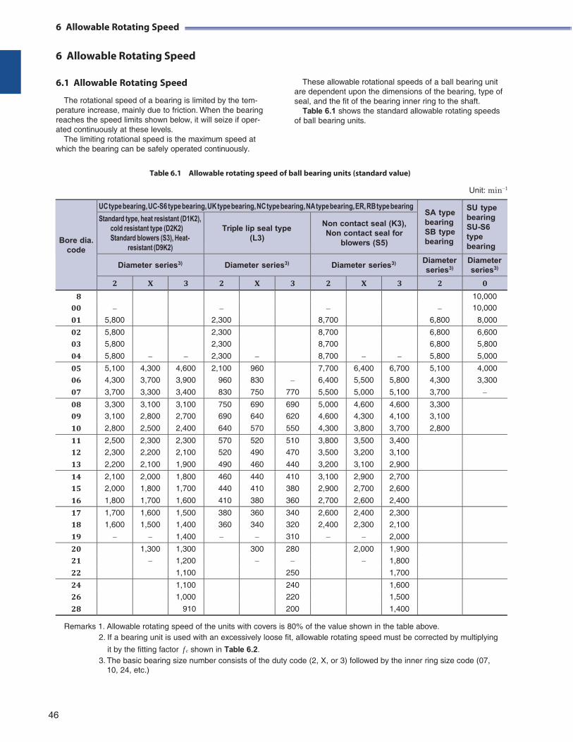
6 Allowable Rotating Speed
6 Allowable Rotating Speed
6.1 Allowable Rotating Speed
The rotational speed of a bearing is limited by the tem- perature increase, mainly due to friction. When the bearing reaches the speed limits shown below, it will seize if oper- ated continuously at these levels.
The limiting rotational speed is the maximum speed at which the bearing can be safely operated continuously.
These allowable rotational speeds of a ball bearing unit are dependent upon the dimensions of the bearing, type of seal, and the fit of the bearing inner ring to the shaft.
Table 6.1 shows the standard allowable rotating speeds of ball bearing units.
Table 6.1 Allowable rotating speed of ball bearing units (standard value)
Unit: min1
Bore dia.
code
UC type bearing, UC-S6 type bearing, UK type bearing, NC type bearing, NA type bearing, ER, RB type bearing SA type bearing SB type bearing
SU type bearing SU-S6 type bearing
Standard type, heat resistant (D1K2), cold resistant type (D2K2) Standard blowers (S3), Heat-
resistant (D9K2)
Triple lip seal type
(L3)
Non contact seal (K3), Non contact seal for
blowers (S5)
Diameter series3) Diameter series3) Diameter series3) Diameter series3)
Diameter series3)
2 X 3 2 X 3 2 X 3 2 0
8
10,000
00 10,000
01 5,800 2,300 8,700 6,800 8,000
02 5,800
2,300
8,700
6,800 6,600
03 5,800 2,300 8,700 6,800 5,800
04 5,800 2,300 8,700 5,800 5,000
05 5,100 4,300 4,600 2,100 960
7,700 6,400 6,700 5,100 4,000
06 4,300 3,700 3,900 960 830 6,400 5,500 5,800 4,300 3,300
07 3,700 3,300 3,400 830 750 770 5,500 5,000 5,100 3,700
08 3,300 3,100 3,100 750 690 690 5,000 4,600 4,600 3,300 09 3,100 2,800 2,700 690 640 620 4,600 4,300 4,100 3,100
10 2,800 2,500 2,400 640 570 550 4,300 3,800 3,700 2,800
11 2,500 2,300 2,300 570 520 510 3,800 3,500 3,400 12 2,300 2,200 2,100 520 490 470 3,500 3,200 3,100
13 2,200 2,100 1,900 490 460 440 3,200 3,100 2,900
14 2,100 2,000 1,800 460 440 410 3,100 2,900 2,700 15 2,000 1,800 1,700 440 410 380 2,900 2,700 2,600
16 1,800 1,700 1,600 410 380 360 2,700 2,600 2,400
17 1,700 1,600 1,500 380 360 340 2,600 2,400 2,300 18 1,600 1,500 1,400 360 340 320 2,400 2,300 2,100
19 1,400 310 2,000
20 1,300 1,300 300 280 2,000 1,900 21 1,200 1,800
22 1,100 250 1,700
24 1,100 240 1,600 26 1,000 220 1,500
28 910 200 1,400
Remarks 1. Allowable rotating speed of the units with covers is 80% of the value shown in the table above. 2. If a bearing unit is used with an excessively loose fit, allowable rotating speed must be corrected by multiplying
it by the fitting factor f c shown in Table 6.2. 3. The basic bearing size number consists of the duty code (2, X, or 3) followed by the inner ring size code (07,
10, 24, etc.)
46
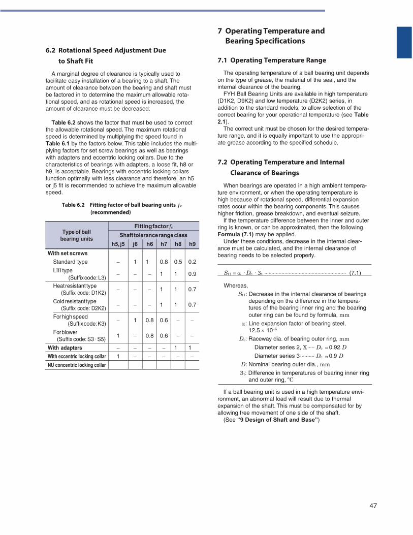
6.2 Rotational Speed Adjustment Due to Shaft Fit
A marginal degree of clearance is typically used to facilitate easy installation of a bearing to a shaft. The amount of clearance between the bearing and shaft must be factored in to determine the maximum allowable rota- tional speed, and as rotational speed is increased, the amount of clearance must be decreased.
Table 6.2 shows the factor that must be used to correct
the allowable rotational speed. The maximum rotational speed is determined by multiplying the speed found in Table 6.1 by the factors below. This table includes the multi- plying factors for set screw bearings as well as bearings with adapters and eccentric locking collars. Due to the characteristics of bearings with adapters, a loose fit, h8 or h9, is acceptable. Bearings with eccentric locking collars function optimally with less clearance and therefore, an h5 or j5 fit is recommended to achieve the maximum allowable speed.
Table 6.2 Fitting factor of ball bearing units f c
(recommended)
7 Operating Temperature and Bearing Specifications
7.1 Operating Temperature Range
The operating temperature of a ball bearing unit depends on the type of grease, the material of the seal, and the internal clearance of the bearing.
FYH Ball Bearing Units are available in high temperature (D1K2, D9K2) and low temperature (D2K2) series, in addition to the standard models, to allow selection of the correct bearing for your operational temperature (see Table 2.1).
The correct unit must be chosen for the desired tempera- ture range, and it is equally important to use the appropri- ate grease according to the specified schedule.
7.2 Operating Temperature and Internal Clearance of Bearings
When bearings are operated in a high ambient tempera- ture environment, or when the operating temperature is high because of rotational speed, differential expansion rates occur within the bearing components. This causes higher friction, grease breakdown, and eventual seizure.
If the temperature difference between the inner and outer ring is known, or can be approximated, then the following Formula (7.1) may be applied.
Under these conditions, decrease in the internal clear- ance must be calculated, and the internal clearance of bearing needs to be selected properly.
St1 · De · 3t (7.1)
Whereas,
St1 : Decrease in the internal clearance of bearings depending on the difference in the tempera- tures of the bearing inner ring and the bearing outer ring can be found by formula, mm
: Line expansion factor of bearing steel, 12.5 106
De: Raceway dia. of bearing outer ring, mm Diameter series 2, X De 0.92 D Diameter series 3 De 0.9 D
D: Nominal bearing outer dia., mm 3t: Difference in temperatures of bearing inner ring
and outer ring, ºC
If a ball bearing unit is used in a high temperature envi- ronment, an abnormal load will result due to thermal expansion of the shaft. This must be compensated for by allowing free movement of one side of the shaft.
(See “9 Design of Shaft and Base”)
47
Type of ball
bearing units
Fitting factor f c
Shaft tolerance range class
h5, j5 j6 h6 h7 h8 h9
With set screws
Standard type
LⅢ type (Suffix code: L3)
1
1
0.8
1
0.5
1
0.2
0.9
Heat resistant type (Suffix code: D1K2)
Cold resistant type (Suffix code: D2K2)
1
1
1
1
0.7
0.7
For high speed (Suffix code: K3)
For blower (Suffix code: S3 · S5)
1
1
0.8
0.8
0.6
0.6
With adapters 1 1
With eccentric locking collar 1 NU concentric locking collar
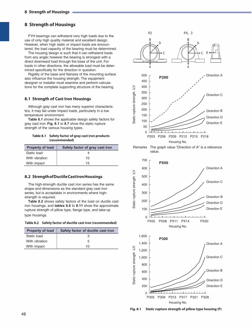
8 Strength of Housings
8 Strength of Housings
FYH bearings can withstand very high loads due to the
use of only high quality material and excellent design. However, when high static or impact loads are encoun- tered, the load capacity of the bearing must be determined.
The housing design is such that it can withstand loads from any angle; however the bearing is strongest with a direct downward load through the base of the unit. For loads in other directions, the allowable load must be deter- mined specifically for the direction in question.
Rigidity of the base and flatness of the mounting surface also influence the housing strength. The equipment designer or installer must examine and perform calcula- tions for the complete supporting structure of the bearing.
8.1 Strength of Cast Iron Housings
Although gray cast iron has many superior characteris- tics, it may fail under impact loads, particularly in a low temperature environment.
Table 8.1 shows the applicable design safety factors for gray cast iron. Fig. 8.1 to 8.7 show the static rupture strength of the various housing types.
500
450
400
350
300
250
200
150
100
50
0
P2 PX, 3
P200
E
Direction A
Direction C
Direction D
Direction E
Table 8.1 Safety factor of gray cast iron products P203 P206 P209 P212 P215 P218 (recommended) Housing No.
Remarks The graph value “Direction of A” is a reference value.
700
600
PX00
Direction A
8.2 Strength of Ductile Cast Iron Housings
The high-strength ductile cast iron series has the same shape and dimensions as the standard gray cast iron series, but is acceptable in environments where high- strength is required.
Table 8.2 shows safety factors of the load on ductile cast iron housings, and tables 8.8 to 8.11 show the approximate rupture strength of pillow type, flange type, and take-up
type housings.
Table 8.2 Safety factor of ductile cast iron (recommended)
500
400
300
200
100
0 PX05
PX08
PX11
PX14
Direction C
Direction B
Direction D
Direction E
PX20
Housing No.
1,600
1,400
1,200
1,000
800
600
400
200
P300
Direction A
Direction C
Direction B
Direction D
Direction E
0 P305
P309
P313
P317
P321
P328
Housing No.
Fig. 8.1 Static rupture strength of pillow type housing (P) 48
8 Strength of Housings
BD
C
A
BD
C
A
Sta
tic r
uptu
re s
tren
gth
kN
S
tatic
rup
ture
str
engt
h k
N
Sta
tic r
uptu
re s
tren
gth
kN
Property of load Safety factor of gray cast iron
Static load
With vibration
With impact
4
10
15
Property of load Safety factor of ductile cast iron
Static load
With vibration
With impact
3
5
10
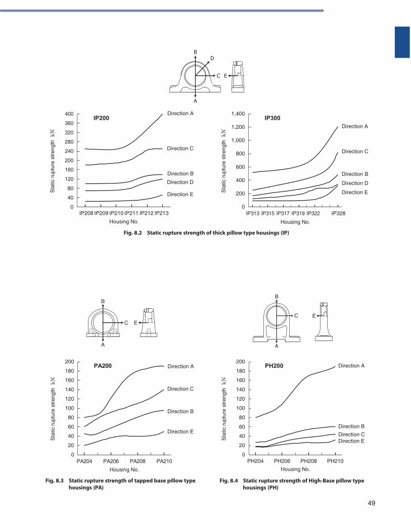
B
C
A
B
D
C E
A
400
360
320
280
240
200
160
120
80
40
0
IP200
Direction A
Direction C
Direction B
Direction D
Direction E
1,400
1,200
1,000
800
600
400
200
0
IP300
Direction A
Direction C
Direction B
Direction D
Direction E
IP208 IP209 IP210 IP211 IP212 IP213
Housing No.
IP313 IP315 IP317 IP319 IP322
Housing No.
IP328
Fig. 8.2 Static rupture strength of thick pillow type housings (IP)
B
E
C E
A
200
180
160
140
120
100
80
60
40
20
0
PA200
Direction A
Direction C
Direction B
Direction E
200
180
160
140
120
100
80
60
40
20
0
PH200 Direction A
Direction B
Direction C Direction E
PA204 PA206 PA208 PA210 PH204 PH206 PH208 PH210
Housing No.
Fig. 8.3 Static rupture strength of tapped base pillow type housings (PA)
Housing No.
Fig. 8.4 Static rupture strength of High-Base pillow type housings (PH)
49
Sta
tic r
uptu
re s
tren
gth
kN
Sta
tic r
uptu
re s
tren
gth
kN
Sta
tic r
uptu
re s
tren
gth
kN
Sta
tic r
uptu
re s
tren
gth
kN
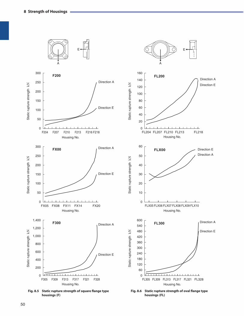
Sta
tic r
uptu
re s
tren
gth
kN
S
tatic
rup
ture
str
engt
h k
N
8 Strength of Housings
E E
A A
300
250
200
F200
Direction A
160
140
120
100
FL200
Direction A
Direction E
150 80
100
50
Direction E 60
40
20
0 F204 F207 F210 F213 F216 F218
0 FL204 FL207 FL210 FL213 FL218
300
250
FX00
Housing No.
Direction A
Housing No.
60 FLX00
50
Direction E
Direction A
200 40
150 Direction E 30
100 20
50 10
0 FX05 FX08 FX11 FX14 FX20
0 FLX05 FLX06 FLX07 FLX08 FLX09 FLX10
Housing No. Housing No.
1,400
1,200
1,000
800
600
400
200
0
F300
Direction A
Direction E
600
540
480
420
360
300
240
180
120
60
0
FL300
Direction A
Direction E
F305 F309 F313 F317 F321 F328 FL305 FL309 FL313 FL317 FL321 FL328
Housing No.
Fig. 8.5 Static rupture strength of square flange type housings (F)
Housing No.
Fig. 8.6 Static rupture strength of oval flange type housings (FL)
50
Sta
tic r
uptu
re s
tren
gth
kN
S
tatic
rup
ture
str
engt
h k
N
Sta
tic r
uptu
re s
tren
gth
kN
Sta
tic r
uptu
re s
tren
gth
kN
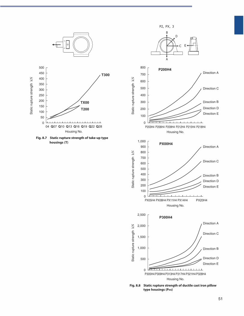
P2, PX, 3
B D
C E
500
450
400
350
300
250
200
150
100
50
0
TX00
T200
T300
800
700
600
500
400
300
200
100
0
A
P200H4
Direction A
Direction C
Direction D
Direction E
Q004 Q07 Q10 Q13 Q16 Q19 Q22 Q28
Housing No.
Fig. 8.7 Static rupture strength of take-up type
P203H4 P206H4 P209H4 P212H4 P215H4 P218H4
Housing No.
housings (T) 1,000
900
800
700
600
500
400
300
200
100
0
PX00H4 Direction A
Direction C
Direction D
Direction E
PX05H4 PX08H4 PX11H4 PX14H4
Housing No.
PX20H4
2,500
2,000
1,500
P300H4
Direction A
Direction C
1,000
500
0
Direction D
Direction E
P305H4 P309H4 P313H4 P317H4 P321H4 P328H4
Housing No.
Fig. 8.8 Static rupture strength of ductile cast iron pillow type housings (PH4)
51
Sta
tic r
uptu
re s
tren
gth
kN
Sta
tic r
uptu
re s
tren
gth
kN
S
tatic
rup
ture
str
engt
h k
N
Sta
tic r
uptu
re s
tren
gth
kN
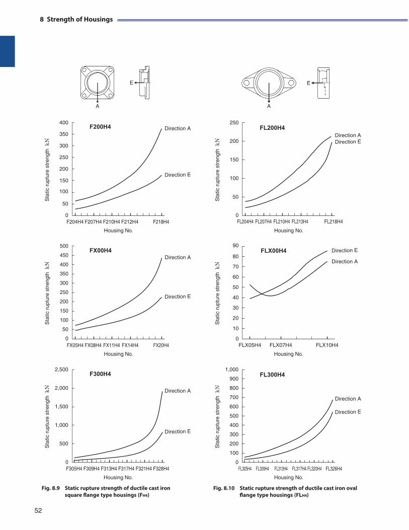
8 Strength of Housings
E E
A A
400
350
300
250
200
150
F200H4
Direction A
250
200
150
100
FL200H4
Direction A
100
50 50
0 F204H4 F207H4 F210H4 F212H4
Housing No.
F218H4
0 FL204H4 FL207H4 FL210H4 FL213H4
Housing No.
FL218H4
500
450
400
350
300
250
200
150
100
50
0
FX00H4
Direction A
90 FLX00H4
80
70
60
50
40
30
20
10
0
Direction A
FX05H4 FX08H4 FX11H4 FX14H4
Housing No.
FX20H4 FLX05H4 FLX07H4
Housing No.
FLX10H4
2,500
2,000
1,500
1,000
500
0
F300H4
Direction A
1,000
900
800
700
600
500
400
300
200
100
0
FL300H4
Direction A
F305H4 F309H4 F313H4 F317H4 F321H4 F328H4 FL305H4 FL309H4 FL313H4 FL317H4 FL320H4 FL326H4
Housing No.
Fig. 8.9 Static rupture strength of ductile cast iron square flange type housings (FH4)
Housing No.
Fig. 8.10 Static rupture strength of ductile cast iron oval flange type housings (FLH4)
52
Sta
tic r
uptu
re s
tren
gth
kN
S
tatic
rup
ture
str
engt
h k
N
Sta
tic r
uptu
re s
tren
gth
kN
Sta
tic r
uptu
re s
tren
gth
kN
S
tatic
rup
ture
str
engt
h k
N
Sta
tic r
uptu
re s
tren
gth
kN
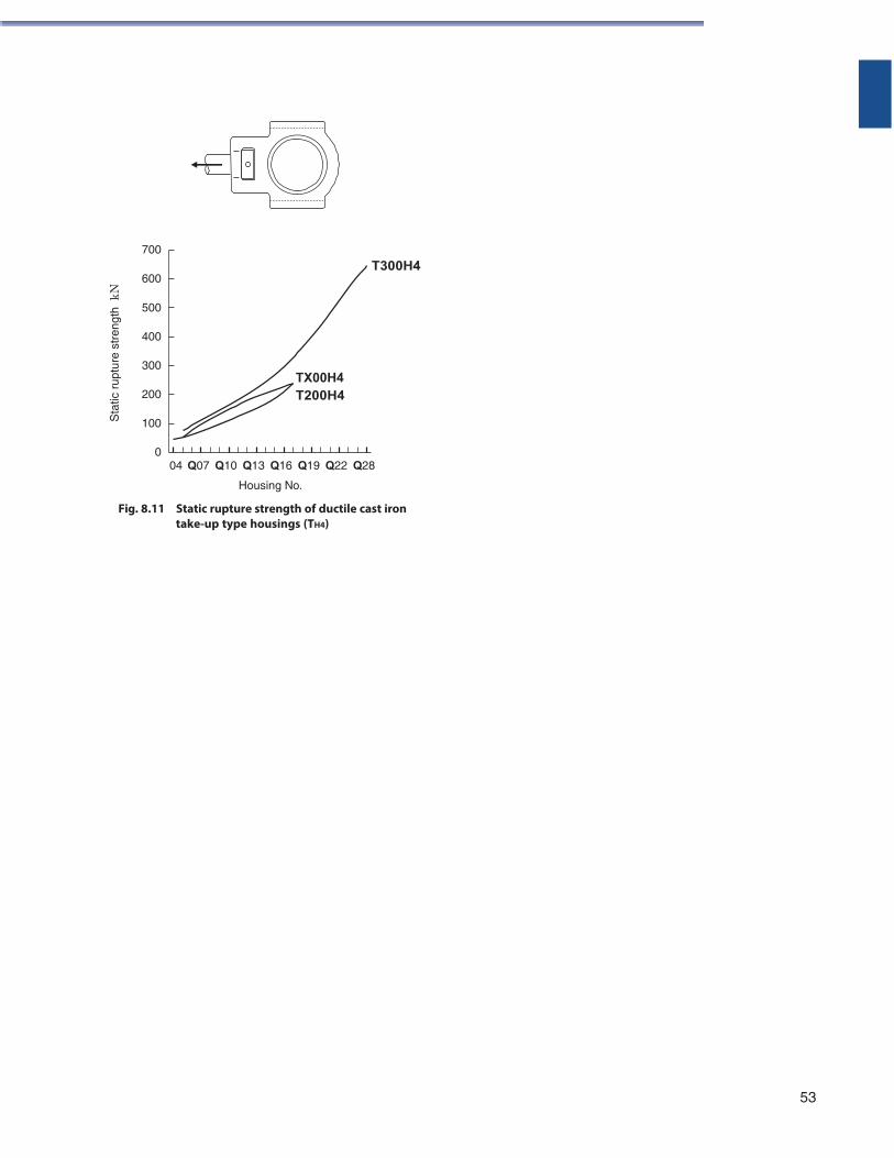
700
600
T300H4
500
400
300
200
TX00H4 T200H4
100
0 Q004 Q07 Q10 Q13 Q16 Q19 Q22 Q28
Housing No.
Fig. 8.11 Static rupture strength of ductile cast iron take-up type housings (TH4)
53
Sta
tic r
uptu
re s
tren
gth
kN
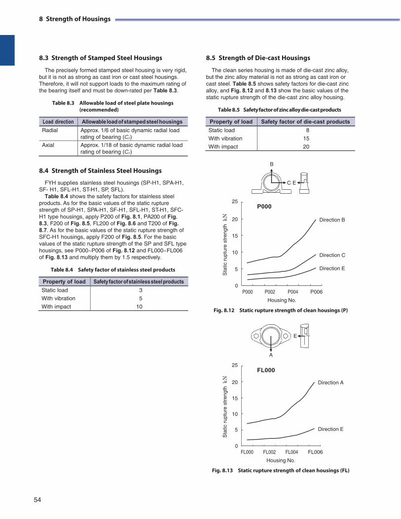
8 Strength of Housings
8.3 Strength of Stamped Steel Housings
The precisely formed stamped steel housing is very rigid, but it is not as strong as cast iron or cast steel housings. Therefore, it will not support loads to the maximum rating of the bearing itself and must be down-rated per Table 8.3.
Table 8.3 Allowable load of steel plate housings
(recommended)
8.5 Strength of Die-cast Housings
The clean series housing is made of die-cast zinc alloy, but the zinc alloy material is not as strong as cast iron or cast steel. Table 8.5 shows safety factors for die-cast zinc alloy, and Fig. 8.12 and 8.13 show the basic values of the static rupture strength of the die-cast zinc alloy housing.
Table 8.5 Safety factor of zinc alloy die-cast products
B 8.4 Strength of Stainless Steel Housings
FYH supplies stainless steel housings (SP-H1, SPA-H1, SF- H1, SFL-H1, ST-H1, SP, SFL).
Table 8.4 shows the safety factors for stainless steel products. As for the basic values of the static rupture strength of SP-H1, SPA-H1, SF-H1, SFL-H1, ST-H1, SFC- H1 type housings, apply P200 of Fig. 8.1, PA200 of Fig. 8.3, F200 of Fig. 8.5, FL200 of Fig. 8.6 and T200 of Fig. 8.7. As for the basic values of the static rupture strength of SFC-H1 housings, apply F200 of Fig. 8.5. For the basic values of the static rupture strength of the SP and SFL type housings, see P000~P006 of Fig. 8.12 and FL000~FL006 of Fig. 8.13 and multiply them by 1.5 respectively.
Table 8.4 Safety factor of stainless steel products
C E
25 P000
20
15
10
5
Direction B
Direction C
Direction E
0 P000
P002
P004
P006
Housing No.
Fig. 8.12 Static rupture strength of clean housings (P)
E
A
25
FL000
20 Direction A
15
10
5 Direction E
0
FL000
FL002
FL004
FL006
Housing No.
Fig. 8.13 Static rupture strength of clean housings (FL)
54
Property of load Safety factor of die-cast products
Static load
With vibration
With impact
8
15
20
Load direction Allowable load of stamped steel housings
Radial Approx. 1/6 of basic dynamic radial load rating of bearing (Cr)
Axial Approx. 1/18 of basic dynamic radial load rating of bearing (Cr)
Sta
tic r
uptu
re s
tren
gth
kN
S
tatic
rup
ture
str
engt
h k
N
Property of load Safety factor of stainless steel products
Static load
With vibration
With impact
3
5
10
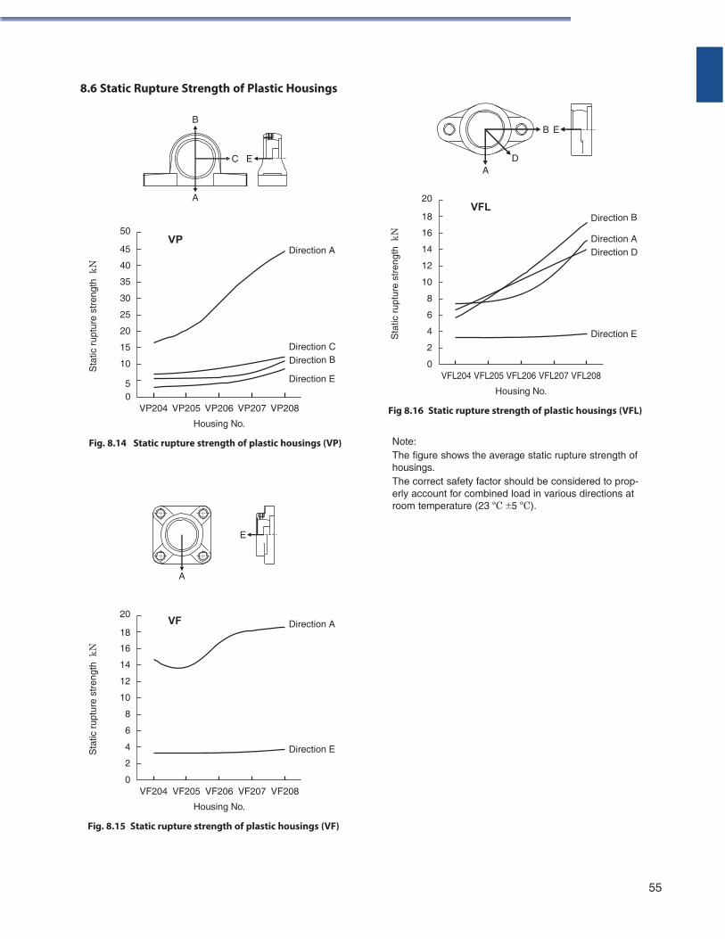
8.6 Static Rupture Strength of Plastic Housings
B B E
C E D A
A
50 VP
45 Direction A
40
35
30
25
20
15 Direction C
10
20 VFL
18
16
14
12
10
8
6
4
2
0
Direction A Direction D
Direction E
5 Direction E
0 VP204 VP205 VP206 VP207 VP208
Housing No.
Fig. 8.14 Static rupture strength of plastic housings (VP)
VFL204 VFL205 VFL206 VFL207 VFL208
Housing No.
Fig 8.16 Static rupture strength of plastic housings (VFL)
Note: The figure shows the average static rupture strength of housings. The correct safety factor should be considered to prop- erly account for combined load in various directions at room temperature (23 ºC 5 ºC).
E
A
20 VF Direction A
18
16
14
12
10
8
6
4 Direction E
2
0 VF204 VF205 VF206 VF207 VF208
Housing No.
Fig. 8.15 Static rupture strength of plastic housings (VF)
55
Sta
tic r
uptu
re s
tren
gth
kN
S
tatic
rup
ture
str
engt
h k
N
Sta
tic r
uptu
re s
tren
gth
kN
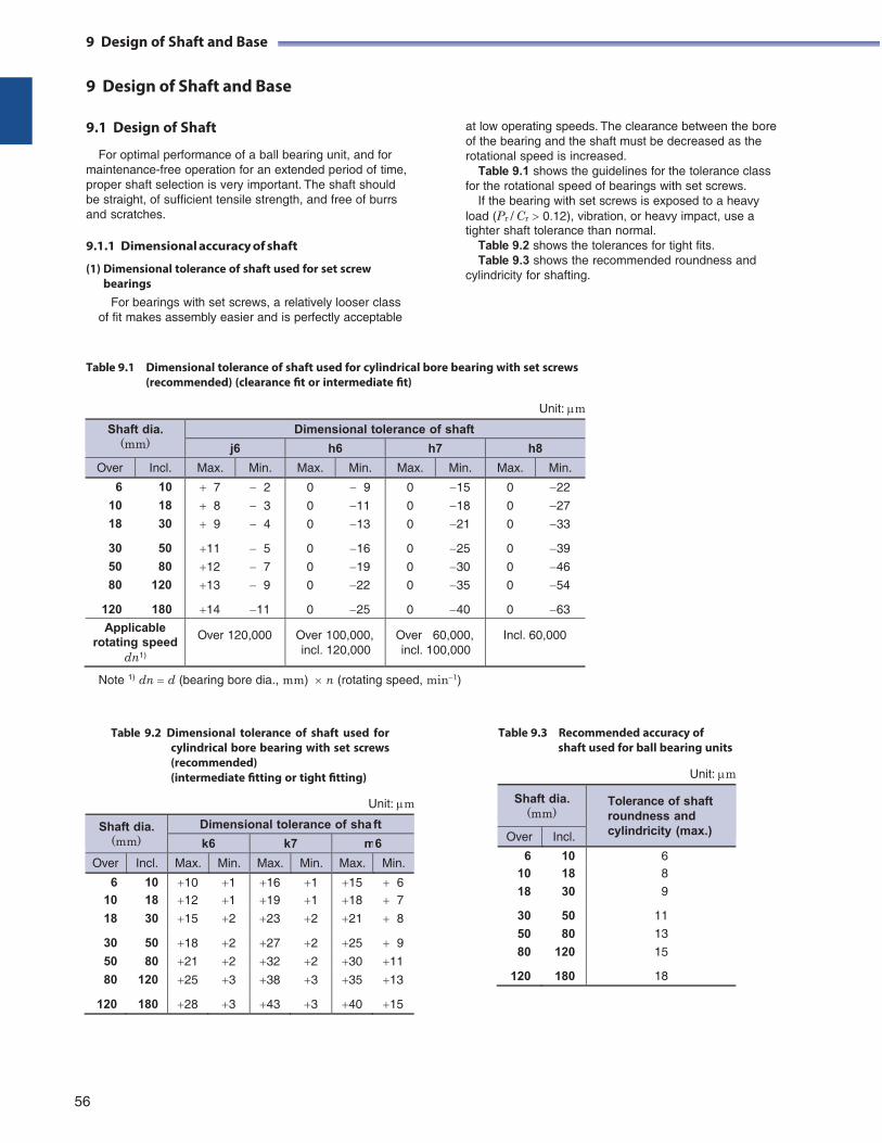
9 Design of Shaft and Base
9 Design of Shaft and Base
9.1 Design of Shaft
For optimal performance of a ball bearing unit, and for maintenance-free operation for an extended period of time, proper shaft selection is very important. The shaft should be straight, of sufficient tensile strength, and free of burrs and scratches.
9.1.1 Dimensional accuracy of shaft
(1) Dimensional tolerance of shaft used for set screw bearings
For bearings with set screws, a relatively looser class of fit makes assembly easier and is perfectly acceptable
at low operating speeds. The clearance between the bore of the bearing and the shaft must be decreased as the rotational speed is increased.
Table 9.1 shows the guidelines for the tolerance class for the rotational speed of bearings with set screws.
If the bearing with set screws is exposed to a heavy load (Pr / Cr 0.12), vibration, or heavy impact, use a tighter shaft tolerance than normal.
Table 9.2 shows the tolerances for tight fits. Table 9.3 shows the recommended roundness and
cylindricity for shafting.
Table 9.1 Dimensional tolerance of shaft used for cylindrical bore bearing with set screws (recommended) (clearance fit or intermediate fit)
Unit: m
Shaft dia. (mm)
Dimensional tolerance of shaft
j6 h6 h7 h8
Over Incl. Max. Min. Max. Min. Max. Min. Max. Min.
6 10
10 18
18 30
30 50
50 80
80 120
120 180
7 2
8 3
9 4
11 5
12 7
13 9
14 11
0 9
0 11
0 13
0 16
0 19
0 22
0 25
0 15
0 18
0 21
0 25
0 30
0 35
0 40
0 22
0 27
0 33
0 39
0 46
0 54
0 63
Applicable rotating speed
dn1)
Over 120,000 Over 100,000, incl. 120,000
Over 60,000, incl. 100,000
Incl. 60,000
Note 1) dn d (bearing bore dia., mm) n (rotating speed, min1)
Table 9.2 Dimensional tolerance of shaft used for cylindrical bore bearing with set screws (recommended) (intermediate fitting or tight fitting)
Unit: m
Table 9.3 Recommended accuracy of shaft used for ball bearing units
Unit: m
Shaft dia. (mm)
Dimensional tolerance of sha ft
k6 k7 m6
Over Incl. Max. Min. Max. Min. Max. Min.
6 10 10 1 16 1 15 6 10 18 12 1 19 1 18 7
18 30 15 2 23 2 21 8
30 50 18 2 27 2 25 9
50 80 21 2 32 2 30 11
80 120 25 3 38 3 35 13
120 180 28 3 43 3 40 15
56
9 Design of Shaft and Base
Shaft dia. (mm)
Tolerance of shaft roundness and cylindricity (max.) Over Incl.
6 10 6 10 18 8
18 30 9
30 50 11
50 80 13
80 120 15
120 180 18
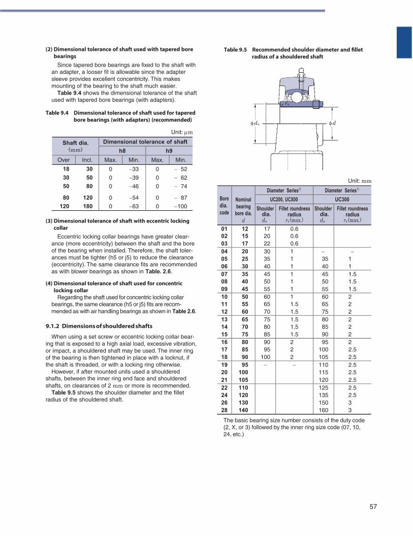
(2) Dimensional tolerance of shaft used with tapered bore bearings
Since tapered bore bearings are fixed to the shaft with an adapter, a looser fit is allowable since the adapter sleeve provides excellent concentricity. This makes mounting of the bearing to the shaft much easier.
Table 9.4 shows the dimensional tolerance of the shaft used with tapered bore bearings (with adapters).
Table 9.4 Dimensional tolerance of shaft used for tapered
bore bearings (with adapters) (recommended)
Unit: m
Table 9.5 Recommended shoulder diameter and fillet radius of a shouldered shaft
ra
da d
Unit: mm
(3) Dimensional tolerance of shaft with eccentric locking collar
Eccentric locking collar bearings have greater clear- ance (more eccentricity) between the shaft and the bore of the bearing when installed. Therefore, the shaft toler- ances must be tighter (h5 or j5) to reduce the clearance (eccentricity). The same clearance fits are recommended as with blower bearings as shown in Table. 2.6.
(4) Dimensional tolerance of shaft used for concentric locking collar
Regarding the shaft used for concentric locking collar bearings, the same clearance (h5 or j5) fits are recom- mended as with air handling bearings as shown in Table 2.6.
9.1.2 Dimensions of shouldered shafts
When using a set screw or eccentric locking collar bear- ing that is exposed to a high axial load, excessive vibration, or impact, a shouldered shaft may be used. The inner ring of the bearing is then tightened in place with a locknut, if the shaft is threaded, or with a locking ring otherwise.
However, if after mounted units used a shouldered shafts, between the inner ring end face and shouldered shafts, on clearances of 2 mm or more is recommended.
Table 9.5 shows the shoulder diameter and the fillet radius of the shouldered shaft.
The basic bearing size number consists of the duty code (2, X, or 3) followed by the inner ring size code (07, 10, 24, etc.)
57
Shaft dia. (mm)
Dimensional tolerance of shaft
h8 h9
Over Incl. Max. Min. Max. Min.
18 30
30 50
50 80
80 120
120 180
0 33
0 39
0 46
0 54
0 63
0 52
0 62
0 74
0 87
0 100
Bore dia. code
Nominal bearing
bore dia. d
Diameter Series1) Diameter Series1)
UC200, UCX00 UC300
Shoulder dia. da
Fillet roundness radius
ra (max.)
Shoulder dia. da
Fillet roundness radius
ra (max.) 01 12 17 0.6 02 15 20 0.6 03 17 22 0.6 04 20 30 1 05 25 35 1 35 1 06 30 40 1 40 1 07 35 45 1 45 1.5 08 40 50 1 50 1.5 09 45 55 1 55 1.5 10 50 60 1 60 2 11 55 65 1.5 65 2 12 60 70 1.5 75 2 13 65 75 1.5 80 2 14 70 80 1.5 85 2 15 75 85 1.5 90 2 16 80 90 2 95 2 17 85 95 2 100 2.5 18 90 100 2 105 2.5 19 95 110 2.5 20 100 115 2.5 21 105 120 2.5 22 110 125 2.5 24 120 135 2.5 26 130 150 3 28 140 160 3
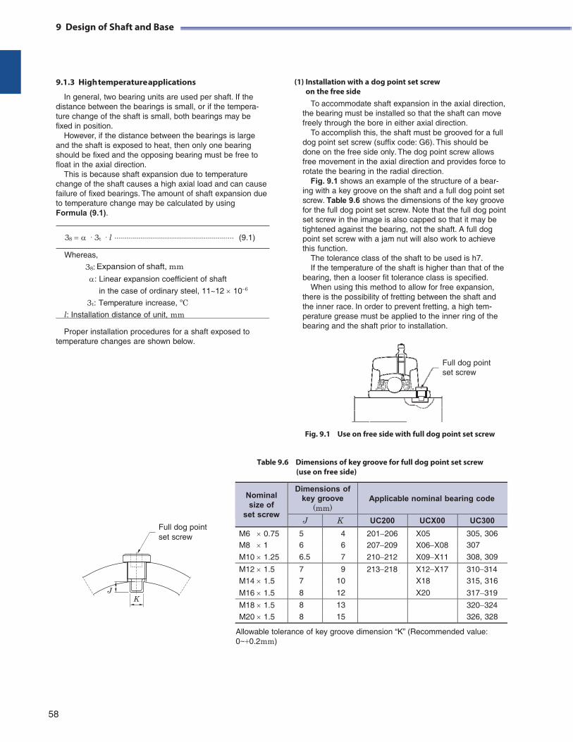
9 Design of Shaft and Base
9.1.3 High temperature applications
In general, two bearing units are used per shaft. If the distance between the bearings is small, or if the tempera- ture change of the shaft is small, both bearings may be fixed in position.
However, if the distance between the bearings is large and the shaft is exposed to heat, then only one bearing should be fixed and the opposing bearing must be free to float in the axial direction.
This is because shaft expansion due to temperature change of the shaft causes a high axial load and can cause failure of fixed bearings. The amount of shaft expansion due to temperature change may be calculated by using Formula (9.1).
38 · 3t · l (9.1)
Whereas,
38: Expansion of shaft, mm : Linear expansion coefficient of shaft
in the case of ordinary steel, 11~12 106
3t: Temperature increase, ºC l: Installation distance of unit, mm
Proper installation procedures for a shaft exposed to
temperature changes are shown below.
(1) Installation with a dog point set screw
on the free side
To accommodate shaft expansion in the axial direction, the bearing must be installed so that the shaft can move freely through the bore in either axial direction.
To accomplish this, the shaft must be grooved for a full dog point set screw (suffix code: G6). This should be done on the free side only. The dog point screw allows free movement in the axial direction and provides force to rotate the bearing in the radial direction.
Fig. 9.1 shows an example of the structure of a bear- ing with a key groove on the shaft and a full dog point set screw. Table 9.6 shows the dimensions of the key groove for the full dog point set screw. Note that the full dog point set screw in the image is also capped so that it may be tightened against the bearing, not the shaft. A full dog point set screw with a jam nut will also work to achieve this function.
The tolerance class of the shaft to be used is h7. If the temperature of the shaft is higher than that of the
bearing, then a looser fit tolerance class is specified. When using this method to allow for free expansion,
there is the possibility of fretting between the shaft and the inner race. In order to prevent fretting, a high tem- perature grease must be applied to the inner ring of the bearing and the shaft prior to installation.
Full dog point set screw
Fig. 9.1 Use on free side with full dog point set screw
Table 9.6 Dimensions of key groove for full dog point set screw (use on free side)
Full dog point set screw
J K
Allowable tolerance of key groove dimension “K” (Recommended value: 0~0.2mm)
58
Nominal size of
set screw
Dimensions of key groove
(mm)
Applicable nominal bearing code
J K UC200 UCX00 UC300
M6 0.75 5 4 201206 X05 305, 306 M8 1 6 6 207209 X06X08 307
M10 1.25 6.5 7 210212 X09X11 308, 309
M12 1.5 7 9 213218 X12X17 310314
M14 1.5 7 10 X18 315, 316
M16 1.5 8 12 X20 317319
M18 1.5 8 13 320324
M20 1.5 8 15 326, 328
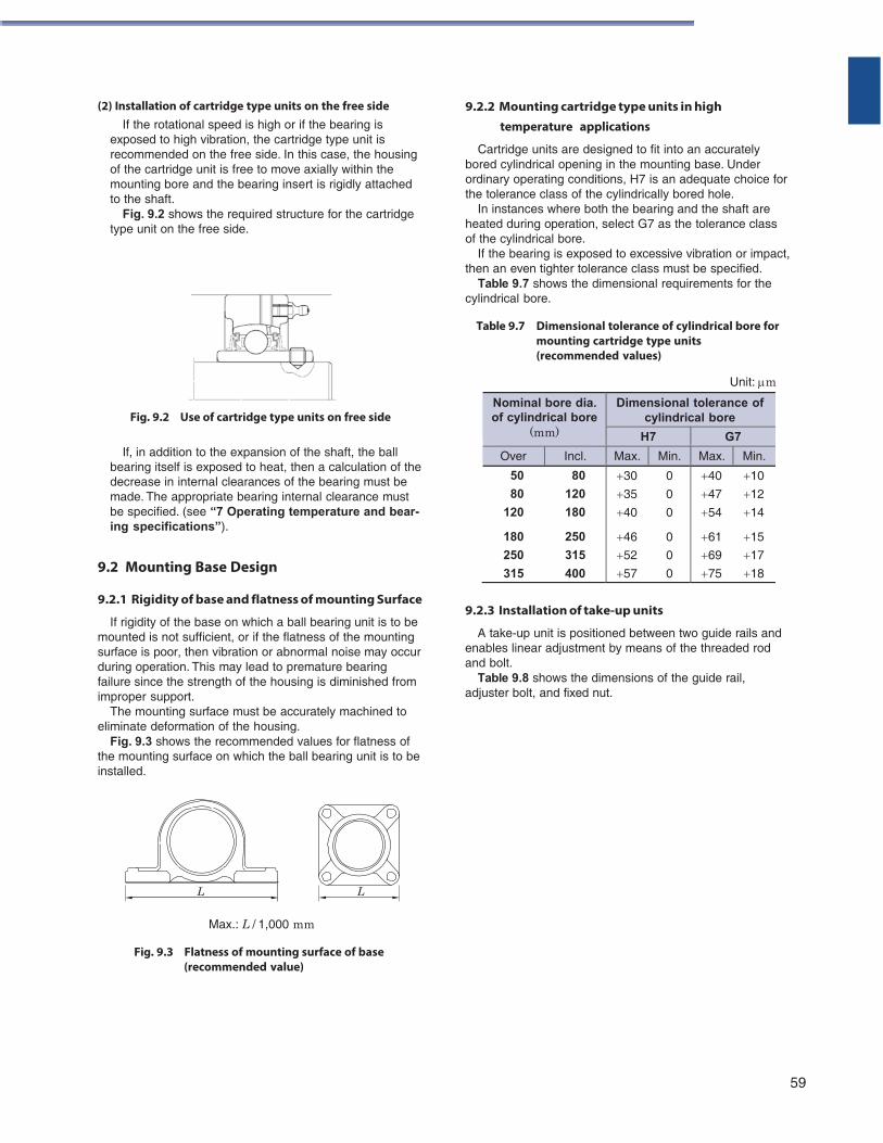
(2) Installation of cartridge type units on the free side
If the rotational speed is high or if the bearing is exposed to high vibration, the cartridge type unit is recommended on the free side. In this case, the housing of the cartridge unit is free to move axially within the mounting bore and the bearing insert is rigidly attached to the shaft.
Fig. 9.2 shows the required structure for the cartridge type unit on the free side.
Fig. 9.2 Use of cartridge type units on free side
9.2.2 Mounting cartridge type units in high temperature applications
Cartridge units are designed to fit into an accurately bored cylindrical opening in the mounting base. Under ordinary operating conditions, H7 is an adequate choice for the tolerance class of the cylindrically bored hole.
In instances where both the bearing and the shaft are heated during operation, select G7 as the tolerance class of the cylindrical bore.
If the bearing is exposed to excessive vibration or impact, then an even tighter tolerance class must be specified.
Table 9.7 shows the dimensional requirements for the cylindrical bore.
Table 9.7 Dimensional tolerance of cylindrical bore for
mounting cartridge type units (recommended values)
Unit: m
If, in addition to the expansion of the shaft, the ball bearing itself is exposed to heat, then a calculation of the decrease in internal clearances of the bearing must be made. The appropriate bearing internal clearance must be specified. (see “7 Operating temperature and bear- ing specifications”).
9.2 Mounting Base Design
9.2.1 Rigidity of base and flatness of mounting Surface
If rigidity of the base on which a ball bearing unit is to be mounted is not sufficient, or if the flatness of the mounting surface is poor, then vibration or abnormal noise may occur during operation. This may lead to premature bearing failure since the strength of the housing is diminished from improper support.
The mounting surface must be accurately machined to eliminate deformation of the housing.
Fig. 9.3 shows the recommended values for flatness of the mounting surface on which the ball bearing unit is to be installed.
9.2.3 Installation of take-up units
A take-up unit is positioned between two guide rails and enables linear adjustment by means of the threaded rod and bolt.
Table 9.8 shows the dimensions of the guide rail, adjuster bolt, and fixed nut.
Max.: L / 1,000 mm
Fig. 9.3 Flatness of mounting surface of base (recommended value)
59
L
L
Nominal bore dia. of cylindrical bore
(mm)
Dimensional tolerance of cylindrical bore
H7 G7
Over Incl. Max. Min. Max. Min.
50 80
80 120
120 180
180 250
250 315
315 400
30 0
35 0
40 0
46 0
52 0
57 0
40 10
47 12
54 14
61 15
69 17
75 18
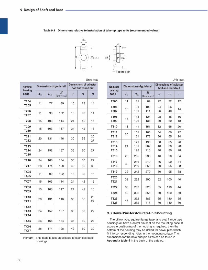
9 Design of Shaft and Base
Table 9.8 Dimensions relative to installation of take-up type units (recommended values)
A 1r
B
H H 1r 0.5 d D
Tapered pin
Unit: mm Unit: mm
Nominal bearing code
Dimensions of guide rail Dimensions of adjuster
bolt and round nut
A1r H1r H
(Reference) d D B
T305 11 81 89 22 32 12
T306
T307
15
91 101
100 111
24 26
36 40
14
T308
T309
16
113 126
124 138
28 30
45 50
16 18
T310 18 141 151 32 55 20
T311
T312
20
151 161
163 178
34 36
60 65
22 24
T313
24 171 190 38 65 26
T314 181 202 40 80 28 T315 193 216 40 80 28
T316 28 205 230 46 90 34
T317
T318
30
216 230
240 255
46 50
90 95
34 38
T319 32 242 270 50 95 38
T320
T321
32
262
290
52
100
40
T322 36 287 320 55 110 44
T324 42 322 355 60 120 50
T326
T328
47
352 382
385 415
65 70
130 140
55 60
Remark This table is also applicable to stainless steel housings.
9.3 Dowel Pins for Accurate Unit Mounting
The pillow type, square flange type, and oval flange type housings all have a dowel pin seat on the mounting base. If accurate positioning of the housing is required, then the bottom of the housing may be drilled for dowel pins which fit into corresponding holes in the mounting surface. The dimensions for the hole and pin sizes can be found in Appendix table 5 in the back of the catalog.
60
Nominal bearing code
Dimensions of guide rail Dimensions of adjuster
bolt and round nut
A1r H1r H
(Reference) d D B
T204
T205
11
77
89
16
28
14
T206
T207
11
90
102
18
32
14
T208 15 103 114 24 42 16
T209
T210
15
103
117
24
42
16
T211
T212
20
131
146
30
55
20 27
T213
T214
T215
24
152
167
36
60
27
T216 24 166 184 36 60 27
T217 28 174 198 42 60 30
TX05
TX06
11
90
102
18
32
14
TX07 15 103 114 24 42 16
TX08
TX09
15
103
117
24
42
16
TX10
TX11
20
131
146
30
55
20 27
TX12
TX13
TX14
24
152
167
36
60
27
TX15 26 166 184 36 60 27
TX16
TX17
26
174
198
42
60
30
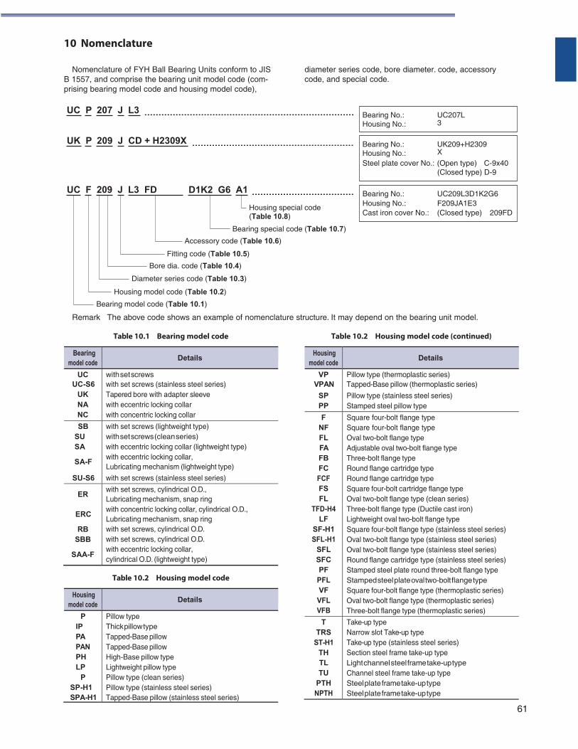
D1K2 G6
10 Nomenclature
Nomenclature of FYH Ball Bearing Units conform to JIS B 1557, and comprise the bearing unit model code (com- prising bearing model code and housing model code),
diameter series code, bore diameter. code, accessory code, and special code.
UC P 207 J L3
UK P 209 J CD + H2309X
UC F 209 J L3 FD A1
Housing special code (Table 10.8)
Bearing special code (Table 10.7)
Accessory code (Table 10.6)
Fitting code (Table 10.5)
Bore dia. code (Table 10.4)
Diameter series code (Table 10.3)
Housing model code (Table 10.2)
Bearing model code (Table 10.1)
Remark The above code shows an example of nomenclature structure. It may depend on the bearing unit model.
Table 10.1 Bearing model code Table 10.2 Housing model code (continued)
Bearing model code
Details
UC with set screws UC-S6 with set screws (stainless steel series)
UK Tapered bore with adapter sleeve NA with eccentric locking collar NC with concentric locking collar
SB SU SA
SA-F
SU-S6
with set screws (lightweight type) with set screws (clean series) with eccentric locking collar (lightweight type) with eccentric locking collar, Lubricating mechanism (lightweight type)
with set screws (stainless steel series)
ER
ERC
RB SBB
SAA-F
with set screws, cylindrical O.D., Lubricating mechanism, snap ring with concentric locking collar, cylindrical O.D., Lubricating mechanism, snap ring with set screws, cylindrical O.D. with set screws, cylindrical O.D. with eccentric locking collar, cylindrical O.D. (lightweight type)
Table 10.2 Housing model code
Housing model code
Details
P IP PA PAN PH LP
P SP-H1 SPA-H1
Pillow type Thick pillow type Tapped-Base pillow Tapped-Base pillow High-Base pillow type Lightweight pillow type Pillow type (clean series) Pillow type (stainless steel series) Tapped-Base pillow (stainless steel series)
61
Bearing No.: Housing No.:
UC207L3
Bearing No.: Housing No.:
UK209+H2309X
Steel plate cover No.: (Open type) C-9x40 (Closed type) D-9
Bearing No.: UC209L3D1K2G6 Housing No.: F209JA1E3 Cast iron cover No.: (Closed type) 209FD
Housing model code
Details
VP Pillow type (thermoplastic series) VPAN Tapped-Base pillow (thermoplastic series)
SP Pillow type (stainless steel series) PP Stamped steel pillow type
F NF FL FA FB FC FCF FS FL
TFD-H4 LF
SF-H1 SFL-H1
SFL SFC PF PFL VF VFL VFB
Square four-bolt flange type Square four-bolt flange type Oval two-bolt flange type Adjustable oval two-bolt flange type Three-bolt flange type Round flange cartridge type Round flange cartridge type Square four-bolt cartridge flange type Oval two-bolt flange type (clean series) Three-bolt flange type (Ductile cast iron) Lightweight oval two-bolt flange type Square four-bolt flange type (stainless steel series) Oval two-bolt flange type (stainless steel series) Oval two-bolt flange type (stainless steel series) Round flange cartridge type (stainless steel series) Stamped steel plate round three-bolt flange type Stamped steel plate oval two-bolt flange type Square four-bolt flange type (thermoplastic series) Oval two-bolt flange type (thermoplastic series) Three-bolt flange type (thermoplastic series)
T TRS
ST-H1 TH TL TU
PTH NPTH
Take-up type Narrow slot Take-up type Take-up type (stainless steel series) Section steel frame take-up type Light channel steel frame take-up type Channel steel frame take-up type Steel plate frame take-up type Steel plate frame take-up type
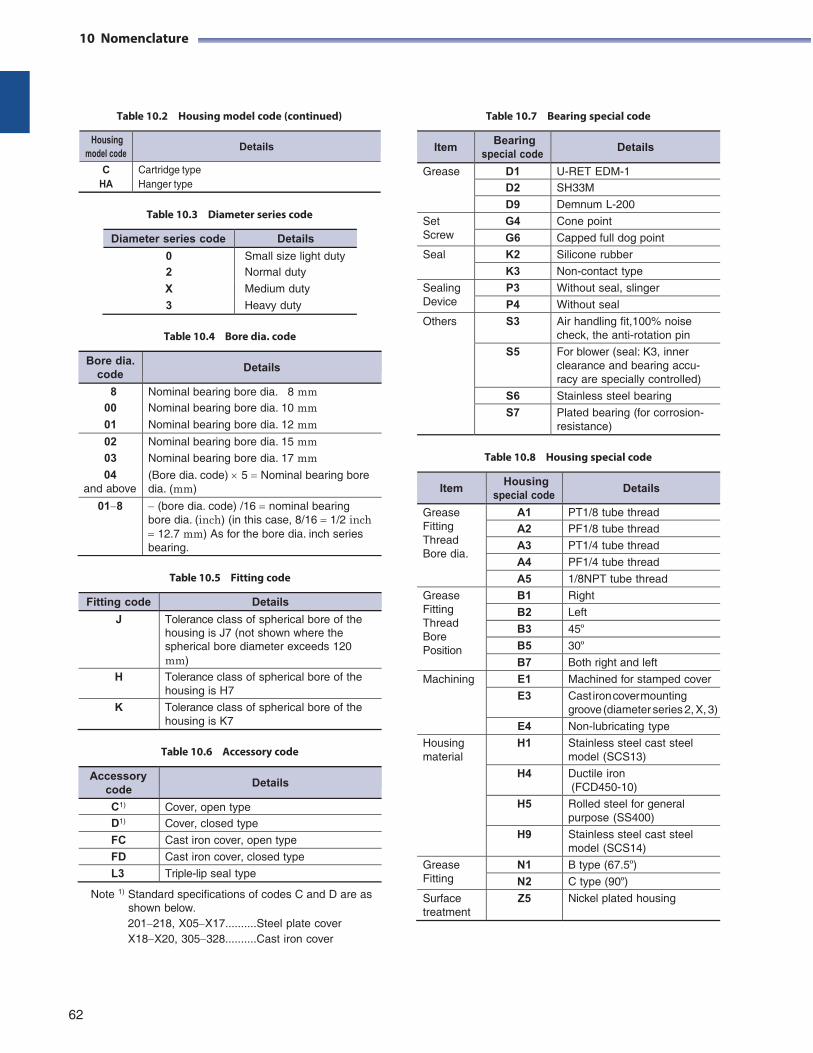
10 Nomenclature
Table 10.2 Housing model code (continued)
Table 10.7 Bearing special code
Housing model code
Details
C HA
Cartridge type Hanger type
Table 10.3 Diameter series code
Diameter series code Details
0 Small size light duty 2 Normal duty
X Medium duty
3 Heavy duty
Table 10.4 Bore dia. code
Table 10.8 Housing special code
Table 10.5 Fitting code
Fitting code Details
J Tolerance class of spherical bore of the housing is J7 (not shown where the spherical bore diameter exceeds 120 mm)
H Tolerance class of spherical bore of the housing is H7
K Tolerance class of spherical bore of the housing is K7
Table 10.6 Accessory code
Accessory code
Details
C1) Cover, open type D1) Cover, closed type
FC Cast iron cover, open type
FD Cast iron cover, closed type
L3 Triple-lip seal type
Note 1) Standard specifications of codes C and D are as shown below. 201218, X05X17..........Steel plate cover X18X20, 305328..........Cast iron cover
62
Item Bearing
special code Details
Grease D1 U-RET EDM-1 D2 SH33M
D9 Demnum L-200
Set Screw
G4 Cone point
G6 Capped full dog point
Seal K2 Silicone rubber
K3 Non-contact type
Sealing Device
P3 Without seal, slinger
P4 Without seal
Others S3 Air handling fit,100% noise check, the anti-rotation pin
S5 For blower (seal: K3, inner clearance and bearing accu- racy are specially controlled)
S6 Stainless steel bearing
S7 Plated bearing (for corrosion- resistance)
Bore dia. code
Details
8 Nominal bearing bore dia. 8 mm 00 Nominal bearing bore dia. 10 mm 01 Nominal bearing bore dia. 12 mm
02 Nominal bearing bore dia. 15 mm 03 Nominal bearing bore dia. 17 mm 04 (Bore dia. code) 5 Nominal bearing bore
and above dia. (mm)
018 (bore dia. code) /16 nominal bearing bore dia. (inch) (in this case, 8/16 1/2 inch 12.7 mm) As for the bore dia. inch series bearing.
Item Housing
special code Details
Grease Fitting Thread Bore dia.
A1 PT1/8 tube thread A2 PF1/8 tube thread
A3 PT1/4 tube thread
A4 PF1/4 tube thread
A5 1/8NPT tube thread
Grease Fitting Thread Bore Position
B1 Right
B2 Left
B3 45º B5 30º B7 Both right and left
Machining E1 Machined for stamped cover
E3 Cast iron cover mounting groove (diameter series 2, X, 3)
E4 Non-lubricating type
Housing material
H1 Stainless steel cast steel model (SCS13)
H4 Ductile iron (FCD450-10)
H5 Rolled steel for general purpose (SS400)
H9 Stainless steel cast steel model (SCS14)
Grease Fitting
N1 B type (67.5º) N2 C type (90º)
Surface treatment
Z5 Nickel plated housing
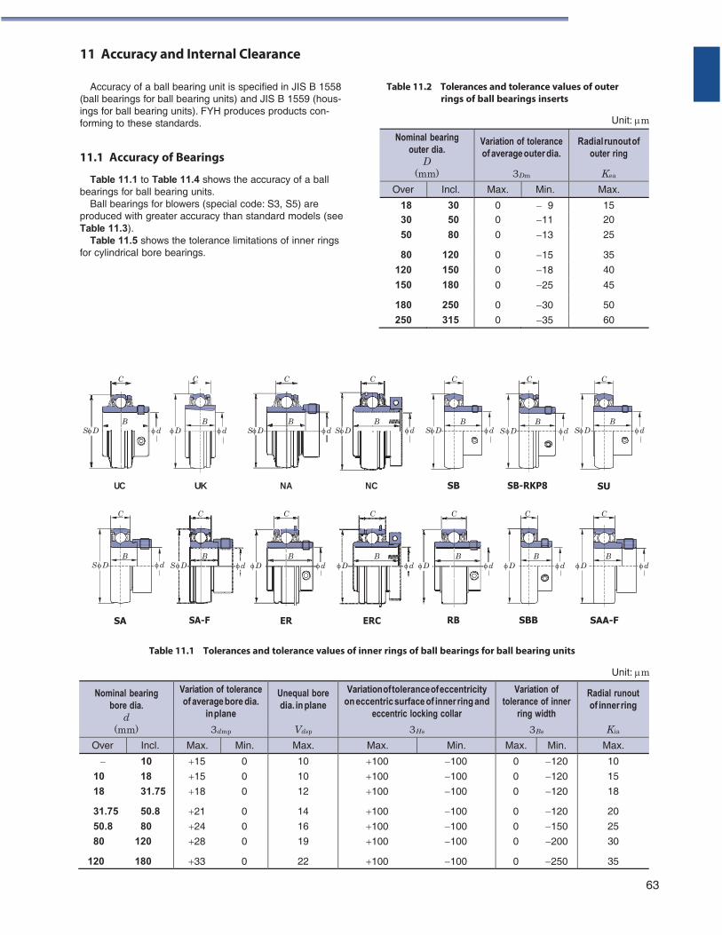
11 Accuracy and Internal Clearance
Accuracy of a ball bearing unit is specified in JIS B 1558 (ball bearings for ball bearing units) and JIS B 1559 (hous- ings for ball bearing units). FYH produces products con- forming to these standards.
11.1 Accuracy of Bearings
Table 11.1 to Table 11.4 shows the accuracy of a ball bearings for ball bearing units.
Ball bearings for blowers (special code: S3, S5) are produced with greater accuracy than standard models (see Table 11.3).
Table 11.5 shows the tolerance limitations of inner rings for cylindrical bore bearings.
Table 11.2 Tolerances and tolerance values of outer rings of ball bearings inserts
Unit: m
C C C C
B B B B
C
B
C
B
C
B SD d D d SD d SD d SD d S D d SD d
UC UK NA NC SB SB-RKP8 SU
C C C C C C C
B B B B B B B S D d S D d D d D d D d D d D d
SA SA-F ER ERC RB SBB SAA-F
Table 11.1 Tolerances and tolerance values of inner rings of ball bearings for ball bearing units
Unit: m
Nominal bearing bore dia.
d (mm)
Variation of tolerance of average bore dia.
in plane
3dmp
Unequal bore dia. in plane
Vdsp
Variation of tolerance of eccentricity on eccentric surface of inner ring and
eccentric locking collar
3Hs
Variation of tolerance of inner
ring width
3Bs
Radial runout of inner ring
Kia
Over Incl. Max. Min. Max. Max. Min. Max. Min. Max.
10
10 18
18 31.75
31.75 50.8
50.8 80
80 120
120 180
15 0
15 0
18 0
21 0
24 0
28 0
33 0
10
10
12
14
16
19
22
100 100
100 100
100 100
100 100
100 100
100 100
100 100
0 120
0 120
0 120
0 120
0 150
0 200
0 250
10
15
18
20
25
30
35
63
Nominal bearing outer dia.
D (mm)
Variation of tolerance of average outer dia.
3Dm
Radial runout of outer ring
Kea
Over Incl. Max. Min. Max.
18 30 0 9 15 30 50 0 11 20
50 80 0 13 25
80 120 0 15 35
120 150 0 18 40
150 180 0 25 45
180 250 0 30 50
250 315 0 35 60
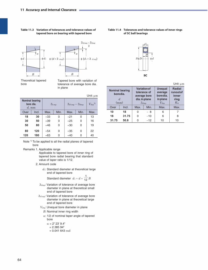
11 Accuracy and Internal Clearance
Table 11.3 Variation of tolerances and tolerance values of tapered bore on bearing with tapered bore
Table 11.4 Tolerances and tolerance values of inner rings
of SC ball bearings
3d1mp 3dmp C 2
B
d d1 (d 3 dmp) (d1 3 d1mp) S D d
Theoretical tapered bore
Tapered bore with variation of tolerance of average bore dia. in plane
Unit: m
SC
Unit: m
Nominal bearing bore dia. d, mm
3d
mp
3d1mp 3dmp
Vdsp
1)
Over Incl. Max. Min. Max. Min. Max.
18 30 33 0 21 0 13 30 50 39 0 25 0 16
50 80 46 0 30 0 19
80 120 54 0 35 0 22
120 180 63 0 40 0 40
Note 1) To be applied to all the radial planes of tapered bore
Remarks 1. Applicable range Applicable to tapered bore of inner ring of tapered bore radial bearing that standard value of taper ratio is 1/12.
2. Amount code
d1: Standard diameter at theoretical large end of tapered bore
1 Standard diameter d1 d 12 B
3dmp: Variation of tolerance of average bore diameter in plane at theoretical small end of tapered bore
3d1mp: Variation of tolerance of average bore diameter in plane at theoretical large end of tapered bore
Vdsp: Unequal bore diameter in plane B: Nominal inner ring width
: 1/2 of nominal taper angle of tapered bore
= 2º 23' 9.4" = 2.385 94º = 0.041 643 rad
64
B B
Nominal bearing bore dia.
d (mm)
Variation of tolerance of average bore dia. in plane
3dmp
Unequal average bore dia. in plane
Vdsp
Radial runout of
inner ring Kia
Over Incl. Max. Min. Max. Max.
10 18 0 8 6 7 18 31.75 0 10 6 8
31.75 50.8 0 12 10 10
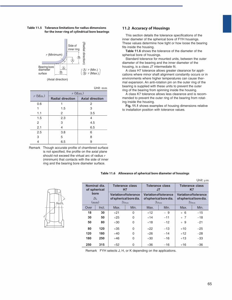
Table 11.5 Tolerance limitations for radius dimensions for the inner ring of cylindrical bore bearings
Side of inner ring
r (Minimum) B
A
11.2 Accuracy of Housings
This section details the tolerance specifications of the inner diameter of the spherical bore of FYH housings. These values determine how tight or how loose the bearing fits inside the housing.
Table 11.6 shows the tolerance of the diameter of the spherical bore of housings.
Standard tolerance for mounted units, between the outer diameter of the bearing and the inner diameter of the
Bearing bore A diameter surface B
(Axial direction)
A : r (Min.) B : r (Max.)
Unit: mm
housing, is a class J7 intermediate fit. A class H7 tolerance allows greater clearance for appli-
cations where minor shaft alignment constantly occurs or in environments where higher temperatures can cause ther- mal expansion. An anti-rotation pin on the outer ring of the bearing is supplied with these units to prevent the outer ring of the bearing from spinning inside the housing.
A class K7 tolerance allows less clearance and is recom- mended to prevent the outer ring of the bearing from rotat- ing inside the housing.
Fig. 11.1 shows examples of housing dimensions relative to installation position with tolerance values.
Remark Though accurate profile of chamfered surface
is not specified, the profile on the axial plane should not exceed the virtual arc of radius r (minimum) that contacts with the side of inner ring and the bearing bore diameter surface.
Table 11.6 Allowance of spherical bore diameter of housings
Unit: m
Remark FYH selects J, H, or K depending on the applications.
65
Nominal dia. of spherical
bore
Da
(mm)
Tolerance class H7
Tolerance class J7
Tolerance class K7
Variation of tolerance of spherical bore dia.
3Dam
Variation of tolerance of spherical bore dia.
3Dam
Variation of tolerance of spherical bore dia.
3Dam
Over Incl. Max. Min. Max. Min. Max. Min.
18 30
30 50
50 80
80 120
120 180
180 250
250 315
21 0
25 0
30 0
35 0
40 0
46 0
52 0
12 9
14 11
18 12
22 13
26 14
30 16
36 16
6 15
7 18
9 21
10 25
12 28
13 33
16 36
S Da
(Radial direction)
r (Min.) r (Max.)
Radial direction Axial direction
0.6 1 2 1 1.5 3
1.1 2 3.5
1.5 2.3 4 2 3 4.5
2.1 4 6.5
2.5 3.8 6
3 5 8
4 6.5 9
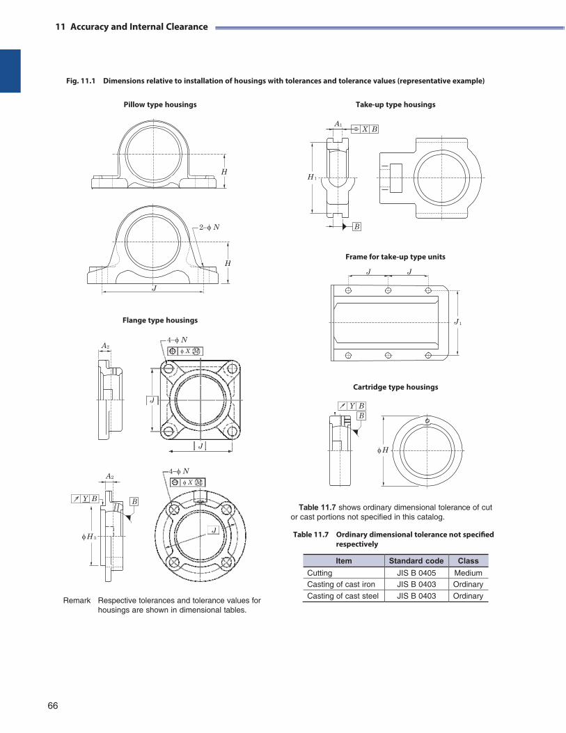
X B A1
H 1
B
H
11 Accuracy and Internal Clearance
Fig. 11.1 Dimensions relative to installation of housings with tolerances and tolerance values (representative example)
Pillow type housings Take-up type housings
Frame for take-up type units
J J
Flange type housings J 1
A2
Cartridge type housings
Y B
A2
B
H 3
Table 11.7 shows ordinary dimensional tolerance of cut
or cast portions not specified in this catalog.
Table 11.7 Ordinary dimensional tolerance not specified respectively
Remark Respective tolerances and tolerance values for housings are shown in dimensional tables.
66
4N X M
J
4N X M
J
J
2N
H
J
B
H
Y B
Item Standard code Class
Cutting JIS B 0405 Medium Casting of cast iron JIS B 0403 Ordinary
Casting of cast steel JIS B 0403 Ordinary
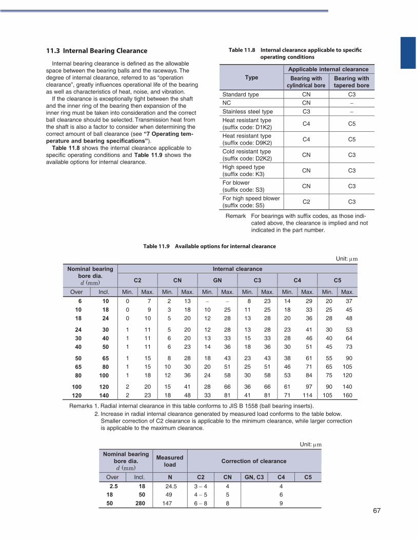
11.3 Internal Bearing Clearance
Internal bearing clearance is defined as the allowable space between the bearing balls and the raceways. The degree of internal clearance, referred to as “operation clearance”, greatly influences operational life of the bearing as well as characteristics of heat, noise, and vibration.
If the clearance is exceptionally tight between the shaft and the inner ring of the bearing then expansion of the inner ring must be taken into consideration and the correct ball clearance should be selected. Transmission heat from the shaft is also a factor to consider when determining the correct amount of ball clearance (see “7 Operating tem- perature and bearing specifications”).
Table 11.8 shows the internal clearance applicable to specific operating conditions and Table 11.9 shows the available options for internal clearance.
Table 11.8 Internal clearance applicable to specific operating conditions
Remark For bearings with suffix codes, as those indi- cated above, the clearance is implied and not indicated in the part number.
Table 11.9 Available options for internal clearance
Unit: m
Nominal bearing bore dia. d (mm)
Internal clearance
C2 CN GN C3 C4 C5
Over Incl. Min. Max. Min. Max. Min. Max. Min. Max. Min. Max. Min. Max.
6 10
10 18
18 24
24 30
30 40
40 50
50 65
65 80
80 100
100 120
120 140
0 7
0 9
0 10
1 11
1 11
1 11
1 15
1 15
1 18
2 20
2 23
2 13
3 18
5 20
5 20
6 20
6 23
8 28
10 30
12 36
15 41
18 48
10 25
12 28
12 28
13 33
14 36
18 43
20 51
24 58
28 66
33 81
8 23
11 25
13 28
13 28
15 33
18 36
23 43
25 51
30 58
36 66
41 81
14 29
18 33
20 36
23 41
28 46
30 51
38 61
46 71
53 84
61 97
71 114
20 37
25 45
28 48
30 53
40 64
45 73
55 90
65 105
75 120
90 140
105 160
Remarks 1. Radial internal clearance in this table conforms to JIS B 1558 (ball bearing inserts). 2. Increase in radial internal clearance generated by measured load conforms to the table below.
Smaller correction of C2 clearance is applicable to the minimum clearance, while larger correction is applicable to the maximum clearance.
Unit: m
67
Type
Applicable internal clearance
Bearing with cylindrical bore
Bearing with tapered bore
Standard type CN C3
NC CN Stainless steel type C3 Heat resistant type (suffix code: D1K2)
C4 C5
Heat resistant type (suffix code: D9K2)
C4 C5
Cold resistant type (suffix code: D2K2)
CN C3
High speed type (suffix code: K3)
CN C3
For blower (suffix code: S3)
CN C3
For high speed blower (suffix code: S5)
C2 C3
Nominal bearing bore dia. d (mm)
Measured load
Correction of clearance
Over Incl. N C2 CN GN, C3 C4 C5
2.5 18 24.5 3 4 4 4 18 50 49 4 5 5 6
50 280 147 6 8 8 9
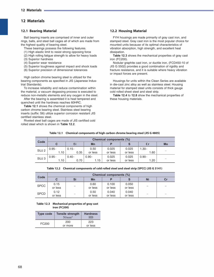
12 Materials
12 Materials
12.1 Bearing Material
Ball bearing inserts are comprised of inner and outer rings, balls, and steel ball cages all of which are made from the highest quality of bearing steel.
These bearings possess the following features. (1) High elastic limit to resist strong opposing force (2) High rolling fatigue strength to allow for heavy loads (3) Superior hardness (4) Superior wear resistance (5) Superior toughness against impact and shock loads (6) Superior precision of dimensional tolerances
High carbon chrome bearing steel is utilized for the
bearing components as specified in JIS (Japanese Indus- trial Standards).
To increase reliability and reduce contamination within the material, a vacuum degassing process is executed to reduce non-metallic elements and any oxygen in the steel.
After the bearing is assembled it is heat tempered and quenched until the hardness reaches 60HRC.
Table 12.1 shows the chemical components of high carbon chrome bearing steel. Stainless steel bearing inserts (suffix: S6) utilize superior corrosion resistant JIS certified stainless steel.
Riveted steel ball cages are made of JIS certified cold rolled steel which is shown in Table 12.2.
12.2 Housing Material
FYH housings are made primarily of gray cast iron, and stamped steel. Gray cast iron is the most popular choice for mounted units because of its optimal characteristics of vibration absorption, high strength, and excellent heat dissipation.
Table 12.3 shows the mechanical properties of gray cast iron (FC200).
Nodular graphite cast iron, or ductile iron, (FCD450-10 of JIS G 5502) provides a good combination of rigidity and fracture resistance, and it is suitable where heavy vibration or impact forces are present.
Housings for units within the Clean Series are available
in die-cast zinc alloy as well as stainless steel. Housing material for stamped steel units consists of thick gauge cold rolled sheet steel and steel strip.
Table 12.4 to 12.8 show the mechanical properties of these housing materials.
Table 12.1 Chemical components of high carbon chrome bearing steel (JIS G 4805)
Code
Chemical components (%)
C Si Mn P S Cr Mo
SUJ 2 0.95
1.10 0.15
0.35 0.50
or less 0.025 or less
0.025 or less
1.30 1.60
SUJ 3 0.95
1.10 0.40
0.70 0.90
1.15 0.025 or less
0.025 or less
0.90 1.20
Table 12.2 Chemical components of cold rolled steel and steel strip (SPCC) (JIS G 3141)
Code
Chemical components (%)
C Si Mn P S Ni Cr
SPCC 0.15
or less
0.60 or less
0.100 or less
0.050 or less
SPCD 0.12
or less
0.50 or less
0.040 or less
0.040 or less
Table 12.3 Mechanical properties of gray cast iron (FC200)
Type code Tensile strength N/mm2
Hardness HB
FC200 200
or more 223
or less
68
12 Materials
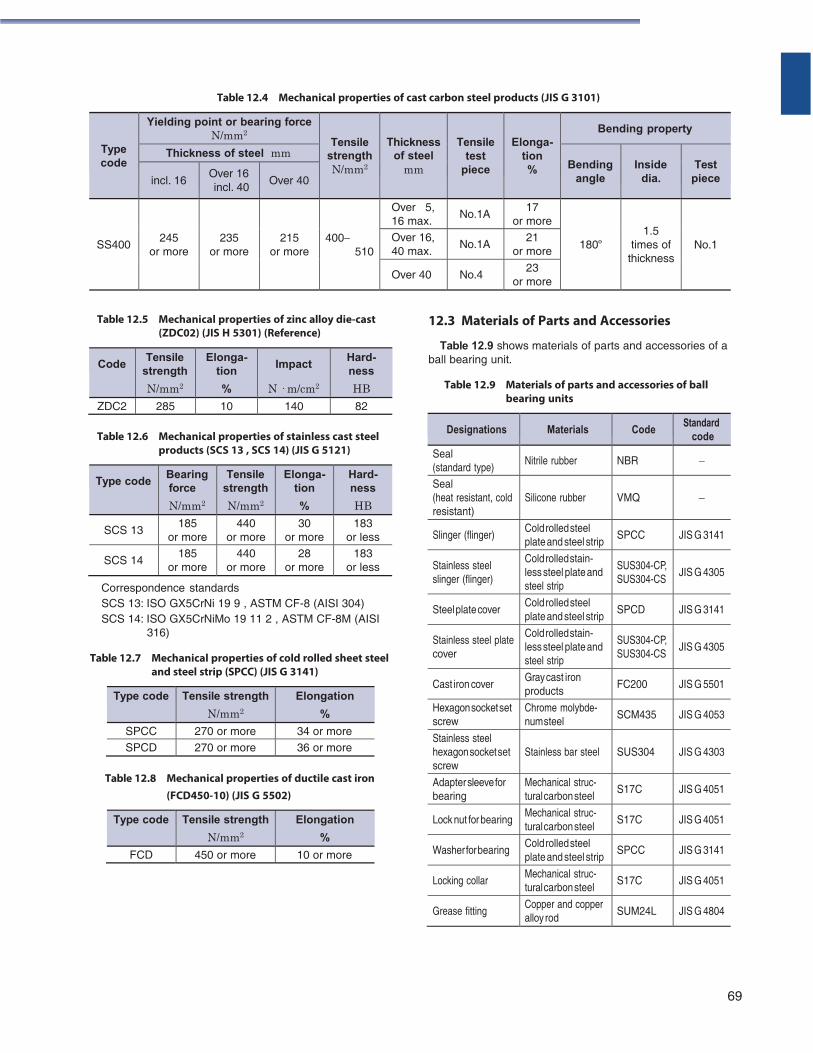
Table 12.4 Mechanical properties of cast carbon steel products (JIS G 3101)
Type code
Yielding point or bearing force N/mm2
Tensile
strength N/mm2
Thickness of steel
mm
Tensile test
piece
Elonga- tion %
Bending property
Thickness of steel mm Bending
angle
Inside
dia.
Test
piece
incl. 16 Over 16 incl. 40
Over 40
SS400
245
or more
235
or more
215
or more
400
510
Over 5, 16 max.
No.1A 17
or more
180º
1.5 times of
thickness
No.1 Over 16, 40 max.
No.1A 21
or more
Over 40 No.4 23
or more
Table 12.5 Mechanical properties of zinc alloy die-cast
(ZDC02) (JIS H 5301) (Reference) 12.3 Materials of Parts and Accessories
Table 12.9 shows materials of parts and accessories of a ball bearing unit.
Table 12.9 Materials of parts and accessories of ball
bearing units
Table 12.6 Mechanical properties of stainless cast steel
products (SCS 13 , SCS 14) (JIS G 5121)
Type code Bearing force
N/mm2
Tensile strength
N/mm2
Elonga- tion
%
Hard- ness
HB
SCS 13 185
or more 440
or more 30
or more 183
or less
SCS 14 185
or more 440
or more 28
or more 183
or less
Correspondence standards SCS 13: ISO GX5CrNi 19 9 , ASTM CF-8 (AISI 304) SCS 14: ISO GX5CrNiMo 19 11 2 , ASTM CF-8M (AISI
316)
Table 12.7 Mechanical properties of cold rolled sheet steel and steel strip (SPCC) (JIS G 3141)
Type code Tensile strength
N/mm2
Elongation
%
SPCC 270 or more 34 or more SPCD 270 or more 36 or more
Table 12.8 Mechanical properties of ductile cast iron (FCD450-10) (JIS G 5502)
Type code Tensile strength
N/mm2
Elongation
%
FCD 450 or more 10 or more
69
Code Tensile
strength
N/mm2
Elonga- tion
%
Impact
N · m/cm2
Hard- ness
HB
ZDC2 285 10 140 82
Designations Materials Code Standard
code
Seal (standard type)
Nitrile rubber NBR
Seal (heat resistant, cold resistant)
Silicone rubber
VMQ
Slinger (flinger) Cold rolled steel plate and steel strip
SPCC JIS G 3141
Stainless steel slinger (flinger)
Cold rolled stain- less steel plate and steel strip
SUS304-CP, SUS304-CS
JIS G 4305
Steel plate cover Cold rolled steel plate and steel strip
SPCD JIS G 3141
Stainless steel plate cover
Cold rolled stain- less steel plate and steel strip
SUS304-CP, SUS304-CS
JIS G 4305
Cast iron cover Gray cast iron products
FC200 JIS G 5501
Hexagon socket set screw
Chrome molybde- num steel
SCM435 JIS G 4053
Stainless steel hexagon socket set screw
Stainless bar steel
SUS304
JIS G 4303
Adapter sleeve for bearing
Mechanical struc- tural carbon steel
S17C JIS G 4051
Lock nut for bearing Mechanical struc- tural carbon steel
S17C JIS G 4051
Washer for bearing Cold rolled steel plate and steel strip
SPCC JIS G 3141
Locking collar Mechanical struc- tural carbon steel
S17C JIS G 4051
Grease fitting Copper and copper alloy rod
SUM24L JIS G 4804
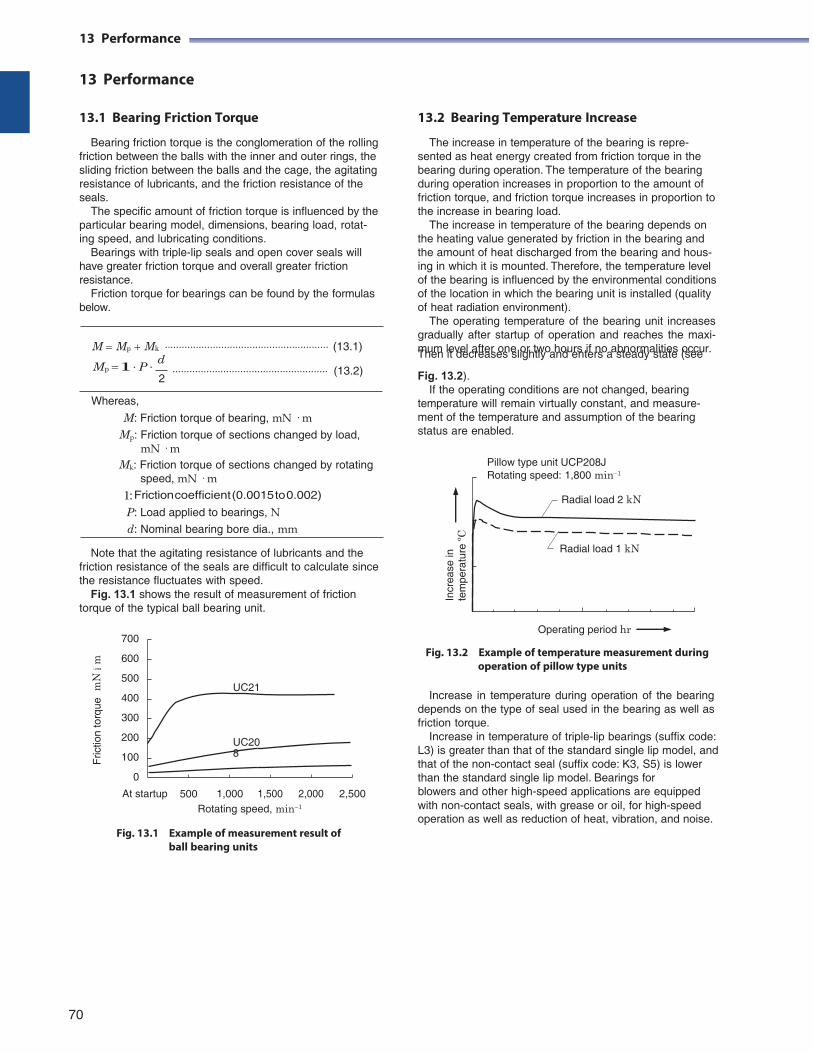
13 Performance
13 Performance
13.1 Bearing Friction Torque
Bearing friction torque is the conglomeration of the rolling friction between the balls with the inner and outer rings, the sliding friction between the balls and the cage, the agitating resistance of lubricants, and the friction resistance of the seals.
The specific amount of friction torque is influenced by the particular bearing model, dimensions, bearing load, rotat- ing speed, and lubricating conditions.
Bearings with triple-lip seals and open cover seals will have greater friction torque and overall greater friction resistance.
Friction torque for bearings can be found by the formulas below.
M Mp Mk (13.1)
13.2 Bearing Temperature Increase
The increase in temperature of the bearing is repre- sented as heat energy created from friction torque in the bearing during operation. The temperature of the bearing during operation increases in proportion to the amount of friction torque, and friction torque increases in proportion to the increase in bearing load.
The increase in temperature of the bearing depends on the heating value generated by friction in the bearing and the amount of heat discharged from the bearing and hous- ing in which it is mounted. Therefore, the temperature level of the bearing is influenced by the environmental conditions of the location in which the bearing unit is installed (quality of heat radiation environment).
The operating temperature of the bearing unit increases gradually after startup of operation and reaches the maxi- mum level after one or two hours if no abnormalities occur. Then it decreases slightly and enters a steady state (see
Mp l ∙ P ∙ d
2
Whereas,
(13.2)
Fig. 13.2). If the operating conditions are not changed, bearing
temperature will remain virtually constant, and measure- M: Friction torque of bearing, mN · m
Mp: Friction torque of sections changed by load, mN · m
Mk: Friction torque of sections changed by rotating speed, mN · m
l: Friction coefficient (0.0015 to 0.002)
P: Load applied to bearings, N d: Nominal bearing bore dia., mm
Note that the agitating resistance of lubricants and the friction resistance of the seals are difficult to calculate since the resistance fluctuates with speed.
Fig. 13.1 shows the result of measurement of friction torque of the typical ball bearing unit.
700
600
500
400
300
200
100
0
ment of the temperature and assumption of the bearing status are enabled.
Pillow type unit UCP208J Rotating speed: 1,800 min1
Radial load 2 kN
Radial load 1 kN
Operating period hr
Fig. 13.2 Example of temperature measurement during operation of pillow type units
Increase in temperature during operation of the bearing
depends on the type of seal used in the bearing as well as friction torque.
Increase in temperature of triple-lip bearings (suffix code: L3) is greater than that of the standard single lip model, and that of the non-contact seal (suffix code: K3, S5) is lower than the standard single lip model. Bearings for
At startup 500 1,000 1,500 2,000 2,500 blowers and other high-speed applications are equipped
Rotating speed, min1
Fig. 13.1 Example of measurement result of
ball bearing units
with non-contact seals, with grease or oil, for high-speed operation as well as reduction of heat, vibration, and noise.
70
UC21
UC208
Fric
tion
torq
ue
mN
á m
Incr
ease
in
tem
pera
ture
ºC
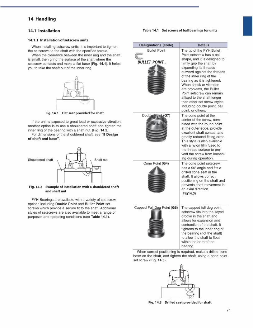
14 Handling
14.1 Installation
14.1.1 Installation of setscrew units
When installing setscrew units, it is important to tighten the setscrews to the shaft with the specified torque.
When the clearance between the inner ring and the shaft is small, then grind the surface of the shaft where the setscrew contacts and make a flat base (Fig. 14.1). It helps you to take the shaft out of the inner ring.
Fig. 14.1 Flat seat provided for shaft
If the unit is exposed to great load or excessive vibration,
another option is to use a shouldered shaft and tighten the inner ring of the bearing with a shaft nut. (Fig. 14.2)
For dimensions of the shouldered shaft, see “9 Design of shaft and base”.
Table 14.1 Set screws of ball bearings for units
Shouldered shaft Shaft nut
Fig. 14.2 Example of installation with a shouldered shaft and shaft nut
FYH Bearings are available with a variety of set screw
options including Double Point and Bullet Point set screws which provide a secure fit to the shaft. Additional styles of setscrews are also available to meet a range of purposes and operating conditions (see Table 14.1).
When correct positioning is required, make a drilled cone base on the shaft, and tighten the shaft, using a cone point set screw (Fig. 14.3).
Fig. 14.3 Drilled seat provided for shaft
71
90 °
Designations (code) Details
Bullet Point
BULLET POINT
The tip of the FYH Bullet Point setscrew has a ball shape, and it is designed to firmly grip the shaft by expanding its threads outward against the threads of the inner ring of the bearing as it is tightened. When shock or vibration are problems, the Bullet Point setscrew can remain affixed to the shaft longer than other set screw styles including double point, ball point, or others.
Double Point (G7)
The cone point at the center of the screw, com- bined with the round point at the outer edge, provide excellent shaft contact and greatly reduced fitting error. This style is also available with a nylon film fused to the thread surface to pre- vent the screw from loosen- ing during operation.
Cone Point (G4) The cone point setscrew has a 90º angle and fits a drilled cone seat in the shaft. It allows correct positioning on the shaft and prevents shaft movement in an axial direction. (Fig14.3)
Capped Full Dog Point (G6) The capped full dog point setscrew fits into the keyed groove in the shaft and allows for expansion and contraction of the shaft. It tightens to the inner ring of the bearing (not the shaft) to allow the shaft to float within the bore of the bearing.
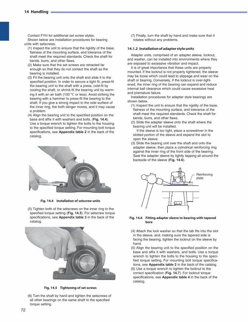
14 Handling
Contact FYH for additional set screw styles. Shown below are installation procedures for bearing
units with setscrews. (1) Inspect the unit to ensure that the rigidity of the base,
flatness of the mounting surface, and tolerance of the shaft meet the required standards. Check the shaft for bends, burrs, and other flaws.
(2) Make sure that the set screws are retracted far enough so that they do not contact the shaft as the bearing is installed.
(3) Fit the bearing unit onto the shaft and slide it to the specified position. In order to secure a tight fit, press-fit the bearing unit to the shaft with a press, cold-fit by cooling the shaft, or shrink-fit the bearing unit by warm- ing it with an air bath (100 ºC or less). Avoid striking the bearing with a hammer to press-fit the bearing to the shaft. If you give a strong impact to the side surface of the inner ring, the both slinger moves, and it may cause a problem.
(4) Align the bearing unit to the specified position on the base and affix it with washers and bolts. (Fig. 14.4). Use a torque wrench to tighten the bolts to the housing to the specified torque setting. For mounting bolt torque specifications, see Appendix table 2 in the back of the catalog.
Fig. 14.4 Installation of setscrew units
(5) Tighten both of the setscrews on the inner ring to the specified torque setting (Fig. 14.5). For setscrew torque specifications, see Appendix table 3 in the back of the catalog.
Fig. 14.5 Tightening of set screws
(7) Finally, turn the shaft by hand and make sure that it
rotates without any problems.
14.1.2 Installation of adapter style units
Adapter units, comprised of an adapter sleeve, locknut, and washer, can be installed into environments where they are exposed to excessive vibration and impact.
It is of great importance that these units are properly mounted. If the locknut is not properly tightened, the sleeve may be loose which could lead to slippage and wear on the shaft or bearing. Conversely, if the locknut is over-tight- ened, the inner ring of the bearing can expand and reduce internal ball clearance which could cause excessive heat and premature failure.
Installation procedures for adapter style bearings are shown below.
(1) Inspect the unit to ensure that the rigidity of the base, flatness of the mounting surface, and tolerance of the shaft meet the required standards. Check the shaft for bends, burrs, and other flaws.
(2) Slide the adapter sleeve onto the shaft where the bearing unit will be installed.
If the sleeve is too tight, place a screwdriver in the slotted portion of the sleeve and expand the slot to open the sleeve.
(3) Slide the bearing unit over the shaft and onto the adapter sleeve, then place a cylindrical reinforcing ring against the inner ring of the front side of the bearing. Seat the adapter sleeve by lightly tapping all around the backside of the sleeve (Fig. 14.6).
Reinforcing plate
Fig. 14.6 Fitting adapter sleeve to bearing with tapered bore
(4) Attach the lock washer so that the tab fits into the slot
in the sleeve, and, making sure the tapered side is facing the bearing, tighten the locknut on the sleeve by hand.
(5) Align the bearing unit to the specified position on the base and affix it with washers, and bolts. Use a torque wrench to tighten the bolts to the housing to the speci- fied torque setting. For mounting bolt torque specifica- tions, see Appendix table 2 in the back of the catalog.
(6) Use a torque wrench to tighten the locknut to the correct specification (Fig. 14.7). For locknut torque specifications, see Appendix table 4 in the back of the catalog.
(6) Turn the shaft by hand and tighten the setscrews of all other bearings on the same shaft to the specified torque setting.
72
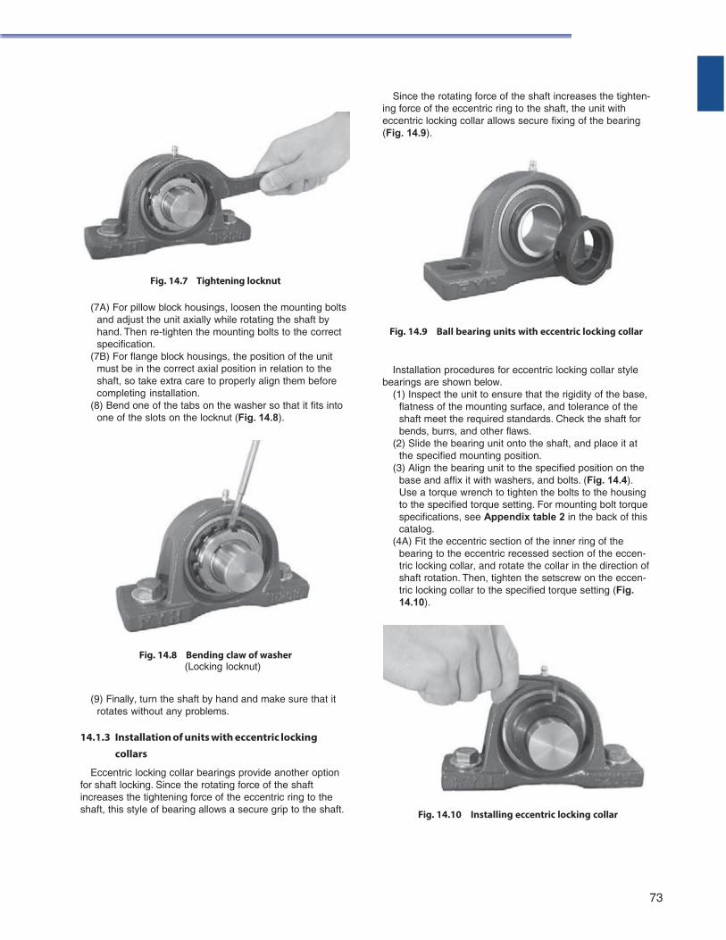
Fig. 14.7 Tightening locknut
(7A) For pillow block housings, loosen the mounting bolts and adjust the unit axially while rotating the shaft by hand. Then re-tighten the mounting bolts to the correct specification.
(7B) For flange block housings, the position of the unit must be in the correct axial position in relation to the shaft, so take extra care to properly align them before completing installation.
(8) Bend one of the tabs on the washer so that it fits into one of the slots on the locknut (Fig. 14.8).
Fig. 14.8 Bending claw of washer (Locking locknut)
(9) Finally, turn the shaft by hand and make sure that it rotates without any problems.
14.1.3 Installation of units with eccentric locking
collars
Eccentric locking collar bearings provide another option for shaft locking. Since the rotating force of the shaft increases the tightening force of the eccentric ring to the shaft, this style of bearing allows a secure grip to the shaft.
Since the rotating force of the shaft increases the tighten-
ing force of the eccentric ring to the shaft, the unit with eccentric locking collar allows secure fixing of the bearing (Fig. 14.9).
Fig. 14.9 Ball bearing units with eccentric locking collar
Installation procedures for eccentric locking collar style bearings are shown below.
(1) Inspect the unit to ensure that the rigidity of the base, flatness of the mounting surface, and tolerance of the shaft meet the required standards. Check the shaft for bends, burrs, and other flaws.
(2) Slide the bearing unit onto the shaft, and place it at the specified mounting position.
(3) Align the bearing unit to the specified position on the base and affix it with washers, and bolts. (Fig. 14.4). Use a torque wrench to tighten the bolts to the housing to the specified torque setting. For mounting bolt torque specifications, see Appendix table 2 in the back of this catalog.
(4A) Fit the eccentric section of the inner ring of the bearing to the eccentric recessed section of the eccen- tric locking collar, and rotate the collar in the direction of shaft rotation. Then, tighten the setscrew on the eccen- tric locking collar to the specified torque setting (Fig. 14.10).
Fig. 14.10 Installing eccentric locking collar
73
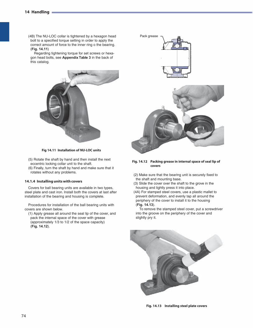
14 Handling
(4B) The NU-LOC collar is tightened by a hexagon head
bolt to a specified torque setting in order to apply the correct amount of force to the inner ring o the bearing. (Fig. 14.11)
Regarding tightening torque for set screws or hexa- gon head bolts, see Appendix Table 3 in the back of this catalog.
Pack grease
Fig 14.11 Installation of NU-LOC units
(5) Rotate the shaft by hand and then install the next
eccentric locking collar unit to the shaft. (6) Finally, turn the shaft by hand and make sure that it
rotates without any problems.
14.1.4 Installing units with covers
Covers for ball bearing units are available in two types, steel plate and cast iron. Install both the covers at last after installation of the bearing and housing is complete.
Procedures for installation of the ball bearing units with
covers are shown below. (1) Apply grease all around the seal lip of the cover, and
pack the internal space of the cover with grease (approximately 1/3 to 1/2 of the space capacity) (Fig. 14.12).
Fig. 14.12 Packing grease in internal space of seal lip of covers
(2) Make sure that the bearing unit is securely fixed to
the shaft and mounting base. (3) Slide the cover over the shaft to the grove in the
housing and lightly press it into place. (4A) For stamped steel covers, use a plastic mallet to
prevent deformation, and evenly tap all around the periphery of the cover to install it to the housing (Fig. 14.13).
To remove the stamped steel cover, put a screwdriver into the groove on the periphery of the cover and slightly pry it.
Fig. 14.13 Installing steel plate covers
74
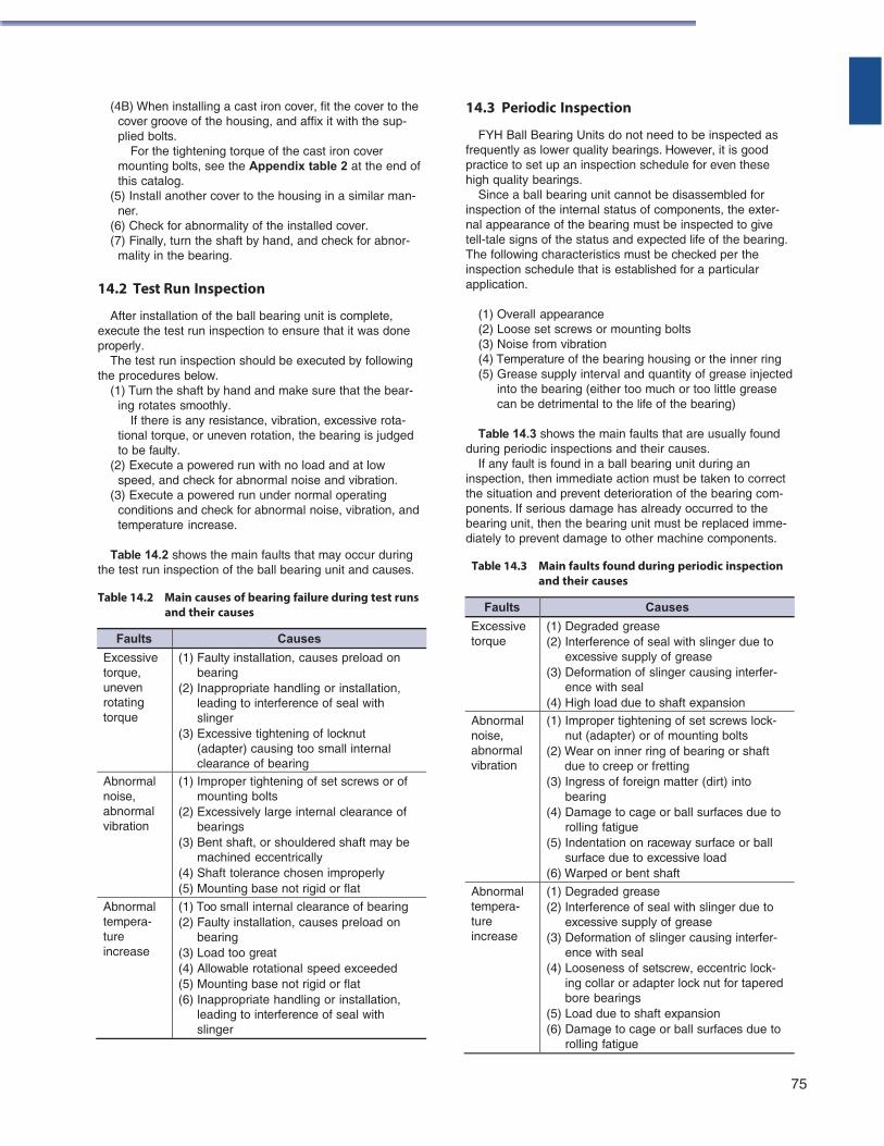
(4B) When installing a cast iron cover, fit the cover to the cover groove of the housing, and affix it with the sup- plied bolts.
For the tightening torque of the cast iron cover mounting bolts, see the Appendix table 2 at the end of this catalog.
(5) Install another cover to the housing in a similar man- ner.
(6) Check for abnormality of the installed cover. (7) Finally, turn the shaft by hand, and check for abnor-
mality in the bearing.
14.2 Test Run Inspection
After installation of the ball bearing unit is complete, execute the test run inspection to ensure that it was done properly.
The test run inspection should be executed by following the procedures below.
(1) Turn the shaft by hand and make sure that the bear- ing rotates smoothly.
If there is any resistance, vibration, excessive rota- tional torque, or uneven rotation, the bearing is judged to be faulty.
(2) Execute a powered run with no load and at low speed, and check for abnormal noise and vibration.
(3) Execute a powered run under normal operating conditions and check for abnormal noise, vibration, and temperature increase.
Table 14.2 shows the main faults that may occur during
the test run inspection of the ball bearing unit and causes.
Table 14.2 Main causes of bearing failure during test runs and their causes
14.3 Periodic Inspection
FYH Ball Bearing Units do not need to be inspected as frequently as lower quality bearings. However, it is good practice to set up an inspection schedule for even these high quality bearings.
Since a ball bearing unit cannot be disassembled for inspection of the internal status of components, the exter- nal appearance of the bearing must be inspected to give tell-tale signs of the status and expected life of the bearing. The following characteristics must be checked per the inspection schedule that is established for a particular application.
(1) Overall appearance (2) Loose set screws or mounting bolts (3) Noise from vibration (4) Temperature of the bearing housing or the inner ring (5) Grease supply interval and quantity of grease injected
into the bearing (either too much or too little grease can be detrimental to the life of the bearing)
Table 14.3 shows the main faults that are usually found
during periodic inspections and their causes. If any fault is found in a ball bearing unit during an
inspection, then immediate action must be taken to correct the situation and prevent deterioration of the bearing com- ponents. If serious damage has already occurred to the bearing unit, then the bearing unit must be replaced imme- diately to prevent damage to other machine components.
Table 14.3 Main faults found during periodic inspection
and their causes
Faults Causes
Excessive torque, uneven rotating torque
(1) Faulty installation, causes preload on bearing
(2) Inappropriate handling or installation, leading to interference of seal with slinger
(3) Excessive tightening of locknut (adapter) causing too small internal clearance of bearing
Abnormal noise, abnormal vibration
(1) Improper tightening of set screws or of mounting bolts
(2) Excessively large internal clearance of bearings
(3) Bent shaft, or shouldered shaft may be machined eccentrically
(4) Shaft tolerance chosen improperly (5) Mounting base not rigid or flat
Abnormal tempera- ture increase
(1) Too small internal clearance of bearing (2) Faulty installation, causes preload on
bearing (3) Load too great (4) Allowable rotational speed exceeded (5) Mounting base not rigid or flat (6) Inappropriate handling or installation,
leading to interference of seal with slinger
75
Faults Causes
Excessive torque
(1) Degraded grease (2) Interference of seal with slinger due to
excessive supply of grease (3) Deformation of slinger causing interfer-
ence with seal (4) High load due to shaft expansion
Abnormal noise, abnormal vibration
(1) Improper tightening of set screws lock- nut (adapter) or of mounting bolts
(2) Wear on inner ring of bearing or shaft due to creep or fretting
(3) Ingress of foreign matter (dirt) into bearing
(4) Damage to cage or ball surfaces due to rolling fatigue
(5) Indentation on raceway surface or ball surface due to excessive load
(6) Warped or bent shaft
Abnormal tempera- ture increase
(1) Degraded grease (2) Interference of seal with slinger due to
excessive supply of grease (3) Deformation of slinger causing interfer-
ence with seal (4) Looseness of setscrew, eccentric lock-
ing collar or adapter lock nut for tapered bore bearings
(5) Load due to shaft expansion (6) Damage to cage or ball surfaces due to
rolling fatigue
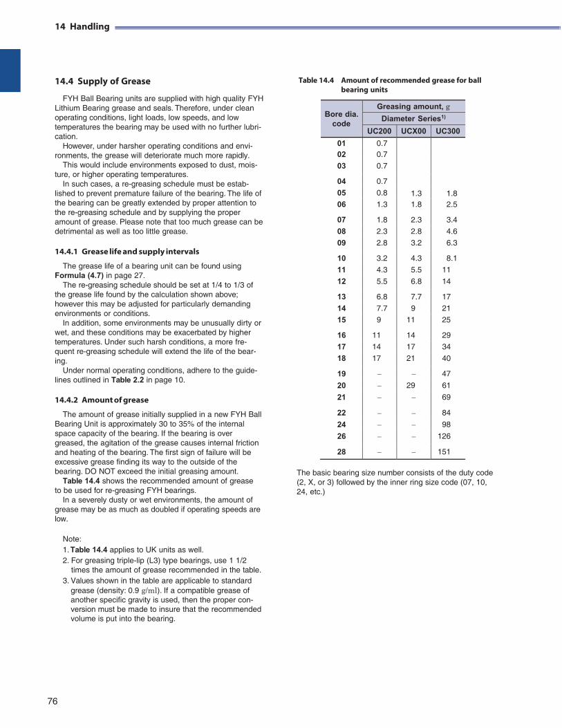
14 Handling
14.4 Supply of Grease
FYH Ball Bearing units are supplied with high quality FYH Lithium Bearing grease and seals. Therefore, under clean operating conditions, light loads, low speeds, and low temperatures the bearing may be used with no further lubri- cation.
However, under harsher operating conditions and envi- ronments, the grease will deteriorate much more rapidly.
This would include environments exposed to dust, mois- ture, or higher operating temperatures.
In such cases, a re-greasing schedule must be estab- lished to prevent premature failure of the bearing. The life of the bearing can be greatly extended by proper attention to the re-greasing schedule and by supplying the proper amount of grease. Please note that too much grease can be detrimental as well as too little grease.
14.4.1 Grease life and supply intervals
The grease life of a bearing unit can be found using Formula (4.7) in page 27.
The re-greasing schedule should be set at 1/4 to 1/3 of the grease life found by the calculation shown above; however this may be adjusted for particularly demanding environments or conditions.
In addition, some environments may be unusually dirty or wet, and these conditions may be exacerbated by higher temperatures. Under such harsh conditions, a more fre- quent re-greasing schedule will extend the life of the bear- ing.
Under normal operating conditions, adhere to the guide- lines outlined in Table 2.2 in page 10.
14.4.2 Amount of grease
The amount of grease initially supplied in a new FYH Ball Bearing Unit is approximately 30 to 35% of the internal space capacity of the bearing. If the bearing is over greased, the agitation of the grease causes internal friction and heating of the bearing. The first sign of failure will be excessive grease finding its way to the outside of the bearing. DO NOT exceed the initial greasing amount.
Table 14.4 shows the recommended amount of grease to be used for re-greasing FYH bearings.
In a severely dusty or wet environments, the amount of grease may be as much as doubled if operating speeds are low.
Note: 1. Table 14.4 applies to UK units as well. 2. For greasing triple-lip (L3) type bearings, use 1 1/2
times the amount of grease recommended in the table. 3. Values shown in the table are applicable to standard
grease (density: 0.9 g/ml). If a compatible grease of another specific gravity is used, then the proper con- version must be made to insure that the recommended volume is put into the bearing.
Table 14.4 Amount of recommended grease for ball
bearing units
Bore dia.
code
Greasing amount, g
Diameter Series1)
UC200 UCX00 UC300
01 0.7
1.3
1.8
02 0.7
03 0.7
04 0.7
05 0.8
06 1.3 1.8 2.5
07 1.8 2.3 3.4
08 2.3 2.8 4.6
09 2.8 3.2 6.3
10 3.2 4.3 8.1
11 4.3 5.5 11
12 5.5 6.8 14
13 6.8 7.7 17
14 7.7 9 21
15 9 11 25
16 11 14 29
17 14 17 34
18 17 21 40
19 47
20 29 61
21 69
22 84
24 98
26 126
28 151
The basic bearing size number consists of the duty code (2, X, or 3) followed by the inner ring size code (07, 10, 24, etc.)
76
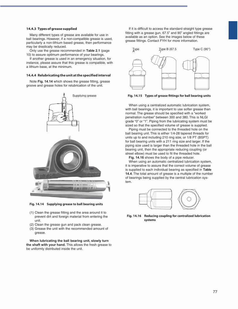
14.4.3 Types of grease supplied
Many different types of grease are available for use in ball bearings. However, if a non-compatible grease is used, particularly a non-lithium based grease, then performance may be drastically reduced.
If it is difficult to access the standard straight type grease fitting with a grease gun, 67.5º and 90º angled fittings are available as an option. See the images below of these grease fittings. Contact FYH for more information.
Only use the grease recommended in Table 2.1 (page 10) to assure optimum performance of your bearings.
If another grease is used in an emergency situation, for instance, please assure that this grease is compatible, with a lithium base, at the minimum.
14.4.4 Relubricating the unit at the specified interval
Note Fig. 14.14 which shows the grease fitting, grease groove and grease holes for relubrication of the unit.
Type A
Type B (67.5 º)
Type C (90 º)
Fig. 14.15 Types of grease fittings for ball bearing units
When using a centralized automatic lubrication system, with ball bearings, it is important to use softer grease than normal. The grease should be specified with a “worked penetration number” between 300 and 380. This is NLGI grade “0” or “1”. Piping from the lubricating system must be sized so that the specified volume of grease is supplied.
Piping must be connected to the threaded hole on the ball bearing unit. This is either 1/4-28 tapered threads for units up to and including 210 ring size, or 1/8 PT (BSPT) for ball bearing units with a 211 ring size and larger. If the piping size used is larger than the threaded hole in the ball bearing unit, then the appropriate reducing coupling (or street elbow) must be used to fit the threaded hole.
Fig. 14.16 shows the body of a pipe reducer. When using an automatic centralized lubrication system,
it is imperative to assure that the correct volume of grease is supplied to each individual bearing as specified in Table 14.4. The total amount of grease is a multiple of the number of bearings being supplied by the central lubrication sys- tem.
Fig. 14.14 Supplying grease to ball bearing units
(1) Clean the grease fitting and the area around it to prevent dirt and foreign material from entering the unit.
(2) Clean the grease gun and pack clean grease. (3) Grease the unit with the recommended amount of
grease.
When lubricating the ball bearing unit, slowly turn the shaft with your hand. This allows the fresh grease to be uniformly distributed inside the unit.
Fig. 14.16 Reducing coupling for centralized lubrication
systems
77
Supplying grease
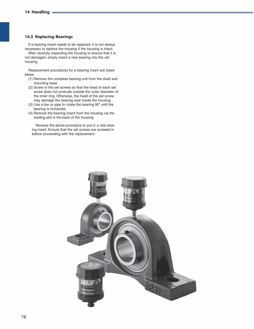
14 Handling
14.5 Replacing Bearings
If a bearing insert needs to be replaced, it is not always necessary to replace the housing if the housing is intact.
After carefully inspecting the housing to ensure that it is not damaged, simply insert a new bearing into the old housing.
Replacement procedures for a bearing insert are listed
below. (1) Remove the complete bearing unit from the shaft and
mounting base. (2) Screw in the set screws so that the head of each set
screw does not protrude outside the outer diameter of the inner ring. Otherwise, the head of the set screw may damage the bearing seat inside the housing.
(3) Use a bar or pipe to rotate the bearing 90º until the bearing is horizontal.
(4) Remove the bearing insert from the housing via the loading slot in the back of the housing.
Reverse the above procedure to put in a new bear-
ing insert. Ensure that the set screws are screwed in before proceeding with the replacement.
78
15 Dimensional Tables for
Ball Bearing Units
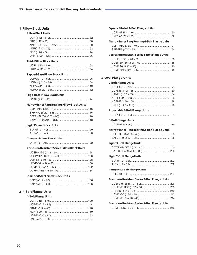
15 Dimensional Tables for Ball Bearing Units (contents)
1 Pillow Block Units Pillow Block Units
UCP (d 12 ~ 140) ....................................................... 82 NAP (d 12 ~ 75) ......................................................... 88 NAP-E (d 1 3/16 ~ 2 15/16) ............................................. 90 NAPK (d 12 ~ 75) ....................................................... 92 NCP (d 20 ~ 60) ......................................................... 94 UKP (d1 20 ~ 125) ...................................................... 96
Thick Pillow Block Units UCIP (d 40 ~ 140) .................................................... 102 UKIP (d1 35 ~ 125) ................................................... 104
Tapped-Base Pillow Block Units UCPA (d 12 ~ 50) ..................................................... 106 UCPAN (d 20 ~ 35) .................................................. 108 NCPA (d 20 ~ 50) ..................................................... 110 NCPAN (d 20 ~ 35) .................................................. 112
High-Base Pillow Block Units UCPH (d 12 ~ 50) .................................................... 114
Narrow Inner Ring Bearing Pillow Block Units SBP-RKP8 (d 20 ~ 40)............................................. 116 SAP-FP9 (d 20 ~ 55) ............................................... 116 SBPAN-RKP8 (d 20 ~ 35) ........................................ 118 SAPAN-FP9 (d 20 ~ 35) ........................................... 118
Light Pillow Block Units BLP (d 12 ~ 40)........................................................ 120 ALP (d 12 ~ 40)........................................................ 120
Compact Pillow Block Units UP (d 10 ~ 30) ......................................................... 122
Corrosion Resistant Series Pillow Block Units UCSP-H1S6 (d 12 ~ 60) .......................................... 124 UCSPA-H1S6 (d 12 ~ 40) ........................................ 126 USP-S6 (d 10 ~ 30) ................................................. 128 UCVP-S6 (d 20 ~ 50) ............................................... 130 UCVP-ES7 (d 20 ~ 50) ............................................ 132 UCVPAN-ES7 (d 20 ~ 35) ........................................ 134
Stamped Steel Pillow Block Units SBPP (d 12 ~ 30) ..................................................... 136 SAPP (d 12 ~ 30) ..................................................... 136
2 4-Bolt Flange Units 4-Bolt Flange Units
UCF (d 12 ~ 140) ..................................................... 138 UCF-E (d 12 ~ 85) ................................................... 144 NANF (d 12 ~ 60) ..................................................... 148 NCF (d 20 ~ 60) ....................................................... 150 NCF-E (d 20 ~ 60) ................................................... 152 UKF (d1 20 ~ 125) .................................................... 154
Square Piloted 4-Bolt Flange Units UCFS (d 25 ~ 140) ................................................... 160 UKFS (d1 20 ~ 125) .................................................. 162
Narrow Inner Ring Bearing 4-Bolt Flange Units SBF-RKP8 (d 20 ~ 40) ............................................. 164 SAF-FP9 (d 20 ~ 55) ................................................ 164
Corrosion Resistant Series 4-Bolt Flange Units UCSF-H1S6 (d 20 ~ 60) ........................................... 166 UCSF-EH1S6 (d 20 ~ 60) ........................................ 168 UCVF-S6 (d 20 ~ 40) ............................................... 170 UCVF-ES7 (d 20 ~ 40) ............................................. 172
3 Oval Flange Units 2- Bolt Flange Units
UCFL (d 12 ~ 120) ................................................... 174 UCFL-E (d 12 ~ 85) .................................................. 180 NANFL (d 12 ~ 55) ................................................... 184 NCFL (d 20 ~ 60) ..................................................... 186 NCFL-E (d 20 ~ 60) .................................................. 188 UKFL (d1 20 ~ 110) .................................................. 190
Adjustable 2-Bolt Flange Units UCFA (d 12 ~ 55) ..................................................... 194
3- Bolt Flange Units UCFB (d 12 ~ 50) ..................................................... 196
Narrow Inner Ring Bearing 2-Bolt Flange Units SBFL-RKP8 (d 20 ~ 40) ........................................... 198 SAFL-FP9 (d 20 ~ 55) .............................................. 198
Light 3-Bolt Flange Units SBTFD-H4RKP8 (d 12 ~ 35) .................................... 200 SATFD-FH4P9 (d 12 ~ 35) ....................................... 200
Light 2-Bolt Flange Units BLF (d 12 ~ 35) ........................................................ 202 ALF (d 12 ~ 35) ........................................................ 202
Compact 2-Bolt Flange Units UFL (d 8 ~ 30) .......................................................... 204
Corrosion Resistant Series 2-Bolt Flange Units UCSFL-H1S6 (d 12 ~ 50) ......................................... 206 UCSFL-EH1S6 (d 12 ~ 50) ...................................... 208 USFL-S6 (d 10 ~ 30) ................................................ 210 UCVFL-S6 (d 20 ~ 40) ............................................. 212 UCVFL-ES7 (d 20 ~ 40) ........................................... 214
Corrosion Resistant Series 3-Bolt Flange Units UCVFB-ES7 (d 20 ~ 35) .......................................... 216
80
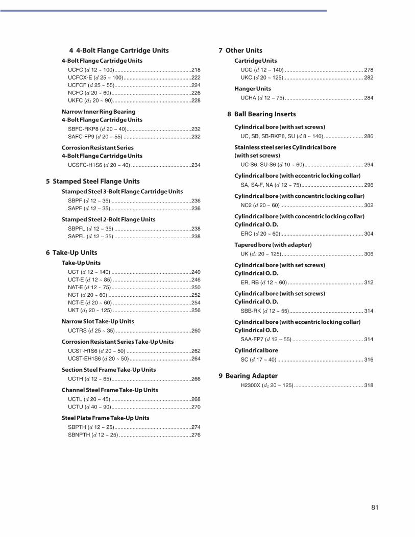
4 4-Bolt Flange Cartridge Units 4- Bolt Flange Cartridge Units
UCFC (d 12 ~ 100) ................................................... 218 UCFCX-E (d 25 ~ 100) ............................................. 222 UCFCF (d 25 ~ 55)................................................... 224 NCFC (d 20 ~ 60) ..................................................... 226 UKFC (d1 20 ~ 90) .................................................... 228
Narrow Inner Ring Bearing 4-Bolt Flange Cartridge Units
SBFC-RKP8 (d 20 ~ 40)........................................... 232 SAFC-FP9 (d 20 ~ 55) ............................................. 232
Corrosion Resistant Series 4-Bolt Flange Cartridge Units
UCSFC-H1S6 (d 20 ~ 40) ........................................ 234
5 Stamped Steel Flange Units Stamped Steel 3-Bolt Flange Cartridge Units
SBPF (d 12 ~ 35) ..................................................... 236 SAPF (d 12 ~ 35) ..................................................... 236
Stamped Steel 2-Bolt Flange Units SBPFL (d 12 ~ 35) ................................................... 238 SAPFL (d 12 ~ 35) ................................................... 238
6 Take-Up Units Take-Up Units
UCT (d 12 ~ 140) ..................................................... 240 UCT-E (d 12 ~ 85) .................................................... 246 NAT-E (d 12 ~ 75) ..................................................... 250 NCT (d 20 ~ 60) ....................................................... 252 NCT-E (d 20 ~ 60) .................................................... 254 UKT (d1 20 ~ 125) .................................................... 256
Narrow Slot Take-Up Units UCTRS (d 25 ~ 35) .................................................. 260
Corrosion Resistant Series Take-Up Units UCST-H1S6 (d 20 ~ 50) ........................................... 262 UCST-EH1S6 (d 20 ~ 50) ......................................... 264
Section Steel Frame Take-Up Units UCTH (d 12 ~ 65) ..................................................... 266
Channel Steel Frame Take-Up Units UCTL (d 20 ~ 45) ..................................................... 268 UCTU (d 40 ~ 90) ..................................................... 270
Steel Plate Frame Take-Up Units SBPTH (d 12 ~ 25) ................................................... 274 SBNPTH (d 12 ~ 25) ................................................ 276
7 Other Units Cartridge Units
UCC (d 12 ~ 140) .................................................... 278 UKC (d 20 ~ 125)..................................................... 282
Hanger Units UCHA (d 12 ~ 75) .................................................... 284
8 Ball Bearing Inserts
Cylindrical bore (with set screws) UC, SB, SB-RKP8, SU (d 8 ~ 140) .......................... 286
Stainless steel series Cylindrical bore (with set screws)
UC-S6, SU-S6 (d 10 ~ 60) ....................................... 294
Cylindrical bore (with eccentric locking collar) SA, SA-F, NA (d 12 ~ 75) ......................................... 296
Cylindrical bore (with concentric locking collar) NC2 (d 20 ~ 60) ....................................................... 302
Cylindrical bore (with concentric locking collar) Cylindrical O. D.
ERC (d 20 ~ 60)....................................................... 304
Tapered bore (with adapter) UK (d1 20 ~ 125) ...................................................... 306
Cylindrical bore (with set screws) Cylindrical O. D.
ER, RB (d 12 ~ 60) .................................................. 312
Cylindrical bore (with set screws) Cylindrical O. D.
SBB-RK (d 12 ~ 55) ................................................. 314
Cylindrical bore (with eccentric locking collar) Cylindrical O. D.
SAA-FP7 (d 12 ~ 55) ............................................... 314
Cylindrical bore SC (d 17 ~ 40) ......................................................... 316
9 Bearing Adapter H2300X (d1 20 ~ 125) .............................................. 318
81
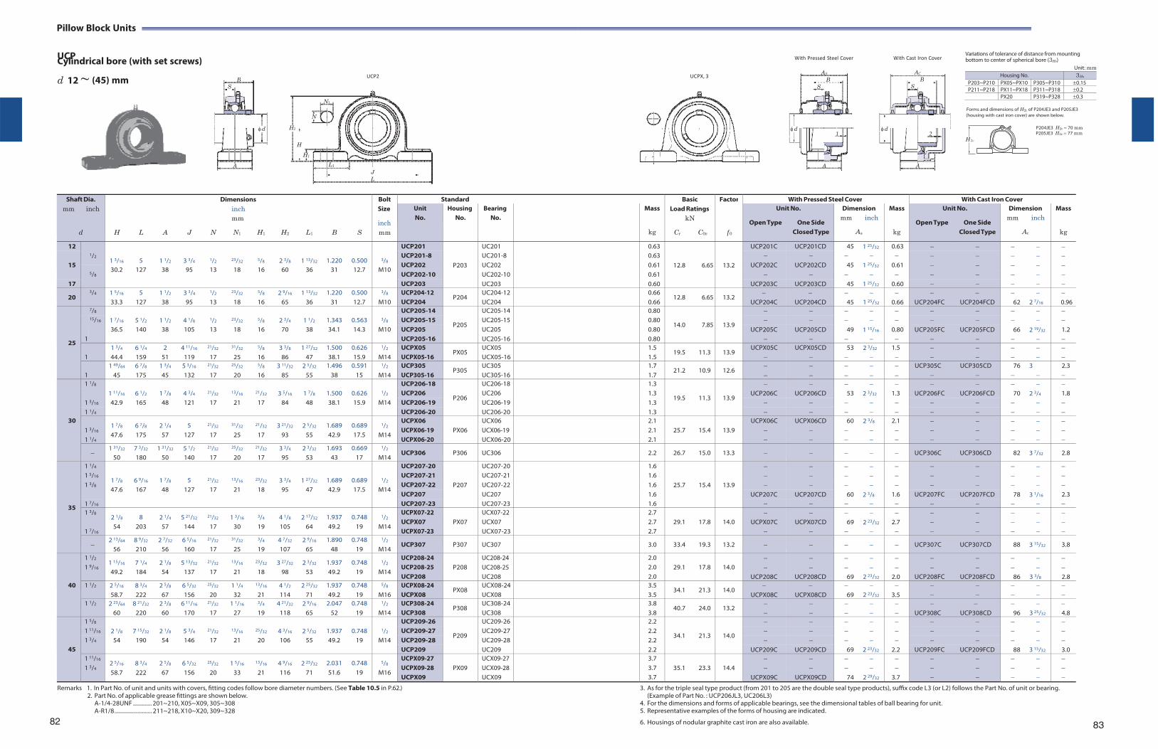
AS
B S
d1
A
AC
BS
d2
A
H 2c
Pillow Block Units
UCP Cylindrical bore (with set screws)
With Pressed Steel Cover
With Cast Iron Cover Variations of tolerance of distance from mounting bottom to center of spherical bore (3Hs)
d 12 ~
(45) mm
UCP2
UCPX, 3
Unit: mm
N1
Forms and dimensions of H2c of P204JE3 and P205JE3
N (housing with cast iron cover) are shown below.
H2 P204JE3 H2c 70 mm P205JE3 H2c 77 mm
H
H1
L1
J L
Shaft Dia.
mm inch
d
H
L
A
J
N
Dimensions inch mm
N1 H1
H2
L1
B
S
Bolt Size
inch mm
Standard BasicLoad Ratings
kN
Cr C0r
Factor
f 0
With Pressed Steel Cover With Cast Iron CoverUnit No.
Housing No.
Bearing No.
Mass
kg
Unit No.
Open Type One Side Closed Type
Dimension mm inch
As
Mass
kg
Unit No.
Open Type One Side Closed Type
Dimension mm inch
Ac
Mass
kg
12 1/2
1 3/16
5
1 1/2
3 3/4
1/2
23/32
5/8
2 3/8
1 13/32
1.220
0.500
3/8
UCP201
P203
UC201 0.63
12.8
6.65
13.2
UCP201C UCP201CD 45 1 25/32 0.63
15
UCP201-8 UC201-8 0.63 UCP202 UC202 0.61 UCP202C UCP202CD 45 1 25/32 0.61
5/8 30.2 127 38 95 13 18 16 60 36 31 12.7 M10
UCP202-10 UC202-10 0.61 17 UCP203 UC203 0.60 UCP203C UCP203CD 45 1 25/32 0.60
20 3/4 1 5/16
33.3 5
127 1 1/2
38 3 3/4
95
1/2
13
23/32
18
5/8
16 2 9/16
65 1 13/32
36 1.220
31 0.500 12.7
3/8
M10 UCP204-12 UCP204
P204 UC204-12UC204
0.66 0.66
12.8 6.65 13.2
UCP204C
UCP204CD 45
1 25/32
0.66
UCP204FC
UCP204FCD
62
2 7/16
0.96
25
7/8 1 7/16
5 1/2
1 1/2
4 1/8
1/2
23/32
5/8
2 3/4
1 1/2
1.343
0.563
3/8
UCP205-14
P205
UC205-14 0.80
14.0
7.85
13.9
15/16 UCP205-15 UC205-15 0.80 36.5 140 38 105 13 18 16 70 38 34.1 14.3 M10 UCP205 UC205 0.80 UCP205C UCP205CD 49 1 15/16 0.80 UCP205FC UCP205FCD 66 2 19/32 1.2
1 UCP205-16 UC205-16 0.80
1 1 3/4
44.4 6 1/4
159 2
51 4 11/16
119
21/32
17
31/32
25
5/8
16 3 3/8
86 1 27/32
47 1.500 38.1
0.626 15.9
1/2
M14 UCPX05 UCPX05-16
PX05 UCX05 UCX05-16
1.5 1.5
19.5 11.3 13.9 UCPX05C
UCPX05CD
53
2 3/32
1.5
1
1 49/64
45 6 7/8
175 1 3/4
45 5 3/16
132
21/32
17
25/32
20
5/8
16 3 11/32
85 2 5/32
55 1.496
38 0.591
15
1/2
M14 UCP305 UCP305-16
P305 UC305 UC305-16
1.7 1.7
21.2 10.9 12.6
UCP305C
UCP305CD
76
3
2.3
30
1 1/8 1 11/16
6 1/2
1 7/8
4 3/4
21/32
13/16
21/32
3 5/16
1 7/8
1.500
0.626
1/2
UCP206-18
P206
UC206-18 1.3
19.5
11.3
13.9
1 3/16
UCP206 UC206 1.3 UCP206C UCP206CD 53 2 3/32 1.3 UCP206FC UCP206FCD 70 2 3/4 1.8 42.9 165 48 121 17 21 17 84 48 38.1 15.9 M14 UCP206-19 UC206-19 1.3
1 1/4 UCP206-20 UC206-20 1.3
1 3/16
1 1/4
1 7/8
47.6 6 7/8
175 2 1/4
57 5
127
21/32
17
31/32
25
21/32
17 3 21/32
93 2 5/32
55 1.689 42.9
0.689 17.5
1/2
M14
UCPX06 UCPX06-19 UCPX06-20
PX06
UCX06 UCX06-19 UCX06-20
2.1 2.1 2.1
25.7
15.4
13.9
UCPX06C
UCPX06CD
60
2 3/8
2.1
1 31/32
50 7 3/32
180 1 31/32
50 5 1/2
140
21/32
17
25/32
20
21/32
17 3 3/4
95 2 3/32
53 1.693
43 0.669
17
1/2
M14 UCP306 P306 UC306 2.2 26.7 15.0 13.3 UCP306C UCP306CD 82 3 7/32 2.8
35
1 1/4
1 7/8
6 9/16
1 7/8
5
21/32
13/16
23/32
3 3/4
1 27/32
1.689
0.689
1/2
UCP207-20
P207
UC207-20 1.6
25.7
15.4
13.9
1 5/16 UCP207-21 UC207-21 1.6 1 3/8 UCP207-22 UC207-22 1.6
47.6 167 48 127 17 21 18 95 47 42.9 17.5 M14 UCP207 UC207 1.6 UCP207C UCP207CD 60 2 3/8 1.6 UCP207FC UCP207FCD 78 3 1/16 2.3
1 7/16 UCP207-23 UC207-23 1.6 1 3/8
1 7/16
2 1/8
54 8
203 2 1/4
57 5 21/32
144
21/32
17 1 3/16
30
3/4
19 4 1/8
105 2 17/32
64 1.937 49.2
0.748 19
1/2
M14
UCPX07-22 UCPX07 UCPX07-23
PX07
UCX07-22 UCX07 UCX07-23
2.7 2.7 2.7
29.1
17.8
14.0
UCPX07C
UCPX07CD
69
2 23/32
2.7
2 13/64
56 8 9/32
210 2 7/32
56 6 5/16
160
21/32
17
31/32
25
3/4
19 4 7/32
107 2 9/16
65 1.890
48 0.748
19
1/2
M14 UCP307 P307 UC307 3.0 33.4 19.3 13.2 UCP307C UCP307CD 88 3 15/32 3.8
40
1 1/2
1 9/16 1 15/16
49.2 7 1/4
184 2 1/8
54 5 13/32
137
21/32
17
13/16
21
23/32
18 3 27/32
98 2 3/32
53 1.937 49.2
0.748 19
1/2
M14
UCP208-24 UCP208-25 UCP208
P208
UC208-24 UC208-25 UC208
2.0 2.0 2.0
29.1
17.8
14.0
UCP208C
UCP208CD
69
2 23/32
2.0
UCP208FC
UCP208FCD
86
3 3/8
2.8
1 1/2 2 5/16
58.7 8 3/4
222 2 5/8
67 6 5/32
156
25/32
20 1 1/4
32
13/16
21 4 1/2
114 2 25/32
71 1.937 49.2
0.748 19
5/8
M16 UCPX08-24 UCPX08
PX08 UCX08-24UCX08
3.5 3.5
34.1 21.3 14.0
UCPX08C
UCPX08CD 69
2 23/32
3.5
1 1/2 2 23/64
60 8 21/32
220 2 3/8
60 6 11/16
170
21/32
17 1 1/16
27
3/4
19 4 21/32
118 2 9/16
65 2.047
52 0.748
19
1/2
M14 UCP308-24 UCP308
P308 UC308-24UC308
3.8 3.8
40.7 24.0 13.2
UCP308C
UCP308CD
96
3 25/32
4.8
45
1 5/8 2 1/8
7 15/32
2 1/8
5 3/4
21/32
13/16
25/32
4 3/16
2 5/32
1.937
0.748
1/2
UCP209-26
P209
UC209-26 2.2
34.1
21.3
14.0
1 11/16 UCP209-27 UC209-27 2.2 1 3/4 54 190 54 146 17 21 20 106 55 49.2 19 M14 UCP209-28 UC209-28 2.2
UCP209 UC209 2.2 UCP209C UCP209CD 69 2 23/32 2.2 UCP209FC UCP209FCD 88 3 15/32 3.0 1 11/16
1 3/4 2 5/16
58.7 8 3/4
222 2 5/8
67 6 5/32
156
25/32
20 1 5/16
33
13/16
21 4 9/16
116 2 25/32
71 2.031 51.6
0.748 19
5/8
M16
UCPX09-27 UCPX09-28 UCPX09
PX09
UCX09-27 UCX09-28 UCX09
3.7 3.7 3.7
35.1
23.3
14.4
UCPX09C
UCPX09CD
74
2 29/32
3.7
Remarks 1. In Part No. of unit and units with covers, fitting codes follow bore diameter numbers. (See Table 10.5 in P.62.) 2. Part No. of applicable grease fittings are shown below.
A-1/4-28UNF ............. 201~210, X05~X09, 305~308 A-R1/8 .......................... 211~218, X10~X20, 309~328
82
3. As for the triple seal type product (from 201 to 205 are the double seal type products), suffix code L3 (or L2) follows the Part No. of unit or bearing. (Example of Part No. : UCP206JL3, UC206L3)
4. For the dimensions and forms of applicable bearings, see the dimensional tables of ball bearing for unit. 5. Representative examples of the forms of housing are indicated.
6. Housings of nodular graphite cast iron are also available. 83
B S
d
A
Housing No. 3Hs
P203~P210 PX05~PX10 P305~P310 0.15P211~P218 PX11~PX18 P311~P318 0.2
PX20 P319~P328 0.3
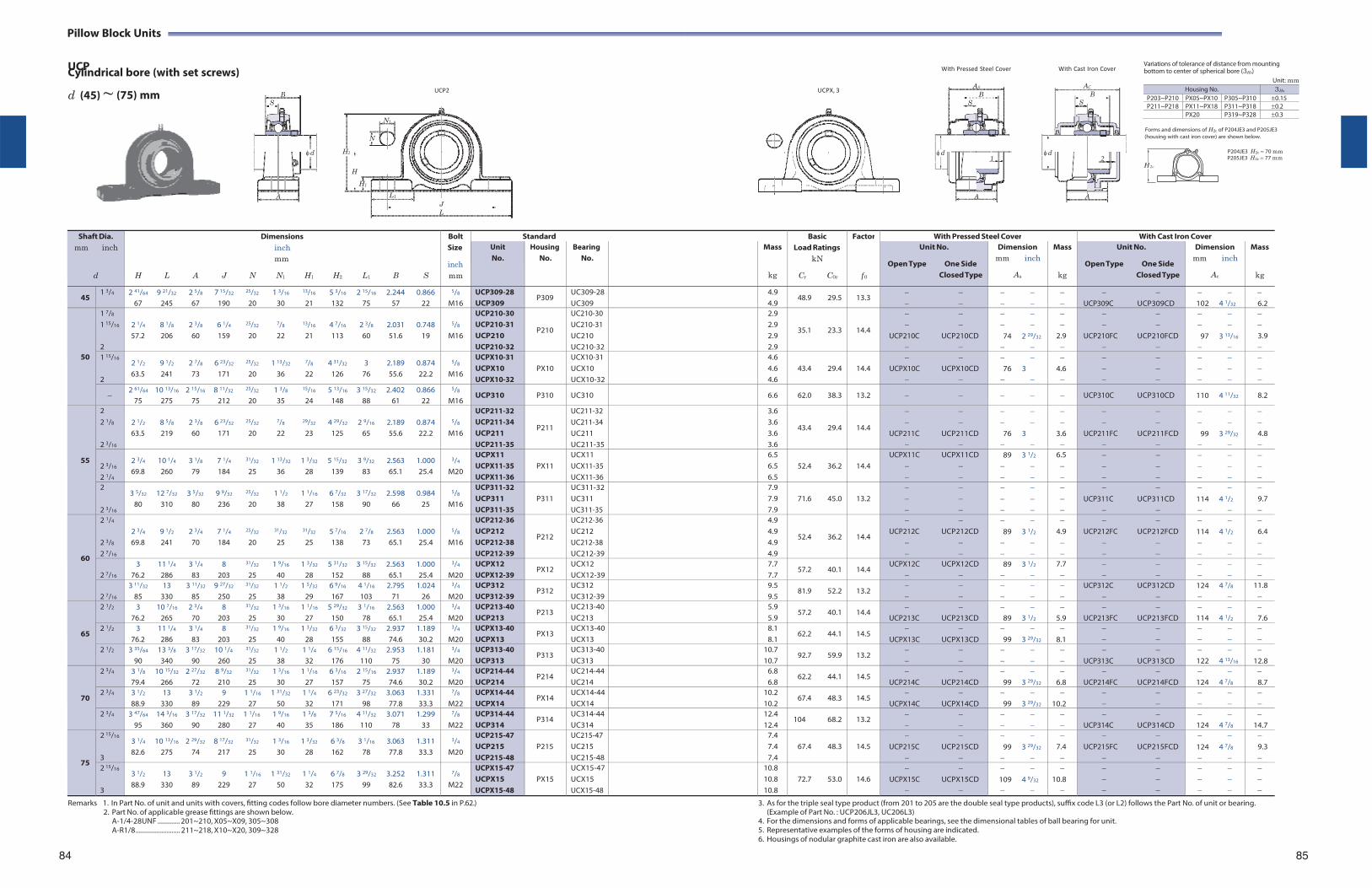
AS
B S
d1
A
AC
BS
d2
A
H 2c
Pillow Block Units
UCP Cylindrical bore (with set screws)
With Pressed Steel Cover
With Cast Iron Cover Variations of tolerance of distance from mounting bottom to center of spherical bore (3Hs)
d (45) ~
(75) mm
UCP2
UCPX, 3
Unit: mm
N1
Forms and dimensions of H2c of P204JE3 and P205JE3
N (housing with cast iron cover) are shown below.
H2 P204JE3 H2c 70 mm P205JE3 H2c 77 mm
H
H1
L1
J L
Shaft Dia.
mm inch
d
Dimensions inch mm
H L A J N N1 H1 H2 L1 B S
Bolt Size
inch mm
Standard BasicLoad Ratings
kN
Cr C0r
Factor
f 0
With Pressed Steel Cover With Cast Iron Cover Unit No.
Housing No.
Bearing No.
Mass
kg
Unit No.
Open Type One Side Closed Type
Dimension mm inch
As
Mass
kg
Unit No.
Open Type One Side Closed Type
Dimension mm inch
Ac
Mass
kg
45 1 3/4 2 41/64 9 21/32 2 5/8 7 15/32 25/32 1 3/16 13/16 5 3/16 2 15/16 2.244 0.866
67 245 67 190 20 30 21 132 75 57 22
5/8
M16 UCP309-28 UCP309
P309 UC309-28UC309
4.9 4.9
48.9 29.5 13.3
UCP309C UCP309CD
102 4 1/32
6.2
50
1 7/8
1 15/16
2
2 1/4 8 1/8 2 3/8 6 1/4 25/32 7/8 13/16 4 7/16 2 3/8 2.031 0.748 57.2 206 60 159 20 22 21 113 60 51.6 19
5/8
M16
UCP210-30 UCP210-31 UCP210 UCP210-32
P210
UC210-30 UC210-31 UC210 UC210-32
2.9 2.9 2.9 2.9
35.1 23.3
14.4
UCP210C UCP210CD
74 2 29/32
2.9
UCP210FC UCP210FCD
97 3 13/16
3.9
1 15/16
2
2 1/2 9 1/2 2 7/8 6 23/32 25/32 1 13/32 7/8 4 31/32 3 2.189 0.874 63.5 241 73 171 20 36 22 126 76 55.6 22.2
5/8
M16
UCPX10-31 UCPX10 UCPX10-32
PX10
UCX10-31 UCX10 UCX10-32
4.6 4.6 4.6
43.4 29.4
14.4
UCPX10C UCPX10CD
76 3
4.6
2 61/64 10 13/16 2 15/16 8 11/32 25/32 1 3/8 15/16 5 13/16 3 15/32 2.402 0.866
75 275 75 212 20 35 24 148 88 61 22
5/8
M16 UCP310 P310 UC310 6.6 62.0 38.3 13.2 UCP310C UCP310CD 110 4 11/32 8.2
55
2 2 1/8
2 3/16
2 1/2 8 5/8 2 3/8 6 23/32 25/32 7/8 29/32 4 29/32 2 9/16 2.189 0.874 63.5 219 60 171 20 22 23 125 65 55.6 22.2
5/8
M16
UCP211-32 UCP211-34 UCP211 UCP211-35
P211
UC211-32 UC211-34 UC211 UC211-35
3.6 3.6 3.6 3.6
43.4 29.4
14.4
UCP211C UCP211CD
76 3
3.6
UCP211FC UCP211FCD
99 3 29/32
4.8
2 3/16
2 1/4
2 3/4 10 1/4 3 1/8 7 1/4 31/32 1 13/32 1 3/32 5 15/32 3 9/32 2.563 1.000 69.8 260 79 184 25 36 28 139 83 65.1 25.4
3/4
M20
UCPX11 UCPX11-35 UCPX11-36
PX11
UCX11 UCX11-35 UCX11-36
6.5 6.5 6.5
52.4 36.2
14.4
UCPX11C UCPX11CD
89 3 1/2
6.5
2
2 3/16
3 5/32 12 7/32 3 5/32 9 9/32 25/32 1 1/2 1 1/16 6 7/32 3 17/32 2.598 0.984 80 310 80 236 20 38 27 158 90 66 25
5/8
M16
UCP311-32 UCP311 UCP311-35
P311
UC311-32UC311 UC311-35
7.9 7.9 7.9
71.6 45.0
13.2
UCP311C UCP311CD
114 4 1/2
9.7
60
2 1/4
2 3/8
2 7/16
2 3/4 9 1/2 2 3/4 7 1/4 25/32 31/32 31/32 5 7/16 2 7/8 2.563 1.000 69.8 241 70 184 20 25 25 138 73 65.1 25.4
5/8
M16
UCP212-36 UCP212 UCP212-38 UCP212-39
P212
UC212-36 UC212 UC212-38 UC212-39
4.9 4.9 4.9 4.9
52.4 36.2
14.4
UCP212C UCP212CD
89 3 1/2
4.9
UCP212FC UCP212FCD
114 4 1/2
6.4
2 7/16
3 11 1/4 3 1/4 8 31/32 1 9/16 1 3/32 5 31/32 3 15/32 2.563 1.000 76.2 286 83 203 25 40 28 152 88 65.1 25.4
3/4
M20 UCPX12 UCPX12-39
PX12 UCX12 UCX12-39
7.7 7.7
57.2 40.1 14.4 UCPX12C UCPX12CD
89 3 1/2
7.7
2 7/16
3 11/32 13 3 11/32 9 27/32 31/32 1 1/2 1 5/32 6 9/16 4 1/16 2.795 1.024 85 330 85 250 25 38 29 167 103 71 26
3/4
M20 UCP312 UCP312-39
P312 UC312 UC312-39
9.5 9.5
81.9 52.2 13.2
UCP312C UCP312CD
124 4 7/8
11.8
65
2 1/2 3 10 7/16 2 3/4 8 31/32 1 3/16 1 1/16 5 29/32 3 1/16 2.563 1.000 76.2 265 70 203 25 30 27 150 78 65.1 25.4
3/4
M20 UCP213-40 UCP213
P213 UC213-40UC213
5.9 5.9
57.2 40.1 14.4
UCP213C UCP213CD 89 3 1/2
5.9
UCP213FC UCP213FCD
114 4 1/2
7.6
2 1/2 3 11 1/4 3 1/4 8 31/32 1 9/16 1 3/32 6 3/32 3 15/32 2.937 1.189 76.2 286 83 203 25 40 28 155 88 74.6 30.2
3/4
M20 UCPX13-40 UCPX13
PX13 UCX13-40UCX13
8.1 8.1
62.2 44.1 14.5
UCPX13C UCPX13CD 99 3 29/32
8.1
2 1/2 3 35/64 13 3/8 3 17/32 10 1/4 31/32 1 1/2 1 1/4 6 15/16 4 11/32 2.953 1.181 90 340 90 260 25 38 32 176 110 75 30
3/4
M20 UCP313-40 UCP313
P313 UC313-40UC313
10.7 10.7
92.7 59.9 13.2
UCP313C UCP313CD
122 4 13/16
12.8
70
2 3/4 3 1/8 10 15/32 2 27/32 8 9/32 31/32 1 3/16 1 1/16 6 3/16 2 15/16 2.937 1.189 79.4 266 72 210 25 30 27 157 75 74.6 30.2
3/4
M20 UCP214-44 UCP214
P214 UC214-44UC214
6.8 6.8
62.2 44.1 14.5
UCP214C UCP214CD 99 3 29/32
6.8
UCP214FC UCP214FCD
124 4 7/8
8.7
2 3/4 3 1/2 13 3 1/2 9 1 1/16 1 31/32 1 1/4 6 23/32 3 27/32 3.063 1.331 88.9 330 89 229 27 50 32 171 98 77.8 33.3
7/8
M22 UCPX14-44 UCPX14
PX14 UCX14-44UCX14
10.2 10.2
67.4 48.3 14.5
UCPX14C UCPX14CD 99 3 29/32
10.2
2 3/4 3 47/64 14 3/16 3 17/32 11 1/32 1 1/16 1 9/16 1 3/8 7 5/16 4 11/32 3.071 1.299 95 360 90 280 27 40 35 186 110 78 33
7/8
M22 UCP314-44 UCP314
P314 UC314-44UC314
12.4 12.4
104 68.2 13.2
UCP314C UCP314CD
124 4 7/8
14.7
75
2 15/16
3
3 1/4 10 13/16 2 29/32 8 17/32 31/32 1 3/16 1 3/32 6 3/8 3 1/16 3.063 1.311 82.6 275 74 217 25 30 28 162 78 77.8 33.3
3/4
M20
UCP215-47 UCP215 UCP215-48
P215
UC215-47 UC215 UC215-48
7.4 7.4 7.4
67.4 48.3
14.5
UCP215C UCP215CD
99 3 29/32
7.4
UCP215FC UCP215FCD
124 4 7/8
9.3
2 15/16
3
3 1/2 13 3 1/2 9 1 1/16 1 31/32 1 1/4 6 7/8 3 29/32 3.252 1.311 88.9 330 89 229 27 50 32 175 99 82.6 33.3
7/8
M22
UCPX15-47 UCPX15 UCPX15-48
PX15
UCX15-47UCX15 UCX15-48
10.8 10.8 10.8
72.7 53.0
14.6
UCPX15C UCPX15CD
109 4 9/32
10.8
Remarks 1. In Part No. of unit and units with covers, fitting codes follow bore diameter numbers. (See Table 10.5 in P.62.) 2. Part No. of applicable grease fittings are shown below.
A-1/4-28UNF ............. 201~210, X05~X09, 305~308 A-R1/8 .......................... 211~218, X10~X20, 309~328
84
3. As for the triple seal type product (from 201 to 205 are the double seal type products), suffix code L3 (or L2) follows the Part No. of unit or bearing. (Example of Part No. : UCP206JL3, UC206L3)
4. For the dimensions and forms of applicable bearings, see the dimensional tables of ball bearing for unit. 5. Representative examples of the forms of housing are indicated. 6. Housings of nodular graphite cast iron are also available.
85
B S
d
A
Housing No. 3Hs
P203~P210 PX05~PX10 P305~P310 0.15P211~P218 PX11~PX18 P311~P318 0.2
PX20 P319~P328 0.3
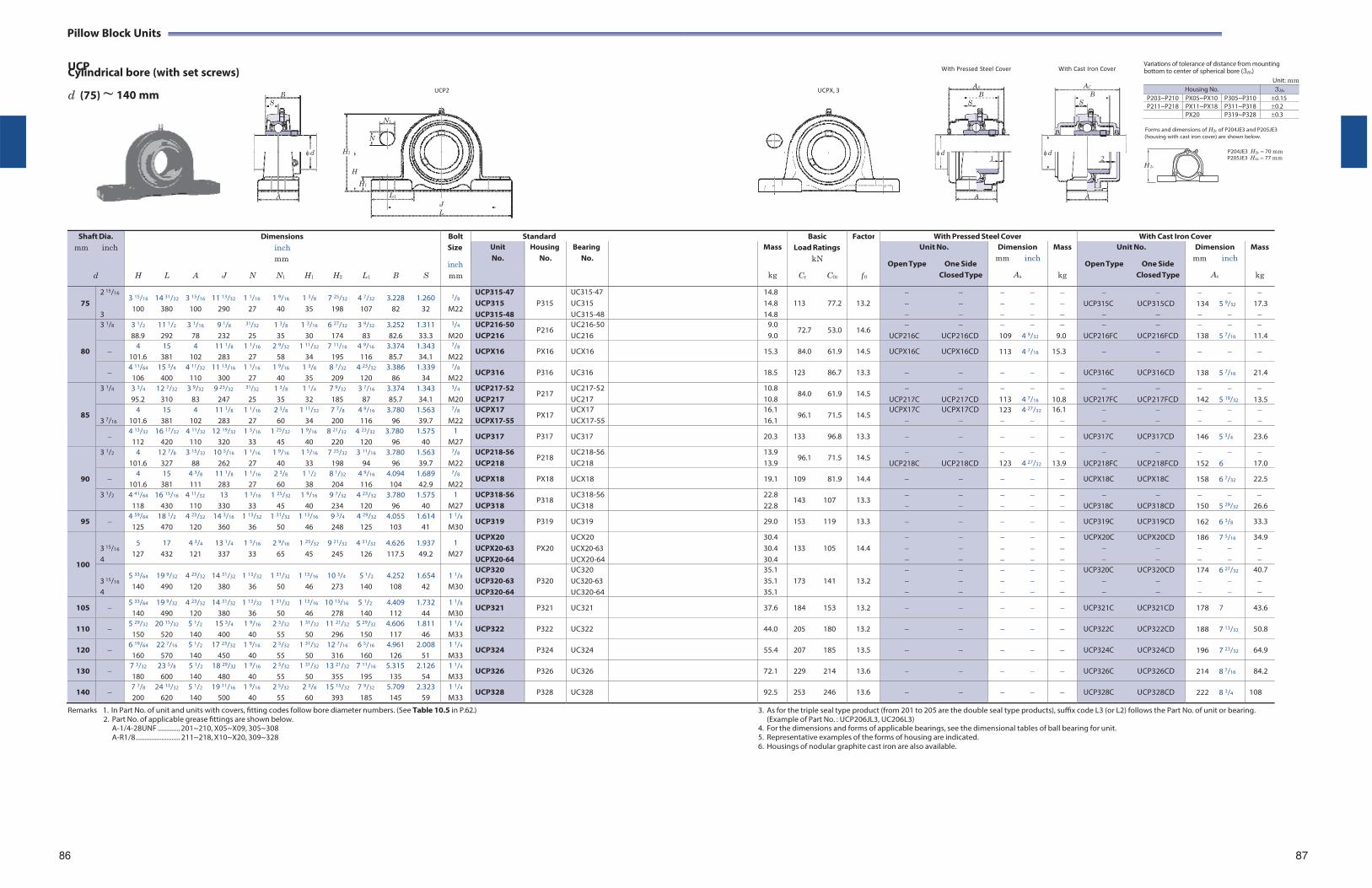
AS
B S
d1
A
AC
BS
d2
A
H 2c
Pillow Block Units
UCP Cylindrical bore (with set screws)
With Pressed Steel Cover
With Cast Iron Cover Variations of tolerance of distance from mounting bottom to center of spherical bore (3Hs)
d (75) ~
140 mm
UCP2
UCPX, 3
Unit: mm
N1
Forms and dimensions of H2c of P204JE3 and P205JE3
N (housing with cast iron cover) are shown below.
H2 P204JE3 H2c 70 mm P205JE3 H2c 77 mm
H
H1
L1
J L
Shaft Dia.
mm inch
d
Dimensions inch mm
H L A J N N1 H1 H2 L1 B S
Bolt Size
inch mm
Standard BasicLoad Ratings
kN
Cr C0r
Factor
f 0
With Pressed Steel Cover With Cast Iron Cover Unit No.
Housing No.
Bearing No.
Mass
kg
Unit No.
Open Type One Side Closed Type
Dimension mm inch
As
Mass
kg
Unit No.
Open Type One Side Closed Type
Dimension mm inch
Ac
Mass
kg
75
2 15/16
3
3 15/16 14 31/32 3 15/16 11 13/32 1 1/16 1 9/16 1 3/8 7 25/32 4 7/32 3.228 1.260 100 380 100 290 27 40 35 198 107 82 32
7/8
M22
UCP315-47 UCP315 UCP315-48
P315
UC315-47 UC315 UC315-48
14.8 14.8 14.8
113 77.2
13.2
UCP315C UCP315CD
134 5 9/32
17.3
80
3 1/8 3 1/2 11 1/2 3 1/16 9 1/8 31/32 1 3/8 1 3/16 6 27/32 3 9/32 3.252 1.311 88.9 292 78 232 25 35 30 174 83 82.6 33.3
3/4
M20 UCP216-50 UCP216
P216 UC216-50UC216
9.0 9.0
72.7 53.0 14.6
UCP216C UCP216CD 109 4 9/32
9.0
UCP216FC UCP216FCD
138 5 7/16
11.4
4 15 4 11 1/8 1 1/16 2 9/32 1 11/32 7 11/16 4 9/16 3.374 1.343
101.6 381 102 283 27 58 34 195 116 85.7 34.1
7/8
M22 UCPX16 PX16 UCX16 15.3 84.0 61.9 14.5 UCPX16C UCPX16CD 113 4 7/16 15.3
4 11/64 15 3/4 4 11/32 11 13/16 1 1/16 1 9/16 1 3/8 8 7/32 4 23/32 3.386 1.339
106 400 110 300 27 40 35 209 120 86 34
7/8
M22 UCP316 P316 UC316 18.5 123 86.7 13.3 UCP316C UCP316CD 138 5 7/16 21.4
85
3 1/4 3 3/4 12 7/32 3 9/32 9 23/32 31/32 1 3/8 1 1/4 7 9/32 3 7/16 3.374 1.343 95.2 310 83 247 25 35 32 185 87 85.7 34.1
3/4
M20 UCP217-52 UCP217
P217 UC217-52UC217
10.8 10.8
84.0 61.9 14.5
UCP217C UCP217CD 113 4 7/16
10.8
UCP217FC UCP217FCD
142 5 19/32
13.5
3 7/16
4 15 4 11 1/8 1 1/16 2 3/8 1 11/32 7 7/8 4 9/16 3.780 1.563 101.6 381 102 283 27 60 34 200 116 96 39.7
7/8
M22 UCPX17 UCPX17-55
PX17 UCX17 UCX17-55
16.1 16.1
96.1 71.5 14.5 UCPX17C UCPX17CD
123 4 27/32
16.1
4 13/32 16 17/32 4 11/32 12 19/32 1 5/16 1 25/32 1 9/16 8 21/32 4 23/32 3.780 1.575
112 420 110 320 33 45 40 220 120 96 40 1
M27 UCP317 P317 UC317 20.3 133 96.8 13.3 UCP317C UCP317CD 146 5 3/4 23.6
90
3 1/2 4 12 7/8 3 15/32 10 5/16 1 1/16 1 9/16 1 5/16 7 25/32 3 11/16 3.780 1.563 101.6 327 88 262 27 40 33 198 94 96 39.7
7/8
M22 UCP218-56 UCP218
P218 UC218-56UC218
13.9 13.9
96.1 71.5 14.5
UCP218C UCP218CD 123 4 27/32
13.9
UCP218FC UCP218FCD
152 6
17.0
4 15 4 3/8 11 1/8 1 1/16 2 3/8 1 1/2 8 1/32 4 9/16 4.094 1.689
101.6 381 111 283 27 60 38 204 116 104 42.9
7/8
M22 UCPX18 PX18 UCX18 19.1 109 81.9 14.4 UCPX18C UCPX18C 158 6 7/32 22.5
3 1/2 4 41/64 16 15/16 4 11/32 13 1 5/16 1 25/32 1 9/16 9 7/32 4 23/32 3.780 1.575 118 430 110 330 33 45 40 234 120 96 40
1 M27
UCP318-56 UCP318
P318 UC318-56UC318
22.8 22.8
143 107 13.3
UCP318C UCP318CD
150 5 29/32
26.6
95 4 59/64 18 1/2 4 23/32 14 3/16 1 13/32 1 31/32 1 13/16 9 3/4 4 29/32 4.055 1.614
125 470 120 360 36 50 46 248 125 103 41 1 1/8
M30 UCP319 P319 UC319 29.0 153 119 13.3 UCP319C UCP319CD 162 6 3/8 33.3
100
3 15/16
4
5 17 4 3/4 13 1/4 1 5/16 2 9/16 1 25/32 9 21/32 4 31/32 4.626 1.937 127 432 121 337 33 65 45 245 126 117.5 49.2
1 M27
UCPX20 UCPX20-63 UCPX20-64
PX20
UCX20 UCX20-63 UCX20-64
30.4 30.4 30.4
133 105
14.4
UCPX20C UCPX20CD
186 7 5/16
34.9
3 15/16
4
5 33/64 19 9/32 4 23/32 14 31/32 1 13/32 1 31/32 1 13/16 10 3/4 5 1/2 4.252 1.654 140 490 120 380 36 50 46 273 140 108 42
1 1/8
M30
UCP320 UCP320-63 UCP320-64
P320
UC320 UC320-63 UC320-64
35.1 35.1 35.1
173 141
13.2
UCP320C UCP320CD
174 6 27/32
40.7
105 5 33/64 19 9/32 4 23/32 14 31/32 1 13/32 1 31/32 1 13/16 10 15/16 5 1/2 4.409 1.732
140 490 120 380 36 50 46 278 140 112 44 1 1/8
M30 UCP321 P321 UC321 37.6 184 153 13.2 UCP321C UCP321CD 178 7 43.6
110 5 29/32 20 15/32 5 1/2 15 3/4 1 9/16 2 5/32 1 31/32 11 21/32 5 29/32 4.606 1.811
150 520 140 400 40 55 50 296 150 117 46 1 1/4
M33 UCP322 P322 UC322 44.0 205 180 13.2 UCP322C UCP322CD 188 7 13/32 50.8
120 6 19/64 22 7/16 5 1/2 17 23/32 1 9/16 2 5/32 1 31/32 12 7/16 6 5/16 4.961 2.008
160 570 140 450 40 55 50 316 160 126 51 1 1/4
M33 UCP324 P324 UC324 55.4 207 185 13.5 UCP324C UCP324CD 196 7 23/32 64.9
130 7 3/32 23 5/8 5 1/2 18 29/32 1 9/16 2 5/32 1 31/32 13 21/32 7 11/16 5.315 2.126 180 600 140 480 40 55 50 355 195 135 54
1 1/4
M33 UCP326 P326 UC326 72.1 229 214 13.6 UCP326C UCP326CD 214 8 7/16 84.2
140 7 7/8 24 13/32 5 1/2 19 11/16 1 9/16 2 5/32 2 3/8 15 15/32 7 9/32 5.709 2.323 200 620 140 500 40 55 60 393 185 145 59
1 1/4
M33 UCP328 P328 UC328 92.5 253 246 13.6 UCP328C UCP328CD 222 8 3/4 108
Remarks 1. In Part No. of unit and units with covers, fitting codes follow bore diameter numbers. (See Table 10.5 in P.62.) 2. Part No. of applicable grease fittings are shown below.
A-1/4-28UNF ............. 201~210, X05~X09, 305~308 A-R1/8 .......................... 211~218, X10~X20, 309~328
3. As for the triple seal type product (from 201 to 205 are the double seal type products), suffix code L3 (or L2) follows the Part No. of unit or bearing. (Example of Part No. : UCP206JL3, UC206L3)
4. For the dimensions and forms of applicable bearings, see the dimensional tables of ball bearing for unit. 5. Representative examples of the forms of housing are indicated. 6. Housings of nodular graphite cast iron are also available.
86 87
B S
d
A
Housing No. 3Hs
P203~P210 PX05~PX10 P305~P310 0.15P211~P218 PX11~PX18 P311~P318 0.2
PX20 P319~P328 0.3
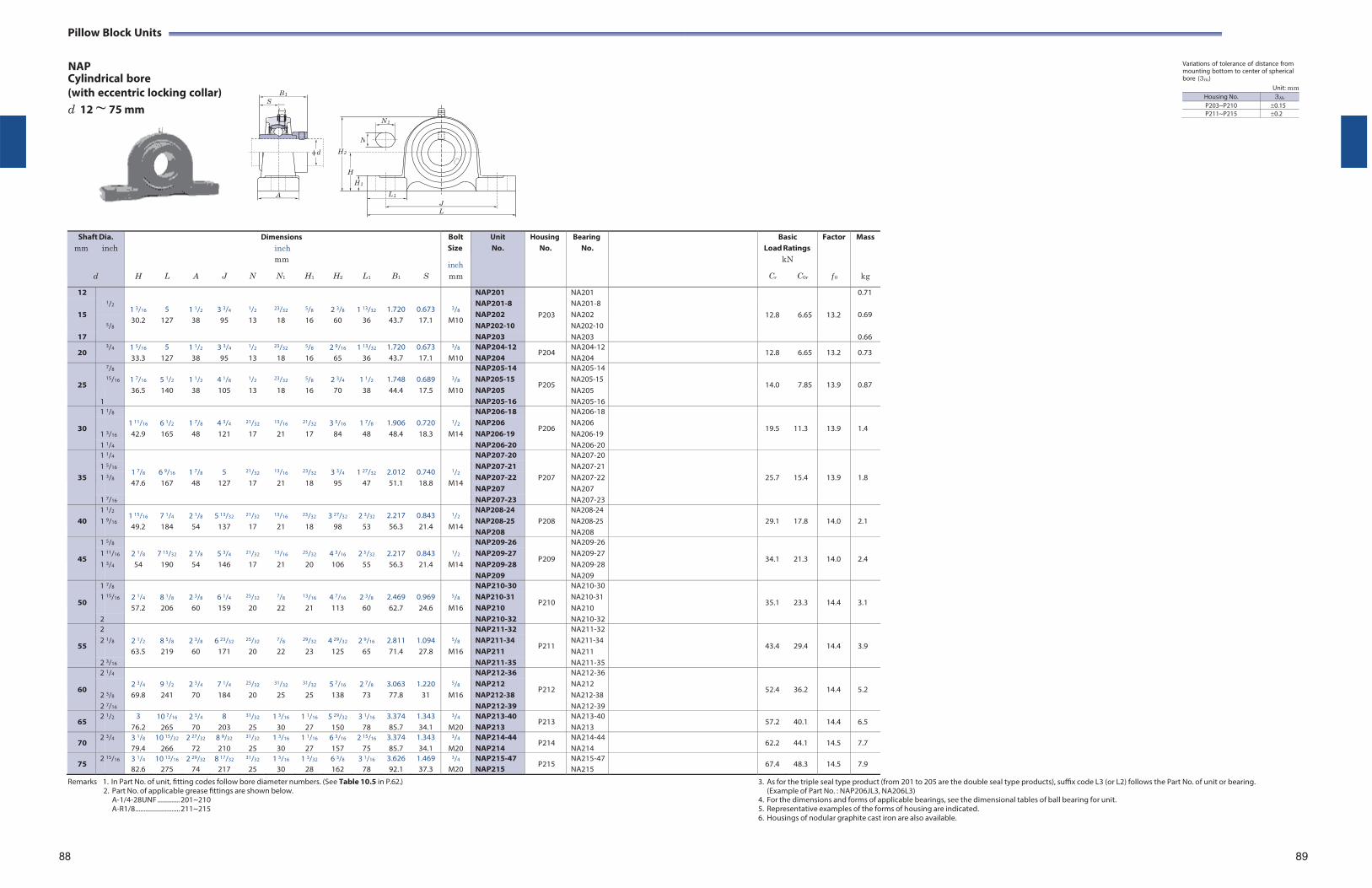
Pillow Block Units
NAP Cylindrical bore
Variations of tolerance of distance from mounting bottom to center of spherical bore (3Hs)
(with eccentric locking collar) d 12 ~ 75 mm
Unit: mm
Shaft Dia. mm inch
d
H
L
A
J
Dimensions inch mm
N N1 H1
H2
L1
B1
S
Bolt Size
inch mm
Unit No.
HousingNo.
BearingNo.
BasicLoad Ratings
kN
Cr C0r
Factor
f 0
Mass
kg
12 1/2
1 3/16
5
1 1/2
3 3/4
1/2
23/32
5/8
2 3/8
1 13/32
1.720
0.673
3/8
NAP201
P203
NA201
12.8
6.65
13.2
0.71
15
NAP201-8 NAP202 NAP202-10
NA201-8 NA202 NA202-10
0.69
5/8 30.2 127 38 95 13 18 16 60 36 43.7 17.1 M10
17 NAP203 NA203 0.66
20 3/4 1 5/16
33.3 5
127 1 1/2
38 3 3/4
95
1/2
13
23/32
18
5/8
16 2 9/16
65 1 13/32
36 1.720 43.7
0.673 17.1
3/8
M10 NAP204-12 NAP204
P204 NA204-12NA204
12.8 6.65 13.2 0.73
25
7/8 1 7/16
5 1/2
1 1/2
4 1/8
1/2
23/32
5/8
2 3/4
1 1/2
1.748
0.689
3/8
NAP205-14
P205
NA205-14
14.0
7.85
13.9
0.87 15/16 NAP205-15 NAP205
NA205-15 NA205 36.5 140 38 105 13 18 16 70 38 44.4 17.5 M10
1 NAP205-16 NA205-16
30
1 1/8 1 11/16
6 1/2
1 7/8
4 3/4
21/32
13/16
21/32
3 5/16
1 7/8
1.906
0.720
1/2
NAP206-18
P206
NA206-18
19.5
11.3
13.9
1.4 1 3/16
NAP206 NAP206-19
NA206 NA206-19 42.9 165 48 121 17 21 17 84 48 48.4 18.3 M14
1 1/4 NAP206-20 NA206-20
35
1 1/4
1 7/8
6 9/16
1 7/8
5
21/32
13/16
23/32
3 3/4
1 27/32
2.012
0.740
1/2
NAP207-20
P207
NA207-20
25.7
15.4
13.9
1.8
1 5/16 NAP207-21 NA207-211 3/8 NAP207-22 NA207-22
47.6 167 48 127 17 21 18 95 47 51.1 18.8 M14 NAP207 NA207
1 7/16 NAP207-23 NA207-23
40 1 1
1/2
9/16 1 15/16
49.2 7 1/4
184 2 1/8
54 5 13/32
137
21/32
17
13/16
21
23/32
18 3 27/32
98 2 3/32
53 2.217 56.3
0.843 21.4
1/2
M14
NAP208-24 NAP208-25 NAP208
P208
NA208-24 NA208-25 NA208
29.1
17.8
14.0
2.1
45
1 5/8 2 1/8
7 15/32
2 1/8
5 3/4
21/32
13/16
25/32
4 3/16
2 5/32
2.217
0.843
1/2
NAP209-26
P209
NA209-26
34.1
21.3
14.0
2.4 1 11/16 NAP209-27 NA209-271 3/4 54 190 54 146 17 21 20 106 55 56.3 21.4 M14 NAP209-28 NA209-28
NAP209 NA209
50
1 7/8 2 1/4
8 1/8
2 3/8
6 1/4
25/32
7/8
13/16
4 7/16
2 3/8
2.469
0.969
5/8
NAP210-30
P210
NA210-30
35.1
23.3
14.4
3.1 1 15/16 NAP210-31
NAP210 NA210-31 NA210 57.2 206 60 159 20 22 21 113 60 62.7 24.6 M16
2 NAP210-32 NA210-32
55
2 2 1/2
8 5/8
2 3/8
6 23/32
25/32
7/8
29/32
4 29/32
2 9/16
2.811
1.094
5/8
NAP211-32
P211
NA211-32
43.4
29.4
14.4
3.9 2 1/8 NAP211-34
NAP211 NA211-34 NA211 63.5 219 60 171 20 22 23 125 65 71.4 27.8 M16
2 3/16 NAP211-35 NA211-35
60
2 1/4 2 3/4
9 1/2
2 3/4
7 1/4
25/32
31/32
31/32
5 7/16
2 7/8
3.063
1.220
5/8
NAP212-36
P212
NA212-36
52.4
36.2
14.4
5.2 2 3/8
NAP212 NAP212-38
NA212 NA212-38 69.8 241 70 184 20 25 25 138 73 77.8 31 M16
2 7/16 NAP212-39 NA212-39
65 2 1/2 3
76.2 10 7/16
265 2 3/4
70 8
203
31/32
25 1 3/16
30 1 1/16
27 5 29/32
150 3 1/16
78 3.374 85.7
1.343 34.1
3/4
M20 NAP213-40 NAP213
P213 NA213-40NA213
57.2 40.1 14.4 6.5
70 2 3/4 3 1/8
79.4 10 15/32
266 2 27/32
72 8 9/32
210
31/32
25 1 3/16
30 1 1/16
27 6 3/16
157 2 15/16
75 3.374 85.7
1.343 34.1
3/4
M20 NAP214-44 NAP214
P214 NA214-44NA214
62.2 44.1 14.5 7.7
75 2 15/16 3 1/4
82.6 10 13/16
275 2 29/32
74 8 17/32
217
31/32
25 1 3/16
30 1 3/32
28 6 3/8
162 3 1/16
78 3.626 92.1
1.469 37.3
3/4
M20 NAP215-47 NAP215
P215 NA215-47NA215
67.4 48.3 14.5 7.9
Remarks 1. In Part No. of unit, fitting codes follow bore diameter numbers. (See Table 10.5 in P.62.) 2. Part No. of applicable grease fittings are shown below.
A-1/4-28UNF ............. 201~210 A-R1/8 .......................... 211~215
3. As for the triple seal type product (from 201 to 205 are the double seal type products), suffix code L3 (or L2) follows the Part No. of unit or bearing. (Example of Part No. : NAP206JL3, NA206L3)
4. For the dimensions and forms of applicable bearings, see the dimensional tables of ball bearing for unit. 5. Representative examples of the forms of housing are indicated. 6. Housings of nodular graphite cast iron are also available.
88 89
B 1
S
d
A L 1
N 1
N
H 2
H
H 1
J L
Housing No. 3Hs
P203~P210 0.15P211~P215 0.2
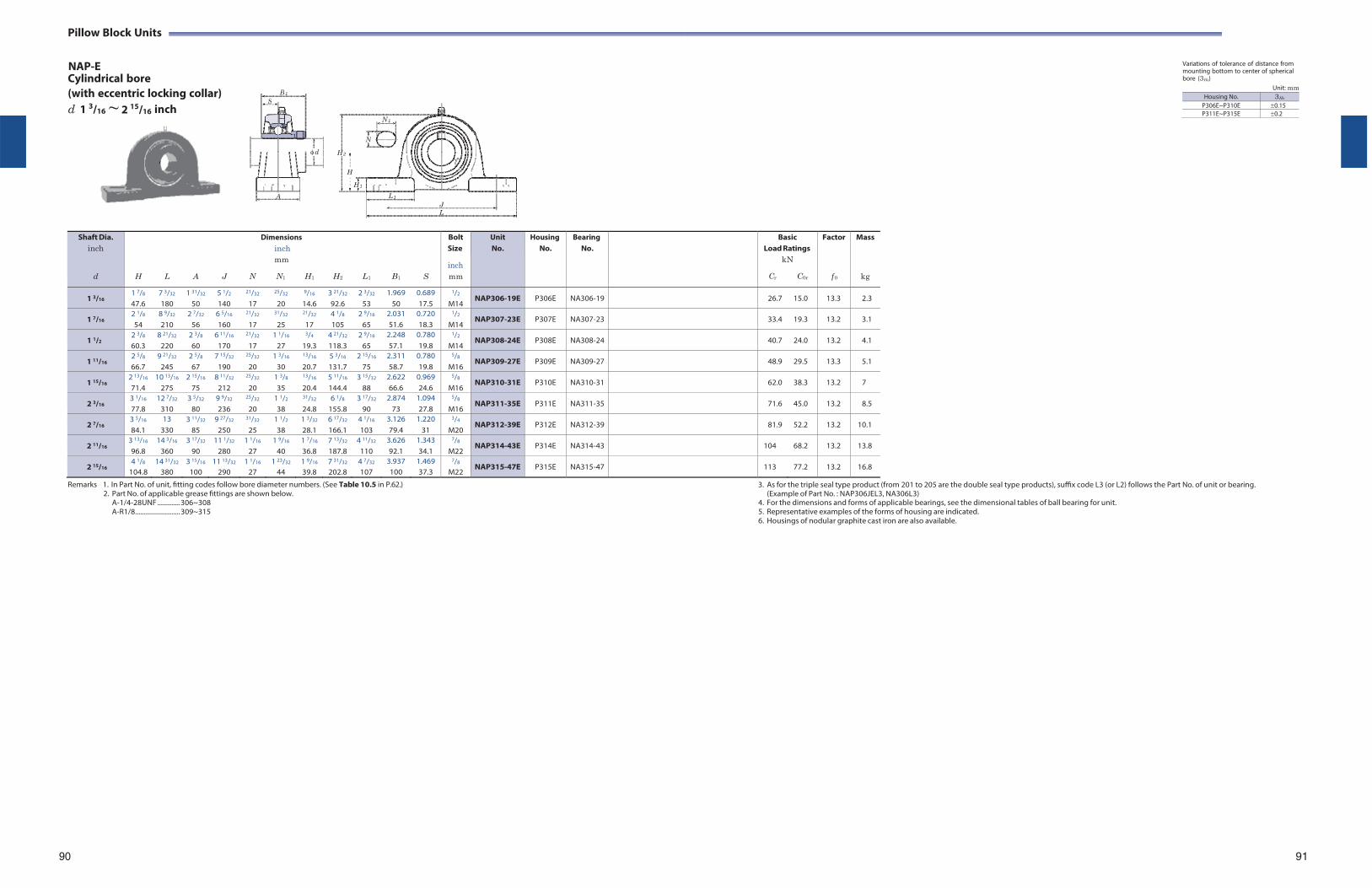
Pillow Block Units
NAP-E Cylindrical bore
Variations of tolerance of distance from mounting bottom to center of spherical bore (3Hs)
(with eccentric locking collar) Unit: mm
d 1 3/16 ~ 2 15/16 inch
Shaft Dia. inch
d
H
L
A
J
Dimensions inch mm
N N1 H1
H2
L1
B1
S
Bolt Size
inch mm
Unit No.
HousingNo.
BearingNo.
BasicLoad Ratings
kN
Cr C0r
Factor
f 0
Mass
kg
1 3/16 1 7/8
47.6 7 3/32
180 1 31/32
50 5 1/2
140
21/32
17
25/32
20
9/16
14.6 3 21/32
92.6 2 3/32
53 1.969
50 0.689 17.5
1/2
M14 NAP306-19E P306E NA306-19 26.7 15.0 13.3 2.3
1 7/16 2 1/8
54 8 9/32
210 2 7/32
56 6 5/16
160
21/32
17
31/32
25
21/32
17 4 1/8
105 2 9/16
65 2.031 51.6
0.720 18.3
1/2
M14 NAP307-23E P307E NA307-23 33.4 19.3 13.2 3.1
1 1/2 2 3/8
60.3 8 21/32
220 2 3/8
60 6 11/16
170
21/32
17 1 1/16
27
3/4
19.3 4 21/32
118.3 2 9/16
65 2.248 57.1
0.780 19.8
1/2
M14 NAP308-24E P308E NA308-24 40.7 24.0 13.2 4.1
1 11/16 2 5/8
66.7 9 21/32
245 2 5/8
67 7 15/32
190
25/32
20 1 3/16
30
13/16
20.7 5 3/16
131.7 2 15/16
75 2.311 58.7
0.780 19.8
5/8
M16 NAP309-27E P309E NA309-27 48.9 29.5 13.3 5.1
1 15/16 2 13/16
71.4 10 13/16
275 2 15/16
75 8 11/32
212
25/32
20 1 3/8
35
13/16
20.4 5 11/16
144.4 3 15/32
88 2.622 66.6
0.969 24.6
5/8
M16 NAP310-31E P310E NA310-31 62.0 38.3 13.2 7
2 3/16 3 1/16
77.8 12 7/32
310 3 5/32
80 9 9/32
236
25/32
20 1 1/2
38
31/32
24.8 6 1/8
155.8 3 17/32
90 2.874
73 1.094 27.8
5/8
M16 NAP311-35E P311E NA311-35 71.6 45.0 13.2 8.5
2 7/16 3 5/16
84.1 13
330 3 11/32
85 9 27/32
250
31/32
25 1 1/2
38 1 3/32
28.1 6 17/32
166.1 4 1/16
103 3.126 79.4
1.220 31
3/4
M20 NAP312-39E P312E NA312-39 81.9 52.2 13.2 10.1
2 11/16 3 13/16
96.8 14 3/16
360 3 17/32
90 11 1/32
280 1 1/16
27 1 9/16
40 1 7/16
36.8 7 13/32
187.8 4 11/32
110 3.626 92.1
1.343 34.1
7/8
M22 NAP314-43E P314E NA314-43 104 68.2 13.2 13.8
2 15/16 4 1/8
104.8 14 31/32
380 3 15/16
100 11 13/32
290 1 1/16
27 1 23/32
44 1 9/16
39.8 7 31/32
202.8 4 7/32
107 3.937 100
1.469 37.3
7/8
M22 NAP315-47E P315E NA315-47 113 77.2 13.2 16.8
Remarks 1. In Part No. of unit, fitting codes follow bore diameter numbers. (See Table 10.5 in P.62.) 2. Part No. of applicable grease fittings are shown below.
A-1/4-28UNF ............. 306~308 A-R1/8 .......................... 309~315
3. As for the triple seal type product (from 201 to 205 are the double seal type products), suffix code L3 (or L2) follows the Part No. of unit or bearing. (Example of Part No. : NAP306JEL3, NA306L3)
4. For the dimensions and forms of applicable bearings, see the dimensional tables of ball bearing for unit. 5. Representative examples of the forms of housing are indicated. 6. Housings of nodular graphite cast iron are also available.
90 91
B 1S
d
A
N 1
N
H 2
H
H 1
L 1
J L
Housing No. 3Hs
P306E~P310E 0.15P311E~P315E 0.2
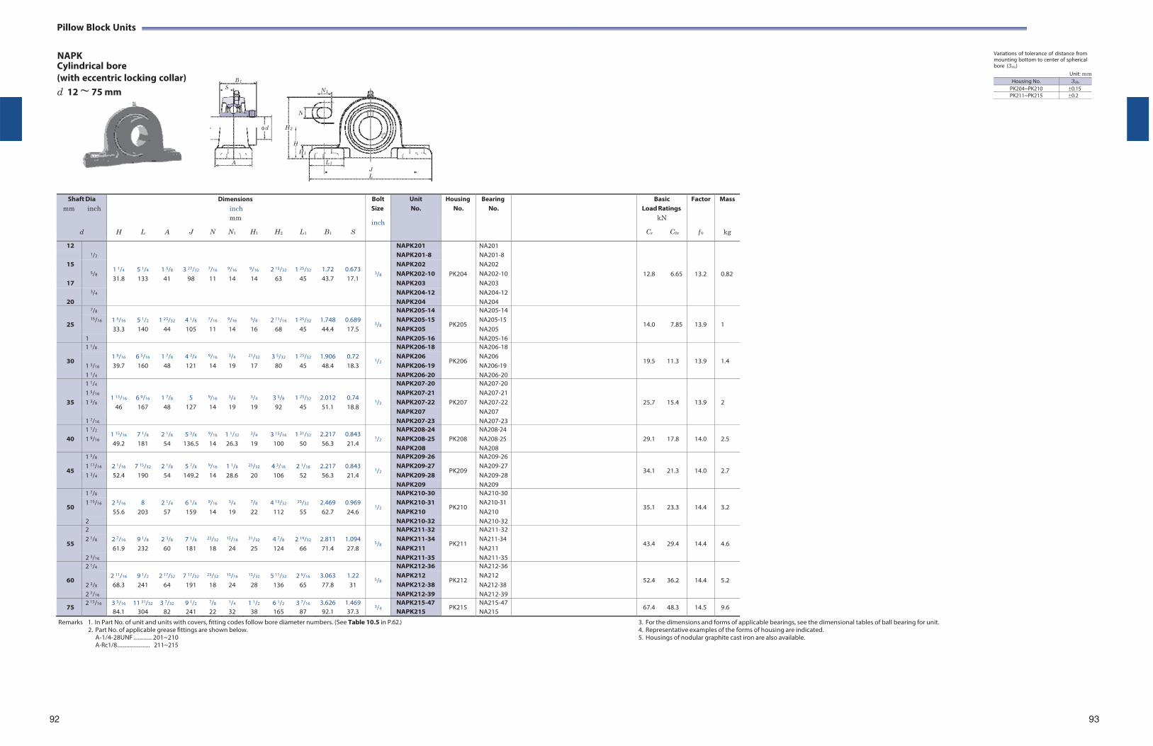
Pillow Block Units
NAPK Cylindrical bore
Variations of tolerance of distance from mounting bottom to center of spherical bore (3Hs)
(with eccentric locking collar) d 12 ~ 75 mm
Unit: mm
Shaft Dia mm inch
d
H
L
A
J
Dimensions inch mm
N N1 H1
H2
L1
B1
S
Bolt Size
inch
Unit No.
HousingNo.
BearingNo.
BasicLoad Ratings
kN
Cr C0r
Factor
f 0
Mass
kg
12 1/2
1 1/4
31.8
5 1/4
133
1 5/8
41
3 27/32
98
7/16
11
9/16
14
9/16
14
2 15/32
63
1 25/32
45
1.72 43.7
0.673 17.1
3/8
NAPK201
PK204
NA201
12.8
6.65
13.2
0.82
NAPK201-8 NA201-8 15
5/8
NAPK202 NA202 NAPK202-10 NA202-10
17 NAPK203 NA203 3/4 NAPK204-12 NA204-12
20 NAPK204 NA204
25
7/8 1 5/16
33.3
5 1/2
140
1 23/32
44
4 1/8
105
7/16
11
9/16
14
5/8
16
2 11/16
68
1 25/32
45
1.748 44.4
0.689 17.5
3/8
NAPK205-14
PK205
NA205-14
14.0
7.85
13.9
1 15/16 NAPK205-15
NAPK205 NA205-15 NA205
1 NAPK205-16 NA205-16
30
1 1/8 1 9/16
39.7
6 5/16
160
1 7/8
48
4 3/4
121
9/16
14
3/4
19
21/32
17
3 5/32
80
1 25/32
45
1.906 48.4
0.72 18.3
1/2
NAPK206-18
PK206
NA206-18
19.5
11.3
13.9
1.4 1 3/16
NAPK206 NAPK206-19
NA206 NA206-19
1 1/4 NAPK206-20 NA206-20
35
1 1/4
1 13/16
46
6 9/16
167
1 7/8
48
5 127
9/16
14
3/4
19
3/4
19
3 5/8
92
1 25/32
45
2.012 51.1
0.74 18.8
1/2
NAPK207-20
PK207
NA207-20
25.7
15.4
13.9
2
1 5/16 NAPK207-21 NA207-211 3/8 NAPK207-22 NA207-22
NAPK207 NA207 1 7/16 NAPK207-23 NA207-23
40
1 1/2
1 9/16 1 15/16
49.2 7 1/8
181 2 1/8
54 5 3/8
136.5
9/16
14 1 1/32
26.3
3/4
19 3 15/16
100 1 31/32
50 2.217 56.3
0.843 21.4
1/2
NAPK208-24 NAPK208-25 NAPK208
PK208
NA208-24 NA208-25 NA208
29.1
17.8
14.0
2.5
45
1 5/8 2 1/16
52.4
7 15/32
190
2 1/8
54
5 7/8
149.2
9/16
14
1 1/8
28.6
25/32
20
4 3/16
106
2 1/16
52
2.217 56.3
0.843 21.4
1/2
NAPK209-26
PK209
NA209-26
34.1
21.3
14.0
2.7 1 11/16 NAPK209-27 NA209-271 3/4 NAPK209-28 NA209-28
NAPK209 NA209
50
1 7/8 2 3/16
55.6
8
203
2 1/4
57
6 1/4
159
9/16
14
3/4
19
7/8
22
4 13/32
112
25/32
55
2.469 62.7
0.969 24.6
1/2
NAPK210-30
PK210
NA210-30
35.1
23.3
14.4
3.2 1 15/16 NAPK210-31
NAPK210 NA210-31 NA210
2 NAPK210-32 NA210-32
55
2 2 7/16
61.9
9 1/8
232
2 3/8
60
7 1/8
181
23/32
18
15/16
24
31/32
25
4 7/8
124
2 19/32
66
2.811 71.4
1.094 27.8
5/8
NAPK211-32
PK211
NA211-32
43.4
29.4
14.4
4.6 2 1/8 NAPK211-34
NAPK211 NA211-34 NA211
2 3/16 NAPK211-35 NA211-35
60
2 1/4 2 11/16
68.3
9 1/2
241
2 17/32
64
7 17/32
191
23/32
18
15/16
24
13/32
28
5 11/32
136
2 9/16
65
3.063 77.8
1.22 31
5/8
NAPK212-36
PK212
NA212-36
52.4
36.2
14.4
5.2 2 3/8
NAPK212 NAPK212-38
NA212 NA212-38
2 7/16 NAPK212-39 NA212-39
75 2 15/16 3 5/16
84.1 11 31/32
304 3 7/32
82 9 1/2
241
7/8
22
1/4
32 1 1/2
38 6 1/2
165 3 7/16
87 3.626 92.1
1.469 37.3
3/4 NAPK215-47 NAPK215
PK215 NA215-47NA215
67.4 48.3 14.5 9.6
Remarks 1. In Part No. of unit and units with covers, fitting codes follow bore diameter numbers. (See Table 10.5 in P.62.) 2. Part No. of applicable grease fittings are shown below.
A-1/4-28UNF ............. 201~210 A-Rc1/8........................ 211~215
3. For the dimensions and forms of applicable bearings, see the dimensional tables of ball bearing for unit. 4. Representative examples of the forms of housing are indicated. 5. Housings of nodular graphite cast iron are also available.
92 93
B 1S
d
A
N 1
N
H 2
HH 1
L 1
J L
Housing No. 3Hs
PK204~PK210 0.15PK211~PK215 0.2
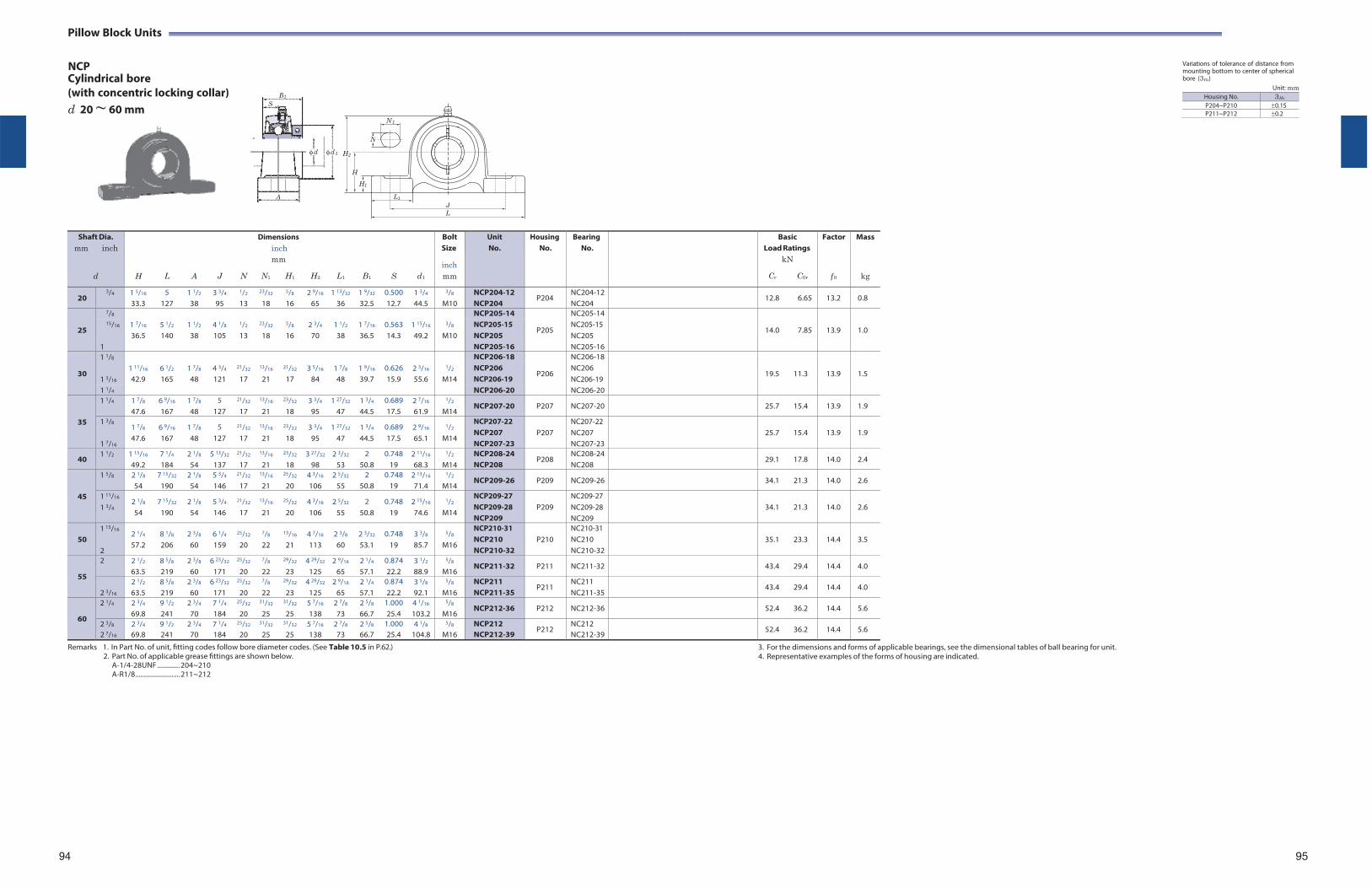
Pillow Block Units
NCP Cylindrical bore
Variations of tolerance of distance from mounting bottom to center of spherical bore (3Hs)
(with concentric locking collar) d 20 ~ 60 mm
Unit: mm
Shaft Dia. mm inch
d
H
L
A
J
N
Dimensions inch mm
N1 H1
H2
L1
B1
S
d1
Bolt Size
inch mm
Unit No.
HousingNo.
BearingNo.
BasicLoad Ratings
kN
Cr C0r
Factor
f 0
Mass
kg
20 3/4 1 5/16
33.3 5
127 1 1/2
38 3 3/4
95
1/2
13
23/32
18
5/8
16 2 9/16
65 1 13/32
36 1 9/32
32.5 0.500 12.7
1 3/4
44.5
3/8
M10 NCP204-12 NCP204
P204 NC204-12NC204
12.8 6.65 13.2 0.8
25
7/8 1 7/16
5 1/2
1 1/2
4 1/8
1/2
23/32
5/8
2 3/4
1 1/2
1 7/16
0.563
1 15/16
3/8
NCP205-14
P205
NC205-14
14.0
7.85
13.9
1.0 15/16 NCP205-15
NCP205 NC205-15 NC205 36.5 140 38 105 13 18 16 70 38 36.5 14.3 49.2 M10
1 NCP205-16 NC205-16
30
1 1/8 1 11/16
6 1/2
1 7/8
4 3/4
21/32
13/16
21/32
3 5/16
1 7/8
1 9/16
0.626
2 3/16
1/2
NCP206-18
P206
NC206-18
19.5
11.3
13.9
1.5 1 3/16
NCP206 NCP206-19
NC206 NC206-19 42.9 165 48 121 17 21 17 84 48 39.7 15.9 55.6 M14
1 1/4 NCP206-20 NC206-20
35
1 1/4 1 7/8
47.6 6 9/16
167 1 7/8
48 5
127
21/32
17
13/16
21
23/32
18 3 3/4
95 1 27/32
47 1 3/4
44.5 0.689 17.5
2 7/16
61.9
1/2
M14 NCP207-20 P207 NC207-20 25.7 15.4 13.9 1.9
1 3/8
1 7/16
1 7/8
47.6 6 9/16
167 1 7/8
48 5
127
21/32
17
13/16
21
23/32
18 3 3/4
95 1 27/32
47 1 3/4
44.5 0.689 17.5
2 9/16
65.1
1/2
M14
NCP207-22 NCP207 NCP207-23
P207
NC207-22 NC207 NC207-23
25.7
15.4
13.9
1.9
40 1 1/2 1 15/16
49.2 7 1/4
184 2 1/8
54 5 13/32
137
21/32
17
13/16
21
23/32
18 3 27/32
98 2 3/32
53 2
50.8 0.748
19 2 11/16
68.3
1/2
M14 NCP208-24 NCP208
P208 NC208-24NC208
29.1 17.8 14.0 2.4
45
1 5/8 2 1/8
54 7 15/32
190 2 1/8
54 5 3/4
146
21/32
17
13/16
21
25/32
20 4 3/16
106 2 5/32
55 2
50.8 0.748
19 2 13/16
71.4
1/2
M14 NCP209-26 P209 NC209-26 34.1 21.3 14.0 2.6
1 11/16
1 3/4 2 1/8
54 7 15/32
190 2 1/8
54 5 3/4
146
21/32
17
13/16
21
25/32
20 4 3/16
106 2 5/32
55 2
50.8 0.748
19 2 15/16
74.6
1/2
M14
NCP209-27 NCP209-28 NCP209
P209
NC209-27 NC209-28 NC209
34.1
21.3
14.0
2.6
50
1 15/16
2
2 1/4
57.2 8 1/8
206 2 3/8
60 6 1/4
159
25/32
20
7/8
22
13/16
21 4 7/16
113 2 3/8
60 2 3/32
53.1 0.748
19 3 3/8
85.7
5/8
M16
NCP210-31 NCP210 NCP210-32
P210
NC210-31 NC210 NC210-32
35.1
23.3
14.4
3.5
55
2 2 1/2
63.5 8 5/8
219 2 3/8
60 6 23/32
171
25/32
20
7/8
22
29/32
23 4 29/32
125 2 9/16
65 2 1/4
57.1 0.874 22.2
3 1/2
88.9
5/8
M16 NCP211-32 P211 NC211-32 43.4 29.4 14.4 4.0
2 3/16
2 1/2
63.5 8 5/8
219 2 3/8
60 6 23/32
171
25/32
20
7/8
22
29/32
23 4 29/32
125 2 9/16
65 2 1/4
57.1 0.874 22.2
3 5/8
92.1
5/8
M16 NCP211 NCP211-35
P211 NC211 NC211-35
43.4 29.4 14.4 4.0
60
2 1/4 2 3/4
69.8 9 1/2
241 2 3/4
70 7 1/4
184
25/32
20
31/32
25
31/32
25 5 7/16
138 2 7/8
73 2 5/8
66.7 1.000 25.4
4 1/16
103.2
5/8
M16 NCP212-36 P212 NC212-36 52.4 36.2 14.4 5.6
2 3/8
2 7/16
2 3/4
69.8 9 1/2
241 2 3/4
70 7 1/4
184
25/32
20
31/32
25
31/32
25 5 7/16
138 2 7/8
73 2 5/8
66.7 1.000 25.4
4 1/8
104.8
5/8
M16 NCP212 NCP212-39
P212 NC212 NC212-39
52.4 36.2 14.4 5.6
Remarks 1. In Part No. of unit, fitting codes follow bore diameter codes. (See Table 10.5 in P.62.) 2. Part No. of applicable grease fittings are shown below.
A-1/4-28UNF ............. 204~210 A-R1/8 .......................... 211~212
3. For the dimensions and forms of applicable bearings, see the dimensional tables of ball bearing for unit. 4. Representative examples of the forms of housing are indicated.
94 95
B1
S
d d 1 H2
A L1
N 1
N
H
H1
J L
Housing No. 3Hs
P204~P210 0.15P211~P212 0.2
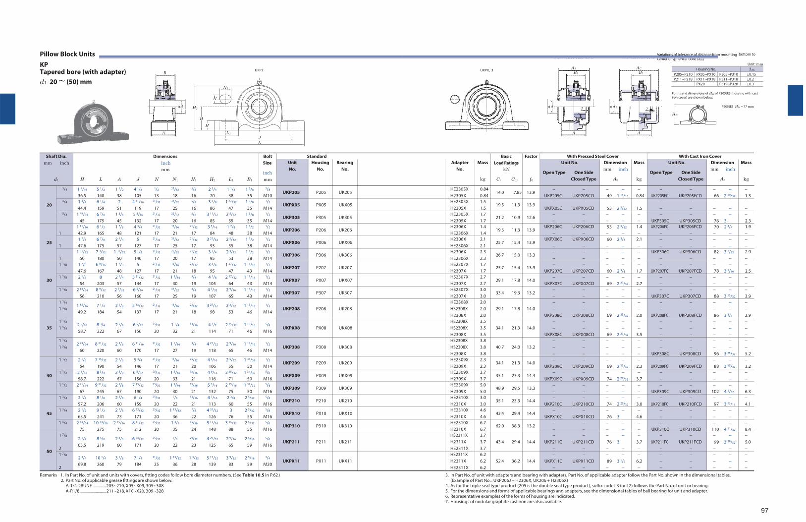
Pillow Block Units KP Tapered bore (with adapter) d1 20 ~ (50) mm
N 1
N
H 2
H
H
L 1
UKP2
J L
UKPX, 3
With Pressed Steel Cover With Cast Iron Cover
Variations of tolerance of distance from mounting bottom to center of spherical bore (3Hs)
Unit: mm Housing No. 3Hs
P205~P210 PX05~PX10 P305~P310 0.15P211~P218 PX11~PX18 P311~P318 0.2
PX20 P319~P328 0.3
Forms and dimensions of H2c of P205JE3 (housing with cast iron cover) are shown below.
P205JE3 H2c 77 mm
Shaft Dia. mm inch
d1
Dimensions inch mm
H L A J N N1 H1 H2 L1 B1
Bolt Size
inch mm
Standard BasicLoad Ratings
kN
Cr C0r
Factor
f 0
With Pressed Steel Cover With Cast Iron Cover Unit No.
Housing No.
Bearing No.
Adapter No.
Mass
kg
Unit No.
Open Type One Side Closed Type
Dimension mm inch
As
Mass
kg
Unit No.
Open Type One Side Closed Type
Dimension mm inch
Ac
Mass
kg
20
3/4 1 7/16 5 1/2 1 1/2 4 1/8 1/2 23/32 5/8 2 3/4 1 1/2 1 3/8
36.5 140 38 105 13 18 16 70 38 35
3/8
M10 UKP205 P205 UK205 HE2305X
H2305X0.840.84
14.0 7.85 13.9
UKP205C UKP205CD 49 1 15/16
0.84
UKP205FC UKP205FCD
66 2 19/32
1.3
3/4 1 3/4 6 1/4 2 4 11/16 21/32 31/32 5/8 3 3/8 1 27/32 1 3/8
44.4 159 51 119 17 25 16 86 47 35
1/2
M14 UKPX05 PX05 UKX05 HE2305X
H2305X 1.5 1.5
19.5 11.3 13.9
UKPX05C UKPX05CD 53 2 3/32
1.5
3/4 1 49/64 6 7/8 1 3/4 5 3/16 21/32 25/32 5/8 3 11/32 2 5/32 1 3/8
45 175 45 132 17 20 16 85 55 35
1/2
M14 UKP305 P305 UK305 HE2305X
H2305X 1.7 1.7
21.2 10.9 12.6
UKP305C UKP305CD
76 3
2.3
25
1
1 11/16 6 1/2 1 7/8 4 3/4 21/32 13/16 21/32 3 5/16 1 7/8 1 1/2
42.9 165 48 121 17 21 17 84 48 38
1/2
M14 UKP206 P206 UK206 H2306X
HE2306X 1.4 1.4
19.5 11.3 13.9 UKP206C UKP206CD
53 2 3/32
1.4
UKP206FC UKP206FCD
70 2 3/4
1.9
1
1 7/8 6 7/8 2 1/4 5 21/32 31/32 21/32 3 21/32 2 5/32 1 1/2
47.6 175 57 127 17 25 17 93 55 38
1/2
M14 UKPX06 PX06 UKX06 H2306X
HE2306X 2.1 2.1
25.7 15.4 13.9 UKPX06C UKPX06CD
60 2 3/8
2.1
1
1 31/32 7 3/32 1 31/32 5 1/2 21/32 25/32 21/32 3 3/4 2 3/32 1 1/2
50 180 50 140 17 20 17 95 53 38
1/2
M14 UKP306 P306 UK306 H2306X
HE2306X 2.3 2.3
26.7 15.0 13.3
UKP306C UKP306CD
82 3 7/32
2.9
30
1 1/8 1 7/8 6 9/16 1 7/8 5 21/32 13/16 23/32 3 3/4 1 27/32 1 11/16
47.6 167 48 127 17 21 18 95 47 43
1/2
M14 UKP207 P207 UK207 HS2307X
H2307X 1.7 1.7
25.7 15.4 13.9
UKP207C UKP207CD 60 2 3/8
1.7
UKP207FC UKP207FCD
78 3 1/16
2.5
1 1/8 2 1/8 8 2 1/4 5 21/32 21/32 1 3/16 3/4 4 1/8 2 17/32 1 11/16
54 203 57 144 17 30 19 105 64 43
1/2
M14 UKPX07 PX07 UKX07 HS2307X
H2307X 2.7 2.7
29.1 17.8 14.0
UKPX07C UKPX07CD 69 2 23/32
2.7
1 1/8 2 13/64 8 9/32 2 7/32 6 5/16 21/32 31/32 3/4 4 7/32 2 9/16 1 11/16
56 210 56 160 17 25 19 107 65 43
1/2
M14 UKP307 P307 UK307 HS2307X
H2307X 3.0 3.0
33.4 19.3 13.2
UKP307C UKP307CD
88 3 15/32
3.9
35
1 1/4
1 3/8 1 15/16 7 1/4 2 1/8 5 13/32 21/32 13/16 23/32 3 27/32 2 3/32 1 13/16
49.2 184 54 137 17 21 18 98 53 46
1/2
M14
UKP208
P208
UK208
HE2308X HS2308X H2308X
2.0 2.0 2.0
29.1 17.8
14.0
UKP208C UKP208CD
69 2 23/32
2.0
UKP208FC UKP208FCD
86 3 3/8
2.9
1 1/4
1 3/8 2 5/16 8 3/4 2 5/8 6 5/32 25/32 1 1/4 13/16 4 1/2 2 25/32 1 13/16
58.7 222 67 156 20 32 21 114 71 46
5/8
M16
UKPX08
PX08
UKX08
HE2308X HS2308X H2308X
3.5 3.5 3.5
34.1 21.3
14.0
UKPX08C UKPX08CD
69 2 23/32
3.5
1 1/4
1 3/8 2 23/64 8 21/32 2 3/8 6 11/16 21/32 1 1/16 3/4 4 21/32 2 9/16 1 13/16
60 220 60 170 17 27 19 118 65 46
1/2
M14
UKP308
P308
UK308
HE2308X HS2308X H2308X
3.8 3.8 3.8
40.7 24.0
13.2
UKP308C UKP308CD
96 3 25/32
5.2
40
1 1/2 2 1/8 7 15/32 2 1/8 5 3/4 21/32 13/16 25/32 4 3/16 2 5/32 1 31/32
54 190 54 146 17 21 20 106 55 50
1/2
M14 UKP209 P209 UK209 HE2309X
H2309X 2.3 2.3
34.1 21.3 14.0
UKP209C UKP209CD 69 2 23/32
2.3
UKP209FC UKP209FCD
88 3 15/32
3.2
1 1/2 2 5/16 8 3/4 2 5/8 6 5/32 25/32 1 5/16 13/16 4 9/16 2 25/32 1 31/32
58.7 222 67 156 20 33 21 116 71 50
5/8
M16 UKPX09 PX09 UKX09 HE2309X
H2309X 3.7 3.7
35.1 23.3 14.4
UKPX09C UKPX09CD 74 2 29/32
3.7
1 1/2 2 41/64 9 21/32 2 5/8 7 15/32 25/32 1 3/16 13/16 5 3/16 2 15/16 1 31/32
67 245 67 190 20 30 21 132 75 50
5/8
M16 UKP309 P309 UK309 HE2309X
H2309X 5.0 5.0
48.9 29.5 13.3
UKP309C UKP309CD
102 4 1/32
6.3
45
1 3/4 2 1/4 8 1/8 2 3/8 6 1/4 25/32 7/8 13/16 4 7/16 2 3/8 2 5/32
57.2 206 60 159 20 22 21 113 60 55
5/8
M16 UKP210 P210 UK210 HE2310X
H2310X 3.0 3.0
35.1 23.3 14.4
UKP210C UKP210CD 74 2 29/32
3.0
UKP210FC UKP210FCD
97 3 13/16
4.1
1 3/4 2 1/2 9 1/2 2 7/8 6 23/32 25/32 1 13/32 7/8 4 31/32 3 2 5/32
63.5 241 73 171 20 36 22 126 76 55
5/8
M16 UKPX10 PX10 UKX10 HE2310X
H2310X 4.6 4.6
43.4 29.4 14.4
UKPX10C UKPX10CD 76 3
4.6
1 3/4 2 61/64 10 13/16 2 15/16 8 11/32 25/32 1 3/8 15/16 5 13/16 3 15/32 2 5/32
75 275 75 212 20 35 24 148 88 55
5/8
M16 UKP310 P310 UK310 HE2310X
H2310X 6.7 6.7
62.0 38.3 13.2
UKP310C UKP310CD
110 4 11/32
8.4
50
1 7/8
2
2 1/2 8 5/8 2 3/8 6 23/32 25/32 7/8 29/32 4 29/32 2 9/16 2 5/16
63.5 219 60 171 20 22 23 125 65 59
5/8
M16
UKP211
P211
UK211
HS2311X H2311X HE2311X
3.7 3.7 3.7
43.4 29.4
14.4
UKP211C UKP211CD
76 3
3.7
UKP211FC UKP211FCD
99 3 29/32
5.0
1 7/8
2
2 3/4 10 1/4 3 1/8 7 1/4 31/32 1 13/32 1 3/32 5 15/32 3 9/32 2 5/16
69.8 260 79 184 25 36 28 139 83 59
3/4
M20
UKPX11
PX11
UKX11
HS2311X H2311X HE2311X
6.2 6.2 6.2
52.4 36.2
14.4
UKPX11C UKPX11CD
89 3 1/2
6.2
Remarks 1. In Part No. of unit and units with covers, fitting codes follow bore diameter numbers. (See Table 10.5 in P.62.) 2. Part No. of applicable grease fittings are shown below.
A-1/4-28UNF ............. 205~210, X05~X09, 305~308 A-R1/8 .......................... 211~218, X10~X20, 309~328
3. In Part No. of unit with adapters and bearing with adapters, Part No. of applicable adapter follow the Part No. shown in the dimensional tables. (Example of Part No. : UKP206J H2306X, UK206 H2306X)
4. As for the triple seal type product (205 is the double seal type product), suffix code L3 (or L2) follows the Part No. of unit or bearing. 5. For the dimensions and forms of applicable bearings and adapters, see the dimensional tables of ball bearing for unit and adapter. 6. Representative examples of the forms of housing are indicated. 7. Housings of nodular graphite cast iron are also available.
97
B
d 1
A
AS
B 1
d 1 1
A
AC
B 1
d 1 2
A
H 2c
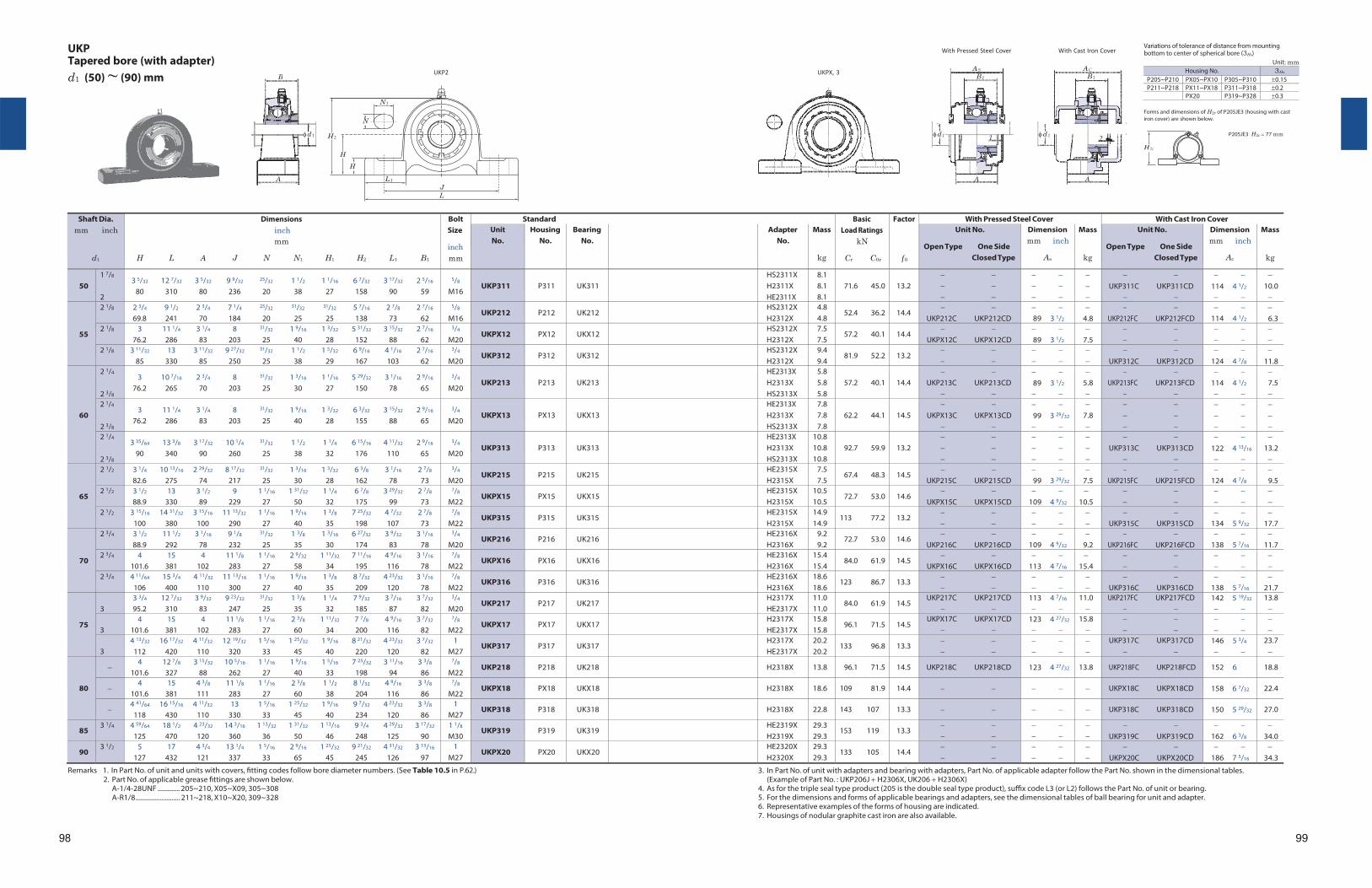
UKP Tapered bore (with adapter) d1 (50) ~ (90) mm
N 1
N
H 2
H
H
L 1
UKP2
J L
UKPX, 3
With Pressed Steel Cover With Cast Iron Cover
Variations of tolerance of distance from mounting bottom to center of spherical bore (3Hs)
Unit: mm Housing No. 3Hs
P205~P210 PX05~PX10 P305~P310 0.15P211~P218 PX11~PX18 P311~P318 0.2
PX20 P319~P328 0.3
Forms and dimensions of H2c of P205JE3 (housing with cast iron cover) are shown below.
P205JE3 H2c 77 mm
Shaft Dia. mm inch
d1
Dimensions inch mm
H L A J N N1 H1 H2 L1 B1
Bolt Size
inch mm
Standard BasicLoad Ratings
kN
Cr C0r
Factor
f 0
With Pressed Steel Cover With Cast Iron Cover Unit No.
Housing No.
Bearing No.
Adapter No.
Mass
kg
Unit No.
Open Type One Side Closed Type
Dimension mm inch
As
Mass
kg
Unit No.
Open Type One Side Closed Type
Dimension mm inch
Ac
Mass
kg
50
1 7/8
2
3 5/32 12 7/32 3 5/32 9 9/32 25/32 1 1/2 1 1/16 6 7/32 3 17/32 2 5/16
80 310 80 236 20 38 27 158 90 59
5/8
M16
UKP311
P311
UK311
HS2311X H2311X HE2311X
8.1 8.1 8.1
71.6 45.0
13.2
UKP311C UKP311CD
114 4 1/2
10.0
55
2 1/8 2 3/4 9 1/2 2 3/4 7 1/4 25/32 31/32 31/32 5 7/16 2 7/8 2 7/16
69.8 241 70 184 20 25 25 138 73 62
5/8
M16 UKP212 P212 UK212 HS2312X
H2312X 4.8 4.8
52.4 36.2 14.4
UKP212C UKP212CD 89 3 1/2
4.8
UKP212FC UKP212FCD
114 4 1/2
6.3
2 1/8 3 11 1/4 3 1/4 8 31/32 1 9/16 1 3/32 5 31/32 3 15/32 2 7/16
76.2 286 83 203 25 40 28 152 88 62
3/4
M20 UKPX12 PX12 UKX12 HS2312X
H2312X 7.5 7.5
57.2 40.1 14.4
UKPX12C UKPX12CD 89 3 1/2
7.5
2 1/8 3 11/32 13 3 11/32 9 27/32 31/32 1 1/2 1 5/32 6 9/16 4 1/16 2 7/16
85 330 85 250 25 38 29 167 103 62
3/4
M20 UKP312 P312 UK312 HS2312X
H2312X 9.4 9.4
81.9 52.2 13.2
UKP312C UKP312CD
124 4 7/8
11.8
60
2 1/4
2 3/8
3 10 7/16 2 3/4 8 31/32 1 3/16 1 1/16 5 29/32 3 1/16 2 9/16
76.2 265 70 203 25 30 27 150 78 65
3/4
M20
UKP213
P213
UK213
HE2313X H2313X HS2313X
5.8 5.8 5.8
57.2 40.1
14.4
UKP213C UKP213CD
89 3 1/2
5.8
UKP213FC UKP213FCD
114 4 1/2
7.5
2 1/4
2 3/8
3 11 1/4 3 1/4 8 31/32 1 9/16 1 3/32 6 3/32 3 15/32 2 9/16
76.2 286 83 203 25 40 28 155 88 65
3/4
M20
UKPX13
PX13
UKX13
HE2313X H2313X HS2313X
7.8 7.8 7.8
62.2 44.1
14.5
UKPX13C UKPX13CD
99 3 29/32
7.8
2 1/4
2 3/8
3 35/64 13 3/8 3 17/32 10 1/4 31/32 1 1/2 1 1/4 6 15/16 4 11/32 2 9/16
90 340 90 260 25 38 32 176 110 65
3/4
M20
UKP313
P313
UK313
HE2313X H2313X HS2313X
10.8 10.8 10.8
92.7 59.9
13.2
UKP313C UKP313CD
122 4 13/16
13.2
65
2 1/2 3 1/4 10 13/16 2 29/32 8 17/32 31/32 1 3/16 1 3/32 6 3/8 3 1/16 2 7/8
82.6 275 74 217 25 30 28 162 78 73
3/4
M20 UKP215 P215 UK215 HE2315X
H2315X 7.5 7.5
67.4 48.3 14.5
UKP215C UKP215CD 99 3 29/32
7.5
UKP215FC UKP215FCD
124 4 7/8
9.5
2 1/2 3 1/2 13 3 1/2 9 1 1/16 1 31/32 1 1/4 6 7/8 3 29/32 2 7/8
88.9 330 89 229 27 50 32 175 99 73
7/8
M22 UKPX15 PX15 UKX15 HE2315X
H2315X 10.5 10.5
72.7 53.0 14.6
UKPX15C UKPX15CD
109 4 9/32
10.5
2 1/2 3 15/16 14 31/32 3 15/16 11 13/32 1 1/16 1 9/16 1 3/8 7 25/32 4 7/32 2 7/8
100 380 100 290 27 40 35 198 107 73
7/8
M22 UKP315 P315 UK315 HE2315X
H2315X 14.9 14.9
113 77.2 13.2
UKP315C UKP315CD
134 5 9/32
17.7
70
2 3/4 3 1/2 11 1/2 3 1/16 9 1/8 31/32 1 3/8 1 3/16 6 27/32 3 9/32 3 1/16
88.9 292 78 232 25 35 30 174 83 78
3/4
M20 UKP216 P216 UK216 HE2316X
H2316X 9.2 9.2
72.7 53.0 14.6
UKP216C UKP216CD
109 4 9/32
9.2
UKP216FC UKP216FCD
138 5 7/16
11.7
2 3/4 4 15 4 11 1/8 1 1/16 2 9/32 1 11/32 7 11/16 4 9/16 3 1/16
101.6 381 102 283 27 58 34 195 116 78
7/8
M22 UKPX16 PX16 UKX16 HE2316X
H2316X 15.4 15.4
84.0 61.9 14.5
UKPX16C UKPX16CD
113 4 7/16
15.4
2 3/4 4 11/64 15 3/4 4 11/32 11 13/16 1 1/16 1 9/16 1 3/8 8 7/32 4 23/32 3 1/16
106 400 110 300 27 40 35 209 120 78
7/8
M22 UKP316 P316 UK316 HE2316X
H2316X 18.6 18.6
123 86.7 13.3
UKP316C UKP316CD
138 5 7/16
21.7
75
3
3 3/4 12 7/32 3 9/32 9 23/32 31/32 1 3/8 1 1/4 7 9/32 3 7/16 3 7/32
95.2 310 83 247 25 35 32 185 87 82
3/4
M20 UKP217 P217 UK217 H2317X
HE2317X 11.0 11.0
84.0 61.9 14.5 UKP217C UKP217CD
113 4 7/16
11.0
UKP217FC UKP217FCD
142 5 19/32
13.8
3
4 15 4 11 1/8 1 1/16 2 3/8 1 11/32 7 7/8 4 9/16 3 7/32
101.6 381 102 283 27 60 34 200 116 82
7/8
M22 UKPX17 PX17 UKX17 H2317X
HE2317X 15.8 15.8
96.1 71.5 14.5 UKPX17C UKPX17CD
123 4 27/32
15.8
3
4 13/32 16 17/32 4 11/32 12 19/32 1 5/16 1 25/32 1 9/16 8 21/32 4 23/32 3 7/32
112 420 110 320 33 45 40 220 120 82 1
M27 UKP317 P317 UK317 H2317X
HE2317X 20.2 20.2
133 96.8 13.3
UKP317C UKP317CD
146 5 3/4
23.7
80
4 12 7/8 3 15/32 10 5/16 1 1/16 1 9/16 1 5/16 7 25/32 3 11/16 3 3/8
101.6 327 88 262 27 40 33 198 94 86
7/8
M22 UKP218 P218 UK218 H2318X 13.8 96.1 71.5 14.5 UKP218C UKP218CD 123 4 27/32 13.8 UKP218FC UKP218FCD 152 6 18.8
4 15 4 3/8 11 1/8 1 1/16 2 3/8 1 1/2 8 1/32 4 9/16 3 3/8
101.6 381 111 283 27 60 38 204 116 86
7/8
M22 UKPX18 PX18 UKX18 H2318X 18.6 109 81.9 14.4 UKPX18C UKPX18CD 158 6 7/32 22.4
4 41/64 16 15/16 4 11/32 13 1 5/16 1 25/32 1 9/16 9 7/32 4 23/32 3 3/8
118 430 110 330 33 45 40 234 120 86 1
M27 UKP318 P318 UK318 H2318X 22.8 143 107 13.3 UKP318C UKP318CD 150 5 29/32 27.0
85 3 1/4 4 59/64 18 1/2 4 23/32 14 3/16 1 13/32 1 31/32 1 13/16 9 3/4 4 29/32 3 17/32
125 470 120 360 36 50 46 248 125 90 1 1/8
M30 UKP319 P319 UK319 HE2319X
H2319X 29.3 29.3
153 119 13.3
UKP319C UKP319CD
162 6 3/8
34.0
90 3 1/2 5 17 4 3/4 13 1/4 1 5/16 2 9/16 1 25/32 9 21/32 4 31/32 3 13/16
127 432 121 337 33 65 45 245 126 97 1
M27 UKPX20 PX20 UKX20 HE2320X
H2320X 29.3 29.3
133 105 14.4
UKPX20C UKPX20CD
186 7 5/16
34.3
Remarks 1. In Part No. of unit and units with covers, fitting codes follow bore diameter numbers. (See Table 10.5 in P.62.) 2. Part No. of applicable grease fittings are shown below.
A-1/4-28UNF ............. 205~210, X05~X09, 305~308 A-R1/8 .......................... 211~218, X10~X20, 309~328
3. In Part No. of unit with adapters and bearing with adapters, Part No. of applicable adapter follow the Part No. shown in the dimensional tables. (Example of Part No. : UKP206J H2306X, UK206 H2306X)
4. As for the triple seal type product (205 is the double seal type product), suffix code L3 (or L2) follows the Part No. of unit or bearing. 5. For the dimensions and forms of applicable bearings and adapters, see the dimensional tables of ball bearing for unit and adapter. 6. Representative examples of the forms of housing are indicated. 7. Housings of nodular graphite cast iron are also available.
98 99
B
d 1
A
AS
B 1
d 1 1
A
AC
B 1
d 1 2
A
H 2c
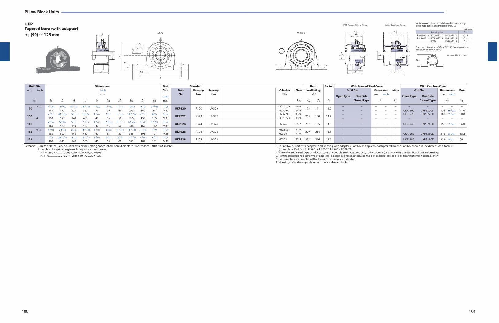
Pillow Block Units
UKP Tapered bore (with adapter) d1 (90) ~ 125 mm
N 1
N
H 2
H
H
L 1
UKP2
J L
UKPX, 3
With Pressed Steel Cover With Cast Iron Cover
Variations of tolerance of distance from mounting bottom to center of spherical bore (3Hs)
Unit: mm Housing No. 3Hs
P205~P210 PX05~PX10 P305~P310 0.15P211~P218 PX11~PX18 P311~P318 0.2
PX20 P319~P328 0.3
Forms and dimensions of H2c of P205JE3 (housing with cast iron cover) are shown below.
P205JE3 H2c 77 mm
Shaft Dia. mm inch
d1
Dimensions inch mm
H L A J N N1 H1 H2 L1 B1
Bolt Size
inch mm
Standard BasicLoad Ratings
kN
Cr C0r
Factor
f 0
With Pressed Steel Cover With Cast Iron Cover Unit No.
Housing No.
Bearing No.
Adapter No.
Mass
kg
Unit No.
Open Type One Side Closed Type
Dimension mm inch
As
Mass
kg
Unit No.
Open Type One Side Closed Type
Dimension mm inch
Ac
Mass
kg
90 3 1/2 5 33/64 19 9/32 4 23/32 14 31/32 1 13/32 1 31/32 1 13/16 10 3/4 5 1/2 3 13/16
140 490 120 380 36 50 46 273 140 97 1 1/8
M30 UKP320 P320 UK320 HE2320X
H2320X34.8 34.8
173 141 13.2
UKP320C UKP320CD
174 6 27/32
41.0
100 4
5 29/32 20 15/32 5 1/2 15 3/4 1 9/16 2 5/32 1 31/32 11 21/32 5 29/32 4 1/8
150 520 140 400 40 55 50 296 150 105 1 1/4
M33 UKP322 P322 UK322 H2322X
HE2322X 43.9 43.9
205 180 13.2
UKP322C UKP322CD
188 7 13/32
50.8
110 6 19/64 22 7/16 5 1/2 17 23/32 1 9/16 2 5/32 1 31/32 12 7/16 6 5/16 4 13/32
160 570 140 450 40 55 50 316 160 112 1 1/4
M33 UKP324 P324 UK324 H2324 55.7 207 185 13.5 UKP324C UKP324CD 196 7 23/32 66.0
115 4 1/2 7 3/32 23 5/8 5 1/2 18 29/32 1 9/16 2 5/32 1 31/32 13 21/32 7 11/16 4 3/4
180 600 140 480 40 55 50 355 195 121 1 1/4
M33 UKP326 P326 UK326 HE2326
H2326 71.9 71.9
229 214 13.6
UKP326C UKP326CD
214 8 7/16
85.2
125 7 7/8 24 13/32 5 1/2 19 11/16 1 9/16 2 5/32 2 3/8 15 15/32 7 9/32 5 5/32
200 620 140 500 40 55 60 393 185 131 1 1/4
M33 UKP328 P328 UK328 H2328 92.5 253 246 13.6 UKP328C UKP328CD 222 8 3/4 109
Remarks 1. In Part No. of unit and units with covers, fitting codes follow bore diameter numbers. (See Table 10.5 in P.62.) 2. Part No. of applicable grease fittings are shown below.
A-1/4-28UNF ............. 205~210, X05~X09, 305~308 A-R1/8 .......................... 211~218, X10~X20, 309~328
3. In Part No. of unit with adapters and bearing with adapters, Part No. of applicable adapter follow the Part No. shown in the dimensional tables. (Example of Part No. : UKP206J H2306X, UK206 H2306X)
4. As for the triple seal type product (205 is the double seal type product), suffix code L3 (or L2) follows the Part No. of unit or bearing. 5. For the dimensions and forms of applicable bearings and adapters, see the dimensional tables of ball bearing for unit and adapter. 6. Representative examples of the forms of housing are indicated. 7. Housings of nodular graphite cast iron are also available.
100 101
B
d 1
A
AS
B 1
d 1 1
A
AC
B 1
d 1 2
A
H 2c
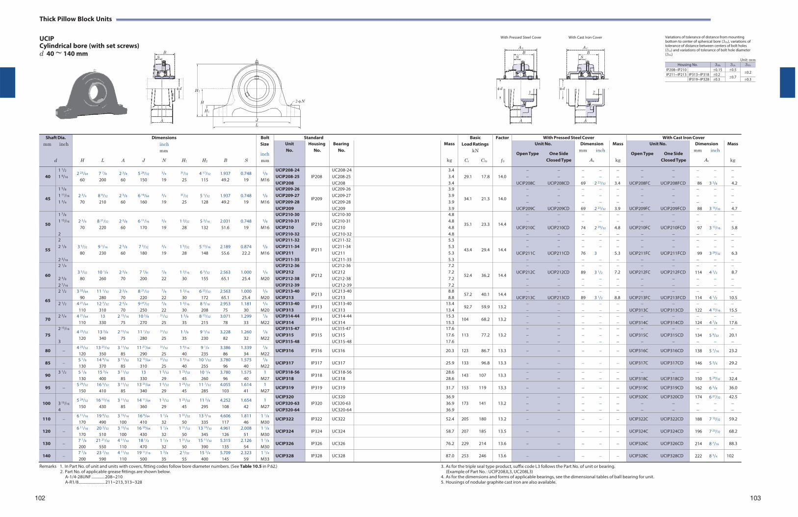
Thick Pillow Block Units
UCIP Cylindrical bore (with set screws) d 40 ~ 140 mm
With Pressed Steel Cover With Cast Iron Cover Variations of tolerance of distance from mounting bottom to center of spherical bore (3Hs), variations of tolerance of distance between centers of bolt holes (3Js) and variations of tolerance of bolt hole diameter (3Ns)
Unit: mm Housing No. 3Hs 3Js 3Ns
IP208~IP210 0.15 0.50.2 IP211~IP213 IP313~IP318 0.2
0.7 IP319~IP328 0.3 0.3
H 2
H 2-N
H 1
J
L
Shaft Dia.
mm inch
d
Dimensions inch mm
H L A J N H1 H2 B S
Bolt Size
inch mm
Standard BasicLoad Ratings
kN
Cr C0r
Factor
f 0
With Pressed Steel Cover With Cast Iron Cover Unit No.
Housing No.
Bearing No.
Mass
kg
Unit No.
Open Type One Side Closed Type
Dimension mm inch
As
Mass
kg
Unit No.
Open Type One Side Closed Type
Dimension mm inch
Ac
Mass
kg
40
1 1/2
1 9/16 2 23/64 7 7/8 2 3/8 5 29/32 3/4 31/32 4 17/32 1.937 0.748
60 200 60 150 19 25 115 49.2 19
5/8
M16
UCIP208-24 UCIP208-25 UCIP208
IP208
UC208-24UC208-25 UC208
3.4 3.4 3.4
29.1 17.8
14.0
UCIP208C UCIP208CD
69 2 23/32
3.4
UCIP208FC UCIP208FCD
86 3 3/8
4.2
45
1 5/8
1 11/16
1 3/4
2 3/4 8 9/32 2 3/8 6 19/64 3/4 31/32 5 1/32 1.937 0.748 70 210 60 160 19 25 128 49.2 19
5/8
M16
UCIP209-26 UCIP209-27 UCIP209-28 UCIP209
IP209
UC209-26 UC209-27 UC209-28 UC209
3.9 3.9 3.9 3.9
34.1 21.3
14.0
UCIP209C UCIP209CD
69 2 23/32
3.9
UCIP209FC UCIP209FCD
88 3 15/32
4.7
50
1 7/8
1 15/16
2
2 3/4 8 21/32 2 3/8 6 11/16 3/4 1 3/32 5 3/16 2.031 0.748 70 220 60 170 19 28 132 51.6 19
5/8
M16
UCIP210-30 UCIP210-31 UCIP210 UCIP210-32
IP210
UC210-30 UC210-31 UC210 UC210-32
4.8 4.8 4.8 4.8
35.1 23.3
14.4
UCIP210C UCIP210CD
74 2 29/32
4.8
UCIP210FC UCIP210FCD
97 3 13/16
5.8
55
2 2 1/8
2 3/16
3 5/32 9 1/16 2 3/8 7 3/32 3/4 1 3/32 5 13/16 2.189 0.874
80 230 60 180 19 28 148 55.6 22.2
5/8
M16
UCIP211-32 UCIP211-34 UCIP211 UCIP211-35
IP211
UC211-32 UC211-34 UC211 UC211-35
5.3 5.3 5.3 5.3
43.4 29.4
14.4
UCIP211C UCIP211CD
76 3
5.3
UCIP211FC UCIP211FCD
99 3 29/32
6.3
60
2 1/4
2 3/8
2 7/16
3 5/32 10 1/4 2 3/4 7 7/8 7/8 1 3/16 6 3/32 2.563 1.000
80 260 70 200 22 30 155 65.1 25.4
3/4
M20
UCIP212-36 UCIP212 UCIP212-38 UCIP212-39
IP212
UC212-36 UC212 UC212-38 UC212-39
7.2 7.2 7.2 7.2
52.4 36.2
14.4
UCIP212C UCIP212CD
89 3 1/2
7.2
UCIP212FC UCIP212FCD
114 4 1/2
8.7
65
2 1/2 3 35/64 11 1/32 2 3/4 8 21/32 7/8 1 3/16 6 25/32 2.563 1.000 90 280 70 220 22 30 172 65.1 25.4
3/4
M20 UCIP213-40 UCIP213
IP213 UC213-40UC213
8.8 8.8
57.2 40.1 14.4
UCIP213C UCIP213CD
89 3 1/2
8.8
UCIP213FC UCIP213FCD
114 4 1/2
10.5
2 1/2 4 21/64 12 7/32 2 3/4 9 27/32 7/8 1 3/16 8 3/16 2.953 1.181 110 310 70 250 22 30 208 75 30
3/4
M20 UCIP313-40 UCIP313
IP313 UC313-40UC313
13.4 13.4
92.7 59.9 13.2
UCIP313C UCIP313CD
122 4 13/16
15.5
70 2 3/4 4 21/64 13 2 15/16 10 5/8 31/32 1 3/8 8 15/32 3.071 1.299
110 330 75 270 25 35 215 78 33
7/8
M22 UCIP314-44 UCIP314
IP314 UC314-44UC314
15.3 15.3
104 68.2 13.2
UCIP314C UCIP314CD
124 4 7/8
17.6
75
2 15/16
3
4 23/32 13 3/8 2 15/16 11 1/32 31/32 1 3/8 9 1/16 3.228 1.260 120 340 75 280 25 35 230 82 32
7/8
M22
UCIP315-47 UCIP315 UCIP315-48
IP315
UC315-47 UC315 UC315-48
17.6 17.6 17.6
113 77.2
13.2
UCIP315C UCIP315CD
134 5 9/32
20.1
80 4 23/32 13 25/32 3 11/32 11 27/64 31/32 1 9/16 9 1/4 3.386 1.339
120 350 85 290 25 40 235 86 34
7/8
M22 UCIP316 IP316 UC316 20.3 123 86.7 13.3 UCIP316C UCIP316CD 138 5 7/16 23.2
85 5 1/8 14 9/16 3 11/32 12 13/64 31/32 1 9/16 10 1/32 3.780 1.575 130 370 85 310 25 40 255 96 40
7/8
M22 UCIP317 IP317 UC317 25.9 133 96.8 13.3 UCIP317C UCIP317CD 146 5 3/4 29.2
90 3 1/2 5 1/8 15 3/4 3 11/32 13 1 5/32 1 25/32 10 1/4 3.780 1.575
130 400 85 330 29 45 260 96 40 1
M27 UCIP318-56 UCIP318
IP318 UC318-56UC318
28.6 28.6
143 107 13.3
UCIP318C UCIP318CD
150 5 29/32
32.4
95 5 29/32 16 5/32 3 11/32 13 25/64 1 5/32 1 25/32 11 7/32 4.055 1.614
150 410 85 340 29 45 285 103 41 1
M27 UCIP319 IP319 UC319 31.7 153 119 13.3 UCIP319C UCIP319CD 162 6 3/8 36.0
100
3 15/16
4
5 29/32 16 15/16 3 11/32 14 11/64 1 5/32 1 25/32 11 5/8 4.252 1.654 150 430 85 360 29 45 295 108 42
1 M27
UCIP320 UCIP320-63 UCIP320-64
IP320
UC320 UC320-63 UC320-64
36.9 36.9 36.9
173 141
13.2
UCIP320C UCIP320CD
174 6 27/32
42.5
110 6 11/16 19 9/32 3 15/16 16 9/64 1 1/4 1 31/32 13 3/16 4.606 1.811
170 490 100 410 32 50 335 117 46 1 1/8
M30 UCIP322 IP322 UC322 52.4 205 180 13.2 UCIP322C UCIP322CD 188 7 13/32 59.2
120 6 11/16 20 3/32 3 15/16 16 59/64 1 1/4 1 31/32 13 19/32 4.961 2.008
170 510 100 430 32 50 345 126 51 1 1/8
M30 UCIP324 IP324 UC324 58.7 207 185 13.5 UCIP324C UCIP324CD 196 7 23/32 68.2
130 7 7/8 21 21/32 4 11/32 18 1/2 1 1/4 1 31/32 15 11/32 5.315 2.126 200 550 110 470 32 50 390 135 54
1 1/8
M30 UCIP326 IP326 UC326 76.2 229 214 13.6 UCIP326C UCIP326CD 214 8 7/16 88.3
140 7 7/8 23 7/32 4 11/32 19 11/16 1 3/8 2 5/32 15 3/4 5.709 2.323 200 590 110 500 35 55 400 145 59
1 1/4
M33 UCIP328 IP328 UC328 87.0 253 246 13.6 UCIP328C UCIP328CD 222 8 3/4 102
Remarks 1. In Part No. of unit and units with covers, fitting codes follow bore diameter numbers. (See Table 10.5 in P.62.) 2. Part No. of applicable grease fittings are shown below.
A-1/4-28UNF ............. 208~210 A-R1/8 .......................... 211~213, 313~328
3. As for the triple seal type product, suffix code L3 follows the Part No. of unit or bearing. (Example of Part No. : UCIP208JL3, UC208L3)
4. As for the dimensions and forms of applicable bearings, see the dimensional tables of ball bearing for unit. 5. Housings of nodular graphite cast iron are also available.
102 103
B S
d
A
AS
BS
d1
A
AC
BS
d 2
A
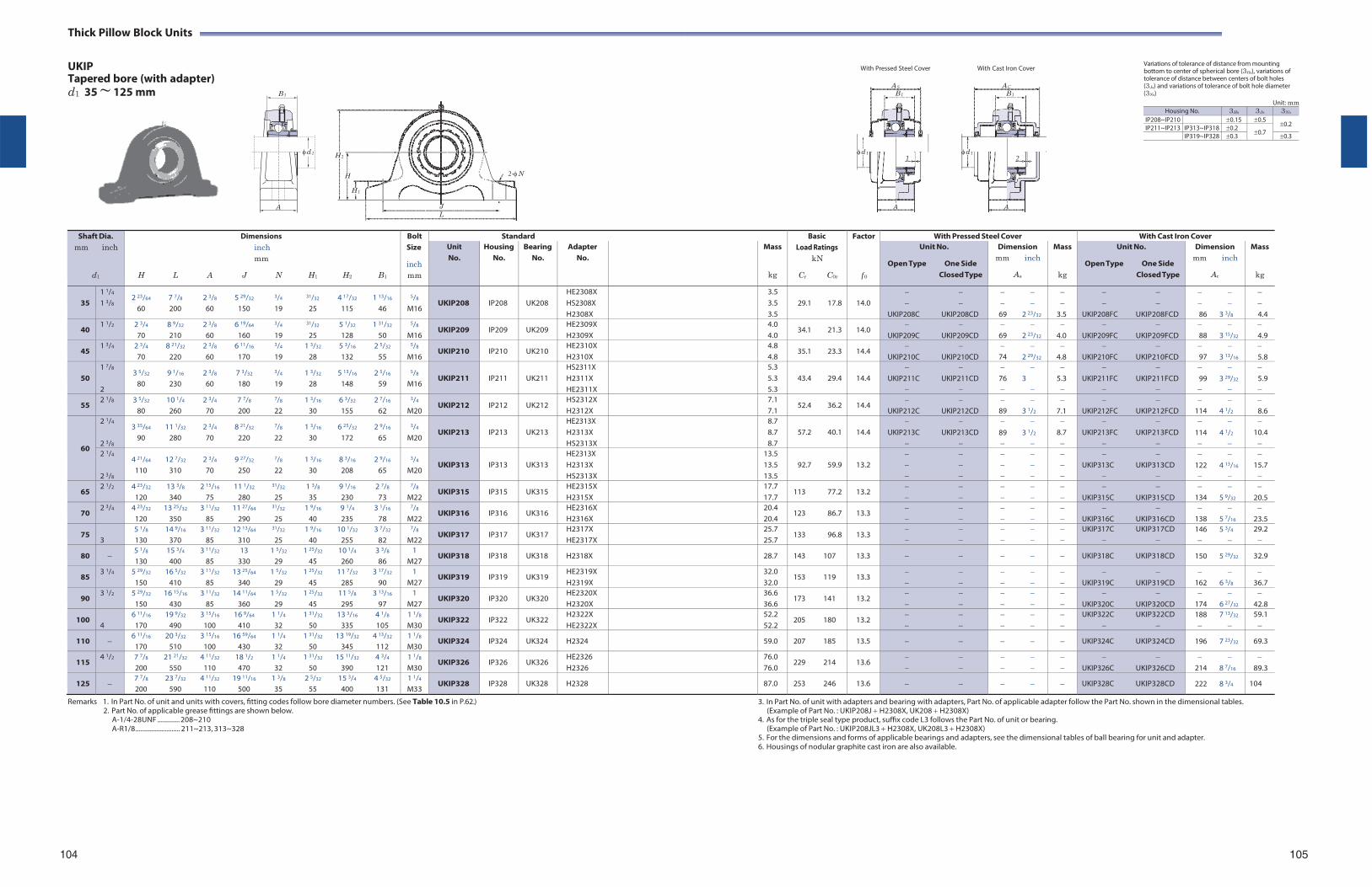
Thick Pillow Block Units
UKIP Tapered bore (with adapter) d1 35 ~ 125 mm
With Pressed Steel Cover With Cast Iron Cover
Variations of tolerance of distance from mounting bottom to center of spherical bore (3Hs), variations of tolerance of distance between centers of bolt holes (3Js) and variations of tolerance of bolt hole diameter (3Ns)
Unit: mm Housing No. 3Hs 3Js 3Ns
IP208~IP210 0.15 0.50.2 IP211~IP213 IP313~IP318 0.2
0.7 IP319~IP328 0.3 0.3
H 2
H 2-N
H 1
J L
Shaft Dia.
mm inch
d1
Dimensions inch mm
H L A J N H1 H2 B1
Bolt Size
inch mm
Standard BasicLoad Ratings
kN
Cr C0r
Factor
f 0
With Pressed Steel Cover With Cast Iron Cover Unit No.
Housing No.
Bearing No.
Adapter No.
Mass
kg
Unit No.
Open Type One Side Closed Type
Dimension mm inch
As
Mass
kg
Unit No.
Open Type One Side Closed Type
Dimension mm inch
Ac
Mass
kg
35
1 1/4
1 3/8 2 23/64 7 7/8 2 3/8 5 29/32 3/4 31/32 4 17/32 1 13/16
60 200 60 150 19 25 115 46
5/8
M16
UKIP208
IP208
UK208
HE2308X HS2308X H2308X
3.5 3.5 3.5
29.1 17.8
14.0
UKIP208C UKIP208CD
69 2 23/32
3.5
UKIP208FC UKIP208FCD
86 3 3/8
4.4
40 1 1/2 2 3/4 8 9/32 2 3/8 6 19/64 3/4 31/32 5 1/32 1 31/32
70 210 60 160 19 25 128 50
5/8
M16 UKIP209 IP209 UK209
HE2309X H2309X
4.0 4.0
34.1 21.3 14.0
UKIP209C UKIP209CD
69 2 23/32
4.0
UKIP209FC UKIP209FCD
88 3 15/32
4.9
45 1 3/4 2 3/4 8 21/32 2 3/8 6 11/16 3/4 1 3/32 5 3/16 2 5/32
70 220 60 170 19 28 132 55
5/8
M16 UKIP210 IP210 UK210
HE2310X H2310X
4.8 4.8
35.1 23.3 14.4
UKIP210C UKIP210CD
74 2 29/32
4.8
UKIP210FC UKIP210FCD
97 3 13/16
5.8
50
1 7/8
2
3 5/32 9 1/16 2 3/8 7 3/32 3/4 1 3/32 5 13/16 2 5/16
80 230 60 180 19 28 148 59
5/8
M16
UKIP211
IP211
UK211
HS2311X H2311X HE2311X
5.3 5.3 5.3
43.4 29.4
14.4
UKIP211C UKIP211CD
76 3
5.3
UKIP211FC UKIP211FCD
99 3 29/32
5.9
55 2 1/8 3 5/32 10 1/4 2 3/4 7 7/8 7/8 1 3/16 6 3/32 2 7/16
80 260 70 200 22 30 155 62
3/4
M20 UKIP212 IP212 UK212
HS2312X H2312X
7.1 7.1
52.4 36.2 14.4
UKIP212C UKIP212CD
89 3 1/2
7.1
UKIP212FC UKIP212FCD
114 4 1/2
8.6
60
2 1/4
2 3/8
3 35/64 11 1/32 2 3/4 8 21/32 7/8 1 3/16 6 25/32 2 9/16
90 280 70 220 22 30 172 65
3/4
M20
UKIP213
IP213
UK213
HE2313X H2313X HS2313X
8.7 8.7 8.7
57.2 40.1
14.4
UKIP213C UKIP213CD
89 3 1/2
8.7
UKIP213FC UKIP213FCD
114 4 1/2
10.4
2 1/4
2 3/8
4 21/64 12 7/32 2 3/4 9 27/32 7/8 1 3/16 8 3/16 2 9/16
110 310 70 250 22 30 208 65
3/4
M20
UKIP313
IP313
UK313
HE2313X H2313X HS2313X
13.5 13.5 13.5
92.7 59.9
13.2
UKIP313C UKIP313CD
122 4 13/16
15.7
65 2 1/2 4 23/32 13 3/8 2 15/16 11 1/32 31/32 1 3/8 9 1/16 2 7/8
120 340 75 280 25 35 230 73
7/8
M22 UKIP315 IP315 UK315
HE2315X H2315X
17.7 17.7
113 77.2 13.2
UKIP315C UKIP315CD
134 5 9/32
20.5
70 2 3/4 4 23/32 13 25/32 3 11/32 11 27/64 31/32 1 9/16 9 1/4 3 1/16
120 350 85 290 25 40 235 78
7/8
M22 UKIP316 IP316 UK316
HE2316X H2316X
20.4 20.4
123 86.7 13.3
UKIP316C UKIP316CD
138 5 7/16
23.5
75 3
5 1/8 14 9/16 3 11/32 12 13/64 31/32 1 9/16 10 1/32 3 7/32
130 370 85 310 25 40 255 82
7/8
M22 UKIP317 IP317 UK317
H2317X HE2317X
25.7 25.7
133 96.8 13.3
UKIP317C UKIP317CD
146 5 3/4
29.2
80 5 1/8 15 3/4 3 11/32 13 1 5/32 1 25/32 10 1/4 3 3/8
130 400 85 330 29 45 260 86 1
M27 UKIP318 IP318 UK318 H2318X 28.7 143 107 13.3 UKIP318C UKIP318CD 150 5 29/32 32.9
85 3 1/4 5 29/32 16 5/32 3 11/32 13 25/64 1 5/32 1 25/32 11 7/32 3 17/32
150 410 85 340 29 45 285 90 1
M27 UKIP319 IP319 UK319
HE2319X H2319X
32.0 32.0
153 119 13.3
UKIP319C UKIP319CD
162 6 3/8
36.7
90 3 1/2 5 29/32 16 15/16 3 11/32 14 11/64 1 5/32 1 25/32 11 5/8 3 13/16
150 430 85 360 29 45 295 97 1
M27 UKIP320 IP320 UK320
HE2320X H2320X
36.6 36.6
173 141 13.2
UKIP320C UKIP320CD
174 6 27/32
42.8
100 4
6 11/16 19 9/32 3 15/16 16 9/64 1 1/4 1 31/32 13 3/16 4 1/8
170 490 100 410 32 50 335 105 1 1/8
M30 UKIP322 IP322 UK322
H2322X HE2322X
52.2 52.2
205 180 13.2
UKIP322C UKIP322CD
188 7 13/32
59.1
110 6 11/16 20 3/32 3 15/16 16 59/64 1 1/4 1 31/32 13 19/32 4 13/32
170 510 100 430 32 50 345 112 1 1/8
M30 UKIP324 IP324 UK324 H2324 59.0 207 185 13.5 UKIP324C UKIP324CD 196 7 23/32 69.3
115 4 1/2 7 7/8 21 21/32 4 11/32 18 1/2 1 1/4 1 31/32 15 11/32 4 3/4
200 550 110 470 32 50 390 121 1 1/8
M30 UKIP326 IP326 UK326
HE2326 H2326
76.0 76.0
229 214 13.6
UKIP326C UKIP326CD
214 8 7/16
89.3
125 7 7/8 23 7/32 4 11/32 19 11/16 1 3/8 2 5/32 15 3/4 4 5/32
200 590 110 500 35 55 400 131 1 1/4
M33 UKIP328 IP328 UK328 H2328 87.0 253 246 13.6 UKIP328C UKIP328CD 222 8 3/4 104
Remarks 1. In Part No. of unit and units with covers, fitting codes follow bore diameter numbers. (See Table 10.5 in P.62.) 2. Part No. of applicable grease fittings are shown below.
A-1/4-28UNF ............. 208~210 A-R1/8 .......................... 211~213, 313~328
3. In Part No. of unit with adapters and bearing with adapters, Part No. of applicable adapter follow the Part No. shown in the dimensional tables. (Example of Part No. : UKIP208J H2308X, UK208 H2308X)
4. As for the triple seal type product, suffix code L3 follows the Part No. of unit or bearing. (Example of Part No. : UKIP208JL3 H2308X, UK208L3 H2308X)
5. For the dimensions and forms of applicable bearings and adapters, see the dimensional tables of ball bearing for unit and adapter. 6. Housings of nodular graphite cast iron are also available.
104 105
B 1
d 1
A
AS
B 1
d 1 1
A
AC
B 1
d 1 2
A
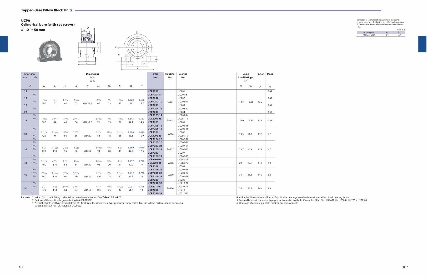
Tapped-Base Pillow Block Units
UCPA Cylindrical bore (with set screws) d 12 ~ 50 mm
H 2
Variations of tolerance of distance from mounting bottom to center of spherical bore (3Hs) and variations of tolerance of distance between centers of bolt holes (3Js)
Unit: mm
H
H 3
L 1 2-N J
L
Shaft Dia. mm inch
d
H
L
A
J
Dimensions inch mm
N H2
H3
L1
B
S
Unit No.
HousingNo.
BearingNo.
BasicLoad Ratings
kN
Cr C0r
Factor
f 0
Mass
kg
12 1/2
1 3/16
3
1 9/16
2 3/64
M10×1.5
2 3/8
1/2
1 1/16
1.220
0.500
UCPA201
PA204
UC201
12.8
6.65
13.2
0.64 UCPA201-8 UC201-8
15 5/8
UCPA202 UC202 0.62 UCPA202-10 UC202-10
30.2 76 40 52 60 13 27 31 12.7 17 UCPA203 UC203 0.61
3/4 UCPA204-12 UC204-12 20 UCPA204 UC204 0.59
25
7/8 1 7/16
3 5/16
1 25/32
2 13/64
M10×1.5
2 25/32
1/2
1 3/16
1.343
0.563
UCPA205-14
PA205
UC205-14
14.0
7.85
13.9
0.83 15/16 UCPA205-15
UCPA205 UC205-15 UC205 36.5 84 45 56 71 13 30 34.1 14.3
1 UCPA205-16 UC205-16
30
1 1/8 1 11/16
3 11/16
1 31/32
2 19/32
M14×2
3 5/16
23/32
1 13/32
1.500
0.626
UCPA206-18
PA206
UC206-18
19.5
11.3
13.9
1.2 1 3/16
UCPA206 UCPA206-19
UC206 UC206-19 42.9 94 50 66 84 18 36 38.1 15.9
1 1/4 UCPA206-20 UC206-20
35
1 1/4
1 7/8
4 11/32
2 5/32
3 5/32
M14×2
3 21/32
25/32
1 5/8
1.689
0.689
UCPA207-20
PA207
UC207-20
25.7
15.4
13.9
1.7
1 5/16 UCPA207-21 UC207-21 1 3/8 UCPA207-22 UC207-22
47.6 110 55 80 93 20 41 42.9 17.5 UCPA207 UC207
1 7/16 UCPA207-23 UC207-23
40 1 1/2
1 9/16 1 15/16
49.2 4 9/16
116 2 9/32
58 3 5/16
84
M14×2 3 27/32
98
25/32
20 1 5/8
41 1.937 49.2
0.748 19
UCPA208-24 UCPA208-25 UCPA208
PA208
UC208-24 UC208-25 UC208
29.1
17.8
14.0
2.0
45
1 5/8 2 9/64
4 23/32
2 3/8
3 35/64
M14×2
4 3/16
31/32
1 21/32
1.937
0.748
UCPA209-26
PA209
UC209-26
34.1
21.3
14.0
2.2 1 11/16 UCPA209-27 UC209-27 1 3/4 54.2 120 60 90 106 25 42 49.2 19 UCPA209-28 UC209-28
UCPA209 UC209
50
1 7/8 2 1/4
5 1/8
2 17/32
3 45/64
M16×2
4 7/16
31/32
1 27/32
2.031
0.748
UCPA210-30
PA210
UC210-30
35.1
23.3
14.4
2.8 1 15/16 UCPA210-31
UCPA210 UC210-31 UC210 57.2 130 64 94 113 25 47 51.6 19
2 UCPA210-32 UC210-32
Remarks 1. In Part No. of unit, fitting codes follow bore diameter codes. (See Table 10.5 in P.62.) 2. Part No. of the applicable grease fitting is A-1/4-28UNF. 3. As for the triple seal type product (from 201 to 205 are the double seal type products), suffix code L3 (or L2) follows Part No. of unit or bearing.
(Example of Part No. : UCPA206JL3, UC206L3)
4. As for the dimensions and forms of applicable bearings, see the dimensional tables of ball bearing for unit. 5. Tapered bore (with adapter) type products are also available. (Example of Part No. : UKPA205J H2305X, UK205 H2305X) 6. Housings of nodular graphite cast iron are also available.
106 107
B S
d
A
Housing No. 3Hs 3Js
PA204~PA210 0.15 0.5
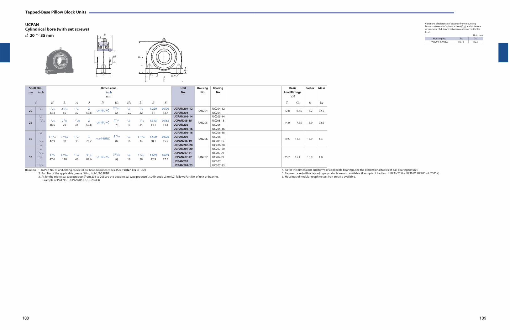
Tapped-Base Pillow Block Units
UCPAN Cylindrical bore (with set screws) d 20 ~ 35 mm
Remarks 1. In Part No. of unit, fitting codes follow bore diameter codes. (See Table 10.5 in P.62.) 2. Part No. of the applicable grease fitting is A-1/4-28UNF. 3. As for the triple seal type product (from 201 to 205 are the double seal type products), suffix code L3 (or L2) follows Part No. of unit or bearing.
(Example of Part No. : UCPAN206JL3, UC206L3)
Variations of tolerance of distance from mounting bottom to center of spherical bore (3Hs) and variations of tolerance of distance between centers of bolt holes (3Js)
Unit: mm Housing No. 3Hs 3Js
PAN204~PAN207 0.15 0.5
4. As for the dimensions and forms of applicable bearings, see the dimensional tables of ball bearing for unit. 5. Tapered bore (with adapter) type products are also available. (Example of Part No. : UKPAN205J H2305X, UK205 H2305X) 6. Housings of nodular graphite cast iron are also available.
108 109
B S
d
A
H 2
H
H 3
L 1J L
2-N
Shaft Dia. mm inch
d
H
L
A
J
Dimensions inch mm
N H2
H3
L1
B
S
Unit No.
HousingNo.
BearingNo.
BasicLoad Ratings
kN
Cr C0r
Factor
f 0
Mass
kg
20 3/4 1 5/16
33.3 2 9/16
65 1 1/4
32 2
50.8 3/
2 17/32 8-16UNC
64
1/2
12.7
7/8
22 1.220
31 0.500 12.7
UCPAN204-12 UCPAN204
PAN204 UC204-12UC204
12.8 6.65 13.2 0.55
25
7/8 1 7/16
36.5
2 3/4
70
1 13/32
36
2
50.8
3/
2 3/4
8-16UNC 70
1/2
13
15/16
24
1.343 34.1
0.563 14.3
UCPAN205-14
PAN205
UC205-14
14.0
7.85
13.9
0.65 15/16 UCPAN205-15
UCPAN205 UC205-15 UC205
1 UCPAN205-16 UC205-16
30
1 1/8 1 11/16
42.9
3 27/32
98
1 1/2
38
3
76.2
7/1
3 7/32
6-14UNC 82
5/8
16
1 11/32
34
1.500 38.1
0.626 15.9
UCPAN206-18
PAN206
UC206-18
19.5
11.3
13.9
1.3 1 3/16
UCPAN206 UCPAN206-19
UC206 UC206-19
1 1/4 UCPAN206-20 UC206-20
35
1 1/4
1 7/8
47.6
4 11/32
110
1 7/8
48
3 1/4
82.6
1/
3 21/32 2-13UNC
93
3/4
19
1 3/32
28
1.689 42.9
0.689 17.5
UCPAN207-20
PAN207
UC207-20
25.7
15.4
13.9
1.8 1 5/16
1 3/8
UCPAN207-21 UCPAN207-22 UCPAN207
UC207-21 UC207-22 UC207
1 7/16 UCPAN207-23 UC207-23
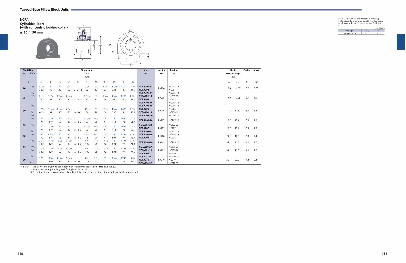
Tapped-Base Pillow Block Units
NCPA Cylindrical bore (with concentric locking collar) d 20 ~ 50 mm
B 1
S
d d 1
A
H 2
H
H 3
L 1
J 2-N
Variations of tolerance of distance from mounting bottom to center of spherical bore (3Hs) and variations of tolerance of distance between centers of bolt holes (3Js)
Unit: mm
L
Shaft Dia. mm inch
d
H
L
A
J
Dimension inch mm
N H2
s
H3
L1
B1
S
d1
Unit No.
HousingNo.
BearingNo.
BasicLoad Ratings
kN
Cr C0r
Factor
f 0
Mass
kg
20 3/4 1 3/16
30.2 3
76 1 9/16
40 2 3/64
52 M10×1.5
2 3/8
60
1/2
13 1 1/16
27 1 9/32
32.5 0.500 12.7
1 3/4
44.5 NCPA204-12 NCPA204
PA204 NC204-12NC204
12.8 6.65 13.2 0.73
25
7/8 1 7/16
3 5/16
1 25/32
2 13/64
M10×1.5
2 25/32
1/2
1 3/16
1 7/16
0.563
1 15/16
NCPA205-14
PA205
NC205-14
14.0
7.85
13.9
1.0 15/16 NCPA205-15
NCPA205 NC205-15 NC205 36.5 84 45 56 71 13 30 36.5 14.3 49.2
1 NCPA205-16 NC205-16
30
1 1/8 1 11/16
3 11/16
1 31/32
2 19/32
M14×2
3 5/16
23/32
1 13/32
1 9/16
0.626
2 3/16
NCPA206-18
PA206
NC206-18
19.5
11.3
13.9
1.4 1 3/16
NCPA206 NCPA206-19
NC206 NC206-19 42.9 94 50 66 84 18 36 39.7 15.9 55.6
1 1/4 NCPA206-20 NC206-20
35
1 1/4 1 7/8
47.6 4 11/32
110 2 5/32
55 3 5/32
80
M14×2 3 21/32
93
25/32
20 1 5/8
41 1 3/4
44.5 0.689 17.5
2 7/16
61.9 NCPA207-20 PA207 NC207-20 25.7 15.4 13.9 2.0
1 3/8
1 7/16
1 7/8
47.6 4 11/32
110 2 5/32
55 3 5/32
80
M14×2 3 21/32
93
25/32
20 1 5/8
41 1 3/4
44.5 0.689 17.5
2 9/16
65.1
NCPA207-22 NCPA207 NCPA207-23
PA207
NC207-22 NC207 NC207-23
25.7
15.4
13.9
2.0
40 1 1/2 1 15/16
49.2 4 9/16
116 2 9/32
58 3 5/16
84
M14×2 3 27/32
98
25/32
20 1 5/8
41 2
50.8 0.748
19 2 11/16
68.3 NCPA208-24 NCPA208
PA208 NC208-24NC208
29.1 17.8 14.0 2.4
45
1 5/8 2 9/64
54.2 4 23/32
120 2 3/8
60 3 35/64
90
M14×2 4 3/16
106
31/32
25 1 21/32
42 2
50.8 0.748
19 2 13/16
71.4 NCPA209-26 PA209 NC209-26 34.1 21.3 14.0 2.6
1 11/16
1 3/4 2 9/64
54.2 4 23/32
120 2 3/8
60 3 35/64
90
M14×2 4 3/16
106
31/32
25 1 21/32
42 2
50.8 0.748
19 2 15/16
74.6
NCPA209-27 NCPA209-28 NCPA209
PA209
NC209-27 NC209-28 NC209
34.1
21.3
14.0
2.6
50
1 15/16
2
2 1/4
57.2 5 1/8
130 2 17/32
64 3 45/64
94
M16×2 4 7/16
113
31/32
25 1 27/32
47 2 3/32
53.1 0.748
19 3 3/8
85.7
NCPA210-31 NCPA210 NCPA210-32
PA210
NC210-31NC210 NC210-32
35.1
23.3
14.4
3.4
Remarks 1. In Part No. of unit, fitting codes follow bore diameter codes. (See Table 10.5 in P.62.) 2. Part No. of the applicable grease fitting is A-1/4-28UNF. 3. As for the dimensions and forms of applicable bearings, see the dimensional tables of ball bearing for unit.
110 111
Housing No. 3Hs 3Js
PA204~PA210 0.15 0.5
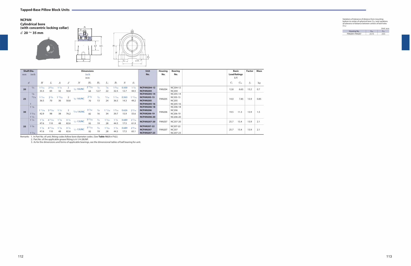
S
Tapped-Base Pillow Block Units
NCPAN Cylindrical bore (with concentric locking collar) B1
d 20 ~ 35 mm
Variations of tolerance of distance from mounting bottom to center of spherical bore (3Hs) and variations of tolerance of distance between centers of bolt holes (3Js)
Unit: mm
d d 1 H 2
H
A L1
H 3
2-N
J L
Shaft Dia.
mm inch
d
H
L
A
J
N
Dimensions inch mm
H2
H3
L1
B1
S
d1
Unit No.
HousingNo.
BearingNo.
BasicLoad Ratings
kN
Cr C0r
Factor
f 0
Mass
kg
20 3/4 1 5/16
33.3 2 9/16
65 1 1/4
32 2
50.8 3/8
2 17/32 -16UNC
64
1/2
12.7
7/8
22 1 9/32
32.5 0.500 12.7
1 3/4
44.5 NCPAN204-12 NCPAN204
PAN204 NC204-12 NC204
12.8 6.65 13.2 0.7
25
7/8 1 7/16
36.5
2 3/4
70
1 13/32
36
2
50.8
3/8
2 3/4
-16UNC 70
1/2
13
15/16
24
1 7/16
36.5
0.563 14.3
1 15/16
49.2
NCPAN205-14
PAN205
NC205-14
14.0
7.85
13.9
0.85 15/16 NCPAN205-15
NCPAN205 NC205-15 NC205
1 NCPAN205-16 NC205-16
30
1 1/8 1 11/16
42.9
3 27/32
98
1 1/2
38
3
76.2
3 7/32
7/16-14UNC 82
5/8
16
1 11/32
34
1 9/16
39.7
0.626 15.9
2 3/16
55.6
NCPAN206-18
PAN206
NC206-18
19.5
11.3
13.9
1.5 1 3/16
NCPAN206 NCPAN206-19
NC206 NC206-19
1 1/4 NCPAN206-20 NC206-20
35
1 1/4 1 7/8
47.6 4 11/32
110 1 7/8
48 3 1/4
82.6 1/2
3 21/32 -13UNC
93
3/4
19 1 3/32
28 1 3/4
44.5 0.689 17.5
2 7/16
61.9 NCPAN207-20 PAN207 NC207-20 25.7 15.4 13.9 2.1
1 3/8
1 7/16
1 7/8
47.6 4 11/32
110 1 7/8
48 3 1/4
82.6
1/2
3 21/32 -13UNC
93
3/4
19 1 3/32
28 1 3/4
44.5 0.689 17.5
2 9/16
65.1
NCPAN207-22 NCPAN207 NCPAN207-23
PAN207
NC207-22 NC207 NC207-23
25.7
15.4
13.9
2.1
Remarks 1. In Part No. of unit, fitting codes follow bore diameter codes. (See Table 10.5 in P.62.) 2. Part No. of the applicable grease fitting is A-1/4-28UNF. 3. As for the dimensions and forms of applicable bearings, see the dimensional tables of ball bearing for unit.
112 113
Housing No. 3Hs 3Js
PAN204~PAN207 0.15 0.5
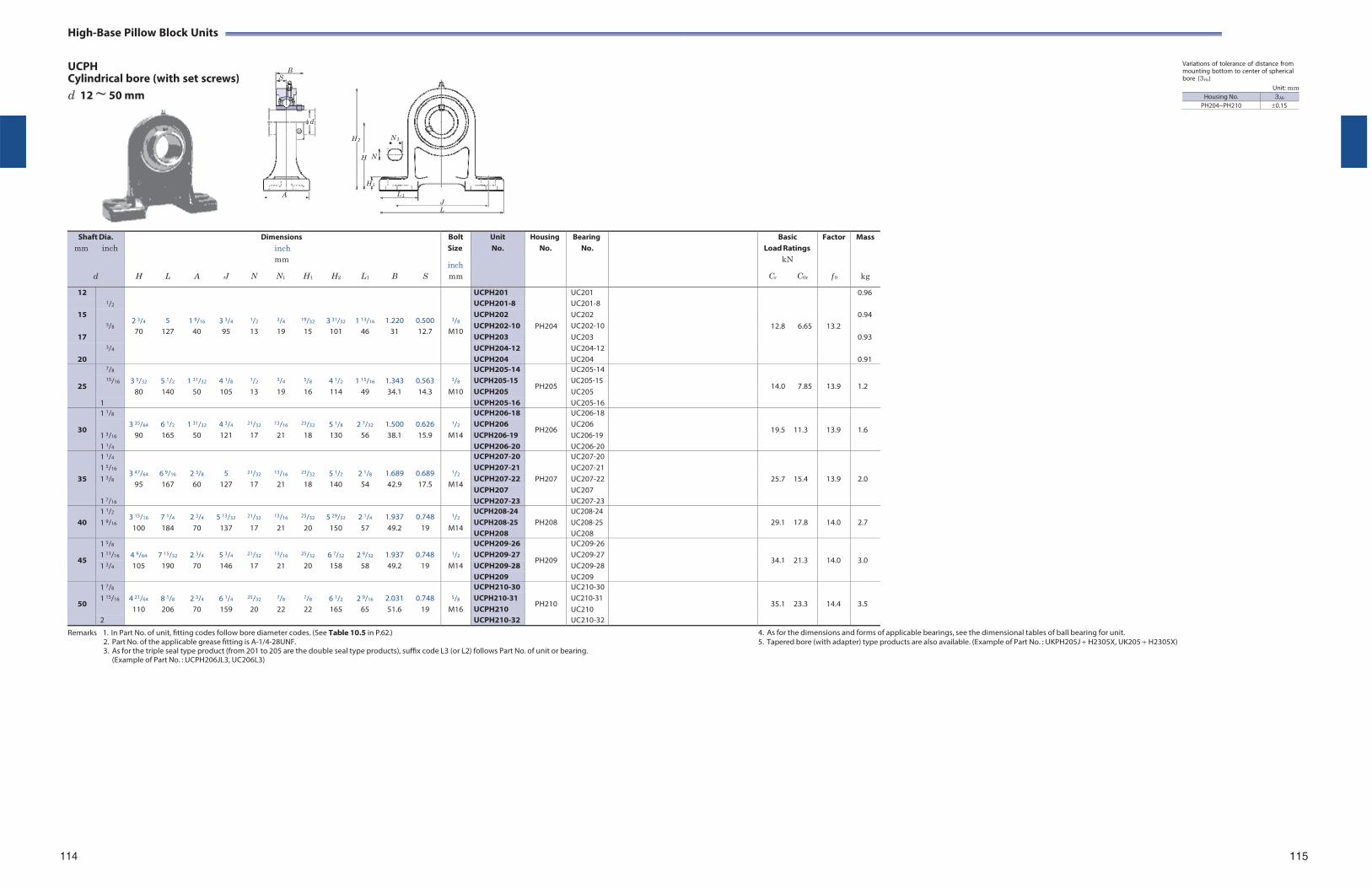
High-Base Pillow Block Units
UCPH Cylindrical bore (with set screws)
Variations of tolerance of distance from mounting bottom to center of spherical bore (3Hs)
d 12 ~ 50 mm Unit: mm
Shaft Dia. mm inch
d
H
L
A
J
Dimensions inch mm
N N1 H1
H2
L1
B
S
Bolt Size
inch mm
Unit No.
HousingNo.
BearingNo.
BasicLoad Ratings
kN
Cr C0r
Factor
f 0
Mass
kg
12 1/2
2 3/4
5
1 9/16
3 3/4
1/2
3/4
19/32
3 31/32
1 13/16
1.220
0.500
3/8
UCPH201
PH204
UC201
12.8
6.65
13.2
0.96 UCPH201-8 UC201-8
15 5/8
UCPH202 UC202 0.94 UCPH202-10 UC202-10
70 127 40 95 13 19 15 101 46 31 12.7 M10 17 UCPH203 UC203 0.93
3/4 UCPH204-12 UC204-1220 UCPH204 UC204 0.91
25
7/8 3 5/32
5 1/2
1 31/32
4 1/8
1/2
3/4
5/8
4 1/2
1 15/16
1.343
0.563
3/8
UCPH205-14
PH205
UC205-14
14.0
7.85
13.9
1.2 15/16 UCPH205-15
UCPH205 UC205-15 UC205 80 140 50 105 13 19 16 114 49 34.1 14.3 M10
1 UCPH205-16 UC205-16
30
1 1/8 3 35/64
6 1/2
1 31/32
4 3/4
21/32
13/16
23/32
5 1/8
2 7/32
1.500
0.626
1/2
UCPH206-18
PH206
UC206-18
19.5
11.3
13.9
1.6 1 3/16
UCPH206 UCPH206-19
UC206 UC206-19 90 165 50 121 17 21 18 130 56 38.1 15.9 M14
1 1/4 UCPH206-20 UC206-20
35
1 1/4
3 47/64
6 9/16
2 3/8
5
21/32
13/16
23/32
5 1/2
2 1/8
1.689
0.689
1/2
UCPH207-20
PH207
UC207-20
25.7
15.4
13.9
2.0
1 5/16 UCPH207-21 UC207-211 3/8 UCPH207-22 UC207-22
95 167 60 127 17 21 18 140 54 42.9 17.5 M14 UCPH207 UC207
1 7/16 UCPH207-23 UC207-23
40 1 1/2
1 9/16 3 15/16
100 7 1/4
184 2 3/4
70 5 13/32
137
21/32
17
13/16
21
25/32
20 5 29/32
150 2 1/4
57 1.937 49.2
0.748 19
1/2
M14
UCPH208-24 UCPH208-25 UCPH208
PH208
UC208-24 UC208-25 UC208
29.1
17.8
14.0
2.7
45
1 5/8 4 9/64
7 15/32
2 3/4
5 3/4
21/32
13/16
25/32
6 7/32
2 9/32
1.937
0.748
1/2
UCPH209-26
PH209
UC209-26
34.1
21.3
14.0
3.0 1 11/16 UCPH209-27 UC209-271 3/4 105 190 70 146 17 21 20 158 58 49.2 19 M14 UCPH209-28 UC209-28
UCPH209 UC209
50
1 7/8 4 21/64
8 1/8
2 3/4
6 1/4
25/32
7/8
7/8
6 1/2
2 9/16
2.031
0.748
5/8
UCPH210-30
PH210
UC210-30
35.1
23.3
14.4
3.5 1 15/16 UCPH210-31
UCPH210 UC210-31 UC210 110 206 70 159 20 22 22 165 65 51.6 19 M16
2 UCPH210-32 UC210-32
Remarks 1. In Part No. of unit, fitting codes follow bore diameter codes. (See Table 10.5 in P.62.) 2. Part No. of the applicable grease fitting is A-1/4-28UNF. 3. As for the triple seal type product (from 201 to 205 are the double seal type products), suffix code L3 (or L2) follows Part No. of unit or bearing.
(Example of Part No. : UCPH206JL3, UC206L3)
4. As for the dimensions and forms of applicable bearings, see the dimensional tables of ball bearing for unit. 5. Tapered bore (with adapter) type products are also available. (Example of Part No. : UKPH205J H2305X, UK205 H2305X)
114 115
B S
d
A
H 2 N 1
H N
H 1
L 1
J L
Housing No. 3Hs
PH204~PH210 0.15
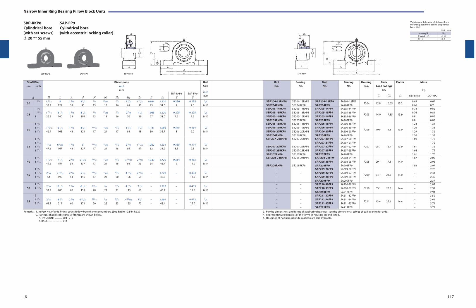
B1
S
d
A
Narrow Inner Ring Bearing Pillow Block Units
SBP-RKP8 Cylindrical bore (with set screws) d 20 ~ 55 mm
SAP-FP9 Cylindrical bore (with eccentric locking collar)
N1
Variations of tolerance of distance from mounting bottom to center of spherical bore (3Hs)
Unit: mm Housing No. 3Hs
P204~P210 0.15P211 0.2
N1
N N
H 2 H2
SBP-RKP8 SAP-FP9
H
H 1
L1
J
SBP-RKP8 L
H
H1
L1
J
SAP-FP9 L
Shaft Dia.
mm inch
d
Dimensions inch mm
BoltSize
inch mm
UnitNo.
BearingNo.
UnitNo.
Bearing No.
Housing No.
BasicLoad Ratings
kN
Cr C0r
Factor
f 0
Mass
kg
SBP-RKP8 SAP-FP9
H L A J N N1 H1 H2 L1 B B1
SBP-RKP8 S
SAP-FP9 S
20 3/4 1 5/16 5 1 1/2 3 3/4 1/2 23/32 5/8 2 9/16 1 13/32 0.984 1.220
33.3 127 38 95 13 18 16 65 36 25 31.0 0.276
7 0.295
7.5
3/8
M10 SBP204-12RKP8
SBP204RKP8SB204-12RKP8 SB204RKP8
SAP204-12FP9 SAP204FP9
SA204-12FP9 SA204FP9
P204 12.8 6.65 13.2 0.65 0.69 0.66 0.7
25
7/8
15/16
1
1 7/16 5 1/2 1 1/2 4 1/8 1/2 23/32 5/8 2 3/4 1 1/2 1.063 1.220 36.5 140 38 105 13 18 16 70 38 27 31.0
0.295
7.5
0.295
7.5
3/8
M10
SBP205-14RKP8 SBP205-15RKP8 SBP205-16RKP8 SBP205RKP8
SB205-14RKP8 SB205-15RKP8 SB205-16RKP8 SB205RKP8
SAP205-14FP9 SAP205-15FP9 SAP205-16FP9 SAP205FP9
SA205-14FP9 SA205-15FP9 SA205-16FP9 SA205FP9
P205
14.0 7.85
13.9
0.78 0.82 0.76 0.81 0.8 0.85 0.8 0.85
30
1 1/8
1 3/16
1 1/4
1 11/16 6 1/2 1 7/8 4 3/4 21/32 13/16 21/32 3 5/16 1 7/8 1.181 1.906 42.9 165 48 121 17 21 17 84 48 30 35.7
0.315
8
0.354
9.0
1/2
M14
SBP206-18RKP8 SBP206-19RKP8 SBP206-20RKP8 SBP206RKP8
SB206-18RKP8 SB206-19RKP8 SB206-20RKP8 SB206RKP8
SAP206-18FP9 SAP206-19FP9 SAP206-20FP9 SAP206FP9
SA206-18FP9 SA206-19FP9 SA206-20FP9 SA206FP9
P206
19.5 11.3
13.9
1.24 1.31 1.26 1.33 1.29 1.36 1.26 1.33
35
1 1/4
1 5/16
1 3/8
1 7/16
1 7/8 6 9/16 1 7/8 5 21/32 13/16 23/32 3 3/4 1 27/32 1.260 1.531 47.6 167 48 127 17 21 18 95 47 32 38.9
0.335 8.5
0.374 9.5
1/2
M14
SBP207-20RKP8
SBP207-22RKP8 SBP207-23RKP8 SBP207RKP8
SB207-20RKP8
SB207-22RKP8 SB207-23RKP8 SB207RKP8
SAP207-20FP9 SAP207-21FP9 SAP207-22FP9 SAP207-23FP9 SAP207FP9
SA207-20FP9 SA207-21FP9 SA207-22FP9 SA207-23FP9 SA207FP9
P207
25.7 15.4
13.9
1.69 1.76 1.72
1.61 1.76 1.64 1.79 1.61 1.76
40
1 1/2
1 9/16 1 15/16 7 1/4 2 1/8 5 13/32 21/32 13/16 23/32 3 27/32 2 3/32 1.339 1.720 49.2 184 54 137 17 21 18 98 53 34 43.7
0.354 9
0.433 11.0
1/2
M14
SBP208-24RKP8
SBP208RKP8
SB208-24RKP8
SB208RKP8
SAP208-24FP9 SAP208-25FP9 SAP208FP9
SA208-24FP9 SA208-25FP9 SA208FP9
P208
29.1 17.8
14.0
1.87 2.02 2.06
1.92 2.07
45
1 5/8
1 11/16
1 3/4
2 1/8 7 15/32 2 1/8 5 3/4 21/32 13/16 25/32 4 3/16 2 5/32 1.720 54 190 54 146 17 21 20 106 55 43.7
0.433 11.0
1/2
M14
SAP209-26FP9 SAP209-27FP9 SAP209-28FP9 SAP209FP9
SA209-26FP9 SA209-27FP9 SA209-28FP9 SA209FP9
P209
34.1 21.3
14.0
2.26 2.31 2.35 2.37
50
1 7/8
1 15/16 2 1/4 8 1/8 2 3/8 6 1/4 25/32 7/8 13/16 4 7/16 2 3/8 1.720 57.2 206 60 159 20 22 21 113 60 43.7
0.433 11.0
5/8
M16
SAP210-30FP9 SAP210-31FP9 SAP210FP9
SA210-30FP9 SA210-31FP9 SA210FP9
P210
35.1 23.3
14.4
2.87 2.91 2.94
55
2 2 1/8
2 3/16
2 1/2 8 5/8 2 3/8 6 23/32 25/32 7/8 29/32 4 29/32 2 3/4 1.906 63.5 219 60 171 20 22 23 125 70 48.4
0.472 12.0
5/8
M16
SAP211-32FP9 SAP211-34FP9 SAP211-35FP9 SAP211FP9
SA211-32FP9 SA211-34FP9 SA211-35FP9 SA211FP9
P211
43.4 29.4
14.4
3.52 3.61 3.74 3.71
Remarks 1. In Part No. of unit, fitting codes follow bore diameter numbers. (See Table 10.5 in P.62.) 2. Part No. of applicable grease fittings are shown below.
A-1/4-28UNF ............. 204~210 A-R1/8 .......................... 211
3. For the dimensions and forms of applicable bearings, see the dimensional tables of ball bearing for unit. 4. Representative examples of the forms of housing are indicated. 5. Housings of nodular graphite cast iron are also available.
116 117
B S
d
A
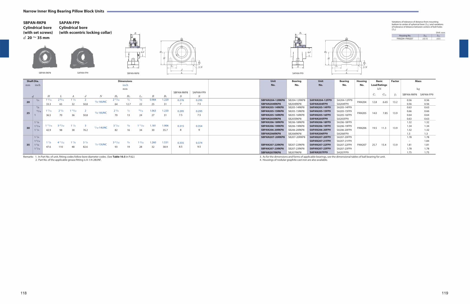
B1
S
d
A
Narrow Inner Ring Bearing Pillow Block Units
SBPAN-RKP8 Cylindrical bore (with set screws) d 20 ~ 35 mm
SAPAN-FP9 Cylindrical bore (with eccentric locking collar)
Variations of tolerance of distance from mounting bottom to center of spherical bore (3Hs) and variations of tolerance of distance between centers of bolt holes (3Js)
Unit: mm
H 2 H2
SBPAN-RKP8 SAPAN-FP9
SBPAN-RKP8
H
H3
L1 2-N J
L
SAPAN-FP9
H
H3
L1 2-N J
L
Shaft Dia.
mm inch
d
Dimensions inch mm
UnitNo.
BearingNo.
UnitNo.
Bearing No.
Housing No.
BasicLoad Ratings
kN
Cr C0r
Factor
f 0
Mass
kg
SBPAN-RKP8 SAPAN-FP9
H L A J N H2 H3 L1 B B1
SBPAN-RKP8 S
SAPAN-FP9 S
20 3/4 1 5/16 2 9/16 1 1/4 2 2 17/32 1/2 7/8 0.984 1.220
3/8-16UNC 33.3 65 32 50.8 64 12.7 22 25 31
0.276 7
0.295 7.5
SBPAN204-12RKP8 SBPAN204RKP8
SB204-12RKP8 SB204RKP8
SAPAN204-12FP9 SAPAN204FP9
SA204-12FP9 SA204FP9
PAN204 12.8 6.65 13.2 0.56 0.56 0.56 0.56
25
7/8
15/16
1
1 7/16 2 3/4 1 13/32 2 2 3/4 1/2 15/16 1.063 1.220
3/8-16UNC 36.5 70 36 50.8 70 13 24 27 31
0.295
7.5
0.295
7.5
SBPAN205-14RKP8 SBPAN205-15RKP8 SBPAN205-16RKP8 SBPAN205RKP8
SB205-14RKP8 SB205-15RKP8 SB205-16RKP8 SB205RKP8
SAPAN205-14FP9 SAPAN205-15FP9 SAPAN205-16FP9 SAPAN205FP9
SA205-14FP9 SA205-15FP9 SA205-16FP9 SA205FP9
PAN205
14.0 7.85
13.9
0.63 0.63 0.66 0.66 0.64 0.64 0.63 0.63
30
1 1/8
1 3/16
1 1/4
1 11/16 3 27/32 1 1/2 3 3 7/32 5/8 1 11/32 1.181 1.906
7/16-14UNC 42.9 98 38 76.2 82 16 34 30 35.7
0.315
8
0.354
9
SBPAN206-18RKP8 SBPAN206-19RKP8 SBPAN206-20RKP8 SBPAN206RKP8
SB206-18RKP8 SB206-19RKP8 SB206-20RKP8 SB206RKP8
SAPAN206-18FP9 SAPAN206-19FP9 SAPAN206-20FP9 SAPAN206FP9
SA206-18FP9 SA206-19FP9 SA206-20FP9 SA206FP9
PAN206
19.5 11.3
13.9
1.32 1.32 1.34 1.34 1.32 1.32 1.3 1.3
35
1 1/4
1 5/16
1 3/8
1 7/16
1 7/8 4 11/32 1 7/8 3 1/4 3 21/32 3/4 1 3/32 1.260 1.531 1/2-13UNC
47.6 110 48 82.6 93 19 28 32 38.9
0.335 8.5
0.374 9.5
SBPAN207-20RKP8
SBPAN207-22RKP8 SBPAN207-23RKP8 SBPAN207RKP8
SB207-20RKP8
SB207-22RKP8 SB207-23RKP8 SB207RKP8
SAPAN207-20FP9 SAPAN207-21FP9 SAPAN207-22FP9 SAPAN207-23FP9 SAPAN207FP9
SA207-20FP9 SA207-21FP9 SA207-22FP9 SA207-23FP9 SA207FP9
PAN207
25.7 15.4
13.9
1.78 1.78 1.84
1.81 1.81 1.78 1.78 1.75 1.75
Remarks 1. In Part No. of unit, fitting codes follow bore diameter codes. (See Table 10.5 in P.62.) 2. Part No. of the applicable grease fitting is A-1/4-28UNF.
3. As for the dimensions and forms of applicable bearings, see the dimensional tables of ball bearing for unit. 4. Housings of nodular graphite cast iron are also available.
118
119
B S
d
A
Housing No. 3Hs 3Js
PAN204~PAN207 0.15 0.5
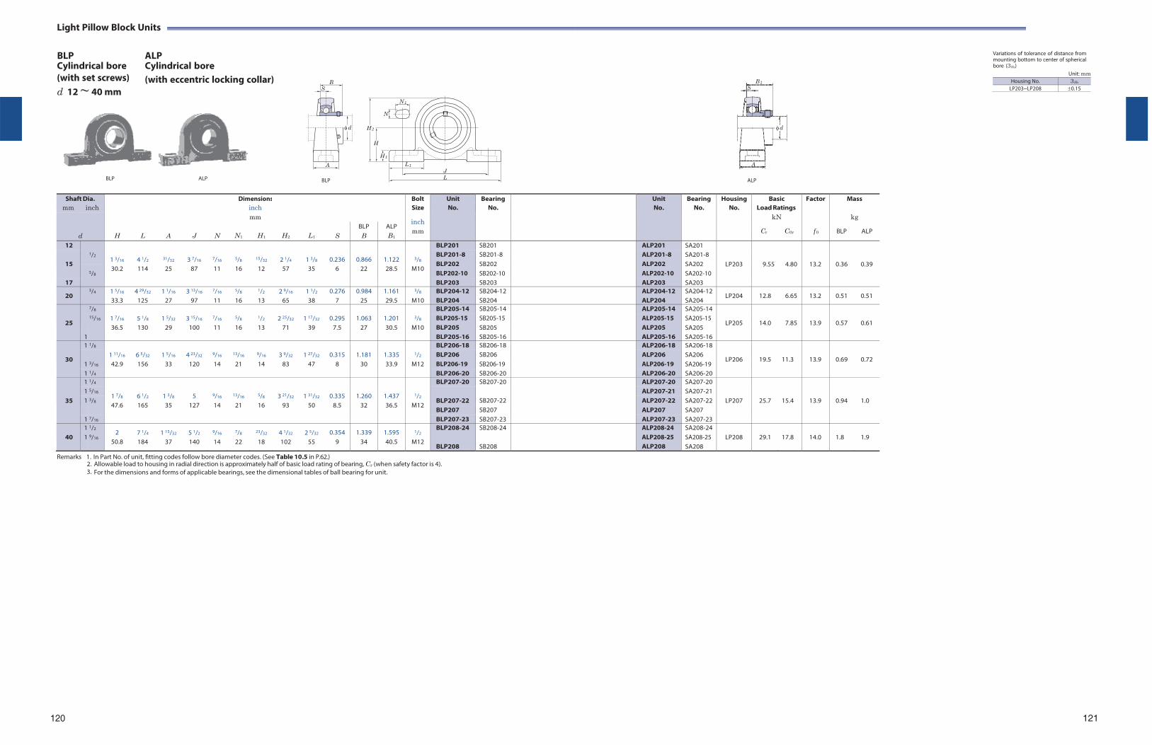
Light Pillow Block Units
BLP Cylindrical bore
ALP Cylindrical bore
Variations of tolerance of distance from mounting bottom to center of spherical bore (3Hs)
(with set screws) d 12 ~ 40 mm
(with eccentric locking collar)
N 1
Unit: mm
N
H 2
H
BLP ALP
BLP
H 1
L 1
J L
ALP
Shaft Dia. Dimensions Bolt Unit Bearing Unit Bearing Housing Basic Factor Mass mm inch inch Size No. No. No. No. No. Load Ratings
d
mm inch
kN kg
H
L
A
J
N
N1
H1
H2
L1
S
BLP B
ALP B1
mm Cr C0r f 0 BLP ALP
12 1/2
1 3/16
4 1/2
31/32
3 7/16
7/16
5/8
15/32
2 1/4
1 3/8
0.236
0.866
1.122
3/8
BLP201 SB201 ALP201 SA201
LP203
9.55
4.80
13.2
0.36
0.39
15
BLP201-8 BLP202 BLP202-10
SB201-8 SB202 SB202-10
ALP201-8 ALP202 ALP202-10
SA201-8 SA202 SA202-10 5/8
30.2 114 25 87 11 16 12 57 35 6 22 28.5 M10
17 BLP203 SB203 ALP203 SA203
20 3/4 1 5/16
33.3 4 29/32
125 1 1/16
27 3 13/16
97
7/16
11
5/8
16
1/2
13 2 9/16
65 1 1/2
38 0.276
7 0.984
25 1.161 29.5
3/8
M10 BLP204-12 BLP204
SB204-12 SB204
ALP204-12 ALP204
SA204-12 SA204
LP204 12.8 6.65 13.2 0.51 0.51
25
7/8 1 7/16
5 1/8
1 5/32
3 15/16
7/16
5/8
1/2
2 25/32
1 17/32
0.295
1.063
1.201
3/8
BLP205-14 SB205-14 ALP205-14 SA205-14
LP205
14.0
7.85
13.9
0.57
0.61 15/16 BLP205-15 BLP205
SB205-15 SB205
ALP205-15 ALP205
SA205-15 SA205 36.5 130 29 100 11 16 13 71 39 7.5 27 30.5 M10
1 BLP205-16 SB205-16 ALP205-16 SA205-16
30
1 1/8 1 11/16
6 5/32
1 5/16
4 23/32
9/16
13/16
9/16
3 9/32
1 27/32
0.315
1.181
1.335
1/2
BLP206-18 SB206-18 ALP206-18 SA206-18
LP206
19.5
11.3
13.9
0.69
0.72 1
3/16
BLP206 BLP206-19
SB206 SB206-19
ALP206 ALP206-19
SA206 SA206-19 42.9 156 33 120 14 21 14 83 47 8 30 33.9 M12
1 1/4 BLP206-20 SB206-20 ALP206-20 SA206-20
35
1 1/4
1 7/8
6 1/2
1 3/8
5
9/16
13/16
5/8
3 21/32
1 31/32
0.335
1.260
1.437
1/2
BLP207-20 SB207-20 ALP207-20 SA207-20
LP207
25.7
15.4
13.9
0.94
1.0
1 5/16 BLP207-22
SB207-22
ALP207-21 SA207-21 1 3/8 ALP207-22 SA207-22
47.6 165 35 127 14 21 16 93 50 8.5 32 36.5 M12 BLP207 SB207 ALP207 SA207
1 7/16 BLP207-23 SB207-23 ALP207-23 SA207-23
40 1 1
1/2
9/16 2
50.8 7 1/4
184 1 15/32
37 5 1/2
140
9/16
14
7/8
22
23/32
18 4 1/32
102 2 5/32
55 0.354
9 1.339
34 1.595 40.5
1/2
M12
BLP208-24
BLP208
SB208-24
SB208
ALP208-24 ALP208-25 ALP208
SA208-24 SA208-25 SA208
LP208
29.1
17.8
14.0
1.8
1.9
Remarks 1. In Part No. of unit, fitting codes follow bore diameter codes. (See Table 10.5 in P.62.) 2. Allowable load to housing in radial direction is approximately half of basic load rating of bearing, Cr (when safety factor is 4). 3. For the dimensions and forms of applicable bearings, see the dimensional tables of ball bearing for unit.
120
121
B S
d
A
B 1S
d
A
Housing No. 3Hs
LP203~LP208 0.15
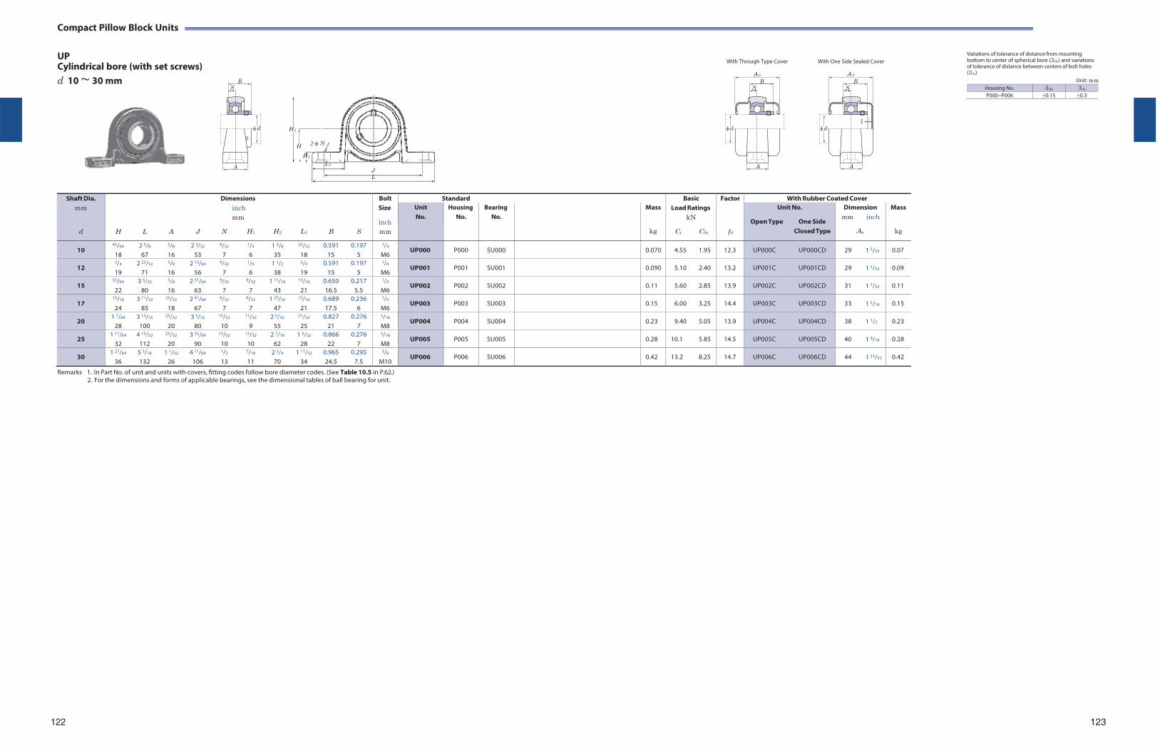
Compact Pillow Block Units
UP Cylindrical bore (with set screws) d 10 ~ 30 mm
With Through Type Cover With One Side Sealed Cover Variations of tolerance of distance from mounting bottom to center of spherical bore (3Hs) and variations of tolerance of distance between centers of bolt holes (3Js)
Unit: mm
H 2
H 2-N
H 1
L 1
J L
Shaft Dia.
mm
d
H
L
A
J
Dimensions inch mm
N H1
H2
L1
B
S
Bolt Size
inch mm
Standard BasicLoad Ratings
kN
Cr C0r
Factor
f 0
With Rubber Coated Cover Unit No.
Housing No.
Bearing No.
Mass
kg
Unit No.
Open Type One Side Closed Type
Dimension mm inch
As
Mass
kg
10 45/64
18 2 5/8
67
5/8
16 2 3/32
53
9/32
7
1/4
6 1 3/8
35
23/32
18 0.591
15 0.197
5
1/4
M6 UP000 P000 SU000 0.070 4.55 1.95 12.3 UP000C UP000CD 29 1 5/32 0.07
12 3/4
19 2 25/32
71
5/8
16 2 13/64
56
9/32
7
1/4
6 1 1/2
38
3/4
19 0.591
15 0.197
5
1/4
M6 UP001 P001 SU001 0.090 5.10 2.40 13.2 UP001C UP001CD 29 1 5/32 0.09
15 55/64
22 3 5/32
80
5/8
16 2 31/64
63
9/32
7
9/32
7 1 11/16
43
13/16
21 0.650 16.5
0.217 5.5
1/4
M6 UP002 P002 SU002 0.11 5.60 2.85 13.9 UP002C UP002CD 31 1 7/32 0.11
17 15/16
24 3 11/32
85
23/32
18 2 41/64
67
9/32
7
9/32
7 1 27/32
47
13/16
21 0.689 17.5
0.236 6
1/4
M6 UP003 P003 SU003 0.15 6.00 3.25 14.4 UP003C UP003CD 33 1 5/16 0.15
20 1 7/64
28 3 15/16
100
25/32
20 3 5/32
80
13/32
10
11/32
9 2 5/32
55
31/32
25 0.827
21 0.276
7
5/16
M8 UP004 P004 SU004 0.23 9.40 5.05 13.9 UP004C UP004CD 38 1 1/2 0.23
25 1 17/64
32 4 13/32
112
25/32
20 3 35/64
90
13/32
10
13/32
10 2 7/16
62 1 3/32
28 0.866
22 0.276
7
5/16
M8 UP005 P005 SU005 0.28 10.1 5.85 14.5 UP005C UP005CD 40 1 9/16 0.28
30 1 27/64
36 5 3/16
132 1 1/32
26 4 11/64
106
1/2
13
7/16
11 2 3/4
70 1 11/32
34 0.965 24.5
0.295 7.5
3/8
M10 UP006 P006 SU006 0.42 13.2 8.25 14.7 UP006C UP006CD 44 1 23/32 0.42
Remarks 1. In Part No. of unit and units with covers, fitting codes follow bore diameter codes. (See Table 10.5 in P.62.) 2. For the dimensions and forms of applicable bearings, see the dimensional tables of ball bearing for unit.
122 123
B S
d
A
AS
B S
1 d
A
AS
B S
d
A
Housing No. 3Hs 3Js
P000~P006 0.15 0.3
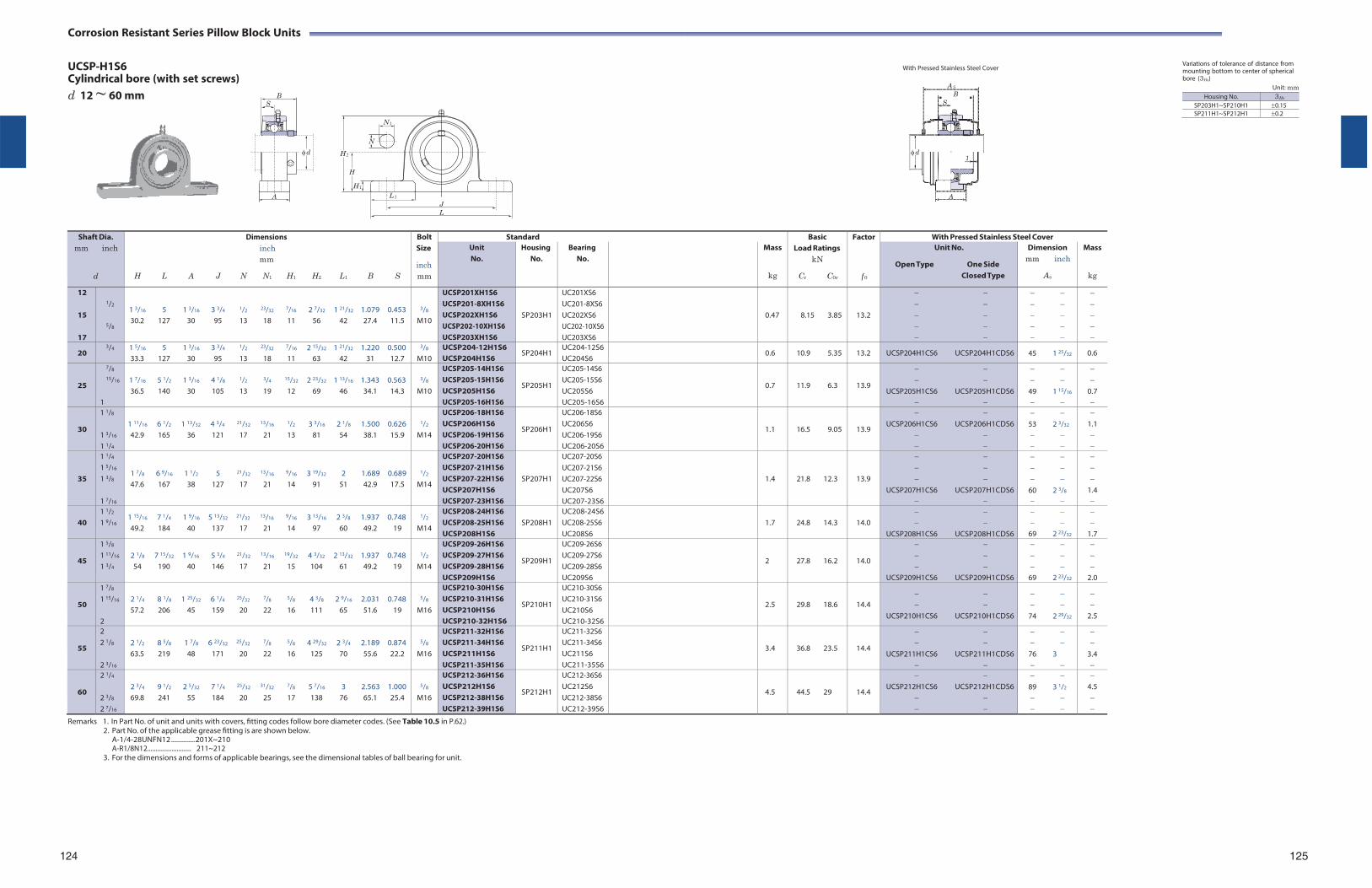
Corrosion Resistant Series Pillow Block Units
UCSP-H1S6 Cylindrical bore (with set screws) d 12 ~ 60 mm
N 1
N
H 2
H
With Pressed Stainless Steel Cover
Variations of tolerance of distance from mounting bottom to center of spherical bore (3Hs)
Unit: mm
H 1
L 1
J L
Shaft Dia.
mm inch
d
Dimensions inch mm
H L A J N N1 H1 H2 L1 B S
Bolt Size
inch mm
Standard BasicLoad Ratings
kN
Cr C0r
Factor
f 0
With Pressed Stainless Steel Cover Unit No.
Housing No.
Bearing No.
Mass
kg
Unit No.
Open Type One Side Closed Type
Dimension mm inch
As
Mass
kg
12
15
17
1/2
5/8
1 3/16 5 1 3/16 3 3/4 1/2 23/32 7/16 2 7/32 1 21/32 1.079 0.453 30.2 127 30 95 13 18 11 56 42 27.4 11.5
3/8
M10
UCSP201XH1S6 UCSP201-8XH1S6 UCSP202XH1S6 UCSP202-10XH1S6 UCSP203XH1S6
SP203H1
UC201XS6 UC201-8XS6 UC202XS6 UC202-10XS6 UC203XS6
0.47
8.15 3.85
13.2
20 3/4 1 5/16 5 1 3/16 3 3/4 1/2 23/32 7/16 2 15/32 1 21/32 1.220 0.500
33.3 127 30 95 13 18 11 63 42 31 12.7
3/8
M10 UCSP204-12H1S6 UCSP204H1S6
SP204H1 UC204-12S6 UC204S6
0.6 10.9 5.35 13.2 UCSP204H1CS6 UCSP204H1CDS6 45 1 25/32 0.6
25
7/8
15/16
1
1 7/16 5 1/2 1 3/16 4 1/8 1/2 3/4 15/32 2 23/32 1 13/16 1.343 0.563 36.5 140 30 105 13 19 12 69 46 34.1 14.3
3/8
M10
UCSP205-14H1S6 UCSP205-15H1S6 UCSP205H1S6 UCSP205-16H1S6
SP205H1
UC205-14S6 UC205-15S6 UC205S6 UC205-16S6
0.7
11.9 6.3
13.9
UCSP205H1CS6 UCSP205H1CDS6
49 1 15/16
0.7
30
1 1/8
1 3/16
1 1/4
1 11/16 6 1/2 1 13/32 4 3/4 21/32 13/16 1/2 3 3/16 2 1/8 1.500 0.626 42.9 165 36 121 17 21 13 81 54 38.1 15.9
1/2
M14
UCSP206-18H1S6 UCSP206H1S6 UCSP206-19H1S6 UCSP206-20H1S6
SP206H1
UC206-18S6 UC206S6 UC206-19S6 UC206-20S6
1.1
16.5 9.05
13.9
UCSP206H1CS6 UCSP206H1CDS6
53 2 3/32
1.1
35
1 1/4
1 5/16
1 3/8
1 7/16
1 7/8 6 9/16 1 1/2 5 21/32 13/16 9/16 3 19/32 2 1.689 0.689 47.6 167 38 127 17 21 14 91 51 42.9 17.5
1/2
M14
UCSP207-20H1S6 UCSP207-21H1S6 UCSP207-22H1S6 UCSP207H1S6 UCSP207-23H1S6
SP207H1
UC207-20S6 UC207-21S6 UC207-22S6 UC207S6 UC207-23S6
1.4
21.8 12.3
13.9
UCSP207H1CS6 UCSP207H1CDS6
60 2 3/8
1.4
40
1 1/2
1 9/16 1 15/16 7 1/4 1 9/16 5 13/32 21/32 13/16 9/16 3 13/16 2 3/8 1.937 0.748 49.2 184 40 137 17 21 14 97 60 49.2 19
1/2
M14
UCSP208-24H1S6 UCSP208-25H1S6 UCSP208H1S6
SP208H1
UC208-24S6 UC208-25S6 UC208S6
1.7
24.8 14.3
14.0
UCSP208H1CS6 UCSP208H1CDS6
69 2 23/32
1.7
45
1 5/8
1 11/16
1 3/4
2 1/8 7 15/32 1 9/16 5 3/4 21/32 13/16 19/32 4 3/32 2 13/32 1.937 0.748 54 190 40 146 17 21 15 104 61 49.2 19
1/2
M14
UCSP209-26H1S6 UCSP209-27H1S6 UCSP209-28H1S6 UCSP209H1S6
SP209H1
UC209-26S6 UC209-27S6 UC209-28S6 UC209S6
2
27.8 16.2
14.0
UCSP209H1CS6 UCSP209H1CDS6
69 2 23/32
2.0
50
1 7/8
1 15/16
2
2 1/4 8 1/8 1 25/32 6 1/4 25/32 7/8 5/8 4 3/8 2 9/16 2.031 0.748 57.2 206 45 159 20 22 16 111 65 51.6 19
5/8
M16
UCSP210-30H1S6 UCSP210-31H1S6 UCSP210H1S6 UCSP210-32H1S6
SP210H1
UC210-30S6 UC210-31S6 UC210S6 UC210-32S6
2.5
29.8 18.6
14.4
UCSP210H1CS6 UCSP210H1CDS6
74 2 29/32
2.5
55
2 2 1/8
2 3/16
2 1/2 8 5/8 1 7/8 6 23/32 25/32 7/8 5/8 4 29/32 2 3/4 2.189 0.874 63.5 219 48 171 20 22 16 125 70 55.6 22.2
5/8
M16
UCSP211-32H1S6 UCSP211-34H1S6 UCSP211H1S6 UCSP211-35H1S6
SP211H1
UC211-32S6 UC211-34S6 UC211S6 UC211-35S6
3.4
36.8 23.5
14.4
UCSP211H1CS6 UCSP211H1CDS6
76 3
3.4
60
2 1/4
2 3/8
2 7/16
2 3/4 9 1/2 2 5/32 7 1/4 25/32 31/32 7/8 5 7/16 3 2.563 1.000 69.8 241 55 184 20 25 17 138 76 65.1 25.4
5/8
M16
UCSP212-36H1S6 UCSP212H1S6 UCSP212-38H1S6 UCSP212-39H1S6
SP212H1
UC212-36S6 UC212S6 UC212-38S6 UC212-39S6
4.5
44.5 29
14.4
UCSP212H1CS6 UCSP212H1CDS6
89 3 1/2
4.5
Remarks 1. In Part No. of unit and units with covers, fitting codes follow bore diameter codes. (See Table 10.5 in P.62.) 2. Part No. of the applicable grease fitting is are shown below.
A-1/4-28UNFN12 .............. 201X~210 A-R1/8N12........................... 211~212
3. For the dimensions and forms of applicable bearings, see the dimensional tables of ball bearing for unit.
124 125
B S
d
A
AS
B S
d 1
A
Housing No. 3Hs
SP203H1~SP210H1 0.15SP211H1~SP212H1 0.2
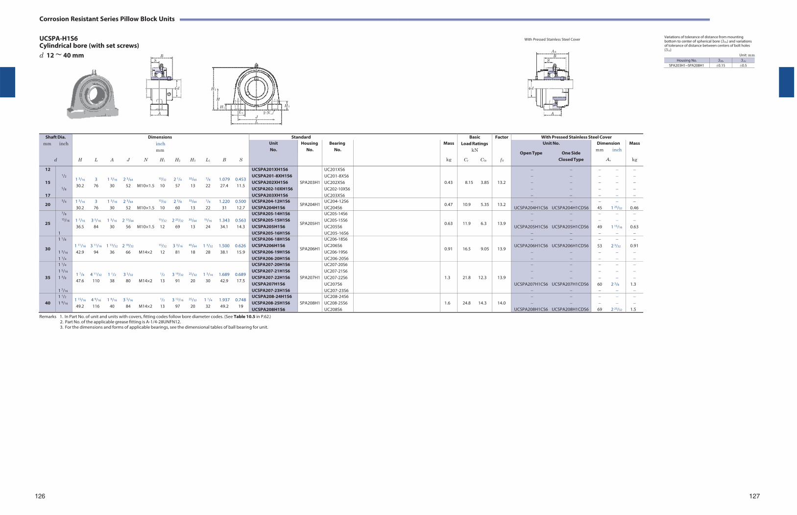
Corrosion Resistant Series Pillow Block Units
UCSPA-H1S6 Cylindrical bore (with set screws) d 12 ~ 40 mm
H 2
With Pressed Stainless Steel Cover
Variations of tolerance of distance from mounting bottom to center of spherical bore (3Hs) and variations of tolerance of distance between centers of bolt holes (3Js)
Unit: mm
H
H 1 H 3
L 1 2-N J L
Shaft Dia.
mm inch
d
Dimensions inch mm
H L A J N H1 H2 H3 L1 B S
Standard BasicLoad Ratings
kN
Cr C0r
Factor
f 0
With Pressed Stainless Steel Cover Unit No.
Housing No.
Bearing No.
Mass
kg
Unit No.
Open Type One Side Closed Type
Dimension mm inch
As
Mass
kg
12
15
17
1/2
5/8
1 3/16 3 1 3/16 2 3/64 13/32 2 1/4 33/64 7/8 1.079 0.453 30.2 76 30 52 M10×1.5 10 57 13 22 27.4 11.5
UCSPA201XH1S6 UCSPA201-8XH1S6 UCSPA202XH1S6 UCSPA202-10XH1S6 UCSPA203XH1S6
SPA203H1
UC201XS6 UC201-8XS6 UC202XS6 UC202-10XS6 UC203XS6
0.43
8.15 3.85
13.2
20 3/4 1 3/16 3 1 3/16 2 3/64 13/32 2 3/8 33/64 7/8 1.220 0.500
30.2 76 30 52 M10×1.5 10 60 13 22 31 12.7 UCSPA204-12H1S6 UCSPA204H1S6
SPA204H1 UC204-12S6 UC204S6
0.47 10.9 5.35 13.2
UCSPA204H1CS6 UCSPA204H1CDS6
45 1 25/32
0.46
25
7/8
15/16
1
1 7/16 3 5/16 1 3/16 2 13/64 15/32 2 23/32 33/64 15/16 1.343 0.563 36.5 84 30 56 M10×1.5 12 69 13 24 34.1 14.3
UCSPA205-14H1S6 UCSPA205-15H1S6 UCSPA205H1S6 UCSPA205-16H1S6
SPA205H1
UC205-14S6 UC205-15S6 UC205S6 UC205-16S6
0.63
11.9 6.3
13.9
UCSPA205H1CS6 UCSPA205H1CDS6
49 1 15/16
0.63
30
1 1/8
1 3/16
1 1/4
1 11/16 3 11/16 1 13/32 2 19/32 15/32 3 3/16 45/64 1 3/32 1.500 0.626 42.9 94 36 66 M14×2 12 81 18 28 38.1 15.9
UCSPA206-18H1S6 UCSPA206H1S6 UCSPA206-19H1S6 UCSPA206-20H1S6
SPA206H1
UC206-18S6 UC206S6 UC206-19S6 UC206-20S6
0.91
16.5 9.05
13.9
UCSPA206H1CS6 UCSPA206H1CDS6
53 2 3/32
0.91
35
1 1/4
1 5/16
1 3/8
1 7/16
1 7/8 4 11/32 1 1/2 3 5/32 1/2 3 19/32 25/32 1 3/16 1.689 0.689 47.6 110 38 80 M14×2 13 91 20 30 42.9 17.5
UCSPA207-20H1S6 UCSPA207-21H1S6 UCSPA207-22H1S6 UCSPA207H1S6 UCSPA207-23H1S6
SPA207H1
UC207-20S6 UC207-21S6 UC207-22S6 UC207S6 UC207-23S6
1.3
21.8 12.3
13.9
UCSPA207H1CS6 UCSPA207H1CDS6
60 2 3/8
1.3
40
1 1/2
1 9/16 1 15/16 4 9/16 1 9/16 3 5/16 1/2 3 13/16 25/32 1 1/4 1.937 0.748 49.2 116 40 84 M14×2 13 97 20 32 49.2 19
UCSPA208-24H1S6 UCSPA208-25H1S6 UCSPA208H1S6
SPA208H1
UC208-24S6 UC208-25S6 UC208S6
1.6
24.8 14.3
14.0
UCSPA208H1CS6 UCSPA208H1CDS6
69 2 23/32
1.5
Remarks 1. In Part No. of unit and units with covers, fitting codes follow bore diameter codes. (See Table 10.5 in P.62.) 2. Part No. of the applicable grease fitting is A-1/4-28UNFN12. 3. For the dimensions and forms of applicable bearings, see the dimensional tables of ball bearing for unit.
126 127
BS
d
A
A SB
S
d 1
A
Housing No. 3Hs 3Js
SPA203H1~SPA208H1 0.15 0.5
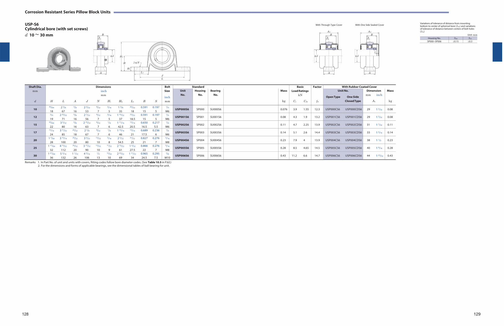
Corrosion Resistant Series Pillow Block Units
USP-S6 Cylindrical bore (with set screws) d 10 ~ 30 mm
H 2
H 2-N
H 1
L 1
J L
With Through Type Cover With One Side Sealed Cover
Variations of tolerance of distance from mounting bottom to center of spherical bore (3Hs) and variations of tolerance of distance between centers of bolt holes (3Js)
Unit: mm
Shaft Dia. mm
d
H
L
A
J
Dimensions inch mm
N H1
H2
L1
B
S
Bolt Size
inch mm
Standard BasicLoad Ratings
kN
Cr C0r
Factor
f 0
With Rubber Coated Cover Unit No.
Housing No.
Bearing No.
Mass
kg
Unit No.
Open Type One Side Closed Type
Dimension mm inch
As
Mass
kg
10 45/64
18 2 5/8
67
5/8
16 2 3/32
53
9/32
7
3/16
5 1 3/8
35
23/32
18 0.591
15 0.197
5
1/4
M6 USP000S6 SP000 SU000S6 0.076 3.9 1.55 12.3 USP000CS6 USP000CDS6 29 1 5/32 0.08
12 3/4
19 2 25/32
71
5/8
16 2 7/32
56
9/32
7
3/16
5 1 15/32
37
23/32
18.5 0.591
15 0.197
5
1/4
M6 USP001S6 SP001 SU001S6 0.08 4.3 1.9 13.2 USP001CS6 USP001CDS6 29 1 5/32 0.08
15 55/64
22 3 5/32
80
5/8
16 2 15/32
63
9/32
7
1/4
6 1 11/16
42.5
13/16
20.5 0.650 16.5
0.217 5.5
1/4
M6 USP002S6 SP002 SU002S6 0.11 4.7 2.25 13.9 USP002CS6 USP002CDS6 31 1 7/32 0.11
17 15/16
24 3 11/32
85
23/32
18 2 5/8
67
9/32
7
1/4
6 1 13/16
46
13/16
21 0.689 17.5
0.236 6
1/4
M6 USP003S6 SP003 SU003S6 0.14 5.1 2.6 14.4 USP003CS6 USP003CDS6 33 1 5/16 0.14
20 1 7/64
28 3 15/16
100
25/32
20 3 5/32
80
13/32
10
5/16
8 2 5/32
54.5
31/32
25 0.827
21 0.276
7
5/16
M8 USP004S6 SP004 SU004S6 0.23 7.9 4 13.9 USP004CS6 USP004CDS6 38 1 1/2 0.23
25 1 17/64
32 4 13/32
112
25/32
20 3 17/32
90
13/32
10
11/32
9 2 13/32
61 1 3/32
27.5 0.866
22 0.276
7
5/16
M8 USP005S6 SP005 SU005S6 0.28 8.5 4.65 14.5 USP005CS6 USP005CDS6 40 1 9/16 0.28
30 1 27/64
36 5 3/16
132 1 1/32
26 4 3/16
106
1/2
13
13/32
10 2 23/32
69 1 11/32
34 0.965 24.5
0.295 7.5
3/8
M10 USP006S6 SP006 SU006S6 0.43 11.2 6.6 14.7 USP006CS6 USP006CDS6 44 1 23/32 0.43
Remarks 1. In Part No. of unit and units with covers, fitting codes follow bore diameter codes. (See Table 10.5 in P.62.) 2. For the dimensions and forms of applicable bearings, see the dimensional tables of ball bearing for unit.
128 129
B S
d
A
A S
B S
d
A
A S
B S
1
d
A
Housing No. 3Hs 3Js
SP000~SP006 0.15 0.3
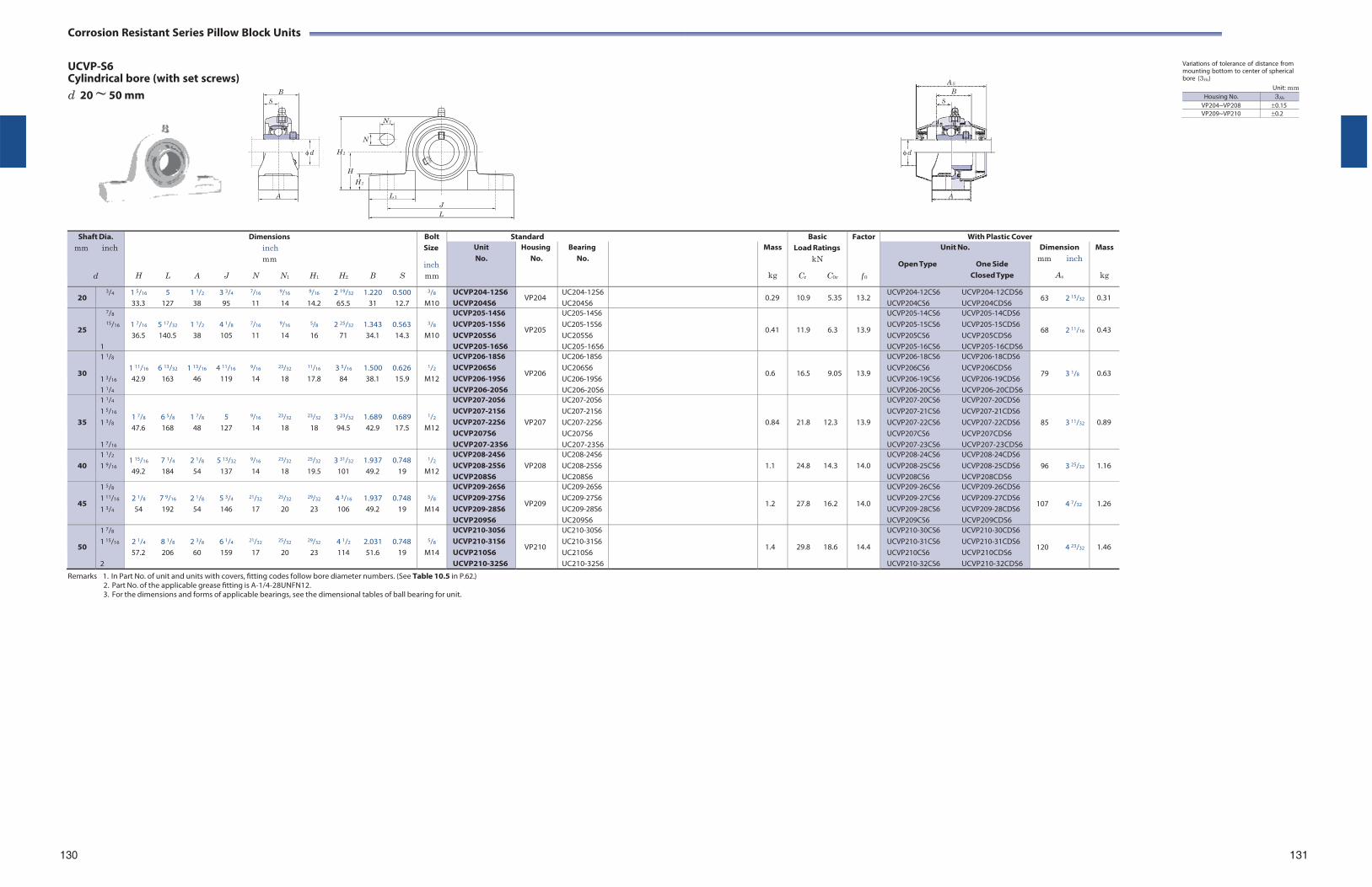
Corrosion Resistant Series Pillow Block Units
UCVP-S6 Cylindrical bore (with set screws)
Variations of tolerance of distance from mounting bottom to center of spherical bore (3Hs)
d 20 ~ 50 mm
N 1
N
H 2
H
H 1
L 1
J L
Unit: mm
Shaft Dia. mm inch
d
Dimensions inch mm
H L A J N N1 H1 H2 B S
Bolt Size
inch mm
Standard BasicLoad Ratings
kN
Cr C0r
Factor
f 0
With Plastic Cover Unit No.
Housing No.
Bearing No.
Mass
kg
Unit No.
Open Type One Side Closed Type
Dimension mm inch
As
Mass
kg
20 3/4 1 5/16 5 1 1/2 3 3/4 7/16 9/16 9/16 2 19/32 1.220 0.500
33.3 127 38 95 11 14 14.2 65.5 31 12.7
3/8
M10 UCVP204-12S6 UCVP204S6
VP204 UC204-12S6 UC204S6
0.29 10.9 5.35 13.2 UCVP204-12CS6 UCVP204-12CDS6 UCVP204CS6 UCVP204CDS6
63 2 15/32 0.31
25
7/8
15/16
1
1 7/16 5 17/32 1 1/2 4 1/8 7/16 9/16 5/8 2 25/32 1.343 0.563 36.5 140.5 38 105 11 14 16 71 34.1 14.3
3/8
M10
UCVP205-14S6 UCVP205-15S6 UCVP205S6 UCVP205-16S6
VP205
UC205-14S6 UC205-15S6 UC205S6 UC205-16S6
0.41
11.9 6.3
13.9
UCVP205-14CS6 UCVP205-14CDS6 UCVP205-15CS6 UCVP205-15CDS6 UCVP205CS6 UCVP205CDS6 UCVP205-16CS6 UCVP205-16CDS6
68 2 11/16
0.43
30
1 1/8
1 3/16
1 1/4
1 11/16 6 13/32 1 13/16 4 11/16 9/16 23/32 11/16 3 5/16 1.500 0.626 42.9 163 46 119 14 18 17.8 84 38.1 15.9
1/2
M12
UCVP206-18S6 UCVP206S6 UCVP206-19S6 UCVP206-20S6
VP206
UC206-18S6 UC206S6 UC206-19S6 UC206-20S6
0.6
16.5 9.05
13.9
UCVP206-18CS6 UCVP206-18CDS6 UCVP206CS6 UCVP206CDS6 UCVP206-19CS6 UCVP206-19CDS6 UCVP206-20CS6 UCVP206-20CDS6
79 3 1/8
0.63
35
1 1/4
1 5/16
1 3/8
1 7/16
1 7/8 6 5/8 1 7/8 5 9/16 23/32 23/32 3 23/32 1.689 0.689 47.6 168 48 127 14 18 18 94.5 42.9 17.5
1/2
M12
UCVP207-20S6 UCVP207-21S6 UCVP207-22S6 UCVP207S6 UCVP207-23S6
VP207
UC207-20S6 UC207-21S6 UC207-22S6 UC207S6 UC207-23S6
0.84
21.8 12.3
13.9
UCVP207-20CS6 UCVP207-20CDS6 UCVP207-21CS6 UCVP207-21CDS6 UCVP207-22CS6 UCVP207-22CDS6 UCVP207CS6 UCVP207CDS6 UCVP207-23CS6 UCVP207-23CDS6
85 3 11/32
0.89
40
1 1/2
1 9/16 1 15/16 7 1/4 2 1/8 5 13/32 9/16 23/32 25/32 3 31/32 1.937 0.748 49.2 184 54 137 14 18 19.5 101 49.2 19
1/2
M12
UCVP208-24S6 UCVP208-25S6 UCVP208S6
VP208
UC208-24S6 UC208-25S6 UC208S6
1.1
24.8 14.3
14.0
UCVP208-24CS6 UCVP208-24CDS6 UCVP208-25CS6 UCVP208-25CDS6 UCVP208CS6 UCVP208CDS6
96 3 25/32
1.16
45
1 5/8
1 11/16
1 3/4
2 1/8 7 9/16 2 1/8 5 3/4 21/32 25/32 29/32 4 3/16 1.937 0.748 54 192 54 146 17 20 23 106 49.2 19
5/8
M14
UCVP209-26S6 UCVP209-27S6 UCVP209-28S6 UCVP209S6
VP209
UC209-26S6 UC209-27S6 UC209-28S6 UC209S6
1.2
27.8 16.2
14.0
UCVP209-26CS6 UCVP209-26CDS6 UCVP209-27CS6 UCVP209-27CDS6 UCVP209-28CS6 UCVP209-28CDS6 UCVP209CS6 UCVP209CDS6
107 4 7/32
1.26
50
1 7/8
1 15/16
2
2 1/4 8 1/8 2 3/8 6 1/4 21/32 25/32 29/32 4 1/2 2.031 0.748 57.2 206 60 159 17 20 23 114 51.6 19
5/8
M14
UCVP210-30S6 UCVP210-31S6 UCVP210S6 UCVP210-32S6
VP210
UC210-30S6 UC210-31S6 UC210S6 UC210-32S6
1.4
29.8 18.6
14.4
UCVP210-30CS6 UCVP210-30CDS6 UCVP210-31CS6 UCVP210-31CDS6 UCVP210CS6 UCVP210CDS6 UCVP210-32CS6 UCVP210-32CDS6
120 4 23/32
1.46
Remarks 1. In Part No. of unit and units with covers, fitting codes follow bore diameter numbers. (See Table 10.5 in P.62.) 2. Part No. of the applicable grease fitting is A-1/4-28UNFN12. 3. For the dimensions and forms of applicable bearings, see the dimensional tables of ball bearing for unit.
130 131
BS
d
A
AS
B S
d
A
Housing No. 3Hs
VP204~VP208 0.15VP209~VP210 0.2

Corrosion Resistant Series Pillow Block Units
UCVP-ES7 Cylindrical bore (with set screws)
Variations of tolerance of distance from mounting bottom to center of spherical bore (3Hs)
d 20 ~ 50 mm
N 1
N
H 2
H
H 1
L 1
J L
Unit: mm
Shaft Dia. mm inch
d
Dimensions inch mm
H L A J N N1 H1 H2 B S
Bolt Size
inch mm
Standard BasicLoad Ratings
kN
Cr C0r
Factor
f 0
With Plastic Cover Unit No.
Housing No.
Bearing No.
Mass
kg
Unit No.
Open Type One Side Closed Type
Dimension mm inch
As
Mass
kg
20 3/4 1 5/16 5 1 1/2 3 3/4 7/16 9/16 9/16 2 19/32 1.220 0.500
33.3 127 38 95 11 14 14.2 65.5 31 12.7
3/8
M10 UCVP204-12ES7 UCVP204ES7
VP204E UC204-12S7 UC204S7
0.29 12.8 6.65 13.2 UCVP204-12ECS7 UCVP204-12ECDS7 UCVP204ECS7 UCVP204ECDS7
63 2 15/32 0.31
25
7/8
15/16
1
1 7/16 5 17/32 1 1/2 4 1/8 7/16 9/16 5/8 2 25/32 1.343 0.563 36.5 140.5 38 105 11 14 16 71 34.1 14.3
3/8
M10
UCVP205-14ES7 UCVP205-15ES7 UCVP205ES7 UCVP205-16ES7
VP205E
UC205-14S7 UC205-15S7 UC205S7 UC205-16S7
0.41
14.0 7.85
13.9
UCVP205-14ECS7 UCVP205-14ECDS7 UCVP205-15ECS7 UCVP205-15ECDS7 UCVP205ECS7 UCVP205ECDS7 UCVP205-16ECS7 UCVP205-16ECDS7
68 2 11/16
0.43
30
1 1/8
1 3/16
1 1/4
1 11/16 6 13/32 1 13/16 4 11/16 9/16 23/32 11/16 3 5/16 1.500 0.626 42.9 163 46 119 14 18 17.8 84 38.1 15.9
1/2
M12
UCVP206-18ES7 UCVP206ES7 UCVP206-19ES7 UCVP206-20ES7
VP206E
UC206-18S7 UC206S7 UC206-19S7 UC206-20S7
0.6
19.5 11.3
13.9
UCVP206-18ECS7 UCVP206-18ECDS7 UCVP206ECS7 UCVP206CDS7 UCVP206-19ECS7 UCVP206-19ECDS7 UCVP206-20ECS7 UCVP206-20ECDS7
79 3 1/8
0.63
35
1 1/4
1 5/16
1 3/8
1 7/16
1 7/8 6 5/8 1 7/8 5 9/16 23/32 23/32 3 23/32 1.689 0.689 47.6 168 48 127 14 18 18 94.5 42.9 17.5
1/2
M12
UCVP207-20ES7 UCVP207-21ES7 UCVP207-22ES7 UCVP207ES7 UCVP207-23ES7
VP207E
UC207-20S7 UC207-21S7 UC207-22S7 UC207S7 UC207-23S7
0.84
25.7 15.4
13.9
UCVP207-20ECS7 UCVP207-20ECDS7 UCVP207-21ECS7 UCVP207-21ECDS7 UCVP207-22ECS7 UCVP207-22ECDS7 UCVP207ECS7 UCVP207ECDS7 UCVP207-23ECS7 UCVP207-23ECDS7
85 3 11/32
0.89
40
1 1/2
1 9/16 1 15/16 7 1/4 2 1/8 5 13/32 9/16 23/32 25/32 3 31/32 1.937 0.748 49.2 184 54 137 14 18 19.5 101 49.2 19
1/2
M12
UCVP208-24ES7 UCVP208-25ES7 UCVP208ES7
VP208E
UC208-24S7 UC208-25S7 UC208S7
1.1
29.1 17.8
14.0
UCVP208-24ECS7 UCVP208-24ECDS7 UCVP208-25ECS7 UCVP208-25ECDS7 UCVP208ECS7 UCVP208ECDS7
96 3 25/32
1.16
45
1 5/8
1 11/16
1 3/4
2 1/8 7 9/16 2 1/8 5 3/4 21/32 25/32 29/32 4 3/16 1.937 0.748 54 192 54 146 17 20 23 106 49.2 19
5/8
M14
UCVP209-26ES7 UCVP209-27ES7 UCVP209-28ES7 UCVP209ES7
VP209E
UC209-26S7 UC209-27S7 UC209-28S7 UC209S7
1.2
34.1 21.3
14.0
UCVP209-26ECS7 UCVP209-26ECDS7 UCVP209-27ECS7 UCVP209-27ECDS7 UCVP209-28ECS7 UCVP209-28ECDS7 UCVP209ECS7 UCVP209ECDS7
107 4 7/32
1.26
50
1 7/8
1 15/16
2
2 1/4 8 1/8 2 3/8 6 1/4 21/32 25/32 29/32 4 1/2 2.031 0.748 57.2 206 60 159 17 20 23 114 51.6 19
5/8
M14
UCVP210-30ES7 UCVP210-31ES7 UCVP210ES7 UCVP210-32ES7
VP210E
UC210-30S7 UC210-31S7 UC210S7 UC210-32S7
1.4
35.1 23.3
14.4
UCVP210-30ECS7 UCVP210-30ECDS7 UCVP210-31ECS7 UCVP210-31ECDS7 UCVP210ECS7 UCVP210ECDS7 UCVP210-32ECS7 UCVP210-32ECDS7
120 4 23/32
1.46
Remarks 1. In Part No. of unit and units with covers, fitting codes follow bore diameter numbers. (See Table 10.5 in P.62.) 2. Part No. of the applicable grease fitting is A-1/4-28UNFN12. 3. For the dimensions and forms of applicable bearings, see the dimensional tables of ball bearing for unit.
132 133
BS
d
A
AS
B S
d
A
Housing No. 3Hs
VP204E~VP208E 0.15VP209E~VP210E 0.2
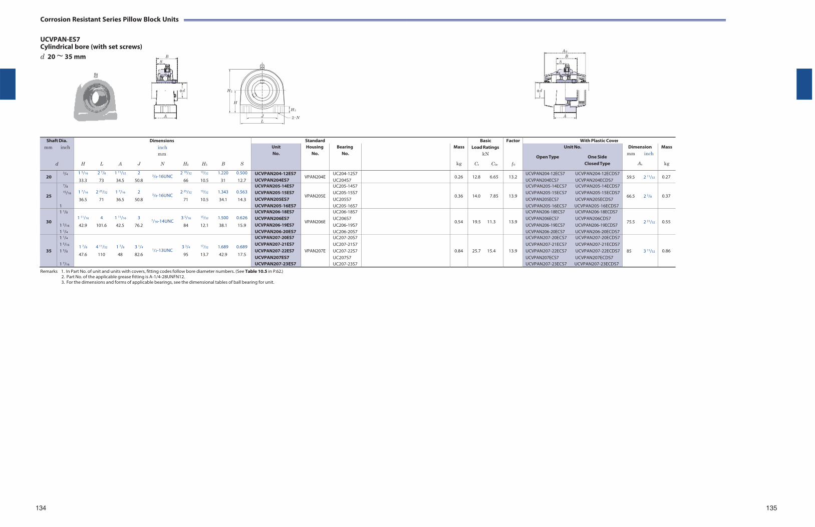
Corrosion Resistant Series Pillow Block Units
UCVPAN-ES7 Cylindrical bore (with set screws) d 20 ~ 35 mm
H 2
H
J L
H 3
2- N
Shaft Dia. mm inch
d
Dimensions inch mm
H L A J N H2 H3 B S
Standard BasicLoad Ratings
kN
Cr C0r
Factor
f 0
With Plastic Cover Unit No.
Housing No.
Bearing No.
Mass
kg
Unit No.
Open Type One Side Closed Type
Dimension mm inch
As
Mass
kg
20 3/4 1 5/16 2 7/8 1 11/32 2 2 19/32 13/32 1.220 0.500
3/8-16UNC 33.3 73 34.5 50.8 66 10.5 31 12.7
UCVPAN204-12ES7 UCVPAN204ES7
VPAN204E UC204-12S7 UC204S7
0.26 12.8 6.65 13.2 UCVPAN204-12ECS7 UCVPAN204-12ECDS7 UCVPAN204ECS7 UCVPAN204ECDS7
59.5 2 11/32 0.27
25
7/8
15/16
1
1 7/16 2 25/32 1 7/16 2 2 25/32 13/32 1.343 0.563
3/8-16UNC 36.5 71 36.5 50.8 71 10.5 34.1 14.3
UCVPAN205-14ES7 UCVPAN205-15ES7 UCVPAN205ES7 UCVPAN205-16ES7
VPAN205E
UC205-14S7 UC205-15S7 UC205S7 UC205-16S7
0.36
14.0 7.85
13.9
UCVPAN205-14ECS7 UCVPAN205-14ECDS7 UCVPAN205-15ECS7 UCVPAN205-15ECDS7 UCVPAN205ECS7 UCVPAN205ECDS7 UCVPAN205-16ECS7 UCVPAN205-16ECDS7
66.5 2 5/8
0.37
30
1 1/8
1 3/16
1 1/4
1 11/16 4 1 11/16 3 3 5/16 15/32 1.500 0.626
7/16-14UNC 42.9 101.6 42.5 76.2 84 12.1 38.1 15.9
UCVPAN206-18ES7 UCVPAN206ES7 UCVPAN206-19ES7 UCVPAN206-20ES7
VPAN206E
UC206-18S7 UC206S7 UC206-19S7 UC206-20S7
0.54
19.5 11.3
13.9
UCVPAN206-18ECS7 UCVPAN206-18ECDS7 UCVPAN206ECS7 UCVPAN206CDS7 UCVPAN206-19ECS7 UCVPAN206-19ECDS7 UCVPAN206-20ECS7 UCVPAN206-20ECDS7
75.5 2 31/32
0.55
35
1 1/4
1 5/16
1 3/8
1 7/16
1 7/8 4 11/32 1 7/8 3 1/4 3 3/4 17/32 1.689 0.689 1/2-13UNC
47.6 110 48 82.6 95 13.7 42.9 17.5
UCVPAN207-20ES7 UCVPAN207-21ES7 UCVPAN207-22ES7 UCVPAN207ES7 UCVPAN207-23ES7
VPAN207E
UC207-20S7 UC207-21S7 UC207-22S7 UC207S7 UC207-23S7
0.84
25.7 15.4
13.9
UCVPAN207-20ECS7 UCVPAN207-20ECDS7 UCVPAN207-21ECS7 UCVPAN207-21ECDS7 UCVPAN207-22ECS7 UCVPAN207-22ECDS7 UCVPAN207ECS7 UCVPAN207ECDS7 UCVPAN207-23ECS7 UCVPAN207-23ECDS7
85 3 11/32
0.86
Remarks 1. In Part No. of unit and units with covers, fitting codes follow bore diameter numbers. (See Table 10.5 in P.62.) 2. Part No. of the applicable grease fitting is A-1/4-28UNFN12. 3. For the dimensions and forms of applicable bearings, see the dimensional tables of ball bearing for unit.
134 135
BS
d
A
A SB
S
d
A
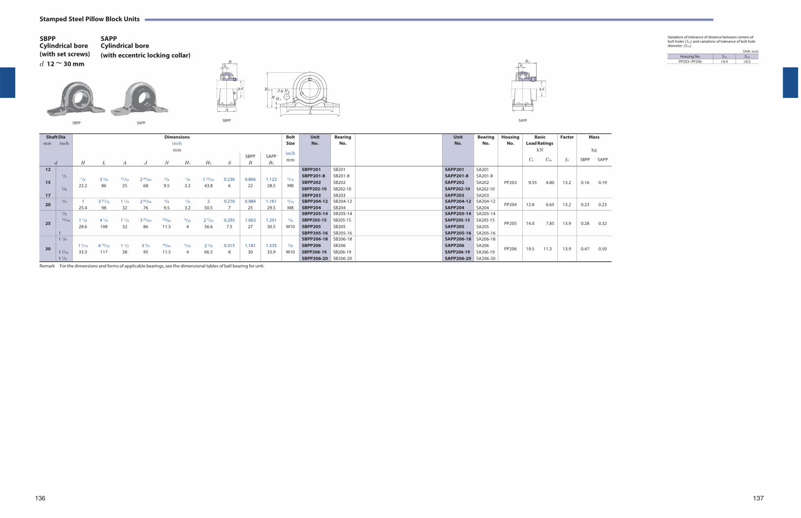
Stamped Steel Pillow Block Units
SBPP Cylindrical bore
SAPP Cylindrical bore
Variations of tolerance of distance between centers of bolt holes (3Js) and variations of tolerance of bolt hole diameter (3Ns)
(with set screws) d 12 ~ 30 mm
(with eccentric locking collar) Unit: mm
H 2 2-N
H H 1
SBPP SAPP
SBPP
J L
SAPP
Shaft Dia Dimensions Bolt Unit Bearing Unit Bearing Housing Basic Factor Mass mm inch inch Size No. No. No. No. No. Load Ratings
d
mm inch
kN kg
H
L
A
J
N
H1
H2
S
SBPP B
SAPP B1
mm Cr C0r f 0 SBPP SAPP
12 1/2
7/8
3 3/8
31/32
2 43/64
3/8
1/8
1 23/32
0.236
0.866
1.122
5/16
SBPP201 SB201 SAPP201 SA201
PP203
9.55
4.80
13.2
0.16
0.19
15
SBPP201-8 SBPP202 SBPP202-10
SB201-8 SB202 SB202-10
SAPP201-8 SAPP202 SAPP202-10
SA201-8 SA202 SA202-10 5/8
22.2 86 25 68 9.5 3.2 43.8 6 22 28.5 M8
17 SBPP203 SB203 SAPP203 SA203
20 3/4 1
25.4 3 27/32
98 1 1/4
32 2 63/64
76
3/8
9.5
1/8
3.2 2
50.5 0.276
7 0.984
25 1.161 29.5
5/16
M8 SBPP204-12 SBPP204
SB204-12 SB204
SAPP204-12 SAPP204
SA204-12 SA204
PP204 12.8 6.65 13.2 0.23 0.23
25
7/8 1 1/8
4 1/4
1 1/4
3 25/64
29/64
5/32
2 7/32
0.295
1.063
1.201
3/8
SBPP205-14 SB205-14 SAPP205-14 SA205-14
PP205
14.0
7.85
13.9
0.28
0.32 15/16 SBPP205-15
SBPP205 SB205-15 SB205
SAPP205-15 SAPP205
SA205-15 SA205 28.6 108 32 86 11.5 4 56.6 7.5 27 30.5 M10
1 SBPP205-16 SB205-16 SAPP205-16 SA205-16
30
1 1/8 1 5/16
4 19/32
1 1/2
3 3/4
29/64
5/32
2 5/8
0.315
1.181
1.335
3/8
SBPP206-18 SB206-18 SAPP206-18 SA206-18
PP206
19.5
11.3
13.9
0.47
0.50 1 3/16
SBPP206 SBPP206-19
SB206 SB206-19
SAPP206 SAPP206-19
SA206 SA206-19 33.3 117 38 95 11.5 4 66.3 8 30 33.9 M10
1 1/4 SBPP206-20 SB206-20 SAPP206-20 SA206-20
Remark For the dimensions and forms of applicable bearings, see the dimensional tables of ball bearing for unit.
136 137
B S
d
A
B 1
S
d
A
Housing No. 3Js 3Ns
PP203~PP206 0.4 0.5
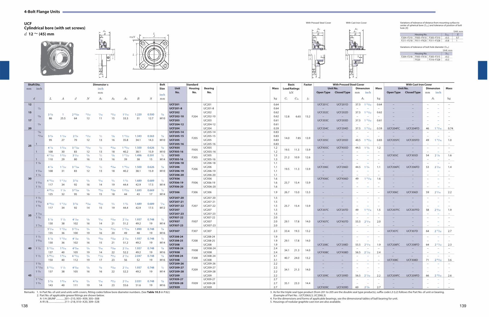
4-Bolt Flange Units
UCF Cylindrical bore (with set screws)
With Pressed Steel Cover With Cast Iron Cover Variations of tolerance of distance from mounting surface to center of spherical bore (3A2s) and tolerance of position of bolt hole (X)
d 12 ~ (45) mm L 4-N J
L J
Variations of tolerance of bolt hole diameter (3Ns)
Unit: mm
Unit: mm
Shaft Dia.
mm inch
d
L
A
J
N
Dimensioninch mm
A1
s
A2
A0
B
S
Bolt Size
inch mm
Standard BasicLoad Ratings
kN
Cr C0r
Factor
f 0
With Pressed Steel Cover With Cast Iron CoverUnit No.
Housing No.
Bearing No.
Mass
kg
Unit No. Open Type Closed Type
Dimension mm inch
As
Mass
kg
Unit No. Open Type Closed Type
Dimension mm inch
Ac
Mass
kg
12 1/2
3 3/8
1
2 33/64
15/32
7/16
19/32
1 5/16
1.220
0.500
3/8
UCF201
F204
UC201 0.64
12.8
6.65
13.2
UCF201C UCF201D 37.5 1 15/32 0.64 UCF201-8 UC201-8 0.64
15 5/8
UCF202 UC202 0.62 UCF202C UCF202D 37.5 1 15/32 0.62 UCF202-10 UC202-10 0.62
86 25.5 64 12 11 15 33.3 31 12.7 M10 17 UCF203 UC203 0.61 UCF203C UCF203D 37.5 1 15/32 0.61
3/4 UCF204-12 UC204-12 0.61 20 UCF204 UC204 0.59 UCF204C UCF204D 37.5 1 15/32 0.59 UCF204FC UCF204FD 46 1 13/16 0.74
25
7/8 3 3/4
1 1/16
2 3/4
15/32
1/2
5/8
1 13/32
1.343
0.563
3/8
UCF205-14
F205
UC205-14 0.83
14.0
7.85
13.9
15/16 UCF205-15 UC205-15 0.83
95 27 70 12 13 16 35.8 34.1 14.3 M10 UCF205 UC205 0.83 UCF205C UCF205D 40.5 1 19/32 0.83 UCF205FC UCF205FD 49 1 15/16 1.0 1 UCF205-16 UC205-16 0.83
1
4 1/4
108 1 3/16
30 3 17/64
83
15/32
12
1/2
13
45/64
18 1 19/32
40.2 1.500 38.1
0.626 15.9
3/8
M10 UCFX05 UCFX05-16
FX05 UCX05 UCX05-16
1.2 1.2
19.5 11.3 13.9 UCFX05C
UCFX05D
44.5
1 3/4
1.2
1
4 11/32
110 1 5/32
29 3 5/32
80
5/8
16
1/2
13
5/8
16 1 17/32
39 1.496
38 0.591
15
1/2
M14 UCF305 UCF305-16
F305 UC305 UC305-16
1.3 1.3
21.2 10.9 12.6
UCF305C
UCF305D
54
2 1/8
1.6
30
1 1/8 4 1/4
1 7/32
3 17/64
15/32
1/2
45/64
1 19/32
1.500
0.626
3/8
UCF206-18
F206
UC206-18 1.1
19.5
11.3
13.9
1 3/16
UCF206 UC206 1.1 UCF206C UCF206D 44.5 1 3/4 1.1 UCF206FC UCF206FD 53 2 3/32 1.4 108 31 83 12 13 18 40.2 38.1 15.9 M10 UCF206-19 UC206-19 1.1
1 1/4 UCF206-20 UC206-20 1.1
1 3/16
1 1/4
4 19/32
117 1 11/32
34 3 5/8
92
5/8
16
9/16
14
3/4
19 1 3/4
44.4 1.689 42.9
0.689 17.5
1/2
M14
UCFX06 UCFX06-19 UCFX06-20
FX06
UCX06 UCX06-19 UCX06-20
1.6 1.6 1.6
25.7
15.4
13.9
UCFX06C
UCFX06D
49
1 15/16
1.6
4 29/32
125 1 1/4
32 3 47/64
95
5/8
16
19/32
15
45/64
18 1 23/32
44 1.693
43 0.669
17
1/2
M14 UCF306 F306 UC306 1.9 26.7 15.0 13.3 UCF306C UCF306D 59 2 5/16 2.2
35
1 1/4
4 19/32
1 11/32
3 5/8
35/64
19/32
3/4
1 3/4
1.689
0.689
7/16
UCF207-20
F207
UC207-20 1.5
25.7
15.4
13.9
1 5/16 UCF207-21 UC207-21 1.5 1 3/8 UCF207-22 UC207-22 1.5
117 34 92 14 15 19 44.4 42.9 17.5 M12 UCF207 UC207 1.5 UCF207C UCF207D 49 1 15/16 1.5 UCF207FC UCF207FD 58 2 9/32 1.9
1 7/16 UCF207-23 UC207-23 1.5 1 3/8
1 7/16
5 1/8
130 1 1/2
38 4 1/64
102
5/8
16
9/16
14
53/64
21 2 1/32
51.2 1.937 49.2
0.748 19
1/2
M14
UCFX07-22 UCFX07 UCFX07-23
FX07
UCX07-22 UCX07 UCX07-23
2.0 2.0 2.0
29.1
17.8
14.0
UCFX07C
UCFX07D
55.5
2 3/16
2.0
5 5/16
135 1 13/32
36 3 15/16
100
3/4
19
5/8
16
25/32
20 1 15/16
49 1.890
48 0.748
19
5/8
M16 UCF307 F307 UC307 2.3 33.4 19.3 13.2 UCF307C UCF307D 64 2 17/32 2.7
40
1 1/2
1 9/16 5 1/8
130 1 13/32
36 4 1/64
102
5/8
16
19/32
15
53/64
21 2 1/32
51.2 1.937 49.2
0.748 19
1/2
M14
UCF208-24 UCF208-25 UCF208
F208
UC208-24 UC208-25 UC208
1.9 1.9 1.9
29.1
17.8
14.0
UCF208C
UCF208D
55.5
2 3/16
1.9
UCF208FC
UCF208FD
64
2 17/32
2.3
1 1/2 5 13/32
137 1 9/16
40 4 9/64
105
3/4
19
9/16
14
55/64
22 2 1/16
52.2 1.937 49.2
0.748 19
5/8
M16 UCFX08-24 UCFX08
FX08 UCX08-24UCX08
2.4 2.4
34.1 21.3 14.0
UCFX08C
UCFX08D
56.5
2 7/32
2.4
1 1/2 5 29/32
150 1 9/16
40 4 13/32
112
3/4
19
21/32
17
29/32
23 2 7/32
56 2.047
52 0.748
19
5/8
M16 UCF308-24 UCF308
F308 UC308-24UC308
3.1 3.1
40.7 24.0 13.2
UCF308C
UCF308D
71
2 25/32
3.6
45
1 5/8 5 13/32
1 1/2
4 9/64
5/8
5/8
55/64
2 1/16
1.937
0.748
1/2
UCF209-26
F209
UC209-26 2.2
34.1
21.3
14.0
1 11/16 UCF209-27 UC209-27 2.2 1 3/4 137 38 105 16 16 22 52.2 49.2 19 M14 UCF209-28 UC209-28 2.2
UCF209 UC209 2.2 UCF209C UCF209D 56.5 2 7/32 2.2 UCF209FC UCF209FD 66 2 19/32 2.6 1 11/16
1 3/4 5 5/8
143 1 9/16
40 4 3/8
111
3/4
19
9/16
14
29/32
23 2 3/16
55.6 2.031 51.6
0.748 19
5/8
M16
UCFX09-27 UCFX09-28 UCFX09
FX09
UCX09-27 UCX09-28 UCX09
2.7 2.7 2.7
35.1
23.3
14.4
UCFX09C
UCFX09D
60
2 3/8
2.7
A 0B
S
d
A 1
A 2
A
A SA 0B
S
d 1
A 1
A 2A
A C A 0
B S
d2
A 1
A 2
A
Housing No. 3A2s X F204~F210 FX05~FX10 F305~F310 0.5 0.7F211~F218 FX11~FX20 F311~F328 0.8 1
Housing No. 3Ns
F204~F218 FX05~FX18 F305~F315 0.2FX20 F316~F328 0.3
Remarks 1. In Part No. of unit and units with covers, fitting codes follow bore diameter numbers. (See Table 10.5 in P.62.) 3. As for the triple seal type product (from 201 to 205 are the double seal type products), suffix code L3 (L2) follows the Part No. of unit or bearing. 2. Part No. of applicable grease fittings are shown below. (Example of Part No. : UCF206JL3, UC206L3)
A-1/4-28UNF ............. 201~210, X05~X09, 305~308 4. For the dimensions and forms of applicable bearings, see the dimensional tables of ball bearing for unit.A-R1/8 .......................... 211~218, X10~X20, 309~328
138 5. Housings of nodular graphite cast iron are also available.
139

4-Bolt Flange Units
UCF Cylindrical bore (with set screws)
With Pressed Steel Cover With Cast Iron Cover Variations of tolerance of distance from mounting surface to center of spherical bore (3A2s) and tolerance of position of bolt hole (X)
d (45) ~ (75) mm L 4-N J
L J
Variations of tolerance of bolt hole diameter (3Ns)
Unit: mm
Unit: mm
Shaft Dia.
mm inch
d
Dimensions inch mm
L A J N A1 A2 A0 B S
Bolt Size
inch mm
Standard BasicLoad Ratings
kN
Cr C0r
Factor
f 0
With Pressed Steel Cover With Cast Iron Cover Unit No.
Housing No.
Bearing No.
Mass
kg
Unit No. Open Type Closed Type
Dimension mm inch
As
Mass
kg
Unit No. Open Type Closed Type
Dimension mm inch
Ac
Mass
kg
45 1 3/4 6 5/16 1 23/32 4 59/64 3/4 23/32 63/64 2 3/8 2.244 0.866
160 44 125 19 18 25 60 57 22
5/8
M16 UCF309-28 UCF309
F309 UC309-28UC309
4.0 4.0
48.9 29.5 13.3
UCF309C UCF309D
76 3
4.6
50
1 7/8
1 15/16
2
5 5/8 1 9/16 4 3/8 5/8 5/8 55/64 2 5/32 2.031 0.748 143 40 111 16 16 22 54.6 51.6 19
1/2
M14
UCF210-30 UCF210-31 UCF210 UCF210-32
F210
UC210-30 UC210-31 UC210 UC210-32
2.5 2.5 2.5 2.5
35.1 23.3
14.4
UCF210C UCF210D
59 2 5/16
2.5
UCF210FC UCF210FD
70.5 2 25/32
3.0
1 15/16
2
6 3/8 1 23/32 5 1/8 3/4 25/32 1 1/32 2 11/32 2.189 0.874 162 44 130 19 20 26 59.4 55.6 22.2
5/8
M16
UCFX10-31 UCFX10 UCFX10-32
FX10
UCX10-31 UCX10 UCX10-32
3.7 3.7 3.7
43.4 29.4
14.4
UCFX10C UCFX10D
64 2 17/32
3.7
6 7/8 1 7/8 5 13/64 29/32 3/4 1 7/64 2 5/8 2.402 0.866 175 48 132 23 19 28 67 61 22
3/4
M20 UCF310 F310 UC310 5.1 62.0 38.3 13.2 UCF310C UCF310D 83 3 9/32 5.9
55
2 2 1/8
2 3/16
6 3/8 1 11/16 5 1/8 3/4 23/32 63/64 2 5/16 2.189 0.874 162 43 130 19 18 25 58.4 55.6 22.2
5/8
M16
UCF211-32 UCF211-34 UCF211 UCF211-35
F211
UC211-32 UC211-34 UC211 UC211-35
3.4 3.4 3.4 3.4
43.4 29.4
14.4
UCF211C UCF211D
63 2 15/32
3.4
UCF211FC UCF211FD
74.5 2 15/16
4.0
2 3/16
2 1/4
6 7/8 1 15/16 5 5/8 3/4 25/32 1 9/64 2 23/32 2.563 1.000 175 49 143 19 20 29 68.7 65.1 25.4
5/8
M16
UCFX11 UCFX11-35 UCFX11-36
FX11
UCX11 UCX11-35 UCX11-36
4.9 4.9 4.9
52.4 36.2
14.4
UCFX11C UCFX11D
73.5 2 29/32
4.9
2
2 3/16
7 9/32 2 1/16 5 33/64 29/32 25/32 1 3/16 2 25/32 2.598 0.984 185 52 140 23 20 30 71 66 25
3/4
M20
UCF311-32 UCF311 UCF311-35
F311
UC311-32UC311 UC311-35
5.6 5.6 5.6
71.6 45.0
13.2
UCF311C UCF311D
87 3 7/16
6.5
60
2 1/4
2 3/8
2 7/16
6 7/8 1 7/8 5 5/8 3/4 23/32 1 9/64 2 23/32 2.563 1.000 175 48 143 19 18 29 68.7 65.1 25.4
5/8
M16
UCF212-36 UCF212 UCF212-38 UCF212-39
F212
UC212-36 UC212 UC212-38 UC212-39
4.2 4.2 4.2 4.2
52.4 36.2
14.4
UCF212C UCF212D
73.5 2 29/32
4.2
UCF212FC UCF212FD
86 3 3/8
5.0
2 7/16
7 3/8 2 5/16 5 55/64 3/4 13/16 1 11/32 2 29/32 2.563 1.000 187 59 149 19 21 34 73.7 65.1 25.4
5/8
M16 UCFX12 UCFX12-39
FX12 UCX12 UCX12-39
5.7 5.7
57.2 40.1 14.4 UCFX12C UCFX12D
78.5 3 3/32
5.7
2 7/16
7 11/16 2 7/32 5 29/32 29/32 7/8 1 19/64 3 1/16 2.795 1.024 195 56 150 23 22 33 78 71 26
3/4
M20 UCF312 UCF312-39
F312 UC312 UC312-39
6.9 6.9
81.9 52.2 13.2
UCF312C UCF312D
95 3 3/4
8.1
65
2 1/2 7 3/8 1 31/32 5 55/64 3/4 7/8 1 3/16 2 3/4 2.563 1.000 187 50 149 19 22 30 69.7 65.1 25.4
5/8
M16 UCF213-40 UCF213
F213 UC213-40UC213
5.2 5.2
57.2 40.1 14.4
UCF213C UCF213D
74.5 2 15/16
5.2
UCF213FC UCF213FD
87 3 7/16
6.0
2 1/2 7 3/8 2 5/16 5 55/64 3/4 13/16 1 11/32 3 3/32 2.937 1.189 187 59 149 19 21 34 78.4 74.6 30.2
5/8
M16 UCFX13-40 UCFX13
FX13 UCX13-40UCX13
6.3 6.3
62.2 44.1 14.5
UCFX13C UCFX13D
83.5 3 9/32
6.3
2 1/2 8 3/16 2 9/32 6 17/32 29/32 7/8 1 19/64 3 1/16 2.953 1.181 208 58 166 23 22 33 78 75 30
3/4
M20 UCF313-40 UCF313
F313 UC313-40UC313
7.8 7.8
92.7 59.9 13.2
UCF313C UCF313D
94 3 11/16
8.9
70
2 3/4 7 19/32 2 1/8 5 63/64 3/4 7/8 1 7/32 2 31/32 2.937 1.189 193 54 152 19 22 31 75.4 74.6 30.2
5/8
M16 UCF214-44 UCF214
F214 UC214-44UC214
5.9 5.9
62.2 44.1 14.5
UCF214C UCF214D
80.5 3 5/32
5.9
UCF214FC UCF214FD
93 3 21/32
6.8
2 3/4 7 3/4 2 3/8 5 63/64 29/32 7/8 1 29/64 3 7/32 3.063 1.331 197 60 152 23 22 37 81.5 77.8 33.3
3/4
M20 UCFX14-44 UCFX14
FX14 UCX14-44UCX14
7.0 7.0
67.4 48.3 14.5
UCFX14C UCFX14D
86.5 3 13/32
7.0
2 3/4 8 29/32 2 13/32 7 1/64 63/64 31/32 1 27/64 3 3/16 3.071 1.299 226 61 178 25 25 36 81 78 33
7/8
M22 UCF314-44 UCF314
F314 UC314-44UC314
10.1 10.1
104 68.2 13.2
UCF314C UCF314D
98 3 27/32
11.2
75
2 15/16
3
7 7/8 2 7/32 6 17/64 3/4 7/8 1 11/32 3 3/32 3.063 1.311 200 56 159 19 22 34 78.5 77.8 33.3
5/8
M16
UCF215-47 UCF215 UCF215-48
F215
UC215-47 UC215 UC215-48
6.4 6.4 6.4
67.4 48.3
14.5
UCF215C UCF215D
83.5 3 9/32
6.4
UCF215FC UCF215FD
96 3 25/32
7.4
2 15/16
3
7 3/4 2 11/16 5 63/64 29/32 15/16 1 9/16 3 17/32 3.252 1.311 197 68 152 23 24 40 89.3 82.6 33.3
3/4
M20
UCFX15-47 UCFX15 UCFX15-48
FX15
UCX15-47UCX15 UCX15-48
8.4 8.4 8.4
72.7 53.0
14.6
UCFX15C UCFX15D
94.5 3 23/32
8.4
Remarks 1. In Part No. of unit and units with covers, fitting codes follow bore diameter numbers. (See Table 10.5 in P.62.) 2. Part No. of applicable grease fittings are shown below.
A-1/4-28UNF ............. 201~210, X05~X09, 305~308 A-R1/8 .......................... 211~218, X10~X20, 309~328
3. As for the triple seal type product (from 201 to 205 are the double seal type products), suffix code L3 (L2) follows the Part No. of unit or bearing. (Example of Part No. : UCF206JL3, UC206L3)
4. For the dimensions and forms of applicable bearings, see the dimensional tables of ball bearing for unit. 5. Housings of nodular graphite cast iron are also available.
140 141
A 0B
S
d
A 1
A 2
A
A SA 0B
S
d 1
A 1
A 2A
A C A 0
B S
d2
A 1
A 2
A
Housing No. 3A2s X F204~F210 FX05~FX10 F305~F310 0.5 0.7F211~F218 FX11~FX20 F311~F328 0.8 1
Housing No. 3Ns
F204~F218 FX05~FX18 F305~F315 0.2FX20 F316~F328 0.3
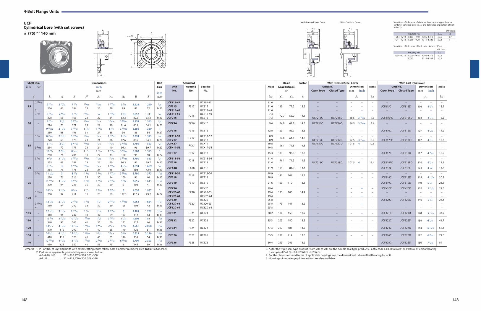
4-Bolt Flange Units
UCF Cylindrical bore (with set screws)
With Pressed Steel Cover With Cast Iron Cover Variations of tolerance of distance from mounting surface to center of spherical bore (3A2s) and tolerance of position of bolt hole (X)
d (75) ~ 140 mm L 4-N J
L J
Variations of tolerance of bolt hole diameter (3Ns)
Unit: mm
Unit: mm
Shaft Dia.
mm inch
d
Dimensions inch mm
L A J N A1 A2 A0 B S
Bolt Size
inch mm
Standard BasicLoad Ratings
kN
Cr C0r
Factor
f 0
With Pressed Steel Cover With Cast Iron Cover Unit No.
Housing No.
Bearing No.
Mass
kg
Unit No. Open Type Closed Type
Dimension mm inch
As
Mass
kg
Unit No. Open Type Closed Type
Dimension mm inch
Ac
Mass
kg
75
2 15/16
3
9 9/32 2 19/32 7 1/4 63/64 31/32 1 17/32 3 1/2 3.228 1.260 236 66 184 25 25 39 89 82 32
7/8
M22
UCF315-47 UCF315 UCF315-48
F315
UC315-47 UC315 UC315-48
11.6 11.6 11.6
113 77.2
13.2
UCF315C UCF315D
106 4 3/16
12.9
80
3 1/8 8 3/16 2 9/32 6 1/2 29/32 7/8 1 11/32 3 9/32 3.252 1.311 208 58 165 23 22 34 83.3 82.6 33.3
3/4
M20 UCF216-50 UCF216
F216 UC216-50UC216
7.3 7.3
72.7 53.0 14.6
UCF216C UCF216D
88.5 3 15/32
7.3
UCF216FC UCF216FD
103 4 1/16
8.5
8 7/16 2 3/4 6 47/64 29/32 15/16 1 9/16 3 19/32 3.374 1.343 214 70 171 23 24 40 91.6 85.7 34.1
3/4
M20 UCFX16 FX16 UCX16 9.4 84.0 61.9 14.5 UCFX16C UCFX16D 96.5 3 13/16 9.4
9 27/32 2 11/16 7 23/32 1 7/32 1 1/16 1 1/2 3 17/32 3.386 1.339
250 68 196 31 27 38 90 86 34 1
M27 UCF316 F316 UC316 12.8 123 86.7 13.3 UCF316C UCF316D 107 4 7/32 14.2
85
3 1/4 8 21/32 2 15/32 6 57/64 29/32 15/16 1 13/32 3 7/16 3.374 1.343 220 63 175 23 24 36 87.6 85.7 34.1
3/4
M20 UCF217-52 UCF217
F217 UC217-52UC217
8.9 8.9
84.0 61.9 14.5
UCF217C UCF217D
92.5 3 21/32
8.9
UCF217FC UCF217FD
107 4 7/32
10.3
3 7/16
8 7/16 2 3/4 6 47/64 29/32 15/16 1 9/16 3 25/32 3.780 1.563 214 70 171 23 24 40 96.3 96 39.7
3/4
M20 UCFX17 UCFX17-55
FX17 UCX17 UCX17-55
10.8 10.8
96.1 71.5 14.5 UCFX17C UCFX17D
101.5 4
10.8
10 1/4 2 29/32 8 1/32 1 7/32 1 1/16 1 47/64 3 15/16 3.780 1.575 260 74 204 31 27 44 100 96 40
1 M27
UCF317 F317 UC317 15.3 133 96.8 13.3 UCF317C UCF317D 117 4 19/32 16.9
90
3 1/2 9 1/4 2 11/16 7 23/64 29/32 31/32 1 9/16 3 25/32 3.780 1.563 235 68 187 23 25 40 96.3 96 39.7
3/4
M20 UCF218-56 UCF218
F218 UC218-56UC218
11.4 11.4
96.1 71.5 14.5
UCF218C UCF218D
101.5 4
11.4
UCF218FC UCF218FD
116 4 9/16
12.9
8 7/16 3 6 47/64 29/32 15/16 1 49/64 4 3/16 4.094 1.689 214 76 171 23 24 45 106.1 104 42.9
3/4
M20 UCFX18 FX18 UCX18 11.9 109 81.9 14.4 UCFX18C UCFX18C 124 4 7/8 13.6
3 1/2 11 1/32 3 8 1/2 1 3/8 1 3/16 1 47/64 3 15/16 3.780 1.575 280 76 216 35 30 44 100 96 40
1 1/8
M30 UCF318-56 UCF318
F318 UC318-56UC318
18.9 18.9
143 107 13.3
UCF318C UCF318D
119 4 11/16
20.8
95 11 13/32 3 11/16 8 31/32 1 3/8 1 3/16 2 21/64 4 3/4 4.055 1.614
290 94 228 35 30 59 121 103 41 1 1/8
M30 UCF319 F319 UC319 21.6 153 119 13.3 UCF319C UCF319D 140 5 1/2 23.8
100
3 15/16
4
10 9/16 3 13/16 8 5/16 1 7/32 1 3/32 2 21/64 5 4.626 1.937 268 97 211 31 28 59 127.3 117.5 49.2
1 M27
UCFX20 UCFX20-63 UCFX20-64
FX20
UCX20 UCX20-63 UCX20-64
19.4 19.4 19.4
133 105
14.4
UCFX20C UCFX20D
152 5 31/32
21.6
3 15/16
4
12 7/32 3 11/16 9 17/32 1 1/2 1 1/4 2 21/64 4 29/32 4.252 1.654 310 94 242 38 32 59 125 108 42
1 1/4
M33
UCF320 UCF320-63 UCF320-64
F320
UC320 UC320-63 UC320-64
25.8 25.8 25.8
173 141
13.2
UCF320C UCF320D
146 5 3/4
28.6
105 12 7/32 3 11/16 9 17/32 1 1/2 1 1/4 2 21/64 5 4.409 1.732
310 94 242 38 32 59 127 112 44 1 1/4
M33 UCF321 F321 UC321 30.2 184 153 13.2 UCF321C UCF321D 148 5 13/16 33.2
110 13 3/8 3 25/32 10 15/32 1 39/64 1 3/8 2 23/64 5 5/32 4.606 1.811 340 96 266 41 35 60 131 117 46
1 3/8
M36 UCF322 F322 UC322 35.3 205 180 13.2 UCF322C UCF322D 154 6 1/16 41.7
120 14 9/16 4 11/32 11 27/64 1 39/64 1 9/16 2 9/16 5 1/2 4.961 2.008
370 110 290 41 40 65 140 126 51 1 3/8
M36 UCF324 F324 UC324 47.3 207 185 13.5 UCF324C UCF324D 163 6 13/32 52.1
130 16 5/32 4 17/32 12 19/32 1 39/64 1 25/32 2 9/16 5 3/4 5.315 2.126
410 115 320 41 45 65 146 135 54 1 3/8
M36 UCF326 F326 UC326 65.5 229 214 13.6 UCF326C UCF326D 172 6 25/32 71.6
140 17 23/32 4 29/32 13 25/32 1 39/64 2 5/32 2 61/64 6 11/32 5.709 2.323
450 125 350 41 55 75 161 145 59 1 3/8
M36 UCF328 F328 UC328 80.4 253 246 13.6 UCF328C UCF328D 186 7 5/16 89
Remarks 1. In Part No. of unit and units with covers, fitting codes follow bore diameter numbers. (See Table 10.5 in P.62.) 2. Part No. of applicable grease fittings are shown below.
A-1/4-28UNF ............. 201~210, X05~X09, 305~308 A-R1/8 .......................... 211~218, X10~X20, 309~328
3. As for the triple seal type product (from 201 to 205 are the double seal type products), suffix code L3 (L2) follows the Part No. of unit or bearing. (Example of Part No. : UCF206JL3, UC206L3)
4. For the dimensions and forms of applicable bearings, see the dimensional tables of ball bearing for unit. 5. Housings of nodular graphite cast iron are also available.
142
143
A 0B
S
d
A 1
A 2
A
A SA 0B
S
d 1
A 1
A 2A
A C A 0
B S
d2
A 1
A 2
A
Housing No. 3A2s X F204~F210 FX05~FX10 F305~F310 0.5 0.7F211~F218 FX11~FX20 F311~F328 0.8 1
Housing No. 3Ns
F204~F218 FX05~FX18 F305~F315 0.2FX20 F316~F328 0.3
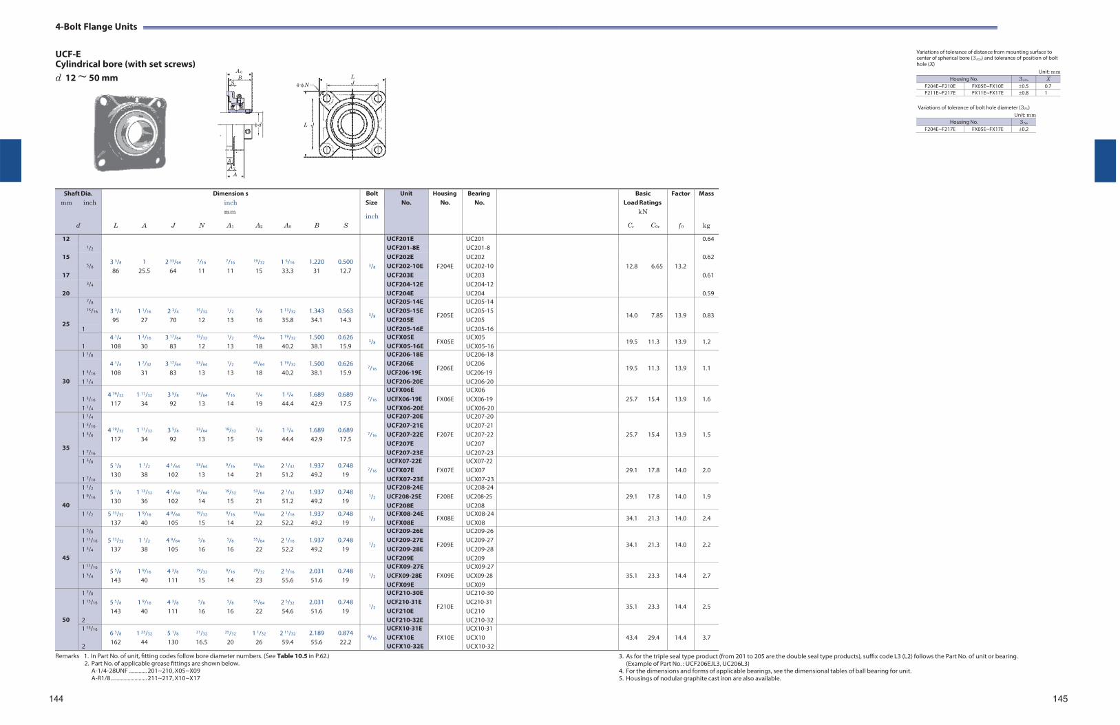
4-Bolt Flange Units
UCF-E Cylindrical bore (with set screws)
Variations of tolerance of distance from mounting surface to center of spherical bore (3A2s) and tolerance of position of bolt hole (X)
d 12 ~ 50 mm
Remarks 1. In Part No. of unit, fitting codes follow bore diameter numbers. (See Table 10.5 in P.62.) 2. Part No. of applicable grease fittings are shown below.
A-1/4-28UNF ............. 201~210, X05~X09 A-R1/8 .......................... 211~217, X10~X17
Variations of tolerance of bolt hole diameter (3Ns)
Unit: mm Housing No. 3Ns
F204E~F217E FX05E~FX17E 0.2
3. As for the triple seal type product (from 201 to 205 are the double seal type products), suffix code L3 (L2) follows the Part No. of unit or bearing. (Example of Part No. : UCF206EJL3, UC206L3)
4. For the dimensions and forms of applicable bearings, see the dimensional tables of ball bearing for unit. 5. Housings of nodular graphite cast iron are also available.
Unit: mm
144 145
A 0B
S
d
A 1
A 2
A
4-NLJ
L J
Housing No. 3A2s X F204E~F210E FX05E~FX10E 0.5 0.7F211E~F217E FX11E~FX17E 0.8 1
Shaft Dia. mm inch
d
L
A
J
N
Dimension inch mm
A1
s
A2
A0
B
S
Bolt Size
inch
Unit No.
HousingNo.
BearingNo.
BasicLoad Ratings
kN
Cr C0r
Factor
f 0
Mass
kg
12 1/2
3 3/8
86
1 25.5
2 33/64
64
7/16
11
7/16
11
19/32
15
1 5/16
33.3
1.220 31
0.500 12.7
3/8
UCF201E
F204E
UC201
12.8
6.65
13.2
0.64 UCF201-8E UC201-8
15 5/8
UCF202E UC202 0.62 UCF202-10E UC202-10
17 UCF203E UC203 0.61 3/4 UCF204-12E UC204-12
20 UCF204E UC204 0.59
25
7/8 3 3/4
95
1 1/16
27
2 3/4
70
15/32
12
1/2
13
5/8
16
1 13/32
35.8
1.343 34.1
0.563 14.3
3/8
UCF205-14E
F205E
UC205-14
14.0
7.85
13.9
0.83 15/16 UCF205-15E UC205-15
UCF205E UC205 1 UCF205-16E UC205-16
1
4 1/4
108 1 3/16
30 3 17/64
83
15/32
12
1/2
13
45/64
18 1 19/32
40.2 1.500 38.1
0.626 15.9
3/8 UCFX05E UCFX05-16E
FX05E UCX05 UCX05-16
19.5 11.3 13.9 1.2
30
1 1/8 4 1/4
108
1 7/32
31
3 17/64
83
33/64
13
1/2
13
45/64
18
1 19/32
40.2
1.500 38.1
0.626 15.9
7/16
UCF206-18E
F206E
UC206-18
19.5
11.3
13.9
1.1 1 3/16
UCF206E UCF206-19E
UC206 UC206-19
1 1/4 UCF206-20E UC206-20
1 3/16
1 1/4
4 19/32
117 1 11/32
34 3 5/8
92
33/64
13
9/16
14
3/4
19 1 3/4
44.4 1.689 42.9
0.689 17.5
7/16
UCFX06E UCFX06-19E UCFX06-20E
FX06E
UCX06 UCX06-19 UCX06-20
25.7
15.4
13.9
1.6
35
1 1/4
4 19/32
117
1 11/32
34
3 5/8
92
33/64
13
19/32
15
3/4
19
1 3/4
44.4
1.689 42.9
0.689 17.5
7/16
UCF207-20E
F207E
UC207-20
25.7
15.4
13.9
1.5 1 5/16 UCF207-21E UC207-211 3/8 UCF207-22E UC207-22
UCF207E UC207 1 7/16 UCF207-23E UC207-231 3/8
1 7/16
5 1/8
130 1 1/2
38 4 1/64
102
33/64
13
9/16
14
53/64
21 2 1/32
51.2 1.937 49.2
0.748 19
7/16
UCFX07-22E UCFX07E UCFX07-23E
FX07E
UCX07-22 UCX07 UCX07-23
29.1
17.8
14.0
2.0
40
1 1/2
1 9/16 5 1/8
130 1 13/32
36 4 1/64
102
35/64
14
19/32
15
53/64
21 2 1/32
51.2 1.937 49.2
0.748 19
1/2
UCF208-24E UCF208-25E UCF208E
F208E
UC208-24UC208-25 UC208
29.1
17.8
14.0
1.9
1 1/2 5 13/32
137 1 9/16
40 4 9/64
105
19/32
15
9/16
14
55/64
22 2 1/16
52.2 1.937 49.2
0.748 19
1/2 UCFX08-24E UCFX08E
FX08E UCX08-24UCX08
34.1 21.3 14.0 2.4
45
1 5/8 5 13/32
137
1 1/2
38
4 9/64
105
5/8
16
5/8
16
55/64
22
2 1/16
52.2
1.937 49.2
0.748
19
1/2
UCF209-26E
F209E
UC209-26
34.1
21.3
14.0
2.2 1 11/16 UCF209-27E UC209-271 3/4 UCF209-28E UC209-28
UCF209E UC209 1 11/16
1 3/4 5 5/8
143 1 9/16
40 4 3/8
111
19/32
15
9/16
14
29/32
23 2 3/16
55.6 2.031 51.6
0.748 19
1/2
UCFX09-27E UCFX09-28E UCFX09E
FX09E
UCX09-27UCX09-28 UCX09
35.1
23.3
14.4
2.7
50
1 7/8 5 5/8
143
1 9/16
40
4 3/8
111
5/8
16
5/8
16
55/64
22
2 5/32
54.6
2.031 51.6
0.748
19
1/2
UCF210-30E
F210E
UC210-30
35.1
23.3
14.4
2.5 1 15/16 UCF210-31E
UCF210E UC210-31 UC210
2 UCF210-32E UC210-321 15/16
2
6 3/8
162 1 23/32
44 5 1/8
130
21/32
16.5
25/32
20 1 1/32
26 2 11/32
59.4 2.189 55.6
0.874 22.2
9/16
UCFX10-31E UCFX10E UCFX10-32E
FX10E
UCX10-31 UCX10 UCX10-32
43.4
29.4
14.4
3.7
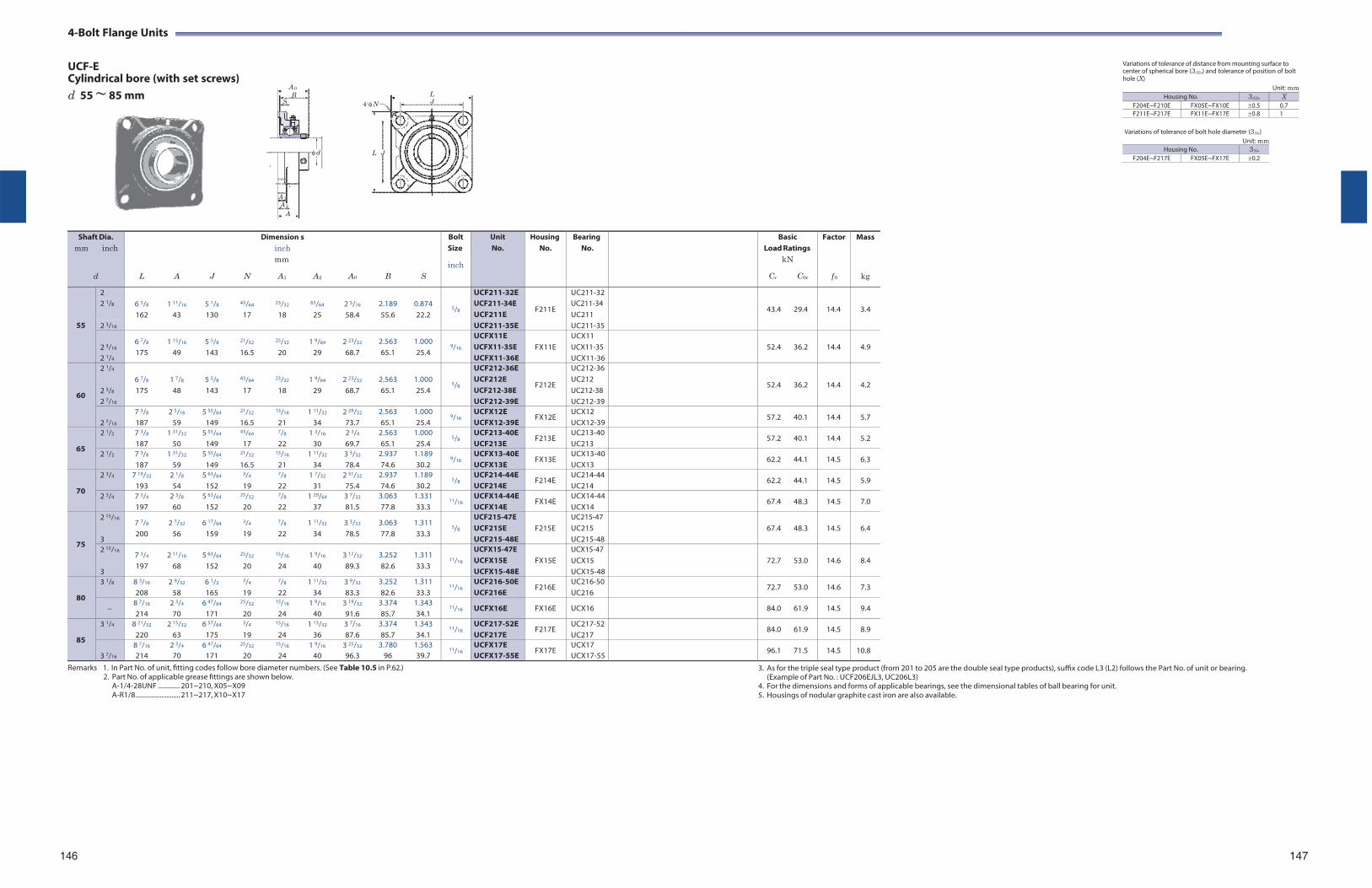
4-Bolt Flange Units
UCF-E Cylindrical bore (with set screws)
Variations of tolerance of distance from mounting surface to center of spherical bore (3A2s) and tolerance of position of bolt hole (X)
d 55 ~ 85 mm
Remarks 1. In Part No. of unit, fitting codes follow bore diameter numbers. (See Table 10.5 in P.62.) 2. Part No. of applicable grease fittings are shown below.
A-1/4-28UNF ............. 201~210, X05~X09 A-R1/8 .......................... 211~217, X10~X17
Variations of tolerance of bolt hole diameter (3Ns)
Unit: mm Housing No. 3Ns
F204E~F217E FX05E~FX17E 0.2
3. As for the triple seal type product (from 201 to 205 are the double seal type products), suffix code L3 (L2) follows the Part No. of unit or bearing. (Example of Part No. : UCF206EJL3, UC206L3)
4. For the dimensions and forms of applicable bearings, see the dimensional tables of ball bearing for unit. 5. Housings of nodular graphite cast iron are also available.
Unit: mm
146 147
A 0B
S
d
A 1
A 2
A
4-NLJ
L J
Housing No. 3A2s X F204E~F210E FX05E~FX10E 0.5 0.7F211E~F217E FX11E~FX17E 0.8 1
Shaft Dia. mm inch
d
L
A
J
N
Dimension inch mm
A1
s
A2
A0
B
S
Bolt Size
inch
Unit No.
HousingNo.
BearingNo.
BasicLoad Ratings
kN
Cr C0r
Factor
f 0
Mass
kg
55
2 6 3/8
162
1 11/16
43
5 1/8
130
43/64
17
23/32
18
63/64
25
2 5/16
58.4
2.189 55.6
0.874 22.2
5/8
UCF211-32E
F211E
UC211-32
43.4
29.4
14.4
3.4 2 1/8 UCF211-34E
UCF211E UC211-34 UC211
2 3/16 UCF211-35E UC211-35
2 3/16
2 1/4
6 7/8
175 1 15/16
49 5 5/8
143
21/32
16.5
25/32
20 1 9/64
29 2 23/32
68.7 2.563 65.1
1.000 25.4
9/16
UCFX11E UCFX11-35E UCFX11-36E
FX11E
UCX11 UCX11-35 UCX11-36
52.4
36.2
14.4
4.9
60
2 1/4 6 7/8
175
1 7/8
48
5 5/8
143
43/64
17
23/32
18
1 9/64
29
2 23/32
68.7
2.563 65.1
1.000 25.4
5/8
UCF212-36E
F212E
UC212-36
52.4
36.2
14.4
4.2 2 3/8
2 7/16
UCF212E UCF212-38E UCF212-39E
UC212 UC212-38 UC212-39
2 7/16
7 3/8
187 2 5/16
59 5 55/64
149
21/32
16.5
13/16
21 1 11/32
34 2 29/32
73.7 2.563 65.1
1.000 25.4
9/16 UCFX12E UCFX12-39E
FX12E UCX12 UCX12-39
57.2 40.1 14.4 5.7
65
2 1/2 7 3/8
187 1 31/32
50 5 55/64
149
43/64
17
7/8
22 1 3/16
30 2 3/4
69.7 2.563 65.1
1.000 25.4
5/8 UCF213-40E UCF213E
F213E UC213-40UC213
57.2 40.1 14.4 5.2
2 1/2 7 3/8
187 1 31/32
59 5 55/64
149
21/32
16.5
13/16
21 1 11/32
34 3 3/32
78.4 2.937 74.6
1.189 30.2
9/16 UCFX13-40E UCFX13E
FX13E UCX13-40UCX13
62.2 44.1 14.5 6.3
70
2 3/4 7 19/32
193 2 1/8
54 5 63/64
152
3/4
19
7/8
22 1 7/32
31 2 31/32
75.4 2.937 74.6
1.189 30.2
5/8 UCF214-44E UCF214E
F214E UC214-44UC214
62.2 44.1 14.5 5.9
2 3/4 7 3/4
197 2 3/8
60 5 63/64
152
25/32
20
7/8
22 1 29/64
37 3 7/32
81.5 3.063 77.8
1.331 33.3
11/16 UCFX14-44E UCFX14E
FX14E UCX14-44UCX14
67.4 48.3 14.5 7.0
75
2 15/16
3
7 7/8
200 2 7/32
56 6 17/64
159
3/4
19
7/8
22 1 11/32
34 3 3/32
78.5 3.063 77.8
1.311 33.3
5/8
UCF215-47E UCF215E UCF215-48E
F215E
UC215-47 UC215 UC215-48
67.4
48.3
14.5
6.4
2 15/16
3
7 3/4
197 2 11/16
68 5 63/64
152
25/32
20
15/16
24 1 9/16
40 3 17/32
89.3 3.252 82.6
1.311 33.3
11/16
UCFX15-47E UCFX15E UCFX15-48E
FX15E
UCX15-47 UCX15 UCX15-48
72.7
53.0
14.6
8.4
80
3 1/8 8 3/16
208 2 9/32
58 6 1/2
165
3/4
19
7/8
22 1 11/32
34 3 9/32
83.3 3.252 82.6
1.311 33.3
11/16 UCF216-50E UCF216E
F216E UC216-50UC216
72.7 53.0 14.6 7.3
8 7/16
214 2 3/4
70 6 47/64
171
25/32
20
15/16
24 1 9/16
40 3 19/32
91.6 3.374 85.7
1.343 34.1
11/16 UCFX16E FX16E UCX16 84.0 61.9 14.5 9.4
85
3 1/4 8 21/32
220 2 15/32
63 6 57/64
175
3/4
19
15/16
24 1 13/32
36 3 7/16
87.6 3.374 85.7
1.343 34.1
11/16 UCF217-52E UCF217E
F217E UC217-52UC217
84.0 61.9 14.5 8.9
3 7/16
8 7/16
214 2 3/4
70 6 47/64
171
25/32
20
15/16
24 1 9/16
40 3 25/32
96.3 3.780
96 1.563 39.7
11/16 UCFX17E UCFX17-55E
FX17E UCX17 UCX17-55
96.1 71.5 14.5 10.8
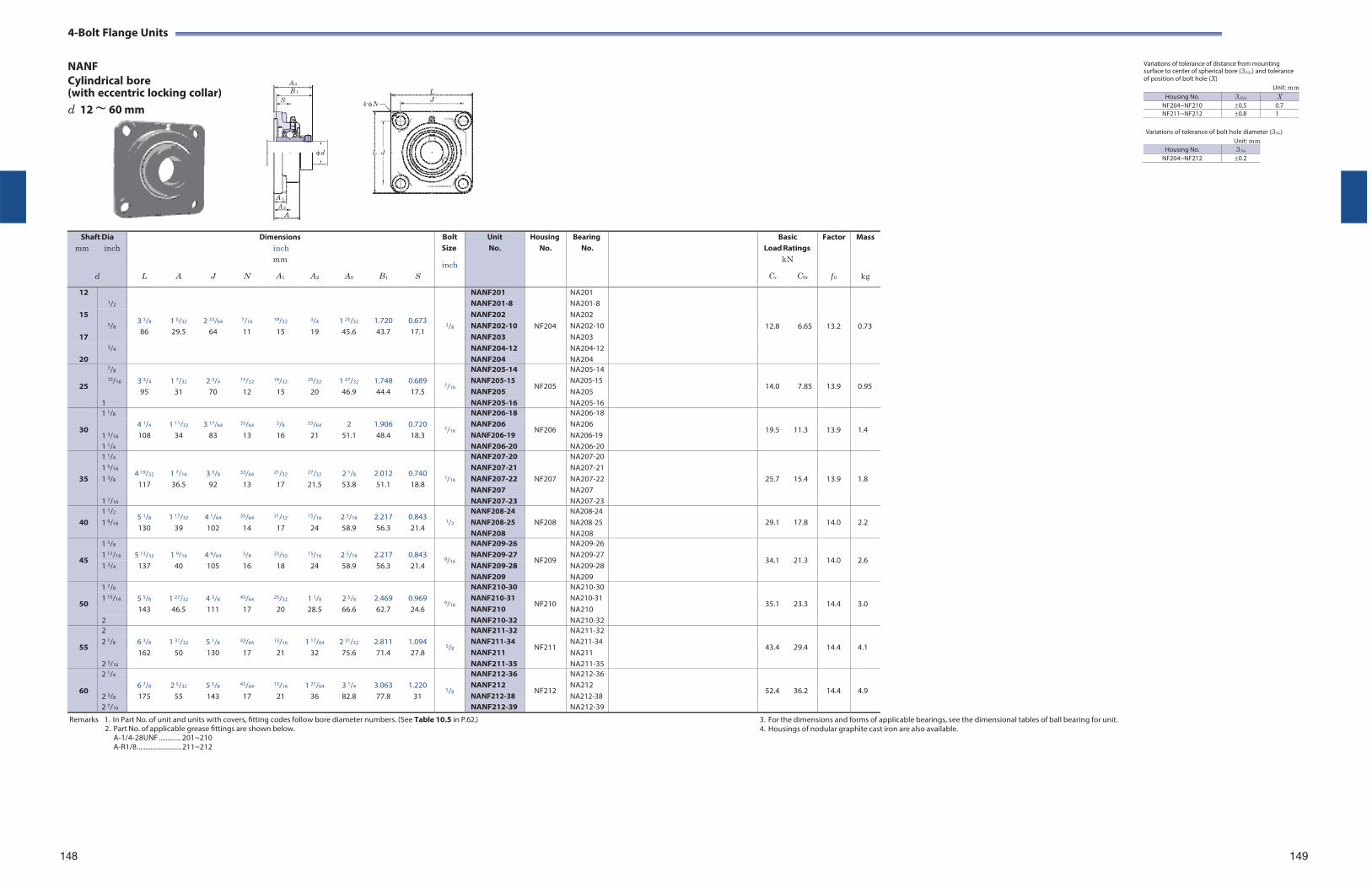
4-Bolt Flange Units
NANF Cylindrical bore (with eccentric locking collar) d 12 ~ 60 mm
Variations of tolerance of distance from mounting surface to center of spherical bore (3A2s) and tolerance of position of bolt hole (X)
Unit: mm
Variations of tolerance of bolt hole diameter (3Ns) Unit: mm
Housing No. 3Ns
NF204~NF212 0.2
Shaft Dia
mm inch
d
L
A
J
N
Dimensions inch mm
A1 A2
A0
B1
S
Bolt Size
inch
Unit No.
HousingNo.
BearingNo.
BasicLoad Ratings
kN
Cr C0r
Factor
f 0
Mass
kg
12 1/2
3 3/8
86
1 5/32
29.5
2 33/64
64
7/16
11
19/32
15
3/4
19
1 25/32
45.6
1.720 43.7
0.673 17.1
3/8
NANF201
NF204
NA201
12.8
6.65
13.2
0.73
NANF201-8 NA201-8 15
5/8
NANF202 NA202 NANF202-10 NA202-10
17 NANF203 NA203 3/4 NANF204-12 NA204-12
20 NANF204 NA204
25
7/8 3 3/4
95
1 7/32
31
2 3/4
70
15/32
12
19/32
15
25/32
20
1 27/32
46.9
1.748 44.4
0.689 17.5
7/16
NANF205-14
NF205
NA205-14
14.0
7.85
13.9
0.95 15/16 NANF205-15
NANF205 NA205-15 NA205
1 NANF205-16 NA205-16
30
1 1/8 4 1/4
108
1 11/32
34
3 17/64
83
33/64
13
5/8
16
53/64
21
2
51.1
1.906 48.4
0.720 18.3
7/16
NANF206-18
NF206
NA206-18
19.5
11.3
13.9
1.4 1 3/16
NANF206 NANF206-19
NA206 NA206-19
1 1/4 NANF206-20 NA206-20
35
1 1/4
4 19/32
117
1 7/16
36.5
3 5/8
92
33/64
13
21/32
17
27/32
21.5
2 1/8
53.8
2.012 51.1
0.740 18.8
7/16
NANF207-20
NF207
NA207-20
25.7
15.4
13.9
1.8
1 5/16 NANF207-21 NA207-211 3/8 NANF207-22 NA207-22
NANF207 NA207 1 7/16 NANF207-23 NA207-23
40
1 1/2
1 9/16 5 1/8
130 1 17/32
39 4 1/64
102
35/64
14
21/32
17
15/16
24 2 5/16
58.9 2.217 56.3
0.843 21.4
1/2
NANF208-24 NANF208-25 NANF208
NF208
NA208-24 NA208-25 NA208
29.1
17.8
14.0
2.2
45
1 5/8 5 13/32
137
1 9/16
40
4 9/64
105
5/8
16
23/32
18
15/16
24
2 5/16
58.9
2.217 56.3
0.843 21.4
9/16
NANF209-26
NF209
NA209-26
34.1
21.3
14.0
2.6 1 11/16 NANF209-27 NA209-271 3/4 NANF209-28 NA209-28
NANF209 NA209
50
1 7/8 5 5/8
143
1 27/32
46.5
4 3/8
111
43/64
17
25/32
20
1 1/8
28.5
2 5/8
66.6
2.469 62.7
0.969 24.6
9/16
NANF210-30
NF210
NA210-30
35.1
23.3
14.4
3.0 1 15/16 NANF210-31
NANF210 NA210-31 NA210
2 NANF210-32 NA210-32
55
2 6 3/8
162
1 31/32
50
5 1/8
130
43/64
17
13/16
21
1 17/64
32
2 31/32
75.6
2.811 71.4
1.094 27.8
5/8
NANF211-32
NF211
NA211-32
43.4
29.4
14.4
4.1 2 1/8 NANF211-34
NANF211 NA211-34 NA211
2 3/16 NANF211-35 NA211-35
60
2 1/4 6 7/8
175
2 5/32
55
5 5/8
143
43/64
17
13/16
21
1 27/64
36
3 1/4
82.8
3.063 77.8
1.220
31
5/8
NANF212-36
NF212
NA212-36
52.4
36.2
14.4
4.9 2 3/8
NANF212 NANF212-38
NA212 NA212-38
2 7/16 NANF212-39 NA212-39
Remarks 1. In Part No. of unit and units with covers, fitting codes follow bore diameter numbers. (See Table 10.5 in P.62.) 2. Part No. of applicable grease fittings are shown below.
A-1/4-28UNF ............. 201~210 A-R1/8 .......................... 211~212
3. For the dimensions and forms of applicable bearings, see the dimensional tables of ball bearing for unit. 4. Housings of nodular graphite cast iron are also available.
148 149
A 0
B 1
S
d
A 1
A 2
A
4-N
LJ
L J
Housing No. 3A2s X NF204~NF210 0.5 0.7NF211~NF212 0.8 1

4-Bolt Flange Units
NCF Cylindrical bore A 0
B 1
(with concentric locking collar) S
d 20 ~ 60 mm
L
4-N J
Variations of tolerance of distance from mounting surface to center of spherical bore (3A2s) and tolerance of position of bolt hole (X)
Unit: mm
d d 1 L J
Variations of tolerance of bolt hole diameter (3Ns) Unit: mm
A 1
A 2
A
Shaft Dia. mm inch
d
L
A
J
N
Dimensions inch mm
A1 A2
A0
B1
S
d1
Bolt Size
inch mm
Unit No.
HousingNo.
BearingNo.
BasicLoad Ratings
kN
Cr C0r
Factor
f 0
Mass
kg
20 3/4 3 3/8
86 1
25.5 2 33/64
64
15/32
12
7/16
11
19/32
15 1 3/8
34.8 1 9/32
32.5 0.500 12.7
1 3/4
44.5
3/8
M10 NCF204-12 NCF204
F204 NC204-12 NC204
12.8 6.65 13.2 0.73
25
7/8 3 3/4
1 1/16
2 3/4
15/32
1/2
5/8
1 1/2
1 7/16
0.563
1 15/16
3/8
NCF205-14
F205
NC205-14
14.0
7.85
13.9
1.0 15/16 NCF205-15
NCF205 NC205-15 NC205 95 27 70 12 13 16 38.2 36.5 14.3 49.2 M10
1 NCF205-16 NC205-16
30
1 1/8 4 1/4
1 7/32
3 17/64
15/32
1/2
45/64
1 21/32
1 9/16
0.626
2 3/16
3/8
NCF206-18
F206
NC206-18
19.5
11.3
13.9
1.3 1 3/16
NCF206 NCF206-19
NC206 NC206-19 108 31 83 12 13 18 41.8 39.7 15.9 55.6 M10
1 1/4 NCF206-20 NC206-20
35
1 1/4 4 19/32
117 1 11/32
34 3 5/8
92
35/64
14
19/32
15
3/4
19 1 13/16
46 1 3/4
44.5 0.689 17.5
2 7/16
61.9
7/16
M12 NCF207-20 F207 NC207-20 25.7 15.4 13.9 1.8
1 3/8
1 7/16
4 19/32
117 1 11/32
34 3 5/8
92
35/64
14
19/32
15
3/4
19 1 13/16
46 1 3/4
44.5 0.689 17.5
2 9/16
65.1
7/16
M12
NCF207-22 NCF207 NCF207-23
F207
NC207-22 NC207 NC207-23
25.7
15.4
13.9
1.8
40 1 1/2 5 1/8
130 1 13/32
36 4 1/64
102
5/8
16
19/32
15
53/64
21 2 3/32
52.8 2
50.8 0.748
19 2 11/16
68.3
1/2
M14 NCF208-24 NCF208
F208 NC208-24 NC208
29.1 17.8 14.0 2.3
45
1 5/8 5 13/32
137 1 1/2
38 4 9/64
105
5/8
16
5/8
16
55/64
22 2 1/8
53.8 2
50.8 0.748
19 2 13/16
71.4
1/2
M14 NCF209-26 F209 NC209-26 34.1 21.3 14.0 2.6
1 11/16
1 3/4 5 13/32
137 1 1/2
38 4 9/64
105
5/8
16
5/8
16
55/64
22 2 1/8
53.8 2
50.8 0.748
19 2 15/16
74.6
1/2
M14
NCF209-27 NCF209-28 NCF209
F209
NC209-27 NC209-28 NC209
34.1
21.3
14.0
2.6
50
1 15/16
2
5 5/8
143 1 9/16
40 4 3/8
111
5/8
16
5/8
16
55/64
22 2 7/32
56.1 2 3/32
53.1 0.748
19 3 3/8
85.7
1/2
M14
NCF210-31 NCF210 NCF210-32
F210
NC210-31 NC210 NC210-32
35.1
23.3
14.4
3.1
55
2 6 3/8
162 1 11/16
43 5 1/8
130
3/4
19
23/32
18
63/64
25 2 11/32
59.9 2 1/4
57.1 0.874 22.2
3 1/2
88.9
5/8
M16 NCF211-32 F211 NC211-32 43.4 29.4 14.4 3.8
2 3/16
6 3/8
162 1 11/16
43 5 1/8
130
3/4
19
23/32
18
63/64
25 2 11/32
59.9 2 1/4
57.1 0.874 22.2
3 5/8
92.1
5/8
M16 NCF211 NCF211-35
F211 NC211 NC211-35
43.4 29.4 14.4 3.8
60
2 1/4 6 7/8
175 1 7/8
48 5 5/8
143
3/4
19
23/32
18 1 9/64
29 2 25/32
70.3 2 5/8
66.7 1.000 25.4
4 1/16
103.2
5/8
M16 NCF212-36 F212 NC212-36 52.4 36.2 14.4 4.9
2 7/16
6 7/8
175 1 7/8
48 5 5/8
143
3/4
19
23/32
18 1 9/64
29 2 25/32
70.3 2 5/8
66.7 1.000 25.4
4 1/8
104.8
5/8
M16 NCF212 NCF212-39
F212 NC212 NC212-39
52.4 36.2 14.4 4.9
Remarks 1. In Part No. of unit, fitting codes follow bore diameter codes. (See Table 10.5 in P.62.) 2. Part No. of applicable grease fittings are shown below.
A-1/4-28UNF ............. 204~210 A-R1/8 .......................... 211~212
3. For the dimensions and forms of applicable bearings, see the dimensional tables of ball bearing for unit. 4. Representative examples of the forms of housing are indicated.
150 151
Housing No. 3A2s X F204~F210 0.5 0.7F211~F212 0.8 1
Housing No. 3Ns
F204~F212 0.2
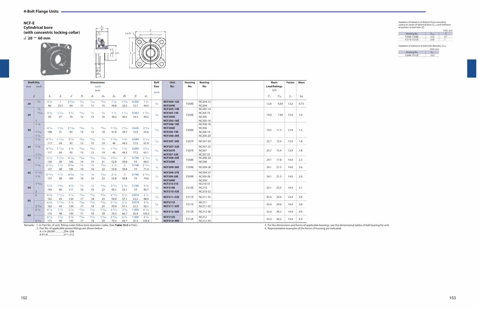
4-Bolt Flange Units
NCF-E Cylindrical bore A 0
B 1
(with concentric locking collar) S
d 20 ~ 60 mm
L
4-N J
Variations of tolerance of distance from mounting surface to center of spherical bore (3A2s) and tolerance of position of bolt hole (X)
Unit: mm
d d 1 L J
Variations of tolerance of bolt hole diameter (3Ns) Unit: mm
A 1
A 2
A
Shaft Dia. mm inch
d
L
A
J
N
Dimensions inch mm
A1 A2
A0
B1
S
d1
Bolt Size
inch
Unit No.
HousingNo.
BearingNo.
BasicLoad Ratings
kN
Cr C0r
Factor
f 0
Mass
kg
20 3/4 3 3/8
86 1
25.5 2 33/64
64
7/16
11
7/16
11
19/32
15 1 3/8
34.8 1 9/32
32.5 0.500 12.7
1 3/4
44.5 3/8
NCF204-12E NCF204E
F204E NC204-12NC204
12.8 6.65 13.2 0.73
25
7/8 3 3/4
95
1 1/16
27
2 3/4
70
15/32
12
1/2
13
5/8
16
1 1/2
38.2
1 7/16
36.5
0.563 14.3
1 15/16
49.2
3/8
NCF205-14E
F205E
NC205-14
14.0
7.85
13.9
1.0 15/16 NCF205-15E
NCF205E NC205-15 NC205
1 NCF205-16E NC205-16
30
1 1/8 4 1/4
108
1 7/32
31
3 17/64
83
33/64
13
1/2
13
45/64
18
1 21/32
41.8
1 9/16
39.7
0.626 15.9
2 3/16
55.6
7/16
NCF206-18E
F206E
NC206-18
19.5
11.3
13.9
1.3 1 3/16
NCF206E NCF206-19E
NC206 NC206-19
1 1/4 NCF206-20E NC206-20
35
1 1/4 4 19/32
117 1 11/32
34 3 5/8
92
33/64
13
19/32
15
3/4
19 1 13/16
46 1 3/4
44.5 0.689 17.5
2 7/16
61.9 7/16 NCF207-20E F207E NC207-20 25.7 15.4 13.9 1.8
1 3/8
1 7/16
4 19/32
117 1 11/32
34 3 5/8
92
33/64
13
19/32
15
3/4
19 1 13/16
46 1 3/4
44.5 0.689 17.5
2 9/16
65.1
7/16
NCF207-22E NCF207E NCF207-23E
F207E
NC207-22NC207 NC207-23
25.7
15.4
13.9
1.8
40 1 1/2 5 1/8
130 1 13/32
36 4 1/64
102
35/64
14
19/32
15
53/64
21 2 3/32
52.8 2
50.8 0.748
19 2 11/16
68.3 1/2
NCF208-24E NCF208E
F208E NC208-24NC208
29.1 17.8 14.0 2.3
45
1 5/8 5 13/32
137 1 1/2
38 4 9/64
105
5/8
16
5/8
16
55/64
22 2 1/8
53.8 2
50.8 0.748
19 2 13/16
71.4 1/2 NCF209-26E F209E NC209-26 34.1 21.3 14.0 2.6
1 11/16
1 3/4 5 13/32
137 1 1/2
38 4 9/64
105
5/8
16
5/8
16
55/64
22 2 1/8
53.8 2
50.8 0.748
19 2 15/16
74.6
1/2
NCF209-27E NCF209-28E NCF209E
F209E
NC209-27NC209-28 NC209
34.1
21.3
14.0
2.6
50
1 15/16
2
5 5/8
143 1 9/16
40 4 3/8
111
5/8
16
5/8
16
55/64
22 2 7/32
56.1 2 3/32
53.1 0.748
19 3 3/8
85.7
1/2
NCF210-31E NCF210E NCF210-32E
F210E
NC210-31 NC210 NC210-32
35.1
23.3
14.4
3.1
55
2 6 3/8
162 1 11/16
43 5 1/8
130
43/64
17
23/32
18
63/64
25 2 11/32
59.9 2 1/4
57.1 0.874 22.2
3 1/2
88.9 5/8 NCF211-32E F211E NC211-32 43.4 29.4 14.4 3.8
2 3/16
6 3/8
162 1 11/16
43 5 1/8
130
43/64
17
23/32
18
63/64
25 2 11/32
59.9 2 1/4
57.1 0.874 22.2
3 5/8
92.1 5/8
NCF211E NCF211-35E
F211E NC211 NC211-35
43.4 29.4 14.4 3.8
60
2 1/4 6 7/8
175 1 7/8
48 5 5/8
143
43/64
17
23/32
18 1 9/64
29 2 25/32
70.3 2 5/8
66.7 1.000 25.4
4 1/16
103.2 5/8 NCF212-36E F212E NC212-36 52.4 36.2 14.4 4.9
2 7/16
6 7/8
175 1 7/8
48 5 5/8
143
43/64
17
23/32
18 1 9/64
29 2 25/32
70.3 2 5/8
66.7 1.000 25.4
4 1/8
104.8 5/8
NCF212E NCF212-39E
F212E NC212 NC212-39
52.4 36.2 14.4 4.9
Remarks 1. In Part No. of unit, fitting codes follow bore diameter codes. (See Table 10.5 in P.62.) 2. Part No. of applicable grease fittings are shown below.
A-1/4-28UNF ............. 204~208 A-R1/8 .......................... 211~212
3. For the dimensions and forms of applicable bearings, see the dimensional tables of ball bearing for unit. 4. Representative examples of the forms of housing are indicated.
152 153
Housing No. 3A2s X F204E~F208E 0.5 0.7F211E~F212E 0.8 1
Housing No. 3Ns
F204E~F212E 0.2
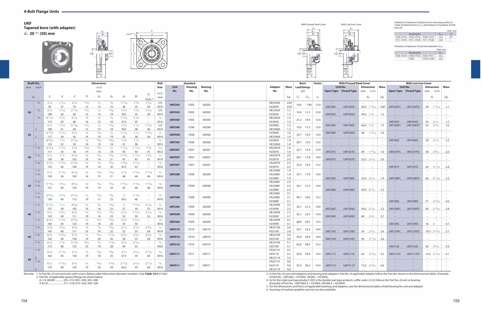
4-Bolt Flange Units
UKF With Pressed Steel Cover With Cast Iron Cover
Variations of tolerance of distance from mounting surface to center of spherical bore (3A2s) and tolerance of position of bolt
Tapered bore (with adapter) d1 20 ~ (50) mm
A 0
B 1
d e
A 1
A 2
A
d1
L
4-N J
L J
AS
A 0
B 1
d e d1 1
A 1
A 2
A
AC
A 0
B 1
d e d1 2
A 1
A 2
A
hole (X)
Variations of tolerance of bolt hole diameter (3Ns) Unit: mm
Unit: mm
Shaft Dia. mm inch
d1
Dimensions inch mm
de L A J N A1 A2 A0 B1
(min.)
Bolt Size
inch mm
Standard BasicLoad Ratings
kN
Cr C0r
Factor
f 0
With Pressed Steel Cover With Cast Iron Cover Unit No.
Housing No.
Bearing No.
Adapter No.
Mass
kg
Unit No. Open Type Closed Type
Dimension mm inch
As
Mass
kg
Unit No. Open Type Closed Type
Dimension mm inch
Ac
Mass
kg
20
3/4 3 3/4 1 1/16 2 3/4 15/32 1/2 5/8 1 13/32 1 3/8 1 3/16
95 27 70 12 13 16 36 35 30 3/8
M10 UKF205 F205 UK205 HE2305X
H2305X0.870.87
14.0 7.85 13.9
UKF205C UKF205D
40.5 1 19/32
0.87
UKF205FC UKF205FD
49 1 15/16
1.1
3/4 4 1/4 1 3/16 3 17/64 15/32 1/2 45/64 1 9/16 1 3/8 1 3/16
108 30 83 12 13 18 39.5 35 30 3/8
M10 UKFX05 FX05 UKX05 HE2305X
H2305X 1.2 1.2
19.5 11.3 13.9
UKFX05C UKFX05D
44.5 1 3/4
1.2
3/4 4 11/32 1 5/32 3 5/32 5/8 1/2 5/8 1 15/32 1 3/8 110 29 80 16 13 16 37.5 35
1/2
M14 UKF305 F305 UK305 HE2305X
H2305X 1.4 1.4
21.2 10.9 12.6
UKF305C UKF305D
54 2 1/8
1.7
25
1
4 1/4 1 7/32 3 17/64 15/32 1/2 45/64 1 9/16 1 1/2 1 13/32
108 31 83 12 13 18 39.5 38 36 3/8
M10 UKF206 F206 UK206 H2306X
HE2306X1.3 1.3
19.5 11.3 13.9 UKF206C UKF206D
44.5 1 3/4
1.3
UKF206FC UKF206FD
53 2 3/32
1.6
1
4 19/32 1 11/32 3 5/8 5/8 9/16 3/4 1 21/32 1 1/2 1 13/32
117 34 92 16 14 19 42 38 36
1/2
M14 UKFX06 FX06 UKX06 H2306X
HE2306X 1.6 1.6
25.7 15.4 13.9 UKFX06C UKFX06D
49 1 15/16
1.6
1
4 29/32 1 1/4 3 47/64 5/8 19/32 45/64 1 5/8 1 1/2 125 32 95 16 15 18 41 38
1/2
M14 UKF306 F306 UK306 H2306X
HE2306X 1.9 1.9
26.7 15.0 13.3
UKF306C UKF306D
59 2 5/16
2.2
30
1 1/8 4 19/32 1 11/32 3 5/8 35/64 19/32 3/4 1 11/16 1 11/16 1 5/8
117 34 92 14 15 19 43 43 41
7/16
M12 UKF207 F207 UK207 HS2307X
H2307X 1.6 1.6
25.7 15.4 13.9
UKF207C UKF207D
49 1 15/16
1.6
UKF207FC UKF207FD
58 2 9/32
2.0
1 1/8 5 1/8 1 1/2 4 1/64 5/8 9/16 53/64 1 27/32 1 11/16 1 5/8
130 38 102 16 14 21 47 43 41
1/2
M14 UKFX07 FX07 UKX07 HS2307X
H2307X 2.0 2.0
29.1 17.8 14.0
UKFX07C UKFX07D
55.5 2 3/16
2.0
1 1/8 5 5/16 1 13/32 3 15/16 3/4 5/8 25/32 1 25/32 1 11/16 135 36 100 19 16 20 45.5 43
5/8
M16 UKF307 F307 UK307 HS2307X
H2307X 2.3 2.3
33.4 19.3 13.2
UKF307C UKF307D
64 2 17/32
2.8
35
1 1/4
1 3/8 5 1/8 1 13/32 4 1/64 5/8 19/32 53/64 1 7/8 1 13/16 1 13/16
130 36 102 16 15 21 48 46 46
1/2
M14
UKF208
F208
UK208
HE2308X HS2308X H2308X
1.9 1.9 1.9
29.1 17.8
14.0
UKF208C UKF208D
55.5 2 3/16
1.9
UKF208FC UKF208FD
64 2 17/32
2.3
1 1/4
1 3/8 5 13/32 1 9/16 4 9/64 3/4 9/16 55/64 1 31/32 1 13/16 1 13/16
137 40 105 19 14 22 50 46 46
5/8
M16
UKFX08
FX08
UKX08
HE2308X HS2308X H2308X
2.3 2.3 2.3
34.1 21.3
14.0
UKFX08C UKFX08D
56.5 2 7/32
2.3
1 1/4
1 3/8 5 29/32 1 9/16 4 13/32 3/4 21/32 29/32 2 1 13/16
150 40 112 19 17 23 50.5 46
5/8
M16
UKF308
F308
UK308
HE2308X HS2308X H2308X
3.1 3.1 3.1
40.7 24.0
13.2
UKF308C UKF308D
71 2 25/32
3.6
40
1 1/2 5 13/32 1 1/2 4 9/64 5/8 5/8 55/64 2 1 31/32 2 1/16
137 38 105 16 16 22 51 50 52
1/2
M14 UKF209 F209 UK209 HE2309X
H2309X 2.3 2.3
34.1 21.3 14.0
UKF209C UKF209D
56.5 2 7/32
2.3
UKF209FC UKF209FD
66 2 19/32
2.8
1 1/2 5 5/8 1 9/16 4 3/8 3/4 9/16 29/32 2 1/16 1 31/32 2 1/16
143 40 111 19 14 23 52 50 52
5/8
M16 UKFX09 FX09 UKX09 HE2309X
H2309X 2.7 2.7
35.1 23.3 14.4
UKFX09C UKFX09D
60 2 3/8
2.7
1 1/2 6 5/16 1 23/32 4 59/64 3/4 23/32 63/64 2 5/32 1 31/32 160 44 125 19 18 25 55 50
5/8
M16 UKF309 F309 UK309 HE2309X
H2309X 4.1 4.1
48.9 29.5 13.3
UKF309C UKF309D
76 3
4.7
45
1 3/4 5 5/8 1 9/16 4 3/8 5/8 5/8 55/64 2 1/16 2 5/32 2 9/32
143 40 111 16 16 22 52 55 58
1/2
M14 UKF210 F210 UK210 HE2310X
H2310X 2.6 2.6
35.1 23.3 14.4
UKF210C UKF210D
59 2 5/16
2.6
UKF210FC UKF210FD
70.5 2 25/32
3.1
1 3/4 6 3/8 1 23/32 5 1/8 3/4 25/32 1 1/32 2 9/32 2 5/32 2 9/32
162 44 130 19 20 26 58 55 58
5/8
M16 UKFX10 FX10 UKX10 HE2310X
H2310X 3.6 3.6
43.4 29.4 14.4
UKFX10C UKFX10D
64 2 17/32
3.6
1 3/4 6 7/8 1 7/8 5 13/64 29/32 3/4 1 7/64 2 3/8 2 5/32 175 48 132 23 19 28 60 55
3/4
M20 UKF310 F310 UK310 HE2310X
H2310X 5.1 5.1
62.0 38.3 13.2
UKF310C UKF310D
83 3 9/32
5.9
50
1 7/8
2
6 3/8 1 11/16 5 1/8 3/4 23/32 63/64 2 1/4 2 5/16 2 17/32
162 43 130 19 18 25 57.5 59 64
5/8
M16
UKF211
F211
UK211
HS2311X H2311X HE2311X
3.5 3.5 3.5
43.4 29.4
14.4
UKF211C UKF211D
63 2 15/32
3.5
UKF211FC UKF211FD
74.5 2 15/16
4.1
1 7/8
2
6 7/8 1 15/16 5 5/8 3/4 25/32 1 9/64 2 17/32 2 5/16 2 17/32
175 49 143 19 20 29 64.5 59 64
5/8
M16
UKFX11
FX11
UKX11
HS2311X H2311X HE2311X
4.6 4.6 4.6
52.4 36.2
14.4
UKFX11C UKFX11D
73.5 2 29/32
4.6
Remarks 1. In Part No. of unit and units with covers, fitting codes follow bore diameter numbers. (See Table 10.5 in P.62.) 2. Part No. of applicable grease fittings are shown below.
A-1/4-28UNF ............. 205~210, X05~X09, 305~308 A-R1/8 .......................... 211~218, X10~X20, 309~328
3. In Part No. of unit with adapters and bearing with adapters, Part No. of applicable adapter follow the Part No. shown in the dimensional tables. (Example of Part No. : UKF206J H2306X, UK206 H2306X)
4. As for the triple seal type product (205 is the double seal type product), suffix code L3 (L2) follows the Part No. of unit or bearing. (Example of Part No. : UKF206JL3 H2306X, UK206L3 H2306X)
5. For the dimensions and forms of applicable bearings and adapters, see the dimensional tables of ball bearing for unit and adapter. 6. Housings of nodular graphite cast iron are also available.
154 155
Housing No. 3A2s X F205~F210 FX05~FX10 F305~F310 0.5 0.7F211~F218 FX11~FX20 F311~F328 0.8 1
Housing No. 3Ns
F205~F218 FX05~FX18 F305~F315 0.2FX20 F316~F328 0.3
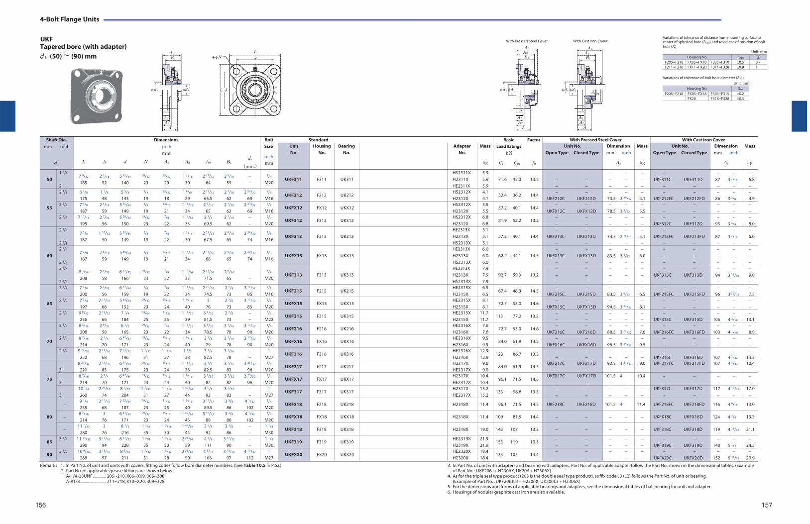
4-Bolt Flange Units
UKF With Pressed Steel Cover With Cast Iron Cover
Variations of tolerance of distance from mounting surface to center of spherical bore (3A2s) and tolerance of position of bolt
Tapered bore (with adapter) d1 (50) ~ (90) mm
A 0
B 1
d e
A 1
A 2
A
d1
L
4-N J
L J
AS
A 0
B 1
d e d1 1
A 1
A 2
A
AC
A 0
B 1
d e d1 2
A 1
A 2
A
hole (X)
Variations of tolerance of bolt hole diameter (3Ns) Unit: mm
Unit: mm
Shaft Dia. mm inch
d1
Dimensions inch mm
de L A J N A1 A2 A0 B1
(min.)
Bolt Size
inch mm
Standard BasicLoad Ratings
kN
Cr C0r
Factor
f 0
With Pressed Steel Cover With Cast Iron Cover Unit No.
Housing No.
Bearing No.
Adapter No.
Mass
kg
Unit No. Open Type Closed Type
Dimension mm inch
As
Mass
kg
Unit No. Open Type Closed Type
Dimension mm inch
Ac
Mass
kg
50
1 7/8
2
7 9/32 2 1/16 5 33/64 29/32 25/32 1 3/16 2 17/32 2 5/16 185 52 140 23 20 30 64 59
3/4
M20
UKF311
F311
UK311
HS2311X H2311X HE2311X
5.9 5.9 5.9
71.6 45.0
13.2
UKF311C UKF311D
87 3 7/16
6.8
55
2 1/8 6 7/8 1 7/8 5 5/8 3/4 23/32 1 9/64 2 19/32 2 7/16 2 23/32
175 48 143 19 18 29 65.5 62 69
5/8
M16 UKF212 F212 UK212 HS2312X
H2312X 4.1 4.1
52.4 36.2 14.4
UKF212C UKF212D
73.5 2 29/32
4.1
UKF212FC UKF212FD
86 3 3/8
4.9
2 1/8 7 3/8 2 5/16 5 55/64 3/4 13/16 1 11/32 2 9/16 2 7/16 2 23/32
187 59 149 19 21 34 65 62 69
5/8
M16 UKFX12 FX12 UKX12 HS2312X
H2312X 5.5 5.5
57.2 40.1 14.4
UKFX12C UKFX12D
78.5 3 3/32
5.5
2 1/8 7 11/16 2 7/32 5 29/32 29/32 7/8 1 19/64 2 3/4 2 7/16 195 56 150 23 22 33 69.5 62
3/4
M20 UKF312 F312 UK312 HS2312X
H2312X 6.8 6.8
81.9 52.2 13.2
UKF312C UKF312D
95 3 3/4
8.0
60
2 1/4
2 3/8
7 3/8 1 31/32 5 55/64 3/4 7/8 1 3/16 2 21/32 2 9/16 2 29/32
187 50 149 19 22 30 67.5 65 74
5/8
M16
UKF213
F213
UK213
HE2313X H2313X HS2313X
5.1 5.1 5.1
57.2 40.1
14.4
UKF213C UKF213D
74.5 2 15/16
5.1
UKF213FC UKF213FD
87 3 7/16
6.0
2 1/4
2 3/8
7 3/8 2 5/16 5 55/64 3/4 13/16 1 11/32 2 11/16 2 9/16 2 29/32
187 59 149 19 21 34 68 65 74
5/8
M16
UKFX13
FX13
UKX13
HE2313X H2313X HS2313X
6.0 6.0 6.0
62.2 44.1
14.5
UKFX13C UKFX13D
83.5 3 9/32
6.0
2 1/4
2 3/8
8 3/16 2 9/32 6 17/32 29/32 7/8 1 19/64 2 13/16 2 9/16 208 58 166 23 22 33 71.5 65
3/4
M20
UKF313
F313
UK313
HE2313X H2313X HS2313X
7.9 7.9 7.9
92.7 59.9
13.2
UKF313C UKF313D
94 3 11/16
9.0
65
2 1/2 7 7/8 2 7/32 6 17/64 3/4 7/8 1 11/32 2 15/16 2 7/8 3 11/32
200 56 159 19 22 34 74.5 73 85
5/8
M16 UKF215 F215 UK215 HE2315X
H2315X 6.5 6.5
67.4 48.3 14.5
UKF215C UKF215D
83.5 3 9/32
6.5
UKF215FC UKF215FD
96 3 25/32
7.5
2 1/2 7 3/4 2 11/16 5 63/64 29/32 15/16 1 9/16 3 2 7/8 3 11/32
197 68 152 23 24 40 76 73 85
3/4
M20 UKFX15 FX15 UKX15 HE2315X
H2315X 8.1 8.1
72.7 53.0 14.6
UKFX15C UKFX15D
94.5 3 23/32
8.1
2 1/2 9 9/32 2 19/32 7 1/4 63/64 31/32 1 17/32 3 7/32 2 7/8 236 66 184 25 25 39 81.5 73
7/8
M22 UKF315 F315 UK315 HE2315X
H2315X 11.7 11.7
113 77.2 13.2
UKF315C UKF315D
106 4 3/16
13.1
70
2 3/4 8 3/16 2 9/32 6 1/2 29/32 7/8 1 11/32 3 3/32 3 1/16 3 17/32
208 58 165 23 22 34 78.5 78 90
3/4
M20 UKF216 F216 UK216 HE2316X
H2316X 7.6 7.6
72.7 53.0 14.6
UKF216C UKF216D
88.5 3 15/32
7.6
UKF216FC UKF216FD
103 4 1/16
8.9
2 3/4 8 7/16 2 3/4 6 47/64 29/32 15/16 1 9/16 3 1/8 3 1/16 3 17/32
214 70 171 23 24 40 79 78 90
3/4
M20 UKFX16 FX16 UKX16 HE2316X
H2316X 9.5 9.5
84.0 61.9 14.5
UKFX16C UKFX16D
96.5 3 25/32
9.5
2 3/4 9 27/32 2 11/16 7 23/32 1 7/32 1 1/16 1 1/2 3 1/4 3 1/16 250 68 196 31 27 38 82.5 78
1 M27
UKF316 F316 UK316 HE2316X H2316X
12.9 12.9
123 86.7 13.3
UKF316C UKF316D
107 4 7/32
14.5
75
3
8 21/32 2 15/32 6 57/64 29/32 15/16 1 13/32 3 1/4 3 7/32 3 25/32
220 63 175 23 24 36 82.5 82 96
3/4
M20 UKF217 F217 UK217 H2317X
HE2317X9.0 9.0
84.0 61.9 14.5 UKF217C UKF217D
92.5 3 21/32
9.0
UKF217FC UKF217FD
107 4 7/32
10.4
3
8 7/16 2 3/4 6 47/64 29/32 15/16 1 9/16 3 7/32 3 7/32 3 25/32
214 70 171 23 24 40 82 82 96
3/4
M20 UKFX17 FX17 UKX17 H2317X
HE2317X 10.4 10.4
96.1 71.5 14.5 UKFX17C UKFX17D
101.5 4
10.4
3
10 1/4 2 29/32 8 1/32 1 7/32 1 1/16 1 47/64 3 5/8 3 7/32 260 74 204 31 27 44 92 82
1 M27
UKF317 F317 UK317 H2317X HE2317X
15.2 15.2
133 96.8 13.3
UKF317C UKF317D
117 4 19/32
17.0
80
9 1/4 2 11/16 7 23/64 29/32 31/32 1 9/16 3 17/32 3 3/8 4 1/32
235 68 187 23 25 40 89.5 86 102
3/4
M20 UKF218 F218 UK218 H2318X 11.4 96.1 71.5 14.5 UKF218C UKF218D 101.5 4 11.4 UKF218FC UKF218FD 116 4 9/16 13.0
8 7/16 3 6 47/64 29/32 15/16 1 49/64 3 15/32 3 3/8 4 1/32
214 76 171 23 24 45 88 86 102
3/4
M20 UKFX18 FX18 UKX18 H2318X 11.4 109 81.9 14.4 UKFX18C UKFX18D 124 4 7/8 13.3
11 1/32 3 8 1/2 1 3/8 1 3/16 1 47/64 3 5/8 3 3/8
280 76 216 35 30 44 92 86 1 1/8
M30 UKF318 F318 UK318 H2318X 19.0 143 107 13.3 UKF318C UKF318D 119 4 11/16 21.1
85 3 1/4 11 13/32 3 11/16 8 31/32 1 3/8 1 3/16 2 21/64 4 3/8 3 17/32
290 94 228 35 30 59 111 90 1 1/8
M30 UKF319 F319 UK319 HE2319X
H2319X 21.9 21.9
153 119 13.3
UKF319C UKF319D
140 5 1/2
24.3
90 3 1/2 10 9/16 3 13/16 8 5/16 1 7/32 1 3/32 2 21/64 4 3/16 3 13/16 4 13/32
268 97 211 31 28 59 106 97 112 1
M27 UKFX20 FX20 UKX20 HE2320X
H2320X 18.4 18.4
133 105 14.4
UKFX20C UKFX20D
152 5 31/32
20.9
Remarks 1. In Part No. of unit and units with covers, fitting codes follow bore diameter numbers. (See Table 10.5 in P.62.) 2. Part No. of applicable grease fittings are shown below.
A-1/4-28UNF ............. 205~210, X05~X09, 305~308 A-R1/8 .......................... 211~218, X10~X20, 309~328
3. In Part No. of unit with adapters and bearing with adapters, Part No. of applicable adapter follow the Part No. shown in the dimensional tables. (Example of Part No. : UKF206J H2306X, UK206 H2306X)
4. As for the triple seal type product (205 is the double seal type product), suffix code L3 (L2) follows the Part No. of unit or bearing. (Example of Part No. : UKF206JL3 H2306X, UK206L3 H2306X)
5. For the dimensions and forms of applicable bearings and adapters, see the dimensional tables of ball bearing for unit and adapter. 6. Housings of nodular graphite cast iron are also available.
156 157
Housing No. 3A2s X F205~F210 FX05~FX10 F305~F310 0.5 0.7F211~F218 FX11~FX20 F311~F328 0.8 1
Housing No. 3Ns
F205~F218 FX05~FX18 F305~F315 0.2FX20 F316~F328 0.3
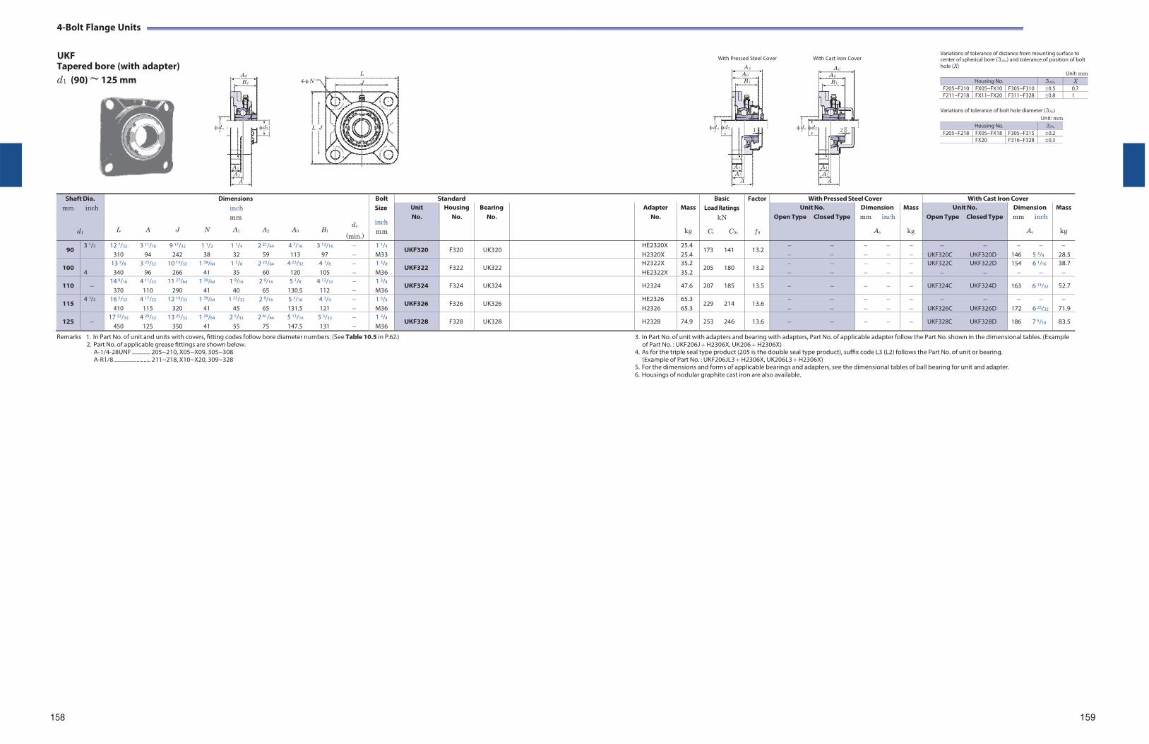
4-Bolt Flange Units
UKF With Pressed Steel Cover With Cast Iron Cover
Variations of tolerance of distance from mounting surface to center of spherical bore (3A2s) and tolerance of position of bolt
Tapered bore (with adapter) d1 (90) ~ 125 mm
A 0
B 1
d e
A 1
A 2
A
d1
L
4-N J
L J
AS
A 0
B 1
d e d1 1
A 1
A 2
A
AC
A 0
B 1
d e d1 2
A 1
A 2
A
hole (X)
Variations of tolerance of bolt hole diameter (3Ns) Unit: mm
Unit: mm
Shaft Dia. mm inch
d1
Dimensions inch mm
de L A J N A1 A2 A0 B1
(min.)
Bolt Size
inch mm
Standard BasicLoad Ratings
kN
Cr C0r
Factor
f 0
With Pressed Steel Cover With Cast Iron Cover Unit No.
Housing No.
Bearing No.
Adapter No.
Mass
kg
Unit No. Open Type Closed Type
Dimension mm inch
As
Mass
kg
Unit No. Open Type Closed Type
Dimension mm inch
Ac
Mass
kg
90 3 1/2 12 7/32 3 11/16 9 17/32 1 1/2 1 1/4 2 21/64 4 7/16 3 13/16
310 94 242 38 32 59 113 97 1 1/4
M33 UKF320 F320 UK320 HE2320X
H2320X25.4 25.4
173 141 13.2
UKF320C UKF320D
146 5 3/4
28.5
100 4
13 3/8 3 25/32 10 15/32 1 39/64 1 3/8 2 23/64 4 23/32 4 1/8 340 96 266 41 35 60 120 105
1 3/8
M36 UKF322 F322 UK322 H2322X
HE2322X 35.2 35.2
205 180 13.2
UKF322C UKF322D
154 6 1/16
38.7
110 14 9/16 4 11/32 11 27/64 1 39/64 1 9/16 2 9/16 5 1/8 4 13/32
370 110 290 41 40 65 130.5 112 1 3/8
M36 UKF324 F324 UK324 H2324 47.6 207 185 13.5 UKF324C UKF324D 163 6 13/32 52.7
115 4 1/2 16 5/32 4 17/32 12 19/32 1 39/64 1 25/32 2 9/16 5 3/16 4 3/4
410 115 320 41 45 65 131.5 121 1 3/8
M36 UKF326 F326 UK326 HE2326
H2326 65.3 65.3
229 214 13.6
UKF326C UKF326D
172 6 25/32
71.9
125 17 23/32 4 29/32 13 25/32 1 39/64 2 5/32 2 61/64 5 13/16 5 5/32
450 125 350 41 55 75 147.5 131 1 3/8
M36 UKF328 F328 UK328 H2328 74.9 253 246 13.6 UKF328C UKF328D 186 7 5/16 83.5
Remarks 1. In Part No. of unit and units with covers, fitting codes follow bore diameter numbers. (See Table 10.5 in P.62.) 2. Part No. of applicable grease fittings are shown below.
A-1/4-28UNF ............. 205~210, X05~X09, 305~308 A-R1/8 .......................... 211~218, X10~X20, 309~328
3. In Part No. of unit with adapters and bearing with adapters, Part No. of applicable adapter follow the Part No. shown in the dimensional tables. (Example of Part No. : UKF206J H2306X, UK206 H2306X)
4. As for the triple seal type product (205 is the double seal type product), suffix code L3 (L2) follows the Part No. of unit or bearing. (Example of Part No. : UKF206JL3 H2306X, UK206L3 H2306X)
5. For the dimensions and forms of applicable bearings and adapters, see the dimensional tables of ball bearing for unit and adapter. 6. Housings of nodular graphite cast iron are also available.
158 159
Housing No. 3A2s X F205~F210 FX05~FX10 F305~F310 0.5 0.7F211~F218 FX11~FX20 F311~F328 0.8 1
Housing No. 3Ns
F205~F218 FX05~FX18 F305~F315 0.2FX20 F316~F328 0.3
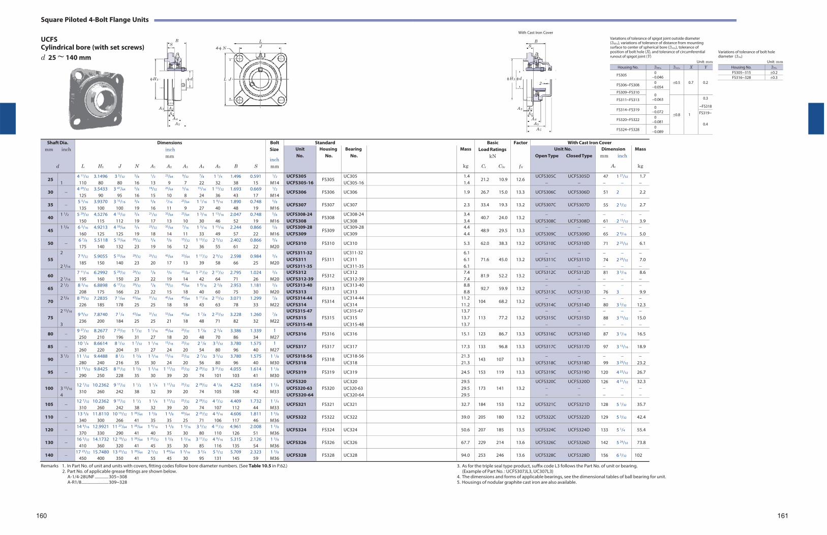
Square Piloted 4-Bolt Flange Units
UCFS B
Cylindrical bore (with set screws) S
d 25 ~ 140 mm
L
4-N J
With Cast Iron Cover
B S
Variations of tolerance of spigot joint outside diameter (3H3s), variations of tolerance of distance from mounting surface to center of spherical bore (3A2s), tolerance of position of bolt hole (X), and tolerance of circumferential runout of spigot joint (Y)
Unit: mm
Variations of tolerance of bolt hole diameter (3Ns)
Unit: mm
H 3 d L J H 3 d 2
A 3 A 1
A 2
A 4
A 5
A 3 A 1
A 2
A 4
A 5
AC
Shaft Dia. mm inch
d
Dimensions inch mm
L H3 J N A1 A2 A3 A4 A5 B S
Bolt Size
inch mm
Standard BasicLoad Ratings
kN
Cr C0r
Factor
f 0
With Cast Iron Cover Unit No.
Housing No.
Bearing No.
Mass
kg
Unit No. Open Type Closed Type
Dimension mm inch
Ac
Mass
kg
25 1
4 11/32 3.1496 3 5/32 5/8 1/2 23/64 9/32 7/8 1 1/4 1.496 0.591 110 80 80 16 13 9 7 22 32 38 15
1/2
M14 UCFS305 UCFS305-16
FS305 UC305 UC305-16
1.4 1.4
21.2 10.9 12.6 UCFS305C UCFS305D
47 1 27/32
1.7
30 4 29/32 3.5433 3 47/64 5/8 19/32 25/64 5/16 15/16 1 13/32 1.693 0.669
125 90 95 16 15 10 8 24 36 43 17
1/2
M14 UCFS306 FS306 UC306 1.9 26.7 15.0 13.3 UCFS306C UCFS306D 51 2 2.2
35 5 5/16 3.9370 3 15/16 3/4 5/8 7/16 23/64 1 1/16 1 9/16 1.890 0.748 135 100 100 19 16 11 9 27 40 48 19
5/8
M16 UCFS307 FS307 UC307 2.3 33.4 19.3 13.2 UCFS307C UCFS307D 55 2 5/32 2.7
40 1 1/2 5 29/32 4.5276 4 13/32 3/4 21/32 33/64 25/64 1 3/16 1 13/16 2.047 0.748
150 115 112 19 17 13 10 30 46 52 19
5/8
M16 UCFS308-24 UCFS308
FS308 UC308-24 UC308
3.4 3.4
40.7 24.0 13.2
UCFS308C UCFS308D 61 2 13/32
3.9
45 1 3/4 6 5/16 4.9213 4 59/64 3/4 23/32 35/64 7/16 1 5/16 1 15/16 2.244 0.866
160 125 125 19 18 14 11 33 49 57 22
5/8
M16 UCFS309-28 UCFS309
FS309 UC309-28 UC309
4.4 4.4
48.9 29.5 13.3
UCFS309C UCFS309D 65 2 9/16
5.0
50 6 7/8 5.5118 5 13/64 29/32 3/4 5/8 15/32 1 13/32 2 5/32 2.402 0.866 175 140 132 23 19 16 12 36 55 61 22
3/4
M20 UCFS310 FS310 UC310 5.3 62.0 38.3 13.2 UCFS310C UCFS310D 71 2 25/32 6.1
55
2
2 3/16
7 9/32 5.9055 5 33/64 29/32 25/32 43/64 33/64 1 17/32 2 9/32 2.598 0.984 185 150 140 23 20 17 13 39 58 66 25
3/4
M20
UCFS311-32 UCFS311 UCFS311-35
FS311
UC311-32 UC311 UC311-35
6.1 6.1 6.1
71.6 45.0
13.2
UCFS311C UCFS311D
74 2 29/32
7.0
60 2 7/16
7 11/16 6.2992 5 29/32 29/32 7/8 3/4 35/64 1 21/32 2 17/32 2.795 1.024 195 160 150 23 22 19 14 42 64 71 26
3/4
M20 UCFS312 UCFS312-39
FS312 UC312 UC312-39
7.4 7.4
81.9 52.2 13.2 UCFS312C UCFS312D
81 3 3/16
8.6
65 2 1/2 8 3/16 6.8898 6 17/32 29/32 7/8 19/32 45/64 1 9/16 2 3/8 2.953 1.181
208 175 166 23 22 15 18 40 60 75 30
3/4
M20 UCFS313-40 UCFS313
FS313 UC313-40 UC313
8.8 8.8
92.7 59.9 13.2
UCFS313C UCFS313D 76 3
9.9
70 2 3/4 8 29/32 7.2835 7 1/64 63/64 31/32 45/64 45/64 1 11/16 2 15/32 3.071 1.299
226 185 178 25 25 18 18 43 63 78 33
7/8
M22 UCFS314-44 UCFS314
FS314 UC314-44 UC314
11.2 11.2
104 68.2 13.2
UCFS314C UCFS314D 80 3 5/32
12.3
75
2 15/16
3
9 9/32 7.8740 7 1/4 63/64 31/32 53/64 45/64 1 7/8 2 25/32 3.228 1.260 236 200 184 25 25 21 18 48 71 82 32
7/8
M22
UCFS315-47 UCFS315 UCFS315-48
FS315
UC315-47 UC315 UC315-48
13.7 13.7 13.7
113 77.2
13.2
UCFS315C UCFS315D
88 3 15/32
15.0
80 9 27/32 8.2677 7 23/32 1 7/32 1 1/16 45/64 25/32 1 7/8 2 3/4 3.386 1.339
250 210 196 31 27 18 20 48 70 86 34 1
M27 UCFS316 FS316 UC316 15.1 123 86.7 13.3 UCFS316C UCFS316D 87 3 7/16 16.5
85 10 1/4 8.6614 8 1/32 1 7/32 1 1/16 15/16 25/32 2 1/8 3 5/32 3.780 1.575 260 220 204 31 27 24 20 54 80 96 40
1 M27
UCFS317 FS317 UC317 17.3 133 96.8 13.3 UCFS317C UCFS317D 97 3 13/16 18.9
90 3 1/2 11 1/32 9.4488 8 1/2 1 3/8 1 3/16 15/16 25/32 2 7/32 3 5/32 3.780 1.575
280 240 216 35 30 24 20 56 80 96 40 1 1/8
M30 UCFS318-56 UCFS318
FS318 UC318-56 UC318
21.3 21.3
143 107 13.3
UCFS318C UCFS318D 99 3 29/32
23.2
95 11 13/32 9.8425 8 31/32 1 3/8 1 3/16 1 17/32 25/32 2 29/32 3 31/32 4.055 1.614
290 250 228 35 30 39 20 74 101 103 41 1 1/8
M30 UCFS319 FS319 UC319 24.5 153 119 13.3 UCFS319C UCFS319D 120 4 23/32 26.7
100
3 15/16
4
12 7/32 10.2362 9 17/32 1 1/2 1 1/4 1 17/32 25/32 2 29/32 4 1/8 4.252 1.654 310 260 242 38 32 39 20 74 105 108 42
1 1/4
M33
UCFS320 UCFS320-63 UCFS320-64
FS320
UC320 UC320-63 UC320-64
29.5 29.5 29.5
173 141
13.2
UCFS320C UCFS320D
126 4 31/32
32.3
105 12 7/32 10.2362 9 17/32 1 1/2 1 1/4 1 17/32 25/32 2 29/32 4 7/32 4.409 1.732
310 260 242 38 32 39 20 74 107 112 44 1 1/4
M33 UCFS321 FS321 UC321 32.7 184 153 13.2 UCFS321C UCFS321D 128 5 1/32 35.7
110 13 3/8 11.8110 10 15/32 1 39/64 1 3/8 1 3/8 63/64 2 25/32 4 3/16 4.606 1.811 340 300 266 41 35 35 25 71 106 117 46
1 3/8
M36 UCFS322 FS322 UC322 39.0 205 180 13.2 UCFS322C UCFS322D 129 5 3/32 42.4
120 14 9/16 12.9921 11 27/64 1 39/64 1 9/16 1 3/8 1 3/16 3 5/32 4 11/32 4.961 2.008
370 330 290 41 40 35 30 80 110 126 51 1 3/8
M36 UCFS324 FS324 UC324 50.6 207 185 13.5 UCFS324C UCFS324D 133 5 1/4 55.4
130 16 5/32 14.1732 12 19/32 1 39/64 1 25/32 1 3/8 1 3/16 3 11/32 4 9/16 5.315 2.126
410 360 320 41 45 35 30 85 116 135 54 1 3/8
M36 UCFS326 FS326 UC326 67.7 229 214 13.6 UCFS326C UCFS326D 142 5 29/32 73.8
140 17 23/32 15.7480 13 25/32 1 39/64 2 5/32 1 49/64 1 3/16 3 3/4 5 5/32 5.709 2.323
450 400 350 41 55 45 30 95 131 145 59 1 3/8
M36 UCFS328 FS328 UC328 94.0 253 246 13.6 UCFS328C UCFS328D 156 6 5/32 102
Remarks 1. In Part No. of unit and units with covers, fitting codes follow bore diameter numbers. (See Table 10.5 in P.62.) 2. Part No. of applicable grease fittings are shown below.
A-1/4-28UNF ............. 305~308 A-R1/8 .......................... 309~328
3. As for the triple seal type product, suffix code L3 follows the Part No. of unit or bearing. (Example of Part No. : UCFS307JL3, UC307L3)
4. The dimensions and forms of applicable bearings, see the dimensional tables of ball bearing for unit. 5. Housings of nodular graphite cast iron are also available.
160 161
Housing No. 3H3s 3A2s X Y
FS305 0 0.046
0.5
0.7
0.2 FS306~FS308 0
0.054 FS309~FS310
0 0.063 FS311~FS313
0.8
1
0.3
~FS318FS314~FS319 0
0.072 FS319~
0.4 FS320~FS322 0
0.081
FS324~FS328 0 0.089
Housing No. 3Ns
FS305~315 0.2FS316~328 0.3
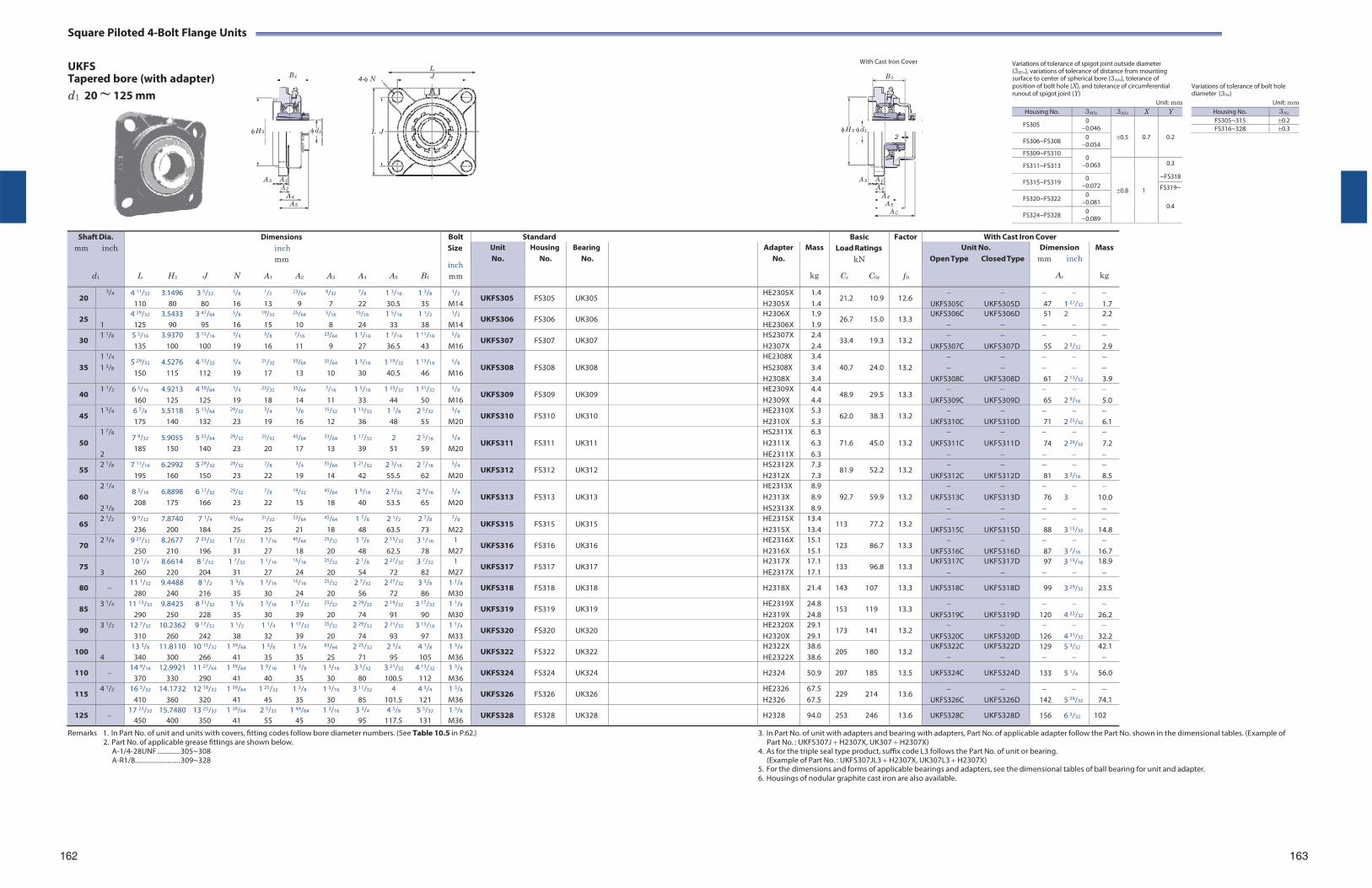
Square Piloted 4-Bolt Flange Units
UKFS Tapered bore (with adapter) d1 20 ~ 125 mm
L
B 1 4-N J
With Cast Iron Cover
B 1
Variations of tolerance of spigot joint outside diameter (3H3s), variations of tolerance of distance from mounting surface to center of spherical bore (3A2s), tolerance of position of bolt hole (X), and tolerance of circumferential runout of spigot joint (Y)
Unit: mm
Variations of tolerance of bolt hole diameter (3Ns)
Unit: mm
H 3 d1 L J
A 3 A 1
A 2
A 4
A 5
H 3 d1
2
A 3 A 1
A 2
A 4
A 5
AC
Shaft Dia. mm inch
d1
Dimensions inch mm
L H3 J N A1 A2 A3 A4 A5 B1
Bolt Size
inch mm
Standard BasicLoad Ratings
kN
Cr C0r
Factor
f 0
With Cast Iron Cover Unit No.
Housing No.
Bearing No.
Adapter No.
Mass
kg
Unit No. Open Type Closed Type
Dimension mm inch
Ac
Mass
kg
20 3/4 4 11/32 3.1496 3 5/32 5/8 1/2 23/64 9/32 7/8 1 3/16 1 3/8
110 80 80 16 13 9 7 22 30.5 35
1/2
M14 UKFS305 FS305 UK305 HE2305X
H2305X1.4 1.4
21.2 10.9 12.6
UKFS305C UKFS305D 47 1 27/32
1.7
25 1
4 29/32 3.5433 3 47/64 5/8 19/32 25/64 5/16 15/16 1 5/16 1 1/2
125 90 95 16 15 10 8 24 33 38
1/2
M14 UKFS306 FS306 UK306 H2306X
HE2306X 1.9 1.9
26.7 15.0 13.3 UKFS306C UKFS306D
51 2
2.2
30 1 1/8 5 5/16 3.9370 3 15/16 3/4 5/8 7/16 23/64 1 1/16 1 7/16 1 11/16
135 100 100 19 16 11 9 27 36.5 43
5/8
M16 UKFS307 FS307 UK307 HS2307X
H2307X 2.4 2.4
33.4 19.3 13.2
UKFS307C UKFS307D 55 2 5/32
2.9
35
1 1/4
1 3/8 5 29/32 4.5276 4 13/32 3/4 21/32 33/64 25/64 1 3/16 1 19/32 1 13/16
150 115 112 19 17 13 10 30 40.5 46
5/8
M16
UKFS308
FS308
UK308
HE2308X HS2308X H2308X
3.4 3.4 3.4
40.7 24.0
13.2
UKFS308C UKFS308D
61 2 13/32
3.9
40 1 1/2 6 5/16 4.9213 4 59/64 3/4 23/32 35/64 7/16 1 5/16 1 23/32 1 31/32
160 125 125 19 18 14 11 33 44 50
5/8
M16 UKFS309 FS309 UK309 HE2309X
H2309X 4.4 4.4
48.9 29.5 13.3
UKFS309C UKFS309D 65 2 9/16
5.0
45 1 3/4 6 7/8 5.5118 5 13/64 29/32 3/4 5/8 15/32 1 13/32 1 7/8 2 5/32
175 140 132 23 19 16 12 36 48 55
3/4
M20 UKFS310 FS310 UK310 HE2310X
H2310X 5.3 5.3
62.0 38.3 13.2
UKFS310C UKFS310D 71 2 25/32
6.1
50
1 7/8
2
7 9/32 5.9055 5 33/64 29/32 25/32 43/64 33/64 1 17/32 2 2 5/16
185 150 140 23 20 17 13 39 51 59
3/4
M20
UKFS311
FS311
UK311
HS2311X H2311X HE2311X
6.3 6.3 6.3
71.6 45.0
13.2
UKFS311C UKFS311D
74 2 29/32
7.2
55 2 1/8 7 11/16 6.2992 5 29/32 29/32 7/8 3/4 35/64 1 21/32 2 3/16 2 7/16
195 160 150 23 22 19 14 42 55.5 62
3/4
M20 UKFS312 FS312 UK312 HS2312X
H2312X 7.3 7.3
81.9 52.2 13.2
UKFS312C UKFS312D 81 3 3/16
8.5
60
2 1/4
2 3/8
8 3/16 6.8898 6 17/32 29/32 7/8 19/32 45/64 1 9/16 2 3/32 2 9/16
208 175 166 23 22 15 18 40 53.5 65
3/4
M20
UKFS313
FS313
UK313
HE2313X H2313X HS2313X
8.9 8.9 8.9
92.7 59.9
13.2
UKFS313C UKFS313D
76 3
10.0
65 2 1/2 9 9/32 7.8740 7 1/4 63/64 31/32 53/64 45/64 1 7/8 2 1/2 2 7/8
236 200 184 25 25 21 18 48 63.5 73
7/8
M22 UKFS315 FS315 UK315 HE2315X
H2315X 13.4 13.4
113 77.2 13.2
UKFS315C UKFS315D 88 3 15/32
14.8
70 2 3/4 9 27/32 8.2677 7 23/32 1 7/32 1 1/16 45/64 25/32 1 7/8 2 15/32 3 1/16
250 210 196 31 27 18 20 48 62.5 78 1
M27 UKFS316 FS316 UK316 HE2316X
H2316X 15.1 15.1
123 86.7 13.3
UKFS316C UKFS316D 87 3 7/16
16.7
75 3
10 1/4 8.6614 8 1/32 1 7/32 1 1/16 15/16 25/32 2 1/8 2 27/32 3 7/32
260 220 204 31 27 24 20 54 72 82 1
M27 UKFS317 FS317 UK317 H2317X
HE2317X17.1 17.1
133 96.8 13.3 UKFS317C UKFS317D
97 3 13/16
18.9
80 11 1/32 9.4488 8 1/2 1 3/8 1 3/16 15/16 25/32 2 7/32 2 27/32 3 3/8
280 240 216 35 30 24 20 56 72 86 1 1/8
M30 UKFS318 FS318 UK318 H2318X 21.4 143 107 13.3 UKFS318C UKFS318D 99 3 29/32 23.5
85 3 1/4 11 13/32 9.8425 8 31/32 1 3/8 1 3/16 1 17/32 25/32 2 29/32 2 19/32 3 17/32
290 250 228 35 30 39 20 74 91 90 1 1/8
M30 UKFS319 FS319 UK319 HE2319X
H2319X 24.8 24.8
153 119 13.3
UKFS319C UKFS319D
120 4 23/32
26.2
90 3 1/2 12 7/32 10.2362 9 17/32 1 1/2 1 1/4 1 17/32 25/32 2 29/32 2 21/32 3 13/16
310 260 242 38 32 39 20 74 93 97 1 1/4
M33 UKFS320 FS320 UK320 HE2320X
H2320X 29.1 29.1
173 141 13.2
UKFS320C UKFS320D
126 4 31/32
32.2
100 4
13 3/8 11.8110 10 15/32 1 39/64 1 3/8 1 3/8 63/64 2 25/32 2 3/4 4 1/8
340 300 266 41 35 35 25 71 95 105 1 3/8
M36 UKFS322 FS322 UK322 H2322X
HE2322X 38.6 38.6
205 180 13.2 UKFS322C UKFS322D
129 5 3/32
42.1
110 14 9/16 12.9921 11 27/64 1 39/64 1 9/16 1 3/8 1 3/16 3 5/32 3 21/32 4 13/32
370 330 290 41 40 35 30 80 100.5 112 1 3/8
M36 UKFS324 FS324 UK324 H2324 50.9 207 185 13.5 UKFS324C UKFS324D 133 5 1/4 56.0
115 4 1/2 16 5/32 14.1732 12 19/32 1 39/64 1 25/32 1 3/8 1 3/16 3 11/32 4 4 3/4
410 360 320 41 45 35 30 85 101.5 121 1 3/8
M36 UKFS326 FS326 UK326 HE2326
H2326 67.5 67.5
229 214 13.6
UKFS326C UKFS326D
142 5 29/32
74.1
125 17 23/32 15.7480 13 25/32 1 39/64 2 5/32 1 49/64 1 3/16 3 3/4 4 5/8 5 5/32
450 400 350 41 55 45 30 95 117.5 131 1 3/8
M36 UKFS328 FS328 UK328 H2328 94.0 253 246 13.6 UKFS328C UKFS328D 156 6 5/32 102
Remarks 1. In Part No. of unit and units with covers, fitting codes follow bore diameter numbers. (See Table 10.5 in P.62.) 2. Part No. of applicable grease fittings are shown below.
A-1/4-28UNF ............. 305~308 A-R1/8 .......................... 309~328
3. In Part No. of unit with adapters and bearing with adapters, Part No. of applicable adapter follow the Part No. shown in the dimensional tables. (Example of Part No. : UKFS307J H2307X, UK307 H2307X)
4. As for the triple seal type product, suffix code L3 follows the Part No. of unit or bearing. (Example of Part No. : UKFS307JL3 H2307X, UK307L3 H2307X)
5. For the dimensions and forms of applicable bearings and adapters, see the dimensional tables of ball bearing for unit and adapter. 6. Housings of nodular graphite cast iron are also available.
162
163
Housing No. 3H3s 3A2s X Y
FS305 0 0.046
0.5
0.7
0.2 FS306~FS308 0
0.054 FS309~FS310
0 0.063 FS311~FS313
0.8
1
0.3
~FS318FS315~FS319 0
0.072 FS319~
0.4 FS320~FS322 0
0.081
FS324~FS328 0 0.089
Housing No. 3Ns
FS305~315 0.2FS316~328 0.3
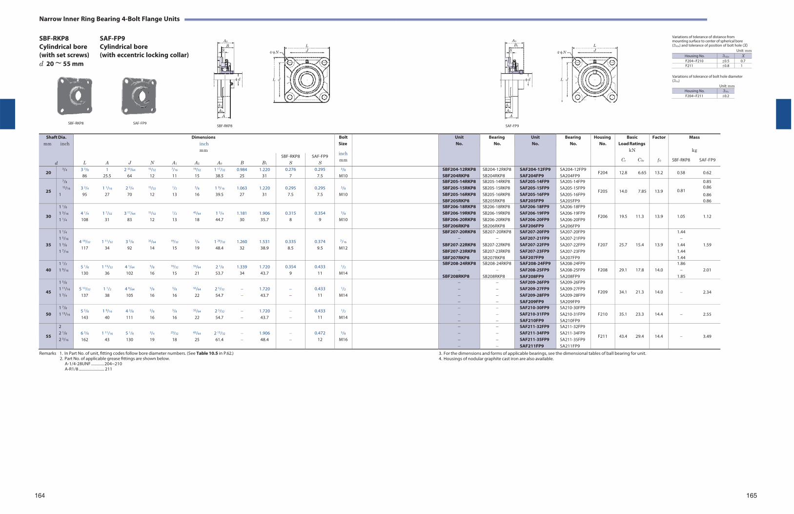
A0
B1
S
d
A1
A2
A
Narrow Inner Ring Bearing 4-Bolt Flange Units
SBF-RKP8 Cylindrical bore (with set screws) d 20 ~ 55 mm
SAF-FP9 Cylindrical bore (with eccentric locking collar)
L
4-N J
L
4-N J
Variations of tolerance of distance from mounting surface to center of spherical bore (3A2s) and tolerance of position of bolt hole (X)
Unit: mm
L J L J Variations of tolerance of bolt hole diameter (3Ns)
Unit: mm Housing No. 3Ns
F204~F211 0.2
SBF-RKP8 SAF-FP9
SBF-RKP8
SAF-FP9
Shaft Dia. mm inch
d
Dimensions inch mm
BoltSize
inch mm
UnitNo.
BearingNo.
UnitNo.
Bearing No.
Housing No.
Basic Load Ratings
kN
Cr C0r
Factor
f 0
Mass
kg
SBF-RKP8 SAF-FP9
L A J N A1 A2 A0 B B1
SBF-RKP8 S
SAF-FP9 S
20 3/4 3 3/8 1 2 33/64 15/32 7/16 19/32 1 17/32 0.984 1.220
86 25.5 64 12 11 15 38.5 25 31 0.276
7 0.295
7.5
3/8
M10 SBF204-12RKP8
SBF204RKP8SB204-12RKP8 SB204RKP8
SAF204-12FP9 SAF204FP9
SA204-12FP9 SA204FP9
F204 12.8 6.65 13.2 0.58 0.62
25
7/8
15/16
1
3 3/4 1 1/16 2 3/4 15/32 1/2 5/8 1 9/16 1.063 1.220 95 27 70 12 13 16 39.5 27 31
0.295
7.5
0.295
7.5
3/8
M10
SBF205-14RKP8 SBF205-15RKP8 SBF205-16RKP8 SBF205RKP8
SB205-14RKP8 SB205-15RKP8 SB205-16RKP8 SB205RKP8
SAF205-14FP9 SAF205-15FP9 SAF205-16FP9 SAF205FP9
SA205-14FP9 SA205-15FP9 SA205-16FP9 SA205FP9
F205
14.0 7.85
13.9
0.85 0.86
0.81 0.86 0.86
30
1 1/8
1 3/16
1 1/4
4 1/4 1 7/32 3 17/64 15/32 1/2 45/64 1 3/4 1.181 1.906 108 31 83 12 13 18 44.7 30 35.7
0.315
8
0.354
9
3/8
M10
SBF206-18RKP8 SBF206-19RKP8 SBF206-20RKP8 SBF206RKP8
SB206-18RKP8 SB206-19RKP8 SB206-20RKP8 SB206RKP8
SAF206-18FP9 SAF206-19FP9 SAF206-20FP9 SAF206FP9
SA206-18FP9 SA206-19FP9 SA206-20FP9 SA206FP9
F206
19.5 11.3
13.9
1.05 1.12
35
1 1/4
1 5/16
1 3/8
1 7/16
4 19/32 1 11/32 3 5/8 35/64 19/32 3/4 1 29/32 1.260 1.531 117 34 92 14 15 19 48.4 32 38.9
0.335 8.5
0.374 9.5
7/16
M12
SBF207-20RKP8
SBF207-22RKP8 SBF207-23RKP8 SBF207RKP8
SB207-20RKP8
SB207-22RKP8 SB207-23RKP8 SB207RKP8
SAF207-20FP9 SAF207-21FP9 SAF207-22FP9 SAF207-23FP9 SAF207FP9
SA207-20FP9 SA207-21FP9 SA207-22FP9 SA207-23FP9 SA207FP9
F207
25.7 15.4
13.9
1.44
1.44 1.59 1.44 1.44
40
1 1/2
1 9/16 5 1/8 1 13/32 4 1/64 5/8 19/32 53/64 2 1/8 1.339 1.720 130 36 102 16 15 21 53.7 34 43.7
0.354 9
0.433 11
1/2
M14
SBF208-24RKP8
SBF208RKP8
SB208-24RKP8
SB208RKP8
SAF208-24FP9 SAF208-25FP9 SAF208FP9
SA208-24FP9 SA208-25FP9 SA208FP9
F208
29.1 17.8
14.0
1.86 2.01
1.85
45
1 5/8
1 11/16
1 3/4
5 13/32 1 1/2 4 9/64 5/8 5/8 55/64 2 5/32 1.720
137 38 105 16 16 22 54.7 43.7
0.433
11
1/2
M14
SAF209-26FP9 SAF209-27FP9 SAF209-28FP9 SAF209FP9
SA209-26FP9 SA209-27FP9 SA209-28FP9 SA209FP9
F209
34.1 21.3
14.0
2.34
50
1 7/8
1 15/16 5 5/8 1 9/16 4 3/8 5/8 5/8 55/64 2 5/32 1.720 143 40 111 16 16 22 54.7 43.7
0.433 11
1/2
M14
SAF210-30FP9 SAF210-31FP9 SAF210FP9
SA210-30FP9 SA210-31FP9 SA210FP9
F210
35.1 23.3
14.4
2.55
55
2 2 1/8
2 3/16
6 3/8 1 11/16 5 1/8 3/4 23/32 63/64 2 13/32 1.906 162 43 130 19 18 25 61.4 48.4
0.472
12
5/8
M16
SAF211-32FP9 SAF211-34FP9 SAF211-35FP9 SAF211FP9
SA211-32FP9 SA211-34FP9 SA211-35FP9 SA211FP9
F211
43.4 29.4
14.4
3.49
Remarks 1. In Part No. of unit, fitting codes follow bore diameter numbers. (See Table 10.5 in P.62.) 2. Part No. of applicable grease fittings are shown below.
A-1/4-28UNF ............. 204~210 A-R1/8 .......................... 211
3. For the dimensions and forms of applicable bearings, see the dimensional tables of ball bearing for unit. 4. Housings of nodular graphite cast iron are also available.
164
165
A0
BS
d
A1
A2
A
Housing No. 3A2s X F204~F210 0.5 0.7F211 0.8 1
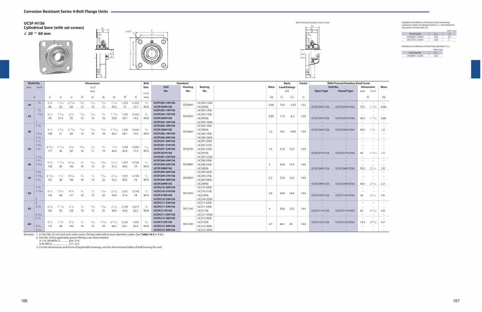
Corrosion Resistant Series 4-Bolt Flange Units
UCSF-H1S6 Cylindrical bore (with set screws) d 20 ~ 60 mm
4-N L J
L J
With Pressed Stainless Steel Cover Variations of tolerance of distance from mounting surface to center of spherical bore (3A2s) and tolerance of position of bolt hole (X)
Unit: mm Housing No. 3A2s X
SF204H1~210H1 0.5 0.7SF211H1~212H1 0.8 1
Variations of tolerance of bolt hole diameter (3Ns)
Unit: mm
Shaft Dia.
mm inch
d
Dimensions inch mm
L A J N A1 A2 A0 B S
Bolt Size
inch mm
Standard BasicLoad Ratings
kN
Cr C0r
Factor
f 0
With Pressed Stainless Steel Cover Unit No.
Housing No.
Bearing No.
Mass
kg
Unit No. Open Type Closed Type
Dimension mm inch
As
Mass
kg
20 3/4 3 3/8 1 1/32 2 33/64 15/32 13/32 19/32 1 5/16 1.220 0.500
86 26 64 12 10 15 33.3 31 12.7
3/8
M10 UCSF204-12H1S6 UCSF204H1S6
SF204H1 UC204-12S6UC204S6
0.66 10.9 5.35 13.2
UCSF204H1CS6 UCSF204H1DS6
37.5 1 15/32
0.66
25
7/8
15/16
1
3 3/4 1 3/32 2 3/4 15/32 13/32 5/8 1 13/32 1.343 0.563 95 27.5 70 12 10 16 35.8 34.1 14.3
3/8
M10
UCSF205-14H1S6 UCSF205-15H1S6 UCSF205H1S6 UCSF205-16H1S6
SF205H1
UC205-14S6 UC205-15S6 UC205S6 UC205-16S6
0.85
11.9 6.3
13.9
UCSF205H1CS6 UCSF205H1DS6
40.5 1 19/32
0.85
30
1 1/8
1 3/16
1 1/4
4 1/4 1 7/32 3 17/64 15/32 13/32 45/64 1 19/32 1.500 0.626 108 31 83 12 10 18 40.2 38.1 15.9
3/8
M10
UCSF206-18H1S6 UCSF206H1S6 UCSF206-19H1S6 UCSF206-20H1S6
SF206H1
UC206-18S6 UC206S6 UC206-19S6 UC206-20S6
1.2
16.5 9.05
13.9
UCSF206H1CS6 UCSF206H1DS6
44.5 1 3/4
1.2
35
1 1/4
1 5/16
1 3/8
1 7/16
4 19/32 1 11/32 3 5/8 35/64 7/16 3/4 1 3/4 1.689 0.689 117 34 92 14 11 19 44.4 42.9 17.5
7/16
M12
UCSF207-20H1S6 UCSF207-21H1S6 UCSF207-22H1S6 UCSF207H1S6 UCSF207-23H1S6
SF207H1
UC207-20S6 UC207-21S6 UC207-22S6 UC207S6 UC207-23S6
1.5
21.8 12.3
13.9
UCSF207H1CS6 UCSF207H1DS6
49 1 15/16
1.5
40
1 1/2
1 9/16 5 1/8 1 13/32 4 1/64 5/8 15/32 53/64 2 1/32 1.937 0.748 130 36 102 16 12 21 51.2 49.2 19
1/2
M14
UCSF208-24H1S6 UCSF208-25H1S6 UCSF208H1S6
SF208H1
UC208-24S6 UC208-25S6 UC208S6
2
24.8 14.3
14.0
UCSF208H1CS6 UCSF208H1DS6
55.5 2 3/16
2.0
45
1 5/8
1 11/16
1 3/4
5 13/32 1 1/2 4 9/64 5/8 1/2 55/64 2 1/16 1.937 0.748
137 38 105 16 13 22 52.2 49.2 19
1/2
M14
UCSF209-26H1S6 UCSF209-27H1S6 UCSF209-28H1S6 UCSF209H1S6
SF209H1
UC209-26S6 UC209-27S6 UC209-28S6 UC209S6
2.3
27.8 16.2
14.0
UCSF209H1CS6 UCSF209H1DS6
56.5 2 7/32
2.3
50
1 7/8
1 15/16
2
5 5/8 1 9/16 4 3/8 5/8 1/2 55/64 2 5/32 2.031 0.748 143 40 111 16 13 22 54.6 51.6 19
1/2
M14
UCSF210-30H1S6 UCSF210-31H1S6 UCSF210H1S6 UCSF210-32H1S6
SF210H1
UC210-30S6 UC210-31S6 UC210S6 UC210-32S6
2.6
29.8 18.6
14.4
UCSF210H1CS6 UCSF210H1DS6
59 2 5/16
2.6
55
2 2 1/8
2 3/16
6 3/8 1 11/16 5 1/8 3/4 19/32 63/64 2 5/16 2.189 0.874 162 43 130 19 15 25 58.4 55.6 22.2
5/8
M16
UCSF211-32H1S6 UCSF211-34H1S6 UCSF211H1S6 UCSF211-35H1S6
SF211H1
UC211-32S6 UC211-34S6 UC211S6 UC211-35S6
4
36.8 23.5
14.4
UCSF211H1CS6 UCSF211H1DS6
63 2 15/32
4.0
60
2 1/4
2 3/8
2 7/16
6 7/8 1 7/8 5 5/8 3/4 19/32 1 9/64 2 23/32 2.563 1.000 175 48 143 19 15 29 68.7 65.1 25.4
5/8
M16
UCSF212-36H1S6 UCSF212H1S6 UCSF212-38H1S6 UCSF212-39H1S6
SF212H1
UC212-36S6 UC212S6 UC212-38S6 UC212-39S6
4.7
44.5 29
14.4
UCSF212H1CS6 UCSF212H1DS6
73.5 2 29/32
4.7
Remarks 1. In Part No. of unit and units with covers, fitting codes follow bore diameter codes. (See Table 10.5 in P.62.) 2. Part No. of the applicable grease fitting is are shown below.
A-1/4-28UNFN12 .............. 204~210 A-R1/8N12........................... 211~212
3. For the dimensions and forms of applicable bearings, see the dimensional tables of ball bearing for unit.
166 167
A 0
B S
d
A 1
A 2
A
A SA 0B
S
d1
A 1
A 2
A
Housing No. 3Ns
SF204H1~212H1 0.2
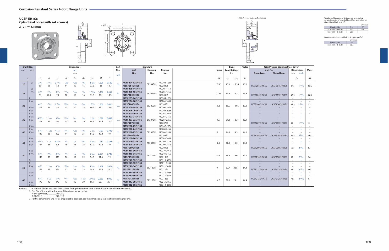
Corrosion Resistant Series 4-Bolt Flange Units
UCSF-EH1S6 Cylindrical bore (with set screws) d 20 ~ 60 mm
4-N L J
L J
With Pressed Stainless Steel Cover Variations of tolerance of distance from mounting surface to center of spherical bore (3A2s) and tolerance of position of bolt hole (X)
Unit: mm Housing No. 3A2s X
SF204EH1~208EH1 0.5 0.7SF211EH1~212EH1 0.8 1
Variations of tolerance of bolt hole diameter (3Ns)
Unit: mm
Shaft Dia.
mm inch
d
Dimensions inch mm
L A J N A1 A2 A0 B S
Bolt Size
inch
Standard BasicLoad Ratings
kN
Cr C0r
Factor
f 0
With Pressed Stainless Steel Cover Unit No.
Housing No.
Bearing No.
Mass
kg
Unit No. Open Type Closed Type
Dimension mm inch
As
Mass
kg
20 3/4 3 3/8 1 1/32 2 33/64 7/16 13/32 19/32 1 5/16 1.220 0.500
86 26 64 11 10 15 33.3 31 12.7 3/8
UCSF204-12EH1S6 UCSF204EH1S6
SF204EH1 UC204-12S6UC204S6
0.66 10.9 5.35 13.2
UCSF204EH1CS6 UCSF204EH1DS6
37.5 1 15/32
0.66
25
7/8
15/16
1
3 3/4 1 3/32 2 3/4 15/32 13/32 5/8 1 13/32 1.343 0.563 95 27.5 70 12 10 16 35.8 34.1 14.3
3/8
UCSF205-14EH1S6 UCSF205-15EH1S6 UCSF205EH1S6 UCSF205-16EH1S6
SF205EH1
UC205-14S6 UC205-15S6 UC205S6 UC205-16S6
0.85
11.9 6.3
13.9
UCSF205EH1CS6 UCSF205EH1DS6
40.5 1 19/32
0.85
30
1 1/8
1 3/16
1 1/4
4 1/4 1 7/32 3 17/64 33/64 13/32 45/64 1 19/32 1.500 0.626 108 31 83 13 10 18 40.2 38.1 15.9
7/16
UCSF206-18EH1S6 UCSF206EH1S6 UCSF206-19EH1S6 UCSF206-20EH1S6
SF206EH1
UC206-18S6 UC206S6 UC206-19S6 UC206-20S6
1.2
16.5 9.05
13.9
UCSF206EH1CS6 UCSF206EH1DS6
44.5 1 3/4
1.2
35
1 1/4
1 5/16
1 3/8
1 7/16
4 19/32 1 11/32 3 5/8 33/64 7/16 3/4 1 3/4 1.689 0.689 117 34 92 13 11 19 44.4 42.9 17.5
7/16
UCSF207-20EH1S6 UCSF207-21EH1S6 UCSF207-22EH1S6 UCSF207EH1S6 UCSF207-23EH1S6
SF207EH1
UC207-20S6 UC207-21S6 UC207-22S6 UC207S6 UC207-23S6
1.5
21.8 12.3
13.9
UCSF207EH1CS6 UCSF207EH1DS6
49 1 15/16
1.5
40
1 1/2
1 9/16 5 1/8 1 13/32 4 1/64 35/64 15/32 53/64 2 1/32 1.937 0.748 130 36 102 14 12 21 51.2 49.2 19
1/2
UCSF208-24EH1S6 UCSF208-25EH1S6 UCSF208EH1S6
SF208EH1
UC208-24S6 UC208-25S6 UC208S6
2
24.8 14.3
14.0
UCSF208EH1CS6 UCSF208EH1DS6
55.5 2 3/16
2.0
45
1 5/8
1 11/16
1 3/4
5 13/32 1 1/2 4 9/64 5/8 1/2 55/64 2 1/16 1.937 0.748
137 38 105 16 13 22 52.2 49.2 19
1/2
UCSF209-26EH1S6 UCSF209-27EH1S6 UCSF209-28EH1S6 UCSF209EH1S6
SF209EH1
UC209-26S6 UC209-27S6 UC209-28S6 UC209S6
2.3
27.8 16.2
14.0
UCSF209EH1CS6 UCSF209EH1DS6
56.5 2 7/32
2.3
50
1 7/8
1 15/16
2
5 5/8 1 9/16 4 3/8 5/8 1/2 55/64 2 5/32 2.031 0.748 143 40 111 16 13 22 54.6 51.6 19
1/2
UCSF210-30EH1S6 UCSF210-31EH1S6 UCSF210EH1S6 UCSF210-32EH1S6
SF210EH1
UC210-30S6 UC210-31S6 UC210S6 UC210-32S6
2.6
29.8 18.6
14.4
UCSF210EH1CS6 UCSF210EH1DS6
59 2 5/16
2.6
55
2 2 1/8
2 3/16
6 3/8 1 11/16 5 1/8 43/64 19/32 63/64 2 5/16 2.189 0.874 162 43 130 17 15 25 58.4 55.6 22.2
5/8
UCSF211-32EH1S6 UCSF211-34EH1S6 UCSF211EH1S6 UCSF211-35EH1S6
SF211EH1
UC211-32S6 UC211-34S6 UC211S6 UC211-35S6
4
30.7 23.5
14.4
UCSF211EH1CS6 UCSF211EH1DS6
63 2 15/32
4.0
60
2 1/4
2 3/8
2 7/16
6 7/8 1 7/8 5 5/8 43/64 19/32 1 9/64 2 23/32 2.563 1.000 175 48 143 17 15 29 68.7 65.1 25.4
5/8
UCSF212-36EH1S6 UCSF212EH1S6 UCSF212-38EH1S6 UCSF212-39EH1S6
SF212EH1
UC212-36S6 UC212S6 UC212-38S6 UC212-39S6
4.7
31.6 29
14.4
UCSF212EH1CS6 UCSF212EH1DS6
73.5 2 29/32
4.7
Remarks 1. In Part No. of unit and units with covers, fitting codes follow bore diameter codes. (See Table 10.5 in P.62.) 2. Part No. of the applicable grease fitting is are shown below.
A-1/4-28UNFN12 .............. 204~210 A-R1/8N12........................... 211~212
3. For the dimensions and forms of applicable bearings, see the dimensional tables of ball bearing for unit.
168 169
A 0
B S
d
A 1
A 2
A
A SA 0B
S
d1
A 1
A 2
A
Housing No. 3Ns
SF204EH1~212EH1 0.2
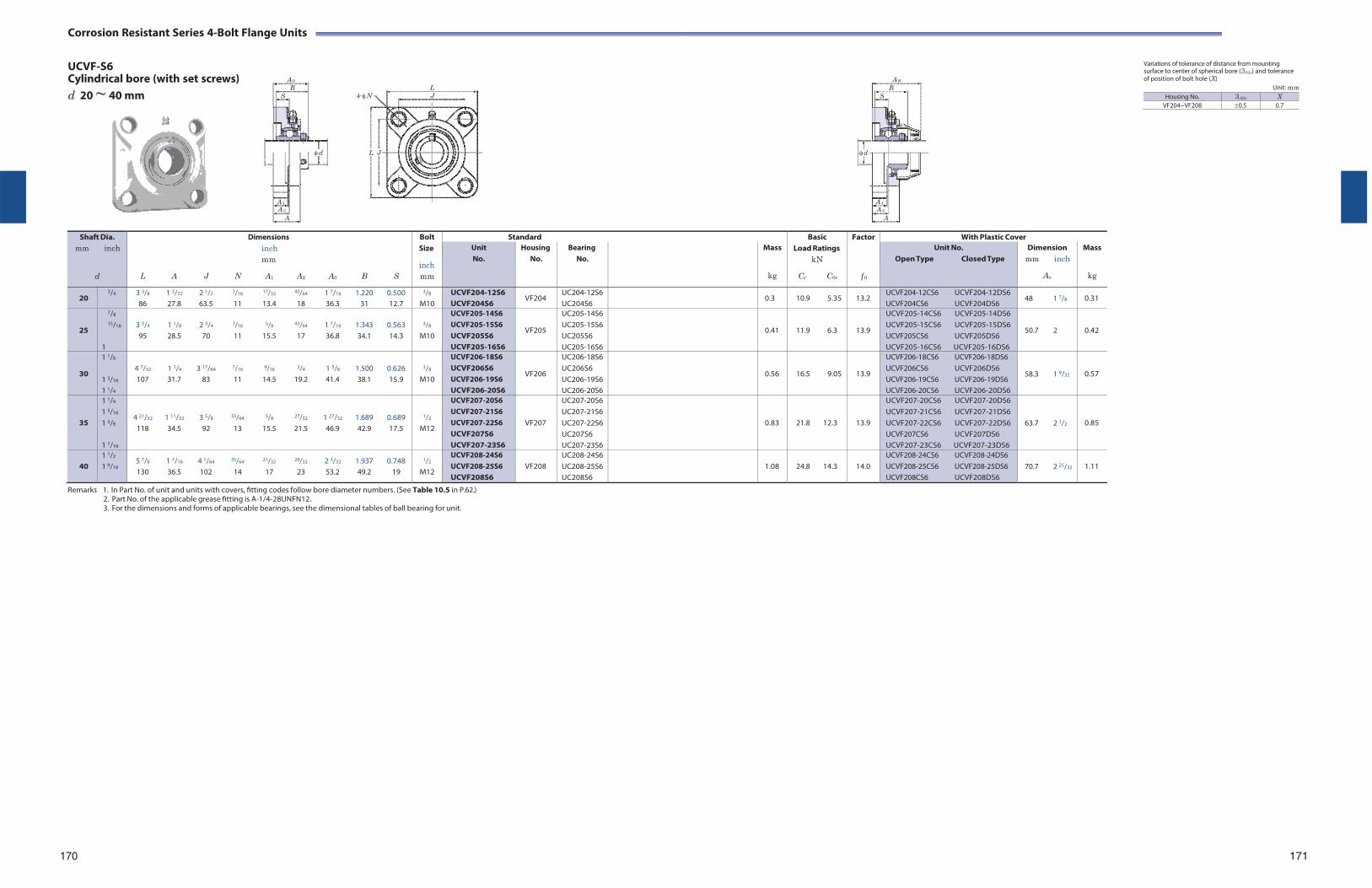
Corrosion Resistant Series 4-Bolt Flange Units
UCVF-S6 Cylindrical bore (with set screws) d 20 ~ 40 mm
L
4-N J
L J
Variations of tolerance of distance from mounting surface to center of spherical bore (3A2s) and tolerance of position of bolt hole (X)
Unit: mm
Shaft Dia.
mm inch
d
Dimensions inch mm
L A J N A1 A2 A0 B S
Bolt Size
inch mm
Standard BasicLoad Ratings
kN
Cr C0r
Factor
f 0
With Plastic Cover Unit No.
Housing No.
Bearing No.
Mass
kg
Unit No. Open Type Closed Type
Dimension mm inch
As
Mass
kg
20 3/4 3 3/8 1 3/32 2 1/2 7/16 17/32 45/64 1 7/16 1.220 0.500
86 27.8 63.5 11 13.4 18 36.3 31 12.7
3/8
M10 UCVF204-12S6 UCVF204S6
VF204 UC204-12S6 UC204S6
0.3 10.9 5.35 13.2 UCVF204-12CS6 UCVF204-12DS6 UCVF204CS6 UCVF204DS6
48 1 7/8 0.31
25
7/8
15/16
1
3 3/4 1 1/8 2 3/4 7/16 5/8 43/64 1 7/16 1.343 0.563 95 28.5 70 11 15.5 17 36.8 34.1 14.3
3/8
M10
UCVF205-14S6 UCVF205-15S6 UCVF205S6 UCVF205-16S6
VF205
UC205-14S6 UC205-15S6 UC205S6 UC205-16S6
0.41
11.9 6.3
13.9
UCVF205-14CS6 UCVF205-14DS6 UCVF205-15CS6 UCVF205-15DS6 UCVF205CS6 UCVF205DS6 UCVF205-16CS6 UCVF205-16DS6
50.7 2
0.42
30
1 1/8
1 3/16
1 1/4
4 7/32 1 1/4 3 17/64 7/16 9/16 3/4 1 5/8 1.500 0.626 107 31.7 83 11 14.5 19.2 41.4 38.1 15.9
3/8
M10
UCVF206-18S6 UCVF206S6 UCVF206-19S6 UCVF206-20S6
VF206
UC206-18S6 UC206S6 UC206-19S6 UC206-20S6
0.56
16.5 9.05
13.9
UCVF206-18CS6 UCVF206-18DS6 UCVF206CS6 UCVF206DS6 UCVF206-19CS6 UCVF206-19DS6 UCVF206-20CS6 UCVF206-20DS6
58.3 1 9/32
0.57
35
1 1/4
1 5/16
1 3/8
1 7/16
4 21/32 1 11/32 3 5/8 33/64 5/8 27/32 1 27/32 1.689 0.689 118 34.5 92 13 15.5 21.5 46.9 42.9 17.5
1/2
M12
UCVF207-20S6 UCVF207-21S6 UCVF207-22S6 UCVF207S6 UCVF207-23S6
VF207
UC207-20S6 UC207-21S6 UC207-22S6 UC207S6 UC207-23S6
0.83
21.8 12.3
13.9
UCVF207-20CS6 UCVF207-20DS6 UCVF207-21CS6 UCVF207-21DS6 UCVF207-22CS6 UCVF207-22DS6 UCVF207CS6 UCVF207DS6 UCVF207-23CS6 UCVF207-23DS6
63.7 2 1/2
0.85
40
1 1/2
1 9/16 5 1/8 1 7/16 4 1/64 35/64 21/32 29/32 2 3/32 1.937 0.748 130 36.5 102 14 17 23 53.2 49.2 19
1/2
M12
UCVF208-24S6 UCVF208-25S6 UCVF208S6
VF208
UC208-24S6 UC208-25S6 UC208S6
1.08
24.8 14.3
14.0
UCVF208-24CS6 UCVF208-24DS6 UCVF208-25CS6 UCVF208-25DS6 UCVF208CS6 UCVF208DS6
70.7 2 25/32
1.11
Remarks 1. In Part No. of unit and units with covers, fitting codes follow bore diameter numbers. (See Table 10.5 in P.62.) 2. Part No. of the applicable grease fitting is A-1/4-28UNFN12. 3. For the dimensions and forms of applicable bearings, see the dimensional tables of ball bearing for unit.
170
171
A 0B
S
d
A 1
A 2
A
A SB
S
d
A 1
A 2
A
Housing No. 3A2s X VF204~VF208 0.5 0.7

Corrosion Resistant Series 4-Bolt Flange Units
UCVF-ES7 Cylindrical bore (with set screws) d 20 ~ 40 mm
L
4-N J
L J
Variations of tolerance of distance from mounting surface to center of spherical bore (3A2s) and tolerance of position of bolt hole (X)
Unit: mm
Shaft Dia.
mm inch
d
Dimensions inch mm
L A J N A1 A2 A0 B S
Bolt Size
inch mm
Standard BasicLoad Ratings
kN
Cr C0r
Factor
f 0
With Plastic Cover Unit No.
Housing No.
Bearing No.
Mass
kg
Unit No. Open Type Closed Type
Dimension mm inch
As
Mass
kg
20 3/4 3 3/8 1 3/32 2 1/2 7/16 17/32 45/64 1 7/16 1.220 0.500
86 27.8 63.5 11 13.4 18 36.3 31 12.7
3/8
M8 UCVF204-12ES7 UCVF204ES7
VF204E UC204-12S7 UC204S7
0.3 12.8 6.65 13.2 UCVF204-12ECS7 UCVF204-12EDS7 UCVF204ECS7 UCVF204EDS7
48 1 7/8 0.31
25
7/8
15/16
1
3 3/4 1 1/8 2 3/4 7/16 5/8 43/64 1 7/16 1.343 0.563 95 28.5 70 11 15.5 17 36.8 34.1 14.3
7/16
M10
UCVF205-14ES7 UCVF205-15ES7 UCVF205ES7 UCVF205-16ES7
VF205E
UC205-14S7 UC205-15S7 UC205S7 UC205-16S7
0.41
14.0 7.85
13.9
UCVF205-14ECS7 UCVF205-14EDS7 UCVF205-15ECS7 UCVF205-15EDS7 UCVF205ECS7 UCVF205EDS7 UCVF205-16ECS7 UCVF205-16EDS7
50.7 2
0.42
30
1 1/8
1 3/16
1 1/4
4 7/32 1 1/4 3 17/64 7/16 9/16 3/4 1 5/8 1.500 0.626 107 31.7 83 11 14.5 19.2 41.4 38.1 15.9
7/16
M10
UCVF206-18ES7 UCVF206ES7 UCVF206-19ES7 UCVF206-20ES7
VF206E
UC206-18S7 UC206S7 UC206-19S7 UC206-20S7
0.56
19.5 11.3
13.9
UCVF206-18ECS7 UCVF206-18EDS7 UCVF206ECS7 UCVF206EDS7 UCVF206-19ECS7 UCVF206-19EDS7 UCVF206-20ECS7 UCVF206-20EDS7
58.5 1 5/16
0.57
35
1 1/4
1 5/16
1 3/8
1 7/16
4 21/32 1 11/32 3 5/8 33/64 5/8 27/32 1 27/32 1.689 0.689 118 34.5 92 13 15.5 21.5 46.9 42.9 17.5
1/2
M12
UCVF207-20ES7 UCVF207-21ES7 UCVF207-22ES7 UCVF207ES7 UCVF207-23ES7
VF207E
UC207-20S7 UC207-21S7 UC207-22S7 UC207S7 UC207-23S7
0.83
25.7 15.4
13.9
UCVF207-20ECS7 UCVF207-20EDS7 UCVF207-21ECS7 UCVF207-21EDS7 UCVF207-22ECS7 UCVF207-22EDS7 UCVF207ECS7 UCVF207EDS7 UCVF207-23ECS7 UCVF207-23EDS7
63.7 2 1/2
0.85
40
1 1/2
1 9/16 5 1/8 1 7/16 4 1/64 35/64 21/32 29/32 2 3/32 1.937 0.748 130 36.5 102 14 17 23 53.2 49.2 19
1/2
M12
UCVF208-24ES7 UCVF208-25ES7 UCVF208ES7
VF208E
UC208-24S7 UC208-25S7 UC208S7
1.08
29.1 17.8
14.0
UCVF208-24ECS7 UCVF208-24EDS7 UCVF208-25ECS7 UCVF208-25EDS7 UCVF208ECS7 UCVF208EDS7
70.7 2 25/32
1.11
Remarks 1. In Part No. of unit and units with covers, fitting codes follow bore diameter numbers. (See Table 10.5 in P.62.) 2. Part No. of the applicable grease fitting is A-1/4-28UNFN12. 3. For the dimensions and forms of applicable bearings, see the dimensional tables of ball bearing for unit.
172
173
A 0B
S
d
A 1
A 2
A
A SB
S
d
A 1
A 2
A
Housing No. 3A2s X VF204E~VF208E 0.5 0.7
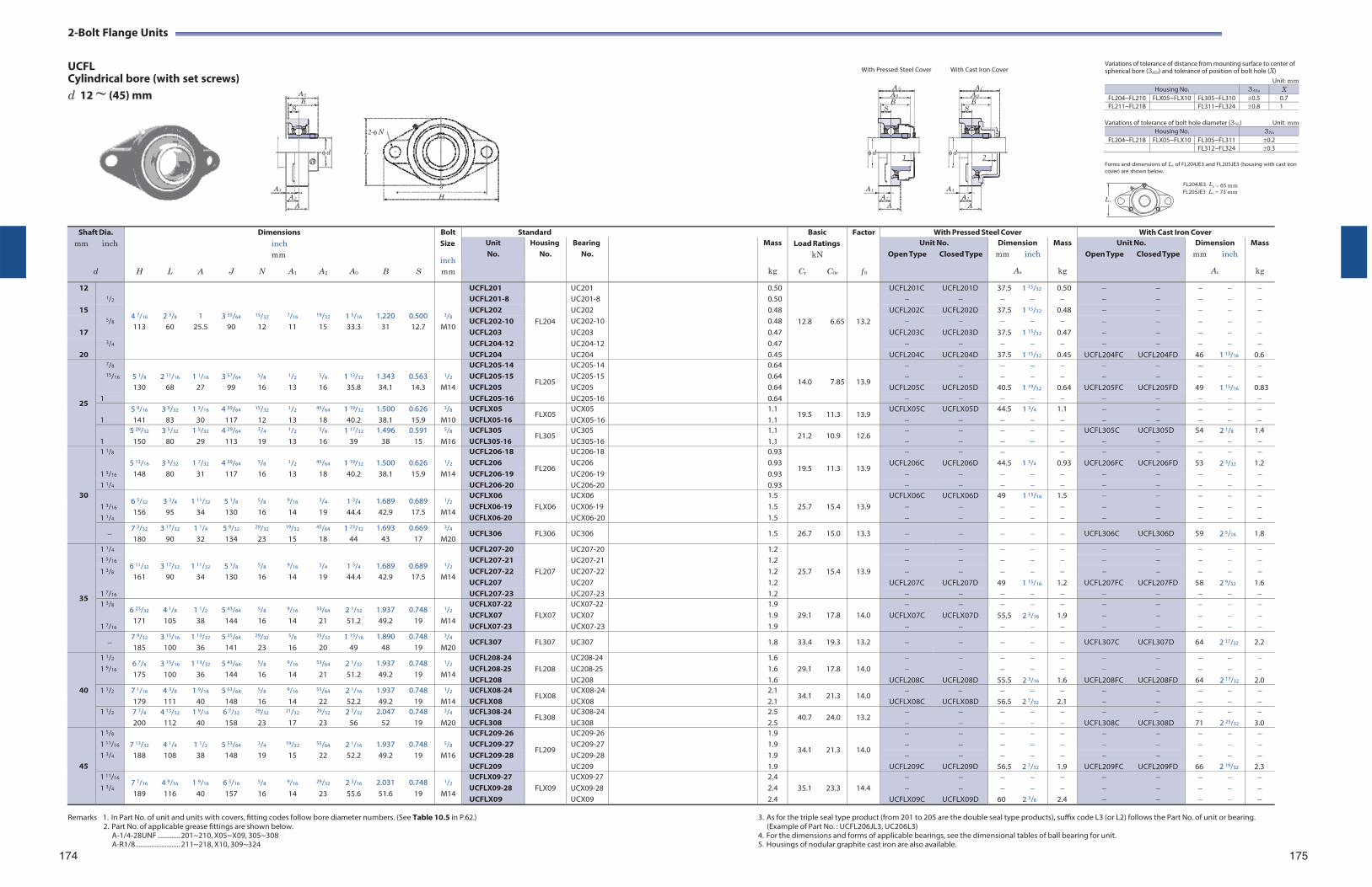
ASA 0 B
S
d1
A 1
A 2
A
AC A 0 B
S
d2
A 1
A 2
A
2-Bolt Flange Units
UCFL Cylindrical bore (with set screws) d 12 ~ (45) mm
2-N
L
With Pressed Steel Cover With Cast Iron Cover
Variations of tolerance of distance from mounting surface to center of spherical bore (3A2s) and tolerance of position of bolt hole (X)
Unit: mm Housing No. 3A2s X
FL204~FL210 FLX05~FLX10 FL305~FL310 0.5 0.7FL211~FL218 FL311~FL324 0.8 1
Variations of tolerance of bolt hole diameter (3Ns) Unit: mm
Housing No. 3Ns
FL204~FL218 FLX05~FLX10 FL305~FL311 0.2FL312~FL324 0.3
Forms and dimensions of Lc of FL204JE3 and FL205JE3 (housing with cast iron cover) are shown below.
FL204JE3 L J
c 65 mm
H Lc
FL205JE3 Lc 73 mm
Shaft Dia. mm inch
d
H
L
A
J
Dimensions inch mm
N A1
A2
A0
B
S
Bolt Size
inch mm
Standard BasicLoad Ratings
kN
Cr C0r
Factor
f 0
With Pressed Steel Cover With Cast Iron CoverUnit No.
Housing No.
Bearing No.
Mass
kg
Unit No. Open Type Closed Type
Dimension mm inch
As
Mass
kg
Unit No. Open Type Closed Type
Dimension mm inch
Ac
Mass
kg
12 1/2
4 7/16
2 3/8
1
3 35/64
15/32
7/16
19/32
1 5/16
1.220
0.500
3/8
UCFL201
FL204
UC201 0.50
12.8
6.65
13.2
UCFL201C UCFL201D 37.5 1 15/32 0.50 UCFL201-8 UC201-8 0.50
15 5/8
UCFL202 UC202 0.48 UCFL202C UCFL202D 37.5 1 15/32 0.48 UCFL202-10 UC202-10 0.48
113 60 25.5 90 12 11 15 33.3 31 12.7 M10 17 UCFL203 UC203 0.47 UCFL203C UCFL203D 37.5 1 15/32 0.47
3/4 UCFL204-12 UC204-12 0.47 20 UCFL204 UC204 0.45 UCFL204C UCFL204D 37.5 1 15/32 0.45 UCFL204FC UCFL204FD 46 1 13/16 0.6
25
7/8 5 1/8
2 11/16
1 1/16
3 57/64
5/8
1/2
5/8
1 13/32
1.343
0.563
1/2
UCFL205-14
FL205
UC205-14 0.64
14.0
7.85
13.9
15/16 UCFL205-15 UC205-15 0.64
130 68 27 99 16 13 16 35.8 34.1 14.3 M14 UCFL205 UC205 0.64 UCFL205C UCFL205D 40.5 1 19/32 0.64 UCFL205FC UCFL205FD 49 1 15/16 0.83 1 UCFL205-16 UC205-16 0.64
1
5 9/16
141 3 9/32
83 1 3/16
30 4 39/64
117
15/32
12
1/2
13
45/64
18 1 19/32
40.2 1.500 38.1
0.626 15.9
3/8
M10 UCFLX05 UCFLX05-16
FLX05 UCX05 UCX05-16
1.1 1.1
19.5 11.3 13.9 UCFLX05C
UCFLX05D
44.5
1 3/4
1.1
1
5 29/32
150 3 5/32
80 1 5/32
29 4 29/64
113
3/4
19
1/2
13
5/8
16 1 17/32
39 1.496
38 0.591
15
5/8
M16 UCFL305 UCFL305-16
FL305 UC305 UC305-16
1.1 1.1
21.2 10.9 12.6
UCFL305C
UCFL305D
54
2 1/8
1.4
30
1 1/8 5 13/16
3 5/32
1 7/32
4 39/64
5/8
1/2
45/64
1 19/32
1.500
0.626
1/2
UCFL206-18
FL206
UC206-18 0.93
19.5
11.3
13.9
1 3/16
UCFL206 UC206 0.93 UCFL206C UCFL206D 44.5 1 3/4 0.93 UCFL206FC UCFL206FD 53 2 3/32 1.2 148 80 31 117 16 13 18 40.2 38.1 15.9 M14 UCFL206-19 UC206-19 0.93
1 1/4 UCFL206-20 UC206-20 0.93
1 3/16
1 1/4
6 5/32
156 3 3/4
95 1 11/32
34 5 1/8
130
5/8
16
9/16
14
3/4
19 1 3/4
44.4 1.689 42.9
0.689 17.5
1/2
M14
UCFLX06 UCFLX06-19 UCFLX06-20
FLX06
UCX06 UCX06-19 UCX06-20
1.5 1.5 1.5
25.7
15.4
13.9
UCFLX06C
UCFLX06D
49
1 15/16
1.5
7 3/32
180 3 17/32
90 1 1/4
32 5 9/32
134
29/32
23
19/32
15
45/64
18 1 23/32
44 1.693
43 0.669
17
3/4
M20 UCFL306 FL306 UC306 1.5 26.7 15.0 13.3 UCFL306C UCFL306D 59 2 5/16 1.8
35
1 1/4
6 11/32
3 17/32
1 11/32
5 1/8
5/8
9/16
3/4
1 3/4
1.689
0.689
1/2
UCFL207-20
FL207
UC207-20 1.2
25.7
15.4
13.9
1 5/16 UCFL207-21 UC207-21 1.2 1 3/8 UCFL207-22 UC207-22 1.2
161 90 34 130 16 14 19 44.4 42.9 17.5 M14 UCFL207 UC207 1.2 UCFL207C UCFL207D 49 1 15/16 1.2 UCFL207FC UCFL207FD 58 2 9/32 1.6
1 7/16 UCFL207-23 UC207-23 1.2 1 3/8
1 7/16
6 23/32
171 4 1/8
105 1 1/2
38 5 43/64
144
5/8
16
9/16
14
53/64
21 2 1/32
51.2 1.937 49.2
0.748 19
1/2
M14
UCFLX07-22 UCFLX07 UCFLX07-23
FLX07
UCX07-22 UCX07 UCX07-23
1.9 1.9 1.9
29.1
17.8
14.0
UCFLX07C
UCFLX07D
55.5
2 3/16
1.9
7 9/32
185 3 15/16
100 1 13/32
36 5 35/64
141
29/32
23
5/8
16
25/32
20 1 15/16
49 1.890
48 0.748
19
3/4
M20 UCFL307 FL307 UC307 1.8 33.4 19.3 13.2 UCFL307C UCFL307D 64 2 17/32 2.2
40
1 1/2
1 9/16 6 7/8
175 3 15/16
100 1 13/32
36 5 43/64
144
5/8
16
9/16
14
53/64
21 2 1/32
51.2 1.937 49.2
0.748 19
1/2
M14
UCFL208-24 UCFL208-25 UCFL208
FL208
UC208-24 UC208-25 UC208
1.6 1.6 1.6
29.1
17.8
14.0
UCFL208C
UCFL208D
55.5
2 3/16
1.6
UCFL208FC
UCFL208FD
64
2 17/32
2.01 1/2 7 1/16
179 4 3/8
111 1 9/16
40 5 53/64
148
5/8
16
9/16
14
55/64
22 2 1/16
52.2 1.937 49.2
0.748 19
1/2
M14 UCFLX08-24 UCFLX08
FLX08 UCX08-24UCX08
2.1 2.1
34.1 21.3 14.0
UCFLX08C
UCFLX08D
56.5
2 7/32
2.1
1 1/2 7 7/8
200 4 13/32
112 1 9/16
40 6 7/32
158
29/32
23
21/32
17
29/32
23 2 7/32
56 2.047
52 0.748
19
3/4
M20 UCFL308-24 UCFL308
FL308 UC308-24UC308
2.5 2.5
40.7 24.0 13.2
UCFL308C
UCFL308D
71
2 25/32
3.0
45
1 5/8 7 13/32
4 1/4
1 1/2
5 53/64
3/4
19/32
55/64
2 1/16
1.937
0.748
5/8
UCFL209-26
FL209
UC209-26 1.9
34.1
21.3
14.0
1 11/16 UCFL209-27 UC209-27 1.9 1 3/4 188 108 38 148 19 15 22 52.2 49.2 19 M16 UCFL209-28 UC209-28 1.9
UCFL209 UC209 1.9 UCFL209C UCFL209D 56.5 2 7/32 1.9 UCFL209FC UCFL209FD 66 2 19/32 2.3 1 11/16
1 3/4 7 7/16
189 4 9/16
116 1 9/16
40 6 3/16
157
5/8
16
9/16
14
29/32
23 2 3/16
55.6 2.031 51.6
0.748 19
1/2
M14
UCFLX09-27 UCFLX09-28 UCFLX09
FLX09
UCX09-27 UCX09-28 UCX09
2.4 2.4 2.4
35.1
23.3
14.4
UCFLX09C
UCFLX09D
60
2 3/8
2.4
A 0
B S
d
A 1
A 2
A
Remarks 1. In Part No. of unit and units with covers, fitting codes follow bore diameter numbers. (See Table 10.5 in P.62.) 3. As for the triple seal type product (from 201 to 205 are the double seal type products), suffix code L3 (or L2) follows the Part No. of unit or bearing. 2. Part No. of applicable grease fittings are shown below. (Example of Part No. : UCFL206JL3, UC206L3)
A-1/4-28UNF ............. 201~210, X05~X09, 305~308 4. For the dimensions and forms of applicable bearings, see the dimensional tables of ball bearing for unit.A-R1/8 .......................... 211~218, X10, 309~324
174 5. Housings of nodular graphite cast iron are also available.
175
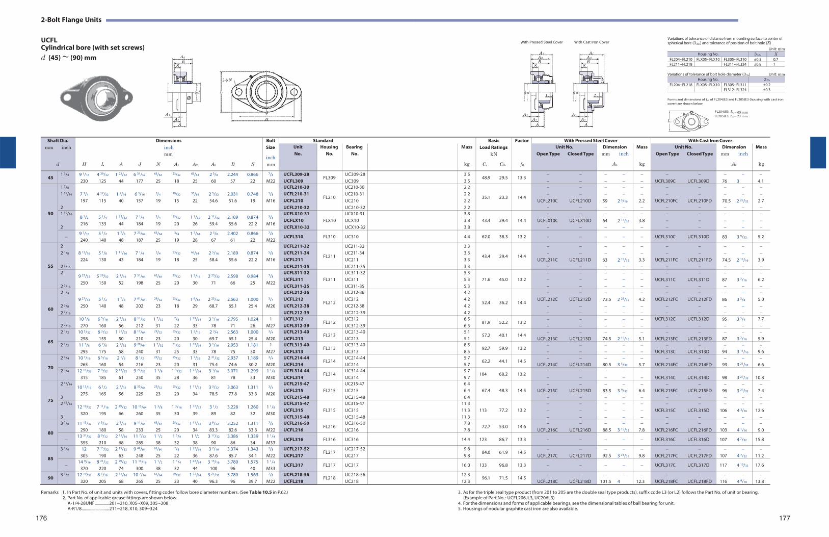
ASA 0 B
S
d1
A 1
A 2
A
AC A 0 B
S
d2
A 1
A 2
A
2-Bolt Flange Units
UCFL Cylindrical bore (with set screws) d (45) ~ (90) mm
2-N
L
With Pressed Steel Cover With Cast Iron Cover
Variations of tolerance of distance from mounting surface to center of spherical bore (3A2s) and tolerance of position of bolt hole (X)
Unit: mm Housing No. 3A2s X
FL204~FL210 FLX05~FLX10 FL305~FL310 0.5 0.7FL211~FL218 FL311~FL324 0.8 1
Variations of tolerance of bolt hole diameter (3Ns) Unit: mm
Housing No. 3Ns
FL204~FL218 FLX05~FLX10 FL305~FL311 0.2FL312~FL324 0.3
Forms and dimensions of Lc of FL204JE3 and FL205JE3 (housing with cast iron cover) are shown below.
FL204JE3 L J
c 65 mm
H Lc
FL205JE3 Lc 73 mm
Shaft Dia. mm inch
d
Dimensions inch mm
H L A J N A1 A2 A0 B S
Bolt Size
inch mm
Standard BasicLoad Ratings
kN
Cr C0r
Factor
f 0
With Pressed Steel Cover With Cast Iron Cover Unit No.
Housing No.
Bearing No.
Mass
kg
Unit No. Open Type Closed Type
Dimension mm inch
As
Mass
kg
Unit No. Open Type Closed Type
Dimension mm inch
Ac
Mass
kg
45 1 3/4 9 1/16 4 29/32 1 23/32 6 31/32 63/64 23/32 63/64 2 3/8 2.244 0.866
230 125 44 177 25 18 25 60 57 22
7/8
M22 UCFL309-28 UCFL309
FL309 UC309-28UC309
3.5 3.5
48.9 29.5 13.3
UCFL309C UCFL309D
76 3
4.1
50
1 7/8
1 15/16
2
7 3/4 4 17/32 1 9/16 6 3/16 3/4 19/32 55/64 2 5/32 2.031 0.748 197 115 40 157 19 15 22 54.6 51.6 19
5/8
M16
UCFL210-30 UCFL210-31 UCFL210 UCFL210-32
FL210
UC210-30 UC210-31 UC210 UC210-32
2.2 2.2 2.2 2.2
35.1 23.3
14.4
UCFL210C UCFL210D
59 2 5/16
2.2
UCFL210FC UCFL210FD
70.5 2 25/32
2.7
1 15/16
2
8 1/2 5 1/4 1 23/32 7 1/4 3/4 25/32 1 1/32 2 11/32 2.189 0.874 216 133 44 184 19 20 26 59.4 55.6 22.2
5/8
M16
UCFLX10-31 UCFLX10 UCFLX10-32
FLX10
UCX10-31 UCX10 UCX10-32
3.8 3.8 3.8
43.4 29.4
14.4
UCFLX10C UCFLX10D
64 2 17/32
3.8
9 7/16 5 1/2 1 7/8 7 23/64 63/64 3/4 1 7/64 2 5/8 2.402 0.866 240 140 48 187 25 19 28 67 61 22
7/8
M22 UCFL310 FL310 UC310 4.4 62.0 38.3 13.2 UCFL310C UCFL310D 83 3 9/32 5.2
55
2 2 1/8
2 3/16
8 13/16 5 1/8 1 11/16 7 1/4 3/4 23/32 63/64 2 5/16 2.189 0.874
224 130 43 184 19 18 25 58.4 55.6 22.2
5/8
M16
UCFL211-32 UCFL211-34 UCFL211 UCFL211-35
FL211
UC211-32 UC211-34 UC211 UC211-35
3.3 3.3 3.3 3.3
43.4 29.4
14.4
UCFL211C UCFL211D
63 2 15/32
3.3
UCFL211FC UCFL211FD
74.5 2 15/16
3.9
2
2 3/16
9 27/32 5 29/32 2 1/16 7 51/64 63/64 25/32 1 3/16 2 25/32 2.598 0.984 250 150 52 198 25 20 30 71 66 25
7/8
M22
UCFL311-32 UCFL311 UCFL311-35
FL311
UC311-32UC311 UC311-35
5.3 5.3 5.3
71.6 45.0
13.2
UCFL311C UCFL311D
87 3 7/16
6.2
60
2 1/4
2 3/8
2 7/16
9 27/32 5 1/2 1 7/8 7 61/64 29/32 23/32 1 9/64 2 23/32 2.563 1.000
250 140 48 202 23 18 29 68.7 65.1 25.4
3/4
M20
UCFL212-36 UCFL212 UCFL212-38 UCFL212-39
FL212
UC212-36 UC212 UC212-38 UC212-39
4.2 4.2 4.2 4.2
52.4 36.2
14.4
UCFL212C UCFL212D
73.5 2 29/32
4.2
UCFL212FC UCFL212FD
86 3 3/8
5.0
2 7/16
10 5/8 6 5/16 2 7/32 8 11/32 1 7/32 7/8 1 19/64 3 1/16 2.795 1.024 270 160 56 212 31 22 33 78 71 26
1 M27
UCFL312 UCFL312-39
FL312 UC312 UC312-39
6.5 6.5
81.9 52.2 13.2
UCFL312C UCFL312D
95 3 3/4
7.7
65
2 1/2 10 5/32 6 3/32 1 31/32 8 17/64 29/32 25/32 1 3/16 2 3/4 2.563 1.000 258 155 50 210 23 20 30 69.7 65.1 25.4
3/4
M20 UCFL213-40 UCFL213
FL213 UC213-40UC213
5.1 5.1
57.2 40.1 14.4
UCFL213C UCFL213D
74.5 2 15/16
5.1
UCFL213FC UCFL213FD
87 3 7/16
5.9
2 1/2 11 5/8 6 7/8 2 9/32 9 29/64 1 7/32 31/32 1 19/64 3 1/16 2.953 1.181 295 175 58 240 31 25 33 78 75 30
1 M27
UCFL313-40 UCFL313
FL313 UC313-40UC313
8.5 8.5
92.7 59.9 13.2
UCFL313C UCFL313D
94 3 11/16
9.6
70
2 3/4 10 7/16 6 5/16 2 1/8 8 1/2 29/32 25/32 1 7/32 2 31/32 2.937 1.189 265 160 54 216 23 20 31 75.4 74.6 30.2
3/4
M20 UCFL214-44 UCFL214
FL214 UC214-44UC214
5.7 5.7
62.2 44.1 14.5
UCFL214C UCFL214D
80.5 3 5/32
5.7
UCFL214FC UCFL214FD
93 3 21/32
6.6
2 3/4 12 13/32 7 9/32 2 13/32 9 27/32 1 3/8 1 3/32 1 27/64 3 3/16 3.071 1.299 315 185 61 250 35 28 36 81 78 33
1 1/8
M30 UCFL314-44 UCFL314
FL314 UC314-44UC314
9.7 9.7
104 68.2 13.2
UCFL314C UCFL314D
98 3 27/32
10.8
75
2 15/16
3
10 13/16 6 1/2 2 7/32 8 55/64 29/32 25/32 1 11/32 3 3/32 3.063 1.311 275 165 56 225 23 20 34 78.5 77.8 33.3
3/4
M20
UCFL215-47 UCFL215 UCFL215-48
FL215
UC215-47 UC215 UC215-48
6.4 6.4 6.4
67.4 48.3
14.5
UCFL215C UCFL215D
83.5 3 9/32
6.4
UCFL215FC UCFL215FD
96 3 25/32
7.4
2 15/16
3
12 19/32 7 11/16 2 19/32 10 15/64 1 3/8 1 3/16 1 17/32 3 1/2 3.228 1.260 320 195 66 260 35 30 39 89 82 32
1 1/8
M30
UCFL315-47 UCFL315 UCFL315-48
FL315
UC315-47 UC315 UC315-48
11.3 11.3 11.3
113 77.2
13.2
UCFL315C UCFL315D
106 4 3/16
12.6
80
3 1/8 11 13/32 7 3/32 2 9/32 9 11/64 63/64 25/32 1 11/32 3 9/32 3.252 1.311 290 180 58 233 25 20 34 83.3 82.6 33.3
7/8
M22 UCFL216-50 UCFL216
FL216 UC216-50UC216
7.8 7.8
72.7 53.0 14.6
UCFL216C UCFL216D
88.5 3 15/32
7.8
UCFL216FC UCFL216FD
103 4 1/16
9.0
13 31/32 8 9/32 2 11/16 11 7/32 1 1/2 1 1/4 1 1/2 3 17/32 3.386 1.339
355 210 68 285 38 32 38 90 86 34 1 1/4
M33 UCFL316 FL316 UC316 14.4 123 86.7 13.3 UCFL316C UCFL316D 107 4 7/32 15.8
85
3 1/4 12 7 15/32 2 15/32 9 49/64 63/64 7/8 1 27/64 3 7/16 3.374 1.343 305 190 63 248 25 22 36 87.6 85.7 34.1
7/8
M22 UCFL217-52 UCFL217
FL217 UC217-52UC217
9.8 9.8
84.0 61.9 14.5
UCFL217C UCFL217D
92.5 3 21/32
9.8
UCFL217FC UCFL217FD
107 4 7/32
11.2
14 9/16 8 21/32 2 29/32 11 13/16 1 1/2 1 1/4 1 47/64 3 15/16 3.780 1.575
370 220 74 300 38 32 44 100 96 40 1 1/4
M33 UCFL317 FL317 UC317 16.0 133 96.8 13.3 UCFL317C UCFL317D 117 4 19/32 17.6
90 3 1/2 12 19/32 8 1/16 2 11/16 10 7/16 63/64 29/32 1 37/64 3 25/32 3.780 1.563
320 205 68 265 25 23 40 96.3 96 39.7
7/8
M22 UCFL218-56 UCFL218
FL218 UC218-56UC218
12.3 12.3
96.1 71.5 14.5
UCFL218C UCFL218D
101.5 4
12.3
UCFL218FC UCFL218FD
116 4 9/16
13.8
A 0
B S
d
A 1
A 2
A
Remarks 1. In Part No. of unit and units with covers, fitting codes follow bore diameter numbers. (See Table 10.5 in P.62.) 3. As for the triple seal type product (from 201 to 205 are the double seal type products), suffix code L3 (or L2) follows the Part No. of unit or bearing. 2. Part No. of applicable grease fittings are shown below. (Example of Part No. : UCFL206JL3, UC206L3)
A-1/4-28UNF ............. 201~210, X05~X09, 305~308 4. For the dimensions and forms of applicable bearings, see the dimensional tables of ball bearing for unit.A-R1/8 .......................... 211~218, X10, 309~324
176
5. Housings of nodular graphite cast iron are also available. 177
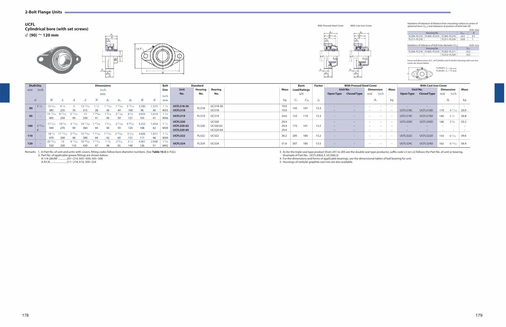
ASA 0 B
S
d1
A 1
A 2
A
AC A 0 B
S
d2
A 1
A 2
A
2-Bolt Flange Units
UCFL Cylindrical bore (with set screws) d (90) ~ 120 mm
2-N
L
With Pressed Steel Cover With Cast Iron Cover
Variations of tolerance of distance from mounting surface to center of spherical bore (3A2s) and tolerance of position of bolt hole (X)
Unit: mm Housing No. 3A2s X
FL204~FL210 FLX05~FLX10 FL305~FL310 0.5 0.7FL211~FL218 FL311~FL324 0.8 1
Variations of tolerance of bolt hole diameter (3Ns) Unit: mm
Housing No. 3Ns
FL204~FL218 FLX05~FLX10 FL305~FL311 0.2FL312~FL324 0.3
Forms and dimensions of Lc of FL204JE3 and FL205JE3 (housing with cast iron cover) are shown below.
FL204JE3 L J
c 65 mm
H Lc
FL205JE3 Lc 73 mm
Remarks 1. In Part No. of unit and units with covers, fitting codes follow bore diameter numbers. (See Table 10.5 in P.62.)
2. Part No. of applicable grease fittings are shown below. A-1/4-28UNF ............. 201~210, X05~X09, 305~308 A-R1/8 .......................... 211~218, X10, 309~324
3. As for the triple seal type product (from 201 to 205 are the double seal type products), suffix code L3 (or L2) follows the Part No. of unit or bearing. (Example of Part No. : UCFL206JL3, UC206L3)
4. For the dimensions and forms of applicable bearings, see the dimensional tables of ball bearing for unit. 5. Housings of nodular graphite cast iron are also available.
178 179
Shaft Dia. mm inch
d
Dimensions inch mm
H L A J N A1 A2 A0 B S
Bolt Size
inch mm
Standard BasicLoad Ratings
kN
Cr C0r
Factor
f 0
With Pressed Steel Cover With Cast Iron Cover Unit No.
Housing No.
Bearing No.
Mass
kg
Unit No. Open Type Closed Type
Dimension mm inch
As
Mass
kg
Unit No. Open Type Closed Type
Dimension mm inch
Ac
Mass
kg
90 3 1/2 15 5/32 9 1/4 3 12 13/32 1 1/2 1 13/32 1 47/64 3 15/16 3.780 1.575
385 235 76 315 38 36 44 100 96 40 1 1/4
M33 UCFL318-56 UCFL318
FL318 UC318-56UC318
19.0 19.0
143 107 13.3
UCFL318C UCFL318D
119 4 11/16
20.9
95 15 15/16 9 27/32 3 11/16 13 1 39/64 1 9/16 2 21/64 4 3/4 4.055 1.614
405 250 94 330 41 40 59 121 103 41 1 3/8
M36 UCFL319 FL319 UC319 24.6 153 119 13.3 UCFL319C UCFL319D 140 5 1/2 26.8
100
3 15/16
4
17 5/16 10 5/8 3 11/16 14 11/64 1 47/64 1 9/16 2 21/64 4 29/32 4.252 1.654 440 270 94 360 44 40 59 125 108 42
1 1/2
M39
UCFL320 UCFL320-63 UCFL320-64
FL320
UC320 UC320-63 UC320-64
29.4 29.4 29.4
173 141
13.2
UCFL320C UCFL320D
146 5 3/4
32.2
110 18 1/2 11 13/16 3 25/32 15 23/64 1 47/64 1 21/32 2 23/64 5 5/32 4.606 1.811 470 300 96 390 44 42 60 131 117 46
1 1/2
M39 UCFL322 FL322 UC322 36.2 205 180 13.2 UCFL322C UCFL322D 154 6 1/16 39.6
120 20 15/32 13 4 11/32 16 59/64 1 27/32 1 7/8 2 9/16 5 1/2 4.961 2.008
520 330 110 430 47 48 65 140 126 51 1 5/8
M42 UCFL324 FL324 UC324 51.6 207 185 13.5 UCFL324C UCFL324D 163 6 13/32 56.4
A 0
B S
d
A 1
A 2
A
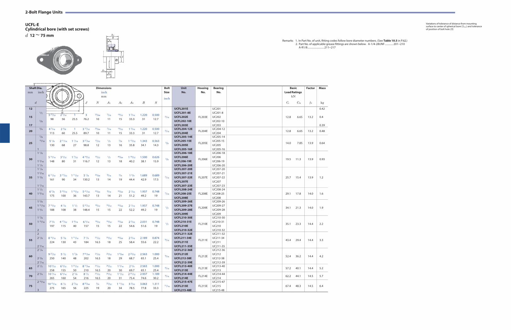
2-Bolt Flange Units
UCFL-E Cylindrical bore (with set screws)
Variations of tolerance of distance from mounting surface to center of spherical bore (3A2s) and tolerance of position of bolt hole (X)
d 12 ~ 75 mm
Remarks 1. In Part No. of unit, fitting codes follow bore diameter numbers. (See Table 10.5 in P.62.)
2. Part No. of applicable grease fittings are shown below. A-1/4-28UNF ............. 201~210 A-R1/8 .......................... 211~217
2-N
L
J H
A 0
B S
d
A 1
A 2
A
Shaft Dia. mm inch
d
H
L
A
J
Dimensions inch mm
N A1
A2
A0
B
S
Bolt Size
inch
Unit No.
HousingNo.
BearingNo.
BasicLoad Ratings
kN
Cr C0r
Factor
f 0
Mass
kg
12 1/2
5/8
3 27/32
98
2 7/32
56
1 25.5
3 76.2
25/64
10
7/16
11
19/32
15
1 5/16
33.3
1.220 31
0.500 12.7
5/16
UCFL201E
FL203E
UC201
12.8
6.65
13.2
0.42
15
UCFL201-8E UCFL202E UCFL202-10E
UC201-8 UC202 UC202-10
0.4
17 UCFL203E UC203 0.39
20 3/4 4 7/16
113 2 3/8
60 1
25.5 3 17/32
89.7
25/64
10
7/16
11
19/32
15 1 5/16
33.3 1.220
31 0.500 12.7
5/16 UCFL204-12E UCFL204E
FL204E UC204-12 UC204
12.8 6.65 13.2 0.48
25
7/8 5 1/8
130
2 11/16
68
1 1/16
27
3 57/64
98.8
15/32
12
1/2
13
5/8
16
1 13/32
35.8
1.343 34.1
0.563 14.3
3/8
UCFL205-14E
FL205E
UC205-14
14.0
7.85
13.9
0.64 15/16 UCFL205-15E UCFL205E
UC205-15 UC205
1 UCFL205-16E UC205-16
30
1 1/8 5 13/16
148
3 5/32
80
1 7/32
31
4 19/32
116.7
15/32
12
1/2
13
45/64
18
1 19/32
40.2
1.500 38.1
0.626 15.9
3/8
UCFL206-18E
FL206E
UC206-18
19.5
11.3
13.9
0.93 1 3/16
UCFL206E UCFL206-19E
UC206 UC206-19
1 1/4 UCFL206-20E UC206-20
35
1 1/4
6 11/32
161
3 17/32
90
1 11/32
34
5 1/8
130.2
33/64
13
9/16
14
3/4
19
1 3/4
44.4
1.689 42.9
0.689 17.5
7/16
UCFL207-20E
FL207E
UC207-20
25.7
15.4
13.9
1.2 1 5/16 UCFL207-21E UC207-21 1 3/8 UCFL207-22E UC207-22
UCFL207E UC207 1 7/16 UCFL207-23E UC207-23
40
1 1
1/2
9/16 6 7/8
175 3 15/16
100 1 13/32
36 5 21/32
143.7
33/64
13
9/16
14
53/64
21 2 1/32
51.2 1.937 49.2
0.748 19
7/16
UCFL208-24E UCFL208-25E UCFL208E
FL208E
UC208-24 UC208-25 UC208
29.1
17.8
14.0
1.6
45
1 5/8 7 13/32
188
4 1/4
108
1 1/2
38
5 27/32
148.4
19/32
15
19/32
15
55/64
22
2 1/16
52.2
1.937 49.2
0.748
19
1/2
UCFL209-26E
FL209E
UC209-26
34.1
21.3
14.0
1.9 1 11/16 UCFL209-27E UC209-27 1 3/4 UCFL209-28E UC209-28
UCFL209E UC209
50
1 7/8 7 3/4
197
4 17/32
115
1 9/16
40
6 3/16
157
19/32
15
19/32
15
55/64
22
2 5/32
54.6
2.031 51.6
0.748
19
1/2
UCFL210-30E
FL210E
UC210-30
35.1
23.3
14.4
2.2 1 15/16 UCFL210-31E
UCFL210E UC210-31 UC210
2 UCFL210-32E UC210-32
55
2 8 13/16
224
5 1/8
130
1 11/16
43
7 1/4
184
21/32
16.5
23/32
18
63/64
25
2 5/16
58.4
2.189 55.6
0.874 22.2
9/16
UCFL211-32E
FL211E
UC211-32
43.4
29.4
14.4
3.3 2 1/8 UCFL211-34E
UCFL211E UC211-34 UC211
2 3/16 UCFL211-35E UC211-35
60
2 1/4 9 27/32
250
5 1/2
140
1 7/8
48
7 61/64
202
21/32
16.5
23/32
18
1 9/64
29
2 23/32
68.7
2.563 65.1
1.000 25.4
9/16
UCFL212-36E
FL212E
UC212-36
52.4
36.2
14.4
4.2 2 3/8
UCFL212E UCFL212-38E
UC212 UC212-38
2 7/16 UCFL212-39E UC212-39
65 2 1/2 10 5/32
258 6 3/32
155 1 31/32
50 8 17/64
210
21/32
16.5
25/32
20 1 3/16
30 2 3/4
69.7 2.563 65.1
1.000 25.4
9/16 UCFL213-40E UCFL213E
FL213E UC213-40 UC213
57.2 40.1 14.4 5.2
70 2 3/4 10 7/16
265 6 5/16
160 2 1/8
54 8 1/2
216
21/32
16.5
25/32
20 1 7/32
31 2 31/32
75.4 2.937 74.6
1.189 30.2
9/16 UCFL214-44E UCFL214E
FL214E UC214-44 UC214
62.2 44.1 14.5 5.7
75
2
3
15/16 10 13/16
275 6 1/2
165 2 7/32
56 8 55/64
225
3/4
19
25/32
20 1 11/32
34 3 3/32
78.5 3.063 77.8
1.311 33.3
11/16
UCFL215-47E UCFL215E UCFL215-48E
FL215E
UC215-47 UC215 UC215-48
67.4
48.3
14.5
6.4
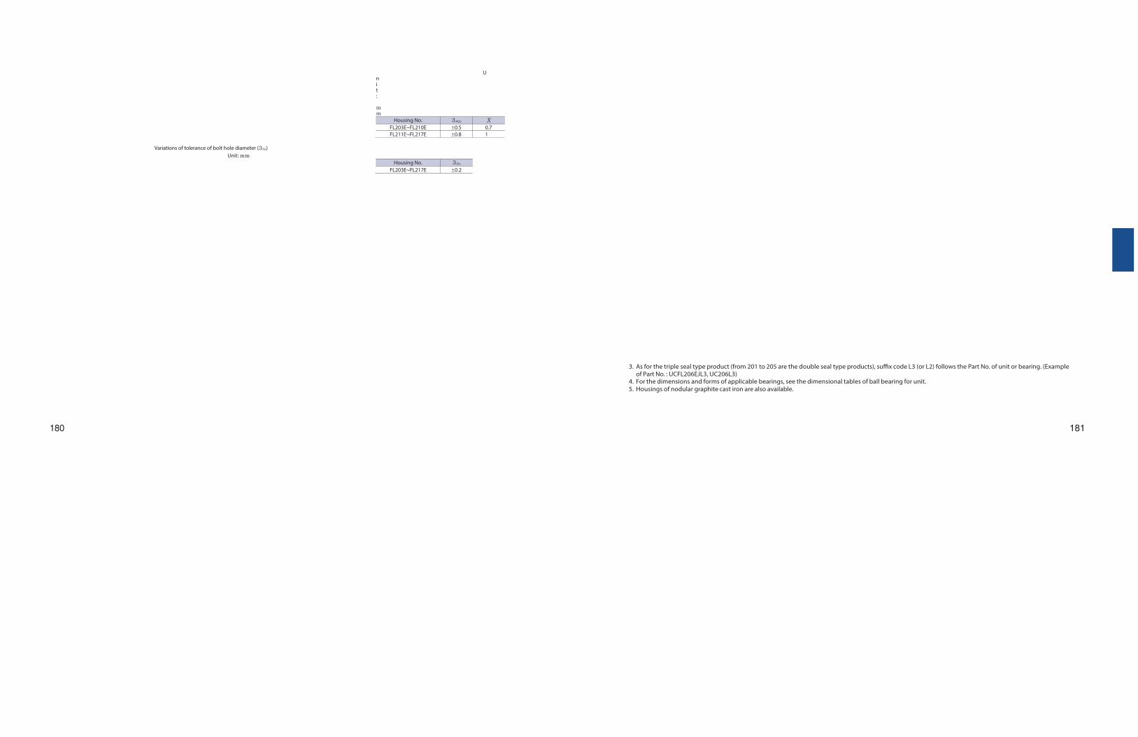
Unit: mm
Housing No. 3A2s X FL203E~FL210E 0.5 0.7FL211E~FL217E 0.8 1
Variations of tolerance of bolt hole diameter (3Ns) Unit: mm
Housing No. 3Ns
FL203E~FL217E 0.2
3. As for the triple seal type product (from 201 to 205 are the double seal type products), suffix code L3 (or L2) follows the Part No. of unit or bearing. (Example of Part No. : UCFL206EJL3, UC206L3)
4. For the dimensions and forms of applicable bearings, see the dimensional tables of ball bearing for unit. 5. Housings of nodular graphite cast iron are also available.
180
181
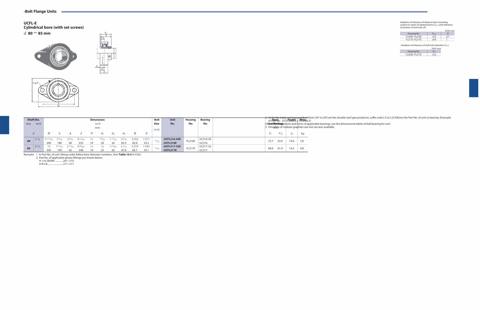
-Bolt Flange Units
UCFL-E Cylindrical bore (with set screws)
Variations of tolerance of distance from mounting surface to center of spherical bore (3A2s) and tolerance of position of bolt hole (X)
d 80 ~ 85 mm
Remarks 1. In Part No. of unit, fitting codes follow bore diameter numbers. (See Table 10.5 in P.62.) 2. Part No. of applicable grease fittings are shown below.
A-1/4-28UNF ............. 201~210 A-R1/8 .......................... 211~217
Unit: mm Housing No. 3A2s X
FL203E~FL210E 0.5 0.7FL211E~FL217E 0.8 1
Variations of tolerance of bolt hole diameter (3Ns)
Unit: mm Housing No. 3Ns
FL203E~FL217E 0.2
3. As for the triple seal type product (from 201 to 205 are the double seal type products), suffix code L3 (or L2) follows the Part No. of unit or bearing. (Example of Part No. : UCFL206EJL3, UC206L3)
4. For the dimensions and forms of applicable bearings, see the dimensional tables of ball bearing for unit. 5. Housings of nodular graphite cast iron are also available.
2-N
L
J H
A 0
B S
d
A 1
A 2
A
Shaft Dia. mm inch
d
H
L
A
J
Dimensions inch mm
N A1
A2
A0
B
S
Bolt Size
inch
Unit No.
HousingNo.
BearingNo.
BasicLoad Ratings
kN
Cr C0r
Factor
f 0
Mass
kg
80 3 1/8 11 13/32
290 7 3/32
180 2 9/32
58 9 11/64
233
3/4
19
25/32
20 1 11/32
34 3 9/32
83.3 3.252 82.6
1.311 33.3
11/16 UCFL216-50E UCFL216E
FL216E UC216-50 UC216
72.7 53.0 14.6 7.8
85 3 1/4 12
305 7 15/32
190 2 15/32
63 9 49/64
248
3/4
19
7/8
22 1 27/64
36 3 7/16
87.6 3.374 85.7
1.343 34.1
11/16 UCFL217-52E UCFL217E
FL217E UC217-52 UC217
84.0 61.9 14.5 9.8

182 183
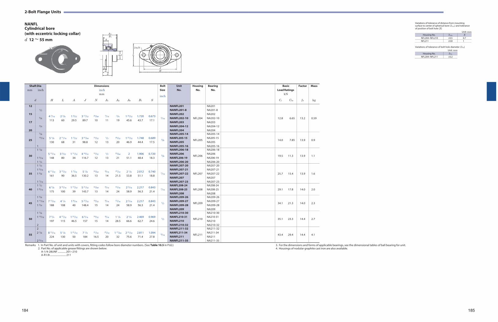
2-Bolt Flange Units
NANFL Cylindrical bore
Variations of tolerance of distance from mounting surface to center of spherical bore (3A2s) and tolerance of position of bolt hole (X)
(with eccentric locking collar) d 12 ~ 55 mm
Remarks 1. In Part No. of unit and units with covers, fitting codes follow bore diameter numbers. (See Table 10.5 in P.62.) 2. Part No. of applicable grease fittings are shown below.
A-1/4-28UNF ............. 201~210 A-R1/8 .......................... 211
3. For the dimensions and forms of applicable bearings, see the dimensional tables of ball bearing for unit. 4. Housings of nodular graphite cast iron are also available.
Unit: mm Housing No. 3A2s X
NFL204~NFL210 0.5 0.7NFL211 0.8 1
Variations of tolerance of bolt hole diameter (3Ns)
Unit: mm
184 185
2-N
L
J H
A 0
B 1
S
d
A 1
A 2
A
Housing No. 3Ns
NFL204~NFL211 0.2
Shaft Dia mm inch
d
H
L
A
J
Dimensions inch mm
N A1
A2
A0
B1
S
Bolt Size
inch
Unit No.
HousingNo.
BearingNo.
BasicLoad Ratings
kN
Cr C0r
Factor
f 0
Mass
kg
12 1/2
4 7/16
113
2 3/8
60
1 5/32
29.5
3 17/32
89.7
25/64
10
7/16
11
3/4
19
1 25/32
45.6
1.720 43.7
0.673 17.1
5/16
NANFL201
NFL204
NA201
12.8
6.65
13.2
0.59
NANFL201-8 NA201-8 15
5/8
NANFL202 NA202 NANFL202-10 NA202-10
17 NANFL203 NA203 3/4 NANFL204-12 NA204-12
20 NANFL204 NA204
25
7/8 5 1/8
130
2 11/16
68
1 7/32
31
3 57/64
98.8
15/32
12
1/2
13
25/32
20
1 27/32
46.9
1.748 44.4
0.689 17.5
3/8
NANFL205-14
NFL205
NA205-14
14.0
7.85
13.9
0.9 15/16 NANFL205-15
NANFL205 NA205-15 NA205
1 NANFL205-16 NA205-16
30
1 1/8 5 13/16
148
3 5/32
80
1 11/32
34
4 19/32
116.7
15/32
12
1/2
13
53/64
21
2
51.1
1.906 48.4
0.720 18.3
3/8
NANFL206-18
NFL206
NA206-18
19.5
11.3
13.9
1.1 1 3/16
NANFL206 NANFL206-19
NA206 NA206-19
1 1/4 NANFL206-20 NA206-20
35
1 1/4
6 11/32
161
3 17/32
90
1 7/16
36.5
5 1/8
130.2
33/64
13
9/16
14
27/32
21.5
2 1/8
53.8
2.012 51.1
0.740 18.8
7/16
NANFL207-20
NFL207
NA207-20
25.7
15.4
13.9
1.6 1 5/16 NANFL207-21 NA207-211 3/8 NANFL207-22 NA207-22
NANFL207 NA207 1 7/16 NANFL207-23 NA207-23
40
1 1/2
1 9/16 6 7/8
175 3 15/16
100 1 17/32
39 5 21/32
143.7
33/64
13
9/16
14
15/16
24 2 5/16
58.9 2.217 56.3
0.843 21.4
7/16
NANFL208-24 NANFL208-25 NANFL208
NFL208
NA208-24 NA208-25 NA208
29.1
17.8
14.0
2.0
45
1 5/8 7 13/32
188
4 1/4
108
1 9/16
40
5 27/32
148.4
19/32
15
9/16
14
15/16
24
2 5/16
58.9
2.217 56.3
0.843 21.4
1/2
NANFL209-26
NFL209
NA209-26
34.1
21.3
14.0
2.3 1 11/16 NANFL209-27 NA209-271 3/4 NANFL209-28 NA209-28
NANFL209 NA209
50
1 7/8 7 3/4
197
4 17/32
115
1 27/32
46.5
6 3/16
157
19/32
15
9/16
14
1 1/8
28.5
2 5/8
66.6
2.469 62.7
0.969 24.6
1/2
NANFL210-30
NFL210
NA210-30
35.1
23.3
14.4
2.7 1 15/16 NANFL210-31
NANFL210 NA210-31 NA210
2 NANFL210-32 NA210-32
55
2 8 13/16
224
5 1/8
130
1 31/32
50
7 1/4
184
21/32
16.5
25/32
20
1 17/64
32
2 31/32
75.6
2.811 71.4
1.094 27.8
9/16
NANFL211-32
NFL211
NA211-32
43.4
29.4
14.4
4.1 2 1/8 NANFL211-34
NANFL211 NA211-34 NA211
2 3/16 NANFL211-35 NA211-35

2-Bolt Flange Units
NCFL Cylindrical bore
Variations of tolerance of distance from mounting surface to center of spherical bore (3A2s) and tolerance of position of bolt hole (X)
(with concentric locking collar) d 20 ~ 60 mm
Unit: mm
Variations of tolerance of bolt hole diameter (3Ns) Unit: mm
Housing No. 3Ns
FL204~FL212 0.2
Remarks 1. In Part No. of unit, fitting codes follow bore diameter codes. (See Table 10.5 in P.62.)
2. Part No. of applicable grease fittings are shown below. A-1/4-28UNF ............. 204~210 A-R1/8 .......................... 211~212
3. For the dimensions and forms of applicable bearings, see the dimensional tables of ball bearing for unit. 4. Representative examples of the forms of housing are indicated.
186 187
Shaft Dia. mm inch
d
H
L
A
J
Dimensions inch mm
N A1 A2
A0
B1
S
d1
Bolt Size
inch mm
Unit No.
HousingNo.
BearingNo.
BasicLoad Ratings
kN
Cr C0r
Factor
f 0
Mass
kg
20 3/4 4 7/16
113 2 3/8
60 1
25.5 3 35/64
90
15/32
12
7/16
11
19/32
15 1 3/8
34.8 1 9/32
32.5 0.500 12.7
1 3/4
44.5
3/8
M10 NCFL204-12 NCFL204
FL204 NC204-12 NC204
12.8 6.65 13.2 0.62
25
7/8 5 1/8
2 11/16
1 1/16
3 57/64
5/8
1/2
5/8
1 1/2
1 7/16
0.563
1 15/16
1/2
NCFL205-14
FL205
NC205-14
14.0
7.85
13.9
0.84 15/16 NCFL205-15
NCFL205 NC205-15 NC205 130 68 27 99 16 13 16 38.2 36.5 14.3 49.2 M14
1 NCFL205-16 NC205-16
30
1 1/8 5 13/16
3 5/32
1 7/32
4 39/64
5/8
1/2
45/64
1 21/32
1 9/16
0.626
2 3/16
1/2
NCFL206-18
FL206
NC206-18
19.5
11.3
13.9
1.1 1 3/16
NCFL206 NCFL206-19
NC206 NC206-19 148 80 31 117 16 13 18 41.8 39.7 15.9 55.6 M14
1 1/4 NCFL206-20 NC206-20
35
1 1/4 6 11/32
161 3 17/32
90 1 11/32
34 5 1/8
130
5/8
16
9/16
14
3/4
19 1 13/16
46 1 3/4
44.5 0.689 17.5
2 7/16
61.9
1/2
M14 NCFL207-20 FL207 NC207-20 25.7 15.4 13.9 1.5
1 3/8
1 7/16
6 11/32
161 3 17/32
90 1 11/32
34 5 1/8
130
5/8
16
9/16
14
3/4
19 1 13/16
46 1 3/4
44.5 0.689 17.5
2 9/16
65.1
1/2
M14
NCFL207-22 NCFL207 NCFL207-23
FL207
NC207-22 NC207 NC207-23
25.7
15.4
13.9
1.5
40 1 1/2 6 7/8
175 3 15/16
100 1 13/32
36 5 43/64
144
5/8
16
9/16
14
53/64
21 2 3/32
52.8 2
50.8 0.748
19 2 11/16
68.3
1/2
M14 NCFL208-24 NCFL208
FL208 NC208-24 NC208
29.1 17.8 14.0 2.0
45
1 5/8 7 13/32
188 4 1/4
108 1 1/2
38 5 53/64
148
3/4
19
19/32
15
55/64
22 2 1/8
53.8 2
50.8 0.748
19 2 13/16
71.4
5/8
M16 NCFL209-26 FL209 NC209-26 34.1 21.3 14.0 2.3
1 11/16
1 3/4 7 13/32
188 4 1/4
108 1 1/2
38 5 53/64
148
3/4
19
19/32
15
55/64
22 2 1/8
53.8 2
50.8 0.748
19 2 15/16
74.6
5/8
M16
NCFL209-27 NCFL209-28 NCFL209
FL209
NC209-27 NC209-28 NC209
34.1
21.3
14.0
2.3
50
1 15/16
2
7 3/4
197 4 17/32
115 1 9/16
40 6 3/16
157
3/4
19
19/32
15
55/64
22 2 7/32
56.1 2 3/32
53.1 0.748
19 3 3/8
85.7
5/8
M16
NCFL210-31 NCFL210 NCFL210-32
FL210
NC210-31 NC210 NC210-32
35.1
23.3
14.4
2.8
55
2 8 13/16
224 5 1/8
130 1 11/16
43 7 1/4
184
3/4
19
23/32
18
63/64
25 2 11/32
59.9 2 1/4
57.1 0.874 22.2
3 1/2
88.9
5/8
M16 NCFL211-32 FL211 NC211-32 43.4 29.4 14.4 3.7
2 3/16
8 13/16
224 5 1/8
130 1 11/16
43 7 1/4
184
3/4
19
23/32
18
63/64
25 2 11/32
59.9 2 1/4
57.1 0.874 22.2
3 5/8
92.1
5/8
M16 NCFL211 NCFL211-35
FL211 NC211 NC211-35
43.4 29.4 14.4 3.7
60
2 1/4 9 27/32
250 5 1/2
140 1 7/8
48 7 61/64
202
29/32
23
23/32
18 1 9/64
29 2 25/32
70.3 2 5/8
66.7 1.000 25.4
4 1/16
103.2
3/4
M20 NCFL212-36 FL212 NC212-36 52.4 36.2 14.4 4.9
2 7/16
9 27/32
250 5 1/2
140 1 7/8
48 7 61/64
202
29/32
23
23/32
18 1 9/64
29 2 25/32
70.3 2 5/8
66.7 1.000 25.4
4 1/8
104.8
3/4
M20 NCFL212 NCFL212-39
FL212 NC212 NC212-39
52.4 36.2 14.4 4.9
A 0
B 1S
d d1 L
A 1
A 2
A
2-N
J H
Housing No. 3A2s X FL204~FL210 0.5 0.7FL211~FL212 0.8 1
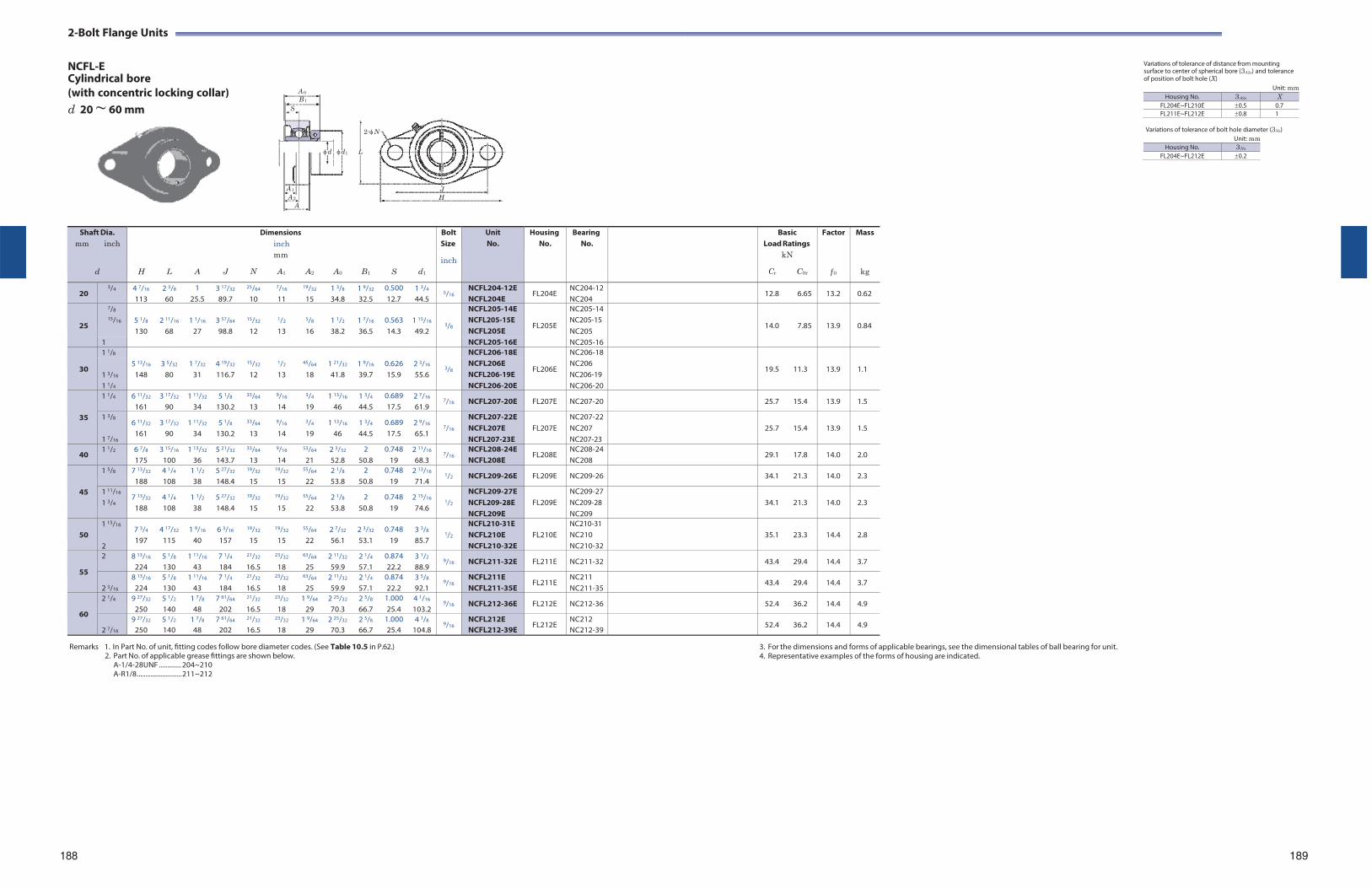
2-Bolt Flange Units
NCFL-E Cylindrical bore
Variations of tolerance of distance from mounting surface to center of spherical bore (3A2s) and tolerance of position of bolt hole (X)
(with concentric locking collar) d 20 ~ 60 mm
Unit: mm
Variations of tolerance of bolt hole diameter (3Ns) Unit: mm
Housing No. 3Ns
FL204E~FL212E 0.2
Remarks 1. In Part No. of unit, fitting codes follow bore diameter codes. (See Table 10.5 in P.62.)
2. Part No. of applicable grease fittings are shown below. A-1/4-28UNF ............. 204~210 A-R1/8 .......................... 211~212
3. For the dimensions and forms of applicable bearings, see the dimensional tables of ball bearing for unit. 4. Representative examples of the forms of housing are indicated.
188 189
Shaft Dia. mm inch
d
H
L
A
J
Dimensions inch mm
N A1 A2
A0
B1
S
d1
Bolt Size
inch
Unit No.
HousingNo.
BearingNo.
BasicLoad Ratings
kN
Cr C0r
Factor
f 0
Mass
kg
20 3/4 4 7/16
113 2 3/8
60 1
25.5 3 17/32
89.7
25/64
10
7/16
11
19/32
15 1 3/8
34.8 1 9/32
32.5 0.500 12.7
1 3/4
44.5 5/16
NCFL204-12E NCFL204E
FL204E NC204-12 NC204
12.8 6.65 13.2 0.62
25
7/8 5 1/8
130
2 11/16
68
1 1/16
27
3 57/64
98.8
15/32
12
1/2
13
5/8
16
1 1/2
38.2
1 7/16
36.5
0.563 14.3
1 15/16
49.2
3/8
NCFL205-14E
FL205E
NC205-14
14.0
7.85
13.9
0.84 15/16 NCFL205-15E
NCFL205E NC205-15 NC205
1 NCFL205-16E NC205-16
30
1 1/8 5 13/16
148
3 5/32
80
1 7/32
31
4 19/32
116.7
15/32
12
1/2
13
45/64
18
1 21/32
41.8
1 9/16
39.7
0.626 15.9
2 3/16
55.6
3/8
NCFL206-18E
FL206E
NC206-18
19.5
11.3
13.9
1.1 1 3/16
NCFL206E NCFL206-19E
NC206 NC206-19
1 1/4 NCFL206-20E NC206-20
35
1 1/4 6 11/32
161 3 17/32
90 1 11/32
34 5 1/8
130.2
33/64
13
9/16
14
3/4
19 1 13/16
46 1 3/4
44.5 0.689 17.5
2 7/16
61.9 7/16 NCFL207-20E FL207E NC207-20 25.7 15.4 13.9 1.5
1 3/8
1 7/16
6 11/32
161 3 17/32
90 1 11/32
34 5 1/8
130.2
33/64
13
9/16
14
3/4
19 1 13/16
46 1 3/4
44.5 0.689 17.5
2 9/16
65.1
7/16
NCFL207-22E NCFL207E NCFL207-23E
FL207E
NC207-22 NC207 NC207-23
25.7
15.4
13.9
1.5
40 1 1/2 6 7/8
175 3 15/16
100 1 13/32
36 5 21/32
143.7
33/64
13
9/16
14
53/64
21 2 3/32
52.8 2
50.8 0.748
19 2 11/16
68.3 7/16
NCFL208-24E NCFL208E
FL208E NC208-24 NC208
29.1 17.8 14.0 2.0
45
1 5/8 7 13/32
188 4 1/4
108 1 1/2
38 5 27/32
148.4
19/32
15
19/32
15
55/64
22 2 1/8
53.8 2
50.8 0.748
19 2 13/16
71.4 1/2 NCFL209-26E FL209E NC209-26 34.1 21.3 14.0 2.3
1 11/16
1 3/4 7 13/32
188 4 1/4
108 1 1/2
38 5 27/32
148.4
19/32
15
19/32
15
55/64
22 2 1/8
53.8 2
50.8 0.748
19 2 15/16
74.6
1/2
NCFL209-27E NCFL209-28E NCFL209E
FL209E
NC209-27 NC209-28 NC209
34.1
21.3
14.0
2.3
50
1 15/16
2
7 3/4
197 4 17/32
115 1 9/16
40 6 3/16
157
19/32
15
19/32
15
55/64
22 2 7/32
56.1 2 3/32
53.1 0.748
19 3 3/8
85.7
1/2
NCFL210-31E NCFL210E NCFL210-32E
FL210E
NC210-31 NC210 NC210-32
35.1
23.3
14.4
2.8
55
2 8 13/16
224 5 1/8
130 1 11/16
43 7 1/4
184
21/32
16.5
23/32
18
63/64
25 2 11/32
59.9 2 1/4
57.1 0.874 22.2
3 1/2
88.9 9/16 NCFL211-32E FL211E NC211-32 43.4 29.4 14.4 3.7
2 3/16
8 13/16
224 5 1/8
130 1 11/16
43 7 1/4
184
21/32
16.5
23/32
18
63/64
25 2 11/32
59.9 2 1/4
57.1 0.874 22.2
3 5/8
92.1 9/16
NCFL211E NCFL211-35E
FL211E NC211 NC211-35
43.4 29.4 14.4 3.7
60
2 1/4 9 27/32
250 5 1/2
140 1 7/8
48 7 61/64
202
21/32
16.5
23/32
18 1 9/64
29 2 25/32
70.3 2 5/8
66.7 1.000 25.4
4 1/16
103.2 9/16 NCFL212-36E FL212E NC212-36 52.4 36.2 14.4 4.9
2 7/16
9 27/32
250 5 1/2
140 1 7/8
48 7 61/64
202
21/32
16.5
23/32
18 1 9/64
29 2 25/32
70.3 2 5/8
66.7 1.000 25.4
4 1/8
104.8 9/16
NCFL212E NCFL212-39E
FL212E NC212 NC212-39
52.4 36.2 14.4 4.9
A 0
B 1S
d d1 L
A 1
A 2
A
2-N
J H
Housing No. 3A2s X FL204E~FL210E 0.5 0.7FL211E~FL212E 0.8 1
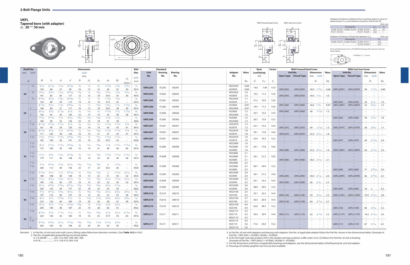
2-Bolt Flange Units
UKFL Tapered bore (with adapter)
With Pressed Steel Cover With Cast Iron Cover
Variations of tolerance of distance from mounting surface to center of spherical bore (3A2s) and tolerance of position of bolt hole (X)
Unit: mm
d1 20 ~ 50 mm AS AC A 0 A 0 A 0
B 1 B 1 B 1
d e d 1
2-N
L
d e d1
d e d1 1 2
Variations of tolerance of bolt hole diameter (3Ns) Unit: mm Housing No. 3Ns
FL205~FL218 FLX05~FLX10 FL305~FL311 0.2FL312~FL324 0.3
Forms and dimensions of Lc of FL205JE3 (housing with cast iron cover) are shown below.
A 1 J A 2 H
A
A 1 A 1
A 2 A2
A A
FL205JE3 Lc 73 mm
Lc
Remarks 1. In Part No. of unit and units with covers, fitting codes follow bore diameter numbers. (See Table 10.5 in P.62.)
2. Part No. of applicable grease fittings are shown below. A-1/4-28UNF ............. 205~210, X05~X09, 305~308 A-R1/8 .......................... 211~218, X10, 309~324
3. In Part No. of unit with adapters and bearing with adapters, Part No. of applicable adapter follow the Part No. shown in the dimensional tables. (Example of Part No. : UKFL206J H2306X, UK206 H2306X)
4. As for the triple seal type product (205 is the double seal type product), suffix code L3 (or L2) follows the Part No. of unit or bearing. (Example of Part No. : UKFL206JL3 H2306X, UK206L3 H2306X)
5. For the dimensions and forms of applicable bearings and adapters, see the dimensional tables of ball bearing for unit and adapter. 6. Housings of nodular graphite cast iron are also available.
190 191
Shaft Dia. mm inch
d1
Dimensions inch mm
de H L A J N A1 A2 A0 B1
(min.)
Bolt Size
inch mm
Standard BasicLoad Ratings
kN
Cr C0r
Factor
f 0
With Pressed Steel Cover With Cast Iron Cover Unit No.
Housing No.
Bearing No.
Adapter No.
Mass
kg
Unit No. Open Type Closed Type
Dimension mm inch
As
Mass
kg
Unit No. Open Type Closed Type
Dimension mm inch
Ac
Mass
kg
20
3/4 5 1/8 2 11/16 1 1/16 3 57/64 5/8 1/2 5/8 1 13/32 1 3/8 1 3/16
130 68 27 99 16 13 16 36 35 30
1/2
M14 UKFL205 FL205 UK205 HE2305X
H2305X0.68 0.68
14.0 7.85 13.9
UKFL205C UKFL205D
40.5 1 19/32
0.68
UKFL205FC UKFL205FD
49 1 15/16
0.89
3/4 5 9/16 3 9/32 1 3/16 4 39/64 15/32 1/2 45/64 1 9/16 1 3/8 1 3/16
141 83 30 117 12 13 18 39.5 35 30
3/8
M10 UKFLX05 FLX05 UKX05 HE2305X
H2305X 1.0 1.0
19.5 11.3 13.9
UKFLX05C UKFLX05D
44.5 1 3/4
1.0
3/4 5 29/32 3 5/32 1 5/32 4 29/64 3/4 1/2 5/8 1 15/32 1 3/8 150 80 29 113 19 13 16 37.5 35
5/8
M16 UKFL305 FL305 UK305 HE2305X
H2305X 1.1 1.1
21.2 10.9 12.6
UKFL305C UKFL305D
54 2 1/8
1.4
25
1
5 13/16 3 5/32 1 7/32 4 39/64 5/8 1/2 45/64 1 9/16 1 1/2 1 13/32
148 80 31 117 16 13 18 39.5 38 36
3/8
M14 UKFL206 FL206 UK206 H2306X
HE2306X 0.97 0.97
19.5 11.3 13.9 UKFL206C UKFL206D
44.5 1 3/4
0.97
UKFL206FC UKFL206FD
53 2 3/32
1.2
1
6 5/32 3 3/4 1 11/32 5 1/8 5/8 9/16 3/4 1 21/32 1 1/2 1 13/32
156 95 34 130 16 14 19 42 38 36
3/8
M14 UKFLX06 FLX06 UKX06 H2306X
HE2306X 1.5 1.5
25.7 15.4 13.9 UKFLX06C UKFLX06D
49 1 15/16
1.5
1
7 3/32 3 17/32 1 1/4 5 9/32 29/32 19/32 45/64 1 5/8 1 1/2 180 90 32 134 23 15 18 41 38
3/4
M20 UKFL306 FL306 UK306 H2306X
HE2306X 1.5 1.5
26.7 15.0 13.3
UKFL306C UKFL306D
59 2 5/16
1.8
30
1 1/8 6 11/32 3 17/32 1 11/32 5 1/8 5/8 9/16 3/4 1 11/16 1 11/16 1 5/8
161 90 34 130 16 14 19 43 43 41
3/8
M14 UKFL207 FL207 UK207 HS2307X
H2307X 1.3 1.3
25.7 15.4 13.9
UKFL207C UKFL207D
49 1 15/16
1.3
UKFL207FC UKFL207FD
58 2 9/32
1.7
1 1/8 6 23/32 4 1/8 1 1/2 5 43/64 5/8 9/16 53/64 1 27/32 1 11/16 1 5/8
171 105 38 144 16 14 21 47 43 41
3/8
M14 UKFLX07 FLX07 UKX07 HS2307X
H2307X 1.8 1.8
29.1 17.8 14.0
UKFLX07C UKFLX07D
55.5 2 3/16
1.8
1 1/8 7 9/32 3 15/16 1 13/32 5 35/64 29/32 5/8 25/32 1 25/32 1 11/16 185 100 36 141 23 16 20 45.5 43
3/4
M20 UKFL307 FL307 UK307 HS2307X
H2307X 1.9 1.9
33.4 19.3 13.2
UKFL307C UKFL307D
64 2 17/32
2.4
35
1 1/4
1 3/8 6 7/8 3 15/16 1 13/32 5 43/64 5/8 9/16 53/64 1 7/8 1 13/16 1 13/16
175 100 36 144 16 14 21 48 46 46
3/8
M14
UKFL208
FL208
UK208
HE2308X HS2308X H2308X
1.6 1.6 1.6
29.1 17.8
14.0
UKFL208C UKFL208D
55.5 2 3/16
1.6
UKFL208FC UKFL208FD
64 2 17/32
2.01 1/4
1 3/8 7 1/16 4 3/8 1 9/16 5 53/64 5/8 9/16 55/64 1 31/32 1 13/16 1 13/16
179 111 40 148 16 14 22 50 46 46
3/8
M14
UKFLX08
FLX08
UKX08
HE2308X HS2308X H2308X
2.1 2.1 2.1
34.1 21.3
14.0
UKFLX08C UKFLX08D
56.5 2 7/32
2.1
1 1/4
1 3/8 7 7/8 4 13/32 1 9/16 6 7/32 29/32 21/32 29/32 2 1 13/16 200 112 40 158 23 17 23 50.5 46
3/4
M20
UKFL308
FL308
UK308
HE2308X HS2308X H2308X
2.5 2.5 2.5
40.7 24.0
13.2
UKFL308C UKFL308D
71 2 25/32
3.0
40
1 1/2 7 13/32 4 1/4 1 1/2 5 53/64 3/4 19/32 55/64 2 1 31/32 2 1/16
188 108 38 148 19 15 22 51 50 52
5/8
M16 UKFL209 FL209 UK209 HE2309X
H2309X 2.0 2.0
34.1 21.3 14.0
UKFL209C UKFL209D
56.5 2 7/32
2.0
UKFL209FC UKFL209FD
66 2 19/32
2.5
1 1/2 7 7/16 4 9/16 1 9/16 6 3/16 5/8 9/16 29/32 2 1/16 1 31/32 2 1/16
189 116 40 157 16 14 23 52 50 52
3/8
M14 UKFLX09 FLX09 UKX09 HE2309X
H2309X 2.5 2.5
35.1 23.3 14.4
UKFLX09C UKFLX09D
60 2 3/8
2.5
1 1/2 9 1/16 4 29/32 1 23/32 6 31/32 63/64 23/32 63/64 2 5/32 1 31/32 230 125 44 177 25 18 25 55 50
7/8
M22 UKFL309 FL309 UK309 HE2309X
H2309X 3.6 3.6
48.9 29.5 13.3
UKFL309C UKFL309D
76 3
4.2
45
1 3/4 7 3/4 4 17/32 1 9/16 6 3/16 3/4 19/32 55/64 2 1/16 2 5/32 2 9/32
197 115 40 157 19 15 22 52 55 58
5/8
M16 UKFL210 FL210 UK210 HE2310X
H2310X 2.3 2.3
35.1 23.3 14.4
UKFL210C UKFL210D
59 2 5/16
2.3
UKFL210FC UKFL210FD
70.5 2 25/32
2.8
1 3/4 8 1/2 5 1/4 1 23/32 7 1/4 3/4 25/32 1 1/32 2 9/32 2 5/32 2 9/32
216 133 44 184 19 20 26 58 55 58
5/8
M16 UKFLX10 FLX10 UKX10 HE2310X
H2310X 3.7 3.7
43.4 29.4 14.4
UKFLX10C UKFLX10D
64 2 17/32
3.7
1 3/4 9 7/16 5 1/2 1 7/8 7 23/64 63/64 3/4 1 7/64 2 3/8 2 5/32 240 140 48 187 25 19 28 60 55
7/8
M22 UKFL310 FL310 UK310 HE2310X
H2310X 4.4 4.4
62.0 38.3 13.2
UKFL310C UKFL310D
83 3 9/32
5.2
50
1 7/8
2
8 13/16 5 1/8 1 11/16 7 1/4 3/4 23/32 63/64 2 1/4 2 5/16 2 17/32
224 130 43 184 19 18 25 57.5 59 64
5/8
M16
UKFL211
FL211
UK211
HS2311X H2311X HE2311X
3.3 3.3 3.3
43.4 29.4
14.4
UKFL211C UKFL211D
63 2 15/32
3.3
UKFL211FC UKFL211FD
74.5 2 15/16
3.9
1 7/8
2
9 27/32 5 29/32 2 1/16 7 51/64 63/64 25/32 1 3/16 2 17/32 2 5/16 250 150 52 198 25 20 30 64 59
7/8
M22
UKFL311
FL311
UK311
HS2311X H2311X HE2311X
5.6 5.6 5.6
71.6 45.0
13.2
UKFL311C UKFL311D
87 3 7/16
6.5
Housing No. 3A2s X FL205~FL210 FLX05~FLX10 FL305~FL310 0.5 0.7FL211~FL218 FL311~FL324 0.8 1
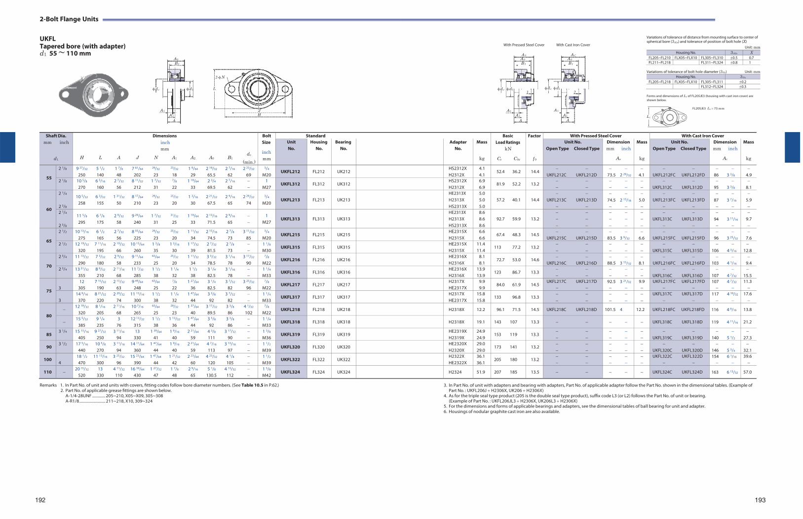
2- Bolt Flange Units
UKFL Tapered bore (with adapter)
With Pressed Steel Cover With Cast Iron Cover
Variations of tolerance of distance from mounting surface to center of spherical bore (3A2s) and tolerance of position of bolt hole (X)
Unit: mm
d1 55 ~ 110 mm AS AC A 0 A 0 A 0
B 1 B 1 B 1
d e d 1
2-N
L
d e d1
d e d1 1 2
Variations of tolerance of bolt hole diameter (3Ns) Unit: mm Housing No. 3Ns
FL205~FL218 FLX05~FLX10 FL305~FL311 0.2FL312~FL324 0.3
Forms and dimensions of Lc of FL205JE3 (housing with cast iron cover) are shown below.
A 1 J A 2 H
A
A 1 A 1
A 2 A2
A A
FL205JE3 Lc 73 mm
Lc
Remarks 1. In Part No. of unit and units with covers, fitting codes follow bore diameter numbers. (See Table 10.5 in P.62.)
2. Part No. of applicable grease fittings are shown below. A-1/4-28UNF ............. 205~210, X05~X09, 305~308 A-R1/8 .......................... 211~218, X10, 309~324
3. In Part No. of unit with adapters and bearing with adapters, Part No. of applicable adapter follow the Part No. shown in the dimensional tables. (Example of Part No. : UKFL206J H2306X, UK206 H2306X)
4. As for the triple seal type product (205 is the double seal type product), suffix code L3 (or L2) follows the Part No. of unit or bearing. (Example of Part No. : UKFL206JL3 H2306X, UK206L3 H2306X)
5. For the dimensions and forms of applicable bearings and adapters, see the dimensional tables of ball bearing for unit and adapter. 6. Housings of nodular graphite cast iron are also available.
192 193
Shaft Dia. mm inch
d1
Dimensions inch mm
de H L A J N A1 A2 A0 B1
(min.)
Bolt Size
inch mm
Standard BasicLoad Ratings
kN
Cr C0r
Factor
f 0
With Pressed Steel Cover With Cast Iron Cover Unit No.
Housing No.
Bearing No.
Adapter No.
Mass
kg
Unit No. Open Type Closed Type
Dimension mm inch
As
Mass
kg
Unit No. Open Type Closed Type
Dimension mm inch
Ac
Mass
kg
55
2 1/8 9 27/32 5 1/2 1 7/8 7 61/64 29/32 23/32 1 9/64 2 19/32 2 7/16 2 23/32
250 140 48 202 23 18 29 65.5 62 69
3/4
M20 UKFL212 FL212 UK212 HS2312X
H2312X4.1 4.1
52.4 36.2 14.4
UKFL212C UKFL212D
73.5 2 29/32
4.1
UKFL212FC UKFL212FD
86 3 3/8
4.9
2 1/8 10 5/8 6 5/16 2 7/32 8 11/32 1 7/32 7/8 1 19/64 2 3/4 2 7/16 270 160 56 212 31 22 33 69.5 62
1 M27
UKFL312 FL312 UK312 HS2312X H2312X
6.9 6.9
81.9 52.2 13.2
UKFL312C UKFL312D
95 3 3/8
8.1
60
2 1/4
2 3/8
10 5/32 6 3/32 1 31/32 8 17/64 29/32 25/32 1 3/16 2 21/32 2 9/16 2 29/32
258 155 50 210 23 20 30 67.5 65 74
3/4
M20
UKFL213
FL213
UK213
HE2313X H2313X HS2313X
5.0 5.0 5.0
57.2 40.1
14.4
UKFL213C UKFL213D
74.5 2 15/16
5.0
UKFL213FC UKFL213FD
87 3 7/16
5.9
2 1/4
2 3/8
11 5/8 6 7/8 2 9/32 9 29/64 1 7/32 31/32 1 19/64 2 13/16 2 9/16 295 175 58 240 31 25 33 71.5 65
1 M27
UKFL313
FL313
UK313
HE2313X H2313X HS2313X
8.6 8.6 8.6
92.7 59.9
13.2
UKFL313C UKFL313D
94 3 11/16
9.7
65
2 1/2 10 13/16 6 1/2 2 7/32 8 55/64 29/32 25/32 1 11/32 2 15/16 2 7/8 3 11/32
275 165 56 225 23 20 34 74.5 73 85
3/4
M20 UKFL215 FL215 UK215 HE2315X
H2315X 6.6 6.6
67.4 48.3 14.5
UKFL215C UKFL215D
83.5 3 9/32
6.6
UKFL215FC UKFL215FD
96 3 25/32
7.6
2 1/2 12 19/32 7 11/16 2 19/32 10 15/64 1 3/8 1 3/16 1 17/32 2 7/32 2 7/8 320 195 66 260 35 30 39 81.5 73
1 1/8
M30 UKFL315 FL315 UK315 HE2315X
H2315X 11.4 11.4
113 77.2 13.2
UKFL315C UKFL315D
106 4 3/16
12.8
70
2 3/4 11 13/32 7 3/32 2 9/32 9 11/64 63/64 25/32 1 11/32 3 3/32 3 1/16 3 17/32
290 180 58 233 25 20 34 78.5 78 90
7/8
M22 UKFL216 FL216 UK216 HE2316X
H2316X 8.1 8.1
72.7 53.0 14.6
UKFL216C UKFL216D
88.5 3 15/32
8.1
UKFL216FC UKFL216FD
103 4 1/16
9.4
2 3/4 13 31/32 8 9/32 2 11/16 11 7/32 1 1/2 1 1/4 1 1/2 3 1/4 3 1/16 355 210 68 285 38 32 38 82.5 78
1 1/4
M33 UKFL316 FL316 UK316 HE2316X
H2316X 13.9 13.9
123 86.7 13.3
UKFL316C UKFL316D
107 4 7/32
15.5
75
3
12 7 15/32 2 15/32 9 49/64 63/64 7/8 1 27/64 3 1/4 3 7/32 3 25/32
305 190 63 248 25 22 36 82.5 82 96
7/8
M22 UKFL217 FL217 UK217 H2317X
HE2317X 9.9 9.9
84.0 61.9 14.5 UKFL217C UKFL217D
92.5 3 21/32
9.9
UKFL217FC UKFL217FD
107 4 7/32
11.3
3
14 9/16 8 21/32 2 29/32 11 13/16 1 1/2 1 1/4 1 47/64 3 5/8 3 7/32 370 220 74 300 38 32 44 92 82
1 1/4
M33 UKFL317 FL317 UK317 H2317X
HE2317X 15.8 15.8
133 96.8 13.3
UKFL317C UKFL317D
117 4 19/32
17.6
80
12 19/32 8 1/16 2 11/16 10 7/16 63/64 29/32 1 37/64 3 17/32 3 3/8 4 1/32
320 205 68 265 25 23 40 89.5 86 102
7/8
M22 UKFL218 FL218 UK218 H2318X 12.2 96.1 71.5 14.5 UKFL218C UKFL218D 101.5 4 12.2 UKFL218FC UKFL218FD 116 4 9/16 13.8
15 5/32 9 1/4 3 12 13/32 1 1/2 1 13/32 1 47/64 3 5/8 3 3/8
385 235 76 315 38 36 44 92 86 1 1/4
M33 UKFL318 FL318 UK318 H2318X 19.1 143 107 13.3 UKFL318C UKFL318D 119 4 11/16 21.2
85 3 1/4 15 15/16 9 27/32 3 11/16 13 1 39/64 1 9/16 2 21/64 4 3/8 3 17/32
405 250 94 330 41 40 59 111 90 1 3/8
M36 UKFL319 FL319 UK319 HE2319X
H2319X 24.9 24.9
153 119 13.3
UKFL319C UKFL319D
140 5 1/2
27.3
90 3 1/2 17 5/16 10 5/8 3 11/16 14 11/64 1 47/64 1 9/16 2 21/64 4 7/16 3 13/16
440 270 94 360 44 40 59 113 97 1 1/2
M39 UKFL320 FL320 UK320 HE2320X
H2320X 29.0 29.0
173 141 13.2
UKFL320C UKFL320D
146 5 3/4
32.1
100 4
18 1/2 11 13/16 3 25/32 15 23/64 1 47/64 1 21/32 2 23/64 4 23/32 4 1/8 470 300 96 390 44 42 60 120 105
1 1/2
M39 UKFL322 FL322 UK322 H2322X
HE2322X 36.1 36.1
205 180 13.2
UKFL322C UKFL322D
154 6 1/16
39.6
110 20 15/32 13 4 11/32 16 59/64 1 27/32 1 7/8 2 9/16 5 1/8 4 13/32
520 330 110 430 47 48 65 130.5 112 1 5/8
M42 UKFL324 FL324 UK324 H2324 51.9 207 185 13.5 UKFL324C UKFL324D 163 6 13/32 57.0
Housing No. 3A2s X FL205~FL210 FLX05~FLX10 FL305~FL310 0.5 0.7FL211~FL218 FL311~FL324 0.8 1
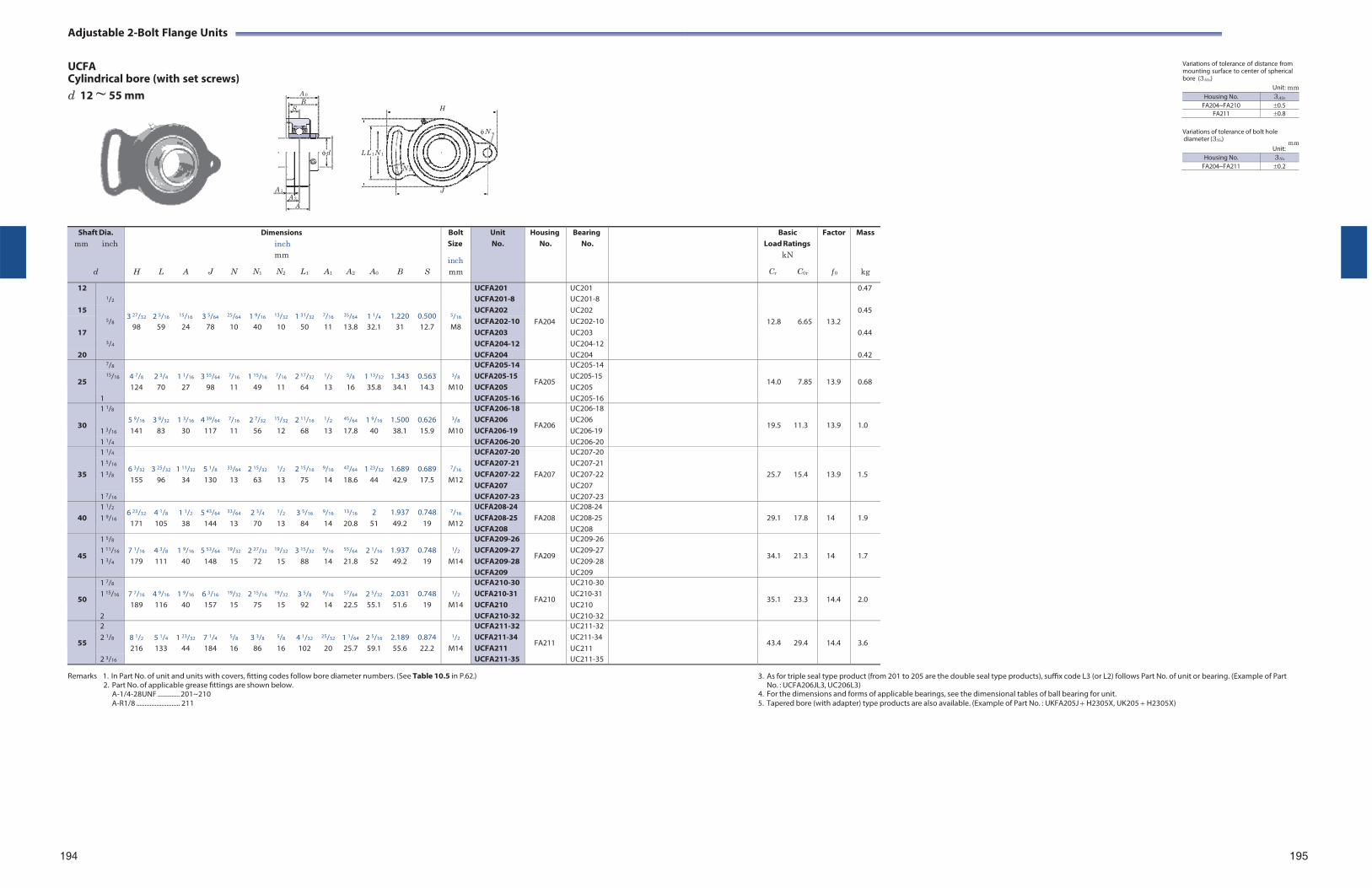
Adjustable 2-Bolt Flange Units
UCFA Cylindrical bore (with set screws) d 12 ~ 55 mm
H
Variations of tolerance of distance from mounting surface to center of spherical bore (3A2s)
Unit: mm
N Variations of tolerance of bolt hole diameter (3Ns) mm
LL 1 N 1
N 2
J
Unit:
Remarks 1. In Part No. of unit and units with covers, fitting codes follow bore diameter numbers. (See Table 10.5 in P.62.)
2. Part No. of applicable grease fittings are shown below. A-1/4-28UNF ............. 201~210 A-R1/8 .......................... 211
3. As for triple seal type product (from 201 to 205 are the double seal type products), suffix code L3 (or L2) follows Part No. of unit or bearing. (Example of Part No. : UCFA206JL3, UC206L3)
4. For the dimensions and forms of applicable bearings, see the dimensional tables of ball bearing for unit. 5. Tapered bore (with adapter) type products are also available. (Example of Part No. : UKFA205J H2305X, UK205 H2305X)
194 195
Shaft Dia. mm inch
d
H
L
A
J
N
Dimensions inch mm
N1 N2 L1
A1
A2
A0
B
S
Bolt Size
inch mm
Unit No.
HousingNo.
BearingNo.
BasicLoad Ratings
kN
Cr C0r
Factor
f 0
Mass
kg
12 1/2
3 27/32
2 5/16
15/16
3 5/64
25/64
1 9/16
13/32
1 31/32
7/16
35/64
1 1/4
1.220
0.500
5/16
UCFA201
FA204
UC201
12.8
6.65
13.2
0.47 UCFA201-8 UC201-8
15 5/8
UCFA202 UC202 0.45 UCFA202-10 UC202-10
98 59 24 78 10 40 10 50 11 13.8 32.1 31 12.7 M8 17 UCFA203 UC203 0.44
3/4 UCFA204-12 UC204-12 20 UCFA204 UC204 0.42
25
7/8 4 7/8
2 3/4
1 1/16
3 55/64
7/16
1 15/16
7/16
2 17/32
1/2
5/8
1 13/32
1.343
0.563
3/8
UCFA205-14
FA205
UC205-14
14.0
7.85
13.9
0.68 15/16 UCFA205-15
UCFA205 UC205-15 UC205 124 70 27 98 11 49 11 64 13 16 35.8 34.1 14.3 M10
1 UCFA205-16 UC205-16
30
1 1/8 5 9/16
3 9/32
1 3/16
4 39/64
7/16
2 7/32
15/32
2 11/16
1/2
45/64
1 9/16
1.500
0.626
3/8
UCFA206-18
FA206
UC206-18
19.5
11.3
13.9
1.0 1 3/16
UCFA206 UCFA206-19
UC206 UC206-19 141 83 30 117 11 56 12 68 13 17.8 40 38.1 15.9 M10
1 1/4 UCFA206-20 UC206-20
35
1 1/4
6 3/32
3 25/32
1 11/32
5 1/8
33/64
2 15/32
1/2
2 15/16
9/16
47/64
1 23/32
1.689
0.689
7/16
UCFA207-20
FA207
UC207-20
25.7
15.4
13.9
1.5 1 5/16 UCFA207-21 UC207-21 1 3/8 UCFA207-22 UC207-22
155 96 34 130 13 63 13 75 14 18.6 44 42.9 17.5 M12 UCFA207 UC207
1 7/16 UCFA207-23 UC207-23
40 1 1/2
1 9/16 6 23/32
171 4 1/8
105 1 1/2
38 5 43/64
144
33/64
13 2 3/4
70
1/2
13 3 5/16
84
9/16
14
13/16
20.8 2
51 1.937 49.2
0.748 19
7/16
M12
UCFA208-24 UCFA208-25 UCFA208
FA208
UC208-24 UC208-25 UC208
29.1
17.8
14
1.9
45
1 5/8 7 1/16
4 3/8
1 9/16
5 53/64
19/32
2 27/32
19/32
3 15/32
9/16
55/64
2 1/16
1.937
0.748
1/2
UCFA209-26
FA209
UC209-26
34.1
21.3
14
1.7 1 11/16 UCFA209-27 UC209-27 1 3/4 179 111 40 148 15 72 15 88 14 21.8 52 49.2 19 M14 UCFA209-28 UC209-28
UCFA209 UC209
50
1 7/8 7 7/16
4 9/16
1 9/16
6 3/16
19/32
2 15/16
19/32
3 5/8
9/16
57/64
2 5/32
2.031
0.748
1/2
UCFA210-30
FA210
UC210-30
35.1
23.3
14.4
2.0 1 15/16 UCFA210-31
UCFA210 UC210-31 UC210 189 116 40 157 15 75 15 92 14 22.5 55.1 51.6 19 M14
2 UCFA210-32 UC210-32
55
2 8 1/2
5 1/4
1 23/32
7 1/4
5/8
3 3/8
5/8
4 1/32
25/32
1 1/64
2 5/16
2.189
0.874
1/2
UCFA211-32
FA211
UC211-32
43.4
29.4
14.4
3.6 2 1/8 UCFA211-34
UCFA211 UC211-34 UC211 216 133 44 184 16 86 16 102 20 25.7 59.1 55.6 22.2 M14
2 3/16 UCFA211-35 UC211-35
A 0
B S
d
A 1A 2
A
Housing No. 3A2s
FA204~FA210 0.5FA211 0.8
Housing No. 3Ns
FA204~FA211 0.2
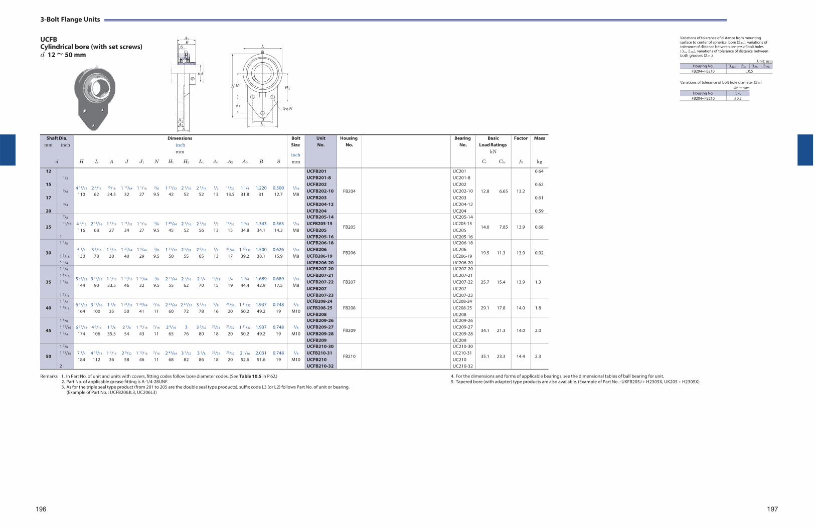
3- Bolt Flange Units
UCFB Cylindrical bore (with set screws) d 12 ~ 50 mm
L
Variations of tolerance of distance from mounting surface to center of spherical bore (3A2s), variations of tolerance of distance between centers of bolt holes (3Js, 3J1s), variations of tolerance of distance between both grooves (3H1s)
Unit: mm Housing No. 3A2s 3Js 3J1s 3H1s
FB204~FB210 0.5
H H 1
J 1
J
L 1
H 2
3-N
Variations of tolerance of bolt hole diameter (3Ns) Unit: mm
Remarks 1. In Part No. of unit and units with covers, fitting codes follow bore diameter codes. (See Table 10.5 in P.62.)
2. Part No. of applicable grease fitting is A-1/4-28UNF. 3. As for the triple seal type product (from 201 to 205 are the double seal type products), suffix code L3 (or L2) follows Part No. of unit or bearing.
(Example of Part No. : UCFB206JL3, UC206L3)
4. For the dimensions and forms of applicable bearings, see the dimensional tables of ball bearing for unit. 5. Tapered bore (with adapter) type products are also available. (Example of Part No. : UKFB205J H2305X, UK205 H2305X)
196 197
Shaft Dia. mm inch
d
H
L
A
J
J1
N
Dimensions inch mm
H1 H2
L1
A1
A2
A0
B
S
Bolt Size
inch mm
Unit No.
HousingNo.
BearingNo.
BasicLoad Ratings
kN
Cr C0r
Factor
f 0
Mass
kg
12 1/2
4 11/32
2 7/16
15/16
1 17/64
1 1/16
3/8
1 21/32
2 1/16
2 1/16
1/2
17/32
1 1/4
1.220
0.500
5/16
UCFB201
FB204
UC201
12.8
6.65
13.2
0.64 UCFB201-8 UC201-8
15 5/8
UCFB202 UC202 0.62 UCFB202-10 UC202-10
110 62 24.5 32 27 9.5 42 52 52 13 13.5 31.8 31 12.7 M8 17 UCFB203 UC203 0.61
3/4 UCFB204-12 UC204-12 20 UCFB204 UC204 0.59
25
7/8 4 9/16
2 11/16
1 1/16
1 11/32
1 1/16
3/8
1 49/64
2 1/16
2 7/32
1/2
19/32
1 3/8
1.343
0.563
5/16
UCFB205-14
FB205
UC205-14
14.0
7.85
13.9
0.68 15/16 UCFB205-15
UCFB205 UC205-15 UC205 116 68 27 34 27 9.5 45 52 56 13 15 34.8 34.1 14.3 M8
1 UCFB205-16 UC205-16
30
1 1/8 5 1/8
3 1/16
1 3/16
1 37/64
1 9/64
3/8
1 31/32
2 5/32
2 9/16
1/2
43/64
1 17/32
1.500
0.626
5/16
UCFB206-18
FB206
UC206-18
19.5
11.3
13.9
0.92 1 3/16
UCFB206 UCFB206-19
UC206 UC206-19 130 78 30 40 29 9.5 50 55 65 13 17 39.2 38.1 15.9 M8
1 1/4 UCFB206-20 UC206-20
35
1 1/4 5 21/32
3 17/32
1 5/16
1 13/16
1 17/64
3/8
2 11/64
2 7/16
2 3/4
19/32
3/4
1 3/4
1.689
0.689
5/16
UCFB207-20
FB207
UC207-20
25.7
15.4
13.9
1.3
1 5/16 UCFB207-21 UC207-21 1 3/8 UCFB207-22 UC207-22
144 90 33.5 46 32 9.5 55 62 70 15 19 44.4 42.9 17.5 M8 UCFB207 UC207
1 7/16 UCFB207-23 UC207-23
40 1 1/2
1 9/16 6 15/32
164 3 15/16
100 1 3/8
35 1 31/32
50 1 39/64
41
7/16
11 2 23/64
60 2 27/32
72 3 1/16
78
5/8
16
25/32
20 1 31/32
50.2 1.937 49.2
0.748 19
3/8
M10
UCFB208-24 UCFB208-25 UCFB208
FB208
UC208-24 UC208-25 UC208
29.1
17.8
14.0
1.8
45
1 5/8 6 27/32
4 3/16
1 3/8
2 1/8
1 11/16
7/16
2 9/16
3
3 5/32
23/32
25/32
1 31/32
1.937
0.748
3/8
UCFB209-26
FB209
UC209-26
34.1
21.3
14.0
2.0 1 11/16 UCFB209-27 UC209-27 1 3/4 174 106 35.5 54 43 11 65 76 80 18 20 50.2 49.2 19 M10 UCFB209-28 UC209-28
UCFB209 UC209
50
1 7/8 7 1/4
4 13/32
1 7/16
2 9/32
1 13/16
7/16
2 43/64
3 7/32
3 3/8
23/32
25/32
2 1/16
2.031
0.748
3/8
UCFB210-30
FB210
UC210-30
35.1
23.3
14.4
2.3 1 15/16 UCFB210-31
UCFB210 UC210-31 UC210 184 112 36 58 46 11 68 82 86 18 20 52.6 51.6 19 M10
2 UCFB210-32 UC210-32
A 0
B S
d
A 1
A 2
A
Housing No. 3Ns
FB204~FB210 0.2
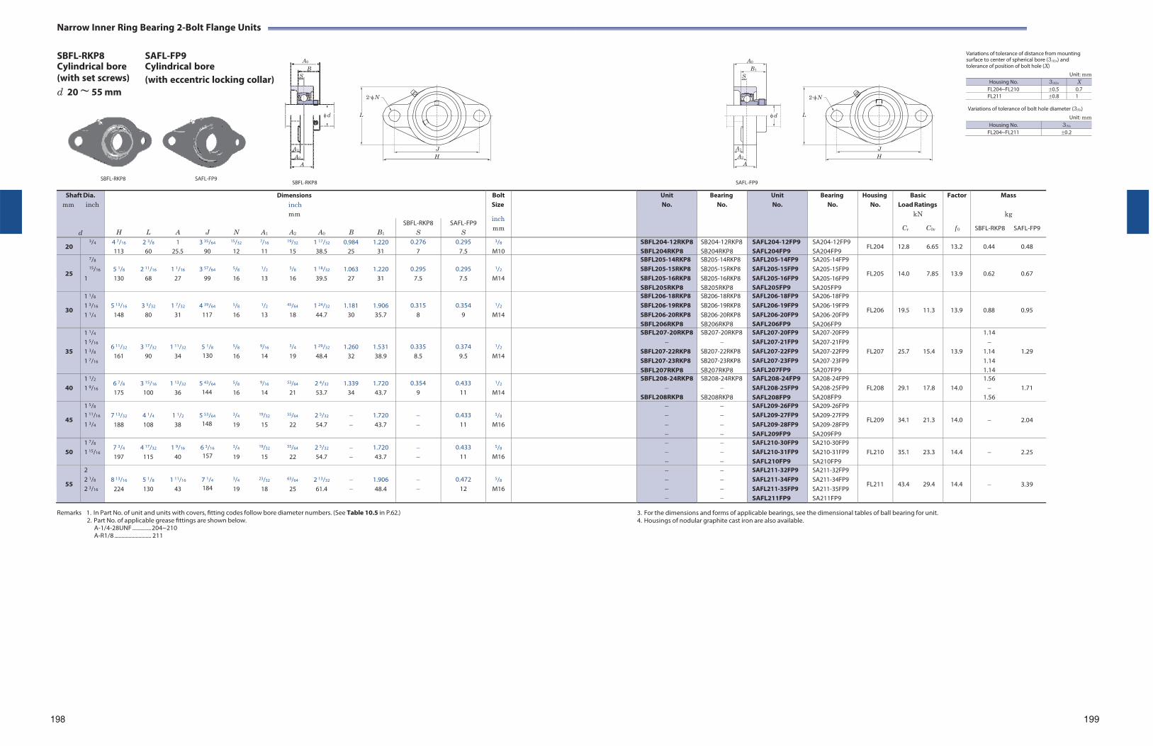
A0
B1
S
d
A1
A2
A
Narrow Inner Ring Bearing 2-Bolt Flange Units
SBFL-RKP8 Cylindrical bore
SAFL-FP9 Cylindrical bore
Variations of tolerance of distance from mounting surface to center of spherical bore (3A2s) and tolerance of position of bolt hole (X)
(with set screws) d 20 ~ 55 mm
(with eccentric locking collar)
2-N
2-N
Unit: mm
Variations of tolerance of bolt hole diameter (3Ns) L L Unit: mm
Housing No. 3Ns
FL204~FL211 0.2
J H
J H
SBFL-RKP8 SAFL-FP9
SBFL-RKP8
SAFL-FP9
Remarks 1. In Part No. of unit and units with covers, fitting codes follow bore diameter numbers. (See Table 10.5 in P.62.)
2. Part No. of applicable grease fittings are shown below. A-1/4-28UNF ............. 204~210 A-R1/8 .......................... 211
3. For the dimensions and forms of applicable bearings, see the dimensional tables of ball bearing for unit. 4. Housings of nodular graphite cast iron are also available.
198
199
Shaft Dia. mm inch
d
Dimensions inch mm
BoltSize
inch mm
UnitNo.
BearingNo.
UnitNo.
Bearing No.
Housing No.
Basic Load Ratings
kN
Cr C0r
Factor
f 0
Mass
kg
SBFL-RKP8 SAFL-FP9
H L A J N A1 A2 A0 B B1
SBFL-RKP8 S
SAFL-FP9 S
20 3/4 4 7/16 2 3/8 1 3 35/64 15/32 7/16 19/32 1 17/32 0.984 1.220
113 60 25.5 90 12 11 15 38.5 25 31 0.276
7 0.295
7.5
3/8
M10 SBFL204-12RKP8
SBFL204RKP8SB204-12RKP8 SB204RKP8
SAFL204-12FP9 SAFL204FP9
SA204-12FP9 SA204FP9
FL204 12.8 6.65 13.2 0.44 0.48
25
7/8
15/16
1
5 1/8 2 11/16 1 1/16 3 57/64 5/8 1/2 5/8 1 18/32 1.063 1.220 130 68 27 99 16 13 16 39.5 27 31
0.295
7.5
0.295
7.5
1/2
M14
SBFL205-14RKP8 SBFL205-15RKP8 SBFL205-16RKP8 SBFL205RKP8
SB205-14RKP8 SB205-15RKP8 SB205-16RKP8 SB205RKP8
SAFL205-14FP9 SAFL205-15FP9 SAFL205-16FP9 SAFL205FP9
SA205-14FP9 SA205-15FP9 SA205-16FP9 SA205FP9
FL205
14.0 7.85
13.9
0.62 0.67
30
1 1/8
1 3/16
1 1/4
5 13/16 3 5/32 1 7/32 4 39/64 5/8 1/2 45/64 1 24/32 1.181 1.906
148 80 31 117 16 13 18 44.7 30 35.7
0.315
8
0.354
9
1/2
M14
SBFL206-18RKP8 SBFL206-19RKP8 SBFL206-20RKP8 SBFL206RKP8
SB206-18RKP8 SB206-19RKP8 SB206-20RKP8 SB206RKP8
SAFL206-18FP9 SAFL206-19FP9 SAFL206-20FP9 SAFL206FP9
SA206-18FP9 SA206-19FP9 SA206-20FP9 SA206FP9
FL206
19.5 11.3
13.9
0.88 0.95
35
1 1/4
1 5/16
1 3/8
1 7/16
6 11/32 3 17/32 1 11/32 5 1/8 5/8 9/16 3/4 1 29/32 1.260 1.531 161 90 34 130 16 14 19 48.4 32 38.9
0.335 8.5
0.374 9.5
1/2
M14
SBFL207-20RKP8
SBFL207-22RKP8 SBFL207-23RKP8 SBFL207RKP8
SB207-20RKP8
SB207-22RKP8 SB207-23RKP8 SB207RKP8
SAFL207-20FP9 SAFL207-21FP9 SAFL207-22FP9 SAFL207-23FP9 SAFL207FP9
SA207-20FP9 SA207-21FP9 SA207-22FP9 SA207-23FP9 SA207FP9
FL207
25.7 15.4
13.9
1.14
1.14 1.29 1.14 1.14
40
1 1/2
1 9/16 6 7/8 3 15/16 1 13/32 5 43/64 5/8 9/16 53/64 2 4/32 1.339 1.720 175 100 36 144 16 14 21 53.7 34 43.7
0.354 9
0.433 11
1/2
M14
SBFL208-24RKP8
SBFL208RKP8
SB208-24RKP8
SB208RKP8
SAFL208-24FP9 SAFL208-25FP9 SAFL208FP9
SA208-24FP9 SA208-25FP9 SA208FP9
FL208
29.1 17.8
14.0
1.56 1.71
1.56
45
1 5/8
1 11/16
1 3/4
7 13/32 4 1/4 1 1/2 5 53/64 3/4 19/32 55/64 2 5/32 1.720
188 108 38 148 19 15 22 54.7 43.7
0.433
11
5/8
M16
SAFL209-26FP9 SAFL209-27FP9 SAFL209-28FP9 SAFL209FP9
SA209-26FP9 SA209-27FP9 SA209-28FP9 SA209FP9
FL209
34.1 21.3
14.0
2.04
50
1 7/8
1 15/16 7 3/4 4 17/32 1 9/16 6 3/16 3/4 19/32 55/64 2 5/32 1.720 197 115 40 157 19 15 22 54.7 43.7
0.433 11
5/8
M16
SAFL210-30FP9 SAFL210-31FP9 SAFL210FP9
SA210-30FP9 SA210-31FP9 SA210FP9
FL210
35.1 23.3
14.4
2.25
55
2 2 1/8
2 3/16
8 13/16 5 1/8 1 11/16 7 1/4 3/4 23/32 63/64 2 13/32 1.906
224 130 43 184 19 18 25 61.4 48.4
0.472
12
5/8
M16
SAFL211-32FP9 SAFL211-34FP9 SAFL211-35FP9 SAFL211FP9
SA211-32FP9 SA211-34FP9 SA211-35FP9 SA211FP9
FL211
43.4 29.4
14.4
3.39
A0
B S
d
A1
A2
A
Housing No. 3A2s X FL204~FL210 0.5 0.7FL211 0.8 1
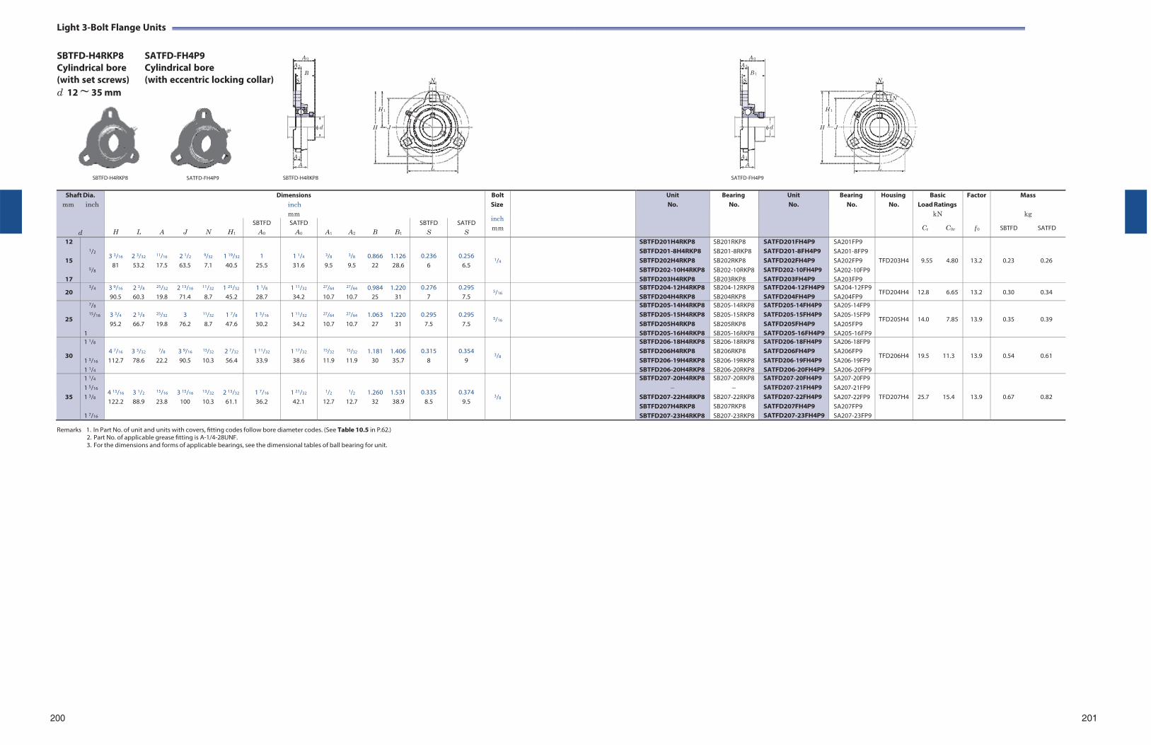
A 0
A 2
B S
d
A 1
A
A 0A 2
B 1S
d
A 1A
Light 3-Bolt Flange Units
SBTFD-H4RKP8 Cylindrical bore (with set screws) d 12 ~ 35 mm
SATFD-FH4P9 Cylindrical bore (with eccentric locking collar) N N
N N
H 1 H 1
H J H J
SBTFD-H4RKP8
L
SBTFD-H4RKP8
L
SATFD-FH4P9
Remarks 1. In Part No. of unit and units with covers, fitting codes follow bore diameter codes. (See Table 10.5 in P.62.)
2. Part No. of applicable grease fitting is A-1/4-28UNF. 3. For the dimensions and forms of applicable bearings, see the dimensional tables of ball bearing for unit.
200 201
Shaft Dia. mm inch
d
Dimensions inch mm
BoltSize
inch mm
UnitNo.
BearingNo.
UnitNo.
Bearing No.
Housing No.
BasicLoad Ratings
kN
Cr C0r
Factor
f 0
Mass
kg
SBTFD SATFD
H L A J N H1
SBTFD A0
SATFD A0
A1 A2 B B1
SBTFD S
SATFD S
12
15
17
1/2
5/8
3 3/16 2 3/32 11/16 2 1/2 9/32 1 19/32
81 53.2 17.5 63.5 7.1 40.5
1 25.5
1 1/4
31.6
3/8 3/8 0.866 1.126 9.5 9.5 22 28.6
0.236 6
0.256 6.5
1/4
SBTFD201H4RKP8 SBTFD201-8H4RKP8 SBTFD202H4RKP8 SBTFD202-10H4RKP8 SBTFD203H4RKP8
SB201RKP8 SB201-8RKP8 SB202RKP8 SB202-10RKP8 SB203RKP8
SATFD201FH4P9 SATFD201-8FH4P9 SATFD202FH4P9 SATFD202-10FH4P9 SATFD203FH4P9
SA201FP9 SA201-8FP9 SA202FP9 SA202-10FP9 SA203FP9
TFD203H4
9.55 4.80
13.2
0.23 0.26
20 3/4 3 9/16 2 3/8 25/32 2 13/16 11/32 1 25/32
90.5 60.3 19.8 71.4 8.7 45.2 1 1/8
28.7 1 11/32
34.2
27/64 27/64 0.984 1.220 10.7 10.7 25 31
0.276 7
0.295 7.5
5/16 SBTFD204-12H4RKP8 SBTFD204H4RKP8
SB204-12RKP8 SB204RKP8
SATFD204-12FH4P9 SATFD204FH4P9
SA204-12FP9 SA204FP9
TFD204H4 12.8 6.65 13.2 0.30 0.34
25
7/8
15/16
1
3 3/4 2 5/8 25/32 3 11/32 1 7/8
95.2 66.7 19.8 76.2 8.7 47.6
1 3/16
30.2
1 11/32
34.2
27/64 27/64 1.063 1.220 10.7 10.7 27 31
0.295
7.5
0.295
7.5
5/16
SBTFD205-14H4RKP8 SBTFD205-15H4RKP8 SBTFD205H4RKP8 SBTFD205-16H4RKP8
SB205-14RKP8 SB205-15RKP8 SB205RKP8 SB205-16RKP8
SATFD205-14FH4P9 SATFD205-15FH4P9 SATFD205FH4P9 SATFD205-16FH4P9
SA205-14FP9 SA205-15FP9 SA205FP9 SA205-16FP9
TFD205H4
14.0 7.85
13.9
0.35 0.39
30
1 1/8
1 3/16
1 1/4
4 7/16 3 3/32 7/8 3 9/16 13/32 2 7/32
112.7 78.6 22.2 90.5 10.3 56.4
1 11/32
33.9
1 17/32
38.6
15/32 15/32 1.181 1.406 11.9 11.9 30 35.7
0.315
8
0.354
9
3/8
SBTFD206-18H4RKP8 SBTFD206H4RKP8 SBTFD206-19H4RKP8 SBTFD206-20H4RKP8
SB206-18RKP8 SB206RKP8 SB206-19RKP8 SB206-20RKP8
SATFD206-18FH4P9 SATFD206FH4P9 SATFD206-19FH4P9 SATFD206-20FH4P9
SA206-18FP9 SA206FP9 SA206-19FP9 SA206-20FP9
TFD206H4
19.5 11.3
13.9
0.54 0.61
35
1 1/4
1 5/16
1 3/8
1 7/16
4 13/16 3 1/2 15/16 3 15/16 13/32 2 13/32
122.2 88.9 23.8 100 10.3 61.1
1 7/16
36.2
1 21/32
42.1
1/2 1/2 1.260 1.531 12.7 12.7 32 38.9
0.335 8.5
0.374 9.5
3/8
SBTFD207-20H4RKP8
SBTFD207-22H4RKP8 SBTFD207H4RKP8 SBTFD207-23H4RKP8
SB207-20RKP8
SB207-22RKP8 SB207RKP8 SB207-23RKP8
SATFD207-20FH4P9 SATFD207-21FH4P9 SATFD207-22FH4P9 SATFD207FH4P9 SATFD207-23FH4P9
SA207-20FP9 SA207-21FP9 SA207-22FP9 SA207FP9 SA207-23FP9
TFD207H4
25.7 15.4
13.9
0.67 0.82
SATFD-FH4P9
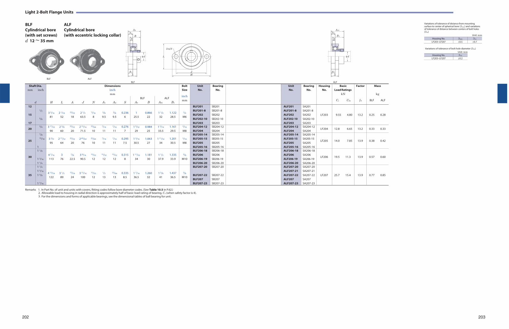
Light 2-Bolt Flange Units
BLF Cylindrical bore (with set screws) d 12 ~ 35 mm
ALF Cylindrical bore (with eccentric locking collar)
Variations of tolerance of distance from mounting surface to center of spherical bore (3A2s) and variations of tolerance of distance between centers of bolt holes (3Js)
Unit: mm
Variations of tolerance of bolt hole diameter (3Ns) Unit: mm
Housing No. 3Ns
LF203~LF207 0.2
BLF ALF
BLF
ALF
Remarks 1. In Part No. of unit and units with covers, fitting codes follow bore diameter codes. (See Table 10.5 in P.62.)
2. Allowable load to housing in radial direction is approximately half of basic load rating of bearing, Cr (when safety factor is 4). 3. For the dimensions and forms of applicable bearings, see the dimensional tables of ball bearing for unit.
202 203
Shaft Dia. Dimensions Bolt Unit Bearing Unit Bearing Housing Basic Factor Mass mm inch inch Size No. No. No. No. No. Load Ratings
d
mm inch
kN kg
H
L
A
J
N
A1
A2
S
BLF A0 B
ALF A01 B1
mm Cr C0r f 0 BLF ALF
12 1/2
3 3/16
2 1/16
23/32
2 1/2
5/16
3/8
3/8
0.236
1 0.866
1 1/4
1.122
1/4
BLF201 SB201 ALF201 SA201
LF203
9.55
4.80
13.2
0.25
0.28
15
BLF201-8 BLF202 BLF202-10
SB201-8 SB202 SB202-10
ALF201-8 ALF202 ALF202-10
SA201-8 SA202 SA202-10 5/8
81 52 18 63.5 8 9.5 9.5 6 25.5 22 32 28.5 M6
17 BLF203 SB203 ALF203 SA203
20 3/4 3 17/32
90 2 3/8
60
25/32
20 2 13/16
71.5
25/64
10
7/16
11
7/16
11 0.276
7 1 5/32 0.984
29 25 1 5/16
33.5 1.161 29.5
5/16
M8 BLF204-12 BLF204
SB204-12 SB204
ALF204-12 ALF204
SA204-12 SA204
LF204 12.8 6.65 13.2 0.33 0.33
25
7/8 3 3/4
2 17/32
25/32
2 63/64
25/64
7/16
7/16
0.295
1 3/16 1.063
1 11/32
1.201
5/16
BLF205-14 SB205-14 ALF205-14 SA205-14
LF205
14.0
7.85
13.9
0.38
0.42 15/16 BLF205-15 BLF205
SB205-15 SB205
ALF205-15 ALF205
SA205-15 SA205 95 64 20 76 10 11 11 7.5 30.5 27 34 30.5 M8
1 BLF205-16 SB205-16 ALF205-16 SA205-16
30
1 1/8 4 7/16
3
7/8
3 9/16
15/32
15/32
15/32
0.315
1 11/32
1.181
1 1/2
1.335
3/8
BLF206-18 SB206-18 ALF206-18 SA206-18
LF206
19.5
11.3
13.9
0.57
0.60 1
3/16
BLF206 BLF206-19
SB206 SB206-19
ALF206 ALF206-19
SA206 SA206-19 113 76 22.5 90.5 12 12 12 8 34 30 37.9 33.9 M10
1 1/4 BLF206-20 SB206-20 ALF206-20 SA206-20
35
1 1/4
4 13/16
3 1/2
15/16
3 15/16
15/32
1/2
33/64
0.335
1 7/16 1.260
1 5/8
1.437
3/8
BLF207-20 SB207-20 ALF207-20 SA207-20
LF207
25.7
15.4
13.9
0.77
0.85
1 5/16 BLF207-22
SB207-22
ALF207-21 SA207-21 1 3/8 ALF207-22 SA207-22
122 89 24 100 12 13 13 8.5 36.5 32 41 36.5 M10 BLF207 SB207 ALF207 SA207
1 7/16 BLF207-23 SB207-23 ALF207-23 SA207-23
A 0
A 2
BS
d
A 1
A
2-N
L
J H
A 01
A 2B 1
S
d
A 1
A
Housing No. 3A2s 3Js
LF203~LF207 0.5 0.7
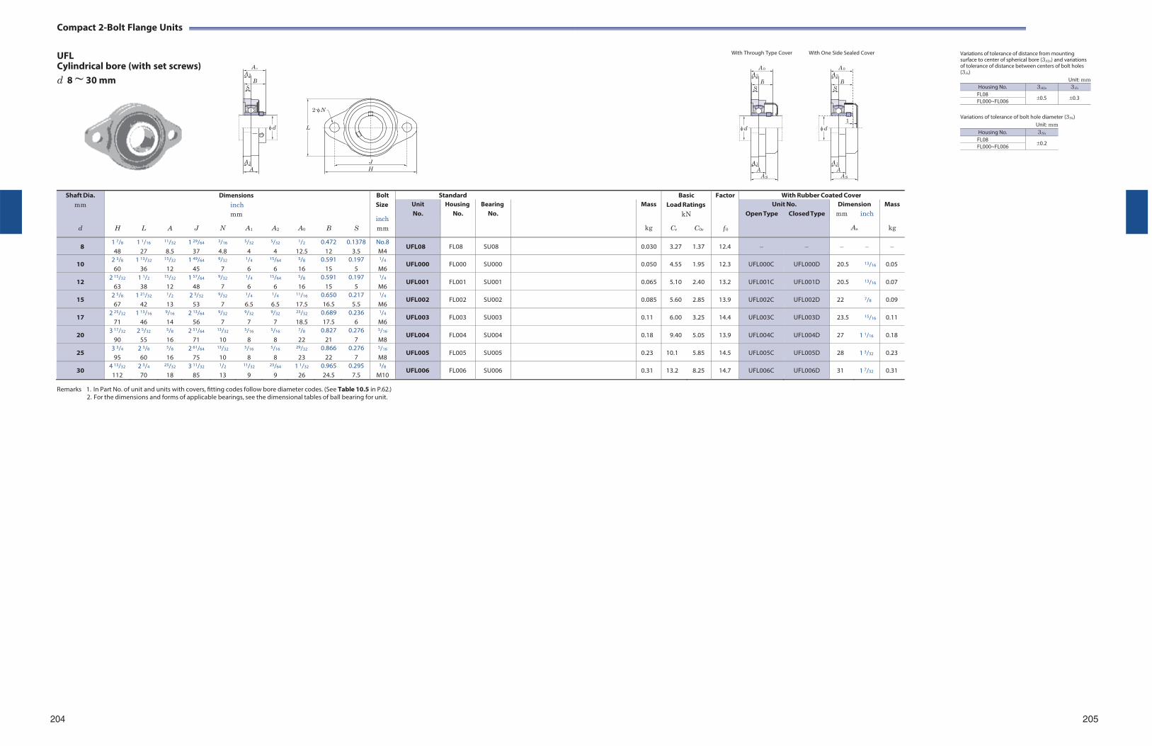
Compact 2-Bolt Flange Units
UFL Cylindrical bore (with set screws) d 8 ~ 30 mm
2-N
L
J H
With Through Type Cover With One Side Sealed Cover Variations of tolerance of distance from mounting surface to center of spherical bore (3A2s) and variations of tolerance of distance between centers of bolt holes (3Js)
Unit: mm Housing No. 3A2s 3Js
FL080.5 0.3 FL000~FL006
Variations of tolerance of bolt hole diameter (3Ns)
Unit: mm
Remarks 1. In Part No. of unit and units with covers, fitting codes follow bore diameter codes. (See Table 10.5 in P.62.)
2. For the dimensions and forms of applicable bearings, see the dimensional tables of ball bearing for unit.
204 205
Shaft Dia. mm
d
H
L
A
J
Dimensions inch mm
N A1
A2
A0
B
S
Bolt Size
inch mm
Standard BasicLoad Ratings
kN
Cr C0r
Factor
f 0
With Rubber Coated Cover Unit No.
Housing No.
Bearing No.
Mass
kg
Unit No. Open Type Closed Type
Dimension mm inch
As
Mass
kg
8 1 7/8
48 1 1/16
27
11/32
8.5 1 29/64
37
3/16
4.8
5/32
4
5/32
4
1/2
12.5 0.472
12 0.1378
3.5 No.8 M4
UFL08 FL08 SU08 0.030 3.27 1.37 12.4
10 2 3/8
60 1 13/32
36
15/32
12 1 49/64
45
9/32
7
1/4
6
15/64
6
5/8
16 0.591
15 0.197
5
1/4
M6 UFL000 FL000 SU000 0.050 4.55 1.95 12.3 UFL000C UFL000D 20.5 13/16 0.05
12 2 15/32
63 1 1/2
38
15/32
12 1 57/64
48
9/32
7
1/4
6
15/64
6
5/8
16 0.591
15 0.197
5
1/4
M6 UFL001 FL001 SU001 0.065 5.10 2.40 13.2 UFL001C UFL001D 20.5 13/16 0.07
15 2 5/8
67 1 21/32
42
1/2
13 2 3/32
53
9/32
7
1/4
6.5
1/4
6.5
11/16
17.5 0.650 16.5
0.217 5.5
1/4
M6 UFL002 FL002 SU002 0.085 5.60 2.85 13.9 UFL002C UFL002D 22 7/8 0.09
17 2 25/32
71 1 13/16
46
9/16
14 2 13/64
56
9/32
7
9/32
7
9/32
7
23/32
18.5 0.689 17.5
0.236 6
1/4
M6 UFL003 FL003 SU003 0.11 6.00 3.25 14.4 UFL003C UFL003D 23.5 15/16 0.11
20 3 17/32
90 2 5/32
55
5/8
16 2 51/64
71
13/32
10
5/16
8
5/16
8
7/8
22 0.827
21 0.276
7
5/16
M8 UFL004 FL004 SU004 0.18 9.40 5.05 13.9 UFL004C UFL004D 27 1 1/16 0.18
25 3 3/4
95 2 3/8
60
5/8
16 2 61/64
75
13/32
10
5/16
8
5/16
8
29/32
23 0.866
22 0.276
7
5/16
M8 UFL005 FL005 SU005 0.23 10.1 5.85 14.5 UFL005C UFL005D 28 1 3/32 0.23
30 4 13/32
112 2 3/4
70
23/32
18 3 11/32
85
1/2
13
11/32
9
23/64
9 1 1/32
26 0.965 24.5
0.295 7.5
3/8
M10 UFL006 FL006 SU006 0.31 13.2 8.25 14.7 UFL006C UFL006D 31 1 7/32 0.31
A 0
A 2
B S
d
A 1
A
A 0A 2
BS
d
A 1
A A S
A 0
A 2B
S
1d
A 1
A A S
Housing No. 3Ns
FL080.2 FL000~FL006
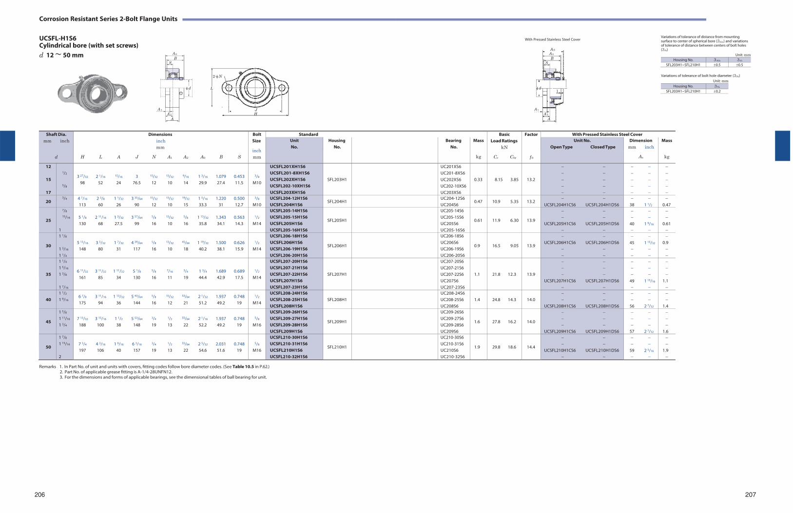
Corrosion Resistant Series 2-Bolt Flange Units
UCSFL-H1S6 Cylindrical bore (with set screws) d 12 ~ 50 mm
2-N
L
J H
With Pressed Stainless Steel Cover
Variations of tolerance of distance from mounting surface to center of spherical bore (3A2s) and variations of tolerance of distance between centers of bolt holes (3Js)
Unit: mm Housing No. 3A2s 3Js
SFL203H1~SFL210H1 0.5 0.5
Variations of tolerance of bolt hole diameter (3Ns)
Unit: mm
Remarks 1. In Part No. of unit and units with covers, fitting codes follow bore diameter codes. (See Table 10.5 in P.62.)
2. Part No. of applicable grease fitting is A-1/4-28UNFN12. 3. For the dimensions and forms of applicable bearings, see the dimensional tables of ball bearing for unit.
206 207
Shaft Dia. mm inch
d
Dimensions inch mm
H L A J N A1 A2 A0 B S
Bolt Size
inch mm
Standard BasicLoad Ratings
kN
Cr C0r
Factor
f 0
With Pressed Stainless Steel Cover Unit No.
Housing No.
Bearing No.
Mass
kg
Unit No. Open Type Closed Type
Dimension mm inch
As
Mass
kg
12
15
17
1/2
5/8
3 27/32 2 1/16 15/16 3 15/32 13/32 9/16 1 3/16 1.079 0.453 98 52 24 76.5 12 10 14 29.9 27.4 11.5
3/8
M10
UCSFL201XH1S6 UCSFL201-8XH1S6 UCSFL202XH1S6 UCSFL202-10XH1S6 UCSFL203XH1S6
SFL203H1
UC201XS6 UC201-8XS6 UC202XS6 UC202-10XS6 UC203XS6
0.33
8.15 3.85
13.2
20 3/4 4 7/16 2 3/8 1 1/32 3 35/64 15/32 13/32 19/32 1 5/16 1.220 0.500
113 60 26 90 12 10 15 33.3 31 12.7
3/8
M10 UCSFL204-12H1S6 UCSFL204H1S6
SFL204H1 UC204-12S6 UC204S6
0.47 10.9 5.35 13.2
UCSFL204H1CS6 UCSFL204H1DS6
38 1 1/2
0.47
25
7/8
15/16
1
5 1/8 2 11/16 1 3/32 3 57/64 5/8 13/32 5/8 1 13/32 1.343 0.563 130 68 27.5 99 16 10 16 35.8 34.1 14.3
1/2
M14
UCSFL205-14H1S6 UCSFL205-15H1S6 UCSFL205H1S6 UCSFL205-16H1S6
SFL205H1
UC205-14S6 UC205-15S6 UC205S6 UC205-16S6
0.61
11.9 6.30
13.9
UCSFL205H1CS6 UCSFL205H1DS6
40 1 9/16
0.61
30
1 1/8
1 3/16
1 1/4
5 13/16 3 5/32 1 7/32 4 39/64 5/8 13/32 45/64 1 19/32 1.500 0.626
148 80 31 117 16 10 18 40.2 38.1 15.9
1/2
M14
UCSFL206-18H1S6 UCSFL206H1S6 UCSFL206-19H1S6 UCSFL206-20H1S6
SFL206H1
UC206-18S6 UC206S6 UC206-19S6 UC206-20S6
0.9
16.5 9.05
13.9
UCSFL206H1CS6 UCSFL206H1DS6
45 1 15/32
0.9
35
1 1/4
1 5/16
1 3/8
1 7/16
6 11/32 3 11/32 1 11/32 5 1/8 5/8 7/16 3/4 1 3/4 1.689 0.689 161 85 34 130 16 11 19 44.4 42.9 17.5
1/2
M14
UCSFL207-20H1S6 UCSFL207-21H1S6 UCSFL207-22H1S6 UCSFL207H1S6 UCSFL207-23H1S6
SFL207H1
UC207-20S6 UC207-21S6 UC207-22S6 UC207S6 UC207-23S6
1.1
21.8 12.3
13.9
UCSFL207H1CS6 UCSFL207H1DS6
49 1 15/16
1.1
40
1 1/2
1 9/16 6 7/8 3 11/16 1 13/32 5 43/64 5/8 15/32 53/64 2 1/32 1.937 0.748 175 94 36 144 16 12 21 51.2 49.2 19
1/2
M14
UCSFL208-24H1S6 UCSFL208-25H1S6 UCSFL208H1S6
SFL208H1
UC208-24S6 UC208-25S6 UC208S6
1.4
24.8 14.3
14.0
UCSFL208H1CS6 UCSFL208H1DS6
56 2 7/32
1.4
45
1 5/8
1 11/16
1 3/4
7 13/32 3 15/16 1 1/2 5 53/64 3/4 1/2 55/64 2 1/16 1.937 0.748
188 100 38 148 19 13 22 52.2 49.2 19
5/8
M16
UCSFL209-26H1S6 UCSFL209-27H1S6 UCSFL209-28H1S6 UCSFL209H1S6
SFL209H1
UC209-26S6 UC209-27S6 UC209-28S6 UC209S6
1.6
27.8 16.2
14.0
UCSFL209H1CS6 UCSFL209H1DS6
57 2 7/32
1.6
50
1 7/8
1 15/16
2
7 3/4 4 3/16 1 9/16 6 3/16 3/4 1/2 55/64 2 5/32 2.031 0.748 197 106 40 157 19 13 22 54.6 51.6 19
5/8
M16
UCSFL210-30H1S6 UCSFL210-31H1S6 UCSFL210H1S6 UCSFL210-32H1S6
SFL210H1
UC210-30S6 UC210-31S6 UC210S6 UC210-32S6
1.9
29.8 18.6
14.4
UCSFL210H1CS6 UCSFL210H1DS6
59 2 5/16
1.9
A 0
B S
d
A 1A 2
A
A SA 0B
S
d1
A 1A 2
A
Housing No. 3Ns
SFL203H1~SFL210H1 0.2
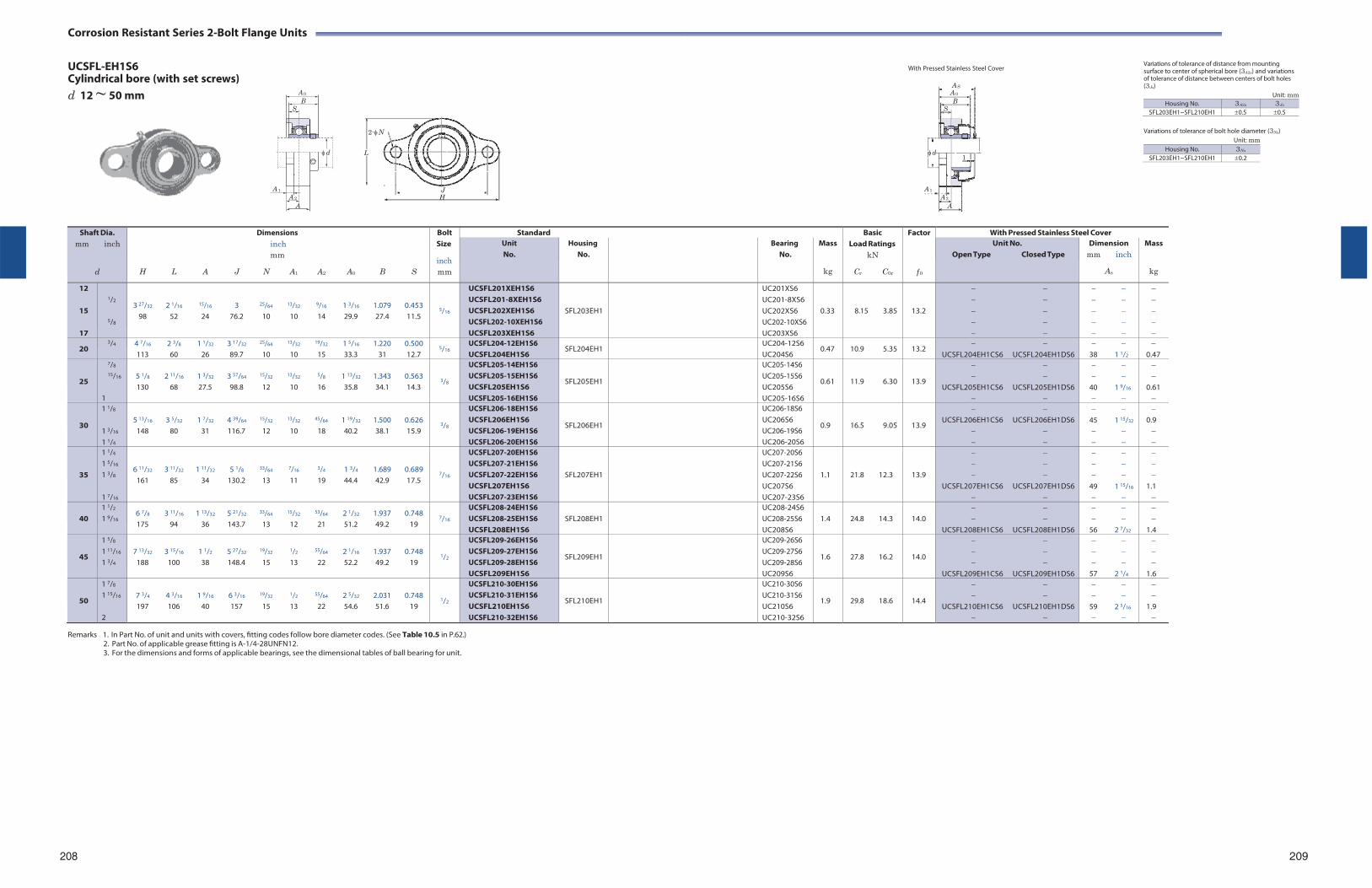
Corrosion Resistant Series 2-Bolt Flange Units
UCSFL-EH1S6 Cylindrical bore (with set screws) d 12 ~ 50 mm
2-N
L
J H
With Pressed Stainless Steel Cover
Variations of tolerance of distance from mounting surface to center of spherical bore (3A2s) and variations of tolerance of distance between centers of bolt holes (3Js)
Unit: mm Housing No. 3A2s 3Js
SFL203EH1~SFL210EH1 0.5 0.5
Variations of tolerance of bolt hole diameter (3Ns)
Unit: mm
Remarks 1. In Part No. of unit and units with covers, fitting codes follow bore diameter codes. (See Table 10.5 in P.62.)
2. Part No. of applicable grease fitting is A-1/4-28UNFN12. 3. For the dimensions and forms of applicable bearings, see the dimensional tables of ball bearing for unit.
208 209
Shaft Dia. mm inch
d
Dimensions inch mm
H L A J N A1 A2 A0 B S
Bolt Size
inch mm
Standard BasicLoad Ratings
kN
Cr C0r
Factor
f 0
With Pressed Stainless Steel Cover Unit No.
Housing No.
Bearing No.
Mass
kg
Unit No. Open Type Closed Type
Dimension mm inch
As
Mass
kg
12
15
17
1/2
5/8
3 27/32 2 1/16 15/16 3 25/64 13/32 9/16 1 3/16 1.079 0.453 98 52 24 76.2 10 10 14 29.9 27.4 11.5
5/16
UCSFL201XEH1S6 UCSFL201-8XEH1S6 UCSFL202XEH1S6 UCSFL202-10XEH1S6 UCSFL203XEH1S6
SFL203EH1
UC201XS6 UC201-8XS6 UC202XS6 UC202-10XS6 UC203XS6
0.33
8.15 3.85
13.2
20 3/4 4 7/16 2 3/8 1 1/32 3 17/32 25/64 13/32 19/32 1 5/16 1.220 0.500
113 60 26 89.7 10 10 15 33.3 31 12.7 5/16
UCSFL204-12EH1S6 UCSFL204EH1S6
SFL204EH1 UC204-12S6 UC204S6
0.47 10.9 5.35 13.2
UCSFL204EH1CS6 UCSFL204EH1DS6
38 1 1/2
0.47
25
7/8
15/16
1
5 1/8 2 11/16 1 3/32 3 57/64 15/32 13/32 5/8 1 13/32 1.343 0.563 130 68 27.5 98.8 12 10 16 35.8 34.1 14.3
3/8
UCSFL205-14EH1S6 UCSFL205-15EH1S6 UCSFL205EH1S6 UCSFL205-16EH1S6
SFL205EH1
UC205-14S6 UC205-15S6 UC205S6 UC205-16S6
0.61
11.9 6.30
13.9
UCSFL205EH1CS6 UCSFL205EH1DS6
40 1 9/16
0.61
30
1 1/8
1 3/16
1 1/4
5 13/16 3 5/32 1 7/32 4 39/64 15/32 13/32 45/64 1 19/32 1.500 0.626
148 80 31 116.7 12 10 18 40.2 38.1 15.9
3/8
UCSFL206-18EH1S6 UCSFL206EH1S6 UCSFL206-19EH1S6 UCSFL206-20EH1S6
SFL206EH1
UC206-18S6 UC206S6 UC206-19S6 UC206-20S6
0.9
16.5 9.05
13.9
UCSFL206EH1CS6 UCSFL206EH1DS6
45 1 15/32
0.9
35
1 1/4
1 5/16
1 3/8
1 7/16
6 11/32 3 11/32 1 11/32 5 1/8 33/64 7/16 3/4 1 3/4 1.689 0.689 161 85 34 130.2 13 11 19 44.4 42.9 17.5
7/16
UCSFL207-20EH1S6 UCSFL207-21EH1S6 UCSFL207-22EH1S6 UCSFL207EH1S6 UCSFL207-23EH1S6
SFL207EH1
UC207-20S6 UC207-21S6 UC207-22S6 UC207S6 UC207-23S6
1.1
21.8 12.3
13.9
UCSFL207EH1CS6 UCSFL207EH1DS6
49 1 15/16
1.1
40
1 1/2
1 9/16 6 7/8 3 11/16 1 13/32 5 21/32 33/64 15/32 53/64 2 1/32 1.937 0.748 175 94 36 143.7 13 12 21 51.2 49.2 19
7/16
UCSFL208-24EH1S6 UCSFL208-25EH1S6 UCSFL208EH1S6
SFL208EH1
UC208-24S6 UC208-25S6 UC208S6
1.4
24.8 14.3
14.0
UCSFL208EH1CS6 UCSFL208EH1DS6
56 2 7/32
1.4
45
1 5/8
1 11/16
1 3/4
7 13/32 3 15/16 1 1/2 5 27/32 19/32 1/2 55/64 2 1/16 1.937 0.748
188 100 38 148.4 15 13 22 52.2 49.2 19
1/2
UCSFL209-26EH1S6 UCSFL209-27EH1S6 UCSFL209-28EH1S6 UCSFL209EH1S6
SFL209EH1
UC209-26S6 UC209-27S6 UC209-28S6 UC209S6
1.6
27.8 16.2
14.0
UCSFL209EH1CS6 UCSFL209EH1DS6
57 2 1/4
1.6
50
1 7/8
1 15/16
2
7 3/4 4 3/16 1 9/16 6 3/16 19/32 1/2 55/64 2 5/32 2.031 0.748 197 106 40 157 15 13 22 54.6 51.6 19
1/2
UCSFL210-30EH1S6 UCSFL210-31EH1S6 UCSFL210EH1S6 UCSFL210-32EH1S6
SFL210EH1
UC210-30S6 UC210-31S6 UC210S6 UC210-32S6
1.9
29.8 18.6
14.4
UCSFL210EH1CS6 UCSFL210EH1DS6
59 2 5/16
1.9
A 0
B S
d
A 1A 2
A
A SA 0B
S
d1
A 1A 2
A
Housing No. 3Ns
SFL203EH1~SFL210EH1 0.2
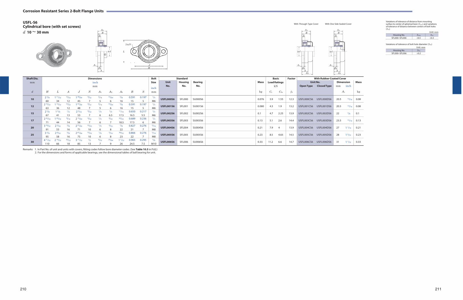
Corrosion Resistant Series 2-Bolt Flange Units
USFL-S6 Cylindrical bore (with set screws) d 10 ~ 30 mm
2-N
L
J H
With Through Type Cover With One Side Sealed Cover
Variations of tolerance of distance from mounting surface to center of spherical bore (3A2s) and variations of tolerance of distance between centers of bolt holes (3Js)
Unit: mm Housing No. 3A2s 3Js
SFL000~SFL006 0.5 0.3
Variations of tolerance of bolt hole diameter (3Ns)
Unit: mm
Remarks 1. In Part No. of unit and units with covers, fitting codes follow bore diameter codes. (See Table 10.5 in P.62.)
2. For the dimensions and forms of applicable bearings, see the dimensional tables of ball bearing for unit.
210 211
Shaft Dia. mm
d
H
L
A
J
Dimensions inch mm
N A1
A2
A0
B
S
Bolt Size
inch mm
Standard BasicLoad Ratings
kN
Cr C0r
Factor
f 0
With Rubber Coated Cover Unit No.
Housing No.
Bearing No.
Mass
kg
Unit No. Open Type Closed Type
Dimension mm inch
As
Mass
kg
10 2 3/8
60 1 11/32
34
15/32
12 1 49/64
45
9/32
7
3/16
5
15/64
6
5/8
16 0.591
15 0.197
5
1/4
M6 USFL000S6 SFL000 SU000S6 0.076 3.9 1.55 12.3 USFL000CS6 USFL000DS6 20.5 13/16 0.08
12 2 15/32
63 1 13/32
36
15/32
12 1 57/64
48
9/32
7
3/16
5
15/64
6
5/8
16 0.591
15 0.197
5
1/4
M6 USFL001S6 SFL001 SU001S6 0.080 4.3 1.9 13.2 USFL001CS6 USFL001DS6 20.5 13/16 0.08
15 2 5/8
67 1 5/8
41
1/2
13 2 3/32
53
9/32
7
1/4
6
1/4
6.5
11/16
17.5 0.650 16.5
0.217 5.5
1/4
M6 USFL002S6 SFL002 SU002S6 0.1 4.7 2.25 13.9 USFL002CS6 USFL002DS6 22 7/8 0.1
17 2 25/32
71 1 23/32
44
9/16
14 2 13/64
56
9/32
7
1/4
6
9/32
7
23/32
18.5 0.689 17.5
0.236 6
1/4
M6 USFL003S6 SFL003 SU003S6 0.13 5.1 2.6 14.4 USFL003CS6 USFL003DS6 23.5 15/16 0.13
20 3 19/32
91 2 3/32
53
5/8
16 2 51/64
71
13/32
10
1/4
6
5/16
8
7/8
22 0.827
21 0.276
7
5/16
M8 USFL004S6 SFL004 SU004S6 0.21 7.9 4 13.9 USFL004CS6 USFL004DS6 27 1 1/16 0.21
25 3 3/4
95 2 9/32
58
5/8
16 2 61/64
75
13/32
10
1/4
6
5/16
8
29/32
23 0.866
22 0.276
7
5/16
M8 USFL005S6 SFL005 SU005S6 0.23 8.5 4.65 14.5 USFL005CS6 USFL005DS6 28 1 3/32 0.23
30 4 11/32
110 2 19/32
66
23/32
18 3 11/32
85
1/2
13
9/32
7
23/64
9 1 1/32
26 0.965 24.5
0.295 7.5
3/8
M10 USFL006S6 SFL006 SU006S6 0.33 11.2 6.6 14.7 USFL006CS6 USFL006DS6 31 1 7/32 0.33
A 0
B S
d
A 1
A 2
A
A 0
B S
d
A 1A 2
A A S
A 0
B S
1d
A 1A 2
A A S
Housing No. 3Ns
SFL000~SFL006 0.2

Corrosion Resistant Series 2-Bolt Flange Units
UCVFL-S6 Cylindrical bore (with set screws)
Variations of tolerance of distance from mounting surface to center of spherical bore (3A2s) and tolerance of position of bolt hole (X)
d 20 ~ 40 mm
2-N
L
J H
Unit: mm
Remarks 1. In Part No. of unit and units with covers, fitting codes follow bore diameter numbers. (See Table 10.5 in P.62.)
2. Part No. of the applicable grease fitting is A-1/4-28UNFN12. 3. For the dimensions and forms of applicable bearings, see the dimensional tables of ball bearing for unit.
212
213
Shaft Dia. mm inch
d
Dimensions inch mm
H L A J N A1 A2 A0 B S
Bolt Size
inch mm
Standard BasicLoad Ratings
kN
Cr C0r
Factor
f 0
With Plastic Cover Unit No.
Housing No.
Bearing No.
Mass
kg
Unit No. Open Type Closed Type
Dimension mm inch
As
Mass
kg
20 3/4 4 7/16 2 9/16 1 1/32 3 35/64 7/16 17/32 19/32 1 5/16 1.220 0.500
113 65 26.5 90 11 13.4 15 33.3 31 12.7
3/8
M8 UCVFL204-12S6 UCVFL204S6
VFL204 UC204-12S6 UC204S6
0.25 10.9 5.35 13.2 UCVFL204-12CS6 UCVFL204-12DS6 UCVFL204CS6 UCVFL204DS6
46.5 1 27/32 0.26
25
7/8
15/16
1
5 5/32 2 3/4 1 3/32 3 57/64 7/16 17/32 5/8 1 13/32 1.343 0.563 131 70 27.5 99 11 13.8 16 35.8 34.1 14.3
3/8
M8
UCVFL205-14S6 UCVFL205-15S6 UCVFL205S6 UCVFL205-16S6
VFL205
UC205-14S6 UC205-15S6 UC205S6 UC205-16S6
0.35
11.9 6.3
13.9
UCVFL205-14CS6 UCVFL205-14DS6 UCVFL205-15CS6 UCVFL205-15DS6 UCVFL205CS6 UCVFL205DS6 UCVFL205-16CS6 UCVFL205-16DS6
50.2 1 31/32
0.36
30
1 1/8
1 3/16
1 1/4
5 13/16 3 5/32 1 3/16 4 39/64 7/16 9/16 45/64 1 19/32 1.500 0.626
148 80 30.5 117 11 14.3 18 40.2 38.1 15.9
3/8
M8
UCVFL206-18S6 UCVFL206S6 UCVFL206-19S6 UCVFL206-20S6
VFL206
UC206-18S6 UC206S6 UC206-19S6 UC206-20S6
0.49
16.5 9.05
13.9
UCVFL206-18CS6 UCVFL206-18DS6 UCVFL206CS6 UCVFL206DS6 UCVFL206-19CS6 UCVFL206-19DS6 UCVFL206-20CS6 UCVFL206-20DS6
57.5 2 1/4
0.50
35
1 1/4
1 5/16
1 3/8
1 7/16
6 15/32 3 17/32 1 1/4 5 1/8 33/64 5/8 3/4 1 3/4 1.689 0.689 164 90 32 130 13 15.5 19 44.4 42.9 17.5
7/16
M10
UCVFL207-20S6 UCVFL207-21S6 UCVFL207-22S6 UCVFL207S6 UCVFL207-23S6
VFL207
UC207-20S6 UC207-21S6 UC207-22S6 UC207S6 UC207-23S6
0.73
21.8 12.3
13.9
UCVFL207-20CS6 UCVFL207-20DS6 UCVFL207-21CS6 UCVFL207-21DS6 UCVFL207-22CS6 UCVFL207-22DS6 UCVFL207CS6 UCVFL207DS6 UCVFL207-23CS6 UCVFL207-23DS6
61.2 2 13/32
0.75
40
1 1/2
1 9/16 6 15/16 3 15/16 1 11/32 5 43/64 35/64 21/32 53/64 2 1/32 1.937 0.748
176 100 34.5 144 14 16.5 21 51.2 49.2 19
1/2
M12
UCVFL208-24S6 UCVFL208-25S6 UCVFL208S6
VFL208
UC208-24S6 UC208-25S6 UC208S6
0.92
24.8 13.3
14.0
UCVFL208-24CS6 UCVFL208-24DS6 UCVFL208-25CS6 UCVFL208-25DS6 UCVFL208CS6 UCVFL208EDS6
69.2 2 23/32
0.95
B A 0
S
d
A 1
A 2
A
A SB
S
d
A 1
A 2
A
Housing No. 3A2s X VFL204~VFL208 0.5 0.7
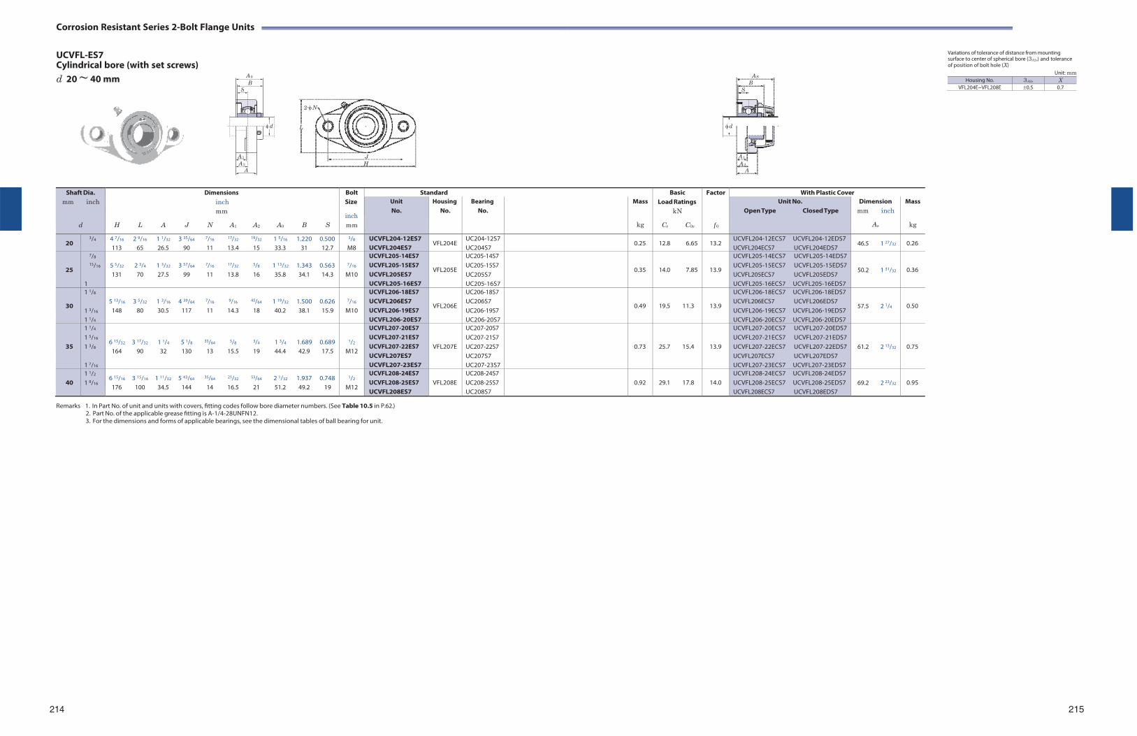
Corrosion Resistant Series 2-Bolt Flange Units
UCVFL-ES7 Cylindrical bore (with set screws)
Variations of tolerance of distance from mounting surface to center of spherical bore (3A2s) and tolerance of position of bolt hole (X)
d 20 ~ 40 mm
2-N
L
J H
Unit: mm
Remarks 1. In Part No. of unit and units with covers, fitting codes follow bore diameter numbers. (See Table 10.5 in P.62.)
2. Part No. of the applicable grease fitting is A-1/4-28UNFN12. 3. For the dimensions and forms of applicable bearings, see the dimensional tables of ball bearing for unit.
214
215
Shaft Dia. mm inch
d
Dimensions inch mm
H L A J N A1 A2 A0 B S
Bolt Size
inch mm
Standard BasicLoad Ratings
kN
Cr C0r
Factor
f 0
With Plastic Cover Unit No.
Housing No.
Bearing No.
Mass
kg
Unit No. Open Type Closed Type
Dimension mm inch
As
Mass
kg
20 3/4 4 7/16 2 9/16 1 1/32 3 35/64 7/16 17/32 19/32 1 5/16 1.220 0.500
113 65 26.5 90 11 13.4 15 33.3 31 12.7
3/8
M8 UCVFL204-12ES7 UCVFL204ES7
VFL204E UC204-12S7 UC204S7
0.25 12.8 6.65 13.2 UCVFL204-12ECS7 UCVFL204-12EDS7 UCVFL204ECS7 UCVFL204EDS7
46.5 1 27/32 0.26
25
7/8
15/16
1
5 5/32 2 3/4 1 3/32 3 57/64 7/16 17/32 5/8 1 13/32 1.343 0.563 131 70 27.5 99 11 13.8 16 35.8 34.1 14.3
7/16
M10
UCVFL205-14ES7 UCVFL205-15ES7 UCVFL205ES7 UCVFL205-16ES7
VFL205E
UC205-14S7 UC205-15S7 UC205S7 UC205-16S7
0.35
14.0 7.85
13.9
UCVFL205-14ECS7 UCVFL205-14EDS7 UCVFL205-15ECS7 UCVFL205-15EDS7 UCVFL205ECS7 UCVFL205EDS7 UCVFL205-16ECS7 UCVFL205-16EDS7
50.2 1 31/32
0.36
30
1 1/8
1 3/16
1 1/4
5 13/16 3 5/32 1 3/16 4 39/64 7/16 9/16 45/64 1 19/32 1.500 0.626
148 80 30.5 117 11 14.3 18 40.2 38.1 15.9
7/16
M10
UCVFL206-18ES7 UCVFL206ES7 UCVFL206-19ES7 UCVFL206-20ES7
VFL206E
UC206-18S7 UC206S7 UC206-19S7 UC206-20S7
0.49
19.5 11.3
13.9
UCVFL206-18ECS7 UCVFL206-18EDS7 UCVFL206ECS7 UCVFL206EDS7 UCVFL206-19ECS7 UCVFL206-19EDS7 UCVFL206-20ECS7 UCVFL206-20EDS7
57.5 2 1/4
0.50
35
1 1/4
1 5/16
1 3/8
1 7/16
6 15/32 3 17/32 1 1/4 5 1/8 33/64 5/8 3/4 1 3/4 1.689 0.689 164 90 32 130 13 15.5 19 44.4 42.9 17.5
1/2
M12
UCVFL207-20ES7 UCVFL207-21ES7 UCVFL207-22ES7 UCVFL207ES7 UCVFL207-23ES7
VFL207E
UC207-20S7 UC207-21S7 UC207-22S7 UC207S7 UC207-23S7
0.73
25.7 15.4
13.9
UCVFL207-20ECS7 UCVFL207-20EDS7 UCVFL207-21ECS7 UCVFL207-21EDS7 UCVFL207-22ECS7 UCVFL207-22EDS7 UCVFL207ECS7 UCVFL207EDS7 UCVFL207-23ECS7 UCVFL207-23EDS7
61.2 2 13/32
0.75
40
1 1/2
1 9/16 6 15/16 3 15/16 1 11/32 5 43/64 35/64 21/32 53/64 2 1/32 1.937 0.748
176 100 34.5 144 14 16.5 21 51.2 49.2 19
1/2
M12
UCVFL208-24ES7 UCVFL208-25ES7 UCVFL208ES7
VFL208E
UC208-24S7 UC208-25S7 UC208S7
0.92
29.1 17.8
14.0
UCVFL208-24ECS7 UCVFL208-24EDS7 UCVFL208-25ECS7 UCVFL208-25EDS7 UCVFL208ECS7 UCVFL208EDS7
69.2 2 23/32
0.95
B A 0
S
d
A 1
A 2
A
A SB
S
d
A 1
A 2
A
Housing No. 3A2s X VFL204E~VFL208E 0.5 0.7
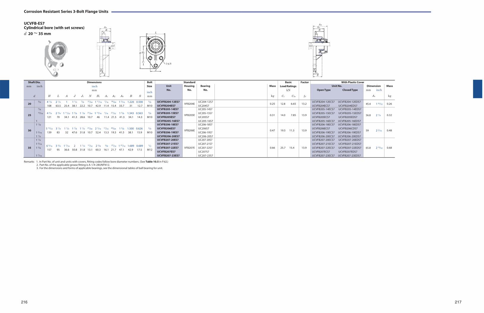
Corrosion Resistant Series 3-Bolt Flange Units
UCVFB-ES7 Cylindrical bore (with set screws) d 20 ~ 35 mm
Remarks 1. In Part No. of unit and units with covers, fitting codes follow bore diameter numbers. (See Table 10.5 in P.62.)
2. Part No. of the applicable grease fitting is A-1/4-28UNFN12. 3. For the dimensions and forms of applicable bearings, see the dimensional tables of ball bearing for unit.
216 217
Shaft Dia. mm inch
d
Dimensions inch mm
H L A J J1 N H1 A1 A2 A0 B S
Bolt Size
inch mm
Standard BasicLoad Ratings
kN
Cr C0r
Factor
f 0
With Plastic Cover Unit No.
Housing No.
Bearing No.
Mass
kg
Unit No. Open Type Closed Type
Dimension mm inch
As
Mass
kg
20 3/4 4 1/4 2 1/2 1 1 1/2 7/8 27/64 1 11/16 7/16 39/64 1 5/16 1.220 0.500
108 63.5 25.4 38.1 22.2 10.7 42.9 11.4 15.4 33.7 31 12.7
3/8
M10 UCVFB204-12ES7 UCVFB204ES7
VFB204E UC204-12S7 UC204S7
0.25 12.8 6.65 13.2 UCVFB204-12ECS7 UCVFB204-12EDS7 UCVFB204ECS7 UCVFB204EDS7
45.4 1 25/32 0.26
25
7/8
15/16
1
4 3/4 2 3/4 1 11/32 1 5/8 1 1/8 27/64 1 13/16 7/16 27/32 1 5/8 1.343 0.563 121 70 34.1 41.3 28.6 10.7 46 11.4 21.5 41.3 34.1 14.3
3/8
M10
UCVFB205-14ES7 UCVFB205-15ES7 UCVFB205ES7 UCVFB205-16ES7
VFB205E
UC205-14S7 UC205-15S7 UC205S7 UC205-16S7
0.31
14.0 7.85
13.9
UCVFB205-14ECS7 UCVFB205-14EDS7 UCVFB205-15ECS7 UCVFB205-15EDS7 UCVFB205ECS7 UCVFB205EDS7 UCVFB205-16ECS7 UCVFB205-16EDS7
56.8 2 1/4
0.32
30
1 1/8
1 3/16
1 1/4
5 15/32 3 1/4 1 1/4 1 7/8 1 1/4 27/64 2 1/16 17/32 49/64 1 5/8 1.500 0.626
139 83 32 47.6 31.8 10.7 52.4 13.3 19.3 41.5 38.1 15.9
3/8
M10
UCVFB206-18ES7 UCVFB206ES7 UCVFB206-19ES7 UCVFB206-20ES7
VFB206E
UC206-18S7 UC206S7 UC206-19S7 UC206-20S7
0.47
19.5 11.3
13.9
UCVFB206-18ECS7 UCVFB206-18EDS7 UCVFB206ECS7 UCVFB206CDS7 UCVFB206-19ECS7 UCVFB206-19EDS7 UCVFB206-20ECS7 UCVFB206-20EDS7
59 2 5/16
0.48
35
1 1/4
1 5/16
1 3/8
1 7/16
6 3/16 3 3/4 1 7/16 2 1 1/4 17/32 2 3/8 5/8 27/32 1 27/32 1.689 0.689 157 95 36.6 50.8 31.8 13.1 60.3 16.1 21.7 47.1 42.9 17.5
1/2
M12
UCVFB207-20ES7 UCVFB207-21ES7 UCVFB207-22ES7 UCVFB207ES7 UCVFB207-23ES7
VFB207E
UC207-20S7 UC207-21S7 UC207-22S7 UC207S7 UC207-23S7
0.66
25.7 15.4
13.9
UCVFB207-20ECS7 UCVFB207-20EDS7 UCVFB207-21ECS7 UCVFB207-21EDS7 UCVFB207-22ECS7 UCVFB207-22EDS7 UCVFB207ECS7 UCVFB207EDS7 UCVFB207-23ECS7 UCVFB207-23EDS7
65.8 2 19/32
0.68
A 0
B S
d
A 1 A 2
A
L
H H 1
J 1 3-N
J
A SA 0
B S
d
A 1
A 2
A
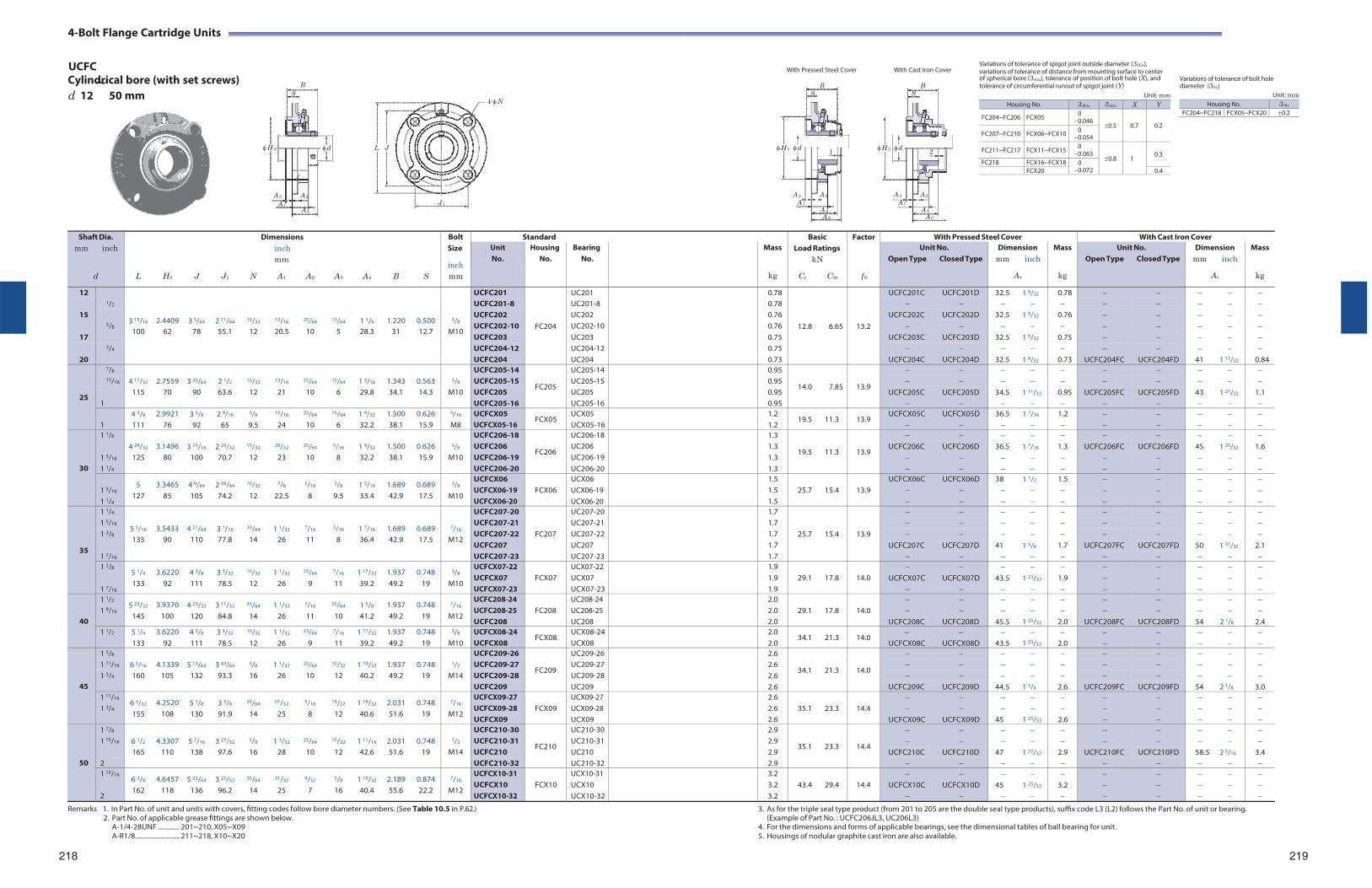
4- Bolt Flange Cartridge Units
UCFC With Pressed Steel Cover With Cast Iron Cover
Variations of tolerance of spigot joint outside diameter (3H3s), variations of tolerance of distance from mounting surface to center
Cylindrical bore (with set screws) B ~ of spherical bore (3A2s), tolerance of position of bolt hole (X), and B B tolerance of circumferential runout of spigot joint (Y)
Variations of tolerance of bolt hole diameter (3Ns)
d 12 50 mm S
H 3 d L J
A 3 A 2
4-N
S
H 3 d 1
A 3 A 2
S
H 3 d 2
A 3 A 2
Unit: mm Unit: mm
A 1 J 1 A 4
A 1 A 1 A 4 A 4 A S A C
Remarks 1. In Part No. of unit and units with covers, fitting codes follow bore diameter numbers. (See Table 10.5 in P.62.) 2. Part No. of applicable grease fittings are shown below.
A-1/4-28UNF ............. 201~210, X05~X09 A-R1/8 .......................... 211~218, X10~X20
218
3. As for the triple seal type product (from 201 to 205 are the double seal type products), suffix code L3 (L2) follows the Part No. of unit or bearing. (Example of Part No. : UCFC206JL3, UC206L3)
4. For the dimensions and forms of applicable bearings, see the dimensional tables of ball bearing for unit. 5. Housings of nodular graphite cast iron are also available.
219
Housing No. 3H3s 3A2s X Y
FC204~FC206 FCX05 0 0.046
0.5
0.7
0.2 FC207~FC210 FCX06~FCX10 0
0.054
FC211~FC217 FCX11~FCX15 0 0.063
0.8
1
0.3
FC218 FCX16~FCX18 0 0.072 FCX20 0.4
Housing No. 3Ns
FC204~FC218 FCX05~FCX20 0.2
Shaft Dia. mm inch
d
L
H3
J
J1
Dimensions inch mm
N A1 A2
A3
A4
B
S
Bolt Size
inch mm
Standard BasicLoad Ratings
kN
Cr C0r
Factor
f 0
With Pressed Steel Cover With Cast Iron CoverUnit No.
Housing No.
Bearing No.
Mass
kg
Unit No. Open Type Closed Type
Dimension mm inch
As
Mass
kg
Unit No. Open Type Closed Type
Dimension mm inch
Ac
Mass
kg
12 1/2
3 15/16
2.4409
3 5/64
2 11/64
15/32
13/16
25/64
13/64
1 1/8
1.220
0.500
3/8
UCFC201
FC204
UC201 0.78
12.8
6.65
13.2
UCFC201C UCFC201D 32.5 1 9/32 0.78 UCFC201-8 UC201-8 0.78
15 5/8
UCFC202 UC202 0.76 UCFC202C UCFC202D 32.5 1 9/32 0.76 UCFC202-10 UC202-10 0.76
100 62 78 55.1 12 20.5 10 5 28.3 31 12.7 M10 17 UCFC203 UC203 0.75 UCFC203C UCFC203D 32.5 1 9/32 0.75
3/4 UCFC204-12 UC204-12 0.75 20 UCFC204 UC204 0.73 UCFC204C UCFC204D 32.5 1 9/32 0.73 UCFC204FC UCFC204FD 41 1 17/32 0.84
25
7/8 4 17/32
2.7559
3 35/64
2 1/2
15/32
13/16
25/64
15/64
1 3/16
1.343
0.563
3/8
UCFC205-14
FC205
UC205-14 0.95
14.0
7.85
13.9
15/16 UCFC205-15 UC205-15 0.95
115 70 90 63.6 12 21 10 6 29.8 34.1 14.3 M10 UCFC205 UC205 0.95 UCFC205C UCFC205D 34.5 1 11/32 0.95 UCFC205FC UCFC205FD 43 1 21/32 1.1 1 UCFC205-16 UC205-16 0.95
1
4 3/8
111 2.9921
76 3 5/8
92 2 9/16
65
3/8
9.5
15/16
24
25/64
10
15/64
6 1 9/32
32.2 1.500 38.1
0.626 15.9
5/16
M8 UCFCX05 UCFCX05-16
FCX05 UCX05 UCX05-16
1.2 1.2
19.5 11.3 13.9 UCFCX05C
UCFCX05D
36.5
1 7/16
1.2
30
1 1/8 4 29/32
3.1496
3 15/16
2 25/32
15/32
29/32
25/64
5/16
1 9/32
1.500
0.626
3/8
UCFC206-18
FC206
UC206-18 1.3
19.5
11.3
13.9
1 3/16
UCFC206 UC206 1.3 UCFC206C UCFC206D 36.5 1 7/16 1.3 UCFC206FC UCFC206FD 45 1 25/32 1.6 125 80 100 70.7 12 23 10 8 32.2 38.1 15.9 M10 UCFC206-19 UC206-19 1.3
1 1/4 UCFC206-20 UC206-20 1.3
1 3/16
1 1/4
5 127
3.3465 85
4 9/64
105 2 59/64
74.2
15/32
12
7/8
22.5
5/16
8
3/8
9.5 1 5/16
33.4 1.689 42.9
0.689 17.5
3/8
M10
UCFCX06 UCFCX06-19 UCFCX06-20
FCX06
UCX06 UCX06-19 UCX06-20
1.5 1.5 1.5
25.7
15.4
13.9
UCFCX06C
UCFCX06D
38
1 1/2
1.5
35
1 1/4
5 5/16
3.5433
4 21/64
3 1/16
35/64
1 1/32
7/16
5/16
1 7/16
1.689
0.689
7/16
UCFC207-20
FC207
UC207-20 1.7
25.7
15.4
13.9
1 5/16 UCFC207-21 UC207-21 1.7 1 3/8 UCFC207-22 UC207-22 1.7
135 90 110 77.8 14 26 11 8 36.4 42.9 17.5 M12 UCFC207 UC207 1.7 UCFC207C UCFC207D 41 1 5/8 1.7 UCFC207FC UCFC207FD 50 1 31/32 2.1
1 7/16 UCFC207-23 UC207-23 1.7 1 3/8
1 7/16
5 1/4
133 3.6220
92 4 3/8
111 3 3/32
78.5
15/32
12 1 1/32
26
23/64
9
7/16
11 1 17/32
39.2 1.937 49.2
0.748 19
3/8
M10
UCFCX07-22 UCFCX07 UCFCX07-23
FCX07
UCX07-22 UCX07 UCX07-23
1.9 1.9 1.9
29.1
17.8
14.0
UCFCX07C
UCFCX07D
43.5
1 23/32
1.9
40
1 1/2
1 9/16 5 23/32
145 3.9370
100 4 23/32
120 3 11/32
84.8
35/64
14 1 1/32
26
7/16
11
25/64
10 1 5/8
41.2 1.937 49.2
0.748 19
7/16
M12
UCFC208-24 UCFC208-25 UCFC208
FC208
UC208-24 UC208-25 UC208
2.0 2.0 2.0
29.1
17.8
14.0
UCFC208C
UCFC208D
45.5
1 25/32
2.0
UCFC208FC
UCFC208FD
54
2 1/8
2.41 1/2 5 1/4
133 3.6220
92 4 3/8
111 3 3/32
78.5
15/32
12 1 1/32
26
23/64
9
7/16
11 1 17/32
39.2 1.937 49.2
0.748 19
3/8
M10 UCFCX08-24 UCFCX08
FCX08 UCX08-24UCX08
2.0 2.0
34.1 21.3 14.0
UCFCX08C
UCFCX08D
43.5
1 23/32
2.0
45
1 5/8 6 5/16
4.1339
5 13/64
3 43/64
5/8
1 1/32
25/64
15/32
1 19/32
1.937
0.748
1/2
UCFC209-26
FC209
UC209-26 2.6
34.1
21.3
14.0
1 11/16 UCFC209-27 UC209-27 2.6 1 3/4 160 105 132 93.3 16 26 10 12 40.2 49.2 19 M14 UCFC209-28 UC209-28 2.6
UCFC209 UC209 2.6 UCFC209C UCFC209D 44.5 1 3/4 2.6 UCFC209FC UCFC209FD 54 2 1/8 3.0 1 11/16
1 3/4 6 3/32
155 4.2520
108 5 1/8
130 3 5/8
91.9
35/64
14
31/32
25
5/16
8
15/32
12 1 19/32
40.6 2.031 51.6
0.748 19
7/16
M12
UCFCX09-27 UCFCX09-28 UCFCX09
FCX09
UCX09-27 UCX09-28 UCX09
2.6 2.6 2.6
35.1
23.3
14.4
UCFCX09C
UCFCX09D
45
1 25/32
2.6
50
1 7/8 6 1/2
4.3307
5 7/16
3 27/32
5/8
1 3/32
25/64
15/32
1 11/16
2.031
0.748
1/2
UCFC210-30
FC210
UC210-30 2.9
35.1
23.3
14.4
1 15/16 UCFC210-31 UC210-31 2.9
165 110 138 97.6 16 28 10 12 42.6 51.6 19 M14 UCFC210 UC210 2.9 UCFC210C UCFC210D 47 1 27/32 2.9 UCFC210FC UCFC210FD 58.5 2 5/16 3.4 2 UCFC210-32 UC210-32 2.9 1 15/16
2
6 3/8
162 4.6457
118 5 23/64
136 3 25/32
96.2
35/64
14
31/32
25
9/32
7
5/8
16 1 19/32
40.4 2.189 55.6
0.874 22.2
7/16
M12
UCFCX10-31 UCFCX10 UCFCX10-32
FCX10
UCX10-31 UCX10 UCX10-32
3.2 3.2 3.2
43.4
29.4
14.4
UCFCX10C
UCFCX10D
45
1 25/32
3.2
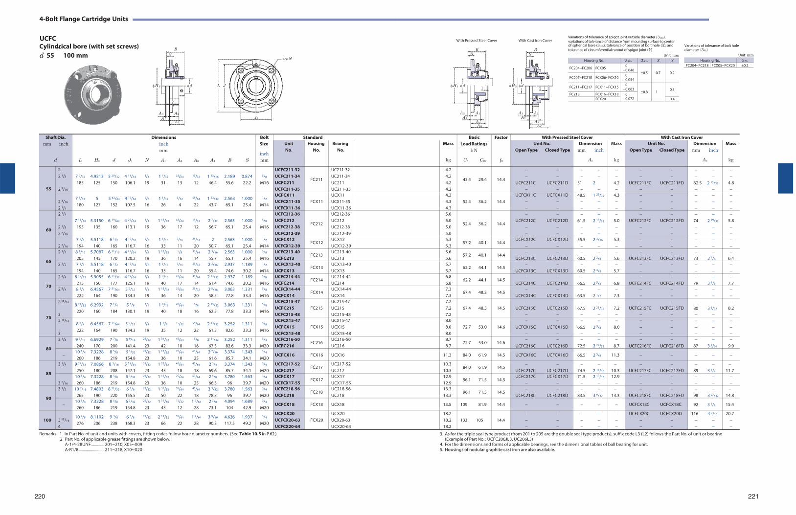
4-Bolt Flange Cartridge Units
UCFC With Pressed Steel Cover With Cast Iron Cover
Variations of tolerance of spigot joint outside diameter (3H3s), variations of tolerance of distance from mounting surface to center
Cylindrical bore (with set screws) B ~ of spherical bore (3A2s), tolerance of position of bolt hole (X), and B B tolerance of circumferential runout of spigot joint (Y)
Variations of tolerance of bolt hole diameter (3Ns)
d 55 100 mm S
H 3 d L J
A 3 A 2
4-N
S
H 3 d 1
A 3 A 2
S
H 3 d 2
A 3 A 2
Unit: mm Unit: mm
A 1 J 1 A 4
A 1 A 1 A 4 A 4 A S A C
Remarks 1. In Part No. of unit and units with covers, fitting codes follow bore diameter numbers. (See Table 10.5 in P.62.) 2. Part No. of applicable grease fittings are shown below.
A-1/4-28UNF ............. 201~210, X05~X09 A-R1/8 .......................... 211~218, X10~X20
3. As for the triple seal type product (from 201 to 205 are the double seal type products), suffix code L3 (L2) follows the Part No. of unit or bearing.
(Example of Part No. : UCFC206JL3, UC206L3) 4. For the dimensions and forms of applicable bearings, see the dimensional tables of ball bearing for unit. 5. Housings of nodular graphite cast iron are also available.
220 221
Housing No. 3H3s 3A2s X Y
FC204~FC206 FCX05 0 0.046
0.5
0.7
0.2 FC207~FC210 FCX06~FCX10 0
0.054
FC211~FC217 FCX11~FCX15 0 0.063
0.8
1
0.3
FC218 FCX16~FCX18 0 0.072 FCX20 0.4
Housing No. 3Ns
FC204~FC218 FCX05~FCX20 0.2
Shaft Dia. mm inch
d
Dimensions inch mm
L H3 J J1 N A1 A2 A3 A4 B S
Bolt Size
inch mm
Standard BasicLoad Ratings
kN
Cr C0r
Factor
f 0
With Pressed Steel Cover With Cast Iron Cover Unit No.
Housing No.
Bearing No.
Mass
kg
Unit No. Open Type Closed Type
Dimension mm inch
As
Mass
kg
Unit No. Open Type Closed Type
Dimension mm inch
Ac
Mass
kg
55
2 2 1/8
2 3/16
7 9/32 4.9213 5 29/32 4 11/64 3/4 1 7/32 33/64 15/32 1 13/16 2.189 0.874 185 125 150 106.1 19 31 13 12 46.4 55.6 22.2
5/8
M16
UCFC211-32 UCFC211-34 UCFC211 UCFC211-35
FC211
UC211-32 UC211-34 UC211 UC211-35
4.2 4.2 4.2 4.2
43.4 29.4
14.4
UCFC211C UCFC211D
51 2
4.2
UCFC211FC UCFC211FD
62.5 2 15/32
4.8
2 3/16
2 1/4
7 3/32 5 5 63/64 4 15/64 5/8 1 1/32 5/32 55/64 1 23/32 2.563 1.000 180 127 152 107.5 16 26 4 22 43.7 65.1 25.4
1/2
M14
UCFCX11 UCFCX11-35 UCFCX11-36
FCX11
UCX11 UCX11-35 UCX11-36
4.3 4.3 4.3
52.4 36.2
14.4
UCFCX11C UCFCX11D
48.5 1 29/32
4.3
60
2 1/4
2 3/8
2 7/16
7 11/16 5.3150 6 19/64 4 29/64 3/4 1 13/32 43/64 15/32 2 7/32 2.563 1.000
195 135 160 113.1 19 36 17 12 56.7 65.1 25.4
5/8
M16
UCFC212-36 UCFC212 UCFC212-38 UCFC212-39
FC212
UC212-36 UC212 UC212-38 UC212-39
5.0 5.0 5.0 5.0
52.4 36.2
14.4
UCFC212C UCFC212D
61.5 2 13/32
5.0
UCFC212FC UCFC212FD
74 2 29/32
5.8
2 7/16
7 5/8 5.5118 6 1/2 4 19/32 5/8 1 5/16 7/16 25/32 2 2.563 1.000 194 140 165 116.7 16 33 11 20 50.7 65.1 25.4
1/2
M14 UCFCX12 UCFCX12-39
FCX12 UCX12 UCX12-39
5.3 5.3
57.2 40.1 14.4 UCFCX12C UCFCX12D
55.5 2 3/16
5.3
65
2 1/2 8 1/16 5.7087 6 11/16 4 47/64 3/4 1 13/32 5/8 35/64 2 3/16 2.563 1.000 205 145 170 120.2 19 36 16 14 55.7 65.1 25.4
5/8
M16 UCFC213-40 UCFC213
FC213 UC213-40UC213
5.6 5.6
57.2 40.1 14.4
UCFC213C UCFC213D
60.5 2 3/8
5.6
UCFC213FC UCFC213FD
73 2 7/8
6.4
2 1/2 7 5/8 5.5118 6 1/2 4 19/32 5/8 1 5/16 7/16 25/32 2 3/16 2.937 1.189 194 140 165 116.7 16 33 11 20 55.4 74.6 30.2
1/2
M14 UCFCX13-40 UCFCX13
FCX13 UCX13-40UCX13
5.7 5.7
62.2 44.1 14.5
UCFCX13C UCFCX13D
60.5 2 3/8
5.7
70
2 3/4 8 15/32 5.9055 6 31/32 4 59/64 3/4 1 9/16 43/64 35/64 2 13/32 2.937 1.189 215 150 177 125.1 19 40 17 14 61.4 74.6 30.2
5/8
M16 UCFC214-44 UCFC214
FC214 UC214-44UC214
6.8 6.8
62.2 44.1 14.5
UCFC214C UCFC214D
66.5 2 5/8
6.8
UCFC214FC UCFC214FD
79 3 1/8
7.7
2 3/4 8 3/4 6.4567 7 31/64 5 9/32 3/4 1 13/32 35/64 25/32 2 5/16 3.063 1.331 222 164 190 134.3 19 36 14 20 58.5 77.8 33.3
5/8
M16 UCFCX14-44 UCFCX14
FCX14 UCX14-44UCX14
7.3 7.3
67.4 48.3 14.5
UCFCX14C UCFCX14D
63.5 2 1/2
7.3
75
2 15/16
3
8 21/32 6.2992 7 1/4 5 1/8 3/4 1 9/16 45/64 5/8 2 15/32 3.063 1.331 220 160 184 130.1 19 40 18 16 62.5 77.8 33.3
5/8
M16
UCFC215-47 UCFC215 UCFC215-48
FC215
UC215-47 UC215 UC215-48
7.2 7.2 7.2
67.4 48.3
14.5
UCFC215C UCFC215D
67.5 2 21/32
7.2
UCFC215FC UCFC215FD
80 3 5/32
8.2
2 15/16
3
8 3/4 6.4567 7 31/64 5 9/32 3/4 1 3/8 15/32 55/64 2 13/32 3.252 1.311 222 164 190 134.3 19 35 12 22 61.3 82.6 33.3
5/8
M16
UCFCX15-47 UCFCX15 UCFCX15-48
FCX15
UCX15-47 UCX15 UCX15-48
8.0 8.0 8.0
72.7 53.0
14.6
UCFCX15C UCFCX15D
66.5 2 5/8
8.0
80
3 1/8 9 7/16 6.6929 7 7/8 5 9/16 29/32 1 31/32 45/64 5/8 2 21/32 3.252 1.311 240 170 200 141.4 23 42 18 16 67.3 82.6 33.3
3/4
M20 UCFC216-50 UCFC216
FC216 UC216-50UC216
8.7 8.7
72.7 53.0 14.6
UCFC216C UCFC216D
72.5 2 27/32
8.7
UCFC216FC UCFC216FD
87 3 7/16
9.9
10 1/4 7.3228 8 5/8 6 3/32 29/32 1 13/32 25/64 63/64 2 7/16 3.374 1.343 260 186 219 154.8 23 36 10 25 61.6 85.7 34.1
3/4
M20 UCFCX16 FCX16 UCX16 11.3 84.0 61.9 14.5 UCFCX16C UCFCX16D 66.5 2 5/8 11.3
85
3 1/4 9 27/32 7.0866 8 3/16 5 51/64 29/32 1 25/32 45/64 45/64 2 3/4 3.374 1.343 250 180 208 147.1 23 45 18 18 69.6 85.7 34.1
3/4
M20 UCFC217-52 UCFC217
FC217 UC217-52UC217
10.3 10.3
84.0 61.9 14.5
UCFC217C UCFC217D
74.5 2 15/16
10.3
UCFC217FC UCFC217FD
89 3 1/2
11.7
3 7/16
10 1/4 7.3228 8 5/8 6 3/32 29/32 1 13/32 25/64 63/64 2 5/8 3.780 1.563 260 186 219 154.8 23 36 10 25 66.3 96 39.7
3/4
M20 UCFCX17 UCFCX17-55
FCX17 UCX17 UCX17-55
12.9 12.9
96.1 71.5 14.5 UCFCX17C UCFCX17D
71.5 2 13/16
12.9
90
3 1/2 10 7/16 7.4803 8 21/32 6 1/8 29/32 1 31/32 55/64 45/64 3 3/32 3.780 1.563 265 190 220 155.5 23 50 22 18 78.3 96 39.7
3/4
M20 UCFC218-56 UCFC218
FC218 UC218-56UC218
13.3 13.3
96.1 71.5 14.5
UCFC218C UCFC218D
83.5 3 9/32
13.3
UCFC218FC UCFC218FD
98 3 27/32
14.8
10 1/4 7.3228 8 5/8 6 3/32 29/32 1 11/16 15/32 1 7/64 2 7/8 4.094 1.689 260 186 219 154.8 23 43 12 28 73.1 104 42.9
3/4
M20 UCFCX18 FCX18 UCX18 13.5 109 81.9 14.4 UCFCX18C UCFCX18C 92 3 5/8 15.4
100
3 15/16
4
10 7/8 8.1102 9 3/8 6 5/8 29/32 2 19/32 55/64 1 7/64 3 9/16 4.626 1.937 276 206 238 168.3 23 66 22 28 90.3 117.5 49.2
3/4
M20
UCFCX20 UCFCX20-63 UCFCX20-64
FCX20
UCX20 UCX20-63 UCX20-64
18.2 18.2 18.2
133 105
14.4
UCFCX20C UCFCX20D
116 4 9/16
20.7
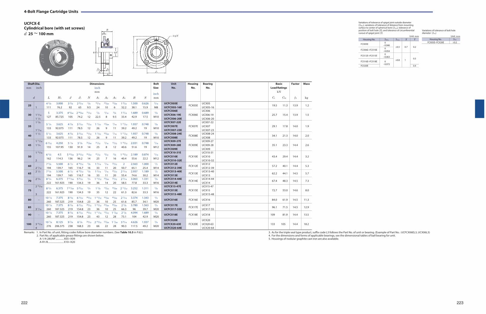
4-Bolt Flange Cartridge Units
UCFCX-E Cylindrical bore (with set screws) B
d 25 ~ 100 mm S
4-N
Variations of tolerance of spigot joint outside diameter (3H3s), variations of tolerance of distance from mounting surface to center of spherical bore (3A2s), tolerance of position of bolt hole (X), and tolerance of circumferential runout of spigot joint (Y)
Unit: mm
Variations of tolerance of bolt hole diameter (3Ns)
Unit: mm Housing No. 3Ns
FCX05E~FCX20E 0.2
H 3 d L J
A 3 A 2
A 1 J 1
A 4
Remarks 1. In Part No. of unit, fitting codes follow bore diameter numbers. (See Table 10.5 in P.62.)
2. Part No. of applicable grease fittings are shown below. A-1/4-28UNF ............. X05~X09 A-R1/8 .......................... X10~X20
3. As for the triple seal type product, suffix code L3 follows the Part No. of unit or bearing. (Example of Part No. : UCFCX06EL3, UCX06L3) 4. For the dimensions and forms of applicable bearings, see the dimensional tables of ball bearing for unit. 5. Housings of nodular graphite cast iron are also available.
222
223
Shaft Dia. mm inch
d
L
H3
J
J1
Dimensions inch mm
N A1 A2
A3
A4
B
S
Bolt Size
inch mm
Unit No.
HousingNo.
BearingNo.
BasicLoad Ratings
kN
Cr C0r
Factor
f 0
Mass
kg
25 1
4 3/8
111 3.000 76.2
3 5/8
92 2 9/16
65
3/8
9.5
15/16
24
25/64
10
15/64
6 1 9/32
32.2 1.500 38.1
0.626 15.9
5/16
M8 UCFCX05E UCFCX05-16E
FCX05E UCX05 UCX05-16
19.5 11.3 13.9 1.2
30
1 3/16
1 1/4
5 127
3.375 85.725
4 9/64
105 2 59/64
74.2
15/32
12
7/8
22.5
5/16
8
3/8
9.5 1 5/16
33.4 1.689 42.9
0.689 17.5
3/8
M10
UCFCX06E UCFCX06-19E UCFCX06-20E
FCX06E
UCX06 UCX06-19 UCX06-20
25.7
15.4
13.9
1.5
35
1 3/8
1 7/16
5 1/4
133 3.625
92.075 4 3/8
111 3 3/32
78.5
15/32
12 1 1/32
26
23/64
9
7/16
11 1 17/32
39.2 1.937 49.2
0.748 19
3/8
M10
UCFCX07-22E UCFCX07E UCFCX07-23E
FCX07E
UCX07-22 UCX07 UCX07-23
29.1
17.8
14.0
1.9
40 1 1/2 5 1/4
133 3.625
92.075 4 3/8
111 3 3/32
78.5
15/32
12 1 1/32
26
23/64
9
7/16
11 1 17/32
39.2 1.937 49.2
0.748 19
3/8
M10 UCFCX08-24E UCFCX08E
FCX08E UCX08-24UCX08
34.1 21.3 14.0 2.0
45
1 11/16
1 3/4 6 3/32
155 4.250
107.95 5 1/8
130 3 5/8
91.9
35/64
14
31/32
25
5/16
8
15/32
12 1 19/32
40.6 2.031 51.6
0.748 19
7/16
M12
UCFCX09-27E UCFCX09-28E UCFCX09E
FCX09E
UCX09-27 UCX09-28 UCX09
35.1
23.3
14.4
2.6
50
1 15/16
2
6 3/8
162 4.5
114.3 5 23/64
136 3 25/32
96.2
35/64
14
31/32
25
9/32
7
5/8
16 1 19/32
40.4 2.189 55.6
0.874 22.2
7/16
M12
UCFCX10-31E UCFCX10E UCFCX10-32E
FCX10E
UCX10-31 UCX10 UCX10-32
43.4
29.4
14.4
3.2
60 2 7/16
7 5/8
194 5.500 139.7
6 1/2
165 4 19/32
116.7
5/8
16 1 5/16
33
7/16
11
25/32
20 2
50.7 2.563 65.1
1.000 25.4
1/2
M14 UCFCX12E UCFCX12-39E
FCX12E UCX12 UCX12-39
57.2 40.1 14.4 5.3
65 2 1/2 7 5/8
194 5.500 139.7
6 1/2
165 4 19/32
116.7
5/8
16 1 5/16
33
7/16
11
25/32
20 2 3/16
55.4 2.937 74.6
1.189 30.2
1/2
M14 UCFCX13-40E UCFCX13E
FCX13E UCX13-40UCX13
62.2 44.1 14.5 5.7
70 2 3/4 8 3/4
222 6.375
161.925 7 31/64
190 5 9/32
134.3
3/4
19 1 13/32
36
35/64
14
25/32
20 2 5/16
58.5 3.063 77.8
1.331 33.3
5/8
M16 UCFCX14-44E UCFCX14E
FCX14E UCX14-44UCX14
67.4 48.3 14.5 7.3
75
2 15/16
3
8 3/4
222 6.375
161.925 7 31/64
190 5 9/32
134.3
3/4
19 1 3/8
35
15/32
12
55/64
22 2 13/32
61.3 3.252 82.6
1.311 33.3
5/8
M16
UCFCX15-47E UCFCX15E UCFCX15-48E
FCX15E
UCX15-47 UCX15 UCX15-48
72.7
53.0
14.6
8.0
80 10 1/4
260 7.375
187.325 8 5/8
219 6 3/32
154.8
29/32
23 1 13/32
36
25/64
10
63/64
25 2 7/16
61.6 3.374 85.7
1.343 34.1
3/4
M20 UCFCX16E FCX16E UCX16 84.0 61.9 14.5 11.3
85 3 7/16
10 1/4
260 7.375
187.325 8 5/8
219 6 3/32
154.8
29/32
23 1 13/32
36
25/64
10
63/64
25 2 5/8
66.3 3.780
96 1.563 39.7
3/4
M20 UCFCX17E UCFCX17-55E
FCX17E UCX17 UCX17-55
96.1 71.5 14.5 12.9
90 10 1/4
260 7.375
187.325 8 5/8
219 6 3/32
154.8
29/32
23 1 11/16
43
15/32
12 1 7/64
28 2 7/8
73.1 4.094 104
1.689 42.9
3/4
M20 UCFCX18E FCX18E UCX18 109 81.9 14.4 13.5
100
3 15/16
4
10 7/8
276 8.125
206.375 9 3/8
238 6 5/8
168.3
29/32
23 2 19/32
66
55/64
22 1 7/64
28 3 9/16
90.3 4.626 117.5
1.937 49.2
3/4
M20
UCFCX20E UCFCX20-63E UCFCX20-64E
FCX20E
UCX20 UCX20-63 UCX20-64
133
105
14.4
18.2
Housing No. 3H3s 3A2s X Y
FCX05E 0 0.046
0.5
0.7
0.2 FCX06E~FCX10E 0
0.054
FCX12E~FCX15E 0 0.063
0.8
1
0.3 FCX16E~FCX18E 0
0.072 FCX20E 0.4
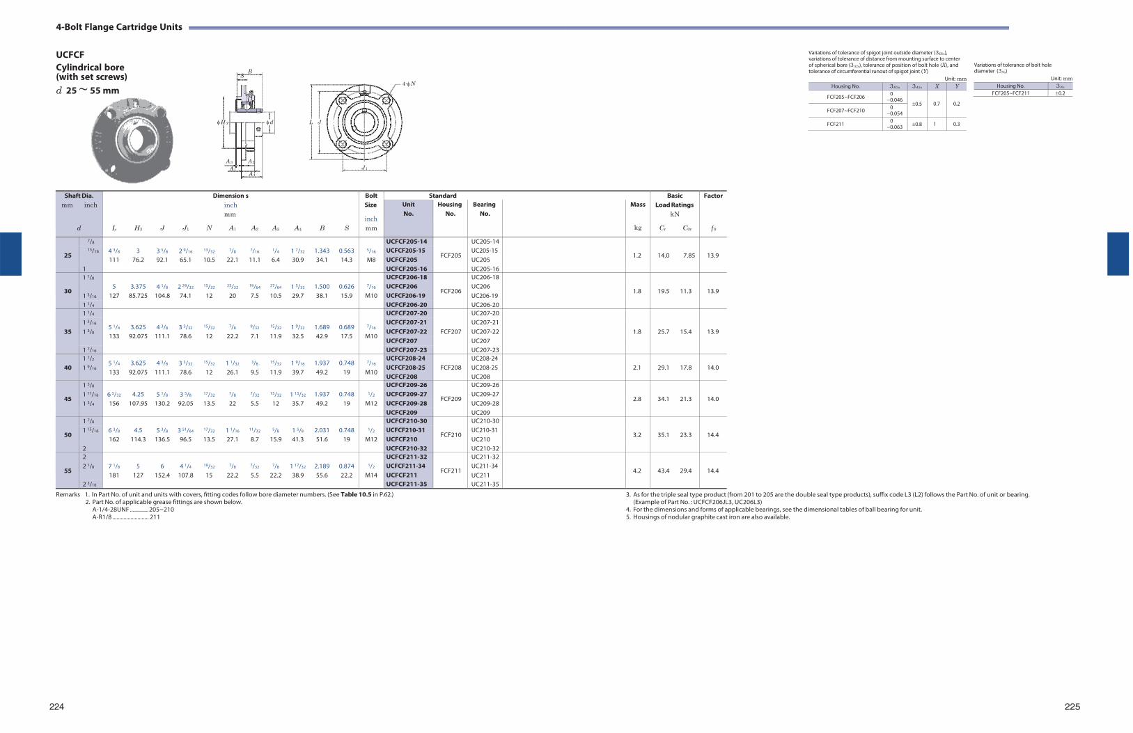
4-Bolt Flange Cartridge Units
UCFCF Cylindrical bore B
(with set screws) S
d 25 ~ 55 mm
4-N
Variations of tolerance of spigot joint outside diameter (3H3s), variations of tolerance of distance from mounting surface to center of spherical bore (3A2s), tolerance of position of bolt hole (X), and tolerance of circumferential runout of spigot joint (Y)
Unit: mm
Variations of tolerance of bolt hole diameter (3Ns)
Unit: mm
H 3 d L J
A 3 A 2
A 1 J 1
A 4
Remarks 1. In Part No. of unit and units with covers, fitting codes follow bore diameter numbers. (See Table 10.5 in P.62.)
2. Part No. of applicable grease fittings are shown below. A-1/4-28UNF ............. 205~210 A-R1/8 .......................... 211
3. As for the triple seal type product (from 201 to 205 are the double seal type products), suffix code L3 (L2) follows the Part No. of unit or bearing. (Example of Part No. : UCFCF206JL3, UC206L3)
4. For the dimensions and forms of applicable bearings, see the dimensional tables of ball bearing for unit. 5. Housings of nodular graphite cast iron are also available.
224 225
Shaft Dia. mm inch
d
L
H3
J
J1
Dimension inch mm
N A1
s
A2
A3
A4
B
S
Bolt Size
inch mm
Standard BasicLoad Ratings
kN
Cr C0r
Factor
f 0
Unit No.
Housing No.
Bearing No.
Mass
kg
25
7/8 4 3/8
3
3 5/8
2 9/16
13/32
7/8
7/16
1/4
1 7/32
1.343
0.563
5/16
UCFCF205-14
FCF205
UC205-14
1.2
14.0
7.85
13.9 15/16 UCFCF205-15
UCFCF205 UC205-15 UC205 111 76.2 92.1 65.1 10.5 22.1 11.1 6.4 30.9 34.1 14.3 M8
1 UCFCF205-16 UC205-16
30
1 1/8 5
3.375
4 1/8
2 29/32
15/32
25/32
19/64
27/64
1 5/32
1.500
0.626
7/16
UCFCF206-18
FCF206
UC206-18
1.8
19.5
11.3
13.9 1 3/16
UCFCF206 UCFCF206-19
UC206 UC206-19 127 85.725 104.8 74.1 12 20 7.5 10.5 29.7 38.1 15.9 M10
1 1/4 UCFCF206-20 UC206-20
35
1 1/4
5 1/4
3.625
4 3/8
3 3/32
15/32
7/8
9/32
15/32
1 9/32
1.689
0.689
7/16
UCFCF207-20
FCF207
UC207-20
1.8
25.7
15.4
13.9
1 5/16 UCFCF207-21 UC207-211 3/8 UCFCF207-22 UC207-22
133 92.075 111.1 78.6 12 22.2 7.1 11.9 32.5 42.9 17.5 M10 UCFCF207 UC207
1 7/16 UCFCF207-23 UC207-23
40 1 1/2
1 9/16 5 1/4
133 3.625
92.075 4 3/8
111.1 3 3/32
78.6
15/32
12 1 1/32
26.1
3/8
9.5
15/32
11.9 1 9/16
39.7 1.937 49.2
0.748 19
7/16
M10
UCFCF208-24 UCFCF208-25 UCFCF208
FCF208
UC208-24 UC208-25 UC208
2.1
29.1
17.8
14.0
45
1 5/8 6 5/32
4.25
5 1/8
3 5/8
17/32
7/8
7/32
15/32
1 13/32
1.937
0.748
1/2
UCFCF209-26
FCF209
UC209-26
2.8
34.1
21.3
14.0 1 11/16 UCFCF209-27 UC209-271 3/4 156 107.95 130.2 92.05 13.5 22 5.5 12 35.7 49.2 19 M12 UCFCF209-28 UC209-28
UCFCF209 UC209
50
1 7/8 6 3/8
4.5
5 3/8
3 51/64
17/32
1 1/16
11/32
5/8
1 5/8
2.031
0.748
1/2
UCFCF210-30
FCF210
UC210-30
3.2
35.1
23.3
14.4 1 15/16 UCFCF210-31
UCFCF210 UC210-31 UC210 162 114.3 136.5 96.5 13.5 27.1 8.7 15.9 41.3 51.6 19 M12
2 UCFCF210-32 UC210-32
55
2 7 1/8
5
6
4 1/4
19/32
7/8
7/32
7/8
1 17/32
2.189
0.874
1/2
UCFCF211-32
FCF211
UC211-32
4.2
43.4
29.4
14.4 2 1/8 UCFCF211-34
UCFCF211 UC211-34 UC211 181 127 152.4 107.8 15 22.2 5.5 22.2 38.9 55.6 22.2 M14
2 3/16 UCFCF211-35 UC211-35
Housing No. 3H3s 3A2s X Y
FCF205~FCF206 0 0.046
0.5
0.7
0.2 FCF207~FCF210 0
0.054
FCF211 0 0.063 0.8 1 0.3
Housing No. 3Ns
FCF205~FCF211 0.2
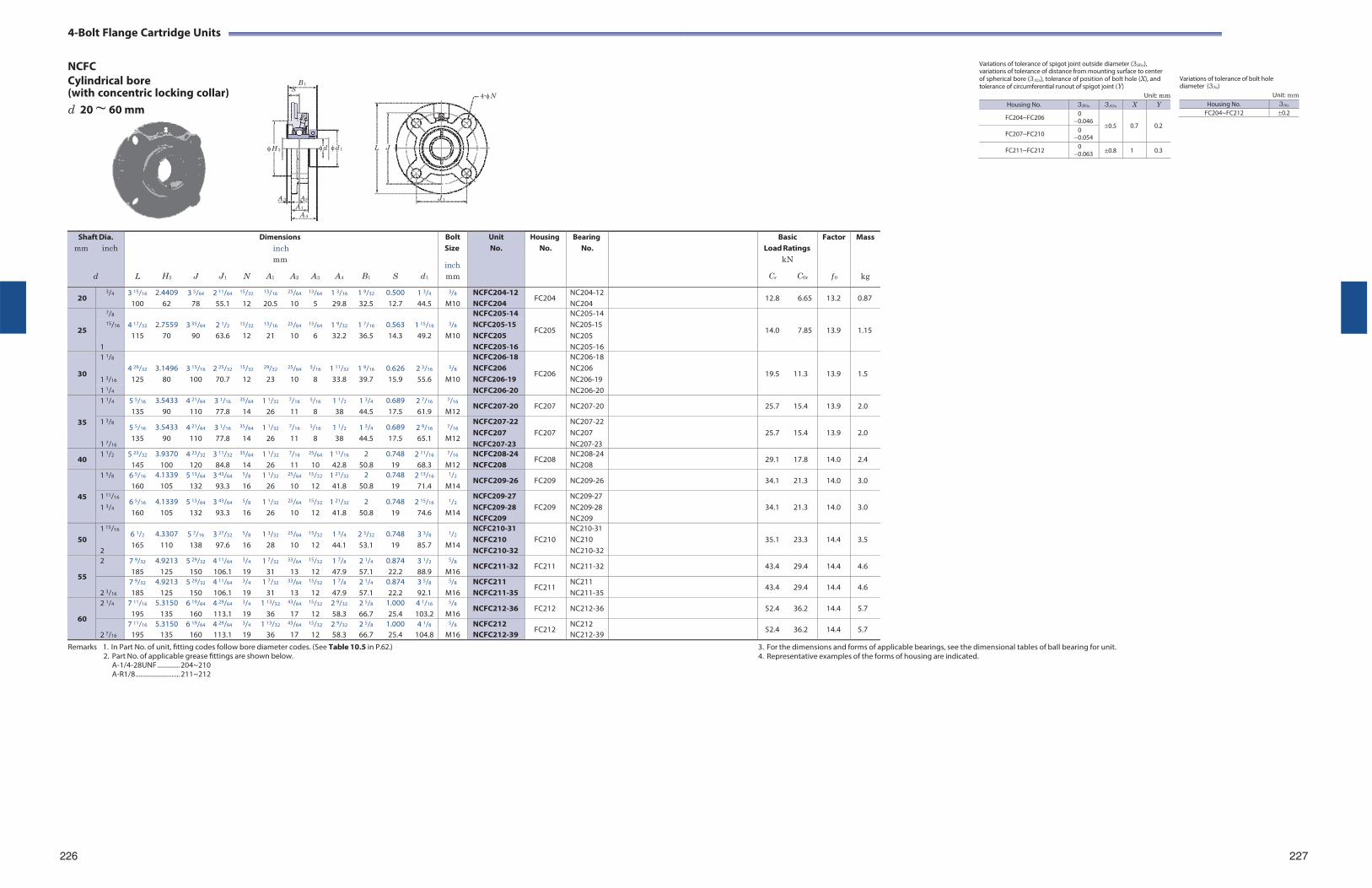
4-Bolt Flange Cartridge Units
NCFC Cylindrical bore B 1
(with concentric locking collar) S
d 20 ~ 60 mm
4-N
Variations of tolerance of spigot joint outside diameter (3H3s), variations of tolerance of distance from mounting surface to center of spherical bore (3A2s), tolerance of position of bolt hole (X), and tolerance of circumferential runout of spigot joint (Y)
Unit: mm
Variations of tolerance of bolt hole diameter (3Ns)
Unit: mm
H 3
d d 1 L J
A 3 A2 J 1
A 1
A 4
Remarks 1. In Part No. of unit, fitting codes follow bore diameter codes. (See Table 10.5 in P.62.)
2. Part No. of applicable grease fittings are shown below. A-1/4-28UNF ............. 204~210 A-R1/8 .......................... 211~212
3. For the dimensions and forms of applicable bearings, see the dimensional tables of ball bearing for unit. 4. Representative examples of the forms of housing are indicated.
226 227
Shaft Dia. mm inch
d
L
H3
J
J1
N
Dimensions inch mm
A1 A2
A3
A4
B1
S
d1
Bolt Size
inch mm
Unit No.
HousingNo.
BearingNo.
BasicLoad Ratings
kN
Cr C0r
Factor
f 0
Mass
kg
20 3/4 3 15/16
100 2.4409
62 3 5/64
78 2 11/64
55.1
15/32
12
13/16
20.5
25/64
10
13/64
5 1 3/16
29.8 1 9/32
32.5 0.500 12.7
1 3/4
44.5
3/8
M10 NCFC204-12 NCFC204
FC204 NC204-12 NC204
12.8 6.65 13.2 0.87
25
7/8 4 17/32
2.7559
3 35/64
2 1/2
15/32
13/16
25/64
15/64
1 9/32
1 7/16
0.563
1 15/16
3/8
NCFC205-14
FC205
NC205-14
14.0
7.85
13.9
1.15 15/16 NCFC205-15
NCFC205 NC205-15 NC205 115 70 90 63.6 12 21 10 6 32.2 36.5 14.3 49.2 M10
1 NCFC205-16 NC205-16
30
1 1/8 4 29/32
3.1496
3 15/16
2 25/32
15/32
29/32
25/64
5/16
1 11/32
1 9/16
0.626
2 3/16
3/8
NCFC206-18
FC206
NC206-18
19.5
11.3
13.9
1.5 1 3/16
NCFC206 NCFC206-19
NC206 NC206-19 125 80 100 70.7 12 23 10 8 33.8 39.7 15.9 55.6 M10
1 1/4 NCFC206-20 NC206-20
35
1 1/4 5 5/16
135 3.5433
90 4 21/64
110 3 1/16
77.8
35/64
14 1 1/32
26
7/16
11
5/16
8 1 1/2
38 1 3/4
44.5 0.689 17.5
2 7/16
61.9
7/16
M12 NCFC207-20 FC207 NC207-20 25.7 15.4 13.9 2.0
1 3/8
1 7/16
5 5/16
135 3.5433
90 4 21/64
110 3 1/16
77.8
35/64
14 1 1/32
26
7/16
11
5/16
8 1 1/2
38 1 3/4
44.5 0.689 17.5
2 9/16
65.1
7/16
M12
NCFC207-22 NCFC207 NCFC207-23
FC207
NC207-22 NC207 NC207-23
25.7
15.4
13.9
2.0
40 1 1/2 5 23/32
145 3.9370
100 4 23/32
120 3 11/32
84.8
35/64
14 1 1/32
26
7/16
11
25/64
10 1 11/16
42.8 2
50.8 0.748
19 2 11/16
68.3
7/16
M12 NCFC208-24 NCFC208
FC208 NC208-24 NC208
29.1 17.8 14.0 2.4
45
1 5/8 6 5/16
160 4.1339
105 5 13/64
132 3 43/64
93.3
5/8
16 1 1/32
26
25/64
10
15/32
12 1 21/32
41.8 2
50.8 0.748
19 2 13/16
71.4
1/2
M14 NCFC209-26 FC209 NC209-26 34.1 21.3 14.0 3.0
1 11/16
1 3/4 6 5/16
160 4.1339
105 5 13/64
132 3 43/64
93.3
5/8
16 1 1/32
26
25/64
10
15/32
12 1 21/32
41.8 2
50.8 0.748
19 2 15/16
74.6
1/2
M14
NCFC209-27 NCFC209-28 NCFC209
FC209
NC209-27 NC209-28 NC209
34.1
21.3
14.0
3.0
50
1 15/16
2
6 1/2
165 4.3307
110 5 7/16
138 3 27/32
97.6
5/8
16 1 3/32
28
25/64
10
15/32
12 1 3/4
44.1 2 3/32
53.1 0.748
19 3 3/8
85.7
1/2
M14
NCFC210-31 NCFC210 NCFC210-32
FC210
NC210-31 NC210 NC210-32
35.1
23.3
14.4
3.5
55
2 7 9/32
185 4.9213
125 5 29/32
150 4 11/64
106.1
3/4
19 1 7/32
31
33/64
13
15/32
12 1 7/8
47.9 2 1/4
57.1 0.874 22.2
3 1/2
88.9
5/8
M16 NCFC211-32 FC211 NC211-32 43.4 29.4 14.4 4.6
2 3/16
7 9/32
185 4.9213
125 5 29/32
150 4 11/64
106.1
3/4
19 1 7/32
31
33/64
13
15/32
12 1 7/8
47.9 2 1/4
57.1 0.874 22.2
3 5/8
92.1
5/8
M16 NCFC211 NCFC211-35
FC211 NC211 NC211-35
43.4 29.4 14.4 4.6
60
2 1/4 7 11/16
195 5.3150
135 6 19/64
160 4 29/64
113.1
3/4
19 1 13/32
36
43/64
17
15/32
12 2 9/32
58.3 2 5/8
66.7 1.000 25.4
4 1/16
103.2
5/8
M16 NCFC212-36 FC212 NC212-36 52.4 36.2 14.4 5.7
2 7/16
7 11/16
195 5.3150
135 6 19/64
160 4 29/64
113.1
3/4
19 1 13/32
36
43/64
17
15/32
12 2 9/32
58.3 2 5/8
66.7 1.000 25.4
4 1/8
104.8
5/8
M16 NCFC212 NCFC212-39
FC212 NC212 NC212-39
52.4 36.2 14.4 5.7
Housing No. 3H3s 3A2s X Y
FC204~FC206 0 0.046
0.5
0.7
0.2 FC207~FC210 0
0.054
FC211~FC212 0 0.063 0.8 1 0.3
Housing No. 3Ns
FC204~FC212 0.2
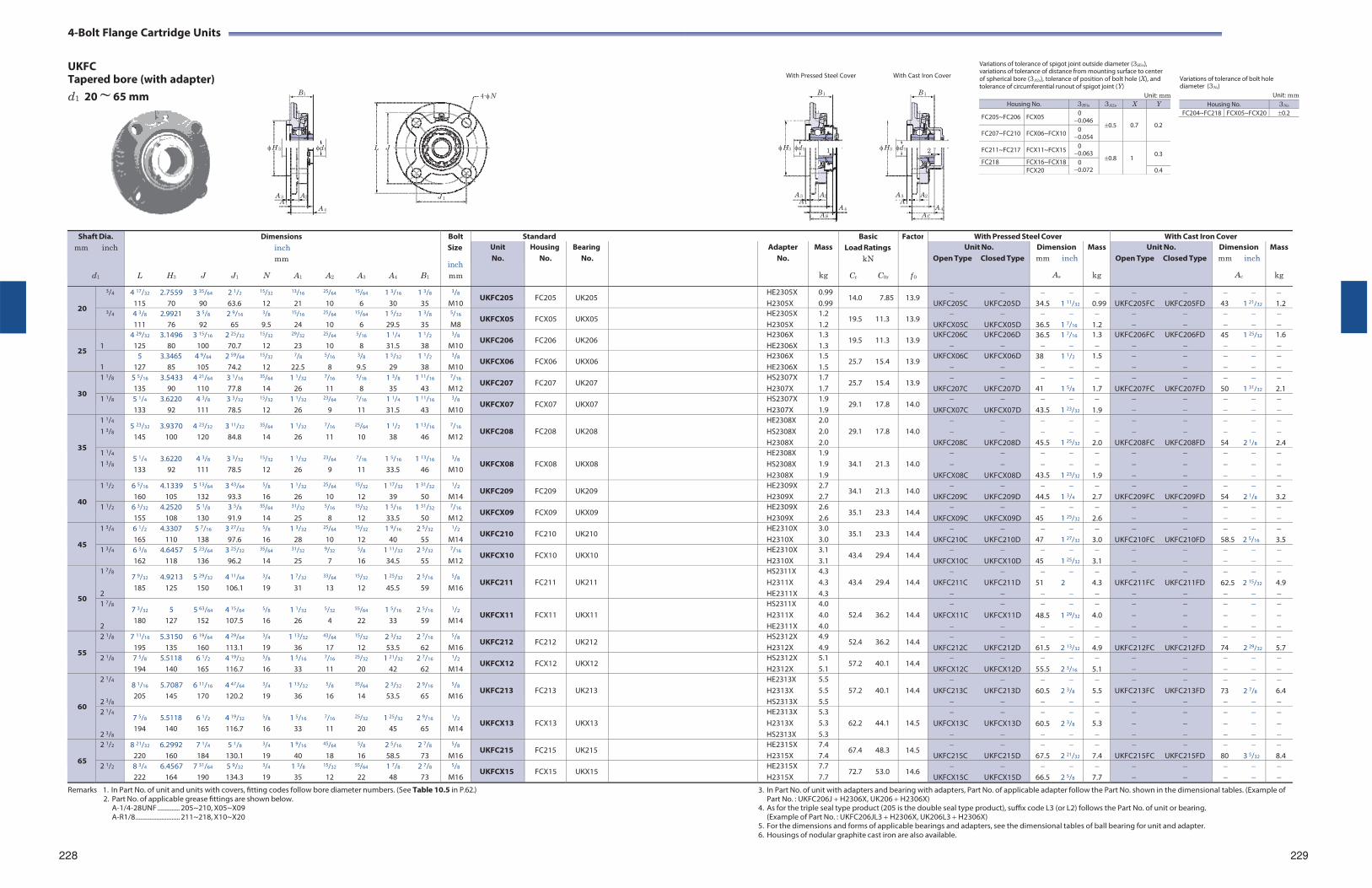
4-Bolt Flange Cartridge Units
UKFC Tapered bore (with adapter)
With Pressed Steel Cover With Cast Iron Cover
Variations of tolerance of spigot joint outside diameter (3H3s), variations of tolerance of distance from mounting surface to center of spherical bore (3A2s), tolerance of position of bolt hole (X), and tolerance of circumferential runout of spigot joint (Y)
Variations of tolerance of bolt hole diameter (3Ns)
d1 20 ~ 65 mm
H 3
B1
d1 L J
4-N B 1
H3 d1 1
B 1
H3 d1 2
Unit: mm Unit: mm
A 3 A2 J 1 A 1
A 4
A 3 A2 A 1
A 4
A S
A 3 A2 A 1
A 4
A C
Remarks 1. In Part No. of unit and units with covers, fitting codes follow bore diameter numbers. (See Table 10.5 in P.62.)
2. Part No. of applicable grease fittings are shown below. A-1/4-28UNF ............. 205~210, X05~X09 A-R1/8 .......................... 211~218, X10~X20
228
3. In Part No. of unit with adapters and bearing with adapters, Part No. of applicable adapter follow the Part No. shown in the dimensional tables. (Example of Part No. : UKFC206J H2306X, UK206 H2306X)
4. As for the triple seal type product (205 is the double seal type product), suffix code L3 (or L2) follows the Part No. of unit or bearing. (Example of Part No. : UKFC206JL3 H2306X, UK206L3 H2306X)
5. For the dimensions and forms of applicable bearings and adapters, see the dimensional tables of ball bearing for unit and adapter. 6. Housings of nodular graphite cast iron are also available.
229
Shaft Dia. mm inch
d1
Dimensions inch mm
L H3 J J1 N A1 A2 A3 A4 B1
Bolt Size
inch mm
Standard BasicLoad Ratings
kN
Cr C0r
Factor
f 0
With Pressed Steel Cover With Cast Iron Cover Unit No.
Housing No.
Bearing No.
Adapter No.
Mass
kg
Unit No. Open Type Closed Type
Dimension mm inch
As
Mass
kg
Unit No. Open Type Closed Type
Dimension mm inch
Ac
Mass
kg
20
3/4 4 17/32 2.7559 3 35/64 2 1/2 15/32 13/16 25/64 15/64 1 3/16 1 3/8
115 70 90 63.6 12 21 10 6 30 35
3/8
M10 UKFC205 FC205 UK205 HE2305X
H2305X0.99 0.99
14.0 7.85 13.9
UKFC205C UKFC205D
34.5 1 11/32
0.99
UKFC205FC UKFC205FD
43 1 21/32
1.2
3/4 4 3/8 2.9921 3 5/8 2 9/16 3/8 15/16 25/64 15/64 1 5/32 1 3/8
111 76 92 65 9.5 24 10 6 29.5 35
5/16
M8 UKFCX05 FCX05 UKX05 HE2305X
H2305X 1.2 1.2
19.5 11.3 13.9
UKFCX05C UKFCX05D
36.5 1 7/16
1.2
25
1
4 29/32 3.1496 3 15/16 2 25/32 15/32 29/32 25/64 5/16 1 1/4 1 1/2
125 80 100 70.7 12 23 10 8 31.5 38
3/8
M10 UKFC206 FC206 UK206 H2306X
HE2306X1.3 1.3
19.5 11.3 13.9 UKFC206C UKFC206D
36.5 1 7/16
1.3
UKFC206FC UKFC206FD
45 1 25/32
1.6
1
5 3.3465 4 9/64 2 59/64 15/32 7/8 5/16 3/8 1 5/32 1 1/2
127 85 105 74.2 12 22.5 8 9.5 29 38
3/8
M10 UKFCX06 FCX06 UKX06 H2306X
HE2306X 1.5 1.5
25.7 15.4 13.9 UKFCX06C UKFCX06D
38 1 1/2
1.5
30
1 1/8 5 5/16 3.5433 4 21/64 3 1/16 35/64 1 1/32 7/16 5/16 1 3/8 1 11/16
135 90 110 77.8 14 26 11 8 35 43
7/16
M12 UKFC207 FC207 UK207 HS2307X
H2307X 1.7 1.7
25.7 15.4 13.9
UKFC207C UKFC207D
41 1 5/8
1.7
UKFC207FC UKFC207FD
50 1 31/32
2.1
1 1/8 5 1/4 3.6220 4 3/8 3 3/32 15/32 1 1/32 23/64 7/16 1 1/4 1 11/16
133 92 111 78.5 12 26 9 11 31.5 43
3/8
M10 UKFCX07 FCX07 UKX07 HS2307X
H2307X 1.9 1.9
29.1 17.8 14.0
UKFCX07C UKFCX07D
43.5 1 23/32
1.9
35
1 1/4
1 3/8 5 23/32 3.9370 4 23/32 3 11/32 35/64 1 1/32 7/16 25/64 1 1/2 1 13/16
145 100 120 84.8 14 26 11 10 38 46
7/16
M12
UKFC208
FC208
UK208
HE2308X HS2308X H2308X
2.0 2.0 2.0
29.1 17.8
14.0
UKFC208C UKFC208D
45.5 1 25/32
2.0
UKFC208FC UKFC208FD
54 2 1/8
2.4
1 1/4
1 3/8 5 1/4 3.6220 4 3/8 3 3/32 15/32 1 1/32 23/64 7/16 1 5/16 1 13/16
133 92 111 78.5 12 26 9 11 33.5 46
3/8
M10
UKFCX08
FCX08
UKX08
HE2308X HS2308X H2308X
1.9 1.9 1.9
34.1 21.3
14.0
UKFCX08C UKFCX08D
43.5 1 23/32
1.9
40
1 1/2 6 5/16 4.1339 5 13/64 3 43/64 5/8 1 1/32 25/64 15/32 1 17/32 1 31/32
160 105 132 93.3 16 26 10 12 39 50
1/2
M14 UKFC209 FC209 UK209 HE2309X
H2309X 2.7 2.7
34.1 21.3 14.0
UKFC209C UKFC209D
44.5 1 3/4
2.7
UKFC209FC UKFC209FD
54 2 1/8
3.2
1 1/2 6 3/32 4.2520 5 1/8 3 5/8 35/64 31/32 5/16 15/32 1 5/16 1 31/32
155 108 130 91.9 14 25 8 12 33.5 50
7/16
M12 UKFCX09 FCX09 UKX09 HE2309X
H2309X 2.6 2.6
35.1 23.3 14.4
UKFCX09C UKFCX09D
45 1 25/32
2.6
45
1 3/4 6 1/2 4.3307 5 7/16 3 27/32 5/8 1 3/32 25/64 15/32 1 9/16 2 5/32
165 110 138 97.6 16 28 10 12 40 55
1/2
M14 UKFC210 FC210 UK210 HE2310X
H2310X 3.0 3.0
35.1 23.3 14.4
UKFC210C UKFC210D
47 1 27/32
3.0
UKFC210FC UKFC210FD
58.5 2 5/16
3.5
1 3/4 6 3/8 4.6457 5 23/64 3 25/32 35/64 31/32 9/32 5/8 1 11/32 2 5/32
162 118 136 96.2 14 25 7 16 34.5 55
7/16
M12 UKFCX10 FCX10 UKX10 HE2310X
H2310X 3.1 3.1
43.4 29.4 14.4
UKFCX10C UKFCX10D
45 1 25/32
3.1
50
1 7/8
2
7 9/32 4.9213 5 29/32 4 11/64 3/4 1 7/32 33/64 15/32 1 25/32 2 5/16
185 125 150 106.1 19 31 13 12 45.5 59
5/8
M16
UKFC211
FC211
UK211
HS2311X H2311X HE2311X
4.3 4.3 4.3
43.4 29.4
14.4
UKFC211C UKFC211D
51 2
4.3
UKFC211FC UKFC211FD
62.5 2 15/32
4.9
1 7/8
2
7 3/32 5 5 63/64 4 15/64 5/8 1 1/32 5/32 55/64 1 5/16 2 5/16
180 127 152 107.5 16 26 4 22 33 59
1/2
M14
UKFCX11
FCX11
UKX11
HS2311X H2311X HE2311X
4.0 4.0 4.0
52.4 36.2
14.4
UKFCX11C UKFCX11D
48.5 1 29/32
4.0
55
2 1/8 7 11/16 5.3150 6 19/64 4 29/64 3/4 1 13/32 43/64 15/32 2 3/32 2 7/16
195 135 160 113.1 19 36 17 12 53.5 62
5/8
M16 UKFC212 FC212 UK212 HS2312X
H2312X 4.9 4.9
52.4 36.2 14.4
UKFC212C UKFC212D
61.5 2 13/32
4.9
UKFC212FC UKFC212FD
74 2 29/32
5.7
2 1/8 7 5/8 5.5118 6 1/2 4 19/32 5/8 1 5/16 7/16 25/32 1 21/32 2 7/16
194 140 165 116.7 16 33 11 20 42 62
1/2
M14 UKFCX12 FCX12 UKX12 HS2312X
H2312X 5.1 5.1
57.2 40.1 14.4
UKFCX12C UKFCX12D
55.5 2 3/16
5.1
60
2 1/4
2 3/8
8 1/16 5.7087 6 11/16 4 47/64 3/4 1 13/32 5/8 35/64 2 3/32 2 9/16
205 145 170 120.2 19 36 16 14 53.5 65
5/8
M16
UKFC213
FC213
UK213
HE2313X H2313X HS2313X
5.5 5.5 5.5
57.2 40.1
14.4
UKFC213C UKFC213D
60.5 2 3/8
5.5
UKFC213FC UKFC213FD
73 2 7/8
6.4
2 1/4
2 3/8
7 5/8 5.5118 6 1/2 4 19/32 5/8 1 5/16 7/16 25/32 1 25/32 2 9/16
194 140 165 116.7 16 33 11 20 45 65
1/2
M14
UKFCX13
FCX13
UKX13
HE2313X H2313X HS2313X
5.3 5.3 5.3
62.2 44.1
14.5
UKFCX13C UKFCX13D
60.5 2 3/8
5.3
65
2 1/2 8 21/32 6.2992 7 1/4 5 1/8 3/4 1 9/16 45/64 5/8 2 5/16 2 7/8
220 160 184 130.1 19 40 18 16 58.5 73
5/8
M16 UKFC215 FC215 UK215 HE2315X
H2315X 7.4 7.4
67.4 48.3 14.5
UKFC215C UKFC215D
67.5 2 21/32
7.4
UKFC215FC UKFC215FD
80 3 5/32
8.4
2 1/2 8 3/4 6.4567 7 31/64 5 9/32 3/4 1 3/8 15/32 55/64 1 7/8 2 7/8
222 164 190 134.3 19 35 12 22 48 73
5/8
M16 UKFCX15 FCX15 UKX15 HE2315X
H2315X 7.7 7.7
72.7 53.0 14.6
UKFCX15C UKFCX15D
66.5 2 5/8
7.7
Housing No. 3H3s 3A2s X Y
FC205~FC206 FCX05 0 0.046
0.5
0.7
0.2 FC207~FC210 FCX06~FCX10 0
0.054
FC211~FC217 FCX11~FCX15 0 0.063
0.8
1
0.3
FC218 FCX16~FCX18 0 0.072 FCX20 0.4
Housing No. 3Ns
FC204~FC218 FCX05~FCX20 0.2
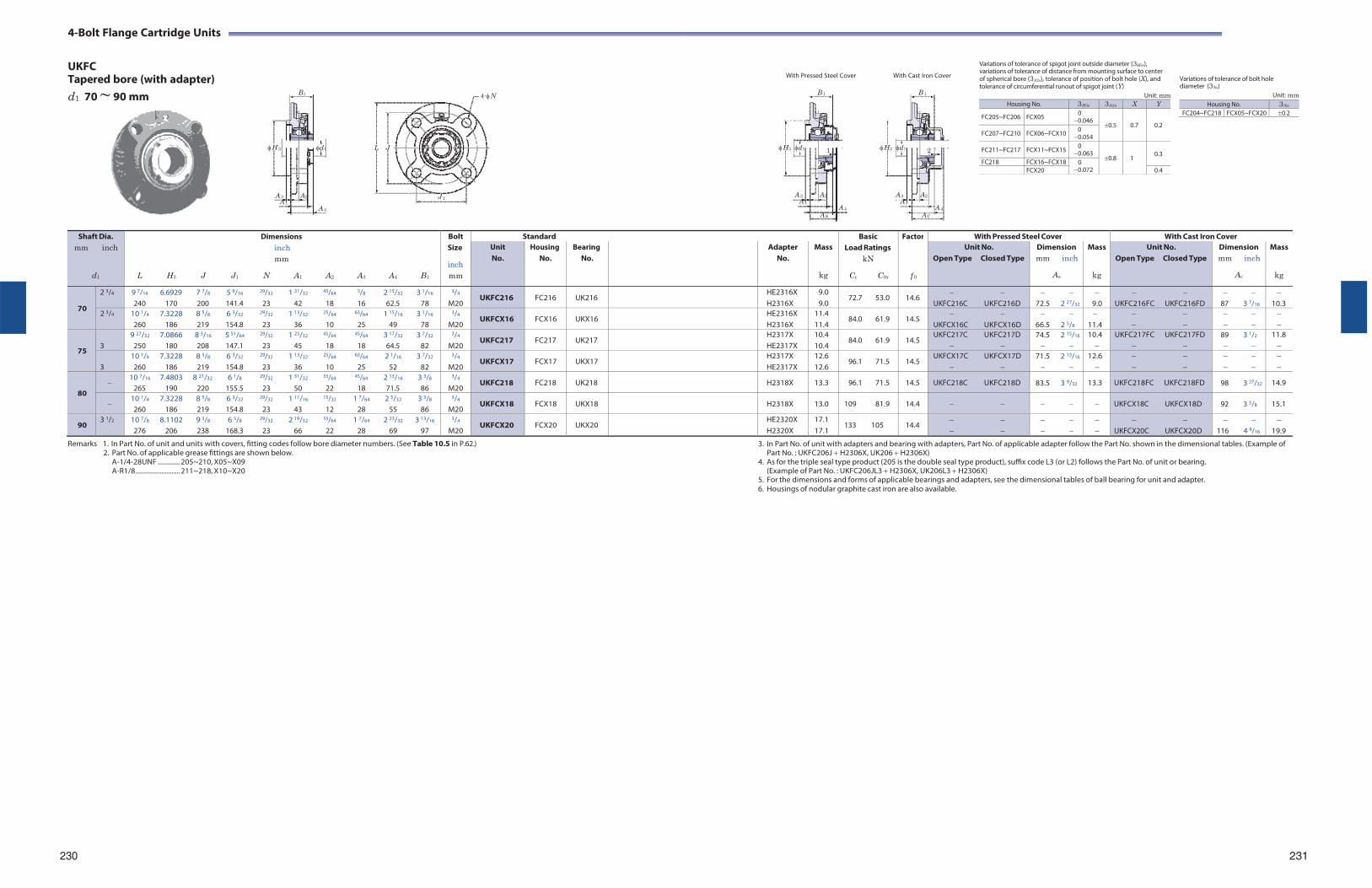
4-Bolt Flange Cartridge Units
UKFC Tapered bore (with adapter)
With Pressed Steel Cover With Cast Iron Cover
Variations of tolerance of spigot joint outside diameter (3H3s), variations of tolerance of distance from mounting surface to center of spherical bore (3A2s), tolerance of position of bolt hole (X), and tolerance of circumferential runout of spigot joint (Y)
Variations of tolerance of bolt hole diameter (3Ns)
d1 70 ~ 90 mm
H 3
B1
d1 L J
4-N B 1
H3 d1 1
B 1
H3 d1 2
Unit: mm Unit: mm
A 3 A2 J 1 A 1
A 4
A 3 A2 A 1
A 4
A S
A 3 A2 A 1
A 4
A C
Remarks 1. In Part No. of unit and units with covers, fitting codes follow bore diameter numbers. (See Table 10.5 in P.62.)
2. Part No. of applicable grease fittings are shown below. A-1/4-28UNF ............. 205~210, X05~X09 A-R1/8 .......................... 211~218, X10~X20
3. In Part No. of unit with adapters and bearing with adapters, Part No. of applicable adapter follow the Part No. shown in the dimensional tables. (Example of Part No. : UKFC206J H2306X, UK206 H2306X)
4. As for the triple seal type product (205 is the double seal type product), suffix code L3 (or L2) follows the Part No. of unit or bearing. (Example of Part No. : UKFC206JL3 H2306X, UK206L3 H2306X)
5. For the dimensions and forms of applicable bearings and adapters, see the dimensional tables of ball bearing for unit and adapter. 6. Housings of nodular graphite cast iron are also available.
230 231
Shaft Dia. mm inch
d1
Dimensions inch mm
L H3 J J1 N A1 A2 A3 A4 B1
Bolt Size
inch mm
Standard BasicLoad Ratings
kN
Cr C0r
Factor
f 0
With Pressed Steel Cover With Cast Iron Cover Unit No.
Housing No.
Bearing No.
Adapter No.
Mass
kg
Unit No. Open Type Closed Type
Dimension mm inch
As
Mass
kg
Unit No. Open Type Closed Type
Dimension mm inch
Ac
Mass
kg
70
2 3/4 9 7/16 6.6929 7 7/8 5 9/16 29/32 1 31/32 45/64 5/8 2 15/32 3 1/16
240 170 200 141.4 23 42 18 16 62.5 78
3/4
M20 UKFC216 FC216 UK216 HE2316X
H2316X9.0 9.0
72.7 53.0 14.6
UKFC216C UKFC216D
72.5 2 27/32
9.0
UKFC216FC UKFC216FD
87 3 7/16
10.3
2 3/4 10 1/4 7.3228 8 5/8 6 3/32 29/32 1 13/32 25/64 63/64 1 15/16 3 1/16
260 186 219 154.8 23 36 10 25 49 78
3/4
M20 UKFCX16 FCX16 UKX16 HE2316X
H2316X 11.4 11.4
84.0 61.9 14.5
UKFCX16C UKFCX16D
66.5 2 5/8
11.4
75
3
9 27/32 7.0866 8 3/16 5 51/64 29/32 1 25/32 45/64 45/64 3 17/32 3 7/32
250 180 208 147.1 23 45 18 18 64.5 82
3/4
M20 UKFC217 FC217 UK217 H2317X
HE2317X10.4 10.4
84.0 61.9 14.5 UKFC217C UKFC217D
74.5 2 15/16
10.4
UKFC217FC UKFC217FD
89 3 1/2
11.8
3
10 1/4 7.3228 8 5/8 6 3/32 29/32 1 13/32 25/64 63/64 2 1/16 3 7/32
260 186 219 154.8 23 36 10 25 52 82
3/4
M20 UKFCX17 FCX17 UKX17 H2317X
HE2317X 12.6 12.6
96.1 71.5 14.5 UKFCX17C UKFCX17D
71.5 2 13/16
12.6
80
10 7/16 7.4803 8 21/32 6 1/8 29/32 1 31/32 55/64 45/64 2 13/16 3 3/8
265 190 220 155.5 23 50 22 18 71.5 86
3/4
M20 UKFC218 FC218 UK218 H2318X 13.3 96.1 71.5 14.5 UKFC218C UKFC218D 83.5 3 9/32 13.3 UKFC218FC UKFC218FD 98 3 27/32 14.9
10 1/4 7.3228 8 5/8 6 3/32 29/32 1 11/16 15/32 1 7/64 2 5/32 3 3/8
260 186 219 154.8 23 43 12 28 55 86
3/4
M20 UKFCX18 FCX18 UKX18 H2318X 13.0 109 81.9 14.4 UKFCX18C UKFCX18D 92 3 5/8 15.1
90 3 1/2 10 7/8 8.1102 9 3/8 6 5/8 29/32 2 19/32 55/64 1 7/64 2 23/32 3 13/16
276 206 238 168.3 23 66 22 28 69 97
3/4
M20 UKFCX20 FCX20 UKX20 HE2320X
H2320X 17.1 17.1
133 105 14.4
UKFCX20C UKFCX20D
116 4 9/16
19.9
Housing No. 3H3s 3A2s X Y
FC205~FC206 FCX05 0 0.046
0.5
0.7
0.2 FC207~FC210 FCX06~FCX10 0
0.054
FC211~FC217 FCX11~FCX15 0 0.063
0.8
1
0.3
FC218 FCX16~FCX18 0 0.072 FCX20 0.4
Housing No. 3Ns
FC204~FC218 FCX05~FCX20 0.2
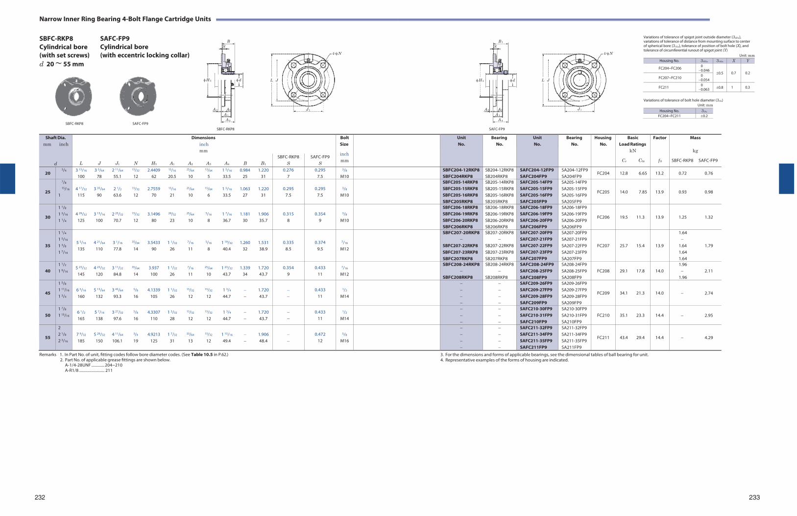
Narrow Inner Ring Bearing 4-Bolt Flange Cartridge Units
SBFC-RKP8 Cylindrical bore (with set screws) d 20 ~ 55 mm
SAFC-FP9 Cylindrical bore (with eccentric locking collar)
B
S
H 3 d L J
4-N
B 1
S
H 3 d L J
4-N
Variations of tolerance of spigot joint outside diameter (3H3s), variations of tolerance of distance from mounting surface to center of spherical bore (3A2s), tolerance of position of bolt hole (X), and tolerance of circumferential runout of spigot joint (Y)
Unit: mm
SBFC-RKP8 SAFC-FP9
A 3 A2 J 1
A 1
A 4
A 3 A2
A 1
A 4
Variations of tolerance of bolt hole diameter (3Ns) Unit: mm
J 1
SBFC-RKP8 SAFC-FP9
Remarks 1. In Part No. of unit, fitting codes follow bore diameter codes. (See Table 10.5 in P.62.)
2. Part No. of applicable grease fittings are shown below. A-1/4-28UNF ............. 204~210 A-R1/8 .......................... 211
3. For the dimensions and forms of applicable bearings, see the dimensional tables of ball bearing for unit. 4. Representative examples of the forms of housing are indicated.
232
233
Shaft Dia. mm inch
d
Dimensions inch mm
BoltSize
inch mm
UnitNo.
BearingNo.
UnitNo.
Bearing No.
Housing No.
Basic Load Ratings
kN
Cr C0r
Factor
f 0
Mass
kg
SBFC-RKP8 SAFC-FP9
L J J1 N H3 A1 A2 A3 A4 B B1
SBFC-RKP8 S
SAFC-FP9 S
20 3/4 3 15/16 3 5/64 2 11/64 15/32 2.4409 13/16 25/64 13/64 1 5/16 0.984 1.220
100 78 55.1 12 62 20.5 10 5 33.5 25 31 0.276
7 0.295
7.5
3/8
M10 SBFC204-12RKP8
SBFC204RKP8SB204-12RKP8 SB204RKP8
SAFC204-12FP9 SAFC204FP9
SA204-12FP9 SA204FP9
FC204 12.8 6.65 13.2 0.72 0.76
25
7/8
15/16
1
4 17/32 3 35/64 2 1/2 15/32 2.7559 13/16 25/64 15/64 1 5/16 1.063 1.220
115 90 63.6 12 70 21 10 6 33.5 27 31
0.295
7.5
0.295
7.5
3/8
M10
SBFC205-14RKP8 SBFC205-15RKP8 SBFC205-16RKP8 SBFC205RKP8
SB205-14RKP8 SB205-15RKP8 SB205-16RKP8 SB205RKP8
SAFC205-14FP9 SAFC205-15FP9 SAFC205-16FP9 SAFC205FP9
SA205-14FP9 SA205-15FP9 SA205-16FP9 SA205FP9
FC205
14.0 7.85
13.9
0.93 0.98
30
1 1/8
1 3/16
1 1/4
4 29/32 3 15/16 2 25/32 15/32 3.1496 29/32 25/64 5/16 1 7/16 1.181 1.906
125 100 70.7 12 80 23 10 8 36.7 30 35.7
0.315
8
0.354
9
3/8
M10
SBFC206-18RKP8 SBFC206-19RKP8 SBFC206-20RKP8 SBFC206RKP8
SB206-18RKP8 SB206-19RKP8 SB206-20RKP8 SB206RKP8
SAFC206-18FP9 SAFC206-19FP9 SAFC206-20FP9 SAFC206FP9
SA206-18FP9 SA206-19FP9 SA206-20FP9 SA206FP9
FC206
19.5 11.3
13.9
1.25 1.32
35
1 1/4
1 5/16
1 3/8
1 7/16
5 5/16 4 21/64 3 1/16 35/64 3.5433 1 1/32 7/16 5/16 1 19/32 1.260 1.531 135 110 77.8 14 90 26 11 8 40.4 32 38.9
0.335 8.5
0.374 9.5
7/16
M12
SBFC207-20RKP8
SBFC207-22RKP8 SBFC207-23RKP8 SBFC207RKP8
SB207-20RKP8
SB207-22RKP8 SB207-23RKP8 SB207RKP8
SAFC207-20FP9 SAFC207-21FP9 SAFC207-22FP9 SAFC207-23FP9 SAFC207FP9
SA207-20FP9 SA207-21FP9 SA207-22FP9 SA207-23FP9 SA207FP9
FC207
25.7 15.4
13.9
1.64
1.64 1.79 1.64 1.64
40
1 1/2
1 9/16 5 23/32 4 23/32 3 11/32 35/64 3.937 1 1/32 7/16 25/64 1 23/32 1.339 1.720
145 120 84.8 14 100 26 11 10 43.7 34 43.7 0.354
9 0.433
11
7/16
M12
SBFC208-24RKP8
SBFC208RKP8
SB208-24RKP8
SB208RKP8
SAFC208-24FP9 SAFC208-25FP9 SAFC208FP9
SA208-24FP9 SA208-25FP9 SA208FP9
FC208
29.1 17.8
14.0
1.96 2.11
1.96
45
1 5/8
1 11/16
1 3/4
6 5/16 5 13/64 3 43/64 5/8 4.1339 1 1/32 15/32 15/32 1 3/4 1.720 160 132 93.3 16 105 26 12 12 44.7 43.7
0.433
11
1/2
M14
SAFC209-26FP9 SAFC209-27FP9 SAFC209-28FP9 SAFC209FP9
SA209-26FP9 SA209-27FP9 SA209-28FP9 SA209FP9
FC209
34.1 21.3
14.0
2.74
50
1 7/8
1 15/16 6 1/2 5 7/16 3 27/32 5/8 4.3307 1 3/32 15/32 15/32 1 3/4 1.720 165 138 97.6 16 110 28 12 12 44.7 43.7
0.433 11
1/2
M14
SAFC210-30FP9 SAFC210-31FP9 SAFC210FP9
SA210-30FP9 SA210-31FP9 SA210FP9
FC210
35.1 23.3
14.4
2.95
55
2 2 1/8
2 3/16
7 9/32 5 29/32 4 11/64 3/4 4.9213 1 7/32 33/64 15/32 1 15/16 1.906 185 150 106.1 19 125 31 13 12 49.4 48.4
0.472
12
5/8
M16
SAFC211-32FP9 SAFC211-34FP9 SAFC211-35FP9 SAFC211FP9
SA211-32FP9 SA211-34FP9 SA211-35FP9 SA211FP9
FC211
43.4 29.4
14.4
4.29
Housing No. 3H3s 3A2s X Y
FC204~FC206 0 0.046
0.5
0.7
0.2 FC207~FC210 0
0.054
FC211 0 0.063 0.8 1 0.3
Housing No. 3Ns
FC204~FC211 0.2
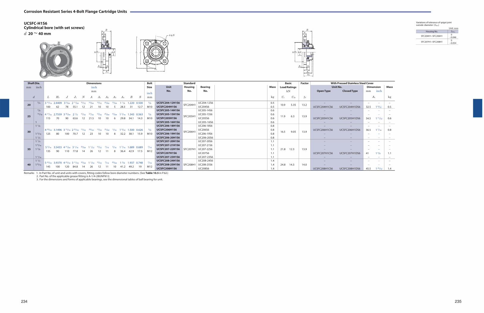
Corrosion Resistant Series 4-Bolt Flange Cartridge Units
UCSFC-H1S6 Cylindrical bore (with set screws) d 20 ~ 40 mm
B S A2
H 3 d L J
4-N
B S A2
H 3 d 1
Variations of tolerance of spigot joint outside diameter (3H3s)
Unit: mm
A 3 A1 A J 1
A 4
A 3 A1
A A 4
A S
Remarks 1. In Part No. of unit and units with covers, fitting codes follow bore diameter numbers. (See Table 10.5 in P.62.)
2. Part No. of the applicable grease fitting is A-1/4-28UNFN12. 3. For the dimensions and forms of applicable bearings, see the dimensional tables of ball bearing for unit.
234
235
Shaft Dia. mm inch
d
Dimensions inch mm
L H3 J J1 N A A1 A2 A3 A4 B S
Bolt Size
inch mm
Standard BasicLoad Ratings
kN
Cr C0r
Factor
f 0
With Pressed Stainless Steel Cover Unit No.
Housing No.
Bearing No.
Mass
kg
Unit No. Open Type Closed Type
Dimension mm inch
As
Mass
kg
20 3/4 3 15/16 2.4409 3 5/64 2 11/64 15/32 53/64 13/32 25/64 13/64 1 1/8 1.220 0.500
100 62 78 55.1 12 21 10 10 5 28.3 31 12.7
3/8
M10 UCSFC204-12H1S6 UCSFC204H1S6
SFC204H1UC204-12S6 UC204S6
0.5 0.5
10.9 5.35 13.2
UCSFC204H1CS6 UCSFC204H1DS6
32.5 1 9/32
0.5
25
7/8
15/16
1
4 17/32 2.7559 3 35/64 2 1/2 15/32 27/32 13/32 25/64 15/64 1 3/16 1.343 0.563
115 70 90 63.6 12 21.5 10 10 6 29.8 34.1 14.3
3/8
M10
UCSFC205-14H1S6 UCSFC205-15H1S6 UCSFC205H1S6 UCSFC205-16H1S6
SFC205H1
UC205-14S6 UC205-15S6 UC205S6 UC205-16S6
0.6 0.6 0.6 0.6
11.9 6.3
13.9
UCSFC205H1CS6 UCSFC205H1DS6
34.5 1 11/32
0.6
30
1 1/8
1 3/16
1 1/4
4 29/32 3.1496 3 15/16 2 25/32 15/32 29/32 13/32 25/64 5/16 1 9/32 1.500 0.626
125 80 100 70.7 12 23 10 10 8 32.2 38.1 15.9
3/8
M10
UCSFC206-18H1S6 UCSFC206H1S6 UCSFC206-19H1S6 UCSFC206-20H1S6
SFC206H1
UC206-18S6 UC206S6 UC206-19S6 UC206-20S6
0.8 0.8 0.8 0.8
16.5 9.05
13.9
UCSFC206H1CS6 UCSFC206H1DS6
36.5 1 7/16
0.8
35
1 1/4
1 5/16
1 3/8
1 7/16
5 5/16 3.5433 4 21/64 3 1/16 35/64 1 1/32 15/32 7/16 5/16 1 7/16 1.689 0.689 135 90 110 77.8 14 26 12 11 8 36.4 42.9 17.5
7/16
M12
UCSFC207-20H1S6 UCSFC207-21H1S6 UCSFC207-22H1S6 UCSFC207H1S6 UCSFC207-23H1S6
SFC207H1
UC207-20S6 UC207-21S6 UC207-22S6 UC207S6 UC207-23S6
1.1 1.1 1.1 1.1 1.1
21.8 12.3
13.9
UCSFC207H1CS6 UCSFC207H1DS6
41 1 5/8
1.1
40
1 1/2
1 9/16 5 23/32 3.9370 4 23/32 3 11/32 35/64 1 1/32 15/32 7/16 25/64 1 5/8 1.937 0.748
145 100 120 84.8 14 26 12 11 10 41.2 49.2 19
7/16
M12
UCSFC208-24H1S6 UCSFC208-25H1S6 UCSFC208H1S6
SFC208H1
UC208-24S6 UC208-25S6 UC208S6
1.4 1.4 1.4
24.8 14.3
14.0
UCSFC208H1CS6 UCSFC208H1DS6
45.5 1 25/32
1.4
Housing No. 3H3s
SFC204H1~SFC206H1 0 0.046
SFC207H1~SFC208H1 0 0.054

Stamped Steel 3-Bolt Flange Cartridge Units
SBPF Cylindrical bore (with set screws) d 12 ~ 35 mm
SAPF Cylindrical bore (with eccentric locking collar)
B B1
S N S
N
Variations of tolerance of distance between centers of bolt holes (3Js)
Unit: mm Housing No. 3Js
PF203~PF207 0.4
Variations of tolerance of bolt hole diameter (3Ns)
Unit: mm
H2 d H J H2 d
SBPF SAPF
A1
A
SBPF
A1
A
SAPF
Note 1) H2 is the minimum size of the mounting hole. Remark For the dimensions and forms of applicable bearings, see the dimensional tables of ball bearing for unit.
236 237
Shaft Dia mm inch
d
Dimensions inch mm
Bolt Size
inch mm
Unit No.
BearingNo.
UnitNo.
BearingNo.
HousingNo.
BasicLoad Ratings
kN
Cr C0r
Factor
f 0
Mass
kg
SBPF SAPF
H A A1 J N H2 S
SBPF B
SAPF B1
12
15
17
1/2
5/8
3 3/16 9/16 5/32 2 1/2 9/32 1 15/16 0.236 81 14 4 63.5 7.1 49 6
0.866 22
1.122 28.5
1/4
M6
SBPF201 SBPF201-8 SBPF202 SBPF202-10 SBPF203
SB201 SB201-8 SB202 SB202-10 SB203
SAPF201 SAPF201-8 SAPF202 SAPF202-10 SAPF203
SA201 SA201-8 SA202 SA202-10 SA203
PF203
9.55 4.80
13.2
0.27 0.3
20 3/4 3 17/32 5/8 5/32 2 13/16 23/64 2 5/32 0.276
90 16 4 71.5 9 55 7 0.984
25 1.161 29.5
5/16
M8 SBPF204-12 SBPF204
SB204-12 SB204
SAPF204-12 SAPF204
SA204-12 SA204
PF204 12.8 6.65 13.2 0.33 0.33
25
7/8
15/16
1
3 3/4 23/32 5/32 2 63/64 23/64 2 3/8 0.295 95 18 4 76 9 60 7.5
1.063
27
1.201 30.5
5/16
M8
SBPF205-14 SBPF205-15 SBPF205 SBPF205-16
SB205-14 SB205-15 SB205 SB205-16
SAPF205-14 SAPF205-15 SAPF205 SAPF205-16
SA205-14 SA205-15 SA205 SA205-16
PF205
14.0 7.85
13.9
0.38 0.42
30
1 1/8
1 3/16
1 1/4
4 7/16 3/4 13/64 3 9/16 7/16 2 25/32 0.315 113 19 5.2 90.5 11 71 8
1.181
30
1.335 33.9
3/8
M10
SBPF206-18 SBPF206 SBPF206-19 SBPF206-20
SB206-18 SB206 SB206-19 SB206-20
SAPF206-18 SAPF206 SAPF206-19 SAPF206-20
SA206-18 SA206 SA206-19 SA206-20
PF206
19.5 11.3
13.9
0.62 0.65
35
1 1/4
1 5/16
1 3/8
1 7/16
4 13/16 7/8 13/64 3 15/16 7/16 3 3/16 0.335 122 22 5.2 100 11 81 8.5
1.260 32
1.437 36.5
3/8
M10
SBPF207-20
SBPF207-22 SBPF207 SBPF207-23
SB207-20
SB207-22 SB207 SB207-23
SAPF207-20 SAPF207-21 SAPF207-22 SAPF207 SAPF207-23
SA207-20 SA207-21 SA207-22 SA207 SA207-23
PF207
25.7 15.4
13.9
0.82 0.9
Housing No. 3Ns
PF203~PF207 0.25
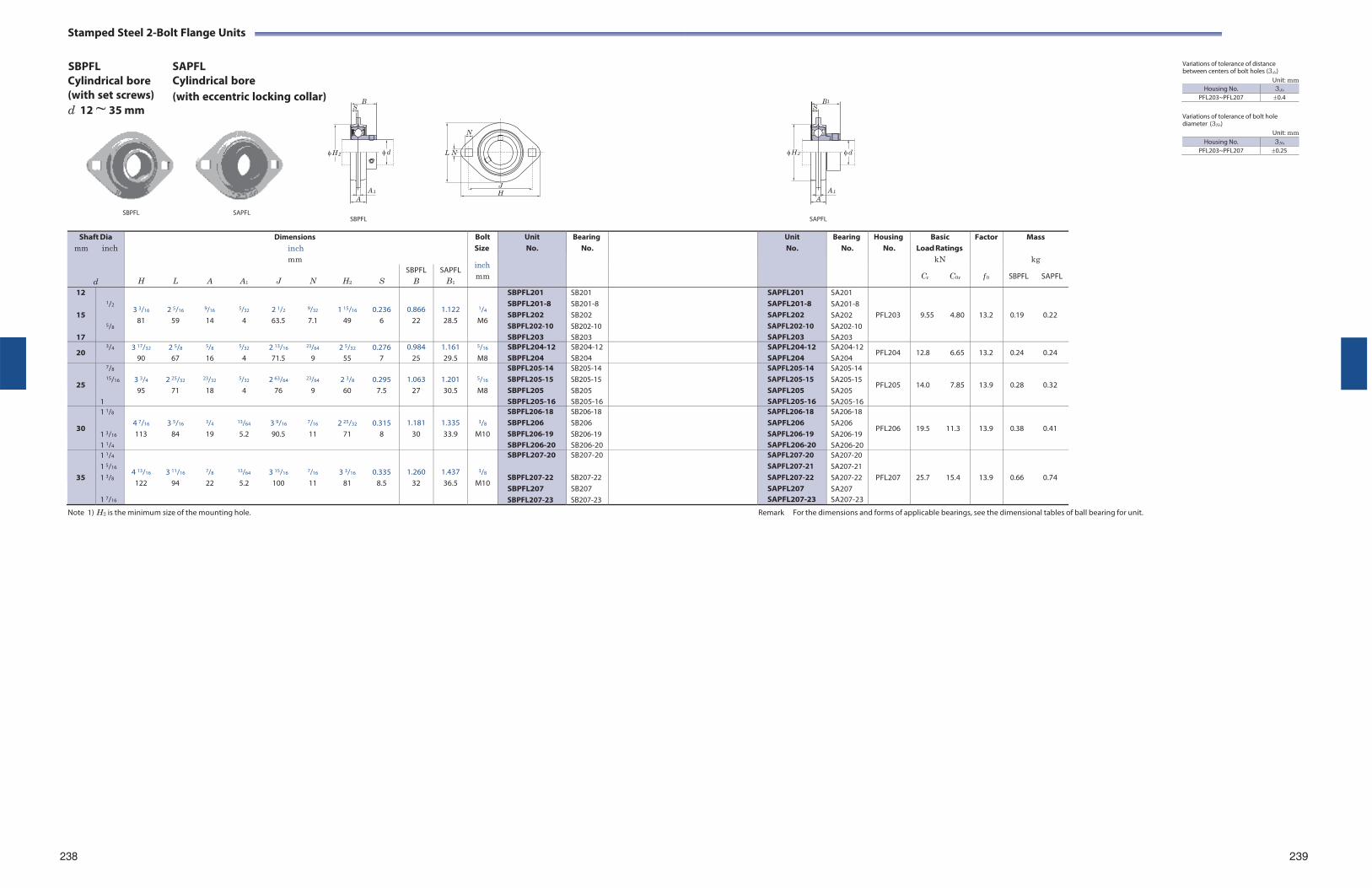
Stamped Steel 2-Bolt Flange Units
SBPFL Cylindrical bore (with set screws) d 12 ~ 35 mm
SAPFL Cylindrical bore (with eccentric locking collar) B B
S S
N
Variations of tolerance of distance between centers of bolt holes (3Js)
Unit: mm Housing No. 3Js
PFL203~PFL207 0.4
Variations of tolerance of bolt hole diameter (3Ns)
Unit: mm
H 2 d L N H 2 d
SBPFL SAPFL
A 1
A
SBPFL
J
H
A 1
A
SAPFL
Note 1) H2 is the minimum size of the mounting hole. Remark For the dimensions and forms of applicable bearings, see the dimensional tables of ball bearing for unit.
238 239
Shaft Dia mm inch
d
Dimensions inch mm
Bolt Size
inch mm
Unit No.
BearingNo.
UnitNo.
BearingNo.
HousingNo.
BasicLoad Ratings
kN
Cr C0r
Factor
f 0
Mass
kg
SBPFL SAPFL
H L A A1 J N H2 S
SBPFL B
SAPFL B1
12
15
17
1/2
5/8
3 3/16 2 5/16 9/16 5/32 2 1/2 9/32 1 15/16 0.236 81 59 14 4 63.5 7.1 49 6
0.866 22
1.122 28.5
1/4
M6
SBPFL201 SBPFL201-8 SBPFL202 SBPFL202-10 SBPFL203
SB201 SB201-8 SB202 SB202-10 SB203
SAPFL201 SAPFL201-8 SAPFL202 SAPFL202-10 SAPFL203
SA201 SA201-8 SA202 SA202-10 SA203
PFL203
9.55 4.80
13.2
0.19 0.22
20 3/4 3 17/32 2 5/8 5/8 5/32 2 13/16 23/64 2 5/32 0.276
90 67 16 4 71.5 9 55 7 0.984
25 1.161 29.5
5/16
M8 SBPFL204-12 SBPFL204
SB204-12 SB204
SAPFL204-12 SAPFL204
SA204-12 SA204
PFL204 12.8 6.65 13.2 0.24 0.24
25
7/8
15/16
1
3 3/4 2 25/32 23/32 5/32 2 63/64 23/64 2 3/8 0.295 95 71 18 4 76 9 60 7.5
1.063
27
1.201 30.5
5/16
M8
SBPFL205-14 SBPFL205-15 SBPFL205 SBPFL205-16
SB205-14 SB205-15 SB205 SB205-16
SAPFL205-14 SAPFL205-15 SAPFL205 SAPFL205-16
SA205-14 SA205-15 SA205 SA205-16
PFL205
14.0 7.85
13.9
0.28 0.32
30
1 1/8
1 3/16
1 1/4
4 7/16 3 5/16 3/4 13/64 3 9/16 7/16 2 25/32 0.315 113 84 19 5.2 90.5 11 71 8
1.181
30
1.335 33.9
3/8
M10
SBPFL206-18 SBPFL206 SBPFL206-19 SBPFL206-20
SB206-18 SB206 SB206-19 SB206-20
SAPFL206-18 SAPFL206 SAPFL206-19 SAPFL206-20
SA206-18 SA206 SA206-19 SA206-20
PFL206
19.5 11.3
13.9
0.38 0.41
35
1 1/4
1 5/16
1 3/8
1 7/16
4 13/16 3 11/16 7/8 13/64 3 15/16 7/16 3 3/16 0.335 122 94 22 5.2 100 11 81 8.5
1.260 32
1.437 36.5
3/8
M10
SBPFL207-20
SBPFL207-22 SBPFL207 SBPFL207-23
SB207-20
SB207-22 SB207 SB207-23
SAPFL207-20 SAPFL207-21 SAPFL207-22 SAPFL207 SAPFL207-23
SA207-20 SA207-21 SA207-22 SA207 SA207-23
PFL207
25.7 15.4
13.9
0.66 0.74
1
Housing No. 3Ns
PFL203~PFL207 0.25
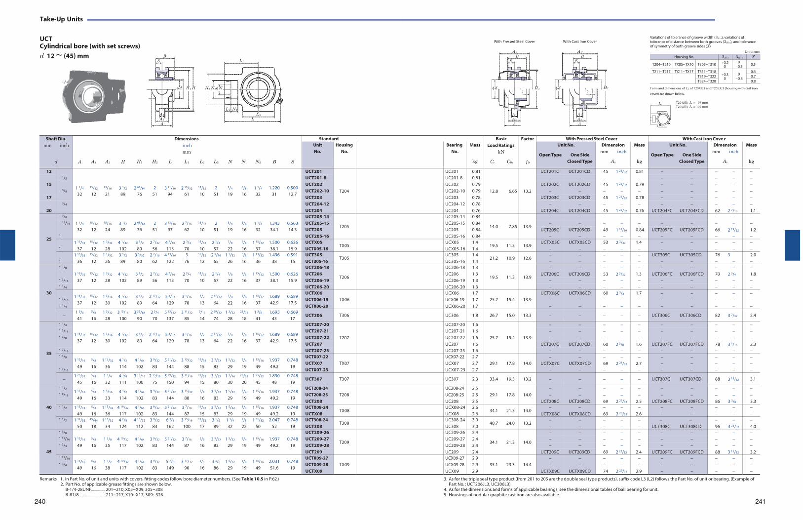
Take-Up Units
UCT Cylindrical bore (with set screws)
With Pressed Steel Cover With Cast Iron Cover
Variations of tolerance of groove width (3A1s), variations of tolerance of distance between both grooves (3H1s), and tolerance of symmetry of both groove sides (X)
d 12 ~ (45) mm
B S L 1
AS AC
B B S S
Unit: mm
d H 1 H
H 2 N 2 N
d H 1 d
H 1 Form and dimensions of Lc of T204JE3 and T205JE3 (housing with cast iron 1 2 cover) are shown below.
L 2 N 1
A 1 L 3
A 2 L A
A 1 A 1
A 2 A 2
A A
T204JE3 Lc 97 mm T205JE3 Lc 102 mm
Remarks 1. In Part No. of unit and units with covers, fitting codes follow bore diameter numbers. (See Table 10.5 in P.62.)
2. Part No. of applicable grease fittings are shown below. B-1/4-28UNF.............. 201~210, X05~X09, 305~308 B-R1/8 .......................... 211~217, X10~X17, 309~328
240
3. As for the triple seal type product (from 201 to 205 are the double seal type products), suffix code L3 (L2) follows the Part No. of unit or bearing. (Example of Part No. : UCT206JL3, UC206L3)
4. As for the dimensions and forms of applicable bearings, see the dimensional tables of ball bearing for unit. 5. Housings of nodular graphite cast iron are also available.
241
Shaft Dia. mm inch
d
A
A1
A2
H
H1
H2
Dimensions inch mm
L L1 L2
L3
N
N1
N2
B
S
Standard BasicLoad Ratings
kN
Cr C0r
Factor
f 0
With Pressed Steel Cover With Cast Iron Cove r Unit No.
Housing No.
Bearing No.
Mass
kg
Unit No.
Open Type One Side Closed Type
Dimension mm inch
As
Mass
kg
Unit No.
Open Type One Side Closed Type
Dimension mm inch
Ac
Mass
kg
12 1/2
1 1/4
15/32
13/16
3 1/2
2 63/64
2
3 11/16
2 13/32
13/32
2
3/4
5/8
1 1/4
1.220
0.500
UCT201
T204
UC201 0.81
12.8
6.65
13.2
UCT201C UCT201CD 45 1 25/32 0.81 UCT201-8 UC201-8 0.81
15 5/8
UCT202 UC202 0.79 UCT202C UCT202CD 45 1 25/32 0.79 UCT202-10 UC202-10 0.79
32 12 21 89 76 51 94 61 10 51 19 16 32 31 12.7 17 UCT203 UC203 0.78 UCT203C UCT203CD 45 1 25/32 0.78
3/4 UCT204-12 UC204-12 0.78 20 UCT204 UC204 0.76 UCT204C UCT204CD 45 1 25/32 0.76 UCT204FC UCT204FCD 62 2 7/16 1.1
25
7/8 1 1/4
15/32
15/16
3 1/2
2 63/64
2
3 13/16
2 7/16
13/32
2
3/4
5/8
1 1/4
1.343
0.563
UCT205-14
T205
UC205-14 0.84
14.0
7.85
13.9
15/16 UCT205-15 UC205-15 0.84
32 12 24 89 76 51 97 62 10 51 19 16 32 34.1 14.3 UCT205 UC205 0.84 UCT205C UCT205CD 49 1 15/16 0.84 UCT205FC UCT205FCD 66 2 19/32 1.2 1 UCT205-16 UC205-16 0.84
1
1 15/32
37
15/32
12 1 3/32
28 4 1/32
102 3 1/2
89 2 7/32
56 4 7/16
113 2 3/4
70
13/32
10 2 1/4
57
7/8
22
5/8
16 1 15/32
37 1.500 38.1
0.626 15.9
UCTX05 UCTX05-16
TX05 UCX05 UCX05-16
1.4 1.4
19.5 11.3 13.9 UCTX05C
UCTX05CD
53
2 3/32
1.4
1
1 13/32
36
15/32
12 1 1/32
26 3 1/2
89 3 5/32
80 2 7/16
62 4 13/16
122 3
76
15/32
12 2 9/16
65 1 1/32
26
5/8
16 1 13/32
36 1.496
38 0.591
15 UCT305 UCT305-16
T305 UC305 UC305-16
1.4 1.4
21.2 10.9 12.6
UCT305C
UCT305CD
76
3
2.0
30
1 1/8 1 15/32
15/32
1 3/32
4 1/32
3 1/2
2 7/32
4 7/16
2 3/4
13/32
2 1/4
7/8
5/8
1 15/32
1.500
0.626
UCT206-18
T206
UC206-18 1.3
19.5
11.3
13.9
1 3/16
UCT206 UC206 1.3 UCT206C UCT206CD 53 2 3/32 1.3 UCT206FC UCT206FCD 70 2 3/4 1.8 37 12 28 102 89 56 113 70 10 57 22 16 37 38.1 15.9 UCT206-19 UC206-19 1.3
1 1/4 UCT206-20 UC206-20 1.3
1 3/16
1 1/4
1 15/32
37
15/32
12 1 3/16
30 4 1/32
102 3 1/2
89 2 17/32
64 5 3/32
129 3 1/16
78
1/2
13 2 17/32
64
7/8
22
5/8
16 1 15/32
37 1.689 42.9
0.689 17.5
UCTX06 UCTX06-19 UCTX06-20
TX06
UCX06 UCX06-19UCX06-20
1.7 1.7 1.7
25.7
15.4
13.9
UCTX06C
UCTX06CD
60
2 3/8
1.7
1 5/8
41
5/8
16 1 3/32
28 3 15/16
100 3 35/64
90 2 3/4
70 5 13/32
137 3 11/32
85
9/16
14 2 29/32
74 1 3/32
28
23/32
18 1 5/8
41 1.693
43 0.669
17 UCT306 T306 UC306 1.8 26.7 15.0 13.3 UCT306C UCT306CD 82 3 7/32 2.4
35
1 1/4 1 15/32
15/32
1 3/16
4 1/32
3 1/2
2 17/32
5 3/32
3 1/16
1/2
2 17/32
7/8
5/8
1 15/32
1.689
0.689
UCT207-20
T207
UC207-20 1.6
25.7
15.4
13.9
1 5/16 UCT207-21 UC207-21 1.6 1 3/8 UCT207-22 UC207-22 1.6
37 12 30 102 89 64 129 78 13 64 22 16 37 42.9 17.5 UCT207 UC207 1.6 UCT207C UCT207CD 60 2 3/8 1.6 UCT207FC UCT207FCD 78 3 1/16 2.3
1 7/16 UCT207-23 UC207-23 1.6 1 3/8
1 7/16
1 15/16
49
5/8
16 1 13/32
36 4 1/2
114 4 1/64
102 3 9/32
83 5 21/32
144 3 15/32
88
19/32
15 3 9/32
83 1 5/32
29
3/4
19 1 15/16
49 1.937 49.2
0.748 19
UCTX07-22 UCTX07 UCTX07-23
TX07
UCX07-22 UCX07 UCX07-23
2.7 2.7 2.7
29.1
17.8
14.0
UCTX07C
UCTX07CD
69
2 23/32
2.7
1 25/32
45
5/8
16 1 1/4
32 4 3/8
111 3 15/16
100 2 15/16
75 5 29/32
150 3 11/16
94
19/32
15 3 5/32
80 1 3/16
30
25/32
20 1 25/32
45 1.890
48 0.748
19 UCT307 T307 UC307 2.3 33.4 19.3 13.2 UCT307C UCT307CD 88 3 15/32 3.1
40
1 1/2
1 9/16 1 15/16
49
5/8
16 1 5/16
33 4 1/2
114 4 1/64
102 3 9/32
83 5 21/32
144 3 15/32
88
5/8
16 3 9/32
83 1 5/32
29
3/4
19 1 15/16
49 1.937 49.2
0.748 19
UCT208-24 UCT208-25 UCT208
T208
UC208-24 UC208-25UC208
2.5 2.5 2.5
29.1
17.8
14.0
UCT208C
UCT208CD
69
2 23/32
2.5
UCT208FC
UCT208FCD
86
3 3/8
3.3
1 1/2 1 15/16
49
5/8
16 1 13/32
36 4 19/32
117 4 1/64
102 3 9/32
83 5 21/32
144 3 7/16
87
19/32
15 3 9/32
83 1 5/32
29
3/4
19 1 15/16
49 1.937 49.2
0.748 19
UCTX08-24 UCTX08
TX08 UCX08-24UCX08
2.6 2.6
34.1 21.3 14.0
UCTX08C
UCTX08CD 69
2 23/32
2.6
1 1/2 1 31/32
50
45/64
18 1 11/32
34 4 7/8
124 4 13/32
112 3 9/32
83 6 3/8
162 3 15/16
100
21/32
17 3 1/2
89 1 1/4
32
7/8
22 1 31/32
50 2.047
52 0.748
19 UCT308-24 UCT308
T308 UC308-24UC308
3.0 3.0
40.7 24.0 13.2
UCT308C
UCT308CD
96
3 25/32
4.0
45
1 5/8 1 15/16
5/8
1 3/8
4 19/32
4 1/64
3 9/32
5 21/32
3 7/16
5/8
3 9/32
1 5/32
3/4
1 15/16
1.937
0.748
UCT209-26
T209
UC209-26 2.4
34.1
21.3
14.0
1 11/16 UCT209-27 UC209-27 2.4 1 3/4 49 16 35 117 102 83 144 87 16 83 29 19 49 49.2 19 UCT209-28 UC209-28 2.4
UCT209 UC209 2.4 UCT209C UCT209CD 69 2 23/32 2.4 UCT209FC UCT209FCD 88 3 15/32 3.2 1 11/16
1 3/4 1 15/16
49
5/8
16 1 1/2
38 4 19/32
117 4 1/64
102 3 9/32
83 5 7/8
149 3 17/32
90
5/8
16 3 3/8
86 1 5/32
29
3/4
19 1 15/16
49 2.031 51.6
0.748 19
UCTX09-27 UCTX09-28 UCTX09
TX09
UCX09-27 UCX09-28UCX09
2.9 2.9 2.9
35.1
23.3
14.4
UCTX09C
UCTX09CD
74
2 29/32
2.9
L c
Housing No. 3A1s 3H1s X
T204~T210 TX05~TX10 T305~T310 0.2 0
0 0.5 0.5
T211~T217 TX11~TX17 T311~T3180.3
0 0 0.8
0.6
T319~T322 0.7T324~T328 0.8
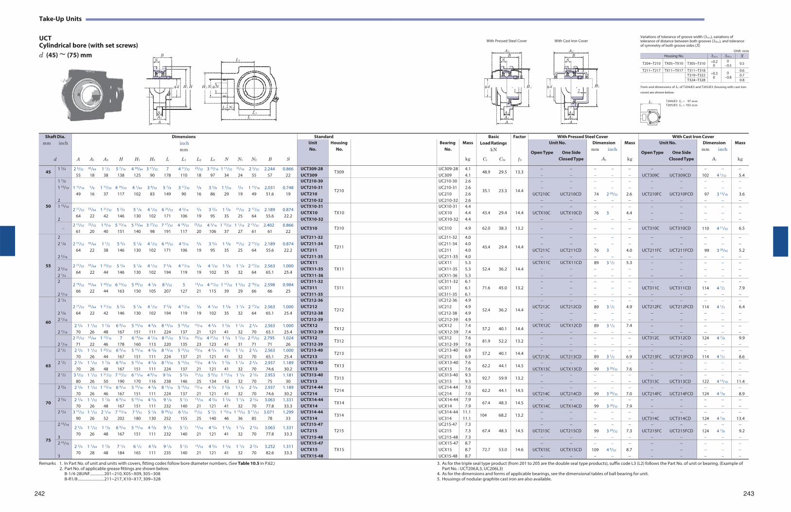
Take-Up Units
UCT Cylindrical bore (with set screws)
With Pressed Steel Cover With Cast Iron Cover
Variations of tolerance of groove width (3A1s), variations of tolerance of distance between both grooves (3H1s), and tolerance of symmetry of both groove sides (X)
d (45) ~ (75) mm
B S L 1
AS AC
B B S S
Unit: mm
d H 1 H
H 2 N 2 N
d H 1 d
H 1 Form and dimensions of Lc of T204JE3 and T205JE3 (housing with cast iron 1 2 cover) are shown below.
L 2 N 1
A 1 L 3
A 2 L A
A 1 A 1
A 2 A 2
A A
T204JE3 Lc 97 mm T205JE3 Lc 102 mm
Remarks 1. In Part No. of unit and units with covers, fitting codes follow bore diameter numbers. (See Table 10.5 in P.62.)
2. Part No. of applicable grease fittings are shown below. B-1/4-28UNF.............. 201~210, X05~X09, 305~308 B-R1/8 .......................... 211~217, X10~X17, 309~328
3. As for the triple seal type product (from 201 to 205 are the double seal type products), suffix code L3 (L2) follows the Part No. of unit or bearing. (Example of Part No. : UCT206JL3, UC206L3)
4. As for the dimensions and forms of applicable bearings, see the dimensional tables of ball bearing for unit. 5. Housings of nodular graphite cast iron are also available.
242 243
Shaft Dia. mm inch
d
Dimensions inch mm
A A1 A2 H H1 H2 L L1 L2 L3 N N1 N2 B S
Standard BasicLoad Ratings
kN
Cr C0r
Factor
f 0
With Pressed Steel Cover With Cast Iron Cover Unit No.
Housing No.
Bearing No.
Mass
kg
Unit No.
Open Type One Side Closed Type
Dimension mm inch
As
Mass
kg
Unit No.
Open Type One Side Closed Type
Dimension mm inch
Ac
Mass
kg
45 1 3/4 2 5/32 45/64 1 1/2 5 7/16 4 59/64 3 17/32 7 4 11/32 23/32 3 13/16 1 11/32 15/16 2 5/32 2.244 0.866
55 18 38 138 125 90 178 110 18 97 34 24 55 57 22 UCT309-28 UCT309
T309 UC309-28UC309
4.1 4.1
48.9 29.5 13.3
UCT309C UCT309CD
102 4 1/32
5.4
50
1 7/8
1 15/16
2
1 15/16 5/8 1 15/32 4 19/32 4 1/64 3 9/32 5 7/8 3 17/32 5/8 3 3/8 1 5/32 3/4 1 15/16 2.031 0.748
49 16 37 117 102 83 149 90 16 86 29 19 49 51.6 19
UCT210-30 UCT210-31 UCT210 UCT210-32
T210
UC210-30 UC210-31 UC210 UC210-32
2.6 2.6 2.6 2.6
35.1 23.3
14.4
UCT210C UCT210CD
74 2 29/32
2.6
UCT210FC UCT210FCD
97 3 13/16
3.6
1 15/16
2
2 17/32 55/64 1 21/32 5 3/4 5 1/8 4 1/32 6 23/32 4 3/16 3/4 3 3/4 1 3/8 31/32 2 17/32 2.189 0.874 64 22 42 146 130 102 171 106 19 95 35 25 64 55.6 22.2
UCTX10-31 UCTX10 UCTX10-32
TX10
UCX10-31 UCX10 UCX10-32
4.4 4.4 4.4
43.4 29.4
14.4
UCTX10C UCTX10CD
76 3
4.4
2 13/32 25/32 1 9/16 5 15/16 5 33/64 3 27/32 7 17/32 4 19/32 25/32 4 3/16 1 15/32 1 1/16 2 13/32 2.402 0.866
61 20 40 151 140 98 191 117 20 106 37 27 61 61 22 UCT310 T310 UC310 4.9 62.0 38.3 13.2 UCT310C UCT310CD 110 4 11/32 6.5
55
2 2 1/8
2 3/16
2 17/32 55/64 1 1/2 5 3/4 5 1/8 4 1/32 6 23/32 4 3/16 3/4 3 3/4 1 3/8 31/32 2 17/32 2.189 0.874
64 22 38 146 130 102 171 106 19 95 35 25 64 55.6 22.2
UCT211-32 UCT211-34 UCT211 UCT211-35
T211
UC211-32 UC211-34 UC211 UC211-35
4.0 4.0 4.0 4.0
43.4 29.4
14.4
UCT211C UCT211CD
76 3
4.0
UCT211FC UCT211FCD
99 3 29/32
5.2
2 3/16
2 1/4
2 17/32 55/64 1 23/32 5 3/4 5 1/8 4 1/32 7 5/8 4 11/16 3/4 4 1/32 1 3/8 1 1/4 2 17/32 2.563 1.000 64 22 44 146 130 102 194 119 19 102 35 32 64 65.1 25.4
UCTX11 UCTX11-35 UCTX11-36
TX11
UCX11 UCX11-35 UCX11-36
5.3 5.3 5.3
52.4 36.2
14.4
UCTX11C UCTX11CD
89 3 1/2
5.3
2
2 3/16
2 19/32 55/64 1 23/32 6 13/32 5 29/32 4 1/8 8 5/32 5 13/16 4 17/32 1 17/32 1 5/32 2 19/32 2.598 0.984 66 22 44 163 150 105 207 127 21 115 39 29 66 66 25
UCT311-32 UCT311 UCT311-35
T311
UC311-32UC311 UC311-35
6.1 6.1 6.1
71.6 45.0
13.2
UCT311C UCT311CD
114 4 1/2
7.9
60
2 1/4
2 3/8
2 7/16
2 17/32 55/64 1 21/32 5 3/4 5 1/8 4 1/32 7 5/8 4 11/16 3/4 4 1/32 1 3/8 1 1/4 2 17/32 2.563 1.000
64 22 42 146 130 102 194 119 19 102 35 32 64 65.1 25.4
UCT212-36 UCT212 UCT212-38 UCT212-39
T212
UC212-36 UC212 UC212-38UC212-39
4.9 4.9 4.9 4.9
52.4 36.2
14.4
UCT212C UCT212CD
89 3 1/2
4.9
UCT212FC UCT212FCD
114 4 1/2
6.4
2 7/16
2 3/4 1 1/32 1 7/8 6 9/16 5 15/16 4 3/8 8 13/16 5 13/32 13/16 4 3/4 1 5/8 1 1/4 2 3/4 2.563 1.000 70 26 48 167 151 111 224 137 21 121 41 32 70 65.1 25.4
UCTX12 UCTX12-39
TX12 UCX12 UCX12-39
7.4 7.4
57.2 40.1 14.4 UCTX12C UCTX12CD
89 3 1/2
7.4
2 7/16
2 25/32 55/64 1 13/16 7 6 19/64 4 7/16 8 21/32 5 5/16 29/32 4 27/32 1 5/8 1 7/32 2 25/32 2.795 1.024 71 22 46 178 160 113 220 135 23 123 41 31 71 71 26
UCT312 UCT312-39
T312 UC312 UC312-39
7.6 7.6
81.9 52.2 13.2
UCT312C UCT312CD
124 4 7/8
9.9
65
2 1/2 2 3/4 1 1/32 1 23/32 6 9/16 5 15/16 4 3/8 8 13/16 5 13/32 13/16 4 3/4 1 5/8 1 1/4 2 3/4 2.563 1.000 70 26 44 167 151 111 224 137 21 121 41 32 70 65.1 25.4
UCT213-40 UCT213
T213 UC213-40UC213
6.9 6.9
57.2 40.1 14.4
UCT213C UCT213CD 89 3 1/2
6.9
UCT213FC UCT213FCD
114 4 1/2
8.6
2 1/2 2 3/4 1 1/32 1 7/8 6 9/16 5 15/16 4 3/8 8 13/16 5 13/32 13/16 4 3/4 1 5/8 1 1/4 2 3/4 2.937 1.189 70 26 48 167 151 111 224 137 21 121 41 32 70 74.6 30.2
UCTX13-40 UCTX13
TX13 UCX13-40UCX13
7.6 7.6
62.2 44.1 14.5
UCTX13C UCTX13CD 99 3 29/32
7.6
2 1/2 3 5/32 1 1/32 1 31/32 7 15/32 6 11/16 4 9/16 9 3/8 5 3/4 31/32 5 9/32 1 11/16 1 1/4 2 3/4 2.953 1.181 80 26 50 190 170 116 238 146 25 134 43 32 70 75 30
UCT313-40 UCT313
T313 UC313-40UC313
9.3 9.3
92.7 59.9 13.2
UCT313C UCT313CD
122 4 13/16
11.4
70
2 3/4 2 3/4 1 1/32 1 13/16 6 9/16 5 15/16 4 3/8 8 13/16 5 13/32 13/16 4 3/4 1 5/8 1 1/4 2 3/4 2.937 1.189 70 26 46 167 151 111 224 137 21 121 41 32 70 74.6 30.2
UCT214-44 UCT214
T214 UC214-44UC214
7.0 7.0
62.2 44.1 14.5
UCT214C UCT214CD 99 3 29/32
7.0
UCT214FC UCT214FCD
124 4 7/8
8.9
2 3/4 2 3/4 1 1/32 1 7/8 6 9/16 5 15/16 4 3/8 9 1/8 5 1/2 13/16 4 3/4 1 5/8 1 1/4 2 3/4 3.063 1.331 70 26 48 167 151 111 232 140 21 121 41 32 70 77.8 33.3
UCTX14-44 UCTX14
TX14 UCX14-44UCX14
7.9 7.9
67.4 48.3 14.5
UCTX14C UCTX14CD 99 3 29/32
7.9
2 3/4 3 17/32 1 1/32 2 1/16 7 15/16 7 3/32 5 1/8 9 29/32 6 3/32 31/32 5 1/2 1 13/16 1 13/32 3 11/32 3.071 1.299 90 26 52 202 180 130 252 155 25 140 46 36 85 78 33
UCT314-44 UCT314
T314 UC314-44UC314
11.1 11.1
104 68.2 13.2
UCT314C UCT314CD
124 4 7/8
13.4
75
2 15/16
3
2 3/4 1 1/32 1 7/8 6 9/16 5 15/16 4 3/8 9 1/8 5 1/2 13/16 4 3/4 1 5/8 1 1/4 2 3/4 3.063 1.331 70 26 48 167 151 111 232 140 21 121 41 32 70 77.8 33.3
UCT215-47 UCT215 UCT215-48
T215
UC215-47 UC215 UC215-48
7.3 7.3 7.3
67.4 48.3
14.5
UCT215C UCT215CD
99 3 29/32
7.3
UCT215FC UCT215FCD
124 4 7/8
9.2
2 15/16
3
2 3/4 1 7/64 1 7/8 7 1/4 6 1/2 4 3/8 9 1/4 5 1/2 13/16 4 3/4 1 5/8 1 1/4 2 3/4 3.252 1.311 70 28 48 184 165 111 235 140 21 121 41 32 70 82.6 33.3
UCTX15-47 UCTX15 UCTX15-48
TX15
UCX15-47UCX15 UCX15-48
8.7 8.7 8.7
72.7 53.0
14.6
UCTX15C UCTX15CD
109 4 9/32
8.7
L c
Housing No. 3A1s 3H1s X
T204~T210 TX05~TX10 T305~T310 0.2 0
0 0.5 0.5
T211~T217 TX11~TX17 T311~T3180.3
0 0 0.8
0.6
T319~T322 0.7T324~T328 0.8
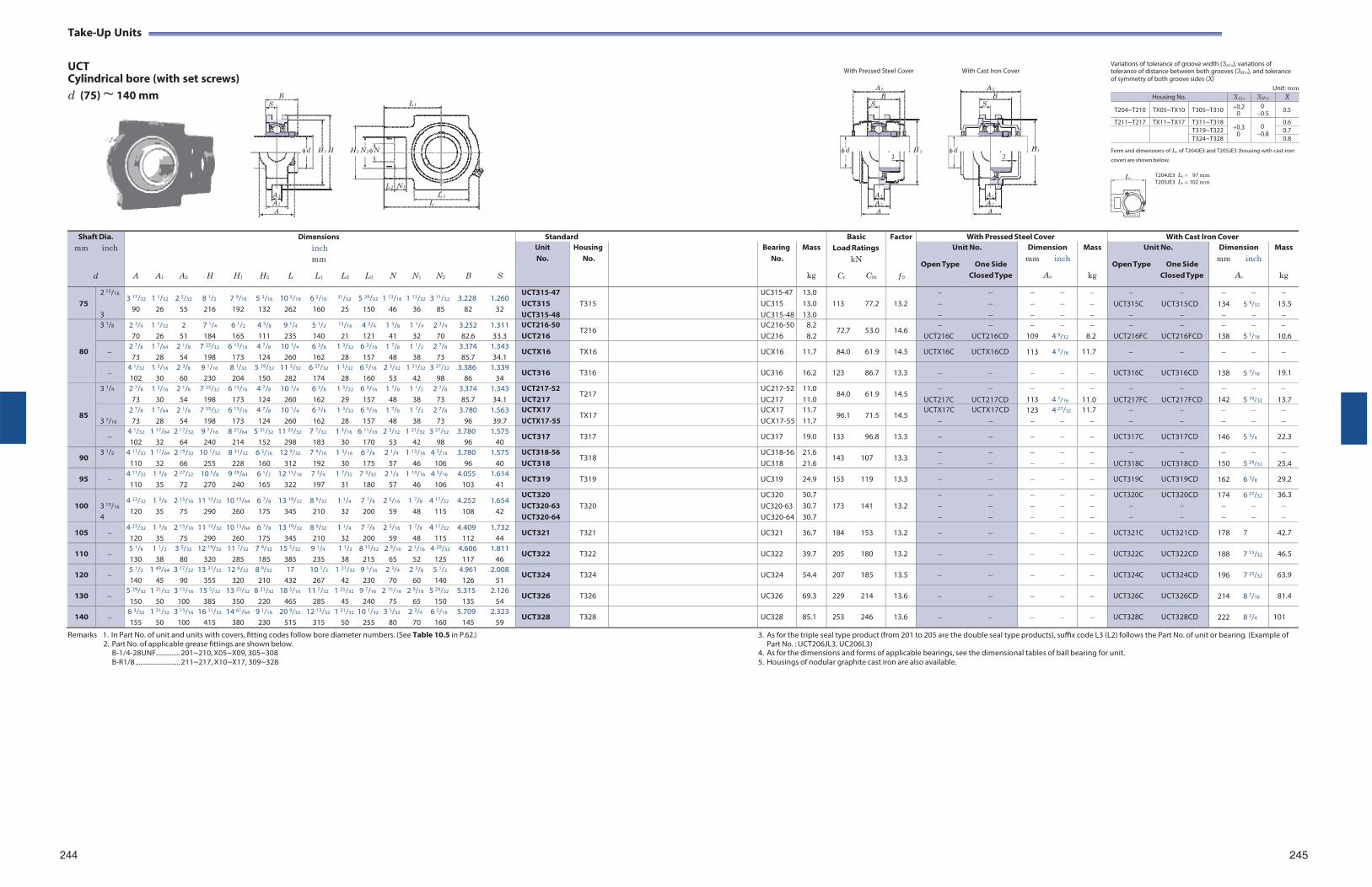
Take-Up Units
UCT Cylindrical bore (with set screws)
With Pressed Steel Cover With Cast Iron Cover
Variations of tolerance of groove width (3A1s), variations of tolerance of distance between both grooves (3H1s), and tolerance of symmetry of both groove sides (X)
d (75) ~ 140 mm
B S L 1
AS AC
B B S S
Unit: mm
d H 1 H
H 2 N 2 N
d H 1 d
H 1 Form and dimensions of Lc of T204JE3 and T205JE3 (housing with cast iron 1 2 cover) are shown below.
L 2 N 1
A 1 L 3
A 2 L A
A 1 A 1
A 2 A 2
A A
T204JE3 Lc 97 mm T205JE3 Lc 102 mm
Remarks 1. In Part No. of unit and units with covers, fitting codes follow bore diameter numbers. (See Table 10.5 in P.62.)
2. Part No. of applicable grease fittings are shown below. B-1/4-28UNF.............. 201~210, X05~X09, 305~308 B-R1/8 .......................... 211~217, X10~X17, 309~328
3. As for the triple seal type product (from 201 to 205 are the double seal type products), suffix code L3 (L2) follows the Part No. of unit or bearing. (Example of Part No. : UCT206JL3, UC206L3)
4. As for the dimensions and forms of applicable bearings, see the dimensional tables of ball bearing for unit. 5. Housings of nodular graphite cast iron are also available.
244 245
Shaft Dia. mm inch
d
Dimensions inch mm
A A1 A2 H H1 H2 L L1 L2 L3 N N1 N2 B S
Standard BasicLoad Ratings
kN
Cr C0r
Factor
f 0
With Pressed Steel Cover With Cast Iron Cover Unit No.
Housing No.
Bearing No.
Mass
kg
Unit No.
Open Type One Side Closed Type
Dimension mm inch
As
Mass
kg
Unit No.
Open Type One Side Closed Type
Dimension mm inch
Ac
Mass
kg
75
2 15/16
3
3 17/32 1 1/32 2 5/32 8 1/2 7 9/16 5 3/16 10 5/16 6 5/16 31/32 5 29/32 1 13/16 1 13/32 3 11/32 3.228 1.260 90 26 55 216 192 132 262 160 25 150 46 36 85 82 32
UCT315-47 UCT315 UCT315-48
T315
UC315-47 UC315 UC315-48
13.0 13.0 13.0
113 77.2
13.2
UCT315C UCT315CD
134 5 9/32
15.5
80
3 1/8 2 3/4 1 1/32 2 7 1/4 6 1/2 4 3/8 9 1/4 5 1/2 13/16 4 3/4 1 5/8 1 1/4 2 3/4 3.252 1.311 70 26 51 184 165 111 235 140 21 121 41 32 70 82.6 33.3
UCT216-50 UCT216
T216 UC216-50UC216
8.2 8.2
72.7 53.0 14.6
UCT216C UCT216CD
109 4 9/32
8.2
UCT216FC UCT216FCD
138 5 7/16
10.6
2 7/8 1 7/64 2 1/8 7 25/32 6 13/16 4 7/8 10 1/4 6 3/8 1 3/32 6 3/16 1 7/8 1 1/2 2 7/8 3.374 1.343 73 28 54 198 173 124 260 162 28 157 48 38 73 85.7 34.1
UCTX16 TX16 UCX16 11.7 84.0 61.9 14.5 UCTX16C UCTX16CD 113 4 7/16 11.7
4 1/32 1 3/16 2 3/8 9 1/16 8 1/32 5 29/32 11 3/32 6 27/32 1 3/32 6 5/16 2 3/32 1 21/32 3 27/32 3.386 1.339 102 30 60 230 204 150 282 174 28 160 53 42 98 86 34
UCT316 T316 UC316 16.2 123 86.7 13.3 UCT316C UCT316CD 138 5 7/16 19.1
85
3 1/4 2 7/8 1 3/16 2 1/8 7 25/32 6 13/16 4 7/8 10 1/4 6 3/8 1 5/32 6 3/16 1 7/8 1 1/2 2 7/8 3.374 1.343 73 30 54 198 173 124 260 162 29 157 48 38 73 85.7 34.1
UCT217-52 UCT217
T217 UC217-52UC217
11.0 11.0
84.0 61.9 14.5
UCT217C UCT217CD
113 4 7/16
11.0
UCT217FC UCT217FCD
142 5 19/32
13.7
3 7/16
2 7/8 1 7/64 2 1/8 7 25/32 6 13/16 4 7/8 10 1/4 6 3/8 1 3/32 6 3/16 1 7/8 1 1/2 2 7/8 3.780 1.563 73 28 54 198 173 124 260 162 28 157 48 38 73 96 39.7
UCTX17 UCTX17-55
TX17 UCX17 UCX17-55
11.7 11.7
96.1 71.5 14.5 UCTX17C UCTX17CD
123 4 27/32
11.7
4 1/32 1 17/64 2 17/32 9 7/16 8 27/64 5 31/32 11 23/32 7 7/32 1 3/16 6 11/16 2 3/32 1 21/32 3 27/32 3.780 1.575 102 32 64 240 214 152 298 183 30 170 53 42 98 96 40
UCT317 T317 UC317 19.0 133 96.8 13.3 UCT317C UCT317CD 146 5 3/4 22.3
90 3 1/2 4 11/32 1 17/64 2 19/32 10 1/32 8 31/32 6 5/16 12 9/32 7 9/16 1 3/16 6 7/8 2 1/4 1 13/16 4 3/16 3.780 1.575
110 32 66 255 228 160 312 192 30 175 57 46 106 96 40 UCT318-56 UCT318
T318 UC318-56UC318
21.6 21.6
143 107 13.3
UCT318C UCT318CD
150 5 29/32
25.4
95 4 11/32 1 3/8 2 27/32 10 5/8 9 29/64 6 1/2 12 11/16 7 3/4 1 7/32 7 3/32 2 1/4 1 13/16 4 3/16 4.055 1.614
110 35 72 270 240 165 322 197 31 180 57 46 106 103 41 UCT319 T319 UC319 24.9 153 119 13.3 UCT319C UCT319CD 162 6 3/8 29.2
100
3 15/16
4
4 23/32 1 3/8 2 15/16 11 13/32 10 15/64 6 7/8 13 19/32 8 9/32 1 1/4 7 7/8 2 5/16 1 7/8 4 17/32 4.252 1.654 120 35 75 290 260 175 345 210 32 200 59 48 115 108 42
UCT320 UCT320-63 UCT320-64
T320
UC320 UC320-63UC320-64
30.7 30.7 30.7
173 141
13.2
UCT320C UCT320CD
174 6 27/32
36.3
105 4 23/32 1 3/8 2 15/16 11 13/32 10 15/64 6 7/8 13 19/32 8 9/32 1 1/4 7 7/8 2 5/16 1 7/8 4 17/32 4.409 1.732
120 35 75 290 260 175 345 210 32 200 59 48 115 112 44 UCT321 T321 UC321 36.7 184 153 13.2 UCT321C UCT321CD 178 7 42.7
110 5 1/8 1 1/2 3 5/32 12 19/32 11 7/32 7 9/32 15 5/32 9 1/4 1 1/2 8 15/32 2 9/16 2 1/16 4 29/32 4.606 1.811 130 38 80 320 285 185 385 235 38 215 65 52 125 117 46
UCT322 T322 UC322 39.7 205 180 13.2 UCT322C UCT322CD 188 7 13/32 46.5
120 5 1/2 1 49/64 3 17/32 13 31/32 12 9/32 8 9/32 17 10 1/2 1 21/32 9 1/16 2 3/4 2 3/8 5 1/2 4.961 2.008 140 45 90 355 320 210 432 267 42 230 70 60 140 126 51
UCT324 T324 UC324 54.4 207 185 13.5 UCT324C UCT324CD 196 7 23/32 63.9
130 5 29/32 1 31/32 3 15/16 15 5/32 13 25/32 8 21/32 18 5/16 11 7/32 1 25/32 9 7/16 2 15/16 2 9/16 5 29/32 5.315 2.126
150 50 100 385 350 220 465 285 45 240 75 65 150 135 54 UCT326 T326 UC326 69.3 229 214 13.6 UCT326C UCT326CD 214 8 7/16 81.4
140 6 3/32 1 31/32 3 15/16 16 11/32 14 61/64 9 1/16 20 9/32 12 13/32 1 31/32 10 1/32 3 5/32 2 3/4 6 5/16 5.709 2.323 155 50 100 415 380 230 515 315 50 255 80 70 160 145 59
UCT328 T328 UC328 85.1 253 246 13.6 UCT328C UCT328CD 222 8 3/4 101
L c
Housing No. 3A1s 3H1s X
T204~T210 TX05~TX10 T305~T310 0.2 0
0 0.5 0.5
T211~T217 TX11~TX17 T311~T3180.3
0 0 0.8
0.6
T319~T322 0.7T324~T328 0.8
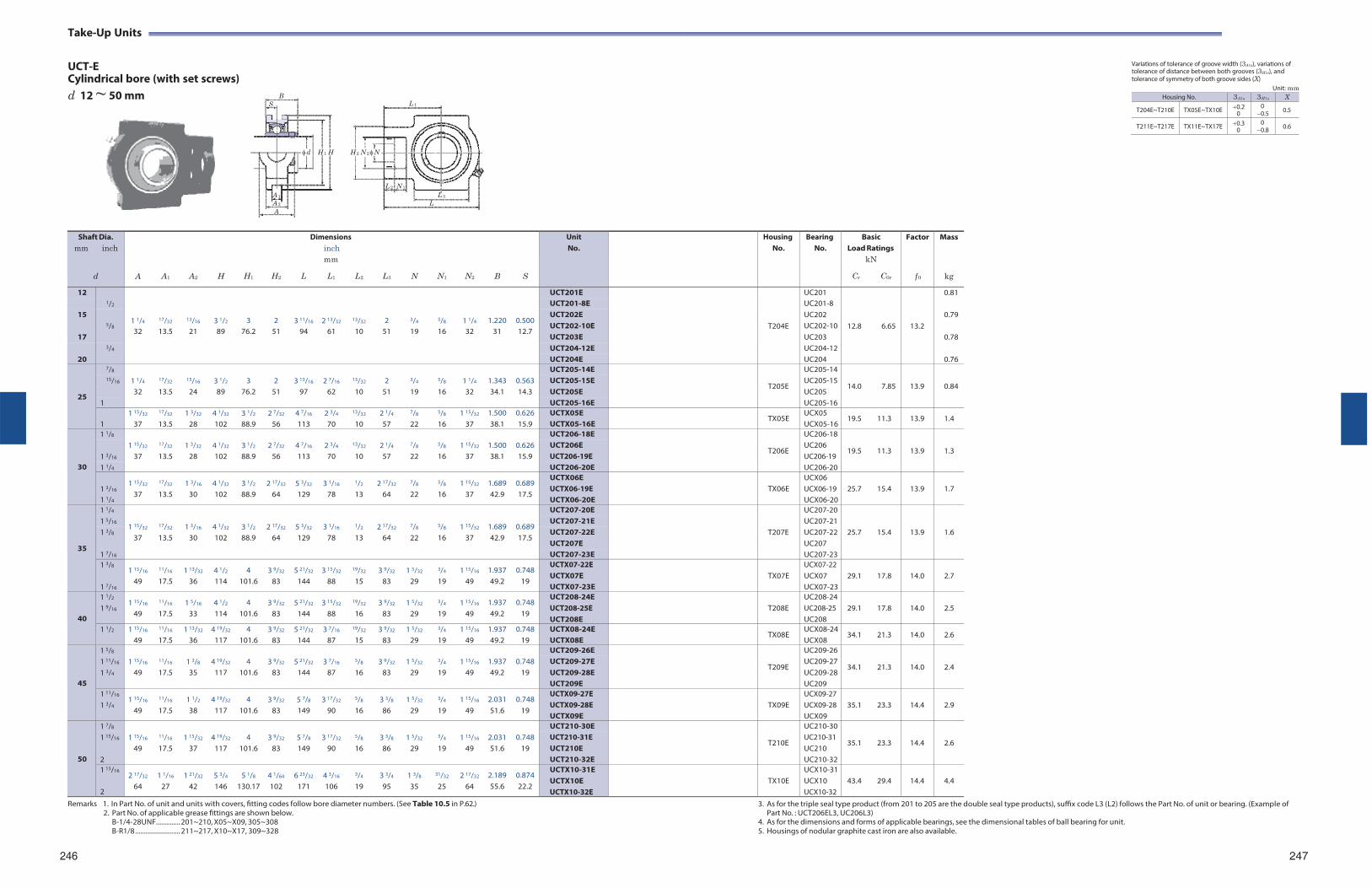
Take-Up Units
UCT-E Cylindrical bore (with set screws)
Variations of tolerance of groove width (3A1s), variations of tolerance of distance between both grooves (3H1s), and tolerance of symmetry of both groove sides (X)
d 12 ~ 50 mm
B S L 1
Unit: mm
d H 1 H
H 2 N 2 N
L 2 N 1
A 1 L 3
A 2 L A
Remarks 1. In Part No. of unit and units with covers, fitting codes follow bore diameter numbers. (See Table 10.5 in P.62.)
2. Part No. of applicable grease fittings are shown below. B-1/4-28UNF.............. 201~210, X05~X09, 305~308 B-R1/8 .......................... 211~217, X10~X17, 309~328
3. As for the triple seal type product (from 201 to 205 are the double seal type products), suffix code L3 (L2) follows the Part No. of unit or bearing. (Example of Part No. : UCT206EL3, UC206L3)
4. As for the dimensions and forms of applicable bearings, see the dimensional tables of ball bearing for unit. 5. Housings of nodular graphite cast iron are also available.
246 247
Shaft Dia. mm inch
d
A
A1
A2
H
H1
H2
Dimensions inch mm
L L1 L2
L3
N
N1
N2
B
S
UnitNo.
HousingNo.
BearingNo.
BasicLoad Ratings
kN
Cr C0r
Factor
f 0
Mass
kg
12 1/2
1 1/4
17/32
13/16
3 1/2
3
2
3 11/16
2 13/32
13/32
2
3/4
5/8
1 1/4
1.220
0.500
UCT201E
T204E
UC201
12.8
6.65
13.2
0.81 UCT201-8E UC201-8
15 5/8
UCT202E UC202 0.79 UCT202-10E UC202-10
32 13.5 21 89 76.2 51 94 61 10 51 19 16 32 31 12.7 17 UCT203E UC203 0.78
3/4 UCT204-12E UC204-1220 UCT204E UC204 0.76
25
7/8 1 1/4
17/32
15/16
3 1/2
3
2
3 13/16
2 7/16
13/32
2
3/4
5/8
1 1/4
1.343
0.563
UCT205-14E
T205E
UC205-14
14.0
7.85
13.9
0.84 15/16 UCT205-15E UC205-15
32 13.5 24 89 76.2 51 97 62 10 51 19 16 32 34.1 14.3 UCT205E UC205 1 UCT205-16E UC205-16
1
1 15/32
37
17/32
13.5 1 3/32
28 4 1/32
102 3 1/2
88.9 2 7/32
56 4 7/16
113 2 3/4
70
13/32
10 2 1/4
57
7/8
22
5/8
16 1 15/32
37 1.500 38.1
0.626 15.9
UCTX05E UCTX05-16E
TX05E UCX05 UCX05-16
19.5 11.3 13.9 1.4
30
1 1/8 1 15/32
17/32
1 3/32
4 1/32
3 1/2
2 7/32
4 7/16
2 3/4
13/32
2 1/4
7/8
5/8
1 15/32
1.500
0.626
UCT206-18E
T206E
UC206-18
19.5
11.3
13.9
1.3 1 3/16
UCT206E UCT206-19E
UC206 UC206-19 37 13.5 28 102 88.9 56 113 70 10 57 22 16 37 38.1 15.9
1 1/4 UCT206-20E UC206-20
1 3/16
1 1/4
1 15/32
37
17/32
13.5 1 3/16
30 4 1/32
102 3 1/2
88.9 2 17/32
64 5 3/32
129 3 1/16
78
1/2
13 2 17/32
64
7/8
22
5/8
16 1 15/32
37 1.689 42.9
0.689 17.5
UCTX06E UCTX06-19E UCTX06-20E
TX06E
UCX06 UCX06-19 UCX06-20
25.7
15.4
13.9
1.7
35
1 1/4
1 15/32
17/32
1 3/16
4 1/32
3 1/2
2 17/32
5 3/32
3 1/16
1/2
2 17/32
7/8
5/8
1 15/32
1.689
0.689
UCT207-20E
T207E
UC207-20
25.7
15.4
13.9
1.6
1 5/16 UCT207-21E UC207-211 3/8 UCT207-22E UC207-22
37 13.5 30 102 88.9 64 129 78 13 64 22 16 37 42.9 17.5 UCT207E UC207
1 7/16 UCT207-23E UC207-231 3/8
1 7/16
1 15/16
49
11/16
17.5 1 13/32
36 4 1/2
114 4
101.6 3 9/32
83 5 21/32
144 3 15/32
88
19/32
15 3 9/32
83 1 5/32
29
3/4
19 1 15/16
49 1.937 49.2
0.748 19
UCTX07-22E UCTX07E UCTX07-23E
TX07E
UCX07-22 UCX07 UCX07-23
29.1
17.8
14.0
2.7
40
1 1/2
1 9/16 1 15/16
49
11/16
17.5 1 5/16
33 4 1/2
114 4
101.6 3 9/32
83 5 21/32
144 3 15/32
88
19/32
16 3 9/32
83 1 5/32
29
3/4
19 1 15/16
49 1.937 49.2
0.748 19
UCT208-24E UCT208-25E UCT208E
T208E
UC208-24UC208-25 UC208
29.1
17.8
14.0
2.5
1 1/2 1 15/16
49
11/16
17.5 1 13/32
36 4 19/32
117 4
101.6 3 9/32
83 5 21/32
144 3 7/16
87
19/32
15 3 9/32
83 1 5/32
29
3/4
19 1 15/16
49 1.937 49.2
0.748 19
UCTX08-24E UCTX08E
TX08E UCX08-24UCX08
34.1 21.3 14.0 2.6
45
1 5/8 1 15/16
11/16
1 3/8
4 19/32
4
3 9/32
5 21/32
3 7/16
5/8
3 9/32
1 5/32
3/4
1 15/16
1.937
0.748
UCT209-26E
T209E
UC209-26
34.1
21.3
14.0
2.4 1 11/16 UCT209-27E UC209-271 3/4 49 17.5 35 117 101.6 83 144 87 16 83 29 19 49 49.2 19 UCT209-28E UC209-28
UCT209E UC209 1 11/16
1 3/4 1 15/16
49
11/16
17.5 1 1/2
38 4 19/32
117 4
101.6 3 9/32
83 5 7/8
149 3 17/32
90
5/8
16 3 3/8
86 1 5/32
29
3/4
19 1 15/16
49 2.031 51.6
0.748 19
UCTX09-27E UCTX09-28E UCTX09E
TX09E
UCX09-27 UCX09-28 UCX09
35.1
23.3
14.4
2.9
50
1 7/8 1 15/16
11/16
1 15/32
4 19/32
4
3 9/32
5 7/8
3 17/32
5/8
3 3/8
1 5/32
3/4
1 15/16
2.031
0.748
UCT210-30E
T210E
UC210-30
35.1
23.3
14.4
2.6 1 15/16 UCT210-31E
UCT210E UC210-31 UC210 49 17.5 37 117 101.6 83 149 90 16 86 29 19 49 51.6 19
2 UCT210-32E UC210-321 15/16
2
2 17/32
64 1 1/16
27 1 21/32
42 5 3/4
146 5 1/8
130.17 4 1/64
102 6 23/32
171 4 3/16
106
3/4
19 3 3/4
95 1 3/8
35
31/32
25 2 17/32
64 2.189 55.6
0.874 22.2
UCTX10-31E UCTX10E UCTX10-32E
TX10E
UCX10-31UCX10 UCX10-32
43.4
29.4
14.4
4.4
Housing No. 3A1s 3H1s X
T204E~T210E TX05E~TX10E 0.2 0
0 0.5 0.5
T211E~T217E TX11E~TX17E 0.3 0
0 0.8 0.6
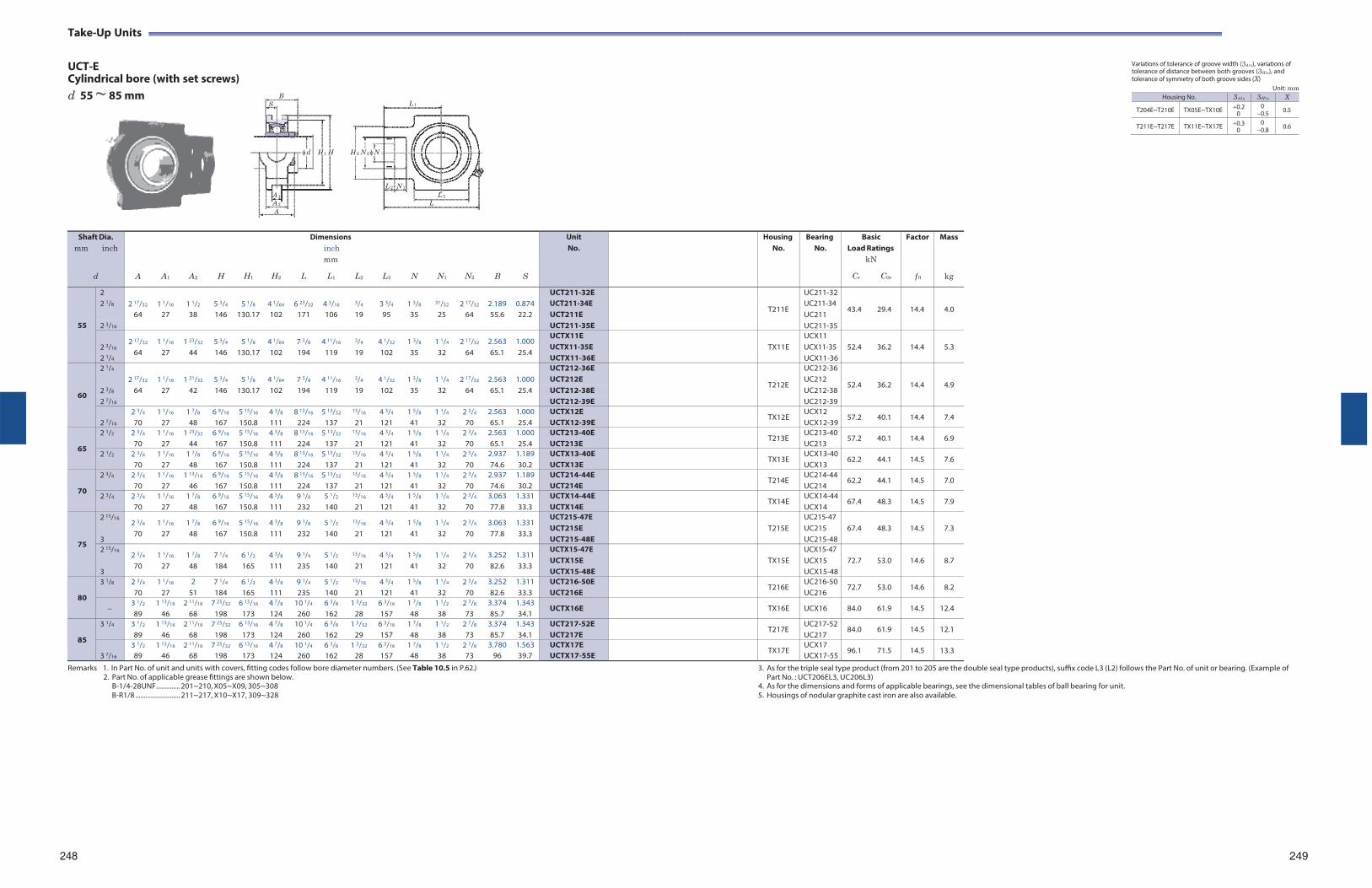
Take-Up Units
UCT-E Cylindrical bore (with set screws)
Variations of tolerance of groove width (3A1s), variations of tolerance of distance between both grooves (3H1s), and tolerance of symmetry of both groove sides (X)
d 55 ~ 85 mm
B S L 1
Unit: mm
d H 1 H
H 2 N 2 N
L 2 N 1
A 1 L 3
A 2 L A
Remarks 1. In Part No. of unit and units with covers, fitting codes follow bore diameter numbers. (See Table 10.5 in P.62.)
2. Part No. of applicable grease fittings are shown below. B-1/4-28UNF.............. 201~210, X05~X09, 305~308 B-R1/8 .......................... 211~217, X10~X17, 309~328
3. As for the triple seal type product (from 201 to 205 are the double seal type products), suffix code L3 (L2) follows the Part No. of unit or bearing. (Example of Part No. : UCT206EL3, UC206L3)
4. As for the dimensions and forms of applicable bearings, see the dimensional tables of ball bearing for unit. 5. Housings of nodular graphite cast iron are also available.
248 249
Shaft Dia. mm inch
d
A
A1
A2
H
H1
H2
Dimensions inch mm
L L1 L2
L3
N
N1
N2
B
S
UnitNo.
HousingNo.
BearingNo.
BasicLoad Ratings
kN
Cr C0r
Factor
f 0
Mass
kg
55
2 2 17/32
1 1/16
1 1/2
5 3/4
5 1/8
4 1/64
6 23/32
4 3/16
3/4
3 3/4
1 3/8
31/32
2 17/32
2.189
0.874
UCT211-32E
T211E
UC211-32
43.4
29.4
14.4
4.0 2 1/8 UCT211-34E
UCT211E UC211-34 UC211 64 27 38 146 130.17 102 171 106 19 95 35 25 64 55.6 22.2
2 3/16 UCT211-35E UC211-35
2 3/16
2 1/4
2 17/32
64 1 1/16
27 1 23/32
44 5 3/4
146 5 1/8
130.17 4 1/64
102 7 5/8
194 4 11/16
119
3/4
19 4 1/32
102 1 3/8
35 1 1/4
32 2 17/32
64 2.563 65.1
1.000 25.4
UCTX11E UCTX11-35E UCTX11-36E
TX11E
UCX11 UCX11-35 UCX11-36
52.4
36.2
14.4
5.3
60
2 1/4 2 17/32
1 1/16
1 21/32
5 3/4
5 1/8
4 1/64
7 5/8
4 11/16
3/4
4 1/32
1 3/8
1 1/4
2 17/32
2.563
1.000
UCT212-36E
T212E
UC212-36
52.4
36.2
14.4
4.9 2 3/8
UCT212E UC212 64 27 42 146 130.17 102 194 119 19 102 35 32 64 65.1 25.4 UCT212-38E UC212-38
2 7/16 UCT212-39E UC212-39
2 7/16
2 3/4
70 1 1/16
27 1 7/8
48 6 9/16
167 5 15/16
150.8 4 3/8
111 8 13/16
224 5 13/32
137
13/16
21 4 3/4
121 1 5/8
41 1 1/4
32 2 3/4
70 2.563 65.1
1.000 25.4
UCTX12E UCTX12-39E
TX12E UCX12 UCX12-39
57.2 40.1 14.4 7.4
65
2 1/2 2 3/4
70 1 1/16
27 1 23/32
44 6 9/16
167 5 15/16
150.8 4 3/8
111 8 13/16
224 5 13/32
137
13/16
21 4 3/4
121 1 5/8
41 1 1/4
32 2 3/4
70 2.563 65.1
1.000 25.4
UCT213-40E UCT213E
T213E UC213-40UC213
57.2 40.1 14.4 6.9
2 1/2 2 3/4
70 1 1/16
27 1 7/8
48 6 9/16
167 5 15/16
150.8 4 3/8
111 8 13/16
224 5 13/32
137
13/16
21 4 3/4
121 1 5/8
41 1 1/4
32 2 3/4
70 2.937 74.6
1.189 30.2
UCTX13-40E UCTX13E
TX13E UCX13-40UCX13
62.2 44.1 14.5 7.6
70
2 3/4 2 3/4
70 1 1/16
27 1 13/16
46 6 9/16
167 5 15/16
150.8 4 3/8
111 8 13/16
224 5 13/32
137
13/16
21 4 3/4
121 1 5/8
41 1 1/4
32 2 3/4
70 2.937 74.6
1.189 30.2
UCT214-44E UCT214E
T214E UC214-44UC214
62.2 44.1 14.5 7.0
2 3/4 2 3/4
70 1 1/16
27 1 7/8
48 6 9/16
167 5 15/16
150.8 4 3/8
111 9 1/8
232 5 1/2
140
13/16
21 4 3/4
121 1 5/8
41 1 1/4
32 2 3/4
70 3.063 77.8
1.331 33.3
UCTX14-44E UCTX14E
TX14E UCX14-44UCX14
67.4 48.3 14.5 7.9
75
2 15/16
3
2 3/4
70 1 1/16
27 1 7/8
48 6 9/16
167 5 15/16
150.8 4 3/8
111 9 1/8
232 5 1/2
140
13/16
21 4 3/4
121 1 5/8
41 1 1/4
32 2 3/4
70 3.063 77.8
1.331 33.3
UCT215-47E UCT215E UCT215-48E
T215E
UC215-47 UC215 UC215-48
67.4
48.3
14.5
7.3
2 15/16
3
2 3/4
70 1 1/16
27 1 7/8
48 7 1/4
184 6 1/2
165 4 3/8
111 9 1/4
235 5 1/2
140
13/16
21 4 3/4
121 1 5/8
41 1 1/4
32 2 3/4
70 3.252 82.6
1.311 33.3
UCTX15-47E UCTX15E UCTX15-48E
TX15E
UCX15-47 UCX15 UCX15-48
72.7
53.0
14.6
8.7
80
3 1/8 2 3/4
70 1 1/16
27 2
51 7 1/4
184 6 1/2
165 4 3/8
111 9 1/4
235 5 1/2
140
13/16
21 4 3/4
121 1 5/8
41 1 1/4
32 2 3/4
70 3.252 82.6
1.311 33.3
UCT216-50E UCT216E
T216E UC216-50UC216
72.7 53.0 14.6 8.2
3 1/2
89 1 13/16
46 2 11/16
68 7 25/32
198 6 13/16
173 4 7/8
124 10 1/4
260 6 3/8
162 1 3/32
28 6 3/16
157 1 7/8
48 1 1/2
38 2 7/8
73 3.374 85.7
1.343 34.1
UCTX16E TX16E UCX16 84.0 61.9 14.5 12.4
85
3 1/4 3 1/2
89 1 13/16
46 2 11/16
68 7 25/32
198 6 13/16
173 4 7/8
124 10 1/4
260 6 3/8
162 1 5/32
29 6 3/16
157 1 7/8
48 1 1/2
38 2 7/8
73 3.374 85.7
1.343 34.1
UCT217-52E UCT217E
T217E UC217-52UC217
84.0 61.9 14.5 12.1
3 7/16
3 1/2
89 1 13/16
46 2 11/16
68 7 25/32
198 6 13/16
173 4 7/8
124 10 1/4
260 6 3/8
162 1 3/32
28 6 3/16
157 1 7/8
48 1 1/2
38 2 7/8
73 3.780
96 1.563 39.7
UCTX17E UCTX17-55E
TX17E UCX17 UCX17-55
96.1 71.5 14.5 13.3
Housing No. 3A1s 3H1s X
T204E~T210E TX05E~TX10E 0.2 0
0 0.5 0.5
T211E~T217E TX11E~TX17E 0.3 0
0 0.8 0.6
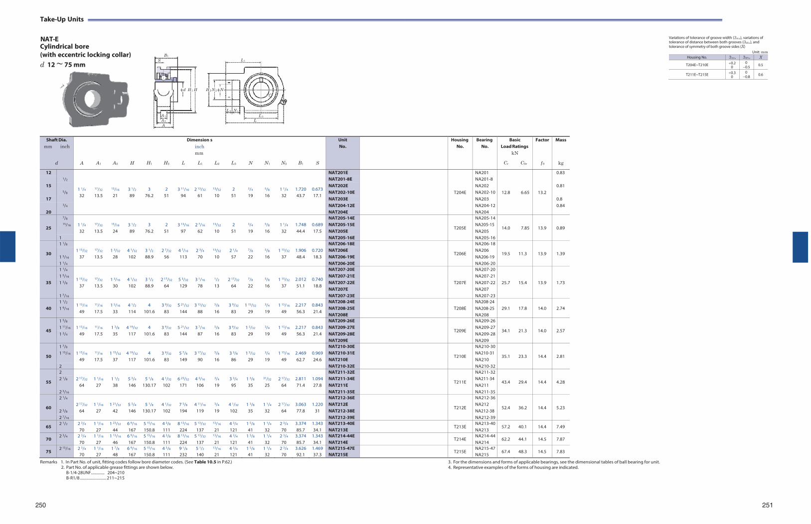
Take-Up Units
NAT-E Cylindrical bore
Variations of tolerance of groove width (3A1s), variations of tolerance of distance between both grooves (3H1s), and tolerance of symmetry of both groove sides (X)
(with eccentric locking collar) d 12 ~ 75 mm
B1
S L 1
Unit: mm
d H 1 H H 2 N 2 N
L 2 N 1
A 1 L 3
A 2 L A
Remarks 1. In Part No. of unit, fitting codes follow bore diameter codes. (See Table 10.5 in P.62.)
2. Part No. of applicable grease fittings are shown below. B-1/4-28UNF.............. 204~210 B-R1/8 .......................... 211~215
3. For the dimensions and forms of applicable bearings, see the dimensional tables of ball bearing for unit. 4. Representative examples of the forms of housing are indicated.
250 251
Shaft Dia. mm inch
d
A
A1
A2
H
H1
H2
Dimension inch mm
L L1
s
L2
L3
N
N1
N2
B1
S
UnitNo.
HousingNo.
BearingNo.
BasicLoad Ratings
kN
Cr C0r
Factor
f 0
Mass
kg
12 1/2
1 1/4
17/32
13/16
3 1/2
3
2
3 11/16
2 13/32
13/32
2
3/4
5/8
1 1/4
1.720
0.673
NAT201E
T204E
NA201
12.8
6.65
13.2
0.83 NAT201-8E NA201-8
15 5/8
NAT202E NA202 0.81 NAT202-10E NA202-10
32 13.5 21 89 76.2 51 94 61 10 51 19 16 32 43.7 17.1 17 NAT203E NA203 0.8
3/4 NAT204-12E NA204-12 0.84 20 NAT204E NA204
25
7/8 1 1/4
17/32
15/16
3 1/2
3
2
3 13/16
2 7/16
13/32
2
3/4
5/8
1 1/4
1.748
0.689
NAT205-14E
T205E
NA205-14
14.0
7.85
13.9
0.89 15/16 NAT205-15E
NAT205E NA205-15 NA205 32 13.5 24 89 76.2 51 97 62 10 51 19 16 32 44.4 17.5
1 NAT205-16E NA205-16
30
1 1/8 1 15/32
17/32
1 3/32
4 1/32
3 1/2
2 7/32
4 7/16
2 3/4
13/32
2 1/4
7/8
5/8
1 15/32
1.906
0.720
NAT206-18E
T206E
NA206-18
19.5
11.3
13.9
1.39 1 3/16
NAT206E NAT206-19E
NA206 NA206-19 37 13.5 28 102 88.9 56 113 70 10 57 22 16 37 48.4 18.3
1 1/4 NAT206-20E NA206-20
35
1 1/4
1 15/32
17/32
1 3/16
4 1/32
3 1/2
2 17/32
5 3/32
3 1/16
1/2
2 17/32
7/8
5/8
1 15/32
2.012
0.740
NAT207-20E
T207E
NA207-20
25.7
15.4
13.9
1.73
1 5/16 NAT207-21E NA207-211 3/8 NAT207-22E NA207-22
37 13.5 30 102 88.9 64 129 78 13 64 22 16 37 51.1 18.8 NAT207E NA207
1 7/16 NAT207-23E NA207-23
40 1 1/2
1 9/16 1 15/16
49
11/16
17.5 1 5/16
33 4 1/2
114 4
101.6 3 9/32
83 5 21/32
144 3 15/32
88
5/8
16 3 9/32
83 1 15/32
29
3/4
19 1 15/16
49 2.217 56.3
0.843 21.4
NAT208-24E NAT208-25E NAT208E
T208E
NA208-24 NA208-25 NA208
29.1
17.8
14.0
2.74
45
1 5/8 1 15/16
11/16
1 3/8
4 19/32
4
3 9/32
5 21/32
3 7/16
5/8
3 9/32
1 5/32
3/4
1 15/16
2.217
0.843
NAT209-26E
T209E
NA209-26
34.1
21.3
14.0
2.57 1 11/16 NAT209-27E NA209-271 3/4 49 17.5 35 117 101.6 83 144 87 16 83 29 19 49 56.3 21.4 NAT209-28E NA209-28
NAT209E NA209
50
1 7/8 1 15/16
11/16
1 15/32
4 19/32
4
3 9/32
5 7/8
3 17/32
5/8
3 3/8
1 5/32
3/4
1 15/16
2.469
0.969
NAT210-30E
T210E
NA210-30
35.1
23.3
14.4
2.81 1 15/16 NAT210-31E
NAT210E NA210-31 NA210 49 17.5 37 117 101.6 83 149 90 16 86 29 19 49 62.7 24.6
2 NAT210-32E NA210-32
55
2 2 17/32
1 1/16
1 1/2
5 3/4
5 1/8
4 1/32
6 23/32
4 3/16
3/4
3 3/4
1 3/8
31/32
2 17/32
2.811
1.094
NAT211-32E
T211E
NA211-32
43.4
29.4
14.4
4.28 2 1/8 NAT211-34E
NAT211E NA211-34 NA211 64 27 38 146 130.17 102 171 106 19 95 35 25 64 71.4 27.8
2 3/16 NAT211-35E NA211-35
60
2 1/4 2 17/32
1 1/16
1 21/32
5 3/4
5 1/8
4 1/32
7 5/8
4 11/16
3/4
4 1/32
1 3/8
1 1/4
2 17/32
3.063
1.220
NAT212-36E
T212E
NA212-36
52.4
36.2
14.4
5.23 2 3/8
NAT212E NAT212-38E
NA212 NA212-38 64 27 42 146 130.17 102 194 119 19 102 35 32 64 77.8 31
2 7/16 NAT212-39E NA212-39
65 2 1/2 2 3/4
70 1 1/16
27 1 23/32
44 6 9/16
167 5 15/16
150.8 4 3/8
111 8 13/16
224 5 13/32
137
13/16
21 4 3/4
121 1 5/8
41 1 1/4
32 2 3/4
70 3.374 85.7
1.343 34.1
NAT213-40E NAT213E
T213E NA213-40NA213
57.2 40.1 14.4 7.49
70 2 3/4 2 3/4
70 1 1/16
27 1 13/16
46 6 9/16
167 5 15/16
150.8 4 3/8
111 8 13/16
224 5 13/32
137
13/16
21 4 3/4
121 1 5/8
41 1 1/4
32 2 3/4
70 3.374 85.7
1.343 34.1
NAT214-44E NAT214E
T214E NA214-44NA214
62.2 44.1 14.5 7.87
75 2 15/16 2 3/4
70 1 1/16
27 1 7/8
48 6 9/16
167 5 15/16
150.8 4 3/8
111 9 1/8
232 5 1/2
140
13/16
21 4 3/4
121 1 5/8
41 1 1/4
32 2 3/4
70 3.626 92.1
1.469 37.3
NAT215-47E NAT215E
T215E NA215-47NA215
67.4 48.3 14.5 7.83
Housing No. 3A1s 3H1s X
T204E~T210E 0.2 0
0 0.5 0.5
T211E~T215E 0.3 0
0 0.8 0.6
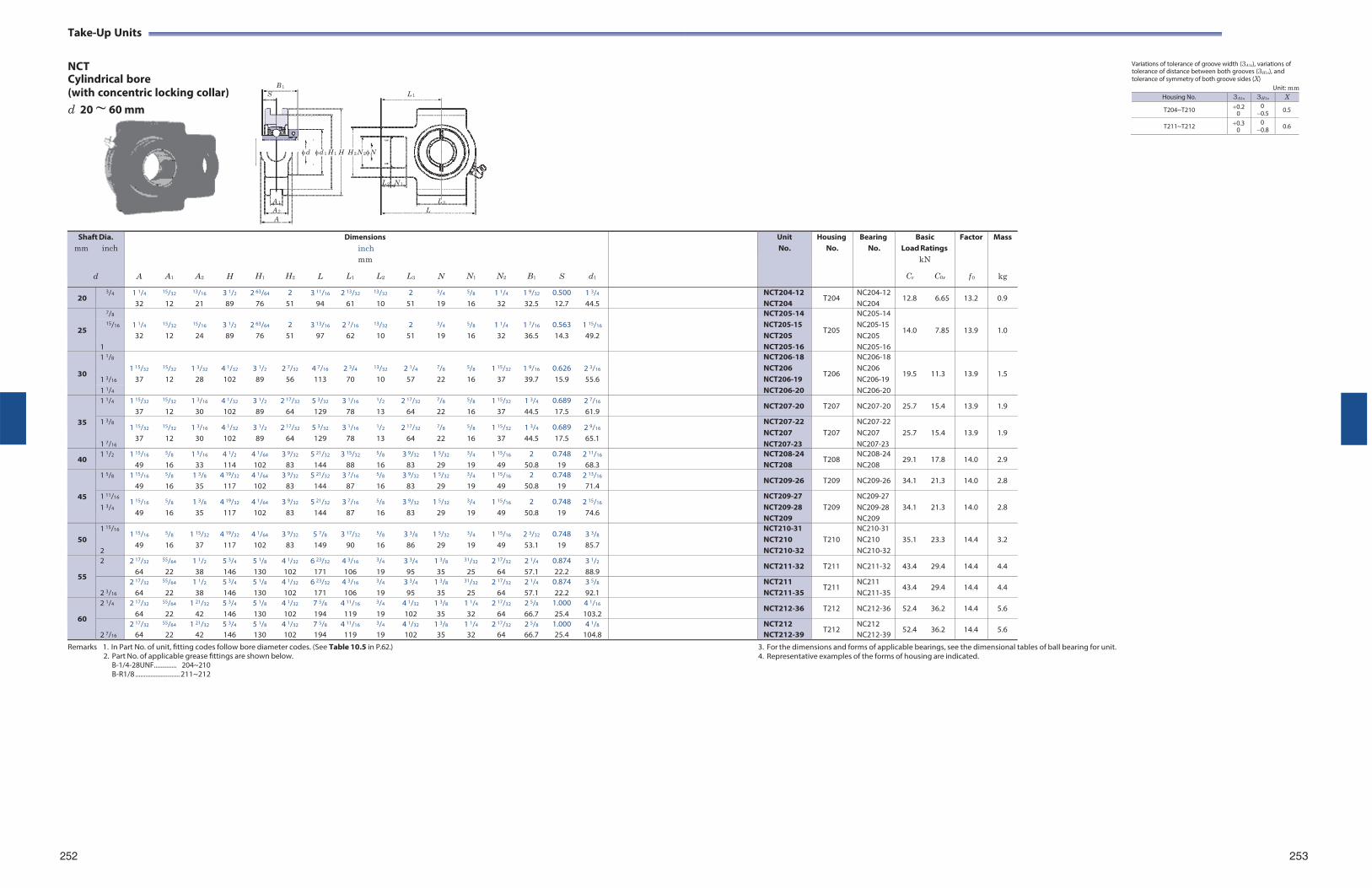
Take-Up Units
NCT Cylindrical bore
B 1
(with concentric locking collar) S L 1
d 20 ~ 60 mm
Variations of tolerance of groove width (3A1s), variations of tolerance of distance between both grooves (3H1s), and tolerance of symmetry of both groove sides (X)
Unit: mm
d d 1 H 1 H H 2 N 2N
L 2 N 1
A 1 L 3
A 2 L A
Remarks 1. In Part No. of unit, fitting codes follow bore diameter codes. (See Table 10.5 in P.62.)
2. Part No. of applicable grease fittings are shown below. B-1/4-28UNF.............. 204~210 B-R1/8 .......................... 211~212
3. For the dimensions and forms of applicable bearings, see the dimensional tables of ball bearing for unit. 4. Representative examples of the forms of housing are indicated.
252 253
Shaft Dia. mm inch
d
A
A1
A2
H
H1
H2
L
Dimensions inch mm
L1 L2
L3
N
N1
N2
B1
S
d1
UnitNo.
HousingNo.
BearingNo.
BasicLoad Ratings
kN
Cr C0r
Factor
f 0
Mass
kg
20 3/4 1 1/4
32
15/32
12
13/16
21 3 1/2
89 2 63/64
76 2
51 3 11/16
94 2 13/32
61
13/32
10 2
51
3/4
19
5/8
16 1 1/4
32 1 9/32
32.5 0.500 12.7
1 3/4
44.5 NCT204-12
NCT204T204
NC204-12 NC204
12.8 6.65 13.2 0.9
25
7/8 1 1/4
15/32
15/16
3 1/2
2 63/64
2
3 13/16
2 7/16
13/32
2
3/4
5/8
1 1/4
1 7/16
0.563
1 15/16
NCT205-14
T205
NC205-14
14.0
7.85
13.9
1.0 15/16 NCT205-15
NCT205 NC205-15 NC205 32 12 24 89 76 51 97 62 10 51 19 16 32 36.5 14.3 49.2
1 NCT205-16 NC205-16
30
1 1/8 1 15/32
15/32
1 3/32
4 1/32
3 1/2
2 7/32
4 7/16
2 3/4
13/32
2 1/4
7/8
5/8
1 15/32
1 9/16
0.626
2 3/16
NCT206-18
T206
NC206-18
19.5
11.3
13.9
1.5 1 3/16
NCT206 NCT206-19
NC206 NC206-19 37 12 28 102 89 56 113 70 10 57 22 16 37 39.7 15.9 55.6
1 1/4 NCT206-20 NC206-20
35
1 1/4 1 15/32
37
15/32
12 1 3/16
30 4 1/32
102 3 1/2
89 2 17/32
64 5 3/32
129 3 1/16
78
1/2
13 2 17/32
64
7/8
22
5/8
16 1 15/32
37 1 3/4
44.5 0.689 17.5
2 7/16
61.9 NCT207-20 T207 NC207-20 25.7 15.4 13.9 1.9
1 3/8
1 7/16
1 15/32
37
15/32
12 1 3/16
30 4 1/32
102 3 1/2
89 2 17/32
64 5 3/32
129 3 1/16
78
1/2
13 2 17/32
64
7/8
22
5/8
16 1 15/32
37 1 3/4
44.5 0.689 17.5
2 9/16
65.1
NCT207-22 NCT207 NCT207-23
T207
NC207-22 NC207 NC207-23
25.7
15.4
13.9
1.9
40 1 1/2 1 15/16
49
5/8
16 1 5/16
33 4 1/2
114 4 1/64
102 3 9/32
83 5 21/32
144 3 15/32
88
5/8
16 3 9/32
83 1 5/32
29
3/4
19 1 15/16
49 2
50.8 0.748
192 11/16
68.3 NCT208-24
NCT208 T208
NC208-24 NC208
29.1 17.8 14.0 2.9
45
1 5/8 1 15/16
49
5/8
16 1 3/8
35 4 19/32
117 4 1/64
102 3 9/32
83 5 21/32
144 3 7/16
87
5/8
16 3 9/32
83 1 5/32
29
3/4
19 1 15/16
49 2
50.8 0.748
192 13/16
71.4 NCT209-26 T209 NC209-26 34.1 21.3 14.0 2.8
1 11/16
1 3/4 1 15/16
49
5/8
16 1 3/8
35 4 19/32
117 4 1/64
102 3 9/32
83 5 21/32
144 3 7/16
87
5/8
16 3 9/32
83 1 5/32
29
3/4
19 1 15/16
49 2
50.8 0.748
19 2 15/16
74.6
NCT209-27 NCT209-28 NCT209
T209
NC209-27 NC209-28 NC209
34.1
21.3
14.0
2.8
50
1 15/16
2
1 15/16
49
5/8
16 1 15/32
37 4 19/32
117 4 1/64
102 3 9/32
83 5 7/8
149 3 17/32
90
5/8
16 3 3/8
86 1 5/32
29
3/4
19 1 15/16
49 2 3/32
53.1 0.748
19 3 3/8
85.7
NCT210-31 NCT210 NCT210-32
T210
NC210-31 NC210 NC210-32
35.1
23.3
14.4
3.2
55
2 2 17/32
64
55/64
22 1 1/2
38 5 3/4
146 5 1/8
130 4 1/32
102 6 23/32
171 4 3/16
106
3/4
19 3 3/4
95 1 3/8
35
31/32
25 2 17/32
64 2 1/4
57.1 0.874 22.2
3 1/2
88.9 NCT211-32 T211 NC211-32 43.4 29.4 14.4 4.4
2 3/16
2 17/32
64
55/64
22 1 1/2
38 5 3/4
146 5 1/8
130 4 1/32
102 6 23/32
171 4 3/16
106
3/4
19 3 3/4
95 1 3/8
35
31/32
25 2 17/32
64 2 1/4
57.1 0.874 22.2
3 5/8
92.1 NCT211
NCT211-35 T211
NC211 NC211-35
43.4 29.4 14.4 4.4
60
2 1/4 2 17/32
64
55/64
22 1 21/32
42 5 3/4
146 5 1/8
130 4 1/32
102 7 5/8
194 4 11/16
119
3/4
19 4 1/32
102 1 3/8
35 1 1/4
32 2 17/32
64 2 5/8
66.7 1.000 25.4
4 1/16
103.2 NCT212-36 T212 NC212-36 52.4 36.2 14.4 5.6
2 7/16
2 17/32
64
55/64
22 1 21/32
42 5 3/4
146 5 1/8
130 4 1/32
102 7 5/8
194 4 11/16
119
3/4
19 4 1/32
102 1 3/8
35 1 1/4
32 2 17/32
64 2 5/8
66.7 1.000 25.4
4 1/8
104.8 NCT212
NCT212-39 T212
NC212 NC212-39
52.4 36.2 14.4 5.6
Housing No. 3A1s 3H1s X
T204~T210 0.2 0
0 0.5 0.5
T211~T212 0.3 0
0 0.8 0.6
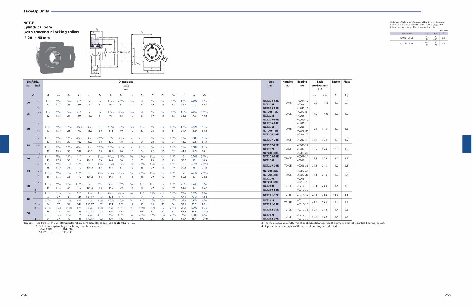
Take-Up Units
NCT-E Cylindrical bore
B 1
(with concentric locking collar) S L 1
d 20 ~ 60 mm
Variations of tolerance of groove width (3A1s), variations of tolerance of distance between both grooves (3H1s), and tolerance of symmetry of both groove sides (X)
Unit: mm
d d 1 H 1 H H 2 N 2N
L 2 N 1
A 1 L 3
A 2 L A
Remarks 1. In Part No. of unit, fitting codes follow bore diameter codes. (See Table 10.5 in P.62.)
2. Part No. of applicable grease fittings are shown below. B-1/4-28UNF.............. 204~210 B-R1/8 .......................... 211~212
3. For the dimensions and forms of applicable bearings, see the dimensional tables of ball bearing for unit. 4. Representative examples of the forms of housing are indicated.
254 255
Shaft Dia. mm inch
d
A
A1
A2
H
H1
H2
L
Dimensions inch mm
L1 L2
L3
N
N1
N2
B1
S
d1
UnitNo.
HousingNo.
BearingNo.
BasicLoad Ratings
kN
Cr C0r
Factor
f 0
Mass
kg
20 3/4 1 1/4
32
17/32
13.5
13/16
21 3 1/2
89 3
76.2 2
51 3 11/16
94 2 13/32
61
13/32
10 2
51
3/4
19
5/8
16 1 1/4
32 1 9/32
32.5 0.500 12.7
1 3/4
44.5 NCT204-12E
NCT204ET204E
NC204-12 NC204
12.8 6.65 13.2 0.9
25
7/8 1 1/4
17/32
15/16
3 1/2
3
2
3 13/16
2 7/16
13/32
2
3/4
5/8
1 1/4
1 7/16
0.563
1 15/16
NCT205-14E
T205E
NC205-14
14.0
7.85
13.9
1.0 15/16 NCT205-15E
NCT205E NC205-15 NC205 32 13.5 24 89 76.2 51 97 62 10 51 19 16 32 36.5 14.3 49.2
1 NCT205-16E NC205-16
30
1 1/8 1 15/32
17/32
1 3/32
4 1/32
3 1/2
2 7/32
4 7/16
2 3/4
13/32
2 1/4
7/8
5/8
1 15/32
1 9/16
0.626
2 3/16
NCT206-18E
T206E
NC206-18
19.5
11.3
13.9
1.5 1 3/16
NCT206E NCT206-19E
NC206 NC206-19 37 13.5 28 102 88.9 56 113 70 10 57 22 16 37 39.7 15.9 55.6
1 1/4 NCT206-20E NC206-20
35
1 1/4 1 15/32
37
17/32
13.5 1 3/16
30 4 1/32
102 3 1/2
88.9 2 17/32
64 5 3/32
129 3 1/16
78
1/2
13 2 17/32
64
7/8
22
5/8
16 1 15/32
37 1 3/4
44.5 0.689 17.5
2 7/16
61.9 NCT207-20E T207E NC207-20 25.7 15.4 13.9 1.9
1 3/8
1 7/16
1 15/32
37
17/32
13.5 1 3/16
30 4 1/32
102 3 1/2
88.9 2 17/32
64 5 3/32
129 3 1/16
78
1/2
13 2 17/32
64
7/8
22
5/8
16 1 15/32
37 1 3/4
44.5 0.689 17.5
2 9/16
65.1
NCT207-22E NCT207E NCT207-23E
T207E
NC207-22 NC207 NC207-23
25.7
15.4
13.9
1.9
40 1 1/2 1 15/16
49
11/16
17.5 1 5/16
33 4 1/2
114 4
101.6 3 9/32
83 5 21/32
144 3 15/32
88
5/8
16 3 9/32
83 1 5/32
29
3/4
19 1 15/16
49 2
50.8 0.748
192 11/16
68.3 NCT208-24E
NCT208E T208E
NC208-24 NC208
29.1 17.8 14.0 2.9
45
1 5/8 1 15/16
49
11/16
17.5 1 3/8
35 4 19/32
117 4
101.6 3 9/32
83 5 21/32
144 3 7/16
87
5/8
16 3 9/32
83 1 5/32
29
3/4
19 1 15/16
49 2
50.8 0.748
192 13/16
71.4 NCT209-26E T209E NC209-26 34.1 21.3 14.0 2.8
1 11/16
1 3/4 1 15/16
49
11/16
17.5 1 3/8
35 4 19/32
117 4
101.6 3 9/32
83 5 21/32
144 3 7/16
87
5/8
16 3 9/32
83 1 5/32
29
3/4
19 1 15/16
49 2
50.8 0.748
19 2 15/16
74.6
NCT209-27E NCT209-28E NCT209E
T209E
NC209-27 NC209-28 NC209
34.1
21.3
14.0
2.8
50
1 15/16
2
1 15/16
49
11/16
17.5 1 15/32
37 4 19/32
117 4
101.6 3 9/32
83 5 7/8
149 3 17/32
90
5/8
16 3 3/8
86 1 5/32
29
3/4
19 1 15/16
49 2 3/32
53.1 0.748
19 3 3/8
85.7
NCT210-31E NCT210E NCT210-32E
T210E
NC210-31 NC210 NC210-32
35.1
23.3
14.4
3.2
55
2 2 17/32
64 1 1/16
27 1 1/2
38 5 3/4
146 5 1/8
130.17 4 1/32
102 6 23/32
171 4 3/16
106
3/4
19 3 3/4
95 1 3/8
35
31/32
25 2 17/32
64 2 1/4
57.1 0.874 22.2
3 1/2
88.9 NCT211-32E T211E NC211-32 43.4 29.4 14.4 4.4
2 3/16
2 17/32
64 1 1/16
27 1 1/2
38 5 3/4
146 5 1/8
130.17 4 1/32
102 6 23/32
171 4 3/16
106
3/4
19 3 3/4
95 1 3/8
35
31/32
25 2 17/32
64 2 1/4
57.1 0.874 22.2
3 5/8
92.1 NCT211E
NCT211-35E T211E
NC211 NC211-35
43.4 29.4 14.4 4.4
60
2 1/4 2 17/32
64 1 1/16
27 1 21/32
42 5 3/4
146 5 1/8
130.17 4 1/32
102 7 5/8
194 4 11/16
119
3/4
19 4 1/32
102 1 3/8
35 1 1/4
32 2 17/32
64 2 5/8
66.7 1.000 25.4
4 1/16
103.2 NCT212-36E T212E NC212-36 52.4 36.2 14.4 5.6
2 7/16
2 17/32
64 1 1/16
27 1 21/32
42 5 3/4
146 5 1/8
130.17 4 1/32
102 7 5/8
194 4 11/16
119
3/4
19 4 1/32
102 1 3/8
35 1 1/4
32 2 17/32
64 2 5/8
66.7 1.000 25.4
4 1/8
104.8 NCT212E
NCT212-39E T212E
NC212 NC212-39
52.4 36.2 14.4 5.6
Housing No. 3A1s 3H1s X
T204E~T210E 0.2 0
0 0.5 0.5
T211E~T212E 0.3 0
0 0.8 0.6
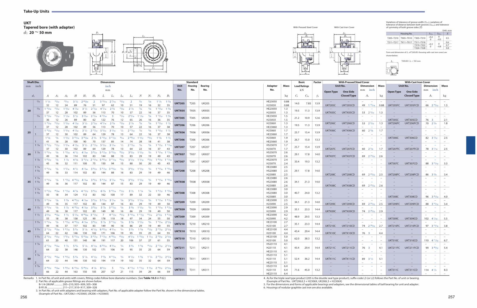
Take-Up Units
UKT Tapered bore (with adapter) d1 20 ~ 50 mm B 1
L 1
With Pressed Steel Cover With Cast Iron Cover
AS AC
B 1 B 1
Variations of tolerance of groove width (3A1s), variations of tolerance of distance between both grooves (3H1s), and tolerance of symmetry of both groove sides (X)
Unit: mm
d1
H 1 H
H 2 N 2 N
d1
H 1 d1
H 1 Form and dimension of Lc of T205JE3 (housing with cast iron cover) are
1 2 shown below.
L 2 N 1
A 1 L 3
A 2 L A
A 1 A 1
A 2 A 2
A A
T205JE3 Lc 102 mm
Remarks 1. In Part No. of unit and units with covers, fitting codes follow bore diameter numbers. (See Table 10.5 in P.62.)
2. Part No. of applicable grease fittings are shown below. B-1/4-28UNF.............. 205~210, X05~X09, 305~308 B-R1/8 .......................... 211~217, X10~X17, 309~328
3. In Part No. of unit with adapters and bearing with adapters, Part No. of applicable adapter follow the Part No. shown in the dimensional tables. (Example of Part No. : UKT206J + H2306X, UK206 + H2306X)
256
4. As for the triple seal type product (205 is the double seal type product), suffix code L3 (or L2) follows the Part No. of unit or bearing. (Example of Part No. : UKT206JL3 + H2306X, UK206L3 + H2306X)
5. For the dimensions and forms of applicable bearings and adapters, see the dimensional tables of ball bearing for unit and adapter. 6. Housings of nodular graphite cast iron are also available.
257
Shaft Dia. mm inch
d1
Dimensions inch mm
A A1 A2 H H1 H2 L L1 L2 L3 N N1 N2 B1
Standard BasicLoad Ratings
kN
Cr C0r
Factor
f 0
With Pressed Steel Cover With Cast Iron Cover Unit No.
Housing No.
Bearing No.
Adapter No.
Mass
kg
Unit No.
Open Type One Side Closed Type
Dimension mm inch
As
Mass
kg
Unit No.
Open Type One Side Closed Type
Dimension mm inch
Ac
Mass
kg
20
3/4 1 1/4 15/32 15/16 3 1/2 2 63/64 2 3 13/16 2 7/16 13/32 2 3/4 5/8 1 1/4 1 3/8
32 12 24 89 76 51 97 62 10 51 19 16 32 35 UKT205 T205 UK205 HE2305X
H2305X0.88 0.88
14.0 7.85 13.9
UKT205C UKT205CD 49 1 15/16
0.88
UKT205FC UKT205FCD
66 2 19/32
1.3
3/4 1 15/32 15/32 1 3/32 4 1/32 3 1/2 2 7/32 4 7/16 2 3/4 13/32 2 1/4 7/8 5/8 1 15/32 1 3/8
37 12 28 102 89 56 113 70 10 57 22 16 37 35 UKTX05 TX05 UKX05 HE2305X
H2305X1.3 1.3
19.5 11.3 13.9
UKTX05C UKTX05CD 53 2 3/32
1.3
3/4 1 13/32 15/32 1 1/32 3 1/2 3 5/32 2 7/16 4 13/16 3 15/32 2 9/16 1 1/32 5/8 1 13/32 1 3/8
36 12 26 89 80 62 122 76 12 65 26 16 36 35 UKT305 T305 UK305 HE2305X
H2305X1.5 1.5
21.2 10.9 12.6
UKT305C UKT305CD
76 3
2.1
25
1
1 15/32 15/32 1 3/32 4 1/32 3 1/2 2 7/32 4 7/16 2 3/4 13/32 2 1/4 7/8 5/8 1 15/32 1 1/2
37 12 28 102 89 56 113 70 10 57 22 16 37 38 UKT206 T206 UK206 H2306X
HE2306X1.3 1.3
19.5 11.3 13.9 UKT206C UKT206CD
53 2 3/32
1.3
UKT206FC UKT206FCD
70 2 3/4
1.8
1
1 15/32 15/32 1 3/16 4 1/32 3 1/2 2 17/32 5 3/32 3 1/16 1/2 2 17/32 7/8 5/8 1 15/32 1 1/2
37 12 30 102 89 64 129 78 13 64 22 16 37 38 UKTX06 TX06 UKX06 H2306X
HE2306X1.7 1.7
25.7 15.4 13.9 UKTX06C UKTX06CD
60 2 3/8
1.7
1
1 5/8 5/8 1 3/32 3 15/16 3 35/64 2 3/4 5 13/32 3 11/32 9/16 2 29/32 1 3/32 23/32 1 5/8 1 1/2
41 16 28 100 90 70 137 85 14 74 28 18 41 38 UKT306 T306 UK306 H2306X
HE2306X1.9 1.9
26.7 15.0 13.3
UKT306C UKT306CD
82 3 7/32
2.5
30
1 1/8 1 15/32 15/32 1 3/16 4 1/32 3 1/2 2 17/32 5 3/32 3 1/16 1/2 2 17/32 7/8 5/8 1 15/32 1 11/16
37 12 30 102 89 64 129 78 13 64 22 16 37 43 UKT207 T207 UK207 HS2307X
H2307X1.7 1.7
25.7 15.4 13.9
UKT207C UKT207CD 60 2 3/8
1.7
UKT207FC UKT207FCD
78 3 1/16
2.5
1 1/8 1 15/16 5/8 1 13/32 4 1/2 4 1/64 3 9/32 5 21/32 3 15/32 19/32 3 9/32 1 5/32 3/4 1 15/16 1 11/16
49 16 36 114 102 83 144 88 15 83 29 19 49 43 UKTX07 TX07 UKX07 HS2307X
H2307X2.6 2.6
29.1 17.8 14.0
UKTX07C UKTX07CD 69 2 23/32
2.6
1 1/8 1 25/32 5/8 1 1/4 4 3/8 3 15/16 2 15/16 5 29/32 3 11/16 19/32 3 5/32 1 3/16 25/32 1 25/32 1 11/16
45 16 32 111 100 75 150 94 15 80 30 20 45 43 UKT307 T307 UK307 HS2307X
H2307X2.4 2.4
33.4 19.3 13.2
UKT307C UKT307CD
88 3 15/32
3.3
35
1 1/4
1 3/8 1 15/16 5/8 1 5/16 4 1/2 4 1/64 3 9/32 5 21/32 3 15/32 5/8 3 9/32 1 5/32 3/4 1 15/16 1 13/16
49 16 33 114 102 83 144 88 16 83 29 19 49 46
UKT208
T208
UK208
HE2308X HS2308X H2308X
2.5 2.5 2.5
29.1 17.8
14.0
UKT208C UKT208CD
69 2 23/32
2.5
UKT208FC UKT208FCD
86 3 3/8
3.4
1 1/4
1 3/8 1 15/16 5/8 1 13/32 4 19/32 4 1/64 3 9/32 5 21/32 3 7/16 19/32 3 9/32 1 5/32 3/4 1 15/16 1 13/16
49 16 36 117 102 83 144 87 15 83 29 19 49 46
UKTX08
TX08
UKX08
HE2308X HS2308X H2308X
2.6 2.6 2.6
34.1 21.3
14.0
UKTX08C UKTX08CD
69 2 23/32
2.6
1 1/4
1 3/8 1 31/32 45/64 1 11/32 4 7/8 4 13/32 3 9/32 6 3/8 3 15/16 21/32 3 1/2 1 1/4 7/8 1 31/32 1 13/16
50 18 34 124 112 83 162 100 17 89 32 22 50 46
UKT308
T308
UK308
HE2308X HS2308X H2308X
3.0 3.0 3.0
40.7 24.0
13.2
UKT308C UKT308CD
96 3 25/32
4.0
40
1 1/2 1 15/16 5/8 1 3/8 4 19/32 4 1/64 3 9/32 5 21/32 3 7/16 5/8 3 9/32 1 5/32 3/4 1 15/16 1 31/32
49 16 35 117 102 83 144 87 16 83 29 19 49 50 UKT209 T209 UK209 HE2309X
H2309X2.5 2.5
34.1 21.3 14.0
UKT209C UKT209CD 69 2 23/32
2.5
UKT209FC UKT209FCD
88 3 15/32
3.4
1 1/2 1 15/16 5/8 1 1/2 4 19/32 4 1/64 3 9/32 5 7/8 3 17/32 5/8 3 3/8 1 5/32 3/4 1 15/16 1 31/32
49 16 38 117 102 83 149 90 16 86 29 19 49 50 UKTX09 TX09 UKX09 HE2309X
H2309X2.9 2.9
35.1 23.3 14.4
UKTX09C UKTX09CD 74 2 29/32
2.9
1 1/2 2 5/32 45/64 1 1/2 5 7/16 4 59/64 3 17/32 7 4 11/32 23/32 3 13/16 1 11/32 15/16 2 5/32 1 31/32
55 18 38 138 125 90 178 110 18 97 34 24 55 50 UKT309 T309 UK309 HE2309X
H2309X4.2 4.2
48.9 29.5 13.3
UKT309C UKT309CD
102 4 1/32
5.5
45
1 3/4 1 15/16 5/8 1 15/32 4 19/32 4 1/64 3 9/32 5 7/8 3 17/32 5/8 3 3/8 1 5/32 3/4 1 15/16 2 5/32
49 16 37 117 102 83 149 90 16 86 29 19 49 55 UKT210 T210 UK210 HE2310X
H2310X2.7 2.7
35.1 23.3 14.4
UKT210C UKT210CD 74 2 29/32
2.7
UKT210FC UKT210FCD
97 3 13/16
3.8
1 3/4 2 17/32 55/64 1 21/32 5 3/4 5 1/8 4 1/32 6 23/32 4 3/16 3/4 3 3/4 1 3/8 31/32 2 17/32 2 5/32
64 22 42 146 130 102 171 106 19 95 35 25 64 55 UKTX10 TX10 UKX10 HE2310X
H2310X4.4 4.4
43.4 29.4 14.4
UKTX10C UKTX10CD 76 3
4.4
1 3/4 2 13/32 25/32 1 9/16 5 15/16 5 33/64 3 27/32 7 17/32 4 19/32 25/32 4 3/16 1 15/32 1 1/16 2 13/32 2 5/32
61 20 40 151 140 98 191 117 20 106 37 27 61 55 UKT310 T310 UK310 HE2310X
H2310X5.0 5.0
62.0 38.3 13.2
UKT310C UKT310CD
110 4 11/32
6.7
50
1 7/8
2
2 17/32 55/64 1 1/2 5 3/4 5 1/8 4 1/32 6 23/32 4 3/16 3/4 3 3/4 1 3/8 31/32 2 17/32 2 5/16
64 22 38 146 130 102 171 106 19 95 35 25 64 59
UKT211
T211
UK211
HS2311X H2311X HE2311X
4.1 4.1 4.1
43.4 29.4
14.4
UKT211C UKT211CD
76 3
4.1
UKT211FC UKT211FCD
99 3 29/32
5.4
1 7/8
2
2 17/32 55/64 1 23/32 5 3/4 5 1/8 4 1/32 7 5/8 4 11/16 3/4 4 1/32 1 3/8 1 1/4 2 17/32 2 5/16
64 22 44 146 130 102 194 119 19 102 35 32 64 59
UKTX11
TX11
UKX11
HS2311X H2311X HE2311X
5.1 5.1 5.1
52.4 36.2
14.4
UKTX11C UKTX11CD
89 3 1/2
5.1
1 7/8
2
2 19/32 55/64 1 23/32 6 13/32 5 29/32 4 1/8 8 5/32 5 13/16 4 17/32 1 17/32 1 5/32 2 19/32 2 5/16
66 22 44 163 150 105 207 127 21 115 39 29 66 59
UKT311
T311
UK311
HS2311X H2311X HE2311X
6.4 6.4 6.4
71.6 45.0
13.2
UKT311C UKT311CD
114 4 1/2
8.3
L c
Housing No. 3A1s 3H1s X
T205~T210 TX05~TX10 T305~T310 0.2 0
0 0.5 0.5
T211~T217 TX11~TX17 T311~T3180.3
0 0 0.8
0.6
T319~T322 0.7T324~T328 0.8
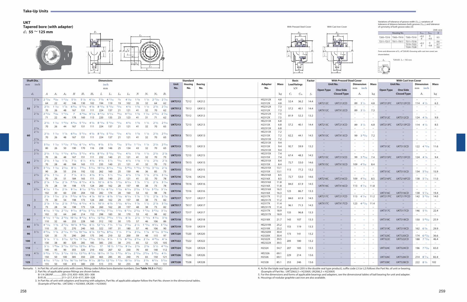
Take-Up Units
UKT Tapered bore (with adapter) d1 55 ~ 125 mm B 1
L 1
With Pressed Steel Cover With Cast Iron Cover
AS AC
B 1 B 1
Variations of tolerance of groove width (3A1s), variations of tolerance of distance between both grooves (3H1s), and tolerance of symmetry of both groove sides (X)
Unit: mm
d1
H 1 H
H 2 N 2 N
d1
H 1 d1
H 1 Form and dimension of Lc of T205JE3 (housing with cast iron cover) are
1 2 shown below.
L 2 N 1
A 1 L 3
A 2 L A
A 1 A 1
A 2 A 2
A A
T205JE3 Lc 102 mm
Remarks 1. In Part No. of unit and units with covers, fitting codes follow bore diameter numbers. (See Table 10.5 in P.62.)
2. Part No. of applicable grease fittings are shown below. B-1/4-28UNF.............. 205~210, X05~X09, 305~308 B-R1/8 .......................... 211~217, X10~X17, 309~328
3. In Part No. of unit with adapters and bearing with adapters, Part No. of applicable adapter follow the Part No. shown in the dimensional tables. (Example of Part No. : UKT206J + H2306X, UK206 + H2306X)
4. As for the triple seal type product (205 is the double seal type product), suffix code L3 (or L2) follows the Part No. of unit or bearing. (Example of Part No. : UKT206JL3 + H2306X, UK206L3 + H2306X)
5. For the dimensions and forms of applicable bearings and adapters, see the dimensional tables of ball bearing for unit and adapter. 6. Housings of nodular graphite cast iron are also available.
258 259
Shaft Dia. mm inch
d1
Dimensions inch mm
A A1 A2 H H1 H2 L L1 L2 L3 N N1 N2 B1
Standard BasicLoad Ratings
kN
Cr C0r
Factor
f 0
With Pressed Steel Cover With Cast Iron Cover Unit No.
Housing No.
Bearing No.
Adapter No.
Mass
kg
Unit No.
Open Type One Side Closed Type
Dimension mm inch
As
Mass
kg
Unit No.
Open Type One Side Closed Type
Dimension mm inch
Ac
Mass
kg
55
2 1/8 2 17/32 55/64 1 21/32 5 3/4 5 1/8 4 1/32 7 5/8 4 11/16 3/4 4 1/32 1 3/8 1 1/4 2 17/32 2 7/16
64 22 42 146 130 102 194 119 19 102 35 32 64 62 UKT212 T212 UK212 HS2312X
H2312X4.8 4.8
52.4 36.2 14.4
UKT212C UKT212CD 89 3 1/2
4.8
UKT212FC UKT212FCD
114 4 1/2
6.3
2 1/8 2 3/4 1 1/32 1 7/8 6 9/16 5 15/16 4 3/8 8 13/16 5 13/32 13/16 4 3/4 1 5/8 1 1/4 2 3/4 2 7/16
70 26 48 167 151 111 224 137 21 121 41 32 70 62 UKTX12 TX12 UKX12 HS2312X
H2312X7.3 7.3
57.2 40.1 14.4
UKTX12C UKTX12CD 89 3 1/2
7.3
2 1/8 2 25/32 55/64 1 13/16 7 6 19/64 4 7/16 8 21/32 5 5/16 29/32 4 27/32 1 5/8 1 7/32 2 25/32 2 7/16
71 22 46 178 160 113 220 135 23 123 41 31 71 62 UKT312 T312 UK312 HS2312X
H2312X7.5 7.5
81.9 52.2 13.2
UKT312C UKT312CD
124 4 7/8
9.9
60
2 1/4
2 3/8
2 3/4 1 1/32 1 23/32 6 9/16 5 15/16 4 3/8 8 13/16 5 13/32 13/16 4 3/4 1 5/8 1 1/4 2 3/4 2 9/16
70 26 44 167 151 111 224 137 21 121 41 32 70 65
UKT213
T213
UK213
HE2313X H2313X HS2313X
6.8 6.8 6.8
57.2 40.1
14.4
UKT213C UKT213CD
89 3 1/2
6.8
UKT213FC UKT213FCD
114 4 1/2
8.5
2 1/4
2 3/8
2 3/4 1 1/32 1 7/8 6 9/16 5 15/16 4 3/8 8 13/16 5 13/32 13/16 4 3/4 1 5/8 1 1/4 2 3/4 2 9/16
70 26 48 167 151 111 224 137 21 121 41 32 70 65
UKTX13
TX13
UKX13
HE2313X H2313X HS2313X
7.2 7.2 7.2
62.2 44.1
14.5
UKTX13C UKTX13CD
99 3 29/32
7.2
2 1/4
2 3/8
3 5/32 1 1/32 1 31/32 7 15/32 6 11/16 4 9/16 9 3/8 5 3/4 31/32 5 9/32 1 11/16 1 1/4 2 3/4 2 9/16
80 26 50 190 170 116 238 146 25 134 43 32 70 65
UKT313
T313
UK313
HE2313X H2313X HS2313X
9.4 9.4 9.4
92.7 59.9
13.2
UKT313C UKT313CD
122 4 13/16
11.6
65
2 1/2 2 3/4 1 1/32 1 13/16 6 9/16 5 15/16 4 3/8 8 13/16 5 13/32 13/16 4 3/4 1 5/8 1 1/4 2 3/4 2 7/8
70 26 48 167 151 111 232 140 21 121 41 32 70 73 UKT215 T215 UK215 HE2315X
H2315X7.4 7.4
67.4 48.3 14.5
UKT215C UKT215CD 99 3 29/32
7.4
UKT215FC UKT215FCD
124 4 7/8
9.4
2 1/2 2 3/4 1 7/64 1 7/8 7 1/4 6 1/2 4 3/8 9 1/4 5 1/2 13/16 4 3/4 1 5/8 1 1/4 2 3/4 2 7/8
70 28 48 184 165 111 235 140 21 121 41 32 70 73 UKTX15 TX15 UKX15 HE2315X
H2315X8.4 8.4
72.7 53.0 14.6
UKTX15C UKTX15CD
109 4 9/32
8.4
2 1/2 3 17/32 1 1/32 2 5/32 8 1/2 7 9/16 5 3/16 10 5/16 6 5/16 31/32 5 29/32 1 13/16 1 13/32 3 11/32 2 7/8
90 26 55 216 192 132 262 160 25 150 46 36 85 73 UKT315 T315 UK315 HE2315X
H2315X13.1 13.1
113 77.2 13.2
UKT315C UKT315CD
134 5 9/32
15.9
70
2 3/4 2 3/4 1 1/32 2 7 1/4 6 1/2 4 3/8 9 1/4 5 1/2 13/16 4 3/4 1 5/8 1 1/4 2 3/4 3 1/16
70 26 51 184 165 111 235 140 21 121 41 32 70 78 UKT216 T216 UK216 HE2316X
H2316X8.5 8.5
72.7 53.0 14.6
UKT216C UKT216CD
109 4 9/32
8.5
UKT216FC UKT216FCD
138 5 7/16
11.0
2 3/4 2 7/8 1 7/64 2 1/8 7 25/32 6 13/16 4 7/8 10 1/4 6 3/8 1 3/32 6 3/16 1 7/8 1 1/2 2 7/8 3 1/16
73 28 54 198 173 124 260 162 28 157 48 38 73 78 UKTX16 TX16 UKX16 HE2316X
H2316X11.8 11.8
84.0 61.9 14.5
UKTX16C UKTX16CD
113 4 7/16
11.8
2 3/4 4 1/32 1 3/16 2 3/8 9 1/16 8 1/32 5 29/32 11 3/32 6 27/32 1 3/32 6 5/16 2 3/32 1 21/32 3 27/32 3 1/16
102 30 60 230 204 150 282 174 28 160 53 42 98 78 UKT316 T316 UK316 HE2316X
H2316X16.3 16.3
123 86.7 13.3
UKT316C UKT316CD
138 5 7/16
19.4
75
3
2 7/8 1 3/16 2 1/8 7 25/32 6 13/16 4 7/8 10 1/4 6 3/8 1 5/32 6 3/16 1 7/8 1 1/2 2 7/8 3 7/32
73 30 54 198 173 124 260 162 29 157 48 38 73 82 UKT217 T217 UK217 H2317X
HE2317X11.2 11.2
84.0 61.9 14.5 UKT217C UKT217CD
113 4 7/16
11.2
UKT217FC UKT217FCD
142 5 19/32
14.0
3
2 7/8 1 7/64 2 1/8 7 25/32 6 13/16 4 7/8 10 1/4 6 3/8 1 3/32 6 3/16 1 7/8 1 1/2 2 7/8 3 7/32
73 28 54 198 173 124 260 162 28 157 48 38 73 82 UKTX17 TX17 UKX17 H2317X
HE2317X11.4 11.4
96.1 71.5 14.5 UKTX17C UKTX17CD
123 4 27/32
11.4
3
4 1/32 1 17/64 2 17/32 9 7/16 8 27/64 5 31/32 11 23/32 7 7/32 1 3/16 6 11/16 2 3/32 1 21/32 3 27/32 3 7/32
102 32 64 240 214 152 298 183 30 170 53 42 98 82 UKT317 T317 UK317 H2317X
HE2317X18.9 18.9
133 96.8 13.3
UKT317C UKT317CD
146 5 3/4
22.4
80 4 11/32 1 17/64 2 19/32 10 1/32 8 31/32 6 5/16 12 9/32 7 9/16 1 3/16 6 7/8 2 1/4 1 13/16 4 3/16 3 3/8
110 32 66 255 228 160 312 192 30 175 57 46 106 86 UKT318 T318 UK318 H2318X 21.7 143 107 13.3 UKT318C UKT318CD 150 5 29/32 25.9
85 3 1/4 4 11/32 1 3/8 2 27/32 10 5/8 9 29/64 6 1/2 12 11/16 7 3/4 1 7/32 7 3/32 2 1/4 1 13/16 4 3/16 3 17/32
110 35 72 270 240 165 322 197 31 180 57 46 106 90 UKT319 T319 UK319 HE2319X
H2319X25.2 25.2
153 119 13.3
UKT319C UKT319CD
162 6 3/8
29.9
90 3 1/2 4 23/32 1 3/8 2 15/16 11 13/32 10 15/64 6 7/8 13 19/32 8 9/32 1 1/4 7 7/8 2 5/16 1 7/8 4 17/32 3 13/16
120 35 75 290 260 175 345 210 32 200 59 48 115 97 UKT320 T320 UK320 HE2320X
H2320X30.4 30.4
173 141 13.2
UKT320C UKT320CD
174 6 27/32
36.6
100 4
5 1/8 1 1/2 3 5/32 12 19/32 11 7/32 7 9/32 15 5/32 9 1/4 1 1/2 8 15/32 2 9/16 2 1/16 4 29/32 4 1/8
130 38 80 320 285 185 385 235 38 215 65 52 125 105 UKT322 T322 UK322 H2322X
HE2322X39.5 39.5
205 180 13.2
UKT322C UKT322CD
188 7 13/32
46.4
110 5 1/2 1 49/64 3 17/32 13 31/32 12 9/32 8 9/32 17 10 1/2 1 21/32 9 1/16 2 3/4 2 3/8 5 1/2 4 13/32
140 45 90 355 320 210 432 267 42 230 70 60 140 112 UKT324 T324 UK324 H2324 54.7 207 185 13.5 UKT324C UKT324CD 196 7 23/32 65.0
115 4 1/2 5 29/32 1 31/32 3 15/16 15 5/32 13 25/32 8 21/32 18 5/16 11 7/32 1 25/32 9 7/16 2 15/16 2 9/16 5 29/32 4 3/4
150 50 100 385 350 220 465 285 45 240 75 65 150 121 UKT326 T326 UK326 HE2326
H232669.1 69.1
229 214 13.6
UKT326C UKT326CD
214 8 7/16
82.4
125 6 3/32 1 31/32 3 15/16 16 11/32 14 61/64 9 1/16 20 9/32 12 13/32 1 31/32 10 1/32 3 5/32 2 3/4 6 5/16 5 5/32
155 50 100 415 380 230 515 315 50 255 80 70 160 131 UKT328 T328 UK328 H2328 85.1 253 246 13.6 UKT328C UKT328CD 222 8 3/4 102
L c
Housing No. 3A1s 3H1s X
T205~T210 TX05~TX10 T305~T310 0.2 0
0 0.5 0.5
T211~T217 TX11~TX17 T311~T3180.3
0 0 0.8
0.6
T319~T322 0.7T324~T328 0.8
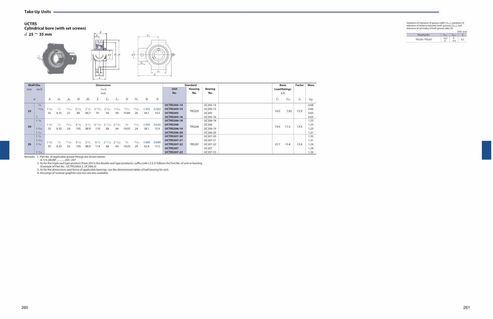
Take-Up Units
UCTRS Cylindrical bore (with set screws) d 25 ~ 35 mm
B S
d H 1 H
L 1
N
N 1
Variations of tolerance of groove width (3A1s), variations of tolerance of distance between both grooves (3H1s), and tolerance of symmetry of both groove sides (X)
Unit: mm
A1 L 3
A 2 L A
Shaft Dia.
mm inch
d
A
A1
A2
H
H1
Dimensions inch mm
L L1
L3
N
N1
B
S
Standard BasicLoad Ratings
kN
Cr C0r
Factor
f 0
Mass
kg
Unit No.
Housing No.
Bearing No.
25
7/8 1 3/8
1/4
13/16
3 5/32
2 5/8
3 19/32
2 7/32
1 9/16
25/32
25/32
1.343
0.563
UCTRS205-14
TRS205
UC205-14
14.0
7.85
13.9
0.68 15/16 UCTRS205-15 UC205-15 0.66
35 6.35 21 80 66.7 91 56 40 19.84 20 34.1 14.3 UCTRS205 UC205 0.65 1 UCTRS205-16 UC205-16 0.65
30
1 1/8 1 3/8
1/4
15/16
4 1/8
3 1/2
4 11/32
2 11/16
2 17/32
3/4
15/16
1.500
0.626
UCTRS206-18
TRS206
UC206-18
19.5
11.3
13.9
1.25
1 3/16
UCTRS206 UC206 1.23 35 6.35 24 105 88.9 110 68 64 19.05 24 38.1 15.9 UCTRS206-19 UC206-19 1.23
1 1/4 UCTRS206-20 UC206-20 1.21
35
1 1/4
1 3/8
1/4
31/32
4 1/8
3 1/2
4 1/2
2 11/16
2 17/32
3/4
15/16
1.689
0.689
UCTRS207-20
TRS207
UC207-20
25.7
15.4
13.9
1.35 1 5/16 UCTRS207-21 UC207-21 1.31 1 3/8 UCTRS207-22 UC207-22 1.29
35 6.35 25 105 88.9 114 68 64 19.05 24 42.9 17.5 UCTRS207 UC207 1.29
1 7/16 UCTRS207-23 UC207-23 1.26
Remarks 1. Part No. of applicable grease fittings are shown below. A-1/4-28UNF ............. 205~207
2. As for the triple seal type product (from 205 is the double seal type products), suffix code L3 (L2) follows the Part No. of unit or bearing. (Example of Part No. : UCTRS206JL3, UC206L3)
3. As for the dimensions and forms of applicable bearings, see the dimensional tables of ball bearing for unit. 4. Housings of nodular graphite cast iron are also available.
260
261
Housing No. 3A1s 3H1s X
TRS205~TRS207 0.2 0
0 0.5 0.5
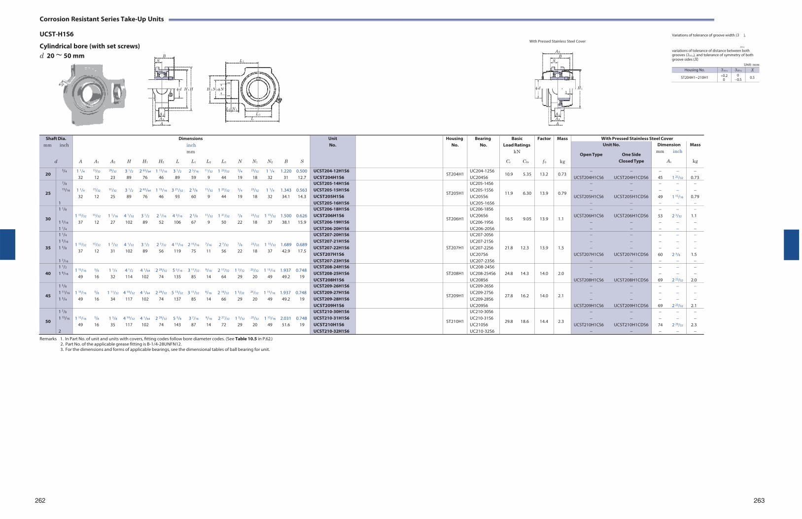
Corrosion Resistant Series Take-Up Units
UCST-H1S6 With Pressed Stainless Steel Cover
Variations of tolerance of groove width (3 ),
Cylindrical bore (with set screws) d 20 ~ 50 mm
B S
d H 1 H
L 1
H 2 N 2 N
A S
B S
d H 1 1
A1s
variations of tolerance of distance between both grooves (3H1s), and tolerance of symmetry of both groove sides (X)
Unit: mm
L 2 N 1
A 1 L 3 A 1
A 2 L A 2
A A
Remarks 1. In Part No. of unit and units with covers, fitting codes follow bore diameter codes. (See Table 10.5 in P.62.)
2. Part No. of the applicable grease fitting is B-1/4-28UNFN12. 3. For the dimensions and forms of applicable bearings, see the dimensional tables of ball bearing for unit.
262 263
Shaft Dia. mm inch
d
Dimensions inch mm
A A1 A2 H H1 H2 L L1 L2 L3 N N1 N2 B S
UnitNo.
HousingNo.
BearingNo.
BasicLoad Ratings
kN
Cr C0r
Factor
f 0
Mass
kg
With Pressed Stainless Steel Cover Unit No.
Open Type One Side Closed Type
Dimension mm inch
As
Mass
kg
20 3/4 1 1/4 15/32 29/32 3 1/2 2 63/64 1 13/16 3 1/2 2 5/16 11/32 1 23/32 3/4 23/32 1 1/4 1.220 0.500
32 12 23 89 76 46 89 59 9 44 19 18 32 31 12.7 UCST204-12H1S6 UCST204H1S6
ST204H1 UC204-12S6 UC204S6
10.9 5.35 13.2 0.73
UCST204H1CS6 UCST204H1CDS6
45 1 25/32
0.73
25
7/8
15/16
1
1 1/4 15/32 31/32 3 1/2 2 63/64 1 13/16 3 21/32 2 3/8 11/32 1 23/32 3/4 23/32 1 1/4 1.343 0.563 32 12 25 89 76 46 93 60 9 44 19 18 32 34.1 14.3
UCST205-14H1S6 UCST205-15H1S6 UCST205H1S6 UCST205-16H1S6
ST205H1
UC205-14S6 UC205-15S6 UC205S6 UC205-16S6
11.9 6.30
13.9
0.79
UCST205H1CS6 UCST205H1CDS6
49 1 15/16
0.79
30
1 1/8
1 3/16
1 1/4
1 15/32 15/32 1 1/16 4 1/32 3 1/2 2 1/16 4 3/16 2 5/8 11/32 1 31/32 7/8 23/32 1 15/32 1.500 0.626
37 12 27 102 89 52 106 67 9 50 22 18 37 38.1 15.9
UCST206-18H1S6 UCST206H1S6 UCST206-19H1S6 UCST206-20H1S6
ST206H1
UC206-18S6 UC206S6 UC206-19S6 UC206-20S6
16.5 9.05
13.9
1.1
UCST206H1CS6 UCST206H1CDS6
53 2 3/32
1.1
35
1 1/4
1 5/16
1 3/8
1 7/16
1 15/32 15/32 1 7/32 4 1/32 3 1/2 2 7/32 4 11/16 2 15/16 7/16 2 7/32 7/8 23/32 1 15/32 1.689 0.689 37 12 31 102 89 56 119 75 11 56 22 18 37 42.9 17.5
UCST207-20H1S6 UCST207-21H1S6 UCST207-22H1S6 UCST207H1S6 UCST207-23H1S6
ST207H1
UC207-20S6 UC207-21S6 UC207-22S6 UC207S6 UC207-23S6
21.8 12.3
13.9
1.5
UCST207H1CS6 UCST207H1CDS6
60 2 3/8
1.5
40
1 1/2
1 9/16 1 15/16 5/8 1 1/4 4 1/2 4 1/64 2 29/32 5 5/16 3 11/32 9/16 2 17/32 1 5/32 25/32 1 15/16 1.937 0.748
49 16 32 114 102 74 135 85 14 64 29 20 49 49.2 19
UCST208-24H1S6 UCST208-25H1S6 UCST208H1S6
ST208H1
UC208-24S6 UC208-254S6 UC208S6
24.8 14.3
14.0
2.0
UCST208H1CS6 UCST208H1CDS6
69 2 23/32
2.0
45
1 5/8
1 11/16
1 3/4
1 15/16 5/8 1 11/32 4 19/32 4 1/64 2 29/32 5 13/32 3 11/32 9/16 2 19/32 1 5/32 25/32 1 15/16 1.937 0.748
49 16 34 117 102 74 137 85 14 66 29 20 49 49.2 19
UCST209-26H1S6 UCST209-27H1S6 UCST209-28H1S6 UCST209H1S6
ST209H1
UC209-26S6 UC209-27S6 UC209-28S6 UC209S6
27.8 16.2
14.0
2.1
UCST209H1CS6 UCST209H1CDS6
69 2 23/32
2.1
50
1 7/8
1 15/16
2
1 15/16 5/8 1 3/8 4 19/32 4 1/64 2 29/32 5 5/8 3 7/16 9/16 2 27/32 1 5/32 25/32 1 15/16 2.031 0.748
49 16 35 117 102 74 143 87 14 72 29 20 49 51.6 19
UCST210-30H1S6 UCST210-31H1S6 UCST210H1S6 UCST210-32H1S6
ST210H1
UC210-30S6 UC210-31S6 UC210S6 UC210-32S6
29.8 18.6
14.4
2.3
UCST210H1CS6 UCST210H1CDS6
74 2 29/32
2.3
Housing No. 3A1s 3H1s X
ST204H1~210H1 0.2 0
0 0.5 0.5
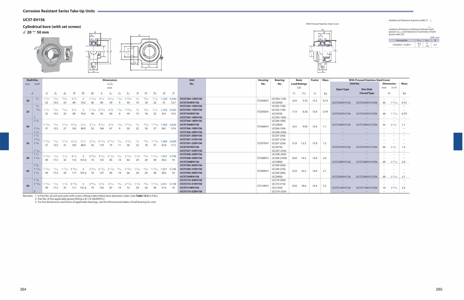
Corrosion Resistant Series Take-Up Units
UCST-EH1S6 With Pressed Stainless Steel Cover
Variations of tolerance of groove width (3 ),
Cylindrical bore (with set screws) d 20 ~ 50 mm
B S
d H 1 H
L 1
H 2 N 2 N
A S
B S
d H 1 1
A1s
variations of tolerance of distance between both grooves (3H1s), and tolerance of symmetry of both groove sides (X)
Unit: mm
L 2 N 1
A 1 L 3 A 1
A 2 L A 2
A A
Remarks 1. In Part No. of unit and units with covers, fitting codes follow bore diameter codes. (See Table 10.5 in P.62.)
2. Part No. of the applicable grease fitting is B-1/4-28UNFN12. 3. For the dimensions and forms of applicable bearings, see the dimensional tables of ball bearing for unit.
264 265
Shaft Dia. mm inch
d
Dimensions inch mm
A A1 A2 H H1 H2 L L1 L2 L3 N N1 N2 B S
UnitNo.
HousingNo.
BearingNo.
BasicLoad Ratings
kN
Cr C0r
Factor
f 0
Mass
kg
With Pressed Stainless Steel Cover Unit No.
Open Type One Side Closed Type
Dimension mm inch
As
Mass
kg
20 3/4 1 1/4 17/32 29/32 3 1/2 3 1 13/16 3 1/2 2 5/16 11/32 1 23/32 3/4 23/32 1 1/4 1.220 0.500
32 13.5 23 89 76.2 46 89 59 9 44 19 18 32 31 12.7 UCST204-12EH1S6 UCST204EH1S6
ST204EH1 UC204-12S6 UC204S6
10.9 5.35 13.2 0.73
UCST204EH1CS6 UCST204EH1CDS6
45 1 25/32
0.73
25
7/8
15/16
1
1 1/4 17/32 31/32 3 1/2 3 1 13/16 3 21/32 2 3/8 11/32 1 23/32 3/4 23/32 1 1/4 1.343 0.563 32 13.5 25 89 76.2 46 93 60 9 44 19 18 32 34.1 14.3
UCST205-14EH1S6 UCST205-15EH1S6 UCST205EH1S6 UCST205-16EH1S6
ST205EH1
UC205-14S6 UC205-15S6 UC205S6 UC205-16S6
11.9 6.30
13.9
0.79
UCST205EH1CS6 UCST205EH1CDS6
49 1 15/16
0.79
30
1 1/8
1 3/16
1 1/4
1 15/32 17/32 1 1/16 4 1/32 3 1/2 2 1/16 4 3/16 2 5/8 11/32 1 31/32 7/8 23/32 1 15/32 1.500 0.626
37 13.5 27 102 88.9 52 106 67 9 50 22 18 37 38.1 15.9
UCST206-18EH1S6 UCST206EH1S6 UCST206-19EH1S6 UCST206-20EH1S6
ST206EH1
UC206-18S6 UC206S6 UC206-19S6 UC206-20S6
16.5 9.05
13.9
1.1
UCST206EH1CS6 UCST206EH1CDS6
53 2 3/32
1.1
35
1 1/4
1 5/16
1 3/8
1 7/16
1 15/32 17/32 1 7/32 4 1/32 3 1/2 2 7/32 4 11/16 2 15/16 7/16 2 7/32 7/8 23/32 1 15/32 1.689 0.689 37 13.5 31 102 88.9 56 119 75 11 56 22 18 37 42.9 17.5
UCST207-20EH1S6 UCST207-21EH1S6 UCST207-22EH1S6 UCST207EH1S6 UCST207-23EH1S6
ST207EH1
UC207-20S6 UC207-21S6 UC207-22S6 UC207S6 UC207-23S6
21.8 12.3
13.9
1.5
UCST207EH1CS6 UCST207EH1CDS6
60 2 3/8
1.5
40
1 1/2
1 9/16 1 15/16 11/16 1 1/4 4 1/2 4 2 29/32 5 5/16 3 11/32 9/16 2 17/32 1 5/32 25/32 1 15/16 1.937 0.748
49 17.5 32 114 101.6 74 135 85 14 64 29 20 49 49.2 19
UCST208-24EH1S6 UCST208-25EH1S6 UCST208EH1S6
ST208EH1
UC208-24S6 UC208-254S6 UC208S6
24.8 14.3
14.0
2.0
UCST208EH1CS6 UCST208EH1CDS6
69 2 23/32
2.0
45
1 5/8
1 11/16
1 3/4
1 15/16 11/16 1 11/32 4 19/32 4 2 29/32 5 13/32 3 11/32 9/16 2 19/32 1 5/32 25/32 1 15/16 1.937 0.748
49 17.5 34 117 101.6 74 137 85 14 66 29 20 49 49.2 19
UCST209-26EH1S6 UCST209-27EH1S6 UCST209-28EH1S6 UCST209EH1S6
ST209EH1
UC209-26S6 UC209-27S6 UC209-28S6 UC209S6
27.8 16.2
14.0
2.1
UCST209EH1CS6 UCST209EH1CDS6
69 2 23/32
2.1
50
1 7/8
1 15/16
2
1 15/16 11/16 1 3/8 4 19/32 4 2 29/32 5 5/8 3 7/16 9/16 2 27/32 1 5/32 25/32 1 15/16 2.031 0.748
49 17.5 35 117 101.6 74 143 87 14 72 29 20 49 51.6 19
UCST210-30EH1S6 UCST210-31EH1S6 UCST210EH1S6 UCST210-32EH1S6
ST210EH1
UC210-30S6 UC210-31S6 UC210S6 UC210-32S6
29.8 18.6
14.4
2.3
UCST210EH1CS6 UCST210EH1CDS6
74 2 29/32
2.3
Housing No. 3A1s 3H1s X
ST204EH1~210EH1 0.2 0
0 0.5 0.5
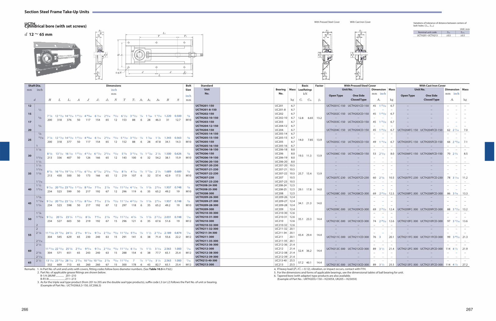
Section Steel Frame Take-Up Units
UCTH Cylindrical bore (with set screws) With Pressed Steel Cover With Cast Iron Cover
Variations of tolerance of distance between centers of bolt holes (3Js, 3J1s)
d 12 ~ 65 mm
L 1
T T 1
Unit: mm
H J 1
6-N
J J J 2
L
Remarks 1. In Part No. of unit and units with covers, fitting codes follow bore diameter numbers. (See Table 10.5 in P.62.)
2. Part No. of applicable grease fittings are shown below. B-1/4-28UNF.............. 201~210 B-R1/8 .......................... 211~213
3. As for the triple seal type product (from 201 to 205 are the double seal type products), suffix code L3 (or L2) follows the Part No. of unit or bearing. (Example of Part No. : UCTH206JL3-150, UC206L3)
4. If heavy load (Pr /Cr 0.12), vibration, or impact occurs, contact with FYH. 5. For the dimensions and forms of applicable bearings, see the dimensional tables of ball bearing for unit. 6. Tapered bore (with adapter) type products are also available.
(Example of Part No. : UKTH205J-150 H2305X, UK205 H2305X)
266 267
Shaft Dia. mm inch
d
H
L
L1
A
J
J1
Dimensions inch mm
J2 N T
T1
A1
A2
A0
B
S
Bolt Size
inch mm
Standard BasicLoad Ratings
kN
Cr C0r
Factor
f 0
With Pressed Steel Cover With Cast Iron Cover Unit No.
Bearing No.
Mass
kg
Unit No.
Open Type One Side Closed Type
Dimension mm inch
As
Mass
kg
Unit No.
Open Type One Side Closed Type
Dimensionmm inch
Ac
Mass
kg
12 1/2
7 7/8
12 17/32
14 13/16
1 31/32
4 39/64
6 1/16
2 9/16
15/32
6 1/32
3 15/32
1/4
1 7/64
1 13/16
1.220
0.500
3/8
UCTH201-150 UC201 6.7
12.8
6.65
13.2
UCTH201C-150 UCTH201CD-150 45 1 25/32 6.7 UCTH201-8-150 UC201-8 6.7
15 5/8
UCTH202-150 UC202 6.7 UCTH202C-150 UCTH202CD-150 45 1 25/32 6.7 UCTH202-10-150 UC202-10 6.7
200 318 376 50 117 154 65 12 153 88 6 28 46.3 31 12.7 M10 17 UCTH203-150 UC203 6.7 UCTH203C-150 UCTH203CD-150 45 1 25/32 6.7
3/4 UCTH204-12-150 UC204-12 6.7 20 UCTH204-150 UC204 6.7 UCTH204C-150 UCTH204CD-150 45 1 25/32 6.7 UCTH204FC-150 UCTH204FCD-150 62 2 7/16 7.0
25
7/8 7 7/8
12 17/32
14 27/32
1 31/32
4 39/64
6 1/16
2 9/16
15/32
5 31/32
3 15/32
1/4
1 7/64
1 7/8
1.343
0.563
3/8
UCTH205-14-150 UC205-14 6.7
14.0
7.85
13.9
15/16 UCTH205-15-150 UC205-15 6.7
200 318 377 50 117 154 65 12 152 88 6 28 47.8 34.1 14.3 M10 UCTH205-150 UC205 6.7 UCTH205C-150 UCTH205CD-150 49 1 15/16 6.7 UCTH205FC-150 UCTH205FCD-150 66 2 19/32 7.1 1 UCTH205-16-150 UC205-16 6.7
30
1 1/8 8 3/8
13 7/32
16 1/32
1 31/32
4 31/32
6 17/32
2 9/16
15/32
5 5/8
3 15/16
1/4
1 17/64
2 1/8
1.500
0.626
3/8
UCTH206-18-150 UC206-18 8.0
19.5
11.3
13.9
1 3/16
UCTH206-150 UC206 8.0 UCTH206C-150 UCTH206CD-150 53 2 3/32 8.0 UCTH206FC-150 UCTH206FCD-150 70 2 3/4 8.5 213 336 407 50 126 166 65 12 143 100 6 32 54.2 38.1 15.9 M10 UCTH206-19-150 UC206-19 8.0
1 1/4 UCTH206-20-150 UC206-20 8.0
35
1 1/4
8 3/8
16 15/16
19 11/16
1 31/32
6 13/16
6 17/32
2 9/16
15/32
8 5/8
4 7/32
1/4
1 17/64
2 1/4
1.689
0.689
3/8
UCTH207-20-230 UC207-20 10.5
25.7
15.4
13.9
1 5/16 UCTH207-21-230 UC207-21 10.5 1 3/8 UCTH207-22-230 UC207-22 10.5
213 430 500 50 173 166 65 12 219 107 6 32 57.4 42.9 17.5 M10 UCTH207-230 UC207 10.5 UCTH207C-230 UCTH207CD-230 60 2 3/8 10.5 UCTH207FC-230 UCTH207FCD-230 78 3 1/16 11.2
1 7/16 UCTH207-23-230 UC207-23 10.5
40 1 1/2
1 9/16 9 7/32
234 20 19/32
523 23 19/32
599 1 31/32
50 8 35/64
217 7 9/16
192 2 5/8
67
15/32
12 11 21/32
296 4 11/16
119
1/4
6 1 3/8
35 2 9/16
65.2 1.937 49.2
0.748 19
3/8
M10
UCTH208-24-300 UCTH208-25-300 UCTH208-300
UC208-24 UC208-25UC208
12.5 12.5 12.5
29.1
17.8
14.0
UCTH208C-300
UCTH208CD-300
69
2 23/32
12.5
UCTH208FC-300
UCTH208FCD-300
86
3 3/8
13.3
45
1 5/8 9 7/32
20 19/32
23 17/32
1 31/32
8 35/64
7 9/16
2 5/8
15/32
11 11/16
4 21/32
1/4
1 3/8
2 9/16
1.937
0.748
3/8
UCTH209-26-300 UC209-26 12.4
34.1
21.3
14.0
1 11/16 UCTH209-27-300 UC209-27 12.4 1 3/4 234 523 598 50 217 192 67 12 297 118 6 35 65.2 49.2 19 M10 UCTH209-28-300 UC209-28 12.4
UCTH209-300 UC209 12.4 UCTH209C-300 UCTH209CD-300 69 2 23/32 12.4 UCTH209FC-300 UCTH209FCD-300 88 3 15/32 13.2
50
1 7/8 9 7/32
20 3/4
23 3/4
1 31/32
8 5/8
7 9/16
2 5/8
19/32
11 21/32
4 3/4
1/4
1 3/8
2 21/32
2.031
0.748
7/16
UCTH210-30-300 UC210-30 12.6
35.1
23.3
14.4
1 15/16 UCTH210-31-300 UC210-31 12.6
234 527 603 50 219 192 67 15 296 121 6 35 67.6 51.6 19 M12 UCTH210-300 UC210 12.6 UCTH210C-300 UCTH210CD-300 74 2 29/32 12.6 UCTH210FC-300 UCTH210FCD-300 97 3 13/16 13.6 2 UCTH210-32-300 UC210-32 12.6
55
2 11 31/32
21 15/32
24 3/4
2 9/16
9 1/16
9 7/16
2 15/32
19/32
11 15/32
5 9/16
1/4
1 1/2
2 13/16
2.189
0.874
7/16
UCTH211-32-300 UC211-32 20.1
43.4
29.4
14.4
2 1/8 UCTH211-34-300
UCTH211-300 UC211-34 UC211
20.1 20.1
UCTH211C-300
UCTH211CD-300
76
3
20.1
UCTH211FC-300
UCTH211FCD-300
99
3 29/32
21.3 304 545 629 65 230 240 63 15 291 141 6 38 71.4 55.6 22.2 M12
2 3/16 UCTH211-35-300 UC211-35 20.1
60
2 1/4 11 31/32
22 15/32
25 5/8
2 9/16
9 9/16
9 7/16
2 15/32
19/32
11 11/32
6 1/16
1/4
1 1/2
3 1/16
2.563
1.000
7/16
UCTH212-36-300 UC212-36 21.4
52.4
36.2
14.4
2 3/8
UCTH212-300 UC212 21.4 UCTH212C-300 UCTH212CD-300 89 3 1/2 21.4 UCTH212FC-300 UCTH212FCD-300 114 4 1/2 21.9 304 571 651 65 243 240 63 15 288 154 6 38 77.7 65.1 25.4 M12 UCTH212-38-300 UC212-38 21.4
2 7/16 UCTH212-39-300 UC212-39 21.4
65 2 1/2 13 1/16
332 23 31/32
609 28 1/16
713 2 9/16
65 10 15/64
260 10 15/64
260 2 5/8
67
19/32
15 11 13/16
300 7
178
1/4
6 1 11/16
43 3 1/4
82.7 2.563 65.1
1.000 25.4
7/16
M12 UCTH213-40-300 UCTH213-300
UC213-40 UC213
25.5 25.5
57.2 40.1 14.4
UCTH213C-300
UCTH213CD-300 89
3 1/2
25.5
UCTH213FC-300
UCTH213FCD-300
114
4 1/2
27.2
A 0
B S
d
A 1
A 2
A
AS
B S
d1
A 1
A 2
A
AC
BS
d2
A 1
A 2
A
Nominal unit code 3Js 3J1s
UCTH201~UCTH213 0.5 0.5
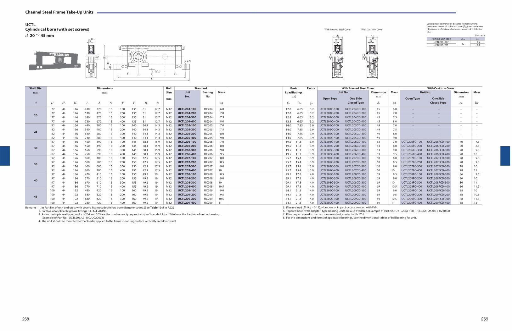
Channel Steel Frame Take-Up Units
UCTL Cylindrical bore (with set screws) d 20 ~ 45 mm
With Pressed Steel Cover With Cast Iron Cover
Variations of tolerance of distance from mounting bottom to center of spherical bore (3Hs) and variations of tolerance of distance between centers of bolt holes (3Js)
Unit: mm
H 2
H H 1
M10 T 1 T T 1
J
2-N
L
Remarks 1. In Part No. of unit and units with covers, fitting codes follow bore diameter codes. (See Table 10.5 in P.62.)
2. Part No. of applicable grease fittings is C-1/4-28UNF. 3. As for the triple seal type product (204 and 205 are the double seal type products), suffix code L3 (or L2) follows the Part No. of unit or bearing.
(Example of Part No. : UCTL206JL3-100, UC206L3) 4. The unit should be mounted so that load is applied to the frame mounting surface vertically and downward.
5. If heavy load (Pr /Cr 0.12), vibration, or impact occurs, contact with FYH. 6. Tapered bore (with adapter) type bearing units are also available. (Example of Part No. : UKTL206J-100 H2306X, UK206 H2306X) 7. If frame parts need to be corrosion resistant, contact with FYH. 8. For the dimensions and forms of applicable bearings, see the dimensional tables of ball bearing for unit.
268 269
Shaft Dia. mm
d
H
H1
H2
L
Dimensions mm
J N
T
T1
B
S
Bolt Size
mm
Standard BasicLoad Ratings
kN
Cr C0r
Factor
f 0
With Pressed Steel Cover With Cast Iron Cover Unit No.
Bearing No.
Mass
kg
Unit No.
Open Type One Side Closed Type
Dimension mm
As
Mass
kg
Unit No.
Open Type One Side Closed Type
Dimension mm
Ac
Mass
kg
20
77 44 146 430 370 15 100 135 31 12.7 M12 UCTL204-100 UC204 6.0 12.8 6.65 13.2 UCTL204C-100 UCTL204CD-100 45 6.0 77 44 146 530 470 15 200 135 31 12.7 M12 UCTL204-200 UC204 7.0 12.8 6.65 13.2 UCTL204C-200 UCTL204CD-200 45 7.0 77 44 146 630 570 15 300 135 31 12.7 M12 UCTL204-300 UC204 7.5 12.8 6.65 13.2 UCTL204C-300 UCTL204CD-300 45 7.5 77 44 146 730 670 15 400 135 31 12.7 M12 UCTL204-400 UC204 8.0 12.8 6.65 13.2 UCTL204C-400 UCTL204CD-400 45 8.0
25
82 44 156 440 380 15 100 140 34.1 14.3 M12 UCTL205-100 UC205 7.0 14.0 7.85 13.9 UCTL205C-100 UCTL205CD-100 49 7.0 82 44 156 540 480 15 200 140 34.1 14.3 M12 UCTL205-200 UC205 7.5 14.0 7.85 13.9 UCTL205C-200 UCTL205CD-200 49 7.5 82 44 156 640 580 15 300 140 34.1 14.3 M12 UCTL205-300 UC205 8.0 14.0 7.85 13.9 UCTL205C-300 UCTL205CD-300 49 8.0 82 44 156 740 680 15 400 140 34.1 14.3 M12 UCTL205-400 UC205 9.0 14.0 7.85 13.9 UCTL205C-400 UCTL205CD-400 49 9.0
30
87 44 166 450 390 15 100 145 38.1 15.9 M12 UCTL206-100 UC206 7.0 19.5 11.3 13.9 UCTL206C-100 UCTL206CD-100 53 7.0 UCTL206FC-100 UCTL206FCD-100 70 7.5 87 44 166 550 490 15 200 145 38.1 15.9 M12 UCTL206-200 UC206 8.0 19.5 11.3 13.9 UCTL206C-200 UCTL206CD-200 53 8.0 UCTL206FC-200 UCTL206FCD-200 70 8.5 87 44 166 650 590 15 300 145 38.1 15.9 M12 UCTL206-300 UC206 9.0 19.5 11.3 13.9 UCTL206C-300 UCTL206CD-300 53 9.0 UCTL206FC-300 UCTL206FCD-300 70 9.5 87 44 166 750 690 15 400 145 38.1 15.9 M12 UCTL206-400 UC206 9.5 19.5 11.3 13.9 UCTL206C-400 UCTL206CD-400 53 9.5 UCTL206FC-400 UCTL206FCD-400 70 10
35
92 44 176 460 400 15 100 150 42.9 17.5 M12 UCTL207-100 UC207 8.0 25.7 15.4 13.9 UCTL207C-100 UCTL207CD-100 60 8.0 UCTL207FC-100 UCTL207FCD-100 78 9.0 92 44 176 560 500 15 200 150 42.9 17.5 M12 UCTL207-200 UC207 8.5 25.7 15.4 13.9 UCTL207C-200 UCTL207CD-200 60 8.5 UCTL207FC-200 UCTL207FCD-200 78 9.5 92 44 176 660 600 15 300 150 42.9 17.5 M12 UCTL207-300 UC207 9.0 25.7 15.4 13.9 UCTL207C-300 UCTL207CD-300 60 9.0 UCTL207FC-300 UCTL207FCD-300 78 10 92 44 176 760 700 15 400 150 42.9 17.5 M12 UCTL207-400 UC207 10 25.7 15.4 13.9 UCTL207C-400 UCTL207CD-400 60 10 UCTL207FC-400 UCTL207FCD-400 78 11
40
97 44 186 470 410 15 100 155 49.2 19 M12 UCTL208-100 UC208 8.5 29.1 17.8 14.0 UCTL208C-100 UCTL208CD-100 69 8.5 UCTL208FC-100 UCTL208FCD-100 86 9.5 97 44 186 570 510 15 200 155 49.2 19 M12 UCTL208-200 UC208 9.0 29.1 17.8 14.0 UCTL208C-200 UCTL208CD-200 69 9.0 UCTL208FC-200 UCTL208FCD-200 86 10 97 44 186 670 610 15 300 155 49.2 19 M12 UCTL208-300 UC208 10 29.1 17.8 14.0 UCTL208C-300 UCTL208CD-300 69 10 UCTL208FC-300 UCTL208FCD-300 86 11 97 44 186 770 710 15 400 155 49.2 19 M12 UCTL208-400 UC208 10.5 29.1 17.8 14.0 UCTL208C-400 UCTL208CD-400 69 10.5 UCTL208FC-400 UCTL208FCD-400 86 11.5
45
100 44 192 480 420 15 100 160 49.2 19 M12 UCTL209-100 UC209 9.0 34.1 21.3 14.0 UCTL209C-100 UCTL209CD-100 69 9.0 UCTL209FC-100 UCTL209FCD-100 88 10 100 44 192 580 520 15 200 160 49.2 19 M12 UCTL209-200 UC209 9.5 34.1 21.3 14.0 UCTL209C-200 UCTL209CD-200 69 9.5 UCTL209FC-200 UCTL209FCD-200 88 10.5 100 44 192 680 620 15 300 160 49.2 19 M12 UCTL209-300 UC209 10.5 34.1 21.3 14.0 UCTL209C-300 UCTL209CD-300 69 10.5 UCTL209FC-300 UCTL209FCD-300 88 11.5 100 44 192 780 720 15 400 160 49.2 19 M12 UCTL209-400 UC209 11 34.1 21.3 14.0 UCTL209C-400 UCTL209CD-400 69 11 UCTL209FC-400 UCTL209FCD-400 88 12
B S
d
40 48
60
A SB
S
d1
404860
A CB
S
d2
40 48 60
Nominal unit code 3Hs 3Js
UCTL204~2072
0.5UCTL208, 209 0.8
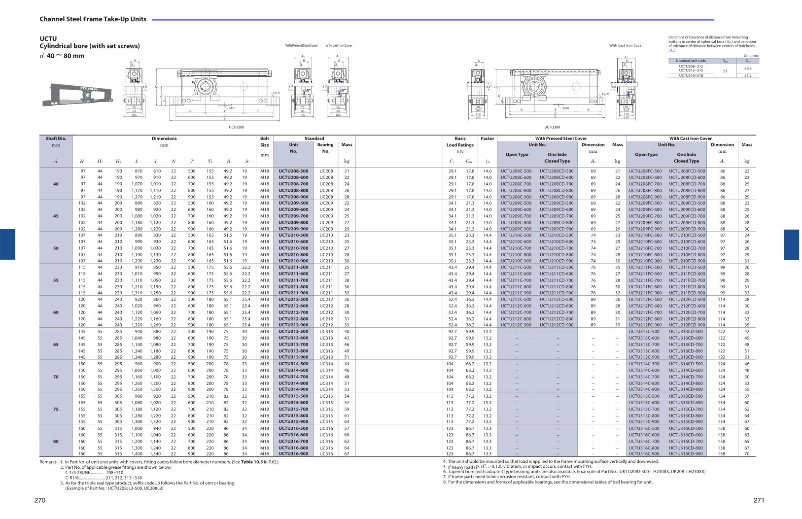
Channel Steel Frame Take-Up Units
UCTU Cylindrical bore (with set screws) d 40 ~ 80 mm
With Pressed Steel Cover With Cast Iron Cover
With Cast Iron Cover
Variations of tolerance of distance from mounting bottom to center of spherical bore (3Hs) and variations of tolerance of distance between centers of bolt holes (3Js)
Unit: mm
H 2
H
H 1
M10 T 1 T T 1
J L
2-N
H2
H
H1
T1 T M10 T1
J L
4-N
UCTU200
UCTU300
Remarks 1. In Part No. of unit and units with covers, fitting codes follow bore diameter numbers. (See Table 10.5 in P.62.)
2. Part No. of applicable grease fittings are shown below. C-1/4-28UNF.............. 208~210 C-R1/8 .......................... 211, 212, 313~318
3. As for the triple seal type product, suffix code L3 follows the Part No. of unit or bearing. (Example of Part No. : UCTU208JL3-500, UC208L3)
270
4. The unit should be mounted so that load is applied to the frame mounting surface vertically and downward. 5. If heavy load (Pr /Cr 0.12), vibration, or impact occurs, contact with FYH. 6. Tapered bore (with adapter) type bearing units are also available. (Example of Part No. : UKTU208J-500 H2308X, UK208 H2308X) 7. If frame parts need to be corrosion resistant, contact with FYH. 8. For the dimensions and forms of applicable bearings, see the dimensional tables of ball bearing for unit.
271
Shaft Dia. mm
d
H
H1
H2
L
Dimensions mm
J N
T
T1
B
S
Bolt Size
mm
Standard BasicLoad Ratings
kN
Cr C0r
Factor
f 0
With Pressed Steel Cover With Cast Iron Cover Unit No.
Bearing No.
Mass
kg
Unit No.
Open Type One Side Closed Type
Dimension mm
As
Mass
kg
Unit No.
Open Type One Side Closed Type
Dimension mm
Ac
Mass
kg
40
97 44 190 870 810 22 500 155 49.2 19 M18 UCTU208-500 UC208 21 29.1 17.8 14.0 UCTU208C-500 UCTU208CD-500 69 21 UCTU208FC-500 UCTU208FCD-500 86 22 97 44 190 970 910 22 600 155 49.2 19 M18 UCTU208-600 UC208 22 29.1 17.8 14.0 UCTU208C-600 UCTU208CD-600 69 22 UCTU208FC-600 UCTU208FCD-600 86 23 97 44 190 1,070 1,010 22 700 155 49.2 19 M18 UCTU208-700 UC208 24 29.1 17.8 14.0 UCTU208C-700 UCTU208CD-700 69 24 UCTU208FC-700 UCTU208FCD-700 86 25 97 44 190 1,170 1,110 22 800 155 49.2 19 M18 UCTU208-800 UC208 26 29.1 17.8 14.0 UCTU208C-800 UCTU208CD-800 69 26 UCTU208FC-800 UCTU208FCD-800 86 27 97 44 190 1,270 1,210 22 900 155 49.2 19 M18 UCTU208-900 UC208 28 29.1 17.8 14.0 UCTU208C-900 UCTU208CD-900 69 28 UCTU208FC-900 UCTU208FCD-900 86 29
45
102 44 200 880 820 22 500 160 49.2 19 M18 UCTU209-500 UC209 22 34.1 21.3 14.0 UCTU209C-500 UCTU209CD-500 69 22 UCTU209FC-500 UCTU209FCD-500 88 23 102 44 200 980 920 22 600 160 49.2 19 M18 UCTU209-600 UC209 24 34.1 21.3 14.0 UCTU209C-600 UCTU209CD-600 69 24 UCTU209FC-600 UCTU209FCD-600 88 25 102 44 200 1,080 1,020 22 700 160 49.2 19 M18 UCTU209-700 UC209 25 34.1 21.3 14.0 UCTU209C-700 UCTU209CD-700 69 25 UCTU209FC-700 UCTU209FCD-700 88 26 102 44 200 1,180 1,120 22 800 160 49.2 19 M18 UCTU209-800 UC209 27 34.1 21.3 14.0 UCTU209C-800 UCTU209CD-800 69 27 UCTU209FC-800 UCTU209FCD-800 88 28 102 44 200 1,280 1,220 22 900 160 49.2 19 M18 UCTU209-900 UC209 29 34.1 21.3 14.0 UCTU209C-900 UCTU209CD-900 69 29 UCTU209FC-900 UCTU209FCD-900 88 30
50
107 44 210 890 830 22 500 165 51.6 19 M18 UCTU210-500 UC210 23 35.1 23.3 14.4 UCTU210C-500 UCTU210CD-500 74 23 UCTU210FC-500 UCTU210FCD-500 97 24 107 44 210 990 930 22 600 165 51.6 19 M18 UCTU210-600 UC210 25 35.1 23.3 14.4 UCTU210C-600 UCTU210CD-600 74 25 UCTU210FC-600 UCTU210FCD-600 97 26 107 44 210 1,090 1,030 22 700 165 51.6 19 M18 UCTU210-700 UC210 27 35.1 23.3 14.4 UCTU210C-700 UCTU210CD-700 74 27 UCTU210FC-700 UCTU210FCD-700 97 28 107 44 210 1,190 1,130 22 800 165 51.6 19 M18 UCTU210-800 UC210 28 35.1 23.3 14.4 UCTU210C-800 UCTU210CD-800 74 28 UCTU210FC-800 UCTU210FCD-800 97 29 107 44 210 1,290 1,230 22 900 165 51.6 19 M18 UCTU210-900 UC210 30 35.1 23.3 14.4 UCTU210C-900 UCTU210CD-900 74 30 UCTU210FC-900 UCTU210FCD-900 97 31
55
115 44 230 910 850 22 500 175 55.6 22.2 M18 UCTU211-500 UC211 25 43.4 29.4 14.4 UCTU211C-500 UCTU211CD-500 76 25 UCTU211FC-500 UCTU211FCD-500 99 26 115 44 230 1,010 950 22 600 175 55.6 22.2 M18 UCTU211-600 UC211 27 43.4 29.4 14.4 UCTU211C-600 UCTU211CD-600 76 27 UCTU211FC-600 UCTU211FCD-600 99 28 115 44 230 1,110 1,050 22 700 175 55.6 22.2 M18 UCTU211-700 UC211 28 43.4 29.4 14.4 UCTU211C-700 UCTU211CD-700 76 28 UCTU211FC-700 UCTU211FCD-700 99 29 115 44 230 1,210 1,150 22 800 175 55.6 22.2 M18 UCTU211-800 UC211 30 43.4 29.4 14.4 UCTU211C-800 UCTU211CD-800 76 30 UCTU211FC-800 UCTU211FCD-800 99 31 115 44 230 1,310 1,250 22 900 175 55.6 22.2 M18 UCTU211-900 UC211 32 43.4 29.4 14.4 UCTU211C-900 UCTU211CD-900 76 32 UCTU211FC-900 UCTU211FCD-900 99 33
60
120 44 240 920 860 22 500 180 65.1 25.4 M18 UCTU212-500 UC212 26 52.4 36.2 14.4 UCTU212C-500 UCTU212CD-500 89 26 UCTU212FC-500 UCTU212FCD-500 114 28 120 44 240 1,020 960 22 600 180 65.1 25.4 M18 UCTU212-600 UC212 28 52.4 36.2 14.4 UCTU212C-600 UCTU212CD-600 89 28 UCTU212FC-600 UCTU212FCD-600 114 30 120 44 240 1,120 1,060 22 700 180 65.1 25.4 M18 UCTU212-700 UC212 30 52.4 36.2 14.4 UCTU212C-700 UCTU212CD-700 89 30 UCTU212FC-700 UCTU212FCD-700 114 32 120 44 240 1,220 1,160 22 800 180 65.1 25.4 M18 UCTU212-800 UC212 31 52.4 36.2 14.4 UCTU212C-800 UCTU212CD-800 89 31 UCTU212FC-800 UCTU212FCD-800 114 33 120 44 240 1,320 1,260 22 900 180 65.1 25.4 M18 UCTU212-900 UC212 33 52.4 36.2 14.4 UCTU212C-900 UCTU212CD-900 89 33 UCTU212FC-900 UCTU212FCD-900 114 35
65
145 55 285 940 880 22 500 190 75 30 M18 UCTU313-500 UC313 40 92.7 59.9 13.2 UCTU313C-500 UCTU313CD-500 122 42 145 55 285 1,040 980 22 600 190 75 30 M18 UCTU313-600 UC313 43 92.7 59.9 13.2 UCTU313C-600 UCTU313CD-600 122 45 145 55 285 1,140 1,080 22 700 190 75 30 M18 UCTU313-700 UC313 46 92.7 59.9 13.2 UCTU313C-700 UCTU313CD-700 122 48 145 55 285 1,240 1,180 22 800 190 75 30 M18 UCTU313-800 UC313 49 92.7 59.9 13.2 UCTU313C-800 UCTU313CD-800 122 51 145 55 285 1,340 1,280 22 900 190 75 30 M18 UCTU313-900 UC313 51 92.7 59.9 13.2 UCTU313C-900 UCTU313CD-900 122 53
70
150 55 295 960 900 22 500 200 78 33 M18 UCTU314-500 UC314 44 104 68.2 13.2 UCTU314C-500 UCTU314CD-500 124 46 150 55 295 1,060 1,000 22 600 200 78 33 M18 UCTU314-600 UC314 46 104 68.2 13.2 UCTU314C-600 UCTU314CD-600 124 48 150 55 295 1,160 1,100 22 700 200 78 33 M18 UCTU314-700 UC314 48 104 68.2 13.2 UCTU314C-700 UCTU314CD-700 124 50 150 55 295 1,260 1,200 22 800 200 78 33 M18 UCTU314-800 UC314 51 104 68.2 13.2 UCTU314C-800 UCTU314CD-800 124 53 150 55 295 1,360 1,300 22 900 200 78 33 M18 UCTU314-900 UC314 53 104 68.2 13.2 UCTU314C-900 UCTU314CD-900 124 55
75
155 55 305 980 920 22 500 210 82 32 M18 UCTU315-500 UC315 54 113 77.2 13.2 UCTU315C-500 UCTU315CD-500 134 57 155 55 305 1,080 1,020 22 600 210 82 32 M18 UCTU315-600 UC315 57 113 77.2 13.2 UCTU315C-600 UCTU315CD-600 134 60 155 55 305 1,180 1,120 22 700 210 82 32 M18 UCTU315-700 UC315 59 113 77.2 13.2 UCTU315C-700 UCTU315CD-700 134 62 155 55 305 1,280 1,220 22 800 210 82 32 M18 UCTU315-800 UC315 61 113 77.2 13.2 UCTU315C-800 UCTU315CD-800 134 64 155 55 305 1,380 1,320 22 900 210 82 32 M18 UCTU315-900 UC315 64 113 77.2 13.2 UCTU315C-900 UCTU315CD-900 134 67
80
160 55 315 1,000 940 22 500 220 86 34 M18 UCTU316-500 UC316 57 123 86.7 13.3 UCTU316C-500 UCTU316CD-500 138 60 160 55 315 1,100 1,040 22 600 220 86 34 M18 UCTU316-600 UC316 60 123 86.7 13.3 UCTU316C-600 UCTU316CD-600 138 63 160 55 315 1,200 1,140 22 700 220 86 34 M18 UCTU316-700 UC316 62 123 86.7 13.3 UCTU316C-700 UCTU316CD-700 138 65 160 55 315 1,300 1,240 22 800 220 86 34 M18 UCTU316-800 UC316 64 123 86.7 13.3 UCTU316C-800 UCTU316CD-800 138 67 160 55 315 1,400 1,340 22 900 220 86 34 M18 UCTU316-900 UC316 67 123 86.7 13.3 UCTU316C-900 UCTU316CD-900 138 70
B S
d
75 83
105
1
A S
B S
d
75 83
105
2
A C
B S
d
75 83
105
B S
d
50 100 112
140
2
A C
B S
d
50 100 112
140
Nominal unit code 3Hs 3Js
UCTU208~212 UCTU313~315
2
0.8
UCTU316~318 1.2
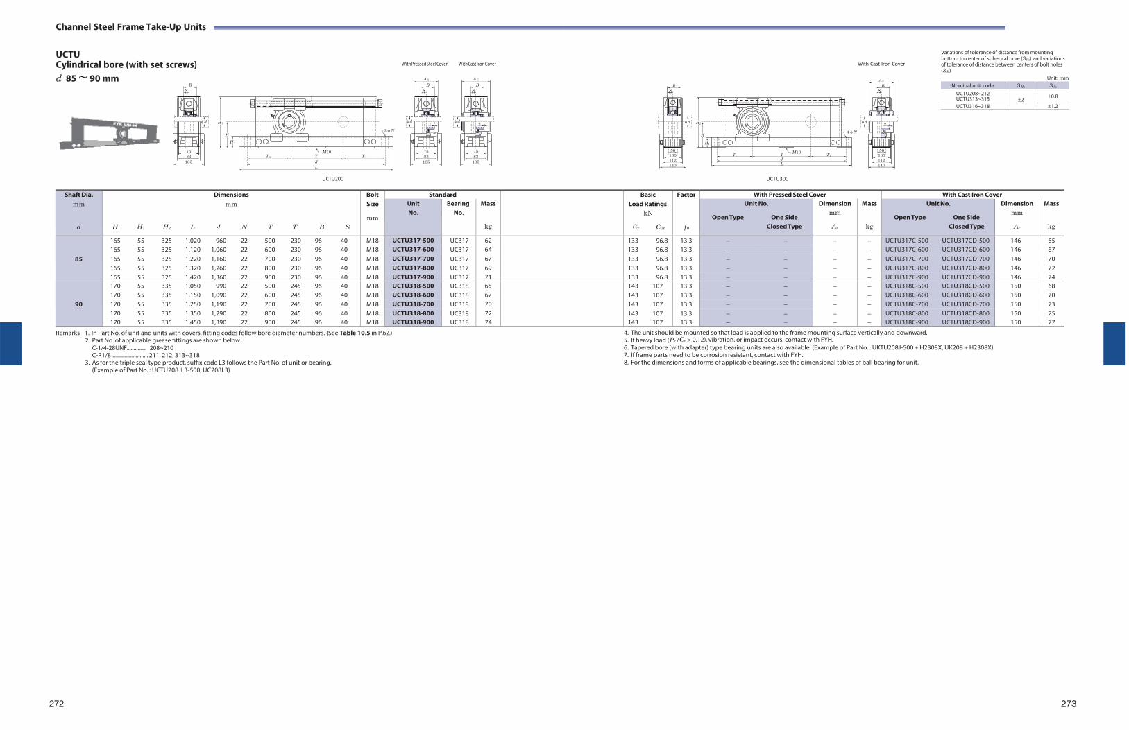
Channel Steel Frame Take-Up Units
UCTU Cylindrical bore (with set screws) d 85 ~ 90 mm
With Pressed Steel Cover With Cast Iron Cover
With Cast Iron Cover
Variations of tolerance of distance from mounting bottom to center of spherical bore (3Hs) and variations of tolerance of distance between centers of bolt holes (3Js)
Unit: mm
H 2
H
H 1
M10 T 1 T T 1
J L
2-N
H2
H
H1
T1 T M10 T1
J L
4-N
UCTU200
UCTU300
Shaft Dia. mm
d
H
H1
H2
L
Dimensions mm
J N
T
T1
B
S
Bolt Size
mm
Standard BasicLoad Ratings
kN
Cr C0r
Factor
f 0
With Pressed Steel Cover With Cast Iron Cover Unit No.
Bearing No.
Mass
kg
Unit No.
Open Type One Side Closed Type
Dimension mm
As
Mass
kg
Unit No.
Open Type One Side Closed Type
Dimension mm
Ac
Mass
kg
85
165 55 325 1,020 960 22 500 230 96 40 M18 UCTU317-500 UC317 62 133 96.8 13.3 UCTU317C-500 UCTU317CD-500 146 65 165 55 325 1,120 1,060 22 600 230 96 40 M18 UCTU317-600 UC317 64 133 96.8 13.3 UCTU317C-600 UCTU317CD-600 146 67 165 55 325 1,220 1,160 22 700 230 96 40 M18 UCTU317-700 UC317 67 133 96.8 13.3 UCTU317C-700 UCTU317CD-700 146 70 165 55 325 1,320 1,260 22 800 230 96 40 M18 UCTU317-800 UC317 69 133 96.8 13.3 UCTU317C-800 UCTU317CD-800 146 72 165 55 325 1,420 1,360 22 900 230 96 40 M18 UCTU317-900 UC317 71 133 96.8 13.3 UCTU317C-900 UCTU317CD-900 146 74
90
170 55 335 1,050 990 22 500 245 96 40 M18 UCTU318-500 UC318 65 143 107 13.3 UCTU318C-500 UCTU318CD-500 150 68 170 55 335 1,150 1,090 22 600 245 96 40 M18 UCTU318-600 UC318 67 143 107 13.3 UCTU318C-600 UCTU318CD-600 150 70 170 55 335 1,250 1,190 22 700 245 96 40 M18 UCTU318-700 UC318 70 143 107 13.3 UCTU318C-700 UCTU318CD-700 150 73 170 55 335 1,350 1,290 22 800 245 96 40 M18 UCTU318-800 UC318 72 143 107 13.3 UCTU318C-800 UCTU318CD-800 150 75 170 55 335 1,450 1,390 22 900 245 96 40 M18 UCTU318-900 UC318 74 143 107 13.3 UCTU318C-900 UCTU318CD-900 150 77
Remarks 1. In Part No. of unit and units with covers, fitting codes follow bore diameter numbers. (See Table 10.5 in P.62.) 2. Part No. of applicable grease fittings are shown below.
C-1/4-28UNF.............. 208~210 C-R1/8 .......................... 211, 212, 313~318
3. As for the triple seal type product, suffix code L3 follows the Part No. of unit or bearing. (Example of Part No. : UCTU208JL3-500, UC208L3)
4. The unit should be mounted so that load is applied to the frame mounting surface vertically and downward. 5. If heavy load (Pr /Cr 0.12), vibration, or impact occurs, contact with FYH. 6. Tapered bore (with adapter) type bearing units are also available. (Example of Part No. : UKTU208J-500 H2308X, UK208 H2308X) 7. If frame parts need to be corrosion resistant, contact with FYH. 8. For the dimensions and forms of applicable bearings, see the dimensional tables of ball bearing for unit.
272 273
B S
d
75 83
105
1
A S
B S
d
75 83
105
2
A C
B S
d
75 83
105
B S
d
50 100 112
140
2
A C
B S
d
50 100 112
140
Nominal unit code 3Hs 3Js
UCTU208~212 UCTU313~315
2
0.8
UCTU316~318 1.2
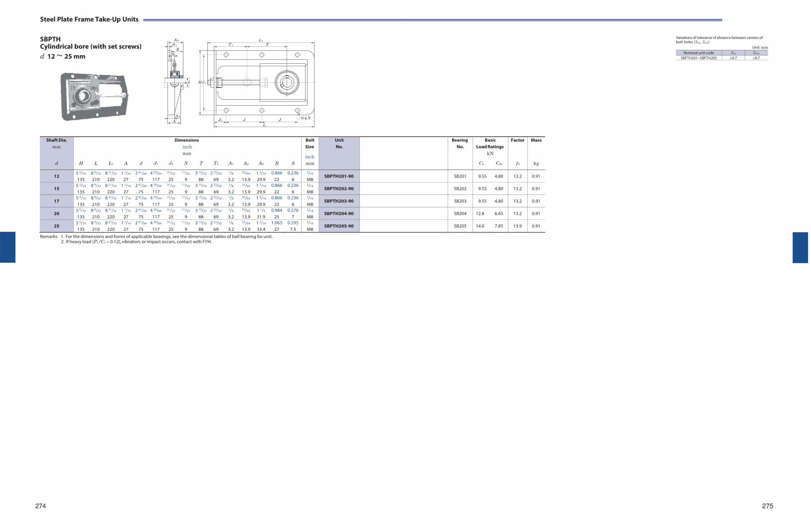
Steel Plate Frame Take-Up Units
SBPTH Cylindrical bore (with set screws) d 12 ~ 25 mm
Remarks 1. For the dimensions and forms of applicable bearings, see the dimensional tables of ball bearing for unit. 2. If heavy load (Pr /Cr 0.12), vibration, or impact occurs, contact with FYH.
Variations of tolerance of distance between centers of bolt holes (3Js, 3J1s)
Unit: mm
274 275
A 2
A 0
A 1
BS
d
A
L 1
T 1 T
HJ 1
J 2 J J 6-N
L
Nominal unit code 3Js 3J1s
SBPTH201~SBPTH205 0.7 0.7
Shaft Dia. mm
d
H
L
L1
A
J
J1
Dimensions inch mm
J2 N T
T1
A1
A2
A0
B
S
Bolt Size
inch mm
UnitNo.
BearingNo.
BasicLoad Ratings
kN
Cr C0r
Factor
f 0
Mass
kg
12 5 5/16
135 8 9/32
210 8 21/32
220 1 1/16
27 2 61/64
75 4 39/64
117
31/32
25
11/32
9 3 15/32
88 2 23/32
69
1/8
3.2
35/64
13.9 1 3/16
29.9 0.866
22 0.236
6
5/16
M8 SBPTH201-90 SB201 9.55 4.80 13.2 0.91
15 5 5/16
135 8 9/32
210 8 21/32
220 1 1/16
27 2 61/64
75 4 39/64
117
31/32
25
11/32
9 3 15/32
88 2 23/32
69
1/8
3.2
35/64
13.9 1 3/16
29.9 0.866
22 0.236
6
5/16
M8 SBPTH202-90 SB202 9.55 4.80 13.2 0.91
17 5 5/16
135 8 9/32
210 8 21/32
220 1 1/16
27 2 61/64
75 4 39/64
117
31/32
25
11/32
9 3 15/32
88 2 23/32
69
1/8
3.2
35/64
13.9 1 3/16
29.9 0.866
22 0.236
6
5/16
M8 SBPTH203-90 SB203 9.55 4.80 13.2 0.91
20 5 5/16
135 8 9/32
210 8 21/32
220 1 1/16
27 2 61/64
75 4 39/64
117
31/32
25
11/32
9 3 15/32
88 2 23/32
69
1/8
3.2
35/64
13.9 1 1/4
31.9 0.984
25 0.276
7
5/16
M8 SBPTH204-90 SB204 12.8 6.65 13.2 0.91
25 5 5/16
135 8 9/32
210 8 21/32
220 1 1/16
27 2 61/64
75 4 39/64
117
31/32
25
11/32
9 3 15/32
88 2 23/32
69
1/8
3.2
35/64
13.9 1 5/16
33.4 1.063
27 0.295
7.5
5/16
M8 SBPTH205-90 SB205 14.0 7.85 13.9 0.91
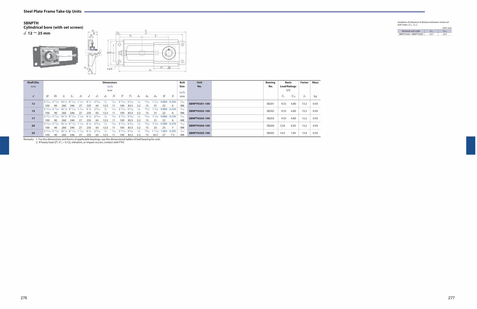
Steel Plate Frame Take-Up Units
SBNPTH Cylindrical bore (with set screws) d 12 ~ 25 mm
A 1
A 0
B S
d
A 2
A
H H 1 J 1
4-N
L J 2 J
T 1 T
57 38 L 1
Variations of tolerance of distance between centers of bolt holes (3Js, 3J1s)
Unit: mm
Shaft Dia. mm
d
H
H1
L
L1
A
J
J1
Dimensions inch mm
J2 N
T
T1
A1
A2
A0
B
S
Bolt Size
inch mm
UnitNo.
BearingNo.
BasicLoad Ratings
kN
Cr C0r
Factor
f 0
Mass
kg
12 3 15/16
100 3 17/32
90 10 1/4
260 9 11/16
246 1 1/16
27 9 1/4
235 2 9/16
65
1/2
12.5
7/16
11 3 15/16
100 3 9/32
83.5
1/8
3.2
19/32
15 1 7/32
31 0.866
22 0.236
6
5/16
M8 SBNPTH201-100 SB201 9.55 4.80 13.2 0.93
15 3 15/16
100 3 17/32
90 10 1/4
260 9 11/16
246 1 1/16
27 9 1/4
235 2 9/16
65
1/2
12.5
7/16
11 3 15/16
100 3 9/32
83.5
1/8
3.2
19/32
15 1 7/32
31 0.866
22 0.236
6
5/16
M8 SBNPTH202-100 SB202 9.55 4.80 13.2 0.93
17 3 15/16
100 3 17/32
90 10 1/4
260 9 11/16
246 1 1/16
27 9 1/4
235 2 9/16
65
1/2
12.5
7/16
11 3 15/16
100 3 9/32
83.5
1/8
3.2
19/32
15 1 7/32
31 0.866
22 0.236
6
5/16
M8 SBNPTH203-100 SB203 9.55 4.80 13.2 0.93
20 3 15/16
100 3 17/32
90 10 1/4
260 9 11/16
246 1 1/16
27 9 1/4
235 2 9/16
65
1/2
12.5
7/16
11 3 15/16
100 3 9/32
83.5
1/8
3.2
19/32
15 1 5/16
33 0.984
25 0.276
7
5/16
M8 SBNPTH204-100 SB204 12.8 6.65 13.2 0.93
25 3 15/16
100 3 17/32
90 10 1/4
260 9 11/16
246 1 1/16
27 9 1/4
235 2 9/16
65
1/2
12.5
7/16
11 3 15/16
100 3 9/32
83.5
1/8
3.2
19/32
15 1 11/32
34.5 1.063
27 0.295
7.5
5/16
M8 SBNPTH205-100 SB205 14.0 7.85 13.9 0.93
Remarks 1. For the dimensions and forms of applicable bearings, see the dimensional tables of ball bearing for unit. 2. If heavy load (Pr /Cr 0.12), vibration, or impact occurs, contact with FYH.
276 277
Nominal unit code 3Js 3J1s
SBNPTH201~SBNPTH205 0.7 0.7
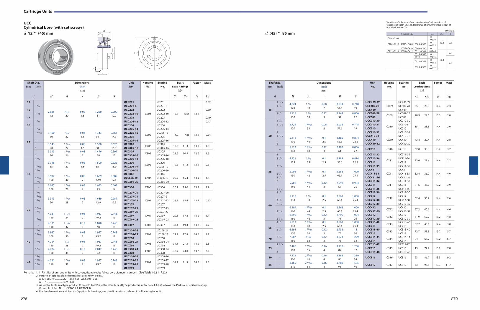
Remarks 1. In Part No. of unit and units with covers, fitting codes follow bore diameter numbers. (See Table 10.5 in P.62.) 2. Part No. of applicable grease fittings are shown below.
A-1/4-28UNF ............. 201~213, X05~X12, 305~308 A-R1/8 .......................... 309~328
3. As for the triple seal type product (from 201 to 205 are the double seal type products), suffix code L3 (L2) follows the Part No. of unit or bearing. (Example of Part No. : UCC206JL3, UC206L3)
4. For the dimensions and forms of applicable bearings, see the dimensional tables of ball bearing for unit.
B S
d
rA
Cartridge Units
UCC Cylindrical bore (with set screws)
Variations of tolerance of outside diameter (3Hs), variations of tolerance of width (3As), and tolerance of circumferential runout of outside diameter (Y)
d 12 ~ (45) mm d (45) ~ 85 mm
r
Remarks 1. In Part No. of unit and units with covers, fitting codes follow bore diameter numbers. (See Table 10.5 in P.62.)
2. Part No. of applicable grease fittings are shown below. A-1/4-28UNF ............. 201~213, X05~X12, 305~308 A-R1/8 .......................... 309~328
3. As for the triple seal type product (from 201 to 205 are the double seal type products), suffix code L3 (L2) follows the Part No. of unit or bearing. (Example of Part No. : UCC206JL3, UC206L3)
4. For the dimensions and forms of applicable bearings, see the dimensional tables of ball bearing for unit.
Unit: mm
278 279
Shaft Dia. mm inch
d
H
A
Dimensions inch mm
r
B
S
Unit No.
Housing No.
Bearing No.
Basic Load Ratings
kN
Cr C0r
Factor
f 0
Mass
kg
12 1/2
2.835
25/32
0.06
1.220
0.500
UCC201
C204
UC201
12.8
6.65
13.2
0.52 UCC201-8 UC201-8
15 5/8
UCC202 UC202 0.50 UCC202-10 UC202-10
72 20 1.5 31 12.7 17 UCC203 UC203 0.49
3/4 UCC204-12 UC204-12 0.47 20 UCC204 UC204
25
7/8 3.150
55/64
0.06
1.343
0.563
UCC205-14
C205
UC205-14
14.0
7.85
13.9
0.64 15/16 UCC205-15
UCC205 UC205-15 UC205 80 22 1.5 34.1 14.3
1 UCC205-16 UC205-16
1 3.543
90 1 1/16
27 0.06 1.5
1.500 38.1
0.626 15.9
UCCX05 UCCX05-16
CX05 UCX05 UCX05-16
19.5 11.3 13.9 1.0
1
3.543 90
1 1/32
26 0.08
2 1.496
38 0.591
15 UCC305 UCC305-16
C305 UC305 UC305-16
21.2 10.9 12.6 1.5
30
1 1/8 3.346
1 1/16
0.06
1.500
0.626
UCC206-18
C206
UC206-18
19.5
11.3
13.9
0.81 1 3/16
UCC206 UCC206-19
UC206 UC206-19 85 27 1.5 38.1 15.9
1 1/4 UCC206-20 UC206-20
1 3/16
1 1/4
3.937 100
1 3/16
30 0.08
2 1.689 42.9
0.689 17.5
UCCX06 UCCX06-19 UCCX06-20
CX06
UCX06 UCX06-19 UCX06-20
25.7
15.4
13.9
1.3
3.937 100
1 7/64
28 0.08
2 1.693
43 0.669
17 UCC306 C306 UC306 26.7 15.0 13.3 1.7
35
1 1/4
3.543
1 7/64
0.08
1.689
0.689
UCC207-20
C207
UC207-20
25.7
15.4
13.9
0.93
1 5/16 UCC207-21 UC207-21 1 3/8 UCC207-22 UC207-22
90 28 2 42.9 17.5 UCC207 UC207
1 7/16 UCC207-23 UC207-23 1 3/8
1 7/16
4.331 110
1 11/32
34 0.08
2 1.937 49.2
0.748 19
UCCX07-22 UCCX07 UCCX07-23
CX07
UCX07-22 UCX07 UCX07-23
29.1
17.8
14.0
1.7
4.331 110
1 17/64
32 0.12
3 1.890
48 0.748
19 UCC307 C307 UC307 33.4 19.3 13.2 2.2
40
1 1/2
1 9/16 3.937 100
1 3/16
30 0.08
2 1.937 49.2
0.748 19
UCC208-24 UCC208-25 UCC208
C208
UC208-24 UC208-25 UC208
29.1
17.8
14.0
1.2
1 1/2 4.724 120
1 1/2
38 0.08
2 1.937 49.2
0.748 19
UCCX08-24 UCCX08
CX08 UCX08-24 UCX08
34.1 21.3 14.0 2.3
1 1/2 4.724 120
1 11/32
34 0.12
3 2.047
52 0.748
19 UCC308-24 UCC308
C308 UC308-24 UC308
40.7 24.0 13.2 2.2
45
1 5/8 4.331
1 7/32
0.08
1.937
0.748
UCC209-26
C209
UC209-26
34.1
21.3
14.0
1.5 1 11/16 UCC209-27 UC209-27 1 3/4 110 31 2 49.2 19 UCC209-28 UC209-28
UCC209 UC209
H
Housing No. 3Hs 3As Y
C204~C205 0 0.030
0.2
0.2 C206~C210 CX05~CX08 C305~C308 0
0.035 CX09~CX10 C309~C310 0
0.040 C211~C213 CX11~CX12 C311~C314 0.3
0.3 C315~C318 0
0.046 C319
0.4 C320~C322 0
0.052
C324~C328 0 0.057
Shaft Dia. mm inch
d
H
A
Dimensions inch mm
r
B
S
Unit No.
HousingNo.
BearingNo.
BasicLoad Ratings
kN
Cr C0r
Factor
f 0
Mass
kg
45
1 11/16
1 3/4 4.724 120
1 1/2
38 0.08
2 2.031 51.6
0.748 19
UCCX09-27 UCCX09-28 UCCX09
CX09
UCX09-27UCX09-28 UCX09
35.1
23.3
14.4
2.3
1 3/4 5.118 130
1 1/2
380.12
32.244
57 0.866
22 UCC309-28 UCC309
C309 UC309-28UC309
48.9 29.5 13.3 2.8
50
1 7/8 4.724
1 19/64
0.08
2.031
0.748
UCC210-30
C210
UC210-30
35.1
23.3
14.4
2.0 1 15/16 UCC210-31
UCC210 UC210-31 UC210 120 33 2 51.6 19
2 UCC210-32 UC210-321 15/16
2
5.118 130
1 37/64
40 0.1 2.5
2.189 55.6
0.874 22.2
UCCX10-31 UCCX10 UCCX10-32
CX10
UCX10-31 UCX10 UCX10-32
43.4
29.4
14.4
2.8
5.512 140
1 37/64
400.12
32.402
61 0.866
22 UCC310 C310 UC310 62.0 38.3 13.2 3.2
55
2 4.921
1 3/8
0.1
2.189
0.874
UCC211-32
C211
UC211-32
43.4
29.4
14.4
2.2 2 1/8 UCC211-34
UCC211 UC211-34 UC211 125 35 2.5 55.6 22.2
2 3/16 UCC211-35 UC211-35
2 3/16
2 1/4
5.906 150
1 21/32
42 0.1 2.5
2.563 65.1
1.000 25.4
UCCX11 UCCX11-35 UCCX11-36
CX11
UCX11 UCX11-35 UCX11-36
52.4
36.2
14.4
4.0
2
2 3/16
5.906 150
1 47/64
44 0.12
3 2.598
66 0.984
25
UCC311-32 UCC311 UCC311-35
C311
UC311-32UC311 UC311-35
71.6
45.0
13.2
3.9
60
2 1/4 5.118
1 1/2
0.1
2.563
1.000
UCC212-36
C212
UC212-36
52.4
36.2
14.4
2.6 2 3/8
UCC212 UCC212-38
UC212 UC212-38 130 38 2.5 65.1 25.4
2 7/16 UCC212-39 UC212-39
2 7/16
6.299 160
1 47/64
440.1 2.5
2.563 65.1
1.000 25.4
UCCX12 UCCX12-39
CX12 UCX12 UCX12-39
57.2 40.1 14.4 4.6
2 7/16
6.299 160
1 13/16
460.12
32.795
71 1.024
26 UCC312 UCC312-39
C312 UC312 UC312-39
81.9 52.2 13.2 4.8
65
2 1/2 5.512 140
1 37/64
400.1 2.5
2.563 65.1
1.000 25.4
UCC213-40 UCC213
C213 UC213-40UC213
57.2 40.1 14.4 3.0
2 1/2 6.693 170
1 31/32
500.12
3 2.953
75 1.181
30 UCC313-40 UCC313
C313 UC313-40UC313
92.7 59.9 13.2 5.7
70 2 3/4 7.087
1802 3/64
520.12
33.071
78 1.299
33 UCC314-44 UCC314
C314 UC314-44UC314
104 68.2 13.2 6.7
75
2 15/16
3
7.480 190
2 11/64
55 0.16
4 3.228
82 1.260
32
UCC315-47 UCC315 UCC315-48
C315
UC315-47 UC315 UC315-48
113
77.2
13.2
7.8
80 7.874 200
2 23/64
600.16
4 3.386
86 1.339
34 UCC316 C316 UC316 123 86.7 13.3 9.2
85 8.465 215
2 33/64
64 0.16
4 3.780
96 1.575
40 UCC317 C317 UC317 133 96.8 13.3 11.7
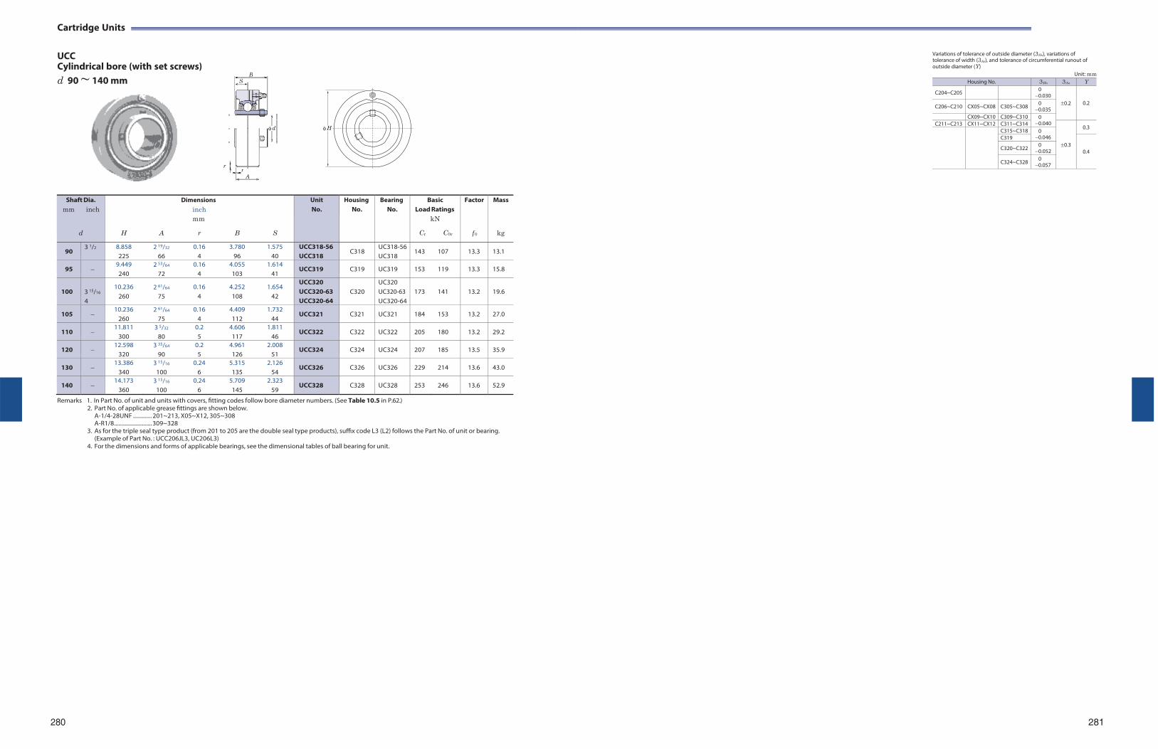
Cartridge Units
UCC Cylindrical bore (with set screws) d 90 ~ 140 mm
r
Variations of tolerance of outside diameter (3Hs), variations of tolerance of width (3As), and tolerance of circumferential runout of outside diameter (Y)
Unit: mm
Shaft Dia. mm inch
d
H
A
Dimensions inch mm
r
B
S
Unit No.
Housing No.
Bearing No.
Basic Load Ratings
kN
Cr C0r
Factor
f 0
Mass
kg
90 3 1/2 8.858
225 2 19/32
66 0.16
4 3.780
96 1.575
40 UCC318-56 UCC318
C318 UC318-56 UC318
143 107 13.3 13.1
95 9.449 240
2 53/64
72 0.16
4 4.055 103
1.614 41
UCC319 C319 UC319 153 119 13.3 15.8
100
3 15/16
4
10.236 260
2 61/64
75 0.16
4 4.252 108
1.654 42
UCC320 UCC320-63 UCC320-64
C320
UC320 UC320-63 UC320-64
173
141
13.2
19.6
105 10.236
260 2 61/64
75 0.16
4 4.409 112
1.732 44
UCC321 C321 UC321 184 153 13.2 27.0
110 11.811
300 3 5/32
80 0.2 5
4.606 117
1.811 46
UCC322 C322 UC322 205 180 13.2 29.2
120 12.598
320 3 35/64
90 0.2 5
4.961 126
2.008 51
UCC324 C324 UC324 207 185 13.5 35.9
130 13.386
340 3 15/16
100 0.24
6 5.315 135
2.126 54
UCC326 C326 UC326 229 214 13.6 43.0
140 14.173
360 3 15/16
100 0.24
6 5.709 145
2.323 59
UCC328 C328 UC328 253 246 13.6 52.9
Remarks 1. In Part No. of unit and units with covers, fitting codes follow bore diameter numbers. (See Table 10.5 in P.62.) 2. Part No. of applicable grease fittings are shown below.
A-1/4-28UNF ............. 201~213, X05~X12, 305~308 A-R1/8 .......................... 309~328
3. As for the triple seal type product (from 201 to 205 are the double seal type products), suffix code L3 (L2) follows the Part No. of unit or bearing. (Example of Part No. : UCC206JL3, UC206L3)
4. For the dimensions and forms of applicable bearings, see the dimensional tables of ball bearing for unit.
280 281
B S
d
rA
H
Housing No. 3Hs 3As Y
C204~C205 0 0.030
0.2
0.2 C206~C210 CX05~CX08 C305~C308 0
0.035 CX09~CX10 C309~C310 0
0.040 C211~C213 CX11~CX12 C311~C314 0.3
0.3 C315~C318 0
0.046 C319
0.4 C320~C322 0 0.052
C324~C328 0 0.057
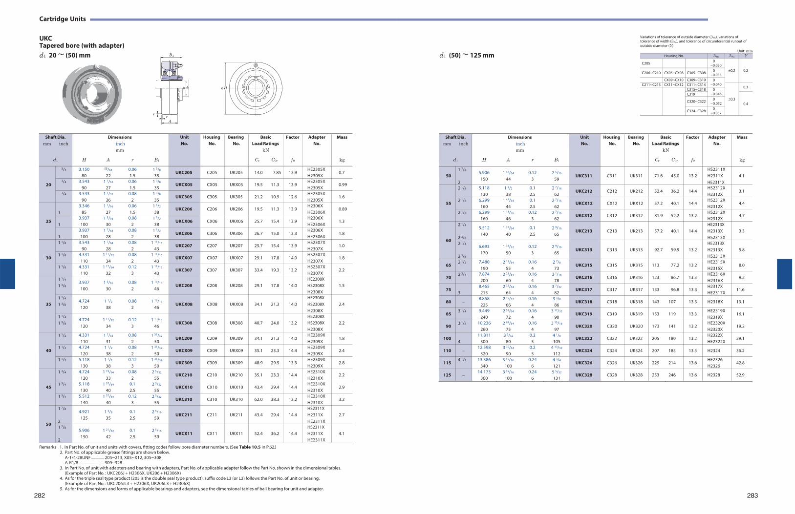
Remarks 1. In Part No. of unit and units with covers, fitting codes follow bore diameter numbers. (See Table 10.5 in P.62.) 2. Part No. of applicable grease fittings are shown below.
A-1/4-28UNF ............. 205~213, X05~X12, 305~308 A-R1/8 .......................... 309~328
3. In Part No. of unit with adapters and bearing with adapters, Part No. of applicable adapter follow the Part No. shown in the dimensional tables. (Example of Part No. : UKC206J H2306X, UK206 H2306X)
4. As for the triple seal type product (205 is the double seal type product), suffix code L3 (or L2) follows the Part No. of unit or bearing. (Example of Part No. : UKC206JL3 H2306X, UK206L3 H2306X)
5. As for the dimensions and forms of applicable bearings and adapters, see the dimensional tables of ball bearing for unit and adapter.
B 1
d1
rA
Cartridge Units
UKC Tapered bore (with adapter)
Variations of tolerance of outside diameter (3Hs), variations of tolerance of width (3As), and tolerance of circumferential runout of outside diameter (Y)
d1 20 ~ (50) mm d1 (50) ~ 125 mm
r
Remarks 1. In Part No. of unit and units with covers, fitting codes follow bore diameter numbers. (See Table 10.5 in P.62.)
2. Part No. of applicable grease fittings are shown below. A-1/4-28UNF ............. 205~213, X05~X12, 305~308 A-R1/8 .......................... 309~328
3. In Part No. of unit with adapters and bearing with adapters, Part No. of applicable adapter follow the Part No. shown in the dimensional tables. (Example of Part No. : UKC206J H2306X, UK206 H2306X)
4. As for the triple seal type product (205 is the double seal type product), suffix code L3 (or L2) follows the Part No. of unit or bearing. (Example of Part No. : UKC206JL3 H2306X, UK206L3 H2306X)
5. As for the dimensions and forms of applicable bearings and adapters, see the dimensional tables of ball bearing for unit and adapter.
282
Unit: mm Housing No. 3Hs 3As Y
C205 0 0.030
0.2
0.2 C206~C210 CX05~CX08 C305~C308 0 0.035
CX09~CX10 C309~C310 0 0.040 C211~C213 CX11~CX12 C311~C314
0.3
0.3 C315~C318 0
0.046 C319
0.4 C320~C322 0
0.052
C324~C328 0 0.057
283
Shaft Dia. mm inch
d1
H
Dimensions inch mm
A r
B1
Unit No.
Housing No.
Bearing No.
Basic Load Ratings
kN
Cr C0r
Factor
f 0
AdapterNo.
Mass
kg
20
3/4 3.150 80
55/64
22 0.06 1.5
1 3/8
35 UKC205 C205 UK205 14.0 7.85 13.9
HE2305X H2305X
0.7
3/4 3.543 90
1 1/16
27 0.06 1.5
1 3/8
35 UKCX05 CX05 UKX05 19.5 11.3 13.9
HE2305X H2305X
0.99
3/4 3.543 90
1 1/32
26 0.08
2 1 3/8
35 UKC305 C305 UK305 21.2 10.9 12.6
HE2305X H2305X
1.6
25
1
3.346 85
1 1/16
27 0.06 1.5
1 1/2
38 UKC206 C206 UK206 19.5 11.3 13.9
H2306X HE2306X
0.89
1
3.937 100
1 3/16
30 0.08
2 1 1/2
38 UKCX06 CX06 UKX06 25.7 15.4 13.9
H2306X HE2306X
1.3
1
3.937 100
1 7/64
28 0.08
2 1 1/2
38 UKC306 C306 UK306 26.7 15.0 13.3
H2306X HE2306X
1.8
30
1 1/8 3.543 90
1 7/64
28 0.08
2 1 11/16
43 UKC207 C207 UK207 25.7 15.4 13.9
HS2307X H2307X
1.0
1 1/8 4.331 110
1 11/32
34 0.08
2 1 11/16
43 UKCX07 CX07 UKX07 29.1 17.8 14.0
HS2307X H2307X
1.8
1 1/8 4.331 110
1 17/64
32 0.12
3 1 11/16
43 UKC307 C307 UK307 33.4 19.3 13.2
HS2307X H2307X
2.2
35
1 1/4
1 3/8 3.937 100
1 3/16
30 0.08
2 1 13/16
46
UKC208
C208
UK208
29.1
17.8
14.0
HE2308X HS2308X H2308X
1.5
1 1/4
1 3/8 4.724 120
1 1/2
38 0.08
2 1 13/16
46
UKCX08
CX08
UKX08
34.1
21.3
14.0
HE2308X HS2308X H2308X
2.4
1 1/4
1 3/8 4.724 120
1 11/32
34 0.12
3 1 13/16
46
UKC308
C308
UK308
40.7
24.0
13.2
HE2308X HS2308X H2308X
2.2
40
1 1/2 4.331 110
1 7/32
31 0.08
2 1 31/32
50 UKC209 C209 UK209 34.1 21.3 14.0
HE2309X H2309X
1.8
1 1/2 4.724 120
1 1/2
38 0.08
2 1 31/32
50 UKCX09 CX09 UKX09 35.1 23.3 14.4
HE2309X H2309X
2.4
1 1/2 5.118 130
1 1/2
38 0.12
3 1 31/32
50 UKC309 C309 UK309 48.9 29.5 13.3
HE2309X H2309X
2.8
45
1 3/4 4.724 120
1 19/64
33 0.08
2 2 5/32
55 UKC210 C210 UK210 35.1 23.3 14.4
HE2310X H2310X
2.2
1 3/4 5.118 130
1 37/64
40 0.1 2.5
2 5/32
55 UKCX10 CX10 UKX10 43.4 29.4 14.4
HE2310X H2310X
2.9
1 3/4 5.512 140
1 37/64
40 0.12
3 2 5/32
55 UKC310 C310 UK310 62.0 38.3 13.2
HE2310X H2310X
3.2
50
1 7/8
2
4.921 125
1 3/8
35 0.1 2.5
2 5/16
59
UKC211
C211
UK211
43.4
29.4
14.4
HS2311X H2311X HE2311X
2.7
1 7/8
2
5.906 150
1 21/32
42 0.1 2.5
2 5/16
59
UKCX11
CX11
UKX11
52.4
36.2
14.4
HS2311X H2311X HE2311X
4.1
H
Shaft Dia. mm inch
d1
H
Dimensions inch mm
A r
B1
Unit No.
Housing No.
BearingNo.
BasicLoad Ratings
kN
Cr C0r
Factor
f 0
AdapterNo.
Mass
kg
50
1 7/8
2
5.906 150
1 47/64
44 0.12
3 2 5/16
59
UKC311
C311
UK311
71.6
45.0
13.2
HS2311X H2311X HE2311X
4.1
55
2 1/8 5.118 130
1 1/2
380.1 2.5
2 7/16
62 UKC212 C212 UK212 52.4 36.2 14.4
HS2312X H2312X
3.1
2 1/8 6.299 160
1 47/64
440.1 2.5
2 7/16
62 UKCX12 CX12 UKX12 57.2 40.1 14.4
HS2312X H2312X
4.4
2 1/8 6.299 160
1 13/16
460.12
3 2 7/16
62 UKC312 C312 UK312 81.9 52.2 13.2
HS2312X H2312X
4.7
60
2 1/4
2 3/8
5.512 140
1 37/64
40 0.1 2.5
2 9/16
65
UKC213
C213
UK213
57.2
40.1
14.4
HE2313X H2313X HS2313X
3.3
2 1/4
2 3/8
6.693 170
1 31/32
50 0.12
3 2 9/16
65
UKC313
C313
UK313
92.7
59.9
13.2
HE2313X H2313X HS2313X
5.8
65 2 1/2 7.480
1902 11/64
550.16
42 7/8
73 UKC315 C315 UK315 113 77.2 13.2
HE2315X H2315X
8.0
70 2 3/4 7.874
2002 23/64
600.16
43 1/16
78 UKC316 C316 UK316 123 86.7 13.3
HE2316X H2316X
9.2
75 3
8.465 215
2 33/64
640.16
4 3 7/32
82 UKC317 C317 UK317 133 96.8 13.3
H2317X HE2317X
11.6
80 8.858 225
2 19/32
660.16
43 3/8
86 UKC318 C318 UK318 143 107 13.3 H2318X 13.1
85 3 1/4 9.449
2402 53/64
720.16
43 17/32
90 UKC319 C319 UK319 153 119 13.3
HE2319X H2319X
16.1
90 3 1/2 10.236
260 2 61/64
750.16
4 3 13/16
97 UKC320 C320 UK320 173 141 13.2
HE2320X H2320X
19.2
100 4
11.811 300
3 5/32
800.2 5
4 1/8
105 UKC322 C322 UK322 205 180 13.2
H2322X HE2322X
29.1
110 12.598
3203 35/64
900.2 5
4 13/32
112 UKC324 C324 UK324 207 185 13.5 H2324 36.2
115 4 1/2 13.386
340 3 15/16
1000.24
6 4 3/4
121 UKC326 C326 UK326 229 214 13.6
HE2326 H2326
42.8
125 14.173
360 3 15/16
100 0.24
6 5 5/32
131 UKC328 C328 UK328 253 246 13.6 H2328 52.9
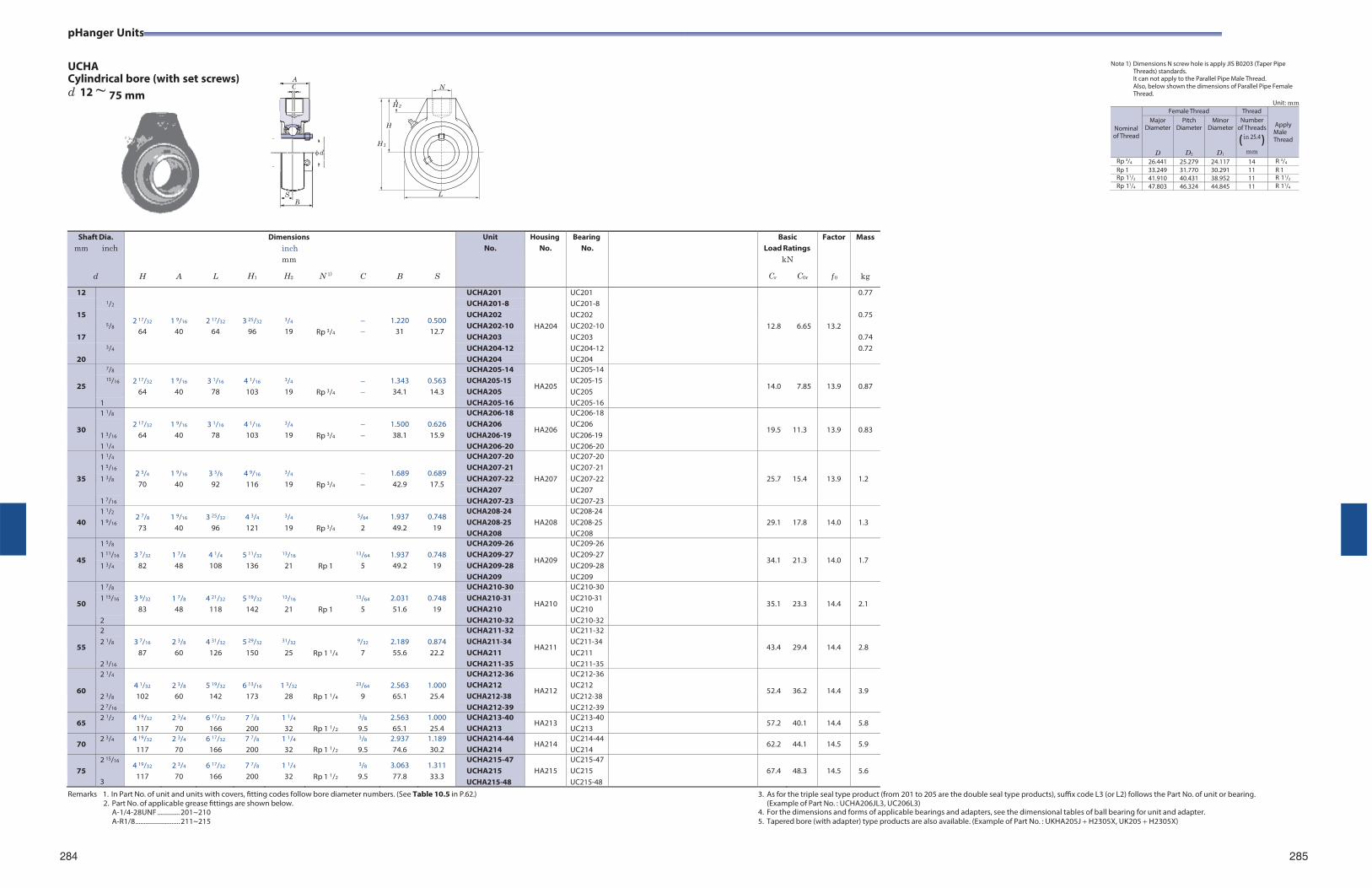
pHanger Units
UCHA Cylindrical bore (with set screws) d 12 ~
Note 1) Dimensions N screw hole is apply JIS B0203 (Taper Pipe Threads) standards. It can not apply to the Parallel Pipe Male Thread. Also, below shown the dimensions of Parallel Pipe Female Thread.
Unit: mm
Nominal of Thread
Female Thread Thread
Apply Male Thread
Major Diameter
D
Pitch Diameter
D2
Minor Diameter
D1
Number of Threads
( in 25.4 )mm
Rp 3/4 26.441 25.279 24.117 14 R 3/4
Rp 1 33.249 31.770 30.291 11 R 1Rp 11/2 41.910 40.431 38.952 11 R 11/2
Rp 11/4 47.803 46.324 44.845 11 R 11/4
Remarks 1. In Part No. of unit and units with covers, fitting codes follow bore diameter numbers. (See Table 10.5 in P.62.)
2. Part No. of applicable grease fittings are shown below. A-1/4-28UNF ............. 201~210 A-R1/8 .......................... 211~215
3. As for the triple seal type product (from 201 to 205 are the double seal type products), suffix code L3 (or L2) follows the Part No. of unit or bearing. (Example of Part No. : UCHA206JL3, UC206L3)
4. For the dimensions and forms of applicable bearings and adapters, see the dimensional tables of ball bearing for unit and adapter. 5. Tapered bore (with adapter) type products are also available. (Example of Part No. : UKHA205J H2305X, UK205 H2305X)
284 285
Shaft Dia. mm inch
d
H
A
L
H1
Dimensions inch mm
H2 N 1)
C
B
S
Unit No.
HousingNo.
BearingNo.
BasicLoad Ratings
kN
Cr C0r
Factor
f 0
Mass
kg
12 1/2
2 17/32
1 9/16
2 17/32
3 25/32
3/4
Rp 3/4
1.220
0.500
UCHA201
HA204
UC201
12.8
6.65
13.2
0.77 UCHA201-8 UC201-8
15 5/8
UCHA202 UC202 0.75 UCHA202-10 UC202-10
64 40 64 96 19 31 12.7 17 UCHA203 UC203 0.74
3/4 UCHA204-12 UC204-12 0.72 20 UCHA204 UC204
25
7/8 2 17/32
1 9/16
3 1/16
4 1/16
3/4
Rp 3/4
1.343
0.563
UCHA205-14
HA205
UC205-14
14.0
7.85
13.9
0.87 15/16 UCHA205-15
UCHA205 UC205-15 UC205 64 40 78 103 19 34.1 14.3
1 UCHA205-16 UC205-16
30
1 1/8 2 17/32
1 9/16
3 1/16
4 1/16
3/4
Rp 3/4
1.500
0.626
UCHA206-18
HA206
UC206-18
19.5
11.3
13.9
0.83 1 3/16
UCHA206 UCHA206-19
UC206 UC206-19 64 40 78 103 19 38.1 15.9
1 1/4 UCHA206-20 UC206-20
35
1 1/4
2 3/4
1 9/16
3 5/8
4 9/16
3/4
Rp 3/4
1.689
0.689
UCHA207-20
HA207
UC207-20
25.7
15.4
13.9
1.2
1 5/16 UCHA207-21 UC207-21 1 3/8 UCHA207-22 UC207-22
70 40 92 116 19 42.9 17.5 UCHA207 UC207
1 7/16 UCHA207-23 UC207-23
40 1 1/2
1 9/16 2 7/8
73 1 9/16
40 3 25/32
96 4 3/4
121
3/4
19
Rp 3/4
5/64
2 1.937 49.2
0.748 19
UCHA208-24 UCHA208-25 UCHA208
HA208
UC208-24 UC208-25 UC208
29.1
17.8
14.0
1.3
45
1 5/8 3 7/32
1 7/8
4 1/4
5 11/32
13/16
Rp 1
13/64
1.937
0.748
UCHA209-26
HA209
UC209-26
34.1
21.3
14.0
1.7 1 11/16 UCHA209-27 UC209-27 1 3/4 82 48 108 136 21 5 49.2 19 UCHA209-28 UC209-28
UCHA209 UC209
50
1 7/8 3 9/32
1 7/8
4 21/32
5 19/32
13/16
Rp 1
13/64
2.031
0.748
UCHA210-30
HA210
UC210-30
35.1
23.3
14.4
2.1 1 15/16 UCHA210-31
UCHA210 UC210-31 UC210 83 48 118 142 21 5 51.6 19
2 UCHA210-32 UC210-32
55
2 3 7/16
2 3/8
4 31/32
5 29/32
31/32
Rp 1 1/4
9/32
2.189
0.874
UCHA211-32
HA211
UC211-32
43.4
29.4
14.4
2.8 2 1/8 UCHA211-34
UCHA211 UC211-34 UC211 87 60 126 150 25 7 55.6 22.2
2 3/16 UCHA211-35 UC211-35
60
2 1/4 4 1/32
2 3/8
5 19/32
6 13/16
1 3/32
Rp 1 1/4
23/64
2.563
1.000
UCHA212-36
HA212
UC212-36
52.4
36.2
14.4
3.9 2 3/8
UCHA212 UCHA212-38
UC212 UC212-38 102 60 142 173 28 9 65.1 25.4
2 7/16 UCHA212-39 UC212-39
65 2 1/2 4 19/32
117 2 3/4
70 6 17/32
166 7 7/8
200 1 1/4
32
Rp 1 1/2
3/8
9.5 2.563 65.1
1.000 25.4
UCHA213-40 UCHA213
HA213 UC213-40 UC213
57.2 40.1 14.4 5.8
70 2 3/4 4 19/32
117 2 3/4
70 6 17/32
166 7 7/8
200 1 1/4
32
Rp 1 1/2
3/8
9.5 2.937 74.6
1.189 30.2
UCHA214-44 UCHA214
HA214 UC214-44 UC214
62.2 44.1 14.5 5.9
75
2 15/16
3
4 19/32
117 2 3/4
70 6 17/32
166 7 7/8
200 1 1/4
32
Rp 1 1/2
3/8
9.5 3.063 77.8
1.311 33.3
UCHA215-47 UCHA215 UCHA215-48
HA215
UC215-47 UC215 UC215-48
67.4
48.3
14.5
5.6
A C
d
SB
N
H 2
H
H 1
L
75 mm
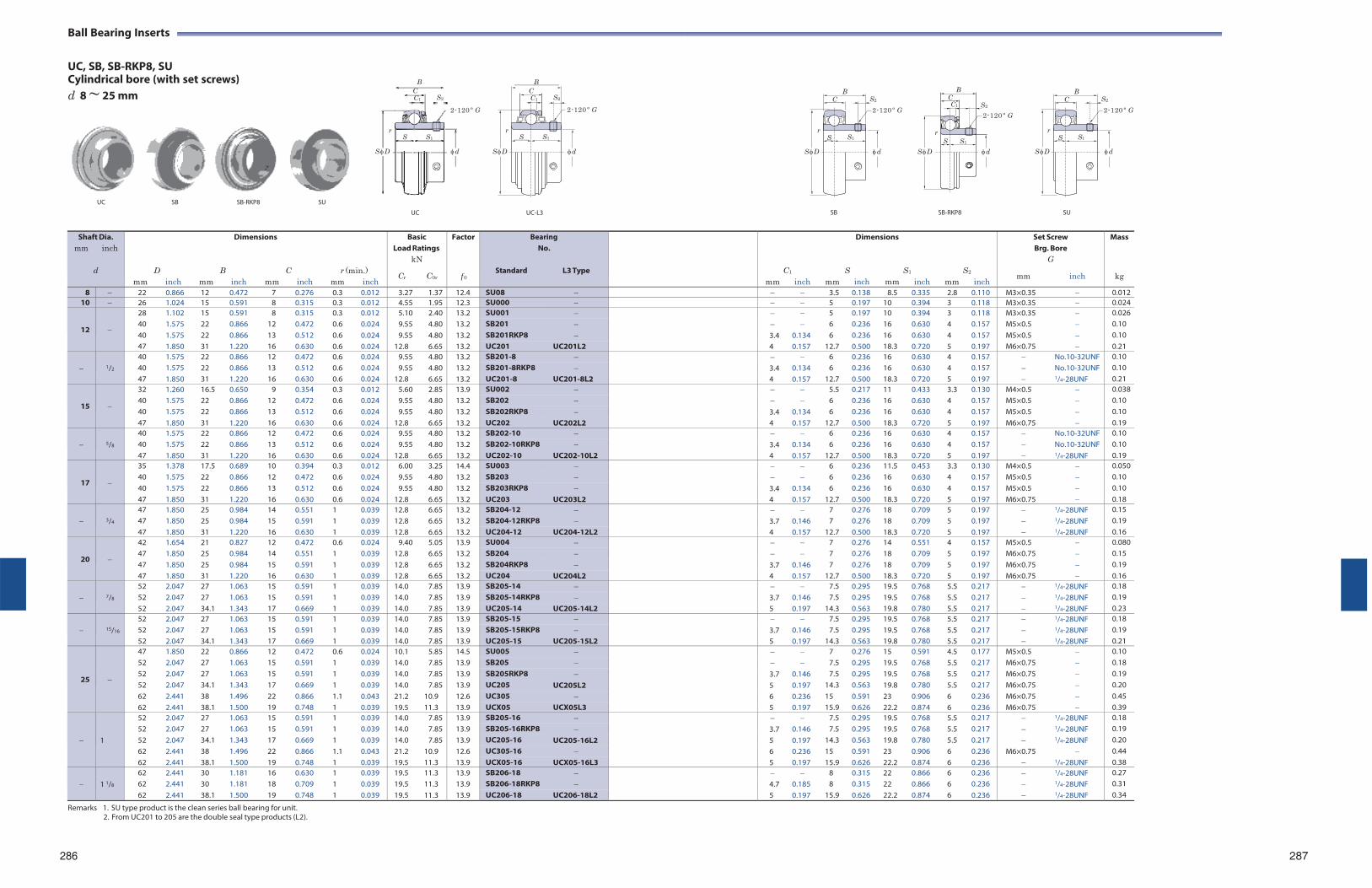
Ball Bearing Inserts
UC, SB, SB-RKP8, SU Cylindrical bore (with set screws)
B B
d 8 ~ 25 mm C C1 S2
2-120 º G
C C1 S2
2-120 º G
B C
S2
2-120 º G
B C
C1
S2
2-120 º G
B C
S2
2-120 º G
r r r r r S S1
S D d
S D
S S1
d
S S1
S D d
S S1
S D d
S S1
S D d
UC SB SB-RKP8 SU
UC UC-L3
SB SB-RKP8 SU
Remarks 1. SU type product is the clean series ball bearing for unit.
2. From UC201 to 205 are the double seal type products (L2).
286 287
Shaft Dia. mm inch
d
mm
D
inch
mm
B
Dimensions
inch mm
C
inch
r (min.) mm inch
Basic Load Ratings
kN
Cr C0r
Factor
f 0
BearingNo.
Standard L3 Type
mm
C1
inch
mm
Dimensions
S inch mm
S1
inch
mm
S2
inch
Set Screw Brg. Bore
G
mm inch
Mass
kg
8 22 0.866 12 0.472 7 0.276 0.3 0.012 3.27 1.37 12.4 SU08 3.5 0.138 8.5 0.335 2.8 0.110 M3×0.35 0.01210 26 1.024 15 0.591 8 0.315 0.3 0.012 4.55 1.95 12.3 SU000 5 0.197 10 0.394 3 0.118 M3×0.35 0.024
12
28 1.102 15 0.591 8 0.315 0.3 0.012 5.10 2.40 13.2 SU001 5 0.197 10 0.394 3 0.118 M3×0.35 0.02640 1.575 22 0.866 12 0.472 0.6 0.024 9.55 4.80 13.2 SB201 6 0.236 16 0.630 4 0.157 M5×0.5 0.10 40 1.575 22 0.866 13 0.512 0.6 0.024 9.55 4.80 13.2 SB201RKP8 3.4 0.134 6 0.236 16 0.630 4 0.157 M5×0.5 0.10 47 1.850 31 1.220 16 0.630 0.6 0.024 12.8 6.65 13.2 UC201 UC201L2 4 0.157 12.7 0.500 18.3 0.720 5 0.197 M6×0.75 0.21
1/2
40 1.575 22 0.866 12 0.472 0.6 0.024 9.55 4.80 13.2 SB201-8 6 0.236 16 0.630 4 0.157 No.10-32UNF 0.10 40 1.575 22 0.866 13 0.512 0.6 0.024 9.55 4.80 13.2 SB201-8RKP8 3.4 0.134 6 0.236 16 0.630 4 0.157 No.10-32UNF 0.10 47 1.850 31 1.220 16 0.630 0.6 0.024 12.8 6.65 13.2 UC201-8 UC201-8L2 4 0.157 12.7 0.500 18.3 0.720 5 0.197 1/4-28UNF 0.21
15
32 1.260 16.5 0.650 9 0.354 0.3 0.012 5.60 2.85 13.9 SU002 5.5 0.217 11 0.433 3.3 0.130 M4×0.5 0.03840 1.575 22 0.866 12 0.472 0.6 0.024 9.55 4.80 13.2 SB202 6 0.236 16 0.630 4 0.157 M5×0.5 0.10 40 1.575 22 0.866 13 0.512 0.6 0.024 9.55 4.80 13.2 SB202RKP8 3.4 0.134 6 0.236 16 0.630 4 0.157 M5×0.5 0.10 47 1.850 31 1.220 16 0.630 0.6 0.024 12.8 6.65 13.2 UC202 UC202L2 4 0.157 12.7 0.500 18.3 0.720 5 0.197 M6×0.75 0.19
5/8
40 1.575 22 0.866 12 0.472 0.6 0.024 9.55 4.80 13.2 SB202-10 6 0.236 16 0.630 4 0.157 No.10-32UNF 0.10 40 1.575 22 0.866 13 0.512 0.6 0.024 9.55 4.80 13.2 SB202-10RKP8 3.4 0.134 6 0.236 16 0.630 4 0.157 No.10-32UNF 0.10 47 1.850 31 1.220 16 0.630 0.6 0.024 12.8 6.65 13.2 UC202-10 UC202-10L2 4 0.157 12.7 0.500 18.3 0.720 5 0.197 1/4-28UNF 0.19
17
35 1.378 17.5 0.689 10 0.394 0.3 0.012 6.00 3.25 14.4 SU003 6 0.236 11.5 0.453 3.3 0.130 M4×0.5 0.05040 1.575 22 0.866 12 0.472 0.6 0.024 9.55 4.80 13.2 SB203 6 0.236 16 0.630 4 0.157 M5×0.5 0.10 40 1.575 22 0.866 13 0.512 0.6 0.024 9.55 4.80 13.2 SB203RKP8 3.4 0.134 6 0.236 16 0.630 4 0.157 M5×0.5 0.10 47 1.850 31 1.220 16 0.630 0.6 0.024 12.8 6.65 13.2 UC203 UC203L2 4 0.157 12.7 0.500 18.3 0.720 5 0.197 M6×0.75 0.18
3/4
47 1.850 25 0.984 14 0.551 1 0.039 12.8 6.65 13.2 SB204-12 7 0.276 18 0.709 5 0.197 1/4-28UNF 0.15 47 1.850 25 0.984 15 0.591 1 0.039 12.8 6.65 13.2 SB204-12RKP8 3.7 0.146 7 0.276 18 0.709 5 0.197 1/4-28UNF 0.19 47 1.850 31 1.220 16 0.630 1 0.039 12.8 6.65 13.2 UC204-12 UC204-12L2 4 0.157 12.7 0.500 18.3 0.720 5 0.197 1/4-28UNF 0.16
20
42 1.654 21 0.827 12 0.472 0.6 0.024 9.40 5.05 13.9 SU004 7 0.276 14 0.551 4 0.157 M5×0.5 0.08047 1.850 25 0.984 14 0.551 1 0.039 12.8 6.65 13.2 SB204 7 0.276 18 0.709 5 0.197 M6×0.75 0.15 47 1.850 25 0.984 15 0.591 1 0.039 12.8 6.65 13.2 SB204RKP8 3.7 0.146 7 0.276 18 0.709 5 0.197 M6×0.75 0.19 47 1.850 31 1.220 16 0.630 1 0.039 12.8 6.65 13.2 UC204 UC204L2 4 0.157 12.7 0.500 18.3 0.720 5 0.197 M6×0.75 0.16
7/8
52 2.047 27 1.063 15 0.591 1 0.039 14.0 7.85 13.9 SB205-14 7.5 0.295 19.5 0.768 5.5 0.217 1/4-28UNF 0.18 52 2.047 27 1.063 15 0.591 1 0.039 14.0 7.85 13.9 SB205-14RKP8 3.7 0.146 7.5 0.295 19.5 0.768 5.5 0.217 1/4-28UNF 0.19 52 2.047 34.1 1.343 17 0.669 1 0.039 14.0 7.85 13.9 UC205-14 UC205-14L2 5 0.197 14.3 0.563 19.8 0.780 5.5 0.217 1/4-28UNF 0.23
15/16
52 2.047 27 1.063 15 0.591 1 0.039 14.0 7.85 13.9 SB205-15 7.5 0.295 19.5 0.768 5.5 0.217 1/4-28UNF 0.18 52 2.047 27 1.063 15 0.591 1 0.039 14.0 7.85 13.9 SB205-15RKP8 3.7 0.146 7.5 0.295 19.5 0.768 5.5 0.217 1/4-28UNF 0.19 52 2.047 34.1 1.343 17 0.669 1 0.039 14.0 7.85 13.9 UC205-15 UC205-15L2 5 0.197 14.3 0.563 19.8 0.780 5.5 0.217 1/4-28UNF 0.21
25
47 1.850 22 0.866 12 0.472 0.6 0.024 10.1 5.85 14.5 SU005 7 0.276 15 0.591 4.5 0.177 M5×0.5 0.10 52 2.047 27 1.063 15 0.591 1 0.039 14.0 7.85 13.9 SB205 7.5 0.295 19.5 0.768 5.5 0.217 M6×0.75 0.18 52 2.047 27 1.063 15 0.591 1 0.039 14.0 7.85 13.9 SB205RKP8 3.7 0.146 7.5 0.295 19.5 0.768 5.5 0.217 M6×0.75 0.19 52 2.047 34.1 1.343 17 0.669 1 0.039 14.0 7.85 13.9 UC205 UC205L2 5 0.197 14.3 0.563 19.8 0.780 5.5 0.217 M6×0.75 0.20 62 2.441 38 1.496 22 0.866 1.1 0.043 21.2 10.9 12.6 UC305 6 0.236 15 0.591 23 0.906 6 0.236 M6×0.75 0.45 62 2.441 38.1 1.500 19 0.748 1 0.039 19.5 11.3 13.9 UCX05 UCX05L3 5 0.197 15.9 0.626 22.2 0.874 6 0.236 M6×0.75 0.39
1
52 2.047 27 1.063 15 0.591 1 0.039 14.0 7.85 13.9 SB205-16 7.5 0.295 19.5 0.768 5.5 0.217 1/4-28UNF 0.18 52 2.047 27 1.063 15 0.591 1 0.039 14.0 7.85 13.9 SB205-16RKP8 3.7 0.146 7.5 0.295 19.5 0.768 5.5 0.217 1/4-28UNF 0.19 52 2.047 34.1 1.343 17 0.669 1 0.039 14.0 7.85 13.9 UC205-16 UC205-16L2 5 0.197 14.3 0.563 19.8 0.780 5.5 0.217 1/4-28UNF 0.20 62 2.441 38 1.496 22 0.866 1.1 0.043 21.2 10.9 12.6 UC305-16 6 0.236 15 0.591 23 0.906 6 0.236 M6×0.75 0.44 62 2.441 38.1 1.500 19 0.748 1 0.039 19.5 11.3 13.9 UCX05-16 UCX05-16L3 5 0.197 15.9 0.626 22.2 0.874 6 0.236 1/4-28UNF 0.38
1 1/8
62 2.441 30 1.181 16 0.630 1 0.039 19.5 11.3 13.9 SB206-18 8 0.315 22 0.866 6 0.236 1/4-28UNF 0.27 62 2.441 30 1.181 18 0.709 1 0.039 19.5 11.3 13.9 SB206-18RKP8 4.7 0.185 8 0.315 22 0.866 6 0.236 1/4-28UNF 0.31 62 2.441 38.1 1.500 19 0.748 1 0.039 19.5 11.3 13.9 UC206-18 UC206-18L2 5 0.197 15.9 0.626 22.2 0.874 6 0.236 1/4-28UNF 0.34
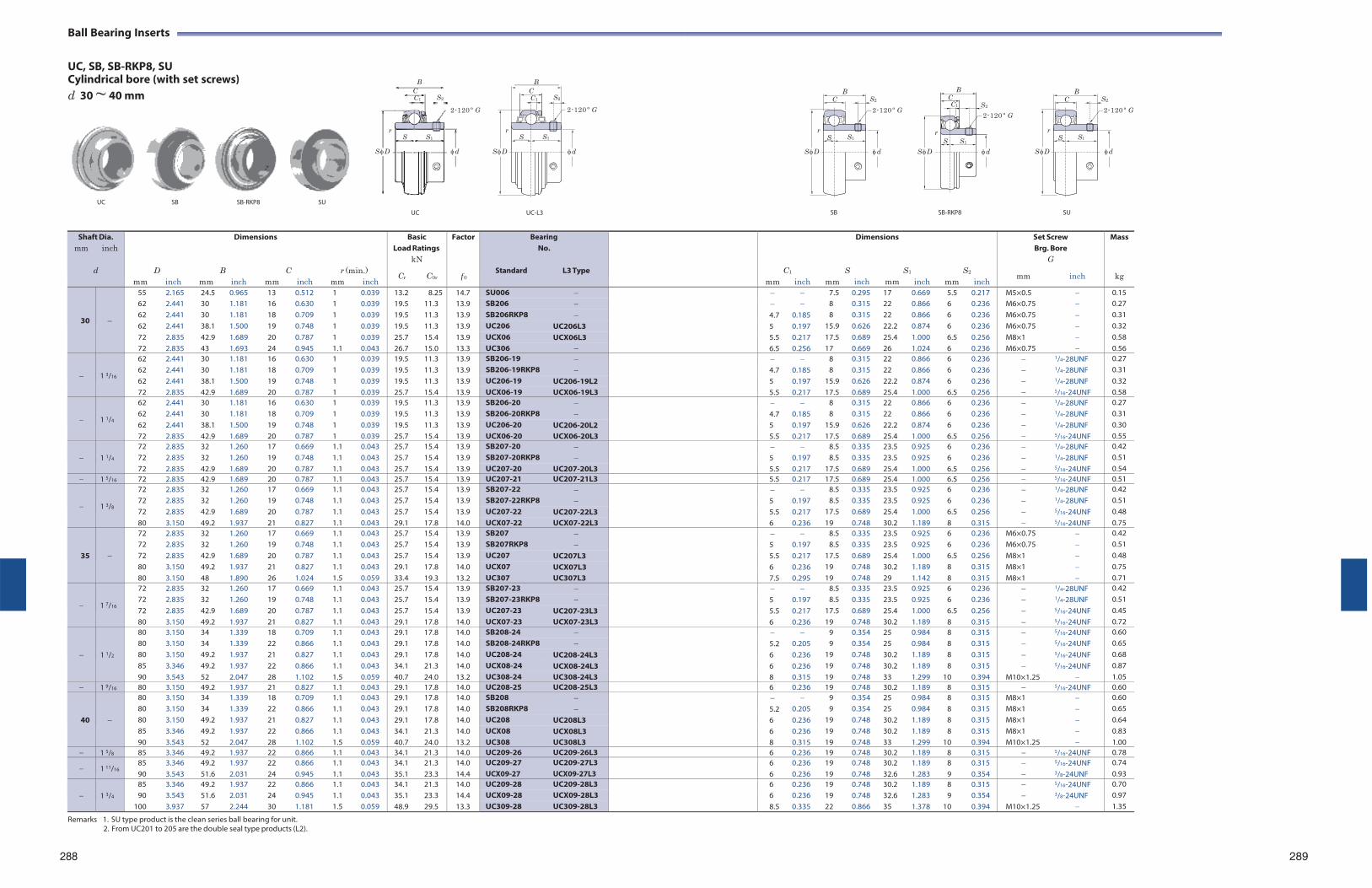
Ball Bearing Inserts
UC, SB, SB-RKP8, SU Cylindrical bore (with set screws)
B B
d 30 ~ 40 mm C C1 S2
2-120 º G
C C1 S2
2-120 º G
B C
S2
2-120 º G
B C
C1
S2
2-120 º G
B C
S2
2-120 º G
r r r r r S S1
S D d
S D
S S1
d
S S1
S D d
S S1
S D d
S S1
S D d
UC SB SB-RKP8 SU
UC UC-L3
SB SB-RKP8 SU
Remarks 1. SU type product is the clean series ball bearing for unit.
2. From UC201 to 205 are the double seal type products (L2).
288 289
Shaft Dia. mm inch
d
mm
D
inch
mm
B
Dimensions
inch mm
C
inch
r (min.) mm inch
Basic Load Ratings
kN
Cr C0r
Factor
f 0
BearingNo.
Standard L3 Type
mm
C1
inch
mm
Dimensions
S inch mm
S1
inch
mm
S2
inch
Set Screw Brg. Bore
G
mm inch
Mass
kg
30
55 2.165 24.5 0.965 13 0.512 1 0.039 13.2 8.25 14.7 SU006 7.5 0.295 17 0.669 5.5 0.217 M5×0.5 0.15 62 2.441 30 1.181 16 0.630 1 0.039 19.5 11.3 13.9 SB206 8 0.315 22 0.866 6 0.236 M6×0.75 0.27 62 2.441 30 1.181 18 0.709 1 0.039 19.5 11.3 13.9 SB206RKP8 4.7 0.185 8 0.315 22 0.866 6 0.236 M6×0.75 0.31 62 2.441 38.1 1.500 19 0.748 1 0.039 19.5 11.3 13.9 UC206 UC206L3 5 0.197 15.9 0.626 22.2 0.874 6 0.236 M6×0.75 0.32 72 2.835 42.9 1.689 20 0.787 1 0.039 25.7 15.4 13.9 UCX06 UCX06L3 5.5 0.217 17.5 0.689 25.4 1.000 6.5 0.256 M8×1 0.58 72 2.835 43 1.693 24 0.945 1.1 0.043 26.7 15.0 13.3 UC306 6.5 0.256 17 0.669 26 1.024 6 0.236 M6×0.75 0.56
1 3/16
62 2.441 30 1.181 16 0.630 1 0.039 19.5 11.3 13.9 SB206-19 8 0.315 22 0.866 6 0.236 1/4-28UNF 0.27 62 2.441 30 1.181 18 0.709 1 0.039 19.5 11.3 13.9 SB206-19RKP8 4.7 0.185 8 0.315 22 0.866 6 0.236 1/4-28UNF 0.31 62 2.441 38.1 1.500 19 0.748 1 0.039 19.5 11.3 13.9 UC206-19 UC206-19L2 5 0.197 15.9 0.626 22.2 0.874 6 0.236 1/4-28UNF 0.32 72 2.835 42.9 1.689 20 0.787 1 0.039 25.7 15.4 13.9 UCX06-19 UCX06-19L3 5.5 0.217 17.5 0.689 25.4 1.000 6.5 0.256 5/16-24UNF 0.58
1 1/4
62 2.441 30 1.181 16 0.630 1 0.039 19.5 11.3 13.9 SB206-20 8 0.315 22 0.866 6 0.236 1/4-28UNF 0.27 62 2.441 30 1.181 18 0.709 1 0.039 19.5 11.3 13.9 SB206-20RKP8 4.7 0.185 8 0.315 22 0.866 6 0.236 1/4-28UNF 0.31 62 2.441 38.1 1.500 19 0.748 1 0.039 19.5 11.3 13.9 UC206-20 UC206-20L2 5 0.197 15.9 0.626 22.2 0.874 6 0.236 1/4-28UNF 0.30 72 2.835 42.9 1.689 20 0.787 1 0.039 25.7 15.4 13.9 UCX06-20 UCX06-20L3 5.5 0.217 17.5 0.689 25.4 1.000 6.5 0.256 5/16-24UNF 0.55
1 1/4
72 2.835 32 1.260 17 0.669 1.1 0.043 25.7 15.4 13.9 SB207-20 8.5 0.335 23.5 0.925 6 0.236 1/4-28UNF 0.42 72 2.835 32 1.260 19 0.748 1.1 0.043 25.7 15.4 13.9 SB207-20RKP8 5 0.197 8.5 0.335 23.5 0.925 6 0.236 1/4-28UNF 0.51 72 2.835 42.9 1.689 20 0.787 1.1 0.043 25.7 15.4 13.9 UC207-20 UC207-20L3 5.5 0.217 17.5 0.689 25.4 1.000 6.5 0.256 5/16-24UNF 0.54
1 5/16 72 2.835 42.9 1.689 20 0.787 1.1 0.043 25.7 15.4 13.9 UC207-21 UC207-21L3 5.5 0.217 17.5 0.689 25.4 1.000 6.5 0.256 5/16-24UNF 0.51
1 3/8
72 2.835 32 1.260 17 0.669 1.1 0.043 25.7 15.4 13.9 SB207-22 8.5 0.335 23.5 0.925 6 0.236 1/4-28UNF 0.42 72 2.835 32 1.260 19 0.748 1.1 0.043 25.7 15.4 13.9 SB207-22RKP8 5 0.197 8.5 0.335 23.5 0.925 6 0.236 1/4-28UNF 0.51 72 2.835 42.9 1.689 20 0.787 1.1 0.043 25.7 15.4 13.9 UC207-22 UC207-22L3 5.5 0.217 17.5 0.689 25.4 1.000 6.5 0.256 5/16-24UNF 0.48 80 3.150 49.2 1.937 21 0.827 1.1 0.043 29.1 17.8 14.0 UCX07-22 UCX07-22L3 6 0.236 19 0.748 30.2 1.189 8 0.315 5/16-24UNF 0.75
35
72 2.835 32 1.260 17 0.669 1.1 0.043 25.7 15.4 13.9 SB207 8.5 0.335 23.5 0.925 6 0.236 M6×0.75 0.42 72 2.835 32 1.260 19 0.748 1.1 0.043 25.7 15.4 13.9 SB207RKP8 5 0.197 8.5 0.335 23.5 0.925 6 0.236 M6×0.75 0.51 72 2.835 42.9 1.689 20 0.787 1.1 0.043 25.7 15.4 13.9 UC207 UC207L3 5.5 0.217 17.5 0.689 25.4 1.000 6.5 0.256 M8×1 0.48 80 3.150 49.2 1.937 21 0.827 1.1 0.043 29.1 17.8 14.0 UCX07 UCX07L3 6 0.236 19 0.748 30.2 1.189 8 0.315 M8×1 0.75 80 3.150 48 1.890 26 1.024 1.5 0.059 33.4 19.3 13.2 UC307 UC307L3 7.5 0.295 19 0.748 29 1.142 8 0.315 M8×1 0.71
1 7/16
72 2.835 32 1.260 17 0.669 1.1 0.043 25.7 15.4 13.9 SB207-23 8.5 0.335 23.5 0.925 6 0.236 1/4-28UNF 0.42 72 2.835 32 1.260 19 0.748 1.1 0.043 25.7 15.4 13.9 SB207-23RKP8 5 0.197 8.5 0.335 23.5 0.925 6 0.236 1/4-28UNF 0.51 72 2.835 42.9 1.689 20 0.787 1.1 0.043 25.7 15.4 13.9 UC207-23 UC207-23L3 5.5 0.217 17.5 0.689 25.4 1.000 6.5 0.256 5/16-24UNF 0.45 80 3.150 49.2 1.937 21 0.827 1.1 0.043 29.1 17.8 14.0 UCX07-23 UCX07-23L3 6 0.236 19 0.748 30.2 1.189 8 0.315 5/16-24UNF 0.72
1 1/2
80 3.150 34 1.339 18 0.709 1.1 0.043 29.1 17.8 14.0 SB208-24 9 0.354 25 0.984 8 0.315 5/16-24UNF 0.60 80 3.150 34 1.339 22 0.866 1.1 0.043 29.1 17.8 14.0 SB208-24RKP8 5.2 0.205 9 0.354 25 0.984 8 0.315 5/16-24UNF 0.65 80 3.150 49.2 1.937 21 0.827 1.1 0.043 29.1 17.8 14.0 UC208-24 UC208-24L3 6 0.236 19 0.748 30.2 1.189 8 0.315 5/16-24UNF 0.68 85 3.346 49.2 1.937 22 0.866 1.1 0.043 34.1 21.3 14.0 UCX08-24 UCX08-24L3 6 0.236 19 0.748 30.2 1.189 8 0.315 5/16-24UNF 0.87 90 3.543 52 2.047 28 1.102 1.5 0.059 40.7 24.0 13.2 UC308-24 UC308-24L3 8 0.315 19 0.748 33 1.299 10 0.394 M10×1.25 1.05
1 9/16 80 3.150 49.2 1.937 21 0.827 1.1 0.043 29.1 17.8 14.0 UC208-25 UC208-25L3 6 0.236 19 0.748 30.2 1.189 8 0.315 5/16-24UNF 0.60
40
80 3.150 34 1.339 18 0.709 1.1 0.043 29.1 17.8 14.0 SB208 9 0.354 25 0.984 8 0.315 M8×1 0.60 80 3.150 34 1.339 22 0.866 1.1 0.043 29.1 17.8 14.0 SB208RKP8 5.2 0.205 9 0.354 25 0.984 8 0.315 M8×1 0.65 80 3.150 49.2 1.937 21 0.827 1.1 0.043 29.1 17.8 14.0 UC208 UC208L3 6 0.236 19 0.748 30.2 1.189 8 0.315 M8×1 0.64 85 3.346 49.2 1.937 22 0.866 1.1 0.043 34.1 21.3 14.0 UCX08 UCX08L3 6 0.236 19 0.748 30.2 1.189 8 0.315 M8×1 0.83 90 3.543 52 2.047 28 1.102 1.5 0.059 40.7 24.0 13.2 UC308 UC308L3 8 0.315 19 0.748 33 1.299 10 0.394 M10×1.25 1.00
1 5/8 85 3.346 49.2 1.937 22 0.866 1.1 0.043 34.1 21.3 14.0 UC209-26 UC209-26L3 6 0.236 19 0.748 30.2 1.189 8 0.315 5/16-24UNF 0.78
1 11/16 85 90
3.346 3.543
49.2 51.6
1.937 2.031
22 24
0.866 0.945
1.1 1.1
0.043 0.043
34.1 35.1
21.3 23.3
14.0 14.4
UC209-27 UCX09-27
UC209-27L3 UCX09-27L3
6 6
0.236 0.236
19 19
0.748 0.748
30.232.6
1.189 1.283
8 9
0.315 0.354
5/16-24UNF 3/8-24UNF
0.74 0.93
1 3/4
85 3.346 49.2 1.937 22 0.866 1.1 0.043 34.1 21.3 14.0 UC209-28 UC209-28L3 6 0.236 19 0.748 30.2 1.189 8 0.315 5/16-24UNF 0.70 90 3.543 51.6 2.031 24 0.945 1.1 0.043 35.1 23.3 14.4 UCX09-28 UCX09-28L3 6 0.236 19 0.748 32.6 1.283 9 0.354 3/8-24UNF 0.97
100 3.937 57 2.244 30 1.181 1.5 0.059 48.9 29.5 13.3 UC309-28 UC309-28L3 8.5 0.335 22 0.866 35 1.378 10 0.394 M10×1.25 1.35
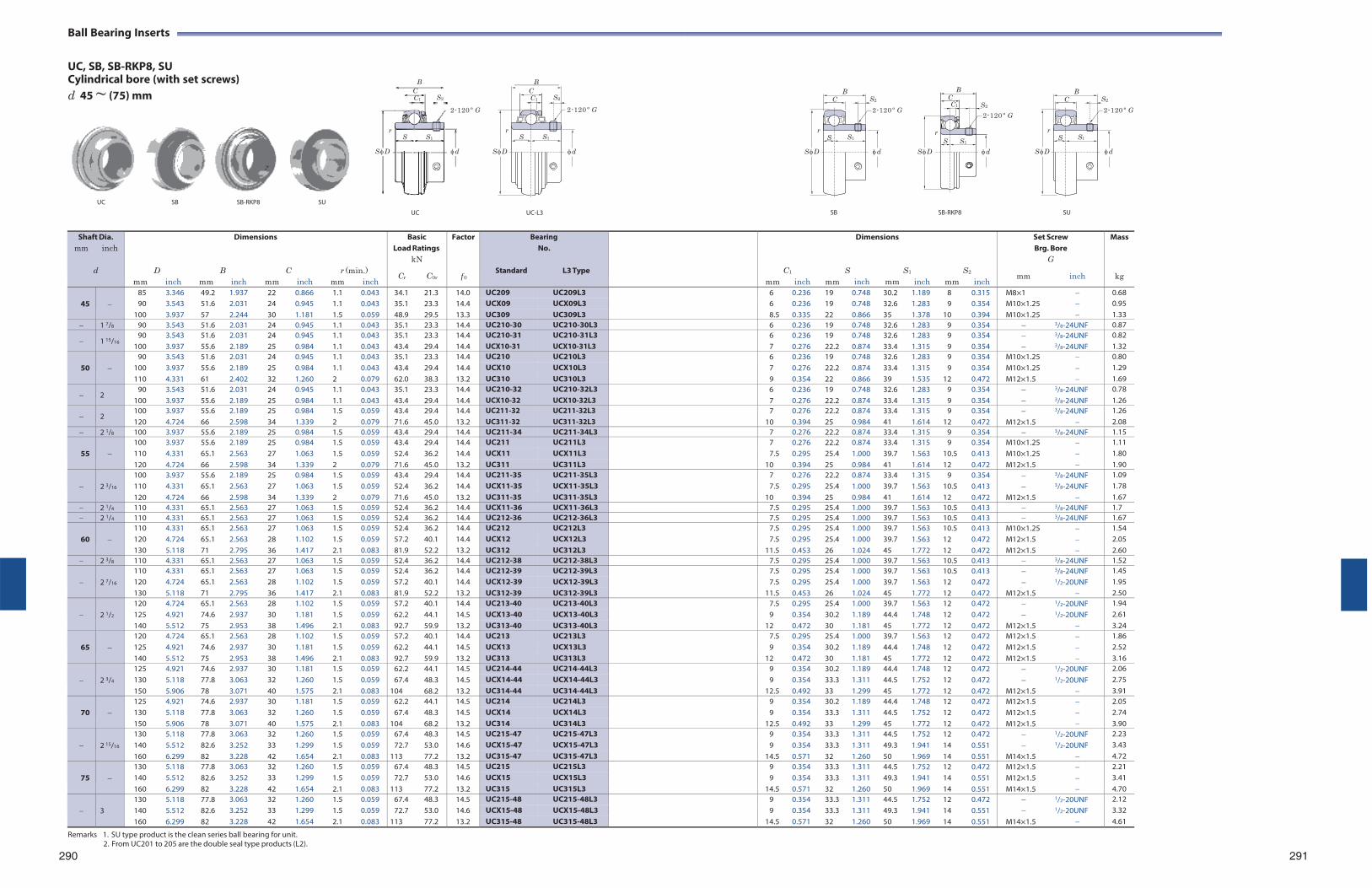
Ball Bearing Inserts
UC, SB, SB-RKP8, SU Cylindrical bore (with set screws)
B B
d 45 ~ (75) mm C C1 S2
2-120 º G
C C1 S2
2-120 º G
B C
S2
2-120 º G
B C
C1
S2
2-120 º G
B C
S2
2-120 º G
r r r r r S S1
S D d
S D
S S1
d
S S1
S D d
S S1
S D d
S S1
S D d
UC SB SB-RKP8 SU
UC UC-L3
SB SB-RKP8 SU
Remarks 1. SU type product is the clean series ball bearing for unit.
2. From UC201 to 205 are the double seal type products (L2).
290
291
Shaft Dia. mm inch
d
mm
D
inch
mm
B
Dimensions
inch mm
C
inch
r (min.) mm inch
Basic Load Ratings
kN
Cr C0r
Factor
f 0
BearingNo.
Standard L3 Type
mm
C1
inch
mm
Dimensions
S inch mm
S1
inch
mm
S2
inch
Set Screw Brg. Bore
G
mm inch
Mass
kg
45
85 3.346 49.2 1.937 22 0.866 1.1 0.043 34.1 21.3 14.0 UC209 UC209L3 6 0.236 19 0.748 30.2 1.189 8 0.315 M8×1 0.68 90 3.543 51.6 2.031 24 0.945 1.1 0.043 35.1 23.3 14.4 UCX09 UCX09L3 6 0.236 19 0.748 32.6 1.283 9 0.354 M10×1.25 0.95
100 3.937 57 2.244 30 1.181 1.5 0.059 48.9 29.5 13.3 UC309 UC309L3 8.5 0.335 22 0.866 35 1.378 10 0.394 M10×1.25 1.33 1 7/8 90 3.543 51.6 2.031 24 0.945 1.1 0.043 35.1 23.3 14.4 UC210-30 UC210-30L3 6 0.236 19 0.748 32.6 1.283 9 0.354 3/8-24UNF 0.87
1 15/16 90
100 3.543 3.937
51.6 55.6
2.031 2.189
24 25
0.945 0.984
1.1 1.1
0.043 0.043
35.1 43.4
23.3 29.4
14.4 14.4
UC210-31 UCX10-31
UC210-31L3 UCX10-31L3
6 7
0.236 0.276
19 22.2
0.748 0.874
32.633.4
1.283 1.315
9 9
0.354 0.354
3/8-24UNF 3/8-24UNF
0.82 1.32
50
90 3.543 51.6 2.031 24 0.945 1.1 0.043 35.1 23.3 14.4 UC210 UC210L3 6 0.236 19 0.748 32.6 1.283 9 0.354 M10×1.25 0.80 100 3.937 55.6 2.189 25 0.984 1.1 0.043 43.4 29.4 14.4 UCX10 UCX10L3 7 0.276 22.2 0.874 33.4 1.315 9 0.354 M10×1.25 1.29 110 4.331 61 2.402 32 1.260 2 0.079 62.0 38.3 13.2 UC310 UC310L3 9 0.354 22 0.866 39 1.535 12 0.472 M12×1.5 1.69
2 90
100 3.543 3.937
51.6 55.6
2.031 2.189
24 25
0.945 0.984
1.1 1.1
0.043 0.043
35.1 43.4
23.3 29.4
14.4 14.4
UC210-32 UCX10-32
UC210-32L3 UCX10-32L3
6 7
0.236 0.276
19 22.2
0.748 0.874
32.633.4
1.283 1.315
9 9
0.354 0.354
3/8-24UNF 3/8-24UNF
0.78 1.26
2 100 120
3.937 4.724
55.6 66
2.189 2.598
25 34
0.984 1.339
1.5 2
0.059 0.079
43.4 71.6
29.4 45.0
14.4 13.2
UC211-32 UC311-32
UC211-32L3 UC311-32L3
7 10
0.276 0.394
22.225
0.874 0.984
33.441
1.315 1.614
9 12
0.354 0.472
M12×1.5
3/8-24UNF
1.26 2.08
2 1/8 100 3.937 55.6 2.189 25 0.984 1.5 0.059 43.4 29.4 14.4 UC211-34 UC211-34L3 7 0.276 22.2 0.874 33.4 1.315 9 0.354 3/8-24UNF 1.15
55
100 3.937 55.6 2.189 25 0.984 1.5 0.059 43.4 29.4 14.4 UC211 UC211L3 7 0.276 22.2 0.874 33.4 1.315 9 0.354 M10×1.25 1.11 110 4.331 65.1 2.563 27 1.063 1.5 0.059 52.4 36.2 14.4 UCX11 UCX11L3 7.5 0.295 25.4 1.000 39.7 1.563 10.5 0.413 M10×1.25 1.80 120 4.724 66 2.598 34 1.339 2 0.079 71.6 45.0 13.2 UC311 UC311L3 10 0.394 25 0.984 41 1.614 12 0.472 M12×1.5 1.90
2 3/16
100 3.937 55.6 2.189 25 0.984 1.5 0.059 43.4 29.4 14.4 UC211-35 UC211-35L3 7 0.276 22.2 0.874 33.4 1.315 9 0.354 3/8-24UNF 1.09 110 4.331 65.1 2.563 27 1.063 1.5 0.059 52.4 36.2 14.4 UCX11-35 UCX11-35L3 7.5 0.295 25.4 1.000 39.7 1.563 10.5 0.413 3/8-24UNF 1.78 120 4.724 66 2.598 34 1.339 2 0.079 71.6 45.0 13.2 UC311-35 UC311-35L3 10 0.394 25 0.984 41 1.614 12 0.472 M12×1.5 1.67
2 1/4 110 4.331 65.1 2.563 27 1.063 1.5 0.059 52.4 36.2 14.4 UCX11-36 UCX11-36L3 7.5 0.295 25.4 1.000 39.7 1.563 10.5 0.413 3/8-24UNF 1.7 2 1/4 110 4.331 65.1 2.563 27 1.063 1.5 0.059 52.4 36.2 14.4 UC212-36 UC212-36L3 7.5 0.295 25.4 1.000 39.7 1.563 10.5 0.413 3/8-24UNF 1.67
60
110 4.331 65.1 2.563 27 1.063 1.5 0.059 52.4 36.2 14.4 UC212 UC212L3 7.5 0.295 25.4 1.000 39.7 1.563 10.5 0.413 M10×1.25 1.54 120 4.724 65.1 2.563 28 1.102 1.5 0.059 57.2 40.1 14.4 UCX12 UCX12L3 7.5 0.295 25.4 1.000 39.7 1.563 12 0.472 M12×1.5 2.05 130 5.118 71 2.795 36 1.417 2.1 0.083 81.9 52.2 13.2 UC312 UC312L3 11.5 0.453 26 1.024 45 1.772 12 0.472 M12×1.5 2.60
2 3/8 110 4.331 65.1 2.563 27 1.063 1.5 0.059 52.4 36.2 14.4 UC212-38 UC212-38L3 7.5 0.295 25.4 1.000 39.7 1.563 10.5 0.413 3/8-24UNF 1.52
2 7/16
110 4.331 65.1 2.563 27 1.063 1.5 0.059 52.4 36.2 14.4 UC212-39 UC212-39L3 7.5 0.295 25.4 1.000 39.7 1.563 10.5 0.413 3/8-24UNF 1.45 120 4.724 65.1 2.563 28 1.102 1.5 0.059 57.2 40.1 14.4 UCX12-39 UCX12-39L3 7.5 0.295 25.4 1.000 39.7 1.563 12 0.472 1/2-20UNF 1.95 130 5.118 71 2.795 36 1.417 2.1 0.083 81.9 52.2 13.2 UC312-39 UC312-39L3 11.5 0.453 26 1.024 45 1.772 12 0.472 M12×1.5 2.50
2 1/2
120 4.724 65.1 2.563 28 1.102 1.5 0.059 57.2 40.1 14.4 UC213-40 UC213-40L3 7.5 0.295 25.4 1.000 39.7 1.563 12 0.472 1/2-20UNF 1.94 125 4.921 74.6 2.937 30 1.181 1.5 0.059 62.2 44.1 14.5 UCX13-40 UCX13-40L3 9 0.354 30.2 1.189 44.4 1.748 12 0.472 1/2-20UNF 2.61 140 5.512 75 2.953 38 1.496 2.1 0.083 92.7 59.9 13.2 UC313-40 UC313-40L3 12 0.472 30 1.181 45 1.772 12 0.472 M12×1.5 3.24
65
120 4.724 65.1 2.563 28 1.102 1.5 0.059 57.2 40.1 14.4 UC213 UC213L3 7.5 0.295 25.4 1.000 39.7 1.563 12 0.472 M12×1.5 1.86 125 4.921 74.6 2.937 30 1.181 1.5 0.059 62.2 44.1 14.5 UCX13 UCX13L3 9 0.354 30.2 1.189 44.4 1.748 12 0.472 M12×1.5 2.52 140 5.512 75 2.953 38 1.496 2.1 0.083 92.7 59.9 13.2 UC313 UC313L3 12 0.472 30 1.181 45 1.772 12 0.472 M12×1.5 3.16
2 3/4
125 4.921 74.6 2.937 30 1.181 1.5 0.059 62.2 44.1 14.5 UC214-44 UC214-44L3 9 0.354 30.2 1.189 44.4 1.748 12 0.472 1/2-20UNF 2.06 130 5.118 77.8 3.063 32 1.260 1.5 0.059 67.4 48.3 14.5 UCX14-44 UCX14-44L3 9 0.354 33.3 1.311 44.5 1.752 12 0.472 1/2-20UNF 2.75 150 5.906 78 3.071 40 1.575 2.1 0.083 104 68.2 13.2 UC314-44 UC314-44L3 12.5 0.492 33 1.299 45 1.772 12 0.472 M12×1.5 3.91
70
125 4.921 74.6 2.937 30 1.181 1.5 0.059 62.2 44.1 14.5 UC214 UC214L3 9 0.354 30.2 1.189 44.4 1.748 12 0.472 M12×1.5 2.05 130 5.118 77.8 3.063 32 1.260 1.5 0.059 67.4 48.3 14.5 UCX14 UCX14L3 9 0.354 33.3 1.311 44.5 1.752 12 0.472 M12×1.5 2.74 150 5.906 78 3.071 40 1.575 2.1 0.083 104 68.2 13.2 UC314 UC314L3 12.5 0.492 33 1.299 45 1.772 12 0.472 M12×1.5 3.90
2 15/16
130 5.118 77.8 3.063 32 1.260 1.5 0.059 67.4 48.3 14.5 UC215-47 UC215-47L3 9 0.354 33.3 1.311 44.5 1.752 12 0.472 1/2-20UNF 2.23 140 5.512 82.6 3.252 33 1.299 1.5 0.059 72.7 53.0 14.6 UCX15-47 UCX15-47L3 9 0.354 33.3 1.311 49.3 1.941 14 0.551 1/2-20UNF 3.43 160 6.299 82 3.228 42 1.654 2.1 0.083 113 77.2 13.2 UC315-47 UC315-47L3 14.5 0.571 32 1.260 50 1.969 14 0.551 M14×1.5 4.72
75
130 5.118 77.8 3.063 32 1.260 1.5 0.059 67.4 48.3 14.5 UC215 UC215L3 9 0.354 33.3 1.311 44.5 1.752 12 0.472 M12×1.5 2.21 140 5.512 82.6 3.252 33 1.299 1.5 0.059 72.7 53.0 14.6 UCX15 UCX15L3 9 0.354 33.3 1.311 49.3 1.941 14 0.551 M12×1.5 3.41 160 6.299 82 3.228 42 1.654 2.1 0.083 113 77.2 13.2 UC315 UC315L3 14.5 0.571 32 1.260 50 1.969 14 0.551 M14×1.5 4.70
3
130 5.118 77.8 3.063 32 1.260 1.5 0.059 67.4 48.3 14.5 UC215-48 UC215-48L3 9 0.354 33.3 1.311 44.5 1.752 12 0.472 1/2-20UNF 2.12 140 5.512 82.6 3.252 33 1.299 1.5 0.059 72.7 53.0 14.6 UCX15-48 UCX15-48L3 9 0.354 33.3 1.311 49.3 1.941 14 0.551 1/2-20UNF 3.32 160 6.299 82 3.228 42 1.654 2.1 0.083 113 77.2 13.2 UC315-48 UC315-48L3 14.5 0.571 32 1.260 50 1.969 14 0.551 M14×1.5 4.61
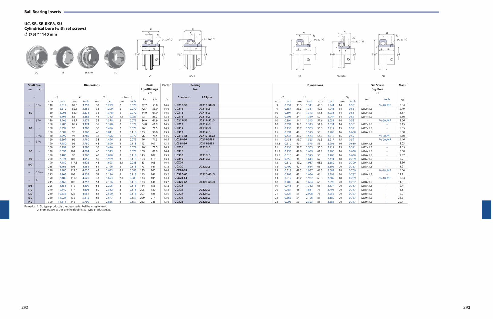
Ball Bearing Inserts
UC, SB, SB-RKP8, SU Cylindrical bore (with set screws)
B B
d (75) ~ 140 mm C C1 S2
2-120 º G
C C1 S2
2-120 º G
B C
S2
2-120 º G
B C
C1
S2
2-120 º G
B C
S2
2-120 º G
r r r r r S S1
S D d
S D
S S1
d
S S1
S D d
S S1
S D d
S S1
S D d
UC SB SB-RKP8 SU
UC UC-L3
SB SB-RKP8 SU
Shaft Dia. mm inch
d
mm
D inch
mm
B
Dimensions
inch mm
C
inch
r (min.) mm inch
Basic Load Ratings
kN
Cr C0r
Factor
f 0
BearingNo.
Standard L3 Type
mm
C1
inch
mm
Dimensions
S inch mm
S1
inch
mm
S2
inch
Set Screw Brg. Bore
G
mm inch
Mass
kg
3 1/8 140 5.512 82.6 3.252 33 1.299 2 0.079 72.7 53.0 14.6 UC216-50 UC216-50L3 9 0.354 33.3 1.311 49.3 1.941 14 0.551 1/2-20UNF 2.84
80
140 5.512 82.6 3.252 33 1.299 2 0.079 72.7 53.0 14.6 UC216 UC216L3 9 0.354 33.3 1.311 49.3 1.941 14 0.551 M12×1.5 2.79 150 5.906 85.7 3.374 35 1.378 2 0.079 84.0 61.9 14.5 UCX16 UCX16L3 10 0.394 34.1 1.343 51.6 2.031 14 0.551 M12×1.5 3.87 170 6.693 86 3.386 44 1.732 2.1 0.083 123 86.7 13.3 UC316 UC316L3 15 0.591 34 1.339 52 2.047 14 0.551 M14×1.5 5.60
3 1/4 150 5.906 85.7 3.374 35 1.378 2 0.079 84.0 61.9 14.5 UC217-52 UC217-52L3 10 0.394 34.1 1.343 51.6 2.031 14 0.551 1/2-20UNF 3.66
85
150 5.906 85.7 3.374 35 1.378 2 0.079 84.0 61.9 14.5 UC217 UC217L3 10 0.394 34.1 1.343 51.6 2.031 14 0.551 M12×1.5 3.45 160 6.299 96 3.780 38 1.496 2 0.079 96.1 71.5 14.5 UCX17 UCX17L3 11 0.433 39.7 1.563 56.3 2.217 15 0.591 M12×1.5 5.05 180 7.087 96 3.780 46 1.811 3 0.118 133 96.8 13.3 UC317 UC317L3 15 0.591 40 1.575 56 2.205 16 0.630 M16×1.5 6.90
3 7/16 160 6.299 96 3.780 38 1.496 2 0.079 96.1 71.5 14.5 UCX17-55 UCX17-55L3 11 0.433 39.7 1.563 56.3 2.217 15 0.591 1/2-20UNF 4.80
3 1/2 160 190
6.299 7.480
96 96
3.780 3.780
38 48
1.496 1.890
2 3
0.079 0.118
96.1 143
71.5 107
14.5 13.3
UC218-56 UC318-56
UC218-56L3 UC318-56L3
11 15.5
0.433 0.610
39.740
1.563 1.575
56.356
2.217 2.205
15 16
0.591 0.630
M16×1.5
1/2-20UNF
4.46 8.03
90
160 6.299 96 3.780 38 1.496 2 0.079 96.1 71.5 14.5 UC218 UC218L3 11 0.433 39.7 1.563 56.3 2.217 15 0.591 M12×1.5 4.35 170 6.693 104 4.094 40 1.575 2 0.079 109 81.9 14.4 UCX18 11.5 0.453 42.9 1.689 61.1 2.406 16 0.630 M14×1.5 6.00 190 7.480 96 3.780 48 1.890 3 0.118 143 107 13.3 UC318 UC318L3 15.5 0.610 40 1.575 56 2.205 16 0.630 M16×1.5 7.87
95 200 7.874 103 4.055 50 1.969 3 0.118 153 119 13.3 UC319 UC319L3 16.5 0.650 41 1.614 62 2.441 18 0.709 M16×1.5 8.91
100 190 215
7.480 8.465
117.5 108
4.626 4.252
43 54
1.693 2.126
2.1 3
0.083 0.118
133 173
105 141
14.4 13.2
UCX20 UC320
UC320L3
13 18
0.512 0.709
49.242
1.937 1.654
68.366
2.689 2.598
18 20
0.709 0.787
M16×1.5 M18×1.5
8.56 11.2
3 15/16 190 215
7.480 8.465
117.5 108
4.626 4.252
43 54
1.693 2.126
2.1 3
0.083 0.118
133 173
105 141
14.4 13.2
UCX20-63 UC320-63
UC320-63L3
13 18
0.512 0.709
49.242
1.937 1.654
68.366
2.689 2.598
18 20
0.709 0.787
M18×1.5
5/8-18UNF
8.56 11.2
4 190 215
7.480 8.465
117.5 108
4.626 4.252
43 54
1.693 2.126
2.1 3
0.083 0.118
133 173
105 141
14.4 13.2
UCX20-64 UC320-64
UC320-64L3
13 18
0.512 0.709
49.242
1.937 1.654
68.366
2.689 2.598
18 20
0.709 0.787
M18×1.5
5/8-18UNF
8.33 11.0
105
225 8.858 112 4.409 56 2.205 3 0.118 184 153 13.2 UC321 19 0.748 44 1.732 68 2.677 20 0.787 M18×1.5 12.7 110 240 9.449 117 4.606 60 2.362 3 0.118 205 180 13.2 UC322 UC322L3 20 0.787 46 1.811 71 2.795 20 0.787 M18×1.5 15.1 120 260 10.236 126 4.961 64 2.520 3 0.118 207 185 13.5 UC324 UC324L3 21 0.827 51 2.008 75 2.953 20 0.787 M18×1.5 19.0 130 280 11.024 135 5.315 68 2.677 4 0.157 229 214 13.6 UC326 UC326L3 22 0.866 54 2.126 81 3.189 20 0.787 M20×1.5 23.6 140 300 11.811 145 5.709 72 2.835 4 0.157 253 246 13.6 UC328 UC328L3 23 0.906 59 2.323 86 3.386 20 0.787 M20×1.5 29.4
Remarks 1. SU type product is the clean series ball bearing for unit. 2. From UC201 to 205 are the double seal type products (L2).
292 293
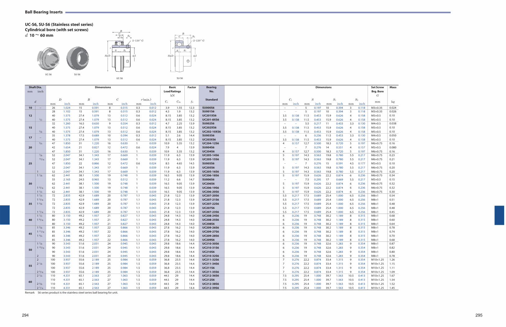
Ball Bearing Inserts
UC-S6, SU-S6 (Stainless steel series) Cylindrical bore (with set screws) d 10 ~ 60 mm
B C C1 S2
2-120 º G
B C S2
2-120 º G
r S S1
r S S1
S D d S D d
UC-S6 SU-S6
UC-S6
SU-S6
Remark S6 series product is the stainless steel series ball bearing for unit.
294 295
Shaft Dia. mm inch
d
mm
D
inch
mm
B
Dimensions
inch mm
C
inch
r (min.) mm inch
Basic Load Ratings
kN
Cr C0r
Factor
f 0
BearingNo.
Standard
mm
C1
inch
mm
Dimensions
S inch mm
S1
inch
mm
S2
inch
Set Screw Brg. Bore
G
mm
Mass
kg
10 26 1.024 15 0.591 8 0.315 0.3 0.012 3.9 1.55 12.3 SU000S6 5 0.197 10 0.394 3 0.118 M3×0.35 0.024
12
1/2
28 1.102 15 0.591 8 0.315 0.3 0.012 4.3 1.9 13.2 SU001S6 5 0.197 10 0.394 3 0.118 M3×0.35 0.026 40 1.575 27.4 1.079 13 0.512 0.6 0.024 8.15 3.85 13.2 UC201XS6 3.5 0.138 11.5 0.453 15.9 0.626 4 0.158 M5×0.5 0.10 40 1.575 27.4 1.079 13 0.512 0.6 0.024 8.15 3.85 13.2 UC201-8XS6 3.5 0.138 11.5 0.453 15.9 0.626 4 0.158 M5×0.5 0.10
15
5/8
32 1.260 16.5 0.650 9 0.354 0.3 0.012 4.7 2.25 13.9 SU002S6 5.5 0.217 11 0.433 3.3 0.130 M4×0.5 0.038 40 1.575 27.4 1.079 13 0.512 0.6 0.024 8.15 3.85 13.2 UC202XS6 3.5 0.138 11.5 0.453 15.9 0.626 4 0.158 M5×0.5 0.10 40 1.575 27.4 1.079 13 0.512 0.6 0.024 8.15 3.85 13.2 UC202-10XS6 3.5 0.138 11.5 0.453 15.9 0.626 4 0.158 M5×0.5 0.10
17 35 40
1.378 1.575
17.5 27.4
0.689 1.079
10 13
0.394 0.512
0.3 0.6
0.012 0.024
5.1 8.15
2.6 3.85
14.4 13.2
SU003S6 UC203XS6
3.5
0.138
6 11.5
0.236 0.453
11.515.9
0.453 0.626
3.34
0.130 0.158
M4×0.5 M5×0.5
0.050 0.10
20
3/4 47 1.850 31 1.220 16 0.630 1 0.039 10.9 5.35 13.2 UC204-12S6 4 0.157 12.7 0.500 18.3 0.720 5 0.197 M6×0.75 0.16 42 1.654 21 0.827 12 0.472 0.6 0.024 7.9 4 13.9 SU004S6 7 0.276 14 0.551 4 0.157 M5×0.5 0.080 47 1.850 31 1.220 16 0.630 1 0.039 10.9 5.35 13.2 UC204S6 4 0.157 12.7 0.500 18.3 0.720 5 0.197 M6×0.75 0.16
25
7/8 52 2.047 34.1 1.343 17 0.669 1 0.039 11.9 6.3 13.9 UC205-14S6 5 0.197 14.3 0.563 19.8 0.780 5.5 0.217 M6×0.75 0.23 15/16 52 2.047 34.1 1.343 17 0.669 1 0.039 11.9 6.3 13.9 UC205-15S6 5 0.197 14.3 0.563 19.8 0.780 5.5 0.217 M6×0.75 0.21
47 1.850 22 0.866 12 0.472 0.6 0.024 8.5 4.65 14.5 SU005S6 7 0.276 15 0.591 4.5 0.177 M5×0.5 0.10 52 2.047 34.1 1.343 17 0.669 1 0.039 11.9 6.3 13.9 UC205S6 5 0.197 14.3 0.563 19.8 0.780 5.5 0.217 M6×0.75 0.20
1 52 2.047 34.1 1.343 17 0.669 1 0.039 11.9 6.3 13.9 UC205-16S6 5 0.197 14.3 0.563 19.8 0.780 5.5 0.217 M6×0.75 0.20
30
1 1/8 62 2.441 38.1 1.500 19 0.748 1 0.039 16.5 9.05 13.9 UC206-18S6 5 0.197 15.9 0.626 22.2 0.874 6 0.236 M6×0.75 0.34 55 2.165 24.5 0.965 13 0.512 1 0.039 11.2 6.6 14.7 SU006S6 7.5 0.295 17 0.669 5.5 0.217 M5×0.5 0.15 62 2.441 38.1 1.500 19 0.748 1 0.039 16.5 9.05 13.9 UC206S6 5 0.197 15.9 0.626 22.2 0.874 6 0.236 M6×0.75 0.32
1 3/16 62 2.441 38.1 1.500 19 0.748 1 0.039 16.5 9.05 13.9 UC206-19S6 5 0.197 15.9 0.626 22.2 0.874 6 0.236 M6×0.75 0.32 1 1/4 62 2.441 38.1 1.500 19 0.748 1 0.039 16.5 9.05 13.9 UC206-20S6 5 0.197 15.9 0.626 22.2 0.874 6 0.236 M6×0.75 0.30
35
1 1/4 72 2.835 42.9 1.689 20 0.787 1.1 0.043 21.8 12.3 13.9 UC207-20S6 5.5 0.217 17.5 0.689 25.4 1.000 6.5 0.256 M8×1 0.54 1 5/16 72 2.835 42.9 1.689 20 0.787 1.1 0.043 21.8 12.3 13.9 UC207-21S6 5.5 0.217 17.5 0.689 25.4 1.000 6.5 0.256 M8×1 0.51 1 3/8 72 2.835 42.9 1.689 20 0.787 1.1 0.043 21.8 12.3 13.9 UC207-22S6 5.5 0.217 17.5 0.689 25.4 1.000 6.5 0.256 M8×1 0.48
72 2.835 42.9 1.689 20 0.787 1.1 0.043 21.8 12.3 13.9 UC207S6 5.5 0.217 17.5 0.689 25.4 1.000 6.5 0.256 M8×1 0.48 1 7/16 72 2.835 42.9 1.689 20 0.787 1.1 0.043 21.8 12.3 13.9 UC207-23S6 5.5 0.217 17.5 0.689 25.4 1.000 6.5 0.256 M8×1 0.45
40
1 1/2 80 3.150 49.2 1.937 21 0.827 1.1 0.043 24.8 14.3 14.0 UC208-24S6 6 0.236 19 0.748 30.2 1.189 8 0.315 M8×1 0.68 1 9/16 80 3.150 49.2 1.937 21 0.827 1.1 0.043 24.8 14.3 14.0 UC208-25S6 6 0.236 19 0.748 30.2 1.189 8 0.315 M8×1 0.60
80 3.150 49.2 1.937 21 0.827 1.1 0.043 24.8 14.3 14.0 UC208S6 6 0.236 19 0.748 30.2 1.189 8 0.315 M8×1 0.64
45
1 5/8 85 3.346 49.2 1.937 22 0.866 1.1 0.043 27.8 16.2 14.0 UC209-26S6 6 0.236 19 0.748 30.2 1.189 8 0.315 M8×1 0.78 1 11/16 85 3.346 49.2 1.937 22 0.866 1.1 0.043 27.8 16.2 14.0 UC209-27S6 6 0.236 19 0.748 30.2 1.189 8 0.315 M8×1 0.74 1 3/4 85 3.346 49.2 1.937 22 0.866 1.1 0.043 27.8 16.2 14.0 UC209-28S6 6 0.236 19 0.748 30.2 1.189 8 0.315 M8×1 0.70
85 3.346 49.2 1.937 22 0.866 1.1 0.043 27.8 16.2 14.0 UC209S6 6 0.236 19 0.748 30.2 1.189 8 0.315 M8×1 0.68
50
1 7/8 90 3.543 51.6 2.031 24 0.945 1.1 0.043 29.8 18.6 14.4 UC210-30S6 6 0.236 19 0.748 32.6 1.283 9 0.354 M8×1 0.87 1 15/16 90 3.543 51.6 2.031 24 0.945 1.1 0.043 29.8 18.6 14.4 UC210-31S6 6 0.236 19 0.748 32.6 1.283 9 0.354 M8×1 0.82
90 3.543 51.6 2.031 24 0.945 1.1 0.043 29.8 18.6 14.4 UC210S6 6 0.236 19 0.748 32.6 1.283 9 0.354 M8×1 0.80 2 90 3.543 51.6 2.031 24 0.945 1.1 0.043 29.8 18.6 14.4 UC210-32S6 6 0.236 19 0.748 32.6 1.283 9 0.354 M8×1 0.78
55
2 100 3.937 55.6 2.189 25 0.984 1.5 0.059 36.8 23.5 14.4 UC211-32S6 7 0.276 22.2 0.874 33.4 1.315 9 0.354 M10×1.25 1.26 2 1/8 100 3.937 55.6 2.189 25 0.984 1.5 0.059 36.8 23.5 14.4 UC211-34S6 7 0.276 22.2 0.874 33.4 1.315 9 0.354 M10×1.25 1.15
100 3.937 55.6 2.189 25 0.984 1.5 0.059 36.8 23.5 14.4 UC211S6 7 0.276 22.2 0.874 33.4 1.315 9 0.354 M10×1.25 1.11 2 3/16 100 3.937 55.6 2.189 25 0.984 1.5 0.059 36.8 23.5 14.4 UC211-35S6 7 0.276 22.2 0.874 33.4 1.315 9 0.354 M10×1.25 1.09
60
2 1/4 110 4.331 65.1 2.563 27 1.063 1.5 0.059 44.5 29 14.4 UC212-36S6 7.5 0.295 25.4 1.000 39.7 1.563 10.5 0.413 M10×1.25 1.67
2
3/8
110 4.331 65.1 2.563 27 1.063 1.5 0.059 44.5 29 14.4 UC212S6 7.5 0.295 25.4 1.000 39.7 1.563 10.5 0.413 M10×1.25 1.54 110 4.331 65.1 2.563 27 1.063 1.5 0.059 44.5 29 14.4 UC212-38S6 7.5 0.295 25.4 1.000 39.7 1.563 10.5 0.413 M10×1.25 1.52
2 7/16 110 4.331 65.1 2.563 27 1.063 1.5 0.059 44.5 29 14.4 UC212-39S6 7.5 0.295 25.4 1.000 39.7 1.563 10.5 0.413 M10×1.25 1.45
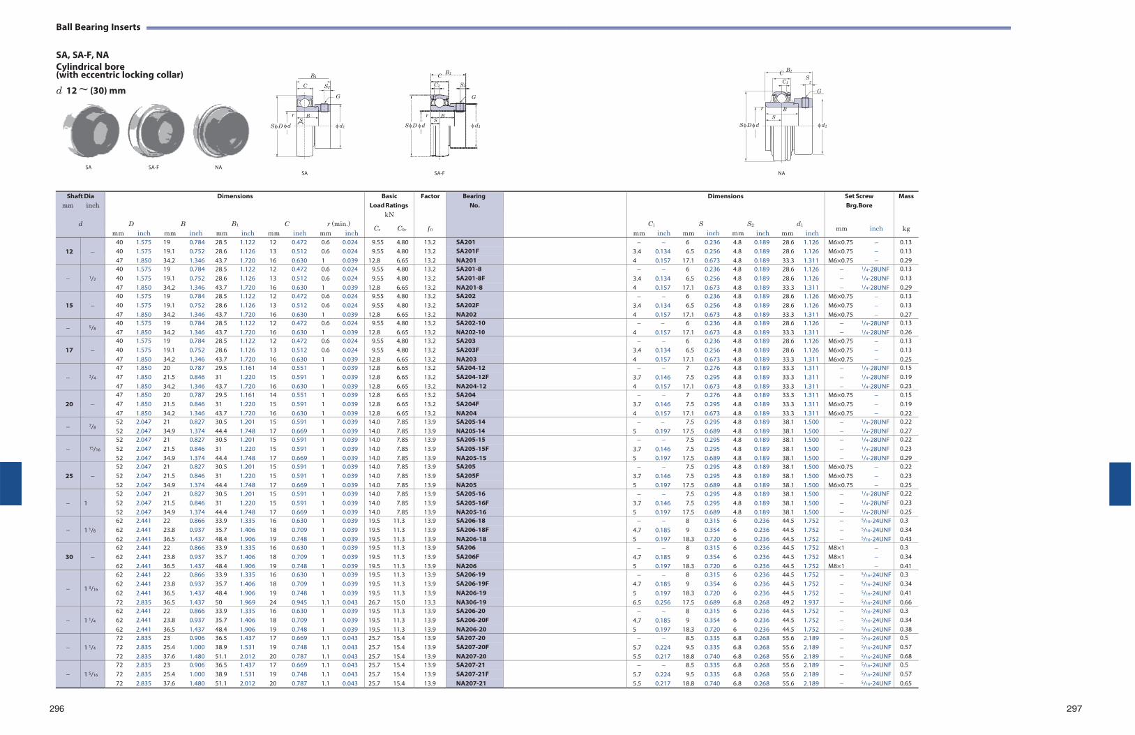
Ball Bearing Inserts
SA, SA-F, NA Cylindrical bore (with eccentric locking collar)
B1 B1
B1 C C S
d 12 ~ (30) mm C S2
G
C1 S2
G
C1 2
G
r B
r B r B S S S
S D d d1 S D d d1 S D d d1
SA SA-F NA SA SA-F NA
296 297
Shaft Dia mm inch
d
mm
D inch
mm
B
inch
Dimensions
B1
mm inch
mm
C
inch
r (min.) mm inch
Basic Load Ratings
kN
Cr C0r
Factor
f 0
BearingNo.
mm
C1
inch
mm
Dimensions
S inch mm
S2
inch
mm
d1
inch
Set Screw Brg.Bore
mm inch
Mass
kg
12
40 1.575 19 0.784 28.5 1.122 12 0.472 0.6 0.024 9.55 4.80 13.2 SA201 6 0.236 4.8 0.189 28.6 1.126 M6×0.75 0.13 40 1.575 19.1 0.752 28.6 1.126 13 0.512 0.6 0.024 9.55 4.80 13.2 SA201F 3.4 0.134 6.5 0.256 4.8 0.189 28.6 1.126 M6×0.75 0.13 47 1.850 34.2 1.346 43.7 1.720 16 0.630 1 0.039 12.8 6.65 13.2 NA201 4 0.157 17.1 0.673 4.8 0.189 33.3 1.311 M6×0.75 0.29
1/2
40 1.575 19 0.784 28.5 1.122 12 0.472 0.6 0.024 9.55 4.80 13.2 SA201-8 6 0.236 4.8 0.189 28.6 1.126 1/4-28UNF 0.13 40 1.575 19.1 0.752 28.6 1.126 13 0.512 0.6 0.024 9.55 4.80 13.2 SA201-8F 3.4 0.134 6.5 0.256 4.8 0.189 28.6 1.126 1/4-28UNF 0.13 47 1.850 34.2 1.346 43.7 1.720 16 0.630 1 0.039 12.8 6.65 13.2 NA201-8 4 0.157 17.1 0.673 4.8 0.189 33.3 1.311 1/4-28UNF 0.29
15
40 1.575 19 0.784 28.5 1.122 12 0.472 0.6 0.024 9.55 4.80 13.2 SA202 6 0.236 4.8 0.189 28.6 1.126 M6×0.75 0.13 40 1.575 19.1 0.752 28.6 1.126 13 0.512 0.6 0.024 9.55 4.80 13.2 SA202F 3.4 0.134 6.5 0.256 4.8 0.189 28.6 1.126 M6×0.75 0.13 47 1.850 34.2 1.346 43.7 1.720 16 0.630 1 0.039 12.8 6.65 13.2 NA202 4 0.157 17.1 0.673 4.8 0.189 33.3 1.311 M6×0.75 0.27
5/8 40 47
1.575 1.850
19 34.2
0.784 1.346
28.5 43.7
1.122 1.720
12 16
0.472 0.630
0.6 1
0.024 0.039
9.55 12.8
4.80 6.65
13.2 13.2
SA202-10 NA202-10
4
0.157
6 17.1
0.236 0.673
4.8 4.8
0.189 0.189
28.633.3
1.126 1.311
1/4-28UNF 1/4-28UNF
0.13 0.26
17
40 1.575 19 0.784 28.5 1.122 12 0.472 0.6 0.024 9.55 4.80 13.2 SA203 6 0.236 4.8 0.189 28.6 1.126 M6×0.75 0.13 40 1.575 19.1 0.752 28.6 1.126 13 0.512 0.6 0.024 9.55 4.80 13.2 SA203F 3.4 0.134 6.5 0.256 4.8 0.189 28.6 1.126 M6×0.75 0.13 47 1.850 34.2 1.346 43.7 1.720 16 0.630 1 0.039 12.8 6.65 13.2 NA203 4 0.157 17.1 0.673 4.8 0.189 33.3 1.311 M6×0.75 0.25
3/4
47 1.850 20 0.787 29.5 1.161 14 0.551 1 0.039 12.8 6.65 13.2 SA204-12 7 0.276 4.8 0.189 33.3 1.311 1/4-28UNF 0.15 47 1.850 21.5 0.846 31 1.220 15 0.591 1 0.039 12.8 6.65 13.2 SA204-12F 3.7 0.146 7.5 0.295 4.8 0.189 33.3 1.311 1/4-28UNF 0.19 47 1.850 34.2 1.346 43.7 1.720 16 0.630 1 0.039 12.8 6.65 13.2 NA204-12 4 0.157 17.1 0.673 4.8 0.189 33.3 1.311 1/4-28UNF 0.23
20
47 1.850 20 0.787 29.5 1.161 14 0.551 1 0.039 12.8 6.65 13.2 SA204 7 0.276 4.8 0.189 33.3 1.311 M6×0.75 0.15 47 1.850 21.5 0.846 31 1.220 15 0.591 1 0.039 12.8 6.65 13.2 SA204F 3.7 0.146 7.5 0.295 4.8 0.189 33.3 1.311 M6×0.75 0.19 47 1.850 34.2 1.346 43.7 1.720 16 0.630 1 0.039 12.8 6.65 13.2 NA204 4 0.157 17.1 0.673 4.8 0.189 33.3 1.311 M6×0.75 0.22
7/8 52 52
2.047 2.047
21 34.9
0.827 1.374
30.5 44.4
1.201 1.748
15 17
0.591 0.669
1 1
0.039 0.039
14.0 14.0
7.85 7.85
13.9 13.9
SA205-14 NA205-14
5
0.197
7.517.5
0.295 0.689
4.8 4.8
0.189 0.189
38.138.1
1.500 1.500
1/4-28UNF 1/4-28UNF
0.22 0.27
15/16
52 2.047 21 0.827 30.5 1.201 15 0.591 1 0.039 14.0 7.85 13.9 SA205-15 7.5 0.295 4.8 0.189 38.1 1.500 1/4-28UNF 0.22 52 2.047 21.5 0.846 31 1.220 15 0.591 1 0.039 14.0 7.85 13.9 SA205-15F 3.7 0.146 7.5 0.295 4.8 0.189 38.1 1.500 1/4-28UNF 0.23 52 2.047 34.9 1.374 44.4 1.748 17 0.669 1 0.039 14.0 7.85 13.9 NA205-15 5 0.197 17.5 0.689 4.8 0.189 38.1 1.500 1/4-28UNF 0.29
25
52 2.047 21 0.827 30.5 1.201 15 0.591 1 0.039 14.0 7.85 13.9 SA205 7.5 0.295 4.8 0.189 38.1 1.500 M6×0.75 0.22 52 2.047 21.5 0.846 31 1.220 15 0.591 1 0.039 14.0 7.85 13.9 SA205F 3.7 0.146 7.5 0.295 4.8 0.189 38.1 1.500 M6×0.75 0.23 52 2.047 34.9 1.374 44.4 1.748 17 0.669 1 0.039 14.0 7.85 13.9 NA205 5 0.197 17.5 0.689 4.8 0.189 38.1 1.500 M6×0.75 0.25
1
52 2.047 21 0.827 30.5 1.201 15 0.591 1 0.039 14.0 7.85 13.9 SA205-16 7.5 0.295 4.8 0.189 38.1 1.500 1/4-28UNF 0.22 52 2.047 21.5 0.846 31 1.220 15 0.591 1 0.039 14.0 7.85 13.9 SA205-16F 3.7 0.146 7.5 0.295 4.8 0.189 38.1 1.500 1/4-28UNF 0.23 52 2.047 34.9 1.374 44.4 1.748 17 0.669 1 0.039 14.0 7.85 13.9 NA205-16 5 0.197 17.5 0.689 4.8 0.189 38.1 1.500 1/4-28UNF 0.25
1 1/8
62 2.441 22 0.866 33.9 1.335 16 0.630 1 0.039 19.5 11.3 13.9 SA206-18 8 0.315 6 0.236 44.5 1.752 5/16-24UNF 0.3 62 2.441 23.8 0.937 35.7 1.406 18 0.709 1 0.039 19.5 11.3 13.9 SA206-18F 4.7 0.185 9 0.354 6 0.236 44.5 1.752 5/16-24UNF 0.34 62 2.441 36.5 1.437 48.4 1.906 19 0.748 1 0.039 19.5 11.3 13.9 NA206-18 5 0.197 18.3 0.720 6 0.236 44.5 1.752 5/16-24UNF 0.43
30
62 2.441 22 0.866 33.9 1.335 16 0.630 1 0.039 19.5 11.3 13.9 SA206 8 0.315 6 0.236 44.5 1.752 M8×1 0.3 62 2.441 23.8 0.937 35.7 1.406 18 0.709 1 0.039 19.5 11.3 13.9 SA206F 4.7 0.185 9 0.354 6 0.236 44.5 1.752 M8×1 0.34 62 2.441 36.5 1.437 48.4 1.906 19 0.748 1 0.039 19.5 11.3 13.9 NA206 5 0.197 18.3 0.720 6 0.236 44.5 1.752 M8×1 0.41
1 3/16
62 2.441 22 0.866 33.9 1.335 16 0.630 1 0.039 19.5 11.3 13.9 SA206-19 8 0.315 6 0.236 44.5 1.752 5/16-24UNF 0.3 62 2.441 23.8 0.937 35.7 1.406 18 0.709 1 0.039 19.5 11.3 13.9 SA206-19F 4.7 0.185 9 0.354 6 0.236 44.5 1.752 5/16-24UNF 0.34 62 2.441 36.5 1.437 48.4 1.906 19 0.748 1 0.039 19.5 11.3 13.9 NA206-19 5 0.197 18.3 0.720 6 0.236 44.5 1.752 5/16-24UNF 0.41 72 2.835 36.5 1.437 50 1.969 24 0.945 1.1 0.043 26.7 15.0 13.3 NA306-19 6.5 0.256 17.5 0.689 6.8 0.268 49.2 1.937 5/16-24UNF 0.66
1 1/4
62 2.441 22 0.866 33.9 1.335 16 0.630 1 0.039 19.5 11.3 13.9 SA206-20 8 0.315 6 0.236 44.5 1.752 5/16-24UNF 0.3 62 2.441 23.8 0.937 35.7 1.406 18 0.709 1 0.039 19.5 11.3 13.9 SA206-20F 4.7 0.185 9 0.354 6 0.236 44.5 1.752 5/16-24UNF 0.34 62 2.441 36.5 1.437 48.4 1.906 19 0.748 1 0.039 19.5 11.3 13.9 NA206-20 5 0.197 18.3 0.720 6 0.236 44.5 1.752 5/16-24UNF 0.38
1 1/4
72 2.835 23 0.906 36.5 1.437 17 0.669 1.1 0.043 25.7 15.4 13.9 SA207-20 8.5 0.335 6.8 0.268 55.6 2.189 5/16-24UNF 0.5 72 2.835 25.4 1.000 38.9 1.531 19 0.748 1.1 0.043 25.7 15.4 13.9 SA207-20F 5.7 0.224 9.5 0.335 6.8 0.268 55.6 2.189 5/16-24UNF 0.57 72 2.835 37.6 1.480 51.1 2.012 20 0.787 1.1 0.043 25.7 15.4 13.9 NA207-20 5.5 0.217 18.8 0.740 6.8 0.268 55.6 2.189 5/16-24UNF 0.68
1 5/16
72 2.835 23 0.906 36.5 1.437 17 0.669 1.1 0.043 25.7 15.4 13.9 SA207-21 8.5 0.335 6.8 0.268 55.6 2.189 5/16-24UNF 0.5 72 2.835 25.4 1.000 38.9 1.531 19 0.748 1.1 0.043 25.7 15.4 13.9 SA207-21F 5.7 0.224 9.5 0.335 6.8 0.268 55.6 2.189 5/16-24UNF 0.57 72 2.835 37.6 1.480 51.1 2.012 20 0.787 1.1 0.043 25.7 15.4 13.9 NA207-21 5.5 0.217 18.8 0.740 6.8 0.268 55.6 2.189 5/16-24UNF 0.65
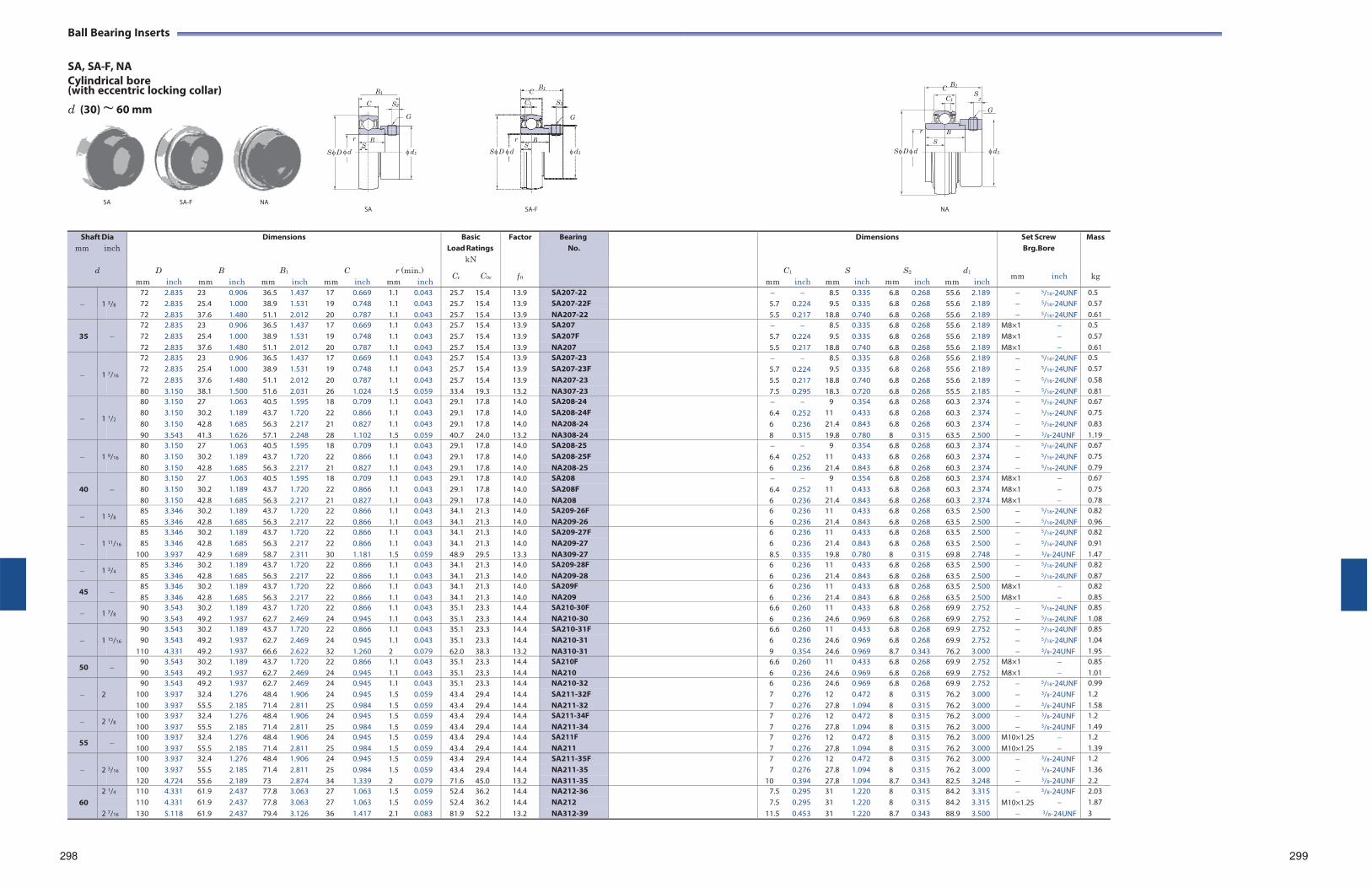
Ball Bearing Inserts
SA, SA-F, NA Cylindrical bore (with eccentric locking collar)
B1 B1
B1 C C S
d (30) ~ 60 mm C S2
G
C1 S2
G
C1 2
G
r B
r B r B S S S
S D d d1 S D d d1 S D d d1
SA SA-F NA SA SA-F NA
298 299
Shaft Dia mm inch
d
mm
D inch
mm
B
inch
Dimensions
B1
mm inch
mm
C
inch
r (min.) mm inch
Basic Load Ratings
kN
Cr C0r
Factor
f 0
BearingNo.
mm
C1
inch
mm
Dimensions
S inch mm
S2
inch
mm
d1
inch
Set Screw Brg.Bore
mm inch
Mass
kg
1
3/8
72 2.835 23 0.906 36.5 1.437 17 0.669 1.1 0.043 25.7 15.4 13.9 SA207-22 8.5 0.335 6.8 0.268 55.6 2.189 5/16-24UNF 0.5 72 2.835 25.4 1.000 38.9 1.531 19 0.748 1.1 0.043 25.7 15.4 13.9 SA207-22F 5.7 0.224 9.5 0.335 6.8 0.268 55.6 2.189 5/16-24UNF 0.57 72 2.835 37.6 1.480 51.1 2.012 20 0.787 1.1 0.043 25.7 15.4 13.9 NA207-22 5.5 0.217 18.8 0.740 6.8 0.268 55.6 2.189 5/16-24UNF 0.61
35
72 2.835 23 0.906 36.5 1.437 17 0.669 1.1 0.043 25.7 15.4 13.9 SA207 8.5 0.335 6.8 0.268 55.6 2.189 M8×1 0.5 72 2.835 25.4 1.000 38.9 1.531 19 0.748 1.1 0.043 25.7 15.4 13.9 SA207F 5.7 0.224 9.5 0.335 6.8 0.268 55.6 2.189 M8×1 0.57 72 2.835 37.6 1.480 51.1 2.012 20 0.787 1.1 0.043 25.7 15.4 13.9 NA207 5.5 0.217 18.8 0.740 6.8 0.268 55.6 2.189 M8×1 0.61
1
7/16
72 2.835 23 0.906 36.5 1.437 17 0.669 1.1 0.043 25.7 15.4 13.9 SA207-23 8.5 0.335 6.8 0.268 55.6 2.189 5/16-24UNF 0.5 72 2.835 25.4 1.000 38.9 1.531 19 0.748 1.1 0.043 25.7 15.4 13.9 SA207-23F 5.7 0.224 9.5 0.335 6.8 0.268 55.6 2.189 5/16-24UNF 0.57 72 2.835 37.6 1.480 51.1 2.012 20 0.787 1.1 0.043 25.7 15.4 13.9 NA207-23 5.5 0.217 18.8 0.740 6.8 0.268 55.6 2.189 5/16-24UNF 0.58 80 3.150 38.1 1.500 51.6 2.031 26 1.024 1.5 0.059 33.4 19.3 13.2 NA307-23 7.5 0.295 18.3 0.720 6.8 0.268 55.5 2.185 5/16-24UNF 0.81
1
1/2
80 3.150 27 1.063 40.5 1.595 18 0.709 1.1 0.043 29.1 17.8 14.0 SA208-24 9 0.354 6.8 0.268 60.3 2.374 5/16-24UNF 0.67 80 3.150 30.2 1.189 43.7 1.720 22 0.866 1.1 0.043 29.1 17.8 14.0 SA208-24F 6.4 0.252 11 0.433 6.8 0.268 60.3 2.374 5/16-24UNF 0.75 80 3.150 42.8 1.685 56.3 2.217 21 0.827 1.1 0.043 29.1 17.8 14.0 NA208-24 6 0.236 21.4 0.843 6.8 0.268 60.3 2.374 5/16-24UNF 0.83 90 3.543 41.3 1.626 57.1 2.248 28 1.102 1.5 0.059 40.7 24.0 13.2 NA308-24 8 0.315 19.8 0.780 8 0.315 63.5 2.500 3/8-24UNF 1.19
1
9/16
80 3.150 27 1.063 40.5 1.595 18 0.709 1.1 0.043 29.1 17.8 14.0 SA208-25 9 0.354 6.8 0.268 60.3 2.374 5/16-24UNF 0.67 80 3.150 30.2 1.189 43.7 1.720 22 0.866 1.1 0.043 29.1 17.8 14.0 SA208-25F 6.4 0.252 11 0.433 6.8 0.268 60.3 2.374 5/16-24UNF 0.75 80 3.150 42.8 1.685 56.3 2.217 21 0.827 1.1 0.043 29.1 17.8 14.0 NA208-25 6 0.236 21.4 0.843 6.8 0.268 60.3 2.374 5/16-24UNF 0.79
40
80 3.150 27 1.063 40.5 1.595 18 0.709 1.1 0.043 29.1 17.8 14.0 SA208 9 0.354 6.8 0.268 60.3 2.374 M8×1 0.67 80 3.150 30.2 1.189 43.7 1.720 22 0.866 1.1 0.043 29.1 17.8 14.0 SA208F 6.4 0.252 11 0.433 6.8 0.268 60.3 2.374 M8×1 0.75 80 3.150 42.8 1.685 56.3 2.217 21 0.827 1.1 0.043 29.1 17.8 14.0 NA208 6 0.236 21.4 0.843 6.8 0.268 60.3 2.374 M8×1 0.78
1 5/8 85 85
3.346 3.346
30.2 42.8
1.189 1.685
43.7 56.3
1.720 2.217
22 22
0.866 0.866
1.1 1.1
0.043 0.043
34.1 34.1
21.3 21.3
14.0 14.0
SA209-26F NA209-26
6 6
0.236 0.236
11 21.4
0.433 0.843
6.86.8
0.268 0.268
63.563.5
2.500 2.500
5/16-24UNF 5/16-24UNF
0.82 0.96
1
11/16
85 3.346 30.2 1.189 43.7 1.720 22 0.866 1.1 0.043 34.1 21.3 14.0 SA209-27F 6 0.236 11 0.433 6.8 0.268 63.5 2.500 5/16-24UNF 0.82 85 3.346 42.8 1.685 56.3 2.217 22 0.866 1.1 0.043 34.1 21.3 14.0 NA209-27 6 0.236 21.4 0.843 6.8 0.268 63.5 2.500 5/16-24UNF 0.91
100 3.937 42.9 1.689 58.7 2.311 30 1.181 1.5 0.059 48.9 29.5 13.3 NA309-27 8.5 0.335 19.8 0.780 8 0.315 69.8 2.748 3/8-24UNF 1.47
1 3/4 85 85
3.346 3.346
30.2 42.8
1.189 1.685
43.7 56.3
1.720 2.217
22 22
0.866 0.866
1.1 1.1
0.043 0.043
34.1 34.1
21.3 21.3
14.0 14.0
SA209-28F NA209-28
6 6
0.236 0.236
11 21.4
0.433 0.843
6.86.8
0.268 0.268
63.563.5
2.500 2.500
5/16-24UNF 5/16-24UNF
0.82 0.87
45 85 85
3.346 3.346
30.2 42.8
1.189 1.685
43.7 56.3
1.720 2.217
22 22
0.866 0.866
1.1 1.1
0.043 0.043
34.1 34.1
21.3 21.3
14.0 14.0
SA209F NA209
6 6
0.236 0.236
11 21.4
0.433 0.843
6.86.8
0.268 0.268
63.563.5
2.500 2.500
M8×1 M8×1
0.82 0.85
1 7/8 90 90
3.543 3.543
30.2 49.2
1.189 1.937
43.7 62.7
1.720 2.469
22 24
0.866 0.945
1.1 1.1
0.043 0.043
35.1 35.1
23.3 23.3
14.4 14.4
SA210-30F NA210-30
6.66
0.260 0.236
11 24.6
0.433 0.969
6.86.8
0.268 0.268
69.969.9
2.752 2.752
5/16-24UNF 5/16-24UNF
0.85 1.08
1
15/16
90 3.543 30.2 1.189 43.7 1.720 22 0.866 1.1 0.043 35.1 23.3 14.4 SA210-31F 6.6 0.260 11 0.433 6.8 0.268 69.9 2.752 5/16-24UNF 0.85 90 3.543 49.2 1.937 62.7 2.469 24 0.945 1.1 0.043 35.1 23.3 14.4 NA210-31 6 0.236 24.6 0.969 6.8 0.268 69.9 2.752 5/16-24UNF 1.04
110 4.331 49.2 1.937 66.6 2.622 32 1.260 2 0.079 62.0 38.3 13.2 NA310-31 9 0.354 24.6 0.969 8.7 0.343 76.2 3.000 3/8-24UNF 1.95
50 90 90
3.543 3.543
30.2 49.2
1.189 1.937
43.7 62.7
1.720 2.469
22 24
0.866 0.945
1.1 1.1
0.043 0.043
35.1 35.1
23.3 23.3
14.4 14.4
SA210F NA210
6.66
0.260 0.236
11 24.6
0.433 0.969
6.86.8
0.268 0.268
69.969.9
2.752 2.752
M8×1 M8×1
0.85 1.01
2
90 3.543 49.2 1.937 62.7 2.469 24 0.945 1.1 0.043 35.1 23.3 14.4 NA210-32 6 0.236 24.6 0.969 6.8 0.268 69.9 2.752 5/16-24UNF 0.99 100 3.937 32.4 1.276 48.4 1.906 24 0.945 1.5 0.059 43.4 29.4 14.4 SA211-32F 7 0.276 12 0.472 8 0.315 76.2 3.000 3/8-24UNF 1.2 100 3.937 55.5 2.185 71.4 2.811 25 0.984 1.5 0.059 43.4 29.4 14.4 NA211-32 7 0.276 27.8 1.094 8 0.315 76.2 3.000 3/8-24UNF 1.58
2 1/8 100 100
3.937 3.937
32.4 55.5
1.276 2.185
48.4 71.4
1.906 2.811
24 25
0.945 0.984
1.5 1.5
0.059 0.059
43.4 43.4
29.4 29.4
14.4 14.4
SA211-34F NA211-34
7 7
0.276 0.276
12 27.8
0.472 1.094
8 8
0.315 0.315
76.276.2
3.000 3.000
3/8-24UNF 3/8-24UNF
1.2 1.49
55 100 100
3.937 3.937
32.4 55.5
1.276 2.185
48.4 71.4
1.906 2.811
24 25
0.945 0.984
1.5 1.5
0.059 0.059
43.4 43.4
29.4 29.4
14.4 14.4
SA211F NA211
7 7
0.276 0.276
12 27.8
0.472 1.094
8 8
0.315 0.315
76.276.2
3.000 3.000
M10×1.25 M10×1.25
1.2 1.39
2
3/16
100 3.937 32.4 1.276 48.4 1.906 24 0.945 1.5 0.059 43.4 29.4 14.4 SA211-35F 7 0.276 12 0.472 8 0.315 76.2 3.000 3/8-24UNF 1.2 100 3.937 55.5 2.185 71.4 2.811 25 0.984 1.5 0.059 43.4 29.4 14.4 NA211-35 7 0.276 27.8 1.094 8 0.315 76.2 3.000 3/8-24UNF 1.36 120 4.724 55.6 2.189 73 2.874 34 1.339 2 0.079 71.6 45.0 13.2 NA311-35 10 0.394 27.8 1.094 8.7 0.343 82.5 3.248 3/8-24UNF 2.2
60
2 1/4 110 4.331 61.9 2.437 77.8 3.063 27 1.063 1.5 0.059 52.4 36.2 14.4 NA212-36 7.5 0.295 31 1.220 8 0.315 84.2 3.315 3/8-24UNF 2.03 110 4.331 61.9 2.437 77.8 3.063 27 1.063 1.5 0.059 52.4 36.2 14.4 NA212 7.5 0.295 31 1.220 8 0.315 84.2 3.315 M10×1.25 1.87
2 7/16 130 5.118 61.9 2.437 79.4 3.126 36 1.417 2.1 0.083 81.9 52.2 13.2 NA312-39 11.5 0.453 31 1.220 8.7 0.343 88.9 3.500 3/8-24UNF 3
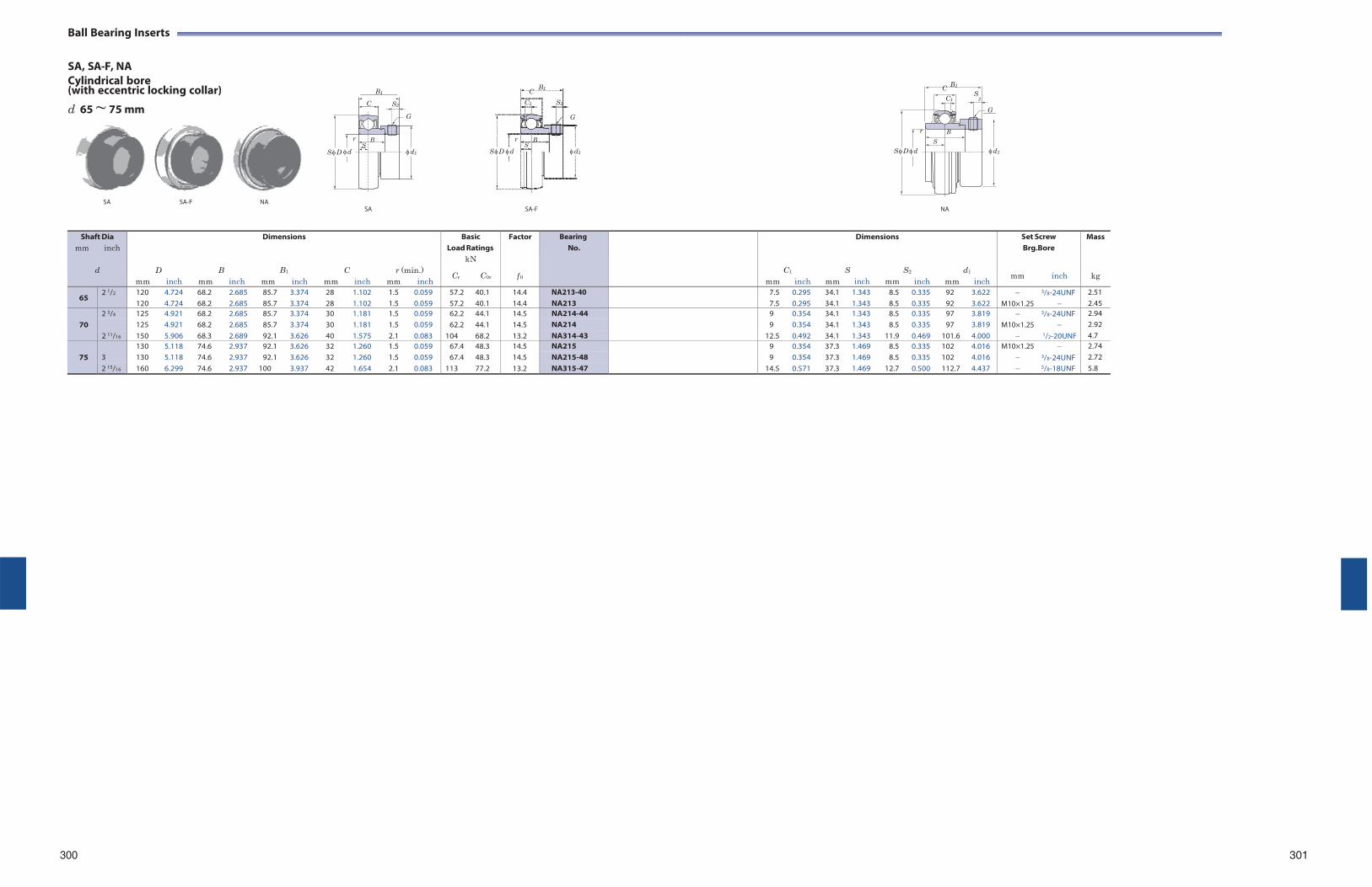
Ball Bearing Inserts
SA, SA-F, NA Cylindrical bore (with eccentric locking collar)
B1 B1
B1 C C S
d 65 ~ 75 mm C S2
G
C1 S2
G
C1 2
G
r B
r B r B S S S
S D d d1 S D d d1 S D d d1
SA SA-F NA SA SA-F NA
Shaft Dia mm inch
d
mm
D inch
mm
B
inch
Dimensions
B1
mm inch
mm
C
inch
r (min.) mm inch
Basic Load Ratings
kN
Cr C0r
Factor
f 0
BearingNo.
mm
C1
inch
mm
Dimensions
S inch mm
S2
inch
mm
d1
inch
Set Screw Brg.Bore
mm inch
Mass
kg
65 2 1/2 120
120 4.724 4.724
68.2 68.2
2.685 2.685
85.7 85.7
3.374 3.374
28 28
1.102 1.102
1.5 1.5
0.059 0.059
57.2 57.2
40.1 40.1
14.4 14.4
NA213-40 NA213
7.57.5
0.295 0.295
34.134.1
1.343 1.343
8.58.5
0.335 0.335
92 92
3.622 3.622
M10×1.25
3/8-24UNF
2.51 2.45
70
2 3/4 125 4.921 68.2 2.685 85.7 3.374 30 1.181 1.5 0.059 62.2 44.1 14.5 NA214-44 9 0.354 34.1 1.343 8.5 0.335 97 3.819 3/8-24UNF 2.94 125 4.921 68.2 2.685 85.7 3.374 30 1.181 1.5 0.059 62.2 44.1 14.5 NA214 9 0.354 34.1 1.343 8.5 0.335 97 3.819 M10×1.25 2.92
2 11/16 150 5.906 68.3 2.689 92.1 3.626 40 1.575 2.1 0.083 104 68.2 13.2 NA314-43 12.5 0.492 34.1 1.343 11.9 0.469 101.6 4.000 1/2-20UNF 4.7
75
3 130 5.118 74.6 2.937 92.1 3.626 32 1.260 1.5 0.059 67.4 48.3 14.5 NA215 9 0.354 37.3 1.469 8.5 0.335 102 4.016 M10×1.25 2.74 130 5.118 74.6 2.937 92.1 3.626 32 1.260 1.5 0.059 67.4 48.3 14.5 NA215-48 9 0.354 37.3 1.469 8.5 0.335 102 4.016 3/8-24UNF 2.72
2 15/16 160 6.299 74.6 2.937 100 3.937 42 1.654 2.1 0.083 113 77.2 13.2 NA315-47 14.5 0.571 37.3 1.469 12.7 0.500 112.7 4.437 5/8-18UNF 5.8
300 301
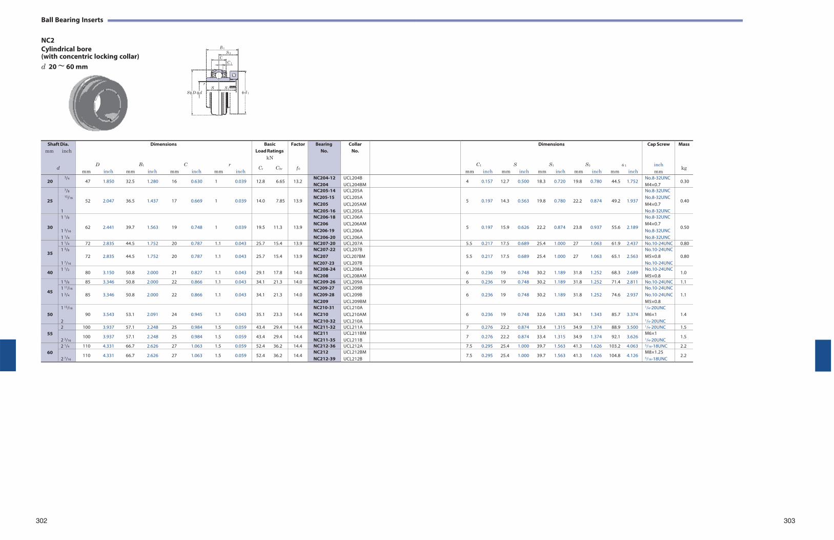
Ball Bearing Inserts
NC2 Cylindrical bore (with concentric locking collar) d 20 ~ 60 mm
302 303
Shaft Dia. mm inch
d
mm
D
inch
mm
B1
Dimensions
inch mm
C
inch
mm
r
inch
Basic Load Ratings
kN
Cr C0r
Factor
f 0
Bearing No.
CollarNo.
mm
C1
inch
mm
S
inch
Dimensions
S1
mm inch
mm
S3
inch
d
mm
1
inch
Cap Screw
inch mm
Mass
kg
20 3/4
47 1.850 32.5 1.280 16 0.630 1 0.039 12.8 6.65 13.2 NC204-12 NC204
UCL204B UCL204BM
4 0.157 12.7 0.500 18.3 0.720 19.8 0.780 44.5 1.752 No.8-32UNC M4×0.7
0.30
25
7/8
52
2.047
36.5
1.437
17
0.669
1
0.039
14.0
7.85
13.9
NC205-14 UCL205A
5
0.197
14.3
0.563
19.8
0.780
22.2
0.874
49.2
1.937
No.8-32UNC
0.40 15/16 NC205-15
NC205 UCL205A UCL205AM
No.8-32UNC M4×0.7
1 NC205-16 UCL205A No.8-32UNC
30
1 1/8
62
2.441
39.7
1.563
19
0.748
1
0.039
19.5
11.3
13.9
NC206-18 UCL206A
5
0.197
15.9
0.626
22.2
0.874
23.8
0.937
55.6
2.189
No.8-32UNC
0.50 1 3/16
NC206 NC206-19
UCL206AM UCL206A
M4×0.7 No.8-32UNC
1 1/4 NC206-20 UCL206A No.8-32UNC
35
1 1/4 72 2.835 44.5 1.752 20 0.787 1.1 0.043 25.7 15.4 13.9 NC207-20 UCL207A 5.5 0.217 17.5 0.689 25.4 1.000 27 1.063 61.9 2.437 No.10-24UNC 0.801 3/8
1 7/16
72
2.835
44.5
1.752
20
0.787
1.1
0.043
25.7
15.4
13.9
NC207-22 NC207 NC207-23
UCL207B UCL207BM UCL207B
5.5
0.217
17.5
0.689
25.4
1.000
27
1.063
65.1
2.563
No.10-24UNCM5×0.8 No.10-24UNC
0.80
40 1 1/2
80 3.150 50.8 2.000 21 0.827 1.1 0.043 29.1 17.8 14.0 NC208-24 NC208
UCL208A UCL208AM
6 0.236 19 0.748 30.2 1.189 31.8 1.252 68.3 2.689 No.10-24UNCM5×0.8
1.0
45
1 5/8 85 3.346 50.8 2.000 22 0.866 1.1 0.043 34.1 21.3 14.0 NC209-26 UCL209A 6 0.236 19 0.748 30.2 1.189 31.8 1.252 71.4 2.811 No.10-24UNC 1.11 11/16
1 3/4
85
3.346
50.8
2.000
22
0.866
1.1
0.043
34.1
21.3
14.0
NC209-27 NC209-28 NC209
UCL209B UCL209B UCL209BM
6
0.236
19
0.748
30.2
1.189
31.8
1.252
74.6
2.937
No.10-24UNCNo.10-24UNCM5×0.8
1.1
50
1 15/16
2
90
3.543
53.1
2.091
24
0.945
1.1
0.043
35.1
23.3
14.4
NC210-31 NC210 NC210-32
UCL210A UCL210AM UCL210A
6
0.236
19
0.748
32.6
1.283
34.1
1.343
85.7
3.374
1/4-20UNC M6×1 1/4-20UNC
1.4
55
2 100 3.937 57.1 2.248 25 0.984 1.5 0.059 43.4 29.4 14.4 NC211-32 UCL211A 7 0.276 22.2 0.874 33.4 1.315 34.9 1.374 88.9 3.500 1/4-20UNC 1.5
2 3/16 100 3.937 57.1 2.248 25 0.984 1.5 0.059 43.4 29.4 14.4
NC211 NC211-35
UCL211BM UCL211B
7 0.276 22.2 0.874 33.4 1.315 34.9 1.374 92.1 3.626 M6×1 1/4-20UNC
1.5
60
2 1/4 110 4.331 66.7 2.626 27 1.063 1.5 0.059 52.4 36.2 14.4 NC212-36 UCL212A 7.5 0.295 25.4 1.000 39.7 1.563 41.3 1.626 103.2 4.063 5/16-18UNC 2.2
2 7/16 110 4.331 66.7 2.626 27 1.063 1.5 0.059 52.4 36.2 14.4
NC212 NC212-39
UCL212BM UCL212B
7.5 0.295 25.4 1.000 39.7 1.563 41.3 1.626 104.8 4.126 M8×1.25 5/16-18UNC
2.2
B 1S 3
C C 1
rS S 1
S D d d 1
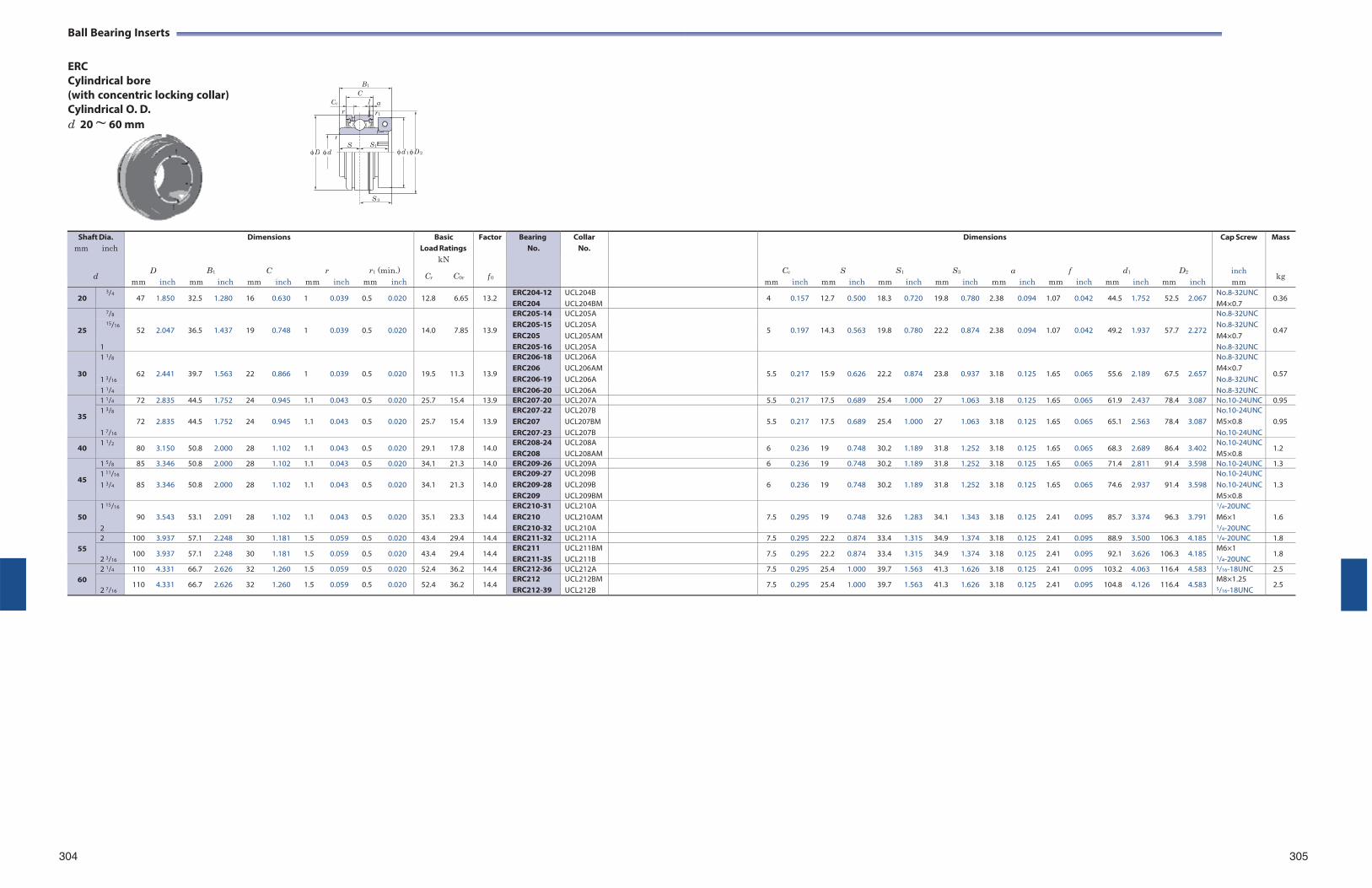
Ball Bearing Inserts
ERC Cylindrical bore (with concentric locking collar) Cylindrical O. D. d 20 ~ 60 mm
304 305
Shaft Dia. mm inch
d
mm
D
inch
B1
mm inch
Dimensions
C
mm inch
mm
r
inch
r1 (min.)
mm inch
Basic Load Ratings
kN
Cr C0r
Factor
f 0
Bearing No.
CollarNo.
Cc
mm inch
mm
S
inch
S1
mm inch
Dimensions
S3
mm inch mm
a
inch
mm
f
inch
d1
mm inch
D2
mm inch
Cap Screw
inch mm
Mass
kg
20 3/4
47 1.850 32.5 1.280 16 0.630 1 0.039 0.5 0.020 12.8 6.65 13.2 ERC204-12 ERC204
UCL204B UCL204BM
4 0.157 12.7 0.500 18.3 0.720 19.8 0.780 2.38 0.094 1.07 0.042 44.5 1.752 52.5 2.067 No.8-32UNC M4×0.7
0.36
25
7/8
52
2.047
36.5
1.437
19
0.748
1
0.039
0.5
0.020
14.0
7.85
13.9
ERC205-14 UCL205A
5
0.197
14.3
0.563
19.8
0.780
22.2
0.874
2.38
0.094
1.07
0.042
49.2
1.937
57.7
2.272
No.8-32UNC
0.47 15/16 ERC205-15
ERC205 UCL205A UCL205AM
No.8-32UNC M4×0.7
1 ERC205-16 UCL205A No.8-32UNC
30
1 1/8
62
2.441
39.7
1.563
22
0.866
1
0.039
0.5
0.020
19.5
11.3
13.9
ERC206-18 UCL206A
5.5
0.217
15.9
0.626
22.2
0.874
23.8
0.937
3.18
0.125
1.65
0.065
55.6
2.189
67.5
2.657
No.8-32UNC
0.57 1 3/16
ERC206 ERC206-19
UCL206AM UCL206A
M4×0.7 No.8-32UNC
1 1/4 ERC206-20 UCL206A No.8-32UNC
35
1 1/4 72 2.835 44.5 1.752 24 0.945 1.1 0.043 0.5 0.020 25.7 15.4 13.9 ERC207-20 UCL207A 5.5 0.217 17.5 0.689 25.4 1.000 27 1.063 3.18 0.125 1.65 0.065 61.9 2.437 78.4 3.087 No.10-24UNC 0.951 3/8
1 7/16
72
2.835
44.5
1.752
24
0.945
1.1
0.043
0.5
0.020
25.7
15.4
13.9
ERC207-22 ERC207 ERC207-23
UCL207B UCL207BM UCL207B
5.5
0.217
17.5
0.689
25.4
1.000
27
1.063
3.18
0.125
1.65
0.065
65.1
2.563
78.4
3.087
No.10-24UNC M5×0.8 No.10-24UNC
0.95
40 1 1/2
80 3.150 50.8 2.000 28 1.102 1.1 0.043 0.5 0.020 29.1 17.8 14.0 ERC208-24 ERC208
UCL208A UCL208AM
6 0.236 19 0.748 30.2 1.189 31.8 1.252 3.18 0.125 1.65 0.065 68.3 2.689 86.4 3.402 No.10-24UNCM5×0.8
1.2
45
1 5/8 85 3.346 50.8 2.000 28 1.102 1.1 0.043 0.5 0.020 34.1 21.3 14.0 ERC209-26 UCL209A 6 0.236 19 0.748 30.2 1.189 31.8 1.252 3.18 0.125 1.65 0.065 71.4 2.811 91.4 3.598 No.10-24UNC 1.31 11/16
1 3/4
85
3.346
50.8
2.000
28
1.102
1.1
0.043
0.5
0.020
34.1
21.3
14.0
ERC209-27 ERC209-28 ERC209
UCL209B UCL209B UCL209BM
6
0.236
19
0.748
30.2
1.189
31.8
1.252
3.18
0.125
1.65
0.065
74.6
2.937
91.4
3.598
No.10-24UNC No.10-24UNCM5×0.8
1.3
50
1 15/16
2
90
3.543
53.1
2.091
28
1.102
1.1
0.043
0.5
0.020
35.1
23.3
14.4
ERC210-31 ERC210 ERC210-32
UCL210A UCL210AM UCL210A
7.5
0.295
19
0.748
32.6
1.283
34.1
1.343
3.18
0.125
2.41
0.095
85.7
3.374
96.3
3.791
1/4-20UNC M6×1 1/4-20UNC
1.6
55
2 100 3.937 57.1 2.248 30 1.181 1.5 0.059 0.5 0.020 43.4 29.4 14.4 ERC211-32 UCL211A 7.5 0.295 22.2 0.874 33.4 1.315 34.9 1.374 3.18 0.125 2.41 0.095 88.9 3.500 106.3 4.185 1/4-20UNC 1.8
2 3/16 100 3.937 57.1 2.248 30 1.181 1.5 0.059 0.5 0.020 43.4 29.4 14.4
ERC211 ERC211-35
UCL211BM UCL211B
7.5 0.295 22.2 0.874 33.4 1.315 34.9 1.374 3.18 0.125 2.41 0.095 92.1 3.626 106.3 4.185 M6×1 1/4-20UNC
1.8
60
2 1/4 110 4.331 66.7 2.626 32 1.260 1.5 0.059 0.5 0.020 52.4 36.2 14.4 ERC212-36 UCL212A 7.5 0.295 25.4 1.000 39.7 1.563 41.3 1.626 3.18 0.125 2.41 0.095 103.2 4.063 116.4 4.583 5/16-18UNC 2.5
2 7/16 110 4.331 66.7 2.626 32 1.260 1.5 0.059 0.5 0.020 52.4 36.2 14.4
ERC212 ERC212-39
UCL212BM UCL212B
7.5 0.295 25.4 1.000 39.7 1.563 41.3 1.626 3.18 0.125 2.41 0.095 104.8 4.126 116.4 4.583 M8×1.25 5/16-18UNC
2.5
r
S
B1
C Cc f a
r1
r S1
D d d 1 D 2
S 3
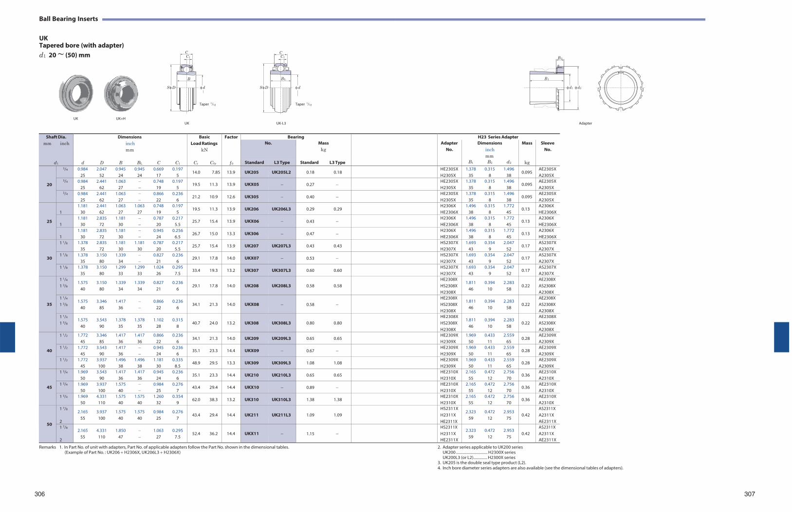
C1 C1
Ball Bearing Inserts
UK Tapered bore (with adapter) d1 20 ~ (50) mm C C
B B L
B 2
B 1
S D d
S D d
d1 d2
Taper 1/12 Taper 1/12
UK UK+H
UK UK-L3
Adapter
Remarks 1. In Part No. of unit with adapters, Part No. of applicable adapters follow the Part No. shown in the dimensional tables.
(Example of Part No. : UK206 H2306X, UK206L3 H2306X) 2. Adapter series applicable to UK200 series
UK200 ................................ H2300X series UK200L3 (or L2).............. H2300X series
3. UK205 is the double seal type product (L2). 4. Inch bore diameter series adapters are also available (see the dimensional tables of adapters).
306 307
Shaft Dia. mm inch
d1
Dimensions inch mm
d D B BL C C1
Basic Load Ratings
kN
Cr C0r
Factor
f 0
Bearing H23 Series Adapter No. Mass
kg
Standard L3 Type
Adapter No.
Dimensions inch mm
B1 B2 d2
Mass
kg
Sleeve No.
Standard L3 Type
20
3/4 0.984 2.047 0.945 0.945 0.669 0.197 25 52 24 24 17 5
14.0 7.85 13.9 UK205 UK205L2 0.18 0.18 HE2305X H2305X
1.378 0.315 1.496 35 8 38
0.095 AE2305X A2305X
3/4 0.984 2.441 1.063 0.748 0.197 25 62 27 19 5
19.5 11.3 13.9 UKX05 0.27 HE2305X H2305X
1.378 0.315 1.496 35 8 38
0.095 AE2305X A2305X
3/4 0.984 2.441 1.063 0.866 0.236 25 62 27 22 6
21.2 10.9 12.6 UK305 0.40 HE2305X H2305X
1.378 0.315 1.496 35 8 38
0.095 AE2305X A2305X
25
1
1.181 2.441 1.063 1.063 0.748 0.197 30 62 27 27 19 5
19.5 11.3 13.9 UK206 UK206L3 0.29 0.29 H2306X HE2306X
1.496 0.315 1.772 38 8 45
0.13 A2306X HE2306X
1
1.181 2.835 1.181 0.787 0.217 30 72 30 20 5.5
25.7 15.4 13.9 UKX06 0.43 H2306X HE2306X
1.496 0.315 1.772 38 8 45
0.13 A2306X HE2306X
1
1.181 2.835 1.181 0.945 0.256 30 72 30 24 6.5
26.7 15.0 13.3 UK306 0.47 H2306X HE2306X
1.496 0.315 1.772 38 8 45
0.13 A2306X HE2306X
30
1 1/8 1.378 2.835 1.181 1.181 0.787 0.217 35 72 30 30 20 5.5
25.7 15.4 13.9 UK207 UK207L3 0.43 0.43 HS2307X H2307X
1.693 0.354 2.047 43 9 52
0.17 AS2307X A2307X
1 1/8 1.378 3.150 1.339 0.827 0.236 35 80 34 21 6
29.1 17.8 14.0 UKX07 0.53 HS2307X H2307X
1.693 0.354 2.047 43 9 52
0.17 AS2307X A2307X
1 1/8 1.378 3.150 1.299 1.299 1.024 0.295 35 80 33 33 26 7.5
33.4 19.3 13.2 UK307 UK307L3 0.60 0.60 HS2307X H2307X
1.693 0.354 2.047 43 9 52
0.17 AS2307X A2307X
35
1 1/4
1 3/8 1.575 3.150 1.339 1.339 0.827 0.236
40 80 34 34 21 6
29.1 17.8
14.0
UK208
UK208L3
0.58 0.58
HE2308X HS2308X H2308X
1.811 0.394 2.283 46 10 58
0.22
AE2308X AS2308X A2308X
1 1/4
1 3/8 1.575 3.346 1.417 0.866 0.236
40 85 36 22 6
34.1 21.3
14.0
UKX08
0.58
HE2308X HS2308X H2308X
1.811 0.394 2.283 46 10 58
0.22
AE2308X AS2308X A2308X
1 1/4
1 3/8 1.575 3.543 1.378 1.378 1.102 0.315
40 90 35 35 28 8
40.7 24.0
13.2
UK308
UK308L3
0.80 0.80
HE2308X HS2308X H2308X
1.811 0.394 2.283 46 10 58
0.22
AE2308X AS2308X A2308X
40
1 1/2 1.772 3.346 1.417 1.417 0.866 0.236 45 85 36 36 22 6
34.1 21.3 14.0 UK209 UK209L3 0.65 0.65 HE2309X H2309X
1.969 0.433 2.559 50 11 65
0.28 AE2309X A2309X
1 1/2 1.772 3.543 1.417 0.945 0.236 45 90 36 24 6
35.1 23.3 14.4 UKX09 0.67 HE2309X H2309X
1.969 0.433 2.559 50 11 65
0.28 AE2309X A2309X
1 1/2 1.772 3.937 1.496 1.496 1.181 0.335 45 100 38 38 30 8.5
48.9 29.5 13.3 UK309 UK309L3 1.08 1.08 HE2309X H2309X
1.969 0.433 2.559 50 11 65
0.28 AE2309X A2309X
45
1 3/4 1.969 3.543 1.417 1.417 0.945 0.236 50 90 36 36 24 6
35.1 23.3 14.4 UK210 UK210L3 0.65 0.65 HE2310X H2310X
2.165 0.472 2.756 55 12 70
0.36 AE2310X A2310X
1 3/4 1.969 3.937 1.575 0.984 0.276 50 100 40 25 7
43.4 29.4 14.4 UKX10 0.89 HE2310X H2310X
2.165 0.472 2.756 55 12 70
0.36 AE2310X A2310X
1 3/4 1.969 4.331 1.575 1.575 1.260 0.354 50 110 40 40 32 9
62.0 38.3 13.2 UK310 UK310L3 1.38 1.38 HE2310X H2310X
2.165 0.472 2.756 55 12 70
0.36 AE2310X A2310X
50
1 7/8
2
2.165 3.937 1.575 1.575 0.984 0.276 55 100 40 40 25 7
43.4 29.4
14.4
UK211
UK211L3
1.09 1.09
HS2311X H2311X HE2311X
2.323 0.472 2.953 59 12 75
0.42
AS2311X A2311X AE2311X
1 7/8
2
2.165 4.331 1.850 1.063 0.295 55 110 47 27 7.5
52.4 36.2
14.4
UKX11
1.15
HS2311X H2311X HE2311X
2.323 0.472 2.953 59 12 75
0.42
AS2311X A2311X AE2311X
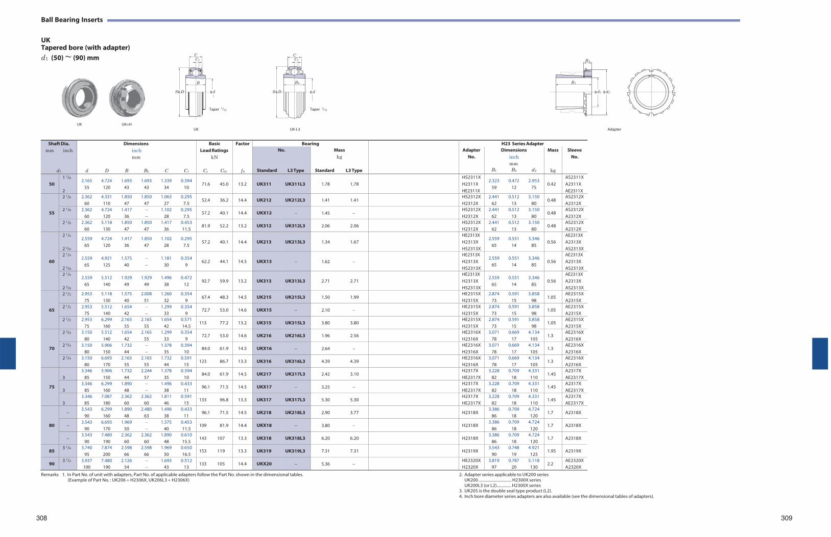
C1 C1
Ball Bearing Inserts
UK Tapered bore (with adapter) d1 (50) ~ (90) mm C C
B B L
B 2
B 1
S D d
S D d
d1 d2
Taper 1/12 Taper 1/12
UK UK+H
UK UK-L3
Adapter
Remarks 1. In Part No. of unit with adapters, Part No. of applicable adapters follow the Part No. shown in the dimensional tables.
(Example of Part No. : UK206 H2306X, UK206L3 H2306X) 2. Adapter series applicable to UK200 series
UK200 ................................ H2300X series UK200L3 (or L2).............. H2300X series
3. UK205 is the double seal type product (L2). 4. Inch bore diameter series adapters are also available (see the dimensional tables of adapters).
308
309
Shaft Dia. mm inch
d1
Dimensions inch mm
d D B BL C C1
Basic Load Ratings
kN
Cr C0r
Factor
f 0
Bearing H23 Series Adapter No. Mass
kg
Standard L3 Type
Adapter No.
Dimensions inch mm
B1 B2 d2
Mass
kg
Sleeve No.
Standard L3 Type
50
1 7/8
2
2.165 4.724 1.693 1.693 1.339 0.394 55 120 43 43 34 10
71.6 45.0
13.2
UK311
UK311L3
1.78 1.78
HS2311X H2311X HE2311X
2.323 0.472 2.953 59 12 75
0.42
AS2311X A2311X AE2311X
55
2 1/8 2.362 4.331 1.850 1.850 1.063 0.295 60 110 47 47 27 7.5
52.4 36.2 14.4 UK212 UK212L3 1.41 1.41 HS2312X H2312X
2.441 0.512 3.150 62 13 80
0.48 AS2312X A2312X
2 1/8 2.362 4.724 1.417 1.102 0.295 60 120 36 28 7.5
57.2 40.1 14.4 UKX12 1.45 HS2312X H2312X
2.441 0.512 3.150 62 13 80
0.48 AS2312X A2312X
2 1/8 2.362 5.118 1.850 1.850 1.417 0.453 60 130 47 47 36 11.5
81.9 52.2 13.2 UK312 UK312L3 2.06 2.06 HS2312X H2312X
2.441 0.512 3.150 62 13 80
0.48 AS2312X A2312X
60
2 1/4
2 3/8
2.559 4.724 1.417 1.850 1.102 0.295 65 120 36 47 28 7.5
57.2 40.1
14.4
UK213
UK213L3
1.34 1.67
HE2313X H2313X HS2313X
2.559 0.551 3.346 65 14 85
0.56
AE2313X A2313X AS2313X
2 1/4
2 3/8
2.559 4.921 1.575 1.181 0.354 65 125 40 30 9
62.2 44.1
14.5
UKX13
1.62
HE2313X H2313X HS2313X
2.559 0.551 3.346 65 14 85
0.56
AE2313X A2313X AS2313X
2 1/4
2 3/8
2.559 5.512 1.929 1.929 1.496 0.472 65 140 49 49 38 12
92.7 59.9
13.2
UK313
UK313L3
2.71 2.71
HE2313X H2313X HS2313X
2.559 0.551 3.346 65 14 85
0.56
AE2313X A2313X AS2313X
65
2 1/2 2.953 5.118 1.575 2.008 1.260 0.354 75 130 40 51 32 9
67.4 48.3 14.5 UK215 UK215L3 1.50 1.99 HE2315X H2315X
2.874 0.591 3.858 73 15 98
1.05 AE2315X A2315X
2 1/2 2.953 5.512 1.654 1.299 0.354 75 140 42 33 9
72.7 53.0 14.6 UKX15 2.10 HE2315X H2315X
2.874 0.591 3.858 73 15 98
1.05 AE2315X A2315X
2 1/2 2.953 6.299 2.165 2.165 1.654 0.571 75 160 55 55 42 14.5
113 77.2 13.2 UK315 UK315L3 3.80 3.80 HE2315X H2315X
2.874 0.591 3.858 73 15 98
1.05 AE2315X A2315X
70
2 3/4 3.150 5.512 1.654 2.165 1.299 0.354 80 140 42 55 33 9
72.7 53.0 14.6 UK216 UK216L3 1.96 2.56 HE2316X H2316X
3.071 0.669 4.134 78 17 105
1.3 AE2316X A2316X
2 3/4 3.150 5.906 1.732 1.378 0.394 80 150 44 35 10
84.0 61.9 14.5 UKX16 2.64 HE2316X H2316X
3.071 0.669 4.134 78 17 105
1.3 AE2316X A2316X
2 3/4 3.150 6.693 2.165 2.165 1.732 0.591 80 170 55 55 44 15
123 86.7 13.3 UK316 UK316L3 4.39 4.39 HE2316X H2316X
3.071 0.669 4.134 78 17 105
1.3 AE2316X A2316X
75
3
3.346 5.906 1.732 2.244 1.378 0.394 85 150 44 57 35 10
84.0 61.9 14.5 UK217 UK217L3 2.42 3.10 H2317X HE2317X
3.228 0.709 4.331 82 18 110
1.45 A2317X AE2317X
3
3.346 6.299 1.890 1.496 0.433 85 160 48 38 11
96.1 71.5 14.5 UKX17 3.25 H2317X HE2317X
3.228 0.709 4.331 82 18 110
1.45 A2317X AE2317X
3
3.346 7.087 2.362 2.362 1.811 0.591 85 180 60 60 46 15
133 96.8 13.3 UK317 UK317L3 5.30 5.30 H2317X HE2317X
3.228 0.709 4.331 82 18 110
1.45 A2317X AE2317X
80
3.543 6.299 1.890 2.480 1.496 0.433
90 160 48 63 38 11 96.1 71.5 14.5 UK218 UK218L3 2.90 3.77 H2318X
3.386 0.709 4.724 86 18 120
1.7 A2318X
3.543 6.693 1.969 1.575 0.453
90 170 50 40 11.5 109 81.9 14.4 UKX18 3.80 H2318X
3.386 0.709 4.724 86 18 120
1.7 A2318X
3.543 7.480 2.362 2.362 1.890 0.610
90 190 60 60 48 15.5 143 107 13.3 UK318 UK318L3 6.20 6.20 H2318X
3.386 0.709 4.724 86 18 120
1.7 A2318X
85 3 1/4 3.740 7.874 2.598 2.598 1.969 0.650
95 200 66 66 50 16.5 153 119 13.3 UK319 UK319L3 7.31 7.31 H2319X
3.543 0.748 4.921 90 19 125
1.95 A2319X
90 3 1/2 3.937 7.480 2.126 1.693 0.512
100 190 54 43 13 133 105 14.4 UKX20 5.36 HE2320X
H2320X 3.819 0.787 5.118
97 20 130 2.2
AE2320X A2320X
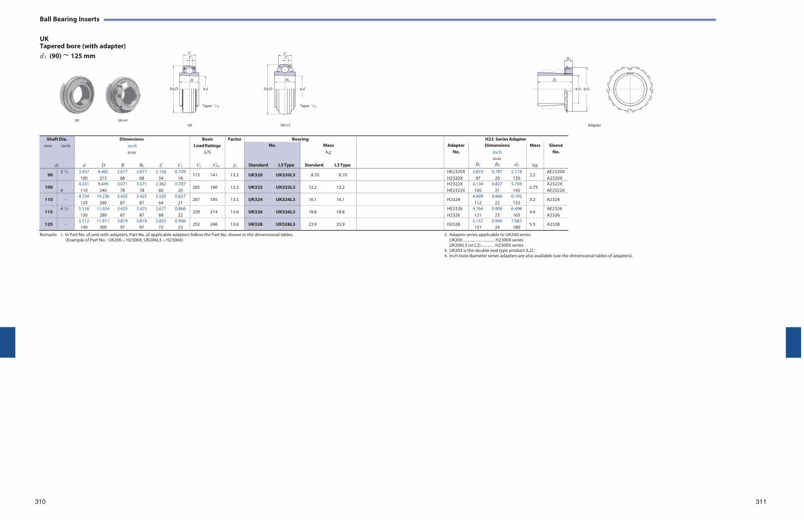
C1 C1
Ball Bearing Inserts
UK Tapered bore (with adapter) d1 (90) ~ 125 mm C C
B B L
B 2
B 1
S D d
S D d
d1 d2
Taper 1/12 Taper 1/12
UK UK+H
UK UK-L3
Adapter
Shaft Dia. mm inch
d1
Dimensions inch mm
d D B BL C C1
Basic Load Ratings
kN
Cr C0r
Factor
f 0
Bearing H23 Series Adapter No. Mass
kg
Standard L3 Type
Adapter No.
Dimensions inch mm
B1 B2 d2
Mass
kg
Sleeve No.
Standard L3 Type
90 3 1/2 3.937 8.465 2.677 2.677 2.126 0.709
100 215 68 68 54 18 173 141 13.2 UK320 UK320L3 8.70 8.70 HE2320X
H2320X3.819 0.787 5.118
97 20 1302.2
AE2320X A2320X
100 4
4.331 9.449 3.071 3.071 2.362 0.787 110 240 78 78 60 20
205 180 13.2 UK322 UK322L3 12.2 12.2 H2322X HE2322X
4.134 0.827 5.709 105 21 145
2.75 A2322X AE2322X
110 4.724 10.236 3.425 3.425 2.520 0.827 120 260 87 87 64 21
207 185 13.5 UK324 UK324L3 16.1 16.1 H2324 4.409 0.866 6.102 112 22 155
3.2 A2324
115 4 1/2 5.118 11.024 3.425 3.425 2.677 0.866
130 280 87 87 68 22 229 214 13.6 UK326 UK326L3 18.8 18.8 HE2326
H2326 4.764 0.906 6.496 121 23 165
4.6 AE2326 A2326
125 5.512 11.811 3.819 3.819 2.835 0.906 140 300 97 97 72 23
253 246 13.6 UK328 UK328L3 23.9 23.9 H2328 5.157 0.945 7.087 131 24 180
5.5 A2328
Remarks 1. In Part No. of unit with adapters, Part No. of applicable adapters follow the Part No. shown in the dimensional tables. (Example of Part No. : UK206 H2306X, UK206L3 H2306X)
2. Adapter series applicable to UK200 series UK200 ................................ H2300X series UK200L3 (or L2).............. H2300X series
3. UK205 is the double seal type product (L2). 4. Inch bore diameter series adapters are also available (see the dimensional tables of adapters).
310 311
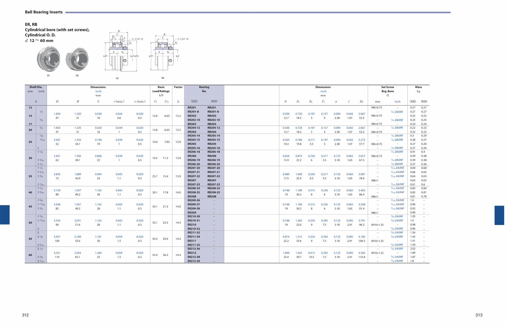
S
Ball Bearing Inserts
ER, RB Cylindrical bore (with set screws), Cylindrical O. D. d 12 ~ 60 mm
B C
CC f a r r1
2
2-120 º G
r
B C 2-120º G
S2
r S S1
r S S1
D d D2 D d
ER RB ER RB
312
313
Shaft Dia. mm inch
d
Dimensions inch mm
D B C r (min.) r1 (min.)
Basic Load Ratings
kN
Cr C0r
Factor
f 0
BearingNo.
Dimensions inch mm
S S1 S2 Cc a f D2
Set Screw Brg. Bore
G
mm inch
Mass kg
(ER) (RB) (ER) (RB)
12
15
17
1/2
5/8
1.850 1.220 0.630 0.024 0.020 47 31 16 0.6 0.5
12.8 6.65
13.2
ER201 ER201-8 ER202 ER202-10 ER203
RB201 RB201-8 RB202 RB202-10 RB203
0.500 0.720 0.197 0.157 0.094 0.042 2.067 12.7 18.3 5 4 2.38 1.07 52.5
M6×0.75 1/4-28UNF
M6×0.75 1/4-28UNF
M6×0.75
0.27 0.27 0.27 0.27 0.25 0.25 0.25 0.25 0.24 0.24
20 3/4 1.850 1.220 0.630 0.039 0.020
47 31 16 1 0.5 12.8 6.65 13.2
ER204-12 ER204
RB204-12 RB204
0.500 0.720 0.197 0.157 0.094 0.042 2.067 12.7 18.3 5 4 2.38 1.07 52.5
1/4-28UNF M6×0.75
0.22 0.22 0.22 0.22
25
7/8
15/16
1
2.047 1.343 0.748 0.039 0.020
52 34.1 19 1 0.5
14.0 7.85
13.9
ER205-14 ER205-15 ER205 ER205-16
RB205-14 RB205-15 RB205 RB205-16
0.563 0.780 0.217 0.197 0.094 0.042 2.272 14.3 19.8 5.5 5 2.38 1.07 57.7
1/4-28UNF 1/4-28UNF
M6×0.75 1/4-28UNF
0.3 0.29 0.28 0.27 0.27 0.26 0.27 0.26
30
1 1/8
1 3/16
1 1/4
2.441 1.500 0.866 0.039 0.020
62 38.1 22 1 0.5
19.5 11.3
13.9
ER206-18 ER206 ER206-19 ER206-20
RB206-18 RB206 RB206-19 RB206-20
0.626 0.874 0.236 0.217 0.125 0.065 2.657 15.9 22.2 6 5.5 3.18 1.65 67.5
1/4-28UNF M6×0.75
1/4-28UNF 1/4-28UNF
0.41 0.4 0.39 0.38 0.39 0.38 0.37 0.36
35
1 1/4
1 5/16
1 3/8
1 7/16
2.835 1.689 0.945 0.043 0.020 72 42.9 24 1.1 0.5
25.7 15.4
13.9
ER207-20 ER207-21 ER207-22 ER207 ER207-23
RB207-20 RB207-21 RB207-22 RB207 RB207-23
0.689 1.000 0.256 0.217 0.125 0.065 3.087 17.5 25.4 6.5 5.5 3.18 1.65 78.4
5/16-24UNF 5/16-24UNF 5/16-24UNF
M8×1 5/16-24UNF
0.69 0.68 0.66 0.65 0.64 0.63 0.63 0.62 0.61 0.6
40
1 1/2
1 9/16 3.150 1.937 1.102 0.043 0.020
80 49.2 28 1.1 0.5
29.1 17.8
14.0
ER208-24 ER208-25 ER208
RB208-24 RB208-25 RB208
0.748 1.189 0.315 0.236 0.125 0.065 3.402 19 30.2 8 6 3.18 1.65 86.4
5/16-24UNF 5/16-24UNF
M8×1
0.85 0.84 0.82 0.81 0.81 0.78
45
1 5/8
1 11/16
1 3/4
3.346 1.937 1.102 0.043 0.020
85 49.2 28 1.1 0.5
34.1 21.3
14.0
ER209-26 ER209-27 ER209-28 ER209
0.748 1.189 0.315 0.236 0.125 0.065 3.598
19 30.2 8 6 3.18 1.65 91.4
5/16-24UNF 5/16-24UNF 5/16-24UNF
M8×1
1.0 0.96 0.92 0.90
50
1 7/8
1 15/16
2
3.543 2.031 1.102 0.043 0.020
90 51.6 28 1.1 0.5
35.1 23.3
14.4
ER210-30 ER210-31 ER210 ER210-32
0.748 1.283 0.354 0.295 0.125 0.095 3.791
19 32.6 9 7.5 3.18 2.41 96.3
3/8-24UNF 3/8-24UNF
M10×1.25 3/8-24UNF
1.05 1.0 0.98 0.96
55
2 2 1/8
2 3/16
3.937 2.189 1.181 0.059 0.020 100 55.6 30 1.5 0.5
43.4 29.4
14.4
ER211-32 ER211-34 ER211 ER211-35
0.874 1.315 0.354 0.295 0.125 0.095 4.185 22.2 33.4 9 7.5 3.18 2.41 106.3
3/8-24UNF 3/8-24UNF
M10×1.25 3/8-24UNF
1.56 1.45 1.41 1.39
60
2 1/4
2 3/8
2 7/16
4.331 2.563 1.260 0.059 0.020 110 65.1 32 1.5 0.5
52.4 36.2
14.4
ER212-36 ER212 ER212-38 ER212-39
1.000 1.563 0.413 0.295 0.125 0.095 4.583 25.4 39.7 10.5 7.5 3.18 2.41 116.4
3/8-24UNF M10×1.25
3/8-24UNF 3/8-24UNF
2.02 1.89 1.87 1.8
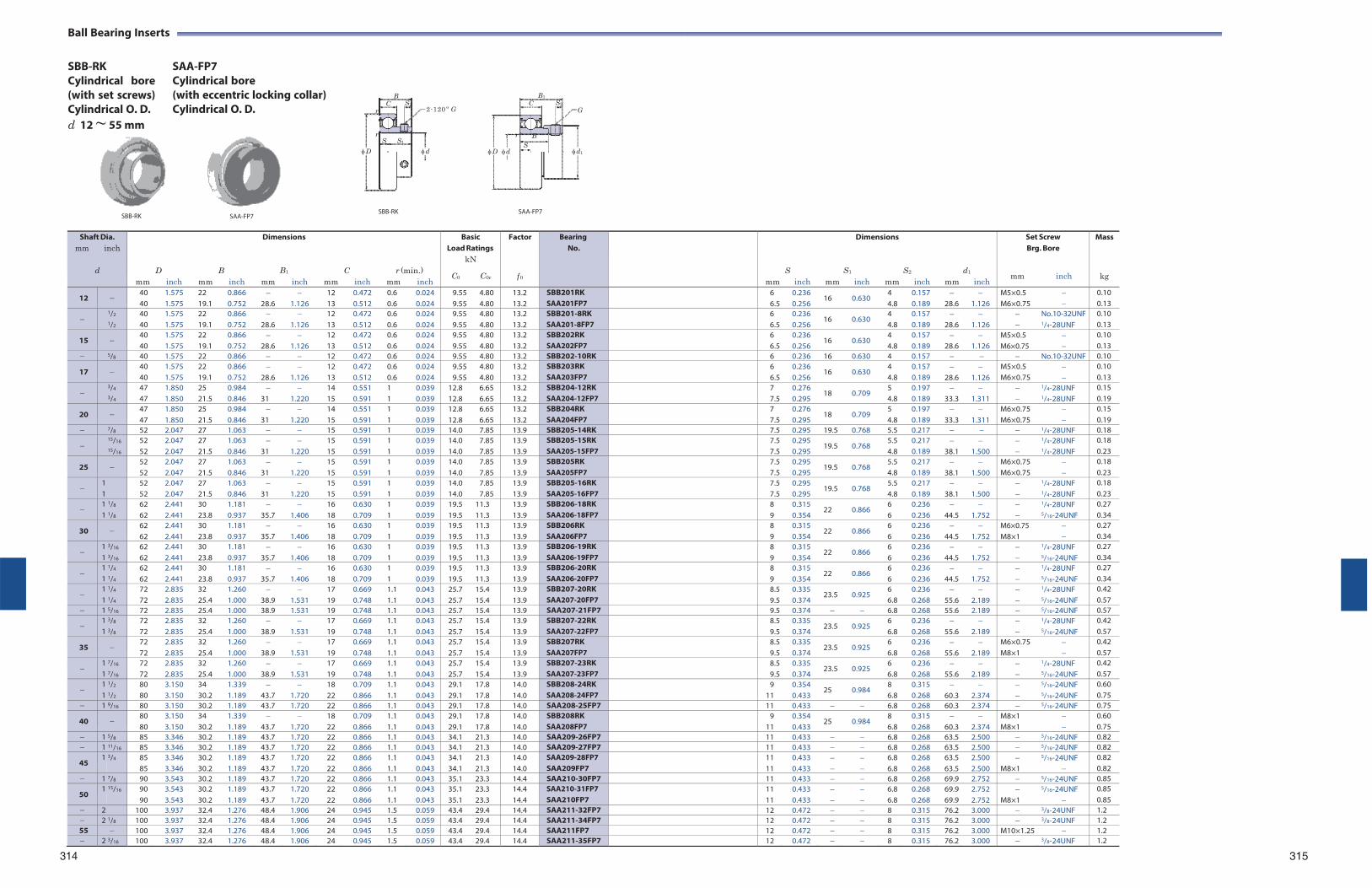
Ball Bearing Inserts
SBB-RK Cylindrical bore (with set screws) Cylindrical O. D. d 12 ~ 55 mm
SAA-FP7 Cylindrical bore (with eccentric locking collar) Cylindrical O. D.
B
C S2
r
r
2-120 º G
B1
C S2
G
r B
S S1
D d S
D d
d1
SBB-RK
SBB-RK
SAA-FP7
314 315
Shaft Dia. mm inch
d
mm
D
inch
mm
B
inch
Dimensions
B1
mm inch
mm
C
inch
r (min.) mm inch
Basic Load Ratings
kN
C0 C0r
Factor
f 0
BearingNo.
mm
S inch
mm
Dimensions
S1
inch mm
S2
inch
mm
d1
inch
Set Screw Brg. Bore
mm inch
Mass
kg
12 40 40
1.575 1.575
22 19.1
0.866 0.752
28.6
1.126
12 13
0.472 0.512
0.6 0.6
0.024 0.024
9.55 9.55
4.80 4.80
13.2 13.2
SBB201RK SAA201FP7
6 6.5
0.236 0.256
16 0.630 4 4.8
0.157 0.189
28.6
1.126
M5×0.5 M6×0.75
0.10 0.13
1/2
1/2
40 40
1.575 1.575
22 19.1
0.866 0.752
28.6
1.126
12 13
0.472 0.512
0.6 0.6
0.024 0.024
9.55 9.55
4.80 4.80
13.2 13.2
SBB201-8RK SAA201-8FP7
6 6.5
0.236 0.256
16 0.630 4 4.8
0.157 0.189
28.6
1.126
No.10-32UNF 1/4-28UNF
0.10 0.13
15 40 40
1.575 1.575
22 19.1
0.866 0.752
28.6
1.126
12 13
0.472 0.512
0.6 0.6
0.024 0.024
9.55 9.55
4.80 4.80
13.2 13.2
SBB202RK SAA202FP7
6 6.5
0.236 0.256
16 0.630 4 4.8
0.157 0.189
28.6
1.126
M5×0.5 M6×0.75
0.10 0.13
5/8 40 1.575 22 0.866 12 0.472 0.6 0.024 9.55 4.80 13.2 SBB202-10RK 6 0.236 16 0.630 4 0.157 No.10-32UNF 0.10
17 40 40
1.575 1.575
22 19.1
0.866 0.752
28.6
1.126
12 13
0.472 0.512
0.6 0.6
0.024 0.024
9.55 9.55
4.80 4.80
13.2 13.2
SBB203RK SAA203FP7
6 6.5
0.236 0.256
16 0.630 4 4.8
0.157 0.189
28.6
1.126
M5×0.5 M6×0.75
0.10 0.13
3/4
3/4
47 47
1.850 1.850
25 21.5
0.984 0.846
31
1.220
14 15
0.551 0.591
1 1
0.039 0.039
12.8 12.8
6.65 6.65
13.2 13.2
SBB204-12RK SAA204-12FP7
7 7.5
0.276 0.295
18 0.709 5 4.8
0.197 0.189
33.3
1.311
1/4-28UNF 1/4-28UNF
0.15 0.19
20 47 47
1.850 1.850
25 21.5
0.984 0.846
31
1.220
14 15
0.551 0.591
1 1
0.039 0.039
12.8 12.8
6.65 6.65
13.2 13.2
SBB204RK SAA204FP7
7 7.5
0.276 0.295
18 0.709 5 4.8
0.197 0.189
33.3
1.311
M6×0.75 M6×0.75
0.15 0.19
7/8 52 2.047 27 1.063 15 0.591 1 0.039 14.0 7.85 13.9 SBB205-14RK 7.5 0.295 19.5 0.768 5.5 0.217 1/4-28UNF 0.18
15/16
15/16
52 52
2.047 2.047
27 21.5
1.063 0.846
31
1.220
15 15
0.591 0.591
1 1
0.039 0.039
14.0 14.0
7.85 7.85
13.9 13.9
SBB205-15RK SAA205-15FP7
7.57.5
0.295 0.295
19.5 0.768 5.54.8
0.217 0.189
38.1
1.500
1/4-28UNF 1/4-28UNF
0.18 0.23
25 52 52
2.047 2.047
27 21.5
1.063 0.846
31
1.220
15 15
0.591 0.591
1 1
0.039 0.039
14.0 14.0
7.85 7.85
13.9 13.9
SBB205RK SAA205FP7
7.57.5
0.295 0.295
19.5 0.768 5.54.8
0.217 0.189
38.1
1.500
M6×0.75 M6×0.75
0.18 0.23
1 1
52 52
2.047 2.047
27 21.5
1.063 0.846
31
1.220
15 15
0.591 0.591
1 1
0.039 0.039
14.0 14.0
7.85 7.85
13.9 13.9
SBB205-16RK SAA205-16FP7
7.57.5
0.295 0.295
19.5 0.768 5.54.8
0.217 0.189
38.1
1.500
1/4-28UNF 1/4-28UNF
0.18 0.23
1 1
1/8
1/8
62 62
2.441 2.441
30 23.8
1.181 0.937
35.7
1.406
16 18
0.630 0.709
1 1
0.039 0.039
19.5 19.5
11.3 11.3
13.9 13.9
SBB206-18RK SAA206-18FP7
8 9
0.315 0.354
22 0.866 6 6
0.236 0.236
44.5
1.752
1/4-28UNF 5/16-24UNF
0.27 0.34
30 62 62
2.441 2.441
30 23.8
1.181 0.937
35.7
1.406
16 18
0.630 0.709
1 1
0.039 0.039
19.5 19.5
11.3 11.3
13.9 13.9
SBB206RK SAA206FP7
8 9
0.315 0.354
22 0.866 6 6
0.236 0.236
44.5
1.752
M6×0.75 M8×1
0.27 0.34
1 1
3/16
3/16
62 62
2.441 2.441
30 23.8
1.181 0.937
35.7
1.406
16 18
0.630 0.709
1 1
0.039 0.039
19.5 19.5
11.3 11.3
13.9 13.9
SBB206-19RK SAA206-19FP7
8 9
0.315 0.354
22 0.866 6 6
0.236 0.236
44.5
1.752
1/4-28UNF 5/16-24UNF
0.27 0.34
1 1
1/4
1/4
62 62
2.441 2.441
30 23.8
1.181 0.937
35.7
1.406
16 18
0.630 0.709
1 1
0.039 0.039
19.5 19.5
11.3 11.3
13.9 13.9
SBB206-20RK SAA206-20FP7
8 9
0.315 0.354
22 0.866 6 6
0.236 0.236
44.5
1.752
1/4-28UNF 5/16-24UNF
0.27 0.34
1 1
1/4
1/4
72 72
2.835 2.835
32 25.4
1.260 1.000
38.9
1.531
17 19
0.669 0.748
1.1 1.1
0.043 0.043
25.7 25.7
15.4 15.4
13.9 13.9
SBB207-20RK SAA207-20FP7
8.59.5
0.335 0.374
23.5 0.925 6 6.8
0.236 0.268
55.6
2.189
1/4-28UNF 5/16-24UNF
0.42 0.57
1 5/16 72 2.835 25.4 1.000 38.9 1.531 19 0.748 1.1 0.043 25.7 15.4 13.9 SAA207-21FP7 9.5 0.374 6.8 0.268 55.6 2.189 5/16-24UNF 0.57
1 1
3/8
3/8
72 72
2.835 2.835
32 25.4
1.260 1.000
38.9
1.531
17 19
0.669 0.748
1.1 1.1
0.043 0.043
25.7 25.7
15.4 15.4
13.9 13.9
SBB207-22RK SAA207-22FP7
8.59.5
0.335 0.374
23.5 0.925 6 6.8
0.236 0.268
55.6
2.189
1/4-28UNF 5/16-24UNF
0.42 0.57
35 72 72
2.835 2.835
32 25.4
1.260 1.000
38.9
1.531
17 19
0.669 0.748
1.1 1.1
0.043 0.043
25.7 25.7
15.4 15.4
13.9 13.9
SBB207RK SAA207FP7
8.59.5
0.335 0.374
23.5 0.925 6 6.8
0.236 0.268
55.6
2.189
M6×0.75 M8×1
0.42 0.57
1 1
7/16
7/16
72 72
2.835 2.835
32 25.4
1.260 1.000
38.9
1.531
17 19
0.669 0.748
1.1 1.1
0.043 0.043
25.7 25.7
15.4 15.4
13.9 13.9
SBB207-23RK SAA207-23FP7
8.59.5
0.335 0.374
23.5 0.925 6 6.8
0.236 0.268
55.6
2.189
1/4-28UNF 5/16-24UNF
0.42 0.57
1 1
1/2
1/2
80 80
3.150 3.150
34 30.2
1.339 1.189
43.7
1.720
18 22
0.709 0.866
1.1 1.1
0.043 0.043
29.1 29.1
17.8 17.8
14.0 14.0
SBB208-24RK SAA208-24FP7
9 11
0.354 0.433
25 0.984 8 6.8
0.315 0.268
60.3
2.374
5/16-24UNF 5/16-24UNF
0.60 0.75
1 9/16 80 3.150 30.2 1.189 43.7 1.720 22 0.866 1.1 0.043 29.1 17.8 14.0 SAA208-25FP7 11 0.433 6.8 0.268 60.3 2.374 5/16-24UNF 0.75
40 80 80
3.150 3.150
34 30.2
1.339 1.189
43.7
1.720
18 22
0.709 0.866
1.1 1.1
0.043 0.043
29.1 29.1
17.8 17.8
14.0 14.0
SBB208RK SAA208FP7
9 11
0.354 0.433
25 0.984 8 6.8
0.315 0.268
60.3
2.374
M8×1 M8×1
0.60 0.75
1 5/8 85 3.346 30.2 1.189 43.7 1.720 22 0.866 1.1 0.043 34.1 21.3 14.0 SAA209-26FP7 11 0.433 6.8 0.268 63.5 2.500 5/16-24UNF 0.82 1 11/16 85 3.346 30.2 1.189 43.7 1.720 22 0.866 1.1 0.043 34.1 21.3 14.0 SAA209-27FP7 11 0.433 6.8 0.268 63.5 2.500 5/16-24UNF 0.82
45 1 3/4 85
85 3.346 3.346
30.2 30.2
1.189 1.189
43.7 43.7
1.720 1.720
22 22
0.866 0.866
1.1 1.1
0.043 0.043
34.1 34.1
21.3 21.3
14.0 14.0
SAA209-28FP7 SAA209FP7
11 11
0.433 0.433
6.86.8
0.268 0.268
63.563.5
2.500 2.500
M8×1
5/16-24UNF
0.82 0.82
1 7/8 90 3.543 30.2 1.189 43.7 1.720 22 0.866 1.1 0.043 35.1 23.3 14.4 SAA210-30FP7 11 0.433 6.8 0.268 69.9 2.752 5/16-24UNF 0.85
50 1 15/16 90
90 3.543 3.543
30.2 30.2
1.189 1.189
43.7 43.7
1.720 1.720
22 22
0.866 0.866
1.1 1.1
0.043 0.043
35.1 35.1
23.3 23.3
14.4 14.4
SAA210-31FP7 SAA210FP7
11 11
0.433 0.433
6.86.8
0.268 0.268
69.969.9
2.752 2.752
M8×1
5/16-24UNF
0.85 0.85
2 100 3.937 32.4 1.276 48.4 1.906 24 0.945 1.5 0.059 43.4 29.4 14.4 SAA211-32FP7 12 0.472 8 0.315 76.2 3.000 3/8-24UNF 1.2 2 1/8 100 3.937 32.4 1.276 48.4 1.906 24 0.945 1.5 0.059 43.4 29.4 14.4 SAA211-34FP7 12 0.472 8 0.315 76.2 3.000 3/8-24UNF 1.2 55 100 3.937 32.4 1.276 48.4 1.906 24 0.945 1.5 0.059 43.4 29.4 14.4 SAA211FP7 12 0.472 8 0.315 76.2 3.000 M10×1.25 1.2 2 3/16 100 3.937 32.4 1.276 48.4 1.906 24 0.945 1.5 0.059 43.4 29.4 14.4 SAA211-35FP7 12 0.472 8 0.315 76.2 3.000 3/8-24UNF 1.2
SAA-FP7
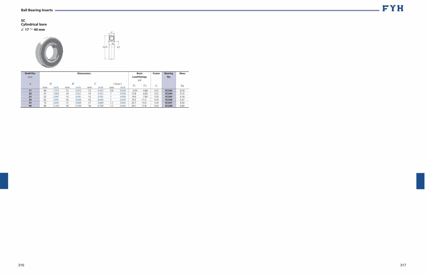
Ball Bearing Inserts
SC Cylindrical bore d 17 ~ 40 mm
Shaft Dia.
mm
d
mm
D
inch
mm
B
Dimensions
inch mm
C
inch
r (min.)
mm inch
Basic Load Ratings
kN
C0 C0r
Factor
f 0
BearingNo.
Mass
kg
17 40 1.575 12 0.472 12 0.472 0.6 0.024 9.55 4.80 13.2 SC203 0.1020 47 1.850 14 0.551 14 0.551 1 0.039 12.8 6.65 13.2 SC204 0.1525 52 2.047 15 0.591 15 0.591 1 0.039 14.0 7.85 13.9 SC205 0.1830 62 2.441 16 0.630 16 0.630 1 0.039 19.5 11.3 13.9 SC206 0.2735 72 2.835 17 0.669 17 0.669 1.1 0.043 25.7 15.4 13.9 SC207 0.4240 80 3.150 18 0.709 18 0.709 1.1 0.043 29.1 17.8 14.0 SC208 0.60
316 317
B
C
r
S D d
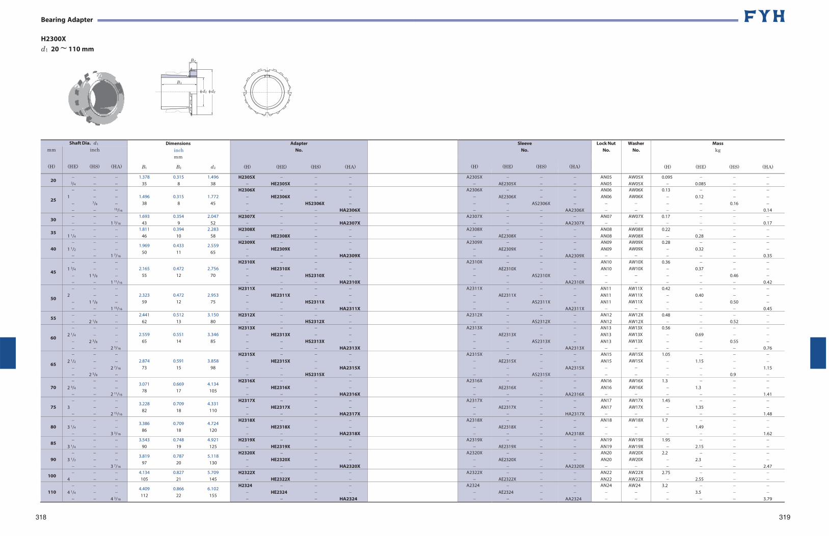
Bearing Adapter
H2300X d1 20 ~ 110 mm
318 319
Shaft Dia. d1 Dimensions inch mm
B1 B2 d2
Adapter No.
(H) (HE) (HS) (HA)
SleeveNo.
Lock Nut No.
Washer No.
Mass kg
(H) (HE) (HS) (HA)
mm
(H)
inch
(HE) (HS) (HA) (H) (HE) (HS) (HA)
20
3/4 1.378 0.315 1.496
35 8 38 H2305X
HE2305X A2305X
AE2305X
AN05 AN05
AW05X AW05X
0.095 0.085
25
1 7/8 15/16
1.496 0.315 1.772
38 8 45
H2306X HE2306X HS2306X HA2306X
A2306X
AE2306X
AS2306X
AA2306X
AN06 AN06
AW06X AW06X
0.13 0.12 0.16 0.14
30 1 3/16
1.693 0.354 2.047 43 9 52
H2307X HA2307X
A2307X
AA2307X
AN07
AW07X
0.17 0.17
35
1 1/4 1.811 0.394 2.283
46 10 58 H2308X
HE2308X A2308X
AE2308X
AN08 AN08
AW08X AW08X
0.22 0.28
40
1 1/2 1 7/16
1.969 0.433 2.559 50 11 65
H2309X HE2309X HA2309X
A2309X
AE2309X
AA2309X
AN09 AN09
AW09X AW09X
0.28 0.32 0.35
45
1 3/4 1 5/8 1 11/16
2.165 0.472 2.756
55 12 70
H2310X HE2310X HS2310X HA2310X
A2310X
AE2310X
AS2310X
AA2310X
AN10 AN10
AW10X AW10X
0.36 0.37 0.46 0.42
50
2 1 7/8 1 15/16
2.323 0.472 2.953
59 12 75
H2311X HE2311X HS2311X HA2311X
A2311X
AE2311X
AS2311X
AA2311X
AN11 AN11 AN11
AW11X AW11X AW11X
0.42 0.40 0.50 0.45
55 2 1/8
2.441 0.512 3.150 62 13 80
H2312X HS2312X
A2312X
AS2312X
AN12 AN12
AW12X AW12X
0.48 0.52
60
2 1/4 2 3/8 2 3/16
2.559 0.551 3.346
65 14 85
H2313X HE2313X HS2313X HA2313X
A2313X
AE2313X
AS2313X
AA2313X
AN13 AN13 AN13
AW13X AW13X AW13X
0.56 0.69 0.55 0.76
65
2 1/2 2 7/16
2 5/8
2.874 0.591 3.858
73 15 98
H2315X HE2315X HA2315X HS2315X
A2315X
AE2315X
AS2315X
AA2315X
AN15 AN15
AW15X AW15X
1.05 1.15 1.15 0.9
70
2 3/4 2 11/16
3.071 0.669 4.134 78 17 105
H2316X HE2316X HA2316X
A2316X
AE2316X
AA2316X
AN16 AN16
AW16X AW16X
1.3 1.3 1.41
75
3 2 15/16
3.228 0.709 4.331 82 18 110
H2317X HE2317X HA2317X
A2317X
AE2317X
HA2317X
AN17 AN17
AW17X AW17X
1.45 1.35 1.48
80
3 1/4 3 3/16
3.386 0.709 4.724 86 18 120
H2318X HE2318X HA2318X
A2318X
AE2318X
AA2318X
AN18
AW18X
1.7 1.49 1.62
85
3 1/4 3.543 0.748 4.921
90 19 125 H2319X
HE2319X A2319X
AE2319X
AN19 AN19
AW19X AW19X
1.95 2.15
90
3 1/2 3 7/16
3.819 0.787 5.118 97 20 130
H2320X HE2320X HA2320X
A2320X
AE2320X
AA2320X
AN20 AN20
AW20X AW20X
2.2 2.3 2.47
100
4 4.134 0.827 5.709 105 21 145
H2322X HE2322X
A2322X
AE2322X
AN22 AN22
AW22X AW22X
2.75 2.55
110
4 1/4 4 3/16
4.409 0.866 6.102 112 22 155
H2324 HE2324 HA2324
A2324
AE2324
AA2324
AN24
AW24
3.2 3.5 3.79
B 1
B 2
d1 d2
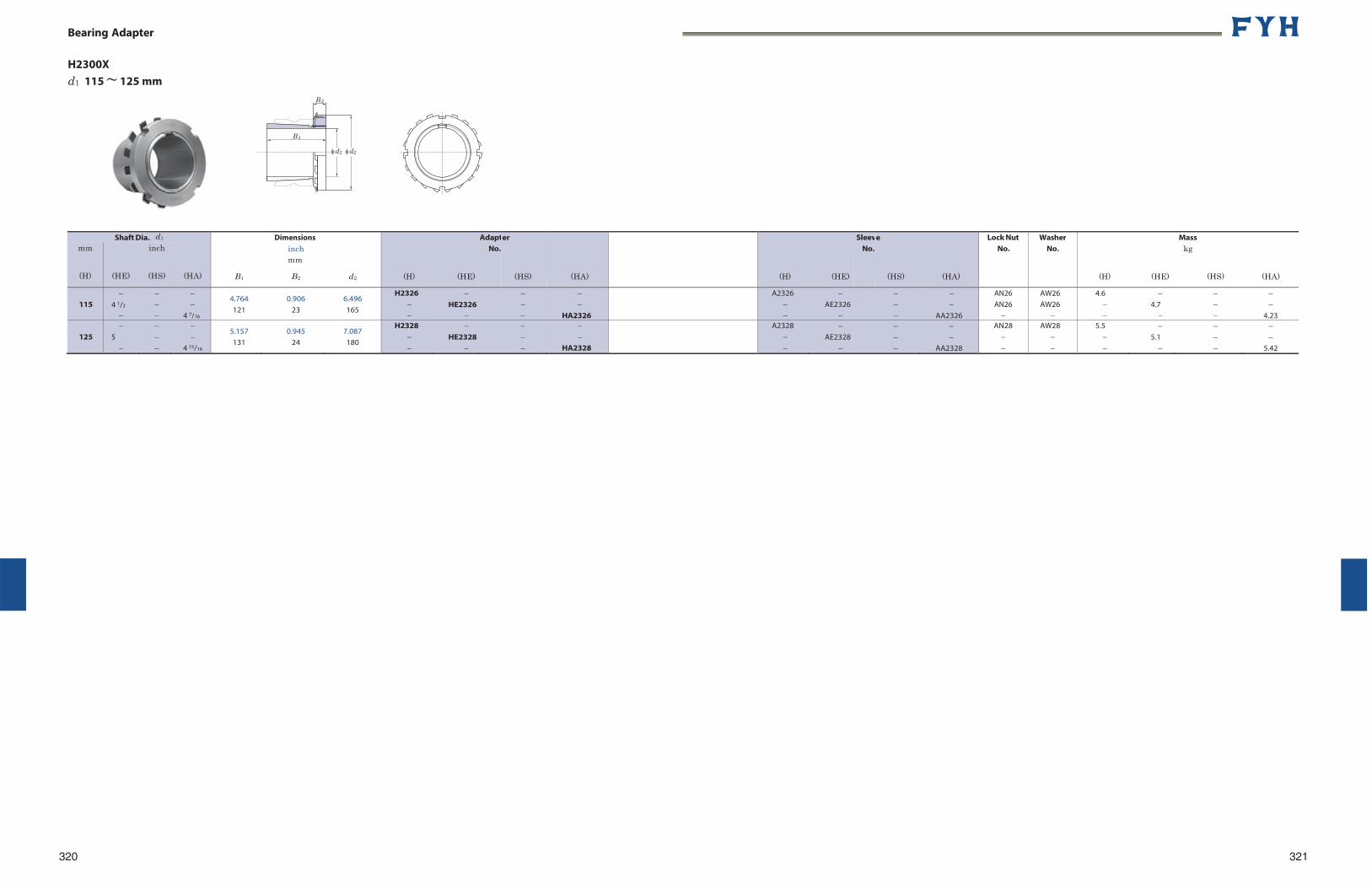
Bearing Adapter
H2300X d1 115 ~ 125 mm
Shaft Dia. d1
B1
Dimensions inch mm
B2
d2
(H) (HE)
AdaptNo.
er
(HS)
(HA)
(H) (HE)
SleevNo.
e
(HS)
(HA)
Lock Nut No.
Washer No.
(H) (HE)
Mass kg
(HS)
(HA)
mm
(H)
(HE)
inch
(HS)
(HA)
115
4 1/2
4 7/16
4.764 121
0.906 23
6.496 165
H2326
HE2326
HA2326
A2326
AE2326
AA2326
AN26 AN26
AW26 AW26
4.6
4.7
4.23
125
5
4 15/16
5.157 131
0.945 24
7.087 180
H2328
HE2328
HA2328
A2328
AE2328
AA2328
AN28
AW28
5.5
5.1
5.42
320 321
B 1
B 2
d1 d2
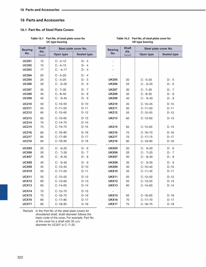
16 Parts and Accessories
16 Parts and Accessories
16.1 Part No. of Steel Plate Covers
Table 16.1 Part No. of steel plate cover for UC type bearing
Table 16.2 Part No. of steel plate cover for UK type bearing
Remark In the Part No. of the steel plate covers for
shouldered shaft, shaft diameter follows the basic code of the cover. For example, Part No. of the cover for a shaft with 35 mm diameter for UC207 is C735.
322
Bearing No.
Shaft dia.
(mm)
Steel plate cover No.
Open type Sealed type
UK205
UK206
UK207
UK208
UK209
UK210
UK211
UK212
UK213
UK215
UK216
UK217
UK218
20
25
30
35
40
45
50
55
60
65
70
75
80
C520
C625
C730
C835
C940
C1045
C1150
C1255
C1360
C1565
C1670
C1775
C1880
D5
D6
D7
D8
D9
D10
D11
D12
D13
D15
D16
D17
D18
UKX05 20 C620 D6
UKX06 25 C725 D7
UKX07 30 C830 D8
UKX08 35 C935 D9
UKX09 40 C1040 D10
UKX10 45 C1145 D11
UKX11 50 C1250 D12
UKX12 55 C1355 D13
UKX13 60 C1460 D14
UKX15 65 C1665 D16
UKX16 70 C1770 D17
UKX17 75 C1875 D18
Bearing No.
Shaft dia.
(mm)
Steel plate cover No.
Open type Sealed type
UC201
UC202
UC203
UC204
UC205
UC206
UC207
UC208
UC209
UC210
UC211
UC212
UC213
UC214
UC215
UC216
UC217
UC218
12
15
17
20
25
30
35
40
45
50
55
60
65
70
75
80
85
90
C412
C415
C417
C420
C525
C630
C735
C840
C945
C1050
C1155
C1260
C1365
C1470
C1575
C1680
C1785
C1890
D4
D4
D4
D4
D5
D6
D7
D8
D9
D10
D11
D12
D13
D14
D15
D16
D17
D18
UCX05 25 C625 D6
UCX06 30 C730 D7
UCX07 35 C835 D8
UCX08 40 C940 D9
UCX09 45 C1045 D10
UCX10 50 C1150 D11
UCX11 55 C1255 D12
UCX12 60 C1360 D13
UCX13 65 C1465 D14
UCX14 70 C1570 D15
UCX15 75 C1675 D16
UCX16 80 C1780 D17
UCX17 85 C1885 D18
16 Parts and Accessories
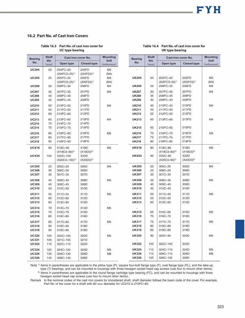
16.2 Part No. of Cast Iron Covers
Table 16.3 Part No. of cast iron cover for UC type bearing
Table 16.4 Part No. of cast iron cover for UK type bearing
Note 1) Items in parentheses are applicable to the pillow type (P), square four-bolt flange type (F), oval flange type (FL), and the take-up
type (T) bearings, and can be mounted to housings with three hexagon socket head cap screws (use four to mount other items). 2) Items in parentheses are applicable to the round flange cartridge type bearing (FC), and can be mounted to housings with three
hexagon socket head cap screws (use four to mount other items). Remark In the nominal codes of the cast iron covers for shouldered shaft, shaft diameter follows the basic code of the cover. For example,
Part No. of the cover for a shaft with 60 mm diameter for UC210 is 210FC60.
323
Bearing No.
Shaft dia.
(mm)
Cast iron cover No. Mounting bolt
(reference) Open type Closed type
UK205
UK206
UK207
UK208
UK209
UK210
UK211
UK212
UK213
UK215
UK216
UK217
UK218
20
25
30 35 40
45 50 55
60
65
70 75 80
205FC20 (205FC320)1)
206FC25
207FC30 208FC35 209FC40
210FC45 211FC50 212FC55
213FC60
215FC65
216FC70 217FC75 218FC80
205FD
(205FD3)1)
206FD
207FD 208FD 209FD
210FD 211FD 212FD
213FD
215FD
216FD 217FD 218FD
M3 (M4) M4
M4
M4
M4
M5
UKX18 80 X18C80 X18D M5 (X18C380)2) (X18D3)2)
UKX20 90 X20C90 X20D
(X20C390)2) (X20D3)2)
UK305 20 305C20 305D M4 UK306 25 306C25 306D UK307 30 307C30 307D
UK308 35 308C35 308D M5 UK309 40 309C40 309D
UK310 45 310C45 310D
UK311 50 311C50 311D M5
UK312 55 312C55 312D
UK313 60 313C60 313D
UK315 65 315C65 315D M5 UK316 70 316C70 316D
UK317 75 317C75 317D M5
UK318 80 318C80 318D
UK319 85 319C85 319D
UK320 90 320C90 320D M5
UK322 100 322C100 322D
UK324 110 324C110 324D M5 UK326 115 326C115 326D M8
UK328 125 328C125 328D
Bearing No.
Shaft dia.
(mm)
Cast iron cover No. Mounting bolt
(reference) Open type Closed type
UC204
UC205
UC206
UC207
UC208
UC209
UC210
UC211
UC212
UC213
UC214
UC215
UC216
UC217
UC218
20
25
30
35 40 45
50 55
60
65 70 75
80 85 90
204FC20
(204FC320)1)
205FC25 (205FC325)1)
206FC30
207FC35
208FC40 209FC45
210FC50
211FC55 212FC60
213FC65 214FC70
215FC75
216FC80 217FC85
218FC90
204FD
(204FD3)1)
205FD
(205FD3)1)
206FD
207FD
208FD 209FD
210FD 211FD
212FD
213FD 214FD 215FD
216FD 217FD 218FD
M3 (M4)
M3 (M4) M4
M4
M4
M4
M5
UCX18 90 X18C90 X18D M5 (X18C390)2) (X18D3)2)
UCX20 100 X20C100 X20D
(X20C3100)2) (X20D3)2)
UC305 25 305C25 305D M4 UC306 30 306C30 306D
UC307 35 307C35 307D
UC308 40 308C40 308D M5
UC309 45 309C45 309D
UC310 50 310C50 310D
UC311 55 311C55 311D M5 UC312 60 312C60 312D UC313 65 313C65 313D
UC314 70 314C70 314D M5 UC315 75 315C75 315D
UC316 80 316C80 316D
UC317 85 317C85 317D M5
UC318 90 318C90 318D
UC319 95 319C95 319D
UC320 100 320C100 320D M5 UC321 105 321C105 321D UC322 110 322C110 322D
UC324 120 324C120 324D M5 UC326 130 326C130 326D M8
UC328 140 328C140 328D
324
SPHERICAL ROLLER BEARING UNITS
Contents
1 Structure and Features
1.1 Structure .......................................................................... 326
1.2 Features ................................................................................... 326
2 Models
2.1 Model List ....................................................................... 329
2.2 Models and Features ........................................................ 330
3 Nomenclature ............................................................................ 332
4 Engineering Information ................................................ 332
5 Installation Guide
5.1 Precautions ...................................................................... 334
5.2 Preparation............................................................................. 334
5.3 Installation ........................................................................ 335
5.4 Lubrication ....................................................................... 336
6 Dimensional Tables for Spherical Roller Bearing Units
XS2P, ZS2P .............................................................................. 338 d 1 3/8 ~ 4 inch 40 ~ 100 mm
XSE2P, ZSE2P .......................................................................... 340 d 1 3/8 ~ 4 inch 40 ~ 100 mm
XS4F, ZS4F ............................................................................... 342 d 1 3/8 ~ 4 inch 40 ~ 100 mm
XSE4F, ZSE4F .......................................................................... 344 d 1 3/8 ~ 4 inch 40 ~ 100 mm
XS4FC, ZS4FC ......................................................................... 346 d 1 3/8 ~ 4 inch 40 ~ 100 mm
XST, ZST ................................................................................... 348 d 1 15/16 ~ 3 1/2 inch 50 ~ 90 mm
XS4P, ZS4P .............................................................................. 350 d 2 7/16 ~ 4 inch 60 ~ 100 mm
XDS4P, ZDS4P ........................................................................ 352 d 2 7/16 ~ 4 inch 60 ~ 100 mm
XS4, ZS4 ................................................................................... 354 d 1 3/8 ~ 4 inch 40 ~ 100 mm
XDS4, ZDS4 ............................................................................ 355 d 2 7/16 ~ 4 inch 60 ~ 100 mm
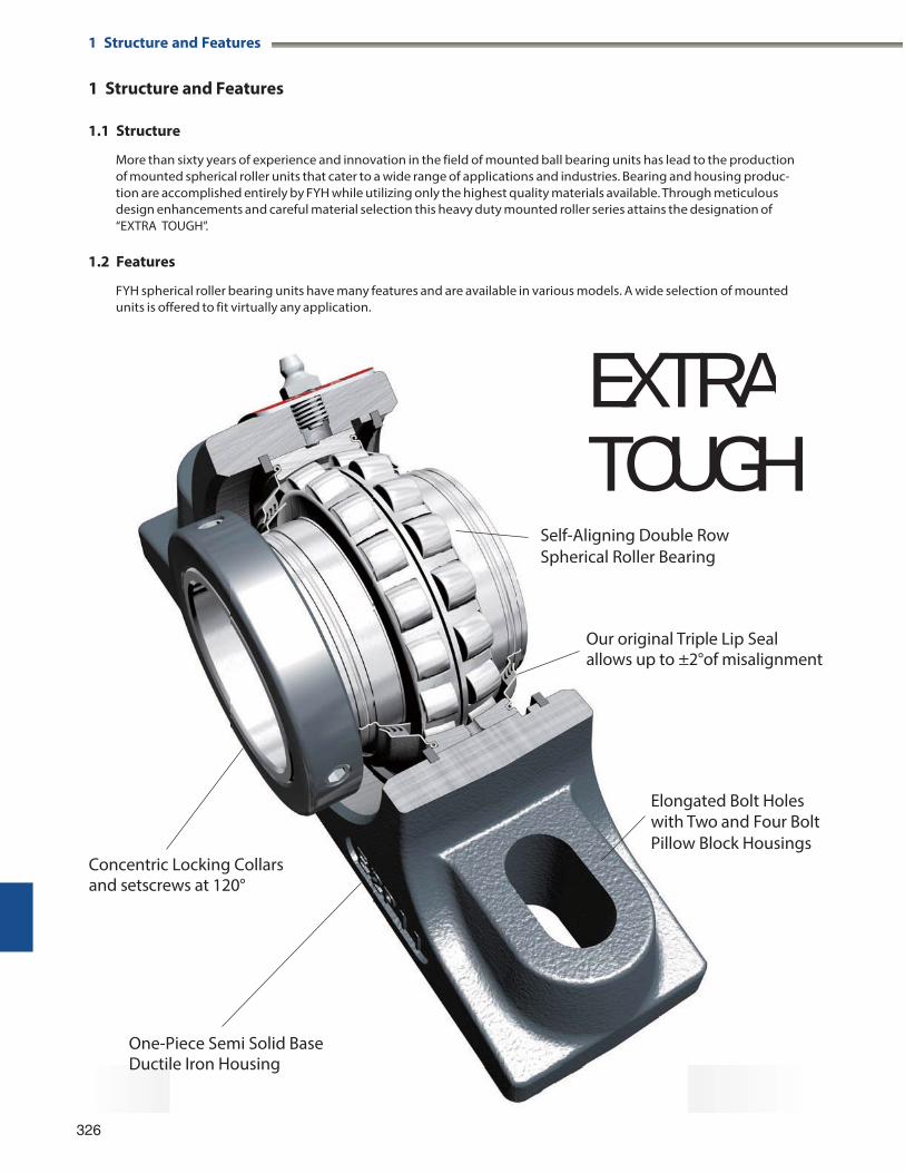
1 Structure and Features 1 Structure and Features
1 Structure and Features
1.1 Structure
More than sixty years of experience and innovation in the field of mounted ball bearing units has lead to the production of mounted spherical roller units that cater to a wide range of applications and industries. Bearing and housing produc- tion are accomplished entirely by FYH while utilizing only the highest quality materials available. Through meticulous design enhancements and careful material selection this heavy duty mounted roller series attains the designation of “EXTRA TOUGH”.
1.2 Features
FYH spherical roller bearing units have many features and are available in various models. A wide selection of mounted units is offered to fit virtually any application.
326
EXTRATOUGH
Self-Aligning Double Row Spherical Roller Bearing
Our original Triple Lip Sealallows up to ±2°of misalignment
Elongated Bolt Holeswith Two and Four BoltPillow Block Housings
Concentric Locking Collars and setscrews at 120°
One-Piece Semi Solid Base Ductile Iron Housing
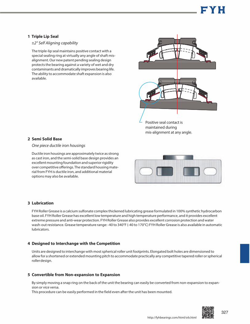
1 Triple Lip Seal ±2° Self Aligning capability
The triple-lip seal maintains positive contact with a special sealing ring at virtually any angle of shaft mis- alignment. Our new patent pending sealing design protects the bearing against a variety of wet and dry contaminants and dramatically improves bearing life. The ability to accommodate shaft expansion is also available.
2 Semi Solid Base
One piece ductile iron housings
Ductile iron housings are approximately twice as strong as cast iron, and the semi-solid base design provides an excellent mounting foundation and superior rigidity over competitive offerings. The standard housing mate- rial from FYH is ductile iron, and additional material options may also be available.
3 Lubrication
Positive seal contact is maintained during mis-alignment at any angle.
FYH Roller Grease is a calcium sulfonate complex thickened lubricating grease formulated in 100% synthetic hydrocarbon base oil. FYH Roller Grease has excellent low temperature and high temperature performance, and it provides excellent extreme pressure and anti-wear protection. FYH Roller Grease also provides excellent corrosion protection and water wash-out resistance. Grease temperature range: -40 to 340°F (-40 to 170°C) FYH Roller Grease is also available in automatic lubricators.
4 Designed to Interchange with the Competition
Units are designed to interchange with most spherical roller unit footprints. Elongated bolt holes are dimensioned to allow for a shortened or extended mounting pitch to accommodate practically any competitive tapered roller or spherical roller design.
5 Convertible from Non-expansion to Expansion
By simply moving a snap ring on the back of the unit the bearing can easily be converted from non-expansion to expan- sion or vice versa. This procedure can be easily performed in the field even after the unit has been mounted.
http://fyhbearings.com/html/srb.html
327
1 Structure and Features
6 Locking Style
The patent pending Z-Lock is the first ever tapered bore locking collar system. Just tighten the cap screws properly and the specialized tapered bore collar provides extreme holding power on the shaft without causing any damage. This is a true 360 degree locking mechanism. Disassembly is easily accomplished with two threaded holes in the collar for standard withdrawal dismounting.
THE MOST REVOLUTIONARY LOCKING SYSTEM
328 http://fyhbearings.com/html/z_lock.html
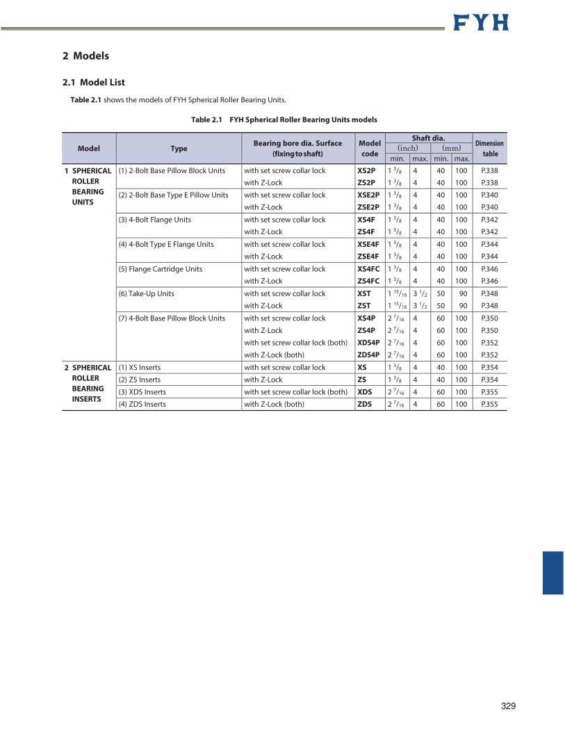
2 Models
2.1 Model List
Table 2.1 shows the models of FYH Spherical Roller Bearing Units.
Table 2.1 FYH Spherical Roller Bearing Units models
Model
Type
Bearing bore dia. Surface (fixing to shaft)
Model code
Shaft dia. Dimension
table (inch) (mm)
min. max. min. max.
1 SPHERICAL ROLLER BEARING UNITS
(1) 2-Bolt Base Pillow Block Units with set screw collar lock
with Z-Lock
XS2P ZS2P
1 3/8
1 3/8
4
4
40
40
100
100
P.338
P.338
(2) 2-Bolt Base Type E Pillow Units with set screw collar lock
with Z-Lock
XSE2P ZSE2P
1 3/8
1 3/8
4
4
40
40
100
100
P.340
P.340
(3) 4-Bolt Flange Units with set screw collar lock
with Z-Lock
XS4F ZS4F
1 3/8
1 3/8
4
4
40
40
100
100
P.342
P.342
(4) 4-Bolt Type E Flange Units with set screw collar lock
with Z-Lock
XSE4F ZSE4F
1 3/8
1 3/8
4
4
40
40
100
100
P.344
P.344
(5) Flange Cartridge Units with set screw collar lock
with Z-Lock
XS4FC ZS4FC
1 3/8
1 3/8
4
4
40
40
100
100
P.346
P.346
(6) Take-Up Units with set screw collar lock
with Z-Lock
XST ZST
1 15/16
1 15/16
3 1/2
3 1/2
50
50
90
90
P.348
P.348
(7) 4-Bolt Base Pillow Block Units with set screw collar lock
with Z-Lock
with set screw collar lock (both)
with Z-Lock (both)
XS4P
ZS4P
XDS4P
ZDS4P
2 7/16
2 7/16
2 7/16
2 7/16
4
4
4
4
60
60
60
60
100
100
100
100
P.350
P.350
P.352
P.352
2 SPHERICAL ROLLER BEARING INSERTS
(1) XS Inserts with set screw collar lock XS 1 3/8 4 40 100 P.354
(2) ZS Inserts with Z-Lock ZS 1 3/8 4 40 100 P.354
(3) XDS Inserts with set screw collar lock (both) XDS 2 7/16 4 60 100 P.355
(4) ZDS Inserts with Z-Lock (both) ZDS 2 7/16 4 60 100 P.355
329
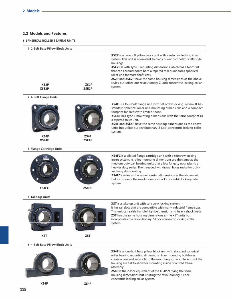
XST is a take-up unit with set screw locking system. It has rail slots that are compatible with many industrial frame sizes. This unit can safely handle high belt tension and heavy shock loads. ZST has the same housing dimensions as the XST units but incorporates the revolutionary Z-Lock concentric locking collar system.
2 Models
2.2 Models and Features
1 SPHERICAL ROLLER BEARING UNITS
1 2-Bolt Base Pillow Block Units
XS2P XSE2P
ZS2P ZSE2P
XS2P is a two-bolt pillow block unit with a setscrew locking insert system. This unit is equivalent to many of our competitors SRB style housings. XSE2P is with Type E mounting dimensions which has a footprint that can accommodate both a tapered roller unit and a spherical roller unit for most shaft sizes. ZS2P and ZSE2P have the same housing dimensions as the above styles but utilize our revolutionary Z-Lock concentric locking collar system.
2 4-Bolt Flange Units
XS4F
XSE4F ZS4F
ZSE4F
3 Flange Cartridge Units
XS4FC ZS4FC
4 Take-Up Units
XST ZST
5 4-Bolt Base Pillow Block Units
330
XS4P ZS4P
XS4P is a four-bolt base pillow block unit with standard spherical roller bearing mounting dimensions. Four mounting bolt-holes create a firm and secure fit to the mounting surface. The ends of the housing are flat to allow for mounting inside of a fixed frame assembly. ZS4P is the Z-lock equivalent of the XS4P carrying the same housing dimensions but utilizing the revolutionary Z-Lock concentric locking collar system.
XS4FC is a piloted flange cartridge unit with a setscrew locking insert system. Its’ pilot mounting dimensions are the same as the medium duty ball bearing units that allow for easy upgrades to a heavier duty series. The threaded withdrawal holes make for quick and easy dismounting. ZS4FC carries as the same housing dimensions as the above unit but incorporate the revolutionary Z-Lock concentric locking collar system.
XS4F is a four-bolt flange unit with set screw locking system. It has standard spherical roller unit mounting dimensions and a compact footprint for areas with limited space. XSE4F has Type E mounting dimensions with the same footprint as a tapered roller unit. ZS4F and ZSE4F have the same housing dimensions as the above units but utilize our revolutionary Z-Lock concentric locking collar system.
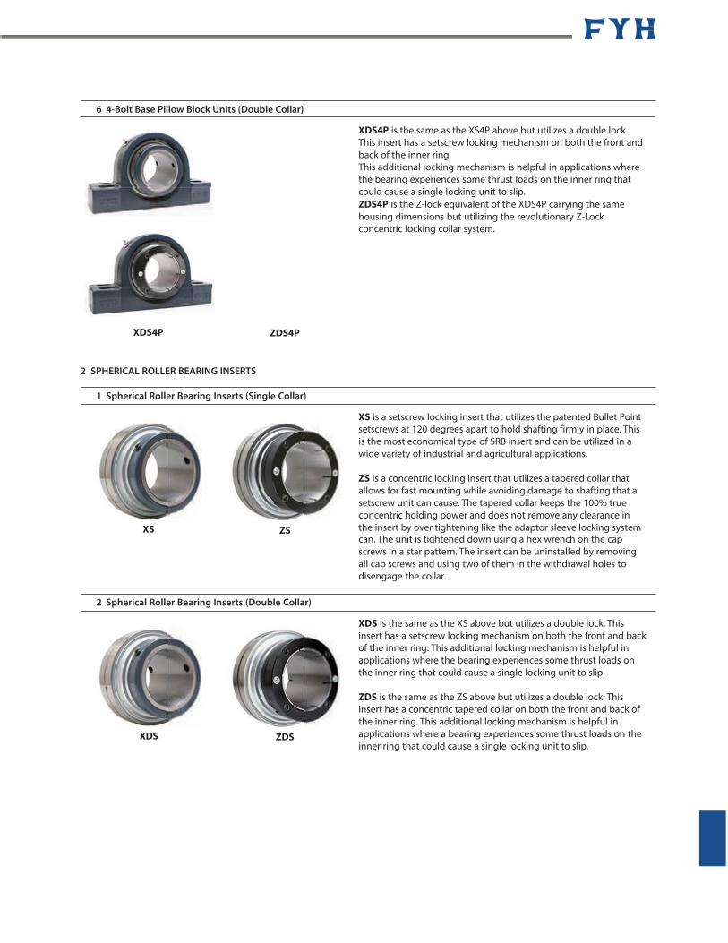
ZS
6 4-Bolt Base Pillow Block Units (Double Collar)
XDS4P ZDS4P
XDS4P is the same as the XS4P above but utilizes a double lock. This insert has a setscrew locking mechanism on both the front and back of the inner ring. This additional locking mechanism is helpful in applications where the bearing experiences some thrust loads on the inner ring that could cause a single locking unit to slip. ZDS4P is the Z-lock equivalent of the XDS4P carrying the same housing dimensions but utilizing the revolutionary Z-Lock concentric locking collar system.
2 SPHERICAL ROLLER BEARING INSERTS
1 Spherical Roller Bearing Inserts (Single Collar)
XS is a setscrew locking insert that utilizes the patented Bullet Point setscrews at 120 degrees apart to hold shafting firmly in place. This is the most economical type of SRB insert and can be utilized in a wide variety of industrial and agricultural applications.
ZS is a concentric locking insert that utilizes a tapered collar that allows for fast mounting while avoiding damage to shafting that a setscrew unit can cause. The tapered collar keeps the 100% true concentric holding power and does not remove any clearance in
XS the insert by over tightening like the adaptor sleeve locking system can. The unit is tightened down using a hex wrench on the cap screws in a star pattern. The insert can be uninstalled by removing all cap screws and using two of them in the withdrawal holes to disengage the collar.
2 Spherical Roller Bearing Inserts (Double Collar)
XDS is the same as the XS above but utilizes a double lock. This insert has a setscrew locking mechanism on both the front and back of the inner ring. This additional locking mechanism is helpful in applications where the bearing experiences some thrust loads on the inner ring that could cause a single locking unit to slip.
XDS
ZDS is the same as the ZS above but utilizes a double lock. This insert has a concentric tapered collar on both the front and back of the inner ring. This additional locking mechanism is helpful in applications where a bearing experiences some thrust loads on the inner ring that could cause a single locking unit to slip.
ZDS

331
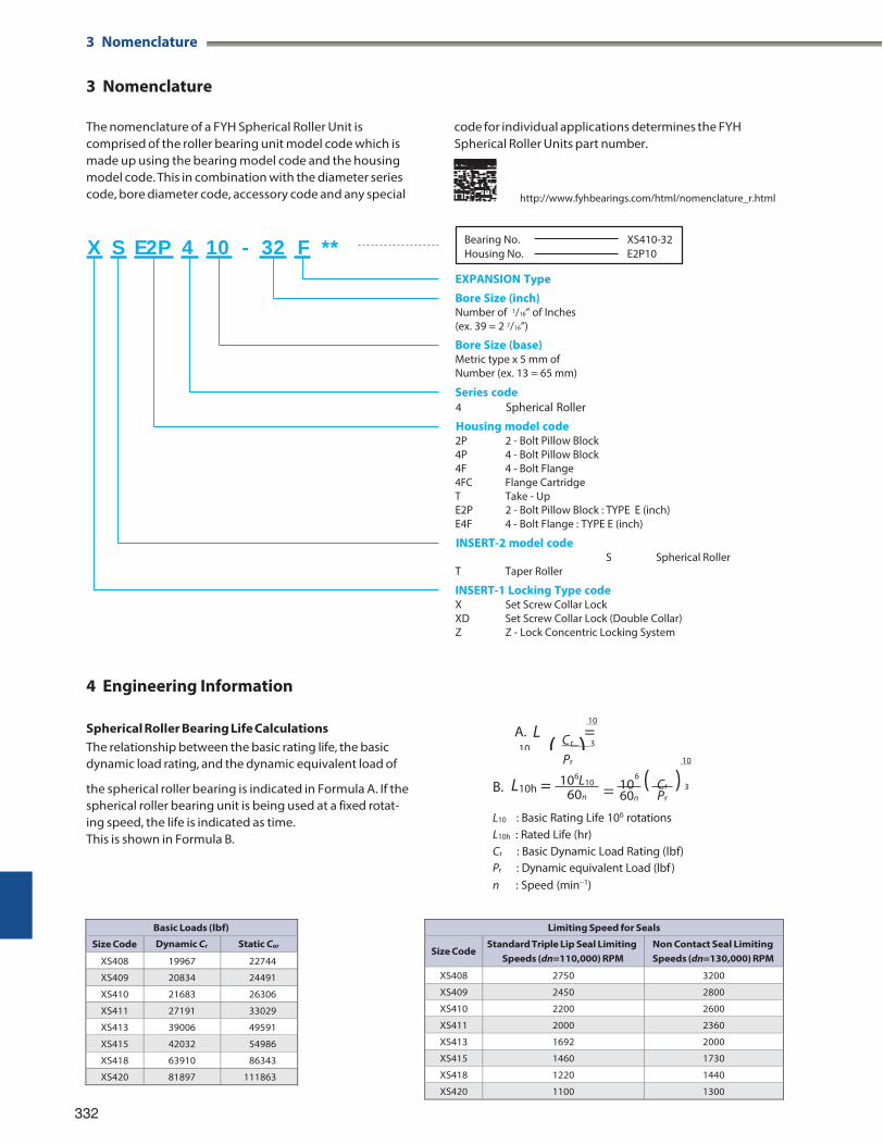
3 Nomenclature
10 ( C )( )
3 Nomenclature
The nomenclature of a FYH Spherical Roller Unit is comprised of the roller bearing unit model code which is made up using the bearing model code and the housing model code. This in combination with the diameter series code, bore diameter code, accessory code and any special
code for individual applications determines the FYH Spherical Roller Units part number.
http://www.fyhbearings.com/html/nomenclature_r.html
EXPANSION Type
Bore Size (inch) Number of 1/16” of Inches (ex. 39 = 2 7/16”)
Bore Size (base) Metric type x 5 mm of Number (ex. 13 = 65 mm)
Series code 4 Spherical Roller
Housing model code 2P 2 - Bolt Pillow Block 4P 4 - Bolt Pillow Block 4F 4 - Bolt Flange 4FC Flange Cartridge T Take - Up E2P 2 - Bolt Pillow Block : TYPE E (inch) E4F 4 - Bolt Flange : TYPE E (inch)
INSERT-2 model code S Spherical Roller
T Taper Roller
INSERT-1 Locking Type code X Set Screw Collar Lock XD Set Screw Collar Lock (Double Collar) Z Z - Lock Concentric Locking System
4 Engineering Information
Spherical Roller Bearing Life Calculations The relationship between the basic rating life, the basic dynamic load rating, and the dynamic equivalent load of
10 A. L =
r 3
Pr
6 6
10
the spherical roller bearing is indicated in Formula A. If the spherical roller bearing unit is being used at a fixed rotat-
B. L10h = 10 L10
60n = 10 Cr 3 60n Pr
ing speed, the life is indicated as time. This is shown in Formula B.
L10 : Basic Rating Life 106 rotations L10h : Rated Life (hr) Cr : Basic Dynamic Load Rating (lbf) Pr : Dynamic equivalent Load (lbf ) n : Speed (min1)
332
Limiting Speed for Seals
Size Code Standard Triple Lip Seal Limiting
Speeds (dn=110,000) RPM Non Contact Seal Limiting Speeds (dn=130,000) RPM
XS408 2750 3200
XS409 2450 2800
XS410 2200 2600
XS411 2000 2360
XS413 1692 2000
XS415 1460 1730
XS418 1220 1440
XS420 1100 1300
Basic Loads (lbf)
Size Code Dynamic Cr Static Cor
XS408 19967 22744
XS409 20834 24491
XS410 21683 26306
XS411 27191 33029
XS413 39006 49591
XS415 42032 54986
XS418 63910 86343
XS420 81897 111863
Bearing No.Housing No.
XS410-32E2P10
3 Nomenclature
X S E2P 4 10 - 32 F **
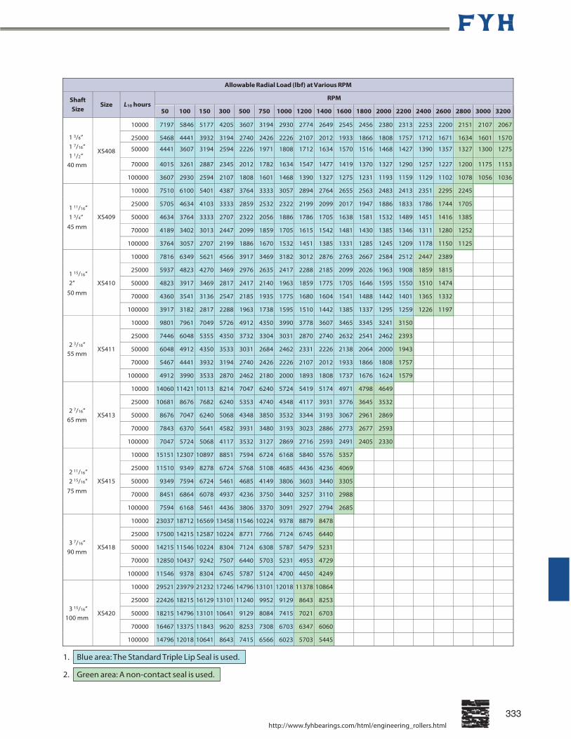
Allowable Radial Load (lbf) at Various RPM
Shaft Size
Size
L10 hours
RPM
50 100 150 300 500 750 1000 1200 1400 1600 1800 2000 2200 2400 2600 2800 3000 3200
1 3/8”
XS408
10000 7197 5846 5177 4205 3607 3194 2930 2774 2649 2545 2456 2380 2313 2253 2200 2151 2107 2067
25000 5468 4441 3932 3194 2740 2426 2226 2107 2012 1933 1866 1808 1757 1712 1671 1634 1601 15701 7/16” 1 1/2”
50000 4441 3607 3194 2594 2226 1971 1808 1712 1634 1570 1516 1468 1427 1390 1357 1327 1300 1275
70000 4015 3261 2887 2345 2012 1782 1634 1547 1477 1419 1370 1327 1290 1257 1227 1200 1175 115340 mm
100000 3607 2930 2594 2107 1808 1601 1468 1390 1327 1275 1231 1193 1159 1129 1102 1078 1056 1036
1 11/16”
XS409
10000 7510 6100 5401 4387 3764 3333 3057 2894 2764 2655 2563 2483 2413 2351 2295 2245 25000 5705 4634 4103 3333 2859 2532 2322 2199 2099 2017 1947 1886 1833 1786 1744 1705 50000 4634 3764 3333 2707 2322 2056 1886 1786 1705 1638 1581 1532 1489 1451 1416 1385 1 3/4”
45 mm 70000 4189 3402 3013 2447 2099 1859 1705 1615 1542 1481 1430 1385 1346 1311 1280 1252 100000 3764 3057 2707 2199 1886 1670 1532 1451 1385 1331 1285 1245 1209 1178 1150 1125
1 15/16”
XS410
10000 7816 6349 5621 4566 3917 3469 3182 3012 2876 2763 2667 2584 2512 2447 2389 25000 5937 4823 4270 3469 2976 2635 2417 2288 2185 2099 2026 1963 1908 1859 1815 50000 4823 3917 3469 2817 2417 2140 1963 1859 1775 1705 1646 1595 1550 1510 1474 2”
50 mm 70000 4360 3541 3136 2547 2185 1935 1775 1680 1604 1541 1488 1442 1401 1365 1332 100000 3917 3182 2817 2288 1963 1738 1595 1510 1442 1385 1337 1295 1259 1226 1197
2 3/16” 55 mm
XS411
10000 9801 7961 7049 5726 4912 4350 3990 3778 3607 3465 3345 3241 3150 25000 7446 6048 5355 4350 3732 3304 3031 2870 2740 2632 2541 2462 2393 50000 6048 4912 4350 3533 3031 2684 2462 2331 2226 2138 2064 2000 1943 70000 5467 4441 3932 3194 2740 2426 2226 2107 2012 1933 1866 1808 1757
100000 4912 3990 3533 2870 2462 2180 2000 1893 1808 1737 1676 1624 1579
2 7/16” 65 mm
XS413
10000 14060 11421 10113 8214 7047 6240 5724 5419 5174 4971 4798 4649 25000 10681 8676 7682 6240 5353 4740 4348 4117 3931 3776 3645 3532 50000 8676 7047 6240 5068 4348 3850 3532 3344 3193 3067 2961 2869 70000 7843 6370 5641 4582 3931 3480 3193 3023 2886 2773 2677 2593
100000 7047 5724 5068 4117 3532 3127 2869 2716 2593 2491 2405 2330
2 11/16”
XS415
10000 15151 12307 10897 8851 7594 6724 6168 5840 5576 5357 25000 11510 9349 8278 6724 5768 5108 4685 4436 4236 4069 50000 9349 7594 6724 5461 4685 4149 3806 3603 3440 3305 2 15/16”
75 mm 70000 8451 6864 6078 4937 4236 3750 3440 3257 3110 2988 100000 7594 6168 5461 4436 3806 3370 3091 2927 2794 2685
3 7/16” 90 mm
XS418
10000 23037 18712 16569 13458 11546 10224 9378 8879 8478 25000 17500 14215 12587 10224 8771 7766 7124 6745 6440 50000 14215 11546 10224 8304 7124 6308 5787 5479 5231 70000 12850 10437 9242 7507 6440 5703 5231 4953 4729
100000 11546 9378 8304 6745 5787 5124 4700 4450 4249
3 15/16” 100 mm
XS420
10000 29521 23979 21232 17246 14796 13101 12018 11378 10864 25000 22426 18215 16129 13101 11240 9952 9129 8643 8253 50000 18215 14796 13101 10641 9129 8084 7415 7021 6703 70000 16467 13375 11843 9620 8253 7308 6703 6347 6060
100000 14796 12018 10641 8643 7415 6566 6023 5703 5445
1.
2.
http://www.fyhbearings.com/html/engineering_rollers.html
333
Blue area: The Standard Triple Lip Seal is used.
Green area: A non-contact seal is used.
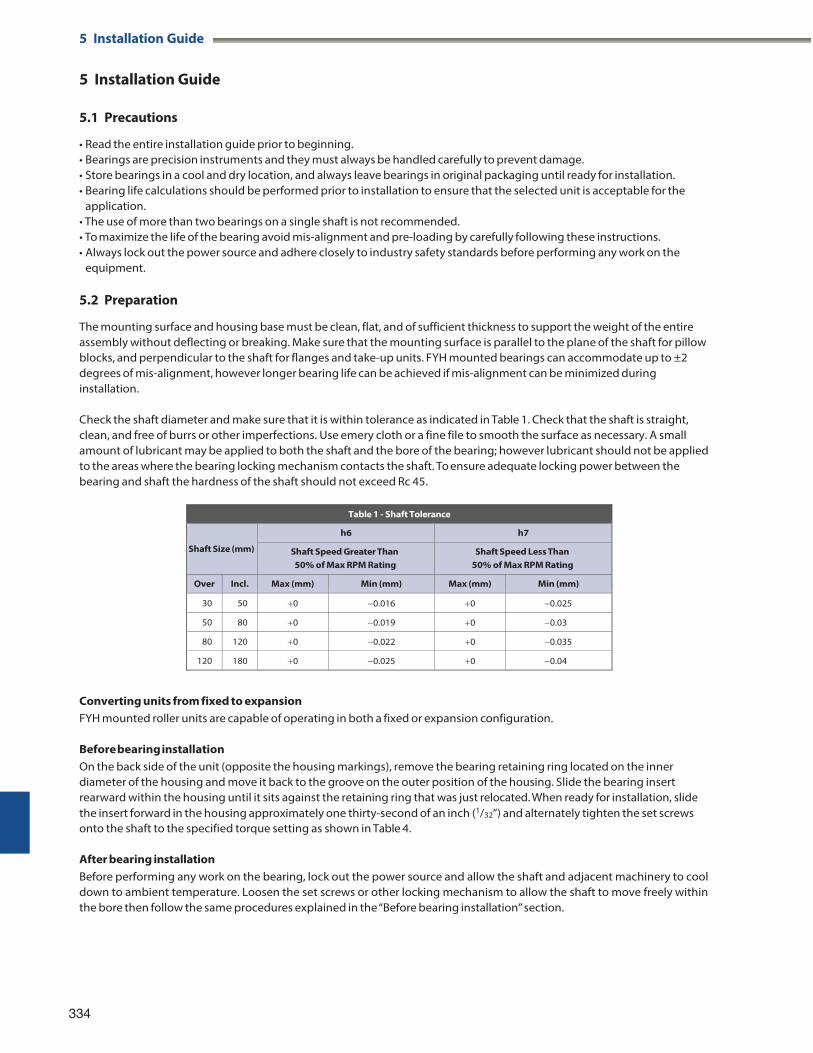
5 Installation Guide
5 Installation Guide
5.1 Precautions
• Read the entire installation guide prior to beginning. • Bearings are precision instruments and they must always be handled carefully to prevent damage. • Store bearings in a cool and dry location, and always leave bearings in original packaging until ready for installation. • Bearing life calculations should be performed prior to installation to ensure that the selected unit is acceptable for the
application. • The use of more than two bearings on a single shaft is not recommended. • To maximize the life of the bearing avoid mis-alignment and pre-loading by carefully following these instructions. • Always lock out the power source and adhere closely to industry safety standards before performing any work on the
equipment.
5.2 Preparation
The mounting surface and housing base must be clean, flat, and of sufficient thickness to support the weight of the entire assembly without deflecting or breaking. Make sure that the mounting surface is parallel to the plane of the shaft for pillow blocks, and perpendicular to the shaft for flanges and take-up units. FYH mounted bearings can accommodate up to ±2 degrees of mis-alignment, however longer bearing life can be achieved if mis-alignment can be minimized during installation.
Check the shaft diameter and make sure that it is within tolerance as indicated in Table 1. Check that the shaft is straight, clean, and free of burrs or other imperfections. Use emery cloth or a fine file to smooth the surface as necessary. A small amount of lubricant may be applied to both the shaft and the bore of the bearing; however lubricant should not be applied to the areas where the bearing locking mechanism contacts the shaft. To ensure adequate locking power between the bearing and shaft the hardness of the shaft should not exceed Rc 45.
Table 1 - Shaft Tolerance
Shaft Size (mm)
h6 h7
Shaft Speed Greater Than 50% of Max RPM Rating
Shaft Speed Less Than 50% of Max RPM Rating
Over Incl. Max (mm) Min (mm) Max (mm) Min (mm)
30 50 0 0.016 0 0.025
50 80 0 0.019 0 0.03
80 120 0 0.022 0 0.035
120 180 0 0.025 0 0.04
Converting units from fixed to expansion FYH mounted roller units are capable of operating in both a fixed or expansion configuration.
Before bearing installation On the back side of the unit (opposite the housing markings), remove the bearing retaining ring located on the inner diameter of the housing and move it back to the groove on the outer position of the housing. Slide the bearing insert rearward within the housing until it sits against the retaining ring that was just relocated. When ready for installation, slide the insert forward in the housing approximately one thirty-second of an inch (1/32”) and alternately tighten the set screws onto the shaft to the specified torque setting as shown in Table 4.
After bearing installation Before performing any work on the bearing, lock out the power source and allow the shaft and adjacent machinery to cool down to ambient temperature. Loosen the set screws or other locking mechanism to allow the shaft to move freely within the bore then follow the same procedures explained in the “Before bearing installation” section.
334
5 Installation Guide
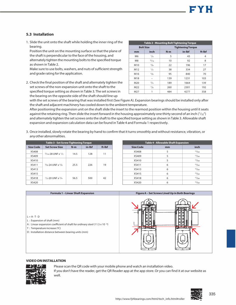
5.3 Installation
1. Slide the unit onto the shaft while holding the inner ring of the bearing. Position the unit on the mounting surface so that the plane of the shaft is perpendicular to the face of the housing, and alternately tighten the mounting bolts to the specified torque as shown in Table 2. Make sure to use bolts, washers, and nuts of sufficient strength and grade rating for the application.
2. Check the final position of the shaft and alternately tighten the
set screws of the non-expansion unit onto the shaft to the specified torque setting as shown in Table 3. The set screws in the bearing on the opposite side of the shaft should line up with the set screws of the bearing that was installed first (See Figure A). Expansion bearings should be installed only after the shaft and adjacent machinery has cooled down to the ambient temperature. After positioning the expansion unit on the shaft slide the insert to the rearmost position within the housing until it seats against the retaining ring. Then slide the insert forward in the housing approximately one thirty second of an inch (1/32”) and alternately tighten the set screws onto the shaft to the specified torque setting as shown in Table 3. Allowable shaft expansion and expansion calculation data can be found in Table 4 and Formula 1 respectively.
3. Once installed, slowly rotate the bearing by hand to confirm that it turns smoothly and without resistance, vibration, or
any other abnormalities.
Formula 1 – Linear Shaft Expansion Figure A – Set Screws Lined Up in Both Bearings L = A · T · D L : Expansion of shaft (mm) A : Linear expansion coefficient of shaft for ordinary steel (11.5 x 10 6) T : Temperature increase (ºC) D : Installation distance between bearing units (mm)
VIDEO ON INSTALLATION
Please scan the QR code with your mobile phone and watch an installation video. If you don’t have the reader, get the QR Reader app at the app store. Or you can find it at our website as well.
http://www.fyhbearings.com/html/tech_info.html#roller
335
Table 4 - Allowable Shaft Expansion
Size Code mm inch
XS408 5 13/64
XS409 5 13/64
XS410 5 13/64
XS411 6 15/64
XS413 6 15/64
XS415 6 15/64
XS418 6 15/64
XS420 6 15/64
Table 3 - Set Screw Tightening Torque
Size Code Set Screw Size N-m in-lbf ft-lbf
XS408 5/16-28 UNF x 1/2
14.5
128
11
XS409
XS410
3/8-24 UNF x 5/8
25.5
226 19 XS411
XS413
XS415
1/2-20 UNF x 3/4
56.5
500 42 XS418
XS420
Table 2 - Mounting Bolt Tightening Torque
Bolt Size Tightening Torque
mm inch N-m in-lbf ft-lbf
M6 1/4 5 43 4
M8 5/16 10 92 8
M10 3/8 22 196 17
M12 1/2 38 334 27
M16 5/8 95 840 70
M18 139 1231 103
M20 3/4 189 1664 139
M22 7/8 260 2301 192
M27 1 484 4277 358
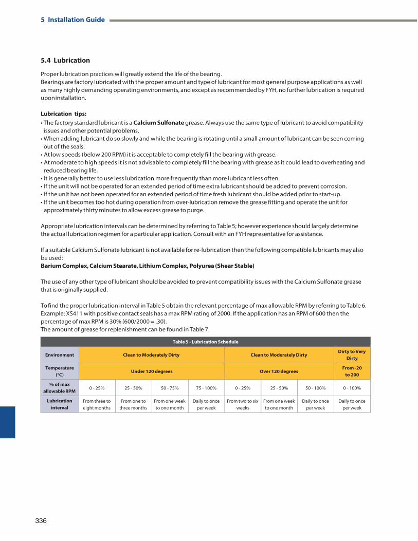
5 Installation Guide
5.4 Lubrication
Proper lubrication practices will greatly extend the life of the bearing. Bearings are factory lubricated with the proper amount and type of lubricant for most general purpose applications as well as many highly demanding operating environments, and except as recommended by FYH, no further lubrication is required upon installation.
Lubrication tips: • The factory standard lubricant is a Calcium Sulfonate grease. Always use the same type of lubricant to avoid compatibility
issues and other potential problems. • When adding lubricant do so slowly and while the bearing is rotating until a small amount of lubricant can be seen coming
out of the seals. • At low speeds (below 200 RPM) it is acceptable to completely fill the bearing with grease. • At moderate to high speeds it is not advisable to completely fill the bearing with grease as it could lead to overheating and
reduced bearing life. • It is generally better to use less lubrication more frequently than more lubricant less often. • If the unit will not be operated for an extended period of time extra lubricant should be added to prevent corrosion. • If the unit has not been operated for an extended period of time fresh lubricant should be added prior to start-up. • If the unit becomes too hot during operation from over-lubrication remove the grease fitting and operate the unit for
approximately thirty minutes to allow excess grease to purge.
Appropriate lubrication intervals can be determined by referring to Table 5; however experience should largely determine the actual lubrication regimen for a particular application. Consult with an FYH representative for assistance.
If a suitable Calcium Sulfonate lubricant is not available for re-lubrication then the following compatible lubricants may also be used: Barium Complex, Calcium Stearate, Lithium Complex, Polyurea (Shear Stable)
The use of any other type of lubricant should be avoided to prevent compatibility issues with the Calcium Sulfonate grease that is originally supplied.
To find the proper lubrication interval in Table 5 obtain the relevant percentage of max allowable RPM by referring to Table 6. Example: XS411 with positive contact seals has a max RPM rating of 2000. If the application has an RPM of 600 then the percentage of max RPM is 30% (600/2000 = .30). The amount of grease for replenishment can be found in Table 7.
336
Table 5 - Lubrication Schedule
Environment
Clean to Moderately Dirty
Clean to Moderately Dirty
Dirty to Very Dirty
Temperature (°C)
Under 120 degrees
Over 120 degrees
From -20 to 200
% of max allowable RPM
0 - 25%
25 - 50%
50 - 75%
75 - 100%
0 - 25%
25 - 50%
50 - 100%
0 - 100%
Lubrication interval
From three to eight months
From one to three months
From one week to one month
Daily to once per week
From two to six weeks
From one week to one month
Daily to once per week
Daily to once per week
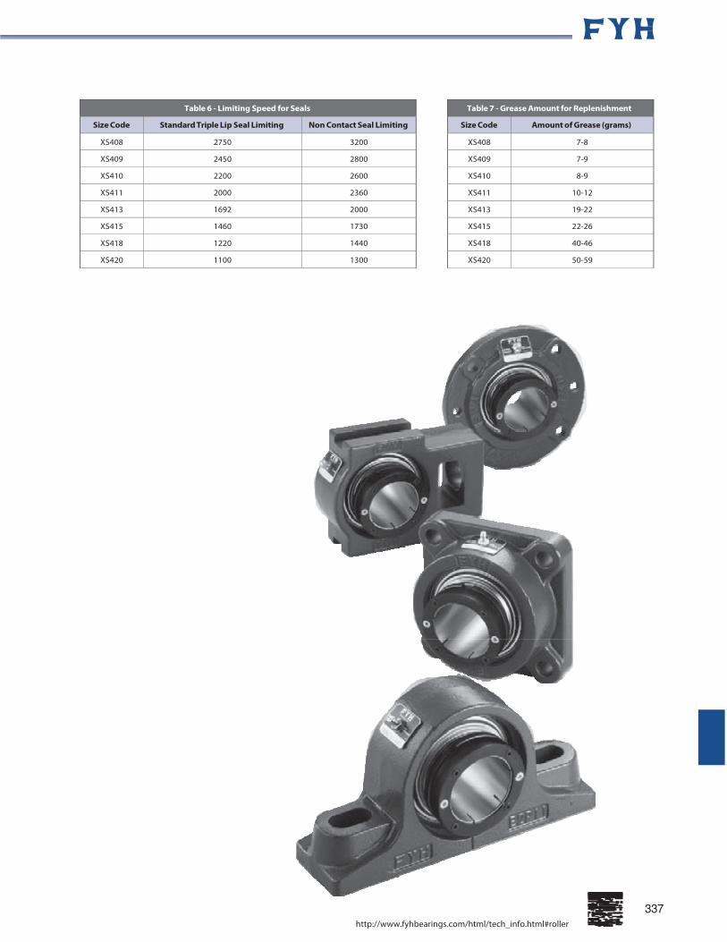
337
Table 7 - Grease Amount for Replenishment
Size Code Amount of Grease (grams)
XS408 7-8
XS409 7-9
XS410 8-9
XS411 10-12
XS413 19-22
XS415 22-26
XS418 40-46
XS420 50-59
Table 6 - Limiting Speed for Seals
Size Code Standard Triple Lip Seal Limiting Non Contact Seal Limiting
XS408 2750 3200
XS409 2450 2800
XS410 2200 2600
XS411 2000 2360
XS413 1692 2000
XS415 1460 1730
XS418 1220 1440
XS420 1100 1300
http://www.fyhbearings.com/html/tech_info.html#roller

2-Bolt Base Pillow Block Units
XS2P Cylindrical bore (with set screw collar lock) d 1 3/8 ~ 4 inch
40 ~ 100 mm
ZS2P Cylindrical bore (with Z-Lock) d 1 3/8 ~ 4 inch
40 ~ 100 mm
N 1
N
H 2
H H 1
J L
338
N 1
N
H 2
H H 1
J L
339
B S S 1
d
A A 0
B S S 1
d
A A 0
Shaft Dia. inch mm
d
H
L
A
J
N
Dimensions inch mm
N1 H1
H2
A0
B
S
S1
UnitNo.
BearingNo.
UnitNo.
Bearing No.
Bolt Size
inch mm
1 3/8 1 7/8
6 7/8
2 5/32
5 9/32
19/32
1 3/32
1 1/4
3 25/32
2 5/8
2.531
1
1.531
XS2P408-22 XS408-22 ZS2P408-22 ZS408-22 1/2 1 7/16 XS2P408-23 XS408-23 ZS2P408-23 ZS408-23
1 1/2 47.6 175 55 134 15 28 32 96 66.4 64.3 25.4 38.9 XS2P408-24 XS408-24 ZS2P408-24 ZS408-24 M12 40 XS2P408 XS408 ZS2P408 ZS408
1 11/16
1 3/4
45
2 1/8
54 7 3/8
187 2 3/8
60 5 25/32
147
19/32
15 1 3/32
28 1 5/16
33 4 1/4
108 2 27/32
72.1 2.657 67.5
1 25.4
1.657 42.1
XS2P409-27 XS2P409-28 XS2P409
XS409-27 XS409-28 XS409
ZS2P409-27 ZS2P409-28 ZS2P409
ZS409-27 ZS409-28 ZS409
1/2
M12
1 15/16
50 2
2 1/4
57.2 8 3/8
213 2 7/16
62 6 17/32
166
25/32
20 1 5/16
33 1 3/8
35 4 1/2
114 3 1/16
77.8 2.843 72.2
1 25.4
1.843 46.8
XS2P410-31 XS2P410 XS2P410-32
XS410-31 XS410 XS410-32
ZS2P410-31 ZS2P410 ZS2P410-32
ZS410-31 ZS410 ZS410-32
5/8
M16
55 2 3/16
2 1/4
2 1/2
63.5 8 7/8
225 2 5/8
67 6 7/8
175
25/32
20 1 3/16
30 1 5/8
41 4 31/32
126 3 1/8
79.5 2.937 74.6
1.126 28.6
1.811 46
XS2P411 XS2P411-35 XS2P411-36
XS411 XS411-35 XS411-36
ZS2P411 ZS2P411-35 ZS2P411-36
ZS411 ZS411-35 ZS411-36
5/8
M16
60 2 3/4
9 1/4
2 7/8
7 9/32
25/32
1 3/16
1 25/32
5 19/32
3 3/8
3.205
1.252
1.953
XS2P412 XS412 ZS2P412 ZS412 5/8 2 7/16 XS2P413-39 XS413-39 ZS2P413-39 ZS413-39
2 1/2 69.8 235 73 185 20 30 45 142 86.1 81.4 31.8 49.6 XS2P413-40 XS413-40 ZS2P413-40 ZS413-40 M16 65 XS2P413 XS413 ZS2P413 ZS413 70
3 1/4
10 7/16
3
8 9/32
15/16
1 9/32
1 7/8
6 3/8
3 13/16
3.594
1.252
2.343
XS2P414 XS414 ZS2P414 ZS414
3/4
2 11/16 XS2P415-43 XS415-43 ZS2P415-43 ZS415-43 2 3/4 XS2P415-44 XS415-44 ZS2P415-44 ZS415-44 2 15/16 82.6 265 76 210 24 32 48 162 97 91.3 31.8 59.5 XS2P415-47 XS415-47 ZS2P415-47 ZS415-47 M20
75 XS2P415 XS415 ZS2P415 ZS415 3 XS2P415-48 XS415-48 ZS2P415-48 ZS415-48
80
3 3/4
13
3 3/8
10 5/16
1 1/16
1 23/32
2 1/4
7 15/32
4 1/4
4.079
1.516
2.563
XS2P416 XS416 ZS2P416 ZS416
7/8
3 1/4 XS2P417-52 XS417-52 ZS2P417-52 ZS417-52 85 XS2P417 XS417 ZS2P417 ZS417
3 7/16 95.2 330 86 262 27 44 57 190 108.1 103.6 38.5 65.1 XS2P418-55 XS418-55 ZS2P418-55 ZS418-55 M22 3 1/2 XS2P418-56 XS418-56 ZS2P418-56 ZS418-56
90 XS2P418 XS418 ZS2P418 ZS418 100
3 15/16
4
4 1/4
108 15 1/4
387 3 3/4
95 11 1/4
286 1 5/32
29 2 5/16
59 2 17/32
64 8 11/32
212 4 23/32
120.1 4.484 113.9
1.626 41.3
2.858 72.6
XS2P420 XS2P420-63 XS2P420-64
XS420 XS420-63 XS420-64
ZS2P420 ZS2P420-63 ZS2P420-64
ZS420 ZS420-63 ZS420-64
1 M27
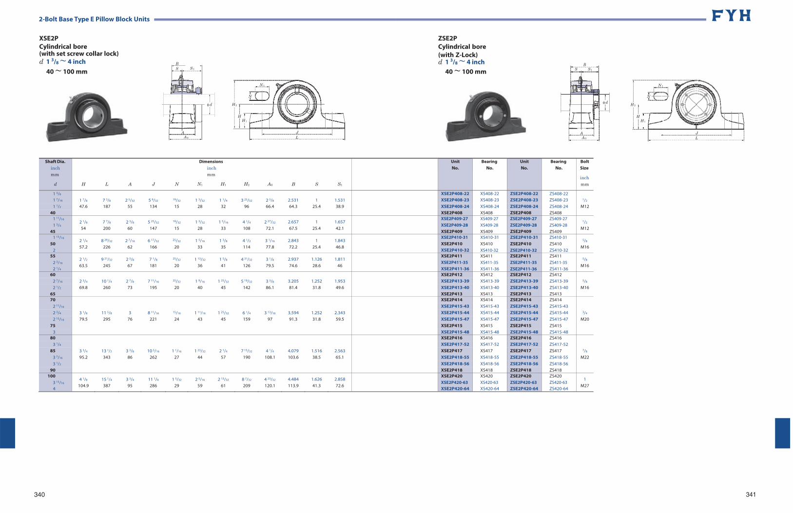
2-Bolt Base Type E Pillow Block Units
XSE2P Cylindrical bore (with set screw collar lock) d 1 3/8 ~ 4 inch
40 ~ 100 mm
ZSE2P Cylindrical bore (with Z-Lock) d 1 3/8 ~ 4 inch
40 ~ 100 mm
N 1
N
H 2
H H 1
J L
340
N 1
N
H 2
H H 1
J L
341
B S S 1
d
A A 0
B S S 1
d
A A 0
Shaft Dia. inch mm
d
H
L
A
J
N
Dimensions inch mm
N1 H1
H2
A0
B
S
S1
UnitNo.
BearingNo.
UnitNo.
Bearing No.
Bolt Size
inch mm
1 3/8 1 7/8
7 3/8
2 5/32
5 9/32
19/32
1 3/32
1 1/4
3 25/32
2 5/8
2.531
1
1.531
XSE2P408-22 XS408-22 ZSE2P408-22 ZS408-22 1/2 1 7/16 XSE2P408-23 XS408-23 ZSE2P408-23 ZS408-23
1 1/2 47.6 187 55 134 15 28 32 96 66.4 64.3 25.4 38.9 XSE2P408-24 XS408-24 ZSE2P408-24 ZS408-24 M12 40 XSE2P408 XS408 ZSE2P408 ZS408
1 11/16
1 3/4
45
2 1/8
54 7 7/8
200 2 3/8
60 5 25/32
147
19/32
15 1 3/32
28 1 5/16
33 4 1/4
108 2 27/32
72.1 2.657 67.5
1 25.4
1.657 42.1
XSE2P409-27 XSE2P409-28 XSE2P409
XS409-27 XS409-28 XS409
ZSE2P409-27 ZSE2P409-28 ZSE2P409
ZS409-27 ZS409-28 ZS409
1/2
M12
1 15/16
50 2
2 1/4
57.2 8 29/32
226 2 7/16
62 6 17/32
166
25/32
20 1 5/16
33 1 3/8
35 4 1/2
114 3 1/16
77.8 2.843 72.2
1 25.4
1.843 46.8
XSE2P410-31 XSE2P410 XSE2P410-32
XS410-31 XS410 XS410-32
ZSE2P410-31 ZSE2P410 ZSE2P410-32
ZS410-31 ZS410 ZS410-32
5/8
M16
55 2 3/16
2 1/4
2 1/2
63.5 9 21/32
245 2 5/8
67 7 1/8
181
25/32
20 1 13/32
36 1 5/8
41 4 31/32
126 3 1/8
79.5 2.937 74.6
1.126 28.6
1.811 46
XSE2P411 XSE2P411-35 XSE2P411-36
XS411 XS411-35 XS411-36
ZSE2P411 ZSE2P411-35 ZSE2P411-36
ZS411 ZS411-35 ZS411-36
5/8
M16
60 2 3/4
10 1/4
2 7/8
7 11/16
25/32
1 9/16
1 25/32
5 19/32
3 3/8
3.205
1.252
1.953
XSE2P412 XS412 ZSE2P412 ZS412 5/8 2 7/16 XSE2P413-39 XS413-39 ZSE2P413-39 ZS413-39
2 1/2 69.8 260 73 195 20 40 45 142 86.1 81.4 31.8 49.6 XSE2P413-40 XS413-40 ZSE2P413-40 ZS413-40 M16 65 XSE2P413 XS413 ZSE2P413 ZS413 70
3 1/8
11 5/8
3
8 11/16
15/16
1 11/16
1 25/32
6 1/4
3 13/16
3.594
1.252
2.343
XSE2P414 XS414 ZSE2P414 ZS414
3/4
2 11/16 XSE2P415-43 XS415-43 ZSE2P415-43 ZS415-43 2 3/4 XSE2P415-44 XS415-44 ZSE2P415-44 ZS415-44 2 15/16 79.5 295 76 221 24 43 45 159 97 91.3 31.8 59.5 XSE2P415-47 XS415-47 ZSE2P415-47 ZS415-47 M20
75 XSE2P415 XS415 ZSE2P415 ZS415 3 XSE2P415-48 XS415-48 ZSE2P415-48 ZS415-48
80
3 3/4
13 1/2
3 3/8
10 5/16
1 1/16
1 23/32
2 1/4
7 15/32
4 1/4
4.079
1.516
2.563
XSE2P416 XS416 ZSE2P416 ZS416
7/8
3 1/4 XSE2P417-52 XS417-52 ZSE2P417-52 ZS417-52 85 XSE2P417 XS417 ZSE2P417 ZS417
3 7/16 95.2 343 86 262 27 44 57 190 108.1 103.6 38.5 65.1 XSE2P418-55 XS418-55 ZSE2P418-55 ZS418-55 M22 3 1/2 XSE2P418-56 XS418-56 ZSE2P418-56 ZS418-56
90 XSE2P418 XS418 ZSE2P418 ZS418 100
3 15/16
4
4 1/8
104.9 15 1/4
387 3 3/4
95 11 1/4
286 1 5/32
29 2 5/16
59 2 13/32
61 8 7/32
209 4 23/32
120.1 4.484 113.9
1.626 41.3
2.858 72.6
XSE2P420 XSE2P420-63 XSE2P420-64
XS420 XS420-63 XS420-64
ZSE2P420 ZSE2P420-63 ZSE2P420-64
ZS420 ZS420-63 ZS420-64
1 M27
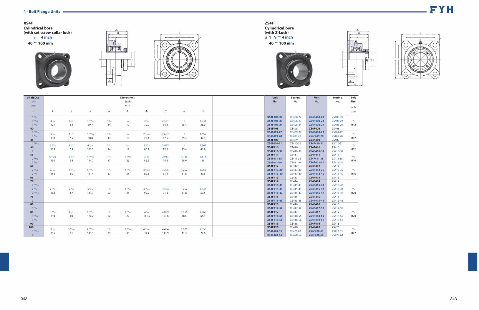
A 0
B
d
A 1
A
4 - Bolt Flange Units
XS4F Cylindrical bore (with set screw collar lock)
ZS4F Cylindrical bore
L (with Z-Lock) L
8 4 inch d 1 /8 ~ 4 inch
342
40 ~ 100 mm
L J
40 ~ 100 mm
L J
343
A 0
B
d
A 1A
Shaft Dia. inch mm
d
L
A
J
N
Dimensions inch mm
A1
A0
B
S
S1
UnitNo.
BearingNo.
UnitNo.
Bearing No.
Bolt Size
inch mm
1 3/8 4 3/4
2 3/32
3 17/32
35/64
3/4
2 3/4
2.531
1
1.531
XS4F408-22 XS408-22 ZS4F408-22 ZS408-22 1/2 1 7/16 XS4F408-23 XS408-23 ZS4F408-23 ZS408-23
1 1/2 121 53 89.7 14 19 70.2 64.3 25.4 38.9 XS4F408-24 XS408-24 ZS4F408-24 ZS408-24 M12 40 XS4F408 XS408 ZS4F408 ZS408
1 11/16
1 3/4
45
5 1/8
130 2 5/32
55 3 57/64
98.8
35/64
14
3/4
19 2 31/32
75.4 2.657 67.5
1 25.4
1.657 42.1
XS4F409-27 XS4F409-28 XS4F409
XS409-27 XS409-28 XS409
ZS4F409-27 ZS4F409-28 ZS4F409
ZS409-27 ZS409-28 ZS409
1/2
M12
1 15/16
50 2
5 5/16
135 2 5/32
55 4 1/16
103.2
35/64
14
3/4
19 3 5/32
80.2 2.843 72.2
1 25.4
1.843 46.8
XS4F410-31 XS4F410 XS4F410-32
XS410-31 XS410 XS410-32
ZS4F410-31 ZS4F410 ZS4F410-32
ZS410-31 ZS410 ZS410-32
1/2
M12
55 2 3/16
2 1/4
5 29/32
150 2 9/32
58 4 33/64
114.7
21/32
17 1 1/32
26 3 1/4
82.2 2.937 74.6
1.126 28.6
1.811 46
XS4F411 XS4F411-35 XS4F411-36
XS411 XS411-35 XS411-36
ZS4F411 ZS4F411-35 ZS4F411-36
ZS411 ZS411-35 ZS411-36
5/8
M16
60 6 1/8
2 9/16
4 25/32
21/32
1 1/32
3 17/32
3.205
1.252
1.953
XS4F412 XS412 ZS4F412 ZS412 5/8 2 7/16 XS4F413-39 XS413-39 ZS4F413-39 ZS413-39
2 1/2 156 65 121.4 17 26 89.3 81.4 31.8 49.6 XS4F413-40 XS413-40 ZS4F413-40 ZS413-40 M16 65 XS4F413 XS413 ZS4F413 ZS413 70
7 7/32
2 5/8
5 9/16
7/8
1 1/32
3 29/32
3.594
1.252
2.343
XS4F414 XS414 ZS4F414 ZS414
3/4
2 11/16 XS4F415-43 XS415-43 ZS4F415-43 ZS415-43 2 3/4 XS4F415-44 XS415-44 ZS4F415-44 ZS415-44 2 15/16 183 67 141.3 22 26 99.2 91.3 31.8 59.5 XS4F415-47 XS415-47 ZS4F415-47 ZS415-47 M20
75 XS4F415 XS415 ZS4F415 ZS415 3 XS4F415-48 XS415-48 ZS4F415-48 ZS415-48
80
8 9/32
3 5/32
6 23/32
7/8
1 5/32
4 3/8
4.079
1.516
2.563
XS4F416 XS416 ZS4F416 ZS416
3/4
3 1/4 XS4F417-52 XS417-52 ZS4F417-52 ZS417-52 85 XS4F417 XS417 ZS4F417 ZS417
3 7/16 210 80 170.7 22 29 111.5 103.6 38.5 65.1 XS4F418-55 XS418-55 ZS4F418-55 ZS418-55 M20 3 1/2 XS4F418-56 XS418-56 ZS4F418-56 ZS418-56
90 XS4F418 XS418 ZS4F418 ZS418 100
3 15/16
4
9 1/4
235 3 19/32
91 7 39/64
193.3
63/64
25 1 3/16
30 4 27/32
123 4.484 113.9
1.626 41.3
2.858 72.6
XS4F420 XS4F420-63 XS4F420-64
XS420 XS420-63 XS420-64
ZS4F420 ZS4F420-63 ZS4F420-64
ZS420 ZS420-63 ZS420-64
7/8
M22
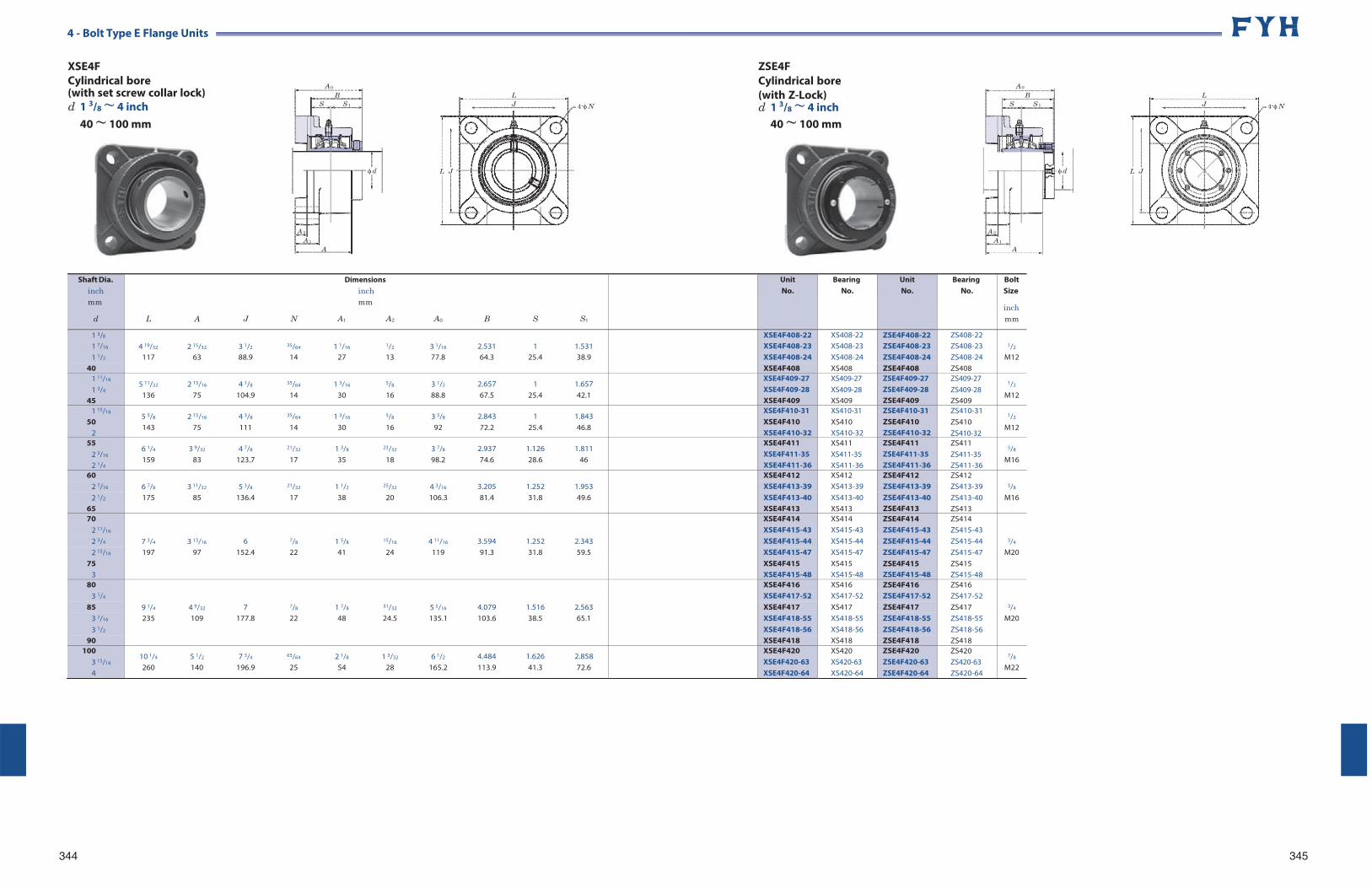
4 - Bolt Type E Flange Units
XSE4F Cylindrical bore (with set screw collar lock) d 1 3/8 ~ 4 inch
40 ~ 100 mm
344
L J 4-N
L J
ZSE4F Cylindrical bore (with Z-Lock) d 1 3/8 ~ 4 inch
40 ~ 100 mm
L J 4-N
L J
345
A 0
B S S 1
d
A 2
A 1A
A 0
B S S 1
d
A 2
A 1A
Shaft Dia. inch mm
d
L
A
J
N
Dimensions inch mm
A1 A2
A0
B
S
S1
UnitNo.
BearingNo.
UnitNo.
Bearing No.
Bolt Size
inch mm
1 3/8 4 19/32
2 15/32
3 1/2
35/64
1 1/16
1/2
3 1/16
2.531
1
1.531
XSE4F408-22 XS408-22 ZSE4F408-22 ZS408-22 1/2 1 7/16 XSE4F408-23 XS408-23 ZSE4F408-23 ZS408-23
1 1/2 117 63 88.9 14 27 13 77.8 64.3 25.4 38.9 XSE4F408-24 XS408-24 ZSE4F408-24 ZS408-24 M12 40 XSE4F408 XS408 ZSE4F408 ZS408
1 11/16
1 3/4
45
5 11/32
136 2 15/16
75 4 1/8
104.9
35/64
14 1 3/16
30
5/8
16 3 1/2
88.8 2.657 67.5
1 25.4
1.657 42.1
XSE4F409-27 XSE4F409-28 XSE4F409
XS409-27 XS409-28 XS409
ZSE4F409-27 ZSE4F409-28 ZSE4F409
ZS409-27 ZS409-28 ZS409
1/2
M12
1 15/16
50 2
5 5/8
143 2 15/16
75 4 3/8
111
35/64
14 1 3/16
30
5/8
16 3 5/8
92 2.843 72.2
1 25.4
1.843 46.8
XSE4F410-31 XSE4F410 XSE4F410-32
XS410-31 XS410 XS410-32
ZSE4F410-31 ZSE4F410 ZSE4F410-32
ZS410-31 ZS410 ZS410-32
1/2
M12
55 2 3/16
2 1/4
6 1/4
159 3 9/32
83 4 7/8
123.7
21/32
17 1 3/8
35
23/32
18 3 7/8
98.2 2.937 74.6
1.126 28.6
1.811 46
XSE4F411 XSE4F411-35 XSE4F411-36
XS411 XS411-35 XS411-36
ZSE4F411 ZSE4F411-35 ZSE4F411-36
ZS411 ZS411-35 ZS411-36
5/8
M16
60 6 7/8
3 11/32
5 3/8
21/32
1 1/2
25/32
4 3/16
3.205
1.252
1.953
XSE4F412 XS412 ZSE4F412 ZS412 5/8 2 7/16 XSE4F413-39 XS413-39 ZSE4F413-39 ZS413-39
2 1/2 175 85 136.4 17 38 20 106.3 81.4 31.8 49.6 XSE4F413-40 XS413-40 ZSE4F413-40 ZS413-40 M16 65 XSE4F413 XS413 ZSE4F413 ZS413 70
7 3/4
3 13/16
6
7/8
1 5/8
15/16
4 11/16
3.594
1.252
2.343
XSE4F414 XS414 ZSE4F414 ZS414
3/4
2 11/16 XSE4F415-43 XS415-43 ZSE4F415-43 ZS415-43 2 3/4 XSE4F415-44 XS415-44 ZSE4F415-44 ZS415-44 2 15/16 197 97 152.4 22 41 24 119 91.3 31.8 59.5 XSE4F415-47 XS415-47 ZSE4F415-47 ZS415-47 M20
75 XSE4F415 XS415 ZSE4F415 ZS415 3 XSE4F415-48 XS415-48 ZSE4F415-48 ZS415-48
80
9 1/4
4 9/32
7
7/8
1 7/8
31/32
5 5/16
4.079
1.516
2.563
XSE4F416 XS416 ZSE4F416 ZS416
3/4
3 1/4 XSE4F417-52 XS417-52 ZSE4F417-52 ZS417-52 85 XSE4F417 XS417 ZSE4F417 ZS417
3 7/16 235 109 177.8 22 48 24.5 135.1 103.6 38.5 65.1 XSE4F418-55 XS418-55 ZSE4F418-55 ZS418-55 M20 3 1/2 XSE4F418-56 XS418-56 ZSE4F418-56 ZS418-56
90 XSE4F418 XS418 ZSE4F418 ZS418 100
3 15/16
4
10 1/4
260 5 1/2
140 7 3/4
196.9
63/64
25 2 1/8
54 1 3/32
28 6 1/2
165.2 4.484 113.9
1.626 41.3
2.858 72.6
XSE4F420 XSE4F420-63 XSE4F420-64
XS420 XS420-63 XS420-64
ZSE4F420 ZSE4F420-63 ZSE4F420-64
ZS420 ZS420-63 ZS420-64
7/8
M22
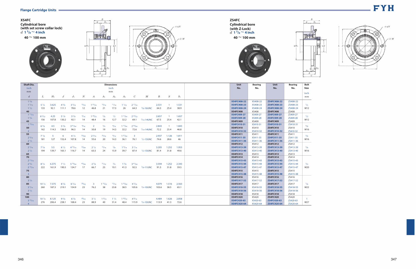
Flange Cartridge Units
XS4FC Cylindrical bore (with set screw collar lock) d 1 3/8 ~ 4 inch
40 ~ 100 mm
B S S 1
H 3 d L J
4- N
2- M
ZS4FC Cylindrical bore (with Z-Lock) d 1 3/8 ~ 4 inch
40 ~ 100 mm
B S S 1
H 3 d L J
4- N
2- M
346
A 2
A 3 A 1
A C
J 1 A 2
A 3 A 1
A C
J 1
347
Shaft Dia. inch mm
d
L
H3
J
J1
N
A
Dimensions inch mm
A1 A2
A3
C
M
B
S
S1
UnitNo.
BearingNo.
UnitNo.
Bearing No.
Bolt Size
inch mm
1 3/8 5 1/4
3.625
4 3/8
3 3/32
15/32
1 27/32
13/16
11/16
1 1/32
2 17/32
2.531
1
1.531
XS4FC408-22 XS408-22 ZS4FC408-22 ZS408-22 1/2 1 7/16 XS4FC408-23 XS408-23 ZS4FC408-23 ZS408-23
1 1/2 133 92.1 111.1 78.6 12 46.8 21 17.3 26 64.3 3/8-16UNC 64.3 25.4 38.9 XS4FC408-24 XS408-24 ZS4FC408-24 ZS408-24 M12 40 XS4FC408 XS408 ZS4FC408 ZS408
1 11/16
1 3/4
45
6 5/32
156 4.25
107.8 5 1/8
130.2 3 5/8
92.1
9/16
14 1 29/32
48.4
5/8
16
1/2
12.7 1 17/64
32.2 2 23/32
69.1
7/16-14UNC 2.657 67.5
1 25.4
1.657 42.1
XS4FC409-27 XS4FC409-28 XS4FC409
XS409-27 XS409-28 XS409
ZS4FC409-27 ZS4FC409-28 ZS4FC409
ZS409-27 ZS409-28 ZS409
1/2
M12
1 15/16
50 2
6 3/8
162 4.5
114.3 5 3/8
136.5 3 51/64
96.5
9/16
14 2
50.8
3/4
19
9/16
14.3 1 17/64
32.2 2 55/64
72.6
7/16-14UNC 2.843 72.2
1 25.4
1.843 46.8
XS4FC410-31 XS4FC410 XS4FC410-32
XS410-31 XS410 XS410-32
ZS4FC410-31 ZS4FC410 ZS4FC410-32
ZS410-31 ZS410 ZS410-32
5/8
M16
55 2 3/16
2 1/4
7 1/8
181 5
127 6
152.4 4 1/4
107.8
35/64
14 2 3/16
55.6
25/32
20
9/16
14.3 1 27/64
36.1 3
76.1
1/2-13UNC 2.937 74.6
1.126 28.6
1.811 46
XS4FC411 XS4FC411-35 XS4FC411-36
XS411 XS411-35 XS411-36
ZS4FC411 ZS4FC411-35 ZS4FC411-36
ZS411 ZS411-35 ZS411-36
5/8
M16
60 7 5/8
5.5
6 1/2
4 19/32
35/64
2 1/2
15/16
5/8
1 9/16
3 7/16
3.205
1.252
1.953
XS4FC412 XS412 ZS4FC412 ZS412 5/8 2 7/16 XS4FC413-39 XS413-39 ZS4FC413-39 ZS413-39
2 1/2 194 139.7 165.1 116.7 14 63.5 24 15.9 39.7 87.4 1/2-13UNC 81.4 31.8 49.6 XS4FC413-40 XS413-40 ZS4FC413-40 ZS413-40 M16 65 XS4FC413 XS413 ZS4FC413 ZS413 70
8 3/4
6.375
7 1/2
5 19/64
43/64
2 5/8
31/32
3/4
1 5/8
3 41/64
3.594
1.252
2.343
XS4FC414 XS414 ZS4FC414 ZS414
3/4
2 11/16 XS4FC415-43 XS415-43 ZS4FC415-43 ZS415-43 2 3/4 XS4FC415-44 XS415-44 ZS4FC415-44 ZS415-44 2 15/16 222 161.9 190.5 134.7 17 66.7 25 19.1 41.3 92.5 5/8-11UNC 91.3 31.8 59.5 XS4FC415-47 XS415-47 ZS4FC415-47 ZS415-47 M20
75 XS4FC415 XS415 ZS4FC415 ZS415 3 XS4FC415-48 XS415-48 ZS4FC415-48 ZS415-48
80
10 1/4
7.375
8 5/8
6 3/32
29/32
3
1 15/32
15/16
1 33/64
4 5/32
4.079
1.516
2.563
XS4FC416 XS416 ZS4FC416 ZS416
7/8
3 1/4 XS4FC417-52 XS417-52 ZS4FC417-52 ZS417-52 85 XS4FC417 XS417 ZS4FC417 ZS417
3 7/16 260 187.3 219.1 154.9 23 76.2 38 23.8 38.5 105.6 3/4-10UNC 103.6 38.5 65.1 XS4FC418-55 XS418-55 ZS4FC418-55 ZS418-55 M22 3 1/2 XS4FC418-56 XS418-56 ZS4FC418-56 ZS418-56
90 XS4FC418 XS418 ZS4FC418 ZS418 100
3 15/16
4
10 7/8
276 8.125 206.4
9 3/8
238.1 6 5/8
168.4
29/32
23 3 1/2
88.9 1 9/16
40 1 1/4
31.4 1 29/32
48.4 4 9/16
115.9
3/4-10UNC 4.484 113.9
1.626 41.3
2.858 72.6
XS4FC420 XS4FC420-63 XS4FC420-64
XS420 XS420-63 XS420-64
ZS4FC420 ZS4FC420-63 ZS4FC420-64
ZS420 ZS420-63 ZS420-64
1 M27
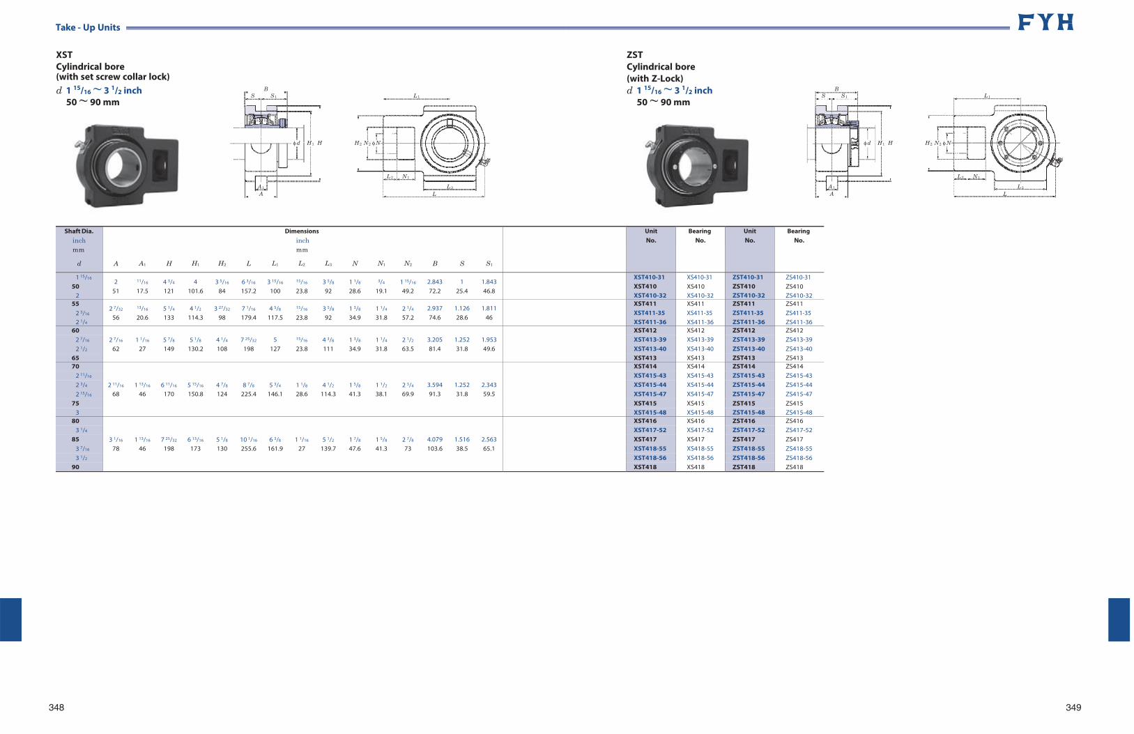
Take - Up Units
XST Cylindrical bore (with set screw collar lock) d 1 15/16 ~ 3 1/2 inch
50 ~ 90 mm
348
B S S 1
A 1
A
d H 1 H
L 1
H 2 N 2 N
L 2 N 1
L 3
L
ZST Cylindrical bore (with Z-Lock) d 1 15/16 ~ 3 1/2 inch
50 ~ 90 mm
B S S 1
A 1
A
d H 1 H
L 1
H 2 N 2 N
L 2 N 1
L 3
L
349
Shaft Dia. inch mm
d
A
A1
H
H1
H2
L
Dimensions inch mm
L1 L2 L3
N
N1
N2
B
S
S1
UnitNo.
BearingNo.
UnitNo.
Bearing No.
1 15/16
50 2
2 51
11/16
17.5 4 3/4
121 4
101.6 3 5/16
84 6 3/16
157.2 3 15/16
100
15/16
23.8 3 5/8
92 1 1/8
28.6
3/4
19.1 1 15/16
49.2 2.843 72.2
1 25.4
1.843 46.8
XST410-31 XST410 XST410-32
XS410-31 XS410 XS410-32
ZST410-31 ZST410 ZST410-32
ZS410-31 ZS410 ZS410-32
55 2 3/16
2 1/4
2 7/32
56
13/16
20.6 5 1/4
133 4 1/2
114.3 3 27/32
98 7 1/16
179.4 4 5/8
117.5
15/16
23.8 3 5/8
92 1 3/8
34.9 1 1/4
31.8 2 1/4
57.2 2.937 74.6
1.126 28.6
1.811 46
XST411 XST411-35 XST411-36
XS411 XS411-35 XS411-36
ZST411 ZST411-35 ZST411-36
ZS411 ZS411-35 ZS411-36
60 2 7/16
1 1/16
5 7/8
5 1/8
4 1/4
7 25/32
5
15/16
4 3/8
1 3/8
1 1/4
2 1/2
3.205
1.252
1.953
XST412 XS412 ZST412 ZS412 2 7/16 XST413-39 XS413-39 ZST413-39 ZS413-39 2 1/2 62 27 149 130.2 108 198 127 23.8 111 34.9 31.8 63.5 81.4 31.8 49.6 XST413-40 XS413-40 ZST413-40 ZS413-40
65 XST413 XS413 ZST413 ZS413 70
2 11/16
1 13/16
6 11/16
5 15/16
4 7/8
8 7/8
5 3/4
1 1/8
4 1/2
1 5/8
1 1/2
2 3/4
3.594
1.252
2.343
XST414 XS414 ZST414 ZS414 2 11/16 XST415-43 XS415-43 ZST415-43 ZS415-43 2 3/4 XST415-44 XS415-44 ZST415-44 ZS415-44 2 15/16 68 46 170 150.8 124 225.4 146.1 28.6 114.3 41.3 38.1 69.9 91.3 31.8 59.5 XST415-47 XS415-47 ZST415-47 ZS415-47
75 XST415 XS415 ZST415 ZS415 3 XST415-48 XS415-48 ZST415-48 ZS415-48
80
3 1/16
1 13/16
7 25/32
6 13/16
5 1/8
10 1/16
6 3/8
1 1/16
5 1/2
1 7/8
1 5/8
2 7/8
4.079
1.516
2.563
XST416 XS416 ZST416 ZS416 3 1/4 XST417-52 XS417-52 ZST417-52 ZS417-52
85 XST417 XS417 ZST417 ZS417 3 7/16 78 46 198 173 130 255.6 161.9 27 139.7 47.6 41.3 73 103.6 38.5 65.1 XST418-55 XS418-55 ZST418-55 ZS418-55 3 1/2 XST418-56 XS418-56 ZST418-56 ZS418-56
90 XST418 XS418 ZST418 ZS418
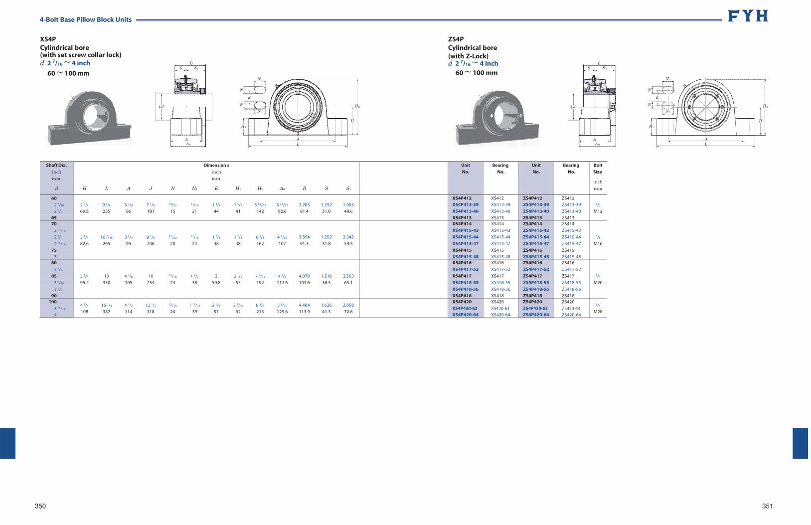
4-Bolt Base Pillow Block Units
XS4P Cylindrical bore (with set screw collar lock) d 2 7/16 ~ 4 inch
60 ~ 100 mm
N 1
ZS4P Cylindrical bore (with Z-Lock) d 2 7/16 ~ 4 inch
60 ~ 100 mm N 1
N
E
N H 2
N 1
H H 1
N
E
N H 2
N 1
H
H 1
350
J L
J L
351
B S S 1
d
A A 0
B S S 1
d
A A 0
Shaft Dia. inch mm
d
H
L
A
J
N
N1
Dimension inch mm
E
s
H1
H2
A0
B
S
S1
UnitNo.
BearingNo.
UnitNo.
Bearing No.
Bolt Size
inch mm
60 2 3/4
9 1/4
3 3/8
7 1/8
19/32
13/16
1 3/4
1 5/8
5 19/32
3 21/32
3.205
1.252
1.953
XS4P412 XS412 ZS4P412 ZS412 1/2 2 7/16 XS4P413-39 XS413-39 ZS4P413-39 ZS413-39
2 1/2 69.8 235 86 181 15 21 44 41 142 92.6 81.4 31.8 49.6 XS4P413-40 XS413-40 ZS4P413-40 ZS413-40 M12 65 XS4P413 XS413 ZS4P413 ZS413 70
3 1/4
10 7/16
3 3/4
8 1/8
25/32
15/16
1 7/8
1 7/8
6 3/8
4 7/32
3.594
1.252
2.343
XS4P414 XS414 ZS4P414 ZS414
5/8
2 11/16 XS4P415-43 XS415-43 ZS4P415-43 ZS415-43 2 3/4 XS4P415-44 XS415-44 ZS4P415-44 ZS415-44 2 15/16 82.6 265 95 206 20 24 48 48 162 107 91.3 31.8 59.5 XS4P415-47 XS415-47 ZS4P415-47 ZS415-47 M16
75 XS4P415 XS415 ZS4P415 ZS415 3 XS4P415-48 XS415-48 ZS4P415-48 ZS415-48
80
3 3/4
13
4 1/8
10
15/16
1 1/2
2
2 1/4
7 9/16
4 5/8
4.079
1.516
2.563
XS4P416 XS416 ZS4P416 ZS416
3/4
3 1/4 XS4P417-52 XS417-52 ZS4P417-52 ZS417-52 85 XS4P417 XS417 ZS4P417 ZS417
3 7/16 95.2 330 105 254 24 38 50.8 57 192 117.6 103.6 38.5 65.1 XS4P418-55 XS418-55 ZS4P418-55 ZS418-55 M20 3 1/2 XS4P418-56 XS418-56 ZS4P418-56 ZS418-56
90 XS4P418 XS418 ZS4P418 ZS418 100
3 15/16
4
4 1/4
108 15 1/4
387 4 1/2
114 12 1/2
318
15/16
24 1 17/32
39 2 1/4
57 2 7/16
62 8 3/8
213 5 3/32
129.6 4.484 113.9
1.626 41.3
2.858 72.6
XS4P420 XS4P420-63 XS4P420-64
XS420 XS420-63 XS420-64
ZS4P420 ZS4P420-63 ZS4P420-64
ZS420 ZS420-63 ZS420-64
3/4
M20
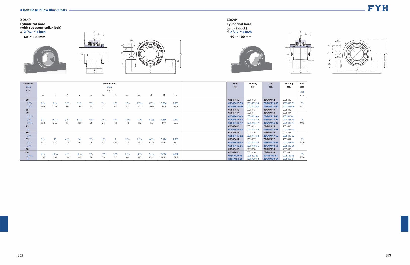
4-Bolt Base Pillow Block Units
XDS4P Cylindrical bore (with set screw collar lock) d 2 7/16 ~ 4 inch
60 ~ 100 mm
N 1
ZDS4P Cylindrical bore (with Z-Lock) d 2 7/16 ~ 4 inch
60 ~ 100 mm N 1
N
E
N H 2
N 1
H H 1
N
E
N H 2
N 1
H
H 1
352
J L
J L
353
BS 1
d
A A 0
BS 1
d
A A 0
Shaft Dia. inch mm
d
H
L
A
J
N
Dimensions inch mm
N1 E
H1
H2
A0
B
S1
UnitNo.
BearingNo.
UnitNo.
Bearing No.
Bolt Size
inch mm
60 2 3/4
9 1/4
3 3/8
7 1/8
19/32
13/16
1 3/4
1 5/8
5 19/32
3 21/32
3.906
1.953
XDS4P412 XDS412 ZDS4P412 ZDS412 1/2 2 7/16 XDS4P413-39 XDS413-39 ZDS4P413-39 ZDS413-39
2 1/2 69.8 235 86 181 15 21 44 41 142 92.6 99.2 49.6 XDS4P413-40 XDS413-40 ZDS4P413-40 ZDS413-40 M12 65 XDS4P413 XDS413 ZDS4P413 ZDS413 70
3 1/4
10 7/16
3 3/4
8 1/8
25/32
15/16
1 7/8
1 7/8
6 3/8
4 7/32
4.686
2.343
XDS4P414 XDS414 ZDS4P414 ZDS414
5/8
2 11/16 XDS4P415-43 XDS415-43 ZDS4P415-43 ZDS415-43 2 3/4 XDS4P415-44 XDS415-44 ZDS4P415-44 ZDS415-44 2 15/16 82.6 265 95 206 20 24 48 48 162 107 119 59.5 XDS4P415-47 XDS415-47 ZDS4P415-47 ZDS415-47 M16
75 XDS4P415 XDS415 ZDS4P415 ZDS415 3 XDS4P415-48 XDS415-48 ZDS4P415-48 ZDS415-48
80
3 3/4
13
4 1/8
10
15/16
1 1/2
2
2 1/4
7 9/16
4 5/8
5.126
2.563
XDS4P416 XDS416 ZDS4P416 ZDS416
3/4
3 1/4 XDS4P417-52 XDS417-52 ZDS4P417-52 ZDS417-52 85 XDS4P417 XDS417 ZDS4P417 ZDS417
3 7/16 95.2 330 105 254 24 38 50.8 57 192 117.6 130.2 65.1 XDS4P418-55 XDS418-55 ZDS4P418-55 ZDS418-55 M20 3 1/2 XDS4P418-56 XDS418-56 ZDS4P418-56 ZDS418-56
90 XDS4P418 XDS418 ZDS4P418 ZDS418 100
3 15/16
4
4 1/4
108 15 1/4
387 4 1/2
114 12 1/2
318
15/16
24 1 17/32
39 2 1/4
57 2 7/16
62 8 3/8
213 5 3/32
129.6 5.716 145.2
2.858 72.6
XDS4P420 XDS4P420-63 XDS4P420-64
XDS420 XDS420-63 XDS420-64
ZDS4P420 ZDS4P420-63 ZDS4P420-64
ZDS420 ZDS420-63 ZDS420-64
3/4
M20
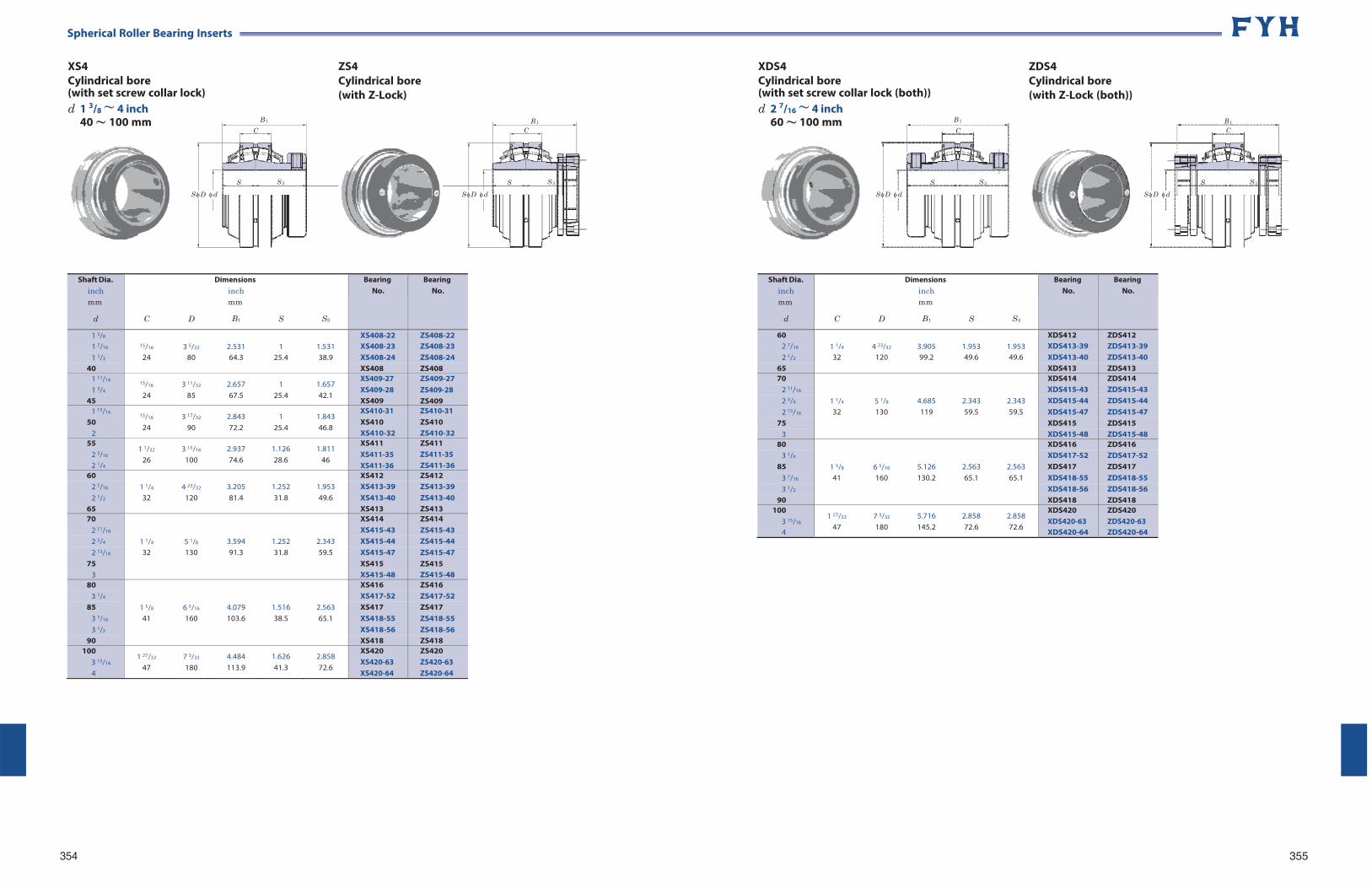
~ ~
Spherical Roller Bearing Inserts
XS4 Cylindrical bore (with set screw collar lock) d 1 3/8 ~ 4 inch
40 100 mm B 1
C
ZS4 Cylindrical bore (with Z-Lock)
B 1
C
XDS4 Cylindrical bore (with set screw collar lock (both)) d 2 7/16 ~ 4 inch
60 100 mm B 1
C
ZDS4 Cylindrical bore (with Z-Lock (both))
B 1
C
S D d
S S 3 S S 3
S D d
S D d
S S 3
S D d
S S 3
354 355
Shaft Dia. inch mm
d
C
D
Dimensions inch mm
B1
S
S3
Bearing No.
BearingNo.
60 1 1/4
4 23/32
3.905
1.953
1.953
XDS412 ZDS412 2 7/16 XDS413-39 ZDS413-39 2 1/2 32 120 99.2 49.6 49.6 XDS413-40 ZDS413-40
65 XDS413 ZDS413 70
1 1/4
5 1/8
4.685
2.343
2.343
XDS414 ZDS414 2 11/16 XDS415-43 ZDS415-43 2 3/4 XDS415-44 ZDS415-44 2 15/16 32 130 119 59.5 59.5 XDS415-47 ZDS415-47
75 XDS415 ZDS415 3 XDS415-48 ZDS415-48
80
1 5/8
6 5/16
5.126
2.563
2.563
XDS416 ZDS416 3 1/4 XDS417-52 ZDS417-52
85 XDS417 ZDS417 3 7/16 41 160 130.2 65.1 65.1 XDS418-55 ZDS418-55 3 1/2 XDS418-56 ZDS418-56
90 XDS418 ZDS418 100
3 15/16
4
1 27/32
47 7 3/32
180 5.716 145.2
2.858 72.6
2.858 72.6
XDS420 XDS420-63 XDS420-64
ZDS420 ZDS420-63 ZDS420-64
Shaft Dia. inch mm
d
C
D
Dimensions inch mm
B1
S
S3
Bearing No.
Bearing No.
1 3/8 15/16
3 5/32
2.531
1
1.531
XS408-22 ZS408-22 1 7/16 XS408-23 ZS408-23 1 1/2 24 80 64.3 25.4 38.9 XS408-24 ZS408-24
40 XS408 ZS408 1 11/16
1 3/4
45
15/16
24 3 11/32
85 2.657 67.5
1 25.4
1.657 42.1
XS409-27 XS409-28 XS409
ZS409-27 ZS409-28 ZS409
1 15/16
50 2
15/16
24 3 17/32
90 2.843 72.2
1 25.4
1.843 46.8
XS410-31 XS410 XS410-32
ZS410-31 ZS410 ZS410-32
55 2 3/16
2 1/4
1 1/32
26 3 15/16
100 2.937 74.6
1.126 28.6
1.811 46
XS411 XS411-35 XS411-36
ZS411 ZS411-35 ZS411-36
60 1 1/4
4 23/32
3.205
1.252
1.953
XS412 ZS412 2 7/16 XS413-39 ZS413-39 2 1/2 32 120 81.4 31.8 49.6 XS413-40 ZS413-40
65 XS413 ZS413 70
1 1/4
5 1/8
3.594
1.252
2.343
XS414 ZS414 2 11/16 XS415-43 ZS415-43 2 3/4 XS415-44 ZS415-44 2 15/16 32 130 91.3 31.8 59.5 XS415-47 ZS415-47
75 XS415 ZS415 3 XS415-48 ZS415-48
80
1 5/8
6 5/16
4.079
1.516
2.563
XS416 ZS416 3 1/4 XS417-52 ZS417-52
85 XS417 ZS417 3 7/16 41 160 103.6 38.5 65.1 XS418-55 ZS418-55 3 1/2 XS418-56 ZS418-56
90 XS418 ZS418 100
3 15/16
4
1 27/32
47 7 3/32
180 4.484 113.9
1.626 41.3
2.858 72.6
XS420 XS420-63 XS420-64
ZS420 ZS420-63 ZS420-64
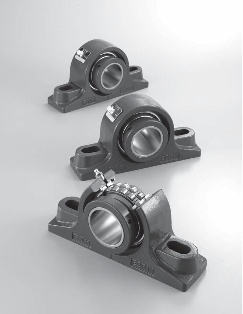
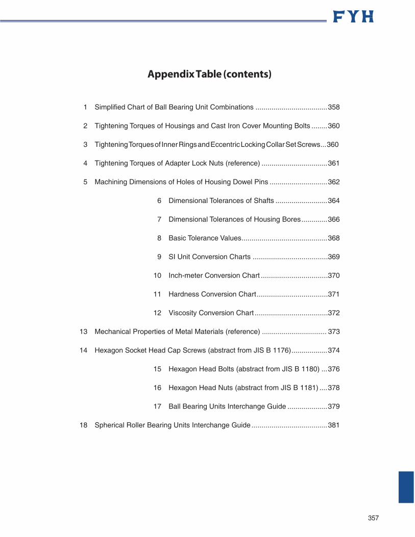
Appendix Table (contents)
1 Simplified Chart of Ball Bearing Unit Combinations .................................... 358
2 Tightening Torques of Housings and Cast Iron Cover Mounting Bolts ........ 360
3 Tightening Torques of Inner Rings and Eccentric Locking Collar Set Screws... 360
4 Tightening Torques of Adapter Lock Nuts (reference) ................................. 361
5 Machining Dimensions of Holes of Housing Dowel Pins ............................. 362
6 Dimensional Tolerances of Shafts .......................... 364
7 Dimensional Tolerances of Housing Bores ............. 366
8 Basic Tolerance Values ........................................... 368
9 SI Unit Conversion Charts .....................................369
10 Inch-meter Conversion Chart .................................370
11 Hardness Conversion Chart ...................................371
12 Viscosity Conversion Chart ....................................372
13 Mechanical Properties of Metal Materials (reference) ................................. 373
14 Hexagon Socket Head Cap Screws (abstract from JIS B 1176) .................. 374
15 Hexagon Head Bolts (abstract from JIS B 1180) ... 376
16 Hexagon Head Nuts (abstract from JIS B 1181) .... 378
17 Ball Bearing Units Interchange Guide .................... 379
18 Spherical Roller Bearing Units Interchange Guide ...................................... 381
357
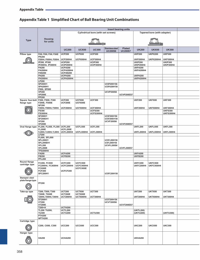
Appendix Table
Appendix Table 1 Simplified Chart of Ball Bearing Unit Combinations
358
Appendix Table
Type
Housing for units
Insert bearing units Cylindrical bore (with set screws) Tapered bore (with adapter)
UC200 UCX00 UC300 Stainless steel UC200S6
Plated UC200S7
UK200 UKX00 UK300
Pillow type P200, PX00, P300, P300E PK200 P200H4, PX00H4, P300H4
UCP200 UCP200H4
UCPX00 UCPX00H4
UCP300 UCP300H4
UKP200 UKP200H4
UKPX200 UKPX200H4
UKP300 UKP300H4
IP200, IP300 IP200H4, IP300H4
UCIP200 UCIP200H4 UCIP300
UCIP300H4 UKIP200 UKIP200H4 UKIP300
UKIP300H4 PA200 PA200H4 PAN200
UCPA200 UCPA200H4 UCPAN200
UKPA200 UKPA200H4
PH200 UCPH200 UKPH200 PH200H4 UCPH200H4 UKPH200H4 LP200 SP200H1 SPA200H1 P000, SP000
UCSP200H1S6 UCSPA200H1S6
VP200 VP200E UCVP200S6
UCVP200ES7 PP200
Square four-bolt flange type
F200, FX00, F300 F200E, FX00E NF200 F200H4, FX00H4, F300H4
UCF200 UCF200E UCF200H4
UCFX00 UCFX00E UCFX00H4
UCF300
UCF300H4
UKF200
UKF200H4
UKFX00
UKFX00H4
UKF300
UKF300H4
FS300 FS300H4 UCFS300
UCFS300H4 UKFS300 UKFS300H4
SF200H1 SF200EH1 VF200 VF200E
UCSF200H1S6 UCSF200EH1S6 UCVF200S6
UCVF200ES7
Oval flange type FL200, FLX00, FL300 FL200E FL200H4, FLX00H4, FL300H4
UCFL200 UCFL200E UCFL200H4
UCFLX00 UCFLX00H4
UCFL300 UCFL300H4
UKFL200 UKFL200H4
UKFLX00 UKFLX00H4
UKFL300 UKFL300H4
LF200 FL000, SFL000 SFL200H1 SFL200EH1 VFL200 VFL200E
UCSFL200H1S6 UCSFL200EH1S6 UCVFL200S6
UCVFL200ES7
TFD200H4 FA200 UCFA200 UKFA200 FB200 UCFB200 UKFB200 PFL200
Round flange cartridge type
FC200, FCX00 FC200H4, FCX00H4 FCX00E FCF200 SFC200H1
UCFC200 UCFC200H4 UCFCF200
UCFCX00 UCFCX00H4 UCFCX00E
UCSFC200H1S6
UKFC200 UKFC200H4
UKFCX00 UKFCX00H4
Stamped steel plate flange type
PF200
Take-up type T200, TX00, T300 T200E, TX00E T200H4, TX00H4, T300H4
UCT200 UCT200E UCT200H4
UCTX00 UCTX00E UCTX00H4
UCT300 UCT300H4
UKT200 UKT200H4
UKTX00 UKTX00H4
UKT300 UKT300H4
ST200H1 VT200 VT200E
UCST200H1S6 UCVT200S6
UCVT200ES7
T200+H UCTH200 TL200 TU200, TU300
UCTL200 UCTU200
UCTU300 (UKTL200) (UKTU200)
(UKTU300) PTH200 NPTH200
Cartridge type C200, CX00, C300
UCC200
UCCX00
UCC300
UKC200
UKCX00
UKC300
Hanger type HA200
UCHA200
UKHA200
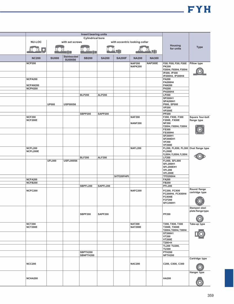
359
Insert bearing units
Housing for units
Type
Cylindrical bore NU-LOC with set screws with eccentric looking collar
NC200 SU000 Stainless steel SU000S6
SB200 SA200 SA200F NA200 NA300
NCP200 NAP200 NAPK200
NAP300E P200, PX00, P300, P300E PK200 P200H4, PX00H4, P300H4
Pillow type
IP200, IP300 IP200H4, IP300H4
NCPA200 NCPAN200
PA200 PA200H4 PAN200
NCPH200 PH200 PH200H4
BLP200 ALP200 LP200
UP000
USP000S6
SP200H1 SPA200H1 P000, SP000
VP200 VP200E
SBPP200 SAPP200 PP200 NCF200 NCF200E NAF200
NANF200
F200, FX00, F300 F200E, FX00E NF200 F200H4, FX00H4, F300H4
Square four-boltflange type
FS300 FS300H4
SF200H1 SF200EH1 VF200 VF200E
NCFL200 NCFL200E NAFL200 FL200, FLX00, FL300
FL200E FL200H4, FLX00H4, FL300H4
Oval flange type
BLF200 ALF200 LF200
UFL000 USFL000S6 FL000, SFL000 SFL200H1 SFL200EH1 VFL200 VFL200E
SATFD200FH4P9 TFD200H4 NCFA200 FA200 NCFB200 FB200
SBPFL200 SAPFL200 PFL200
NCFC200 NAFC200 FC200, FCX00 FC200H4, FCX00H4 FCX00E FCF200 SFC200H1
Round flange cartridge type
SBPF200
SAPF200
PF200
Stamped steel plate flange type
NCT200 NCT200E NAT200
NAT200E T200, TX00, T300 T200E, TX00E T200H4, TX00H4, T300H4
Take-up type
ST200H1 VT200 VT200E T200+H
TL200 TU200, TU300
SBPTH200 SBNPTH200 PTH200
NPTH200 NCC200
NAC200
C200, CX00, C300
Cartridge type
NCHA200
HA200
Hanger type
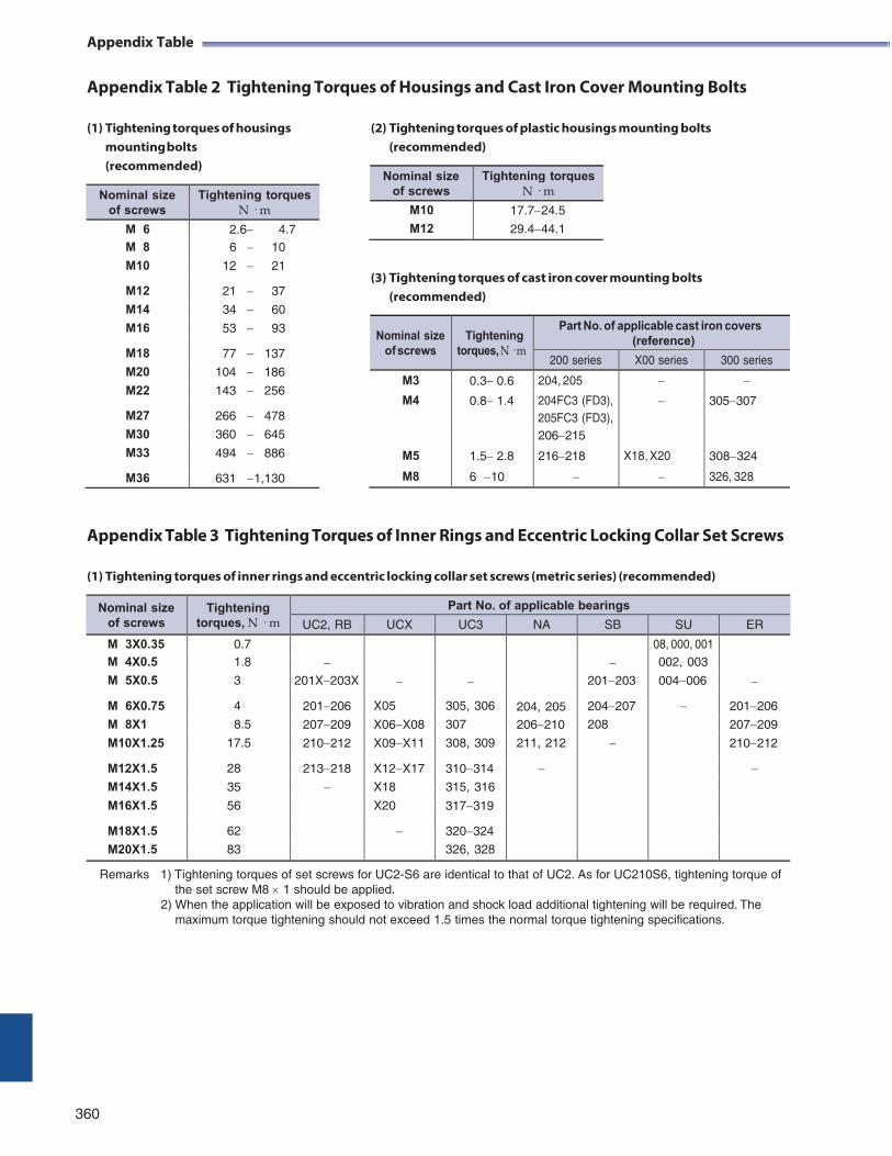
Appendix Table
Appendix Table 2 Tightening Torques of Housings and Cast Iron Cover Mounting Bolts
(1) Tightening torques of housings mounting bolts (recommended)
(2) Tightening torques of plastic housings mounting bolts (recommended)
(3) Tightening torques of cast iron cover mounting bolts (recommended)
Nominal size
of screws
Tightening
torques, N · m
Part No. of applicable cast iron covers (reference)
200 series X00 series 300 series
M3 0.30.6 204, 205
M4 0.81.4 204FC3 (FD3), 305307 205FC3 (FD3), 206215
M5 1.52.8 216218 X18, X20 308324
M8 6 10 326, 328
Appendix Table 3 Tightening Torques of Inner Rings and Eccentric Locking Collar Set Screws
(1) Tightening torques of inner rings and eccentric locking collar set screws (metric series) (recommended)
Nominal size of screws
Tightening torques, N · m
Part No. of applicable bearings
UC2, RB UCX UC3 NA SB SU ER
M 3X0.35 0.7
204, 205
08, 000, 001
M 4X0.5 1.8 002, 003
M 5X0.5 3 201X203X 201203 004006
M 6X0.75 4 201206 X05 305, 306 204207 201206
M 8X1 8.5 207209 X06X08 307 206210 208 207209
M10X1.25 17.5 210212 X09X11 308, 309 211, 212 210212
M12X1.5 28 213218 X12X17 310314 M14X1.5 35 X18 315, 316
M16X1.5 56 X20 317319
M18X1.5 62 320324
M20X1.5 83 326, 328
Remarks 1) Tightening torques of set screws for UC2-S6 are identical to that of UC2. As for UC210S6, tightening torque of the set screw M8 1 should be applied.
2) When the application will be exposed to vibration and shock load additional tightening will be required. The maximum torque tightening should not exceed 1.5 times the normal torque tightening specifications.
360
Nominal size of screws
Tightening torques N · m
M10
M12
17.724.5
29.444.1
Nominal size of screws
Tightening torques N · m
M 6 2.6 4.7 M 8 6 10
M10 12 21
M12 21 37
M14 34 60
M16 53 93
M18 77 137
M20 104 186
M22 143 256
M27 266 478
M30 360 645
M33 494 886
M36 631 1,130
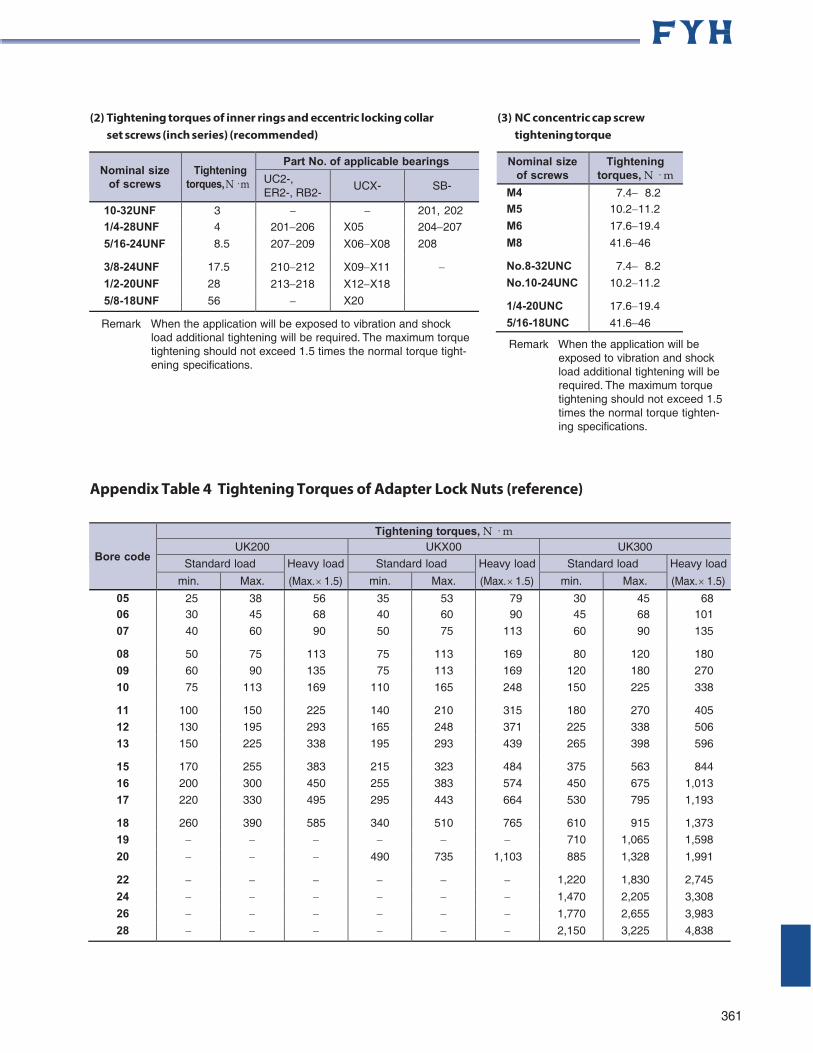
(2) Tightening torques of inner rings and eccentric locking collar set screws (inch series) (recommended)
(3) NC concentric cap screw tightening torque
Nominal size
of screws
Tightening
torques, N · m
Part No. of applicable bearings
UC2-, ER2-, RB2-
UCX- SB-
10-32UNF 3 201, 202 1/4-28UNF 4 201206 X05 204207
5/16-24UNF 8.5 207209 X06X08 208
3/8-24UNF 17.5 210212 X09X11 1/2-20UNF 28 213218 X12X18
5/8-18UNF 56 X20
Remark When the application will be exposed to vibration and shock load additional tightening will be required. The maximum torque tightening should not exceed 1.5 times the normal torque tight- ening specifications.
Remark When the application will be exposed to vibration and shock load additional tightening will be required. The maximum torque tightening should not exceed 1.5 times the normal torque tighten- ing specifications.
Appendix Table 4 Tightening Torques of Adapter Lock Nuts (reference)
Bore code
Tightening torques, N · m UK200 UKX00 UK300
Standard load Heavy load
(Max. 1.5)
Standard load Heavy load
(Max. 1.5)
Standard load Heavy load
(Max. 1.5) min. Max. min. Max. min. Max.
05 25 38 56 35 53 79 30 45 68 06 30 45 68 40 60 90 45 68 101
07 40 60 90 50 75 113 60 90 135
08 50 75 113 75 113 169 80 120 180
09 60 90 135 75 113 169 120 180 270
10 75 113 169 110 165 248 150 225 338
11 100 150 225 140 210 315 180 270 405
12 130 195 293 165 248 371 225 338 506
13 150 225 338 195 293 439 265 398 596
15 170 255 383 215 323 484 375 563 844
16 200 300 450 255 383 574 450 675 1,013
17 220 330 495 295 443 664 530 795 1,193
18 260 390 585 340 510 765 610 915 1,373
19 710 1,065 1,598
20 490 735 1,103 885 1,328 1,991
22 1,220 1,830 2,745
24 1,470 2,205 3,308
26 1,770 2,655 3,983
28 2,150 3,225 4,838
361
Nominal size of screws
Tightening torques, N · m
M4 7.48.2 M5 10.211.2
M6 17.619.4
M8 41.646
No.8-32UNC 7.48.2
No.10-24UNC 10.211.2
1/4-20UNC 17.619.4
5/16-18UNC 41.646
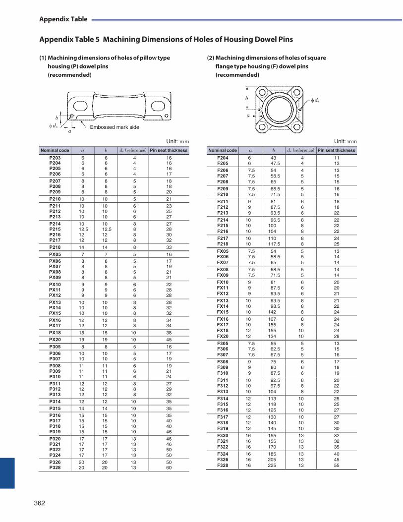
Appendix Table
Appendix Table 5 Machining Dimensions of Holes of Housing Dowel Pins
(1) Machining dimensions of holes of pillow type housing (P) dowel pins (recommended)
(2) Machining dimensions of holes of square flange type housing (F) dowel pins (recommended)
ds
b
ds
a
Embossed mark side
Unit: mm
Unit: mm
362
Nominal code a b ds (reference) Pin seat thickness
F204 6 43 4 11 F205 6 47.5 4 13
F206 7.5 54 4 13 F207 7.5 58.5 5 15 F208 7.5 65 5 15
F209 7.5 68.5 5 16 F210 7.5 71.5 5 16
F211 9 81 6 18 F212 9 87.5 6 18 F213 9 93.5 6 22
F214 10 96.5 8 22 F215 10 100 8 22 F216 10 104 8 22
F217 10 110 8 24 F218 10 117.5 8 25
FX05 7.5 54 5 13 FX06 7.5 58.5 5 14 FX07 7.5 65 5 14
FX08 7.5 68.5 5 14 FX09 7.5 71.5 5 14
FX10 9 81 6 20 FX11 9 87.5 6 20 FX12 9 93.5 6 21
FX13 10 93.5 8 21 FX14 10 98.5 8 22 FX15 10 142 8 24
FX16 10 107 8 24 FX17 10 155 8 24 FX18 12 155 10 24 FX20 12 134 10 28
F305 7.5 55 5 13 F306 7.5 62.5 5 15 F307 7.5 67.5 5 16
F308 9 75 6 17 F309 9 80 6 18 F310 9 87.5 6 19
F311 10 92.5 8 20 F312 10 97.5 8 22 F313 10 104 8 22
F314 12 113 10 25 F315 12 118 10 25 F316 12 125 10 27
F317 12 130 10 27 F318 12 140 10 30 F319 12 145 10 30
F320 16 155 13 32 F321 16 155 13 32 F322 16 170 13 35
F324 16 185 13 40 F326 16 205 13 45 F328 16 225 13 55
Nominal code a b ds (reference) Pin seat thickness
P203 6 6 4 16 P204 6 6 4 16 P205 6 6 4 16 P206 6 6 4 17
P207 8 8 5 18 P208 8 8 5 18 P209 8 8 5 20
P210 10 10 5 21
P211 10 10 6 23 P212 10 10 6 25 P213 10 10 6 27
P214 10 10 8 27 P215 12.5 12.5 8 28 P216 12 12 8 30 P217 12 12 8 32
P218 14 14 8 33
PX05 7 7 5 16
PX06 8 8 5 17 PX07 8 8 5 19 PX08 8 8 5 21 PX09 8 8 5 21
PX10 9 9 6 22 PX11 9 9 6 28 PX12 9 9 6 28
PX13 10 10 8 28 PX14 10 10 8 32 PX15 10 10 8 32
PX16 12 12 8 34 PX17 12 12 8 34
PX18 15 15 10 38
PX20 19 19 10 45
P305 8 8 5 16 P306 10 10 5 17 P307 10 10 5 19
P308 11 11 6 19 P309 11 11 6 21 P310 11 11 6 24
P311 12 12 8 27 P312 12 12 8 29 P313 12 12 8 32
P314 12 12 10 35
P315 14 14 10 35
P316 15 15 10 35 P317 15 15 10 40 P318 15 15 10 40 P319 15 15 10 46
P320 17 17 13 46 P321 17 17 13 46 P322 17 17 13 50 P324 17 17 13 50
P326 20 20 13 50 P328 20 20 13 60
Appendix Table
b
a
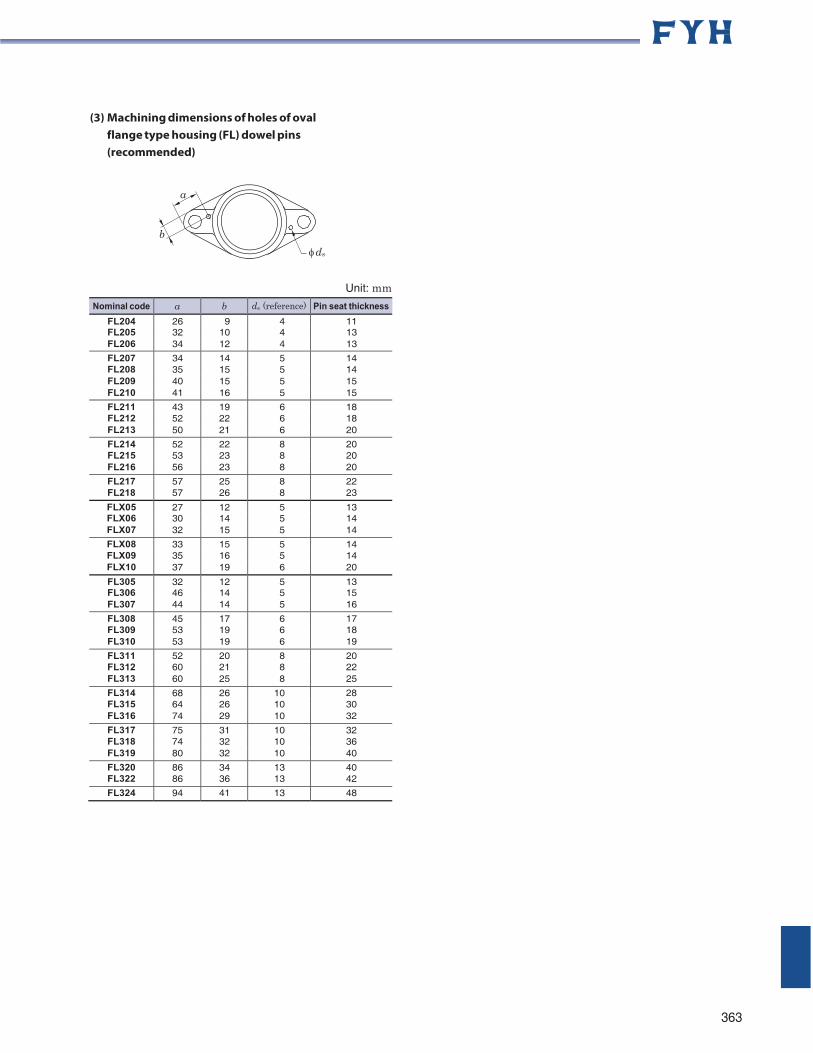
(3) Machining dimensions of holes of oval flange type housing (FL) dowel pins (recommended)
Unit: mm
Nominal code a b ds (reference) Pin seat thickness
FL204 26 9 4 11 FL205 32 10 4 13 FL206 34 12 4 13
FL207 34 14 5 14 FL208 35 15 5 14 FL209 40 15 5 15 FL210 41 16 5 15
FL211 43 19 6 18 FL212 52 22 6 18 FL213 50 21 6 20
FL214 52 22 8 20 FL215 53 23 8 20 FL216 56 23 8 20
FL217 57 25 8 22 FL218 57 26 8 23
FLX05 27 12 5 13 FLX06 30 14 5 14 FLX07 32 15 5 14
FLX08 33 15 5 14 FLX09 35 16 5 14 FLX10 37 19 6 20
FL305 32 12 5 13 FL306 46 14 5 15 FL307 44 14 5 16
FL308 45 17 6 17 FL309 53 19 6 18 FL310 53 19 6 19
FL311 52 20 8 20 FL312 60 21 8 22 FL313 60 25 8 25
FL314 68 26 10 28 FL315 64 26 10 30 FL316 74 29 10 32
FL317 75 31 10 32 FL318 74 32 10 36 FL319 80 32 10 40
FL320 86 34 13 40 FL322 86 36 13 42
FL324 94 41 13 48
363
a
b
ds
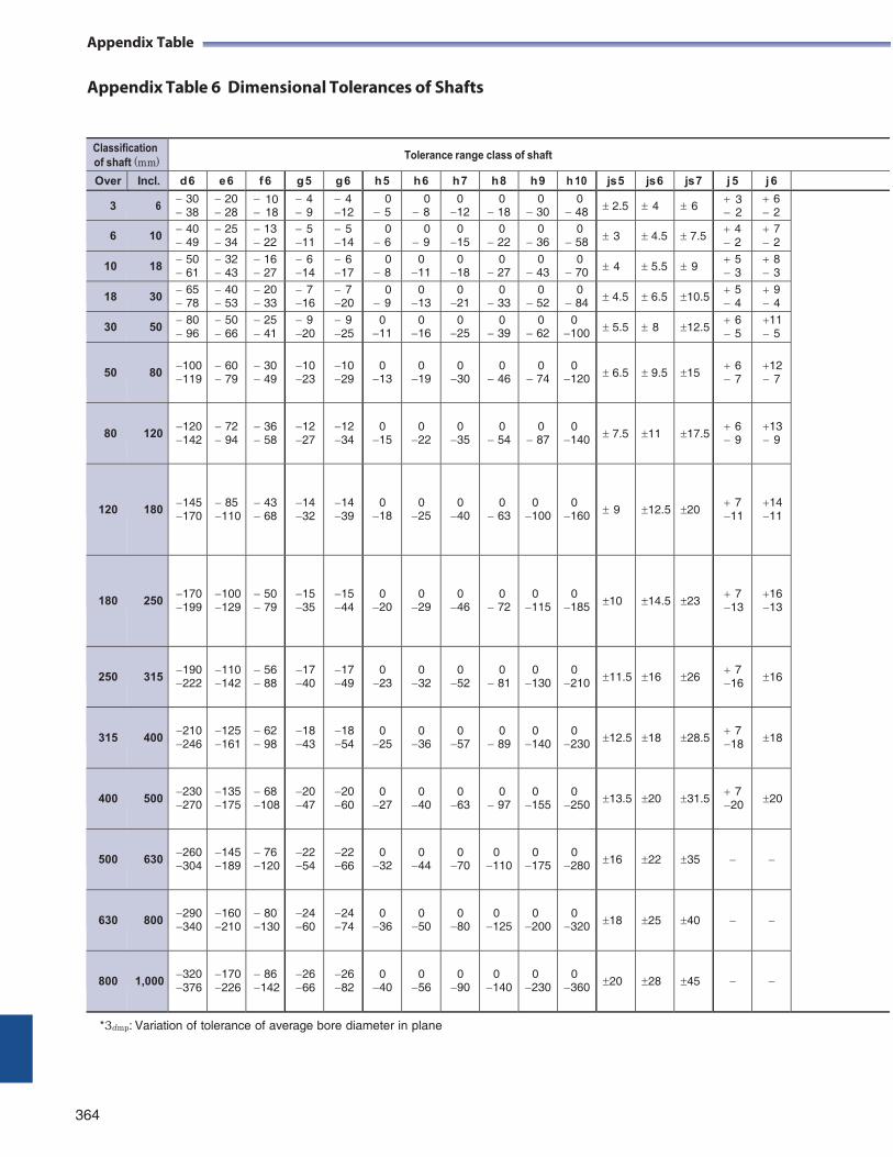
Appendix Table
Appendix Table 6 Dimensional Tolerances of Shafts
*3dmp: Variation of tolerance of average bore diameter in plane
364
Appendix Table
Classification of shaft (mm)
Tolerance range class of shaft
Over Incl. d 6 e 6 f 6 g 5 g 6 h 5 h 6 h 7 h 8 h 9 h 10 js 5 js 6 js 7 j 5 j 6
3 6 30 38
20 28
10 18
4 9
4 12
0 5
0 8
0 12
0 18
0 30
0 48 2.5 4 6
3 2
6 2
6 10 40 49
25 34
13 22
5 11
5 14
0 6
0 9
0 15
0 22
0 36
0 58 3 4.5 7.5
4 2
7 2
10 18 50 61
32 43
16 27
6 14
6 17
0 8
0 11
0 18
0 27
0 43
0 70 4 5.5 9
5 3
8 3
18 30 65 78
40 53
20 33
7 16
7 20
0 9
0 13
0 21
0 33
0 52
0 84 4.5 6.5 10.5
5 4
9 4
30 50 80 96
50 66
25 41
9 20
9 25
0 11
0 16
0 25
0 39
0 62
0 100 5.5 8 12.5
6 5
11 5
50
80
100 119
60 79
30 49
10 23
10 29
0
13
0
19
0
30
0
46
0
74
0
120
6.5
9.5
15
6 7
12 7
80
120
120 142
72 94
36 58
12 27
12 34
0
15
0
22
0
35
0
54
0
87
0
140
7.5
11
17.5
6 9
13 9
120
180
145 170
85 110
43 68
14 32
14 39
0
18
0
25
0
40
0
63
0
100
0
160
9
12.5
20
7 11
14 11
180
250
170 199
100 129
50 79
15 35
15 44
0
20
0
29
0
46
0
72
0
115
0
185
10
14.5
23
7 13
16 13
250
315
190 222
110 142
56 88
17 40
17 49
0 23
0
32
0
52
0
81
0
130
0
210
11.5
16
26
7 16
16
315
400
210 246
125 161
62 98
18 43
18 54
0
25
0
36
0
57
0
89
0
140
0
230
12.5
18
28.5
7 18
18
400
500
230 270
135 175
68 108
20 47
20 60
0
27
0
40
0
63
0
97
0
155
0
250
13.5
20
31.5
7 20
20
500
630
260 304
145 189
76 120
22 54
22 66
0
32
0
44
0
70
0
110
0
175
0
280
16
22
35
630
800
290 340
160 210
80 130
24 60
24 74
0
36
0 50
0
80
0
125
0
200
0
320
18
25
40
800
1,000
320 376
170 226
86 142
26 66
26 82
0
40
0
56
0
90
0
140
0
230
0
360
20
28
45
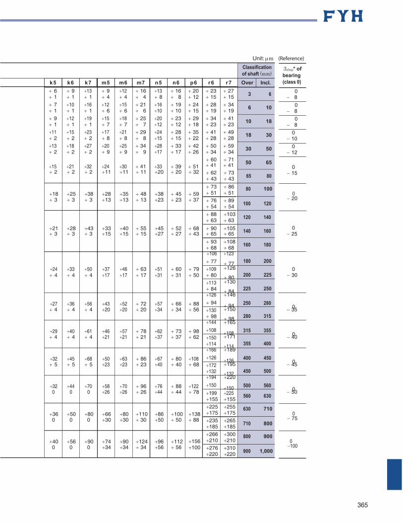
Unit: m (Reference)
Classification of shaft (mm)
65 80
3dmp* of bearing (class 0)
0 8
0 8
0 8
0 10
0 12
0
15
80 100 0
20
106
123
100 120
120 140
140 160
160 180
0
25
24 4
33 4
50 4
37 17
46 17
63 17
51 31
60 31
79 50
77 109 80 113 84 126
77 180 200 126
80 200 225 130
84 225 250 146
0 30
27 36 56 43 52 72 57 66 88 94 94 250 280 0
4 4 4 20 20 20 34 34 56 130
98 144
150
98 280 315 165
35
29 40 61 46 57 78 62 73 98 108 108 315 355 0
4 4 4 21 21 21 37 37 62 150
114 166
171
114 355 400 189
40
32 45 68 50 63 86 67 80 108 126 126 400 450 0
5 5 5 23 23 23 40 40 68 172
132 194
195
132 450 500 220
45
32 44 70 58 70 96 76 88 122 150 150 500 560 0
0 0 0 26 26 26 44 44 78 199 225 560 630
50
630 710 0
75 710 800
800 900 0 100
900 1,000
365
k 5 k 6 k 7 m 5 m 6 m 7 n 5 n 6 p 6 r 6 r 7 Over Incl.
6 9 13 9 12 16 13 16 20 23 27 1 1 1 4 4 4 8 8 12 15 15
7 10 16 12 15 21 16 19 24 28 34 1 1 1 6 6 6 10 10 15 19 19
9 12 19 15 18 25 20 23 29 34 41 1 1 1 7 7 7 12 12 18 23 23 11 15 23 17 21 29 24 28 35 41 49 2 2 2 8 8 8 15 15 22 28 28
13 18 27 20 25 34 28 33 42 50 59 2 2 2 9 9 9 17 17 26 34 34
60 71 15 21 32 24 30 41 33 39 51 41 41
3 6
6 10
10 18
18 30
30 50
50 65
2 2 2 11 11 11 20 20 32 62 43
73 43
18
25
38
28
35
48
38
45
59
73 51
86 51
3 3 3 13 13 13 23 23 37 76 54
89 54
88 63
103 63
21 28 43 33 40 55 45 52 68 90 105 3 3 3 15 15 15 27 27 43 65 65
93 68
108 68
155 155
36
50
80
66
80
110
86
100
138
225 175
255 175
0 0 0 30 30 30 50 50 88 235 185
265 185
40
56
90
74
90
124
96
112
156
266 210
300 210
0 0 0 34 34 34 56 56 100 276 220
310 220
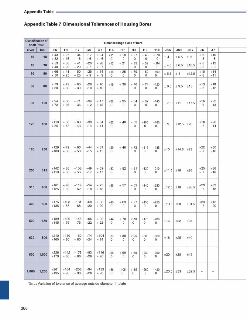
Appendix Table
Appendix Table 7 Dimensional Tolerances of Housing Bores
*3Dmp: Variation of tolerance of average outside diameter in plate
366
Appendix Table
Classification of shaft (mm)
Tolerance range class of bore
Over Incl. E 6 F 6 F 7 G 6 G 7 H 6 H 7 H 8 H 9 H 10 JS 5 JS 6 JS 7 J 6 J 7
10 18 43 32
27 16
34 16
17 6
24 6
11 0
18 0
27 0
43 0
70 0 4 5.5 9
6 5
10 8
18 30 53 40
33 20
41 20
20 7
28 7
13 0
21 0
33 0
52 0
84 0 4.5 6.5 10.5
8 5
12 9
30 50 66 50
41 25
50 25
25 9
34 9
16 0
25 0
39 0
62 0
100 0 5.5 8 12.5
10 6
14 11
50
80
79 60
49 30
60 30
29 10
40 10
19 0
30
0
46
0
74
0
120 0
6.5
9.5
15
13 6
18 12
80
120
94 72
58 36
71 36
34 12
47 12
22 0
35
0
54
0
87
0
140 0
7.5
11
17.5
16 6
22 13
120
180
110 85
68 43
83 43
39 14
54 14
25 0
40
0
63
0
100
0
160 0
9
12.5
20
18 7
26 14
180
250
129 100
79 50
96 50
44 15
61 15
29 0
46
0
72
0
115 0
185 0
10
14.5
23
22 7
30 16
250
315
142 110
88 56
108 56
49 17
69 17
32 0
52
0
81
0
130 0
210 0
11.5
16
26
25 7
36 16
315
400
161 125
98 62
119 62
54 18
75 18
36 0
57
0
89
0
140 0
230 0
12.5
18
28.5
29 7
39 18
400
500
175 135
108 68
131 68
60 20
83 20
40 0
63
0
97
0
155 0
250 0
13.5
20
31.5
33 7
43 20
500
630
189 145
120 76
146 76
66 22
92 22
44 0
70
0
110 0
175 0
280 0
16
22
35
630
800
210 160
130 80
160 80
74 24
104 24
50 0
80
0
125 0
200 0
320 0
18
25
40
800
1,000
226 170
142 86
176 86
82 26
116 26
56 0
90
0
140 0
230 0
360 0
20
28
45
1,000
1,250
261 195
164 98
203 98
94 28
133 28
66 0
105
0
165 0
260 0
420 0
23.5
33
52.5
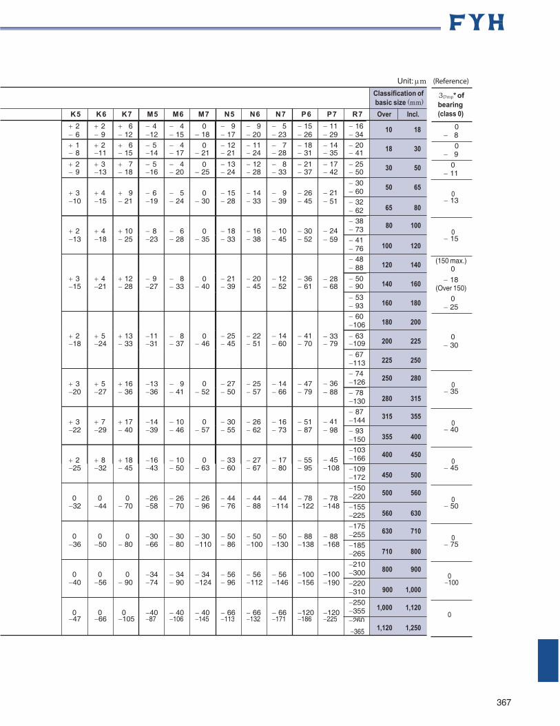
Unit: m (Reference)
Classification of basic size (mm)
K 5 K 6 K 7 M 5 M 6 M 7 N 5 N 6 N 7 P 6 P 7 R 7 Over Incl.
10 18
18 30
30 50
3Dmp* of bearing (class 0)
0 8
0 9
0 11
50 65 0
13 65 80
80 100 0
15 100 120
120 140
140 160
160 180
180 200
200 225
225 250
(150 max.) 0
18 (Over 150)
0 25
0 30
250 280 0
35 280 315
315 355 0
40 355 400
400 450 0
45 450 500
500 560 0
50 560 630
630 710 0
75 710 800
800 900 0 100
900 1,000
1,000 1,120 0
365 1,120 1,250
367
2 6
2 9
6 12
4 12
4 15
0 18
9 17
9 20
5 23
15 26
11 29
16 34
1 2 6 5 4 0 12 11 7 18 14 20 8 11 15 14 17 21 21 24 28 31 35 41
2 3 7 5 4 0 13 12 8 21 17 25 9 13 18 16 20 25 24 28 33 37 42 50
3
4
9
6
5
0
15
14
9
26
21
30 60
10 15 21 19 24 30 28 33 39 45 51 32 62
2
4
10
8
6
0
18
16
10
30
24
38 73
13 18 25 23 28 35 33 38 45 52 59 41 76
48 88
3 4 12 9 8 0 21 20 12 36 28 50 15 21 28 27 33 40 39 45 52 61 68 90
53 93
60 106
2 5 13 11 8 0 25 22 14 41 33 63 18 24 33 31 37 46 45 51 60 70 79 109
67 113
3
5
16
13
9
0
27
25
14
47
36
74 126
20 27 36 36 41 52 50 57 66 79 88 78 130
3
7
17
14
10
0
30
26
16
51
41
87 144
22 29 40 39 46 57 55 62 73 87 98 93 150
2
8
18
16
10
0
33
27
17
55
45
103 166
25 32 45 43 50 63 60 67 80 95 108 109 172
0
0
0
26
26
26
44
44
44
78
78
150 220
32 44 70 58 70 96 76 88 114 122 148 155 225
0
0
0
30
30
30
50
50
50
88
88
175 255
36 50 80 66 80 110 86 100 130 138 168 185 265
0
0
0
34
34
34
56
56
56
100
100
210 300
40 56 90 74 90 124 96 112 146 156 190 220 310
0
0
0
40
40
40
66
66
66
120
120
250 355
47 66 105 87 106 145 113 132 171 186 225 260
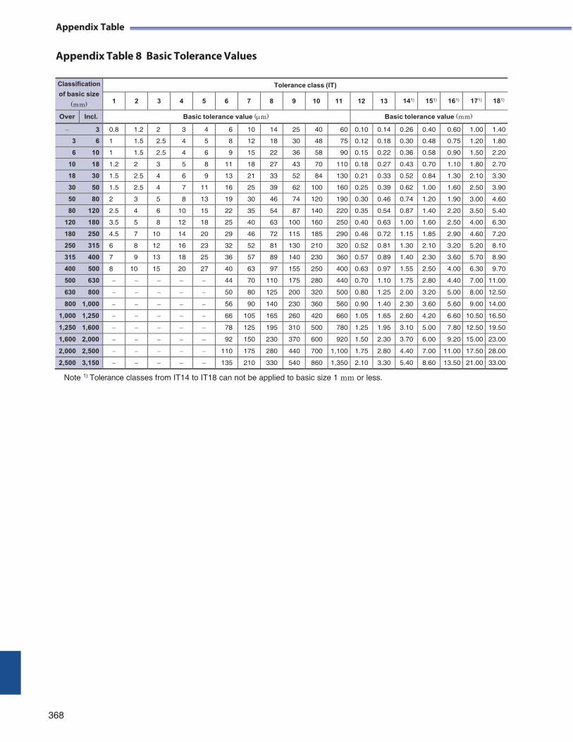
Appendix Table
Appendix Table 8 Basic Tolerance Values
Classification
of basic size
(mm)
Tolerance class (IT)
1 2 3 4 5 6 7 8 9 10 11 12 13 141) 151) 161) 171) 181)
Over Incl. Basic tolerance value (m) Basic tolerance value (mm)
3 0.8 1.2 2 3 4 6 10 14 25 40 60 0.10 0.14 0.26 0.40 0.60 1.00 1.40
3 6 1 1.5 2.5 4 5 8 12 18 30 48 75 0.12 0.18 0.30 0.48 0.75 1.20 1.80
6 10 1 1.5 2.5 4 6 9 15 22 36 58 90 0.15 0.22 0.36 0.58 0.90 1.50 2.20
10 18 1.2 2 3 5 8 11 18 27 43 70 110 0.18 0.27 0.43 0.70 1.10 1.80 2.70
18 30 1.5 2.5 4 6 9 13 21 33 52 84 130 0.21 0.33 0.52 0.84 1.30 2.10 3.30
30 50 1.5 2.5 4 7 11 16 25 39 62 100 160 0.25 0.39 0.62 1.00 1.60 2.50 3.90
50 80 2 3 5 8 13 19 30 46 74 120 190 0.30 0.46 0.74 1.20 1.90 3.00 4.60
80 120 2.5 4 6 10 15 22 35 54 87 140 220 0.35 0.54 0.87 1.40 2.20 3.50 5.40
120 180 3.5 5 8 12 18 25 40 63 100 160 250 0.40 0.63 1.00 1.60 2.50 4.00 6.30
180 250 4.5 7 10 14 20 29 46 72 115 185 290 0.46 0.72 1.15 1.85 2.90 4.60 7.20
250 315 6 8 12 16 23 32 52 81 130 210 320 0.52 0.81 1.30 2.10 3.20 5.20 8.10
315 400 7 9 13 18 25 36 57 89 140 230 360 0.57 0.89 1.40 2.30 3.60 5.70 8.90
400 500 8 10 15 20 27 40 63 97 155 250 400 0.63 0.97 1.55 2.50 4.00 6.30 9.70
500 630 44 70 110 175 280 440 0.70 1.10 1.75 2.80 4.40 7.00 11.00
630 800 50 80 125 200 320 500 0.80 1.25 2.00 3.20 5.00 8.00 12.50
800 1,000 56 90 140 230 360 560 0.90 1.40 2.30 3.60 5.60 9.00 14.00
1,000 1,250 66 105 165 260 420 660 1.05 1.65 2.60 4.20 6.60 10.50 16.50
1,250 1,600 78 125 195 310 500 780 1.25 1.95 3.10 5.00 7.80 12.50 19.50
1,600 2,000 92 150 230 370 600 920 1.50 2.30 3.70 6.00 9.20 15.00 23.00
2,000 2,500 110 175 280 440 700 1,100 1.75 2.80 4.40 7.00 11.00 17.50 28.00
2,500 3,150 135 210 330 540 860 1,350 2.10 3.30 5.40 8.60 13.50 21.00 33.00
Note 1) Tolerance classes from IT14 to IT18 can not be applied to basic size 1 mm or less.
368
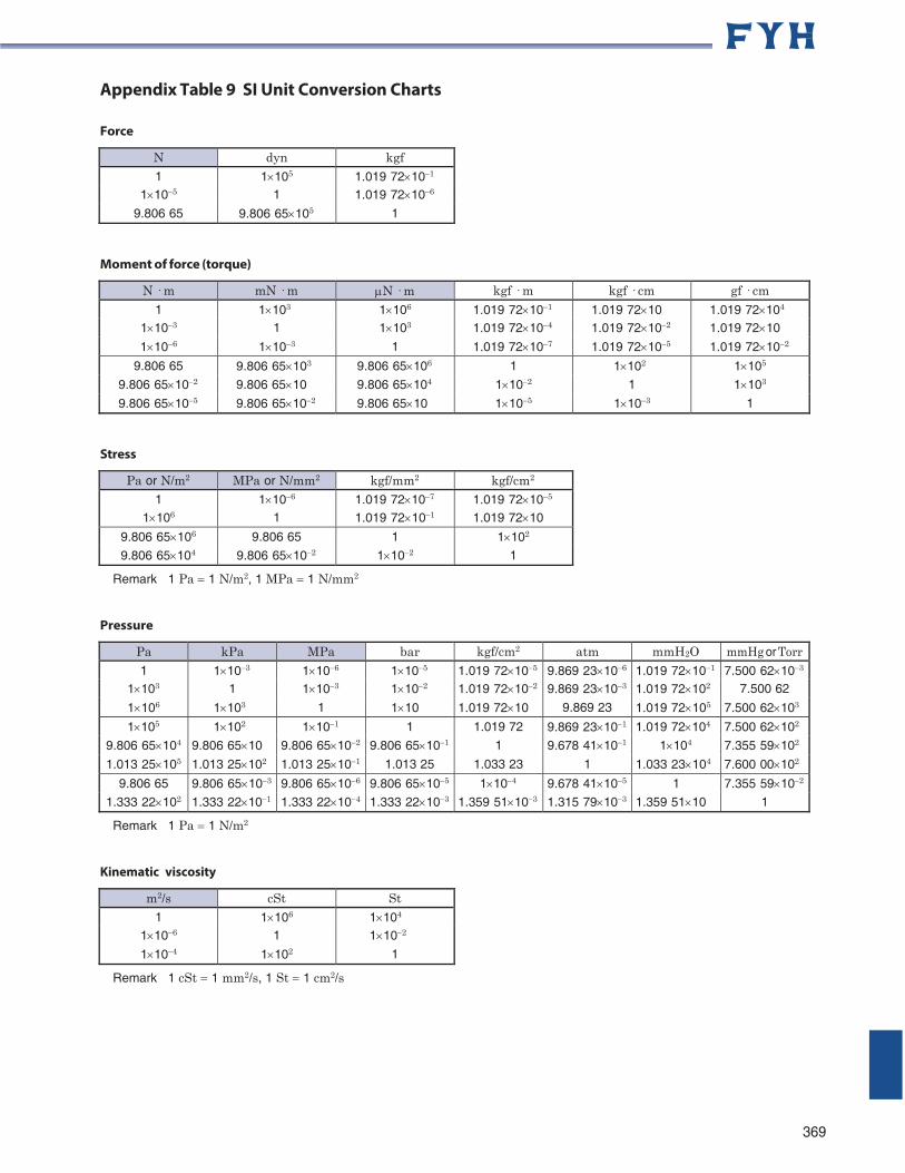
Appendix Table 9 SI Unit Conversion Charts
Force
N dyn kgf 1 1105 1.019 72101
1105 1 1.019 72106
9.806 65 9.806 65105 1
Moment of force (torque)
N · m mN · m N · m kgf · m kgf · cm gf · cm 1 1103 1106 1.019 72101 1.019 7210 1.019 72104
1103 1 1103 1.019 72104 1.019 72102 1.019 7210
1106 1103 1 1.019 72107 1.019 72105 1.019 72102
9.806 65 9.806 65103 9.806 65106 1 1102 1105
9.806 65102 9.806 6510 9.806 65104 1102 1 1103
9.806 65105 9.806 65102 9.806 6510 1105 1103 1
Stress
Pa or N/m2 MPa or N/mm2 kgf/mm2 kgf/cm2
1 1106 1.019 72107 1.019 72105
1106 1 1.019 72101 1.019 7210
9.806 65106 9.806 65 1 1102
9.806 65104 9.806 65102 1102 1
Remark 1 Pa 1 N/m2, 1 MPa 1 N/mm2
Pressure
Pa kPa MPa bar kgf/cm2 atm mmH2O mmHg or Torr1 1103 1106 1105 1.019 72105 9.869 23106 1.019 72101 7.500 62103
1103 1 1103 1102 1.019 72102 9.869 23103 1.019 72102 7.500 62
1106 1103 1 110 1.019 7210 9.869 23 1.019 72105 7.500 62103
1105 1102 1101 1 1.019 72 9.869 23101 1.019 72104 7.500 62102
9.806 65104 9.806 6510 9.806 65102 9.806 65101 1 9.678 41101 1104 7.355 59102
1.013 25105 1.013 25102 1.013 25101 1.013 25 1.033 23 1 1.033 23104 7.600 00102
9.806 65 9.806 65103 9.806 65106 9.806 65105 1104 9.678 41105 1 7.355 59102
1.333 22102 1.333 22101 1.333 22104 1.333 22103 1.359 51103 1.315 79103 1.359 5110 1
Remark 1 Pa 1 N/m2
Kinematic viscosity
m2/s cSt St 1 1106 1104
1106 1 1102
1104 1102 1
Remark 1 cSt 1 mm2/s, 1 St 1 cm2/s
369
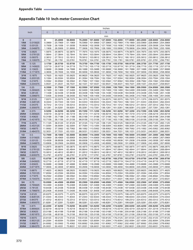
Appendix Table
Appendix Table 10 Inch-meter Conversion Chart
370
Inch
Inches
0 1 2 3 4 5 6 7 8 9 10
mm
0 0 0 25.4000 50.8000 76.2000 101.6000 127.0000 152.4000 177.8000 203.2000 228.6000 254.0000 1/64 0.015625 0.3969 25.7969 51.1969 76.5969 101.9969 127.3969 152.7969 178.1969 203.5969 228.9969 254.3969 1/32 0.03125 0.7938 26.1938 51.5938 76.9938 102.3938 127.7938 153.1938 178.5938 203.9938 229.3938 254.7938 3/64 0.046875 1.1906 26.5906 51.9906 77.3906 102.7906 128.1906 153.5906 178.9906 204.3906 229.7906 255.1906
1/16 0.0625 1.5875 26.9875 52.3875 77.7875 103.1875 128.5875 153.9875 179.3875 204.7875 230.1875 255.5875 5/64 0.078125 1.9844 27.3844 52.7844 78.1844 103.5844 128.9844 154.3844 179.7844 205.1844 230.5844 255.9844 3/32 0.09375 2.3812 27.7812 53.1812 78.5812 103.9812 129.3812 154.7812 180.1812 205.5812 230.9812 256.3812 7/64 0.109375 2.7781 28.1781 53.5781 78.9781 104.3781 129.7781 155.1781 180.5781 205.9781 231.3781 256.7781
1/8 0.125 3.1750 28.5750 53.9750 79.3750 104.7750 130.1750 155.5750 180.9750 206.3750 231.7750 257.1750 9/64 0.140625 3.5719 28.9719 54.3719 79.7719 105.1719 130.5719 155.9719 181.3719 206.7719 232.1719 257.5719 5/32 0.15625 3.9688 29.3688 54.7688 80.1688 105.5688 130.9688 156.3688 181.7688 207.1688 232.5688 257.9688
11/64 0.171875 4.3656 29.7656 55.1656 80.5656 105.9656 131.3656 156.7656 182.1656 207.5656 232.9656 258.3656
3/16 0.1875 4.7625 30.1625 55.5625 80.9625 106.3625 131.7625 157.1625 182.5625 207.9625 233.3625 258.7625 13/64 0.203125 5.1594 30.5594 55.9594 81.3594 106.7594 132.1594 157.5594 182.9594 208.3594 233.7594 259.1594
7/32 0.21875 5.5562 30.9562 56.3562 81.7562 107.1562 132.5562 157.9562 183.3562 208.7562 234.1562 259.5562 15/64 0.234375 5.9531 31.3531 56.7531 82.1531 107.5531 132.9531 158.3531 183.7531 209.1531 234.5531 259.9531
1/4 0.25 6.3500 31.7500 57.1500 82.5500 107.9500 133.3500 158.7500 184.1500 209.5500 234.9500 260.3500 17/64 0.265625 6.7469 32.1469 57.5469 82.9469 108.3469 133.7469 159.1469 184.5469 209.9469 235.3469 260.7469
9/32 0.28125 7.1438 32.5438 57.9438 83.3438 108.7438 134.1438 159.5438 184.9438 210.3438 235.7438 261.1438 19/64 0.296875 7.5406 32.9406 58.3406 83.7406 109.1406 134.5406 159.9406 185.3406 210.7406 236.1406 261.5406
5/16 0.3125 7.9375 33.3375 58.7375 84.1375 109.5375 134.9375 160.3375 185.7375 211.1375 236.5375 261.9375 21/64 0.328125 8.3344 33.7344 59.1344 84.5344 109.9344 135.3344 160.7344 186.1344 211.5344 236.9344 262.3344 11/32 0.34375 8.7312 34.1312 59.5312 84.9312 110.3312 135.7312 161.1312 186.5312 211.9312 237.3312 262.7312 23/64 0.359375 9.1281 34.5281 59.9281 85.3281 110.7281 136.1281 161.5281 186.9281 212.3281 237.7281 263.1281
3/8 0.375 9.5250 34.9250 60.3250 85.7250 111.1250 136.5250 161.9250 187.3250 212.7250 238.1250 263.5250 25/64 0.390625 9.9219 35.3219 60.7219 86.1219 111.5219 136.9219 162.3219 187.7219 213.1219 238.5219 263.9219 13/32 0.40625 10.3188 35.7188 61.1188 86.5188 111.9188 137.3188 162.7188 188.1188 213.5188 238.9188 264.3188 27/64 0.421875 10.7156 36.1156 61.5156 86.9156 112.3156 137.7156 163.1156 188.5156 213.9156 239.3156 264.7156
7/16 0.4375 11.1125 36.5125 61.9125 87.3125 112.7125 138.1125 163.5125 188.9125 214.3125 239.7125 265.1125 29/64 0.453125 11.5094 36.9094 62.3094 87.7094 113.1094 138.5094 163.9094 189.3094 214.7094 240.1094 265.5094 15/32 0.46875 11.9062 37.3062 62.7062 88.1062 113.5062 138.9062 164.3062 189.7062 215.1062 240.5062 265.9062 31/64 0.484375 12.3031 37.7031 63.1031 88.5031 113.9031 139.3031 164.7031 190.1031 215.5031 240.9031 266.3031
1/2 0.5 12.7000 38.1000 63.5000 88.9000 114.3000 139.7000 165.1000 190.5000 215.9000 241.3000 266.7000 33/64 0.515625 13.0969 38.4969 63.8969 89.2969 114.6969 140.0969 165.4969 190.8969 216.2969 241.6969 267.0969 17/32 0.53125 13.4938 38.8938 64.2938 89.6938 115.0938 140.4938 165.8938 191.2938 216.6938 242.0938 267.4938 35/64 0.546875 13.8906 39.2906 64.6906 90.0906 115.4906 140.8906 166.2906 191.6906 217.0906 242.4906 267.8906
9/16 0.5625 14.2875 39.6875 65.0875 90.4875 115.8875 141.2875 166.6875 192.0875 217.4875 242.8875 268.2875 37/64 0.578125 14.6844 40.0844 65.4844 90.8844 116.2844 141.6844 167.0844 192.4844 217.8844 243.2844 268.6844 19/32 0.59375 15.0812 40.4812 65.8812 91.2812 116.6812 142.0812 167.4812 192.8812 218.2812 243.6812 269.0812 39/64 0.609375 15.4781 40.8781 66.2781 91.6781 117.0781 142.4781 167.8781 193.2781 218.6781 244.0781 269.4781
5/8 0.625 15.8750 41.2750 66.6750 92.0750 117.4750 142.8750 168.2750 193.6750 219.0750 244.4750 269.8750 41/64 0.640625 16.2719 41.6719 67.0719 92.4719 117.8719 143.2719 168.6719 194.0719 219.4719 244.8719 270.2719 21/32 0.65625 16.6688 42.0688 67.4688 92.8688 118.2688 143.6688 169.0688 194.4688 219.8688 245.2688 270.6688 43/64 0.671875 17.0656 42.4656 67.8656 93.2656 118.6656 144.0656 169.4656 194.8656 220.2656 245.6656 271.0656
11/16 0.6875 17.4625 42.8625 68.2625 93.6625 119.0625 144.4625 169.8625 195.2625 220.6625 246.0625 271.4625 45/64 0.703125 17.8594 43.2594 68.6594 94.0594 119.4594 144.8594 170.2594 195.6594 221.0594 246.4594 271.8594 23/32 0.71875 18.2562 43.6562 69.0562 94.4562 119.8562 145.2562 170.6562 196.0562 221.4562 246.8562 272.2562 47/64 0.734375 18.6531 44.0531 69.4531 94.8531 120.2531 145.6531 171.0531 196.4531 221.8531 247.2531 272.6531
3/4 0.75 19.0500 44.4500 69.8500 95.2500 120.6500 146.0500 171.4500 196.8500 222.2500 247.6500 273.0500 49/64 0.765625 19.4469 44.8469 70.2469 95.6469 121.0469 146.4469 171.8469 197.2469 222.6469 248.0469 273.4469 25/32 0.78125 19.8438 45.2438 70.6438 96.0438 121.4438 146.8438 172.2438 197.6438 223.0438 248.4438 273.8438 51/64 0.796875 20.2406 45.6406 71.0406 96.4406 121.8406 147.2406 172.6406 198.0406 223.4406 248.8406 274.2406
13/16 0.8125 20.6375 46.0375 71.4375 96.8375 122.2375 147.6375 173.0375 198.4375 223.8375 249.2375 274.6375 53/64 0.828125 21.0344 46.4344 71.8344 97.2344 122.6344 148.0344 173.4344 198.8344 224.2344 249.6344 275.0344 27/32 0.84375 21.4312 46.8312 72.2312 97.6312 123.0312 148.4312 173.8312 199.2312 224.6312 250.0312 275.4312 55/64 0.859375 21.8281 47.2281 72.6281 98.0281 123.4281 148.8281 174.2281 199.6281 225.0281 250.4281 275.8281
7/8 0.875 22.2250 47.6250 73.0250 98.4250 123.8250 149.2250 174.6250 200.0250 225.4250 250.8250 276.2250 57/64 0.890625 22.6219 48.0219 73.4219 98.8219 124.2219 149.6219 175.0219 200.4219 225.8219 251.2219 276.6219 29/32 0.90625 23.0188 48.4188 73.8188 99.2188 124.6188 150.0188 175.4188 200.8188 226.2188 251.6188 277.0188 59/64 0.921875 23.4156 48.8156 74.2156 99.6156 125.0156 150.4156 175.8156 201.2156 226.6156 252.0156 277.4156
15/16 0.9375 23.8125 49.2125 74.6125 100.0125 125.4125 150.8125 176.2125 201.6125 227.0125 252.4125 277.8125 61/64 0.953125 24.2094 49.6094 75.0094 100.4094 125.8094 151.2094 176.6094 202.0094 227.4094 252.8094 278.2094 31/32 0.96875 24.6062 50.0062 75.4062 100.8062 126.2062 151.6062 177.0062 202.4062 227.8062 253.2062 278.6062 63/64 0.984375 25.0031 50.4031 75.8031 101.2031 126.6031 152.0031 177.4031 202.8031 228.2031 253.6031 279.0031
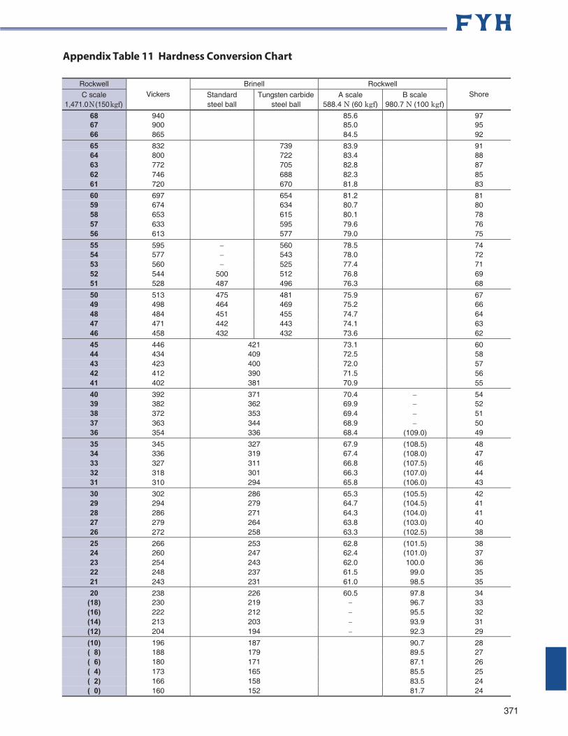
Appendix Table 11 Hardness Conversion Chart
Rockwell Vickers
Brinell Rockwell Shore C scale
1,471.0 N (150 kgf) Standard steel ball
Tungsten carbide steel ball
A scale 588.4 N (60 kgf)
B scale 980.7 N (100 kgf)
68 940 85.6 97 67 900 85.0 95 66 865 84.5 92
65 832 739 83.9 91 64 800 722 83.4 88 63 772 705 82.8 87 62 746 688 82.3 85 61 720 670 81.8 83
60 697 654 81.2 81 59 674 634 80.7 80 58 653 615 80.1 78 57 633 595 79.6 76 56 613 577 79.0 75
55 595 560 78.5 74 54 577 543 78.0 72 53 560 525 77.4 71 52 544 500 512 76.8 69 51 528 487 496 76.3 68
50 513 475 481 75.9 67 49 498 464 469 75.2 66 48 484 451 455 74.7 64 47 471 442 443 74.1 63 46 458 432 432 73.6 62
45 446 421 73.1 60 44 434 409 72.5 58 43 423 400 72.0 57 42 412 390 71.5 56 41 402 381 70.9 55
40 392 371 70.4 54 39 382 362 69.9 52 38 372 353 69.4 51 37 363 344 68.9 50 36 354 336 68.4 (109.0) 49
35 345 327 67.9 (108.5) 48 34 336 319 67.4 (108.0) 47 33 327 311 66.8 (107.5) 46 32 318 301 66.3 (107.0) 44 31 310 294 65.8 (106.0) 43
30 302 286 65.3 (105.5) 42 29 294 279 64.7 (104.5) 41 28 286 271 64.3 (104.0) 41 27 279 264 63.8 (103.0) 40 26 272 258 63.3 (102.5) 38
25 266 253 62.8 (101.5) 38 24 260 247 62.4 (101.0) 37 23 254 243 62.0 100.0 36 22 248 237 61.5 99.0 35 21 243 231 61.0 98.5 35
20 238 226 60.5 97.8 34 (18) 230 219 96.7 33 (16) 222 212 95.5 32 (14) 213 203 93.9 31 (12) 204 194 92.3 29
(10) 196 187 90.7 28 ( 8) 188 179 89.5 27 ( 6) 180 171 87.1 26 ( 4) 173 165 85.5 25 ( 2) 166 158 83.5 24 ( 0) 160 152 81.7 24
371
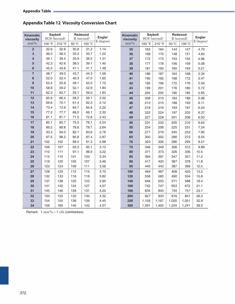
Appendix Table
Appendix Table 12 Viscosity Conversion Chart
Remark 1 mm2/s 1 cSt (centistokes)
372
Kinematic viscosity
mm2/s
Saybolt SUS (second)
Redwood R (second)
Engler
E (degree)100 ºF 210 ºF 50 ºC 100 ºC
35 163 164 144 147 4.70 36 168 170 148 151 4.83
37 172 173 153 155 4.96
38 177 178 156 159 5.08
39 181 183 160 164 5.21
40 186 187 164 168 5.34 41 190 192 168 172 5.47
42 195 196 172 176 5.59
43 199 201 176 180 5.72
44 204 205 180 185 5.85
45 208 210 184 189 5.98 46 213 215 188 193 6.11
47 218 219 193 197 6.24
48 222 224 197 202 6.37
49 227 228 201 206 6.50
50 231 233 205 210 6.63 55 254 256 225 231 7.24
60 277 279 245 252 7.90
65 300 302 266 273 8.55
70 323 326 286 294 9.21
75 346 349 306 315 9.89 80 371 373 326 336 10.5
85 394 397 347 357 11.2
90 417 420 367 378 11.8
95 440 443 387 399 12.5
100 464 467 408 420 13.2 120 556 560 490 504 15.8
140 649 653 571 588 18.4
160 742 747 653 672 21.1
180 834 840 734 757 23.7
200 927 933 816 841 26.3 250 1,159 1,167 1,020 1,051 32.9
300 1,391 1,400 1,224 1,241 39.5
Kinematic viscosity
mm2/s
Saybolt SUS (second)
Redwood R (second)
Engler
E (degree)100 ºF 210 ºF 50 ºC 100 ºC
2 32.6 32.8 30.8 31.2 1.14 3 36.0 36.3 33.3 33.7 1.22
4 39.1 39.4 35.9 36.5 1.31
5 42.3 42.6 38.5 39.1 1.40
6 45.5 45.8 41.1 41.7 1.48
7 48.7 49.0 43.7 44.3 1.56 8 52.0 52.4 46.3 47.0 1.65
9 55.4 55.8 49.1 50.0 1.75
10 58.8 59.2 52.1 52.9 1.84
11 62.3 62.7 55.1 56.0 1.93
12 65.9 66.4 58.2 59.1 2.02 13 69.6 70.1 61.4 62.3 2.12
14 73.4 73.9 64.7 65.6 2.22
15 77.2 77.7 68.0 69.1 2.32
16 81.1 81.7 71.5 72.6 2.43
17 85.1 85.7 75.0 76.1 2.54
18 89.2 89.8 78.6 79.7 2.64
19 93.3 94.0 82.1 83.6 2.76
20 97.5 98.2 85.8 87.4 2.87
21 102 102 89.5 91.3 2.98
22 106 107 93.3 95.1 3.10
23 110 111 97.1 98.9 3.22
24 115 115 101 103 3.34
25 119 120 105 107 3.46
26 123 124 109 111 3.58
27 128 129 112 115 3.70
28 132 133 116 119 3.82
29 137 138 120 123 3.95
30 141 142 124 127 4.07
31 145 146 128 131 4.20
32 150 150 132 135 4.32
33 154 155 136 139 4.45
34 159 160 140 143 4.57
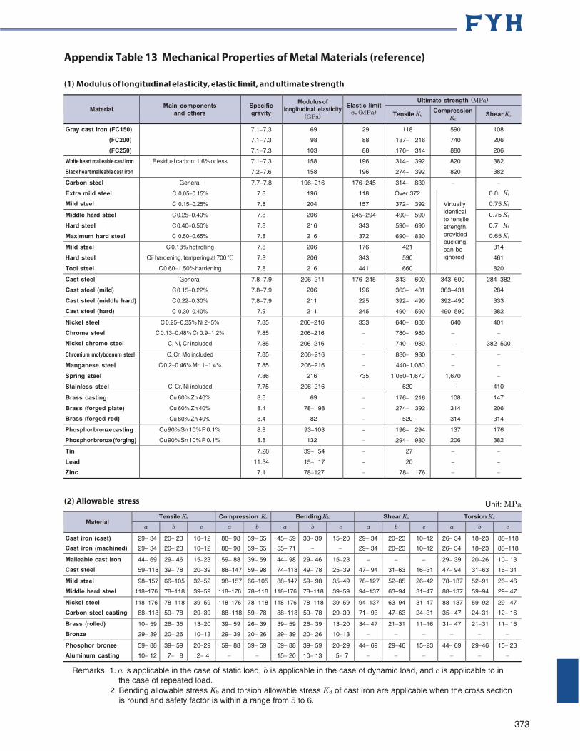
Appendix Table 13 Mechanical Properties of Metal Materials (reference)
(1) Modulus of longitudinal elasticity, elastic limit, and ultimate strength
Material
Main components
and others
Specific gravity
Modulus of longitudinal elasticity
(GPa)
Elastic limit e (MPa)
Ultimate strength (MPa)
Tensile Kt Compression
Kc Shear Ks
Gray cast iron (FC150)
(FC200)
(FC250)
7.17.3
7.17.3
7.17.3
69
98
103
29
88
88
118
137 216
176 314
590
740
880
108
206
206
White heart malleable cast iron
Black heart malleable cast iron
Residual carbon: 1.6% or less 7.17.3
7.27.6
158
158
196
196
314 392
274 392
820
820
382
382
Carbon steel
Extra mild steel
Mild steel
General
C 0.050.15%
C 0.150.25%
7.77.8
7.8
7.8
196216
196
204
176245
118
157
314 830
Over 372
372 392
0.8 Kt
0.75 Kt
Virtually identical to tensile strength, provided buckling can be ignored
Middle hard steel
Hard steel
Maximum hard steel
C 0.250.40%
C 0.400.50%
C 0.500.65%
7.8
7.8
7.8
206
216
216
245294
343
372
490 590
590 690
690 830
0.75 Kt
0.7 Kt
0.65 Kt
Mild steel
Hard steel
Tool steel
C 0.18% hot rolling
Oil hardening, tempering at 700 ºC
C 0.601.50% hardening
7.8
7.8
7.8
206
206
216
176
343
441
421
590
660
314
461
820
Cast steel
Cast steel (mild)
Cast steel (middle hard)
Cast steel (hard)
General
C 0.150.22%
C 0.220.30%
C 0.300.40%
7.87.9
7.87.9
7.87.9
7.9
206211
206
211
211
176245
196
225
245
343 600
363 431
392 490
490 590
343600
363431
392490
490590
284382
284
333
382
Nickel steel
Chrome steel
Nickel chrome steel
C 0.250.35% Ni 25%
C 0.130.48% Cr 0.91.2%
C, Ni, Cr included
7.85
7.85
7.85
206216
206216
206216
333
640 830
780 980
740 980
640
401
382500
Chromium molybdenum steel
Manganese steel
Spring steel
Stainless steel
C, Cr, Mo included
C 0.20.46% Mn 11.4%
C, Cr, Ni included
7.85
7.85
7.86
7.75
206216
206216
216
206216
735
830 980
4401,080
1,0801,670
620
1,670
410
Brass casting
Brass (forged plate)
Brass (forged rod)
Cu 60% Zn 40%
Cu 60% Zn 40%
Cu 60% Zn 40%
8.5
8.4
8.4
69
7898
82
176 216
274 392
520
108
314
314
147
206
314
Phosphor bronze casting
Phosphor bronze (forging)
Cu 90% Sn 10% P 0.1%
Cu 90% Sn 10% P 0.1%
8.8
8.8
93103
132
196 294
294 980
137
206
176
382
Tin
Lead
Zinc
7.28
11.34
7.1
3954
1517
78127
27
20
78176
(2) Allowable stress Unit: MPa
Material
Tensile Kt Compression Kc Bending Kb Shear Ks Torsion Kd
a b c a b a b c a b c a b c
Cast iron (cast) 2934 2023 1012 8898 5965 4559 3039 1520 2934 2023 1012 2634 1823 88118
Cast iron (machined) 2934 2023 1012 8898 5965 5571 2934 2023 1012 2634 1823 88118
Malleable cast iron 4469 2946 1523 5988 3959 4498 2946 1523 2939 2026 1013
Cast steel 59118 3978 2039 88147 5998 74118 4978 2539 4794 3163 1631 4794 3163 1631
Mild steel 98157 66105 3252 98157 66105 88147 5998 3549 78127 5285 2642 78137 5291 2646
Middle hard steel 118176 78118 3959 118176 78118 118176 78118 3959 94137 6394 3147 88137 5994 2947
Nickel steel 118176 78118 3959 118176 78118 118176 78118 3959 94137 6394 3147 88137 5992 2947
Carbon steel casting 88118 5978 2939 88118 5978 88118 5978 2939 7193 4763 2431 3547 2431 1216
Brass (rolled) 1059 2635 1320 3959 2639 3959 2639 1320 3447 2131 1116 3147 2131 1116
Bronze 2939 2026 1013 2939 2026 2939 2026 1013
Phosphor bronze 5988 3959 2029 5988 3959 5988 3959 2029 4469 2946 1523 4469 2946 1523
Aluminum casting 1012 78 24 1520 1013 57
Remarks 1. a is applicable in the case of static load, b is applicable in the case of dynamic load, and c is applicable to in the case of repeated load.
2. Bending allowable stress Kb and torsion allowable stress Kd of cast iron are applicable when the cross section is round and safety factor is within a range from 5 to 6.
373
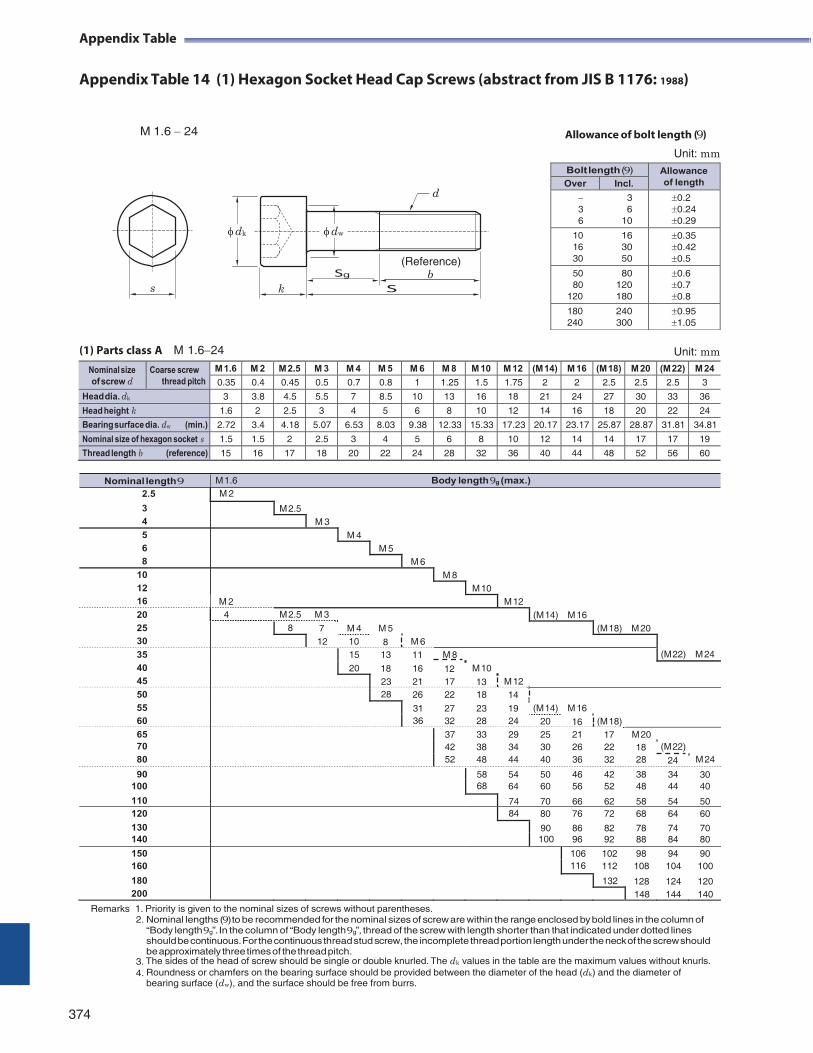
Nominal length 9 M 1.6 Body length9g (max.)
Appendix Table
Appendix Table 14 (1) Hexagon Socket Head Cap Screws (abstract from JIS B 1176: 1988)
M 1.6 24 Allowance of bolt length (9)
Unit: mm
(1) Parts class A M 1.624 Unit: mm
Nominal size of screw d
Coarse screw thread pitch
M 1.6 M 2 M 2.5 M 3 M 4 M 5 M 6 M 8 M 10 M 12 (M 14) M 16 (M 18) M 20 (M 22) M 24
0.35 0.4 0.45 0.5 0.7 0.8 1 1.25 1.5 1.75 2 2 2.5 2.5 2.5 3
Head dia. dk 3 3.8 4.5 5.5 7 8.5 10 13 16 18 21 24 27 30 33 36
Head height k 1.6 2 2.5 3 4 5 6 8 10 12 14 16 18 20 22 24
Bearing surface dia. dw (min.) 2.72 3.4 4.18 5.07 6.53 8.03 9.38 12.33 15.33 17.23 20.17 23.17 25.87 28.87 31.81 34.81
Nominal size of hexagon socket s 1.5 1.5 2 2.5 3 4 5 6 8 10 12 14 14 17 17 19
Thread length b (reference) 15 16 17 18 20 22 24 28 32 36 40 44 48 52 56 60
2.5 M 2 3 M 2.5 4 M 3 5 M 4 6 M 5 8 M 6
10 M 8 12 M 10 16 M 2 M 12 20 4 M 2.5 M 3 (M 14) M 16 25 8 7 M 4 M 5 (M 18) M 20 30 12 10 8 M 6 35 15 13 11 M 8 (M 22) M 24
40 20 18 16 12 M 10 45 23 21 17 13 M 12 50 28 26 22 18 14 55 31 27 23 19 (M 14) M 16 60 36 32 28 24 20 16 (M 18) 65 37 33 29 25 21 17 M 20 70 42 38 34 30 26 22 18 (M 22) 80 52 48 44 40 36 32 28 24 M 24
90 58 54 50 46 42 38 34 30 100 68 64 60 56 52 48 44 40
110 74 70 66 62 58 54 50 120 84 80 76 72 68 64 60
130 90 86 82 78 74 70 140 100 96 92 88 84 80
150 106 102 98 94 90 160 116 112 108 104 100
180 132 128 124 120 200 148 144 140
Remarks 1. Priority is given to the nominal sizes of screws without parentheses. 2. Nominal lengths (9) to be recommended for the nominal sizes of screw are within the range enclosed by bold lines in the column of
“Body length 9g”. In the column of “Body length 9g”, thread of the screw with length shorter than that indicated under dotted lines should be continuous. For the continuous thread stud screw, the incomplete thread portion length under the neck of the screw should be approximately three times of the thread pitch.
3. The sides of the head of screw should be single or double knurled. The dk values in the table are the maximum values without knurls. 4. Roundness or chamfers on the bearing surface should be provided between the diameter of the head (dk) and the diameter of
bearing surface (dw), and the surface should be free from burrs.
374
Bolt length (9) Allowance of length Over Incl.
3 3 6 6 10
0.2 0.24 0.29
10 16 16 30 30 50
0.35 0.42 0.5
50 80 80 120
120 180
0.6 0.7 0.8
180 240 240 300
0.95 1.05
d
dk dw
Sg
k
(Reference) b Ss
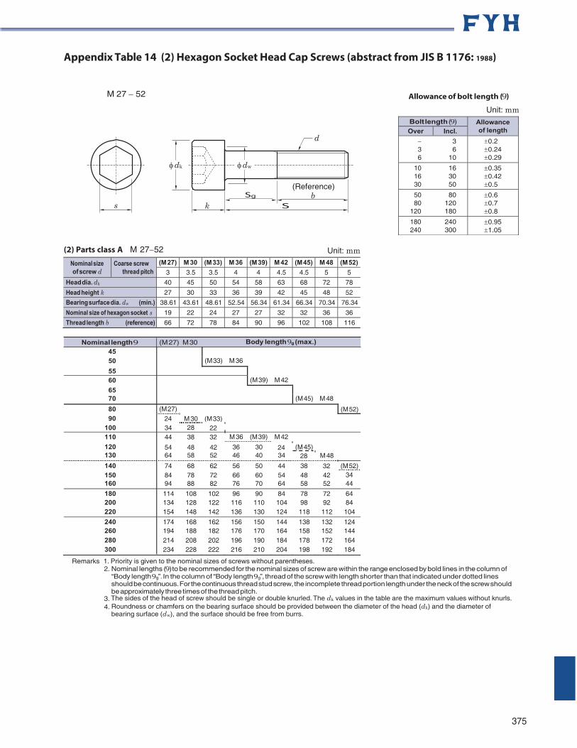
Nominal length 9 (M 27) M 30 Body length9g (max.)
Appendix Table 14 (2) Hexagon Socket Head Cap Screws (abstract from JIS B 1176: 1988)
M 27 52 Allowance of bolt length (9)
Unit: mm
(2) Parts class A M 2752 Unit: mm
Nominal size of screw d
Coarse screw thread pitch
(M 27) M 30 (M 33) M 36 (M 39) M 42 (M 45) M 48 (M 52)
3 3.5 3.5 4 4 4.5 4.5 5 5
Head dia. dk 40 45 50 54 58 63 68 72 78
Head height k 27 30 33 36 39 42 45 48 52
Bearing surface dia. dw (min.) 38.61 43.61 48.61 52.54 56.34 61.34 66.34 70.34 76.34
Nominal size of hexagon socket s 19 22 24 27 27 32 32 36 36
Thread length b (reference) 66 72 78 84 90 96 102 108 116
45 50 (M 33) M 36
55 60 (M 39) M 42
65 70 (M 45) M 48
80 (M 27) (M 52) 90 24 M 30 (M 33)
100 34 28 22 110 44 38 32 M 36 (M 39) M 42
120 54 48 42 36 30 24 (M 45) 130 64 58 52 46 40 34 28 M 48
140 74 68 62 56 50 44 38 32 (M 52) 150 84 78 72 66 60 54 48 42 34 160 94 88 82 76 70 64 58 52 44
180 114 108 102 96 90 84 78 72 64 200 134 128 122 116 110 104 98 92 84 220 154 148 142 136 130 124 118 112 104
240 174 168 162 156 150 144 138 132 124 260 194 188 182 176 170 164 158 152 144 280 214 208 202 196 190 184 178 172 164 300 234 228 222 216 210 204 198 192 184
Remarks 1. Priority is given to the nominal sizes of screws without parentheses. 2. Nominal lengths (9) to be recommended for the nominal sizes of screw are within the range enclosed by bold lines in the column of
“Body length 9g”. In the column of “Body length 9g”, thread of the screw with length shorter than that indicated under dotted lines should be continuous. For the continuous thread stud screw, the incomplete thread portion length under the neck of the screw should be approximately three times of the thread pitch.
3. The sides of the head of screw should be single or double knurled. The dk values in the table are the maximum values without knurls. 4. Roundness or chamfers on the bearing surface should be provided between the diameter of the head (dk) and the diameter of
bearing surface (dw), and the surface should be free from burrs.
375
Bolt length (9) Allowance of length Over Incl.
3 3 6 6 10
0.2 0.24 0.29
10 16 16 30 30 50
0.35 0.42 0.5
50 80 80 120
120 180
0.6 0.7 0.8
180 240 240 300
0.95 1.05
d
dk dw
Sg
k
(Reference) b Ss
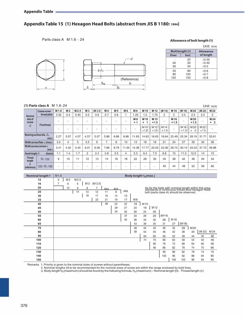
Appendix Table
Appendix Table 15 (1) Hexagon Head Bolts (abstract from JIS B 1180: 1994)
Parts class A M 1.6 24 Allowance of bolt length (9)
Unit: mm
(1) Parts class A M 1.624 Unit: mm
Nominal size of screw
d
Coarse screw thread pitch
M 1.6 M 2 M 2.5 M 3 (M 3.5) M 4 M 5 M 6 M 8 M 10 M 12 (M 14) M 16 (M 18) M 20 (M 22) M 24 0.35 0.4 0.45 0.5 0.6 0.7 0.8 1 1.25 1.5 1.75 2 2 2.5 2.5 2.5 3
Fine thread M 8
× 1 M 10 × 1
M 12 × 1.5 M 16
×1.5 M 20 ×1.5 M 24
× 2
M 10 × 1.25
M 12 × 1.25
M 14 ×1.5 M 18
×1.5 M 20 × 2
M 22 × 1.5
Bearing surface dia. dw (min.)
2.27 3.07 4.07 4.57 5.07 5.88 6.88 8.88 11.63 14.63 16.63 19.64 22.49 25.34 28.19 31.71 33.61
Width across flats s (max.) 3.2 4 5 5.5 6 7 8 10 13 16 18 21 24 27 30 34 36
Width across corners e (min.)
3.41 4.32 5.45 6.01 6.58 7.66 8.79 11.05 14.38 17.77 20.03 23.36 26.75 30.14 33.53 37.72 39.98
Head height k (basic) 1.1 1.4 1.7 2 2.4 2.8 3.5 4 5.3 6.4 7.5 8.8 10 11.5 12.5 14 15
Thread length
b (reference)
9125 9 10 11 12 13 14 16 18 22 26 30 34 38 42 46 50 54
125 9150 40 44 48 52 56 60
standards of continuous thread stud hexagon head
Remarks 1. Priority is given to the nominal sizes of screws without parentheses. 2. Nominal lengths (9) to be recommended for the nominal sizes of screw are within the range enclosed by bold lines. 3. Body length 9g (maximum) should be found by the following formula :9g (maximum) Nominal length (9) Thread length (b)
376
Bolt length (9) Allowance of length Over Incl.
20 0.35 20 30 0.42 30 50 0.5
50 80 0.6 80 120 0.7
120 150 0.8
d
dw
(Reference)
Sg b k S
e
s
Nominal length 9 M 1.6 Body length 9g (max.) 12 16 20
3 M 2 M 2.5 7 6 5 M 3 (M 3.5)
10 9 8 7 M 4 M 5 As for the bolts with nominal length within this area, 25 30 35
14 13 12 11 9 M 6 bolt (parts class A) should be observed. 18 17 16 14 12
M 8 22 21 19 17
40 45 50
26 24 22 18 M 10
29 27 23 19 M 12 34 32 28 24 20
(M 14) 55 60 65
37 33 29 25 42 38 34 30 26 M 16
43 39 35 31 27 (M 18)
70 80 90
48 44 40 36 32 28 M 20 58 54 50 46 42 38 34 (M 22) M 24
64 60 56 52 48 44 40 36 100 110 120
74 70 66 62 58 54 50 46
80 76 72 68 64 60 56 90 86 82 78 74 70 66
130 140 150
90 86 82 78 74 70 100 96 92 88 84 80
106 102 98 94 90
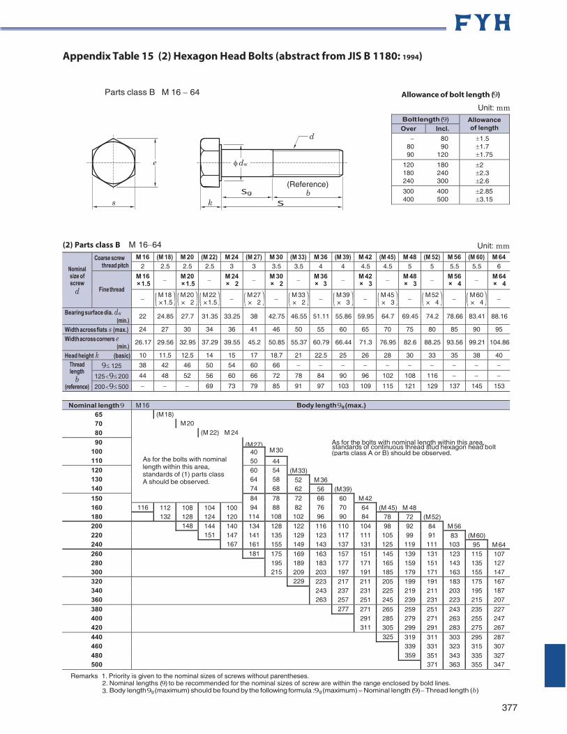
Appendix Table 15 (2) Hexagon Head Bolts (abstract from JIS B 1180: 1994)
Parts class B M 16 64 Allowance of bolt length (9)
Unit: mm
(2) Parts class B M 1664 Unit: mm
Nominal size of screw
d
Coarse screw thread pitch
M 16 (M 18) M 20 (M 22) M 24 (M 27) M 30 (M 33) M 36 (M 39) M 42 (M 45) M 48 (M 52) M 56 (M 60) M 64 2 2.5 2.5 2.5 3 3 3.5 3.5 4 4 4.5 4.5 5 5 5.5 5.5 6
Fine thread
M 16 ×1.5 M 20
×1.5 M 24 × 2 M 30
× 2 M 36 × 3 M 42
× 3 M 48 × 3 M 56
× 4 M 64 × 4
M 18 ×1.5
M 20 × 2
M 22 ×1.5 M 27
× 2 M 33 × 2 M 39
× 3 M 45 × 3 M 52
× 4 M 60 × 4
Bearing surface dia. dw (min.)
22 24.85 27.7 31.35 33.25 38 42.75 46.55 51.11 55.86 59.95 64.7 69.45 74.2 78.66 83.41 88.16
Width across flats s (max.) 24 27 30 34 36 41 46 50 55 60 65 70 75 80 85 90 95
Width across corners e (min.)
26.17 29.56 32.95 37.29 39.55 45.2 50.85 55.37 60.79 66.44 71.3 76.95 82.6 88.25 93.56 99.21 104.86
Head height k (basic) 10 11.5 12.5 14 15 17 18.7 21 22.5 25 26 28 30 33 35 38 40 Thread length
b (reference)
9125 38 42 46 50 54 60 66
125 9200 44 48 52 56 60 66 72 78 84 90 96 102 108 116
200 9500 69 73 79 85 91 97 103 109 115 121 129 137 145 153
standards of continuous thread stud hexagon head bolt
Remarks 1. Priority is given to the nominal sizes of screws without parentheses. 2. Nominal lengths (9) to be recommended for the nominal sizes of screw are within the range enclosed by bold lines. 3. Body length 9g (maximum) should be found by the following formula :9g (maximum) Nominal length (9) Thread length (b)
377
Bolt length (9) Allowance of length Over Incl.
80 80 90 90 120
1.5 1.7 1.75
120 180 180 240 240 300
2 2.3 2.6
300 400 400 500
2.85 3.15
d
dw
Sg
(Reference) b
k S
e
s
Nominal length 9 M 16 Body length 9g (max.) 65 70 80
(M 18) M 20
(M 22) M 24
90 100 110
As for the bolts with nominal length within this area, standards of (1) parts class A should be observed.
(M 27) As for the bolts with nominal length within this area,
40 50
M 30 (parts class A or B) should be observed. 44
(M 33) 120 130 140
60 64 74
54 58 68
52 62
M 36 56 (M 39)
150 160 180
84 94 114
78 88 108
72 82 102
66 76 96
60 70 90
M 42 116 112
132 108 128
104 124
100 120
64 84
(M 45) M 48 78 72 (M 52)
200 220 240
148 144 151
140 147 167
134 141 161
128 135 155
122 129 149
116 123 143
110 117 137
104 111 131
98 105 125
92 99 119
84 91 111
M 56 83 103
(M 60) 95 M 64
260 280 300
181 175 195 215
169 189 209
163 183 203
157 177 197
151 171 191
145 165 185
139 159 179
131 151 171
123 143 163
115 135 155
107 127 147
320 340 360
229 223 243 263
217 237 257
211 231 251
205 225 245
199 219 239
191 211 231
183 203 223
175 195 215
167 187 207
380 400 420
277 271 291 311
265 285 305
259 279 299
251 271 291
243 263 283
235 255 275
227 247 267
440 460 480 500
325 319 339 359
311 331 351 371
303 323 343 363
295 315 335 355
287 307 327 347
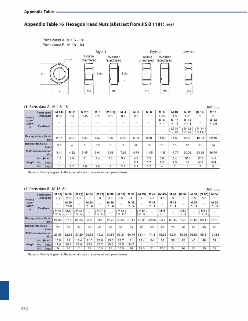
Appendix Table
Appendix Table 16 Hexagon Head Nuts (abstract from JIS B 1181: 1993)
Parts class A M 1.6 16 Parts class B M 18 64
Style 1
Style 2 Low nut Double
d chamfered Washer
faced head Double
chamfered Washer
faced head
e
s
(1) Parts class A M 1.616 Unit: mm
Nominal size of screw
d
Coarse screw thread pitch
M 1.6 M 2 M 2.5 M 3 (M 3.5) M 4 M 5 M 6 M 8 M 10 M 12 (M 14) M 16 0.35 0.4 0.45 0.5 0.6 0.7 0.8 1 1.25 1.5 1.75 2 2
Fine thread M 8
× 1 M 10 × 1
M 12 × 1.5 M 16
× 1.5
M 10 × 1.25
M 12 × 1.25
M 14 × 1.5
Bearing surface dia. dw (min.)
2.27 3.07 4.07 4.57 5.07 5.88 6.88 8.88 11.63 14.63 16.63 19.64 22.49
Width across flats s (max.)
3.2 4 5 5.5 6 7 8 10 13 16 18 21 24
Width across corners e (min.)
3.41 4.32 5.45 6.01 6.58 7.66 8.79 11.05 14.38 17.77 20.03 23.36 26.75
Height
m1 (max.) 1.3 1.6 2 2.4 2.8 3.2 4.7 5.2 6.8 8.4 10.8 12.8 14.8 m2 (max.) 5.1 5.7 7.5 9.3 12 14.1 16.4 m3 (max.) 1 1.2 1.6 1.8 2 2.2 2.7 3.2 4 5 6 7 8
Remark Priority is given to the nominal sizes of screws without parentheses.
(2) Parts class B M 1864 Unit: mm
Nominal size of screw
d
Coarse screw thread pitch
(M 18) M 20 (M 22) M 24 (M 27) M 30 (M 33) M 36 (M 39) M 42 (M 45) M 48 (M 52) M 56 (M 60) M 64 2.5 2.5 2.5 3 3 3.5 3.5 4 4 4.5 4.5 5 5 5.5 5.5 6
Fine thread M 20
×1.5 M 24 × 2 M 30
× 2 M 36 × 3 M 42
× 3 M 48 × 3 M 56
× 4 M 64 × 4
M 18 × 1.5
M 20 × 2
M 22 × 1.5 M 27
× 2 M 33 × 2 M 39
× 3 M 45 × 3 M 52
× 4 M 60 × 4
Bearing surface dia. dw (min.)
24.85 27.7 31.35 33.25 38 42.75 46.55 51.11 55.86 59.95 64.7 69.45 74.2 78.66 83.41 88.16
Width across flats s (max.)
27 30 34 36 41 46 50 55 60 65 70 75 80 85 90 95
Width across corners e (min.)
29.56 32.95 37.29 39.55 45.2 50.85 55.37 60.79 66.44 71.3 76.95 82.6 88.25 93.56 99.21 104.86
Height
m1 (max.) 15.8 18 19.4 21.5 23.8 25.6 28.7 31 33.4 34 36 38 42 45 48 51 m2 (max.) 17.6 20.3 21.8 23.9 26.7 28.6 32.5 34.7 m3 (max.) 9 10 11 12 13.5 15 16.5 18 19.5 21 22.5 24 26 28 30 32
Remark Priority is given to the nominal sizes of screws without parentheses.
378
dw dw
m1 m1 m2 m2 m3
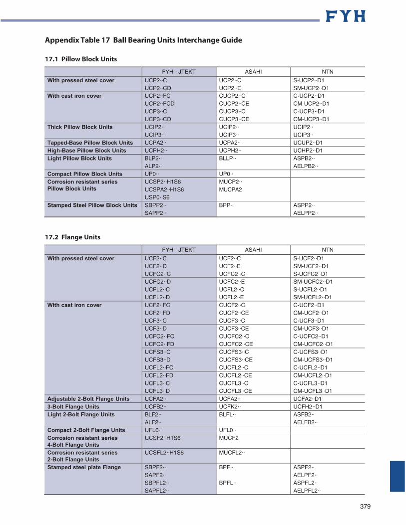
Appendix Table 17 Ball Bearing Units Interchange Guide
17.1 Pillow Block Units
FYH · JTEKT ASAHI NTN
With pressed steel cover UCP2··C UCP2··CD
UCP2··C UCP2··E
S-UCP2··D1 SM-UCP2··D1
With cast iron cover UCP2··FC UCP2··FCD UCP3··C UCP3··CD
CUCP2··C CUCP2··CE CUCP3··C CUCP3··CE
C-UCP2··D1 CM-UCP2··D1 C-UCP3··D1 CM-UCP3··D1
Thick Pillow Block Units UCIP2·· UCIP3··
UCIP2·· UCIP3··
UCIP2·· UCIP3··
Tapped-Base Pillow Block Units UCPA2·· UCPA2·· UCUP2··D1 High-Base Pillow Block Units UCPH2·· UCPH2·· UCHP2··D1 Light Pillow Block Units BLP2··
ALP2·· BLLP·· ASPB2··
AELPB2·· Compact Pillow Block Units UP0·· UP0·· Corrosion resistant series Pillow Block Units
UCSP2··H1S6 UCSPA2··H1S6 USP0··S6
MUCP2·· MUCPA2
Stamped Steel Pillow Block Units SBPP2·· SAPP2··
BPP·· ASPP2·· AELPP2··
17.2 Flange Units
FYH · JTEKT ASAHI NTN
With pressed steel cover UCF2··C UCF2··D UCFC2··C
UCF2··C UCF2··E UCFC2··C
S-UCF2··D1 SM-UCF2··D1 S-UCFC2··D1
UCFC2··D UCFL2··C UCFL2··D
UCFC2··E UCFL2··C UCFL2··E
SM-UCFC2··D1 S-UCFL2··D1 SM-UCFL2··D1
With cast iron cover UCF2··FC UCF2··FD UCF3··C
CUCF2··C CUCF2··CE CUCF3··C
C-UCF2··D1 CM-UCF2··D1 C-UCF3··D1
UCF3··D UCFC2··FC UCFC2··FD
CUCF3··CE CUCFC2··C CUCFC2··CE
CM-UCF3··D1 C-UCFC2··D1 CM-UCFC2··D1
UCFS3··C UCFS3··D UCFL2··FC
CUCFS3··C CUCFS3··CE CUCFL2··C
C-UCFS3··D1 CM-UCFS3··D1 C-UCFL2··D1
UCFL2··FD UCFL3··C UCFL3··D
CUCFL2··CE CUCFL3··C CUCFL3··CE
CM-UCFL2··D1 C-UCFL3··D1 CM-UCFL3··D1
Adjustable 2-Bolt Flange Units UCFA2·· UCFA2·· UCFA2··D1 3-Bolt Flange Units UCFB2·· UCFK2·· UCFH2··D1 Light 2-Bolt Flange Units BLF2··
ALF2·· BLFL·· ASFB2··
AELFB2·· Compact 2-Bolt Flange Units UFL0·· UFL0·· Corrosion resistant series 4-Bolt Flange Units
UCSF2··H1S6 MUCF2
Corrosion resistant series 2-Bolt Flange Units
UCSFL2··H1S6 MUCFL2··
Stamped steel plate Flange SBPF2·· SAPF2·· SBPFL2·· SAPFL2··
BPF··
BPFL··
ASPF2·· AELPF2·· ASPFL2·· AELPFL2··
379
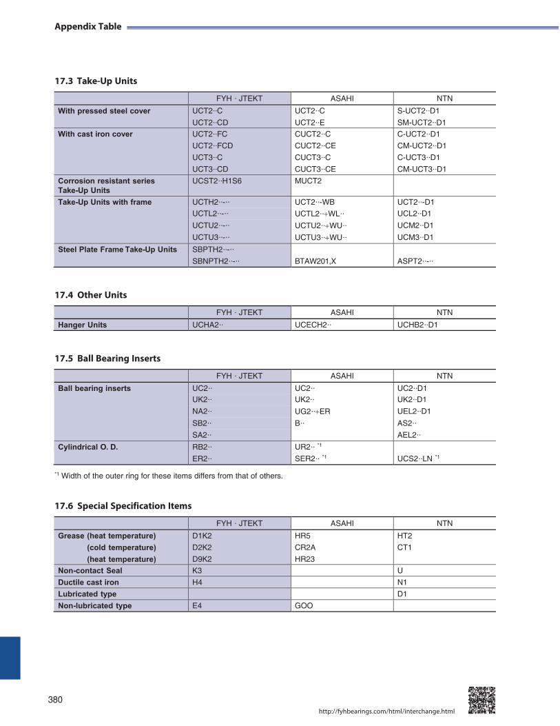
Appendix Table
17.3 Take-Up Units
FYH · JTEKT ASAHI NTN
With pressed steel cover UCT2··C
UCT2··CD
UCT2··C
UCT2··E
S-UCT2··D1
SM-UCT2··D1
With cast iron cover UCT2··FC
UCT2··FCD
UCT3··C
UCT3··CD
CUCT2··C
CUCT2··CE
CUCT3··C
CUCT3··CE
C-UCT2··D1
CM-UCT2··D1
C-UCT3··D1
CM-UCT3··D1
Corrosion resistant series Take-Up Units
UCST2··H1S6 MUCT2
Take-Up Units with frame UCTH2··-·· UCT2··-WB UCT2··-D1
UCTL2··-·· UCTL2··WL·· UCL2··D1
UCTU2··-·· UCTU2··WU·· UCM2··D1
UCTU3··-·· UCTU3··WU·· UCM3··D1
Steel Plate Frame Take-Up Units SBPTH2··-··
SBNPTH2··-·· BTAW201,X
ASPT2··-··
17.4 Other Units
FYH · JTEKT ASAHI NTN
Hanger Units UCHA2·· UCECH2·· UCHB2··D1
17.5 Ball Bearing Inserts
FYH · JTEKT ASAHI NTN
Ball bearing inserts UC2·· UC2·· UC2··D1 UK2·· UK2·· UK2··D1
NA2·· UG2··ER UEL2··D1
SB2·· B·· AS2··
SA2·· AEL2··
Cylindrical O. D. RB2··
ER2··
UR2·· *1
SER2·· *1
UCS2··LN *1
*1 Width of the outer ring for these items differs from that of others.
17.6 Special Specification Items
FYH · JTEKT ASAHI NTN
Grease (heat temperature)
(cold temperature)
(heat temperature)
D1K2
D2K2
D9K2
HR5
CR2A
HR23
HT2
CT1
Non-contact Seal K3 U
Ductile cast iron H4 N1
Lubricated type D1
Non-lubricated type E4 GOO
380
http://fyhbearings.com/html/interchange.html
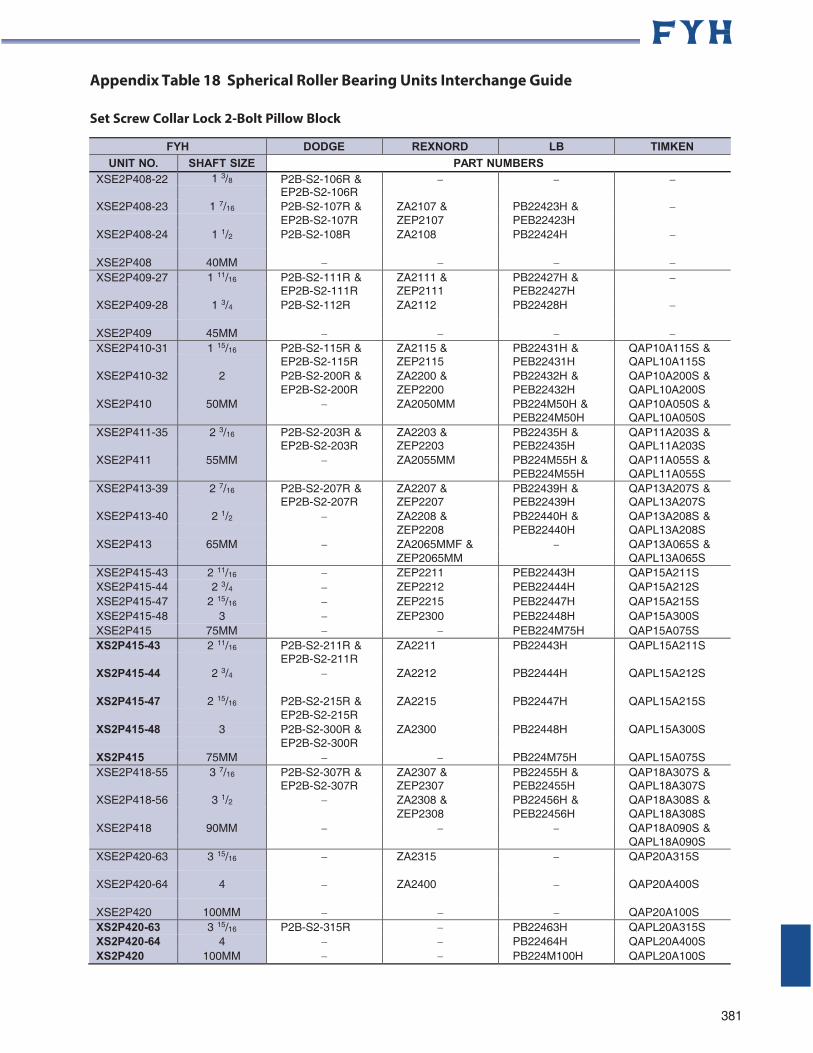
Appendix Table 18 Spherical Roller Bearing Units Interchange Guide
Set Screw Collar Lock 2-Bolt Pillow Block
FYH DODGE REXNORD LB TIMKEN
UNIT NO. SHAFT SIZE PART NUMBERS XSE2P408-22 1 3/8 P2B-S2-106R &
EP2B-S2-106R XSE2P408-23 1 7/16 P2B-S2-107R & ZA2107 & PB22423H &
EP2B-S2-107R ZEP2107 PEB22423H XSE2P408-24 1 1/2 P2B-S2-108R ZA2108 PB22424H
XSE2P408 40MM XSE2P409-27 1 11/16 P2B-S2-111R & ZA2111 & PB22427H &
EP2B-S2-111R ZEP2111 PEB22427H XSE2P409-28 1 3/4 P2B-S2-112R ZA2112 PB22428H
XSE2P409 45MM XSE2P410-31 1 15/16 P2B-S2-115R & ZA2115 & PB22431H & QAP10A115S &
EP2B-S2-115R ZEP2115 PEB22431H QAPL10A115S XSE2P410-32 2 P2B-S2-200R & ZA2200 & PB22432H & QAP10A200S &
EP2B-S2-200R ZEP2200 PEB22432H QAPL10A200S XSE2P410 50MM ZA2050MM PB224M50H & QAP10A050S &
PEB224M50H QAPL10A050S XSE2P411-35 2 3/16 P2B-S2-203R & ZA2203 & PB22435H & QAP11A203S &
EP2B-S2-203R ZEP2203 PEB22435H QAPL11A203S XSE2P411 55MM ZA2055MM PB224M55H & QAP11A055S &
PEB224M55H QAPL11A055S XSE2P413-39 2 7/16 P2B-S2-207R & ZA2207 & PB22439H & QAP13A207S &
EP2B-S2-207R ZEP2207 PEB22439H QAPL13A207S XSE2P413-40 2 1/2 ZA2208 & PB22440H & QAP13A208S &
ZEP2208 PEB22440H QAPL13A208S XSE2P413 65MM ZA2065MMF & QAP13A065S &
ZEP2065MM QAPL13A065S XSE2P415-43 2 11/16 ZEP2211 PEB22443H QAP15A211S XSE2P415-44 2 3/4 ZEP2212 PEB22444H QAP15A212S XSE2P415-47 2 15/16 ZEP2215 PEB22447H QAP15A215S XSE2P415-48 3 ZEP2300 PEB22448H QAP15A300S XSE2P415 75MM PEB224M75H QAP15A075S XS2P415-43 2 11/16 P2B-S2-211R & ZA2211 PB22443H QAPL15A211S
EP2B-S2-211R XS2P415-44 2 3/4 ZA2212 PB22444H QAPL15A212S
XS2P415-47 2 15/16 P2B-S2-215R & ZA2215 PB22447H QAPL15A215S
EP2B-S2-215R XS2P415-48 3 P2B-S2-300R & ZA2300 PB22448H QAPL15A300S
EP2B-S2-300R XS2P415 75MM PB224M75H QAPL15A075S XSE2P418-55 3 7/16 P2B-S2-307R & ZA2307 & PB22455H & QAP18A307S &
EP2B-S2-307R ZEP2307 PEB22455H QAPL18A307S XSE2P418-56 3 1/2 ZA2308 & PB22456H & QAP18A308S &
ZEP2308 PEB22456H QAPL18A308S XSE2P418 90MM QAP18A090S &
QAPL18A090S XSE2P420-63 3 15/16 ZA2315 QAP20A315S
XSE2P420-64 4 ZA2400 QAP20A400S
XSE2P420 100MM QAP20A100S XS2P420-63 3 15/16 P2B-S2-315R PB22463H QAPL20A315S XS2P420-64 4 PB22464H QAPL20A400S XS2P420 100MM PB224M100H QAPL20A100S
381
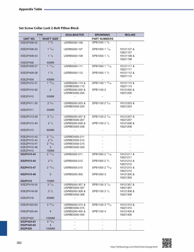
Appendix Table
Set Screw Collar Lock 2-Bolt Pillow Block
382
http://fyhbearings.com/html/interchange.html
FYH SEALMASTER BROWNING MOLINE
UNIT NO. SHAFT SIZE PART NUMBERS XSE2P408-22 1 3/8 USRB5000-106 SPB1000 1 3/8
XSE2P408-23 1 7/16 USRB5000-107 SPB1000 1 7/16 19121107 & 19221107
XSE2P408-24 1 1/2 USRB5000-108 SPB1000 1 1/2 19121108 &
19221108 XSE2P408 40MM XSE2P409-27 1 11/16 USRB5000-111 SPB1000 1 11/16 19121111 &
19221111 XSE2P409-28 1 3/4 USRB5000-112 SPB1000 1 3/4 19121112 &
19221112 XSE2P409 45MM XSE2P410-31 1 15/16 USRB5000-115 & SPB1100 1 15/16 19121115 &
USRBE5000-115 19221115 XSE2P410-32 2 USRB5000-200 & SPB1100 2 19121200 &
USRBE5000-200 19221200 XSE2P410 50MM
XSE2P411-35 2 3/16 USRB5000-203 & SPB1100 2 3/16 19121203 &
USRBE5000-203 19221203 XSE2P411 55MM
XSE2P413-39 2 7/16 USRB5000-207 & SPB1100 2 7/16 19121207 & USRBE5000-207 19221207
XSE2P413-40 2 1/2 USRB5000-208 & SPB1100 2 1/2 19121208 &
USRBE5000-208 19221208 XSE2P413 65MM
XSE2P415-43 2 11/16 USRBE5000-211 XSE2P415-44 2 3/4 USRBE5000-212 XSE2P415-47 2 15/16 USRBE5000-215 XSE2P415-48 3 USRBE5000-300 XSE2P415 75MM XS2P415-43 2 11/16 USRB5000-211 SPB1000 2 11/16 19121211 &
19221211 XS2P415-44 2 3/4 USRB5000-212 SPB1000 2 3/4 19121212 &
19221212 XS2P415-47 2 15/16 USRB5000-215 SPB1000 2 15/16 19121215 &
19221215 XS2P415-48 3 USRB5000-300 SPB1000 3 19121300 &
19221300 XS2P415 75MM XSE2P418-55 3 7/16 USRB5000-307 & SPB1100 3 7/16 19121307 &
USRBE5000-307 19221307 XSE2P418-56 3 1/2 USRB5000-308 & SPB1100 3 1/2 19121308 &
USRBE5000-308 19221308 XSE2P418 90MM
XSE2P420-63 3 15/16 USRB5000-315 & SPB1100 3 15/16 19121315 &
USRBE5000-315 19221315 XSE2P420-64 4 USRB5000-400 & SPB1100 4 19121400 &
USRBE5000-400 19221400 XSE2P420 100MM XS2P420-63 3 15/16 XS2P420-64 4 XS2P420 100MM

-------------FYH

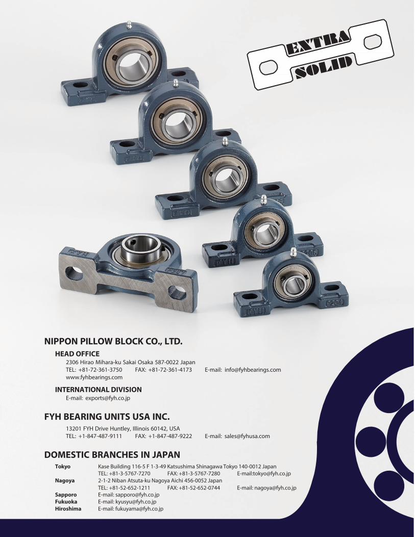
NIPPON PILLOW BLOCK CO., LTD. HEAD OFFICE
2306 Hirao Mihara-ku Sakai Osaka 587-0022 Japan TEL: +81-72-361-3750 FAX: +81-72-361-4173 E-mail: [email protected] www.fyhbearings.com
INTERNATIONAL DIVISION E-mail: [email protected]
FYH BEARING UNITS USA INC. 13201 FYH Drive Huntley, Illinois 60142, USA TEL: +1-847-487-9111 FAX: +1-847-487-9222 E-mail: [email protected]
DOMESTIC BRANCHES IN JAPAN Tokyo Kase Building 116-5 F 1-3-49 Katsushima Shinagawa Tokyo 140-0012 Japan
TEL: +81-3-5767-7270 FAX: +81-3-5767-7280 E-mail:[email protected] Nagoya 2-1-2 Niban Atsuta-ku Nagoya Aichi 456-0052 Japan
TEL: +81-52-652-1211 FAX: +81-52-652-0744 E-mail: [email protected] Sapporo E-mail: [email protected] Fukuoka E-mail: [email protected] Hiroshima E-mail: [email protected]
fyhbearings.com
CAT.No.3320 2015.02.20000DS
![Synthesis and Structural confirmation of product selective Cyclic [1,3]oxazines and Schiff bases bearing symmetrical / unsymmetrical units](https://img.pdfslide.net/doc/110x75/635b6cc84028fc5adf01af66/synthesis-and-structural-confirmation-of-product-selective-cyclic-13oxazines.jpg)


