Embed Size (px)
Citation preview
Sabanci University
Ball Catching Direct Drive SCARA Robot
by
Melih Fidanoğlu (5484)
Ahmet Fatih Tabak (5604)
Uğur Tümerdem (6127)
Hüseyin Atakan Varol (6386)
A Graduation Project Report
Submitted to
Mustafa Ünel
and
Kemalettin Erbatur
in Partial Fulfillment of the ENS 492 Course
in
Mechatronics Undergraduate Program
Istanbul, Turkey
Spring 2005
1
INDEX 1. Introduction: 2 2. Problem Definition: 3 3. Electrical Design and Implementation: 4 4. Mechanical Design and Implementation: 7 4.1. Design of the Parts: 7 4.2. FEM Analysis of the Parts: 12 4.3. Computer Aided Manufacturing: 16 4.4. Mechanical Assembly: 18 5. Control System Design: 20 5.1. Introduction: 20 5.2. Control Hardware and Software: 20 5.3. Reference Generation: 21 5.4. Controller Design: 23 6. Vision System Design: 24 6.1. Vision Hardware: 24 6.2. Vision Software: 24 Appendix A: Direct Drive Scara Robot Matlab M-Trace Codes: 28 Appendix B: Direct Drive Scara Robot ANSI-C Control Codes: 31 Appendix C: Direct Drive Scara Robot OpenCV BallTrack Visual C++ Codes: 51 Appendix D: Direct Drive Scara Robot OpenCV-dSpace Interfacing
Matlab .m Codes: 56 Appendix E: Direct Drive Scara Robot Electrical Drawings: 60 Appendix F: Direct Drive Scara Robot Part Sample G-Codes
& CNC Documentations & Total Process Plan: 85 Appendix G: Direct Drive Scara Robot Part Technical Drawings: 102 Appendix H: dSpace Control Board Pins: 117 Bibliography & Sources: 118

2
1. Introduction
Design, implementation and vision based control of a 2 DOF Direct Drive Scara Robot system is the general definition to this graduation project. In that regard the overall project can be seen as a combination of several sub-projects.
The mechanical part starts with 3D design of necessary link, sensor towers and camera holder in SolidWork 2004. Some parts like base or lower link were already manufactured beforehand. Than CosmosWorks 2004 is used to perform FEM analysis on the links for several aspects such as factor of safety or Von Misses analysis. Than all work space is redrawn in 3D, including even the crane around. Than the necessary G-codes to manufacture these parts are generated and the manufacturing procedures are simulated via SolidCam 2005. To produce these parts, Emco 155 and Maho are used. Finally all the links, sensor handlers and motors are assembled together.
Electrical system is designed all over with the help of Dr. Kemalettin Erbatur
and electrical drawings are done by hand. After the necessary ‘off the shelf’ parts are acquired the control cabinet was build. Control cabinet has the motor drivers, line filters, several fuses and relays etc. Total 24 pages of electrical drawing, accounts for both inner cabinet connections and the connections between motors-cabinet-computer triple with own produces connectors.
Control system was built with combination of Matlab M-trace, and ANSI-C
codes. M-trace makes it possible to get external variables into Control Desktop Utility. These ANSI-C code pieces are consisting of software security protocols and the forward and inverse kinematics calculations as well as the PID controller routines. There are over one thousand lines of ANSI-C codes constructed under Control Desktop utility which communicates with the robot and allows user to interact with the overall system via graphic interface.
Vision system is the combination of a CMOS digital camera mounted on the
ceiling of the workspace, a Visual C++ code to acquire the sight of workspace as frames. These frames are collated with the help of OpenCV 4.0b, DirectX and IP libraries. The C++ codes are responsible from detecting any moving object inside the region of interest and updating the coordinates and detection time inside a .txt file on the hard drive. On the other hand a Matlab .m file is responsible from reading this file simultaneously and updating the general information inside the ANSI-C codes which are taken by M-Trace codes and used as the position references.

3
Figure 1. General System Structure 2. Problem Definition
The real intension is to catch a thrown ball with the help of the direct drive Scara robot arm. The Camera has a conical sight, hence the higher it is mounted the larger area can be seen. The region of interest is tuned to be smaller in order to avoid the shadows of the external objects or the like. Region of interest is calibrated accordingly with the center of the biggest motor of the Scara robot. When the ball enters the region of interest, which is 1.5x1 m2 out of total 2.7x1.4 m2, camera detects the coordinates and the contemporary points are updated inside the system. The robotic arm can reach maximum 0.68 meters and minimum 0.22 meters and both arms are limited with ± 120 degrees in software via codes; ± 135 degrees in hardware via inductive proximity sensor. When the coordinates are detected inside the region of interest a line is fitted and the intersection point of outer region of the robot workspace and the fitted line is calculated. Tip of the arm is send to the intersection point. After sending the tip to the intersection, the trajectory inside the workspace, but outside the region of the interest is to be guessed and robotic arm is to follow that trajectory. Following figure is for demonstrational purposes:
Figure 2. Artificial test conditions

4
3. Electrical Design and Implementation:
Fig-3) In this picture, the backside of the electrical cabinet which contains Electrical components like relays, nodes, PCB board and electrical cabling can be seen.
Fig-4) Relays have been placed on the back of the cabinet, with the required cabling has been done.
Fig-5) The PCB board has been designed and placed on the back of the cabinet.
Fig-6) The nodes –X2, –X3 and –X4 are used for connecting several cables on the back of the cabinet.
Fig-7) The power cables, encoder cables and other cables are distributed to the related components.

5
Fig-8) In this picture, the front of the control cabinet which contains encoders, line filters, fuses can be seen.
Fig-9) The node –X1 and the fuses from F1 to F7 are placed to the front of the cabinet.
Fig-10) The 24V DC power supply and two other fuses are placed to the upper right part of the cabinet.
Fig-11) There are two drivers for two motors, and they are placed to the cabinet initially.
Fig-12) There are two identical line filters for each driver.
Fig-13) The operator panel is used for starting procedure, emergency conditions and manual control.

6
Fig-14) The main switch is mounted to the front door of the cabinet. By turning the switch, power is provided to the system.
Fig-15) A fan is mounted to the side of the cabinet for preventing the cabinet from excessive heat caused by the drivers.
Fig-16) The fan is mounted to the left side of the cabinet.
Fig-17) The whole picture of the cabinet with the operator panel can be seen.
Fig-18) The front side of the cabinet and the main switch is shown above.
Fig-19) The cabinet is seen at its operating place.

7
4. Mechanical Design and Implementation: 4.1. Design of the Parts (CAD): All of the parts are designed in the Solidworks. The FEM analysis is done by COSMOS, which is integrated to the Solidworks. The SolidCAM is used for creating the Gcodes. The parts can be seen below:
Fig-20) Lower part of the camera holder
8
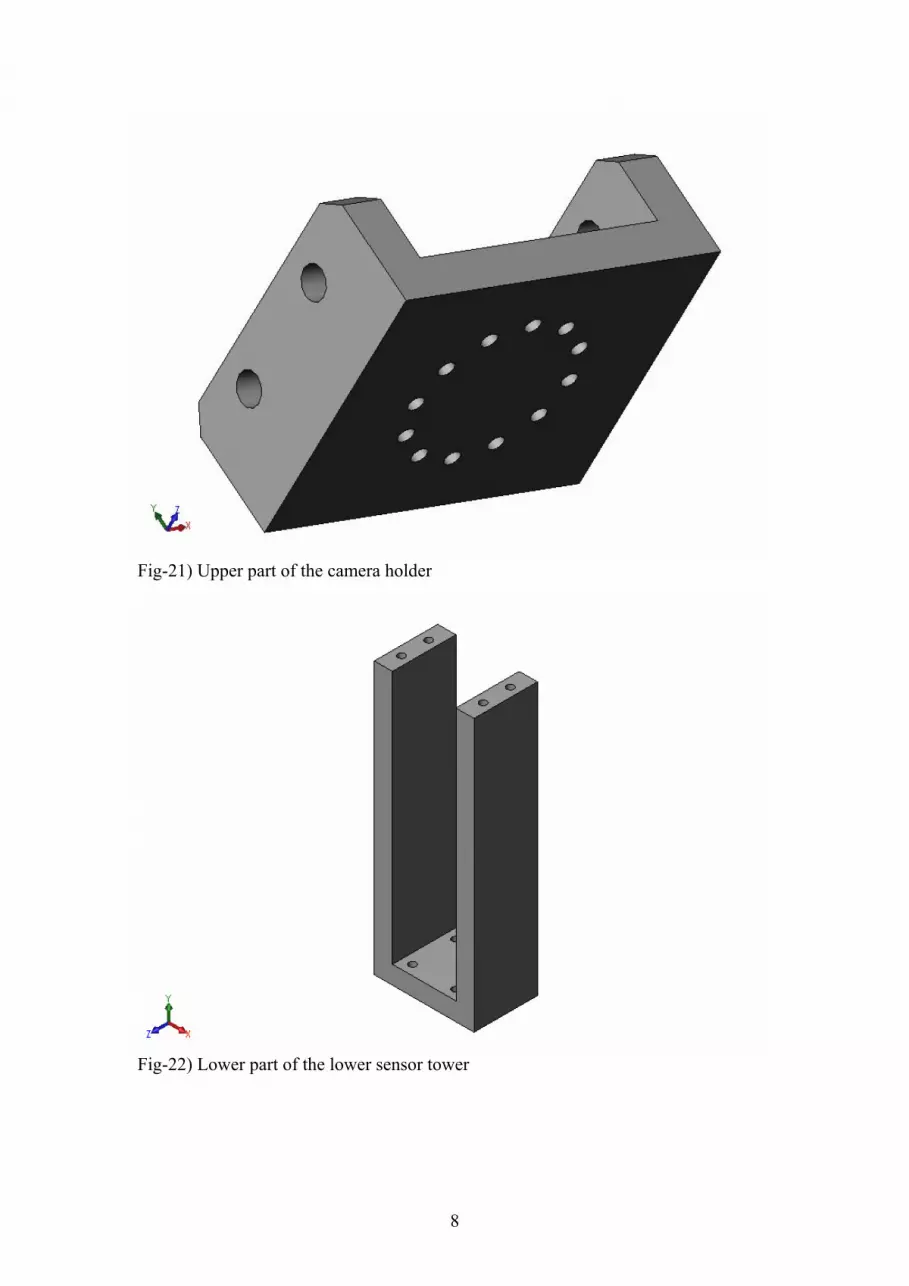
Fig-21) Upper part of the camera holder
Fig-22) Lower part of the lower sensor tower

9
Fig-23) Upper part of the lower sensor tower
Fig-24) Lower part of the upper sensor tower

10
Fig-25) Upper part of the upper sensor tower
Fig-26) Camera holder assembly

11
Fig-27) Lower sensor tower assembly
Fig-28) Upper sensor tower assembly The technical drawings of the parts can be found in the Appendix G.

12
Fig-29) By assembling all the parts above, the workspace has been created in the computer environment with the help of SolidWorks. This workspace has later been implemented in L001 following the production of the parts. 4.2. FEM analysis of the parts: Camera holder does not have any significant force or moment acting on it, therefore a FEM analysis is not required. However the second link that will be manufactured will carry a load of about 1.2 kilograms and a moment on the joint will be created.
Fig-30) Shoulder link with mesh applied force and constraints

13
Fig-31) A mass of 1.2 kg is applied on the center of gravity of the shoulder link.
Fig-32) Von Mises stresses created on the shoulder link

14
Fig-33) Displacement on shoulder link has maximum of micron level displacement.
Fig-34) Strain on the shoulder link, again in microns at maximum.

15
Fig-35) Factor of safety distribution for shoulder joint; it is safe everywhere, the minimum value is about 54.

16
4.3. Computer Aided Manufacturing:
Fig-36) Production of the Small Arm Using MAHO. The small arm is produced in MAHO. An oil is sprayed to the part such that undesired increase in the temperature can be prevented. In addition, this oil does the lubrication, which increases the life of the machine. Also, it cleans the surface of the part, thus makes the machining better.
Fig-37) The Small Arm with the screw holes.
In the picture, it can be seen that one side of the part is finished. The remaining sections are the other face of the part, and the sides of the part.
Fig-38) Production of the lower sensor tower lower part. For the parts other than the small arm, the CNC machine EMCO is used. It is smaller than MAHO, as a result it is not capable of machining big parts like MAHO.

17
Fig-39) Production of the lower part of the upper sensor tower.
Fig-40) The CNC EMCO. For the parts other than the small arm, the CNC machine EMCO is used. It is smaller than MAHO, as a result it is not capable of machining big parts like MAHO.
Fig-41) The parts produced in CNCs. A total of seven parts are produced via CNC machines EMCO and MAHO. The Gcodes that are given in this document( and the previous progress report) are used for producing some of these parts.
Fig-42) The parts after the production is finished. The sensor can be seen at the upper part of the picture. The two sensor towers will hold each of these sensors.
18
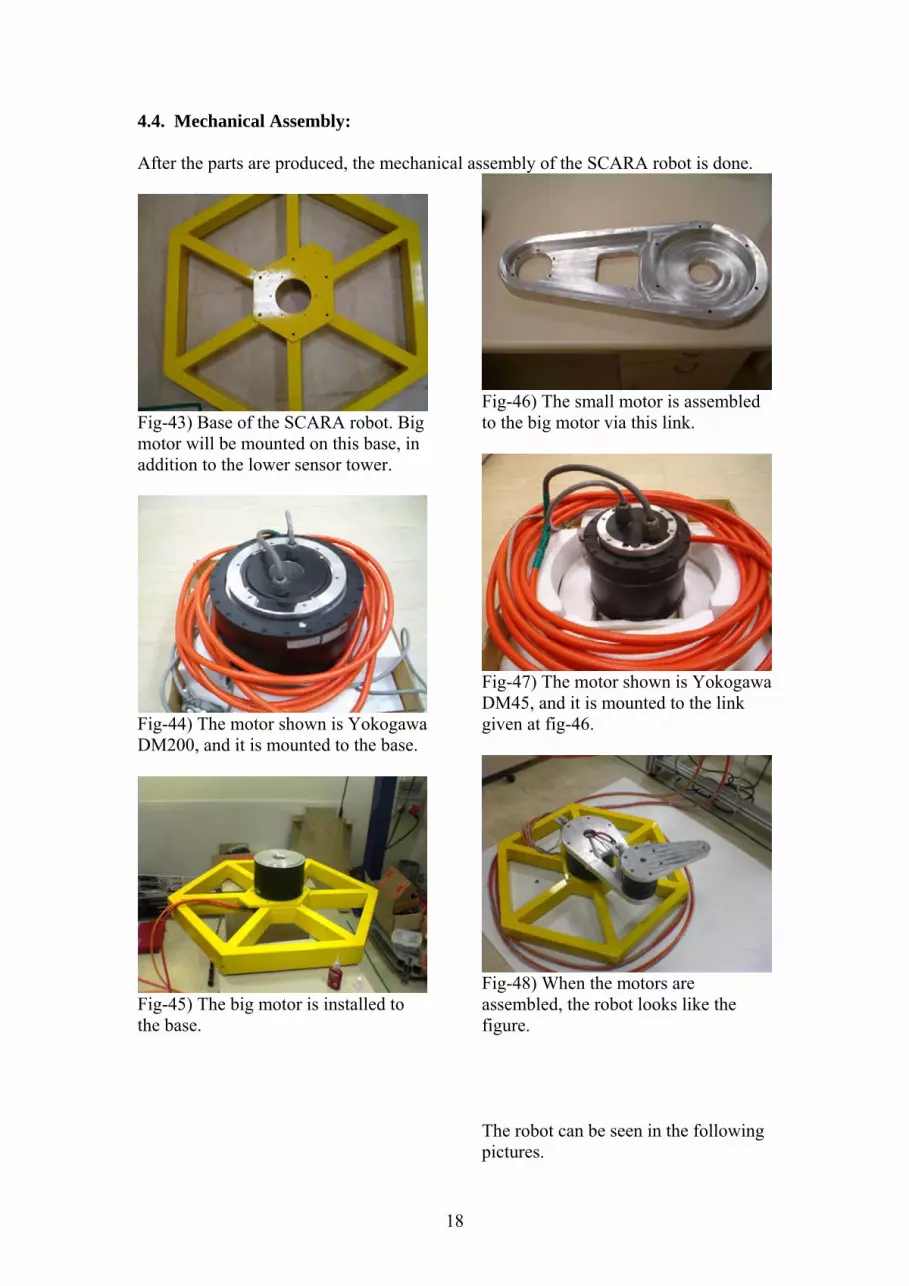
4.4. Mechanical Assembly: After the parts are produced, the mechanical assembly of the SCARA robot is done.
Fig-43) Base of the SCARA robot. Big motor will be mounted on this base, in addition to the lower sensor tower.
Fig-44) The motor shown is Yokogawa DM200, and it is mounted to the base.
Fig-45) The big motor is installed to the base.
Fig-46) The small motor is assembled to the big motor via this link.
Fig-47) The motor shown is Yokogawa DM45, and it is mounted to the link given at fig-46.
Fig-48) When the motors are assembled, the robot looks like the figure. The robot can be seen in the following pictures.

19
Fig-49) The cables are strong against torsion.
Fig-50)
Fig-51) A bowl is placed on the little link for catching the robot.
Fig-52) The robot with the operator console.
Fig-53) Sensor towers are attached to the base and the big link.
Fig-54) The experiment setup.

20
5. Control System Design: 5.1. Introduction
After the mechanical and electrical design and implementation is completed, the control system is designed. The control system design consists of creating the required analog torque reference signals for the base and elbow motor drivers and setting the logic signals required for the proper operation of the drivers. Then the motor drivers will create the required currents for the motors. Position and velocity control is done using digital independent joint PID controllers. 5.2 Control Hardware and Software:
For the control system hardware, the DSPACE DS1102 DSP Board is used. Two analog outputs, 10 Digital IO’s and 2 encoders of the DSPACE board are employed. The control program is written in ANSI-C and it is over 1200 lines (See Appendix B). It is noted that creating a control code for a complex system having multiple states is a very tedious process and Simulink(especially Stateflow tool) should be employed. Furthermore, Graphical User Interfaces are created in DSPACE Control Desk (See Figure 55-57)
Figure 55: Control Desk Main Control Window
21
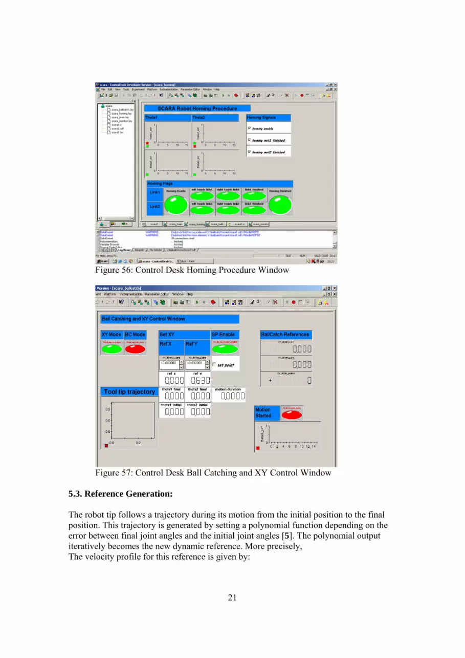
Figure 56: Control Desk Homing Procedure Window
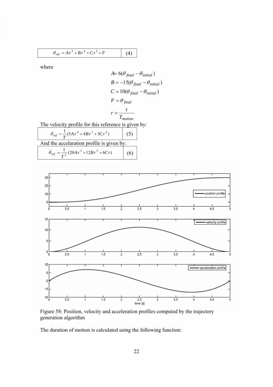
Figure 57: Control Desk Ball Catching and XY Control Window
5.3. Reference Generation: The robot tip follows a trajectory during its motion from the initial position to the final position. This trajectory is generated by setting a polynomial function depending on the error between final joint angles and the initial joint angles [5]. The polynomial output iteratively becomes the new dynamic reference. More precisely, The velocity profile for this reference is given by:
22
FCBAref +++= 345 τττθ (4) where
motion
final
initialfinal
initialfinal
initialfinal
Tt
F
C
B
A
=
=
−=
−−=
−=
τ
θ
θθ
θθ
θθ
)(10
)(15
)(6
The velocity profile for this reference is given by:
)345(1 234 τττθ CBATref ++=& (5)
And the accelaration profile is given by:
)61220(1 232
τττθ CBAT
ref ++=&& (6)
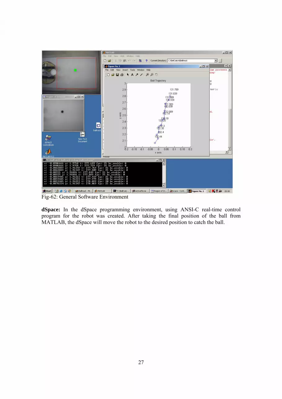
Figure 58: Position, velocity and acceleration profiles computed by the trajectory generation algorithm The duration of motion is calculated using the following function:

23
4max2max13 )**(* kkkkTMotion ++= θθ where
2.047.03
0485.025878.01
==−=
=
kkkk
5.4. Controller Design:
A digital independent joint PID controller is used to control each motor. The controller has the following form. Using high proportional gain low error is achieved, but high P-Gain also increases the oscillations in the system. Unfortunately, D-Gain is set to very low values. A good velocity filter should be designed in order to use D-Gain with higher values.
∫ −+−
+−=t
trefi
refdrefp dtK
dtd
KKU0
)()(
)( θθθθ
θθ

24
6. Vision System Design 6.1. Vision Hardware
Philips PCVC830K digital USB video camera is used as the sensor of the vision system. The USB camera works at 30 frames per second in 320x240 resolution.
Figure 59: Philips PCVC830K digital USB video camera
6.2. Vision Software Three softwares are used for several purposes. The programs are MATLAB, OPENCV and dSpace. OPENCV: This programming library is used for tracking a ball by processing the images acquired from the camera. The code is written in Visual C++ and functions of OPENCV library are used in this code. Using cvGoodFeaturestotrack function the position of the ball is estimated. Intel Image Processing Library (IPL) and DirectX SDK Library (Microsoft) are integrated to OPENCV in order to increase processing speed. 25 fps processing speed is achieved.

25
Fig-60: OPENCV software environment

26
MATLAB: Matlab is used as an interface between OpenCV and dSpace. OpenCV writes ball coordinates and a timestamp to a text file which is read by Matlab. Matlab takes ball position values and fits a time dependent line to these points. This way the destination of the ball can be predicted. Matlab writes the predicted destination to dSpace with the use of Mlib.
Fig-61: Detected Trajectory of the Thrown Ball
27
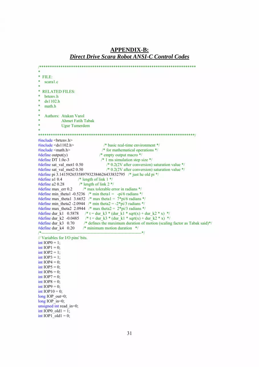
Fig-62: General Software Environment dSpace: In the dSpace programming environment, using ANSI-C real-time control program for the robot was created. After taking the final position of the ball from MATLAB, the dSpace will move the robot to the desired position to catch the ball.

28
APPENDIX-A: Direct Drive Scara Robot Matlab M-Trace Codes
-- File: Scara1.trc -- Author: Atakan Varol -- Melih Fidanoğlu sampling_period = 1.0E-3 -- signals available for TRACE -- -- signal name type address group "Model" group "DigitalIO" IOP0 int IOP1 int IOP2 int IOP3 int IOP4 int IOP5 int IOP6 int IOP7 int IOP8 int IOP9 int IOP10 int IOP_out int IOP_in int read_in int endgroup group "Enable_signals" sys_enable int con_enable int homing_enable int demo_mode int xy_mode int bc_mode int mode_select int endgroup group "Homing Signals" homing_finished int homing_mot1_finished int homing_left_touch_mot1 int homing_right_touch_mot1 int homing_mot2_finished int homing_left_touch_mot2 int homing_right_touch_mot2 int endgroup

29
group "Base Motor" u1 flt theta1 flt theta1_dot flt theta1_vel_err flt theta1_ref_vel flt theta1_off flt theta1_err flt theta1_ref flt theta1_ref_dot flt theta1_initial flt theta1_final flt theta1_dur_motion flt theta1_dot_est flt endgroup group "Elbow Motor" u2 flt theta2 flt theta2_dot flt theta2_vel_err flt theta2_ref_vel flt theta2_off flt theta2_err flt theta2_ref flt theta2_ref_dot flt theta2_initial flt theta2_final flt theta2_dur_motion flt theta2_dot_est flt endgroup group "XY_BC" x flt y flt ref_x flt ref_y flt ref_x_cand flt ref_y_cand flt ref_x_bc flt ref_y_bc flt bc_enable int xy_motion_enable int set_point int endgroup endgroup group "Control Parameters" group "Base Motor" kp_mot1 flt ki_mot1 flt kd_mot1 flt kp_vel_mot1 flt

30
ki_vel_mot1 flt kd_vel_mot1 flt endgroup group "Elbow Motor" kp_mot2 flt ki_mot2 flt kd_mot2 flt kp_vel_mot2 flt ki_vel_mot2 flt kd_vel_mot2 flt endgroup endgroup group "Task Info" exec_time flt processor_load flt msg_last_error_no int endgroup
31
APPENDIX-B: Direct Drive Scara Robot ANSI-C Control Codes
/************************************************************************** * * FILE: * scara1.c * * RELATED FILES: * brtenv.h * ds1102.h * math.h * * Authors: Atakan Varol * Ahmet Fatih Tabak * Ugur Tumerdem * **************************************************************************/ #include <brtenv.h> #include <ds1102.h> /* basic real-time environment */ #include <math.h> /* for mathematical operations */ #define output(y) /* empty output macro */ #define DT 1.0e-3 /* 1 ms simulation step size */ #define sat_val_mot1 0.50 /* 0.2(2V after conversion) saturation value */ #define sat_val_mot2 0.50 /* 0.2(2V after conversion) saturation value */ #define pi 3.1415926535897932384626433832795 /* just he old pi */ #define a1 0.4 /* length of link 1 */ #define a2 0.28 /* length of link 2 */ #define max_err 0.2 /* max tolerable error in radians */ #define min_theta1 -0.5236 /* min theta1 = -pi/6 radians */ #define max_theta1 3.6652 /* max theta1 = 7*pi/6 radians */ #define min_theta2 -2.0944 /* min theta2 = -2*pi/3 radians */ #define max_theta2 2.0944 /* max theta2 = 2*pi/3 radians */ #define dur_k1 0.5878 /* t = dur_k3 * (dur_k1 * sqrt(x) + dur_k2 * x) */ #define dur_k2 -0.0485 /* t = dur_k3 * (dur_k1 * sqrt(x) + dur_k2 * x) */ #define dur_k3 0.70 /* defines the maximum duration of motion (scaling factor as Tabak said)*/ #define dur_k4 0.20 /* minimum motion duration */ /*-----------------------------------------------------------------------*/ // Variables for I/O pins' bits. int IOP0 = 1; int IOP1 = 0; int IOP2 = 1; int IOP3 = 1; int IOP4 = 0; int IOP5 = 0; int IOP6 = 0; int IOP7 = 0; int IOP8 = 0; int IOP9 = 0; int IOP10 = 0; long IOP_out=0; long IOP_in=0; unsigned int read_in=0; int IOP0_old1 = 1; int IOP1_old1 = 0;

32
int IOP2_old1 = 1; int IOP3_old1 = 1; int IOP4_old1 = 0; int IOP5_old1 = 0; int IOP6_old1 = 0; int IOP7_old1 = 0; int IOP8_old1 = 0; int IOP9_old1 = 0; int IOP10_old1 = 0; // Variables for Scopes // for motor 1 volatile float u1 = 0; volatile float theta1 = 0; volatile float theta1_dot = 0; volatile float theta1_err = 0; volatile float theta1_vel_err = 0; volatile float theta1_ref = 0; volatile float theta1_ref_vel = 0; volatile float theta1_off = 0; volatile float theta1_initial = 0; volatile float theta1_final = 0; volatile float theta1_dur_motion = 0; volatile float theta1_dot_est = 0; volatile float theta1_ref_dot = 0; volatile float u1_old1 = 0; volatile float theta1_old1 = 0; volatile float theta1_dot_old1 = 0; volatile float theta1_err_old1 = 0; volatile float theta1_vel_err_old1 = 0; volatile float theta1_ref_old1 = 0; volatile float theta1_ref_vel_old1 = 0; volatile float theta1_off_old1 = 0; volatile float theta1_initial_old1 = 0; volatile float theta1_final_old1 = 0; volatile float theta1_dur_motion_old1 = 0; volatile float theta1_dot_est_old1 = 0; volatile float u1_old2 = 0; volatile float theta1_err_old2 = 0; volatile float theta1_vel_err_old2 = 0; volatile float theta1_dot_est_old2 = 0; // for motor 2 volatile float u2 = 0; volatile float theta2 = 0; volatile float theta2_dot = 0; volatile float theta2_err = 0; volatile float theta2_vel_err = 0; volatile float theta2_ref = 0; volatile float theta2_ref_vel = 0; volatile float theta2_off = 0; volatile float theta2_initial = 0; volatile float theta2_final = 0; volatile float theta2_dur_motion = 0; volatile float theta2_est = 0; volatile float theta2_dot_est = 0; volatile float theta2_ref_dot = 0; volatile float u2_old1 = 0;

33
volatile float theta2_old1 = 0; volatile float theta2_dot_old1 = 0; volatile float theta2_err_old1 = 0; volatile float theta2_vel_err_old1 = 0; volatile float theta2_ref_old1 = 0; volatile float theta2_ref_vel_old1 = 0; volatile float theta2_off_old1 = 0; volatile float theta2_initial_old1 = 0; volatile float theta2_final_old1 = 0; volatile float theta2_dur_motion_old1 = 0; volatile float theta2_est_old1 = 0; volatile float theta2_dot_est_old1 = 0; volatile float u2_old2 = 0; volatile float theta2_err_old2 = 0; volatile float theta2_vel_err_old2 = 0; volatile float theta2_dot_est_old2 = 0; volatile float theta2_est_old2 = 0; // Position variables volatile float x = 0; volatile float y = 0; // Ball Catch and XY Control Variables volatile float ref_x = 0; volatile float ref_y = 0; volatile float ref_x_cand = 0; volatile float ref_y_cand = 0; volatile float ref_x_bc = 0; volatile float ref_y_bc = 0; int set_point = 0; int bc_enable = 0; // Enable variables int sys_enable = 0; int homing_enable = 0; int con_enable = 0; int demo_mode = 0; int xy_motion_enable = 0; int bc_motion_enable = 0; int xy_mode = 0; int bc_mode = 0; int mode_select = 3; // Start with the idle mode int sys_enable_old1 = 0; int homing_enable_old1 = 0; int con_enable_old1 = 0; int demo_mode_old1 = 0; int xy_mode_old1 = 0; int xy_motion_enable_old1 = 0; int bc_mode_old1 = 0; // Homing Variables int homing_finished = 0; // Motor 1 int homing_mot1_finished = 0; int homing_left_touch_mot1 = 0; int homing_right_touch_mot1 = 0; // Motor 2 int homing_mot2_finished = 0; int homing_left_touch_mot2 = 0; int homing_right_touch_mot2 = 0;

34
int homing_finished_old1 = 0; // Motor 1 int homing_mot1_finished_old1 = 0; int homing_left_touch_mot1_old1 = 0; int homing_right_touch_mot1_old1 = 0; // Motor 2 int homing_mot2_finished_old1 = 0; int homing_left_touch_mot2_old1 = 0; int homing_right_touch_mot2_old1 = 0; // ------------------------------------ // Variables for Control // motor 1 control parameters volatile float kp_mot1 = 4; volatile float ki_mot1 = 1; volatile float kd_mot1 = 0; volatile float kp_vel_mot1 = 0.1; volatile float ki_vel_mot1 = 0.5; volatile float kd_vel_mot1 = 0; // motor2 controller parameters volatile float kp_mot2 = 3; volatile float ki_mot2 = 1; volatile float kd_mot2 = 0; volatile float kp_vel_mot2 = 0.2; volatile float ki_vel_mot2 = 1; volatile float kd_vel_mot2 = 0; //--------------------------------------- float lambda1 = 0.8; float lambda2 = 0.8; // Counters int counter1 = 0; int counter2 = 0; int counter3 = 0; int counter4 = 0; int counter5 = 0; // Timers volatile float t1 = 0; volatile float t2 = 0; volatile float t3 = 0; volatile float t4 = 0; volatile float t5 = 0; // Trajectory variables volatile float A = 0; volatile float B = 0; volatile float C = 0; volatile float F = 0; // Security variables int unstability = 0; // Variables for execution time profiling float exec_time; /* execution time */ float processor_load; /* processor load */ /*-----------------------------------------------------------------------*/ void fwd_kin() { x = a1 * cos( theta1 ) + a2 * cos( theta1 + theta2 ); y = a1 * sin( theta1 ) + a2 * sin( theta1 + theta2 ); }

35
void inv_kin() { if ( sqrt( ref_x_cand*ref_x_cand + ref_y_cand*ref_y_cand) <= (a1+a2) && sqrt( ref_x_cand*ref_x_cand + ref_y_cand*ref_y_cand) >= (a1-a2) ) { float D; D = (ref_x_cand * ref_x_cand + ref_y_cand * ref_y_cand - a1*a1 - a2*a2)/ (2*a1*a2); theta2_final = atan2( sqrt(1-D*D),D); theta1_final = atan2(ref_y_cand,ref_x_cand) - atan2(a2*sin(theta2_final), ( a1 + a2*cos(theta2_final))); theta1_initial = theta1; theta2_initial = theta2; if ( theta1_final >= max_theta1 || theta1_final <= min_theta1 || theta2_final >= max_theta2 || theta2_final <= min_theta2 ) { counter4 = 0; theta2_final = 0; theta1_final = 0; } else { counter4++; xy_motion_enable = 1; ref_x = ref_x_cand; ref_y = ref_y_cand; } } else { counter4 = 0; theta2_final = 0; theta1_final = 0; } set_point = 0; } void inv_kin_bc() { if ( sqrt( ref_x_bc*ref_x_bc + ref_y_bc*ref_y_bc) <= (a1+a2) && sqrt( ref_x_bc*ref_x_bc + ref_y_bc*ref_y_bc) >= (a1-a2) ) { float D; D = (ref_x_bc * ref_x_bc + ref_y_bc * ref_y_bc - a1*a1 - a2*a2)/ (2*a1*a2); theta2_final = atan2( sqrt(1-D*D),D); theta1_final = atan2(ref_y_bc,ref_x_bc) - atan2(a2*sin(theta2_final), ( a1 + a2*cos(theta2_final))); theta1_initial = theta1; theta2_initial = theta2; if ( theta1_final >= max_theta1 || theta1_final <= min_theta1 || theta2_final >= max_theta2 || theta2_final <= min_theta2 ) { counter5 = 0; theta2_final = 0; theta1_final = 0; } else { counter5++; bc_motion_enable = 1;

36
ref_x = ref_x_bc; ref_y = ref_y_bc; } } else { counter5 = 0; theta2_final = 0; theta1_final = 0; } set_point = 0; } void apply_u1(float u1_fnc) { // output saturation (For security reasons) if ((IOP9 == 1) | (IOP0 == 1) | (sys_enable == 0)) { u1_fnc = 0; } if (u1_fnc > sat_val_mot1) { u1_fnc = sat_val_mot1; } if (u1_fnc < -sat_val_mot1) { u1_fnc = -sat_val_mot1; } ds1102_da(1,-u1_fnc); } void apply_u2(float u2_fnc) { // output saturation (For security reasons) if ((IOP9 == 1) | (IOP0 == 1) | (sys_enable == 0)) { u2_fnc = 0; } if (u2_fnc > sat_val_mot2) { u2_fnc = sat_val_mot2; } if (u2_fnc < -sat_val_mot2) { u2_fnc = -sat_val_mot2; } ds1102_da(2,-u2_fnc); } void pid_vel_mot1() { theta1_vel_err = theta1_ref_vel - theta1_dot; // PID Control u1 = u1_old2 + theta1_vel_err*(kp_vel_mot1 + ki_vel_mot1*DT/2 + kd_vel_mot1*2/DT) + theta1_vel_err_old1*(-kd_vel_mot1*4/DT + ki_vel_mot1*DT) + theta1_vel_err_old2*(-kp_vel_mot1 + ki_vel_mot1*DT/2 + kd_vel_mot1*2/DT); apply_u1(u1); // apply control } void pid_vel_mot2()

37
{ theta2_vel_err = theta2_ref_vel - theta2_dot; // PID Control u2 = u2_old2 + theta2_vel_err*(kp_vel_mot2 + ki_vel_mot2*DT/2 + kd_vel_mot2*2/DT) + theta2_vel_err_old1*(-kd_vel_mot2*4/DT + ki_vel_mot2*DT) + theta2_vel_err_old2*(-kp_vel_mot2 + ki_vel_mot2*DT/2 + kd_vel_mot2*2/DT); apply_u2(u2); // apply control } void traj_pos_mot1() { float tau1 = 0; tau1 = t1 / theta1_dur_motion; if (tau1 > 1) { tau1 = 1; } A = 6*(theta1_final - theta1_initial); B = -15*(theta1_final - theta1_initial); C = 10*(theta1_final - theta1_initial); F = theta1_initial; // Thanks: From Atakan to Peter Corke theta1_ref = A*pow(tau1,5) + B*pow(tau1,4) + C*pow(tau1,3) + F; theta1_ref_dot = 5*A*pow(tau1,4) + 4*B*pow(tau1,3) + 3*C*pow(tau1,2); t1 = t1 + DT; } void traj_pos_mot2() { float tau2 = 0; tau2 = t2 / theta2_dur_motion; if (tau2 > 1) { tau2 = 1; } A = 6*(theta2_final - theta2_initial); B = -15*(theta2_final - theta2_initial); C = 10*(theta2_final - theta2_initial); F = theta2_initial; // Thanks: From Atakan to Peter Corke theta2_ref = A*pow(tau2,5) + B*pow(tau2,4) + C*pow(tau2,3) + F; theta2_ref_dot = 5*A*pow(tau2,4) + 4*B*pow(tau2,3) + 3*C*pow(tau2,2); t2 = t2 + DT; } void pid_security(float theta_err) { if (theta_err > max_err) { IOP0 = 1; // if error is big, disable servo on sys_enable = 0; unstability = 1; } } void pid_pos_mot1() { theta1_err = theta1_ref - theta1; pid_security(theta1_err);

38
// PI Control /* u1 = u1_old2 + theta1_err*(kp_mot1 + ki_mot1*DT/2 + kd_mot1*2/DT) + theta1_err_old1*(-kd_mot1*4/DT + ki_mot1*DT) + theta1_err_old2*(-kp_mot1 + ki_mot1*DT/2 + kd_mot1*2/DT); */ u1 = u1_old2 + theta1_err*(kp_mot1 + ki_mot1*DT/2) + theta1_err_old1*(ki_mot1*DT) + theta1_err_old2*(-kp_mot1 + ki_mot1*DT/2); u1 = u1 + kd_mot1*(theta1_ref_dot - theta1_dot_est); apply_u1(u1); // apply control } void pid_pos_mot2() { theta2_err = theta2_ref - theta2; pid_security(theta2_err); // PI Control /* u2 = u2_old2 + theta2_err*(kp_mot2 + ki_mot2*DT/2 + kd_mot2*2/DT) + theta2_err_old1*(-kd_mot2*4/DT + ki_mot2*DT) + theta2_err_old2*(-kp_mot2 + ki_mot2*DT/2 + kd_mot2*2/DT); */ u2 = u2_old2 + theta2_err*(kp_mot2 + ki_mot2*DT/2) + theta2_err_old1*(ki_mot2*DT) + theta2_err_old2*(-kp_mot2 + ki_mot2*DT/2); u2 = u2 + kd_mot2*(theta2_ref_dot - theta2_dot_est); apply_u2(u2); // apply control } void homing_mot1() { if (homing_mot1_finished == 0 && homing_mot2_finished == 0) { // go to right if (homing_mot1_finished == 0 && homing_left_touch_mot1 == 0 && counter1 < 30) { theta1_ref_vel = -1.0; pid_vel_mot1(); // turn the second motor to left with 0.2 rad/s, rise pid_vel_enable flag } } // if prox sensor touched for the first time rise the homing_left_touch flag if ( ((IOP2 - IOP2_old1) == -1) && homing_left_touch_mot1 == 0 && counter1 < 30) { homing_left_touch_mot1 = 1; u1 = 0; } // go to right with high velocity for 0.1 seconds if ( homing_left_touch_mot1 == 1 && counter1 < 200) { counter1++; apply_u1(0.1); } // go to left with low vel

39
if (counter1 == 200) { theta1_ref_vel = -0.1; pid_vel_mot1(); // turn the second motor to left with 0.05 rad/s, rise pid_vel_enable flag } // stop if the proximity seen if ( ((IOP2 - IOP2_old1) == -1) && (counter1 == 200)) { counter1 = 201; u1 = 0; apply_u1(0.1); } // wait for 0.1 seconds if ( counter1 >= 201 && counter1 < 300) { counter1++; } // clear the counter if (counter1 == 300) { ds1102_inc_clear_counter(1); } if ( counter1 >= 300 & counter1 < 400) { counter1++; u1 = 0; } if ( counter1 == 400) { theta1_ref_vel = 1.0; pid_vel_mot1(); // turn the second motor to left with 0.2 rad/s, rise pid_vel_enable flag } if ( ((IOP2 - IOP2_old1) == -1) && homing_right_touch_mot1 == 0 && counter1 >= 400) { homing_right_touch_mot1 = 1; u1 = 0; } // go to left open loop for 0.1 seconds if ( homing_right_touch_mot1 == 1 && counter1 < 600) { counter1++; apply_u1(-0.1); } // go to right with low velocity if (counter1 == 600) { theta1_ref_vel = 0.1; pid_vel_mot1(); // turn the second motor to left with 0.05 rad/s, rise pid_vel_enable flag } // stop if the proximity seen if ( ((IOP2 - IOP2_old1) == -1) && (counter1 == 600)) { counter1 = 601; u1 = 0; apply_u1(0); }

40
// wait for 0.1 seconds if ( counter1 >= 601 && counter1 < 700) { counter1++; } // determine the initial and final positions of the trajectory if ( counter1 == 700 ) { theta1_initial = theta1; theta1_final = (theta1/2) - (pi/2); theta1_dur_motion = abs(theta1_final - theta1_initial) / (pi/3); counter1 = 701; t1 = 0; } // generate trajectory and go to the final point if ( (counter1 == 701) && (t1 < (theta1_dur_motion + 3)) ) { traj_pos_mot1(); pid_pos_mot1(); } if ( counter1 == 701 && t1 > (theta1_dur_motion + 3)) { u1 = 0; theta1_initial = 0; theta1_final = 0; theta1_dur_motion = 0; theta1_ref = 0; ds1102_inc_clear_counter(1); } } void homing_mot2() { if (homing_mot1_finished == 1 && homing_mot2_finished == 0) { // go to right if (homing_mot2_finished == 0 && homing_left_touch_mot2 == 0 && counter2 < 30) { theta2_ref_vel = -pi/2.0; pid_vel_mot2(); // turn the second motor to left with 0.2 rad/s, rise pid_vel_enable flag } // if prox sensor touched for the first time rise the homing_left_touch flag if ( ((IOP3 - IOP3_old1) == -1) && homing_left_touch_mot2 == 0 && counter2 < 30) { homing_left_touch_mot2 = 1; u2 = 0; } // go to right with high velocity for 0.1 seconds if ( homing_left_touch_mot2 == 1 && counter2 < 100) { counter2++; apply_u2(0.08); } // go to left with low vel if (counter2 == 100) { theta2_ref_vel = -0.1;

41
pid_vel_mot2(); // turn the second motor to left with 0.05 rad/s, rise pid_vel_enable flag } // stop if the proximity seen if ( ((IOP3 - IOP3_old1) == -1) && (counter2 == 100)) { counter2 = 101; u2 = 0; apply_u2(0.05); } // wait for 0.1 seconds if ( counter2 >= 101 && counter2 < 200) { counter2++; } // clear the counter if (counter2 == 200) { ds1102_inc_clear_counter(2); } if ( counter2 >= 200 & counter2 < 300) { counter2++; u2 = 0; } if ( counter2 == 300) { theta2_ref_vel = pi/2.0; pid_vel_mot2(); // turn the second motor to left with 0.2 rad/s, rise pid_vel_enable flag } if ( ((IOP3 - IOP3_old1) == -1) && homing_right_touch_mot2 == 0 && counter2 >= 300) { homing_right_touch_mot2 = 1; u2 = 0; } // go to left open loop for 0.1 seconds if ( homing_right_touch_mot2 == 1 && counter2 < 400) { counter2++; apply_u2(-0.08); } // go to right with low velocity if (counter2 == 400) { theta2_ref_vel = 0.1; pid_vel_mot2(); // turn the second motor to left with 0.05 rad/s, rise pid_vel_enable flag } // stop if the proximity seen if ( ((IOP3 - IOP3_old1) == -1) && (counter2 == 400)) { counter2 = 401; u2 = 0; apply_u2(0); } // wait for 0.1 seconds if ( counter2 >= 401 && counter2 < 500) {

42
counter2++; } // determine the initial and final positions of the trajectory if ( counter2 == 500 ) { theta2_initial = theta2; theta2_final = (theta2/2); theta2_dur_motion = abs(theta2_final - theta2_initial) / (pi/2); counter2 = 501; t2 = 0; } // generate trajectory and go to the final point if ( (counter2 == 501) && (t2 < (theta2_dur_motion + 3)) ) { traj_pos_mot2(); pid_pos_mot2(); } if ( counter2 == 501 && (t2 > (theta2_dur_motion + 3) )) { u2 = 0; t2 = 0; theta2_initial = 0; theta2_final = 0; theta2_dur_motion = 0; theta2_ref = 0; ds1102_inc_clear_counter(2); } } // All the homings finished if (homing_mot1_finished == 1 && homing_mot2_finished == 1) { homing_finished = 1; } } void scara_demo() { if ( counter3 <10) { u1 = 0; u1_old1 = 0; u1_old2 = 0; u2 = 0; u2_old1 = 0; u2_old2 = 0; t1 = 0; t2 = 0; theta1_initial = theta1; theta1_final = pi/2; theta1_dur_motion = abs(theta1_final - theta1_initial) / (pi/4); theta2_initial = theta2; theta2_final = 0; theta2_dur_motion = abs(theta2_final - theta2_initial) / (pi/4); counter3++; } if ( counter3 == 10) {

43
traj_pos_mot1(); traj_pos_mot2(); pid_pos_mot1(); pid_pos_mot2(); } if ( counter3 == 10 && ( t1 > theta1_dur_motion ) && ( abs(theta1_err) < 0.005) && ( t2 > theta2_dur_motion ) && ( abs(theta2_err) < 0.005)) { u1 = 0; u1_old1 = 0; u1_old2 = 0; u2 = 0; u2_old1 = 0; u2_old2 = 0; t1 = 0; t2 = 0; theta1_initial = 0; theta1_final = 0; theta1_dur_motion = 0; theta2_initial = 0; theta2_final = 0; theta2_dur_motion = 0; counter3 = 11; } if (counter3 > 10 && counter3 < 450) { counter3++; } if ( counter3 == 450 && t1 < 12 ) { float ref_time = t1; if ( ref_time > 9) { ref_time = 9; theta1_ref_dot = 0; theta2_ref_dot = 0; } theta1_ref = pi/2 + pi/2*sin(pi/6*ref_time); theta1_ref_dot = (pi*pi)/8*cos(pi/6*ref_time); theta2_ref = 3*pi/4*sin(2*pi/3*ref_time); theta2_ref_dot = 3*pi*pi/4*cos(2*pi/3*ref_time); pid_pos_mot1(); pid_pos_mot2(); t1 = t1 + DT; } if ( counter3 == 450 && t1> 12) { u1 = 0; u1_old1 = 0; u1_old2 = 0; u2 = 0; u2_old1 = 0; u2_old2 = 0; t1 = 0; t2 = 0; theta1_initial = 0; theta1_final = 0;

44
theta1_dur_motion = 0; mode_select = 3; } } void xy_calc_duration() { float xy_max_theta; float dummy; xy_max_theta = theta1_final - theta1_initial; if ( xy_max_theta < 0 ) { xy_max_theta = -1*xy_max_theta; } dummy = theta2_final - theta2_initial; if ( dummy < 0 ) { dummy = -1*dummy; } //calculate the maximum theta if (xy_max_theta < dummy) { xy_max_theta = dummy; } // calculate the motion duration theta1_dur_motion = dur_k3 * (dur_k1 * pow(xy_max_theta,0.5) + dur_k2 * xy_max_theta) + dur_k4; theta2_dur_motion = theta1_dur_motion; } void scara_xy() { // if xy mode initiated, set all control variables to zero. if ( counter4 < 1 ) { u1 = 0; u1_old1 = 0; u1_old2 = 0; u2 = 0; u2_old1 = 0; u2_old2 = 0; t1 = 0; t2 = 0; theta1_initial = 0; theta1_final = 0; theta1_dur_motion = 0; theta2_initial = 0; theta2_final = 0; theta2_dur_motion = 0; counter4++; } // Calculate the inverse kinematics if ( counter4 == 1 && set_point == 1 ) { inv_kin(); } if ( counter4 ==2 && xy_motion_enable == 1) { xy_calc_duration();

45
counter4++; t1 = 0; t2 = 0; } if ( counter4 > 2 && (t1 < (theta1_dur_motion + 2)) ) { traj_pos_mot1(); traj_pos_mot2(); pid_pos_mot1(); pid_pos_mot2(); } if ( counter4 > 2 && (t1 >= (theta1_dur_motion + 2) )) { u1 = 0; u1_old1 = 0; u1_old2 = 0; u2 = 0; u2_old1 = 0; u2_old2 = 0; t1 = 0; t2 = 0; theta1_initial = 0; theta1_final = 0; theta1_dur_motion = 0; theta2_initial = 0; theta2_final = 0; theta2_dur_motion = 0; counter4 = 0; xy_motion_enable = 0; } } void scara_bc() { // if xy mode initiated, set all control variables to zero. if ( counter5 <2) { u1 = 0; u1_old1 = 0; u1_old2 = 0; u2 = 0; u2_old1 = 0; u2_old2 = 0; t1 = 0; t2 = 0; theta1_initial = theta1; theta1_final = pi/2; theta1_dur_motion = abs(theta1_final - theta1_initial) / (pi/4); theta2_initial = theta2; theta2_final = 0; theta2_dur_motion = abs(theta2_final - theta2_initial) / (pi/4); counter5++; } if ( counter5 == 2) { traj_pos_mot1(); traj_pos_mot2(); pid_pos_mot1();

46
pid_pos_mot2(); } if ( counter5 == 2 && ( t1 > theta1_dur_motion ) && ( abs(theta1_err) < 0.05) && ( t2 > theta2_dur_motion ) && ( abs(theta2_err) < 0.05)) { u1 = 0; u1_old1 = 0; u1_old2 = 0; u2 = 0; u2_old1 = 0; u2_old2 = 0; t1 = 0; t2 = 0; theta1_initial = 0; theta1_final = 0; theta1_dur_motion = 0; theta2_initial = 0; theta2_final = 0; theta2_dur_motion = 0; counter5 = 10; } // Calculate the inverse kinematics if ( counter5 == 10 && bc_enable == 1) { inv_kin_bc(); bc_enable = 0; } if ( counter5 ==11 && bc_motion_enable == 1) { xy_calc_duration(); counter5++; t1 = 0; t2 = 0; } if ( counter5 > 11 && (t1 < (theta1_dur_motion)) ) { traj_pos_mot1(); traj_pos_mot2(); pid_pos_mot1(); pid_pos_mot2(); } if ( counter5 > 11 && (t1 >= (theta1_dur_motion)) ) { u1 = 0; u1_old1 = 0; u1_old2 = 0; u2 = 0; u2_old1 = 0; u2_old2 = 0; t1 = 0; t2 = 0; theta1_initial = 0; theta1_final = 0; theta1_dur_motion = 0; theta2_initial = 0; theta2_final = 0;

47
theta2_dur_motion = 0; counter5 = 0; bc_motion_enable = 0; mode_select = 3; } } void read_enc1() // read base motor encoder { theta1 = -1*ds1102_inc_read_count(1)*2*pi/(1024000*1024/4); // read the encoder theta1_dot = (theta1 - theta1_old1)/DT; // calculate the angular velocity theta1_dot_est = (1 - lambda1) * theta1_dot + lambda1 * ( theta1_dot_est_old1); } void read_enc2() // read elbow motor encoder { theta2 = -1*ds1102_inc_read_count(2)*2*pi/(655360*1024/4); // read the encoder theta2_dot = (theta2 - theta2_old1)/DT; // calculate the angular velocity theta2_dot_est = (1 - lambda2) * theta2_dot + lambda2 *(theta2_dot_est_old1); } void read_dio() { // Calculate decimal to be output?? IOP_out=IOP0; ds1102_p14_pin_io_write(IOP_out); // Deal with the input pins?? read_in = ds1102_p14_pin_io_in(); //read the iops. IOP_in = (read_in-IOP_out)/2; // Take the input pins only. // Calculate each bit of the inputs?? IOP1= IOP_in%2; IOP2= ((IOP_in-IOP1)/2)%2; IOP3= ((((IOP_in-IOP1)/2)-IOP2)/2)%2; IOP4= ((((((IOP_in-IOP1)/2)-IOP2)/2)-IOP3)/2)%2; IOP5= ((((((((IOP_in-IOP1)/2)-IOP2)/2)-IOP3)/2)-IOP4)/2)%2; IOP6= ((((((((((IOP_in-IOP1)/2)-IOP2)/2)-IOP3)/2)-IOP4)/2)-IOP5)/2)%2; IOP7= ((((((((((((IOP_in-IOP1)/2)-IOP2)/2)-IOP3)/2)-IOP4)/2)-IOP5)/2)-IOP6)/2)%2; IOP8= ((((((((((((((IOP_in-IOP1)/2)-IOP2)/2)-IOP3)/2)-IOP4)/2)-IOP5)/2)-IOP6)/2)-IOP7)/2)%2; IOP9= ((((((((((((((((IOP_in-IOP1)/2)-IOP2)/2)-IOP3)/2)-IOP4)/2)-IOP5)/2)-IOP6)/2)-IOP7)/2)-IOP8)/2)%2; IOP10=((((((((((((((((((IOP_in-IOP1)/2)-IOP2)/2)-IOP3)/2)-IOP4)/2)-IOP5)/2)-IOP6)/2)-IOP7)/2)-IOP8)/2)-IOP9)/2)%2; } void select_mode() { if (mode_select == 0 ) { demo_mode = 1; xy_mode = 0; bc_mode = 0; } if (mode_select == 1 ) { demo_mode = 0; xy_mode = 1; bc_mode = 0; } if (mode_select == 2 ) { demo_mode = 0; xy_mode = 0; bc_mode = 1; } if (mode_select == 3 ) {

48
demo_mode = 0; xy_mode = 0; bc_mode = 0; } } void calc_execution() { exec_time = 1000*RTLIB_TIC_READ(); /* calculate execution time */ processor_load = 100 * exec_time / (1000 * DT); } void record_history() { //----------------------------------------------------------- // OLD2 history u1_old2 = u1_old1; theta1_err_old2 = theta1_err_old1; theta1_vel_err_old2 = theta1_vel_err_old1; theta1_dot_est_old1 = theta1_dot_est; u2_old2 = u2_old1; theta2_err_old2 = theta2_err_old1; theta2_vel_err_old2 = theta2_vel_err_old1; theta2_dot_est_old1 = theta2_dot_est; //----------------------------------------------------------- // OLD1 history // record dio history IOP0_old1 = IOP0; IOP1_old1 = IOP1; IOP2_old1 = IOP2; IOP3_old1 = IOP3; IOP4_old1 = IOP4; IOP5_old1 = IOP5; IOP6_old1 = IOP6; IOP7_old1 = IOP7; IOP8_old1 = IOP8; IOP9_old1 = IOP9; IOP10_old1 = IOP10; // record motor1 history u1_old1 = u1; theta1_old1 = theta1; theta1_dot_old1 = theta1_dot; theta1_err_old1 = theta1_err; theta1_ref_old1 = theta1_ref; theta1_off_old1 = theta1_off; theta1_vel_err_old1 = theta1_vel_err; // record motor2 history u2_old1 = u2; theta2_old1 = theta2; theta2_dot_old1 = theta2_dot; theta2_err_old1 = theta2_err; theta2_ref_old1 = theta2_ref; theta2_off_old1 = theta2_off; theta2_vel_err_old1 = theta2_vel_err; // Homing variables homing_finished_old1 = homing_finished; // Motor 1 homing_mot1_finished_old1 = homing_mot1_finished; homing_left_touch_mot1_old1 = homing_left_touch_mot1; homing_right_touch_mot1_old1 = homing_right_touch_mot1;

49
// Motor 2 homing_mot2_finished_old1 = homing_mot2_finished; homing_left_touch_mot2_old1 = homing_left_touch_mot2; homing_right_touch_mot2_old1 = homing_right_touch_mot2; } void isr_t1() /* timer1 interrupt service routine */ { RTLIB_SRT_ISR_BEGIN(); /* overload check */ host_service(1,0); RTLIB_TIC_START(); /* start execution time measurement */ // ----------------------------------------------------------------------- ds1102_da(1,0); // make the analog outputs zero ds1102_da(2,0); // for security read_dio(); // read digital inputs and outputs read_enc1(); // read incremental encoder 1 read_enc2(); // read incremental encoder 2 fwd_kin(); // calculate the tip position if (IOP0 == 0 && IOP9 == 0 && IOP10 == 0 && sys_enable == 1) { //homing subroutine (will be run at every start of Dspace application) if ( homing_enable == 1 && homing_finished == 0) { homing_mot1(); // homing procedure for link 1 homing_mot2(); // homing procedure for link 1 } if ( homing_finished == 1) { select_mode(); if ( demo_mode == 1) { scara_demo(); } if ( xy_mode == 1) { scara_xy(); } if ( bc_mode == 1) { scara_bc(); } if ( demo_mode != 1) { counter3 = 0; ref_x_bc = 0; ref_y_bc = 0; bc_enable = 0; } if ( xy_mode != 1) { counter4 = 0; } if ( bc_mode != 1) { counter5 = 0; } }

50
} else // Security is important { u1 = 0; u1_old1 = 0; u1_old2 = 0; u2 = 0; u2_old1 = 0; u2_old2 = 0; counter3 = 0; counter4 = 0; t1 = 0; t2 = 0; ds1102_da(1,0); // make the analog outputs zero ds1102_da(2,0); // for security bc_mode = 0; xy_mode = 0; demo_mode = 0; mode_select = 3; } /*-----------------------------------------------------------------------*/ calc_execution(); // calculate execution time and processor load record_history(); RTLIB_SRT_ISR_END(); /* end of interrupt service routine */ } void main() { init(); /* initialize hardware system */ /*-----------------------------------------------------------------------*/ //Initialize pins as output and input. ds1102_p14_pin_io_init(1); // Configure bit 0 as output.(for servo_on) /*-----------------------------------------------------------------------*/ msg_info_set(MSG_SM_RTLIB, 0, "System started."); RTLIB_TIC_INIT(); /* enable execution time measurement */ RTLIB_SRT_START(DT, isr_t1); /* enable sampling clock timer */ while(1) { /* background process */ while (msg_last_error_number() == DS1102_NO_ERROR) { RTLIB_BACKGROUND_SERVICE() ; } /* while NO_ERROR */ RTLIB_SRT_DISABLE(); /* disable sampling clock timer */ while (msg_last_error_number() != DS1102_NO_ERROR) { RTLIB_BACKGROUND_SERVICE() ; } /* while ERROR */ RTLIB_SRT_ENABLE(); } }

51
APPENDIX-C: Direct Drive Scara Robot OpenCV BallTrack Visual C++ Codes
/************************************************************************** * * FILE: * balltrack.cpp * * RELATED FILES: * cy.h * highgui.h * cycam.h * stdio.h * ctype.h * math.h * time.h * * Authors: Atakan Varol * Ugur Tumerdem * **************************************************************************/ /* BallzTrakkin See the printf below */ #ifdef _CH_ #pragma package <opencv> #endif #ifndef _EiC #include "cv.h" #include "highgui.h" #include "cvcam.h" #include <stdio.h> #include <ctype.h> #include <iostream.h> #include <math.h> #include <time.h> #endif IplImage *prev_grey = 0, *pyramid = 0, *prev_pyramid = 0, *swap_temp = 0; IplImage *frame = 0, *grey = 0, *dummy = 0; int win_size = 10; const int MAX_COUNT = 10; CvPoint2D32f* points[2] = {0,0}, *prevpt[2]; CvPoint pt; int count = 0; int add_remove_pt = 0; int ball_x= 0; int ball_y=0; int p=0; double m=0; int inix=0; int iniy=0; double finix=0; double finiy=0; int time_old=0; float fps=0; float fpsmax=0; clock_t t;

52
int bc_enable=0; float time1 = 0; float time1_old = 0; int k=0; float ts_bc_en; float ball_centroid_x_old1 = 1000; // arbitrarily big value float ball_centroid_x_old2 = 1000; float ball_centroid_x_old3 = 1000; // arbitrarily big value float ball_centroid_x_old4 = 1000; void print_file (float ref_x, float ref_y, float ref_t, int bc_enable) { // This file prints the detected point information to the cv_ref.txt FILE * pFile; char buf[100] = " "; sprintf(buf, "%f %f %f %d ", ref_x, ref_y, ref_t, bc_enable); pFile = fopen ("cv_ref.txt" , "w"); fwrite (buf , 3 ,22 , pFile); fclose (pFile); } void set_roi(IplImage* frame, double x, double y, double width, double height) //function for region of interest { CvRect rect1; rect1.x = x; rect1.y = y; rect1.width = width; rect1.height = height; cvSetImageROI( frame, rect1 ); } void ballcatch_fnc(IplImage* image); // This ballcatch_fnc is called after every frame is acquired. void calibrate(IplImage* image); // This ballcatch_fnc is called after every frame is acquired. int main( int argc, char** argv ) { int ncams = cvcamGetCamerasCount(); int* out; int nselected = 0; cout << nselected << endl; int width = 320; int height = 240; int MyWin; print_file(0,0,0,0); // Clean the cv_ref.txt cvcamSetProperty(0, CVCAM_PROP_ENABLE, &nselected); //Selects the 1-st found camera cvcamSetProperty(0, CVCAM_RNDWIDTH, &width ); cvcamSetProperty(0, CVCAM_RNDHEIGHT, &height ); cvcamSetProperty(0, CVCAM_PROP_RENDER, &nselected); //We'll render stream from this source int mode = 0; while ( mode != 1 && mode != 2) { // Select the working mode cout << "Please enter the mode (1 for calibration) (2 for ball catching): "; cin >> mode; } cout << endl << "Mode " << mode << " selected" << endl; if (mode == 1)
{

53
cvcamSetProperty(0, CVCAM_PROP_CALLBACK, calibrate); } if (mode == 2)
{ cvcamSetProperty(0, CVCAM_PROP_CALLBACK, ballcatch_fnc);
} cvcamSetProperty(0, CVCAM_PROP_WINDOW, &MyWin); cvcamInit(); cvcamStart(); system("PAUSE"); cvcamStop(); cvcamExit(); return 0; } void ballcatch_fnc(IplImage* image) { char wndname1[] = "Region of Interest"; cvNamedWindow(wndname1,1); // Set the region and the channel of the interest int xin=90, yin=40, xlen=205, ylen=159; set_roi(image, xin, yin, xlen, ylen); if( !frame ) { frame = cvCreateImage( cvGetSize(image), 8, 3 ); frame->origin = image->origin; grey = cvCreateImage( cvGetSize(image), 8, 1 ); prev_grey = cvCreateImage( cvGetSize(image), 8, 1 ); pyramid = cvCreateImage( cvGetSize(image), 8, 1 ); prev_pyramid = cvCreateImage( cvGetSize(image), 8, 1 ); points[0] = (CvPoint2D32f*)cvAlloc(MAX_COUNT*sizeof(points[0][0])); points[1] = (CvPoint2D32f*)cvAlloc(MAX_COUNT*sizeof(points[0][0])); } cvCopy(image,frame); // set frame as the image of interest cvCvtColor(frame, grey, CV_RGB2GRAY); // convert to grayscale /* FEATURE TRACKING AS A FUNCTION OF TIME */ double quality = 0.1; double min_distance = 1; IplImage* eig = cvCreateImage( cvGetSize(grey), 32, 1 ); IplImage* temp = cvCreateImage( cvGetSize(grey), 32, 1 ); // detect the point with the highest eigval in the frame ( hope that it is the ball) count = MAX_COUNT; cvGoodFeaturesToTrack( grey, eig, temp, points[1], &count,quality, min_distance, 0); cvReleaseImage( &eig ); cvReleaseImage( &temp ); float ball_centroid_x = 0; float ball_centroid_y = 0; for( int i = k = 0; i < count; i++ ) {
points[1][k++] = points[1][i]; ball_x = points[1][i].x; ball_y = points[1][i].y; ball_centroid_x = ball_centroid_x + ball_x; ball_centroid_y = ball_centroid_y + ball_y;
points[1][i].x = ball_centroid_x; points[1][i].y = ball_centroid_y;

54
cvCircle( image, cvPointFrom32f(points[1][i]), 3, CV_RGB (249,1,0), -1); // show feature point on image } ball_centroid_x = ball_centroid_x /count; ball_centroid_y = ball_centroid_y /count; // Plot the centroid of the object points[1][i].x = ball_centroid_x; points[1][i].y = ball_centroid_y; cvCircle( image, cvPointFrom32f(points[1][i]), 7, CV_RGB (0,255,0), -1); // show feature point on image CvPoint pt1_sr={1,1}; CvPoint pt2_sr={xlen-1,1}; CvPoint pt3_sr={xlen-1,ylen-1}; CvPoint pt4_sr={1,ylen-1}; /*cvLine( image, pt1_sr, pt2_sr, CV_RGB (255, 0, 0),1, 8, 0 ); cvLine( image, pt2_sr, pt3_sr, CV_RGB (255, 0, 0),1, 8, 0 ); cvLine( image, pt4_sr, pt3_sr, CV_RGB (255, 0, 0),1, 8, 0 ); cvLine( image, pt1_sr, pt4_sr, CV_RGB (255, 0, 0),1, 8, 0 ); */ cvShowImage( wndname1, frame ); // show the grayscale image
// calculate frame rate t = clock(); time1_old = time1; time1 = t/(CLOCKS_PER_SEC/1000);//FEATURE TRACKING ENDS fps = 1000/(time1-time1_old); //LINE FITTING
if( ball_centroid_x>=185 && ball_centroid_x<=210 ) {
p=1; } if(p == 1 && ball_centroid_x>=165 && ball_centroid_x<=185) {
p=0; bc_enable = 1; cout << endl << "BALL CATCH ENABLED" << endl; ts_bc_en = time1; } if ( ( (time1 - ts_bc_en) > 1000 | ball_centroid_x > ball_centroid_x_old1) && bc_enable == 1 ) { bc_enable = 0; }
// Convert camera coordinates to the world coordinates float xreal=-(ball_centroid_y-122+yin)*0.0085; float yreal=(ball_centroid_x-4+xin)*0.0111; print_file(xreal, yreal, time1/1000,bc_enable); // print to the file // Flush the values to the screen cout << " x: " << xreal << " y: " << yreal << " t: " << time1/1000 << " fps: " << fps << " bc_enable: " << bc_enable << endl;
cvWaitKey(5); // Wait for 20 miliseconds (adjusts the cpu usage) ball_centroid_x_old4 = ball_centroid_x_old3; ball_centroid_x_old3 = ball_centroid_x_old2; ball_centroid_x_old2 = ball_centroid_x_old1; ball_centroid_x_old1 = ball_centroid_x;

55
} void on_mouse( int event, int x, int y, int flags ) { if( event == CV_EVENT_LBUTTONDOWN ) { pt = cvPoint(x,y); add_remove_pt = 1; cout << "The selected point is: x=" << x <<" y=" << y << endl; } } void calibrate(IplImage* image) { char wndname2[] = "Region of Interest2"; cvNamedWindow(wndname2,1); cvShowImage( wndname2, image ); cvSetMouseCallback( wndname2, on_mouse ); cvWaitKey(10); }

56
APPENDIX-D: Direct Drive Scara Robot OpenCV-dSpace Interfacing Matlab .m Codes
%% OPENCV - DSPACE Connection Module %% Authors: Atakan Varol %% Ahmet Fatih Tabak %% %% 1. This program reads the data written to a txt.file by opencv algorithm. %% 2. The data contains the information regarding the position of a detected %% object. %% 3. Then the read data is transformed into world coordinates from the %% camera coordinates. %% 4. The transformed data is fitted to a line. %% 5. With the help of the latency factor l, the position where the robot %% tool tip must move is estimated. %% 6. The robot tooltip reference is updated 2 times. %% 7. And sent to dspace over Mlib-Mtrace. %% %% select DS1102 board for use with MLIB mlib('SelectBoard','DS1102'); % check if the application smdtf_1102_sl.obj is running DemoApplName = lower(['C:\BallCatch\scara\Scara1.obj']); if mlib('IsApplRunning'), ApplInfo = mlib('GetApplInfo'); if strcmp(DemoApplName,lower(ApplInfo.name)) ~= 1 err_msg = sprintf('*** This MLIB demo file needs the real-time processor application\n*** ''%s'' running!',... DemoApplName); error(err_msg); end; else err_msg = sprintf('*** This MLIB demo file needs the real-time processor application\n*** ''%s'' running!',... DemoApplName); error(err_msg); end; % specify the variables used by MLIB and get they descriptors variables = {'Model/XY_BC/ref_x_bc';... 'Model/XY_BC/ref_y_bc';... 'Model/XY_BC/bc_enable'}; [ref_x_bc_dsp, ref_y_bc_dsp, bc_enable_dsp ] = mlib('GetTrcVar', variables); %% Go to the working root cd \; Address = 'C:\BallCatch\Balltrack'; cd(Address); while 1 %% Initialize the array which will store the ball's time dependent %% trajectory ball_x_arr = [0]; ball_y_arr = [0];

57
time_stamp_arr = [0]; estimated_points_x = []; estimated_points_y = []; a_arr = []; b_arr = []; c_arr = []; d_arr = []; nearing_started = 0; bc_enable_old = 0; count1 = 0; latency = 0.05; % define the latency while 1 %% Read data from the txt file fid = fopen('cv_ref.txt'); data_read = fscanf(fid,'%g',[1 inf])'; % It has two rows now. fclose(fid); new_data_read = 0; enable_update = 0; if length(data_read) == 4 % if data can be read from the file, update the variables ball_x = data_read(1); ball_y = data_read(2); time_stamp = data_read(3); bc_enable = data_read(4); if (bc_enable == 1) % if ball catching is enabled store the read data % only if the read data is different from the last reading if ( ball_x_arr(1) ~= ball_x | ball_y_arr(1) ~= ball_y) %% add the new data to the beginning of the arrays %% (bad programming practice for Matlab, dont use if you dont have to.) ball_x_arr = [ball_x ball_x_arr]; ball_y_arr = [ball_y ball_y_arr]; time_stamp_arr = [time_stamp time_stamp_arr]; new_data_read = 1; end end end %% with the falling flag of the ball catch enable signal finish the %% cycle if ( (bc_enable_old - bc_enable) == 1) bc_enable_old = bc_enable; break; end %% Estimate the robot reference positions if ( length(time_stamp_arr) > 3 & new_data_read == 1) %% if the 5 and 10 samples are sampled update the dspace reference %% Send data to dspace %% fit the x line fit_x = polyfit(time_stamp_arr(1:end-1) , ball_x_arr(1:end-1),1); a = fit_x(1); b = fit_x(2); %% fit the y line fit_y = polyfit(time_stamp_arr(1:end-1) , ball_y_arr(1:end-1),1); c = fit_y(1); d = fit_y(2);

58
a_arr = [ a a_arr]; b_arr = [ b b_arr]; c_arr = [ c c_arr]; d_arr = [ d d_arr]; %% Reference generation %% First go to the first line's intersection with the robot workspace outer region if (nearing_started == 0) for t_den = 0:0.03:0.30 ref_x_bc = a * ( time_stamp_arr(1) + latency + t_den ) + b; ref_y_bc = c * ( time_stamp_arr(1) + latency + t_den ) + d; if ( (ref_x_bc^2 + ref_y_bc^2) < 0.68*0.68) nearing_started = 1; enable_update = 1; break; end end end end if ( enable_update == 1) disp(sprintf('Estimated point: %1.3g %1.3g',ref_x_bc, ref_y_bc)) estimated_points_x = [ ref_x_bc estimated_points_x]; estimated_points_y = [ ref_y_bc estimated_points_y]; mlib('Write',ref_x_bc_dsp,'Data',ref_x_bc); mlib('Write',ref_y_bc_dsp,'Data',ref_y_bc); mlib('Write',bc_enable_dsp,'Data',bc_enable); end %% Tune the pause interval in order to set the number of pollings per %% second (50 writings to dspace in this case) pause(0.01) enable_update = 0; bc_enable_old = bc_enable; end estimated_points =[estimated_points_x; estimated_points_y]'; %% Pause1 disp('press any key to see the balls trajectory') pause %% Plot the figure figure(1) cla axis([-0.8 0.8 0 3]) hold on ball_x_arr(end) = []; ball_y_arr(end) = []; plot(ball_x_arr, ball_y_arr, 'o') plot(ball_x_arr, ball_y_arr ) plot(estimated_points(:,1), estimated_points(:,2), 'r*') for i = 1:length(ball_x_arr) text(ball_x_arr(i), 0.1 + ball_y_arr(i),num2str(time_stamp_arr(i))) end y = 0:0.1:3; for i = 1:length(a_arr)

59
x = a_arr(i)/c_arr(i)*y - a_arr(i)*d_arr(i)/c_arr(i) + b_arr(i); a1 = plot(x,y); set(a1, 'Color', [ rand rand rand]); end x = -0.68: 0.02 : 0.68; y = sqrt(0.68^2 - x.^2); plot(x,y) axis image hold off %% Pause2 disp('press any key for continue polling, press ctrl-c for breaking the loop') pause end

60
APPENDIX-E: Direct Drive Scara Robot Electrical Drawings
61

62

63

64

65

66

67

68

69

70

71

72

73

74

75

76

77

78

79

80

81

82

83

84

85
APPENDIX-F: Direct Drive Scara Robot Part Sample G-Codes & CNC Documentations & Total Process Plan
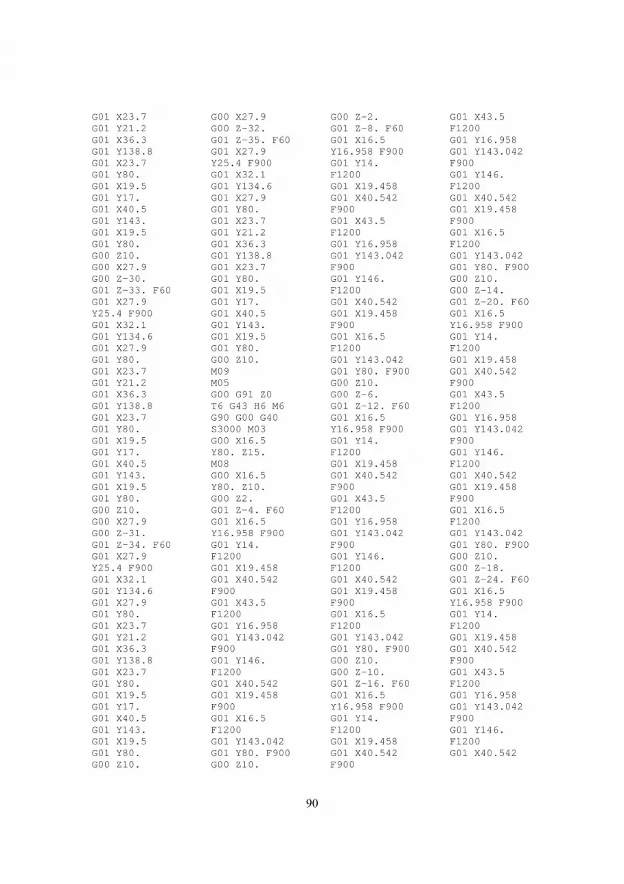
Name : LOWER_SENSOR_TOWER_NEW ------------------------------ Program number : 1 Subroutine number : 80 Jobs : 2 ---- Pocket : 2 Total time : 0:36:59 Toolpath Lengths : 33291.6055 Tool DiameterCorner radius Type Number Length H D -------------------------------------------------------------------------------- 4 12.0000 0.0000 TOOL END MILL 2 24.0000 4 54 6 8.0000 0.0000 TOOL END MILL 2 24.0000 6 56 Job Calls --------- 1. P_profile_T4 Time: 0:32:53 Toolpath Length: 29886.6016 2. P_profile_T6 Time: 0:04:06 Toolpath Length: 3405.0020 Job name : P_profile_T4 ------------------------ Job type : Pocket Geometry name : profile Time : 0:32:53 Tool Toolpath Length : 29886.6016 ---- Tool Number : 4 Spin Feed ---- ---- Spin type : S Feed type : FZ Spin Rate : 3000.0000 Feed XY : 0.1500 Feed Z : 0.0100 Pocket type Milling levels ----------- -------------- Pocket type : CONTOUR Clearance level : 10.0000 Direction : Climb Safety distance : 2.0000 Connect islands : No Job Upper level : 0.0000 Exit material : No Pocket depth : 35.0000 Corner : NONE Down step : 1.0000 Offsets Overlap : 0.6500 -------------- Compensation : No Wall offset : 1.0000 Island offset : 0.0000 Floor offset : 0.0000 Finish : None Retreat Approach ------- -------- Retreat : None
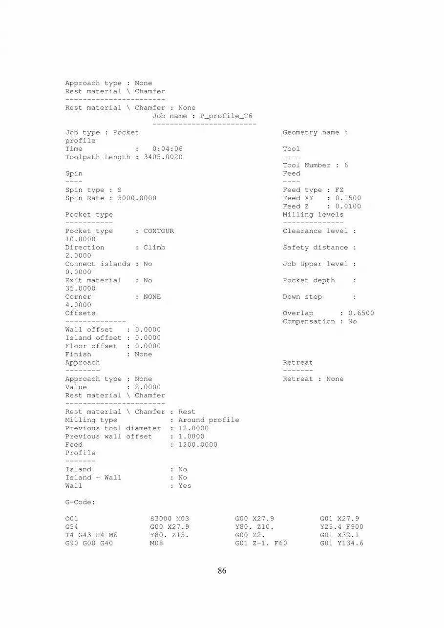
86
Approach type : None Rest material \ Chamfer ----------------------- Rest material \ Chamfer : None Job name : P_profile_T6 ------------------------ Job type : Pocket Geometry name : profile Time : 0:04:06 Tool Toolpath Length : 3405.0020 ---- Tool Number : 6 Spin Feed ---- ---- Spin type : S Feed type : FZ Spin Rate : 3000.0000 Feed XY : 0.1500 Feed Z : 0.0100 Pocket type Milling levels ----------- -------------- Pocket type : CONTOUR Clearance level : 10.0000 Direction : Climb Safety distance : 2.0000 Connect islands : No Job Upper level : 0.0000 Exit material : No Pocket depth : 35.0000 Corner : NONE Down step : 4.0000 Offsets Overlap : 0.6500 -------------- Compensation : No Wall offset : 0.0000 Island offset : 0.0000 Floor offset : 0.0000 Finish : None Approach Retreat -------- ------- Approach type : None Retreat : None Value : 2.0000 Rest material \ Chamfer ----------------------- Rest material \ Chamfer : Rest Milling type : Around profile Previous tool diameter : 12.0000 Previous wall offset : 1.0000 Feed : 1200.0000 Profile ------- Island : No Island + Wall : No Wall : Yes G-Code: O01 G54 T4 G43 H4 M6 G90 G00 G40
S3000 M03 G00 X27.9 Y80. Z15. M08
G00 X27.9 Y80. Z10. G00 Z2. G01 Z-1. F60
G01 X27.9 Y25.4 F900 G01 X32.1 G01 Y134.6

87
G01 X27.9 G01 Y80. G01 X23.7 G01 Y21.2 G01 X36.3 G01 Y138.8 G01 X23.7 G01 Y80. G01 X19.5 G01 Y17. G01 X40.5 G01 Y143. G01 X19.5 G01 Y80. G00 Z10. G00 X27.9 G00 Z1. G01 Z-2. F60 G01 X27.9 Y25.4 F900 G01 X32.1 G01 Y134.6 G01 X27.9 G01 Y80. G01 X23.7 G01 Y21.2 G01 X36.3 G01 Y138.8 G01 X23.7 G01 Y80. G01 X19.5 G01 Y17. G01 X40.5 G01 Y143. G01 X19.5 G01 Y80. G00 Z10. G00 X27.9 G00 Z0. G01 Z-3. F60 G01 X27.9 Y25.4 F900 G01 X32.1 G01 Y134.6 G01 X27.9 G01 Y80. G01 X23.7 G01 Y21.2 G01 X36.3 G01 Y138.8 G01 X23.7 G01 Y80. G01 X19.5 G01 Y17. G01 X40.5 G01 Y143. G01 X19.5
G01 Y80. G00 Z10. G00 X27.9 G00 Z-1. G01 Z-4. F60 G01 X27.9 Y25.4 F900 G01 X32.1 G01 Y134.6 G01 X27.9 G01 Y80. G01 X23.7 G01 Y21.2 G01 X36.3 G01 Y138.8 G01 X23.7 G01 Y80. G01 X19.5 G01 Y17. G01 X40.5 G01 Y143. G01 X19.5 G01 Y80. G00 Z10. G00 X27.9 G00 Z-2. G01 Z-5. F60 G01 X27.9 Y25.4 F900 G01 X32.1 G01 Y134.6 G01 X27.9 G01 Y80. G01 X23.7 G01 Y21.2 G01 X36.3 G01 Y138.8 G01 X23.7 G01 Y80. G01 X19.5 G01 Y17. G01 X40.5 G01 Y143. G01 X19.5 G01 Y80. G00 Z10. G00 X27.9 G00 Z-3. G01 Z-6. F60 G01 X27.9 Y25.4 F900 G01 X32.1 G01 Y134.6 G01 X27.9 G01 Y80. G01 X23.7 G01 Y21.2
G01 X36.3 G01 Y138.8 G01 X23.7 G01 Y80. G01 X19.5 G01 Y17. G01 X40.5 G01 Y143. G01 X19.5 G01 Y80. G00 Z10. G00 X27.9 G00 Z-4. G01 Z-7. F60 G01 X27.9 Y25.4 F900 G01 X32.1 G01 Y134.6 G01 X27.9 G01 Y80. G01 X23.7 G01 Y21.2 G01 X36.3 G01 Y138.8 G01 X23.7 G01 Y80. G01 X19.5 G01 Y17. G01 X40.5 G01 Y143. G01 X19.5 G01 Y80. G00 Z10. G00 X27.9 G00 Z-5. G01 Z-8. F60 G01 X27.9 Y25.4 F900 G01 X32.1 G01 Y134.6 G01 X27.9 G01 Y80. G01 X23.7 G01 Y21.2 G01 X36.3 G01 Y138.8 G01 X23.7 G01 Y80. G01 X19.5 G01 Y17. G01 X40.5 G01 Y143. G01 X19.5 G01 Y80. G00 Z10. G00 X27.9 G00 Z-6.
G01 Z-9. F60 G01 X27.9 Y25.4 F900 G01 X32.1 G01 Y134.6 G01 X27.9 G01 Y80. G01 X23.7 G01 Y21.2 G01 X36.3 G01 Y138.8 G01 X23.7 G01 Y80. G01 X19.5 G01 Y17. G01 X40.5 G01 Y143. G01 X19.5 G01 Y80. G00 Z10. G00 X27.9 G00 Z-7. G01 Z-10. F60 G01 X27.9 Y25.4 F900 G01 X32.1 G01 Y134.6 G01 X27.9 G01 Y80. G01 X23.7 G01 Y21.2 G01 X36.3 G01 Y138.8 G01 X23.7 G01 Y80. G01 X19.5 G01 Y17. G01 X40.5 G01 Y143. G01 X19.5 G01 Y80. G00 Z10. G00 X27.9 G00 Z-8. G01 Z-11. F60 G01 X27.9 Y25.4 F900 G01 X32.1 G01 Y134.6 G01 X27.9 G01 Y80. G01 X23.7 G01 Y21.2 G01 X36.3 G01 Y138.8 G01 X23.7 G01 Y80.

88
G01 X19.5 G01 Y17. G01 X40.5 G01 Y143. G01 X19.5 G01 Y80. G00 Z10. G00 X27.9 G00 Z-9. G01 Z-12. F60 G01 X27.9 Y25.4 F900 G01 X32.1 G01 Y134.6 G01 X27.9 G01 Y80. G01 X23.7 G01 Y21.2 G01 X36.3 G01 Y138.8 G01 X23.7 G01 Y80. G01 X19.5 G01 Y17. G01 X40.5 G01 Y143. G01 X19.5 G01 Y80. G00 Z10. G00 X27.9 G00 Z-10. G01 Z-13. F60 G01 X27.9 Y25.4 F900 G01 X32.1 G01 Y134.6 G01 X27.9 G01 Y80. G01 X23.7 G01 Y21.2 G01 X36.3 G01 Y138.8 G01 X23.7 G01 Y80. G01 X19.5 G01 Y17. G01 X40.5 G01 Y143. G01 X19.5 G01 Y80. G00 Z10. G00 X27.9 G00 Z-11. G01 Z-14. F60 G01 X27.9 Y25.4 F900 G01 X32.1
G01 Y134.6 G01 X27.9 G01 Y80. G01 X23.7 G01 Y21.2 G01 X36.3 G01 Y138.8 G01 X23.7 G01 Y80. G01 X19.5 G01 Y17. G01 X40.5 G01 Y143. G01 X19.5 G01 Y80. G00 Z10. G00 X27.9 G00 Z-12. G01 Z-15. F60 G01 X27.9 Y25.4 F900 G01 X32.1 G01 Y134.6 G01 X27.9 G01 Y80. G01 X23.7 G01 Y21.2 G01 X36.3 G01 Y138.8 G01 X23.7 G01 Y80. G01 X19.5 G01 Y17. G01 X40.5 G01 Y143. G01 X19.5 G01 Y80. G00 Z10. G00 X27.9 G00 Z-13. G01 Z-16. F60 G01 X27.9 Y25.4 F900 G01 X32.1 G01 Y134.6 G01 X27.9 G01 Y80. G01 X23.7 G01 Y21.2 G01 X36.3 G01 Y138.8 G01 X23.7 G01 Y80. G01 X19.5 G01 Y17. G01 X40.5 G01 Y143.
G01 X19.5 G01 Y80. G00 Z10. G00 X27.9 G00 Z-14. G01 Z-17. F60 G01 X27.9 Y25.4 F900 G01 X32.1 G01 Y134.6 G01 X27.9 G01 Y80. G01 X23.7 G01 Y21.2 G01 X36.3 G01 Y138.8 G01 X23.7 G01 Y80. G01 X19.5 G01 Y17. G01 X40.5 G01 Y143. G01 X19.5 G01 Y80. G00 Z10. G00 X27.9 G00 Z-15. G01 Z-18. F60 G01 X27.9 Y25.4 F900 G01 X32.1 G01 Y134.6 G01 X27.9 G01 Y80. G01 X23.7 G01 Y21.2 G01 X36.3 G01 Y138.8 G01 X23.7 G01 Y80. G01 X19.5 G01 Y17. G01 X40.5 G01 Y143. G01 X19.5 G01 Y80. G00 Z10. G00 X27.9 G00 Z-16. G01 Z-19. F60 G01 X27.9 Y25.4 F900 G01 X32.1 G01 Y134.6 G01 X27.9 G01 Y80. G01 X23.7
G01 Y21.2 G01 X36.3 G01 Y138.8 G01 X23.7 G01 Y80. G01 X19.5 G01 Y17. G01 X40.5 G01 Y143. G01 X19.5 G01 Y80. G00 Z10. G00 X27.9 G00 Z-17. G01 Z-20. F60 G01 X27.9 Y25.4 F900 G01 X32.1 G01 Y134.6 G01 X27.9 G01 Y80. G01 X23.7 G01 Y21.2 G01 X36.3 G01 Y138.8 G01 X23.7 G01 Y80. G01 X19.5 G01 Y17. G01 X40.5 G01 Y143. G01 X19.5 G01 Y80. G00 Z10. G00 X27.9 G00 Z-18. G01 Z-21. F60 G01 X27.9 Y25.4 F900 G01 X32.1 G01 Y134.6 G01 X27.9 G01 Y80. G01 X23.7 G01 Y21.2 G01 X36.3 G01 Y138.8 G01 X23.7 G01 Y80. G01 X19.5 G01 Y17. G01 X40.5 G01 Y143. G01 X19.5 G01 Y80. G00 Z10. G00 X27.9

89
G00 Z-19. G01 Z-22. F60 G01 X27.9 Y25.4 F900 G01 X32.1 G01 Y134.6 G01 X27.9 G01 Y80. G01 X23.7 G01 Y21.2 G01 X36.3 G01 Y138.8 G01 X23.7 G01 Y80. G01 X19.5 G01 Y17. G01 X40.5 G01 Y143. G01 X19.5 G01 Y80. G00 Z10. G00 X27.9 G00 Z-20. G01 Z-23. F60 G01 X27.9 Y25.4 F900 G01 X32.1 G01 Y134.6 G01 X27.9 G01 Y80. G01 X23.7 G01 Y21.2 G01 X36.3 G01 Y138.8 G01 X23.7 G01 Y80. G01 X19.5 G01 Y17. G01 X40.5 G01 Y143. G01 X19.5 G01 Y80. G00 Z10. G00 X27.9 G00 Z-21. G01 Z-24. F60 G01 X27.9 Y25.4 F900 G01 X32.1 G01 Y134.6 G01 X27.9 G01 Y80. G01 X23.7 G01 Y21.2 G01 X36.3 G01 Y138.8 G01 X23.7
G01 Y80. G01 X19.5 G01 Y17. G01 X40.5 G01 Y143. G01 X19.5 G01 Y80. G00 Z10. G00 X27.9 G00 Z-22. G01 Z-25. F60 G01 X27.9 Y25.4 F900 G01 X32.1 G01 Y134.6 G01 X27.9 G01 Y80. G01 X23.7 G01 Y21.2 G01 X36.3 G01 Y138.8 G01 X23.7 G01 Y80. G01 X19.5 G01 Y17. G01 X40.5 G01 Y143. G01 X19.5 G01 Y80. G00 Z10. G00 X27.9 G00 Z-23. G01 Z-26. F60 G01 X27.9 Y25.4 F900 G01 X32.1 G01 Y134.6 G01 X27.9 G01 Y80. G01 X23.7 G01 Y21.2 G01 X36.3 G01 Y138.8 G01 X23.7 G01 Y80. G01 X19.5 G01 Y17. G01 X40.5 G01 Y143. G01 X19.5 G01 Y80. G00 Z10. G00 X27.9 G00 Z-24. G01 Z-27. F60 G01 X27.9 Y25.4 F900
G01 X32.1 G01 Y134.6 G01 X27.9 G01 Y80. G01 X23.7 G01 Y21.2 G01 X36.3 G01 Y138.8 G01 X23.7 G01 Y80. G01 X19.5 G01 Y17. G01 X40.5 G01 Y143. G01 X19.5 G01 Y80. G00 Z10. G00 X27.9 G00 Z-25. G01 Z-28. F60 G01 X27.9 Y25.4 F900 G01 X32.1 G01 Y134.6 G01 X27.9 G01 Y80. G01 X23.7 G01 Y21.2 G01 X36.3 G01 Y138.8 G01 X23.7 G01 Y80. G01 X19.5 G01 Y17. G01 X40.5 G01 Y143. G01 X19.5 G01 Y80. G00 Z10. G00 X27.9 G00 Z-26. G01 Z-29. F60 G01 X27.9 Y25.4 F900 G01 X32.1 G01 Y134.6 G01 X27.9 G01 Y80. G01 X23.7 G01 Y21.2 G01 X36.3 G01 Y138.8 G01 X23.7 G01 Y80. G01 X19.5 G01 Y17. G01 X40.5
G01 Y143. G01 X19.5 G01 Y80. G00 Z10. G00 X27.9 G00 Z-27. G01 Z-30. F60 G01 X27.9 Y25.4 F900 G01 X32.1 G01 Y134.6 G01 X27.9 G01 Y80. G01 X23.7 G01 Y21.2 G01 X36.3 G01 Y138.8 G01 X23.7 G01 Y80. G01 X19.5 G01 Y17. G01 X40.5 G01 Y143. G01 X19.5 G01 Y80. G00 Z10. G00 X27.9 G00 Z-28. G01 Z-31. F60 G01 X27.9 Y25.4 F900 G01 X32.1 G01 Y134.6 G01 X27.9 G01 Y80. G01 X23.7 G01 Y21.2 G01 X36.3 G01 Y138.8 G01 X23.7 G01 Y80. G01 X19.5 G01 Y17. G01 X40.5 G01 Y143. G01 X19.5 G01 Y80. G00 Z10. G00 X27.9 G00 Z-29. G01 Z-32. F60 G01 X27.9 Y25.4 F900 G01 X32.1 G01 Y134.6 G01 X27.9 G01 Y80.
90
G01 X23.7 G01 Y21.2 G01 X36.3 G01 Y138.8 G01 X23.7 G01 Y80. G01 X19.5 G01 Y17. G01 X40.5 G01 Y143. G01 X19.5 G01 Y80. G00 Z10. G00 X27.9 G00 Z-30. G01 Z-33. F60 G01 X27.9 Y25.4 F900 G01 X32.1 G01 Y134.6 G01 X27.9 G01 Y80. G01 X23.7 G01 Y21.2 G01 X36.3 G01 Y138.8 G01 X23.7 G01 Y80. G01 X19.5 G01 Y17. G01 X40.5 G01 Y143. G01 X19.5 G01 Y80. G00 Z10. G00 X27.9 G00 Z-31. G01 Z-34. F60 G01 X27.9 Y25.4 F900 G01 X32.1 G01 Y134.6 G01 X27.9 G01 Y80. G01 X23.7 G01 Y21.2 G01 X36.3 G01 Y138.8 G01 X23.7 G01 Y80. G01 X19.5 G01 Y17. G01 X40.5 G01 Y143. G01 X19.5 G01 Y80. G00 Z10.
G00 X27.9 G00 Z-32. G01 Z-35. F60 G01 X27.9 Y25.4 F900 G01 X32.1 G01 Y134.6 G01 X27.9 G01 Y80. G01 X23.7 G01 Y21.2 G01 X36.3 G01 Y138.8 G01 X23.7 G01 Y80. G01 X19.5 G01 Y17. G01 X40.5 G01 Y143. G01 X19.5 G01 Y80. G00 Z10. M09 M05 G00 G91 Z0 T6 G43 H6 M6 G90 G00 G40 S3000 M03 G00 X16.5 Y80. Z15. M08 G00 X16.5 Y80. Z10. G00 Z2. G01 Z-4. F60 G01 X16.5 Y16.958 F900 G01 Y14. F1200 G01 X19.458 G01 X40.542 F900 G01 X43.5 F1200 G01 Y16.958 G01 Y143.042 F900 G01 Y146. F1200 G01 X40.542 G01 X19.458 F900 G01 X16.5 F1200 G01 Y143.042 G01 Y80. F900 G00 Z10.
G00 Z-2. G01 Z-8. F60 G01 X16.5 Y16.958 F900 G01 Y14. F1200 G01 X19.458 G01 X40.542 F900 G01 X43.5 F1200 G01 Y16.958 G01 Y143.042 F900 G01 Y146. F1200 G01 X40.542 G01 X19.458 F900 G01 X16.5 F1200 G01 Y143.042 G01 Y80. F900 G00 Z10. G00 Z-6. G01 Z-12. F60 G01 X16.5 Y16.958 F900 G01 Y14. F1200 G01 X19.458 G01 X40.542 F900 G01 X43.5 F1200 G01 Y16.958 G01 Y143.042 F900 G01 Y146. F1200 G01 X40.542 G01 X19.458 F900 G01 X16.5 F1200 G01 Y143.042 G01 Y80. F900 G00 Z10. G00 Z-10. G01 Z-16. F60 G01 X16.5 Y16.958 F900 G01 Y14. F1200 G01 X19.458 G01 X40.542 F900
G01 X43.5 F1200 G01 Y16.958 G01 Y143.042 F900 G01 Y146. F1200 G01 X40.542 G01 X19.458 F900 G01 X16.5 F1200 G01 Y143.042 G01 Y80. F900 G00 Z10. G00 Z-14. G01 Z-20. F60 G01 X16.5 Y16.958 F900 G01 Y14. F1200 G01 X19.458 G01 X40.542 F900 G01 X43.5 F1200 G01 Y16.958 G01 Y143.042 F900 G01 Y146. F1200 G01 X40.542 G01 X19.458 F900 G01 X16.5 F1200 G01 Y143.042 G01 Y80. F900 G00 Z10. G00 Z-18. G01 Z-24. F60 G01 X16.5 Y16.958 F900 G01 Y14. F1200 G01 X19.458 G01 X40.542 F900 G01 X43.5 F1200 G01 Y16.958 G01 Y143.042 F900 G01 Y146. F1200 G01 X40.542

91
G01 X19.458 F900 G01 X16.5 F1200 G01 Y143.042 G01 Y80. F900 G00 Z10. G00 Z-22. G01 Z-28. F60 G01 X16.5 Y16.958 F900 G01 Y14. F1200 G01 X19.458 G01 X40.542 F900 G01 X43.5 F1200 G01 Y16.958 G01 Y143.042 F900 G01 Y146. F1200 G01 X40.542 G01 X19.458 F900 G01 X16.5 F1200 G01 Y143.042
G01 Y80. F900 G00 Z10. G00 Z-26. G01 Z-32. F60 G01 X16.5 Y16.958 F900 G01 Y14. F1200 G01 X19.458 G01 X40.542 F900 G01 X43.5 F1200 G01 Y16.958 G01 Y143.042 F900 G01 Y146. F1200 G01 X40.542 G01 X19.458 F900 G01 X16.5 F1200 G01 Y143.042 G01 Y80. F900 G00 Z10. G00 Z-30. G01 Z-35. F60
G01 X16.5 Y16.958 F900 G01 Y14. F1200 G01 X19.458 G01 X40.542 F900 G01 X43.5 F1200 G01 Y16.958 G01 Y143.042 F900 G01 Y146. F1200 G01 X40.542 G01 X19.458 F900 G01 X16.5 F1200 G01 Y143.042 G01 Y80. F900 G00 Z10. M9 M5 G00 G91 Z0 M30 %
Name : LOWER_ST_TOP_NEW ------------------------ Program number : 1 Subroutine number : 80 Jobs : 2 ---- Pocket : 1 Drill : 1 Total time : 0:04:29 Toolpath Lengths : 2634.9155 Tool DiameterCorner radius Type Number Length H D -------------------------------------------------------------------------------- 4 12.0000 0.0000 TOOL END MILL 2 24.0000 4 54 10 4.0000 118.0000 TOOL DRILL 2 24.0000 10 60 Job Calls --------- 1. P_profile_T4 Time: 0:02:41 Toolpath Length: 2234.9136 2. D_drill_T10 Time: 0:01:48 Toolpath Length: 400.0020 Job name : P_profile_T4 ------------------------ Job type : Pocket Geometry name : profile Time : 0:02:41 Tool Toolpath Length : 2234.9136 ---- Tool Number : 4 Spin Feed

92
---- ---- Spin type : S Feed type : FZ Spin Rate : 3000.0000 Feed XY : 0.1500 Feed Z : 0.0100 Pocket type Milling levels ----------- -------------- Pocket type : CONTOUR Clearance level : 10.0000 Direction : Climb Safety distance : 2.0000 Connect islands : No Job Upper level : 0.0000 Exit material : No Pocket depth : 10.0000 Corner : NONE Down step : 1.0000 Offsets Overlap : 0.6500 -------------- Compensation : No Wall offset : 0.0000 Island offset : 0.0000 Floor offset : 0.0000 Finish : None Retreat Approach ------- -------- Retreat : None Approach type : None Rest material \ Chamfer ----------------------- Rest material \ Chamfer : None Job name : D_drill_T10 ----------------------- Job type : Drill Geometry name : drill Time : 0:01:48 Tool Toolpath Length : 400.0020 ---- Tool Number : 10 Spin Feed ---- ---- Spin type : S Feed type : FZ Spin Rate : 3000.0000 Feed Z : 0.0050 Milling levels Drill Parameters -------------- ---------------- Clearance level : 10.0000 Drill cycle type : G81 Safety distance : 2.0000 Job Upper level : 0.0000 Drill depth : 11.0000 Sort sequence by : DEFAULT G-Code: O01 G54 T4 G43 H4 M6 G90 G00 G40 S3000 M03 G00 X33.5 Y62.5 Z15. M08 G00 X33.5 Y62.5 Z10. G00 Z2. G01 Z-1. F60
G01 X33.5 Y105. F900 G03 X30. Y108.5 I-3.5 J0. G03 X26.5 Y105. I0. J-3.5 G01 Y20. G03 X30. Y16.5 I3.5 J0. G03 X33.5 Y20. I0. J3.5 G01 Y62.5 G00 Z10.
G00 Z1. G01 Z-2. F60 G01 X33.5 Y105. F900 G03 X30. Y108.5 I-3.5 J0. G03 X26.5 Y105. I0. J-3.5 G01 Y20. G03 X30. Y16.5 I3.5 J0. G03 X33.5 Y20. I0. J3.5
G01 Y62.5 G00 Z10. G00 Z0. G01 Z-3. F60 G01 X33.5 Y105. F900 G03 X30. Y108.5 I-3.5 J0. G03 X26.5 Y105. I0. J-3.5 G01 Y20. G03 X30. Y16.5 I3.5 J0.

93
G03 X33.5 Y20. I0. J3.5 G01 Y62.5 G00 Z10. G00 Z-1. G01 Z-4. F60 G01 X33.5 Y105. F900 G03 X30. Y108.5 I-3.5 J0. G03 X26.5 Y105. I0. J-3.5 G01 Y20. G03 X30. Y16.5 I3.5 J0. G03 X33.5 Y20. I0. J3.5 G01 Y62.5 G00 Z10. G00 Z-2. G01 Z-5. F60 G01 X33.5 Y105. F900 G03 X30. Y108.5 I-3.5 J0. G03 X26.5 Y105. I0. J-3.5 G01 Y20. G03 X30. Y16.5 I3.5 J0. G03 X33.5 Y20. I0. J3.5 G01 Y62.5 G00 Z10.
G00 Z-3. G01 Z-6. F60 G01 X33.5 Y105. F900 G03 X30. Y108.5 I-3.5 J0. G03 X26.5 Y105. I0. J-3.5 G01 Y20. G03 X30. Y16.5 I3.5 J0. G03 X33.5 Y20. I0. J3.5 G01 Y62.5 G00 Z10. G00 Z-4. G01 Z-7. F60 G01 X33.5 Y105. F900 G03 X30. Y108.5 I-3.5 J0. G03 X26.5 Y105. I0. J-3.5 G01 Y20. G03 X30. Y16.5 I3.5 J0. G03 X33.5 Y20. I0. J3.5 G01 Y62.5 G00 Z10. G00 Z-5. G01 Z-8. F60 G01 X33.5 Y105. F900
G03 X30. Y108.5 I-3.5 J0. G03 X26.5 Y105. I0. J-3.5 G01 Y20. G03 X30. Y16.5 I3.5 J0. G03 X33.5 Y20. I0. J3.5 G01 Y62.5 G00 Z10. G00 Z-6. G01 Z-9. F60 G01 X33.5 Y105. F900 G03 X30. Y108.5 I-3.5 J0. G03 X26.5 Y105. I0. J-3.5 G01 Y20. G03 X30. Y16.5 I3.5 J0. G03 X33.5 Y20. I0. J3.5 G01 Y62.5 G00 Z10. G00 Z-7. G01 Z-10. F60 G01 X33.5 Y105. F900 G03 X30. Y108.5 I-3.5 J0. G03 X26.5 Y105. I0. J-3.5
G01 Y20. G03 X30. Y16.5 I3.5 J0. G03 X33.5 Y20. I0. J3.5 G01 Y62.5 G00 Z10. M09 M05 G00 G91 Z0 T10 G43 H10 M6 G90 G00 G40 S3000 M03 G00 X7.5 Y55. Z15. M08 G00 X7.5 Y55. Z10. G81 Z-11. P0 R2. F30 Y40. X52.5 Y55. M9 M5 G00 G91 Z0 M30 %
Name : UPPER_ST_TOP_LAST ------------------------- Program number : 1 Subroutine number : 80 Jobs : 2 ---- Pocket : 1 Drill : 1 Total time : 0:04:05 Toolpath Lengths : 2290.9155 Tool DiameterCorner radius Type Number Length H D -------------------------------------------------------------------------------- 4 12.0000 0.0000 TOOL END MILL 2 24.0000 4 54 10 4.0000 118.0000 TOOL DRILL 2 24.0000 10 60 Job Calls --------- 1. P_profile_T4 Time: 0:02:08 Toolpath Length: 1734.9135 2. D_drill_T10 Time: 0:01:58 Toolpath Length: 556.0020 Job name : P_profile_T4 ------------------------

94
Job type : Pocket Geometry name : profile Time : 0:02:08 Tool Toolpath Length : 1734.9135 ---- Tool Number : 4 Spin Feed ---- ---- Spin type : S Feed type : FZ Spin Rate : 3000.0000 Feed XY : 0.1500 Feed Z : 0.0100 Pocket type Milling levels ----------- -------------- Pocket type : CONTOUR Clearance level : 10.0000 Direction : Climb Safety distance : 2.0000 Connect islands : No Job Upper level : 0.0000 Exit material : No Pocket depth : 10.0000 Corner : NONE Down step : 1.0000 Offsets Overlap : 0.6500 -------------- Compensation : No Wall offset : 0.0000 Island offset : 0.0000 Floor offset : 0.0000 Finish : None Retreat Approach ------- -------- Retreat : None Approach type : None Rest material \ Chamfer ----------------------- Rest material \ Chamfer : None Job name : D_drill_T10 ----------------------- Job type : Drill Geometry name : drill Time : 0:01:58 Tool Toolpath Length : 556.0020 ---- Tool Number : 10 Spin Feed ---- ---- Spin type : S Feed type : FZ Spin Rate : 3000.0000 Feed Z : 0.0100 Milling levels Drill Parameters -------------- ---------------- Clearance level : 10.0000 Drill cycle type : G81 Safety distance : 2.0000 Job Upper level : 0.0000 Drill depth : 12.0000 Sort sequence by : DEFAULT G-Code: O01 G54 T4 G43 H4 M6 G90 G00 G40 S3000 M03 G00 X31. Y50. Z15. M08
G00 X31. Y50. Z10. G00 Z2. G01 Z-1. F60 G01 X31. Y80. F900 G03 X27.5 Y83.5 I-3.5 J0.
G03 X24. Y80. I0. J-3.5 G01 Y20. G03 X27.5 Y16.5 I3.5 J0. G03 X31. Y20. I0. J3.5 G01 Y50.
G00 Z10. G00 Z1. G01 Z-2. F60 G01 X31. Y80. F900 G03 X27.5 Y83.5 I-3.5 J0.

95
G03 X24. Y80. I0. J-3.5 G01 Y20. G03 X27.5 Y16.5 I3.5 J0. G03 X31. Y20. I0. J3.5 G01 Y50. G00 Z10. G00 Z0. G01 Z-3. F60 G01 X31. Y80. F900 G03 X27.5 Y83.5 I-3.5 J0. G03 X24. Y80. I0. J-3.5 G01 Y20. G03 X27.5 Y16.5 I3.5 J0. G03 X31. Y20. I0. J3.5 G01 Y50. G00 Z10. G00 Z-1. G01 Z-4. F60 G01 X31. Y80. F900 G03 X27.5 Y83.5 I-3.5 J0. G03 X24. Y80. I0. J-3.5 G01 Y20. G03 X27.5 Y16.5 I3.5 J0. G03 X31. Y20. I0. J3.5 G01 Y50. G00 Z10.
G00 Z-2. G01 Z-5. F60 G01 X31. Y80. F900 G03 X27.5 Y83.5 I-3.5 J0. G03 X24. Y80. I0. J-3.5 G01 Y20. G03 X27.5 Y16.5 I3.5 J0. G03 X31. Y20. I0. J3.5 G01 Y50. G00 Z10. G00 Z-3. G01 Z-6. F60 G01 X31. Y80. F900 G03 X27.5 Y83.5 I-3.5 J0. G03 X24. Y80. I0. J-3.5 G01 Y20. G03 X27.5 Y16.5 I3.5 J0. G03 X31. Y20. I0. J3.5 G01 Y50. G00 Z10. G00 Z-4. G01 Z-7. F60 G01 X31. Y80. F900 G03 X27.5 Y83.5 I-3.5 J0. G03 X24. Y80. I0. J-3.5 G01 Y20.
G03 X27.5 Y16.5 I3.5 J0. G03 X31. Y20. I0. J3.5 G01 Y50. G00 Z10. G00 Z-5. G01 Z-8. F60 G01 X31. Y80. F900 G03 X27.5 Y83.5 I-3.5 J0. G03 X24. Y80. I0. J-3.5 G01 Y20. G03 X27.5 Y16.5 I3.5 J0. G03 X31. Y20. I0. J3.5 G01 Y50. G00 Z10. G00 Z-6. G01 Z-9. F60 G01 X31. Y80. F900 G03 X27.5 Y83.5 I-3.5 J0. G03 X24. Y80. I0. J-3.5 G01 Y20. G03 X27.5 Y16.5 I3.5 J0. G03 X31. Y20. I0. J3.5 G01 Y50. G00 Z10. G00 Z-7. G01 Z-10. F60
G01 X31. Y80. F900 G03 X27.5 Y83.5 I-3.5 J0. G03 X24. Y80. I0. J-3.5 G01 Y20. G03 X27.5 Y16.5 I3.5 J0. G03 X31. Y20. I0. J3.5 G01 Y50. G00 Z10. M09 M05 G00 G91 Z0 T10 G43 H10 M6 G90 G00 G40 S3000 M03 G00 X5. Y60. Z15. M08 G00 X5. Y60. Z10. G81 Z-12. P0 R2. F60 Y45. Y30. Y15. X50. Y30. Y45. Y60. M9 M5 G00 G91 Z0 M30 %
Name : CAMERAHOLDER_TOP_NEW2 ----------------------------- Program number : 5000 Subroutine number : 1 Jobs : 2 ---- Pocket : 1 Drill : 1 Total time : 0:18:16 Toolpath Lengths : 13717.4561 Tool DiameterCorner radius Type Number Length H D -------------------------------------------------------------------------------- 4 12.0000 0.0000 TOOL END MILL 2 24.0000 4 54 10 4.0000 118.0000 TOOL DRILL 2 24.0000 10 60 Job Calls --------- 1. P_profile_T4

96
Time: 0:16:28 Toolpath Length: 12964.4014 2. D_drill_T10 Time: 0:01:49 Toolpath Length: 753.0541 Job name : P_profile_T4 ------------------------ Job type : Pocket Geometry name : profile Time : 0:16:28 Tool Toolpath Length : 12964.4014 ---- Tool Number : 4 Spin Feed ---- ---- Spin type : S Feed type : FZ Spin Rate : 3000.0000 Feed XY : 0.1500 Feed Z : 0.0100 Pocket type Milling levels ----------- -------------- Pocket type : CONTOUR Clearance level : 10.0000 Direction : Climb Safety distance : 2.0000 Connect islands : No Job Upper level : 0.0000 Exit material : No Pocket depth : 20.0000 Corner : NONE Down step : 1.0000 Offsets Overlap : 0.6500 -------------- Compensation : No Wall offset : 0.0000 Island offset : 0.0000 Floor offset : 0.0000 Finish : None Retreat Approach ------- -------- Retreat : None Approach type : None Rest material \ Chamfer Extra parameters ----------------------- ---------------- Rest material \ Chamfer : None Extra parameters : OPT1 DELY : 0.0000 FEAD : 0.0000 Job name : D_drill_T10 ----------------------- Job type : Drill Geometry name : drill Time : 0:01:49 Tool Toolpath Length : 753.0541 ---- Tool Number : 10 Spin Feed ---- ---- Spin type : S Feed type : FZ Spin Rate : 3000.0000 Feed Z : 0.0100 Milling levels Drill Parameters -------------- ---------------- Clearance level : 10.0000 Drill cycle type : Drilling Safety distance : 2.0000 Job Upper level : -20.0000 Drill depth : 12.0000 Sort sequence by : DEFAULT Extra parameters ---------------- Extra parameters : OPT1 DELY : 0.0000 FEAD : 0.0000

97
G Code: O01 G54 T4 G43 H4 M6 G90 G00 G40 S3000 M03 G00 X35.453 Y43. Z15. M08 G00 X35.453 Y43. Z10. G00 Z2. G01 Z-1. F60 G01 X20.555 Y43. F900 G01 Y37. G01 X50.35 G01 Y43. G01 X35.453 G01 Y47.2 G01 X16.355 G01 Y32.8 G01 X54.55 G01 Y47.2 G01 X35.453 G01 Y51.4 G01 X12.155 G01 Y28.6 G01 X58.75 G01 Y51.4 G01 X35.453 G01 Y55.6 G01 X7.955 G01 Y24.4 G01 X62.95 G01 Y55.6 G01 X35.453 G01 Y59.8 G01 X3.755 G01 Y20.2 G01 X67.15 G01 Y59.8 G01 X35.453 G01 Y64. G01 X-0.445 G01 Y16. G01 X71.35 G01 Y64. G01 X35.453 G00 Z10. G00 Y43. G00 Z1. G01 Z-2. F60 G01 X20.555 Y43. F900 G01 Y37.
G01 X50.35 G01 Y43. G01 X35.453 G01 Y47.2 G01 X16.355 G01 Y32.8 G01 X54.55 G01 Y47.2 G01 X35.453 G01 Y51.4 G01 X12.155 G01 Y28.6 G01 X58.75 G01 Y51.4 G01 X35.453 G01 Y55.6 G01 X7.955 G01 Y24.4 G01 X62.95 G01 Y55.6 G01 X35.453 G01 Y59.8 G01 X3.755 G01 Y20.2 G01 X67.15 G01 Y59.8 G01 X35.453 G01 Y64. G01 X-0.445 G01 Y16. G01 X71.35 G01 Y64. G01 X35.453 G00 Z10. G00 Y43. G00 Z0. G01 Z-3. F60 G01 X20.555 Y43. F900 G01 Y37. G01 X50.35 G01 Y43. G01 X35.453 G01 Y47.2 G01 X16.355 G01 Y32.8 G01 X54.55 G01 Y47.2 G01 X35.453 G01 Y51.4 G01 X12.155 G01 Y28.6 G01 X58.75 G01 Y51.4 G01 X35.453
G01 Y55.6 G01 X7.955 G01 Y24.4 G01 X62.95 G01 Y55.6 G01 X35.453 G01 Y59.8 G01 X3.755 G01 Y20.2 G01 X67.15 G01 Y59.8 G01 X35.453 G01 Y64. G01 X-0.445 G01 Y16. G01 X71.35 G01 Y64. G01 X35.453 G00 Z10. G00 Y43. G00 Z-1. G01 Z-4. F60 G01 X20.555 Y43. F900 G01 Y37. G01 X50.35 G01 Y43. G01 X35.453 G01 Y47.2 G01 X16.355 G01 Y32.8 G01 X54.55 G01 Y47.2 G01 X35.453 G01 Y51.4 G01 X12.155 G01 Y28.6 G01 X58.75 G01 Y51.4 G01 X35.453 G01 Y55.6 G01 X7.955 G01 Y24.4 G01 X62.95 G01 Y55.6 G01 X35.453 G01 Y59.8 G01 X3.755 G01 Y20.2 G01 X67.15 G01 Y59.8 G01 X35.453 G01 Y64. G01 X-0.445 G01 Y16.
G01 X71.35 G01 Y64. G01 X35.453 G00 Z10. G00 Y43. G00 Z-2. G01 Z-5. F60 G01 X20.555 Y43. F900 G01 Y37. G01 X50.35 G01 Y43. G01 X35.453 G01 Y47.2 G01 X16.355 G01 Y32.8 G01 X54.55 G01 Y47.2 G01 X35.453 G01 Y51.4 G01 X12.155 G01 Y28.6 G01 X58.75 G01 Y51.4 G01 X35.453 G01 Y55.6 G01 X7.955 G01 Y24.4 G01 X62.95 G01 Y55.6 G01 X35.453 G01 Y59.8 G01 X3.755 G01 Y20.2 G01 X67.15 G01 Y59.8 G01 X35.453 G01 Y64. G01 X-0.445 G01 Y16. G01 X71.35 G01 Y64. G01 X35.453 G00 Z10. G00 Y43. G00 Z-3. G01 Z-6. F60 G01 X20.555 Y43. F900 G01 Y37. G01 X50.35 G01 Y43. G01 X35.453 G01 Y47.2 G01 X16.355

98
G01 Y32.8 G01 X54.55 G01 Y47.2 G01 X35.453 G01 Y51.4 G01 X12.155 G01 Y28.6 G01 X58.75 G01 Y51.4 G01 X35.453 G01 Y55.6 G01 X7.955 G01 Y24.4 G01 X62.95 G01 Y55.6 G01 X35.453 G01 Y59.8 G01 X3.755 G01 Y20.2 G01 X67.15 G01 Y59.8 G01 X35.453 G01 Y64. G01 X-0.445 G01 Y16. G01 X71.35 G01 Y64. G01 X35.453 G00 Z10. G00 Y43. G00 Z-4. G01 Z-7. F60 G01 X20.555 Y43. F900 G01 Y37. G01 X50.35 G01 Y43. G01 X35.453 G01 Y47.2 G01 X16.355 G01 Y32.8 G01 X54.55 G01 Y47.2 G01 X35.453 G01 Y51.4 G01 X12.155 G01 Y28.6 G01 X58.75 G01 Y51.4 G01 X35.453 G01 Y55.6 G01 X7.955 G01 Y24.4 G01 X62.95 G01 Y55.6 G01 X35.453 G01 Y59.8
G01 X3.755 G01 Y20.2 G01 X67.15 G01 Y59.8 G01 X35.453 G01 Y64. G01 X-0.445 G01 Y16. G01 X71.35 G01 Y64. G01 X35.453 G00 Z10. G00 Y43. G00 Z-5. G01 Z-8. F60 G01 X20.555 Y43. F900 G01 Y37. G01 X50.35 G01 Y43. G01 X35.453 G01 Y47.2 G01 X16.355 G01 Y32.8 G01 X54.55 G01 Y47.2 G01 X35.453 G01 Y51.4 G01 X12.155 G01 Y28.6 G01 X58.75 G01 Y51.4 G01 X35.453 G01 Y55.6 G01 X7.955 G01 Y24.4 G01 X62.95 G01 Y55.6 G01 X35.453 G01 Y59.8 G01 X3.755 G01 Y20.2 G01 X67.15 G01 Y59.8 G01 X35.453 G01 Y64. G01 X-0.445 G01 Y16. G01 X71.35 G01 Y64. G01 X35.453 G00 Z10. G00 Y43. G00 Z-6. G01 Z-9. F60 G01 X20.555 Y43. F900
G01 Y37. G01 X50.35 G01 Y43. G01 X35.453 G01 Y47.2 G01 X16.355 G01 Y32.8 G01 X54.55 G01 Y47.2 G01 X35.453 G01 Y51.4 G01 X12.155 G01 Y28.6 G01 X58.75 G01 Y51.4 G01 X35.453 G01 Y55.6 G01 X7.955 G01 Y24.4 G01 X62.95 G01 Y55.6 G01 X35.453 G01 Y59.8 G01 X3.755 G01 Y20.2 G01 X67.15 G01 Y59.8 G01 X35.453 G01 Y64. G01 X-0.445 G01 Y16. G01 X71.35 G01 Y64. G01 X35.453 G00 Z10. G00 Y43. G00 Z-7. G01 Z-10. F60 G01 X20.555 Y43. F900 G01 Y37. G01 X50.35 G01 Y43. G01 X35.453 G01 Y47.2 G01 X16.355 G01 Y32.8 G01 X54.55 G01 Y47.2 G01 X35.453 G01 Y51.4 G01 X12.155 G01 Y28.6 G01 X58.75 G01 Y51.4 G01 X35.453 G01 Y55.6
G01 X7.955 G01 Y24.4 G01 X62.95 G01 Y55.6 G01 X35.453 G01 Y59.8 G01 X3.755 G01 Y20.2 G01 X67.15 G01 Y59.8 G01 X35.453 G01 Y64. G01 X-0.445 G01 Y16. G01 X71.35 G01 Y64. G01 X35.453 G00 Z10. G00 Y43. G00 Z-8. G01 Z-11. F60 G01 X20.555 Y43. F900 G01 Y37. G01 X50.35 G01 Y43. G01 X35.453 G01 Y47.2 G01 X16.355 G01 Y32.8 G01 X54.55 G01 Y47.2 G01 X35.453 G01 Y51.4 G01 X12.155 G01 Y28.6 G01 X58.75 G01 Y51.4 G01 X35.453 G01 Y55.6 G01 X7.955 G01 Y24.4 G01 X62.95 G01 Y55.6 G01 X35.453 G01 Y59.8 G01 X3.755 G01 Y20.2 G01 X67.15 G01 Y59.8 G01 X35.453 G01 Y64. G01 X-0.445 G01 Y16. G01 X71.35 G01 Y64. G01 X35.453

99
G00 Z10. G00 Y43. G00 Z-9. G01 Z-12. F60 G01 X20.555 Y43. F900 G01 Y37. G01 X50.35 G01 Y43. G01 X35.453 G01 Y47.2 G01 X16.355 G01 Y32.8 G01 X54.55 G01 Y47.2 G01 X35.453 G01 Y51.4 G01 X12.155 G01 Y28.6 G01 X58.75 G01 Y51.4 G01 X35.453 G01 Y55.6 G01 X7.955 G01 Y24.4 G01 X62.95 G01 Y55.6 G01 X35.453 G01 Y59.8 G01 X3.755 G01 Y20.2 G01 X67.15 G01 Y59.8 G01 X35.453 G01 Y64. G01 X-0.445 G01 Y16. G01 X71.35 G01 Y64. G01 X35.453 G00 Z10. G00 Y43. G00 Z-10. G01 Z-13. F60 G01 X20.555 Y43. F900 G01 Y37. G01 X50.35 G01 Y43. G01 X35.453 G01 Y47.2 G01 X16.355 G01 Y32.8 G01 X54.55 G01 Y47.2 G01 X35.453 G01 Y51.4
G01 X12.155 G01 Y28.6 G01 X58.75 G01 Y51.4 G01 X35.453 G01 Y55.6 G01 X7.955 G01 Y24.4 G01 X62.95 G01 Y55.6 G01 X35.453 G01 Y59.8 G01 X3.755 G01 Y20.2 G01 X67.15 G01 Y59.8 G01 X35.453 G01 Y64. G01 X-0.445 G01 Y16. G01 X71.35 G01 Y64. G01 X35.453 G00 Z10. G00 Y43. G00 Z-11. G01 Z-14. F60 G01 X20.555 Y43. F900 G01 Y37. G01 X50.35 G01 Y43. G01 X35.453 G01 Y47.2 G01 X16.355 G01 Y32.8 G01 X54.55 G01 Y47.2 G01 X35.453 G01 Y51.4 G01 X12.155 G01 Y28.6 G01 X58.75 G01 Y51.4 G01 X35.453 G01 Y55.6 G01 X7.955 G01 Y24.4 G01 X62.95 G01 Y55.6 G01 X35.453 G01 Y59.8 G01 X3.755 G01 Y20.2 G01 X67.15 G01 Y59.8 G01 X35.453
G01 Y64. G01 X-0.445 G01 Y16. G01 X71.35 G01 Y64. G01 X35.453 G00 Z10. G00 Y43. G00 Z-12. G01 Z-15. F60 G01 X20.555 Y43. F900 G01 Y37. G01 X50.35 G01 Y43. G01 X35.453 G01 Y47.2 G01 X16.355 G01 Y32.8 G01 X54.55 G01 Y47.2 G01 X35.453 G01 Y51.4 G01 X12.155 G01 Y28.6 G01 X58.75 G01 Y51.4 G01 X35.453 G01 Y55.6 G01 X7.955 G01 Y24.4 G01 X62.95 G01 Y55.6 G01 X35.453 G01 Y59.8 G01 X3.755 G01 Y20.2 G01 X67.15 G01 Y59.8 G01 X35.453 G01 Y64. G01 X-0.445 G01 Y16. G01 X71.35 G01 Y64. G01 X35.453 G00 Z10. G00 Y43. G00 Z-13. G01 Z-16. F60 G01 X20.555 Y43. F900 G01 Y37. G01 X50.35 G01 Y43. G01 X35.453 G01 Y47.2
G01 X16.355 G01 Y32.8 G01 X54.55 G01 Y47.2 G01 X35.453 G01 Y51.4 G01 X12.155 G01 Y28.6 G01 X58.75 G01 Y51.4 G01 X35.453 G01 Y55.6 G01 X7.955 G01 Y24.4 G01 X62.95 G01 Y55.6 G01 X35.453 G01 Y59.8 G01 X3.755 G01 Y20.2 G01 X67.15 G01 Y59.8 G01 X35.453 G01 Y64. G01 X-0.445 G01 Y16. G01 X71.35 G01 Y64. G01 X35.453 G00 Z10. G00 Y43. G00 Z-14. G01 Z-17. F60 G01 X20.555 Y43. F900 G01 Y37. G01 X50.35 G01 Y43. G01 X35.453 G01 Y47.2 G01 X16.355 G01 Y32.8 G01 X54.55 G01 Y47.2 G01 X35.453 G01 Y51.4 G01 X12.155 G01 Y28.6 G01 X58.75 G01 Y51.4 G01 X35.453 G01 Y55.6 G01 X7.955 G01 Y24.4 G01 X62.95 G01 Y55.6 G01 X35.453

100
G01 Y59.8 G01 X3.755 G01 Y20.2 G01 X67.15 G01 Y59.8 G01 X35.453 G01 Y64. G01 X-0.445 G01 Y16. G01 X71.35 G01 Y64. G01 X35.453 G00 Z10. G00 Y43. G00 Z-15. G01 Z-18. F60 G01 X20.555 Y43. F900 G01 Y37. G01 X50.35 G01 Y43. G01 X35.453 G01 Y47.2 G01 X16.355 G01 Y32.8 G01 X54.55 G01 Y47.2 G01 X35.453 G01 Y51.4 G01 X12.155 G01 Y28.6 G01 X58.75 G01 Y51.4 G01 X35.453 G01 Y55.6 G01 X7.955 G01 Y24.4 G01 X62.95 G01 Y55.6 G01 X35.453 G01 Y59.8
G01 X3.755 G01 Y20.2 G01 X67.15 G01 Y59.8 G01 X35.453 G01 Y64. G01 X-0.445 G01 Y16. G01 X71.35 G01 Y64. G01 X35.453 G00 Z10. G00 Y43. G00 Z-16. G01 Z-19. F60 G01 X20.555 Y43. F900 G01 Y37. G01 X50.35 G01 Y43. G01 X35.453 G01 Y47.2 G01 X16.355 G01 Y32.8 G01 X54.55 G01 Y47.2 G01 X35.453 G01 Y51.4 G01 X12.155 G01 Y28.6 G01 X58.75 G01 Y51.4 G01 X35.453 G01 Y55.6 G01 X7.955 G01 Y24.4 G01 X62.95 G01 Y55.6 G01 X35.453 G01 Y59.8 G01 X3.755
G01 Y20.2 G01 X67.15 G01 Y59.8 G01 X35.453 G01 Y64. G01 X-0.445 G01 Y16. G01 X71.35 G01 Y64. G01 X35.453 G00 Z10. G00 Y43. G00 Z-17. G01 Z-20. F60 G01 X20.555 Y43. F900 G01 Y37. G01 X50.35 G01 Y43. G01 X35.453 G01 Y47.2 G01 X16.355 G01 Y32.8 G01 X54.55 G01 Y47.2 G01 X35.453 G01 Y51.4 G01 X12.155 G01 Y28.6 G01 X58.75 G01 Y51.4 G01 X35.453 G01 Y55.6 G01 X7.955 G01 Y24.4 G01 X62.95 G01 Y55.6 G01 X35.453 G01 Y59.8 G01 X3.755 G01 Y20.2
G01 X67.15 G01 Y59.8 G01 X35.453 G01 Y64. G01 X-0.445 G01 Y16. G01 X71.35 G01 Y64. G01 X35.453 G00 Z10. M09 M05 G00 G91 Z0 T10 G43 H10 M6 G90 G00 G40 S3000 M03 G00 X17.679 Y50. Z15. M08 G00 X17.679 Y50. Z10. G83 Z-31. P0 R-18. Q5. F60 X15. Y40. X17.679 Y30. X25. Y22.679 X35. Y20. X45. Y22.679 X52.321 Y30. X55. Y40. X52.321 Y50. X45. Y57.321 X35. Y60. X25. Y57.321 M9 M5 G00 G91 Z0 M30 %

101
Total Process Plan (EMCO 155):

102
APPENDIX-G: Direct Drive Scara Robot Part Technical Drawings
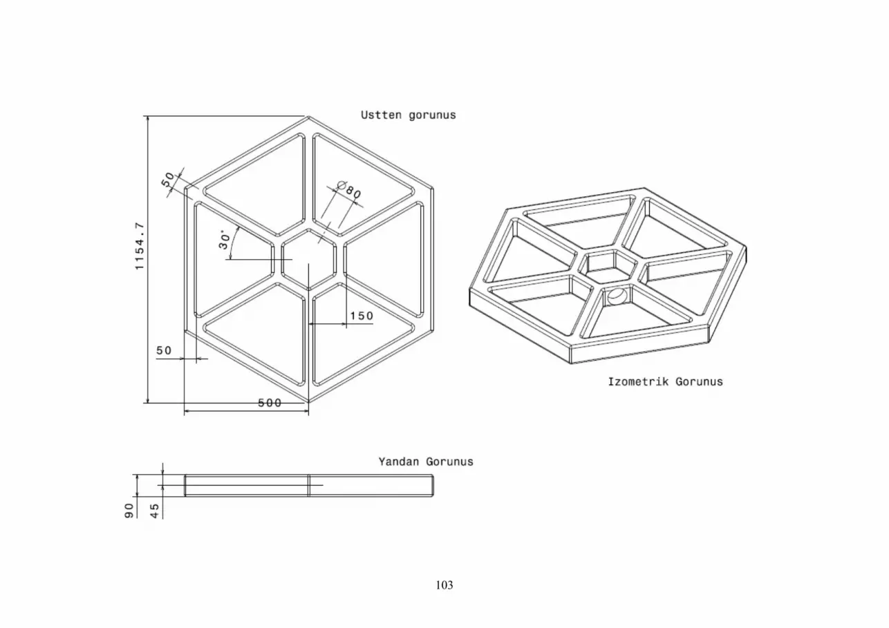
103

104

105

106

107
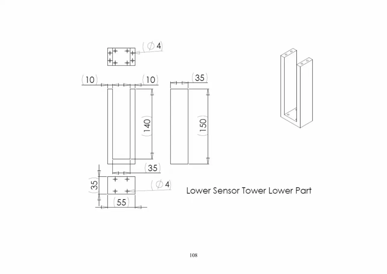
108

109

110

111

112

113

114

115

116

117
APPENDIX-H: dSpace Control Board Pins

118
Bibliography & Sources:
1. Dynaserv DD Servo-Actuator DM/SD Series Introduction Manuel, Yokogawa MAT Corporation, Mar 1 2000.
2. Floating-Point Controller Board DS 1102 Hardware Reference 3. Fundamentals of Robotics: analysis and control / Robert J. Schilling.
Englewood Cliffs, N.J.: Prentice Hall, c1990 4. Robot Dynamics and Control / Mark W. Spong, M. Vidyasagar. New
York: Willey, 1989 5. Visual Control of Robots: High-Performance Visual Servoing (Robotics
and Mechatronics Series, 2) / Peter Corke. Research Studies Press, June 1 1996.


