Embed Size (px)
Citation preview
Citation: Abbas, A.H.; Ahmed, A.J.;
Rashid, S.A. A Cross-Layer Approach
MAC/NET with Updated-GA
(MNUG-CLA)-Based Routing
Protocol for VANET Network. World
Electr. Veh. J. 2022, 13, 87. https://
doi.org/10.3390/wevj13050087
Academic Editor: Grzegorz
Sierpinski
Received: 19 March 2022
Accepted: 25 April 2022
Published: 12 May 2022
Publisher’s Note: MDPI stays neutral
with regard to jurisdictional claims in
published maps and institutional affil-
iations.
Copyright: © 2022 by the authors.
Licensee MDPI, Basel, Switzerland.
This article is an open access article
distributed under the terms and
conditions of the Creative Commons
Attribution (CC BY) license (https://
creativecommons.org/licenses/by/
4.0/).
Article
A Cross-Layer Approach MAC/NET with Updated-GA(MNUG-CLA)-Based Routing Protocol for VANET NetworkAli Hashim Abbas 1,* , Ahmed Jamal Ahmed 2 and Sami Abduljabbar Rashid 2
1 College of Information Technology, Imam Ja’afar Al-Sadiq University, Al-Muthanna, Samawah 66002, Iraq2 Department of Computer Engineering Technology, Al-Maarif University College, Al-Anba,
Ramadi 31001, Iraq; [email protected] (A.J.A.); [email protected] (S.A.R.)* Correspondence: [email protected]; Tel.: +964-7826-333-304
Abstract: Nowadays, technology is developed rapidly in communication technology. Several newtechnologies have been introduced due to the evolution of wireless communication and this providedthe way to communicate among vehicles, using a Vehicular Ad-Hoc Network (VANETs). Routing inVANETs becomes most challenging because of the huge mobility and dynamical topology changes,which lead to reduced efficiency in the network. The core idea of this network is to increase theefficiency during the process of the communication. The most suited routing protocol for VANETs isGeographic routing, for the reason that it provides higher scalability and low overheads. The majorchallenges in VANETs are the selection of best neighbor in dynamically changing VANET topology.Furthermore, to provide better QoS needful actions are essential. In this paper, we introduced anew MAC/NET with Updated Genetic Algorithm—A Cross Layer Approach, (MNUG-CLA) basedon a MAC layer and network layer to overcome the drawbacks of the network. In the networklayer, a new neighbor discovery protocol is developed to select the best next hop for the dynamicallyvarying network. In the MAC layer, in order to improve the quality, multi-channel MAC model isintroduced for instantaneous transmission from various service channels. For overall optimal pathselection, we used an updated GA algorithm. The performance was demonstrated through the use ofan extensive simulation environment, NS-2. The simulation results prove that this protocol providesbetter results, in terms of energy efficiency, energy consumption and successive packet transmission,when compared with the earlier approaches.
Keywords: VANETs; genetic algorithm; MAC/NET; QoS; energy consumption
1. Introduction
Due to the rapid advancement in wireless communication technology and ever-growing traffic volumes, VANETs (Vehicular Ad hoc Networks) have attracted grow-ing attention regarding the potential in intelligent transportation systems in the last fewyears [1]. The VANET allows automobiles to communicate with each other without theuse of infrastructure, allowing people to drive securely. Along with its various forms ofsecurity and entertainment technologies, it has gained favor among scholars. It was stilldifficult to develop a routing system that can handle a high-mobility atmosphere. Databecomes obsolete as a consequence of elevated mobility and variable topologies, resultingin disconnectedness and packet dropping concerns across vehicle nodes. Various routingalgorithms have solved these difficulties. Table-driven or topology-based forwarding andgeographic-based forwarding are two distinct kinds of routing systems. The data are con-tained in routing updates for topology-based forwarding. Proactive and reactive routingare the two sorts of routing. Since destinations are determined before transmissions to bedone, the proactive kind has a minimal latency. Due to the huge amount of route updatequeries, proactive routing protocols have a large overhead. Approaches, on the other hand,involve a significant delay, since routes must be identified whenever the base station makesthe r_req message [2].
World Electr. Veh. J. 2022, 13, 87. https://doi.org/10.3390/wevj13050087 https://www.mdpi.com/journal/wevj
World Electr. Veh. J. 2022, 13, 87 2 of 14
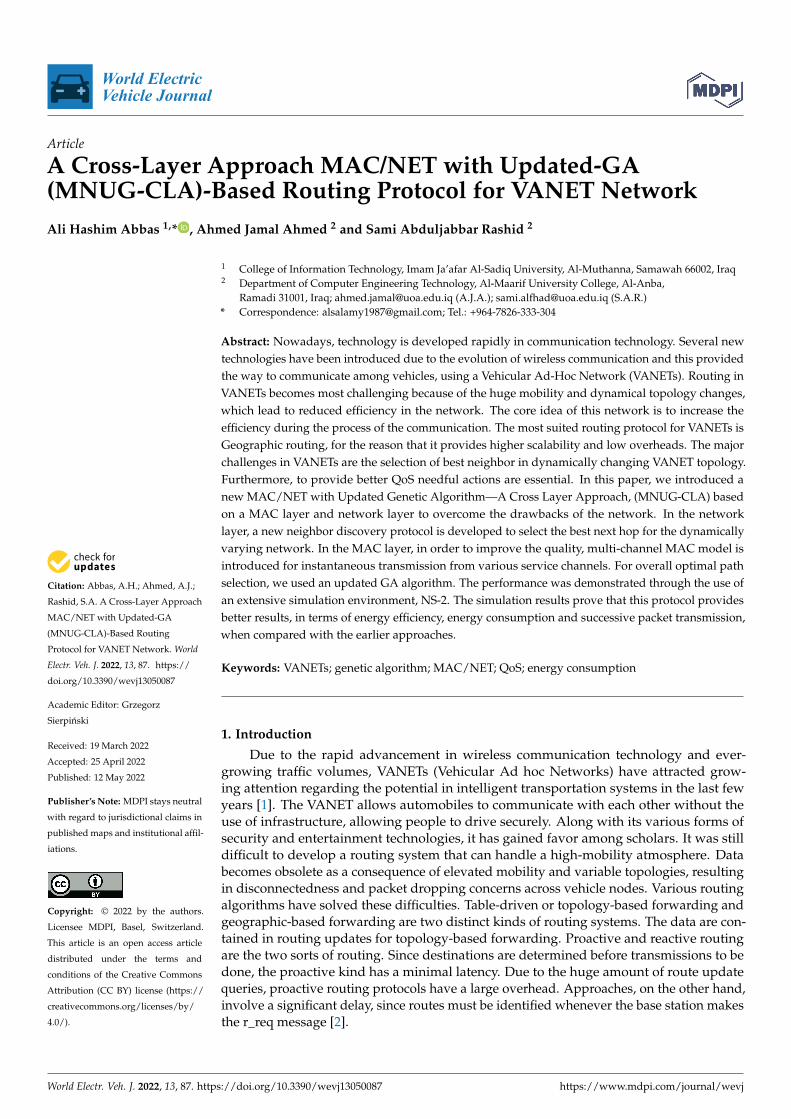
Whenever there is information to transmit, approaches choose destinations. TheVehicle-to-Vehicle, Vehicle-to-Infrastructure, and Infrastructure-to-Infrastructure communi-cations are shown in Figure 1. Geographical routing techniques only employ data fromneighbor nodes that are within their broadcast range. Data transmission algorithms inthese methods are based on node location data. In the beacon-based geographic routingalgorithm, packets are being used to discover the location coordinates of neighbor nodes.Revised control packets provide the foundation of the beaconless geographical routingalgorithm. Geographical routing systems rely on the Global Positioning System (GPS) toidentify the precise location of a vehicle. Geographic routing techniques are thought to bemore practical and efficient for variable architectures. GPRS gave birth to the concept ofgeographical type. The greedy and perimeter approaches are used by GPSR. Greedy modewill activate when information is supplied to the node that is nearest to the destination.Whenever the greedy method expires, the protocols fall back to perimeter mode. Once thesource node is close to the destination and its neighbors are distant, multicast routing chal-lenges arise. The procedure then shifts to perimeter mode, which employs the right-handprinciple. The right-hand principle refers to the process by which all networks conveydata to their neighbors clockwise whenever they transmit it anti-clockwise, face routingdifficulties with the GPSR, and struggle to cope with irregular traffic patterns. The GPSRonly takes distance metrics and does not consider direction metrics, which leads to wrongpacket forwarding decisions and increased packet loss [3].
World Electr. Veh. J. 2022, 13, x FOR PEER REVIEW 2 of 15
hand, involve a significant delay, since routes must be identified whenever the base sta-tion makes the r_req message [2].
Whenever there is information to transmit, approaches choose destinations. The Ve-hicle-to-Vehicle, Vehicle-to-Infrastructure, and Infrastructure-to-Infrastructure communi-cations are shown in Figure 1. Geographical routing techniques only employ data from neighbor nodes that are within their broadcast range. Data transmission algorithms in these methods are based on node location data. In the beacon-based geographic routing algorithm, packets are being used to discover the location coordinates of neighbor nodes. Revised control packets provide the foundation of the beaconless geographical routing algorithm. Geographical routing systems rely on the Global Positioning System (GPS) to identify the precise location of a vehicle. Geographic routing techniques are thought to be more practical and efficient for variable architectures. GPRS gave birth to the concept of geographical type. The greedy and perimeter approaches are used by GPSR. Greedy mode will activate when information is supplied to the node that is nearest to the destination. Whenever the greedy method expires, the protocols fall back to perimeter mode. Once the source node is close to the destination and its neighbors are distant, multicast routing challenges arise. The procedure then shifts to perimeter mode, which employs the right-hand principle. The right-hand principle refers to the process by which all networks con-vey data to their neighbors clockwise whenever they transmit it anti-clockwise, face rout-ing difficulties with the GPSR, and struggle to cope with irregular traffic patterns. The GPSR only takes distance metrics and does not consider direction metrics, which leads to wrong packet forwarding decisions and increased packet loss [3].
Figure 1. System Architecture of MNUG-CLA Approach.
The organization of the rest of the paper is as follows. Section 2 explains the survey about the geographic routing in VANETs and cross-layer approaches. Section 3 explains the background, challenges and motivation in VANETs. Section 4 proposes the MAC/NET with an updated genetic algorithm for VANETs. Section 5 presents the simulation results and discussion about the proposed model. At last, in Section 5, conclusions are given.
2. Comprehensive Survey New studies have shown that the more efficient routing protocols for VANETs are
those which take numerous variables into account while making routing decisions at the relay node. This study is focused on approaches that analyze neighbor nodes using nu-merous routing parameters and identify the best candidate node to route packets. As a result, we have highlighted some current intriguing suggestions in spatial routing algo-rithms. Greedy perimeter stateless routing (GPSR) [4] is one of the earliest geographic routing algorithms devised for VANETs and is often cited as a benchmark. Position-based methods are preferable to VANETs over topology-based methods, according to research, since geographic routing avoids the operational costs and latency of establishing a
Figure 1. System Architecture of MNUG-CLA Approach.
The organization of the rest of the paper is as follows. Section 2 explains the surveyabout the geographic routing in VANETs and cross-layer approaches. Section 3 explainsthe background, challenges and motivation in VANETs. Section 4 proposes the MAC/NETwith an updated genetic algorithm for VANETs. Section 5 presents the simulation resultsand discussion about the proposed model. At last, in Section 5, conclusions are given.
2. Comprehensive Survey
New studies have shown that the more efficient routing protocols for VANETs are thosewhich take numerous variables into account while making routing decisions at the relaynode. This study is focused on approaches that analyze neighbor nodes using numerousrouting parameters and identify the best candidate node to route packets. As a result,we have highlighted some current intriguing suggestions in spatial routing algorithms.Greedy perimeter stateless routing (GPSR) [4] is one of the earliest geographic routingalgorithms devised for VANETs and is often cited as a benchmark. Position-based methodsare preferable to VANETs over topology-based methods, according to research, sincegeographic routing avoids the operational costs and latency of establishing a forwardingtable but rather relies on the geographic position of nodes, which could be derived using a
World Electr. Veh. J. 2022, 13, 87 3 of 14
Global Positioning System (GPS) device on a vehicle. Still, there is a research gap present inefficiency improvement in GPS-based VANETs. The Anchor-based Street and Traffic AwareRouting (A-STAR) and Greedy Perimeter Stateless Routing (GPSR) protocols are tested on anormal city map in this research. VANET simulations on real-world map settings producereliable data and are also valuable for designing and deploying VANETs in the real world.The real-world dynamic model is crucial because that reflects the efficiency of the protocolsunder consideration in the physical world. Analysis of performance is carried in termsof throughput, packet delivery ratio, packet loss and average delay. However, this modelprovides moderate results in most dynamic topology [5].
VANET needs constant wireless data transmission among vehicles in order for con-nectivity to be feasible, and a reliable routing protocol makes this possible. However, themovement of cars has an impact on wireless communication on a broad scale, and thenetwork architecture becomes unstable, necessitating a robust routing protocol design.Researchers compared the traditional Cluster-Based Routing Protocol (CBRP) with anoptimized method using the particle swarm optimization (PSO) method in this work. PSOhas been used to fine-tune several of CBRP’s variables and timing parameters, enhancingthe protocol’s effectiveness and precision. However, for VANETs, an effective model isessential, which concentrates both in optimal path selection and collision reduction, inorder to improve the efficiency of the network [6].
In VANETs, establishing a stable path for distributing packets is difficult due to thespeed of vehicles and frequent link interruptions. This research [7] proposes an artifi-cial spider geographic routing in metropolitan VAENTs (ASGR) to address these issues.The methods provide good results in terms of overhead. However, efficiency is moderatewhen it is applied to the highly dynamic network.
Geographic routing protocols, also known as position-based routing protocols, aremuch more suitable for fast changing and wireless connections, since they are centered ongreedy routing. Unfortunately, in a metropolitan context, this type of protocol confronts ahigher difficulty due to radio obstructions, such as towers, trees, and other barriers, thatlimit channel integrity and packet receiving rate. This work describes the available position-based routing mechanism in depth and introduces the Greedy Curve metric RoutingProtocol (GCRP) [8], which uses the curved metric duration instead of the Euclideandistance to pick the next hop. The simulation results show better performance in termsof packet delivery ratio and throughput. However, from the point of view of efficiency, itis moderate.
Whenever possible, the author uses unicast messages in this operation to save networkresource consumption. By placing directional antennae in automobiles, we can limit thespread of information. The author created an approach to select the best antenna array forunicasting information, allowing vehicles outside of the message’s propagating range todo other things. Furthermore, when information is not obtained after a certain amount oftime, each vehicle executes route discovery to nodes that hold information. As a result,pathways are rearranged as needed to accommodate additional vehicles. This methodis only suitable for VANETs with less mobility. It is not suitable for networks with hugemobility models [9].
The Intersection-based Geographical Routing Protocol (IGRP) is a category of AODVprotocol for VANETs that surpasses existing routing algorithms in metropolitan contexts.The Internet Gateway Routing Protocol (IGRP) is centered on attention for road intersec-tions, through which a signal should traverse to access the Http server. The decision isconstructed in such a way that the internet connection between crossing points is guaran-teed with a strong likelihood, while meeting quality-of-service (QoS) criteria on acceptablelatency, network capacity, and confidence interval. However, it is moderate in terms ofefficiency when it is applied to networks with huge mobility [10].
Researchers suggested a parking-area-assisted spider-web routing protocol (PASRP)for data delivery in urban VANETs. Using remote sensing and GPS techniques witha digital map, PASRP creates a spider-web propagation design based on the parking
World Electr. Veh. J. 2022, 13, 87 4 of 14
lot. The transmission path from the source unit to the destination device is determinedby sending two control packets, request-spider and confirm-spider, and the route withthe shortest latency is chosen as the transmission link. The essential information isthen transferred to the route using a multi-mode greedy method, with a dynamic multi-priority concept prioritizing it. This method only concentrates on packet delivery ratioand throughput, others are not taken care of [11].
Under this research, the authors present RSU-assisted Q-learning-based Traffic-AwareRouting, an innovative routing algorithm for metropolitan VANETs (QTAR). QTAR usesthe Q-learning algorithm to study road network traffic statistics, combining the benefits ofspatial transportation with fixed road spatial information. A routing method in QTAR ismade up of many dynamically determined high-availability connecting road sections thatallow payloads to effectively arrive at their destination. To decrease transmission delay andthe impact of high-speed traffic flows on path vulnerability, distributed V2V Q-learningcombined with Q-greedy geographical forwarding is used for routing packets inside a roadsegment, while distributed R2R Q-learning (Q-learning occurs between RSU units) is usedfor packet forwarding at every transitional link. However, this method only concentrateson throughput and delay. Overhead is not calculated [12].
In a Public Transportation System (PTS), GeOpps-N is presented as a novel hybridrouting protocol for communications between buses and procedure control centers. Everythirty seconds, the bus location must be updated. The system can be modeled as a VehicularAdvertising Network that incorporates vehicles and Road-Side Units (RSU). Since thenetwork has a low population density and is frequently congested, data must be relayed.When contrasted to other methods, such as geographic-based routing or storm routing,topology-based routing methods have been found to be more appropriate for low-quantityenvironments. Rather than seeking the endpoint within the source group, these methodssearch for the right candidate to deliver the idea to its endpoint. This method is inefficientwhen it is applied to networks with huge mobility [13].
This research offers a unique routing protocol based on the fuzzy systems that canaid in the coordination and analysis of metrics that are in conflict. To choose the bestnext-hop for routing packets, the suggested technique considers many parameters, such asposition of the vehicle, orientation, network quality, and possible bandwidth. In terms ofpacket delivery ratio, end-to-end latency, and total network performance, the outcomesof these simulated studies in reasonably congested metropolitan contexts demonstratesignificant gains. Still, this type of method produces reasonable performance when appliedto a high-speed dynamic network [14].
The designers present a hop greedy routing mechanism in this research that offers aroute with the fewest number of intermediate intersection nodes, while considering con-nection. They also present back-bone nodes, which play an important role in determiningconnection over a confluence. Aside from that, the backbone nodes permit a payloadto be routed in a different path by tracking the position of both the sender and receiver.The suggested routing method has better packet delivery ratio and a lower end-to-endlatency, according to numerical simulations. However, this provides moderate results interms of efficiency [15].
A novel adaptive geographic routing system for enabling simplex VOD broadcast inmetropolitan areas is suggested in this study. Instead of one route, a number of randomroutes between network and host vehicles are established in this system, and the amount isdetermined by the size of the demanded clip and the lifespan. The connection likelihoodof a path is estimated using a shuttered formula, which can then be utilized to pick thegreatest linked lines. The optimal path selection is done using this method, which does notsatisfy the current drawbacks of VANETs, such as efficiency improvement and collisionreduction [16]. A few recent models are discussed [17–20], such as mobility management,SDN networks performance with VANETs, optimal path findings and trust-based priorityin VANETs. All these models produce moderate efficiency in the overall calculation.
World Electr. Veh. J. 2022, 13, 87 5 of 14
2.1. Cross-Layer Routing Parameters
To reach the desired performance advantages, cross-layer routing takes advantageof the reliance among protocol layers. To put it another way, it enables data interchangebetween layers to increase connection speeds. When routing decisions are taken usingparameters accessible at the PHY, MAC, and NET levels, the routing will be more resilientto challenges involving traffic and interruption. The signal-to-interference plus-noise ratio(SINR) of a wireless medium, which is generally possible at the Protocol stack, has difficultyin determining disturbance. Only at the MAC layer, metrics relevant to node features,including as buffer space and retransmission rate, are available, whereas including thesemetrics results in the decision to reduce congestion and packet drops. These metrics,combined with the typical ETE path characteristics accessible at the NET layer, includinghop count and round-trip duration, could be used to make routing information that resultsin good network quality. As a result, the chosen route or next hop at the NET level will alsohave the least amount of impact on the aforementioned difficulties.
2.2. Cross-Layer Routing Protocols in VANETs
The available cross-layer schemes are classified depending on (a) cross-layer routingcharacteristics, (b) routing method, and (c) geographic measure. No geographic measureis being used by the cross-layer routing protocol. Independent cross-layer protocols havebeen designed that rely on routing characteristics from the PHY, MAC, and NET levels [21].
3. Background
An ad-hoc network is a transitory network that is created by combining base stationswith wireless devices in the absence of any defined system and service administration.The VANET is cutting-edge technology that provides wireless networks to next-generationcars. It is important for study because it offers the potential for a dramatic transforma-tion in the transport network through ITS. The method’s main goal is to provide vehi-cles with better communication, resulting in a more stable and safe transport network.The establishment of the VANET was motivated by the need to transmit data on the roadsamong vehicles in order to avert disasters and, hence, improve vehicle and driver secu-rity. Based on the conditions, all the data from sensor devices can be shown to the driver,communicated to an on-road unit (RSU), or relayed into neighboring vehicles. With theexception of road safety information, a range of different uses for automobile networks arediscussed, such as gaming, travel/tourism, entertainment, internet connectivity, and so on.
3.1. Challenges in VANETs
Due to the obvious unique properties of VANETs, the routing protocol is a big issuethat must be overcome before these systems can be implemented. The number of packetswill be sent from the source input to the output using the available vehicles. However,because of the dense population of vehicles and the tremendous nature with continuousdensity variations, simple traffic lights and bridges may cause a network partition, posinga major difficulty for routing. On the contrary, routing system design features, such asmobility limitations and constant road mobility, help VANETs. Extra information, suchas GPS location and city maps, can indeed be made accessible. The present routingprotocols suggested to VANETs could be grouped into the following classes: mobility-orientated activity algorithms, which use relative movement variables, such as radius,velocity, acceleration, and orientations, to forecast the lifespan and extent of a path fromsource to destination; connectivity protocols that have been proposed are used to verify thestability and confidentiality of VANET communication via infrastructure, such as RSUsand cellular ground stations; geographical location routing protocols, in which VANETsemploy GPS coordinates to find paths closer to the destination vehicle, and probabilisticrouting protocols, in which probability principles are used to predict incidents, including abroken link and the projected communication time [22].
World Electr. Veh. J. 2022, 13, 87 6 of 14
3.2. Motivation and Contribution of the Paper
Combination of both the network layer and the MAC layer creates the cross-layerapproach for the network’s better performance and is mainly focused on increasing theefficiency of the VANETs by finding the optimal path and best neighbor selection.
Originally, the MAC-based neighbor discovery and HELLO packet processing forfinding the best neighbors in VANETs were introduced.
In order to overcome the delay and overhead optimal path finding, using the updatedgenetic algorithm is proposed.
Analyzing with serious network scenarios, better performance is gained.
4. MAC/NET with Updated Genetic Algorithm—A Cross-Layer Approach (MNUG-CLA)
The Greedy Perimeter Stateless Routing (GPSR) method is an efficient and flexibleroute discovery strategy for VANET that has been devised and implemented [23–25]. Infact, the GPSR method relies on the terminals’ geographical positions to route the data, andit presumes that all devices have the same level of a zone. The GPSR system allowed anetwork to incorporate its location in header-wise packets to sends properly. Every mobiledevice transmits beacons, including location and identity, hence, the available nodes canrecognize where it is. The networks can develop their orientation process by exchangingthis control information on a regular basis. One of the benefits of such control informationis that it requires less information about the immediate neighbors, which means thatbandwidth is conserved. As per the packing density, GPSR uses two options for packetforwarding, such as Greedy Forwarding and Perimeter Forwarding.
There are two major issues when using the standard GPSR methodology in urbansettings, whereas greedy methods select the network segment closest to the target nodewhen adopting the next link in a significant way. The delay in information transmissiondue to heavy traffic or poor density may arise. When the distant node in the specified linksection is chosen as the next node, the issue of minimizing the objective function may arise.
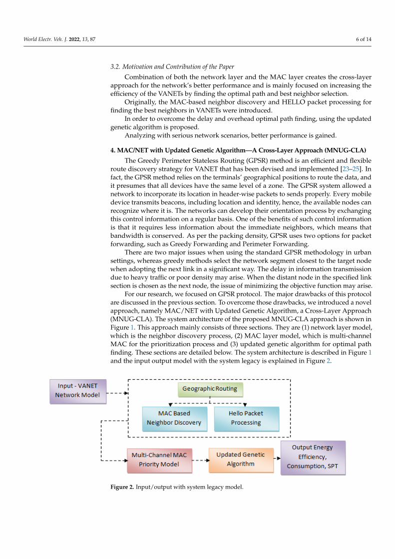
For our research, we focused on GPSR protocol. The major drawbacks of this protocolare discussed in the previous section. To overcome those drawbacks, we introduced a novelapproach, namely MAC/NET with Updated Genetic Algorithm, a Cross-Layer Approach(MNUG-CLA). The system architecture of the proposed MNUG-CLA approach is shown inFigure 1. This approach mainly consists of three sections. They are (1) network layer model,which is the neighbor discovery process, (2) MAC layer model, which is multi-channelMAC for the prioritization process and (3) updated genetic algorithm for optimal pathfinding. These sections are detailed below. The system architecture is described in Figure 1and the input output model with the system legacy is explained in Figure 2.
World Electr. Veh. J. 2022, 13, x FOR PEER REVIEW 7 of 15
Figure 2. Input/output with system legacy model.
4.1.Network Layer Model—Neighbor Discovery Process HELLO messages are generated and processed using the neighbor discovery mech-
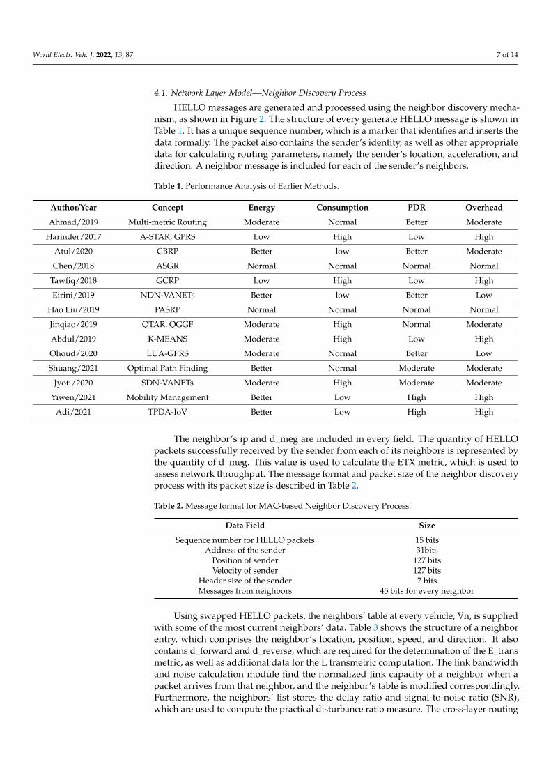
anism, as shown in Figure 2. The structure of every generate HELLO message is shown in Table 1. It has a unique sequence number, which is a marker that identifies and inserts the data formally. The packet also contains the sender’s identity, as well as other appropriate data for calculating routing parameters, namely the sender’s location, acceleration, and direction. A neighbor message is included for each of the sender’s neighbors.
Table 1. Performance Analysis of Earlier Methods.
Author/Year Concept Energy Consumption PDR Overhead Ahmad/2019 Multi-metric Routing Moderate Normal Better Moderate
Harinder/2017 A-STAR, GPRS Low High Low High Atul/2020 CBRP Better low Better Moderate Chen/2018 ASGR Normal Normal Normal Normal
Tawfiq/2018 GCRP Low High Low High Eirini/2019 NDN-VANETs Better low Better Low
Hao Liu/2019 PASRP Normal Normal Normal Normal Jinqiao/2019 QTAR, QGGF Moderate High Normal Moderate Abdul/2019 K-MEANS Moderate High Low High Ohoud/2020 LUA-GPRS Moderate Normal Better Low Shuang/2021 Optimal Path Finding Better Normal Moderate Moderate
Jyoti/2020 SDN-VANETs Moderate High Moderate Moderate Yiwen/2021 Mobility Management Better Low High High
Adi/2021 TPDA-IoV Better Low High High
The neighbor’s ip and d_meg are included in every field. The quantity of HELLO packets successfully received by the sender from each of its neighbors is represented by the quantity of d_meg. This value is used to calculate the ETX metric, which is used to assess network throughput. The message format and packet size of the neighbor discovery process with its packet size is described in Table 2.
Table 2. Message format for MAC-based Neighbor Discovery Process.
Data Field Size Sequence number for HELLO packets 15 bits
Address of the sender 31bits Position of sender 127 bits Velocity of sender 127 bits
Header size of the sender 7 bits Messages from neighbors 45 bits for every neighbor
Figure 2. Input/output with system legacy model.
World Electr. Veh. J. 2022, 13, 87 7 of 14
4.1. Network Layer Model—Neighbor Discovery Process
HELLO messages are generated and processed using the neighbor discovery mecha-nism, as shown in Figure 2. The structure of every generate HELLO message is shown inTable 1. It has a unique sequence number, which is a marker that identifies and inserts thedata formally. The packet also contains the sender’s identity, as well as other appropriatedata for calculating routing parameters, namely the sender’s location, acceleration, anddirection. A neighbor message is included for each of the sender’s neighbors.
Table 1. Performance Analysis of Earlier Methods.
Author/Year Concept Energy Consumption PDR Overhead
Ahmad/2019 Multi-metric Routing Moderate Normal Better Moderate
Harinder/2017 A-STAR, GPRS Low High Low High
Atul/2020 CBRP Better low Better Moderate
Chen/2018 ASGR Normal Normal Normal Normal
Tawfiq/2018 GCRP Low High Low High
Eirini/2019 NDN-VANETs Better low Better Low
Hao Liu/2019 PASRP Normal Normal Normal Normal
Jinqiao/2019 QTAR, QGGF Moderate High Normal Moderate
Abdul/2019 K-MEANS Moderate High Low High
Ohoud/2020 LUA-GPRS Moderate Normal Better Low
Shuang/2021 Optimal Path Finding Better Normal Moderate Moderate
Jyoti/2020 SDN-VANETs Moderate High Moderate Moderate
Yiwen/2021 Mobility Management Better Low High High
Adi/2021 TPDA-IoV Better Low High High
The neighbor’s ip and d_meg are included in every field. The quantity of HELLOpackets successfully received by the sender from each of its neighbors is represented bythe quantity of d_meg. This value is used to calculate the ETX metric, which is used toassess network throughput. The message format and packet size of the neighbor discoveryprocess with its packet size is described in Table 2.
Table 2. Message format for MAC-based Neighbor Discovery Process.
Data Field Size
Sequence number for HELLO packets 15 bitsAddress of the sender 31bits
Position of sender 127 bitsVelocity of sender 127 bits
Header size of the sender 7 bitsMessages from neighbors 45 bits for every neighbor
Using swapped HELLO packets, the neighbors’ table at every vehicle, Vn, is suppliedwith some of the most current neighbors’ data. Table 3 shows the structure of a neighborentry, which comprises the neighbor’s location, position, speed, and direction. It alsocontains d_forward and d_reverse, which are required for the determination of the E_transmetric, as well as additional data for the L transmetric computation. The link bandwidthand noise calculation module find the normalized link capacity of a neighbor when apacket arrives from that neighbor, and the neighbor’s table is modified correspondingly.Furthermore, the neighbors’ list stores the delay ratio and signal-to-noise ratio (SNR),which are used to compute the practical disturbance ratio measure. The cross-layer routing
World Electr. Veh. J. 2022, 13, 87 8 of 14
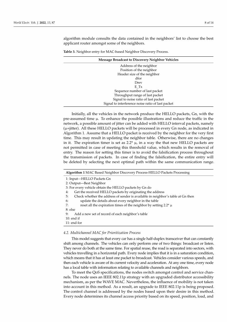
algorithm module consults the data contained in the neighbors’ list to choose the bestapplicant router amongst some of the neighbors.
Table 3. Neighbor entry for MAC-based Neighbor Discovery Process.
Message Broadcast to Discovery Neighbor Vehicles
Address of the neighborPosition of the neighbor
Header size of the neighbordforDrevE_Tx
Sequence number of last packetThroughput range of last packet
Signal to noise ratio of last packetSignal to interference noise ratio of last packet
Initially, all the vehicles in the network produce the HELLO packets, Gn, with thepre-assumed time µ. To enhance the possible illustrations and reduce the traffic in thenetwork, a possible amount of jitter can be added with HELLO interval packets, namely(µ+jitter). All these HELLO packets will be processed in every Gn node, as indicated inAlgorithm 1. Assume that a HELLO packet is received by the neighbor for the very firsttime. This may result in updating the neighbor table. Otherwise, there are no changesin it. The expiration timer is set as 2.2* µ, in a way the that new HELLO packets arenot permitted in case of meeting this threshold value, which results in the removal ofentry. The reason for setting this timer is to avoid the falsification process throughoutthe transmission of packets. In case of finding the falsification, the entire entry willbe deleted by selecting the next optimal path within the same communication range.
Algorithm 1 MAC Based Neighbor Discovery Process-HELLO Packets Processing
1: Input—HELLO Packets Gn2: Output—Best Neighbor3: For every vehicle obtain the HELLO packets by Gn do4: Get the received HELLO packets by originating the address5: Check whether the address of sender is available in neighbor’s table at Gn then6: update the details about every neighbor in the table7: reset all the expiration times of the neighbor by setting 2.2* µ8: else9: Add a new set of record of each neighbor’s table10: end if11: end for
4.2. Multichannel MAC for Prioritization Process
This model suggests that every car has a single half-duplex transceiver that can constantlyshift among channels. The vehicles can only perform one of two things: broadcast or listen.They never do both at the same time. For spatial reuse, the road is separated into sectors, withvehicles travelling in a horizontal path. Every node implies that it is in a saturation condition,which means that it has at least one packet to broadcast. Vehicles consider various speeds, andthen each vehicle is aware of its current velocity and acceleration. At any one time, every nodehas a local table with information relating to available channels and neighbors.
To meet the QoS specifications, the nodes switch amongst control and service chan-nels. The node uses an IEEE 802.11p strategy with an upgraded distributor accessibilitymechanism, as per the WAVE MAC. Nevertheless, the influence of mobility is not takeninto account in this method. As a result, an upgrade to IEEE 802.11p is being proposed.The control channel is addressed by the nodes based upon their desire in this method.Every node determines its channel access priority based on its speed, position, load, and
World Electr. Veh. J. 2022, 13, 87 9 of 14
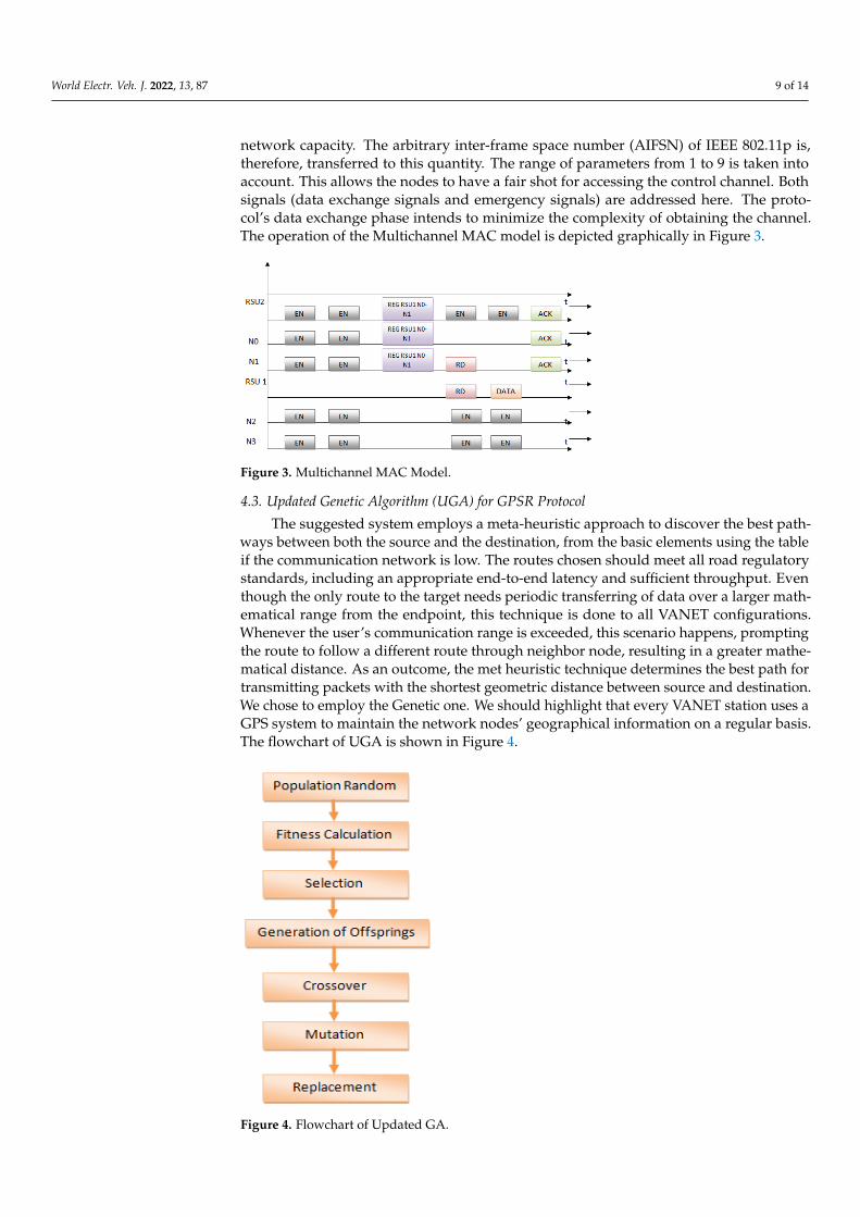
network capacity. The arbitrary inter-frame space number (AIFSN) of IEEE 802.11p is,therefore, transferred to this quantity. The range of parameters from 1 to 9 is taken intoaccount. This allows the nodes to have a fair shot for accessing the control channel. Bothsignals (data exchange signals and emergency signals) are addressed here. The proto-col’s data exchange phase intends to minimize the complexity of obtaining the channel.The operation of the Multichannel MAC model is depicted graphically in Figure 3.
World Electr. Veh. J. 2022, 13, x FOR PEER REVIEW 9 of 15
4.2. Multichannel MAC for Prioritization Process This model suggests that every car has a single half-duplex transceiver that can con-
stantly shift among channels. The vehicles can only perform one of two things: broadcast or listen. They never do both at the same time. For spatial reuse, the road is separated into sectors, with vehicles travelling in a horizontal path. Every node implies that it is in a saturation condition, which means that it has at least one packet to broadcast. Vehicles consider various speeds, and then each vehicle is aware of its current velocity and accel-eration. At any one time, every node has a local table with information relating to available channels and neighbors.
To meet the QoS specifications, the nodes switch amongst control and service chan-nels. The node uses an IEEE 802.11p strategy with an upgraded distributor accessibility mechanism, as per the WAVE MAC. Nevertheless, the influence of mobility is not taken into account in this method. As a result, an upgrade to IEEE 802.11p is being proposed. The control channel is addressed by the nodes based upon their desire in this method. Every node determines its channel access priority based on its speed, position, load, and network capacity. The arbitrary inter-frame space number (AIFSN) of IEEE 802.11p is, therefore, transferred to this quantity. The range of parameters from 1 to 9 is taken into account. This allows the nodes to have a fair shot for accessing the control channel. Both signals (data exchange signals and emergency signals) are addressed here. The protocol’s data exchange phase intends to minimize the complexity of obtaining the channel. The operation of the Multichannel MAC model is depicted graphically in Figure 3.
Figure 3. Multichannel MAC Model.
4.3. Updated Genetic Algorithm (UGA) for GPSR Protocol The suggested system employs a meta-heuristic approach to discover the best path-
ways between both the source and the destination, from the basic elements using the table if the communication network is low. The routes chosen should meet all road regulatory standards, including an appropriate end-to-end latency and sufficient throughput. Even though the only route to the target needs periodic transferring of data over a larger math-ematical range from the endpoint, this technique is done to all VANET configurations. Whenever the user’s communication range is exceeded, this scenario happens, prompting the route to follow a different route through neighbor node, resulting in a greater mathe-matical distance. As an outcome, the met heuristic technique determines the best path for transmitting packets with the shortest geometric distance between source and destination. We chose to employ the Genetic one. We should highlight that every VANET station uses a GPS system to maintain the network nodes’ geographical information on a regular basis. The flowchart of UGA is shown in Figure 4.
Figure 3. Multichannel MAC Model.
4.3. Updated Genetic Algorithm (UGA) for GPSR Protocol
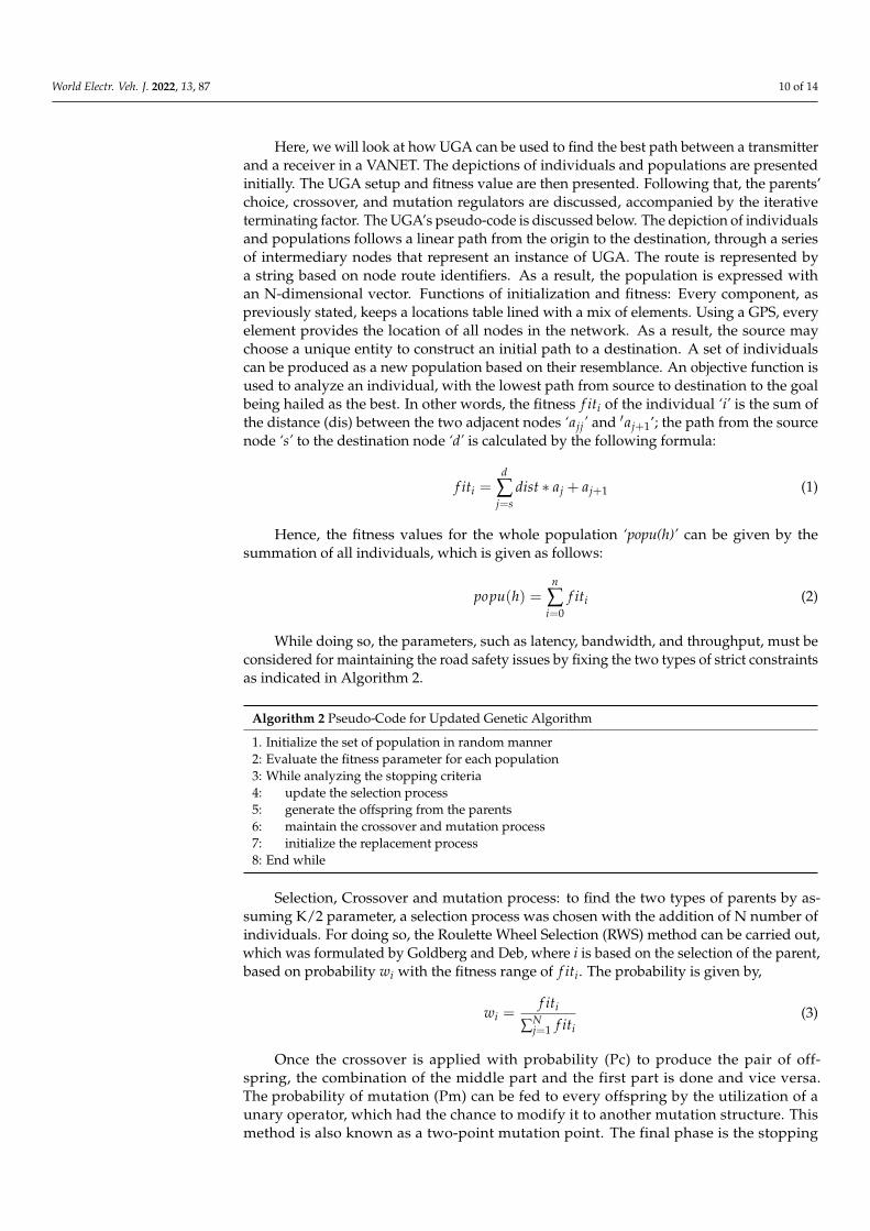
The suggested system employs a meta-heuristic approach to discover the best path-ways between both the source and the destination, from the basic elements using the tableif the communication network is low. The routes chosen should meet all road regulatorystandards, including an appropriate end-to-end latency and sufficient throughput. Eventhough the only route to the target needs periodic transferring of data over a larger math-ematical range from the endpoint, this technique is done to all VANET configurations.Whenever the user’s communication range is exceeded, this scenario happens, promptingthe route to follow a different route through neighbor node, resulting in a greater mathe-matical distance. As an outcome, the met heuristic technique determines the best path fortransmitting packets with the shortest geometric distance between source and destination.We chose to employ the Genetic one. We should highlight that every VANET station uses aGPS system to maintain the network nodes’ geographical information on a regular basis.The flowchart of UGA is shown in Figure 4.
World Electr. Veh. J. 2022, 13, x FOR PEER REVIEW 10 of 15
Figure 4. Flowchart of Updated GA.
Here, we will look at how UGA can be used to find the best path between a transmit-ter and a receiver in a VANET. The depictions of individuals and populations are pre-sented initially. The UGA setup and fitness value are then presented. Following that, the parents’ choice, crossover, and mutation regulators are discussed, accompanied by the iterative terminating factor. The UGA’s pseudo-code is discussed below. The depiction of individuals and populations follows a linear path from the origin to the destination, through a series of intermediary nodes that represent an instance of UGA. The route is represented by a string based on node route identifiers. As a result, the population is ex-pressed with an N-dimensional vector. Functions of initialization and fitness: Every com-ponent, as previously stated, keeps a locations table lined with a mix of elements. Using a GPS, every element provides the location of all nodes in the network. As a result, the source may choose a unique entity to construct an initial path to a destination. A set of individuals can be produced as a new population based on their resemblance. An objec-tive function is used to analyze an individual, with the lowest path from source to desti-nation to the goal being hailed as the best. In other words, the fitness 𝑓𝑖𝑡 of the individ-ual ‘i’ is the sum of the distance (dis) between the two adjacent nodes ‘𝑎 ’ and ′𝑎 ’; the path from the source node ‘s’ to the destination node ‘d’ is calculated by the following formula:
𝑓𝑖𝑡 = 𝑑𝑖𝑠𝑡 ∗ 𝑎 + 𝑎 (1)
Hence, the fitness values for the whole population ‘popu(h)’ can be given by the sum-mation of all individuals, which is given as follows:
𝑝𝑜𝑝𝑢 ℎ = 𝑓𝑖𝑡 (2)
While doing so, the parameters, such as latency, bandwidth, and throughput, must be considered for maintaining the road safety issues by fixing the two types of strict con-straints as indicated in Algorithm 2.
Figure 4. Flowchart of Updated GA.
World Electr. Veh. J. 2022, 13, 87 10 of 14
Here, we will look at how UGA can be used to find the best path between a transmitterand a receiver in a VANET. The depictions of individuals and populations are presentedinitially. The UGA setup and fitness value are then presented. Following that, the parents’choice, crossover, and mutation regulators are discussed, accompanied by the iterativeterminating factor. The UGA’s pseudo-code is discussed below. The depiction of individualsand populations follows a linear path from the origin to the destination, through a seriesof intermediary nodes that represent an instance of UGA. The route is represented bya string based on node route identifiers. As a result, the population is expressed withan N-dimensional vector. Functions of initialization and fitness: Every component, aspreviously stated, keeps a locations table lined with a mix of elements. Using a GPS, everyelement provides the location of all nodes in the network. As a result, the source maychoose a unique entity to construct an initial path to a destination. A set of individualscan be produced as a new population based on their resemblance. An objective function isused to analyze an individual, with the lowest path from source to destination to the goalbeing hailed as the best. In other words, the fitness f iti of the individual ‘i’ is the sum ofthe distance (dis) between the two adjacent nodes ‘ajj’ and ′aj+1’; the path from the sourcenode ‘s’ to the destination node ‘d’ is calculated by the following formula:
f iti =d
∑j=s
dist ∗ aj + aj+1 (1)
Hence, the fitness values for the whole population ‘popu(h)’ can be given by thesummation of all individuals, which is given as follows:
popu(h) =n
∑i=0
f iti (2)
While doing so, the parameters, such as latency, bandwidth, and throughput, must beconsidered for maintaining the road safety issues by fixing the two types of strict constraintsas indicated in Algorithm 2.
Algorithm 2 Pseudo-Code for Updated Genetic Algorithm
1. Initialize the set of population in random manner2: Evaluate the fitness parameter for each population3: While analyzing the stopping criteria4: update the selection process5: generate the offspring from the parents6: maintain the crossover and mutation process7: initialize the replacement process8: End while
Selection, Crossover and mutation process: to find the two types of parents by as-suming K/2 parameter, a selection process was chosen with the addition of N number ofindividuals. For doing so, the Roulette Wheel Selection (RWS) method can be carried out,which was formulated by Goldberg and Deb, where i is based on the selection of the parent,based on probability wi with the fitness range of f iti. The probability is given by,
wi =f iti
∑Nj=1 f iti
(3)
Once the crossover is applied with probability (Pc) to produce the pair of off-spring, the combination of the middle part and the first part is done and vice versa.The probability of mutation (Pm) can be fed to every offspring by the utilization of aunary operator, which had the chance to modify it to another mutation structure. Thismethod is also known as a two-point mutation point. The final phase is the stopping
World Electr. Veh. J. 2022, 13, 87 11 of 14
criterion, with the adoption of the dynamic concept. The maximum threshold (max_th)can be fixed with the adoption of the stagnating state (min_th). These two thresholdscan be adopted with empirical values.
The control channel conveys emergency alerts and data negotiator signals in a multi-channel environment; meanwhile, the service channel communicates with data. Whenan emergency occurs, all locations respond to the control channel, and a control packetis created, which passes across the control channel based on the importance of the node.During the data time of negotiation, the node determines the relative importance andthen correlates it to the protocol-specific channel-access characteristics. The specificationsof the delivery channel selected by the originator, as well as the projected time of datatransmission, are sent, including the data negotiation message. The broadcaster thenchanges to the designated service channel and listens for the receiver to send the ready(RD) signal. If the channel is available on the recipient side, it switches to the designatedchannel and sends the ready (RD) signal. The transmitter starts transmission after obtainingthe ready signal, and the receiver sends back an acknowledgement through the controlchannel after collecting all data, prompting all nodes to change their local tables. Each nodekeeps local tables with information about its neighbors and a list of available channels.The channel list includes information on free channels, channels that have been taggedas busy for an expected time, and networks that have been used previously. The servicechannel for negotiation is assigned to the channel with the lowest load/relatively freebandwidth. If the requested channel is not accessible at the receiver, the receiver respondswith a negative acknowledgement and the available channel data after one slot. When thetransmitter receives this, it switches to the next available channel and begins transmitting.The free channel list on all other nodes is updated.
5. Results and Discussion
Network Simulator 2 (NS2) is a simple event-driven simulation program that hasproven to be beneficial in researching the dynamic behavior of communications infrastruc-ture. It could be used to simulate wired and wireless network functions and standards.Generally, NS2 allows the user to select network protocols and simulate their behavior. Asa result, we are employing the NS2-based simulation for protocol simulations, in additionto providing significant support for TCP, routing, and multicast protocols over wired andwireless networks. The NS2 code is developed in C++ (to define the core mechanisms ofthe simulation objects) and TCL (to start the scheduler events), resulting in a NAM outputfile. Then, it displays the output of the nodes talking with each other, which comprisestwo tools, plotting the nodes in a place given by the code script. All frequently deployedIP protocols are included in the network simulator (NS2). The simulation analysis is donewith various network scenarios, such as nodes of 20, 40, 60, 80 and 100. Five differentscenarios are conducted and the graphic results are shown in the upcoming sub-sections.
In this simulation, our protocol is compared with the earlier models, such as GPSR,MM-GPSR [23] and GEO-LU [25]. The parameters, which are calculated for the resultanalysis, are Network Energy Efficiency (NEE), Network Energy Consumption (NEC) andSuccessful Packet Transmission (SPT).
5.1. Network Energy Efficiency (NEE)
Network energy efficiency is calculated as the amount of residual energy measured atthe final stage of simulation. The mathematical expression to calculate the residual energyis given as follows,
ARE =1n×
n
∑i=1
REi (4)
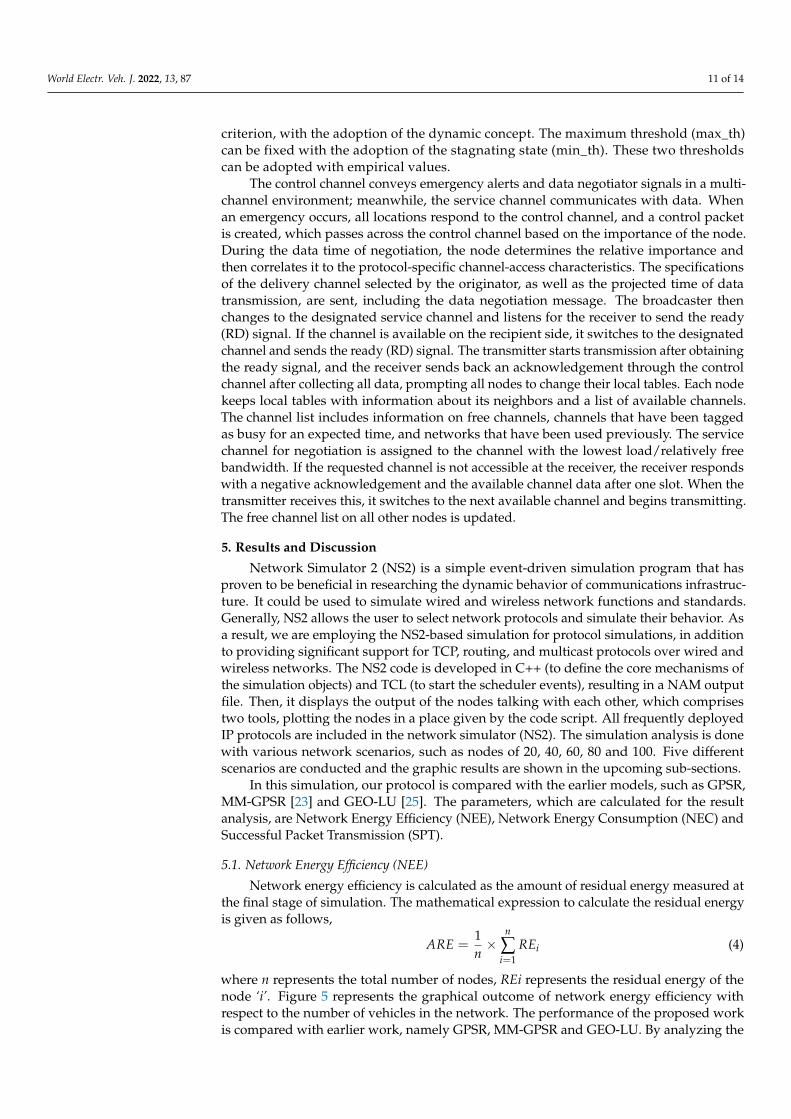
where n represents the total number of nodes, REi represents the residual energy of thenode ‘i’. Figure 5 represents the graphical outcome of network energy efficiency withrespect to the number of vehicles in the network. The performance of the proposed workis compared with earlier work, namely GPSR, MM-GPSR and GEO-LU. By analyzing the
World Electr. Veh. J. 2022, 13, 87 12 of 14
table values and graphs, it can be understood that our proposed MNUG-CLA protocolperformed better than the earlier research methods.
World Electr. Veh. J. 2022, 13, x FOR PEER REVIEW 12 of 15
behavior. As a result, we are employing the NS2-based simulation for protocol simula-tions, in addition to providing significant support for TCP, routing, and multicast proto-cols over wired and wireless networks. The NS2 code is developed in C++ (to define the core mechanisms of the simulation objects) and TCL (to start the scheduler events), result-ing in a NAM output file. Then, it displays the output of the nodes talking with each other, which comprises two tools, plotting the nodes in a place given by the code script. All fre-quently deployed IP protocols are included in the network simulator (NS2). The simula-tion analysis is done with various network scenarios, such as nodes of 20, 40, 60, 80 and 100. Five different scenarios are conducted and the graphic results are shown in the up-coming sub-sections.
In this simulation, our protocol is compared with the earlier models, such as GPSR, MM-GPSR [23] and GEO-LU [25]. The parameters, which are calculated for the result anal-ysis, are Network Energy Efficiency (NEE), Network Energy Consumption (NEC) and Successful Packet Transmission (SPT).
5.1.Network Energy Efficiency (NEE) Network energy efficiency is calculated as the amount of residual energy measured
at the final stage of simulation. The mathematical expression to calculate the residual en-ergy is given as follows,
𝐴𝑅𝐸 = 1𝑛 × 𝑅𝐸 (4)
where n represents the total number of nodes, REi represents the residual energy of the node ‘i’. Figure 5 represents the graphical outcome of network energy efficiency with re-spect to the number of vehicles in the network. The performance of the proposed work is compared with earlier work, namely GPSR, MM-GPSR and GEO-LU. By analyzing the table values and graphs, it can be understood that our proposed MNUG-CLA protocol performed better than the earlier research methods.
Figure 5. Network Energy Efficiency Calculation.
5.2.Network Energy Consumption (NEC). This represents the energy allocation of all the nodes in the network. In this research,
the network energy consumption is defined as the energy being utilized by a node to es-tablish the path (EP). The mathematical expression to calculate the energy consumption is given as follows, 𝑁𝐸𝐶 = Number of nodes * Energy (EP) (5)
Figure 5. Network Energy Efficiency Calculation.
5.2. Network Energy Consumption (NEC)
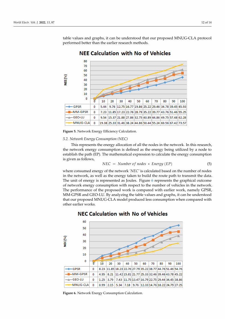
This represents the energy allocation of all the nodes in the network. In this research,the network energy consumption is defined as the energy being utilized by a node toestablish the path (EP). The mathematical expression to calculate the energy consumptionis given as follows,
NEC = Number o f nodes ∗ Energy (EP) (5)
where consumed energy of the network ‘NEC’ is calculated based on the number of nodesin the network, as well as the energy taken to build the route path to transmit the data.The unit of energy is represented as Joules. Figure 6 represents the graphical outcomeof network energy consumption with respect to the number of vehicles in the network.The performance of the proposed work is compared with earlier work, namely GPSR,MM-GPSR and GEO-LU. By analyzing the table values and graphs, it can be understoodthat our proposed MNUG-CLA model produced less consumption when compared withother earlier works.
World Electr. Veh. J. 2022, 13, x FOR PEER REVIEW 13 of 15
where consumed energy of the network ‘NEC’ is calculated based on the number of nodes in the network, as well as the energy taken to build the route path to transmit the data. The unit of energy is represented as Joules. Figure 6 represents the graphical outcome of network energy consumption with respect to the number of vehicles in the network. The performance of the proposed work is compared with earlier work, namely GPSR, MM-GPSR and GEO-LU. By analyzing the table values and graphs, it can be understood that our proposed MNUG-CLA model produced less consumption when compared with other earlier works.
Figure 6. Network Energy Consumption Calculation.
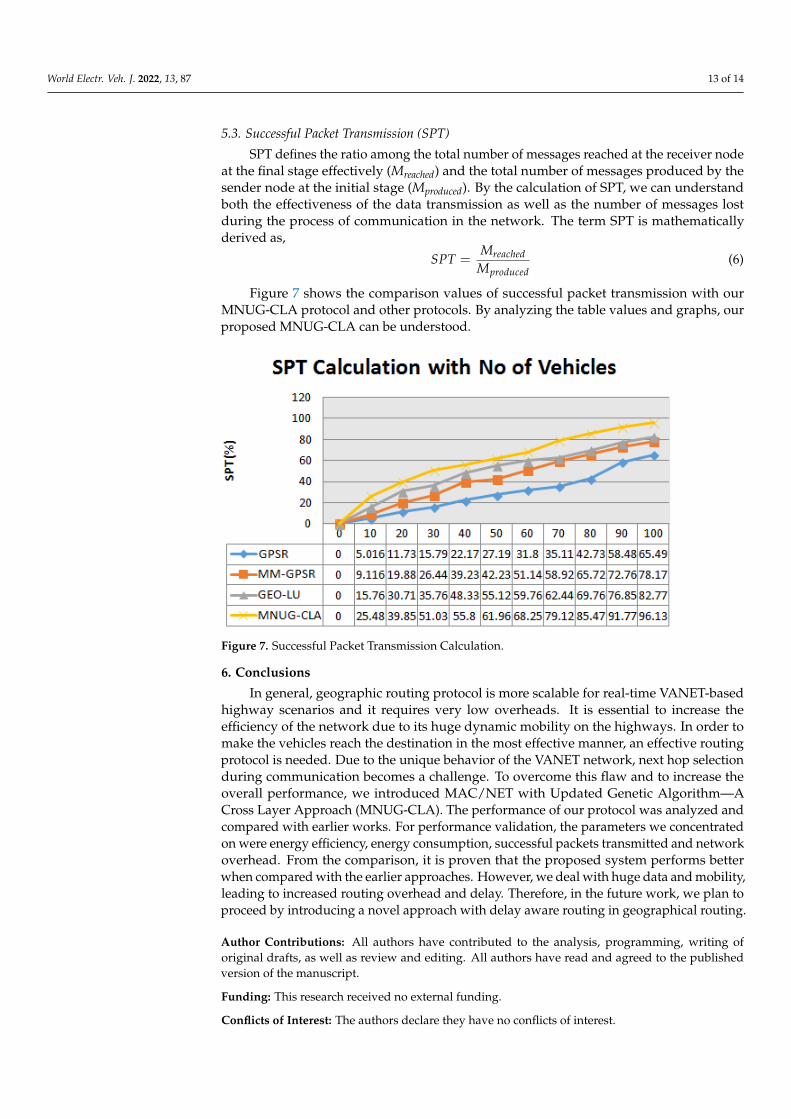
5.3. Successful Packet Transmission (SPT). SPT defines the ratio among the total number of messages reached at the receiver
node at the final stage effectively (Mreached) and the total number of messages produced by the sender node at the initial stage (Mproduced). By the calculation of SPT, we can understand both the effectiveness of the data transmission as well as the number of messages lost during the process of communication in the network. The term SPT is mathematically derived as, 𝑆𝑃𝑇 = 𝑀𝑀 (6)
Figure 7 shows the comparison values of successful packet transmission with our MNUG-CLA protocol and other protocols. By analyzing the table values and graphs, our proposed MNUG-CLA can be understood.
Figure 6. Network Energy Consumption Calculation.
World Electr. Veh. J. 2022, 13, 87 13 of 14
5.3. Successful Packet Transmission (SPT)
SPT defines the ratio among the total number of messages reached at the receiver nodeat the final stage effectively (Mreached) and the total number of messages produced by thesender node at the initial stage (Mproduced). By the calculation of SPT, we can understandboth the effectiveness of the data transmission as well as the number of messages lostduring the process of communication in the network. The term SPT is mathematicallyderived as,
SPT =Mreached
Mproduced(6)
Figure 7 shows the comparison values of successful packet transmission with ourMNUG-CLA protocol and other protocols. By analyzing the table values and graphs, ourproposed MNUG-CLA can be understood.
World Electr. Veh. J. 2022, 13, x FOR PEER REVIEW 14 of 15
Figure 7. Successful Packet Transmission Calculation.
6. Conclusions In general, geographic routing protocol is more scalable for real-time VANET-based
highway scenarios and it requires very low overheads. It is essential to increase the effi-ciency of the network due to its huge dynamic mobility on the highways. In order to make the vehicles reach the destination in the most effective manner, an effective routing pro-tocol is needed. Due to the unique behavior of the VANET network, next hop selection during communication becomes a challenge. To overcome this flaw and to increase the overall performance, we introduced MAC/NET with Updated Genetic Algorithm—A Cross Layer Approach (MNUG-CLA). The performance of our protocol was analyzed and compared with earlier works. For performance validation, the parameters we concen-trated on were energy efficiency, energy consumption, successful packets transmitted and network overhead. From the comparison, it is proven that the proposed system performs better when compared with the earlier approaches. However, we deal with huge data and mobility, leading to increased routing overhead and delay. Therefore, in the future work, we plan to proceed by introducing a novel approach with delay aware routing in geo-graphical routing.
Author Contributions: All authors have contributed to the analysis, programming, writing of orig-inal drafts, as well as review and editing. All authors have read and agreed to the published version of the manuscript.
Funding: This research received no external funding.
Conflicts of Interest: The authors declare they have no conflicts of interest.
References 1. Chen, C.; Liu, L.; Qiu, T.; Wu, D.O.; Ren, Z. Delay-Aware Grid-Based Geographic Routing in Urban VANETs: A Backbone
Approach. IEEE/ACM Trans. Netw. 2019, 27, 2324–2337. 2. Din, S.; Qureshi, K.N.; Afsar, M.S.; Rodrigues, J.J.P.C.; Ahmad, A.; Choi, G.S. Beaconless Traffic-Aware Geographical Routing
Protocol for Intelligent Transportation System. IEEE Access 2020, 8, 187671–187686. 3. Sudheera, K.L.K.; Ma, M.; Chong, P.H.J. Link Stability Based Optimized Routing Framework for Software Defined Vehicular
Networks. IEEE Trans. Veh. Technol. 2019, 68, 2934–2945. 4. Cardenas, L.L.; Mezher, A.M.; Bautista, P.A.B.; Igartua, M.A. A Probability-Based Multimetric Routing Protocol for Vehicular
Ad Hoc Networks in Urban Scenarios. IEEE Access 2019, 7, 178020–178032. 5. Kaur, H.; Meenakshi. Analysis of VANET Geographic Routing Protocols on Real City Map. In Proceedings of the IEEE Interna-
tional Conference on Recent Trends in Electronics Information & Communication Technology (RTEICT), Bangalore, India, 19–20 May 2017.
Figure 7. Successful Packet Transmission Calculation.
6. Conclusions
In general, geographic routing protocol is more scalable for real-time VANET-basedhighway scenarios and it requires very low overheads. It is essential to increase theefficiency of the network due to its huge dynamic mobility on the highways. In order tomake the vehicles reach the destination in the most effective manner, an effective routingprotocol is needed. Due to the unique behavior of the VANET network, next hop selectionduring communication becomes a challenge. To overcome this flaw and to increase theoverall performance, we introduced MAC/NET with Updated Genetic Algorithm—ACross Layer Approach (MNUG-CLA). The performance of our protocol was analyzed andcompared with earlier works. For performance validation, the parameters we concentratedon were energy efficiency, energy consumption, successful packets transmitted and networkoverhead. From the comparison, it is proven that the proposed system performs betterwhen compared with the earlier approaches. However, we deal with huge data and mobility,leading to increased routing overhead and delay. Therefore, in the future work, we plan toproceed by introducing a novel approach with delay aware routing in geographical routing.
Author Contributions: All authors have contributed to the analysis, programming, writing oforiginal drafts, as well as review and editing. All authors have read and agreed to the publishedversion of the manuscript.
Funding: This research received no external funding.
Conflicts of Interest: The authors declare they have no conflicts of interest.
World Electr. Veh. J. 2022, 13, 87 14 of 14
References1. Chen, C.; Liu, L.; Qiu, T.; Wu, D.O.; Ren, Z. Delay-Aware Grid-Based Geographic Routing in Urban VANETs: A Backbone
Approach. IEEE/ACM Trans. Netw. 2019, 27, 2324–2337. [CrossRef]2. Din, S.; Qureshi, K.N.; Afsar, M.S.; Rodrigues, J.J.P.C.; Ahmad, A.; Choi, G.S. Beaconless Traffic-Aware Geographical Routing
Protocol for Intelligent Transportation System. IEEE Access 2020, 8, 187671–187686. [CrossRef]3. Sudheera, K.L.K.; Ma, M.; Chong, P.H.J. Link Stability Based Optimized Routing Framework for Software Defined Vehicular
Networks. IEEE Trans. Veh. Technol. 2019, 68, 2934–2945. [CrossRef]4. Cardenas, L.L.; Mezher, A.M.; Bautista, P.A.B.; Igartua, M.A. A Probability-Based Multimetric Routing Protocol for Vehicular Ad
Hoc Networks in Urban Scenarios. IEEE Access 2019, 7, 178020–178032. [CrossRef]5. Kaur, H.; Meenakshi. Analysis of VANET Geographic Routing Protocols on Real City Map. In Proceedings of the IEEE
International Conference on Recent Trends in Electronics Information & Communication Technology (RTEICT), Bangalore, India,19–20 May 2017.
6. Deshmukh, A.R.; Dhawale, S.A.; Dorle, S.S. Analysis of Cluster Based Routing Protocol (CBRP) for Vehicular Adhoc Network(VANet) in Real Geographic Scenario. In Proceedings of the 2020 IEEE International Conference on Electronics, Computing andCommunication Technologies (CONECCT), Bangalore, India, 2–4 July 2020.
7. Chen, C.; Liu, L.; Qiu, T.; Yang, K.; Gong, F.; Song, H. ASGR: An Artificial Spider-Web-Based Geographic Routing in HeterogeneousVehicular Networks. IEEE Trans. Intell. Transp. Syst. 2018, 20, 1604–1620. [CrossRef]
8. Nebbou, T.; Lehsaini, M. Greedy Curvemetric-based Routing Protocol for VANETs. In Proceedings of the 2018 InternationalConference on Selected Topics in Mobile and Wireless Networking (MoWNeT), Tangier, Morocco, 20–22 June 2018.
9. Kalogeiton, E.; Iapello, D.; Torsten Braun, T. A Geographical Aware Routing Protocol Using Directional Antennas for NDN-VANETs. In Proceedings of the 2019 IEEE 44th Conference on Local Computer Networks (LCN), Osnabrueck, Germany,14–17 October 2019.
10. Saleet, H.; Langar, R.; Naik, K.; Boutaba, R.; Nayak, A.; Goel, N. Intersection-Based Geographical Routing Protocol for VANETs:A Proposal and Analysis. IEEE Trans. Veh. Technol. 2011, 60, 4560–4574. [CrossRef]
11. Liu, H.; Qiu, T.; Zhou, X.; Chen, C.; Chen, N. Parking-area-assisted Spider-web Routing Protocol for Emergency Data in UrbanVANET. IEEE Trans. Veh. Technol. 2019, 69, 971–982. [CrossRef]
12. Wu, J.; Fang, M.; Li, H.; Li, X. RSU-Assisted Traffic-Aware Routing Based on Reinforcement Learning for Urban Vanets.IEEE Access 2019, 8, 5733–5748. [CrossRef]
13. Rios, M. GeOpps-N: Opportunistic Routing for VANET in a Public Transit System. IEEE Lat. Am. Trans. 2016, 14, 1630–1637.[CrossRef]
14. Alzamzami, O.; Mahgoub, I. Fuzzy Logic-Based Geographic Routing for Urban Vehicular Networks Using Link Quality andAchievable Throughput Estimations. IEEE Trans. Intell. Transp. Syst. 2018, 20, 2289–2300. [CrossRef]
15. Sahu, P.K.; Wu, E.H.K.; Sahoo, J.; Gerla, M. BAHG: Back-Bone-Assisted Hop Greedy Routing for VANET’s City Environments.IEEE Trans. Intell. Transp. Syst. 2013, 14, 199–213. [CrossRef]
16. Salkuyeh, M.A.; Abolhassani, B. An Adaptive Multipath Geographic Routing for Video Transmission in Urban VANETs. IEEETrans. Intell. Transp. Syst. 2016, 17, 2822–2831. [CrossRef]
17. Zhou, S.; Li, D.; Tang, Q.; Fu, Y.; Guo, C.; Chen, X. Multiple intersection selection routing protocol based on road sectionconnectivity probability for urban VANETs. Comput. Commun. 2021, 177, 255–264. [CrossRef]
18. Sultana, R.; Grover, J.; Tripathi, M. Security of SDN-based vehicular ad hoc networks: State-of-the-art and challenges.Veh. Commun. 2020, 27, 100284. [CrossRef]
19. Jeong, J.; Shen, Y.; Oh, T.; Céspedes, S.; Benamar, N.; Wetterwald, M.; Härri, J. A comprehensive survey on vehicular networks forsmart roads: A focus on IP-based approaches. Veh. Commun. 2021, 29, 100334. [CrossRef]
20. Qureshi, K.N.; Alhudhaif, A.; Shah, A.A.; Majeed, S.; Jeon, G. Trust and priority-based drone assisted routing and mobility andservice-oriented solution for the internet of vehicles networks. J. Inf. Secur. Appl. 2021, 59, 102864. [CrossRef]
21. Husain, K.; Awang, A.; Kamel, N.; Aïssa, S. Routing in Vehicular Ad-hoc Networks: A Survey on Singleand Cross-layer DesignTechniques, and Perspectives. IEEE Access 2016, 5, 9497–9517.
22. Kazi, A.K.; Khan, S.M.; Haider, N.G. Reliable Group of Vehicles (RGoV) in VANET. IEEE Access 2019, 9, 111407–111416. [CrossRef]23. Yang, X.; Li, M.; Qian, Z.; Di, T. Improvement of GPSR protocol in Vehicular Ad hoc Network. IEEE Access 2017, 6, 39515–39524.
[CrossRef]24. Abbas, A.H.; Audah, L.; Alduais, N.M.N. An efficient load balance algorithm for vehicular ad-hoc network. In Proceedings
of the 2018 Electrical Power, Electronics, Communications, Controls and Informatics Seminar (EECCIS), Batu, Indonesia,9–11 October 2018.
25. Alzamzami, O.; Mahgoub, I. Link utility aware geographic routing for urban VANETs using two-hop neighbor information.Ad Hoc Netw. 2020, 106, 102213. [CrossRef]


